Embed Size (px)
Citation preview

October 2012 LTE: a real disruptive technology
and business opportunity?
White Paper

LTE: a real disruptive technology and business opportunity? – White Paper
© 2012 WiTech www.witech.it Reproduction prohibited 2
ABOUT WITECH
Founded in October 2003 as a spin-off of the University of Pisa, WiTech has quickly become a
leading company operating in the telecommunication market with a focus on next generation
wireless technologies.
WiTech provides high performance managed services and solutions to create a measurable
business value for its international clients, including network operators & service providers,
vendors & manufactures, regulators, analysts & consulting firms and universities.
Focusing on Technology Consulting, WiTech has an in-depth expertise in developing the cost
modeling of telco networks to understand the actual costs and improve pricing and market entry
decisions. Moreover, WiTech has a global track record with the assessment of business cases for
telco initiatives ensuring the best possible alignment between business and technology strategies
from the outset. In addition, WiTech manages efficiently the entire RFI/RFQ process, developing
accurate RFI/RFQ documents and evaluating submitted proposals, as well as selecting the vendor
best suited to requirements and negotiating the contract. Furthermore, WiTech has extensive
experience in preparing reports and white papers on the hottest topics in the telco industry,
driven by both clients’ and WiTech’s interest.
Thanks to its R&D team, WiTech has developed TEA (Technical & Economic Analyses), a family of
business case analysis tools, which enable thorough techno-economic analyses in support of
accurate and reliable business cases for 4G initiatives (e.g. LTE and WiMAX) in a fast and
dependable manner.
WiTech has earned several industry recognitions, both national and international, thanks to its
hard work made of an inborn innovative and creative inclination.
For additional information you can visit us at www.witech.it, or you can contact us at
[email protected] or at +39 050 77 50 56.

LTE: a real disruptive technology and business opportunity? – White Paper
© 2012 WiTech www.witech.it Reproduction prohibited 3
THE AUTHORS OF THE REPORT
Elena Briola is VP of Technology Consulting at WiTech. She has an in-depth technical and
economic expertise in wireless access technologies, such as GSM, UMTS/HSPA, LTE, WiMAX,
TETRA/TEDS and Wi-Fi, as well as in high-capacity wireless backhauling solutions. She is well-
skilled to develop cost modelings for telco network and she is the product manager for the family
of business case analysis tools TEA. She has written several articles and reports on new generation
wireless technologies. She holds a Degree in Telecommunications Engineering (Summa Cum
Laude) from the University of Pisa, Italy. She can be contacted at [email protected].
Andrea Calcagno is CEO and founder of WiTech. He has a strong technical and economic
background in the telecommunication industry with a focus on next generation networks and
services. Thanks to his expertise, he has been the leader of more than fifty projects concerning
wireless next generation networks and services (WiFi, 3G/HSPA, WiMAX, LTE, Smart Metering) for
several telco operators, system integrators, vendors and consulting firms in the domestic market
and international arena. He has written several articles and reports on new generation wireless
technologies. He holds a Degree in Telecommunications Engineering (Summa Cum Laude) from
the University of Pisa, Italy. He can be contacted at [email protected].
THE CONTRIBUTORS OF THE REPORT
Rosalba Campanale is Senior Analyst at WiTech. She has an exhaustive technical knowledge in
wireless access technologies, such as GSM, UMTS/HSPA, LTE and WiMAX, as well as in high-
capacity wireless backhauling solutions. She holds a Degree in Telecommunications Engineering
(Summa Cum Laude) from the University of Pisa, Italy. She can be contacted at
THE EDITORS OF THE REPORT
Emma Cale is a qualified teacher of the English language and currently teaches English to
speakers of other languages. She holds a BA (Hons) Degree in English Literature and History of
Art from the University of Reading and a MA in Media Studies from the University of East London.
She can be contacted at [email protected].
With good communication skills Armida Kaloti is in charge of Operational Marketing at WiTech. She
holds a Degree in Communication Science from the University of Pisa, Italy. She can be contacted at
© 2012 WiTech – All rights reserved. No selection of this material can be copied, photocopied, duplicated in
any form or by any means, or redistributed without express written permission from WiTech. While the report
is based upon information that we consider accurate and reliable, WiTech makes no warranty, express or
implied, as to the accuracy of the information in this document. WiTech assumes no liability for any damage or
loss arising from reliance on this information. Names of companies and products here mentioned may be the
trademarks of their respective owners.

LTE: a real disruptive technology and business opportunity? – White Paper
© 2012 WiTech www.witech.it Reproduction prohibited 4
HOW TO REQUIRE YOUR FREEWARE LICENSE OF TEA|LTE
The download of the white paper entitles you to receive a freeware licence of TEA|LTE, a unique
and innovative application to perform LTE business case analyses taking into account all critical
factors (market, technical, economic and financial) from the outset
To get your the freeware licence of TEA|LTE, fill in the form at our website.

LTE: a real disruptive technology and business opportunity? – White Paper
© 2012 WiTech www.witech.it Reproduction prohibited 5
TABLE OF CONTENTS
ABOUT WITECH ....................................................................................................................................................................... 2
THE AUTHORS OF THE REPORT ........................................................................................................................................ 3
THE CONTRIBUTORS OF THE REPORT ........................................................................................................................... 3
THE EDITORS OF THE REPORT........................................................................................................................................... 3
HOW TO REQUIRE YOUR FREEWARE LICENSE OF TEA|LTE ................................................................................... 4
TABLE OF CONTENTS ............................................................................................................................................................ 5
LIST OF FIGURES ...................................................................................................................................................................... 6
LIST OF TABLES ........................................................................................................................................................................ 7
EXECUTIVE SUMMARY .......................................................................................................................................................... 8
1. A SMOOTH MIGRATION TOWARDS 4G .........................................................................................................10
1.1 LTE: a promising technology .................................................................................................................................10
1.2 Structure of this white paper ................................................................................................................................11
2. LTE TECHNOLOGY PRIMER ..................................................................................................................................12
2.1 A clear standardization path ................................................................................................................................12
2.2 How LTE works...........................................................................................................................................................13
2.2.1 Targets.......................................................................................................................................................................... 14
2.2.2 Evolved radio air interface .................................................................................................................................... 15
2.2.3 Simplified core network ........................................................................................................................................ 21
2.2.4 QoS differentiation .................................................................................................................................................. 23
2.2.5 Security ........................................................................................................................................................................ 24
2.2.6 Mobility ........................................................................................................................................................................ 25
2.2.7 SON ............................................................................................................................................................................... 25
2.2.8 Voice and SMS services over LTE....................................................................................................................... 26
2.3 LTE Advanced and beyond ....................................................................................................................................26
2.3.1 Targets.......................................................................................................................................................................... 28
2.3.2 Additional technology components ................................................................................................................. 29
2.4 Performance in a nutshell .....................................................................................................................................32
3. CRITICAL FACTORS FOR THE LTE BUSINESS CASE .....................................................................................34
3.1 Framework ..................................................................................................................................................................34
ACRONYMS .............................................................................................................................................................................36
REFERENCES ............................................................................................................................................................................45
Annex A – TEA|LTE: THE LTE BUSINESS CASE ANALYSIS TOOL .....................................................................48
WiTech – WiFi Cloud ............................................................................................................................................................51

LTE: a real disruptive technology and business opportunity? – White Paper
© 2012 WiTech www.witech.it Reproduction prohibited 6
LIST OF FIGURES
Figure 1 – Standardization timeline for LTE and beyond ......................................................................................13 Figure 2 – LTE features ........................................................................................................................................................13 Figure 3 – Frequency representation of OFDM.........................................................................................................15 Figure 4 – Spatial multiplexing and transmit diversity ...........................................................................................16 Figure 5 – Beamforming .....................................................................................................................................................16 Figure 6 – OFDMA scheme ...............................................................................................................................................17 Figure 7 – High PAPR challenge ......................................................................................................................................17 Figure 8 – SC-FDMA scheme ............................................................................................................................................18 Figure 9 – FFR .........................................................................................................................................................................20 Figure 10 – SFR ......................................................................................................................................................................20 Figure 11 – High level view of EPS .................................................................................................................................21 Figure 12 – Possible hardware configurations of EPC ............................................................................................22 Figure 13 – SAE bearer model .........................................................................................................................................23 Figure 14 – Timeline for IMT Advanced and LTE Advanced ................................................................................27 Figure 15 – Additional LTE Advanced features..........................................................................................................30 Figure 16 – High level view of the technical-economic model TEA..................................................................35 Figure 17 – Work flow for the Market Analysis .........................................................................................................48 Figure 18 – Work flow for the Technical Analysis ....................................................................................................49 Figure 19 – Work flow for the Economic and Financial Analysis........................................................................50 Figure 20 – Environment of TEA|LTE..............................................................................................................................50

LTE: a real disruptive technology and business opportunity? – White Paper
© 2012 WiTech www.witech.it Reproduction prohibited 7
LIST OF TABLES
Table 1 – LTE key targets ...................................................................................................................................................15 Table 2 – LTE FDD vs LTE TDD .........................................................................................................................................18 Table 3 – UE classes .............................................................................................................................................................19 Table 4 – QCI classes ...........................................................................................................................................................24 Table 5 – IMT Advanced and LTE Advanced key targets.......................................................................................29 Table 6 – LTE and LTE Advanced performance at a glance ..................................................................................33

LTE: a real disruptive technology and business opportunity? – White Paper
© 2012 WiTech www.witech.it Reproduction prohibited 8
EXECUTIVE SUMMARY
Nowadays, it is not only people who require an ‘always on’ connection to the Internet gaining
access to innovative applications (e.g. video streaming, social networks, content publishing, web
conferences, etc.), but also things, that need to communicate among themselves through the
Internet anytime and anywhere creating smart environments. This paradigm is the Internet of
Things!
All this means that the demand for mobile broadband is expected to grow exponentially in the next
few years with a CAGR of 96% from 2010 to 2015, driven also by the availability of new UE,
including tablets, routers, M2M, smartphones, etc.
This forces the adoption of new generation technologies, such as LTE, with the consequent need for
changes for all players of the Telecom market, starting from network operators and service
providers, proceeding to regulators and standardization and industry bodies and, finally, moving to
vendors.
But is LTE a real disruptive technology and business opportunity?
It is not easy to find an answer to this question straightaway because several circumstances come
into play. It is certain that LTE offers real potentialities to network operators thanks to the advanced
features and functionalities supported. However there are several critical factors, which can turn the
LTE initiative from a potential success into a total failure and, they therefore need to be properly
and carefully analyzed and defined.
This white paper wants to introduce some of the main topics of the report, which is a valid help to
explore the emerging world of LTE not only from a technological but also a business perspective,
along six paths of investigation:
Key drivers for the LTE adoption
Overview of LTE and its evolution LTE Advanced
Candidate spectrum bands and licensing experience to date
Current status of the LTE ecosystem
Operator plans, commitments, trials, deployments, launches
Critical factors for the LTE business case.
The increasing demand for mobile broadband represents the main driver for LTE, whose adoption
involves deep changes for the entire Telecom market. Network operators and service providers
need to redefine their business model and redesign their network infrastructure to fully enable the
Internet of Things. Regulators need to outline new strategies for a forward-looking spectrum
management capable of supporting network operators and service providers in their initiatives.
Standardization and industry bodies need to ensure an industry alignment for LTE deployments
through the E2E interoperability among different vendors and across different network elements.
Vendors need to become the suppliers of feature-rich and cost competitive solutions taking into
account the real requirements of network operators and service providers.
In comparison with legacy 3GPP systems, LTE and its evolution LTE Advanced have introduced
enhanced features and functionalities. Specifically, OFDM and MIMO have been included in the
radio air interface respectively to defeat multipath environments increasing the spectral efficiency,

LTE: a real disruptive technology and business opportunity? – White Paper
© 2012 WiTech www.witech.it Reproduction prohibited 9
and to boost the peak data rate or to enhance the signal robustness. Moreover, a flat all-IP and PS
domain optimized core network has been defined to provide reduced latency and improved QoS,
support for only packet switched services, separation between the U-plane and C-plane traffic
handling, convergence and seamless internetworking with legacy 3GPP and non-3GPP systems. In
addition, the heterogeneous networks approach has been introduced to combine different cell
types (macrocells, microcells, picocells, etc.) across multiple RAT and on multiple spectrum bands.
Finally, the SON capabilities, including the functionalities of self-configuration, self-optimization
and self-healing, have been defined to optimize the network deployment and management.
The 3GPP has identified several paired and unpaired spectrum bands (thirty-four in total) in order
to support not only FDD operations but also TDD operations providing network operators higher
flexibility to deploy mobile networks based on frequency availability and investment possibilities.
Some spectrum bands are particularly of interest in the deployment of LTE systems (e.g. 700, 800,
900, 1700/2100, 1900, 2000, 2300, 2600 and 3500 MHz), as confirmed by the worldwide licensing
experience to date.
The LTE ecosystem is quite complex if compared with any of the previous technologies, because it
includes a lot of players (e.g. users, network operators and service providers, regulators and
standard bodies, vendors). However, all these players are closely cooperating to speed up the
evolution of the LTE ecosystem to avoid replicating the experience of 3G technologies. Looking at
the current trends and focusing on UE, for example, around 250 new devices have been announced
over the past year.
The number of LTE network deployments is quickly growing across the globe involving more and
more countries and network operators. At the moment, 312 network operators are investing in LTE
in 98 different countries. Specifically, there are 64 commercial networks in 34 countries, 253
commercial network commitments in 84 countries and 59 pre-commitments trials in 14 countries.
In addition, 129 commercial network commitments are expected by the end of 2012.
LTE has real business potentialities, as deduced through the business case sample1 provided. Thus,
network operators can benefit from higher flexibility in the realization of the infrastructure, defining
better suited deployments according to their specific business models and fully seizing the business
opportunities offered. Nevertheless, many aspects can undermine the LTE success. Hence,
performing an in-depth scenario and sensitivity analysis becomes a must to understand the
dynamics of the technical and economic feasibility of the LTE initiative depending on the critical
factors, whose little changes could make the investment not profitable.
1 The 10-year business case sample refers to an Italian incumbent mobile operator and it has been carried out by means of the
business case analysis tool TEA|LTE from WiTech. Specifically, this mobile operator needs to migrate its nationwide mobile
network from the legacy 3G technology to the emerging LTE technology in order to offer attractive triple play services to both
residential and business users in a mobile and fixed access. It is worth highlighting that this business case sample is
imaginary and it does not represent any Italian incumbent mobile operator. Therefore, all possible references to real business
strategies and network deployments are merely casual.

LTE: a real disruptive technology and business opportunity? – White Paper
© 2012 WiTech www.witech.it Reproduction prohibited 10
1. A SMOOTH MIGRATION TOWARDS 4G
This section mainly provides a thorough overview of the key factors, which make LTE a promising
technology to cope with the emerging market needs including the increasing demand for mobile
broadband. In addition, it presents the structure of this white paper providing a high level
description of topics covered in each section.
1.1 LTE: a promising technology
The Telecom market is continuously changing and reinventing itself to meet the growing demand
of mobile broadband driven by the availability of new UE (e.g. tablets, routers, M2M, smartphones,
etc.), as well as by the widespread diffusion of disruptive applications (e.g. video streaming, social
networks, content publishing, web conferences, etc.) and the Internet of Things.
Therefore, new technologies need to be adopted. Keeping an eye on the surrounding technological
landscape, the trends are well defined: 4G technologies and, in particular, LTE represents the
evolutionary path towards the new generation.
Thus, LTE opens the door for broadband services through traditional and non traditional UE also
combining the fixed and mobile access in a hybrid approach and looking at areas which have not
been fully explored yet, such as consumer electronics and appliances, health care, public utilities
and telematics.
This is supported by several advantages and benefits, which LTE provides including:
Higher capacity: As LTE supports wider channel bandwidths as well as the MIMO feature
(i.e. spatial multiplexing), it provides higher data rates truly enabling innovative services,
such as video streaming
Deployment flexibility: Thanks to the support for heterogeneous networks, LTE gives the
possibility of focusing coverage and capacity extensions through the combination of
local area sites (e.g. picocells and femtocells) with medium and wide area sites (e.g.
micro and macro cells), that spread across multiple RAT and operate in both licensed
and unlicensed spectrum bands.
Self-optimizing network capability: LTE supports self-configuration, self-optimization
and self-healing, reducing the effort in time and money required to deploy and manage
the network.
Spectrum flexibility: Since LTE supports various spectrum bands and channel
bandwidths, it enables network operators to define better suited deployments
according to their specific business model.
Lower latency: LTE reduces the E2E latency both on the C-plane and U-plane, providing
a direct service advantage for interactive services, such as multiplayer gaming and rich
multimedia communications.
QoS: Through a detailed QoS differentiation, LTE allows meeting specific QoS
requirements of each service in order to ensure a real user experience.

LTE: a real disruptive technology and business opportunity? – White Paper
© 2012 WiTech www.witech.it Reproduction prohibited 11
Improved coverage: Thanks to the MIMO feature (i.e. transmit diversity) and lower
spectrum bands (e.g. 800 MHz), LTE has coverage and in-built penetration advantages
over legacy 3GPP systems.
Security: LTE provides enhanced security through advanced mechanisms, defined on the
basis of architectural design decisions, internetworking with legacy 3GPP and non-3GPP
systems, new services to be provided and alocal-based security approach.
Higher mobility: LTE works in high mobile speeds scenarios (even up to 500 Km/h
depending on the spectrum band).
However, in order to fully take advantage of the aforementioned benefits and seize the business
opportunity offered by LTE it is required to properly analyze the main critical factors for the success
of the LTE initiative.
1.2 Structure of this white paper
The remainder of this white paper is structured as follows:
Section 1: This section provides a clear and concise overview of the LTE technology,
including the standardization timeline, the main technical features implemented and,
eventually, the performance comparison between LTE and its evolution.
Section 2: This section discusses the possible spectrum bands, which can be adopted for
LTE deployment across the globe and presents a picture of trends and outcomes of the
earliest auctions and attributions of LTE spectrum bands.
Section 3: This section aims at highlighting the framework for the analysis of the critical
factors of an LTE initiative.
Annex A: This annex describes the business case analysis tool TEA|LTE from WiTech.

LTE: a real disruptive technology and business opportunity? – White Paper
© 2012 WiTech www.witech.it Reproduction prohibited 12
2. LTE TECHNOLOGY PRIMER
This section provides a clear and concise overview of the LTE technology. More specifically, it firstly
presents the standardization timeline for LTE and beyond. It then describes the main technical
features implemented in LTE and LTE Advanced, setting out advantages and benefits introduced by
each one. Finally it shows the results of the comparison between LTE and its evolution to outline
their performance.
2.1 A clear standardization path
LTE describes the last standardization work of the 3GPP providing a new high speed radio access
method for mobile communication systems and representing the natural evolution of legacy
3GPP/non-3GPP systems towards emerging IMT Advanced systems2.
The concept of LTE was discussed for the first time in 2004 in Toronto, with the initiative RAN
Evolution Workshop. This initiative gathered more than forty network operators, vendors and
research institutes (including the 3GPP) who provided their considerations about the evolution of
the UTRAN.
Following the Toronto Workshop, in December 2004 the 3GPP launched a feasibility study in order
‘to develop a framework for the evolution of the 3GPP radio access technology towards high data
rate, low latency and packed optimized radio access technologies’. This study, hence, settled out
technical specifications for a new radio access network capable of supporting mobile broadband.
The first LTE specifications were provided in the Release 8 that was frozen in December 2008 and
published in March 2009. In this Release, the 3GPP defined a new PHY layer using OFDMA in DL
and SC-FDMA in UL as well as supporting channel bandwidth between 1.4 and 20 MHz. This
Release defined options for both FDD and TDD operations, a suite of MIMO capabilities and
interference coordination techniques. In addition it provided several other enhancements related to
common IMS, service continuity between LTE systems and legacy 3GPP systems and multimedia
priority systems.
After the completion of the Release 8, the 3GPP turned to the Release 9, which was subsequently
completed in March 2010. Several features and capabilities were added; specifically -emergency
and location-based services, enhancement for CSFB and MBMS, self-organizing network feature,
dual layer beamforming, femtocells, vocoder rate adaptation based on cell loading, IMS Centralized
Services and UICC.
While the 3GPP was completing the Release 9, it recognized the need to develop a new solution to
meet the IMT Advanced requirements and make the evolution of LTE a candidate for future new
spectrum bands still to be identified. Therefore, the 3GPP worked on a study item called LTE
Advanced, which represented the keystone of the Release 10. This Release, completed in March
2011, added new features and performance enhancements, including carrier aggregation, MIMO
enhancements, relaying, SON enhancement, coordinated multipoint and heterogeneous networks.
2 The IMT Advanced systems promise to provide best-in-class performance such as peak and sustained data rates and
corresponding spectral efficiencies, capacity, latency, overall network complexity and quality-of-service management. In addition, they promise to support innovative and multimedia applications, including, but not limited to, video, file
uploading and downloading without size limitations (e.g., FTP), streaming video and streaming audio, IP Multicast, location based services, VPN connections, VoIP, instant messaging and on- line multiplayer gaming. Finally they promise to enable the mobile user with an ‘always-on’ experience while also preserving battery life. [5]

LTE: a real disruptive technology and business opportunity? – White Paper
© 2012 WiTech www.witech.it Reproduction prohibited 13
When the Release 10 was almost complete, the 3GPP started to focus on the Release 11 planning
with a target deadline timeframe expected for September to December 2012. Several
enhancements are planned to be added, such as carrier aggregation and ICIC enhancements.
Figure 1 provides the standardization timeline for LTE and beyond.
Figure 1 – Standardization timeline for LTE and beyond
2.2 How LTE works
LTE promises to considerably improve performance in comparison with legacy 3GPP systems. More
specifically, the goal of LTE is to provide high data rates, low latency, spectrum flexibility, higher
mobile speeds, real E2E QoS and packet-optimized network.
In order to achieve these targets several features have been added, as shown in Figure 2, including
OFDM, MIMO, advanced interference coordination techniques, evolved core network, SAE bearer
model and SON capabilities. A detailed analysis of the aforementioned features is provided in the
following sections.
Figure 2 – LTE features
‘04 ‘09 ‘10 ‘11
Toronto ‘s workshop
Start of study item
Close Rel-8
Close Rel-9
Close Rel- 10
Start Rel-11
OFDM
SON MIMO
Interference
coordination
EPC
SAE bearer model

LTE: a real disruptive technology and business opportunity? – White Paper
© 2012 WiTech www.witech.it Reproduction prohibited 14
2.2.1 Targets
The main requirements for the design of LTE were identified at the beginning of the 3GPP work
item [6]. A brief and clear summary is provided below.
Peak data rate
The peak data rate should have targeted 100 Mbps in DL and 50 Mbps in UL.
Latency
o Control Plane
The target for the transition time from the idle mode to the connected mode
should have been less than 100 ms; whilst the target for the transition time
from the dormant state to the connected mode less than 50 ms.
o User Plane
The latency target should have been less than 5 ms.
Spectrum efficiency
Spectrum efficiency should have been 3-4 times better than the Release 6 in DL (i.e.
higher than 5 bps/Hz), whereas spectrum efficiency 2-3 times better than the Release 6
in UL (i.e. higher than 2.5 bps/Hz).
Mobility
Performance should have been optimized for low mobile speeds from 0 to 15 km/h.
However higher mobile speeds (up to 350 Km/h) should have been supported.
Spectrum flexibility
Scalable channel bandwidths of 1.4, 3, 5, 10, 15 and 20 MHz in both DL and UL should
have been supported, as well as FDD and TDD for paired and unpaired spectrum bands
respectively.
Architecture
LTE should have been packet switched domain optimized, assuming that all operations
were based on a packet type.
Internetworking
Interworking with legacy 3GPP and non-3GPP systems (such as WiMAX and Wi-Fi)
should have been ensured, including inter-system handover to and from 3GPP systems.
Quality of service
E2E QoS should have been supported. In addition, VoIP service should have been
provided with at least as good radio and backhaul efficiency and latency as voice traffic
over the 3GPP systems.
Costs
LTE should have reduced CAPEX and OPEX ensuring low investments and operational
costs compared to the earlier systems.
Table 1 summarizes the main key targets for LTE.

LTE: a real disruptive technology and business opportunity? – White Paper
© 2012 WiTech www.witech.it Reproduction prohibited 15
Table 1 – LTE key targets
Performance indicator LTE
Peak data rate DL: 100 Mbps
UL: 50 Mbps
Latency C-plane < 50 - 100 ms
U-plane < 5 ms
Spectrum
efficiency3
Peak DL: > 5.0 bps/Hz
UL: > 2.5 bps/Hz
Average4
DL: > 1.60 bps/Hz
UL: > 0.66 bps/Hz
Cell-edge5
DL: > 0.04 bps/Hz
UL: > 0.02 bps/Hz
Mobility Up to 350 Km/h
Channel bandwidth Up to 20 MHz
2.2.2 Evolved radio air interface
In comparison with legacy 3GPP systems, LTE has introduced several features to address the
aforementioned requirements [7], [8], [9], [10], [11], [12], [13], [14], [15], [16], [17], [18], [19], but the
most important ones are OFDM and MIMO that constitute the major differentiation over legacy
3GPP systems.
OFDM
OFDM6 is a multi carrier transmission which works by splitting the signal into multiple narrowband
signals that are simultaneously transmitted on different sub-carriers partially overlapped but
orthogonal, as shown in Figure 14. The number of sub-carriers defines the size of the OFDM symbol
(i.e. of FFT).
Figure 3 – Frequency representation of OFDM
OFDM has superior performance mostly in multipath environments, characterized by several paths
between the transmitter and the receiver due to the presence of obstacles (such as trees, buildings,
3 This spectrum efficiency has been estimated by assuming four antenna elements at eNB side and 2 antenna elements at
UE side. 4 The average spectrum efficiency is defined as the aggregate throughput of all users normalized by the overall bandwidth
divided by the number of sites. 5 The cell-edge spectrum efficiency is based on the cell-edge user throughput. It is defined as the 5% point of the CDF of
the user throughput normalized with the overall cell bandwidth. 6 OFDM is not a new technology, but it was patented by Bell Labs in 1970. Today it is used in different systems, such as
ADSL, DAB, DVB, Wi-Fi and WiMAX.

LTE: a real disruptive technology and business opportunity? – White Paper
© 2012 WiTech www.witech.it Reproduction prohibited 16
mountains, hills and other natural or manmade structures or objects). In these environments, hence,
OFDM allows defeating multipath through its narrowband nature. In addition, OFDM limits the
intersymbol interference through its structure (cyclic prefix) and increases the spectral efficiency
thanks to the orthogonality between sub-carriers.
MIMO
MIMO uses multiple antenna elements at TX/RX to either increase the peak data rate or enhance
the signal robustness. More specifically, LTE supports up to four transmit and receive antenna
elements in DL, whilst one transmit antenna element and up to four receive antenna elements in
UL.
Three main modes of MIMO can be pointed out: spatial multiplexing, transmit diversity and
beamforming.
Spatial multiplexing relies on sending independent signals from two or more different antenna
elements in order to increase the peak data rate by a factor that depends on their numbers.
Transmit diversity relies on sending the same signal from multiple antenna elements in order to
enhance the coverage radius. Spatial multiplexing and transmit diversity are tied through the
adaptive antenna switching. This such technique, currently implemented in the majority of eNB
supporting MIMO, allows switching between the spatial multiplexing and transmit diversity based
on the quality of the radio propagation channel in order to fully benefit from MIMO. Figure 4
provides a high level description of the way these techniques work.
Figure 4 – Spatial multiplexing and transmit diversity
Beamforming allows automatically chancing the directionality of the antenna radiation pattern
through advanced signal processing capabilities in order to dynamically minimize interference,
maximize intended signal reception and improve the management of the system power and
spectrum allocation. Figure 5 provides a high level description of the way this technique works.
Figure 5 – Beamforming
Spatial
Multiplexing
Transmit
Diversity
Data stream A
Data stream B
Data stream A
Data stream A
eNodeB UE
UEeNodeB
Target
UE
Interfering
UE
eNodeB

LTE: a real disruptive technology and business opportunity? – White Paper
© 2012 WiTech www.witech.it Reproduction prohibited 17
Multiple access techniques
In DL the multiple accesses is based on OFDMA. In detail, OFDMA is an extension of OFDM in which
available sub-carriers are assigned to different users based on their capacity demand and radio
channel propagation conditions. As shown in Figure 6, multiple users can be scheduled to receive
data simultaneously like in FDMA, but their mutual interference is reduced thanks to the
orthogonality among sub-carriers.
Figure 6 – OFDMA scheme
In addition, OFDMA is used in combination with TDMA and, therefore, resources are partitioned in
the time-frequency plane.
The main drawback of OFDMA is the high PAPR. Since OFDMA consists of several sub-carriers in
the frequency domain, that is several sinusoidal waves in the time domain, it is characterized by a
strong variation of the signal envelope, as depicted in Figure 7. This results in the need to use
expensive non-linear PA with low power consumption mainly at UE side.
Figure 7 – High PAPR challenge
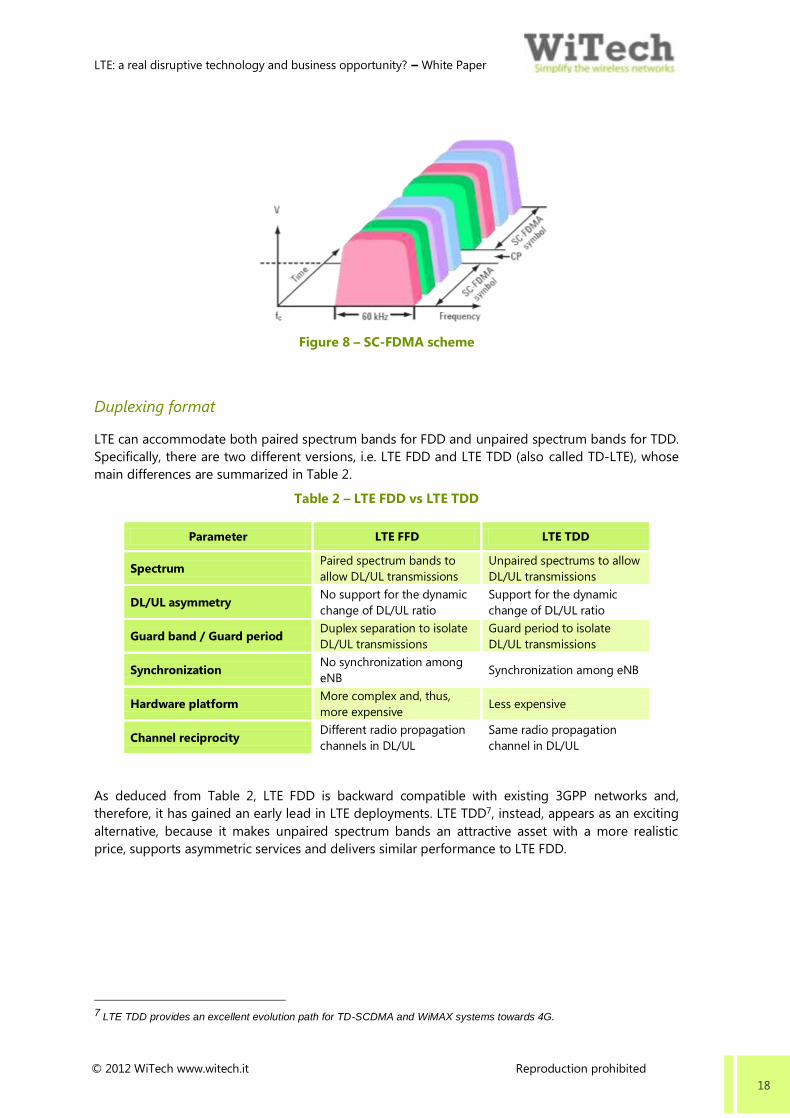
To solve this critical issue, in UL the power efficient SC-FDMA is implemented. This is a variant of
OFDM and is generated through a DFTS-OFDM. Like in OFDM the channel bandwidth is divided
into multiple sub-carriers, however in SC-FDMA the sub-carriers are transmitted sequentially and
not in parallel, as shown in Figure 8. Therefore, since only one sub-carrier is used at a time, PAPR is
reduced and, consequently, a more efficient PA implementation can be carried out.
LTE: a real disruptive technology and business opportunity? – White Paper
© 2012 WiTech www.witech.it Reproduction prohibited 18
Figure 8 – SC-FDMA scheme
Duplexing format
LTE can accommodate both paired spectrum bands for FDD and unpaired spectrum bands for TDD.
Specifically, there are two different versions, i.e. LTE FDD and LTE TDD (also called TD-LTE), whose
main differences are summarized in Table 2.
Table 2 – LTE FDD vs LTE TDD
Parameter LTE FFD LTE TDD
Spectrum Paired spectrum bands to
allow DL/UL transmissions
Unpaired spectrums to allow
DL/UL transmissions
DL/UL asymmetry No support for the dynamic
change of DL/UL ratio
Support for the dynamic
change of DL/UL ratio
Guard band / Guard period Duplex separation to isolate
DL/UL transmissions
Guard period to isolate
DL/UL transmissions
Synchronization No synchronization among
eNB Synchronization among eNB
Hardware platform More complex and, thus,
more expensive Less expensive
Channel reciprocity Different radio propagation
channels in DL/UL
Same radio propagation
channel in DL/UL
As deduced from Table 2, LTE FDD is backward compatible with existing 3GPP networks and,
therefore, it has gained an early lead in LTE deployments. LTE TDD7, instead, appears as an exciting
alternative, because it makes unpaired spectrum bands an attractive asset with a more realistic
price, supports asymmetric services and delivers similar performance to LTE FDD.
7 LTE TDD provides an excellent evolution path for TD-SCDMA and WiMAX systems towards 4G.

LTE: a real disruptive technology and business opportunity? – White Paper
© 2012 WiTech www.witech.it Reproduction prohibited 19
UE categories
The 3GPP has defined five different UE categories, often referred to as UE classes, which are
summarized in Table 3.
Table 3 – UE classes
Parameter Class 1 Class 2 Class 3 Class 4 Class 5
Peak rate DL/UL [Mbps] 10/5 50/25 100/50 150/50 300/75
Channel bandwidth [MHz] 20 20 20 20 20
Modulation DL 64QAM
Modulation UL 16QAM 64QAM
MIMO DL Optional 2x2 4x4
As shown in Table 3, 64QAM is mandatory in DL whereas it is optional in UL with the exception of
Class 5. In addition, regardless of whatever class a UE belongs in, it supports different MIMO
configuration: Class 1 does not support MIMO; Classes 2 to 4 support 2x2 MIMO and, finally, Class
5 supports 4x4 MIMO.
However, some capabilities are not specified in the UE classes, such as inter-RAT capabilities and
duplexing format.
Interference coordination
A considerable requirement for LTE is the improvement of cell edge coverage and throughput
performance in comparison with the Release 6. In noise-limited scenarios, cell edge performance
can be improved through a higher power gain, achieved by using high gain antennas, increasing
transmit power, adopting beamforming or transmit diversity. Instead in interference-limited
scenarios, cell edge performance can be enhanced by using interference coordination techniques to
mitigate the interference at cell edge.
Three different techniques of interference coordination have been identified: Power Control, FFR
and SFR.
Power control allows adapting the transmit power level to support a specific data rate in DL and UL
on the basis of radio propagation channel conditions.
FFR is based on the concept of frequency reuse partitioning, according to which users with a high
signal quality (located in the inner cell) adopt a lower reuse factor whilst users with a low signal
quality (located in the outer cell) adopt a higher reuse factor. Figure 9 provides a sample of FFR that
assumes the reuse-1 for users in the inner cell while the reuse-3 for users in the outer cell. In this
case, the total frequency resource is divided into four main segments: one segment, representing
the secondary band, is used in the inner cell with reuse-1; the three remaining segments,
representing the primary band, are used in the outer cell with reuse-3.

LTE: a real disruptive technology and business opportunity? – White Paper
© 2012 WiTech www.witech.it Reproduction prohibited 20
Figure 9 – FFR
However, FFR has the main drawback of the spectrum inefficiency, because the segments of the
primary band used for cell edge users in the neighboring cells are left empty in a given cell. This
means that in each cell two segments of the primary band are unused.
This issue is addressed thanks to SFR, where all the segments can be used in all the cells. For
example, for a soft reuse-3, the total frequency resource is divided into three segments: the primary
band consists of one segment while the secondary band of two segments, as depicted in Figure 10.
To reduce the interference to cell edge users in the neighboring cells, a lower transmit power is
applied to the secondary band.
Figure 10 – SFR
1
2
3
4
5
6
7
8
9
Power
Frequency
Primary
Band
Secondary
Band
Sector Cell 1, 4, 7
Power
Frequency
Primary
Band
Sector Cell 2, 5, 8
Power
Frequency
Primary
Band
Sector Cell 3, 6, 9
Inner Cell
Outer Cell
Secondary
Band
Secondary
Band
1
2
3
4
5
6
7
8
9
Power
Frequency
Secondary
Band
Primary
Band
Sector Cell 1, 4, 7
Power
Frequency
Sector Cell 2, 5, 8
Power
Frequency
Sector Cell 3, 6, 9
Inner Cell
Outer Cell
Primary
Band Secondary
Band
Secondary
Band
Secondary
Band
Primary
Band

LTE: a real disruptive technology and business opportunity? – White Paper
© 2012 WiTech www.witech.it Reproduction prohibited 21
2.2.3 Simplified core network
LTE needs to address specific requirements, as specified previously, including reduced latency and
improved QoS, support for only packet switched services, separation between the U-plane and C-
plane traffic handling, convergence and seamless internetworking with legacy 3GPP and non-3GPP
systems.
Therefore, in order to overcome these challenges, the 3GPP has defined a new simplified
architecture, called EPS, as a combination of an evolved radio access part -called E-UTRAN, and an
IP based core network - called EPS [20], [21], [22], [23], [24], [25], [26].
As depicted in Figure 11, EPS is made up of various network elements each of which is inter-
connected through standard interfaces, enabling network operators to select different network
elements from different vendors with the maximum flexibility.
Figure 11 – High level view of EPS
E-UTRAN
As shown in Figure 11, E-UTRAN consists of only one network element; eNB8
that is connected to
UE through the interface LTE-Uu, to EPC through the interface S1 and to another eNB through the
interface X2. eNB implements all radio-related functions, including RRM (radio bearer control, radio
admission control, radio mobility control, scheduling and dynamic allocation of resource to UE), IP
packet header compression, security and connectivity to EPC (the signaling towards MME and the
bearer path towards S-GW).
EPC
As depicted in Figure 11, EPC is mainly made up of three network elements: S-GW, P-GW and MME.
S-GW represents the user-plane node providing a data path between eNB and P-GW. It
provides various functions, including mobility anchoring for inter-eNB handovers,
management of mobility between LTE and legacy 3GPP systems, support for lawful
interception and charging functionalities, packet routing and forwarding (eNB, P-GW).
8 The RNC inherited form BSC has disappeared from E-UTRAN and eNB is directly connected to the core network through
the S1 interface. Therefore, the features supported by RNC and BSC have been distributed between eNB, MME and S-GW.
UEeNode B
MME
S-GW P-GW
E-UTRANEPC
HSS
PCRF
eNode B

LTE: a real disruptive technology and business opportunity? – White Paper
© 2012 WiTech www.witech.it Reproduction prohibited 22
P-GW constitutes the termination point of the PDN interface. It provides several
functions, including mobility anchoring with non-3GPP systems, per-user-based packet
filtering (DPI), policy and charging enforcement, support for charging, support for lawful
interception, packet routing and forwarding (S-GW and PDN), packet screening (firewall
functionalities) and IP addressing allocation for UE.
MME is a pure signaling entity inside EPC and is in charge of signaling and control
functions, updates of tracking area, management of mobility states that support
roaming and paging, UE attach/detach, bearer management control and security.
The 3GPP has not specified the hardware configuration of the EPC architecture and, hence, each
EPC component supplier can implement various configurations. However, three main hardware
configurations can be picked out, as depicted in Figure 12: the ‘classical configuration’, the ‘SAE
configuration’ and, finally, the ‘one box configuration’. In the ‘classical configuration’ each network
element is implemented in a distinct equipment; in the ‘SAE configuration’ S-GW and P-GW are
combined in the same equipment called SAE-GW and, finally, in the ‘one box configuration’ the
whole EPC architecture is realized in a unique equipment.
Figure 12 – Possible hardware configurations of EPC
Besides S-GW, P-GW and MME, EPC includes other network elements such as PCRF and HSS:
PCRF mainly coordinates QoS between PDN and EPC. It provides functionalities such as
QoS policy negotiation with PDN, charging policy, policy and charging control rules at
set-up of a new bearer.
HSS is the concatenation of HLR and AuC, two network elements already present in
legacy 3GPP systems. HLR is in charge of storing and updating, when necessary, the
database containing all user subscription information (such as user identification and
addressing, service subscription state and SLA). AuC is in charge of generating security
information from user identity keys for mutual network-terminal authentication and
protection of data and signaling transmitted between network and UE.
Evolution towards EPC
EPC represents a radical change from legacy 3GPP systems due to several aspects, such as the
departure from the circuit-switched domain. This means that a migration path towards EPC needs
to be properly defined guaranteeing service continuity, with a focus on voice and SMS services.
eNode B
MME S-GW
P-GW
Classical configuration
eNode B
MME
eNode B
SAE configuration One box configuration
S-GW
P-GW
MME S-GW
P-GW
SAE-GW Fully combined
LTE: a real disruptive technology and business opportunity? – White Paper
© 2012 WiTech www.witech.it Reproduction prohibited 23
Regarding the migration from legacy 3GPP systems, a smooth step-by-step approach could be
adopted in order to minimize changes. This means that initially EPC is deployed as an overlay on
top of legacy 3GPP systems.9
Then, a software upgrade of legacy 3GPP interfaces into new LTE S-
interfaces is applied to guarantee the internetworking.10 Finally, a unique gateway (S-GW plus P-
GW) is used by legacy 3GPP and LTE access.
Regarding the migration from non-3GPP systems (e.g. WiMAX), the main requirement to achieve a
seamless integration with EPC is to provide an appropriate authentication infrastructure. Thus, EPC
is connected to the WiMAX system through P-GW on the data plane; whereas to the AAA server
through HSS and BBERF through PCRF on the control plane.
2.2.4 QoS differentiation
Since various services need to be provided through LTE, such as VoIP, web browsing, video
telephony and video streaming more advanced QoS mechanisms are requested in order to assure
the real user experience. Each service, therefore, has specific QoS requirements: for example VoIP
has more stringent requirements in terms of delay and delay jitter than web browsing and FTP.
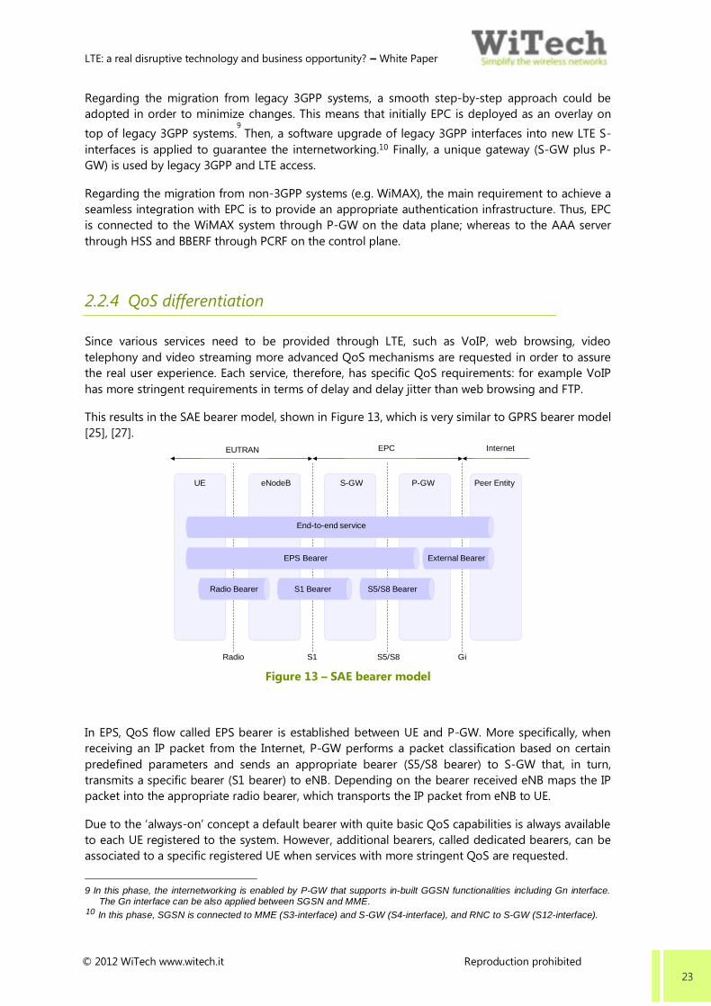
This results in the SAE bearer model, shown in Figure 13, which is very similar to GPRS bearer model
[25], [27].
Figure 13 – SAE bearer model
In EPS, QoS flow called EPS bearer is established between UE and P-GW. More specifically, when
receiving an IP packet from the Internet, P-GW performs a packet classification based on certain
predefined parameters and sends an appropriate bearer (S5/S8 bearer) to S-GW that, in turn,
transmits a specific bearer (S1 bearer) to eNB. Depending on the bearer received eNB maps the IP
packet into the appropriate radio bearer, which transports the IP packet from eNB to UE.
Due to the ‘always-on’ concept a default bearer with quite basic QoS capabilities is always available
to each UE registered to the system. However, additional bearers, called dedicated bearers, can be
associated to a specific registered UE when services with more stringent QoS are requested.
9 In this phase, the internetworking is enabled by P-GW that supports in-built GGSN functionalities including Gn interface.
The Gn interface can be also applied between SGSN and MME. 10 In this phase, SGSN is connected to MME (S3-interface) and S-GW (S4-interface), and RNC to S-GW (S12-interface).
UE eNodeB S-GW P-GW Peer Entity
EUTRAN EPC Internet
Radio S1 S5/S8 Gi
End-to-end service
EPS Bearer External Bearer
Radio Bearer S1 Bearer S5/S8 Bearer

LTE: a real disruptive technology and business opportunity? – White Paper
© 2012 WiTech www.witech.it Reproduction prohibited 24
Each bearer is characterized by two or four QoS parameters, depending whether it is associated to
a real-time or best effort service:
QCI: It identifies a set of logically configured values for priority, delay and loss rate.
Specifically, the 3GPP has defined nine classes of standardized QCI, as shown in Table 4.
Table 4 – QCI classes
QCI Resource
type Priority
Packet
delay
budget
[ms]
Packet
error
loss rate
Example services
1
GBR
2 100 10-2
Conversational voice
2 4 150 10-3
Conversational video
(live streaming)
3 5 300 10-6
Non-conversational video
(buffered streaming)
4 3 50 10-3
Real time gaming
5
Non-GBR
1 100 10-6
IMS signaling
6 7 100 10-3
Voice, video (live streaming),
interactive gaming
7 6 300 10-6
Video (buffered streaming)
8 8 300 10-6
TCP based (e.g. www, e-mail),
chat, FTP, P2P file sharing,
progressive video, etc.
9 9 300 10-6
Best effort
ARP: It indicates the priority of the specific bearer compared to other bearers.
GBR: Specified only in case of real-time services, it identifies the bit rate guaranteed for
the specific bearer.
MBR: Specified only in case of real-time services, it identifies the maximum bit rate for
the specific bearer.
AMBR: Specified only in case of real-time services, it indicates the total maximum bit
rate UE can have when multiple IP packets are associated to the same bearer.
2.2.5 Security
In setting security features, the 3GPP has taken into account several aspects, including architectural
design decisions, internetworking with legacy 3GPP and non-3GPP systems, new services to be
provided and local-based security approach.
As a result, the 3GPP has included additional features into all network elements from UE through
the core network [21], [22]. Specifically:
A hierarchy of security keys has been introduced, supporting dynamic key changing
thanks to explicit re-keying or implicit key-refresh procedures.
Two different security procedures for NAS and AS have been adopted to ensure
confidentiality and integrity protection for signaling and user data in EPS.

LTE: a real disruptive technology and business opportunity? – White Paper
© 2012 WiTech www.witech.it Reproduction prohibited 25
The forward security has been added to ensure that MME provides a new key after
handover in case of failure during handover.
Security functions have been introduced between LTE and legacy 3GPP networks.
2.2.6 Mobility
LTE‘s goal is to provide a seamless mobility. This means that the continuity of the user experience
has to be guaranteed, when a user is moving from one eNB to another eNB (intra-RAT mobility) or
from the LTE system to legacy 3GPP and non-3GPP systems (inter-RAT mobility) and vice versa,
while being in a VoIP session or downloading files.
In the case of the intra-RAT mobility, two different handover procedures have been defined:
through the X2 interface and through the S1 interface. The handover through the X2 is directly
performed between two eNB in order to speed up the preparation phase; whereas the handover
through the S1 interface is carried out by MME and is similar to the handover implemented in the
UMTS system.
In the case of the inter-RAT mobility, the handover procedure depends on RAT involved. For
example, for mobility from the LTE system towards the 3G system, the handover procedure can
reuse the S1-handover with some exceptions. Instead of mobility towards the CDMA system,
dedicated procedures have been introduced in LTE based on the tunneling of the CDMA signaling
between UE and the CDMA system over the S1 interface.
2.2.7 SON
SON aims at substantially reducing the effort required to deploy and manage the network [28]. This
has an impact on radio planning as well as on the O&M interface to the eNB.
More specifically, in the Release 8 the self-configuration functionality has been defined, that is the
one-time process of automating a specific event by means of the O&M interface and the network
management module. For example, a new base station is automatically configured and integrated
into the network through a simple download of configuration parameters and software.
Among the implemented features, ANR is very significant. In detail, ANR allows the automatic
discovery and setup of neighbor relations, when UE moves from the serving eNB to the target eNB,
as well as the automat set up of the LTE unique X2 interface between eNB, primarily used for
handover. In this way the manual handling of neighbor relations is minimized as well as decreasing
the number of dropped connections (due to missing or incorrect neighbor relations) with a
consequent increase of the number of successful handovers.
LTE: a real disruptive technology and business opportunity? – White Paper
© 2012 WiTech www.witech.it Reproduction prohibited 26
2.2.8 Voice and SMS services over LTE
Since in EPC there is no CS domain to handle voice calls, a number of possible solutions have been
investigated to provide voice and SMS services, as outlined below:
Circuit Switched Fall Back: a network and UE based mechanism by which active UE on
LTE is required to re-tune on legacy 3GPP systems and, thus, performs CS fallback from
LTE in order to access legacy CS based services (i.e. voice and SMS).
Voice over LTE11
: a mechanism that uses IMS and SIP specifications developed by the
3GPP as its basis to address voice and SMS services over LTE. Specifically, the voice call
continuity between IMS over PS access and CS access is guaranteed by SRVCC.
Voice over LTE via Generic Access: based on the existing 3GPP GAN standard, the voice
call continuity between LTE and legacy 3GPP systems is guaranteed through the
implementation of a gateway, also called VANC, which connects existing MSC to EPC.
Since VoLGA has been constantly loosing traction in the industry due to the adoption of VoLTE by
GSMA, VoLTE represents the optimal solution to provide voice and SMS services. However, the road
towards VoLTE is not so clear and it mainly depends on the initial LTE coverage and chosen
deployment strategy. Network operators with aggressive LTE roll-out plans would likely adopt
VoLTE immediately; whist network operators starting with spotty LTE coverage would probably
deploy CSFB as a first step to avoid too frequent call handovers between the CS and PS domain.
2.3 LTE Advanced and beyond
In early 2008 ITU-R issued a Circular Letter to invite candidate RIT for IMT Advanced. In this Circular
Letter, key features of IMT Advanced were listed. The following are the general system
requirements and features that the IMT Advanced systems need to support [5]:
Higher spectral efficiencies and peak data rates
Lower latencies to enable new delay-sensitive applications
Mobility Support:
o Stationary (Fixed applications)
o Pedestrian (Pedestrian speeds up to 10 km/h)
o Typical Vehicular (Vehicular speeds up to 120 km/h)
o High Speed Vehicular (Vehicular speeds up to 500 km/h)
o Optimized system performance for low mobility environments
11 VoLTE is a GSMA initiative formally announced on February 15 2010. In establishing the VoLTE initiative, GSMA has
adopted the work of the One Voice Initiative as the basis of the work to lead the global mobile industry towards a standard
way of delivering voice and messaging services for LTE. Using IMS specifications developed by 3GPP as its basis, GSMA have expanded upon the original scope of One Voice work to address the entire E2E voice and SMS ecosystem by also focusing on roaming and interconnect interfaces, in addition to the interface between customer and network.
LTE: a real disruptive technology and business opportunity? – White Paper
© 2012 WiTech www.witech.it Reproduction prohibited 27
o Seamless application connectivity to other mobile and IP networks
Support for larger cell sizes and improved cell-edge performance
Low-cost and low-complexity UE for worldwide use
Mobile user interface
Ubiquitous Access
Improved unicast and multicast broadcast services
Provision for PAN / LAN / WAN co-location and coexistence.
The 3GPP decided to respond to this Circular Letter in order to make LTE Advanced a candidate for
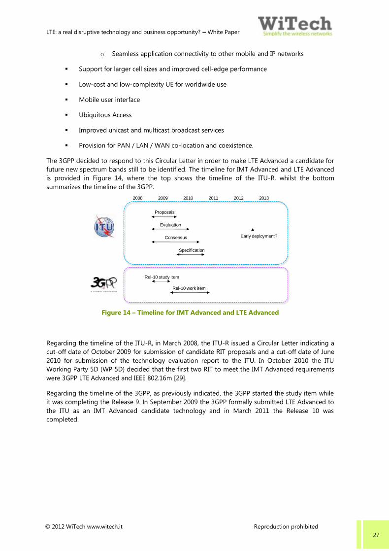
future new spectrum bands still to be identified. The timeline for IMT Advanced and LTE Advanced
is provided in Figure 14, where the top shows the timeline of the ITU-R, whilst the bottom
summarizes the timeline of the 3GPP.
Figure 14 – Timeline for IMT Advanced and LTE Advanced
Regarding the timeline of the ITU-R, in March 2008, the ITU-R issued a Circular Letter indicating a
cut-off date of October 2009 for submission of candidate RIT proposals and a cut-off date of June
2010 for submission of the technology evaluation report to the ITU. In October 2010 the ITU
Working Party 5D (WP 5D) decided that the first two RIT to meet the IMT Advanced requirements
were 3GPP LTE Advanced and IEEE 802.16m [29].
Regarding the timeline of the 3GPP, as previously indicated, the 3GPP started the study item while
it was completing the Release 9. In September 2009 the 3GPP formally submitted LTE Advanced to
the ITU as an IMT Advanced candidate technology and in March 2011 the Release 10 was
completed.
2008 2009 2010 2011
Proposals
Evaluation
Consensus
Specification
2012 2013
Early deployment?
Rel-10 study item
Rel-10 work item

LTE: a real disruptive technology and business opportunity? – White Paper
© 2012 WiTech www.witech.it Reproduction prohibited 28
2.3.1 Targets
Defining the LTE Advanced specifications, the 3GPP has taken into account two different key
drivers: firstly to meet or even to exceed the IMT Advanced specifications; secondly to make LTE
Advanced backwards compatible12
with LTE being not a new radio access standard but rather the
evolution of LTE13
.
Therefore, the following requirements for LTE Advanced have been defined [30]:
Peak data rate
The peak data rate should have targeted 1 Gbps in DL, whilst 500 Mbps in UL
Latency
o Control Plane
The target for the transition time from the idle mode to the connected mode
should have been less than 50 ms, including the set-up of the U-plane; whilst
the target for the transition time from the dormant state to the connected
mode less than 10 ms.
o User Plane
The target latency should have been less than 5 ms14
Spectrum efficiency
The peak spectrum efficiency should have been 30 bps/Hz in DL, whilst 15 bps/Hz in UL.
The average spectrum efficiency and the cell-edge spectrum efficiency targets have
been defined depending on the MIMO configuration.
Mobility
Mobile speeds up to 350 Km/h (or even up to 500 Km/h depending on the spectrum
band) should have been supported.
Spectrum flexibility
Additional spectrum bands should have been included, as well as channel bandwidths
wider than 20 MHz. Further, FDD and TDD should have been supported for paired and
unpaired spectrum bands respectively.
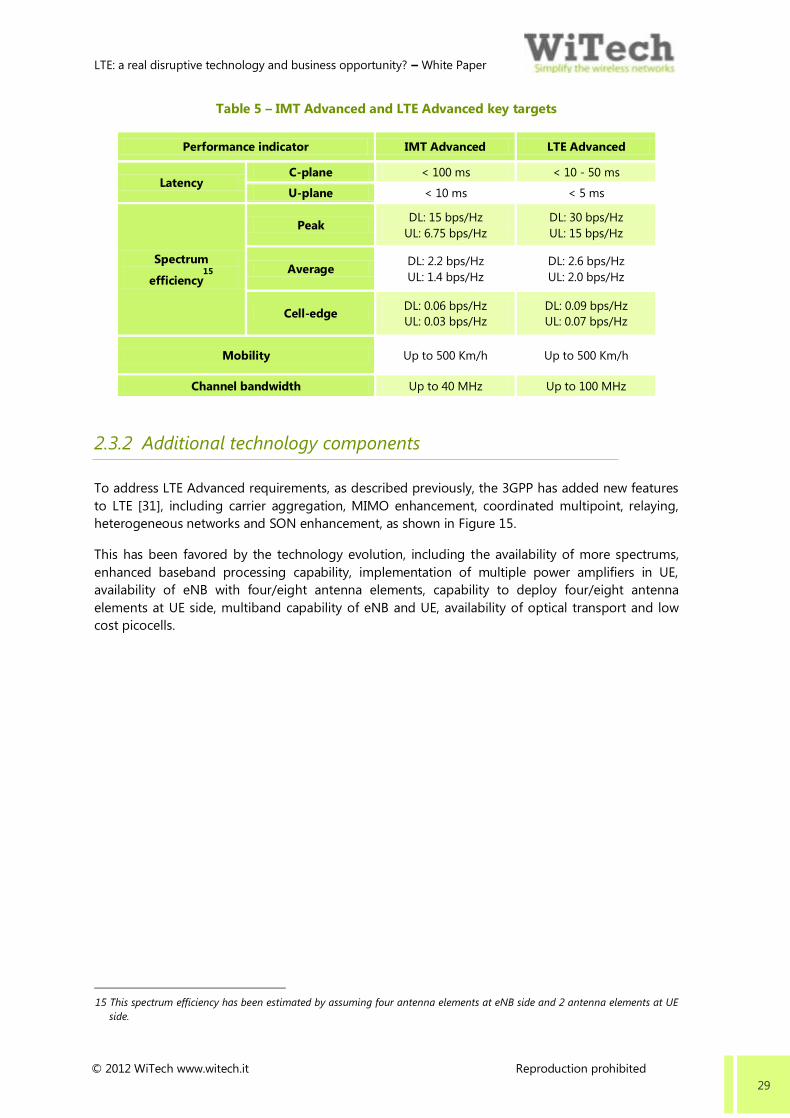
Table 5 summarizes some of the key targets related to IMT Advanced and LTE Advanced and, as
shown, the targets for LTE Advanced are more stringent that those of IMT Advanced.
12 It means that it should be possible to deploy LTE-Advanced in spectrum already occupied by the first release of LTE with no
impact on existing LTE UE. A direct consequence of this requirement is that for a LTE UE a LTE-Advanced-capable network
should appear as a LTE network.
13 The migration towards LTE Advanced should require hardware and/or software upgrades depending on the specific features
to be implemented.
14 LTE-Advanced should reduce the U-plane latency compared to LTE (Release 8).
LTE: a real disruptive technology and business opportunity? – White Paper
© 2012 WiTech www.witech.it Reproduction prohibited 29
Table 5 – IMT Advanced and LTE Advanced key targets
Performance indicator IMT Advanced LTE Advanced
Latency C-plane < 100 ms < 10 - 50 ms
U-plane < 10 ms < 5 ms
Spectrum
efficiency15
Peak DL: 15 bps/Hz
UL: 6.75 bps/Hz
DL: 30 bps/Hz
UL: 15 bps/Hz
Average DL: 2.2 bps/Hz
UL: 1.4 bps/Hz
DL: 2.6 bps/Hz
UL: 2.0 bps/Hz
Cell-edge DL: 0.06 bps/Hz
UL: 0.03 bps/Hz
DL: 0.09 bps/Hz
UL: 0.07 bps/Hz
Mobility Up to 500 Km/h Up to 500 Km/h
Channel bandwidth Up to 40 MHz Up to 100 MHz
2.3.2 Additional technology components
To address LTE Advanced requirements, as described previously, the 3GPP has added new features
to LTE [31], including carrier aggregation, MIMO enhancement, coordinated multipoint, relaying,
heterogeneous networks and SON enhancement, as shown in Figure 15.
This has been favored by the technology evolution, including the availability of more spectrums,
enhanced baseband processing capability, implementation of multiple power amplifiers in UE,
availability of eNB with four/eight antenna elements, capability to deploy four/eight antenna
elements at UE side, multiband capability of eNB and UE, availability of optical transport and low
cost picocells.
15 This spectrum efficiency has been estimated by assuming four antenna elements at eNB side and 2 antenna elements at UE
side.

LTE: a real disruptive technology and business opportunity? – White Paper
© 2012 WiTech www.witech.it Reproduction prohibited 30
Figure 15 – Additional LTE Advanced features
Carrier aggregation
Carrier aggregation provides high data rates without the need of contiguous spectrum to exploit
the highest flexibility in spectrum usage and, at the same time, improves single user throughput by
distributing the traffic dynamically over multiple carriers.
In detail, carrier aggregation allows combining up to five carriers to support channel bandwidths up
to 100 MHz. These carriers need to be LTE compatible in order to support legacy LTE UE and can be
both contiguous and non-contiguous even at different frequency bands.
In the Release 10, two different spectrum bands have been identified both for intra-band and inter-
band aggregation. More specifically, the 2000 and 2300 MHz spectrum bands have been pointed
out for intra-band aggregation, whereas the 2000 and 800 MHz spectrum band for inter-band
aggregation.
MIMO enhancement
The number of transmit and receive antenna elements has been increased in order to enhance peak
data rate as well as improve radio propagation channel conditions. Specifically, LTE Advanced
supports up to eight transmit and receive antenna elements in DL, whereas up to four transmit
antenna elements and eight receive antenna elements in UL.
Coordinated multipoint
Coordinated multipoint allows improving coverage and capacity performance through an active
interference cancellation, by transforming the interference from another eNB into a useful signal at
cell edge.
Carrier aggregation
SON enhancement MIMO enhancement
Coordinated multipoint
Relaying
Heterogeneous
networks

LTE: a real disruptive technology and business opportunity? – White Paper
© 2012 WiTech www.witech.it Reproduction prohibited 31
In DL the coordinated multipoint enables coordinated scheduling and beamforming16
as well as the
joint processing17
from two or more physically separated locations. However, to support these
operations a feedback from UE is required, containing channel properties, noise and interference
measurements.
In UL the coordinated multipoint is restricted to use of the coordinated scheduling18,
because when
two or more UE are transmitted from different places there is no realistic mechanism to share the
data between UE for the precoding.
Relaying
Relaying enables focus coverage and capacity extensions by means of relay nodes using the LTE
Advanced radio interface for self-backhaul.
In detail, UE communicates with RN which in turn communicates with the Donor eNB through a
new air interface. The Donor eNB, in addition to serving one or more RN, can communicate with
non-relayed UE directly.
Two different types of RN have been defined: type 1 and type 2. The RN type 1 effectively creates
its own cell (e.g. it transmits its own cell ID and own synchronization and reference signals) and,
therefore, from the UE perspective it looks like an eNB. Instead the RN type 2 cannot create its own
cell and, thus, the control information is transmitted directly by the Donor eNB whilst the data
information is transmitted through the RN.
Heterogeneous networks
Heterogeneous networks enable focus coverage and capacity extensions by combining local area
sites (such as picocells, femtocells, repeaters and relays) with medium and wide area sites (such as
macrocells and microcells), that spread across multiple RAT19
and operate in both licensed and
unlicensed spectrum bands.
This more complex network poses a new set of challenges including interference coordination,
handover among different-scale cells to provide seamless mobility, self-configuration and self-
optimization capability, security management between cells of different ownership (consumer,
enterprise, network operator) and, finally, service continuity to guarantee a real user experience.
SON enhancement
In LTE Advanced SON has been further improved thanks to the introduction of additional SON
functionalities, such as self-optimization and self-healing. Self-optimization represents the
continuous process of using environmental data (e.g. UE and eNB measurements) to optimize the
current network settings; whilst self-healing denotes the process of recovering from an exceptional
event caused by unusual circumstances (e.g. changing of interference conditions).
16 The transmission data to a single UE is available at the serving eNB only, but user scheduling/beamforming decisions
are made with coordination among eNB. 17 The transmission data to a single UE is available at multiple eNB. In case of joint processing, data is transmitted
simultaneously from multiple eNB; whereas in case of dynamic cell selection, data is transmitted from one eNB at a time. 18 The coordinated scheduling in UL implies the coordination among multiple eNB to control interference. 19 A range of different RAT, including GSM, UMTS, HSPA, LTE, WiMAX and Wi-Fi, should all co-exist.

LTE: a real disruptive technology and business opportunity? – White Paper
© 2012 WiTech www.witech.it Reproduction prohibited 32
Among the features implemented, MDT is very important. This is an automated solution involving
UE active in order to collect data (e.g. coverage vs position and dropped call vs position) to monitor
and detect coverage problems. This allows minimizing drive test activities, that are expensive in
terms of staff, time and equipment needed, and hence to reduce costs for network deployment and
operations.
2.4 Performance in a nutshell
In order to better understand how LTE has been evolved and, hence, how performance has been
enhanced, a close and consistent comparison of LTE vs LTE Advanced has been carried out, based
on the following parameters:
Spectrum flexibility: It denotes the capability of supporting various spectrum bands and
channel bandwidths. This enables network operators to deploy LTE networks according
to their specific needs in terms of spectrum regulation, availability of radio resources
and the possibility of purchasing spectrum licenses.
Coverage: It denotes the ability to better address coverage requirements in different
scenarios, such as indoor, outdoor and vehicular. This allows the reduction of the site
count in coverage-limited scenarios and, hence, minimizes TCO.
Capacity: It denotes the capability of supporting high data rates in DL and UL. This
allows the reduction of the site count in capacity-limited scenarios and, hence,
minimizes TCO.
Response: It denotes the ability to reduce the E2E latency both on C-plane and U-plane.
This enables network operators to offer innovative and multimedia services,
guaranteeing a real user experience.
Mobility: It denotes the capability of supporting high mobile speeds. This means that
the technology can operate not only in typical vehicular scenarios (up to 120 Km/h) but
also in high speed vehicular scenarios (up to 500 km/h).
QoS: It denotes the ability to assure the real user experience, providing differentiate QoS
levels tailored to specific services.
Security: It denotes the ability to securely exchange signaling and user data in all
network elements from UE through the core network.
Deployment flexibility: It denotes the possibility of deploying local area sites as well as
medium and wide area sites, based on various radio access technologies, in order to
focus coverage and capacity extensions.
Self-optimizing network capability: It denotes the capability of supporting self-
configuration, self-optimization and self-healing functionalities in order to reduce the
effort required to deploy and manage the network.
Standard and maturity: It denotes the support provided by industry and standard bodies
in order to favor the worldwide diffusion of the technology, creating a widespread
ecosystem and, thus, providing economies of scale.
Table 6 shows LTE and LTE Advanced performance at a glance.

LTE: a real disruptive technology and business opportunity? – White Paper
© 2012 WiTech www.witech.it Reproduction prohibited 33
Table 6 – LTE and LTE Advanced performance at a glance20
LTE LTE Advanced
Spectrum flexibility
Coverage
Capacity
Response
Mobility
QoS
Security
Deployment flexibility
Self-optimizing network
Standard and maturity
As depicted in Table 6 and as well expected, LTE Advanced has a better performance than LTE from
several points of view.
Specifically, LTE Advanced provides more spectrum flexibility than LTE. Therefore, new spectrum
bands (thirty-four in total) have been included in the Release 10, as specified in the following
session; as well as the addition of the carrier aggregation feature in the Release 10 to support up
to 100 MHz channel bandwidth.
Moreover, LTE Advanced has a better performance in terms of coverage and capacity thanks to
various additional features, such as MIMO enhancement that includes 8x8 configuration in DL and
4x8 configuration in UL; coordinated multipoint that allows transforming eNB interference into a
useful signal at cell edge and, finally, relaying that provides focused coverage and capacity
extensions.
In addition, since LTE Advanced has been designed to address IMT Advanced requirements
including the support of high speed vehicular scenarios, it can operate up to 500 Km/h unlike LTE
that can operate up to 350 Km/h.
Furthermore, LTE Advanced enables network operators to deploy different types of sites (macro
sites, micro sites, picocells, femtocells, repeaters and relays) spreading across multiple radio access
technologies as well as combining them in the same network, on the basis of the specific business
model adopted.
Besides, LTE Advanced includes additional SON functionalities, such as self-optimizing and self-
healing, that allow optimizing the network deployment and maintenance, as well as reducing
investments and costs for operations.
Finally, since LTE Advanced has been included among IMT Advanced technologies by ITU, industry
and standard bodies are expected to put more effort into accelerating the adoption, deployment
and expansion of this technology across the globe.
20 The symbol denotes high performance, the symbol medium performance and finally the symbol low
performance.

LTE: a real disruptive technology and business opportunity? – White Paper
© 2012 WiTech www.witech.it Reproduction prohibited 34
3. CRITICAL FACTORS FOR THE LTE BUSINESS CASE
This section aims at highlighting the framework for the analysis of the critical factors of an LTE
initiative.
3.1 Framework
In order to explore the potentialities of the very promising LTE technology, a business case sample
for a nationwide initiative has been analyzed, covering both the technological and business
perspective.
This analysis has been carried out by means of TEA|LTE, a specialized decision support tool
developed by WiTech and built over eight years of extensive industry experience supporting major
operators and equipment suppliers in several strategic initiatives and projects.
TEA|LTE allows analyzing the business case for LTE initiatives with an integrated and iterative way,
taking into account all critical aspects (marketing, technical, economic and financial ones) at the
same time and, hence, avoiding focusing on each single facet separately. Specifically, this tool
features comprehensive market and revenue forecast models, well calibrated technical modeling
tailored to the LTE technology, calculation of CAPEX and OPEX as well as TCO, analysis of P&L and
Cash Flow with the close evaluation of key performance indicators.
TEA|LTE is based on the proprietary technical-economic model TEA designed by WiTech.
The TEA model aims at capturing all relevant elements for the business case analysis and, hence,
forecasting market and revenues, performing the network dimensioning and, finally, estimating all
key economic and financial projections and indicators. To perform this, the TEA model takes into
account a number of sound technical-economic principles, such as the real representation of the
territory and demography of the area of interest, the inclusion of the customer base and the legacy
network, the satisfaction of both coverage and capacity requirements, the identification of the
proper structure of capital and operational expenses.
Specifically, the TEA model consists of four modules according to the main analyses that it can
perform:
The Market Analysis module evaluates properly the potential market for LTE and makes
reliable revenue forecasts for the LTE services to be offered, taking into account
territorial and socio-demographic parameters, identifying target segments, defining
service profiles, choosing types of UE and, finally, forecasting revenues.
The Technical Analysis module realizes the dimensioning the LTE infrastructure in terms
of access, backhaul and core network. In detail, it defines the required bill of quantities
(eNB, logical sectors, radio links, MME, S-GW and P-GW) by considering coverage and
capacity requirements, technology and equipment characterization, path loss model for
the link budget analysis and legacy assets.
The Economic & Financial Analysis module assesses the feasibility of the LTE initiative
after having calculated all the economic and financial projections (TCO, P&L, Cash Flow,
Balance Sheet) and indicators (Gross Margin, EBITDA, EBIT, Net Income, NPV, IRR, PBP,
Funding Peak, etc.).
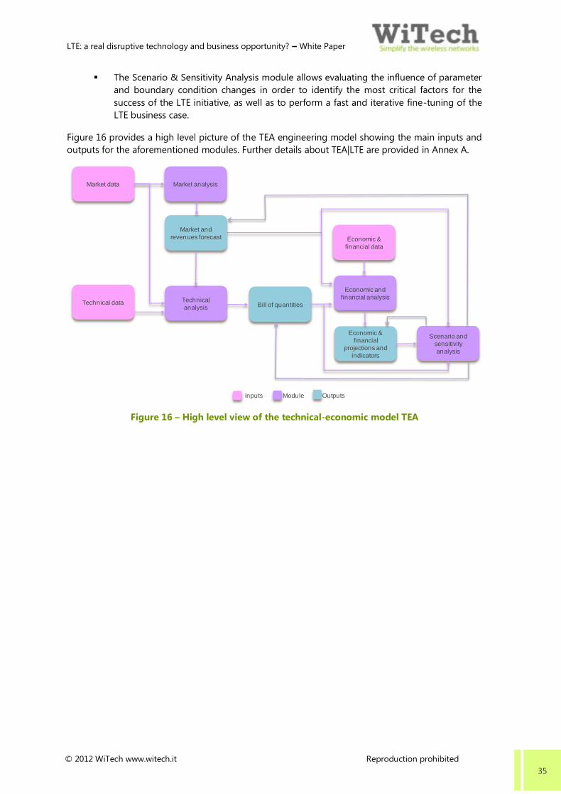
LTE: a real disruptive technology and business opportunity? – White Paper
© 2012 WiTech www.witech.it Reproduction prohibited 35
The Scenario & Sensitivity Analysis module allows evaluating the influence of parameter
and boundary condition changes in order to identify the most critical factors for the
success of the LTE initiative, as well as to perform a fast and iterative fine-tuning of the
LTE business case.
Figure 16 provides a high level picture of the TEA engineering model showing the main inputs and
outputs for the aforementioned modules. Further details about TEA|LTE are provided in Annex A.
Figure 16 – High level view of the technical-economic model TEA
Market analysisMarket data
Technical data
Economic &
financial data
Technical
analysis
Economic and
financial analysis
ModuleInputs Outputs
Market and
revenues forecast
Bill of quantities
Economic &
financial
projections and
indicators
Scenario and
sensitivity
analysis

LTE: a real disruptive technology and business opportunity? – White Paper
© 2012 WiTech www.witech.it Reproduction prohibited 36
ACRONYMS
2G 2nd Generation Mobile System
3G 3rd Generation Mobile System
3GDT 3G Direct Tunnel
3GPP 3rd Generation Partnership Project
4G 4th Generation Mobile System
AAA Authentication, Authorization, and Accounting
ACMA Australian Communications and Media Authority
ADSL Asymmetric Digital Subscriber Line
AES Advanced Encryption Standard
AGC Automatic Gain Control
AGPS Assisted GPS
AMBR Aggregated Maximum Bit Rate
AMC Adaptive Modulation and Coding
ANACOM Autoridade Nacional de Comunicações
ANCOM National Authority for Management and Regulation in Communications of
Romania
ANR Automatic Neighbour Relation
AP Access Point
APJ Asia Pacific Japan
ARCEP Autorité de Régulation des Communications Électroniques et des Postes
ARP Allocation and Retention Priority
AS Access Stratum
ASK Amplitude Shift Keying
ASIC Application-Specific Integrated Circuit
ATCA Advanced Telecom Computing Architecture
ATPC Automatic Transmit Power Control
AuC Authentication Centre
AWS Advanced Wireless Services
B-SON Backhaul Self Organizing Network
BBERF Bearer Binding and Event Reporting Function
BBU Base Band Unit
BEM Block Edge Mask
BIPT Belgian Institute for Postal services and Telecommunications
BS Base Station
BSC Base Station Controller
BTS Base Transceiver Station

LTE: a real disruptive technology and business opportunity? – White Paper
© 2012 WiTech www.witech.it Reproduction prohibited 37
CAGR Compound Annual Growth Rate
CAPEX Capital Expenditures
CCA Combinatorial Clock Auction
CCTV Closed Circuit Television
CDF Cumulative Distribution Function
CDMA Code Division Multiple Access
CE Consumer Equipment
CEPT Conference of European Postal and Telecommunications
CES Circuit Emulation Services
CGN Carrier Grade Network
CIR Committed Information Rate
CMOS Complementary Metal-Oxide Semiconductor
CMU Compact Modem Unit
COS Cost Of Service
CPE Customer Premises Equipment
CRC Communications Regulation Commission
CS Circuit Switched
CSFB Circuit Switched Fallback
DC-HSPA Dual Carrier High Speed Packet Access
DFTS-OFDM DFT Spreading OFDM
DAB Digital Audio Broadcasting
DBDM Dual Band Dual Mode
DBPSK Differential Binary Phase Shift Keying
DBS Direct Broadcast Satellite
DDNS Dynamic DNS
DECT Digital Enhanced Cordless Telecommunications
DFS Dynamic Frequency Selection
DFT Discrete Fourier Transform
DHCP Dynamic Host Configuration Protocol
DL Down Link
DLNA Diplexer Low Noise Amplifier
DNS Domain Name System
DPI Deep Packet Inspection
DSP Digital Signal Processing
DVB Digital Video Broadcasting
DVR Digital Video Recorder
E2E End To End
E-UTRA Evolved Universal Terrestrial Radio Access
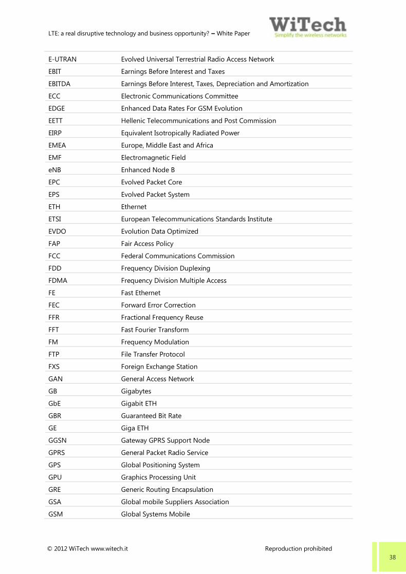
LTE: a real disruptive technology and business opportunity? – White Paper
© 2012 WiTech www.witech.it Reproduction prohibited 38
E-UTRAN Evolved Universal Terrestrial Radio Access Network
EBIT Earnings Before Interest and Taxes
EBITDA Earnings Before Interest, Taxes, Depreciation and Amortization
ECC Electronic Communications Committee
EDGE Enhanced Data Rates For GSM Evolution
EETT Hellenic Telecommunications and Post Commission
EIRP Equivalent Isotropically Radiated Power
EMEA Europe, Middle East and Africa
EMF Electromagnetic Field
eNB Enhanced Node B
EPC Evolved Packet Core
EPS Evolved Packet System
ETH Ethernet
ETSI European Telecommunications Standards Institute
EVDO Evolution Data Optimized
FAP Fair Access Policy
FCC Federal Communications Commission
FDD Frequency Division Duplexing
FDMA Frequency Division Multiple Access
FE Fast Ethernet
FEC Forward Error Correction
FFR Fractional Frequency Reuse
FFT Fast Fourier Transform
FM Frequency Modulation
FTP File Transfer Protocol
FXS Foreign Exchange Station
GAN General Access Network
GB Gigabytes
GbE Gigabit ETH
GBR Guaranteed Bit Rate
GE Giga ETH
GGSN Gateway GPRS Support Node
GPRS General Packet Radio Service
GPS Global Positioning System
GPU Graphics Processing Unit
GRE Generic Routing Encapsulation
GSA Global mobile Suppliers Association
GSM Global Systems Mobile

LTE: a real disruptive technology and business opportunity? – White Paper
© 2012 WiTech www.witech.it Reproduction prohibited 39
GSMA GSM Association
GTP Group Termination Point
H-FDD Half Frequency Division Duplexing
HD-SDI High Definition Serial Digital Interface
HBS High BS
HD High Definition
HDMI High Definition Multimedia Interface
HLR Home Location Register
HO Handover
HRPD High Rate Packet Data
HSPA High Speed Packet Access
HSS Home Subscriber Server
HSU High SU
HTTP HyperText Transport Protocol
HTTPS Hypertext Transfer Protocol Secure
I&C Installation & Commissioning
ICIC Inter-Cell Interference Coordination
ICRST Industry Canada
ID Identity
IDU Indoor Unit
IEEE Institute of Electrical & Electronics Engineers
IGMP Internet Group Management
IMS Internet Protocol Multimedia Subsystem
IMT International Mobile Telecommunication
IP Internet Protocol
IPOE Industrial High Power PoE
IPS Intrusion Prevention System
IRR Internal Rate of Return
ISM Industrial, Scientific and Medical
ISP Internet Service Providers
ISR Interrupt Service Routine
ISTAT Istituto nazionale di statistica
IT Information Technology
ITU International Telecommunication Union
KCC Ministry of Communications and Information
L2TP Layer 2 Tunneling Protocol
LAN Local Area Network
LCD Liquid Crystal Display

LTE: a real disruptive technology and business opportunity? – White Paper
© 2012 WiTech www.witech.it Reproduction prohibited 40
LED Light Emitting Diode
LGA Land Grid Array
LOS Line Of Sight
LTE Long Term Evolution
LU Local Unit
M2M Machine To Machine
MAC Media Access Control
MB Megabytes
MBMS Multimedia Broadcast and Multicast Service
MBR Maximum Bit Rate
MCS Modulation and Coding Scheme
MDI Medium Dependent Interface
MDIX Medium Dependent Interface, Crossover
MDT Minimization Drive Test
MEF ETH Forum
MIMO Multiple Input Multiple Output
MMC MultiMediaCar
MME Mobility Management Entity
MMS Multimedia Messaging Service
MPLS Multiprotocol Label Switching
MSAU Multi-Station Access Unit
MSC Mobile Switching Centre
MTS Mobile TeleSystems
MU Management Unit
MVNO Mobile Virtual Network Operator
NAS Non-Access Stratum
NAS Network Attached Storage
NASDAQ National Association of Securities Dealers Automated Quotation
NAT Network Address Translation
NDS Network Domain Security
NET Network
NGMN Next Generation Mobile Networks
NLOS Non Line Of Sight
NMHH National Media and Infocommunication Authority
NPT Norwegian Post and Telecommunications Authority
NVP Net Present Value
O&M Operations & Maintenance
ODM Original Design Manufacturer

LTE: a real disruptive technology and business opportunity? – White Paper
© 2012 WiTech www.witech.it Reproduction prohibited 41
ODU Outdoor Unit
OEM Original Equipment Manufacturer
OFCOM Office of Communications
OFDM Orthogonal Frequency Division Multiplexing
OFDMA Orthogonal Frequency Division Multiple Access
OFTA Office of the Telecommunications Authority
OMS Operation and Maintenance Subsystem
OPEX Operational Expenditures
OS Operational System
OSS Operations Support System
P2P Peer To Peer
P-GW Packet Data Network Gateway
P&L Profit & Loss
PA Power Amplifier
PAN Personal Area Network
PAPR Peak-to-Average Power Ratio
PAT Port Address Translation
PBP Payback Period
PC Personal Computer
PCI Peripheral Component Interconnect
PCRF Policy Control and Charging Rules Function
PCS Personnal Communication Services
PDH Plesiochronous Digital Hierarchy
PDN Packet Data Network
PDP Policy Decision Point
PE Provider Edge
PHY Physical
PIR Peak Information Rate
PMP Point To Multipoint
POE Power Over Ethernet
POP Population
POS Point Of Sales
PPPOE Point-to-Point Protocol Over Ethernet
PPTP Point to Point Tunneling Protocol
PS Packet Switched
PTP Point To Point
QAM Quadrature Amplitude Modulation
QCI QoS Class Indicator

LTE: a real disruptive technology and business opportunity? – White Paper
© 2012 WiTech www.witech.it Reproduction prohibited 42
QoS Quality Of Service
QPSK Quadrature Phase Shift Keying
R&D Research & Development
RADIUS Remote Authentification Dial in User Service
RAM Random-Access Memory
RAN Radio Access Network
RAT Radio Access Technology
RF Radio Frequency
RIP Routing Information Protocol
RIT Radio Interface Technologies
RN Relay Node
RNC Radio Network Controller
RRH Remote Radio Head
RRM Radio Resource Management
RRU Remote Radio Unit
RX Receiver
S-GW Serving Gateway
SAE-GW System Architecture Evolution Gateway
SC-FDMA Single Carrier Frequency Division Multiple Access
SAE System Architecture Evolution
SATA Serial Advanced Technology Attachment
SCP Secure Copy
SD Secure Digital
SDH Synchronous Digital Hierarchy
SDHC Secure Digital High Capacity
SDR Software Defined Radio
SFR Soft Frequency Reuse
SFP System File Protection
SG&A Sales General & Administrative
SGSN Serving GPRS Support Node
SIGTRAN Signaling Transport
SIM Subscriber Identity Module
SIP Session Initiation Protocol
SLA Service Level Agreement
SMA Sub Multi Assembly
SME Small Medium Enterprise
SMRA Simultaneous Multiple Round Ascending
SMS Short Message Service

LTE: a real disruptive technology and business opportunity? – White Paper
© 2012 WiTech www.witech.it Reproduction prohibited 43
SNMP Simple Network Management Protocol
SNTP Simple Network Time Protocol
SOC System On Chip
SOHO Small Office Home Office
SON Self Organizing Network
SONET Synchronous Optical Network
SRVCC Single Radio Voice Call Continuity
SSH Secure Shell
SSL Solid State Logic
STC Saudi Telecom Company
SU Subscriber Unit
SUI Stanford University Interim
SWOT Strengths Weaknesses Opportunities Threats
TD-LTE Time Division Long Term Evolution
TD-SCDMA Time Division Synchronous Code Division Multiple Access
TCO Total Cost Of Ownership
TCP Transmission Control Protocol
TD Time Division
TDD Time Division Duplexing
TDM Time Division Multiplexing
TDMA Time Division Multiple Access
TEA Technical Economic Analyses
TFTP Trivial File Transfer Protocol
TRA Telecommunications Regulatory Authority of Bahrain
TRAI Telecom Regulatory Authority of India
TSG Technical Specification Group
TX Transmitter
UE User Equipment
UKE Prezes Urzędu Komunikacji Elektronicznej
UI User Interface
UICC Universal Integrated Circuit Card
UL Up Link
UMTS Universal Mobile Telephone System
UPS Uninterruptible Power System
URL Uniform Resource Locator
US United States
USB Universal Serial Bus
USIM Universal SIM

LTE: a real disruptive technology and business opportunity? – White Paper
© 2012 WiTech www.witech.it Reproduction prohibited 44
UTRA Universal Terrestrial Radio Access
UTRAN Universal Terrestrial Radio Access Network
VANC VoLGA Access Network Controller
VDSL Very High Speed Digital Subscriber Line
VGA Video Graphics Array
VHF Very High Frequency
VLR Visitor Location Register
VoIP Voice Over IP
VoLGA Voice Over LTE via Generic Access
VoLTE Voice Over LTE
VPN Virtual Private Network
VRRP Virtual Router Redundancy Protocol
WAN Wide Area Network
WDS Virtual Router Redundancy Protocol
WEP Wired Equivalent Privacy
Wi-Bro Wireless Broadband
Wi-Fi Wireless Fidelity
WiMAX Worldwide Interoperability for Microwave Access
WLAN Wireless Local Area Network
WP Working Party
WPA Wi-Fi Protected Access
WRC World Radiocommunication Conference
WSVGA Wide Super Video Graphics Array
WVGA Wide Video Graphic Array
xDSL x Digital Subscriber Line
XPIC Cross Polarisation Interference Canceller

LTE: a real disruptive technology and business opportunity? – White Paper
© 2012 WiTech www.witech.it Reproduction prohibited 45
REFERENCES
[1] Cisco VNI Mobile, Global Mobile Data Traffic Forecast Update, 2010-2015
[2] www.3gpp.org
[3] 3GPP, 3GPP Scope and Objectives, 31 August 2007
[4] www.ngmn.org
[5] ITU-R IMT.[REST], “Requirements, evaluation criteria and submission templates for the
development of IMTAdvanced”, http://www.itu.int/md/R07-SG05-C-0068/en
[6] 3GPP Technical Specification Group Radio Access Network, Requirements for Evolved UTRA
(E-UTRA) and Evolved UTRAN (E-UTRAN) Release 8, 3GPP TR 25.913
[7] 3GPP Technical Specification Group Radio Access Network, Physical layer aspects for evolved
Universal Terrestrial Radio Access (UTRA), 3GPP TR 25.814
[8] 3GPP Technical Specification Group Radio Access Network, Evolved Universal Terrestrial
Radio Access (E-UTRA), Radio Frequency (RF) system scenarios, 3GPP TR 36.942
[9] 3GPP Technical Specification Group Radio Access Network, Evolved Universal Terrestrial
Radio Access (E-UTRA), User Equipment (UE) radio transmission and reception, 3GPP TS
36.101
[10] 3GPP Technical Specification Group Radio Access Network, Evolved Universal Terrestrial
Radio Access (E-UTRA), User Equipment (UE) radio access capabilities, TS.36.306
[11] 3GPP Technical Specification Group Radio Access Network, Evolved Universal Terrestrial
Radio Access (E-UTRA), LTE physical layer; General description, TS 36.201
[12] 3GPP Technical Specification Group Radio Access Network, Evolved Universal Terrestrial
Radio Access (E-UTRA), Physical Channels and Modulation, TS 36.211
[13] 3GPP Technical Specification Group Radio Access Network, Evolved Universal Terrestrial
Radio Access (E-UTRA), Multiplexing and channel coding, TS 36.212
[14] 3GPP Technical Specification Group Radio Access Network, Evolved Universal Terrestrial
Radio Access (E-UTRA), Physical layer procedures, 3GPP TS 36.213
[15] 3GPP Technical Specification Group Radio Access Network, Evolved Universal Terrestrial
Radio Access (E-UTRA), Physical layer, Measurements, TS 36.214
[16] 3GPP Technical Specification Group Radio Access Network, Evolved Universal Terrestrial
Radio Access (E-UTRA) and Evolved Universal Terrestrial Radio Access Network (E-UTRAN),
Overall description, TS 36.300
[17] 3GPP Technical Specification Group Radio Access Network, Evolved Universal Terrestrial
Radio Access (E-UTRA), Radio Resource Control (RRC), Protocol specification, 3GPP TS 36.331
[18] 3GPP Technical Specification Group Radio Access Network, Evolved Universal Terrestrial
Radio Access (E-UTRA), Base Station (BS) conformance testing, 3GPP TS 36.141
[19] 3GPP Soft Frequency Reuse Scheme for UTRAN LTE, 3GPP TSG RAN WG1 Meeting #41
[20] 3GPP Technical Specification Group Core Network and Terminals, Non-Access-Stratum (NAS)
protocol for Evolved Packet System (EPS, 3GPP TS. 24.301
[21] 3GPP Technical Specification Group Services and System Aspects; 3GPP System Architecture
Evolution (SAE); Security architecture, 3GPP TS 33.401
[22] 3GPP Technical Specification Group Services and System Aspects; 3GPP System Architecture
Evolution (SAE); Security aspects of non-3GPP accesses, 3GPP TS 33.402

LTE: a real disruptive technology and business opportunity? – White Paper
© 2012 WiTech www.witech.it Reproduction prohibited 46
[23] 3GPP Technical Specification Group Services and System Aspects, Architecture enhancements
for non-3GPP accesses, 3GPP TS 23.402
[24] 3GPP Technical Specification Group Core Network and Terminals, General Packet Radio
Service (GPRS); GPRS Tunnelling Protocol (GTP) across the Gn and Gp interface, 3GPP TS
29.060
[25] 3GPP Technical Specification Group Services and System Aspects, Policy and charging control
architecture, 3GPP TS 23.203
[26] 3GPP Technical Specification, Evolved Universal Terrestrial Radio Access (E-UTRA) and
Evolved Universal Terrestrial Radio Access Network (E-UTRAN); Overall description, 3GPP TS
36.300
[27] 3GPP Technical Specification Group Radio Access Network, Evolved Universal Terrestrial
Radio Access (E-UTRA), Layer 2 – Measurements, 3GPP TS 36.314
[28] 3GPP Technical Specification Group Services and System Aspects, Telecommunication
Management, Self-Organizing Networks (SON) Policy Network Resource Model (NRM)
Integration Reference Point (IRP), Requirements, 3GPP TS 32.521
[29] http://3gpp.org/ITU-R-Confers-IMT Advanced-4G
[30] 3GPP Technical Specification Group Radio Access Network, Requirements for further
advancements for Evolved Universal Terrestrial Radio Access(E-UTRA) LTE Advanced, 3GPP TR
36.913
[31] 3GPP Technical Specification Group Radio Access Network, Feasibility study for Further
Advancements for E-UTRA (LTE Advanced), 3GPP TR 36.912
[32] 3GPP Technical Specification Group Radio Access Network, UMTS-LTE 3500 MHz Work Item
Technical Report, TR 37.801
[33] www.itu.int/net/itunews/issues/2010/01/27.aspx
[34] FCC - Lower 700 MHz Band Releases, 2003
[35] NPSTC - 700 MHz Public Safety Broadband Task Force Report and Recommendation
September 4, 2009
[36] 2010/267/EU
[37] ECC/DEC/(09)03
[38] CEPT Report 30 – ‘The identification of common and minimal (least restrictive) technical
conditions for 790 - 862 MHz for the digital dividend in the European Union’
[39] CEPT Report 31 – ‘Frequency (channelling) arrangements for the 790-862 MHz band’
[40] 2009/766/EC
[41] C(2011)2633 - Final amending decision 2009/766/EC
[42] CEPT Report 40 – ‘Compatibility study for LTE and WiMAX operating within the bands 880-
915 MHz / 925-960 MHz and 1710-1785 MHz / 1805- 1880 MHz (900/1800 MHz bands)’
[43] CEPT Report 41 – ‘Compatibility between LTE and WiMAX operating within the bands 880-
915 MHz / 925-960 MHz and 1710-1785 MHz / 1805-1880 MHz (900/1800 MHz bands) and
systems operating in adjacent bands’
[44] CEPT Report 42 – ‘Compatibility between UMTS and existing and planned aeronautical
systems above 960 MHz’
[45] ECC Report 96 – ‘Compatibility between UMTS 900/1800 and systems operating in adjacent
bands’
[46] FCC modifies PCS and AWS power limit rules to facilitate broadband wireless technologies,
March 21, 2008

LTE: a real disruptive technology and business opportunity? – White Paper
© 2012 WiTech www.witech.it Reproduction prohibited 47
[47] www.itu.int/publ/R-ACT-WRC.8-2007/en
[48] CEPT - Use of 2.3 GHz Band for mobile broadband 23rd September 2011
[49] ECC/DEC/(06)01
[50] CEPT Report 39 – ‘Report from CEPT to the European Commission in response to the
Mandate to develop least restrictive technical conditions for 2 GHz bands’
[51] ECC/DEC/(05)05
[52] 2008/477/EC
[53] CEPT Report 131 – ‘Derivation of a block edge mask (BEM) for terminal stations in the 2600
MHz frequency band (2500-2690 MHz)’
[54] ECC/REC/(04)05
[55] ECC/DEC/(07)02
[56] Decision 2008/411/EC
[57] GSA, Evolution to LTE Report
[58] EBU ECS Workshop, 800 MHz auctions and implementation of the DD in Germany
[59] www.mityc.es/en-
US/GabinetePrensa/NotasPrensa/2011/Paginas/npfinaizacionsubasta010811.aspx
[60] www.lvm.fi/web/en/pressreleases/view/867823
[61] GSA, “Report: Status of the LTE eco system”, January 20 2012
[62] GSA, “Report: Status of the LTE eco system”, October 28 2011
[63] Gartner, Magic Quadrant for LTE Network Infrastructure, 26 May 2011
[64] GSA, Evolution to LTE Report, GSM/3G market/technology update, January 5 2012

LTE: a real disruptive technology and business opportunity? – White Paper
© 2012 WiTech www.witech.it Reproduction prohibited 48
ANNEX A – TEA|LTE: THE LTE BUSINESS CASE ANALYSIS TOOL
TEA|LTE is one of the members of the TEA family. It is made up of powerful and unique applications
(TEA|LTE and TEA|WiMAX) that WiTech has built over eight years of extensive industry experience
supporting major operators and equipment suppliers in several strategic initiatives and projects.
The tools enable thorough techno-economic analyses in support of accurate and reliable business
cases for LTE and WiMAX initiatives in a fast and dependable manner.
Specifically, TEA|LTE allows analyzing the business case for a LTE network initiative with a holistic
approach, in an integrated and iterative way. The tool features comprehensive market and revenue
forecast models, well calibrated technical modeling tailored to the LTE technology, calculation of
TCO as well as detailed P&L and Cash Flow with close evaluation of key performance indicators.
This is performed through four main integrated analyses, that is Market Analysis, Technical Analysis,
Economic & Financial Analysis and, finally, the Scenario & Sensitivity Analysis.
The Market Analysis evaluates properly the potential market for LTE and at making
reliable revenue forecasts for the LTE services to be offered. This analysis is performed
taking into account various elements, such as:
o Extension of the geographical areas (up to 5) to be served and their specific
scenario distribution, the Market segments (up to 6) to be addressed
o Service profiles (up to 6) to be offered
o Market segment penetration per year
o Impact of churn.
Figure 17 shows the work flow for the Market Analysis.
Figure 17 – Work flow for the Market Analysis
Territorial
analysis
Territory &
demography
Target
percentages
Service profile
Service profiles
characterization
Service profiles
distribution
Market forecast
Penetration and
churn rates
Other revenues
RevenuesMarket forecast
Revenues
forecast
ModuleInputs Outputs

LTE: a real disruptive technology and business opportunity? – White Paper
© 2012 WiTech www.witech.it Reproduction prohibited 49
The Technical Analysis performs the dimensioning the LTE infrastructure in terms of
access, backhaul and core network. In detail, this analysis defines the required bill of
quantities (eNB, logical sectors, radio links, MME, S-GW and P-GW) by considering:
o Technology characterization
o Type of eNB (up to 3) and UE (up to 6)
o Path loss model for the link budget analysis
o Down and up link capacity demand per year
o Existing backbone infrastructures
o Wireless backhaul technology distribution.
Figure 18 shows the work flow for the Technical Analysis.
Figure 18 – Work flow for the Technical Analysis
The Economic & Financial Analysis assesses the feasibility of the LTE initiative after
having calculated all the economic and financial projections (TCO, P&L, Cash Flow,
Balance Sheet) and indicators (Gross Margin, EBITDA, EBIT, Net Income, NPV, IRR, PBP,
Shareholder Value, etc.). This analysis is carried out taking into consideration:
o CAPEX & OPEX
o Depreciations
o Interest rate on borrowings, tax rate, discount rate
o Financing
o Equity
o Perpetual growth.
Figure 19 shows the work flow for the Economic and Financial Analysis.
Technology
Frequency
Channel
bandwidth
Equipment
BTS/eNodeB
configuration
User equipment
configuration
MCS & SNIR
Performance
Capacity demand
ModuleInputs Outputs
Bill of quantities
Market forecast
Margins Path loss model
Network
dimensioning
Roll-out Roll-out function
Service profile
characterization
and distribution Target area
Cell overlapping
factor
EPC
characterization
Backhaul
characterization

LTE: a real disruptive technology and business opportunity? – White Paper
© 2012 WiTech www.witech.it Reproduction prohibited 50
Figure 19 – Work flow for the Economic and Financial Analysis
The Scenario & Sensitivity Analysis allows evaluating the influence of parameter and
boundary condition changes in order to identify the most critical factors for the success
of the LTE initiative, as well as to perform a fast and iterative fine-tuning of the LTE
business case.
At the end of the aforementioned analyses, a very detailed report is automatically compiled and
published in editable and PDF formats. The report contains a complete summary (with tables,
diagrams and charts) of input parameters and assumptions, the results of the market analysis, the
outcome of the technical modeling, and the economic and financial statements for up to ten years.
A fast and simplified configuration of more than 500 different input variables and assumptions
(with suggested/best-practice-recommended values) allows a fine-tuned setting of the tool. An
interactive, dashboard-styled and very easy-to-use GUI provides users with optimum interactivity
and the ability to perform fine-grained scenario & sensitivity analyses to align the business case
with a company’s strategies, analyzing the influence of parameter changes and the consequence of
fundamentally changed boundary conditions in real time.
Figure 20 provides a picture of the environment of TEA|LTE.
Figure 20 – Environment of TEA|LTE
COS
Bill of quantities
COS items
ModuleInputs Outputs
CAPEX
Market forecast
Bill of quantities
CAPEX items
Market forecast
D&A
Years to
depreciate
TCO
Personnel
Head countSalaries &
benefits
Statements
Economic &
financial
projections and
indicators
Market and
revenues forecast
SG&A
SG&A items
Revenues
forecast

LTE: a real disruptive technology and business opportunity? – White Paper
© 2012 WiTech www.witech.it Reproduction prohibited 51
WITECH – WIFI CLOUD
The Cloud Solution for
next gen WiFi Hotspot services
WiFi Cloud is WiTech’s innovative solution to
provide new generation managed WiFi
Hotspot services, capable of enriching end
customers’ experience.
WiFi Cloud enables telco carriers and system
integrators to deliver their customers a
complete self-managed solution. Through a
simple control panel, it enables a fully self-
management of access connectivity services,
splash portal and web apps.
WiFi Cloud leverages on the cloud approach,
both public, hosted in the Amazon Web
Services Cloud infrastructure, and private,
hosted in the data center of the Managed
Service Provider. In addition, it allows a fast
initiative setup thanks also to the vendor
agnostic concept.
Splash portal
The splash portal is a fully
customizable web responsive
portal for multi- device user
experience
Web apps: new experience,
new concept, new revenues
A powerful set of web
applications and tools both
enhances the user experiences
and provides new value and
revenue stream for WiFi
Hotspot service providers
Multi-level and distributed
access policies management
WiFi Cloud permits different
players to self-manage the WiFi
Hotspot service based on a
tree-based hierarchical
enforcement
Vendor agnostic
WiFi Cloud is an application
level solution, integrated with
the most famous vendors
access and network devices as
well as popular firmware
Public or private cloud
delivery
WiFi Cloud can be hosted in the
Amazon Web Service cloud
infrastructure (public cloud) or
in a private data center (private
cloud)
Carrier class wngine
Based on WROP, WiFi Cloud
supports any business model
and access service
guaranteeing a high level of
reliability and flexibility