Embed Size (px)
DESCRIPTION
lte
Citation preview
LTE Advanced Description
All Rights Reserved © Alcatel-Lucent 20092 | Advanced LTE Description | June 2009
Contents
Summary on single site studiesCOMP Classification Positioning of COMP technologies Requirements on the X2
Enabling technologies Efficient feedback
Feedback compression Discrete feedback: Best companion
Receivers: SIC and IRC Pilot design and concepts
Summary and way forward Outlook: ARTIST-4G project proposal
All Rights Reserved © Alcatel-Lucent 20093 | Advanced LTE Description | June 2009
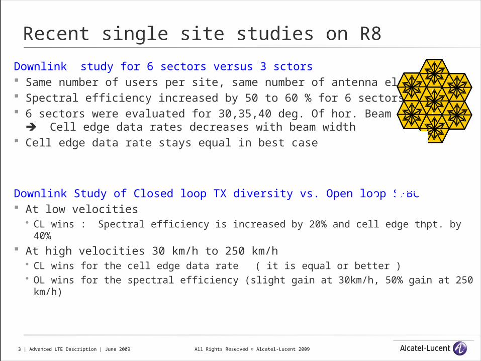
Downlink study for 6 sectors versus 3 sctors Same number of users per site, same number of antenna elements Spectral efficiency increased by 50 to 60 % for 6 sectors 6 sectors were evaluated for 30,35,40 deg. Of hor. Beam width
Cell edge data rates decreases with beam width Cell edge data rate stays equal in best case
Downlink Study of Closed loop TX diversity vs. Open loop SFBC At low velocities
CL wins : Spectral efficiency is increased by 20% and cell edge thpt. by 40% At high velocities 30 km/h to 250 km/h
CL wins for the cell edge data rate ( it is equal or better ) OL wins for the spectral efficiency (slight gain at 30km/h, 50% gain at 250 km/h)
Recent single site studies on R8
All Rights Reserved © Alcatel-Lucent 20094 | Advanced LTE Description | June 2009
LTE Advanced
All Rights Reserved © Alcatel-Lucent 20095 | Advanced LTE Description | June 2009
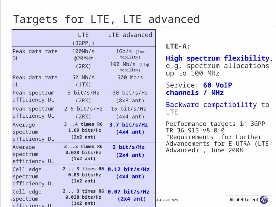
Targets for LTE, LTE advancedLTE
(3GPP,)
LTE advanced
Peak data rate DL 100Mb/s @20MHz
(2RX)
1Gb/s (low mobility)
100 Mb/s (high mobility)
Peak data rate UL 50 Mb/s(1TX)
500 Mb/s
Peak spectrum efficiency DL
5 bit/s/Hz
(2RX)
30 bit/s/Hz
(8x8 ant)
Peak spectrum efficiency UL
2.5 bit/s/Hz
(2RX)
15 bit/s/Hz
(4x4 ant)
Average spectrum efficiency DL
3 ..4 times R6 1.69 bits/Hz
(2x2 ant)
3.7 bit/s/Hz (4x4 ant)
Average spectrum efficiency UL
2 ..3 times R60.028 bits/Hz
(1x2 ant)
2 bit/s/Hz
(2x4 ant)
Cell edge spectrum efficiency DL
2 .. 3 times R6 0.05 bits/Hz
(1x2 ant)
0.12 bit/s/Hz (4x4 ant)
Cell edge spectrum efficiency UL
2 .. 3 times R60.028 bits/Hz
(1x2 ant)
0.07 bit/s/Hz (2x4 ant)
LTE-A:
High spectrum flexibility, e.g. spectrum allocations up to 100 MHz
Service: 60 VoIP channels / MHz
Backward compatibility to LTE
Performance targets in 3GPP TR 36.913 v8.0.0 “Requirements for Further Advancements for E-UTRA (LTE-Advanced)”, June 2008
All Rights Reserved © Alcatel-Lucent 20096 | Advanced LTE Description | June 2009
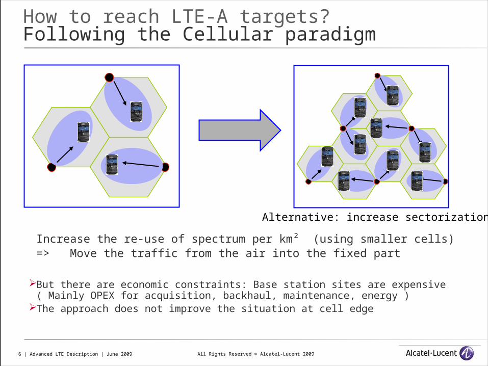
How to reach LTE-A targets?Following the Cellular paradigm
Increase the re-use of spectrum per km² (using smaller cells) => Move the traffic from the air into the fixed part
But there are economic constraints: Base station sites are expensive ( Mainly OPEX for acquisition, backhaul, maintenance, energy )
The approach does not improve the situation at cell edge
Alternative: increase sectorization
All Rights Reserved © Alcatel-Lucent 20097 | Advanced LTE Description | June 2009
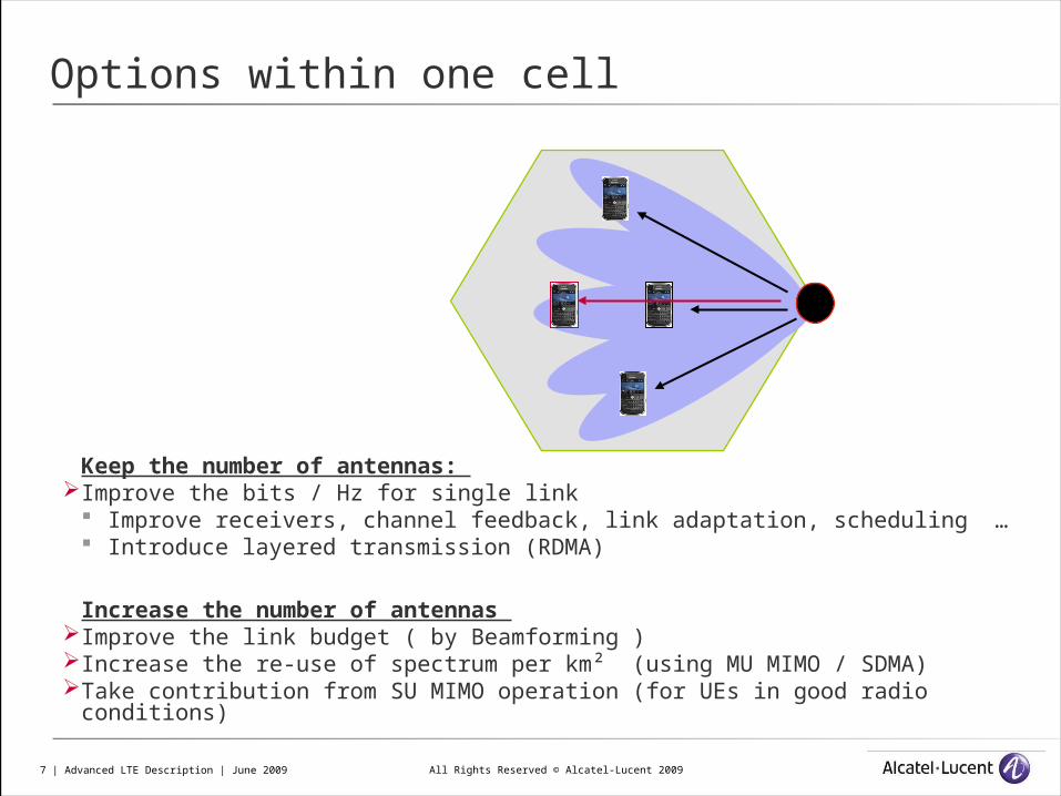
Options within one cell
Keep the number of antennas: Improve the bits / Hz for single link
Improve receivers, channel feedback, link adaptation, scheduling … Introduce layered transmission (RDMA)
Increase the number of antennas Improve the link budget ( by Beamforming )Increase the re-use of spectrum per km² (using MU MIMO / SDMA)Take contribution from SU MIMO operation (for UEs in good radio conditions)
All Rights Reserved © Alcatel-Lucent 20098 | Advanced LTE Description | June 2009
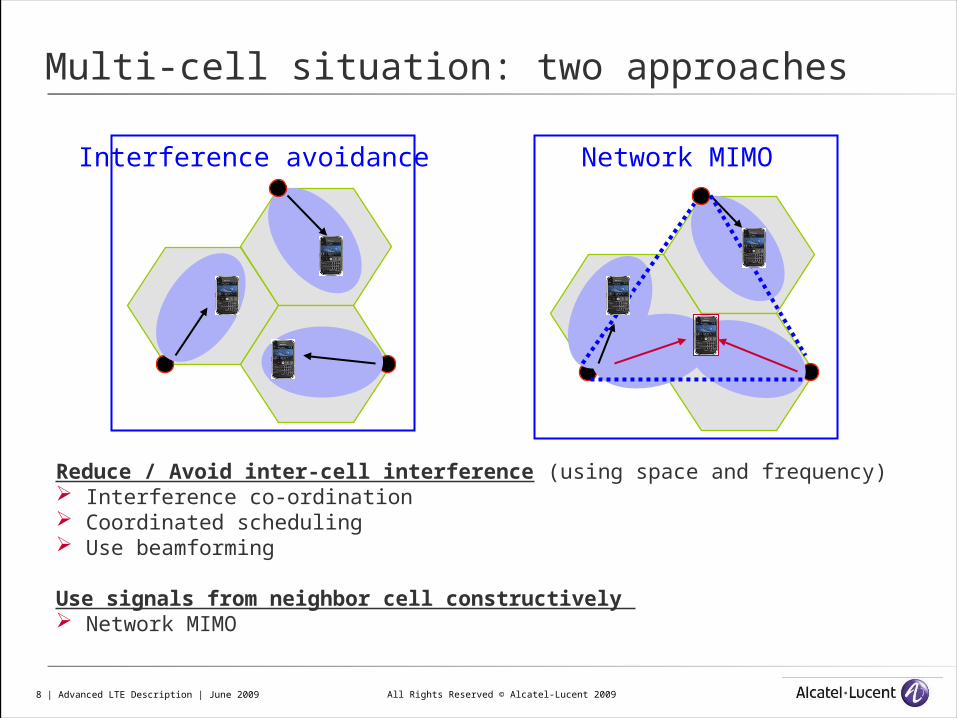
Multi-cell situation: two approaches
Reduce / Avoid inter-cell interference (using space and frequency) Interference co-ordination Coordinated scheduling Use beamforming
Use signals from neighbor cell constructively Network MIMO
Interference avoidance Network MIMO
All Rights Reserved © Alcatel-Lucent 20099 | Advanced LTE Description | June 2009
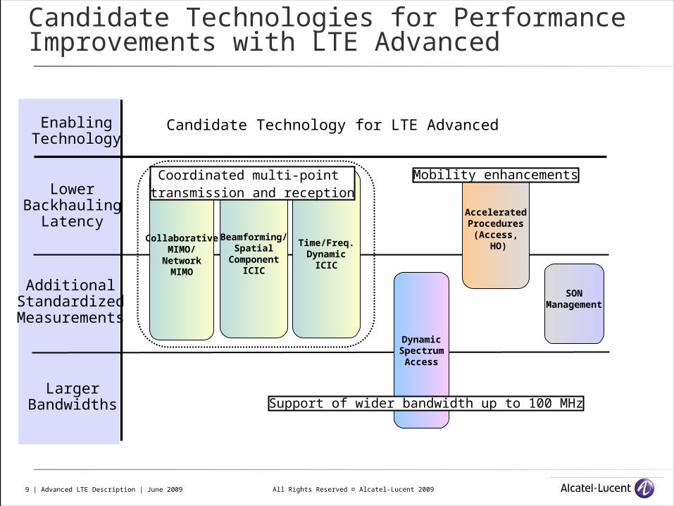
Candidate Technologies for Performance Improvements with LTE Advanced
EnablingTechnology
CollaborativeMIMO/
NetworkMIMO
LowerBackhauling
Latency
AdditionalStandardized
Measurements
LargerBandwidths
Beamforming/Spatial
ComponentICIC
Time/Freq.Dynamic
ICIC
DynamicSpectrum
Access
Coordinated multi-point transmission and reception
Candidate Technology for LTE Advanced
AcceleratedProcedures
(Access, HO)
SONManagement
Mobility enhancements
Support of wider bandwidth up to 100 MHz
All Rights Reserved © Alcatel-Lucent 200910 | Advanced LTE Description | June 2009
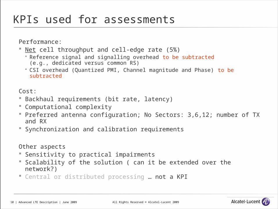
KPIs used for assessments
Performance: Net cell throughput and cell-edge rate (5%)
Reference signal and signalling overhead to be subtracted(e.g., dedicated versus common RS)
CSI overhead (Quantized PMI, Channel magnitude and Phase) to be subtracted
Cost: Backhaul requirements (bit rate, latency) Computational complexity Preferred antenna configuration; No Sectors: 3,6,12; number of TX and
RX Synchronization and calibration requirements
Other aspects Sensitivity to practical impairments Scalability of the solution ( can it be extended over the network?) Central or distributed processing … not a KPI
All Rights Reserved © Alcatel-Lucent 200911 | Advanced LTE Description | June 2009
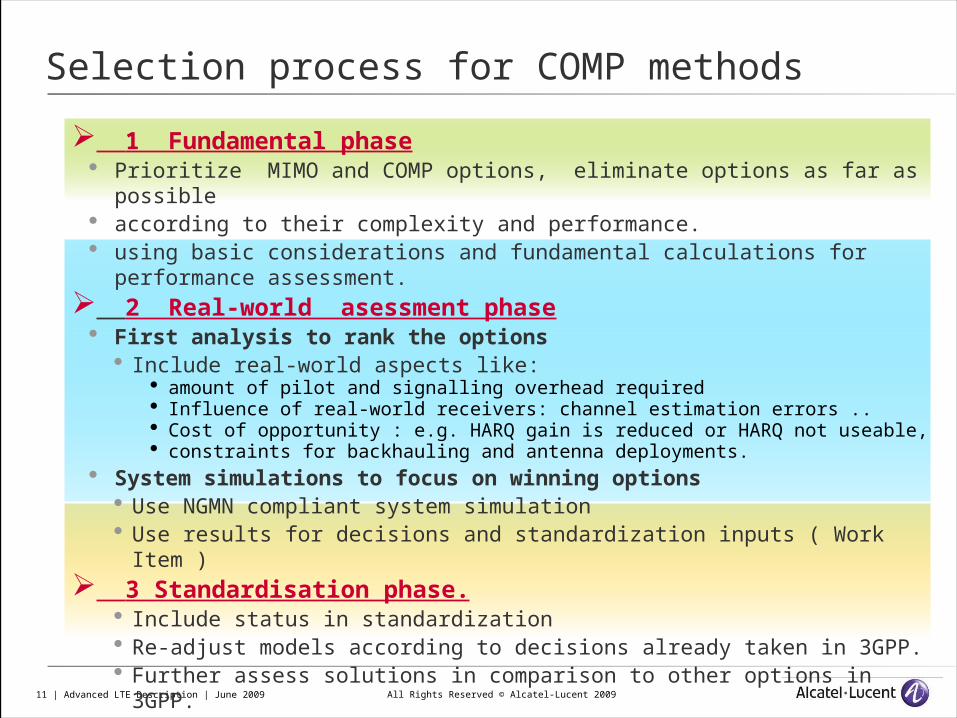
Selection process for COMP methods
1 Fundamental phase Prioritize MIMO and COMP options, eliminate options as far as possible according to their complexity and performance. using basic considerations and fundamental calculations for performance assessment.
2 Real-world asessment phase First analysis to rank the options
Include real-world aspects like: amount of pilot and signalling overhead required Influence of real-world receivers: channel estimation errors .. Cost of opportunity : e.g. HARQ gain is reduced or HARQ not useable, constraints for backhauling and antenna deployments.
System simulations to focus on winning options Use NGMN compliant system simulation Use results for decisions and standardization inputs ( Work Item )
3 Standardisation phase. Include status in standardization Re-adjust models according to decisions already taken in 3GPP. Further assess solutions in comparison to other options in 3GPP.
All Rights Reserved © Alcatel-Lucent 200912 | Advanced LTE Description | June 2009
COMP/ Network MIMO
All Rights Reserved © Alcatel-Lucent 200913 | Advanced LTE Description | June 2009
spectra
l effi
cien
cy
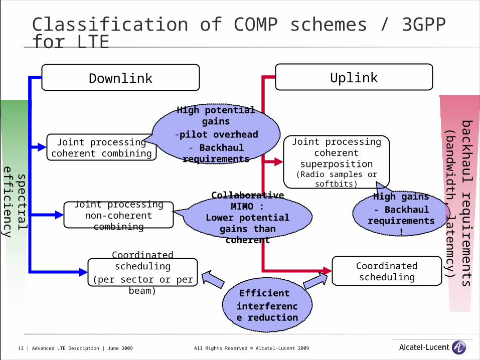
Classification of COMP schemes / 3GPP for LTE
High gains- Backhaul
requirements!
Downlink Uplink
Joint processingcoherent combining
Joint processingnon-coherent
combining
Coordinated scheduling
(per sector or per beam)
Joint processingcoherent
superposition(Radio samples or
softbits)
Coordinated scheduling
High potential gains
-pilot overhead- Backhaul
requirements
Collaborative MIMO :
Lower potential gains than coherent
Efficient interference reduction
back
hau
l req
uire
men
ts (b
an
dw
idth
, late
nm
cy)
All Rights Reserved © Alcatel-Lucent 200914 | Advanced LTE Description | June 2009
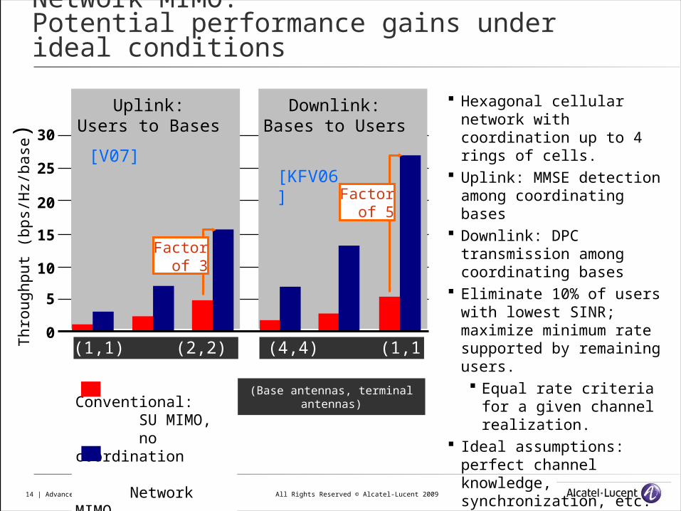
Network MIMO: Potential performance gains under ideal conditions
Uplink:Users to Bases
Downlink:Bases to Users
(1,1) (2,2) (4,4) (1,1) (2,2) (4,4)
Thr
ough
put (
bps/
Hz/
base
)
5
0
10
15
20
25
30
Conventional: SU MIMO, no coordination
Network MIMO
(Base antennas, terminal antennas)
Factorof 5
[KFV06] [V07]
Factorof 3
Hexagonal cellular network with coordination up to 4 rings of cells.
Uplink: MMSE detection among coordinating bases
Downlink: DPC transmission among coordinating bases
Eliminate 10% of users with lowest SINR; maximize minimum rate supported by remaining users. Equal rate criteria for a
given channel realization. Ideal assumptions: perfect
channel knowledge, synchronization, etc.
All Rights Reserved © Alcatel-Lucent 200915 | Advanced LTE Description | June 2009
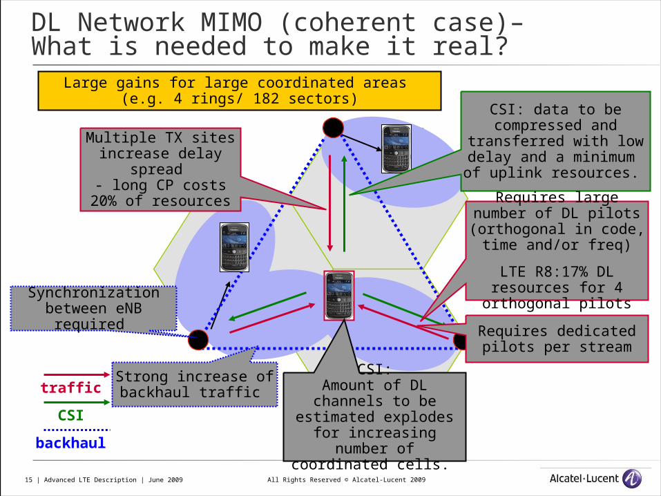
DL Network MIMO (coherent case)– What is needed to make it real?
Multiple TX sites increase delay
spread - long CP costs 20%
of resources
traffic
CSI
backhaul
CSI:Amount of DL channels
to be estimated explodes for increasing number of coordinated
cells.
CSI: data to be compressed and
transferred with low delay and a minimum of
uplink resources.
Requires large number of DL pilots (orthogonal
in code, time and/or freq)
LTE R8:17% DL resources for 4
orthogonal pilotsSynchronization between eNB required
Strong increase of backhaul traffic
Large gains for large coordinated areas (e.g. 4 rings/ 182 sectors)
Requires dedicated pilots per stream
All Rights Reserved © Alcatel-Lucent 200916 | Advanced LTE Description | June 2009
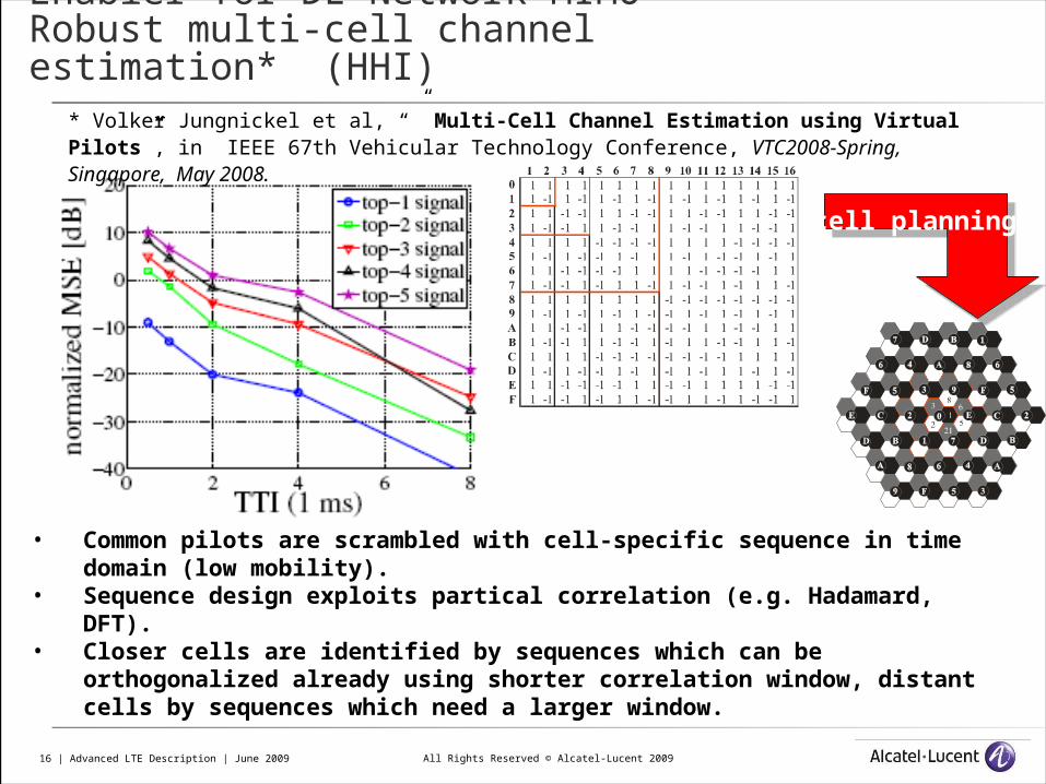
Enabler for DL Network MIMO Robust multi-cell channel estimation* (HHI)
cell planning
• Common pilots are scrambled with cell-specific sequence in time domain (low mobility).
• Sequence design exploits partical correlation (e.g. Hadamard, DFT).• Closer cells are identified by sequences which can be orthogonalized already
using shorter correlation window, distant cells by sequences which need a larger window.
* Volker Jungnickel et al, “” Multi-Cell Channel Estimation using Virtual Pilots”, in IEEE 67th Vehicular Technology Conference, VTC2008-Spring, Singapore, May 2008.
All Rights Reserved © Alcatel-Lucent 200917 | Advanced LTE Description | June 2009
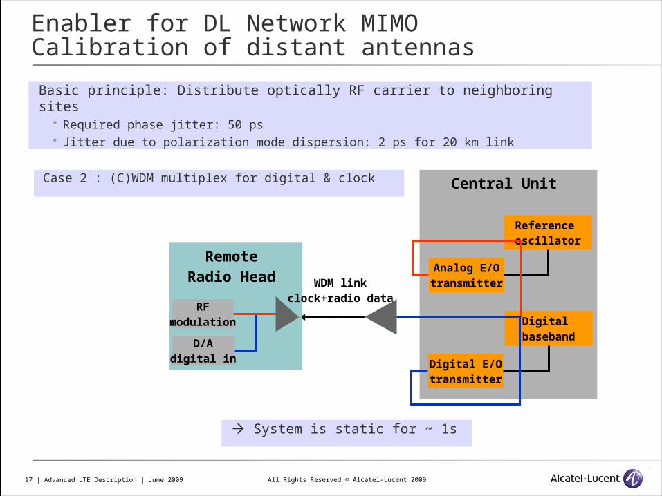
Enabler for DL Network MIMO Calibration of distant antennas
Basic principle: Distribute optically RF carrier to neighboring sites Required phase jitter: 50 ps Jitter due to polarization mode dispersion: 2 ps for 20 km link
Case 2 : (C)WDM multiplex for digital & clock Central Unit
Digital E/Otransmitter
Reference oscillator
Analog E/Otransmitter
Digital baseband
Remote Radio Head
D/Adigital in
RFmodulation
WDM linkclock+radio data
System is static for ~ 1s
All Rights Reserved © Alcatel-Lucent 200918 | Advanced LTE Description | June 2009
Summary on DL Network MIMO
Situation today Highest theoretical gains among all DL COMP methods
For Downlink FDD: Theoretical gains of the method are consumed by impairments
e.g. Uplink is consumed by Channel state signalling Pilots consume large part of Downlink
We need further progress on enablers Synchronization and antenna calibration Principles are established Pilots First proposals Efficient channel feedback ideas for single sector, to be extended
We think that coherent COMP will not be available in the next 3 years!

All Rights Reserved © Alcatel-Lucent 200919 | Advanced LTE Description | June 2009
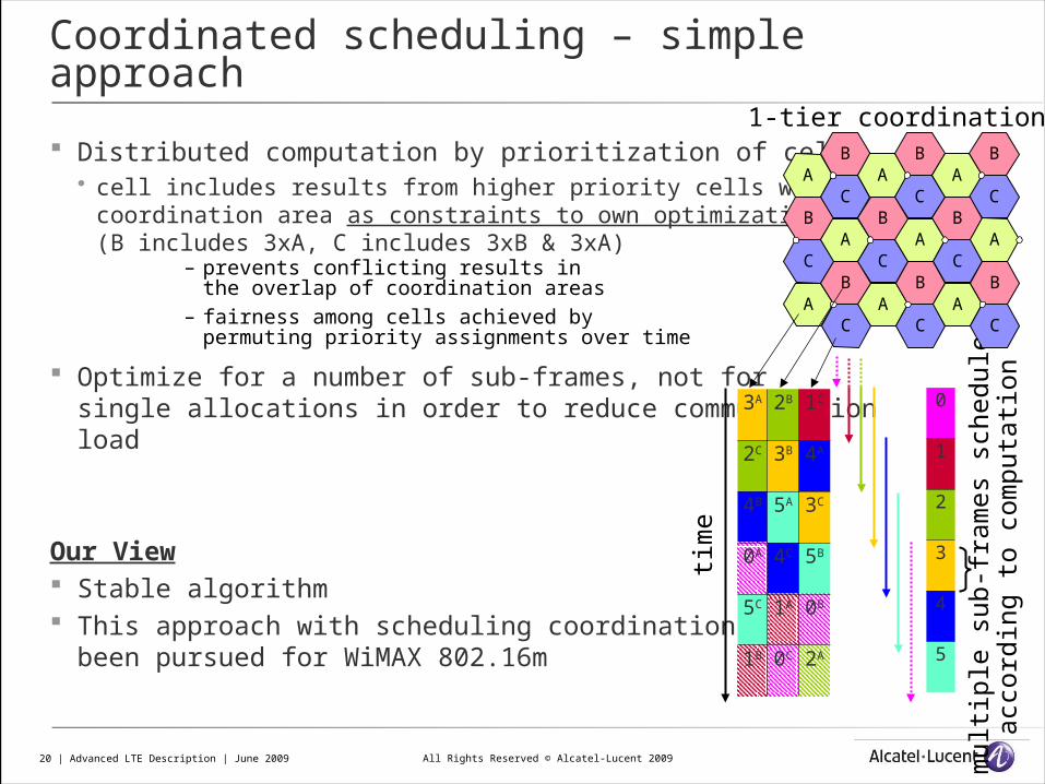
Coordinated scheduling – simple approach
Coordination area around every cell is defined a coordination area
with the cell in the center a cell coordinates only with cells within its coordination area
Establish data basis for interference estimation correlation matrix describing every channel between every BS antenna and
UE antenna within a given coordination area around each cell– requires knowledge of inter-cell channels
Coordinated uplink sounding– BS measures all inter-cell channels
within its coordination area
Optimize scheduling & beamforming/Tx powerper UE within coordination area
1. select UEs with lowest mutual interferenceto be scheduled on same resource and
2. balance their SINR/throughput by adapting Tx power/beam pattern/direction
ca1 cb1
BSa BSb
ca2 cb2
UE1
cell 1
cell 2
UE2
All Rights Reserved © Alcatel-Lucent 200920 | Advanced LTE Description | June 2009
Distributed computation by prioritization of cells cell includes results from higher priority cells within its
coordination area as constraints to own optimization(B includes 3xA, C includes 3xB & 3xA)
– prevents conflicting results inthe overlap of coordination areas
– fairness among cells achieved bypermuting priority assignments over time
Optimize for a number of sub-frames, not for single allocations in order to reduce communicationload
Our View Stable algorithm This approach with scheduling coordination has
been pursued for WiMAX 802.16m
mult
iple
su
b-f
ram
es
schedule
dacc
ord
ing t
o c
om
pu
tati
on
3A 2B 1C
2C 3B 4A
4B 5A 3C
0A 4C 5B
5C 1A 0B
1B 0C 2A
AB
CA
B
CA
B
CB
CA
B
CA
B
CA
AB
CA
B
CA
B
C
1-tier coordination
tim
e
0
1
2
3
4
5
Coordinated scheduling – simple approach
All Rights Reserved © Alcatel-Lucent 200921 | Advanced LTE Description | June 2009
0 0.5 1 1.5 2 2.5 30
100
200
300
400
500
600
700
800
900
1000
spectral efficiency [bit/s/Hz]
5-pe
rcen
tile
thro
ughp
ut [
kbps
]
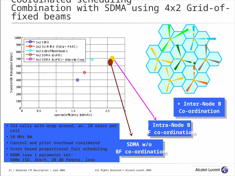
1x2 SIMO
2x2 SU-MIMO (TxDiv + PARC)
4x2 Grid-of-fixed-beams4x2 SDMA (GoFB)
4x2 SDMA (GoFB) + intra-site Coop
• 7x3 cells with wrap around, av. 10 users per cell
• 10 MHz BW• Control and pilot overhead considered• Score based proportional fair scheduling• NGNM case 1 parameter set:
500m ISD, 3km/h, 20 dB Penetr. loss
Coordinated scheduling Combination with SDMA using 4x2 Grid-of-fixed beams
+ Intra-Node B BF co-ordination
+ Intra-Node B BF co-ordination
+ Inter-Node BCo-ordination
+ Inter-Node BCo-ordination
SDMA w/o BF co-ordination
SDMA w/o BF co-ordination
All Rights Reserved © Alcatel-Lucent 200922 | Advanced LTE Description | June 2009
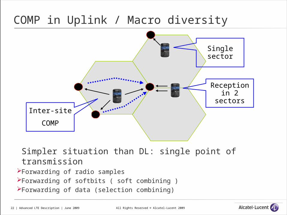
COMP in Uplink / Macro diversity
Simpler situation than DL: single point of transmissionForwarding of radio samples Forwarding of softbits ( soft combining )Forwarding of data (selection combining)
Inter-site
COMP
Reception in 2 sectors
Single sector
All Rights Reserved © Alcatel-Lucent 200923 | Advanced LTE Description | June 2009
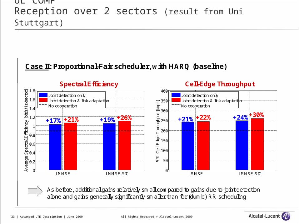
UL COMP Reception over 2 sectors (result from Uni Stuttgart)
LMMSE LMMSE-SIC0
0.2
0.4
0.6
0.8
1
1.2
1.4
1.6
1.8
Ave
rage
Spe
ctra
l Eff
icie
ncy
[bit/
s/H
z/se
ctor
]
Joint detection onlyJoint detection & link adaptationNo cooperation
Results: Joint Link Adaptation (II)
11
March 4, 2009
Case II: Proportional-Fair scheduler, with HARQ (baseline)
Spectral Efficiency
+19%+26%+17%+21%
LMMSE LMMSE-SIC0
50
100
150
200
250
300
350
400
5 %
Cel
l Edg
e T
hrou
ghpu
t [k
bps]
Joint detection onlyJoint detection & link adaptationNo cooperation
Cell-Edge Throughput
+21%+22% +24%+30%
As before, additional gains relatively small compared to gains due to joint detectionalone and gains generally significantly smaller than for (dumb) RR scheduling
All Rights Reserved © Alcatel-Lucent 200924 | Advanced LTE Description | June 2009
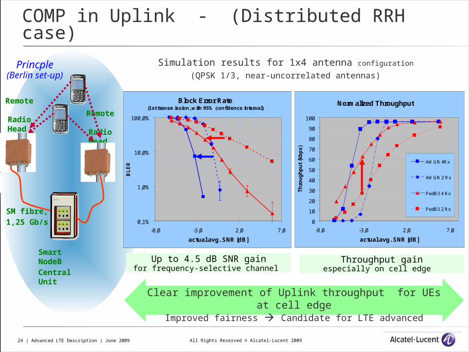
COMP in Uplink - (Distributed RRH case)
Simulation results for 1x4 antenna configuration (QPSK 1/3, near-uncorrelated antennas)
Up to 4.5 dB SNR gain for frequency-selective channel
Normalized Throughput
0
10
20
30
40
50
60
70
80
90
100
-8,0 -3,0 2,0 7,0
actual avg. SNR [dB]
Th
rou
gh
pu
t (k
bp
s)
AWGN 4Rx
AWGN 2 Rx
PedB3 4 Rx
PedB3 2 Rx
Throughput gainespecially on cell edge
Clear improvement of Uplink throughput for UEs at cell edge
Improved fairness Candidate for LTE advanced
Remote
Radio Head
Smart NodeBCentral Unit
SM fibre, 1,25 Gb/s
Remote
Radio Head
Block Error Rate (1st transmission, with 95% confidence interval)
0,1%
1,0%
10,0%
100,0%
-8,0 -3,0 2,0 7,0
actual avg. SNR [dB]
BL
ER
Princple(Berlin set-up)
All Rights Reserved © Alcatel-Lucent 200925 | Advanced LTE Description | June 2009
Additional BW4
5 Mbps (control traffic, in & out)Latency: 10ms for decoupled (lower gains!))< 1 ms*/arbitrary (scheduling and coordination coupled)
Additional BW2
30 Mbps (CSI, in)
45 Mbps (user data, out)3
Latency < 3 ms*
spectra
l effi
cien
cy
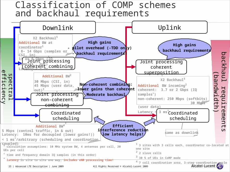
Classification of COMP schemes and backhaul requirements
Downlink Uplink
Joint processingcoherent combining
Joint processingnon-coherent
combining
Coordinated scheduling
Joint processingcoherent
superposition
Coordinated scheduling
back
hau
l req
uire
men
ts (b
an
dw
idth
)
§ calculation assumptions: 10 MHz system BW, 4 antennas per cell, 20 UEs per cell+ time and frequency domain IQ samples (in this order)* latency is site to site one way, includes eNB processing time!
X2 Backhaul§
Additional BW incoming2
coherent: 3.7 or 2 Gbps (IQ samples+)non-coherent: 250 Mbps (softbits) 30 Mbps (user data)
Latency < 3 ms*
X2 Backhaul§
Additional BW at coordinator1
8- 14 Gbps (samples or CSI, in)11 or 6 Gbps (IQ
samples+, out)Latency < 1 ms*
1 3 sites with 3 cells each, coordinator co-located at one site2 2 slave cells3 30 % of UEs in CoMP mode4 7 cell coordination area, 3-step coordination cycle
same as downlink
High gains- pilot overhead (-TDD only)
- backhaul requirements!
High gains- backhaul requirements
Efficientinterference reduction
low latency helps!
Non-coherent combining:lower gains than coherent
Moderate backhaul
All Rights Reserved © Alcatel-Lucent 200926 | Advanced LTE Description | June 2009
Enabling technologies - Efficient feedback
- pre-coding schemes- IRC and SIC receivers
All Rights Reserved © Alcatel-Lucent 200927 | Advanced LTE Description | June 2009
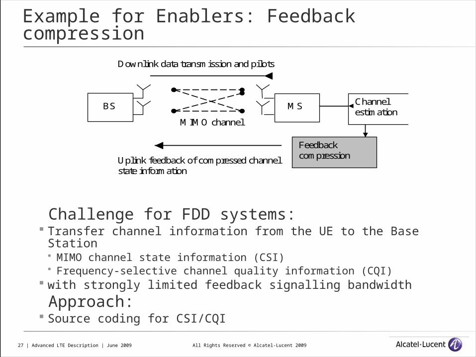
Example for Enablers: Feedback compression
Challenge for FDD systems: Transfer channel information from the UE to the Base Station
MIMO channel state information (CSI) Frequency-selective channel quality information (CQI)
with strongly limited feedback signalling bandwidth Approach: Source coding for CSI/CQI
BS MS
MIMO channel
Channel estimation
Downlink data transmission and pilots
Uplink feedback of compressed channel state information
Feedback compression
All Rights Reserved © Alcatel-Lucent 200928 | Advanced LTE Description | June 2009
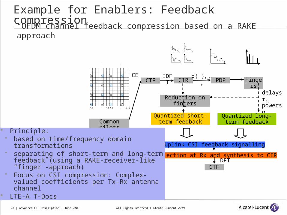
Common pilots
CTFCE IDF
T CIRE{ }t,ant PDP Finger
sdelays τf,
powers pf
Quantized long-term feedback
Quantized short-term feedback
Reduction on fingers
Uplink CSI feedback signalling
Collection at Rx and synthesis to CIRDFT
CTF
Principle: based on time/frequency domain
transformations separating of short-term and long-term
feedback (using a RAKE-receiver-like “finger”-approach)
Focus on CSI compression: Complex-valued coefficients per Tx-Rx antenna channel
LTE-A T-Docs
“OFDM channel feedback compression based on a RAKE approach”
Example for Enablers: Feedback compression
All Rights Reserved © Alcatel-Lucent 200929 | Advanced LTE Description | June 2009
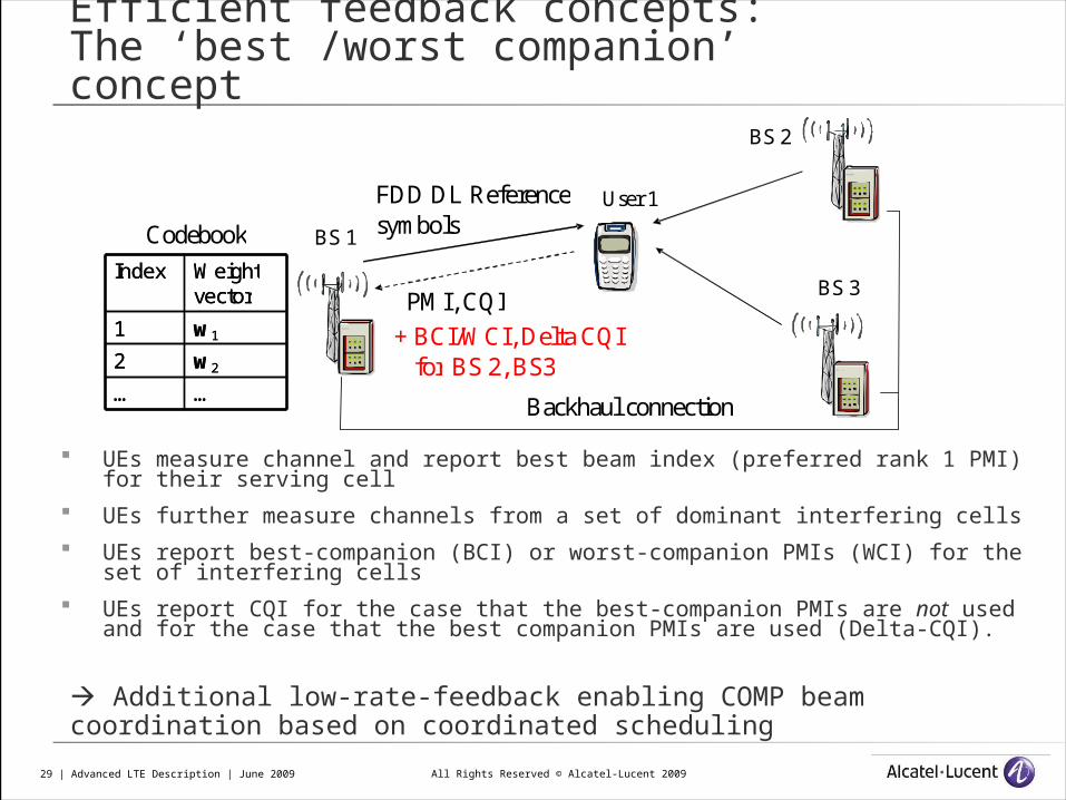
Efficient feedback concepts:The ‘best /worst companion’ concept
UEs measure channel and report best beam index (preferred rank 1 PMI) for their serving cell
UEs further measure channels from a set of dominant interfering cells
UEs report best-companion (BCI) or worst-companion PMIs (WCI) for the set of interfering cells
UEs report CQI for the case that the best-companion PMIs are not used and for the case that the best companion PMIs are used (Delta-CQI).
FDD DL Reference symbols
PMI, CQI + BCI/WCI, Delta CQI
for BS 2, BS3
User 1
Backhaul connection
BS 1
BS 2
BS 3 Codebook
… … w 2 2 w 1 1
Weight vector
Index
… … w 2 2 w 1 1
Weight vector
Index
Additional low-rate-feedback enabling COMP beam coordination based on coordinated scheduling
All Rights Reserved © Alcatel-Lucent 200930 | Advanced LTE Description | June 2009
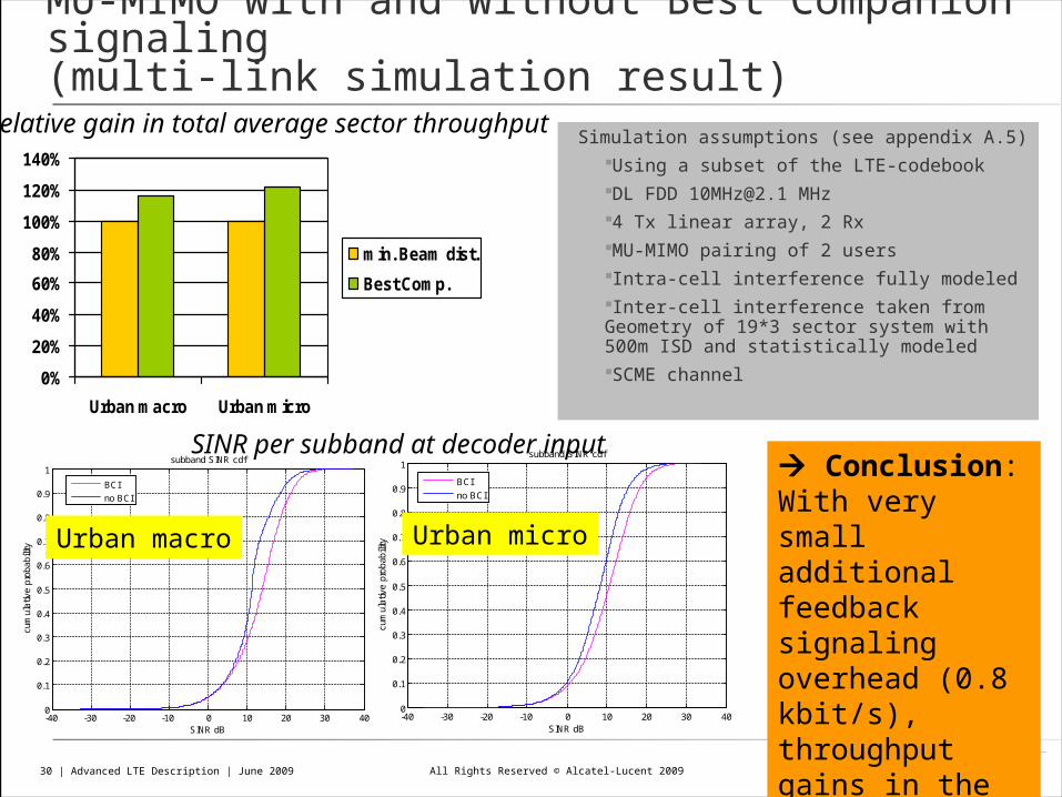
MU-MIMO with and without Best Companion signaling(multi-link simulation result)
0%
20%
40%
60%
80%
100%
120%
140%
Urban macro Urban micro
min. Beam dist.
Best Comp.
Relative gain in total average sector throughput Simulation assumptions (see appendix A.5)Using a subset of the LTE-codebookDL FDD [email protected] MHz4 Tx linear array, 2 RxMU-MIMO pairing of 2 usersIntra-cell interference fully modeledInter-cell interference taken from Geometry of 19*3 sector system with 500m ISD and statistically modeledSCME channel
-40 -30 -20 -10 0 10 20 30 400
0.1
0.2
0.3
0.4
0.5
0.6
0.7
0.8
0.9
1subband SINR cdf
SINR dB
cum
ulat
ive
prob
abili
ty
BCI
no BCI
-40 -30 -20 -10 0 10 20 30 400
0.1
0.2
0.3
0.4
0.5
0.6
0.7
0.8
0.9
1subband SINR cdf
SINR dB
cum
ulat
ive
prob
abili
ty
BCI
no BCI
SINR per subband at decoder input
Urban macro Urban micro
Conclusion:With very small additional feedback signaling overhead (0.8 kbit/s), throughput gains in the order of 20%
All Rights Reserved © Alcatel-Lucent 200931 | Advanced LTE Description | June 2009
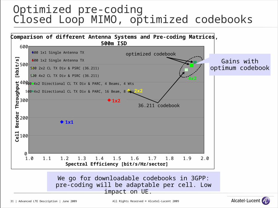
Optimized pre-coding Closed Loop MIMO, optimized codebooks
Comparison of different Antenna Systems and Pre-coding Matrices,500m ISD
0
100
200
300
400
500
600
1.0 1.1 1.2 1.3 1.4 1.5 1.6 1.7 1.8 1.9 2.0Spectral Efficiency [bit/s/Hz/sector]
Ce
ll B
ord
er
Th
rou
gh
pu
t [k
bit
/s]
500 1x1 Single Antenna TX
500 1x2 Single Antenna TX
500 2x2 CL TX Div & PSRC (36.211)
500 4x2 CL TX Div & PSRC (36.211)
500 4x2 Directional CL TX Div & PARC, 4 Beams, 4 Wts
500 4x2 Directional CL TX Div & PARC, 16 Beam, 8 Wts
1x1
1x2
2x2
4x2
optimized codebook
36.211 codebook
Gains with optimum codebook
We go for downloadable codebooks in 3GPP:pre-coding will be adaptable per cell. Low impact on
UE.
All Rights Reserved © Alcatel-Lucent 200932 | Advanced LTE Description | June 2009
Summary :
We aim at a smooth introduction of LTE-A into the field System should adapt to available spectrum System should extend on LTE (antenna) deployment System should allow to select optimum COMP scheme
depending on available backhauling capabilities(bandwidth and latency )
Depending on existing antenna sites and configurations
All Rights Reserved © Alcatel-Lucent 200933 | Advanced LTE Description | June 2009
www.alcatel-lucent.comThank you!
www.alcatel-lucent.com