Embed Size (px)
Citation preview
LTE Release 9Technology IntroductionWhite paper
The LTE technology as specified within3GPP Release 8 was first commerciallydeployed by end 2009. Since then thenumber of operators implementing thetechnology is strongly increasing aroundthe globe. LTE has become the fastestdeveloping mobile system technology. Thesame way GSM and WCDMA have beenenhanced with additional features overtime, LTE is continuously worked on. Initialenhancements have been included in3GPP Release 9 and are described in thiswhite paper.
1MA1
91
M.Ko
ttkam
p,A.
Röss
ler,J
.Sch
lienz
,J.
Schü
tzDe
cemb
er20
11-0
E
Tem
plat
e:35
73.7
380.
02/C
I01.
00
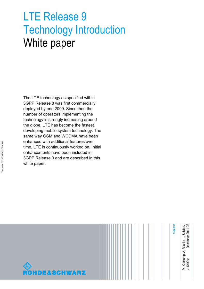
Table of Contents
0E Rohde & Schwarz LTE Release 9 Technology Introduction 2
Table of Contents1 Introduction ............................................................................ 4
2 evolved MBMS (eMBMS)........................................................ 52.1 History of MBMS...........................................................................................5
2.2 MBMS in LTE (3GPP Release 8 and 9) .......................................................6
2.2.1 MBSFN, MBSFN area ...................................................................................7
2.2.2 New channels for MBMS..............................................................................8
2.2.3 Physical layer aspects of evolved MBMS..................................................9
2.2.4 Extended: SIB Type 2.................................................................................11
2.2.5 NEW: SIB Type 13 ......................................................................................12
2.2.6 MCCH content.............................................................................................13
3 Positioning methods in LTE................................................ 153.1 Introduction, (Assisted-)Global Navigation Satellite Systems ..............15
3.2 General aspects of LTE positioning.........................................................18
3.3 OTDOA – Observed Time Difference of Arrival.......................................20
3.3.1 Reference Signal Time Difference (RSTD) measurement ......................20
3.3.2 Positioning Reference Signals (PRS).......................................................20
3.4 Enhanced Cell ID ........................................................................................22
3.4.1 Timing Advance (TDAV), Round Trip Time (RTT) ...................................23
3.4.2 Angle-of-Arrival (AoA) measurement.......................................................23
4 LTE MIMO: dual-layer beamforming................................... 254.1 Physical layer details: ................................................................................25
5 Public Warning System (PWS)............................................ 285.1 Commercial Mobile Alert System (CMAS) ...............................................28
6 RF requirements for multi-carrier and multi-RAT basestations ................................................................................. 31
6.1 Operating bands and Band Categories....................................................32
7 Home eNodeB specification (femto-cell)............................ 347.1 New RAN functionalities............................................................................34
8 Self Organizing Networks.................................................... 368.1 Architecture ................................................................................................36
Table of Contents
0E Rohde & Schwarz LTE Release 9 Technology Introduction 3
8.2 SON Processing .........................................................................................37
8.3 Use Cases for Self Configuration .............................................................38
8.4 Use Cases for Self Optimization...............................................................38
8.4.1 Mobility Robustness Optimization ...........................................................38
8.4.2 Mobility Load Balancing Optimization .....................................................40
8.4.3 RACH Optimization ....................................................................................40
9 Literature............................................................................... 42
10 Additional Information......................................................... 43
Introduction
0E Rohde & Schwarz LTE Release 9 Technology Introduction 4
1 IntroductionInitiated in 2004, the Long Term Evolution (LTE) project in 3GPP standardizationfocused on enhancing the Universal Terrestrial Radio Access (UTRA) and optimizing3GPP’s radio access architecture. In 2007, LTE progressed from the feasibility studystage to the first issue of approved technical specifications. End 2008 thespecifications were sufficiently stable for commercial implementation and the firstcommercial LTE network was launched in Sweden and Norway in December 2009. 35commercial networks were launched by end October 2011.
From experience on GSM and UMTS it can be seen that the initial specification releaseafter creation of a new technology is usually a minor one. This means this first follow-up release includes leftovers, that were not completed in the initial release or somesmaller features are added. As an example UMTS Release 4, the first release aftercreation of the UMTS technology in early 2000, included the additional UMTS TDDmode – not finalized in Release 99 – and just small optimizations of the FDD mode.More significant enhancements like the HSDPA feature took another release to beincluded in the specifications. The same holds true for LTE Release 9. The Releaseincludes a set of features that either were not completed in release 8 or which providesome smaller optimizations or improvements. These are namely:
● Multimedia Broadcast Multicast Services (MBMS) for LTE,● LTE MIMO: dual-layer beamforming,● LTE positioning● PWS (Public Warning System)● RF requirements for multi-carrier and multi-RAT base stations,● Home eNodeB specification (femto-cell),● Self–Organizing Networks (SON).
This application note describes each feature in detail.
evolved MBMS (eMBMS)
0E Rohde & Schwarz LTE Release 9 Technology Introduction 5
2 evolved MBMS (eMBMS)
2.1 History of MBMS
As the term evolved implies, Multimedia Broadcast Multicast Services (MBMS), is notfundamentally new to 3GPP and not defined as a LTE-only feature. In fact MBMS hasfirst time been specified with 3GPP Release 6. It has than continuously been enhancedin the following versions of the specification. Initially defined for UTRAN/WCDMA (3G)it is also supported by GERAN/GSM (2G).
The goal with MBMS is to provide network operators with the possibility to broadcastover their cellular network. Some advantages are considered over traditional mobilebroadcast technologies, such as DVB-H, DMB-H or former MediaFLO. These are:
The same infrastructure is used
No need for additional spectrum
Interaction with user is possible due to available uplink
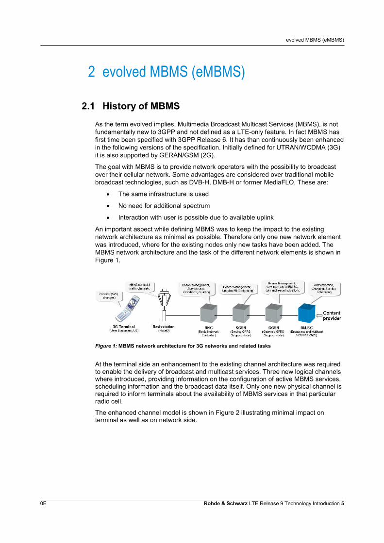
An important aspect while defining MBMS was to keep the impact to the existingnetwork architecture as minimal as possible. Therefore only one new network elementwas introduced, where for the existing nodes only new tasks have been added. TheMBMS network architecture and the task of the different network elements is shown inFigure 1.
Figure 1: MBMS network architecture for 3G networks and related tasks
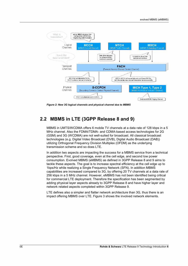
At the terminal side an enhancement to the existing channel architecture was requiredto enable the delivery of broadcast and multicast services. Three new logical channelswhere introduced, providing information on the configuration of active MBMS services,scheduling information and the broadcast data itself. Only one new physical channel isrequired to inform terminals about the availability of MBMS services in that particularradio cell.
The enhanced channel model is shown in Figure 2 illustrating minimal impact onterminal as well as on network side.
evolved MBMS (eMBMS)
0E Rohde & Schwarz LTE Release 9 Technology Introduction 6
Figure 2: New 3G logical channels and physical channel due to MBMS
2.2 MBMS in LTE (3GPP Release 8 and 9)
MBMS in UMTS/WCDMA offers 6 mobile TV channels at a data rate of 128 kbps in a 5MHz channel. Also the FDMA/TDMA- and CDMA-based access technologies for 2G(GSM) and 3G (WCDMA) are not well-suited for broadcast. All classical broadcasttechnologies (e.g. Digital Video Broadcast (DVB), Digital Audio Broadcast (DAB))utilizing Orthogonal Frequency Division Multiplex (OFDM) as the underlyingtransmission scheme and so does LTE.
In addition two aspects are impacting the success for a MBMS service from a technicalperspective. First, good coverage, even at the cell edge, and second low powerconsumption. Evolved MBMS (eMBMS) as defined in 3GPP Release 8 and 9 aims totackle these aspects. The goal is to increase spectral efficiency at the cell edge up to1bps/Hz while realizing a Single Frequency Network (SFN). In addition MBMScapabilities are increased compared to 3G, by offering 20 TV channels at a data rate of256 kbps in a 5 MHz channel. However, eMBMS has not been identified being criticalfor commercial LTE deployment. Therefore the specification has been segmented byadding physical layer aspects already to 3GPP Release 8 and have higher layer andnetwork related aspects completed within 3GPP Release 9.
LTE defines also a simpler and flatter network architecture than 3G, thus there is animpact offering MBMS over LTE. Figure 3 shows the involved network elements.
evolved MBMS (eMBMS)
0E Rohde & Schwarz LTE Release 9 Technology Introduction 7
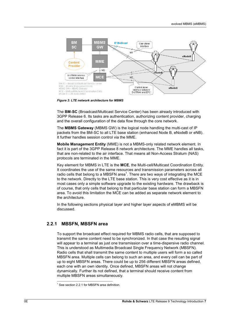
Figure 3: LTE network architecture for MBMS
The BM-SC (Broadcast/Multicast Service Center) has been already introduced with3GPP Release 6. Its tasks are authentication, authorizing content provider, chargingand the overall configuration of the data flow through the core network.
The MBMS Gateway (MBMS GW) is the logical node handling the multi-cast of IPpackets from the BM-SC to all LTE base station (enhanced Node B, eNodeB or eNB).It further handles session control via the MME.
Mobile Management Entity (MME) is not a MBMS-only related network element. Infact it is part of the 3GPP Release 8 network architecture. The MME handles all tasks,that are non-related to the air interface. That means all Non-Access Stratum (NAS)protocols are terminated in the MME.
Key element for MBMS in LTE is the MCE, the Multi-cell/Multicast Coordination Entity.It coordinates the use of the same resources and transmission parameters across allradio cells that belong to a MBSFN area1. There are two ways of integrating the MCEto the network. Directly to the LTE base station. This is very cost effective as it is inmost cases only a simple software upgrade to the existing hardware. The drawback isof course, that only cells that belong to that particular base station can form a MBSFNarea. To avoid this limitation the MCE can be added as separate network element tothe architecture.
In the following sections physical layer and higher layer aspects of eMBMS will bediscussed.
2.2.1 MBSFN, MBSFN area
To support the broadcast effect required for MBMS radio cells, that are supposed totransmit the same content need to be synchronized. In that case the resulting signalwill appear to a terminal as just one transmission over a time-dispersive radio channel.This is understood as Multimedia Broadcast Single Frequency Network (MBSFN).Radio cells that shall transmit the same content to multiple users will form a so calledMBSFN area. Multiple cells can belong to such an area, and every cell can be part ofup to eight MBSFN areas. There could be up to 256 different MBSFN areas defined,each one with an own identity. Once defined, MBSFN areas will not changedynamically. Further its not defined, that a terminal should receive content frommultiple MBSFN areas simultaneously.
1 See section 2.2.1 for MBSFN area definition.
evolved MBMS (eMBMS)
0E Rohde & Schwarz LTE Release 9 Technology Introduction 8
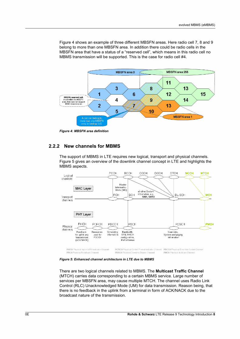
Figure 4 shows an example of three different MBSFN areas. Here radio cell 7, 8 and 9belong to more than one MBSFN area. In addition there could be radio cells in theMBSFN area that have a status of a “reserved cell”, which means in this radio cell noMBMS transmission will be supported. This is the case for radio cell #4.
Figure 4: MBSFN area definition
2.2.2 New channels for MBMS
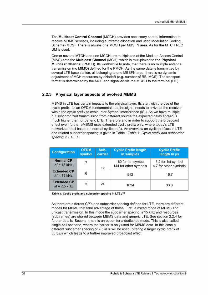
The support of MBMS in LTE requires new logical, transport and physical channels.Figure 5 gives an overview of the downlink channel concept in LTE and highlights theMBMS aspects.
Figure 5: Enhanced channel architecture in LTE due to MBMS
There are two logical channels related to MBMS. The Multicast Traffic Channel(MTCH) carries data corresponding to a certain MBMS service. Large number ofservices per MBSFN area, may cause multiple MTCH. The channel uses Radio LinkControl (RLC) Unacknowledged Mode (UM) for data transmission. Reason being, thatthere is no feedback in the uplink from a terminal in form of ACK/NACK due to thebroadcast nature of the transmission.
evolved MBMS (eMBMS)
0E Rohde & Schwarz LTE Release 9 Technology Introduction 9
The Multicast Control Channel (MCCH) provides necessary control information toreceive MBMS services, including subframe allocation and used Modulation CodingScheme (MCS). There is always one MCCH per MBSFN area. As for the MTCH RLCUM is used.
One or several MTCH and one MCCH are multiplexed at the Medium Access Control(MAC) onto the Multicast Channel (MCH), which is multiplexed to the PhysicalMulticast Channel (PMCH). Its worthwhile to note, that there is no multiple antennatransmission (no MIMO) defined for the PMCH. As the same data is transmitted byseveral LTE base station, all belonging to one MBSFN area, there is no dynamicadjustment of MCH resources by eNodeB (e.g. number of RB, MCS). The transportformat is determined by the MCE and signalled via the MCCH to the terminal (UE).
2.2.3 Physical layer aspects of evolved MBMS
MBMS in LTE has certain impacts to the physical layer. Its start with the use of thecyclic prefix. Its an OFDM fundamental that the signal needs to arrive at the receiverwithin the cyclic prefix to avoid Inter-Symbol Interference (ISI). As we have multiple,but synchronized transmission from different source the expected delay spread ismuch higher than for generic LTE. Therefore and in order to support the broadcasteffect even further eMBMS uses extended cyclic prefix only, where today’s LTEnetworks are all based on normal cyclic prefix. An overview on cyclic prefixes in LTEand related subcarrier spacing is given in Table 1Table 1: Cyclic prefix and subcarrierspacing in LTE [1]
Configuration OFDMsymbol
Sub-carrier
Cyclic Prefix lengthin samples
Cyclic Prefixlength in µs
Normal CP∆f = 15 kHz 7 160 for 1st symbol
144 for other symbols5.2 for 1st symbol
4.7 for other symbolsExtended CP∆f = 15 kHz 6
12
512 16.7
Extended CP∆f = 7.5 kHz 3 24 1024 33.3
Table 1: Cyclic prefix and subcarrier spacing in LTE [1]
As there are different CP’s and subcarrier spacing defined for LTE, there are differentmodes for MBMS that take advantage of these. First, a mixed mode of MBMS andunicast transmission. In this mode the subcarrier spacing is 15 kHz and resources(subframes) are shared between MBMS data and generic LTE. See section 2.2.4 forfurther details. Second, there is an option for a dedicated mode. This is also calledsingle-cell scenario, where the carrier is only used for MBMS data. In this case adifferent subcarrier spacing of 7.5 kHz will be used, offering a larger cyclic prefix of33.3 µs which leads to a further improved broadcast effect.
evolved MBMS (eMBMS)
0E Rohde & Schwarz LTE Release 9 Technology Introduction 10
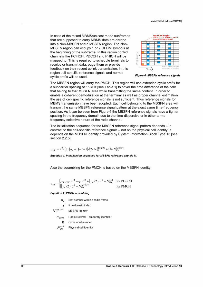
In case of the mixed MBMS/unicast mode subframesthat are supposed to carry MBMS data are dividedinto a Non-MBSFN and a MBSFN region. The Non-MBSFN region can occupy 1 or 2 OFDM symbols atthe beginning of the subframe. In this region controlchannels like PCFICH, PDCCH and PHICH will bemapped to. This is required to schedule terminals toreceive or transmit data, page them or providefeedback on their recent uplink transmission. In thisregion cell-specific reference signals and normalcyclic prefix will be used. Figure 6: MBSFN reference signals
The MBSFN-region will carry the PMCH. This region will use extended cyclic prefix fora subcarrier spacing of 15 kHz [see Table 1] to cover the time difference of the cellsthat belong to that MBSFN area while transmitting the same content. In order toenable a coherent demodulation at the terminal as well as proper channel estimationthe use of cell-specific reference signals is not sufficient. Thus reference signals forMBMS transmission have been adopted. Each cell belonging to the MBSFN area willtransmit the same MBSFN reference signal pattern at the exact same time-frequencyposition. As it can be seen from Figure 6 the MBSFN reference signals have a tighterspacing in the frequency domain due to the time-dispersive or in other termsfrequency-selective nature of the radio channel.
The initialization sequence for the MBSFN reference signal pattern depends – incontrast to the cell-specific reference signals – not on the physical cell identity. Itdepends on the MBSFN Identity provided by System Information Block Type 13 [seesection 2.2.5].
MBSFNID
MBSFNID
9init 121172 NNlnc s
Equation 1: Initialization sequence for MBSFN reference signals [1]
Also the scrambling for the PMCH is based on the MBSFN identity.
PMCHfor22PDSCHfor2222
MBSFNID
9s
cellID
9s
1314RNTI
init NnNnqnc
Equation 2: PMCH scrambling
sn Slot number within a radio frame
l time domain indexMBSFNIDN MBSFN identity
RNTIn Radio Network Temporary identifier
q Code word numbercellIDN Physical cell identity
evolved MBMS (eMBMS)
0E Rohde & Schwarz LTE Release 9 Technology Introduction 11
2.2.4 Extended: SIB Type 2
The System Information Block Type 2 (SIB Type 2) carries all relevant informationabout common and shared channels in LTE. Due to this importance it is part of everysingle System Information (SI) message in LTE. With 3GPP Release 9 it has beenextended to provide also information on MBMS. The new information element (IE)MBSFN-SubframeConfig defines which radio frames contain subframes, that can beused for MBMS [4]. These so called MBSFN subframes can be used by ALL MBSFNareas. First important information are the radio frame allocation period and a radioframe allocation offset. This two information now determines the periodicity when radioframes occur that contain MBSFN subframes. Further subframe allocation mode isdefined within SIB Type 2. It could be one radio frame or four consecutive radio framesthat allow MBSFN subframes.
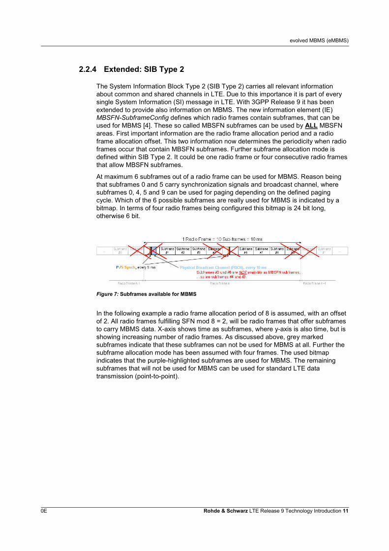
At maximum 6 subframes out of a radio frame can be used for MBMS. Reason beingthat subframes 0 and 5 carry synchronization signals and broadcast channel, wheresubframes 0, 4, 5 and 9 can be used for paging depending on the defined pagingcycle. Which of the 6 possible subframes are really used for MBMS is indicated by abitmap. In terms of four radio frames being configured this bitmap is 24 bit long,otherwise 6 bit.
Figure 7: Subframes available for MBMS
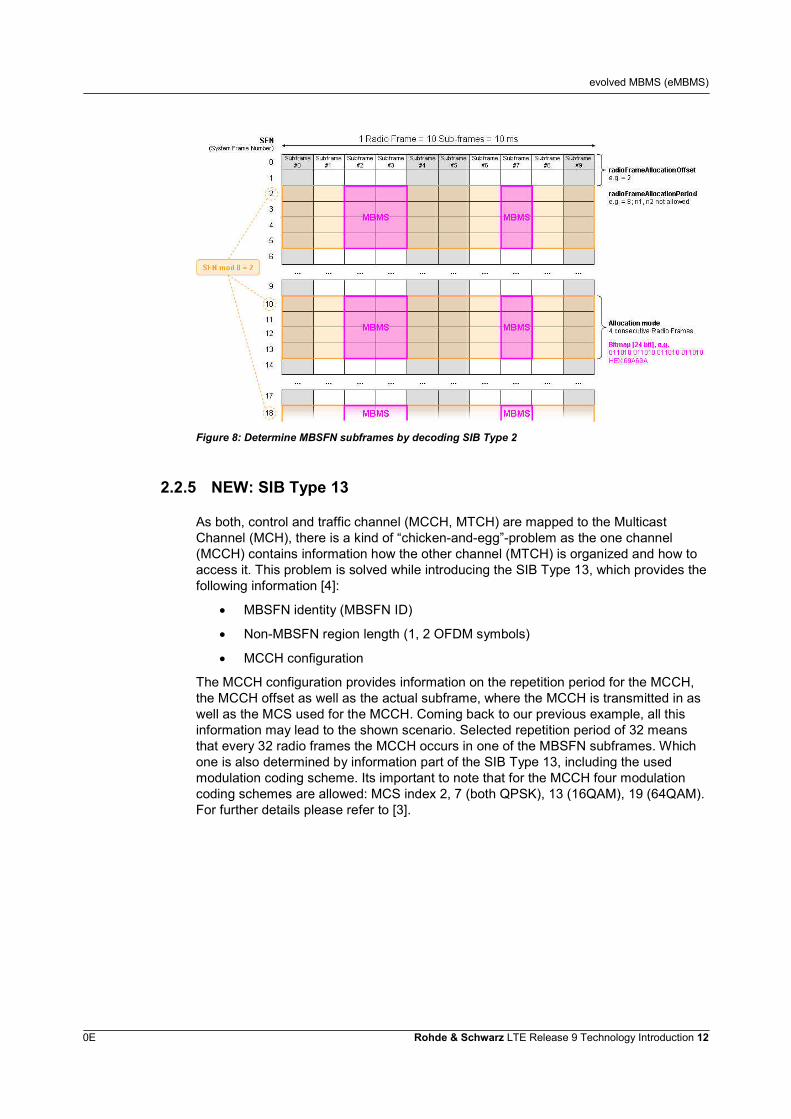
In the following example a radio frame allocation period of 8 is assumed, with an offsetof 2. All radio frames fulfilling SFN mod 8 = 2, will be radio frames that offer subframesto carry MBMS data. X-axis shows time as subframes, where y-axis is also time, but isshowing increasing number of radio frames. As discussed above, grey markedsubframes indicate that these subframes can not be used for MBMS at all. Further thesubframe allocation mode has been assumed with four frames. The used bitmapindicates that the purple-highlighted subframes are used for MBMS. The remainingsubframes that will not be used for MBMS can be used for standard LTE datatransmission (point-to-point).
evolved MBMS (eMBMS)
0E Rohde & Schwarz LTE Release 9 Technology Introduction 12
Figure 8: Determine MBSFN subframes by decoding SIB Type 2
2.2.5 NEW: SIB Type 13
As both, control and traffic channel (MCCH, MTCH) are mapped to the MulticastChannel (MCH), there is a kind of “chicken-and-egg”-problem as the one channel(MCCH) contains information how the other channel (MTCH) is organized and how toaccess it. This problem is solved while introducing the SIB Type 13, which provides thefollowing information [4]:
MBSFN identity (MBSFN ID)
Non-MBSFN region length (1, 2 OFDM symbols)
MCCH configuration
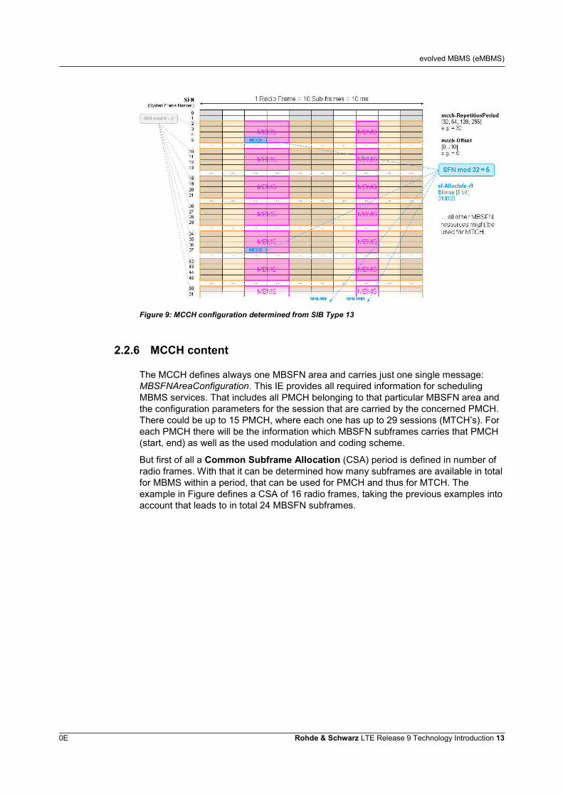
The MCCH configuration provides information on the repetition period for the MCCH,the MCCH offset as well as the actual subframe, where the MCCH is transmitted in aswell as the MCS used for the MCCH. Coming back to our previous example, all thisinformation may lead to the shown scenario. Selected repetition period of 32 meansthat every 32 radio frames the MCCH occurs in one of the MBSFN subframes. Whichone is also determined by information part of the SIB Type 13, including the usedmodulation coding scheme. Its important to note that for the MCCH four modulationcoding schemes are allowed: MCS index 2, 7 (both QPSK), 13 (16QAM), 19 (64QAM).For further details please refer to [3].
evolved MBMS (eMBMS)
0E Rohde & Schwarz LTE Release 9 Technology Introduction 13
Figure 9: MCCH configuration determined from SIB Type 13
2.2.6 MCCH content
The MCCH defines always one MBSFN area and carries just one single message:MBSFNAreaConfiguration. This IE provides all required information for schedulingMBMS services. That includes all PMCH belonging to that particular MBSFN area andthe configuration parameters for the session that are carried by the concerned PMCH.There could be up to 15 PMCH, where each one has up to 29 sessions (MTCH’s). Foreach PMCH there will be the information which MBSFN subframes carries that PMCH(start, end) as well as the used modulation and coding scheme.
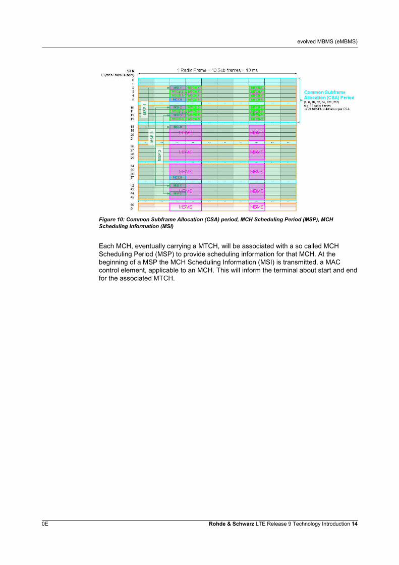
But first of all a Common Subframe Allocation (CSA) period is defined in number ofradio frames. With that it can be determined how many subframes are available in totalfor MBMS within a period, that can be used for PMCH and thus for MTCH. Theexample in Figure defines a CSA of 16 radio frames, taking the previous examples intoaccount that leads to in total 24 MBSFN subframes.
evolved MBMS (eMBMS)
0E Rohde & Schwarz LTE Release 9 Technology Introduction 14
Figure 10: Common Subframe Allocation (CSA) period, MCH Scheduling Period (MSP), MCHScheduling Information (MSI)
Each MCH, eventually carrying a MTCH, will be associated with a so called MCHScheduling Period (MSP) to provide scheduling information for that MCH. At thebeginning of a MSP the MCH Scheduling Information (MSI) is transmitted, a MACcontrol element, applicable to an MCH. This will inform the terminal about start and endfor the associated MTCH.
Positioning methods in LTE
0E Rohde & Schwarz LTE Release 9 Technology Introduction 15
3 Positioning methods in LTE
3.1 Introduction, (Assisted-)Global Navigation SatelliteSystems
Positioning defines the process of determining the positioning and/or velocity of adevice using radio signals.
Location Based Services, short LBS, are a significant element in today’s serviceportfolio offered via a network operators cellular network. It starts with simple thingslike answering the question “Where am I?” which is very often combined withdetermining points of interests, such as closest restaurants, shopping possibilities orfinding a route from one point to another. Further social networks like facebook,Google Plus and others allow that status updates can be linked with the currentposition of the user.
Beside the commercial usage, there are also a safety aspects for positioning. As anexample more than half of all emergency calls in the European Union (EU) are madeusing a mobile device. In almost 60% of all cases, the caller can not provide its currentposition accurately. Therefore the EU has issued a directive in 2003, where networkoperators are required to provide emergency services with whatever information isavailable about the location where the emergency call was made from. In the UnitedStates of Americas this is mandatory since a long time with the FCC’s Enhanced 911mandate making the location of a cell phone available to emergency call dispatchers[10]. With this mandate the FCC has defined accuracy requirements for the differentmethods position estimation can be based on for county and country level, i.e. 67% ofall emergency calls made on the county level need to be in a range of 50 m or less.These are quite high accuracy requirements, that need to be fulfilled and guaranteedno matter what the underlying position estimation technology is or in whichenvironment the position will estimated in. The challenges for an accurate positionestimation comes with the environment, means if the position is to be determined inrural and urban areas, city centre, outdoor or indoor and by mobility of the user. Basedon these two categories the one or other technological approach might provide a betterfit.
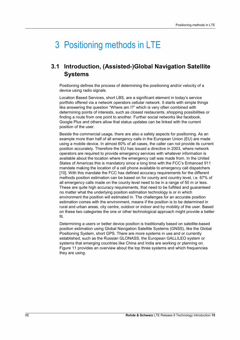
Determining a users or better device position is traditionally based on satellite-basedposition estimation using Global Navigation Satellite Systems (GNSS), like the GlobalPositioning System, short GPS. There are more systems in use and or currentlyestablished, such as the Russian GLONASS, the European GALLILEO system orsystems that emerging countries like China and India are working or planning on.Figure 11 provides an overview about the top three systems and which frequenciesthey are using.
Positioning methods in LTE
0E Rohde & Schwarz LTE Release 9 Technology Introduction 16
Figure 11: Frequencies being used by GPS, GALLILEO and GLONASS
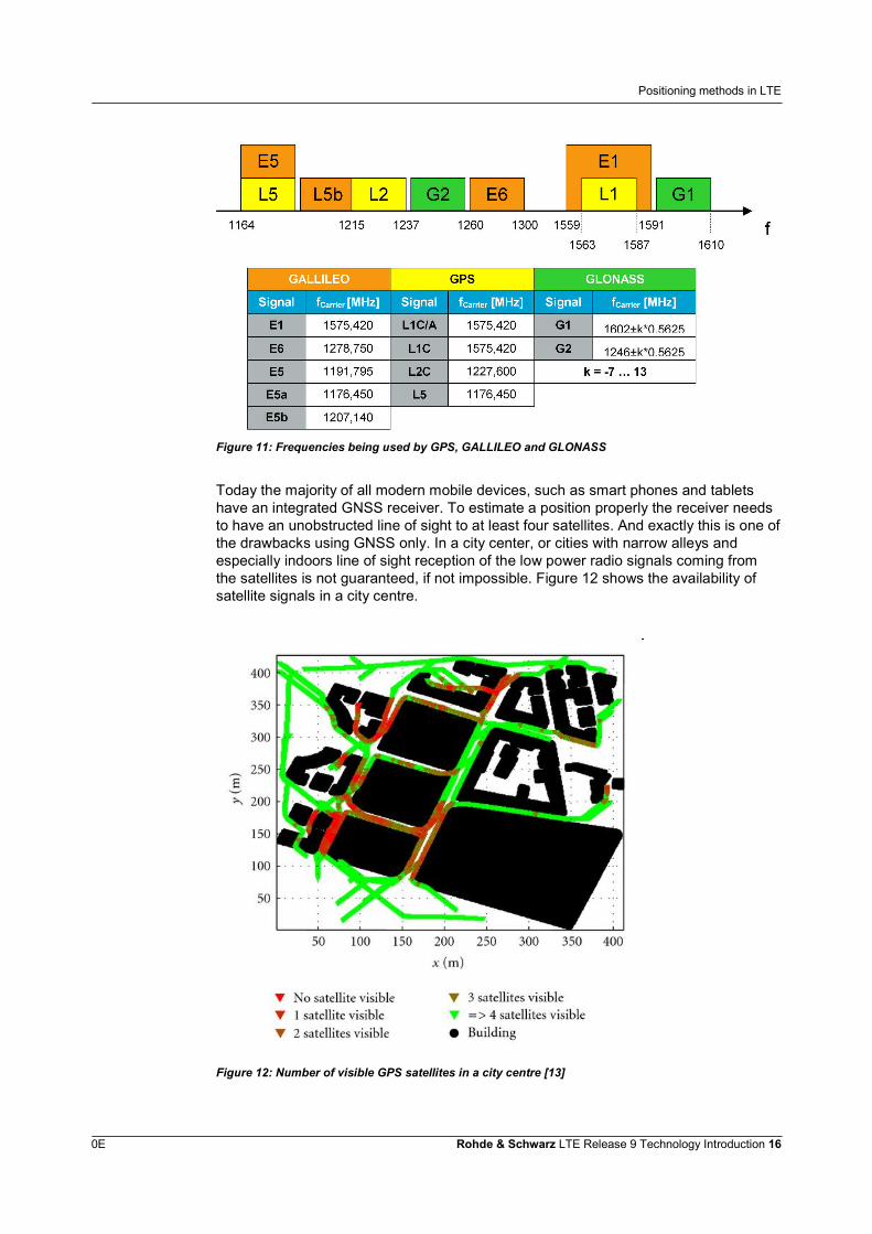
Today the majority of all modern mobile devices, such as smart phones and tabletshave an integrated GNSS receiver. To estimate a position properly the receiver needsto have an unobstructed line of sight to at least four satellites. And exactly this is one ofthe drawbacks using GNSS only. In a city center, or cities with narrow alleys andespecially indoors line of sight reception of the low power radio signals coming fromthe satellites is not guaranteed, if not impossible. Figure 12 shows the availability ofsatellite signals in a city centre.
Figure 12: Number of visible GPS satellites in a city centre [13]
Positioning methods in LTE
0E Rohde & Schwarz LTE Release 9 Technology Introduction 17
To overcome this situation, especially in an environment with poor signal conditions,Assisted-GNSS (A-GNSS) has been developed, where Assisted GPS is the naturalexample. By means of A-GPS a cellular network uses network resources to provideassistance data that helps the device to locate and utilize the available GPS satellitesfaster. A-GNSS reduces start-up and acquisition times, increases sensitivity and allowthe device to reduce power consumption.
As statistics prove that almost 50% of all connections are made from inside, indoorremains a challenging environment. Often there is still an acceptable coverage bymobile radio signals, to determine the A-GPS information for instance, however thisdoes not help if the satellites can not be detected due to no reception of GPS signalsinside a building.
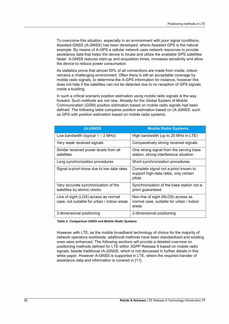
In such a critical scenario position estimation using mobile radio signals is the wayforward. Such methods are not new. Already for the Global System of MobileCommunication (GSM) position estimation based on mobile radio signals had beendefined. The following table compares position estimation based on (A-)GNSS, suchas GPS with position estimation based on mobile radio systems.
(A-)GNSS Mobile Radio Systems
Low bandwidth (typical 1 – 2 MHz) High bandwidth (up to 20 MHz in LTE)
Very weak received signals Comparatively strong received signals
Similar received power levels from allsatellites
One strong signal from the serving basestation, strong interference situation
Long synchronization procedures Short synchronization procedures
Signal a-priori know due to low data rates Complete signal not a-priori known tosupport high-data rates, only certainpilots
Very accurate synchronization of thesatellites by atomic clocks
Synchronization of the base station not a-priori guaranteed
Line of sight (LOS) access as normalcase, not suitable for urban / indoor areas
Non-line of sight (NLOS) access asnormal case, suitable for urban / indoorareas
3-dimensional positioning 2-dimensional positioning
Table 2: Comparison GNSS and Mobile Radio Systems
However with LTE, as the mobile broadband technology of choice for the majority ofnetwork operators worldwide, additional methods have been standardized and existingones were enhanced. The following sections will provide a detailed overview onpositioning methods defined for LTE within 3GPP Release 9 based on mobile radiosignals, beside traditional (A-)GNSS, which is not discussed in further details in thiswhite paper. However A-GNSS is supported in LTE, where the required transfer ofassistance data and information is covered in [11].
Positioning methods in LTE
0E Rohde & Schwarz LTE Release 9 Technology Introduction 18
3.2 General aspects of LTE positioning
Generally an execution of a positioning method, independent if based on satellite ormobile radio signals, consist of three steps:
1. Providing initial assistance and information for position estimation.2. Execution of certain measurements and reporting of measurement results.3. Position estimation based on measurement results.
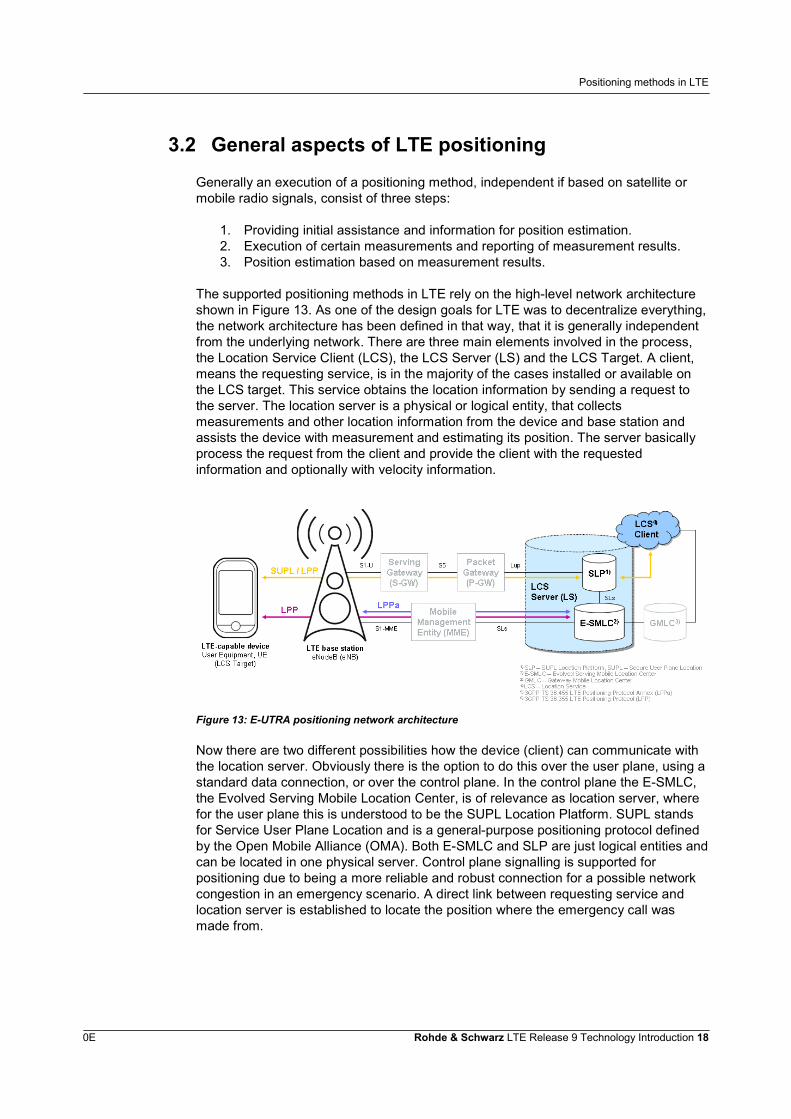
The supported positioning methods in LTE rely on the high-level network architectureshown in Figure 13. As one of the design goals for LTE was to decentralize everything,the network architecture has been defined in that way, that it is generally independentfrom the underlying network. There are three main elements involved in the process,the Location Service Client (LCS), the LCS Server (LS) and the LCS Target. A client,means the requesting service, is in the majority of the cases installed or available onthe LCS target. This service obtains the location information by sending a request tothe server. The location server is a physical or logical entity, that collectsmeasurements and other location information from the device and base station andassists the device with measurement and estimating its position. The server basicallyprocess the request from the client and provide the client with the requestedinformation and optionally with velocity information.
Figure 13: E-UTRA positioning network architecture
Now there are two different possibilities how the device (client) can communicate withthe location server. Obviously there is the option to do this over the user plane, using astandard data connection, or over the control plane. In the control plane the E-SMLC,the Evolved Serving Mobile Location Center, is of relevance as location server, wherefor the user plane this is understood to be the SUPL Location Platform. SUPL standsfor Service User Plane Location and is a general-purpose positioning protocol definedby the Open Mobile Alliance (OMA). Both E-SMLC and SLP are just logical entities andcan be located in one physical server. Control plane signalling is supported forpositioning due to being a more reliable and robust connection for a possible networkcongestion in an emergency scenario. A direct link between requesting service andlocation server is established to locate the position where the emergency call wasmade from.
Positioning methods in LTE
0E Rohde & Schwarz LTE Release 9 Technology Introduction 19
Two protocols are used for the overall information exchange: the LTE PositioningProtocol (LPP) and the LTE Positioning Protocol Annex (LPPa) [11], [12]. The latterone is used for the communication between the Location Server and the eNode B, theLTE base station. The base station is in case of OTDOA in charge for properconfiguration of the radio signals that are used by the terminal for positioningmeasurements, the so called positioning reference signals (PRS)2. It further providesinformation back to the E-SMLC, enables the device to do inter-frequencymeasurements if required and – based on the E-SMLC request – takes measurementitself and sends the results back to the server.
The LPP can be used in both: user plane and control plane. LPP is a point-to-pointprotocol, that allows multiple connections to different devices. The exchanged LPPmessages and information can be divided into 4 categories:
1. UE positioning capability information transfer to the E-SMLC.
2. Positioning assistance data delivery from the E-SMLC to the device.
3. Location information transfer.
4. Session management.
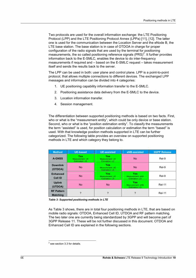
The differentiation between supported positioning methods is based on two facts. First,who or what is the “measurement entity”, which could be only device or base station.Second, who or what is the “position estimation entity”. To classify the measurementsthe term “assisted” is used, for position calculation or estimation the term “based” isused. With that knowledge position methods supported in LTE can be furthercategorized. The following table provides an overview on supported positioningmethods in LTE and which category they belong to.
Method UE-based UE-assisted eNB-assisted 3GPP Release
A-GNSSYes
Measurement: UEEstimation: UE
YesMeasurement: UE
Estimation: LCNo Rel-9
Downlink(OTDOA)
NoYes
Measurement: UEEstimation: LS
No Rel-9
EnhancedCell ID
NoYes
Measurement: UEEstimation: LS
YesMeasurement: eNB
Estimation: LSRel-9
Uplink(UTDOA)
No NoYes
Measurement: eNBEstimation: LS
Rel-11
RF PatternMatching
? ? ? Rel-11
Table 3: Supported positioning methods in LTE
As Table 3 shows, there are in total four positioning methods in LTE, that are based onmobile radio signals: OTDOA, Enhanced Cell ID, UTDOA and RF pattern matching.The two later one are currently being standardized by 3GPP and will become part of3GPP Release 11. These will be not further discussed in this document. OTDOA andEnhanced Cell ID are explained in the following sections.
2 see section 3.3 for details.
Positioning methods in LTE
0E Rohde & Schwarz LTE Release 9 Technology Introduction 20
3.3 OTDOA – Observed Time Difference of Arrival
3.3.1 Reference Signal Time Difference (RSTD) measurement
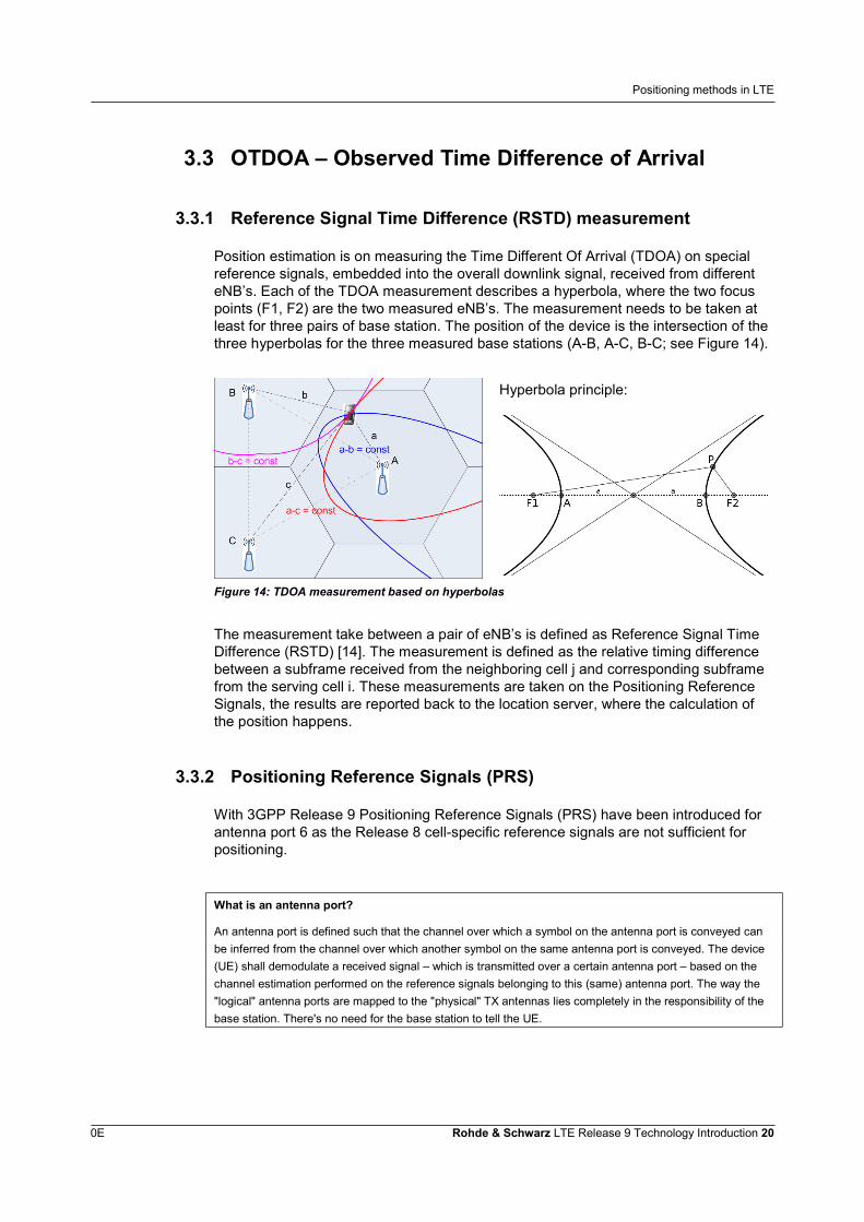
Position estimation is on measuring the Time Different Of Arrival (TDOA) on specialreference signals, embedded into the overall downlink signal, received from differenteNB’s. Each of the TDOA measurement describes a hyperbola, where the two focuspoints (F1, F2) are the two measured eNB’s. The measurement needs to be taken atleast for three pairs of base station. The position of the device is the intersection of thethree hyperbolas for the three measured base stations (A-B, A-C, B-C; see Figure 14).
Hyperbola principle:
Figure 14: TDOA measurement based on hyperbolas
The measurement take between a pair of eNB’s is defined as Reference Signal TimeDifference (RSTD) [14]. The measurement is defined as the relative timing differencebetween a subframe received from the neighboring cell j and corresponding subframefrom the serving cell i. These measurements are taken on the Positioning ReferenceSignals, the results are reported back to the location server, where the calculation ofthe position happens.
3.3.2 Positioning Reference Signals (PRS)
With 3GPP Release 9 Positioning Reference Signals (PRS) have been introduced forantenna port 6 as the Release 8 cell-specific reference signals are not sufficient forpositioning.
What is an antenna port?
An antenna port is defined such that the channel over which a symbol on the antenna port is conveyed canbe inferred from the channel over which another symbol on the same antenna port is conveyed. The device(UE) shall demodulate a received signal – which is transmitted over a certain antenna port – based on thechannel estimation performed on the reference signals belonging to this (same) antenna port. The way the"logical" antenna ports are mapped to the "physical" TX antennas lies completely in the responsibility of thebase station. There's no need for the base station to tell the UE.
Positioning methods in LTE
0E Rohde & Schwarz LTE Release 9 Technology Introduction 21
The simple reason is that the required high probability of detection could not beguaranteed. A neighbor cell with its synchronization signals (Primary-/ SecondarySynchronization Signals) and reference signals is seen as detectable, when the Signal-to-Interference-and-Noise Ratio (SINR) is at least -6 dB. Simulations duringstandardization have shown, that this can be only guaranteed for 70% of all cases forthe 3rd best-detected cell, means 2nd best neighboring cell. This is not enough and hasbeen assumed an interference-free environment, which can not be ensured in a real-world scenario. However, PRS have still some similarities with cell-specific referencesignals as defined in 3GPP Release 8. It is a pseudo-random QPSK sequence that isbeing mapped in diagonal patterns with shifts in frequency and time to avoid collisionwith cell-specific reference signals and an overlap with the control channels (PDCCH).
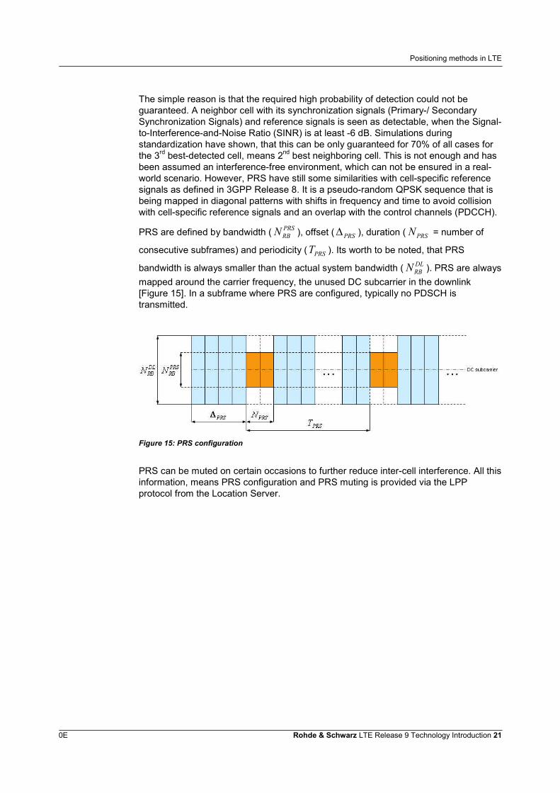
PRS are defined by bandwidth ( PRSRBN ), offset ( PRS ), duration ( PRSN = number of
consecutive subframes) and periodicity ( PRST ). Its worth to be noted, that PRS
bandwidth is always smaller than the actual system bandwidth ( DLRBN ). PRS are always
mapped around the carrier frequency, the unused DC subcarrier in the downlink[Figure 15]. In a subframe where PRS are configured, typically no PDSCH istransmitted.
Figure 15: PRS configuration
PRS can be muted on certain occasions to further reduce inter-cell interference. All thisinformation, means PRS configuration and PRS muting is provided via the LPPprotocol from the Location Server.
Positioning methods in LTE
0E Rohde & Schwarz LTE Release 9 Technology Introduction 22
3.4 Enhanced Cell ID
OTDOA is the method of choice for urban and indoor areas, where (A-)GNSS will notprovide its best or no performance at all. Another method for position estimation in LTEis Enhanced Cell ID (E-CID), based on Cell of Origin (COO). With COO the position ofthe device is estimated using the knowledge of the geographical coordinates of itsserving base station, in terms of LTE the eNB. The knowledge of the serving cell canbe obtained executing a tracking area update or by paging. The position accuracy is inthat case linked to the cell size, as the location server is only aware that the device isserved by this base station. This method would of course not fulfill the accuracyrequirements defined by the FCC. Therefore Enhanced Cell ID has been defined withLTE, mainly for devices where no GNSS receiver has been integrated. On top of usingthe knowledge of the geographical coordinates of the serving base station, the positionof the device is estimated more accurately by performing measurements on radiosignals. E-CID can be executed in three ways, using different types of measurements:
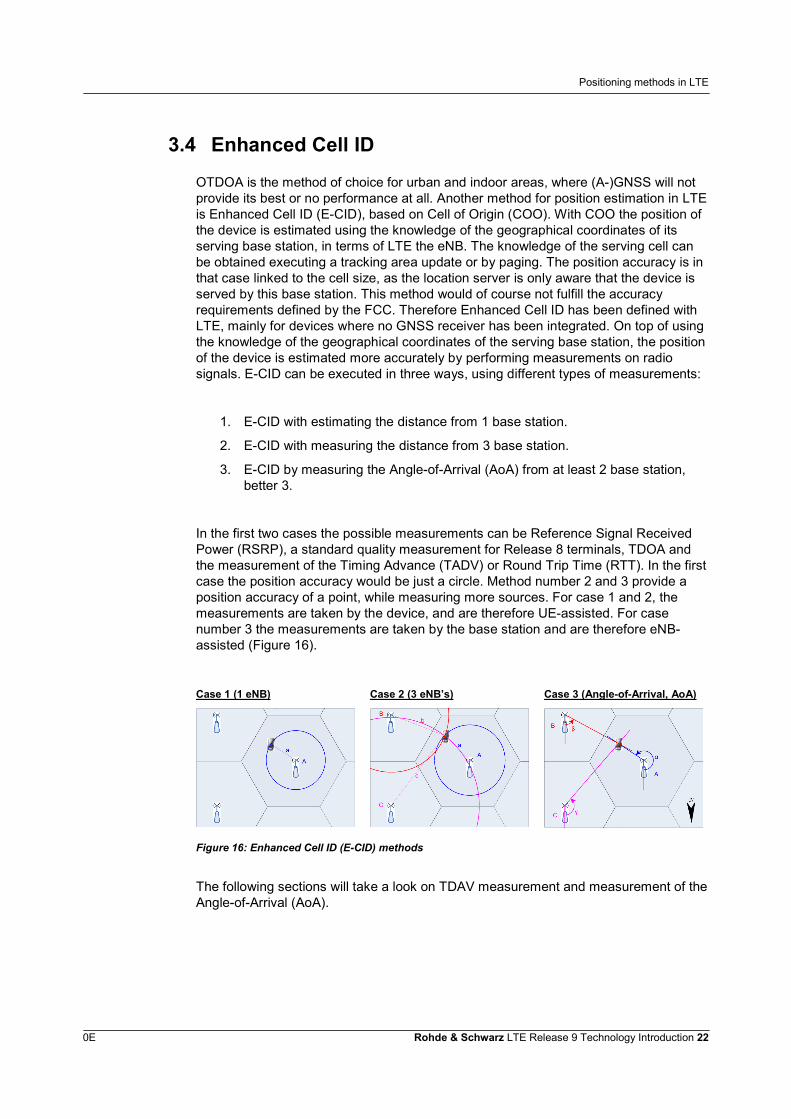
1. E-CID with estimating the distance from 1 base station.
2. E-CID with measuring the distance from 3 base station.
3. E-CID by measuring the Angle-of-Arrival (AoA) from at least 2 base station,better 3.
In the first two cases the possible measurements can be Reference Signal ReceivedPower (RSRP), a standard quality measurement for Release 8 terminals, TDOA andthe measurement of the Timing Advance (TADV) or Round Trip Time (RTT). In the firstcase the position accuracy would be just a circle. Method number 2 and 3 provide aposition accuracy of a point, while measuring more sources. For case 1 and 2, themeasurements are taken by the device, and are therefore UE-assisted. For casenumber 3 the measurements are taken by the base station and are therefore eNB-assisted (Figure 16).
Case 1 (1 eNB) Case 2 (3 eNB’s) Case 3 (Angle-of-Arrival, AoA)
Figure 16: Enhanced Cell ID (E-CID) methods
The following sections will take a look on TDAV measurement and measurement of theAngle-of-Arrival (AoA).
Positioning methods in LTE
0E Rohde & Schwarz LTE Release 9 Technology Introduction 23
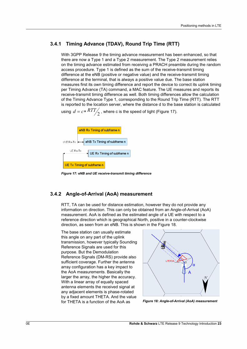
3.4.1 Timing Advance (TDAV), Round Trip Time (RTT)
With 3GPP Release 9 the timing advance measurement has been enhanced, so thatthere are now a Type 1 and a Type 2 measurement. The Type 2 measurement relieson the timing advance estimated from receiving a PRACH preamble during the randomaccess procedure. Type 1 is defined as the sum of the receive-transmit timingdifference at the eNB (positive or negative value) and the receive-transmit timingdifference at the terminal, that is always a positive value due. The base stationmeasures first its own timing difference and report the device to correct its uplink timingper Timing Advance (TA) command, a MAC feature. The UE measures and reports itsreceive-transmit timing difference as well. Both timing differences allow the calculationof the Timing Advance Type 1, corresponding to the Round Trip Time (RTT). The RTTis reported to the location server, where the distance d to the base station is calculated
using 2RTTcd , where c is the speed of light (Figure 17).
Figure 17: eNB and UE receive-transmit timing difference
3.4.2 Angle-of-Arrival (AoA) measurement
RTT, TA can be used for distance estimation, however they do not provide anyinformation on direction. This can only be obtained from an Angle-of-Arrival (AoA)measurement. AoA is defined as the estimated angle of a UE with respect to areference direction which is geographical North, positive in a counter-clockwisedirection, as seen from an eNB. This is shown in the Figure 18.
The base station can usually estimatethis angle on any part of the uplinktransmission, however typically SoundingReference Signals are used for thispurpose. But the DemodulationReference Signals (DM-RS) provide alsosufficient coverage. Further the antennaarray configuration has a key impact tothe AoA measurements. Basically thelarger the array, the higher the accuracy.With a linear array of equally spacedantenna elements the received signal atany adjacent elements is phase-rotatedby a fixed amount THETA. And the valuefor THETA is a function of the AoA as Figure 18: Angle-of-Arrival (AoA) measurement

Positioning methods in LTE
0E Rohde & Schwarz LTE Release 9 Technology Introduction 24
well as the antenna element spacing andcarrier frequency.
LTE MIMO: dual-layer beamforming
0E Rohde & Schwarz LTE Release 9 Technology Introduction 25
4 LTE MIMO: dual-layer beamformingThe LTE system targets for high data rate, high system capacity and large coverage toprovide excellent user experience. Beamforming (BF) is one of the technologieshelping to reach this goal, specifically by improving the cell edge performance. LTE asspecified in 3GPP Release 8 already supports single-layer beamforming based onuser-specific Reference Symbols (also referred to as Dedicated RS or DRS or DMRS). Single-layer beamfroming uses only one codeword, i.e. one transport block. Ingeneral the solution allows to direct the beam towards a specific UE through positionestimation at the eNodeB (direction of arrival). The eNodeB generates a beam usingthe array of antenna elements, and then applies the same precoding to both the datapayload and the UE-specific reference signal with this beam. It is important to note thatthe UE-specific reference signal is transmitted in a way such that its time-frequencylocation does not overlap with the cell-specific reference signal. As the scheme is notinvolving any UE feedback mechanism, it is specifically suited for LTE in TDD mode ofoperation, leveraging the reciprocity of the propagation channel in DL and UL direction.
To further evolve the DRS based beamforming technology, multi-layer beamforminghas been included in LTE Release 9. Extending the Release 8 single-layerbeamforming operation to a multi-layer version provides a good opportunity for aUMTS LCR-TDD operator to migrate its network to a TD-LTE network while continuingto use DRS based beamforming technology and leveraging the installed base ofpotentially existing antenna arrays.
4.1 Physical layer details:
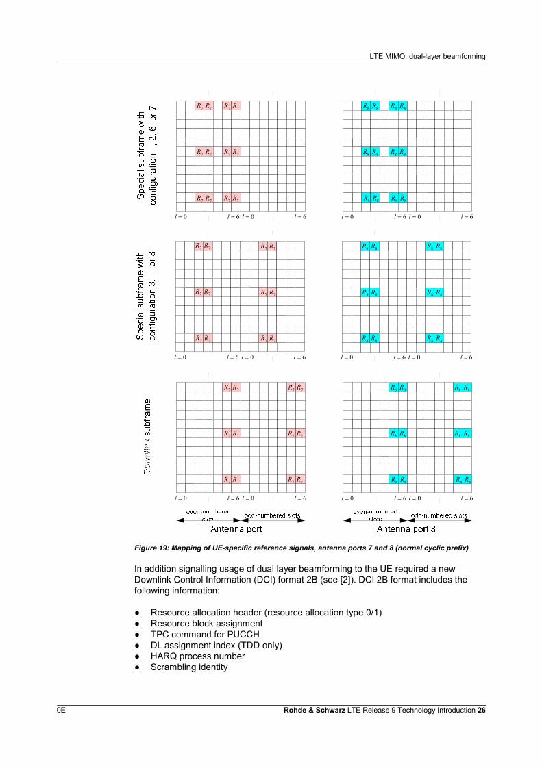
As mentioned above beamforming requires UE specific reference symbols. With duallayer beamforming using two codewords (transport blocks) and two antennas, theexisting UE specific reference symbol scheme in [1], section 6.10.3 had to beextended. The position of the UE specific reference symbols on antenna port 7 and 8are illustrated in Figure 19.
LTE MIMO: dual-layer beamforming
0E Rohde & Schwarz LTE Release 9 Technology Introduction 26
0l 6l 0l 6l
7R7R7R7R
7R7R7R7R
7R7R7R7R
0l 6l 0l 6l
8R 8R8R 8R
8R 8R8R 8R
8R 8R8R 8R
0l 6l 0l 6l
7R7R
7R7R7R7R
7R7R7R7R
0l 6l 0l 6l
8R 8R8R 8R
8R 8R8R 8R
8R 8R8R 8R
7R7R
0l 6l 0l 6l
7R7R 7R7R
7R7R 7R7R
7R7R 7R7R
0l 6l 0l 6l
8R 8R 8R 8R
8R 8R 8R 8R
8R 8R 8R 8R
Figure 19: Mapping of UE-specific reference signals, antenna ports 7 and 8 (normal cyclic prefix)
In addition signalling usage of dual layer beamforming to the UE required a newDownlink Control Information (DCI) format 2B (see [2]). DCI 2B format includes thefollowing information:
● Resource allocation header (resource allocation type 0/1)● Resource block assignment● TPC command for PUCCH● DL assignment index (TDD only)● HARQ process number● Scrambling identity
LTE MIMO: dual-layer beamforming
0E Rohde & Schwarz LTE Release 9 Technology Introduction 27
● And for each transport block Modulation and coding scheme New data indicator Redundancy version
If both transport blocks are enabled, the number of layers equals two. Transport block1 is mapped to codeword 0 and transport block 2 is mapped to codeword 1. Antennaports 7 and 8 are used for spatial multiplexing. In case one of the transport blocks isdisabled, the number of layers equals one.
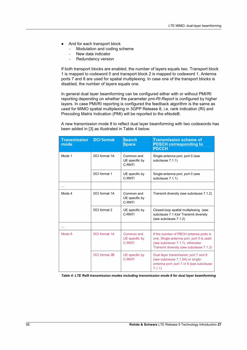
In general dual layer beamforming can be configured either with or without PMI/RIreporting depending on whether the parameter pmi-RI-Report is configured by higherlayers. In case PMI/RI reporting is configured the feedback algorithm is the same asused for MIMO spatial multiplexing in 3GPP Release 8, i.e. rank indication (RI) andPrecoding Matrix Indication (PMI) will be reported to the eNodeB.
A new transmission mode 8 to reflect dual layer beamforming with two codewords hasbeen added in [3] as illustrated in Table 4 below.
Transmissionmode
DCI format SearchSpace
Transmission scheme ofPDSCH corresponding toPDCCH
DCI format 1A Common andUE specific byC-RNTI
Single-antenna port, port 0 (seesubclause 7.1.1)
Mode 1
DCI format 1 UE specific byC-RNTI
Single-antenna port, port 0 (seesubclause 7.1.1)
…
DCI format 1A Common andUE specific byC-RNTI
Transmit diversity (see subclause 7.1.2)Mode 4
DCI format 2 UE specific byC-RNTI
Closed-loop spatial multiplexing (seesubclause 7.1.4)or Transmit diversity(see subclause 7.1.2)
…
DCI format 1A Common andUE specific byC-RNTI
If the number of PBCH antenna ports isone, Single-antenna port, port 0 is used(see subclause 7.1.1), otherwiseTransmit diversity (see subclause 7.1.2)
Mode 8
DCI format 2B UE specific byC-RNTI
Dual layer transmission; port 7 and 8(see subclause 7.1.5A) or single-antenna port; port 7 or 8 (see subclause7.1.1)
Table 4: LTE Rel9 transmission modes including transmission mode 8 for dual layer beamforming
Public Warning System (PWS)
0E Rohde & Schwarz LTE Release 9 Technology Introduction 28
5 Public Warning System (PWS)There has been an interest to ensure that the public has the capability to receive timelyand accurate alerts, warnings and critical information regarding disasters and otheremergencies irrespective of what communications technologies they use. As has beenlearned from disasters such as earthquakes, tsunamis, hurricanes and wild fires; sucha capability is essential to enable the public to take appropriate action to protect theirfamilies and themselves from serious injury, or loss of life or property. In some cases,warnings are already made via commercial or government-owned radio or televisionbroadcast facilities. With the significant deployment of cellular mobile networks andtheir ability to provide broadcast services, warnings can also be transmitted to largenumbers of subscribers via their user device. Support over cellular mobile networks isto supplement other notification methods. The interest to enhance the reliability,resiliency, and security of Warning Notifications to the public has been the driving forcefor the PWS feature.
The high level requirements for the feature are summarized below:● PWS shall be able to broadcast Warning Notifications to multiple users
simultaneously with no acknowledgement required.● PWS shall be able to support concurrent broadcast of multiple Warning
Notifications.● Warning Notifications shall be broadcast to a Notification Area which is based on
the geographical information as specified by the Warning Notification Provider.● PWS capable UEs (PWS-UE) in idle mode shall be capable of receiving
broadcasted Warning Notifications.● PWS shall only be required to broadcast Warning Notifications in languages as
prescribed by regulatory requirements.● Warning Notifications are processed by PWS on a first in, first out basis, subject to
regulatory requirements.● Reception and presentation of Warning Notifications to the user shall not pre-empt
an active voice or data session.● Warning Notifications shall be limited to those emergencies where life or property
is at imminent risk, and some responsive action should be taken.
5.1 Commercial Mobile Alert System (CMAS)
An initial support for alerting end users was already included in LTE Release 8 knownas the ETWS feature, i.e. Earthquake and Tsunami Warning Systems. PWS extendsthe possibilities from ETWS by providing:
● support for multiple parallel warning notifications● support for replacing and cancelling a warning notification● support for repeating the warning notification with a repetition period as short as
2 seconds and as long as 24 hours● support for more generic "PWS" indication in the paging indication
Public Warning System (PWS)
0E Rohde & Schwarz LTE Release 9 Technology Introduction 29
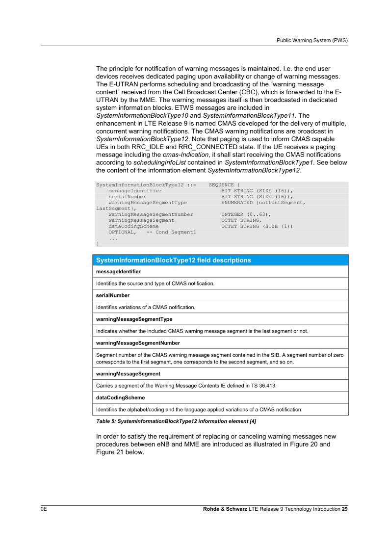
The principle for notification of warning messages is maintained. I.e. the end userdevices receives dedicated paging upon availability or change of warning messages.The E-UTRAN performs scheduling and broadcasting of the “warning messagecontent” received from the Cell Broadcast Center (CBC), which is forwarded to the E-UTRAN by the MME. The warning messages itself is then broadcasted in dedicatedsystem information blocks. ETWS messages are included inSystemInformationBlockType10 and SystemInformationBlockType11. Theenhancement in LTE Release 9 is named CMAS developed for the delivery of multiple,concurrent warning notifications. The CMAS warning notifications are broadcast inSystemInformationBlockType12. Note that paging is used to inform CMAS capableUEs in both RRC_IDLE and RRC_CONNECTED state. If the UE receives a pagingmessage including the cmas-Indication, it shall start receiving the CMAS notificationsaccording to schedulingInfoList contained in SystemInformationBlockType1. See belowthe content of the information element SystemInformationBlockType12.
SystemInformationBlockType12 ::= SEQUENCE {messageIdentifier BIT STRING (SIZE (16)),serialNumber BIT STRING (SIZE (16)),warningMessageSegmentType ENUMERATED {notLastSegment,
lastSegment},warningMessageSegmentNumber INTEGER (0..63),warningMessageSegment OCTET STRING,dataCodingScheme OCTET STRING (SIZE (1))OPTIONAL, -- Cond Segment1...
}
SystemInformationBlockType12 field descriptionsmessageIdentifier
Identifies the source and type of CMAS notification.
serialNumber
Identifies variations of a CMAS notification.
warningMessageSegmentType
Indicates whether the included CMAS warning message segment is the last segment or not.
warningMessageSegmentNumber
Segment number of the CMAS warning message segment contained in the SIB. A segment number of zerocorresponds to the first segment, one corresponds to the second segment, and so on.
warningMessageSegment
Carries a segment of the Warning Message Contents IE defined in TS 36.413.
dataCodingScheme
Identifies the alphabet/coding and the language applied variations of a CMAS notification.
Table 5: SystemInformationBlockType12 information element [4]
In order to satisfy the requirement of replacing or canceling warning messages newprocedures between eNB and MME are introduced as illustrated in Figure 20 andFigure 21 below.
Public Warning System (PWS)
0E Rohde & Schwarz LTE Release 9 Technology Introduction 30
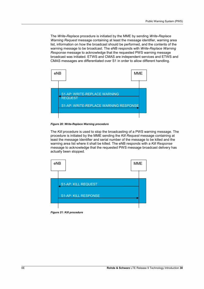
The Write-Replace procedure is initiated by the MME by sending Write-ReplaceWarning Request message containing at least the message identifier, warning arealist, information on how the broadcast should be performed, and the contents of thewarning message to be broadcast. The eNB responds with Write-Replace WarningResponse message to acknowledge that the requested PWS warning messagebroadcast was initiated. ETWS and CMAS are independent services and ETWS andCMAS messages are differentiated over S1 in order to allow different handling.
S1-AP: WRITE-REPLACE WARNINGREQUEST
MMEeNB
S1-AP: WRITE-REPLACE WARNING RESPONSE
Figure 20: Write-Replace Warning procedure
The Kill procedure is used to stop the broadcasting of a PWS warning message. Theprocedure is initiated by the MME sending the Kill Request message containing atleast the message Identifier and serial number of the message to be killed and thewarning area list where it shall be killed. The eNB responds with a Kill Responsemessage to acknowledge that the requested PWS message broadcast delivery hasactually been stopped.
S1-AP: KILL REQUEST
MMEeNB
S1-AP: KILL RESPONSE
Figure 21: Kill procedure
RF requirements for multi-carrier and multi-RAT base stations
0E Rohde & Schwarz LTE Release 9 Technology Introduction 31
6 RF requirements for multi-carrier andmulti-RAT base stations
Traditionally requirements for base stations have been specified on a per technologybasis. I.e. base stations were designed to transmit either radio technology, for instanceGSM or UMTS. In the meantime base stations architectures have become flexible insupporting multiple radio access technologies (RATs) as well as multiple carrierfrequencies. 3GPP standardisation did respond to this technology development within3GPP Release 9 by creating a dedicated specification for multi-carrier and multi-RATbase stations using the expression Multi Standard Radio (MSR) base stations. Therequirements for MSR are in most parts specified in [5], while many requirements arealso specified through normative references to the respective single-RATspecifications. The specification cover the radio access technologies GSM,UMTS/HSPA and LTE. There are three types of requirements:
● Generic MSR requirement: A common generic requirement is specified in [5] thatapplies for all RATs supported by the base station. In some cases, there areadditional requirement(s) that apply only in some specific Band Category. In thiscase there are no references to the single-RAT specifications.
● Generic MSR requirement, with additional single-RAT requirements: Acommon generic requirement is specified in [5]. In addition some single RATrequirement(s) apply, included by normative reference(s) to the single-RATspecification(s).
● Single-RAT only requirements: In this case, no common generic requirement isdefined. The existing single-RAT requirement applies for each RAT, included bynormative reference(s) to the single-RAT specification(s).
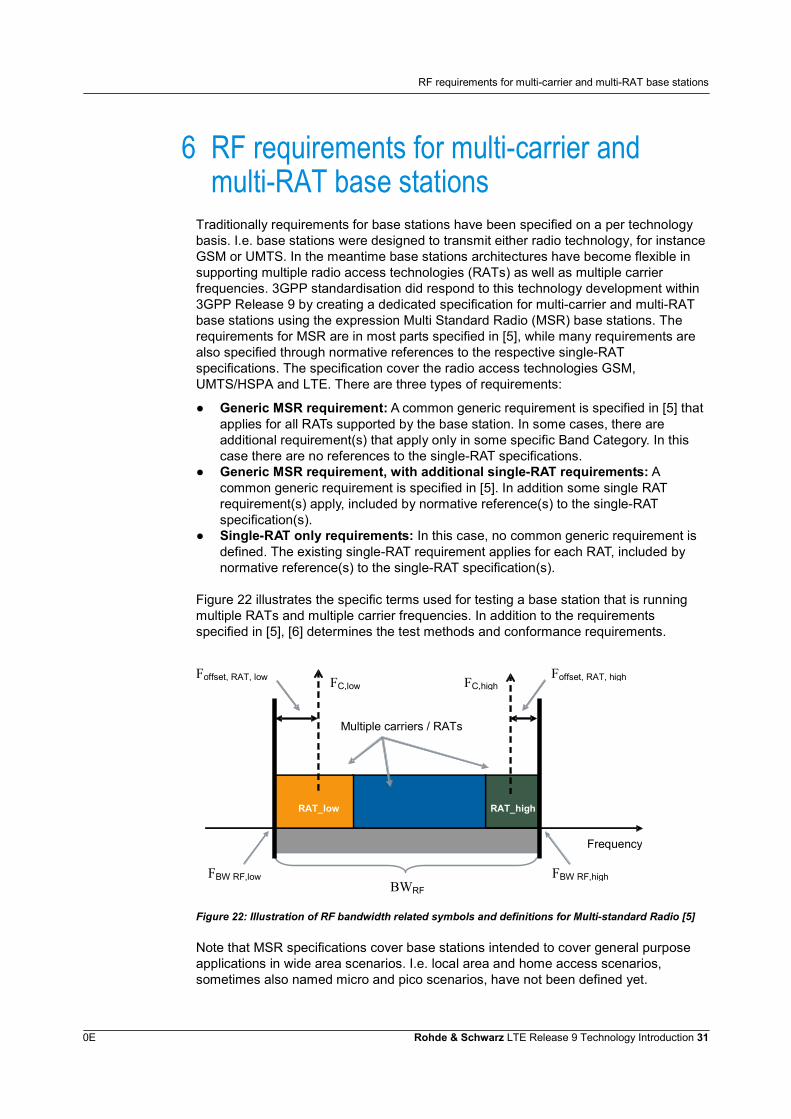
Figure 22 illustrates the specific terms used for testing a base station that is runningmultiple RATs and multiple carrier frequencies. In addition to the requirementsspecified in [5], [6] determines the test methods and conformance requirements.
Frequency
Multiple carriers / RATs
RAT_low RAT_high
BWRF
FBW RF,highFBW RF,low
Foffset, RAT, highFoffset, RAT, low FC,highFC,low
Figure 22: Illustration of RF bandwidth related symbols and definitions for Multi-standard Radio [5]
Note that MSR specifications cover base stations intended to cover general purposeapplications in wide area scenarios. I.e. local area and home access scenarios,sometimes also named micro and pico scenarios, have not been defined yet.
RF requirements for multi-carrier and multi-RAT base stations
0E Rohde & Schwarz LTE Release 9 Technology Introduction 32
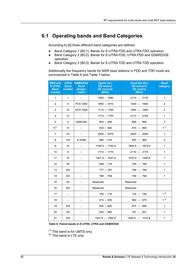
6.1 Operating bands and Band Categories
According to [5] three different band categories are defined:
● Band Category 1 (BC1): Bands for E-UTRA FDD and UTRA FDD operation● Band Category 2 (BC2): Bands for E-UTRA FDD, UTRA FDD and GSM/EDGE
operation● Band Category 3 (BC3): Bands for E-UTRA TDD and UTRA TDD operation
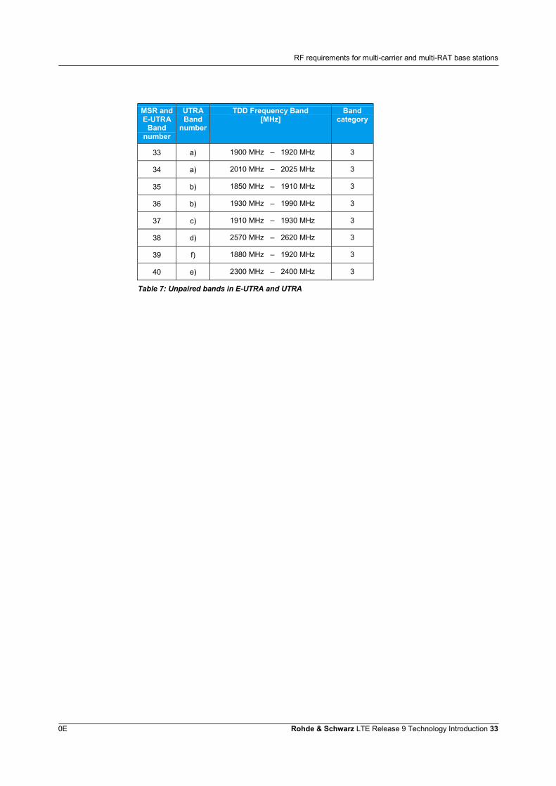
Additionally the frequency bands for MSR base stations in FDD and TDD mode aresummarized in Table 6 and Table 7 below.
MSR andE-UTRA
Bandnumber
UTRABand
number
GSM/EDGEBand
design-nation
Uplink (UL)BS receiveUE transmit
[MHz]
Downlink (DL)BS transmitUE receive
[MHz]
Bandcategory
1 I - 1920 – 1980 2110 – 2170 1
2 II PCS 1900 1850 – 1910 1930 – 1990 2
3 III DCS 1800 1710 – 1785 1805 – 1880 2
4 IV - 1710 – 1755 2110 – 2155 1
5 V GSM 850 824 – 849 869 – 894 2
6(1) VI - 830 – 840 875 – 885 1 (1)
7 VII - 2500 – 2570 2620 – 2690 1
8 VIII E-GSM 880 – 915 925 – 960 2
9 IX - 1749.9 – 1784.9 1844.9 – 1879.9 1
10 X - 1710 – 1770 2110 – 2170 1
11 XI - 1427.9 – 1447.9 1475.9 – 1495.9 1
12 XII - 699 – 716 729 – 746 1
13 XIII - 777 – 787 746 – 756 1
14 XIV - 788 – 798 758 – 768 1
15 XV - Reserved Reserved
16 XVI - Reserved Reserved
17 - - 704 – 716 734 – 746 1 (2)
18 - - 815 – 830 860 – 875 1 (2)
19 XIX - 830 – 845 875 – 890 1
20 XX - 832 – 862 791 – 821 1
21 XXI - 1447.9 – 1462.9 1495.9 – 1510.9 1
Table 6: Paired bands in E-UTRA, UTRA and GSM/EDGE
(1) This band is for UMTS only(2) This band is LTE only
RF requirements for multi-carrier and multi-RAT base stations
0E Rohde & Schwarz LTE Release 9 Technology Introduction 33
MSR andE-UTRA
Bandnumber
UTRABand
number
TDD Frequency Band[MHz]
Bandcategory
33 a) 1900 MHz – 1920 MHz 3
34 a) 2010 MHz – 2025 MHz 3
35 b) 1850 MHz – 1910 MHz 3
36 b) 1930 MHz – 1990 MHz 3
37 c) 1910 MHz – 1930 MHz 3
38 d) 2570 MHz – 2620 MHz 3
39 f) 1880 MHz – 1920 MHz 3
40 e) 2300 MHz – 2400 MHz 3
Table 7: Unpaired bands in E-UTRA and UTRA
Home eNodeB specification (femto-cell)
0E Rohde & Schwarz LTE Release 9 Technology Introduction 34
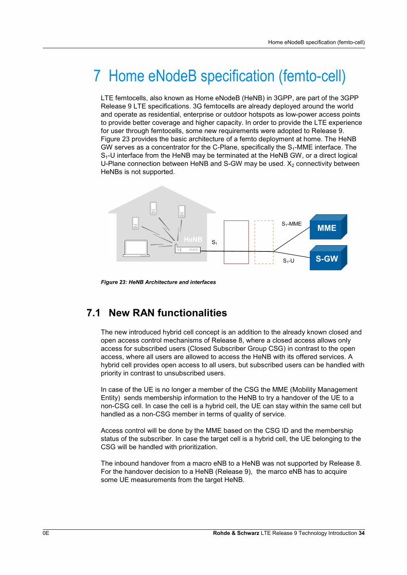
7 Home eNodeB specification (femto-cell)LTE femtocells, also known as Home eNodeB (HeNB) in 3GPP, are part of the 3GPPRelease 9 LTE specifications. 3G femtocells are already deployed around the worldand operate as residential, enterprise or outdoor hotspots as low-power access pointsto provide better coverage and higher capacity. In order to provide the LTE experiencefor user through femtocells, some new requirements were adopted to Release 9.Figure 23 provides the basic architecture of a femto deployment at home. The HeNBGW serves as a concentrator for the C-Plane, specifically the S1-MME interface. TheS1-U interface from the HeNB may be terminated at the HeNB GW, or a direct logicalU-Plane connection between HeNB and S-GW may be used. X2 connectivity betweenHeNBs is not supported.
Figure 23: HeNB Architecture and interfaces
7.1 New RAN functionalities
The new introduced hybrid cell concept is an addition to the already known closed andopen access control mechanisms of Release 8, where a closed access allows onlyaccess for subscribed users (Closed Subscriber Group CSG) in contrast to the openaccess, where all users are allowed to access the HeNB with its offered services. Ahybrid cell provides open access to all users, but subscribed users can be handled withpriority in contrast to unsubscribed users.
In case of the UE is no longer a member of the CSG the MME (Mobility ManagementEntity) sends membership information to the HeNB to try a handover of the UE to anon-CSG cell. In case the cell is a hybrid cell, the UE can stay within the same cell buthandled as a non-CSG member in terms of quality of service.
Access control will be done by the MME based on the CSG ID and the membershipstatus of the subscriber. In case the target cell is a hybrid cell, the UE belonging to theCSG will be handled with prioritization.
The inbound handover from a macro eNB to a HeNB was not supported by Release 8.For the handover decision to a HeNB (Release 9), the marco eNB has to acquiresome UE measurements from the target HeNB.
MMESecurityGW
HeNBGW
S-GW
S1
S1-MME
S1-U
HeNB
Home eNodeB specification (femto-cell)
0E Rohde & Schwarz LTE Release 9 Technology Introduction 35
For efficiency reasons a newly defined proximity report can be configured within theRRC reconfiguration message. With this report the UE is able to send in the uplink a“proximity indication” to the source eNB. In order to reduce network load when manyUE’s send their proximity indicator information, a so-called prohibit proximity timer wasintroduced.The UE is able to identify that it is nearby a HeNB, and can inform the networkcomponents to prepare the necessary actions for a handover to the HeNB.
CSG related parameters stored on the SIM card of the UE were already defined inRelease 8. Release 9 introduces some additional parameters controllable by theoperator. The entries on the USIM are: PLMN identifier, CSG Identifier, Home eNBname and CSG type.
The number of deployed HeNB’s might be very high and the location is not alwaysaccessible by operators for onsite maintenance, especially when the HeNB is installedin private homes. Therefore the HeNB will be managed via the HeNB managementsystem (HeMS). The HeMS can reboot the HeNB, start or stop transmissions oncertain frequencies or allow downloads of software. Fault management and securitymanagement are further tasks of the HeMS.
The unpredictable deployment of HeNB and the potential high number of HeNB’s in acertain area were already discussed in a 3GPP Release 8 technical report (TR25.820). In Release 9 this leads to specific RF requirements for HeNB’s. One of thebiggest challenges is interference handling from/to macro cells and other HeNB’s. Topay attention to the interference reduction techniques in uplink and downlink 3GPPreleased two technical reports on LTE FDD [7] and LTE TDD [8].
Home BS are characterised by requirements derived from Femto Cell szenarios.In order to limit interferences from HeNB’s to macro eNB’s the transmitter output powerof the HeNB was limited. According to [9] the Home BS maximum output power isdefined to +20 dBm for one transmit antenna port, +17dBm for two transmit antennaports and +14dBm for four transmit antenna ports respectively. To minimize theinterference level the Home BS has to adjust the TX output power on adjacentchannels licensed to other operators in the same area while optimizing coverage.
In order to reduce the unwanted interferences, one has to identify the interferencesbefore taking any actions. The HeNB could use it’s own receiver to monitor the uplinkinterferences and measure the received interference power. On this way a nearby UEtransmitting to a macro eNB could be identified. On the other hand, informationtransmitted from a macro eNB itself or an adjacent HeNB can carry useful informationfor the HeNB itself. This type of measurements requires an additional downlinkreceiver to listen to the neighbour base station. This mode is called the networklistening mode or sniffer mode. In addition [9] defines different RF requirements forHeNB compared to other types of base stations, i.e. local area or wide area BS. Theseare mainly lower maximum output power, lower dynamic range, larger unwanted andspurious emission levels, lower intermodulation requirements or more relaxedfrequency error and sensitivity levels. Accordingly new conformance test cases havebeen added in [15].
Self Organizing Networks
0E Rohde & Schwarz LTE Release 9 Technology Introduction 36
8 Self Organizing NetworksThe complexity of a network is increasing for every new release, due to multi-technology environments, tight spectrum usage, advanced radio interface features andparameterization. So, setting the parameters by hand and optimizing them becomes amore and more time consuming task, resulting in enhanced costs for networkoperation.In addition, manual parameter setting is a rather static way to control the network. Theoptimal network settings are often time dependent, reflecting the changes of userbehavior and location. Therefore, settings should be changed in a fast way and asflexible as possible. The only way to cope with these requirements is to do thesesettings autonomously.Whereas in these scenarios the autonomous configuration is a highly desirable feature,it is a must for the new emerging so called Heterogeneous Networks. Here, macro,micro, pico and femto cells are all transmitting and receiving in the same frequencybands, leveraging each other in coverage and capacity. By construction thesenetworks are very complex, and for the case of femto cells the parameters are even, atleast partially, out of control to the operator.So, the concept of Self Organizing Network (SON) was introduced from LTE Release 8on in order to reduce OPEX and to improve the network quality. The settings ofnetwork parameters are automated, supported by measurements of the UE and eNBs.Thus, the SON can be considered as a kind of control loop, a concept which wasalready successfully implemented in different layers of the protocol stack. This SONcontrol loop acts on parameters which are visible to the outside world, like transmitpower or antenna tilt, but also on internal parameters like the handover (HO)parameters or the neighborhood list.
8.1 Architecture
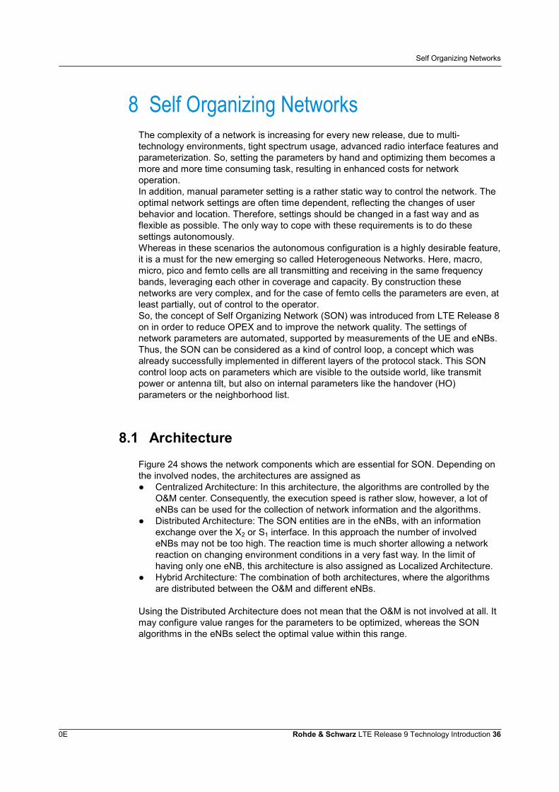
Figure 24 shows the network components which are essential for SON. Depending onthe involved nodes, the architectures are assigned as● Centralized Architecture: In this architecture, the algorithms are controlled by the
O&M center. Consequently, the execution speed is rather slow, however, a lot ofeNBs can be used for the collection of network information and the algorithms.
● Distributed Architecture: The SON entities are in the eNBs, with an informationexchange over the X2 or S1 interface. In this approach the number of involvedeNBs may not be too high. The reaction time is much shorter allowing a networkreaction on changing environment conditions in a very fast way. In the limit ofhaving only one eNB, this architecture is also assigned as Localized Architecture.
● Hybrid Architecture: The combination of both architectures, where the algorithmsare distributed between the O&M and different eNBs.
Using the Distributed Architecture does not mean that the O&M is not involved at all. Itmay configure value ranges for the parameters to be optimized, whereas the SONalgorithms in the eNBs select the optimal value within this range.
Self Organizing Networks
0E Rohde & Schwarz LTE Release 9 Technology Introduction 37
Figure 24: Network components for the SON architecture
8.2 SON Processing
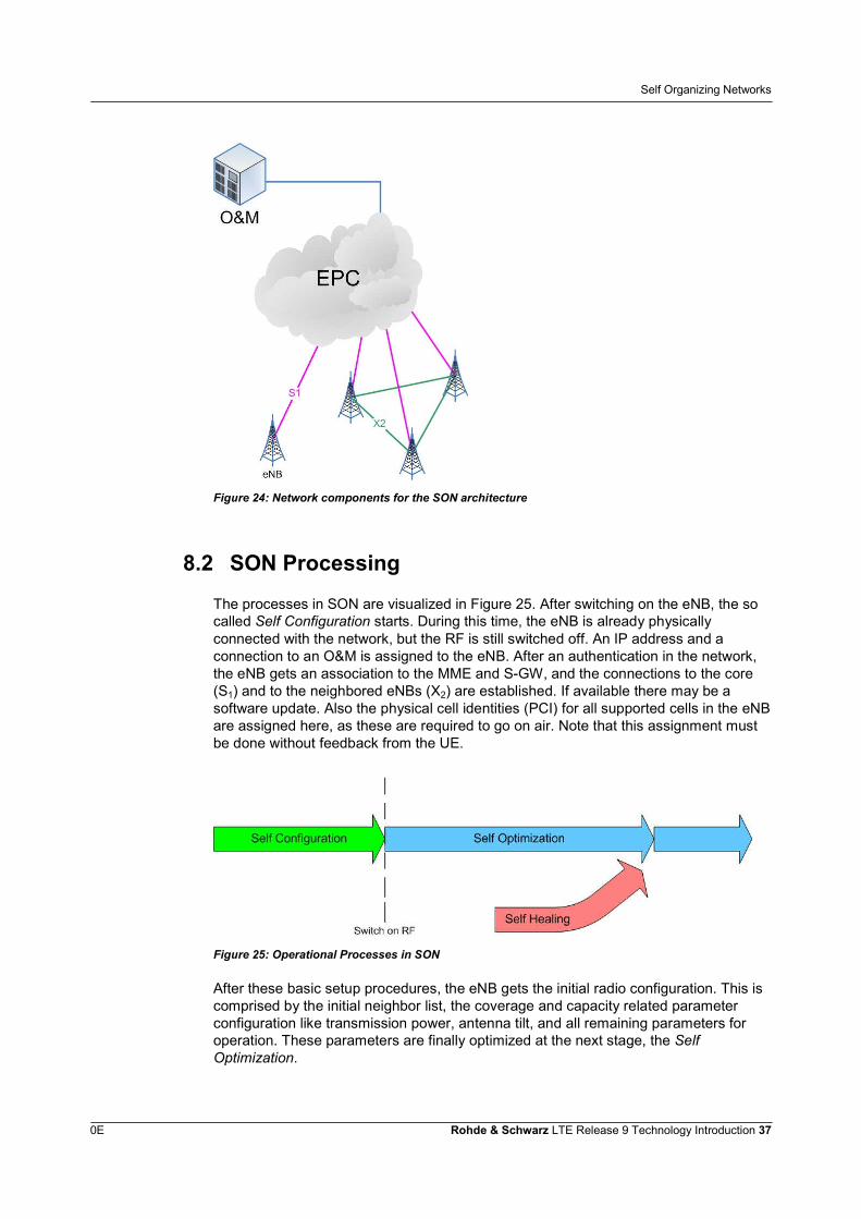
The processes in SON are visualized in Figure 25. After switching on the eNB, the socalled Self Configuration starts. During this time, the eNB is already physicallyconnected with the network, but the RF is still switched off. An IP address and aconnection to an O&M is assigned to the eNB. After an authentication in the network,the eNB gets an association to the MME and S-GW, and the connections to the core(S1) and to the neighbored eNBs (X2) are established. If available there may be asoftware update. Also the physical cell identities (PCI) for all supported cells in the eNBare assigned here, as these are required to go on air. Note that this assignment mustbe done without feedback from the UE.
Figure 25: Operational Processes in SON
After these basic setup procedures, the eNB gets the initial radio configuration. This iscomprised by the initial neighbor list, the coverage and capacity related parameterconfiguration like transmission power, antenna tilt, and all remaining parameters foroperation. These parameters are finally optimized at the next stage, the SelfOptimization.
Self Organizing Networks
0E Rohde & Schwarz LTE Release 9 Technology Introduction 38
This stage starts by switching on the RF. Mobiles may now connect with the cells andreturn feedback to improve the initial radio configuration and also to adopt them to(time dependent) traffic load or measured propagation conditions. For this feedback,existing RRC measurements have been extended.In the case of a failure, the so called Self Healing applies. Depending on the failurereason the eNB either switches to a spare part (if existing) in case of a hardwarefailure, or reloads a former software when the failure was caused by a not properlyrunning software update. When none of these remedies work, the remaining eNBschange their settings in order to fill the coverage gap created by the failure.So, with SON, rolling out new eNBs shall be a kind of Plug and Play system, havingonly a single site visit to install and operate the station. All parameter settings,including the changes in the network neighbourhood, shall work in an autonomousway.
8.3 Use Cases for Self Configuration
The use cases for Self Configuration have been defined in Release 8. There was anupdate in Release 9 to take the CSGs of the Femto-Cells into account.
8.4 Use Cases for Self Optimization
These use cases have been started with Release 9 and are expanded in laterreleases. They comprise support for the optimization of HO parameters, balancing theload between different cells or eNBs, and an optimization of the RACH settings.
8.4.1 Mobility Robustness Optimization
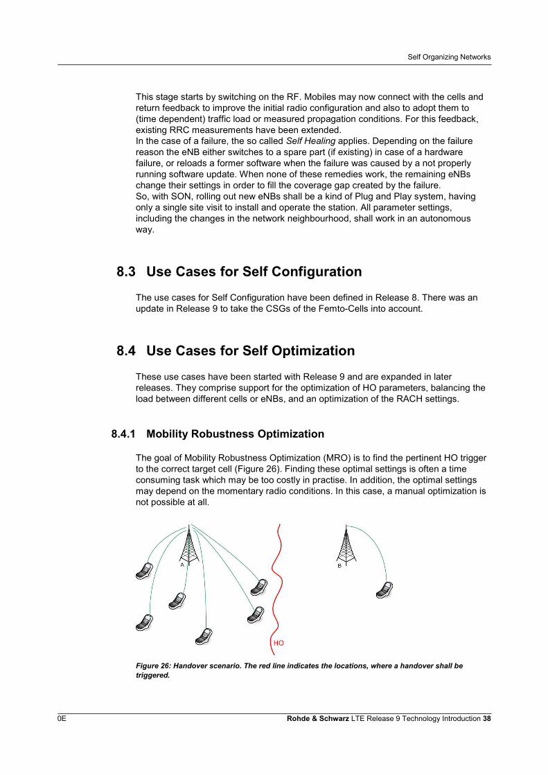
The goal of Mobility Robustness Optimization (MRO) is to find the pertinent HO triggerto the correct target cell (Figure 26). Finding these optimal settings is often a timeconsuming task which may be too costly in practise. In addition, the optimal settingsmay depend on the momentary radio conditions. In this case, a manual optimization isnot possible at all.
Figure 26: Handover scenario. The red line indicates the locations, where a handover shall betriggered.
Self Organizing Networks
0E Rohde & Schwarz LTE Release 9 Technology Introduction 39
Effects caused by incorrect HO parameter settings may be classified in threecategories:
● Unnecessary or missing HOs: In this category are the so called ping-pong HOs,i.e. the HOs forth and back between two cells, but also unwanted HOs directly afterthe connection setup. The latter case occurs when the cell reselection parametersdo not match with the HO parameter settings. The missing HOs on the other handimply that a UE remains connected with a non-optimal cell, whereas a HO to abetter cell would be available.
● HO failure without radio link failure (RLF): These failures are mainly perceived by adegradation in the service. Also, additional signalling traffic is created in thenetwork.
● HO failure with RLF: This is the worst scenario on handover failures. These failureshave a combined impact on user experience and on signalling traffic. So, the mainobjective of MRO is the reduction of HO failures with a RLF.
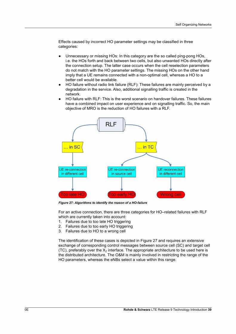
Figure 27: Algorithms to identify the reason of a HO-failure
For an active connection, there are three categories for HO–related failures with RLFwhich are currently taken into account:1. Failures due to too late HO triggering2. Failures due to too early HO triggering3. Failures due to HO to a wrong cell
The identification of these cases is depicted in Figure 27 and requires an extensiveexchange of corresponding control messages between source cell (SC) and target cell(TC), preferably over the X2 interface. The appropriate architecture to be used here isthe distributed architecture. The O&M is mainly involved in restricting the range of theHO parameters, whereas the eNBs select a value within this range.
Self Organizing Networks
0E Rohde & Schwarz LTE Release 9 Technology Introduction 40
8.4.2 Mobility Load Balancing Optimization
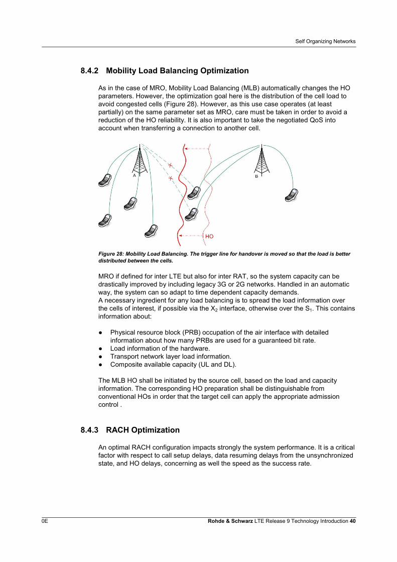
As in the case of MRO, Mobility Load Balancing (MLB) automatically changes the HOparameters. However, the optimization goal here is the distribution of the cell load toavoid congested cells (Figure 28). However, as this use case operates (at leastpartially) on the same parameter set as MRO, care must be taken in order to avoid areduction of the HO reliability. It is also important to take the negotiated QoS intoaccount when transferring a connection to another cell.
Figure 28: Mobility Load Balancing. The trigger line for handover is moved so that the load is betterdistributed between the cells.
MRO if defined for inter LTE but also for inter RAT, so the system capacity can bedrastically improved by including legacy 3G or 2G networks. Handled in an automaticway, the system can so adapt to time dependent capacity demands.A necessary ingredient for any load balancing is to spread the load information overthe cells of interest, if possible via the X2 interface, otherwise over the S1. This containsinformation about:
● Physical resource block (PRB) occupation of the air interface with detailedinformation about how many PRBs are used for a guaranteed bit rate.
● Load information of the hardware.● Transport network layer load information.● Composite available capacity (UL and DL).
The MLB HO shall be initiated by the source cell, based on the load and capacityinformation. The corresponding HO preparation shall be distinguishable fromconventional HOs in order that the target cell can apply the appropriate admissioncontrol .
8.4.3 RACH Optimization
An optimal RACH configuration impacts strongly the system performance. It is a criticalfactor with respect to call setup delays, data resuming delays from the unsynchronizedstate, and HO delays, concerning as well the speed as the success rate.
Self Organizing Networks
0E Rohde & Schwarz LTE Release 9 Technology Introduction 41
One point is the number of allocated RACH slots. If this number is too small, theprobability to get a successful access is reduced by collisions. On the other hand,allocating too many RACH slots is a waste of physical resources, as these slots cannot be used by other traffic. Therefore, selecting the optimal number of access slots isof strong importance to the system.The optimal number depends on the number of users and on the networkconfiguration. With SON these values are varying in time, so the selection of optimalvalues is time dependent, too.Apart from the delays, also the UL interference is a critical point. The UE starts itsRACH transmission with a preamble. If there is no response the UE again sends apreamble, this time with an increased power. The purpose of this procedure is toaccess the system with a minimum of power in order to minimize interference.However, if the preamble rejection is not caused by a too weak power but due tocongestion, another preamble with a further increased power is transmitted. Thisobviously enhances the UL interference for the PUSCH, but also for RACH attempts ofUEs to a different cell, respectively.
There are 3 classes of parameters which can be optimized:● RACH configuration: Selection of number and location of the RACH access slots.
This is further optimized by a smart choice of the pRACH Configuration Index andthe Root Sequence Index.
● RACH preamble splitting and backoff parameter values to avoid congestion.● RACH transmission power control parameters: The power of the initial preamble
and the power ramping on each step. Depending on this choice, different scenarioscan be managed in an optimal way. For example, if the range of a cell containsregions with a very large fading difference, a small initial power with a large powerramping may be optimal, whereas in small cells with a more uniform fading a largerinitial power together with a smaller power ramping might be the best solution.
The SON entity for the RACH optimization is in the eNB, with the main signalling usingeither RRC or MAC control. So the main impact is on the air interface protocol stack.However, also the X2 interface will be concerned in order to be able to exchangeaccess slot configuration between adjacent eNBs for avoiding RACH interferences.
Literature
0E Rohde & Schwarz LTE Release 9 Technology Introduction 42
9 Literature[1] TS 36.211 Evolved Universal Terrestrial Radio Access (E-UTRA); Physical
Channels and Modulation; Release 9
[2] TS 36.212 Evolved Universal Terrestrial Radio Access (E-UTRA); Multiplexingand Channel Coding; Release 9
[3] TS 36.213 Evolved Universal Terrestrial Radio Access (E-UTRA); Physical LayerProcedures; Release 9
[4] TS 36.331 Evolved Universal Terrestrial Radio Access (E-UTRA); RadioResource Control (RRC); Protocol Specification; Release 9
[5] TS 37.104 E-UTRA, UTRA and GSM/EDGE; Multi-Standard Radio (MSR) BaseStation (BS) radio transmission and reception; Release 9
[6] TS 37.141 E-UTRA, UTRA and GSM/EDGE; Multi-Standard Radio (MSR) BaseStation (BS) conformance testing; Release 9
[7] TR 36.921 Evolved Universal Terrestrial Radio Access (E-UTRA); FDD HomeeNodeB (HeNB) Radio Frequency (RF) requirements analysis; Release 9
[8] TR 36.922 Evolved Universal Terrestrial Radio Access (E-UTRA); TDD HomeeNodeB (HeNB) Radio Frequency (RF) requirements analysis; Release 9
[9] TS 36.104 Evolved Universal Terrestrial Radio Access (E-UTRA); Base Station(BS) radio transmission and reception; Release 9
[10] http://www.fcc.gov/document/wireless-e911-location-accuracy-requirements-1
[11] TS 36.355 Evolved Universal Terrestrial Radio Access (E-UTRA); LTEPositioning Protocol (LPP); Release 9
[12] TS 36.455 Evolved Universal Terrestrial Radio Access (E-UTRA); LTEPositioning Protocol A (LPPa); Release 9
[13] “Hybrid Data Fusion and Tracking for Positioning with GNSS and 3GPP-LTE”;http://www.hindawi.com/journals/ijno/2010/812945/
[14] TS 36.214 Evolved Universal Terrestrial Radio Access (E-UTRA); Physical Layermeasurements; Release 9
[15] TS 36.141 Evolved Universal Terrestrial Radio Access (E-UTRA); Base Station(BS) conformance testing; Release 9

Additional Information
0E Rohde & Schwarz LTE Release 9 Technology Introduction 43
10 Additional InformationPlease send your comments and suggestions regarding this white paper to

About Rohde & SchwarzRohde & Schwarz is an independent groupof companies specializing in electronics. It isa leading supplier of solutions in the fields oftest and measurement, broadcasting,radiomonitoring and radiolocation, as well assecure communications. Established morethan 75 years ago, Rohde & Schwarz has aglobal presence and a dedicated servicenetwork in over 70 countries. Companyheadquarters are in Munich, Germany.
Environmental commitment● Energy-efficient products● Continuous improvement in
environmental sustainability● ISO 14001-certified environmental
management system
Regional contactEurope, Africa, Middle East+49 89 4129 [email protected]
North America1-888-TEST-RSA (1-888-837-8772)[email protected]
Latin [email protected]
Asia/Pacific+65 65 13 04 [email protected]
This application note and the suppliedprograms may only be used subject to theconditions of use set forth in the downloadarea of the Rohde & Schwarz website.
R&S® is a registered trademark of Rohde & SchwarzGmbH & Co. KG; Trade names are trademarks of theowners.
Rohde & Schwarz GmbH & Co. KGMühldorfstraße 15 | D - 81671 MünchenPhone + 49 89 4129 - 0 | Fax + 49 89 4129 – 13777
www.rohde-schwarz.com