Embed Size (px)
Citation preview
8/13/2019 Ltmetering Cabinet Spec Metering Cabinet090908
http://slidepdf.com/reader/full/ltmetering-cabinet-spec-metering-cabinet090908 1/28
1
MAHARASHTRA STATE ELECTRICITY DISTRIBUTION COMPANY LTD.
Specification for a Unit comprising of 100/5A or 50/5 A Plug in Type CTs and160 A (setting at 100 A) or 100 A(setting at 50 A) MCCB and
LT CT Operated TOD meter and other arrangementSPEC NO: DIST:18/2008 Dt.14.08.2008
INDEX
----------------------------------------------------------------------------------------------------------
SR.NO. PARTICULARS. PAGE
-----------------------------------------------------------------------------------------------------------
1) SCOPE 2
2) SERVICE CONDITIONS 2
3) STANDARDS 2
4) GENERAL TECHNICAL PARTICULARS 2
5) TECHNICAL SPECIFICATION FOR METER 3-18
6) CURRENT TRANSFORMER 19
7) MOULDED CASE CIRCUIT BREAKERS 20
8) ENCLOSURE 20-23
9) TESTS & TEST CERTIFICATE 23
10) TESTING & MANUFACTURING FACILITIES 24
11) PROTOTYPE & DRAWINGS 2412) GUARANTEE 25
13) INSPECTION 25
14) RANDIM SAMPLE TESTING 25
15) TENDER SAMPLE 26
16) SCHEDULE 26
SCHEDULE-A (GTP on e-tendering)
SCHEDULE-C 27
17) ANNEXURE U-1 (for Meter Suppliers only) 28
8/13/2019 Ltmetering Cabinet Spec Metering Cabinet090908
http://slidepdf.com/reader/full/ltmetering-cabinet-spec-metering-cabinet090908 2/28
2
MAHARASHTRA STATE ELECTRICITY DISTRIBUTION CO.LTD.
Specification for a Unit comprising of 100/5A or 50/5 A Plug in Type CTs and160 A (setting at 100 A) or 100 A(setting at 50 A) MCCB and
LT CT Operated TOD meter and other arrangementSPEC NO: DIST:18/2008 Dt.14.08.2008
1.0 Scope:- Specification covers the design ,manufacture, testing at worksand supply of a unit comprising of 100/5A or 50/5 A CTs with plug in typearrangement and 160 A (setting at 100 A) or 100 A (setting at 50 A) MCCBand LT CT operated static TOD energy meter and other arrangement asper specification for use in electrical distribution system in Maharashtra.The system shall be A.C. 3 phase- 4 wire, 415V, 50 HZ with effectivelygrounded neutral with C.T. ratios of 100/5A or 50/5 Amp.
2.0 Service Conditions: Equipment to be supplied against this specificationshall be suitable for satisfactory continuous operation under the followingtropical conditions.
i) Maximum ambient temperature (Degree C) ... 50ii) Maximum temperature in shade (Degree C) ... 45iii) Minimum temperature of Air in Shade(Degree C) … 3.5iv) Relative Humidity (Percent) ... 10 to 95v) Maximum annual rain fall (mm) ... 1450vi) Maximum wind pressure (Kg/sq.M.) ... 150vii) Maximum altitude above mean sea level (Meter) … 1000viii) Isoceranic level (days per year) ... 50ix) Siesmic level (Horizontal Acceleration) ... 0.3 gx) Moderately hot and humid tropical climate
conducive to rust and fungus growth ...
3.0 Standards: Unless otherwise modified in this specification:
(a) The MCCB shall comply with IS: 13947 /1993 amended upto date.(b) The enclosure box shall comply with IS:13947 /1993 amended upto
date.(c) The C.T. shall conform to IS:2705/1992 or its latest version thereof.(d) The Electronic Meter shall conform to IS:14697/1999 or IEC:687 or
its latest version thereof.(e) MCCB, CT and meters having relevant BIS certification and ISO
certification would be preferred.
4.0 General Technical Particulars:-
4.01 These cabinets are to be supplied as complete units consisting of 3 phase4 wire 100/5A or 50/5 A LT CT Operated TOD Meter, C.Ts with plug intype arrangement , MCCB in sheet steel cabinet duly wired as shown inthe general arrangement drawings No.DIST/MM-IV/CTMTR/2008/01 Sheet1/3 , 2/3 & 3/3. The supply shall be as per final approved drawings.
8/13/2019 Ltmetering Cabinet Spec Metering Cabinet090908
http://slidepdf.com/reader/full/ltmetering-cabinet-spec-metering-cabinet090908 3/28
3
4.02 Tenderer should submit Type Test Reports for offered Meter , C.T.s. withplug in type arrangement, MCCB & CT operated metering unit of eachrating, along with offer, failing which offer shall be rejected. All the TypeTest Reports shall be within the period of Five Years from the date ofopening of the Tender.
5.0 Technical Specification for L.T.CT Operated TOD Meters.
5.01 This specification covers design, manufacture, testing, supply and deliveryof ISI mark, static LTCT Operated TOD meter. Meters shall be suitable formeasurement of energy (kWh) and demand (kWMD & kVAMD) as perpower tariff requirement of A.C. balanced / unbalanced loads. The systemshall be AC 3-phase 4 wire 415 V, 50 Hz with effectively grounded neutralwith CT ratio of 100/5 A or 50/5 A. The meter shall have a RS-232 or RS-485 Communication port for retrieval of data and for Automatic MeterReading programme in future.
5.02 QUALIFYING REQUIREMENTS FOR METERS:-
I) Meters of only original manufacturers of L.T.A.C. Static Energy Metersshall be accepted against the Tender.
II) The following qualifying requirement shall be fulfilled by the
manufacturers
a) The manufacturer should have turnover of Rs.80 crores during
any one of the last three financial years.
b) The manufacturer should have supplied 12.5 lakhs static meters duringthe last three financial years.
c) The manufacturer should have minimum experience of three years ofsupply or manufacturing for static meters up to the end of the lastfinancial year.
III) The meters of Indian subsidiary company, whose parent company islocated abroad fulfilling the qualifying requirements shall be consideredprovided the Indian participant subsidiary company fulfils the minimumexperience of three years of supply or manufacturing for static energymeters upto the end of the last financial year. However, the conditions ofturnover of Rs.80 crores during any one of the last three financial years andsupply of minimum quantity of 12.5 lakhs static energy meters during lastthree financial years can be fulfilled by the parent company located inabroad on behalf of their Indian subsidiary company. The parent companyshall furnish undertaking for accepting responsibility for supplying qualitymeters as per specifications and execution of the contract on behalf of its
India based subsidiary unit who has participated in the tender in AnnexureU-I.
IV) In case of meters of Foreign manufacturers, they shall fulfill QualifyingRequirement as per Sr. No. 2.1 [I] and 2.1 [II] above.
The bidder should submit the documentary evidence fulfilling the qualifyingrequirement for meter as above from meter manufacturers.
8/13/2019 Ltmetering Cabinet Spec Metering Cabinet090908
http://slidepdf.com/reader/full/ltmetering-cabinet-spec-metering-cabinet090908 4/28
4
5.03 APPLICABLE STANDARDS:
• The Meter should conform to requirements of IS:14697/1999 (amendedup to date) or IEC: 687 and other relevant IS specifications includingCBIP Tech-Report-88 amended up to date. The specifications given inthis document supersedes the relevant clauses of IS: 14697/1999
(amended up to date) wherever applicable.
• The meter must bear ISI Mark.
• The class of accuracy shall be 0.5S.
5.04.01 Current & Voltage rating
The energy meter shall be suitable for 100/5A or 50/5A, A.C. 3 phase 4wire 415Volts 50 Hz system. These meters shall be of direct reading typewithout application of any multiplying factor.
The voltage range shall be +15% to -30% of rated voltage.
Current :- Rated basic current 5 Amps.The maximum continuous current of the meter is 2 times (200%) of IbThe starting current for the meter should be 0.1% of Ib
5.04.02 Temperature
The standard reference temperature for performance shall be 270C. Themean temperature co-efficient should not exceed 0.03%.
5.04.03 Frequency
The rated frequency shall be 50 Hz ± 5%.
5.04.04 Power Factor : Power Factor range - Zero Lag-Unity-Zero Lead. Forleading Power factor the value of kVAh should be equal to kWh. For thepurpose of calculation of average power factor (on the basis of kWh/ kVAh)i.e. The value of kVAh shall be based on lagging value of kVARh &kWh.
5.04.05 Power consumption - less than 1Watt and 4 VA/phase in voltage circuitand 1 VA /phase in current circuit.
5.05 CONSTRUCTION
5.05.01 The meter shall be projection type, dust and moisture proof. The covershall be made of Polycarbonate material so as to give it tough and non-breakable qualities. The meter body shall be type tested for IP51 degree ofprotection.
5.05.02 Moulded single terminal block for current & voltage connections asper IS: 14697/1999 (amended up to date) conforming to relevant
8/13/2019 Ltmetering Cabinet Spec Metering Cabinet090908
http://slidepdf.com/reader/full/ltmetering-cabinet-spec-metering-cabinet090908 5/28
5
standard to meet the requirement of terminal connection arrangement shallbe provided. The termination arrangement shall be provided with anextended type transparent terminal cover and shall be sealableindependently to prevent unauthorized tampering. Proper size of groovesshould be provided at bottom of this terminal cover for incoming & outgoingservice wires.
5.05.03 All insulating materials used in the construction of the meter shall be
substantially non-hygroscopic, non aging and of tested quality.
5.05.04 All parts that are likely to develop corrosion under normal workingcondition shall be effectively protected against corrosion by suitable methodto achieve durable results.
5.05.05 The meter shall be pilfer-proof & tamper-proof. Sealing provision shall bemade against opening of the terminal cover and front cover. It is necessaryto provide unidirectional screws with two holes for sealing purpose.
5.05.06 The meter shall have Poly-carbonate translucent base and transparentcover of Poly-carbonate material, which shall be ultra-sonically welded
(continuous welding) so that once the meter is manufactured and tested atfactory, it should not be possible to open the cover at site except theterminal cover. The thickness of material for meter cover and base shall be2 mm (minimum).
5.05.07 The real time quartz clock shall be used in the meter for maintainingtime (IST) and calendar. Facility for adjustment of real time should beprovided through CMRI with proper security.
5.05.08 The meter shall be completely factory sealed except the terminalblock cover. The provision shall be made on the Meter for at least twoseals to be put by utility user. The Terminal cover should be
transparent with one side hinge with sealing arrangement.
5.05.09 The meter shall have a suitable test output device for testing meter.Preferably the blinking LED or LCD shall be provided. The test outputdevice should have constant pulse rate i.e. Pulse/kWh and pulse/kVARhand its value (meter constant) should be indelibly printed on the nameplate.
5.05.10 The meter accuracy shall not be affected by AC/DC magnetic fieldupto 0.2 Tesla on all the sides of meter i.e. front, sides, top andbottom of the meter as per CBIP-88 Technical Report with latestamendments. Under influence of any magnetic field
(AC/DC/Permanent) above 0.2 Tesla, meter shall record energyconsidering Imax and reference voltage at unity power factor.
5.05.11 Meter CTs are to be provided with magnetic shielding and theyshould be tested separately.
8/13/2019 Ltmetering Cabinet Spec Metering Cabinet090908
http://slidepdf.com/reader/full/ltmetering-cabinet-spec-metering-cabinet090908 6/28
6
5.05.12 The meter shall also be capable to withstand and shall not getdamaged if phase-to-phase voltage is applied between phases &neutral at least for 5 minutes.
5.05.13 The RTC battery & the battery for display in case of power failureshould be separate.
5.05.14 In meter, Power supply unit should be micro control type instead of
providing transformer and then conversion to avoid magneticinfluence.
5.05.15 Non specified display parameter in the meter should be blocked andit should not be accessible for reprogramming at site.
5.05.16 Complete metering system should not be affected by the externalelectromagnetic interference such as electrical discharge of cablesand capacitors, harmonics, electrostatic discharges, external magneticfields and DC current in AC supply etc. The Meter shall meet therequirement of CBIP Tech-report 88 (amended up to date).
5.05.17 The meter shall have RS 232 or RS 485 communication port forremote meter reading facility and data retrieval shall be possiblethrough this port using CMRI, Laptop, PC and if possible, throughLine carrier communication. Sealing arrangement for this Optical portshall be provided.
5.05.18 The accuracy of the meter should not be affected with theapplication of abnormal voltage/frequency generating device such asspark discharge of approximately 35 KV. The meter shall be tested byfeeding the output of this device to meter in any of the followingmanner for 10 minutes:
i) On any of the phases or neutral terminals
ii) On any connecting wires of the meter (Voltage discharge with 0-10mm spark gap)
iii) At any place in load circuit
The accuracy of meter shall be checked before and after the application ofabove device.
5.05.19 Self Diagnostic Features.
5.05.19.1 The meter shall keep log in its memory for unsatisfactoryfunctioning or nonfunctioning of Real Time Clock battery, also it shallbe recorded and indicated in reading file at base computer software.
5.05.19.2 All display segments: "LED/LCD Test" display shall be providedfor this purpose.
5.05.20 The meter shall have facility to read the default display parametersduring Power supply failure. An internal maintenance free battery (Ni-
8/13/2019 Ltmetering Cabinet Spec Metering Cabinet090908
http://slidepdf.com/reader/full/ltmetering-cabinet-spec-metering-cabinet090908 7/28
7
mh or Li-ion or NI CD) of long life of 15 years shall be provided for thesame. A suitable Push Button arrangement for activation of batteryshall be provided. This battery may be of external type with inductivecoupling arrangement. External Battery is to be provided with inbuiltcharger, in the ratio of one battery pack per 50 nos. meters.
5.05.21 Wire/Cable less design. The meter PCB should be wire less toavoid improper and loose connections / contacts.
5.05.22 PCB used in meter shall be made by Surface Mounting Technology.
5.06 TOD TIMINGS
There shall be provision for at least 6 (Six) TOD time zones for energyand demand. The number and timings of these TOD time Zones shallbe programmable.
At present the time zones shall be programmed as below:
TIME ZONE "A" 00-00 to 06.00hrs & 22.00 to 24.00 hrs.TIME ZONE "B" 06.00 to 09.00 hrs & 12.00 to 18.00 hrs.TIME ZONE "C" 09.00 to 12.00 hrs.TIME ZONE “D” 18.00 to 22.00 hrs.
5.07 ANTI TAMPER FEATURES
The meter shall detect and correctly register energy (Active +Reactive) only in forward direction under following tamper conditions:
5.07.01 The meter accuracy shall not be affected by change of phasesequence. It should maintain the desired accuracy in case of reversalof phase sequence.
5.07.02 Reversal of line and load terminals. Even on interchanging the loadand line wires, the meter should register correct total energy (passingthrough the meter. The meter shall also display the energy recordedin reverse mode separately.
5.07.03 Drawing of current through local Earth, the meter should registeraccurate energy even if load is drawn partially or fully through a localearth.
5.07.04 The three phase meter should continue to work even withoutneutral.
5.07.05 The three phase meter should work in absence of any two phases i.e. it
should work on any one phase wire and neutral, to record relevant energy.
8/13/2019 Ltmetering Cabinet Spec Metering Cabinet090908
http://slidepdf.com/reader/full/ltmetering-cabinet-spec-metering-cabinet090908 8/28
8
5.07.06 The meter should work without earth.
5.07.07 The potential link shall not be provided.
5.07.08 Visual indication shall be provided to safeguard against wrongconnections to the meter terminals.
5.07.09 The meter shall be immune to the external magnetic field
(AC/DC/Permanent) upto 0.2 Tesla. If it is more than 0.2 Tesla, thenthe same should be recorded as magnetic tamper event with date &time stamping and the meter should record Energy considering themaximum value current (Imax) at ref. voltage and unity PF in all thethree phases.
5.08 TAMPER EVENTS
The meter should have features to detect the occurrence andrestoration of the following abnormal events.
5.08.01 Missing potential and potential imbalance.
The meter shall be capable of detecting and recording occurrence andrestoration with date and time the cases of potential failure and lowpotential, which could happen due to disconnection of potential leads (oneor two). Meter shall also detect and log cases of voltage unbalance (10%or more for 5 Minutes.) Higher of the 3 phase voltages shall be consideredas reference for this purpose.
5.08.02 Current unbalance:
The meter shall be capable of detecting and recording occurrence andrestoration with date and time of current unbalance (30% or more for
15 minutes) Higher of the 3 phase currents shall be considered asreference for this purpose.
5.08.03 Current Reversal:
The meter shall be capable of detecting and recording occurrence andrestoration with date and time of reversal of current with phase identificationfor persistence time of 5 minutes. The meter shall record the total energyi.e.(Active + Reactive) including harmonic energy in forward direction in allconditions. The meter should be programmed for import mode and in caseof reversal of energy direction(reversal of CT terminals) meter shoulddisplay in billing parameter the total energy including energy recorded inexport register and also show separately the energy recorded in export
mode for analysis purpose.
5.08.04 Power ON / OFF
The meter shall be capable to record power ON/OFF events in themeter memory. All potential failure should record as power off event.
The meter shall keep records for the minimum 280 events.(Occurrence + Restoration). For above abnormal conditions the
8/13/2019 Ltmetering Cabinet Spec Metering Cabinet090908
http://slidepdf.com/reader/full/ltmetering-cabinet-spec-metering-cabinet090908 9/28
9
recording of events shall be on FIFO basis. It shall be possible toretrieve the abnormal event data along with all related snap shotsdata through the meter optical port with the help of CMRI &downloaded the same to the base computer. All the information shallbe made available in simple & easy to understand format.
5.08.05 Current circuit short
The meter shall be capable of detecting and recording occurrencesand restoration of shorting of any one or two phases of current, withdate & time of occurrence and restoration.
5.09 DISPLAY OF MEASURED VALUES
5.09.01 The permanently backlit display shall show relevant informationabout the parameters to be displayed. The corresponding non-volatile memory shall have a minimum retention time of 10 years. In thecase of multiple values presented by a single display it shall be possible todisplay the content of all relevant memories. When displaying thememory, the identification of each parameter applied shall be possible.
The principal unit for the measured values shall be the kilowatthour (kWh)for active energy, kVARh for reactive energy and kVAh for apparentenergy.
5.09.02 The display shall be minimum full 6 digit type display. The size of digitshould be minimum 8X5 mm. The decimal units shall not be displayed.The adequate back up arrangement for storing of energy registered atthe time of power interruption shall be provided.
5.09.03 The display parameters will be preprogrammed at factory as per Annexure-I & the scroll period for auto scroll should be 9 sec.Maximum Demand resetting should be manual. A separate push button
should be provided for resetting MD along with proper sealing arrangement.The display order shall be as per Annexure -I .The “record number field should be 10 digits Alphanumeric.(2digit forZones,2 for Circle & 6 for consumer No.) Before accepting the data for“Record Number” the system should wait for pressing of “Enter” key.Two separate fields should be provided for consumer name and address –one name field of one line , and other Address field for two lines
5.09.04 Maximum Demand Integration Period:-Integration period for kVAMDshould be of 30 minutes real time based. However same shall beprogrammable to 15 minutes if required.
5.10 DEMONSTRATION
The purchaser reserves the right to ask to give the demonstration ofthe equipment offered at the purchaser’s place.
5.11 BILLING HISTORY & LOAD SURVEY
8/13/2019 Ltmetering Cabinet Spec Metering Cabinet090908
http://slidepdf.com/reader/full/ltmetering-cabinet-spec-metering-cabinet090908 10/28
10
The meter shall have sufficient non-volatile memory for recordinghistory of billing parameters (Cumulative kWh at the time of reset andkVAMD) for last 6 months.
Load survey parameters :- kWh , kVAh , RkVAH, Voltage per phase andCurrent per phase.
The logging interval for load survey shall be 30 minutes. Load surveydata shall be logged for last 60 days on non time based basis. i.e. if
there is no power for more than 24 hours, the day should not berecorded Whenever meter is taken out and brought to laboratory theL/S data shall be retained for the period of actual use of meter. Thisload survey data can be retrieved as and when desired and loadprofiles shall be viewed graphically / analytically with the help of meterapplication software. The meter application software shall be capableof exporting / transmitting these data for analysis to other usersoftware in spreadsheet format.
5.11.01 Potential terminal voltage to be monitored continuously. Metershall work within accuracy limit at low load upto -30% of 240 Volts(P-N)i.e.168 volts. Low voltage below 168 volts to 1 volts shall be stored innon-volatile memory along with the date and time of low voltage andsubsequent restoration to normal voltages. The NO voltage i.e.0 voltsshall be separately monitored and stored in memory along with date andtime.
5.12 COMPUTER SOFTWARE.
5.12.01 For efficient and speedy recovery of data downloaded throughCMRI on base computer, licensed copies of base computer softwareshall have to be supplied free of cost. This software will be used atnumber of places up to Division level. The time required for datadownloading from meter to CMRI and CMRI to BCS shall be minimum.
The computer software shall be "Window" based & user friendly. Thedata transfer shall be highly reliable and fraud proof (No editing shallbe possible on base computer by any means).The software shall havecapability to convert all the data into ASCII format.
As many copies of base computer software as required up to Divisionlevel shall be provided by Supplier.
The protocol used in the meter shall have to be provided at thetime of supply for the purpose of Automatic Meter ReadingSystem.
5.12.02 The total time taken for downloading Billing, Tamper and LoadSurvey Data for 60 Days should be less than or equal to 3 minutes.
5.12.03 Parameters to be covered in the Billing, Tamper and Load Survey Datashall be as per Annexure-‘III’.
5.12.04 Downloading time of only Billing and Tamper data should be less than
8/13/2019 Ltmetering Cabinet Spec Metering Cabinet090908
http://slidepdf.com/reader/full/ltmetering-cabinet-spec-metering-cabinet090908 11/28
11
or equal to 20 sec.
5.12.05 Meter manufacturer should provide API/Exe field with documentationfor H.T.Meters to query the data downloaded from the Meter
5.12.06 Checksum file is to be provided loaded in the downloaded file fromMeter and also for the file created by API/Exe in XML format.
5.12.07 Checksum checking Exe/API should also be given to MSEDCL forvalidating downloaded meter data as well as generated XML file.
5.12.08 As and when meter manufacturer releases new or latest oradvanced versions of Meter Hardware/Firmware / Software, the sameshould be made available to MSEDCL immediately by default on therelease date free of cost .The latest versions should support all existinghardware/ meters in the field.
5.12.09 Downloading software should also be provided so as to install on ourLaptop for downloading data directly on Laptop from meter without the
use of CMRI
5.12.10 MSEDCL is procuring large quantity of meters .As such meterManufacturer have to depute Hardware Engineers and Software Engineerson call basis , who should have thorough knowledge of meter hardware/software used for downloading and converting so as to discuss theproblems if any or new development in the hardware/software withG.M.(IT)/C.E.(Dist) without any additional charge.
5.13 CONNECTION DIAGRAM AND TERMINAL MARKINGS.
The connection diagram of the meter shall be clearly shown on inside
portion of the terminal cover and shall be of permanent nature. Meterterminals shall also be marked and this marking should appear in the abovediagram. The diagram & terminal marking on sticker will not be allowed.
5.14 NAME PLATE AND MARKING
Meter shall have a name plate clearly visible, effectively secured againstremoval and indelibly and distinctly marked with all essential particulars asper relevant standards. Meter Serial Number shall be Bar Coded along withnumeric number. The size of bar coded number should not be less than35x5 mm. The manufacturer’s meter constant shall be marked on the name
plate. Meter serial number & bar code on sticker will not be allowed.
In addition to the requirement as per IS following shall be marked onthe name plate.1) Purchase order No.2) Month and Year of manufacture3) Name of purchaser i.e. MSEDCL4) Guarantee Five and half years
8/13/2019 Ltmetering Cabinet Spec Metering Cabinet090908
http://slidepdf.com/reader/full/ltmetering-cabinet-spec-metering-cabinet090908 12/28
12
5) ISI mark.
5.15 TESTS:-
5.15.01 Type Tests:-The Meter shall be fully type tested as per IS: 14697/1999 (amended upto date) and within the last 5 (five) years prior to the date ofopening of offer . The type test reports of the offered meters shall besubmitted along with the offer. The offers without type test reports shall be
rejected. All the Type Tests specified in the technical specifications and asper IS: 14697 shall be carried out at laboratories which are accredited bythe National Board of Testing and Calibration Laboratories (NABL) of Govt.of India such as CPRI Bangalore/ Bhopal, ERDA Baroda. Type TestReports conducted in manufacturers own laboratory and certified by testinginstitute shall not be acceptable.
The type test reports shall clearly indicate the constructional features of thetype tested meters. The type test reports for each offered type of metersshall be submitted separately. The purchaser reserves the right to demandrepetition of some or all the type tests in presence of purchaser’srepresentative at purchaser's cost.
5.15.02 Acceptance Tests:- All acceptance tests as per IS 14697/1999 shall becarried out on the meter.
5.15.03 Routine Test:- All routine tests as per IS:14697/1999 shall be carriedout on all the meters.
5.15.04 Transportation Test:
At least 50% of the samples of the meters be tested for error at Imax,Ib and 5% Ib at unity power factor and 50% Imax and 10% Ib at 0.5lagging Power Factor besides checking them for starting current. This
test shall be conducted on ready to install meter i.e. meter cover
ultrasonically welded & sealed. After recording these errors, themeters be put in their normal packing and transported for at least 50km in any transport vehicle such as pick up van, Jeep, etc. on unevenrural roads and then re-tested at all these loads after thetransportation. The variation in errors recorded before and aftertransportation should not exceed 1% at higher loads and 1.5% atloads below Ib.
5.15.05 Other Acceptance Test
i. The meter shall withstand continuously for a period of at least 5minutes at a voltage of 440 V between phase and neutral withoutdamage/problems.
ii. Meters shall be tested for tamper conditions as stated in thisspecification.
iii. Glow wire testing for poly-carbonate body.
iv. Power consumption tests shall be carried out.
v. The meter shall comply all the test for external AC/DC magneticfield as per CBIP Tech Report 88 with latest amendments. Moreover,
8/13/2019 Ltmetering Cabinet Spec Metering Cabinet090908
http://slidepdf.com/reader/full/ltmetering-cabinet-spec-metering-cabinet090908 13/28
13
the magnetic influence test for permanent magnet of 0.5 Tesla forminimum period of 15 minutes shall be carried out. After removal ofmagnet. meter shall be subjected to accuracy test as per IS14697/1999 (amended up to date). No deviation in error is allowed inthe accuracy as per specification.
vi. The meter shall withstand impulse voltage at 10 kV.
The test 5.15.05, (i) to (iv) shall be carried out at factory for eachinspected lot at the time of pre dispatch inspection.
The tests 5.15.05 (v) & (vi) shall be carried out on one sample from firstlot as per procedure laid down in IS14697/1999( amended up to date)and CBIP Tech-Report 88.( with latest amendments) in NABL LAB. Thetest report shall be got approved from CE (Dist.) before commencementof supply.
5.15.06 For influence quantities like, voltage variation, frequency variation,voltage unbalance etc. the limits of variation in percentage error will be asper IS:14697/1999.( amended up to date)
5.16 Guaranteed Technical Particulars:- The tenderer should also furnish the
particulars giving specific required details of Meters in GTP schedule on e-tendering. The offer without the duly filled in GTP stands rejected.
5.17 GUARANTEE
The Meter shall be guaranteed for the period of five years from the dateof commissioning or five and half year from the date of dispatch whicheveris earlier. The meters found defective within the above guarantee periodshall be replaced/repaired by the supplier free of cost within one month ofreceipt of intimation. If the defective meters are not replaced/repairedwithin the specified period above, the MSEDCL shall recover anequivalent amount plus 15 % supervision charges from any of the bills of
the supplier.
5.18 The COMPONENT SPECIFICATION as per Annexure -II enclosed.
8/13/2019 Ltmetering Cabinet Spec Metering Cabinet090908
http://slidepdf.com/reader/full/ltmetering-cabinet-spec-metering-cabinet090908 14/28
14
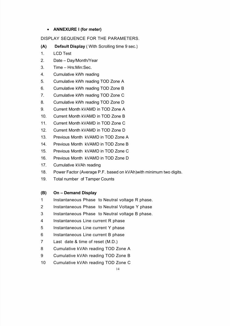
• ANNEXURE I (for meter)
DISPLAY SEQUENCE FOR THE PARAMETERS.
(A) Default Display ( With Scrolling time 9 sec.)
1. LCD Test
2. Date – Day/Month/Year
3. Time – Hrs:Min:Sec.
4. Cumulative kWh reading
5. Cumulative kWh reading TOD Zone A
6. Cumulative kWh reading TOD Zone B
7. Cumulative kWh reading TOD Zone C
8. Cumulative kWh reading TOD Zone D
9. Current Month kVAMD in TOD Zone A
10. Current Month kVAMD in TOD Zone B
11. Current Month kVAMD in TOD Zone C
12. Current Month kVAMD in TOD Zone D
13. Previous Month kVAMD in TOD Zone A
14. Previous Month kVAMD in TOD Zone B
15. Previous Month kVAMD in TOD Zone C
16. Previous Month kVAMD in TOD Zone D
17. Cumulative kVAh reading
18. Power Factor (Average P.F. based on kVAh)with minimum two digits.
19. Total number of Tamper Counts
(B) On – Demand Display
1 Instantaneous Phase to Neutral voltage R phase.
2 Instantaneous Phase to Neutral Voltage Y phase
3 Instantaneous Phase to Neutral voltage B phase.
4 Instantaneous Line current R phase
5 Instantaneous Line current Y phase6 Instantaneous Line current B phase
7 Last date & time of reset (M.D.)
8 Cumulative kVAh reading TOD Zone A
9 Cumulative kVAh reading TOD Zone B
10 Cumulative kVAh reading TOD Zone C
8/13/2019 Ltmetering Cabinet Spec Metering Cabinet090908
http://slidepdf.com/reader/full/ltmetering-cabinet-spec-metering-cabinet090908 15/28
15
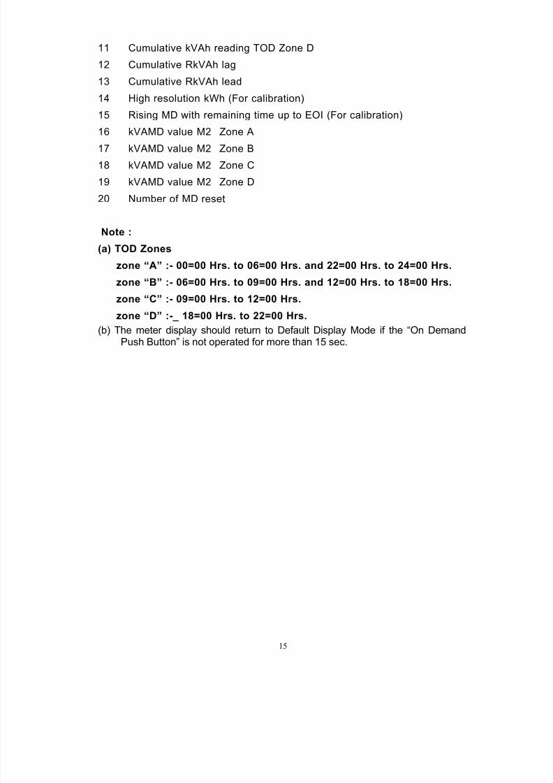
11 Cumulative kVAh reading TOD Zone D
12 Cumulative RkVAh lag
13 Cumulative RkVAh lead
14 High resolution kWh (For calibration)
15 Rising MD with remaining time up to EOI (For calibration)
16 kVAMD value M2 Zone A17 kVAMD value M2 Zone B
18 kVAMD value M2 Zone C
19 kVAMD value M2 Zone D
20 Number of MD reset
Note :
(a) TOD Zones
zone “A” :- 00=00 Hrs. to 06=00 Hrs. and 22=00 Hrs. to 24=00 Hrs.
zone “B” :- 06=00 Hrs. to 09=00 Hrs. and 12=00 Hrs. to 18=00 Hrs.
zone “C” :- 09=00 Hrs. to 12=00 Hrs.
zone “D” :-_ 18=00 Hrs. to 22=00 Hrs.
(b) The meter display should return to Default Display Mode if the “On DemandPush Button” is not operated for more than 15 sec.
8/13/2019 Ltmetering Cabinet Spec Metering Cabinet090908
http://slidepdf.com/reader/full/ltmetering-cabinet-spec-metering-cabinet090908 16/28
16
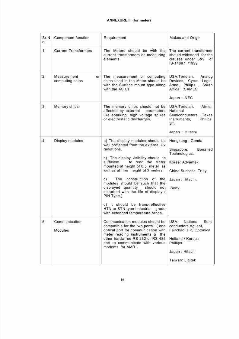
ANNEXURE II (for meter)
Sr.No.
Component function Requirement Makes and Origin
1 Current Transformers The Meters should be with thecurrent transformers as measuring
elements.
The current transformershould withstand for the
clauses under 5&9 ofIS-14697 /1999
2 Measurement orcomputing chips
The measurement or computingchips used in the Meter should bewith the Surface mount type alongwith the ASICs.
USA:Teridian, AnalogDevices, Cyrus Logic, Atmel, Phil ips , South Afr ica :SAMES
Japan : NEC
3 Memory chips The memory chips should not beaffected by external parameterslike sparking, high voltage spikes
or electrostatic discharges.
USA:Teridian, Atmel,NationalSemiconductors, Texas
Instruments, Philips,ST,
Japan : Hitachi
4 Display modules a) The display modules should bewell protected from the external Uvradiations.
b) The display visibility should besufficient to read the Metermounted at height of 0.5 meter aswell as at the height of 2 meters.
c) The construction of themodules should be such that thedisplayed quantity should notdisturbed with the life of display (PIN Type ).
d) It should be trans-reflectiveHTN or STN type industrial gradewith extended temperature range.
Hongkong : Genda
Singapore: BonafiedTechnologies.
Korea: Advantek
China Success ,Truly
Japan : Hitachi,
Sony.
5 Communication
Modules
Communication modules should becompatible for the two ports ( oneoptical port for communication withmeter reading instruments & the
other hardwired RS 232 or RS 485port to communicate with variousmodems for AMR )
USA: National Semiconductors,Agilent,Fairchild, HP, Optonica
Holland / Korea :Phillips
Japan : Hitachi
Taiwan: Ligitek
8/13/2019 Ltmetering Cabinet Spec Metering Cabinet090908
http://slidepdf.com/reader/full/ltmetering-cabinet-spec-metering-cabinet090908 17/28
17
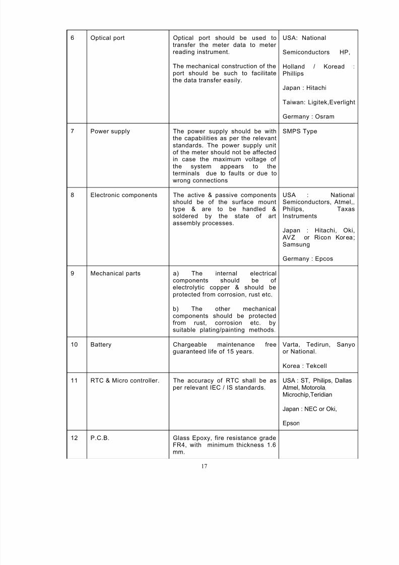
6 Optical port Optical port should be used totransfer the meter data to meterreading instrument.
The mechanical construction of theport should be such to facilitatethe data transfer easily.
USA: National
Semiconductors HP,
Holland / Koread :Phillips
Japan : Hitachi
Taiwan: Ligitek,Everlight
Germany : Osram
7 Power supply The power supply should be withthe capabilities as per the relevantstandards. The power supply unitof the meter should not be affectedin case the maximum voltage ofthe system appears to theterminals due to faults or due towrong connections
SMPS Type
8 Electronic components The active & passive componentsshould be of the surface mounttype & are to be handled &soldered by the state of artassembly processes.
USA : NationalSemiconductors, Atmel,,Philips, TaxasInstruments
Japan : Hitachi, Oki, AVZ or Ricon Korea;Samsung
Germany : Epcos
9 Mechanical parts a) The internal electricalcomponents should be ofelectrolytic copper & should be
protected from corrosion, rust etc.
b) The other mechanicalcomponents should be protectedfrom rust, corrosion etc. bysuitable plating/painting methods.
10 Battery Chargeable maintenance freeguaranteed life of 15 years.
Varta, Tedirun, Sanyoor National.
Korea : Tekcell
11 RTC & Micro controller. The accuracy of RTC shall be asper relevant IEC / IS standards.
USA : ST, Philips, Dallas Atmel, Motorola,
Microchip,Teridian
Japan : NEC or Oki,
Epson
12 P.C.B. Glass Epoxy, fire resistance gradeFR4, with minimum thickness 1.6mm.
8/13/2019 Ltmetering Cabinet Spec Metering Cabinet090908
http://slidepdf.com/reader/full/ltmetering-cabinet-spec-metering-cabinet090908 18/28
18
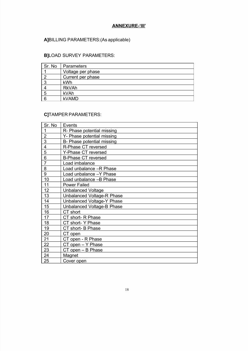
ANNEXURE-‘III’
A]BILLING PARAMETERS:(As applicable)
B]LOAD SURVEY PARAMETERS:
Sr. No Parameters
1 Voltage per phase
2 Current per phase
3 kWh
4 RkVAh
5 kVAh
6 kVAMD
C]TAMPER PARAMETERS:
Sr. No Events
1 R- Phase potential missing
2 Y- Phase potential missing
3 B- Phase potential missing
4 R-Phase CT reversed
5 Y-Phase CT reversed
6 B-Phase CT reversed
7 Load imbalance
8 Load unbalance –R Phase
9 Load unbalance –Y Phase
10 Load unbalance –B Phase
11 Power Failed12 Unbalanced Voltage
13 Unbalanced Voltage-R Phase
14 Unbalanced Voltage-Y Phase
15 Unbalanced Voltage-B Phase
16 CT short
17 CT short- R Phase
18 CT short- Y Phase
19 CT short- B Phase
20 CT open
21 CT open - R Phase
22 CT open – Y Phase23 CT open – B Phase
24 Magnet
25 Cover open
8/13/2019 Ltmetering Cabinet Spec Metering Cabinet090908
http://slidepdf.com/reader/full/ltmetering-cabinet-spec-metering-cabinet090908 19/28
19
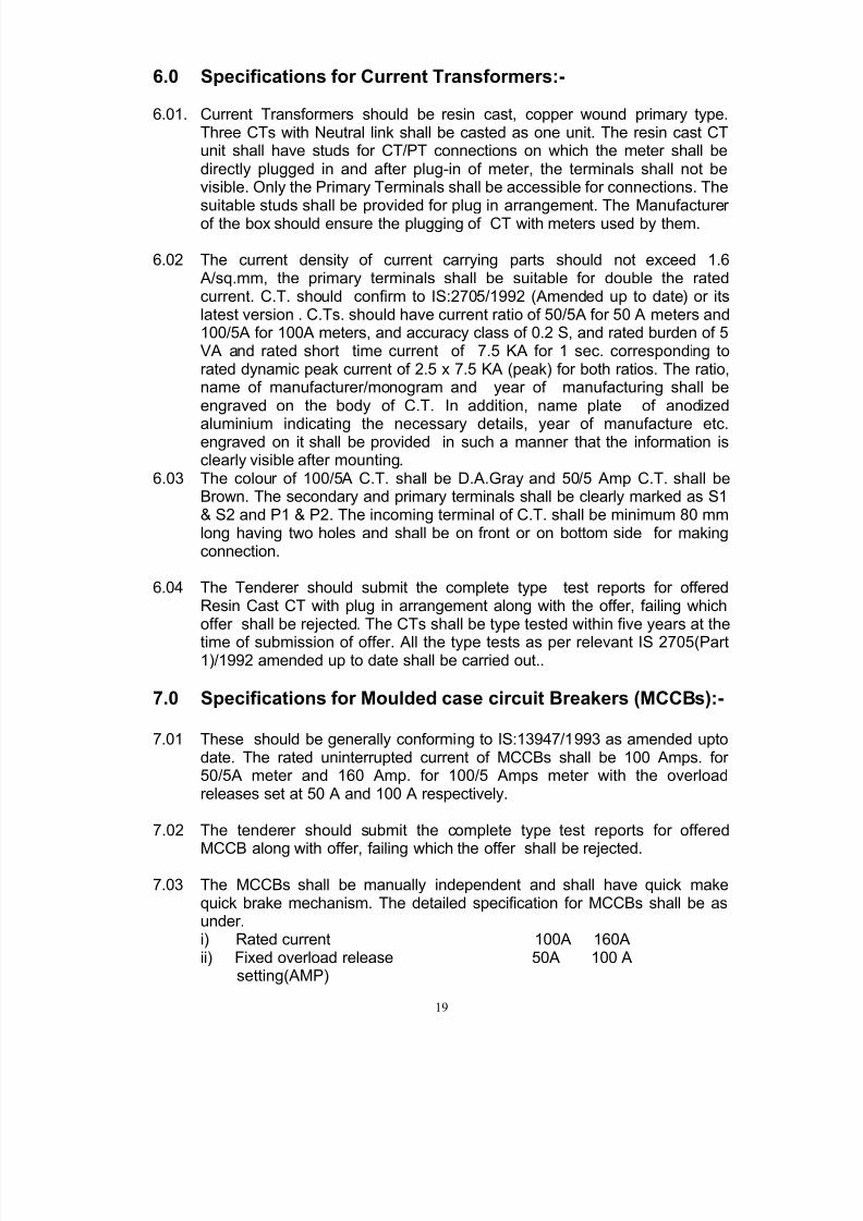
6.0 Specifications for Current Transformers:-
6.01. Current Transformers should be resin cast, copper wound primary type.Three CTs with Neutral link shall be casted as one unit. The resin cast CTunit shall have studs for CT/PT connections on which the meter shall bedirectly plugged in and after plug-in of meter, the terminals shall not bevisible. Only the Primary Terminals shall be accessible for connections. The
suitable studs shall be provided for plug in arrangement. The Manufacturerof the box should ensure the plugging of CT with meters used by them.
6.02 The current density of current carrying parts should not exceed 1.6 A/sq.mm, the primary terminals shall be suitable for double the ratedcurrent. C.T. should confirm to IS:2705/1992 (Amended up to date) or itslatest version . C.Ts. should have current ratio of 50/5A for 50 A meters and100/5A for 100A meters, and accuracy class of 0.2 S, and rated burden of 5VA and rated short time current of 7.5 KA for 1 sec. corresponding torated dynamic peak current of 2.5 x 7.5 KA (peak) for both ratios. The ratio,name of manufacturer/monogram and year of manufacturing shall beengraved on the body of C.T. In addition, name plate of anodized
aluminium indicating the necessary details, year of manufacture etc.engraved on it shall be provided in such a manner that the information isclearly visible after mounting.
6.03 The colour of 100/5A C.T. shall be D.A.Gray and 50/5 Amp C.T. shall beBrown. The secondary and primary terminals shall be clearly marked as S1& S2 and P1 & P2. The incoming terminal of C.T. shall be minimum 80 mmlong having two holes and shall be on front or on bottom side for makingconnection.
6.04 The Tenderer should submit the complete type test reports for offeredResin Cast CT with plug in arrangement along with the offer, failing whichoffer shall be rejected. The CTs shall be type tested within five years at the
time of submission of offer. All the type tests as per relevant IS 2705(Part1)/1992 amended up to date shall be carried out..
7.0 Specifications for Moulded case circuit Breakers (MCCBs):-
7.01 These should be generally conforming to IS:13947/1993 as amended uptodate. The rated uninterrupted current of MCCBs shall be 100 Amps. for50/5A meter and 160 Amp. for 100/5 Amps meter with the overloadreleases set at 50 A and 100 A respectively.
7.02 The tenderer should submit the complete type test reports for offered
MCCB along with offer, failing which the offer shall be rejected.
7.03 The MCCBs shall be manually independent and shall have quick makequick brake mechanism. The detailed specification for MCCBs shall be asunder.i) Rated current 100A 160Aii) Fixed overload release 50A 100 A
setting(AMP)
8/13/2019 Ltmetering Cabinet Spec Metering Cabinet090908
http://slidepdf.com/reader/full/ltmetering-cabinet-spec-metering-cabinet090908 20/28
20
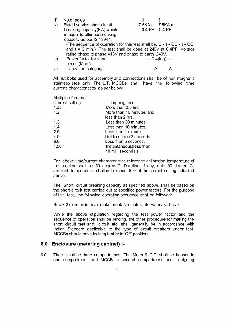
iii) No.of poles 3 3iv) Rated service short circuit 7.5KA at 7.5KA at
breaking capacity(KA) which 0.4 PF 0.4 PFis equal to ultimate breakingcapacity as per IS 13947.(The sequence of operation for this test shall be, O - t - CO - t - CO,and t = 3 min.) The test shall be done at 240V at 0.4PF. Voltagerating phase to phase 415V and phase to earth 240V.
v) Power factor for short --- 0.4(lag) ---circuit (Max.)
vi) Utilization category A A------------------------------------------------------------------------------------------ All nut bolts used for assembly and connections shall be of non magneticstainless steel only. The L.T. MCCBs shall have the following timecurrent characteristics as per below:
Multiple of normalCurrent setting Tripping time1.05 More than 2.5 hrs.
1.2 More than 10 minutes andless than 2 hrs.1.3 Less than 30 minutes.1.4 Less than 10 minutes.2.5 Less than 1 minute.4.0 Not less than 2 seconds.6.0 Less than 5 seconds.12.0 Instantaneous(less than
40 milli seconds.)
For above time/current characteristics reference calibration temperature ofthe breaker shall be 50 degree C. Duration, if any, upto 60 degree C.
ambient temperature shall not exceed 10% of the current setting indicatedabove.
The Short circuit breaking capacity as specified above, shall be based onthe short circuit test carried out at specified power factors. For the purposeof this test, the following operation sequence shall be followed:
Break-3 minutes interval-make break-3 minutes interval-make break.
While the above stipulation regarding the test power factor and thesequence of operation shall be binding, the other procedure for making theshort circuit test and circuit etc. shall generally be in accordance with
Indian Standard applicable to the type of circuit breakers under test.MCCBs should have locking facility in 'Off' position.
8.0 Enclosure (metering cabinet) :-
8.01 There shall be three compartments .The Meter & C.T. shall be housed inone compartment and MCCB in second compartment and outgoing
8/13/2019 Ltmetering Cabinet Spec Metering Cabinet090908
http://slidepdf.com/reader/full/ltmetering-cabinet-spec-metering-cabinet090908 21/28
21
terminal block in third compartment. Separate sheet steel partitions toisolate the three compartments from each other shall be provided.
8.02 The compartments shall be fabricated by using sheet steel of 14 SWG (2mm) thick and additional M.S. angle of min.20x20x2 mm or formed channelof 2 mm sheet steel for supporting the Doors shall be provided.
8.03 The enclosure shall be fabricated by using sheet steel of not less than 14SWG (2 mm) thickness and shall be properly continuous welded frominside.
8.04 The enclosure shall comply with the requirement of IP-44 type as per IS-13947 or the latest version thereof.
8.05 Suitable vents fitted with G.I.double wire mesh shall be provided frominside to ensure that the temperature inside the enclosure is notsubstantially different from that of the atmosphere.
8.06 Fixing of circuit breakers inside the enclosure shall be such as to allow free
circulation of air at its back and sides.
8.07 Doors of the each chamber shall be provided with panel lock/locks. Twomaster keys for opening the doors shall be provided. In addition to thepanel lock, arrangement for providing pad locks shall be made. Thehinges for compartment covers shall be as in the drawing and shall be sodesigned that the door cannot be opened without breaking the seals i.e.the hinges shall be provided from inside.
8.08 The enclosure shall be powder coated both inside and outside with suitableweather proof and corrosion resistant paints. The colour of the inside andoutside paint shall be dark admiralty gray for 100/5 A metering unit &
brown for 50/5 A metering unit.
8.09 Necessary fixing arrangement shall be provided at the back of theenclosure. The thickness of the fixing plate shall be minimum 5 mm.
8.10 Durable rubber gasket should be provided around the box to ensure dustand vermin proof door construction. Rubber lining should at least be 3 mmthick.
8.11 Roof should be slopping down with 5 degree angle.
8.12 The flats provided for fixing shall be of welded construction and the welding
should be on all sides.
8.13 The Knock out holes should be provided on the bottom plate. Suitable sizeof brass Cable glands should be provided for these holes. The size of cablewill be 3 1/2 core 70/120 mm.sq. aluminium XLPE armoured cable.
8/13/2019 Ltmetering Cabinet Spec Metering Cabinet090908
http://slidepdf.com/reader/full/ltmetering-cabinet-spec-metering-cabinet090908 22/28
22
8.14 50 x50 x 2 mm Channel should be welded below the bottom plate so thatthe Box and bottom plate will not come in direct contact with the groundwhile it is stored.
8.15 Sealing arrangement shall be provided for Meter, CT & MCCB chamberseparately.
8.16 Inter connecting cable for connection from C.T. to MCCB & MCCB tooutgoing terminal block shall be single core multi- stranded copper cable ofsize 35 sq. mm for 50 A. & 70 sq. mm for 100 A. cabinet. For neutralconnection single core copper multi stranded cable of size 35/50 mm. sq.as above shall be used.
8.17 The Danger Board as per MSEDCL drawing NO:62.70,2/2 shall be fitted onthe boxes.
8.18 The lugs suitable for copper stranded Cables of sizes 70/35 sq. mm ,singlecore cable shall be used for making connection inside box. All lugs shall beof tinned copper.
8.19 All holes for internal connections through which cables/leads are supposedto pass should be provided with rubber reels.
8.20 Handles of 10 mm. M.S. rod will be provided to all the doors separately toopen and close.
8.21 MCCB & CTs shall be mounted on metallic sheet of 2 mm thick or an angleframe and then it should be fitted in the enclosure box. Meter shall bemounted on the arrangement as shown in the drawing DIST/MM-IV/CTMR/2008/01 Sheet No.3/3 enclosed.
8.22 For both 100 A/50 A outgoing terminal block of bakelite/DMC shall beminimum of 300x50x15 mm thick size. The tinned copper strip of 25x6 mmand 180 mm long size should be provided for out going termination ofcables. Incoming terminal of C.T. having 80 mm minimum length will bebolted directly on terminal block. Stainless steel bolts fully threaded with 2nuts and washers of size shown in drawing shall be provided forconnections. Two resin cast insulators shall be provided for support ofeach terminal block.
8.23 MCCB shall be so mounted that it's operating knob/lever can be operatedfrom outside without opening the door. It should also be possible to lock theMCCB in 'OFF' position so that it cannot be switched 'ON'.
8.24 Toughened glass of 200 x150 x2 mm size for observing meter readingshould be provided from inside the door. It should be so fitted that in theevent of breaking ,it should be possible to replace it after opening thedoor.
8.25 All the wiring inside the box is included in the scope of work. The internalcopper cables should be suitably clamped inside the cabinet.
8/13/2019 Ltmetering Cabinet Spec Metering Cabinet090908
http://slidepdf.com/reader/full/ltmetering-cabinet-spec-metering-cabinet090908 23/28
23
8.26 C.Ts. shall be fixed with proper clamps using stainless steel bolts. All nutbolts used in the cabinet for current carrying path shall be of stainless steelonly.
8.27 Finish of Cabinet:- All sheet metal works shall undergochemical/mechanical cleaning process before powder coating.
8.28 Safety Arrangements
8.28.01 Two earthing studs of galvanized M.S. 50 mm long & 12 mm dia.shall be provided for external earth connections. These should be completewith plain washer, spring washer, nuts etc. Earthing Bolts must be weldedto prevent removal of the same from the Box.
8.28.02 All live connections shall be insulated with durable insulationmaterial.
9.0 Tests & Test Certificates:- For the MCCB & CT & Meter, requiredtestes shall be carried out at original manufacturer's work.
9.01 The L.T.C.T.Operated Metering Unit consisting of Meter, MCCB ,CTs etcand Meter, MCCB & CT as per the specifications shall be fully type testedand relevant standards at NABL Accredited lab. The tenderer shall furnishdetailed type test report of the test carried out within 5 years prior to duedate of opening of offer. The detailed type test reports are to be submittedin sealed cover duly super-scribed on it following details along with the offer:-
“ Detail Type Test Report of L.T. CT.Operated Metering Unit, Meter,MCCB & CT against Tender No.-------.The detailed type test reports shall be furnished with relevant
oscillogram & certified drawings of the equipment tests. The offers withouttype test reports shall be rejected.
The purchaser reserves the right to demand repetition of some or allthe type tests in presence of purchaser’s representative at purchaser'scost. All the above Type Test shall be carried out from laboratories whichare accredited by the National Board of Testing and CalibrationLaboratories (NABL) of Govt of India such as CPRI Bangalore/Bhopal,ERDA Baroda, to prove that equipments meet the requirements of thespecification. The Tenderers should also furnish certificate fromlaboratories where type tested that, requisite test facility available in housefor that particular test. Type Test Reports conducted in manufacturers ownlaboratory and certified by testing institute shall not be acceptable.
The tenderer should also furnish the guaranteed technical particularsof C.T.Operated Metering Unit, C.T.Operated Meter,MCCB & CTs in GTPschedule. The offer without duly filled in GTP schedule stands rejected.
8/13/2019 Ltmetering Cabinet Spec Metering Cabinet090908
http://slidepdf.com/reader/full/ltmetering-cabinet-spec-metering-cabinet090908 24/28
24
9.02 Acceptance Tests: Following tests shall be carried out as acceptancetests in addition to Routine Tests given below.
On complete unit.
a) Temperature rise test on one sample of each rating.b) Time current characteristics for MCCB at 1.05 & 1.2 times overload
release setting currentc) On C.T. as per relevant IS.2705/1992.d) On MCCB as per relevant IS:13947/1993.
9.03 Routine Testa) On complete unitb) Overall dimensions checkingc) Insulation Resistance Tests.d) High Voltage Test .e) Operation Test on MCCB.f) On C.T. as per relevant IS.2705/1992.g) On MCCB as per relevant IS:13947/1993.
10.0 Testing & Manufacturing Facilities:
i) Testing Facilities:-The Tenderer must clearly indicate the details oftesting facilities available in the works of manufacturer and whether thefacilities are adequate to carry out all Routine & Acceptance tests. Thesefacilities should be available to MSEDCL Engineers, if deputed to carry outor witness the tests in the manufacturer's works. The tenderer must haveall in-house testing facility to carry out acceptance test on the unit. If anytest cannot be carried out in the manufacturers works, the same should beclearly stated. All testing equipments shall be duly calibrated in the NABLapproved laboratories.
ii) Manufacturing Facilities: The tenderer should have following minimummanufacturing facilities in house to prove his reliability as a manufacturer ofCT operated energy metering unit.
a) Power operating shearing machineb) Power operated press breakc) Power operated power pressesd) Welding machinese) Assembling tools
The tenderer should furnish detailed process of painting. In case painting is
to be carried out from outside agency, the tenderer shall furnish thefacilities available with sub-contractor.
11.0 Prototype & Drawings:- The successful tenderer have to manufacturer theprototype Unit for each rating as per this specification before bulkmanufacturing. The tenderer should intimate the readiness of prototype toChief Engineer (Distribution) ,Prakashgad, 5th floor, MSEDCL, Mumbai. Therepresentative of C.E.(Distribution) will inspect the prototype on any day
8/13/2019 Ltmetering Cabinet Spec Metering Cabinet090908
http://slidepdf.com/reader/full/ltmetering-cabinet-spec-metering-cabinet090908 25/28
25
within 15 days from the date of readiness intimated. The inspection reportof prototype jointly signed by manufacturer and MSEDCL representativealong with the drawings shall be submitted by the tenderer toC.E.(Distribution). The Tenderers should submit the final drawings in linewith this specification and prototype to C.E.(Distribution ) for approvalbefore bulk manufacturing. The approval of prototype & drawings shall be aresponsibility of tenderer. No extra period will be allowed for gettingapproval of prototype and drawing & this will be inclusive in the period ofdelivery schedule given by the tenderer.
12.0 GUARANTEE:- The equipment shall be guaranteed for the period of five
years from the date of commissioning or five and half year from the date ofdispatch whichever is earlier. The equipments found defective within theabove guarantee period shall be replaced/repaired by the supplier free ofcost within one month of receipt of intimation .If the defective equipmentsare not replaced/repaired within the specified period above, the MSEDCLshall recover an equivalent amount plus 15% supervision charges from anyof the bills of the supplier.
13.0 Inspection:- All tests and inspection on the items like metering cabinet,static meter,CTs and the MCCB etc. shall be made at the place ofmanufacturer unless otherwise specially agreed upon by the manufacturerand the purchaser. The manufacturer shall provide the purchaser allreasonable facilities, without any charge to satisfy him that the material isbeing supplied in accordance with this specification. Inspection of the firstlot shall be carried out jointly by representative of CE (Dist) and EE ofInspection wing.
14.0 Random Sample Testing:- After dispatch of material against inspected lotto various store centers, RST shall be carried out at each stores. For thispurpose, two no.s of samples out of each hundred no.s received quantity of
the metering cabinets shall be selected for testing. RST of all the items i.e.CT operated static meter, CTs and MCCB shall be carried out invariably.
The 5 days advance information will be given to supplier for jointinspection and the date will not be altered to the convenience or request ofsupplier. If the supplier/supplier’s representative fails to attend on the datefixed for RST, the RST will be carried out in his absence & results of RSTwill be binding on supplier. If the single item of the meter cabinet fails inRST, the lot received at that particular stores will be rejected.
The meters will be tested by our EE (Testing) for –i) No load conditionii) Limits of error tests
iii) Starting current.iv) Repeatability of error testv) Temper. conditions as per specifications.
Also for the other items, Acceptance & Routine tests as perspecification will be carried out. In case the selected meter/ otheritem fails in any of the tests, the lot received at that particular storeswill be rejected.
8/13/2019 Ltmetering Cabinet Spec Metering Cabinet090908
http://slidepdf.com/reader/full/ltmetering-cabinet-spec-metering-cabinet090908 26/28
26
15.00 TENDER SAMPLE
Tenderers are required to submit 05 (Five) nos. of sample meters andCTs of each offered type / item along with the offer for evaluation. Thesamples shall be clearly marked with each type / item for whichsample is submitted and name of bidder. Out of these, one sampleshould be without Ultrasonic welding to confirm constructional
features. If samples of same make/brand of Meters/ CTs are offered
by more than one bidders, then only 3 No,s of them (of same make)will be selected randomly amongst samples received from variousbidders for type testing at ERDA and the test report thereof shall beapplicable to all such bidders for particular make/brand of LTCTmeters and CTs.
16.0 SCHEDULES
The tenderer shall fill in the following schedules which are part and partialof the tender specification and offer. If the schedules are not submitted
duly filled in with the offer, the offer shall be liable for rejection.
Schedule `A' ... Guaranteed and technical particulars .(As per GTPuploaded on e-tendering site)
Schedule ̀ C' ... Tenderer's ExperienceThe discrepancies if any between the specification and the catalogs
and/or literatures submitted as part of the offer by the bidders, the sameshall not be considered and representations in this regard will not beentertained.
If it is observed that there are deviations in the offer in GuaranteedTechnical Particulars , then, such deviations shall be treated as
deviations.
8/13/2019 Ltmetering Cabinet Spec Metering Cabinet090908
http://slidepdf.com/reader/full/ltmetering-cabinet-spec-metering-cabinet090908 27/28
27
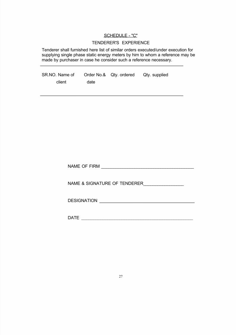
SCHEDULE - "C"
TENDERER'S EXPERIENCE
Tenderer shall furnished here list of similar orders executed/under execution forsupplying single phase static energy meters by him to whom a reference may be
made by purchaser in case he consider such a reference necessary.
SR.NO. Name of Order No.& Qty. ordered Qty. supplied
client date
NAME OF FIRM _______________________________________
NAME & SIGNATURE OF TENDERER_________________
DESIGNATION ________________________________________
DATE _______________________________________________
8/13/2019 Ltmetering Cabinet Spec Metering Cabinet090908
http://slidepdf.com/reader/full/ltmetering-cabinet-spec-metering-cabinet090908 28/28
28
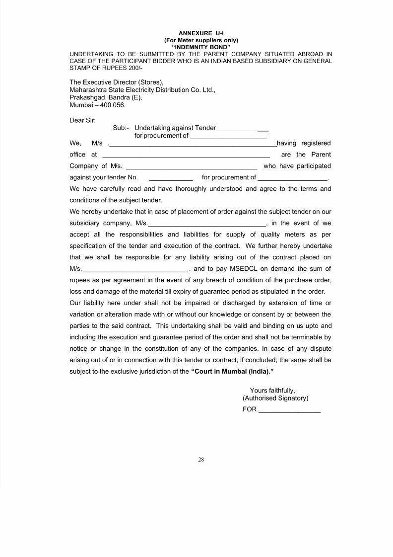
ANNEXURE U-I(For Meter suppliers only)
“INDEMNITY BOND” UNDERTAKING TO BE SUBMITTED BY THE PARENT COMPANY SITUATED ABROAD INCASE OF THE PARTICIPANT BIDDER WHO IS AN INDIAN BASED SUBSIDIARY ON GENERALSTAMP OF RUPEES 200/-
The Executive Director (Stores),Maharashtra State Electricity Distribution Co. Ltd.,
Prakashgad, Bandra (E),Mumbai – 400 056.
Dear Sir:Sub:- Undertaking against Tender ______________
for procurement of _____________________We, M/s .______________________________________________having registered
office at ______________________________________________ are the Parent
Company of M/s. ____________________________________ who have participated
against your tender No. ____________ for procurement of ___________________.
We have carefully read and have thoroughly understood and agree to the terms and
conditions of the subject tender.
We hereby undertake that in case of placement of order against the subject tender on our
subsidiary company, M/s.________________________________, in the event of we
accept all the responsibilities and liabilities for supply of quality meters as per
specification of the tender and execution of the contract. We further hereby undertake
that we shall be responsible for any liability arising out of the contract placed on
M/s._____________________________. and to pay MSEDCL on demand the sum of
rupees as per agreement in the event of any breach of condition of the purchase order,
loss and damage of the material till expiry of guarantee period as stipulated in the order.Our liability here under shall not be impaired or discharged by extension of time or
variation or alteration made with or without our knowledge or consent by or between the
parties to the said contract. This undertaking shall be valid and binding on us upto and
including the execution and guarantee period of the order and shall not be terminable by
notice or change in the constitution of any of the companies. In case of any dispute
arising out of or in connection with this tender or contract, if concluded, the same shall be
subject to the exclusive jurisdiction of the “Court in Mumbai (India).”
Yours faithfully,(Authorised Signatory)
FOR _________________