Embed Size (px)
Citation preview

Installation, Operation and Maintenance Instructions
Lubricated Rotary Vane Medical Vacuum SystemPart number 4107 9000 96Revision 04August 27, 2018


Part number 4107 9000 96Revision 04August 27, 2018
Installation, Operation and Maintenance Manual1.5 - 25 Hp Medical Lubricated Rotary Vane Vacuum System(Not intended for use on dedicated WAGD applications as per NFPA 99 - 2005 edition)
This unit is purchased from:
Date purchased:
Model number:
Serial number:
Option(s) included:
Any information, service or spare parts requests should include the machine serial number and be directed to:
BeaconMedæs1059 Paragon WayRock Hill, SC 29730
Telephone: (888) 463-3427Fax: (803) 817-5750
BeaconMedæs reserves the right to make changes and improvements to update products sold previously without notice or obligation.

i
Medical Lubricated Vacuum
4107 9000 96.04
Table of Contents
1.0 Electromagnetic Immunity
2.0 Installation2.1 Inspection Upon Receiving
2.2 Handling
2.3 Location
2.4 Locations Above Sea Level
2.5 Electrical Requirements
2.6 Intake Piping
2.7 Exhaust Piping
3A.0 Start Up - TotalAlert Embedded Controls
3A.1 Prestart-up
3A.2 Initial Start-up
3A.3 Initial Operation
3B.0 Start Up - Basic Controls
3B.1 Prestart-up
3B.2 Initial Start-up
3B.3 Initial Operation
4A.0 General Operation - TotalAlert Embedded Controls
4A.1 Electrical Control Panel
4A.2 Tank Drains
4A.3 Emergency Shutdown / Alarms
4A.4 Backup Vacuum Switch Set Point Adjustments
4B.0 General Operation - Basic Controls
4B.1 Electrical Control Panel
4B.2 Tank Drains
4B.3 Emergency Shutdown / Alarms
4B.4 Vacuum Switch Set Point Adjustments
5.0 Trouble Shooting
ii
Medical Lubricated Vacuum
4107 9000 96.04
6.0 Maintenance
6.1 General Maintenance
6.2 Oil
6.3 Drip Leg and Filters
6.4 Bearings
6.5 General Inspections
7.0 Replacement / Maintenance Parts
Service Kits for Lubricated Vane Systems
8.0 Maintenance Record
Appendix A: TotalAlert Embedded Control SystemA.1 Board Configurations
A.2 PCB1 (5.7” Display Controller)
A.3 PCB2 (3.5” Display Controller)
A.4 Password Access
A.5 Testing Alarms
A.6 Maintenance
A.7 Remote Monitoring
A.8 BACnet Activation
Table of Contents (continued)

iii
Medical Lubricated Vacuum
4107 9000 96.04
Safety PrecautionsThe operator should carefully read the entire contents of this manual before installing, wiring, starting, operating, adjusting and maintaining the system.
The operator is expected to use common-sense safety precautions, good workmanship practices and follow any related local safety precautions.
In addition:
• Before starting any installation or maintenance procedures, disconnect all power to the package.
• All electrical procedures must be in compliance with all national, state, and local codes and requirements.
• A certified electrician should connect all wiring.
• Refer to the electrical wiring diagram provided with the unit before starting any installation or maintenance work.
• Release all vacuum from the affected components before removing, loosening, or servicing any covers, guards, fittings, connections, or other devices.
• Notify appropriate hospital personnel if repairs or maintenance will affect available vacuum levels.
• Prior to using the LifeLine® Lubricated Rotary Vane Medical Vacuum System, the medical facility must have a Certifier perform all installation tests as specified in NFPA 99. The medical facility is also responsible for ensuring that the medical vacuum meets the minimum requirements for medical vacuum as specified in NFPA 99.
• This is a high speed, rotating piece of machinery. Do not attempt to service any part while machine is in operation.
• To prevent automatic starting, disconnect all electrical power before performing any maintenance functions.
• Do not operate unit without guards, shields or screens in place.
• Make sure that all loose articles, packing material, and tools are clear of the package.
• Check all safety devices periodically for proper operation.
• Electrical service must be the same as specified on the control panel nameplate or damage to the equipment may occur.
• Vibration during shipment can loosen electrical terminals, fuse inserts, and mechanical connections. Tighten all electrical connections prior to energizing the control panel.

1-1
Medical Lubricated Vacuum
4107 9000 96.04
Note: This section applicable to Lubricated Rotary Vane Medical Vacuum Systems with the TotalAlert Embedded electronic control system.
EN 61000-6-2
Medical Electrical Equipment needs special precautions regarding EMC and needs to be installed and put into service according to the EMC information provided in this manual.
Portable and mobile RF communications equipment can affect Medical Electrical Equipment.
The use of accessories, transducers, and cables other than those specified by the manufacturer, may result in decreased immunity of the TotalAlert Embedded control system.
The TotalAlert Embedded control system should not be used adjacent to other equipment. If adjacent use is necessary, the TotalAlert Embedded control system should be observed to verify normal operation in the configuration in which it will be used.
1.0 Electromagnetic Immunity

1-2
Medical Lubricated Vacuum
4107 9000 96.04
1.0 Electromagnetic Immunity
EN 61000-6-2 (Cont.)
Guidance and manufacturer’s declaration - electromagnetic immunityThe TotalAlert Embedded control system is intended for use in the electromagnetic environment specified below. The customer or the user of the TotalAlert Embedded control system should assure that it is used in such an environment.
Immunity test IEC 60601test level Compliance level Electromagnetic environment - guidance
Electrostatic Discharge (ESD) IEC 61000-4-2
±6 kV contact ±8 kV air
±6 kV contact ±8 kV air
Floors should be wood, concrete, metal or ceramic tile. If floors are covered with synthetic material, the relative humidity should be at least 30 %.
Electrical fast transient/burst IEC 61000-4-4
±2 kV for power supply lines ±1 kV for input/output lines
±2 kV for power supply lines ±1 kV for input/output lines
Mains power quality should be that of a typical commercial or hospital environment.
Surge IEC 61000-4-5
±1 kV differential mode ±2 kV common mode
±1 kV differential mode ±2 kV common mode
Mains power quality should be that of a typical commercial or hospital environment
Voltage dips, short Interruptions and voltage variations on power supply input lines IEC 61000-4-11
<5 % UT(>95 % dip in UT) for 0,5 cycle <40 % UT (>60 % dip in UT) for 5 cycles <70 % UT (>30 % dip in UT) for 25 cycles <5 % UT (>95 % dip in UT) for 5 sec
<5 % UT (>95 % dip in UT) for 0,5 cycle <40 % UT (>60 % dip in UT) for 5 cycles <70 % UT(>30 % dip in UT) for 25 cycles <5 % UT (>95 % dip in UT) for 5 sec
Mains power quality should be that of a typical commercial or hospital environment. If the user of the TotalAlert Embedded control system requires continued operation during power mains interruptions, it is recommended that the system be installed on an emergency power service.
Power frequency (50/60 Hz) magnetic field IEC 61000-4-8
3 A/m 3 A/m Power frequency magnetic fields should be at levels characteristic of a typical location in a typical commercial or hospital environment.
NOTE: UT is the a.c. mains voltage prior to application of the test level.

1-3
Medical Lubricated Vacuum
4107 9000 96.04
1.0 Electromagnetic Immunity
EN 61000-6-2 (Cont.)
Guidance and manufacturer’s declaration - electromagnetic immunityThe TotalAlert Embedded control system is intended for use in the electromagnetic environment specified below. The customer or the user of the TotalAlert Embedded control system should assure that it is used in such an environment.
Immunity test IEC 60601 test level Compliance level Electromagnetic environment - guidance
Conducted RFIEC 61000-4-6
Radiated RFIEC 61000-4-3
3 Vrms150 kHz to 80 MHz
3 V/m80 MHz to 2,5 GHz
3 Vrms
3 V/m
Portable and mobile RF communications equipment should be used no closer to any part of the TotalAlert Embedded control system, including cables, than the recommended separation distance calculated from the equation applicable to the frequency of the transmitter.
Recommended separation distance
d = 1,2√P
d = 1,2√P 80 MHz to 800 MHz
d = 2,3√P 800 MHz to 2,5 GHz
where P is the maximum output power rating of the transmitter in watts (W) according to the transmitter manufacturer and d is the recommended separation distance in metres (m).
Field strengths from fixed RF transmitters, as determined by an electromagnetic site survey,a should be less than the compliance level in each frequency range.b
Interference may occur in the vicinity of equipment marked with the following symbol:
NOTE 1 At 80 MHz and 800 MHz, the higher frequency range applies.
NOTE 2 These guidelines may not apply in all situations. Electromagnetic propagation is affected by absorption and reflection from structures, objects and people. a Field strengths from fixed transmitters, such as base stations for radio (cellular/cordless) telephones and land mobile radios, amateur radio, AM and FM radio broadcast and TV broadcast cannot be predicticted theoretically with accuracy. To assess the electromagnetic environment due to fixed RF transmitters, an electromagnetic site survey should be considered. If the measured field strength in the location in which the TotalAlert Embedded control system is used exceeds the applicable RF compliance level above, the TotalAlert Embedded control system should be observed to verify normal operation. If abnormal performance is observed, additional measures may be necessary, such as reorienting or relocating the TotalAlert Embedded control system.b Over the frequency range 150 kHz to 80 MHz, field strengths should be less than 3 V/m.

2-1
Medical Lubricated Vacuum
4107 9000 96.04
2.1 Inspection Upon Receiving
The condition of the LifeLine® Lubricated Rotary Vane Medical Vacuum System should be carefully inspected upon delivery. Any indication of damage by the carrier should be noted on the delivery receipt, especially if the system will not be immediately uncrated and installed. BeaconMedæs ships all systems F.O.B. factory; therefore, damage is the responsibility of the carrier, and all claims must be made with them. Lubricated Vane systems may remain in their shipping containers until ready for installation. If LifeLine® Lubricated Vane systems are to be stored prior to installation, they must be protected from the elements to prevent rust and deterioration.
DO NOT REMOVE the protective covers from the inlet and discharge connection ports of the unit until they are ready for connecting to the hospital’s pipeline distribution system.
2.2 Handling
WARNING:
USE APPROPRIATE LOAD RATED LIFTING EQUIPMENT AND OBSERVE SAFE LIFTING PROCEDURES DURING ALL MOVES.
The vacuum package can be moved with either a forklift or dollies. Keep all packing in place during installation to minimize damage. Walk along the route the unit must travel and note dimensions of doorways and low ceilings. Most LifeLine® Lubricated Vane systems are designed to go through 36” doorways (15 Hp through 25 Hp systems have bases that measure 43”).
Most Single Point Connection systems can be separated to fit through 36” doorways (15 Hp through 25 Hp skid bases measure 43”). If separating bases, carefully label all removed electrical connections for easier re-assembly at the final destination.
Modular systems are shipped as separate units to facilitate a variety of installations. Most modular and tank mount units are designed to fit through a standard 36” doorway, though some receiver modules may need to be tipped slightly (15 Hp through 25 Hp skid bases measure 43”). Some interconnecting piping and wiring between modules may be necessary on modular systems only.
Refer to the diagrams supplied with your system for dimensional, wiring and installation information.
Place units to ensure high visibility of indicators and gauges and for performing maintenance on the system. Refer to your installation diagram. If you do not have one, please contact BeaconMedæs Technical Support at 888-4-MEDGAS.
2.3 Location
The LifeLine® Lubricated Rotary Vane Medical Vacuum system should be installed indoors in a clean, well-ventilated environment. Areas of excessive dust, dirt or other air-borne particulate should be avoided.
Certain considerations should be given to the placement of the system. The package may be installed in a location that is flat, level, and will support its weight. Clearance between the unit and adjacent walls should be no less than 24” to ensure sufficient airflow for cooling. There should be a minimum of three feet of clearance in front of the control panel for safe operation and maintenance. A vertical distance of 24” is required above the modules for ventilation and maintenance.
No special foundation is required. However, all units must be securely bolted using all mounting holes provided. If a raised concrete pad is used, the module bases must not overhang the concrete base. A method to drain away moisture is necessary.
Adequate ventilation is required. The pumps are air-cooled. Therefore, it is very important that the
2.0 Installation

2-2
Medical Lubricated Vacuum
4107 9000 96.04
ambient temperature should be between 40˚F and 105˚F (if the maximum ambient exceeds 105˚F, contact factory for special instructions). The system should be located as close as possible to the point of usage to prevent excessive loss of operating vacuum due to pressure drop.
When selecting the location for the system, remember to keep in mind the requirements for service, such as cleaning, changing filters, and changing oil.
2.4 Locations Above Sea Level
All vacuum pumps above sea level have reduced flow and should be de-rated. After determining the correct flow needed for the medical vacuum system, multiply this number by the adjustment factor located in Table 2.1. After determining the new flow required, use this number to size the medical vacuum system.
Table 2.1 Altitude Adjustment Factor
Altitude (ft) Normal Barometric
Pressure (inches HG)
Multiplier Used for Required
SCFM
0 29.92 1.00500 29.39 1.02
1,000 28.86 1.041,500 28.33 1.062,000 27.82 1.082,500 27.32 1.103,000 26.82 1.123,500 26.33 1.144,000 25.84 1.165,000 24.90 1.206,000 23.98 1.257,000 23.09 1.308,000 22.23 1.359,000 21.39 1.40
10,000 20.58 1.45
2.0 Installation
2.5 Electrical Requirements
WARNING:
BE SURE THAT ALL POWER IS TURNED OFF PRIOR TO PERFORMING ANY WORK ON THE ELECTRICAL PANEL!
Refer to the electrical diagram provided with the unit before starting any installation or maintenance work.
Do not operate vacuum pump on a voltage other than the voltage specified on the control panel nameplate.
All customer wiring should be in compliance with the National Electrical Code and any other applicable state or local codes.
Refer to the wiring diagram(s) that came with the vacuum pump system for pertinent wiring connections.
Electrical power for the medical system must be supplied from the emergency life support circuit.
Check the control voltage, phase, and amp ratings before starting the electrical installation, and make sure the voltage supplied by the hospital is the same. The wire size should be able to handle peak motor amp load of all operating units. Refer to the vacuum pump system full load amperes on the wiring diagram.
Check all electrical connections within the vacuum system that may have loosened during shipment.
Qualified electricians only should make power connections to the control panel and any interconnecting wiring. The control panel has openings for electrical and alarm/data connections. Do not drill additional holes in the control panel as this may void the system warranty. See Figure 2.1 for opening locations.

2-3
Medical Lubricated Vacuum
4107 9000 96.04
2.0 InstallationElectrical
ConnectionAlarm Wires
Data Connection
Figure 2.1 Electrical/Alarm/Data Openings
Ensure that the emergency generation system electrical supply is consistent with the vacuum system’s requirements.
The electrical controls for the system were wired at the factory and were fully tested.
Three-phase power supplied from emergency generator(s) must match that of the normal supply to allow for correct direction of the motor rotation at all times.
NOTE: It may be necessary to switch two of the leads when performing start-up, if the pump rotation is in the wrong direction.
2.6 Intake Piping
Before connecting any piping, the plastic thread protector installed in the connection port must be removed. We recommend that the main vacuum line to the receiver should not be reduced below that provided on the receiver. Long piping runs may need to be increased in size to minimize pressure drop. Improper line sizing may result in a loss of capacity. Ideally, piping should be constructed using long radius elbows and a minimum number of turns.
All secondary lines should be taken from the top or side of the main line to prevent any accumulated moisture from draining towards the pumps. All lines should slope away from the pumps. Any low points in the piping should be equipped with pipe drains to remove accumulated moisture.
All intake vacuum lines must be piped in accordance with NFPA 99. All pipe must be either seamless copper tubing or other corrosion-resistant metallic tubing, as detailed in NFPA 99.
2.7 Exhaust Piping
The exhaust line must be piped outside of the building in accordance with NFPA 99. To ensure that no restriction of airflow will occur, size the piping according to Table 2.2. All pipe must be either seamless copper tubing or other corrosion-resistant metallic tubing as detailed in NFPA 99. A flexible connector must be installed on each exhaust port of the vacuum pump before connecting to the main exhaust line leading outdoors. Additionally, a drip leg must be installed at each exhaust port connection to allow for the draining of any accumulated moisture (Refer to the installation schematics for more details). The outside pipe must be turned down and screened to prevent contamination.

2-4
Medical Lubricated Vacuum
4107 9000 96.04
2.0 Installation
WARNING:
THE VACUUM EXHAUST VENT MUST BE LOCATED AWAY FROM MEDICAL AIR INTAKES, DOORS, AND OPENINGS IN THE BUILDINGS TO MINIMIZE POSSIBLE CONTAMINATION TO THE FACILITY, IN ACCORDANCE WITH NFPA 99.
Table 2.2 Exhaust Pipe Length
LifeLine Units
Pump Connection
System Exhaust Pipe Length (ft) - See Notes25 50 75 100 150 200 250 300 350 400 450 500
SIM
PLEX
1.5 Hp 1.25 1.25 1.25 1.25 1.25 1.25 1.25 1.25 1.25 1.25 1.25 1.25 1.25
2 Hp 1.25 1.25 1.25 1.25 1.25 1.25 1.25 1.25 1.25 1.25 1.5 1.5 1.5
3 Hp 1.25 1.5 1.5 1.5 1.5 1.5 1.5 1.5 1.5 1.5 1.5 2 2
5 Hp1 1.25 1.5 1.5 1.5 1.5 1.5 2 2 2 2 2 2 2
5 Hp2 2 2 2 2 2 2 2 2 2 2 3 3 3
7.5 Hp 2 2 2 2 2 2 2 3 3 3 3 3 3
10 Hp 2 2 2 2 3 3 3 3 3 3 3 3 3
15 Hp 3 3 3 3 3 3 3 3 3 4 4 4 4
20 Hp 3 3 3 3 3 3 3 3 4 4 4 4 4
25 Hp 3 3 3 3 3 3 4 4 4 4 4 4 4
DU
PLEX
1.5 Hp 1.25 1.25 1.25 1.25 1.25 1.25 1.25 1.5 1.5 1.5 1.5 1.5 1.5
2 Hp 1.25 1.5 1.5 1.5 1.5 1.5 1.5 2 2 2 2 2 2
3 Hp 1.25 1.5 1.5 1.5 1.5 2 2 2 2 2 2 3 3
5 Hp1 1.25 2 2 2 2 2 3 3 3 3 3 3 3
5 Hp2 2 2 2 2 3 3 3 3 3 3 3 3 3
7.5 Hp 2 3 3 3 3 3 3 3 3 3 3 4 4
10 Hp 2 3 3 3 3 3 4 4 4 4 4 4 4
15 Hp 3 3 3 4 4 4 4 4 4 4 4 4 5
20 Hp 3 4 4 4 4 4 4 4 5 5 5 5 5
25 Hp 3 4 4 4 4 4 5 5 5 5 5 5 5
TRIP
LEX
5 Hp2 2 3 3 3 3 3 3 3 3 4 4 4 4
7.5 Hp 2 3 3 3 3 3 4 4 4 4 4 4 4
10 Hp 2 4 4 4 4 4 4 4 4 4 5 5 5
15 Hp 3 4 4 4 4 4 5 5 5 5 5 5 5
20 Hp 3 5 5 5 5 5 5 5 5 5 6 6 6
25 Hp 3 5 5 5 5 5 5 6 6 6 6 6 6

2-5
Medical Lubricated Vacuum
4107 9000 96.04
LifeLine Units
Pump Connection
System Exhaust Pipe Length (ft) - See Notes25 50 75 100 150 200 250 300 350 400 450 500
QU
ADRU
PLEX
5 Hp2 2 3 3 3 3 3 4 4 4 4 4 4 4
7.5 Hp 2 3 3 3 3 4 4 4 4 4 4 5 5
10 Hp 2 4 4 4 4 4 4 5 5 5 5 5 5
15 Hp 3 5 5 5 5 5 5 5 5 6 6 6 6
20 Hp 3 6 6 6 6 6 6 6 6 6 6 6 6
25 Hp 3 6 6 6 6 6 6 6 6 8 8 8 8
Notes:
1. 5 Hp pump model RC0101 and RA0100. Incorporated into horizontal tankmount system designs.
2. 5 Hp pump model RC0155 and RA0155. Incorporated into basemount system designs.
3. All pipe sizes are based on the following: copper pipe (Type L), 14.7 psia.
4. The minimum pipe size must be maintained for the total length of the exhaust pipe. Use next larger size pipe in the event the minimum size is not available.
5. When determining the total pipe length, add all the straight lengths of pipe together in addition to the number of elbows times the effective pipe length for that pipe size. (See the following table and example.)
Table 2.3 Pipe Length for 90˚ Elbow
Effective Pipe Length Equivalent to each 90 degree Elbow Pipe Size (in.) 1.25 1.50 2.00 2.50 3.00 3.50 4.00 5.00 6.00 8.00
Eff. Pipe Length (ft) 3.4 4.0 4.9 6.4 7.9 9.4 10.0 11.9 13.2 14.5
Example: Select the pipe size for a Triplex 7.5 HP with 130 feet of straight pipe and six elbows:
A) Select the pipe size of 3” diameter for 130 feet of straight pipe.
B) Determine the eff. pipe length for an elbow of 3” dia. (EPL= 7.9 ft / elbow).
C) Calculate the SYSTEM PIPE LENGTH {SPL (3.0” D) = 130 + (6 x 7.9) = 177.4 ft}
D) Check this SYSTEM PIPE LENGTH to see if it exceeds the minimum pipe size. In this case it does, select the next larger pipe size from the table (D = 4”).
E) To double-check the pipe size, recalculate the SPL with the new diameter. SPL (D = 4”) = 130 + (6 x 10.0) = 190 ft. This is
in the allowable range.
2.0 Installation


3A-1
Medical Lubricated Vacuum
4107 9000 96.04
Note: This section applicable to Lubricated Rotary Vane Medical Vacuum Systems with the TotalAlert Embedded electronic control system.
3A.1 Prestart-up
The contractor should notify BeaconMedæs two weeks prior to start-up date to schedule an appointment for an authorized technician to review the installation prior to start-up.
CAUTION: Failure to install the unit properly and have an authorized technician from BeaconMedæs start-up the system can void the manufacturer’s warranties.
WARNING:
Prior to putting the LifeLine® Lubricated Rotary Vane Medical Vacuum system into use, the medical facility must have a Certifier perform all installation tests as specified in NFPA 99. The medical facility is also responsible for ensuring that the Medical Vacuum meets the minimum requirements for Medical Vacuum as specified in NFPA 99.
Prestart-up and start-up procedures should be performed for a new installation or when major maintenance has been performed.
WARNING:
Have more than one person on hand during prestart-up and start-up procedures to ensure safety and to facilitate certain checks.
The main power source to the control panel should be OFF for the duration of the visual inspection.
Ensure that the equipment is installed on a solid level surface. Walk around the system to ensure that there is enough clearance on all sides to perform operational checks/actions and maintenance. The temperature of the area containing the modules
should be approximately 70°F (21.1°C) with a minimum ambient temperature of 40°F (4.4°C) and a maximum ambient temperature of 105°F (40°C).
• Check the intake piping for proper size and connection to the vacuum modules.
• Check all piping system joints that might have come loose during shipment and installation to ensure they are tight.
• Check the air receiver, controls, and pumps for damage.
• Check the drain valve on the air receiver.
• Check all valves for full open and full close travel. Ensure that the system’s valves are positioned for proper operation. (Refer to labeling on valve handles)
• Remove all packing material from the unit.
• Check the electrical connections to the control cabinet.
• Verify electrical service. Before starting the system, check to see that voltage, amperage, and wire size are appropriate.
CAUTION: Electrical service must be as specified or damage to equipment may occur.
WARNING:
To prevent electrical shock, ensure that ALL electrical power to the system is OFF, including the disconnect switches and Automatic-Off-Manual touch screens on the control panel. The facility’s supply circuit breaker should also be locked out.
• Open the electrical cabinet by loosening the fasteners on the front.
3A.0 Start Up - TotalAlert Embedded Controls

3A-2
Medical Lubricated Vacuum
4107 9000 96.04
CAUTION: Vibration during shipment and installation can loosen electrical terminals, fuse inserts, and mechanical connections. Tighten as necessary.
• Check the electrical cabinet for any broken components.
• Check that all motor starter connections are tight and that there are no loose objects such as terminal lugs, screws, nuts, etc., in the cabinet.
3A.2 Initial Start-up
CAUTION: Complete the prestart-up procedure before continuing with the initial start-up procedure
WARNING:
To prevent electrical shock, ensure that ALL electrical power to the system is OFF, including the disconnect switches. The facility’s supply circuit breaker should also be locked out.
3A.2.1 Lubrication
The pumps are oil lubricated. The lubricating oil can be put into the pump at the oil filler port of the oil separator housing, observing the “MAX” and “MIN” position at the oil level sight glass. (For recommended oil type, refer to Section 6.1.) After filling, make sure the oil filler port is closed.
All LifeLine® lubricated vacuum pumps are shipped with the required amount of oil for start-up. The systems are shipped with separate oil containers, which must be added before start-up.
3A.2.2 Pump Rotation
Inside the control panel, make sure that all unit printed circuit boards are set to the manual override “Off” position. This is indicated by the middle position “X” on the three-position sliding switch as shown in Figure 3.1.
3A.0 Start Up - TotalAlert Embedded ControlsCheck all voltages supplied to the LifeLine® system to ensure they are the required value and phases needed by the control panel.
Apply power to the system and turn the disconnect switches to “On”.
Manual Override Switch
O - On ManualX - OffA - Automatic
Figure 3A.1 Unit PCB Override Switch
Prior to actual operation, the pumps must be checked for correct rotation.
Inside the control cabinet, switch one of the unit printed circuit boards from the manual override “Off” position to the bottom position, the default “Automatic” mode. Make sure the Pump Mode on the Unit touchscreens are in the Off position, see Figures 3.2 and 3.3. (See Figure A.15 for complete list of Screen Toolbar Descriptions).
Check for correct direction of rotation of each pump by pressing the “Rotation” button on touchscreen display (found in the Service section of the Unit touchscreens) and observing rotation. See Figure 3.4. The Pump Mode for each compressor must be in the Off Position for the Rotation to function.
3A-3
Medical Lubricated Vacuum
4107 9000 96.04
3A.0 Start Up - TotalAlert Embedded Controls
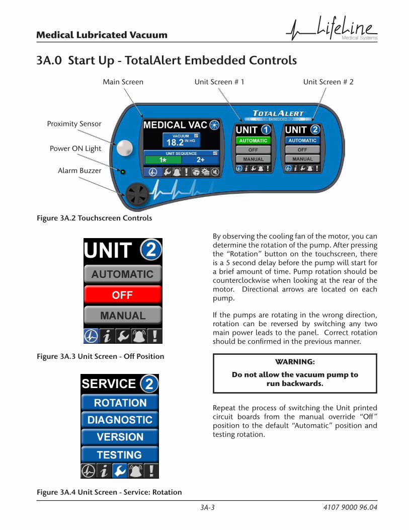
Figure 3A.2 Touchscreen Controls
Main Screen
Proximity Sensor
Unit Screen # 2Unit Screen # 1
Alarm Buzzer
Power ON Light
Figure 3A.3 Unit Screen - Off Position
Figure 3A.4 Unit Screen - Service: Rotation
By observing the cooling fan of the motor, you can determine the rotation of the pump. After pressing the “Rotation” button on the touchscreen, there is a 5 second delay before the pump will start for a brief amount of time. Pump rotation should be counterclockwise when looking at the rear of the motor. Directional arrows are located on each pump.
If the pumps are rotating in the wrong direction, rotation can be reversed by switching any two main power leads to the panel. Correct rotation should be confirmed in the previous manner.
WARNING:
Do not allow the vacuum pump to run backwards.
Repeat the process of switching the Unit printed circuit boards from the manual override “Off” position to the default “Automatic” position and testing rotation.

3A-4
Medical Lubricated Vacuum
4107 9000 96.04
3A.0 Start Up - TotalAlert Embedded Controls
3A.3 Initial Operation
Start each pump by pressing “Automatic” on the touchscreen. See Figure 3.5.
Figure 3A.5 Unit Screen - Automatic Mode
WARNING:
Pumps that have reached operating temperature may have a high surface temperature on the top of the exhaust muffler.
DO NOT TOUCH!
Run the pump for two minutes in the correct rotation. Stop the pump and top off the oil level utilizing the oil filler port to the correct level as shown in the sight glass. DO NOT OPEN THE FILLER PORT WHILE THE PUMP IS RUNNING.
After testing each pump, if everything appears normal, put each pump into the “Automatic” mode and allow each pump to run until vacuum builds. Check for any leaks in the piping. Repair leaks, if needed.

3B-1
Medical Lubricated Vacuum
4107 9000 96.04
Note: This section applicable to Lubricated Rotary Vane Medical Vacuum Systems with the Basic control system.
3B.1 Prestart-up
The contractor should notify BeaconMedæs two weeks prior to start-up date to schedule an appointment for an authorized technician to review the installation prior to start-up.
CAUTION: Failure to install the unit properly and have an authorized technician from BeaconMedæs start-up the system can void the manufacturer’s warranties.
WARNING:
Prior to putting the LifeLine® Lubricated Rotary Vane Medical Vacuum system into use, the medical facility must have a Certifier perform all installation tests as specified in NFPA 99. The medical facility is also responsible for ensuring that the Medical Vacuum meets the minimum requirements for Medical Vacuum as specified in NFPA 99.
Prestart-up and start-up procedures should be performed for a new installation or when major maintenance has been performed.
WARNING:
Have more than one person on hand during prestart-up and start-up procedures to ensure safety and to facilitate certain checks.
The main power source to the control panel should be OFF for the duration of the visual inspection.
Ensure that the equipment is installed on a solid level surface. Walk around the system to ensure that there is enough clearance on all sides to perform operational checks/actions and maintenance. The temperature of the area containing the modules
should be approximately 70°F (21.1°C) with a minimum ambient temperature of 40°F (4.4°C) and a maximum ambient temperature of 105°F (40°C).
• Check the intake piping for proper size and connection to the vacuum modules.
• Check all piping system joints that might have come loose during shipment and installation to ensure they are tight.
• Check the air receiver, controls, and pumps for damage.
• Check the drain valve on the air receiver.
• Check all valves for full open and full close travel. Ensure that the system’s valves are positioned for proper operation. (Refer to labeling on valve handles)
• Remove all packing material from the unit.
• Check the electrical connections to the control cabinet.
• Verify electrical service. Before starting the system, check to see that voltage, amperage, and wire size are appropriate.
CAUTION: Electrical service must be as specified or damage to equipment may occur.
WARNING:
To prevent electrical shock, ensure that ALL electrical power to the system is OFF, including the disconnect switches and Automatic-Off-Manual switches on the control panel. The facility’s supply circuit breaker should also be locked out.
• Open the electrical cabinet by loosening the fasteners on the front.
3B.0 Start Up - Basic Controls

3B-2
Medical Lubricated Vacuum
4107 9000 96.04
CAUTION: Vibration during shipment and installation can loosen electrical terminals, fuse inserts, and mechanical connections. Tighten as necessary.
• Check the electrical cabinet for any broken components.
• Check that all motor starter connections are tight and that there are no loose objects such as terminal lugs, screws, nuts, etc., in the cabinet.
3B.2 Initial Start-up
CAUTION: Complete the prestart-up procedure before continuing with the initial start-up procedure
WARNING:
To prevent electrical shock, ensure that ALL electrical power to the system is OFF, including the disconnect switches. The facility’s supply circuit breaker should also be locked out.
3B.2.1 Lubrication
The pumps are oil lubricated. The lubricating oil can be put into the pump at the oil filler port of the oil separator housing, observing the “MAX” and “MIN” position at the oil level sight glass. (For recommended oil type, refer to Section 6.1.) After filling, make sure the oil filler port is closed.
All LifeLine® lubricated vacuum pumps are shipped with the required amount of oil for start-up. The systems are shipped with separate oil containers, which must be added before start-up.
3B.2.2 Pump Rotation
Prior to actual operation, the pumps must be checked for correct rotation.
Apply power to the system and turn the disconnect switches to “On”.
3B.0 Start Up - Basic ControlsCheck all voltages supplied to the LifeLine® system to ensure they are the required value and phases needed by the control panel.
Using the Hand-Off-Auto switch on the door of the control panel, jog the motor of the specific pump that is to be checked by momentarily turning the switch to “Hand” and back to “Off”. By observing the cooling fan of the motor, you can determine the rotation of the pump. Pump rotation should be counterclockwise when looking at the rear of the motor. Directional arrows are located on each pump.
If the pumps are rotating in the wrong direction, rotation can be reversed by switching any two main power leads to the panel. Correct rotation should be confirmed in the previous manner.
WARNING:
Do not allow the vacuum pump to run backwards.
Repeat the process of testing rotation for each vacuum pump.
3B.3 Initial Operation
Using the “Hand-Off-Auto” switch, start pump by switching to “Auto”.
Run the pump for two minutes in the correct rotation. Stop the pump and top off the oil level utilizing the oil filler port to the correct level as shown in the sight glass. DO NOT OPEN THE FILLER PORT WHILE THE PUMP IS RUNNING.
WARNING:
Pumps that have reached operating temperature may have a high surface temperature on the top of the exhaust muffler.
DO NOT TOUCH!

3B-3
Medical Lubricated Vacuum
4107 9000 96.04
3B.0 Start Up - Basic Controls
After testing each pump, if everything appears normal, put each pump into the “Auto” mode and allow each pump to run until vacuum builds. Check for any leaks in the piping. Repair leaks, if needed.


4A-1
Medical Lubricated Vacuum
4107 9000 96.04
Note: This section applicable to Lubricated Rotary Vane Medical Vacuum Systems with the TotalAlert Embedded electronic control system.
WARNING:
NEVER RUN THE PUMP WITHOUT LUBRICATING OIL!
4A.1 Electrical Control Panel
The LifeLine multiplex control system is U.L. labeled. The control system has a touch screen control, automatic lead/lag sequencing, external operators with circuit breaker disconnects, full voltage motor starters, overload protection, 24V control circuit, and automatic-off-manual selector for each vacuum pump. Automatic alternation of all vacuum pumps is based on first-on/first-off principle with provisions for simultaneous operation if required. Automatic activation of reserve unit, if required, will activate an audible alarm as well as a visual alarm on the control panel. The control panel displays service alert, run hours for each vacuum pump, system status, system vacuum level, and high discharge air temperature. A complete alarm and service history is available on the control panel. (see Appendix A for more details)
During normal operation, all pumps should be in the “Automatic” position so that the control system can effectively run the system. The control system monitors the system vacuum level, starts and stops the pumps depending on changing vacuum level conditions and minimum run time values, and automatically alternates the lead position between units.
On the initial system start-up, when the system vacuum level is below the set point of the vacuum transducer, pump 1 will start immediately. Another pump starts after a programmed time delay. The time delay prevents high inrush current after a power failure or emergency power switch over. During this initial system start-up, the lag alarm may come on at this point and is normal. It can be
reset once the system reaches its normal operating vacuum and the lag pump times out and stops. See Figure 4A.1.
Reset Button
Figure 4A.1 Main Screen - Reset Button
In a typical duplex system, one pump will be able to handle the system load. The control system will signal the lead pump to start when the vacuum transducer senses the vacuum level below its set point. If one pump can carry the load, then the vacuum level will rise and maintain the vacuum level setting. At this point, if the minimum run timer for that pump has been satisfied, the control system will turn off the lead pump. If the minimum run timer for that pump has not been satisfied, the lead pump will continue to run until the timer expires. When the system vacuum drops below the vacuum level setting, the control system will automatically sequence the lead role to the other pump and will start it. This is also known as “first on/first off” instead of the more traditional “last on/first off”.
4A.0 General Operation - TotalAlert Embedded Controls
4A-2
Medical Lubricated Vacuum
4107 9000 96.04
With the “first on/first off” sequencing technique, starts and stops on the pump are minimized. If the lead pump runs continuously in lead for more than the minimum run time, the control system will automatically sequence the pump attempting to evenly distribute the run time among all available pumps. If during operation, the second pump is required to come on in addition to the lead pump, the control system will turn on the “Lag Alarm” (see section 4A.3).
In a triplex or quadruplex system, the operation is very similar to the duplex operation described above with the following differences. With a triplex or a quadruplex system, the lag unit running alarm may not necessarily correspond to the third or fourth pump coming on. To determine when the control system turns on the lag alarm, it counts the number of units in the “Automatic” position and makes a decision based on the vacuum transducer signal. A lag alarm occurs when the last available pump (in automatic) starts.
4A.1.1 Run Timer
All LifeLine lubricated vacuum systems incorporate run timers to minimize the starts and stops on the vacuum pumps. After the pump has stopped, its runtime will be adjusted based on how long the lead pump is off.
• 1.5 Hp through 5 Hp pumps runtime range is 2.5 - 10 minutes
• 7.5 Hp through 25 Hp pumps runtime range is 5 - 15 minutes
4A.2 Tank Drains
The standard tank drain consists of a manually operated ball valve.
To drain the liquid from the tank, open the tank bypass valve and close the tank isolation valves. Then open the vent and drain valves. When draining is complete, close the vent and drain valves first, then open the tank isolation valves and close the tank bypass valve.
4A.0 General Operation - TotalAlert Embedded Controls
4A.3 Emergency Shutdown / Alarms
The following conditions may arise during operation.
4A.3.1 Unit Shutdown / Alarms
Unit Screens
Figure 4A.2 Unit Screens - Shutdown and Alarms
Motor Overload Shutdown - This will shut down the pump in question and will not re-start the pump until the reset button on the starter is reset (See “Motor breakers trip” in the Trouble Shooting Section 5). Press the alarm silence button on the main display screen to silence the alarm. After the starter is reset, push the “Reset” button on the Unit Shutdown screen. On the Unit main screen, put the pump into “Automatic” mode to make the pump available for operation.
High Discharge Exhaust Temperature ShutdownThis will shut down the vacuum pump in question and not re-start the pump until the condition is corrected, the “Reset” button is pushed on the Unit Shutdown screen and the “Automatic” button is pressed on the Unit main screen. Before allowing the unit to re-start, the condition should be checked (see “Pump overheats” in the Trouble Shooting Section 5.0). Even after resetting the alarm and putting the vacuum unit in “Automatic” mode, the unit may not re-start, depending on system sequencing and system pressure.

4A-3
Medical Lubricated Vacuum
4107 9000 96.04
4A.0 General Operation - TotalAlert Embedded Controls
High Discharge Exhaust Temperature AlarmThis will not shut down the pump in question but instead is a warning that a shutdown is likely to occur. The condition should be checked immediately (see “Pump overheats” in the Trouble Shooting Section 5.0) to avoid a pump shutdown.
Control Circuit Alarm - This will not shut down the pump in question but instead is a notification that there is a loss of communication between printed circuit boards within the control panel. See Appendix A on Control System for trouble shooting.
4A.3.2 System Alarms
Figure 4A.3 Main Screen
Lag Unit Running Alarm - This alarm will activate if the last available vacuum pump comes on. Press the alarm silence button on the main display screen to silence the alarm. If a lag condition remains, the “Red” indicating light on the Main screen will remain on. Once the lag condition is corrected, press the reset button to turn off alarm light on display screen.
In the case of a duplex system, it will activate when the second vacuum pump turns on based on the signal from the vacuum transducer. In the case of a multiplex system, the lag alarm will activate when the last available unit is required to come on. For example, in a quadruplex system, if all four pumps are set to “Automatic”, then the lag
alarm will trigger when the fourth unit comes on. If on the same system, three (3) of the four pumps are set to “Automatic” and the other to “Off” or “Manual”, then the lag alarm will activate when the third unit comes on. In the event the lag alarm is persistent, check to see if any leaks or valves are open downstream or reduce the system load.
Please note that the lag alarm may not be reset if the lag pump is still running. This can happen due to the run timer not having expired, but the lag vacuum level itself may be above the alarm setting.
The Lag Alarm will activate if the vacuum transducer signal circuit is lost or the transducer malfunctions. Press the alarm silence button on the main display screen to silence the alarm (see Troubleshooting Section 5). The vacuum level reading on the main display will read “ERR” when this alarm occurs. The vacuum system will continue to run off the backup vacuum switch.
Ambient Temperature Alarm - This alarm will activate when the temperature in the room exceeds the set point. The audible alarm will not sound but the touchscreen will show an active alarm and record it in the event log. The alarm remains latched until the alarm condition is reset by the operator.
Control Circuit Alarm - This alarm will activate when there is a loss of communication between printed circuit boards within the control panel. See Appendix A on Control System for trouble shooting.
4A.3.3 Service Warnings
Service Due Alarm - Service intervals and type of service are preprogrammed into the control system. The background of the wrench icon on the main display screen toolbar will turn red when one of these services are required. See Table 6.1 Maintenance Schedules.

4A-4
Medical Lubricated Vacuum
4107 9000 96.04
4A.4 Backup Vacuum Switch Set Point Adjustments
The backup switch is set at the factory to the operating point(s) as stated on the wiring diagram supplied with the unit. It is good practice to cycle the switch to determine actual operating points before proceeding with readjustment. Refer to Figure 4A.4 for location of adjustment.
CAUTION:
• ALWAYS change vacuum setting gradually.
• ALWAYS check switch setting before making any adjustments.
• DO NOT force adjustment sleeve when it becomes difficult to turn.
• ALWAYS isolate the vacuum transducer before making any adjustments to the backup vacuum switch.
Figure 4A.4 Backup Vacuum Switch
4A.0 General Operation - TotalAlert Embedded Controls
Adjusting Instructions
1. To make an adjustment, loosen the tamper resistant set screws (2) on the adjustment sleeve.
2. Secure the hex body with an open-end wrench. Hand turn the adjustment sleeve: counter-clockwise to increase and clockwise to decrease the set point. The backup vacuum switch should always be set with falling vacuum level starting at a vacuum level higher than the setpoint.
3. Using the vacuum gauge determine the actuation point of the switch.
4. If the actuation point is above the desired value, turn the adjustment sleeve clockwise to decrease the actuation point, and if it is below, turn the adjustment sleeve counter-clockwise to increase it.
5. For exact vacuum setting, cycle vacuum switch and make fine adjustments by repeating steps 2 through 4 (trial and error process) until the desired setting is obtained.
6. Secure the tamper resistant set screws (2) on the adjustment sleeve.
CAUTION: Do not overtighten set screws.
Tamper ResistantSet Screws (2)Increase
Decrease

4B-1
Medical Lubricated Vacuum
4107 9000 96.04
Note: This section applicable to Lubricated Rotary Vane Medical Vacuum Systems with the Basic control system.
WARNING:
NEVER RUN THE PUMP WITHOUT LUBRICATING OIL!
4B.1 Electrical Control Panel
The LifeLine multiplex control panel includes a visual and audible lag pump alarm and a 0-30”Hg vacuum gauge. It also has the following for each pump: 24V power supply with fuses, hourmeter, vacuum control switch, high discharge air temperature switch with alarm, illuminated Hand-Off-Auto switch, motor starter and circuit breaker with external disconnect. All components are enclosed in a NEMA 12 enclosure.
During normal operation, all H-O-A switches should be turned to the “Auto” position so that the PLC can effectively control the system. The PLC monitors the system vacuum switch condition, starts and stops the pumps depending on changing vacuum switch conditions and minimum run time values, and automatically alternates the lead position between units.
In a typical duplex system, one pump will be able to handle the system load. The PLC will signal the lead pump to start when the lead vacuum switch (VS-1) closes with decreasing vacuum level. If the one pump can carry the load, then the vacuum level will rise and VS-1 will open. At this point, if the minimum run timer for that pump has been satisfied, the PLC will turn off the lead pump. If the minimum run timer for that pump has not been satisfied, the lead pump will continue to run until the timer expires. When the system vacuum drops again and VS-1 closes, the PLC will automatically sequence the lead role to the other pump and will start it. This is also known as “first on/first off” instead of the more traditional “last on/first off”. With the “first on/first off” sequencing technique, starts and stops on the pump are minimized. If the
lead pump runs continuously in lead for more than 15 minutes, the PLC will automatically sequence the pump attempting to evenly distribute the run time among all available pumps. (This value is variable and is equal to the current minimum run time value.) If during operation, the second pump is required to come on in addition to the lead pump, the PLC will turn on the “Lag Alarm”.
In a triplex or quadruplex system, the operation is very similar to the duplex operation described above with the following differences. For each additional pump, there is an additional vacuum switch. (Refer to the wiring diagram that came with the unit for actual vacuum switch setpoints.) With a triplex or a quadruplex system, the lag unit running alarm may not necessarily correspond to the third or fourth pump coming on. To determine when the PLC turns on the lag alarm, it counts the number of units in the “Auto” position and makes a decision based on the vacuum switch conditions. For instance, in a quadruplex system with only 2 H-O-A switches in the “Auto” position, the lag alarm will turn on when the second unit is started (or the lag vacuum switch VS-2 closes).
On the initial system start-up, when the system vacuum level is below the setpoints of the vacuum control switches, pumps 1 and 4 will start. After a 7 second delay, pump 2 will start. After another 7 second delay, pump 3 will start. The time delay is to prevent high inrush current after a power failure or emergency power switch over. During this initial system start-up, the lag alarm will come on at this point and is normal. It can be reset once the vacuum level is high enough to open the lag vacuum switch. Refer to the wiring diagram supplied with the system for the correct vacuum switch settings.
4B.0 General Operation - Basic Controls

4B-2
Medical Lubricated Vacuum
4107 9000 96.04
4B.2 Tank Drains
The standard tank drain consists of a manually operated ball valve.
To drain the liquid from the tank, open the tank bypass valve and close the tank isolation valves. Then open the vent and drain valves. When draining is complete, close the vent and drain valves first, then open the tank isolation valves and close the tank bypass valve.
4B.3 Emergency Shutdown / Alarms
The following conditions may arise during operation.
Motor Overload Shutdown - This will shut down the pump in question and will not re-start the pump until the reset button on the starter inside the main control cabinet is reset. See Section 5 for troubleshooting information.
High Discharge Exhaust Temperature ShutdownThis will shut down the vacuum pump in question and not re-start the pump until the condition is corrected and the appropriate red push button is pressed on the main control panel. Before allowing the unit to re-start, the condition should be checked (see “Pump overheats” in the Trouble Shooting Section 5.0). Even after resetting the alarm and putting the vacuum unit in “Auto” mode, the unit may not re-start, depending on system sequencing and system pressure.
Lag Unit Running Alarm - This alarm will activate if the last available vacuum pump comes on. In the case of a duplex system, it will activate when the second pump turns on or the lag vacuum switch (VS-2) closes. In the case of a multiplex system, the lag alarm will activate when the last available unit is required to come on. For example, in a quadruplex system, if all four (4) H-O-A switches are set to “Auto”, then the lag alarm will trigger when the fourth unit comes on. If on the same system, three (3) of the four (4) H-O-A switches are set to “Auto” and the other to “Off” or “Hand”, then the lag alarm will activate when the third
4B.0 General Operation - Basic Controlsunit comes on. To silence the alarm, press the amber push button. In the event the lag alarm is persistent, check to see if any leaks or valves are open downstream or reduce the system load.
Please note that the lag alarm may be reset even if the lag pump is still running. This can happen due to the minimum run timer not having expired, but the lag vacuum switch itself may be open.
4B.4 Vacuum Switch Set Point Adjustments
The vacuum switch is set at the factory to the operating point(s) as stated on the wiring diagram supplied with the unit. It is good practice to cycle the switch to determine actual operating points before proceeding with readjustment. Refer to Figure 4B.1 for location of adjustment.
Figure 4B.1 Vacuum Switch
Adjusting Instructions
1. First - Adjust the range (screw “A”) to the required cut-in vacuum setting. Turning the screw clockwise lowers the cut-in and cut-out vacuum settings equally.
2. Second - Adjust the differential (screw “B”) to the required cut-out vacuum setting. Turning the screw counter-clockwise will increase the cut-out vacuum setting. Turning the screw counter-clockwise will increase the cut-out vacuum setting only. Differential is the difference between cut-in and cut-out settings.

5-1
Medical Lubricated Vacuum
4107 9000 96.04
Problem Possible Causes Solution
Power failure Main fuse blown Replace fuse
Fuse blown in control circuit Replace fuse
Unit lacks sufficient vacuum or lag alarm has occurred
System may not be vacuum tight. Check hose/pipe and connections for possible leaks.
The oil tank may be low/empty of oil.
Immediately shut off the pump, drain the remaining oil from the tank and replenish with new fresh oil.
The oil tank has contaminated oil or was filled with the incorrect type of oil.
Make sure the pump has reached its operating temperature before shutting down and replace with fresh new oil. Refer to section 6.2 for the correct oil type.
Clogged inlet filter Clean filter.
Inlet check valve plate assembly may be worn or damaged due to process contamination.
Disassemble valve plate assembly, clean, replace worn or damaged parts and reassemble.
Leaking oil lines on the pump could introduce an atmospheric pressure bleed spoiling the vacuum.
Check all oil lines for leakage. Replace or tighten as required. Make sure to use the same size and type of line when replacing.
The exhaust oil filter may be clogged.
Measure the amount of pressure between the exhaust side of the pump cylinder and the exhaust oil separator(s). The separator element(s) must be replaced if this pressure is near 0.7 bar or greater (approximately 10 psig).
Insufficient pump speed (RPM) Check voltage and amperage to motor.
Inspect motor and coupling halves.
Check that the pump shaft turns freely.
Defective gaskets Inspect gaskets for breakage or disintegration. Replace if necessary.
Line losses too high Piping diameter too small- replace with larger diameter.
Check for clogged filter elements - replace if necessary.
5.0 Trouble Shooting

5-2
Medical Lubricated Vacuum
4107 9000 96.04
5.0 Trouble Shooting
Problem Possible Causes Solution
Unit lacks sufficient vacuum Unit is operating at an elevated altitude
Contact the factory for assistance. Performance may be reduced when operating above sea level (see Section 2.4).
Exhaust valve may not be properly seated or stuck open.
Contact the factory for assistance. Have pump model and serial number available.
Shaft seal may be leaking.
Radial clearance between rotor and cylinder may need adjustment.
Internal parts may be damaged or worn.
Transducer fault with lag alarm. Replace Transducer (TAE controls only).
Motor breakers trip Defective motor Test motor and replace if necessary.
Low motor voltage Check at motor terminals.
Contact electric service provider.
Ambient temperature too high Reduce ambient temperature.
Stuck rotor Disassemble pump to determine reason. Replace all necessary parts.
Clogged exhaust oil separator(s) - back pressure too high Replace separator(s).
Unit runs rough and cannot be rotated manually
Broken rotor vane Disassemble unit and replace vane. Check cylinder for wear.
Worn coupling disc Remove motor and inspect rubber coupling disc and pins. Replace, if necessary, and realign.
Seized bearings Remove end shields and inspect cylinder. Replace if necessary. Re-shim bearings to maintain proper clearance.
Locked rotor Remove end shields and inspect cylinder. Remove contamination.
Pump overheats Cooling ducts blocked Clean cooling ducts.
Cooling fan broken Replace fan.

5-3
Medical Lubricated Vacuum
4107 9000 96.04
5.0 Trouble Shooting
Problem Possible Causes Solution
Smoke/Oil Mist (emitted) from exhaust (port)
Pump is overfilled with oil. Adjust oil level to proper setting as recommended in Section 3.2.
Exhaust filters not correctly seated or installed
Check filters
Pump is operated at vacuum levels outside the recommended range on a continuous basis.
Consult factory for assistance.
Runs excessively hot Pump does not have adequate ventilation for cool operation.
If pump is installed in an enclosure, make sure re-circulation of hot exhaust cooling air is avoided and pump receives enough fresh cooling air. Do not block cooling air entrance to pump. Do not allow the pump to become covered with dirt, dust or process material. This will act as an insulator which may severely damage the pump.
Pump is operated at vacuum levels outside the recommended range on a continuous basis.
Consult factory for assistance.
The oil tank may be low/empty of oil, has contaminated oil or was filled with an incorrect type of oil.
If the oil level is found to be low, immediately shut off the pump, drain the remaining oil from the tank and replenish with new fresh oil. If an incorrect oil type or contamination is found, make sure the pump has reached its operating temperature before replacing with new fresh oil. Refer to Section 6.2 for the correct type of oil.
Excessive noise level The coupling rubbers may be worn. Call the factory for replacements.
Worn bearings Call the factory for replacements.
Pump has seized Pump may have been operated without enough oil.
Call the factory for assistance. Have pump model and serial number available.
NOTE: If liquid is found to have been ingested or if process vapor is condensing inside the pump, protective measures must be taken. Install trap or filter device on inlet of pump to remove the contaminate from the air stream.
Liquid may have been ingested into pump.
Process vapor may have condensed inside pump.

5-4
Medical Lubricated Vacuum
4107 9000 96.04
Problem Possible Causes Solution
Pump has seized Pump may have been operated in the wrong direction for an extended period of time.
Call the factory for assistance. Have pump model and serial number available.
Pump motor draws high amperage or pump starts but labors
Pump is operating in the wrong direction.
Make sure pump is operating in the proper direction. See rotation arrow on the pump.
Ambient temperature may be too low for the recommended oil.
Multi-weight non-detergent oil may be required. Contact the factory for assistance.
The exhaust oil filter may be clogged.
This can be checked by measuring the amount of pressure between the exhaust side of the pump cylinder and the exhaust oil separator(s). The separator element(s) must be replaced if this pressure is near 0.7 bar or greater (approximately 10 psig).
Make sure the pump is not overfilled with oil or that the wrong type of oil has been used.
Adjust oil level to proper setting or replace oil with the correct type. Refer to Section 6.2 for the correct oil type.
The wiring connection in the electrical circuit may have become loose.
Check all connections and tighten or replace as required.
Make sure the electrical circuit is properly sized to handle load.
Wiring sized too small will create a voltage drop large enough to produce over amperage of motor. Check line voltage for unusually low supply voltage.
Motor damage may have occurred. Consult a qualified electrician for further diagnosis.
A bearing may be worn. Call the factory for replacement. Please have the pump model and serial number available.
Process vapor may be condensing inside pump.
Stop pump, change oil and install protective devices on inlet of pump to prevent recurrence.
5.0 Trouble Shooting

6-1
Medical Lubricated Vacuum
4107 9000 96.04
6.1 General Maintenance
WARNING:
ISOLATE POWER BEFORE STARTING ANY MAINTENANCE PROCEDURES, TO PREVENT ELECTRICAL SHOCK OR ACCIDENTAL STARTING OF EQUIPMENT.
WARNING:
Pumps that have reached normal operating temperature may have a high surface temperature.
Do not perform any maintenance until after a sufficient cool down period.
Never perform any maintenance functions while the unit is in operation.
Table 6.1 Maintenance ScheduleItem Frequency Action
Exhaust drip leg Daily/Adjust as needed Check for accumulated moisture
Oil / Oil Filter 500 hours Change oil and replace oil filter
Exhaust filters Check monthly
Replace annually
Check monthly and replace if required.
Replace exhaust filters.
Inlet filter screens / Inlet filters Check monthly and Replace annually Clean as required.
Motor bearings*
1.5 - 10 HP motors15 - 20 HP motors25 Hp motors
Every 2 Years 8 grams of grease per fitting17 grams of grease per fitting23 grams of grease per fitting
Coupling Every 2 Years Inspect coupling rubbers for wear. Replace as needed
* Motors have been lubricated at the factory. Motors that do not have the re-grease capability (no grease fittings) are factory lubricated for the normal life of the bearings. Refer to the service manual for grease specifications.
6.0 Maintenance

6-2
Medical Lubricated Vacuum
4107 9000 96.04
Maintain the pump regularly to achieve the best operating results. Maintenance intervals will depend on the pump’s use and ambient conditions. Each pump in the LifeLine system is a lubricated rotary vane vacuum pump.
Do not run pumps without lubricating oil.
Exhaust filter
Oil return valve
Rotor
Vane
Anti-suckback valve
ExhaustInlet Inlet screen
Exhaust valve
Oil sight glass
Automotive type spin-on filter
Main oil feed line
Gas ballastOil return line to inlet
Figure 6.1 Vacuum Pump
6.0 Maintenance

6-3
Medical Lubricated Vacuum
4107 9000 96.04
The oil might appear foamy, which is a normal phenomenon with aerated oil.
The technical data in Table 6.2 gives the approximate quantities of oil required for each pump. The oil capacity chart should only be used as a guide, since oil capacity may be slightly lower, depending on whether the pump was filled previously, and whether all components such as oil filter, oil lines, etc. were allowed to completely drain. Use only the sight glass reading for proper level. Never overfill.
To change the oil, the pump must be switched off and ventilated to reach atmospheric pressure. Open the oil drain valve and drain the oil. When the oil stops draining, close the drain valve.
Start the pump again for a few seconds. Stop the pump once again, and then reopen the drain valve and discharge any remaining oil. Close the drain valve.
CAUTION: Oil filters and used oil must be disposed of corresponding with the relevant health, safety and environmental laws.
After changing the oil filter (see Section 6.2.3), fill the pump with the recommended vacuum oil through the oil filling port, observing “MAX” and “MIN” position on the oil level sight glass.
Table 6.2 Oil Quantity per Pump
Unit SizeOil Quantity
(quarts)1.5 Hp 1.42 Hp 1.43 Hp 2.5
5 Hp (RC0101 and RA0100) 2.75 Hp (RC0155 and RA0155) 7.0
7.5 Hp 7.010 Hp 7.015 Hp 1420 Hp 1625 Hp 16
6.0 Maintenance
6.2 Oil
6.2.1 Oil Type
Non-detergent oil should be used. Do not use detergent motor oil as additives in detergent will plug exhaust filter elements and shorten their life.
It is recommended that BeaconMedaes oil be used to receive the best performance from your vacuum equipment. BeaconMedaes oil is a high quality vacuum oil which will give longer running time between oil changes, will provide better lubrication at high operating temperatures, and will prolong the life of the exhaust filter elements.
NOTE: It is important to completely drain oil from the pump, if changing brands.
6.2.2 Oil Level
WARNING:
Do not add oil while the pump is running since hot oil vapor may escape through the oil fill port.
WARNING:
Insufficient oil quantity in the pump has the potential, under certain conditions, to lead to self-ignition of the remaining oil in the pump.
Check the oil level daily by observing the built-in sight glass. Each pump requires the proper oil to operate correctly (see Section 6.2.1 for the correct oil types). The oil should be changed every 500 hours of operation. The oil will need to be changed more frequently when operating at ambient temperatures above 105°F.
Oil level readings should be done only when the pump is turned off. Oil can be added to the oil fill port if the pump is shut off and the circulating oil has sufficient time to return to the oil sump.

6-4
Medical Lubricated Vacuum
4107 9000 96.04
6.0 Maintenance6.2.3 Automotive-Type Oil Filter
The pump is equipped with an automotive-type oil filter. (See Figure 6.1 for location.)
Replace the oil filter when changing the oil. After draining the oil, remove the oil filter and replace it with a new one using a BeaconMedæs oil filter. Make sure to tighten the filter securely against the aluminum sealing surface so that leaks will not occur.
6.3 Drip Leg and Filters
6.3.1 Exhaust Drip Leg Valve
Each pump should have a drip leg at the exhaust port on the pump. This valve should be checked daily at first, then depending on the moisture accumulated, could be checked less frequently.
6.3.2 Inlet Filter
Each pump is equipped with an inlet filter. The filter cartridge should be checked on a monthly basis and cleaned as required. The filter cartridge should be changed annually.
To clean the inlet filter, unsnap the lid clamps and lift off the filter lid. Remove cartridge, being careful not to knock any foreign particles present inside the canister into the pump section. Clean foreign particles from the canister with an air hose, and carefully back flush the filter cartridge with shop air. If the filter cartridge has been subjected to moisture or is extremely dirty, it may need replacement.
6.3.3 Exhaust Filter
Exhaust filters should be checked monthly. A pressure gauge is supplied as part of the oil fill plug. This gauge has a green field and a red field. A pressure within the green field indicates normal pressure. Any pressure in the red field (for a continuous period of time) requires an immediate change of the exhaust filter(s). Annually, or as necessary, replace the exhaust filter elements.
For 1.5 Hp, 2 Hp, 3 Hp and 5 Hp5 Hp pump model RC0101 and RA0100. Incorporated into horizontal tankmount system designs.
NOTE: Refer to Figure 6.2 for numbers referenced below in parenthesis.
To replace the exhaust filters, unscrew the screws (146) and lockwashers (143) from the exhaust cover plate (145). Remove cover plate and gasket (141).
Use a slotted head screw driver to loosen the exhaust filter retaining spring (125), then rotate and remove the spring. Pull the filter cartridge (120) out of the exhaust box.
Reinstall the filter elements. Make sure the open end of the element is properly seated down in its recess in the exhaust box with the O-ring (121) correctly positioned. The indicating arrow on each filter element must be pointing upward toward the top of the exhaust box after the assembly has been installed.
Retain the filter with the spring clip (125), tighten the tension screw until the filter is secure.
Place the exhaust port gasket (141) and cover (145) in position on the exhaust box and retain with the cap screws (146) and lockwashers (143).
For 5 Hp (RA0155)
NOTE: Refer to Figure 6.3 for numbers referenced below in parenthesis.
To replace the exhaust filters, unscrew thescrews (142) and lockwashers (143) from theexhaust cover plate (140). Remove cover plateand gasket (141).
Use a slotted head screw driver to loosen theexhaust filter retaining spring (125), then rotateand remove the spring. Pull the filter cartridge(120) out of the exhaust box.

6-5
Medical Lubricated Vacuum
4107 9000 96.04
6.0 MaintenanceReinstall the filter elements. Make sure the openend of the element is properly seated down inits recess in the exhaust box with the O-ring(121) correctly positioned. The indicating arrowon each filter element must be pointing upwardtoward the top of the exhaust box after theassembly has been installed.
Retain the filter with the spring clip (125), tightenthe tension screw until the filter is secure.
Place the exhaust port gasket (141) and cover(140) in position on the exhaust box and retainwith the cap screws (142) and lockwashers (143).
For 5 Hp (RC0155), 7.5 Hp, and 10 Hp5 Hp pump model RC0155. Incorporated into basemount system designs.
NOTE: Refer to Figure 6.4 for numbers referenced below in parenthesis.
To replace the exhaust filters, unscrew the screws (142) and washers (143) from the exhaust cover plate (140). Remove cover plate and gasket (141).
Remove the distance pin (137), the baffle strainer (130) and the sheet metal plate (136).
Remove the discharge filter assembly by unscrewing the nut (134) and removing the lockwasher (132). Carefully slide the assembly out of the exhaust box. Stand the filter assembly up on a clean flat surface. To access the individual filters, unscrew the two cylinder cover screws (126), remove the two lockwashers (128) and remove the exhaust filter grip plate (115).
Remove the exhaust filters (120) and O-rings (121). Remove the filter support (118) and O-rings (119).
Replace the support and O-rings with new ones. Make sure that the O-rings are fitted securely and that the filter elements (120) fit securely into the depressions on the filter support (118). The indicating arrow on each filter element must be pointing upward toward the top of the exhaust box after the assembly has been installed.
Carefully position the filter support tube (133) between the exhaust filter grip (115) and the filter support without displacing the filters from their seated position in the filter support. Install the two lockwashers (128) and two screws (126).
Insert the support and filter assembly into the exhaust box using the stud (131) as a guide. The stud should slide through the hole in the support (133). Secure the assembly with the lockwasher (132) and hexagon nut (134).
Reinstall the sheet metal plate (136) and the baffle strainer (130) into the guide track of the exhaust box. Press to the bottom of the exhaust box and make sure that the baffle strainer touches all sides of the exhaust box. Insert the distance sleeve (137) into the two grooves. This holds the sheet metal plate and baffle strainer in place.
Inspect the exhaust box and cover gasket (141) for damage and replace if damaged. With the gasket in place, secure the exhaust cover end plate (140) to the exhaust box using eight hex head cap screws (142) and eight lockwashers (143).
For 15 Hp, 20 Hp, and 25 Hp
NOTE: Refer to Figure 6.5 for numbers referenced below in parenthesis.
To replace the exhaust filters, unscrew the screws (142) and lockwashers (143) from the exhaust cover plate (140). Remove cover plate and gasket (141).
Use a slotted head screw driver to loosen the exhaust filter retaining spring (125), then rotate and remove the spring. Pull the filter cartridge (120) out of the exhaust box.
Reinstall the filter elements. Make sure the open end of the element is properly seated down in its recess in the exhaust box with the O-ring (121) correctly positioned. The indicating arrow on each filter element must be pointing upward toward the top of the exhaust box after the assembly has been installed.

6-6
Medical Lubricated Vacuum
4107 9000 96.04
6.0 MaintenanceRetain the filter with the spring clip (125), tighten the tension screw until the filter is secure.
Place the exhaust port gasket (141) and cover (140) in position on the exhaust box and retain with the cap screws (142) and lockwashers (143).
6.4 Bearings
6.4.1 Greasing the Motor Bearings
If greasing the motor becomes necessary, wipe the fittings completely clean and use clean equipment. More bearing failures are caused by dirt introduced by greasing than from insufficient grease. Be careful not to over-grease the motor. If this occurs, the excess grease will spill out of the motor and drip onto the vacuum pump.
Use good quality rust inhibited polyurea-based grease, such as Chevron SRI. Motors that do not have re-greasing capabilities (no grease fittings) are factory lubricated for normal bearing life.
6.5 General Inspections
6.5.1 Monthly Inspections
A general inspection should be performed on a regular basis (monthly) for safety items. Items to inspect include all wiring, flex hoses, and other items. If a damaged item is viewed, call your local BeaconMedæs service technician for a thorough inspection and report of findings.
6.5.2 Every Six Months
A thorough inspection of the vacuum pump cooling air intake and discharge grating should be performed at least every six months or more frequently if conditions require. If a dust/dirt buildup is visible, clean the grating to remove the buildup. Excess dust/dirt buildup in these areas will prevent air from cooling the vacuum pump, affecting peformance of the vacuum system.
6.5.3 Oil Leak
If upon inspection of the vacuum system, a noticeable amount of oil is seen on the base of the system or on the floor around the system, immediate action is required to prevent the possibility of injury. Using an oil absorbent or like product, absorb the oil on the base frame or floor to remove the potential of slipping. Call your local BeaconMedæs service technician for a thorough inspection of the vacuum pumps.

6-7
Medical Lubricated Vacuum
4107 9000 96.04
6.0 Maintenance
15
Figure 6.2 Exhaust Filter (1.5 Hp through 5 Hp RC0101 and RA0100)
Figure 6.3 Exhaust Filter (5 Hp RA0155)

6-8
Medical Lubricated Vacuum
4107 9000 96.04
Figure 6.5 Exhaust Filter (15 Hp through 25 Hp)
Figure 6.4 Exhaust Filter (5 Hp RC0155 through 10 Hp)
6.0 Maintenance

7-1
Medical Lubricated Vacuum
4107 9000 96.04
Service Kits for Lubricated Vane Systems
KIT NUMBER DESCRIPTION QTY WHERE USED CONTENTS1-Year Basic Service Kit
4107 4001 84 Unit Kit, Basic Service Kit A, 1.5 - 2 Hp
1 per pump 1.5 - 2 Hp
Inlet filter element, Exhaust filter with O-ring, Cover gasket
4107 4001 85 Unit Kit, Basic Service Kit B, 3 - 5 Hp
1 per pump 3 - 5 Hp1
Inlet filter element, Exhaust filter with O-ring, Cover gasket
4107 4018 85 Unit Kit, Basic Service Kit C, 5 Hp (RA0155)
1 per pump 5 Hp3
Inlet filter element, Exhaust filter with O-ring, Cover gasket
4107 4001 86 Unit Kit, Basic Service Kit C, 5 - 10 Hp
1 per pump 5 - 10 Hp2
Inlet filter element, Exhaust filter with O-ring, Synthetic baffle strainer, Cover gasket
4107 4001 87 Unit Kit, Basic Service Kit D, 15 - 25 Hp
1 per pump 15 - 25 Hp
Inlet filter element, Exhaust filter, (2) Synthetic baffle strainers, Cover gasket
2-Year Extended Service Kits
4107 4002 07 Unit Kit, Extended Service Kit, Size A
1 per pump 1.5 - 2 Hp Coupling insert
4107 4002 31 Unit Kit, Extended Service Kit, Size B
1 per pump 3 Hp Coupling insert
4107 4002 32 Unit Kit, Extended Service Kit, Size C
1 per pump 5 Hp1 Coupling insert
4107 4018 80 Unit Kit, Extended Service Kit, Size D
1 per pump 5 Hp3 Coupling insert
4107 4002 33 Unit Kit, Extended Service Kit, Size D
1 per pump 5 - 7 Hp2 Coupling insert
4107 4002 34 Unit Kit, Extended Service Kit, Size E
1 per pump 10 Hp Coupling insert
4107 4002 35 Unit Kit, Extended Service Kit, Size F
1 per pump 15 - 20 Hp Coupling insert
4107 4002 36 Unit Kit, Extended Service Kit, Size G
1 per pump 25 Hp Coupling insert
Notes:1. 5 Hp pump model RC0101 and RA0100. Incorporated into horizontal tankmount system designs.2. 5 Hp pump model RC0155. Incorporated into basemount system design.3. 5 Hp pump model RA0155. Incorporated into basemount system design.
7.0 Replacement / Maintenance Parts

7-2
Medical Lubricated Vacuum
4107 9000 96.04
7.0 Replacement / Maintenance Parts
KIT NUMBER DESCRIPTION QTY WHERE USED CONTENTS
500 Hour Oil Change Kits1
4107 4001 90 Unit Kit, 500 Hour Oil Change A
1 per pump 1.5 - 2 Hp Oil Filter, Vacuum Oil
(Mineral)
4107 4001 91 Unit Kit, 500 Hour Oil Change B
1 per pump 3 - 5 Hp3 Oil Filter, Vacuum Oil
(Mineral)
4107 4019 03 Unit Kit, 500 Hour Oil Change C
1 per pump 5 Hp5 Oil Filter, Vacuum Oil
(Mineral)
4107 4001 92 Unit Kit, 500 Hour Oil Change C
1 per pump 5 - 10 Hp4 Oil Filter, Vacuum Oil
(Mineral)
4107 4001 93 Unit Kit, 500 Hour Oil Change D
1 per pump 15 Hp Oil Filter, Vacuum Oil
(Mineral)
4107 4001 94 Unit Kit, 500 Hour Oil Change E
1 per pump 20 - 25 Hp Oil Filter, Vacuum Oil
(Mineral)
2,000 Hour Oil Change Kits2
4107 4001 95 Unit Kit, 2,000 Hour Oil Change A
1 per pump 1.5 - 2 Hp Oil Filter, Vacuum Oil
(Synthetic)
4107 4001 96 Unit Kit, 2,000 Hour Oil Change B
1 per pump 3 - 5 Hp3 Oil Filter, Vacuum Oil
(Synthetic)
4107 4018 84 Unit Kit, 2,000 Hour Oil Change C
1 per pump 5 Hp5 Oil Filter, Vacuum Oil
(Synthetic)
4107 4001 97 Unit Kit, 2,000 Hour Oil Change C
1 per pump 5 - 10 Hp4 Oil Filter, Vacuum Oil
(Synthetic)
4107 4001 98 Unit Kit, 2,000 Hour Oil Change D
1 per pump 15 Hp Oil Filter, Vacuum Oil
(Synthetic)
4107 4001 99 Unit Kit, 2,000 Hour Oil Change E
1 per pump 20 - 25 Hp Oil Filter, Vacuum Oil
(Synthetic)Notes:1. All units ship with mineral oil, which requires changing every 500 hours.2. Synthetic oil is available for the units and using synthetic oil can extend the oil change interval from 500 to 2,000 hours.3. 5 Hp pump model RC0101 and RA0100. Incorporated into horizontal tankmount system designs.4. 5 Hp pump model RC0155. Incorporated into basemount system designs.5. 5 Hp pump model RA0155. Incorporated into basemount system designs.

8-1
Medical Lubricated Vacuum
4107 9000 96.04
Model Number
Serial Number
Installation Date
Date of Service
Hours
Load
Ambient Temp.
Vacuum Level
Inlet Filters
Inlet Screen
Oil Change
Oil Filter
Motor Bearings
Coupling Inserts
Exhaust Filters
Relief Valves
Misc.
Serviced By
8.0 Maintenance Record

8-2
Medical Lubricated Vacuum
4107 9000 96.04
Model Number
Serial Number
Installation Date
Date of Service
Hours
Load
Ambient Temp.
Vacuum Level
Inlet Filters
Inlet Screen
Oil Change
Oil Filter
Motor Bearings
Coupling Inserts
Exhaust Filters
Relief Valves
Misc.
Serviced By
8.0 Maintenance Record

A-1
Medical Lubricated Vacuum
4107 9000 96.04
Figure A.1 Touchscreen Controls
Appendix A: TotalAlert Embedded Control System
TM
EMBEDDED
Main Screen
Proximity Sensor
Unit Screen # 2Unit Screen # 1
Alarm Buzzer
Power ON Light
Figure A.2 Duplex Medical Vacuum Configuration - Printed Circuit Boards
PCB2Unit
Display
PCB1Main
Display
PCB2Unit
Display
PCB4Pump
PCB4Pump
PCB3Master
Controller
RS485 & Power (6 Conductor Cable)
Customer
EthernetEthernet Network
PCB3 & PCB4 Mounted on Back Panel

A-2
Medical Lubricated Vacuum
4107 9000 96.04
A.1 Board Configurations
The source control system is comprised of four (4) different printed circuit boards (PCBs) with interconnecting wiring (RS485 or Ethernet) for internal communications between the boards. See Figure A.2.
1. PCB1: Display Board for 5.7” Touch Screen Display
2. PCB2: Display Board for 3.5” Touch Screen Display
3. PCB3: Master Source Controller Board
4. PCB4: Pump Controller Board
In a standard medical vacuum duplex system, the PCB configuration consists of the following quantities and types of boards:
• PCB1 – (1) One for the Main 5.7” display
• PCB2 – (2) One for each of the Unit 3.5” displays
• PCB3 – (1) Master Controller
• PCB4 – (2) One for each pump
In a standard medical vacuum quadruplex system, the PCB configuration consists of the following quantities and types of boards:
• PCB1 – (1) One for the Main 5.7” display
• PCB2 – (4) One for each of the Unit 3.5” displays
• PCB3 – (1) Master Controller
• PCB4 – (4) One for each pump
Appendix A: TotalAlert Embedded Control System
A.2 PCB1 (5.7” Display Controller)
A.2.1 Basic Software Architecture
The primary purpose of PCB1 is to drive the LCD display for the 5.7” Master screen. Its other functions include the following:
1. Communicate to the Master Controller Board (PCB3) via a RS-485 bus to relay commands from the touch screen interface and display messages from the master controller.
2. Interface to the 5.7” Display touch screen to interpret the user interaction.
3. Drive the 24VDC local alarm horn when signaled by the master controller via the RS485 bus.
4. Read the input from the motion detector at the front panel and relay the status to the master controller so it can distribute the information to the other pump controllers and then to their corresponding 3.5” display boards (PCB2).
5. Accept new firmware via the Ethernet jack when connected to a PC configured with genuine BeaconMedæs software for reprogramming.

A-3
Medical Lubricated Vacuum
4107 9000 96.04
Appendix A: TotalAlert Embedded Control System
A.2.2 5.7” User Interface for Source Systems
Figure A.3 Main Screen
The primary master screen user interface is displayed on a 5.7” 640 x 480 pixel display as shown in Figure A.3. The interface is designed such that any information can be accessed with a minimal amount of touches by the user.
The 5.7” screen is divided into two main areas – the top portion above the toolbar which changes depending on the icon selected on the toolbar and bottom portion which contains the toolbar (Figure A.4) and is available on most screens.
Figure A.4 5.7” Screen Toolbar
From left to right, the toolbar icons represent the following:
Main Screen (default)
Service
Alarms (no Shutdown)
Shutdown
Event History Log
System Configuration Settings
Horn Silence
A.2.3 5.7” Boot/Communication Screen
Figure A.5 Boot/Communication Screen
The boot/communication screen (Figure A.5) shows at boot time and will change to the default main screen once communication and compatibility are confirmed:
• If a RS485 link failure is detected the link icon at the top of the screen will appear and the bottom version button will appear to allow the user to check display board (PCB1) version information.
• If the connecting board is incompatible with the display board (for example, board not properly connected), only the bottom version button will appear with a red button background.

A-4
Medical Lubricated Vacuum
4107 9000 96.04
Appendix A: TotalAlert Embedded Control System
• If a unit is unavailable because it is in Manual mode and it is running, that color bar shows green and the adjoining symbol shows “X”.
• If the unit is unavailable because the unit is an expandable unit, that color bar shows dark grey and the adjoining symbol shows “E”.
• If the unit is unavailable because the unit cannot be reached via ethernet, that color bar shows dark grey and the adjoining symbol shows “?”.
A.2.5 5.7” Trend Screen
Figure A.7 Trend Screen
The trend screen (Figure A.7) shows the measured value over a specific time period:
• The default time period when opening the window is the last 60 minutes. For a given period, the maximum amount of data stored will only be for the most recent time period and the older data will be removed from view and memory.
• Another time period is selected by pressing the buttons at the bottom of the window. These periods are 60 minutes (240 data points – 0.25 min resolution), 4 hours (240 data points – 1 min resolution), 24 hours (240 data points – 6 min resolution) and 6 days (240 data points – 0.6 hour resolution).
A.2.4 5.7” Main Screen
Figure A.6 Main Screen
The main (default) screen (Figure A.6) shows the pertinent system measurements as well as unit sequence information.
The pertinent system measurements include Vacuum Level. Pressing pertinent system data buttons shows Trend information for that value.
Unit Sequence information shows all system units.
• If the unit is running, that color bar shows green and the adjoining symbol shows “*” for across the line (full speed).
• If a unit is available and not running, that color bar shows blue and the adjoining symbol shows “+” if that unit is next to start.
• If a unit is stopped, that color bar shows red and the adjoining symbol shows “!” if stopped for a shutdown.
• If the unit is unavailable and not running, that color bar shows dark grey and the adjoining symbol shows “X”.

A-5
Medical Lubricated Vacuum
4107 9000 96.04
Appendix A: TotalAlert Embedded Control System
A.2.6 5.7” Service Screen
Figure A.8 Service Screen
The service screen (Figure A.8) allows the selection of various sub screens along with the current ambient temperature at the system:
• Maintenance – Additional multiple screens depicting suggested and required maintenance items with resettable timers. When maintenance is due, both the maintenance button and the service icon on the tool bar turn red instead of blue.
• Diagnostic - Depicts the I/O status of the connecting unit controller board. For example, the digital inputs (X1-X7 as 0 or 1), the analog readings (T1-T2, I1-I4, P1-P2 and V1-V2 with A/D values), the 24VDC powered digital outputs (Z1-Z2 as 0 or 1) and the dry contacts (Y1-Y12 as 0 or 1).
• Version – Displays the RS485 communication version, firmware versions for the 5.7 display board and the connecting controller board.
• Testing – Allows for test mode of all alarm events. See Section A.5 for more information.
• Ambient – Current ambient temperature. When the button is pressed, the trend information is available for this temperature.
A.2.7 5.7” Maintenance Screen
Unit Maintenance Screen
Maintenance History Screen
Figure A.9 Maintenance Screens
The maintenance screens (Figure A.9) are accessed via the service screen:
• Additional multiple screens depicting suggested and required maintenance items with resettable timers. If an item is past due the button color changes from blue to red if the item is a required maintenance versus a suggested maintenance.

A-6
Medical Lubricated Vacuum
4107 9000 96.04
Appendix A: TotalAlert Embedded Control System• The first (default) screen shows as the System
maintenance. Items that are suggested are shown as a grey button and indicators are not visible or flagged for these items. When the user resets the timer, the action is logged in the service history.
• Other screens (Unit and History) are accessed by pressing the bottom round icons. Note that only unit icons are shown if the unit is physically installed and not an expansion unit.
A.2.8 5.7” Alarms Screen
Figure A.10 Alarms Screen
The alarms screen (Figure A.10) shows all of the system alarm information. An alarm is classified as an event of significance that does not shut the system down. These alarms are latched and are not cleared until a user presses the reset button on the alarms screen. This reset button will reset all alarms for that given system.
• Green alarm condition indicates a normal status for that condition.
• Red alarm condition indicates an abnormal status for that condition.
• The horn silence button at the bottom right
will show Red if the horn is on and not reset yet. Once the horn is silenced, the button will return back to the gray condition.
A.2.9 5.7” Shutdown Screen
Figure A.11 Shutdown Screen
The shutdown screen (Figure A.11) shows the unit shutdown event information. A shutdown is classified as an event of significance that shuts the unit down. Shutdown events are latched and are not cleared until the condition is corrected and a user presses the reset button on the unit shutdown screen. See Section A.3.9 for details. Unit “X” shutdown events are latched at the individual unit screen and reset at that screen.
• Green shutdown condition indicates a normal status for that condition.
• Red alarm shutdown indicates an abnormal status for that condition.
CAUTION: After a Shutdown condition is corrected and reset, the unit needs to be placed back in Automatic on the Unit main screen for the pump to resume normal operation.

A-7
Medical Lubricated Vacuum
4107 9000 96.04
Appendix A: TotalAlert Embedded Control SystemA.2.10 5.7” History Screen
Figure A.12 History Screen
The history screen (Figure A.12) shows all of the system event history excluding service maintenance history.
• Most recent events are shown on the first (default) page and are shown in descending date/time order. Located at the top right are the page number and the total number of pages . The maximum number of pages is 200 (1000 events divided by 5 events per page).
• Page up and Page down arrows change the view 5 events up or down at a time and are only visible if subsequent event information is available. The Home button changes the view to the top or most recent events and the End button changes to the bottom or the oldest events.
• A maximum of 1000 most recent events are stored for the system.
A.2.11 5.7” Settings Screen
Figure A.13 Settings Screen
The settings screen (Figure A.13) allows the selection of various sub screens that pertain to system configuration data. All value/adjustment changes are password protected.
• Vacuum – Allows the adjustment of system vacuum operating range.
• Audible – Allows the horn to re-initiate if an alarm or shutdown event has not cleared, but the horn was silenced. The allowable values for re-initiate time are never, 15 min, 30 min, 1 hour, 8 hours, and 24 hours.
• Language – Allows the choice of pre-defined display language.
• Units – Allows the display units to be displayed and changed.
• Model – Displays the pertinent system model information.
• Date/Time – Allows the date/time to be displayed and changed.
• Network – Allows the network (IP address, etc) to be displayed and changed.
• General – Allows the miscellaneous general information to be displayed and changed.

A-8
Medical Lubricated Vacuum
4107 9000 96.04
Appendix A: TotalAlert Embedded Control System
A.3 PCB2 (3.5” Display Controller)
A.3.1 Basic Software Architecture
The primary purpose of PCB2 is to drive the LCD display for the 3.5” Unit screen. Its other functions include the following.
1. Communicate to the Pump Controller Board (PCB4) via a RS-485 bus to relay commands from the touch screen interface and display messages from the pump controller.
2. Interface to the 3.5” Display touch screen to interpret the user interaction.
3. Accept new firmware via the Ethernet jack when connected to a PC configured with genuine BeaconMedaes software for reprogramming.
A.3.2 3.5” User Interface for Source Systems
Figure A.14 Unit Screen
The primary unit screen user interface (Figure A.14) is displayed on a 3.5” 240 x 320 pixel display. The interface is designed such that any information can be accessed with a minimal amount of touches by the user.
The 3.5” screen is divided into two main areas – the top portion above the toolbar which changes depending on the icon selected on the toolbar and bottom portion which contains the toolbar (Figure A.15) and is visible on most screens.
Figure A.15 3.5” Screen Toolbar
From left to right, the toolbar icons represent the following:
Main Screen (default)
Status/Information (Hourmeter)
Service
Alarms (no Shutdown)
Shutdown
A.3.3 3.5” Boot/Communication Screen
Figure A.16 Boot/Communication Screen
The boot/communication screen (Figure A.16) shows at boot time and changes to the default main screen once communication and compatibility are confirmed:
• If a RS485 link failure is detected the link icon at the top of the screen appears and the version button appears to allow the user to check display board (PCB2) version information.

A-9
Medical Lubricated Vacuum
4107 9000 96.04
Appendix A: TotalAlert Embedded Control System
• If the connecting board is incompatible with the display board (for example, the boards are not properly connected), only the bottom version button appears with a red button background.
A.3.4 3.5” Main Screen
Figure A.17 3.5” Main Screen
The main (default) screen (Figure A.17) shows the operation mode of the unit along with its automatic versus manual mode setting:
• Automatic (Blue = Standby, Grey = Unselected, Green = Unit Running)
• Off (Red = Selected, Grey = Unselected)
• Manual (Blue = Standby – Backup Vacuum Switch is not closed, Grey = Unselected, Green = Unit Running)
A.3.5 3.5” Main Screen: Manual Override
During the system startup, the manual override, located on the printed circuit board (PCB4), switch is utilized to ensure the pump is in the Off position. The manual override switch on PCB4 is a safety measure as well, for emergency situations to ensure the pump unit produces medical vacuum.
In the event of an emergency and the control system is not operating effectively, the manual override switch can be moved from the Automatic position to the Manual position. See Figure A.18. Moving to this position forces the pump to operate against the backup vacuum switch, starting and stopping according to the switch settings.

A-10
Medical Lubricated Vacuum
4107 9000 96.04
Appendix A: TotalAlert Embedded Control System
3.5” Unit screen with Manual Override selected
Manual Override Switch
O - On ManualX - OffA - Automatic
PCB4 with Manual Override switch On
Figure A.18 Manual Override
If the switch is in Manual or Off postion on PCB4, the touchscreen controls no longer control the vacuum pump. Moving the switch back to the Automatic position puts the unit under the control of the TotalAlert Embedded control system.
CAUTION: The “Manual Override” mode of operation should only be used for emergencies such as a loss of unit display board or loss of display touchscreen and should not be used for normal operation.
A.3.6 3.5” Status Screen
Figure A.19 3.5” Status Screen
The status screen (Figure A.19) shows the running hour meter values.

A-11
Medical Lubricated Vacuum
4107 9000 96.04
Appendix A: TotalAlert Embedded Control System
A.3.7 3.5” Service Screen
Figure A.20 3.5” Service Screen
The service screen (Figure A.20) allows access to the unit “jog” feature, diagnostic screen and version screen:
• Rotation – Allows the unit to run for a short period to check rotation. When pressed, the unit will either begin the “jog” sequence or show a screen instructing you to place the unit in “OFF” mode first (the unit must be in “OFF” mode before it can check rotation). When “jog” mode is started, the unit will first delay for 5 seconds to allow the user to get in position to check the rotation, then run the unit for a brief period.
• Diagnostic – Depicts the I/O status of the connecting unit controller board. For example, the digital inputs (X1-X4 as 0 or 1), the analog readings (T1-T3 and I1 with A/D values), the 24VDC powered digital outputs (Z1-Z5 as 0 or 1) and the dry contacts (Y1-Y3 as 0 or 1).
• Version – Displays the RS485 communication version, the firmware versions for the 3.5 display board and the connecting controller board.
• Testing – Allows for test mode of all shutdown events. See Section A.5 for more information.
A.3.8 3.5” Alarms Screen
Figure A.21 3.5” Alarms Screen
The alarms screen (Figure A.21) shows all of the unit alarm information. An alarm is classified as an event of significance that does not shut the unit down. These alarms are latched and are not cleared until a user presses the reset button on the alarms screen. This reset button will reset all alarms for that given unit.
• Green alarm condition indicates a normal status for that condition.
• Red alarm condition indicates an abnormal status for that condition.

A-12
Medical Lubricated Vacuum
4107 9000 96.04
Appendix A: TotalAlert Embedded Control SystemA.3.9 3.5” Shutdown Screen
Figure A.22 3.5” Shutdown Screen
The shutdown screen (Figure A.22) shows all of the unit shutdown event information. A shutdown is classified as an event of significance that shuts the unit down. These shutdown events are latched and are not cleared until a user presses the reset button on the shutdown screen. This reset button will reset all shutdown events for that given unit.
CAUTION: The unit will need to be placed back in Automatic for the pump to resume normal operation.
• Green shutdown condition indicates a normal status for that condition.
• Red alarm shutdown indicates an abnormal status for that condition.
A.4 Password Access
Figure A.23 Password Screen
The TotalAlert Embedded control system contains items that can be changed or adjusted. Before making any changes on the system or unit screens, a password prompt appears. A proper password must be entered before adjusting the control system. See Figure A.23.
The password for the Lubricated Rotary Vane Medical Vacuum System is “121212”. After entering the password, the password remains valid for approximately ten minutes or until the unit resets itself to the default display screens. Reentering the password after “timing out” allows the user to continue making system adjustments.
A.4.1 Main Screen Password Items
On the 5.7” main screen, several screens allow adjustments with the proper password.
• Maintenance - Resetting a Service Activity: A service notification activates when a service item is past due. Upon completion of the past due service activity, reset the service due counter by pressing the item on the service screen, selecting reset, and entering the password when prompted.

A-13
Medical Lubricated Vacuum
4107 9000 96.04
Appendix A: TotalAlert Embedded Control System• Maintenance - Testing the System Alarms: The
Testing button allows the operator to create an Alarm or Shutdown condition to test the complete alarm network. See section A.5 for additional information.
• Settings - Pressure: Adjust system “Max” and “Min” operating pressure settings within a factory-set range of pressures.
• Settings - Horn: An option is available to reinitiate the horn during an alarm/shutdown event. The operator can elect to have the horn reinitiate after a set period of time after the silencing of the horn.
• Settings - Language: The operator can select from the language options available on the system.
• Settings - Display Units: The operator can select preferences for the display of pressure, dew point, and other temperatures.
• Settings - Date and Time: Ensure the correct date and time for the system, as this impacts history log reporting.
• Settings - Network Configuration: Configure how the system operates remotely within the existing facility network.
• Settings - General Options: Select method for displaying alarms/shutdowns. Operator can change the timer setting for sleep mode on the screens.
A.4.2 Unit Screen Password Items
In the Service section of the Unit screens, the operator can create alarm or shutdown conditions to test the complete alarm network. See section A.5 for additional information.
A.5 Testing Alarms
In the Service section of the Main screen and Unit screens, the operator is able to test each alarm and shutdown event. When an alarm/shutdown event is selected to test, the actual alarm/shutdown is latched. At this point, the system responds as if an actual alarm/shutdown has occured.
CAUTION: If testing a shutdown event, the pump being tested will shut down. Notify the appropriate hospital personnel BEFORE testing any alarms.
For an alarm/shutdown event, the following will occur (in addition to the pump shutting down for a shutdown event):
• The horn will initiate.
• All appropriate control screens will show the alarm/shutdown condition.
• An alarm/shutdown signal will be sent to the Master alarms.
• The operator must respond and reset the alarm/shutdown signal by pressing the “reset” button on the appropriate main screen or unit screen.
• A History item will be created that shows the “Test” alarm/shutdown event and a subsequent event for the correction of the “Test” item.
• If testing a Shutdown condition, the operator must restart the pump by pressing Automatic on the Unit screen.
CAUTION: When testing a Shutdown condition, the pump shuts down and must be restarted after the test. Press Automatic on the Unit main screen.

A-14
Medical Lubricated Vacuum
4107 9000 96.04
Appendix A: TotalAlert Embedded Control System
A.6 Maintenance
A.6.1 Maintenance Screens
The TotalAlert Embedded touchscreen displays all of the necessary information to plan service activities and order the correct service kits to perform the maintenance.
To view the service schedule, press the Service icon on the 5.7” main screen (Figure A.8), then select Maintenance from the list of headings.
When the Lube Vane icon located in the bottom left is blue or red, this indicates that the service items and service due times pertain to the general medical vacuum system (Figure A.9). By selecting the numbers next to the Lube Vane icon in the bottom left, the service activities for the individual units (pumps) are displayed.
To see details on an individual service activity, press that service on the touchscreen and details of the activity appear, with a description of the service kit required to perform the service.
A.6.2 Maintenance Alerts
Figure A.24 Maintenance Alert
When a maintenance activity is due, a notification appears on the main 5.7” screen (Figure A.24). The Service icon appears in Red. There is not
an audible horn activated to alert to the service activity, just the colored icon.
To view the alert, press the Service icon on the toolbar, then select the Maintenance choice from the menu. This is highlighted in Red.
Within the Maintenance screen, if one of the Service Items on the list appears in red, the overdue Service Activity is a System maintenance item. If one of the Unit numbers in the bottom right corner appears in red, the overdue service activity is related to the particular unit. Press the Unit number to move to the service screen for that unit to find the overdue activity.
By selecting the activity that is overdue (in red), the detail screen appears for that service item and provides the necessary information for the service activity: part number, description.
A history is available for all maintenance due alerts and maintenance performed by pressing the “History” icon (clock) located in the lower right hand corner of the Maintenance screen. See Figure A.9.
A.6.3 Resetting a Service Activity
Figure A.25 Resetting a Service Activity

A-15
Medical Lubricated Vacuum
4107 9000 96.04
Appendix A: TotalAlert Embedded Control System
After a service activity is performed, to reset the schedule, do the following:
• Select the service activity on the touchscreen (Figure A.25).
• Press the Reset button.
• Enter the password (as explained in Section A.4).
A.7 Remote Monitoring
CAUTION: The information systems personnel should be notified before changing any of the network settings. Changing the settings could keep the equipment from working properly.
A.7.1 Set Up: Equipment Required
• PC with an Ethernet connection
• PC with a web browser, such as Microsoft Internet Explorer
• Cat5 or better Ethernet cable
A.7.2 Set Up: Physical Connection
WARNING:
ONLY CONNECT THE CUSTOMER NETWORK TO THE CUSTOMER ETHERNET CONNECTION AS SHOWN IN FIGURE A.26.
DO NOT UNPLUG EXISTING ETHERNET CABLES USED FOR THE INTERNAL CONNECTIONS. DO NOT ATTEMPT TO REMOVE ETHERNET SECURITY PROTECTORS TO USE FOR CUSTOMER ETHERNET CONNECTION.
IF THE CUSTOMER ETHERNET IS PLACED IN AN INTERNAL ETHERNET CONNECTION, THE INTERNAL ETHERNET FUNCTIONALITY WILL NOT PERFORM AS DESIGNED.
Customer Ethernet Connection on PCB3 Master
Figure A.26 Connecting the cable
1. Using a Cat5 Ethernet cable, connect the medical vacuum system to an Ethernet switch or hub. Connect the cable to the Customer Ethernet Connection (Figure A.26) on PCB3 Master board.
2. Verify the green LINK LED on the printed circuit board illuminates.

A-16
Medical Lubricated Vacuum
4107 9000 96.04
Appendix A: TotalAlert Embedded Control System
A.7.3 Set Up: Network Configuration
(Network screen is found in Settings section from Main toolbar)
Figure A.27 System IP Address
1. IP Address using DHCP method: Upon power-up of the system, the device will search for a DHCP server. If a DHCP server is found, IP Address, subnet mask and gateway are automatically obtained. If not found, the device will check for a DHCP server every 30 seconds. When found, the IP Address, subnet mask and gateway are automatically obtained.
2. IP Address using Static method: Upon power-up of the system, the device will immediately begin using the fixed IP configuration.
A.7.4 Set Up: Connecting to the Embedded Website of the Vacuum System
1. Start a web browser such as Microsoft Internet Explorer.
2. Enter the system’s IP address in the browser’s address bar.
Example: http://10.213.11.97
Note: To learn the IP address of the vacuum system, go to the 5.7” main touchscreen, press the Settings icon, press Network from the listing and the IP address will appear in the second line underneath the method. See Figure A.27.

A-17
Medical Lubricated Vacuum
4107 9000 96.04
Appendix A: TotalAlert Embedded Control System
Figure A.28 Typical Medical Vacuum System home page
A.7.5 Login to Setup Pages
Figure A.29 Login for Setup Pages
1. Once connected to the TotalAlert Embedded control system, your browser will display the typical home page (Figure A.28).
2. Click “Login” on the menu bar in the left pane. The web browser will request a username and password (Figure A.29).
3. The factory defaults are:
Username: new
Password: new
4. The left sidebar will now contain the setup links (Figure A.30).

A-18
Medical Lubricated Vacuum
4107 9000 96.04
Appendix A: TotalAlert Embedded Control System
Figure A.30 Setup Menu
A.7.6 Device Setup
This Device Setup page (Figure A.31) is used to configure the medical vacuum system name, location, facility name, and contact information.
Figure A.31 Device Setup
1. Click Device Setup to access the Device Setup page.
2. Enter the new device name.
3. Enter the location
4. Enter the facility description.
5. Enter the contact information.
6. Click the Submit button.
A.7.7 Network Setup
This Network Setup page (Figure A.32) is used to configure the facility network information and e-mail server configuration.
NOTE: Obtain the IP Address and DNS Name from the facility’s Information Systems department.
Figure A.32 Network Setup
1. Click Network Setup to access the Network Setup page.
2. Select Enable or Disable for the DHCP Mode.
3. Enter the IP Address for the DNS server configuration.
4. Enter the IP Address and DNS name for the e-mail SMTP server configuration.
5. Click the Submit button.
A.7.8 Website Setup
This Website Setup page (Figure A.33) is used to configure the automatic refresh interval for the website. By selecting an auto-refresh interval, the web page will be refreshed automatically, keeping all information current during a viewing period.

A-19
Medical Lubricated Vacuum
4107 9000 96.04
Appendix A: TotalAlert Embedded Control System
Figure A.33 Website Setup
1. Click Website Setup to access the Website Setup page.
2. Select a time interval from the pull-down list of options.
3. Click the Submit button.
A.7.9 System Trend Setup
Figure A.34 System Trend Setup
This System Trend Setup page (Figure A.34) is used to configure the trend log for the website and to allow the data to be cleared. The System Trend screen contains a maximum of 720 events for each of the items recorded, so the actual duration of the trend log changes with the time interval selected. The durations available to select are 6 hours, 24 hours, 2.5 days, and 10 days.
1. Click System Trend Setup to access the System Trend Setup page.
2. Select a time interval from the pull-down list of options.
3. Click the Submit button.
A.7.10 Electronic Notification Setup
This Electronic Notification Setup page (Figure A.35) is used to configure the Electronic Notification feature of the TotalAlert Embedded control system. By setting up the Electronic Notification, key personnel can receive notifications of all alarm/shutdown alerts and/or all maintenance alerts (e-mail, pager, phone text message). The device acts as an SMTP client. An SMTP server is required for electronic notification to function.
Figure A.35 Electronic Notification Setup
1. Click Electronic Notification Setup to access the Electronic Notification Setup page.
2. Select Enable to enable the e-mail notification tool.
3. Enter up to five email addresses.
4. For each address, select “System” for that person to receive all alarm/shutdown alerts. Select “Maintenance” for that person to receive all maintenance alerts. An individual may receive both types of alerts.
5. Enter an email address in the “From” box as this will be the sender of the notifications.

A-20
Medical Lubricated Vacuum
4107 9000 96.04
Appendix A: TotalAlert Embedded Control System
6. If desired, early warning notifications can be set up for maintenance items. By selecting these time intervals, a notification will be sent before the maintenance item is due, providing time for planning the service activity.
7. Click the Submit button.
A.7.11 Navigating the Website
The TotalAlert Embedded website allows the user to easily view the status of all activity pertaining to the medical vacuum system. By clicking the menu items to the left of the screen, a user can view pages displaying accurate and timely information about the system. These pages include:
Figure A.36 Status Page
Status: The Status page (Figure A.36)displays current information for both the overall system (run hours, vacuum level, ambient temperature, alarms, shutdown, and service) and the units (run hours, operation mode, run mode, sequence, alarms, shutdown, and service).
Figure A.37 Alarms Page
Alarms: The Alarms page (Figure A.37) displays the current status of all system alarms and alarm status for each unit.
Figure A.38 Shutdown Page
Shutdown: The Shutdown page (Figure A.38)displays the current status of all system shutdowns and shutdown status for each unit.
Figure A.39 Maintenance Page
Maintenance: The Maintenance page (Figure A.39) displays a listing of all service items for both the system and each unit. The display includes the time frame for which the service activity is due and the time interval for each service activity.
Figure A.40 Maintenance Kits Page

A-21
Medical Lubricated Vacuum
4107 9000 96.04
Appendix A: TotalAlert Embedded Control System
Maintenance Kits: The Maintenance Kits page (Figure A.40) displays all service kits required to perform the maintenance activities on the Maintenance page. Included on the page are the service item, the time interval for each time, and the part number and description of the service kit required to perform the maintenance function, specific to the medical vacuum system installed.
Figure A.41 Maintenance Log Page
Maintenance Log: The Maintenance Log page (Figure A.41) displays a listing of all maintenance activity for both the system and the units. The log displays the date/time of the event and a description of the event (maintenance due alert, maintenance performed, interval reset). The Maintenance Log page includes the option to create a downloadable text file of the log.
Figure A.42 Network Devices
Network Devices: The Network Devices page (Figure A.42) displays all TotalAlert and TotalAlert Embedded devices on the facility’s network. The page displays the device name, IP address, device type, device serial number, and device location. By clicking the IP address of a device, the user moves to the website of that device.
Figure A.43 Device Information
Device Information: The Device Information page (Figure A.43) displays information specific to the TotalAlert Embedded device. The information displayed includes an array of details pertaining to the system, including model number, serial number, contact information for service, and much more. The Device Information page includes specific information about the printed circuit boards found in the control cabinet (hardware and software descriptions).

A-22
Medical Lubricated Vacuum
4107 9000 96.04
Appendix A: TotalAlert Embedded Control System
Figure A.44 System Trend
System Trend: The System Trend page (Figure A.44) displays multiple items on the system measured at specified time intervals. These items may include vacuum level, pump operation, and ambient temperature. The time intervals may be every 30 seconds, 2 minutes, 5 minutes, or 20 minutes (see section A.7.6 System Trend Setup). The System Trend page includes the option to create a downloadable spreadsheet file of the events. To clear the system trend data, go to the System Trend Setup page on the website (see Section A.7.9).
Figure A.45 System Log
System Log: The System Log page (Figure A.45)displays a listing of all alarm and shutdown activity
for both the system and the units. The log displays the date/time of the event and a description of the event (alarm/shutdown, reset, test). The System Log page includes the option to create a downloadable text file of the log.
A.7.12 Available for Download
In three of the viewing pages on the website, the user can download information for analysis or record keeping. The Maintenance Log, System Trend, and System Log pages all contain a link for the user to click to create the downloadable file.
1. Click on one of the pages to display the information available for download (Maintenance Log, System Trend, or System Log).
2. Click on the link to create a downloadable file, located in the upper right above the displayed information.
3. Select to view the information on the web page or to save the file to the computer.
The Maintenance Log and the System Log create text files that list all of the events in descending order from most recent to oldest. See Figure A.46.
The System Trend creates a CSV file (spreadsheet) that contains all of the trend information, decsending from most recent to oldest. See Figure A.47.

A-23
Medical Lubricated Vacuum
4107 9000 96.04
Appendix A: TotalAlert Embedded Control System
Figure A.46 System Log Download
Figure A.47 System Trend Download

A-24
Medical Lubricated Vacuum
4107 9000 96.04
Appendix A: TotalAlert Embedded Control System
A.8 BACnet Activation
A.8.1 BACnet Activation
To activate the BACnet device, go to the TotalAlert Embedded web page for the system, using the IP address found in the set up menu on the touchscreen. Enter the password protected Setup section by logging in with the basic password (see section A.4).
A.8.2 BACnet Setup
On the BACnet Setup page, set the BACnet Device ID#. The default value is 10000 but the owner must set this to the Device Number they want for their BACnet Network. Enter a name for the BACnet Device after assigning the ID# (see Figure A.48).
A.8.2 BACnet Unlock
After submitting the ID# and name, the BACnet Unlock Screen appears. If system shipped with the BACnet Activation complete, the Activation code is populated and the readout states “Unlocked” (see Figure A.49).
If the system is not unlocked during production, the Activation code must be entered at this time. Enter the code and press Submit. When the page is reloaded, the code will remain in place and the box to the right will show “Unlocked”.
Figure A.49 BACnet Unlock
Figure A.48 BACnet Setup


1059 Paragon Way Rock Hill, SC 29730(888) 4-MEDGAS (888) 463-3427
Fax (803) 817-5750www.beaconmedaes.com


![U 5[inch] 2.6 10. 9 1 G2 6 5.3 5.1 0. 6 9. 7 4. 6 6 6 7.1 12.2 17.6 0.8 15 │ rotary vane vacuum pumps, oil-lubricated :: U 4.165 U 5.200 Rotary vane vacuum pumps oil-lubricated and](https://img.pdfslide.net/doc/110x75/5e4a5e78c665b375a83e103d/u-5-inch-26-10-9-1-g2-6-53-51-0-6-9-7-4-6-6-6-71-122-176-08-15-a.jpg)