Embed Size (px)
Citation preview

lunar Base Applications of Superconductivify
NASA Contract No. NAS9-17878 Eagle Eng. Report No. 88-218 October 31,1988 EAGLE
https://ntrs.nasa.gov/search.jsp?R=19890006394 2018-06-02T07:25:32+00:00Z

Lunar Base Applications of Superconductivity
National Aeronautics and Space Administration
Lyndon B. Johnson Space Center
Advanced Projects Office
Lunar Base Systems Study Task 3.4
Prepared by:
Eagle Engineering, Inc.
Houston, Texas
NASA Contract NAS9- 17878
Eagle Engineering Report No. 88-218

Foreword
The Lunar Base Applications of Superconductivity task was performed as a part of the Advanced
Space Transportation Support Contract (ASTS), which is part of a NASA study to address
planning for a Lunar Base near the year 2000. This report describes how superconductor
technology may be applied to several key aspects of an advanced-stage Lunar Base. Applica-
tions in magnetic energy storage, electromagnetic launching, and radiation shielding are
discussed.
Dr. John Alred was the NASA technical monitor for this contract. The NASA task manager was
Mr. Mike Roberts.
Mr. Bill Stump was the Eagle Project Manager for the ASTS contract. Mr. Steve Erickson was
the Eagle Task Manager for this study, with technical contributions from Ms. Lisa Guerra and
Mr. Jeevan Perera. Illustration support was provided by Mr. Mike Stovall.
i

TABLE OF CONTENTS
1.0 ExecutiveSummary . . . . . . . . . . . . . . . . . . . . . . . . . . . . . . . . . . . . . . . . . . . . . . . . . . . . . 1
2.0 Background . . . . . . . . . . . . . . . . . . . . . . . . . . . . . . . . . . . . . . . . . . . . . . . . . . . . . . . . . . . 6
3.0 Superconducting Magnetic Energy Storage . . . . . . . . . . . . . . . . . . . . . . . . . . . . . . . . . . . 8 3.1 Requirements . . . . . . . . . . . . . . . . . . . . . . . . . . . . . . . . . . . . . . . . . . . . . . . . . . . . 9 3.2 Configuration . . . . . . . . . . . . . . . . . . . . . . . . . . . . . . . . . . . . . . . . . . . . . . . . . . . 10 3.3 Environmental Considerations . . . . . . . . . . . . . . . . . . . . . . . . . . . . . . . . . . . . . . 15 3.4 Concluding Remarks . . . . . . . . . . . . . . . . . . . . . . . . . . . . . . . . . . . . . . . . . . . . . 16
4.0 Electromagnetic Launcher . . . . . . . . . . . . . . . . . . . . . . . . . . . . . . . . . . . . . . . . . . . . . . 18 4.1 Historical Perspective . . . . . . . . . . . . . . . . . . . . . . . . . . . . . . . . . . . . . . . . . . . . 18 4.2 EML Configurations . . . . . . . . . . . . . . . . . . . . . . . . . . . . . . . . . . . . . . . . . . . . . 21 4.3 TheCoaxialEML . . . . . . . . . . . . . . . . . . . . . . . . . . . . . . . . . . . . . . . . . . . . . . . 22 4.4 Applications of High Temperature Superconductors . . . . . . . . . . . . . . . . . . . . 24 4.5 A Lunar EML Design Using Superconductor Quenching . . . . . . . . . . . . . . . . . 27 4.6 Lunar Environmental Considerations . . . . . . . . . . . . . . . . . . . . . . . . . . . . . . . . 31 4.7 Concluding Remarks . . . . . . . . . . . . . . . . . . . . . . . . . . . . . . . . . . . . . . . . . . . . . 32
5.0 Magnetic Shielding . . . . . . . . . . . . . . . . . . . . . . . . . . . . . . . . . . . . . . . . . . . . . . . . . . . . 34 5.1 Background . . . . . . . . . . . . . . . . . . . . . . . . . . . . . . . . . . . . . . . . . . . . . . . . . . . . 34 5.2 Magnetic Shielding . . . . . . . . . . . . . . . . . . . . . . . . . . . . . . . . . . . . . . . . . . . . . . 37 5.3 Plasma Core Shield . . . . . . . . . . . . . . . . . . . . . . . . . . . . . . . . . . . . . . . . . . . . . . 41 5.4 Concluding Remarks . . . . . . . . . . . . . . . . . . . . . . . . . . . . . . . . . . . . . . . . . . . . . 45
6.0 References . . . . . . . . . . . . . . . . . . . . . . . . . . . . . . . . . . . . . . . . . . . . . . . . . . . . . . . . . . . 47
.. 11

LIST OF FIGURES
Figure 3.1. SMES Principles of Operation . . . . . . . . . . . . . . . . . . . . . . . . . . . . . . . . . . . . . . . . .
Figure 3.3. Magnetic Storage Coil Geometries . . . . . . . . . . . . . . . . . . . . . . . . . . . . . . . . . . . . . Figure 3.4. Energy Transfer Circuit . . . . . . . . . . . . . . . . . . . . . . . . . . . . . . . . . . . . . . . . . . . . . . Figure 3.5. SMES Coil Dimensions . . . . . . . . . . . . . . . . . . . . . . . . . . . . . . . . . . . . . . . . . . . . . 14
Figure 4.2. Coaxial EML System Components . . . . . . . . . . . . . . . . . . . . . . . . . . . . . . . . . . . . .
Figure 4.4. Quenchgun Operations . . . . . . . . . . . . . . . . . . . . . . . . . . . . . . . . . . . . . . . . . . . . . .
Figure 5.2. Magnetic Field Configurations . . . . . . . . . . . . . . . . . . . . . . . . . . . . . . . . . . . . . . . .
Figure 5.4. Passive & Magnetic Shield Weights Comparisons . . . . . . . . . . . . . . . . . . . . . . . . . Figure 5.3. Solenoid Core Plasma Shield .........................................
9 Figure 3.2. Cost of Magnetic Storage Versus Capacity .............................. 10
11 12
Figure 4- 1. Two General Classes of Electromagnetic Accelerators ..................... 21 23
Figure 4.3. Quenchgun Concept . Solenoid Acceleration . . . . . . . . . . . . . . . . . . . . . . . . . . . . . 28 29
Figure 5.1. Effect of Magnetic Field on Charged Particle Path ........................ 36 40
Figure 5.3. Component Weights of Hybrid Torus Magnetic Shields .................... 41 41 42
iii
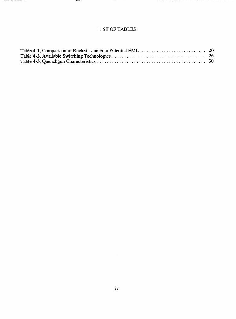
LIST OF TABLES
Table 4.1. Comparison of Rocket Launch to Potential EML . . . . . . . . . . . . . . . . . . . . . . . . . . 20 Table 4.2. Available Switching Technologies . . . . . . . . . . . . . . . . . . . . . . . . . . . . . . . . . . . . . . 26 Table 4.3. Quenchgun Characteristics . . . . . . . . . . . . . . . . . . . . . . . . . . . . . . . . . . . . . . . . . . . . 30
iv

LIST OF ABBREVIATIONS
A BeV cm EML G GeV GWH Hc HTSC J JC
kA kg kHz kV kW KWH m MeV MJ m o l M w M W H REM
SMES T TC WH
S
b P S Billion electron volts centimeter Electromagnetic launcher Gravity Giga-electron-volt Giga-watt-hour Critical magnetic field strength High temperature superconductor Joule Critical current density
kilogram kilo-hert z
kilo-watt Kilo-watt-hour meter Meg a-electron-volts Mega-Joule milli-mole Mega-watt Mega-w att-hour Roentgen equivalent man second Superconducting magnetic energy storage Tesla Critical temperature Watt-hour
kilo-amps
kilo-volt
V

1.0 Executive Summary
Superconductors are materials that exhibit zero electrical resistance when cooled to temperatures
below a critical value characteristic of the material. Until recently, these temperatures have been
in the 1-40"K range, which requires that the materials be cooled using expensive liquid helium.
In the past two years, advances in the development of high-temperature superconductors have
led to a resurgent interest in their potential applications. Materials are being discovered that
achieve superconducting characteristics at temperatures over 100OK, allowing cooling with
relatively inexpensive liquid nitrogen. Research is continuing to find a room-temperature
superconductor that will require no refrigeration.
Magnets constructed of superconducting materials are finding many applications because of their
ability to store large amounts of energy in their coils in the form of electrical current with
virtually no energy loss. They have the added advantage of being dischargeable in durations
ranging from a fraction of a second to many hours or days. Three applications of superconductor
magnet technology at a lunar base are discussed in this report: magnetic energy storage during
the lunar day for usage during the night; electromagnetic rad launchers to propel lunar-derived
oxygen or raw materials into lunar orbit; and magnetic shielding to protect lunar inhabitants
from radiation.
The practical usage of superconducting magnetic energy storage (SMES) devices to store large
amounts of energy has been proven through the development of prototypes by several research
institutes and utility companies. Current technology makes them competitive with capacitor
1
storage but not yet with fuel cells. SMES devices are practical as energy storage units only at
stored levels above 500 MWH, which corresponds to lunar energy storage requirements at the
early settlement phase (100-1000 persons).
Several geometries are considered for the coil, and a toroid shape is recommended to eliminate
fringe fields. Such a device would be about 200 meters in diameter and 30 meters high to store
500 MWH.
Current terrestrial designs require cooling of the coil with liquid helium or liquid nitrogen in
order for the devices to achieve their superconducting characteristics. Low temperatures on the
moon may eliminate this need, though, making SMES even more competitive. Devices situated
above the surface can be shaded with artificial shadows, producing operating temperatures of
about 110°K. Superconducting materials already exist that work at this temperature, but higher
current densities than those experimentally achieved are necessary before these can be used for
practical energy storage. An above-ground SMES device would require strong containment,
probably with steel, to withstand the large hoop stresses generated by the coil. The device could
be buried in lunar bedrock to contain these forces, but a subsurface temperature of 230°K would
require the discovery of a new superconductor material with a critical temperature higher than
this.
Some advantages of SMES over other technologies include high efficiency, high reliability, and
high energy density.
2

Superconductor technology has made possible the development of electromagnetic launchers
(EML), which require the delivery of high energy in short bursts of power. EML designs have
been proposed that are capable of accelerating 1000 kgs at 1000 gravities (G’s) to 12.3 kmh.
These devices offer several advantages for continuous cargo launch over rocket launch systems,
including a higher payload fraction, greater launch rate, lower launch unit cost, and greater
reliability. On the negative side, the electric launchers require heavy and complicated surface
installations; and the payloads require catchers or small rockets to circularize, and must be able
to withstand high G loadings.
Two families of EML are discussed: railgun and coaxial. Railgun devices consist of two parallel
rails connected to a direct current with a projectile propelled between the rails by Lorentz forces
generated in the projectile’s armature. Coaxial devices use a linear synchronous motor to
accelerate payload buckets containing energized coils along an assembly of fixed coaxial coils
several kilometers in length. Coaxial EML’s offer several advantages over railguns, including
larger bore diameters for the projectiles, greater efficiency, longer life span, and the ability to
operate well at moderate accelerations. A problem with coaxial EML’s is the generation of large
internal voltages that could cause arcing.
The development of high temperature superconductors has led to the application of quenching
methods to a lunar electromagnetic launcher. This method uses successive switching on and off
(quenching) of adjacent coils to propel the projectile. Problems with this approach that need
further attention include the requirement to withstand high magnetic induction, high current
3
densities, and large stresses. The advantage over other coaxial designs is the elimination of the
need for superconducting switches. Quenchguns are able to accelerate 1000 kg payloads to 1.7
l u n / S .
Further study is needed to determine the tradeoffs of electromagnetic launchers versus reusable
landers for oxygen and raw material transport.
A major concern of lunar mission planners is the exposure of astronauts to high levels of cosmic
radiation, and occasional high-radiation dosages from solar flares. To safeguard the astronauts,
radiation shielding must be considered for lunar habitats. The large magnetic fields generated in
superconducting magnets may be beneficial for trapping charged particles away from the
habitats. Three approaches are considered here: passive shielding, toroidal magnetic shielding,
and plasma core shielding.
The cosmic ray spectrum must be cut off at 10-15 GeV/nucleon to achieve an acceptable dosage
rate of 5 rem/year. It is estimated that 785 grams/cm2 of passive regolith shielding is required to
provide this protection. If active magnetic shielding is used, current densities of lo9 A/m2 are
required to achieve this cutoff, a value approachable only with the use of superconducting coil
materials.
T h e configurations are considered for magnetic shielding:
An unconfined field dipole, which is toroidal in shape producing a shield outside
the torus,
4

A confmed field double torus, which places one toroid inside another and traps
the particles between them, and
A hybrid of the two in which a deformed toroidal winding is used to produce a
spherical shape.
The hybrid magnetic shield is the most attractive configuration because it leads to the lowest
dosage rate and has the lowest system mass.
An elaborate technique called plasma core shielding was also investigated. A plasma core shield
creates a huge electric field around the habitat that deflects positively charged cosmic rays back
into space. The attraction of surrounding electrons could neutralize the device, but supercon-
ducting magnets are arranged to create an electron well that traps these electrons. The advantage
of a plasma core shield over a magnetic shield is that no electrons occur near the exterior
surfaces of the habitat. However, there may be several obstacles to be safely overcome in
operating within a 15 billion volt lunar base environment.
5
2.0 Background
A superconductor is an element or compound that changes its thermodynamic state when it is
cooled to extremely low temperatures, causing it to exhibit zero electrical resistance. The
temperature at which this state change occurs is known as the critical temperature, or T,.
Superconductivity was first observed in Mercury by Kamerlingh Onnes in 1911 at Leiden,
Holland.' The critical temperature of Mercury is 4°K. A bath of liquid helium, which is
relatively expensive, is required to maintain this material at such low temperatures.
Subsequent research has led to the discovery of other materials that exhibit superconductor
characteristics at higher temperatures. In 1973, niobium-germanium (Nb,Ge) was found to have
a T, of 23°K. The first of what is considered to be a high-temperature superconductor (HTSC)
was discovered in 1986 by J. Georg Bednorz and K. Alex Muller of IBM's Zurich Research
Laboratory, for which they were awarded the Nobel Prize in Physics. This material, lanthanum-
barium-copper-oxide ((LaBa),CuO,), has a T, of 3040°K. The search continued for a material
that exhibits superconductivity at temperatures above 77°K. This is the boiling point of liquid
nitrogen, which is a much cheaper cooling medium than liquid helium.
In 1987, Ching-Wu (Paul) Chu and his colleagues at the University of Houston broke the liquid
nitrogen barrier with yttrium-barium-coppex-oxide (YBqCu,O,), which has a T, of 95°K. In
1988, H. Maeda et al. of NRlM in Tsukuba, Japan, achieved a T, of 107°K in bismuth-stron-
tium-calcium-copper-oxide (BiSrCaCuO), and Zhengzhi Sheng and Allen Hermann of the
University of Arkansas achieved 125'K in thallium-barium-calcium-copper-oxide
6
(TI,B%CqCu,O,). There have been claims of higher critical temperatures, but these have not
been verified as repeatable (ref.). Dr. Chu has noted signs of superconductivity in materials with
critical temperatures as high as 240'K.'
A property of superconductors known as the Meissner effect was discovered in 1933. When a
magnet is placed near a material in a non-superconducting state, the magnetic lines of flux will
pass through the material. If the superconductor is cooled to below its critical temperature, and
if the magnetic field is below a critical value (denoted H,), the material will repel these external-
ly-applied fields3 As a result, the magnet will levitate above the superconductor. If the exter-
nally-applied field is increased above H,, the magnetic flux lines will again penetrate the
material and the material will no longer be superconducting. This transition is reversible by
decreasing the magnetic field to below H,.
Superconductors also become resistive when a critical current density J, (induced, or impressed
by transport currents) is e~ceeded.~
7

3.0 Superconducting Magnetic Energy Storage
Energy storage is one of the most attractive near-term applications of superconductor technolo-
gy. A lunar superconducting magnetic energy storage (SMES) device could accumulate energy
from solar power plants during the lunar day, and discharge it during the night when the power
plant is inoperable. The concept has been proven through the development of prototype SMES
devices by Brookhaven National Laborato$ and Bonneville Power Authority', and recent
advances in producing higher-temperature superconductors has made this approach economical-
ly competitive with other energy storage technologies'. SMES technology is at an advanced
enough stage that it does not depend on the development of other technologies, and in fact does
not demand significant advances in superconductor or cryogenic technology.
A SMES device is essentially a coil made of superconducting material wrapped around a
structural core and contained in a cryostat that thermally isolates it from its surroundings.'
(Figure 3-1). Electrical energy is injected into the coil and the two leads are shorted. The
current will continue to flow through the coil with virtually no energy loss until it is tapped for
release.' The lifetime of an untapped current is on the order of 100,000 years.'
'Like an electromagnet, when a superconducting coil is energized it will generate a magnetic field, whence the name Superconducting Magnetic Energy Storage.
8

. , ‘ . \ - _ - - - -
# ‘. A I -. - - - - - e .
, I 0 . , I
I
i I
I
I /
I I I
I
1 I I - POWER I CONDITIONING
!
r
TO LOAD
S U P E R C D N D U ~ I N G -- CDII, ~
# I L INDUCTANCE .’ / I ‘, ‘\- I CURRENT “---“MACNETlCflECD LINES‘- -- -
I I .
\
\
\
I
\ \
\
\
\
L
I I
I
I
I I
/ I
/ ,
, \
\ ,
I
I I I I I
I I
I /
/
Figure 3-1, SMES Principles of Operation
3.1 Requirements
Burden and Angelo9 have estimated that an initial lunar base (6-12 persons) would require about
100 k W of power, or about 40 MWH of energy storage capacity for the 394 hours that are
effectively lunar night”. Early lunar settlements (100-1000 persons) would require about 1
MWe of power, or about 400 MWH of energy storage. A mature lunar settlement (10,000
persons) would require about 100 MWe of power, or about 40,000 MWH of energy storage.
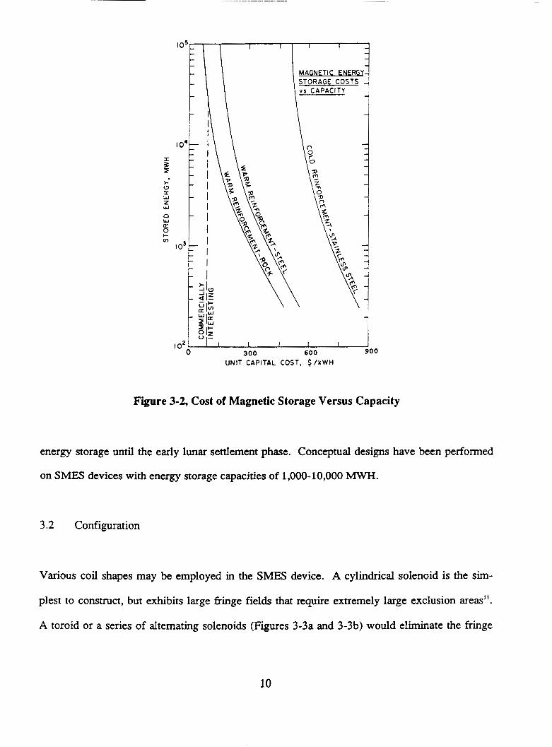
Capital costs for fuel cells is approximately $150-250/KWH. In order for SMES to be eco-
nomically competitive, its energy storage must be in the 500-1000 MWH (1.3-2.5 Mw) range
(refer to Figure 3-2)11*6. Therefore, superconductor technology would not be a candidate for
9
UNIT CAPITAL COST, $ / k W H
Figure 3-2, Cost of Magnetic Storage Versus Capacity
energy storage until the early lunar settlement phase. Conceptual designs have been performed
on SMES devices with energy storage capacities of 1,000-10,000 MWH.
3.2 Configuration
Various coil shapes may be employed in the SMES device. A cylindrical solenoid is the s b -
plest to construct, but exhibits large fringe fields that require extremely large exclusion areas".
A toroid or a series of alternating solenoids (Figures 3-3a and 3-3b) would eliminate the fringe
10
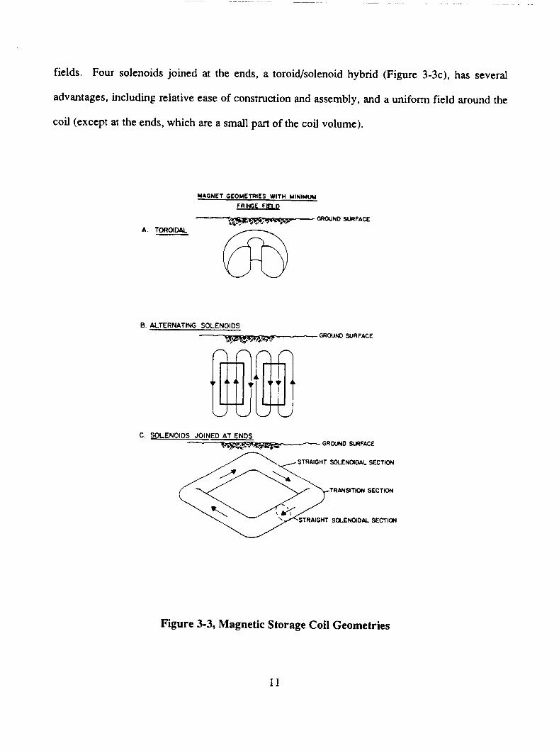
fields. Four solenoids joined at the ends, a toroid/solenoid hybrid (Figure 3-3c), has several
advantages, including relative ease of construction and assembly, and a uniform field around the
coil (except at the ends, which are a small part of the coil volume).
MAGNET GEOMETRIES WITH MINIMUM
FRINGE F M
4 UHWND SURFACE w# A TOROIDAL
B. ALTERNATING SOLENOIDS GROUND SURFACE
C SOLENOIDS JOINED AT ENDS L - GROUND SLRFACE
STRAIGHT SOLENOIDAL SECTION
TRILNSlTlON SECTION
Figure 3-3, Magnetic Storage Coil Geometries
11

To maintain the magnet at the desired level of energy storage, it is short-circuited with a super-
conducting switch” (see Figure 3-4). The current supply to the magnet is then shut off and the
magnet is energized with a persistent current flow through the switch. The advantage of using a
superconducting switch is that no outside current needs to be applied to the coil so there is no
joule heating in the leads connecting it to ambient temperature. (Joule heating is the pheno-
menon associated with heat loss to the surroundings due to the loss of electrical energy across a
coil). To de-energize the magnet, the switch is driven normal by heating it to its critical temper-
ature with a special heating coil.
H d Load
t--- J
S.C. Switch
Figure 3-4, Energy Transfer Circuit
12

Recent studies of terrestrial SMES devices recommend the use of NbTi as the superconductor',
whose critical temperature is 1.8'K, magnetic field is 3T, and current density is 7 x lo5 A/cm2.
This can be formed into a hollow conductor, through which supercritical helium could be
pumped for direct cooling. This type of construction would probably lead to lower cryostat and
assembly costs".
A toroidal shape is used to calculate the magnitude of an NbTi SMES device (Figure 3-5). The
flux density is given by
€3 = po(hT,)R,(P-a)/( 1-a).
so
(U,) = B( 1-~)l[p.-p0(P-a)l
where
(U,) is the current density in amps/metet
B is the flux density in tesla
a = RJR,, the ratio of inside coil radius to toroid radius
p = R&,, the ratio of outside coil radius to toroid radius
p, is the permeability constant (1.26 x 1 O4 henrydmeter).
The energy stored in a toroid is given by
w = 2po~R,'(W,)'f(a,P)
where
W is the energy stored in joules
R, is the toroid radius
f(a,P) is the geometry factor.
13

RO I I
1 1 I I I I 1 I I 1 I 1 I I 1
Figure 3-5, SMES Coil Dimensions
Substituting (2) into (3) above, it is shown that
W = [2*RdB2( l-ol)r(ol,P)]/[CLo(P-a),I
or
R: = [W~,(P-~)’]/[2KZB2( I-a)Y(a,p)].
(4)
We use 500 MWH or 1.8 x lo’, joules as the storage requirement; and select the two parameters
-0.2, P=0.3 to obtain f(a,P)=2.468 x 10‘. This results in a toroid radius R, = 93.1 meters, an
inside coil diameter R, = 18.6 meters, and an outside coil diameter R, = 27.9 meters.
14

The hoop stress is given by
o,.,,, = ~,B(hro)(2P-P'>1/[(P-a)2(1-P)I or 1.4 x lo8 N/m2
and the radial stress is given by
~ r . , . , = R,B(hr0)P/2(P-a) or 5.8 x lo' N/m2.
3.3 Environmental Considerations
The drawback to NbTi for lunar applications is the requirement for large amounts of liquid
helium to cool the coil. The need for liquid gases as a cooling agent could be eliminated if
superconductors were employed whose critical temperatures were below the lunar temperature.
Since the cryostat and refrigerators account for approximately 30% of the total system cost, this
would lead to considerable cost reduction. The sub-surface temperature below a depth of about
one meter is considered to be uniformly about 230°K13. Temperatures as low as llO°K can be
achieved artificially above the surface by producing shading".
Recently discovered HTSC's have critical temperatures that are entering this lower range. The
problem with these materials is their relatively low current densities, too small to make them
effective for high levels of energy storage. Should higher current densities be achieved, and
above-surface devices designed, then special consideration would have to be given to developing
strong structural shells to contain the huge hoop stresses generated by these magnets.
The discovery of higher critical temperature materials, provided they have sufficient current
density, would allow the development of SMES devices that could be stored underground. This
15

would have the advantage of eliminating the need for special structures, since the surrounding
lunar material would act as the container. Unfortunately, little is currently known about the
compressive strength of lunar material at the depths necessary for the SMES device (up to
several hundred meters, depending on the tensile strength of the rock). Compressive strength of
about 30,000 psi or greater is required. Some sort of adjustable volume fluid chamber may be
needed between the coil and the rock to accommodate movement of the rock as it is stressed".
Much geotechnical research must be performed to design these underground support structures
with a high degree of mechanical ~tability'~.
Coils that become damaged can suffer from thermal runaway. This can be caused by coil
burnout due to over-dissipation, or by insulation breakdown due to excessive voltages produced
by sudden current quenching. If one of these occurs, there needs to be a way to dump the stored
energy'; otherwise the energy will dissipate as joule heating in quantities large enough to fuse
the wire and destroy the coil locally. Dumping can be achieved by either switching a resistance
much larger than the coil in series with it, or by attaching a low-resistance transformer in parallel
with it.
3.4 Concluding Remarks
The usage of SMES devices for energy storage carries many advantages over other technologies.
The energy stored in a superconducting magnet is stored as electricity, so it is immediately
available. There is no penalty for energy conversion to or from mechanical, thermal, or chemi-
cal energy6. This gives SMES the highest round-trip efficiency, at 98%. (The 2% loss comes
16

from transmitting the current into and out of the coil over ordinary copper wiCesl6). In addition
to being efficient, SMES coils have no moving parts, which contributes to its reliability. Finally,
current SMES system designs have a storage density of about 10s joules or 27.7 WH per kilo-
gram, which is ten times better than capacitor storage, but about 15-30 times worse than
hydrogen-oxygen fuel cells (at 400-850 WH/kg)lz. SMES density will improve if refrigerator
requirements are eliminated, since the dewar structure is approximately 25% of the total mass”.
17
4.0 Electromagnetic Launcher
The direct use of electromagnetic energy for accelerating macroscopic rather than sub-atomic
matter is an old concept that inspired many premature and dramatically unsuccessful attempts
over the years. An electromagnetic cannon built in Germany during World War II, based on a
linear induction motor, tended to melt its projectiles, and an aircraft launcher built in the U.S.
during the forties, the "Westinghouse Electropult," failed to come even close to the performance
of steam and compressed air devices".
Recent research in superconductivity has brought electromagnetic launch closer to practical
reality. One type of electromagnetic launcher (EML) accelerates a payload to near orbital
velocity using electromagnetic forces induced by superconducting magnets. Although several
Earth-based EML/superconductivity applications have been proposed, from magnetic levitating
trains to first-stage boosters for space launch, the most attractive and original application is for
lunar material transport. The basic function of the lunar EML would be the launching of lunar-
derived oxygen or raw materials (regolith) into low lunar orbit or to L2 for transfer to low Earth
orbit. The oxygen would support advanced space transportation systems while the raw lunar
regolith could be utilized for shielding or on-orbit processing.
4.1 Historical Perspective
Technological progress in the development of a lunar-based EML system began in the mid
1970's when Dr. Gerard O'Neill proposed the Transport Linear Accelerator, more commonly
referred to as the mass driver, as a means of launching lunar materials to a predetermined point
18

in space19. This original concept led to the development of Mass Driver I which achieved
accelerations of approximately 35 gravities in 1977. By 1979 work had begun on Mass Driver II
which used superconducting coils and eventually achieved accelerations of about 800 gravities".
O'Neill's mass driver systems used payload canisters accelerated on recirculating buckets with
the payloads collected by an on-orbit "catcher." This method required a number of launches on
the order of lo7 per year (due to small payload canister capacity), an on-orbit materials process-
ing facility, plus the complex and poorly defined "catcher" system". Snow et al. modified the
O'Neill proposal by eliminating the recirculating bucket, simpllfying the accelerator, and
launching a larger payload in a "smart" projectile, eliminating the requirement for the on-orbit
"catcher." This method reduced the number of launches per year to the order of lo3."
Dr. Kolm furthered the latest mass driver design in 1980 by proposing an Earth-based EML
capable of accelerating a 1000 kg payload at 1,000 gravities to 12.3 krn/s.'O Interested in Earth-
to-orbit electromagnetic launch, NASA commissioned Batelle Columbus Laboratories in 198 1 to
investigate the feasibility of using an EML to launch nuclear waste out of the solar system". The
recent discovery of high temperature superconductors has renewed the research efforts in the
field of electromagnetic launch technology as applied to Earth-based launch, particularly by
NASA and the Defense Advanced Research Projects Agencyz3. Fully developed EML systems
offer many potential advantages and some disadvantages over current rocket launchers. Some of
the comparisons are summarized in Table 4-1." Note that certain figures are projections since
EML technology does not have a verified history like rocket propulsion. Development costs will
also be substantial for the EML option.
19

Table 4-1, Comparison of Rocket Launch to Potential EML%
Rocket Launch Electromagnetic Launch
1-5% Payload fraction
Large payloads (5-50 ton)
Low accelerations (5-20 G’s)
1 Launch per month
1 Todday launched
$4,000-$40,000 per kg
High launch hazards
Expendable or short lifetime
Launch delays of months to years
90%-98% Reliability
10-80% Payload fraction
Small payloads (. 1-5 ton)
High accelerations (2,000-20,000 G’s)
10,OOO Launches per month
50 Tons/day launched
$20-$1000 per kg
Low launch hazards
Long lifetime
Launch delays of minutes to hours
99.8%-99.999% Reliability
Conventional rocket technology is quite mature and only incremental advances can be expected
in the future. Conversely, electromagnetic launch technology is relatively immature, with
extensive developments expected as advances in superconductivity are made.
20
4.2 EML Configurations
Basically there exist two broad families of launchers: railpuns and coaxial EMLs.
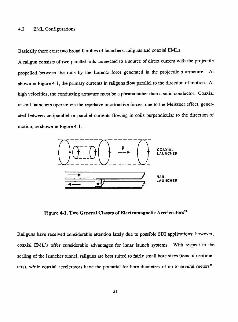
A railgun consists of two parallel rails connected to a source of direct current with the projectile
propelled between the rails by the Lorentz force generated in the projectile’s armature. As
shown in Figure 4-1, the primary currents in railguns flow parallel to the direction of motion. At
high velocities, the conducting armature must be a plasma rather than a solid conductor. Coaxial
or coil launchers operate via the repulsive or attractive forces, due to the Meissner effect, gener-
ated between antiparallel or parallel currents flowing in coils perpendicular to the direction of
motion, as shown in Figure 4-1.
COAXIAL LA U tJCH ER
RAIL LAUNCHER
Figure 4-1, Two General Classes of Electromagnetic Ac~elerators~~
Railguns have received considerable attention lately due to possible SDI applications; however,
coaxial EML’s offer considerable advantages for lunar launch systems. With respect to the
scaling of the launcher tunnel, railguns are best suited to fairly small bore sizes (tens of centime-
ters), while coaxial accelerators have the potential for bore diameters of up to several meters2’.
21

Coaxial EML's are inherently more efficient than railguns, on the order of 80-90%. The low
efficiency of railguns (1-10%) leads to problems with building very large power supplies and
removing launcher heat". Distributed energy-store railguns offer higher theoretical efficiencies
but are complex. While railguns apply a force only to the base of the payload, coaxial systems
can be designed to distribute the force along its entire length. This allows for lower current
densities and a long slender payload vehicle, important for structural and aerodynamic consider-
ations. Finally, coaxial EML's perform well at moderate accelerations, on the order of 1,000
gravities, and thus are suitable for a wide variety of payloads. Furthermore, coil launchers have
a long lifetime in comparison to the railgun's short span of 1-10 launche?.
Coaxial accelerators have potential for lower costs than the railgun systems for several reasons.
The projectile stresses are lower because multiple projectile coils distribute the acceleration
loads throughout the projectile, thus reducing the structural mass. The launcher guideway hoop
stresses are also lower which correlates to reduced guideway structural mass. Based on these
comparisons, the coaxial configuration has been recommended for lunar base applications.
4.3 The Coaxial EML
The basic coaxial EML uses a linear synchronous motor to accelerate small payload buckets.
These buckets contain superconducting coils energized with persistent current while travelling
along an assembly of coaxial coils several kilometers in length. The induced magnetic field in
the guideway coils magnetically levitates the bucket for non-contact suspension. Each bucket is
22
propelled linearly as the guideway c oils are energized in a timed sequence, generating a moving
magnetic wave. The bucket is first iittracted and then repelled by each drive coil. Attraction has
a centering effect, while repulsion hils a destabilizing effect. The net stability is therefore neutral
under completely symmetric timing :onditions. However, if the wave form is made asymmetric
so that the attractive pulse has a 1argh:r amplitude than the repulsive pulse, then the net effect will
be stabilization of lateral motionu.
E a t t e '-y 5 t o r a ge
A r m a t u r e Charging/ Pro j ec t i 1 e I n j e c t o r
I
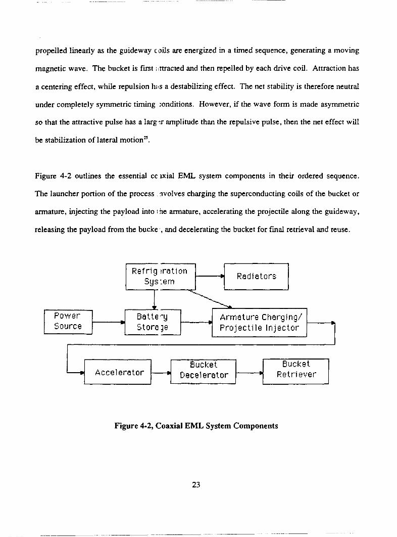
Figure 4-2 outlines the essential c c ~ ~ i a l EML system components in their ordered sequence.
The launcher portion of the process wolves charging the superconducting coils of the bucket or
armature, injecting the payload into I 3e armature, accelerating the projectile along the guideway,
releasing the payload from the bucke , and decelerating the bucket for fmal retrieval and reuse.
L I Source t
Bucket Accel era t o r + D ec e 1 era t o r L
Bucket Ret-r-i e v e r
>
I I I I I I
Figure 4-2, Coaxial EML System Components
23

4.4 Applications of High Temperature Superconductors (HTSC)
Many of the EML components would benefit from advances in superconductivity and thus make
the concept viable for a lunar scenario. Applications of high temperature superconductors are
prevalent for many of the EML components, including prime power generation, bus work,
inductive energy storage, opening switches, launcher coils, and payloads. Of particular interest
is the state of the art challenges for energy storage, switching, and coils. In addition to improv-
ing components, HTSC's generate stronger magnetic fields and reduce the stringent refrigeration
requirements.
Power requirements for an Earth-based EML have been estimated as high as 10 MWH per
metric ton, with a recommended delivery time of approximately one second'". While storage
devices capable of meeting these demands are possible with conventional technologies, the costs
are significant. Superconducting coils are theoretically capable of storing electromagnetic
energy indefmitely , the only storage related losses being those associated with refrigerating the
conductors. Researchers at the University of Wisconsin have performed studies on Supercon-
ducting Magnetic Energy Storage systems for load leveling applications'". These systems would
absorb energy during periods of low demand and feed it back into the system during peak
requirements, thus reducing the need for excess generating capacity. Recently, Bechtel has
proposed an SMES sized for a 5,000 MWH capacity to the Department of Energy; furthennore,
SMES systems as large as 10 GWH have been proposed elsewhere''. These systems have not
been designed to operate in the pulse mode required for the EML. The pulse mode might pose
24

significant problems since it requires large currents and substantial forces for very short periods
of time.
Perhaps the most promising application of HTSC’s is in high current opening switches. Within
the launcher system circuit, it is desirable to have a solid state, reusable switch that releases the
necessary current to the launcher coils as close to instantaneously as possible. The switching
requirements for a lunar launcher have yet to be defined quantitatively. Although the lunar
application would be less demanding than an Earth-based system, an Earth-based EML requires
switches capable of standing off over 100 kV and of carrying mega-amp currents over submicro-
second rise times of 10’’ A/S.~’ Table 4-2 provides an overview of currently available switching
technology. (The listed parameters represent available hardware rather than performance limits).
Considering the EML switch requirements, the extant switching systems are not sufficient to
sustain mega-amp currents. Explosive switches provide the best capabilities so far; however,
because they are expendable they are not practical for continuous launch scenarios.
25

Gas Gap
Vacuum Gap
Thyratron
Ignitron
Solid State
Explosives
Mechanical
Table 4-2 Available Switching Technologyz6
Current (kA) Voltage (kV) Frequency (kHz) Interruption Time (s)
io3 103
1 o2 1 o2
10 10
103 1 o2
10 10
103 103
103 103
1
10
10
0.1
1 os 0
0.01
1 0 - 3
1 0 5
1 o-6 1 o-2
1 o-6 1 o-6 1 o-2
The actual performance of a switch depends on two characteristics of the superconductor: the
current density and the normal state resistivity. Current densities as low as a few hundred amps
per square centimeter coupled with normal state resistivities of over 0.1 ohm-cm could make
HTSC's effective for this applicatiod'. Low current densities are preferred in order to reduce
switch heating; however, high current densities are more probable in launchers to sustain the
large magnetic fields.
To properly latch the switch in the open position, the HTSC must be raised to its critical temper-
ature, thus achieving the high resistivity in the normal state. This method of inducing supercon-
ductivity loss through slight heating is referred to as quenching. Magnetic quenching applied to
26
a switch is advantageous for rapid switch reclosure, possible by just turning off the quenching
field. Such rapid reclosure is necessary if an armature is not present in the launcher to accept the
current from the switch.
Although low temperature superconductors have proven capable for launcher coil technology,
HTSC materials appear more promising, particularly if quenching techniques are applied. A
superconducting quench coil launcher, or quenchgun, operates by successively quenching the
line of adjacent coaxial coils along the launcher guideway. Each coil in turn is quenched -
turned "on" and "off' - so that only the magnets in front of the payload are attracting the pay-
load. Thus, the payload rides an electromagnetic wave accelerating rapidly to high velocities.
Like the linear synchronous motor previously described for coaxial EML's, the quenchgun
provides propulsive energy stored directly in the drive coils and transferred to the payload
bucket without contact leads".
Various potential problems exist with the quenchgun application, particularly with regard to the
coils which must withstand high fields (20 Teslas), current densities (>50 kA/cm*>, and stresses
(>3x10R Pascals). Further critical areas include synchronization and payload alignment due to
the high velocities as well as sensitive quench timing on the order of five microsecondsx.
4.5 A Lunar EML Design Using Superconductor Quenching
Kolm recently applied the superconducting quench methods to a lunar electromagnetic launch-
e P . Kolm's design specifies that the required energy is stored directly in the superconducting
27
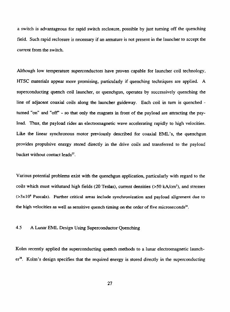
coils, thus eliminating the need for external storage or power conditioning. The exemplary
quenchgun also exhibits mechanical simplicity by removing the need for switches. Rather than a
switch inducing the current in the coils, the projectile generates the superconducting phase
change in the coil windings. Figure 4-3 shows the solenoid configuration of the quenchgun.
Both the guideway and the projectile are solenoids with currents operating in the same direction.
Kolm projects a high level of efficiency for this system, approximately 90%.
SOLENOID
= CURRENT
4 = FORCE
Figure 4-3, Quenchgun Concept - Solenoid Acceleration2*
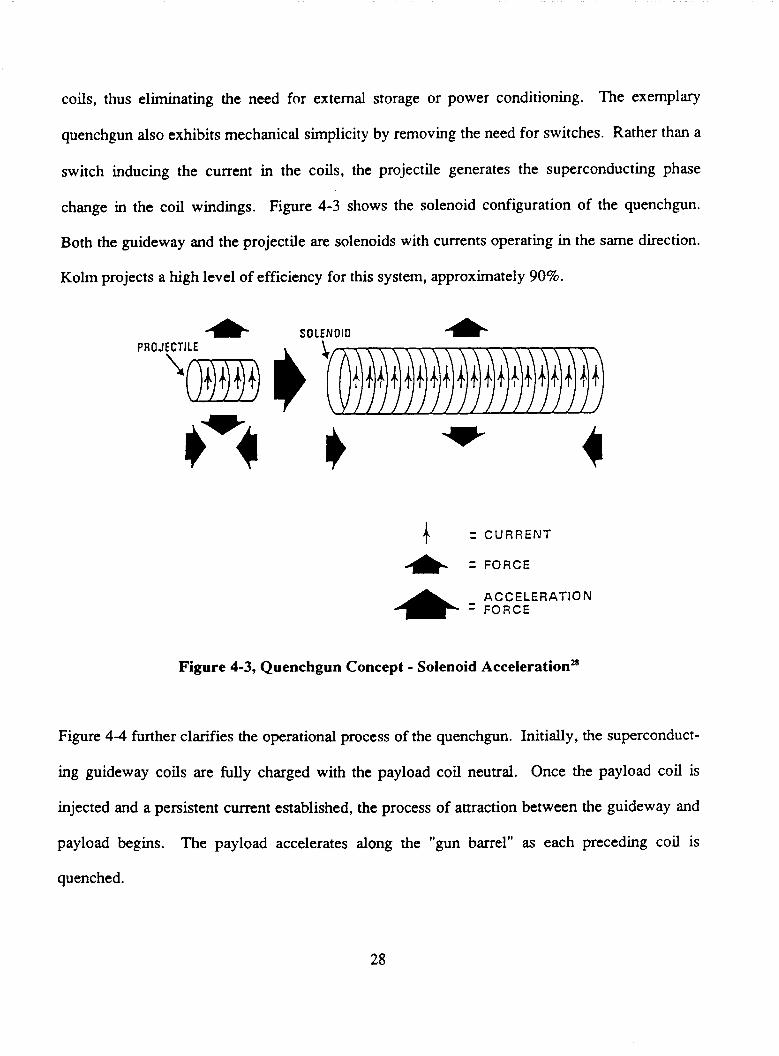
Figure 4 4 further clarifies the operational process of the quenchgun. Initially, the superconduct-
ing guideway coils are fully charged with the payload coil neutral. Once the payload coil is
injected and a persistent current established, the process of attraction between the guideway and
payload begins. The payload accelerates along the "gun barrel" as each preceding coil is
quenched .
28
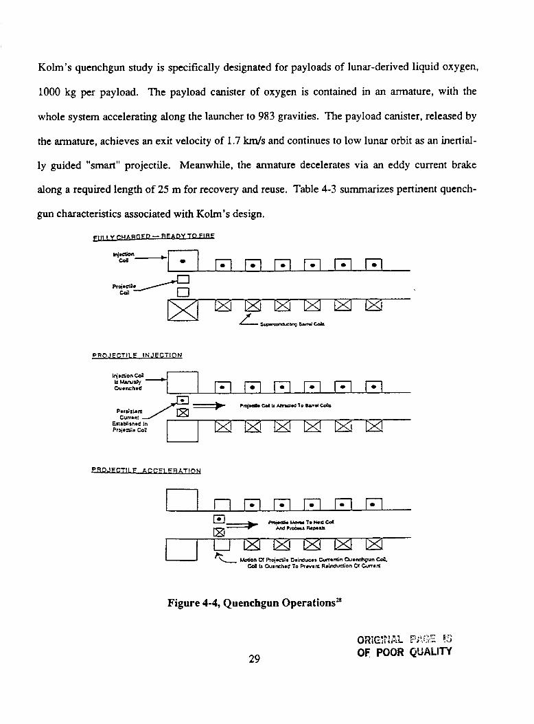
Kolm's quenchgun study is specifically designated for payloads of lunar-derived liquid oxygen,
1000 kg per payload. The payload canister of oxygen is contained in an armature, with the
whole system accelerating along the launcher to 983 gravities. The payload canister, released by
the armature, achieves an exit velocity of 1.7 km/s and continues to low lunar orbit as an inertial-
ly guided "smart" projectile. Meanwhile, the annature decelerates via an eddy current brake
along a required length of 25 m for recovery and reuse. Table 4-3 summarizes pertinent quench-
gun characteristics associated with Kolm's design.
DY TO FlEE
p RO J ECTl L E IN JFCTl O N
Injaaion C d
Ouanchmd *-* I n n n n n m 0 m m 0 m
Figure 4-4, Quenchgun OperationsB
29
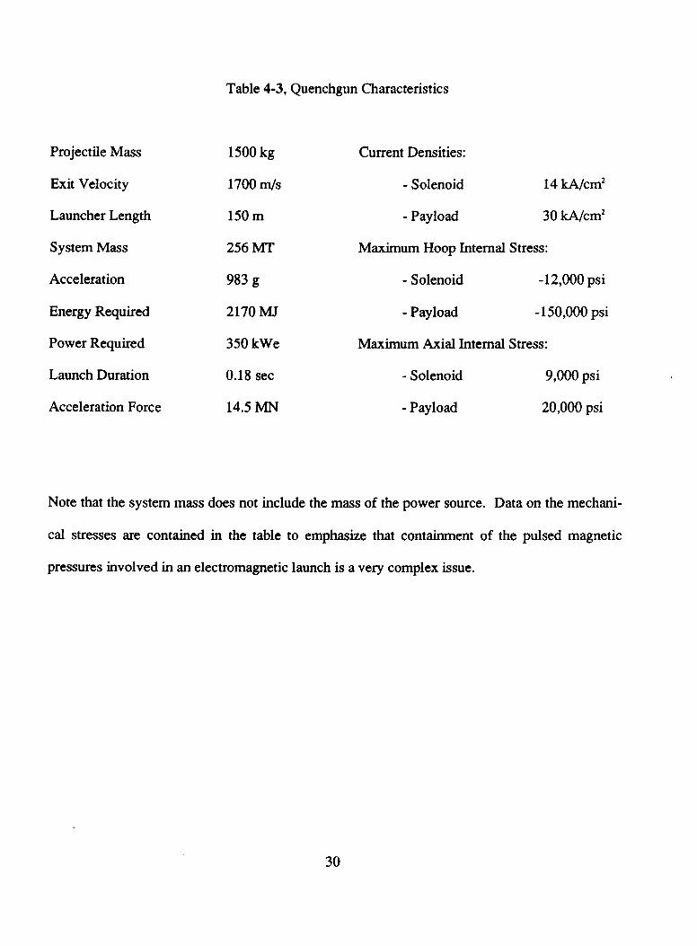
Table 4-3, Quenchgun Characteristics
Projectile Mass 1500 kg Current Densities:
Exit Velocity 1700 m/s - Solenoid 14 A/cmz
Launcher Length 150 m - Payload 30 kA/cm2
System Mass 256 MT Maximum Hoop Internal Stress:
Acceleration 983 g - Solenoid - 12,000 psi
Energy Required 2170 MJ - Payload - 150,000 psi
Power Required 350 kWe Maximum Axial Internal Stress:
Launch Duration 0.18 sec - Solenoid 9,000 psi
Acceleration Force 14.5 MN - Payload 20,000 psi
Note that the system mass does not include the mass of the power source. Data on the mechani-
cal stresses are contained in the table to emphasize that containment of the pulsed magnetic
pressures involved in an electromagnetic launch is a very complex issue.
30

4.6 Lunar Environmental Considerations
The lunar environment will pose serious constraints on the construction and operation of an
EML. The most significant environmental factor is the surface temperature, ranging from
384’K during lunar day to 102’K during lunar night29. As previously discussed, supercon-
ductors currently require cooling temperatures on the order of the liquid nitrogen boiling point.
In addition to active refrigeration, recommendations have been made to activate the EML and
launch payloads only during lunar night”. Since temperatures below approximately one meter
remain constant at about 230°K, burial of the launcher might provide additional thermal con-
troll3. Furthermore, burial would protect the system from possible micrometeorite damage.
Burial might also prove advantageous for anchoring the launcher assembly. Kolm’s recent
design projects an acceleration force of 14.5 MN along 150 meters of guideway (Table 4-2).
Such an intense axial force will incur strong radial forces throughout the launcher, in addition to
the gravitational and recoil forces experienced during each launch. Burial supplemented by
anchor supports, possibly constructed from lunar concrete, will be necessary to stabilize the
launcher. Complete burial might create problems with respect to the angular positioning of the
launcher. A 2 degree launch angle with respect to the lunar surface at an equatorial launch site
was recommended as a safety factor to assure clearance of distant lunar obstacles2’. However, a
larger launch angle might be preferred depending on the projectile orbital requirements.
With extremely high launch rates expected for robust lunar base scenarios, EML reliability
becomes a paramount concern. Bucket snap out, payload breakup, large dynamic excursions,
31
and the consequence of superconducting magnet normalization become serious challenges due to
the extensive use rate. Lunar dust might also present EML operational complications, particular-
ly if particles penetrate the superconducting coil regions.
4.7 Concluding Remarks
Various laboratory prototype EML’s have been developed by Kolm, O’Neill, and others using
low temperature superconductors. With the current advances in superconductor technology, the
viability of electromagnetic launchers appears promising. Strides toward less stringent tempera-
ture requirements and more malleable candidate materials will instigate the development of
Earth-based as well as lunar-based EML’s. Of course, the moon offers advantages over the
Earth, by providing a lower escape velocity and no atmosphere.
Although technical studies continue to evaluate EML designs and usage, the actual benefits to a
lunar base have yet to be determined. The lunar EML, more likely than not, would be designated
to launch payloads of lunar-derived liquid oxygen. However, is it more cost effective to use an
electromagnetic launch system rather than a reusable lunar lander to deliver the payload to low
lunar orbit? In order to answer that question, the costs to construct, set-up, and operate the EML
need to be evaluated.
Certain technical factors also need to be considered for practical EML utilization on the lunar
surface. The effect of the strong magnetic field on the crew and instrumentation functioning at
the base has yet to be studied. Possible risk could be avoided by autonomous launcher opera-
32
tions placed a considerable distance from the main base. Other concerns include coil reliability,
failure of the projectile guidance system, rotational instability of the payload, and overheating of
the guideway.
33
5.0 Magnetic Shielding 1
Shielding against cosmic rays may be required for the longer extraterrestrial human expeditions
due to the serious physical danger of radiation. Without help of extensive protection for long
duration missions, radiation will shorten life expectancies and interfere with electronic support
systems. The obvious solution considered has been mass shielding, but there may be a more
effective protection technique. This section of the study will examine the different options that
are available for active (magnetic) shielding. The applications of superconductivity in magnetic
shielding will be investigated, including unconfined magnetic fields, confined magnetic fields
and an elaborate technique called plasma core shielding.
5.1 Background
Destruction of tissue by radiation is of vital concern. As radioactive charged particles pass
through tissue, chemical bonds are broken. This damaging result is closely related to the
particle's "ionizing power" and can be measured in terms of the number of chemical bonds per
unit mass of body that are broken. A charged particle's ionizing power is proportional to the
charge squared over its velocity squared. Thus, highly charged, slow moving particles create the
most damage. The current bone level radiation dose limit (5cm depth) for astronauts is 5
redyear. Average dose rates for humans on Earth range from 0.1 redyear to 0.8 redyear. A
sudden dose of 50 to 100 rem is fatal. The two sources of extraterrestrial radiation are Galactic
Cosmic Rays and Solar Cosmic Rays. Galactic Cosmic Rays are low intensity, high energy
particles which are comprised of 85% protons (H'), 13% alpha particles (He") and 2% heavier
,
34
nuclei. These particles originate from outside the solar system. Solar Cosmic Rays are also
mostly protons and alpha particles, but originate during solar flares from disturbed regions of the
sun.
A simple method to protect against this radiation is to use mass shielding. As the charged
particle enters the mass shield, it excites electrons for many hundreds of angstroms about its
trajectory. This excitation extracts kinetic energy at roughly a constant rate for relativistic
particles and thus acts as a braking mechanism. Also, if a charged particle travels far enough
into the shield it will collide with the nucleus of another atom and lose energy by inelastic
collision. Thus, if the thickness of the mass shield is great enough, the charged particle will be
stopped. It was estimated that to provide protection for an astronaut with a average dose level of
0.5 redyear at the bone (similar to Earth), regolith mass shielding of 785 grams/cm2 is required
(for regolith densities of approximately 1 gdcm’ to 3 gm/cm’).
The magnetic force on a constant velocity particle that is moving at right angles to a uniform
magnetic field tends to push it into a circular path (as shown in Figure 5-1). The diameter (A) of
this path is:
A = 2mv/qB (6)
where m is the mass of the particle, v is velocity, q is the particle charge and B is the magnetic
field strength. It is important to note the dependency of the particle energy on A. Particles with
higher energy require thicker magnetic shields (e.g. larger A’s) given a constant magnetic
strength field.
35

INCIDENT PROTON
C R I T I C A L TRAJECTORY JUST GRAZES F I E L D
FIELD 6 I TO PAGE
Figure 5-1, Effect of Magnetic Field on Charged Particle Pathm.
A particle on the critical trajectory that is barely contained by the magnetic field has what is
called the cutoff energy. In other words, particles with higher than cutoff energy can escape
through the other side of the magnetic fieId (A is larger than the thickness of the field). A parti-
cle, with less energy than the cutoff cannot penetrate past such a field since its direction is
reversed by these forces (see Figure 5-1). This behavior by particles is what protects the Earth
from some of the radiation. It has been shown that within a specific solid angle, particles of a
certain energy are excluded from reaching the Earth by this redirection process. This type of
motion can be applied to spacecraft/space colonies to exclude certain particles from reaching a
shielded "safe haven". One way to create uniform fields is to use the poles of a magnet, howev-
er, for spacecraft applications it is more convenient to use the field of a torus.
To shield large volumes from high particle energies, the use of superconducting magnets can
prove beneficial over normal coil magnets since normal magnet power requirements are substan-
tially higher. Designs vary from a simple circular coil creating dipole fields to a convoluted
torus containing no magnetic fields external or internal to the magnet. The coil system basically
protects against monodirectional radiation by providing a magnetic field of about 0.1 T'.
36
An early NASA study showed that a "safe haven" of 30 m3 could be protected by a 4 T magnet
having a stored energy of approximately 50 to 100 MJ. Production of such magnets was deemed
viable within existing capabilities. The report also stated that a larger volume of 144 m3 could
be protected from energetic particles below 1 BeV by a system weighing 150 tons7. Most of the
weight of this system is support structure. In comparison, Lockheed has constructed a prototype
superconductive shielding magnet. The circular magnet has an inner diameter of 1.8 m with a
0.1 T central field (1.5 T at the winding). The magnet could protect several cubic meters from
particles with an energy less than 100 MeV, and has an operation period of 5 to 10 days. The
entire superconducting magnetic shield system weighs 85 kg, including the cooling system7.
The effects of high magnetic fields on humans are not known, but initial research into magnetic
fields suggests caution since testing on lower-level life forms has caused undesirable effects.
Possible human risk suggests that the magnetic fields be arranged such that the field strength
inside approaches zero for the volume to remain habitable.
5.2 Magnetic Shielding
Magnetic shielding takes advantage of the fact that charged particles follow curved trajectories
when in a magnetic field. Thus, the proper configuration of magnetic field lines creates a region
where hazardous particles cannot enter, i.e. a "safe haven". Since the radius of curvature of a
charged particle's path through a magnetic field is proportional to that particle's momentum
(cutoff energy), a magnetic shield only filters particles less than this cutoff energy. However,
particles of higher energy that penetrate through the magnetic field do not degrade their level of
37

energy. This filtering process prevents the generation of secondary radiation beyond the mag-
netic field, particularly for the blocked particles below cutoff. Radioactive particles that only
contact a magnetic field can not create secondary radiation.
The cosmic ray spectrum must be cutoff any where between 10 and 15 GeV/nucleon to achieve a
dose rate of 0.5 redyear’’. To achieve a field with this cutoff energy, it was determined that
current densities in the coil of lo9 amperes/m2 are required”. The pressure between the coils is
proportional to the current and the length of the conductor. Tremendous amounts of structural
mass are required because these large currents place the structure supporting the inner coil in
compression and the outer coil support structure in tension (due to Lorentz forces). Another
detrimental point is that the structural mass (required to resist the created magnetic pressure)
creates many secondary particles when struck by those particles that penetrate through the
magnetic field. Thus, so much of the cosmic ray spectrum must be cutoff using very large
magnetic fields that virtually no particles ever penetrate far enough to hit the support structure.
The fatal flaw in magnetic shielding is that the structural mass required to support these huge
magnetic fields makes quite a mass shield in itself.
To maintain the current level with a minimum expenditure of power, superconductor coils must
be used. Superconducting coils should be constrained to materials that can operate superconduc-
tively above 70°K. This will allow the utilization of liquid nitrogen or oxygen for the refrigera-
tion system. These two refrigerants are more abundant and have lower operating costs compared
to liquid helium (the latter is used for applications that require operation close to zero degree
kelvin). The radiant heat load from the sun determines the amount of cooling required to
38
kelvin). The radiant heat load from the sun determines the amount of cooling required to
maintain the superconductor temperature. Both insulation and refrigeration should be used to
minimize the amount of energy required to maintain this temperature. The refrigeration-insula-
tion components usually make up about 1/3 of the total weight of the magnetic shielding system.
The cryogenic equipment consists of insulation, refrigeration machinery, power supply, and a
waste heat radiator.
There! are two confmed and one unconfined field configurations for magnetic shielding that have
been investigated and warrant consideration. The unconfined field dipole is toroidal in shape,
similar to a ring-shaped hollow conductor. Plackg the coil windings at the outer limit of the
shielded region formed by the dipole field produces a desirable region of relatively low field
strength. The resulting shielded region blocks particles below the design energy. The configura-
tion is shown at the top of Figure 5-2.
The confined field double torus consists of two toroidal windings, one inside the other. The
general arrangement is shown on the bottom left of Figure 5-2. Current direction on the inner
winding is opposite to that on the outer winding, confining the magnetic field in the annular
space formed between the windings and providing a field free shielded region within the inner
torus.
39

1 UNCONFINED FIELD
EXTERNAL FIELD TOROID GEOMETRY (HOLLOW CONDUCTOR 1
CURRENT
II CONFINED FIELD DOUBLE TORUS HYBRID TORUS
SURFACE STRUCTURE
CURRENT
SUPPORT STRUCTURE FIELD
SUPPORT STRUCTURE (INNER TORUS)
Figure 5-2, Magnetic Field Configurations3’,
The hybrid toms has a confined field geometry that can be generated by deforming a toroidal
winding, as shown on the bottom right of Figure 5-2. The shielded region is spherical in shape
and is located in the center of the geometry. For this configuration, it is necessary to add a polar
plug of passive shielding material to prevent proton leakage at the field interface. The field is
generated by a single toroidal winding and remains confiied within the winding to provide a
field-free shielded region.
Analysis has shown that, of the field geometries studied, the hybrid geometry not only yields the
lowest dose rate for a given magnetic cutoff energy but also has the lowest system mass (see
figures 5-3 & 5-4 on following page)”.
40

0 * E VI vi
Q I
I I 1 I
I
a I
104 LDOUBLE TORUS
MYBRIO TORUS
B w A x < 16 WEBERS / M z
JC .iii09 m w m Z
($);I.6n1O6 I N t
I I I l l 1 I I 1
SHIELDED VOLUME.M~
100 1000
Figure 5-3, ComponcnI WdBhb of Hjbrld Torus hlqnetk ShlcldP Flgum 5-4, Pmlre & M.gmtlc Shlcld Welghb Comparlsonfl.
5.3 Plasma Core Shield
Plasma core shielding is used to create a huge electric field around a habitat that will deflect the
predominately positively-charged, cosmic rays back into space. As a result, this strong positive
charge on the habitat will attract surrounding electrons thus neutralizing the system. Such a
neutralizing effect can be avoided if a magnetic field is erected around the habitat in such a way
as to keep bending the electrons around and away from the structure. The center of the plasma
core shield contains an "electron well" which holds about 1000 coulombs of electrons. A
moderate magnetic field of approximately 0.3 T can contain these electrons by constraining the
motion to be along the lines of magnetic force3'. In addition, an "electric mirror" effect, referred
to as the Meissner effect, at the end of the electron well pulls straying electrons back into the
well by using the strong electric fields from the positively-charged well surface. This is shown
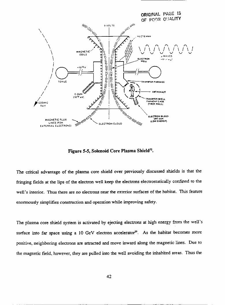
in Figure 5-5.
41
ORlGlNAL PAGE IS OF POOR QUALITY
\ \ , I t 1 C 1 t N N A
\ \ In\ In\ In\ IA\ in\ I v v w v w w
p W A V C S
\ \ \ I I
/ /
/ /
/ 1 ‘KC
TRANSFER (.(ELL F A R A D I I CAOE vntw. WALL)
E L E m O M B L E W OFF OUH
(LOW EMEROI) M&GNETIC FLUX
EXTE A N A L ELECTRON51 LINES IFEH ELECTRON CLOUD
Figure 5-5, Solenoid Core Plasma Shield32.
The critical advantage of the plasma core shield over previously discussed shields is that the
fringing fields at the lips of the electron well keep the electrons electrostatically confined to the
well’s interior. Thus there are no electrons near the exterior surfaces of the habitat. This feature
enormously simplifies construction and operation while improving safety.
The plasma core shield system is activated by ejecting electrons at high energy from the well’s
surface into far space using a 10 GeV electron accelerate?. As the habitat becomes more
positive, neighboring electrons are attracted and move inward along the magnetic lines. Due to
the magnetic field, however, they are pulled into the well avoiding the inhabited areas. Thus the
42

electron plasma is safely contained in the shielded volume not adjacent to living quarters. The
system energy requires about lOI3 joules (equivalent to one day use of a lOOMW power plant) to
supply the electron accelerator with drive energy3'. After start-up, the main power requirements
exist for the refrigeration systems. The electron accelerator also sustains the shield from leakage
currents.
All metal surfaces bolted onto the electron well will acquire an electric potential of approxi-
mately 15 billion volts. At this potential, the positively charged cosmic rays will be deflected
away from all volumes contained inside any metal surface bolted to the electron well. The
overall system is electronically neutral because the electron cloud inside the well is intensely
negative in electric potential. This device is referred to as a bolt-on shield, because any metallic
structure in electrostatic contact with the electron well is protected. Provided that the structure
stays well within the last magnetic flux line which passes through the electron well (any line that
touches is "shorted out"). The enormous electrostatic potential created by the system repels the
protons and other cosmic ray nuclei from the shielded "safe haven", and cuts off the cosmic ray
spectrum for energies below 7.5 GeV/nucleon (15 GeV for protons). This net radiation dose
cutoff, including secondary production, is well below the acceptable dose of 5 ren~/year.~~
The electron well contains 1013 J of electrostatic energy which could easily be transfonned into
penetrating high energy radiation should a subsystem failure occur (Le. the magnetic cryogenic
system). One procedure of safely disposing of this energy is to accelerate positive ions away
from the habitat, thus making all metal structures electrically neutral. The procedure can be
easily accomplished, since an electron cloud charge of 1000 coulombs is only about 10 mmol of
43

easily accomplished, since an electron cloud charge of 1000 coulombs is only about 10 m o l of
particles. Thus, 1 percent of a mole of hydrogen ionized outside the metal structure would be
enough to neutralize the habitat once the habitat's electric field had accelerated the ions away.
In effect, the "charge" account is balanced by absorbing the electrons contributed by the ions,
receding from the habitat at great speed. As the fringing electric fields die away, the electric
mirror effect would cease and the well's electrons would repel themselves along the lines of
magnetic flux - arranged not to touch the lunar habitat. Since the abort action would act more
quickly than the magnetic field could decay, the magnetic flux would still exist. Thus, in
perhaps a millisecond, l O I 3 joules and 1000 coulombs of electrons are safely neutralized.
If the shield requires operation 100 percent of the time, it must be possible to gain entrance or
exit from the habitat without turning off the shield. Since there are essentially no electrons
external to the well this is not difficult. Varying levels of charge on objects must be achieved in
order to transfer them from the habitat to the unshielded zone and back again. Such a transfer is
accomplished by using a Faraday cage equipped with electrodion guns to neutralize the transfer
item (Le. astronaut or cargo vehicle). After the transfer item enters the transfer cage, the electron
gun bleeds off enough electrons (which go into the well) to equalize the potential between its
cargo and the habitat. Once this equi-potential is achieved, the transfer item can safely enter the
habitat through the transfer passage. Note that for this procedure to work safely, the Faraday
cage cannot be in electrostatic contact with the rest of the habitat and must be heavily insulated.
In reversing the operation the transfer item with supporting systems emits positive ions (directed
to infinity) to neutralize its cargo.
44

The plasma magnetic shielding scheme was originally designed for space station applications.
There may be several obstacles that will have to be overcome before it can be safely applied to a
lunar surface habitat. The required potential of 15 billion volts may cause severe problems. If
this large habitat potential arcs to ground, the destructive stored energy will explosively dis-
charge. In the absence of an insulator, arcing on the order of 100 meters may occur. However, a
properly shaped, extensive insulation system (perhaps using lunar-derived ceramics) may be able
to prevent this occurrence. The impact of this insulation system on the overall mass will have to
be evaluated. If a combined system of mass and magnetic shielding is used, a 15 billion volt
potential may not be required. Thus, the insulation requirements may be more reasonable. The
feasibility of this shielding method can not be assessed until analysis is performed on a configu-
ration specifically designed for the lunar surface.
5.4 Concluding Remarks
Several concerns were raised during study evaluation. For example, will the 15 billion volt
potential of the habitat in the plasma core shield have any adverse effects on the crew or onboard
electronic systems? Would
secondary production of charged particles in the magnetic structure by the unshielded primary
flux above the cutoff energy require additional mass shielding? The effect of these large
magnetic fields on humans is not understood and further research is required. The energy stored
in the magnetic field is in thousands of foot pounds. Interruption of the current flow will impose
a substantial shock load to the structure. Structural and electrical effects and safeguards will
Can arcing due to this high voltage potential be eliminated?
45
require attention. Also, effects of the magnetic field on outside equipment and communications
will have to be determined. These and other concerns will have to be answered in future work.
46
~ ~~~
6.0
1.
2.
3.
4.
5 .
6.
7.
8.
9.
10.
11.
12.
13.
14.
15.
16.
References
ADpkations of High TemDerature Superconductivitv, IEEE Videoconference Seminar Via Satellite, October 20, 1988.
Popular Science, Volume 232, Number 4, April 1988, p57.
Charles G. Kuper, An Introduction to the Theory of Sumrconductivitv, Clarendon Press, Oxford, 1968.
H. Brechna, Sumperconductinn Mannet Systems, Springer-Verlag, New York, 1973.
Superconductor Industry Magazine, Volume 1, Number 1, Fall 1988, p38.
Advances in ADdied Superconductivitv: A P r e l h i n q Evaluation of Goals and Impacts, A.M. Wolsky et al., Argonne National Laboratory, January 1988.
The Role of Superconductivity in the Space Propram: An Assessment of Present Capabilities and Future Potential, Prepared for NASA by the National Bureau of Standards, Boulder, Colorado, NASA Contract Number A-437018(JM), May 1978.
Suuerconductivity: A Practical Guide For Decision Makers. Technology Futures, Inc., Austin, Texas, 1988.
Nuclear Energv - Key to Lunar DeveloDment, David Burden and Joseph A. Angelo, Jr., Lunar Bases and Space Activities of the 21st Century Symposium, Washington, D.C., October 29-3 1, 1984.
ConceDtual Desiyn of a Lunar Base Solar Power Plant, NASA Contract Number NAS9- 17878, Eagle Engineering Report Number 88-199, August 14,1988.
Simon Foner and Brian B. Schwartz, Superconducting Machines and Devices - Large Systems Applications, Plenum Press, New York and London, 1974.
R.D. Parks, Sumrconductivitv. Volume 2, Marcel Defier, Inc., New York, 1969.
Conceptual Design of a Lunar Colony, 1972 NASNASEE Engineering Systems Design Institute, Charles Dalton and Edward Hohmann, 1972.
Alexander S. Adorjan, Eagle Engineering, Inc., Personal Communication, October 26, 1988.
F.Y. Chu, ADDlications of High TemDerature Superconducting Materials in the Electric Power Svstem of Ontario Hvdro Persmctive, Proceedings of the World Congress on Superconductivity, Houston, Texas, February 20-24, 1988.
The Wall Street Journal, December 18,1987.
47

17.
18.
19.
20.
21.
22.
23.
24.
25.
26.
27.
28.
29.
Thome, R.J. and Z.J.J. Stekly, "Design and Model Tests For A 5 Tesla Superconducting Saddle Magnet," Proceedings of the 1972 Applied Superconductivity Conference, May 1-3, 1972.
Kolm, H., "Basic Coaxial Mass Driver Reference Design," Proceedings of the Third PrincetodAIAA Conference on Space Manufacturing Facilities, May 9-12, 1977.
O'Neill, Gerard K., "The Colonization of Space," Physics Today 27:9, 1974.
Roth, Bruce, "Update on Earth to Space Electromagnetic Launchers," Proceedings of the Eighth Princeton/AIAA/SSI Conference on Space Manufacturing Facilities, May 6-9, 1987.
Bilby, C., Davis, H., Nozette, S., Driga, M., and R. Kamm, "A Lunar Electromagnetic Launcher," Paper #LBS-88-073, Lunar bases and Space Activities in the 21st Century Symposium, April 5-7,1988.
Snow, W.R., Kubby, J.A., and R.S. Dunbar, "A Small Scale Lunar Launcher for Early Lunar Material Utilization," Proceedings of the Fifth PrincetodAIAA Conference on Space Manufacturing Facilities, March 18-21,1981.
Lemer, Eric, "Superconductors Heat Up Aerospace," Aerospace America, October, 1987.
Palmer, Miles R., and Ali E. Dabiri, "High Temperature Superconductor Applications in Electromagnetic Space Launch," Propress in High Temperature Suwrconductivity - Volume 8, Proceedings of the World Congress on Superconductivity, February 20-24, 1988.
Arnold, William, et al., "Mass Drivers 1:Electrical Design," Space Resources and Space Settlements, NASA SP-428, 1979.
Kolm, H., and P. Mongeau, "Assessment of Coaxial Launcher Technology for Earth-to- Space and Orbital Transfer Missions," Report for NASA Lewis Research Center, April, 1983.
Kolm, H., Fine, K., Mongeau, P., and F. Williams, "Electromagnetic Propulsion Alterna- tives," Proceedings of the Fourth Princeton/AIAA Conference on Space Manufacturing Facilities, May 14-17, 1979.
Electromagnetic Launch Research, Inc., and Large Scale Programs Institute, "Application of Superconductivity Technology to the Lunar Electromagnetic Launcher Concept," Presentation to Advanced Programs Office - NASA Johnson Space Center, June 20, 1988.
Podnieks, E., "Environmental Considerations for Lunar Base Engineering," Engineering, Construction. and Operations in SDace, Proceedings of Space 88, August 29-3 1, 1988.
48

30. Hannah, E. C., "Radiation Protection for Space Colonies," Journal of the British Interplanetary Society, Volume 30, 1977, pp310-313.
Lunar Storm Shelter Conceptual Design, Eagle Engineering, Inc., Houston, Texas, NASA Contract Number NAS9-17878, May 1988, pp72-75.
Bemert, R.E., and Z.I.J. Stekly, "Magnetic Radiation Shielding Using Superconducting Coils," Second Symposium on Protection Against Radiation in Space, Gatlhburg, Tennessee, October 12-14,1964, pp199-209.
3 I .
32. t
33. Johnson, R.D., and C. Holbrow (ed),Space Settlements - 1977, ~ ~ 6 7 - 6 9 .
A Design Study, NASA SP-413,
49