Embed Size (px)
Citation preview
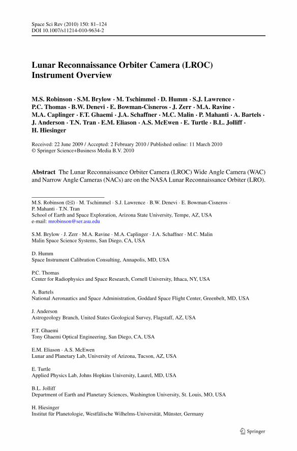
Space Sci Rev (2010) 150: 81–124DOI 10.1007/s11214-010-9634-2
Lunar Reconnaissance Orbiter Camera (LROC)Instrument Overview
M.S. Robinson · S.M. Brylow · M. Tschimmel · D. Humm · S.J. Lawrence ·P.C. Thomas · B.W. Denevi · E. Bowman-Cisneros · J. Zerr · M.A. Ravine ·M.A. Caplinger · F.T. Ghaemi · J.A. Schaffner · M.C. Malin · P. Mahanti · A. Bartels ·J. Anderson · T.N. Tran · E.M. Eliason · A.S. McEwen · E. Turtle · B.L. Jolliff ·H. Hiesinger
Received: 22 June 2009 / Accepted: 2 February 2010 / Published online: 11 March 2010© Springer Science+Business Media B.V. 2010
Abstract The Lunar Reconnaissance Orbiter Camera (LROC) Wide Angle Camera (WAC)and Narrow Angle Cameras (NACs) are on the NASA Lunar Reconnaissance Orbiter (LRO).
M.S. Robinson (�) · M. Tschimmel · S.J. Lawrence · B.W. Denevi · E. Bowman-Cisneros ·P. Mahanti · T.N. TranSchool of Earth and Space Exploration, Arizona State University, Tempe, AZ, USAe-mail: [email protected]
S.M. Brylow · J. Zerr · M.A. Ravine · M.A. Caplinger · J.A. Schaffner · M.C. MalinMalin Space Science Systems, San Diego, CA, USA
D. HummSpace Instrument Calibration Consulting, Annapolis, MD, USA
P.C. ThomasCenter for Radiophysics and Space Research, Cornell University, Ithaca, NY, USA
A. BartelsNational Aeronautics and Space Administration, Goddard Space Flight Center, Greenbelt, MD, USA
J. AndersonAstrogeology Branch, United States Geological Survey, Flagstaff, AZ, USA
F.T. GhaemiTony Ghaemi Optical Engineering, San Diego, CA, USA
E.M. Eliason · A.S. McEwenLunar and Planetary Lab, University of Arizona, Tucson, AZ, USA
E. TurtleApplied Physics Lab, Johns Hopkins University, Laurel, MD, USA
B.L. JolliffDepartment of Earth and Planetary Sciences, Washington University, St. Louis, MO, USA
H. HiesingerInstitut für Planetologie, Westfälische Wilhelms-Universität, Münster, Germany

82 M.S. Robinson et al.
The WAC is a 7-color push-frame camera (100 and 400 m/pixel visible and UV, respec-tively), while the two NACs are monochrome narrow-angle linescan imagers (0.5 m/pixel).The primary mission of LRO is to obtain measurements of the Moon that will enable fu-ture lunar human exploration. The overarching goals of the LROC investigation includelanding site identification and certification, mapping of permanently polar shadowed andsunlit regions, meter-scale mapping of polar regions, global multispectral imaging, a globalmorphology base map, characterization of regolith properties, and determination of currentimpact hazards.
Keywords LRO · LROC · Instrument · Camera · Moon · Lunar · Calibration
1 Introduction
The observations, fieldwork, and sampling performed by the Apollo astronauts in lunar or-bit and on the lunar surface yielded key insights into the origin, composition, and geologicevolution of the Moon and transformed humanity’s knowledge of the Solar System. One ofthe key reasons that the Apollo missions were so successful was the intensive reconnais-sance of the lunar surface performed using the five robotic Lunar Orbiter spacecraft, whichprovided synoptic photographic coverage of the entire Moon (Bowker and Hughes 1971),as well as high-resolution (1 m/pixel) observations specifically targeted at candidate Apollolanding sites. The Lunar Orbiter observations enabled the subsequent early Apollo land-ings and provided a valuable dataset for lunar geologic studies (El-Baz and Kosofsky 1970;Musgrove 1971). Existing lunar datasets (including Lunar Orbiter, Apollo, Clementine, andLunar Prospector) are insufficient to effectively plan for future landings (human or ro-botic), especially in areas outside of the so-called “Apollo Zone” where meter-scale im-agery and topographical data vital for landing site certification and operational planning issparse or non-existent. Recent lunar missions (including JAXA’s Kaguya mission, the CNSAChang’E, and the ISRO’s Chandrayaan-1) collected datasets of high scientific and explo-ration value, though none reveal lunar surface morphology at the scale needed to support theprojected engineering requirements of NASA’s next-generation human lunar exploration.
The Space Exploration Policy of the United States calls for a resumption of human lu-nar landings no later than 2020 under the aegis of Project Constellation, with the goal ofeventually establishing a permanent outpost on the lunar surface (NASA 2004a). The Lu-nar Reconnaissance Orbiter (LRO) is designed to serve Project Constellation as Lunar Or-biter served Apollo, providing comprehensive remote sensing data that will enable the nextgeneration of human lunar exploration and development. The Lunar Reconnaissance Or-biter Camera (LROC) is designed to address two of the LRO Level 1 measurement objec-tives: Landing site certification and determination of polar illumination (Chin et al. 2007;NASA 2004b). LROC data will help us redefine our understanding of the Moon’s historyand current state and guide lunar surface operations for decades to come.
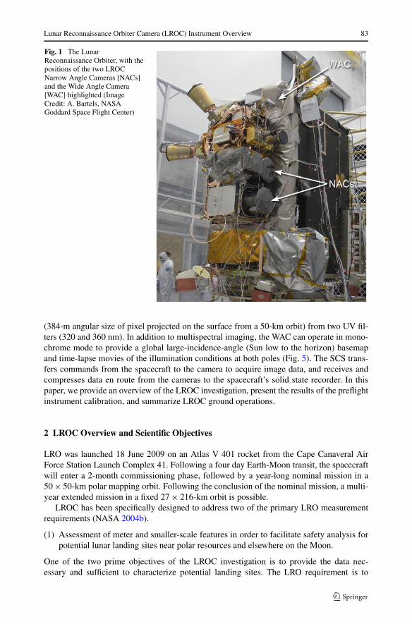
LROC consists of three imaging subsystems (Figs. 1, 2, 5) with a supporting Sequenceand Compressor System (SCS). The two Narrow Angle Cameras (NACs) are monochromepush-broom scanners, with an instantaneous field-of-view (IFOV) of 10-microradians(50-cm angular resolution from the nominal 50-km orbit (Fig. 2)). The multispectral WideAngle Camera (WAC) is a push-frame imager with five visible wavelength filters (415 to690 nm) with an IFOV of 1.498-milliradians (75-m angular size of pixel projected on thesurface from a 50-km altitude) with the visible light filters, and IFOV of 9.672-milliradians
Lunar Reconnaissance Orbiter Camera (LROC) Instrument Overview 83
Fig. 1 The LunarReconnaissance Orbiter, with thepositions of the two LROCNarrow Angle Cameras [NACs]and the Wide Angle Camera[WAC] highlighted (ImageCredit: A. Bartels, NASAGoddard Space Flight Center)
(384-m angular size of pixel projected on the surface from a 50-km orbit) from two UV fil-ters (320 and 360 nm). In addition to multispectral imaging, the WAC can operate in mono-chrome mode to provide a global large-incidence-angle (Sun low to the horizon) basemapand time-lapse movies of the illumination conditions at both poles (Fig. 5). The SCS trans-fers commands from the spacecraft to the camera to acquire image data, and receives andcompresses data en route from the cameras to the spacecraft’s solid state recorder. In thispaper, we provide an overview of the LROC investigation, present the results of the preflightinstrument calibration, and summarize LROC ground operations.
2 LROC Overview and Scientific Objectives
LRO was launched 18 June 2009 on an Atlas V 401 rocket from the Cape Canaveral AirForce Station Launch Complex 41. Following a four day Earth-Moon transit, the spacecraftwill enter a 2-month commissioning phase, followed by a year-long nominal mission in a50 × 50-km polar mapping orbit. Following the conclusion of the nominal mission, a multi-year extended mission in a fixed 27 × 216-km orbit is possible.
LROC has been specifically designed to address two of the primary LRO measurementrequirements (NASA 2004b).
(1) Assessment of meter and smaller-scale features in order to facilitate safety analysis forpotential lunar landing sites near polar resources and elsewhere on the Moon.
One of the two prime objectives of the LROC investigation is to provide the data nec-essary and sufficient to characterize potential landing sites. The LRO requirement is to
84 M.S. Robinson et al.
assess the threat posed by “meter and smaller-scale features” (NASA 2004b). This as-sessment requires a 0.5-m pixel scale in order to ensure unambiguous two-pixel detec-tion of meter-scale features. The NACs will detect blocks down to ∼1 m horizontal scalewith ≤ 0.5 m heights, and craters with diameters ≥ 2.5 m. In addition to high-resolutionimaging, topographic data derived from both geometric and photometric stereo (photo-clinometry) observations of potential landing sites at spatial scales of 2 to 5 m/pixelwill provide quantitative information about the slopes in small craters that pose a riskfor landing spacecraft. From both the Apollo and Surveyor experience, it is known thatsmall craters, rather than blocks, may actually present a greater danger to landing ve-hicles because they are far more abundant. In fact, except for very young Copernicanunits, the lunar surface is saturated with craters smaller than 100 m in diameter (Gault1970). Thus, a lunar landing site will contain many craters, presenting a sub-horizontalsurface at the scale of any lander. Blocks, on the other hand, are much less common, es-pecially in areas away from fresh craters (Cameron and Coyle 1971; Cintala et al. 1982;Cintala and McBride 1995; Lee et al. 1986; Moore 1971). The presence of small, shal-low craters can be assessed from images with large (> 70◦) incidence angles and meter-scale topography. LROC will provide essential morphology information and stereogram-metric and photometric stereo observations for high-priority exploration sites (NASA 2005;Taylor and Spudis 1990).
(2) Acquire multi-temporal synoptic 100 m/pixel imaging of the poles during every orbit tounambiguously identify regions of permanent shadow and permanent or near-permanentillumination.
The Moon’s equator is tilted only 1.54◦ to the ecliptic, so seasonal lighting conditionschange only a small amount during a year. Thus there are regions of permanent shadowand permanent or nearly permanent illumination in the vicinity of the lunar poles. The-ory as well as radar and neutron measurements suggest that deposits of water-ice (a poten-tially valuable lunar resource) may occur in permanently shadowed regions near the poles(Feldman et al. 2000; Ingersoll et al. 1992; Nozette et al. 2001; Watson et al. 1961). Re-gions that are illuminated for extended periods are prime candidates for future lunar basesowing to relatively benign thermal conditions and constant solar power (Goddard 1920;Heiken et al. 1991). Clementine imaged the poles every 10 hours (250 to 500 m/pixel)allowing a synoptic reconstruction of lighting conditions over a period of two Earthmonths (i.e., two lunar days). At the time of the Clementine mission, the Moon wasin southern winter (sub-solar point 1.5◦N to 0.3◦N), therefore the derived lighting mapsmore accurately show permanent shadows and near-permanent illumination in the north-ern and southern hemispheres, respectively. Clementine lighting maps revealed peaks nearthe South Pole that receive sunlight for almost 70% of a lunar day (Bussey et al. 1999;Noda et al. 2008). Unfortunately, the Moon was in a nearly identical configuration duringthe Apollo-era Lunar Orbiter polar missions, and so it is not possible to construct maps ofregions of anomalously long illumination near the North Pole from any existing data.
In monochrome mode from the nominal 50-km orbit, the WAC FOV covers a swath∼104-km wide resulting in repeat coverage every orbit for the region between 88◦ and 90◦at each pole. LROC will image 80◦ to 90◦ on the dayside and back to 80◦ on the nightside on each orbit, enabling the creation of a year-long illumination movie with time stepsat least every five hours from ±88–90◦, and coverage to 85◦ with lesser but still sufficienttime resolution over a full lunar year. WAC images will provide a calibrated, archived, andreduced dataset completely delimiting permanently shadowed regions and permanently (ornear-permanently) illuminated terrain at both poles at a scale of 100 m.
Lunar Reconnaissance Orbiter Camera (LROC) Instrument Overview 85
In addition to these two primary objectives, LROC will return six other high-valuedatasets valuable both for planning future human exploration and supporting basic lunarscience investigations.
(3) Meter-scale mapping of regions of permanent or near-permanent illumination of polarmassifs.
While the combined NAC FOV will limit its temporal sampling of polar illuminationconditions, it can provide meter-scale sampling of the boundaries of shadowed regionsand complete mapping of illuminated terrain within 5◦ of the poles. During respectivesummers, when shadows are at a minimum, the NAC will acquire hundreds of imagesat 1-m/pixel to enable mosaics of each pole. The mosaics are built up by first imag-ing from 87.5◦ latitude to 0.8◦ past the pole on one orbit. For the next two orbits, theNACs then image from 85.5◦ to 88.8◦. This three orbit cycle is repeated for 29 daysuntil complete coverage of the map region is obtained. The summer mosaics will serveas a basemap of illuminated regions and will provide high-resolution details of the mar-gins of permanently shadowed regions. During winter much of the polar regions arein shadow, so NAC imaging will concentrate on targets known to have extended peri-ods of illumination. Two massifs near the South Pole collectively receive illuminationfor more than 95% of a winter day at a scale of ∼200 m/pixel (Bussey et al. 1999;Noda et al. 2008). Lighting conditions of these topographic peaks will be examined at1 m/pixel over extended periods.
Identification and high-resolution mapping of highly illuminated sites is of critical im-portance for future human surface operations in the lunar polar region for both power andenvironmental reasons (Goddard 1920; Heiken et al. 1991; Watson et al. 1961). Since thepersistently illuminated regions are by definition massifs, it is probable that their summitareas will receive the most illumination. Such regions could be as small as a few to tens ofmeters across, below the resolution of other lunar datasets. A 10 × 10 m region represents1% of a WAC pixel, 4% of a SMART-1 AMIE pixel, 1 Kaguya terrain camera pixel, and2×2 Chandrayaan Terrain camera pixels, but will be covered by 400 NAC pixels (20×20).The value of such small areas may actually be very high, providing mission planners withspecific areas where installed solar arrays would provide continuous or nearly continuouspower to nearby assets. High-priority landing and operational sites will be imaged at fullresolution (0.5 m/pixel) allowing characterization of the suitability for landing and surfaceoperations at these high value targets.
(4) Repeat observations of portions of potential landing sites and elsewhere for the deriva-tion of high-resolution topography through stereogrammetric and photometric stereoanalyses.
LROC will provide photogrammetric and photometric stereo data for high-priority candi-date landing sites and select areas of high scientific interest. Most of the processing fortopographic maps will need to be funded by programs other than LRO, but the LROC teamwill generate example geometric and photometric stereo-based products for select sitesto demonstrate the utility of the methods and data reduction procedures. For photometricstereo, at least three nadir observations of the same scene, each under different illuminationconditions will be acquired. For geometric stereo, the LRO will have to be rolled into anoff-nadir geometry to collect cross-track images at appropriate lighting conditions, but theseopportunities will be limited to at most three per 24-hour period due to constraints imposedby other LRO instruments.
86 M.S. Robinson et al.
(5) Global multispectral observations in seven wavelengths to characterize lunar resources,in particular ilmenite.
The WAC multispectral dataset will allow the science community to improve maps of somemineralogical components of the lunar crust, in conjunction with complementary datasets(Clementine, Kaguya, Chandrayaan-1, and SMART-1). The bandpasses of LROC WAC areparticularly suited for the detection of ilmenite (FeTiO3), which is identified as a valuablelunar resource. Ilmenite is notable for being an excellent source of oxygen, titanium metal(Williams et al. 1979; Zhao and Shadman 1993), and solar-wind-implanted volatiles (such asH and He), which are preferentially retained by ilmenite-rich soils (Cameron 1993). Volatileelements may be useful to facilitate the production of water and possibly fuels (H and 3He).The accurate determination of titanium abundance in lunar surface deposits is thereforean import part of lunar resource assessment and development. No funding is provided toconstruct the global multi-spectral map.
(6) A global 100-m/pixel basemap with incidence angles (60◦–80◦) favorable for morpho-logical interpretations.
Global coverage at scales of 100-m/pixel and large incidence angles (> 50◦) is crucial forsystematic geologic mapping and crater counting efforts. High precision crater counts ofthe lunar surface are especially important because the Moon is the only planetary bodyfor which relative ages from crater counts can be correlated with absolute dating of rocksamples collected by trained field observers (Stoffler et al. 2006, and references therein).The best existing lunar morphologic basemap is the recently completed Lunar Orbiter digitalmosaic (Becker et al. 2004) with scales ranging from 60 to 600 m/pixel, although this datasetcould eventually be superseded by the data collected by instruments aboard recent lunarmissions (i.e., Chang’E, Kaguya). The current lack of globally uniform, high-resolutionlunar imaging means that large parts of the Moon’s surface (especially on the lunar farside)have not been systematically dated using crater statistics. Clementine observations wereintentionally acquired at high Sun angles to enhance the analysis of the color data and arenot suitable for morphologic mapping at non-polar latitudes (Nozette et al. 1994). LROCWAC will provide imaging to construct a 100-m/pixel global map with incidence anglesbetween 55◦–75◦ (except at in polar regions, where incidence angles are always higher) toenable the creation of a uniform global crater chronology dataset with consistent incidenceangles.
(7) Sub-meter imaging of a variety of geologic units to characterize their physical proper-ties, the variability of the regolith, and other key science questions.
The physical properties of the lunar regolith have been characterized in great detail from dataand samples returned by Surveyor, Apollo, and Soviet missions. Meteorite bombardmentover time has converted crystalline rock to a soil that is essentially uniform in terms ofthickness, particle size distribution, bearing strength, cohesion, and many other physicalproperties (Carrier et al. 1991). This layer is known as the regolith, and it covers the entirelunar surface. Regolith typically varies in thickness between 1 and 10 m in the maria, andmost likely greater than 10 m in depth in highlands regions (Cintala et al. 1982). All lunarsurface operations will take place on or within the regolith, and all exploitable resourcesand construction materials will come from the regolith, which means that understandingthe properties of the regolith is vital for successful lunar surface activities. Although muchis known about the physical properties of lunar soils, LROC NAC imaging will providethe necessary data (0.5 m/pixel imaging) needed to apply proven techniques to estimateregolith thickness and other key parameters (Oberbeck and Quaide 1968, 1967; Quaide and
Lunar Reconnaissance Orbiter Camera (LROC) Instrument Overview 87
Oberbeck 1968). Among the science questions that will be addressed using LROC NACimages include the rates of regolith generation, local variability in regolith thickness, andthe presence within the regolith of coherent blocks.
(8) Meter-scale coverage overlapping with Apollo-era panoramic images (1–2 m/pixel) todocument the number of small impacts since 1971–1972. The current impact rate forbolides in the 0.5 to 10 m diameter range is not known to better than 1 or 2 orders ofmagnitude (Ivanov 2006). Elucidating the impact rate at these sizes enables engineeringremediation measures for future surface operations and interplanetary travel.
Particles with masses 50 g to 1000 g (4 to 10 cm diameter at 2 g/cm3) impact the Moonas often as 10 times/day (Duennebier et al. 1976). LROC NAC observations (0.5 m/pixel)of (1) very young mare surfaces and (2) regions photographed using the Apollo 15–17Panoramic Camera will be used to place estimates on the number of small craters (1 to100 m diameter) that have formed from 1971–2010. LROC NAC images will be collectedfrom and compared to as many of the regions with comparable Apollo panoramic cameraimaging (i.e., 1 m/pixel) as possible (Lawrence et al. 2008a). This comparison will providethe first direct measure of the current formation rate of 1 to 100 m craters and place animportant constraint on the most energetic hypervelocity impact from which future lunarstructures must be protected.
3 Instrument Design
Leveraging the extensive experience of LROC prime contractor Malin Space Science Sys-tems (MSSS), the LROC instrument subsystems share heritage from the Mars Color Imager(MARCI) and Context Camera (CTX) aboard the Mars Reconnaissance Orbiter (MRO),the Mars Climate Orbiter (MCO), Mars Polar Lander (MPL), Mars Odyssey, and the MarsPhoenix Lander spacecraft (Malin et al. 2001, 2007; Bell et al. 2009).
3.1 Narrow Angle Cameras (NACs)
The two NACs (Fig. 2), designated NAC-Left (NAC-L) and NAC-Right (NAC-R), are de-signed to provide 0.5 m scale panchromatic images over a combined 5-km swath. Each NACutilizes a 700-mm focal-length telescope that images onto a 5000-pixel charge coupled de-vice (CCD) line-array, providing an IFOV of 10 μradians and a cross-track field-of-viewof 2.85◦ each, which yields a total ground track swath-width for both cameras of 5-km atthe nominal 50-km altitude. Each NAC internal buffer holds 256 MB of uncompressed data,enough for a full-swath image 25-km in length or a 2× binned image 104-km long. The NACdata are sampled to 12-bits, then companded (bit compression) to 8-bits. Prior to downlinkan additional lossless first-difference Huffman compression is applied.
3.1.1 NAC Optics
The principal challenges of the NAC optical design were to provide near diffraction-limitedperformance at a half-meter ground sample distance over a relatively wide field, in the lu-nar orbit thermal environment and with low mass. While the starting point for the NACdesign was the MRO CTX (Malin et al. 2007), that design was unable to meet these NACrequirements. The NAC resolution requirement was twice that of CTX (10 microradians perpixel rather than CTX’s 20 microradians) but with the same field of view. The temperature
88 M.S. Robinson et al.
range the instrument experiences in lunar orbit is considerably greater than what CTX seesat Mars, prompting us to seek a less thermally sensitive design than the CTX Maksutov tele-scope. Finally, cost minimization drove the need to maximize the reuse the CTX detectorand electronics. Central to our strategy for addressing these requirements was to build twoduplicate NACs with offset pointing to provide twice the field of view of a single copy ofthe instrument.
Using two instances of the instrument to get the full 5.7◦ swath requires an individual unitFOV of 2.85◦. To limit the thermal sensitivity of NAC optics, we pursued optical designswithout a large refractive front corrector group. The flight NAC telescope uses hyperbolicprimary and secondary mirrors (Ritchey-Chretien, hereafter RC) with an all spherical tripletfield corrector lens to provide an optical field of view of approximately 3◦ (large for an RCdesign). This f/3.59 telescope had a design MTF at Nyquist of greater than 56% over theentire field. The design also incorporates a 650 mm long sunshade to prevent illumination ofthe primary mirror by rays more than 30◦ off axis. The specifications of each of the two NACtelescopes are given in Table 2. To minimize both mass and thermal sensitivity, the meteringstructure is made of graphite-cyanate composite. Because of the composite resin is hygro-scopic, there is a significant focus shift between fully dry, the case which pertains to lunar or-bit, and “wet,” the state the instruments were in the laboratory environment. Validation of fo-cus for flight was by baking-out the cameras in at 65°C in vacuum while imaging a collima-tor stimulus. A final confirmation of focus was made by imaging the Moon immediately afterremoving each unit from thermal vac (Fig. 21). The NAC telescopes were built by Light-Works Optics of Tustin, CA in collaboration with Vanguard Composites of San Diego, CA.
3.1.2 NAC Electronics
The NAC electronics design is based on the Context Camera (CTX) on the Mars Reconnais-sance Orbiter (MRO) mission, with modifications to increase the maximum pixel rate from2 megapixels/second to 7.5 megapixels/second. The electronics are built around the KodakKLI-5001G line array. This device is a 5064-element CCD with 7 micron pixels, and an av-erage QE through the instrument bandpass of >60%. It is fabricated in an NMOS two-metaltwo-poly process by Kodak Image Sensor Solutions in Rochester, NY. Correlated DoubleSampling (CDS) is incorporated on-chip. The device has dual readouts with a maximumreadout rate of 12.5 MHz. Though the datasheet noise floor is fairly high (150 e− at roomtemperature and 12.5 MHz operation) performance is better at operating temperature andslower clocking.
The NAC analog signal processing chain is considerably simplified by the on-chip CDSprovided by the CCD. There are two duplicate analog signal chains, one handling the evenpixels, the other handling the odd pixels. Although CDS is performed on the CCD die, theoutput signals still have a large DC pedestal, which varies device-to-device and (potentially)with temperature and radiation exposure. To mitigate excess background the design includesa black-level DAC that allows a constant black level to be removed prior to amplification.The black level was established during calibration and can be changed via ground command.The digitization range is set to 300 Ke− maximum, yielding a scale factor of about 90 e−/DN(90.5 NAC-L and 92.5 NAC-R), which is close to the best-expected noise performance ofthe CCD.
The NAC digital electronics provides clock generation, sampling of the CCD signal, con-version of the 12-bit samples to 8-bit encoded pixels, storage of the pixels, and finally read-out of the pixels to the SCS. A dedicated field-programmable gate array (FPGA) rather thana general-purpose processor performs these functions. The specific functions implementedin the FPGA are:

Lunar Reconnaissance Orbiter Camera (LROC) Instrument Overview 89
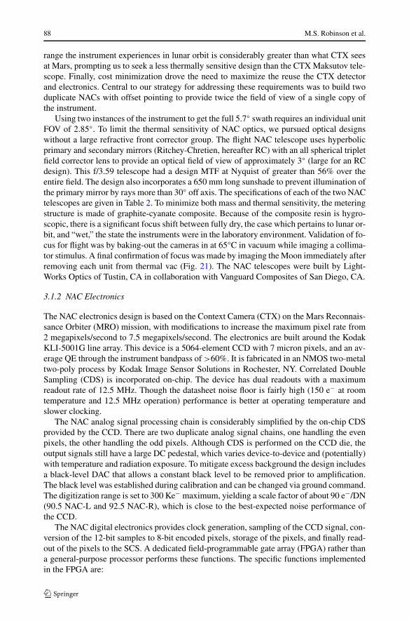
Fig. 2 The LROC Narrow Angle Cameras side by side without their radiators. The black baffle preventsstray light from entering the optics (silver part of the tube). The focal plane array and associated electronicsare in the triangular housing on the right end. The diameter of each tube is 27 cm
• Serial command interface from the SCS• Serial data interface to the SCS• DRAM interface• CCD clock generation• 12-to-8 bit pixel companding• Commanding and DRAM readout
The NACs use 256 Mbit synchronous DRAM for image storage. Eight devices provide atotal capacity of 256 MB (268,435,456 bytes). Each pixel value is mapped through an ad-justable piecewise linear transfer function. Approximate square root encoding allows con-version of 12-bit per pixel data to 8-bit form with only minimal loss of information. Sincethe transfer function can be changed in flight, other forms of encoding (e.g., linear withoffset) can be used as well (see Appendix A).
The SCS communicates with the NAC via a 3-signal (data, clock, and enable) synchro-nous serial LVDS interface, at a maximum clocking rate of 2 MHz. The command interfacesection of the FPGA is clocked by the interface clock and its outputs are synchronized tothe system clock domain using dual flip-flops. The instrument communicates with the SCSvia a 3-signal (data, clock, and enable) synchronous serial interface, at a maximum clockingrate of 30 MHz.
Only minimal instrument health monitoring is provided in the form of a thermistor atthe focal plane (backside of CCD), at the field programmable gate array (FPGA) in theelectronics box, and on the metering structure between the primary and secondary mirrors.Operating temperatures of the focal plane are expected to range from 0°C to 20°C over thecourse of the mission, mostly a function of local time-of-day.
3.1.3 NAC Orientation
The NACs are mounted on the spacecraft such that the CCDs are perpendicular to the space-craft’s X-axis. The NAC-L is off-pointed ∼2.85◦ from the NAC-R so that the footprints of

90 M.S. Robinson et al.
Fig. 3 Orientations of NAC CCDs as mounted on the spacecraft. Numbers show pixel addresses (zero basedcoordinates). The NACs overlap ∼135 pixels in the crosstrack direction (Y) and are separated ∼0.106◦(185 pixels) downtrack (X)
the two images overlap only ∼135 pixels. The NAC-R is also mounted 0.106◦ forward of theNAC-L. The NACS are mounted such that pixel 0 for the NAC-L is at the −Y (in spacecraftcoordinates) end of its CCD and pixel 0 for the NAC-R is at the +Y end of its CCD (Fig. 3).This orientation requires that one of the NAC frames from a NAC-L and NAC-R pairedobservation must be transformed such that both images have the same ground orientation.
3.2 Wide Angle Camera (WAC)
The WAC (Fig. 4) is designed to provide global imaging at a scale of 100 m/pixel in sevencolor bands over a 105-km swath in monochrome mode and 57-km in color mode. TheLROC WAC uses a 1000 by 1000 pixel CCD that has seven narrow-band interference filtersbonded to the detector. Two of the filters are in the ultraviolet (UV) and five are in the visible.The WAC has two short-focal-length lenses, one UV and one visible, both of which imageonto the same detector. From the nominal 50-km altitude orbit in monochrome imagingmode, the WAC will provide a nadir ground sample distance of 75 m/pixel (98 m/pixel atfar field). In the UV system, the nadir resolution is 384 m/pixel. The seven-band color filterarray provides different sections of the CCD with different bandpasses. Repeated imaging ata rate such that each of the narrow framelets of each color band overlap provides continuouscoverage in any one color (“push-frame imaging”). The layout of the WAC filters is similarto the MRO MARCI instrument as described in Bell et al. (2009). WAC pixel values aredigitized to 11-bits and subsequently companded to 8-bit values. After transmission to theSCS, the WAC data have a lossless first-difference Huffman compression that is appliedprior to downlink.
3.2.1 WAC Optics
The WAC optics consist of four optical elements: the visible lens, the UV lens, the prismand the color filter array (CFA). The visible lens has a 6.0 mm focal length and a focalratio of 5.5. It has six fused silica elements and is optimized for the wavelength range from395 nm to 690 nm. It provides a 90◦ field of view over the full 1008 pixel width of thedetector. The lens has a design MTF of greater than 60% at 56 line pairs per mm in allbands. The UV lens has a 4.7 mm focal length and a focal ratio of 5.1. It has five elementsand is optimized for the wavelength range from 290 nm to 370 nm. It provides a 60◦ fieldof view over a 512 pixel width on the detector. Because signal is low in the UV bands, theUV system data is acquired by summing pixels 4 × 4. The optical design provides a 4 by4-pixel ensquared energy of greater than 80% in both UV bands. The physical diameter ofeach of these lenses is greater than the format of the CCD detector. A prism is used to allowboth lenses to image on the same CCD. This prism provides a straight-through path fromthe visible lens to the detector, and a periscope-type optical path for the UV lens. The latter
Lunar Reconnaissance Orbiter Camera (LROC) Instrument Overview 91
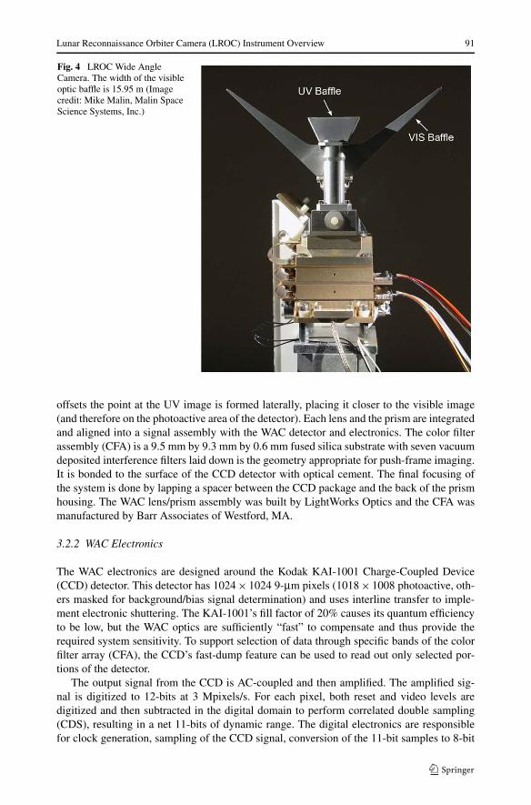
Fig. 4 LROC Wide AngleCamera. The width of the visibleoptic baffle is 15.95 m (Imagecredit: Mike Malin, Malin SpaceScience Systems, Inc.)
offsets the point at the UV image is formed laterally, placing it closer to the visible image(and therefore on the photoactive area of the detector). Each lens and the prism are integratedand aligned into a signal assembly with the WAC detector and electronics. The color filterassembly (CFA) is a 9.5 mm by 9.3 mm by 0.6 mm fused silica substrate with seven vacuumdeposited interference filters laid down is the geometry appropriate for push-frame imaging.It is bonded to the surface of the CCD detector with optical cement. The final focusing ofthe system is done by lapping a spacer between the CCD package and the back of the prismhousing. The WAC lens/prism assembly was built by LightWorks Optics and the CFA wasmanufactured by Barr Associates of Westford, MA.
3.2.2 WAC Electronics
The WAC electronics are designed around the Kodak KAI-1001 Charge-Coupled Device(CCD) detector. This detector has 1024 × 1024 9-μm pixels (1018 × 1008 photoactive, oth-ers masked for background/bias signal determination) and uses interline transfer to imple-ment electronic shuttering. The KAI-1001’s fill factor of 20% causes its quantum efficiencyto be low, but the WAC optics are sufficiently “fast” to compensate and thus provide therequired system sensitivity. To support selection of data through specific bands of the colorfilter array (CFA), the CCD’s fast-dump feature can be used to read out only selected por-tions of the detector.
The output signal from the CCD is AC-coupled and then amplified. The amplified sig-nal is digitized to 12-bits at 3 Mpixels/s. For each pixel, both reset and video levels aredigitized and then subtracted in the digital domain to perform correlated double sampling(CDS), resulting in a net 11-bits of dynamic range. The digital electronics are responsiblefor clock generation, sampling of the CCD signal, conversion of the 11-bit samples to 8-bit
92 M.S. Robinson et al.
encoded pixels, storage of the pixels, and readout of the pixels to the SCS. These functionsare performed by a digital signal processor (DSP) with software emulation.
WAC instrument health monitoring includes real-time telemetry monitoring of voltageand temperature during S-band contacts, and trend analysis of voltage and temperature us-ing stored telemetry downlinked during Ka-band contacts. Additional health monitoring isperformed by statistical analysis of acquired images, especially WAC dark pixels.
3.2.3 WAC Monochrome Imaging
The highest-resolution existing morphologic basemap is the Lunar Orbiter digital mosaic(Becker et al. 2004) with resolutions ranging from 60 to 600 m/pixel (Bowker and Hughes1971). The WAC will accordingly be operated in single-band mode (nominally the 605 nmfilter) to acquire a global morphology basemap with incidence angles between 60◦ and 80◦ toprovide an improved morphologic map of the Moon at a uniform resolution of 100 m/pixel.
3.2.4 WAC Multispectral Imaging
The WAC has two ultraviolet filters (320 and 360 nm), and five visible filters (415, 565, 605,645, and 690 nm). These bandpass filters were selected to characterize spectral features forsome common minerals found at the lunar surface and will complement Clementine UVVIS(415, 750, 900, 950, 1000 nm) and NIR datasets (1100, 1250, 1500, 2000, 2600, 2780 nm)(Nozette et al. 1994) as well as VIS-NIR data being collected by Chandrayaan-1 and Selene(Haruyama et al. 2008; Green et al. 2007).
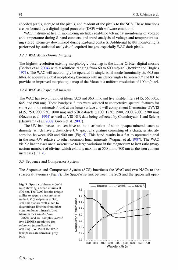
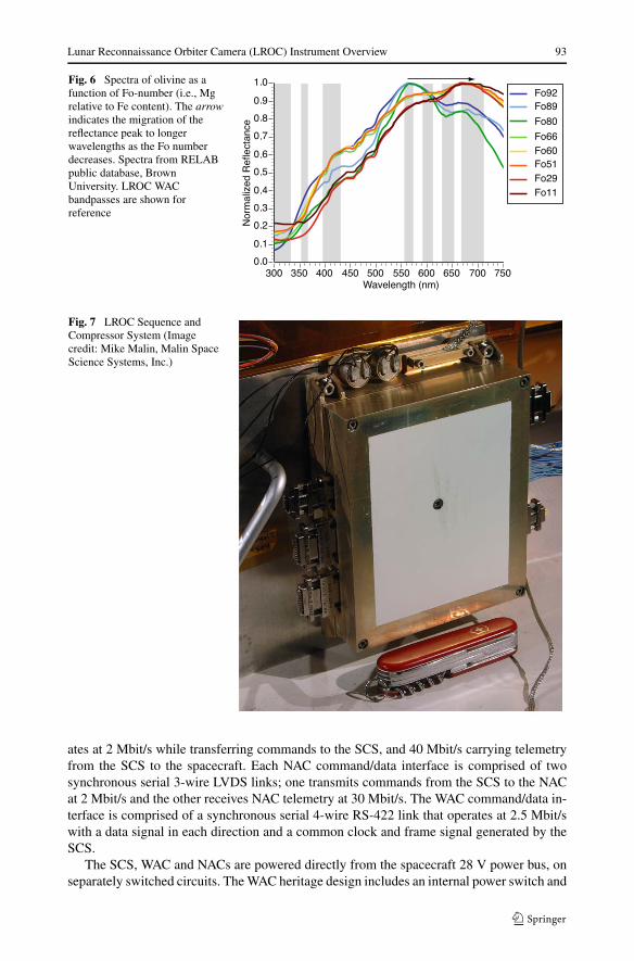
The UV bandpasses are sensitive to the distribution of some opaque minerals such asilmenite, which have a distinctive UV spectral signature consisting of a characteristic ab-sorption between 450 and 500 nm (Fig. 5). This band results in a flat to upturned signalin the near-UV relative to other common lunar minerals (Wagner et al. 1987). The WACvisible bandpasses are also sensitive to large variations in the magnesium to iron ratio (mag-nesium number) of olivine, which exhibits maxima at 550 nm to 700 nm as the iron contentincreases (Fig. 6).
3.3 Sequence and Compressor System
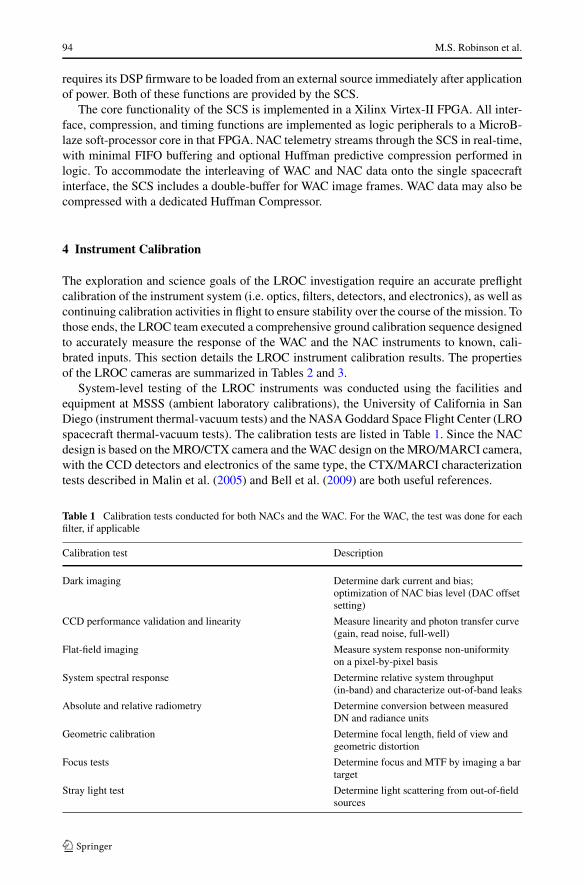
The Sequence and Compressor System (SCS) interfaces the WAC and two NACs to thespacecraft avionics (Fig. 7). The SpaceWire link between the SCS and the spacecraft oper-
Fig. 5 Spectra of ilmenite (solidline) showing a broad minima at500 nm. The WAC has the uniqueability to acquire measurementsin the UV (bandpasses at 320,360 nm) that are well suited todiscriminate ilmenite from othercommon lunar minerals. Lowtitanium rock (dashed line12063R) and soil samples (dottedline 12070S) are plotted forreference (normalized at450 nm). FWHM of the WACbandpasses are shown as graybars
Lunar Reconnaissance Orbiter Camera (LROC) Instrument Overview 93
Fig. 6 Spectra of olivine as afunction of Fo-number (i.e., Mgrelative to Fe content). The arrowindicates the migration of thereflectance peak to longerwavelengths as the Fo numberdecreases. Spectra from RELABpublic database, BrownUniversity. LROC WACbandpasses are shown forreference
Fig. 7 LROC Sequence andCompressor System (Imagecredit: Mike Malin, Malin SpaceScience Systems, Inc.)
ates at 2 Mbit/s while transferring commands to the SCS, and 40 Mbit/s carrying telemetryfrom the SCS to the spacecraft. Each NAC command/data interface is comprised of twosynchronous serial 3-wire LVDS links; one transmits commands from the SCS to the NACat 2 Mbit/s and the other receives NAC telemetry at 30 Mbit/s. The WAC command/data in-terface is comprised of a synchronous serial 4-wire RS-422 link that operates at 2.5 Mbit/swith a data signal in each direction and a common clock and frame signal generated by theSCS.
The SCS, WAC and NACs are powered directly from the spacecraft 28 V power bus, onseparately switched circuits. The WAC heritage design includes an internal power switch and
94 M.S. Robinson et al.
requires its DSP firmware to be loaded from an external source immediately after applicationof power. Both of these functions are provided by the SCS.
The core functionality of the SCS is implemented in a Xilinx Virtex-II FPGA. All inter-face, compression, and timing functions are implemented as logic peripherals to a MicroB-laze soft-processor core in that FPGA. NAC telemetry streams through the SCS in real-time,with minimal FIFO buffering and optional Huffman predictive compression performed inlogic. To accommodate the interleaving of WAC and NAC data onto the single spacecraftinterface, the SCS includes a double-buffer for WAC image frames. WAC data may also becompressed with a dedicated Huffman Compressor.
4 Instrument Calibration
The exploration and science goals of the LROC investigation require an accurate preflightcalibration of the instrument system (i.e. optics, filters, detectors, and electronics), as well ascontinuing calibration activities in flight to ensure stability over the course of the mission. Tothose ends, the LROC team executed a comprehensive ground calibration sequence designedto accurately measure the response of the WAC and the NAC instruments to known, cali-brated inputs. This section details the LROC instrument calibration results. The propertiesof the LROC cameras are summarized in Tables 2 and 3.
System-level testing of the LROC instruments was conducted using the facilities andequipment at MSSS (ambient laboratory calibrations), the University of California in SanDiego (instrument thermal-vacuum tests) and the NASA Goddard Space Flight Center (LROspacecraft thermal-vacuum tests). The calibration tests are listed in Table 1. Since the NACdesign is based on the MRO/CTX camera and the WAC design on the MRO/MARCI camera,with the CCD detectors and electronics of the same type, the CTX/MARCI characterizationtests described in Malin et al. (2005) and Bell et al. (2009) are both useful references.
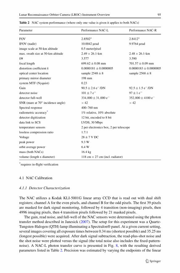
Table 1 Calibration tests conducted for both NACs and the WAC. For the WAC, the test was done for eachfilter, if applicable
Calibration test Description
Dark imaging Determine dark current and bias;optimization of NAC bias level (DAC offsetsetting)
CCD performance validation and linearity Measure linearity and photon transfer curve(gain, read noise, full-well)
Flat-field imaging Measure system response non-uniformityon a pixel-by-pixel basis
System spectral response Determine relative system throughput(in-band) and characterize out-of-band leaks
Absolute and relative radiometry Determine conversion between measuredDN and radiance units
Geometric calibration Determine focal length, field of view andgeometric distortion
Focus tests Determine focus and MTF by imaging a bartarget
Stray light test Determine light scattering from out-of-fieldsources
Lunar Reconnaissance Orbiter Camera (LROC) Instrument Overview 95
Table 2 NAC system performance (where only one value is given it applies to both NACs)
Parameter Performance NAC-L Performance NAC-R
FOV 2.8502◦ 2.8412◦IFOV (nadir) 10.0042 μrad 9.9764 μrad
image scale at 50-km altitude 0.5 meter/pixel
max. swath size at 50-km altitude 2.49 × 26.1-km 2.48 × 26.1-km
f/# 3.577 3.590
focal length 699.62 ± 0.08 mm 701.57 ± 0.09 mm
distortion coefficient k 0.0000181 ± 0.0000005 0.0000183 ± 0.0000005
optical center location sample 2548 ± 8 sample 2568 ± 8
primary mirror diameter 198 mm
system MTF (Nyquist) 0.23
Gain 90.5 ± 2.6 e−/DN 92.5 ± 1.5 e−/DN
detector noise 101 ± 7 e− 97 ± 1 e−detector full-well 334,000 ± 31,000 e− 352,000 ± 4100 e−SNR (mare at 70◦ incidence angle) > 42 > 42
Spectral response 400–760 nm
radiometric accuracy* 1% relative, 10% absolute
detector digitization 12 bit, encoded to 8 bit
data link to SCS LVDS, 30 Mbps
temperature sensors 2 per electronics box, 2 per telescope
lossless compression ratio 1.7:1
Voltage 28 ± 7 V DC
peak power 9.3 W
orbit average power 6.4 W
mass (both NACs) 16.4 kg
volume (length x diameter) 118 cm × 27 cm (incl. radiator)
*requires in-flight verification
4.1 NAC Calibration
4.1.1 Detector Characterization
The NAC utilizes a Kodak KLI-5001G linear array CCD that is read out with dual shiftregisters; channel A for the even pixels, and channel B for the odd pixels. The first 39 pixelsare masked for dark signal monitoring, followed by 4 transition (non-imaging) pixels, then4996 imaging pixels, then 4 transition pixels followed by 21 masked pixels.
The gain, read noise, and full-well of the NAC sensors were determined using the photontransfer method described in Janesick (2007). The setup for this experiment was a Quartz-Tungsten-Halogen (QTH) lamp illuminating a Spectralon® panel. At a given current setting,several images covering all exposure times between 0.34 ms (shortest possible) and 35.25 ms(longest possible) were acquired. After dark signal subtraction, the read-plus-shot noise andthe shot noise were plotted versus the signal (the total noise also includes the fixed-pattern-noise). A NAC-L photon transfer curve is presented in Fig. 8, with the resulting derivedparameters listed in Table 2. Precision was estimated by varying the endpoints of the linear
96 M.S. Robinson et al.
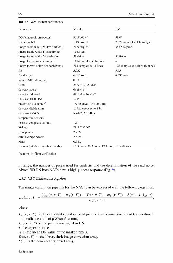
Table 3 WAC system performance
Parameter Visible UV
FOV (monochrome/color) 91.9◦/61.4◦ 59.0◦IFOV (nadir) 1.498 mrad 7.672 mrad (4 × 4 binning)
image scale (nadir, 50-km altitude) 74.9 m/pixel 383.5 m/pixel
image frame width monochrome 104.6-km –
image frame width 7-band color 59.6-km 56.8-km
image format monochrome 1024 samples × 14 lines –
image format color (for each band) 704 samples × 14 lines 128 samples × 4 lines (binned)
f/# 5.052 5.65
focal length 6.013 mm 4.693 mm
system MTF (Nyquist) 0.37
Gain 25.9 ± 0.7 e−/DN
detector noise 66 ± 4 e−detector full-well 46,100 ± 3600 e−SNR (at 1000 DN) > 150
radiometric accuracy* 1% relative, 10% absolute
detector digitization 11 bit, encoded to 8 bit
data link to SCS RS422, 2.5 Mbps
temperature sensors 1
lossless compression ratio 1.7:1
Voltage 28 ± 7 V DC
peak power 2.7 W
orbit average power 2.6 W
Mass 0.9 kg
volume (width × length × height) 15.8 cm × 23.2 cm × 32.3 cm (incl. radiator)
*requires in-flight verification
fit range, the number of pixels used for analysis, and the determination of the read noise.Above 200 DN both NACs have a highly linear response (Fig. 9).
4.1.2 NAC Calibration Pipeline
The image calibration pipeline for the NACs can be expressed with the following equation:
Ical(x, τ, T ) = (Iraw(x, τ, T ) − mI(τ,T )) − (D(x, τ, T ) − mD(τ,T )) − S(x) − L(Ioff , x)
F (x) · τ · r ,
where,
Ical(x, τ, T ) is the calibrated signal value of pixel x at exposure time τ and temperature T
in radiance units of μW/(cm2·sr·nm),Iraw(x, τ, T ) is the pixel’s raw signal in DN,τ the exposure time,m is the mean DN value of the masked pixels,D(x, τ, T ) is the library dark image correction array,S(x) is the non-linearity offset array,
Lunar Reconnaissance Orbiter Camera (LROC) Instrument Overview 97
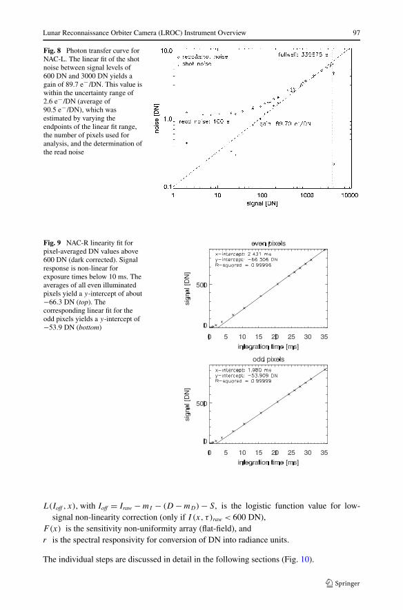
Fig. 8 Photon transfer curve forNAC-L. The linear fit of the shotnoise between signal levels of600 DN and 3000 DN yields again of 89.7 e−/DN. This value iswithin the uncertainty range of2.6 e−/DN (average of90.5 e−/DN), which wasestimated by varying theendpoints of the linear fit range,the number of pixels used foranalysis, and the determination ofthe read noise
Fig. 9 NAC-R linearity fit forpixel-averaged DN values above600 DN (dark corrected). Signalresponse is non-linear forexposure times below 10 ms. Theaverages of all even illuminatedpixels yield a y-intercept of about−66.3 DN (top). Thecorresponding linear fit for theodd pixels yields a y-intercept of−53.9 DN (bottom)
L(Ioff , x), with Ioff = Iraw − mI − (D − mD) − S, is the logistic function value for low-signal non-linearity correction (only if I (x, τ )raw < 600 DN),
F(x) is the sensitivity non-uniformity array (flat-field), andr is the spectral responsivity for conversion of DN into radiance units.
The individual steps are discussed in detail in the following sections (Fig. 10).

98 M.S. Robinson et al.
Fig. 10 Schematic overview of the NAC calibration pipeline. Depending on the electronics temperature “T ,”images have a different bias level, which is subtracted with the masked pixels (both for the raw scene imageand the library dark image). The library dark image subtraction then corrects the pixel-to-pixel variationof the dark current. The non-linearity correction is a two-step process applied to DNs below 600: additiveoffset term and a linearization process using a logistic function. The final steps are sensitivity non-uniformitycorrection (flat-fielding), division by exposure time, and the conversion into radiance units. Steps applied ona pixel-by-pixel basis are indicated with orange dotted border
4.1.3 Interleaving and Conversion to 12 bits
For each NAC the even and odd pixels are read out independently during image acquisition.This strategy enables line readout and transfer to the buffer in the required 337.6 microsec-onds that corresponds to one pixel of down-track ground motion (nominal 50-km orbit). Theeven and odd pixels are stored in separate buffers and thus raw data files must be interleavedto form a coherent image. The 12-bit pixel values are companded to 8-bit values using oneof six on-board schemes, three schemes are optimized for different signal levels, one is gen-eral purpose, while two others are used for calibration sequences (Fig. 11). To enable thefast pixel readout each bit-compression scheme consists of a piecewise linear function com-posed of up to 5 segments. After ground reception, these 8-bit digital values are convertedback to 12-bit with the corresponding decompression tables. The linear functions of eachsegment are listed for each table in Appendix A.
4.1.4 Bias Level and Dark Images
The offset level of the digital-to-analog converter (DAC) determines the bias level for digi-tization, i.e. the coarse DN value of a dark image (no incident photons) at shortest exposure.A finer adjustment of the bias level is set with an additional offset parameter for each evenand odd channel. Using dark images acquired during thermal vacuum tests, the dependenceof the DAC offset setting as a function of focal plane temperature was determined. Thus, inflight, the bias level will be optimized for each individual image based on predicted detectortemperature and exposure time (cf. Fig. 12).
Lunar Reconnaissance Orbiter Camera (LROC) Instrument Overview 99
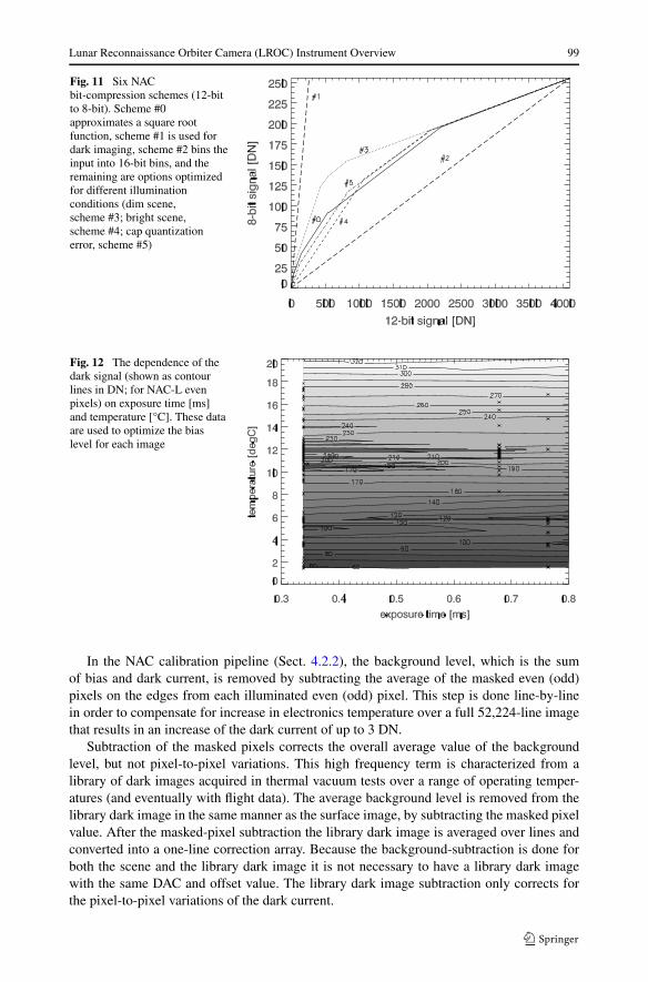
Fig. 11 Six NACbit-compression schemes (12-bitto 8-bit). Scheme #0approximates a square rootfunction, scheme #1 is used fordark imaging, scheme #2 bins theinput into 16-bit bins, and theremaining are options optimizedfor different illuminationconditions (dim scene,scheme #3; bright scene,scheme #4; cap quantizationerror, scheme #5)
Fig. 12 The dependence of thedark signal (shown as contourlines in DN; for NAC-L evenpixels) on exposure time [ms]and temperature [°C]. These dataare used to optimize the biaslevel for each image
In the NAC calibration pipeline (Sect. 4.2.2), the background level, which is the sumof bias and dark current, is removed by subtracting the average of the masked even (odd)pixels on the edges from each illuminated even (odd) pixel. This step is done line-by-linein order to compensate for increase in electronics temperature over a full 52,224-line imagethat results in an increase of the dark current of up to 3 DN.
Subtraction of the masked pixels corrects the overall average value of the backgroundlevel, but not pixel-to-pixel variations. This high frequency term is characterized from alibrary of dark images acquired in thermal vacuum tests over a range of operating temper-atures (and eventually with flight data). The average background level is removed from thelibrary dark image in the same manner as the surface image, by subtracting the masked pixelvalue. After the masked-pixel subtraction the library dark image is averaged over lines andconverted into a one-line correction array. Because the background-subtraction is done forboth the scene and the library dark image it is not necessary to have a library dark imagewith the same DAC and offset value. The library dark image subtraction only corrects forthe pixel-to-pixel variations of the dark current.
100 M.S. Robinson et al.
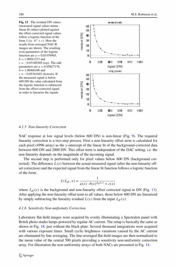
Fig. 13 The residual DN values(measured signal values minuslinear fit values) plotted againstthe offset-corrected signal valuesfollow a logistic function of theform 1/(a · bx + c). Here theresults from averaged NAC-Rimages are shown. The resultingeven parameters of the logisticfunction are a = 0.03359405,b = 1.00561273 andc = −0.03180369 (top). The oddparameters are a = 0.05827176,b = 1.00466108 andc = −0.05361603 (bottom). Ifthe measured signal is below600 DN the value calculated fromthe logistic function is subtractedfrom the offset-corrected signalin order to linearize the signals
4.1.5 Non-linearity Correction
NAC response at low signal levels (below 600 DN) is non-linear (Fig. 9). The requiredlinearity correction is a two-step process. First a non-linearity offset term is calculated foreach pixel (4996 array) as the y-intercept of the linear fit of the background-corrected databetween 600 DN and 2000 DN. This offset term is independent of the DAC setting, i.e. thenon-linearity depends on the magnitude of the incoming signal.
The second step is performed only for pixel values below 600 DN (background cor-rected). The difference L(x) between the actual measured signal (after the non-linearity off-set correction) and the expected signal from the linear fit function follows a logistic functionof the form:
L(Ioff , x) = 1
a(x) · b(x)Ioff (x) + c(x)
where Ioff (x) is the background and non-linearity offset corrected signal in DN (Fig. 13).After applying the non-linearity offset term to all values, those below 600 DN are linearizedby simply subtracting the linearity residual L(x) from the input Ioff (x).
4.1.6 Sensitivity Non-uniformity Correction
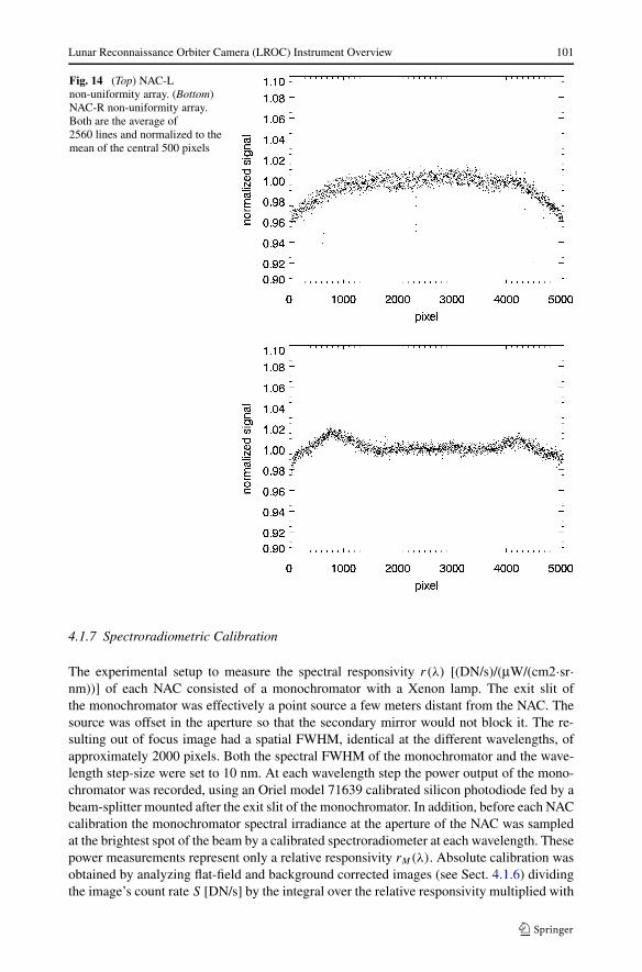
Laboratory flat-field images were acquired by evenly illuminating a Spectralon panel withBritek photo studio lamps powered by regular AC current. The setup is basically the same asshown in Fig. 18, just without the black plate. Several thousand integrations were acquiredwith various exposure times. Small cyclic brightness variations caused by the AC currentare eliminated by line averaging. The line-averaged flat-field images are then normalized tothe mean value of the central 500 pixels providing a sensitivity non-uniformity correctionarray. For illustration the non-uniformity arrays of both NACs are presented in Fig. 14.
Lunar Reconnaissance Orbiter Camera (LROC) Instrument Overview 101
Fig. 14 (Top) NAC-Lnon-uniformity array. (Bottom)NAC-R non-uniformity array.Both are the average of2560 lines and normalized to themean of the central 500 pixels
4.1.7 Spectroradiometric Calibration
The experimental setup to measure the spectral responsivity r(λ) [(DN/s)/(μW/(cm2·sr·nm))] of each NAC consisted of a monochromator with a Xenon lamp. The exit slit ofthe monochromator was effectively a point source a few meters distant from the NAC. Thesource was offset in the aperture so that the secondary mirror would not block it. The re-sulting out of focus image had a spatial FWHM, identical at the different wavelengths, ofapproximately 2000 pixels. Both the spectral FWHM of the monochromator and the wave-length step-size were set to 10 nm. At each wavelength step the power output of the mono-chromator was recorded, using an Oriel model 71639 calibrated silicon photodiode fed by abeam-splitter mounted after the exit slit of the monochromator. In addition, before each NACcalibration the monochromator spectral irradiance at the aperture of the NAC was sampledat the brightest spot of the beam by a calibrated spectroradiometer at each wavelength. Thesepower measurements represent only a relative responsivity rM(λ). Absolute calibration wasobtained by analyzing flat-field and background corrected images (see Sect. 4.1.6) dividingthe image’s count rate S [DN/s] by the integral over the relative responsivity multiplied with

102 M.S. Robinson et al.
Fig. 15 Spectral responsivity ofNAC-L (solid line) and NAC-R(dashed line). Thehigh-frequency variation reflectsnoise in the measurement, buthave no significant effect on thederived calibration
the spectral radiance of the source I ′S(λ) [μW/(cm2·sr·nm)]. This spectral radiance was mea-
sured with a spectroradiometer. However, it turned out that the spectroradiometer measure-ments had a systematic error that required a cross-calibration with a calibrated integratingsphere in order to obtain the necessary scaling factor γ = 2.3 ± 0.1. Thus IS(λ) = γ · I ′
S(λ).In other words, for the absolute calibration the relative responsivity rM(λ) was scaled bya factor equal to the ratio of the actual count rate S observing the laboratory source to thecount rate predicted if the absolute responsivity were equal to the relative responsivity. Thisapproach can be expressed as follows:
r(λ) = rM(λ) · S∫
λ′ rM(λ′) · IS(λ′)dλ′ .
The spectral responsivity characterization (Fig. 15) allows the calibrated DN values to beconverted to radiance. For a given observation the measured count rate SL [DN/ms] consti-tutes the spectral radiance IL(λ) of the lunar scene weighted by the NAC responsivity, i.e.:
SL =∫
λ
r(λ) · IL(λ)dλ.
So the weighted mean radiance measured by the NAC is:
I =∫
λr(λ) · IL(λ)dλ∫
λr(λ)dλ
= SL∫λr(λ)dλ
= SL
rNAC.
The radiometric conversion parameters are rNAC-L = 180.56 (DN/ms)/(μW/(cm2·sr·nm)) andrNAC-R = 166.83 (DN/ms)/(μW/(cm2·sr·nm)).
Radiance can be further converted into the reflectivity I/F (Minnaert 1961), with I theobserved radiance depending on the observation geometry and F the solar radiance comingfrom a normally illuminated Lambertian surface. The term I/F is also called radiance factorby Hapke (1993).
With �E the solar irradiance at a distance of 1 AU the measured reflectivity of a lunarscene is:
I/F = IL · π · d2
�E
with d [AU] the distance Sun–Moon. With the formulas above the weighted mean of I/F
as measured by the NAC is:
Lunar Reconnaissance Orbiter Camera (LROC) Instrument Overview 103
I/F =∫
λr · I/F · �Edλ∫
λr · �Edλ
= SL · π · d2
∫λr · �Edλ
= SL · d2
ϕNAC.
Using the solar irradiance �E at 1 AU of (Allen 1976) the conversion parameters areϕNAC-L = 9308.5 (DN/ms)/AU2 and ϕNAC-R = 8504.1 (DN/ms)/AU2.
Finally, the signal-to-noise ratio (SNR) is calculated from assumed radiances for mareand highlands materials under various incidence angles. The signal is the expected meanradiance for those conditions, and the noise is composed of read noise, shot noise and quan-tization noise. The minimum SNR is estimated with a 70◦ solar incidence angle on marematerial and presented in Table 2.
4.1.8 Geometric Calibration
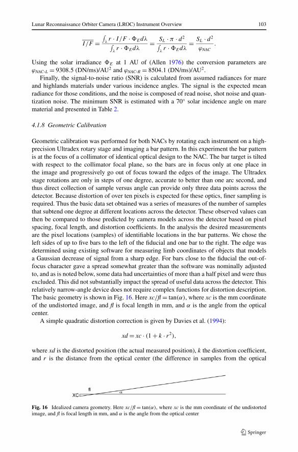
Geometric calibration was performed for both NACs by rotating each instrument on a high-precision Ultradex rotary stage and imaging a bar pattern. In this experiment the bar patternis at the focus of a collimator of identical optical design to the NAC. The bar target is tiltedwith respect to the collimator focal plane, so the bars are in focus only at one place inthe image and progressively go out of focus toward the edges of the image. The Ultradexstage rotations are only in steps of one degree, accurate to better than one arc second, andthus direct collection of sample versus angle can provide only three data points across thedetector. Because distortion of over ten pixels is expected for these optics, finer sampling isrequired. Thus the basic data set obtained was a series of measures of the number of samplesthat subtend one degree at different locations across the detector. These observed values canthen be compared to those predicted by camera models across the detector based on pixelspacing, focal length, and distortion coefficients. In the analysis the desired measurementsare the pixel locations (samples) of identifiable locations in the bar patterns. We chose theleft sides of up to five bars to the left of the fiducial and one bar to the right. The edge wasdetermined using existing software for measuring limb coordinates of objects that modelsa Gaussian decrease of signal from a sharp edge. For bars close to the fiducial the out-of-focus character gave a spread somewhat greater than the software was nominally adjustedto, and as is noted below, some data had uncertainties of more than a half pixel and were thusexcluded. This did not substantially impact the spread of useful data across the detector. Thisrelatively narrow-angle device does not require complex functions for distortion description.The basic geometry is shown in Fig. 16. Here xc/fl = tan(α), where xc is the mm coordinateof the undistorted image, and fl is focal length in mm, and α is the angle from the opticalcenter.
A simple quadratic distortion correction is given by Davies et al. (1994):
xd = xc · (1 + k · r2),
where xd is the distorted position (the actual measured position), k the distortion coefficient,and r is the distance from the optical center (the difference in samples from the optical
Fig. 16 Idealized camera geometry. Here xc/fl = tan(α), where xc is the mm coordinate of the undistortedimage, and fl is focal length in mm, and α is the angle from the optical center
104 M.S. Robinson et al.
center). In this one-dimensional case, offset of the true optical center from the line arraycannot be measured, and would largely affect the value of the distortion coefficient. Theundistorted coordinates thus are:
xc = xd
1 + k · r2.
For any combination of focal length, optical center position, and distortion coefficient wecan calculate left and right sample coordinates for 1 degree changes in α across the entirefield of view. We choose to measure this difference as right (greater) sample − left (lesser)sample, and thus are able to tabulate this difference for samples up to 5000 samples minusthe one degree difference in samples, or roughly from sample 1 to sample ∼3200. Our fitis made by comparing the observed one degree difference in samples versus the predictedvalue for the (left, low-pixel) samples tabulated. Residuals are the predicted minus observednumber of samples, and the best fit is taken at minimum root mean square of the residuals.
It is assumed that the detector lies in the plane of rotation of the stage. If the detectoris tilted relative to this rotation, a given angular rotation will result in a larger change inposition on the detector, which would result in a larger calculated focal length. Review ofthe mechanical arrangement indicates possible misalignment of 0.88 ± 0.1◦. Error inducedacross the field of view from this would be ∼0.8 pixels. We choose to leave the numbersuncorrected.
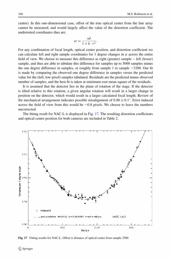
The fitting result for NAC-L is displayed in Fig. 17. The resulting distortion coefficientsand optical center position for both cameras are included in Table 2.
Fig. 17 Fitting results for NAC-L. Offset is distance of optical center from sample 2500

Lunar Reconnaissance Orbiter Camera (LROC) Instrument Overview 105
4.1.9 Stray Light Measurements
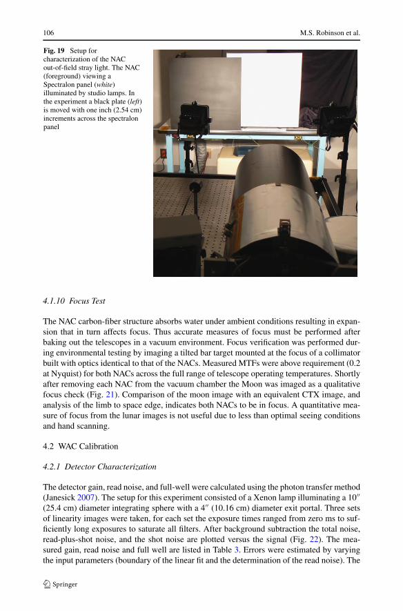
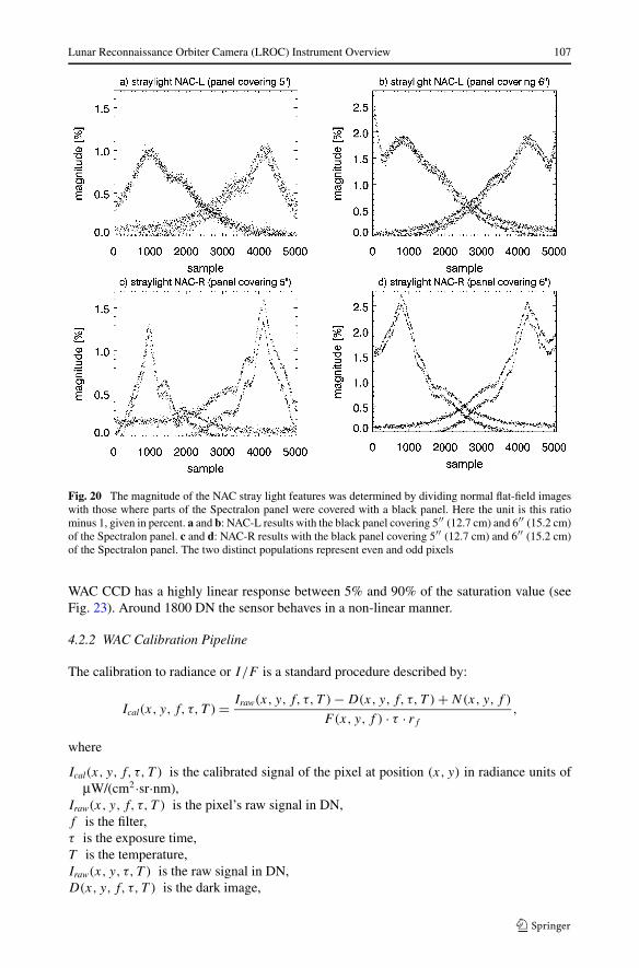
To search for stray light effects, the beam of the QTH calibration lamp was aimed directlyinto the NAC’s aperture at various angles (up to about 60 degrees in the crosstrack directiononly). A photo of this setup is shown in Fig. 18. No light leaks and no large-angle stray-light problems were identified. However, two out-of-field low-level stray light features weredetected affecting the pixels centered at samples 1000 and 4000. These features were fur-ther quantified with two setups: (a) an integrating sphere illuminated with a QTH lamp wasmoved perpendicularly to the camera’s line of sight, with small increments centered aroundan angle of about 5◦; (b) the flat-field images described in Sect. 4.2.5 were compared withflat-field images where increasingly large parts of the Spectralon panel were covered withblack panel (a photo of this setup is shown in Fig. 19). Both the NAC-L and NAC-R straylight features have magnitudes of 1–3% of a uniform flat field wide enough to include theentire out-of-field source of the stray light (Fig. 20). The test data acquired is sufficient tofully characterize and develop a mitigation strategy if necessary.
Additionally, with no ambient illumination a high intensity focused flashlight beam washeld adjacent to all structural seams and fasteners for both the telescope and electronicshousing (both NACs) while long integration images were acquired. This test revealed nolight leaks.
Fig. 18 NAC stray light test setup. The quartz tungsten halogen lamp in the back-left corner was movedperpendicularly to the line of sight between the NAC (right foreground) and the black plate on the wall whilerotating the lamp such that it pointed at the telescope aperture
106 M.S. Robinson et al.
Fig. 19 Setup forcharacterization of the NACout-of-field stray light. The NAC(foreground) viewing aSpectralon panel (white)illuminated by studio lamps. Inthe experiment a black plate (left)is moved with one inch (2.54 cm)increments across the spectralonpanel
4.1.10 Focus Test
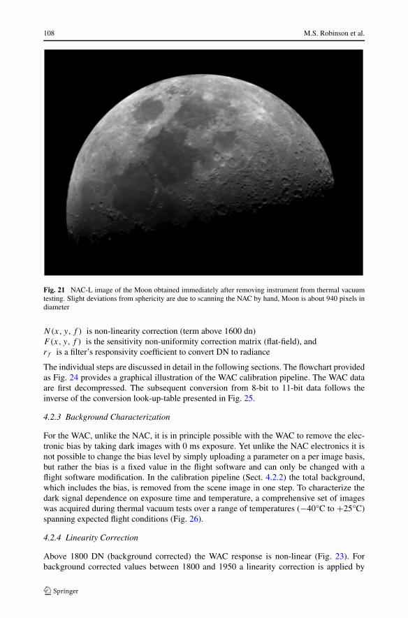
The NAC carbon-fiber structure absorbs water under ambient conditions resulting in expan-sion that in turn affects focus. Thus accurate measures of focus must be performed afterbaking out the telescopes in a vacuum environment. Focus verification was performed dur-ing environmental testing by imaging a tilted bar target mounted at the focus of a collimatorbuilt with optics identical to that of the NACs. Measured MTFs were above requirement (0.2at Nyquist) for both NACs across the full range of telescope operating temperatures. Shortlyafter removing each NAC from the vacuum chamber the Moon was imaged as a qualitativefocus check (Fig. 21). Comparison of the moon image with an equivalent CTX image, andanalysis of the limb to space edge, indicates both NACs to be in focus. A quantitative mea-sure of focus from the lunar images is not useful due to less than optimal seeing conditionsand hand scanning.
4.2 WAC Calibration
4.2.1 Detector Characterization
The detector gain, read noise, and full-well were calculated using the photon transfer method(Janesick 2007). The setup for this experiment consisted of a Xenon lamp illuminating a 10′′(25.4 cm) diameter integrating sphere with a 4′′ (10.16 cm) diameter exit portal. Three setsof linearity images were taken, for each set the exposure times ranged from zero ms to suf-ficiently long exposures to saturate all filters. After background subtraction the total noise,read-plus-shot noise, and the shot noise are plotted versus the signal (Fig. 22). The mea-sured gain, read noise and full well are listed in Table 3. Errors were estimated by varyingthe input parameters (boundary of the linear fit and the determination of the read noise). The
Lunar Reconnaissance Orbiter Camera (LROC) Instrument Overview 107
Fig. 20 The magnitude of the NAC stray light features was determined by dividing normal flat-field imageswith those where parts of the Spectralon panel were covered with a black panel. Here the unit is this ratiominus 1, given in percent. a and b: NAC-L results with the black panel covering 5′′ (12.7 cm) and 6′′ (15.2 cm)of the Spectralon panel. c and d: NAC-R results with the black panel covering 5′′ (12.7 cm) and 6′′ (15.2 cm)of the Spectralon panel. The two distinct populations represent even and odd pixels
WAC CCD has a highly linear response between 5% and 90% of the saturation value (seeFig. 23). Around 1800 DN the sensor behaves in a non-linear manner.
4.2.2 WAC Calibration Pipeline
The calibration to radiance or I/F is a standard procedure described by:
Ical(x, y, f, τ, T ) = Iraw(x, y, f, τ, T ) − D(x,y,f, τ, T ) + N(x,y,f )
F (x, y,f ) · τ · rf
,
where
Ical(x, y, f, τ, T ) is the calibrated signal of the pixel at position (x, y) in radiance units ofμW/(cm2·sr·nm),
Iraw(x, y, f, τ, T ) is the pixel’s raw signal in DN,f is the filter,τ is the exposure time,T is the temperature,Iraw(x, y, τ, T ) is the raw signal in DN,D(x,y,f, τ, T ) is the dark image,
108 M.S. Robinson et al.
Fig. 21 NAC-L image of the Moon obtained immediately after removing instrument from thermal vacuumtesting. Slight deviations from sphericity are due to scanning the NAC by hand, Moon is about 940 pixels indiameter
N(x,y,f ) is non-linearity correction (term above 1600 dn)F(x, y,f ) is the sensitivity non-uniformity correction matrix (flat-field), andrf is a filter’s responsivity coefficient to convert DN to radiance
The individual steps are discussed in detail in the following sections. The flowchart providedas Fig. 24 provides a graphical illustration of the WAC calibration pipeline. The WAC dataare first decompressed. The subsequent conversion from 8-bit to 11-bit data follows theinverse of the conversion look-up-table presented in Fig. 25.
4.2.3 Background Characterization
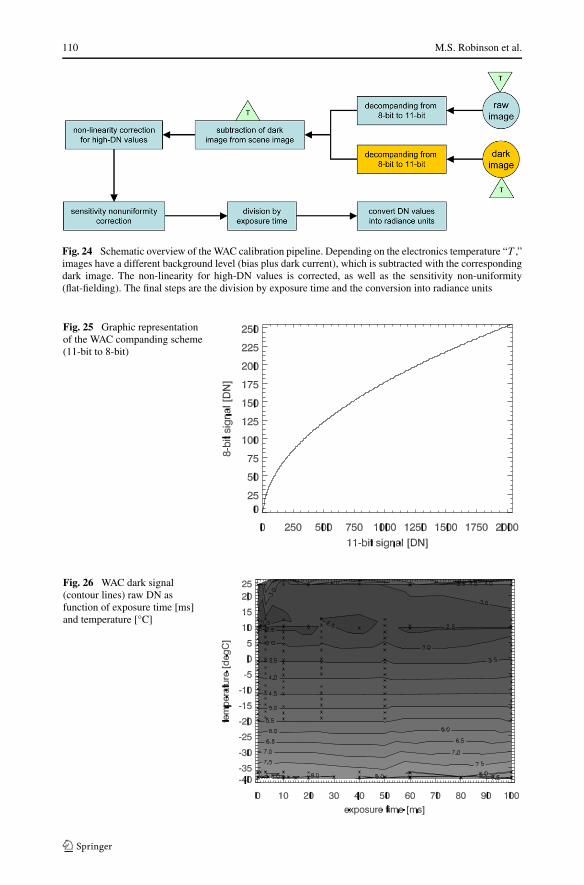
For the WAC, unlike the NAC, it is in principle possible with the WAC to remove the elec-tronic bias by taking dark images with 0 ms exposure. Yet unlike the NAC electronics it isnot possible to change the bias level by simply uploading a parameter on a per image basis,but rather the bias is a fixed value in the flight software and can only be changed with aflight software modification. In the calibration pipeline (Sect. 4.2.2) the total background,which includes the bias, is removed from the scene image in one step. To characterize thedark signal dependence on exposure time and temperature, a comprehensive set of imageswas acquired during thermal vacuum tests over a range of temperatures (−40°C to +25°C)spanning expected flight conditions (Fig. 26).
4.2.4 Linearity Correction
Above 1800 DN (background corrected) the WAC response is non-linear (Fig. 23). Forbackground corrected values between 1800 and 1950 a linearity correction is applied by
Lunar Reconnaissance Orbiter Camera (LROC) Instrument Overview 109
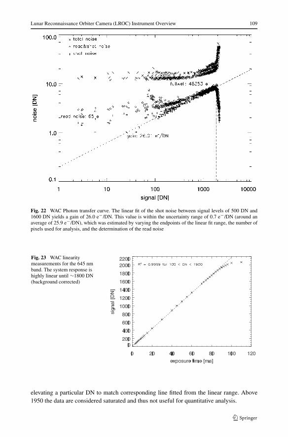
Fig. 22 WAC Photon transfer curve. The linear fit of the shot noise between signal levels of 500 DN and1600 DN yields a gain of 26.0 e−/DN. This value is within the uncertainty range of 0.7 e−/DN (around anaverage of 25.9 e−/DN), which was estimated by varying the endpoints of the linear fit range, the number ofpixels used for analysis, and the determination of the read noise
Fig. 23 WAC linearitymeasurements for the 645 nmband. The system response ishighly linear until ∼1800 DN(background corrected)
elevating a particular DN to match corresponding line fitted from the linear range. Above1950 the data are considered saturated and thus not useful for quantitative analysis.
110 M.S. Robinson et al.
Fig. 24 Schematic overview of the WAC calibration pipeline. Depending on the electronics temperature “T ,”images have a different background level (bias plus dark current), which is subtracted with the correspondingdark image. The non-linearity for high-DN values is corrected, as well as the sensitivity non-uniformity(flat-fielding). The final steps are the division by exposure time and the conversion into radiance units
Fig. 25 Graphic representationof the WAC companding scheme(11-bit to 8-bit)
Fig. 26 WAC dark signal(contour lines) raw DN asfunction of exposure time [ms]and temperature [°C]
Lunar Reconnaissance Orbiter Camera (LROC) Instrument Overview 111
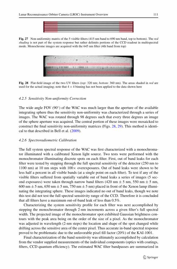
Fig. 27 Non-uniformity matrix of the 5 visible filters (415 nm band to 690 nm band, top to bottom). The redshading is not part of the system response but rather delimits portions of the CCD readout in multispectralmode. Monochrome images are acquired with the 645 nm filter (4th band from top)
Fig. 28 Flat-field image of the two UV filters (top: 320 nm; bottom: 360 nm). The areas shaded in red areused for the actual imaging; note that 4 × 4 binning has not been applied to the data shown here
4.2.5 Sensitivity Non-uniformity Correction
The wide angle FOV (90◦) of the WAC was much larger than the aperture of the availableintegrating sphere thus the sensitivity non-uniformity was characterized through a series ofimages. The WAC was rotated through 98 degrees such that every three degrees an imageof the sphere aperture was acquired. The central portion of these images were mosaicked toconstruct the final sensitivity non-uniformity matrices (Figs. 28, 29). This method is identi-cal to that described in Bell et al. (2009).
4.2.6 Spectroradiometric Calibration
The full system spectral response of the WAC was first characterized with a monochroma-tor illuminated with a calibrated Xenon light source. Two tests were performed with themonochromator illuminating discrete spots on each filter. First, out of band leaks for eachfilter were tested by stepping through the full spectral sensitivity of the detector (250 nm to1100 nm) at 10 nm steps with 100× overexposures. Out of band leaks were shown to beless half a percent in all visible bands (at a single point on each filter). To test if any of thevisible filters suffered from spatially variable out of band leaks a series of images (5 sec-ond exposures) were taken through narrow band filters (420 nm ± 5 nm, 550 nm ± 5 nm,600 nm ± 5 nm, 650 nm ± 5 nm, 750 nm ± 5 nm) placed in front of the Xenon lamp illumi-nating the integrating sphere. These images indicated no out of band leaks, though we notethis test did not test the full spectral sensitivity range of the CCD. Therefore it is concludedthat all filters have a maximum out-of-band leak of less than 0.5%.
Characterizing the system sensitivity profile for each filter was next accomplished bystepping the monochromator through 2-nm increments across a given filter’s full spectralwidth. The projected image of the monochromator spot exhibited Gaussian brightness con-tours with the peak area being on the order of the size of a pixel. As the monochromatorwas adjusted in wavelength (2-nm steps) the location and shape of the spot changed whiledrifting across the sensitive area of the center pixel. Thus accurate in-band spectral responseproved to be problematic due to the unfavorable pixel fill factor (20%) of the KAI-1001.
Final characterization of the band sensitivity was ultimately accomplished by calculationfrom the vendor supplied measurements of the individual components (optics with coatings,filters, CCD quantum efficiency). The estimated WAC filter bandpasses are summarized in
112 M.S. Robinson et al.
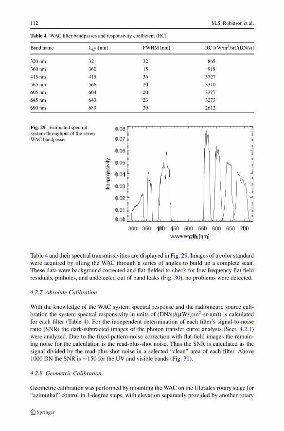
Table 4 WAC filter bandpasses and responsivity coefficient (RC)
Band name λeff [nm] FWHM [nm] RC [(W/m3/sr)/(DN/s)]
320 nm 321 32 865
360 nm 360 15 918
415 nm 415 36 3727
565 nm 566 20 3310
605 nm 604 20 3377
645 nm 643 23 3273
690 nm 689 39 2612
Fig. 29 Estimated spectralsystem throughput of the sevenWAC bandpasses
Table 4 and their spectral transmissivities are displayed in Fig. 29. Images of a color standardwere acquired by tilting the WAC through a series of angles to build up a complete scan.These data were background corrected and flat-fielded to check for low frequency flat fieldresiduals, pinholes, and undetected out of band leaks (Fig. 30), no problems were detected.
4.2.7 Absolute Calibration
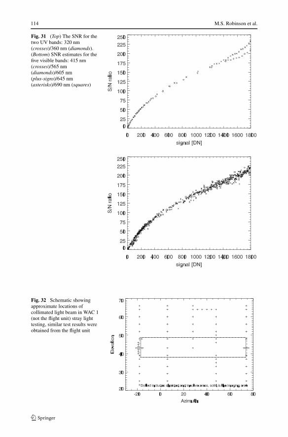
With the knowledge of the WAC system spectral response and the radiometric source cali-bration the system spectral responsivity in units of (DN/s)/(μW/(cm2·sr·nm)) is calculatedfor each filter (Table 4). For the independent determination of each filter’s signal-to-noiseratio (SNR) the dark-subtracted images of the photon transfer curve analysis (Sect. 4.2.1)were analyzed. Due to the fixed-pattern-noise correction with flat-field images the remain-ing noise for the calculation is the read-plus-shot noise. Thus the SNR is calculated as thesignal divided by the read-plus-shot noise in a selected “clean” area of each filter. Above1000 DN the SNR is ∼150 for the UV and visible bands (Fig. 31).
4.2.8 Geometric Calibration
Geometric calibration was performed by mounting the WAC on the Ultradex rotary stage for“azimuthal” control in 1-degree steps, with elevation separately provided by another rotary
Lunar Reconnaissance Orbiter Camera (LROC) Instrument Overview 113
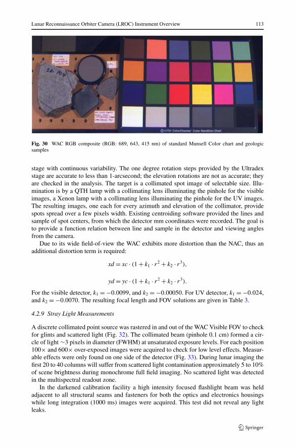
Fig. 30 WAC RGB composite (RGB: 689, 643, 415 nm) of standard Munsell Color chart and geologicsamples
stage with continuous variability. The one degree rotation steps provided by the Ultradexstage are accurate to less than 1-arcsecond; the elevation rotations are not as accurate; theyare checked in the analysis. The target is a collimated spot image of selectable size. Illu-mination is by a QTH lamp with a collimating lens illuminating the pinhole for the visibleimages, a Xenon lamp with a collimating lens illuminating the pinhole for the UV images.The resulting images, one each for every azimuth and elevation of the collimator, providespots spread over a few pixels width. Existing centroiding software provided the lines andsample of spot centers, from which the detector mm coordinates were recorded. The goal isto provide a function relation between line and sample in the detector and viewing anglesfrom the camera.
Due to its wide field-of-view the WAC exhibits more distortion than the NAC, thus anadditional distortion term is required:
xd = xc · (1 + k1 · r2 + k2 · r3),
yd = yc · (1 + k1 · r2 + k2 · r3).
For the visible detector, k1 = −0.0099, and k2 = −0.00050. For UV detector, k1 = −0.024,and k2 = −0.0070. The resulting focal length and FOV solutions are given in Table 3.
4.2.9 Stray Light Measurements
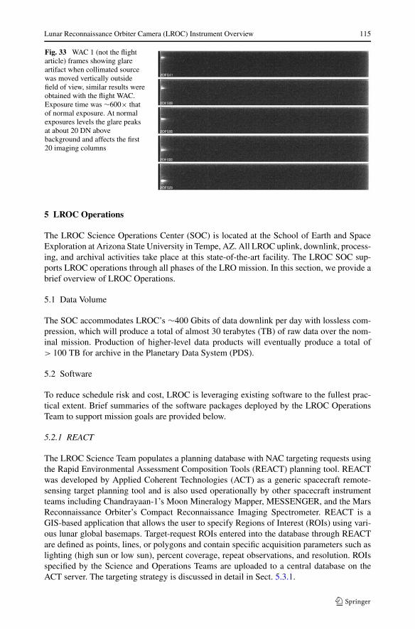
A discrete collimated point source was rastered in and out of the WAC Visible FOV to checkfor glints and scattered light (Fig. 32). The collimated beam (pinhole 0.1 cm) formed a cir-cle of light ∼3 pixels in diameter (FWHM) at unsaturated exposure levels. For each position100× and 600× over-exposed images were acquired to check for low level effects. Measur-able effects were only found on one side of the detector (Fig. 33). During lunar imaging thefirst 20 to 40 columns will suffer from scattered light contamination approximately 5 to 10%of scene brightness during monochrome full field imaging. No scattered light was detectedin the multispectral readout zone.
In the darkened calibration facility a high intensity focused flashlight beam was heldadjacent to all structural seams and fasteners for both the optics and electronics housingswhile long integration (1000 ms) images were acquired. This test did not reveal any lightleaks.
114 M.S. Robinson et al.
Fig. 31 (Top) The SNR for thetwo UV bands: 320 nm(crosses)/360 nm (diamonds).(Bottom) SNR estimates for thefive visible bands: 415 nm(crosses)/565 nm(diamonds)/605 nm(plus-signs)/645 nm(asterisks)/690 nm (squares)
Fig. 32 Schematic showingapproximate locations ofcollimated light beam in WAC 1(not the flight unit) stray lighttesting, similar test results wereobtained from the flight unit
Lunar Reconnaissance Orbiter Camera (LROC) Instrument Overview 115
Fig. 33 WAC 1 (not the flightarticle) frames showing glareartifact when collimated sourcewas moved vertically outsidefield of view, similar results wereobtained with the flight WAC.Exposure time was ∼600× thatof normal exposure. At normalexposures levels the glare peaksat about 20 DN abovebackground and affects the first20 imaging columns
5 LROC Operations
The LROC Science Operations Center (SOC) is located at the School of Earth and SpaceExploration at Arizona State University in Tempe, AZ. All LROC uplink, downlink, process-ing, and archival activities take place at this state-of-the-art facility. The LROC SOC sup-ports LROC operations through all phases of the LRO mission. In this section, we provide abrief overview of LROC Operations.
5.1 Data Volume
The SOC accommodates LROC’s ∼400 Gbits of data downlink per day with lossless com-pression, which will produce a total of almost 30 terabytes (TB) of raw data over the nom-inal mission. Production of higher-level data products will eventually produce a total of> 100 TB for archive in the Planetary Data System (PDS).
5.2 Software
To reduce schedule risk and cost, LROC is leveraging existing software to the fullest prac-tical extent. Brief summaries of the software packages deployed by the LROC OperationsTeam to support mission goals are provided below.
5.2.1 REACT
The LROC Science Team populates a planning database with NAC targeting requests usingthe Rapid Environmental Assessment Composition Tools (REACT) planning tool. REACTwas developed by Applied Coherent Technologies (ACT) as a generic spacecraft remote-sensing target planning tool and is also used operationally by other spacecraft instrumentteams including Chandrayaan-1’s Moon Mineralogy Mapper, MESSENGER, and the MarsReconnaissance Orbiter’s Compact Reconnaissance Imaging Spectrometer. REACT is aGIS-based application that allows the user to specify Regions of Interest (ROIs) using vari-ous lunar global basemaps. Target-request ROIs entered into the database through REACTare defined as points, lines, or polygons and contain specific acquisition parameters such aslighting (high sun or low sun), percent coverage, repeat observations, and resolution. ROIsspecified by the Science and Operations Teams are uploaded to a central database on theACT server. The targeting strategy is discussed in detail in Sect. 5.3.1.
116 M.S. Robinson et al.
5.2.2 JMoon
JMoon (JMars 2010) is a derivative of the Java Mission-Planning and Analysis for RemoteSensing (JMARS) software, the observation and planning tool that was developed to supportthe Mars Odyssey THEMIS experiment. JMoon uses the spacecraft’s predict ephemeris todetermine the LROC observing opportunities that lie under LRO’s orbit track, allowing ana-lysts to interactively select and position LROC NAC targets from the target request databasecreated by the LROC Science Team. The LROC Operations Team uses JMoon to convertthe ROIs created by the LROC Science Team in REACT into the command loads sent to theinstrument in flight.
5.2.3 AutoTarget
AutoTarget is a tool developed by the LROC Operations Team designed to facilitate the auto-mated generation of LROC command loads. AutoTarget automatically creates LROC com-mand loads using the LRO predict ephemeris to locate targets in the LROC target requestdatabase or by randomly placing NAC targets where no target requests are available. Auto-Target is used for specific LROC targeting functions, including random observations along acomplete orbit track, planning observations for the global or polar mapping campaigns, andpairing complementary stereo or mosaic observations with existing observations.
5.2.4 CommandGen
Once the LROC Operations Team has completed an observational plan, the software toolCommandGen (short for Command Generator) collects the details of all the planned ob-servations for the given orbit window and compiles them into command load files. TheseCommandGen products are then sent to the LRO Mission Operations Center (MOC) at theNASA Goddard Space Flight Center for integration with the LRO command load and sub-sequent uplink to the spacecraft.
5.2.5 LROC Database
The LROC SOC uses PostgreSQL 8.3 to store data accumulated and created during LROCoperations. PostgreSQL was chosen due to its extensive and mature feature set, includingrobust transaction logging, foreign key relationships, point-in-time recovery, and its demon-strated ability to handle large volumes of data under heavy load. The database will supportLROC operations both by providing an archive of the data produced during operations andalso by providing data storage and retrieval services (session management) for all aspectsof LROC data processing. The LROC Database will facilitate creation of PDS deliveries bypre-packaging all pertinent information prior to the PDS delivery process. The LROC data-base natively supports geographic objects and functions, enabling the LROC SOC to storeand produce OpenGIS compliant data products.
5.3 Concept of Operations
Here, we provide an overview of the concept of operations for the LROC Science and Oper-ations Teams during the LRO nominal mission. These operations include science targeting,operational target definition, operational target selection, command sequence generation,transfer of downlinked image data, data processing, special product generation, and dataarchiving.
Lunar Reconnaissance Orbiter Camera (LROC) Instrument Overview 117
5.3.1 LROC Science Targeting Request Process and Strategy
LROC NAC science target requests are generated by the LROC Science and Operationsteams interactively using the REACT software package (Sect. 5.2.1) and are organized inseveral ways, the most important of which is target priority. The priorities are as follows:
(1) Exploration targets requested by NASA’s Project Constellation(2) Targets that fulfill other LROC Level 1 Requirements (detailed in Sect. 2)(3) Targets that support LROC Science Team and LRO mission science objectives(4) Science requests from outside the LRO team(5) Public target requests
During the first year of the LRO mission, the Priority 1 targets consist of sites specified bythe NASA Constellation Project. These sites were selected on the basis of scientific, resourceutilization, and operational merits as well as a desire to span the range of lunar terrain andgeologic features, including polar sites, mare and cryptomare surfaces, pyroclastic depositsand other volcanic landforms, impact basins and crater terrains, locations with representativerock-type exposures, and unusual features such as radar anomalies, magnetic anomalies,albedo swirls, sites of possible outgassing, and compositional anomalies that have beenobserved from orbit. The Priority 1 targets are derived primarily from three reference targetsets (1) The ten design reference sites listed by the 2005 Exploration Systems ArchitectureStudy, (2) the six sites evaluated by the 1991 Site Selection Strategy for a Lunar Outpostworkshop for the First Lunar Outpost study, and (3) the 59 sites identified by the 1988workshop on Geoscience and a Lunar Base: A Comprehensive Plan for Lunar Exploration(Taylor and Spudis 1990; NASA 2005, 1990).
The LROC Science Team is also generating a comprehensive set of NAC high-resolutionimage acquisition target requests that achieve LROC measurement objectives, science objec-tives proposed by the LROC participating scientists, and targets relating to features of gen-erally known geologic interest. These targets include, but are not limited to, spectral anom-alies (Wood and Head 1975), Copernican craters (Wilhelms et al. 1987), Apollo Panoramicphoto areas (Masursky et al. 1978; Lawrence et al. 2008b), crater central peaks and peakrings, sites of lunar pyroclastic volcanism (Gaddis et al. 1985, 1995, 2000, 2003), lava flowmargins (Gifford and El-Baz 1981), possible lava tubes (Coombs and Hawke 1992), maresurfaces for crater counting (Hiesinger et al. 2003), volcanic domes (Head and McCord1978), geologic units in the Apennine Mountains and Imbrium backslope (Wilhelms 1980;Wilhelms et al. 1987), tectonic structures, dark haloed impact craters and cryptomaria(Blewett et al. 1995; Giguere et al. 2003, 2007; Hawke et al. 2004, 2005, 2007, 2008;Lawrence et al. 2008b), concentric craters (Wood 1978), sites of observed impact flashes(Ortiz et al. 2000, 2002, 2006; Yanagisawa and Kisaichi 2002; Cudnik et al. 2003), andhighland scarps.
5.3.2 Operational Target Definition
The LROC SOC uses the software tools described in Sect. 5.2 to plan observations andgenerate command loads for the NAC and WAC on a daily basis. Based on the most recentpredicted LRO spacecraft ephemeris (which will be received and updated daily from theLRO MOC) and the NAC Target Request Database for upcoming orbits, an operations planfor the next 72 hours of normal operations will be generated and submitted to the LRO MOCeach day. The NACs can be commanded individually or together, and in normal operatingmode can acquire images of any length in 1024-line increments up to the full length of
118 M.S. Robinson et al.
52,224 lines with a maximum of 15 NAC image-pairs of the illuminated surface possible perorbit, for a theoretical daily total of 180 NAC pairs (or 360 images). Each LROC operationalplan will therefore include NAC requests for at least 1000 images. Before NAC images arewritten to the spacecraft’s solid-state data recorder, they are temporarily stored in a 256 MBbuffer. It takes approximately 15 seconds to acquire a full NAC image pair and another 220seconds to read that image pair through the SCS to the LRO solid-state recorder. It is notpossible to obtain another NAC image until the buffer is cleared, so after the collection ofeach NAC pair there is an 11◦ down-track latitude zone where additional imaging cannotbe acquired. In addition to NAC commands for target requests, each 3-day plan will alsoinclude commands for the WAC. The WAC is not buffer limited and will almost always beimaging when over the daylight side of the Moon.
5.3.3 Spacecraft Slews
The daily target plans include on average three off-nadir spacecraft roll (up to 20◦) observa-tions per 24-hour period and any number of slews 2◦ or less, barring no operational conflicts.More than three slews greater than 20◦ per day are not permitted in order to minimize dis-ruption to the other LRO science instruments. Off-nadir slews are necessary to fulfill stereoand mosaic requests. Geometric stereo requires two images of the same terrain with a 10–50◦ angle between the two observations with respect to the target and incidence angles assimilar as possible (< 20◦ difference). Photometric stereo requires three or more imagesof the same terrain, with each observation in the set differing by at least 20◦ in incidenceand azimuth angles from one another. Instrument slew maneuvers for star calibrations, limbviews, 90◦ yaw offset, or slews > 20◦ are specially planned in advance due to the operationalcomplexity and disruption to normal mapping for the payload suite.
5.4 In-flight Calibration
Comprehensive in-flight calibration sequences are planned for the operational phase of theLRO mission. Details for both the NAC and WAC subsystems are provided below.
5.4.1 LROC NAC Calibration Imaging
The NACs will acquire images on the lunar farside during non-illuminated periods in orderto characterize the dark current behavior of the CCDs. This operation is not possible whilethe spacecraft is on the night-time nearside because of Earth-shine. During the initial cruiseto lunar orbit (0–3 days after the launch), the NACs will image open space while the Moonis: (1) far from the edge of the field of view (2) near the edge of the FOV and (3) withinthe FOV. This series of observations will be used to characterize stray light within the NACinstruments.
5.4.2 LROC WAC Calibration Imaging
Calibration images will be obtained with the WAC during the cruise phase by imaging theEarth and Moon, both inside and outside of the instrument’s imaging field of view. Theimaging of point-sources such as stars and nearby planets will also be performed. In the50-km nominal mission orbit, image calibration will typically include the acquisition ofimages on the non-illuminated far side of the Moon for dark reference calculation and theregular imaging of select stars and planets.
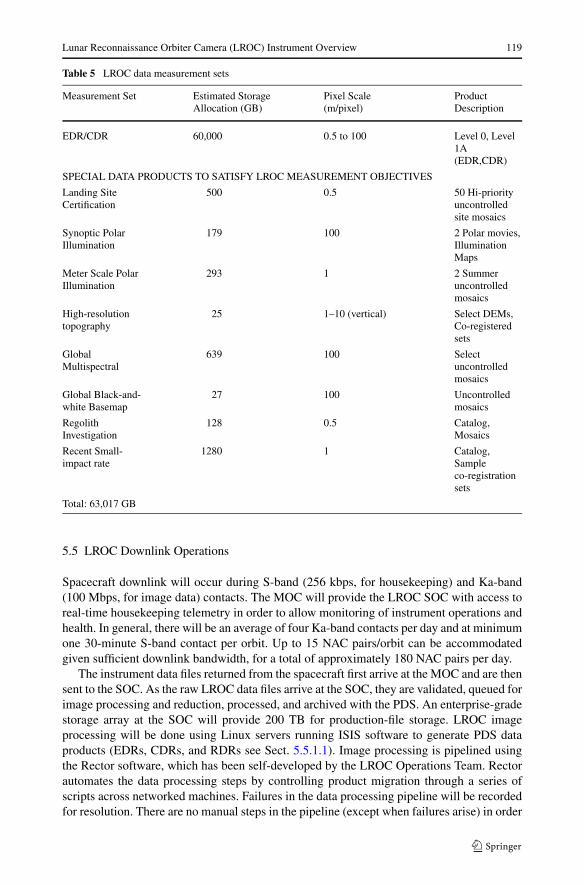
Lunar Reconnaissance Orbiter Camera (LROC) Instrument Overview 119
Table 5 LROC data measurement sets
Measurement Set Estimated StorageAllocation (GB)
Pixel Scale(m/pixel)
ProductDescription
EDR/CDR 60,000 0.5 to 100 Level 0, Level1A(EDR,CDR)
SPECIAL DATA PRODUCTS TO SATISFY LROC MEASUREMENT OBJECTIVES
Landing SiteCertification
500 0.5 50 Hi-priorityuncontrolledsite mosaics
Synoptic PolarIllumination
179 100 2 Polar movies,IlluminationMaps
Meter Scale PolarIllumination
293 1 2 Summeruncontrolledmosaics
High-resolutiontopography
25 1–10 (vertical) Select DEMs,Co-registeredsets
GlobalMultispectral
639 100 Selectuncontrolledmosaics
Global Black-and-white Basemap
27 100 Uncontrolledmosaics
RegolithInvestigation
128 0.5 Catalog,Mosaics
Recent Small-impact rate
1280 1 Catalog,Sampleco-registrationsets
Total: 63,017 GB
5.5 LROC Downlink Operations
Spacecraft downlink will occur during S-band (256 kbps, for housekeeping) and Ka-band(100 Mbps, for image data) contacts. The MOC will provide the LROC SOC with access toreal-time housekeeping telemetry in order to allow monitoring of instrument operations andhealth. In general, there will be an average of four Ka-band contacts per day and at minimumone 30-minute S-band contact per orbit. Up to 15 NAC pairs/orbit can be accommodatedgiven sufficient downlink bandwidth, for a total of approximately 180 NAC pairs per day.
The instrument data files returned from the spacecraft first arrive at the MOC and are thensent to the SOC. As the raw LROC data files arrive at the SOC, they are validated, queued forimage processing and reduction, processed, and archived with the PDS. An enterprise-gradestorage array at the SOC will provide 200 TB for production-file storage. LROC imageprocessing will be done using Linux servers running ISIS software to generate PDS dataproducts (EDRs, CDRs, and RDRs see Sect. 5.5.1.1). Image processing is pipelined usingthe Rector software, which has been self-developed by the LROC Operations Team. Rectorautomates the data processing steps by controlling product migration through a series ofscripts across networked machines. Failures in the data processing pipeline will be recordedfor resolution. There are no manual steps in the pipeline (except when failures arise) in order

120 M.S. Robinson et al.
to mitigate time-intensive tasks associated with the processing of the large volume of LROCdata received daily during the nominal mission.
5.5.1 Data Products
5.5.1.1 EDRs and CDRs LROC’s key data products are the documented, verified PDS-format Experiment Data Records and Calibrated Data Records. These products form thebasis of all Reduced Data Records (RDR) produced in order to extract scientific informationfrom various measurement data sets. RDRs might include: image cubes of multispectraldata, mosaics of multiple images, DEMs, perspective view maps, and various color com-posites. All RDRs are produced on a best-effort basis, using the United States GeologicalSurvey’s ISIS image processing software (USGS 2010) in a geometrically uncontrolled for-mat to support the LROC measurement goals. The LROC RDRs that will be generated tofulfill the LROC proposed measurement objectives are detailed in Table 5.
Acknowledgements We thank the many contractors who helped bring LROC to realization. This paperwas improved by comments from two anonymous reviewers.
Appendix A
NAC bit-compression tables (from 12-bit to 8-bit data):NAC images are companded using a piecewise linear transfer function with up to five
segments. The companding scheme can be described as linear functions with correspondingsegments defined by 12-bit DN ranges. Note that the y-values (8-bit) are always truncated.
Code 0: NAC nominal table (square-root-like)
linear function 12-bit DN range (y) 8-bit DN range (x)
Segment 1 y = 1/2 · x + 0 0–31 0–15
Segment 2 y = 1/4 · x + 8 32–135 16–41
Segment 3 y = 1/8 · x + 25 136–542 42–92
Segment 4 y = 1/16 · x + 59 543–2206 92–196
Segment 5 y = 1/32 · x + 128 2207–4095 196–255
Code 1: NAC lin1 (0 DN to 255 DN mapped one-to-one)
linear function 12-bit DN range (y) 8-bit DN range (x)
Segment 1 y = x 0–255 0–255
Segment 2 y = x − 256 256–510 0–254
Segment 3 y = 1/32 · x 511–4095 15–127
Code 2: NAC lin16 (12 bit to 8 bit linear)
linear function 12-bit DN range (y) 8-bit DN range (x)
Segment 1 y = 1/16 · x 0–4094 0–255
Segment 2 y = 1/32 · x 4095–4095 127–127

Lunar Reconnaissance Orbiter Camera (LROC) Instrument Overview 121
Code 3: NAC low signal table (optimized for DN < 500)
linear function 12-bit DN range (y) 8-bit DN range (x)
Segment 1 y = 1/2 · x + 0 0–63 0–31
Segment 2 y = 1/4 · x + 16 64–423 32–121
Segment 3 y = 1/8 · x + 69 424–535 122–135
Segment 4 y = 1/16 · x + 103 536–799 136–152
Segment 5 y = 1/32 · x + 128 800–4095 153–255
Code 4: NAC high signal table (optimized for 500 < DN < 2000)
linear function 12-bit DN range (y) 8-bit DN range (x)
Segment 1 y = 1/8 · x + 0 0–1039 0–129
Segment 2 y = 1/16 · x + 65 1040–1999 130–189
Segment 3 y = 1/32 · x + 128 2000–4095 190–255
Code 5: NAC cap Nq/Ne table (minimize quantization noise for low DN)
linear function 12-bit DN range (y) 8-bit DN range (x)
Segment 1 y = 1/4 · x + 0 0–111 0–27
Segment 2 y = 1/8 · x + 14 112–815 28–115
Segment 3 y = 1/16 · x + 65 816–1999 116–189
Segment 4 y = 1/32 · x + 128 2000–4095 190–255
Simply inverting the companding equations allows the 8-bit value to be decompandedback to the original 12-bit DN. However there is an ambiguity when inverting, the 8-bit valuecould have been any of the 12-bit values within the particular bin. Simply inverted equationreturns the lowest 12-bit DN within the bin. An alternate method is to use a lookup table andfor a particular implementation the analyst can choose the lowest, middle, or highest valuewithin a bin (or any value that meets the particular requirements).
References
C.W. Allen, Astrophysical Quantities, 3rd edn. (The Athlone Press, London, 1976)T. Becker, L. Weller, L. Gaddis, D. Soltesz, D. Cook, A. Bennett, D. Galuszka, B. Redding, J. Richie, Progress
on reviving Lunar Orbiter: scanning, archiving, and cartographic processing at USGS, in Lunar Planet.Sci. Conf. XXXV. Abstract 1791 (Lunar and Planetary Institute, Houston, 2004), CD-ROM
J.F. Bell III, M.J. Wollf, M.C. Malin, W.M. Calvin, B.A. Cantor, M.A. Caplinger, R.T. Clancy, K.S. Edgett,L.J. Edwards, J. Fahle, F. Ghaemi, R.M. Haberle, A. Hale, P.B. James, S.W. Lee, T. McConnochie, E.Noe Dobrea, M.A. Ravine, D. Schaeffer, K.D. Supulver, P.C. Thomas, Mars Reconnaissance OrbiterMars Color Imager (MARCI): instrument description, calibration, and performance. J. Geophys. Res.114, E08S92 (2009). doi:10.1029/2008JE003315
D.T. Blewett, B.R. Hawke, P.G. Lucey, G.J. Taylor, R. Jaumann, P.D. Spudis, Remote sensing and geologicstudies of the Schiller-Schickard region of the Moon. J. Geophys. Res. 100, 16959–16978 (1995)
D.E. Bowker, J.K. Hughes, Lunar Orbiter Photographic Atlas of the Moon. NASA Special Publication,vol. 206 (1971)
D.B.J. Bussey, P.D. Spudis, M.S. Robinson, Illumination conditions at the lunar South Pole. Geophys. Res.Lett. 26, 1187–1190 (1999)
E.N. Cameron, Evaluation of the Regolith of Mare Tranquillitatis as a Source of Volatile Elements (Universityof Wisconsin-Madison, Madison, 1993)

122 M.S. Robinson et al.
W.S. Cameron, G.J. Coyle, An analysis of the distribution of boulders in the vicinity of small lunar craters.Earth Moon Planets 3, 159–188 (1971)
W.D. Carrier, G.R. Olhoeft, W. Mendell, Physical properties of the lunar surface, in Lunar Sourcebook, ed.by G.H. Heiken, D.T. Vaniman, B.M. French (Cambridge University Press, Cambridge, 1991), pp. 475–594
G. Chin, S. Brylow, M. Foote, J. Garvin, J. Kasper, J. Keller, M. Litvak, I. Mitrofanov, D. Paige, K. Raney,M. Robinson, A. Sanin, D. Smith, H. Spence, P. Spudis, S.A. Stern, M. Zuber, Lunar ReconnaissanceOrbiter overview: the instrument suite and mission. Space Sci. Rev. 129, 391–419 (2007)
M.J. Cintala, J.B. Garvin, S.J. Wetzel, The distribution of blocks around a fresh lunar mare crater, in LunarPlanet. Sci. Conf. XIII (Lunar and Planetary Institute, Houston, 1982), pp. 100–101
M.J. Cintala, K. McBride, Block distribution on the lunar surface: a comparison between measurementsobtained from surface and orbital photography. NASA, Johnson Space Center, Houston, TX, 1995
C.R. Coombs, B.R. Hawke, A search for intact lava tubes on the Moon: Possible lunar base habitats, in Lunarand Planetary Institute, Houston, TX (1992), pp. 219–229
B.M. Cudnik, D.W. Palmer, D.M. Palmer, A. Cook, R. Venable, P.S. Gural, The observation and characteri-zation of lunar meteoroid impact phenomena. Earth Moon Planets 93, 97–106 (2003)
M.E. Davies, T.R. Colvin, M.J.S. Belton, J. Veverka, P.C. Thomas, The direction of the north pole and thecontrol network of asteroid 951 Gaspra. Icarus 107, 18–22 (1994)
F.K. Duennebier, Y. Nakamura, G.V. Latham, H.J. Dorman, Meteoroid storms detected on the Moon. Science192, 1000–1002 (1976)
F. El-Baz, L.J. Kosofsky, The Moon as Viewed by Lunar Orbiter. NASA SP (United States GovernmentPrinting Office (USGPO), Washington, 1970)
W.C. Feldman, D.J. Lawrence, R.C. Elphic, B.L. Barraclough, S. Maurice, I. Getenay, Polar hydrogen de-posits on the Moon. J. Geophys. Res. 105, 4175–4195 (2000)
L.R. Gaddis, C.M. Pieters, B. Ray Hawke, Remote sensing of lunar pyroclastic mantling deposits. Icarus 61,461–489 (1985)
L.R. Gaddis, A.S. McEwen, T.L. Becker, Compositional variations on the Moon: recalibration of Galileosolid-state imaging data for the Orientale region and farside. J. Geophys. Res. 100, 26345–26356 (1995)
L.R. Gaddis, B.R. Hawke, M.S. Robinson, C. Coombs, Compositional analyses of small lunar pyroclasticdeposits using Clementine multispectral data. J. Geophys. Res. 105, 4245–4262 (2000)
L. Gaddis, M.I. Staid, A. Tyburczy, B.R. Hawke, N.E. Petro, Compositional analyses of lunar pyroclasticdeposits. Icarus 161, 262–280 (2003)
D.E. Gault, Saturation and equilibrium conditions for impact cratering on the lunar surface: criteria andimplications. Radio Sci. 5, 273–291 (1970)
A.W. Gifford, F. El-Baz, Thicknesses of lunar mare flow fronts. Moon Planets 24, 391–398 (1981)T.A. Giguere, B.R. Hawke, D.T. Blewett, D.B.J. Bussey, P.G. Lucey, G.A. Smith, P.D. Spudis, G.J. Taylor,
Remote sensing studies of the Lomonosov-Fleming region of the Moon. J. Geophys. Res. 108, 5118(2003)
T.A. Giguere, B.R. Hawke, D.T. Blewett, B.A. Campbell, J.J. Gillis-Davis, P.G. Lucey, C.A. Peterson, C.Runyon, G.J. Taylor, Cryptomare and Pyroclastic Deposits in the Gassendi Region of the Moon (2007),p. 1132
R. Goddard, in The Papers of Robert H. Goddard, ed. by E.C. Goddard, G.E. Pendray (McGraw-Hill, NewYork, 1920), pp. 413–430
R.O. Green, C. Pieters, P. Mouroulis, G. Sellars, M. Eastwood, S. Geier, J. Shea, The Moon mineralogymapper: characteristics and early laboratory calibration results, in Lunar Planet. Sci. Conf. XXXVIII,Abstract 2354 (Lunar and Planetary Institute, Houston, 2007), CD-ROM
B. Hapke, Theory of Reflectance and Emittance Spectroscopy (Cambridge University Press, Cambridge,1993)
J. Haruyama, T. Matsunaga, M. Ohtake, T. Morota, C. Honda, Y. Yokota, M. Torii, Y. Ogawa, LISM WorkingGroup, Global lunar surface mapping experiment using the Lunar Imager/Spectrometer on Selene. EarthPlanets Space 60, 243–256 (2008)
B.R. Hawke, J.J. Gillis, T.A. Giguere, D.T. Blewett, D.J. Lawrence, P.G. Lucey, G.A. Smith, P.D. Spudis,G.J. Taylor, Remote Sensing and Geologic Studies of the Balmer Region of the Moon (2004), p. 1190
B.R. Hawke, J.J. Gillis, T.A. Giguere, D.T. Blewett, D.J. Lawrence, P.G. Lucey, G.A. Smith, P.D. Spudis, G.J.Taylor, Remote sensing and geologic studies of the Balmer-Kapteyn region of the Moon. J. Geophys.Res. 110, E06004 (2005)
B.R. Hawke, T.A. Giguere, D.T. Blewett, B.A. Campbell, J.J. Gillis-Davis, J.J. Hagerty, D.J. Lawrence, P.G.Lucey, C.A. Peterson, G.A. Smith, P.D. Spudis, G.J. Taylor, Remote Sensing Studies of the Schiller-Schickard Region of the Moon: Final Results (2007), p. 1474
B.R. Hawke, T.A. Giguere, D.T. Blewett, J.M. Boyce, J.J. Gillis-Davis, J.J. Hagerty, P.G. Lucey, C.A. Peter-son, G.A. Smith, P.D. Spudis, G.J. Taylor, Light Plains and Cryptomare Deposits on the NortheasternPortion of the Lunar Nearside (2008), p. 1512

Lunar Reconnaissance Orbiter Camera (LROC) Instrument Overview 123
J.W. Head, T.B. McCord, Imbrian-age highland volcanism on the Moon: the Gruithuisen and Mairan Domes.Science 199, 1433–1436 (1978)
G.H. Heiken, D.T. Vaniman, B.M. French (eds.), Lunar Sourcebook (Cambridge University Press, Cam-bridge, 1991)
H. Hiesinger, J.W. Head, U. Wolf, R. Jaumann, G. Neukem, Ages and stratigraphy of mare basalts in OceanusProcellarum, Mare Nubium, Mare Cognitum, and Mare Insularum. J. Geophys. Res. 108, 5065 (2003)
A.P. Ingersoll, T. Svitek, B.C. Murray, Stability of polar frosts in spherical bowl-shaped craters on the Moon,Mercury, and Mars. Icarus 100, 40–47 (1992)
B.A. Ivanov, Earth/Moon impact rate comparisons: Searching constraints for lunar secondary/primary crater-ing proportion. Icarus 183, 504–507 (2006)
J.R. Janesick, Photon Transfer. SPIE Publications (2007)JMars (2010). http://jmars.asu.edu/node/2055S.J. Lawrence, M.S. Robinson, M. Broxton, J.D. Stopar, W. Close, J. Grunsfeld, R. Ingram, L. Jefferson, S.
Locke, R. Mitchell, T. Scarsella, M. White, M.A. Hager, T.R. Watters, E. Bowman-Cisneros, J. Danton,J. Garvin, The Apollo digital image archive: new research and data products. LPI Contrib. 1415, 2066(2008a)
S.J. Lawrence, B.R. Hawke, J.J. Gillis-Davis, G.J. Taylor, D.J. Lawrence, J.T. Cahill, J.J. Hagerty, P.G. Lucey,G.A. Smith, K. Keil, Composition and origin of the Dewar geochemical anomaly. J. Geophys. Res.(Planets) 113, 02001 (2008b)
S.W. Lee, P. Thomas, J. Veverka, Phobos, Deimos, and the Moon: size and distribution of crater ejecta blocks.Icarus 68, 77–86 (1986)
M.C. Malin, J.F. Bell III, W. Calvin, R.T. Clancy, R.M. Haberle, P.B. James, S.W. Lee, P.C. Thomas, M.A.Caplinger, Mars Color Imager (MARCI) on the Mars Climate Orbiter. J. Geophys. Res. 106, 17651–17672 (2001)
M.C. Malin, J.F. Bell III, W.M. Calvin, B.A. Cantor, M.A. Caplinger, R.T. Clancy, T. Ghaemi, R.M. Haberle,P.B. James, S.W. Lee, T. McConnochie, E.N. Dobrea, M.A. Ravine, P.C. Thomas, M.J. Wolff, MarsReconnaissance Orbiter Mars Color Imager (MARCI) and Context Camera (CTX) pre-flight calibrationreport [MSSS-CTX-DOC-2002]. Malin Space Science Systems, San Diego, CA, 2005
M.C. Malin, J.F. Bell, B.A. Cantor, M.A. Caplinger, W.M. Calvin, R.T. Clancy, K.S. Edgett, L. Edwards,R.M. Haberle, P.B. James, S.W. Lee, M.A. Ravine, P.C. Thomas, M.J. Wolff, Context camera investiga-tion on board the Mars Reconnaissance Orbiter. J. Geophys. Res. 112, E05S04 (2007)
H. Masursky, G.W. Colton, F. El-Baz (eds.), Apollo over the Moon: A View From Orbit. NASA SP, vol. 362(United States Government Printing Office, Washington, 1978)
M. Minnaert, Photometry of the Moon, in Planets and Satellites, ed. by G.P. Kuiper, B.M. Middlehurst(University of Chicago Press, Chicago, 1961), p. 601
H.J. Moore, Large blocks around lunar craters, in Analysis of Apollo 10 Photography and Visual Observations(National Aeronautics and Space Administration, Washington, 1971), pp. 26–27
R.G. Musgrove, Lunar Photographs from Apollos 8, 10, and 11. NASA Special Publication, vol. 246 (1971)NASA, A Site Selection Strategy for a Lunar Outpost: Science and Operational Parameters (Lunar and Mars
Exporation Program Office, Johnson Space Center, Houston, 1990)NASA, The Vision for Space Exploration [NP-2004-01-334-HQ] (NASA, Washington, 2004a)NASA, Announcement of opportunity Lunar Reconnaissance Orbiter measurement investigations.
NNH04ZSS003O, 2004bNASA, Exploration systems architecture study. NASA-TM-2005-214062, 2005H. Noda, H. Araki, S. Goossens, Y. Ishihara, K. Matsumoto, S. Tazawa, N. Kawano, S. Sasaki, Illumination
conditions at the lunar polar regions by KAGUYA(SELENE) laser altimeter. Geophys. Res. Lett. 35,L24203 (2008)
S. Nozette, P. Rustan, L.P. Pleasance, D.M. Horan, P. Regeon, E.M. Shoemaker, P.D. Spudis, C.H. Acton,D.N. Baker, J.E. Blamont, B.J. Buratti, M.P. Corson, M.E. Davies, T. Duxbury, E.M. Eliason, B.M.Jakosky, J.F. Kordas, I.T. Lewis, C.L. Lichtenberg, P.G. Lucey, E. Malaret, M.A. Massie, J.H. Resnick,C.J. Rollins, H.S. Park, A.S. McEwen, R.E. Priest, C. Pieters, R.A. Reisse, M.S. Robinson, R.A. Simp-son, D.E. Smith, T.C. Sorensen, R.W. Vorder Breugge, M.T. Zuber, The Clementine mission to theMoon: scientific overview. Science 266, 1835–1839 (1994)
S. Nozette, P.D. Spudis, M.S. Robinson, D.B.J. Bussey, C. Lichenstein, R. Bonner, Integration of lunar polarremote-sensing data sets: evidence for ice at the lunar south pole. J. Geophys. Res. 106, 23253–23266(2001)
V.R. Oberbeck, W.L. Quaide, Estimated thickness of a fragmental surface layer of Oceanus Procellarum.J. Geophys. Res. 72, 4697–4704 (1967)
V.R. Oberbeck, W.L. Quaide, Genetic implications of Lunar regolith thickness variations. Icarus 9, 446–465(1968)

124 M.S. Robinson et al.
J.L. Ortiz, P.V. Sada, L.R. Bellot Rubio, F.J. Aceituno, J. Aceituno, P.J. Gutierrez, U. Thiele, Optical detectionof meteoroidal impacts on the Moon. Nature 405, 921–923 (2000)
J.L. Ortiz, J.A. Quesada, J. Aceituno, F.J. Aceituno, L.R.B. Rubio, Observation and interpretation of Leonidimpact flashes on the Moon in 2001. Astrophys. J. 576, 567–573 (2002)
J. Ortiz, F. Aceituno, J. Quesada, J. Aceituno, M. Fernández, P. Santos-Sanz, J. Trigo-Rodríguez, J. Llorca,F. Martín-Torres, P. Montañés-Rodríguez, E. Pallé, Detection of sporadic impact flashes on the Moon:Implications for the luminous efficiency of hypervelocity impacts and derived terrestrial impact rates.Icarus 184, 319–326 (2006)
W.L. Quaide, V.R. Oberbeck, Thickness determinations of the lunar surface layer from lunar impact craters.J. Geophys. Res. 73, 5247–5270 (1968)
D. Stoffler, G. Ryder, B.A. Ivanov, N.A. Artemieva, M.J. Cintala, R.A.F. Grieve, Cratering history and lunarchronology. Rev. Min. Geochem. 60, 519–596 (2006)
G.J. Taylor, P.D. Spudis, Geoscience and a Lunar Base: A Comprehensive Plan for Lunar Exploration, 1990USGS, 2010. http://isis.astrogeology.usgs.gov/UserDocs/index.htmlJ.K. Wagner, B.W. Hapke, E.N. Wells, Atlas of reflectance spectra of terrestrial, lunar, and meteoritic powders
and frosts from 92 to 1800 nm. Icarus 69, 14–28 (1987)K. Watson, B.C. Murray, H. Brown, On the possible presence of ice on the Moon. J. Geophys. Res. 66,
1598–1600 (1961)D.E. Wilhelms, Stratigraphy of Part of the Lunar Near Side. United States Geological Survey Professional
Paper, vol. 1046-A (United States Government Printing Office, Washington, 1980)D.E. Wilhelms, J.F. McCauley, N.J. Trask, The Geologic History of the Moon. U.S. Geol. Surv. Prof. Pap.,
vol. 1348 (United States Government Printing Office, Washington, 1987)R.J. Williams, D.S. McKay, D. Giles, T.E. Bunch, Mining and beneficiation of lunar ores, in Space Resources
and Space Settlements, ed. by G.K. O’Neill, J. Billingham, W. Gilbreath, B. O’Leary (NASA, 1979),pp. 275–188
C.A. Wood, Lunar Concentric Craters (1978), pp. 1264–1266C.A. Wood, J.W. Head, Geologic setting and provenance of spectrally distinct pre-mare material of possible
volcanic origin, in LPI Contributions (Lunar Science Institute, Houston, 1975), p. 189M. Yanagisawa, N. Kisaichi, Lightcurves of 1999 Leonid impact flashes on the Moon. Icarus 159, 31–38
(2002)Y. Zhao, F. Shadman, Production of oxygen from lunar ilmenite, in Resources of Near-Earth Space, ed. by J.
Lewis, M.S. Matthews, M.L. Guerrieri (University of Arizona Press, Tucson, 1993), pp. 149–178