Embed Size (px)
Citation preview
NASA-CR-195540
C j-" "j/ -,,,.J
Lunar T ransportat_on" SystemFinal Report
Spacecraft Design TeamUniversity of Minnesota
Twin Cities
July 21, 1993
(,_:ASA-CR- 195540) LUNAR
TRANSPORTATION SYSTEM Final
(_innesota Univ.) I06 p
Report
N94-24805
Unclas
G3/37 0204275

Table of Contents
Table of Contents
List of Tables and Figures
List of Acronyms and Abbreviations
1.0 INTEGRATION
1.1 Motivation
1.2 Mission Statement
1.3 Executive Summary
2.0 MISSION ANALYSIS
2.1
2.2
2.3
2.4
2.5
2.6
2.7
2.8
Mission Goals and Objectives
Earth to Orbit Vehicle
On-Orbit OperationsPiloted Mission Scenario
Cargo Mission Scenario
Landing Site
Contingency PlanningConclusion
3.0 SYSTEM LAYOUT
3.1 Scope
3.2 Design Process
3.3 Design Configurations3.4 Final Configuration
3.5 Vibration
4.0 ORBITAL MECHANICS
4.1 Introduction4.2 Orbit Mode Selections
4.3 Interplanetary Trajectories4.4 Lunar Ascent / Descent Trajectories
4.5 Earth Orbit Activities
4.6 Abort Scenarios
4.7 Delta V Requirements4.8 Conclusion
5.0 PROPULSION
5.1 Introduction
5.2 LTV Primary Propulsion
5.3 LEV Primary Propulsion5.4 RCS
5.5 Fuel Requirements5.6 Conclusion
6.0 STRUCTURAL AND THERMAL ANALYSIS
6.1 Structural Developments
6.2 Physical Testing of LTS System6.3 Thermal Analysis Development
i
I11
vi
I
2
3
5
6
10
10
11
12
12
12
12
1216
18
19
19
1920
23
2425
25
25
25
25
26
30
31
34
34
35
3542
42

Table of Contents
(cont.)
7.0 CREW SYSTEMS, AVIONICS AND POWER
7.1 Crew Systems Introduction7,2 Avionics Introduction
7.3 Power System Introduction
8.0 CONCLUSION
Appendix A
Appendix B
Appendix C
Appendix D
Appendix E
Appendix F
Appendix G
Appendix H
Appendix I
Appendix J
Crew Activity Timeline
Specification Sheet
Propulsion Spreadsheet
Thermal Analysis Program
MLI Analysis and CodeLTVCM Structure
LTS Power RequirementsLEVCM Structure
LEV Avionics
LTV Avionics
References
Contributors
49
49
59
62
69
70
73
76
90
93
100
102
103
105
106
107
110
ii

List of Tables and Figures
Table 2. l
Table 2.2
Figure 2.1
Figure 2.2
Figure 2.3
Figure 2.4
Figure 2.5
Figure 2.6
Figure 2.7
Figure 2.8
Figure 2.9
Table 3.1
Table 3.2
Figure 3.1
Figure 3.2
Figure 3.3
Figure 3.4
Figure 3.5
Figure 3.6
Figure 3.7
Figure 3.8
Figure 3.9
Figure 3.10
Figure 3.11
Table 4.1
Figure 4.1
Figure 4.2
Figure 4.3
Figure 4.4
Figure 4.5
Figure 4.6
Figure 4.7Figure 4.8
Figure 4.9
Figure 4.10
Figure 4.11
Table 5.1
Table 5.2
Table 5.3
Table 5.4
Table 5.5
Lunar Outpost Timeline
Possible Heavy Lift Launch Vehicles
Payload Shroud
Heavy Lift Launch VehiclesLTV in Low Earth Orbit
Earth - Moon Transit
LEV in Low Lunar Orbit
LEV ascending to LTV
LEV propulsively brakes into LEO
Lunar Outpost Landing Site
Contingency Plans
LEV Masses
LTV Masses
TLI Stage for Cryogenic Propulsion Layout
TEI Stage for Cryogenic Propulsion Layout
One-Tank Nuclear Configuration
Four-Tank Layout with Nuclear Propulsion
Layout with TLI Tanks away from Propulsion
Layout with Large and Small Truss Sections
LEV Configuration
LTV ConfigurationMode 1 Vibration
Mode 2 Vibration
Mode 3 Vibration
Delta V Table
Earth Departure
Trans-Lunar Injection
Trans-Lunar Trajectory
Earth DepartureManeuvers between Orbits
Lunar DepartureTrans-Earth InjectionLunar Descent
Lunar Ascent
Earth Orbits
Abort Scenarios
Burn Times for Piloted & Unpiloted Missions
RL10A-4 Engine Specifications
LOX/LH2 RCS Engine
Shuttle Primary Thrusters
Storable Lander RCS Engine
4
5
6
7
8
9
10
11
11
18
18
13
13
14
14
15
15
16
17
18
18
19
25
20
21
21
21
22
22
22
2324
24
25
29
31
31
32
33
°°°
Ul

List of TableS and Figures(cont.)
Figure 5.1
Figure 5.2
Figure 5.3
Figure 5.4
Table 6.1
Table 6.2
Table 6.3
Table 6.4
Figure 6.1
Figure 6.2
Figure 6.3
Figure 6.4
Figure 6.5
Figure 6.6
Figure 6.7
Figure 6.8
Figure 6.9
Figure 6.10
Figure 6.11
Figure 6.12
Figure 6.13
Figure 6.14
Figure 6.15
Figure 6.16
Figure 6.17
Figure 6.18
Figure 6.19
Figure 6.20Figure 6.21
Figure 6.22
Figure 6.23
Table 7.1
Table 7.2
Table 7.3
Table 7.4
Table 7.5
Table 7.6Table 7.7
Table 7.8
Table 7.9
Table 7.10
Table 7.11
Table 7.12
Comparison of Vehicle & Fuel Masses
NTR Operating Cycle
Diagram of Two Fuel Elements
Fuel Requirements for Mission Phases
Material Properties
Duration of Tank Exposure
Physical Properties of TanksMLI Thicknesses and Masses
Worst-Case Landing Orientation
Unstable Equilibrium Point
Initial Values of Spring Constants
Modified Spring Constants
LEV Truss ConfigurationI-DEAS Finite Element Model of LEV
Tank Loads on the Four Nearest Nodes
Mohr's Circle of Stress
LTV Truss ConfigurationI-DEAS Model of LTV Truss
I-DEAS Predicted Deformed Geometry For LTV Truss
Physical Test Article GeometryThermal Loads in Low Earth Orbit
Thermal Loads in Transit
Thermal Loads in LOw Lunar Orbit
Definition of Heat Transfer Terms
Single Model Element and Heat Transfer Modes
Minimum and Maximum Element Temperatures
Rotating Louvers Configuration
Heat Pipe for LTSThermal Environment on Lunar Surface
Tank Configuration
MLI Layers
Mass Loop Closure Comparison
Human Daily Consumable RequirementsEffects of Reduced 02 Partial Pressure
Standard Sea Level Partial Pressure
Short Term Dose Equivalent
Career Whole Body Dose Equivalent Limits
Avionics Subsystem Masses
LTS Power Requirements (LEV and LTV Docked)
LEV Power Requirements (undocked and occupied)LTV Power Requirements (unoccupied on orbit)
LEV Power Requirements (unoccupied on surface)
Battery Chemical Types
27
27
29
34
38
47
48
49
35
35
36
37
37
38
39
40
41
41
42
42
43
43
44
44
44
45
46
46
47
47
48
49
50
52
52
57
5862
63
63
63
64
64
iv

List of Tables and Figures(cont.)
Table 7.13
Table 7.14
Table 7.15
Table 7.16
Table 7.17
Table 7.18
Table 7.19
Table 7.20
Table 7.21
Figure 7.1
Figure 7.2
Figure 7.3
Figure 7.4
Figure 7.5
Figure 7.6
Figure 7.7
Figure 7.8
Figure 7.9
Figure 7.10
Figure 7.11
Figure 7.12
Figure 7.13
Figure 7.14
Figure 7.15
Figure 7.16
Figure 7.17
Figure 7.18
Solar Cell Conversion Efficiencies
Silicon Solar Cells with Rigid Array Technologies
Performance of Solar Cells with Rigid Arrays
Power Parameters of the Octagonal Truss Section
Power Parameters of the Square Truss Section
Array Output and Mass to Meet Peek Power DemandFuel Cell Reaction Rates
Fuel Cell Power SystemLEV and LTV Power System Mass Summary
THC Schematic
Space Shuttle WMFLTVCM External Dimensions
LTVCM Internal Dimensions
LTVCM Component Layout
Space Shuttle GalleyLEVCM Internal Dimensions
LEVCM Flight Deck Layout
Mission Specialist Seat
Mission Specialist Seat in Stowed PositionPilot Seat
Water DispenserBATH Radiation Shield Location
Power Requirements vs. Mission
Regenerative Fuel Cell Schematic
Octagonal Cross Section of Truss
Square Cross Section of Truss
Normalized Solar Array Power Output
65
65
67
67
67
67
68
68
69
5O
51
53
53
54
54
55
55
56
56
56
57
59
62
65
66
66
66
v

Table Of Acronyms and Abbreviations
ACS
AMO
AR
ASE
ASRM
ATDRSS
BATH
BFO
CAD/CAM
CDR
CHX
CIS
CM
DoD
DSN
ECLS
ECLSS
ELVIS
EOC
EOI
EPD&C
Atmosphere Control and SupplyAir Mass Zero
Air Revitalization
Advanced Space EngineAdvanced Solid Rocket Motor
Advanced Tracking and Data Relay Satellite System
Borated Aluminum Titanium Hydride
Blood Forming Organs
Computer Aided Design / Computer Aided Manufacturing
Commander
Heat Exchanger
Commonwealth of Independent StatesCommand or Crew Module
Department of Defense
Deep Space Network
Environmental Control and Life Support
Environmental Control and Life Support System
Expendable Iaunch Vehicle in Space
Earth Orbit CaptureEarth Orbit Insertion
Electrical Power Distribution and Control
ET External Tank
ETO Earth To Orbit
EVA
FDS
FLO
GCR Galactic Cosmic Radiation
GN&C
HEPA
HI .! N
HM
IMU
JSC
KSC
LAM
LEO
LEV
LEVCM
LH2
LLO
LOI
LOX
LRB
LTS
LTV
Extra-Vehicular Activity
Fire Detection and Suppression
First Lunar Outpost
Guidance, Navigation, & Control
High Particulate Atmosphere
Heav_ Lift Launch VehicleHabitation Module
Inertial Mass Unit
Johnson Space Center
Kennedy Space CenterLunar Abort Module
Low Earth Orbit
Lunar Excursion Vehicle
See LEV and CM
Liquid Hydrogen
Low Lunar Orbit
Lunar Orbit Insertion
Liquid Oxygen
Liquid Rocket Booster
Lunar Transportation SystemLunar Transfer Vehicle
vi

Table Of Acronyms and Abbreviations(cont.)
LTVCM See LTV and CM
MLI
MS
MSFC
NA
NASA
NERVA
NIR
NLS
Multi-Layer Insulation
Mission Specialist
Marshall Space Flisht Center
Not Applicable
NSO
NTR Nuclear Thermal Rocket
OMV
PLS
PLT
RBE
RCS
Rem
RGA
RHC
SCEVA
SEI
National Aeronautics and Space Administration
Nuclear Engine for Rocket Vehicle Application
Non-Ionizing Radiation
National Launch SystemNuclear Safe Orbit
Orbital Maneuvering Vehicle
Personnel Launch System
Pilot
Relative Biological Effectiveness
Reaction Control System
Roentgen Equivalent Man
Rate G_,ro AssemblyRotational Hand Controller
Sample Collection / Extra-Vehicular Activity
Space Exploration InitiativeS PE Solar Particle Event
SRB Solid Rocket Booster
SSCM
SSF
SSME
STME
STS
Space Station Crew Module
Space Station Freedom
Sv
TBD To Be Determined
TCCA
TDRSS
TEl
THC
TLI
WMF
WFS
Space Shuttle Main Engine
Space Transportation Main En£ine
Space Transportation SystemSieviert
Trace Contaminate Control Assembly
Tracking and Data Relay Satellite System
Trans-Earth Injection
Temperature and Humidity Control
Trans-Lunar Injection
Waste Management Facility
Waste Management System
vii

"Destiny is not a matter of chance, it is a matter of choice;it is not a thing to be waited for, it is a thing to be
achieved."
.William Jennings Bryan
1.0 SYSTEM INTEGRATION 1.3 Executive Summary
1.1 Motivation
If America is to regain the lead in space endeavors and
become a spacefaring nation, a significant presence on the
Moon will be required. The Moon is the gateway to the
solar system, acting as a transportation node as well as asource of raw materials. For this reason, a major
investment in a Lunar transportation infrastructure must
be made. The University Space Research Association
(USRA) requested the University of Minnesota Spacecraft
Design Team design just such an infrastructure. This
task was a year long design effort culminating in a
complete conceptual design and presentation at Johnson
Space Center. The design team was divided disciplines to
ensure all aspects of the project were investigated.
1.2 Mission Statement
In order to stay focused a design group must have a welldefined mission task. This is the reason for declaring a
mission statement. The design group has formulated the
following statement for just that purpose:
"Design a system of vehicles to bring a habitation
module, cargo, and crew to the Lunar surface from LEOand return either or both crew and cargo safely to LEO
while emphasizing component commonality, reusability,and cost effectiveness."
Elaborating on this statement, the goal of the Lunar
Transportation System (LTS) is to return America to the
Moon to stay. The scope of this project is significantly
larger than Apollo and will require a significantly largerinfrastructure to support it. This large infrastructure will
require massive amounts of funding. To help reduce thecost and complexity of the mission, components such asthe Lunar lander will be reusable. This permits a
functional infrastructure to be emplaced in cis Lunar space
which can be used multiple times before requiring
replacement. It is simply not feasible to throw away
large portions of a space transportation system and retain a
permanent presence on the Moon without horrendous
expenditures.
During the course of the design, the LTS has taken on
many forms. The final design of the system is composedof two vehicles, an Lunar Transfer Vehicle (LTV) and a
Lunar Excursion Vehicle (LEV). The LTV serves as an
efficient orbital transfer vehicle between the Earth and the
Moon. The LEV carries crew and cargo to the Lunar
surface. The reason for using a Lunar Orbit Rendezvousis to reduce the amount of fuel. This also give a lifeboat
capability to the LEV in case of emergencies.
The LTV has seen the most drastic design changes of the
two vehicles. After an initial configuration using all
cryogenic propellants was analyzed, it was found to require
inordinately large fuel masses. For this reason, a nuclear
propulsion system for the LTV was investigated. This
system was found to be superior to a comparable chemical
system in many ways and was baselined for the LTV
primary propulsion system.
After the choice was made to use nuclear propulsion on
the LTV, the next major revision of the LTV design wasthe elimination of the aerobrake. This was done for two
reasons. First, the nuclear propulsion package was
efficient enough to allow the LTV to propulsively brakeinto Earth orbit. Second, it was considered unacceptable
to aerobrake a nuclear reactor into the Earth's atmosphere
and risk a nuclear accident.
An added concern of using a nuclear reactor is the
placement of the reactor in between missions. The orbitof the reactor must be sufficiently high to ensure that in
the event of a catastrophe no radioactive products reach the
ground in any concentration. Furthermore, the orbitselected must be as free of orbiting debris as possible to
ensure that nothing will collide with the reactor. The
first requirement resulted in an initial parking orbit of
1200km (720 miles). However, this orbit contained
much debris from Soviet weapons testing. Finally, it
was decided to park the LTV in an orbit 10km (6 miles)
higher than Freedom's orbit.
The choice of a nuclear rocket also influenced the
structural design of the LTV. The reactor had to bemaintained at a distance sufficiently far from the crew so

asto offer no significant radiation hazard. This distance
was approximately 33m (108.3 ft). Initially, it was
thought that a single large hydrogen tank could serve as aboth a fuel tank and a main structural element. However,
this introduced other complications related to fuel transfer.
Instead, the hydrogen fuel was broken up into four tanks
and the single large tank was replaced by a 33m (108.3 ft)truss.
Since it is easy to lose sight of the overall mission goals,
it is important to dedicate a portion of the design to
defining the mission characteristics
2.0 MISSION ANALYSIS
2.0.1 Introduction
The Mission Analysis discipline is responsible for the
definition, safety, and reliability of the overall mission.
Specific responsibilities include: misgion goals and
objectives; selection of the Earth To Orbit (ETO) vehicle;
operations on-orbit, in transit, and on the Lunar surface;site selection; mission timelines; and contingency
planning and abort scenarios.
2.1 Mission Goals and Objectives
The first major goal of the Space Exploration Initiative
(SEI) is to establish a permanent Lunar outpost.
Returning to the Moon to stay will require a series of
cargo and crew missions. This objective is divided into
three phases. The first phase missions will send largehabitation and research modules to be assembled into a
Lunar base. Several crews will be sent to accomplish
this task. Once this architecture is complete, the next
phase is to reach steady state operation. This involvesextended stays for crews who will be resupplied on a
regular basis. The last phase and long range goal is to
attain a level of self-sufficiency by utilizing the Moon's
resources to supply oxygen and materials for the outpost.
The initial phase timeline is as follows:
Mission #I 2 3 4 5 6 7 8
tt IIII2005 2006 2007 2008
Year
9 10 I1
t2009 2010
Lunar Mission Outline
!. First Habitation Module with Solar Power
.
3.
4.
Lunar Abort Module and Equipment
First crew of four - 14 day stay
SCEVA Module
5. Second crew of four - 14 day stay
6. First Living Quarters and Nuclear Power
7. Third crew of six - 30 to 60 day stay
8. Science and Research Module
.
10.
11.
Fourth crew of six - 30 to 60 day stay
Second Living Quarters
Fifth crew of six - 30 to 60 day stay
Table 2.1 Lunar Outpost Timeline
As shown in Table 2.1, the first two Lunar missions will
send the Habitation Module (HM) and a Lunar Abort
Module (LAM) along with construction equipment to
begin the initial phase of the Lunar base. The first
piloted mission will consist of a crew of four who will
stay for one Lunar day (14 days). Their primary mission
will be to bring the HM to full operational status. The
next cargo sent will be the Sample Collection and Extra-
Vehicular Activity (SCEVA) module. This module will
serve as a storage facility for EVA equipment and Lunar
soil samples. The addition of this module will allow the
next crew to begin in-situ resource utilization studies
which are very important for attaining self-sufficiency.The second crewed mission will also consist of a crew of
four who will stay for 14 days. The fourth cargo flight
will deliver a living quarters module and a nuclear powersource. This will allow for a larger crew of six and
extended stays from 30 to 60 days. The Lunar outpostwill be completed with the addition of a science research
module and a second living quarters.
The steady-state phase of the Lunar base will begin after
the year 20102.1 . The Lunar base will be permanently
occupied with crews of up to twelve people.
The Lunar Transportation System (LTS) has been
designed to meet the goal of building and supporting aLunar base. The first step in implementing this plan is
to literally "get it off the ground."
2

2.2 Earth To Orbit Vehicle
During the initial stage of design the mission analysis
discipline determined the ETO vehicle to be used for the
LTS. This has been an on-going, evolutionary process.
Any change in the LTS usually required a change in thelaunch scenario. The LTS and the ETO vehicle are
mutually dependent systems. The requirements of each
will drive the design or selection of the other. The
launch vehicle selection is important since it imposes size
and weight constraints on the LTS design.
2.2.1 HLLV Candidates
The United States currently has no heavy lift capability.
A new launch system or one derived from existing
components must be developed to support the SEI
requirements. It is estimated that a direct launch Lunar
mission would require a 75 to 105 metric ton payload
capacity at post Trans-Lunar Injection (TLI). Future
Mars missions require a lift capacity of about 250 metrictons to Low Earth Orbit (LEO). Both of these
requirements can be met with the same Heavy Lift Launch
Vehicle (HLLV). NASA's Marshall Space Flight Center
(MSFC) has been investigating the development of a
HLLV to meet these requirements. Various configuration
possibilities which met these requirements are listed in
Table 2.2. 2.2 All lift capacities are metric tons of
payload to LEO.
Possible Heavy Lift LaunchVehicles
ET Core with 2 ASRM boosters
ET Core with 4x2 F-1A boosters
ET Core with 8x I F-lA boosters
ET Core with 3x3 F-1A boosters
ET Core with 8 Enersia boostersSaturn 5 derivative with 2x2 F-IA
Energia with 8 Zenit boosters
Lift
Capacity
6It
265t
265t
280t
250t
254t
200t
Table 2.2
Possible Heavy Lift Launch Vehicles
One proposed concept of an HLLV is derived from the
current Space Transportation System (STS). A ShuttleExternal Tank (ET) is utilized as the first stage by
extending the tank an extra five feet and adding a
propulsion module at the base. The propulsion module
consists of four Space Transportation Main Engines
(STME). The STME is a new engine currently under
development by the Space Transportation Propulsion
Team, a partnership formed by Aerojet, Pratt & Whitney,
and Rocketdyne. The will be a cost efficient, more
reliable engine, with performance characteristics
comparable to the Space Shuttle Main Engine (SSME).
2.3 This first stage is the center core of many possible
configurations. The Advanced Solid Rocket Motor
(ASRM) is the new booster currently under development
for the STS. It will replace the currently used Solid
Rocket Booster (SRB) providing an additional 5.5t of
payload lifting capacity to the STS. 2"4 The F-IA
booster is a Liquid Rocket Booster (LRB) based on a
redesigned F-i motor from the Saturn 5.
Another option for an HLLV is a Saturn 5 derivative
consisting of the first and second stages of the Saturn 5with the ET core as the third stage. Like the STS derived
option, this option remains in the conceptual design
stage. There is no Saturn 5 hardware that could berefurbished. Thus, it is not feasible to resurrect the
Saturn 5.
The last possibility available is the Energia rocket of the
Commonwealth of Independent States (CIS) . TheEnergia consists of a LH 2 / LOX central core with four
engines and up to eight strap-on LOX / kerosene Zenitboosters. It is currently the only existing HLLV in the
world and has flown successfully with four Zenit
boosters. 2.5
2.2.2 Shroud Size
All possible HLLV's would use the same payload shroud
whose sizing was a constraint on the LTS design. Theconcern was to determine if the HM needed to be down
sized in order to be placed in the shroud. For a crew of
six, the module would have a length of 16.0m (52.5 ft)
and a diameter of 4.4m (14.4 ft). The current
configuration of the payload fairing has a length of 18.3m
(60 ft) along the mid-section and l l.0m (36.1 ft) outsidediameter. The usable volume inside has a diameter of
10m (32.8 ft)2.3 as shown in Figure 2.1. The HM will
fit within the shroud if it is oriented vertically. With
proper structural support, this orientation should not
present any loading problems during launch.

J
8.2 m
t 30.8 m
18.3 m
2.2.3 Final Selections
The STS derived HLLV was selected as the launch vehicle
for the LTS. This design was chosen for its versatility in
configurations for specific missions as listed below.
Also, this design is the most cost effective and feasiblelaunch vehicle for the near future. The vehicle provides a
maximum lift capability of 265t to LEO and should not
impose a design constraint on the LTS.
The HLLV with ASRM's in Figure 2.2 is capable of
lifting 61t into LEO. This vehicle will be used to place
the Lunar Transportation Vehicle (LTV) truss, crew
module, and Lunar Excursion Vehicle (LEV) into orbit in
a single launch.
S Oll.0m
_ O10,0 m
Figure 2.1 Payload Shroud
4

PayloadShroud
KickStage-- --
First Stage -- --
ASRM's --
STME's
TEl FuelTanks
TLI Fuel
Tanks
92.2 m
_........_ __._
122.0 m
_____2'
lll.2m
HLLV with
ASRM'sCargo HLLV Fuel HLLVwith LRB's
Saturn V
Figure 2.2 Heavy Lift Launch Vehicles
The HLLV with two LRB's in Figure 2.2 is capable of
lifting 123t into LEO. This vehicle will be used to place
various cargo such as the HM into orbit.
The current mission requires 130t of Liquid Hydrogen
(LH2) fuel for the Nuclear Thermal Rocket (NTR). The
density of LH2 is 0.071 t/m 3 which translates into a
volume with a diameter of I0 m (maximum) and a length
of 23 m. This is too long to fit in the payload shroud of
the HLLV. One possible way of avoiding this sizing
constraint is to integrate the tanks into an upper stage ofthe HLLV. A conversation with Steve Cook, lead
engineer for the HLLV project at MSFC, confirmed thatthis is feasible. The outside diameter of each tank is
8.4m (27.6 ft). The third HLLV configuration in Figure2.2 will be used to lift the LTS fuel into orbit.
2.3 On-Orbit Operations
Preparing for any mission requires on-orbit operations.Initially, the entire LTV must be launched and assembled.
This will require two launches. One vehicle carries the
three major truss sections, crew modules, and the LEV.
The other transports the NTR which is launched separately
on a Titan 11I for safety reasons as outlined in Section 2.7.Assembly in a parking orbit near Space Station Freedom
(SSF) follows. The major components will require
minimal on-orbit construction utilizing Orbital
Maneuvering Vehicles (OMV) from SSF. Rendezvous
and docking of the components will be all that is
necessary for assembly.
Once the LTV is completed in LEO, cargo missions to
the Moon will begin. Each cargo mission will requiretwo HLLV launches. One launch will consist of LH2
fuel, the other would deliver the heavy lander with its
cargo to the LTV.
A piloted mission would involve one HLLV launch forthe fuel. The crew arrives by the shuttle or a personnel
launch system (PLS) to SSF and then transfer to the LTV
in the LEV which will be initially docked at SSF.

2.4 Piloted Mission Scenario
See Appendix A for a detailed crew activity timeline.
2.4.1 Low Earth Orbit
At the start of the mission, the LTV is in LEO as shown
in Figure 2.3. The fuel tanks are attached by an orbital
maneuvering vehicle (OMV) from SSF. A wet tank
transfer was chosen for its simplicity and level of safety.
The fuel launch, attachment, and vehicle check out will
take no more than one week. After the vehicle is fully
assembled, the crew transfers from SSF to the LTV in the
LEV. The LEV docks with the LTV for the trip to theMoon. Once the LTV has been checked out in LEO, the
crew prepares for the TLI burn. Finally, the NTR is
engaged and the TLI burn initiated.
- - VVV Vl L
-
Figure 2.3 LTV in Low Earth Orbit
2.4.2 Trans-Lunar Injection
The TLI burn lasts for 35 minutes, after which the LTV
coasts for approximately three days until reaching LowLunar Orbit (LLO). During transit, various crew
activities and experiments are performed. First the
maneuver to drop the TLI tanks is initiated as displayed in
Figure 2.4. The tanks will be targeted for Lunar impact
at some designated location on the surface. This would
require a delta V of 5 m/s. 2'7 Since the tanks have no
avionics or reaction control system (RCS), the disposal
maneuver will be made by the LTV which will then have
to be realigned to its planned course. The LTV is
designed for accurate targeting which would be necessary
for tank disposal. Performance of the disposal maneuvertakes the LTV off course from the free-return trajectory
designed for mission abort contingencies. This does addsome risk should a total RCS or avionics failure occur.
Then a reorientation of the LTV is executed to prepare for
the Lunar Orbital Insertion (LOI) burn of the NTR.

/ \
I
I
\ /\ / i
JJ
/
/
/
/
/
/
/
/
/
I
I
/
I
/
Figure 2.4 Earth - Moon Transit
/
/
J \ /
f
2.4.3 Lunar Orbit Insertion 2.4.4 Low Lunar Orbit
At this point the LTV undergoes a 9.05 minute LOI burndecelerating the spacecraft into LLO.
Now in LLO, the LTV undergoes an orbital adjustment to
the desired inclination for a landing. The crew at this
time must enter the LEV. Now the LEV separates fromthe LTV and maneuvers to leave its orbit and descend as
shown in Figure 2.5. At this point, the mission elapsedtime is at T+72 hours.

Figure 2.5 LEV in Low Lunar Orbit
2.4.5 Descent To Lunar Surface
The LEV descends to the lunar surface using its RL10
engines, for a duration of 17.64 minutes.
Once on the lunar surface, the crew must execute anumber of activities. In order, these tasks are:
f. The crew will then reenter the LEV and prepare for
ascent.
g. Finally, the crew ignites the RLI0 engines for theascent to LLO.
2.4.6 Ascent to LLO, rendezvous with LTV
a. The crew will conduct an LEV systems check.
b. The crew will change into Extra-Vehicular Activity
(EVA) suits.c. The crew then leaves the LEV and enters the HM.d. The HM is secured with activities to be determined.
e. The total Lunar surface stay for this mission is 14
days.
The ascent burn of the RL10 engines is 10.13 minutes.Now back in LLO, the LEV rendezvous with the LTV as
shown in Figure 2.6. An orbital adjustment is made to
prepare for the Trans-Earth Injection (TEI) trajectory.
The NTR is prepared to be engaged for the TEI burn and
the return mission elapsed time is at T+ 5 hours.

vvVv
Figure 2.6 LEV ascending to LTV
2.4.7 Trans-Earth Injection 2.4.8 Earth Orbit Insertion
The NTR is engaged for a 5.15 minute TEl burn. Transitback to LEO will take about two days in which manytasks must be executed. In-transit crew activities will be
performed. The LTV will execute a series of mid-coursecorrections. Finally, the LTV must be reoriented to the
proper position needed for Earth orbital insertion (EOI).At this time determination of the status of the NTR for
EOI will be performed.
On approach to Earth, the EOI burn is performed placingthe LTV into LEO as illustrated in Figure 2.7. The EOI
burn lasts for 10.82 minutes. The orbit of the LTV is
adjusted to rendezvous with SSF. After sustaining LEO
and completing the required orbital adjustments, themission clock is at T+ 20 days.
9
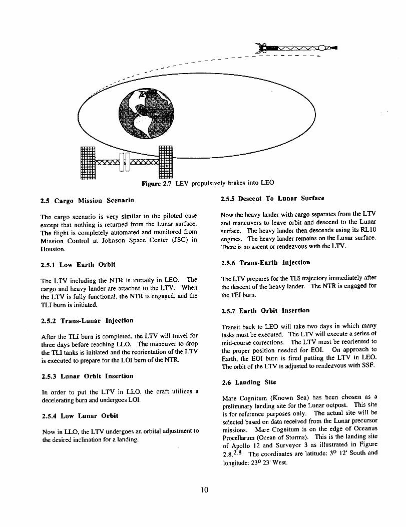
Figure 2.7 LEV propulsively brakes into LEO
2.5 Cargo Mission Scenario 2.5.5 Descent To Lunar Surface
The cargo scenario is very similar to the piloted case
except that nothing is returned from the Lunar surface.
The flight is completely automated and monitored fromMission Control at Johnson Space Center (JSC) in
Houston.
Now the heavy lander with cargo separates from the LTVand maneuvers to leave orbit and descend to the Lunar
surface. The heavy lander then descends using its RL10
engines. The heavy lander remains on the Lunar surface.There is no ascent or rendezvous with the LTV.
2.5.1 Low Earth Orbit 2.5.6 Trans-Earth Injection
The LTV including the NTR is initially in LEO. The
cargo and heavy lander are attached to the LTV. Whenthe LTV is fully functional, the NTR is engaged, and theTLI burn is initiated.
2.5.2 Trans-Lunar Injection
After the TLI burn is completed, the LTV will travel for
three days before reaching LLO. The maneuver to dropthe TLI tanks is initiated and the reorientation of the LTV
is executed to prepare for the LOI burn of the NTR.
2.5.3 Lunar Orbit Insertion
In order to put the LTV in LLO, the craft utilizes a
decelerating burn and undergoes LOI.
2.5.4 Low Lunar Orbit
Now in LLO, the LTV undergoes an orbital adjustment to
the desired inclination for a landing.
The LTV prepares for the TEl trajectory immediately after
the descent of the heavy lander. The NTR is engaged for
the TEl burn.
2.5.7 Earth Orbit Insertion
Transit back to LEO will take two days in which manytasks must be executed. The LTV will execute a series of
mid-course corrections. The LTV must be reoriented to
the proper position needed for EOI. On approach to
Earth, the EOI burn is fired putting the LTV in LEO.The orbit of the LTV is adjusted to rendezvous with SSF.
2.6 Landing Site
Mare Cognitum (Known Sea) has been chosen as a
preliminary landing site for the Lunar outpost. This siteis for reference purposes only. The actual site will beselected based on data received from the Lunar precursor
missions. Mare Cognitum is on the edge of OceanusProcellarum (Ocean of Storms). This is the landing site
of Apollo 12 and Surveyor 3 as illustrated in Figure2.8. 2.8 The coordinates are latitude: 3 ° 12' South and
longitude: 23 ° 23' West.
10

i ?
ShelfCrater
..... Triple: Crater
o pol_ 1
Proposed XBench landing site
Crater 0 100 200mI I I
Figure 2.8 Lunar
This site was selected for several reasons. The location is
within the +/_ 5° latitude limits set by the orbital mechanics
of the mission. In addition, this site has been surveyed and
photographed in detail. Finally, the Apollo 12 Lunar
descent stage and Surveyor spacecraft should provide
valuable data on the long term effects of the Lunarenvironment on materials used in the construction of the
Lunar outpost.
2.7 Contingency Planning
Contingency plans must be made for many different system
failures. Every possible scenario could not possibly be
studied in the amount of time available. Only the "worstcase" scenarios which could lead to mission failure or loss of
life are included.
2.7.1 Possible failures for critical systems
.Outpost Landing Site
excellent disposal option. For this reason, the launch from
KSC will maintain a flight path over water up to the orbital
injection point. 2.9
NTR:
All of the following contingency plans for NTR failure refer
to Figure 2.9 below.
Figure 2.9 In Transit Contingency Plans
1. While in LEO, if a malfunction should arise before the
NTR is ignited, the LTV will remain in orbit.
Launch."
The NTR will be launched separately from the rest of the
LTV to reduce mission risks. Launching from Kennedy
Space Center (KSC) provides a unique hydrological feature
known as the Blake Escarpment 400km (240 miles)
downrange of the launch site. The ocean depth before this
point is ll00m (3609 ft). The depth then increases toseveral kilometers and extends for 8000km (4800 miles).
The interchange of water from the surface to the bottom
takes hundreds of years in this region. Thus, in the event
of a launch failure, this hydrological region provides an
2. After TLI, a NTR failure requires either a fly-by around
the Moon and flight back to LEO in the LEV or an abort to
the Lunar surface. This latter option allows the crew to
complete their mission and return to Earth in the LAM.
3. In LLO prior to descent, an NTR failure requires theLEV fuel for TEl. An LEV failure requires the use of the
NTR as planned to complete the trip back to Earth.Alternatively, an automated launch and rendezvous of the
LAM with the LTV in LLO is also possible.
11

4. A problem with the LTV while the crew is on the
surface requires returning to Earth in the LAM.
5. After ascent, there will be no fuel in the LEV. An NTR
failure at this point requires an automated launch andrendezvous of the LAM with the LTV in LLO. The crew
transfers to the LAM for the trip back to Earth.
6. After TEI, NTR failures are again considered. In the
event that the NTR does not fire, there are no options for
braking into LEO. The large delta V required in any type of
abort at this point results in an unacceptably large massincrease on the LTV. This type of failure is considered
unlikely and was deemed an acceptable risk for the mission.
7. An NTR failure in LEO also has possible solutions.The crew could be rescued with the use of an ETO such as
the shuttle. In the event of a core failure, the NTR can be
disposed of with the use of a core ejection system (CES), an
independent means for launching the reactor core to a higher
orbit with an orbital decay period on the order of thousands
of years.
LEV:
A single engine failure on the LEV can be compensated by
the remaining engine and the RCS system. Descent andascent can be accomplished with a single engine.
Crew Modules ;
Failure of any critical system in the crew modules are
covered by redundant systems.
2.8 Conclusion
The mission scenarios outlined above reflect a concern for
safety, reliability, and cost efficiency. All possible
contingencies were analyzed and necessary abort scenarioshave been devised.
3.0 SYSTEMS LAYOUT
3.1 Scope
The following section details the design process and trial
configurations leading up to the final configuration. Also,the final configuration is presented in detail through all
phases of the piloted mission.
3.2 Design Process
The primary tasks of the Systems Layout Discipline are to
conceptually assemble the subsystems of the LTS into afunctional, efficient system, to investigate and optimize the
stability and control of that system, and to prepare detailed
drawings of the system's final configuration layout. To
complete these tasks, a design process was followed toaccumulate many trial configurations and to then choose and
optimize a layout that is functional, stable, and efficient.
To obtain trial configurations, a process of gathering
information about each subsystem and all design parameters
had to be completed. This process included gaining a
complete understanding of the geometric attributes, massdistributions, and operational function of each subsystem.
This was completed by interacting with each discipline in
the Spacecraft Design Team to gather information and layout
ideas about the disciplines' individual subsystems. Once areasonable level of understanding of the LTS and its required
components and design parameters was attained, sketches and
block diagrams of layout ideas were produced and analyzed.
The sketches that were created provided a means of viewing
and analyzing the attributes of each subsystem whenassembled with all of the other components. Such
drawings were especially helpful in analyzing the geometricconstraints that had to be dealt with and the stability of each
layout idea.
As can be expected, the use of Computer Aided Design
(CAD) software proved to be very valuable in designing the
layout of the LTS. Three-dimensional views of an object,for example, were very simple to obtain from the CAD
software, once the object's geometry was defined. This also
helped in the determination of geometric constraints, sincehand-made three-dimensional sketches were often difficult to
construct and interpret. The software used was
Pro/ENGINEER (by Parametric Technology Corporation), a
user-friendly package with many powerful drafting
capabilities. This CAD package not only helped in
sketching and analyzing trial configurations, but was veryuseful in the addition and modification of the many details
that had to be included in the drawings of the final
configuration of the LTS.
3.3 Design Configurations
Analyzing the trial configurations was the next step in
choosing an optimum layout. This was done individually
and by comparing the accumulated layouts. This analysisled to the elimination of many proposed designs because of a
lack of agreement with the design parameters gathered
previously or obvious lack of efficiency. The followingsections describe a few of the candidates for the LTS layout
and an analysis of the advantages and disadvantages of each.
12
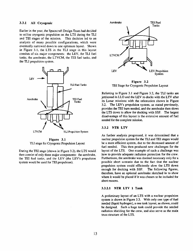
3.3.1 All Cryogenic
Earlier in the year, the Spacecraft Design Team had decided
to utilize cryogenic propulsion on the LTS during the TLI
and TEl stages of the mission. This decision led to an
analysis of many possible configurations, which were
eventually narrowed down to one optimum layout. Shown
in Figure 3.1, the LTS in the TLI stage in this layout
consists of six major components: the LEV, the TLI fueltanks, the aerobrake, the LTVCM, the TEl fuel tanks, and
the TLI propulsion system.
LEV
TL! Fuel Tanks
Aerobrake
\TEl Fuel
Tanks
/LTVCM TLI Propulsion System
Figure 3.1
TLI stage for Cryogenic Propulsion Layout
During the TEl stage (shown in Figure 3.2), the LTS would
then consist of only three major components: the aerobrake,
the TEl fuel tanks, and the LEV (the LEV's propulsion
system would be used for TEl propulsion).
Aerobrake TEl FuelTanks
LTV
LEV LEV PropulsionSystem
Figure 3.2
TEl Stage for Cryogenic Propulsion Layout
Referring to Figure 3.1 and Figure 3.2, the TLI tanks are
jettisoned in LLO and the LEV re-docks with the LTV after
its Lunar missions with the orientation shown in Figure
3.2. The LEV's propulsion system, as stated previously,
provides the TEl burn needed, and the aerobrake then slows
the LTS down to allow for docking with SSF. The largest
disadvantage of this layout is the extensive amount of fuel
needed for the complete mission.
3.3.2 NTR LTV
As further analysis progressed, it was determined that a
nuclear propulsion system for the TLI and TEI stages would
be a more efficient system, due to the decreased amount of
fuel needed. This then produced new challenges for the
layout of the LTS. One example of such a challenge was
how to provide adequate radiation protection for the crew.Furthermore, the aerobrake was deemed necessary only for a
possible abort scenario due to the fact that the nuclear
propulsion system could efficiently slow the LTS down
enough for docking with SSF. The following figures,
therefore, have an optional aerobrake sketched in to show
where it would be placed if it was chosen to be included forabort reasons.
3.3.2.1 NTR LTV 1 Tank
A preliminary layout of an LTS with a nuclear propulsionsystem is shown in Figure 3.3. With only one type of fuel
needed (liquid hydrogen), a one tank layout, as shown, could
be designed. Such a huge tank could provide the needed
radiation shielding for the crew, and also serve as the maintruss structure of the LTS.
13

LEVLTVCM
t i J
\Aerobrake
(optional)
Fuel Tank 7
,r • ..,91-._
Nuclearpropulsion
system
Figure 3.3
One-Tank Nuclear Configuration
However, since it has been determined, through previous
Spacecraft Design Team research, that a wet-tank transfer ismuch more desirable than a refueling fluid transfer,
especially in such a large scale as this, a massive orbital
rendezvous operation would be necessary at the start of eachmission. This would involve the handling and
maneuvering of a potentially dangerous nuclear reactor quite
frequently. Also a disadvantage would be the fact that thewhole mass of the tank would be hauled along throughout
the entire mission, causing a loss in efficiency.
3.3.2.1 NTR LTV 4 Tanks
With these problems in mind, a layout with four fuel tanks
(two for the TLI stages and two for the TEl stages) attached
to a long truss was produced and is shown in Figure 3.4.
The symmetry of this design is an obvious advantage while
the four tank layout allows for jettisoning of the TLI tanks
after use, limiting the amount of extra mass being carried bythe LTS.
TTHSS 7
(length needed forradiation shielding)
Nuclearpropulsion
system
LTVCM
J
\Aerobrake(optional)
TLI Tanks
__EI Tanks
Figure 3.4
Four-Tank Layout with Nuclear Propulsion
However, with a one meter square truss, a structurally sound
layout, the fuel tanks have to be set radially outward from
the truss by one and a half meters to keep the tanks from
interfering with one another. This would present a fairly
difficult problem in structurally attaching the tanks to the
truss. Two approaches were then taken two encounter this
problem.
One way to avoid this attachment problem was to move the
TLI tanks away from the propulsion system just enough to
keep them from interfering with the TEl tanks. This
configuration is shown in Figure 3.5. This layout seemsto solve the attachment difficulty quite well, but it also
produces another problem.
14

tzv LrvcM
\
Figure 3.5
Layout with TLI Tanks away from propulsion
In order to place the TLI fuel tanks as shown in Figure 3.5,
fuel lines of eight meters in length or more would have to
be utilized, which would thus cause a fairly inefficientmeans of fuel transfer.
Another means of countering the attachment problem was
then produced. As shown in Figure 3.6, a smaller truss is
still used for the majority of the length of the LTV, but a
larger one (four meters square) is used for the area where the
tanks are attached. This design allows for all of the tanks
to be placed fairly close to the propulsion system, without
interference, thus eliminating the lengthy fuel lines.
tzv LrvcM
J
T _ _ _Aerobrake
(length nrUe_edfo_'- (optional)
radi i s
Figure 3.6
Layout with Large and Small Truss Sections
With continuous modifications of the layout shown in
Figure 3.6, and the inclusion of extensive details, an
optimum layout of the LTS was then produced.
15

3.4 Final Configuration
The final LTV configuration consists of the LEV, NTR, and
fuel tanks attached to a truss. The length of the truss
provides the crew with adequate radiation protection. Tank
sizes were determined working under the assumption that theTLI fuel would be contained in two large tanks, while the
remaining fuel for LOI, TEl, and EOI will be contained intwo smaller tanks. This allows the TLI tanks to be
jettisoned. The final LTV layout with major dimensions is
included as Figure 3.7 and 3.8. Masses are included in
Tables 3.1 and 3.2. The specification sheet of this vehicle
is located in Appendix B.
5JT_L[ g,lll
Figure 3.7 LEV Configuration
16

iI.U
M.I
1II.M,
1
Figure 3.8 LTV Configuration
17

Component
Truss
Mass (mT)
3.75
Crew Module 9.95
Power 1.746
Prim.Prop.
D_ Tanks
Total Dr/'
Fuel
.344
1.977
17.84
Burn LH2 LOX
Xfer from .028 .139
SSF
Descent 3.6 18.0
Ascent 2.12 10.6
Xfer to SSF .009 .044
RCS
Total Fuel
.48
[5.76 28.78
Table 3.1 LEV Masses
_m
Truss 5.5
Crew Mod 10.068
Power 1.345
Prim.Prop. 13RCS .692
D Tanks 14.367
78.2
LOI 19.99
TEl 12.39
EOC 26.58
RCS
Table 3.2 LTV Masses
3.5 Vibration
Vibrational analysis consisted of the analysis of the LTVtruss only. Because of the unusually long length of this
truss, it was determined that this truss would be the mostsensitive to vibrations out of all the LTS structures. The
analysis involved the determination of the frequency,
deformation, and maximum displacement for the first three
modes of vibration. The results are contained in Figures
3.9, 3.10, and 3.11.
Max Disp: !.0 mFreq: 1.34 Hz
I
Figure 3.9 Mode 1 Vibration
Max Disp: 1.0 mFreq: 1.34 Hz
Figure 3.10 Mode 2 Vibration
18

Max Disp: 1.08mFreq: 3.84 Hz
Figure 3.11 Mode 3 Vibration
Three modes of vibration were checked using the I-DEAS
solid modeling program. The results were within thestructures tolerance levels so at maximum acceleration and
deceleration the structure could withstand the vibrational
stresses.
4.0 ORBITAL MECHANICS
4.1 Introduction
The goal of the orbital mechanics discipline is to determine
the orbits and trajectories necessary to accomplish themission of the LTS. This includes selecting orbit modes,
determining trajectories between the Earth and Moon,
planning the Lunar descent and ascent, coordinating Earthorbit activities, and preparing abort scenarios. In
conjunction with the mission statement, emphasis was
placed on minimizing propulsion requirements in order to
maximize cost efficiency..
4.2 Orbit Mode Selections
The goal in selecting orbit modes is essentially to determinewhich modes are the most feasible according to certain
mission parameters such as safety, cost effectiveness, and
weight limitations. A brief synopsis of available options
for orbit modes will be presented.
4.2.1 Earth Orbit Modes
To accomplish its mission, the LTV must be placed in a
specific position at a specific time in LEO in order to
perform a TLI burn. The most practical and efficient
technique for Earth departure is launching the transfervehicle(s) into circular parking orbits prior to injection.
These parking orbits allow greater mission flexibility by
providing: (1) Sufficient time for final on-board and ground
checkouts before injection, (2) Injection capability any timeof the month, twice a day, and (3) The same ascent and
injection trajectory profile for any mission. The only
disadvantage to parking orbits are the increased requirements
for tracking and communications, however this problem will
be minimized as more ground tracking facilities become
operational in the future.
There are two basic launch techniques that can be used to
obtain launch frequencies, direct and indirect ascents. In the
direct launch technique, the LTV arrives directly at its
appointed TLI time and position from launch. This methodsolves the timing problem on the ground prior to launch,
but only allows launch windows of a few minutes. Anindirect ascent involves launching the LTV into LEO at any
time and solving the timing problem while in orbit. This
option involves longer launch windows, but also requires
additional propulsive burns in orbit. Since the missionstatement assumes rendezvous with SSF prior to injection,the indirect launch scenario will be used.
Prior to injection, the LTV will maneuver into the
appropriate parking orbit. The required change in velocity
(delta V) needed for TLI is a function of a number of
parameters including Earth orbit inclination, orbit altitude,and trans-Earth trajectory inclination, to name a few. Once
the particular mission has been planned, an optimumconfiguration for the LTS voyage can be determined, and the
required delta V necessary to accomplish the mission can becalculated.
4.2.2 Lunar Orbit Modes
As with Earth orbit modes, there are two choices for descent
upon reaching Lunar orbit, direct and indirect descent.Direct descent involves a straight shot to the Lunar surface
directly from the trans-Lunar orbit. In this case, the entire
space vehicle becomes a multipurpose landing module.This method is the least complex, since it avoids orbital
rendezvous with a LTV prior to Earth departure. The major
disadvantage of this option is the requirement of lifting off
more weight from the Lunar surface upon departure forEarth. However, this scenario is ideal for unpiloted cargo
or probe missions that will require little or no lift-off
capabilities.
19

The second orbit mode involves injecting the LTV into a
Lunar satellite orbit upon arrival. Next, the landing module
is separated from the LTV for descent to the Moon's surface.The LEV is landed on the Lunar surface, and later launched
to rendezvous with the LTV. This approach presents
smaller fuel requirements, since less weight needs to belifted off from the Moon's surface, however it limits landing
sites to low latitudes.
4.3 Interplanetary Trajectories
4.3.1 Earth Departure
Interplanetary trajectory analysis begins with looking at the
parameter requirements for Earth departure. The Earth-Moon distance has been chosen as a mean of 56 Earth radii.
The Earth injection altitude corresponds to 250km (150miles), and the Lunar altitude corresponds to 185km (111
miles). For piloted missions, it is desirable to limit the
exposure any astronauts would have to harmful spaceradiation, therefore one of the mission priorities is to
minimize flight times to and from the Moon. Also, inorder to maximize the cost efficiency of the mission, the
required delta Vs will be minimized.
4.3.1.1 Earth Departure Requirements
Figure 4.1 shows our Earth departure configuration on a
translunar plane inclined at an angle to the Moon orbitalplane, ia, which is 60 degrees. The inclination of the
Moon orbital plane to the Earth equatorial plane, ib, is 28
degrees. It is assumed to be constant, neglecting the rate of
nodal regression due to the Earth's oblateness. Alsoconstant is ic, the inclination angle of the parking orbit, at
30 degrees. The Moon lead angle, f, is measured at 37
degrees. In order to minimize the maneuvering capability
of delta V and maximize the launch frequency and tolerance,
the angle from the ascending node of the Moon orbital planeto the intersection of the parking orbit, id, is measured at
-65 degrees. According to NASA studies, an optimum
trajectory can be achieved at injection with a prior parking
orbit. As such, the LTV will perform its TLI burn with a
maneuver from the initial parking orbit altitude of 425 km
(255 miles). In order to satisfy certain mission constraints
such as flight time, missed distance, and Lunar approach
orbital orientation, an optimum configuration for the
propulsion system will have to be determined to meet themission statement. This will be discussed in the next
section.
Parking Orbit
Moon Orbital
Plane
Equator
_ PericynthionMoon at
injection Ascending node ofMoon Orbital Plane
Figure 4.1 Earth Departure
4.3.1.2 Propulsion System Requirements
To determine the propulsion system requirements for Earth
departure, it is necessary to optimize a set of parameters:injection velocity, V; injection position, j; flight path
angle, g; and change in injection position, delta j. The
injection position is achieved by an initial parking orbit.To minimize energy requirements for departure, the flight
path angle has to be in the range from 2 degrees to 7
degrees. Within this range of operation, the delta V
requirement is also minimized. For a maneuver at whichthe initial parking altitude begins at 425 km (255 miles), an
optimum configuration includes a thrust-to-weight ratio of
0.15, and a specific impulse of 915 seconds. With the
above figures, the total flight time is minimized at
approximately 68 hours, and a required delta V of 3.1 km/s
to escape the Earth's gravitational attraction.
4.3.2 Earth-Moon Transfer
4.3.2.1 Trans-Lunar Injection Conditions
Trans-Lunar trajectory depicts the passage from the Earth to
the Moon. Figure 4.2 shows the configuration for the TLI
phase of the mission. The Earth-Moon distance is assumedto be 56 Earth radii, and the injection altitude, h, is
measured at 250km (150 miles). For most piloted Lunar
missions, circumlunar trajectories generally describe the
outbound passage and the return passage trajectories. Upon
TLI phase, the LTV is injected with a velocity of 10.9km/s, and flight path angle, g, of 5 degrees. The injection
position is defined by j equal to 20 degrees, with a Moonlead angle, f, of 37 degrees. Deltaj denotes the magnitude
of the change in injection position prior to injection.
20

InjectionOrbit
h _'_ Translunar
.. _ .)? Trajectory
delta t,p _V
Figure 4.2 Trans-Lunar Injection
The angle between the Lunar orbit and the Moon orbitalplane, ie, is 5 degrees, and the inclination of the Earth-Moon
line and the descending node of the Lunar orbit, if, is 60
degrees (see Figure 4.3). The Lunar plane orientation and
the inclination of the trajectory plane at arrival time aredetermined by the measurements of ie and if.
Trans-Lunar
Trajectory
/Earth-Moon
/ / ,inoI Moon
Pericynthion
Figure 4.3 Trans-Lunar Trajectory
The orientation of the trans-Lunar plane to the Moon orbital
plane, ig, is 60 degrees (see Figure 4.4). The pericynthion
altitude for trans-Lunar trajectory is 185km (111 miles), and
the time of flight from injection to pericynthion altitude is
minimized at 68 hours. The TLI burn requires a delta V of
3.1 km/s to escape Earth's realm, and LOI requires a delta Vof 1.1 km/s.
Trans
Moon Orbital
Plane
Earth
Figure 4.4 Earth Departure
4.3.3 Lunar Orbit Determination
4.3.3.1 Maneuvers between Lunar Orbits and
Transfer Trajectories
In order to establish the delta V requirements for entry into
Lunar orbits from trans-Lunar trajectories, and to inject into
trans-Earth trajectories from Lunar orbits, it is necessary to
look at entry and departure maneuvers between Lunar orbits
and transfer trajectories. Figure 4.5 shows the maneuvers
between Lunar orbits and transfer trajectories. The LTS
mission requires a complicated and variable thrust schedule.
As such, the orbital mechanics aspect of the transfer
trajectories is based on the assumption that the entire
transfer maneuver is conducted on the trans-Lunar trajectory
plane and the trans-Earth trajectory plane, and that the
propulsive thrust vector is constantly parallel to the velocity
vector. For a Lunar orbital entry at a Lunar orbital altitude
of 185km (111 miles), the delta V requirement is 1.1 km/s.
Similarly for a Lunar orbital departure from the same Lunar
orbital altitude, the delta V requirement is also 1.1 km/s.
In these calculations, the off-nominal effects during entry
maneuver are neglected.
21

"ILI N
Parking Orbit
/ J ___oonline
I ik Moon
,- : Orbi l
.... _ Plane
Figure 4 5 Maneuvers between Orbits _ Descending node
4.3.4 Moon-Earth Transfer Trans-Earth[ of Parking Orbit
4.3.4.1 Trans-Earth Injection Conditions
Figure 4.6 shows the configuration for the trans-Earth
trajectory phase of the mission. After ascending from the
Lunar surface, the LTV is placed into a circular parking orbitaround the Moon. The Lunar orbit altitude for TEl
trajectory is 185km (111 miles), with a flight path angle,
gamma, of zero degrees. The inclination of the parking
orbit to the Moon orbital plane, ij, is 5 degrees. The angle
between the parking orbit plane and the Moon orbital plane,ik, is 60 degrees, measured positively eastward from the
Earth-Moon line to the descending node of the parking orbit.
The central angle for the injection into the trans-Earthtrajectory, i1, is 50 degrees and is measured toward north
from the descending node of the parking orbit. Both ij andik determine the orientation of the circular Lunar orbit, and
the position of the LTV is specified by the radius of theLunar orbit and the measurement of the central angle. The
injection position, psi, is measured at -10 degrees, with an
injection velocity of 1.2 km/s.
injection point
Figure 4.6 Lunar Departure
The return inclination of the trans-Earth trajectory to the
Moon orbital plane, ih, is defined at 180 degrees (see Figure
4.7). The delta V requirement for the Earth return leg is 1.1
knds, and flight time for the trans-Earth trajectory is
approximately 50 hours. The decrease in these values from
the trans-Lunar trajectory reflects the lesser gravitational
effect of the Moon compared to the Earth. These values are
minimized for the Moon-Earth transfer profile.
Moon Orbital
Plane
Trans Earth Plane
Moon
Figure 4.7 Trans-Earth Injection
4.3.5 Earth Return
4.3.5.1 Earth Orbit Capture
For Earth return, the mission statement requires arrival in
LEO from the trans-Earth trajectory for rendezvous with
SSF. Upon entering the EOC phase, the kinetic energy ofthe LTV must be reduced to that of a circular Earth orbit by
application of NTR thrust. The NTR deceleration technique
22

involves a direct reduction of the speed of the approaching
LEV to that of an Earth orbital speed, along with a
propulsive burn. Fuel requirements for EOC can be
obtained by assuming the trans-Earth trajectory of the LTV
as that of a hyperbolic profile, and that the required velocity
reduction occurs impulsively. In the above configuration,
the delta V requirement for the EOC phase is minimized at 3
knds.
4.3.5.2 Orbital Circularization
After executing the EOC phase, the orbital mechanics aspectof the mission calls for an orbital circularization phase.
The LTV subsequently performs an orbital circularization ina low Earth satellite orbit, with a delta V of 310 ntis. In
order for the LTV to execute a phasing with SSF to an orbit
within 25km (15 miles), a delta V of 10 m/s is required.
The final phase of the mission entails a docking of the LEVwith SSF.
4.4 Lunar Ascent / Descent Trajectories
While the LTV is in orbit around the Moon, the LEV must
be able to descend the to Lunar surface to deliver the crew or
cargo. A piloted mission also requires the LEV to ascendfrom the Lunar surface to return the crew to the orbiting
LTV.
4.4.1 Descent to the Lunar Surface
Once the LTV is in Lunar orbit at 185km (111 miles) from
the Lunar surface, preparations are made for descent to the
Moon's surface. Lunar descent is performed in two stages,
a braking from the translunar hyperbolic trajectory to
circular or elliptical Lunar orbits, and a subsequent descentto the Lunar surface by the LEV. Figure 4.8 depicts a Lunar
descent profile. After separation from the LTV, the LEV
experiences a retrothrust and enters the deorbit phase. Delta
V required in deorbit is approximately 10 m/s. The LEV
follows the deorbit coast, and performs orbital braking at an
altitude of 20km (12 miles). When the LEV is 300 metersfrom the Lunar surface, the lateral velocity is reduced to
zero, and the lander rotates such that the thrust vector is
pitched over for hovering. The final descent phase entails a
maneuvering capability of hovering and translation.Maximum vertical landing velocity on the Lunar surface is
3.1 m/s (10.2 ft/s); maximum horizontal velocity is 1.2 m/s
(3.94 ft/s). Delta V required for Lunar descent is 2 km/s.
Considering a thrust-to-weight ratio of 1.2, orbital brakingat 20km (12 miles), terminal altitude at 300 meters, and a
specific impulse of 450 seconds, the descent range is 90
degrees. Descent time to the Lunar surface is approximately17 minutes.
Lunar orbit = 185 km
Deorbit Maneuver / .Coast Phase
Descent Range__Hovering and
(90 degrees, / _f\_ j_NI_._._ Translation
Figure 4.8 Lunar Descent
4.4.2 Hovering and Translation
This section considers the propellant requirements and the
optimum conditions for translation, vertical descent from
hover, and hovering. After the final descent phase, the LEV
is capable of hovering and translation. In order to achieve
its mission, the LEV propulsion system must provide a
constant acceleration of propulsive flow. Small mass ratio
requirements for hovering and simplicity in analysis are the
two most important reasons for a constant acceleration
analysis of propulsive flow. In the motion profile of
translation, vertical descent from hover, and hovering, a
constant engine thrust with steady propellant flow rate is
required. Vertical landing on the Lunar surface is 3.1 m/s,and horizontal maneuvering velocity is approximately 1.2
m/s.
4.4.3 Ascent from the Lunar Surface
Ascent from the surface of the Moon to Lunar orbit requires
three phases: ascent, coast, and injection. Figure 4.9
shows the profile of a Lunar ascent, which is very similar to
the descent profile. The ascent phase burnout altitude is20km (12 miles). Following that is a transfer coast phaseto the Lunar orbit. The lunar ascent phase is completed
with a propulsive injection into the Lunar parking orbit at
an altitude of 185km (111 miles), where the LEV performs arendezvous with the orbiting LTV. Delta V required for
Lunar ascent is 1.9 km/s. Considering the thrust-to-weight
ratio, burnout altitude, and specific impulse, the ascent rangeis found to be 180 degrees. Ascent time from the Lunar
surface is approximately 10 minutes.
23

Lunar Orbit = 185 kmCoast Phase
Ascent
Figure 4.9 Lunar Ascent
4.5 Earth Orbit Activities
4.5.1 Orbit Options
While the LTV is in orbit around the Earth, it will be
necessary to dock with SSF for such purposes as transferring
crew and cargo, or for maintenance. Since safety
limitations require the LTV to maintain a distance of at least
10km (6 miles) from SSF during all other times while in
orbit, it is necessary to find an adequate orbit and
accompanying docking procedure for when rendezvous with
SSF is performed. Three different options were considered.
The first option places the LTV in the same orbit as SSF,but at a different orbital position. This would give the
effect of the LTV "following" SSF around the Earth. One
major disadvantage of this option is the fact that it would
require the LTV to perform two in-plane orbit changes todock with SSF, one to put it at a different orbital radius to
"catch up" with SSF, and one to bring it back to SSF.Plus, this would cause SSF to pass through the trail of
radioactive matter left by the NTR.
A second option is to place the LTV in an orbit at the samealtitude as SSF, but in a different orbital plane. One of the
biggest disadvantages is the high delta V required to change
planes. For example, a one degree plane change at theorbital radius of SSF would require a delta V of about 135
m/s. The other disadvantage is that it would either require
precise timing upon EOC to synchronize the LTV with
SSF, or two in-plane orbit changes would still be required to
align the two orbiting bodies.
The last option is to place the LTV in a slightly higherorbit than SSF, but in the same orbital plane. This
eliminates one of the in-plane orbit changes, requiring onlyone in order to rendezvous with SSF. However, difficulties
in timing arise due to the difference in orbital periods atdifferent orbital radii.
4.5.2 LTV and SSF Orbits
After considering all three options, the last one was chosen.
In order to analyze this option in more detail, the following
parameters were used.
Space Station Freedom:Orbital altitude = 400km (240 miles)
Orbital period = 92.56 minutes
LTV Parking Orbit:Orbital altitude = 425km (255 miles)
Orbital period = 93.07 minutes
LTV Hohmann Transfer between orbits:
Delta V = 14.1 m/s
Transfer time = 46.4 minutes
Possible every 11.7 days
f LTVSSF
425 km400 km
Figure 4.10 Earth Orbits
The altitude of the LTV parking orbit was chosen to insure
the safety factor of at least 10km (6 miles) separationbetween the LTV and SSF. A slightly larger margin,
25km (15 miles), was used to increase the difference in
orbital periods, since a larger difference improves the
frequency of performing a Hohmann transfer. At thisaltitude, a Hohmann transfer could be performed
approximately once every 11.7 days. This would require
starting the transfer when the angle between the two orbits
is approximately zero. If a transfer is needed to be done atsome other time, it would still be possible, however a
higher delta V would be required to achieve the maneuver.
24

4.6 Abort Scenarios
In the case of an NTR failure, several scenarios had to be
studied to plan for an abort. Figure 4.11 illustrates the fourcases considered.
Figure 4.11 Abort Scenarios
1. Post-TLI / Pre-LOI stage. This case occurs after the
,trans-Lunar injection burn has been performed, but before
the Lunar orbit insertion. The preferred abort scenario forthis case is to disconnect the LEV from the LTV, orbit
around the Moon utilizing Lunar gravity assist, and return to
Earth. Upon arrival at Earth, the propulsive burn necessary
to achieve LEO would be performed using the LEV.
2. Post-LOI / Pre-Ascent stage. This case is after the LTV
has been placed in LLO, or after the LEV has descended tothe Lunar surface, but before the ascent stage. If the crew
has not yet descended, the abort scenario includes descent.Once on the Lunar surface, the crew can complete their
mission, and then return to Earth in the LAM that will beavailable on the Moon.
3. Post-Ascent / Pre-TEI stage. Once the LEV hasascended in order to rendezvous with the LTV, it no longer
is capable of landing on the Lunar surface again during that
mission. If the TEl stage has not yet been completed, the
LAM is remotely controlled to rendezvous with the LEV,and the crew transfer to the LAM to return to Earth.
4. Post-TEI / Pre-EOC stage. The last abort scenario case
considered occurs after the LTV has performed the TEl burnbut before insertion into Earth orbit. There is no alternate
plan for this case in the event of an abort; it is considered an
acceptable risk of the mission.
For the fourth case, three options were considered:
acceptable risk, aerobrake the LEV to the Earth's surface, and
equip the LTV with a ballistic capsule to return the crew toEarth. For either the case of the aerobrake or the ballistic
capsule, a delta V would be required to change the trajectory
of the vehicle from a hyperbolic orbit past the Earth to a
trajectory that would send it to the Earth's surface. This
delta V is approximately 3 km/s, which would result in a
mass penalty of over 100 metric tons in fuel. Uponexamining the factors involved, the only realistic option was
to consider an NTR failure at this stage an acceptable risk
for the crew.
4.7 Delta V Requirements
Table 4.1 shows a summary of the delta Vs required for each
stage of the LTS mission. The total mission delta V
required is approximately 12.5 km/s, and may vary slightly
depending on such details as how many times the LTVdocks with SSF while in LEO and if a Hohmann transfer is
used or not.
Phase
Trans-Lunar injection
Mid-course correction (Earth-Moon)Lunar orbit insertion
Delta V
_m/s)
3100
10
1100
Lunar descent 2000
Lunar ascent 1900
Trans-Earth injection 110010Mid-course correction (Moon-Earth)
Earth orbit capture 3000
Circularization 300
Docking with SSF _minimum)
Total
14
] 121534
Table 4.1 Delta V Table
4.8 Conclusion
According to mission constraints and parameters, the orbitalmechanics of the LTS mission have been determined in order
to maximize efficiency, minimize cost, and ensure the safetyof each mission. The scenarios are based on pre-established
assumptions and priorities for the given mission.
5.0 PROPULSION
5.1 Introduction
The responsibilities of the propulsion group include the
selection of primary propulsion and Reaction Control
Systems (RCS) for the LTV and LEV, as well as thedetermination of fuel requirements for the various mission
stages. The evaluation of these systems took place over the
course of one academic year and involved research and
analysis of many competing propulsion systems. Several
iterations and design changes occurred before the final
propulsion configurations were obtained.
25

The following sections detail the selection of the LTV and
LEV primary propulsion and Reaction Control Systems.
Throughout the design process an effort was made by the
propulsion discipline to justify its design selections through
quantitative comparisons with other existing propulsion
options. Final selection of the various LTS propulsive
systems was made by judgingthe extent to which each system was compatible with the
design group's mission statement. The members of the
discipline feel that their efforts resulted in LTS propulsive
systems which are indeed safe, reusable, economical and
practical to interface with the rest of the LTS hardware.
5.2 LTV Primary Propulsion
The primary propulsion system for the LTV is a NuclearThermal Rocket (NTR). The decision to pursue the
development of an NTR was made after determining that the
fuel requirements of an all cryogenic LTV were too massive.
By'using an NTR, the LTV was able to be designed tofulfill the original mission goal of providing a robust
transportation system, capable of supporting a permanent
Lunar outpost.
5.2.1 Nuclear Thermal Rockets
The use of a nuclear thermal rocket for space vehicle
propulsion is certainly not a new concept. In fact, NTR
propulsion has a history spanning the past 38 years. In1955, the U.S. Air Force and the Atomic Energy
Commission (AEC) began the Rover Project. Rover wasdirected towards the research and initial development of
nuclear reactor technology for single stage Intercontinental
Ballistic Missile propulsion. 5"1 Several reactors were built
and tested during this program in a series of designs denoted
Kiwi. In 1958, the newly formed National Aeronautics and
Space Administration (NASA) replaced the Air Force as
partners with the AEC as primary developer of the nuclear
propulsion effort. Then, in 1959, a new program began
that was to expand on the successes of the Rover Project.
This new program was known as the Nuclear Engine for
Rocket Vehicle Application, or more succinctly, NERVA.
The NERVA program was directed towards the design and
testing of a complete nuclear flight engine. By building
upon the knowledge acquired through the Rover Projectresearch, NERVA strove to develop the necessary
components of an NTR and validate the concept throughextensive component and full scale engine testing. In
1961, contracts were negotiated with Westinghouse and
Aerojet General to build the reactor and system components,
respectively. Component testing took place at Los Alamos
Scientific Laboratory with complete system testing at the
nuclear test facility at Jackass Flats, Nevada.
Originally, the NERVA engine was a candidate for the upper
stage of the Apollo program, 5"2 but the successes of an all
chemical system relegated the nuclear rocket to the
nonspecific role of a propulsion system for interplanetary
travel. Work towards this goal continued until 1973, when
the changing post-Apollo priorities of the nation shifted
away from space exploration and the NERVA program wascanceled. At its close, the combined Rover and NERVA
programs had overseen the construction and testing of
twenty reactors and two complete flight engines. 5.1 More
importantly, these programs generated a data base that isagain being reviewed by NASA, as the agency and the
nation once again look towards the future of space
exploration.
5.2.2 NTR Fundamentals
A nuclear thermal rocket uses a single propellant rather thanthe fuel-oxidizer combination of traditional chemical
propulsion. An NTR replaces the combustion cycle of achemical rocket with a simple heat transfer process between
the reactor core and the propellant. This is accomplished
by passing the propellant through a hot nuclear core, whereit is heated to temperatures in excess of 2500 °K.
Following this heat transfer, the propellant is expanded
through the rocket nozzle which accelerates the flow to
supersonic exit velocities. It is this expansion process
which provides the thrust generated by an NTR.
Since specific impulse (Isp) is inversely proportional tomolecular weight, fuel selection for the NTR is critical.
For optimum performance, hydrogen was chosen as the
propellant for the NERVA flight engine due to its lowmolecular weight and high specific heat. It is the use of
hydrogen as the single propellant which allows an NTR to
surpass the Isp of chemical rockets by a factor of two. To
compare, a conventional liquid hydrogen/liquid oxygen
chemical system has an average Isp of less than 500seconds, while the NERVA flight engines demonstrated Isp
values in excess of 800 seconds with a thrust of 333,600N
(75,000 Ibf). 5"1 Dr. S.K. Borowski, oftbe Nuclear
Propulsion Office at NASA Lewis Research Center,estimates that with the inclusion of current technology, the
Isp values of a NERVA derived NTR will reach 925seconds. 5.3
5.2.3 NTR versus Cryogenic Systems
It is the two-fold advantage in Isp which enables an NTR to
use substantially less fuel than a chemical system. This is
26

due to the fact that the fuel mass flow rate at a specified
thrust level is inversely proportional to Isp as evident in
equation 5. i.
Tria = _ (5.1)
golsp
Thus, the fuel mass flow rate required to generate a specificlevel of thrust is much less for an NTR than it is for a
chemical system. This results in a significant reduction in
the fuel required for the LTV to perform a round trip missionto the Moon. A comparison of the piloted LTV scenario is
displayed in Figure 5.1.
INITIAL MASS IN LOW EARTH ORBIT
500 mT
400 mT
300 mT
200 mT
100 mT
469 mT l Vehicle Mass
Propellant Mass
238 mT
137 mT
CRYOGENIC NTR
Figure 5.1
Comparison of Vehicle & Fuel Masses.
As can be seen in Figure 5.1, the use of the NTR results ina 50.7% reduction in the total vehicle mass. This translates
to a 64% reduction in the propellant mass, a savings of 245
t. In steady state operation, this represents significant
savings with respect to mission costs. If one estimates thelaunch costs for the proposed Heavy Lift Launch Vehicle at
$1000 per kilogram, the monetary savings generated through
the use of the NTR surpass $230 million dollars per launch
over a comparable chemical system. The reduction of
propellant mass requirements as well as mission costs are
the driving forces behind the decision to employ a nuclear
propulsion system for the LTV.
5.2.4 NTR Specifications
Several proposals for nuclear thermal rocket engines exist.These include such conceptual designs as liquid core, plasma
core, and particle bed reactors. However, these designs are
conceptual in nature with no prototype flight engines evertested. As such, the development of a flight ready engine in
time to meet mission initiation in the year 2005 would be
difficult to achieve. For this reason, a modified version of
the solid core NERVA flight engine is selected as the
primary propulsion system for the LTV. It is estimated
that a flight rated engine based on the NERVA design can be
ready within six years. 5" 1
The NTR to be used on the LTV is an updated version of the
NERVA flight engine that will be capable of an Isp of 925seconds and 333,600 N (75,000 Ibf) of thrust. The engine
components consist of the nuclear reactor, turbomachinery,
fuel pumps and lines, exhaust nozzle, and internal shield.The total mass of the reactor and its subsystems is
approximately 8.5t. A 4.5t external radiation shield is alsoincluded to attenuate the radiation dose that the crew module
will experience. This brings the NTR component mass to
13t. 5.4 The internal and external radiation shielding are
constructed of borated-aluminum-titanium-hydride (BATH).
This shielding attenuates the neutron and gamma radiation
emitted from the reactor. Hydrogen is the single propellant
and is thermodynamically expanded in an Expander cycle, as
represented in Figure 5.2.
FuelElements
-. NTR EXPANDER CYCLE!!
Radiation
_ ShieldingControlRods
ExhaustNozzle
Figure 5.2 NTR Operating Cycle
27

In the Expander cycle, LH2 is pumped from the fuel tanks
down into the nozzle extension as indicated in Figure 5.2.
It then passes through channels in the nozzle to cool thenozzle structure. Next, the hydrogen passes through
coolant channels in the pressure vessel walls and into the
upper portion of the reactor. Here, the LH2 cools the
internal shield before being drawn off and routed through
turbines which provide the work energy to operate the fuel
pumps. By using the heated hydrogen propellant to run the
turbomachinery, the NTR requires no external power source
to maintain full power operation. Next, the LH2 is passed
through the reactor core, where it is heated to 2500 °K (4500
°R). Finally, the hydrogen exits the exhaust nozzle atvelocities in excess of 9,000 m/s, generating 333.600 N
(75,000 lbf) of thrust.
A fully redundant system with dual turbopumps, fuel lines,
and valves is incorporated into the design of the NTR. This
full redundancy was found to increase the mass of the NTR
by a mere 171 kg. 5"4 This modest mass penalty is deemed
acceptable, in view of the criticality of engine restart with
respect to the mission abort scenario, as defined by Mission
Analysis.
5.2.5 NTR Operational Cycle
The operational cycle of the NTR begins with the rotationof the 16 actuator control drums indicated in Figure 5.2.
The purpose of these control drums is to moderate the level
of the reaction. This is accomplished by coating one half
of a drum with a neutron absorbing material such as boroncarbide, and the other side with a neutron reflective coating
of beryllium. The reaction is begun by rotating the
beryllium side toward the core, thus increasing the rate ofthe nuclear reaction. There exists a modest start-up
transient of approximately 30 seconds. This is based on the
original NERVA design criteria that the reactor be able towithstand the thermal loads associated with a transient of 85
OK/s.5.1 The propulsive burn is terminated by rotating thecontrol drums such that the boron carbide side once againfaces the core and absorbs the neutrons emitted from the fuel
elements.
Following the main burn, a cool-down burn must be
performed to bring the reactor temperatures down to adequatelevels. The cool-down transient is more difficult to define
than the main burn transient. The cool-down consists of
flushing hydrogen through the NTR to remove the heat that
is built up during the burn. The removal of the latent heat
built up within the NTR structure takes place within a fewminutes at an approximate thrust level of 25,000 N (5600
Ibf). However, there continues to be radiation heating due
to the longer time required for the nuclear reaction to come
to a stop. To dissipate this radiation heating, the NTR
must send short bursts of hydrogen into the engine, repeated
over the span of a few hours. The thrust generated by these
bursts is nominal, only 58 N (13 lbf) and is experienced for
only brief periods. 5"6
5.2.6 Nuclear Fuel Elements
The reactor core itself is composed of a cluster of hexagonalfuel rods. Each of these fuel rods has 19 coolant channels,
2.5 mm in diameter, through which the LH2 flows. 5"1
The fuel rods themselves are composed of fine particles of
the fissionable element uranium (U 235) suspended in a
carbide compound. In the original NERVA engine, theuranium-carbide (UC) fuel was shaped into pellets and then
suspended in a matrix material. A carbon-based matrixmaterial is used because of its low neutron absorption as
well as its high melting point, low density, and high
strength at high temperatures. 5"5
However, carbon reacts with hot hydrogen to corrode the fuelmatrix and form methane and other hydrocarbons. This
corrosion can seriously degrade the reactors performance as
well as shorten the operational lifetime due to the carbon
loss from the matrix. This process can be attenuated by
coating the matrix with a non-reactive material such a
zirconium-carbide (ZrC). Eventually, cracks will form in
the ZrC coating due the repeated thermal cycling between
shutdown and full power operation, at which time carbon
mass loss will begin. With this inevitability in mind, a
UC-ZrC composite fuel element was designed in which the
reactive fuel is mixed with ZrC and dispersed throughout the
carbon matrix in layers. In this design, once the outer ZrC
coating is cracked, carbon will only be lost until the next
layer of ZrC is reached. This is in contrast to the fuelparticle design in which carbon loss would be indefinite dueto the continuous carbon matrix. The two different fuel
element concepts are illustrated in Figure 5.3. 5.5
28

HYDROGENSTREAM
COATING
0
00
GRAPHITEMATRIX
UC-ZrC
UCFUELPA_CLE
COATED FUEL
PARTICLE MATRIX
COMPOSITE
MATRIX
Figure 5.3 Diagram of Two Fuel Elements
It is this composite matrix fuel element which is
incorporated into the NTI_ flight engine due to its potentialfor increased resistance to hydrogen degradation and thus a
longer NTR service life.
5.2.7 NTR Service Life
The dominant factor in the service life of the NTR is the
burn endurance. Burn endurance is defined as the
cumulative time that the NTR is engaged during any
mission. The burn times for all primary propulsive burnshave been calculated and are included in Table 5.1.
Mission Piloted UnpilotedPhase Mission Mission
TLI 35. i6min 39.88min
LOI 9.05min 10.26min
TEl 5.15min 3.66min
EOI 10.82min 7.78min
Table 5.1
Burn Times for Piloted & Unpiloted Missions
All calculations were done by relating total impulse (IT ) to
the thrust generated. Total impulse is defined as the
integral of thrust with respect to time. If thrust can beassumed constant then IT can be expressed as thrust times
time. A second expression for total impulse is IT --
(Isp)*(mp)*(go), where mp is the mass of the propellant tobe burned during that stage and go is the relative acceleration
of gravity at Earth. Upon substitution, an expression forburn time can be obtained as follows:
t - Ispmp_0_z (5.2)T
As was previously mentioned, there are transients in the
thrust generation of the NTR. However, they are relatively
small and can be neglected. Thus, the assumption of
constant thrust for the NTR is a useful approximation for
calculating burn times which can further be compared to
those published in other baseline configurations. In this
way, the analysis of the propellant requirements of the LTV
can be further validated by comparing results with those of
other independent sources. The values indicated in table 5.1
were compared with those of a baseline configuration for a
fully reusable Lunar NTR proposed by Dr. Borowski. 5-6
The NTR burn times compare favorably with those of Dr.
Borowski and thus justify the assumption of constant thrust.
The cumulative burn endurance of the NTR is approximately
60 minutes for both the piloted and unpiloted missions.
Fuel element tests conducted under the NERVA programdemonstrated a maximum burn endurance of 10 hours and 40
minutes before fuel element degradation becomes such that
the NTR is no longer serviceable 5.3 Based on this figure,
the expected service life of the NTR will be on the order of
five years (10 missions) before the effects of uranium mass
loss and hydrogen degradation will require that the reactor be
replaced.
5.2.8 End of Life NTR Disposal
The end of life disposal scenario is defined with two primary
considerations in mind. First, the projected service life ofthe LTV crew module will exceed that of the NTR. As
such, any disposal scenario will have to initiate in LEO, sothat the LTV crew module can be removed. Second, it is
undesirable to store the NTR in any sort of near-Earth
disposal location such as a high Earth orbit. For these
reasons, the most likely disposal scenario consists of
placing the NTR in a long-term, stable, Solar circular orbit.
Additionally, the NTR could be used as the primary
propulsion system for either a Mars precursor mission or a
deep space science probe.
At the end of the defined NTR service life of five years, the
NTR will still be capable of producing useful amounts ofthrust. This is based on the fact that the actual reactor life
is 5.33 years, based on the NERVA test data. As such, the
NTR will have enough fissionable uranium remaining in its
fuel elements to provide the thrust necessary to propel itself
to the final disposal orbit. The Solar circular orbit definedfor the NTR is at 1.19 times the Earth-Sun radius at an
angle of inclination of 2 degrees. This orbit is a non-Earthcrossing orbit that is stable for well beyond one million
29

years and which can be obtained for the modest delta V
requirement of 1250 seconds. 5"6
Another unique alternative for NTR disposal is to use it as
the primary propulsion system for a Mars precursor mission
or a deep space probe. This is a particularly attractive
disposal scenario as it can meet the propulsive requirements
of a future science mission while removing the NTR from
Earth orbit. This represents a best case disposal scenario.
5.3 LEV Primary Propulsion
While the NTR system on the LTV does an excellent job of
shuttling between Earth orbit and Lunar orbit, a second
vehicle, the LEV, is required to actually send people and
material to the Lunar surface. Therefore, a primary
propulsion system for the LEV must also be defined.
Careful consideration of the primary propulsion system for
the LEV is an important factor in controlling the initial
mass in low earth orbit (IMLEO) of the LTS. This is due
to the large extent to which Lunar ascent and descent fuel
requirements, as well as LEV hardware masses, affect
IMLEO. Fuel requirement analysis, aided by the use of a
spreadsheet, see Appendix C, reveals that the addition of one
kilogram in hardware to the piloted LEV increases IMLEO
by six kilograms.
5.3.1 System Requirements
Due to the difference in requirements between the landers of
the piloted and unpiloted missions, the same primary
propulsion system can not be used for both vehicles. In the
piloted scenario, the propulsion system must be capable of
landing 18.7 metric tons of dry mass and 12.7 metric tons of
ascent fuel on the Lunar surface. The propulsion system
will then be required to lift 18 metric tons of dry mass
during Lunar ascent. The unpiloted mission descends with
58 metric tons of dry mass and requires no ascent propellant.
Upon touchdown the difference in mass between the twomissions is a full 27.3 metric tons, requiring the placement
of a more robust main propulsion system on the unpilotedLEV.
5.3.2 Engine Selection
RLIOA-4 engines will be used as the primary propulsion
system on both the piloted and cargo versions of the LEV.
The other propulsion options available for use on the LEV
are quite limited. Among these options are one other
cryogenic system, several storable systems and a hybrid
storable/cryogenic system.
Storable systems lend themselves well to two-stage LEV
designs. In most scenarios currently under consideration,
the descent stage utilizes a conventional cryogenic system,
while the ascent stage relies on storable propellants. This
is advantageous because a storable ascent stage has no boil-
off. 5.8 Furthermore, the ascent stage fuel requirements are
relatively small, and the lower Isp's of the storable system
usually do not have a large impact on the overall LEV mass.
The design under discussion here, however, utilizes a single
stage LEV. For this reason, storable system options are
eliminated on the basis of their Isp values. The use of
storable systems on the LEV would increase the LEV fuel
requirement by 60% over a comparable cryogenic system.This increased LEV fuel requirement would also have a large
affect on the fuel requirement of the LTV.
Another option for the LEV primary propulsion system is a
hybrid LOX/CH4 system. This system does not fit the
LTS mission scenario. Although it is capable of 1.5 times
the thrust of the new generation RLI0, a LOX/CH4 engine
masses 100 kg more than an RL10 engine. Furthermore,
the Isp values of the hybrid LOX/CH4 system are
considerably less than that of the RLI0. 5"9 Although the
RL10 and the hybrid system are both capable of delivering
the crewed mission to the Lunar surface with one engine, it
is thought necessary that the crewed LEV have two thrustersin case of an engine-out occurrence. However, placing two
massive hybrid thrusters on the LEV would be an
unnecessary mass penalty when the lighter RLI0's are
capable of satisfying the performance requirements.
A final option for the LEV main propulsions system is the
Advanced Space Engine (ASE). The Isp values of the ASE
are greater than those of the RL10, but like the
aforementioned hybrid system, the ASE is a more massive
engine.. The ASE is capable of approximately the same
thrust levels as that of its RLI0 counterpart, so it is
presumed that the extra mass is a result of the high throttle
ratio of the ASE. The throttle ratio of the ASE is given as20:1, twice that of the RL10. However, the RL10 throttleratio is more than sufficient for the scenario under
consideration. Lastly, the RL10 is a proven design whereas
the ASE is not presently in use. 5"10 The RL10 thrusters
have been used extensively on the Centaur upper stages. 5" 11
Therefore, the ASE is not an optimum choice for the LEV.
5.3.3 Functional Aspects
Like other conventional cryogenic systems, the RLI0 is a
pump-fed engine. The engine uses hydrogen fuel at
cryogenic temperatures to cool the thrust chamber. The
engine is unique in that it then uses this expanded hydrogen
to run the turbines for the pump-feed. This gaseous
30

hydrogen is then pumped directly into the combustionchamber.5.11
One factor contributing to the RL10's relatively high
efficiency can be found in the aforementioned utilization of
expanded hydrogen for turbine power. Utilizing expanded
hydrogen to run the engine's turbines is novel in that most
conventional systems use a gas generator cycle for this
purpose. In this gas generator concept, the main propellant
is tapped into directly, and portions of the main propellant
are burned in a separate combustion chamber to power theturbines. This more conventional method, also known as
the "bootstrap" concept, is less efficient because it fails to
utilize turbine exhaust gas which has some bulk kinetic
energy.5.11
•TotalMass
ThrustMixture Ratio
159 kg (350 Ibm)
91180N (20500 lbf)
5:1.
Specific Impulse 450 sec
• Throttle Ratio
• Length
i- Nozzle Diameter
10:1.
2.22m (90in)
1.18m (46in)
Table 5.2 RLIOA-4 Engine Specifications
5.3.4 Provisions for Engine-Out
Two RL10 thrusters will be used on the piloted LEV. Two
of these engines provide a thrust to Lunar weight ratio
(T/W) greater than one for the entire duration of the Lunardescent in both the piloted and unpiloted case.
Complications arise, however, when one considers the
possibility of loosing the functionality of one of the RLI0thrusters.
For the piloted case, one engine will provide a Lunar T/W of
greater than one for the entire descent, therefore enabling asuccessful touchdown even in the case of engine-out.
However, due to the significantly larger mass of the cargo
mission, the possibility of engine-out for this mission
poses a more complicated problem. One RL10 engine
would require the majority of the descent burn time to reach
a T/W of unity, as it burns off LEV fuel at a rate of 20
kg/sec. This would leave too little time and too little fuelto decelerate the craft to a safe touchdown. This added
complication to the engine-out scenario is due to the factthat the mass of the unpiloted LEV is 33 metric tons greater
at the very beginning of the descent stage than that of the
piloted LEV. Thus, four RL10 thrusters will be used on
the unpiloted LEV. In the event of an engine-out, the
remaining thrusters are capable of maintaining a T/W of
greater than one throughout the entire descent.
5.3.5 Engine and Fuel Line Placement
The RL10 thrusters are to be mounted on the lower tier of
the LEV truss structure, using the structure itself as the hard
point. The upper portion of the nozzle as well as the
turbomachinery will then be positioned between the lowerand middle tiers of the truss.
One concern in the use of a fuel line network as extensive as
that found on the LEV, is the possibility of line rupture.
Although a slim possibility, a ruptured line could result in
fire if it occurred during operation of the RLI0 or RCS
thrusters. This would be most likely to occur during the
various LEV docking maneuvers with the LTV or SSF. In
an attempt to minimize the chances of rupture at any point
in the mission, the fuel lines will always be mounted to theinside of the truss structure.
5.4 RCS
Like the primary propulsion system on the LEV, propulsive
options for both the LTV and the LEV reaction control
systems are limited strictly to chemical propellants. As
with all chemically propelled rockets, a choice between
cryogenic propellants and storable propellants must be made.
Along with these considerations, the LTV and LEV RCS
must be capable of performing both large and smallmaneuvers in a reasonable amount of time.
5.4.1 Cryogenic RCS
While no cryogenic RCS's have yet been built, projected
specifications for one concept of such a system are listed inTable 5.3.
Mass 14.1 kg (31 Ibm)
Thrust 5560N (1250 lbf)
Specific Impulse 427 seconds
Mixture Ratio 4.5:1
Table 5.3 LOX/LH2 RCS Engine
While this system is a LOX/LH2 fed engine, it is reasonable
to expect comparable performance from a gaseous, boil-off
fed system. Not surprisingly, this engine exhibits a high
specific impulse. However, this benefit is somewhat
negated by the nature of an RCS system. Since this systemwill not be called upon to produce long burns or large delta-
V's, the total amount of system propellant will be quitesmall. Thus, the full benefits of a high specific impulse
31

will notbenearlyassignificantaswasthecasewiththeLEVprimarypropulsionsystem.Anotherbenefitof usinga cryogenicsystemis theutilizationof themaintankboiloffwhichwouldotherwisesimplybevented.However,thistypeofsystemrequiresanadditionalexpandersystemtosiphonoff liquidfuelfromthemaintanks,sincetheboiloffratewill notprovideenoughfuelby itself.5'12 A furtherbenefitof cryogenicpropellantsis theirnon-toxicnature.Unlikestorablepropellants,oxygenandhydrogenhavevirtuallynosignificantpoisonouseffects.Thislackoftoxicitysimplifiesservicingbyhumanoperators.
In additionto havingtwo majoradvantages,cryogenicenginesalsohavetwomajordisadvantages.Thelargestdisadvantageofcryogenicsystemsisthelackofanyexistingenginedesignsor well-detailedengineproposals.Unlikestorablesystemswhichhaveover30 yearsof provenoperation,nocryogenicRCSexists. Additionally,if acryogenicsystemis tousemaintankboiloff,thenfuellineandsystemcomplexityincreasesdramatically.Ontheotherhand,if aseparatesetoffueltanksarededicatedtotheRCS,thenboiloffbecomesaconcern.Insteadystateoperations,theLTVwillberequiredtostayinorbitforapproximatelysix months. Duringthisperiodsignificantamounts,possiblyasmuchas5%,of thecryogenicpropellantswillbelosttoboiloff.
In comparinga storablesystemto thecryogenicsystempreviouslydescribed,themostnotabledifferenceisinenginespecificimpulse.StorablesystemshavesignificantlylowerIsp'sthantheircryogeniccounterparts.Thisis themajordisadvantageof storablesystems. An additionaldisadvantageof storableRCSthrustersis thetoxicityoftheirpropellants.Whilethesepropellantsarenotfataloncontact,addedcaremustbetakenwheneverhumanoperatorsservicethesethrusters.
Asexpected,themajorbenefitof astorableRCSthrusterisits lackof boiloff. Unlikecryogenicthrusters,storablethrustersexperiencenolossinfuelregardlessofthemissionduration.Thismeansnoinsulationmassisrequiredandnoextrafuelmarginneedstobeadded.Additionally,storablesystemsusepropellantswith relativelyhighdensities.Thus,thefueltanksforstorablesystemsaremuchsmallerthanforacomparablecryogenicsystem.Thesesmallfueltankspermitindividualthrustersorentireclustersofenginestobeassembledasacompletemodulecontainingbothfuelandengine. Thesemodulescanthenbeplacedexactlywhereneededonthevehicle.A modulardesignofthistypereducestheamountofextrafuellineplumbingrequiredandaddsaninherentredundancytotheentireRCS.
5.4.3 LTV RCS
5.4.2 Storable RCS 5.4.3.1 Engine Selection
Since the space shuttle RCS utilizes storable propellants,
this system serves as a good reference point for evaluating
storable systems in general. Specifically, the shuttle
system is fueled by monomethylhydrazine (MMH) and uses
nitrogen tetroxide (N204) as an oxidizer. Caution must be
taken to distinguish this system from the OMS system,
which produces a higher thrust level than that required of theeither the LTV or LEV RCS. The shuttle system is
composed of 38 primary thrusters and 6 vernier thrusters.
Because the shuttle utilizes its RCS system for stability and
control during reentry into the atmosphere, it is much more
complex than that needed on the LTV or LEV. 5"13
Specifications for the shuttle primary thrusters are given inTable 5.4. 5.14
Manufacturer Marquardt Company
System Mass 500kg (1100 Ibm)
Thrust 3870N (870 lbf)
Specific Impulse 280 seconds
Fuel/Oxidizer MMH/N204
Table 5.4 Shuttle Primary Thrusters
Based on the relative benefits and disadvantages of the two
RCS options discussed earlier, the most likely candidate foruse on the LTV is a storable RCS. The modularity of a
storable RCS greatly reduces the complexity of the entire
system and, as mentioned previously, a modular systemlends added redundancy.
One type of RCS which is readily adaptable to the LTV is
the previously discussed shuttle RCS. This system
produces thrust at levels deemed necessary for operation ofthe LTS. The RCS will be needed for several different
vehicle maneuvers. The system will be expected to impart a
10 ntis midrange correction to the vehicle on both theoutbound and inbound trajectories as well as a small
trajectory correction to facilitate disposal of the TLI/LOI
main tanks. Furthermore, the RCS will have to provide
enough thrust to swing the vehicle around 180 degrees to
change the direction of the NTR thrust vector. The vehicle
will also be rotated about its axis of symmetry. In the
current configuration, the LTV RCS is responsible for
imparting a 70 m/s total delta V to the LTS during the
mission. Due to the large delta V required for the finalcircularization burn, the LTV RCS will not be used.
Instead, the NTR system will be used for this 300 ntis burn.
32

Thissignificantlyreducesthethrust requirement for the LTVRCS.
The reader is asked to refer to Table 5.4 for technical data on
the Marquardt thrusters to be used on the LTV.
5.4.3.2 Engine, Tank, and Fuel Line Placement
It is necessary that the LTV vehicle be able to maneuver
freely in all six degrees of freedom. This will be
accomplished by strategic placement of eight, quad-
directional pods on the LTV. To improve rotational
maneuvering time of the LTV, the RCS pods will be locatedas far from the LTV center of mass as is practical. Thus,
the pods will have the longest possible moment arms over
which to act on the LTV. The pods will be placed on each
face of the truss, forming two rings of thrusters at each endof the vehicle.
The fuel mass requirements for the RCS total 2.3 mT.
This results in the placement of eight spherical Nitrogen
Tetroxide tanks each having a diameter of .59 meters and
eight monomethylhydrazine tanks each having a diameter of
.68 meters. The LTV RCS tanks may be conveniently
placed to the inside of the main truss, with each pair of
propellant tanks in close proximity to their respective
thruster pod. This arrangement is suitable in terms of spaceas well as conducive to simple fuel line placement.
5.4.4 LEV RCS
5.4.4.1 Engine Selection
The earlier decision to use only two RL10 engines for the
LEV primary propulsion simplifies the truss design by
eliminating the use of a force distribution manifold.
However, use of only two RLI0 engines requires the
placement of a substantial RCS system on the LEV to
control the craft during ascent and descent in the event of
engine-out..
As was the case with the LTV RCS, both storable and
cryogenic propellants presented themselves as options forthe LEV RCS. To date, no gaseous oxygen/hydrogen RCS
has ever been employed in Lunar lander operations.Conversely, many landers have flown with storable RCS
systems. Historically, the Apollo missions utilized a
storable RCS fueled with Aerozine-50 and used nitrogen
tetroxide as an oxidizer. Each of the various Apollomissions consumed between 300 and 600 Ibm of RCS
fuel.5.15 Because the mission scenario currently under
consideration utilizes a considerably larger lander than
Apollo, the mass of required LEV RCS fuel will be greater.
This fuel mass requirement will be somewhat reduced
through the use of next generation RCS thrusters with
higher lsp's. The RCS for use on the LEV is a storable
thruster and is specified in Table 5.5. 5.16
Manufacturer Hamilton Standard
Total System Mass w/Tanks 73.1 kg (160.8 Ibm)
Thrust 622N (140 lbf)
Fuel Hydrazine
Number of Thrusters 16 (4 per quad)
Mass Per Thruster 2kg (4.4 Ibm)
Table 5.5 Storable Lander RCS Engine
As was the case with the LTV RCS, the modularity and
redundancy of storable systems is simply too valuable to
neglect. Also, the total vehicle mass penalty incurred by
using a lower Isp storable system is less than one ton.
5.4.4.2 Engine, Tank and Fuel Line Placement
The best location for the lander RCS is on the lander legs
themselves. This removes the nozzle exhaust from any
sensitive lander components and utilizes long moment arms
to help in craft rotational maneuvering. The thruster fueltank can be located inside the structure of the landing leg.
Currently, both the piloted and unpiloted LEV's are allowed
only 30 seconds of hovering. This limitation makes the useof moderately powerful RCS thrusters necessary because the
vehicle must be able to rotate and translate quickly enoughto insure achievement of correct orientation within the 30
second time limit.
In the 30 second hovering window, the RCS system is
capable of accelerating the piloted LEV to a velocity of 1.2
m/s, allowing the vehicle to translate 14 meters within thistime frame.
The hydrazine fuel tank arrangement for the RCS will
consist of four equally sized spherical tanks. Each tank willmeasure .68 meters in diameter, and will be mounted on the
inside of the landing gear structure. This placement shouldafford considerably more protection for the tanks that if they
were mounted externally, and lends simplicity to placement
of fuel lines because of the proximity of each tank to the
RCS thruster pods.
33

5.5 Fuel RequirementsFUELREQUIREMENTSFORPROPULSIVESTAGES
5.5.1 Propulsion Spreadsheet: Appendix C
To accommodate the continually changing design
configurations as well as mass revisions, a spreadsheet
capable of continually recalculating fuel masses is utilized.To meet the needs of the design group as it undergoes the
critical task of trial configuration analyses, the spreadsheet is
designed to accommodate changes in every major component
of the mission scenario. In this way, the trial configuration
can be modified to provide for best fuel efficiency. The
spreadsheet lends itself well to determining the feasibility of
various abort options. It also provides a secondary
specification sheet which can be used for mission scenario
clarification. The current spreadsheet provides for up to ! 2
modestly differing trial configurations to be compared at any
given time. It also provides short descriptions of the trial
configuration and brief comments on trial configuration
feasibility. As well as calculating the fuel requirements for
the six major propulsive stages of the mission, the
spreadsheet also calculates RCS fuel requirements for the
LEV and LTV in every RCS burn stage.
5.5.2 Fuel Requirement Breakdown
The LTS fuel mass requirements are shown Figure 5.4.
The fuel requirements for both missions are separated into
the six major propulsive phases.
ECI
0 20 40 60 80 100
FUEL MASS IN METRIC TONI
Mission Piloted UnpilotedPhase
TLI 78.2 91.5
LOI 20.0 23.4
Lunar Descent 21.6 40
Lunar Ascent 12.7 0
TEI 12.4 8.2
EOI 26.6 18.5
Figure 5.4
Fuel Requirements for Mission Phases
Figure 5.4 clearly shows that the unpiloted missionconsumes more fuel in TLI, TEl, and Lunar descent, while
the piloted mission consumes more fuel during all return
stages. This result is intuitive when one considers the large
amount of mass which the unpiloted mission leaves on the
Lunar surface. The total fuel requirement for the piloted and
unpiloted missions are 137.2 and 141.5 metric tons
respectively.
The fuel requirement analysis also shows effects of massadditions on IMLEO. Mass increases on permanent parts of
the LTV increases LTS IMLEO by a factor of three. Mass
increases on permanent parts of the LEV increases LTS
IMLEO by a factor of six.
5.6 Conclusion
An important part the mission statement which drove the
design of the Lunar Transportation System was that partwhich stressed economy in design and function. One
important factor in mission cost is the IMLEO estimate,
which is very much a function of fuel requirements. The
propulsion discipline has chosen high efficiency propulsion
systems in an attempt to reduce IMLEO. At the same time,
the discipline's design efforts have stressed utility,
reliability, and safety as key to successful LTS missions.
34

6.0 STRUCTURAL
ANALYSIS OF LTS
AND THERMAL
6.1 Structural Developments
6.1.1 Lunar Excursion Vehicle
The focus of the Structures discipline has been the design
and analysis of truss structures to provide support to the
components of both the Lunar Transportation Vehicle (LTV)and the Lunar Excursion Vehicle (LEV). The design process
consisted of laying out truss structures to maintain
separation of the components of the vehicles as well as
defining material and geometric properties for the trusses.
The analysis consisted of developing finite element modelsof each truss including specification of proper boundary
conditions and interpretation of the results from the model,
and testing of a physical scale model of the landing gear to
provide closure to the design by verifying the computer
results by direct comparison with physical test results.
6.1.1.1 Specification and Modeling of Operating
Conditions for LEV
The function of the LEV truss is to provide support to the
crew module, fuel tanks and engines of the LEV during
transport to the Moon and descent to the Lunar surface.
The most critical loading condition for the LEV truss was
established to be the landing. The analysis of the landingwas considered to include an examination of the LEV's rigid
body lateral stability in tipping at touchdown, modeling of
the spring/damper system in the landing gear to predict the
acceleration input to the vehicle at touchdown and an
analysis of the load distribution in the truss structure toallow for mass reduction in the truss through removal of
non-load-bearing members.
The lateral tipping stability model of the vehicle was
developed using conventions established for the Apollomissions. These missions assumed a worst case landing
scenario with a 12 degree surface incline at the landing siteand a maximum vehicle horizontal velocity at impact of i.2
m/s (3.94 ft/s). A schematic representation of the model of
the LEV at touchdown is presented in Figure 6.1:
I IX
V= 1.2 m/s
Figure 6.1 Worst-Case Landing Orientation
From consideration of Figure 6.1, it is evident that modelreflects the most severe orientation for the lander with the
velocity vector oriented between two of the landing gear.This condition presents the shortest distance from the
support base of the vehicle to its center of gravity. Inaddition to the orientation of the velocity vector relative to
the vehicle, the velocity was also considered oriented for a
down the slope of the landing site. With these
assumptions, the stability tipping analysis was reduced to
equating the horizontal kinetic energy of the vehicle attouchdown with the gravitational potential energy change of
the center of mass required to rotate the vehicle up onto two
legs, into an unstable equilibrium. This is shown
schematically in Figure 6.2.
12
Figure 6.2 Unstable Equilibrium Point
For the initial lateral stability analysis, the center of gravity
was assumed to be at the top of the lander, 8m (26.25 ft)
above the surface. Assuming this location of the center of
35

gravity,thelander was found to reach the unstable lateral
tipping equilibrium point when the critical distance X,
shown in Figure 6.1, was 4.6m (15.1 ft). This criticaldistance was used to define the current diagonal length
between landing gear from foot to foot of 13.02 m (47.72
ft). Further specification of the LEV configuration indicatedthat the true center of mass of the vehicle at approximately
2m above the bottom tier of the truss. Assuming this
location for the center of mass, the critical distance X is
found to be 1.665 m (5.075 ft). With the new critical
distance, the diagonal length between landing gear would be
reduced to 11.21 m (34.17 ft). This is a change that would
be incorporated in the next revision of the design.
In addition to achieving lateral tipping stability, it was also
identified as necessary to limit the accelerations experienced
by the components supported by the truss. A specific
acceleration requirement was established by the Crew
Systems Discipline such that the astronauts not exceed an
acceleration equal to 1.7 times that of Earth's gravity during
landing. For specification of the landing gear, a safetyfactor of 1.5 was assumed, establishing a maximum
allowable design acceleration of less than 1.13 g's.
A separate model of the LEV was developed for analysis of
the acceleration input to the vehicle at touchdown. At
touchdown , the kinetic and potential energy of the LEV
must be completely dissipated. This dissipation was
assumed to occur entirely in the landing gear of the truss.
An additional constraint to the landing was that the landing
gear deflect less than 1 meter (3.28 ft) in length during
landing to reduce the possibility of bending and warping of
connected truss members. The dissipation device in the
landing gear was modeled as a spring-mass-damper system,
and differential equations describing the response wereformulated. The exact solution to the differential equations
was found to be impractical. Hence, an approximatenumerical solution was formulated by integrating finite
difference equations with a spreadsheet. For the finitedifference analysis, a time step of 0.001 seconds was selected
for a step increment two orders of magnitude smaller thanthe total duration of the impact, estimated at approximately
0.3 seconds. This time step was selected to provide adequate
resolution of the solution. At each time step, the position
of the vehicle was calculated from the velocity during the
previous step. The difference between the downward kinetic
energy of the vehicle from the previous time step and the
change in energy lost to the damper and spring through the
change in position was used to establish the current kinetic
energy. The new kinetic energy was then converted into the
velocity at that time step.
Initially, values were assigned to the spring constant (k) and
the damping coefficient (b) such that these values provided
the maximum individual accelerations of 1.13g. Hence,
when the velocity was at a maximum, the damper would
provide maximum acceleration; where the displacement is
maximum, the spring provides maximum acceleration.
Assuming the maximum vertical landing velocity of 3.1m/s (10.2 ft/s), and defining the maximum displacement at I
meter (3.28 ft), the initial estimates were 4K = 650 kN/m
and 4b = 200 kN/m/s. The constants (k) and (b) were
considered multiplied by four (4) to allow for the four
landing gear which each have a spring damper system. A
plot of the acceleration and velocity of the lander after
touchdown assuming these values is provided as Figure 6.3.
AccelerltkJ. a_l Veh_tl}' vi. T|m
12
!10
i °i '2
0
4K = 650 IG_/m
z
6 d c5 t5 d 6 6 6 6 t5 o o
Tim (_¢)
Figure 6.3
Initial Values of Spring Constants
This analysis revealed that the entire kinetic energy of thelander was absorbed into the spring-damper system with a
displacement of 0.6 meters (1.97 ft). However, as evident
from Figure 6.3, the impact at landing was at a level thatwas considered too rigorous for the astronauts, with aninstantaneous accelerational increment of 10 m/sec 2. Since
the lander was found to come to rest in a displacement of
less than one meter, it was possible to increase the spring
constant and decrease the damping coefficient to reduce theinstantaneous acceleration to the astronauts. Figure 6.4
shows results from the analysis using 4K = 800 kN/m and4b -- 150 kN/rn/s. The instantaneous acceleration for this
model is found to be 8.9 m/sec 2. While the instantaneous
accelerational increment is still large, it is less than that atthe Earth's surface.
36

A¢cektatioe aad Velocity _ Time
10,
9'] B,
©_ 5.,'; 4.
s'_ 3,
;;* 2.
0
4K =800_/m
Vd,.x_j 4b: I_1kJN/m/s
o. o. o o. _ _ ,_ _. _ 6 ,_ N. _ _ _. '!.0 0 0 0 0 0 0 0 0 0 0 0 0 0 0
Time (secl
Figure 6.4 Modified Spring Constants
6.1.1.2 Vehicle Configurationai Layout with
Structural Justification
The third analysis on the LEV was of the distribution of
forces, under loading, in the truss structure. Several
potential configurations were considered for this analysis.
The optimum shape was chosen based on the factorsestablished by the lateral tipping stability analysis andacceleration models described above as well as
configurational issues such as fuel tanks, engine and crew
module support as described below.
An vertical octagonal truss shape was derived to provide
support for the crew module during descent to the Lunarsurface. The crew module was approximated as a cylinder
with a diameter of 4.42m (14.5 ft) and 5m (16.4 fi) high.
A second factor considered in the truss design was the layout
of the landing gear, fuel tanks, and the cargo on the truss.
It was decided to attach these components to the truss at the
intersection of truss members, called "hardpoints", for
maximum structural support. The third factor considered in
the truss design was the failure mode of the truss under
loading. The second concentric ring in each tier was
included outside of the first to provide in-plane rigidity to
the structure as well as increased support in the verticaldirection.
Another factor considered in the truss design was the failuremodes of the truss members themselves. The most relevant
of these failure modes was identified as buckling. Buckling
is most evident in long, slender truss members. To avoid
this failure mode, the configuration was designed to
minimize the number of "long" members involved. Thus,
a three tier configuration was established. This three tier
configuration provided the necessary hardpoints to mount
components, while simultaneously increasing the overall
rigidity of the structure by reducing the likelihood of
buckling in any member.
Finally, the members of the truss structure were set for first
analysis as having a tubular cross-section of 10 cm (3.92 in)outer diameter and wall thickness of 2 cm (0.79 in). The
final conceptual design configuration for the LEV truss is
shown in Figure 6.5.
SIDE VIEW
TOP VIEW
Figure 6.5 LEV Truss Configuration
The final design factor considered was the placement and
mounting of the engines to the truss structure. The RL-10
engines have a height of 2.3m (7.55 ft) and a minimum
required clearance between the bottom of the engine and theLunar surface at touchdown of 1.5m (4.92 ft). The distance
from the bottom tier of the LEV truss to the ground was set
at 3m (9.84 ft) to allow the astronauts to easily maneuver
beneath the vehicle. These constraints dictated that the
engines be mounted within the truss itself. Hence, the
engines were mounted on the middle tier of the truss and
approximately 1 m above the bottom tier. The enginemounts attached both to the inner and outer octagons of the
middle tier with the thrust force supported at the top of the
RL- 10 engines.
The material chosen for the members of the LEV truss
structure was an Aluminum Lithium (A1Li) alloy, in
particular, Weldalite 049 because of the weight consideration
37

of the vehicle. Titanium alloys were also considered to
provide increased strength where necessary.
For comparison, Table 6.1 presents the mechanical
properties of several high-strength alloys. 6"1 From Figure
6.1, it is evident that Weldalite has strength comparable to
steel with a density as low as Aluminum.
The fuel tanks were considered as being constructed of
Weldalite at minimum gage thickness. The Hydrogen tanks
were considered as cylindrical with a diameter of 2.5 m (7.62
ft). The oxygen tanks were modeled as spherical. Each ofthe tanks is connected to the four nearest nodes on the truss.
Material Modulus Strength Density
(GPa) (MPa) (kg/m 3)
AILi 77 700 2700
117 910 4960Ti alloySteel
AI
207
68
703
100
7770
2700
Table 6.1 Material Properties
6.1.1.3 I-DEAS Model Description
Structural analysis of the defined LEV truss configuration
was attempted with the I-DEAS finite element analysis
software. The first step of the analysis was the specification
of a model geometry within the I-DEAS program. The
geometric model was then meshed into a finite element
model automatically by I-DEAS. The mesh was constructed
from linear beam elements. A global element size of 1meter was used to allow for better resolution of the
deformation. Linear beam elements were selected to provide
accurate modeling of the rigid connections assumed for thewelded construction of the truss. The finite element model
developed for structural analysis with I-DEAS is shown in
Figure 6.6.
Figure 6.6 I-DEAS Finite Element Model of LEV
Before implementation of the I-DEAS structural analysis, it
was necessary to establish proper boundary conditions for
the model. Proper constraint of a modeled structure for
analysis in I-DEAS involves elimination of all rigid body
rotations and translations from the model, while ensuringthat the model is not over constrained in a manner that is
not physically accurate. Constraining all four landing gearfeet on the lander from movement in any direction wasdeemed inaccurate. It was reasoned that in actual
application, the legs of the lander would tend to spread outaway from the center of the truss when loaded vertically.
The landing gear were constrained from motion vertically,
based on the assumption that each leg would support load
and be employed on a planar surface. However, the vertical
constraint on the landing gear was not sufficient for analysisof the truss since it allows for the model to rotate about its
axis and translate in the horizontal plane. To eliminate thetranslational freedom of the model, one landing gear foot
was constrained from translational motion in all three
directions. To eliminate the rotation of the model about
the truss axis, the foot diagonally opposite the completelyconstrained foot was restrained from translational motion in
a direction perpendicular to the diagonal connecting the twofeet.
For purposes of loading the truss model, the restraint thatthe lander should not exceed an acceleration of 1.7 times the
Earth's gravity was used. Again, a safety factor of 1.5 wasassumed to ensure that the structure would withstand loads
due to an acceleration 2.55 times that of Earth's gravity.
In order to properly load the model it was necessary todetermine the loads that various components that comprise
the LEV will impart to the truss. The most significant of
38

these loads came from the fuel tanks, particularly the oxygen
fuel tanks, and crew module on the lander. The loads due
to the fuel tanks were modeled as follows: Each of the eight
fuel tanks were attached at one face of the octagonal truss
between two tiers of the truss. The tanks were supported
by connection to the tiers above and below it. Thus, each
tank was supported by four nodal connections. The
spherical oxygen tanks were located on the lower half of thetruss, between the landing gear, while the cylindrical
hydrogen tanks were connected at the upper half of the truss,above the landing gear. Each tank was modeled as
distributing the support load equally over the four nodes onthe local face of the truss. Hence, each tank was modeled as
exerting a vertical support force equal to one-quarter its
weight on the four nodes supporting it. In addition, because
the center of gravity of the tank was necessarily away fromthe structure because of the geometry, the tank also caused
inward and outward forces on the truss. The complete
loading scheme for a typical fuel tank is presented in Figure
6.7.
W/4
W/4
W/4
W
W/4
Figure 6.7Tank Loads on the Four Nearest Nodes
This configuration also served to simplify the moment
calculation: the weight of the tank acted on a moment armof the same length as the reaction forces. Thus, the inwardand outward tank forces divided the moment equally.
Hence, the inward and outward forces were also one fourth
the weight of the tank.
The other loads on the truss structure were less difficult to
model. The weight of the crew module in the center of thetruss was modeled as distributed evenly over the interior ring
nodes of each tier and the four support nodes across the
bottom of the truss. The weight of the engines was applied
at the engine mounts. With the loads to the LEV trussdefined, the model was then analyzed.
6.1.1.4 Description of and Results from I-DEAS
Analysis
The I-DEAS analysis provided the displacements of the trussat the nodes, and the complete stress state in each beam.
Unfortunately, I-DEAS provided output for the stress stateof the beams in terms of the individual maximum stress
components, but did not give a single numerical value forthe combined stress state. Hence, it was necessary to input
the individual stress components in a spreadsheet to combinethem. As a convention, the maximum shear stress was
assumed to always occur at the location of maximum
bending stress for purposes of combining the stress state.This was a conservative assumption.
With this assumption, it was necessary to convert the stress
components from the local Cartesian coordinates of the bar
to local cylindrical coordinates. The conversion was forease of calculation. In cylindrical coordinates, SRR must be
zero, since there was no load against the side of the bar.Since the inside of the bar is not pressurized, stt also had to
be zero. Correspondingly, the shear stress between thesetwo directions must also be zero.
The assumption that the maximum stress in the beamoccurs at the same location as the maximum bending stress
required the determination of the location of this point. The
magnitude and direction of the maximum bending stresswere calculated from the maximum bending stresses in the X
and Y direction by vector addition. Once that angle was
calculated, 90 degrees were added or subtracted from it to
locate the point of maximum compressive or tensile stress.If the axial force on that beam was compressive, then the
side of the beam that was in compression from the bending
moment had the greatest axial load. The location of that
point was taken at 90 degrees clockwise from the directionof the combined bending stress. Likewise, if the axial
stress on the beam was tensile, the maximum axial load was
taken on the tensile side of the bending moment. Thus the
point of maximum stress was at 90 degrees counter-clockwise from the angle of maximum stress. Once that
angle was determined, the maximum shear stress wasconverted from x-y coordinates to r-t coordinates. Becausethe stress state was considered in cylindrical coordinates, the
torsional stress was Tzt.
39

T_ Tz t
Tzr
Figure 6.8 Mohr's Circle of Stress
Using the three stresses in cylindrical coordinates, Mohr's
circle was used to provide information about the combined
stress state in the bar. Figure 6.7 shows an application of
Mohr's circle to this particular problem. The maximumstress state was taken as the combination of Szz with
whichever shear stress is larger-- in this instance Tzt. TheTresca shear criterion was used for failure. Hence, if the
maximum shear stress exceeded half of the yield stress, the
member was considered to have failed.
Using the configuration described above, with the memberdescribed above, I-DEAS indicated a maximum stress state
for the entire truss structure of 6.38E7 Pa (9256 psi),
compared to Tresca failure value of 3.5E8 Pa (50776 psi).Hence, even the conservative estimate was only 18% of the
yield strength of the material.
Since the safety factor was included in the loading scenario,
the goal was to make the truss as light as possible while
maintaining the maximum stress in the members less thanthe specified maximum. For purposes of mass reduction,two new tubular cross sections were created: the first section
has an outer diameter of 8cm (3.15 in) and the second has an
outer diameter of 6cm (2.36 in), Both sections were set
with a wall thickness of lcm (0.39 in). The horizontal
members forming the inner and outer rings on all three tiers
were reduced to the 6cm (2.36 in) diameter section members,and the connections between the inner and outer rings were
reduced to 8cm (3.15 in) diameter sections. The analysis
was performed on the reduced truss model, and I-DEAS
predicted a maximum stress of 1.08E8 Pa (15668 psi) while
the spreadsheet calculated 1.23E8 Pa (17844 psi). These
values were still roughly one-third of the allowed maximum.
6.1.2 Lunar Transportation Vehicle
6.1.2.1 Specification and Modeling of OperatingConditions for LTV
The operating environment for the LTV was identified to be
significantly different than that for the LEV since the LTVdoes not maintain contact with a grounded body, but rather
is accelerated by the NTR engine. The acceleration of the
LTV produces loading in the truss structure through themasses which are attached to the truss and must be
accelerated with it. The most crucial loading condition for
the LTV was identified to be the TLI burn, when the vehicleis accelerated with its maximum fuel. As a worst case
scenario, the vehicle was modeled to experience itsmaximum mission acceleration with its maximum fuel
mass. The maximum acceleration to be experienced by the
LTV was specified by the Propulsion Discipline to be 0.6
earth g's. Hence, this is the acceleration from which the
analysis was pursued.
6.1.2.2 Vehicle Configurational Layout with
Structural Justification.
The purpose of the LTV truss is to maintain the LEV andLTV crew module 33m (108.3 ft) from the Nuclear Thermal
Rocket to maintain the radiation exposure to the crew within
acceptable limits. The truss was modeled with rectangular
sections spaced at three meter intervals. At the end of thetruss where the fuel tanks are attached, the truss sectional
dimensions were established at 4m (13.1 ft) by 4m (13.1 ft)to allow for attachment of fuel tanks to the truss without
interference between them. At the mid-point of the truss,the sectional dimensions were reduced to 3m (9.144 fl) by
3m (9.144 ft) to minimize the weight of the truss while
maintaining its rigidity. Finally, at the end of the trusswhere the crew module is located, the truss assumes an
octagonal shape identical to the inner rings of the LEV to
provide support to the LTV crew module and to provide for a
favorable mating to the LEV truss. In addition to the
rectangular members in the truss, diagonal members are also
included to provide rigidity against torsion and bending.These members were located such that no more than six
members connect at any node to reduce the complexity of
the truss structure. For preliminary analysis, the truss wasconsidered to be constructed of Weldalite members of the
heavy cross-section defined for the LEV with 10cm (3.94 in)outer diameter and 2cm (.79 in) wall thickness. The final
conceptual design for the LTV truss is shown in Figure 6.8.
40

LTV Cre_ ModuleLo(otion
Figure 6.9 LTV Truss Configuration
The fuel tanks were assumed to mount to the truss at the
corner nodes nearest to them. The tanks were modeled as
constructed of Weldalite at minimum gage wall thickness. Itis assumed that the tanks would include some soft of
baffling within them to minimize shifting of the fuel mass
during acceleration of the vehicle. The details of the bafflingstructure within the tanks were not resolved at this stage of
the design.
6.1.2.3 I-DEAS Model Description
An I-DEAS model of the LTV truss structure was developed.The LTV truss was also modeled with linear beam elements
similarly to the LEV, again with a global element size of
one meter for an adequate resolution of the stress distributionin the model. The I-DEAS model of the LTV truss is
shown in Figure 6.10.
Figure 6.10 I-DEAS Model of LTV Truss
Although, the loading of the LTV truss is due to
acceleration, the deformation of the truss was analyzed with
linear statics nonetheless by applying the loads that would
be imparted to the truss if the fully loaded vehicle (all fueltanks full) were accelerated at its maximum acceleration in
the lightest configuration, 0.6 earth g's. These
assumptions create a worst-case loading scenario for thevehicle. The loads to the truss were assumed to be
distributed as follows: The LEV is attached to the LTV
truss at the forward-most octagonal ring of the truss. Hence,the acceleration load due to the LEV on the LTV was
modeled as distributed over the eight corner nodes of the
forward ring. The crew module acceleration load wasassumed to be distributed over the two middle tiers of the
octagonal section of the truss. Hence, the crew module
acceleration load was applied over the sixteen nodes of the
middle two octagonal sections of the truss. The large (TLI)fuel tanks were considered to each distribute axial load to the
truss over the nearest eight nodes. In addition, to the axial
loads, these tanks were considered to impart moment loads
on the truss outward at the front two pairs of nodes and
inward to the truss at the two rear pairs of nodes. The small
(TEl) fuel tanks were modeled as distributing load at the
large section of the truss at the two middle sets of the nodes
in the larger section of the truss. Similarly to the TLItanks, the TEl tanks were assumed to impart moment loads
as well, with the outward forces at the front pair of nodes
and inward forces at the rear pair of nodes.
41

6.1.2.4 Description of and Results from I-DEAS
Analysis
The analysis of the LTV truss was not completed at the time
of this report. However, initial buckling analysis
performed indicated that additional members were necessary,
particularly in the region of the truss where the octagonal
section joins to the square sections, to withstand the loads
on the truss. The deformed geometry predicted by this
analysis is shown in Figure 6. I 1.
Figure 6.11 I-DEAS Predicted Deformed
Geometry For LTV Truss
6.2 Physical Testing of LTS Systems
As described above, the analysis of the LTS systems was
performed with the I-DEAS structural finite element analysissoftware. Both trusses were modeled with linear beam
finite elements to reflect the welded construction assumed for
the truss structure. In order to gain increased insight into
the validity of this modeling method, it was proposed to
perform a physical test for comparison to the I-DEAS
prediction. The scope of the test was restricted to involve
the landing gear of the LEV, rather than either truss in
entirety to reduce the labor required to construct the test
fixture. In addition, since the scope of the test was to
provide verification of the modeling method only, the I-
DEAS model of the landing gear was constructed to reflect
the physical test article, rather than the actual LEV landing
gear. The physical test article was constructed from
Aluminum 6061 tubing with 0.500" outer diameter and0.0625" wall thickness to approximate the landing gear
structure roughly to 1/8 scale. Again, since the I-DEASmodel was constructed to model the test article, it was not
significant for the test article to exactly replicate the truss
landing gear. A diagram of the test article is shown in
Figure 6.12.
Concrete
Article
Loading
Jack
Figure 6.12 Physical Test Article Geometry
6.3 Thermal Analysis Developments
The primary focus of the Thermal Analysis Discipline was
thermal control of the LTS systems. Thermal control is
defined by establishing acceptable temperature ranges for all
components on the vehicle and then designing thermal
systems to maintain the components within the specified
temperature limits while operating in the surrounding
environment. Two primary types of thermal control
systems are typically considered: active and passive. 6"2
Active thermal control systems involve some energy input
to operate such as a compressor or pump. Passive thermalcontrol devices make use of natural phenomenon to transfer
heat.
Two heat transfer mechanisms have been identified for space
travel: radiation and conduction. 6'2 Radiation heat transfer
is considered to occur primarily on a macroscopic scalebetween the vehicle and other bodies surrounding it.
Conduction is modeled as occurring locally between
components on the vehicle. These modes of heat transfercan cause numerous undesirable effects to the vehicle. In
particular, they are responsible for boil-off of the cryogenicfuels in the tanks. Effective thermal design minimizes theeffects of heat transfer.
42

6.3.1 Lunar Transportation Vehicle
6.3.1.1 Specification of Design Thermal
Conditions / Constraints
Three primary thermal loading environments have beendefined for the LTV corresponding to the three phases of its
mission. These include heat loads experienced while in
Low Earth Orbit, during transit to and from the Moon, and
while in Low Lunar Orbit. 6'2 Figures 6.13, 6.14 and 6.15
summarize schematically the thermal loads on the LTV ineach environment.
Thermal Loads in Low Earth Orbit (LEO)
(_. ...QSun
\ \ "" _Q_pace-_
\ QER/4_ \
X / _QSE\¢'
Energy Balance @ Steady State:
QSun + QER + Qi = QSpace + QSE
Figure 6.13Thermal Loads in Low Earth Orbit
Figure 6.13 describes the thermal loads to the vehicle whilein Low Earth Orbit. These are defined as follows: Qsun
represents the radiant energy from the sun that is directly
incident upon the vehicle. Qspace represents the radiantheat transfer from the vehicle to the surrounding
environment. Qi allows for possible internal thermal
energy generation by the spacecraft. Qse represents theradiation between the spacecraft and the Earth and Qer
represents solar radiation which is reflected off of the Earth'satmosphere. At steady state the energy balance on the
spacecraft is that shown in Figure 6.13.
Thermal Loads in Trapsit (TLI or TEl)
QSu
QSpace
Energy Balance @ Steady State:
QSun + Qi = QSpace
Figure 6.14 Thermal Loads in Transit
The heat load environment while the vehicle is in transit
between the Earth and Moon is described in Figure 6.14.
Only two heat transfer terms were identified for this
environment, namely Qsun and Qspace, defined as above.
Again, a thermal energy balance was defined as shown in the
figure.
The final heat load environment identified for the LTV
occurs during occupancy in Low Lunar Orbit. Thisenvironment was identified as similar to that in Low Earth
Orbit except that the reflected radiation from the sun is not
evident. Figure 6.15 summarizes the thermal loads on the
LTS during this phase of the mission.
43

Thermal Loads in Low Lunar Orbit (LLO)
__ QSun
_ -- @QSpace
fEnergy Balance @ Steady State:
QSun + Qi = QSpace + QSM
Figure 6.15Thermal Loads in Low Lunar Orbit
Expanded representation of each of the heat
mechanisms described above are presented in Figure 6.12:
Qsun = ¢XsAt Is
Qspac¢ = O£sFs,sAs(Ts 4 - "I'2space)
QER = acx sFs, EA s Is
QSE = 0 A s FS, E(es T4 - eE T4)
QSM = (5 A s Fs, M (esTs4 - eMT4)
T 4 4QENG = G A s FS,EN G (EEN G ENG - esTs )
transfer
tx _ Absorptivity (typical)
E _ Emissivity (typical)
Fx, Y :_ View Factor between Body X and Body Y
Figure 6.16Definition of Heat Transfer Terms
The values of alpha and epsiion vary with position on thevehicle.
6.3.1.2 Thermal Analysis of LTV
For purposes of thermal analysis of the LTV truss, the
following assumptions were held. First, the incident
radiation from the sun (Qsun) was taken at a constant valueof 1400 W/m 2 rather than a difference in fourth order
temperatures for radiation heat transfer. The truss wasassumed to be such that shading of members onto others
could be ignored. Hence, all elements of the truss, exceptthose covered by the fuel tanks and the louvers around the
crew module were assumed to be radiated equally by
sunlight. No method to determine the sun radiation input tothe other areas of the truss was developed at this stage of the
design. Resolution of the view factors for concealed and/orshaded areas of the truss would be included in the next level
of design of the truss.
With the assumption that the members of the truss are at all
times illuminated by sunlight, there was found to be no
development of a "hot" and "cold" side of the truss.
However, it was still necessary to consider the possibility
that each individual member on the truss might develop hotand cold sides which would introduce unfavorable thermal
stresses into the LTV truss. Hence, a computer finite
element code was developed to examine the temperature
gradient which might result in the members radiated in thismanner. This model simulated the effect of solar flux on a
cross section of a typical truss member. A complete listing
of the program, including comments, is included in
Appendix D.
The model breaks the beam cross section into 60 wedges or
elements. A schematic representation of a model element is
shown in Figure 6.17. Heat transfer to and from elements is
accomplished by two mechanisms: radiation and conduction.
Re-Radiation
Solar Flux_ _ .,r
Figure 6.17
Single Model Element and Heat Transfer Modes
44

Asisshownin thefigure,eachelementradiatesouttospacethroughits outersurfaceandalsoradiatesto eachotherelementin thecrosssectionexceptfor its fournearestneighbors.All surfacesareconsideredto havethesameviewfactorsandabsortivityandemissivitycharacteristics.In addition,all elementsaretreatedasblackbodies.Theassumptionof uniformviewfactorsisnotthemostaccurateassumptionthatcanbemade.However,theresultsof theprogramdemonstratethattheeffectsof thisviewfactorerrorarenegligible.
Conductionisconsideredtooccur between adjacent elements
only and uses a forward difference method. The characteristic
length is taken as the average of the inner and outer arc
lengths of each wedge section. The flux area is taken as the
wall thickness of the member. All heat transfer operations
are defined per unit length and can be scaled to any member
length.
Minimum and maximum temperatures in the cross section
are plotted in Figure 6.18. It can be clearly seen that the
temperatures trend toward 265K. It is also important to notethe small difference in minimum and maximum
temperatures. Essentially what is occurring is the
conduction terms are dominating the radiation terms. The
total solar flux into the cross section is quite small
compared to the ability of the material to conduct heat awayfrom the hot areas. This translates into small thermal
gradients in the truss cross section and hence low thermalstresses.
The reason for the small transient and the rapid onset of
steady state temperatures is found in the selection of initial
conditions. After iterating the program for a few cycles,
trends in the minimum and maximum temperatures wereobserved. The initial conditions were modified based on
these trends which reduced the total computation time by
orders of magnitude.
Minimum & Maximum Cross Section Temperatures
i i i i26s., ................... .........
g 2. .................LJ............. i il--o--,m,oIN 265 ................. : ............... _"................ :..... :................
ii iiiiilli265 ......................1-
265 .....................
"- O! C, 10 0 i 0264.9 ...................................................................................
i i ' i i
264.9 i I I i "-5 -1 3 7 11 5
Time (see)
Figure 6.18
Minimum and Maximum Element Temperatures
6.3.1.3 Configurational Layout with Thermal
Justification
The coating for the LTV truss is white paint. The paint was
assumed for analysis to be degraded with emissivity e = 0.90and absorptivity ot = 0.36, respectively. The crew module
is also assumed covered with the white paint. The fuel tankswere considered as covered with MLI insulation. These are
discussed separately due to the unique importance of heattransfer to them.
Three concepts were considered to effect thermal control on
the LTV crew module. 6.2 Two are presented in Figures
6.19 and 6.20 below. As shown in Figure 6.19, radiant
heat transfer to and from the LTV crew module is regulated
with a series of louvers, which are mounted on the octagonaltruss structure around the crew module. The louvers consist
of flat plates mounted on rods which rotate about acenterline. The louvers are covered with solar cells for
power production. The heat transfer to the solar cells on the
louvers was not analyzed in detail at this stage of the design.
By rotating the louvers open and closed, the effective view
factor and absorptivity of the crew module is controlled.
The configuration of the louvers during operation of theLTV is such that the louvers on the side of the vehicle upon
which sunlight is incident are closed completely to takeadvantage of the maximum area for solar power collection.
On the opposite side of the vehicle, the louvers were
assumed to be left open completely to allow for the crew
module to radiate to space. By proper implementation of an
automatic thermal control system on the vehicle, the louvers
would be oriented such that the steady state temperature ofthe vehicle is constant. 6.2
45

Rotating Louver Configuration
\
\ \ \ _ Rotating
!LTV Crew X _ Radiation
M°dule) _ _ "N-- Pivot to Vehicle
Figure 6.19
Rotating Louvers Configuration
While the louvers allow for a net balance of the thermal
energy input to and output from the vehicle, there is no
provision for the asymmetric thermal stresses which result
from this loading. Two additional concepts were considered
to deal with this issue. The first concept is taken from a
technique employed during the Apollo missions, which
involves axial rotation of the vehicle during transit betweenthe Earth and Moon. The rotation allow for a more
distributed thermal loading of the vehicle.
The second concept considered for alleviating the asymmetric
thermal loading of the LTV was to include a heat pipe on
the crew module. 6.2 Figure 6.20 shows a concept
developed for spacecraft to effectively distribute heat aroundthe vehicle surface.
Heat Pipe for LTS
Heat Pipe Schematic
QspaceQsun Direction of Condensate
Motion in Wick
Direction
Vapor Motion
FluidBoiloff Condensation
'ick
Figure 6.20 Heat pipe for LTS
The heat pipe consists of a wick mounted within a tube
which is then wrapped around the vehicle surface. The pipefunctions when incident radiation to the tube on the
thermally loading side of the vehicle boils off the thermal
fluid (typically ammonia or some other refrigerant). The
vapor expands and travels in the tube around the hull of the
vehicle. When it reaches the opposite side of the vehicle,
there is a net heat transfer from the pipe to space and hencethe fluid condenses. The condensate is then returned to the
input side of the vehicle through capillary action due to thewick. The most useful aspect of the heat pipe is that over
appropriate temperature ranges, it functions passively; nopumps or compressors are required. The combination of the
heat pipe system and rotation of the vehicle was used to
provide thermal control for the LTV.
6.3.2 Lunar Excursion Vehicle
6.3.2.1 Specification of Design ThermalConditions / Constraints
In addition to the thermal loads described above for the LTV,
the LEV experiences the heat loading environment presenton the surface of the Moon. This loading environment is
presented in Figure 6.21. 6"2
46

Thermal Loads in Low Lunar Orbit (LLO)
©\ QSun
\ /
• /
QSpace #
\ QSM
Energy Balance @ Steady State:
QSun + Qi + QENG -- QSpace + QSM
Figure 6.21Thermal Environment on Lunar Surface
As shown in Figure 6.21, the heat transfer loads to thevehicle in this environment include heat transfer between the
vehicle and the sun, between the vehicle and the surface and
between the vehicle and the radiating engines after descent.
6.3.2 Thermal Analysis of LEV
Thermal analysis of the LEV, other than the analysis of the
cryogenic boiloff from the fuel tanks was not completed at
the time of this report.
6.3.3 Cryogenic Boiloff
Since the LEV requires the use of cryogenic propellants, an
investigation of thermal effects on these propellants isrequired. Several issues arise when transporting cryogenic
liquid fuels in the harsh space environment. The boiling
temperatures of LH2 and LOX are approximately 21°K (-
252°C) and 92"K (-181"C), respectively. While the average
temperature in space is 3°K (-270* C), the intense thermal
energy from the sun, radiation reflecting from the earth's
surface and radiation reflecting from the moons surface
working together, bring the temperature of the cryogens to
their boiling point. 6'3 When this occurs, the fuels inside
the tanks evaporate. This evaporation is known as boiloff.If the boiloff is not effectively controlled, it can jeopardize
the mission by a reduction in fuel mass and a pressure
increase inside the tanks. The increase in pressure is
resolved with pressure release valves on the tanks that vent
the boiloff vapor to space or redirect it to the fuel cells or
the engines. The loss of fuel mass is critical and is the
primary reason for examining boiloff phenomenon.
In considering boiloff rates for the LTS, each tank set is
placed into one of four mission phase categories depending
on the duration of exposure to thermal energy. These
phases are summarized in Table 6.2 below:
Mission Phase Duration (days)
Q) LTV TLI 7
(2) LEV DESC l0
(3) LEV ASC 24
(4) LTV TEI 27
Table 6.2 Duration of Tank Exposure
An allowable boiloff percentage for each tank, depending on
the duration of exposure to thermal energy, was "defined as1% for the LTV TLI and LEV descent tanks and 5% for LEV
ascent and LTV TEl tanks.
6.3.2.1 Multi-layer Insulation
The goal for each tank for each mission phase is to
minimize the heat leak into the cryogen tanks, since heat
leakage is directly related to boiloff. This is accomplished
through the use of Multi-layer Insulation or MLI. MLI is athermal blanket that surrounds each tank. It is assumed that
one blanket surrounds each tank and is attached to the tank
with velcro straps and Lexan pins. 6"3 An outer jacket
surrounds the MLI to protect the tanks from dust and
meteoroids. Figure 6.22 depicts the tank configuration
incorporating the MLI blanket.
_ outerjacket
layer
cryogen tank
cryogenLH2 or LOX
Figure 6.22 Tank Configuration
The MLI consists of aluminized Kapton shields which are
separated by Dacron spacers. The Kapton shields exhibit
excellent reflective properties, while the Dacron spacers
47
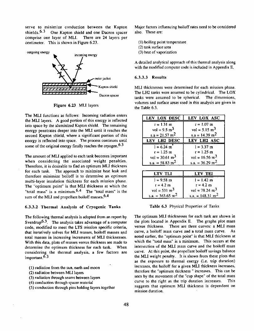
serve to minimize conduction between the Kapton
shields. 6.3 One Kapton shield and one Dacron spacer
comprise one layer of MLI. There are 24 layers per
centimeter. This is shown in Figure 6.23.
outgoing energyincomingenergy
•acket
shield
Dacron spacer
Figure 6.23 MLI layers
The MLI functions as follows: Incoming radiation enters
the MLI layers. A good portion of this energy is reflected
into space by the aluminized Kapton shield. The remaining
energy penetrates deeper into the MLI until it reaches the
second Kapton shield, where a significant portion of this
energy is reflected into space. The process continues until
some of the original energy finally reaches the cryogen. 6"3
The amount of MLI applied to each tank becomes important
when considering the associated weight penalties.
Therefore, it is desirable to find an optimum MLI thickness
for each tank. The approach to minimize heat leak and
therefore minimize boiloff is to determine an optimum
multi-layer insulation thickness for each mission phase.
The "optimum point" is that MLI thickness at which the"total mass" is a minimum. 6"4 The "total mass" is the
sum of the MLI and propellant boiloff masses. 6'4
6.3.3.2 Thermal Analysis of Cryogenic Tanks
The following thermal analysis is adopted from an report by
Sverdrup 6.3. The analysis takes advantage of a computer
code, modified to meet the LTS mission specific criteria,that iteratively solves for MLI masses, boiloff masses and
total masses in increasing increments of MLI thicknesses.
With this data, plots of masses versus thickness are made todetermine the optimum thickness for each tank. When
considering the thermal analysis, a few factors are
important.6.3
(1) radiation from the sun, earth and moon
(2) radiation between MLI layers
(3) radiation through seams between layers
(4) conduction through spacer material
(5) conduction through pins holding layers together
Major factors influencing boiloff rates need to be consideredalso. These are:
(1) boiling point temperature(2) tank surface area
(3) heat of vaporization
A detailed analytical approach of this thermal analysis along
with the modified computer code is included in Appendix E.
6.3.3.3 Results
MLI thicknesses were determined for each mission phase.
The LH2 tanks were assumed to be cylindrical. The LOX
tanks were assumed to be spherical. The dimensions,
volumes and surface areas used in this analysis are given inthe Table 6.3.
LEV LOX DESC LEV LOX ASC
r= 1.31 m r= 1.07m
vol = 9.5 m 3 vol = 5.15 m 3
s.a = 21.57 m 2 s.a = 14.39 m2
LEV LH2 DESC LEV LH2 ASC
I = 6.24 m' I = 3.37 m
r = 1.25 m r = 1.25 m
vol -- 30.61 m 3 vol = 16.56 m3
s.a. = 58.83 m 2 s.a. = 36.29 m2
LTV TLI LTV TEl
1=9.58m 1= 1.42m
r=4.2m r---4.2 m
vol = 531 m 3 vol = 78.24 m3
s.a. = 363.65 m 2 s.a. = 148.31 m 2
Table 6.3 Physical Properties of Tanks
The optimum MLI thicknesses for each tank are shown in
the plots located in Appendix E. The graphs plot massversus thickness. There are three curves: a MLI mass
curve, a boiloff mass curve and a total mass curve. As
noted earlier, the "optimum point" is that MLI thickness atwhich the "total mass" is a minimum. This occurs at theintersection of the MLI mass curve and the boiloff mass
curve. At this point, the propellant boiloff savings balance
the MLI weight penalty. It is shown from these plots that
as the exposure to thermal energy (i.e. trip duration)increases, the boiloff for a given MLI thickness increases,
therefore the "optimum thickness " increases. This can be
seen by the movement of the "cup shape" of the total mass
curve to the right as the trip duration increases. This
suggests that optimum MLI thickness is dependent onmission duration.
48

The resulting MLI thicknesses and corresponding masses foreach tank are summarized in tabular form below:
Tank Thickness
LTV TLI 1.524cm
LEV LH2 des 2.54 cm
LEV LOX asc 12.7 cm
LEV LH2 asc 10.16 cm
LEV LOX des 3.05 cm
LTV TEl 4.57 cm
Mass
161.9 kg
49.41 kg
71.75 kg
118.1 kg
33.72 kg
167.25 kg
Table 6.4 MLI Thicknesses and Masses
For each mission, there are two of each of the tanks listed
above. Therefore, the total MLI mass is:
Total MLI Mass (12 tanks) = 1024.26 kg (2258.5 Ibm)
It should be noted this analysis is a first approach to
determine optimum MLI thicknesses. The values forthicknesses and therefore masses are subject to change as
fuel masses and tank sizing changes.
7.0 CREW SYSTEMS, AVIONICS, AND
POWER
7.1 Crew Systems Introduction
The crew systems group defines the crew needs and develops
the appropriate systems to meet those needs. Crew systems
is responsible for the crew module sizing and design, the life
support systems and environmental control, radiation
protection and the crew functions.
7.1.1 Environmental Control and Life Support
System (ECLSS)
The purpose of the environmental control and life support
system is to provide the basic functions needed to supportlife. These functions include atmosphere revitalization,
control and supply; temperature and humidity control; water
recovery and management; waste management; fire detection
and suppression; food storage and preparation; radiation
protection; and external dust removal.
7.1.1.1 ECLSS Design Considerations
When designing an ECLS system, there are several factorswhich determine the systems that will be placed on the
spacecraft. The crew size and mission duration affect a
number of systems. The amount of consumables needed,
the power requirements, hardware design and vehicle mass
are all areas that depend on these parameters The mission
location determines the availability of resupply and the
degree of spacecraft self-sufficiency. It also determines the
degree of mass loop closure needed. Finally, to satisfy the
mission requirements, the system must be designed to have
component commonalty, reusability and cost efficiency.
7.1.1.2 Mass Loop Closure
Mass loop closure deals with water and oxygen (02)
recovery. The degree of closure depends on the crew size,mission duration and the availability of resupply. Table
7.1 compares several levels of closure and the mission
duration supported for the type of closure.
Level of Type of MissionClosure Closure Duration
Closed
Partially Closed
Open
closed except
for losses (e.g.
leaks)utilizes
regeneration
techniques toreduce
expendablesall masses
brought along
or resupplied
(no reuse)
permanentbases
weeks
days
Table 7.1
Mass loop closure comparison
Closing the loop reduces the amount of consumables thatmust be brought along; however, reclaiming water and 02
from waste products requires special equipment. Closing
the loop only becomes cost effective when weight savings
can be accomplished with the closure.
Both the LEV and LTV will utilize a open loop system for
several reasons. The mission length is on the order of six
days for the LTV and a matter of hours for the LEV in
normal operations. A crew of six requires a relatively smallamount of consumables for these mission durations. The
LEV and LTV will undergo servicing and resupply at SSF
between each mission.
7.1.1.3 Crew Consumable Requirements
For the crew to survive in the space environment, certain
needs must be met. Oxygen, water and food must be
supplied. A human can survive for only 4 minutes without
49
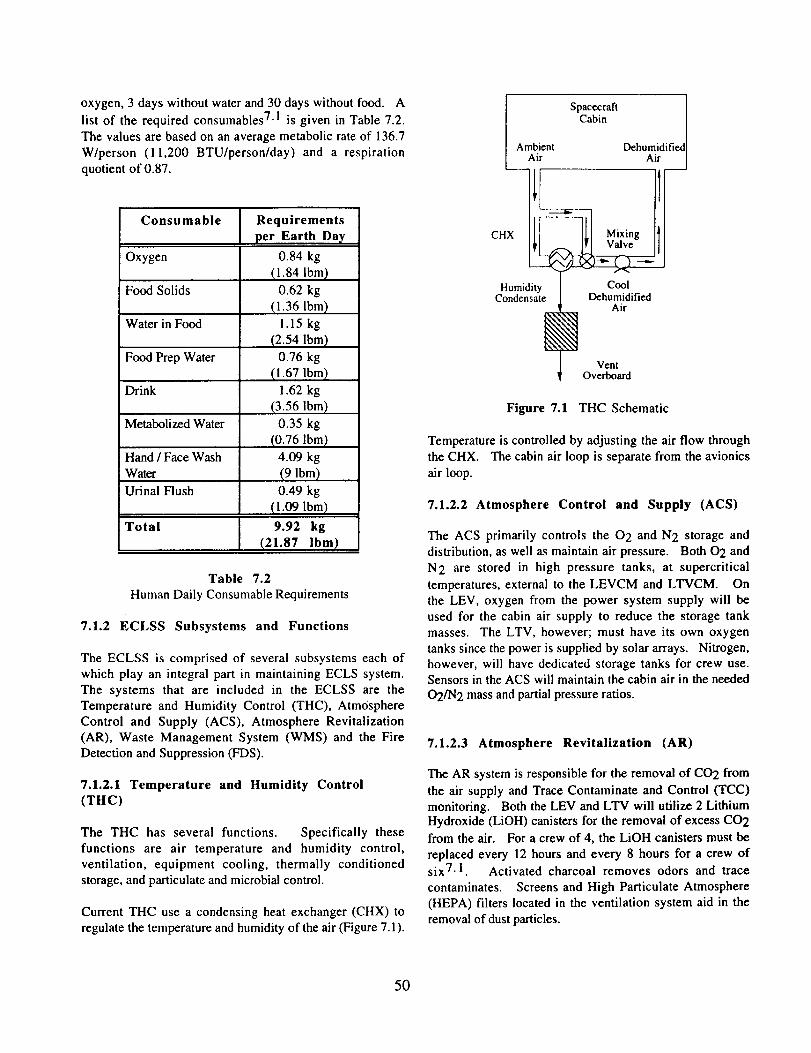
oxygen, 3 days without water and 30 days without food. A
list of the required consumables 7"1 is given in Table 7.2.
The values are based on an average metabolic rate of 136.7
W/person (11,200 BTU/person/day) and a respiration
quotient of 0.87.
Spacecraft 1
Cabin
Ambient Dehumidifie
LAir Air ___J
Consumable ] Requirementsper Earth Day
Oxygen
Food Solids
Water in Food
Food Prep Water
Drink
Metabolized Water
Hand / Face Wash
Water
Urinal Flush
Total
0.84 kg
(1.84 Ibm)
0.62 kg
(1.36 Ibm)
1.15 kg
(2.54 Ibm)
0.76 kg
(I.67 Ibm)
1.62 kg
(3.56 Ibm)
0.35 kg
(0.76 Ibm)
4.09 kg
(9 Ibm)
0.49 kg
(1.09 Ibm)
9.92 kg
(21.87 lbm_
Table 7.2
Human Daily Consumable Requirements
7.1.2 ECLSS Subsystems and Functions
The ECLSS is comprised of several subsystems each of
which play an integral part in maintaining ECLS system.The systems that are included in the ECLSS are the
Temperature and Humidity Control (THC), Atmosphere
Control and Supply (ACS), Atmosphere Revitalization
(AR), Waste Management System (WMS) and the Fire
Detection and Suppression (FDS).
7.1.2.1 Temperature and Humidity Control(THC)
The THC has several functions. Specifically these
functions are air temperature and humidity control,
ventilation, equipment cooling, thermally conditionedstorage, and particulate and microbial control.
Current THC use a condensing heat exchanger (CHX) toregulate the temperature and humidity of the air (Figure 7.1).
CHX
HumidityCondensate
Y- tL]__Y Valve ---,.
CoolDehumidified
Air
VentOverboard
Figure 7.1 THC Schematic
Temperature is controlled by adjusting the air flow through
the CHX. The cabin air loop is separate from the avionics
air loop.
7.1.2.2 Atmosphere Control and Supply (ACS)
The ACS primarily controls the 0 2 and N 2 storage and
distribution, as well as maintain air pressure. Both 02 and
N2 are stored in high pressure tanks, at supercritical
temperatures, external to the LEVCM and LTVCM. On
the LEV, oxygen from the power system supply will be
used for the cabin air supply to reduce the storage tank
masses. The LTV, however; must have its own oxygen
tanks since the power is supplied by solar arrays. Nitrogen,
however, will have dedicated storage tanks for crew use.Sensors in the ACS will maintain the cabin air in the needed
O2/N2 mass and partial pressure ratios.
7.1.2.3 Atmosphere Revitalization (AR)
The AR system is responsible for the removal of CO2 from
the air supply and Trace Contaminate and Control (TCC)
monitoring. Both the LEV and LTV will utilize 2 LithiumHydroxide (LiOH) canisters for the removal of excess CO2
from the air. For a crew of 4, the LiOH canisters must be
replaced every 12 hours and every 8 hours for a crew ofsix 7.1. Activated charcoal removes odors and trace
contaminates. Screens and High Particulate Atmosphere
(HEPA) filters located in the ventilation system aid in the
removal of dust particles.
50

7.1.2.4 Waste Management System
The waste management system encompasses four types of
waste products. The metabolic wastes consist of moistsolids, i.e. feces and vomitus, and urine. Other solid wastes
are generally paper and plastic products. The sourcesinclude fax machines and food containers. Liquid wastes are
produced by water processors, perspiration and hygienewater. Gaseous wastes are generally produced by
respiration. These gases include CH4, H2S, H2, CO, and
CO2.
Several systems are needed to remove the different waste
products from the environment. A Waste Management
Facility (WMF) or commode can be used to collect,
dehydrate and store feces until the system can be serviced.The commode also collects urine which is vented overboard.
The commode can be unreliable; therefore, fecal bags are
used as a backup. The waste products in the used bags are
mixed with a biocide to prevent the growth of
microorganisms. The bags are then stored and disposed of
at the end of the mission. The LTVCM will have a
commode, similar to the space shuttle's (Figure 7.2), as the
primary metabolic waste disposal system, with fecal bags as
the backup. The weight constraints on the LEVCM
prevent the use of a commode. However, stay times on theLEVCM will be on the order of a few hours in normal
operations. The crew pressure suits are capable of
collecting the waste products. In abort scenarios, the
primary system of waste collection on the LEVCM will be
fecal bags.
t,t,
products are easily removed from the vehicles when they areserviced in LEO.
There are several options for the disposal of liquid wastes.
Water residues from perspiration that enter the air can be
removed by the Temperature and Humidity Control (THC)
system. Depending on the amount of hygiene water, thewaste can be vented overboard if the amount is small, or
collected and removed during servicing for larger amounts.
Other liquid wastes will be stored and removed at servicing.
Several processes can be used to remove gaseous wastesfrom the air. For short missions, CO2 is commonly
removed from the air by lithium hydroxide (LiOH) canisters.
The process is non-reversible and the canisters must be
replaced periodically. Other gaseous wastes be removed bythe Trace Contaminate Control Assembly (TCCA).
7.1.2.5 Fire Detection and Suppression (FDS)
The FDS system uses sensors located in the cabin andavionics air return lines to detect smoke particulate. If afire is detected, the FDS releases stored CO2 to suppress the
fire.
7.1.2.6 Atmosphere Composition
Historically, spacecraft atmospheres have consisted either of
100% oxygen (i.e. Mercury, Gemini and Apollo) or an
oxygen and nitrogen mixture (i.e. Skylab and the Shuttle).
The most important air constituent in determining aircontent is oxygen (02).
There are several requirements for determining the 02 levels.
For long durations, the partial pressure of 02 must be
maintained above 3.0 psi. and the total pressure above 8 psi
for normal functioning crew members. A pure oxygenenvironment can be tolerated at low total pressures (3.75 to
7.3 psia). However, there is a considerable fire hazard inthese conditions. To reduce the risk of fire, a
physiologically inert gas is combined with the oxygen toincrease the cabin total pressure while maintaining the
partial pressure of oxygen around 3 psia.
The partial pressure of oxygen is crucial to the crew's health.Table 7.3 indicates the.effects of reduced 02 partial
pressures.
Figure 7.2 Space Shuttle WMF 7"5
On both the LEVCM and LTVCM, other solid wastes will
be collected, packaged and stored onboard. The waste
51

OxygenPartial
Pressure
(psia_
Effect
3.1 Normal sea level atmospherelevel
2.7
2.2
1.9
1.6
0-0.89
Accepted limit of alertness. Loss
of night vision. Earliest
symptoms of dilation of the
pupils.
Performance seriously impaired.Hallucinations, excitation,
apathy.
Physical coordination impaired.Emotionally upset, paralysis,
loss of memoo'.Eventual irreversible
unconsciousness.
Anoxia. Near-immediate
unconsciousness, convulsions,
paralysis. Death in 90 to 180seconds.
Table 7.3
Effects of Reduced 02 Partial Pressure
Oxygen partial pressures between 3.1 psia (normal sea level)
and 6 psia can also be undesirable. In this partial pressure
range, a oxygen toxicity (hyperoxia) occurs. The
symptoms are generally respiratory (inflammation of lungs,
various heart symptoms). At PO2 around 5 psia changes in
red blood cell fragility and permeability have been reported at
long periods of exposure 7'3.
Other considerations in the design of the spacecraftatmosphere are the carbon dioxide (CO2) and carbonmonoxide (CO) levels in the air. Excess CO2
concentrations (3% and higher) can cause chronic CO2
toxicity which is characterized by changes in blood pressure,pulse or temperature. The characteristics generally
normalize after about a month of breathing normal air.
Carbon monoxide is particularly dangerous because it is
odorless, colorless, and the symptoms of CO toxicity are
not readily noticeable. The ECLSS maintains CO
concentrations at acceptable levels.
The current design approach for manned spacecraftatmospheres is the use of a standard sea level atmosphere.This is done for several reasons. The combined O2-N2
atmosphere significantly reduces the risk of a fire. Also,
the higher internal pressure of 14.7 psia reduces the mass of
the power system by improving the convectioncharacteristics. Finally, experiments do not have the added
complication of nonstandard pressure or atmospheric
composition.
Both the LEVCM and the LTVCM will have a standard
atmosphere for most on-orbit operations. Table 7.4
indicates the standard partial pressures of a sea level
atmosphere.
Parameter Standard Sea Level
Values
kPa psia
Total Pressure 101.36 14.7
Oxygen Partial 21.37 3.04Pressure
Nitrogen Partial 78.6 11.44Pressure
Water Vapor Partial 1.38 0.2Pressure
Carbon Dioxide 0.04 0.0058
Partial Pressure
Table 7.4
Standard Sea Level Partial Pressures
It will be necessary to introduce a 100% 02 and
approximately 5 psia environment on the LEVCM for pre-
EVA operations to prevent decompression sickness (seesection 7.1.7). The reduced pressure environment will be
initiated after the LEV landing and will continue through
EVA suit donning and vehicle exit.
7.1.2 Crew Module Design Considerations
When designing a crew module, several factors must beconsidered to make the module and the crew functional in its
environment. The modules purpose and functionality, theuser and the environment it is operated in must all be taken
into account during the design process.
The primary consideration is modules purpose. The primary
purpose of the LTVCM is to transport the crew from LEOto LLO and return. The LEVCM has several functions.
First, it serves as a transport vehicle between SSF and the
LTV. Second, it transports the crew between LLO and the
Lunar surface. Finally, in an abort situation, it must be
capable of providing life support to the crew until the Lunarsurface can be reached.
52

Theuserpopulationofthemoduleneedstobeconsideredinthe initial designphases.Becauseof the internationalcooperation(JapanesetoEuropeansandAmericans)thatwillbenecessarytosupportaLunarbaseandbewiderangeofpeople(scientiststopilots)thatarelikelytotravelthere,themodulesmustbedesignedto accommodatea varietyofpeople.Designlimitsarebasedonthe5thpercentiletothe95thpercentileof theuserpopulation.Forthepurposesofdefininglimitingsizesof thepopulation,NASAprovidesinformation7.3onthebodysizesof the5thpercentileofAsianJapanesetothe95thpercentileoftheAmericanmale.
Another consideration is the environment the module will be
operating in. The LTV operates only in a microgravity
environment; while the LEV operates in the microgravity of
space, as well as, the 1/6th gravity environment of the
Lunar surface. On the LTV, placement of stowage and
equipment are not limited by the crew members reach.
However, the body assumes a neutral body position (joints
bend slightly) in a microgravity environment. A
workstation positioned at a comfortable waist level in a
gravity environment is not necessarily in a comfortable towork at in a microgravity environment.
7.1.3 LTV Crew Module
The LTVCM is designed to support a crew of 6 for the
transit between LEO and LLO. All life support systems on
the LTVCM are independent of the LEVCM. In the event
of a system failure, the LEV can take over life supportfunctions.
7.1.3.1 Dimensions and Structural Mass
A Space Station Common Module (SSCM) is used for the
LTVCM. By using a module that is already in production,costs are minimized. Also, much of the hardware used on
future Lunar missions (i.e. FLO) scenarios is developed forthe SSCM.
The external dimensions of the LTVCM are shown in
Figure 7.3. The modules outside diameter of 4.42 m (14.5
ft) is determined by the maximum diameter that the Space
Shuttle payload bay is capable holding (SSF modules will
be deployed by the shuttle). A length of 5 m (16.4 It) was
determined to be adequate for the mission. The 5 m length
gives ample room to carry out in transit experiments and
provides relatively comfortable living space.
5.0 m
4 422 m
Figure 7.3 LTVCM External Dimensions
The structural mass of the module was determined from
SSCM data 7"4. The mass of the primary structure is 3712
kg (8184 lb) and the mass of the secondary structure is 1657
kg (3653 lb). Appendix F gives a breakdown of the
primary and secondary structural components and masses.
7.1.3.2 Internal Layout
The usable internal dimensions of the module are given in
Figure 7.4. All four sides of the module contain racks
1.016 m (40 in) deep. The racks provide structural support
to the module cylinder and contain the systems which will
be used in the module (i.e. galley, science station, ECLSS).
A 0.1016 m (4 in) space is provided between the racks and
the module wall for plumbing. The usable width and
length of the module are 2.19 m (7.19 ft) and 4 m (13.12
ft), respectively.
I1.016 m
J
I1.016 m
l
4.00 m
Figure 7.4 LTVCM Internal Dimensions
The placement of internal components is shown in Figure7.5. The science station was placed opposite the galley and
WMF to better distribute the weights along the x-axis of the
module. The WMF was placed on the module end opposite
of the galley to reduce the chance of bacteria spreading. Thepersonal hygiene station was placed next to the WMF for
53

the same reason. A systems interface panel was added toallow the crew members to control certain functions of the
module (i.e. temperature) and to display systems status to
the crew. Stowage is provided in several locations
throughout the module.
Stowage Stowage Science StationLockers Lockers
_ Stowage._'= GalleyWMF _,_ _ Lockers
Figure 7.5 LTVCM Component Layout
The science station will carry crew oriented and autonomous
experiments that will be carried out throughout the mission.Several hours of the crews schedule is set aside for
performing experiments during the transit. The autonomous
experiments can be run in transit and also in LLO while the
crew is on the surface. These experiments offer an advantage
over SSF since the LTV will provide a stable platform in
microgravity, free of crew disturbances. The science station
experiments will be a modular design so that they can be
readily swapped for other experiments during LTS servicingin LEO
The galley serves as a food preparation facility. It containsareas to store the food, meal accessories, tray and food related
trash. The oven can heat meals for up to seven persons in
approximately 90 minutes. A diagram of the galley is
given in Figure 7.6. 7.5
Figure 7.6 Space Shuttle Galley 7-5
7.1.3.3 LTV Consumable Requirements
The consumables for the LTVCM include food, water, 02
and N2. The mass of the consumables depends on trip
duration and crew size. Trip time is considered to be 6 days
with a 48 hour contingency. The number of crew members
is assumed to be 6 (for steady state operation).
Each crew member requires 0.62 kg (1.36 Ib) of food per day
which is provided in snacks and three meals for each normal
day in transit. The food consists of individually packaged
re-hydratable items.
The water requirements for the crew members are 15 kg
(33.1 Ib) per person per day. The water will be used for
food preparation (rehydration), drink, hand and face washwater and urinal flush. Water for the LTV must be brought
along from LEO since the power system utilizes a solar
array instead of fuel cells which create water. The water willbe stored in tanks external to the crew module. The crews
water requirements are 720 kg (1587 lb) for normal
operations and contingency. The science station may also
require a water supply; therefore, 280 kg (617 lb) has beenincluded in the mass estimates. The total LTV water
requirements are 1000 kg (2204 lb).
Oxygen and nitrogen requirements are not only based on the
amount needed for metabolic purposes, but also on the
54

internalvolumeandnumberof repressurizations. For the
analysis it was assumed that the LTVCM would undergo 6repressurizations. This gives a total 02 mass of 200 kg
(441 Ib) and N2 mass of 650 kg (1433 lb).
7.1.3.4 LTVCM Power Requirements andVehicle Total Mass
The average power required for the ECLSS and internal
components is 3.1 kW. The total wet mass of the LTVCM
is 9809 kg (21625 lb). A detailed breakdown is given in
Appendix G.
7.1.4 LEV Crew Module
The LEVCM supports a crew of six for both descent and
assent operations to the Moon. It also serves as a transfer
vehicle between SSF and the LTV during normal operations.In the event of an LTV ECLSS failure or an abort due to the
NTR, the LEVCM is capable of providing primary life
support to the crew.
7.1.4.1 Dimensions and Structural Mass
Like the LTVCM, the LEVCM also utilizes the SSCM.
The exterior dimensions (diameter and length) of the module
are the same as the LTVCM (see Figure 7.3). The mass of
the primary structure is 4278 kg (9431 lb). The mass of the
secondary structure is 1657 kg (3653 lb). Appendix H givesa detailed breakdown of the structural masses.
7.1.4.2 Internal Layout
The dimensions of the internal usable space on the flight
deck and dust containment deck (DCD) are 2.2m by 2.2m
(7.22 ft by 7.22 ft). These dimensions were determinedfrom the internal diameter of the module (4.22 m) and the
rack depth (1.016 m). The usable length of the module is 4
m (13.1 ft). The height of the dust containment deck was
chosen to be 2.10 m (6.9 ft) so that a crew member would
be able to'comfortably stand in the DCD while donning an
EVA suit. The height of the flight deck is 1.75 m (5.74
ft). This was deemed adequate since crew will be in a
microgravity environment or seated for the majority of the
time they occupy the flight deck. Once on the Lunarsurface, the crew can move into the DCD.
0.15 m
2.10mI
Dust ContainmentDeck
11.75 m
Figure 7.7 LEVCM Internal Dimensions
Figure 7.8 depicts the layout of the flight deck. The
Commander (CDR) and Pilot (PLT) each have a side panel
containing system interfaces. The side panels give both the
CDR and PLT assess to system function controls with
minimal movement. The side panels are also less likely to
be bumped, inadvertently changing switch positions, when
crew members are entering or exiting their seats. The panels
directly in front of the CDR and PLT contain the CRTs for
monitoring the functioning of various systems, as well as,
screens which will display images from the externallymounted video cameras.
Figure 7.8 LEVCM Flight Deck Layout
55

The Mission Specialists' (MS) seats (Figure 7.9) were
rotated 90 degrees to allow for more leg room and easier
mobility in the 1/6 g environment of the Moon. The MS
seats are removable and can be folded to a height of 0.28 m
(11 in) for stowage (Figure 7.10). The seats can easily be
stored in lockers while on orbit to give more room in the
LEVCM. Before undocking from the LTV, the seats can be
secured in place for the Lunar descent. On the surface, it
may be desirable to remove the same seats from the flight
deck and place them in the airlock area for use in the EVA
suit donning.
743 :iiuii;iP:ii i:i!!itlFigure 7.9 Mission Specialist Seat 7-5
Consumables for the LEVCM are considerably less than the
LTVCM in normal operations. In the event of an abortfrom the LTV, the LEVCM must be able to sustain a crew
of 6 for up to 3 days. The LEVCM will carry 7.44 kg
(16.4 ibm) of food, enough for one meal per crew member.
The meals can be rehydrated with a small water dispenser
(Figure 7.12) located on the flight deck. The water
dispenser will draw water from a storage tank used to collectthe fuel cell water.
Figure 7.10
Mission Specialist Seat in Stowed Position 7"5
The pilots seats (Figure 7.11) are permanently mounted tothe LEVCM floor. The Rotational Hand Controller (RHC)
used to fly the vehicle is mounted onto the seat frame. For
both the MS and PLT, a portable life support system can be
attached to the seat. This life support system is used by the
crew members while in pressure suits.
56

Figure 7.12 Water Dispenser 7"5
The 02 and N2 supplies allow for 3 days of normal use with
24 hours as a contingency and 6 repressurizations. The
total mass of consumables for the LEVCM is 943.5 kg
(2081 Ib). A breakdown of consumable masses is given in
Appendix H.
7.1.4.5 Power Requirements and Total VehicleMass
The LEVCM power requirements are considerably less thanthose of the LTVCM. The ECLSS system consumes most
of the LEVCM power needs. A vacuum located in the DCD
used during EVA activities and a water dispenser located on
the flight deck for aborts and Lunar activities both use a
small amount of power. The average power requirement for
these systems is 2.8 kW. The total wet mass of the
LEVCM is 9360 kg (20635 lb). A breakdown of the power
requirements and masses are given in Appendix G.
7.1.5 Radiation
The two types of radiation that the crew will be exposed to
in space flight are Ionizing and Non-Ionizing Radiation.
Non-Ionizing Radiation (NIR) is generally not energetic
enough to break molecular bonds. Most of the NIR that
the crew would be exposed to comes from within the
spacecraft from sources such as communications and
electronic equipment, lasers etc. Ionizing radiation breakschemical bonds within biological systems. The effects are
dependent on the radiation type (e.g. gamma, X-ray,electron) and magnitude as well as the tissue effected.
Sources of ionizing radiation are naturally and artificially
generated. The three main sources of natural radiation are
geomagnetically trapped radiation; galactic cosmic radiation
(GCR); and solar particle event radiation (SPE). Artificial
sources occur from on-board electric power sources such as
radioisotopes and nuclear reactors, small radiation sources
and induced radioactivity.
7.1.5.1 Definition of Terms
Dose (D):
• The amount of radiation energy absorbed by the tissue.• Common unit of measure is the rad
(! rad = 100 ergs/g of material)
• SI unit is the gray (Gy); 1 Gy = 100 rads
Linear Energy Transfer (LET):
• The rate of energy dissipation along the path of a charged
particle.•Units are keV/I.tm
Quality Factor (Q):
•An artificial factor dependent on the LET of which
biological effects from absorbed doses may be related to x-
and gamma radiation (how much biological damage) havingunits which are non-dimensionalized
•Values are based on the most detrimental biological effects
from continuous low dose exposure. Values for many high
rate exposures may be considerably lower
Dose Equivalent (DE)
•The amount of biologically damaging ionizing radiation
•Common units of measure are rein (roentgen equivalent
man)•SI unit is sieviert (Sv) where 1 Sv = 100 rem
•DE = D X Q (dose times quality)
Relative Biological Effectiveness (RBE)
•Nondimensional parameter related to but different from Q.
•Based on experimentally determined effects of different types
of radiation on biological systems
7.1.5.2 Radiation Exposure Limits
Radiation exposure guidelines have been established to
define how much ionizing radiation a person can be exposedto. Tables 7.5 and 7.6 describe the short term dose
equivalent limits and career limits for protection againstnon-stochastic effects.
Time
Period
Skin
(Sv)BFO* Lens
(Sv) of Eye
(Sv)
0.25 1.0
0.50 2.0
4.0
30 day 1.5
Annual 3.0
Career see 6.0Table 7.6
*Blood Forming Organs (BFO) denotes the dose
at a depth of 5 cm (1.97 in).
Table 7.5
Short Term Dose Equivalent Limits
57

Age Female
(years) (Sv)
25 1.00
35 1.75
45 2.00
55 3.00
Male
1.5
2.5
3.2
4.0
Table 7.6
Career Whole Body Dose EquivalentLimits
The limits in Table 7.6 are based on a 3% lifetime excess
risk of cancer mortality.
7.1.5.3 Radiation From NTR
To determine if any radiation shielding is necessary, the
amount of radiation exposure must be estimated. It wasdetermined that the crew can expect to receive 5.48 rems per
mission (2.74 rems per transit leg) from the NTR. 7"6 This
figure assumes that the center of the crew module is 46.8 mfrom the center of the reactor core and that the BATH
radiation shield is in place. The amount of background
radiation (GCR) at an altitude of above 38000 km with no
shielding is 57 rems per year. This equates to
approximately 1 rem per mission. The combined radiationlevels due to the NTR and GCR for a 3 day transit to or
from the Moon is 4 rems. This level of radiation exposure
falls well within the NASA guidelines of 25 rems in a 30
day period.7.2
To reduce truss weight, it is desirable to decrease the distancebetween the crew module and the center of the core. It was
determined that the radiation level is inversely proportional
to the square of the distance. Using a separation distance of46.8 m and radiation dosage of 5.48 rems, a multiplier of
12000 was calculated. This gives the following equationfor the variation of radiation with distance for the LTS NTR:
12000Re ms -
r 2
This formula with a length of 33 m gives a missionradiation level of 11.02 rems. For the three day trip to the
Moon, the total radiation level is approximately 6.5 rems.The combined radiation dosage due to the background
radiation and the NTR radiation per mission is
approximately 13 rems. Exposure levels on the lunarsurface should be minimal since the habitation module will
be buried in the regolith for radiation shielding. These
radiation levels again fall within the NASA guidelines for
both the 30 day and 1 year exposure limits.
7.1.5.4 Types of Radiation Shielding
To protect the crew from radiation overexposure, radiation
shielding must be used. Electromagnetic shielding deflects
the charged particles. This type of shielding is impracticaldue to its weight and power requirements. Chemical
protectors involve injecting chemicals into the blood.
These protectors have adverse side effects, only protect
against low LET radiation and have only been successfullyused on animals.
Mass shielding offers the best means of protecting the crew
from radiation overexposure. With mass shielding, the
structure provides protection from radiation. The outer skin
of the spacecraft and associated structural elements can be
used as a radiation shield. Strategically placing massive
internal components can also increase radiation protection.
However, this method only provides protection in certain
directions.
There are a number of materials that provide radiation
shielding. Aluminum provides good radiation protection
for all types of radiation. Polyethylene has good protection
for electron radiation and lead protects against bremBtrahlung
or high power radiation.
7.1.5.5 Radiation Shielding Recommendations
The NTR has two radiation shields included in the design.
The internal shield primarily protects the turbomachinary.
The external shield, located between the NTR and the truss
(Figure 7.13), provides radiation protection for the crew.The external shield is made of Borated Aluminum Titanium
Hydride (BATH). The shield is 2.54m (8.3 ft) in diameter,0.186m (7.3 in) thick and weighs 4t.
58

EXTEF_U_
RADIATION_
SHIELD
(4.5 roT)
tTo CM
TrusII
0..186 rn thick
J2.54 n diameter
NERVA
DERIEVED
REACTOR
(&5 mT incl. nc_dc)
NOZ21E
Figure 7.13BATH Radiation Shield Location
Additional radiation shielding is provided by massive objects
placed between the radiation source and the crew member.The end cones and standoff structure of the LTVCM will
provide some shielding from NTR radiation.
The LEVCM can serve as a storm shelter in the event of an
in transit SPE. The pre-descent LEV is surrounded by LOXand LH2. This provides an ideal mass shield. The LTV
could also be reoriented so that the X axis is aligned with
the radiation source (the sun). This will allow themaximum amount of mass to absorb the radiation before it
reaches the crew.
7.1.6 Lunar Dust
A special consideration in the design of the LEVCM were
problems with the lunar dust. There are severalcharacteristics of lunar dust that make it especially difficult
to control. Electromagnetic potential causes the dust tolevitate near the terminator and the dust has sharp edges
which dig into the surfaces it comes into contact with,
making it harder to remove.
Dust containment on the LEV is important for two reasons.
First, unlike Apollo, the LTS is reusable. The internal
components must be protected from contamination whichmay reduce there usable life span. Second, the LEV serves
as the transfer vehicle between the LTV and SSF. The
integrity of the experiments on SSF could be jeopardized ifLunar dust were to enter the air supply.
To contain the dust from the surface, the LEVCM utilizes a
Dust Containment Deck (DCD). The crew will don and doff
the EVA suits in this area. Upon returning to the vehicle,
the crew will doff there suits and remove as much dust as
possible with a small vacuum located in the DCD. Thecrew will then enter the flight deck and seal the hatch
between the two decks. The hatch will remain sealed until a
more thorough cleaning can take place during servicing.Another method the crew will use to prevent LEV dust
contamination is overalls worn over the EVA suit. The
overalls will be removed and stored immediately prior to
entering the LEV. The overalls will not only prevent dust
from entering the vehicle, but will also help preventexcessive wear on the suits from the dust.
7.1.7 Decompression Sickness
Decompression sickness can result if the change in pressure
(from cabin pressure to the EVA suit pressure) is rapid
enough and has a large differential. The most common
symptom of decompression sickness is the bends. Thebends is characterized by extreme pain in the joints when it
is being flexed. It usually begins in the tissue around the
joints and extends along the bone shaft. The chokes is thenext most common symptom. The chokes are characterized
by chest pain, cough and respiratory distress. The chokes
generally requires longer altitude exposure then required forthe bend.
Decompression sickness is impossible to predict. However,
if the supersaturation ratio (partial pressure of N2/total
barometric pressure) exceeds 1.22 there is a risk of
decompression sickness. Several factors can cause increasedsusceptibility to decompression sickness; obesity, very cold
temperatures, exposure to compressed air breathing within
24 hours of decompression, age, physical exertion and
injuries.
7.2 Avionics Introduction
In order to reach its destination, the LTS must have a
system of avionics. This system will entail a set ofsubsystems that include communications, GN&C, and data
management. Failure of any of these systems can lead to a
major mission catastrophe.
7.2.1 Avionics Requirements
A primary requirement of the LTS avionics is that it be
useful for both piloted and unpiloted missions. All
59

subsystems must be controllable by both pilots and groundcontrollers.
The avionics will also be required to be largely redundant.
A failure will still permit the LTS to function smoothly.
Too guard against faults, much of the avionics will have
multiple redundancy.
Subsystem avionics will be nearly identical on each crewmodule. The LTV will contain the main avionics because
that module will be the CM for steady-state operations.
The LEV will only be used for the lunar descent and ascentand in case of LTV failure.
7.2.2 Communications
Communications with the spacecraft are vital for mission
success. Communication is more than just audio andvisual interaction. It also includes commands to the crew,
commands to the hardware on the spacecraft, and tracking.
7.2.2.1 Communication Bands
Two communication bands will be used throughout theseLunar missions. The first will be the Ku-band. The
frequencies of the Ku-band are between 12 and 14 GHz. 7"7
This will be the primary band used for all communication.
The second band is the S-band. It operates near the 2
GHz 7-7 frequency range. Although the S-band will be used
primarily as a back-up, it will also be used for some routinecommunication.
The Ku-band is selected as the primary communication band
because of its high frequency. Signals sent on high
frequencies have lower power requirements than those sent
on lower bands. However, signals sent to Earth on high
frequencies tend to dissipate in bad weather near ground
stations. In severe weather, signals can be completely
dissipated. Lower frequencies can withstand inclement
weather. That is the reason for selecting the S-band as a
communications backup. The disadvantage in these lower
frequencies is the higher power requirements. 7"7
7.2.2.2 Tracking and Data Relay Satellite
System (TDRSS)
The TDRSS is an existing system of satellites designed to
track and relay data to and from vehicles in space. This also
includes orbiting satellites. It can operate on most
frequency bands, but mainly utilizes the Ku and S bands. 7"8
TDRSS uses three ground stations around the earth to assist
in its operation. Their locations are in Goldstone,California; Canberra, Australia; and Madrid, Spain. 7"9
7.2.2.3 Advanced Tracking and Data Relay
Satellite (ATDRSS)
The ATDRSS uses the same concept as the TDRSS onlymore advanced. The communication bands of the ATDRSS
will remain the Ku and S bands. The specifics of the
ATDRSS are still being studied. NASA does not know if
it will merely add on to or create a whole new system to
replace the existing TDRSS. 7'10 Nevertheless, at the time
of these lunar missions, the ATDRSS is scheduled to be in
place.
7.2.2.4 Antennae
Several antennae will be used by the LTS. Two main
antennae, in particular, will be utilized, one carrying Ku-band and the other S-band. Both steerable antennae will be
attached to the LTV. The antennae will send and receive the
bulk of the communications necessary for the LTS.
To assist the main antennae, several omnidirectional
antennae will be placed on each crew module. These are not
steerable. They are placed on the surface of the crew
modules such that communications can be sent in anydirection from each module.
On the lunar surface, erectable, or possibly semi-permanent,
antennae will be in place. These can be erected by the first
crew to the lunar surface. These type of antennae will beused for main communications while on the lunar surface.
7.2.2.5 Video Cameras
Several video cameras will be placed on the LTS. Two will
be placed on the LTV for docking assistance. Another pair
will be placed on the LEV for lunar landing assistance.
Additionally, there are six other cameras on the LTS. Eachmodule has one internal camera similar to that carried on the
shuttle. These cameras will show what is going on inside
the crew modules. The remaining four cameras are on theLEV's lander truss. The truss mounted cameras will
provide pictures of the landing area for the crew and ground
stations. Each of these cameras have a pan/tilt unit.Thus, the cameras can be moved at will.
7.2.3 Guidance, Navigation, and Control
(GN&C)
Guidance of the spacecraft is necessary to ensure the that it
reaches its destination. Navigation accurate to within a
small error is made easier with GN&C equipment, such as
gyroscopes, accelerometers, and sensors.
60
7.2.3.1 Hexad Navigation Unit
Gyroscopes, accelerometers, and IMU's are normally used forGN&C. However, a new product has been created. It is the
Hexad Inertial Navigation Unit, commonly referred to as justHexad. It contains a set of laser-ring gyroscopes,
accelerometers, and IMU's all in one unit. 7"11 This unit
will provide improved navigation over individual pieces of
equipment.
Gyroscopes measure the vehicle's angular rates of the about
predesigned axes. These measurements are then sent into an
onboard computer for processing. 7"11 In the Hexad, laser
ring gyros replace traditional gimbal gyros. A laser ring of
light provides a closed path, or loop. Two counter-rotating
laser beams circulate in this ring. When the gyro is rotated
the path lengths for the beams change, one becomes longerwhile the other becomes shorter. This causes a phase shift
in the beams. When the shifted beams are combined the
phase difference describes the rate of rotation. 7"7
Accelerometers measure normal and lateral acceleration.
These are used for flight control calculations. These
measurements are also sent to the flight computer. 7" 11
IMU's supply the vehicle with attitude and acceleration data.
IMU's are normally installed on a rigid, structural beam. 7" I 1
The Hexad is a new piece of equipment. It is not space
rated at this time. 7" 11 It is assumed to be space rated by
the time these missions are ready to commence.
7.2.3.2 Star Trackers
Star Trackers are sensors that assist in navigation by
aligning themselves with select stars. These sensors are
supplied with a "star catalog" software program to determinewhere certain stars are and to identify them. They measure
changes in the vehicle motion relative to these stars. 7-7
Early Star Trackers had to select certain stars from all visible
stars. This also required astronaut expertise of constellation
and star recognition. Current Star Trackers block out distantstars or stars with small light output. They also have
shielding to protect themselves from the intensity of the sun
as it is too bright for this instrument. 7"7
7.2.3.3 Sun Sensors
Sun Sensors are another type of sensor that assists
navigation. They "see" where the sun is. These sensors
measure angles that the sun makes in body coordinates. Sun
Sensors, along with Star Trackers, are used to calibrate theIMU's inside the Hexad. 7"7
7.2.3.4 Landing and Docking
Landing and docking will be assisted by three items. The
first two, radar and lighting, have been used extensively in
the past. Radar works like a homing device and can tellhow close a vehicle is to its intended target. Video cameraswill also be used. These will assist a great deal in
minimizing time and fuel consumed for landing and docking
operations. With this equipment, automatic docking may
be possible. Currently, only the former Soviets have
accomplished automatic docking.
7.2.4 Data Management
Data management is a set of hardware which stores and
retrieves data for any subsystem on a spacecraft. Most data
used is by the GN&C. Data can be sent from anywhere viacommunication links, sensors, guidance equipment, crew
commands, computer software, and other computer
hardware.7.11
7.2.5 Crew Interface
Though the crew will have a large amount of electronics towork with, this design focuses only on what the pilots will
use. The pilots will have a set of instruments that willinclude video displays of the landing area, video controllers,
Rotational Hand Controllers (RHC), keyboards, and warning
lights.
7.2.5.1 Glass Cockpit
To make the flight as easy as possible, CRT screens will beinstalled on each flight deck. These screens will be used to
show normal flight operations, display information entered
from the keyboards, and to communicate with the crew inthe event of audio blackout. The most important advantage
will be the ability to instantly inform the crew in the case of
a system failure or similar problem
7.2.5.2 Video Control
Also available to the crew will be another set of screens
which will be able to display any available camera angle.Ground stations will have similar control for unpiloted
missions.
61

7.2.6 Avionics Summary 7.3. Power System Introduction
Lists of all the avionics for the LTS are contained in the
Appendices. Appendix I details the LEV's avionics.
Appendix J describes the LTV's avionics. Masses for each
LTS avionics subsystem are listed in Table 7.7.
Subsystem
Communication
GN&C
Data Manase.
LEV Mass
(kg)
LTV Mass
(kg)
157.4 151.4
213.2 200.0
52.6 62.6
Total 423.2 414.0
Table 7.7 Avionics Subsystem Masses
Thus, the total mass of the LTS avionics is 837.2
kilograms.
Electrical power generation, distribution, and control isanother focus of Crew Systems, Avionics, and Power.
Electrical power is a necessity for the systems on board the
Lunar Transportation System.
The electrical power requirements of the LTS are comprised
of the needs of the crew systems, avionics equipment,
propulsion systems, and allowance for future growth.
These power requirements are met by the electrical power
production devlces on the LTS and are dehvered by means ofthe Electrical Power Distribution and Control (EPD&C)
assemblies.
7.3.1 Power Requirements
The power requirements for the LTS are best broken down
into the primary mission occurrences with respect to powerdemanded. These four mission occurrences consist of the
LTV and LEV docked and sharing power generation systems,
the occupied LEV undocked from the LTV, the unoccupied
LTV with the LEV undocked, and the unoccupied LEV under
low power consumption during periods on the Lunar surface.
The power requirements for these four mission occurrences
are represented in Figure 7.14.
Power Requirements Vs. Mission Phase
12000
, ooooIi80006000
40002000
0 I
L'FV and LEV
(docked)
LEV
(undocked
from LTV)
Mission
LTV
(with LEV
undocked)
Ooourance
I
LEV
(unoccupied)
[] Avionics [] Propulsion[] 15% Growth I
Figure 7.14 Power Requirements vs. Mission Phase
62

The power number presented represents the peak load power
requirement for the corresponding mission occurrence.
System power requirements are a summation of the
individual sub-system power requirements as obtained from
documentation concerning the individual sub-systems. For
more information on these system power requirements
please reference relevant sections in this report along withAppendix G, Appendix I and Appendix J. The amount of
power allotted for the propulsion systems of the LEV and
LTV is representative of a cryogenic propulsion system. 7' 12
A fifteen percent growth factor is added to the total of the
operating power load to allow for the addition of other
systems at a later date.
7.3.1.1 LTV and LEV Docked
The first of the mission occurrences affecting power
requirements occurs while the LTV and the LEV are docked
together. An example of this is situation occurs during TLI
and TEl. During these times the total power demanded is
slightly less than 10.3kWe. The power consumption of
each system of the LTS while the LTV and LEV are docked
is represented in Table 7.8.
System Power (We)
LTS ECLSS 6373
LTS Avionics 1929
LTS Propulsion 65015% Growth 1342
Total 10294
Table 7.8
LTS Power Requirements CLEV and LTV Docked)
7.3.1.2 Occupied LEV Undocked from LTV
A separate mission occurrence is while the occupied LEV isundocked from the LTV. During such times the LEV is
typically under one of the following conditions: ferrying thecrew from SSF to the LTV, transporting the crew from LLOto the Moon's surface and back to LLO from the Moon's
surface, ferrying the crew from the LTV to SSF, operating
as part of an abort scenario, or performing as a temporary
shelter on the Lunar surface. The power required by the
LEV under these circumstances is presented in Table 7.9.
System Power (We)
LEV ECLSS 4414
LEV Avionics 1929
LEV Propulsion 65015% Growth 1048
Total 8041
Table 7.9
LEV Power Requirements (undocked and occupied)
7.3.1.3 Unoccupied LTV with LEV Undocked
Another possible occurrence with respect to power
consumption occurs when the LTV is unoccupied and the
LEV detached and operating independently. The power
requirements of the LTV while unoccupied is represented inTable 7. I 0.
System Power (We)
LTV ECLSS 3410
LTV Avionics 1559
LTV Propulsion 650
15% Growth 842
Total 6461
Table 7.10
LTV Power Requirements (unoccupied on orbit)
7.3.1.4 LEV Unoccupied on Lunar Surface
The LEV will achieve its lowest power requirement while
on the Lunar surface. During this time the ECLSS system
will be powered down to run at a reduced load primarily to
control the temperature and humidity in the LEVCM. The
avionics will be operating at minimal power levels;
however, the avionics are expected to be able to providesome communication and data handling capabilities while
the LEV is unoccupied on the Lunar surface. The
propulsion system of the LEV will be entirely shutoff
during this interval. While the LEV is on the Lunar surface
the power demanded will be approximately 4.2kWe asshown in Table 7.3.4.
63

System Power (We)
LEV ECLSS 2820
LEV Avionics 826
LEV Propulsion 015% Growth 546
t
Total 4192
Table 7.11
LEV Power Requirements (unoccupied on surface)
7.3.2 Power Generation Systems
Several systems for meeting the power requirements of theLTS were examined. These included batteries, flywheel
systems, photovoltaic arrays, open loop fuel cells,
regenerative fuel cells, radioisotope thermoelectric
generators, nuclear reactor power systems, and others. Of
these systems the flywheel and radioisotope thermoelectric
generators were eliminated due to lack of a space qualified
system and poor efficiency, respectively. The powersystems that have been designed for the LTS will
incorporate the use of a photovoltaic arrays, fuel cells, andbatteries.
7.3.2.1 Battery Systems
Battery systems are and will continue to be the primary
means of electric energy storage onboard spacecraft.
Batteries are generally divided into two major categories:
primary and secondary. Primary batteries typically have
high power densities but are non-rechargeable. These
batteries are especially well adapted to one-time events.Primary batteries have historically been silver-zinc batteries
with a limited cycle life; however, more recently lithium
batteries having greater power densities and capabilities for
recharge have gained acceptance. Secondary batteries are
strongly suited to continuous charging and discharging.
Nickel-cadmium batteries are the predominant type;
however, nickel-hydrogen batteries are becoming more
prevalent due to their greater charge per unit mass and depth
of discharge capabilities. 7"7
Table 7.12 lists popular chemical battery types, their energy
densities, and pros or cons. 7"7
Battery Type Energy Pro/Con
Density
175 W-hr/kg Limited life cycleSilver-zinc
(Ag-Zn)Nickel-cadmium
(NiCd)
Nickel-hydrogen(NiH2)
Lithium
(LiSOCI2)
Lithium
(Li-V205)
Lithium
(LiS02)
15-30 W-hr/kg
40 W-hr/kg 7" 13
650 W-hr/kg
250 W-hr/kg
58-80 W-hr/kg
Low energy
density
Long life
Deep dischargetolerant
High pressurePromise high
energy densities
Very high energy
density
Higher Cell
Voltage
High energy
density
Higher Cell
Voltal]e
High energy
density
Higher CellVoltage
Table 7.12 Battery Chemical Types
7.3.2.2 Photovoltaic Systems
Photovoltaic or solar arrays are the workhorse when it
comes to spacecraft power systems. Photovoltaic arrays are
comprised of a large number of individual cells arranged on
an appropriate substrate. Each cell produces a relativelylimited current and voltage. However, proper arrangement
of series and parallel electrical connections can provide any
desired current and voltage within physical limitations.
Deployable photovoltaic arrays have been built with power
outputs of 20 kWe and Space Station Freedom will use56.25 kWe provided by six 34 by 12m (111.6 ft by 39.4 ft)
solar panels. 7' 14
Various array systems exist including extendible panels and
roll-up arrays. A problem with very large arrays and the
attendant high voltage and power levels is that of conductormass and insulation between circuit elements. This can be
particularly detrimental in flexible arrays and represents oneof the practical limits to the sizing of solar arrays.
Additional problems concerning photovoltaic arrays includeconversion efficiencies, tolerance to the natural charged-
particle space irradiation environment, micrometeoriods,
64

artificial threats, temperature stability, pointing and tracking
requirements, and ground test qualification of large-area solar
arrays. 7.14 Photovoltaic arrays are most efficient when the
array is normal to the impinging sun light. Therefore,
positioning of a craft or directional control of a solar array
may be necessary in order to meet the required power levels.Radiation has a detrimental effect on solar cells, and some
degradation will occur with any mission. However,
missions that take place or spend an appreciable amount of
time in the van Allen belts will experience greater
degradation rates. 7.7
Table 7.13 details some of the currently available
photovoltaic cells and their energy conversionefficiencies.7.14
Solar Cell Type Conversion Efficiency
13- 15
16- 18Silicon (Si)
Gallium Arsenide (GaAs)Gallium Arsenide /
Germanium
(Gags/Ge)
19
Table 7.13 Solar Cell Conversion Efficiencies
Table 7.14 shows present day silicon solar cells with rigid
array technologies. This table shows the difference in
specific power relative to the structure it is attached to. A
panel consists of the solar cells, substrate, and wiring. An
array consists of a panel plus a boom assembly and
fittings.7.14
7.3.2.3 Fuel Cell Systems
Fuel cells are devices which allow direct conversion of
chemical energy into electricity. The fuel cell operates by
injecting an oxidizer and fuel into a cell similar in internal
arrangement to a battery where an internal oxidation reactioncreates electricity. This process takes place without the
high temperature and other complications associated withcombustion.
Hydrogen and oxygen are the reactants used in currently
operational fuel cells. The output from these cells is
essentially pure water. In an open loop fuel cell this water
may then be used for crew consumption and other uses with
little or no treatment. For regenerative fuel cells this water
is later disassociated into its constituents of hydrogen and
oxygen, see Figure 7.15. 7"15 Fuel cells are a proven
technology and have been used to power Gemini, Apollo,
and Space Shuttle vehicles. 7'7
Electric Bus I
Fuel Cell Module
Criteria Panel Array
23.8 - 36.3 21.0 - 28.2
111.5- 113.8 111.5- 113.8
Specific Power
0V/kg)
Areal Power
Density (W/m 2)
Areal Density
(kg/m 2 )
3.14 -- 4.67 4.04 - 5.32
Table 7.14
Silicon Solar Cells with Rigid Array Technologies
From Table 7.14 it is apparent that the addition of structural
mass to support a solar panel is non-negligible.
Electrical Lines
Fluid Lines
Figure 7.15 Regenerative Fuel Cell Schematic
7.3.3 LTV Power Generation System
7.3.3.1 LTV Photovoltaic Array System
The LTV primarily consists of a truss network which exists
for the purpose radiation protection by keeping the crew asufficient distance away from the nuclear thermal rocket.
This structure provides a large surface on which to attach a
solar panel. Placement of a solar panel on the trussnetwork allows for a lighter solar array design since a
65

structuralsystemis already in place. For this reason, a
solar array is selected as the primary power generation sourceon the LTV.
The LTV truss network consists of two basic cross-sectional
shapes: an octagonal portion of the truss that encloses the
LTVCM and a square portion of the truss which is the
structural member from the NTR to the octagonal section.
Octagonal and square cross-sectional views of each of these
sections are shown in Figure 7.16 and Figure 7.17,
respectively.
_" 4.42 mCrew Module Outer Skin
•, 4.50 ra
Figure 7.16 Octagonal Cross Section of Truss
radiation which it converts to electricity. However, it will
be necessary for the LTS to rotate about the axis normal to
the cross-section (out of the page) in order to control solar
heating of the LTS. Because of the need for the vehicle torotate, each side of the truss will need to be covered with a
solar array and the output of the solar array will depend on
the angle that the LTS is rotating through.
In order to explore the effect of this rotation on power
generation, it is first necessary to define a set of axes.
Using the cross sections from Figure 7.16 and Figure 7.17
the axes are placed such that the positive x-direction starts
from the center of each section and extends to the right, the
positive y-direction starts from the center of each section andextends in the upward direction, and a positive angle is
defined as starting from the positive x-axis and traversing in
a counterclockwise direction. Since these figures are
symmetric, an analysis of the power output of a solar array
placed on one of their faces need only be performed for the
interval of zero to ninety degrees (for the case where the z-axis is normal to the incident solar radiation). The
incoming solar energy was assumed to be normal to the face
having the positive x-direction normal and then the cross
section is rotated about the z-axis through ninety degrees.
The normalized values calculated for the output of the
octagonal cross section, the square cross section, and the
combination of these are shown in Figure 7.18.
Normalized Power Output
0 20 40 60 80
Degree ol Rotstlon
m CorniCed m Aver_. ........ Oela_nel ..... S(lullC_w Combined Cross Cm_
Sec_n Cmss Seclion S_-#on
Norrnalizo Secbofl Normalize Normalizo
d O_ot Ouq_l d O_pul d Ouqpul
Figure 7.17 Square Cross Section of Truss
The shape of the cross section is important to the operationof a solar array because a solar array is most efficient when
the collecting surface is normal to the incident solar
Figure 7.18
Normalized Solar Array Power Output
From this figure it can be seen that the octagonal cross
section has a more continuous power output (average of
97% of maximum) than the square cross section (average of89% of maximum). Also, the combined cross section
power output does not drop below sixty percent of itsmaximum, and the average of the combined cross section
power output is approximately ninety-five percent of the
66

maximum power output. This shows that a solar array
would perform favorably if placed on the truss of the LTV.
Next a comparison needs to be made between the kinds of
solar cells available. Table 7.15 shows a comparison
between various solar cells with rigid array
technologies.7" 14
Silicon ArrayCriteria
Efficiency (% AMO)
Specific Power (W/kg)
Areal Power Density
(W/m 2)
Areal Density (kg/m 2)
Cell Thickness (mm)
Result
13
33.2
103.3
3.1
0.2
GaAs I GaAs Array
Criteria
Efficiency (% AMO)
Specific Power (W/kg)
Areal Power Density
Q_'/m 2 )
Areal Density (kg/m 2)
Cell Thickness (mm)
Result
17
34.1
122.7
3.6
0.25
GaAs/Ge ArrayCriteria
Efficiency (% AMO)
Specific Power (W/kg)
Areal Power Density
(W/m 2 )
Areal Density (kg/m 2)
Cell Thickness (ram)
Result
19
44.0
137.8
3.1
0.125
Table 7.15
Performance of Solar Cells with Rigid Arrays
Table 7.15 clearly shows that the best choice for a solar
array is GaAs/Ge solar cells. The next step is to determine
the effective area of the octagonal section of the truss to
determine the effective area for power output from the array.
This is done by multiplying the average of the normalized
output value by the amount of effective surface of the
octagonal truss observing solar radiation. To get the
electrical power output from the octagonal section of thesolar array the area which has just been calculated is
multiplied by the areal power density. To obtain the massof this array the total array area, including parts of the array
not producing power, is multiplied by the areal density andis referenced in Table 7.16
GaAs/Ge Array on the Truss Octagonal Section
Criteria (6.25 m Result
Octagon)
Power Output (We) 4060
Array Mass (kg) 288
Table 7.16
Power Parameters of the Octagonal Truss Section
Additional power is obtained by completing the same
procedure for the square section of the truss. Table 7.17
gives these numbers as a function of array length.
GaAs/Ge Array on the Truss Square SectionCriteria Result
Power Output (We/m) 520
Array Mass (kg/m) 37.2
Table 7.17
Power Parameters of the Square Truss Section
In order to meet the peak power requirement of the LTS of10294 We, twelve meters of the square truss network in
addition to the octagonal truss section will be covered with
solar panels. This results in the total array mass and power
given in Table 7.18.
GaAs/Ge ArrayCriteria Result
Total Power Output (We)
Total Array Mass (k_)
10300
735
Table 7.18
Array Output and Mass to Meet Peak Power Demand
7.3.3.2 LTV Battery System
The LTV will require the addition of a battery system inorder to deal with the sudden variations in power that
accompany the usage of a photovoltaic array and any sudden
power loading on the LTV. This battery system will be
comprised of Ag-Zn batteries due to their large energy
density and ability to accommodate heavy power draws.
Such a system would consist of 60kg (132 Ibm) of batteries
having a total storage capability of 16500 W-hr. The LTVrunning on the battery system alone at peak power would
67

exhaustthebatteriesinslightlymore than one and one-halfhours.
7.3.4 LEV Power Generation System
7.3.4.1 LEV Fuel Cell System
The LEV has a lower power requirement than the LTV, and
it is impractical to power by photovoltaic arrays due to the
Lunar landing loads. Therefore, a power generation system
consisting of fuel cells was determined to be the best choice.
The peak load on the LEV is 8041 We. This load can be
met for 6 days, using the reaction rates of the fuel cells
given in Table 7.197"16 , and consists of the equipmentlisted in Table 7.20. 7.14
Constituent
Hydrogen (consume)
Oxygen (consume)
Water (generate)
Waste Heat (generate)
Reaction Rate
0.051 kg/kW-hr
0.406 k_/kW-hr
0.453 ks/kW-hr1978 J/kW-hr
Table 7.19 Fuel Cell Reaction Rates
Component ] QuantityTotal Mass
(kR)
Fuel Cell 4 351
02 Tank 3 254
H2 Tank 3 27 !
H20 Tank 3 14
120Support Equip.02 Reactants 850
H2 Reactants 101
Totals 1961
Table 7.20 Fuel Cell Power System
These tables show that mass of a fuel cell power system is
not negligible. The quantity of fuel cells needed is based on
a maximum generation of 2.6 kWe each. 7"7 Tankage and
reactants account for 69% of the mass of the LEV power
generation system. This system meets all of the design
criteria except that there is not enough reactants available to
accommodate the longest stay times on the Lunar surface.
During such times, the LEV may be "plugged into" the
power generation system for the Lunar Habitation Modules.
7.3.4.2 LEV Battery System
The LEV will require the addition of a battery system inorder to deal with the sudden variations in power that
accompany the usage of a vacuum and other ECLSS items.
This battery system will be comprised of Ag-Zn batteries
due to their large energy density and ability to accommodate
heavy loadings. Such a system will consist of 60kg (132
Ibm) of batteries having a total storage capability of 16500
W-hr. Running on the batteries alone, the LEV can operate
at peak power for only two hours.
7.3.5 Electrical Power Distribution and Control
(EPD&C)
The EPD&C system contains all of the sub-systems
necessary to utilize the power systems on the LEV andLTV. The EPD&C consists of three redundant bus
distribution systems, which transfer dc power to loads
throughout. Inverters convert dc power to ac power. Three
redundant ac bus systems transfer three-phase ac power to thecrew module(s). Power is distributed and switched via
assemblies for power control and load control assemblies.Power contactors connect battery modules to the power bus.
A bus interface transfers power from the LTV to the LEVwhile the two are docked. Three battery voltage regulators
maintain the battery supply within acceptable tolerances and
a battery charge control trickle charges the Ag-Zn batteries.
The LEV and LTV will reach require their own individual
EPD&C systems which can be connected while the two are
docked together. The EPD&C for the LEV and LTV is
estimated to be 550kg (1210 Ibm) each. 7' 12
7.3.6 Power System Mass Summary
Adding the contributions of the components of the power
systems for the LTV and the LEV, their respective masses
are presented in Table 7.21.
68

LTV
Component Mass
Solar Array 735
Battery System 60
EPD&C 550
Total 13 4 5
LEV
Component Mass
Fuel Cell System 1136
Battery System 60EPD&C 550
Total 1746
Table 7.21
LEV and LTV Power System Mass Summary
8.0 CONCLUSION
Our once great lead in space has diminished. New powers
like Japan and Europe stand ready to exploit the vast
frontier. Losing to these powers will end the era of U.S.
space domination which could finally lead to losing it all
together. This report is dedicated to the exploration of
space, the greatest adventure of all time.
Space is truly the last great frontier. There are vast distanceswhich must be crossed, hostile environments to overcome,
and horizons which quite literally reach to eternity. These
are the challenges, the callings to which humanity has
always answered.
We have marveled at the birds, and learned toffy. We
have gazed at the moon, and set foot upon it's surface.
Humanity has reached out to the four corners of the earth andnow reaches to the stars. It is human nature .... it is
human destiny.
-Mike Mecklenburg 1993
69

Appendix A
Crew Activity Timeline
Daily Cycle
T - 00:18:00
T - 00:14:00
T - 00:12:00
T - 00:11:00
T - 00:10:00
T - 00:09:00
T - 00:08:00
T + 00:00:00
Mission Time
T - 01:00:00
T - 00:20:00
T - 00:18:00
T - 00:17:00
T - 00:16:00
T- 00:15:00
T - 00:14:00
T - 00:06:00
T + 00:01:00 T - 00:05:00
T + 00:02:00 T - 00:04:00
T + 00:04:00 T - 00:02:00
T + 00:05:30
T + 00:06:00
T - 00:00:30
T + 00:00:00
T + 00:06:35 T + 00:00:35
T + 00:08:30 T + 00:02:30
T + 00:09:30 T + 00:03:30
T + 00:12:00 T + 00:06:00
T + 00:13:00 T + 00:07:00
T + 00:14:00
T + 00:15:00
T + 00:16:00
T + 01:00:00
T + 01:01:00
T + 01:02:00
T + 01:05:00
T + 01:06:00
T + 01:07:00
T +01:10:00
T+01:ll:00
T + 00:08:00
T + 00:09:00i
T + 00:10:00
T + 00:18:00
T + 00:19:00
T + 00:20:00
T + 00:23:00
T + 01:00:00
T + 01:01:00
T + 01:04:00
T + 01:05:00
1Activity
Crew transfers from SSF to LTV in LEV
LEV rendezvous with LTV
Doff suits and stowage complete, PR
Personal stowage, MS 1 prepares meal
Evenin[ Meal
Prepare for Sleep Period
Begin Sleep Period
Wake -up, MS2 prepares meals
_Breakfast
Don Suits
Systems Checkout
Crew enters LEV, prepares for TLI Burn
TLI bum initiates
TLI bum completed
Doff Suits, stowase complete, MS3 prepares meal
Lunch
Jettison TLI Tanks
MS4 prepares meal
' Evenin[_ Meal
Prepare for Sleep Period
Begin Sleep Period
Wake -up, MS 1 prepares breakfast
Breakfast
Begin Scientific Activities
MS2 prepares lunch
Lunch
Continue Scientific Activities
MS3 prepares dinner
Dinner
A-I

T + 01:12:00
T + 01:14:00
T +01:15:00
T + 01:16:00
T + 02:00:00
T + 02:01:00
T + 02:02:00
T + 02:05:00
T + 02:06:00
T + 02:07:00
T + 02:10:00
T + 02:11:00
T + 02:12:00
T + 02:13:00
T + 02:14:00
T + 02:22:00
T + 02:23:00
T + 03:00:00
T + 03:01:30
T + 03:02:00
T + 03:02:09
T + 03:03:00
T + 03:04:42
T + 03:05:00
T + 03:06:00
T + 03:07:00
T + 03:09:00
T + 00:01:30
T + 00:03:30
T + 00:05:30
T + 00:05:41
T + 00:08:30
T + 01:06:00
T + 01:08:00
T + 01:09:00
T + 01:10:00
T +01:18:00
T+01:I9:00
T + 01:20:00
PR
'Mid-Course Correction Burn
Prepare for sleep period
Sleep Period
Wake Up, MS4 prepares breakfast
Breakfast
Scientific Activities
MS 1 prepares lunch
Lunch
Continue Scientific Activities
MS2 prepares dinner
Dinner
T + 01:23:00
T + 02:00:00
T + 02:01:00
T + 02:04:00
T + 02:05:00
T + 02:06:00
T + 02:07:00
T + 02:08:00
T + 02:16:00
T + 02:17:00
T + 02:18:00
T + 02:19:30
T + 02:20:00
T + 02:20:09
T + 02:21:00
T + 02:22:42
T + 02:23:00
T + 03:00:00
T + 03:01:00
T + 03:03:00
T - 00:04:00
T - 00:02:00
T + 00:00:00
T + 00:00:11
T + 00:03:00
Relaxation, PR
Prepare for Sleep Period
Sleep Period
Wake up, MS3 Prepares Breakfast, Donn Suits
Breakfast, Continue Donn Suits
S),stems checkout
Crew enters LEV, Prepares for LOI Burn
Lunar Orbit Insertion Burn
LOI Burn Complete
Begin Landing Sequence
Descent Bum
Landing Complete
Systems check, begin 02 pre-breathe
Donn EVA suits
De-pressurize cabin and exit
Enter LEVCM, Doff EVA Suits
Systems Check, Donn Partial Pressure Suits
I.EV Ascent Burn
LEV Ascent Burn Complete
LEV rendezvous with LTV
_-2_.

T + 00:09:130
T + 00:10:30
T + 00:10:35
T+00:13:00
T + 00:14:00
T + 00:15:00
T + 00:16:00
T + 01:00:00
T + 01:01:00
T + 01:02:00
T + 01:02:30
T + 01:05:30
T + 01:06:30
T + 01:07:30
T +01:10:30
T+01:lI:30
T +01:12:30
T+01:I5:00
T +01:16:00
T + 02:00:00
T + 02:01:00
T + 02:02:00
T + 02:07:00
T + 02:07:30
T + 02:07:41
T + 02:10:30
T + 02:12:30
T + 00:03:30
T + 00:05:00
T + 00:05:05
T + 00:07:30
T + 00:08:30
T + 00:09:30
T + 00:10:30
T + 00:18:30
T + 00:19:30
T + 00:20:30
T + 00:21:00
T + 01:00:00
T + 01:01:00
T + 01:02:00
T + 01:05:00
T + 01:06:00
T + 01:07:00
T + 01:09:30
T + 01:10:30
T - 01:18:30
T - 01:19:30
T - 01:20:30
T - 02:01:30
T + 02:02:00
T + 02:02:11
T + 02:05:00
T + 02:07:00
Systems check, Snack
TEl Burn
TEl Bum Complete
Doff Suits, Stowage complete, MS 1 prepare meal
Dinner
Prepare for Sleep Period
Begin Sleep Period
Wake Up, MS2 prepares breakfast
Breakfast
Mid-Course Correction Bum
,Begin Scientific Activities
MS3 prepares lunch
Lunch
Continue Scientific Activities
MS4 prepares dinner
Dinner
Relaxation, PR
Prepare for Sleep Period
Sleep Period
Wake -up, MS 1 prepares meals
Breakfast
Don Suits, Systems Checkout
Crew enters LEV, prepares for EOI Burn
EOI bum initiates
EOI bum completed
Rendezvous with SSF
Transfer to SSF in LEV
Appendix B
Specification Sheet

_E _
L.u-_0_
Z
"IS
LI.Io
i_ ._E
IEI,I
[I
D
C
.9
U
Q
!I__
i "
c_

1
i
_c• _ 0
JL.<0:J Q-_V)C
C
I
"ilil ll 'II"IIII,III
!

Appendix C
Propulsion Spreadsheet
c-I

!

Appendix D
Thermal Analysis Program
C
C
C
C
C
10
C
C
C
C
C
C
C
C
C
C
program finelem
implicit real(a-h,n-y),complex(z),integer(i-m)dimension t(60),energy(60)
complex findneighbordimension index(60)
real midd,out,in,junk 1,junk2,junk3,junk4common/ugh/t(60),index(60),min,max
intialize the element temperatures & indices -- guess a final
temp of 265K
do 10 i=1,60
t(i)=265.index(i)=icontinue
calculate our inner and outer radiation surfaces
also get the conduction length
in=3.1415926/30.0out=in* .04in=in* .05
midd=(in+out)/2.cond=237
sig=5.67e-8eps=0.9
cp is really mass*Cp
cp=903" midd*.02* 2700open(unit= 10,file='bs2',form='formatted',status='new')
run main loop
do 20 i=0,15000
calculate the conduction and solar flux into all 60 elem.
do 30 k= 1,60if ((index(k).ge. 1).and.(index(k).le.30)) then
energy(k)= 1400"0.36"outelse
energy(k)=0endif
zget=findneighbor(k)left=real(zget)
b-I

4030
19
35C
C
C
20
C
C
C
C
C
C
right=imag(zget)energy(k)=energy(k)+.O2*cond*(t(left)-t(k))/middenergy(k)=energy(k)+.02*cond*(t(right)-t(k))/middenergy(k)=energy(k)-out*sig*eps*t(k)**4
calculate the interior radiation between all 60 elem.
do 40 1= 1,60
if ((k.eq. 1).and.((l.eq.59).or.(1.eq.60))) goto 40
if ((k.eq.2).and.(l.eq.60)) goto 40if ((k.eq.60).and.((l.eq. 1).or.(1.eq.2))) goto 40if ((k.eq.59).and.(l.eq. 1)) goto 40if ((1.gt.k+2).or.(l.lt.k-2)) then
energy(k)=energy(k)-.O 15*sig*eps*(t(k)**4-t(l)**4)*inendif
continuecontinue
do 35 k= 1,60format (f, 1a,f, 1a)t(k)=t(k)+energy(k)*. 1/cpif (t(k).lt.O.O) then
t(k)=O.Oendif
rotate at 1 rpm
if ((i/lO).eq.(i/lO.O)) thenindex(k)=index(k)- 1
if (index(k).lt. 1) thenindex(k)=60
endifendif
continue
write out data every 10 sec
if ((i/lO0).eq.(i/100.0)) thencall minmax
write(unit= 10,fmt= 19) t(min),',',t(max),','endifcontinuecall minmax
print*,t(min),t(max),energy(min)stopend
complex function findneighbor (element)
this function finds the left and right neighbors of the elem
specified in element
integer elementcomplex zhold
1) °,2,.

C
C
C
C
C
C
C
100C
if (element.eq. 1) thenzhold=cmplx(60,2)
else if (element.eq.60) thenzhold=cmplx(59,1)
else
zhold=cmplx(element- 1,element+ 1)endif
findneighbor=-zholdreturnend
subroutine minmax
this subroutine finds the minimum and maximum temps in the c
common/ugh/t(60),index(60),min,max
min= 1max= 1
tmax=t(1)tmin=t(1)do 1O0 i= 1,60
if (tmin.gt.t(i)) thentmin=t(i)min=i
endif
if (tmax.lt.t(i)) thentmax=t(i)max=i
endifcontinue
remmend
bealn

Appendix E
MLI Analysis and Code
The following is a detailed thermal analysis adopted from Sverdrup 6"3 used to quantify heat transfer between the tanks and
their surroundings.
Assumptions made in this analysis are:
(1) The tanks are covered with MLI for thermal control and an outer jacket to protect the tanks from dust and meteoroids
(see figure 6.22).
(2) No energy is stored in the outer jacket of the MLI. No space was assumed between the jacket and MLI and there isno conduction between the two surfaces. The thickness of the jacket was neglected. The jacket temperature was assumed to
be 245 K. The absorptivity and emissivity of the outer jacket were assumed to be 0.36 and 0.9, respectively.
(3) The cryogens were assumed to be isothermal in the tank. Their temperatures are to be constant at saturation
conditions and 20 psia. The tank wall thickness was neglected and the outer tank wall was assumed to be the temperature of
the cryogen.
(4) The MLI was assumed to consist of double aluminized Kapton shields separated by Dacron spacers. The shields wereassumed to be .0076mm thick and stacked 24 shields/cm. Lexan pins and buttons, and velcro tabs were to be used and
methods of attachment. The diameter of the pins was assumed to be .3175 cm. There were assumed to be seams in the MLI
layer. These seams were assumed to be .3175 cm wide, and it was assumed that there were 1.772 meters of seam length per
square meter of insulation. The density of the MLI was assumed to be 35.1 kg/m^3. The emissivity of the MLI was
assumed to be .04 and the total hemispherical emissivity was assumed to be .031. There was assumed to be one MLI blanket
on each tank.
(5) The structural heat leak was assumed to be 20 % of the MLI heat leak. The structural heat leak consists of heat leak
due to support struts, plumbing, wires, etc.
(6) No energy is stored in the insulation system.
A nodal representation of the thermal analysis is shown in figure 6.3.
Equations used in the analysis:
The heat leak into the tank is the sum of the heat leak through the MLI and the heat leak due to structural supports.
Qboiloff = Qmli + Qstructural (W)
but
therefore,
Qstructural = 0.2 Qmli (w)
Qboiloff = 1.2 Qmli (W)
The mass boiloff rate is:

Qboiioff/ hfg (kg/hr)
where hfg is the heat of vaporization for the cryogen.The heat leak through the MLI blankets consists of:
Qmli = Qconduction + Qradiation + Qseam + Qpin
where,
Qmli =
Qconduction =
Qradiation =
Qseam =
Qpin =
heat rate through MLI (W)
heat rate through MLI via spacer conduction (W)
heat rate through MLI via radiation shields (W)
heat rate through MLI blanket seams (W)
heat rate through MLI blanket attachment pins (W)
The Qconduction and Qradiation terms represent the basic MLI performance. These are evaluated as:
Qconduction = (8.95E-08) (NLC^2.56) (Tmli^2 - Tc^2)
2(N-I)
A
and,
Qradiation = (5.39E-10) (etot h) (Tmli^4.67 - Tc^4.67)
N-I
A
where,
Qconduction =
Qradiation =NLC=
N=
etot h =
Tmli =
Tc=
A=
heat rate through MLI via spacer conduction (W)
heat rate through MLI via radiation shields (W)
number of layers of MLI/cm
total number of MLI layers
total hemispherical emittence of radiation shields
temperature of outer MLI surface (K)
temperature of cryogen tank (K)
surface area of outer jacket
The heat leak through the MLI blankets due to seams can be evaluated using a one dimensional heat transfer approach:
Qseam = el e2 Fseam Lseam Wseam o (Tmli^4 - Tc^4)
where,
Qse.alll = heat rate through MLI blanket seams (W)
E-7

el=
e2 =
Fseam =
Lseam =
Wseam --
O =
Tmli =
Tc =
emissivity of outer side
emissivity of inner sideone dimensional view factor
total length of seams along blanket layer (m)width of seam (m)
Stefan-Boltzman constant (W/m^2K^4)
temperature of outer MLI layer (K)
temperature of cryogen tank (K)
The heat leak through on MLI blanket due to conduction through connecting pins is:
Qpins = NPINS Ap Kpin (Tmli - Tc)
DX
where,
Qpins =NPINS =
Ap =DX =
Kpin =Tmli =
Tc=
heat rate through MLI blanket attachment pins (W)
number of pins through insulation blankets
cross sectional area of pin (m^2)
total MLI thickness (m)
thermal conductivity of pin material (W/mK)
temperature of outer MLI layer (K)
temperature of cryogen tank (K)
The previous equations cannot be evaluated unless the outer MLI surface temperature is known. It is assumed that all of the
energy absorbed by the outer jacket is eventually transmitted through the MLI to the cryogen tank. Therefore, the energy
received by the outer jacket is equal to the energy radiated from the outer jacket to the MLI outer layer and to the energy
transmitted through the MLI to the cryogen tank.
Qin = Qj-mli = Qmli (W)
The energy transferred by radiation from the outer jacket to the outer surface MLI layer is:
Qj-mli = o Fj-mli Fe A (Tj^4 - Tmli^4)
where,
Qj-mli =O =
Fj-mli =A=
Tj=Tmli =
energy transmitted from outer jacket to outer MLI layer (W)Stefan-Boltzman constant 0hr/ma2 K A4)
configuration factorsurface area of outer jacket (m^2)
temperature of outer jacket (K)
temperature of outer MLI layer (K)

andwhereFe,theemissivityfactorforconcentricspheresofcylinders,isdeterminedas:
Fe=(l/emli+(A1/A2)(1/ej- 1))^-I
where,
A1= areaofouterjacket(m^2)A2= areaofouterMLIlayer(m^2)emli= emissivityofouterMLIlayerej= emissivityofI.D.ofouterjacket
AssumingnospacebetweentheouterjacketandtheMLIouterlayer(AI=A2=A):
Qmli = A o(Tj^4-Tmli^4)
(l/emli + l/ej - 1)
Modified code used to calculate MLI masses, MLI thicknesses, boiloff masses and total masses. This piece of code is for the
LEV hydrogen ascent tank but it can be modified for all tanksets.
z$="LEV hydrogen ascent tank"
a=36.29
ar=l.25
1c=3.37
vo1=16.56
tc=21. I
hfg---436823 !rho=71
rhomli=35.1
nlc=24
dx=0
asm_
fjm=.5fjs=.5am=.93
aj=.36
ej=.9
eji=.9em=.93
esm=.04
esmo=.04
qs= 1394.3stef=5.67E-08
lseam=1.772wseam=.003175
apin=7.917E-06nbl=l
/_-,4

npin= I 1.302
tj---473OPEN "levha.dat" FOR OUTPUT AS #1
FOR j=l TO 40dx=dx+.00508
wovt=dx/wseam
nl=(nlc*dx* 100)+2*nbl
fseam=(( I +(wovt/nbl)^2) ^.5-wovt/nbl)/nbl
mi=rhomli*((((3.1415926#*(ar+dx)A2)*(lc+dx))-vol))
tmli=tj- 1FOR i=l TO 20
tav=(tmli+tc)/2
kpin 1=(.0323365+(.000335183#)*(tav)-(4.6414E-07)* (tav^2))
kpin=(kpin 1+(.0(XXX0)O_323797#)*(tav^3)) * 1.7307
seam=ej*ej* fseam*stef*lseam*wseam* (tmli^4-tc^4)
pin=npin*kpin*apin*(tmli-tc)/dxbasic 1=(8.95E-08*nlcA2.56*(tmliA2-tc^2))/(2*( nl- 1))
basic2=(5.39E- 10".031 *(tmliA4.67-tch4.67))/(nl - 1)
qmli=asm* (seam+pin+basic 1+basic2)
tmli=(-qmli*(l/esmo+ 1/eji- 1)/(stef*a)+tj^4)^.25NEXT i
qt=qmli* ! .2bo=(qt/hfg)*3600botot=bo*576
tmass=mi+botot
thick--dx* 100
WRITE#1 ,thick,mi,botot,tmass
PRINT thick,mi,botot,tmass
NEXT jCLOSE#1
750
_, 6OO
450
'i_ 300
150
0
7 days
LTV TLI
• I . .. II= , m • | • i • • • , J
t
I---"" _ I_ i i..... I -.-4a-- BOILOFF MASS li .............................. _ ............................... i .......................... "_1
I --i-- TOTAL MASS Ili i i ....- O'_ __
•" i_ "_. !
: :" : _i -• . • ..... 2........... .._ .........:.......................
_ :- i _'_" _/ i :................._ ......._................_ ..........:
N. ___._._ i -:: _ j._..____--__ ................._-
............................. : ......................................... - .......................... - .............................
- " --..L. i i "i ""_ -"_; ------ ---_. --_. --
i i .... i .... ; ....
O 1 2 3 4 5
MLI THICKNESS (C"N_[)

<
10 days
250
200
150
100
50
LEV HYDROGEN DESCENT TANK.....,....,....,....,....,....,....,....ii !i Li -_ _, _
BOILOFF MASSt...._o.... ................... ° ... ............................. °• .o_.................
m6_ TOTAL MASS i
.........._"_...................T..................i...................i...................T__:;-_ ......
..............• ..... ...%.......L...................................._ _-i ...........
.... i,," i .. i .... i .... ', .... : .... : ....
0 1 2 3 4 5 6 7 8
MLI THICKNESS (CM)
500
,--, 400
300
i 200
100
0
24 days
LEV HYDROGEN ASCENTI I ! I
• i: i
,,i.,...............................i t.................%....." -....................--_ _o,_OFF_ ................-.- TOTALMASS
.............................k ..........................................................._.......................,._'*" .........................
............................._............................_.............................._...................... • ...........................- i_ ! _;:;_
............................., ......_ ......... _...........................
'' 'I .... I .... I ......
0 5 10 15 20
MLI THICKNESS (CM)
<2
24 days
lOOOf',i800 ....................................
600 ..............
400
200
LTV TEIi... I --I --I ""
I _ ML' MASS I.....................i.................I ---_ _"-°_ _'_ ...........
i I-_- TOT,,,__,,_ .
• 110 LJkYERS _ [- -'4r'_
.................k?_ ......._........"'l .........i............._."'"='__'_ ................
_ --,-/- i.'-- ;_ i....................!-__ ....................i......................i.....................i................., . i ...... i . . . i . . . i . . . i . . .
! i i i l
0 2 4 6 8 10
MLI THICKNESS (CM)
12 14

10days
<
24 days
200
150 -
100 -
5O
500
437.5
375
312.5
250
187.5
125
62.5
0
LEV OXYGEN DESCENT
i, i ; i i i !
_I-_- _''_ i iI ii--_ _O,LOF_MASSI i
-._............il_o_TOTALMAS_l"_..................._.................._.................._y .....-, i i i i ! i .._
r _ " : = i _ _ . .=.......,........i..................._..................._...................i........._..._=_-. ...............
.............._............._ .............
i i""'-"_"-" _ --__-.._ __..=.. i_i i i t i t i
0 2 4 6 8 10 12 14 16
MLI THICKNESS (CM)
LEV OXYGEN ASCENT
---..o---..MLI MASS
BOILOFF MASS
--t-- TOTAL MASS
J ..........................._, ._.......................................• ........................................................................._o, ................. ,I, ........................... I ......................................
..................... ._ "_ 12.7 CM " 1
] _ _ 305 LAYEI_: .
......................................_..........._..._..._..._....................................._......_.........................
......................................i.......................................___-_ .....................
......................................_"_i ......................................._....................... :............... -"_'-
4 8 12
MLI THICKNESS (CM)
16
_-'7

Appendix F
LTVCM Structure
Structural Component
Cylinder Skin (5m)Aft Bulkhead
Mass (kg)
178
Total Mass (kg)
581 581
Forward Bulkhead 577 577107.5 215Intermediate Rings (2)
Endcone Mounting and Standoff Structure
Hatch (2)Docking RingTotal
1016 1016
233 233
200 200
3712
Secondary Structure
Subsystem Mass (kg)
Rack structure - double 65421880" single bay rack
75" crossover rack 408
Rack attachments 297
Removable center panel 80Subtotal 1657
ECLSS LTVCM
Subsystem Mass (kg)
520Temperature and Humidity Control (THC)
Atmosphere Control and Supply (ACS)
Air Revitalization (AR)
Fire Detection and Suppression (FDS)Water Storage Tanks (7)
Water Storage Tank Support
High Pressure Tanks (02)
High Pressure Tanks (N2)Total
280
400
136
33
108
85
190
1752
Internal Components LTVCM
Subsystem Mass (kg)
Commode/Urinal 122
Galley 50Stowage Lockers 100Science Station 500
Total 772
F-i

Miscellaneous Items LTVCM
Subsystem
Clothing
Personal Hygiene
Medical SuppliesTools
Mass (kg)
14
Miscellaneous 10
Total 3 2
Consumables LTVCM
Subsystem Mass (kg)
Food
Oxygen
NitrogenWater (720 kg for crew consumption, 280
kg for science station)Total
34
200
65O
1000
1884
LTVCM Subsystem Total
Subsystem
Primar_ Structure
Secondary StructureECLSS
Mass (kg)
3712
1657
1752
Internal Components 772Consumables 1884
Miscellaneous Items 32
Total 9809

Appendix G
LTS POWER REQUIREMENTS
System Power Requirement
Connected Load (W)] Average Load (W)
Vacuum
THC 1065 915
ACS 26 26
ARS 1300 1194
FDS 838 40
GCA 240 240
238 12
Water Dispenser 707
Total
393
4414 I 2820
LTVCM POWER REQUIREMENTS
System
THC
Power Requirement
Connected Load (w)l Average Load (W)
1065 915
ACS 26 26
ARS 1300 1194
FDS 838 40
GCA 240 240
Galley
Water StorageScience Station
1629 444
70 14
500 400
205
500Waste Management
Hygiene
Total I 6373
27
110
3410

Appendix H
LEVCM Structure
Structural Component Mass (kg) Total Mass (kg)
Cylinder Skin (5m)Aft Bulkhead
Forward Bulkhead
Intermediate Rings (2)
- Endcone Mounting and Standoff Structure
Hatch (3)Flight Deck Floor
Docking RingSubtotal
178
581
890
581
577 577
107.5 215
1016 1016
233
200
100
699
200
100
4278
Secondary Structure
Subsystem Mass (kg)
Rack structure - double 654218
80" single bay rack75" crossover rack 408
Rack attachments 297
Removable center panel 80Subtotal 1657
ECLSS LEVCM
Subsystem Mass (kg)
Temperature and Humidity Control _'I-IC)
Atmosphere Control and Supply (ACS)Air Revitalization (AR)
Fire Detection and Suppression (FDS)
High Pressure TanksSubtotal
520
280
400
136
190
1526
Miscellaneous Items LEVCM
Subsystem
Crew (82 kg/person)
Pressure Suits (14 kg/suit)
EVA suits (70 ks/suit )
Stowage Lockers
Seats (16.5 kg/seat)
Medical SuppliesTools
Subtotal
Mass (kg)
492
84
420
100
100
2
3
1201
14-1

Consumables LEVCM
Subsystem
Food
Oxygen
NitrogenWater Storase Tank and Plumbin 8Subtotal
Mass (kg)
8
130
500
60
698
LEVCM Subsystem Total
Subsystem
Structure
ECLSS
Secondary StructureConsumablesMiscellaneous Items
Total
Mass (kg)
4278
1526
1657
698
1201
936O

Appendix I
LEV Avionics
The left-hand column shows all of the avionics for the LEV. The next three columns show the quantity, weight, and power
of the items. The next three columns show which piece of equipment that needs power for each of the mission phases as
defined by power required.
LEV Avionics Equipment ILEVAvionics Power Demanded
Item
dounted Video Cameras
Pan/Tilt Units for Cameras
Internal Camera
Digital TVProcessor
Video Controller 1
EVA VHF Antenna 1
S-Band Omnidirectional Antenna 2
Ku-Band Omnidirectional Antenna
S-Band Transceiver/Transmitter
Ku-Band Transceiver/Transmitter
Radio Power Amplifier
Radio Frequency Assembly
Keyboard/Display
Caution/Warning Electronic Assembly
Internal Lights
Star Trackers
ISun Sensors
Hexad Navigation Unit
Mounted Video Cameras
Landing 1_adar
Landing Lights
Navigation Sensor: Landing
Control Electronics
Data Storage Unit
Data Management Processor
Flight Processor
Command and Telemetry Processor
LEV Total._ (oower in integer values)
Quantity Item Unit [tern Total
Power (W) Weight
(kg)
LTV and
LEV
(docked)
LEV LEV
(undocked) (unoccupied)
4 7.5 28 30 30 30
4 15 21.6 60 ' 60 60
1 7.5 7 7.5 7.5 7.5
30
60
30
15
4 15
1 0.8
1
2
0.8
72
2 50
13.6
6.8
0.9
2.2
60
13.2
60
2
1
6O
30
40
13
30
4.4 0 60
9.1 0 0.8
9.1 0 0.8
17.2 0 144
11 0 100
0 80
8.3 13
10 15 5 150
6 10 26 0
8 2.5 14 0
75 16
14
38 0
22 0
13.2 0
7.5
1 123
2 130
1 100
13
6O
0
30
30
6O
0.8
0.8
144
100
80
13
150 150
6O 0
20 0
75 0
15 0
123 0
260 0
100 0
01 150 70 0 150
2 25 9 0 50 0
2 75 20 0 0150
40
60
I 1929
0
I 320
2 20
2 30
I
13.6
10
[ 423.2
60
I 826
Indicates Estimate
st..- i

Appendix J
LTV Avionics
The left-hand column shows all of the avionics for the LTV. The next three columns show the quantity, weight, and power
of the items. The next two columns show which piece of equipment that needs power for each of the mission phases as
defined by power required.
LTV
Item
Avionics Equipment
Internal Camera
Digital TV Processor
Video Recorder
S-Band Steerable Antenna
Ku-Band Steerable Antenna
S-Band Omnidirectional Antenna
Ku-Band Omnidirectional Antenna
S-Band Transceiver/Transmitter
Ku-Band Transceiver/Transmitter
Radio Power Amplifier
Radio Frequency Assembly
Keyboard/Display
Caution/Warning Electronic Assembly
Internal Lights
Video Controller
Quantity Item Unit Item TotalPower (W) Weight
(kg)1 7.5 7
2 30 13.6
1
1 12.7
1 12.7
2 15 2.2
15 4.4
0.8 9.1
0.8 9.1
72 17.2
1140 17.2
13 8.3
1 60 6.8
Hexad Navigation Unit 1 75 16
Star Trackers 3 10 13
Sun Sensors 4 2.5 7
Navigation Sensor: Rendezvous 20.5
Rendezvous and Docking Radar
Docking Lights
Video Cameras
Control Electronics
Data Storage Unit
Data Management Processor
Flight Processor
Command and Telemetry Processor
LTV Avionics Power])emanded
LTV and LTV (withLEV LEV
(docked) undocked)
7.5 0
60 0
50 0
50 50
50 50
30 0
60 0
0.8 0.8
0.8 0.8
144 144
100 100
80 0
13 13
150 0
60 0
75 75
30 30
10 10
1 200 0 200
1 123 38 0 123
2 130 22 (J 260
2 7.5 14 0 15
1 150 70 150 0
2 25 9 50 50
LTV Totals
3 113 30 337.5 337.5
2 20 13.6 40 40
2 30 10 60 60
I 414 I 1608 I 1559
3"-I

References
2. l Space Exploration Initiative: A Modified Scenario, Spacecraft Design Team, University of Minnesota, 1992.
2.2 Cook, Stephen; Hueter, Uwe; Launch Vehicles For The Space Exploration Initiative, AIAA 92-1546, NASA-
Marshall Space Flight Center, Huntsville, AL.
2.3 "STME: Streamlining the Engine of Change." Aerospace America. July 1992: 22.
2.4 "ASRM: Turning in a Solid Performance." Aerospace America July 1992: 26.
2.5 Isakowitz, Stephen J., International Reference Guide to Space Launch Systems, AIAA 1991.
2.6 First Lunar Outpost Heavy Lift Launch Vehicle Design and Assessment, Preliminary Status Report, May 1992.
2.7 ibid.
2.8 Hall, A! ed. Petersen's Book of Man in Space. Volume V. Beyond the Threshold. Los Angeles: Petersen, 1974.
2.9 Buden, David, Nuclear Rocket Safety, ACTA Astronautica, Volume 18, 1988, pp. 217-224.
• 1. NASA Office of Technical Information: Lunar Flight Handbook, Volume 2: Lunar Mission Phases. NASA
N63-21105, 1963.
4.2. Bate, Roger R., Mueller, Donald D., and White, Jerry E., Fundamentals of Astrodynamics, Dover Publications,
Inc., New York, 1971.
4.3 Griffin and French, Space Vehicle Design_ American Institute of Aeronautics and Astronautics, Inc., Washington,
DC, 1991.
4.4. Gennaro Avvento, Automated Rendezvous Techniques, University of Houston, May 1986.
5.1 David L. Black and Stanely Gunn, "A Technical Summary of Engine and Reactor Subsystem Design Performance
During the NERVA Program", AIAA 91-3450•
5.2 W.H. Robbins and H.B. Finger, "An Historical of the NERVA Nuclear Rocket Engine Technology Program",
AIAA 91-3451.
5.3 S.K. Borowski, "The Rational/Benefits of Nuclear Thermal Rocket Propulsion for NASA 's Lunar Transportation
System", 27th Joint Propulsion Conference, Sacramento, California, June 24-26, 1991.
5.4 D. Peaccio, C. Scheil, and J. Collins, "Near Term Lunar Nuclear Thermal Rocket Engine Options", 27th Joint
Propulsion Conference, Sacramento, California, June 24-26, 1991.
5.5 James T. Walton, "An Overview of Tested and Analyzed NTP Concepts", AIAA 91-3503.
5.6 M. Stancati and J. Collins, "Mission Design Considerations for Nuclear Risk Mitigation", Space Applications
International Corporation, Technical Report.
5.7 Lunar Transportation Systems, NASA Technical Document, Volume 2, Marshall Space Flight Center, Huntsville,
Alabama, 1990.

References (cont.)
5.8 FLO Lander and Return Stage Propulsion System Trade Study, NASA Propulsion Workshop II, Johnson Space
Flight Center, Houston, 1992.
5.9 Design of a Lunar Excursion Vehicle, NASA Technical Paper !-1828-!-35D, Marshall Space Flight Center,
Huntsville,AL, 1991.
5.10 Lunar Transportation Systems, NASA Technical Document, Volume #2, Marshall Space Flight Center, Huntsville,
AL, 1990.
5.11 Griffin and French, Space Vehicle Design, American Institute of Aeronautics and Astronautics, Inc., Washington,
DC, 1991.
5.12 Lunar Lander Conceptual Design, EEl Report # 88-181, NASA LBJ Space Center, 1988.
5.13 Space Shuttle Spacecraft Systems, NASA Press Release, Rockwell International, 1984.
5.14 Rockwell International Technical Document #172 P02
5.15 Lunar Module Reaction Control System, NASA Technical Paper TN D-6740, Manned Spacecraft Center, Houston,
TX, 1972
5.16 First Lunar Outpost (FLO) Study, NASA Space Transit Subsegment Subteam, 1992
6.1 Metals Handbook - Volume I Tenth Edition, Properties and Selection: Irons, Steels, and High-Performance Alloys.
American Society for Metals, Metals Pork, Ohio: 1990
6.2 Griffin and French, Space Vehicle Design, American Institute of Aeronautics and Astronautics, Inc., Washington,
DC, 1991.
6.3 "Cryogenic Boiloff in Low Earth Orbit - A Parametric Study Utilizing Multilayer Insulation", Sverdrup Technology,
Task Number 313-002, February 12, 1990.
6.4 "In-House Study - Design of a Lunar Excursion Vehicle ", Marshall Space Flight Center Program Development,
December 1991.
7.1 Designing for the Human Presence in Space
7.2 Manned Systems Integration Standards, NASA 1989
7.3 Space Shuttle Transportation System, Rockwell International, 1984
7.4 FLO Trade Study, MSFC 1992
7.5 Space Shuttle Systems Handbook NASA JSC 1991
7.6 Schitzler, B.G. and Borowski, S.K, Radiation Dose Estimate for Typical NTR Lunar and Mars Mission Engine
Operations, 1991.
7.7 Griffin and French, Space Vehicle Design, American Institute of Aeronautics and Astronautics, Inc., Washington,
DC, 1991.