Embed Size (px)
Citation preview
M~ ~ ~ Gult- ItQ-, t ,2z, UNITED STATES
I-. S > +, t S NUCLEAR REGULATORY COMMISSIONWASHINGTON. D.C. 20-5
N V 1 W 1979
MEMORANDUM FOR: V. Stello, Director, Office of Inspection and Enforcement
FROM: H.R. Denton, Director, Office of Nuclear ReactorRegulation.
SUBJECT: GUIDELINES FOR EVALUATING QUALIFICATION OF CLASS IEELECTRICAL EQUIPMENT IN OPERATING REACTORS
Enclosed is a copy of the subject guidelines. These guidelines wereprepared by NRR, DOR to satisfy its conmitment to IE to provide guidelinesand criteria for IE to use In its reviews of the licensee responses toIE Bulletin 79-01. %
As stated in Section 1.0, Introduction, the objective in preparing theguidelines was to set forth guidelines that should be used to identifyClass IE equipment fnstalled in operating reactors whose documentationdoes not provide reasonable assurance of environmental qualification.Once IE has identified any such equipment it is anticipated that IEwould transfer the lead responsibility for the final resolution to NRR,DOR. This is consistent with our plan as outlined at the July 11, 1979,Commission Briefing on IE Bulletin 79-01 and equipment qualification.
Your particular attention is directed to Appendix C, Thermal and RadiationAging Degradation of Selected Materials. This appendix is provided tosupport implementation of the staff position stated in Section 7.0, Aging.In summary, the staff position for existing equipment in operating reactorsis that a specific qualified life based on thermal and radiation agedegradation need only be established for equipment using materialsknown to exhibit significant degradation from these aging effects.Appendix C is a partial listing of materials which may be found in nuclearpower plants along with an indication of the material susceptibility to*htng. This listing is based on input from only one of several DORconsultants. Reports from the other DOR consultants are under review.We expect to complete the review by the end of December 1979, and wewill supplement Appendix C with additional informa.n at that time.
H,R. Denton, DirectorOffice of Nuclear Reactor Regulation
Contact:E. ButcherX-27900
- 2 Mb ,
Enclosure:As stated
cc w/enclosure:E. JordanH. DentonF. SchroederR. MattsonD. EisenhutR. VollmerJ. MillerW. GammillB. GrimesS. HanauerG. KnightonG. LainasD. TondiR. SatterfieldD. CrutchfieldB. SnyderF. RosaW. RussellT. DunningW. MorrisD. McDonald (IE Region IV)S. BlockT. QuayR. FeltA. SzukiewiczM. ChiramalJ.E. KnightE. Butcher
:J
GUIDELINES FOR EVALUATING ENVIRONMENTAL QUALItICATION
OF CLASS IE ELECTRICAL EQUIPMENT
IN OPERATING REACTORS
1.0 Introduction
2.0 Discussion
3.0 Identification of Class IE Equipment
4.0 Service Conditions
4.1 Service Conditions Inside Containment for a Loss ofCoolant Accident (LOCA)
1. Temperature and Pressure Steam Conditions
2. Radiation
3. Submergence
4. Chemical Sprays
4.2 Service Conditions for a PWR Main Steam Line Break (MSLB)Inside Containment
1. Temperature and Pressure Steam Conditions
2. Radiation
3. Submergence
4. Chemical Sprays
4.3 Service Conditions Outside Containment
4.3.1 Areas Subject to a Severe Environment as a Resultof a High Energy LOne Break (HELB)
4.3.2 Areas Where Fluids are Recirculated From InsideContainment to Accomplish Long-Term EmergencyCore CoolIng Following a LOCA
1. Temperature, Pressure and Relative Humidity
2. Radiation
3. Submergence
4. Chemical Sprays
'-'- -"-7
7'_77r.. --7,T;
1. )~ ',-, .- 2 -
I 4.3.3 Areas Normally Mat talned at Room Conditions
5.0 Qualification Methods
5.1 Selection of Qualification Method
5.2 Qualification by Type Testing
1. Simulated Service Conditions and Test Duration
2. Test Specimen
3. Test Sequence
4. Test Specimen Aging
5. Functional Testing and Failure Criteria
6. Installation Interfaces
5.3 Qualification by a Combination of Methods (Test, Evaluation,Analysis)
6.0 Margin
7.0 Aging
8.0 Documentation
Appendix A - Typical Equipment/Functions Needed for Mitigation ofa LOCA or MSLE Accident
Appendix B - Guidelines for Evaluating Radiation Service ConditionsInside Containment for a LOCA and MSLB Accident
Appendix C - Thermal and Radiation Aging Degradation of SelectedMaterials
I..L
GUIDELINES FOR EVALUATING ENVIRONMENTAL QUALIFICATION
OF CLASS IE ELECTRICAL EQUIPMENT
IN OPERATING REACTORS
1.0 INTRODUCTION
On February 8, 1979, the NRC Office of Inspection and Enforcement issued
IE Bulletin 79-01, entitled, "Environmental Qualification of Class IE
Equipment." This bulletin requested that licensees for operating power
reactors complete within 120 days their reviews of equipment qualification
begun earlier in connection with IE Circular 78-08. The objective of
IE Circular 78-08 was to initikte a review by the licensees to determine
whether proper documentation existed to verify that all Class IE electrical
equipment would function as required in the hostile environment which could
result from design basis events.
The licensees' reviews are now essentially complete and the NRC staff has
begun to evaluate the results. This document sets forth guidelines for the
NRC staff to use in its evaluations of the licensees' responses to IE
Bulletin 79-01 and selected associated qualification documentation. The
objective of the evaluations using these guidelines is to identify Class IE
equipment whose documentation does not provide reasonable assurance of environ-
mental qualification. All such equipment identified will then be subjected
to a plant application specific evaluation to determine whether it should be
requalified or replaced with a component whose qualification has been adequately
ver fled.
These guidelines are intended to be used by the NRC staff to evaluate the
qualification methods used for existing equipment in a particular class of
plants, I.e., currently operating reactors including SEP plants.
, ~r
Equipmnit in other classes of plants not yet licensed to operate, or
replacement equipment for operating reactors, may be subject to different
requirements such as those set forth in NUREG-0588, Interim Staff Position
on Environmental Qualification of Safety-Related Electrical Equipment.
In addition to its reviews in connection with IE Bulletin 79-01 the staff
is engaged in other generic-reviews that include aspects of the equipment
qualification issue. TMI-2 lessons learned and the effects of failures of
non-Class IE control and indication equipment are examples of these generic
reviews. In some cases these guidelines may be applicable, however, this
determination will be made as part of that related generic review.
2.0 DISCUSSION
IEEE Std. 323-19741 is the current industry standard for environmentalF'I?
.: qualification of safety-related electrical equipment. This standard was
first issued as a trail use standard, IEEE Std. 323-1971, in 1971 and later
after substantial revision, the current version was issued in 1974. Both
versions of the standard set forth generic requirements for equipment quali-
fication but the 1974 standard includes specific requirements for aging,
margins, and maintaining documentation records that were not included in
the 1971 trial use standard.
The intent of this document is not to provide guidelines for implementing
either version of IEEE Std. 323 for operating reactors. In fact most of
the operating reactors are not committed to comply with any particular
Industry standard for electrical equipment qualification. However, all of
the operating reactors are required to comply with the General Design Criteria
; * IEEE Std. 323-1974, 'IEEE Standard for Qualifying Class IE Equipment forNuclear Power Generating Stations.'
-
/
-
specified in Appendix A of 10 CFR SO. General Design Criterion 4 states
in part that "structures, systems and components important to safet. shall
be designed to accomodate the affects of and to be compatible with the
environmental conditions associated with normal operation, maintenance,
testing and postulated accidents, including loss-of-coolant accidents."
The intent of these guidelines is to provide a basis for judgements required
to confirm that operating reactors are in compliance with General Design
Criterion 4.
3.0 IDENTIFICATION OF CLASS rE EQUIPMENT
Class IE equipment includes all electrical equipment needed to achieve
emergency reactor shutdown, containment isolation, reactor core cooling,
containment and reactor heat removal, and prevention of significant release
.of radioactive material to the environment. Typical systems included in
pressurized and boiling water reactor designs to perform these functions
for the most severe postulated loss of coolant accident (LOCA) and main
steamline break accident (MSLE) are listed in Appendix A.
/
More detailed descriptions of the Class IE equipment installed at specific
plants can be obtained from FSARs, Technical specifications, and emergency
procedures. Although variation in nomenclature may exist at the various plants,
environmental qualification of those systems which perform the functions
identified in Appendix A should be evaluated against the appropriate service
conditions (Section 4.0).
/The guidelines in this document are applicable to all components necessary
for operation of the systems listed in Appendix A including but not limited
to valves, motors, cables, connectors, relays, switches, transmitters and
valve position indicators.(I.
- 7/ - -.
4.0 SERVICE CONDITIONS
In order to determine the adequacy of the qualification of equipment it Is
necessary to specify the environment the equipment is exposed to during
normal and accident conditions with a requirement to remain functional,
These environments are referred to as the *service conditions.*
The approved service conditions specified in the FSAR or other licensee
submittals are acceptable, unless otherwise-noted in the guidelines discussued
below,
4.1 Service Conditions Instde Containment for a Loss of Coolant Accident (LOCA)
l. Temperature and Pressure Steam Conditions , In general, the containment
temperature and pressure conditions as a function of time should be
based on the analyses in the FSAR, In the specific case of pressure
'.F'. . suppression type containments, the following minimum high tempeature
-- conditions should be used: (1) 8WR Drywells . 340°F for 6 hours; and
(21 PWR ke Condenser Lower Compartments q 340°F for 3 hours,,
2, Radtation - When specifying radiatton service conditions for equipment
exposed to radiation during normal operating and accident conditions,
the normal operating dose should be added to the dose received during
the course of an accident. Guidelines for evaluating beta and gamma
radiation service conditions for general areas inside containment are
provided below, Radiation servtce conditions for equipment located
directly above the containment sump, In the vicinity of filters, or
submerged in contaminated liquids must be evaluated on a case by case
basts, Gut.delines for these evaluations are not provided in this
document,
- "S - m v
//00 ffo@<
/ 9;
' 5 -
I -
Gamia Radiation Doses - A total gamma dose radiation service condition
of 2 x 10⁷ RADS is acceptable for Class IE equipm. 1.t located In general
areas inside containment for PWRs with dry type containments. Where a
dose less than this value has been specified, an application specific
evaluation must be performed to determine if the dose specified is
acceptable. Procedures for evaluating radiatton service conditions
in such cases are provided in Appendix 8, The procedures in Appendix
B are based on the calculation for a typical PWR reported in Appendix
D of NUREGO0588 1
Gamma dose radiation service conditions for BWRs and PMRs with ice
condenser containments must be evaluated on a case by case basis.
Since the procedures tn Appendix B are based on a calculation for. a
typical PWR with a dry type containment, they are not directly applicable
to BWRs and other containment types, However, doses for these other
plant configurations may be evaluated using similar procedures with
conservative dose assumptions and adjustment factors developed on a
case by case basis,
Beta Radiation Doses - Beta radiation doses generally are less significant
than gamna radiation doses for equipment qualification, This is due to
the low penetrating power of beta particles in comparison to gamma rays
of equivalent energy, Of the general classes of electrical equipment
in a plant (e.g,, cables, tnstrument transmitters, valve operators,
containment penetrations), electrical cable ts considered the most
NUREG-0588, Interim Staff Position on Environmental Qualification ofSafety-Related Electrical Equipment,
6-
vulnerable to damage from beta radiation. Assuming a TJD 14844,
source term. the average maximum beta energy and isotopic abundance
will vary as a function of time following an accident. If these
parameters are considered in a detailed calculation. the conservative
beta surface dose of 1.40 x x 108 RADS reported in Appendix 0 of NIJREG
0588 would be reduced by approximately a factor of ten within 30 mils
of the surface of electrical cable insulation of unit density. An
additional 40 mils of insulation (total of 70 mils) results in another
factor of 10 reduction in-dose. Any structures or other equipment in
the vicinity of the equipment of interest would act as shielding to
further reduce beta doses. If it can be shown, by assuming a conserva-
tive unshielded surface beta dose of .2,0 x 108 RADS and considering
* the shielding factors discussed here, that the beta dose to radiation
- ~~sensitive equipment internals would be less than or equal to 10% of
the total gamma dose to which an 4tesi of equipment has been qualified,
then that equipment may be considered qualified for the total radiation
envirorinent (gammia plus beta). If this criterion is not satisfied
the radiation service condition should be determined by the sum of
the gamma and beta doses.
3. ~S uha !erqen e The preferred method of protection against the effects
of submergency is to locate equipment above the water flooding level.
Specifying saturated steam as a service ccndition during tMp testing
of equ Ipment that will beco~me flooded (in service Is nbot an acceptable
alternative for &cdw.3y floc.diaq the equIpvant during the test.
FF .:
4. Containment Sprays - Equipment exposed to chemical sprays should be
qualified for the most severe chemical envfronment (actdic or
basic) which could exist, Demineralized water sprays should not
be exempt from consideration as a potentially adverse service
condition.
4.2 Service Conditions for a PWR Main Steam Line Break (MSLB) tnside Containment
Equipment required to function in a steam line break environment must
be qualified for the high temperature and pressure that could result.
In same cases the environmental stress on exposed equipment may be
higher than that resulting from a LOCA, in others it may be no more
severe than for a LOCA due to the automatic operation of a containment
spray system.
1l. Temperature and Pressure Steam Conditions - Equipment qualified for
a LOCA environment is considered qualified for a MSLB accident environ-
I ment in plants with automatic spray systems not subject to disabling
single component failures. This position is based on the "Best
Estimate" calculation of a typical plant peak temperature and pressure
and a thermal analysis of typical components inside containment.l/
The final acceptability of this approach, i.e., use of the "Best Estimate",
is pending the completion of Task Action Plan A-21, Main Steamline
Break Inside Containment.
Class 1E equipment installed in plants without automatic spray
systems or plants with ;pray systems subject to disabling single
failures or delayed initiation should be qualified for a MSLB accident
environment determined by a plant specific analysis. Acceptable methods
See NUREG 0458, Short Term Safety Assessment on the EnvironmtntalQualification of Safety-Related Electrical Equipment of SEP OperatingReactors, for a more detailed discussion of the best estimate calculation.
for performing such an analysis for operating reactors are provided
in Section 1.2 for Category II plants in NUREG-0588, Interim Staff
Position on Environmental Qualification of Safety-Related Eloctrical
Equipment.
2. Radiation - Same as Section 4.1 above except that a conservative
gamma dose of 2 x 10⁶ RADS is acceptable.
3. Submergence - Same as Section 4.1 above.
4. Chemical Sprays - Same as Section 4.1 above.
4.3 Service Conditions Outside of Containment
4.3.1 Areas Subject to a Severe Environment as a Result of a High Energy
Line Break (HELD)
Service conditions for areas outside containment exposed to a HELB were
evaluated on a plant by plant basis as part of a program initiated by
the staff in December. 1972 to evaluate the effects of a HELB. The
equipment required to mitigate the event was also identified. This
equipment should be qualified for the service conditions reviewed and
approved 'n the WLB Safety Evaluation Report for each specific plant.
4.3.2 Areas Where Fluids are Recirculated from Inside Containment to Accomplish
Lono-Term Core Cooling Following a LOCA
1. Temperature and Relative Humidity - One hundred percent relative humidity
shouTd be established as a service condition in confined spaces. The
temperature and pressure as a function of time should be based on the
plant unique analysis reported in the FSAR.
2. Radiation - Due to differences in equipment arrangement within
these areas and the significant effect of this factor on doses,
radiation service conditions must be evaluated on a case by case
basis. In general, a dose of at least 4 x 10⁶ RADS would be
expected.
3. Submergence - Not applicable.
4. Chemical Sprays - Not applicable.
4.3.3 Areas Normally Maintained at Room Conditions
Class IE equipment located in these areas does not experience significant
stress due to a change in service conditions during a design basis event.
This equipment was designed and installed using standard engineering
practices and industry codes and standards (e.g., ANSI, NEMA, National
Electric Code). Based on these factors, failures of equipment in these
areas during a design basis event are expected to be random except to
the extent that they may be due to aging or failures of air conditioning or
ventilation systems. Therefore, no special consideration need be given to
the environmental qualification of Class IE equipment in these areas provided
the aging requirements discussed in Section 7.0 below are satisfied and the
areas are maintained at room conditions by redundant air conditioning or
ventilation systems served by the onsite emergency electrical power system.
huipmen loc din areas not served by redundant systems powered from
onsite emergency sources should be qualified for the environmental extremes
which could result from a failure of the systems as determined from a plant
specific analysis.
5.0 QUALIFICATION METHODS
; . =-.t t ~~~~~- 10 -
- 'V
Is l Selection of Qualification Method
The choice of qualification method employed for a particular application
of equipment is largely a matter of technical Judgement based on such
factors as: (1) the severity of the service conditions; (2) the structural
and material complexity of the equipment; and (3) the degree of certainty
required in the qualification procedure (i.e., the safety importance
of the equipment function). Based on these considerations, type testing
is the preferred method of qualification for electrical equipment located
inside containment required to nitigate the consequences of design basis
events, i.e., Class IE equipment (see Section 3.0 above). As a minimum,
the qualification for severe temperature _e stamseic
conditions for Class IE equipment should be based on type-testing,.
:Qualification fr cq such as radiation d chemicalu'
says may be by analysis (evaluation) supported by aet data (see Section
5.3 below). ExciptionsToVeffi general guidelines must be justified on a
case by case basis.
2 Qualification by Type Testing
The evaluation of test plans and results should include consideration of
the following factors:
1. Simulated Service Conditions and Test Duration - The environment in the
test chamber should be established and maintained so that envelopes
the service conditionsdjefned z,.accort aewth
The time duration of the test should be at least as long as the period
from the initiation of the accident until the temperature and pressure
service conditions return to essentially the same levels that existed
before the postulated accident. A shorter test duration may be acceptable
.7~~~~~~~~~~~~~
- ll m
|if specific analyses are provided o demonstrate that the materials
involved Will not experience significant accelerated thermal aging
during the period not tested.
2. Test Specimen - The test specimen should be the same model as the
equipment being qualified. The type test should only be considered valid
for equipment Identical in design and material construction to the test
specimen. Any deviations should be evaluated as part of the qualifica-
tion documentation (see also Section 8.0 below).
3. Test Sequence - The component being tested should be exposed to a
steam/air environment at elevated temperature, and pressure in the
sequence defined for its service conditions. Where radiation is a
service condition which is to be considered as part of a type test, it
may be applied at any time during the test sequence provided the c6mponent
does not contain any materials which are known to be susceptible to
significant radiation damage at the service condition levels or
materials whose susceptibility to radiation damage is not known (see
Appendix C). If the component contains any such materials, the radiation
dose should be applied prior to or concurrent with exposure to the elevated
temperature and pressure steam/air environment. The same test specimen
should be used throughout the test sequence for all service conditions
the equipment is to be qualified for by type testing. The type test
should only be considered valid for the service conditions applied to
the same test specimen in the appropriate sequence.
4. Test Specimen Aging - Tests which were successful using test specimens
which had not been preaged may be considered acceptable provided the
component does not contain materials which are known to be susceptible
Jim
-11
to significant degradation due to thermal and radiation agint (see Section
7.0). If the component contains such materials a alified life for the
component must be established on a case by case basis. Arrhenius techniques
anerallycnsider cetable fotrmalaging.
5. Functional Testing and Failure Criteria Operational modes tested
should be representative of the actual application requirements
(e.g., components which operate normally energized in the plant
should be normally energized during the tests, motor and electrical
cable loading during the lest should be representative of actual
operating codtos.Fiuecieishudicuentrmt
laccuracy requirements based on the 'Maximum error assumed in the
plant safety ifacmoetfisa n iedrn
e test, even in a so called 'fail safe" mode, the test should
be considered inconclusive with regard to demonstrating the ability
of the component to function for the entire period prior to the
failure.
6. Installation Interfaces - The equipment mounting and electrical or
mechanical seals used during the type test should be representative
of the actual installation for the test to be considered conclusive.
The equipment qualification program should include an as-built
inspection in the field to verify that equipment was Installed
as it was tested. Particular emphasis should be placed on common
problems such as protective enclosures Installed upside down with
drain holes at the top and penetrations in equipment housings for
electrical connections being left unsealed or susceptible to
moisture incursion through stranded conductors.
: 13 -
"4. 5.3 Qualification by a Combination of Methods (Test, Evaluation,
Analysis
As discussed in Section 5.1 above, an item of Class IE equipment may
be shown to be qualified for a complete spectrum of service conditions
even though it was only type tested for high temperature, pressure
and steam. The qualification for service conditions such as radiation
and chemical sprays may be demonstrated by analysis (evaluation). In
such cases the overall qualification is said to be by a combination of
methods. Following are two specific examples of procedures that are
considered acceptable. Other similar procedures may also be reviewed
and found acceptable on a case by case basis.
.- 1. Radiation Oualification - Some of the earlier tvDA tests performed
for operating reactors did not Include radiation as a service
condition. In these cases the equipment may be shown to be
radiation qualified by performing a calculation of the dose
expected, taking into account the time the equipment is required
to remain functional and its location using the methods described
in Appendix S, and analyzing the effect of the calculated dose
on the materials used in the equipment (see Appendix C). As a
general rule, the time required to remain functional assumed for dose
calculations should be at least 1 hour.
2. Chemical Spray Qualification - Components enclosed entirely in
corrosion resistant cases (egg., stainless steel) may be shown
to be qualified for a chemical environment by an analysis of
the effects of the particular chemicals on the particular enclo-
sure materials. The effects of chemical sprays on the pressure
i.ntegrity of any gaskets or seals present should be considered
in the analysis.
-- .?-,.
- 14 -
6.0 Margin
IEEE Std. 323-1974 defines margin as the difference between the most
severe specified service conditions of the plant and the conditions used -
in type testing to account for normal variations in commercial production
of equipment and reasonable errors in defining satisfactory performance.
Section 6.3.1.5 of the standard provides-suggested factors to be applied
to the service conditions to assure adequate margins. The factor applied
to the time equipment is required to remain functional is the most
significant in terms of the additional confidence in qualification that
is achieved by adding margins to service conditions when establishing
test environments. For this reason, special consideration was given to
the time required to remain functional when the guidelines for Functional
Testing and Failure Criteria in Section 5.2 above were established. In
addition, all of the guidelines in Sectton 4.0 for establishing service
conditions include conservatisms which assure margins between the service
conditions specified and the actual conditions which could realistically
be expected in a design basis event. Therefore, if the guidelines in
-,Min factors are required
to be added to the service conditions when specifying test conditions.
7.0 Aging
Implicit in the staff position in Regulatory Guide 1.89 with regard to
backfitting IEEE Std. 323-1974 is the staff's conclusion that the
incremental improvement In safety from arbitrarily requiring that a
specific qualified life be demonstrated for all Class IE equipment is
not sufficient to Justify the expense for plants already constructed
and operating. This position does not, however, exclude equipment
_ . . . .
-~~~~~~~~~~ ~ '. -.
using materials that have been identified as being susceptible to
significant degradation due to thermal and radiation aging. Component
maintenance or replacement schedules should include considerations of
the specific aging characteristics of the component materials. 'Ongoing.
programs should exist at the plant to review'surveillance and maintenance
records to assure that equipment whichis: exhibiting ige related degrada-
tion will be identified and-replaced as necessary. Appendix C contains a
listing of materials which may be found in nuclear power plants along with
an jdfIaetI6K'of the material susceptability to thermal and radiation aging.
8.0 Documentation
Complete and auditable records must be available for qualification by
any of the methods described in Section 5.0 above to be considered valid.
These records should describe the qualification method in sufficient
detail to verify that all of the guidelines have been
satisfied. A simple vendor certification of compliance with a design
specification should not be considered adequate.
,~~ ~ ~ ~ ~ ~ ~ ~ .* .
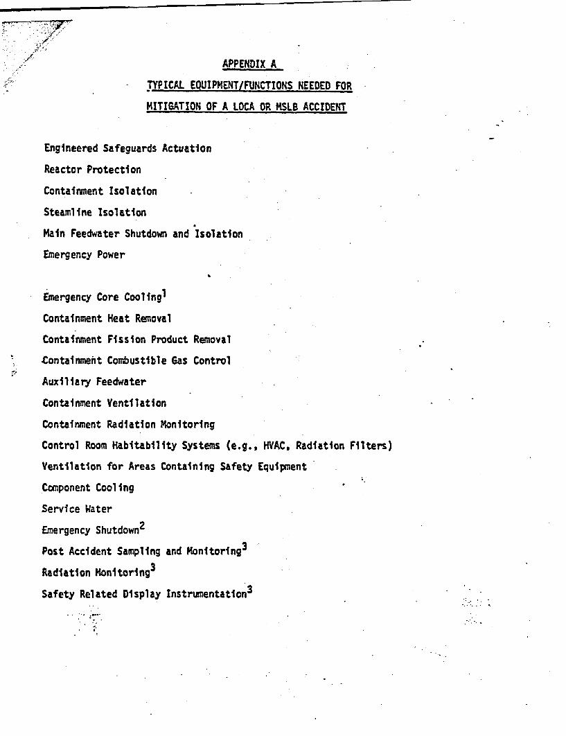
APPENDIX A
TYPICAL EQUIPMENT/FUNCTIONS NEEDED FOR
MITIGATION OF A LOCA OR MSLB ACCIDENT
Engineered Safeguards Actuation
Reactor Protection
Containment Isolation
Steamline Isolation
Main Feedwater Shutdown and Isolation
Emergency Power
Emergency Core Cooling1
Containment Heat Removal
Containment Fission Product Removal
.Containment Combustible Gas Control
Auxiliary Feedwater
Containment Ventilation
Containment Radiation Monitoring
Control Room Habitability Systems (e.g., HVAC, Radiation Filters)
Ventilation for Areas Containing Safety Equipment
Component Cooling
Service Water
Emergency Shutdown2
Post Accident Sampling and Monitoring3
Radiation Monitoring3
Safety Related Display Instrumentation3
1These systems will differ for PWRs and BWRs, and for old-r and newerplants. In each case the system features which allow f- transfer torecirculation cooling mode and establishment of long term coolingwith boron precipitation control are to be considered as part ofthe system to be evaluated.
2Emnergency shutdown systems include those systems used to bring theplant to a cold shutdown condition following accidents which do notresult in a breach of the reactor coolant pressure boundary togetherwith a rapid depressurization of the reactor coolant system. Examplesof such systems and equipment are the RHR system, PORVs, RCIC, pressurizersprays, chemical and volume control system, and steam dump systems.
MJwore specific identification of these types of equipment can be foundin th'e plant emergency procedures.
= + S~~~~~~~~~~~~~~~
- - 2 -~~~~~~~~~~~~~~~~~~~~~~~~~~~~~~
cS-
APPENDIX B
PROCEDURES FOR EVALUATING GAMMA RADIATION SERVICE CONDITIONS
Introduction and Discussion
The adequacy of gamma radlatton service conditions specified for inside
containment during a LOCA or MSLB accident can be verified by assuming
a conservative dose at the containment centerline and adjusting the dose
according the plant specific parameters, The purpose of this appendix
ts to identify those parameters whose effect on the total gamma dose Is
easy to quantify with a high degree of confidence and describe procedures
which may be used to take these effects into consideration.
The bases for the procedures and restrictions for their use are as
follows:
(11 A conservative dose at the containment centerline of 2 x 10⁷ RADS
for a LOCA and 2 x 10⁶ RADS for a MSL8 accident has been assumed.
This assumption and all the dose rates used in the procedure out-
lined below are based on the methods and sample calculation
described in Appendix D of NUREG.0588, *Interim Staff Position
on Environmental Qualification of Safety-Related Electrical Equip-
ment,* Therefore, all the limitations listed in Appendix D of
NUREG60588 apply to these procedures.
(2) The sample calculation in Appendix D of NUREG.0588 is for a 4,000
MWth pressurized water reactor housed in a 2.52 x 106 ft3 contain-
ment with an Iodine scrubbing spray system. A similar calculation
without iodine scrubbing sprays would increase the dose to equipment
approximately 15X. The conservative dose of 2 x 10⁷ RADS assumed
in the procedure below includes sufficient conservatism to
account for this factor. Therefore, the pro ..dure is also
applicable to plants without an iodine scrubbing spray system.
(3) Shielding calculations are based on an average gamhma energy of
I MEY derived from TID 14844.
(4) These procedures are not applicable to equipment located directly
above the containment sump, submerged in contaminated liquids,
or near filters. Doses specified for equipment located in these
areas must be evaluated on a case-by case basis.
(5) Since the dose adjustment factors used in these procedures are
based on a calculation for a typical pressurized water reactor with
a dry type containment, they are not directly'applicable to
boiling water reactors or other containment types. However,
doses for these other plant configurations may be evaluated
using similar procedures with conservative dose assumptions
and adjustment factors developed on a case by case basis.
Procedure
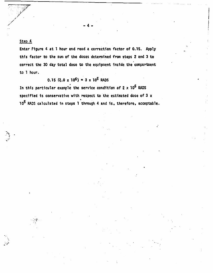
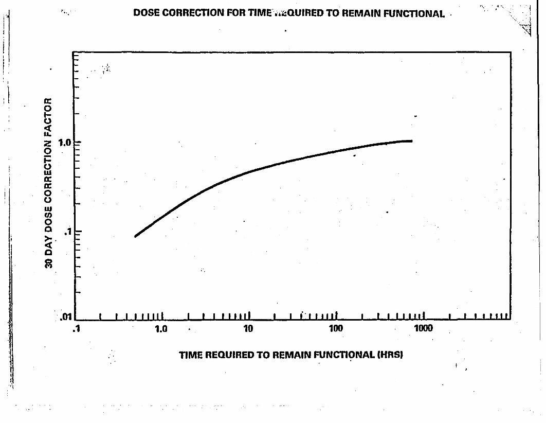
Figures I through 4 provide factors to be applied to the conservative
dose to correct the dose for the following plant specifi c parameters:
(1) reactor power level; (2) containment volume; (3) shielding; (4)
compartment volume; and (5) time equipment is required to remain
functional.
.gi.
77-
-3
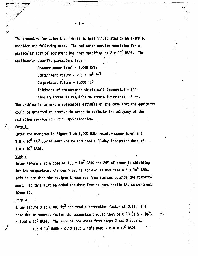
The procedure for using the figures is best illustrated by an example.
Consider the following case. The radiation service condition for a
particular item of equipment has been specified as 2 x 10 RADS. The
application specific parimeters are:
Reactor power level - 3,000 HWth
Containment volume - 2.5 x 106 ft3
Compartment Volume - 8,000 ft 3
Thickness of compartment shield wall (concrete) - 24"
Time equipment is required to remain functional - 1 hr.
The problem is to make a reasonable estimate of the dose that the equipment
could be expected to receive in order to evaluate the adequacy of the
radiation service condition specification.
' Step 1
Enter the nomogram in Figure 1 at 3,000 MWth reactor power level and
2.5 x lo6 ft3 containment volume and read a 30-day integrated dose of
1.6 x 10⁷ RADS.
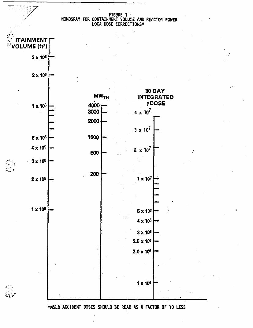
Step 2
Enter Figure 2 at a dose of 1.5 x 10⁷ RADS and 24" of concrete shielding
for the compartment the equipment is located in and read 4.5 x 10⁴ RADS.
This is the dose the equipment receives from sources outside the compart-
ment. To this must be added the dose from sources inside the compartment
(Step 3).
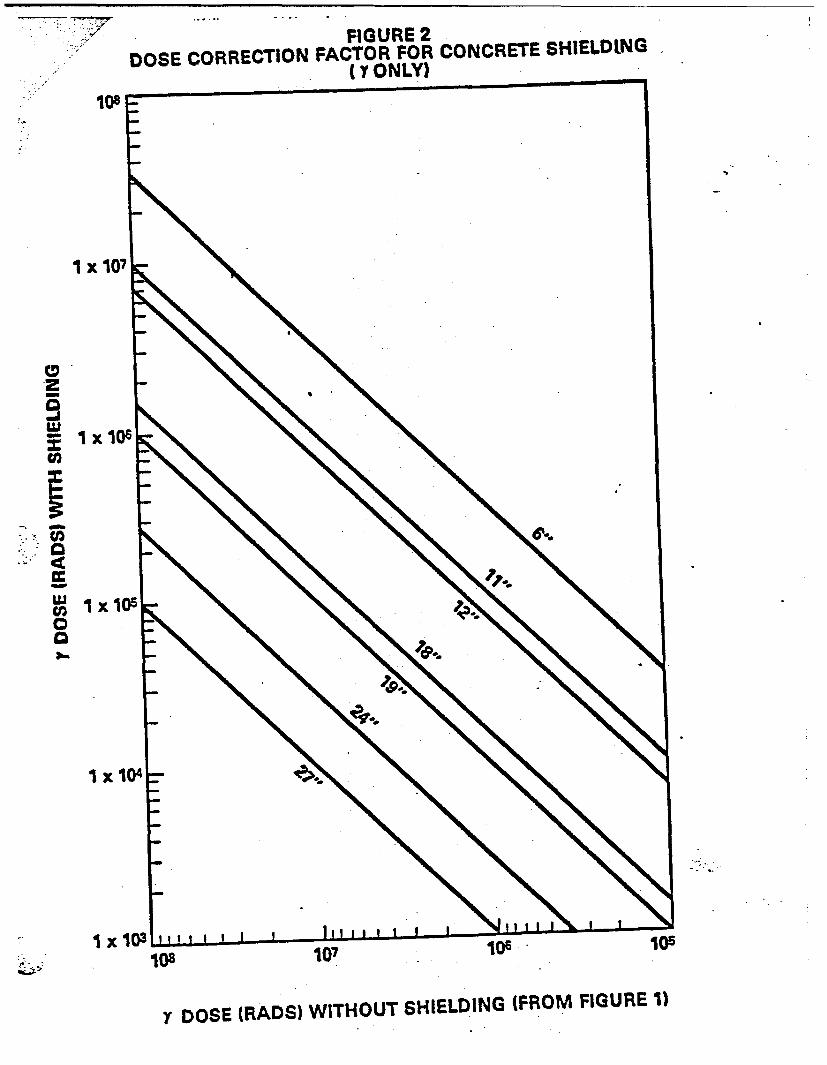
Step 3
Enter Figure 3 at 8,000 ft3 and read a correction factor of 0.13. The
dose due to sources inside the compartment would then be 0.13 (1.S x 107)
=1.95 x 10⁶ RADS. The suns of the doses from steps 2 and 3 equals:
4.5 x 10⁴ RDS + 0.13 (1.5 x 10⁷) RADS a 2.0 x 10⁶ RADS
.4
Step 4
Enter Figure 4 at 1 hour and read a correction factor of 0.15. Apply
this factor to the sum of the doses determined from steps 2 and 3 to
correct the 30 day total dose to the equipment inside the compartment
to 1 hour.
0.15 (Z.0 x 106) * 3 x 105 RADS
In this particular example the service condition of 2 x 10⁶ RADS
specified is conservative with respect to the estimated dose of 3 x
105 RADS calculated in steps I through 4 and is, therefore, acceptable.
.. .4.
-- 7-FIGURE 1
NOMOGRAM FOR CONTAINMENT VOLUME AND REACTOR POWERLOCA DOSE CORRECTIONS*
.' ITAINMENT*-VOLUME (ft3)
3 x 10⁶ . _
2x 10_ I-
1 x 10⁶
MWTH
4000 -
34000_290D -
30 DAYINTEGRATED
YDOSE
4 x 10⁷
5x 10⁶ 10D0
4 x 10⁵ F-500
* 3x1Os
2 x 10⁶
1 x 10i
200
3 x 10⁷
2 x107
I x 107
6 x 10⁶
4 x 10⁶
3x10⁶
2.5 x 10⁶
2.OxlOsh
i x 106 I-
i.
*V'SLE ACCIDENT DOSES SHOULD BE READ AS A FACTOR OF 10 LESS
: -/ I
,; 108
I X 107
IFIGURE 2
DOSE CORRECTION FACTOR FOR CONCRETE SHIELDING .(I ONLY)
a ,23-
Lu
U)co
a
,-0. a
¶x 106
I x lO5
I X14
I X 13I0 107
v DOSE (RADS) WITHOUT SHIELDING (FROM FIGURE 1)
L..,
FIGURE 3DOSE CORRECTION FACTOR FOR COMPARTMENT VOLUME
106 .m
a
I
_. 1I *
WS.
- -iI
104
-' 103 * I I I I I I I I9 5 I - . -- - , -- - -
0 .2 .4 .6 .8 1.0
CORRECTION FA(~oTOR
. _~~~_
.... I . 4 !,
IDOSE CORRECTION FOR TIME StQUIRED TO REMAIN FUNCTIONAL
cc0
zI-
0
0wa:Cam00
00a
a
1.0
.1
.01 I I I I .1111 II I I mimail I I I. I iill I I I I I I I IIl I I 1I 111
.1 1.0 10 100 1000
TIME REQUIRED TO REMAIN FUNCTIONAL MHRSIl
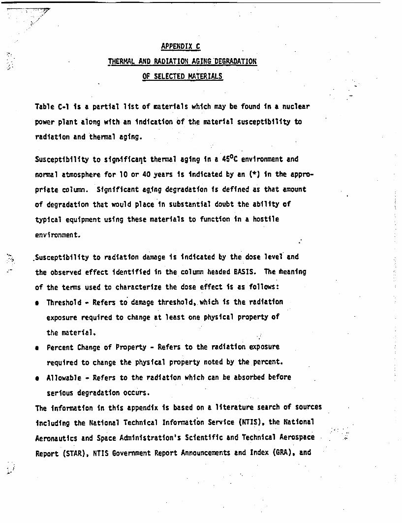
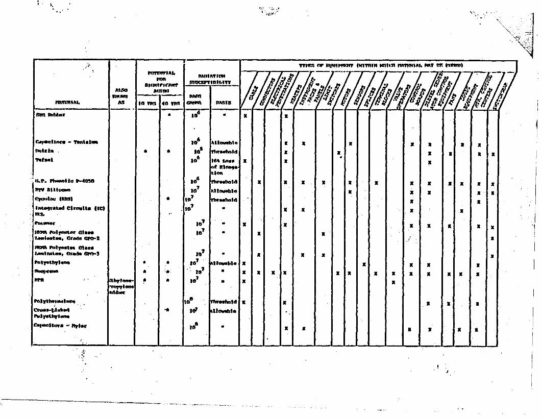
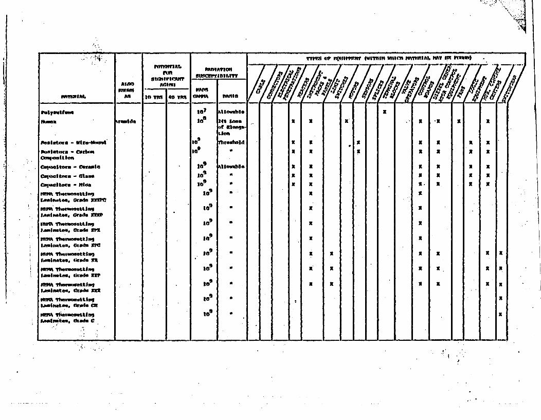
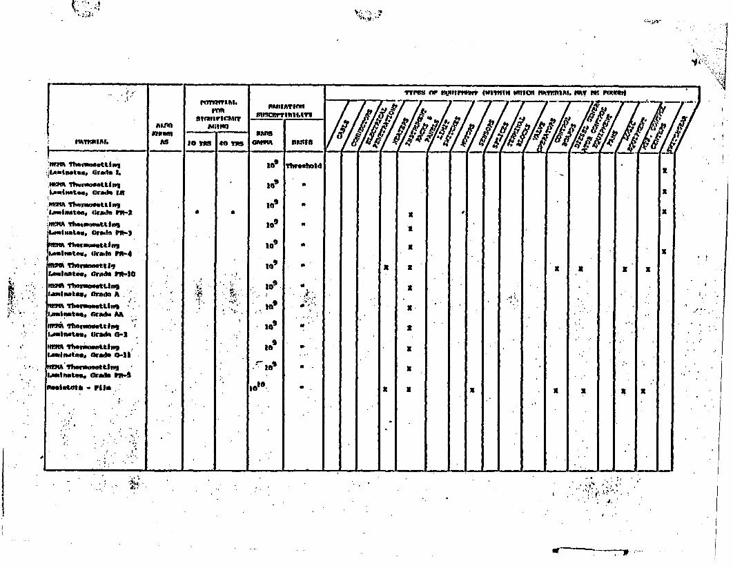
APPENDIX C
THERMAL AND RADIATION AGING-DEGRADATION
OF SELECTED MATERIALS
Table C-l is a partial list of materials which may be found in a nuclear
power plant along with an indication of the material susceptibility to
radiation and thermal aging.
Susceptibility to sign.ificaqt thermal aging in a 450C environment and
normal atmosphere for 10 or 40 years is indicated by an (*) in the appro-
priate column. Significant aging degradation is defined as that amount
of degradation that would place in substantial doubt the ability of
typical equipment using these materials to function in a hostile
environment.
Susceptibility to radiation damage is indicated by the dose level and
the observed effect identified in the column headed BASIS. The Meaning
of the terms used to characterize the dose effect is as follows:
o Threshold - Refers to damage threshold, which is the radiation
exposure required to change at least one physical property of
the material.
a Percent Change of Property - Refers to the radiation exposure
required to change the physical property noted by the percent.
* Allowable - Refers to the radiation which can be absorbed before
serious degradation occurs.
The information in this appendix is based on a literature search of sources
including the National Technical Information Service (NTIS), the National
Aeronautics and Space Administration's Scientific and Technical Aerospace
Report (STAR), NTIS Government Report Announcements and Index (GRA), and
-2-~~~
various manufacturers data reports. The materials list is not to be
considered all *inc~iusive neither is it to be used as a basis for
specifying materials to be used for specific applications within a
nuclear plant. The list is solely intended for use by the NRC staff
in making Judgements as to the possibility of a particular material
in a particular application being susceptible to significant degradation
due to radiation or thermal aging.
The data base for thermal and radiation aging in engineering materials
is rapidly expanding at this time. As additional information becomes
available Table C-1 will be updated accordingly.
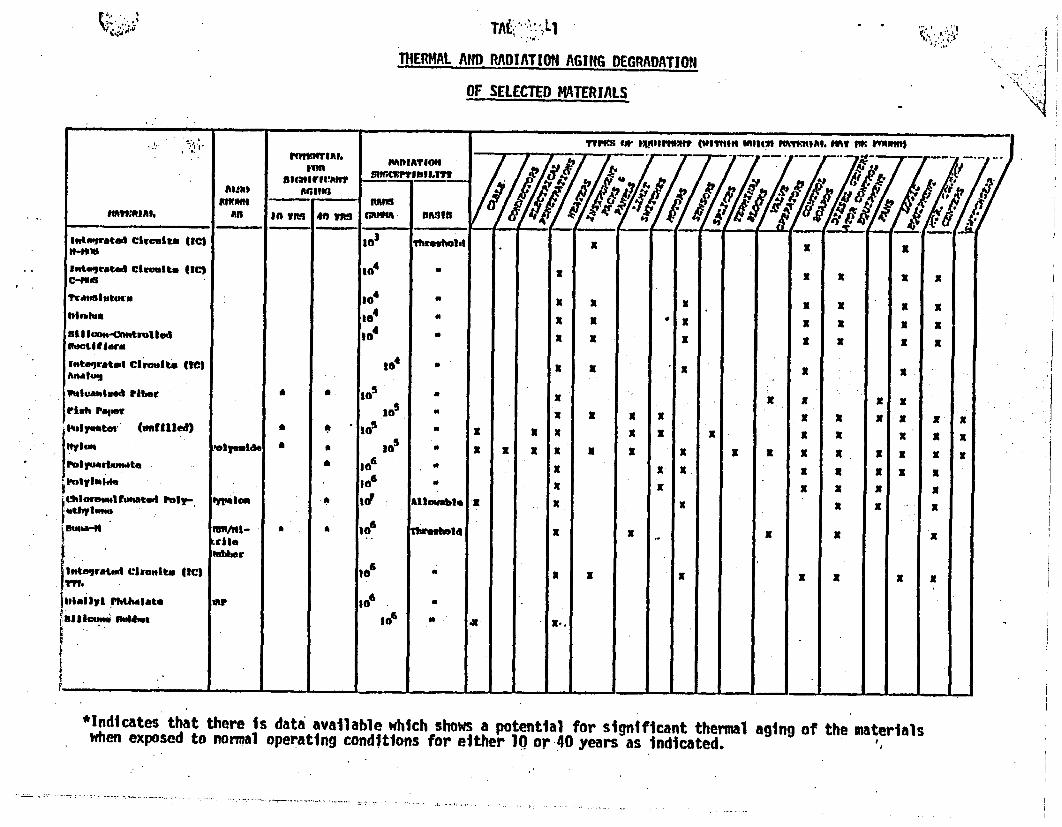
i;' ~~~~~~~~~TA&,',Ll -'!.,
THERMAL AND RADIATION AGING DEGRADATION
OF SELECTED MATERIALS
*Indicates that there is data available which shows a potential for significant thermal aging of the materialswhen exposed to normal operating conditions for either 10 or 40 years as indicated.
I
I I : *
'N_A--
.
PAUMI
Ia w~tS140 711
..
*IAINIAItCtMhI"PTrreS.1tv-
rYPs (i WI" MW MmIN hWI" MI lt" IL "Rt V 18 mInt hU
-r M f @ i r Q g i A -;4 ff
(W _ , / 7 7 __._Also
AsIn# mtlM. DASIS_ __. I I- _a - _ I
- -- - -- 9- 1� 11 - Z.4
Mn D
CqmaIlmee - Tontalam
.P. Mh Inola ?-40m
t amftdr efteutl sINLS
SRSff ('oleutor Claw.1LANIAtome Gradf Gr02Ntj polyeatea Glans
I.Miflt", Graft cr-I
Pwblyethyle"a
NO"prene
M
It} .*
a
.a
106
,6106
,6
1076
7
7
to"
107
107
107
10"
l1
a
tht.ovldPklOt 3bom
16% tonof CloNgatleog
Wouhoid
htlovable
fTbWtold0a
I wvableU
a
N
N
N
N
N
N
I
I
K
I
N
N
N
N
I
X
S
:II
x
N
N
N
It
K
K
N
N
x
N
x
N
N
N
N
x
N
N
N
a X
X K
Nethypenu-4ro"enetiljeg
a
N'Cruse-_IoPolytha tal a
wCfacltura - ftfee
rbwomfold xI
llo"bRt
a
I ~ ~ ~ ~ ~ ~ ~ ~ ~ ~ . -
9..9g*
I *
I
ti. ...., , V. , -M
I j� A�4
. -.. 14;1 .I., . Ale.
. . - 4% .,..,, -- ., 11 1 -7".'1 . . : : fl� - -.
. . J. ,
I ..


![유형정복 모의고사 - ebook.academysoft.co.krebook.academysoft.co.kr/databox/ITQ/2019 ITQ 엑셀/ITQ 엑셀 모의... · 유형정복 모의고사 1 [제1작업] 표 서식](https://img.pdfslide.net/doc/110x75/5f51fde46eb52b045c4c11b6/oee-ee-ebook-itq-itq-e-oee.jpg)