Embed Size (px)
Citation preview
ST 3-22.7
Distribution Restriction: Approved for public release; distribution is unlimited.
18 February 2009 ST 3-22.7 i
Special Text
No. 3-22.7
US Army Infantry School Fort Benning, GA18 February 2009
Stryker Mortar Platoon and Section Leaders’ Handbook
Contents
Page
PREFACE ..................................................................................................................... i
Chapter 1 M1129A1 STRYKER MORTAR CARRIER VEHICLE ............................................. 1-1
Section I — OVERVIEW ........................................................................................... 1-1 Organization .............................................................................................................. 1-1
Section II — MCV CHARACTERISTICS AND CAPABILITIES ............................. 1-1 Stryker Variant ........................................................................................................... 1-1 Crew Configuration .................................................................................................... 1-2 Weapons Systems ..................................................................................................... 1-3 MCV Configurations .................................................................................................. 1-5 Secondary Weapon ................................................................................................... 1-6 RMS6-L 120-mm Mortar System ............................................................................... 1-6 M95 Mortar Fire Control System ............................................................................... 1-7 Mortar Ammunition Stowage ..................................................................................... 1-8
SECTION III — UNIT MORTAR TRAINING ............................................................. 1-9 Training Priority ......................................................................................................... 1-9 Mortar Training at Training Base ............................................................................... 1-9 Unit Training ............................................................................................................ 1-11 Training Evaluation .................................................................................................. 1-14
Chapter 2 OPERATIONAL PROCEDURES .............................................................................. 2-1
Section I — MORTAR AMMUNITION...................................................................... 2-1 Mortar Storage Space, 60-mm/81-mm ...................................................................... 2-1 Ammunition Storage Space ....................................................................................... 2-1 120-mm Ammunition ................................................................................................. 2-2 81-mm Ammunition ................................................................................................... 2-9 60-mm Ammunition ................................................................................................. 2-12
Section II — BORESIGHT AND SIGHT CALIBRATION OF 120-MM MORTAR . 2-16 Manual Boresight ..................................................................................................... 2-16 Digital Boresight ...................................................................................................... 2-21
Table of Contents
ii ST 3-22.7 18 February 2009
Section III — NAVIGATION AND EMPLACING THE PLATOON OR SECTION. 2-24 Emplacing the Platoon/Section Using Waypoint Method ....................................... 2-24 Emplacing the Section Using Fire Area Method ..................................................... 2-26
Chapter 3 FIRE MISSIONS USING THE MORTAR FIRE CONTROL SYSTEM...................... 3-1
Section I — STANDARD FIRE MISSIONS ............................................................. 3-1 Standard Fire Mission Features ................................................................................ 3-1 Example Mission Data Screen .................................................................................. 3-2 Common Actions ....................................................................................................... 3-4
Section II — BASIC FIRE MISSIONS ..................................................................... 3-5 Basic Digital Missions ............................................................................................... 3-5 Manual Missions ..................................................................................................... 3-16
Section III — SPECIAL MISSIONS ...................................................................... 3-20 Registration Point .................................................................................................... 3-20 Target/Known Point ................................................................................................ 3-22 Illumination Mission ................................................................................................. 3-24 Coordinated Illumination Mission ............................................................................ 3-31 Final Protective Fires .............................................................................................. 3-33 Smoke Missions ...................................................................................................... 3-43
Chapter 4 STRYKER MCV CREW AND BATTLE DRILLS ..................................................... 4-1
Section I — TRAINING ............................................................................................ 4-1 Drill Training .............................................................................................................. 4-1 Training Guidance ..................................................................................................... 4-2 Force Protection (Safety) .......................................................................................... 4-3
Section II — MCV CREW DRILLS .......................................................................... 4-4 Crew and Squad Drills .............................................................................................. 4-4 React to a Rollover While Mounted on a MCV ......................................................... 4-5 Evacuate a Stryker Mortar Carrier Vehicle ............................................................... 4-6 Extinguish a Fire on a MCV ...................................................................................... 4-7 Place a 120-mm Stryker Mortar into Action ............................................................ 4-10 Perform Small Deflection and Elevation Changes on a Stryker Mounted 120-mm
Mortar System .................................................................................................. 4-12 Perform Large Deflection and Elevation Changes on a Stryker Mounted 120-mm
Mortar System .................................................................................................. 4-13 Reciprocal Lay a Stryker Mounted 120-mm Mortar ................................................ 4-14 Conduct Misfire Procedures on a Stryker 120-mm Mortar System ........................ 4-15
Section III — MCV BATTLE DRILLS .................................................................... 4-19 React to a Biological or Chemical Attack ................................................................ 4-20 React to a Nuclear Attack ....................................................................................... 4-22 React to an Ambush (Mounted) .............................................................................. 4-24 React to Direct Fire (Mounted) ............................................................................... 4-25 React to Indirect Fire (Mounted) ............................................................................. 4-25
Chapter 5 GUNNER’S EXAMINATION ..................................................................................... 5-1
Section I — PREPARATION ................................................................................... 5-1 Methods of Instruction ............................................................................................... 5-1 Prior Training ............................................................................................................. 5-1
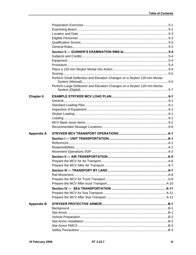
Table of Contents
18 February 2009 ST 3-22.7 iii
Preparation Exercises ............................................................................................... 5-1 Examining Board ....................................................................................................... 5-1 Location and Date ..................................................................................................... 5-3 Eligible Personnel ...................................................................................................... 5-3 Qualification Scores................................................................................................... 5-3 General Rules ............................................................................................................ 5-3
Section II — GUNNER’S EXAMINATION RMS-6L ................................................. 5-4 Subjects and Credits ................................................................................................. 5-4 Equipment ................................................................................................................. 5-4 Procedure .................................................................................................................. 5-4 Place a 120-mm Stryker Mortar into Action .............................................................. 5-4 Scoring ...................................................................................................................... 5-5 Perform Small Deflection and Elevation Changes on a Stryker 120-mm Mortar
System (Manual) ................................................................................................. 5-6 Perform Large Deflection and Elevation Changes on a Stryker 120-mm Mortar
System (Digital) ................................................................................................... 5-7
Chapter 6 EXAMPLE STRYKER MCV LOAD PLAN ................................................................ 6-1 General ...................................................................................................................... 6-1 Standard Loading Plan .............................................................................................. 6-1 Inspection of Equipment ............................................................................................ 6-1 Stryker Loading ......................................................................................................... 6-1 Loading ...................................................................................................................... 6-1 MCV Basic Issue Items ............................................................................................. 6-2 Recommended Stowage Locations .......................................................................... 6-6
Appendix A STRYKER MCV TRANSPORT OPERATIONS ....................................................... A-1
Section I — UNIT TRANSPORTATION .................................................................. A-1 References ................................................................................................................A-1 Responsibilities ..........................................................................................................A-1 Movement Operations SOP ......................................................................................A-2
Section II — AIR TRANSPORTATION ................................................................... A-5 Prepare the MCV for Air Transport ............................................................................A-6 Prepare the MCV After Air Transport ........................................................................A-7
Section III — TRANSPORT BY LAND ................................................................... A-7 Rail Movement ...........................................................................................................A-8 Prepare the MCV for Truck Transport .......................................................................A-9 Prepare the MCV After truck Transport .................................................................. A-10
Section IV — SEA TRANSPORTATION ............................................................. A-11 Prepare the MCV for Sea Transport....................................................................... A-11 Prepare the MCV After Sea Transport ................................................................... A-11
Appendix B STRYKER PROTECTIVE ARMOR .......................................................................... B-1 Background ...............................................................................................................B-1 Slat Armor ..................................................................................................................B-1 Vehicle Preparation ...................................................................................................B-2 Slat Armor Installation ...............................................................................................B-2 Slat Armor PMCS ......................................................................................................B-3 Safety Precautions ....................................................................................................B-3
Table of Contents
iv ST 3-22.7 18 February 2009
Unexploded Ordnance (UXO) Procedures ............................................................... B-4
Appendix C RANGE SAFETY PROECEDURES AND RISK MANAGEMENT ........................... C-1
Section I — SAFETY OFFICER DUTIES ................................................................ C-1 Mortar Range Safety Checklist ................................................................................. C-1 Safety Diagram and Safety “T” ................................................................................. C-4 Surface Danger Zones .............................................................................................. C-8 Ammunition Care and Handling ................................................................................ C-9 Ammunition Color Codes ........................................................................................ C-10 Field Storage of Ammunition ................................................................................... C-11
Section II — RISK MANAGEMENT ...................................................................... C-13 Risk Management ................................................................................................... C-13 Required Publications ................................................................................................... 1
GLOSSARY ................................................................................................. Glossary-1
REFERENCES ......................................................................................... References-1
INDEX ................................................................................................................ Index-1
Figures
Figure 1-1. The Stryker mortar carrier vehicle. ................................................................................... 1-2
Figure 1-2. Crew configuration. ........................................................................................................... 1-2
Figure 1-3. Mortar doors. .................................................................................................................... 1-4
Figure 1-4. Horizontal ammunition rack. ............................................................................................. 1-5
Figure 1-5. Right side ammunition rack. ............................................................................................. 1-8
Figure 1-6. Integrated mortar platoon training strategy. ................................................................... 1-12
Figure 2-1. Left side 120-mm ammunition horizontal rack (stowage). ............................................... 2-3
Figure 2-2. Left side 120-mm ammunition horizontal rack (removal). ................................................ 2-4
Figure 2-3. Left side 120-mm ammunition vertical rack (stowage). .................................................... 2-5
Figure 2-4. Left side 120-mm ammunition vertical rack (removal). .................................................... 2-6
Figure 2-5. Right side 120-mm ammunition vertical rack (stowage). ................................................. 2-7
Figure 2-6. Right side 120-mm ammunition vertical rack (removal). .................................................. 2-8
Figure 2-7. Right side 81-mm ammunition vertical/horizontal rack (stowage).................................... 2-9
Figure 2-8. Right side 81-mm ammunition vertical/horizontal rack (removal). ................................. 2-11
Figure 2-9. Right side 60-mm ammunition vertical/horizontal rack (stowage).................................. 2-13
Figure 2-10. Right side 60-mm ammunition vertical/horizontal rack (stowage). .............................. 2-14
Figure 2-11. Right side 60-mm ammunition vertical/horizontal rack (removal). ............................... 2-15
Figure 2-12. Example distant aiming point for boresight. ................................................................. 2-16
Figure 2-13. M67 Sight unit. .............................................................................................................. 2-17
Figure 2-14. Cant correction (cross-level knob). .............................................................................. 2-17
Figure 2-15. Blast attenuator device. ................................................................................................ 2-18
Figure 2-16. M45 Boresight on cannon. ........................................................................................... 2-18
Figure 2-17. M45 Boresight elevation bubble. .................................................................................. 2-19
Figure 2-18. Turntable azimuth lock. ................................................................................................ 2-20
Figure 2-19. Gunner’s quadrant sight. .............................................................................................. 2-22
Table of Contents
18 February 2009 ST 3-22.7 v
Figure 2-20. Navigation screen. ........................................................................................................ 2-25
Figure 2-21. Start navigation. ............................................................................................................ 2-25
Figure 2-22. Navigation instructions on driver’s display. ................................................................... 2-26
Figure 2-23. Navigation to fire area. .................................................................................................. 2-27
Figure 2-24. Driver’s display during navigation. ................................................................................ 2-28
Figure 3-1. Mortar Fire Control System (MFCS) example mission data screen. ................................ 3-3
Figure 3-2. MFCS new call for fire screen. .......................................................................................... 3-6
Figure 3-3. MFCS mission data view screen. ..................................................................................... 3-7
Figure 3-4. MFCS solution view screen. ............................................................................................. 3-8
Figure 3-5. MFCS safety data screen. ................................................................................................ 3-9
Figure 3-6. MFCS plot view screen. .................................................................................................. 3-10
Figure 3-7. MFCS solution view screen. ........................................................................................... 3-11
Figure 3-8. MFCS mission status screen. ......................................................................................... 3-12
Figure 3-9. MFCS messages screen. ................................................................................................ 3-13
Figure 3-10. MFCS mission data view screen. ................................................................................. 3-14
Figure 3-11. MFCS end of mission message screen view. ............................................................... 3-15
Figure 3-12. MFCS save data screen. .............................................................................................. 3-16
Figure 3-13. MFCS manual call for fire screen. ................................................................................ 3-18
Figure 3-14. MCFS manual adjust fire screen. ................................................................................. 3-19
Figure 3-15. MFCS manual end of mission screen. .......................................................................... 3-20
Figure 3-16. MFCS save registration screen. ................................................................................... 3-21
Figure 3-17. MFCS registration screen. ............................................................................................ 3-22
Figure 3-18. MCFS targets screen. ................................................................................................... 3-23
Figure 3-19. MFCS known points screen. ......................................................................................... 3-24
Figure 3-20. MFCS new call for fire screen. ...................................................................................... 3-25
Figure 3-21. MFCS mission data view screen. ................................................................................. 3-26
Figure 3-22. MFCS solution view screen. ......................................................................................... 3-27
Figure 3-23. MFCS safety data view screen. .................................................................................... 3-28
Figure 3-24. MFCS solution view screen. ......................................................................................... 3-29
Figure 3-25. MFCS mission status screen. ....................................................................................... 3-30
Figure 3-26. MCFS message view screen. ....................................................................................... 3-31
Figure 3-27. MCFS new call for fire view screen. ............................................................................. 3-34
Figure 3-28. MFCS final protective fire data view screen. ................................................................ 3-35
Figure 3-29. MCFS final protective fire solution view screen. ........................................................... 3-36
Figure 3-30. MFCS safety data view screen. .................................................................................... 3-37
Figure 3-31. MFCS solution view screen. ......................................................................................... 3-38
Figure 3-32. MCFS mission status view screen. ............................................................................... 3-39
Figure 3-33. MFCS mission data status view screen. ....................................................................... 3-40
Figure 3-34. MFCS solution end of mission view screen. ................................................................ 3-41
Figure 3-35. MFCS mission status view screen. ............................................................................... 3-42
Figure 3-36. MFCS mission status view screen. ............................................................................... 3-43
Table of Contents
vi ST 3-22.7 18 February 2009
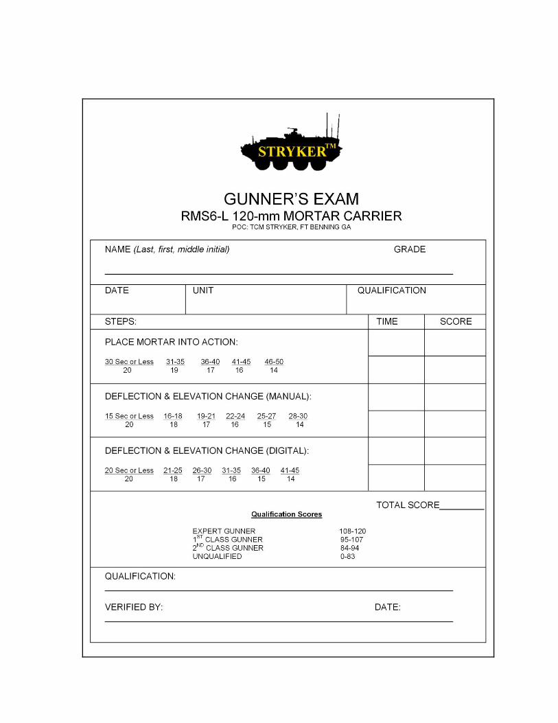
Figure 5-1. Example of completed RTMS6-L 120-mm MCV gunner’s exam. .................................... 5-2
Figure 6-1. Exterior MCV stowage – front and rear. ........................................................................... 6-6
Figure 6-2. Exterior MCV stowage–top. .............................................................................................. 6-7
Figure 6-3. Exterior MCV stowage – right side. .................................................................................. 6-8
Figure 6-4. Exterior MCV stowage – left side. .................................................................................... 6-9
Figure 6-5. Interior MCV stowage – driver's compartment ................................................................. 6-9
Figure 6-6. Interior MCV stowage – commander's station................................................................ 6-10
Figure 6-7. Interior MCV stowage – troop compartment (right side). ............................................... 6-10
Figure 6-8. Interior MCV stowage – troop compartment (behind vehicle commander's seat) ......... 6-11
Figure 6-9. Interior MCV stowage – troop compartment (left side)................................................... 6-12
Figure 6-10. Interior MCV stowage – troop compartment (gun turntable). ....................................... 6-13
Figure 6-11. Interior MCV stowage – troop compartment (gun turntable). ....................................... 6-13
Figure A-1. Stryker vehicle C-130, C-17, C-5 aircraft lift comparison. ............................................... A-6
Figure A-2. Stryker on railcar (front view). .......................................................................................... A-8
Figure A-3. Stryker on railcar (rear-view). ........................................................................................... A-8
Figure A-4. Stryker secured on heavy equipment transporter (HET) front view. .............................. A-10
Figure A-5. Stryker secured on heavy equipment transporter (HET) rear view. .............................. A-10
Figure B-1. Stryker MCV with slat armor. ........................................................................................... B-2
Figure C-1. Safety diagram for M8221 HE and M835A1 ILLUM. ....................................................... C-7
Figure C-2. Safety "T" for M821 HE. ................................................................................................... C-7
Figure C-3. Safety "T" for M852A1 ILLUM. ......................................................................................... C-7
Figure C-4. Stacked ammunition. ..................................................................................................... C-12
Figure C-5. Example risk management worksheet for squad/platoon. ............................................. C-19
Tables
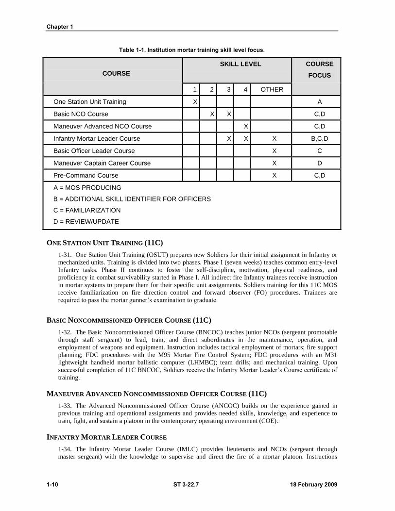
Table 1-1. Institution mortar training skill level focus. ....................................................................... 1-10
Table 3-1. MFCS steps, sequence of screens, and operator actions. ............................................... 3-2
Table 3-2. Example mission data screen. ........................................................................................... 3-4
Table 5-1. Gunner’s examination maximum credit scores. ................................................................ 5-4
Table 6-1. Stryker load area responsibilities. ...................................................................................... 6-2
Table 6-2. Stryker MCV basic issue items. ......................................................................................... 6-2
Table 6-3. BII for 120-mm, 81-mm, and 60-mm mortars. ................................................................... 6-5
Table A-1. Unit movement operations SOP ........................................................................................ A-2
Table C-1. Example completed safety record or card. ....................................................................... C-4
Table C-2. DOF calculation. ................................................................................................................ C-5
Table C-3. DOF or mounting azimuth round off calculation. .............................................................. C-5
Table C-4. Left limit deflection calculation. ......................................................................................... C-5
Table C-5. Mils from the mounting azimuth to the right limit calculation. ........................................... C-6
Table C-6. Right limit deflection calculation. ....................................................................................... C-6
Table C-7. Minimum and maximum charges and elevations calculation. .......................................... C-6
Table C-8. Maximum and minimum charges, elevations, and time setting calculations. ................... C-6
Table C-9. Mortar ammunition color codes. ...................................................................................... C-11

Table of Contents
18 February 2009 ST 3-22.7 vii
Table C-10. DA Form 7566 worksheet instructions. ........................................................................ C-15
Table C-11. Risk assessment matrix. ............................................................................................... C-17
Table C-12. Risk examples. ............................................................................................................. C-18


18 February 2009 ST 3-22.7 i
Preface
The purpose of this handbook is to provide M1129A1 Stryker mortar carrier vehicle (MCV) mortarmen with
operational knowledge of the tactics, techniques, and procedures associated with the MCV. Special emphasis is
placed on operational features of the Mortar Fire Control System (MFCS).
Though the MCV has multimortar capability, the primary focus of this handbook is 120-mm mortar operations.
Subjects include:
MFCS operational knowledge and fire missions
120-mm mortar boresight and sight calibration
MCV unit training
MCV drills
MCV basic issue items, inspection, and load plan
MCV equipment limitations and use during training and deployment
MCV mortar ammunition storage
MCV navigation and mortar platoon/section placement
MCV gunner's examination
Unless otherwise stated, whenever the masculine gender is used, both men and women are included.
The proponent for this publication is the U.S. Army Infantry School. You may send comments and
recommendations by any means, US mail, e-mail, fax, or telephone, as long as you use the format of DA
Form 2028, Recommended Changes to Publications and Blank Forms.
E mail [email protected]
Office/Fax COM 706 545 1619/6138 (DSN 835)
US Mail Commandant, USAIS
ATTN: ATSH-OTY
7602 Chesney Street
Fort Benning, GA 31905-5593

18 February 2009 ST 3-22.7 1-1
Chapter 1
The M1129A1 Stryker Mortar Carrier Vehicle
This handbook provides Infantry mortarmen with the tactics, techniques, and
procedures associated with the M1129A1 Stryker mortar carrier vehicle (MCV). The
MCV is a multi-mortar carrier equipped with a fixed 120-mm mortar system and
storage space for 81-mm or 60-mm mortars. Furnishing this choice of mortar
configurations provides commanders with the flexibility to choose the system that
best supports their area of operations (AO) terrain. Though the MCV has
multi-mortar capability, the primary focus of this training handbook is 120-mm
operations, and the operational steps and activities specific to the MCV. This
introductory chapter discusses the MCV’s place in the Infantry battalion, capabilities,
and mortar training.
Section I — OVERVIEW
1-1. The Stryker Brigade Combat Team (SBCT) Infantry battalion’s primary mission is to close the
enemy by fire and maneuver to destroy, capture, or repel the enemy’s assault by fire, close combat, and
counterattack. These operations typically incorporate a primary base of fire provided by the respective
platoon’s weapon squads, and is supported, when possible, by the direct and indirect fires of supporting
systems. Regardless of the operational scenario, Stryker Infantry tactical operations are controlled and
synchronized at the battalion level. They are executed by companies employing organic and/or attached
combined arms elements, and are supported by organic and supporting fires/effects. While the SBCT
Infantry battalion’s main combat mission is to defeat or destroy enemy forces, it also provides U.S. Army
combat operations with a predominant force for seizing, securing, retaining, and controlling terrain. MCV
squads contribute greatly to this mission.
ORGANIZATION
1-2. The 120-mm mortar is a traditional Infantry battalion asset. Attached to rifle companies as necessary
by the battalion commander, the 120-mm mortar provides crucial fire support in combat operations. In
addition to the four 120-mm mounted mortar carrier vehicles assigned to the battalion mortar platoon, each
SBCT Infantry company is assigned a two-mortar carrier vehicle section consisting of 10 Soldiers that
make up two mortar crews. The battalion mortar platoon as an organic asset of the Infantry battalion can
perform direct support, general support, or reinforcing missions.
Section II — MCV CHARACTERISTICS AND CAPABILITIES
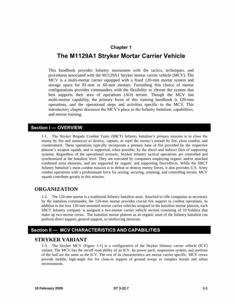
STRYKER VARIANT 1-3. The Stryker MCV (Figure 1-1) is a configuration of the Stryker Infantry carrier vehicle (ICV)
variant. The MCV has the on/off road ability of an ICV. Its power pack, suspension system, and portions
of the hull are the same as the ICV. The rest of its characteristics are mortar carrier specific. MCV crews
provide mobile, high-angle fire for close-in support of ground troops in complex terrain and urban
environments.
Chapter 1
1-2 ST 3-22.7 18 February 2009
Figure 1-1. The Stryker mortar carrier vehicle.
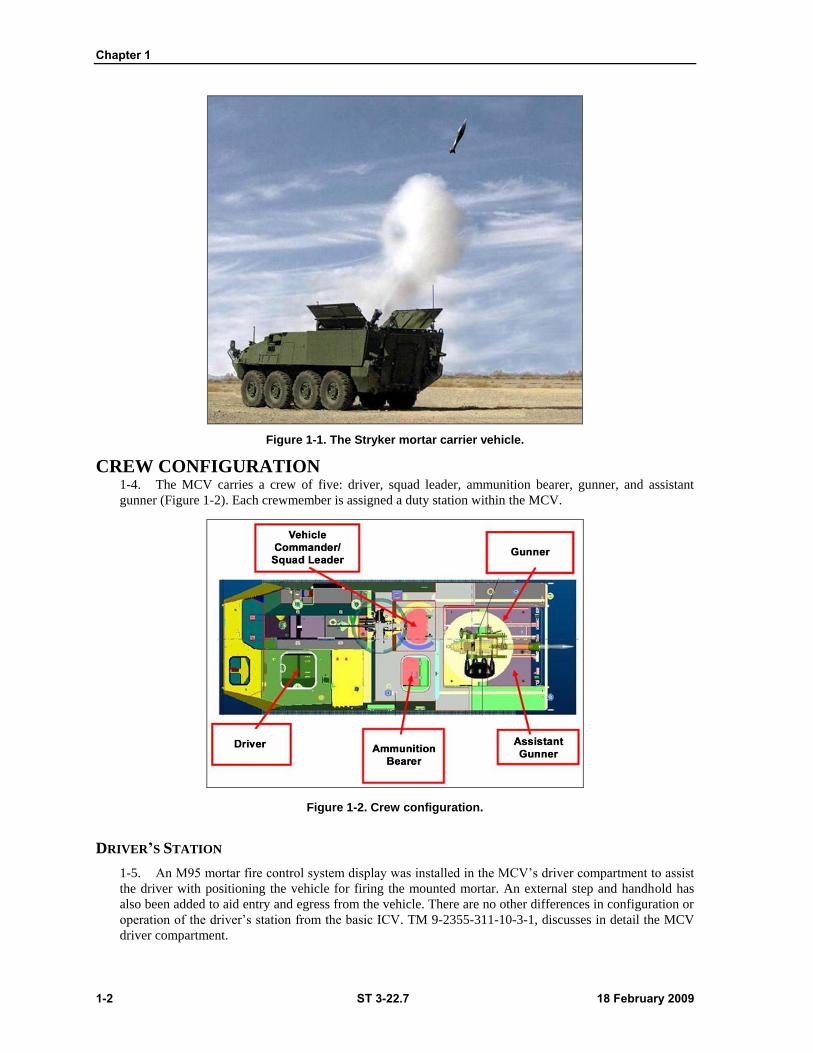
CREW CONFIGURATION 1-4. The MCV carries a crew of five: driver, squad leader, ammunition bearer, gunner, and assistant
gunner (Figure 1-2). Each crewmember is assigned a duty station within the MCV.
Figure 1-2. Crew configuration.
DRIVER’S STATION
1-5. An M95 mortar fire control system display was installed in the MCV’s driver compartment to assist
the driver with positioning the vehicle for firing the mounted mortar. An external step and handhold has
also been added to aid entry and egress from the vehicle. There are no other differences in configuration or
operation of the driver’s station from the basic ICV. TM 9-2355-311-10-3-1, discusses in detail the MCV
driver compartment.
The M1129A1 Stryker Mortar Carrier Vehicle
18 February 2009 ST 3-22.7 1-3
SQUAD LEADER’S STATION
1-6. The MCV variant’s absence of a remote weapons station (RWS) distinguishes its unique squad
leader’s station (Figure 1-2). The MCV has no RWS display which allows for more space for the squad
leader and a mounted video display terminal (VDT). The VDT can display the driver’s thermal viewer and
FBCB2 screens. The commander’s interface (CI) display and FBCB2 display are mounted on swing out
mounts to enable viewing from both squad leader and ammunition bearer positions.
AMMUNITION BEARER STATION
1-7. The ammunition bearer sits to the left of and facing toward the squad leader (Figure 1-2). His station
includes a single seat with a lap belt restraint, a padded base, and a fold down backrest. The CI display and
FBCB2 display swings out for use from this position.
Note: The M3 heater and ventilated facemask hose have been moved from the ICV
common variant position. Both are mounted forward and left of the ammunition
bearer’s position on the transition of the engine bulkhead.
GUNNER/ASSISTANT GUNNER STATIONS
1-8. The gunner/assistant gunner seats are in the rear of the troop compartment (Figure 1-2). The gunner
sits on the right-rear side facing toward the front of the vehicle; the assistant gunner sits on the left-rear
side of the vehicle facing the cannon’s blast attenuator device. Both station’s seats are designed to provide
passenger restraints, including lap belts with inertia type retractors. Both Each station is equipped with
overhead handholds (subway straps) mounted to the roof of the vehicle. The seatbacks in the gunner and
assistant gunner stations fold down and have a step stool for raising and lowering the mortar doors. The
seats fold up when not in use to allow for entry and exit from the carrier. In addition, both squad members
have their own M3 heater and ventilated facemask hose that are located above the radio rack on the right
side sponson shelf.
WEAPONS SYSTEMS
1-9. MCVs come equipped with two weapon systems: an M240B machine gun mounted at the
commander’s station and a mounted RMS6-L 120-mm mortar. The MCV is also designed to carry an
81-mm mortar (battalion load plan), and a 60-mm mortar (company load plan), with ammunition storage
capabilities for all three systems. The MCV retains the same integral protection characteristics as the ICV.
However, it is not provided with slat armor at initial delivery, though it can be mounted with slat armor if
required.
CARRIER DOORS
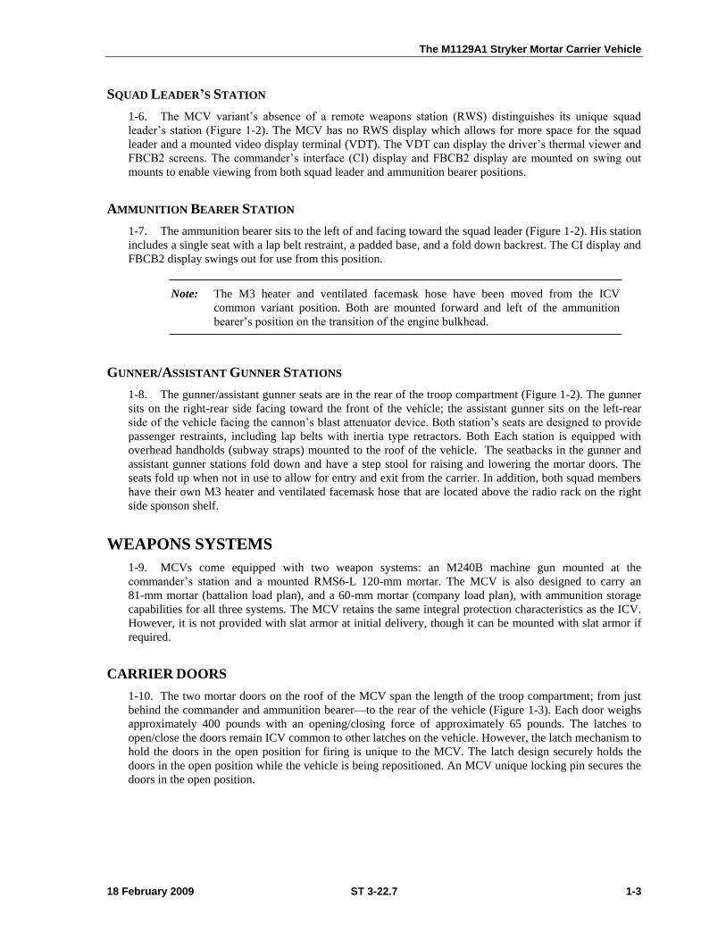
1-10. The two mortar doors on the roof of the MCV span the length of the troop compartment; from just
behind the commander and ammunition bearer—to the rear of the vehicle (Figure 1-3). Each door weighs
approximately 400 pounds with an opening/closing force of approximately 65 pounds. The latches to
open/close the doors remain ICV common to other latches on the vehicle. However, the latch mechanism to
hold the doors in the open position for firing is unique to the MCV. The latch design securely holds the
doors in the open position while the vehicle is being repositioned. An MCV unique locking pin secures the
doors in the open position.
Chapter 1
1-4 ST 3-22.7 18 February 2009
Figure 1-3. Mortar doors.
CAUTION
Moving with the mortar doors open and latched is limited to short distances and vehicle speed no faster than 10 mph. Crew members must verify that the mortar doors are latched and the latch pins are properly installed. Crew members must remain in their seat with their seatbelts properly secured. The 120-mm mortar must be secured in the travel position.
WARNING
Mortar doors are large and extremely heavy. Two people are required to safely open, close, and secure the doors in the opened or closed position. Attempts to open or close mortar doors with less than two people may result in serious injury.
Mortar doors must be securely locked when in the open position with safety pins installed to prevent doors from accidentally closing. Failure to lock mortar doors in open door position may result in serious injury.
WARNING
Mortar doors must be securely locked when in the closed-door position. Doors may bounce up and down while vehicle is moving and cause serious injury.

The M1129A1 Stryker Mortar Carrier Vehicle
18 February 2009 ST 3-22.7 1-5
WARNING
Mortar doors are under spring tension. To avoid serious injury, keep face and body parts clear of doors, and hands clear of door edges when opening or closing mortar doors.
1-11. A minor modification made to the left rear of the MCV accommodates a horizontal ammunition rack
located above the left rear sponson (Figure 1-4). This adaptation incorporated changes to the upper
sidewalls of the MCV that restructured the common upper sidewall angles of the ICV to a vertical angle.
To accommodate the ammunition rack, portions of the spall lining were removed. More armor was added
to this area to retain the same level of protection.
Figure 1-4. Horizontal ammunition rack.
MCV CONFIGURATIONS
1-12. The MCV recoiling mortar system incorporates some characteristics of the basic M120/M121.
Except for adding an external shoulder on the breech cap that allows mounting the barrel into the recoiling
system, the mortar tube is identical to the M120/M121. The RMS6-L 120-mm Mortar System recoiling
mechanism is designed to reduce the recoil forces transferred to the vehicle. The type of dismountable
mortar carried on the vehicle is dependent upon vehicle configuration. Configurations include:
Battalion Configuration. The platoon MCVs consists of the 120-mm Mounted Mortar System
and carries the 81-mm mortar M252 for dismounted use. The 81-mm base plate is stowed on the
outside right rear of the vehicle above the tires. The bipod is stowed in the right side of the
vehicle just behind the squad leader’s station. The bipod can also be stowed on top of the
vehicle just behind the winch pocket.
Company Configuration. The company section MCVs consists of the 120-mm Mounted
Mortar System and carries the 60-mm mortar M224 for dismounted use. The 60-mm base plate,
bipod, and cannon are stowed in the same location as the 81-mm on the battalion configuration.
RECONNAISSANCE, SURVEILLANCE, TARGETING, AND ACQUISTION (RSTA) SQUADRON
1-13. The SBCT battalion RSTA squadron MCV consists of only the 120-mm Mounted Mortar System.
Chapter 1
1-6 ST 3-22.7 18 February 2009
Note: MCV configurations are driven by the different assignments of the MCV, to the
battalion, company, or RSTA squadron.
SECONDARY WEAPON
1-14. The secondary weapon on the MCV is the M240B 7.62-mm machine gun. The machine gun is
attached to a skate mount with an articulated arm. The mount allows 360-degrees of coverage. A total of
1,000 rounds of ammunition can be stowed on the exterior of the vehicle. The stowage box is to the right
of the commander and can hold up to 5 cans (200 rounds each) of ammunition.
RMS6-L 120-MM MORTAR SYSTEM
1-15. The RMS6-L 120-mm Mortar System is a simply constructed and mobile weapon capable of
producing a large volume of fire quickly and accurately on any given target within its range. The system is
designed for employment in all phases and types of land warfare—on every type of terrain—in all kinds of
weather. The system can be brought into or taken out of action quickly.
MCV 120-MM MORTAR CAPABILITY
1-16. The MCV mortar is a smooth bore, muzzle loaded, high angle of fire weapon that provides—
A traverse field of regard of 4400 mils.
A maximum range of 6700 meters.
A maximum angle of elevation of 1486 mils enabling the mortar to engage targets effectively on
reverse slopes or behind cover.
Accurate firing on targets from 180 to 6700 meters.
MCV 120-MM MORTAR CHARACTERISTICS
1-17. The MCV mortar system includes:
A smooth bore barrel with rounded muzzle end to allow for easy loading.
A sight instrument mounting bracket with cant correction knob provided for mounting the M67
sight unit.
A replenisher mounted on top of the cradle that contains hydraulic fluid for the recoil system.
The cradle assembly is attached to the saddle and contains a recoil mechanism that buffers barrel
recoil during firing.
Trunnions that allow for vertical pivot of the cradle.
A connecting hub that attaches the barrel assembly to the cradle.
The breech piece, which is screwed into the end of the barrel to form a gas tight metal seal. This
breech piece houses the firing pin and safety mechanism.
A traversing handle that provides quick and accurate rotation of the turntable changing the
barrel azimuth.
A saddle assembly, which supports the cradle/barrel assemblies and attaches to the traverse
bearing of the lower vehicle mount.
A traverse bearing assembly that attaches the mortar and recoil system directly to the MCV.
A quick release lever used to disengage the traversing gear from the traverse bearing assembly
that allows free rotation of the saddle assembly.
An elevating mechanism attached through a folding mechanism to the underside of the cradle
that allows for lowering the cannon to the travel position.
The M1129A1 Stryker Mortar Carrier Vehicle
18 February 2009 ST 3-22.7 1-7
An elevating handle that provides quick and accurate raising or lowering of the cannon in
elevation.
A folding mechanism bushing that allows lowering of the cannon to the travel position.
A recuperator for maintaining nitrogen and fluid pressure forces the gun back into battery after
recoil.
Note: To accept the weight and recoil forces transferred to the vehicle by the
RMS6-L MCV 120-mm Mortar System, slight modifications were made to the floor
panels. A mounting pad was added to provide for additional support and mounting
of the bearing (turntable) on which the mortar traverses. The main bearing of the
mortar system is bolted directly to the mounting pad on the floor of the MCV. A fuel
transfer control access cover was added to the floor plates.
M95 MORTAR FIRE CONTROL SYSTEM
1-18. The M95 mortar fire control system (MFCS) provides ―shoot and scoot‖ capability to the MCV.
Controlled by a software operating system, the commander’s interface microprocessor manages computer
activities, performs computations, and controls the interface with other components and devices. MFCS
components work together to—
Compute targeting solutions.
Direct movement of the MCV into position.
Allow real-time gun orientation.
Present gun orders to the M95 components mounted in the MCV.
1-19. MFCS components make up a complete, fully integrated digital on-board fire control system that
can establish weapon location and orientation without the use of a sight unit, aiming posts, or distant
aiming points. The MFCS delivers seamless integration of mortar fires into the digital fire support network,
calculates navigation instructions, and computes ballistic solutions while the MCV is moving.
MFCS CAPABILITY
1-20. The 120-mm Mortar System is aligned on the MFCS to maintain alignment with accuracy of 3-mils
azimuth and 1-mil elevation in all conditions. The commander’s interface stores up to—
18 gun positions.
3 gun sections.
50 known targets.
16 registration points
3 final protective fire (FPF) missions.
12 forward observer (FO) locations.
1-21. If the designated fire direction center (FDC) becomes inoperative for any reason during tactical or
training operations, any MFCS equipped MCV can assume FDC responsibilities.
MFCS COMPONENTS
1-22. Major components of the MFCS include the commander’s interface, power distribution assembly,
gunner’s display, pointing device, and driver’s display.
Commander’s Interface. Interface capabilities include:
Managing the information flow between the gun and FDC.
Providing interface between MFCS components using text and graphics.
Computing technical fire control solution for weapon operation.
Chapter 1
1-8 ST 3-22.7 18 February 2009
Power distribution assembly. Power assembly filters MCV power through the DC power
system that isolates MFCS components from power fluctuations, and provides circuit breakers
for MFCS components.
Gunner’s display. Display receives deflection and elevation orders, and provides ―check fire‖
and ―call for fire‖ capability to the gunner.
Pointing device. Device provides effective pointing and position performance between 80
South to 84 North latitude.
Driver’s display. Display provides steering directions, distance and heading in a numerical
format, and information needed to orient the MCV upon emplacement.
MORTAR AMMUNITION STOWAGE
1-23. The MCV’s ammunition storage system consists of a modular rack system on the right side of the
vehicle capable of storing 60-mm, 81-mm, and 120-mm ammunition. Storage is possible in three different
combinations depending on the vehicle configuration (battalion, company, or RSTA). A permanent rack on
the left side of the MCV holds 120-mm rounds only in horizontal and vertical ―ready round‖ racks. See
Chapter 2 for detailed instruction on mortar ammunition stowage and removal.
STOWED 120-MM AND 81-MM MORTAR AMMUNITION
1-24. The MCV is capable of storing sixty 120-mm rounds stored within their individual round containers.
The left rear side of the vehicle contains a 120-mm rack that is capable of storing 48 120-mm rounds, 24
horizontal—and 24 vertical. The right side has a flex rack that is capable of storing 12 rounds of 120mm
motor ammunition. The right side flex rack is also capable of storing 35, 81-mm rounds. On the 120-mm
and 81-mm flex rack located in the right side of the MCV, mortar rounds are held in place by using
webbed straps that tighten around the ammunition to provide a positive means of holding the rounds in
place (Figure 1-5).
Figure 1-5. Right side ammunition rack.
STOWED 60-MM MORTAR AMMUNITION
1-25. The Infantry company MCV is capable of storing both 120-mm and 60-mm rounds. The left side
storage space is common to the battalion and RSTA squadron’s MCVs. The right-side rack is capable of
storing 77 rounds of 60-mm ammunition. The 60-mm flex rack incorporates a single door that covers the
front of the rack. In addition to the webbed straps and aluminum door of the 60-mm configuration, there
are wave springs that keep rounds from sliding or rolling while loading and unloading.
The M1129A1 Stryker Mortar Carrier Vehicle
18 February 2009 ST 3-22.7 1-9
RSTA SQUADRON MCV MORTAR AMMUNITION STORAGE
1-26. The RSTA squadron MCV carries the same number of 120-mm rounds as the battalion and
company configurations. Though RSTA MCVs carry only 120mm mortar rounds, they can be configured
to stow 60-mm and 81-mm ammunition.
SECTION III — UNIT MORTAR TRAINING
1-27. Because MCV lethal and disruptive fires in combat operations are only as effective as training
permits, this section focuses on the need for efficient and continuing SBCT mortar training.
TRAINING PRIORITY
1-28. Continuing chapters in this handbook cover operational procedures and fire missions; however,
without effective mortar training, effective fire cannot be attained. The importance of skilled and proficient
mortarmen must not be overlooked within the context of the company or battalion’s overall training
strategy. A good training strategy will therefore prioritize continuing training and will allocate the needed
resources to make training effective. Leaders may also require training. Unless leaders have a mortar
background, they may not understand the distinct training requirements and tactical role of mortars. This
can be achieved through officer professional development (OPD) and noncommissioned officer
professional development (NCOPD) mortar instruction. Both training opportunities include technical and
tactical mortar subjects.
SOUND TRAINING
1-29. Technical and tactical proficiency is based on sound training. Once mortarmen have mastered their
own tasks, they must be fully integrated into the training exercises of the company, battalion, or both. It is
only within the context of a full maneuver exercise that a mortar unit’s indirect fire support abilities can be
fully trained and evaluated. Mortars suffer a training deficiency by not having a Multiple Integrated Laser
Engagement System (MILES)-like training device to simulate the terminal effects of mortar rounds. As a
result, maneuver units tend to under-employ their supporting mortars. Despite the current absence of such
devices, there are other techniques to assess the effects of indirect fire. FM 25-4, How to Conduct Training
Exercises, outlines them fully. Fire missions not specifically using enemy targets such as registration and
adjusting final protective fire should also be routinely conducted in maneuver exercises.
Note: A training plan that employs mortarmen only as an opposing force (OPFOR)
riflemen is not effective for many reasons. First, when leaders make this training
mistake, mortarmen are not being trained in the technical and tactical tasks pertinent
to their mission. Second, riflemen are deprived of a valid training experience as
OPFOR. Third, maneuver units are not trained to employ their mortar indirect fire
support.
MORTAR TRAINING AT TRAINING BASE
1-30. Good mortar unit training strategies begin with a well prepared training base. Leaders must know
what skills mortarmen bring with them when they report to their unit. This understanding provides a base
on which they can build unit mortar training. The career pattern for officers and NCOs is developed
individual training. Effective training will alternate between the training base and units with progressively
advanced skill and responsibility levels. Mortar training in the institution focuses on Soldier preparation for
these positions. Depending on the course, an effective training focus will include technical training in
mortar skills, mortar familiarization, and mortar issues update. Table 1-1 illustrates an institutional mortar
training skill level focus.
Chapter 1
1-10 ST 3-22.7 18 February 2009
Table 1-1. Institution mortar training skill level focus.
COURSE
SKILL LEVEL
COURSE
FOCUS
1 2 3 4 OTHER
One Station Unit Training X A
Basic NCO Course X X C,D
Maneuver Advanced NCO Course X C,D
Infantry Mortar Leader Course X X X B,C,D
Basic Officer Leader Course X C
Maneuver Captain Career Course X D
Pre-Command Course X C,D
A = MOS PRODUCING
B = ADDITIONAL SKILL IDENTIFIER FOR OFFICERS
C = FAMILIARIZATION
D = REVIEW/UPDATE
ONE STATION UNIT TRAINING (11C)
1-31. One Station Unit Training (OSUT) prepares new Soldiers for their initial assignment in Infantry or
mechanized units. Training is divided into two phases. Phase I (seven weeks) teaches common entry-level
Infantry tasks. Phase II continues to foster the self-discipline, motivation, physical readiness, and
proficiency in combat survivability started in Phase I. All indirect fire Infantry trainees receive instruction
in mortar systems to prepare them for their specific unit assignments. Soldiers training for this 11C MOS
receive familiarization on fire direction control and forward observer (FO) procedures. Trainees are
required to pass the mortar gunner’s examination to graduate.
BASIC NONCOMMISSIONED OFFICER COURSE (11C)
1-32. The Basic Noncommissioned Officer Course (BNCOC) teaches junior NCOs (sergeant promotable
through staff sergeant) to lead, train, and direct subordinates in the maintenance, operation, and
employment of weapons and equipment. Instruction includes tactical employment of mortars; fire support
planning; FDC procedures with the M95 Mortar Fire Control System; FDC procedures with an M31
lightweight handheld mortar ballistic computer (LHMBC); team drills; and mechanical training. Upon
successful completion of 11C BNCOC, Soldiers receive the Infantry Mortar Leader’s Course certificate of
training.
MANEUVER ADVANCED NONCOMMISSIONED OFFICER COURSE (11C)
1-33. The Advanced Noncommissioned Officer Course (ANCOC) builds on the experience gained in
previous training and operational assignments and provides needed skills, knowledge, and experience to
train, fight, and sustain a platoon in the contemporary operating environment (COE).
INFANTRY MORTAR LEADER COURSE
1-34. The Infantry Mortar Leader Course (IMLC) provides lieutenants and NCOs (sergeant through
master sergeant) with the knowledge to supervise and direct the fire of a mortar platoon. Instructions
The M1129A1 Stryker Mortar Carrier Vehicle
18 February 2009 ST 3-22.7 1-11
include tactical employment of the mortar platoon, graphics, fire planning, mechanical training, FO
procedures, and fire direction control measures. Officers are awarded the additional skill identifier of 3Z.
Mortar skills learned in this and other mortar classes are complex.. Therefore, commanders must ensure
that IMLC graduates fill mortar leadership positions to apply and sustain this vital training.
INFANTRY BASIC OFFICER LEADERSHIP COURSE III
1-35. The Infantry Basic Officer leadership Course (IBOLC) III trains lieutenants in weapons, equipment,
leadership, and tactics. The course also prepares them to instruct subordinates in the maintenance,
operation, and employment of weapons. Students receive instruction on the fundamentals of fire support
planning, and detailed instruction on FO procedures.
MANEUVER CAPTAINS CAREER COURSE (MC3)
1-36. MC3 trains first lieutenants (promotable) and captains with the skills required to serve as company
commanders and staff officers at battalion and brigade levels. Course instruction includes leadership,
warfighting, and combat service support skills. Mortar training focuses on supervisory tasks.
INFANTRY PRE-COMMAND COURSE
1-37. Infantry Pre-Command Course (IPCC) is intended for field grade officers (major through colonel)
designated for battalion and brigade command. Training consists of a review and update on mortar issues
such as new equipment, tactics, techniques, and procedures (TTP), battle drills, and safety.
UNIT TRAINING
1-38. An effective unit training program consists of initial and sustainment training. Both may include
individual and collective skills. Resources such as training devices, simulators, and simulations (TADSS),
ranges, and ammunition further develop skills learned at the institution. The main goal of unit training is
the integration of Soldiers into a collective, cohesive effort as mortar squads and platoon members. Drills,
simulated training exercises (STXs), and live-fire exercises (LFXs) serve to develop these collective skills.
TRAINING PLAN DEVELOPMENT
1-39. Training plans are developed at higher headquarters to be published in the form of command
guidance so subordinate units can develop their plans. The process begins with identifying the unit’s
mission-essential task list (METL). The METL contains all the collective tasks that a unit must perform to
be successful in combat. The following two steps are involved in the process:
1. Commanders assess the unit’s proficiency level in each METL task. Information for this
assessment is obtained by reviewing past gunner and FDC examinations, Army Training
Evaluation Program (ARTEP) results, external evaluation after-action reports (AARs), and by
observing the execution of current training.
2. Once the assessment is complete, the commander lists the tasks in priority. Tasks that are
identified as untrained (U) and are critical to the mission have training priority. These are
followed by tasks that need practice (P), and tasks that are trained (T) to standard. Resources
(ranges, ammunition, equipment and time) are requested to train those tasks that do not meet
the (T) standard. Finally, the commander refines his plan in the form of training guidance and
training schedules. FM 7-1, Battle Focused Training, contains specific information on the
training plan and METL development process.
INITIAL TRAINING
1-40. Initial training prepares Soldiers and units to a high degree of proficiency. This training level
ensures that each Soldier, squad, and platoon has the basic core skills proficiency for his skill level or the
collective team.
Chapter 1
1-12 ST 3-22.7 18 February 2009
SUSTAINMENT TRAINING
1-41. Sustainment training reduces skill decay and maintains proficiency within the band of excellence
described in FM 7-0.
INTEGRATED TRAINING STRATEGY
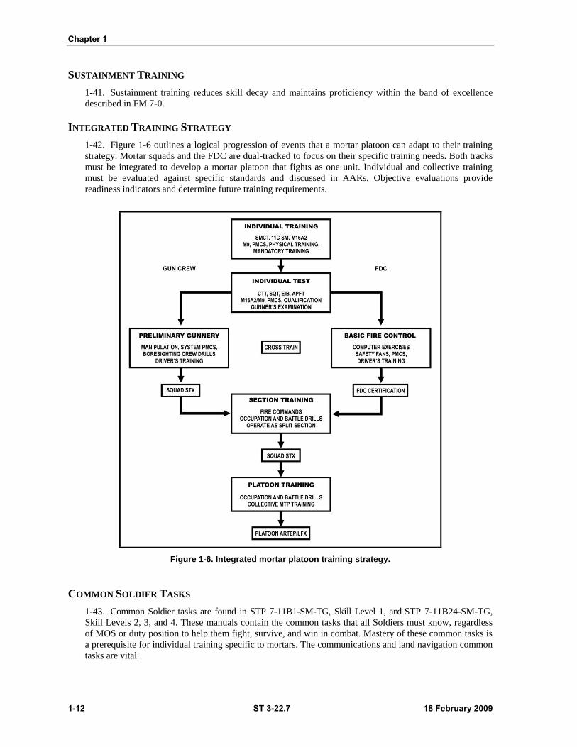
1-42. Figure 1-6 outlines a logical progression of events that a mortar platoon can adapt to their training
strategy. Mortar squads and the FDC are dual-tracked to focus on their specific training needs. Both tracks
must be integrated to develop a mortar platoon that fights as one unit. Individual and collective training
must be evaluated against specific standards and discussed in AARs. Objective evaluations provide
readiness indicators and determine future training requirements.
Figure 1-6. Integrated mortar platoon training strategy.
COMMON SOLDIER TASKS
1-43. Common Soldier tasks are found in STP 7-11B1-SM-TG, Skill Level 1, and STP 7-11B24-SM-TG,
Skill Levels 2, 3, and 4. These manuals contain the common tasks that all Soldiers must know, regardless
of MOS or duty position to help them fight, survive, and win in combat. Mastery of these common tasks is
a prerequisite for individual training specific to mortars. The communications and land navigation common
tasks are vital.
The M1129A1 Stryker Mortar Carrier Vehicle
18 February 2009 ST 3-22.7 1-13
MOS 11C TASKS
1-44. STP 7-11C14-SM-TG, Skill Levels 1-4 for MOS 11C, contains individual tasks specific to
mortarmen. The trainer’s guide provides leaders with the information required to develop individual
portions of a unit plan. Each 11C task is listed in this guide.
CROSS TRAINING
1-45. Casualties (whether in war or in training) can quickly render mortars ineffective if key personnel are
lost. This fact makes cross training Soldiers outside of their assigned position in mortars essential.
COLLECTIVE TRAINING
1-46. Collective training includes squad, section, and platoon drills and exercises.
Squad Training
1-47. Squad-level mortar tasks are in the Infantry MTP. Training can be performed in garrison using
devices or live ammunition. Once these tasks are mastered, an increased challenge is introduced by
performing them under different conditions such as urbanized terrain, limited visibility or chemical,
biological, radiological, and nuclear (CBRN). Cross training is accomplished at this level by rotating
Soldiers among duty positions, such as squad leader, and FDC positions, while providing coaching.
1-48. The focus of squad-level training is the Drill. If individual proficiency is effectively sustained, new
Soldiers can be readily integrated into the unit during collective training. Soldiers arrive at a unit proficient
in specific tasks learned in the training base, such as ground mount 60/81-mm mortar operations. Once in
the unit they must learn additional tasks (mortar carrier/MFCS) while training with their experienced peers
and squad leaders. MCV battle and squad drills are included in Chapter 4 of this handbook. The foundation
of squad training is sound individual training.
Section and Platoon Training
1-49. The core section, platoon tasks, collective tasks and other training products are located on the Digital
Training Management System (DTMS). Infantry unit task lists and collective tasks are accessible through the
DTMS, and are also posted to the Warrior University Web site (https://www.warrioruniversity.army.mil/login.html)
Training usually consists of an exercise in the field: LFX, STX (either alone or with a rifle company), or field
training exercise (FTX) as part of the battalion. LFXs may involve subcaliber or service ammunition. STXs and
FTXs may incorporate live fire, dry fire, and TADSS in combination or separately.
1-50. The fire support team (FIST) must be a part of this training. An LFX must never take place without
the FISTs normally associated with the battalion. Trainers may wish to integrate these artillerymen into the
mortar unit to teach them the capabilities, limitations, and unique requirements of operating mortars.
The Mortar’s Role in Task Force Operations
1-51. Mortars also play a vital role in overall task force operations. Collective training mainly involves
leaders in an FTX. However, mortars must be considered along with other fire support assets when
conducting a MAPEX, CFX, TEWT or CPX.
Collective Training Resources
1-52. Warrior tasks, battle drills, collective tasks and other training products are located on the Digital
Training Management System (DTMS). Infantry unit task lists and collective tasks are accessible through
the DTMS, and are also posted to the Warrior University Web site
(https://www.warrioruniversity.army.mil/login.html).
Chapter 1
1-14 ST 3-22.7 18 February 2009
Battle Drills. The first are battle drills (previously termed crew drills). Battle drills involve specific
categories of collective tasks performed at the squad, section, or platoon level. They are standardized
throughout the U.S. Army and may not be modified in training. The mortar unit is required to be
proficient in all battle drills contained in the drill book because they are vital to the mortar’s success
in combat. Their focus is on the mechanical manipulation of the mortar such as small deflection
changes and removing misfires. Full proficiency in battle drill tasks is a prerequisite to participating
in fire support missions. Less critical drills are published in other sources such as training circulars
or field manuals.
Survival Battle Drills. The second area encompasses those battle drills essential to combat survival
such as React to Chemical Attack, React to Indirect Fire, and React to Nuclear Attack.
Mission Training Plan
1-53. The mission training plan (MTP) is a descriptive ARTEP document for training mortarmen to
critical wartime mission proficiency. It gives the mortar platoon or section a clear description of ―what‖
and ―how‖ to train. This is achieved through comprehensive, detailed training and evaluation outlines
(T&EOs); guidance on training exercises; and other related training management aids. While its focus is on
collective training, the MTP also provides matrices that identify individual tasks and common 11C SM
tasks.
TRAINING EVALUATION
1-54. Evaluation cannot be separated from effective training. It occurs during the top-down analysis when
planners develop their training plan. Planners use various sources of information to assess their unit’s
individual and collective training status. Evaluation is continuous during training. Soldiers receive
feedback through coaching and AARs. Leaders also assess their own training plan and the instructional
skills of subordinate leaders. After training, leaders evaluate by sampling training or reviewing AARs.
Much of this evaluation is conducted informally. Formal evaluations occur under the Individual Training
and Evaluation Program and the Army Training and Evaluation Program (ARTEP) to assess individual and
collective training respectively.
INDIVIDUAL TRAINING
Commander’s Evaluation
1-55. Supported by the MOS 11C Soldier manuals and trainer guides, the commander’s evaluation is
conducted routinely at the unit level. Commanders select and evaluate individual tasks that support their
unit mission and contribute to unit proficiency. This may be performed through local tests or assessments
of Soldier proficiency on crucial mortar MOS tasks or common tasks. The evaluation is based on year-
round constant evaluation by the chain of command.
Gunner’s Examination
1-56. The gunner’s examination is a continuation of the mortar-based drills in which a mortar man’s
proficiency as a gunner is established. The examination is contained in Chapter 5 of this handbook. The
examination includes gunner tests, equipment, conditions, testing procedures, scoring, and administrative
procedures. The gunner’s success also depends on the collective performance of his assistants. So within
these limitations, evaluators should try to standardize the examination. The battalion level training model
requires the squad leader, gunner, and assistant gunner to pass the gunner’s exam semiannually. All
gunners must have a current qualification before participating in an LFX.
The M1129A1 Stryker Mortar Carrier Vehicle
18 February 2009 ST 3-22.7 1-15
Fire Direction Control Certification
1-57. Fire direction control certification provides commanders with a means to verify that their FDC
mortarmen have the knowledge and skills for their positions. Certification helps ensure that ammunition is
expended wisely, and that training is conducted both safely and effectively. Mortarmen are certified when
they receive a passing score on the two-part examination. (See FM 3-22.91, Mortar Gunnery for FDC
certification.)
COLLECTIVE TRAINING
Army Training and Evaluation Program
1-58. The aim of collective training is to provide units with the skills required to perform unit-level tasks.
ARTEPs provide the overall program for collective training. They prescribe the collective tasks a mortar
unit must successfully perform to accomplish its mission and to survive in combat. Located in MTPs and
drill books, collective training tasks include conditions and performance standards.
External Evaluation
1-59. The commander formally determines the status of his collective training through external evaluation.
The external evaluation gives the commander an objective appraisal of this status by using mortar expertise
found outside the normal chain of command. The external evaluation is not a test in which a unit passes or
fails; it is a diagnostic tool for identifying training strengths and weaknesses. An external evaluation is not
a specific training event; it is a means to evaluate a training event. Mortar units undergo external
evaluations during an LFX, FTX, or a combination of the two. The unit may be evaluated alone, as part of
its parent unit, or with other mortar units. The MTP provides guidance on planning, preparing, and
conducting an external evaluation.
Evaluation of Forward Observer
1-60. Mortar fires can be no more effective than their spotting forward observers (FOs). It is therefore
critical that FIST FOs are present and evaluated during an externally evaluated mortar LFX. If an FO fails
to meet his performance standards, mortarmen should not be penalized. Only as a last resort should a fire
mission be deleted from the evaluation. In the event of an FO failure, mortarmen should be given the
opportunity to successfully complete the fire mission in the following ways:
1. Start the fire mission over. Though ammunition constraints during live-fire may not permit this,
tasks can be repeated using devices, or less preferably, by dry fire.
2. Correct the call for fire or correction. Mortarmen should not have to use wrong firing data if an
FO makes an incorrect call for fire or correction. This wastes valuable training ammunition. To
avoid this, FO evaluators at the observation point can change a call for fire or correction to reflect
proper procedures.

18 February 2009 ST 3-22.7 2-1
Chapter 2
OPERATIONAL PROCEDURES
Mortar ammunition and sighting accuracy make the Stryker MCV a formidable
Infantry weapon. This chapter addresses the proper stowage of MCV mortar
ammunition based upon battalion, RSTA, and company carrier configurations. It also
discusses procedures for boresighting the 120-mm cannon (both manually and in
digital mode), and emplacement procedures for the section and platoon using the
Mortar Fire Control System.
Section I — MORTAR AMMUNITION
2-1. Though the 120-mm mortar system is the primary weapon of the MCV; mission, enemy, terrain and
weather, troops and support available, time available and civil considerations (METT-TC) may dictate use
of the 60-mm or 81-mm weapon system. FM 3-22.90, Mortars, and FM 3-22.91, Mortar Gunnery, cover
60-mm and 81-mm mortar ground-mounted installation, placement, and firing procedures. These manuals
also cover other 120-mm mortar platform systems. This handbook covers only those things specific to
MCV operations.
MORTAR STORAGE SPACE, 60-MM/81-MM
2-2. Example Load Plan, Chapter 6 of this handbook, has been extracted from TM 9-2355-311-10-3-1.
Chapter 6 illustrates in graphic detail the storage location of the 60-mm (company load plan) and 81-mm
(battalion load plan). Chapter 4 of this handbook, ―Drills,‖ covers storage and dismounting of the
60-mm/81-mm systems.
AMMUNITION STORAGE SPACE
2-3. The MCV is equipped with two ammunition racks capable of storing 120-mm, 81-mm, or 60-mm
ammunition. The quantity of each type of ammunition stored onboard the vehicle is based on where the
MCV is assigned. If the MCV is assigned to a RSTA squadron, it can store 60 rounds of 120-mm
ammunition. At the Infantry battalion it can store 48 rounds of 120-mm, and 35 rounds of 81-mm
ammunition. When assigned at the Infantry company level, it can store 48 rounds of 120-mm ammunition,
and 77 rounds of 60-mm ammunition.
Note: Orientation of the MCV’s right versus left side is based on a rear vehicle view.
LEFT-SIDE AMMUNITION RACK
2-4. The left ammunition rack is used to store 120-mm ammunition only. It has six vertical compartments
and six horizontal compartments. This rack can hold four rounds in each of the 12 compartments for a total
of 48 rounds.
Chapter 2
2-2 ST 3-22.7 18 February 2009
RIGHT-SIDE AMMUNITION RACK
2-5. The right ammunition rack can be configured to store 120-mm, 81-mm, or 60-mm ammunition.
1. When the rack is configured for 120-mm, it has four vertical compartments. It can hold three
rounds in each of the four compartments for a total of 12 rounds.
2. When the rack is configured for 81-mm, it has one horizontal compartment and six vertical
compartments. It can hold five rounds in each of the seven compartments for a total of 35
rounds.
3. When the rack is configured for 60-mm ammunition, it has two vertical compartments and nine
horizontal compartments. It can hold seven rounds in each of the eleven compartments for a
total of 77 rounds.
Notes: 1. All ammunition is stored in its original containers with seals unbroken.
2. HE ammunition can be stored in either the horizontal or vertical compartments.
3. WP ammunition must be stored in the vertical compartments only. WP
ammunition must be stored in the vertical compartments only.
4. Illumination ammunition can be stored in either the horizontal or vertical
compartments.
5. Load ammunition from the bottom compartment of the rack to the top
compartment.
6. Unload ammunition from the top compartment of the rack to the bottom
compartment.
SECURING AMMUNITION
2-6. All ammunition must be secured before moving the MCV. Ammunition is held in the ammunition
compartments by retainer clips. However, it can fall out when traveling over rough terrain or when making
sharp turns. Doors on the ammunition racks must be closed and secured. Straps on the vertical
compartments must be hooked and tight.
WARNING
Ammunition may fall out of ammunition racks if not properly secured. Failure to secure ammunition prior to moving the MCV can result in damage to equipment or ammunition and/or injury to personnel.
120-MM AMMUNITION
2-7. To ensure ammunition is being correctly stowed and removed from ammunition racks, vehicle
leaders should be present during the handling of 120-mm ammunition.
2-8. Stow and secure 120-mm ammunition in left-side horizontal rack. The following steps should be
performed in order when stowing 120-mm ammunition (Figure 2-1).
OPERATIONAL PROCEDURES
18 February 2009 ST 3-22.7 2-3
Figure 2-1. Left side 120-mm ammunition horizontal rack (stowage).
1. Push and hold latch (1) on left side of ammunition rack (2).
2. Grasp top of door (3) and pull up to clear internal locking device located inside of rack.
3. Pull door (3) out slightly and release latch.
4. Grasp top of door (3) with two hands and pull down to open position.
5. Load up to four rounds into compartment.
6. Push door (3) up toward closed position.
7. When door approaches closed position, grasp top of door, pull up to clear internal locking
device, and continue closing door.
8. When door (3) is in the full closed position, push door down while making sure latch (1) snaps
back into lock position. Ensure door is secure.
9. Repeat steps 1-8 for other compartments as required.
WARNING
Ammunition may fall out of the horizontal ammunition rack if not properly secured. Failure to secure ammunition before moving the MCV can result in damage to equipment or ammunition and/or injury to personnel.
Chapter 2
2-4 ST 3-22.7 18 February 2009
REMOVE 120-MM AMMUNITION FROM LEFT SIDE HORIZONTAL RACK
2-9. Perform the following steps when removing 120-mm ammunition in the horizontal rack
(Figure 2-2).
Figure 2-2. Left side 120-mm ammunition horizontal rack (removal).
1. Push and hold latch (1) on left side of ammunition rack (2).
2. Grasp top of door (3) and pull up to clear internal locking device located inside of rack.
3. Pull door out slightly and release latch (1).
4. Grasp door (3) with two hands and pull down to open position.
5. Remove one round from compartment.
Note: Unload ammunition from the top compartment of rack to the bottom compartment.
6. Repeat step 5 as required until desired number of rounds are removed or compartment is empty.
7. Push door (3) up toward closed position.
8. When door (3) approaches closed position, grasp top of door, pull up to clear internal locking
device, and continue closing the door.
9. When door is in fully closed position, push door down, and make sure latch (1) snaps back into
the locked position. Ensure door is secure.
10. Perform steps 1-9 for other compartments as required.
OPERATIONAL PROCEDURES
18 February 2009 ST 3-22.7 2-5
STOW AND SECURE 120-MM AMMUNITION IN LEFT SIDE VERTICAL RACK
2-10. Perform the following steps when stowing 120-mm ammunition in the vertical rack (Figure 2-3).
Figure 2-3. Left side 120-mm ammunition vertical rack (stowage).
1. Ensure fixed straps (1) and (2) are out of the way.
2. Ensure retractable straps (3) and (4) are fully retracted. If not, press release lever (5) and allow
straps to retract.
3. Load up to four rounds in each vertical compartment (6) as required.
CAUTION
Make sure to route straps on inside of frame and around outermost ammunition. Straps routed on outside of frame will not secure ammunition and will cause strap to fray. Failure to properly route straps may result in damage to equipment.
4. Press release lever (5) and pull upper retractable strap (3) through frame of rack, around
ammunition, and all the way toward upper fixed strap (1).
Note: To ensure ammunition is held securely in place, make sure more rounds of
ammunition are loaded into compartments located toward the center of the rack than
compartments located toward either end of rack.
5. Insert hook on retractable strap (7) into loop on fixed strap (8).
6. Release both straps and allow retractable strap (3) to retract.
7. Operate ratchet handle until retractable strap (3) is snug.
8. Verify that ammunition is securely held in place by retractable strap. If not, repeat step 7.
9. Push ratchet handle (9) in to the stowed position.
10. Repeat steps 4-9 for fixed strap (2) and lower retractable strap (4).
Chapter 2
2-6 ST 3-22.7 18 February 2009
WARNING
Ammunition may fall out of the vertical ammunition rack if not properly secured. Failure to secure ammunition before the MCV is moved can result in damage to equipment or ammunition and/or injury to personnel.
REMOVE 120-MM AMMUNITION FROM LEFT SIDE VERTICAL RACK
2-11. Perform the following steps when removing 120-mm ammunition in the vertical rack (Figure 2-4).
Figure 2-4. Left side 120-mm ammunition vertical rack (removal).
1. Press release lever (1) and pull retractable strap (2) to loosen.
2. Grasp lower fixed strap (3) and remove lower hook (4) from loop.
3. Release both straps and allow retractable strap (2) to retract.
4. Repeat steps 1-3 for upper retractable strap (6) and fixed strap (7).
5. Remove one round from desired compartment (8).
6. Repeat step 5 as required until desired number of rounds are removed.
Note: To ensure ammunition remaining in ammunition rack is securely held in place, make
sure more rounds of ammunition are left in compartments located toward the center
of rack than compartments located toward either end.
STOW AND SECURE 120-MM AMMUNITION IN RIGHT SIDE VERTICAL RACK
2-12. Perform the following steps when stowing 120-mm ammunition in the vertical rack (Figure 2-5).
OPERATIONAL PROCEDURES
18 February 2009 ST 3-22.7 2-7
Figure 2-5. Right side 120-mm ammunition vertical rack (stowage).
1. Make sure that right ammunition rack (1) is configured for 120-mm ammunition. If not, notify
field maintenance.
2. Press release lever (2) and adjust to lengthen strap (3).
3. Remove hook (4) of adjustable strap (3) from loop (5) on fixed strap (6).
Note: To ensure ammunition is held securely in place, make sure more rounds of
ammunition are loaded into compartments located toward the center of rack than
compartments located toward either end of rack.
4. Load up to three rounds in each vertical compartment (7) as required.
5. Ensure both straps are routed through opening on side of rack to inside of frame and around
ammunition.
CAUTION
Make sure to route straps on inside of frame and around outermost ammunition. Straps routed on outside of frame will not secure ammunition and will cause the strap to fray. Failure to properly route straps may result in damage to equipment.
6. Press release lever (2) and adjust to lengthen strap (3) as required.
7. Attach hook (4) of adjustable strap (3) into loop (5) on fixed strap (6).
8. Pull adjustable strap (3) to tighten and retain stowed ammunition.
9. Verify that ammunition is securely held in place by straps. If not, repeat steps 7 and 8.
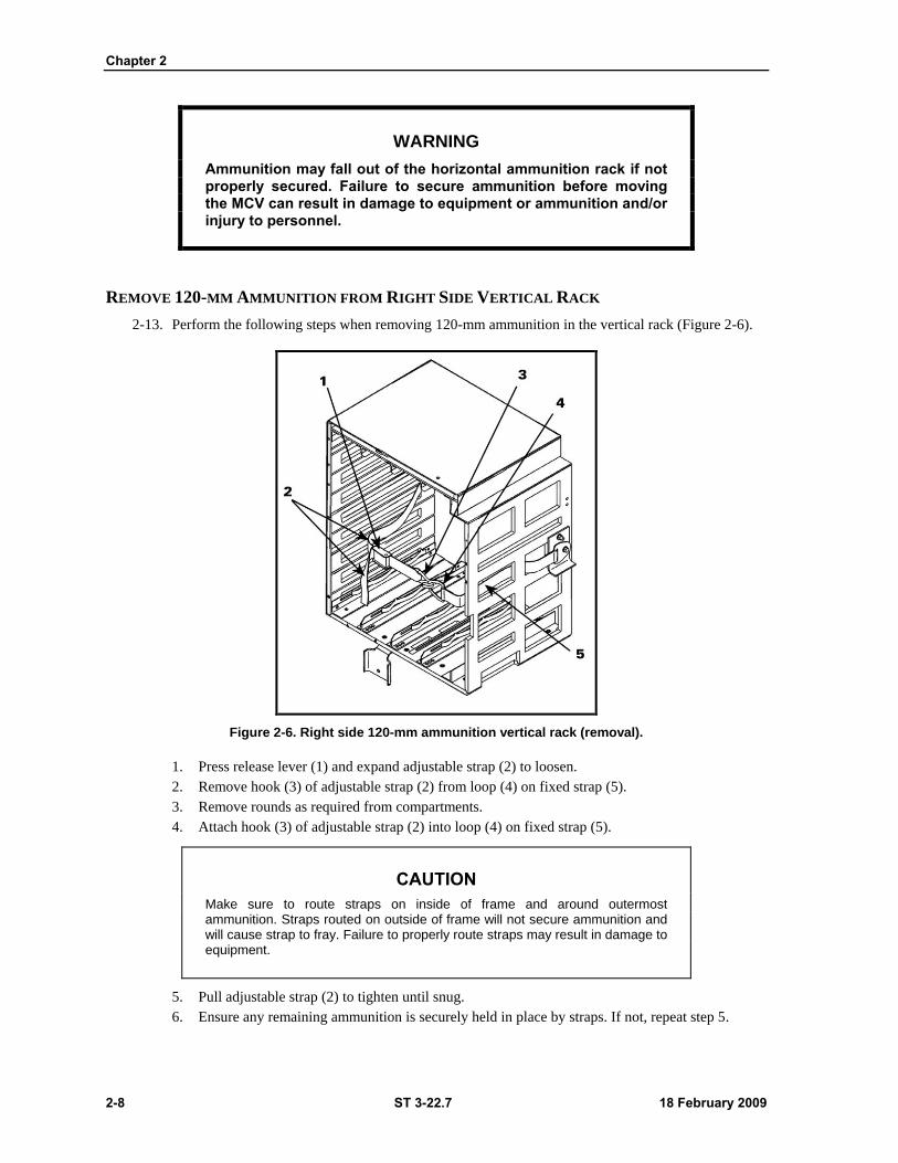
Chapter 2
2-8 ST 3-22.7 18 February 2009
WARNING
Ammunition may fall out of the horizontal ammunition rack if not properly secured. Failure to secure ammunition before moving the MCV can result in damage to equipment or ammunition and/or injury to personnel.
REMOVE 120-MM AMMUNITION FROM RIGHT SIDE VERTICAL RACK
2-13. Perform the following steps when removing 120-mm ammunition in the vertical rack (Figure 2-6).
Figure 2-6. Right side 120-mm ammunition vertical rack (removal).
1. Press release lever (1) and expand adjustable strap (2) to loosen.
2. Remove hook (3) of adjustable strap (2) from loop (4) on fixed strap (5).
3. Remove rounds as required from compartments.
4. Attach hook (3) of adjustable strap (2) into loop (4) on fixed strap (5).
CAUTION
Make sure to route straps on inside of frame and around outermost ammunition. Straps routed on outside of frame will not secure ammunition and will cause strap to fray. Failure to properly route straps may result in damage to equipment.
5. Pull adjustable strap (2) to tighten until snug.
6. Ensure any remaining ammunition is securely held in place by straps. If not, repeat step 5.
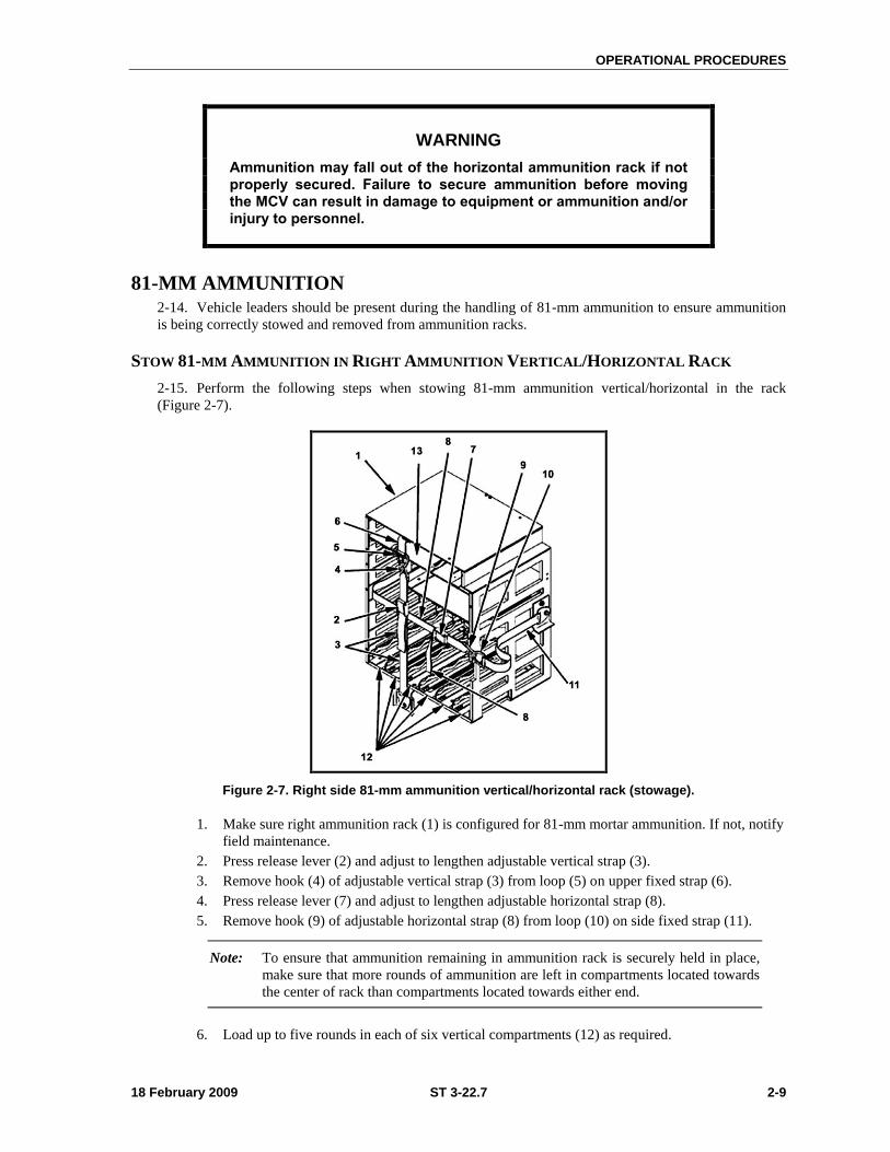
OPERATIONAL PROCEDURES
18 February 2009 ST 3-22.7 2-9
WARNING
Ammunition may fall out of the horizontal ammunition rack if not properly secured. Failure to secure ammunition before moving the MCV can result in damage to equipment or ammunition and/or injury to personnel.
81-MM AMMUNITION 2-14. Vehicle leaders should be present during the handling of 81-mm ammunition to ensure ammunition
is being correctly stowed and removed from ammunition racks.
STOW 81-MM AMMUNITION IN RIGHT AMMUNITION VERTICAL/HORIZONTAL RACK
2-15. Perform the following steps when stowing 81-mm ammunition vertical/horizontal in the rack
(Figure 2-7).
Figure 2-7. Right side 81-mm ammunition vertical/horizontal rack (stowage).
1. Make sure right ammunition rack (1) is configured for 81-mm mortar ammunition. If not, notify
field maintenance.
2. Press release lever (2) and adjust to lengthen adjustable vertical strap (3).
3. Remove hook (4) of adjustable vertical strap (3) from loop (5) on upper fixed strap (6).
4. Press release lever (7) and adjust to lengthen adjustable horizontal strap (8).
5. Remove hook (9) of adjustable horizontal strap (8) from loop (10) on side fixed strap (11).
Note: To ensure that ammunition remaining in ammunition rack is securely held in place,
make sure that more rounds of ammunition are left in compartments located towards
the center of rack than compartments located towards either end.
6. Load up to five rounds in each of six vertical compartments (12) as required.
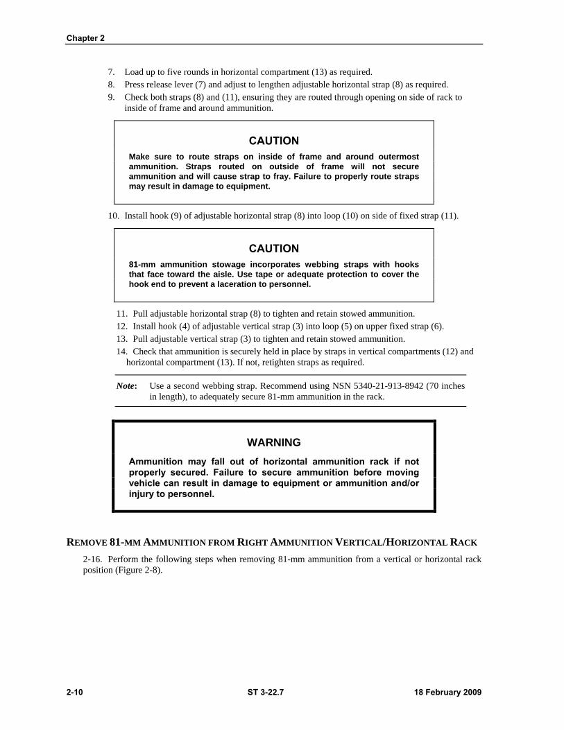
Chapter 2
2-10 ST 3-22.7 18 February 2009
7. Load up to five rounds in horizontal compartment (13) as required.
8. Press release lever (7) and adjust to lengthen adjustable horizontal strap (8) as required.
9. Check both straps (8) and (11), ensuring they are routed through opening on side of rack to
inside of frame and around ammunition.
CAUTION
Make sure to route straps on inside of frame and around outermost
ammunition. Straps routed on outside of frame will not secure
ammunition and will cause strap to fray. Failure to properly route straps
may result in damage to equipment.
10. Install hook (9) of adjustable horizontal strap (8) into loop (10) on side of fixed strap (11).
CAUTION
81-mm ammunition stowage incorporates webbing straps with hooks
that face toward the aisle. Use tape or adequate protection to cover the
hook end to prevent a laceration to personnel.
11. Pull adjustable horizontal strap (8) to tighten and retain stowed ammunition.
12. Install hook (4) of adjustable vertical strap (3) into loop (5) on upper fixed strap (6).
13. Pull adjustable vertical strap (3) to tighten and retain stowed ammunition.
14. Check that ammunition is securely held in place by straps in vertical compartments (12) and
horizontal compartment (13). If not, retighten straps as required.
Note: Use a second webbing strap. Recommend using NSN 5340-21-913-8942 (70 inches
in length), to adequately secure 81-mm ammunition in the rack.
WARNING
Ammunition may fall out of horizontal ammunition rack if not properly secured. Failure to secure ammunition before moving vehicle can result in damage to equipment or ammunition and/or injury to personnel.
REMOVE 81-MM AMMUNITION FROM RIGHT AMMUNITION VERTICAL/HORIZONTAL RACK
2-16. Perform the following steps when removing 81-mm ammunition from a vertical or horizontal rack
position (Figure 2-8).
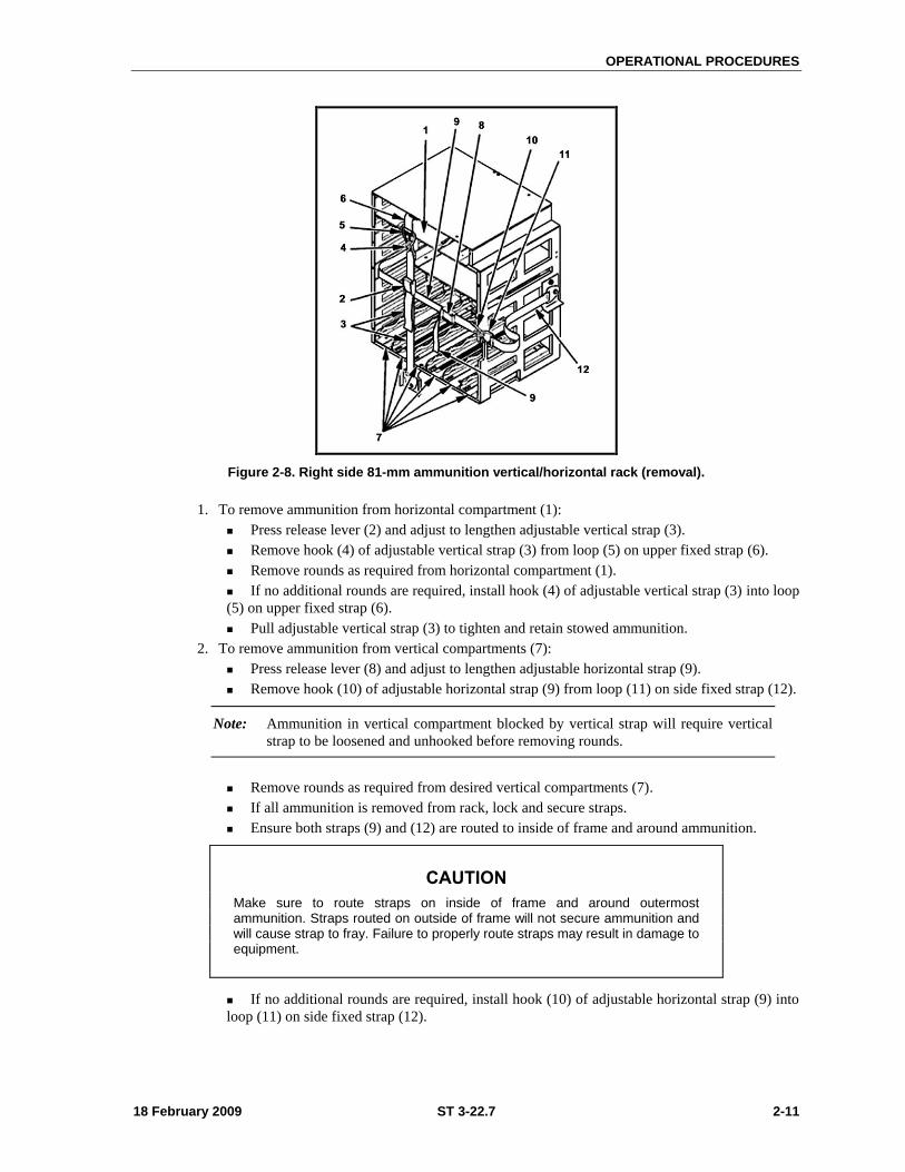
OPERATIONAL PROCEDURES
18 February 2009 ST 3-22.7 2-11
Figure 2-8. Right side 81-mm ammunition vertical/horizontal rack (removal).
1. To remove ammunition from horizontal compartment (1):
Press release lever (2) and adjust to lengthen adjustable vertical strap (3).
Remove hook (4) of adjustable vertical strap (3) from loop (5) on upper fixed strap (6).
Remove rounds as required from horizontal compartment (1).
If no additional rounds are required, install hook (4) of adjustable vertical strap (3) into loop
(5) on upper fixed strap (6).
Pull adjustable vertical strap (3) to tighten and retain stowed ammunition.
2. To remove ammunition from vertical compartments (7):
Press release lever (8) and adjust to lengthen adjustable horizontal strap (9).
Remove hook (10) of adjustable horizontal strap (9) from loop (11) on side fixed strap (12).
Note: Ammunition in vertical compartment blocked by vertical strap will require vertical
strap to be loosened and unhooked before removing rounds.
Remove rounds as required from desired vertical compartments (7).
If all ammunition is removed from rack, lock and secure straps.
Ensure both straps (9) and (12) are routed to inside of frame and around ammunition.
CAUTION
Make sure to route straps on inside of frame and around outermost ammunition. Straps routed on outside of frame will not secure ammunition and will cause strap to fray. Failure to properly route straps may result in damage to equipment.
If no additional rounds are required, install hook (10) of adjustable horizontal strap (9) into
loop (11) on side fixed strap (12).
Chapter 2
2-12 ST 3-22.7 18 February 2009
Note: To ensure that ammunition remaining in ammunition rack is securely held in place,
make sure that more rounds of ammunition are left in compartments located towards
the center of rack than compartments located towards either end.
Pull adjustable horizontal strap (9) to tighten and retain remaining ammunition.
CAUTION
81-mm ammunition stowage incorporates webbing straps with hooks that face toward the aisle. Use tape or adequate protection to cover the hook end to prevent a laceration to personnel.
3. Check ammunition is securely held in place by straps in vertical compartments (7) and horizontal
compartment (1). If not, rearrange ammunition and retighten straps as required.
WARNING
Ammunition may fall out of the horizontal ammunition rack if not properly secured. Failure to secure ammunition before moving the MCV can result in damage to equipment or ammunition and/or injury to personnel.
Note: Use a second webbing strap. Recommend using NSN 5340-21-913-8942 (70 inches
in length) to adequately secure 81-mm ammunition in the rack.
60-MM AMMUNITION
2-17. Vehicle leaders should be present during the handling of 60-mm ammunition to ensure ammunition
is being correctly stowed and removed from ammunition racks.
STOW 60-MM AMMUNITION IN RIGHT AMMUNITION VERTICAL/HORIZONTAL RACK
2-18. Perform the following steps when stowing or when removing 60-mm ammunition from the right
vertical/horizontal rack (Figure 2-9).
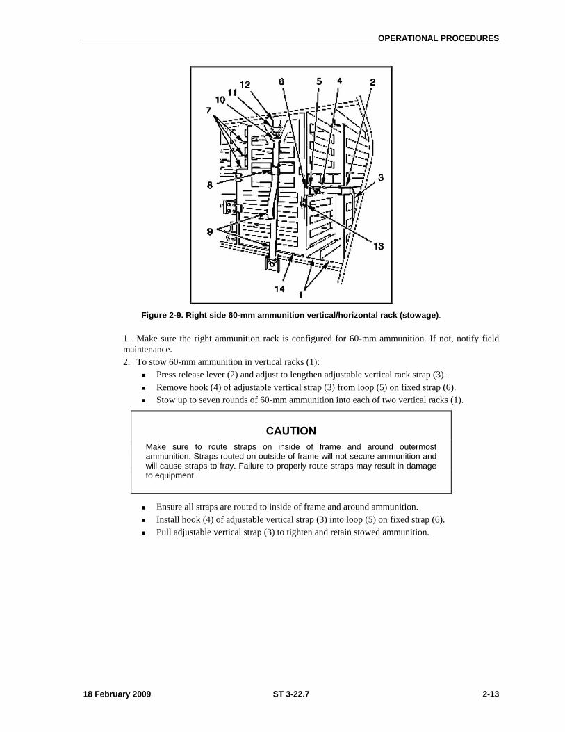
OPERATIONAL PROCEDURES
18 February 2009 ST 3-22.7 2-13
Figure 2-9. Right side 60-mm ammunition vertical/horizontal rack (stowage).
1. Make sure the right ammunition rack is configured for 60-mm ammunition. If not, notify field
maintenance.
2. To stow 60-mm ammunition in vertical racks (1):
Press release lever (2) and adjust to lengthen adjustable vertical rack strap (3).
Remove hook (4) of adjustable vertical strap (3) from loop (5) on fixed strap (6).
Stow up to seven rounds of 60-mm ammunition into each of two vertical racks (1).
CAUTION
Make sure to route straps on inside of frame and around outermost ammunition. Straps routed on outside of frame will not secure ammunition and will cause straps to fray. Failure to properly route straps may result in damage to equipment.
Ensure all straps are routed to inside of frame and around ammunition.
Install hook (4) of adjustable vertical strap (3) into loop (5) on fixed strap (6).
Pull adjustable vertical strap (3) to tighten and retain stowed ammunition.

Chapter 2
2-14 ST 3-22.7 18 February 2009
CAUTION
81-mm ammunition stowage incorporates webbing straps with hooks that face toward the aisle. Use tape or adequate protection to cover the hook end to prevent a laceration to personnel (see Figure 2-10).
Figure 2-10. Right side 60-mm ammunition vertical/horizontal rack (stowage).
3. To stow 60-mm ammunition in horizontal racks (7):
Press release lever (8) and adjust to lengthen adjustable horizontal rack strap (9).
Remove hook (10) of adjustable horizontal rack strap (9) from loop (11) on fixed strap (12).
Lift door latch (13) and open door (14).
Stow up to seven rounds of 60-MM ammunition into each of nine horizontal racks (7).
When all ammo required for horizontal racks is stowed, close door (14) and lock door latch
(13).
Install hook (10) of adjustable horizontal rack strap (9) into loop (11) on fixed strap (12).
Pull adjustable horizontal rack strap (9) to tighten.
4. Ensure vertical rack strap (3) and horizontal rack strap (9) are fully tightened. If not, retighten
straps as required.
WARNING
Ammunition may fall out of the horizontal ammunition rack if not properly secured. Failure to secure ammunition before moving vehicle could result in damage to equipment or ammunition and/or injury to personnel.
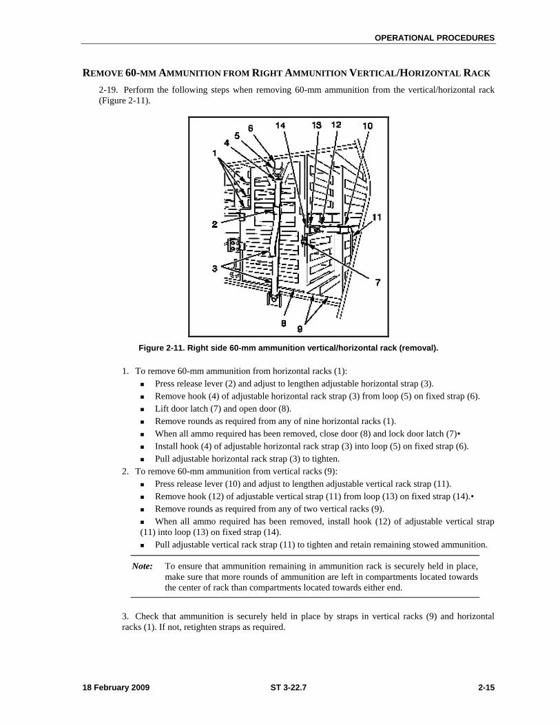
OPERATIONAL PROCEDURES
18 February 2009 ST 3-22.7 2-15
REMOVE 60-MM AMMUNITION FROM RIGHT AMMUNITION VERTICAL/HORIZONTAL RACK
2-19. Perform the following steps when removing 60-mm ammunition from the vertical/horizontal rack
(Figure 2-11).
Figure 2-11. Right side 60-mm ammunition vertical/horizontal rack (removal).
1. To remove 60-mm ammunition from horizontal racks (1):
Press release lever (2) and adjust to lengthen adjustable horizontal strap (3).
Remove hook (4) of adjustable horizontal rack strap (3) from loop (5) on fixed strap (6).
Lift door latch (7) and open door (8).
Remove rounds as required from any of nine horizontal racks (1).
When all ammo required has been removed, close door (8) and lock door latch (7)•
Install hook (4) of adjustable horizontal rack strap (3) into loop (5) on fixed strap (6).
Pull adjustable horizontal rack strap (3) to tighten.
2. To remove 60-mm ammunition from vertical racks (9):
Press release lever (10) and adjust to lengthen adjustable vertical rack strap (11).
Remove hook (12) of adjustable vertical strap (11) from loop (13) on fixed strap (14).•
Remove rounds as required from any of two vertical racks (9).
When all ammo required has been removed, install hook (12) of adjustable vertical strap
(11) into loop (13) on fixed strap (14).
Pull adjustable vertical rack strap (11) to tighten and retain remaining stowed ammunition.
Note: To ensure that ammunition remaining in ammunition rack is securely held in place,
make sure that more rounds of ammunition are left in compartments located towards
the center of rack than compartments located towards either end.
3. Check that ammunition is securely held in place by straps in vertical racks (9) and horizontal
racks (1). If not, retighten straps as required.
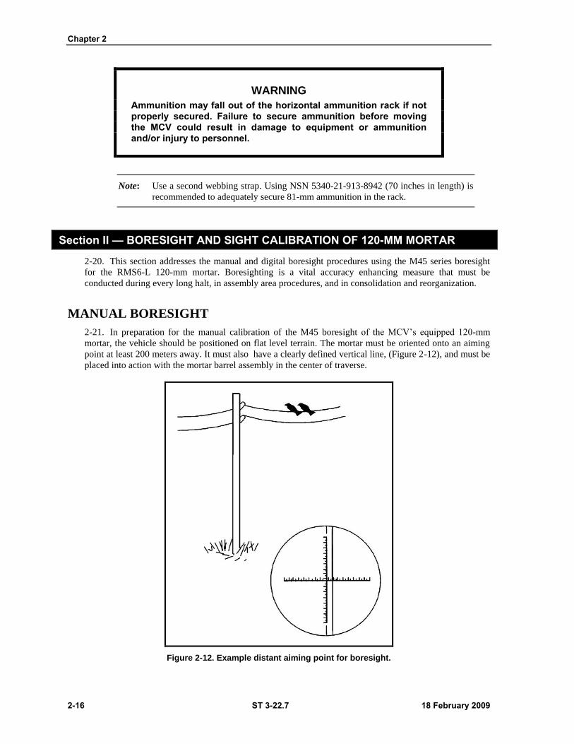
Chapter 2
2-16 ST 3-22.7 18 February 2009
WARNING
Ammunition may fall out of the horizontal ammunition rack if not properly secured. Failure to secure ammunition before moving the MCV could result in damage to equipment or ammunition and/or injury to personnel.
Note: Use a second webbing strap. Using NSN 5340-21-913-8942 (70 inches in length) is
recommended to adequately secure 81-mm ammunition in the rack.
Section II — BORESIGHT AND SIGHT CALIBRATION OF 120-MM MORTAR
2-20. This section addresses the manual and digital boresight procedures using the M45 series boresight
for the RMS6-L 120-mm mortar. Boresighting is a vital accuracy enhancing measure that must be
conducted during every long halt, in assembly area procedures, and in consolidation and reorganization.
MANUAL BORESIGHT
2-21. In preparation for the manual calibration of the M45 boresight of the MCV’s equipped 120-mm
mortar, the vehicle should be positioned on flat level terrain. The mortar must be oriented onto an aiming
point at least 200 meters away. It must also have a clearly defined vertical line, (Figure 2-12), and must be
placed into action with the mortar barrel assembly in the center of traverse.
Figure 2-12. Example distant aiming point for boresight.
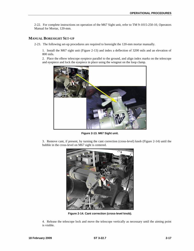
OPERATIONAL PROCEDURES
18 February 2009 ST 3-22.7 2-17
2-22. For complete instructions on operation of the M67 Sight unit, refer to TM 9-1015-250-10, Operators
Manual for Mortar, 120-mm.
MANUAL BORESIGHT SET-UP
2-23. The following set-up procedures are required to boresight the 120-mm mortar manually.
1. Install the M67 sight unit (Figure 2-13) and index a deflection of 3200 mils and an elevation of
800 mils.
2. Place the elbow telescope eyepiece parallel to the ground, and align index marks on the telescope
and eyepiece and lock the eyepiece in place using the wingnut on the loop clamp.
Figure 2-13. M67 Sight unit.
3. Remove cant, if present, by turning the cant correction (cross-level) knob (Figure 2-14) until the
bubble in the cross-level on M67 sight is centered.
Figure 2-14. Cant correction (cross-level knob).
4. Release the telescope lock and move the telescope vertically as necessary until the aiming point
is visible.
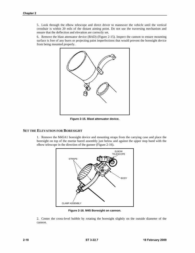
Chapter 2
2-18 ST 3-22.7 18 February 2009
5. Look through the elbow telescope and direct driver to maneuver the vehicle until the vertical
crosshair is within 20 mils of the distant aiming point. Do not use the traversing mechanism and
ensure that the deflection and elevation are correctly set.
6. Remove the blast attenuator device (BAD) (Figure 2-15). Inspect the cannon to ensure mounting
surface is free of any burrs or projecting paint imperfections that would prevent the boresight device
from being mounted properly.
Figure 2-15. Blast attenuator device.
SET THE ELEVATION FOR BORESIGHT
1. Remove the M45A1 boresight device and mounting straps from the carrying case and place the
boresight on top of the mortar barrel assembly just below and against the upper stop band with the
elbow telescope in the direction of the gunner (Figure 2-16).
Figure 2-16. M45 Boresight on cannon.
2. Center the cross-level bubble by rotating the boresight slightly on the outside diameter of the
cannon.
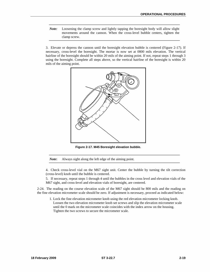
OPERATIONAL PROCEDURES
18 February 2009 ST 3-22.7 2-19
Note: Loosening the clamp screw and lightly tapping the boresight body will allow slight
movements around the cannon. When the cross-level bubble centers, tighten the
clamp screw.
3. Elevate or depress the cannon until the boresight elevation bubble is centered (Figure 2-17). If
necessary, cross-level the boresight. The mortar is now set at 0800 mils elevation. The vertical
hairline of the boresight should be within 20 mils of the aiming point. If not, repeat steps 1 through 3
using the boresight. Complete all steps above, so the vertical hairline of the boresight is within 20
mils of the aiming point.
Figure 2-17. M45 Boresight elevation bubble.
Note: Always sight along the left edge of the aiming point.
4. Check cross-level vial on the M67 sight unit. Center the bubble by turning the tilt correction
(cross-level) knob until the bubble is centered.
5. If necessary, repeat steps 1 through 4 until the bubbles in the cross level and elevation vials of the
M67 sight, and cross-level and elevation vials of boresight, are centered.
2-24. The reading on the course elevation scale of the M67 sight should be 800 mils and the reading on
the fine elevation micrometer scale should be zero. If adjustment is necessary, proceed as indicated below:
1. Lock the fine elevation micrometer knob using the red elevation micrometer locking knob.
Loosen the two elevation micrometer knob set screws and slip the elevation micrometer scale
until the 0 mark on the micrometer scale coincides with the index arrow on the housing.
Tighten the two screws to secure the micrometer scale.
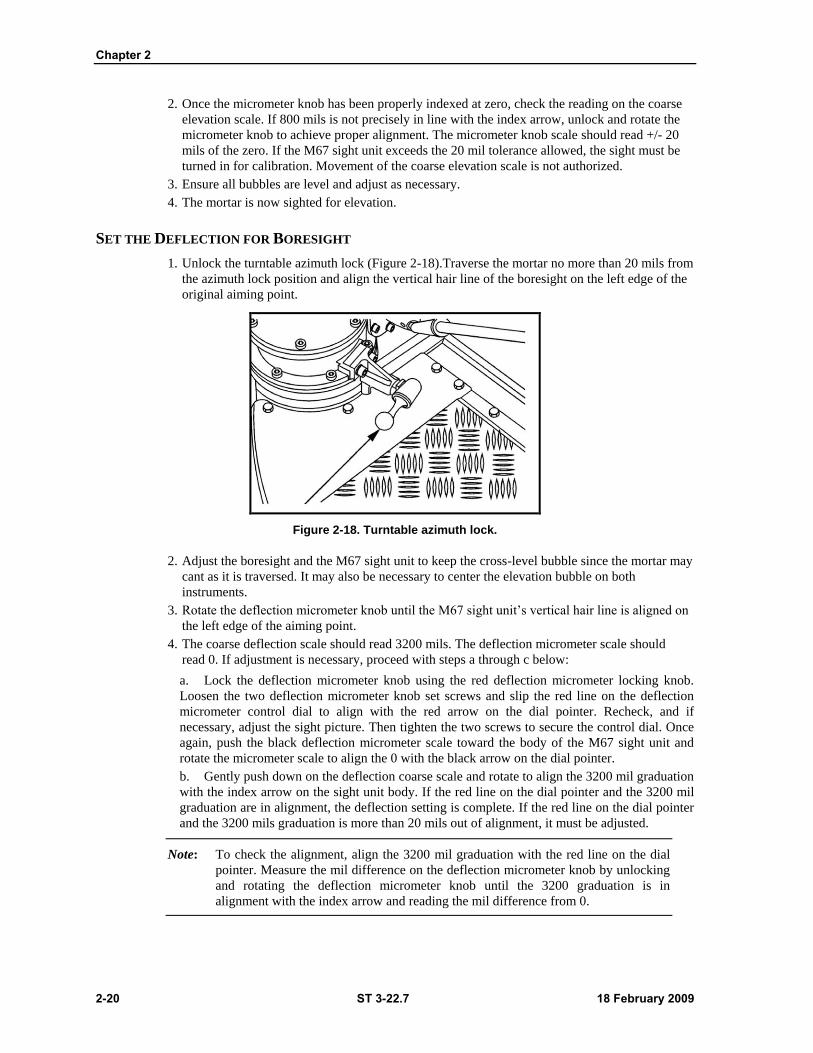
Chapter 2
2-20 ST 3-22.7 18 February 2009
2. Once the micrometer knob has been properly indexed at zero, check the reading on the coarse
elevation scale. If 800 mils is not precisely in line with the index arrow, unlock and rotate the
micrometer knob to achieve proper alignment. The micrometer knob scale should read +/- 20
mils of the zero. If the M67 sight unit exceeds the 20 mil tolerance allowed, the sight must be
turned in for calibration. Movement of the coarse elevation scale is not authorized.
3. Ensure all bubbles are level and adjust as necessary.
4. The mortar is now sighted for elevation.
SET THE DEFLECTION FOR BORESIGHT
1. Unlock the turntable azimuth lock (Figure 2-18).Traverse the mortar no more than 20 mils from
the azimuth lock position and align the vertical hair line of the boresight on the left edge of the
original aiming point.
Figure 2-18. Turntable azimuth lock.
2. Adjust the boresight and the M67 sight unit to keep the cross-level bubble since the mortar may
cant as it is traversed. It may also be necessary to center the elevation bubble on both
instruments.
3. Rotate the deflection micrometer knob until the M67 sight unit’s vertical hair line is aligned on
the left edge of the aiming point.
4. The coarse deflection scale should read 3200 mils. The deflection micrometer scale should
read 0. If adjustment is necessary, proceed with steps a through c below:
a. Lock the deflection micrometer knob using the red deflection micrometer locking knob.
Loosen the two deflection micrometer knob set screws and slip the red line on the deflection
micrometer control dial to align with the red arrow on the dial pointer. Recheck, and if
necessary, adjust the sight picture. Then tighten the two screws to secure the control dial. Once
again, push the black deflection micrometer scale toward the body of the M67 sight unit and
rotate the micrometer scale to align the 0 with the black arrow on the dial pointer.
b. Gently push down on the deflection coarse scale and rotate to align the 3200 mil graduation
with the index arrow on the sight unit body. If the red line on the dial pointer and the 3200 mil
graduation are in alignment, the deflection setting is complete. If the red line on the dial pointer
and the 3200 mils graduation is more than 20 mils out of alignment, it must be adjusted.
Note: To check the alignment, align the 3200 mil graduation with the red line on the dial
pointer. Measure the mil difference on the deflection micrometer knob by unlocking
and rotating the deflection micrometer knob until the 3200 graduation is in
alignment with the index arrow and reading the mil difference from 0.
OPERATIONAL PROCEDURES
18 February 2009 ST 3-22.7 2-21
c. If necessary, with the deflection micrometer knob and coarse scale correctly indexed to
3200 mils and locked, loosen the dial pointer set screws and rotate the red line on the dial
pointer until it is in alignment with the 3200 mil graduation. Tighten the two screws to secure
the dial pointer. Unlock the deflection micrometer knob.
5. Recheck and level all bubbles. Ensure all data is precisely set, control dial and dial pointer are
within tolerances, both sight pictures are identical on the aiming point, and the turntable is no
more than 20 mils from center. If any or all of these conditions are not met, repeat the
necessary boresight procedures and recheck.
CORRECTING FOR CANT
1. To insure proper alignment, remove and place the boresight in position underneath the cannon.
Center the boresight cross-level bubble and check the vertical crosshair to see if it is still on the
aiming point. If cant exists, the vertical crosshair of the boresight will not be on the aiming
point. This indicates that the true axis of the bore lies halfway between the aiming point and
where the boresight is now pointing.
2. To correct this error, look through the boresight. Traverse the mortar onto the aiming point
while keeping all bubbles level on both the boresight and sight unit. Using the deflection
micrometer knob, place the vertical crosshair of the sight back onto the aiming point.
Determine the mil difference from the original 3200 mils deflection and rotate the micrometer
one half the mil difference back in the direction of 3200 mils. Lock the red deflection
micrometer knob and continue to follow the steps outlined above in 4 (a) to adjust the
deflection micrometer knob back to 0.
3. Ensure all bubbles are level and the boresight retains the correct sight picture.
4. Remove and store the M45 boresight and M67 sight unit in their carrying cases.
5. Install BAD.
6. Manual boresight is complete.
DIGITAL BORESIGHT
2-25. For the Mortar Fire Control System (MFCS) software to properly compute the boresight values, the
mortar trunnions must be leveled. In a tactical environment, this is most easily accomplished using a
gunner’s quadrant. To make the process easier to perform, the vehicle should be parked on a slight incline,
roughly 20 to 50 mils, with the front of the MCV higher than the rear. The incline may be measured with
the gunner’s quadrant placed on top of the mortar’s traversing mechanism gearbox, or traversing gear ring,
and aligned with the fore and aft axis of the carrier. The ―line of fire‖ indicated on the gunner’s quadrant
(Figure 2-19) should point toward the front of the vehicle.
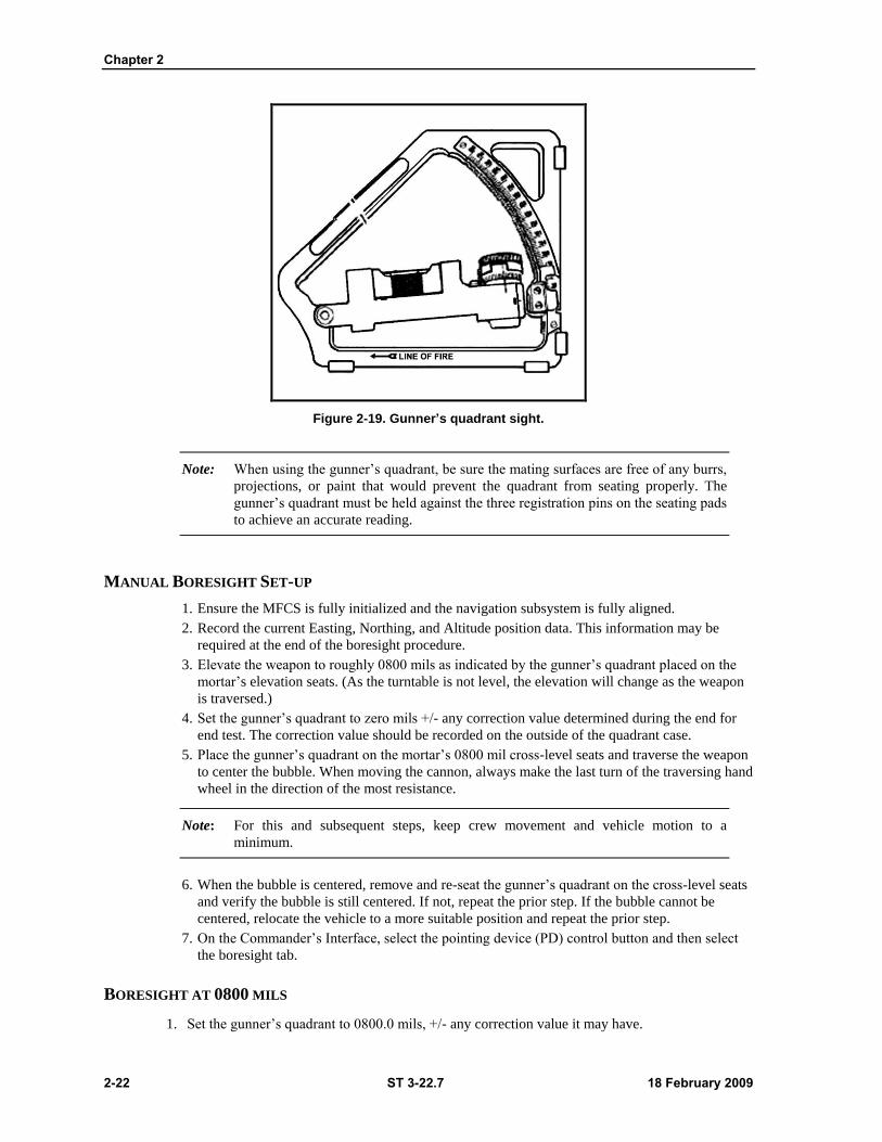
Chapter 2
2-22 ST 3-22.7 18 February 2009
Figure 2-19. Gunner’s quadrant sight.
Note: When using the gunner’s quadrant, be sure the mating surfaces are free of any burrs,
projections, or paint that would prevent the quadrant from seating properly. The
gunner’s quadrant must be held against the three registration pins on the seating pads
to achieve an accurate reading.
MANUAL BORESIGHT SET-UP
1. Ensure the MFCS is fully initialized and the navigation subsystem is fully aligned.
2. Record the current Easting, Northing, and Altitude position data. This information may be
required at the end of the boresight procedure.
3. Elevate the weapon to roughly 0800 mils as indicated by the gunner’s quadrant placed on the
mortar’s elevation seats. (As the turntable is not level, the elevation will change as the weapon
is traversed.)
4. Set the gunner’s quadrant to zero mils +/- any correction value determined during the end for
end test. The correction value should be recorded on the outside of the quadrant case.
5. Place the gunner’s quadrant on the mortar’s 0800 mil cross-level seats and traverse the weapon
to center the bubble. When moving the cannon, always make the last turn of the traversing hand
wheel in the direction of the most resistance.
Note: For this and subsequent steps, keep crew movement and vehicle motion to a
minimum.
6. When the bubble is centered, remove and re-seat the gunner’s quadrant on the cross-level seats
and verify the bubble is still centered. If not, repeat the prior step. If the bubble cannot be
centered, relocate the vehicle to a more suitable position and repeat the prior step.
7. On the Commander’s Interface, select the pointing device (PD) control button and then select
the boresight tab.
BORESIGHT AT 0800 MILS
1. Set the gunner’s quadrant to 0800.0 mils, +/- any correction value it may have.

OPERATIONAL PROCEDURES
18 February 2009 ST 3-22.7 2-23
2. Place the gunner’s quadrant on the mortar’s elevation seats. Elevate or depress the cannon to
center the bubble. When elevating the cannon always make sure the last turn of the hand wheel
moves the cannon up. If 0800.0 mils is overshot, lower the elevation to below 0800.0 mils and
increase upward movement to center the bubble.
3. When the bubble is centered, remove and reseat the gunner’s quadrant on the seats at least two
times and verify the bubble is centered both times. Consistency of this measurement is critical for
boresight. Do not proceed to the next step until an accurate and consistent 0800.0 mil elevation (+/-
any correction value) is achieved.
4. Set the gunner’s quadrant to zero mils.
5. Place the gunner’s quadrant on the mortar’s 800 mil cross-level seats and verify the bubble is still
centered. If not centered, traverse the weapon in the same direction needed to center the bubble.
6. When the bubble is centered, remove and reseat the gunner’s quadrant on the 800 mil cross-level
seats and verify the bubble is still centered.
7. On the Commanders’ Interface, select the ON DAP AT 800 MILS button on the boresight tab.
8. Record the azimuth displayed in the upper right hand corner of the CI.
BORESIGHT AT 1300 MILS
1. Using the current elevation value, in the upper right hand corner of the CI, elevate the cannon
slightly less than 1300 mils (approximately 1290 mils).
2. Set the gunner’s quadrant to 1300.0 mils +/- any correction value it may have.
3. Place the gunner’s quadrant on the mortar’s elevation seats (coarse scale closest to the elevation
seats). Elevate the cannon to center the bubble. When elevating the cannon, always make sure the
last turn of the hand wheel moves the cannon up.
4. When the bubble is centered, remove and reseat the gunner’s quadrant on the seats at least two
times and verify the bubble is centered both times.
5. Set the gunner’s quadrant to zero mils.
6. Place the gunner’s quadrant on the mortar’s 1300 mil cross-level seats and verify the bubble is
still centered. If the bubble is not centered, traverse the weapon in the same direction needed to
center the bubble.
7. When the bubble is centered, remove and reseat the gunner’s quadrant on the cross-level seats
and verify the bubble is still centered. If not, repeat steps 1 through 7. Do not proceed to the next
step until an accurate and consistent zero mil cross-level measurement is achieved.
8. Compare the azimuth currently displayed in the upper right hand corner of the CI to the
previously recorded azimuth. The difference between the two should not exceed three mils.
9. On the CI, select the ON DAP AT 1300 MILS button on the PD boresight tab.
10. Read and record the azimuth, elevation, and roll values displayed in the New Boresight
Corrections window at the bottom of the PD boresight tab.
11. Select the Save Corrections button on the PD boresight tab. PD OUT should be displayed in the
upper right hand corner of the CI.
12. Set the PD Power Switch on the PDA to OFF. Ensure the PLGR or DAGR is operational and
after ten seconds switch the PD Power to ON.
Note: If the PLGR or DAGR is not tracking the required number of satellites, the PD will
not begin aligning and a manual position update will be required, or you may wait to
obtain the correct number of satellites so the PD will align. Allow no movement on
the vehicle during alignment.
13. Select the PD Status tab and verify that the PD has restarted (by watching the countdown at the
top right of the screen). If it has not restarted, select Position Update and enter the current Easting,
Northing, and Altitude position data recorded during boresight set-up and press Send Update.
Chapter 2
2-24 ST 3-22.7 18 February 2009
14. When the alignment countdown ends, select the bore sight tab.
15. Verify that the azimuth, elevation, and roll values displayed in the current boresight correction
window at the top of the PD boresight tab match the recorded values. If not, the values were not
retained in the PD and the process must be repeated.
16. Digital boresight is now complete.
Section III — NAVIGATION AND EMPLACING THE PLATOON OR SECTION
2-26. The mortar platoon is normally employed by section when it needs to cover wide frontages. Each
section is positioned so it can provide fires within the area of responsibility of a part of the battalion.
Depending on the range to the target and the separation of sections, more than one section may be able to
mass fires on the same target. When employed by section, each section has an FDC. There are two
fundamental procedures for navigation when emplacing the Stryker Mortar Platoon or Section using the
Mortar Fire Control System. These procedures are known as the Waypoint method and Fire Area method.
This section addresses both methods from the receipt of the movement order from the FDC, through the
emplacement process.
EMPLACING THE PLATOON/SECTION USING WAYPOINT
METHOD
2-27. When a deviation of a straight line distance and direction to a destination is desired, one or more
waypoints are established and their grid coordinates are entered in the Mortar Fire Control System
Commander’s Interface (CI) as a waypoint. When a way point is selected as a destination, the AN/PSN-11
or AN/PSN-13 provides steering indications, azimuth, and range information to the Driver’s Display (DD),
to the waypoint. Offset distance from this course line is shown.
2-28. Upon receipt of a movement order using the waypoint method from FDC, transmitted through
plaintext message or voice, the Squad Leader selects Nav/Emplace button (1) on the control button area
and clicks the Nav tab (2) (Figure 2-20).
1. Navigating to a Waypoint. Squad leader selects Type by clicking the down arrow and choosing
Waypoint (3),and enters the received Easting, Northing and Altitude (Alt). Zone, Hemisphere
and Datum are auto-filled.
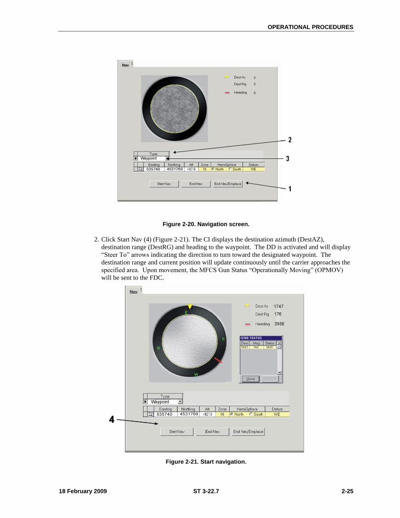
OPERATIONAL PROCEDURES
18 February 2009 ST 3-22.7 2-25
Figure 2-20. Navigation screen.
2. Click Start Nav (4) (Figure 2-21). The CI displays the destination azimuth (DestAZ),
destination range (DestRG) and heading to the waypoint. The DD is activated and will display
―Steer To‖ arrows indicating the direction to turn toward the designated waypoint. The
destination range and current position will update continuously until the carrier approaches the
specified area. Upon movement, the MFCS Gun Status ―Operationally Moving‖ (OPMOV)
will be sent to the FDC.
Figure 2-21. Start navigation.
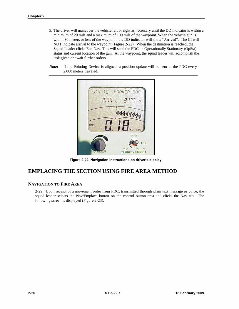
Chapter 2
2-26 ST 3-22.7 18 February 2009
3. The driver will maneuver the vehicle left or right as necessary until the DD indicator is within a
minimum of 20 mils and a maximum of 100 mils of the waypoint. When the vehicle/gun is
within 30 meters or less of the waypoint, the DD indicator will show ―Arrived‖. The CI will
NOT indicate arrival to the waypoint (Figure 2-22). When the destination is reached, the
Squad Leader clicks End Nav. This will send the FDC an Operationally Stationary (OpSta)
status and current location of the gun. At the waypoint, the squad leader will accomplish the
task given or await further orders.
Note: If the Pointing Device is aligned, a position update will be sent to the FDC every
2,000 meters traveled.
Figure 2-22. Navigation instructions on driver’s display.
EMPLACING THE SECTION USING FIRE AREA METHOD
NAVIGATION TO FIRE AREA
2-29. Upon receipt of a movement order from FDC, transmitted through plain text message or voice, the
squad leader selects the Nav/Emplace button on the control button area and clicks the Nav tab. The
following screen is displayed (Figure 2-23).
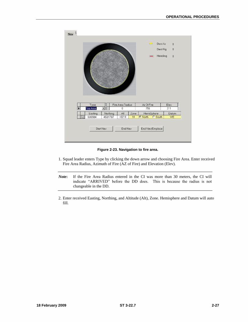
OPERATIONAL PROCEDURES
18 February 2009 ST 3-22.7 2-27
Figure 2-23. Navigation to fire area.
1. Squad leader enters Type by clicking the down arrow and choosing Fire Area. Enter received
Fire Area Radius, Azimuth of Fire (AZ of Fire) and Elevation (Elev).
Note: If the Fire Area Radius entered in the CI was more than 30 meters, the CI will
indicate ―ARRIVED‖ before the DD does. This is because the radius is not
changeable in the DD.
2. Enter received Easting, Northing, and Altitude (Alt), Zone. Hemisphere and Datum will auto
fill.

Chapter 2
2-28 ST 3-22.7 18 February 2009
3. Click Start Nav. Upon movement, the MFCS Gun Status ―Operationally Moving‖ (OPMOV)
will be sent to the FDC. The following DD screen is displayed (Figure 2-24).
Figure 2-24. Driver’s display during navigation.
Note: The CI displays destination azimuth (DestAZ), destination range (DestRg) and
Heading. The DD displays ―Steer To‖ arrows indicating the direction to turn. The
destination range and current position will update continuously until the vehicle
approaches the specified area.
4. When the vehicle/gun is within 30 meters or less of the fire area, the DD indicator will show
―Arrived‖. If the Fire Area Radius of 30 meters was entered, the Squad Leader’s CI will also
indicate ―ARRIVED‖.
Note: If the Fire Area Radius entered in the CI was more than 30 meters, the CI will
indicate ―Arrived‖ before the DD does. This is because the radius is not changeable
in the DD.
5. The driver will maneuver the vehicle left or right until the DD indicator is within a minimum of
20 mils and a maximum of 100 mils of the firing area.
6. The driver will pull into position, assuring that the turntable is centered over the firing position.
Lock the vehicle into position, shut off the vehicle, and assume the duties of an ammunition
bearer.
7. The squad leader selects End Nav. This will transmit Operationally Stationary (OpSta) status
and current location to the FDC.
Note: Current position, shown in yellow on the Position screen in Setup and which has
also been sent to the FDC is your locked-in current position. The position shown in
the upper right hand corner of the CI may slightly change due to PLGR drift and
may differ from the locked-in position.
8. Select End Nav/Emplace. The Emplace screen will be displayed.
9. To emplace, if not already in the Emplace screen, select the Emplace tab. The entered AZ of
Fire and Elev in Emplace At from the movement order will be displayed in Emplace At. The

OPERATIONAL PROCEDURES
18 February 2009 ST 3-22.7 2-29
actual AZ, EL, and RL will be displayed on the CI as well as the Gunner’s Display (GD) and
will update when the gun tube is within 1 mil of the commanded AZ and EL.
10. Select Start Emplacing.
11. The gun crew places the mortar into action from the traveling mode.
12. Once in position, select Emplaced, located at the bottom of screen. This will put gun status at
OpRdy. The status of gun will be transmitted digitally to the FDC. The gun is ready to receive a
Fire Mission.

18 February 2009 ST 3-22.7 3-1
Chapter 3
FIRE MISSIONS USING THE MORTAR FIRE CONTROL SYSTEM
The Mortar Fire Control System (MFCS) is a revolutionary improvement in mortar
capability that seamlessly links mortar fires in the future digital battlefield. The
MFCS (Heavy) provides an on-board fire control system that includes a fire control
computer, position navigation system, and gun pointing system. The MFCS allows
mortar crews to set-up and fire in one minute or less, down from the current eight
minutes and accuracy is increased by a factor of four. This chapter consists of three
sections: (1) Parts of a standard fire mission: (2) Basic fire missions: and (3) Special
missions that details specific missions such as registration, illumination, coordinated
illumination and the final protective fire FPF.
Section I — STANDARD FIRE MISSIONS
3-1. This section discusses the feature of a standard digital and manually generated MFCS fire
mission. It includes the sequence of actions used by the MFCS operator during a fire mission, and
common actions performed throughout the operation. The steps common to all basic and manual fire
missions are covered fully.
STANDARD FIRE MISSION FEATURES
3-2. The MFCS provides a standard set of steps and screens to view the fire mission data for grid,
polar, shift from a known point, and quick fire missions. The sequence of actions from the initial call for
fire (CFF) to the end of mission (EOM) is standard, though some steps may be omitted or repeated for all
CFF, regardless of the type of equipment supporting the FDC. The screens are used for missions received
digitally as well as missions requiring manual input of commands from the forward observer (FO). The
MFCS also utilizes common actions to process fire missions and transmit commands. These common
actions are found throughout the text and explained in detail below. Only the procedure name is used
hereafter. The example fire command describes, in general, the steps common to all fire commands.
Specific mission procedures are detailed further in the text. Other missions, (registration, illumination,
coordinated illumination, and FPFs) also use the standard set of screens and the same common actions.
They are described separately in Section III of this chapter. Grid, polar, shifts from a known point and
quick fire missions received digitally are processed using the same steps. Once the date for the initial CFF
and later adjustments are entered, manual fire missions are processed in the same manner.
SEQUENCE OF ACTIONS FROM THE INITIAL CFF TO EOM
3-3. Fire missions are composed of four basic components: an initial CFF; adjustment to the initial data
to bring the rounds onto the target; a fire for effect (FFE); and an EOM. The sequence can be stopped at
any time with an EOM from the fire support element (FSE) or FSO.
The initial fire mission (CFF) can be new or an established target.
The fire is adjusted onto the target. This may be omitted if the initial impact hits within the
target area.
Chapter 3
3-2 ST 3-22.7 18 February 2009
The FSO or FSE then calls for a FFE.
An EOM is sent from the FSE or FO and the mission is either saved or deleted. Sequence of
Screens.
3-4. Most fire missions require the MFCS operator to record data, make changes, and approve data
listed on a common set of screens in a standard sequence. Table 3-1 lists the steps, sequence of screens,
and primary actions taken by the operator on each screen from the start of a mission to its end. The
operator’s options such as denying the mission (MTO DENY), are explained in the specific section on the
action.
USE OF SCREENS IN A NEW CALL FOR FIRE
3-5. Table 3-1 illustrates the order in which the MFCS operator uses screens to review and adjust data.
The same order is used for adjustments, FFEs, and special missions.
Table 3-1. MFCS steps, sequence of screens, and operator actions.
EXAMPLE MISSION DATA SCREEN
3-6. Figure 3-1 displays the mission data screen. It is one of several screens on which the operator can
view the current mission data. The mission data screen is similar to the other view screens and illustrates
the format of every fire mission view screen. The control button area displayed to the right is used to select
the MFCS functions. The tab area, located at the top of the screen, displays the types of missions (Manual,
New CFF, or a previously saved mission) available. The working button area, located at the bottom of the
screen contains buttons to accept, modify, or refuse data shown in the working area. The working area can
have up to four subareas: (1) The message screen. (2) The gun status area. (3) The fire command fields.
(4) The view buttons areas. The message area features the current message from the FSE, FO, or another
unit. The gun status area displays the status of each gun controlled by the FDC and which guns are
assigned to the current mission. The fire command fields show the various components of the fire
command. The view area button provides the operator with the means to select different fields for viewing
data.
FIRE MISSIONS USING THE
MORTAR FIRE CONTROL SYSTEM
18 February 2009 ST 3-22.7 3-3
Figure 3-1. Mortar Fire Control System (MFCS) example mission data screen.
DIGITAL AND MANUAL FIRE MISSION TABS AND SCREENS
3-7. The MFCS uses tabs for missions and views to display mission and related data. Table 3-2 lists
the tabs and screens typically used during both digital and manual fire missions. They are also used in
special missions described in Section III of this chapter.
Chapter 3
3-4 ST 3-22.7 18 February 2009
Table 3-2. Example mission data screen.
COMMON ACTIONS
3-8. The operator of the MFCS uses the same commands repeatedly throughout the fire mission.
These commands are usually done by clicking a button in the working button area of the screen or in
response to a query in a message box. Commands include OpACK, MTO ACCEPT or DENY, PROCESS
or DELETE, SELECT THE GUNS TO FIRE THE MISSION, CONFIRM GUN ORDERS, and ACCEPT
OR MODIFY DATA.
ACKNOWLEDGING RECEIPT (OPACK)
3-9. Clicking on the OpACK button acknowledges receipt of a mission. When turned on it deactivates
the audio alarm. The term ―acknowledge receipt by clicking the OpACK button‖ is used throughout this
chapter to indicate this action.
RECORDING DATA
3-10. Data is recorded throughout the process to maintain a record and preserve data should the MFCS
fail. Data is transcribed onto DA Form 2399 (Computer’s Record) or DA Form 2188-R (Data Sheet). The
term ―Record data‖ is used throughout this chapter to indicate this action.
MTO ACCEPT OR MTO DENY
3-11. The MFCS uses MTO (Message to Observer) ACCEPT to accept the mission and MTO DENY to
refuse the mission. If the operator selects MTO DENY the DELETE button becomes visible and when
clicked deletes the mission. If there is an error beyond FDC control, the only choice is MTO DENY. The
terms ―Click MTO ACCEPT‖ to accept the mission or ―Click MTO DENY‖ to refuse the mission are used
throughout this chapter to indicate these actions.
FIRE MISSIONS USING THE
MORTAR FIRE CONTROL SYSTEM
18 February 2009 ST 3-22.7 3-5
PROCESS OR DELETE
3-12. There is usually a choice to process or delete a fire mission. The operator can click PROCESS to
continue with a mission, or DELETE to stop a mission. The terms ―process‖ or ―deny‖ are used
throughout this chapter to indicate these actions.
SELECTING THE GUNS TO FIRE THE MISSION
3-13. Guns for the mission are pre-selected by the software and are checked in the SEL box in GUN
SELECT. The operator has the option to modify these selections by clicking in the SEL box to select or
deselect any OpRDY gun. There is also an option to select all or none of the guns listed by clicking ALL
or NONE. The term ―select guns‖ is used throughout this chapter to indicate this action.
ACCEPTING OR MODIFYING DATA
3-14. If required, the operator makes adjustments to the mission data. To undo any changes, he clicks
UNDO CHANGES and the data fields re-display the original data. If any changes are made, the operator
clicks USE ALL to accept all the changes. If no changes are made, the operator clicks USE ALL. The
term ―modify data if necessary‖ is used throughout this chapter to indicate this action.
Section II — BASIC FIRE MISSIONS
3-15. This section details how the MFCS is used to conduct digital and manual fire missions using grid
or polar coordinates or a shift from a known point to locate the target. It also explains how the MFCS
records RPs, targets, and known points. The operator can use the MFCS’ GUI, with its tabs and buttons
and/or the keyboard to navigate throughout the commands and screens to process, conduct, and record fire
missions.
BASIC DIGITAL MISSIONS
3-16. The MFCS can process up to six active missions at a given time. Basic new fire missions are
received digitally from the FSE or FSO. The FSE or FO identifies the location of a target using grid
coordinates, polar plots, or shifts from a known location. Once a mission has been fired it can be saved
and designated as a target or known point. The following are examples of a new CFF received digitally
with the FO using grid coordinates to locate the target. The process is the same when using the polar or
shift from a known point methods of target location. Except for the initial CFF screen, the adjustment of
fires, FFE, and previously fired missions are conducted in the same manner.
RECEIPT OF A FIRE MISSION
3-17. Upon receipt of a fire mission, the MISSIONS button in the control button area is highlighted.
When enabled the audio alarm sounds. The operator clicks the MISSIONS button and the NEW CFF tab
appears. The operator can click MTO DENY to deny the mission. If the operator clicks PROCESS the
Mission Data screen appears (Figure 3-2).
Chapter 3
3-6 ST 3-22.7 18 February 2009
Figure 3-2. MFCS new call for fire screen.
MISSION DATA VIEW
3-18. The Mission Data screen automatically generates a new target number and the mission data view.
It allows the operator to review and record mission data and make any necessary adjustments. Adjustments
include the selection of guns to fire the mission and other mission data such as method of control, type of
sheaf, and fuze-shell combinations. Once satisfied, the operator clicks USE ALL (if any changes were
made), or SOLUTIONS (Figure 3-3).
FIRE MISSIONS USING THE
MORTAR FIRE CONTROL SYSTEM
18 February 2009 ST 3-22.7 3-7
Figure 3-3. MFCS mission data view screen.
SOLUTION
3-19. The Solution screen displays the gun orders, the guns selected, and any errors and warnings. This
screen allows the operator to review the gun status and to make changes to the gun selection based on any
errors and warnings received. It provides for MTO DENY and is the screen from which gun orders are
sent (Figure 3-4).
Chapter 3
3-8 ST 3-22.7 18 February 2009
Figure 3-4. MFCS solution view screen.
SAFETY DATA
3-20. Prior to sending the gun orders, or at any time, the operator reviews and records the safety data by
viewing the Safety Data screen (Figure 3-5).
FIRE MISSIONS USING THE
MORTAR FIRE CONTROL SYSTEM
18 February 2009 ST 3-22.7 3-9
Figure 3-5. MFCS safety data screen.
PLOT VIEW SCREEN
3-21. The plot screen is available at any time during the mission (Figure 3-7). The digital plot screen
displays burst points, canister points; fire support coordination measures (FSCMs), known points, stored
targets, targets, units, waypoints, and friendly units. The operator can select the display by selecting or
deselecting from the list above the LEGEND button (the default shows all items checked). To obtain
information on a particular icon on the plot, the cursor is placed over the icon. Icon information varies
depending on the icon type. Click the SOLUTION button to return to the Solution screen (Figure 3-6).
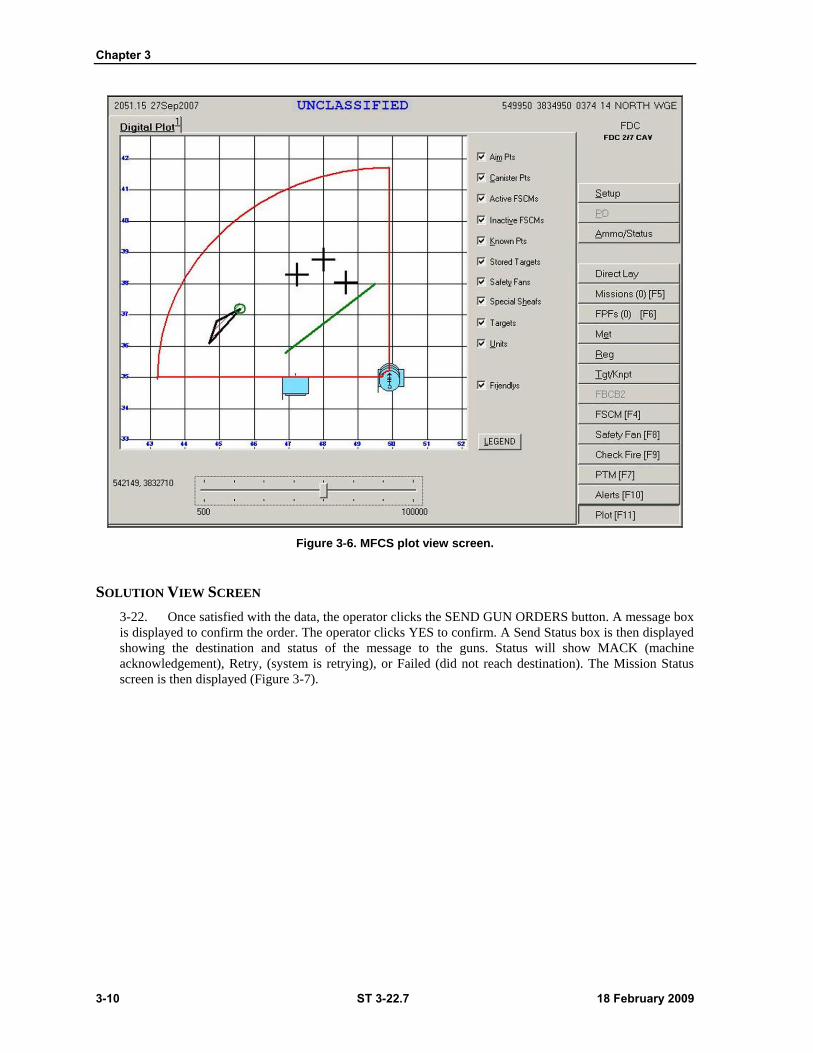
Chapter 3
3-10 ST 3-22.7 18 February 2009
Figure 3-6. MFCS plot view screen.
SOLUTION VIEW SCREEN
3-22. Once satisfied with the data, the operator clicks the SEND GUN ORDERS button. A message box
is displayed to confirm the order. The operator clicks YES to confirm. A Send Status box is then displayed
showing the destination and status of the message to the guns. Status will show MACK (machine
acknowledgement), Retry, (system is retrying), or Failed (did not reach destination). The Mission Status
screen is then displayed (Figure 3-7).
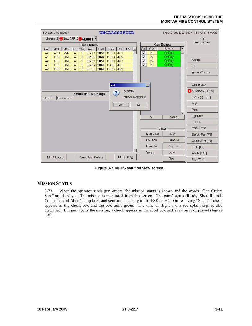
FIRE MISSIONS USING THE
MORTAR FIRE CONTROL SYSTEM
18 February 2009 ST 3-22.7 3-11
Figure 3-7. MFCS solution view screen.
MISSION STATUS
3-23. When the operator sends gun orders, the mission status is shown and the words ―Gun Orders
Sent‖ are displayed. The mission is monitored from this screen. The guns’ status (Ready, Shot, Rounds
Complete, and Abort) is updated and sent automatically to the FSE or FO. On receiving ―Shot,‖ a check
appears in the check box and the box turns green. The time of flight and a red splash sign is also
displayed. If a gun aborts the mission, a check appears in the abort box and a reason is displayed (Figure
3-8).
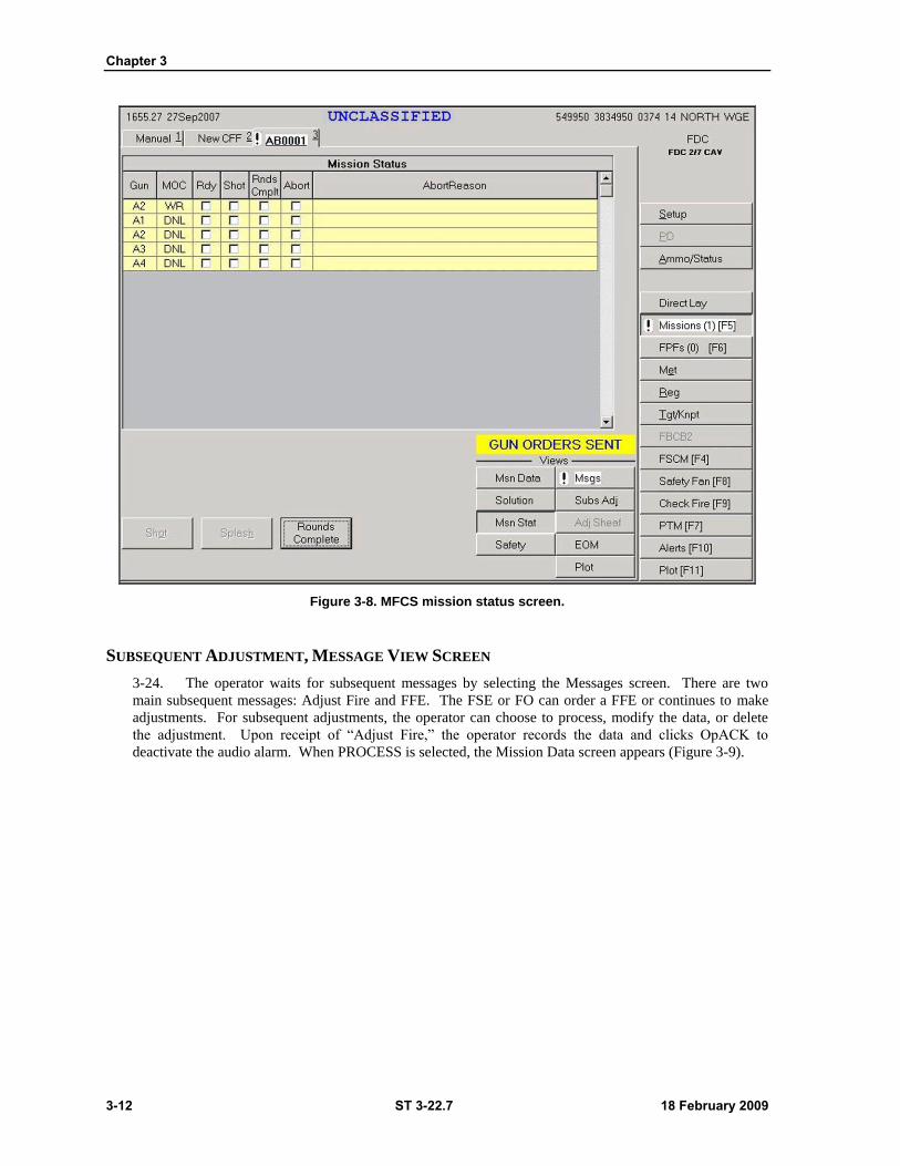
Chapter 3
3-12 ST 3-22.7 18 February 2009
Figure 3-8. MFCS mission status screen.
SUBSEQUENT ADJUSTMENT, MESSAGE VIEW SCREEN
3-24. The operator waits for subsequent messages by selecting the Messages screen. There are two
main subsequent messages: Adjust Fire and FFE. The FSE or FO can order a FFE or continues to make
adjustments. For subsequent adjustments, the operator can choose to process, modify the data, or delete
the adjustment. Upon receipt of ―Adjust Fire,‖ the operator records the data and clicks OpACK to
deactivate the audio alarm. When PROCESS is selected, the Mission Data screen appears (Figure 3-9).
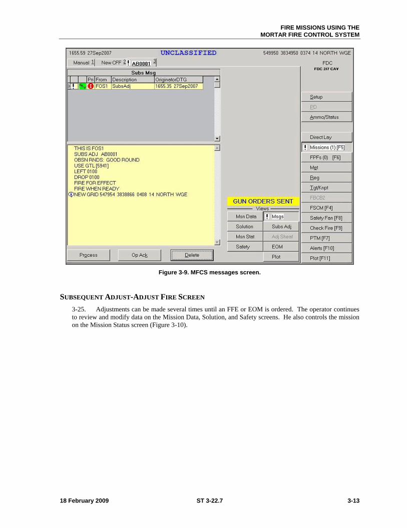
FIRE MISSIONS USING THE
MORTAR FIRE CONTROL SYSTEM
18 February 2009 ST 3-22.7 3-13
Figure 3-9. MFCS messages screen.
SUBSEQUENT ADJUST-ADJUST FIRE SCREEN
3-25. Adjustments can be made several times until an FFE or EOM is ordered. The operator continues
to review and modify data on the Mission Data, Solution, and Safety screens. He also controls the mission
on the Mission Status screen (Figure 3-10).
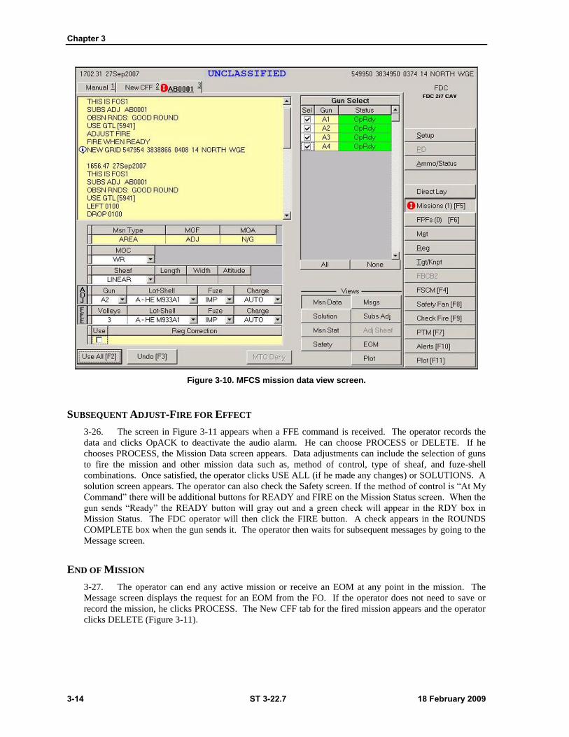
Chapter 3
3-14 ST 3-22.7 18 February 2009
Figure 3-10. MFCS mission data view screen.
SUBSEQUENT ADJUST-FIRE FOR EFFECT
3-26. The screen in Figure 3-11 appears when a FFE command is received. The operator records the
data and clicks OpACK to deactivate the audio alarm. He can choose PROCESS or DELETE. If he
chooses PROCESS, the Mission Data screen appears. Data adjustments can include the selection of guns
to fire the mission and other mission data such as, method of control, type of sheaf, and fuze-shell
combinations. Once satisfied, the operator clicks USE ALL (if he made any changes) or SOLUTIONS. A
solution screen appears. The operator can also check the Safety screen. If the method of control is ―At My
Command‖ there will be additional buttons for READY and FIRE on the Mission Status screen. When the
gun sends ―Ready‖ the READY button will gray out and a green check will appear in the RDY box in
Mission Status. The FDC operator will then click the FIRE button. A check appears in the ROUNDS
COMPLETE box when the gun sends it. The operator then waits for subsequent messages by going to the
Message screen.
END OF MISSION
3-27. The operator can end any active mission or receive an EOM at any point in the mission. The
Message screen displays the request for an EOM from the FO. If the operator does not need to save or
record the mission, he clicks PROCESS. The New CFF tab for the fired mission appears and the operator
clicks DELETE (Figure 3-11).
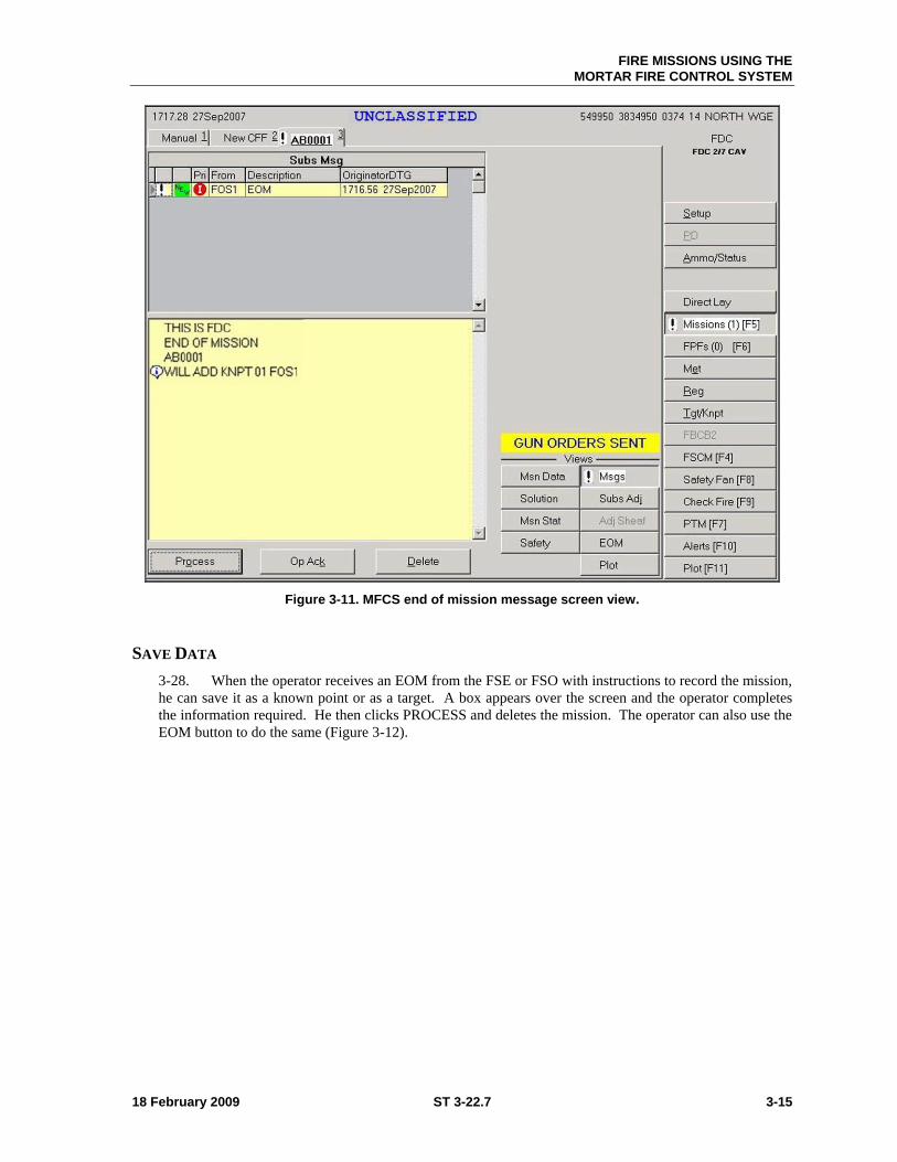
FIRE MISSIONS USING THE
MORTAR FIRE CONTROL SYSTEM
18 February 2009 ST 3-22.7 3-15
Figure 3-11. MFCS end of mission message screen view.
SAVE DATA
3-28. When the operator receives an EOM from the FSE or FSO with instructions to record the mission,
he can save it as a known point or as a target. A box appears over the screen and the operator completes
the information required. He then clicks PROCESS and deletes the mission. The operator can also use the
EOM button to do the same (Figure 3-12).
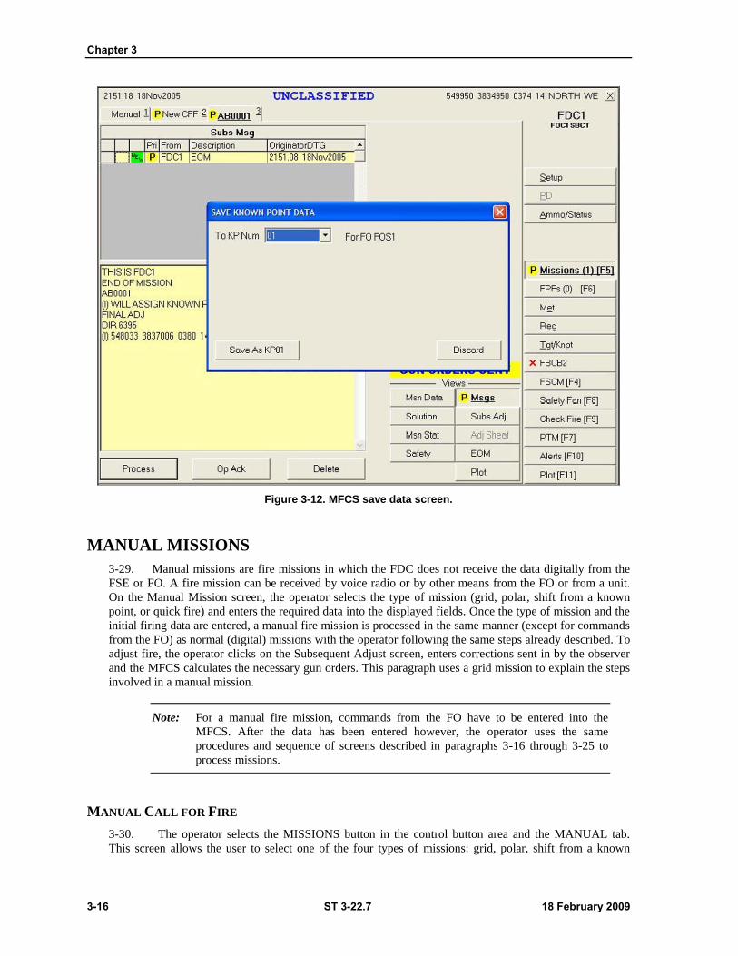
Chapter 3
3-16 ST 3-22.7 18 February 2009
Figure 3-12. MFCS save data screen.
MANUAL MISSIONS
3-29. Manual missions are fire missions in which the FDC does not receive the data digitally from the
FSE or FO. A fire mission can be received by voice radio or by other means from the FO or from a unit.
On the Manual Mission screen, the operator selects the type of mission (grid, polar, shift from a known
point, or quick fire) and enters the required data into the displayed fields. Once the type of mission and the
initial firing data are entered, a manual fire mission is processed in the same manner (except for commands
from the FO) as normal (digital) missions with the operator following the same steps already described. To
adjust fire, the operator clicks on the Subsequent Adjust screen, enters corrections sent in by the observer
and the MFCS calculates the necessary gun orders. This paragraph uses a grid mission to explain the steps
involved in a manual mission.
Note: For a manual fire mission, commands from the FO have to be entered into the
MFCS. After the data has been entered however, the operator uses the same
procedures and sequence of screens described in paragraphs 3-16 through 3-25 to
process missions.
MANUAL CALL FOR FIRE
3-30. The operator selects the MISSIONS button in the control button area and the MANUAL tab.
This screen allows the user to select one of the four types of missions: grid, polar, shift from a known

FIRE MISSIONS USING THE
MORTAR FIRE CONTROL SYSTEM
18 February 2009 ST 3-22.7 3-17
point, and quick fire. (Again, a grid mission is used as an example.) The operator enters data common to
all types of missions and data required for specific types (Figure 3-13).
Note: Common for all missions–the operator enters EASTING, NORTHING, and ALT.
The ZONE, DATUM, and HEMISPHERE fields are then auto-filled. At the bottom
of the screen, he also selects the type of round and the method of fire.
Polar Missions. The following data is entered for a polar mission:
Choose the OBS (observer) from the pick list.
Enter direction (DIR). Use four digits from 0000 to 6399.
Enter distance (DIST). Use four digits from 0000 to 9999.
Enter the vertical interval (VI) between the observer and the target. Use a ―+‖ for up (up is
also the default setting) or a ―-‖ sign for down, and four digits from 0000 to 9999. The VI can
be missing.
Shift Missions. Enter the following, in addition to the common data items for a shift from a
known point mission.
Choose the OBS (Observer) from the pick list.
Choose the KNPT (Known Point) from the pick list.
Enter DIR. Use four digits from 0000 to 6399.
Enter the lateral displacement direction of Right or Left, and then the lateral displacement
distance within a range of 0000 to 9999.
Enter the range displacement direction of Add or Drop and enter the range displacement
distance within a range of 0000 to 9999.
Enter the VI (Up/Down) between the observer and the target. Use a ―+‖ for up (Up is also
the default setting) or a ―-‖ sign for down, and four digits from 0000 to 9999. The VI can be
missing.
Quick Fire. Select the target number (TARGET) from the pick list and then HE FFE or IL FFE
from the bottom of the screen
Select Ammunition and MOF. After selecting the desired ammunition/mission combination,
the New CFF tab is displayed. The operator uses the same procedures to process the New CFF
as described in paragraphs 3-16 through 3-25 digital CFF and adjust fire.
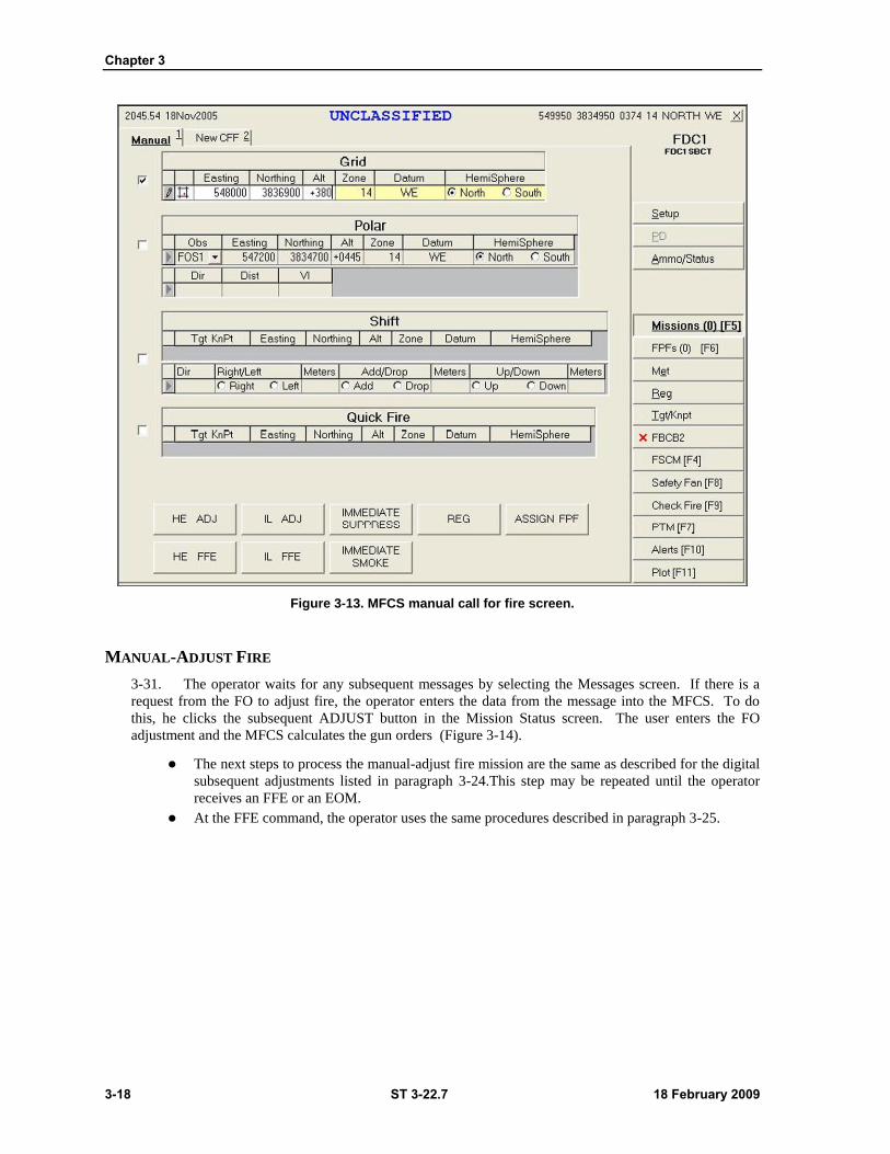
Chapter 3
3-18 ST 3-22.7 18 February 2009
Figure 3-13. MFCS manual call for fire screen.
MANUAL-ADJUST FIRE
3-31. The operator waits for any subsequent messages by selecting the Messages screen. If there is a
request from the FO to adjust fire, the operator enters the data from the message into the MFCS. To do
this, he clicks the subsequent ADJUST button in the Mission Status screen. The user enters the FO
adjustment and the MFCS calculates the gun orders (Figure 3-14).
The next steps to process the manual-adjust fire mission are the same as described for the digital
subsequent adjustments listed in paragraph 3-24.This step may be repeated until the operator
receives an FFE or an EOM.
At the FFE command, the operator uses the same procedures described in paragraph 3-25.
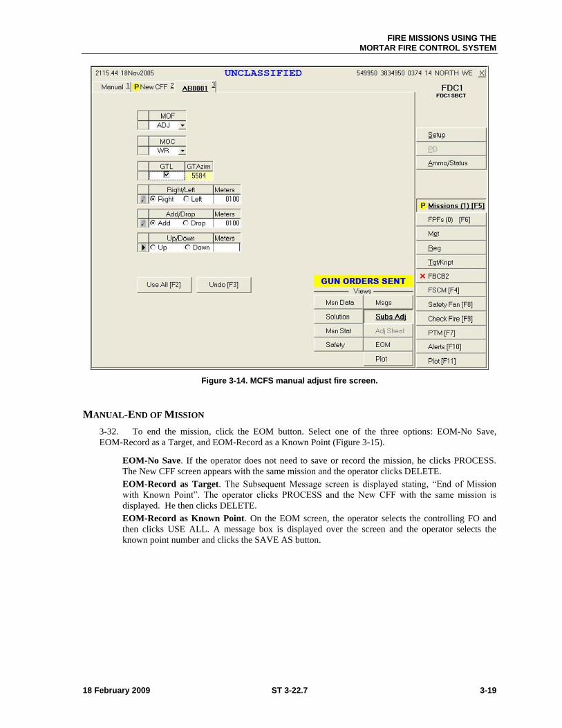
FIRE MISSIONS USING THE
MORTAR FIRE CONTROL SYSTEM
18 February 2009 ST 3-22.7 3-19
Figure 3-14. MCFS manual adjust fire screen.
MANUAL-END OF MISSION
3-32. To end the mission, click the EOM button. Select one of the three options: EOM-No Save,
EOM-Record as a Target, and EOM-Record as a Known Point (Figure 3-15).
EOM-No Save. If the operator does not need to save or record the mission, he clicks PROCESS.
The New CFF screen appears with the same mission and the operator clicks DELETE.
EOM-Record as Target. The Subsequent Message screen is displayed stating, ―End of Mission
with Known Point‖. The operator clicks PROCESS and the New CFF with the same mission is
displayed. He then clicks DELETE.
EOM-Record as Known Point. On the EOM screen, the operator selects the controlling FO and
then clicks USE ALL. A message box is displayed over the screen and the operator selects the
known point number and clicks the SAVE AS button.
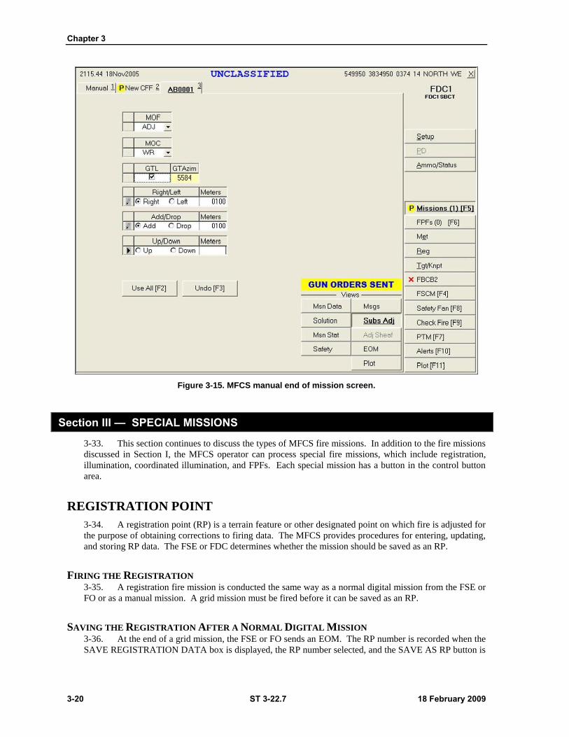
Chapter 3
3-20 ST 3-22.7 18 February 2009
Figure 3-15. MFCS manual end of mission screen.
Section III — SPECIAL MISSIONS
3-33. This section continues to discuss the types of MFCS fire missions. In addition to the fire missions
discussed in Section I, the MFCS operator can process special fire missions, which include registration,
illumination, coordinated illumination, and FPFs. Each special mission has a button in the control button
area.
REGISTRATION POINT
3-34. A registration point (RP) is a terrain feature or other designated point on which fire is adjusted for
the purpose of obtaining corrections to firing data. The MFCS provides procedures for entering, updating,
and storing RP data. The FSE or FDC determines whether the mission should be saved as an RP.
FIRING THE REGISTRATION 3-35. A registration fire mission is conducted the same way as a normal digital mission from the FSE or
FO or as a manual mission. A grid mission must be fired before it can be saved as an RP.
SAVING THE REGISTRATION AFTER A NORMAL DIGITAL MISSION 3-36. At the end of a grid mission, the FSE or FO sends an EOM. The RP number is recorded when the
SAVE REGISTRATION DATA box is displayed, the RP number selected, and the SAVE AS RP button is
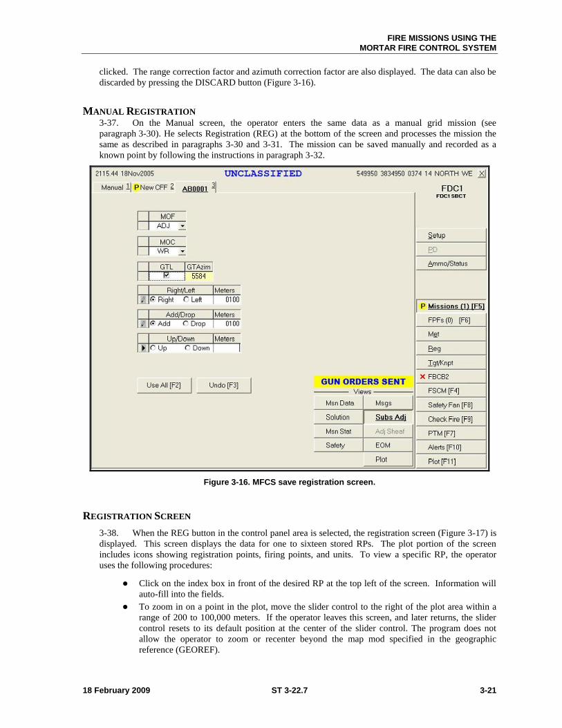
FIRE MISSIONS USING THE
MORTAR FIRE CONTROL SYSTEM
18 February 2009 ST 3-22.7 3-21
clicked. The range correction factor and azimuth correction factor are also displayed. The data can also be
discarded by pressing the DISCARD button (Figure 3-16).
MANUAL REGISTRATION 3-37. On the Manual screen, the operator enters the same data as a manual grid mission (see
paragraph 3-30). He selects Registration (REG) at the bottom of the screen and processes the mission the
same as described in paragraphs 3-30 and 3-31. The mission can be saved manually and recorded as a
known point by following the instructions in paragraph 3-32.
Figure 3-16. MFCS save registration screen.
REGISTRATION SCREEN
3-38. When the REG button in the control panel area is selected, the registration screen (Figure 3-17) is
displayed. This screen displays the data for one to sixteen stored RPs. The plot portion of the screen
includes icons showing registration points, firing points, and units. To view a specific RP, the operator
uses the following procedures:
Click on the index box in front of the desired RP at the top left of the screen. Information will
auto-fill into the fields.
To zoom in on a point in the plot, move the slider control to the right of the plot area within a
range of 200 to 100,000 meters. If the operator leaves this screen, and later returns, the slider
control resets to its default position at the center of the slider control. The program does not
allow the operator to zoom or recenter beyond the map mod specified in the geographic
reference (GEOREF).
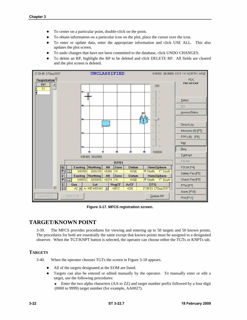
Chapter 3
3-22 ST 3-22.7 18 February 2009
To center on a particular point, double-click on the point.
To obtain information on a particular icon on the plot, place the cursor over the icon.
To enter or update data, enter the appropriate information and click USE ALL. This also
updates the plot screen.
To undo changes that have not been committed to the database, click UNDO CHANGES.
To delete an RP, highlight the RP to be deleted and click DELETE RP. All fields are cleared
and the plot screen is deleted.
Figure 3-17. MFCS registration screen.
TARGET/KNOWN POINT
3-39. The MFCS provides procedures for viewing and entering up to 50 targets and 50 known points.
The procedures for both are essentially the same except that known points must be assigned to a designated
observer. When the TGT/KNPT button is selected, the operator can choose either the TGTs or KNPTs tab.
TARGETS
3-40. When the operator chooses TGTs the screen in Figure 3-18 appears.
All of the targets designated at the EOM are listed.
Targets can also be entered or edited manually by the operator. To manually enter or edit a
target, use the following procedures:
Enter the two alpha characters (AA to ZZ) and target number prefix followed by a four digit
(0000 to 9999) target number (for example, AA0027).
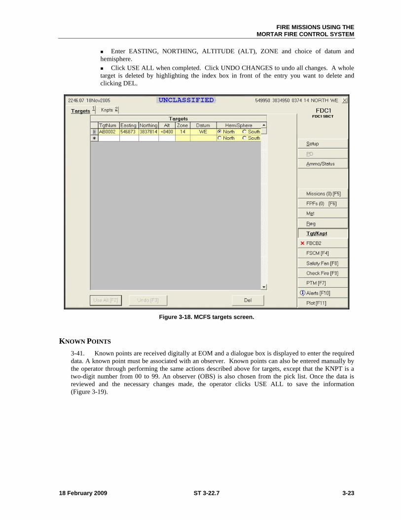
FIRE MISSIONS USING THE
MORTAR FIRE CONTROL SYSTEM
18 February 2009 ST 3-22.7 3-23
Enter EASTING, NORTHING, ALTITUDE (ALT), ZONE and choice of datum and
hemisphere.
Click USE ALL when completed. Click UNDO CHANGES to undo all changes. A whole
target is deleted by highlighting the index box in front of the entry you want to delete and
clicking DEL.
Figure 3-18. MCFS targets screen.
KNOWN POINTS
3-41. Known points are received digitally at EOM and a dialogue box is displayed to enter the required
data. A known point must be associated with an observer. Known points can also be entered manually by
the operator through performing the same actions described above for targets, except that the KNPT is a
two-digit number from 00 to 99. An observer (OBS) is also chosen from the pick list. Once the data is
reviewed and the necessary changes made, the operator clicks USE ALL to save the information
(Figure 3-19).
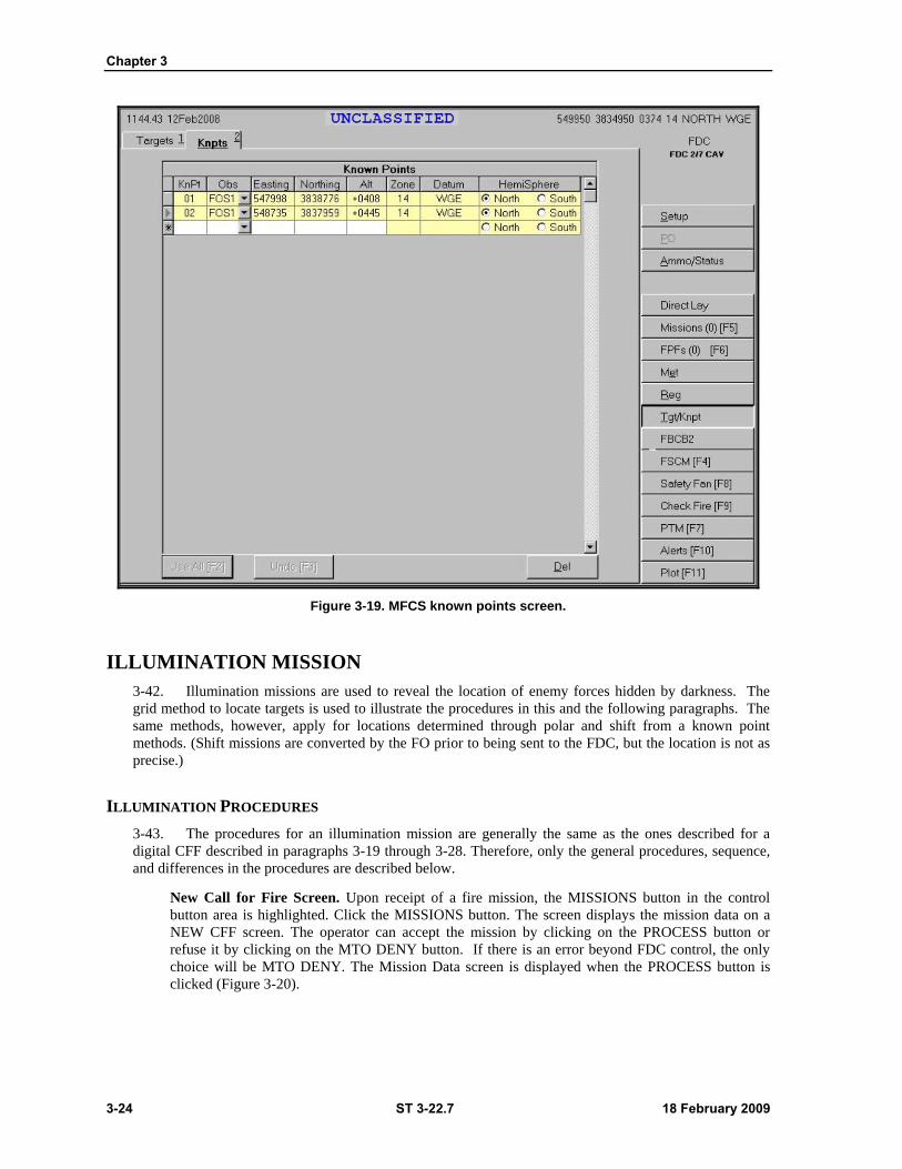
Chapter 3
3-24 ST 3-22.7 18 February 2009
Figure 3-19. MFCS known points screen.
ILLUMINATION MISSION
3-42. Illumination missions are used to reveal the location of enemy forces hidden by darkness. The
grid method to locate targets is used to illustrate the procedures in this and the following paragraphs. The
same methods, however, apply for locations determined through polar and shift from a known point
methods. (Shift missions are converted by the FO prior to being sent to the FDC, but the location is not as
precise.)
ILLUMINATION PROCEDURES
3-43. The procedures for an illumination mission are generally the same as the ones described for a
digital CFF described in paragraphs 3-19 through 3-28. Therefore, only the general procedures, sequence,
and differences in the procedures are described below.
New Call for Fire Screen. Upon receipt of a fire mission, the MISSIONS button in the control
button area is highlighted. Click the MISSIONS button. The screen displays the mission data on a
NEW CFF screen. The operator can accept the mission by clicking on the PROCESS button or
refuse it by clicking on the MTO DENY button. If there is an error beyond FDC control, the only
choice will be MTO DENY. The Mission Data screen is displayed when the PROCESS button is
clicked (Figure 3-20).
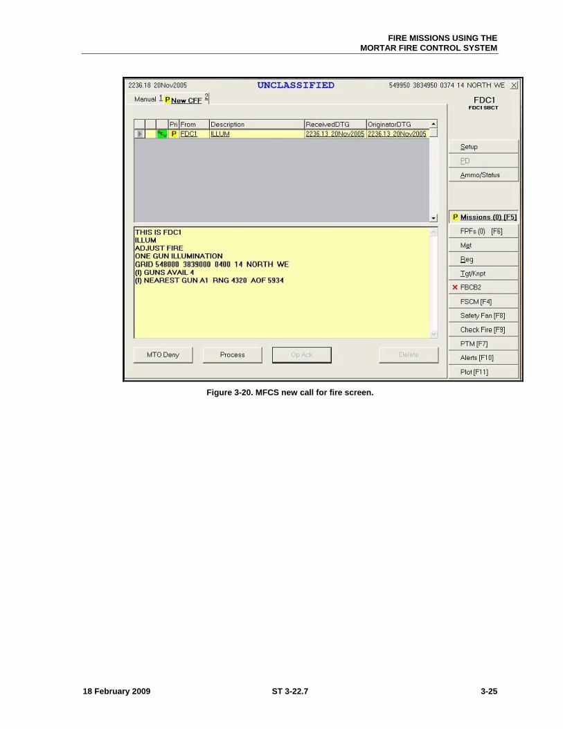
FIRE MISSIONS USING THE
MORTAR FIRE CONTROL SYSTEM
18 February 2009 ST 3-22.7 3-25
Figure 3-20. MFCS new call for fire screen.
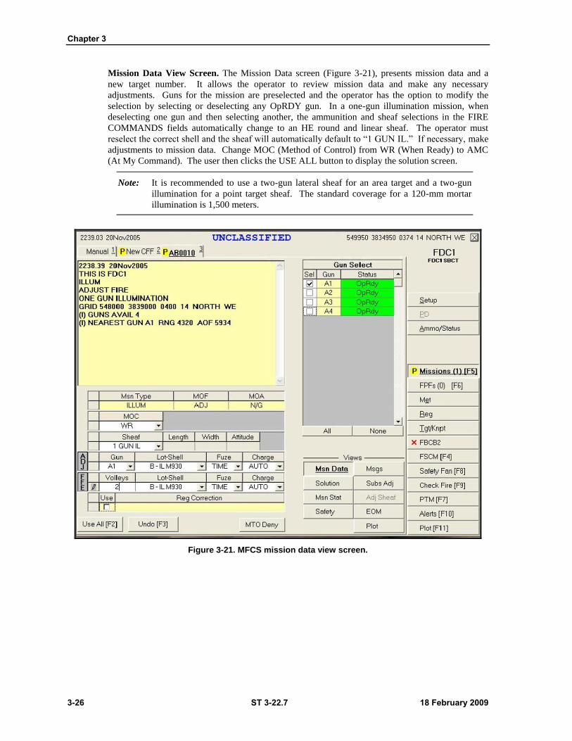
Chapter 3
3-26 ST 3-22.7 18 February 2009
Mission Data View Screen. The Mission Data screen (Figure 3-21), presents mission data and a
new target number. It allows the operator to review mission data and make any necessary
adjustments. Guns for the mission are preselected and the operator has the option to modify the
selection by selecting or deselecting any OpRDY gun. In a one-gun illumination mission, when
deselecting one gun and then selecting another, the ammunition and sheaf selections in the FIRE
COMMANDS fields automatically change to an HE round and linear sheaf. The operator must
reselect the correct shell and the sheaf will automatically default to ―1 GUN IL.‖ If necessary, make
adjustments to mission data. Change MOC (Method of Control) from WR (When Ready) to AMC
(At My Command). The user then clicks the USE ALL button to display the solution screen.
Note: It is recommended to use a two-gun lateral sheaf for an area target and a two-gun
illumination for a point target sheaf. The standard coverage for a 120-mm mortar
illumination is 1,500 meters.
Figure 3-21. MFCS mission data view screen.
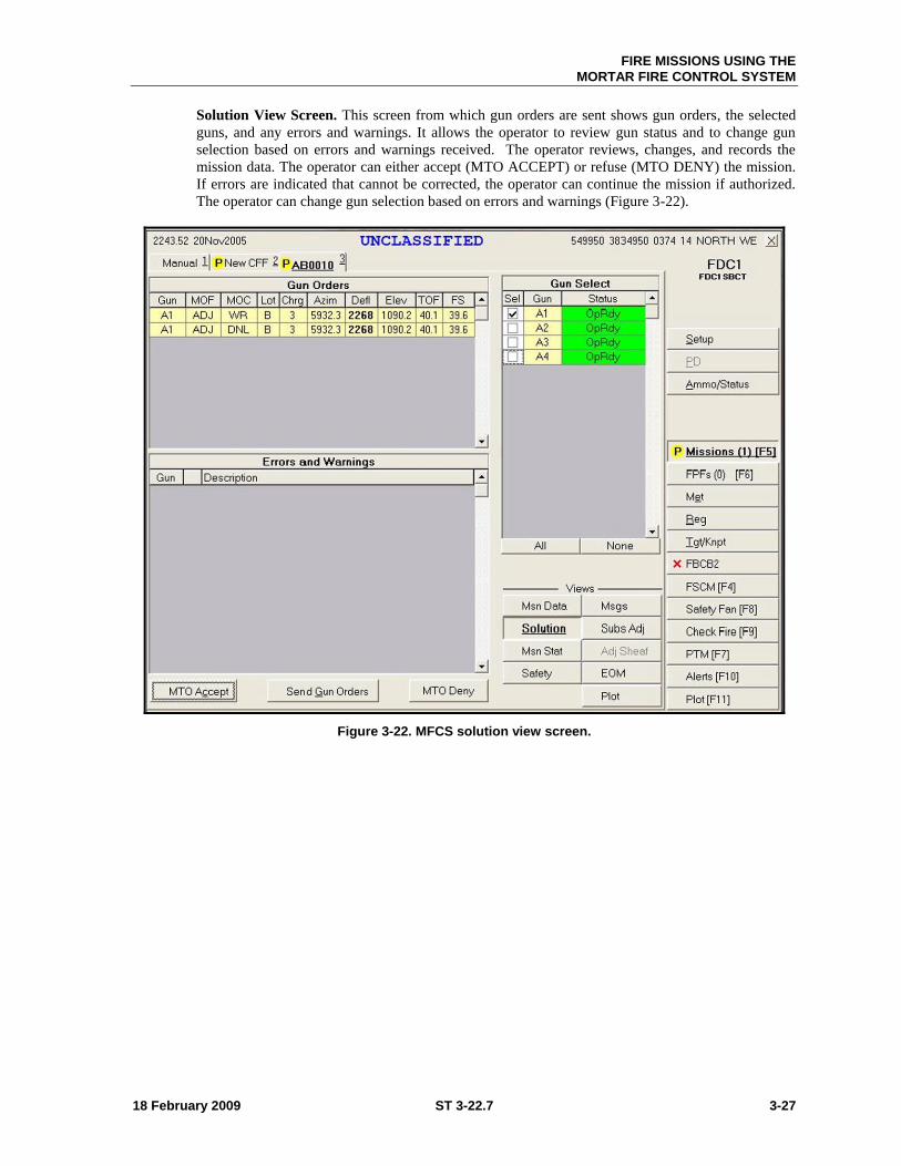
FIRE MISSIONS USING THE
MORTAR FIRE CONTROL SYSTEM
18 February 2009 ST 3-22.7 3-27
Solution View Screen. This screen from which gun orders are sent shows gun orders, the selected
guns, and any errors and warnings. It allows the operator to review gun status and to change gun
selection based on errors and warnings received. The operator reviews, changes, and records the
mission data. The operator can either accept (MTO ACCEPT) or refuse (MTO DENY) the mission.
If errors are indicated that cannot be corrected, the operator can continue the mission if authorized.
The operator can change gun selection based on errors and warnings (Figure 3-22).
Figure 3-22. MFCS solution view screen.
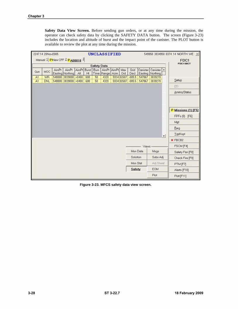
Chapter 3
3-28 ST 3-22.7 18 February 2009
Safety Data View Screen. Before sending gun orders, or at any time during the mission, the
operator can check safety data by clicking the SAFETY DATA button. The screen (Figure 3-23)
includes the location and altitude of burst and the impact point of the canister. The PLOT button is
available to review the plot at any time during the mission.
Figure 3-23. MFCS safety data view screen.
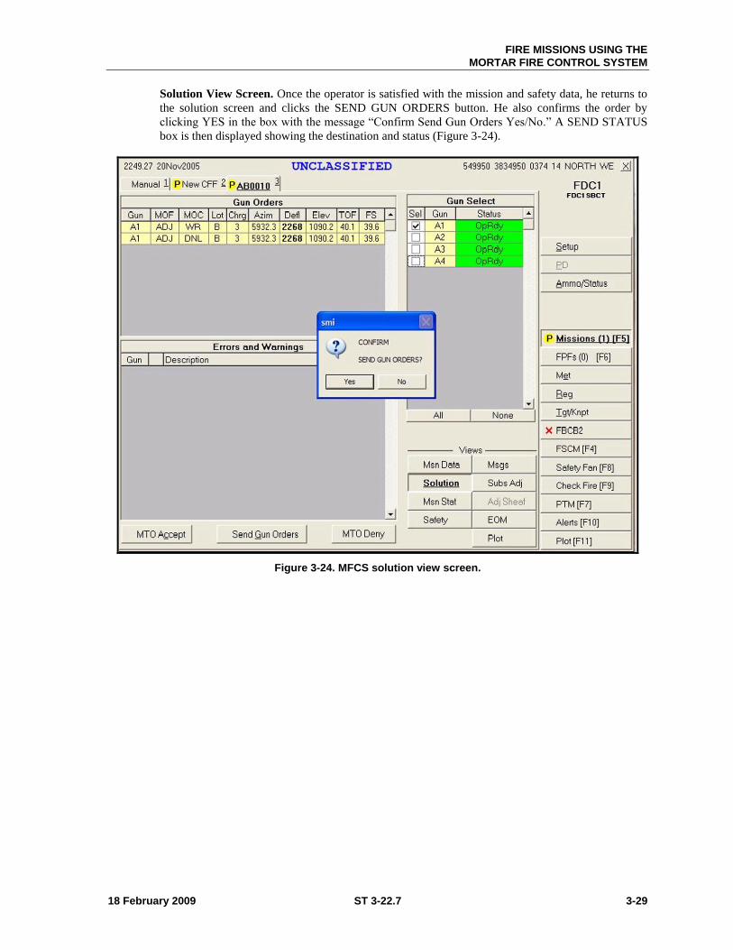
FIRE MISSIONS USING THE
MORTAR FIRE CONTROL SYSTEM
18 February 2009 ST 3-22.7 3-29
Solution View Screen. Once the operator is satisfied with the mission and safety data, he returns to
the solution screen and clicks the SEND GUN ORDERS button. He also confirms the order by
clicking YES in the box with the message ―Confirm Send Gun Orders Yes/No.‖ A SEND STATUS
box is then displayed showing the destination and status (Figure 3-24).
Figure 3-24. MFCS solution view screen.
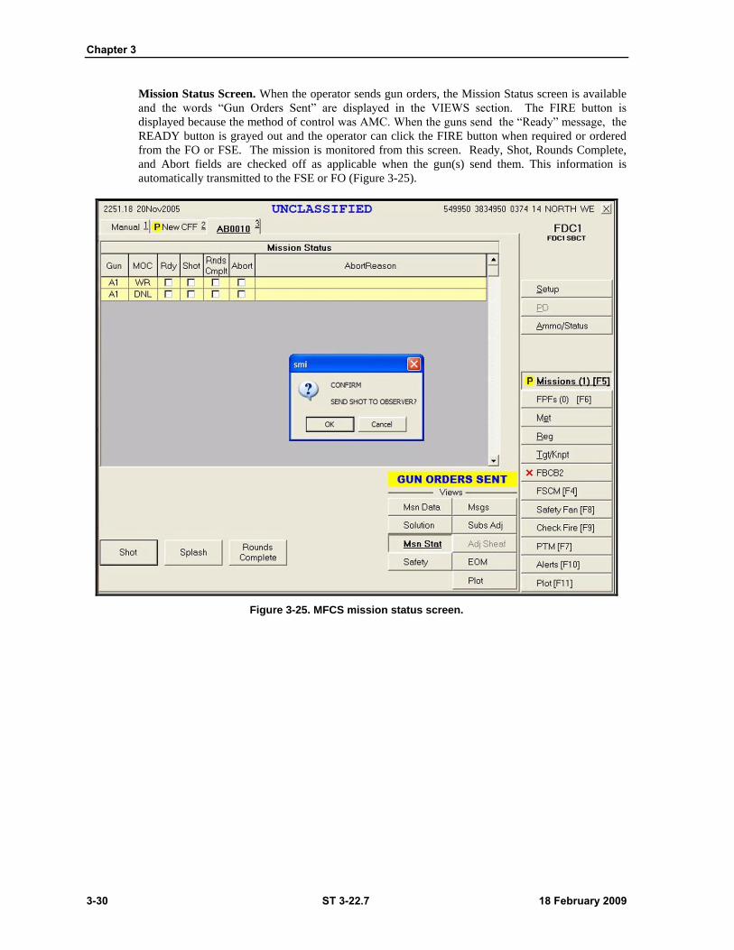
Chapter 3
3-30 ST 3-22.7 18 February 2009
Mission Status Screen. When the operator sends gun orders, the Mission Status screen is available
and the words ―Gun Orders Sent‖ are displayed in the VIEWS section. The FIRE button is
displayed because the method of control was AMC. When the guns send the ―Ready‖ message, the
READY button is grayed out and the operator can click the FIRE button when required or ordered
from the FO or FSE. The mission is monitored from this screen. Ready, Shot, Rounds Complete,
and Abort fields are checked off as applicable when the gun(s) send them. This information is
automatically transmitted to the FSE or FO (Figure 3-25).
Figure 3-25. MFCS mission status screen.
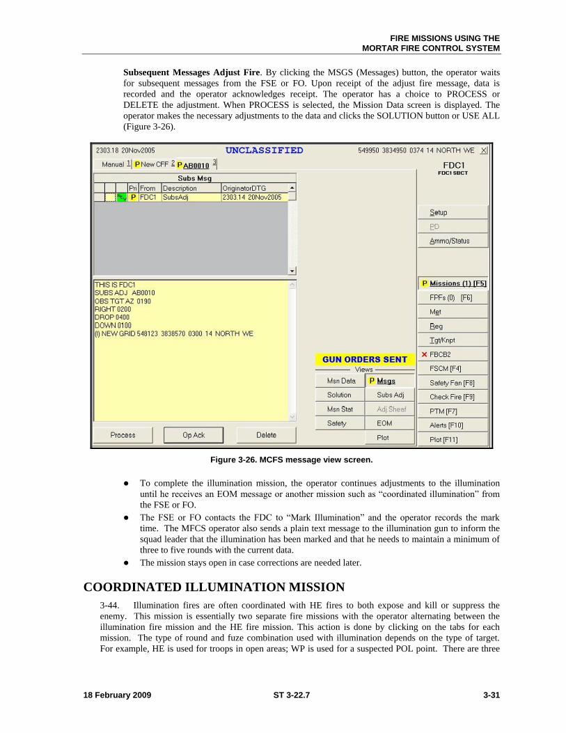
FIRE MISSIONS USING THE
MORTAR FIRE CONTROL SYSTEM
18 February 2009 ST 3-22.7 3-31
Subsequent Messages Adjust Fire. By clicking the MSGS (Messages) button, the operator waits
for subsequent messages from the FSE or FO. Upon receipt of the adjust fire message, data is
recorded and the operator acknowledges receipt. The operator has a choice to PROCESS or
DELETE the adjustment. When PROCESS is selected, the Mission Data screen is displayed. The
operator makes the necessary adjustments to the data and clicks the SOLUTION button or USE ALL
(Figure 3-26).
Figure 3-26. MCFS message view screen.
To complete the illumination mission, the operator continues adjustments to the illumination
until he receives an EOM message or another mission such as ―coordinated illumination‖ from
the FSE or FO.
The FSE or FO contacts the FDC to ―Mark Illumination‖ and the operator records the mark
time. The MFCS operator also sends a plain text message to the illumination gun to inform the
squad leader that the illumination has been marked and that he needs to maintain a minimum of
three to five rounds with the current data.
The mission stays open in case corrections are needed later.
COORDINATED ILLUMINATION MISSION
3-44. Illumination fires are often coordinated with HE fires to both expose and kill or suppress the
enemy. This mission is essentially two separate fire missions with the operator alternating between the
illumination fire mission and the HE fire mission. This action is done by clicking on the tabs for each
mission. The type of round and fuze combination used with illumination depends on the type of target.
For example, HE is used for troops in open areas; WP is used for a suspected POL point. There are three

Chapter 3
3-32 ST 3-22.7 18 February 2009
parts to a coordinated illumination mission: (1) adjustment of the illumination and ordering its fire during
an HE adjustment and FFE, (2) the adjustment of the HE, (3) the coordination of illumination and HE fires.
ADJUSTMENT AND FIRE OF THE ILLUMINATION
3-45. The adjustment and firing of the illumination is identical to the one described in paragraph 3-42.
Illumination is fired and, if necessary, adjusted throughout the coordinated illumination mission. Once the
illumination is adjusted, a subsequent adjust message for FFE is received for the illumination gun mission
and is processed through to Mission Status without adjustments. During the HE adjustment and FFE, the
operator receives subsequent messages from the FO to fire illumination in coordination with the HE. He
does this by alternating between the ILLUMINATION MISSION tab and the HE MISSION tab. After the
illumination is adjusted, the method of control for both fires is changed from WR to AMC.
HIGH-EXPLOSIVE ADJUSTMENT
3-46. The adjustment of the HE is identical to the one described in paragraph 3-16, Basic Digital
Missions.
1. Upon receipt of a fire mission, the MISSIONS button in the control button area is highlighted.
The operator clicks the MISSIONS button and a new CFF tab appears. The operator has the
option to accept (PROCESS) the mission or refuse (MTO DENY) the mission. If the mission is
acceptable, he records the data and clicks PROCESS.
2. The screen now displays the mission data. The operator processes the mission the same way
and uses the same screens as a regular HE adjustment except for the method of command. The
method of command is changed from WR to AMC. After any other adjustments to the data, he
clicks USE ALL and the SOLUTION screen appears.
3. This screen displays Gun Orders and Solution Errors and Warnings. It allows the operator to
review gun status and to change gun selection based on errors and warnings received. It also
provides for MTO ACCEPT or MTO DENY and is the screen from which gun orders are sent.
4. Before sending the gun orders, the operator checks the safety data by clicking the SAFETY
DATA button (he can also check the plot screen). He reviews and records the safety data and
clicks the SOLUTION button to return to the Solution screen.
5. When ready, the operator clicks SEND GUN ORDERS and confirms the order. A Send Status
box is now displayed showing destination and status.
6. The Mission Status screen appears with the words ―GUN ORDERS SENT‖ displayed. The
mission is monitored from this screen. Gun status is checked off as completed and messages
are automatically sent to the FO or FSE. When the adjusting HE gun sends a status of ―ready,‖
the operator begins coordinating the fires of the illumination and the HE.
7. A subsequent adjust message is received for the illumination gun mission. The operator
processes the mission without adjustment and clicks the FIRE button.
8. The operator waits for the appropriate mark time and clicks the FIRE button for the HE
mission.
9. The operator continues to perform the steps above until the subsequent Adjust-FFE or EOM
message is received. Fire for Effect
3-47. On receipt of the subsequent Adjust-FFE message the operator records the data and can either
process or delete the mission. Selecting PROCESS displays the MISSION DATA screen.
1. The operator performs the same reviews and decisions on this screen. The method of command
is changed from WR to AMC. When complete, he clicks either USE ALL or SOLUTION
buttons.
2. At the Solution screen, the operator reviews and records data. He also checks the Safety Data
and Plot screens. He then clicks the SOLUTION button to return to the Solution screen. When
satisfied, the operator clicks SEND GUN ORDERS and confirms the order. He then waits for
all guns to report a ―Ready‖ status.
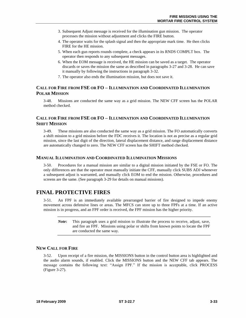
FIRE MISSIONS USING THE
MORTAR FIRE CONTROL SYSTEM
18 February 2009 ST 3-22.7 3-33
3. Subsequent Adjust message is received for the illumination gun mission. The operator
processes the mission without adjustment and clicks the FIRE button.
4. The operator waits for the splash signal and then the appropriate mark time. He then clicks
FIRE for the HE mission.
5. When each gun reports rounds complete, a check appears in its RNDS COMPLT box. The
operator then responds to any subsequent messages.
6. When the EOM message is received, the HE mission can be saved as a target. The operator
discards or saves the mission the same as described in paragraphs 3-27 and 3-28. He can save
it manually by following the instructions in paragraph 3-32.
7. The operator also ends the illumination mission, but does not save it.
CALL FOR FIRE FROM FSE OR FO – ILLUMINATION AND COORDINATED ILLUMINATION
POLAR MISSION
3-48. Missions are conducted the same way as a grid mission. The NEW CFF screen has the POLAR
method checked.
CALL FOR FIRE FROM FSE OR FO – ILLUMINATION AND COORDINATED ILLUMINATION
SHIFT MISSION
3-49. These missions are also conducted the same way as a grid mission. The FO automatically converts
a shift mission to a grid mission before the FDC receives it. The location is not as precise as a regular grid
mission, since the last digit of the direction, lateral displacement distance, and range displacement distance
are automatically changed to zero. The NEW CFF screen has the SHIFT method checked.
MANUAL ILLUMINATION AND COORDINATED ILLUMINATION MISSIONS
3-50. Procedures for a manual mission are similar to a digital mission initiated by the FSE or FO. The
only differences are that the operator must manually initiate the CFF, manually click SUBS ADJ whenever
a subsequent adjust is warranted, and manually click EOM to end the mission. Otherwise, procedures and
screens are the same. (See paragraph 3-29 for details on manual missions).
FINAL PROTECTIVE FIRES
3-51. An FPF is an immediately available prearranged barrier of fire designed to impede enemy
movement across defensive lines or areas. The MFCS can store up to three FPFs at a time. If an active
mission is in progress, and an FPF order is received, the FPF mission has the higher priority.
Note: This paragraph uses a grid mission to illustrate the process to receive, adjust, save,
and fire an FPF. Missions using polar or shifts from known points to locate the FPF
are conducted the same way.
NEW CALL FOR FIRE
3-52. Upon receipt of a fire mission, the MISSIONS button in the control button area is highlighted and
the audio alarm sounds, if enabled. Click the MISSIONS button and the NEW CFF tab appears. The
message contains the following text: ―Assign FPF.‖ If the mission is acceptable, click PROCESS
(Figure 3-27).
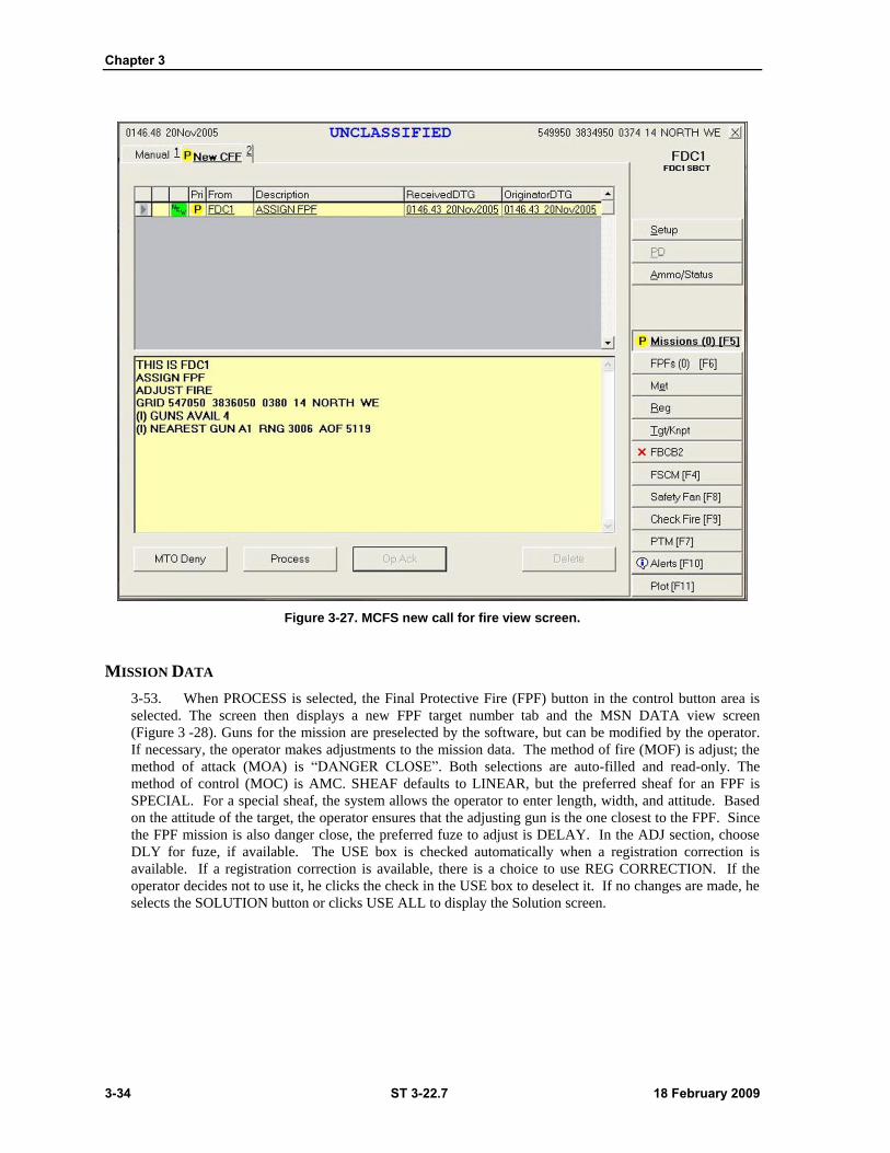
Chapter 3
3-34 ST 3-22.7 18 February 2009
Figure 3-27. MCFS new call for fire view screen.
MISSION DATA
3-53. When PROCESS is selected, the Final Protective Fire (FPF) button in the control button area is
selected. The screen then displays a new FPF target number tab and the MSN DATA view screen
(Figure 3 -28). Guns for the mission are preselected by the software, but can be modified by the operator.
If necessary, the operator makes adjustments to the mission data. The method of fire (MOF) is adjust; the
method of attack (MOA) is ―DANGER CLOSE‖. Both selections are auto-filled and read-only. The
method of control (MOC) is AMC. SHEAF defaults to LINEAR, but the preferred sheaf for an FPF is
SPECIAL. For a special sheaf, the system allows the operator to enter length, width, and attitude. Based
on the attitude of the target, the operator ensures that the adjusting gun is the one closest to the FPF. Since
the FPF mission is also danger close, the preferred fuze to adjust is DELAY. In the ADJ section, choose
DLY for fuze, if available. The USE box is checked automatically when a registration correction is
available. If a registration correction is available, there is a choice to use REG CORRECTION. If the
operator decides not to use it, he clicks the check in the USE box to deselect it. If no changes are made, he
selects the SOLUTION button or clicks USE ALL to display the Solution screen.
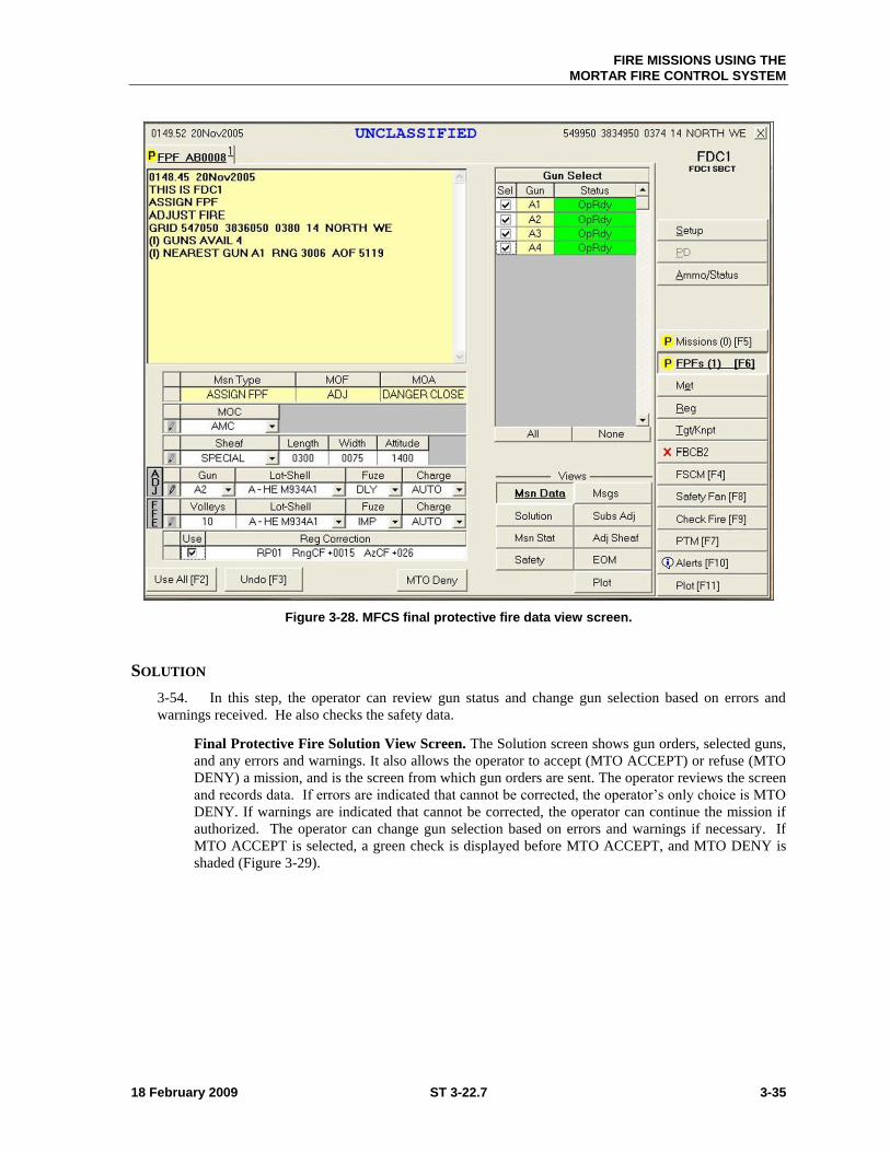
FIRE MISSIONS USING THE
MORTAR FIRE CONTROL SYSTEM
18 February 2009 ST 3-22.7 3-35
Figure 3-28. MFCS final protective fire data view screen.
SOLUTION
3-54. In this step, the operator can review gun status and change gun selection based on errors and
warnings received. He also checks the safety data.
Final Protective Fire Solution View Screen. The Solution screen shows gun orders, selected guns,
and any errors and warnings. It also allows the operator to accept (MTO ACCEPT) or refuse (MTO
DENY) a mission, and is the screen from which gun orders are sent. The operator reviews the screen
and records data. If errors are indicated that cannot be corrected, the operator’s only choice is MTO
DENY. If warnings are indicated that cannot be corrected, the operator can continue the mission if
authorized. The operator can change gun selection based on errors and warnings if necessary. If
MTO ACCEPT is selected, a green check is displayed before MTO ACCEPT, and MTO DENY is
shaded (Figure 3-29).
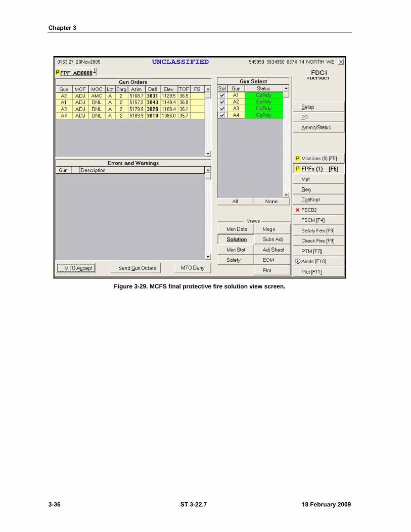
Chapter 3
3-36 ST 3-22.7 18 February 2009
Figure 3-29. MCFS final protective fire solution view screen.
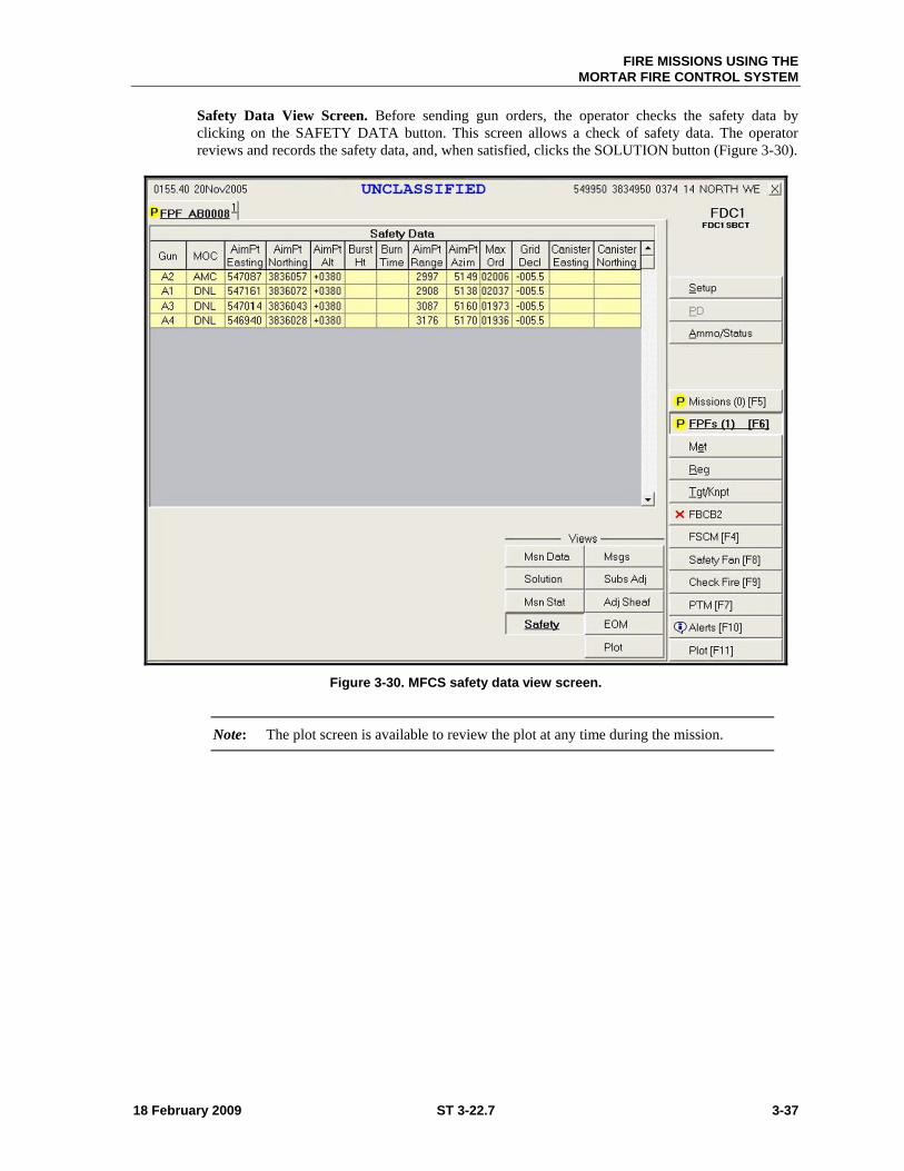
FIRE MISSIONS USING THE
MORTAR FIRE CONTROL SYSTEM
18 February 2009 ST 3-22.7 3-37
Safety Data View Screen. Before sending gun orders, the operator checks the safety data by
clicking on the SAFETY DATA button. This screen allows a check of safety data. The operator
reviews and records the safety data, and, when satisfied, clicks the SOLUTION button (Figure 3-30).
Figure 3-30. MFCS safety data view screen.
Note: The plot screen is available to review the plot at any time during the mission.
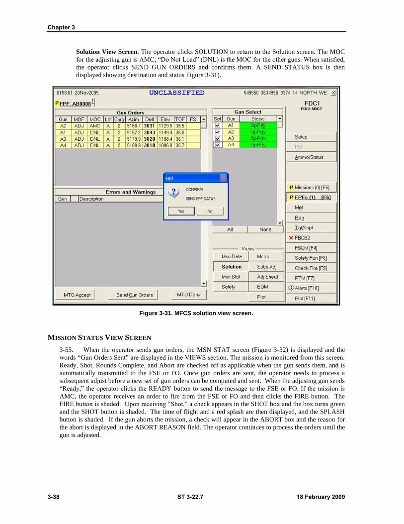
Chapter 3
3-38 ST 3-22.7 18 February 2009
Solution View Screen. The operator clicks SOLUTION to return to the Solution screen. The MOC
for the adjusting gun is AMC; ―Do Not Load‖ (DNL) is the MOC for the other guns. When satisfied,
the operator clicks SEND GUN ORDERS and confirms them. A SEND STATUS box is then
displayed showing destination and status Figure 3-31).
Figure 3-31. MFCS solution view screen.
MISSION STATUS VIEW SCREEN
3-55. When the operator sends gun orders, the MSN STAT screen (Figure 3-32) is displayed and the
words ―Gun Orders Sent‖ are displayed in the VIEWS section. The mission is monitored from this screen.
Ready, Shot, Rounds Complete, and Abort are checked off as applicable when the gun sends them, and is
automatically transmitted to the FSE or FO. Once gun orders are sent, the operator needs to process a
subsequent adjust before a new set of gun orders can be computed and sent. When the adjusting gun sends
―Ready,‖ the operator clicks the READY button to send the message to the FSE or FO. If the mission is
AMC, the operator receives an order to fire from the FSE or FO and then clicks the FIRE button. The
FIRE button is shaded. Upon receiving ―Shot,‖ a check appears in the SHOT box and the box turns green
and the SHOT button is shaded. The time of flight and a red splash are then displayed, and the SPLASH
button is shaded. If the gun aborts the mission, a check will appear in the ABORT box and the reason for
the abort is displayed in the ABORT REASON field. The operator continues to process the orders until the
gun is adjusted.
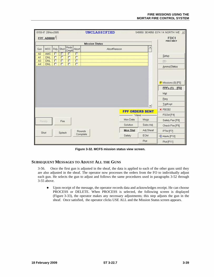
FIRE MISSIONS USING THE
MORTAR FIRE CONTROL SYSTEM
18 February 2009 ST 3-22.7 3-39
Figure 3-32. MCFS mission status view screen.
SUBSEQUENT MESSAGES TO ADJUST ALL THE GUNS
3-56. Once the first gun is adjusted in the sheaf, the data is applied to each of the other guns until they
are also adjusted in the sheaf. The operator now processes the orders from the FO to individually adjust
each gun. He selects the gun to adjust and follows the same procedures used in paragraphs 3-52 through
3-55 above.
Upon receipt of the message, the operator records data and acknowledges receipt. He can choose
PROCESS or DELETE. When PROCESS is selected, the following screen is displayed
(Figure 3-33), the operator makes any necessary adjustments; this step adjusts the gun in the
sheaf. Once satisfied, the operator clicks USE ALL and the Mission Status screen appears.
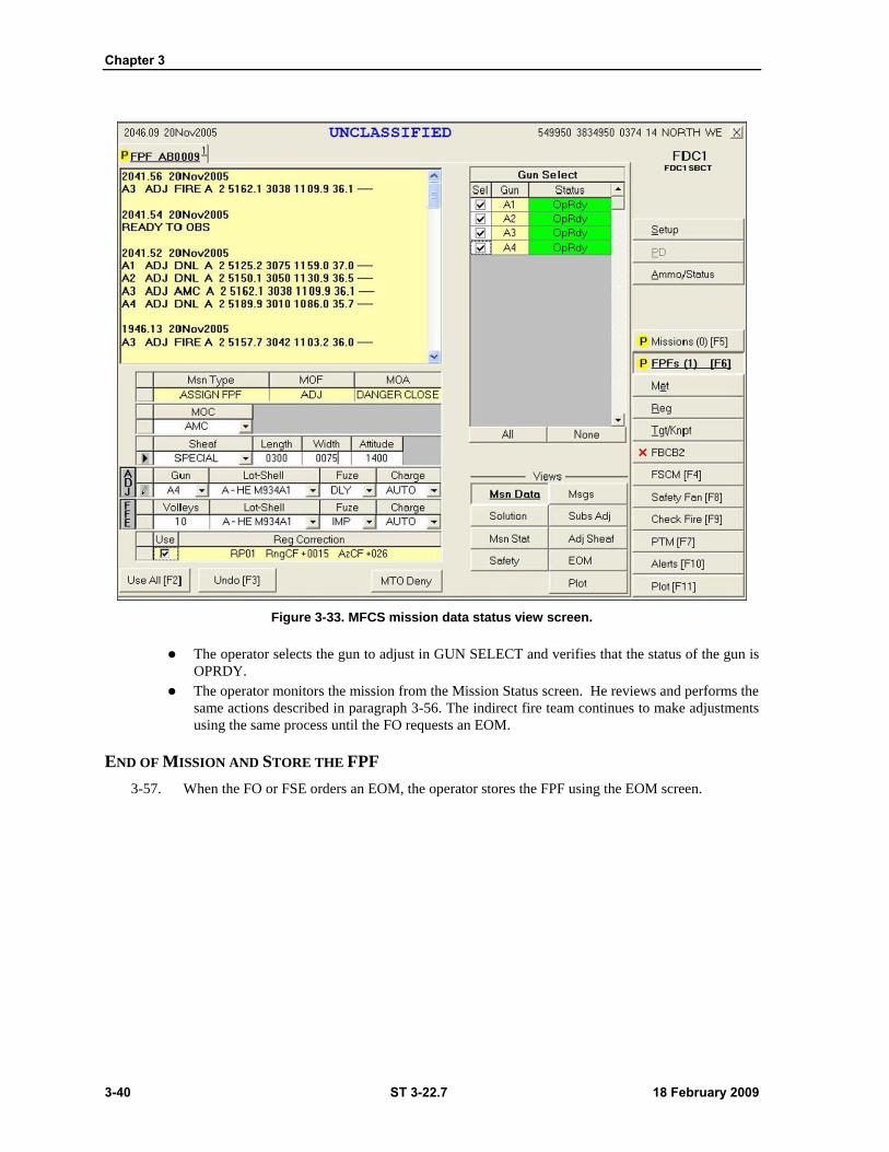
Chapter 3
3-40 ST 3-22.7 18 February 2009
Figure 3-33. MFCS mission data status view screen.
The operator selects the gun to adjust in GUN SELECT and verifies that the status of the gun is
OPRDY.
The operator monitors the mission from the Mission Status screen. He reviews and performs the
same actions described in paragraph 3-56. The indirect fire team continues to make adjustments
using the same process until the FO requests an EOM.
END OF MISSION AND STORE THE FPF
3-57. When the FO or FSE orders an EOM, the operator stores the FPF using the EOM screen.
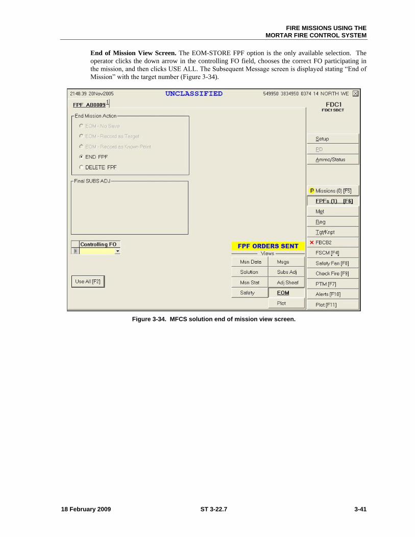
FIRE MISSIONS USING THE
MORTAR FIRE CONTROL SYSTEM
18 February 2009 ST 3-22.7 3-41
End of Mission View Screen. The EOM-STORE FPF option is the only available selection. The
operator clicks the down arrow in the controlling FO field, chooses the correct FO participating in
the mission, and then clicks USE ALL. The Subsequent Message screen is displayed stating ―End of
Mission‖ with the target number (Figure 3-34).
Figure 3-34. MFCS solution end of mission view screen.
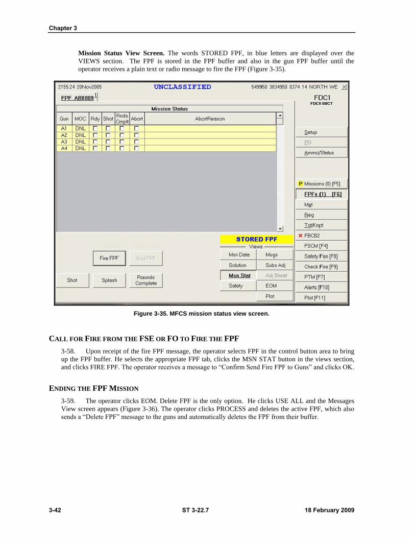
Chapter 3
3-42 ST 3-22.7 18 February 2009
Mission Status View Screen. The words STORED FPF, in blue letters are displayed over the
VIEWS section. The FPF is stored in the FPF buffer and also in the gun FPF buffer until the
operator receives a plain text or radio message to fire the FPF (Figure 3-35).
Figure 3-35. MFCS mission status view screen.
CALL FOR FIRE FROM THE FSE OR FO TO FIRE THE FPF
3-58. Upon receipt of the fire FPF message, the operator selects FPF in the control button area to bring
up the FPF buffer. He selects the appropriate FPF tab, clicks the MSN STAT button in the views section,
and clicks FIRE FPF. The operator receives a message to ―Confirm Send Fire FPF to Guns‖ and clicks OK.
ENDING THE FPF MISSION
3-59. The operator clicks EOM. Delete FPF is the only option. He clicks USE ALL and the Messages
View screen appears (Figure 3-36). The operator clicks PROCESS and deletes the active FPF, which also
sends a ―Delete FPF‖ message to the guns and automatically deletes the FPF from their buffer.
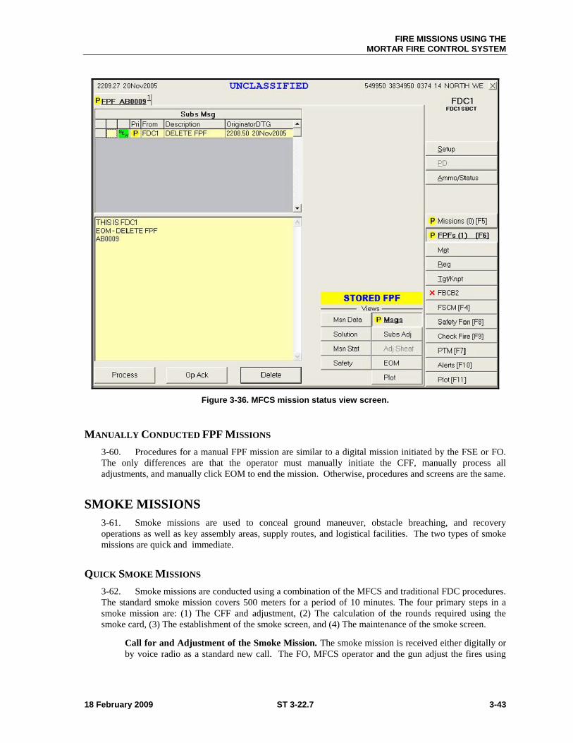
FIRE MISSIONS USING THE
MORTAR FIRE CONTROL SYSTEM
18 February 2009 ST 3-22.7 3-43
Figure 3-36. MFCS mission status view screen.
MANUALLY CONDUCTED FPF MISSIONS
3-60. Procedures for a manual FPF mission are similar to a digital mission initiated by the FSE or FO.
The only differences are that the operator must manually initiate the CFF, manually process all
adjustments, and manually click EOM to end the mission. Otherwise, procedures and screens are the same.
SMOKE MISSIONS
3-61. Smoke missions are used to conceal ground maneuver, obstacle breaching, and recovery
operations as well as key assembly areas, supply routes, and logistical facilities. The two types of smoke
missions are quick and immediate.
QUICK SMOKE MISSIONS
3-62. Smoke missions are conducted using a combination of the MFCS and traditional FDC procedures.
The standard smoke mission covers 500 meters for a period of 10 minutes. The four primary steps in a
smoke mission are: (1) The CFF and adjustment, (2) The calculation of the rounds required using the
smoke card, (3) The establishment of the smoke screen, and (4) The maintenance of the smoke screen.
Call for and Adjustment of the Smoke Mission. The smoke mission is received either digitally or
by voice radio as a standard new call. The FO, MFCS operator and the gun adjust the fires using

Chapter 3
3-44 ST 3-22.7 18 February 2009
HE. Due to ballistic differences between the HE and the smoke shell, a smoke round is fired to
confirm the adjustments.
Calculation of the Rounds Required Using the Smoke Card. As the rounds are being adjusted,
the section chief uses the smoke card to determine the number of rounds required to sustain the
smoke screen based on relative humidity, temperature gradient, and wind speed.
Establishing the Smoke Screen. Once the adjustments are made, the guns fire 12 smoke cartridges
with proximity fuses to establish the curtain.
Maintaining the Smoke Screen. The guns fire the necessary rounds per minute to sustain the smoke
screen. The FDC controls these fires by alternating fire between the guns assigned to the mission.
IMMEDIATE SMOKE MISSIONS
3-63. The primary requirement for an immediate smoke mission is speed. The CFF is usually
conducted by voice radio. The manual MFCS methods are used with the MFCS operator entering the data
and then clicking the IMMEDIATE SMOKE button.
18 February 2009 ST 3-22.7 4-1
Chapter 4
STRYKER MCV CREW AND BATTLE DRILLS
SBCT Infantry battle and crew drills describe how platoons and sections apply
immediate action, fire, and maneuver to commonly encountered situations and
equipment malfunctions. Drills require leaders to make decisions rapidly and to issue
brief oral orders quickly. A Stryker platoon’s ability to accomplish its mission often
depends on Soldiers, leaders, squads, and sections that execute key actions quickly.
Section I — TRAINING
4-1. The goal of training is to produce combat ready units that respond to known or suspected enemy
activity and defeat the enemy. Drill training is a key factor in achieving this goal. Drills require proficiency
in individual, leader, and collective tasks prior to conducting critical wartime missions. Leaders should
therefore tailor training to be realistic and challenging while increasing the difficulty of conditions as the
unit becomes more efficient.
DRILL TRAINING
4-2. There are two types of drills; crew and battle drills. In this chapter we will focus on M1129A1
Stryker mortar carrier vehicle crew and battle drills. Drills are disciplined, repetitious exercises that teach
and perfect skills or procedures (actions), collective tasks, or task steps. Warrior tasks, battle drills,
collective tasks and other training products are located on the Digital Training Management System
(DTMS). Infantry unit task lists and collective tasks are accessible through the DTMS, and are also posted
to the Warrior University website (https://www.warrioruniversity.army.mil/login.html).
CREW DRILLS
4-3. Drilled actions are trained responses to ―a given stimulus, such as an enemy action, a leader's brief
order, or the status of the weapon or equipment.‖ A crew drill is a critical collective action (or task)
performed by a weapon or equipment crew to train in the use of weapons and equipment in combat, or to
preserve life. Crew drills are initiated on cue with minimal leader orders and are performed to standard
throughout like units in the Army. This chapter’s crew drills are for MCV mounted elements.
Note: Dismounted crew drills are listed in ARTEP 7-90-DRILL.
BATTLE DRILLS
4-4. A battle drill is a critical collective action (or task) performed by a platoon or smaller element
without the application of a deliberate decision making process. The battle drill is initiated on cue,
accomplished with minimal leader orders, and performed to standard throughout like-Army units. The
action of a battle drill is vital to success in combat and critical to preserving life. It is initiated on cue

Chapter 4
4-2 ST 3-22.7 18 February 2009
(enemy action or a brief order), usually involves fire or maneuver, and is a trained response to a given
stimulus.
4-5. Drills provide the following training advantages:
1. They are based on unit missions applying specific tasks, standards, and performance measures
required to support mission proficiency.
2. They build from simple to complex and focus on the basics.
3. They link how-to-train and how-to-fight at small unit level.
4. They provide an agenda for continuous coaching and critiquing.
5. They develop leaders and build teamwork and cohesion under stress.
6. They enhance the chance for individual and unit survival on the battlefield.
TRAINING GUIDANCE
4-6. Battle and crew drill training is conducted through the use of the ―talk-through, walk-through,
run-through‖ method. M1129A1 MCV trainers must be masters of a drill to train others in it. They may
wish to periodically talk their MCV crew through the drill—explaining each Soldier’s role; then have them
go through it slowly, on open ground, correcting any mistakes as they go. Concepts that should be applied
when developing MCV crew and battle drill training are train as you fight; train using appropriate doctrine;
use performance-oriented training; train to challenge; and train to sustain proficiency.
TRAIN AS YOU FIGHT
4-7. The goal of combat-level MCV training is to achieve combat-level standards. Every effort must be
made to attain this difficult goal. Within the confines of safety and common sense, leaders must be willing
to accept less than perfect initial results, and demand realism in MCV training. Integrated realistic
conditions should include smoke, noise, simulated CBRN, battlefield debris, loss of key leaders, and cold
weather.
TRAIN USING APPROPRIATE DOCTRINE
4-8. MCV training must conform to Army doctrine. FM 3-0 (100-5), Operations, describes common
procedures and uniform operational methods that permit leaders and organizations to adjust rapidly to
changing situations.
USE PERFORMANCE-ORIENTED TRAINING
4-9. Soldiers learn best by using a hands-on approach. Leaders are therefore responsible to provide
these opportunities. All M1129A1 MCV training assets and resources including training aids, devices,
simulators, and simulations (TADSS) must be included in the strategy.
TRAIN TO CHALLENGE
4-10. Tough, realistic training challenges the intellect and body while exciting and motivating Soldiers
and leaders. It builds competence and confidence by developing and honing skills.
STRYKER MCV CREW AND BATTLE DRILLS
18 February 2009 ST 3-22.7 4-3
TRAIN TO SUSTAIN PROFICIENCY
4-11. Once individuals have been trained to a required level of MCV crew and battle drill proficiency,
leaders must structure training plans to repeat critical MCV drill tasks at the minimum frequency necessary
for sustainment.
FORCE PROTECTION (SAFETY)
4-12. Risk assessment is the thought process of making operations safe without compromising the
mission. Unit leaders must continuously perform risk assessments of the conditions in which training is
conducted to prevent the unnecessary loss of Soldiers and equipment. The degree of risk varies with the
conditions at the time of training. In reality, risk management is smart decision making. Assessment
concepts should include the following questions:
Have MCV crews done the training before?
Will the training be done for the first time at night?
Are the crews fatigued?
4-13. A well-trained Stryker unit is normally accident free. However, accidents can occur through no
fault of a Soldier or equipment operator. Most accidents result from inadequately trained, unsupervised,
fatigued, or complacent personnel.
TRAINING TOUGH AND SAFE
4-14. MCV training must be tough, realistic, and SAFE. Stryker unit leaders should consider the
following points as they integrate risk assessment into their training:
Accept no unnecessary risks.
Make risk decisions at the proper level.
Accept risks if mission benefits outweigh the costs.
4-15. It is important to remember that the commander is the safety officer, but all Soldiers and leaders
are responsible for safe training.
4-16. Every leader is responsible to—
Identify the risks using the factors of METT-TC.
Assess possible loss, cost, and probability.
Make decisions and develop controls to reduce risks.
Implement controls by integrating them into plans, orders, standing operating procedures
(SOPs), training performance standards, and rehearsals.
Supervise and enforce safety controls and standards at all times. (Leaders should make
on-the-spot corrections when an unsafe act is observed.)
4-17. Stryker brigade combat team leaders use the safety checklist of the United States Army Safety
Center, Fort Rucker, Alabama. The checklist is used in conjunction with local unit safety checklists to
enhance the overall safety practices of Stryker Infantry units during training.
Chapter 4
4-4 ST 3-22.7 18 February 2009
Section II — MCV CREW DRILLS
4-18. MCV crew drill training emphasizes rapid response to critical situations involving enemy action,
weapons, or equipment failure. When MCV training is effective, crewmen will respond immediately when
anticipated cues alert needed action.
CREW AND SQUAD DRILLS
4-19. Like Stryker battle drills, Soldiers must practice Stryker crew drills so they can accomplish them
without the application of a deliberate decision-making process. Crew drills are initiated on cue with
minimal leader orders. It is the Stryker MCV squad leader’s responsibility to explain and demonstrate the
drill duties and responsibilities of each vehicle squad member. It is up to the squad leader to instruct and
walk his MCV Soldiers through each squad drill to ensure they can perform their assigned positions.
4-20. Vehicle operations add another dimension to MCV squad training. Many of the techniques are
similar, but with differing procedures. The squad leader assigns MCV vehicle positions to the crew/squad,
and trains each Soldier in his assigned position. The crew/squad is then given the opportunity to observe
individual instruction of other assigned MCV positions. This way, every squad member has situational
understanding of each other’s position duties and can assume the responsibilities of those positions if
required. No drill should be done collectively until each member of the crew/squad can perform his
individual duties and responsibilities, proficiently perform all drill steps, and accomplish all drill standards.
4-21. Teamwork is essential when performing crew drills because it requires each squad member to be
proficient in his assigned position for the good of every team member. Every Soldier in a Stryker MCV
squad must be trained independently on his assigned vehicle position, and must perform the drill to
standard before a crew drill is performed collectively. The squad leader should have the MCV Soldier
demonstrate his functioning part of the drill several times; first for proficiency; and finally, for time.
Leaders conduct MCV crew drills collectively when every Soldier within the squad has met the standard at
his assigned position.
Note: The MCV squad must demonstrate proficiency in each crew drill before conducting
a drill for time.
4-22. The following MCV crew drills cover actions such as mounting and dismounting from a vehicle
with or without equipment organic to the vehicle; placing the 120-mm Stryker mortar into combat action,
and extinguishing a fire on the MCV. The actions a Soldier takes will differ depending on the
configuration of the vehicle, the equipment organic to the vehicle, and the equipment issued to assigned
vehicle Soldiers. MCV Soldiers should be trained on each crew drill until they are proficient on their
assigned vehicle position and can execute the steps to standard. MCV crew drills should be performed
during all hours of the day, including periods of limited visibility, and at least once in MOPP 4.
CAUTION
Personnel could receive injuries and equipment could be damaged if all safety cautions and warnings are not adhered to when operating the Stryker MCV. Crew Drills should be performed using the crawl, walk, and run method of training. Walk the Soldiers through each drill before running them for time.
STRYKER MCV CREW AND BATTLE DRILLS
18 February 2009 ST 3-22.7 4-5
REACT TO A ROLLOVER WHILE MOUNTED ON A MCV
ACTION: React to a Rollover on a Mortar Carrier Vehicle (MCV).
CONDITION: As a member of a mounted squad or crew, given individual equipment, assigned individual
weapons and ammunition, and a fully equipped MCV. (1) The driver is maneuvering off-road and loses control
of the vehicle on the side slope of a hill, causing the vehicle to roll over. The M240B is mounted and ready to
fire, and all hatches are closed. (2) The driver is maneuvering on the side of a roadway and the shoulder of the
road gives way, causing the vehicle to turn over. The M240B is mounted and ready to fire, all hatches are open,
and crew/squad personnel are standing up in the hatches. (3) The driver is maneuvering off-road along side a
body of water and loses control of the vehicle, causing the vehicle to turn upside down into the water.
STANDARD: When the command ROLLOVER was given, the crew/squad took appropriate actions for:
1. Moving vehicle with all hatches closed.
2. Moving vehicle with all hatches open, with crew/squad personnel standing up in the hatches.
3. Moving vehicle along side a body of water.
WARNING
During a rollover, gas from batteries can explode and cause serious injuries. If the driver must exit through the crew compartment, precautions must be taken to prevent contact with battery acid that could spill and cause serious burns or blindness.
WARNING
Never attempt to exit an overturning or rolling vehicle. Wait until the vehicle comes to a complete stop. Soldiers can be killed or injured by premature removal or disconnection of seat belts or safety harnesses.
WARNING
Jumping from the top of a Stryker Vehicle with or without slat armor can cause injury to personnel.
HATCHES CLOSED
4-23. The squad leader commands, ROLLOVER. The squad leader is seated in his position, and braces
for impact. The gunner, assistant gunner and ammunition bearer also brace for impact and hold onto hand
straps for stability. The driver braces for impact.
Chapter 4
4-6 ST 3-22.7 18 February 2009
HATCHES OPEN
4-24. The squad leader commands, ROLLOVER. The squad leader is standing up in his hatch, drops
down into a seated position, and braces for impact. The gunner, assistant gunner, and ammunition bearer
drop to their seats and brace for impact, holding hand straps for stability. The driver drops his seat and
braces for impact.
MCV HAS ROLLED OVER
4-25. The squad leader checks for fires and accountability of personnel. All Soldiers check themselves
for injuries and report to the squad leader. The driver shuts down the engine, engages the fuel shutoff, and
turns the AUTO and AUX MASTER switches to the OFF position. If a fire is present in the engine
compartment, he activates the engine compartment fire extinguishing system before shutting off AUTO
and AUX MASTER switches.
EVACUATE THE MCV
4-26. The MCV squad leader checks for injured personnel and reports the incident. The gunner assists
the driver in evacuating the vehicle. The squad members exit the vehicle through an unobstructed hatch.
Extinguish fire if required. The MCV driver exits the vehicle through the driver's hatch or through crew
compartment if driver's hatch is blocked. Soldiers who may have sustained injuries are assisted in
evacuation from the MCV as necessary.
Notes: 1. The senior leader determines if it is safe to exit the vehicle and begins
evacuation.
2. If the senior leader determines it is unsafe to exit the vehicle, personnel will wait
for recovery and attempt to contact other platoon vehicles, or higher.
3. Rollover drill steps are not timed. They are drills the crew/squad should be
aware of and practice if time permits, prior to vehicle movement.
4. Because the egress door hinges are located on the bottom of the door, it may
require two personnel to open and brace this door (due to its weight) if vehicle
rolls onto its top.
5. If the carrier is equipped with slat or add-on armor it may require two personnel
to open and brace the egress door, if the vehicle rolls onto its left side.
EVACUATE A STRYKER MORTAR CARRIER VEHICLE
ACTION: Vacate an MCV.
CONDITION: As a member of a mounted MCV squad or crew, given individual equipment, assigned
individual weapons and ammunition, and a fully equipped MCV. The vehicle has been engaged by enemy fire
and is burning out of control. The M240B is loaded and ready to fire, and the ramp and all hatches are closed.
STANDARD: When the command BAIL OUT is given, the squad vacates the vehicle. The squad leader
commands, BAIL OUT, and disconnects his CVC helmet. The ammunition bearer disconnects his CVC helmet
and moves out through his hatch. The assistant gunner releases the emergency ramp release lever; then the
assistant gunner and gunner exit the vehicle and move away from it. The driver disconnects his CVC helmet
and opens his hatch. The squad leader exits behind the assistant gunner and moves away from the vehicle. The
driver exits through his hatch, climbs off the vehicle, and joins the squad leader, ammunition bearer, gunner,
and assistant gunner.
STRYKER MCV CREW AND BATTLE DRILLS
18 February 2009 ST 3-22.7 4-7
WARNING
Jumping from the top of a Stryker Vehicle with or without slat armor can cause injury to personnel.
Notes: 1. Some actions such as raising and lowering the MCV ramp should be simulated
by the assistant gunner due to wear and tear on equipment caused by repetitive
training.
2. If unobstructed, the MCV driver should exit the vehicle through the driver's
hatch instead of exiting through the back of the vehicle. This is recommended
due to the close quarters between the driver's seat, other stored equipment, and
the time taken during an emergency evacuation. If the driver must evacuate the
carrier via the back of the carrier, he must lower the seatback to the fully
reclined position.
3. All Stryker vehicles are issued with seat belts for injury prevention during
vehicle movement. Adjusting time for seat belt hook-ups is therefore
recommended when conducting crew drills.
4. Each MCV crew/squad member must be familiar with the location and
operations of all hatches and egress doors in the event that one escape route is
blocked during an emergency evacuation.
5. When slat protective armor is mounted on the carrier, evacuating crew/squad
members may need to climb over and down the armor to expedite their escape.
EXTINGUISH A FIRE ON A MCV
ACTION: Put out a fire on a MCV.
CONDITION: As a member of a mounted MCV squad or crew, given individual equipment, assigned
individual weapons and ammunition, and a fully equipped MCV. The MCV squad leader is maneuvering the
Stryker to a designated position, when the vehicle fire alarm alerts the crew that a fire has started in the vehicle.
STANDARD: When the command FIRE was given the MCV squad leader and driver maneuvered the vehicle
to a safe location. The squad immediately extinguished the fire, minimizing damage to equipment and injury to
Soldiers. Standards were accomplished through the following actions:
1. Acknowledged fire indicator in the annunciator panel by pressing the AFES reset button.
2. Engaged fire suppression system manually before exiting the vehicle.
3. Suppressed fire using portable fire extinguisher as needed.
Notes: 1. While in training, when the MCV is in motion, the driver will stop the vehicle,
place the transmission into neutral, and engage the parking brake.
2. DO NOT manually engage the fire suppression system if the AFES fire
indicator light remains off after pressing the reset button.
3. When the reset button is pushed, the light will illuminate and stay illuminated
indicating that the fire has not been successfully extinguished. Light will
illuminate periodically, indicating that a fire was present and has been
extinguished. Light will also indicate when the fire extinguisher is partially
discharged or empty and needs to be replaced.
Chapter 4
4-8 ST 3-22.7 18 February 2009
4. The AFES will activate all fire extinguishing bottles in an attempt to extinguish
the fire. If the fire indicator light remains ON, activate the manual toggle switch
to ensure all fire extinguishers were fully discharged prior to dismounting
vehicle.
5. Each crew/squad member must be familiar with the location and operations of
all hatches and egress doors in the event that one escape route is blocked during
an emergency evacuation.
6. When SLAT protective armor is mounted, evacuating MCV crew/squad
members may need to climb over and down the armor to expedite their escape.
WARNING
If fire-extinguishing chemicals are discharged into the engine compartment while the MCV engine is running, engine exhaust becomes poisonous. Poison gas can cause serious injury.
WARNING
Ensure that the area behind the MCV is clear before attempting to lower the ramp. Personnel can be injured and equipment damaged when the ramp opens. Ensure the ramp door is closed and locked.
WARNING
Discharge from fire extinguishers can freeze skin. A discharging fire extinguisher can move violently when not properly secured. Personnel can be seriously injured and equipment damaged.
WARNING
HFC 25 (FE25) is a health hazard. Exposure to skin can cause freezing. Inhaling high concentrations may cause respiratory effects such as shortness of breath producing heart rhythm irregularities.
STRYKER MCV CREW AND BATTLE DRILLS
18 February 2009 ST 3-22.7 4-9
WARNING
FM 200 is a health hazard. Exposure to skin can cause freezing. Inhaling high concentrations may cause respiratory effects such as shortness of breath producing heart rhythm irregularities.
CAUTION
In spite of different stowage areas for the CBRN decontamination bottle and portable fire extinguishing bottles, there is a possibility of using one instead of the other, especially when the compartment is filled with smoke. Therefore, care should be exercised to avoid making this identification mistake. Always check labels before use.
MCV ENGINE COMPARTMENT FIRE
1. The MCV driver alerts crew/squad, ENGINE FIRE, and acknowledges fire by pressing the AFES
reset button.
2. The MCV squad leader directs the driver to a safe position. The driver moves the vehicle to a
safe position, stops, shuts down the engine, places the transmission in neutral, and engages the
parking brake.
3. The MCV squad leader disconnects his seat belt and CVC helmet and secures his personal
weapon. The ammunition bearer disconnects his CVC helmet and secures his personal weapon, then
opens his hatch and climbs off the front slope of the vehicle. The gunner and assistant gunner
disconnect their seat belts and secure their personal weapons. The assistant gunner then pushes the
emergency ramp button and lowers the ramp. The driver opens the driver’s hatch, disconnects his
CVC helmet, and secures his personal weapon and portable fire extinguisher.
4. The MCV squad leader secures the rear portable fire extinguisher, exits the vehicle behind the
ammunition bearer, and moves to the front of the vehicle to supervise the extinguishing of the engine
compartment fire. The MCV driver checks the AFES indicator light and manually discharges AFES
(if the light indicator remains ON) by raising the engine toggle guard on the AFES panel and
pushing up on the toggle switch.
5. The MCV driver turns off all vehicle power, exits through driver's hatch, and climbs off the front
slope of the vehicle.
6. The MCV squad leader accounts for all personnel and supervises extinguishing of the fire. The
driver and the gunner extinguish the fire using the portable fire extinguishers (as needed).
Note: The MCV squad leader checks for location and condition of the fire before allowing
the crew near the vehicle and reports to higher.
7. The MCV squad leader checks the engine compartment to assess the condition of the fire.
Notes: 1. Some actions such as raising and lowering the MCV ramp should be simulated
due to the wear and tear on the equipment, which is caused by repetitive
training.
2. During training the use of fire extinguishers is simulated.
Chapter 4
4-10 ST 3-22.7 18 February 2009
3. All Stryker vehicles come with seat belts, which should be used to prevent
injuries to Soldiers during vehicle movement. Adjusting time for seat belt
hook-ups is recommended when conducting crew drills.
4. MCV crew members must wait 3 to 5 minutes before opening engine access
hatch to assess the condition of the fire.
TROOP COMPARTMENT FIRE
1. The MCV driver alerts crew/squad by announcing, TROOP COMPARTMENT FIRE. He then
acknowledges fire by pressing the AFES reset button.
2. The MCV squad leader directs the driver to a safe position. The driver moves the vehicle to a
safe position, stops, shuts down the engine, places the transmission in neutral, and engages the
parking brake.
3. The squad leader and ammunition bearer disconnect their CVC helmets and secure their personal
weapons. The driver opens his hatch, disconnects his CVC helmet, and secures his personal weapon
and portable fire extinguisher. The assistant gunner disconnects his seat belt, secures his personal
weapons, releases the emergency ramp lever, and exits the vehicle. The gunner disconnects his CVC
helmet and seat belt, secures his personal weapon and exits the vehicle.
4. The squad leader secures the portable fire extinguisher and exits the vehicle behind the
ammunition bearer.
5. The driver checks the AFES indicator light and manually discharges AFES (if the light indicator
remains ON) by raising the toggle guard on the AFES panel and pushing up on the TROOP toggle
switch.
6. The driver turns off all vehicle power, exits through the driver's hatch, and climbs off the front
slope of the vehicle.
7 The driver and gunner position themselves IAW where the fire is located. The squad leader
accounts for all personnel and checks for the location and condition of the fire before allowing
anyone near the vehicle. He reports the incident to higher.
8. The driver extinguishes the fire assisted by the gunner. The squad leader supervises the
extinguishing of the fire.
Notes: 1. Some actions such as raising and lowering the MCV ramp should be simulated
by the gunner and driver due to wear and tear on equipment that is caused by
repetitive training.
2. Use of fire extinguishers is simulated.
3. All Stryker vehicles are issued seat belts that should be used to prevent injuries
during vehicle movement. Adjusting time for seat belt hook-ups is therefore
recommended when conducting crew drills.
4. In the event of a hull fire, the squad leader investigates the location and
condition of the fire before attempting to extinguish .
PLACE A 120-MM STRYKER MORTAR INTO ACTION
ACTION: Place a Stryker 120-mm mortar into action.
CONDITION: Given a M11291A Stryker with the gun crew seated in their normal positions; seat belts on; a
120-mm mortar complete and locked in the traveling position (muzzle cover on); cargo hatches in the closed
position and combat locked; and the M67 sight unit secured in the sight box with latches locked. The vehicle
ramp can be open or closed.
STRYKER MCV CREW AND BATTLE DRILLS
18 February 2009 ST 3-22.7 4-11
STANDARD: Placed the mortar into action so that the sight was set at 3200 mils deflection, 1100 mils
elevation, all bubbles were level.
WARNING
M1129A1 Stryker Mortar doors are large and extremely heavy. Two Soldiers are required to safely open, close, and secure the doors in the open or closed position. Attempting to open or close mortar doors can result in serious injury to personnel.
WARNING
Mortar doors must be securely locked with lock pins installed when in the open door position to prevent doors from accidentally closing. Failure to lock mortar doors with lock pins in the open door position when firing or repositioning vehicle may result in serious injury to personnel.
WARNING
Mortar doors are under spring tension. To avoid serious injury, keep face and body parts clear of doors and hands clear of door edges when opening or closing.
CAUTION
When the commander’s hatch is opened to the 180-degree position, it interferes with the opening/closing of mortar doors. Ensure the commander’s hatch is not open at the 180-degree position or damage to the vehicle will occur.
Note: The left M1129A1 mortar door must be opened before the right mortar door can be
opened. Each door’s close latch has a combat lock. Combat locks must be
disengaged to open mortar doors from inside the vehicle.
PLACEMENT OF THE RMS6-L INTO FIRING CONFIGURATION
4-27. This drill should begin with the MCV mortar crew mounted in the carrier. The purpose of this
drill is to get the mortar into a firing position to be reciprocally laid; or to engage a target using the direct
lay method. The MCV driver leaves the engine running. The intercom between the driver, gunner, and
squad leader is maintained so the squad leader and gunner can direct the driver to move the carrier for the
first deflection reading in reciprocal laying. To mount the mortar in the firing position, the squad leader
Chapter 4
4-12 ST 3-22.7 18 February 2009
gives the preparatory command, PREPARE FOR ACTION, and the mortar squad takes the following
actions:
1. The gunner places one hand on the rear combat lock handle of the assistant gunner’s (left) mortar
door, and the other hand on his seatbelt release lever. The assistant gunner places one hand on the
rear combat lock release handle of the gunner’s (right) mortar door and the other hand on his seatbelt
release lever. The ammunition bearer places one hand on the forward combat lock handle of the
assistant gunner’s (left) mortar door and one hand on his seatbelt release. When the squad is ready,
the squad leader commands, ACTION.
2. On the command, ACTION, the gunner, assistant gunner, and ammunition bearer simultaneously
release their seat belts and rotate the combat lock handles they are holding. Each crew member will
then open his corresponding door close latch handle.
3. The ammunition bearer unlatches the assistant gunner’s toolbox, removes the sight box, closes
the tool box, and places the sight unit on the heat exchanger cover with the handle facing toward the
gunner’s position. The ammunition bearer does not open the sight box.
4. The assistant gunner releases the elevation travel strap and removes the dovetail slot cover from
the sight mount. The gunner moves forward to the center of the left mortar door and opens the center
combat lock handle and door close latch handle. The gunner moves to the left mortar door forward
combat lock and door close latch handle and opens both.
5. The assistant gunner and ammunition bearer push the assistant gunner’s (left) mortar door up and
out, ensuring it fully engages the door open latches. They then insert the mortar door locking pins
front and rear. The ammunition bearer turns and assists the gunner in pushing the gunner’s (right)
mortar door up and out, ensuring it fully engages the door open latches. They then insert the mortar
door locking pins, front, and rear.
6. The assistant gunner moves to the front of the cannon. He places his right shoulder under the
mortar, then pushes up until the elevation folding mechanism locks in the raised position, and the
bronze bushing drops down into the fully locked position. He then elevates the cannon
approximately 35 turns on the elevation hand wheel.
7. The gunner removes the sight unit from its case and then closes the case. He ensures it is on a
deflection of 3200 mils and elevation of 1100 mils, and locks it into the dovetail slot on the mortar.
8. The gunner correctly indexes the telescope in the horizontal or vertical position and locks the
telescope in place and dead levels the mortar. The assistant gunner removes the muzzle cover. The
gunner and assistant gunner cross-level the mortar.
9. The gunner ensures the mortar fire/safety switch is in the ―fire‖ position and then announces, UP.
The squad leader signals UP to the aiming circle operator. At this time the crew should be at their
firing posts. The MCV squad is now ready to reciprocal lay or to engage a target by the direct lay
method.
PERFORM SMALL DEFLECTION AND ELEVATION CHANGES ON
A STRYKER MOUNTED 120-MM MORTAR SYSTEM
ACTION: Perform small deflection and elevation changes on a Stryker mounted 120-mm mortar system.
CONDITION: Given an M1129A1 Stryker mortar carrier vehicle with M67 sight installed, aiming posts
placed out at 50 and 100 meters from the mortar system, and a deflection of 3200 mils and elevation of 1100
mils indexed on the sight.
STANDARD: The new deflection and elevation will be indexed without error. Vertical cross line will be
within 2 mils of an aligned sight picture. Bubbles will be leveled within the outer red lines.
Note: Small deflection changes are greater than 50 mils, but less than 75 mils. Elevation
changes are greater than 35 mils, but less than 90 mils.
STRYKER MCV CREW AND BATTLE DRILLS
18 February 2009 ST 3-22.7 4-13
LAY FOR SMALL DEFLECTION AND ELEVATION CHANGE
Note: The gun crew will repeat all elements of fire commands.
1. The gunner is given a deflection and elevation change in the form of a fire command. Example:
SECTION, 1 GUN, HE QUICK, 1 ROUND, DEFLECTION 5890, CHARGE 2, ELEVATION
1255.
2. As soon as the gunner receives the fire command, he places the data on the sight and elevates or
depresses the mortar to float the elevation bubble.
3. The gunner then looks into the sight to determine where he has to traverse the mortar. The
gunner will then place his hand on the traversing hand wheel and traverse half the distance to his
aiming posts and stop.
4. The gunner commands the assistant gunner to ―level.‖
5. The assistant gunner uses the cant correction knob to level the deflection bubble and announces,
CHECK.
6. The gunner and assistant gunner repeat steps 3 through 5 until the vertical cross line is within 2
mils of the left side of the aiming post and the deflection bubble is level.
7. The gunner will then level his elevation bubble with the elevation hand wheel.
8. Before the gunner announces, GUN UP, he should recheck his data and bubbles to ensure the
proper lay of the weapon system.
PERFORM LARGE DEFLECTION AND ELEVATION CHANGES ON
A STRYKER MOUNTED 120-MM MORTAR SYSTEM
ACTION: Perform large deflection and elevation changes on a Stryker mounted 120-mm mortar system.
CONDITION: Given an M1129A1 Stryker Mortar Carrier with M67 sight installed. Aiming posts are placed
out at 50 and 100 meters from the mortar system with a deflection of 3200 mils and elevation of 1100 mils
indexed on the sight.
STANDARD: The new deflection and elevation will be indexed without error. Vertical cross line will be
within 2 mils of an aligned sight picture. Bubbles will be leveled within the outer red lines.
Note: Large deflection changes are greater than 200 mils, but less than 300 mils. Elevation
changes are greater than 100 mils, but less than 200 mils.
LAY FOR LARGE DEFLECTION AND ELEVATION CHANGE
Note: The gun crew will repeat all elements of fire commands.
1. The gunner is given a deflection and elevation change in the form of a fire command.
2. As soon as the gunner receives the fire command, he places the data on the sight and elevates or
depresses the mortar to float the elevation bubble, and unlocks the azimuth quick release lever (lever
out).
3. The gunner then looks into the sight to determine where he has to traverse the mortar. The
gunner shifts the mortar back to within 20 mils of the aiming posts, levels the mortar, and reengages
the azimuth quick release lever (lever in). The gunner then places his hand on the traversing hand
wheel and traverses half the distance to his aiming posts.
Chapter 4
4-14 ST 3-22.7 18 February 2009
Note: Each tooth of the traversing gear is approximately 65 mils. To lock the traversing
gear after the azimuth quick release lever is re-engaged, the crew may need to rotate
the turntable. To save time, the gunner should coordinate with the assistant gunner to
push the turntable in the same direction every time.
4. The gunner commands the assistant gunner to LEVEL.
5. The assistant gunner uses the cant correction knob to level the deflection bubble and announces
CHECK.
6. The gunner and assistant gunner repeat steps 3-5 until the vertical cross line is within 2 mils of
the left side of the aiming post and his deflection bubble is level.
7. The gunner will then cross level his deflection bubble (the assistant gunner may manipulate the
cant knob in cross leveling).
8. The gunner will repeat steps 3-5 with the assistance of the assistant gunner until the vertical cross
line is within 2 mils of his aiming post and his deflection bubble is level.
9. The gunner will then level his elevation bubble with the elevation hand wheel.
10. Before the gunner announces, GUN UP, he should recheck his data and bubbles to ensure the
proper lay of the weapon system.
RECIPROCAL LAY A STRYKER MOUNTED 120-MM MORTAR
ACTION: Reciprocal lay a Stryker mounted 120-mm mortar.
CONDITION: Given an M1129A1 Stryker Mortar Carrier, M2 aiming circle, an aiming circle operator, M67
sight mounted with bubbles level on a deflection of 3200 mils, and elevation of 1100 mils.
STANDARD: The gun is laid within 1 mil of mounting azimuth. All bubbles are leveled. Aiming posts are
properly emplaced. The vertical cross hairs of the M67 sight are within 2 mils of the left side of the aiming
post. The gunner must announce GUN UP within 80 seconds.
SETUP CONDITIONS:
The mortar is prepared for action and laid on an initial azimuth.
The sight is set at 3200 mils deflection and 1100 mils elevation.
The aiming circle is set up about 75 meters from the carrier where it is visible to the gunner.
The aiming circle is oriented on an azimuth of not less than 100 mils or not more than 200 mils
away from the initial azimuth.
A relay man is positioned halfway between the aiming circle and carrier to relay commands.
The turntable is centered with the turntable azimuth lock engaged.
The aiming circle operator lays the vertical hair line on the mortar sight and announces,
AIMING POINT THIS INSTRUMENT.
The gunner refers the sight unit (using the deflection micrometer knob) to the aiming circle with
the vertical cross line splitting the lens of the aiming circle, and announces; NUMBER
(NUMBER OF GUN) GUN, AIMING POINT IDENTIFIED.
The aiming circle operator reads the deflection to the gunner. Example: NUMBER (NUMBER
OF GUN) GUN, DEFLECTION, THREE THREE ONE FIVE (3315).
The gunner repeats the command and indexes the announced deflection on the sight and relays
on the center of the aiming circle lens by directing the driver to turn the vehicle left/right. The
vehicle is turned until the vertical hair line of the sight unit bisects the aiming circle lens
+/- twenty (20) mils. The assistant gunner must maintain the cross-level bubble during carrier
movement. The gunner directs the driver to straighten the wheels and set the brakes. The gunner
releases the azimuth locking handle and the gunner traverses while the assistant gunner
STRYKER MCV CREW AND BATTLE DRILLS
18 February 2009 ST 3-22.7 4-15
cross-levels back to the center of the aiming circle lens. Once the correct sight picture is
obtained and the bubbles are level, the gunner announces, NUMBER (NUMBER OF GUN)
GUN, READY FOR RECHECK.
The aiming circle operator uses his azimuth micrometer knob to place the vertical hair line on
the lens of the mortar sight unit and reads the new deflection to the gunner. Example: NUMBER
(NUMBER OF GUN) GUN, DEFLECTION, THREE THREE TWO SIX (3326). The gunner
and crew repeat all commands and the process is repeated until the gunner announces,
NUMBER (NUMBER OF GUN) GUN, ZERO MILS (OR ONE MIL) MORTAR LAID.
CONDUCT MISFIRE PROCEDURES ON A STRYKER 120-MM
MORTAR SYSTEM
ACTION: Conduct misfire procedures on a Stryker 120-mm mortar system.
CONDITION: Given a Stryker Mortar Carrier Vehicle with a loaded mortar which fails to fire. The first crew
member that notices the failure of the round to fire announces, MISFIRE.
STANDARD: All required actions to remove the misfire must be performed in sequence and without error.
WARNING
Do not drop another cartridge on top of a misfired cartridge. Dropping another cartridge on top of a misfired cartridge may result in detonation of propelling charges, fuzes, and main charges of both cartridges causing injury or death to personnel.
WARNING
Crew members must keep head clear of front and rear of mortar when performing misfire procedures. Placing any part of the body in front of cannon or directly behind recoil mechanism may result in serious injury or death to personnel.
Note: A misfire is a failure of a cartridge to fire after it is dropped into the mortar cannon.
Misfires can be caused by defective or dirty ammunition and cartridges dropped with
the safety mechanism set to SAFE. Other causes include damaged or worn firing
pins, dirty cannons, and obstructions in the cannon that prevent the cartridge from
sliding down and striking the firing pin.
1. When a misfire occurs, the first crew member that notices shouts, MISFIRE!
2. The vehicle commander alerts the FDC of misfire using either voice or digital radio
communications.
Chapter 4
4-16 ST 3-22.7 18 February 2009
Note: To avoid injury during peacetime live-fire exercises, all crew members, except the
gunner and squad leader, will exit the vehicle through the squad leader or
ammunition bearer’s hatch. They will then move to a position 100 meters in the
opposite direction of fire. In combat, all crew members remain inside the vehicle.
3. Gunner confirms safety mechanism is set to FIRE position (―F‖ position is showing) and
announces, WEAPON IS ON FIRE.
Note: If the gunner confirms system is on SAFE, the gunner announces, WEAPON IS ON
SAFE, and leaves the weapon on SAFE. If the squad leader confirms the system is
on SAFE, he announces, WEAPON IS ON SAFE, and he and the gunner exit the
vehicle in the opposite direction of fire. They then move to the same location as the
rest of the crew, then proceed to step 8.
4. The squad leader confirms the action of the gunner by physically observing that the ―F‖ is
showing and announces, WEAPON IS ON FIRE.
5. The gunner secures the rubber mallet and strikes the upper portion of the cannon up to three
times with the rubber mallet. If the cartridge fires, the squad leader will call the crew back to the
vehicle and the mission will resume. If the cartridge does not fire after striking the cannon with the
rubber mallet, the squad leader and gunner will exit the vehicle from the opposite direction of fire
and wait for one minute.
6. After one minute, the gunner, assistant gunner, and squad leader return to the vehicle.
WARNING
Do not touch the cannon with bare hands if the cannon is hot. Touching a hot cannon may result in injury to personnel. The cannon and breech must be cool enough to touch with bare hands before continuing with misfire procedures. Cartridge cook-off may occur if misfire procedures are conducted before the cannon and breech are cool. Failure to wait until the cannon and breech are cool may result in injury or death to personnel.
7. The gunner checks the barrel for heat using bare hands. Starting at the muzzle, the bare hand is
moved close to the barrel, sensing for heat, if heat is not sensed with the hands, the gunner touches
the barrel lightly with his fingertips every few inches down to the breech cap. If the barrel is too hot,
the crew uses some means (water, snow, or elapsed time) to cool the barrel before attempting to
remove the misfire.
8. When the barrel is cool enough to handle, the gunner places the safety mechanism on SAFE
(―S‖ showing) and announces, THE SAFETY MECHANISM IS IN THE SAFE POSITION.
9. The assistant gunner physically confirms that the safety mechanism is on SAFE (―S‖ showing)
and announces, THE SAFETY MECHANISM IS IN THE SAFE POSITION.
10. The squad leader confirms the actions of the gunner and assistant gunner and physically
verifies that the safety mechanism is in the SAFE position.
11. Ensuring the cannon is pointed toward the target area, the gunner traverses the mortar using the
traversing hand wheel until the cannon is at the 3200 mils position and travel lock is engaged. (The
cannon is pointed over the center of the ramp.)
12. The assistant gunner lowers the ramp as directed by the squad leader if not already lowered
using the troop ramp control box.
STRYKER MCV CREW AND BATTLE DRILLS
18 February 2009 ST 3-22.7 4-17
13. If the M67 sight is installed, the gunner locks data on the sight and removes the sight and
places it back in the sight box.
14. The assistant gunner removes and stows the blast attenuator device (BAD). The squad leader
confirms the actions of the assistant gunner.
15. The gunner and assistant gunner stow their seats in the raised position.
16. The gunner slowly lowers the cannon to its lowest elevation using the elevation hand wheel.
17. The gunner and assistant gunner slowly lower the cannon to the travel position by pushing up
on the brass bushing and lowering the folding mechanism.
WARNING
If cleaning staff assembly sections cannot be extended and tightly locked when attached to the cartridge extractor, or cartridge extractor catches do not operate properly, the cartridge extractor is not mission capable. Do not use a defective cartridge extractor assembly to remove a misfired cartridge from the cannon. Use of a defective cartridge extractor assembly may result in injury or death to personnel.
18. The assistant gunner inspects extractor catches on the cartridge extractor to ensure they are
the latest configuration. There should be a 1/8 inch hole in the face of each catch. The hole
indicates that the catch is the latest configuration. The assistant gunner inspects the cartridge
extractor and makes sure that the cartridge extractor catches are free of burrs, wear, or
rust/corrosion that would impair function. The assistant gunner tests each cartridge extractor catch
to ensure free operation, and that each catch will snap positively into its original position.
19. The squad leader confirms the actions of the assistant gunner. If the cartridge extractor fails to
meet inspection standards, the squad leader will attempt to retrieve another mission capable
cartridge extractor from another squad. If unable to retrieve another mission capable cartridge
extractor from another squad, he will proceed to removal of a stuck cartridge in step 32.
20. The assistant gunner attaches the cartridge extractor to the extended artillery cleaning staff
assembly ensuring the extractor is securely attached and the cleaning staff assembly sections are
fully extended and locked.
21. While keeping head and body away from the front of the cannon, the assistant gunner rotates
the artillery cleaning staff assembly to obtain positive control of the extractor head. The assistant
gunner must place the extractor in his left palm facing upward. He inserts the cartridge extractor
into the cannon and lowers the cartridge extractor slowly (hand to hand) deeper into the cannon
until contact is made with the round.
22. The assistant gunner rotates the extractor in either direction until the spring-loaded extractor
catches connect into the round. Rotation continues until resistance is felt.
Note: If the round is grasped by the extractor, continue with step 23. If the round is not
grasped by the extractor, proceed to removal of a stack cartridge in step 32.
23. When the assistant gunner has ensured that the cartridge extractor is firmly connected with
the round, the round is to be extracted in one steady motion (hand to hand) without stopping.
24. With the gunner’s hands held at the ready at the muzzle, the assistant gunner withdraws the
cartridge extractor assembly in a steady motion until the extractor appears at the end of the
muzzle.
Chapter 4
4-18 ST 3-22.7 18 February 2009
WARNING
When removing the cartridge, do not touch the cartridge primer and do not stand in front of the cannon. Touching the cartridge primer or standing in front of cannon may result in injury or death to personnel.
25. The assistant gunner continues to withdraw the round. The gunner grasps the body of the
round as it comes out of the barrel. The cartridge extractor and round are moved by the assistant
gunner and gunner down the ramp as they proceed to the left or right side of the vehicle.
26. Once the gunner and assistant gunner have cleared the ramp, the ammunition bearer comes
forward and stands beside the gunner.
27. With the assistant gunner holding the artillery cleaning staff assembly and the gunner holding
the round, the ammunition bearer presses on all four extractor catches at the same time, releasing
the round from the cartridge extractor.
28. The gunner inspects the cartridge for cause of misfire. If the primer has been struck by the
firing pin, he disposes of the cartridge in accordance with applicable safety regulations and unit
SOP.
Note: If no contact or insufficient contact was made with the firing pin, check the safety
mechanism function on the cannon. Clean the cannon before attempting to fire the
round a second time. If the cartridge does not fire after checking the safety
mechanism and swabbing the cannon, repeat the misfire procedure and dispose of
the cartridge in accordance with applicable safety regulations and unit SOP.
29. The assistant gunner swabs the barrel and replaces the blast attenuator device. The gunner
places the safety mechanism to the FIRE position (―F‖ is showing).
30. The squad leader confirms the actions of the gunner and assistant gunner and verifies that the
safety mechanism is in the FIRE position.
31. The gunner places the mortar into action (replacing the M67 sight unit if applicable), and the
mission is continued.
IN THE EVENT OF A STUCK CARTRIDGE
WARNING
Procedures for removing a stuck cartridge are to be performed ONLY after misfire procedures have been attempted and a stuck cartridge cannot be pulled out of the barrel. Performing this procedure without first attempting misfire procedure may result in injury or death to personnel.
STRYKER MCV CREW AND BATTLE DRILLS
18 February 2009 ST 3-22.7 4-19
WARNING
Crew members must keep head clear of the front and rear of the mortar when performing misfire procedures. Placing any part of the body in front of a cannon or directly behind a recoil mechanism may result in serious injury or death to personnel.
32. Squad leader verifies safety mechanism is set to SAFE position (with ―S‖ showing).
33. The gunner loosens the wiper compression clamp and removes the two wiper segments.
34. The ammunition bearer pulls out and turns the cannon retaining ring plunger.
35. The ammunition bearer unscrews and removes the cannon retaining ring using a large
spanner wrench and hammer while the gunner secures the cannon to keep it from sliding. The
assistant gunner maintains positive control of the artillery cleaning staff.
36. The gunner slowly pushes the cannon forward approximately 3 inches until the breech key
clears the cradle assembly keyway.
37. The ammunition bearer unscrews and removes the breech cap using a hammer and removal
tool while the gunner holds the upper portion of the cannon.
38. The assistant gunner attempts to push the cartridge out through the base of the cannon (fin
first and in one steady motion) while the ammunition bearer places his hands ready to catch the
round.
39. The ammunition bearer grasps the round by the fin and body of the round as it comes out of
the barrel.
40. Once the ammunition bearer has positive control of the round, the assistant gunner allows the
cleaning staff to rest in the bore and moves to the rear of the cannon.
41. The assistant gunner presses on all four of the extractor catches at the same time releasing the
round from the cartridge extractor.
42. The ammunition bearer hands the round to the assistant gunner who passes the round to the
gunner. The gunner carries the round down the ramp and proceeds to the left or right side of the
vehicle. At this point the crew follows steps 28-31.
43. The ammunition bearer replaces the breech cap and cannon retaining ring and engages the
cannon retaining ring plunger.
44. The assistant gunner and gunner replace the wiper segments and tighten the wiper
compression clamp.
45. The crew places the gun into action and continues the mission.
Note: If the round cannot be pushed out of the cannon, the gunner, assistant gunner, and
ammunition bearer—keeping the cannon in a horizontal position—slide the cannon
toward the rear of the vehicle and out of the cradle assembly, then walk the barrel
down the ramp. The cannon with stuck round is placed a safe distance from the
carrier and the unit contacts EOD. The squad leader reports his actions to the chain
of command.
Section III — MCV BATTLE DRILLS
4-28. A battle drill is ―a critical collective action (or task) performed by a platoon or smaller element
without the application of a deliberate decision making process. Battle drills usually involve fire or
maneuver. They are initiated on cue (such as an enemy action or a leader's brief order); are accomplished

Chapter 4
4-20 ST 3-22.7 18 February 2009
with minimal leader orders, and are performed to standard throughout like units in the Army. Drill actions
are vital to success in combat and critical to preserving life.
4-29. Effective battle drills produce a trained response to a given stimulus. The following battle drills
are for mounted MCV elements.
REACT TO A BIOLOGICAL OR CHEMICAL ATTACK
ACTION: React to a biological and/or chemical attack while dismounted/mounted on a Stryker Mortar Carrier
Vehicle (MCV).
CONDITION: As a member of a dismounted/mounted squad or crew, given individual equipment, assigned
individual weapons and ammunition, and a fully equipped MCV. The squad/crew is in a defensive position near
a contaminated area. Personnel hear a chemical alarm or are ordered to mask.
STANDARD: When the command ―GAS‖ is given:
1. The squad or crew immediately dons their protective masks and hoods within 15 seconds and
mounts/dismounts as necessary.
2. Connect their breathing apparatus to the vehicle M13A1 gas particular filtration unit (GPFU)
within 60 seconds.
3. Within 90 seconds, Soldiers begin self-decontamination.
4. Soldiers assume MOPP4 posture within 8 minutes.
5. Soldiers complete basic skills decontamination within 15 minutes.
6. Decontaminate vehicle and equipment.
1. A Chemical Alarm is sounded.
1. The squad leader stops breathing and within 9 seconds dons, clears, and seals his protective
mask. Within 6 seconds, he pulls the hood overhead and zips it up. He then alerts the vehicle
crew by giving the alarm ―GAS,‖ using arm and hand signals, or by using radio
communications.
2. Squad members stop breathing and within 9 seconds don their protective masks, clear, and seal.
Within 6 seconds they pull hoods overhead and zip them up. All give the alarm "GAS" or give
arm-and-hand signals for a chemical attack.
Note: While mounted, the squad leader, ammunition bearer, and driver hatches are closed,
and the M240B is in the ready-to-fire configuration.
3. Crew/squad, if dismounted, takes shelter on vehicle.
4. All squad members connect their protective mask breathing apparatuses to the vehicle M13A1
gas particular filtration unit (GPFU).
Note: If the squad is in a mounted configuration, the squad leader, ammunition bearer,
driver hatches, and ramp are closed.
2. The squad leader directs the squad to perform self decontamination and report status when
decontamination is complete.
1. All decontaminate with M258A1/M291 kit and provide buddy aid as necessary.
2. The squad leader reestablishes the chain-of-command and communications, and reports the
situation to the company commander. The squad leader asks for an ―Up‖ from the crew/squad
when decontamination is complete. He then sends a situation report to the commander.
STRYKER MCV CREW AND BATTLE DRILLS
18 February 2009 ST 3-22.7 4-21
3. The gunner, assistant gunner, ammunition bearer, and driver, reply with “Up” when finished with the
decontamination process.
4. Mission Oriented Protective Posture 4 (MOPP4) is initiated.
1. The squad leader directs the squad to don MOPP4 gear.
2. The crew/squad dons MOPP4 using buddy aid as necessary.
5. Identify chemical agent using chemical detector paper and the M256 detector kit.
1. The squad leader directs the gunner, assistant gunner, and driver to check for chemical agents.
2. The gunner disconnects his protective mask breathing apparatus from the vehicle M13A1
GPFU, exits through his hatch, and checks the top of the vehicle and the M240B machine gun.
He then gives the squad leader a report of his findings.
3. The driver disconnects his protective mask breathing apparatus from the vehicle M13A1
GPFU, exits through his hatch, then assists the gunner checking the top of the vehicle and the
driver's compartment. The squad leader is provided a report of his findings.
4. The assistant gunner disconnects his protective mask breathing apparatus from the vehicle
M13A1 GPFU and checks the inside and outside of vehicle. The squad leader is provided a
report of his findings.
Note: Ramp remains closed. Assistant gunner exits vehicle using the ramp door.
6. Squad leader determines if decontamination is required and requests support, if necessary.
1. The squad leader directs the squad to prepare for vehicle decontamination. Crew/squad reports
chemical presence on vehicle, if any, then reports findings to commander.
2. The ammunition bearer locates the M11 or the M13 decon apparatus and passes it to the driver.
7. Uses the M11 or the M13 decontaminating apparatus to decontaminate equipment.
1. The squad leader directs decontamination of the vehicle. He reports to the commander when the
decontamination process is completed.
2. The gunner assists the decontamination process and reports to the squad leader when the
decontamination process is completed.
3. The driver decontaminates the vehicle using the M11 or M13 decon apparatus.
4. If necessary, the gunner and/or assistant gunner assist the driver. They disconnect their
protective mask breathing apparatuses from the vehicle M13A1 GPFU.
8. Designated personnel begin monitoring with monitoring equipment.
1. The squad leader directs the squad to perform monitoring, and then disconnects his protective
mask breathing apparatus from the vehicle M13A1 GPFU. He supervises the use of monitoring
equipment to monitor the environment in and around the vehicle and reports all findings to the
commander.
2. The gunner uses monitoring equipment to monitor the environment in and around the vehicle.
He reports to the squad leader when the monitoring process is completed.
3. The driver and ammunition bearer assist monitoring as necessary.
Note: Ramp remains closed. The crew members exit the vehicle using the ramp door.
Chapter 4
4-22 ST 3-22.7 18 February 2009
9. The squad moves and displaces as appropriate or continues its mission.
Note: The squad/crew remains in MOPP4 and remains connected to the vehicle M13A1
GPFU until the squad leader commands, ALL CLEAR.
1. The squad leader commands, MOUNT UP, and connects his protective mask to the vehicle
M13A1 GPFU.
2. The squad/crew performs drill steps IAW ―Mount the Carrier.‖ They connect their protective
masks to the vehicle M13A1 GPFU.
Notes: 1. Some actions such as raising and lowering the ramp should be simulated due to
wear and tear on the equipment caused by repetitive training.
2. Use of decontaminates and monitoring equipment is simulated.
3. All Stryker vehicles are issued seat belts to prevent injuries during vehicle
movement. Adjusting time for seat belt hook-ups is therefore recommended
when conducting battle drills.
REACT TO A NUCLEAR ATTACK
ACTION: React to a nuclear attack while dismounted/mounted on Stryker Mortar Carrier Vehicle.
CONDITION: As a member of a dismounted/mounted squad or crew, given individual equipment, assigned
individual weapons and ammunition, and a fully equipped MCV. The squad or crew is warned of a possible
nuclear attack. Soldiers see a brilliant flash of light. (The squad or platoon leader may give the alert to initiate
the drill.)
STANDARD: If dismounted, personnel immediately drop to a prone position and take individual steps
necessary to survive the blast. If mounted, personnel immediately drop down inside the vehicle and brace
themselves; then establish local security immediately after the blast.
1. Personnel react to unwarned nuclear attack (a brilliant flash of light).
Note: The squad is in a dismounted configuration.
1. The squad leader commands, HIT THE GROUND, immediately drops to the prone position,
and closes his eyes.
Note: The vehicle commander, ammunition bearer, and driver’s hatch should be closed and
the M240B in operation when Soldiers are dismounted.
2. The squad drops to the ground and closes their eyes.
3. The squad leader and squad members turn their bodies toward the blast, stick their thumbs in
their ears, cover their faces with their hands, tuck their arms and weapons under their bodies,
tuck their heads down into their shoulders, keep their helmets on, and face downward.
2. All personnel stay down until the blast wave passes and debris stops falling.
1. The squad leader commands, ALL CLEAR, and stands up.
2. The gunner, assistant gunner, and ammunition bearer move back to the carrier.
3. The driver moves back to the driver's compartment.
4. The squad leader moves back to his position.
STRYKER MCV CREW AND BATTLE DRILLS
18 February 2009 ST 3-22.7 4-23
3. The squad leader commands, CHECK PERSONNEL AND EQUIPMENT.
4. Personnel give casualties first aid, if needed, and evacuate.
1. The squad leader directs members to report their status and requests medical evacuation, if
necessary. He then submits a casualty report to commander, if needed.
2. The crew members report equipment status, as ―Up‖ or ―Down.‖ If injured, they report the type
of injury.
5. The squad leader establishes security and reports to higher headquarters.
1. The squad leader directs the crew members to ―post security,‖ and submits an initial NBC-1
Report to the commander.
2. The gunner places the M240B into operation and observes the squad sector.
3. The driver and crew stand by for the order to move.
6. Personnel react to unwarned nuclear attack (a brilliant flash of light).
Note: The squad is in a mounted configuration, and the vehicle is moving.
1. The squad leader commands, STOP THE VEHICLE.
2. The driver slows down and stops the vehicle.
7. The squad leader commands, TAKE COVER, then turns his body and faces toward the rear of the vehicle,
away from day/night vision aids, and closes his eyes. The ammunition bearer and driver turn to face the rear of
the vehicle, away from day/night vision aids, and close their eyes. The gunner and assistant gunner turn their
body to face the rear of the vehicle and close their eyes.
8. Actions before the arrival of the blast wave.
Note: Squad remains in their seated positions.
1. The squad leader commands, SECURE THE VEHICLE AND BRACE, and turns off all radios
that are not needed. He then tucks his chin against his chest, bends over at the waist, and braces
by holding on to his seat.
2. The ammunition bearer and driver secure their hatches, lower their seats to the full down
position, tuck their chins against their chests, bend over at the waist, and brace by holding on to
their seats.
3. The gunner/assistant gunner tucks his chin against his chest, bends over at the waist, and braces
by holding on to his seat.
9. Actions after blast wave.
1. The squad leader commands, ALL CLEAR, and moves back to squad leader position.
2. The crew prepares their stations.
10. The squad leader re-establishes the chain of command and communications.
1. The squad leader commands, CHECK PERSONNEL AND EQUIPMENT, and turns vehicle
radios ON.
2. All squad members check their stations.

Chapter 4
4-24 ST 3-22.7 18 February 2009
11. The squad leader submits reports to the commander. Other personnel render casualties first aid, if needed,
and evacuate.
1. The squad leader directs the squad to report their status and checks the crew for injuries if they
are not moving. If needed, a medical evacuation is requested, and casualty and initial NBC-1 Reports
are submitted to the commander.
2. The crew reports equipment status as ―Up‖ or ―Down.‖ If injured, they report the type of injury.
Notes: 1. Some actions such as raising and lowering the ramp should be simulated due to
wear and tear on the equipment caused by repetitive training.
2. The squad leader or a selected representative should complete an NBC-1
Report, direct the Soldiers to apply buddy aid to any casualties with injuries
such as broken limbs, remove the casualties from the vehicle without causing
further injury, and call for a medical evacuation.
3. All Stryker vehicles are issued seat belts that should be used to prevent injuries
during vehicle movement. Adjusting time for seat belt hook-ups is therefore
recommended when conducting battle drills.
REACT TO AN AMBUSH (MOUNTED)
ACTION: React to an ambush while mounted on a Stryker Mortar Carrier Vehicle (MCV).
CONDITIONS: As a member of a mounted squad, given individual equipment, assigned individual weapons
and ammunition, and a fully equipped MCV. The MCV is in a platoon traveling formation with driver and
gunner/ammunition bearer hatches open. The M240B is traversed left/right for flank security, and the weapon is
loaded on SAFE. The platoon enters a kill zone and the enemy initiates an ambush with a light anti-armor
weapon and high volume of fire.
STANDARDS: The squad moves out of the kill zone to a covered and concealed position, returns fire and
forces the enemy to withdraw with no damage to the vehicle, receives no casualties, and causes no damage to
friendly forces.
1. The squad leader commands, AMBUSH, and directs the driver to seek cover. He then alerts the
squad and other members of the section or platoon over the vehicle radio to the direction of ambush
(front, left/right flank, or rear). The driver moves the vehicle out of the kill zone or to a covered and
concealed position, stops, and secures driver's hatch.
2. The squad leader returns suppressive fire in the direction of the ambush. The driver observes the
area through viewing ports and alerts the squad leader to enemy activity.
3. The squad leader calls in a SITREP to the platoon leader.
Notes: 1. Time stops when the MCV has moved out of the kill zone and the squad leader
has called in a SITREP to the platoon leader.
2. Some actions such as raising and lowering the ramp should be simulated due to
wear and tear on the equipment caused by repetitive training.
3. All Stryker vehicles come with seat belts that should be used to prevent injuries
during vehicle movement. Adjusting time for seat belt hook-ups is therefore
recommended when conducting battle drills.
STRYKER MCV CREW AND BATTLE DRILLS
18 February 2009 ST 3-22.7 4-25
REACT TO DIRECT FIRE (MOUNTED)
ACTION: React to direct fire/ATGM while mounted on a Stryker Mortar Carrier Vehicle (MCV).
CONDITIONS: As a member of a mounted squad, given individual equipment, assigned individual weapons
and ammunition, and a fully equipped MCV. The MCV is in a platoon traveling formation with the M240B
traversed left or right for flank security, and the weapon loaded on SAFE. The platoon detects the signature of
an antitank weapon or detects heavy machine gun fire.
STANDARDS: The driver takes evasive actions by seeking a covered and concealed position. The squad
leader returns fire using the M240B machine gun at known or suspected enemy positions, forcing enemy
withdrawal with no damage to the vehicle, receives no casualties, and causes no damage to friendly forces.
1. The squad leader commands, ENEMY FIRE, and directs the driver to seek cover. He then alerts
the squad over the vehicle radio to the direction of enemy fire (front, left/right flank, or rear). The
driver moves the vehicle out of the kill zone using evasive action, stops, then secures the driver's
hatch.
Note: Evasive actions involve varying speeds, zigzagging, and changing direction
frequently while moving to a covered and concealed position.
2. The squad leader returns fire in the direction of enemy fire. The driver observes the area through
viewing ports and alerts the squad to enemy activity.
3. The squad leader calls in a SITREP to the platoon leader, and if needed, calls for and adjusts
indirect fire.
Notes: 1. Time stops when the MCV has moved out of the kill zone and the squad leader
has called in a SITREP to the platoon leader.
2. Some actions such as raising and lowering the ramp should be simulated due to
wear and tear on the equipment, which is caused by repetitive training.
3. All Stryker vehicles are issued seat belts that should be used to prevent injuries
during vehicle movement. Adjusting time for seat belt hook-ups is therefore
recommended when conducting battle drills.
REACT TO INDIRECT FIRE (MOUNTED)
ACTION: React to indirect fire while mounted on a Stryker Mortar Carrier Vehicle (MCV).
CONDITION: As a member of a mounted squad, given individual equipment, assigned individual weapons
and ammunition, and a fully equipped MCV. Exercise is conducted during daytime or periods of limited
visibility. The MCV is in a platoon traveling formation with the M240B traversed left or right for flank
security, with weapon loaded and on SAFE or in a secured halt position. The platoon is engaged with indirect
fire.
STANDARDS: On impact of round, the squad leader has the driver move the MCV out of the impact area. The
squad sustains no more than one casualty and receives no vehicle damage.
1. The squad leader commands, IN COMING, and secures the squad leader's hatch. He then directs
the driver to move as quickly as possible in a direction out of the engagement area. (Example: ―move
out at 3 o'clock, 200 meters.‖) The driver secures his hatch and moves the vehicle as rapidly as
possible out of the impact area in the direction given by the squad leader. The vehicle gunner secures
his hatch.

Chapter 4
4-26 ST 3-22.7 18 February 2009
2. The squad leader directs the driver to an alternate firing position or rally point. The driver stops
the vehicle in a covered and concealed position.
3. The squad leader calls in a SITREP to the platoon leader.
Notes: 1. Some actions such as raising and lowering the ramp should be simulated due to
wear and tear on equipment caused by repetitive training.
2. All Stryker vehicles are issued seat belts that should be used to prevent injuries
during vehicle movement. Adjusting time for seat belt hook-ups is
recommended when conducting crew drills.
18 February 2009 ST 3-22.7 5-1
Chapter 5
GUNNER’S EXAMINATION
This chapter addresses the procedures for administrating the gunner’s examination
for the M1129A1 Stryker MCV RMS6-L Mortar System. Existing steps and
procedures for conducting the gunner’s examination for the ground mounted mortar
are found in FM 3-22.90, Mortars, Chapter 9. The Stryker gunner’s examination tests
the proficiency of the gunner in three areas: (1) Placing the RMS6-L Mortar System
into action; (2) Making small and large deflection and elevation changes manually;
(3) Making small and large deflection and elevation changes digitally. The gunner’s
examination is also a test of the crew member’s ability to assist the gunner in
accomplishing these tasks.
Section I — PREPARATION
5-1. Preparation for the gunner’s examination teaches the Soldier how to properly and accurately
perform the gunner’s duties. The squad leader is responsible for this preparation. Squad members are
rotated within the squad so each member can become proficient in all squad positions. Individual test
scores should be maintained and consolidated to determine each squad’s score. These squad scores can
then be compared to build spirit de corps.
METHODS OF INSTRUCTION
5-2. The conditions and requirements of each step of the qualification course are explained and
demonstrated. Each candidate is given practical work and is constantly supervised by his squad leader to
ensure accuracy. Speed-accuracy is stressed from the start and is attained through repetition. The platoon
leader/platoon sergeant monitors the instruction given by the squad leaders within the platoon.
Demonstrations are usually given to the entire group. Squads also perform practical work under the
supervision of the squad leader.
PRIOR TRAINING
5-3. A Soldier must be proficient in mechanical training, crew drill, and the execution of fire commands
before he qualifies to take the examination.
PREPARATION EXERCISES
5-4. The preparatory exercises for the gunner’s examination consist of training in those steps found in
the qualification course. After sufficient preparatory exercises, candidates are given the gunner’s
examination. Those failing the examination should be retrained for testing at a later date.
EXAMINING BOARD
5-5. The examining board consists of one officer and two senior NCOs who are proficient with the
RMS6-L Mortar System. No more than one member is selected from the candidate’s organization. (The
commander who has authority to issue special orders appoints the board.) Scores are recorded on the
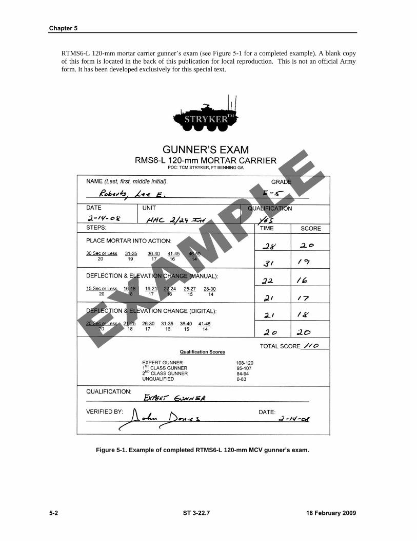
Chapter 5
5-2 ST 3-22.7 18 February 2009
RTMS6-L 120-mm mortar carrier gunner’s exam (see Figure 5-1 for a completed example). A blank copy
of this form is located in the back of this publication for local reproduction. This is not an official Army
form. It has been developed exclusively for this special text.
Figure 5-1. Example of completed RTMS6-L 120-mm MCV gunner’s exam.
STRYKER MCV CREW AND BATTLE DRILLS
18 February 2009 ST 3-22.7 5-3
LOCATION AND DATE
5-6. Each unit armed with a mortar weapon system gives examinations semiannually. Other units may
conduct examinations or allow their eligible members to take the qualification tests at nearby stations. (The
commander authorizing the issue special orders determines the date of the examination.) The area selected
should be on flat terrain consisting of soil that allows for aiming posts to be easily positioned at 50 and
100-meters from the station position.
ELIGIBLE PERSONNEL
5-7. The following personnel are eligible to take the examination:
Commissioned officers, NCOs, and enlisted men assigned to a mortar unit.
Commissioned officers, NCOs, and enlisted men whose duties require them to maintain
proficiency in the use of mortars, as determined by battalion and higher commanders.
QUALIFICATION SCORES
5-8. A gunner’s earlier qualification ends when he is administered a record course with the mortar. He is
classified according to his latest examination score as follows:
Expert Gunner: 108-120
First Class Gunner: 95-107
Second Class Gunner: 84-94
Unqualified: 83 or less
GENERAL RULES
5-9. Conditions should be the same for all gunners during the test. The examining board ensures that
information obtained by a candidate during testing is not passed to another gunner, and that gunners do not
receive sight settings or laying of mortars left by a previous gunner.
Unit equipment should be used in the examination; however, it should be the best available.
Sight settings are considered correct when any part of the index coincides with any part of the
line of graduation of the required setting.
The left side of the aiming post is used for alignment. The elevation and cross-level bubbles are
considered centered when the bubbles are resting entirely within the outer etched lines on the
vials.
The candidate is permitted to traverse the mortar to the middle point of traverse before each trial
at laying the mortar.
In time trials, the candidate does not receive credit for the trial if he performs any part of it after
announcing ―Up.‖
The candidate selects his assistants from within his squad to participate in the test. When squad
members are unavailable for testing, the candidate may select his assistants from outside the
squad but from within his organization. The board makes sure that no unauthorized assistance is
given the candidate during the examination.
A candidate is given three trials – one for practice, and two for record. If he takes the first trial
for record, then he must take the second trial for record even if he fails it. His credit score is the
total of the two record trials. When he fails in any trial through the fault of an examiner,
defective sight, mortar, mount, or any other instrument used, that trial is void and the candidate
is given another trial as soon as possible. If his actions cause the mortar to function
unsatisfactorily during testing, he receives no credit for that portion of the test.
When a mechanical failure occurs and a mortar fails to maintain the lay after the candidate
announces, UP, a board member twists or pushes the mortar (taking up the play without
Chapter 5
5-4 ST 3-22.7 18 February 2009
manipulation) until the cross-level bubble is within the two outer etched lines. He then looks
through the sight and, if the vertical line is within two mils of the correct sight picture, the
candidate is given credit for that trial as long as other conditions are met. The candidate must
repeat all commands. Commands should be varied between trials, using even and odd numbers,
and right and left deflections.
Section II — GUNNER’S EXAMINATION RMS-6L
5-10. This examination tests the gunner’s ability to perform basic mortar gunnery tasks with the
RMS-6LMortar System on a Stryker MCV (Figure 5-1, p. 5-2).
SUBJECTS AND CREDITS
5-11. The examination consists of the following tests with maximum credit scores as shown in Table 5-1.
Table 5-1. Gunner’s examination maximum credit scores.
Place the 120-mm Stryker Mortar into Action 40
Perform Deflection and Elevation Changes
Manually on a Stryker 120-mm Mortar 40
Perform Deflection and Elevation Changes
Digitally on a Stryker 120-mm Mortar 40
EQUIPMENT
5-12. The minimum equipment needed for the three stations includes three complete MCVs, three sights,
one aiming circle, six aiming posts, and three stopwatches.
Note: To reduce the number of MCVs required, both manual and digital deflection changes
can be tested on the same MCV, but both tasks must be performed by each gunner.
PROCEDURE
5-13. The gunner carries his scorecard from station to station. The evaluator at each station fills in the
time, trial score, and credit score, and initials the appropriate spaces.
PLACE A 120-MM STRYKER MORTAR INTO ACTION
5-14. The gunner is tested at Station No. 1 on his ability to perform quickly and accurately the gunner’s
duties of placing the mortar into action from the traveling position.
EQUIPMENT
5-15. One MCV complete. One stopwatch for the evaluator.
CONDITIONS
5-16. The mortar is locked in the traveling position.

STRYKER MCV CREW AND BATTLE DRILLS
18 February 2009 ST 3-22.7 5-5
1. The crew is seated in their normal positions with seat belts on.
2. The M67 sight is in its case and the case is stored in the IAW the Stryker load plan.
3. Muzzle cover is on the cannon.
4. The mortar doors are in the closed position and combat locked. (The ramp may be in the up or
down position).
5. The evaluator ensures that the candidate understands the requirement of the test and instructs
him to report I AM READY before each trial.
PROCEDURE
5-17. The gunner is given three trials. If he chooses to use the first (practice) as a record, he must also use
the second trial as a record. If he chooses to use the first trial as a practice, he must use the second and third
trials as record. His credit score for the test is the total of the two record trials.
1. The evaluator positions himself inside or outside of the carrier where he can best observe the
action of the gunner. The evaluator’s position should not interfere with the actions of the
candidate.
2. The trial is complete when the gunner announces, UP.
3. The gunner must place the mortar into action so that the sight is set at 3200 mils deflection,
1100 mils elevation, and all bubbles are level, within 50 seconds.
4. Time starts when the squad leader commands, ACTION.
5. The ammunition bearer unlocks the front latches on the left and then right top cargo doors in
coordination with the assistant gunner and gunner.
6. The assistant gunner unlocks the center and rear latches on the left cargo door and locks the
door in the open position.
7. The gunner unlocks the rear latch on the right cargo door and locks the door in the open
position.
8. The assistant gunner removes the cannon muzzle cover and cannon tie-down strap, then lifts the
cannon to the firing position and locks the folding bushing. Next he elevates the cannon
approximately 35 turns using the elevation hand wheel.
9. The gunner removes the M67 sight from its case and indexes a deflection of 3200 mils and an
elevation of 1100 mils.
10. The gunner mounts the M67 sight onto the sight mount, levels the elevation bubble with the
elevation hand wheel, and tells the assistant gunner, LEVEL.
11. The assistant gunner cross levels the M67 sight using the cant knob and tells the gunner,
CHECK.
12. The gunner and assistant gunner will repeat steps 6 and 7 until all bubbles are level.
13. When the gunner is satisfied that the mortar is mounted correctly he will announce, GUN UP,
so the squad leader can inspect the weapon system.
SCORING
5-18. Scoring procedures are as follows:
1. The gunner receives no credit when the–
Time exceeds 50 seconds.
Sight is not set at 3200 mils of deflection and 1100 mils elevation.
Elevation and cross-level bubbles are not centered (within outer red marks).
The traversing lock handle is not locked.
Mortar doors are not secure in the open position with hatch pins installed.
The safety mechanism is not set to FIRE (with F showing).
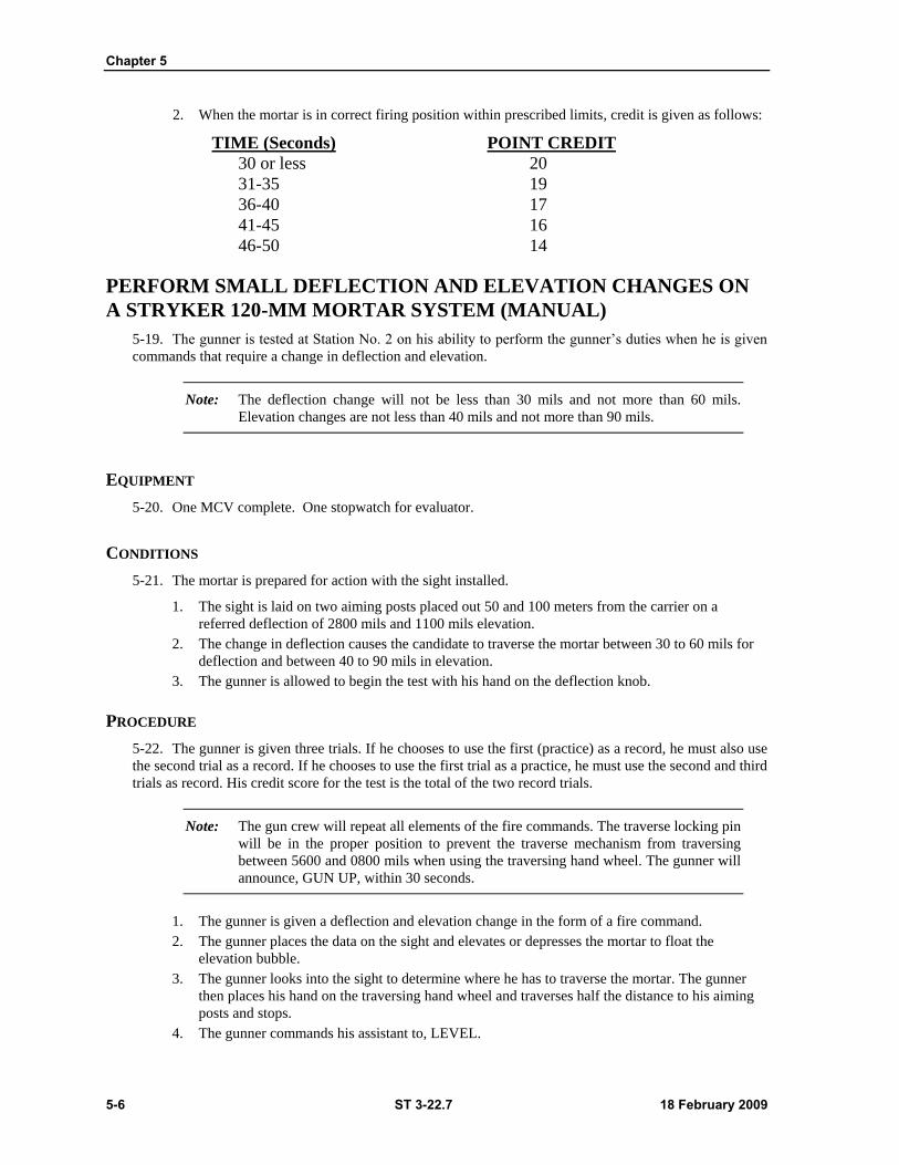
Chapter 5
5-6 ST 3-22.7 18 February 2009
2. When the mortar is in correct firing position within prescribed limits, credit is given as follows:
TIME (Seconds) POINT CREDIT
30 or less 20
31-35 19
36-40 17
41-45 16
46-50 14
PERFORM SMALL DEFLECTION AND ELEVATION CHANGES ON
A STRYKER 120-MM MORTAR SYSTEM (MANUAL)
5-19. The gunner is tested at Station No. 2 on his ability to perform the gunner’s duties when he is given
commands that require a change in deflection and elevation.
Note: The deflection change will not be less than 30 mils and not more than 60 mils.
Elevation changes are not less than 40 mils and not more than 90 mils.
EQUIPMENT
5-20. One MCV complete. One stopwatch for evaluator.
CONDITIONS
5-21. The mortar is prepared for action with the sight installed.
1. The sight is laid on two aiming posts placed out 50 and 100 meters from the carrier on a
referred deflection of 2800 mils and 1100 mils elevation.
2. The change in deflection causes the candidate to traverse the mortar between 30 to 60 mils for
deflection and between 40 to 90 mils in elevation.
3. The gunner is allowed to begin the test with his hand on the deflection knob.
PROCEDURE
5-22. The gunner is given three trials. If he chooses to use the first (practice) as a record, he must also use
the second trial as a record. If he chooses to use the first trial as a practice, he must use the second and third
trials as record. His credit score for the test is the total of the two record trials.
Note: The gun crew will repeat all elements of the fire commands. The traverse locking pin
will be in the proper position to prevent the traverse mechanism from traversing
between 5600 and 0800 mils when using the traversing hand wheel. The gunner will
announce, GUN UP, within 30 seconds.
1. The gunner is given a deflection and elevation change in the form of a fire command.
2. The gunner places the data on the sight and elevates or depresses the mortar to float the
elevation bubble.
3. The gunner looks into the sight to determine where he has to traverse the mortar. The gunner
then places his hand on the traversing hand wheel and traverses half the distance to his aiming
posts and stops.
4. The gunner commands his assistant to, LEVEL.
STRYKER MCV CREW AND BATTLE DRILLS
18 February 2009 ST 3-22.7 5-7
5. The assistant gunner uses the cant correction knob to level the deflection bubble and announces,
CHECK.
6. The gunner and assistant gunner repeat steps 3-5 until the vertical cross-line is within 2 mils of
the left side of the aiming post and his deflection bubble is level.
7. The gunner levels his elevation bubble with the elevation hand wheel.
8. Before the gunner announces GUN UP he should recheck his data and ensure all bubbles are
level and proper lay of the weapon system.
9. Time is charged against the gunner from the announcement of the last digit of the elevation
element until the gunner announcement of UP.
SCORING
5-23. Scoring procedures are as follows:
1. The candidate receives no credit when–
The time exceeds 30 seconds.
The deflection or elevation is not indexed correctly.
The elevation or cross-level bubbles are not centered within the outer lines.
The vertical cross-line of the sight is not within 2 mils of the left edge of the aiming post.
2. When the mortar is laid correctly within the prescribed limits, credit is given as follows:
TIME (Seconds) POINT CREDIT
15 or less 20
16-18 18
19-21 17
22-24 16
25-27 15
28-30 14
PERFORM LARGE DEFLECTION AND ELEVATION CHANGES ON
A STRYKER 120-MM MORTAR SYSTEM (DIGITAL)
5-24. The gunner is tested at Station No. 3 on his ability to perform the gunner’s duties when he is given
commands that require a change in deflection and elevation using the Mortar Fire Control System (MFCS).
Note: Deflection changes are greater than 200 mils, but less than 300 mils. Elevation
changes are greater than 100 mils but less than 200 mils.
Note: For test purposes, the mortar is mounted with the traversing quick release lever
locked. The Gunner’s Display (GD) is activated and shows AZ LAYED and
EL LAYED. Time will start when the information for azimuth and elevation change
is displayed on the gunner’s display.
EQUIPMENT
5-25. One MCV complete, fully operational MFCS, an operator for the Commander’s Interface and an
assistant gunner. One stopwatch for evaluator.

Chapter 5
5-8 ST 3-22.7 18 February 2009
CONDITIONS
5-26. The mortar is prepared for action.
1. The change in deflection causes the candidate to traverse the mortar between 200 to 300 mils
for deflection and between 100 to 200 mils in elevation.
2. The candidate is allowed to begin the test with his hand on the deflection knob.
PROCEDURE
5-27. The gunner is given three trials. If he chooses to use the first (practice) as a record, he must also use
the second trial as a record. If he chooses to use the first trial as a practice, he must use the second and third
trials as record. His credit score for the test is the total of the two record trials.
1. The squad leader alerts the crew of a change by announcing the gun number. (Example:
NUMBER 2 GUN).
2. The gunner observes the GD as the correction arrows appear.
3. The gunner elevates the gun with the elevation hand wheel until the GD shows EL LAYED.
4. The gunner may unlock the traverse quick release or turn the traversing hand wheel until the
GD shows AZ LAYED. If the traverse quick release lever is used, it must be locked after it is
used. (before the gunner announces GUN UP).
5. The gunner makes fine adjustments with the traversing and elevation hand wheel until the GD
shows AZ LAYED and EL LAYED.
6. Once the GD shows AZ LAYED and EL LAYED, the gunner announces GUN UP.
Note: Time stops when the gunner announces GUN UP. The evaluator observes the GD
and verifies the lay of the gun.
SCORING
5-28. Scoring procedures are as follows:
1. The candidate receives no credit when –
The time exceeds 45 seconds.
The deflection or elevation is not indexed correctly.
The turntable is not in the locked position.
2. When the mortar is laid correctly within the prescribed limits, credit is given as follows:
TIME (Seconds) POINT CREDIT
20 or less 20
21-25 18
26-30 17
31-35 16
36-40 15
41-45 14
18 February 2009 ST 3-22.7 6-1
Chapter 6
EXAMPLE STRYKER MCV LOAD PLAN
This chapter describes the use of matrixes and illustrations IAW the standard combat
load plan of the Stryker MCV. Equipment addressed in this load plan includes basic
issue items (BII), additional authorization list (AAL), and components of end item
(COEI). This chapter’s example load plan can be adopted by SBCT commanders and
leaders when establishing their own vehicle load plans. Some of the items listed in
the Stryker MCV load plan are METT-TC dependent.
GENERAL
6-1. Combat loading consists of standard stowing of ammunition and equipment in and on a MCV.
When performed efficiently, the process ensures that all material is readily accessible and stowed in the
proper location.
STANDARD LOADING PLAN
6-2. Because the equipment carried on a MCV will vary slightly depending on its intended use (squad,
platoon leader, company commander), a standard combat-loading plan should be developed for each
vehicle. Authorized unit equipment may also vary based upon unit mission, geographical location, and
basic ammunition loads. Standard procedures for MCV combat loading discussed in chapter X should be
used in conjunction with the operator’s manual. Based on mission essential equipment and ammunition, the
process can be modified to fit the needs of each unit.
INSPECTION OF EQUIPMENT
6-3. The first step in combat loading ensures all items are present and serviceable through a
comprehensive inspection. Assigned MCV equipment (weapons, tools, individual equipment, and
ammunition) should be laid out in logical inspection sequence. Items are arranged in groups for easy
accountability. Regular complete inspections ensure the MCV is always fully equipped.
STRYKER LOADING
6-4. All individual TA-50 equipment issued to Soldiers cannot be stowed on a MCV. Therefore, only
those individual items required on a day-to-day basis are carried on board. Based on guidance from the
platoon leader or company SOP, the platoon sergeant is responsible for the selection of stowed MCV
TA-50 equipment. Other items such as cold weather gear and extra sets of clothing (if not needed) are
carried in the company trains. When required, the platoon sergeant coordinates the storage of excess TA-50
with company supply.
LOADING
6-5. Loading the Stryker MCV is most efficiently accomplished by dividing the vehicle into loading
areas and assigning responsibility for each area to designated squad members. Loading responsibilities can
be divided IAW Table 6-1.
Chapter 6
6-2 ST 3-22.7 18 February 2009
Table 6-1. Stryker load area responsibilities.
RESPONSIBLE PERSON AREA
Squad Leader Overall Supervision
Vehicle Commander/Gunner Commander's Station/Vehicle Interior
Assistant Gunner Ammunition Stowage/Troop Compartment
Ammunition Bearer Ammunition Stowage/Vehicle Exterior
Driver Driver's Compartment
6-6. Every item loaded must be secured to protect it from damage and injuring occupants when the
vehicle is moving. Extra equipment or ammunition (for which there is no designated vehicle stowage
space) must be securely strapped down in the best available place.
Note: Equipment or ammunition should never be thrown into the vehicle.
MCV BASIC ISSUE ITEMS
6-7. The equipment listed by category in Tables 6-2 through 6-3 is standard issue on the Stryker MCV.
Leaders may choose to include or withhold certain items in accordance with their mission. But these are the
basic equipment items each vehicle should have on board.
TABLE LEGEND ACRONYMS
6-8. Legend category acronyms include: basic issue items (BII); components of end item (COEI); and
additional authorization list (AAL) equipment.
Table 6-2. Stryker MCV basic issue items.
BASIC ISSUE ITEMS (BII)
ITEM NSN QTY CATEGORY
Adapter, grease gun 4930-01-061-0433 1 BII
Ax, single bit 5110-00-293-2336 1 BII
Bag, assy, pamphlet 2540-00-670-2459 1 BII
Bag, tool, satchel 5140-00-473-6256 1 BII
Brush, paint 8020-00-205-6512 1 BII
Brush, wire scratch 7920-00-269-1259 1 BII
Cable assy (tow rope, synthetic) 4020-20-000-0583 1 BII
Cable assy (NATO slave) 2590-00-148-7961 1 BII
Can, fuel, 5 gal 7240-01-337-5269 2 BII
Can, water, 5 gal 7240-00-089-3827 2 BII
Chock block 2540-00-678-3469 2 BII
CVC, headset-microphone, (small to medium) 5965-01-453-2687 3 BII
CVC, headset-microphone, (large) 5965-01-453-2684 2 BII
CVC, shell, helmet (small to medium) 8470-01-389-3815 3 BII
CVC, shell, helmet (large) 8470-01-389-3821 2 BII
Coupling assy, quick disconnect (emergency) 4730-01-171-2275 1 BII
Example Stryker MCV Load Plan
18 February 2009 ST 3-22.7 6-3
Table 6-2. Stryker MCV basic issue items (continued).
BASIC ISSUE ITEMS (BII)
ITEM NSN QTY CATEGORY
Coupling assy, quick disconnect (service) 4730-01-171-2276 1 BII
Crowbar, 26-inch length 5120-00-224-1372 1 BII
Cutter wire 5110-00-595-8229 1 BII
Drain plug, large 4730-21-912-9286 1 BII
Drain plug, small 4730-21-912-9285 1 BII
Extension, socket wrench, 5 inch, 1/2 inch dr 5120-01-335-1050 1 BII
Extension, socket wrench, 8 inch, 3/4 inch dr 5120-00-234-7328 1 BII
First aid kit 6545-00-922-1200 1 BII
Flag set (complete) 8345-00-375-0223 1 BII
Folder, equipment record 7510-00-889-3494 1 BII
Fuel transfer assembly 4720-20-000-7467 1 BII
Funnel, steel, flex spout 7240-00-559-7364 1 BII
Gage and hose assy 4910-00-441-8685 1 BII
Gage, air pressure 4910-01-003-9599 1 BII
Grease gun, lubricating 4930-00-253-2478 1 BII
Hammer, hand sledge 10 lbs 5130-00-243-2957 1 BII
Handle, mattock pick 5120-00-288-6574 1 BII
Handle, socket wrench, ratchet 1/2 inch dr 5120-00-230-6385 1 BII
Head nut spinner 5120-01-335-1892 1 BII
Heater, water and ration 7310-01-387-1305 1 BII
Hose assy, trailer brake (towing) 7420-21-919-0309 1 BII
Inflator assembly 4910-21-920-4694 1 BII
Jack assembly 12-ton 5120-01-146-8096 1 BII
Key set, socket head screw (kit 2mm-19mm) 5120-01-335-1508 1 BII
Litter, folding, rigid 6530-01-380-7309 1 BII
Mattock pick 5120-00-243-2395 1 BII
Mirror, pick-up 5120-01-428-8005 1 BII
Mittens, heat protective, asbestos (pr.) M240B 8415-01-092-0039 1 BII
Oilier, hand, 6 oz 4930-00-262-8870 1 BII
Padlock set (6 each) 5340-01-408-8452 1 set BII
Pliers, slip joint, angled nose multi-tongue 5120-00-278-0352 1 BII
Pliers, slip joint, w/cutters, 8-inch long 5120-00-223-7397 1 BII
Screwdriver attachment, socket wrench 5120-01-437-3760 1 BII
Screwdriver, cross tip, 4-inch long 5120-00-234-8913 1 BII
Screwdriver, cross tip, 8-inch long 5120-00-542-3438 1 BII
Screwdriver, flat tip #2, 10-inch long 5120-00-293-3309 1 BII
Screwdriver, flat tip #2, 6-inch long 5120-00-062-0813 1 BII
Shackle 12-ton 2510-01-321-1221 1 BII
Shackle 30-ton 4030-01-186-7197 4 BII
Shovel, hand 5120-00-293-3336 1 BII
Snatch block 3950-01-347-9666 1 BII
Socket, 1/2 inch dr, 1/2 inch, 6-point 5120-01-398-7937 1 BII
Socket, 1/2 inch dr, 10mm, 6-point 5120-01-349-4547 1 BII
Socket, 1/2 inch dr, 13mm, 6-point 5120-01-398-8033 1 BII
Socket, 1/2 inch dr, 14mm, 6-point 5120-01-348-9033 1 BII
Socket, 1/2 inch dr, 16mm, 6-point 5120-01-348-9035 1 BII
Socket, 1/2 inch dr, 18mm, 6-point 5120-01-348-9037 1 BII
Socket, 1/2 inch dr, 19mm, 6-point 5120-01-398-7919 1 BII
Chapter 6
6-4 ST 3-22.7 18 February 2009
Socket, 3/4 inch dr, 27mm, 6-point 5120-01-348-9698 1 BII Table 6-2. Stryker MCV basic issue items (continued).
BASIC ISSUE ITEMS (BII)
ITEM NSN QTY CATEGORY
Support plate, jacking 5340-21-914-1589 1 BII
Tarpaulin, nylon 12 ft x 17 ft 8340-00-841-6456 1 BII
Tire repair kit 2640-00-922-6921 1 BII
Tow pintle 2540-00-776-0103 1 BII
Triangle set 9905-00-148-9546 1 BII
Wrench box & OE 7/16 inch 5120-01-335-1291 1 BII
Wrench box & OE 10mm 5120-01-431-1012 1 BII
Wrench box & OE 15mm 5120-01-431-1031 1 BII
Wrench box & OE 19mm 5120-01-435-6953 1 BII
Wrench box & OE 24mm 5120-01-054-7141 1 BII
Wrench box & OE 6mm 5120-01-431-1090 1 BII
Wrench box & OE 7mm 5120-01-431-0985 1 BII
Wrench, adjustable 12 inch 5120-00-264-3796 1 BII
Wrench transfer case assembly 5120-20-000-7448 1 BII
Flashlight, MX-991U w/batteries 6230-00-264-8261 2 BII
ADDITIONAL AUTHORIZATION LIST (AAL) ITEM NSN QTY CATEGORY
Alarm, chemical agent automatic M22 6665-01-438-6963 1 AAL
Aiming light IR AN/PAQ-4 5855-01-107-5925 5 AAL
AN/PVS-6 MELIOS 5860-01-350-8551 1 AAL
AN/VSQ-2 (V-1) EPLRS 7010-01-475-5277 1 AAL
Baseplate 81mm (battalion mortars) 1015-01-236-0389 1 AAL
Baseplate 60mm 1010-01-043-7504 1 AAL
Binoculars 7x50 6650-01-224-2555 1 AAL
Bipod 81mm M177 11579803 1 AAL
Bipod 60mm M170 11579090 1 AAL
Cannon, 120mm 1 AAL
Cannon, 81mm, M253 1015-01-440-5935 1 AAL
Cannon 60mm, M225 1010-01-044-5883 1 AAL
Carbine, 5.56mm M4 1005-01-231-0973 5 AAL
Commander's interface M95 TBD 1 AAL
Compass, magnetic 1290-00-930-4260 5 AAL
Computer sys. digital, AN/UYK-128 (FBCB2) 7010-01-475-5277 1 AAL
Data transfer device, AN/CYZ-10 w/lanyard 5810-01-343-1194 2 AAL
Decon kit individual M295 6850-01-357-8456 5 AAL
Detector kit chemical Agent M256A1 6665-01-133-4964 1 AAL
Driver's display M95 TBD 1 AAL
Global positioning system (PLGR) 5825-01-395-3513 1 AAL
Interrogator set AN/PSX-1 5895-01-472-6633 5 AAL
Lightweight weapon sight AN/PAS-13 (crew) 5855-01-464-3151 1 AAL
Machine gun, 7.62mm M240B 1005-01-412-3129 1 AAL
Mask, protective M40 w/carrier (small) 4240-01-258-0061 1 AAL
Mask, protective M40 w/carrier (medium) 4240-01-258-0062 1 AAL
Mask, protective M40 w/carrier (large) 4240-01-258-0063 1 AAL
Mask, protective M42 w/carrier (small) 4240-01-413-4100 1 AAL
Mask, protective M42 w/carrier (medium) 4240-01-413-4101 1 AAL
Mask, protective M42 w/carrier (large) 4240-01-413-4102 1 AAL
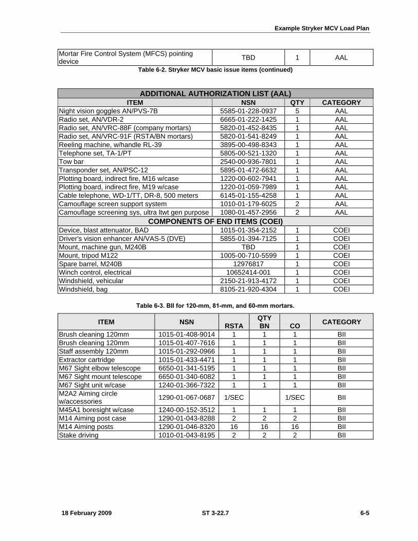
Example Stryker MCV Load Plan
18 February 2009 ST 3-22.7 6-5
Mortar Fire Control System (MFCS) pointing device
TBD 1 AAL
Table 6-2. Stryker MCV basic issue items (continued)
ADDITIONAL AUTHORIZATION LIST (AAL) ITEM NSN QTY CATEGORY
Night vision goggles AN/PVS-7B 5585-01-228-0937 5 AAL
Radio set, AN/VDR-2 6665-01-222-1425 1 AAL
Radio set, AN/VRC-88F (company mortars) 5820-01-452-8435 1 AAL
Radio set, AN/VRC-91F (RSTA/BN mortars) 5820-01-541-8249 1 AAL
Reeling machine, w/handle RL-39 3895-00-498-8343 1 AAL
Telephone set, TA-1/PT 5805-00-521-1320 1 AAL
Tow bar 2540-00-936-7801 1 AAL
Transponder set, AN/PSC-12 5895-01-472-6632 1 AAL
Plotting board, indirect fire, M16 w/case 1220-00-602-7941 1 AAL
Plotting board, indirect fire, M19 w/case 1220-01-059-7989 1 AAL
Cable telephone, WD-1/TT, DR-8, 500 meters 6145-01-155-4258 1 AAL
Camouflage screen support system 1010-01-179-6025 2 AAL
Camouflage screening sys, ultra ltwt gen purpose 1080-01-457-2956 2 AAL
COMPONENTS OF END ITEMS (COEI) Device, blast attenuator, BAD 1015-01-354-2152 1 COEI
Driver's vision enhancer AN/VAS-5 (DVE) 5855-01-394-7125 1 COEI
Mount, machine gun, M240B TBD 1 COEI
Mount, tripod M122 1005-00-710-5599 1 COEI
Spare barrel, M240B 12976817 1 COEI
Winch control, electrical 10652414-001 1 COEI
Windshield, vehicular 2150-21-913-4172 1 COEI
Windshield, bag 8105-21-920-4304 1 COEI
Table 6-3. BII for 120-mm, 81-mm, and 60-mm mortars.
ITEM NSN
RSTA QTY BN
CO
CATEGORY
Brush cleaning 120mm 1015-01-408-9014 1 1 1 BII
Brush cleaning 120mm 1015-01-407-7616 1 1 1 BII
Staff assembly 120mm 1015-01-292-0966 1 1 1 BII
Extractor cartridge 1015-01-433-4471 1 1 1 BII
M67 Sight elbow telescope 6650-01-341-5195 1 1 1 BII
M67 Sight mount telescope 6650-01-340-6082 1 1 1 BII
M67 Sight unit w/case 1240-01-366-7322 1 1 1 BII
M2A2 Aiming circle w/accessories
1290-01-067-0687 1/SEC 1/SEC BII
M45A1 boresight w/case 1240-00-152-3512 1 1 1 BII
M14 Aiming post case 1290-01-043-8288 2 2 2 BII
M14 Aiming posts 1290-01-046-8320 16 16 16 BII
Stake driving 1010-01-043-8195 2 2 2 BII
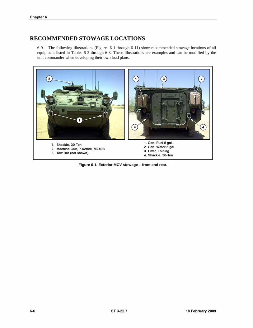
Chapter 6
6-6 ST 3-22.7 18 February 2009
RECOMMENDED STOWAGE LOCATIONS
6-9. The following illustrations (Figures 6-1 through 6-11) show recommended stowage locations of all
equipment listed in Tables 6-2 through 6-3. These illustrations are examples and can be modified by the
unit commander when developing their own load plans.
Figure 6-1. Exterior MCV stowage – front and rear.
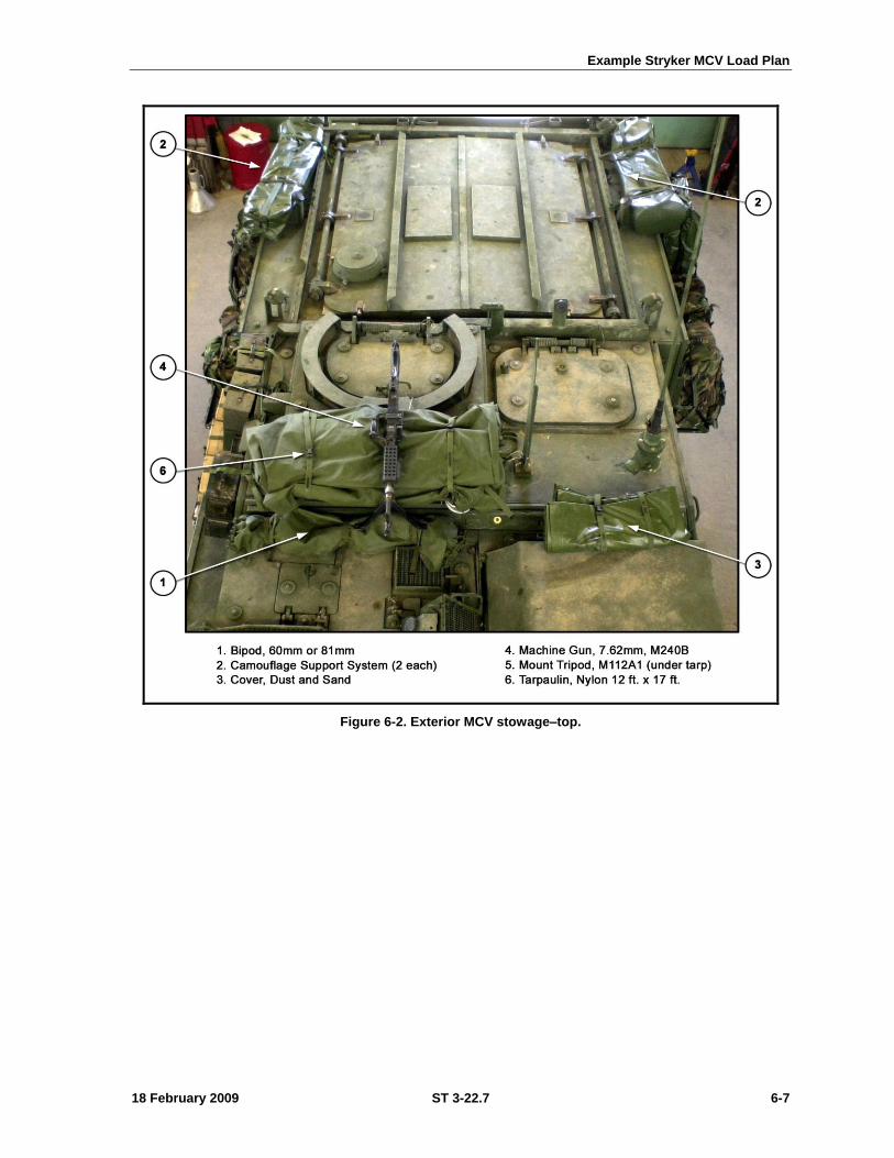
Example Stryker MCV Load Plan
18 February 2009 ST 3-22.7 6-7
Figure 6-2. Exterior MCV stowage–top.
Chapter 6
6-8 ST 3-22.7 18 February 2009
Figure 6-3. Exterior MCV stowage – right side.
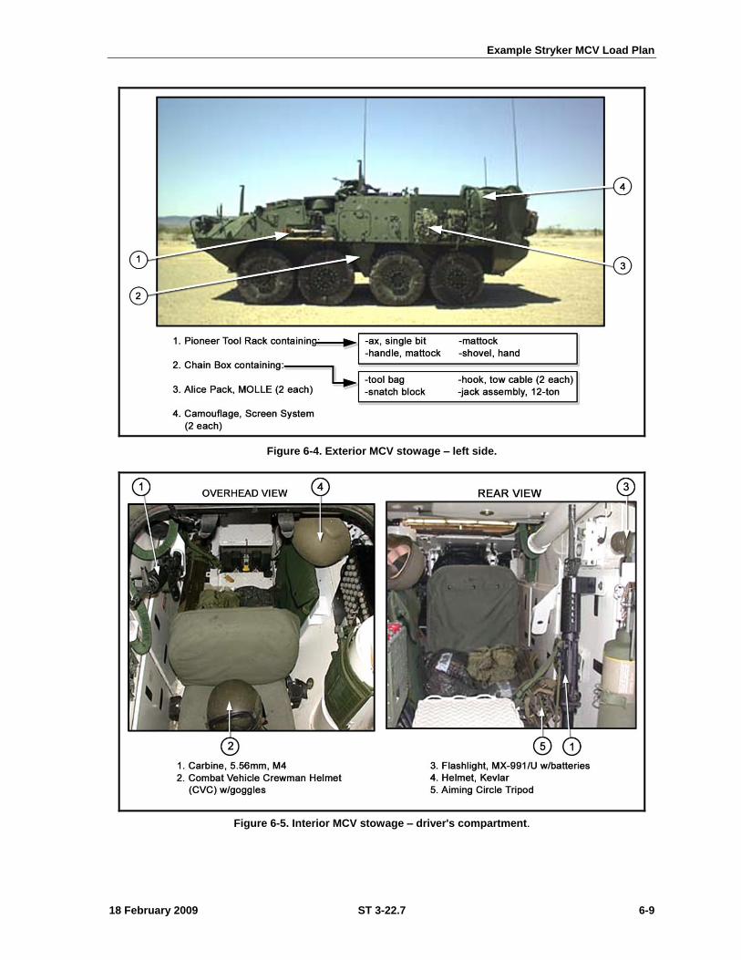
Example Stryker MCV Load Plan
18 February 2009 ST 3-22.7 6-9
Figure 6-4. Exterior MCV stowage – left side.
Figure 6-5. Interior MCV stowage – driver's compartment.
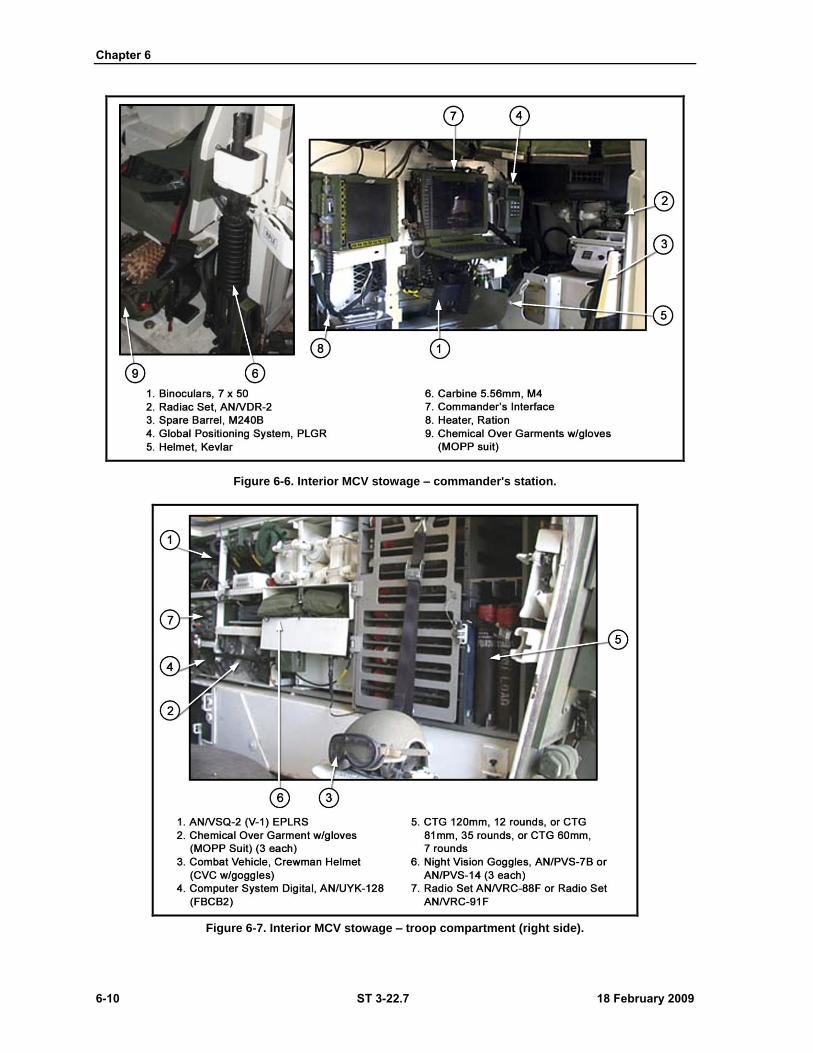
Chapter 6
6-10 ST 3-22.7 18 February 2009
Figure 6-6. Interior MCV stowage – commander's station.
Figure 6-7. Interior MCV stowage – troop compartment (right side).
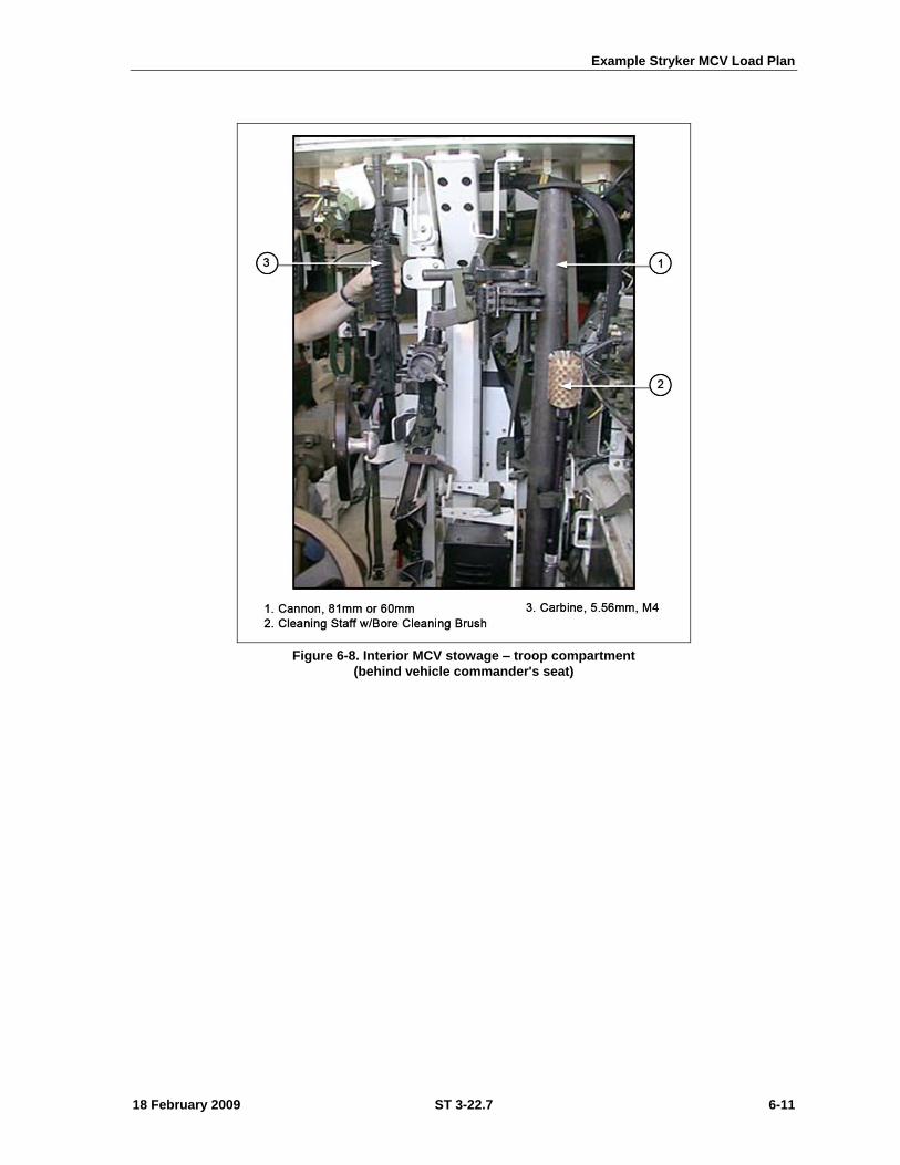
Example Stryker MCV Load Plan
18 February 2009 ST 3-22.7 6-11
Figure 6-8. Interior MCV stowage – troop compartment
(behind vehicle commander's seat)
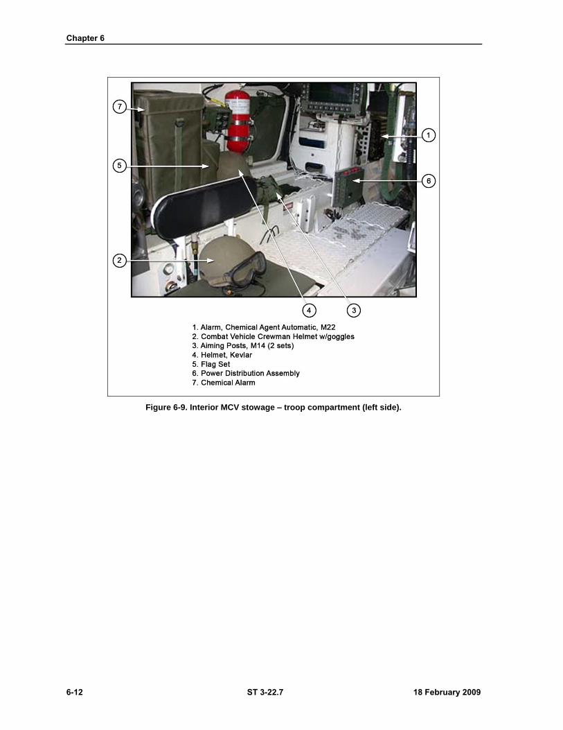
Chapter 6
6-12 ST 3-22.7 18 February 2009
Figure 6-9. Interior MCV stowage – troop compartment (left side).
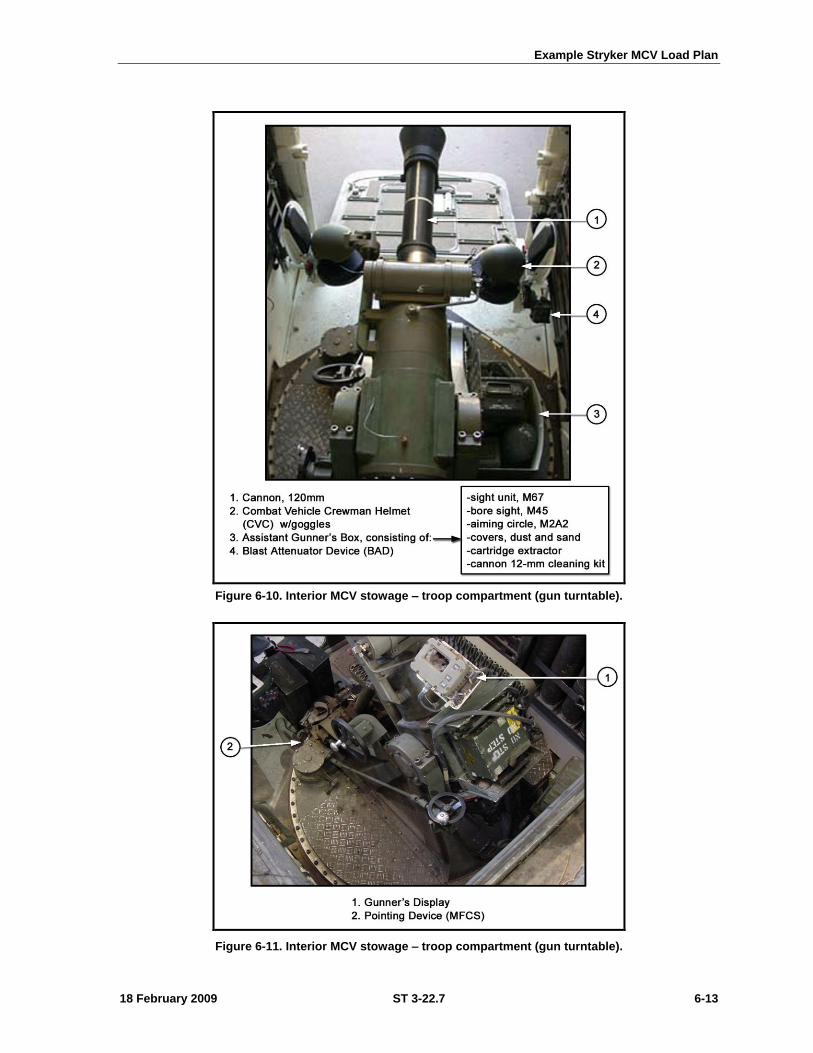
Example Stryker MCV Load Plan
18 February 2009 ST 3-22.7 6-13
Figure 6-10. Interior MCV stowage – troop compartment (gun turntable).
Figure 6-11. Interior MCV stowage – troop compartment (gun turntable).

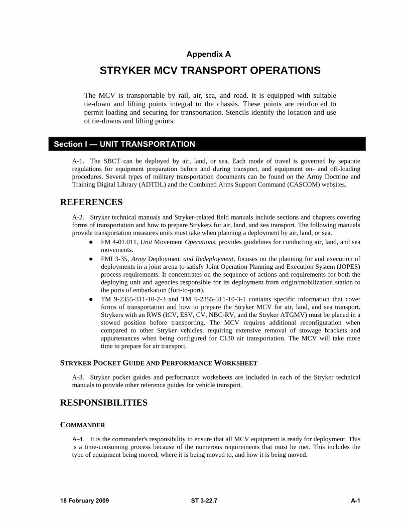
18 February 2009 ST 3-22.7 A-1
Appendix A
STRYKER MCV TRANSPORT OPERATIONS
The MCV is transportable by rail, air, sea, and road. It is equipped with suitable
tie-down and lifting points integral to the chassis. These points are reinforced to
permit loading and securing for transportation. Stencils identify the location and use
of tie-downs and lifting points.
Section I — UNIT TRANSPORTATION
A-1. The SBCT can be deployed by air, land, or sea. Each mode of travel is governed by separate
regulations for equipment preparation before and during transport, and equipment on- and off-loading
procedures. Several types of military transportation documents can be found on the Army Doctrine and
Training Digital Library (ADTDL) and the Combined Arms Support Command (CASCOM) websites.
REFERENCES
A-2. Stryker technical manuals and Stryker-related field manuals include sections and chapters covering
forms of transportation and how to prepare Strykers for air, land, and sea transport. The following manuals
provide transportation measures units must take when planning a deployment by air, land, or sea.
FM 4-01.011, Unit Movement Operations, provides guidelines for conducting air, land, and sea
movements.
FMI 3-35, Army Deployment and Redeployment, focuses on the planning for and execution of
deployments in a joint arena to satisfy Joint Operation Planning and Execution System (JOPES)
process requirements. It concentrates on the sequence of actions and requirements for both the
deploying unit and agencies responsible for its deployment from origin/mobilization station to
the ports of embarkation (fort-to-port).
TM 9-2355-311-10-2-3 and TM 9-2355-311-10-3-1 contains specific information that cover
forms of transportation and how to prepare the Stryker MCV for air, land, and sea transport.
Strykers with an RWS (ICV, ESV, CV, NBC-RV, and the Stryker ATGMV) must be placed in a
stowed position before transporting. The MCV requires additional reconfiguration when
compared to other Stryker vehicles, requiring extensive removal of stowage brackets and
appurtenances when being configured for C130 air transportation. The MCV will take more
time to prepare for air transport.
STRYKER POCKET GUIDE AND PERFORMANCE WORKSHEET
A-3. Stryker pocket guides and performance worksheets are included in each of the Stryker technical
manuals to provide other reference guides for vehicle transport.
RESPONSIBILITIES
COMMANDER
A-4. It is the commander's responsibility to ensure that all MCV equipment is ready for deployment. This
is a time-consuming process because of the numerous requirements that must be met. This includes the
type of equipment being moved, where it is being moved to, and how it is being moved.
Appendix A
A-2 ST 3-22.7 18 February 2009
INSTALLATION
A-5. The installation is responsible for procuring and storing, blocking, bracing, packing, crating, and
tie-down material. Vessel captains provide tie-down chains for their ships. The Air Force normally
provides tie-down chains for equipment moved on its aircraft. Therefore, it is imperative that the unit
determine its needs and convey them through the chain of command to the appropriate support agency.
LOAD TEAMS
A-6. Each unit is required to have an appropriate number of personnel trained in vehicle preparation and
aircraft, rail, and truck loading/unloading techniques. Specific skills required include—
Preparing and activating vehicle load plans.
Preparing vehicles for shipment (purging, protecting fragile components, weighing, and marking
for movement).
Executing aircraft, truck, and railcar tie-down procedures.
Loading and unloading unit vehicles on aircraft, trucks, and railcars.
Palletizing cargo on 463L pallets (see FMI 3-35).
A-7. Load team composition is tailored to the type and quantity of equipment to be loaded, and the time
available for loading. In general—
For rail movement: a well-trained team of five operators using prefabricated tie-down devices
can complete loading of equipment on a flatcar in approximately 15 minutes.
For air movement: a six-person team can provide efficient loading and tie-down of equipment.
A-8. There are many references available for help and direction on the loading of equipment. Some of
these include Department of Defense (DoD) Military Standards (MIL-STDs) 209K, 810F, 910, 913, and
MIL-HDBKs 669 and 1791.
MOVEMENT OPERATIONS SOP
A-9. Table A-1 provides ideas, data, and a template for a unit movement SOP. It is not intended to be all
inclusive. Rather, it is intended to identify those things that a unit must consider and plan for when
preparing for deployment. Use only those items that apply.
Table A-1. Unit movement operations SOP.
STANDING OPERATING PROCEDURES Unit Movement Operations
1. APPLICATION: Identify operations that are applicable to this SOP.
2. PURPOSE: Define the purpose of this SOP and how it will be used to support movement operations within the unit.
3. REFERENCES: Identify any FMs, TMs, and any higher headquarters’ SOPs that may be applicable to developing your unit's SOP.
Table A-1. Unit movement operations SOP (continued).
Stryker MCV Transport Operations
18 February 2009 ST 3-22.7 A-3
4. RESPONSIBILITY FOR PREPARATION, CHANGES, and REVISIONS: Identify the section or individual responsible for preparation of this SOP, and to whom recommended changes or revisions should be routed.
5. EFFECTIVE DATE:
6. MOTOR MOVEMENT:
a. Vehicles. Preparation for movement.
b. Motor marches.
(1) Strip maps.
(2) Route reconnaissance.
(3) Messing and refueling.
(4) Night marches.
(5) Makeup of march units and serials.
(6) Vehicle gap.
(7) Speed and rate of march.
(a) Column rate of march.
(b) Lead vehicle speed.
(c) Permissible catch-up speed.
(d) March unit or serial time length.
(8) Posting traffic guards during halt.
(c) Infiltration.
(d) Personnel. Conduct during movement.
(1) Passengers
(2) Drivers.
7. VEHICLE AND EQUIPMENT OPERATIONS:
a. Motor pool.
(1) Dispatch.
(2) Service.
(3) Maintenance.
b. Administrative vehicles. Regulations.
8. RAIL MOVEMENT:
a. S1 Action. Movement policy.
b. S2 Action.
(1) Reconnaissance report.
(2) Security.
c. S3 Action.
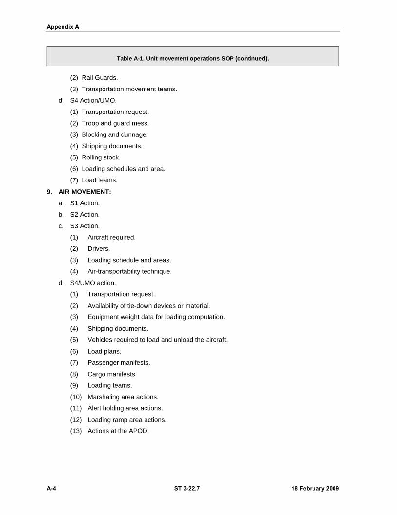
Appendix A
A-4 ST 3-22.7 18 February 2009
Table A-1. Unit movement operations SOP (continued).
(2) Rail Guards.
(3) Transportation movement teams.
d. S4 Action/UMO.
(1) Transportation request.
(2) Troop and guard mess.
(3) Blocking and dunnage.
(4) Shipping documents.
(5) Rolling stock.
(6) Loading schedules and area.
(7) Load teams.
9. AIR MOVEMENT:
a. S1 Action.
b. S2 Action.
c. S3 Action.
(1) Aircraft required.
(2) Drivers.
(3) Loading schedule and areas.
(4) Air-transportability technique.
d. S4/UMO action.
(1) Transportation request.
(2) Availability of tie-down devices or material.
(3) Equipment weight data for loading computation.
(4) Shipping documents.
(5) Vehicles required to load and unload the aircraft.
(6) Load plans.
(7) Passenger manifests.
(8) Cargo manifests.
(9) Loading teams.
(10) Marshaling area actions.
(11) Alert holding area actions.
(12) Loading ramp area actions.
(13) Actions at the APOD.
Stryker MCV Transport Operations
18 February 2009 ST 3-22.7 A-5
Table A-1. Unit movement operations SOP (continued).
10. WATER MOVEMENT:
a. S1 Action. Movement policy.
b. S2 Action.
(1) Reconnaissance report.
(2) Security.
c. S3 Action.
(1) Troop list.
(2) Loading plan.
(3) Supercargoes.
d. S4/UMO Action.
(1) Transportation request.
(2) Troop mess.
(3) Shipping documents.
(4) Vessels required.
(5) Loading schedule and area.
(6) Passenger manifests.
(7) Cargo manifests.
(8) Marshaling area actions.
(9) Staging area actions.
(10) Actions at the SPOD.
Section II — AIR TRANSPORTATION
A-10. The Army and Air Force have an agreement that enables the Stryker family of vehicles to be
deployed through the military's three major transport aircrafts (C-5, C-17, and C-130), (Figure A-1).
Commanders and leaders must ensure all U.S. Air Force requirements are strictly adhered to when
conducting air transport operations. Loading aircraft leaves little room for mistakes. Air Force crews
responsible for airlift of the Stryker family of vehicles will ensure Soldiers are aware of emergency
evacuation procedures prior to loading the aircraft, and before lift-off. Air crewmen prepare the aircraft
before any vehicle or equipment is loaded and notify personnel when the aircraft preparation is ready for
loading. Complete procedures on preparation before-and-after air transport can be found in the appropriate
technical manual for the specific vehicle variant.
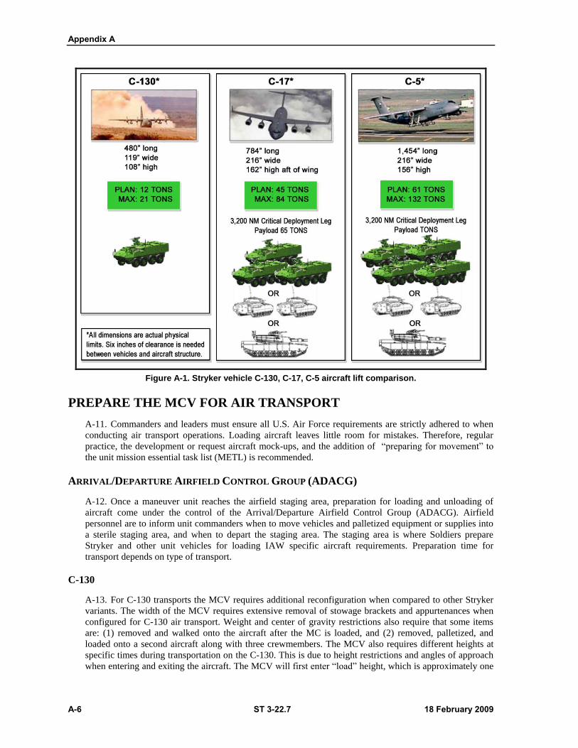
Appendix A
A-6 ST 3-22.7 18 February 2009
Figure A-1. Stryker vehicle C-130, C-17, C-5 aircraft lift comparison.
PREPARE THE MCV FOR AIR TRANSPORT
A-11. Commanders and leaders must ensure all U.S. Air Force requirements are strictly adhered to when
conducting air transport operations. Loading aircraft leaves little room for mistakes. Therefore, regular
practice, the development or request aircraft mock-ups, and the addition of ―preparing for movement‖ to
the unit mission essential task list (METL) is recommended.
ARRIVAL/DEPARTURE AIRFIELD CONTROL GROUP (ADACG)
A-12. Once a maneuver unit reaches the airfield staging area, preparation for loading and unloading of
aircraft come under the control of the Arrival/Departure Airfield Control Group (ADACG). Airfield
personnel are to inform unit commanders when to move vehicles and palletized equipment or supplies into
a sterile staging area, and when to depart the staging area. The staging area is where Soldiers prepare
Stryker and other unit vehicles for loading IAW specific aircraft requirements. Preparation time for
transport depends on type of transport.
C-130
A-13. For C-130 transports the MCV requires additional reconfiguration when compared to other Stryker
variants. The width of the MCV requires extensive removal of stowage brackets and appurtenances when
configured for C-130 air transport. Weight and center of gravity restrictions also require that some items
are: (1) removed and walked onto the aircraft after the MC is loaded, and (2) removed, palletized, and
loaded onto a second aircraft along with three crewmembers. The MCV also requires different heights at
specific times during transportation on the C-130. This is due to height restrictions and angles of approach
when entering and exiting the aircraft. The MCV will first enter ―load‖ height, which is approximately one
Stryker MCV Transport Operations
18 February 2009 ST 3-22.7 A-7
half the difference between nominal (normal) and flying (lowest) heights. After successful entry the MCV
is required to lower to ―flying‖ height to ensure adequate clearance and stability for the actual flight.
C-17 and C-5
A-14. C-17 and C-5 aircraft require little or no vehicle preparation. Load masters inspect vehicles before
loading them on the aircraft. Vehicles are placed on scales and then moved to the aircraft for loading. Load
masters load aircraft based on maneuver unit load plans, which can be adjusted by the load master. Aircraft
personnel have the final authority regarding which aircraft will be loaded and the method of loading the
assigned aircraft .
STRYKER COMBAT MISSION-READY CONFIGURATION
A-15. Crews must place a Stryker in a combat mission-ready configuration without substantial assembly or
refit. As a result, set times are established for each configuration, ranging from 15 to 100 minutes to meet
specific missions. Stryker technical manuals outline the necessary steps for preparing individual Stryker
variants to meet chosen aircraft requirements for transport. Only the larger aircraft such as the C-5 and
C-17 can transport Strykers with complete assigned crews. However, as a minimum, Strykers should
deploy with vehicle crews. Prior to beginning loading, all emitters of electromagnetic interference (EMI)
shall be de-energized. Weapon/smoke projectors shall be placed on SAFE and disconnected. All antennae
shall be removed (leaving antenna mounts in place) and secured inside the vehicle. Weapon systems must
be removed from the mount and secured inside the vehicle.
PREPARE THE MCV AFTER AIR TRANSPORT
A-16. Upon exiting the aircraft, crews have 10 minutes to prepare the vehicle for movement. Tasks
included in this step are—
Activate the central tire inflation system (CTIS) and select the proper tire inflation setting.
At the end of the 10 minutes, move off the airfield to secure a location or a position that
provides cover and concealment. Upon reaching a secure location or a position that provides
cover and concealment, the crew will be required to complete the following:
Prepare the vehicle commander's position for mounting the M240B.
Load the weapon. (If ammunition is not deployed with the vehicle due to weight constraints, it
should be drawn as the vehicle moves off of the airfield.)
Perform communications check and enter appropriate radio net.
Activate FBCB2 (if network is available).
Stow and reinstall any additional equipment removed from vehicle exterior such as
camouflage nets, ammunition, rucksacks, and water cans.
Additional tasks include mounting any equipment removed and flown on other aircraft due to
weight and space requirements (example; slat armor).
Note: Mounting any protective armor taken off for transporting is METT-TC dependent.
Section III — TRANSPORT BY LAND
A-17. Rail and trucks are the most common modes of transport used by Army units. They are logistically
easier than transporting by air or sea. Transportation Engineering Agency (TEA) Pamphlet 55-19 provides
proper methods for securing vehicles on chain-equipped flatcars.
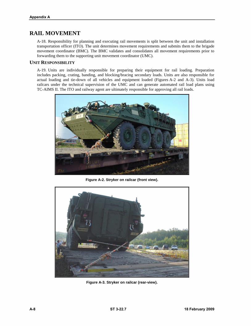
Appendix A
A-8 ST 3-22.7 18 February 2009
RAIL MOVEMENT
A-18. Responsibility for planning and executing rail movements is split between the unit and installation
transportation officer (ITO). The unit determines movement requirements and submits them to the brigade
movement coordinator (BMC). The BMC validates and consolidates all movement requirements prior to
forwarding them to the supporting unit movement coordinator (UMC).
UNIT RESPONSIBILITY
A-19. Units are individually responsible for preparing their equipment for rail loading. Preparation
includes packing, crating, banding, and blocking/bracing secondary loads. Units are also responsible for
actual loading and tie-down of all vehicles and equipment loaded (Figures A-2 and A-3). Units load
railcars under the technical supervision of the UMC and can generate automated rail load plans using
TC-AIMS II. The ITO and railway agent are ultimately responsible for approving all rail loads.
Figure A-2. Stryker on railcar (front view).
Figure A-3. Stryker on railcar (rear-view).
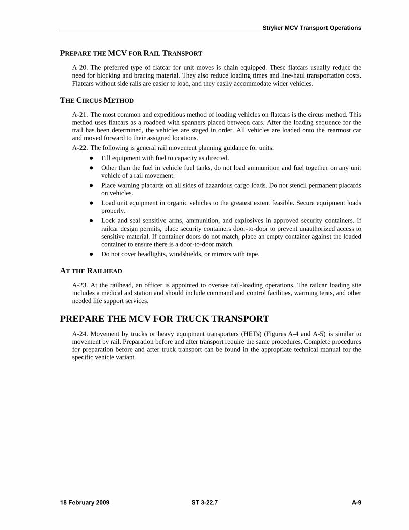
Stryker MCV Transport Operations
18 February 2009 ST 3-22.7 A-9
PREPARE THE MCV FOR RAIL TRANSPORT
A-20. The preferred type of flatcar for unit moves is chain-equipped. These flatcars usually reduce the
need for blocking and bracing material. They also reduce loading times and line-haul transportation costs.
Flatcars without side rails are easier to load, and they easily accommodate wider vehicles.
THE CIRCUS METHOD
A-21. The most common and expeditious method of loading vehicles on flatcars is the circus method. This
method uses flatcars as a roadbed with spanners placed between cars. After the loading sequence for the
trail has been determined, the vehicles are staged in order. All vehicles are loaded onto the rearmost car
and moved forward to their assigned locations.
A-22. The following is general rail movement planning guidance for units:
Fill equipment with fuel to capacity as directed.
Other than the fuel in vehicle fuel tanks, do not load ammunition and fuel together on any unit
vehicle of a rail movement.
Place warning placards on all sides of hazardous cargo loads. Do not stencil permanent placards
on vehicles.
Load unit equipment in organic vehicles to the greatest extent feasible. Secure equipment loads
properly.
Lock and seal sensitive arms, ammunition, and explosives in approved security containers. If
railcar design permits, place security containers door-to-door to prevent unauthorized access to
sensitive material. If container doors do not match, place an empty container against the loaded
container to ensure there is a door-to-door match.
Do not cover headlights, windshields, or mirrors with tape.
AT THE RAILHEAD
A-23. At the railhead, an officer is appointed to oversee rail-loading operations. The railcar loading site
includes a medical aid station and should include command and control facilities, warming tents, and other
needed life support services.
PREPARE THE MCV FOR TRUCK TRANSPORT
A-24. Movement by trucks or heavy equipment transporters (HETs) (Figures A-4 and A-5) is similar to
movement by rail. Preparation before and after transport require the same procedures. Complete procedures
for preparation before and after truck transport can be found in the appropriate technical manual for the
specific vehicle variant.
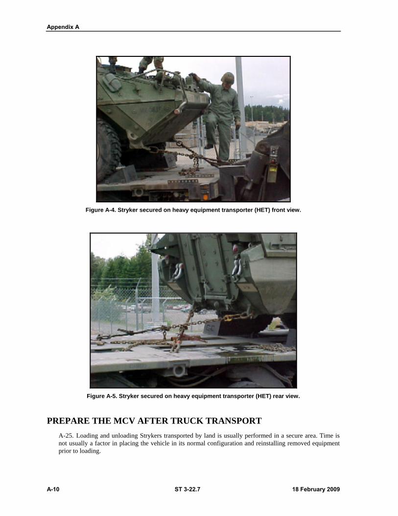
Appendix A
A-10 ST 3-22.7 18 February 2009
Figure A-4. Stryker secured on heavy equipment transporter (HET) front view.
Figure A-5. Stryker secured on heavy equipment transporter (HET) rear view.
PREPARE THE MCV AFTER TRUCK TRANSPORT
A-25. Loading and unloading Strykers transported by land is usually performed in a secure area. Time is
not usually a factor in placing the vehicle in its normal configuration and reinstalling removed equipment
prior to loading.
Stryker MCV Transport Operations
18 February 2009 ST 3-22.7 A-11
Section IV — SEA TRANSPORTATION
A-26. Military Sealift Command (MSC) ships have been transporting U.S. Army and Marine Corps cargo
in support of Operation Iraqi Freedom since early 2003. At the end of 2003, MSC transported the first
SBCT deployed in support of Operation Iraqi Freedom. The Stryker is transportable by all strategic
material transport vessels including break-bulk ships, containerships, lighter-aboard-ships, sea-barge
carriers, and roll-on/roll-off ships.
PREPARE THE MCV FOR SEA TRANSPORT
A-27. Staging area setup and activities for sea deployment transport preparations are consistent with air
and land transport requirements. MSC load masters and shipboard personnel determine what configuration
Strykers must be in prior to on-board loading. Once approved load masters secure vehicles with the
assistance of Stryker crews. The latest classes of MSC ships have drive-on capability. This capability
allows for transportation of the Stryker in its combat ready configuration and minimizes vehicle transport
preparation time.
PORT STAGING AND MARSHALLING AREAS
A-28. Unit personnel, supplies, and equipment are held in the port staging area to prepare for shipment;
however, before moving to the port staging area, the unit, supplies, and equipment may be assembled in a
marshaling area. Though they serve much the same purpose, there is a distinction between the two areas. In
a marshaling area, the owning command retains responsibility and accountability for shipment. Once in the
staging area, the port commander assumes responsibility and accountability. The following preparations
and checks are conducted prior to loading vessels:
1. Unit equipment and supplies are checked to ensure they are properly labeled/tagged and
accompanied by proper documentation.
2. Cargo lashing and height limitations are checked to ensure loads are within parameters for
shipment. Secondary loads (unit supplies and equipment on vehicles) are checked to ensure
they are properly blocked, braced, and secured.
3. Preventive maintenance checks and services (PMCS) are conducted and any required
organizational or direct support maintenance accomplished. Fuel levels in vehicles and
equipment are adjusted to proper levels.
4. Hazardous cargo is checked to ensure it is segregated, properly classified, described, packaged,
marked, labeled, and in proper condition for transportation. This must be done IAW the Code
of Federal Regulations (CFR) 49 and other prescribed regulations or directives.
A-29. Complete procedures on preparation before sea transport can be found in the appropriate technical
manual for the specific vehicle variant.
PREPARE THE MCV AFTER SEA TRANSPORT
A-30. Though many of the ships used by deploying maneuver units require little or no change to Stryker
configuration when boarding and stowing equipment, they do require the removal of protective armor (slat
or AoA). As is true with air transport, the reason for armor removal is the increased Stryker dimensions
when equipped with it, not increased vehicle weight.

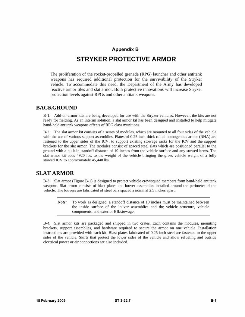
18 February 2009 ST 3-22.7 B-1
Appendix B
STRYKER PROTECTIVE ARMOR
The proliferation of the rocket-propelled grenade (RPG) launcher and other antitank
weapons has required additional protection for the survivability of the Stryker
vehicle. To accommodate this need, the Department of the Army has developed
reactive armor tiles and slat armor. Both protective innovations will increase Stryker
protection levels against RPGs and other antitank weapons.
BACKGROUND
B-1. Add-on-armor kits are being developed for use with the Stryker vehicles. However, the kits are not
ready for fielding. As an interim solution, a slat armor kit has been designed and installed to help mitigate
hand-held antitank weapons effects of RPG class munitions.
B-2. The slat armor kit consists of a series of modules, which are mounted to all four sides of the vehicle
with the use of various support assemblies. Plates of 0.25 inch thick rolled homogenous armor (RHA) are
fastened to the upper sides of the ICV, to support existing stowage racks for the ICV and the support
brackets for the slat armor. The modules consist of spaced steel slats which are positioned parallel to the
ground with a built-in standoff distance of 10 inches from the vehicle surface and any stowed items. The
slat armor kit adds 4920 lbs. to the weight of the vehicle bringing the gross vehicle weight of a fully
stowed ICV to approximately 45,440 lbs.
SLAT ARMOR
B-3. Slat armor (Figure B-1) is designed to protect vehicle crew/squad members from hand-held antitank
weapons. Slat armor consists of blast plates and louver assemblies installed around the perimeter of the
vehicle. The louvers are fabricated of steel bars spaced a nominal 2.5 inches apart.
Note: To work as designed, a standoff distance of 10 inches must be maintained between
the inside surface of the louver assemblies and the vehicle structure, vehicle
components, and exterior BII/stowage.
B-4. Slat armor kits are packaged and shipped in two crates. Each contains the modules, mounting
brackets, support assemblies, and hardware required to secure the armor on one vehicle. Installation
instructions are provided with each kit. Blast plates fabricated of 0.25-inch steel are fastened to the upper
sides of the vehicle. Skirts that protect the lower sides of the vehicle and allow refueling and outside
electrical power or air connections are also included.
Appendix B
B-2 ST 3-22.7 18 February 2009
Figure B-1. Stryker MCV with slat armor.
VEHICLE PREPARATION
B-5. Numerous mounting fixtures (such as stowage racks and brackets) used to hold BII/stowage items
must be removed from the Stryker exterior before slat armor can be installed. Some of these components
are not used after slat armor is mounted and should be stored accordingly. Other remaining components are
re-installed on top of the installed armor.
B-6. The following items do not get re-installed and need to be stored accordingly:
Driver's handgrip.
Stowage rails.
Brackets.
Brush guards.
SLAT ARMOR INSTALLATION
B-7. For complete installation instructions, TM 9-2540-231-12 for installers, and TM 9-2540-232-10 for
operators, are available through individual Stryker unit publication clerks, and logs. Maneuverability
details are fully covered in TC 7-21, Stryker Driver, Chapter 8.
B-8. Generally, slat armor is installed in groups based on vehicle location (front, left side, right side, and
rear). Once shipping crates are unpacked, blast plates and louver assemblies are laid out in their respective
groups as follows.
All exterior BII and stowage from the vehicle is removed and laid aside for re-installation once
armor is installed. Stowage items located on the roof are not removed.
Lower stowage rails and brackets, pioneer tool rack, and bustle stowage rack are removed from
the sides of the vehicle. Stowage rail and brackets will not be used after installation, therefore,
store accordingly. Lay all other parts aside for re-installation.
Headlight brush guards from the front and right vehicle corners are also removed. Brush guards
are not used after armor is installed and should be stored accordingly.
If attached on the vehicle, hook and pile strips are removed from the emergency hatch to the
back of vehicle on left side, and from the chain box to the back of the vehicle on the right side.
Stryker Protective Armor
18 February 2009 ST 3-22.7 B-3
B-9. Some existing vehicle components, such as the side bustle stowage racks, are impacted by the
installation of the armor. The installation instruction guide packed with the armor explains any changes
required.
SLAT ARMOR PMCS
B-10. When slat armor is installed, both the vehicle PMCS and the following must be used:
VEHICLE FRONT, LEFT, REAR, AND RIGHT SIDE CHECKS
B-11. The driver visually checks the front, left, rear, and right side of the vehicle for damage and loose or
missing hardware. Mounting bolts are inspected for looseness. If bolts are loose, they are tightened. When
time permits, bolts are tightened to the proper torque value by the maintenance CRT.
SAFETY PRECAUTIONS
B-12. Safety related precautions identified with the installation of slat armor are as follows:
To prevent injuries during installation of the slat armor kit, three personnel are required to
handle and install the modular assemblies.
Slat armor may have sharp edges, which could cause injury. Leather work gloves must be worn
when handling the armor.
The lower front portion of the slat armor hangs low enough to impact the ground during the
crossing of ditches or depressions during cross-country operations. Caution must be observed by
the driver under these driving conditions.
The emergency escape hatch opens rapidly outward when unlatched. During an emergency
escape situation, the crewmen must quickly release the hatch and allow it to open without trying
to restrict the outward motion.
Due to the weight of the emergency escape hatch, opening and closing the hatch during
non-emergency situations is a three-man operation that requires two crewmen on the outside to
control and hold the hatch, and a third person inside the vehicle to operate the latch.
The addition of slat armor to the rear access door increases the weight of the door. Opening and
closing the door then becomes a two-man operation and requires the addition of a strap to the
inside handle so that closing the door can be accomplished by two personnel.
The means for climbing on and off the vehicle can be a hazard because of the possibility of
falling. A three step means consists of a cable loop on the bottom of the slat armor with a metal
rectangular shaped step approximately 20 inches above it, with the third step being on the top of
the front of the vehicle. The slats in the front module are to be used for handholds.
The possibility of injury from slipping and/or falling from the slat armor during deployment of
the winch cable exists. Caution must be observed.
Use of the standard tow bar for the Stryker vehicle during towing or recovery operations
provides only 4.5 inches between the slat armor on the towing vehicle and the vehicle being
towed. The standard tow bar is not to be used unless the front slat armor on the towed vehicle
and the rear of the towing vehicle is removed. When the armor is removed, only 21 degrees of
turning capability is provided. This condition is inadequate, except under emergency
towing/recovery conditions. Use of the M984A1 HEMTT wrecker with PLS tow bar extension
is recommended.
The slat armor causes visibility degradation to the headlight capabilities for both the right and
left front area of the vehicle. The driver will need to use caution and direct more attention to
observance of the edge of the road, and to the recognition of objects and obstructions along the
side of the roadway during nighttime operations.

Appendix B
B-4 ST 3-22.7 18 February 2009
Training and guidance provided to the crewmen for the Stryker equipped with slat armor should
emphasize the following:
A minimum standoff distance of 10 inches MUST be maintained between the inside surface
of the slat armor and the vehicle structure, and any components and/or stowed items.
No gear or other items are to be hung or attached to the outside or inside of the slat
armor kit.
UNEXPLODED ORDNANCE (UXO) PROCEDURES
B-13. Once the operator knows that a round is lodged in the armor, he should—
Immediately evacuate the vehicle.
Call for explosive ordinance disposal (EOD) support.
Mark off the area around the vehicle at a safe distance.
Never try to dislodge the round.
18 February 2009 ST 3-22.7 C-1
Appendix C
RANGE SAFETY PROCEDURES AND RISK MANAGEMENT
Though safety is a command responsibility, each member of the Stryker MCV mortar
fire team must know safety procedures and enforce them. Safety is enhanced with
MFCS features that provide safety and situational awareness information. However,
no system is foolproof, so the individual awareness of each fire team member will be
the most important factor in maintaining safe firing conditions. Misfire procedures
mentioned in this appendix are based on peacetime operations. (See
ARTEP 7-90-Drill for combat operations.)
Section I — SAFETY OFFICER DUTIES
C-1. Safety officers help commanders meet the responsibility of enforcing safety procedures. Safety
officers have two principle duties:
1. To ensure the section is properly laid so when rounds are fired, they land in the impact area.
2. To ensure that all safety precautions are observed at the firing point.
DUTIES BEFORE DEPARTING FOR RANGE
C-2. The safety officer must read and understand the following:
AR 385-63, Range Safety. 19 May 2003.
Post range and terrain regulations.
The terrain request of the firing area to know safety limits and coordinates of firing positions.
Appropriate field and technical manuals pertaining to weapons and ammunition to be fired.
DUTIES OF SUPERVISORY PERSONNEL
C-3. Supervisory personnel must know the immediate action to be taken for firing accidents. The
following is a list of minimum actions that must be taken if an accident occurs.
1. Ensure first aid is administered to injured personnel and that medical assistance is arranged.
2. If ammunition or equipment presents further danger, move all personnel and equipment out of
the area.
3. Ensure settings are not changed and that the mortar position is not modified until a firing
accident investigation has been completed.
4. Records the ammunition lot numbers involved in the accident or malfunction and report it to
the battalion ammunition officer. If a certain lot number is suspect, its use is suspended (by the
platoon leader).
MORTAR RANGE SAFETY CHECKLIST
C-4. A mortar range safety checklist can be written for local use. The following is a suggested checklist
(it can also include three columns on the right titled ―Yes,‖ ―No,‖ and ―Remarks‖).

Appendix C
C-2 ST 3-22.7 18 February 2009
ITEMS TO CHECK BEFORE FIRING
1. Is a range log or journal maintained by the officer in charge (OIC)?
(a) Is radio or telephone communication maintained with—
(b) Range control?
(c) Unit S3?
(1) Firing crew?
(2) Forward observers (FO)?
(3) Road or barrier guards?
2. Are the required emergency personnel and equipment present on the range?
(a) Are they properly briefed and qualified medical personnel?
(b) Is there a wheeled or tracked ambulance?
(c) Is there fire-fighting equipment?
3. Are the following range controls and warning devices available, readily visible, and in use
during the firing exercise?
(a) Barrier/road guards briefed and in position.
(b) Road barriers in position?
(c) Red range flag in position?
(d) Blinking red lights for night firing.
(e) Signs warning trespassers to beware of explosive hazards and not to remove duds or
ammunition components from ranges.
(f) Noise hazard warning signs.
4. Are current copies of the following documents available and complied with?
(a) AR 385-63.
(b) Technical and field manuals pertinent to the mortar in use.
(c) Appropriate firing tables.
(d) Installation range regulations.
5. Are the following personal safety devices and equipment available and in use?
(a) Helmets.
(b) Protective earplugs.
(c) Protective earmuffs.
6. Is the ammunition the correct caliber, type, and quantity required for the day’s firing?
(a) Are the rounds, fuzes, and charges—
(1) Stored in a location to minimize possible ignition or detonation?
(2) Covered to protect them from moisture and direct sunlight?
(3) Stacked on dunnage to keep them clear of the ground?
(4) Strictly accounted for by lot number?
(5) Exposed only immediately before firing?
(6) Stored separately from ammunition and protected from ignition?
7. Has the range safety officer verified the following?
(a) The mortar safety card applies to the unit and exercise.
(b) The firing position is correct and applies to the safety card, and the base mortar is within
100 meters of the surveyed firing point.
(c) Boresighting and aiming circle declination are correct.
(d) The plotting board or mortar ballistic computer (MBC) is correct.
(e) The FO has been briefed on the firing exercise and knows the limits of the safety fan.
(f) The lay of each mortar is correct.
Range Safety Procedures and Risk Management
18 February 2009 ST 3-22.7 C-3
(g) The safety stakes (if used) are placed along the right and left limits.
(h) Each safety NCO and gunner has been informed in writing of the following:
(1) Right and left limits (deflection).
(2) Maximum elevation and charge.
(3) Minimum elevation and charge.
(4) Minimum time setting for fuzes.
(5) All personnel at the firing position have been briefed on safety misfire procedures.
(6) If the safety card specified overhead fire, firing is IAW AR 385-63. (Marine Corps
units firing mortars over the heads of unprotected troops is not authorized. This
practice is not recommended for Army units.)
(i) The mortars are safe to fire by checking—
(1) Prefire safety checks for the specific mortar.
(2) Mask and overhead clearance.
(3) Weapons and ammunition.
(4) Properly seated sights on weapons.
(5) The lights on the sights and aiming stakes for night firing.
(j) The OIC is informed that the range is cleared to fire and that range control has placed it in a
―wet‖ status.
ITEMS TO CHECK DURING FIRING
1. Are the unit personnel adhering to the safety regulations?
2. Is each charge, elevation, and deflection setting checked before firing?
3. Does the safety NCO declare the mortar safe to fire before the squad leader announces, HANG IT, FIRE?
4. Do all gun settings remain at last data announced until a subsequent fire command is issued by the FDC?
5. Are ammunition lots kept separate to avoid the firing of mixed lots?
ITEMS TO CHECK AFTER FIRING
1. Have the gunners and safety NCO verified that no loose propellants are mixed with the empty containers?
2. Has the safety NCO disposed of the unused propellants?
3. Has the unused ammunition been inventoried and repacked properly?
4. Have the proper entries been made in the equipment logbook (DA Form 2408-4, Weapon Record Data)?
5. Has the OIC or safety officer notified range control of range status and other required information?
6. Has a thorough range police been conducted?
SAFETY CARD
C-5. The safety officer receives a copy of the safety card from the OIC or range control—depending on
local regulation—before allowing fire to begin. He constructs a safety diagram based on safety card
information. The card is prepared and approved for each firing position and type of used ammunition.
Though a mortar firing safety card’s ultimate form will depend upon local regulations (training list,
overlay, range bulletin), its basic format should contain the following:
Unit firing or problem number.
Type of weapon and fire.
Authorized projectile, fuze, and charge zone.
Grid of the platoon center.
Azimuth of left and right limits.
Minimum and maximum ranges and elevations.
Any special instructions to allow for varying limits on special ammunition or situations.
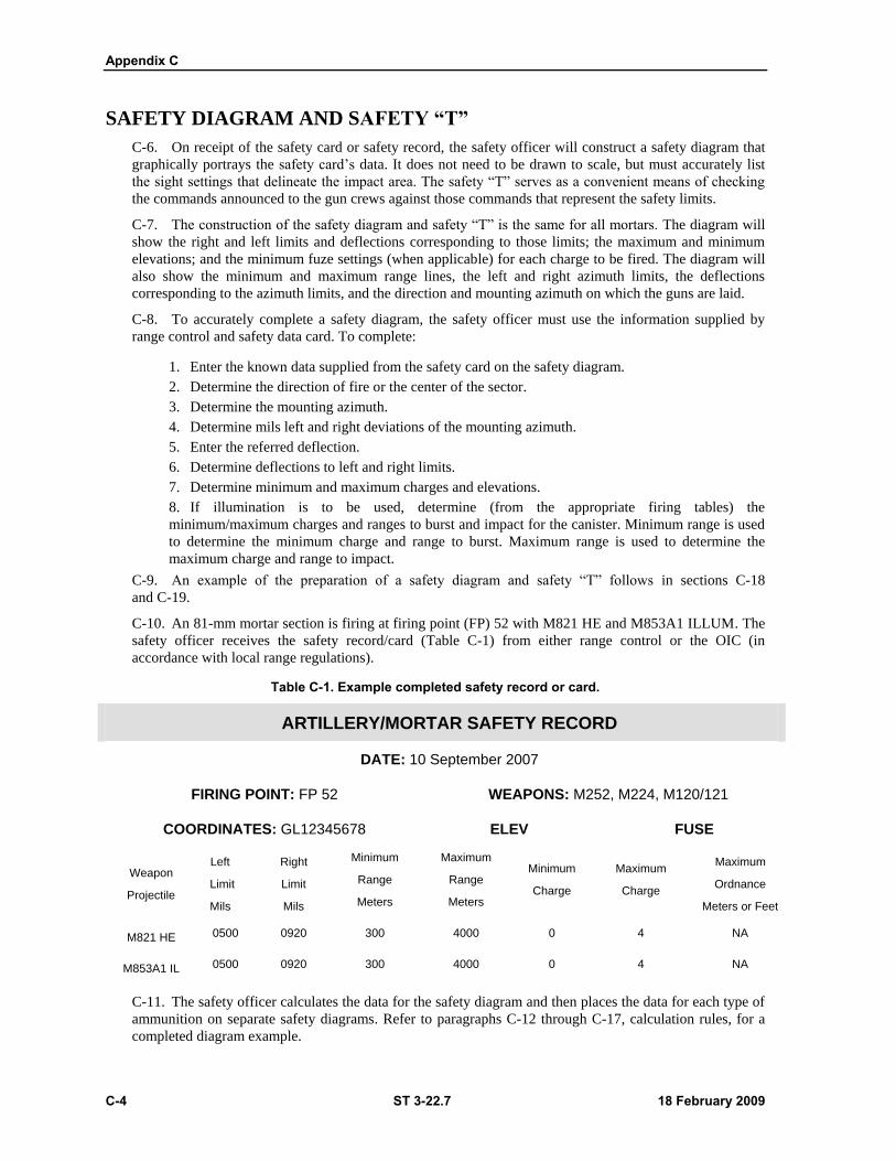
Appendix C
C-4 ST 3-22.7 18 February 2009
SAFETY DIAGRAM AND SAFETY “T”
C-6. On receipt of the safety card or safety record, the safety officer will construct a safety diagram that
graphically portrays the safety card’s data. It does not need to be drawn to scale, but must accurately list
the sight settings that delineate the impact area. The safety ―T‖ serves as a convenient means of checking
the commands announced to the gun crews against those commands that represent the safety limits.
C-7. The construction of the safety diagram and safety ―T‖ is the same for all mortars. The diagram will
show the right and left limits and deflections corresponding to those limits; the maximum and minimum
elevations; and the minimum fuze settings (when applicable) for each charge to be fired. The diagram will
also show the minimum and maximum range lines, the left and right azimuth limits, the deflections
corresponding to the azimuth limits, and the direction and mounting azimuth on which the guns are laid.
C-8. To accurately complete a safety diagram, the safety officer must use the information supplied by
range control and safety data card. To complete:
1. Enter the known data supplied from the safety card on the safety diagram.
2. Determine the direction of fire or the center of the sector.
3. Determine the mounting azimuth.
4. Determine mils left and right deviations of the mounting azimuth.
5. Enter the referred deflection.
6. Determine deflections to left and right limits.
7. Determine minimum and maximum charges and elevations.
8. If illumination is to be used, determine (from the appropriate firing tables) the
minimum/maximum charges and ranges to burst and impact for the canister. Minimum range is used
to determine the minimum charge and range to burst. Maximum range is used to determine the
maximum charge and range to impact.
C-9. An example of the preparation of a safety diagram and safety ―T‖ follows in sections C-18
and C-19.
C-10. An 81-mm mortar section is firing at firing point (FP) 52 with M821 HE and M853A1 ILLUM. The
safety officer receives the safety record/card (Table C-1) from either range control or the OIC (in
accordance with local range regulations).
Table C-1. Example completed safety record or card.
ARTILLERY/MORTAR SAFETY RECORD
DATE: 10 September 2007
FIRING POINT: FP 52 WEAPONS: M252, M224, M120/121
COORDINATES: GL12345678 ELEV FUSE
Weapon
Projectile
Left
Limit
Mils
Right
Limit
Mils
Minimum
Range
Meters
Maximum
Range
Meters
Minimum
Charge
Maximum
Charge
Maximum
Ordnance
Meters or Feet
M821 HE 0500 0920 300 4000 0 4 NA
M853A1 IL 0500 0920 300 4000 0 4 NA
C-11. The safety officer calculates the data for the safety diagram and then places the data for each type of
ammunition on separate safety diagrams. Refer to paragraphs C-12 through C-17, calculation rules, for a
completed diagram example.
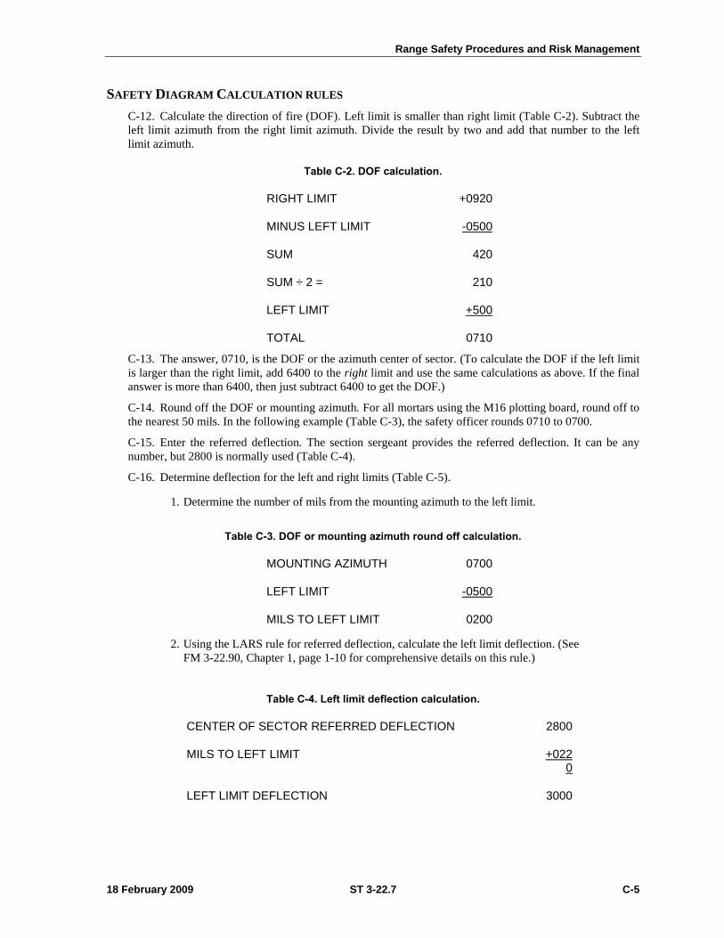
Range Safety Procedures and Risk Management
18 February 2009 ST 3-22.7 C-5
SAFETY DIAGRAM CALCULATION RULES
C-12. Calculate the direction of fire (DOF). Left limit is smaller than right limit (Table C-2). Subtract the
left limit azimuth from the right limit azimuth. Divide the result by two and add that number to the left
limit azimuth.
Table C-2. DOF calculation.
RIGHT LIMIT +0920
MINUS LEFT LIMIT -0500
SUM 420
SUM ÷ 2 = 210
LEFT LIMIT +500
TOTAL 0710
C-13. The answer, 0710, is the DOF or the azimuth center of sector. (To calculate the DOF if the left limit
is larger than the right limit, add 6400 to the right limit and use the same calculations as above. If the final
answer is more than 6400, then just subtract 6400 to get the DOF.)
C-14. Round off the DOF or mounting azimuth. For all mortars using the M16 plotting board, round off to
the nearest 50 mils. In the following example (Table C-3), the safety officer rounds 0710 to 0700.
C-15. Enter the referred deflection. The section sergeant provides the referred deflection. It can be any
number, but 2800 is normally used (Table C-4).
C-16. Determine deflection for the left and right limits (Table C-5).
1. Determine the number of mils from the mounting azimuth to the left limit.
Table C-3. DOF or mounting azimuth round off calculation.
MOUNTING AZIMUTH 0700
LEFT LIMIT -0500
MILS TO LEFT LIMIT 0200
2. Using the LARS rule for referred deflection, calculate the left limit deflection. (See
FM 3-22.90, Chapter 1, page 1-10 for comprehensive details on this rule.)
Table C-4. Left limit deflection calculation.
CENTER OF SECTOR REFERRED DEFLECTION 2800
MILS TO LEFT LIMIT +0220
LEFT LIMIT DEFLECTION 3000
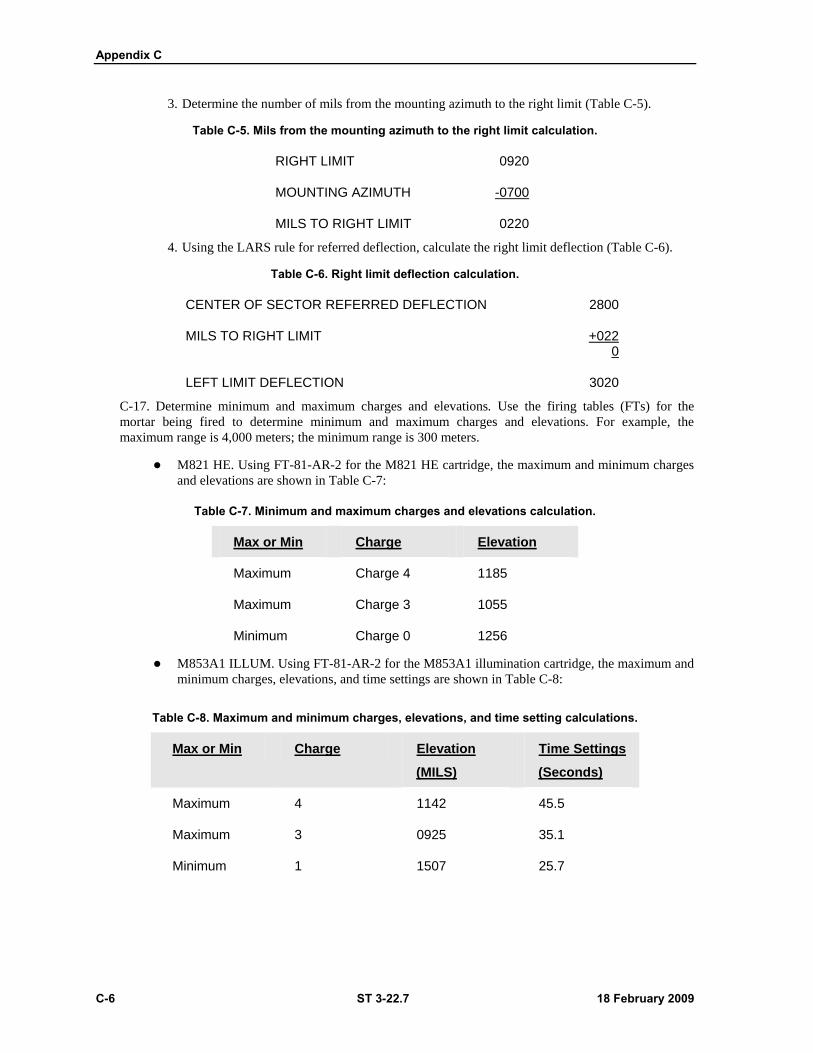
Appendix C
C-6 ST 3-22.7 18 February 2009
3. Determine the number of mils from the mounting azimuth to the right limit (Table C-5).
Table C-5. Mils from the mounting azimuth to the right limit calculation.
RIGHT LIMIT 0920
MOUNTING AZIMUTH -0700
MILS TO RIGHT LIMIT 0220
4. Using the LARS rule for referred deflection, calculate the right limit deflection (Table C-6).
Table C-6. Right limit deflection calculation.
CENTER OF SECTOR REFERRED DEFLECTION 2800
MILS TO RIGHT LIMIT +0220
LEFT LIMIT DEFLECTION 3020
C-17. Determine minimum and maximum charges and elevations. Use the firing tables (FTs) for the
mortar being fired to determine minimum and maximum charges and elevations. For example, the
maximum range is 4,000 meters; the minimum range is 300 meters.
M821 HE. Using FT-81-AR-2 for the M821 HE cartridge, the maximum and minimum charges
and elevations are shown in Table C-7:
Table C-7. Minimum and maximum charges and elevations calculation.
Max or Min Charge Elevation
Maximum Charge 4 1185
Maximum Charge 3 1055
Minimum Charge 0 1256
M853A1 ILLUM. Using FT-81-AR-2 for the M853A1 illumination cartridge, the maximum and
minimum charges, elevations, and time settings are shown in Table C-8:
Table C-8. Maximum and minimum charges, elevations, and time setting calculations.
Max or Min Charge Elevation
(MILS)
Time Settings
(Seconds)
Maximum 4 1142 45.5
Maximum 3 0925 35.1
Minimum 1 1507 25.7
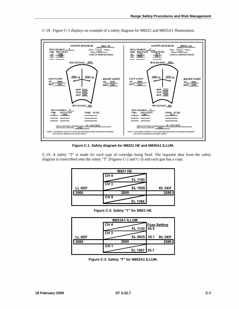
Range Safety Procedures and Risk Management
18 February 2009 ST 3-22.7 C-7
C-18. Figure C-1 displays an example of a safety diagram for M8221 and M835A1 Illumination.
Figure C-1. Safety diagram for M8221 HE and M835A1 ILLUM.
C-19. A safety "T" is made for each type of cartridge being fired. The requisite data from the safety
diagram is transcribed onto the safety "T" (Figures C-2 and C-3) and each gun has a copy.
Figure C-2. Safety "T" for M821 HE.
Figure C-3. Safety "T" for M852A1 ILLUM.
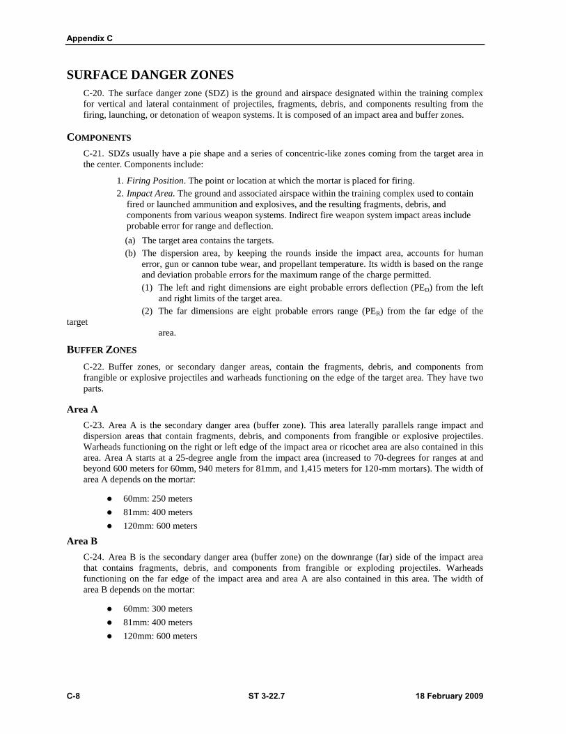
Appendix C
C-8 ST 3-22.7 18 February 2009
SURFACE DANGER ZONES
C-20. The surface danger zone (SDZ) is the ground and airspace designated within the training complex
for vertical and lateral containment of projectiles, fragments, debris, and components resulting from the
firing, launching, or detonation of weapon systems. It is composed of an impact area and buffer zones.
COMPONENTS
C-21. SDZs usually have a pie shape and a series of concentric-like zones coming from the target area in
the center. Components include:
1. Firing Position. The point or location at which the mortar is placed for firing.
2. Impact Area. The ground and associated airspace within the training complex used to contain
fired or launched ammunition and explosives, and the resulting fragments, debris, and
components from various weapon systems. Indirect fire weapon system impact areas include
probable error for range and deflection.
(a) The target area contains the targets.
(b) The dispersion area, by keeping the rounds inside the impact area, accounts for human
error, gun or cannon tube wear, and propellant temperature. Its width is based on the range
and deviation probable errors for the maximum range of the charge permitted.
(1) The left and right dimensions are eight probable errors deflection (PED) from the left
and right limits of the target area.
(2) The far dimensions are eight probable errors range (PER) from the far edge of the
target
area.
BUFFER ZONES
C-22. Buffer zones, or secondary danger areas, contain the fragments, debris, and components from
frangible or explosive projectiles and warheads functioning on the edge of the target area. They have two
parts.
Area A
C-23. Area A is the secondary danger area (buffer zone). This area laterally parallels range impact and
dispersion areas that contain fragments, debris, and components from frangible or explosive projectiles.
Warheads functioning on the right or left edge of the impact area or ricochet area are also contained in this
area. Area A starts at a 25-degree angle from the impact area (increased to 70-degrees for ranges at and
beyond 600 meters for 60mm, 940 meters for 81mm, and 1,415 meters for 120-mm mortars). The width of
area A depends on the mortar:
60mm: 250 meters
81mm: 400 meters
120mm: 600 meters
Area B
C-24. Area B is the secondary danger area (buffer zone) on the downrange (far) side of the impact area
that contains fragments, debris, and components from frangible or exploding projectiles. Warheads
functioning on the far edge of the impact area and area A are also contained in this area. The width of
area B depends on the mortar:
60mm: 300 meters
81mm: 400 meters
120mm: 600 meters
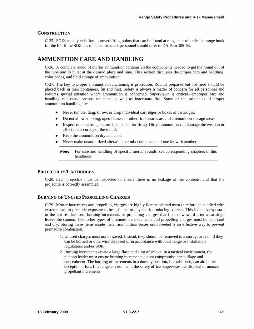
Range Safety Procedures and Risk Management
18 February 2009 ST 3-22.7 C-9
CONSTRUCTION
C-25. SDZs usually exist for approved firing points that can be found at range control or in the range book
for the FP. If the SDZ has to be constructed, personnel should refer to DA Pam 385-63.
AMMUNITION CARE AND HANDLING
C-26. A complete round of mortar ammunition contains all the components needed to get the round out of
the tube and to burst at the desired place and time. This section discusses the proper care and handling,
color codes, and field storage of ammunition.
C-27. The key to proper ammunition functioning is protection. Rounds prepared but not fired should be
placed back in their containers, fin end first. Safety is always a matter of concern for all personnel and
requires special attention where ammunition is concerned. Supervision is critical—improper care and
handling can cause serious accidents as well as inaccurate fire. Some of the principles of proper
ammunition handling are:
Never tumble, drag, throw, or drop individual cartridges or boxes of cartridges.
Do not allow smoking, open flames, or other fire hazards around ammunition storage areas.
Inspect each cartridge before it is loaded for firing. Dirty ammunition can damage the weapon or
affect the accuracy of the round.
Keep the ammunition dry and cool.
Never make unauthorized alterations or mix components of one lot with another.
Note: For care and handling of specific mortar rounds, see corresponding chapters in this
handbook.
PROJECTILES/CARTRIDGES
C-28. Each projectile must be inspected to ensure there is no leakage of the contents, and that the
projectile is correctly assembled.
BURNING OF UNUSED PROPELLING CHARGES
C-29. Mortar increments and propelling charges are highly flammable and must therefore be handled with
extreme care to preclude exposure to heat, flame, or any spark-producing sources. This includes exposure
to the hot residue from burning increments or propelling charges that float downward after a cartridge
leaves the cannon. Like other types of ammunition, increments and propelling charges must be kept cool
and dry. Storing these items inside metal ammunition boxes until needed is an effective way to prevent
premature combustion.
1. Unused charges must not be saved. Instead, they should be removed to a storage area until they
can be burned or otherwise disposed of in accordance with local range or installation
regulations and/or SOP.
2. Burning increments create a large flash and a lot of smoke. In a tactical environment, the
platoon leader must ensure burning increments do not compromise camouflage and
concealment. The burning of increments in a dummy position, if established, can aid in the
deception effort. In a range environment, the safety officer supervises the disposal of unused
propellant increments.
Appendix C
C-10 ST 3-22.7 18 February 2009
FUZES
C-30. A round is never to be fired with a fuze that is not authorized for that round.
1. Fuzes are sensitive to shock and must be handled with care. Before fuzing a round, inspect the
threads of the fuze and fuze well for cleanliness and crossed threads. The fuze should be
screwed into the fuze well slowly until resistance is met and then firmly seated with a sharp
twist of the M25 or M18 fuze wrench, as appropriate.
WARNING
Premature detonation may occur if a fuze is not properly seated.
2. To prevent accidental functioning of the point-detonating elements of fuzes of the M524 series,
the fuzes must not be dropped, rolled, or struck under any circumstances. Any mechanical-time
fuze that is set and modified must be reset to SAFE, and the safety wires (if applicable) must be
replaced before the fuze is repacked in the original carton.
3. All primers must be inspected before use for signs of corrosion. If a seal has been broken, it is
likely that the primer has been affected by moisture. In this case, the fuze should be turned in.
SEGREGATION OF AMMUNITION LOTS
C-31. Different lots of propellant burn at different rates and give slightly different effects in the target area.
Therefore, the registration corrections derived from one lot do not always apply to another. Ammunition
MUST be segregated by lot and weight zone. In the field storage area, on vehicles, or in a dump,
ammunition lots should be roped off with communications wire or twine. They should also be
conspicuously marked with a cardboard sign or other marker.
AMMUNITION COLOR CODES
C-32. Mortar ammunition is painted and marked with a color code for quick, accurate identification. A
color-code chart (Table C-9) identifies rounds using the NATO color code and the U.S. color code.
Range Safety Procedures and Risk Management
18 February 2009 ST 3-22.7 C-11
Table C-9. Mortar ammunition color codes.
TYPE OF ROUND
NATO COLOR CODE U.S. COLOR CODE
ROUND
MARKINGS
BAND ROUN
D MARKING
S BAND
HIGH EXPLOSIVE
(Causes troop casualties and damage to light material)
Olive Drab
Yellow
Drab NA Olive Yellow
Yellow
WHITE PHOSPHORUS
(Screens, signals, and acts as an incendiary)
Light Green
Red Yellow Light
Green Red
Yellow
RED PHOSPHORUS
(Screens, signals, and acts as an incendiary)
Light Green
Black Brown Light
Green Black Brown
ILLUMINATION
(Illuminates, signals, and marks)
White Black NA NA NA NA
TRAINING PRACTICE
(For training and practice)
Blue White
Brown
or None
Blue White Brown
FIELD STORAGE OF AMMUNITION
C-33. Most ammunition components can be stored at temperatures as low as -80 degrees for no longer than
three days; and as high as 160 degrees for no longer than four hours.
C-34. The greatest hazards to ammunition in the storage area are weather, enemy fire, CBRN
contamination, improper handling, and accidental fires. Regardless of the method of storage, those hazards
must be considered. Some general considerations that apply to storage follow:
1. Stack ammunition by type, lot number, and weight zone (Figure C-4).
Note: WP ammunition must be stacked fuze-end up so melted filler will settle at the
bottom, reducing the chance of voids forming off the long axis of the cartridge. The
presence of voids off the long axis of the cartridge will cause the cartridge to fly
erratically.
Appendix C
C-12 ST 3-22.7 18 February 2009
Figure C-4. Stacked ammunition.
2. If ammunition is stored on the ground, good strong dunnage at least 6 inches under each stack
should be used.
3. Ammunition must be kept dry and out of direct sunlight by storing it in a vehicle or covering it
with a tarpaulin. Adequate ventilation must be provided around ammunition and between
covering material and ammunition.
4. Ammunition must be protected as much as possible from enemy indirect fires. To ensure proper
ventilation when sandbags are used for protection—
(a) Walls should be kept at least 6 inches from the stacks.
(b) The roof must be kept at least 18 inches from the stacks.
C-35. An increase in malfunctions can occur with some proximity fuzes when fired if the temperature is
below 0-degrees or above 120-degrees. Powder temperature affects the muzzle velocity of a projectile and
is of frequent concern to the FDC.
Range Safety Procedures and Risk Management
18 February 2009 ST 3-22.7 C-13
Section II — RISK MANAGEMENT
C-36. This section describes how risk management is integrated into the Army training management cycle
and training planning. FM 5-19, Composite Risk Management, provides the doctrinal framework for this
critical aspect of safe training and operations. It also provides detailed guidance on the implementation of
risk management across a wide range of Army applications.
RISK MANAGEMENT
C-37. All risk management, training, and operations assessment is performed IAW the requirements of AR
385-10, TRADOC Regulation 385-2, FM 7-0, FM 7-1, FM 100-14, and this handbook. Following is a brief
description of risk management and assessment leader responsibilities to be applied during MCV mortar
firing training:
SAFETY MANAGER
C-38. The safety manager will—
Provide overall coordination of the risk management program.
Provide guidance and assistance to facilitate effective implementation of the program.
Review the risk management worksheet for operations and training determined to have high or
extremely high residual risk factors.
Check worksheet during range and training inspections.
COMMANDERS
C-39. Commanders will—
Develop in writing and implement a comprehensive risk management program that meets the
requirements of this manual.
Integrate risk management into all operations and training.
Train all leaders in risk management concepts, the requirements of this handbook, and the
organizational risk management program.
Ensure that a formal, documented risk management worksheet is completed for each training
activity and operation, using the procedures and form described in this handbook. This
document will be completed during the planning phase of any operation or training.
Ensure worksheets are reviewed and accepted in writing by the leader at the appropriate level as
designated in this manual.
Maintain copies of all worksheets in the appropriate organizational files and at the training or
operation site.
Develop a comprehensive daily risk assessment checklist that addresses those factors, which
may change from day-to-day or iteration-to-iteration, and identify new hazards not addressed in
the risk management worksheet.
Ensure a daily risk assessment checklist is completed before beginning the training or operation.
This document will be completed immediately before the execution phase of an operation or
training. For those operations conducted on a repetitive basis, the checklist must be completed
before each day’s activities. If conditions change significantly during an operation, the checklist
should be reevaluated.
Require the leader conducting the operation or training to consult with and receive approval
from the individual who accepted the risk on the risk management worksheet. This must be done
when the daily risk assessment checklist indicates the overall rating for the operation or training
Appendix C
C-14 ST 3-22.7 18 February 2009
is high or extremely high, when any factor is rated as extreme risk, or when more than one
factor is rated as high risk.
Ensure daily risk assessment checklists are maintained at the operation or training site until the
event is completed. If an accident occurs during an operation, the checklist should be maintained
until the investigation is completed.
Ensure risk management worksheets are reevaluated before each operation or training event in
coordination with the daily risk assessment checklist by the individual(s) responsible for the
operation or training.
Ensure the worksheet and daily risk assessment checklists are used as the basis for
preoperational or training safety briefings with involved personnel.
GENERAL PROCEDURES
C-40. Risk management will be integrated into every operation and training event conducted on an
installation, or by installation organizations at other locations.
A formal, documented risk management worksheet and daily risk assessment checklist will be
prepared for every operation and training event.
The worksheet and daily risk assessment checklists will be prepared and risks will be assessed
using the methodology and form described in this manual.
For those training events or operations conducted on a repetitive basis, there is no requirement
to complete a new worksheet before a new iteration. The initial worksheet is sufficient unless
changes have been made to the training scenario or operation plan. Any changes would pertain
to personnel safety, equipment, the environment, or new hazards identified on the daily risk
assessment checklist that are not on the initial risk management worksheet.
Whenever there is a change of command or supervision, risk management worksheets accepted
by the outgoing commander or manager will be revised, updated, and submitted to the new
commander or manager, for acceptance of risks.
The worksheet will be revised whenever a change in the training or operation could affect the
safety of personnel, equipment, area environment, or identified hazards not listed on a current
risk management worksheet.
RULES OF RISK MANAGEMENT
C-41. Unnecessary risks will not be accepted. Leaders with authority to accept risks are responsible for
protecting their personnel from unnecessary ones. Unnecessary risks are those that could be reduced or
eliminated without hindering mission accomplishment.
Risk decisions must be made at a level consistent with the risk involved. The leader ultimately
responsible for the mission should make the risk decision.
An identified risk is acceptable if it benefits or outweighs any costs. Leaders must understand
that risk-taking is a decision making process that balances mission benefits and costs. They must
be prepared to take acceptable risks to accomplish a mission.
RISK MANAGEMENT PROCESS
C-42. The process of risk management involves a complete cycle that feeds back to its start point in a
logical manner. A key consideration when assessing risk options is to match process considerations with
the extent of any risk probability. If the risk is high, the process should be complete and detailed. If the risk
level is low, the process may be abbreviated. Generally, all steps of the process should be standard, yet
curtailed by cutting back on step details, but not by eliminating any step. The following steps will be
documented on all risk management worksheets and daily risk assessment checklists:
1. Identify the Hazards. Hazards are sources of danger that could be encountered while
performing a task or mission. Leaders must try to identify any potential ones during operations
or training planning. Special attention should be paid to identifying those hazards with a
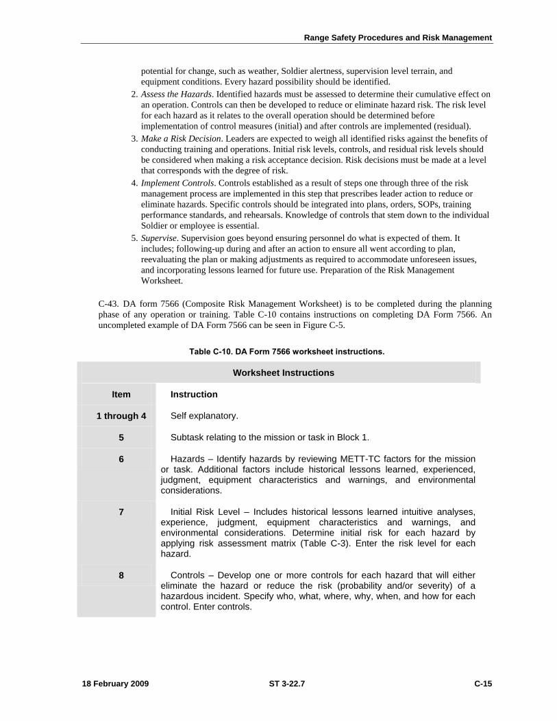
Range Safety Procedures and Risk Management
18 February 2009 ST 3-22.7 C-15
potential for change, such as weather, Soldier alertness, supervision level terrain, and
equipment conditions. Every hazard possibility should be identified.
2. Assess the Hazards. Identified hazards must be assessed to determine their cumulative effect on
an operation. Controls can then be developed to reduce or eliminate hazard risk. The risk level
for each hazard as it relates to the overall operation should be determined before
implementation of control measures (initial) and after controls are implemented (residual).
3. Make a Risk Decision. Leaders are expected to weigh all identified risks against the benefits of
conducting training and operations. Initial risk levels, controls, and residual risk levels should
be considered when making a risk acceptance decision. Risk decisions must be made at a level
that corresponds with the degree of risk.
4. Implement Controls. Controls established as a result of steps one through three of the risk
management process are implemented in this step that prescribes leader action to reduce or
eliminate hazards. Specific controls should be integrated into plans, orders, SOPs, training
performance standards, and rehearsals. Knowledge of controls that stem down to the individual
Soldier or employee is essential.
5. Supervise. Supervision goes beyond ensuring personnel do what is expected of them. It
includes; following-up during and after an action to ensure all went according to plan,
reevaluating the plan or making adjustments as required to accommodate unforeseen issues,
and incorporating lessons learned for future use. Preparation of the Risk Management
Worksheet.
C-43. DA form 7566 (Composite Risk Management Worksheet) is to be completed during the planning
phase of any operation or training. Table C-10 contains instructions on completing DA Form 7566. An
uncompleted example of DA Form 7566 can be seen in Figure C-5.
Table C-10. DA Form 7566 worksheet instructions.
Worksheet Instructions
Item Instruction
1 through 4 Self explanatory.
5 Subtask relating to the mission or task in Block 1.
6 Hazards – Identify hazards by reviewing METT-TC factors for the mission or task. Additional factors include historical lessons learned, experienced, judgment, equipment characteristics and warnings, and environmental considerations.
7 Initial Risk Level – Includes historical lessons learned intuitive analyses, experience, judgment, equipment characteristics and warnings, and environmental considerations. Determine initial risk for each hazard by applying risk assessment matrix (Table C-3). Enter the risk level for each hazard.
8 Controls – Develop one or more controls for each hazard that will either eliminate the hazard or reduce the risk (probability and/or severity) of a hazardous incident. Specify who, what, where, why, when, and how for each control. Enter controls.
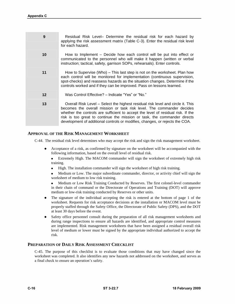
Appendix C
C-16 ST 3-22.7 18 February 2009
9 Residual Risk Level– Determine the residual risk for each hazard by applying the risk assessment matrix (Table C-3). Enter the residual risk level for each hazard.
10 How to Implement – Decide how each control will be put into effect or communicated to the personnel who will make it happen (written or verbal instruction; tactical, safety, garrison SOPs, rehearsals). Enter controls.
11 How to Supervise (Who) – This last step is not on the worksheet. Plan how each control will be monitored for implementation (continuous supervision, spot-checks) and reassess hazards as the situation changes. Determine if the controls worked and if they can be improved. Pass on lessons learned.
12 Was Control Effective? – Indicate “Yes” or “No.”
13 Overall Risk Level – Select the highest residual risk level and circle it. This becomes the overall mission or task risk level. The commander decides whether the controls are sufficient to accept the level of residual risk. If the risk is too great to continue the mission or task, the commander directs development of additional controls or modifies, changes, or rejects the COA.
APPROVAL OF THE RISK MANAGEMENT WORKSHEET
C-44. The residual risk level determines who may accept the risk and sign the risk management worksheet.
Acceptance of a risk, as confirmed by signature on the worksheet will be accompanied with the
following information, based on the overall level of residual risk.
Extremely High. The MACOM commander will sign the worksheet of extremely high risk
training.
High. The installation commander will sign the worksheet of high risk training.
Medium or Low. The major subordinate commander, director, or activity chief will sign the
worksheet of medium to low risk training.
Medium or Low Risk Training Conducted by Reserves. The first colonel-level commander
in their chain of command or the Directorate of Operations and Training (DOT) will approve
medium or low-risk training conducted by Reserves or other units.
The signature of the individual accepting the risk is entered at the bottom of page 1 of the
worksheet. Requests for risk acceptance decisions at the installation or MACOM level must be
properly staffed through the Safety Office, the Directorate of Public Safety (DPS), and the DOT
at least 30 days before the event.
Safety office personnel consult during the preparation of all risk management worksheets and
during range inspections to ensure all hazards are identified, and appropriate control measures
are implemented. Risk management worksheets that have been assigned a residual overall risk
level of medium or lower must be signed by the appropriate individual authorized to accept the
risk.
PREPARATION OF DAILY RISK ASSESSMENT CHECKLIST
C-45. The purpose of this checklist is to evaluate those conditions that may have changed since the
worksheet was completed. It also identifies any new hazards not addressed on the worksheet, and serves as
a final check to ensure an operation’s safety.
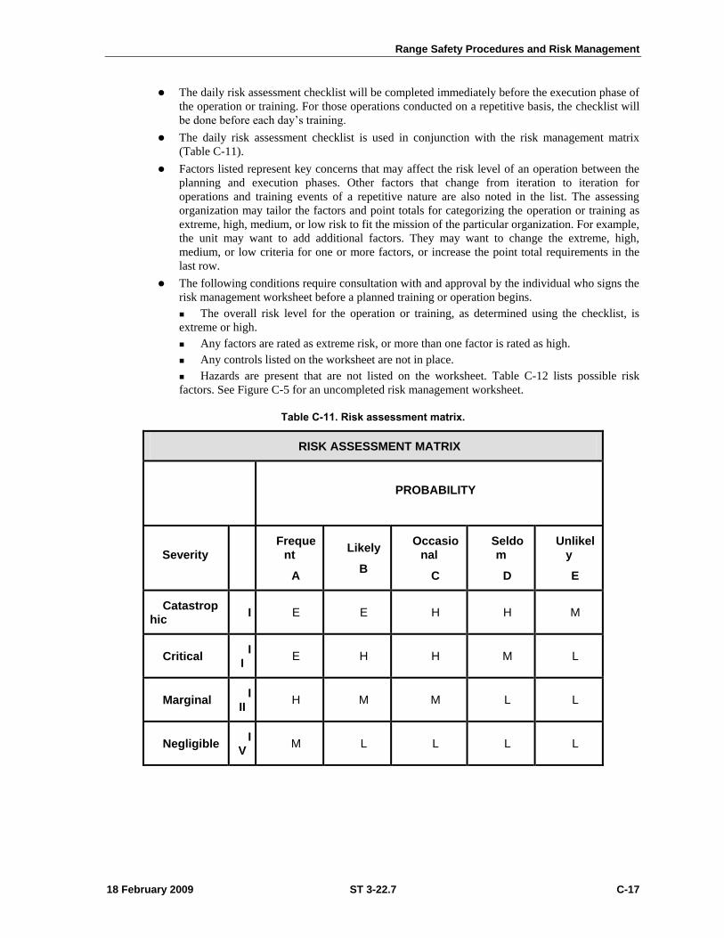
Range Safety Procedures and Risk Management
18 February 2009 ST 3-22.7 C-17
The daily risk assessment checklist will be completed immediately before the execution phase of
the operation or training. For those operations conducted on a repetitive basis, the checklist will
be done before each day’s training.
The daily risk assessment checklist is used in conjunction with the risk management matrix
(Table C-11).
Factors listed represent key concerns that may affect the risk level of an operation between the
planning and execution phases. Other factors that change from iteration to iteration for
operations and training events of a repetitive nature are also noted in the list. The assessing
organization may tailor the factors and point totals for categorizing the operation or training as
extreme, high, medium, or low risk to fit the mission of the particular organization. For example,
the unit may want to add additional factors. They may want to change the extreme, high,
medium, or low criteria for one or more factors, or increase the point total requirements in the
last row.
The following conditions require consultation with and approval by the individual who signs the
risk management worksheet before a planned training or operation begins.
The overall risk level for the operation or training, as determined using the checklist, is
extreme or high.
Any factors are rated as extreme risk, or more than one factor is rated as high.
Any controls listed on the worksheet are not in place.
Hazards are present that are not listed on the worksheet. Table C-12 lists possible risk
factors. See Figure C-5 for an uncompleted risk management worksheet.
Table C-11. Risk assessment matrix.
RISK ASSESSMENT MATRIX
PROBABILITY
Severity Freque
nt
A
Likely
B
Occasional
C
Seldom
D
Unlikely
E
Catastrophic
I E E H H M
Critical I
I E H H M L
Marginal I
II H M M L L
Negligible I
V M L L L L
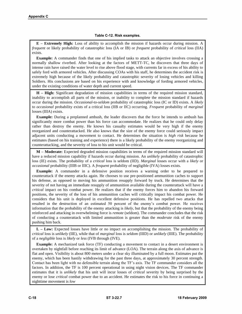
Appendix C
C-18 ST 3-22.7 18 February 2009
Table C-12. Risk examples.
E – Extremely High: Loss of ability to accomplish the mission if hazards occur during mission. A
frequent or likely probability of catastrophic loss (IA or IB) or frequent probability of critical loss (IIA)
exists.
Example: A commander finds that one of his implied tasks to attack an objective involves crossing a
normally shallow riverbed. After looking at the factors of METT-TC, he discovers that three days of
intense rain have raised the water level to rise above flood stage, with currents far in excess of his ability to
safely ford with armored vehicles. After discussing COAs with his staff, he determines the accident risk is
extremely high because of the likely probability and catastrophic severity of losing vehicles and killing
Soldiers. His conclusions are based on his experience with and knowledge of fording armored vehicles,
under the existing conditions of water depth and current speed.
H – High: Significant degradation of mission capabilities in terms of the required mission standard,
inability to accomplish all parts of the mission, or inability to complete the mission standard if hazards
occur during the mission. Occasional-to-seldom probability of catastrophic loss (IC or ID) exists. A likely
to occasional probability exists of a critical loss (IIB or IIC) occurring. Frequent probability of marginal
losses (IIIA) exists.
Example: During a preplanned ambush, the leader discovers that the force he intends to ambush has
significantly more combat power than his force can accommodate. He realizes that he could only delay
rather than destroy the enemy. He knows his casualty estimates would be very high if the enemy
reorganized and counterattacked. He also knows that the size of the enemy force could seriously impact
adjacent units conducting a movement to contact. He determines the situation is high risk because he
estimates (based on his training and experience) there is a likely probability of the enemy reorganizing and
counterattacking, and the severity of loss to his unit would be critical.
M – Moderate: Expected degraded mission capabilities in terms of the required mission standard will
have a reduced mission capability if hazards occur during mission. An unlikely probability of catastrophic
loss (IE) exists. The probability of a critical loss is seldom (IID). Marginal losses occur with a likely or
occasional probability (IIIB or IIIC). A frequent probability of negligible (IVA) losses exists.
Example: A commander in a defensive position receives a warning order to be prepared to
counterattack if the enemy attacks again. He chooses to use pre-positioned ammunition caches to support
his defense, as opposed to moving his ammunition resupply forward by truck. He determines that the
severity of not having an immediate resupply of ammunition available during the counterattack will have a
critical impact on his combat power. He realizes that if the enemy forces him to abandon his forward
positions, the severity of the loss of his ammunition caches will critically impact his combat power. He
considers that his unit is deployed in excellent defensive positions. He has repelled two attacks that
resulted in the destruction of an estimated 50 percent of the enemy’s combat power. He receives
information that the probability of the enemy attacking is likely, but that the probability of the enemy being
reinforced and attacking in overwhelming force is remote (seldom). The commander concludes that the risk
of conducting a counterattack with limited ammunition is greater than the moderate risk of the enemy
pushing him back.
L – Low: Expected losses have little or no impact on accomplishing the mission. The probability of
critical loss is unlikely (IIE), while that of marginal loss is seldom (IIID) or unlikely (IIIE). The probability
of a negligible loss is likely or less (IVB through (IVE).
Example: A mechanized task force (TF) conducting a movement to contact in a desert environment is
overtaken by nightfall before reaching its limit of advance (LOA). The terrain along the axis of advance is
flat and open. Visibility is about 800 meters under a clear sky illuminated by a full moon. Estimates put the
enemy, which has been hastily withdrawing for the past three days, at approximately 30 percent strength.
Contact has been light with no defensible terrain along the TF’s axis. The TF commander considers all the
factors. In addition, the TF is 100 percent operational in using night vision devices. The TF commander
estimates that it is unlikely that his unit will incur losses of critical severity by being surprised by the
enemy or lose critical combat power due to an accident. He estimates the risk to his force in continuing a
nighttime movement is low
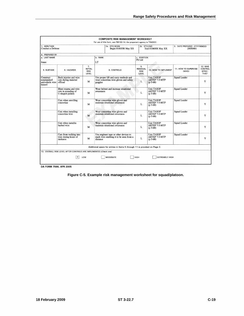
Range Safety Procedures and Risk Management
18 February 2009 ST 3-22.7 C-19
Figure C-5. Example risk management worksheet for squad/platoon.


18 February 2009 ST 3-22.7 Glossary-1
GLOSSARY
AAL additional authorization list
AAR after-action report
ADACG Arrival/Departure Airfield Control Group
ADTDL Army Doctrine and Training Digital Library
ANCOC Advanced Noncomissioned Officer Course
AO area of operations
AoA add-on-armor
ARTEP Army Training Evaluation Program
ATGMV antitank guided missile vehicle
BAD blast attenuator device
BII basic issue items
BMC brigade movement coordinator
BN battalion
BNCOC Basic Noncommissioned Officer Course
CASCOM Combined Arms Support Command
CBRN chemical, biological, radiological, and nuclear
CFF call for fire
CI commander’s interface
COE contemporary operating environment
COEI components of end item
CTIS central tire inflation system
CV commander’s vehicle
DAGR defense advanced GPS reciever
DOF direction of fire
DPS Directorate of Public Safety
EMI electromagnetic interference
EOD explosive ordinance demolition
EOM end of mission
ESV engineer squad vehicle
FDC fire direction center
FFE fire for effect
FIST fire support team
FO forward observer
FP firing point
FPF final protective fire
FSCM fire support coordination measure

Glossary
Glossary-2 ST 3-22.7 18 February 2009
FO forward observer
FT firing table
GPFU gas particular filtration unit
GPS global positioning system
HET heavy equipment transporter
IAW in accordance with
IBOLC Infantry Basic Officer Leadership Course
ICV Infantry carrier vehicle
IMLC Infantry Mortar Leader Course
IPCC Infantry Pre-Command Course
ITO installation transportation officer
JOPES Joint Operation Planning and Execution System
LFX live-fire exercise
LHMBC lightweight handheld mortar ballistic computer
LOA limit of advance
MBC mortar ballistic computer
MC3 Maneuver Captains Career Course
MCV mortar carrier vehicle
METL mission-essential task list
METT-TC mission, enemy, terrain and weather, troops and support available, time
available, civil considerations
MFCS Mortar Fire Control System
MILES Multiple Integrated Laser Engagement System
MTP mission training plan
NBC-RV nuclear, biological, chemical-reconnaissance vehicle
NCOPD noncommissioned officer professional development
OPD officer professional development
OPFOR opposing force
OSUT One Station Unit Training
P practice
PED probable errors deflection
PER probable errors range
PLGR Position Lightweight GPS Reciever
PMCS preventive maintanance checks and service
RHA rolled homogenous armor
RPG rocket propelled grenade
RSTA reconnaissance, surveillance, targeting, and acquistion
RWS remote weapons station
SBCT Stryker Brigade Combat Team
SDZ surface danger zone
SOP standing operating procedure

Glossary
18 February 2009 ST 3-22.7 Glossary-3
STX simulated training exercise
T trained
T&EO training and evaluation outline
TADSS training aids, devices, simulators, and simulations
TEA Transportation Engineering Agency
TF task force
TTP tactics, techniques, and procedures
U untrained
UMC unit movement coordinator
UXO unexploded ordnance
VDT video display terminal

18 February 2009 ST 3-22.7 REFERENCES-1
REFERENCES
REQUIRED PUBLICATIONS
These are the sources quoted or paraphrased in this publication. All must be available to the intended
users of this publication.
ARMY REGULATIONS
AR 385-10. The Army Safety Program. 23 August 2007.
AR 385-63. Range Safety {MCO 3570.1B}. 19 May 2003.
DA Pam 385-63. Range Safety. 20 April 2003.
DA Form 2399-R. Computer’s Record, February 2005, or DA Form 2188-R Data Sheet. March 1991.
DA Form 2408-4. Weapon Record Data. January 1979.
DA Form 5964-R.Gunner’s Examination Scorecard-Mortars. Sep 1990. See FM 3-22.90. Mortars.
December 2007
DA Form 7566. Composite Risk Management Worksheet. April 2005.
FM 3-0 (100-5). Operations. 27 February 2008.
FM 3-22.90. Mortars. 7 December 2007.
FM 3-22.91 Mortar Fire Direction Procedures. July 2008.
FMI 3-35 (FM 3-35.4). Army Deployment and Redeployment. 15 June 2007.
FM 4-01.011. Unit Movement Operations. 31 October 2002.
FM 5-19 (100-14). Composite Risk Management. 21 August 2006.
FM 7-0. Training the Force. 22 October 2002.
FM 7-1. Battle Focused Training. 15 September 2003.
STP 7-11B1-SM-TG. Soldier’s Manual and Trainer’s Guide, MOS 11B, Infantry, Skill Level 1.
06 August 2004.
STP 7-11B24-SM-TG. Soldier’s Manual and Trainer’s Guide, MOS 11B, Infantry, Skill Levels 2, 3,
and 4. 06 August 2004.
STP 7-11C14-SM-TG. Soldier’s Manual and Trainer’s Guide, MOS 11C, Indirect Fire infantryman,
Skill Levels 1, 2, 3, and 4. 06 August 2004.
TC 7-21. Stryker Driver Training. 01 December 2006.
TRADOC Regulation 385-2. U.S. Army Training and Doctrine Command Safety Program.
19 December 2007.
FM 25-4. How to Conduct Training Exercises. 10 September 1984.
TEA PAM 55-19. Tiedown Handbook for Rail Movements, 6th Edition. September 2003.
TECHNICAL MANUALS
STRYKER MCV TMS ARE CURRENTLY AVAILABLE ONLY AT THE UNIT LEVEL
TM 9-1015-250-10. Operator’s Manual for Mortar, 120MM: Towed M120 (NSN 1015-01-226-1672)
(EIC: 4SL) and Mortar, 120MM: CarrierMounted M121 (NSN 1015-01-292-3801)
(EIC: 4SE).

References
18 February 2009 ST 3-22.7 REFERENCES-2
TB 9-2355-311-10-1. Installation Instructions Crew Maintenance Level for Cupola Shield for Vehicles
Fire Support Vehicle (FSV) M1131 Reconnaissance Vehicle (RV) M1127.
TM 9-2355-311-10-2-3. Operator’s Manual, Volume 3 of 3, Infantry Carrier Vehicle (ICV), M1125,
(2355-01-481-8575) (EIC: AFF), Stryker.
TM 9-2355-311-10-3. Operators Manual for the Mortar Carrier Vehicle (MCV) M1129A1.
TB 9-2540-231-12. Stryker Slat Armor for Vehicles; Commander's Vehicle (CV); M1130 Engineering
Squad Vehicle (ESV); M1132 Fire Support Vehicle (FSV) and Fire Support Sensor System
(FS3); M1131E1 Reconnaissance/Scout Vehicle (RV); M1127 Infantry Carrier Vehicle (ICV);
M1126 Medical Evacuation Vehicle (MEV); M1133 Mortar Carrier-B (MC-B); Anti-Tank
Guided Missile (ATGM) M1134.
TB 9-2540-232-10. Crew Maintenance Level for Slat Armor Operator for Vehicles; Infantry Carrier
Vehicle (ICV); M1126 Reconnaissance Vehicle (RV); M1127 Mortar Carrier (MC);
XM1129E1 Commander’s Vehicle (CV); M1130 Fire Support Vehicle (FSV); M1131
Engineer Squad Vehicle (ESC); M1132 Medical Evacuation Vehicle (MEV); M1133
Anti-Tank Guided Missile (ATGM) M1134.
18 February 2009 ST 3-22.7 Index-1
Index
ammunition, 1-5, 1-8 (illus), 2-1, 2-4 (illus), C-9,
C-11 (table), C-12 (illus)
armor, B-1
basic issue items, 6-2 (illus)
battle drills, 4-19
boresight, 2-16 through 2-21 (illus)
configurations, 1-2 through 1-8 (illus)
crew drills, 4-3
crew stations, 1-3
DA Form 7566 Composite Risk Management
Worksheet, C-15 (illus)
direction of fire, C-4
equipment, See basic issue items
stowage, 6-6 (illus)
fire missions
basic, 3-5
special, 3-20
standard, 3-1
fuzes, 3-44, 4-16, C-2, C-10, C-12
gunner examination, 5-2 (illus)
quadrant sight, 2-21 (illus)
Integrated Mortar Platoon Training Strategy, 1-12
(illus)
load plan, 6-1
basic issue items, 6-2 (illus)
equipment stowage, 6-6 (illus)
M67 sight unit, 2-17 (illus)
platoon techniques, 2-23 through 2-26 (illus)
racks, ammunition stowage, 1-5 (illus), 2-3
through 2-11 (illus), 2-13 through 2-15 (illus)
risk management, C-13
risk management worksheet, C-20 (illus)
safety, C-1
diagram, C-4
manager, C-13
record, C-4 (table)
safety ―T,‖ C-4
surface danger zones (SDZ), C-8
vehicle fire, 4-8
WARNING
ammunition
60-mm, 2-14, 2-16
81-mm, 2-10, 2-12
120-mm, 2-4, 2-6, 2-7 to 2-9
cannon, 4-16, 4-18
cartridge extractor, 4-17
detonation, premature, C-10
fire extinguisher, chemicals, 4-8
misfires, 4-15
mortar doors, 1-4 (illus), 4-11
mortar, keeping clear of, 4-19
primer, 4-18
ramp, 4-8
rollover, 4-5
stuck cartridge procedures, 4-18
safety manager, responsibility, C-13
screens, 3-2, 3-6, 3-21
sight, calibration of, 2-16
standing operating procedures (SOP), A-3
stowage, see racks
surface danger zone, C-8
tactics, techniques, and procedures, 1-1, 1-11
training
drills, 4-1
evaluation, 1-14
mortar, 1-9 (illus)
unit, 1-11
transport, A-1
air, A-5
comparison by aircraft type, A-6 (illus)
land, A-7, A-8 (illus), A-10, (illus)
sea, A-11
unit movement operations SOP, A-3, (illus)
unexploded ordnance, B-4
unit movement operations SOP, A-2
vehicle configurations, 1-4 through 1-8 (illus)
weapon systems, 1-3
Ammunition Storage System, 1-8
M95 Mortar Fire Control System, 1-7
RMS6-L 120-mm Mortar System, 1-6