Embed Size (px)
Citation preview

Before InstallIngThis information is included as a quick reference installation guide. Refer to the control panel installation manual for detailed system information. If the modules will be installed in an existing operational system, inform the opera-tor and local authority that the system will be temporarily out of service. Dis-connect power to the control panel before installing the modules.
NOTICE: This manual should be left with the owner/user of this equipment.
general DescrIptIonM300CJ Supervised Control Modules are intended for use in intelligent, two-wire systems, where the individual address of each module is selected us-ing the built-in rotary switches. This module is used to switch an external power supply, which can be a DC power supply or an audio amplifier (up to 80 VRMS), to notification appliances. It also supervises the wiring to the connected loads and reports their status to the panel as NORMAL, OPEN, or SHORT CIRCUIT. The M300CJ has two pairs of output termination points available for fault-tolerant wiring and a panel-controlled LED indicator. This module can be used to replace a M510CJ module that has been configured for supervised wiring operation.
compatIBIlIty requIrementsTo ensure proper operation, this module shall be connected to a compatible system control panel (list available from Johnson Controls).
mountIngThe M300CJ mounts directly to 4-inch square electrical boxes (see Figure 2A). The box must have a minimum depth of 21⁄8 inches. Surface mounted electri-cal boxes (SMB500) are available from Johnson Controls. The module can also mount to the DNR(W) housing.
WIrIngNOTE: All wiring must conform to applicable local codes, ordinances, and regulations. When using control modules in nonpower limited applications, the CB500 Module Barrier must be used to meet UL requirements for the sepa-ration of power-limited and nonpower-limited terminals and wiring. The bar-rier must be inserted into a 4˝×4˝×21⁄8˝ junction box, and the control module must be placed into the barrier and attached to the junction box (Figure 2A). The power-limited wiring must be placed into the isolated quadrant of the module barrier (Figure 2B).
1. Install module wiring in accordance with the job drawings and appropri-ate wiring diagrams.
2. Set the address on the module per job drawings.3. Secure module to electrical box, supplied by installer (see Figure 2A).Wire should be stripped to the appropriate length (recommended strip length is 1/4“ to 3/8”). Exposed conductor should be secured under the clamping plate and should not protrude beyond the terminal block area. Caution: Do not loop wire under terminals. Break wire run to provide supervision of connections.
specIfIcatIonsNormal Operating Voltage: 15 to 32 VDCMaximum Current Draw: 6.5 mA (LED on)Average Operating Current: 375µA (LED Flashing, Group Poll); 350µA (LED Flashing, Direct Poll); 485µA Max. (LED Flashing, NAC Shorted)Maximum NAC Line Loss: 4 VDCExternal Supply Voltage (between Terminals T10 and T11) Maximum (NAC): Regulated 24 VDC Maximum (Speakers): 70.7Vrms, 50WDrain on External Supply: 1.7 mA Max. using 24 VDC supply; 2.2 mA max. using 80Vrms supplyMaximum NAC Current Ratings: For Class B Wiring System, 3A; For Class A Wiring System, 2ATemperature Range: 32°F to 120°F (0°C to 49°C)Humidity: 10% to 93% Non-condensingDimensions: 41⁄2˝ H x 4˝ W x 11⁄4˝ D (Mounts to a 4˝ square by 21⁄8˝ deep box.)Accessories: SMB500 Electrical Box; CB500 Barrier
m300cJ superVIseD control moDule
JC-460-000 1 I56-3750-003
I56-3750-003
507 E. Michigan StreetMilwaukee, WI 53201
InstallatIon anD maIntenance InstructIons
IMPORTANT: When using the M300CJ for fire fighter telephone applications, remove Jumper (J1) and discard. The Jumper is located on the back as shown in Figure 1B. The module does not provide ring back when used as a fire-fighter telephone circuit.
J1 must be removed whenever power supply monitoring feature is not required.
fIgure 1a: fIgure 1B. Jumper locatIon:
J1
C1059-00 C0910-00fIgure 2a. moDule mountIng fIgure 2B: WIth BarrIer:
C1070-00
JC-460-000 2 I56-3750-003
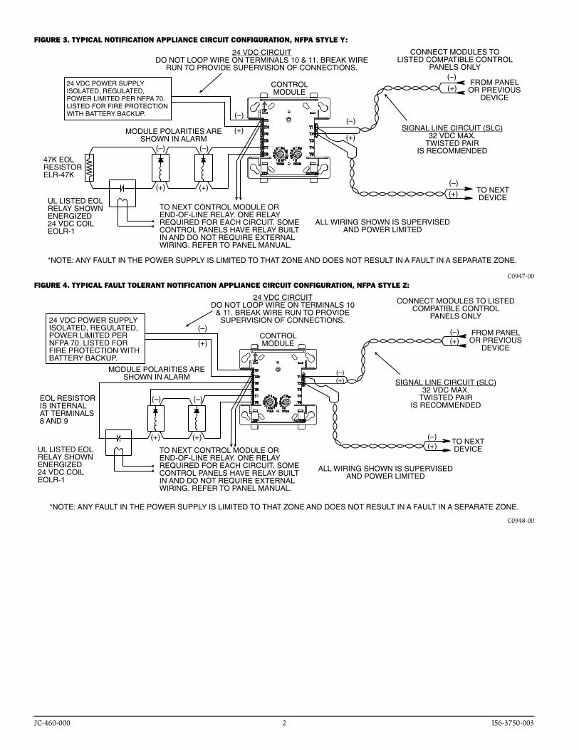
fIgure 3. typIcal notIfIcatIon applIance cIrcuIt confIguratIon, nfpa style y:
(+)
(+)
(+)
(+)
(+)
(+)
47K EOLRESISTORELR-47K
UL LISTED EOL RELAY SHOWN ENERGIZED24 VDC COIL EOLR-1
24 VDC CIRCUITDO NOT LOOP WIRE ON TERMINALS 10 & 11. BREAK WIRE
RUN TO PROVIDE SUPERVISION OF CONNECTIONS.
TO NEXT CONTROL MODULE OR END-OF-LINE RELAY. ONE RELAY REQUIRED FOR EACH CIRCUIT. SOME CONTROL PANELS HAVE RELAY BUILT IN AND DO NOT REQUIRE EXTERNAL WIRING. REFER TO PANEL MANUAL.
24 VDC POWER SUPPLYISOLATED, REGULATED, POWER LIMITED PER NFPA 70. LISTED FOR FIRE PROTECTION WITH BATTERY BACKUP.
MODULE POLARITIES ARE SHOWN IN ALARM
CONNECT MODULES TO LISTED COMPATIBLE CONTROL
PANELS ONLY
SIGNAL LINE CIRCUIT (SLC)32 VDC MAX.
TWISTED PAIRIS RECOMMENDED
ALL WIRING SHOWN IS SUPERVISED AND POWER LIMITED
CONTROL MODULE
FROM PANEL OR PREVIOUS
DEVICE
TO NEXT DEVICE
*NOTE: ANY FAULT IN THE POWER SUPPLY IS LIMITED TO THAT ZONE AND DOES NOT RESULT IN A FAULT IN A SEPARATE ZONE.
(–) (–)
(–)(–)
(–)
(–)
C0947-00fIgure 4. typIcal fault tolerant notIfIcatIon applIance cIrcuIt confIguratIon, nfpa style Z:
(+)(–)
(+)(–)
(+)(–)
(–)
(+)
(–)
(+)
(+)
(–)
ALL WIRING SHOWN IS SUPERVISED AND POWER LIMITED
MODULE POLARITIES ARE SHOWN IN ALARM
EOL RESISTOR IS INTERNAL AT TERMINALS 8 AND 9
UL LISTED EOL RELAY SHOWN ENERGIZED24 VDC COIL EOLR-1
TO NEXT CONTROL MODULE OR END-OF-LINE RELAY. ONE RELAY REQUIRED FOR EACH CIRCUIT. SOME CONTROL PANELS HAVE RELAY BUILT IN AND DO NOT REQUIRE EXTERNAL WIRING. REFER TO PANEL MANUAL.
CONTROL MODULE
TO NEXT DEVICE
SIGNAL LINE CIRCUIT (SLC)32 VDC MAX.
TWISTED PAIRIS RECOMMENDED
CONNECT MODULES TO LISTED COMPATIBLE CONTROL
PANELS ONLY
FROM PANEL OR PREVIOUS
DEVICE
24 VDC CIRCUITDO NOT LOOP WIRE ON TERMINALS 10
& 11. BREAK WIRE RUN TO PROVIDE SUPERVISION OF CONNECTIONS.24 VDC POWER SUPPLY
ISOLATED, REGULATED, POWER LIMITED PER NFPA 70. LISTED FOR FIRE PROTECTION WITH BATTERY BACKUP.
*NOTE: ANY FAULT IN THE POWER SUPPLY IS LIMITED TO THAT ZONE AND DOES NOT RESULT IN A FAULT IN A SEPARATE ZONE.
C0948-00

JC-460-000 3 I56-3750-003
fIgure 5. typIcal WIrIng for speaker superVIsIon anD sWItchIng, nfpa style y:
(+)
(–)
(+)(–)
(+)
(–)
(–)
(+)
(–)
(+)
(+)
(–)
AUDIO CIRCUITDO NOT LOOP WIRE AROUND TERMINALS 10 & 11.
BREAK WIRE TO ENSURESUPERVISION OF CONNECTIONS.
SIGNAL LINE CIRCUIT (SLC)32 VDC MAX.
TWISTED PAIRIS RECOMMENDED
ALL WIRING SHOWN IS SUPERVISED AND POWER LIMITED
WIRES MUST BE SUPERVISED PER NFPA
CONNECT MODULES TO LISTED COMPATIBLE CONTROL PANELS ONLY
FROM PANEL OR PREVIOUS
DEVICE
CONTROL MODULE
47K EOLRESISTORELR-47K
SPEAKERS MUST BE LISTED FOR FIRE PROTECTION. REFER TO THE RELAY CONTACT RATING TABLE FOR
MAXIMUM LOAD.
TO NEXT DEVICE
MODULE POLARITIES ARE SHOWN IN ALARM
TO NEXT CONTROL MODULE LAST MODULE MUST RETURN WIRES FOR SUPERVISION
SUPERVISION
AUDIO CIRCUIT WIRING MUST BE TWISTED PAIR AS A MINIMUM.SEE NOTIFIER INSTALLATION MANUAL FOR DETAILED INFORMATION.
AUDIO AMPLIFIER, 70.7 Vrms MAX.USE ONLY MODELS AA-30, AA100 OR AA-120. AMPLIFIER MUST PROVIDE WIRING SUPERVISION PER NFPA.
*NOTE: ANY FAULT IN THE POWER SUPPLY IS LIMITED TO THAT ZONE AND DOES NOT RESULT IN A FAULT IN A SEPARATE ZONE.
C0949-00fIgure 6. typIcal fault tolerant WIrIng for speaker superVIsIon anD sWItchIng, nfpa style Z:
(+)(–)
(+)(–)
(+)
(–)(+)
(–)
(–)
(+)
(–)
(+)
ALL WIRING SHOWN IS SUPERVISED AND POWER LIMITED
TO NEXT DEVICE
SIGNAL LINE CIRCUIT (SLC)32 VDC MAX.
TWISTED PAIRIS RECOMMENDED
WIRES MUST BE SUPERVISED PER NFPA
CONNECT MODULES TO LISTED COMPATIBLE CONTROL PANELS ONLY
FROM PANEL OR PREVIOUS
DEVICECONTROL MODULE
SPEAKERS MUST BE LISTED FOR FIRE PROTECTION. REFER TO THE
RELAY CONTACT RATING TABLE FOR MAXIMUM LOAD.
47K EOL RESISTORIS INTERNAL AT TERMINALS 8 & 9
MODULE POLARITIES ARE SHOWN IN ALARM
TO NEXT CONTROL MODULE LAST MODULE MUST RETURN WIRES FOR SUPERVISION
SUPERVISION
AUDIO CIRCUIT WIRING MUST BE TWISTED PAIR AS A MINIMUM.SEE NOTIFIER INSTALLATION MANUAL FOR DETAILED INFORMATION.
AUDIO AMPLIFIER, 70.7 Vrms MAX.USE ONLY MODELS AA-30, AA100 OR AA-120. AMPLIFIER MUST PROVIDE WIRING SUPERVISION PER NFPA.
AUDIO CIRCUITDO NOT LOOP WIRE AROUND TERMINALS 10 & 11.
BREAK WIRE TO ENSURESUPERVISION OF CONNECTIONS.
BYPASS CAPACITORS: 100µA2143-20 NONPOLARIZED
<10µA LEAKAGE
*NOTE: ANY FAULT IN THE POWER SUPPLY IS LIMITED TO THAT ZONE AND DOES NOT RESULT IN A FAULT IN A SEPARATE ZONE.
C0950-00

JC-460-000 4 I56-3750-003 ©2009 Johnson Controls, Inc.


![Untitled-1 [media.bizwebmedia.net]media.bizwebmedia.net/sites/84220/upload/documents/catalogues_2015.pdf · Ban có thé së tùng dôi làn 10 láng ve viêc quên tát bép gas](https://img.pdfslide.net/doc/110x75/5e27f003b5dbc42f5304090b/untitled-1-media-media-ban-c-th-s-tng-di-ln-10-lng-ve-vic-qun.jpg)