Embed Size (px)
Citation preview
Revised 12-01-00 Page 1 of 15
M7 / M8 Arctic Cat Turbo (Pump Gas)
EFI Control Box Instructions
Before you begin, please read all the instructions below and check kit contents.
Kit Contents: Quality check by:
___1 Control Box
___1 EFI harness
___2 black connectors
___1 battery/jumper connector
___1 Reusable Zip Tie
Arctic Cat Wiring Harness Connector Assembly Instructions
The two black connectors must be installed on the Control Box EFI harness as shown below
before continuing with the installation.
All Models: Connect a test light to the chassis ground. Unplug a stock injector. Connect the other connector of the
test light to one of the contacts on the stock injector connector. Pull the starter rope and watch for the test light to
come on. If there is no light, try the other contact terminal. The terminal that produces light is positive.
After you have determined which of the terminals is positive, insert the red wire of the BoonDocker harness into the
black connector to correspond with the positive wire on the factory connector.
Insert the terminals into the connectors by following the steps below:
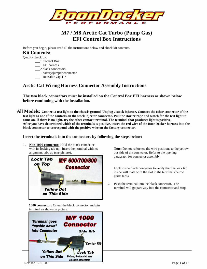
1. Non-1000 connector: Hold the black connector
with its locking tab up. Insert the terminal with its
alignment tabs up (see picture).
1000 connector: Orient the black connector and pin
terminal as shown in picture.
Note: Do not reference the wire positions to the yellow
dot side of the connector. Refer to the opening
paragraph for connector assembly.
Look inside black connector to verify that the lock tab
inside will mate with the slot in the terminal (below
guide tabs).
2. Push the terminal into the black connector. The
terminal will go part way into the connector and stop.
Revised 12-01-00 Page 2 of 15
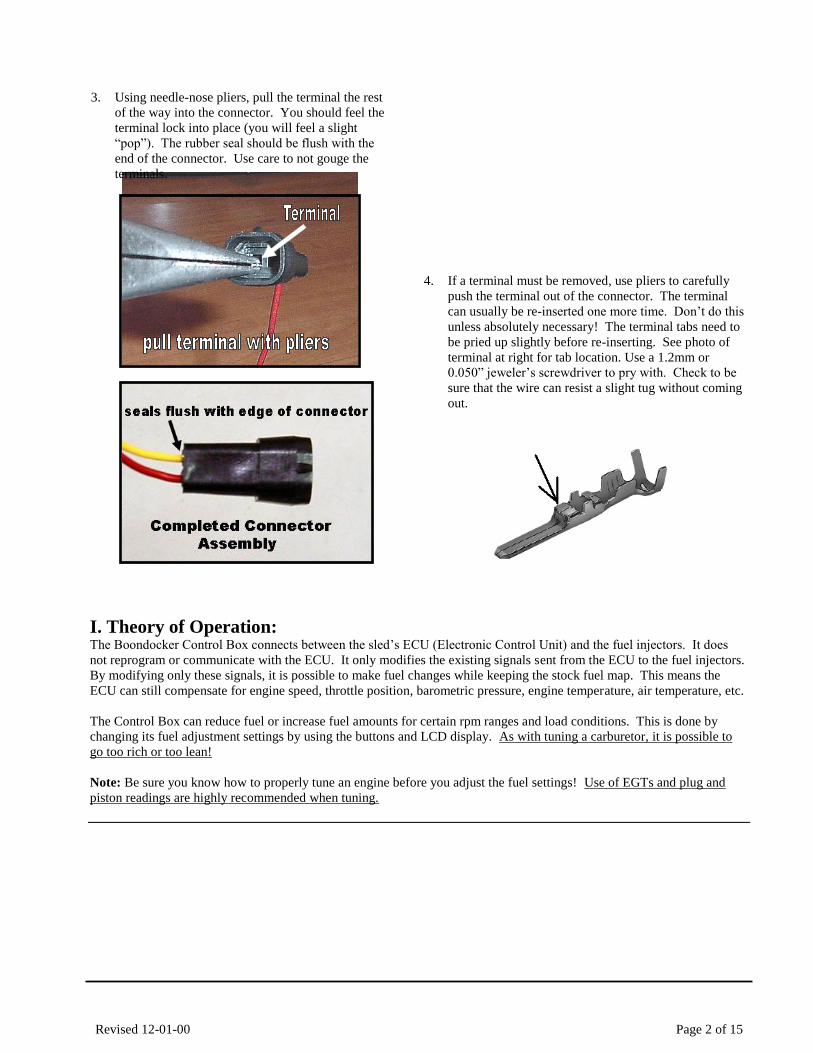
3. Using needle-nose pliers, pull the terminal the rest
of the way into the connector. You should feel the
terminal lock into place (you will feel a slight
“pop”). The rubber seal should be flush with the
end of the connector. Use care to not gouge the
terminals.
4. If a terminal must be removed, use pliers to carefully
push the terminal out of the connector. The terminal
can usually be re-inserted one more time. Don’t do this
unless absolutely necessary! The terminal tabs need to
be pried up slightly before re-inserting. See photo of
terminal at right for tab location. Use a 1.2mm or
0.050” jeweler’s screwdriver to pry with. Check to be
sure that the wire can resist a slight tug without coming
out.
I. Theory of Operation: The Boondocker Control Box connects between the sled’s ECU (Electronic Control Unit) and the fuel injectors. It does
not reprogram or communicate with the ECU. It only modifies the existing signals sent from the ECU to the fuel injectors.
By modifying only these signals, it is possible to make fuel changes while keeping the stock fuel map. This means the
ECU can still compensate for engine speed, throttle position, barometric pressure, engine temperature, air temperature, etc.
The Control Box can reduce fuel or increase fuel amounts for certain rpm ranges and load conditions. This is done by
changing its fuel adjustment settings by using the buttons and LCD display. As with tuning a carburetor, it is possible to
go too rich or too lean!
Note: Be sure you know how to properly tune an engine before you adjust the fuel settings! Use of EGTs and plug and
piston readings are highly recommended when tuning.
Revised 12-01-00 Page 3 of 15
IMPORTANT NOTES – READ THIS!
Note 1: We recommend using Dielectric Grease on all connections to help prevent corrosion on the terminals.
Note 2: Avoid exposing the Control Box to environments where static charges may exist. For example, quickly
removing a sled cover from the sled in a dry environment can create a static spark that will damage the box (especially if
box is mounted on handlebars).
Note 3: The Control Box is sealed – do not take it apart or it will no longer be sealed. The Control Box is designed to be
splash-proof. Do not submerge or subject the box to high-pressure spray. During long periods of non-use it is
recommended that you do not leave the control box exposed to the elements.
Note 4: If the headlights have been removed (hood is removed or aftermarket hood is used), the electrical system can
cause interference with the Control Box. In some cases, the sled’s computer may become damaged! We recommend
and sell a 100W power resistor that can be used to place a sufficient load on the electrical system to avoid this condition.
Note 5: Always use Resistor Spark Plugs! Non-resistor plugs will cause electrical interference with the Control Box.
II. Control Box Harness ConnectorsThe Control Box will plug directly into the factory injector connectors. There is also an unused connector for the optional
Nitrous wiring harness or for the battery jumper (see below).
Note: We recommend using Dielectric Grease on all connections to help prevent corrosion on the terminals.
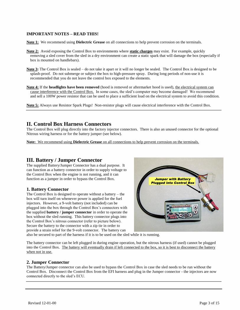
III. Battery / Jumper ConnectorThe supplied Battery/Jumper Connector has a dual purpose. It
can function as a battery connector in order to supply voltage to
the Control Box when the engine is not running, and it can
function as a jumper in order to bypass the Control Box.
1. Battery ConnectorThe Control Box is designed to operate without a battery – the
box will turn itself on whenever power is applied for the fuel
injectors. However, a 9-volt battery (not included) can be
plugged into the box through the Control Box’s connectors with
the supplied battery / jumper connector in order to operate the
box without the sled running. This battery connector plugs into
the Control Box’s nitrous connector (refer to picture below).
Secure the battery to the connector with a zip tie in order to
provide a strain relief for the 9-volt connector. The battery can
also be secured to part of the harness if it is to be used on the sled while it is running.
The battery connector can be left plugged in during engine operation, but the nitrous harness (if used) cannot be plugged
into the Control Box. The battery will eventually drain if left connected to the box, so it is best to disconnect the battery
when not in use.
2. Jumper ConnectorThe Battery/Jumper connector can also be used to bypass the Control Box in case the sled needs to be run without the
Control Box. Disconnect the Control Box from the EFI harness and plug in the Jumper connector - the injectors are now
connected directly to the sled’s ECU.
Revised 12-01-00 Page 4 of 15
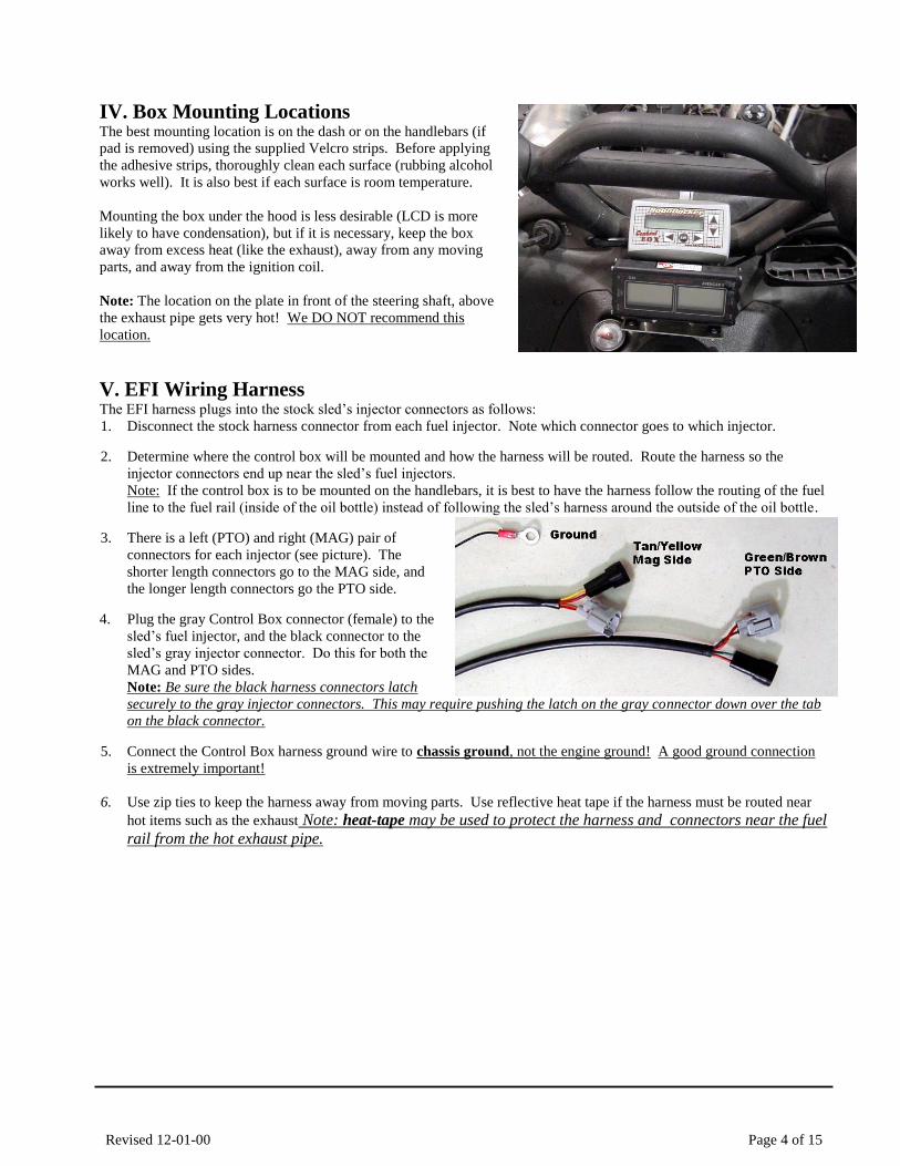
IV. Box Mounting LocationsThe best mounting location is on the dash or on the handlebars (if
pad is removed) using the supplied Velcro strips. Before applying
the adhesive strips, thoroughly clean each surface (rubbing alcohol
works well). It is also best if each surface is room temperature.
Mounting the box under the hood is less desirable (LCD is more
likely to have condensation), but if it is necessary, keep the box
away from excess heat (like the exhaust), away from any moving
parts, and away from the ignition coil.
Note: The location on the plate in front of the steering shaft, above
the exhaust pipe gets very hot! We DO NOT recommend this
location.
V. EFI Wiring Harness The EFI harness plugs into the stock sled’s injector connectors as follows:
1. Disconnect the stock harness connector from each fuel injector. Note which connector goes to which injector.
2. Determine where the control box will be mounted and how the harness will be routed. Route the harness so the
injector connectors end up near the sled’s fuel injectors.
Note: If the control box is to be mounted on the handlebars, it is best to have the harness follow the routing of the fuel
line to the fuel rail (inside of the oil bottle) instead of following the sled’s harness around the outside of the oil bottle.
3. There is a left (PTO) and right (MAG) pair of
connectors for each injector (see picture). The
shorter length connectors go to the MAG side, and
the longer length connectors go the PTO side.
4. Plug the gray Control Box connector (female) to the
sled’s fuel injector, and the black connector to the
sled’s gray injector connector. Do this for both the
MAG and PTO sides.
Note: Be sure the black harness connectors latch
securely to the gray injector connectors. This may require pushing the latch on the gray connector down over the tab
on the black connector.
5. Connect the Control Box harness ground wire to chassis ground, not the engine ground! A good ground connection
is extremely important!
6. Use zip ties to keep the harness away from moving parts. Use reflective heat tape if the harness must be routed near
hot items such as the exhaust Note: heat-tape may be used to protect the harness and connectors near the fuel
rail from the hot exhaust pipe.
Revised 12-01-00 Page 5 of 15
VII. Control Box Menus
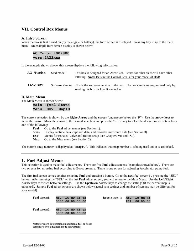
A. Intro Screen When the box is first turned on (by the engine or battery), the Intro screen is displayed. Press any key to go to the main
menu. An example Intro screen display is shown below:
AC Turbo 700/800
vers:5A22xxx
In the example shown above, this screen displays the following information:
AC Turbo Sled model This box is designed for an Arctic Cat. Boxes for other sleds will have other
lettering. Note: Be sure the Control Box is for your model of sled!
4A5dBDT Sofware Version This is the software version of the box. The box can be reprogrammed only by
sending the box back to Boondocker.
B. Main Menu The Main Menu is shown below:
Main Fuel Stats
Menu ExV Map1U
The current selection is shown by the Right-Arrow and the cursor (underscore below the “F”). Use the arrow keys to
move the cursor. Move the cursor to the desired selection and press the “SEL” key to select the desired menu option from
one of the following:
Fuel Go to the Fuel adjust menus (see Section 1).
Stats Display runtime data, captured data, and recorded maximum data (see Section 3).
ExV Menus for Exhaust Valve and Button setup (see Chapters VII and IX..).
Map Go to the Map menu (see Section 2)
The current Map number is displayed as “Map1U”. This indicates that map number 1 is being used and it is Unlocked.
1. Fuel Adjust MenusThis selection is used to make fuel adjustments. There are five Fuel adjust screens (examples shown below). There are
two screens for adjusting fuel according to Boost pressure. There is one screen for adjusting Accelerator pump fuel.
The first fuel screen comes up after selecting Fuel and pressing a button. Go to the next fuel screen by pressing the “SEL”
button. After pressing the “SEL” on the last Fuel adjust screen, you will return to the Main Menu. Use the Left/Right
Arrow keys to switch between settings. Use the Up/Down Arrow keys to change the settings (if the current map is
unlocked). Sample Fuel adjust screens are shown below (actual rpm settings and number of screens may be different for
your model).
Fuel screen1: M1L LO MD HI tr
3000 00 00 00 00
Fuel screen2: M1L LO MD HI tr
5000 00 00 00 00
Note: for more information on additional fuel or boost
screens refer to advanced mode instructions.
Boost screen1: M1L Lo Md Hi
PSI 00 00 00
Revised 12-01-00 Page 6 of 15
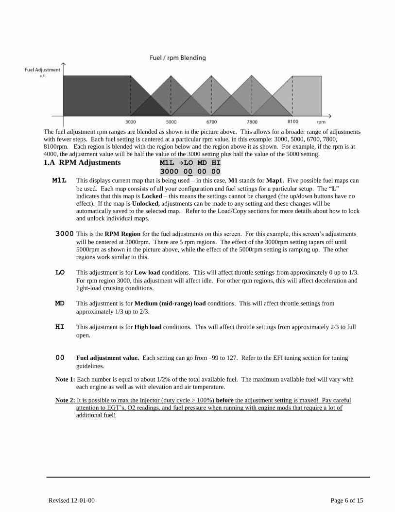
The fuel adjustment rpm ranges are blended as shown in the picture above. This allows for a broader range of adjustments
with fewer steps. Each fuel setting is centered at a particular rpm value, in this example: 3000, 5000, 6700, 7800,
8100rpm. Each region is blended with the region below and the region above it as shown. For example, if the rpm is at
4000, the adjustment value will be half the value of the 3000 setting plus half the value of the 5000 setting.
1.A RPM Adjustments M1L LO MD HI
3000 00 00 00
M1L This displays current map that is being used – in this case, M1 stands for Map1. Five possible fuel maps can
be used. Each map consists of all your configuration and fuel settings for a particular setup. The “L”
indicates that this map is Locked – this means the settings cannot be changed (the up/down buttons have no
effect). If the map is Unlocked, adjustments can be made to any setting and these changes will be
automatically saved to the selected map. Refer to the Load/Copy sections for more details about how to lock
and unlock individual maps.
3000 This is the RPM Region for the fuel adjustments on this screen. For this example, this screen’s adjustments
will be centered at 3000rpm. There are 5 rpm regions. The effect of the 3000rpm setting tapers off until
5000rpm as shown in the picture above, while the effect of the 5000rpm setting is ramping up. The other
regions work similar to this.
LO This adjustment is for Low load conditions. This will affect throttle settings from approximately 0 up to 1/3.
For rpm region 3000, this adjustment will affect idle. For other rpm regions, this will affect deceleration and
light-load cruising conditions.
MD This adjustment is for Medium (mid-range) load conditions. This will affect throttle settings from
approximately 1/3 up to 2/3.
HI This adjustment is for High load conditions. This will affect throttle settings from approximately 2/3 to full
open.
00 Fuel adjustment value. Each setting can go from –99 to 127. Refer to the EFI tuning section for tuning
guidelines.
Note 1: Each number is equal to about 1/2% of the total available fuel. The maximum available fuel will vary with
each engine as well as with elevation and air temperature.
Note 2: It is possible to max the injector (duty cycle > 100%) before the adjustment setting is maxed! Pay careful
attention to EGT’s, O2 readings, and fuel pressure when running with engine mods that require a lot of
additional fuel!
Revised 12-01-00 Page 7 of 15
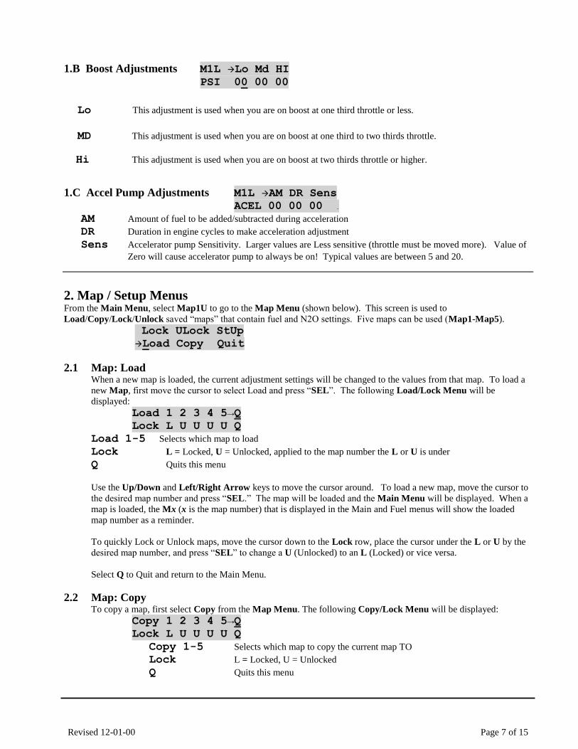
1.B Boost Adjustments M1L Lo Md HI
PSI 00 00 00
Lo This adjustment is used when you are on boost at one third throttle or less.
MD This adjustment is used when you are on boost at one third to two thirds throttle.
Hi This adjustment is used when you are on boost at two thirds throttle or higher.
1.C Accel Pump Adjustments M1L AM DR Sens
ACEL 00 00 00 .
AM Amount of fuel to be added/subtracted during acceleration
DR Duration in engine cycles to make acceleration adjustment
Sens Accelerator pump Sensitivity. Larger values are Less sensitive (throttle must be moved more). Value of
Zero will cause accelerator pump to always be on! Typical values are between 5 and 20.
2. Map / Setup MenusFrom the Main Menu, select Map1U to go to the Map Menu (shown below). This screen is used to
Load/Copy/Lock/Unlock saved “maps” that contain fuel and N2O settings. Five maps can be used (Map1-Map5).
Lock ULock StUp Load Copy Quit
2.1 Map: Load When a new map is loaded, the current adjustment settings will be changed to the values from that map. To load a
new Map, first move the cursor to select Load and press “SEL”. The following Load/Lock Menu will be
displayed:
Load 1 2 3 4 5→Q
Lock L U U U U Q Load 1-5 Selects which map to load
Lock L = Locked, U = Unlocked, applied to the map number the L or U is under
Q Quits this menu
Use the Up/Down and Left/Right Arrow keys to move the cursor around. To load a new map, move the cursor to
the desired map number and press “SEL.” The map will be loaded and the Main Menu will be displayed. When a
map is loaded, the Mx (x is the map number) that is displayed in the Main and Fuel menus will show the loaded
map number as a reminder.
To quickly Lock or Unlock maps, move the cursor down to the Lock row, place the cursor under the L or U by the
desired map number, and press “SEL” to change a U (Unlocked) to an L (Locked) or vice versa.
Select Q to Quit and return to the Main Menu.
2.2 Map: Copy To copy a map, first select Copy from the Map Menu. The following Copy/Lock Menu will be displayed:
Copy 1 2 3 4 5→Q
Lock L U U U U Q Copy 1-5 Selects which map to copy the current map TO
Lock L = Locked, U = Unlocked
Q Quits this menu
Revised 12-01-00 Page 8 of 15
This screen is used to save the CURRENT fuel adjustment map TO one of five available map locations. The map
that is being copied TO must be Unlocked – otherwise a message will be displayed telling you that the map you
selected cannot be overwritten.
Note: When a map is copied, the Control Box will load the map copied TO to be the new current map.
Use the Up/Down and Left/Right Arrow keys to move the cursor to the map number you want to copy TO and
press “SEL”. The following confirmation message will be displayed:
Overwrite Map A
With Map B? YN
“A” represents the map copied TO and “B” represents the current map to be copied FROM. If this is exactly what
you intend, use the Left Arrow to underscore “Y” and press “SEL”. Then the current map will be loaded into the
selected map number, the selected map number will become the current map, and the Control Box will return to the
Main Menu. To quickly Lock or Unlock maps, move the cursor down to the Lock row, place the cursor under the L or U by the
desired map number, and press “SEL” to change a U (Unlocked) to an L (Locked) or vice versa.
Select Q to Quit and return to the Main Menu.
2.3 Map – Lock and ULock Either Lock or ULock (UnLock) can be selected from the Map Menu to quickly lock or unlock the current map.
Move the cursor to the desired selection and press “SEL”. The box will return to the Main Menu and the current
map will be locked or unlocked when SEL is pressed.
3. Stats MenusThis Control Box has a new feature that allows real-time data to be displayed and captured. This feature can be useful for
tuning or for diagnostic purposes.
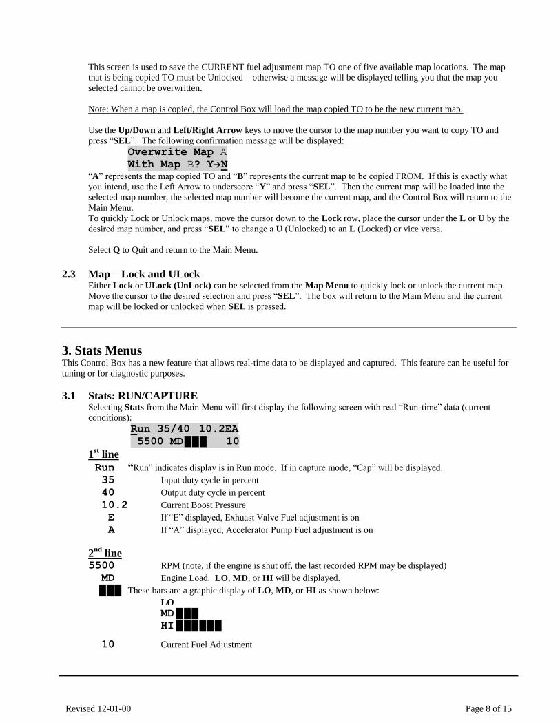
3.1 Stats: RUN/CAPTURE Selecting Stats from the Main Menu will first display the following screen with real “Run-time” data (current
conditions):
Run 35/40 10.2EA 5500 MD █ █ █ 10
1st line
Run “Run” indicates display is in Run mode. If in capture mode, “Cap” will be displayed.
35 Input duty cycle in percent
40 Output duty cycle in percent
10.2 Current Boost Pressure
E If “E” displayed, Exhuast Valve Fuel adjustment is on
A If “A” displayed, Accelerator Pump Fuel adjustment is on
2nd
line5500 RPM (note, if the engine is shut off, the last recorded RPM may be displayed)
MD Engine Load. LO, MD, or HI will be displayed.
█ █ █ These bars are a graphic display of LO, MD, or HI as shown below:
LO
MD █ █ █ HI █ █ █ █ █ █
10 Current Fuel Adjustment
Revised 12-01-00 Page 9 of 15
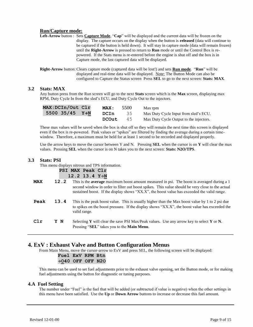
Run/Capture mode: Left-Arrow button : Sets Capture Mode, “Cap” will be displayed and the current data will be frozen on the
display. The capture occurs on the display when the button is released (data will continue to
be captured if the button is held down). It will stay in capture mode (data will remain frozen)
until the Right-Arrow is pressed to return to Run mode or until the Control Box is re-
powered. If the Stats menu is re-entered before the engine is shut off and the box is in
Capture mode, the last captured data will be displayed.
Right-Arrow button: Clears capture mode (captured data will be lost!) and sets Run mode. “Run” will be
displayed and real-time data will be displayed. Note: The Button Mode can also be
configured to Capture the Status screen Press SEL to go to the next screen: Stats: MAX.
3.2 Stats: MAX Any button press from the Run screen will go to the next Stats screen which is the Max screen, displaying max
RPM, Duty Cycle In from the sled’s ECU, and Duty Cycle Out to the injectors.
MAX:DCIn/Out Clr.
5500 35/45 YN.
MAX: 5500 Max rpm
DCIn 35 Max Duty Cycle Input from sled’s ECU.
DCOut 45 Max Duty Cycle Output to the injectors.
These max values will be saved when the box is shut off so they will remain the next time this screen is displayed
even if the box is re-powered. Peak values or “spikes” are filtered by finding the average during a certain time-
window. Therefore, a maximum must be held for at least 1 second to be recorded and displayed properly.
Use the arrow keys to move the cursor between Y and N. Pressing SEL when the cursor is on Y will clear the max
values. Pressing SEL when the cursor is on N takes you to the next screen: Stats: N2O/TPS.
3.3 Stats: PSI This menu displays nitrous and TPS information.
PSI MAX Peak Clr.
12.2 13.4 YN.
MAX 12.2 This is the average maximum boost amount measured in psi. The boost is averaged during a 1
second window in order to filter out boost spikes. This value should be very close to the actual
sustained boost. If the display shows “XX.X”, the boost value has exceeded the valid range.
Peak 13.4 This is the peak boost value. This is usually higher than the Max boost value by 1 to 2 psi due
to spikes on the boost pressure. If the display shows “XX.X”, the boost value has exceeded the
valid range.
Clr Y N Selecting Y will clear the save PSI Max/Peak values. Use any arrow key to select Y or N.
Pressing “SEL” takes you to the Main Menu.
4. ExV : Exhaust Valve and Button Configuration MenusFrom Main Menu, move the cursor-arrow to ExV and press SEL, the following screen will be displayed:
Fuel ExV RPM Btn
O40 OFF OFF N2O
This menu can be used to set fuel adjustments prior to the exhaust valve opening, set the Button mode, or for making
fuel adjustments using the button for diagnostic or tuning purposes.
4.A Fuel SettingThe number under “Fuel” is the fuel that will be added (or subtracted if value is negative) when the other settings in
this menu have been satisfied. Use the Up or Down Arrow buttons to increase or decrease this fuel amount.
Revised 12-01-00 Page 10 of 15
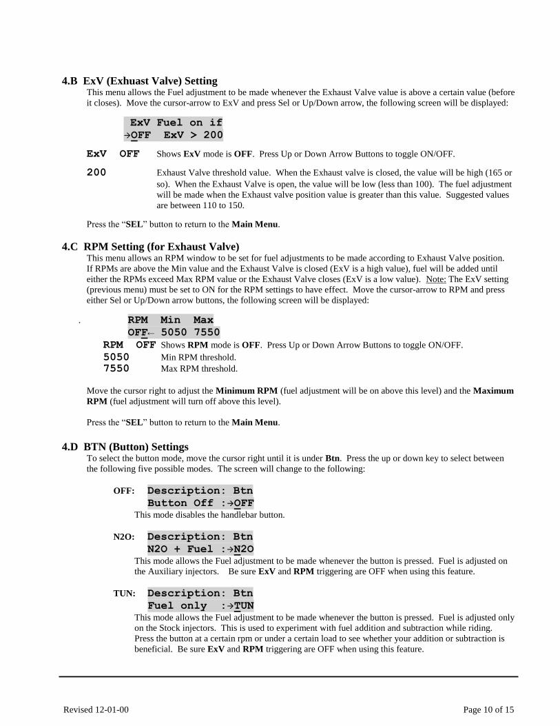
4.B ExV (Exhuast Valve) SettingThis menu allows the Fuel adjustment to be made whenever the Exhaust Valve value is above a certain value (before
it closes). Move the cursor-arrow to ExV and press Sel or Up/Down arrow, the following screen will be displayed:
ExV Fuel on if
OFF ExV > 200
ExV OFF Shows ExV mode is OFF. Press Up or Down Arrow Buttons to toggle ON/OFF.
200 Exhaust Valve threshold value. When the Exhaust valve is closed, the value will be high (165 or
so). When the Exhaust Valve is open, the value will be low (less than 100). The fuel adjustment
will be made when the Exhaust valve position value is greater than this value. Suggested values
are between 110 to 150.
Press the “SEL” button to return to the Main Menu.
4.C RPM Setting (for Exhaust Valve)This menu allows an RPM window to be set for fuel adjustments to be made according to Exhaust Valve position.
If RPMs are above the Min value and the Exhaust Valve is closed (ExV is a high value), fuel will be added until
either the RPMs exceed Max RPM value or the Exhaust Valve closes (ExV is a low value). Note: The ExV setting
(previous menu) must be set to ON for the RPM settings to have effect. Move the cursor-arrow to RPM and press
either Sel or Up/Down arrow buttons, the following screen will be displayed:
. RPM Min Max
OFF← 5050 7550
RPM OFF Shows RPM mode is OFF. Press Up or Down Arrow Buttons to toggle ON/OFF.
5050 Min RPM threshold.
7550 Max RPM threshold.
Move the cursor right to adjust the Minimum RPM (fuel adjustment will be on above this level) and the Maximum
RPM (fuel adjustment will turn off above this level).
Press the “SEL” button to return to the Main Menu.
4.D BTN (Button) SettingsTo select the button mode, move the cursor right until it is under Btn. Press the up or down key to select between
the following five possible modes. The screen will change to the following:
OFF: Description: Btn
Button Off :OFF This mode disables the handlebar button.
N2O: Description: Btn
N2O + Fuel :N2O
This mode allows the Fuel adjustment to be made whenever the button is pressed. Fuel is adjusted on
the Auxiliary injectors. Be sure ExV and RPM triggering are OFF when using this feature.
TUN: Description: Btn
Fuel only :TUN
This mode allows the Fuel adjustment to be made whenever the button is pressed. Fuel is adjusted only
on the Stock injectors. This is used to experiment with fuel addition and subtraction while riding.
Press the button at a certain rpm or under a certain load to see whether your addition or subtraction is
beneficial. Be sure ExV and RPM triggering are OFF when using this feature.
Revised 12-01-00 Page 11 of 15
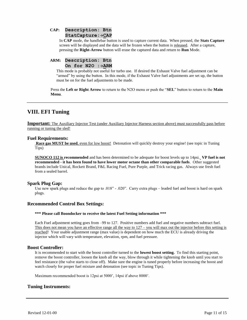
CAP: Description: Btn
StatCapture:CAP In CAP mode, the handlebar button is used to capture current data. When pressed, the Stats Capture
screen will be displayed and the data will be frozen when the button is released. After a capture,
pressing the Right-Arrow button will erase the captured data and return to Run Mode.
ARM: Description: Btn
On for N2O :ARM This mode is probably not useful for turbo use. If desired the Exhaust Valve fuel adjustment can be
“armed” by using the button. In this mode, if the Exhaust Valve fuel adjustments are set up, the button
must be on for the fuel adjustments to be made.
Press the Left or Right Arrow to return to the N2O menu or push the “SEL” button to return to the Main
Menu.
VIII. EFI Tuning
Important: The Auxiliary Injector Test (under Auxiliary Injector Harness section above) must successfully pass before
running or tuning the sled!
Fuel Requirements: Race gas MUST be used, even for low boost! Detonation will quickly destroy your engine! (see topic in Tuning
Tips)
SUNOCO 112 is recommended and has been determined to be adequate for boost levels up to 14psi. VP fuel is not
recommended - it has been found to have lower motor octane than other comparable fuels. Other suggested
brands include Unical, Rockett Brand, F&L Racing Fuel, Pure Purple, and Trick racing gas. Always use fresh fuel
from a sealed barrel.
Spark Plug Gap: Use new spark plugs and reduce the gap to .018” - .020”. Carry extra plugs – leaded fuel and boost is hard on spark
plugs.
Recommended Control Box Settings:
*** Please call Boondocker to receive the latest Fuel Setting information ***
Each Fuel adjustment setting goes from –99 to 127. Positive numbers add fuel and negative numbers subtract fuel.
This does not mean you have an effective range all the way to 127 – you will max out the injector before this setting is
reached! Your usable adjustment range (max value) is dependent on how much the ECU is already driving the
injector which will vary with temperature, elevation, rpm, and fuel pressure.
Boost Controller: It is recommended to start with the boost controller turned to the lowest boost setting. To find this starting point,
remove the boost controller, loosen the knob all the way, blow through it while tightening the knob until you start to
feel resistance (the valve starts to close off). Make sure the engine is tuned properly before increasing the boost and
watch closely for proper fuel mixture and detonation (see topic in Tuning Tips).
Maximum recommended boost is 12psi at 5000’, 14psi if above 8000’.
Tuning Instruments:
Revised 12-01-00 Page 12 of 15
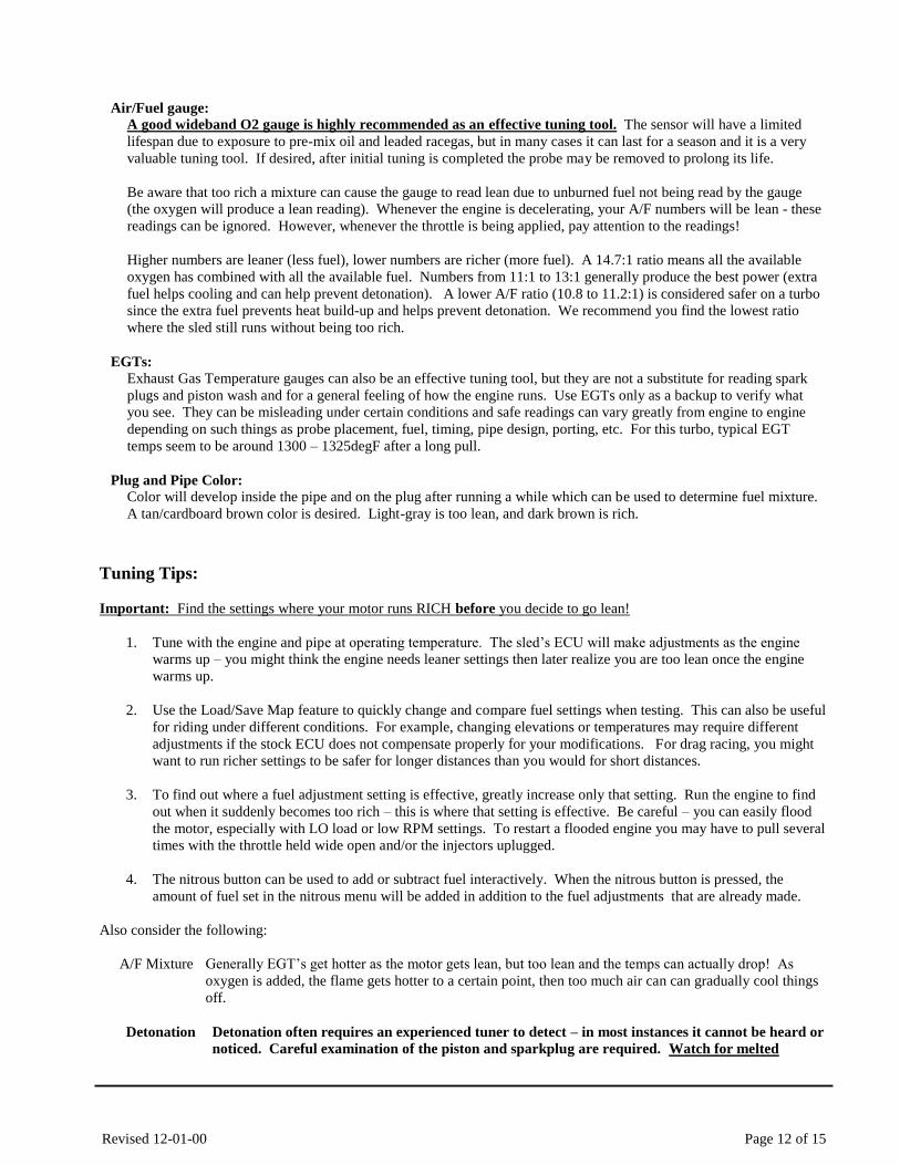
Air/Fuel gauge:
A good wideband O2 gauge is highly recommended as an effective tuning tool. The sensor will have a limited
lifespan due to exposure to pre-mix oil and leaded racegas, but in many cases it can last for a season and it is a very
valuable tuning tool. If desired, after initial tuning is completed the probe may be removed to prolong its life.
Be aware that too rich a mixture can cause the gauge to read lean due to unburned fuel not being read by the gauge
(the oxygen will produce a lean reading). Whenever the engine is decelerating, your A/F numbers will be lean - these
readings can be ignored. However, whenever the throttle is being applied, pay attention to the readings!
Higher numbers are leaner (less fuel), lower numbers are richer (more fuel). A 14.7:1 ratio means all the available
oxygen has combined with all the available fuel. Numbers from 11:1 to 13:1 generally produce the best power (extra
fuel helps cooling and can help prevent detonation). A lower A/F ratio (10.8 to 11.2:1) is considered safer on a turbo
since the extra fuel prevents heat build-up and helps prevent detonation. We recommend you find the lowest ratio
where the sled still runs without being too rich.
EGTs:
Exhaust Gas Temperature gauges can also be an effective tuning tool, but they are not a substitute for reading spark
plugs and piston wash and for a general feeling of how the engine runs. Use EGTs only as a backup to verify what
you see. They can be misleading under certain conditions and safe readings can vary greatly from engine to engine
depending on such things as probe placement, fuel, timing, pipe design, porting, etc. For this turbo, typical EGT
temps seem to be around 1300 – 1325degF after a long pull.
Plug and Pipe Color:
Color will develop inside the pipe and on the plug after running a while which can be used to determine fuel mixture.
A tan/cardboard brown color is desired. Light-gray is too lean, and dark brown is rich.
Tuning Tips:
Important: Find the settings where your motor runs RICH before you decide to go lean!
1. Tune with the engine and pipe at operating temperature. The sled’s ECU will make adjustments as the engine
warms up – you might think the engine needs leaner settings then later realize you are too lean once the engine
warms up.
2. Use the Load/Save Map feature to quickly change and compare fuel settings when testing. This can also be useful
for riding under different conditions. For example, changing elevations or temperatures may require different
adjustments if the stock ECU does not compensate properly for your modifications. For drag racing, you might
want to run richer settings to be safer for longer distances than you would for short distances.
3. To find out where a fuel adjustment setting is effective, greatly increase only that setting. Run the engine to find
out when it suddenly becomes too rich – this is where that setting is effective. Be careful – you can easily flood
the motor, especially with LO load or low RPM settings. To restart a flooded engine you may have to pull several
times with the throttle held wide open and/or the injectors uplugged.
4. The nitrous button can be used to add or subtract fuel interactively. When the nitrous button is pressed, the
amount of fuel set in the nitrous menu will be added in addition to the fuel adjustments that are already made.
Also consider the following:
A/F Mixture Generally EGT’s get hotter as the motor gets lean, but too lean and the temps can actually drop! As
oxygen is added, the flame gets hotter to a certain point, then too much air can can gradually cool things
off.
Detonation Detonation often requires an experienced tuner to detect – in most instances it cannot be heard or
noticed. Careful examination of the piston and sparkplug are required. Watch for melted
Revised 12-01-00 Page 13 of 15
sparkplug electrodes, speckling on the sparkplug insulator, or shiny or gray flakes on the
electrode which could be melted aluminum from the piston. If possible, watch the crown of the
piston (near exhaust port) for a pitted or sand-blasted look. EGT’s can sometimes read low
during detonation – heat is going into the cylinder and piston instead of out the pipe.
Timing Timing can affect the pipe temperature. Generally if the ignition is retarded, more heat will build up in
the pipe. Too much advance may drop EGT temps, but increase cylinder temps. Stock timing seems to
work best for this turbo.
Fuel Different fuels have different specific gravities (densities) and other characteristics which can affect
your mixture requirements from one fuel to another – be aware of this if you change fuels. Oxygenated
fuel will run leaner than non-oxygenated fuel and is not recommended.
Lean spots Sometimes a motor runs hot at certain rpms and throttle positions (usually in its mid-range) no matter
what. The fuel adjustment settings can be used to richen this up, but the engine may quickly become
too rich and run erratic. Under light load conditions you can sometimes get away with running hot for
short periods of time. Under such conditions it is best to vary the throttle position often and not stay at
one throttle setting for long durations.
IX. Control Box Troubleshooting
Stuck Button When the Control Box is first turned on, all buttons are checked to verify that a button is not stuck on. If a button is
detected to be on during power up, the button will be disabled and the following message will be displayed until
another button is pressed. To verify if a button really is stuck on, re-power the box without pressing any buttons.
Button is Stuck!
Note: A common problem is a bad ground connection on the sled causing the box to keep resetting itself. If a button
is being pressed when this occurs, the “button stuck” message will be displayed. Start the sled without pressing a
button and see if the message goes away. If it is not present, start looking for a disconnected ground on the sled (see
Other Issues below).
If a button really is stuck on, the Control Box can still function and adjust fuel properly. The Control Box can be sent
back to Boondocker to be serviced.
Injector Fault The Control Box monitors the signals from the sled’s ECU. If it detects signals on one set of wires but not the other, it
will detect a fault on that injector and display one of the two error messages.
MAG Inj. Fault! Missing or bad signal detected on the MAG side injector (yellow or tan wire).
PTO Inj. Fault! Missing or bad signal detected on the PTO side injector (green or brown wire).
xxx Inj. Fault! This means a previous injector fault has occurred which has not yet been
cleared.
If any of these conditions occur, the Control Box will still function and it will still try to make fuel adjustments, but
the intermittent injector connection will need to be fixed. Contact Boondocker to determine if the Control Box and
harness need to be sent back to be inspected or serviced.
Note 1: Injector errors that occur infrequently can be ignored since they are likely caused by sporadic electrical noise.

Revised 12-01-00 Page 14 of 15
Note 2: It is possible for the sled to run but the wiring harness to be wrong – the box cannot make proper fuel
adjustments. If you see an injector error, first recheck the wire positions in the black connectors according to
the tables in these instructions.
Other Issues
Engine runs erratic:
1. Verify that the ground on the sled’s harness (heavy brown wire) has a good connection to the chassis. On the M7
model, this ground is connected by an eyelet attached to the bolt at the base of the steering support hoop on the
Mag side of the sled (close to the gas tank)
Note: The nut that holds the ECU ground wire on M7 sleds is known to come loose!
2. Verify that the EFI Harness Ground Wire has a good connection.
Note1: Arctic Cats require that this ground wire on the Control Box must be connected to CHASSIS
GROUND (not Engine ground!).
Note2: If the headlights have been removed (hood is removed or aftermarket hood is used), the electrical
system can cause interference with the Control Box. We recommend using a 100W power resistor to place a
sufficient replacement load on the electrical system.
3. Verify that all wiring is in good condition and that the wires have not pulled out of the terminals. To verify this,
look inside each connector and verify that the terminal pins are all at the same height. If a terminal is starting to
back out, it will appear to be lower in the connector.
4. Unplug the EFI harness and plug original harness back into the injectors and verify that the sled runs OK (test can
only be done at low rpms before boost comes on).
5. If problem only occurs with Control Box plugged in, change all fuel adjustment settings to 0 and see if problem
persists.
6. Verify that the Control Box does not reset itself when the sled is running by doing the following:
a. When the sled is first powered up, change the menu screen on the Control Box to one of the fuel adjust
screens.
b. Run the sled.
c. Before shutting off the sled, verify that the screen is still on the same menu selection.
d. If the startup screen is displayed (showing version number etc.), the box has reset itself. This is likely
caused by bad voltage to the box due to an intermittent connection.
7. If necessary, the voltage supply to the box can be verified using a voltmeter. Probe from the Mag-side gray
connector on the EFI harness where two red wires go to one connector terminal. Insert a small thin wire such as a
paperclip or a small probe tip between the connector and the rubber seal in order to make contact with the terminal
inside. Place the positive voltmeter probe here. Place the negative voltmeter probe on chassis ground. At idle the
DC voltage should read around 19-21V. On the AC voltage setting, the reading should be less than 1V (this will
be much higher if an older analog-needle meter is used). A bad ground to the sled’s ECU will cause these
readings to be incorrect (DC readings around 7-9V).
Rough Idle Idle adjustments are much more sensitive than other adjustments since the injectors are on for a
very short duration. You may not be able to adjust your 3000 LO settings by very much.
LCD is dim If you are using a 9 volt battery to power the box when the sled is not running, your battery voltage
is getting low – replace your battery. Extreme hot or cold temperatures may cause the LCD to not
display properly.
LCD display is slow Cold weather conditions can make the LCD respond very slowly. The Control Box will still
function OK. You can locate the box under the hood in order to provide heat so the LCD will
display quicker.
Revised 12-01-00 Page 15 of 15
Moisture on LCD Condensation is normal if the Control Box is quickly moved from a cold to a warm environment.
In some cases, the Control Box enclosure may no longer be sealing properly. If such problems
persist, contact Boondocker to determine if resealing the box is necessary.
Check Engine light Make sure the wires in the EFI harness are correct and check for a bad connection in the wiring
harness. Recheck all connectors and be sure each is completely latched. Also inspect each wire to
make sure there are no frayed, broken, or melted wires.
Engine won’t start when Hot
A problem has been known to occur on some sleds involving the engine temperature sensor when
the engine is hot and especially after it has been sitting for a while (gets heat soaked). Unplug the
temp sensor (yellow connector located below where the rope goes into the recoil). Pull the engine
over once or twice – it usually pops. Then plug the sensor back in and the engine should operate
normal.
Another trick is to use the battery jumper to turn on the control box and set 3000 LO to +10 (to add
just enough fuel get the engine started), start the engine, then set it back to the original setting.
X. Warranty, Terms & Conditions Returned Goods – No merchandise will be accepted without prior approval. A RMA number (Return Merchandise
Authorization) provided by Boondocker is required before a return will be accepted. A 20% handling and restocking
charge will be applied to returned merchandise. No unauthorized returns will be accepted.
Limited Warranty – Boondocker warrants its product to the original purchaser against workmanship defects for a period
of 90 days, commencing from the date of product delivery to the Consumer.
Maximum Liability – The maximum liability of Boondocker in connection with this warranty shall not under any
circumstances exceed the price of the product claimed to be defective.