Embed Size (px)
Citation preview
machine design, Vol.5(2013) No.1, ISSN 1821-1259 pp. 57-60
*Correspondence Author’s Address: Department of Mechanical Engineering, TKIET, Shivaji University, Kolhapur. [email protected]
Research paper
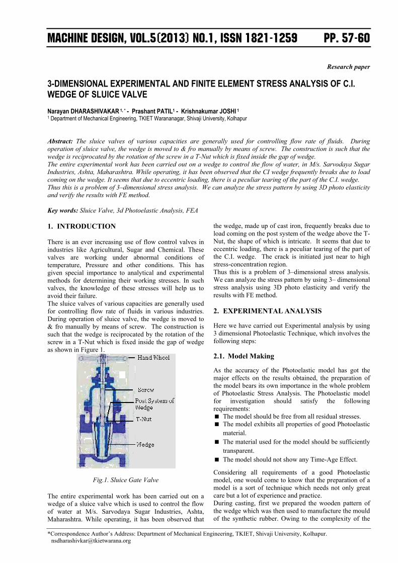
3-DIMENSIONAL EXPERIMENTAL AND FINITE ELEMENT STRESS ANALYSIS OF C.I. WEDGE OF SLUICE VALVE Narayan DHARASHIVAKAR 1, * - Prashant PATIL1 - Krishnakumar JOSHI 1
1 Department of Mechanical Engineering, TKIET Warananagar, Shivaji University, Kolhapur Abstract: The sluice valves of various capacities are generally used for controlling flow rate of fluids. During operation of sluice valve, the wedge is moved to & fro manually by means of screw. The construction is such that the wedge is reciprocated by the rotation of the screw in a T-Nut which is fixed inside the gap of wedge. The entire experimental work has been carried out on a wedge to control the flow of water, in M/s. Sarvodaya Sugar Industries, Ashta, Maharashtra. While operating, it has been observed that the CI wedge frequently breaks due to load coming on the wedge. It seems that due to eccentric loading, there is a peculiar tearing of the part of the C.I. wedge. Thus this is a problem of 3–dimensional stress analysis. We can analyze the stress pattern by using 3D photo elasticity and verify the results with FE method. Key words: Sluice Valve, 3d Photoelastic Analysis, FEA 1. INTRODUCTION There is an ever increasing use of flow control valves in industries like Agricultural, Sugar and Chemical. These valves are working under abnormal conditions of temperature, Pressure and other conditions. This has given special importance to analytical and experimental methods for determining their working stresses. In such valves, the knowledge of these stresses will help us to avoid their failure. The sluice valves of various capacities are generally used for controlling flow rate of fluids in various industries. During operation of sluice valve, the wedge is moved to & fro manually by means of screw. The construction is such that the wedge is reciprocated by the rotation of the screw in a T-Nut which is fixed inside the gap of wedge as shown in Figure 1.
Fig.1. Sluice Gate Valve
The entire experimental work has been carried out on a wedge of a sluice valve which is used to control the flow of water at M/s. Sarvodaya Sugar Industries, Ashta, Maharashtra. While operating, it has been observed that
the wedge, made up of cast iron, frequently breaks due to load coming on the post system of the wedge above the T-Nut, the shape of which is intricate. It seems that due to eccentric loading, there is a peculiar tearing of the part of the C.I. wedge. The crack is initiated just near to high stress-concentration region. Thus this is a problem of 3–dimensional stress analysis. We can analyze the stress pattern by using 3– dimensional stress analysis using 3D photo elasticity and verify the results with FE method. 2. EXPERIMENTAL ANALYSIS
Here we have carried out Experimental analysis by using 3 dimensional Photoelastic Technique, which involves the following steps: 2.1. Model Making
As the accuracy of the Photoelastic model has got the major effects on the results obtained, the preparation of the model bears its own importance in the whole problem of Photoelastic Stress Analysis. The Photoelastic model for investigation should satisfy the following requirements: The model should be free from all residual stresses. The model exhibits all properties of good Photoelastic
material. The material used for the model should be sufficiently
transparent. The model should not show any Time-Age Effect.
Considering all requirements of a good Photoelastic model, one would come to know that the preparation of a model is a sort of technique which needs not only great care but a lot of experience and practice. During casting, first we prepared the wooden pattern of the wedge which was then used to manufacture the mould of the synthetic rubber. Owing to the complexity of the
Narayan Dharashivakar, Prashant Patil, Krishnakumar Joshi: 3-Dimensional Experimental and Finite Element Stress Analysis of C.I. Wedge of Sluice Valve; Machine Design, Vol.5(2013) No.1, ISSN 1821-1259; pp. 57-60
58
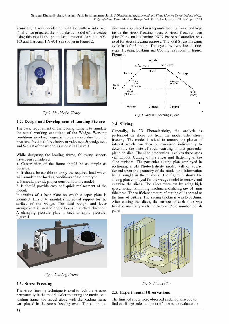
geometry, it was decided to split the pattern into two. Finally, we prepared the photoelastic model of the wedge using this mould and photoelastic material (Araldite AY-103 and Hardener HY-951.) as shown in Figure 2.
Fig.2. Mould of a Wedge 2.2. Design and Development of Loading Fixture
The basic requirement of the loading frame is to simulate the actual working conditions of the Wedge. Working conditions involve, tangential force caused due to fluid pressure, frictional force between valve seat & wedge seat and Weight of the wedge, as shown in Figure 3 While designing the loading frame, following aspects have been considered: a. Construction of the frame should be as simple as possible. b. It should be capable to apply the required load which will simulate the loading conditions of the prototype. c. It should provide proper constraint to the model. d. It should provide easy and quick replacement of the model. It consists of a base plate on which a taper plate is mounted. This plate simulates the actual support for the surface of the wedge. The dead weight and lever arrangement is used to apply forces in vertical direction. A clamping pressure plate is used to apply pressure. Figure 4
Fig.4. Loading Frame
2.3. Stress Freezing
The stress freezing technique is used to lock the stresses permanently in the model. After mounting the model on a loading frame, the model along with the loading frame was placed in the stress freezing oven. The calibration
disc was also placed in a separate loading frame and kept inside the stress freezing oven. A stress freezing oven (Han-Yong make) having PX09 Process Controller was used for stress freezing purpose. The total Stress Freezing cycle lasts for 34 hours. This cycle involves three distinct steps, Heating, Soaking and Cooling, as shown in figure. Figure 5.
Fig.5. Stress Freezing Cycle
2.4. Slicing
Generally, in 3D Photoelasticity, the analysis is performed on slices cut from the model after stress freezing. The model is sliced to remove the planes of interest which can then be examined individually to determine the state of stress existing in that particular plane or slice. The slice preparation involves three steps viz. Layout, Cutting of the slices and flattening of the slice surfaces. The particular slicing plan employed in sectioning a 3D Photoelasticity model will of course depend upon the geometry of the model and information being sought in the analysis. The figure 6 shows the slicing plan employed for the wedge model to remove and examine the slices. The slices were cut by using high speed horizontal milling machine and slicing saw of 1mm thickness. The sufficient amount of cutting oil is spread at the time of cutting. The slicing thickness was kept 3mm. After cutting the slices, the surface of each slice was finished manually with the help of Zero number polish paper.
Fig.6. Slicing Plan
2.5. Experimental Observations
The finished slices were observed under polariscope to find out fringe order at a point of interest to evaluate the
Narayan Dharashivakar, Prashant Patil, Krishnakumar Joshi: 3-Dimensional Experimental and Finite Element Stress Analysis of C.I. Wedge of Sluice Valve; Machine Design, Vol.5(2013) No.1, ISSN 1821-1259; pp. 57-60
59
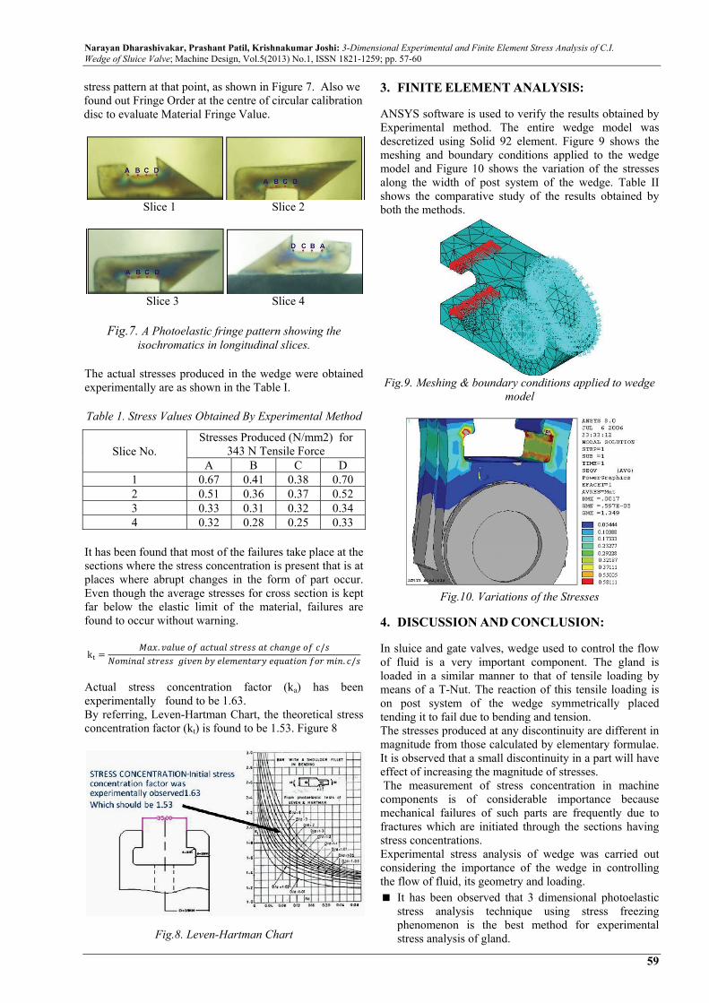
stress pattern at that point, as shown in Figure 7. Also we found out Fringe Order at the centre of circular calibration disc to evaluate Material Fringe Value.
Slice 1 Slice 2
Slice 3 Slice 4
Fig.7. A Photoelastic fringe pattern showing the isochromatics in longitudinal slices.
The actual stresses produced in the wedge were obtained experimentally are as shown in the Table I. Table 1. Stress Values Obtained By Experimental Method
Slice No. Stresses Produced (N/mm2) for
343 N Tensile ForceA B C D
1 0.67 0.41 0.38 0.70 2 0.51 0.36 0.37 0.52 3 0.33 0.31 0.32 0.34 4 0.32 0.28 0.25 0.33
It has been found that most of the failures take place at the sections where the stress concentration is present that is at places where abrupt changes in the form of part occur. Even though the average stresses for cross section is kept far below the elastic limit of the material, failures are found to occur without warning. k
. / . /
Actual stress concentration factor (ka) has been experimentally found to be 1.63. By referring, Leven-Hartman Chart, the theoretical stress concentration factor (kt) is found to be 1.53. Figure 8
Fig.8. Leven-Hartman Chart
3. FINITE ELEMENT ANALYSIS:
ANSYS software is used to verify the results obtained by Experimental method. The entire wedge model was descretized using Solid 92 element. Figure 9 shows the meshing and boundary conditions applied to the wedge model and Figure 10 shows the variation of the stresses along the width of post system of the wedge. Table II shows the comparative study of the results obtained by both the methods.
Fig.9. Meshing & boundary conditions applied to wedge
model
Fig.10. Variations of the Stresses
4. DISCUSSION AND CONCLUSION:
In sluice and gate valves, wedge used to control the flow of fluid is a very important component. The gland is loaded in a similar manner to that of tensile loading by means of a T-Nut. The reaction of this tensile loading is on post system of the wedge symmetrically placed tending it to fail due to bending and tension. The stresses produced at any discontinuity are different in magnitude from those calculated by elementary formulae. It is observed that a small discontinuity in a part will have effect of increasing the magnitude of stresses. The measurement of stress concentration in machine components is of considerable importance because mechanical failures of such parts are frequently due to fractures which are initiated through the sections having stress concentrations. Experimental stress analysis of wedge was carried out considering the importance of the wedge in controlling the flow of fluid, its geometry and loading. It has been observed that 3 dimensional photoelastic
stress analysis technique using stress freezing phenomenon is the best method for experimental stress analysis of gland.
Narayan Dharashivakar, Prashant Patil, Krishnakumar Joshi: 3-Dimensional Experimental and Finite Element Stress Analysis of C.I. Wedge of Sluice Valve; Machine Design, Vol.5(2013) No.1, ISSN 1821-1259; pp. 57-60
60
Low temperature curing epoxy mixture is a good material for casting such type of component. Good castings can be obtained by using silicon rubber molds.
Only longitudinal slices are helpful in exhibiting the stress pattern in the wedge.
The stress concentration factor at stress concentration region is observed to be more that theoretically required.
Referring to Figure 8 and 11, it is observed that stress concentration factor goes on reducing with r/d ratio.
If we neglect tensile stresses created by bending at inner edge, there is fairly good agreement between theoretical, experimental and FE analysis as in Table 2.
There seems to be condition of impact between the surface of T-Nut and that of post system of wedge as there is a gap of 3-4mm between these two. The failure may be because of the impact of T-Nut on surface of wedge.
Fig.11. Variation of Stress concentration factor with r/D ratio
Table 2. Stresses Produced (N/mm2) for 343 N Tensile Force
Slice No.
A B
*E *A *V *E *A *V
1 0.67 0.58 18 0.41 0.37 10
2 0.51 0.42 18 0.36 0.32 11
3 0.33 0.29 12 0.31 0.37 16
4 0.32 0.29 09 0.28 0.32 14
Slice No.
C D
*E *A *V *E *A *V
1 0.38 0.32 16 0.70 0.58 17
2 0.37 0.32 14 0.52 0.40 19
3 0.32 0.34 09 0.34 0.29 15
4 0.25 0.32 20 0.33 0.37 12
*E: Experimental Value
*A: ANSYS Value
*V: Variation in Percentage
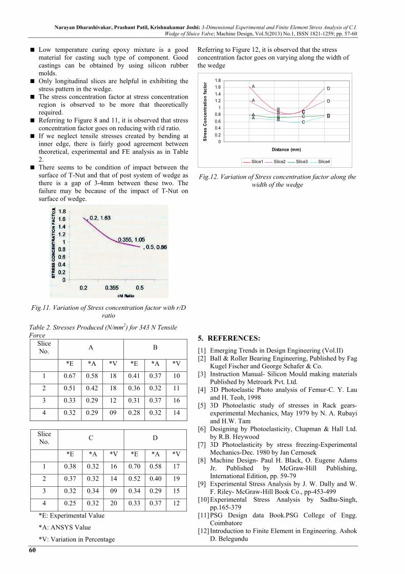
Referring to Figure 12, it is observed that the stress concentration factor goes on varying along the width of the wedge Fig.12. Variation of Stress concentration factor along the
width of the wedge
5. REFERENCES:
[1] Emerging Trends in Design Engineering (Vol.II) [2] Ball & Roller Bearing Engineering, Published by Fag
Kugel Fischer and George Schafer & Co. [3] Instruction Manual- Silicon Mould making materials
Published by Metroark Pvt. Ltd. [4] 3D Photoelastic Photo analysis of Femur-C. Y. Lau
and H. Teoh, 1998 [5] 3D Photoelastic study of stresses in Rack gears-
experimental Mechanics, May 1979 by N. A. Rubayi and H.W. Tam
[6] Designing by Photoelasticity, Chapman & Hall Ltd. by R.B. Heywood
[7] 3D Photoelasticity by stress freezing-Experimental Mechanics-Dec. 1980 by Jan Cernosek
[8] Machine Design- Paul H. Black, O. Eugene Adams Jr. Published by McGraw-Hill Publishing, International Edition, pp. 59-79
[9] Experimental Stress Analysis by J. W. Dally and W. F. Riley- McGraw-Hill Book Co., pp-453-499
[10] Experimental Stress Analysis by Sadhu-Singh, pp.165-379
[11] PSG Design data Book.PSG College of Engg. Coimbatore
[12] Introduction to Finite Element in Engineering. Ashok D. Belegundu
A
B C
D
A
B C
D
A B C DA B CD
0
0.2
0.4
0.6
0.8
1
1.2
1.4
1.6
1.8
Distance (mm)
Str
ess
Co
nce
ntr
atio
n f
acto
r
Slice1 Slice2 Slice3 Slice4