Embed Size (px)
Citation preview

1
Machine-learning-based nonlinear decomposition ofCT images for metal artifact reduction
Hyung Suk Park∗, Sung Min Lee†, Hwa Pyung Kim†, and Jin Keun Seo†∗ Division of Strategic Research, National Institute for Mathematical Sciences, Daejeon, 34047, South Korea† Department of Computational Science and Engineering, Yonsei University, Seoul, 120-749, South Korea
Abstract—Computed tomography (CT) images containingmetallic objects commonly show severe streaking and shadowartifacts. Metal artifacts are caused by nonlinear beam-hardeningeffects combined with other factors such as scatter and Poissonnoise. In this paper, we propose an implant-specific methodthat extracts beam-hardening artifacts from CT images with-out affecting the background image. We found that in caseswhere metal is inserted in the water (or tissue), the generatedbeam-hardening artifacts can be approximately extracted bysubtracting artifacts generated exclusively by metals. We useda deep learning technique to train nonlinear representationsof beam-hardening artifacts arising from metals, which appearas shadows and streaking artifacts. The proposed network isnot designed to identify ground-truth CT images (i.e., the CTimage before its corruption by metal artifacts). Consequently,these images are not required for training. The proposed methodwas tested on a dataset consisting of real CT scans of pelvisescontaining simulated hip prostheses. The results demonstrate thatthe proposed deep learning method successfully extracts bothshadowing and streaking artifacts.
Index Terms—Computerized tomography, Metal artifact re-duction, Beam hardening, Deep learning.
I. INTRODUCTION
X-ray computed tomography (CT) provides tomographicimages of the human body by assigning an X-ray attenuationcoefficient to each pixel, using sinogram data (i.e., X-ray datacollected at all angles around the object). The reconstructionmethods used for CT images are based on a linear assumptionof the sinogram data: namely, the Radon transform of animage. However, this assumption of linearity is violated inthe presence of highly attenuating materials such as metalimplants (e.g., hip replacements, dental fillings, surgical clips,and pacemaker wires) in the CT scan field. These discrepanciesin the linear model are mainly caused by beam-hardeningeffects, which are associated with the polychromatic natureof the X-ray beam and the energy-dependent variations inthe attenuation coefficients of highly attenuating materials.The inconsistent sinogram data attributable to these beam-hardening effects do not match the Radon transform of anyattenuation coefficient distribution. Consequently, metallic ar-tifacts seriously degrade the CT images of patients with metalimplants.
Because metallic implants are increasingly popular, thereis a growing demand for metal artifact reduction (MAR) indentistry and medicine. Despite numerous efforts to develop
Manuscript received XXX; revised XXX. Corresponding author: S. M. Lee(email: [email protected]).
MAR methods in the last four decades, it remains a verychallenging problem because of the difficulties presented bythe nonlinear effects that arise from the geometry of high-attenuation materials, polychromatic X-ray beams, and relatedartifacts, together with Compton scattering, photon noise, andso on. Existing MAR methods include dual-energy CT [1],statistical iterative-reconstruction methods [6], [7], [18], [21],[30], data completion/inpainting-based methods [3], [12], [16],[19], [22], [24], [27], and hybrid methods [15]. However,several current methods produce new artifacts that are notpresent before the application of the method [19], [20].
In this paper, we propose a deep learning method forimplant-specific MAR that extracts beam-hardening artifactsfrom CT images. In cases where metal inserts are placedinside of tissue (or water), we found that metal-induced beam-hardening artifacts can be approximately extracted by sub-tracting artifacts generated exclusively by metal inserts. Withthis observation, the proposed MAR method takes advantageof training with metal-only images to extract features of thebeam-hardening artifacts.
Because beam-hardening artifacts depend on the metalgeometry, energy dependency of the attenuation coefficient,and the spectrum of the incident X-ray beam, the number ofvariations is too great to allow the features to be learned. Thisobstacle is dealt with by incorporating prior knowledge of thegeometry of the metallic objects. Indeed, the geometry andmaterial information of implants such as hip replacements andendovascular stents are usually known. With this knowledgeof the scanned metal, we adopt a multi-scale convolutionalnetwork, called U-net [28], to train the model using metal-only images.
In the presence of metallic objects, no ground-truth CTimages (i.e., CT images before corruption by metal artifacts)are available. In such cases, they cannot be used as label datafor learning. The proposed method does not require ground-truth image, insofar as it learns artifacts generated exclusivelyby metal, rather than artifact-free CT images.
We explore the feasibility of applying a deep learningapproach to MAR using a dataset consisting of real CTscan of pelvises containing two simulated hip prostheses. Theresults demonstrate that the proposed deep learning methodsuccessfully extracts both shadowing and streaking artifacts.
II. METHOD
Considering a two-dimensional parallel beam, we define X-ray data for a polychromatic X-ray along the rotation direction
arX
iv:1
708.
0024
4v1
[ph
ysic
s.m
ed-p
h] 1
Aug
201
7
2
(cosϕ, sinϕ), ϕ ∈ [0, 2π) as
Pf (ϕ, s) = − ln
(ˆ E
0
η(E)e−RfE(ϕ,s)dE
), (1)
where fE(x) denotes the distribution of the attenuation co-efficient at position x = (x1, x2) and at energy level E,η(E) represents the fractional energy at photon energy Ein the spectrum of the X-ray source [11], [25], that is,´ E
0η(E)dE = 1, and R denotes the Radon transform [26].
The most widely used reconstruction method for CT is thefiltered backprojection algorithm (FBP):
fCT(x) := R−1Pf (x), (2)
where R−1 denotes the filtered backprojection operator [4].
A. Metal-induced beam-hardening artifact extraction
In this section, we propose a method of extracting beam-hardening artifacts arising from metallic objects from themeasured fCT. Let the cross-sectional slice to be scannedoccupy a domain Ω. Assume that fE can be expressed as
fE(x) = µt(E)χDt
(x) + µm(E)χDm
(x), x ∈ Ω, (3)
where µt and µm denote the linear attenuation coefficients oftissue and the metal in the domain Dt, Dm ⊂ Ω, respectively.Here, χD denotes the characteristic function, which is 1 inthe region D and 0, otherwise. Let Pfm , Pft be the projectiondata for metal and tissue given by
Pfm(ϕ, s) = − ln
(ˆ E
0
η(E)e−µm(E)RχDm
(ϕ,s)dE
), (4)
and
Pft(ϕ, s) = − ln
(ˆ E
0
η(E)e−µt(E)Rχ
Dt(ϕ,s)
dE
), (5)
respectively. Let fm and f t be the CT images for Pfm andPft , respectively. The following observation expresses theextraction of metal artifacts (fm) from fCT (see also Fig.1):
Observation 2.1: Let Dm be a homogeneous metal regioninserted in the tissue. Then, the fCT in (2) can be approxi-mately decomposed into
fCT(x) ≈ τχDm
(x) + f t(x) + γfm(x), (6)
where τ, γ are the constants depending on the distribution ofµm and µt. In the absence of tissue, that is, f t(x) = 0, forall x ∈ Ω, τ = 0 and γ = 1 .
Figure 1 illustrates Observation 2.1. Fig. 1(a) shows a phan-tom consisting of water and two cylinders filled with highlyattenuating fluid. The fluid consists of iodinated contrast mediaand saline. Fig. 1(b) shows the corresponding fCT obscuredby artifacts arising from this fluid. Figs. 1(c) and (d) showfm and fCT − γfm with γ = 0.4, respectively. Fig. 1(d)shows that the beam-hardening artifacts are almost completelyremoved from fCT. In addition, because fm is subtracted fromfCT, streaking artifacts due to under-sampling are significantlyreduced. In this experiment, CT images were acquired from
Fig. 1. Illustration of Observation 2.1: (a) water phantom consisting of waterand two cylinders filled with highly attenuating fluid; (b) reconstructed imagefCT; (c) metal-induced artifact fm; and (d) fCT − γfm with γ = 0.4.(C=-1000 HU/W=4000 HU for CT images.)
an industrial CT scanner (DUKIN, Korea) with an X-ray tubevoltage of 100 kV and a tube current of 12 mA.
Now, let us discuss the meaning of Observation 2.1. Equa-tion (6) implies that for all X-rays passing through metallicobjects, two µm at mean beam energies in the presenceand absence of tissue have a nearly-linear relationship. Morespecifically, the projection data corresponding to (6) is givenby
Pf (ϕ, s) ≈ τRχDm
(ϕ, s) + Pft(ϕ, s) + γPfm(ϕ, s). (7)
Because´ E
0η(E)dE = 1, it follows from the mean value
theorem for integration that for each (ϕ, s) ∈ [0, 2π) × R,there exists Ecϕ,s, E
mϕ,s ∈ [0, E], such that
ˆ E
0
η(E)e−µm(E)Rχ
Dm(ϕ,s)−µt(E)Rχ
Dt(ϕ,s)
dE
= e−µm(Ecϕ,s)Rχ
Dm(ϕ,s)
ˆ E
0
η(E)e−µt(E)Rχ
Dt(ϕ,s)
dE
(8)
andˆ E
0
η(E)e−µm(E)RχDm
(ϕ,s)dE = e−µm(Emϕ,s)Rχ
Dm(ϕ,s).
(9)
It follows from (8) and (9) that (7) can be expressed as
µm(Ecϕ,s)RχDm(ϕ, s) (10)
≈ τRχDm
(ϕ, s) + γ µm(Emϕ,s)RχDm(ϕ, s). (11)

3
This leads to
µm(Ecϕ,s) ≈ γµm(Emϕ,s) + τ, for (ϕ, s) ∈ supp(RχDm
)(12)
where supp(RχDm
) denotes the support of RχDm
, definedas (ϕ, s) ∈ [0, 2π)× R : Rχ
Dm(ϕ, s) 6= 0.
We show convincing evidence from numerical simulationthat the relation in Equation (12) is valid. Fig. 2 (a) showsthe CT image with a water phantom containing two metallicobjects (viz., titanium). Fig. 2 (c) shows the plot of µm(Ecϕ,s)along the y-axis versus the corresponding µm(Emϕ,s) along thex-axis. As shown in Fig. 2 (c), these two variables satisfy anearly linear relationship for all (ϕ, s) ∈ [0, 2π) × R. Thisrelation can be approximated by the line γµm(Emϕ,s) + τ withγ = 0.65 and τ = 0.051, and the corresponding reconstructedimage fCT − γfm almost completely removes the metal-induced beam-hardening artifacts, as shown in Fig. 2 (b). Inthis simulation, µm(Ecϕ,s) and µm(Emϕ,s) were computed fromthe relation of (8) and (9), which, for (ϕ, s) ∈ supp(Rχ
Dm),
is given by
µm(Ecϕ,s) =Pf (ϕ, s)− Pft(ϕ, s)
RχDm
(ϕ, s), (13)
and
µm(Emϕ,s) =Pfm(ϕ, s)
RχDm
(ϕ, s), (14)
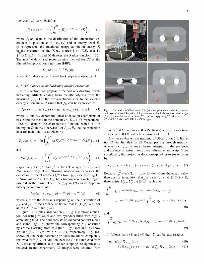
respectively. Note that there remain streaking artifacts alongthe X-ray line passing through both two titanium inserts. Thisis because of photon starvation [2]. We placed three titaniuminserts, one iron insert, and one bone insert, all of differentshapes and sizes, inside of water phantom, as shown in Fig. 3(a). The relation (6) in Observation 2.1 seems to be valid formore complex metallic inserts; beam-hardening artifacts areeffectively extracted by subtracting fm from fCT. However,the beam-hardening artifacts in fm cannot deal with artifactsbetween metallic inserts and bone. These still remain in fCT−γfm, as shown in Fig. 3 (c). More careful analysis is neededto deal with such artifacts.
In order to extract fm from the measured fCT, fm canbe computed numerically from (4). This requires the domainoccupying the metallic region Dm, the X-ray spectrum η, andthe linear attenuation coefficient of the metal object µm in[0, E]. However, the information regarding η and µm mightnot be (accurately) provided for commercial CT scanners andscanned metallic inserts. Moreover, discretization methods forintegrating (4) can lead to discretization errors. Alternatively,in the following we apply a deep convolutional neural network(CNN) technique to estimate fm directly.
B. Deep learning method for generating metal beam-hardening artifacts
To learn the features of metal-induced beam-hardening arti-facts, we need to consider a suitable dataset and CNN. Becausefm depends on the metal geometry, the energy distribution ofthe X-ray beam, and the incident X-ray spectrum, the numberof variations is too great to allow the features to be learned.
Fig. 2. (a) fCT for water phantom containing two metallic inserts (titanium);(b) fCT − γfm with γ = 0.65 and τ = 0.051; and (c) µm(Ec
ϕ,s)-µm(Em
ϕ,s) plot for the phantom in (a)
Hence, it is crucial to choose an input image that takes intoaccount such information.
Recently, Park et al showed that fm can be approximatedby the nonlinear function gm, given as [23]
gm(x) = −R−1
[ln
(sinh(λRχ
Dm)
λRχDm
)](x) + cχ
Dm(x),
(15)
where λ is the parameter depending on µm and η, and cis some constant. In other words, the measured fm from aCT scan can be approximated without the use of any priorknowledge of µm and η.
In our deep learning network, the goal is to learn the mapfrom the formula-based artifact gm to the corresponding trueartifact fm. We used a labeled dataset (gmi , fmi ) : i =1, 2, · · · to find the map, Υ : gm 7→ fm, that minimizesthe L2 error Err(Υ), given by
Err(Υ) = ‖fm −Υ(gm)‖2L2(R2). (16)
We apply a multi-scale convolutional network, called U-net, toestimate Υ. Unlike traditional deep CNNs [13], this networkdoes not have a fully connected layer. Hence, U-net can learnlarge-scale input images (i.e., gm). In addition, simulationresults show that this multi-scale network can efficiently learnglobal features such as streaking [9], [10].
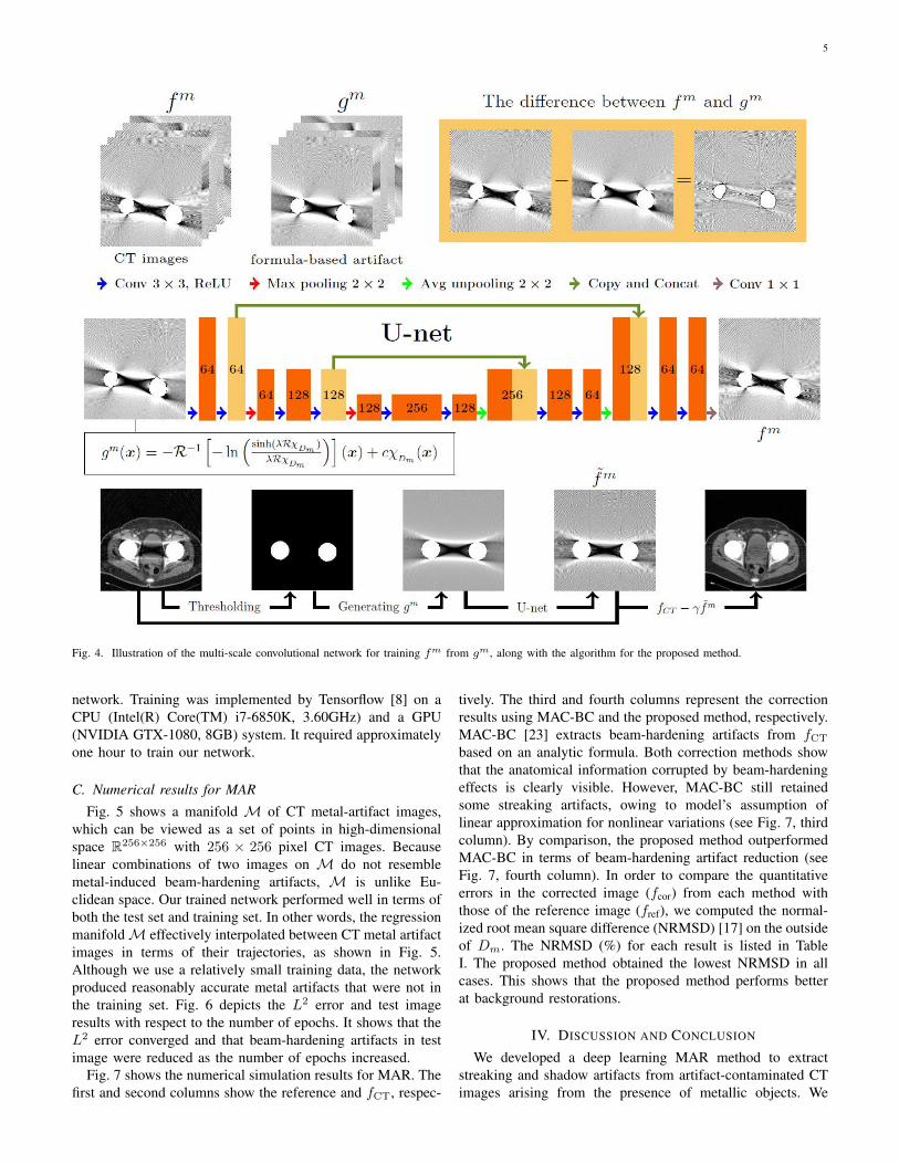
The architecture of the multi-scale convolutional networkis shown in Fig. 4. The architecture consists of a contractingpath and an expansive path. Each step of the contracting pathcontains two convolutions with a 3×3 window, each followed
4
Fig. 3. Results from extracting metal-induced beam-hardening artifacts. Figures (a) and (b) show fCT for a water phantom containing four metallic inserts(three titanium and one iron) and fm, respectively. Figures (c) and (d) show fCT − γfm with γ = 0.74 at different window levels. (C=-500 HU/W=3000HU for (a), (b) and (c), and C=2500 HU/W=6000 HU for (d).)
by a rectified linear unit (ReLU), along with 2×2 max poolingwith strides of two in each direction of the domain. In eachstep of the expansive path, the average unpooling is usedinstead of max pooling. Then, it is concatenated with thefeatures in the contracting path during the same step. Notethe every convolution in our network is performed with zero-padding in order to match the size of the input and labelimages.
C. AlgorithmThe proposed method is based on the following steps (see
also Fig. 4):(i) From the measured Pf , reconstruct the uncorrected fCT
using the FBP algorithm.(ii) Generate gm from the formula (15), and then generate
the output fm from the trained network.(iii) Compute corrected CT image fCT − γfm.In Step (ii), gm in (15) is determined by the region Dm
and parameters λ and c, which are obtained by the followingprocedure. First, the Dm is extracted with simple thresholdingfrom fCT, and λ is determined as in [23]. From the relationof (15) and fm ≈ gm, c is computed as follows:
c =1
|χDm|
ˆDm
fm(x) +R−1
[ln
(sinh(λRχ
Dm)
λRχDm
)](x) dx.
(17)
Here, c is computed as the average value over Dm. In Step(iii), we determine γ in such a way that any streaking artifactsarising from metals are alleviated in fCT − γfm. Morespecifically, we find the γ minimizing the function Φ givenby
Φ(γ) =
ˆΩ\Dm
|∇(fCT(x)− γfm(x))|2dx. (18)
Because Φ(γ) is one-dimensional function with respect to γ,one can easily find minimizer γ by computing Φ(γ) over thesuitable interval.
Note that the error gm−fm comes from model’s assumptionused to derived the formula gm, for example, from the use of alinear approximation for nonlinear variation in the attenuationcoefficient [23] (see Fig. 4).
III. RESULTS
A. Dataset
In general, deep learning methods require a considerableamount of training data. However, it is very difficult to obtainlarge amounts of real training data for MAR. We show thefeasibility of applying a deep learning approach to MARby using numerical simulations with real data. The proposedmethod was tested on real CT images of pelvises containingtwo simulated metallic (iron) inserts. In our simulations, Pfand Pfm in (1) and (4) were generated with an X-ray tubevoltage of 100 kV with added Poisson noise. We used ηfor the tungsten anode generated at a tube voltage of 100kVp [5]. Other causes of metal artifacts, such as scatteringand nonlinear partial volume effects were not considered.Here, fCT and fm were acquired by applying FBP to Pfand Pfm , respectively. We took fm as the label. The inputimage gm was generated from (15). Note that λ and c in(15) are associated with the η and µm of metallic materials.Hence, we used fixed λ and c for all input gm. To train ournetwork, we generated 690 CT images for two metallic objectsin a symmetric position around the origin by changing theirshape and position. More specifically, let (θ, r, (a1, b1, a2, b2))be a pair of transformation parameters for metallic objectsto determine the shape and position. Here, θ denotes therotation angle around the origin, r is the distance from theorigin to center of the metal, and (a1, b1), (a2, b2) denotesthe pair of semi-major and semi-minor axes of the ellipsefor each metal. We selected θ = (−43,−39, · · · , 45),r = (7cm, 9cm, · · · , 15cm), and (a1, b1, a2, b2) = (2, 2, 2, 2),(3, 3, 3, 3), (4, 4, 4, 4), (1, 2, 2, 1), (2, 3, 3, 2), (3, 4, 4, 3), withan image size of 50×50 cm (see Fig. 5). For the test images,we generated CT images for a simulated hip prosthesis, withgeometry similar to the training set, obtained from pelvis CTimages.
B. Network setting
The error (16) was minimized using the RMSPropOptimizer[29] with a learning rate of 0.001, weight decay of 0.9,and mini-batch size of 20. We used 200 epochs to train the
5
Fig. 4. Illustration of the multi-scale convolutional network for training fm from gm, along with the algorithm for the proposed method.
network. Training was implemented by Tensorflow [8] on aCPU (Intel(R) Core(TM) i7-6850K, 3.60GHz) and a GPU(NVIDIA GTX-1080, 8GB) system. It required approximatelyone hour to train our network.
C. Numerical results for MAR
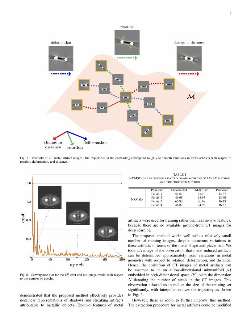
Fig. 5 shows a manifold M of CT metal-artifact images,which can be viewed as a set of points in high-dimensionalspace R256×256 with 256 × 256 pixel CT images. Becauselinear combinations of two images on M do not resemblemetal-induced beam-hardening artifacts, M is unlike Eu-clidean space. Our trained network performed well in terms ofboth the test set and training set. In other words, the regressionmanifoldM effectively interpolated between CT metal artifactimages in terms of their trajectories, as shown in Fig. 5.Although we use a relatively small training data, the networkproduced reasonably accurate metal artifacts that were not inthe training set. Fig. 6 depicts the L2 error and test imageresults with respect to the number of epochs. It shows that theL2 error converged and that beam-hardening artifacts in testimage were reduced as the number of epochs increased.
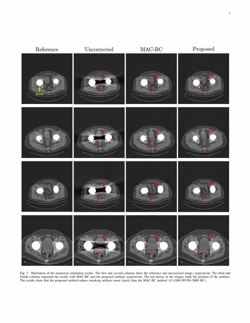
Fig. 7 shows the numerical simulation results for MAR. Thefirst and second columns show the reference and fCT, respec-
tively. The third and fourth columns represent the correctionresults using MAC-BC and the proposed method, respectively.MAC-BC [23] extracts beam-hardening artifacts from fCT
based on an analytic formula. Both correction methods showthat the anatomical information corrupted by beam-hardeningeffects is clearly visible. However, MAC-BC still retainedsome streaking artifacts, owing to model’s assumption oflinear approximation for nonlinear variations (see Fig. 7, thirdcolumn). By comparison, the proposed method outperformedMAC-BC in terms of beam-hardening artifact reduction (seeFig. 7, fourth column). In order to compare the quantitativeerrors in the corrected image (fcor) from each method withthose of the reference image (fref), we computed the normal-ized root mean square difference (NRMSD) [17] on the outsideof Dm. The NRMSD (%) for each result is listed in TableI. The proposed method obtained the lowest NRMSD in allcases. This shows that the proposed method performs betterat background restorations.
IV. DISCUSSION AND CONCLUSION
We developed a deep learning MAR method to extractstreaking and shadow artifacts from artifact-contaminated CTimages arising from the presence of metallic objects. We
6
Fig. 5. Manifold of CT metal-artifact images. The trajectories in the embedding correspond roughly to smooth variations in metal artifacts with respect torotation, deformation, and distance.
Fig. 6. Convergence plot for the L2 error and test image results with respectto the number of epochs.
demonstrated that the proposed method effectively providesnonlinear representations of shadows and streaking artifactsattributable to metallic objects. Ex-vivo features of metal
TABLE INRMSD OF THE RECONSTRUCTED IMAGE WITH THE MAC-BC METHOD
AND THE PROPOSED METHOD
Phantom Uncorrected MAC-BC Proposed
NRMSD
Pelvis 1 54.67 21.10 14.67Pelvis 2 46.68 18.95 13.60Pelvis 3 65.83 26.68 16.43Pelvis 4 46.87 24.96 16.87
artifacts were used for training rather than real in-vivo features,because there are no available ground-truth CT images fordeep learning.
The proposed method works well with a relatively smallnumber of training images, despite numerous variations tothese artifacts in terms of the metal shape and placement. Wetook advantage of the observation that metal-induced artifactscan be determined approximately from variations in metalgeometry with respect to rotation, deformation, and distance.Hence, the collection of CT images of metal artifacts canbe assumed to lie on a low-dimensional submanifold Membedded in high-dimensional space RN , with the dimensionN denoting the number of pixels in the CT images. Thisobservation allowed us to reduce the size of the training setsignificantly, with interpolation over the trajectory as shownin Fig. 5.
However, there is room to further improve this method.The extraction procedure for metal artifacts could be modified
7
Fig. 7. Illustration of the numerical simulation results. The first and second columns show the reference and uncorrected image, respectively. The third andfourth columns represent the results with MAC-BC and the proposed method, respectively. The red arrows in the images mark the position of the artifacts.The results show that the proposed method reduce streaking artifacts more clearly than the MAC-BC method. (C=1000 HU/W=3000 HU.)

8
by enhancing the forward model, which accurately representsreal artifacts arising exclusively from metal inserts. Based onObservation 2.1, these real artifacts could be extracted directlyfrom CT images, without any deep learning process. Variousexperimental studies with patients will be required to explorethe ability of this deep-learning-based approach, and we shallexplore this in our future work.
ACKNOWLEDGEMENTS
The authors (S. M. Lee, H. P. Kim, and J. K. Seo)was supported by Samsung Science & Technology Founda-tion (No. SSTF-BA1402-01). The first author (H. S. Park)was partially supported by the National Research Founda-tion of Korea(NRF) grant funded by the Korea govern-ment(Ministry of Science, ICT & Future Planning) (No. NRF-2016R1C1B2008098) and the National Institute for Mathemat-ical Sciences (NIMS) grant funded by the Korean government(No. A21300000).
REFERENCES
[1] R. E. Alvarez and A. Macovski, Energy-selective reconstructions in X-ray computerised tomography, Physics in Medicine and Biology, 21,pp. 733, 1976.
[2] J. F. Barrett, and N Keat, Artifacts in CT: recognition and avoidance,Radiographics, 24, pp. 1679–1691, 2004.
[3] M. Bazalova, L. Beaulieu, S. Palefsky, and F. Verhaegen, Correction ofCT artifacts and its influence on monte carlo dose calculations, MedicalPhysics, 34, pp. 2119–2132, 2007.
[4] Bracewell RN, Riddle AC. Inversion of fan-beam scans in radio astron-omy. The Astrophysical Journal. 150. pp. 427, 1967.
[5] J. Bushberg, J. Seibert, E. Leidholdt Jr, and J. Boone, The essentialphysics of medical imaging. Lippincott Williams & Wilkins, 2002.
[6] B. De Man, J. Nuyts, P. Dupont, G. Marchal, and P. Suetens, Aniterative maximum-likelihood polychromatic algorithm for CT, IEEETransactions on Medical Imaging, 20, pp. 999–1008, 2001.
[7] I. A. Elbakri and J. A. Fessler, Statistical image reconstruction forpolyenergetic X-ray computed tomography, IEEE Transactions on Med-ical Imaging, 21, pp. 89–99, 2002.
[8] Google. TensorFlow: Large-scale machine learning on heterogeneoussystems, 2015. URL http://tensorflow.org/. Software available fromtensorflow.org.
[9] J. Gu, and J. C. Ye, Multi-Scale Wavelet Domain Residual Learningfor Limited-Angle CT Reconstruction, arXiv preprint arXiv:1703.01382,2017.
[10] Y. Han, J. Yoo, and J. C. Ye, Deep residual learning for compressedsensing CT reconstruction via persistent homology analysis, arXivpreprint arXiv:1611.06391, 2016.
[11] G. T. Herman and S. S. Trivedi, A comparative study of two postre-construction beam hardening correction methods, IEEE Transactions onMedical Imaging, 2, pp. 128–135, 1983.
[12] W. A. Kalender, R. Hebel, and J. Ebersberger, Reduction of CT artifactscaused by metallic implants, Radiology, 164, pp. 576–577, 1987.
[13] Y. LeCun, B. Boser, J.S. Denker, D. Henderson, R.E. Howard, W.Hubbard, L.D. Jackel, Backpropagation applied to handwritten zip coderecognition, Neural Computation, 1, pp. 541–551, 1989.
[14] L. Lehmann, R. Alvarez, A. Macovski, W. Brody, N. Pelc, S. Riederer,and A. Hall, Generalized image combinations in dual kVp digitalradiography, Medical Physics, 8, pp. 659–667, 1981.
[15] C. Lemmens, D. Faul, and J. Nuyts, Suppression of metal artifacts inCT using a reconstruction procedure that combines MAP and projectioncompletion, IEEE Transactions on Medical Imaging, 28, pp. 250–260,2009.
[16] R. M. Lewitt and R. H. T. Bates, Image reconstruction from projections:Iv: Projection completion methods (computational examples), Optik, 50,pp. 269–278, 1978.
[17] A. Mehranian, M. R. Ay, A. Rahmim, and H. Zaidi, X-ray CT metalartifact reduction using wavelet domain sparse regularization, IEEETransactions on Medical Imaging, 32, pp. 1707–1722, 2013.
[18] N. Menvielle, Y. Goussard, D. Orban, and G. Soulez, Reduction ofbeam-hardening artifacts in X-ray CT, Engineering in Medicine andBiology Society, 27th Annual International Conference of the, IEEE,2005, pp. 1865–1868.
[19] E. Meyer, R. Raupach, M. Lell, B. Schmidt, and M. Kachelrieß,Normalized metal artifact reduction (NMAR) in computed tomography,Medical Physics, 37, pp. 5482–5493, 2010.
[20] J. Muller and T. M. Buzug, Spurious structures created by interpolation-based CT metal artifact reduction, Proc. SPIE 7258, Medical Imaging2009, pp. 1Y1–1Y8.
[21] J. A. O’Sullivan and J. Benac, Alternating minimization algorithms fortransmission tomography, IEEE Transactions on Medical Imaging, 26,pp. 283–297, 2007.
[22] H. S. Park, J. K. Choi, K. R. Park, K. S. Kim, S. H. Lee, J. C. Ye,and J. K. Seo, Metal artifact reduction in CT by identifying missingdata hidden in metals, Journal of X-ray Science and Technology, 21,pp. 357–372, 2013.
[23] H. S. Park, D. Hwang and J. K. Seo, “Metal artifact reduction forpolychromatic X-ray CT based on a beam hardening corrector”, IEEETrans. Med. Imag. vol.35, pp. 480–487, 2016.
[24] M. Abdoli, M. R. Ay, A. Ahmadian, R. A. Dierckx, and H. Zaidi,Reduction of dental filling metallic artifacts in CT-based attenuationcorrection of PET data using weighted virtual sinograms optimized bya genetic algorithm, Medical Physics, 37, pp. 6166–6177, 2010.
[25] G. Poludniowski, G. Landry, F. DeBlois, P. Evans, and F. Verhaegen,Spekcalc: a program to calculate photon spectra from tungsten anode X-ray tubes, Physics in Medicine and Biology, 54, pp. N433–N438, 2009.
[26] J. Radon, “1.1 uber die bestimmung von funktionen durch ihre inte-gralwerte langs gewisser mannigfaltigkeiten”, Classic papers in moderndiagnostic radiology, 5, (2005).
[27] J. C. Roeske, C. Lund, C. A. Pelizzari, X. Pan, and A. J. Mundt, Re-duction of computed tomography metal artifacts due to the fletcher-suitapplicator in gynecology patients receiving intracavitary brachytherapy,Brachytherapy, 2, pp. 207–214, 2003.
[28] O. Ronneberger, P. Fischer, and T. Brox, U-net: Convolutional networksfor biomedical image segmentation, In International Conference onMedical Image Computing and Computer-Assisted Intervention, pp.234–241, Springer, 2015.
[29] T. Tieleman and G. Hinton, “Lecture 6.5-rmsprop: Divide the gradientby a running average of its recent magnitude”, COURSERA:NeuralNetworks for Machine Learning, 2012
[30] G. Wang, D. L. Snyder, D. A. O’Sullivan, M. W. Vannier, Iterativedeblurring for ct metal artifact reduction, IEEE Transactions on MedicalImaging, 15, pp. 657–664, 1996


![[1.2cm] Nonlinear Optimization - hu-berlin.de · 2015-10-15 · Nonlinear Optimization Claudia Schillings HU Berlin - 14. October 2015 based on material by Michael Hintermuller, HU](https://img.pdfslide.net/doc/110x75/5f0976527e708231d426f1ee/12cm-nonlinear-optimization-hu-2015-10-15-nonlinear-optimization-claudia.jpg)


![Overlapping Schwarz Decomposition for Nonlinear Optimal ... · [17], and Jacobi/Gauss-Seidel methods [18], [19]. Lagrangian dual decomposition, ADMM, and dual dynamic programming](https://img.pdfslide.net/doc/110x75/5f20426a361a060b480a45b0/overlapping-schwarz-decomposition-for-nonlinear-optimal-17-and-jacobigauss-seidel.jpg)