Embed Size (px)
DESCRIPTION
Machine Progress Towards Higher Luminosity. Frank Zimmermann CMS Upgrade Meeting FNAL, Chicago, 7 N ovember 2011 (via EVO) - PowerPoint PPT Presentation
Citation preview

Machine Progress Towards Higher Luminosity
Frank ZimmermannCMS Upgrade Meeting
FNAL, Chicago, 7 November 2011 (via EVO)Thanks to Martin Aleksa, Gianluigi Arduini, Ralph
Assmann, Hannes Bartosik, Oliver Brüning, Massimiliano Ferro-Luzzi, Jordan Nash, Yannis Papaphilippou, Anders Ryd, Benoit Salvant

topics• luminosity evolution over next few years
in light of 2011 experience- beam-beam limits- b* reach (aperture, collimation, optics)- leveling, pile up
• 50-ns vs 25-ns running- electron cloud- enhanced satellites w 50 ns spacing
• before/after Linac4 & other upgrades• how to reach highest luminosity?

2011 peak luminosity evolution
peak luminosity increased almost linearly over the year (adding more bunches, increasing bunch intensity, reducing b*) – now near the limit

~1.5/fb/month
~1/fb/month
9 months with ~26 days each & peak luminosity of 3.6x1033 cm-2s-1 (at the end) and 5.5/fb in total gives a “Hübner factor” of ~0.08
2011 integrated luminosity evolution

2011 LHC recordsCMS ATLAS
peak stable luminosity delivered 3.55x1033 cm-2 s-1 3.65x1033 cm-2 s-1
maximum luminosity in on fill 123.13 pb-1 122.44 pb-1
maximum luminosity in one day 135.65 pb-1 135.45 pb-1
maximum luminosity in 7 days 537.9 pb-1 583.5 pb-1
maximum luminosity in 1 month 1614.99 pb-1
maximum colliding bunches (w/o satellites) 1331 1331
maximum peak #events /crossing 23.8 (33.96)
maximum (av.) #events / bunch crossing 19.94 17.5 (32.21)
longest time in stable beams for one fill 26 h 26 h
longest time in stable beams for one day 19.9 h (82.9%) 21.9 h (91.2%)
longest time in stable beams for one week 107.1 h (63.7%)? 107.1 h (63.7%)
longest time in stable beams for one month 232.2 h 232.2 h?
fastest turnaround to stable beams 2.1 h 2.1 h

2011 time spent in physics
1400/(31 24 8) ~23.5% of the total, + lumi decay + lumi ramp up → consistent with Hübner factor 0.08

2011 time spent in physics

2011 length of physics fills

9
2022
LS3
Installation of the HL-LHC hardware
p-Pbrun
4 TeV? 6.5 TeV?
from early 201110 year plan 2011-2021

design October 2011 end 2012 ? 2016 ??
Beam energy 7 TeV 3.5 TeV 4 TeV 6.5 TeV
transv. norm. emittance 3.75 mm 2.5 mm 2.5 mm 3.5 mm
beta* 0.55 m 1.0 m 0.7 m 0.5 m
IP beam size 16.7 mm 24 mm 19 mm 17 mm
bunch intensity 1.15x10¹¹ 1.5x10¹¹ 1.6x10¹¹ 1.2x10¹¹
# colliding bunches 2808 1331 1350 2800
bunch spacing 25 ns 50 ns 50 ns 25 ns
beam current 0.582 A 0.335 A 0.388 A 0.604 A
rms bunch length 7.55 cm 9 cm 9 cm 7.6 cm
full crossing angle 285 mrad 240 mrad 240 mrad 260 mrad
“Piwinski angle” 0.64 0.37 0.51 0.61
peak luminosity 1034 cm-2s-1 3.6x1033 cm-2s-1 7.4x1033 cm-2s-1 1.3x1034 cm-2s-1
average peak pile up* 25 18 36 30
LHC beam parameters
* with s~80 mbarn

10-year luminosity forecast
modified from O. Brüning, M. Lamont, L. Rossi
6.5 TeV &transitionto 25 ns
total17 fb-1
total156 fb-1
total~400 fb-1

10-year luminosity forecast
HL-LHC
modified from O. Brüning, M. Lamont, L. Rossi
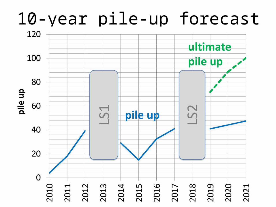
10-year pile-up forecast

2011: offset leveling test
conclusion: the luminosity can be successfully leveled using transverse offsets between 0 and a few s (here at IP8) without significant effects on the beam or the performance of the other experiments (IP1&5)
W. Herr et al,March 2011

15LMC 08/06/2011
Beam intensities
Luminosities
1.4e11
1.2e33
Wk 3
Blow up
leveling works
Monday 30/5 to Wednesday 08/062011: routine leveling in IP2 & 8
3e32

enhanced satellites for ALICE• wall current profile SPS beam• average over sequential 10 turns, 20 ms before extraction• 144 bunches with satellites
T.Bohl, S.Hancock
Satellites going up to about 8 %, average of few %
test in week 43
enhancedsatellitesare producedby RFgymnasticsin the PS(S. Hancock)
R. Assmann, LMC

T. Pieloni, W. Herr et al, May 2011
beam parameters investigated beyond nominal LHC (Nb = 1.8 1.95x10‐ 11, ε =1.2-1.4 μm); no significant beam losses nor emittance effects observed with linear head-on parameter of ξbb= 0.02 /IP and ξbb=0.034 (total) – more than 3x above design!
>0.03
no head-on beam-beam limit found yet

high pile-up test – CMS results
A. Ryd, LMC112
no “pile-up limit” found yet

long-range beam-beam effect
40%
35%
50%
30%
HD 2-8Small LR
HD 1-5Strong LR
HD 1-2-5Strong LR
HD 8Tiny LR
crossing angle100% = 240 mradat b*=1.5 m50-ns spacing
W. Herr et al, August 2011
we cannot reduce the crossing angle
much below 240 mrad at b*=1 m

b* reach from 2011 MDs
R. Assmann et al, CERN-ATS-Note-2011-079 MD
tight collimator settings tested in MD block2 “We found a good IR aperture in both planes and IPs. So good that we want to take more time to see if we overlooked something. Had to open the TCT aperture to the following values before seeing primary losses at the triplet:”IR1 - V -> 18.3 - 18.8 s (at b*=1.5 m)IR1 - H -> 19.8 - 20.3 sIR5 - V -> ≥ 20.3 s (corrector limit reached)IR5 - H -> 19.8 - 20.3 sS. Redaelli, M. Giovannozzi et alLHC MD block 3
tight collimator settingswith TCT at 9.3 s qualified for physics operation
at present TCTs at 11.8 s at *=1 b m; this could be reduced
to 9.3 s( *<0.7 b m)

2011: LHC emittance vs bunch intensity with 50 ns spacing
G. Arduini, LMC110
at Nb=1.5x10¹¹
emittance is about~2.5 mm

2011: injector emittance vs equivalent LHC bunch intensity (w/o losses)
G. Arduini, LMC110

50 ns vs 25 ns• 50-ns beam: smaller emittance from the PS (less splittings in the PS;
i.e. less charge in the PSB); ~2 mm vs ~3.5 mm at LHC injection• 25-ns beam: emittance growth due to e-cloud in the SPS and LHC (to
be improved by scrubbing in the LHC, and a-C coating in the SPS)• 25-ns has more long-range collisions• total current limit (by vacuum; RF) → limit # bunches• bunch train current limits in SPS & LHC → limit # bunches• UFO rate seems to greatly increase for 25-ns spacing• ultimately (2014?) we must (try to) transit to 25-ns spacing because
of pile up• also there are the possibilities to alternate high-luminosity high-pile-
up 50-ns running and lower-luminosity 25-ns running with reduced pile up (?); or to use ALICE enhanced satellites to get both high and low pile up events at the same time – preferences of experiments?

e-cloud emittance blow up with 25 nsMD October 2011
2 mm
3.5 mm

electron cloud scrubbing – LHC arcs
of low-energy e-
after April 2011 scrubbing run
H. Maury
25-ns testsOctober 2011
goal for 25 ns

possible concerns for 2014/15
• radiation to electronics – SEU’s
• UFOs at higher energy & with 25 ns
• electron cloud & high energy & at 25 ns
• emittance growth in physics
• …

Duoplasmatron = Source 90 keV (kinetic energy)LINAC2 = Linear accelerator 50 MeVPSBooster = Proton Synchrotron Booster 1.4 GeVPS = Proton Synchrotron 25 GeVSPS = Super Proton Synchrotron 450 GeVLHC = Large Hadron Collider 7 TeV
LHC injector complex

Possible Characteristics 2011 PSB extraction PS extraction SPS extraction Ip / ring ɛh and ɛv nb nb Ip / bunch ɛh and ɛv nb Ip / bunch ɛh and ɛv ɛlongit nb
[x1011][mm ∙mrad]
batches
bunches [x1011]
[mm ∙mrad]
bunches [x1011]
[mm ∙mrad] [eVs] bunches
1σ, norm. 1σ, norm. 1σ,
norm. LHC25 (DB) 16 2.5 2 4 + 2 1.3 2.5 72 1.15 3.6 0.7 4 x 72LHC50 (SB) 24 3.5 1 3 x 2 1.75 3.5 36 1.45 <3.5 ≤ 0.8 4 x 36LHC50 (DB) 8 1.2 2 4 + 2 1.3 1.3 36 1.15 (?) 1.5 (?) ≤ 0.8 4 x 36
Ɛh/v very low, potential for higher than nominal intensity
25 ns beam from the PS 50 ns beam from the PS
RendeSteerenbergChamonix2011
3 LHC p beams from the CERN PS
LHC50 SB (2010) → LHC 50 DB (low emittance, 2011) or LHC25 DB (more bunches)+ future PS “batch compression” to (further) boost the brightness?

SPS: 50ns bunch train – Double PSB batch
Intensity 1.65 1011 p/b reached !• Up to 4 batches injected• Very low losses along the cycle (reproducible 3%)• ex=2.0 mm and ey=1.9 mm at flat top (sum 3.9)
Roland Garoby, LHCC 14/06/2011
May 2011

Slippage factor in SPS relative to nominal optics
1978
20101998
nominal
• SPS intensity limitations for LHC p beams in SPS– TMCI due to transverse impedance, Nth ~ η
– Loss of longitudinal Landau damping), Nth ~ ε2τη
– Longitudinal coupled bunch instabilities, Nth ~ ηε2/τ – Electron cloud instability
• Slippage factor η defined by optics through transition energy (γt):
Increase in instability thresholds Nth for higher slippage factor η due to faster synchrotron motion ( ) and faster damping of instabilities
new optics for SPS (low γt or “Q20”) Nth … Instability threshold ε … longitudinal emittanceτ … bunch lengthη … slippage factor
Low γt opticsNominal optics
H. Bartosik, Y. Papaphilippounot yet fully commissioned for LHC

SPS single-bunch intensity limits (units of protons/bunch)
Benoit Salvant
chromaticity Q’/Q 0.0 0.07old Q26 optics 1.7x10¹¹ 2.2 x10¹¹
new Q20 optics 2.8x10¹¹ 3.8 x10¹¹
>2 x LHCultimate

Nb & e with SPS Q20 low-gt optics (1 bunch)• extracted intensity together with total losses along the cycle• overestimation of horizontal emittance and its slope (dependence of dp/p on
intensity)• PSB emittances: ~ 1μm < 1.5e11p / ~ 1.1μm @ 2e11p / ~ 1.3μm @ 3e11p • bunch length slightly increasing with intensity• up to Nb~3x10¹¹ (~3x LHC at 450 GeV with ge~2.5 mm (2/3 LHC design!)
Hannes Bartosik11 May 2011
intensity
emittance measured!
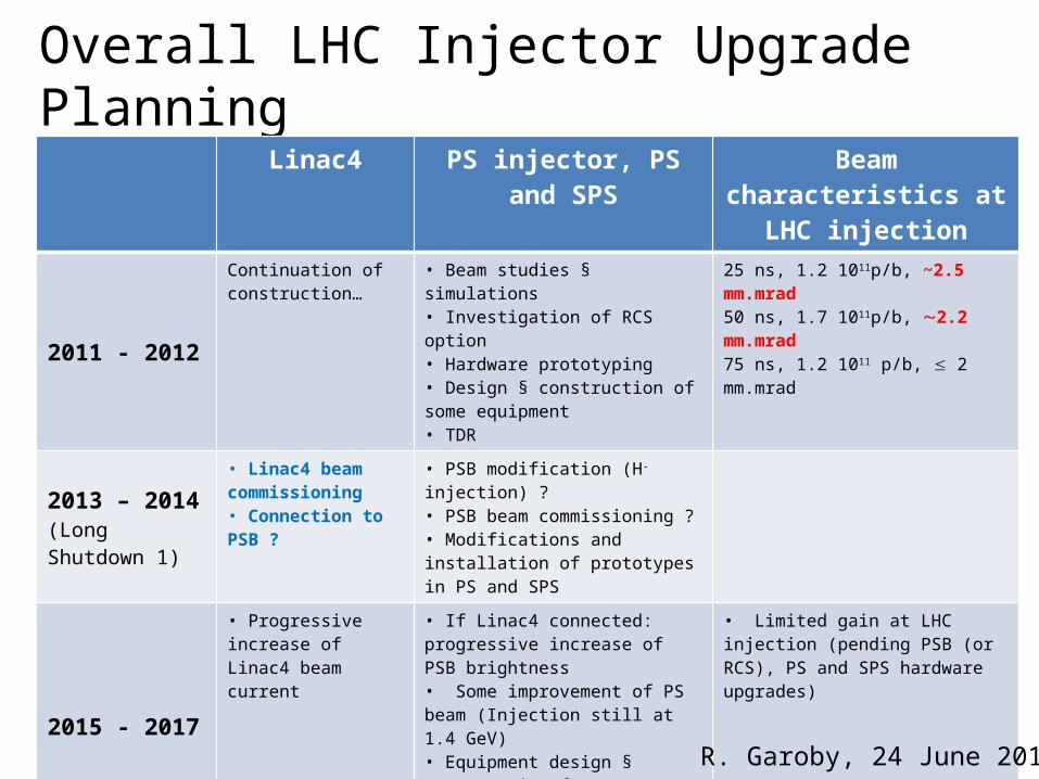
Overall LHC Injector Upgrade PlanningLinac4 PS injector, PS and SPS Beam characteristics at
LHC injection
2011 - 2012
Continuation of construction…
• Beam studies § simulations• Investigation of RCS option• Hardware prototyping• Design § construction of some equipment• TDR
25 ns, 1.2 1011p/b, ~2.5 mm.mrad50 ns, 1.7 1011p/b, ~2.2 mm.mrad75 ns, 1.2 1011 p/b, £ 2 mm.mrad
2013 – 2014 (Long Shutdown 1)
• Linac4 beam commissioning• Connection to PSB ?
• PSB modification (H- injection) ?• PSB beam commissioning ?• Modifications and installation of prototypes in PS and SPS
2015 - 2017
• Progressive increase of Linac4 beam current
• If Linac4 connected: progressive increase of PSB brightness• Some improvement of PS beam (Injection still at 1.4 GeV)• Equipment design § construction for PS injector, PS and SPS • Beam studies
• Limited gain at LHC injection (pending PSB (or RCS), PS and SPS hardware upgrades)
2018(Long Shutdown 2)
• Extensive installations in PS injector, PS and SPS• Beam commissioning
2019 –2021After ~1 year of operation: beam characteristics for HL-LHC…
R. Garoby, 24 June 2011

Linac4 commissioning schedule
34
ID Task Name
1 Linac 4 - Machine2 L4L (3 MeV)
3 End of Test Stand operation
4 source H- installation
5 LEBT installation
6 RFQ installation
7 MEBT installation
8 Hardware Test
9 Beam commissioning - 3 MeV
10 L4D (50 MeV)
11 DTL tanks 3 installation
12 DTL tank 1 installation
13 Hardware Test
14 Beam commissioning
15 DTL tanks 2 installation
16 intertanks 1-2 & 2-3 installation
17 Hardware Test
18 Beam commissioning - 50 MeV
19 L4C (102MeV)
20 CCDTL 3-7 installation
21 CCDTL 1-2 installation
22 Hardware Test
23 Beam commissioning - 102 MeV
24 L4P (160 MeV)
25 PIMS 4-12 installation
26 PIMS 1-3 installation
27 Hardware Test
28 L4Z
29 Main dump
30 MQF installation
31 BI installation (BTVx3, BCT)
32 Beam commissioning Linac4 - 160 MeV
Linac 4 - Machine
L4L (3 MeV)
End of Test Stand operation
source H- installation
LEBT installation
RFQ installation
MEBT installation
Hardware Test
Beam commissioning - 3 MeV
L4D (50 MeV)
DTL tanks 3 installation
DTL tank 1 installation
Hardware Test
Beam commissioning
DTL tanks 2 installation
intertanks 1-2 & 2-3 installation
Hardware Test
Beam commissioning - 50 MeV
L4C (102MeV)
CCDTL 3-7 installation
CCDTL 1-2 installation
Hardware Test
Beam commissioning - 102 MeV
L4P (160 MeV)
PIMS 4-12 installation
PIMS 1-3 installation
Hardware Test
L4ZL4Z
Main dump
MQF installation
BI installation (BTVx3, BCT)
Beam commissioning Linac4 - 160 MeV
1 2 3 4 5 6 7 8 9 10 11 12 13 14 15 16 17 18 19 20 21 22 23 24 25 26 27 28 29 30 31 32 33 34 35 36 37 38 39 40 4142 4344 4546 474849 50 5152 1 2 3 4 5 6 7 8 9 10 11 12 13 14 15 16 17 18 19December 2012January 2013February 2013March 2013 April 2013 May 2013 June 2013 July 2013 August 2013September 2013October 2013November 2013December 2013January 2014February 2014March 2014 April 2014 May 2014
2012 2013 2014
Start of beam commissioning (3MeV): May 2013 End of beam commissioning (160 MeV): April 2014
(version November 2010)
5 commissioning stages: (on intermediate dumps) 3 MeV 10 MeV 50 MeV 100 MeV 160 MeV
Linac4 ready : April 2014M. Vretenar, CERN MAC, August 2011
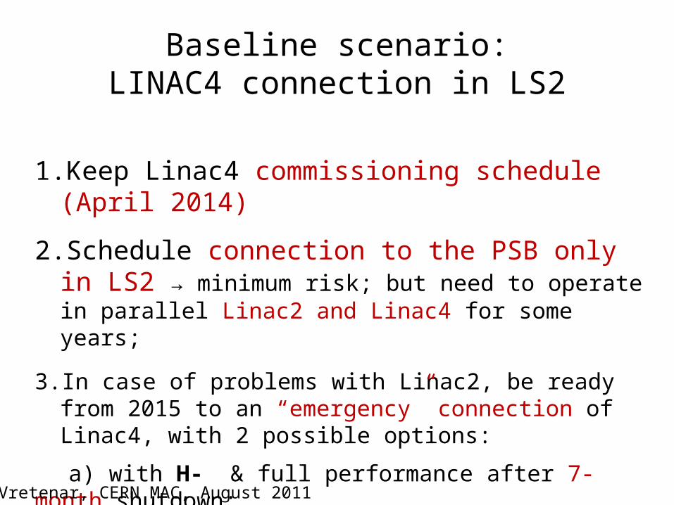
Baseline scenario:LINAC4 connection in LS2
1. Keep Linac4 commissioning schedule (April 2014)
2. Schedule connection to the PSB only in LS2 → minimum risk; but need to operate in parallel Linac2 and Linac4 for some years;
3. In case of problems with Linac2, be ready from 2015 to an “emergency” connection of Linac4, with 2 possible options:
a) with H- & full performance after 7-month shutdown;
b) with protons at 50 MeV after a few days shutdown but with reduced PSB performance.
M. Vretenar, CERN MAC, August 2011

+ : Linac4 + PSB available from 2015 (PSB performance + mitigate risk of Linac2 failure) - : a) Start LHC only in 2015 b) Injectors have to stop in 2014.
alternative LINAC4 connection scenarios for LS1 (NOT baseline)
1 2 3 4 5 6 7 8 9 10 11 12 1 2 3 4 5 6 7 8 9 10 11 12Linac4 commissioning
PSB mod.PSB comm.
2013 2014A.
“green light” Jan. 2014, Linac4 commissioned only to 100 MeV
1 2 3 4 5 6 7 8 9 10 11 12 1 2 3 4 5 6 7 8 9 10 11 12 1 2 3Linac4 commissioning
Reliability runPSB mod.
PSB comm.
2013 2014 2015B. “green light” June 2015, Linac4 commissioned + 5 months reliability run
+ : Linac4 + PSB available from 2015 (PSB performance + mitigate risk of Linac2 failure) - : a) Risk of reliability/performance issues appearing in the last phase of commissioning b) Injectors have to stop in 2014.
M. Vretenar, CERN MAC, August 2011

would there be any benefit for LHC from Linac4 alone?
• For 25 ns spacing it is very difficult to go beyond what is done today without RF & e-cloud improvements in the SPS & PSB energy upgrade (all planned in LS2)
• With 50 ns bunch spacing one might gain up to a factor of 2 in intensity at the SPS from LINAC4
R. Garoby, CERN MAC, August 2011

potential 50-ns luminosity reachwith LINAC4 (my estimate)
• ge ~2.5 mm• Nb ~2.5x10¹¹
E= 4 TeV, b*~0.7 m: L~1.6x1034 cm-2s-1, pile up ~74
E = 6.5 TeV, b*~0.45 m : L~3.7x1034 cm-2s-1, pile up ~170
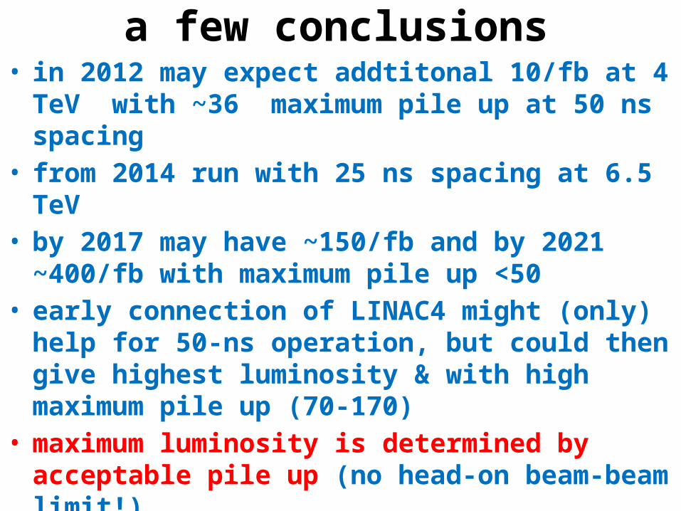
a few conclusions• in 2012 may expect addtitonal 10/fb at 4 TeV with ~36
maximum pile up at 50 ns spacing• from 2014 run with 25 ns spacing at 6.5 TeV• by 2017 may have ~150/fb and by 2021 ~400/fb with
maximum pile up <50• early connection of LINAC4 might (only) help for 50-ns
operation, but could then give highest luminosity & with high maximum pile up (70-170)
• maximum luminosity is determined by acceptable pile up (no head-on beam-beam limit!)
• leveling could also be applied for CMS to limit the pile up• enhanced satellites would give low & high pile up events• LHC will exceed design luminosity; 2021: time for HL-LHC

thank you for your attention