Embed Size (px)
Citation preview

MACHINE SOFTWARE
Engel Industries, Inc. 81 22 Reilly Avenue
St. Louis, Missouri 631 1 1 (314) 638 0100
www.enqelind.com e-mail: [email protected]
O Copyright 1990-1 999 Engel Industries, Inc.

ENGEL STANDARD COlLlNE CONTROLLER MANUAL
""* TABLE OF CONTENTS ""*
SECTION
...................... ........ INTRODUCTION .. ................................
GENEFWL SPECIFICATIONS .............................................. B
FRONT PANEL .................................................................... C
SETUP MODE ...................................................................... D
...................................................................... BATCH MODE E
RUN MODE .......................................................................... F
......................................................................... COIL MODE G
C"'"3\" hl'EF.!'GFS H . . . . . . . . . . . . . . . . . . . . . . . . . . . . . . . . . . . . . . . . .
END NOTCH LOCK TYPES ......................... ... ..................... I
SETUP DATA SHEETS ....................................................... J
FILE STRUCTURE K ...............................................................
CALC U L4TO R ..................................................................... L
TROUBLESHOOTING GUIDEILENGTH CALIBRATION ...... M
PAGES
1
1 - 2
1 - 5
1 -13
1 - 9
1 - 4
1 - 2
1 - 2
1
7-10
1 - 6
1 - 3
1 -16

GENERAL SPECIFICATIONS
The following is a general specification for the controller. A NEMA 12 console
houses the control system. The console size varies depending on the quantity of purchased
options, in general, the E.C.-11 uses a 24 inch console, and the E.C.-21 incorporates a 48
inch console.
Resolution: .OlO inch with a 12 inch wheel Accuracy output turned on within 25
microseconds of operation excluding errors in machine tolerance.
Maximum Counting Speed: 200 feet per minute
Maximum Part Length 9999.99 inches
Maximum job Quantity: 9999
Number of Batches: 100
Pattern Types: 5 each - (Blank, Flat, L-duct, U-duct, and
Wrapper)
Input Power: 1 15 VAC +I- 1096, 50-60 Hz (1 32vac - 109vac)
Outputs: Forward, Slow, Reverse, Shear, End Notch, - . - . 1 T - 7 n - - I
U G . L & . " L U , , , - 5 - L U - d - , .... - . 4 . -

FRONT PANEL CONTROLS
On the front panel of the controller console are 10 lighted push button switches and a 101 -key keyboard on the console deck. The operator passes information to the controller with the switches and keyboard. The functions of the push button switches are as follows:
HALT The HALT key is used to stop the machine from running material in automatic mode. The red lamp indicates that the controller is in the HALT mode.
RUN The RUN key is used to initiate an automatic run of the controller. The green lamp indicates that the controller is in the RUN mode.
REMOTE DATA LlNK The DATA LlNK key is used to turn the remote link on or off. The blue lamp indicates when the remote data link is on. See the ENGELINK section of this manual for more information.
MANUAL SHEAR The MANUAL SHEAR key is used to manually cycle the shear output when the line is in the HALT mode. The yellow lamp indicates when the shear output is "on" in either the HALT or RUN mode.
RESET . . - ,
I IW K&L I pclSn bu~~uil IS U S e O Lo res& iCle Ccri-l~tur~r v v r , t i i & J& ib uktr rb rt;~;;cJ. First level reset (pressed once for short period of time). Use: Drop out of run mode. Second level reset - referred to as a long or total reset (pressed once for a long period of time). Screen will display "Down stream data destroyed" Use: Destroy data setups to LOM, Brake, etc.
MANUAL VEE NOTCH The MANUAL VEE NOTCH key is used to manually cycle the vee notch output when the line is in the HALT mode. The yellow lamp indicates when the vee notch output is 'on" in either the HALT or RUN mode.
MANUAL END NOTCH The MANUAL END NOTCH key is used to manually cycle the end notch output when the line is in the HALT mode. The yellow lamp indicates when the end notch output is 'on" in either in HALT or RUN mode.

FRONT PANEL CONTROLS
Press ~ ( 1 I--?----Edit Setup Data a
Press F(2)------- Edit Product Data Press F(3)------- Information Press F(4)------- Status Pfeas P(5)------ -Quit - Press F(6)------ Haintenance schedule
00:21:19 am b
]I 01-02-2000 1. II Please' make a selection I
ENGELRUN / version 12.0 X86 machine software Copyright (C) 1996 - 1998 h g e l Industries, Inc.
LT-RT ARROW The LEFT or RIGHT ARROW key is used in all modes of operation to move the cursor left or right. The position of the cursor in respect to the data column is retained.
PACF I ID -Phf
The PAGE UP or ON key is used in the setup and batch modes to view the next screen or page of data. In the setup mode, if the current page is page 3, pressing the page down key will cause the screen to display page 4. In the batch mode, pressing PAGE DN will cause the screen to show the next page of batch data unless the cursor is presently on the last page.
F1 - EDIT SETUP DATA SCREEN (See section D) The FI key is used to enter the setup mode from the main menu. If the security key located on the front panel is not on, data may be reviewed, but may not be changed.
F2 - CALCULATOR The F2 key is used, while in the setur> or roroduction screen, to enable the on screen calculator. The calculator has the capability of exporting a result back to the main program.
F3 - PRINT OUT The F3 key is used, while in the s e t u ~ orproduction screen, to make a hard copy of the setup or production data.

FRONT PANEL CONTROLS
LABELS The F7 key is used, while in the omduction screen, to enter the label development and printing area. The operator has the option of entering a label header and three comment lines, entering the job number will automatically enter other information onto the label.
ENTER The ENTER key is used by the operator to indicate the end of a valid data entry.
FRONT PANEL CLEAR The BACK SPACE key is the data clear key and it is used to erase a data entry before the enter key is pressed. For example, upon entering a data value, you press a wrong key. Pressing the BACK SPACE key will cause the controller to delete a previously typed character. Once all typed characters are deleted the original value will be displayed.
NUMERIC ENTRY KEYS The keys 0 through 9, and the decimal point key are used in entering the numeric values required for a specific data item.
ESC The ESCAPE key is used to return to the main menus. It may be necessary to press this key several times.
SECURIlY KEY-LOCK The sewritv kev-lock switch, located on the controller front panel, provides a measure
aia V&UeS. k \ r i ~ c uit: of security against tampering. This sw~tch protects only setup u- switch turned off, you may only view the data. If you try to change the data with the security switch off, the soware will display an error message.
Maintenance schedule COMPONENT ACTION ROTATION COMPONENT ACTION ROTAT ION
A
I
C5
.... .. ....... MOTOR. NOISE......,., 3.3 HRS CHAIN.... MOUNTS 123.3 HRS MOUNTS,.. .... 123.3 HRS SP ROCICET...WEAR......... 123.3 HRS ..... REDUCER ... NOISE.... ..... 3.3 HRS KEYS.... 123.3 HRS .... OIL LEVEL 123.3 HRS LACING.......923.3 HFG
BELT......TRACKING. .... 123.3 HRS V-BELT.....TBNSION.. ..... 3.3 HRS ... TEXSION... 123.3 HRS WEAR....,.... 123.3 HRS LACING.... ... 443.3 HRS ALIGNP3ENT. .. .123.3 HRS
BEXtING ... MUUNTS...,...123.3 HRS STRUCTURE,.NUTSbrf30LTSS,.. 3.3 HRS LUBRICATION.,123.3 HRS HYDRUALIC..NOISE........, 3.3 ERS NOISE........123.3 EIRS LEVEL........123.3 HRS
CBAIN.....TENSION....... 3.3 BRS OIL CHANGE...923.3 HRS .... LUBRICATION... 3.3 HRS WILINE OIL CHANGE..B23.3 HRS Press P t o Print, R to Reset, 'Esc or Q to ~lrif
I

SETUP MODE
The setup mode allows the user to enter the machine parameters and other seldom
changed variables. This data may vary from machine to machine, and therefore, cannot be
permanently set into the controller. To access the setup mode, press the FI key from the
main menu. This area consists of 14 pages. The first page contains general data that the
controller needs to know about the machine. The second page contains information about
the different punch dies that the controller will use. The third and fourth pages contain
information about the different lock types that are available. The fifth, sixth, seventh, etc.
pages contain the setup data for the downstream units. Be sure to record your setup data
in the back of this manual. This will protect you in the event of a data loss.
The keyboard on the front panel allows the input of information. Data entered into the
controller will reside at the location of the data input window or cursor. A shaded
rectangular box serves as the marker for the current data input point. The information
displayed in the window, before user input, is the.data for the current item. The operator
can readily observe where the keyed in data will go and what data will be overwritten by
user input. The window size also indicates the quantity of input and displayed characters.
Numeric values, that require fewer digits than the maximum allowed, may be input without
the leading or trailing zeroes. For example, suppose that you wish to change the slowdown
distance to 5.7 inches. The minimum required key strokes would be: 5.7 (enter)
The screen now shows 5.70 inches, and the cursor has advanced to the next data item.
Also, if only 5 inches were to be programmed, no decimal point is needed to indicate
fraction separations. The key strokes needed to enter just 5 inches would be: 5 (enter)
This method of data entry limits the key strokes required per input point, while providing a
more user-friendly controller.
The following text describes the functions of the special- keys located on the keyboard.

SETUP MODE
ENGLISH MEASURE SECURITY DISABLED
~(1)------- POSITION CURSOR ON PAGE OHE ~(2)------- ENABLE ON SCREEN fZALCULATOR ~ ( 3 ) - - - - - - - SEND SETUP DATA TO PRINTER
Cycles per revolution :I200 Distance per rwolution: 12.00 Correction factor : 1 -0000
Slowdown Distance : 4.00 Minimum Movement : 0.25
Shear Actuation Time : 1-00 Pause Time after Shear : 7.00 Remote Metal F l w : RKVriRSE Halt Shear-only Batches: NO
Enter the encoder pulses per revolution. Page 1 of 14
CYCLES PER REVOLUTION
The controller utilizes an optical encoder to generate an exact number of pulses for a given
amount of movement. The computer counts the pulses generated by the encoder. The
pulses are then used to calculate the amount of material that traveled beneath the encoder
wheel. The controller needs to know the quantity of pulses generated by the encoder wheel
per revolution. Enter this value at the CYCLES PER REVOLUTION prompt. 1200 is the
normal setting of this parameter.

SETUP MODE
MINIMUM MOVEMENT
Sets the minimum distance that the material must move between operations when the line
is started. If the distance to the next operation is shorter than the minimum movement
parameter, the controller will back the metal out until the distance to the next operation is
longer than the MINIMUM MOVEMENT distance.
SHEAR ACTUATION TlME
The time required for the shear output to be 'on" to completely shear off the part.
PAUSE TlME AFTER SHEAR
The time delay after a shear that the line will be stopped. The purpose of this would be
to allow some distance between parts before the line starts in forward again.
REMOTE METAL FLOW
Will determine the Length or Width to be the Leading edge or trailing edge. In NORMAL
mode, you have a Z-shaped machine and the length is the resultinq Leading edge. In
REVERSE mode, you have a U-shaped machine and the width will be the resulting leading
edge. (The resulting edge is that edge that enters the brake first).
HAL'l - S H U H ONLY PAR^ S
Normally the controller stops the line at the completion of each batch. However, if a No
response is given to this YESIN0 selection, there will be no halt between batches of shear-
only parts provided there is not a coil change required. The line will still halt after making
other types of parts, or before starting to make another type.

SETUP MODE
VEE NOTCH ACTUATION TlME
The VEE NOTCH ACTUATION TlME is the time required for the vee-notch output to be
"on" to complete an vee notch operation.
HOLE PUNCH TO SHEAR DISTANCE
The HOLE PUNCH TO SHEAR DISTANCE is the distance from the center of the hole
punch die to the center of the shear die. This distance can be determined in the same
manner as for the end notch die. The hole punch production screen entry's will be by-
passed (no hole punch available), by entering zero in the hole punch to shear distance.
HOLE PUNCH ACTUATION TlME
The HOLE PUNCH ACTUATION TlME is the time required for the hole punch output to be
"onn to complete a hole punch operation.
LEADING EDGE DIE SlZE
The LEADING EDGE DIE SlZE is the distance from the trailing edge of the notch die to the
center of the notch die. This parameter is used to calculate the LEADING EDGE LOCK
SlZE of the part.
TRAILING EDGE DIE SlZE - - - . , - - - - - - , - . , f . '- ' - - 7 J l - - - - L - l - ,A*- ',-
r r a: i i \ h r i r ' \ a LUUL U L ; SZi i3 u.C u'3LG. .-- :. v l l r .. .- I - & ~ . . .3 - - & - - I . - - - - - 2
the center of the notch die. This parameter is used to calculate the TRAILING EDGE LOCK
SlZE of the part.
SETUP MODE
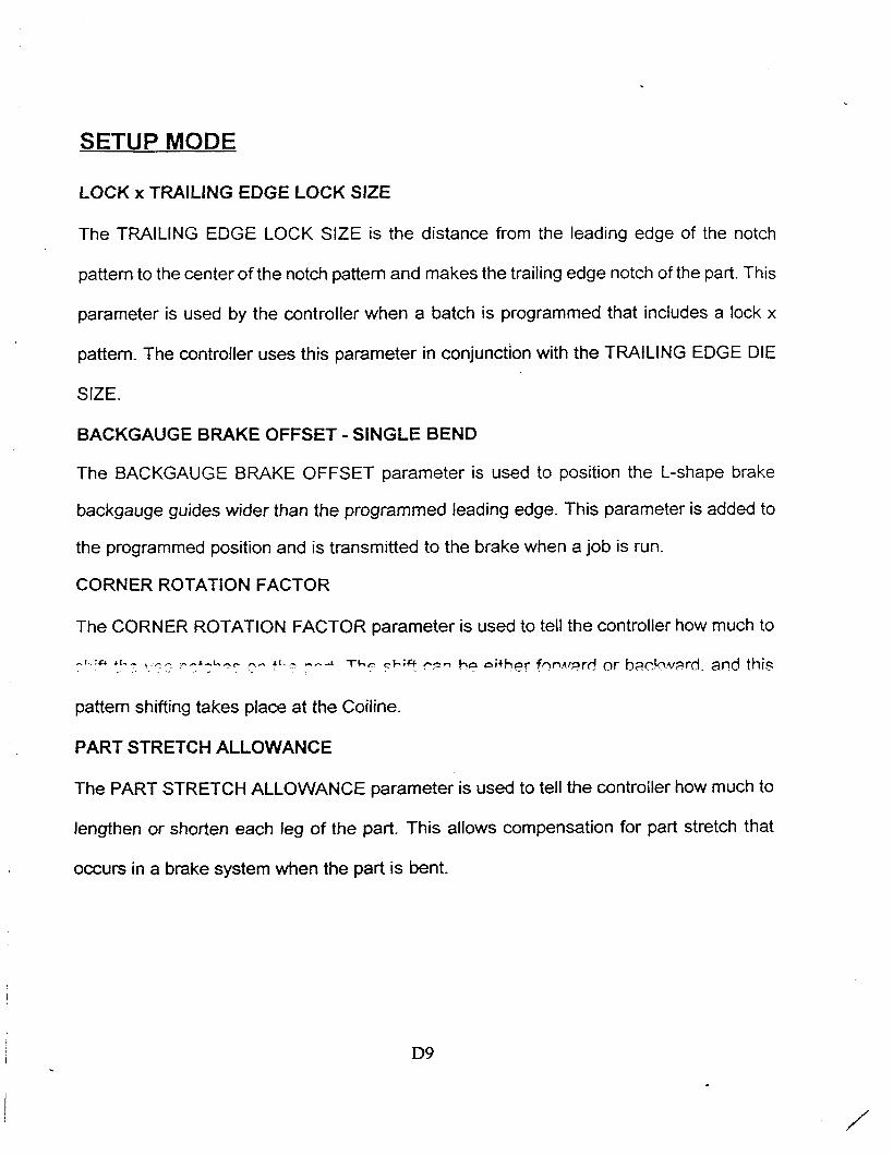
LOCK x TRAILING EDGE LOCK SlZE
The TRAILING EDGE LOCK SlZE is the distance from the leading edge of the notch
pattern to the center of the notch pattern and makes the trailing edge notch of the part. This
parameter is used by the controller when a batch is programmed that includes a lock x
pattern. The controller uses this parameter in conjunction with the TRAILING EDGE DIE
SIZE.
BACKGAUGE BRAKE OFFSET - SINGLE BEND
The BACKGAUGE BRAKE OFFSET parameter is used to position the L-shape brake
backgauge guides wider than the programmed leading edge. This parameter is added to
the programmed position and is transmitted to the brake when a job is run.
CORNER ROTATION FACTOR
The CORNER ROTATION FACTOR parameter is used to tell the controller how much to
..f.'Cr b l - , ,, ..,l,l,, ,, J - - T ~ C cb;* r=.- ho either fnn.u=?rd or b ~ c k w ~ r d . and this
pattern shifting takes place at the Coiline.
PART STRETCH ALLOWANCE
The PART STRETCH ALLOWANCE parameter is used to tell the controller how much to
lengthen or shorten each leg of the part. This allows compensation for part stretch that
occurs in a brake system when the part is bent.

SETUP MODE
6H6LISK MEASURE SECURITY DISABLED
....................... LIN-&mTIC PIN SPOTm----------------------------------
CYCLES PER REVOLUTION I 1200 DISTANCE PER RGVOLUTION: 12.00 CORRECTION FACTOR 1.0000
FIRE TIME 0.10 DELAY TIHE 0.10 LOAD TIHE 0.10
Page 9 of 14 Enter the acoder pulses per revolution,
LIN-0-MATIC OFFSET
The LIN-0-MATIC OFFSET parameter is used to tell the controller how far to shift the pins
back on the part when making insulated duct.
FlRE TlME
The FlRE TlME parameter is used to tell the controller how much time to allow when firing
pins om insulated duct.
DELAY TlME
The DELAY TlME parameter is used to tell the controller how much time to allow before
loading a new pin. This parameter is only required on older style pin-spotters.
LOAD TlME
The LOAD TlME parameter is used to tell the controller how much time to allow when
loading new pins. This parameter is only required on older style pin-spotters.

SETUP MODE
OFFSET BEND LOCATION x
The OFFSET BEND LOCATION x parameter is used to tell the controller how much to
offset the bending point when a full wrapper brake system is installed. This allows for
material thickness and different type locks.
TOTAL INVENTORY COIL
The amount of inventory material in footage on coil. This entry is program connected to the
Ga column on the production screen. If tracking of inventory of a coil is desired, enter a
total footage for a coil number 1 through 15. This entry will be displayed on the coil screen
(F4) screen from the Production screen.
0 0 B 0.00 l' 0 0 B 0.00 0.00 1 0-.0 N N X X 0 *** 0 0 B 0.00 0.00 1 0 - 0 N R X X 0 *** 0 0 B 0.00 0.00 1 0 - 0 H 'N X X 0 ***
Use arrows to aelact: (C)lear coil, (R)eset coil or (shift-Print).
W G L I S H KEASURX produ&ion Data ENTXR/noNITOR Mode p r e s s ~(1)------ Poeltlon cursor on page one PAGE 1 of 7 Prese F(2)------- Enable on acre POIL DAT& Prcaa P(3)------ Ssnd product d COILS POOTAGb REUAINING 1
-r.-- v r r ------I-+:- / --tc-i2 15-6- 0 0 I* Preas F(5)----- purge anusort Presa P(6)-----Krac all job Press F(7)----- Label Developr
W "" -"P =T rn 1 1 111 1 u 12.00 1 22 1 u 12.00 1 33 - 1 L 12.00 1 44 1 C 12.00 - 1 0 0 B 0.00 0 0 B 0.00 0 0 B 0-00 0 0 B 0.00 0 0 B .o.oo 0 0 B 0.00
16-uu V
15-48 0 0 24-48 0 1-60 0- 0
0 0 T 0 S
0- 0 0 Y 0- 0 ) 0 Y 0- 0 0 Y 0 - 0 0 Y 0- 0 0 * 0- 0 0 0-0 - 0 t
0- Q - 0 * 0- 0 0 * *

BATCH MODE
ENGLISH MEASURE production Data ENTER/HONITOR Mode Press F(1)------- Position cureor on page one PAGE 1 of 7 Press F(2)------- Enable on screen calculator Job 4 Press F(3)------- Send' product data to printer Quantity: 10 Press P(4)------- Coil / material information Length : 193.82 Press F(5)------- Purge andsort job data N e x t Op: : END NOTCH Press F(6)------- Erase all job data Count : +O. 00 Press F(7)------- Label Development and Print
Jab Q u a n t i t y Type Length Width Lk Ga-Wd VE; CO HPL HPT Wb STAT 1 1 L 12-00 12-00 1 26-60 L T X X 1 SKP 2 1 L 24.00 24.00 1 1-60 L T X X 1 SRP 3 1 L 36.00 36.00 1 2-60 L T X X 1 DNE 4 10 W 48.00 48.00 1 3 - 6 0 L T X X 1 WRK 5 0 L 0.00 0.00 1 3-60 L T X X 1 *** 0 0 B 0.00 0.00 1 0 - 0 N N X X 0 *** 0 0 B 0.00 0.00 1 0 - 0 N N X X 0 *** 0 0 B 0.00 0.00 1 0 - 0 N N X X 0 *** 0 0 B 0.00 0.00 1 0 - 0 N N X X 0 *** 0 0 B 0.00 0.00 1 0 - 0 N N X X 0 *** 0 0 B 0. Oil 0.00 1 0 - 0 N N X X 0 *** 0 0 B 0.00 0.00 1 0- 0 N -N X X 0 *** 0 0 3 0.00 0.00 1 0 - 0 N N X X 0 *** 0 0 B 0.00 0.00 1 0-'0 N N X X 0 *** 0 0 B 0.00 0.00 1 0 - 0 N N X X 0 ***
Enter a job identifier up to six digits in length.
The batch mode allows the entry of information pertaining to the parts the operator wants
to run. Enter this mode by pressing the F2 key from the main menu. A batch is the
combination of data items necessary to produce a particular part on the machine. This
controller ailows the user to mput aata in a maxlrnurn oi l u d ainerei~i oh~crres a1 any or re
time. The operator may enter batch data in either the halt or run modes. This feature allows
data input while the machine is running production. To use this option, the operator should
enter several jobs, then place the machine in RUN. The operator may then input the
remaining batch data while the machine is running the previously entered production
schedule.
BATCH MODE
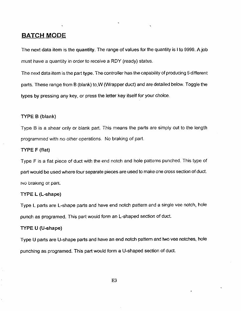
The next data item is the quantity. The range of values for the quantity is I to 9999. A job
must have a quantity in order to receive a ROY (ready) status.
The next data item is the part type. The controller has the capability of producing 5 different
parts. These range from B (blank) to,W (Wrapper duct) and are detailed below. Toggle the
types by pressing any key, or press the letter key itself for your choice.
TYPE B (blank)
Type B is a shear only or blank part. This means the parts are simply cut to the length
programmed with no other operations. No braking of part.
TYPE F (flat)
Type F is a flat piece of duct with the end notch and hole patterns punched. This type of
part would be used where four separate pieces are used to make one cross section of duct.
NO brak~ng ot part.
lYPE L (L-shape)
Type L parts are L-shape parts and have end notch pattern and a single vee notch, hole
punch as programed. This part would form an 1-shaped section of duct.
TYPE U (U-shape)
Type U parts are U-shape parts and have an end notch pattern and two vee notches, hole
punching as programed. This part would form a U-shaped section of duct.

BATCH MODE
The next data item is the duct velocity specification. This option is for machines with pin-
spotter controllers used to automatically fasten insulation to ducts with metal pins. Ducts
with different velocities require different pin spacing. Using the information specified in this
column, the controller passes the required pattern information to the pin-spotter. Option
details are as follows.
NO - No insulation used
HI - High velocity duct
LO - Low velocity duct
SP - Special velocity duct
This column is bypassed if a type B (she ar only part) is selected.
The next data item in the Production schedule is the Connector punch type specification.
The option types are: Drive cleat, Transverse, and None. Selection is made by pressing any
key to toggle the display, or you may press the letter key itself for your choice.
Depending on the connector type specified by the operator, the controller will activate the
respective dies when doing any punching operations. Also, the controller will use the
information entered in the setup mode for the punch selected in its internal part calculations.
For example, if the drive cleat punch option is selected, the controller will use the punch
information entered under the drive cleat header in the setup mode. If the transverse punch
option is selected, the controller will use the punch information entered under the transverse
cleat header in the setup mode.

BATCH MODE
Any number of jobs can have SKP (skip) status, and any of these, by operator intewention,
may later get RDY (ready) status. A status of WRK (work) or DNE (done) is unalterable by
the operator. A status of RES (reset) means the job was reset, quantity updated for
completed. Pressing enter with cursor on the status will change the display from RES to
ROY, although the RES job will run again as it did before it was reset.
After the operator completes the job entry, the cursor will advance to the next job line. If this
line is empty, the controller increments the job number and copies the optional data down
to this line. This provides for faster data entry on jobs that require the same options.
The minimum amount of data required to fabricate a part includes the quantity, type and
length. After entering this data, the remaining items make up the operator selected options.
The text that follows explains the special features that are available in the batch mode.
Function key FI
Causes the displayed page to change from the current page to page one.
Function key F2
Enables the on-screen calculator. See the calculator section for operational details.
Function key F3
Creates a hard copy of the scheduled jobs in the production schedule along with all current
coil data. The output is to the printer port Lptl.

BATCH MODE
Function key F7
Enables the label development and printing area. once in this area, you must supply a job
number. This ties the label and job together. The computer stores the label data in the label
file (LABEL.DAT). This file retains the label per job. Most of the label data is predetermined
by the job information. The user may, however, enter a header and three lines of comments
up to 33 characters in length.
The minimum label size required by the software is 4 x 2 15116 inches. The labels should
be continuous form feed (tractor) and single width. These are standard label specifications,
and they should be readily available at any office supply.

RUN MODE
The purpose of the run mode is to produce the parts programmed. When the operator
presses the RUN pushbutton, you enter this mode. The RUN may have to be pressed
numerous times if there are material, lock or connector changes. Pressing the HALT
pushbutton will halt the operation of the machine, but it will still restrict the altering of
most parameters, (the job in work will remain odd color). Pressing the HALT then
RESET pushbuttons will cause the control to exit the run mode completely. At the
completion of a job, the controller also will exit the run mode.
Upon entering the run mode, the controller will begin processing material from where it
left off if it was previously in the run mode and not RESET (manually or automatically).
Once running, the batches are produced in the order that they appear in the job list. The
only exception to this is by batches with NXT (next) or SKP (skip) status. A batch
whose status is NXT (next) will be run before any RDY (ready) batches. When
completed, execution continues with other RDY (ready) batches sequentially down the
screen. Only one batch may have NXT (next) status at any given time. A batch whose
status is SKP (skip) will be skipped. The job order also may be altered by inserting or
deleting batches using the INSERT or DELETE key respectively. To insert a batch,
position the cursor anywhere on the line where you want the line to be inserted and
press the INSERT key. The controller will shift the data down one line starting with the
current job. This shift will continue to the bottom of the production schedule.

RUN MODE
After a batch is completed, the controller will exit the run mode and enter the halt mode. To
run the next available job, simply press the RUN pushbutton again. If you wish to change
the order in which the batches are being processed, change the status of appropriate
batches to NXT (next), or SKP (skip).
The current controller status is observable anytime while in the batch mode by viewing the
controller screen. The information lines contain the following data:
1. Job number being processed
2. Quantity left to be made
3. Current length of part being made
4. Description and location of next action to occur
5. Maintenance Due will be in the back ground of next action
This section of the controller screen is updated continuously.
After the completion of a batch and entry into a new job, the controller checks several
the indication of a different coil than the previous batch. if this occurs, the controller will
prompt the operator to check the coil. This action will confirm that the proper material is
ready for fabrication. A prompt for a die change will appear if required.

COIL MODE
The controller is capable of storing information pertaining to 15 different coils of material.
This information can be reviewed by the operator by pressing the F4 in the batch mode or
SETUP page 14. With the display in the PRODUCTION screen, the controller will display
all active coils with the following information:
1. Gauge and width or coil number
2. Total length run (footage)
3. Remaining inventory of tracked coils
To reset a coil counter, place the pointer on the coil you wish to reset using the arrow
keys, then press the R key. To clear a coil, position the cursor on the coil you want to clear
and press the C key. The controller will first confirm that the coil is not in use. Then, and
only then, can the deletion take place. To print the production screen coil information,
mess the "Shiftn kev p h ~ ~ the "Print Screen" key. This will produce a hard copy of the
screen.

ERROR MESSAGES
The controller can detect certain operator errors. These are reported as messages on the
last line of the screen. Errors must be acknowledged and cleared by pressing any key. The
messages you may see are shown below.
DISKETTE NOT READY I DISKETTE DRIVE FAILURE
INVALID KEYSTROKE
ACCEPTABLE RANGE 25 - 1200 PULSES PER REVOLUTION
ACCEPTABLE RANGE .5 - 2.0 CORRECTION FACTOR
ACCEPTABLE RANGE 0 - 99.99 SECONDS
ACCEPTABLE RANGE 0 - 327.67 INCHES OR 8322.81 MM
ACCEPTABLE RANGE I - 6 LOCK TYPE
ACCEPTABLE RANGE I - 99 CODE FOR COlL GAUGE
ACCEPTABLE RANGE 1 - 99 CODE FOR COlL WIDTH
- - - - - . - 8 , ,- .\,-r - r L r n. t r \ I r ? r r p f r c ~ ! ~ r \ f p n h l c b ., U" ,. l . \ . ' / -
- - - - - -
CURRENT BATCH IS EMPTY ANOTHER JOB CANNOT 6E INSERTED
JOB STACK IS FULL ANOTHER JOB CANNOT BE INSERTED
A BATCH IN PROCESS CANNOT BE DELETED
A BATCH IN PROCESS CANNOT BE ALTERED
THE LOCK TYPE SPECIFIED HAS NOT BEEN DEFINED
THE JOB STACK CANNOT BE ERASED IF A BATCH IS IN PROCESS
SECURITY KEY-SWITCH IS OFF, SETUP DATA CANNOT BE ALTERED
COlL STACK IS FULL ANOTHER COlL CANNOT BE ADDED
END NOTCH LOCK TYPES
The controller is capable of handling up to six different notch widths per die
configuration. This allows the machine to be able to make a notch pattern that is up to
twice the actual notch die size.
When the controller encounters a part with a notch pattern, it compares the
machines programmed die size to the parts programmed notch size. If the notch size is
greater than the actual die size, the controller will double notch the material to produce a
notch pattem that is equal to the programmed notch size.
If the notch size is smaller than the actual die size, the controller will notch the
material once. But, when the part reaches the cutoff press, the controller will double shear
the part to eliminate the excessive notch pattem. This means that the controller will shear
once for the trailing edge of one part and once for the leading edge of the next part.
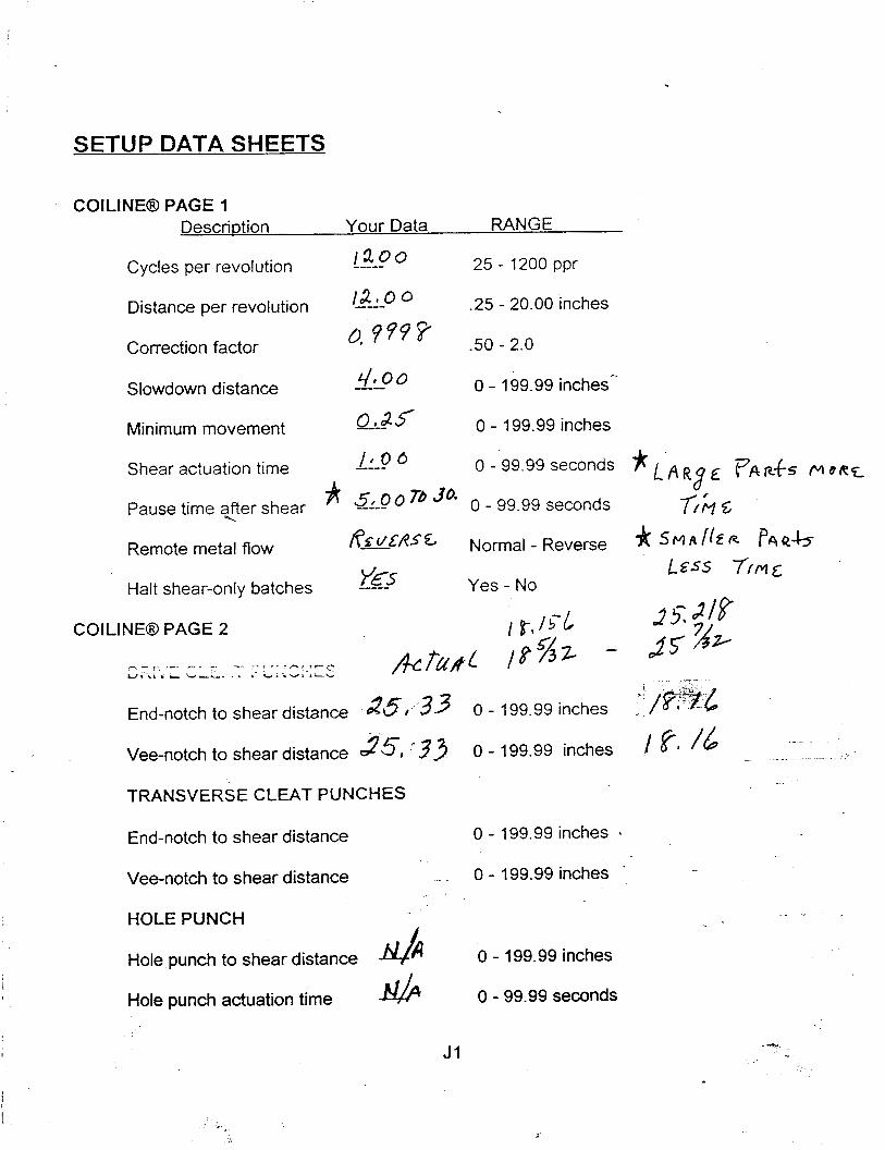
SETUP DATA SHEETS
COILINEO PAGE 1 RANGE Description Your Data
Cycles per revolution 1 2 0 0 ----- 25 - 1200 ppr
Distance per revolution @.& 0 .25 - 20.00 inches
Correction factor
Slowdown distance 4 00 -- 0 - 199.99 inches-'
Minimum movement QL& 5 0 - 199.99 inches
Shear actuation time / t o 6 ---- 0 - 99.99 seconds # I A RB vfi RfS ploRc
Pause time <Rer shear * 5 4 0 7b 0 - 99-99 seconds 7% 5
*, / g + ! L End-notch to shear distance 25 3 3 0 - 199.99 inches
25, -33 0 - 199.99 inches I fl 16 . -
Vee-notch to shear distance - . - ,
TRANSVERSE CLEAT PUNCHES
End-notch to shear distance 0 - 199.99 inches .
Vee-notch to shear distance 0 - 199.99 inches '
HOLE PUNCH
Hole punch to shear distance 0 - 199.99 inches
Hole punch actuation time N& 0 - 99.99 seconds

SETUP DATA SHEETS
COILINE@ PAGE 3 CONT'D
Descri~tion Your Data RANGE {Lock 3) Leading edge lock size
Trailing edge lock size
Backgauge brake offset
Corner rotation factor
Part stretch allowance
COILINEGD PAGE 4
{Lock 4)
Leading edge lock size
Trailing edge lock size
Backgauge brake offset
Corner rotation tactor
Part stretch allowance
(Lock 5 )
Leading edge lock size
Trailing edge lock size
Backgauge brake offset
Comer rotation factor
Part stretch allowance
----------- 0 - 199.99 inches
------- 0 -. 199.99 inches
-- 0 - 199.99 inches
------ ( T ) 0 - 199.99 inches-
--- (T) 0 - 199.99 inches
------ 0 - 199.99 inches
-- 0 - 199.99 inches
0 - 199.99 inches
--------- (5) 0 - 199.99 inches
(r) 0 - 199.99 inches
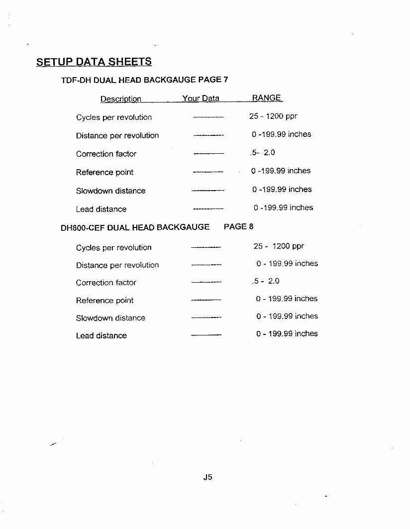
SETUP DATA SHEETS
TDF-DH DUAL HEAD BACKGAUGE PAGE 7
Descri~tion Your Data RANGE
Cycles per revolution -------- 25 - 1200 ppr
Distance per revolution ---- 0 -1 99.99 inches
Correction factor --- -5- 2.0
Reference point --- 0-199.99inches
Slowdown distance 0 -199.99 inches
Lead distance ------- 0 -1 99.99 inches
DH800-CEF DUAL HEAD BACKGAUGE PAGE 8
Cycles per revolution 25 - 1200 ppr
Distance per revolution -------- 0 - 199.99 inches
Correction factor ------ .5 - 2.0
Reference point --- 0 - 199.99 inches
Slowdown distance ------- 0 - 199.99 inches
Lead distance 0 - 199.99 inches
SETUP DATA SHEETS
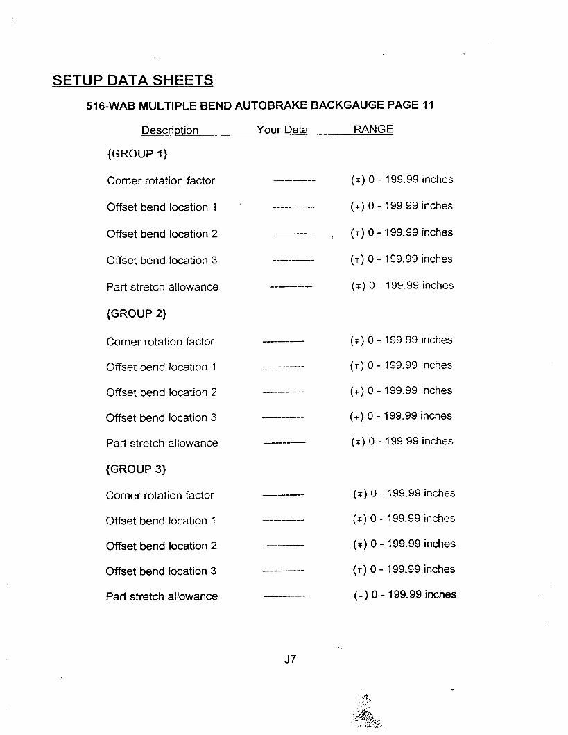
516-WAB MULTIPLE BEND AUTOBRAKE BACKGAUGE PAGE 11
Descri~tion Your Data RANGE
{GROUP I)
Corner rotation factor
Offset bend location 1
Offset bend location 2
Offset bend location 3
Part stretch allowance
{GROUP 2)
Comer rotation factor
Offset bend location 1
Offset bend location 2
Offset bend location 3
Part stretch allowance
{GROUP 3)
Corner rotation factor
Offset bend location 1
Offset bend location 2
Offset bend location 3
Part stretch allowance
(r) 0 - 199.99 inches
(T) 0 - 199.99 inches
( r ) 0 - 199.99 inches
(T) 0 - 199.99 inches
( T ) 0 - 199.99 inches
(T) 0 - 199.99 inches
(F) 0 - 199.99 inches
( T ) 0 - 199.99 inches
(T) 0 - 199.99 inches
(T) 0 - 199.99 inches
(T) 0 - 199.99 inches
(T) 0 - 199.99 inches
(r) 0 - 199.99 inches
(T) 0 - 199.99 inches
(r ) 0 - 199.99 inches
SETUP DATA SHEETS
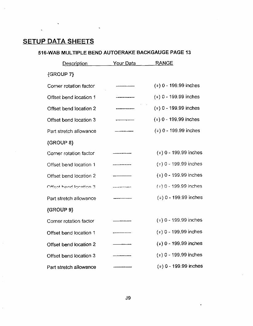
516-WAB MULTIPLE BEND AUTOERAKE BACKGAUGE PAGE 13
Descri~tion Your Data RANGE
{GROUP 7)
Comer rotation factor
Offset bend location 1
Offset bend location 2
Offset bend location 3
Part stretch allowance
{GROUP 8)
Corner rotation factor
Offset bend location 1
Offset bend location 2
n Y c d hand Ir\rptinn ?
Part stretch allowance
{GROUP 9)
Corner rotation factor
Offset bend location 1
Offset bend location 2
Offset bend location 3
Part stretch allowance
( r ) 0 - 199.99 inches
( T ) 0 - 199.99 inches
( r ) 0 - 199.99 inches
( r ) 0 - 199.99 inches
(+) 0 - 199.99 inches
( r ) 0 - 199.99 inches
( T ) 0 - 199.99 inches
( T ) 0 - 199.99 inches
(11 0 - 199.99 inches
(T) 0 - 199.99 inches
(F) 0 - 199.99 inches
( T ) 0 - 199.99 inches
( r ) 0 - 199.99 inches
( T ) 0 - 199.99 inches
( r ) 0 - 199.99 inches

FILE STRUCTURE
There are five (5) files that the user can manipulate using their self-developed software.
The information included here is given strictly as a guide for our customers. Engel
Industries does not intend to write software for other than Engel equipment. It is the
responsibility of the customers' programmer to maintain compatibility between any external
computers and the Coiline control system. The files are listed below.
PRODUCT-DAT
SETUP.DAT
LABEL. OAT
COIL.DAT
REPORT.TXT
A few points that pertain to all the data files (.DAT), is as follows. All files are the random
access type. All numeric data is left justified, single precision, and stored using the IEEE
format. The acronym IEEE represents the Institute of Electrical and Electronics Engineers.
The IEEE format differs from the Microsoft Binary Format in that it extends the single
precision range of numbers and obtains more accurate results.
Also co-processor support is easier to implement. The ENGELRUN and ENGELINK
software was written using Microsoft's Professional Development System (PDS 7.x). Data
that involves measured amounts uses the english measurement system.

FILE STRUCTURE
When the stored data does not represent numeric data, as in the following examples, then
the following special values are stored in its place.
Type: Blank = 66
Flat = 70
L-shape = 76
U-shape = 85
Wrapper = 87
VE: High = 72
Low = 76
None = 78
w u . L v - .dL
None = 78
TDF = 84
HP: X = 8 8 A = 65 B = 66 C = 67 D = 68 E = 69
F = 70 G = 71 H = 72 I = 7 3 J = 74
FILE STRUCTURE
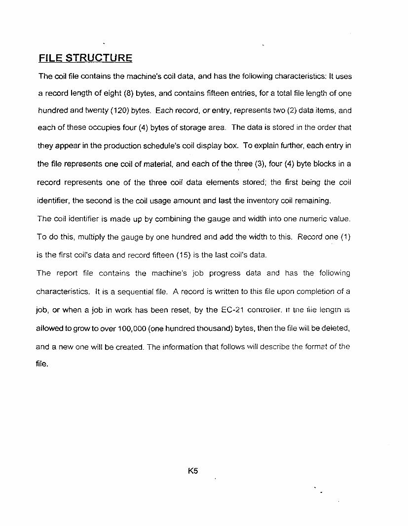
The coil file contains the machine's coil data, and has the following characteristics: it uses
a record length of eight (8) bytes, and contains fifteen entries, for a total file length of one
hundred and twenty (120) bytes. Each record, or entry, represents two (2) data items, and
each of these occupies four (4) bytes of storage area. The data is stored in the order that
they appear in the production schedule's coil display box. To explain further, each entry in
the file represents one coil of material, and each of the three (3), four (4) byte blocks in a
record represents one of the three coil data elements stored; the first being the coil
identifier, the second is the coil usage amount and last the inventory coil remaining.
The coil identifier is made up by combining the gauge and width into one numeric value.
To do this, multiply the gauge by one hundred and add the width to this. Record one (1)
is the first coil's data and record fifteen (1 5) is the last coil's data.
The report file contains the machine's job progress data and has the following
characteristics. It is a sequential file. A record is written to this file upon completion of a
job, or when a job in work has been reset, by the EC-21 controller. IT tne file iengrh IS
allowed to grow to over 100,000 (one hundred thousand) bytes, then the file will be deleted,
and a new one will be created. The information that follows \will describe the format of the
file.

CALCULATOR
This tool is accessible to the user while in the setup or production schedule areas. Entry is
gained by simply pressing the F2 key. A list of special features is always displayed with the
calculator for quick reference. It's total capabilities include the four basic functions, plus
squaring, square root, reciprocal, and exponential math. An additional enhancement is the
ability to export the current value in the display back to the main program for further use.
Based on the algebraic type calculator, it is quite easy to operate. Some sample problems
are detailed below.
Problem (2 + 5 - 3 = ? ):
Keystroke Display
2
+ 2.000 ...
5
- 7.000 ...
3
- - 4.000 ...
Problem (12 * 10 / 5 = ?): Keystroke Display
12.000 ...
120.000 ...
24.000 ...

CALCULATOR
F8 - Exponential math
Pressing this key will give the exponential result of the last numeric values keyed into
the calculator. An example follows.
Problem (2 3, :
Keystroke Display
2
+ 2.000 ...
3
F8 8.000 ...
Since the calculator is based on the standard algebraic model, one of the following
keys must be used to load the initial value. These include + - * I =. Also, the ENTER key
may be substituted for the EQUAL key at any time. All functions can be chained together.
excepting exponential math. This feature requires both allocated storage areas.

TROUBLESHOOTING GUIDE
This troubleshooting guide is designed to aid the operator when attempting to isolate a
problem in the machine or control unit. The guide consist of four sections ...
1. Troubleshooting Length Problems
2. Checking Measuring System Accuracy
3. Checking Sequence of Operation
4. Troubleshooting the Machine
Section 1 covers common problems as they relate to length errors. The
recommendations given assume that the tests in sections 2 and 3 have been run
successfully.
Section 2 explains how to examine the accuracy of the measuring system.
Section 3 describes the machine's normal sequence of operation.
Section 4, details possible electrical and mechanical solutions to common problems.
These tests should be run whenever there is a problem. They should also be used by
anyone who wishes to become familiar wiih the basic iunctions oi une rriaciline & ~ L J ~ i - t t ;
control system.
TROUBLESHOOTING GUIDE
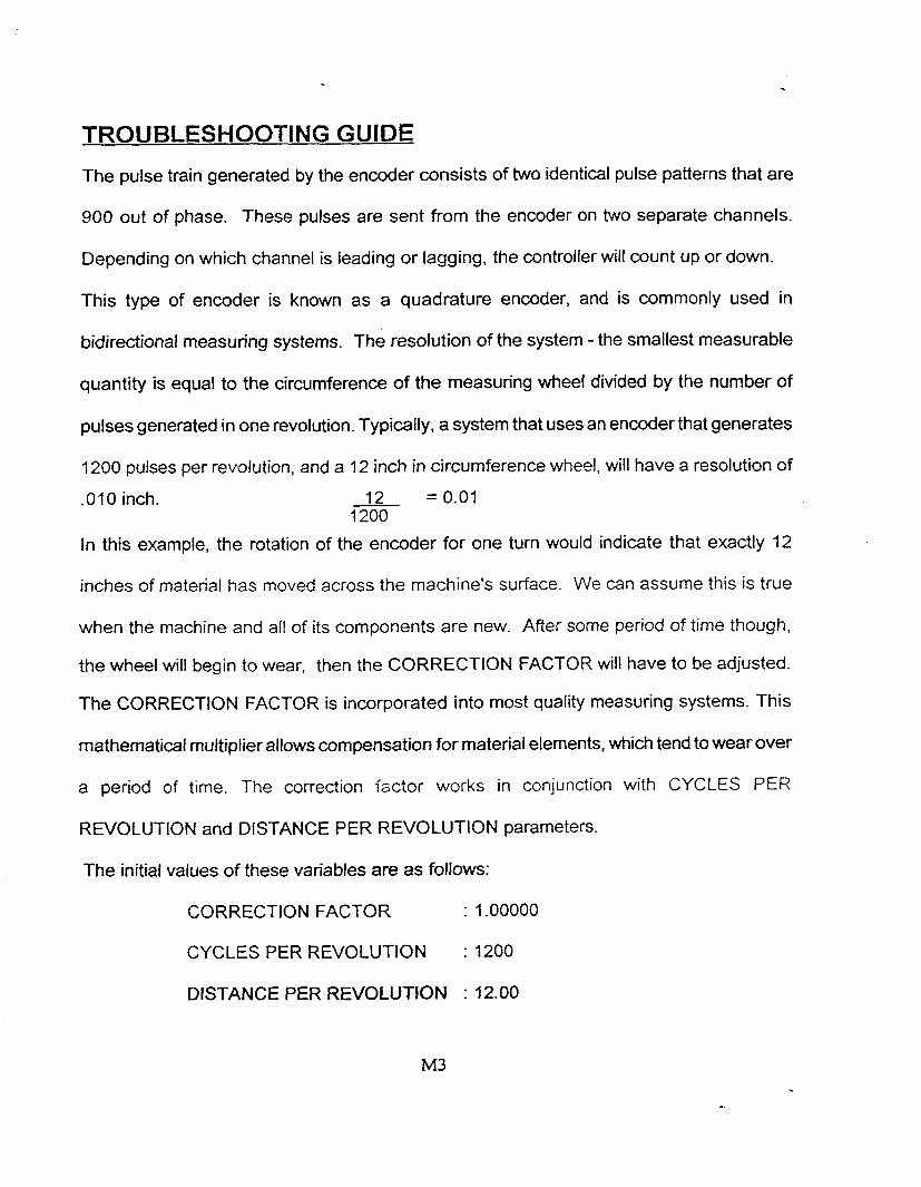
The pulse train generated by the encoder consists of two identical pulse patterns that are
900 out of phase. These pulses are sent from the encoder on two separate channels.
Depending on which channel is leading or lagging, the controller will count up or down.
This type of encoder is known as a quadrature encoder, and is commonly used in
bidirectional measuring systems. The resolution of the system - the smallest measurable
quantity is equal to the circumference of the measuring wheel divided by the number of
pulses generated in one revolution. Typically, a system that uses an encoder that generates
1200 pulses per revolution, and a 12 inch in circumference wheel, will have a resolution of
-01 0 inch.
In this example, the rotation of the encoder for one turn would indicate that exactly 12
inches of material has moved across the machine's surface. We can assume this is true
when the machine and all of its components are new. After some period of time though,
the wheel will begin to wear, then the CORRECTION FACTOR will have to be adjusted.
The CORRECTION FACTOR is incorporated into most quality measuring systems. This
mathematical multiplier allows compensation for material elements, which tend to wear over
a period of time. The correction factor works in conjunction with CYCLES PER
REVOLUTION and DISTANCE PER REVOLUTION parameters.
The initial values of these variables are as follows:
CORRECTION FACTOR : 1.00000
CYCLES PER REVOLUTION : 1200
DISTANCE PER REVOLUTION : 12.00
TROUBLESHOOTING GUIDE
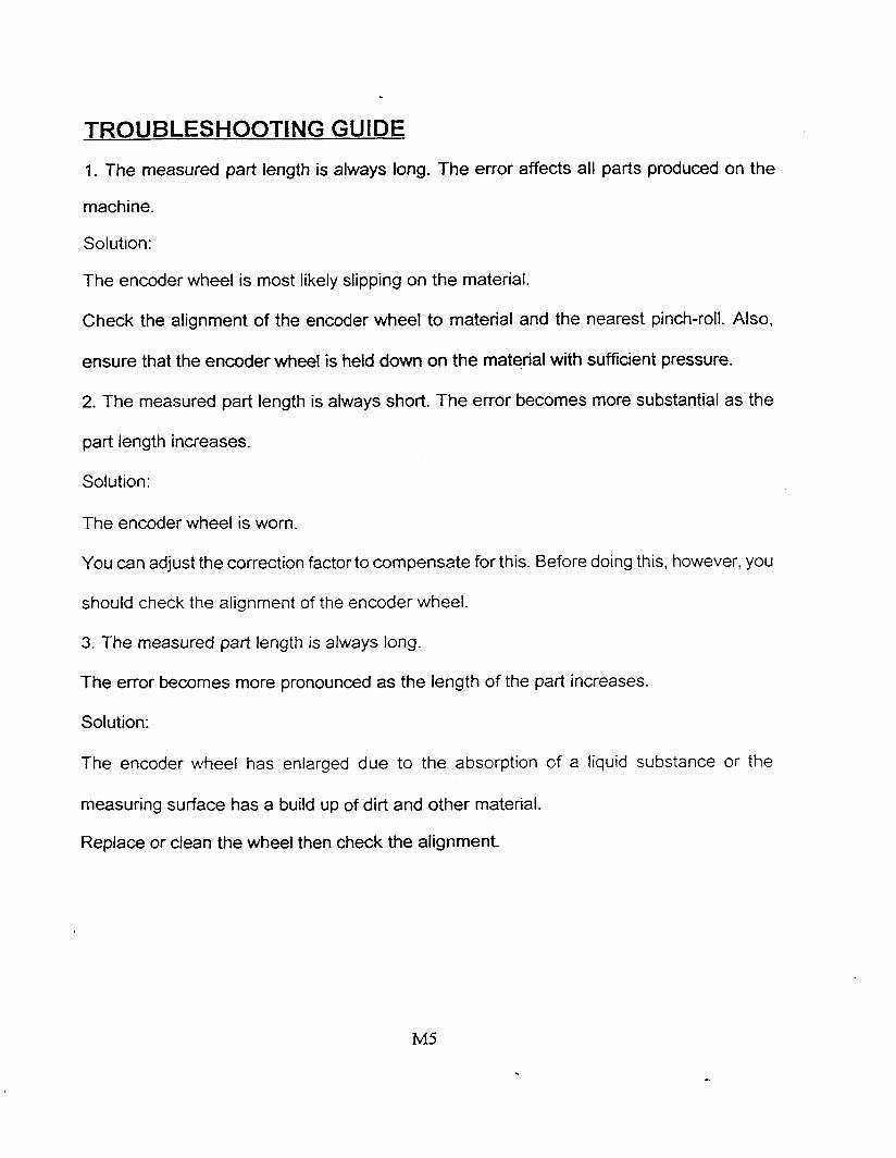
1. The measured part length is always long. The error affects all parts produced on the
machine.
Solution:
The encoder wheel is most likely slipping on the material.
Check the alignment of the encoder wheel to material and the nearest pinch-roll. Also,
ensure that the encoder wheel is held down on the material with sufficient pressure.
2. The measured part length is always short. The error becomes more substantial as the
part length increases.
Solution:
The encoder wheel is worn.
You can adjust the correction factor to compensate for this. Before doing this, however, you
should check the alignment of the encoder wheel.
3. The measured part length is always long.
The error becomes more pronounced as the length of the part increases.
Solution:
The encoder wheel has enlarged due to the absorption of a liquid substance or the
measuring surface has a build up of dirt and other material.
Replace or clean the wheel then check the alignment.
TROUBLESHOOTING GUIDE
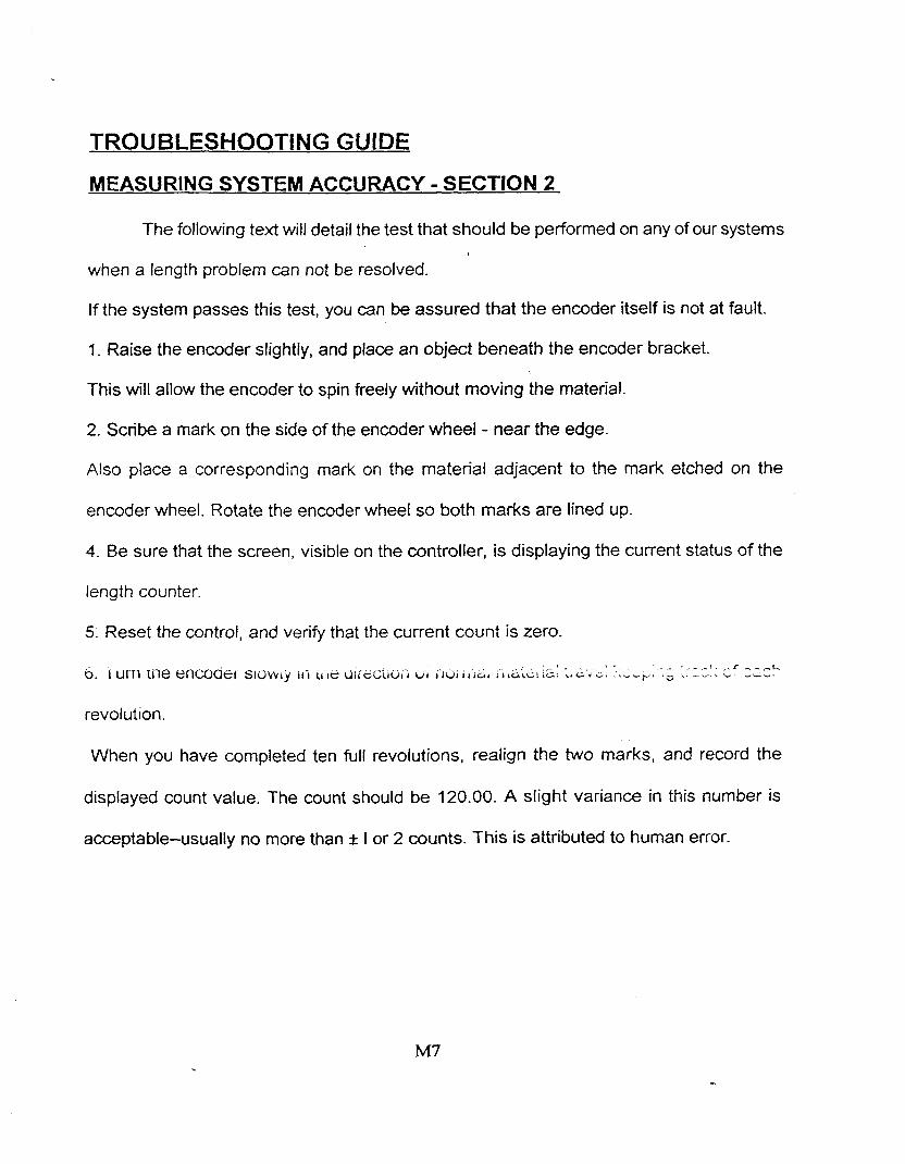
MEASURING SYSTEM ACCURACY - SECTION 2
The following text will detail the test that should be performed on any of our systems
when a length problem can not be resolved.
If the system passes this test, you can be assured that the encoder itself is not at fault.
1. Raise the encoder slightly, and place an object beneath the encoder bracket.
This will allow the encoder to spin freely without moving the material.
2. Scribe a mark on the side of the encoder wheel - near the edge.
Also place a corresponding mark on the material adjacent to the mark etched on the
encoder wheel. Rotate the encoder wheel so both marks are lined up.
4. Be sure that the screen, visible on the controller, is displaying the current status of the
length counter.
5. Reset the control, and verify that the current count is zero.
- . , . - - - - r .r - - ..L 6. 1 urn rile encoasr SIULVI~ 111 11 d l i ~ Z i i u i r U I i 3 1 I r r $ G r c i t ~ . r. L r G , ha..r+ . -- \ ". ---
revolut~on.
When you have completed ten full revolutions, realign the two marks, and record the
displayed count value. The count should be 120.00. A slight variance in this number is
acceptable-usually no more than * I or 2 counts. This is attributed to human error.
TROUBLESHOOTING GUIDE
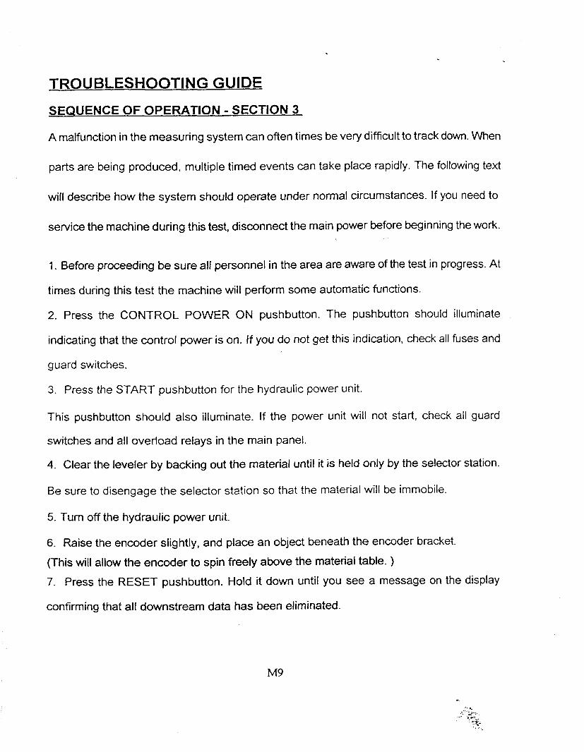
SEQUENCE OF OPERATION - SECTION 3
A malfunction in the measuring system can often times be very difficult to track down. When
parts are being produced, multiple timed events can take place rapidly. The following text
will describe how the system should operate under normal circumstances. If you need to
service the machine during this test, disconnect the main power before beginning the work.
1. Before proceeding be sure all personnel in the area are aware of the test in progress. At
times during this test the machine will perform some automatic functions.
2. Press the CONTROL POWER ON pushbutton. The pushbutton should illuminate
indicating that the control power is on. If you do not get this indication, check all fuses and
guard switches.
3. Press the START pushbutton for the hydraulic power unit.
This pushbutton should also illuminate. If the power unit will not start, check all guard
switches and all overload relays in the main panel.
4. Clear the leveler by backing out the material until it is held only by the selector station.
Be sure to disengage the selector station so that the material will be immobile.
5. Turn off the hydraulic power unit.
6. Raise the encoder slightly, and place an object beneath the encoder bracket.
(This will allow the encoder to spin freely above the material table. )
7. Press the RESET pushbutton. Hold it down until you see a message on the display
confirming that all downstream data has been eliminated.
TROUBLESHOOTING GUIDE
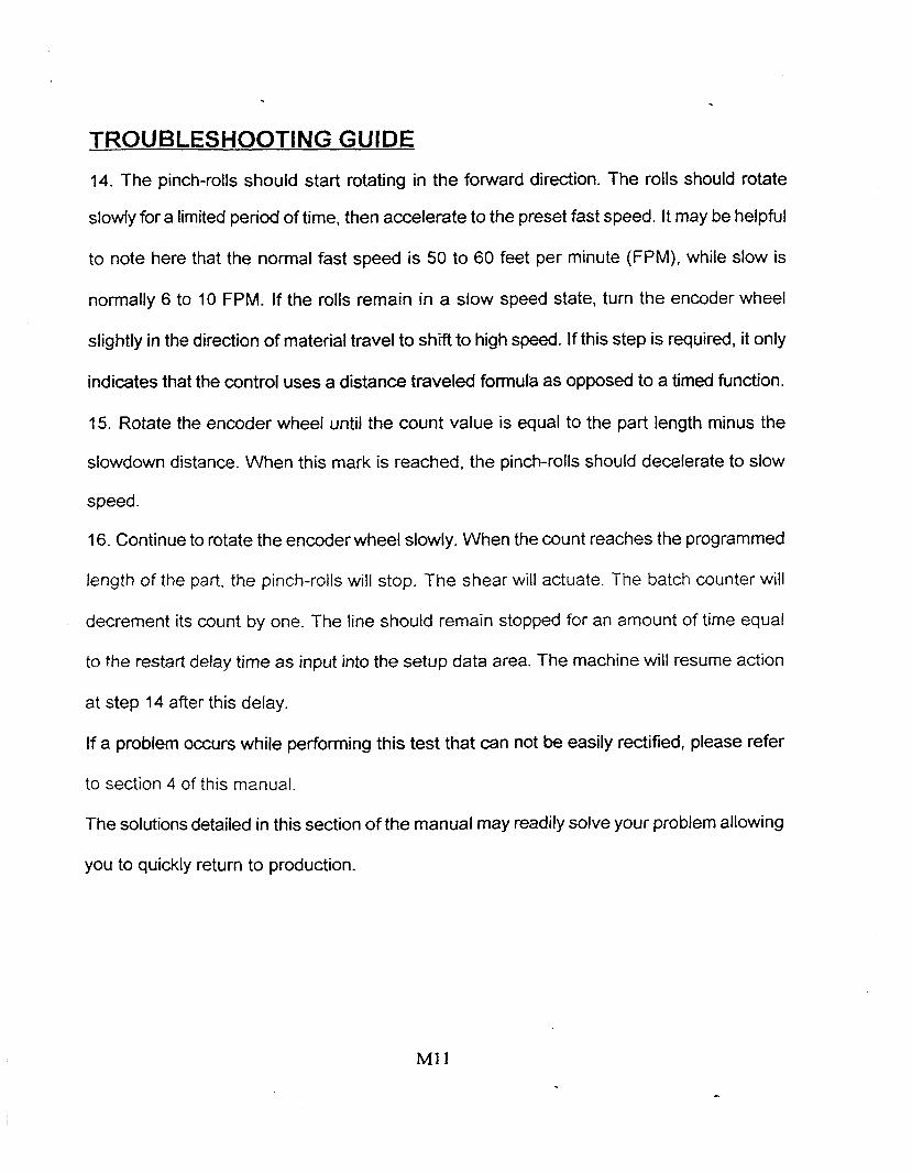
14. The pinch-rolls should start rotating in the forward direction. The rolls should rotate
slowly for a limited period of time, then accelerate to the preset fast speed. It may be helpful
to note here that the normal fast speed is 50 to 60 feet per minute (FPM), while slow is
normally 6 to 10 FPM. If the rolls remain in a slow speed state, turn the encoder wheel
slightly in the direction of material travel to shift to high speed. If this step is required, it only
indicates that the control uses a distance traveled formula as opposed to a timed function.
15. Rotate the encoder wheel until the count value is equal to the part length minus the
slowdown distance. When this mark is reached, the pinch-rolls should decelerate to slow
speed.
16. Continue to rotate the encoder wheel slowly. When the count reaches the programmed
length of the part, the pinch-rolls will stop. The shear will actuate. The batch counter will
decrement its count by one. The line should remain stopped for an amount of time equal
to the restart delay time as input into the setup data area. The machine will resume action
at step 14 after this delay.
If a problem occurs while performing this test that can not be easily rectified, please refer
to section 4 of this manual.
The solutions detailed in this section of the manual may readily solve your problem allowing
you to quickly return to production.
TROUBLESHOOTING GUIDE
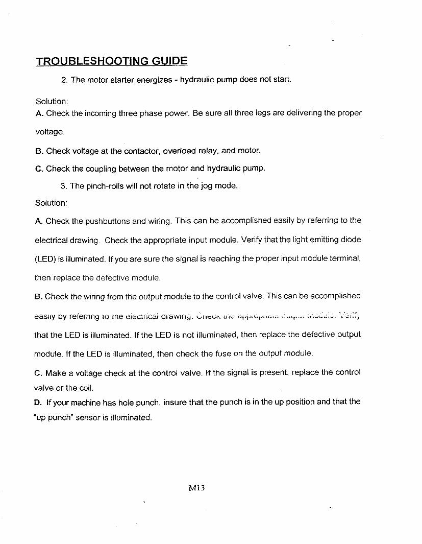
2. The motor starter energizes - hydraulic pump does not start.
Solution:
A. Check the incoming three phase power. Be sure all three legs are delivering the proper
voltage.
B. Check voltage at the contactor, overload relay, and motor.
C. Check the coupling between the motor and hydraulic pump.
3. The pinch-rolls will not rotate in the jog mode.
Solution:
A. Check the pushbuttons and wiring. This can be accomplished easily by referring to the
electrical drawing. Check the appropriate input module. Verify that the light emitting diode
(LED) is illuminated. If you are sure the signal is reaching the proper input module terminal,
then replace the defective module.
6. Check the wiring from the output module to the control valve. This can be accomplished
that the LED is illuminated. If the LED is not illuminated, then replace the defective output
module. If the LED is illuminated, then check the fuse on the output module.
C. Make a voltage check at the control valve. If the signal is present, replace the control
valve or the coil.
D. If your machine has hole punch, insure that the punch is in the up position and that the
'up punch" sensor is illuminated.

- -
TROUBLESHOOTING GUIDE
6. One or more manual operations do not function.
Solution:
A. Verify that you are in HALT or HAND mode. Manual operations are locked out while in
any automatic.
B. If the operation is of a timed nature, then check the value you have entered in the setup
data area. Even if this function has worked before, take. the time to verify that the data is
not corrupt.
C. Check the pushbutton and wiring. This can be accomplished easily by referring to the
electrical drawing. Check the appropriate input module. verify that the light emitting diode
(LED) is illuminated. If you are sure the signal is reaching the proper input module terminal,
then replace the defective module.
D. Check the wiring from the output module to the control valve. This can be accomplished
easilv by referrina to the electrical drawing. Check the appropriate output module. Verify
that the LED is illuminated. If the LED is not illuminated, then replace the defective output
module. If the LED is illuminated, then check the fuse on the output module.
E. Make a voltage check at the control valve. If the signal is present replace the control
valve or the coil
CONTENTS
INTRODUCTION
Section I
Hardware Requirements . .
Installation and Startup
Command Line Options
Section I1
Software Operation '
General Data Entry
Setup Mode
Batch Mode
Data Printout
Calculator

Introduction:
The Engelink software allows a remote computer to communicate, point to point, with the EC-21 Coiline controller, using the standard EIA RS-232C interface. Through this communication the remote computer can send messages and uploadldownload data to the controller on the plant floor. This frees plant personnel from the data entry process. This manual seeks to define the hardware and software parameters required to establish this link between the Engel Coiline and your office PC system. To utilize this software, a thorough knowledge of computer systems and communication techniques is required-it is assumed that the user has such knowledge. Although this manual gives detailed data and transmission examples pertaining to the implementation of this product, it does not attempt and does not intend to teach computer programming, or communications.
The documentation and enclosed software is proprietary material and is copyrighted by Engel Industries, Inc.; all rights are reserved,
Engel Industries, Inc. reserves the right to make improvements in this product at any time and without notice.
Engel Industries, Inc. warrants that the enclosed software will perform in accordance with the product documentation. In the event an operational error is found, then Engel Industries, Inc. will, at its option, either correct the error so that the software conforms to the product documentation, or refund an amount equal to the purchased price of the software. All claims under this warranty must be made in writing. to Engel Industries, Inc. within thirty (30) days from date of purchase.
The foregoing warranty is exclusive and is In lieu of ail otner warranties. Engei Industries, Inc. makes no other warranty of any kind whatever, express or implied; and all implied warranties of merchantability and fitness for a particular purpose are hereby disclaimed by Engel Industries, Inc. and are excluded from this sale.
IBM is a registered trademark of International Business Machines Corporation
IEEE is a registered trademark of the Institute of Electrical and Electronics Engineers
Microsof? is a registered trademark of Microsoft Corporation

Section I
Installation and Start Up:
Before continuing be sure to make a backup copy of your Engelink disk, place the original in a safe place, and use the copy during the installation process.
Create a directory on your hard disk, then copy all files from the Engelink diskette to this directory. To run the program change to the new directory and type ENGELINK, then press the ENTER key. The following may clarify this for you. Press the ENTER key after each line of input.
> CD\ step I. switch computer to root directory . - step 2. create new directory > MD ENGEL step 3. copy all files to new directory >COPY A:*.* C:\ ENGEL step 4. change to new directory >CD\ENGEL step 5. run program >ENGELINK
Command Line Options:
TF--r-- 7'- c-.,cc-I pn-m-mA l ;mn -*+;-me ~ \ , c ; l ~ h l ~ tn fhe k - ~ ~ r , 9 - . ' - . . - L C . L -
list of these options will be displayed on your monitor if you start the Engeiink program with a I? suffix. They are also listed below for your convenience.
lCOM2 : directs software to use communication channel 2 ICOM OFF : disables all RS-232C communications /HELP OFF : disables screen assistance messages /METRIC : uses metric measure system for input data /MONO : sets color defaults to black and white
As an example, if using a monochrome monitor, the user could start the Engelink software by typing the following line at the DOS prompt. :

Section II
Setup Mode Instructions:
The setup screens are primarily used to input machine parameters, that may require an occasional change. These values will normally be quite different from one machine to another. This mode contains thirteen pages of setup data. The prompts are listed below with a brief explanation, for your convenien&.
CYCLES PER REVOLUTION :number of pulses generated by the encoder DISTANCE PER REVOLUTION :circumference of the encoder wheel CORRECTION FACTOR :a multiplier used to match the encoder to the system SLOWDOWN DISTANCE :amount of deceleration time required by the machine MINIMUM MOVEMENT :smallest forward move allowed PAUSE TlME AFTER SHEAR :part spacing time value
REMOTE- METAL FLOW :direction of flow of downstream components HALT SHEAR-ONLY BATCHES :enables capability to'run blanks continuously END NOTCH TO SHEAR DlST :distance f rom shear to the user reference on die VEE NOTCH TO SHEAR DlST :distance from shear to center of notch die HOLE PUNCH TO SHEAR DlST : distance f rom shear to center of hole punch die ACTUATION TIME ' :allocated time to f ire the designated dies LEAU~NG E v G t LjM SriE stance itom usei reiei-en* LW GIG^ ica~ GUYG
TRAILING EDGE DIE SIZE :distance from user reference to dies forward edge NOTCH X LEADING EDGE :leading edge lock allowance for part NOTCH X TRAILING EDGE :trailing edge lock allowance for part BACKGAUGE BRAKE OFFSET :bend point offset for L-shape brake REFERENCE POINT :home position measurement for gauging equipment LIN-0-MATIC OFFSET :pin shifting value to align pins on insulated parts VELOCITY SETTINGS :pin spacing values for insulated parts CORNER ROTATION FACTOR :value that will shift V-notches as a group on part OFFSET BEND LOCATION X :bend point offset for full wrapper brake

Section II
Data Printout:
The software has the capability of providing a printout, or hard copy, of the machine setup, or production data. To obtain a printout simply press function key F(3), while in the setup, or production schedule areas. When the computer prints out the data it will start with a standard header, which will include the -type of data, and the current date and time.
When doing a production schedule dump the computer will print only jobs with a status other than ***. The current coil / material information will be included at the end of a production schedule printout. If the requested data is not available, the computer will print a short message stating this.
Calculator:
An on-screen calculator is available to the user in either the setup, or production schedule mode. The operation of the calculator is very straight forward, with one special feature, and that is the exportation of the accumulator back to the main proaram. To exmrt the accumulator, simply press the E key at the end of the calculation session. The accumulator will then be inserted into the current window, to accept this value the user must then press the ENTER key. To input a negative amount, press the S key, this will cause the accumulator to be toggled negative and positive each time the key is pressed. The standard functions of the calculator include addition, subtraction, multiplication, and division. If the result of a calculation is out of the range of the display window, an E will displayed indicating this fault. Use the ESC key to exit the calculator mode without using the export feature.

Section IV Transmission Process:
The remote computer is considered the line master, or host device. All transmissions use the standard ASCll code. The software line discipline is half duplex, characters are not echoed back to the host device. The EC-21 controller will not initiate transmissions, except in response to a valid command from the host. AU messages must start with STX (ASCII 2), and end with ETX (ASCII 3), followed by a checksum byte, and ending the transmission with EOT (ASCII 4). The checksum is calculated by summing the ASCll weight of each character in the message, excluding the control characters. An ASCll chart is shown intappendix A of, this manual. A typical exchange of data between the EC-21 control and a remote computer would be as follows.
The remote computer initiates a message: STX (ASCII 2) I start of text MESSAGE ETX (ASCII 3) I end of text CHECKSUM EOT (ASCII 4) / end of transmission
If the message is received without errors the EC-21 will respond with: STX (ASCII 2) I start of text ACK(ASCIT 6) I acknowledge ETX (ASCII 3) i end oi text EOT (ASCII 4) / end of transmission
If the message was received with an error, the EC-21 will not respond. The remote computer should start the transmission over, after a three second timeout. There are 2 groups of data that can be transmitted over the data link, these are the setup data, and production schedule. The EC-21 expects to receive and transmit the data in complete groups, if an error occurs during a transmission, the complete group must be transmitted again. Production data must be transmitted in the following order, first the job data, next the coil data, and finally the label data. If the transmission contains setup or production data, then an item number must also be included in data stream, this will inform the computer as to the destination of the data that follows. Examples of this are given in appendix B of this manual.

Section V
File Structure:
There are four (4) files that the user can manipulate, using their selfdeveloped soware. The information included here is given strictly as a guide for our customers. Engel Industries does not intend to write software for other than Engel equipment, it is the responsibility of the customers programmer to maintain compatibility between any external computers and the coiline control system. The files are listed below.
PRODUCT. DAT SETUP-DAT LABEL-DAT
COIL. DAT
A few points that pertain to all the files, is as follows. All files are the random access type. AN numeric data is left justified, single precision, and stored using the IEEE format. The acronym IEEE represents the Institute of Electrical and Electronics Engineers. The IEEE format differs from the Microsoft Binary Format, in that it extends the single precision range of numbers, and obtains more accurate results, also coprocessor support is easier to implement. Data that involves measured amounts uses
- , i t I - ch lalib6 1 I I ~ G G ~ L I ~ ~I-l-iLa t~ zJ "bed I ' .
The setup file contains all the machine's setup data, and has the following characteristics. It uses a record length of four (4) bytes, and contains one hundred and
eleven (Ill) entries, for a total file length of four hundred and forty-four (444) bytes. Each record or entry represents one data item. The data is stored in the order that they appear in the setup area of the Engelink program. When the stored data does not represent numeric data, as in the following examples, then the following special values are stored in its place.
Remote Metal Flow: Normal = 0 / Reverse = 1
Halt Shear-only Batches: Yes = O/No = 1

Section V
The label file contains the machine's label comment data, and has the following characteristics. It is composed of ASCII string data, uses a record length of ninety-nine (99) bytes, and contains one hundred entries, for a total file length of nine thousand nine hundred (9900) bytes. Each record or entry represents three (3) data items, and each of these occupies thirty-three (33) bytes of storage area. The data is stored in the order that they appear in the production schedule's label display box. To explain further, each entry in the file represents one label, and each of the three (3), thirty-three (33) byte blocks in a record represents one of the three label comment lines. Record one (1) is the first job's label data and record one hundred (100) is the last job's label data.
The coil file contains the machine's coil data, and has the following characteristics. It uses a record length of eight (8) bytes, and contains fifteen entries, for a total file length of one hundred and twenty (1 20) bytes. Each record or entry represents two (2) data items, and each of these occupies four (4) bytes of storage area. The data is stored in the order that they appear in the production schedule's coil display box. To explain further, each entry in the file represents one coil of material, and each of the two (2), four (4) byte blocks in a record represents one of the two coil data elements stored; the first being the coil identifier and the second is the coil usage amount. The coil identifier is made up by combining the gage and width into one numeric value, to do this multiply the gauge by one hundred and add the width to this. Record one (1) is the first coil's data and record fifteen (15) is the last
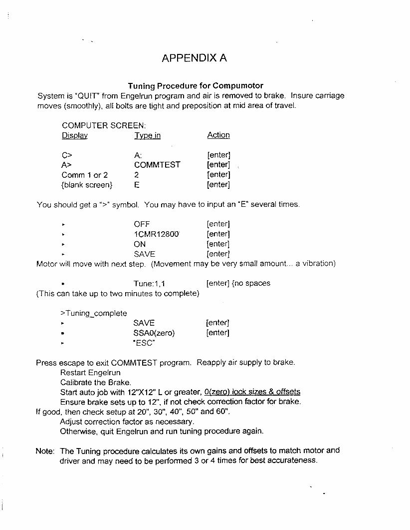
APPENDIX A
Tuning Procedure for Compumotor System is "QUIT" from Engelrun program and air is removed to brake. Insure carriage moves (smoothly), all bolts are tight and preposition at mid area of travel.
COMPUTER SCREEN: Display T Y D ~ in Action
C> A: [enter] A> COMMTEST [enter] Comm 1 or 2 2 [enter] {blank screen) E [enter]
You should get a ">" symbol. You may have to input an "En several times.
t OFF [enter] t 1 CMR12800' [enter] t ON [enter] t SAVE [enter]
Motor will move with next step. (Movement may be very small amount ... a vibration)
Tune: 1 , l [enter] {no spaces (This can take up to two minutes to complete)
>Tuning-complete t SAVE [enter]
SSAO(zero) [enter] t 'ESC"
Press escape to exit COMMTEST program. Reapply air supply to brake. Restart Engelrun Calibrate the Brake. Start auto job with 12"X12" L or greater, Okero) lock sizes & offsets Ensure brake sets up to 12", if not check correction factor for brake.
If good, then check setup at 20", 3 0 , 40", 50" and 60". Adjust correction factor as necessary. Otherwise, quit Engelrun and run tuning procedure again.
Note: The Tuning procedure calculates its own gains and offsets to match motor and driver and may need to be performed 3 or 4 times for best accurateness.
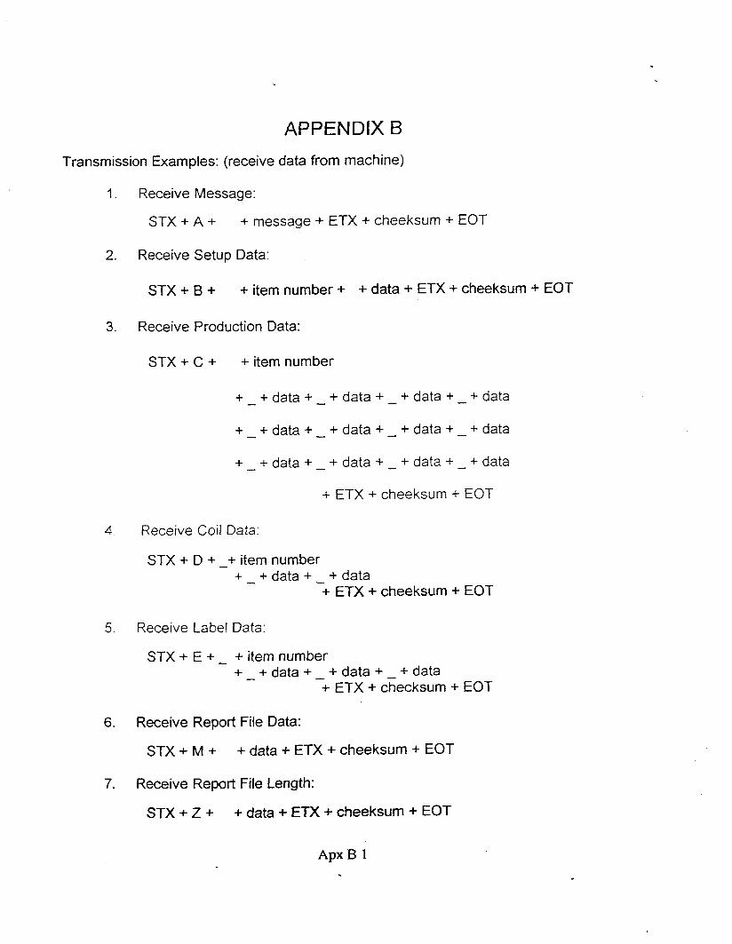
APPENDIX B
Transmission Examples: (receive data from machine)
1. Receive Message:
STX + A + + message + ETX + cheeksum + EOT
2. Receive Setup Data:
STX + B + + item number + + data + ETX + cheeksum + EOT
3. Receive Production Data:
STX + C + + item number
+ - + data + - + data + - + data + - + data
+ - + data + - + data + - + data + - + data
+ - + data + - + data + - + data + - -1- data
+ ETX + cheeksum + EOT
4. Receive Coil Data
STX + D + -+ item number + + data + - + data -
+ ETX + cheeksum + EOT
5. Receive Labe! Data:
STX + E + - + item number + + data + - + data + - + data -
+ ETX + checksum + EOT
6. Receive Report File Data:
STX + M + + data + ETX + cheeksum + EOT
7. Receive Report File Length:
STX + Z + + data + ETX + cheeksum + EOT
Apx B 1


APPENDIX C
MANUAL HOLE PUNCH
Blank parts will not contain end-notches, vee-notches or hole punches.
Fiats can be either a leading edge panel (non shifted) or a trailing edge
panel (shifted holes). All leading edge selections are non shifted and
all trailing edge selections are shifted.
"L" type parts contain one leading edge and one trailing edge.
"U" type parts contain one leading edge, one trailing edge and another leading
edge.
"W" type parts contain one leading edge, one trailing edge, another leading
edge and another trailing edge.
The hole punch does not have any maximum size limitations outside of the 120"
limitation of the standard coiline machine. The minimum size is limited to 5 panels of hole
can be 6.6". The following page defines the hole-punch patterns given for a defined code
code FUH code FUH code RIH code R/H code RIH code RJH code RIH
A = 1,1 B = l , 2 C = 1 , 3 D = 2 , 1 E = 2,2 F = 2 , 3 G = 3 , 1
H = 3,2 I = 3,3 X = O , O J = SPECIAL
Example: HPLeading HPTrailing
A G
(1 rowlsection, 1 holelrow) (3 rowslsection, 1 holelrow)
Note:
F = one leading edge U = two leading, one trziiling edge
L = one leading, one trailing edge W = two leading, two trailing edges
Apx C3

APPENDIX D
. .....
Computer at office Com 1 at machine
Apdx D l

APPENDIX D
... .. . . . .
Computer at ofice Com 1 at machine
Apdx D l