Embed Size (px)
DESCRIPTION
MacPro (Mid 2010)Gabriel Flores RozasE-Mail: [email protected]: www.gflores.clMAC TRAINING, BI Technology SpASoluciones Informáticas en Mac, Windows, iPhone y iPadURL: www.mactraining.clINDEI, Instituto para el Desarrollo IntegralArtes Marciales, Medicina Tradicional China, Tai Chi, Chi Kung y YogaURL: www.indei.cl
Citation preview
Apple Technician Guide
Mac Pro (Mid 2010) 2010-09-27
Apple Inc.
© 2010 Apple Inc. All rights reserved.
Under the copyright laws, this document may not be copied, in whole or in part, without the written consent of Apple.
Every effort has been made to ensure that the information in this document is accurate. Apple is not responsible for printing or clerical errors.
Apple 1 Infinite Loop Cupertino, CA 95014-2084 USA + 1 408 996 1010 www.apple.com
Apple, the Apple logo, Mac, and Macintosh are trademarks of Apple Inc., registered in the U.S. and other countries.
Mac Pro (Mid 2010)
Contents
About This Guide
Manual Updates 9
Feedback 10
Basics
Overview 12How to Identify Single- and Dual-Processor Configurations 13Serial Number Location 14
New Accessories 15Magic Trackpad 15Apple Battery Charger 17
Troubleshooting
General Troubleshooting 19Update System Software and Firmware 19Troubleshooting Theory 19Emerging Issues 19Hardware vs. Software 19Wireless Troubleshooting 20Mac Pro Firmware Updates 20Memory Configuration 22Memory Diagnostic LEDs 24PCIe/Graphics Cards 26Functional Overview 27Block Diagram 29Common Reset Procedures 30Power-On Self Test: RAM and Processor Verification 32Minimum Configuration Testing 33Processor Diagnostic LEDs 37
Symptom Charts Overview 39
Startup and Power Issues 42No Power/Dead Unit 42
Intermittent Shutdown 45Memory Issues/Kernel Panic and Freezes 48No Video 53Power, but No Boot 56Noise/Hum/Vibration 57Burnt Smell/Odor 59Uncategorized Symptom 60
Communications 61Ethernet Port/Device Issue 61AirPort/Bluetooth: Defective Wireless Devices 63No/Poor Wireless Signal 65Wireless Input Device Loses Connection 67AirPort Card: Kernel Panic 69Wireless Performance Issue / Slow Connection 70Wireless Input Device Doesn’t Pair 73Uncategorized Symptom 74Hard Drive/SSD Read/Write Issue 75Hard Drive/SSD Not Recognized/Not Mounting 77Hard Drive Noisy 79Optical Drive Won’t Accept/Reject Media 80Optical Drive Read/Write Data Error 82Optical Drive Not Recognized/Not Mounting 84Optical Drive Noisy 86Optical Drive Not Performing to Specs 89Uncategorized Symptom 90
Input/Output Devices 91USB Port Does Not Recognize Known Devices 91FireWire Port Does Not Recognize Known Good Devices 92No Audio from Internal Speaker 94Distorted Audio from Internal Speaker 95Front Headphone Jack Has No Audio 97Line-In Jack Has No Input 98Line-In Jack Has Distorted Input 100Rear Line-Out Jack Has No Audio 101Optical Digital Audio In Has No Input 103Optical Digital Audio Out Has No Output 105Apple Wireless Mouse/Magic Trackpad Erratic Tracking 107Apple Battery Charger Does Not Charge Batteries 108Uncategorized Symptom 109
Mechanical Issues: Thermals and Enclosure 110Computer Runs Slow with Fast/Failed Fans 110Power Button Stuck 112Internal Cables and Connectors Defective 114
Mechanical/Physical Damage 115Uncategorized Symptom 115
Take Apart
General Information 117Orientation 117Tools 117Parts Requiring Enclosure Replacement 117How to Identify Single- and Dual-Processor Configurations 117Icon Legend 118Note on Illustrations 118
Opening the Computer 119
Hard Drive/Solid-State Drive and Drive Carrier 121Removal 122Reassembly, SATA Drive and Carrier 122Reassembly, SSD Drive and Carrier 123
SSD Carrier Adapter 127Removal 128Reassembly 129Replacing the Carrier for SSD 130
Optical Drive Carrier and Optical Drive 131Removal 132Reassembly 133
Processor Tray 134
Memory DIMMs 136Memory Configuration 137Removal 139
PCI Express/Graphics Card 140
Power Supply 149
AirPort Extreme Card 153
Bluetooth Card 155
Battery 157Removal 158Reassembly 158
PCIe Fan 159Removal 160
Reassembly 160
Mac Pro RAID Card and Battery 161Removal 162Reassembly 163
Processor Cage 165
Processor Cage Fans, Front and Rear 168
Speaker Assembly 170
Processor Heatsinks, Dual 172Removal 173Reassembly 173
Processor Heatsink, Single 177Removal 178Reassembly 178
Processor, Dual 182Removal 183Reassembly 185
Processor, Single 188Removal 189Reassembly 191
Processor Board, Dual 194
Processor Board, Single 196
Processor Tray Support Plate 198
Front-Panel-Board-to-Backplane-Board Cable 200
Backplane Board 202
Front Panel Board 206
Power Button 208
Optical Drive Cable Harness 210
Bluetooth Antenna Board with Cable 212
Views
Exploded Views 217

External Views 219
Screw Matrix 221

© 2010 Apple Inc. All rights reserved.
Apple Technician Guide
About This GuideMac Pro (Mid 2010)
Mac Pro (Mid 2010) About This Guide — Manual Updates 9 2010-09-27
Manual Updates
Update 27 September 2010
Troubleshooting Symptom Charts: Added reference and link for SYS_PWR solder-pad photo in “Minimum Configuration Testing” to SYS_PWR solder-pad icons in “No Power/Dead Unit” and ”Power Button Stuck” Deep Dives.
Update 31 August 2010
Troubleshooting Symptom Charts: Added step for re-aligning graphics card to Deep Dive for three wireless connection issues.
Mac Pro (Mid 2010) Introduced 27 July 2010

Mac Pro (Mid 2010) About This Guide — Feedback 10 2010-09-27
Feedback
We want your feedback to help improve this and future Technician Guides!
Please email any comments to:

© 2010 Apple Inc. All rights reserved.
Apple Technician Guide
BasicsMac Pro (Mid 2010)
Mac Pro (Mid 2010) Basics — Overview 12 2010-09-27
Overview
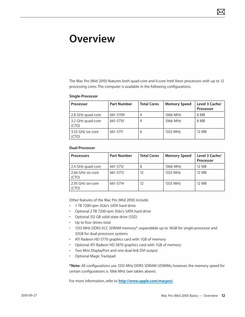
The Mac Pro (Mid 2010) features both quad-core and 6-core Intel Xeon processors with up to 12 processing cores. The computer is available in the following configurations.
Single-Processor
Processor Part Number Total Cores Memory Speed Level 3 Cache/Processor
2.8 GHz quad-core 661-5709 4 1066 MHz 8 MB3.2 GHz quad-core (CTO)
661-5710 4 1066 MHz 8 MB
3.33 GHz six-core (CTO)
661-5711 6 1333 MHz 12 MB
Dual-Processor
Processors Part Number Total Cores Memory Speed Level 3 Cache/Processor
2.4 GHz quad-core 661-5712 8 1066 MHz 12 MB2.66 GHz six-core (CTO)
661-5713 12 1333 MHz 12 MB
2.93 GHz six-core (CTO)
661-5714 12 1333 MHz 12 MB
Other features of the Mac Pro (Mid 2010) include:• 1 TB 7200-rpm 3Gb/s SATA hard drive• Optional 2 TB 7200-rpm 3Gb/s SATA hard drive• Optional 512 GB solid-state drive (SSD)• Up to four drives total• 1333 MHz DDR3 ECC SDRAM memory*, expandable up to 16GB for single-processor and
32GB for dual-processor systems• ATI Radeon HD 5770 graphics card with 1GB of memory• Optional ATI Radeon HD 5870 graphics card with 1GB of memory• Two Mini DisplayPort and one dual-link DVI output• Optional Magic Trackpad
*Note: All configurations use 1333 MHz-DDR3 SDRAM UDIMMs; however, the memory speed for certain configurations is 1066 MHz (see tables above).
For more information, refer to http://www.apple.com/macpro/.
Mac Pro (Mid 2010) Basics — Overview 13 2010-09-27
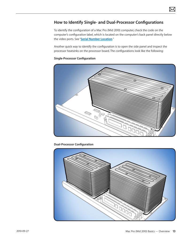
How to Identify Single- and Dual-Processor Configurations
To identify the configuration of a Mac Pro (Mid 2010) computer, check the code on the computer’s configuration label, which is located on the computer’s back panel directly below the video ports. See “Serial Number Location.”
Another quick way to identify the configuration is to open the side panel and inspect the processor heatsinks on the processor board. The configurations look like the following:
Single-Processor Configuration
Dual-Processor Configuration
Mac Pro (Mid 2010) Basics — Overview 14 2010-09-27
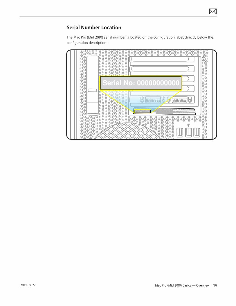
Serial Number Location
The Mac Pro (Mid 2010) serial number is located on the configuration label, directly below the configuration description.
Mac Pro (Mid 2010) Basics — New Accessories 15 2010-09-27
New Accessories
Magic Trackpad
The wireless Magic Trackpad uses Bluetooth technology to connect to the Mac and comes with two AA batteries installed. Use of the Magic Trackpad and its full features requires Mac OS X version 10.6.4 or later and the latest trackpad software.
Note: If the Mac Pro (Mid 2010) has had system software reinstalled for any reason, pair the Magic Trackpad and then run Software Update. If only basic functionality is present on Magic Trackpad, ensure that it is paired correctly before launching Software Update. For more information, refer to:• HT4254 About Magic Trackpad and Multi-Touch Trackpad Update 1.0• HT4273 About Magic Trackpad Update 1.0 for Windows
About the Indicator Light
The indicator light displays the status of the Magic Trackpad and the batteries.• When you first turn on the trackpad, the indicator light glows steadily for 2 to 3 seconds,
indicating the batteries are good.• If the trackpad isn’t paired with a Mac, the light blinks, indicating the trackpad is in discovery
mode and ready to pair (pairing means connecting the trackpad and Mac to each other wirelessly).
• If you don’t pair the trackpad with the Mac within 3 minutes, the light and trackpad turn off to conserve battery life. Press the On/off button on the trackpad to turn it on again, allowing you to pair it with the Mac.
• When the trackpad is on and connected, the indicator light turns off.
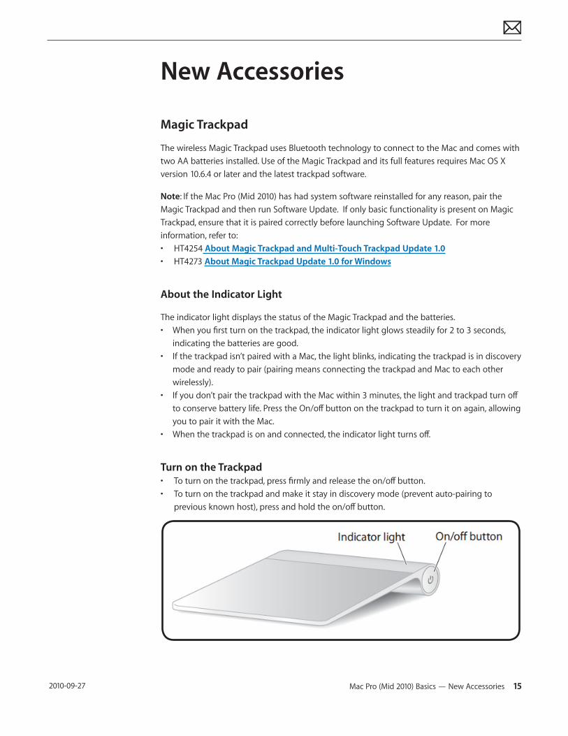
Turn on the Trackpad• To turn on the trackpad, press firmly and release the on/off button.• To turn on the trackpad and make it stay in discovery mode (prevent auto-pairing to
previous known host), press and hold the on/off button.
Mac Pro (Mid 2010) Basics — New Accessories 16 2010-09-27
Pairing the Magic Trackpad
To pair the trackpad:
1. Choose Apple () > System Preferences, and then click Trackpad.
2. Click “Set Up Bluetooth Trackpad …” in the lower-right corner.
3. Press the On/off button on the trackpad to turn it on.
4. Click Continue when the trackpad is detected.
Once the trackpad is paired with the Mac, use Software Update again to make sure the latest software is installed.
Note: If the Mac Pro (Mid 2010) has had system software reinstalled for any reason, pair the Magic Trackpad and then run Software Update. If only basic functionality is present on Magic Trackpad, ensure that it is paired correctly before launching Software Update.
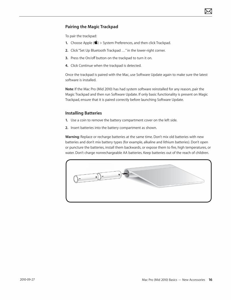
Installing Batteries1. Use a coin to remove the battery compartment cover on the left side.
2. Insert batteries into the battery compartment as shown.
Warning: Replace or recharge batteries at the same time. Don’t mix old batteries with new batteries and don’t mix battery types (for example, alkaline and lithium batteries). Don’t open or puncture the batteries, install them backwards, or expose them to fire, high temperatures, or water. Don’t charge nonrechargeable AA batteries. Keep batteries out of the reach of children.
Mac Pro (Mid 2010) Basics — New Accessories 17 2010-09-27
Apple Battery Charger
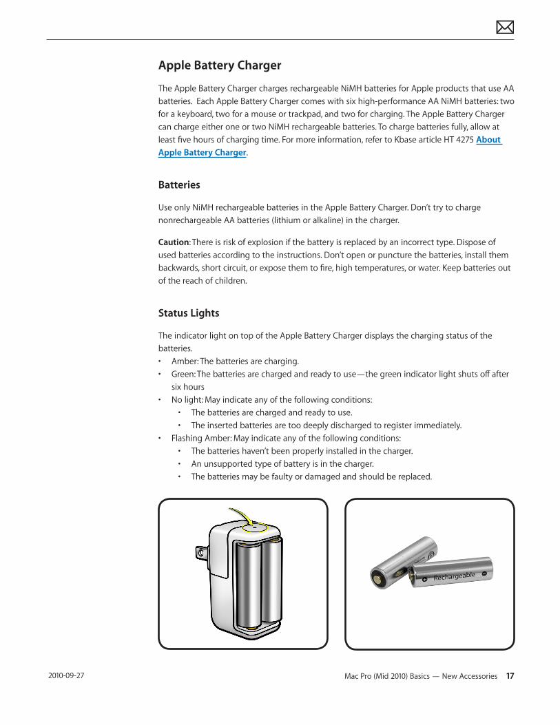
The Apple Battery Charger charges rechargeable NiMH batteries for Apple products that use AA batteries. Each Apple Battery Charger comes with six high-performance AA NiMH batteries: two for a keyboard, two for a mouse or trackpad, and two for charging. The Apple Battery Charger can charge either one or two NiMH rechargeable batteries. To charge batteries fully, allow at least five hours of charging time. For more information, refer to Kbase article HT 4275 About Apple Battery Charger.
Batteries
Use only NiMH rechargeable batteries in the Apple Battery Charger. Don’t try to charge nonrechargeable AA batteries (lithium or alkaline) in the charger.
Caution: There is risk of explosion if the battery is replaced by an incorrect type. Dispose of used batteries according to the instructions. Don’t open or puncture the batteries, install them backwards, short circuit, or expose them to fire, high temperatures, or water. Keep batteries out of the reach of children.
Status Lights
The indicator light on top of the Apple Battery Charger displays the charging status of the batteries.• Amber: The batteries are charging.• Green: The batteries are charged and ready to use—the green indicator light shuts off after
six hours• No light: May indicate any of the following conditions:
• The batteries are charged and ready to use.• The inserted batteries are too deeply discharged to register immediately.
• Flashing Amber: May indicate any of the following conditions:• The batteries haven’t been properly installed in the charger.• An unsupported type of battery is in the charger.• The batteries may be faulty or damaged and should be replaced.
© 2010 Apple Inc. All rights reserved.
Apple Technician Guide
TroubleshootingMac Pro (Mid 2010)
Mac Pro (Mid 2010) Take Apart — General Troubleshooting 19 2010-09-27
General Troubleshooting
Update System Software and Firmware
Important: Apply the latest software and firmware updates before you begin troubleshooting. Computers sometimes exhibit symptoms that indicate the wrong Mac OS X system software is
Troubleshooting Theory
For general information on troubleshooting theory, refer to:
http://service.info.apple.com/service_training/en/006/troubleshoot/index.php?page=intro
Emerging Issues
For the latest on troubleshooting issues, refer to:
http://support.apple.com/kb/index?page=search&q=khot%20Mac%20Pro%20Emerging%20Issue
Hardware vs. Software
For information on how to isolate a hardware issue from a software issue, refer to:
TS1388—Mac OS X: Isolating issues in Mac OS X <http://support.apple.com/kb/TS1388?viewlocale=en_US>
TS1394—Mac OS X: Troubleshooting installation and software updates <http://support.apple.com/kb/TS1394>
HT2956—Troubleshooting Mac OS X installation from CD or DVD <http://support.apple.com/kb/HT2956>
For information on how to troubleshoot a software issue, refer to:
HT1199—Mac OS X: How to troubleshoot a software issue <http://support.apple.com/kb/HT1199>
Mac Pro (Mid 2010) Take Apart — General Troubleshooting 20 2010-09-27
Wireless Troubleshooting
If you’re having issues with Bluetooth and wireless connectivity issues, refer to the following:• TS3048 Troubleshooting wireless mouse and keyboard issues• HT3887 Wireless input devices: Bluetooth frequently asked questions• HT1365 AirPort and Bluetooth: Potential sources of interference for wireless devices and
networks • HT3903 Apple Wireless Keyboard and Mouse: How to install batteries• HT4273 About Apple Magic Trackpad Update 1.0 for Windows• HT4254 About: Magic Trackpad and Multi-Touch Trackpad Update 1.0• HT 4275 About Apple Battery Charger• Bluetooth Service Diagnostic (BSD) self-paced training• Bluetooth Troubleshooting Course
Mac Pro Firmware Updates
Firmware is software written into memory circuits, such as flash memory, that will hold the software code indefinitely, even when power is removed from the hardware. Firmware on Intel Mac computers is designed to be updated if necessary through a software update.
EFI firmware updates update the Boot ROM, and SMC updates update the System Management Controller firmware. The SMC manages fans and other environmental parameters that are independent of the Boot ROM.
Firmware symptoms can be easily mistaken for hardware issues (e.g., overheating issues, fan noise issues, etc.). Always check both EFI and SMC firmware versions and update if necessary before replacing any hardware components.
The following lists describe the type of symptoms that may be resolved by updating the EFI and SMC firmware.
Symptoms that may be resolved by updating EFI firmware:• Cannot eject media (various conditions)• No video on start up• Blue system failure screens in Windows XP/Vista• Not waking or sleeping when expected• Bad media taking too long to eject (including holding mouse button down at startup taking
minutes to eject)
Symptoms that may be resolved by updating SMC firmware:• Fan related behavior (excessive speed or noise)• Loud audible clicking from some fans• Thermal shut down or warnings• Diagnostics reporting failures• Sleep/wake issues• Intermittent shut down• SMC causes bad/missing ambient sensor to cause the computer to go to sleep• Hangs, black screen on restart from Windows
Mac Pro (Mid 2010) Take Apart — General Troubleshooting 21 2010-09-27
• Quick power cycle causes Memory Processor Board Diagnostic LEDs and CPU Overtemp LEDs to illuminate solidly
Important: Since the SMC firmware is stored on both the backplane board and processor board, it is important that the version of SMC firmware is the same on both boards.
Please follow the steps outlined in KnowledgeBase article HT1557, “About Firmware Updates for Intel-based Macs,” to perform an EFI and/or SMC firmware update. Information about firmware versions for Intel Macs can be found in KnowledgeBase article HT1237, “EFI and SMC Firmware Updates for Intel-based Macs.”
Mac Pro (Mid 2010) Take Apart — General Troubleshooting 22 2010-09-27
Memory Configuration
Mac Pro (Mid 2010) comes with a minimum of 3 GB of memory in single-processor configurations, or a minimum of 6 GB memory in dual-processor configurations, installed as 1 GB unbuffered ECC dual inline memory modules (UDIMMs).
DIMMs must fit these specifications:• PC3-10600E,1333 MHz, DDR3 SDRAM UDIMMs• Error-correcting code (ECC)• 72-bit wide, 240-pin ECC modules• 36 memory ICs maximum per ECC UDIMM
For proper operation of Mac Pro (Mid 2010) computers, Apple recommends using only Apple-approved DIMMs. Refer to GSX for Apple DIMM service part numbers. Memory from older Macintosh computers is not compatible with Mac Pro (Mid 2010).
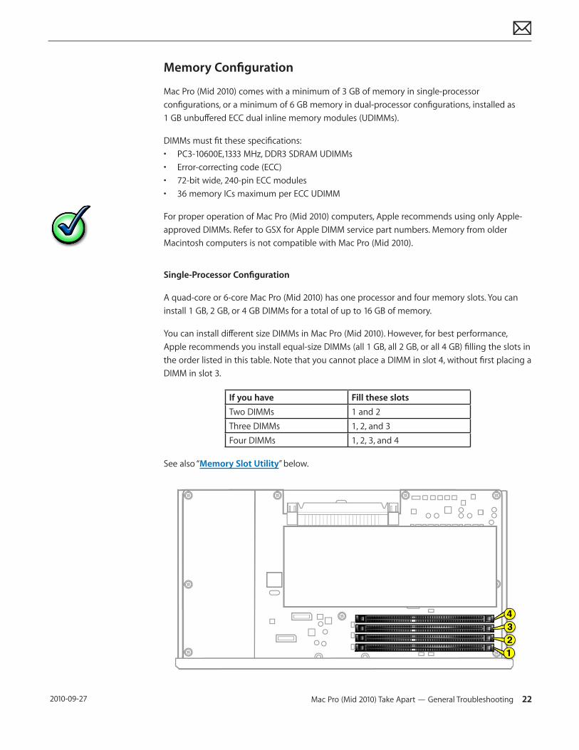
Single-Processor Configuration
A quad-core or 6-core Mac Pro (Mid 2010) has one processor and four memory slots. You can install 1 GB, 2 GB, or 4 GB DIMMs for a total of up to 16 GB of memory.
You can install different size DIMMs in Mac Pro (Mid 2010). However, for best performance, Apple recommends you install equal-size DIMMs (all 1 GB, all 2 GB, or all 4 GB) filling the slots in the order listed in this table. Note that you cannot place a DIMM in slot 4, without first placing a DIMM in slot 3.
If you have Fill these slotsTwo DIMMs 1 and 2Three DIMMs 1, 2, and 3Four DIMMs 1, 2, 3, and 4
See also “Memory Slot Utility” below.
Mac Pro (Mid 2010) Take Apart — General Troubleshooting 23 2010-09-27
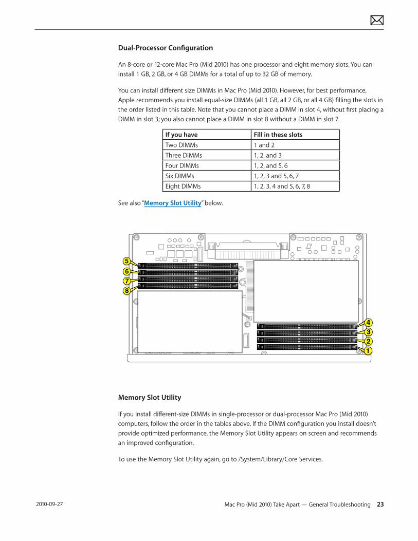
Dual-Processor Configuration
An 8-core or 12-core Mac Pro (Mid 2010) has one processor and eight memory slots. You can install 1 GB, 2 GB, or 4 GB DIMMs for a total of up to 32 GB of memory.
You can install different size DIMMs in Mac Pro (Mid 2010). However, for best performance, Apple recommends you install equal-size DIMMs (all 1 GB, all 2 GB, or all 4 GB) filling the slots in the order listed in this table. Note that you cannot place a DIMM in slot 4, without first placing a DIMM in slot 3; you also cannot place a DIMM in slot 8 without a DIMM in slot 7.
If you have Fill in these slotsTwo DIMMs 1 and 2Three DIMMs 1, 2, and 3Four DIMMs 1, 2, and 5, 6Six DIMMs 1, 2, 3 and 5, 6, 7Eight DIMMs 1, 2, 3, 4 and 5, 6, 7, 8
See also “Memory Slot Utility” below.
Memory Slot Utility
If you install different-size DIMMs in single-processor or dual-processor Mac Pro (Mid 2010) computers, follow the order in the tables above. If the DIMM configuration you install doesn’t provide optimized performance, the Memory Slot Utility appears on screen and recommends an improved configuration.
To use the Memory Slot Utility again, go to /System/Library/Core Services.
Mac Pro (Mid 2010) Take Apart — General Troubleshooting 24 2010-09-27
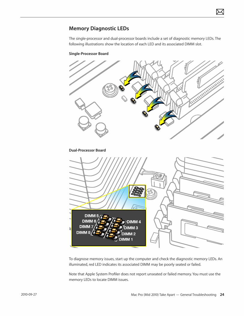
Memory Diagnostic LEDs
The single-processor and dual-processor boards include a set of diagnostic memory LEDs. The following illustrations show the location of each LED and its associated DIMM slot.
Single-Processor Board
Dual-Processor Board
To diagnose memory issues, start up the computer and check the diagnostic memory LEDs. An illuminated, red LED indicates its associated DIMM may be poorly seated or failed.
Note that Apple System Profiler does not report unseated or failed memory. You must use the memory LEDs to locate DIMM issues.
Mac Pro (Mid 2010) Take Apart — General Troubleshooting 25 2010-09-27
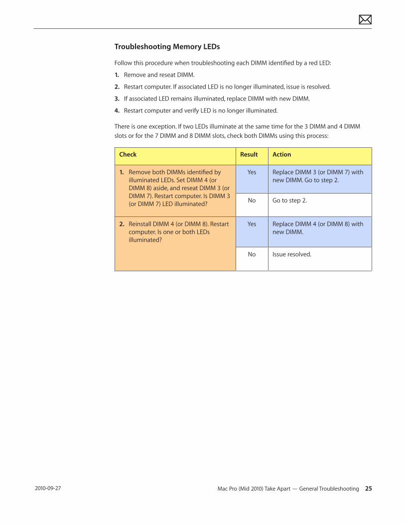
Troubleshooting Memory LEDs
Follow this procedure when troubleshooting each DIMM identified by a red LED:
1. Remove and reseat DIMM.
2. Restart computer. If associated LED is no longer illuminated, issue is resolved.
3. If associated LED remains illuminated, replace DIMM with new DIMM.
4. Restart computer and verify LED is no longer illuminated.
There is one exception. If two LEDs illuminate at the same time for the 3 DIMM and 4 DIMM slots or for the 7 DIMM and 8 DIMM slots, check both DIMMs using this process:
Check Result Action
1. Remove both DIMMs identified by illuminated LEDs. Set DIMM 4 (or DIMM 8) aside, and reseat DIMM 3 (or DIMM 7). Restart computer. Is DIMM 3 (or DIMM 7) LED illuminated?
Yes Replace DIMM 3 (or DIMM 7) with new DIMM. Go to step 2.
No Go to step 2.
2. Reinstall DIMM 4 (or DIMM 8). Restart computer. Is one or both LEDs illuminated?
Yes Replace DIMM 4 (or DIMM 8) with new DIMM.
No Issue resolved.
Mac Pro (Mid 2010) Take Apart — General Troubleshooting 26 2010-09-27
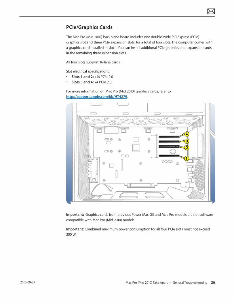
PCIe/Graphics Cards
The Mac Pro (Mid 2010) backplane board includes one double-wide PCI Express (PCIe) graphics slot and three PCIe expansion slots, for a total of four slots. The computer comes with a graphics card installed in slot 1. You can install additional PCIe graphics and expansion cards in the remaining three expansion slots.
All four slots support 16-lane cards.
Slot electrical specifications:• Slots 1 and 2: x16 PCIe 2.0• Slots 3 and 4: x4 PCIe 2.0
For more information on Mac Pro (Mid 2010) graphics cards, refer to http://support.apple.com/kb/HT4279.
Important: Graphics cards from previous Power Mac G5 and Mac Pro models are not software-compatible with Mac Pro (Mid 2010) models.
Important: Combined maximum power consumption for all four PCIe slots must not exceed 300 W.
Mac Pro (Mid 2010) Take Apart — General Troubleshooting 27 2010-09-27
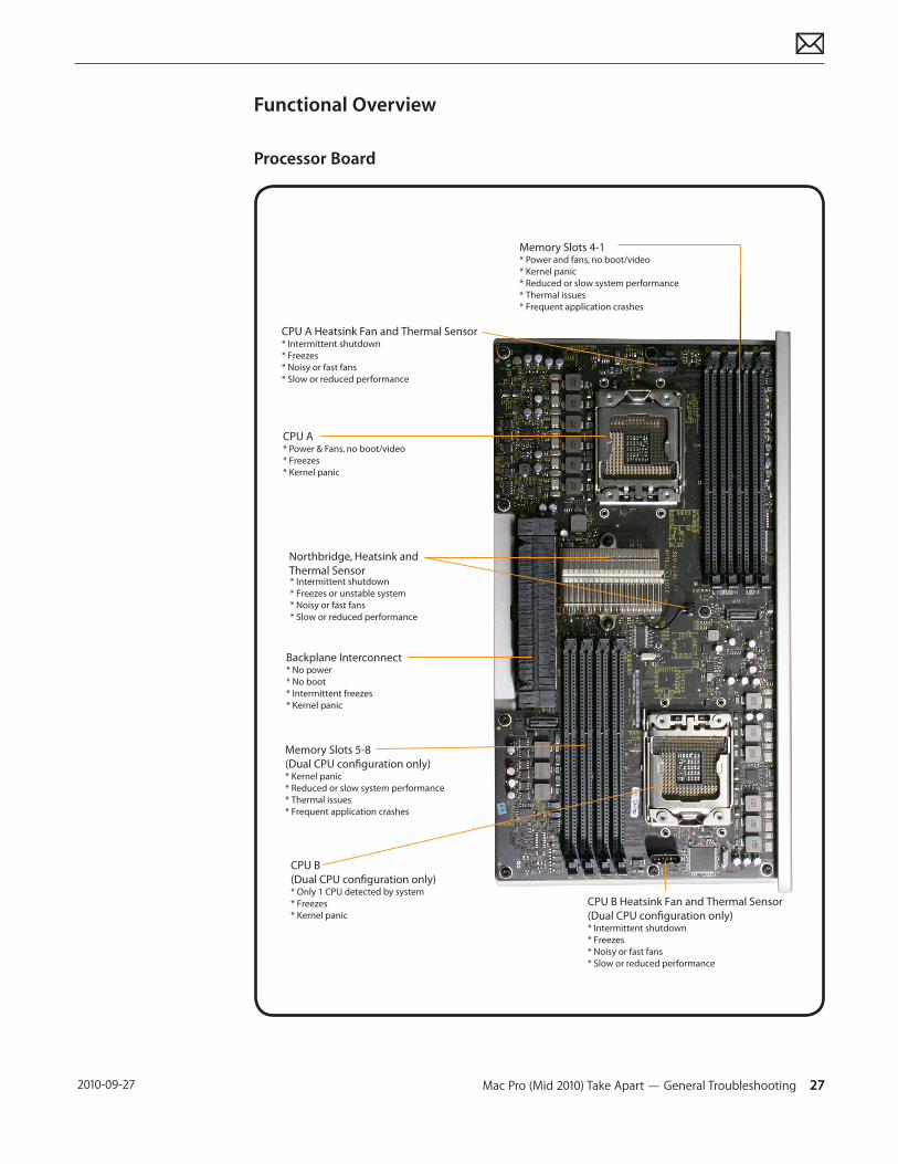
Functional Overview
Processor Board
CPU A Heatsink Fan and Thermal Sensor* Intermittent shutdown* Freezes* Noisy or fast fans* Slow or reduced performance
CPU A* Power & Fans, no boot/video* Freezes* Kernel panic
Northbridge, Heatsink and Thermal Sensor* Intermittent shutdown* Freezes or unstable system* Noisy or fast fans* Slow or reduced performance
Backplane Interconnect* No power* No boot* Intermittent freezes* Kernel panic
Memory Slots 5-8 (Dual CPU conguration only)* Kernel panic* Reduced or slow system performance* Thermal issues* Frequent application crashes
CPU B(Dual CPU conguration only)* Only 1 CPU detected by system* Freezes* Kernel panic
CPU B Heatsink Fan and Thermal Sensor(Dual CPU conguration only)* Intermittent shutdown* Freezes* Noisy or fast fans* Slow or reduced performance
Memory Slots 4-1 * Power and fans, no boot/video* Kernel panic* Reduced or slow system performance* Thermal issues* Frequent application crashes
Mac Pro (Mid 2010) Take Apart — General Troubleshooting 28 2010-09-27
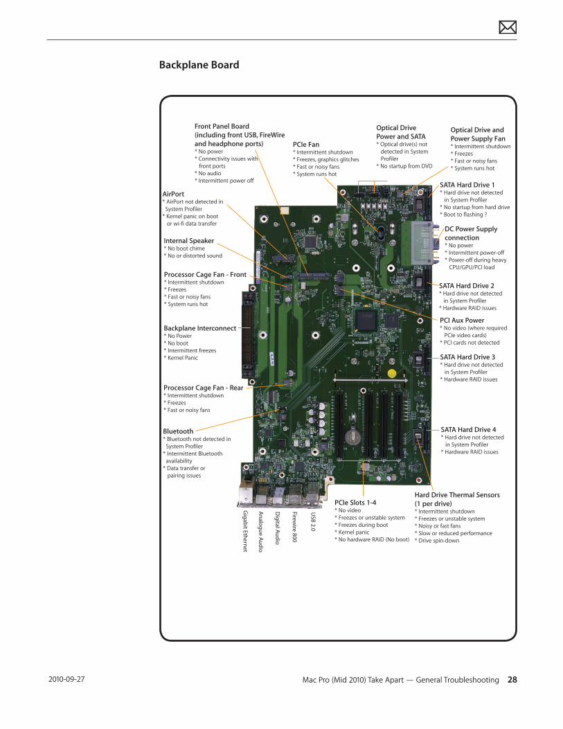
Backplane Board
Hard Drive Thermal Sensors(1 per drive)* Intermittent shutdown* Freezes or unstable system* Noisy or fast fans* Slow or reduced performance* Drive spin-down
Backplane Interconnect* No Power* No boot* Intermittent freezes* Kernel Panic
AirPort* AirPort not detected in System Profiler* Kernel panic on boot or wi-fi data transfer
Internal Speaker* No boot chime* No or distorted sound
Processor Cage Fan - Front* Intermittent shutdown* Freezes* Fast or noisy fans* System runs hot
Processor Cage Fan - Rear* Intermittent shutdown* Freezes* Fast or noisy fans
Bluetooth* Bluetooth not detected in System Profiler* Intermittent Bluetooth availability* Data transfer or pairing issues
Front Panel Board(including front USB, FireWireand headphone ports)* No power* Connectivity issues with front ports * No audio* Intermittent power off
Optical Drive Power and SATA* Optical drive(s) not detected in System Profiler* No startup from DVD
Optical Drive and Power Supply Fan* Intermittent shutdown* Freezes* Fast or noisy fans* System runs hot
SATA Hard Drive 1* Hard drive not detected in System Profiler* No startup from hard drive* Boot to flashing ?
DC Power Supplyconnection* No power* Intermittent power-off* Power-off during heavy CPU/GPU/PCI load
PCIe Fan* Intermittent shutdown* Freezes, graphics glitches* Fast or noisy fans* System runs hot
SATA Hard Drive 2* Hard drive not detected in System Profiler* Hardware RAID issues
SATA Hard Drive 3* Hard drive not detected in System Profiler* Hardware RAID issues
SATA Hard Drive 4* Hard drive not detected in System Profiler* Hardware RAID issues
PCI Aux Power* No video (where required PCIe video cards)* PCI cards not detected
PCIe Slots 1-4* No video* Freezes or unstable system* Freezes during boot* Kernel panic* No hardware RAID (No boot)
USB 2.0
Firewire 800
Digital Audio
Analogue Audio
Gigabit Ethernet
Mac Pro (Mid 2010) Take Apart — General Troubleshooting 29 2010-09-27
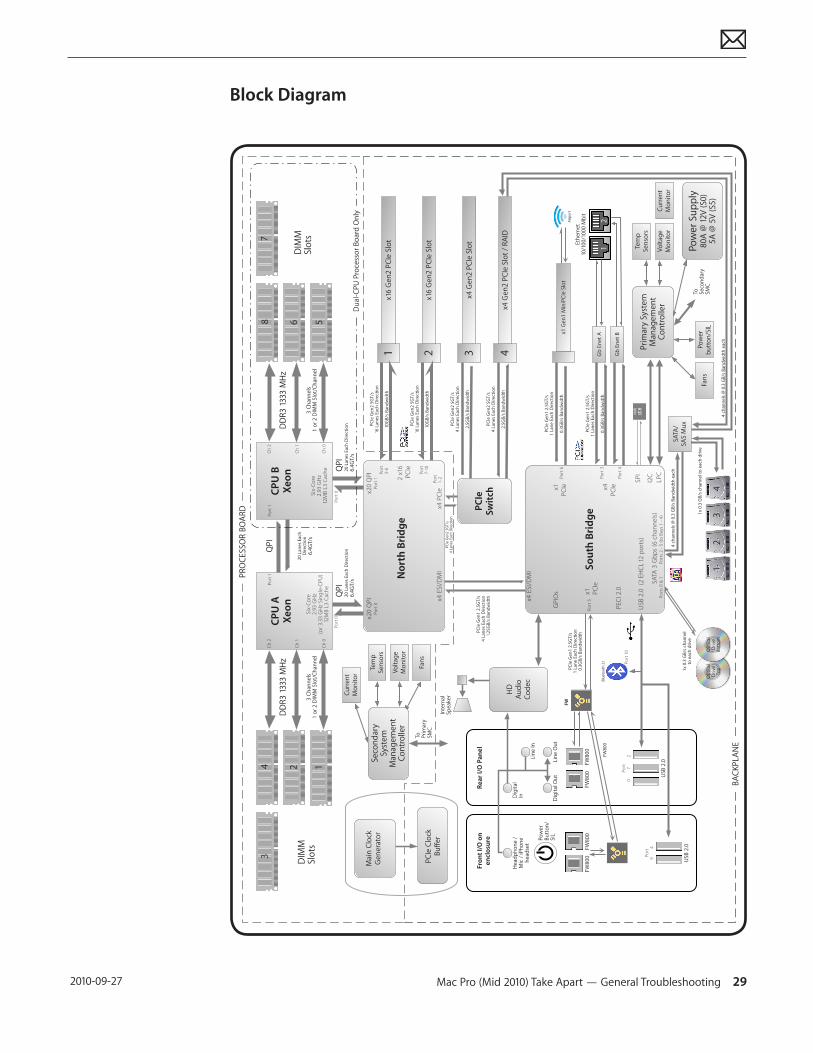
Block Diagram
Op
tica
l D
rive
Top
PC
Ie G
en
1 2
.5G
T/s
1 L
anes
Eac
h D
ire
ctio
n
0.3
GB
/s B
and
wid
th
PC
Ie G
en
1 2
.5G
T/s
1 L
ane
Eac
h D
ire
ctio
n
0.3
GB
/s B
and
wid
th
x4 E
SI/D
MI
Gb
En
et
A
1x1
6 G
en
2 P
CIe
Slo
t
2x1
6 G
en
2 P
CIe
Slo
t
PC
Ie G
en
2 5
GT/
s16
Lan
es E
ach
Dir
ect
ion
10G
B/s
Ban
dw
idth
Mac
Pro
(M
id 2
010
) Sy
ste
m B
lock
Dia
gra
m
SATA
3 G
bp
s (6
ch
ann
els
)
USB
2.0
(2
EH
CI,
12 ports)
GPIOs
CP
U A
Xe
on
Six-Core
2.9
3 G
Hz
(or
3.33
GH
z Si
ng
le-C
PU
)12
MB
L3
Cache
PC
Ie G
en
2 5
GT/
s16
Lan
es E
ach
Dir
ect
ion
10G
B/s
Ban
dw
idth
4x4
Ge
n2
PC
Ie S
lot
/ R
AID
PC
Ie G
en
2 5
GT/
s4
Lan
es E
ach
Dir
ect
ion
2.5
GB
/s B
and
wid
th
CP
U B
Xe
on
Six-Core
2.9
3 G
Hz
12M
B L
3 Cache
DD
R3
133
3 M
Hz
3 C
han
ne
ls1
or
2 D
IMM
Slo
t/C
han
ne
l
DD
R3
133
3 M
Hz
3 C
han
ne
ls1
or
2 D
IMM
Slo
t/C
han
ne
l
2 x
16PCIe
x4 PCIex2
0 Q
PI
Port
1x2
0 Q
PI
Port
0
x4 E
SI/D
MI
No
rth
Bri
dg
e
QP
I
20 L
anes
Eac
h
Dir
ect
ion
6.4
GT/
s
QP
I20
Lan
es E
ach
Dir
ect
ion
6.4
GT/
s
QP
I20
Lan
es E
ach
Dir
ect
ion
6.4
GT/
s
PC
Ie G
en
1 2
.5G
T/s
4 L
anes
Eac
h D
ire
ctio
n1.
25
GB
/s B
and
wid
th
Vo
ltag
e
Mo
nit
or
Tem
p
Sen
sors
Pri
mar
y Sy
ste
mM
anag
em
en
tC
on
tro
ller
Pow
er
bu
tto
n/S
IL
LPC
I2C
Pow
er
Sup
ply
80
A @
12
V (
S0)
5A
@ 5
V (
S5)
FW8
00
Op
tica
l D
rive
Bo
tto
m
PC
Ie G
en
1 2
.5G
T/s
1 L
ane
Eac
h D
ire
ctio
n0
.3G
B/s
Ban
dw
idth
HD
Au
dio
Co
de
c
Inte
rnal
Sp
eak
er
Re
ar
I/O
Pa
ne
l
Lin
e In
Dig
ital
In
Dig
ital
Ou
t
He
adp
ho
ne
/
Mic
/ iP
ho
ne
h
ead
set
x1
PCIe
So
uth
Bri
dg
e
SPI
Eth
ern
et
10/1
00
/10
00
Mb
it
x1
PCIe x4
PCIe
x1 G
en
1 M
iniP
CIe
Slo
t
Fro
nt
I/O
on
e
ncl
osu
re
Lin
e O
ut
Mai
n C
lock
G
en
era
tor
PEC
I 2.0
PC
IeS
wit
ch
3x4
Ge
n2
PC
Ie S
lot
PC
Ie G
en
2 5
GT/
s4
Lan
es E
ach
Dir
ect
ion
2.5
GB
/s B
and
wid
th
PC
Ie G
en
2 5
GT/
s4
Lan
es E
ach
Dir
ect
ion
FW8
00
FW8
00
PC
Ie C
lock
Bu
ffe
r
Fan
s
Gb
En
et
B
4M
B
Vo
ltag
e
Mo
nit
or
Tem
p
Sen
sors
Fan
s
FW
Ch
2
Ch
1
Ch
0
Ch
2
Ch
1
Ch
0
Cu
rre
nt
Mo
nit
or
Seco
nd
ary
Syst
em
Man
age
me
nt
Co
ntr
olle
r
To
Pri
mar
y SM
C
Cu
rre
nt
Mo
nit
or
Port
3-6
Port
7-10
Port
1-2
Port
0Port
0
Port
1Port
1
12
34
DIM
MSl
ots
5687
DIM
MSl
ots
To
Seco
nd
ary
SMC
USB
2.0
USB
2.0
Port
6
Port
3
Port
4
4 c
han
ne
ls @
0.3
GB
/s B
and
wid
th e
ach
1x
0.3
GB
/s c
han
ne
l to
eac
h d
rive
SATA
/SA
S M
ux
4 c
han
ne
ls @
0.3
GB
/s B
and
wid
th e
ach
Port
s 0
& 1
Port
s 2
- 5
(to
Bay
s 1
- 4
)
12
34
Port
5FW
80
0FW
80
0
Pow
er
Bu
tto
n/
SIL
12A
irp
ort
Blu
eto
oth
2.1
PR
OC
ESSO
R B
OA
RD
BA
CK
PLA
NE
Du
al-C
PU
Pro
cess
or
Bo
ard
On
ly
Port
10
Port
0
7
2
Port
9
4
1x
0.3
GB
/s c
han
ne
lto
eac
h d
rive
Mac Pro (Mid 2010) Take Apart — General Troubleshooting 30 2010-09-27
Common Reset Procedures
The following reset procedures are often helpful in troubleshooting Mac Pro issues.
Resetting the System Management Controller (SMC)
The System Management Controller (SMC) controls all power functions for the computer. If the computer is experiencing any power issue, resetting the SMC may resolve it. The SMC controls several functions, including:• Telling the computer when to turn on, turn off, sleep, wake, idle, and so forth• Handling system resets from various commands• Controlling the fans
It is also recommended that the SMC be reset after a backplane board or processor board is replaced as part of a repair.
Note that resetting the SMC does not reset the PRAM. Resetting the SMC will not resolve issues in which the computer is unresponsive—in these situations, restarting the computer generally works. If the computer isn’t responding, perform these steps one at a time, in the following order, until the issue has been resolved:
1. Force Quit (Option-Command-Escape)
2. Restart (Control-Command-Power)
3. Force Shut Down (press the power button for 10 seconds)
Resetting the SMC can resolve some computer issues such as not starting up, not displaying video, sleep issues, fan noise issues, and so forth. If the computer still exhibits these types of issues after you’ve restarted the computer, try resetting the SMC by removing AC power:
1. From the Apple menu, choose Shut Down (or if the computer is not responding, hold the power button until it turns off).
2. Unplug the AC power cord.
3. Wait at least 15 seconds.
4. Plug the power cord back in, making sure the power button is not being pressed at the time.
5. Press the power button to start up the computer.
For more information:
http://www.apple.com/support
HT1411—Mac Pro: How to reset the System Management Controller (SMC) <http://support.apple.com/kb/HT1806>
Mac Pro (Mid 2010) Take Apart — General Troubleshooting 31 2010-09-27
Resetting the Parameter RAM (PRAM)
To reset PRAM:
1. If the computer is on, turn it off.
2. Locate the following keys on the keyboard: Command, Option, P, and R. You will need to hold these keys down simultaneously in Step 4.
3. Turn on the computer.
4. Press and hold the Command-Option-P-R keys.
Important: You must press this key combination before the gray screen appears.
5. Hold the keys down until the computer restarts and you hear the startup sound for the second time.
6. Release the keys.
For more information:
http://www.apple.com/support
HT1379—Resetting your Mac’s PRAM and VRAM <http://support.apple.com/kb/HT1379>
Starting Up in Safe Mode
A Safe Boot is a special way to start Mac OS X when troubleshooting. To start up into Safe Mode (Safe Boot):
1. Make sure the computer is shut down.
2. Press the power button.
3. Immediately after you hear the startup tone, press and hold the Shift key.
Note: The Shift key should be held as soon as possible after the startup tone but not before.
4. Release the Shift key when you see the screen with the gray Apple and progress indicator (looks like a spinning gear). During startup, ”Safe Boot” appears on the Mac OS X startup screen. To leave Safe Mode, restart the computer normally, without holding down any keys during startup.
For more information:
http://www.apple.com/support
HT1564—What is Safe Boot, Safe Mode? <http://support.apple.com/kb/HT1564>
TS1884—Safe Boot take longer than normal startup <http://support.apple.com/kb/TS1884>
Mac Pro (Mid 2010) Take Apart — General Troubleshooting 32 2010-09-27
Real Time Clock (RTC) Reset
The Real Time Clock (RTC) is a chip on the backplane board that controls the date and time functions of the computer. Resetting the RTC may resolve booting issues.
1. From the Apple menu, choose Shut Down (or if the computer is not responding, hold the power button until it turns off).
2. Unplug the AC power cord.
3. Remove the battery for at least 20 seconds. You may need to remove a PCI Express card to have access to the battery.
Alternatively, you can use the RTC reset button (small button located next to the battery). Press the button for one second when the computer is shut down but still connected to AC power.
Power-On Self Test: RAM and Processor Verification
When the computer is started up after being fully shut down, a self test in the computer’s ROM is automatically run. (The test is not run if the computer is only restarted.) If the test detects a problem, the status LED (located above the power button on the front of the computer) flashes in the following ways*: • 1 Flash: No RAM is installed or detected or the quick memory test failed. An LED will light up
on the processor board next to the affected DIMM or empty DIMM slot.• 3 Flashes: A RAM bank failed extended memory testing. An LED will light up on the
processor board corresponding to the affected DIMM.
Troubleshooting: Try reseating the memory DIMMs. Check memory installation instructions for proper installation order. Swap affected DIMM with known good DIMM.
*Note: The status LED lights up when the power button is depressed at startup. Do not count this light as one of the diagnostic flashes. The memory processor board diagnostic LEDs also flash briefly startup and shut down and when the computer goes in and out of sleep mode. This is normal behavior.
Mac Pro (Mid 2010) Take Apart — General Troubleshooting 33 2010-09-27
Minimum Configuration Testing
The following procedure can help you troubleshoot a “No Power” or other startup related symptom.
The method gradually builds up the system from a minimum configuration and verifies expected behaviors at each step. This approach helps determine which modules function together. The goal is to identify which module(s) cause a symptom to recur when they are added. This method may also help you discover a loose or faulty cable or connector.
If you encounter unexpected behavior during a step, you shoul investigate the last module you re-installed. Backtrack to the previous step, remove the last installed module, and re-verify the expected behavior.
Note: Minimum configuration testing may not be practical for every repair. Refer to other troubleshooting sections in this manual for additional direction.
Take Mac Pro Down to Minimum Configuration
1. Remove the following items from the Mac Pro:• Hard drives/solid state drives• Optical drives• Processor tray and processor board (containing processors, processor heatsinks, and
memory)• PCIe cards• AirPort card• Bluetooth card• Battery• PCIe fan• Processor cage (including fans)• Front panel board
Disconnect all cables from the backplane board, except the power supply.
Mac Pro (Mid 2010) Take Apart — General Troubleshooting 34 2010-09-27
2. Attach a known good power cord from a known good AC source to the Mac Pro.
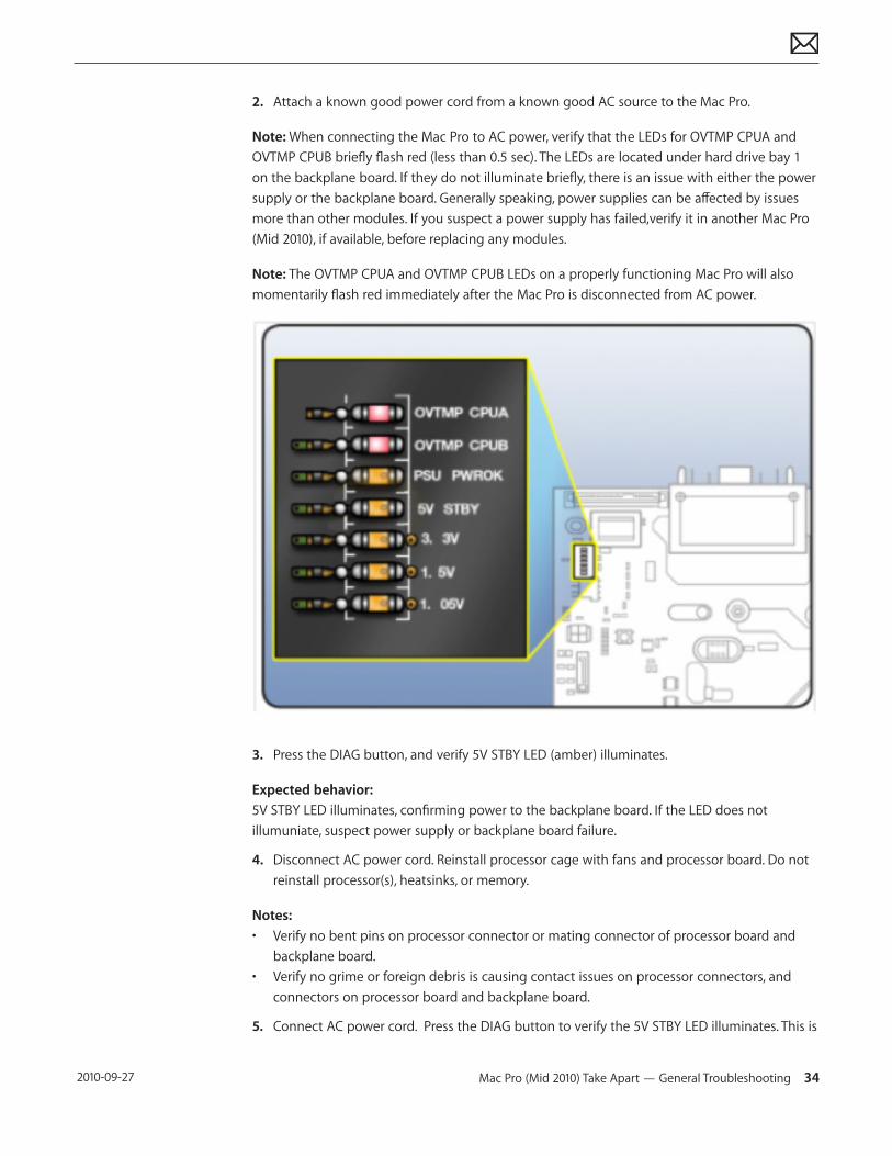
Note: When connecting the Mac Pro to AC power, verify that the LEDs for OVTMP CPUA and OVTMP CPUB briefly flash red (less than 0.5 sec). The LEDs are located under hard drive bay 1 on the backplane board. If they do not illuminate briefly, there is an issue with either the power supply or the backplane board. Generally speaking, power supplies can be affected by issues more than other modules. If you suspect a power supply has failed,verify it in another Mac Pro (Mid 2010), if available, before replacing any modules.
Note: The OVTMP CPUA and OVTMP CPUB LEDs on a properly functioning Mac Pro will also momentarily flash red immediately after the Mac Pro is disconnected from AC power.
3. Press the DIAG button, and verify 5V STBY LED (amber) illuminates.
Expected behavior: 5V STBY LED illuminates, confirming power to the backplane board. If the LED does not illumuniate, suspect power supply or backplane board failure.
4. Disconnect AC power cord. Reinstall processor cage with fans and processor board. Do not reinstall processor(s), heatsinks, or memory.
Notes:• Verify no bent pins on processor connector or mating connector of processor board and
backplane board.• Verify no grime or foreign debris is causing contact issues on processor connectors, and
connectors on processor board and backplane board.
5. Connect AC power cord. Press the DIAG button to verify the 5V STBY LED illuminates. This is
Mac Pro (Mid 2010) Take Apart — General Troubleshooting 35 2010-09-27
a verify step, as you’ve added modules since previous step.
Expected behavior: 5V STBY LED illuminates, confirming power to the backplane board. If the LED does not illuminate, suspect power supply or backplane board failure.
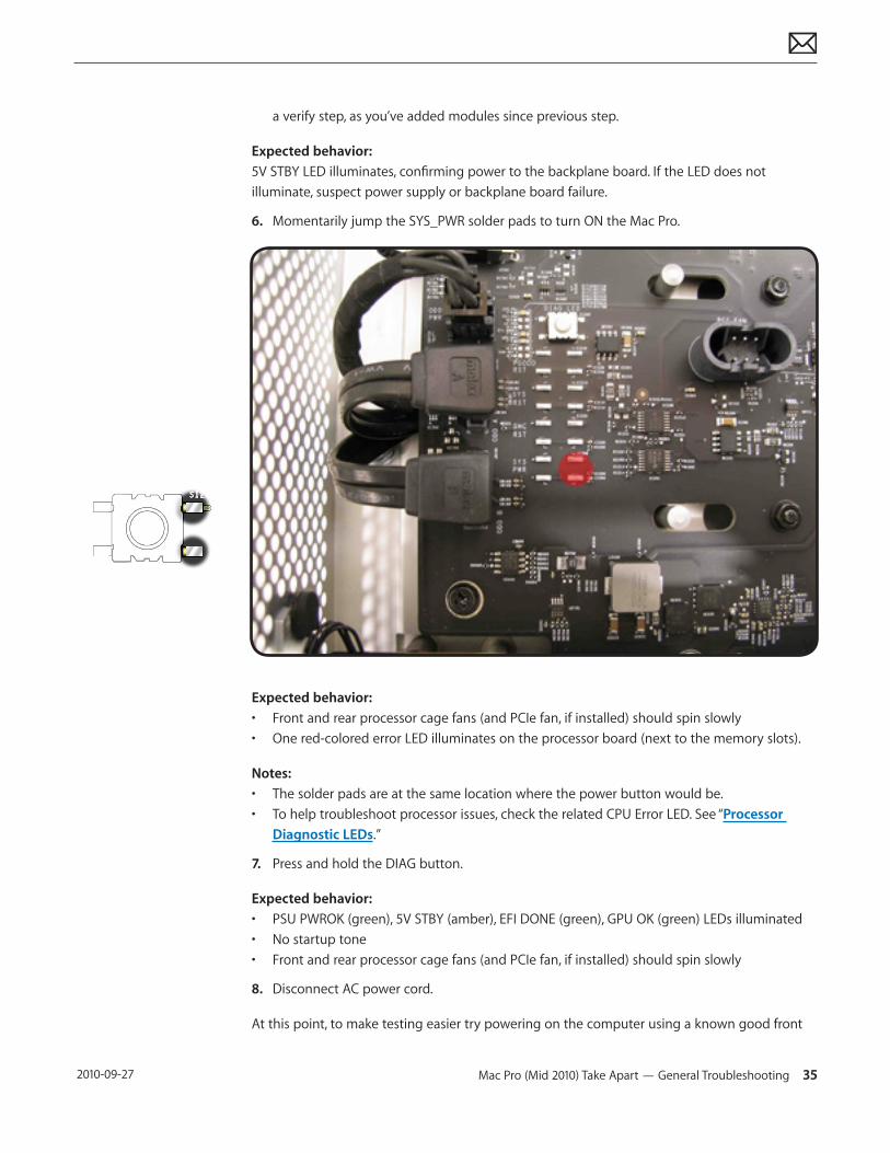
6. Momentarily jump the SYS_PWR solder pads to turn ON the Mac Pro.
Expected behavior: • Front and rear processor cage fans (and PCIe fan, if installed) should spin slowly• One red-colored error LED illuminates on the processor board (next to the memory slots).
Notes: • The solder pads are at the same location where the power button would be.• To help troubleshoot processor issues, check the related CPU Error LED. See “Processor
Diagnostic LEDs.”
7. Press and hold the DIAG button.
Expected behavior: • PSU PWROK (green), 5V STBY (amber), EFI DONE (green), GPU OK (green) LEDs illuminated• No startup tone• Front and rear processor cage fans (and PCIe fan, if installed) should spin slowly
8. Disconnect AC power cord.
At this point, to make testing easier try powering on the computer using a known good front
Mac Pro (Mid 2010) Take Apart — General Troubleshooting 36 2010-09-27
panel board, power button, and cable, instead of jumpering SYS_PWR solder pads.
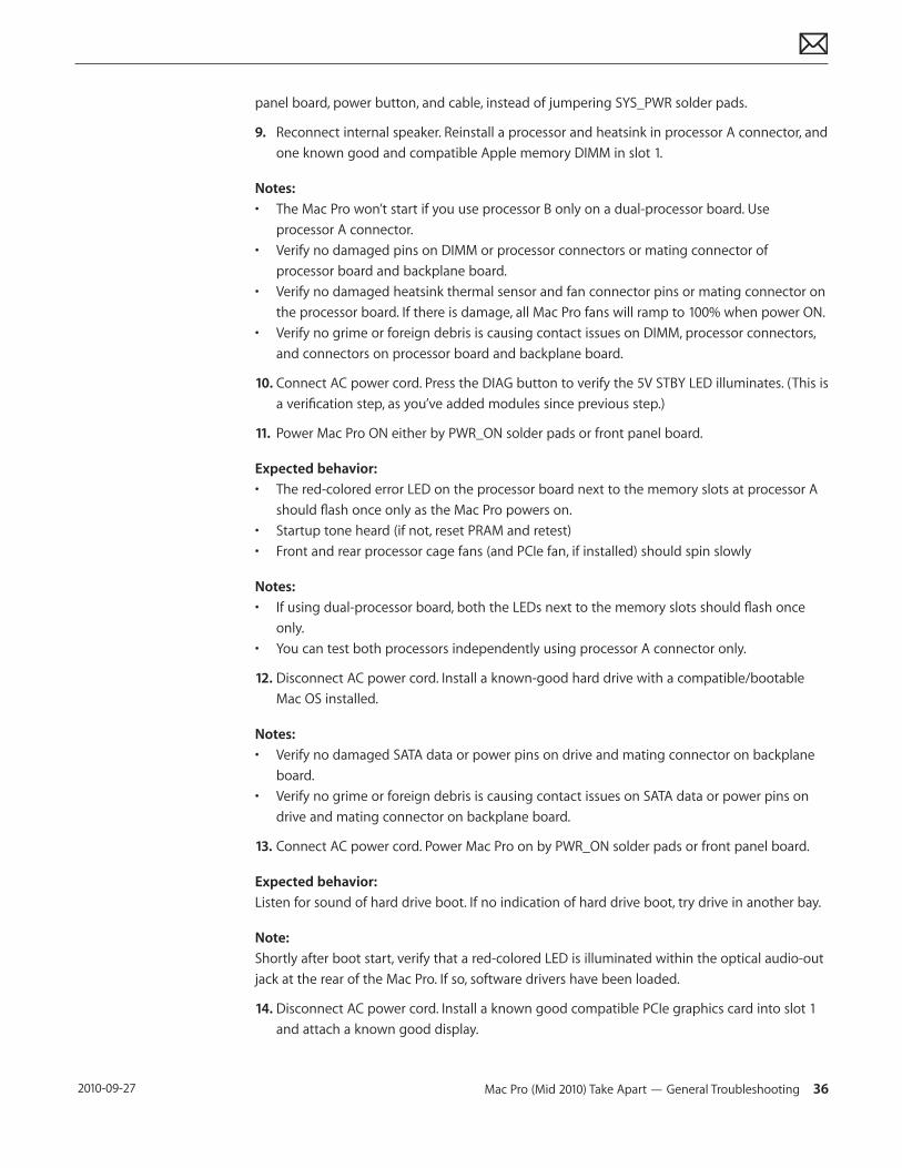
9. Reconnect internal speaker. Reinstall a processor and heatsink in processor A connector, and one known good and compatible Apple memory DIMM in slot 1.
Notes: • The Mac Pro won’t start if you use processor B only on a dual-processor board. Use
processor A connector.• Verify no damaged pins on DIMM or processor connectors or mating connector of
processor board and backplane board.• Verify no damaged heatsink thermal sensor and fan connector pins or mating connector on
the processor board. If there is damage, all Mac Pro fans will ramp to 100% when power ON.• Verify no grime or foreign debris is causing contact issues on DIMM, processor connectors,
and connectors on processor board and backplane board.
10. Connect AC power cord. Press the DIAG button to verify the 5V STBY LED illuminates. (This is a verification step, as you’ve added modules since previous step.)
11. Power Mac Pro ON either by PWR_ON solder pads or front panel board.
Expected behavior: • The red-colored error LED on the processor board next to the memory slots at processor A
should flash once only as the Mac Pro powers on. • Startup tone heard (if not, reset PRAM and retest)• Front and rear processor cage fans (and PCIe fan, if installed) should spin slowly
Notes: • If using dual-processor board, both the LEDs next to the memory slots should flash once
only.• You can test both processors independently using processor A connector only.
12. Disconnect AC power cord. Install a known-good hard drive with a compatible/bootable Mac OS installed.
Notes:• Verify no damaged SATA data or power pins on drive and mating connector on backplane
board.• Verify no grime or foreign debris is causing contact issues on SATA data or power pins on
drive and mating connector on backplane board.
13. Connect AC power cord. Power Mac Pro on by PWR_ON solder pads or front panel board.
Expected behavior: Listen for sound of hard drive boot. If no indication of hard drive boot, try drive in another bay.
Note: Shortly after boot start, verify that a red-colored LED is illuminated within the optical audio-out jack at the rear of the Mac Pro. If so, software drivers have been loaded.
14. Disconnect AC power cord. Install a known good compatible PCIe graphics card into slot 1 and attach a known good display.
Mac Pro (Mid 2010) Take Apart — General Troubleshooting 37 2010-09-27
Notes:• Verify no damaged PCIe pins on the video card and mating PCIe connector on backplane
board.• Verify no grime or foreign debris is causing contact issues on the video card and mating
connector on backplane board.
15. Connect AC power cord. Power Mac Pro ON either by PWR_ON solder pads or front panel board.
Expected behavior: • Listen for sound of hard drive boot.• Verify good uncorrupted video on display.
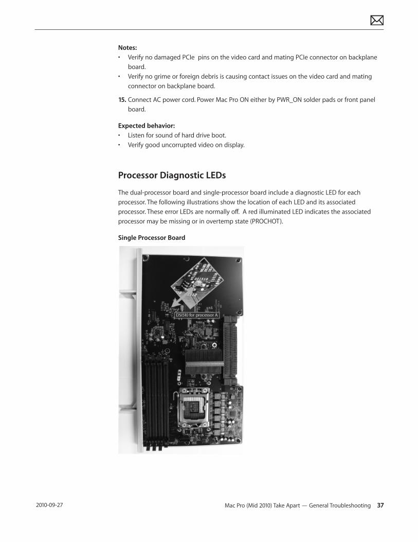
Processor Diagnostic LEDs
The dual-processor board and single-processor board include a diagnostic LED for each processor. The following illustrations show the location of each LED and its associated processor. These error LEDs are normally off. A red illuminated LED indicates the associated processor may be missing or in overtemp state (PROCHOT).
Single Processor Board
Mac Pro (Mid 2010) Take Apart — General Troubleshooting 38 2010-09-27
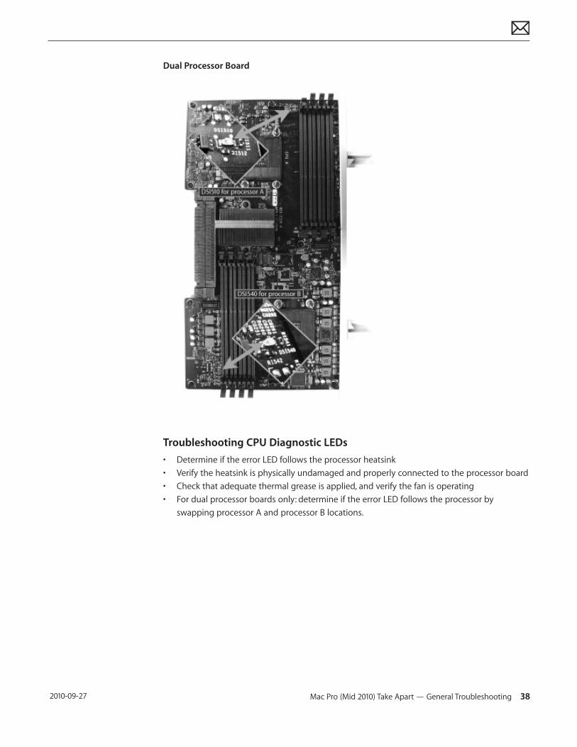
Dual Processor Board
Troubleshooting CPU Diagnostic LEDs• Determine if the error LED follows the processor heatsink• Verify the heatsink is physically undamaged and properly connected to the processor board• Check that adequate thermal grease is applied, and verify the fan is operating• For dual processor boards only: determine if the error LED follows the processor by
swapping processor A and processor B locations.
Mac Pro (Mid 2010) Symptom Charts 39 2010-09-27
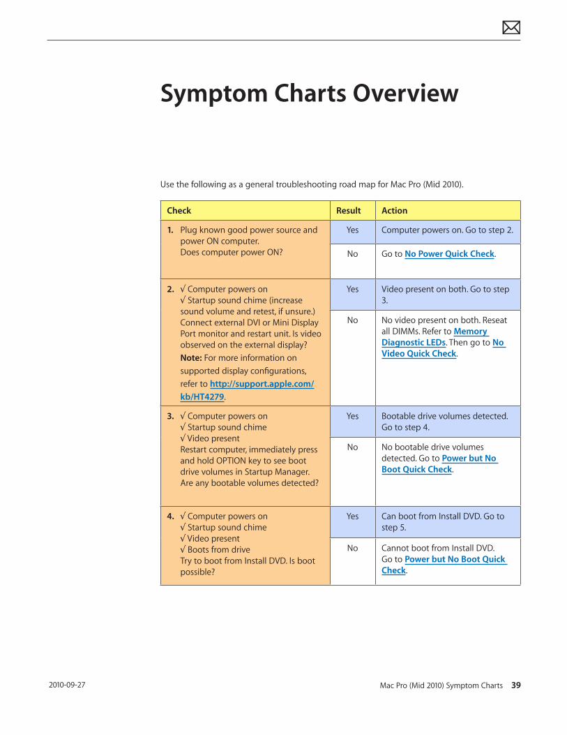
Symptom Charts Overview
Use the following as a general troubleshooting road map for Mac Pro (Mid 2010).
Check Result Action
1. Plug known good power source and power ON computer. Does computer power ON?
Yes Computer powers on. Go to step 2.
No Go to No Power Quick Check.
2. √ Computer powers on√ Startup sound chime (increase sound volume and retest, if unsure.)Connect external DVI or Mini Display Port monitor and restart unit. Is video observed on the external display? Note: For more information on supported display configurations, refer to http://support.apple.com/kb/HT4279.
Yes Video present on both. Go to step 3.
No No video present on both. Reseat all DIMMs. Refer to Memory Diagnostic LEDs. Then go to No Video Quick Check.
3. √ Computer powers on√ Startup sound chime √ Video presentRestart computer, immediately press and hold OPTION key to see boot drive volumes in Startup Manager. Are any bootable volumes detected?
Yes Bootable drive volumes detected. Go to step 4.
No No bootable drive volumes detected. Go to Power but No Boot Quick Check.
4. √ Computer powers on√ Startup sound chime √ Video present√ Boots from driveTry to boot from Install DVD. Is boot possible?
Yes Can boot from Install DVD. Go to step 5.
No Cannot boot from Install DVD. Go to Power but No Boot Quick Check.
Mac Pro (Mid 2010) Symptom Charts 40 2010-09-27
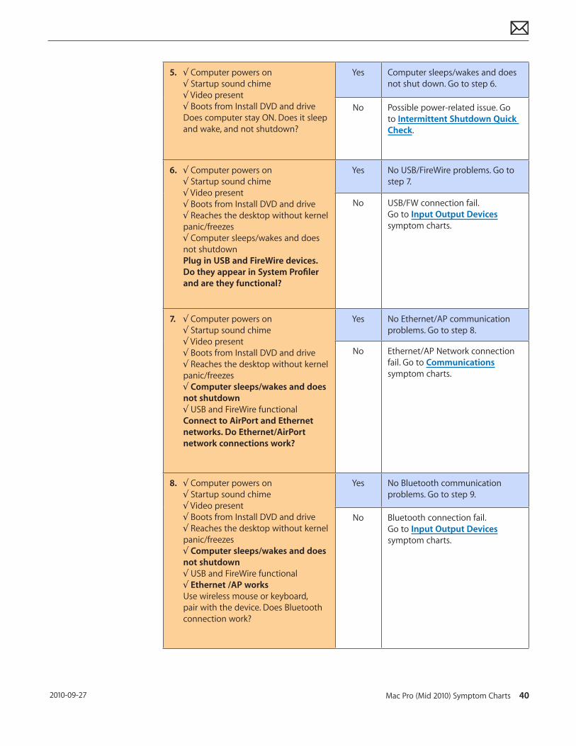
5. √ Computer powers on√ Startup sound chime √ Video present√ Boots from Install DVD and driveDoes computer stay ON. Does it sleep and wake, and not shutdown?
Yes Computer sleeps/wakes and does not shut down. Go to step 6.
No Possible power-related issue. Go to Intermittent Shutdown Quick Check.
6. √ Computer powers on√ Startup sound chime √ Video present√ Boots from Install DVD and drive√ Reaches the desktop without kernel panic/freezes √ Computer sleeps/wakes and does not shutdown Plug in USB and FireWire devices. Do they appear in System Profiler and are they functional?
Yes No USB/FireWire problems. Go to step 7.
No USB/FW connection fail. Go to Input Output Devices symptom charts.
7. √ Computer powers on√ Startup sound chime √ Video present√ Boots from Install DVD and drive√ Reaches the desktop without kernel panic/freezes √ Computer sleeps/wakes and does not shutdown√ USB and FireWire functionalConnect to AirPort and Ethernet networks. Do Ethernet/AirPort network connections work?
Yes No Ethernet/AP communication problems. Go to step 8.
No Ethernet/AP Network connection fail. Go to Communications symptom charts.
8. √ Computer powers on√ Startup sound chime √ Video present√ Boots from Install DVD and drive√ Reaches the desktop without kernel panic/freezes √ Computer sleeps/wakes and does not shutdown√ USB and FireWire functional√ Ethernet /AP works Use wireless mouse or keyboard, pair with the device. Does Bluetooth connection work?
Yes No Bluetooth communication problems. Go to step 9.
No Bluetooth connection fail. Go to Input Output Devices symptom charts.
Mac Pro (Mid 2010) Symptom Charts 41 2010-09-27
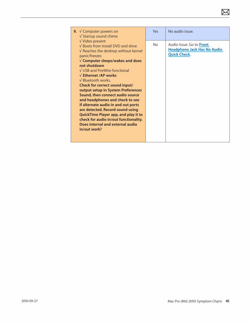
9. √ Computer powers on√ Startup sound chime √ Video present√ Boots from Install DVD and drive√ Reaches the desktop without kernel panic/freezes √ Computer sleeps/wakes and does not shutdown√ USB and FireWire functional√ Ethernet /AP works√ Bluetooth works.Check for correct sound input/output setup in System Preferences Sound, then connect audio source and headphones and check to see if alternate audio in and out ports are detected. Record sound using QuickTime Player app, and play it to check for audio in/out functionality. Does internal and external audio in/out work?
Yes No audio issue.
No Audio Issue. Go to Front Headphone Jack Has No Audio Quick Check.
Mac Pro (Mid 2010) Symptom Charts — No Power/Dead Unit 42 2010-09-27
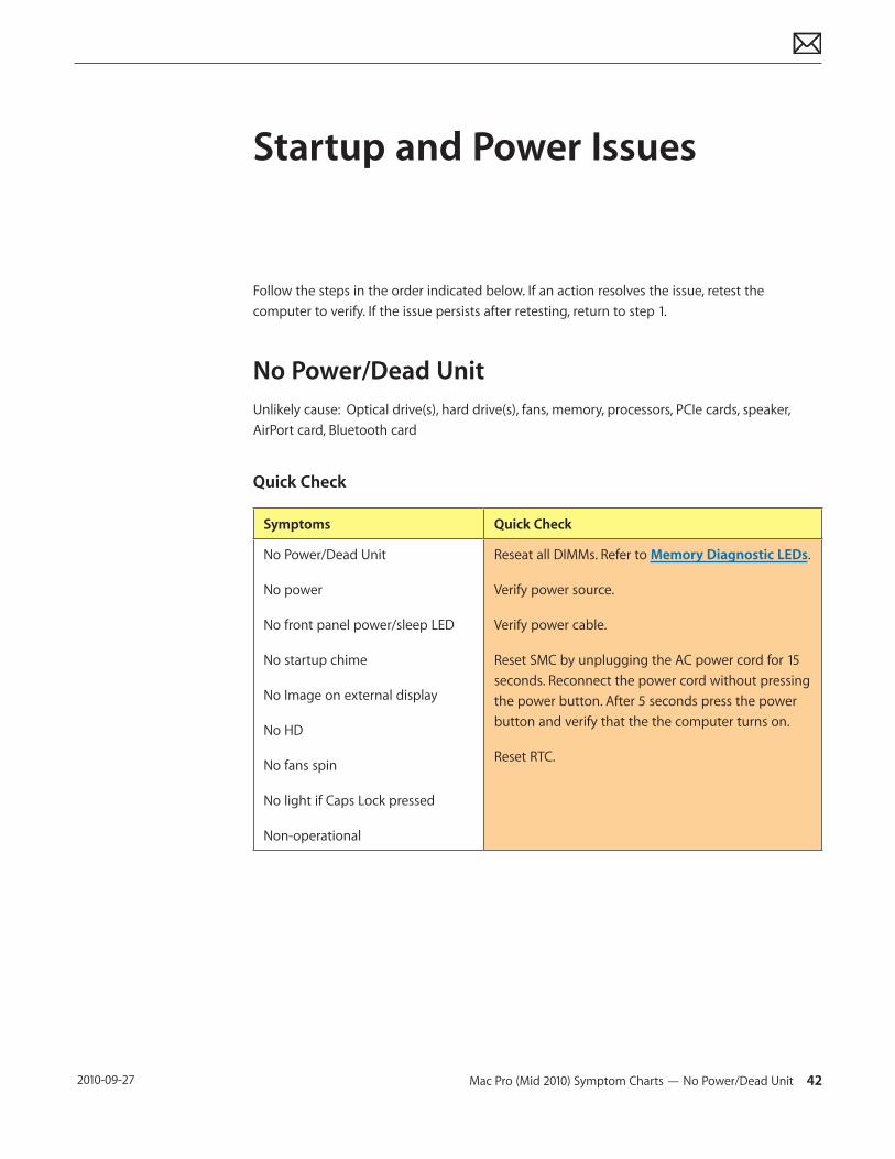
Startup and Power Issues
Follow the steps in the order indicated below. If an action resolves the issue, retest the computer to verify. If the issue persists after retesting, return to step 1.
No Power/Dead UnitUnlikely cause: Optical drive(s), hard drive(s), fans, memory, processors, PCIe cards, speaker, AirPort card, Bluetooth card
Quick Check
Symptoms Quick Check
No Power/Dead Unit
No power
No front panel power/sleep LED
No startup chime
No Image on external display
No HD
No fans spin
No light if Caps Lock pressed
Non-operational
Reseat all DIMMs. Refer to Memory Diagnostic LEDs.
Verify power source.
Verify power cable.
Reset SMC by unplugging the AC power cord for 15 seconds. Reconnect the power cord without pressing the power button. After 5 seconds press the power button and verify that the the computer turns on.
Reset RTC.
Mac Pro (Mid 2010) Symptom Charts — No Power/Dead Unit 43 2010-09-27
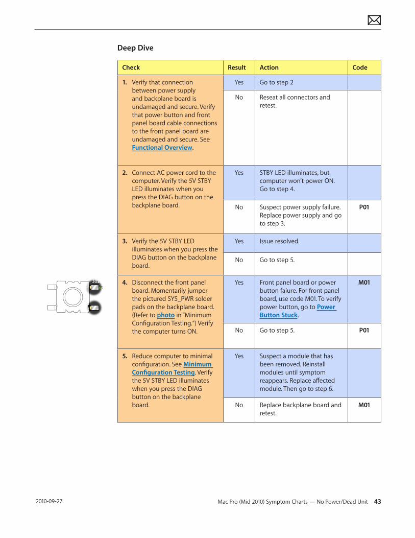
Deep Dive
Check Result Action Code
1. Verify that connection between power supply and backplane board is undamaged and secure. Verify that power button and front panel board cable connections to the front panel board are undamaged and secure. See Functional Overview.
Yes Go to step 2
No Reseat all connectors and retest.
2. Connect AC power cord to the computer. Verify the 5V STBY LED illuminates when you press the DIAG button on the backplane board.
Yes STBY LED illuminates, but computer won’t power ON. Go to step 4.
No Suspect power supply failure. Replace power supply and go to step 3.
P01
3. Verify the 5V STBY LED illuminates when you press the DIAG button on the backplane board.
Yes Issue resolved.
No Go to step 5.
4. Disconnect the front panel board. Momentarily jumper the pictured SYS_PWR solder pads on the backplane board. (Refer to photo in “Minimum Configuration Testing.”) Verify the computer turns ON.
Yes Front panel board or power button faiure. For front panel board, use code M01. To verify power button, go to Power Button Stuck.
M01
No Go to step 5. P01
5. Reduce computer to minimal configuration. See Minimum Configuration Testing. Verify the 5V STBY LED illuminates when you press the DIAG button on the backplane board.
Yes Suspect a module that has been removed. Reinstall modules until symptom reappears. Replace affected module. Then go to step 6.
No Replace backplane board and retest.
M01
Mac Pro (Mid 2010) Symptom Charts — No Power/Dead Unit 44 2010-09-27
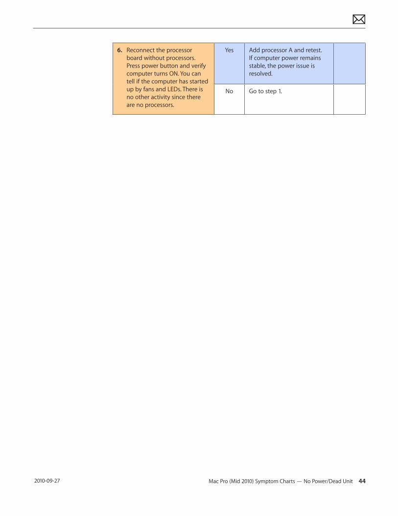
6. Reconnect the processor board without processors. Press power button and verify computer turns ON. You can tell if the computer has started up by fans and LEDs. There is no other activity since there are no processors.
Yes Add processor A and retest. If computer power remains stable, the power issue is resolved.
No Go to step 1.
Mac Pro (Mid 2010) Symptom Charts — Intermittent Shutdown 45 2010-09-27
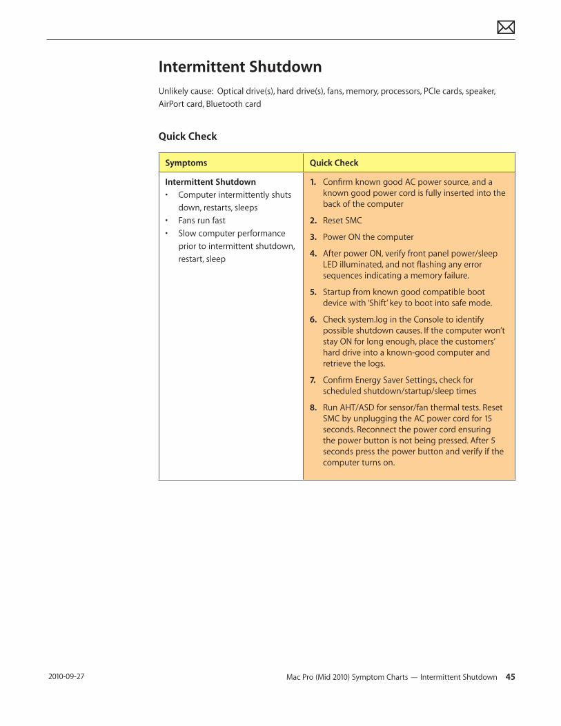
Intermittent ShutdownUnlikely cause: Optical drive(s), hard drive(s), fans, memory, processors, PCIe cards, speaker, AirPort card, Bluetooth card
Quick Check
Symptoms Quick Check
Intermittent Shutdown• Computer intermittently shuts
down, restarts, sleeps• Fans run fast• Slow computer performance
prior to intermittent shutdown, restart, sleep
1. Confirm known good AC power source, and a known good power cord is fully inserted into the back of the computer
2. Reset SMC
3. Power ON the computer
4. After power ON, verify front panel power/sleep LED illuminated, and not flashing any error sequences indicating a memory failure.
5. Startup from known good compatible boot device with ‘Shift’ key to boot into safe mode.
6. Check system.log in the Console to identify possible shutdown causes. If the computer won’t stay ON for long enough, place the customers’ hard drive into a known-good computer and retrieve the logs.
7. Confirm Energy Saver Settings, check for scheduled shutdown/startup/sleep times
8. Run AHT/ASD for sensor/fan thermal tests. Reset SMC by unplugging the AC power cord for 15 seconds. Reconnect the power cord ensuring the power button is not being pressed. After 5 seconds press the power button and verify if the computer turns on.
Mac Pro (Mid 2010) Symptom Charts — Intermittent Shutdown 46 2010-09-27
Deep Dive
Check Result Action Code
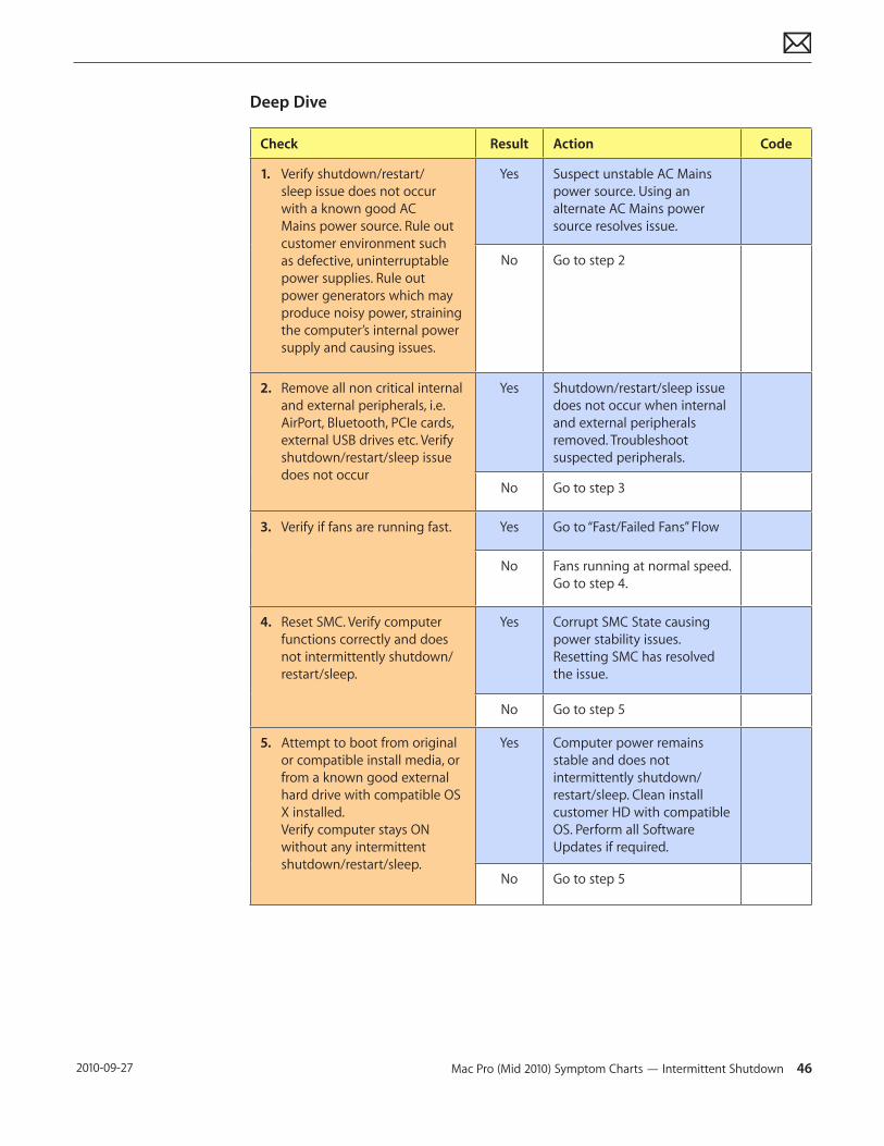
1. Verify shutdown/restart/sleep issue does not occur with a known good AC Mains power source. Rule out customer environment such as defective, uninterruptable power supplies. Rule out power generators which may produce noisy power, straining the computer’s internal power supply and causing issues.
Yes Suspect unstable AC Mains power source. Using an alternate AC Mains power source resolves issue.
No Go to step 2
2. Remove all non critical internal and external peripherals, i.e. AirPort, Bluetooth, PCIe cards, external USB drives etc. Verify shutdown/restart/sleep issue does not occur
Yes Shutdown/restart/sleep issue does not occur when internal and external peripherals removed. Troubleshoot suspected peripherals.
No Go to step 3
3. Verify if fans are running fast. Yes Go to “Fast/Failed Fans” Flow
No Fans running at normal speed. Go to step 4.
4. Reset SMC. Verify computer functions correctly and does not intermittently shutdown/restart/sleep.
Yes Corrupt SMC State causing power stability issues. Resetting SMC has resolved the issue.
No Go to step 5
5. Attempt to boot from original or compatible install media, or from a known good external hard drive with compatible OS X installed. Verify computer stays ON without any intermittent shutdown/restart/sleep.
Yes Computer power remains stable and does not intermittently shutdown/restart/sleep. Clean install customer HD with compatible OS. Perform all Software Updates if required.
No Go to step 5
Mac Pro (Mid 2010) Symptom Charts — Intermittent Shutdown 47 2010-09-27
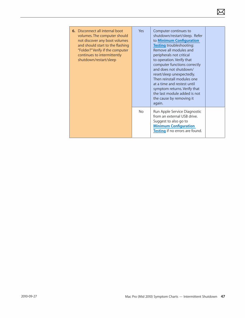
6. Disconnect all internal boot volumes. The computer should not discover any boot volumes and should start to the flashing “Folder?” Verify if the computer continues to intermittently shutdown/restart/sleep
Yes Computer continues to shutdown/restart/sleep. Refer to Minimum Configuration Testing troubleshooting: Remove all modules and peripherals not critical to operation. Verify that computer functions correctly and does not shutdown/reset/sleep unexpectedly. Then reinstall modules one at a time and restest until symptom returns. Verify that the last module added is not the cause by removing it again.
No Run Apple Service Diagnostic from an external USB drive. Suggest to also go to Minimum Configuration Testing if no errors are found.
Mac Pro (Mid 2010) Symptom Charts — Memory Issues/Kernel Panic and Freezes 48 2010-09-27
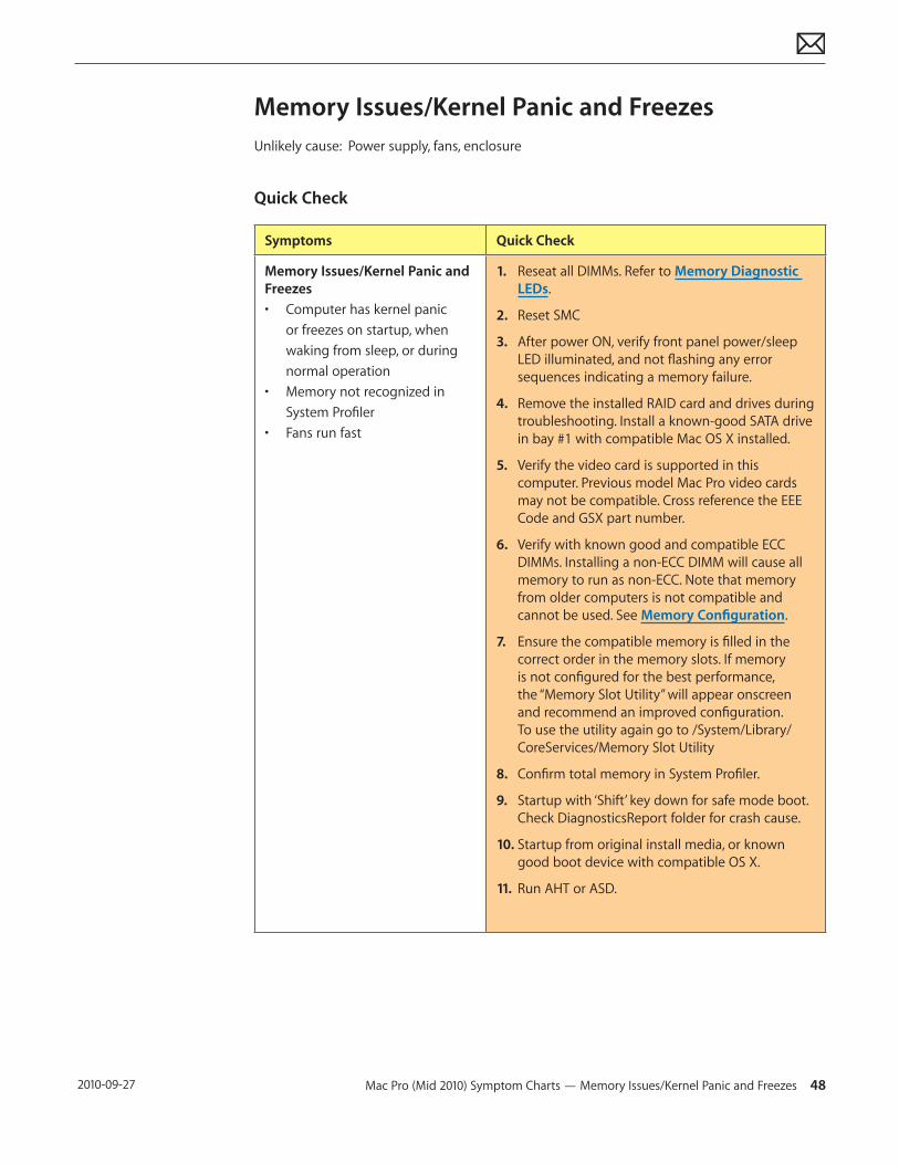
Memory Issues/Kernel Panic and FreezesUnlikely cause: Power supply, fans, enclosure
Quick Check
Symptoms Quick Check
Memory Issues/Kernel Panic and Freezes• Computer has kernel panic
or freezes on startup, when waking from sleep, or during normal operation
• Memory not recognized in System Profiler
• Fans run fast
1. Reseat all DIMMs. Refer to Memory Diagnostic LEDs.
2. Reset SMC
3. After power ON, verify front panel power/sleep LED illuminated, and not flashing any error sequences indicating a memory failure.
4. Remove the installed RAID card and drives during troubleshooting. Install a known-good SATA drive in bay #1 with compatible Mac OS X installed.
5. Verify the video card is supported in this computer. Previous model Mac Pro video cards may not be compatible. Cross reference the EEE Code and GSX part number.
6. Verify with known good and compatible ECC DIMMs. Installing a non-ECC DIMM will cause all memory to run as non-ECC. Note that memory from older computers is not compatible and cannot be used. See Memory Configuration.
7. Ensure the compatible memory is filled in the correct order in the memory slots. If memory is not configured for the best performance, the “Memory Slot Utility” will appear onscreen and recommend an improved configuration. To use the utility again go to /System/Library/CoreServices/Memory Slot Utility
8. Confirm total memory in System Profiler.
9. Startup with ‘Shift’ key down for safe mode boot. Check DiagnosticsReport folder for crash cause.
10. Startup from original install media, or known good boot device with compatible OS X.
11. Run AHT or ASD.
Mac Pro (Mid 2010) Symptom Charts — Memory Issues/Kernel Panic and Freezes 49 2010-09-27
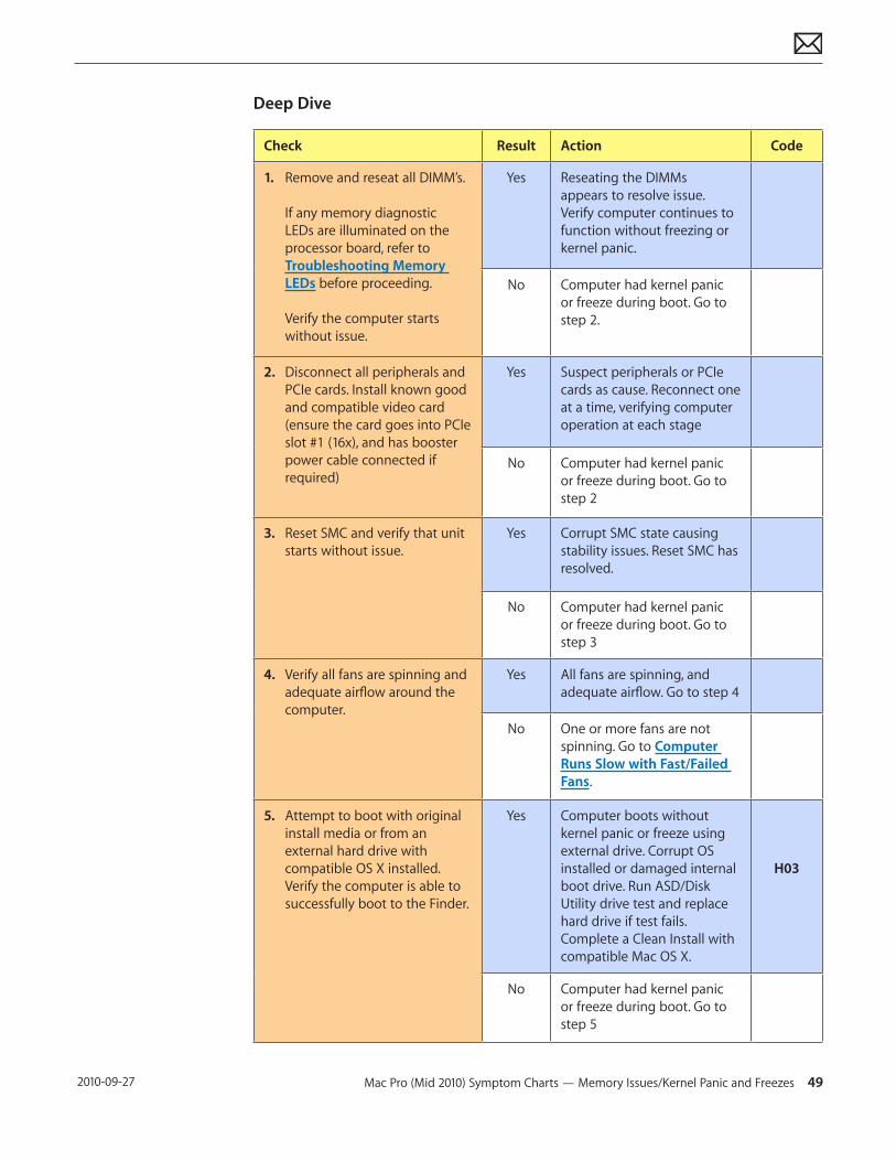
Deep Dive
Check Result Action Code
1. Remove and reseat all DIMM’s. If any memory diagnostic LEDs are illuminated on the processor board, refer to Troubleshooting Memory LEDs before proceeding. Verify the computer starts without issue.
Yes Reseating the DIMMs appears to resolve issue. Verify computer continues to function without freezing or kernel panic.
No Computer had kernel panic or freeze during boot. Go to step 2.
2. Disconnect all peripherals and PCIe cards. Install known good and compatible video card (ensure the card goes into PCIe slot #1 (16x), and has booster power cable connected if required)
Yes Suspect peripherals or PCIe cards as cause. Reconnect one at a time, verifying computer operation at each stage
No Computer had kernel panic or freeze during boot. Go to step 2
3. Reset SMC and verify that unit starts without issue.
Yes Corrupt SMC state causing stability issues. Reset SMC has resolved.
No Computer had kernel panic or freeze during boot. Go to step 3
4. Verify all fans are spinning and adequate airflow around the computer.
Yes All fans are spinning, and adequate airflow. Go to step 4
No One or more fans are not spinning. Go to Computer Runs Slow with Fast/Failed Fans.
5. Attempt to boot with original install media or from an external hard drive with compatible OS X installed. Verify the computer is able to successfully boot to the Finder.
Yes Computer boots without kernel panic or freeze using external drive. Corrupt OS installed or damaged internal boot drive. Run ASD/Disk Utility drive test and replace hard drive if test fails. Complete a Clean Install with compatible Mac OS X.
H03
No Computer had kernel panic or freeze during boot. Go to step 5
Mac Pro (Mid 2010) Symptom Charts — Memory Issues/Kernel Panic and Freezes 50 2010-09-27
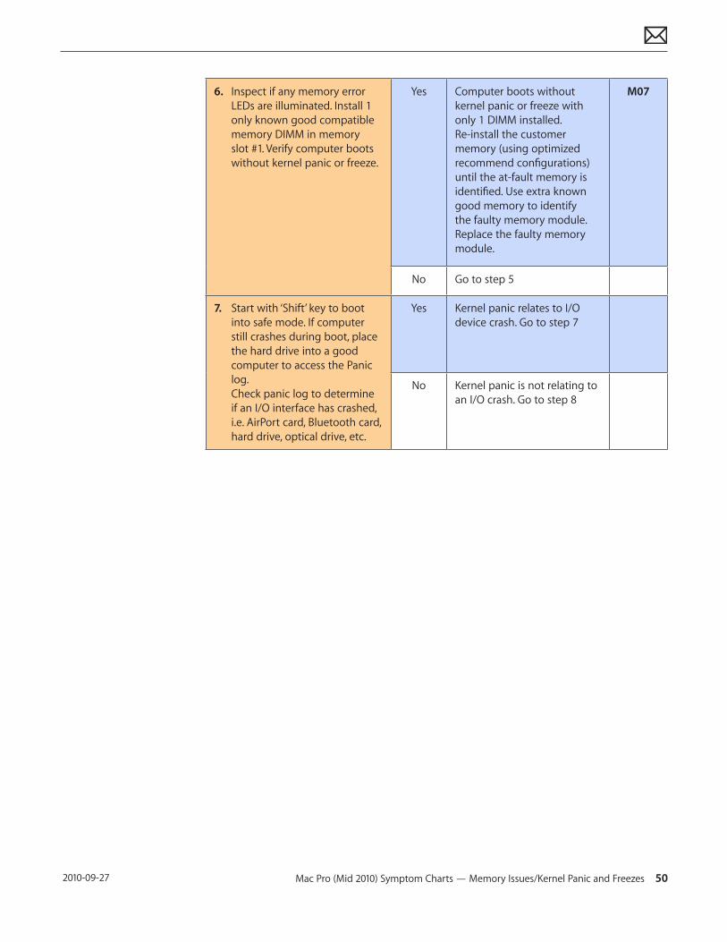
6. Inspect if any memory error LEDs are illuminated. Install 1 only known good compatible memory DIMM in memory slot #1. Verify computer boots without kernel panic or freeze.
Yes Computer boots without kernel panic or freeze with only 1 DIMM installed. Re-install the customer memory (using optimized recommend configurations) until the at-fault memory is identified. Use extra known good memory to identify the faulty memory module. Replace the faulty memory module.
M07
No Go to step 5
7. Start with ‘Shift’ key to boot into safe mode. If computer still crashes during boot, place the hard drive into a good computer to access the Panic log. Check panic log to determine if an I/O interface has crashed, i.e. AirPort card, Bluetooth card, hard drive, optical drive, etc.
Yes Kernel panic relates to I/O device crash. Go to step 7
No Kernel panic is not relating to an I/O crash. Go to step 8
Mac Pro (Mid 2010) Symptom Charts — Memory Issues/Kernel Panic and Freezes 51 2010-09-27
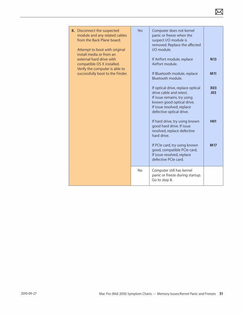
8. Disconnect the suspected module and any related cables from the Back Plane board. Attempt to boot with original install media or from an external hard drive with compatible OS X installed. Verify the computer is able to successfully boot to the Finder.
Yes Computer does not kernel panic or freeze when the suspect I/O module is removed. Replace the affected I/O module. If AirPort module, replace AirPort module. If Bluetooth module, replace Bluetooth module. If optical drive, replace optical drive cable and retest. If issue remains, try using known good optical drive. If issue resolved, replace defective optical drive. If hard drive, try using known good hard drive. If issue resolved, replace defective hard drive. If PCIe card, try using known good, compatible PCIe card, If issue resolved, replace defective PCIe card.
N13
M11
X03 J03
H01
M17
No Computer still has kernel panic or freeze during startup. Go to step 8.
Mac Pro (Mid 2010) Symptom Charts — Memory Issues/Kernel Panic and Freezes 52 2010-09-27
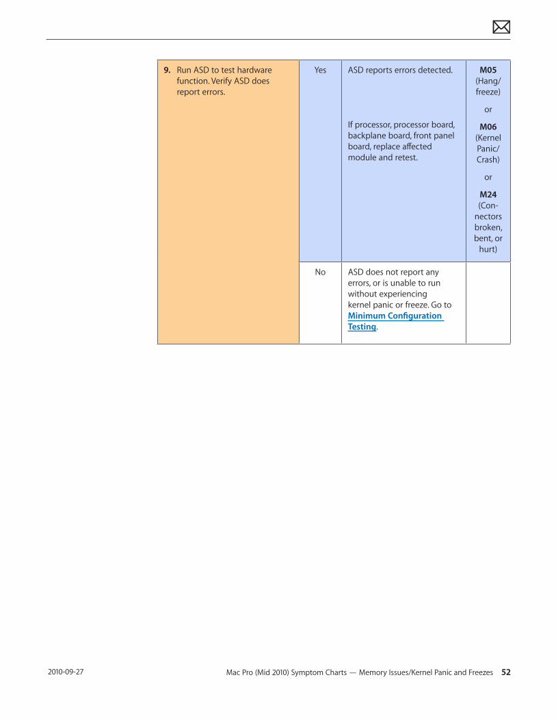
9. Run ASD to test hardware function. Verify ASD does report errors.
Yes ASD reports errors detected. If processor, processor board, backplane board, front panel board, replace affected module and retest.
M05 (Hang/freeze)
or
M06 (Kernel Panic/Crash)
or
M24 (Con-
nectors broken, bent, or
hurt)
No ASD does not report any errors, or is unable to run without experiencing kernel panic or freeze. Go to Minimum Configuration Testing.
Mac Pro (Mid 2010) Symptom Charts — No Video 53 2010-09-27
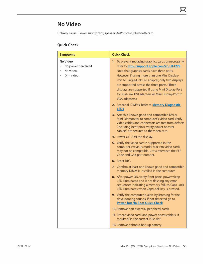
No VideoUnlikely cause: Power supply, fans, speaker, AirPort card, Bluetooth card
Quick Check
Symptoms Quick Check
No Video• No power perceived• No video• Dim video
1. To prevent replacing graphics cards unnecessarily, refer to http://support.apple.com/kb/HT4279. Note that graphics cards have three ports. However, if using more than one Mini Display-Port to Single-Link DVI adapter, only two displays are supported across the three ports. (Three displays are supported if using Mini Display-Port to Dual-Link DVI adapters or Mini Display-Port to VGA adapters.)
2. Reseat all DIMMs. Refer to Memory Diagnostic LEDs.
3. Attach a known good and compatible DVI or Mini-DP monitor to computer’s video card. Verify video cables and connectors are free from defects (including bent pins). Verify power booster cable(s) are secured to the video card.
4. Power OFF/ON the display.
5. Verify the video card is supported in this computer. Previous model Mac Pro video cards may not be compatible. Cross reference the EEE Code and GSX part number.
6. Reset RTC.
7. Confirm at least one known good and compatible memory DIMM is installed in the computer.
8. After power ON, verify front panel power/sleep LED illuminated and is not flashing any error sequences indicating a memory failure. Caps Lock LED illuminates when CapsLock key is pressed.
9. Verify the computer is alive by listening for the drive booting sounds. If not detected go to Power, but No Boot Quick Check.
10. Remove non essential peripheral cards
11. Reseat video card (and power boost cable(s) if required) in the correct PCIe slot
12. Remove onboard backup battery.
Mac Pro (Mid 2010) Symptom Charts — No Video 54 2010-09-27
Deep Dive
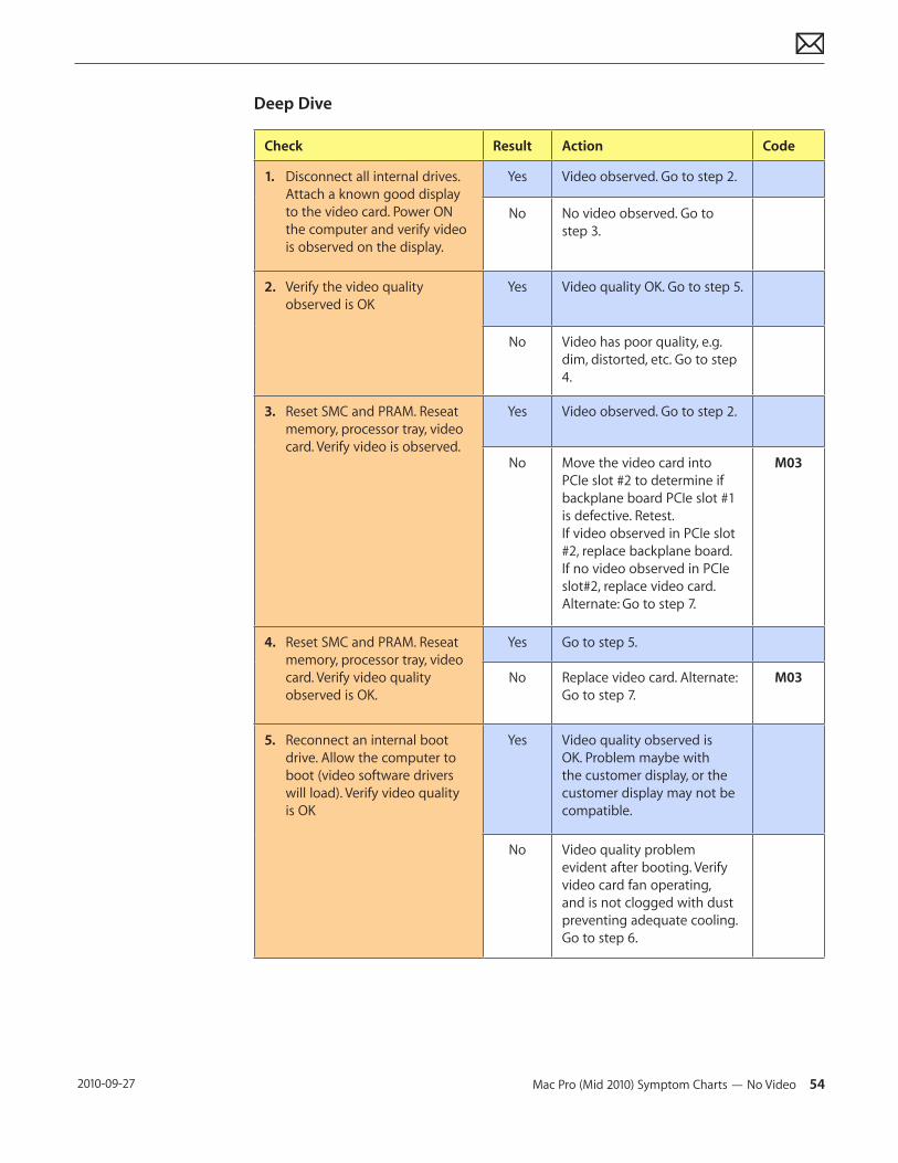
Check Result Action Code
1. Disconnect all internal drives. Attach a known good display to the video card. Power ON the computer and verify video is observed on the display.
Yes Video observed. Go to step 2.
No No video observed. Go to step 3.
2. Verify the video quality observed is OK
Yes Video quality OK. Go to step 5.
No Video has poor quality, e.g. dim, distorted, etc. Go to step 4.
3. Reset SMC and PRAM. Reseat memory, processor tray, video card. Verify video is observed.
Yes Video observed. Go to step 2.
No Move the video card into PCIe slot #2 to determine if backplane board PCIe slot #1 is defective. Retest. If video observed in PCIe slot #2, replace backplane board. If no video observed in PCIe slot#2, replace video card. Alternate: Go to step 7.
M03
4. Reset SMC and PRAM. Reseat memory, processor tray, video card. Verify video quality observed is OK.
Yes Go to step 5.
No Replace video card. Alternate: Go to step 7.
M03
5. Reconnect an internal boot drive. Allow the computer to boot (video software drivers will load). Verify video quality is OK
Yes Video quality observed is OK. Problem maybe with the customer display, or the customer display may not be compatible.
No Video quality problem evident after booting. Verify video card fan operating, and is not clogged with dust preventing adequate cooling. Go to step 6.
Mac Pro (Mid 2010) Symptom Charts — No Video 55 2010-09-27
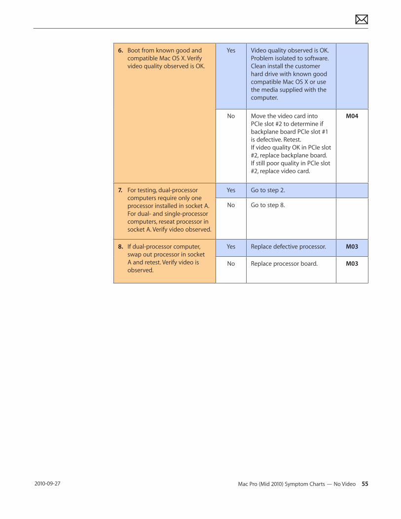
6. Boot from known good and compatible Mac OS X. Verify video quality observed is OK.
Yes Video quality observed is OK. Problem isolated to software. Clean install the customer hard drive with known good compatible Mac OS X or use the media supplied with the computer.
No Move the video card into PCIe slot #2 to determine if backplane board PCIe slot #1 is defective. Retest. If video quality OK in PCIe slot #2, replace backplane board. If still poor quality in PCIe slot #2, replace video card.
M04
7. For testing, dual-processor computers require only one processor installed in socket A. For dual- and single-processor computers, reseat processor in socket A. Verify video observed.
Yes Go to step 2.
No Go to step 8.
8. If dual-processor computer, swap out processor in socket A and retest. Verify video is observed.
Yes Replace defective processor. M03
No Replace processor board. M03
Mac Pro (Mid 2010) Symptom Charts — Power, but No Boot 56 2010-09-27
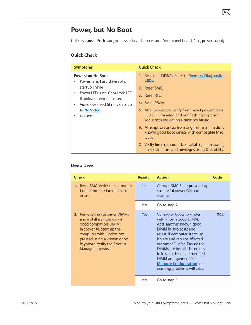
Power, but No BootUnlikely cause: Enclosure, processor board, processors, front panel board, fans, power supply
Quick Check
Symptoms Quick Check
Power, but No Boot• Power, fans, hard drive spin,
startup chime• Power LED is on, Caps Lock LED
illuminates when pressed • Video observed (if no video, go
to No Video)• No boot
1. Reseat all DIMMs. Refer to Memory Diagnostic LEDs.
2. Reset SMC.
3. Reset RTC.
4. Reset PRAM
5. After power ON, verify front panel power/sleep LED is illuminated and not flashing any error sequences indicating a memory failure.
6. Attempt to startup from original install media, or known good boot device with compatible Mac OS X.
7. Verify internal hard drive available, smart status, check structure and privileges using Disk utility.
Deep Dive
Check Result Action Code
1. Reset SMC. Verify the computer boots from the internal hard drive
Yes Corrupt SMC State preventing successful power ON and startup.
No Go to step 2
2. Remove the customer DIMMs and install a single known good compatible DIMM in socket #1. Start up the computer with Option key pressed using a known good keyboard. Verify the Startup Manager appears.
Yes Computer boots to Finder with known good DIMM. Add another known good DIMM in socket #2 and retest. If computer starts up, isolate and replace affected customer DIMMs. Ensure the DIMMs are installed correctly following the recommended DIMM arrangement (see Memory Configuration) or crashing problems will arise.
X02
No Go to step 3
Mac Pro (Mid 2010) Symptom Charts — Noise/Hum/Vibration 57 2010-09-27
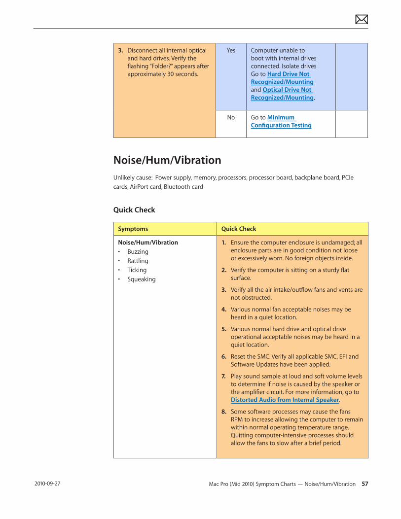
3. Disconnect all internal optical and hard drives. Verify the flashing “Folder?” appears after approximately 30 seconds.
Yes Computer unable to boot with internal drives connected. Isolate drives Go to Hard Drive Not Recognized/Mounting and Optical Drive Not Recognized/Mounting.
No Go to Minimum Configuration Testing
Noise/Hum/VibrationUnlikely cause: Power supply, memory, processors, processor board, backplane board, PCIe cards, AirPort card, Bluetooth card
Quick Check
Symptoms Quick Check
Noise/Hum/Vibration• Buzzing• Rattling• Ticking• Squeaking
1. Ensure the computer enclosure is undamaged; all enclosure parts are in good condition not loose or excessively worn. No foreign objects inside.
2. Verify the computer is sitting on a sturdy flat surface.
3. Verify all the air intake/outflow fans and vents are not obstructed.
4. Various normal fan acceptable noises may be heard in a quiet location.
5. Various normal hard drive and optical drive operational acceptable noises may be heard in a quiet location.
6. Reset the SMC. Verify all applicable SMC, EFI and Software Updates have been applied.
7. Play sound sample at loud and soft volume levels to determine if noise is caused by the speaker or the amplifier circuit. For more information, go to Distorted Audio from Internal Speaker.
8. Some software processes may cause the fans RPM to increase allowing the computer to remain within normal operating temperature range. Quitting computer-intensive processes should allow the fans to slow after a brief period.
Mac Pro (Mid 2010) Symptom Charts — Noise/Hum/Vibration 58 2010-09-27
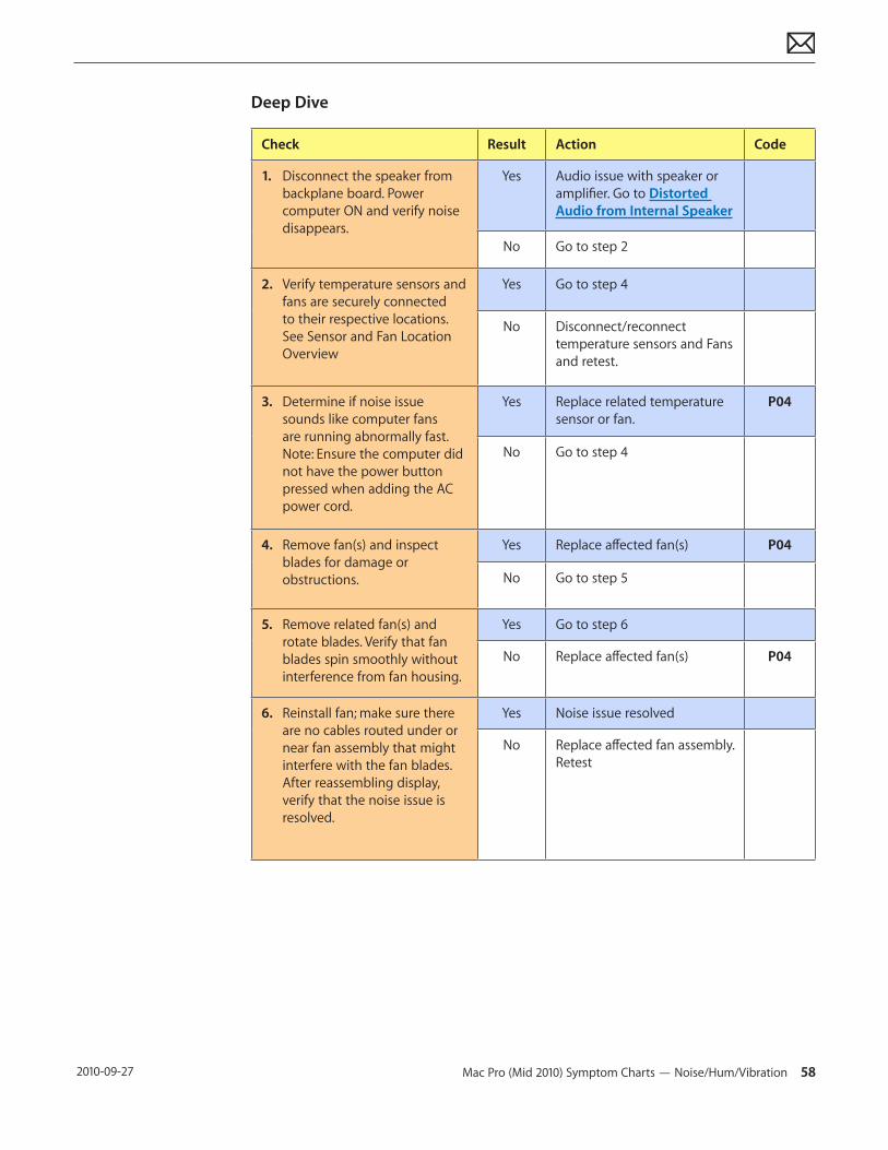
Deep Dive
Check Result Action Code
1. Disconnect the speaker from backplane board. Power computer ON and verify noise disappears.
Yes Audio issue with speaker or amplifier. Go to Distorted Audio from Internal Speaker
No Go to step 2
2. Verify temperature sensors and fans are securely connected to their respective locations. See Sensor and Fan Location Overview
Yes Go to step 4
No Disconnect/reconnect temperature sensors and Fans and retest.
3. Determine if noise issue sounds like computer fans are running abnormally fast. Note: Ensure the computer did not have the power button pressed when adding the AC power cord.
Yes Replace related temperature sensor or fan.
P04
No Go to step 4
4. Remove fan(s) and inspect blades for damage or obstructions.
Yes Replace affected fan(s) P04
No Go to step 5
5. Remove related fan(s) and rotate blades. Verify that fan blades spin smoothly without interference from fan housing.
Yes Go to step 6
No Replace affected fan(s) P04
6. Reinstall fan; make sure there are no cables routed under or near fan assembly that might interfere with the fan blades. After reassembling display, verify that the noise issue is resolved.
Yes Noise issue resolved
No Replace affected fan assembly. Retest
Mac Pro (Mid 2010) Symptom Charts — Burnt Smell/Odor 59 2010-09-27
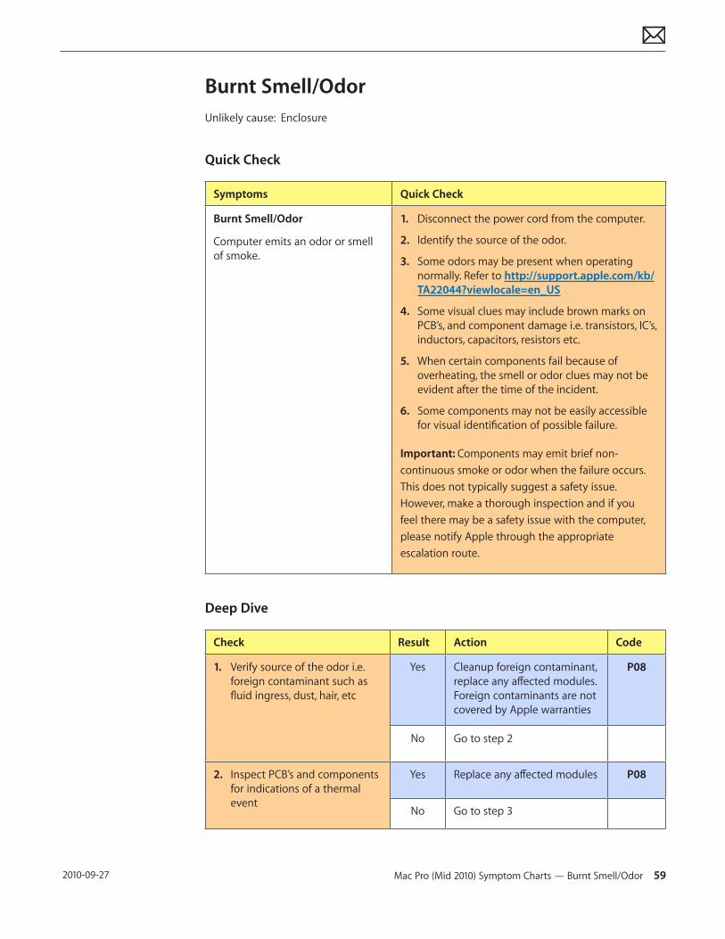
Burnt Smell/OdorUnlikely cause: Enclosure
Quick Check
Symptoms Quick Check
Burnt Smell/Odor
Computer emits an odor or smell of smoke.
1. Disconnect the power cord from the computer.
2. Identify the source of the odor.
3. Some odors may be present when operating normally. Refer to http://support.apple.com/kb/TA22044?viewlocale=en_US
4. Some visual clues may include brown marks on PCB’s, and component damage i.e. transistors, IC’s, inductors, capacitors, resistors etc.
5. When certain components fail because of overheating, the smell or odor clues may not be evident after the time of the incident.
6. Some components may not be easily accessible for visual identification of possible failure.
Important: Components may emit brief non-continuous smoke or odor when the failure occurs. This does not typically suggest a safety issue. However, make a thorough inspection and if you feel there may be a safety issue with the computer, please notify Apple through the appropriate escalation route.
Deep Dive
Check Result Action Code
1. Verify source of the odor i.e. foreign contaminant such as fluid ingress, dust, hair, etc
Yes Cleanup foreign contaminant, replace any affected modules. Foreign contaminants are not covered by Apple warranties
P08
No Go to step 2
2. Inspect PCB’s and components for indications of a thermal event
Yes Replace any affected modules P08
No Go to step 3
Mac Pro (Mid 2010) Symptom Charts — Uncategorized Symptom 60 2010-09-27
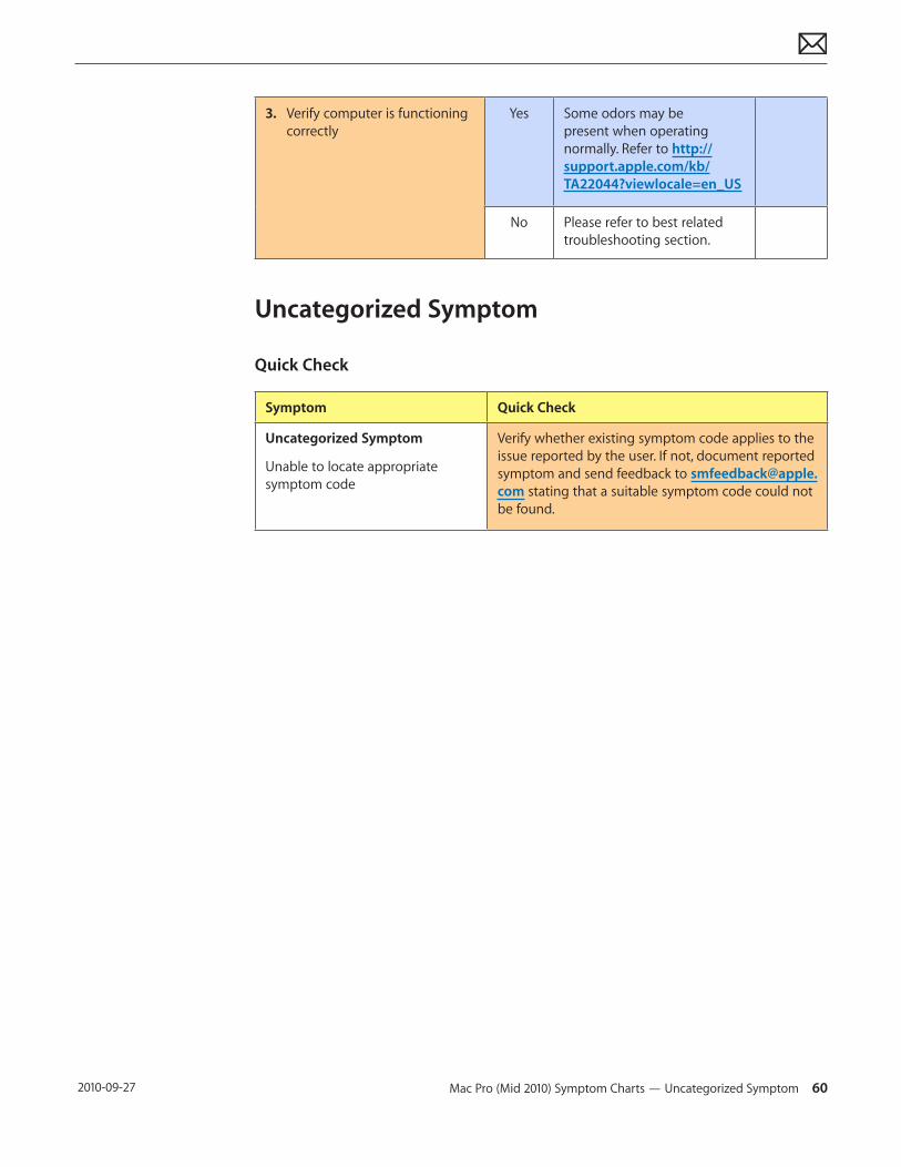
3. Verify computer is functioning correctly
Yes Some odors may be present when operating normally. Refer to http://support.apple.com/kb/TA22044?viewlocale=en_US
No Please refer to best related troubleshooting section.
Uncategorized Symptom
Quick Check
Symptom Quick Check
Uncategorized Symptom
Unable to locate appropriate symptom code
Verify whether existing symptom code applies to the issue reported by the user. If not, document reported symptom and send feedback to [email protected] stating that a suitable symptom code could not be found.
Mac Pro (Mid 2010) Symptom Charts — Ethernet Port/Device Issue 61 2010-09-27
Communications
Follow the steps in the order indicated below. If an action resolves the issue, retest the computer to verify. If the issue persists after retesting, return to step 1.
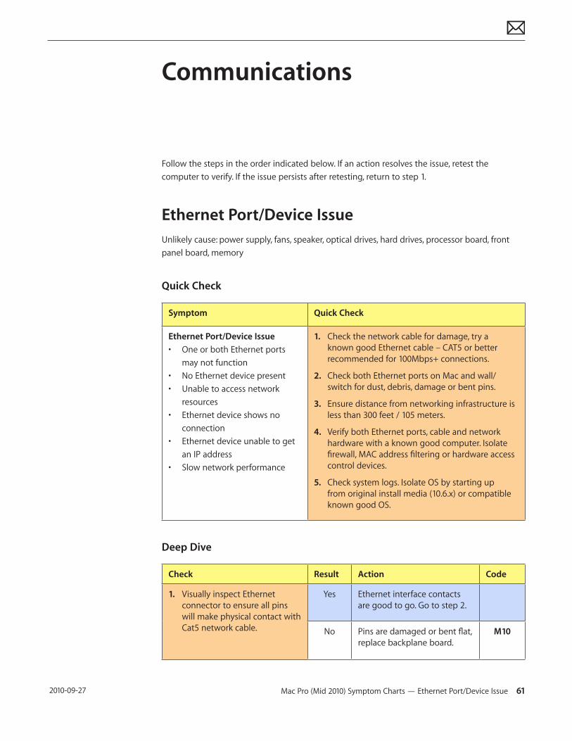
Ethernet Port/Device IssueUnlikely cause: power supply, fans, speaker, optical drives, hard drives, processor board, front panel board, memory
Quick Check
Symptom Quick Check
Ethernet Port/Device Issue• One or both Ethernet ports
may not function• No Ethernet device present• Unable to access network
resources• Ethernet device shows no
connection• Ethernet device unable to get
an IP address• Slow network performance
1. Check the network cable for damage, try a known good Ethernet cable – CAT5 or better recommended for 100Mbps+ connections.
2. Check both Ethernet ports on Mac and wall/switch for dust, debris, damage or bent pins.
3. Ensure distance from networking infrastructure is less than 300 feet / 105 meters.
4. Verify both Ethernet ports, cable and network hardware with a known good computer. Isolate firewall, MAC address filtering or hardware access control devices.
5. Check system logs. Isolate OS by starting up from original install media (10.6.x) or compatible known good OS.
Deep Dive
Check Result Action Code
1. Visually inspect Ethernet connector to ensure all pins will make physical contact with Cat5 network cable.
Yes Ethernet interface contacts are good to go. Go to step 2.
No Pins are damaged or bent flat, replace backplane board.
M10
Mac Pro (Mid 2010) Symptom Charts — Ethernet Port/Device Issue 62 2010-09-27
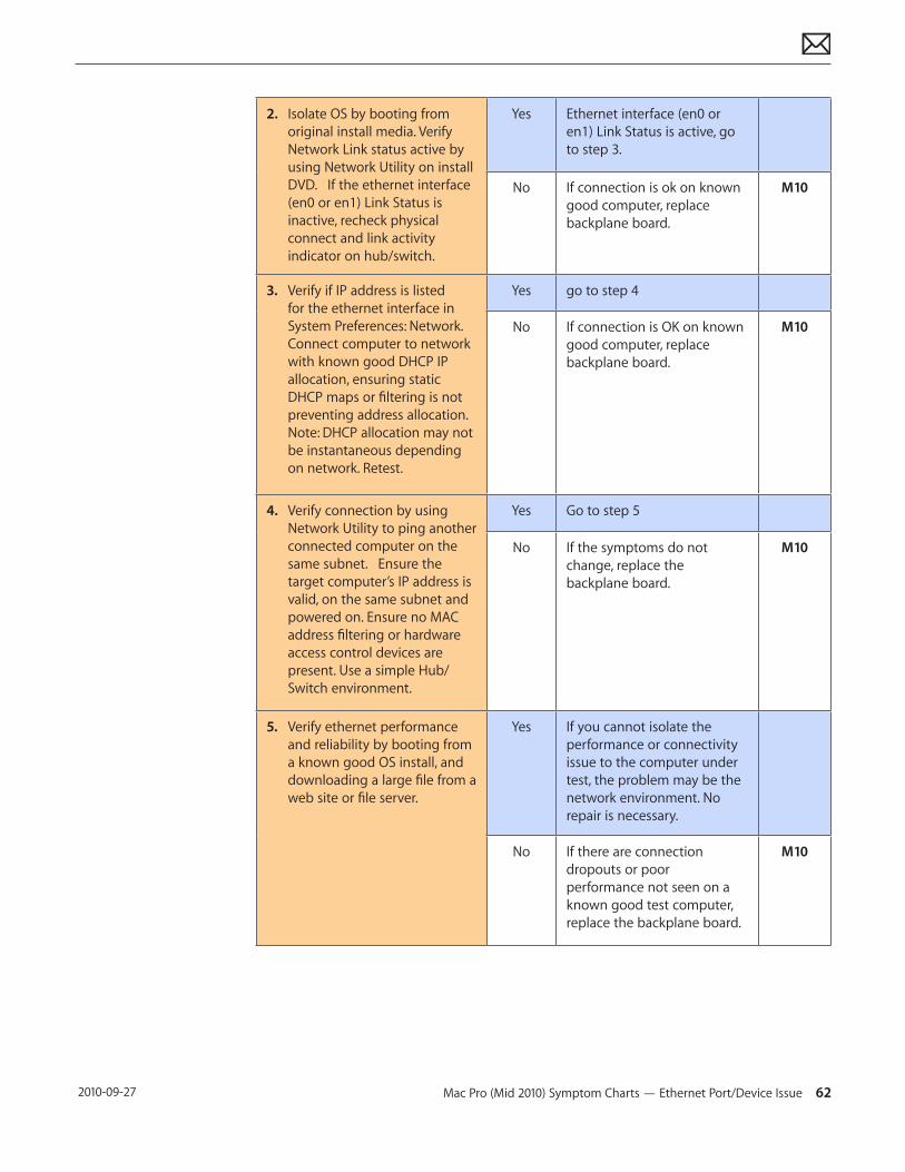
2. Isolate OS by booting from original install media. Verify Network Link status active by using Network Utility on install DVD. If the ethernet interface (en0 or en1) Link Status is inactive, recheck physical connect and link activity indicator on hub/switch.
Yes Ethernet interface (en0 or en1) Link Status is active, go to step 3.
No If connection is ok on known good computer, replace backplane board.
M10
3. Verify if IP address is listed for the ethernet interface in System Preferences: Network. Connect computer to network with known good DHCP IP allocation, ensuring static DHCP maps or filtering is not preventing address allocation. Note: DHCP allocation may not be instantaneous depending on network. Retest.
Yes go to step 4
No If connection is OK on known good computer, replace backplane board.
M10
4. Verify connection by using Network Utility to ping another connected computer on the same subnet. Ensure the target computer’s IP address is valid, on the same subnet and powered on. Ensure no MAC address filtering or hardware access control devices are present. Use a simple Hub/Switch environment.
Yes Go to step 5
No If the symptoms do not change, replace the backplane board.
M10
5. Verify ethernet performance and reliability by booting from a known good OS install, and downloading a large file from a web site or file server.
Yes If you cannot isolate the performance or connectivity issue to the computer under test, the problem may be the network environment. No repair is necessary.
No If there are connection dropouts or poor performance not seen on a known good test computer, replace the backplane board.
M10
Mac Pro (Mid 2010) Symptom Charts — AirPort/Bluetooth: Defective Wireless Devices 63 2010-09-27
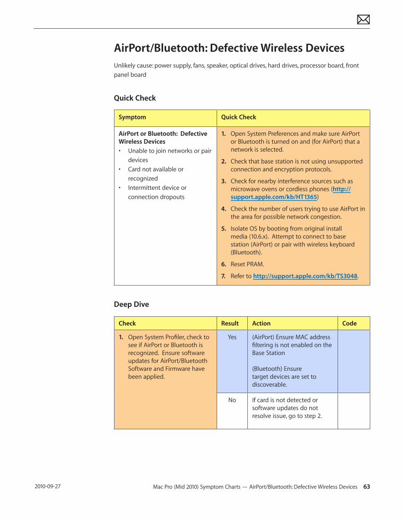
AirPort/Bluetooth: Defective Wireless DevicesUnlikely cause: power supply, fans, speaker, optical drives, hard drives, processor board, front panel board
Quick Check
Symptom Quick Check
AirPort or Bluetooth: Defective Wireless Devices• Unable to join networks or pair
devices• Card not available or
recognized• Intermittent device or
connection dropouts
1. Open System Preferences and make sure AirPort or Bluetooth is turned on and (for AirPort) that a network is selected.
2. Check that base station is not using unsupported connection and encryption protocols.
3. Check for nearby interference sources such as microwave ovens or cordless phones (http://support.apple.com/kb/HT1365)
4. Check the number of users trying to use AirPort in the area for possible network congestion.
5. Isolate OS by booting from original install media (10.6.x). Attempt to connect to base station (AirPort) or pair with wireless keyboard (Bluetooth).
6. Reset PRAM.
7. Refer to http://support.apple.com/kb/TS3048.
Deep Dive
Check Result Action Code
1. Open System Profiler, check to see if AirPort or Bluetooth is recognized. Ensure software updates for AirPort/Bluetooth Software and Firmware have been applied.
Yes (AirPort) Ensure MAC address filtering is not enabled on the Base Station (Bluetooth) Ensure target devices are set to discoverable.
No If card is not detected or software updates do not resolve issue, go to step 2.
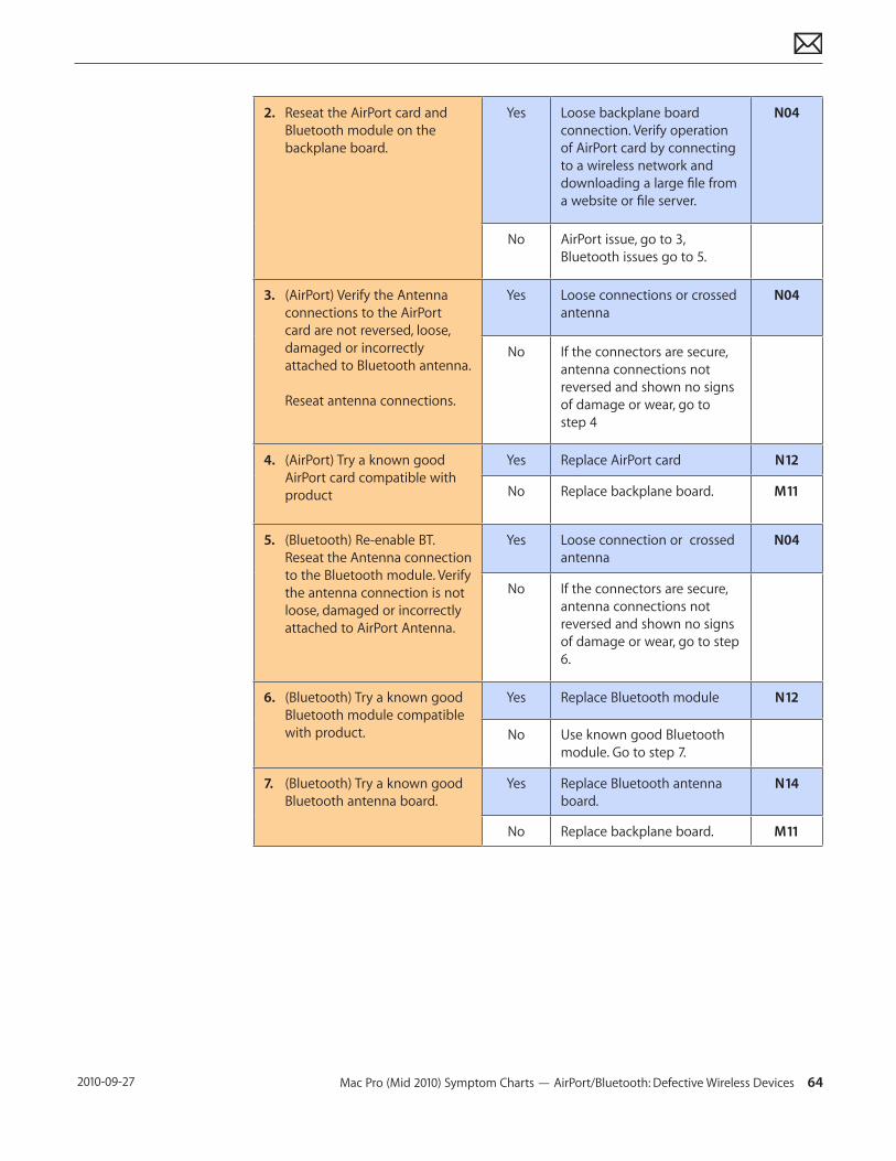
Mac Pro (Mid 2010) Symptom Charts — AirPort/Bluetooth: Defective Wireless Devices 64 2010-09-27
2. Reseat the AirPort card and Bluetooth module on the backplane board.
Yes Loose backplane board connection. Verify operation of AirPort card by connecting to a wireless network and downloading a large file from a website or file server.
N04
No AirPort issue, go to 3, Bluetooth issues go to 5.
3. (AirPort) Verify the Antenna connections to the AirPort card are not reversed, loose, damaged or incorrectly attached to Bluetooth antenna. Reseat antenna connections.
Yes Loose connections or crossed antenna
N04
No If the connectors are secure, antenna connections not reversed and shown no signs of damage or wear, go to step 4
4. (AirPort) Try a known good AirPort card compatible with product
Yes Replace AirPort card N12
No Replace backplane board. M11
5. (Bluetooth) Re-enable BT. Reseat the Antenna connection to the Bluetooth module. Verify the antenna connection is not loose, damaged or incorrectly attached to AirPort Antenna.
Yes Loose connection or crossed antenna
N04
No If the connectors are secure, antenna connections not reversed and shown no signs of damage or wear, go to step 6.
6. (Bluetooth) Try a known good Bluetooth module compatible with product.
Yes Replace Bluetooth module N12
No Use known good Bluetooth module. Go to step 7.
7. (Bluetooth) Try a known good Bluetooth antenna board.
Yes Replace Bluetooth antenna board.
N14
No Replace backplane board. M11
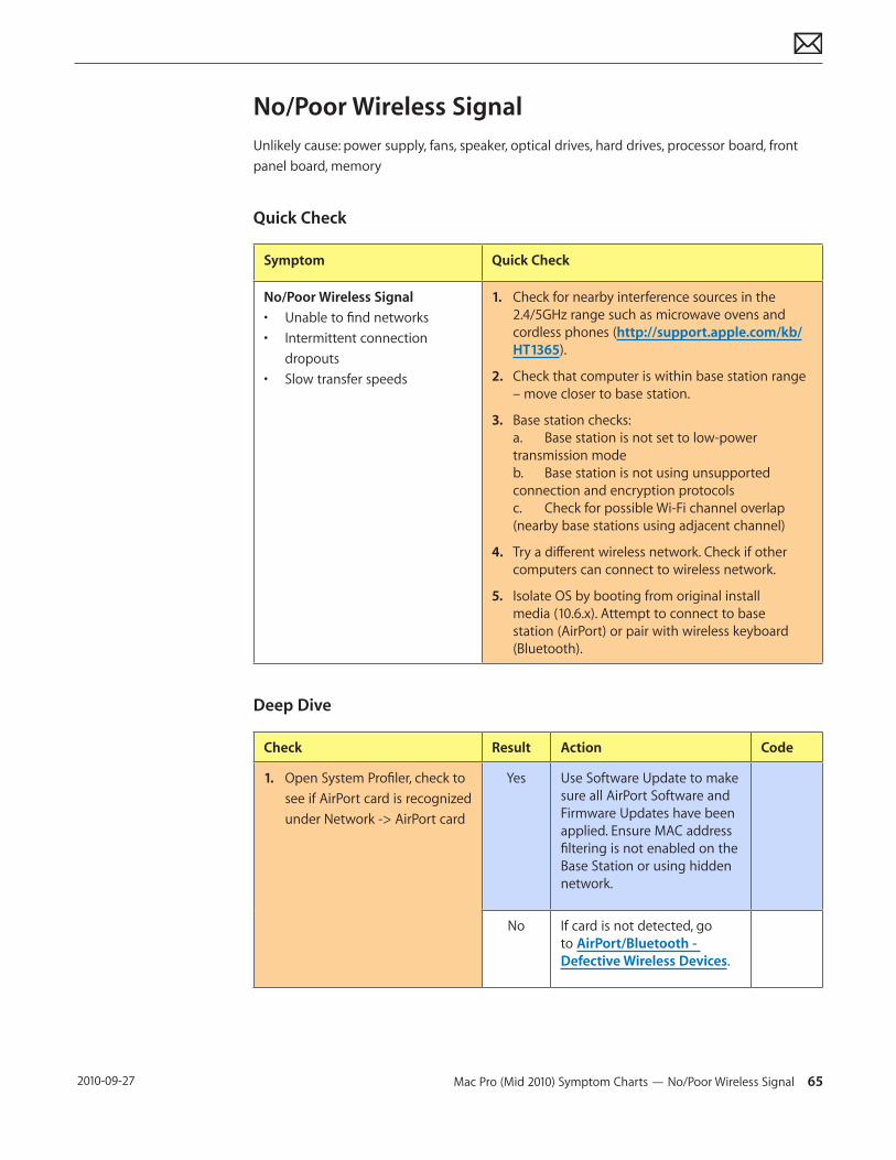
Mac Pro (Mid 2010) Symptom Charts — No/Poor Wireless Signal 65 2010-09-27
No/Poor Wireless SignalUnlikely cause: power supply, fans, speaker, optical drives, hard drives, processor board, front panel board, memory
Quick Check
Symptom Quick Check
No/Poor Wireless Signal• Unable to find networks• Intermittent connection
dropouts• Slow transfer speeds
1. Check for nearby interference sources in the 2.4/5GHz range such as microwave ovens and cordless phones (http://support.apple.com/kb/HT1365).
2. Check that computer is within base station range – move closer to base station.
3. Base station checks: a. Base station is not set to low-power transmission mode b. Base station is not using unsupported connection and encryption protocols c. Check for possible Wi-Fi channel overlap (nearby base stations using adjacent channel)
4. Try a different wireless network. Check if other computers can connect to wireless network.
5. Isolate OS by booting from original install media (10.6.x). Attempt to connect to base station (AirPort) or pair with wireless keyboard (Bluetooth).
Deep Dive
Check Result Action Code
1. Open System Profiler, check to see if AirPort card is recognized under Network -> AirPort card
Yes Use Software Update to make sure all AirPort Software and Firmware Updates have been applied. Ensure MAC address filtering is not enabled on the Base Station or using hidden network.
No If card is not detected, go to AirPort/Bluetooth - Defective Wireless Devices.
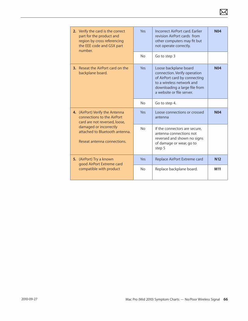
Mac Pro (Mid 2010) Symptom Charts — No/Poor Wireless Signal 66 2010-09-27
2. Verify the card is the correct part for the product and region by cross referencing the EEE code and GSX part number.
Yes Incorrect AirPort card. Earlier revision AirPort cards from other computers may fit but not operate correctly.
N04
No Go to step 3
3. Reseat the AirPort card on the backplane board.
Yes Loose backplane board connection. Verify operation of AirPort card by connecting to a wireless network and downloading a large file from a website or file server.
N04
No Go to step 4.
4. (AirPort) Verify the Antenna connections to the AirPort card are not reversed, loose, damaged or incorrectly attached to Bluetooth antenna. Reseat antenna connections.
Yes Loose connections or crossed antenna
N04
No If the connectors are secure, antenna connections not reversed and shown no signs of damage or wear, go to step 5
5. (AirPort) Try a known good AirPort Extreme card compatible with product
Yes Replace AirPort Extreme card N12
No Replace backplane board. M11
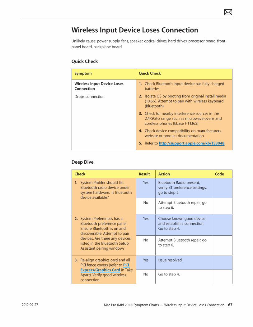
Mac Pro (Mid 2010) Symptom Charts — Wireless Input Device Loses Connection 67 2010-09-27
Wireless Input Device Loses ConnectionUnlikely cause: power supply, fans, speaker, optical drives, hard drives, processor board, front panel board, backplane board
Quick Check
Symptom Quick Check
Wireless Input Device Loses Connection
Drops connection
1. Check Bluetooth input device has fully charged batteries.
2. Isolate OS by booting from original install media (10.6.x). Attempt to pair with wireless keyboard (Bluetooth)
3. Check for nearby interference sources in the 2.4/5GHz range such as microwave ovens and cordless phones (kbase HT1365)
4. Check device compatibility on manufacturers website or product documentation.
5. Refer to http://support.apple.com/kb/TS3048.
Deep Dive
Check Result Action Code
1. System Profiler should list Bluetooth radio device under system hardware. Is Bluetooth device available?
Yes Bluetooth Radio present, verify BT preference settings, go to step 2.
No Attempt Bluetooth repair, go to step 6.
2. System Preferences has a Bluetooth preference panel. Ensure Bluetooth is on and discoverable. Attempt to pair devices. Are there any devices listed in the Bluetooth Setup Assistant pairing window?
Yes Choose known good device and establish a connection. Go to step 4.
No Attempt Bluetooth repair, go to step 6.
3. Re-align graphics card and all PCI fence covers (refer to PCI Express/Graphics Card in Take Apart). Verify good wireless connection.
Yes Issue resolved.
No Go to step 4.
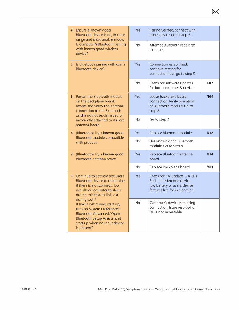
Mac Pro (Mid 2010) Symptom Charts — Wireless Input Device Loses Connection 68 2010-09-27
4. Ensure a known good Bluetooth device is on, in close range and discoverable mode. Is computer’s Bluetooth pairing with known good wireless device?
Yes Pairing verified, connect with user’s device, go to step 5.
No Attempt Bluetooth repair, go to step 6.
5. Is Bluetooth pairing with user’s Bluetooth device?
Yes Connection established, continue testing for connection loss, go to step 9.
No Check for software updates for both computer & device.
K07
6. Reseat the Bluetooth module on the backplane board. Reseat and verify the Antenna connection to the Bluetooth card is not loose, damaged or incorrectly attached to AirPort antenna board.
Yes Loose backplane board connection. Verify operation of Bluetooth module. Go to step 8.
N04
No Go to step 7.
7. (Bluetooth) Try a known good Bluetooth module compatible with product.
Yes Replace Bluetooth module. N12
No Use known good Bluetooth module. Go to step 8.
8. (Bluetooth) Try a known good Bluetooth antenna board.
Yes Replace Bluetooth antenna board.
N14
No Replace backplane board. M11
9. Continue to actively test user’s Bluetooth device to determine if there is a disconnect. Do not allow computer to sleep during this test. Is link lost during test ? If link is lost during start up, turn on System Preferences: Bluetooth: Advanced: “Open Bluetooth Setup Assistant at start up when no input device is present”.
Yes Check for SW update, 2.4 GHz Radio interference, device low battery or user’s device features list for explanation.
No Customer’s device not losing connection. Issue resolved or issue not repeatable.
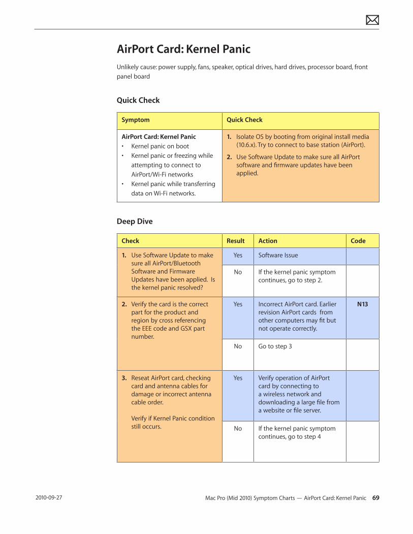
Mac Pro (Mid 2010) Symptom Charts — AirPort Card: Kernel Panic 69 2010-09-27
AirPort Card: Kernel PanicUnlikely cause: power supply, fans, speaker, optical drives, hard drives, processor board, front panel board
Quick Check
Symptom Quick Check
AirPort Card: Kernel Panic• Kernel panic on boot• Kernel panic or freezing while
attempting to connect to AirPort/Wi-Fi networks
• Kernel panic while transferring data on Wi-Fi networks.
1. Isolate OS by booting from original install media (10.6.x). Try to connect to base station (AirPort).
2. Use Software Update to make sure all AirPort software and firmware updates have been applied.
Deep Dive
Check Result Action Code
1. Use Software Update to make sure all AirPort/Bluetooth Software and Firmware Updates have been applied. Is the kernel panic resolved?
Yes Software Issue
No If the kernel panic symptom continues, go to step 2.
2. Verify the card is the correct part for the product and region by cross referencing the EEE code and GSX part number.
Yes Incorrect AirPort card. Earlier revision AirPort cards from other computers may fit but not operate correctly.
N13
No Go to step 3
3. Reseat AirPort card, checking card and antenna cables for damage or incorrect antenna cable order. Verify if Kernel Panic condition still occurs.
Yes Verify operation of AirPort card by connecting to a wireless network and downloading a large file from a website or file server.
No If the kernel panic symptom continues, go to step 4
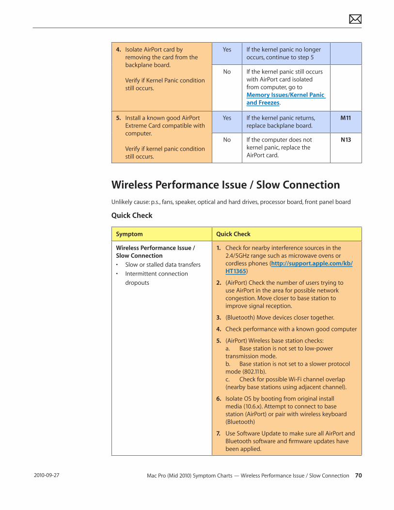
Mac Pro (Mid 2010) Symptom Charts — Wireless Performance Issue / Slow Connection 70 2010-09-27
4. Isolate AirPort card by removing the card from the backplane board. Verify if Kernel Panic condition still occurs.
Yes If the kernel panic no longer occurs, continue to step 5
No If the kernel panic still occurs with AirPort card isolated from computer, go to Memory Issues/Kernel Panic and Freezes.
5. Install a known good AirPort Extreme Card compatible with computer. Verify if kernel panic condition still occurs.
Yes If the kernel panic returns, replace backplane board.
M11
No If the computer does not kernel panic, replace the AirPort card.
N13
Wireless Performance Issue / Slow ConnectionUnlikely cause: p.s., fans, speaker, optical and hard drives, processor board, front panel board
Quick Check
Symptom Quick Check
Wireless Performance Issue / Slow Connection• Slow or stalled data transfers• Intermittent connection
dropouts
1. Check for nearby interference sources in the 2.4/5GHz range such as microwave ovens or cordless phones (http://support.apple.com/kb/HT1365)
2. (AirPort) Check the number of users trying to use AirPort in the area for possible network congestion. Move closer to base station to improve signal reception.
3. (Bluetooth) Move devices closer together.
4. Check performance with a known good computer
5. (AirPort) Wireless base station checks: a. Base station is not set to low-power transmission mode. b. Base station is not set to a slower protocol mode (802.11b). c. Check for possible Wi-Fi channel overlap (nearby base stations using adjacent channel).
6. Isolate OS by booting from original install media (10.6.x). Attempt to connect to base station (AirPort) or pair with wireless keyboard (Bluetooth)
7. Use Software Update to make sure all AirPort and Bluetooth software and firmware updates have been applied.
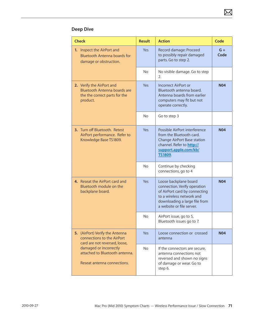
Mac Pro (Mid 2010) Symptom Charts — Wireless Performance Issue / Slow Connection 71 2010-09-27
Deep Dive
Check Result Action Code
1. Inspect the AirPort and Bluetooth Antenna boards for damage or obstruction.
Yes Record damage: Proceed to possibly repair damaged parts. Go to step 2.
G + Code
No No visible damage. Go to step 2.
2. Verify the AirPort and Bluetooth Antenna boards are the the correct parts for the product.
Yes Incorrect AirPort or Bluetooth antenna board. Antenna boards from earlier computers may fit but not operate correctly.
N04
No Go to step 3
3. Turn off Bluetooth. Retest AirPort performance. Refer to Knowledge Base TS1809.
Yes Possible AirPort interference from the Bluetooth card. Change AirPort Base station channel. Refer to http://support.apple.com/kb/TS1809.
N04
No Continue by checking connections, go to 4
4. Reseat the AirPort card and Bluetooth module on the backplane board.
Yes Loose backplane board connection. Verify operation of AirPort card by connecting to a wireless network and downloading a large file from a website or file server.
N04
No AirPort issue, go to 5, Bluetooth issues go to 7.
5. (AirPort) Verify the Antenna connections to the AirPort card are not reversed, loose, damaged or incorrectly attached to Bluetooth antenna. Reseat antenna connections.
Yes Loose connection or crossed antenna
N04
No If the connectors are secure, antenna connections not reversed and shown no signs of damage or wear. Go to step 6.
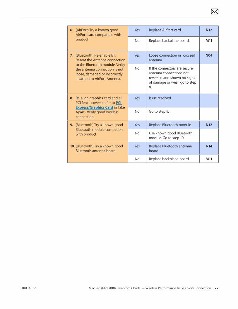
Mac Pro (Mid 2010) Symptom Charts — Wireless Performance Issue / Slow Connection 72 2010-09-27
6. (AirPort) Try a known good AirPort card compatible with product
Yes Replace AirPort card. N12
No Replace backplane board. M11
7. (Bluetooth) Re-enable BT. Reseat the Antenna connection to the Bluetooth module. Verify the antenna connection is not loose, damaged or incorrectly attached to AirPort Antenna.
Yes Loose connection or crossed antenna
N04
No If the connectors are secure, antenna connections not reversed and shown no signs of damage or wear, go to step 8.
8. Re-align graphics card and all PCI fence covers (refer to PCI Express/Graphics Card in Take Apart). Verify good wireless connection.
Yes Issue resolved.
No Go to step 9.
9. (Bluetooth) Try a known good Bluetooth module compatible with product
Yes Replace Bluetooth module. N12
No Use known good Bluetooth module. Go to step 10.
10. (Bluetooth) Try a known good Bluetooth antenna board.
Yes Replace Bluetooth antenna board.
N14
No Replace backplane board. M11
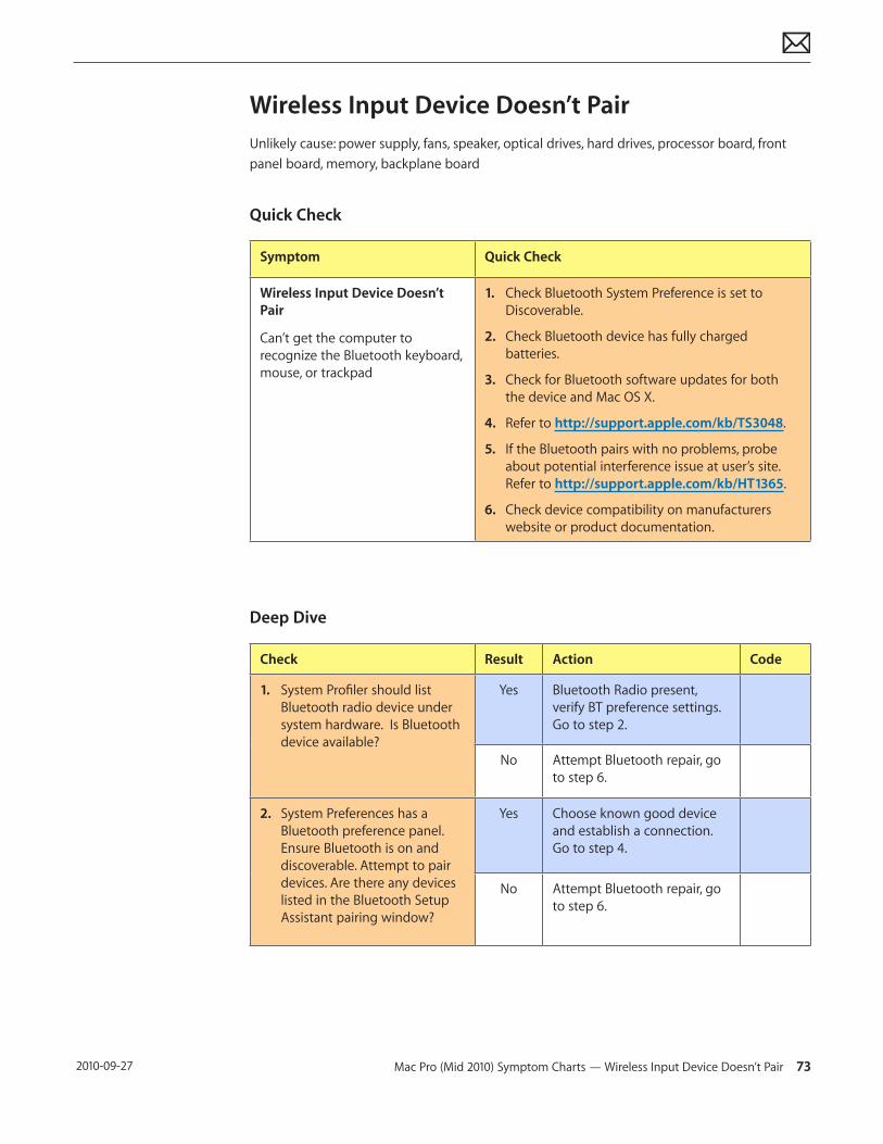
Mac Pro (Mid 2010) Symptom Charts — Wireless Input Device Doesn’t Pair 73 2010-09-27
Wireless Input Device Doesn’t PairUnlikely cause: power supply, fans, speaker, optical drives, hard drives, processor board, front panel board, memory, backplane board
Quick Check
Symptom Quick Check
Wireless Input Device Doesn’t Pair
Can’t get the computer to recognize the Bluetooth keyboard, mouse, or trackpad
1. Check Bluetooth System Preference is set to Discoverable.
2. Check Bluetooth device has fully charged batteries.
3. Check for Bluetooth software updates for both the device and Mac OS X.
4. Refer to http://support.apple.com/kb/TS3048.
5. If the Bluetooth pairs with no problems, probe about potential interference issue at user’s site. Refer to http://support.apple.com/kb/HT1365.
6. Check device compatibility on manufacturers website or product documentation.
Deep Dive
Check Result Action Code
1. System Profiler should list Bluetooth radio device under system hardware. Is Bluetooth device available?
Yes Bluetooth Radio present, verify BT preference settings. Go to step 2.
No Attempt Bluetooth repair, go to step 6.
2. System Preferences has a Bluetooth preference panel. Ensure Bluetooth is on and discoverable. Attempt to pair devices. Are there any devices listed in the Bluetooth Setup Assistant pairing window?
Yes Choose known good device and establish a connection. Go to step 4.
No Attempt Bluetooth repair, go to step 6.
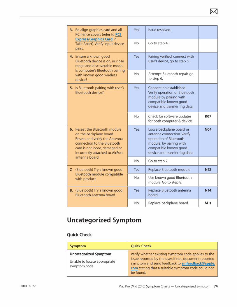
Mac Pro (Mid 2010) Symptom Charts — Uncategorized Symptom 74 2010-09-27
3. Re-align graphics card and all PCI fence covers (refer to PCI Express/Graphics Card in Take Apart). Verify input device pairs.
Yes Issue resolved.
No Go to step 4.
4. Ensure a known good Bluetooth device is on, in close range and discoverable mode. Is computer’s Bluetooth pairing with known good wireless device?
Yes Pairing verified, connect with user’s device, go to step 5.
No Attempt Bluetooth repair, go to step 6.
5. Is Bluetooth pairing with user’s Bluetooth device?
Yes Connection established. Verify operation of Bluetooth module by pairing with compatible known good device and transferring data.
No Check for software updates for both computer & device.
K07
6. Reseat the Bluetooth module on the backplane board. Reseat and verify the Antenna connection to the Bluetooth card is not loose, damaged or incorrectly attached to AirPort antenna board
Yes Loose backplane board or antenna connection. Verify operation of Bluetooth module, by pairing with compatible known good device and transferring data.
N04
No Go to step 7.
7. (Bluetooth) Try a known good Bluetooth module compatible with product
Yes Replace Bluetooth module N12
No Use known good Bluetooth module. Go to step 8.
8. (Bluetooth) Try a known good Bluetooth antenna board.
Yes Replace Bluetooth antenna board.
N14
No Replace backplane board. M11
Uncategorized Symptom
Quick Check
Symptom Quick Check
Uncategorized Symptom
Unable to locate appropriate symptom code
Verify whether existing symptom code applies to the issue reported by the user. If not, document reported symptom and send feedback to [email protected] stating that a suitable symptom code could not be found.
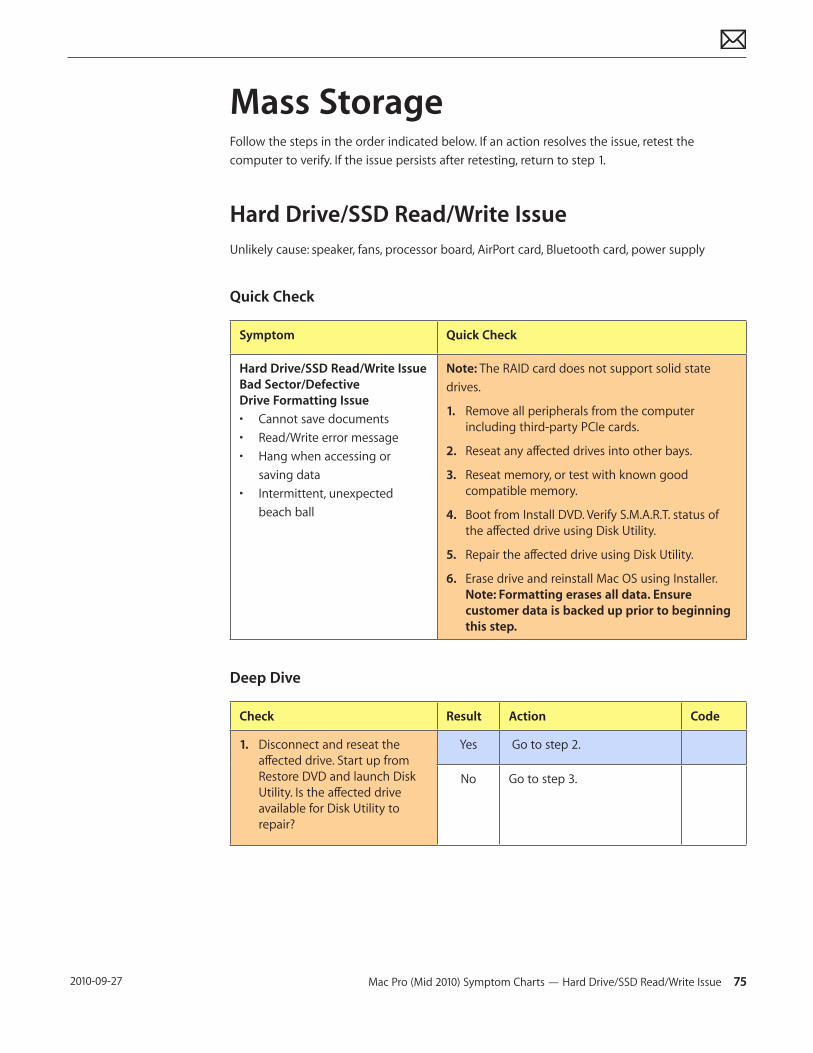
Mac Pro (Mid 2010) Symptom Charts — Hard Drive/SSD Read/Write Issue 75 2010-09-27
Mass StorageFollow the steps in the order indicated below. If an action resolves the issue, retest the computer to verify. If the issue persists after retesting, return to step 1.
Hard Drive/SSD Read/Write IssueUnlikely cause: speaker, fans, processor board, AirPort card, Bluetooth card, power supply
Quick Check
Symptom Quick Check
Hard Drive/SSD Read/Write Issue Bad Sector/Defective Drive Formatting Issue• Cannot save documents• Read/Write error message• Hang when accessing or
saving data• Intermittent, unexpected
beach ball
Note: The RAID card does not support solid state drives.
1. Remove all peripherals from the computer including third-party PCIe cards.
2. Reseat any affected drives into other bays.
3. Reseat memory, or test with known good compatible memory.
4. Boot from Install DVD. Verify S.M.A.R.T. status of the affected drive using Disk Utility.
5. Repair the affected drive using Disk Utility.
6. Erase drive and reinstall Mac OS using Installer. Note: Formatting erases all data. Ensure customer data is backed up prior to beginning this step.
Deep Dive
Check Result Action Code
1. Disconnect and reseat the affected drive. Start up from Restore DVD and launch Disk Utility. Is the affected drive available for Disk Utility to repair?
Yes Go to step 2.
No Go to step 3.

Mac Pro (Mid 2010) Symptom Charts — Hard Drive/SSD Read/Write Issue 76 2010-09-27
2. Verify that Disk Utility is able to mount, and the affected drive is successfully repaired.
Yes Restart the computer. Go to step 6.
No If the computer has not been verified with a known good drive, go to step 3; otherwise take affected drive to step 6.
3. Install a known good compatible Mac OS X bootable drive. Verify the computer boots to desktop.
Yes Re-install the affected drive. Go to step 2.
No Issue not hard drive or SSD related. Continue to use the known good bootable drive to determine computer root cause. Go to step 4.
4. Install a known good compatible Mac OS X bootable drive into a different drive bay. Verify the computer boots to desktop.
Yes Remove the known good drive. Re-install the original affected drive into the same bay. Go to step 2.
H03
No Replace backplane board. Go to step 5.
M19
5. Verify the computer boots to desktop and is able to successfully read/write data.
Yes Issue resolved.
No Affected drive repairs also necessary. Go to step 6.
6. Format affected drive using GUID scheme, and clean install compatible Mac OS X on the drive. Verify the install completes without error and is able to start up the computer successfully. Note: Formatting erases all data. Ensure customer data is backed up prior to beginning this step.
Yes Issue resolved.
No Affected drive appears to be defective. Replace drive.
H03
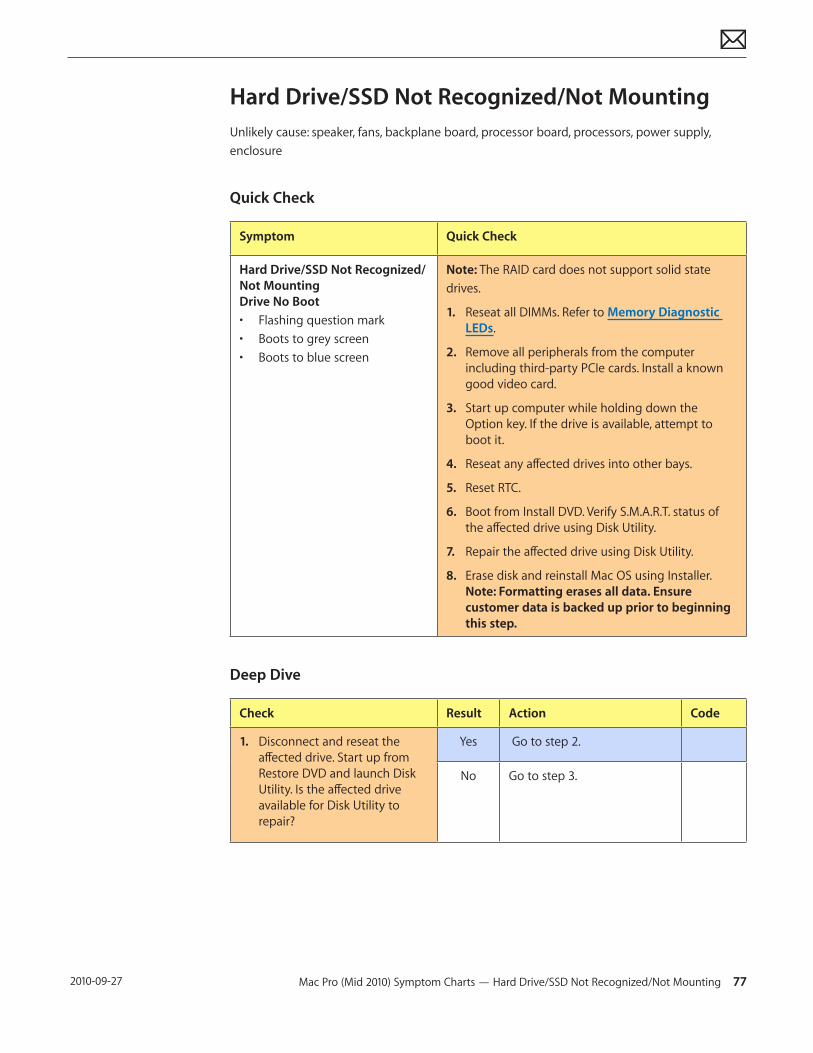
Mac Pro (Mid 2010) Symptom Charts — Hard Drive/SSD Not Recognized/Not Mounting 77 2010-09-27
Hard Drive/SSD Not Recognized/Not MountingUnlikely cause: speaker, fans, backplane board, processor board, processors, power supply, enclosure
Quick Check
Symptom Quick Check
Hard Drive/SSD Not Recognized/Not Mounting Drive No Boot• Flashing question mark• Boots to grey screen• Boots to blue screen
Note: The RAID card does not support solid state drives.
1. Reseat all DIMMs. Refer to Memory Diagnostic LEDs.
2. Remove all peripherals from the computer including third-party PCIe cards. Install a known good video card.
3. Start up computer while holding down the Option key. If the drive is available, attempt to boot it.
4. Reseat any affected drives into other bays.
5. Reset RTC.
6. Boot from Install DVD. Verify S.M.A.R.T. status of the affected drive using Disk Utility.
7. Repair the affected drive using Disk Utility.
8. Erase disk and reinstall Mac OS using Installer. Note: Formatting erases all data. Ensure customer data is backed up prior to beginning this step.
Deep Dive
Check Result Action Code
1. Disconnect and reseat the affected drive. Start up from Restore DVD and launch Disk Utility. Is the affected drive available for Disk Utility to repair?
Yes Go to step 2.
No Go to step 3.
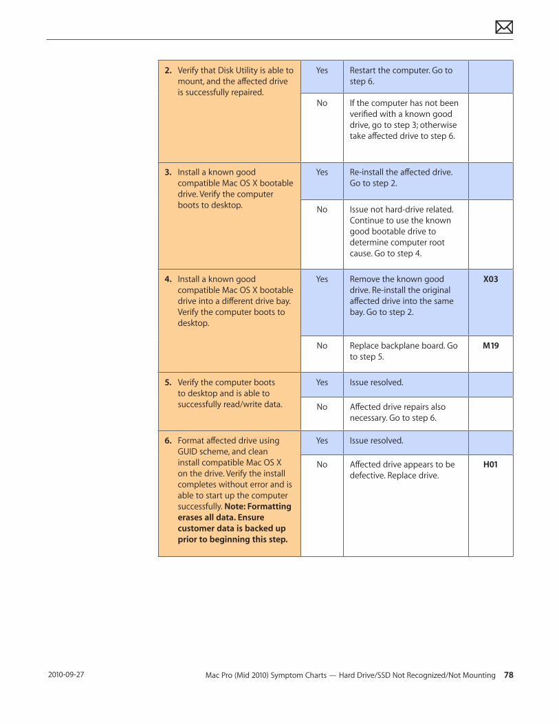
Mac Pro (Mid 2010) Symptom Charts — Hard Drive/SSD Not Recognized/Not Mounting 78 2010-09-27
2. Verify that Disk Utility is able to mount, and the affected drive is successfully repaired.
Yes Restart the computer. Go to step 6.
No If the computer has not been verified with a known good drive, go to step 3; otherwise take affected drive to step 6.
3. Install a known good compatible Mac OS X bootable drive. Verify the computer boots to desktop.
Yes Re-install the affected drive. Go to step 2.
No Issue not hard-drive related. Continue to use the known good bootable drive to determine computer root cause. Go to step 4.
4. Install a known good compatible Mac OS X bootable drive into a different drive bay. Verify the computer boots to desktop.
Yes Remove the known good drive. Re-install the original affected drive into the same bay. Go to step 2.
X03
No Replace backplane board. Go to step 5.
M19
5. Verify the computer boots to desktop and is able to successfully read/write data.
Yes Issue resolved.
No Affected drive repairs also necessary. Go to step 6.
6. Format affected drive using GUID scheme, and clean install compatible Mac OS X on the drive. Verify the install completes without error and is able to start up the computer successfully. Note: Formatting erases all data. Ensure customer data is backed up prior to beginning this step.
Yes Issue resolved.
No Affected drive appears to be defective. Replace drive.
H01
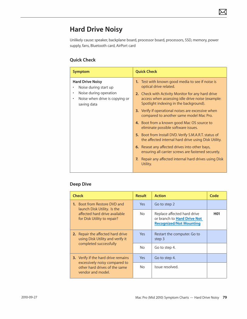
Mac Pro (Mid 2010) Symptom Charts — Hard Drive Noisy 79 2010-09-27
Hard Drive NoisyUnlikely cause: speaker, backplane board, processor board, processors, SSD, memory, power supply, fans, Bluetooth card, AirPort card
Quick Check
Symptom Quick Check
Hard Drive Noisy• Noise during start up• Noise during operation• Noise when drive is copying or
saving data
1. Test with known good media to see if noise is optical drive related.
2. Check with Activity Monitor for any hard drive access when assessing idle drive noise (example: Spotlight indexing in the background).
3. Verify if operational noises are excessive when compared to another same model Mac Pro.
4. Boot from a known good Mac OS source to eliminate possible software issues.
5. Boot from Install DVD. Verify S.M.A.R.T. status of the affected internal hard drive using Disk Utility.
6. Reseat any affected drives into other bays, ensuring all carrier screws are fastened securely.
7. Repair any affected internal hard drives using Disk Utility.
Deep Dive
Check Result Action Code
1. Boot from Restore DVD and launch Disk Utility. Is the affected hard drive available for Disk Utility to repair?
Yes Go to step 2
No Replace affected hard drive or branch to Hard Drive Not Recognized/Not Mounting
H01
2. Repair the affected hard drive using Disk Utility and verify it completed successfully
Yes Restart the computer. Go to step 3
No Go to step 4.
3. Verify if the hard drive remains excessively noisy compared to other hard drives of the same vendor and model.
Yes Go to step 4.
No Issue resolved.
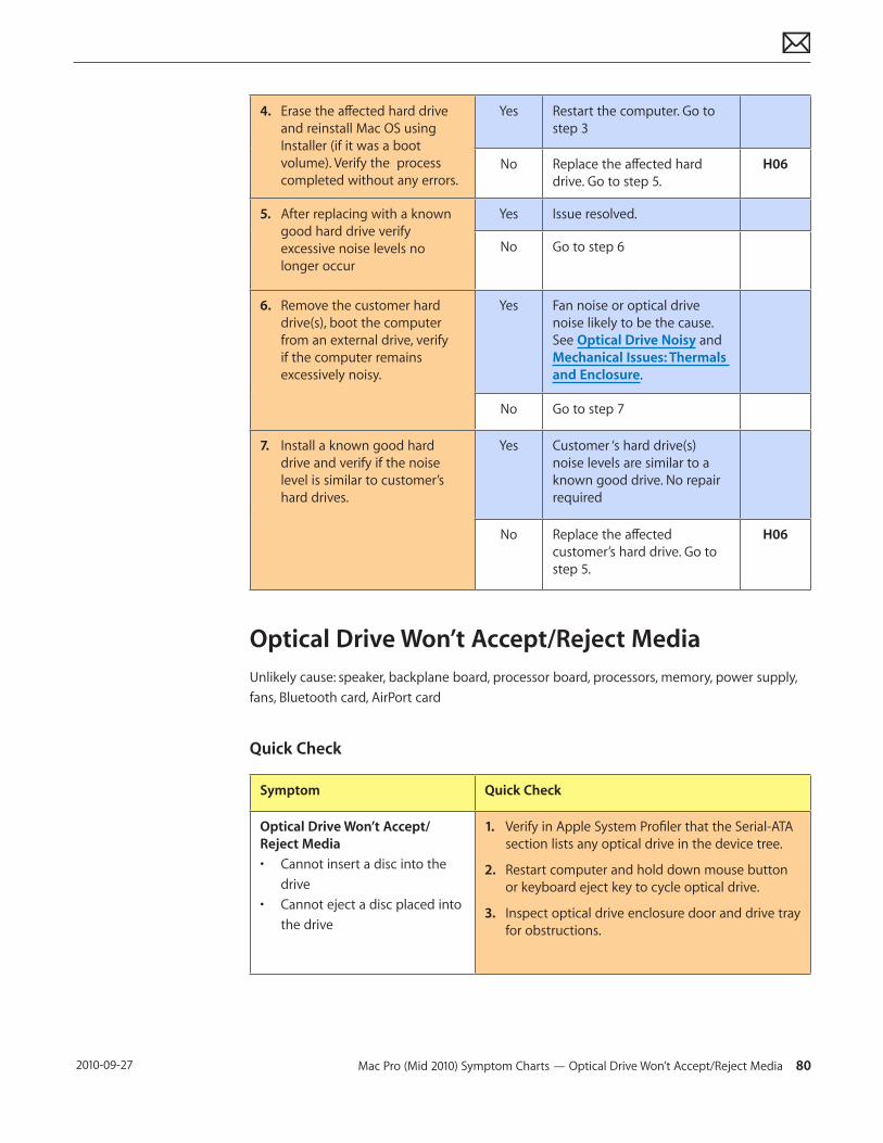
Mac Pro (Mid 2010) Symptom Charts — Optical Drive Won’t Accept/Reject Media 80 2010-09-27
4. Erase the affected hard drive and reinstall Mac OS using Installer (if it was a boot volume). Verify the process completed without any errors.
Yes Restart the computer. Go to step 3
No Replace the affected hard drive. Go to step 5.
H06
5. After replacing with a known good hard drive verify excessive noise levels no longer occur
Yes Issue resolved.
No Go to step 6
6. Remove the customer hard drive(s), boot the computer from an external drive, verify if the computer remains excessively noisy.
Yes Fan noise or optical drive noise likely to be the cause. See Optical Drive Noisy and Mechanical Issues: Thermals and Enclosure.
No Go to step 7
7. Install a known good hard drive and verify if the noise level is similar to customer’s hard drives.
Yes Customer ‘s hard drive(s) noise levels are similar to a known good drive. No repair required
No Replace the affected customer’s hard drive. Go to step 5.
H06
Optical Drive Won’t Accept/Reject MediaUnlikely cause: speaker, backplane board, processor board, processors, memory, power supply, fans, Bluetooth card, AirPort card
Quick Check
Symptom Quick Check
Optical Drive Won’t Accept/Reject Media • Cannot insert a disc into the
drive• Cannot eject a disc placed into
the drive
1. Verify in Apple System Profiler that the Serial-ATA section lists any optical drive in the device tree.
2. Restart computer and hold down mouse button or keyboard eject key to cycle optical drive.
3. Inspect optical drive enclosure door and drive tray for obstructions.
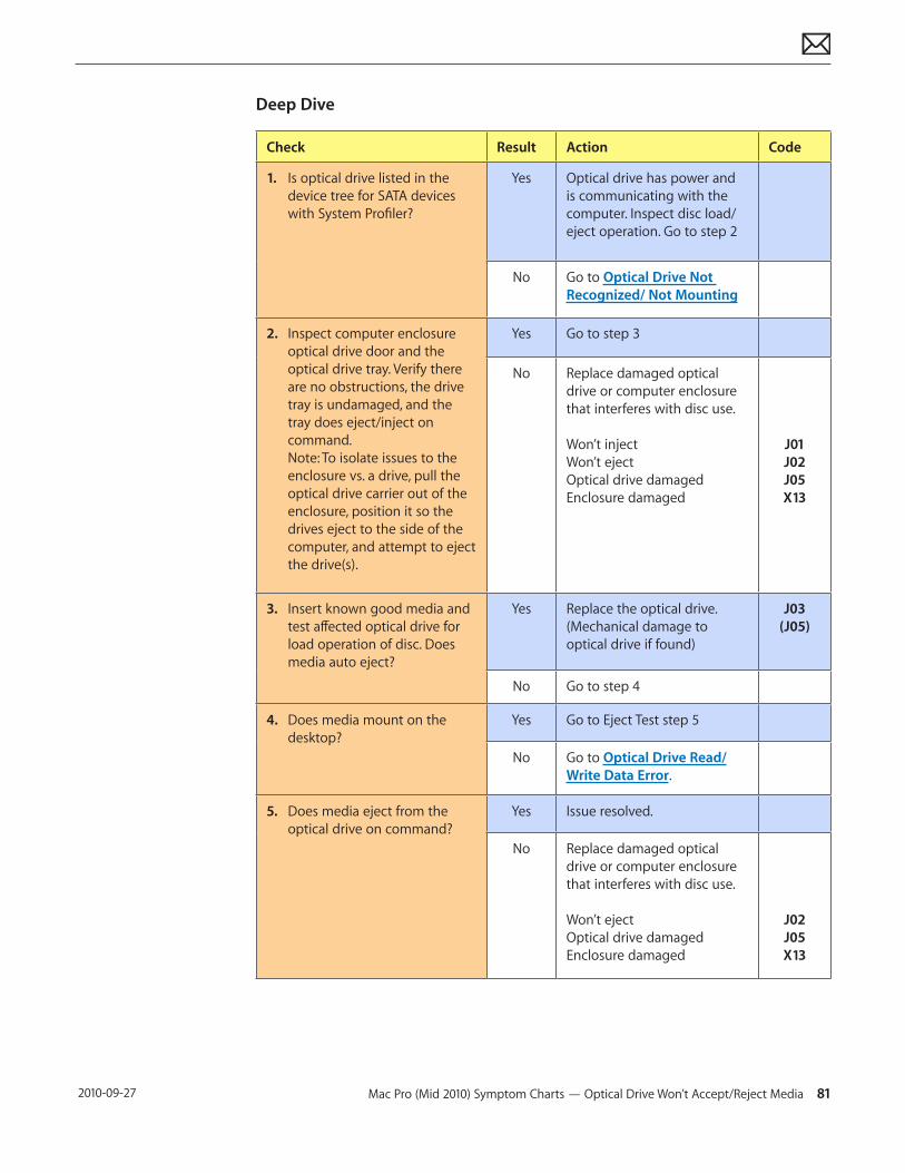
Mac Pro (Mid 2010) Symptom Charts — Optical Drive Won’t Accept/Reject Media 81 2010-09-27
Deep Dive
Check Result Action Code
1. Is optical drive listed in the device tree for SATA devices with System Profiler?
Yes Optical drive has power and is communicating with the computer. Inspect disc load/eject operation. Go to step 2
No Go to Optical Drive Not Recognized/ Not Mounting
2. Inspect computer enclosure optical drive door and the optical drive tray. Verify there are no obstructions, the drive tray is undamaged, and the tray does eject/inject on command. Note: To isolate issues to the enclosure vs. a drive, pull the optical drive carrier out of the enclosure, position it so the drives eject to the side of the computer, and attempt to eject the drive(s).
Yes Go to step 3
No Replace damaged optical drive or computer enclosure that interferes with disc use. Won’t inject Won’t eject Optical drive damaged Enclosure damaged
J01 J02 J05 X13
3. Insert known good media and test affected optical drive for load operation of disc. Does media auto eject?
Yes Replace the optical drive. (Mechanical damage to optical drive if found)
J03 (J05)
No Go to step 4
4. Does media mount on the desktop?
Yes Go to Eject Test step 5
No Go to Optical Drive Read/Write Data Error.
5. Does media eject from the optical drive on command?
Yes Issue resolved.
No Replace damaged optical drive or computer enclosure that interferes with disc use. Won’t eject Optical drive damaged Enclosure damaged
J02 J05 X13
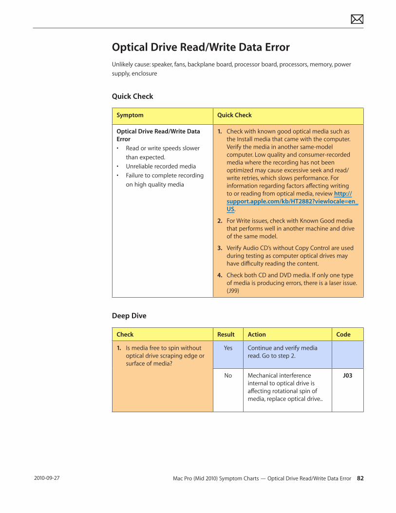
Mac Pro (Mid 2010) Symptom Charts — Optical Drive Read/Write Data Error 82 2010-09-27
Optical Drive Read/Write Data ErrorUnlikely cause: speaker, fans, backplane board, processor board, processors, memory, power supply, enclosure
Quick Check
Symptom Quick Check
Optical Drive Read/Write Data Error• Read or write speeds slower
than expected.• Unreliable recorded media• Failure to complete recording
on high quality media
1. Check with known good optical media such as the Install media that came with the computer. Verify the media in another same-model computer. Low quality and consumer-recorded media where the recording has not been optimized may cause excessive seek and read/write retries, which slows performance. For information regarding factors affecting writing to or reading from optical media, review http://support.apple.com/kb/HT2882?viewlocale=en_US.
2. For Write issues, check with Known Good media that performs well in another machine and drive of the same model.
3. Verify Audio CD’s without Copy Control are used during testing as computer optical drives may have difficulty reading the content.
4. Check both CD and DVD media. If only one type of media is producing errors, there is a laser issue. (J99)
Deep Dive
Check Result Action Code
1. Is media free to spin without optical drive scraping edge or surface of media?
Yes Continue and verify media read. Go to step 2.
No Mechanical interference internal to optical drive is affecting rotational spin of media, replace optical drive..
J03
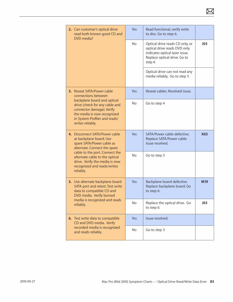
Mac Pro (Mid 2010) Symptom Charts — Optical Drive Read/Write Data Error 83 2010-09-27
2. Can customer’s optical drive read both known good CD and DVD media?
Yes Read functional, verify write to disc. Go to step 6.
No Optical drive reads CD only, or optical drive reads DVD only indicates optical laser issue. Replace optical drive. Go to step 6
J03
Optical drive can not read any media reliably, Go to step 3
3. Reseat SATA/Power cable connections between backplane board and optical drive (check for any cable and connector damage). Verify the media is now recognized in System Profiler and reads/writes reliably.
Yes Reseat cables. Resolved issue.
No Go to step 4
4. Disconnect SATA/Power cable at backplane board. Use spare SATA/Power cable as alternate. Connect the spare cable to the port. Connect the alternate cable to the optical drive. Verify the media is now recognized and reads/writes reliably.
Yes SATA/Power cable defective. Replace SATA/Power cable. Issue resolved.
X03
No Go to step 5
5. Use alternate backplane board SATA port and retest. Test write data to compatible CD and DVD media. Verify burned media is recognized and reads reliably.
Yes Backplane board defective. Replace backplane board. Go to step 6.
M19
No Replace the optical drive. Go to step 6.
J03
6. Test write data to compatible CD and DVD media. Verify recorded media is recognized and reads reliably.
Yes Issue resolved.
No Go to step 3
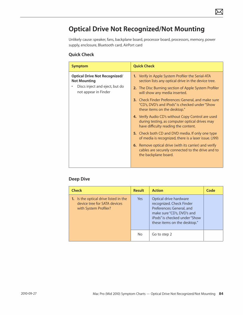
Mac Pro (Mid 2010) Symptom Charts — Optical Drive Not Recognized/Not Mounting 84 2010-09-27
Optical Drive Not Recognized/Not MountingUnlikely cause: speaker, fans, backplane board, processor board, processors, memory, power supply, enclosure, Bluetooth card, AirPort card
Quick Check
Symptom Quick Check
Optical Drive Not Recognized/Not Mounting• Discs inject and eject, but do
not appear in Finder
1. Verify in Apple System Profiler the Serial-ATA section lists any optical drive in the device tree.
2. The Disc Burning section of Apple System Profiler will show any media inserted.
3. Check Finder Preferences: General, and make sure “CD’s, DVD’s and iPods” is checked under “Show these items on the desktop.”
4. Verify Audio CD’s without Copy Control are used during testing, as computer optical drives may have difficulty reading the content.
5. Check both CD and DVD media. If only one type of media is recognized, there is a laser issue. (J99)
6. Remove optical drive (with its carrier) and verify cables are securely connected to the drive and to the backplane board.
Deep Dive
Check Result Action Code
1. Is the optical drive listed in the device tree for SATA devices with System Profiler?
Yes Optical drive hardware recognized. Check Finder Preferences: General, and make sure “CD’s, DVD’s and iPods” is checked under “Show these items on the desktop.”
No Go to step 2
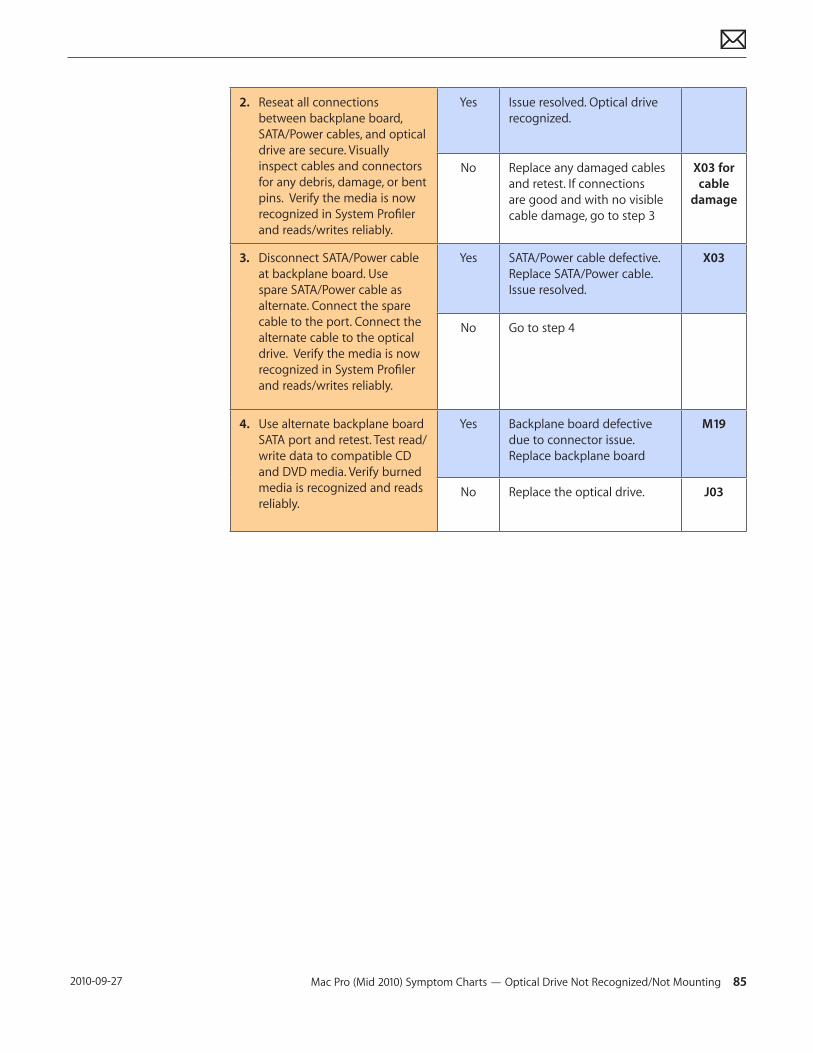
Mac Pro (Mid 2010) Symptom Charts — Optical Drive Not Recognized/Not Mounting 85 2010-09-27
2. Reseat all connections between backplane board, SATA/Power cables, and optical drive are secure. Visually inspect cables and connectors for any debris, damage, or bent pins. Verify the media is now recognized in System Profiler and reads/writes reliably.
Yes Issue resolved. Optical drive recognized.
No Replace any damaged cables and retest. If connections are good and with no visible cable damage, go to step 3
X03 for cable
damage
3. Disconnect SATA/Power cable at backplane board. Use spare SATA/Power cable as alternate. Connect the spare cable to the port. Connect the alternate cable to the optical drive. Verify the media is now recognized in System Profiler and reads/writes reliably.
Yes SATA/Power cable defective. Replace SATA/Power cable. Issue resolved.
X03
No Go to step 4
4. Use alternate backplane board SATA port and retest. Test read/write data to compatible CD and DVD media. Verify burned media is recognized and reads reliably.
Yes Backplane board defective due to connector issue. Replace backplane board
M19
No Replace the optical drive. J03
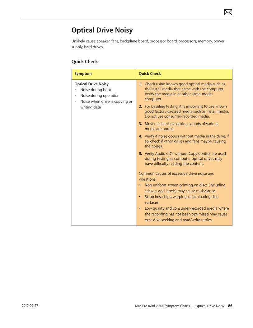
Mac Pro (Mid 2010) Symptom Charts — Optical Drive Noisy 86 2010-09-27
Optical Drive NoisyUnlikely cause: speaker, fans, backplane board, processor board, processors, memory, power supply, hard drives
Quick Check
Symptom Quick Check
Optical Drive Noisy• Noise during boot• Noise during operation• Noise when drive is copying or
writing data
1. Check using known good optical media such as the Install media that came with the computer. Verify the media in another same-model computer.
2. For baseline testing, it is important to use known good factory-pressed media such as Install media. Do not use consumer-recorded media.
3. Most mechanism seeking sounds of various media are normal
4. Verify if noise occurs without media in the drive. If so, check if other drives and fans maybe causing the noises.
5. Verify Audio CD’s without Copy Control are used during testing as computer optical drives may have difficulty reading the content.
Common causes of excessive drive noise and vibrations • Non uniform screen-printing on discs (including
stickers and labels) may cause misbalance• Scratches, chips, warping, delaminating disc
surfaces• Low quality and consumer-recorded media where
the recording has not been optimized may cause excessive seeking and read/write retries.
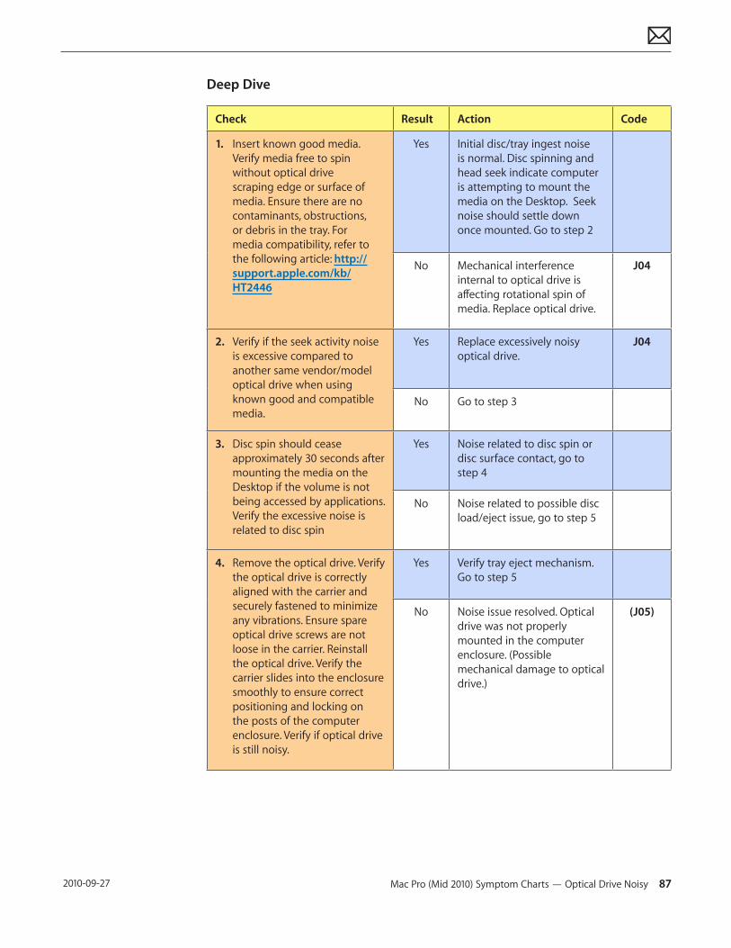
Mac Pro (Mid 2010) Symptom Charts — Optical Drive Noisy 87 2010-09-27
Deep Dive
Check Result Action Code
1. Insert known good media. Verify media free to spin without optical drive scraping edge or surface of media. Ensure there are no contaminants, obstructions, or debris in the tray. For media compatibility, refer to the following article: http://support.apple.com/kb/HT2446
Yes Initial disc/tray ingest noise is normal. Disc spinning and head seek indicate computer is attempting to mount the media on the Desktop. Seek noise should settle down once mounted. Go to step 2
No Mechanical interference internal to optical drive is affecting rotational spin of media. Replace optical drive.
J04
2. Verify if the seek activity noise is excessive compared to another same vendor/model optical drive when using known good and compatible media.
Yes Replace excessively noisy optical drive.
J04
No Go to step 3
3. Disc spin should cease approximately 30 seconds after mounting the media on the Desktop if the volume is not being accessed by applications. Verify the excessive noise is related to disc spin
Yes Noise related to disc spin or disc surface contact, go to step 4
No Noise related to possible disc load/eject issue, go to step 5
4. Remove the optical drive. Verify the optical drive is correctly aligned with the carrier and securely fastened to minimize any vibrations. Ensure spare optical drive screws are not loose in the carrier. Reinstall the optical drive. Verify the carrier slides into the enclosure smoothly to ensure correct positioning and locking on the posts of the computer enclosure. Verify if optical drive is still noisy.
Yes Verify tray eject mechanism. Go to step 5
No Noise issue resolved. Optical drive was not properly mounted in the computer enclosure. (Possible mechanical damage to optical drive.)
(J05)
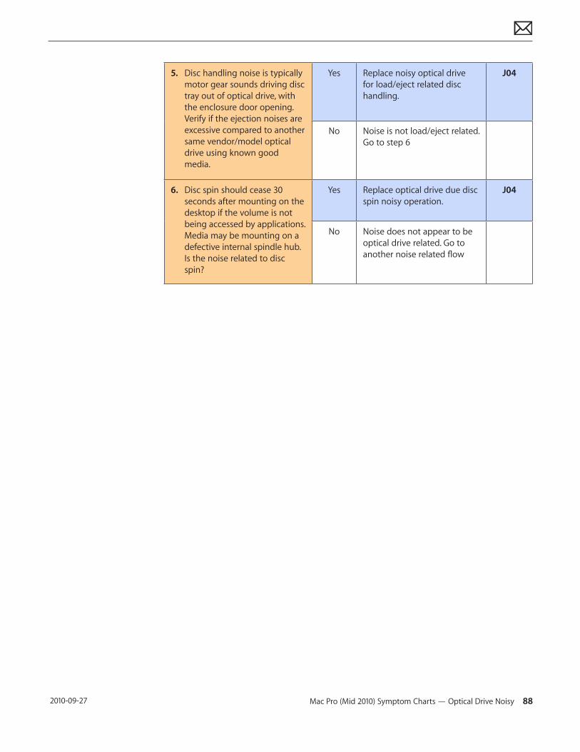
Mac Pro (Mid 2010) Symptom Charts — Optical Drive Noisy 88 2010-09-27
5. Disc handling noise is typically motor gear sounds driving disc tray out of optical drive, with the enclosure door opening. Verify if the ejection noises are excessive compared to another same vendor/model optical drive using known good media.
Yes Replace noisy optical drive for load/eject related disc handling.
J04
No Noise is not load/eject related. Go to step 6
6. Disc spin should cease 30 seconds after mounting on the desktop if the volume is not being accessed by applications. Media may be mounting on a defective internal spindle hub. Is the noise related to disc spin?
Yes Replace optical drive due disc spin noisy operation.
J04
No Noise does not appear to be optical drive related. Go to another noise related flow
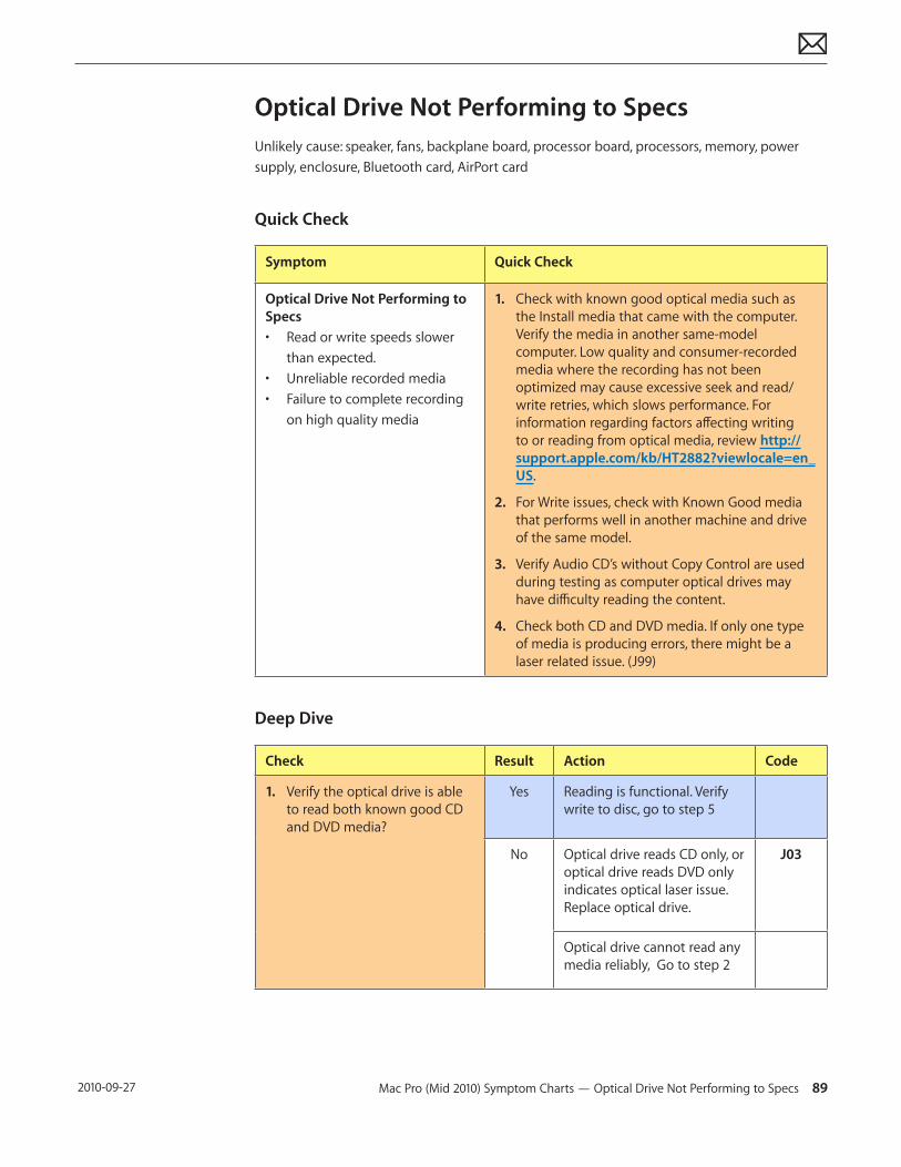
Mac Pro (Mid 2010) Symptom Charts — Optical Drive Not Performing to Specs 89 2010-09-27
Optical Drive Not Performing to SpecsUnlikely cause: speaker, fans, backplane board, processor board, processors, memory, power supply, enclosure, Bluetooth card, AirPort card
Quick Check
Symptom Quick Check
Optical Drive Not Performing to Specs• Read or write speeds slower
than expected.• Unreliable recorded media• Failure to complete recording
on high quality media
1. Check with known good optical media such as the Install media that came with the computer. Verify the media in another same-model computer. Low quality and consumer-recorded media where the recording has not been optimized may cause excessive seek and read/write retries, which slows performance. For information regarding factors affecting writing to or reading from optical media, review http://support.apple.com/kb/HT2882?viewlocale=en_US.
2. For Write issues, check with Known Good media that performs well in another machine and drive of the same model.
3. Verify Audio CD’s without Copy Control are used during testing as computer optical drives may have difficulty reading the content.
4. Check both CD and DVD media. If only one type of media is producing errors, there might be a laser related issue. (J99)
Deep Dive
Check Result Action Code
1. Verify the optical drive is able to read both known good CD and DVD media?
Yes Reading is functional. Verify write to disc, go to step 5
No Optical drive reads CD only, or optical drive reads DVD only indicates optical laser issue. Replace optical drive.
J03
Optical drive cannot read any media reliably, Go to step 2
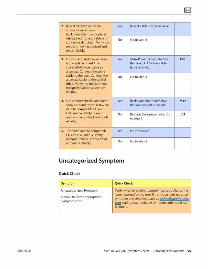
Mac Pro (Mid 2010) Symptom Charts — Uncategorized Symptom 90 2010-09-27
2. Reseat SATA/Power cable connections between backplane board and optical drive (check for any cable and connector damage). Verify the media is now recognized and reads reliably.
Yes Reseat cables resolved issue.
No Go to step 3
3. Disconnect SATA/Power cable at backplane board. Use spare SATA/Power cable as alternate. Connect the spare cable to the port. Connect the alternate cable to the optical drive. Verify the media is now recognized and reads/writes reliably.
Yes SATA/Power cable defective. Replace SATA/Power cable. Issue resolved.
X03
No Go to step 4
4. Use alternate backplane board SATA port and retest. Test write data to compatible CD and DVD media. Verify burned media is recognized and reads reliably.
Yes backplane board defective. Replace backplane board
M19
No Replace the optical drive. Go to step 5
J03
5. Test write data to compatible CD and DVD media. Verify recorded media is recognized and reads reliably.
Yes Issue resolved.
No Go to step 2
Uncategorized Symptom
Quick Check
Symptom Quick Check
Uncategorized Symptom
Unable to locate appropriate symptom code
Verify whether existing symptom code applies to the issue reported by the user. If not, document reported symptom and send feedback to [email protected] stating that a suitable symptom code could not be found.
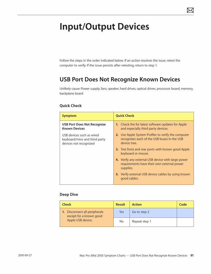
Mac Pro (Mid 2010) Symptom Charts — USB Port Does Not Recognize Known Devices 91 2010-09-27
Input/Output Devices
Follow the steps in the order indicated below. If an action resolves the issue, retest the computer to verify. If the issue persists after retesting, return to step 1.
USB Port Does Not Recognize Known DevicesUnlikely cause: Power supply, fans, speaker, hard drives, optical drives, processor board, memory, backplane board
Quick Check
Symptom Quick Check
USB Port Does Not Recognize Known Devices
USB devices such as wired keyboard/mice and third-party devices not recognized
1. Check the for latest software updates for Apple and especially third party devices.
2. Use Apple System Profiler to verify the computer recognizes each of the USB buses in the USB device tree.
3. Test front and rear ports with known good Apple keyboard or mouse.
4. Verify any external USB device with large power requirements have their own external power supplies.
5. Verify external USB device cables by using known good cables.
Deep Dive
Check Result Action Code
1. Disconnect all peripherals except for a known good Apple USB device.
Yes Go to step 2
No Repeat step 1
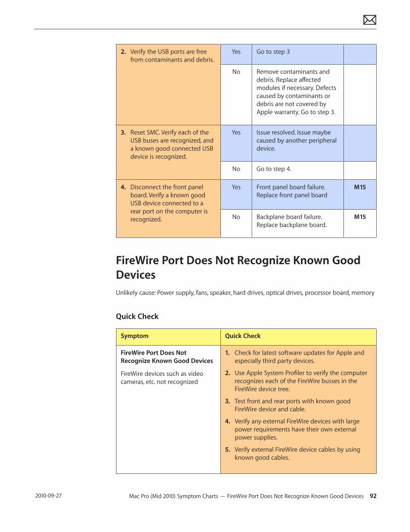
Mac Pro (Mid 2010) Symptom Charts — FireWire Port Does Not Recognize Known Good Devices 92 2010-09-27
2. Verify the USB ports are free from contaminants and debris.
Yes Go to step 3
No Remove contaminants and debris. Replace affected modules if necessary. Defects caused by contaminants or debris are not covered by Apple warranty. Go to step 3.
3. Reset SMC. Verify each of the USB buses are recognized, and a known good connected USB device is recognized.
Yes Issue resolved. Issue maybe caused by another peripheral device.
No Go to step 4.
4. Disconnect the front panel board. Verify a known good USB device connected to a rear port on the computer is recognized.
Yes Front panel board failure. Replace front panel board
M15
No Backplane board failure. Replace backplane board.
M15
FireWire Port Does Not Recognize Known Good DevicesUnlikely cause: Power supply, fans, speaker, hard drives, optical drives, processor board, memory
Quick Check
Symptom Quick Check
FireWire Port Does Not Recognize Known Good Devices
FireWire devices such as video cameras, etc. not recognized
1. Check for latest software updates for Apple and especially third party devices.
2. Use Apple System Profiler to verify the computer recognizes each of the FireWire busses in the FireWire device tree.
3. Test front and rear ports with known good FireWire device and cable.
4. Verify any external FireWire devices with large power requirements have their own external power supplies.
5. Verify external FireWire device cables by using known good cables.
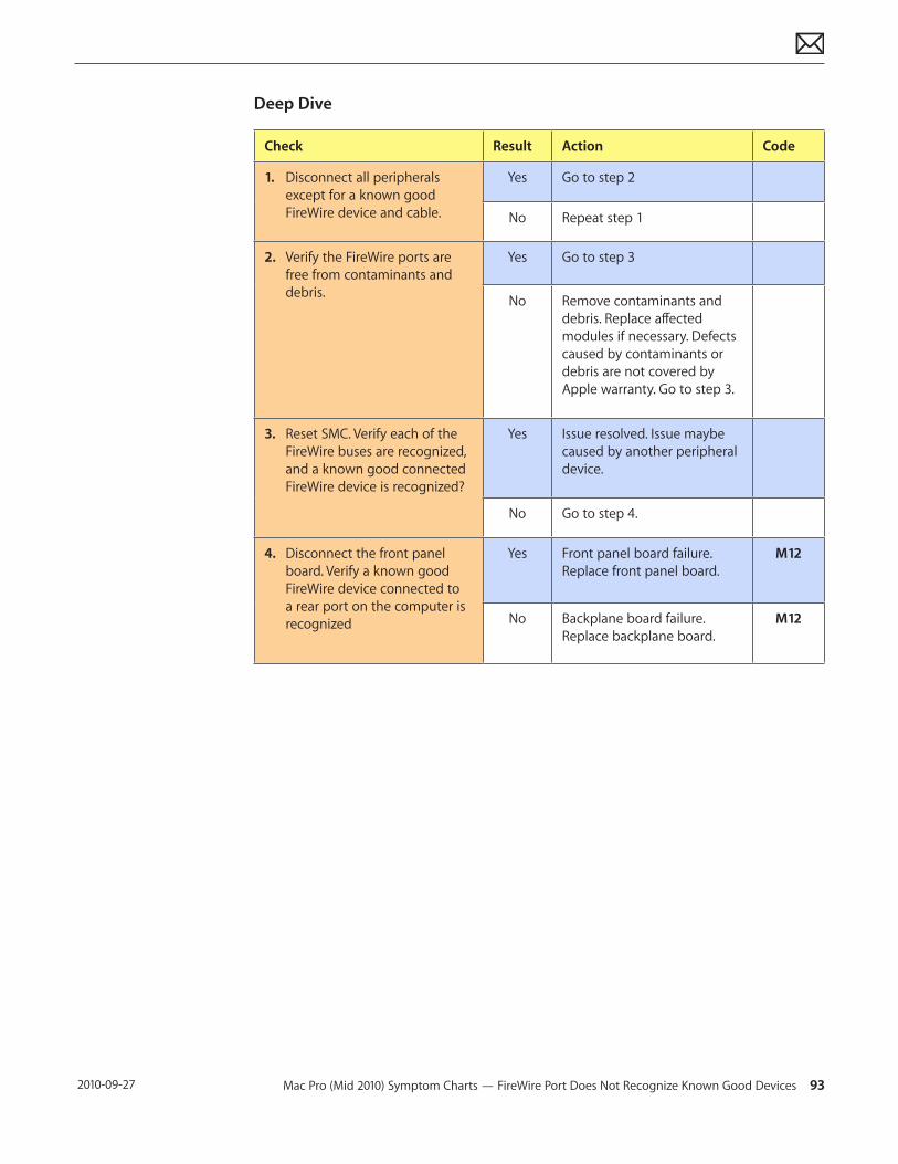
Mac Pro (Mid 2010) Symptom Charts — FireWire Port Does Not Recognize Known Good Devices 93 2010-09-27
Deep Dive
Check Result Action Code
1. Disconnect all peripherals except for a known good FireWire device and cable.
Yes Go to step 2
No Repeat step 1
2. Verify the FireWire ports are free from contaminants and debris.
Yes Go to step 3
No Remove contaminants and debris. Replace affected modules if necessary. Defects caused by contaminants or debris are not covered by Apple warranty. Go to step 3.
3. Reset SMC. Verify each of the FireWire buses are recognized, and a known good connected FireWire device is recognized?
Yes Issue resolved. Issue maybe caused by another peripheral device.
No Go to step 4.
4. Disconnect the front panel board. Verify a known good FireWire device connected to a rear port on the computer is recognized
Yes Front panel board failure. Replace front panel board.
M12
No Backplane board failure. Replace backplane board.
M12
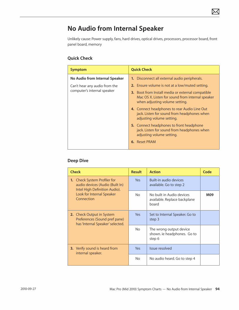
Mac Pro (Mid 2010) Symptom Charts — No Audio from Internal Speaker 94 2010-09-27
No Audio from Internal SpeakerUnlikely cause: Power supply, fans, hard drives, optical drives, processors, processor board, front panel board, memory
Quick Check
Symptom Quick Check
No Audio from Internal Speaker
Can’t hear any audio from the computer’s internal speaker
1. Disconnect all external audio peripherals.
2. Ensure volume is not at a low/muted setting.
3. Boot from Install media or external compatible Mac OS X. Listen for sound from internal speaker when adjusting volume setting.
4. Connect headphones to rear Audio Line Out jack. Listen for sound from headphones when adjusting volume setting.
5. Connect headphones to front headphone jack. Listen for sound from headphones when adjusting volume setting.
6. Reset PRAM
Deep Dive
Check Result Action Code
1. Check System Profiler for audio devices (Audio (Built In) Intel High Definition Audio). Look for Internal Speaker Connection
Yes Built-in audio devices available. Go to step 2
No No built in Audio devices available. Replace backplane board
M09
2. Check Output in System Preferences (Sound pref pane) has ‘Internal Speaker’ selected.
Yes Set to Internal Speaker. Go to step 3
No The wrong output device shown. ie headphones. Go to step 6
3. Verify sound is heard from internal speaker.
Yes Issue resolved
No No audio heard. Go to step 4
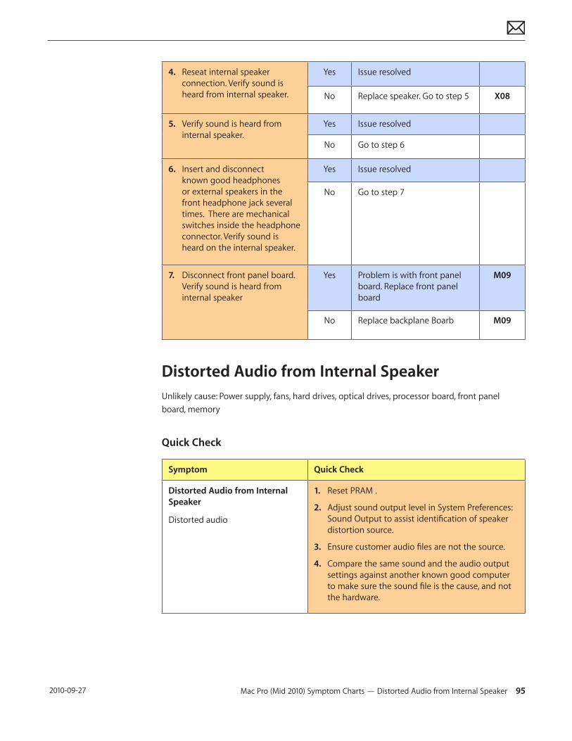
Mac Pro (Mid 2010) Symptom Charts — Distorted Audio from Internal Speaker 95 2010-09-27
4. Reseat internal speaker connection. Verify sound is heard from internal speaker.
Yes Issue resolved
No Replace speaker. Go to step 5 X08
5. Verify sound is heard from internal speaker.
Yes Issue resolved
No Go to step 6
6. Insert and disconnect known good headphones or external speakers in the front headphone jack several times. There are mechanical switches inside the headphone connector. Verify sound is heard on the internal speaker.
Yes Issue resolved
No Go to step 7
7. Disconnect front panel board. Verify sound is heard from internal speaker
Yes Problem is with front panel board. Replace front panel board
M09
No Replace backplane Boarb M09
Distorted Audio from Internal SpeakerUnlikely cause: Power supply, fans, hard drives, optical drives, processor board, front panel board, memory
Quick Check
Symptom Quick Check
Distorted Audio from Internal Speaker
Distorted audio
1. Reset PRAM .
2. Adjust sound output level in System Preferences: Sound Output to assist identification of speaker distortion source.
3. Ensure customer audio files are not the source.
4. Compare the same sound and the audio output settings against another known good computer to make sure the sound file is the cause, and not the hardware.
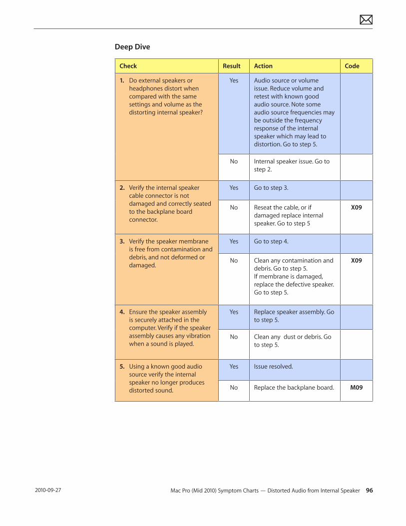
Mac Pro (Mid 2010) Symptom Charts — Distorted Audio from Internal Speaker 96 2010-09-27
Deep Dive
Check Result Action Code
1. Do external speakers or headphones distort when compared with the same settings and volume as the distorting internal speaker?
Yes Audio source or volume issue. Reduce volume and retest with known good audio source. Note some audio source frequencies may be outside the frequency response of the internal speaker which may lead to distortion. Go to step 5.
No Internal speaker issue. Go to step 2.
2. Verify the internal speaker cable connector is not damaged and correctly seated to the backplane board connector.
Yes Go to step 3.
No Reseat the cable, or if damaged replace internal speaker. Go to step 5
X09
3. Verify the speaker membrane is free from contamination and debris, and not deformed or damaged.
Yes Go to step 4.
No Clean any contamination and debris. Go to step 5. If membrane is damaged, replace the defective speaker. Go to step 5.
X09
4. Ensure the speaker assembly is securely attached in the computer. Verify if the speaker assembly causes any vibration when a sound is played.
Yes Replace speaker assembly. Go to step 5.
No Clean any dust or debris. Go to step 5.
5. Using a known good audio source verify the internal speaker no longer produces distorted sound.
Yes Issue resolved.
No Replace the backplane board. M09
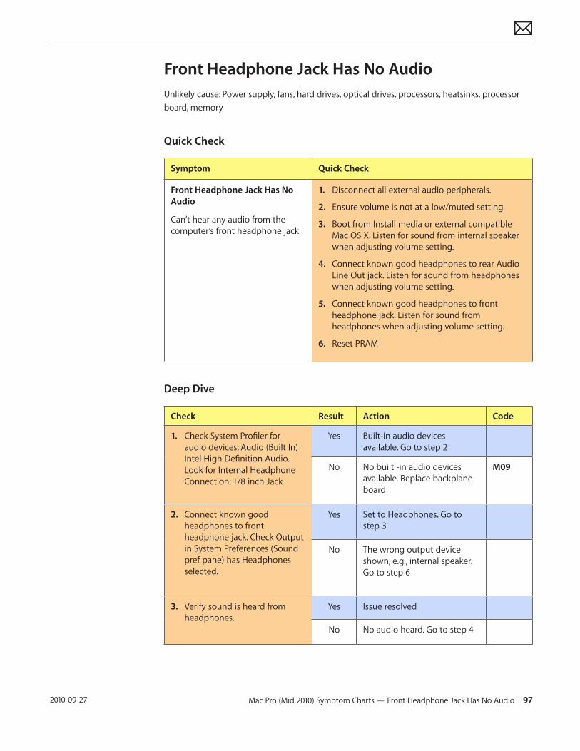
Mac Pro (Mid 2010) Symptom Charts — Front Headphone Jack Has No Audio 97 2010-09-27
Front Headphone Jack Has No AudioUnlikely cause: Power supply, fans, hard drives, optical drives, processors, heatsinks, processor board, memory
Quick Check
Symptom Quick Check
Front Headphone Jack Has No Audio
Can’t hear any audio from the computer’s front headphone jack
1. Disconnect all external audio peripherals.
2. Ensure volume is not at a low/muted setting.
3. Boot from Install media or external compatible Mac OS X. Listen for sound from internal speaker when adjusting volume setting.
4. Connect known good headphones to rear Audio Line Out jack. Listen for sound from headphones when adjusting volume setting.
5. Connect known good headphones to front headphone jack. Listen for sound from headphones when adjusting volume setting.
6. Reset PRAM
Deep Dive
Check Result Action Code
1. Check System Profiler for audio devices: Audio (Built In) Intel High Definition Audio. Look for Internal Headphone Connection: 1/8 inch Jack
Yes Built-in audio devices available. Go to step 2
No No built -in audio devices available. Replace backplane board
M09
2. Connect known good headphones to front headphone jack. Check Output in System Preferences (Sound pref pane) has Headphones selected.
Yes Set to Headphones. Go to step 3
No The wrong output device shown, e.g., internal speaker. Go to step 6
3. Verify sound is heard from headphones.
Yes Issue resolved
No No audio heard. Go to step 4
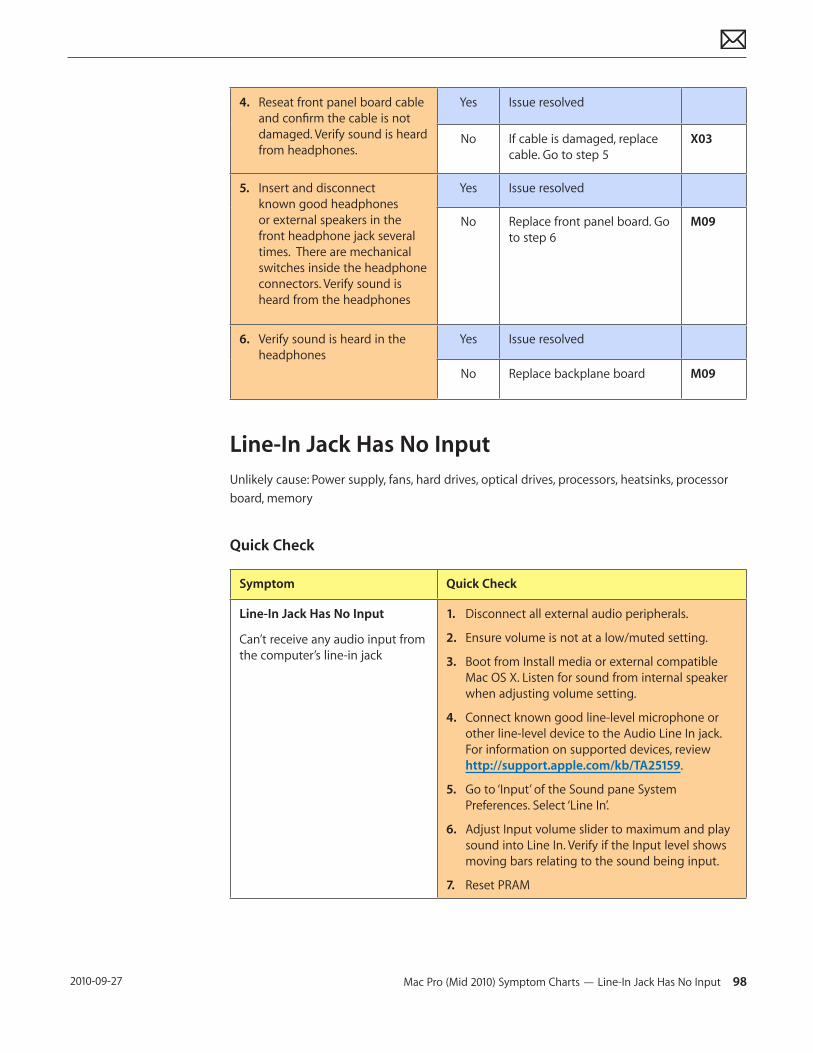
Mac Pro (Mid 2010) Symptom Charts — Line-In Jack Has No Input 98 2010-09-27
4. Reseat front panel board cable and confirm the cable is not damaged. Verify sound is heard from headphones.
Yes Issue resolved
No If cable is damaged, replace cable. Go to step 5
X03
5. Insert and disconnect known good headphones or external speakers in the front headphone jack several times. There are mechanical switches inside the headphone connectors. Verify sound is heard from the headphones
Yes Issue resolved
No Replace front panel board. Go to step 6
M09
6. Verify sound is heard in the headphones
Yes Issue resolved
No Replace backplane board M09
Line-In Jack Has No InputUnlikely cause: Power supply, fans, hard drives, optical drives, processors, heatsinks, processor board, memory
Quick Check
Symptom Quick Check
Line-In Jack Has No Input
Can’t receive any audio input from the computer’s line-in jack
1. Disconnect all external audio peripherals.
2. Ensure volume is not at a low/muted setting.
3. Boot from Install media or external compatible Mac OS X. Listen for sound from internal speaker when adjusting volume setting.
4. Connect known good line-level microphone or other line-level device to the Audio Line In jack. For information on supported devices, review http://support.apple.com/kb/TA25159.
5. Go to ‘Input’ of the Sound pane System Preferences. Select ‘Line In’.
6. Adjust Input volume slider to maximum and play sound into Line In. Verify if the Input level shows moving bars relating to the sound being input.
7. Reset PRAM
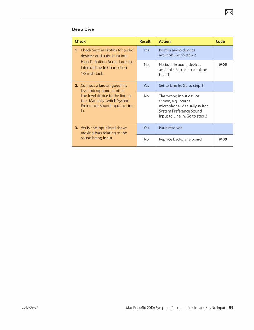
Mac Pro (Mid 2010) Symptom Charts — Line-In Jack Has No Input 99 2010-09-27
Deep Dive
Check Result Action Code
1. Check System Profiler for audio devices: Audio (Built In) Intel High Definition Audio. Look for Internal Line-In Connection: 1/8 inch Jack.
Yes Built-in audio devices available. Go to step 2
No No built-in audio devices available. Replace backplane board.
M09
2. Connect a known good line-level microphone or other line-level device to the line-in jack. Manually switch System Preference Sound Input to Line In.
Yes Set to Line In. Go to step 3
No The wrong input device shown, e.g. internal microphone. Manually switch System Preference Sound Input to Line In. Go to step 3
3. Verify the Input level shows moving bars relating to the sound being input.
Yes Issue resolved
No Replace backplane board. M09
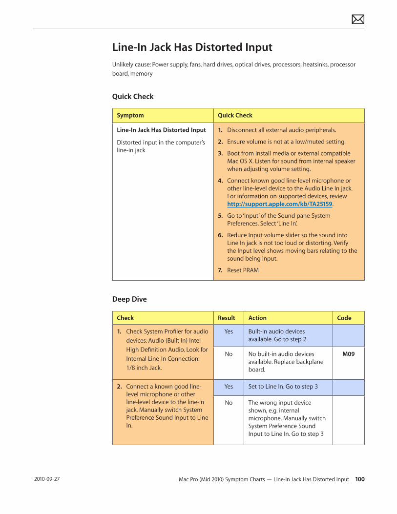
Mac Pro (Mid 2010) Symptom Charts — Line-In Jack Has Distorted Input 100 2010-09-27
Line-In Jack Has Distorted InputUnlikely cause: Power supply, fans, hard drives, optical drives, processors, heatsinks, processor board, memory
Quick Check
Symptom Quick Check
Line-In Jack Has Distorted Input
Distorted input in the computer’s line-in jack
1. Disconnect all external audio peripherals.
2. Ensure volume is not at a low/muted setting.
3. Boot from Install media or external compatible Mac OS X. Listen for sound from internal speaker when adjusting volume setting.
4. Connect known good line-level microphone or other line-level device to the Audio Line In jack. For information on supported devices, review http://support.apple.com/kb/TA25159.
5. Go to ‘Input’ of the Sound pane System Preferences. Select ‘Line In’.
6. Reduce Input volume slider so the sound into Line In jack is not too loud or distorting. Verify the Input level shows moving bars relating to the sound being input.
7. Reset PRAM
Deep Dive
Check Result Action Code
1. Check System Profiler for audio devices: Audio (Built In) Intel High Definition Audio. Look for Internal Line-In Connection: 1/8 inch Jack.
Yes Built-in audio devices available. Go to step 2
No No built-in audio devices available. Replace backplane board.
M09
2. Connect a known good line-level microphone or other line-level device to the line-in jack. Manually switch System Preference Sound Input to Line In.
Yes Set to Line In. Go to step 3
No The wrong input device shown, e.g. internal microphone. Manually switch System Preference Sound Input to Line In. Go to step 3
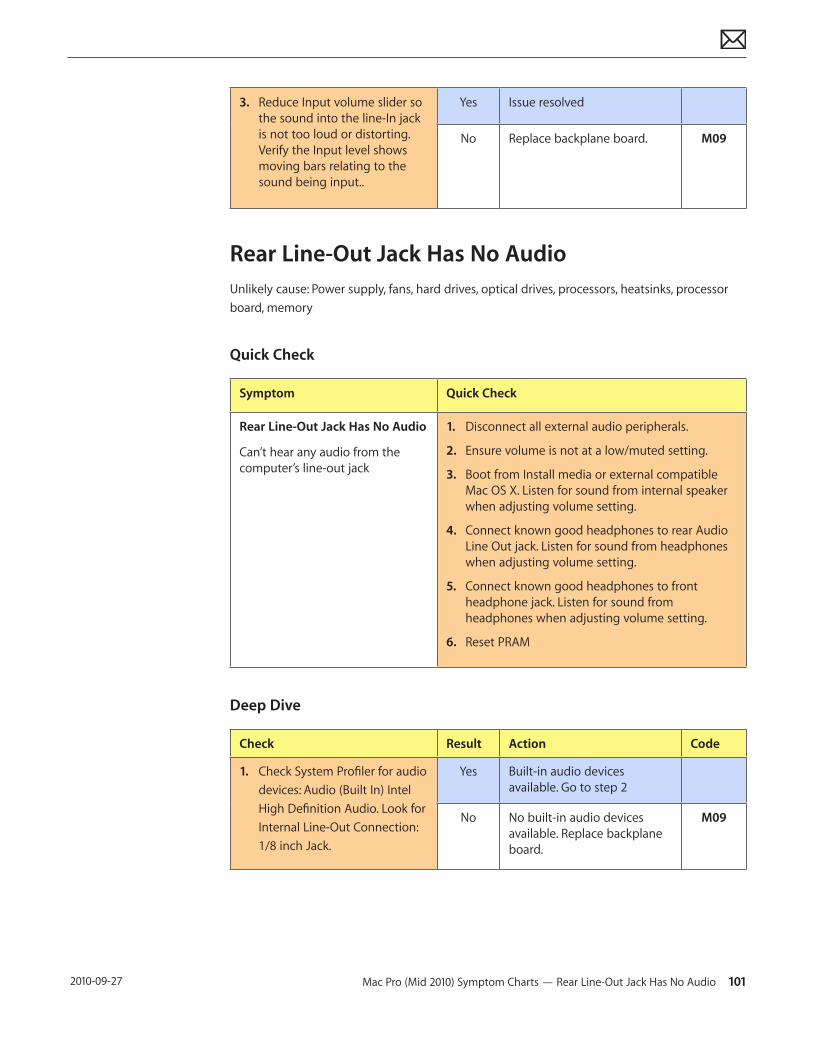
Mac Pro (Mid 2010) Symptom Charts — Rear Line-Out Jack Has No Audio 101 2010-09-27
3. Reduce Input volume slider so the sound into the line-In jack is not too loud or distorting. Verify the Input level shows moving bars relating to the sound being input..
Yes Issue resolved
No Replace backplane board. M09
Rear Line-Out Jack Has No AudioUnlikely cause: Power supply, fans, hard drives, optical drives, processors, heatsinks, processor board, memory
Quick Check
Symptom Quick Check
Rear Line-Out Jack Has No Audio
Can’t hear any audio from the computer’s line-out jack
1. Disconnect all external audio peripherals.
2. Ensure volume is not at a low/muted setting.
3. Boot from Install media or external compatible Mac OS X. Listen for sound from internal speaker when adjusting volume setting.
4. Connect known good headphones to rear Audio Line Out jack. Listen for sound from headphones when adjusting volume setting.
5. Connect known good headphones to front headphone jack. Listen for sound from headphones when adjusting volume setting.
6. Reset PRAM
Deep Dive
Check Result Action Code
1. Check System Profiler for audio devices: Audio (Built In) Intel High Definition Audio. Look for Internal Line-Out Connection: 1/8 inch Jack.
Yes Built-in audio devices available. Go to step 2
No No built-in audio devices available. Replace backplane board.
M09
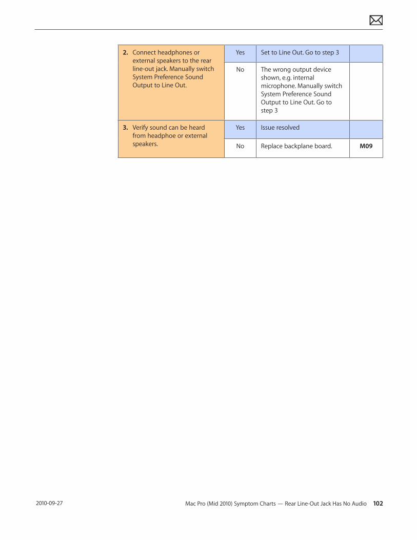
Mac Pro (Mid 2010) Symptom Charts — Rear Line-Out Jack Has No Audio 102 2010-09-27
2. Connect headphones or external speakers to the rear line-out jack. Manually switch System Preference Sound Output to Line Out.
Yes Set to Line Out. Go to step 3
No The wrong output device shown, e.g. internal microphone. Manually switch System Preference Sound Output to Line Out. Go to step 3
3. Verify sound can be heard from headphoe or external speakers.
Yes Issue resolved
No Replace backplane board. M09
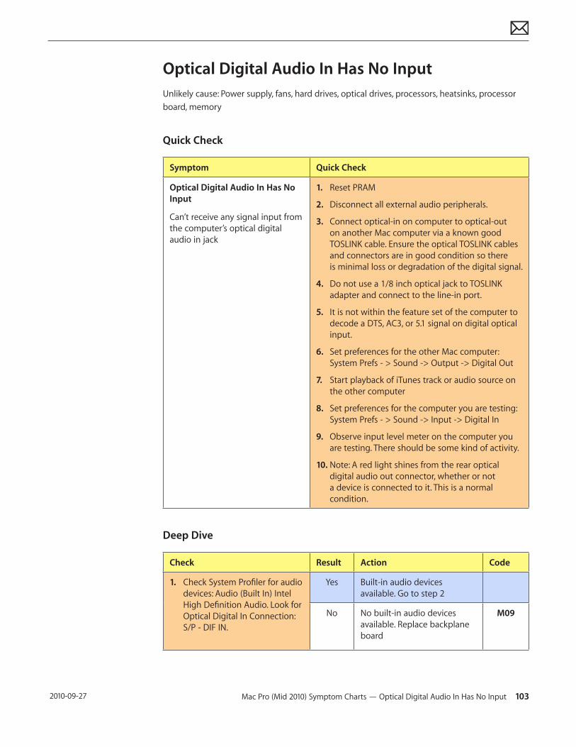
Mac Pro (Mid 2010) Symptom Charts — Optical Digital Audio In Has No Input 103 2010-09-27
Optical Digital Audio In Has No InputUnlikely cause: Power supply, fans, hard drives, optical drives, processors, heatsinks, processor board, memory
Quick Check
Symptom Quick Check
Optical Digital Audio In Has No Input
Can’t receive any signal input from the computer’s optical digital audio in jack
1. Reset PRAM
2. Disconnect all external audio peripherals.
3. Connect optical-in on computer to optical-out on another Mac computer via a known good TOSLINK cable. Ensure the optical TOSLINK cables and connectors are in good condition so there is minimal loss or degradation of the digital signal.
4. Do not use a 1/8 inch optical jack to TOSLINK adapter and connect to the line-in port.
5. It is not within the feature set of the computer to decode a DTS, AC3, or 5.1 signal on digital optical input.
6. Set preferences for the other Mac computer: System Prefs - > Sound -> Output -> Digital Out
7. Start playback of iTunes track or audio source on the other computer
8. Set preferences for the computer you are testing: System Prefs - > Sound -> Input -> Digital In
9. Observe input level meter on the computer you are testing. There should be some kind of activity.
10. Note: A red light shines from the rear optical digital audio out connector, whether or not a device is connected to it. This is a normal condition.
Deep Dive
Check Result Action Code
1. Check System Profiler for audio devices: Audio (Built In) Intel High Definition Audio. Look for Optical Digital In Connection: S/P - DIF IN.
Yes Built-in audio devices available. Go to step 2
No No built-in audio devices available. Replace backplane board
M09
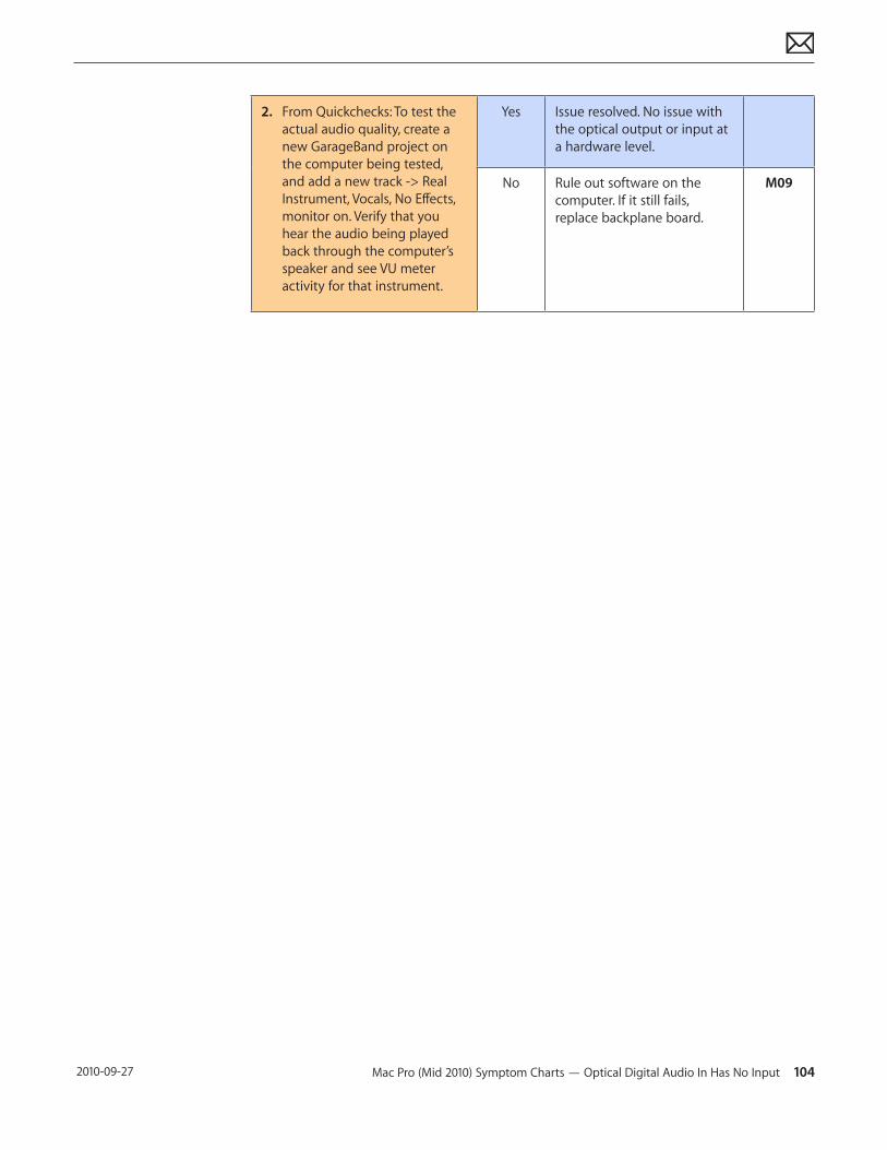
Mac Pro (Mid 2010) Symptom Charts — Optical Digital Audio In Has No Input 104 2010-09-27
2. From Quickchecks: To test the actual audio quality, create a new GarageBand project on the computer being tested, and add a new track -> Real Instrument, Vocals, No Effects, monitor on. Verify that you hear the audio being played back through the computer’s speaker and see VU meter activity for that instrument.
Yes Issue resolved. No issue with the optical output or input at a hardware level.
No Rule out software on the computer. If it still fails, replace backplane board.
M09
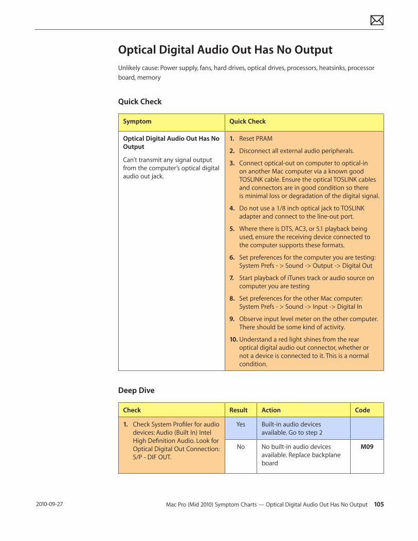
Mac Pro (Mid 2010) Symptom Charts — Optical Digital Audio Out Has No Output 105 2010-09-27
Optical Digital Audio Out Has No OutputUnlikely cause: Power supply, fans, hard drives, optical drives, processors, heatsinks, processor board, memory
Quick Check
Symptom Quick Check
Optical Digital Audio Out Has No Output
Can’t transmit any signal output from the computer’s optical digital audio out jack.
1. Reset PRAM
2. Disconnect all external audio peripherals.
3. Connect optical-out on computer to optical-in on another Mac computer via a known good TOSLINK cable. Ensure the optical TOSLINK cables and connectors are in good condition so there is minimal loss or degradation of the digital signal.
4. Do not use a 1/8 inch optical jack to TOSLINK adapter and connect to the line-out port.
5. Where there is DTS, AC3, or 5.1 playback being used, ensure the receiving device connected to the computer supports these formats.
6. Set preferences for the computer you are testing: System Prefs - > Sound -> Output -> Digital Out
7. Start playback of iTunes track or audio source on computer you are testing
8. Set preferences for the other Mac computer: System Prefs - > Sound -> Input -> Digital In
9. Observe input level meter on the other computer. There should be some kind of activity.
10. Understand a red light shines from the rear optical digital audio out connector, whether or not a device is connected to it. This is a normal condition.
Deep Dive
Check Result Action Code
1. Check System Profiler for audio devices: Audio (Built In) Intel High Definition Audio. Look for Optical Digital Out Connection: S/P - DIF OUT.
Yes Built-in audio devices available. Go to step 2
No No built-in audio devices available. Replace backplane board
M09

Mac Pro (Mid 2010) Symptom Charts — Optical Digital Audio Out Has No Output 106 2010-09-27
2. From Quickchecks: To test the actual audio quality, create a new GarageBand project on another Mac computer, and add a new track -> Real Instrument, Vocals, No Effects, monitor on. Verify that you hear the audio being played back through the other computer’s speaker and see VU meter activity for that instrument.
Yes Issue resolved. No issue with the optical output or input at a hardware level.
No Rule out software on the computer. If it still fails, replace backplane board.
M09
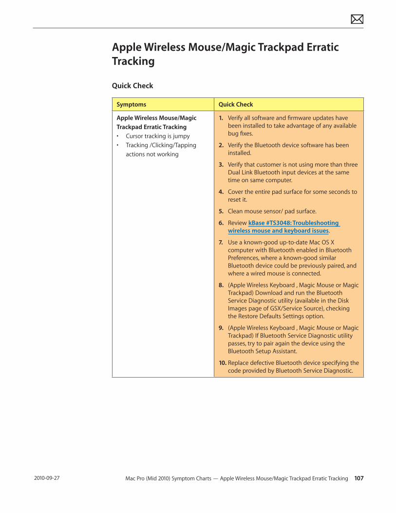
Mac Pro (Mid 2010) Symptom Charts — Apple Wireless Mouse/Magic Trackpad Erratic Tracking 107 2010-09-27
Apple Wireless Mouse/Magic Trackpad Erratic Tracking
Quick Check
Symptoms Quick Check
Apple Wireless Mouse/Magic Trackpad Erratic Tracking• Cursor tracking is jumpy• Tracking /Clicking/Tapping
actions not working
1. Verify all software and firmware updates have been installed to take advantage of any available bug fixes.
2. Verify the Bluetooth device software has been installed.
3. Verify that customer is not using more than three Dual Link Bluetooth input devices at the same time on same computer.
4. Cover the entire pad surface for some seconds to reset it.
5. Clean mouse sensor/ pad surface.
6. Review kBase #TS3048: Troubleshooting wireless mouse and keyboard issues.
7. Use a known-good up-to-date Mac OS X computer with Bluetooth enabled in Bluetooth Preferences, where a known-good similar Bluetooth device could be previously paired, and where a wired mouse is connected.
8. (Apple Wireless Keyboard , Magic Mouse or Magic Trackpad) Download and run the Bluetooth Service Diagnostic utility (available in the Disk Images page of GSX/Service Source), checking the Restore Defaults Settings option.
9. (Apple Wireless Keyboard , Magic Mouse or Magic Trackpad) If Bluetooth Service Diagnostic utility passes, try to pair again the device using the Bluetooth Setup Assistant.
10. Replace defective Bluetooth device specifying the code provided by Bluetooth Service Diagnostic.
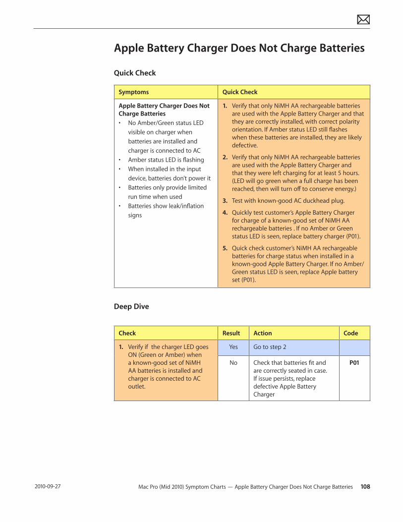
Mac Pro (Mid 2010) Symptom Charts — Apple Battery Charger Does Not Charge Batteries 108 2010-09-27
Apple Battery Charger Does Not Charge Batteries
Quick Check
Symptoms Quick Check
Apple Battery Charger Does Not Charge Batteries• No Amber/Green status LED
visible on charger when batteries are installed and charger is connected to AC
• Amber status LED is flashing• When installed in the input
device, batteries don’t power it• Batteries only provide limited
run time when used• Batteries show leak/inflation
signs
1. Verify that only NiMH AA rechargeable batteries are used with the Apple Battery Charger and that they are correctly installed, with correct polarity orientation. If Amber status LED still flashes when these batteries are installed, they are likely defective.
2. Verify that only NiMH AA rechargeable batteries are used with the Apple Battery Charger and that they were left charging for at least 5 hours. (LED will go green when a full charge has been reached, then will turn off to conserve energy.)
3. Test with known-good AC duckhead plug.
4. Quickly test customer’s Apple Battery Charger for charge of a known-good set of NiMH AA rechargeable batteries . If no Amber or Green status LED is seen, replace battery charger (P01).
5. Quick check customer’s NiMH AA rechargeable batteries for charge status when installed in a known-good Apple Battery Charger. If no Amber/Green status LED is seen, replace Apple battery set (P01).
Deep Dive
Check Result Action Code
1. Verify if the charger LED goes ON (Green or Amber) when a known-good set of NiMH AA batteries is installed and charger is connected to AC outlet.
Yes Go to step 2
No Check that batteries fit and are correctly seated in case. If issue persists, replace defective Apple Battery Charger
P01
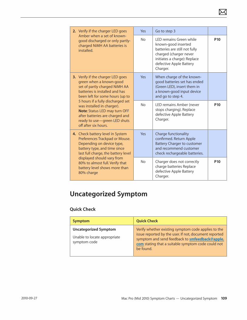
Mac Pro (Mid 2010) Symptom Charts — Uncategorized Symptom 109 2010-09-27
2. Verify if the charger LED goes Amber when a set of known-good discharged or only partly-charged NiMH AA batteries is installed.
Yes Go to step 3
No LED remains Green while known-good inserted batteries are still not fully charged (charger never initiates a charge): Replace defective Apple Battery Charger.
P10
3. Verify if the charger LED goes green when a known-good set of partly charged NiMH AA batteries is installed and has been left for some hours (up to 5 hours if a fully discharged set was installed in charger). Note: Status LED may turn OFF after batteries are charged and ready to use—green LED shuts off after six hours.
Yes When charge of the known-good batteries set has ended (Green LED), insert them in a known-good input device and go to step 4.
No LED remains Amber (never stops charging). Replace defective Apple Battery Charger.
P10
4. Check battery level in System Preferences Trackpad or Mouse. Depending on device type, battery type, and time since last full charge, the battery level displayed should vary from 80% to almost full. Verify that battery level shows more than 80% charge
Yes Charge functionality confirmed. Return Apple Battery Charger to customer and recommend customer check rechargeable batteries.
No Charger does not correctly charge batteries Replace defective Apple Battery Charger.
P10
Uncategorized Symptom
Quick Check
Symptom Quick Check
Uncategorized Symptom
Unable to locate appropriate symptom code
Verify whether existing symptom code applies to the issue reported by the user. If not, document reported symptom and send feedback to [email protected] stating that a suitable symptom code could not be found.
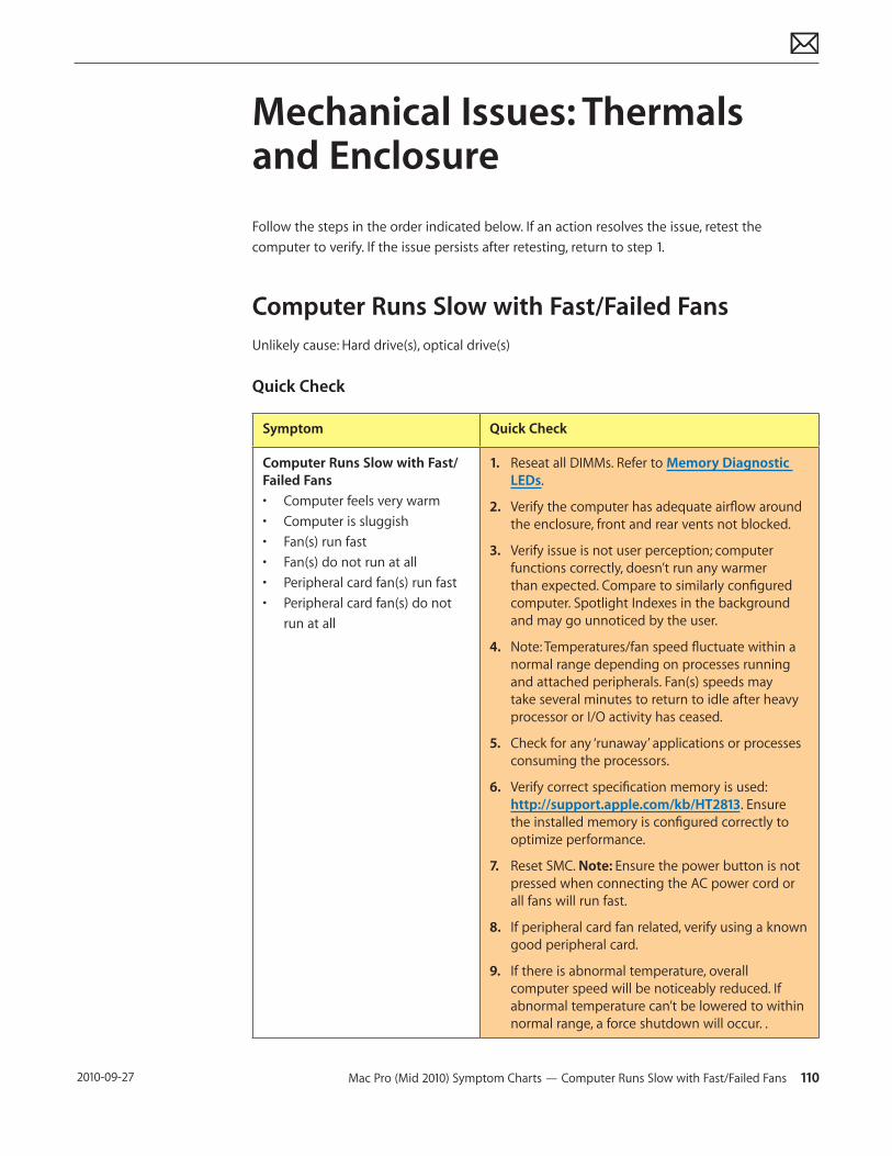
Mac Pro (Mid 2010) Symptom Charts — Computer Runs Slow with Fast/Failed Fans 110 2010-09-27
Mechanical Issues: Thermals and Enclosure
Follow the steps in the order indicated below. If an action resolves the issue, retest the computer to verify. If the issue persists after retesting, return to step 1.
Computer Runs Slow with Fast/Failed FansUnlikely cause: Hard drive(s), optical drive(s)
Quick Check
Symptom Quick Check
Computer Runs Slow with Fast/Failed Fans• Computer feels very warm• Computer is sluggish• Fan(s) run fast• Fan(s) do not run at all• Peripheral card fan(s) run fast• Peripheral card fan(s) do not
run at all
1. Reseat all DIMMs. Refer to Memory Diagnostic LEDs.
2. Verify the computer has adequate airflow around the enclosure, front and rear vents not blocked.
3. Verify issue is not user perception; computer functions correctly, doesn’t run any warmer than expected. Compare to similarly configured computer. Spotlight Indexes in the background and may go unnoticed by the user.
4. Note: Temperatures/fan speed fluctuate within a normal range depending on processes running and attached peripherals. Fan(s) speeds may take several minutes to return to idle after heavy processor or I/O activity has ceased.
5. Check for any ‘runaway’ applications or processes consuming the processors.
6. Verify correct specification memory is used: http://support.apple.com/kb/HT2813. Ensure the installed memory is configured correctly to optimize performance.
7. Reset SMC. Note: Ensure the power button is not pressed when connecting the AC power cord or all fans will run fast.
8. If peripheral card fan related, verify using a known good peripheral card.
9. If there is abnormal temperature, overall computer speed will be noticeably reduced. If abnormal temperature can’t be lowered to within normal range, a force shutdown will occur. .
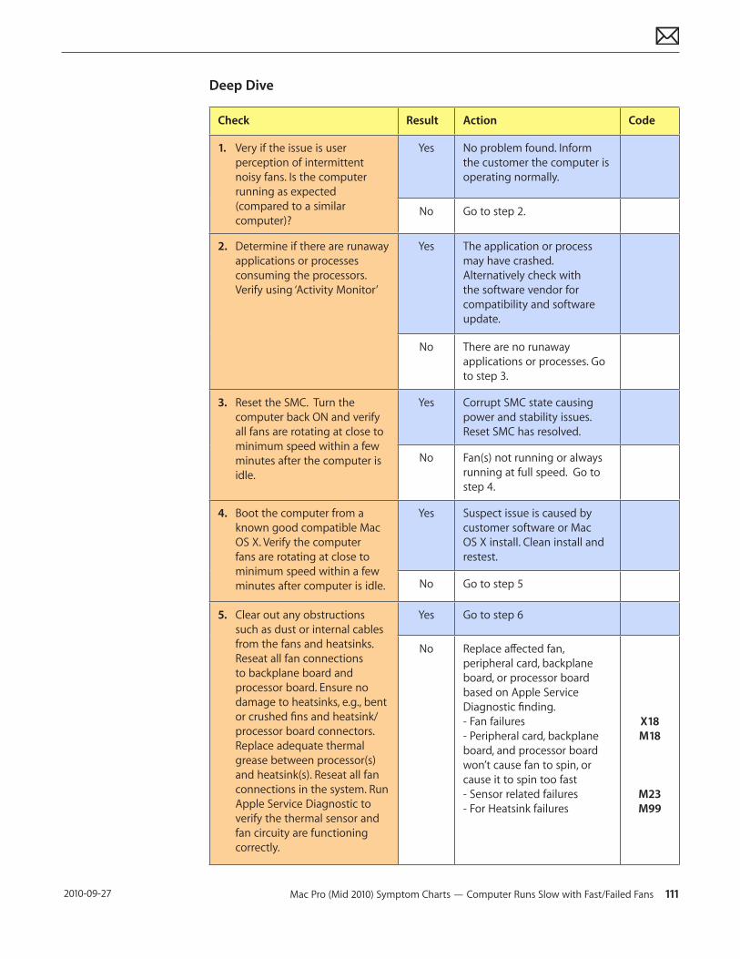
Mac Pro (Mid 2010) Symptom Charts — Computer Runs Slow with Fast/Failed Fans 111 2010-09-27
Deep Dive
Check Result Action Code
1. Very if the issue is user perception of intermittent noisy fans. Is the computer running as expected (compared to a similar computer)?
Yes No problem found. Inform the customer the computer is operating normally.
No Go to step 2.
2. Determine if there are runaway applications or processes consuming the processors. Verify using ‘Activity Monitor’
Yes The application or process may have crashed. Alternatively check with the software vendor for compatibility and software update.
No There are no runaway applications or processes. Go to step 3.
3. Reset the SMC. Turn the computer back ON and verify all fans are rotating at close to minimum speed within a few minutes after the computer is idle.
Yes Corrupt SMC state causing power and stability issues. Reset SMC has resolved.
No Fan(s) not running or always running at full speed. Go to step 4.
4. Boot the computer from a known good compatible Mac OS X. Verify the computer fans are rotating at close to minimum speed within a few minutes after computer is idle.
Yes Suspect issue is caused by customer software or Mac OS X install. Clean install and restest.
No Go to step 5
5. Clear out any obstructions such as dust or internal cables from the fans and heatsinks. Reseat all fan connections to backplane board and processor board. Ensure no damage to heatsinks, e.g., bent or crushed fins and heatsink/processor board connectors. Replace adequate thermal grease between processor(s) and heatsink(s). Reseat all fan connections in the system. Run Apple Service Diagnostic to verify the thermal sensor and fan circuity are functioning correctly.
Yes Go to step 6
No Replace affected fan, peripheral card, backplane board, or processor board based on Apple Service Diagnostic finding. - Fan failures - Peripheral card, backplane board, and processor board won’t cause fan to spin, or cause it to spin too fast - Sensor related failures - For Heatsink failures
X18 M18
M23 M99
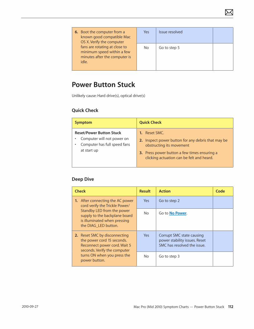
Mac Pro (Mid 2010) Symptom Charts — Power Button Stuck 112 2010-09-27
6. Boot the computer from a known good compatible Mac OS X. Verify the computer fans are rotating at close to minimum speed within a few minutes after the computer is idle.
Yes Issue resolved
No Go to step 5
Power Button StuckUnlikely cause: Hard drive(s), optical drive(s)
Quick Check
Symptom Quick Check
Reset/Power Button Stuck• Computer will not power on• Computer has full speed fans
at start up
1. Reset SMC.
2. Inspect power button for any debris that may be obstructing its movement
3. Press power button a few times ensuring a clicking actuation can be felt and heard.
Deep Dive
Check Result Action Code
1. After connecting the AC power cord verify the Trickle Power/Standby LED from the power supply to the backplane board is illuminated when pressing the DIAG_LED button.
Yes Go to step 2
No Go to No Power.
2. Reset SMC by disconnecting the power cord 15 seconds. Reconnect power cord. Wait 5 seconds. Verify the computer turns ON when you press the power button.
Yes Corrupt SMC state causing power stability issues. Reset SMC has resolved the issue.
No Go to step 3
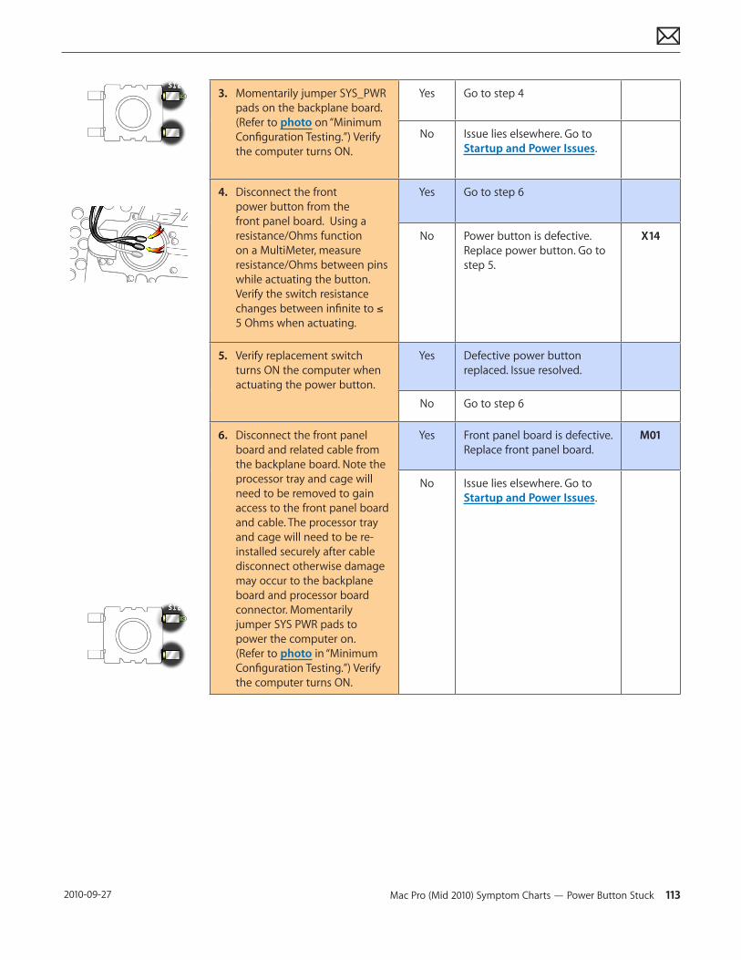
Mac Pro (Mid 2010) Symptom Charts — Power Button Stuck 113 2010-09-27
3. Momentarily jumper SYS_PWR pads on the backplane board. (Refer to photo on “Minimum Configuration Testing.”) Verify the computer turns ON.
Yes Go to step 4
No Issue lies elsewhere. Go to Startup and Power Issues.
4. Disconnect the front power button from the front panel board. Using a resistance/Ohms function on a MultiMeter, measure resistance/Ohms between pins while actuating the button. Verify the switch resistance changes between infinite to ≤ 5 Ohms when actuating.
Yes Go to step 6
No Power button is defective. Replace power button. Go to step 5.
X14
5. Verify replacement switch turns ON the computer when actuating the power button.
Yes Defective power button replaced. Issue resolved.
No Go to step 6
6. Disconnect the front panel board and related cable from the backplane board. Note the processor tray and cage will need to be removed to gain access to the front panel board and cable. The processor tray and cage will need to be re-installed securely after cable disconnect otherwise damage may occur to the backplane board and processor board connector. Momentarily jumper SYS PWR pads to power the computer on. (Refer to photo in “Minimum Configuration Testing.”) Verify the computer turns ON.
Yes Front panel board is defective. Replace front panel board.
M01
No Issue lies elsewhere. Go to Startup and Power Issues.
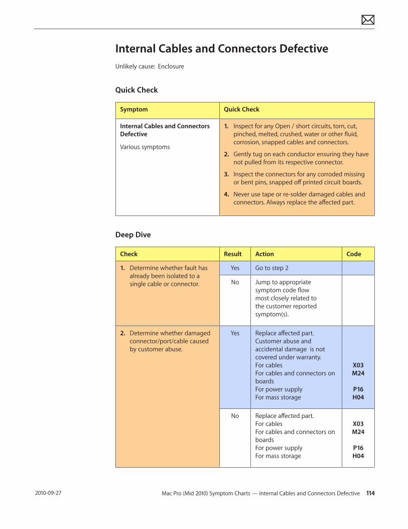
Mac Pro (Mid 2010) Symptom Charts — Internal Cables and Connectors Defective 114 2010-09-27
Internal Cables and Connectors DefectiveUnlikely cause: Enclosure
Quick Check
Symptom Quick Check
Internal Cables and Connectors Defective
Various symptoms
1. Inspect for any Open / short circuits, torn, cut, pinched, melted, crushed, water or other fluid, corrosion, snapped cables and connectors.
2. Gently tug on each conductor ensuring they have not pulled from its respective connector.
3. Inspect the connectors for any corroded missing or bent pins, snapped off printed circuit boards.
4. Never use tape or re-solder damaged cables and connectors. Always replace the affected part.
Deep Dive
Check Result Action Code
1. Determine whether fault has already been isolated to a single cable or connector.
Yes Go to step 2
No Jump to appropriate symptom code flow most closely related to the customer reported symptom(s).
2. Determine whether damaged connector/port/cable caused by customer abuse.
Yes Replace affected part. Customer abuse and accidental damage is not covered under warranty. For cables For cables and connectors on boards For power supply For mass storage
X03 M24
P16 H04
No Replace affected part. For cables For cables and connectors on boards For power supply For mass storage
X03 M24
P16 H04

Mac Pro (Mid 2010) Symptom Charts — Mechanical/Physical Damage 115 2010-09-27
Mechanical/Physical Damage
Quick Check
Symptom Quick Check
Mechanical/Physical Damage• Damaged ODD door(s)• Damaged side access door• Damaged latch mechanism• Stripped screw/head• Stripped screw boss• Dent or scratch to enclosure• Bent feet or handles• Fluid damage or rust• Damaged processor tray
latches• Damaged processor cage• Damaged PCI port bracket and
covers• Damaged PCI slider
1. Determine damage caused by customer/technician environment, accidental damage, or abuse.
2. Inform customer/technician the failures are not covered by Apple warranties. Refer to http://www.apple.com/legal/warranty
Uncategorized Symptom
Quick Check
Symptom Quick Check
Uncategorized Symptom
Unable to locate appropriate symptom code
Verify whether existing symptom code applies to the issue reported by the user. If not, document reported symptom and send feedback to [email protected] stating that a suitable symptom code could not be found.
© 2010 Apple Inc. All rights reserved.
Apple Technician Guide
Take ApartMac Pro (Mid 2010)
Mac Pro (Mid 2010) Take Apart — General Information 117 2010-09-27
General Information
Orientation
For most take-apart procedures, Apple recommends laying the computer on its side before removing or installing the part. For proper operation, however, Apple recommends running the unit in the upright position. Never operate the computer on its side with the access panel facing down.
Tools
The following tools are required to service all configurations of the computer:• Magnetized Phillips #1 screwdriver• Long-handled, magnetized Phillips #2 screwdriver• Magnetized jeweler’s Phillips #1 screwdriver• Long-handled, magnetized 3 mm flathead hex screwdriver (Apple part number 922-7122) • Long-handled, magnetized T8 torx screwdriver• Right-angle or short-handled, magnetized 2.5 mm hex screwdriver• Flatblade screwdriver• Jeweler’s flatblade screwdriver• Thermal grease kit (Apple part number 076-1225)• Soft cloth (for protecting processor tray)
Parts Requiring Enclosure Replacement
The following are not separate, orderable parts. To replace them, you must replace the enclosure.• Media shelf• Media fan• AirPort antenna board and cables• Rear panel latch
How to Identify Single- and Dual-Processor Configurations
See “How to Identify Single- and Dual-Processor Configurations” in the Basics chapter.
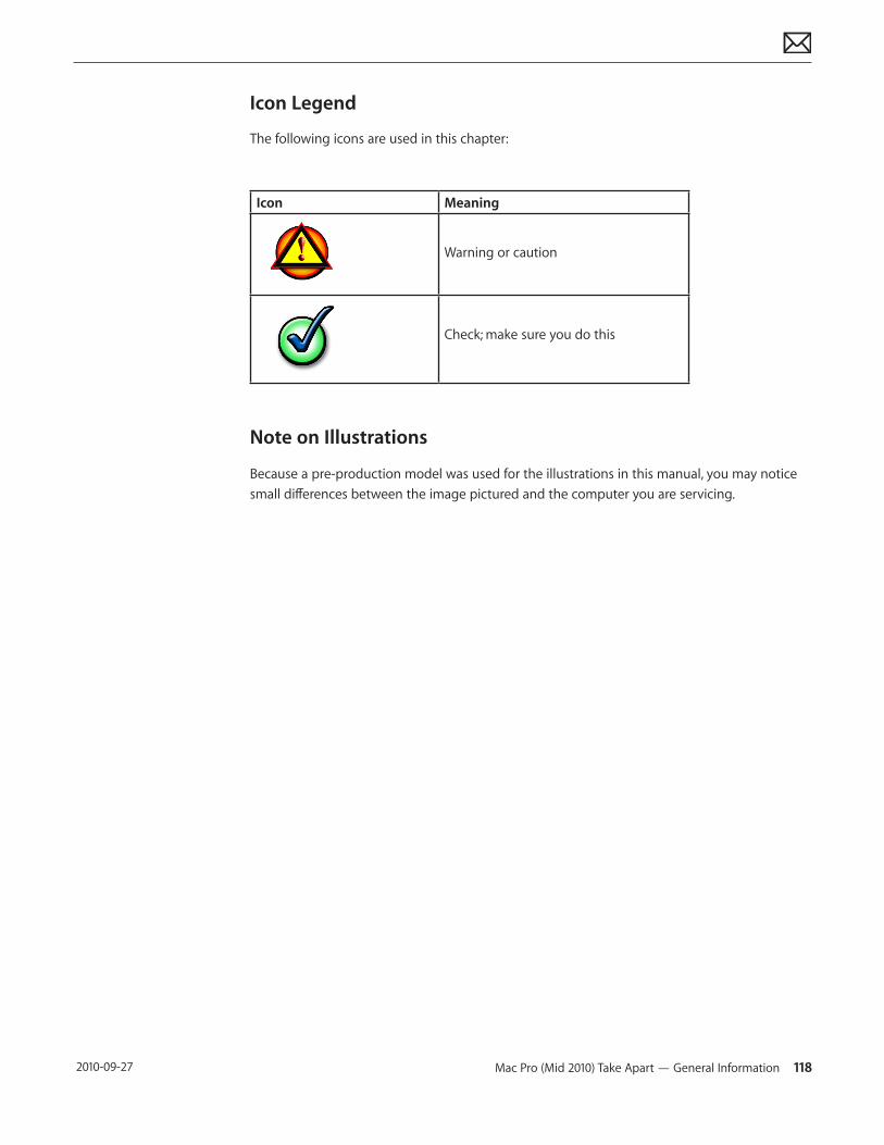
Mac Pro (Mid 2010) Take Apart — General Information 118 2010-09-27
Icon Legend
The following icons are used in this chapter:
Icon Meaning
Warning or caution
Check; make sure you do this
Note on Illustrations
Because a pre-production model was used for the illustrations in this manual, you may notice small differences between the image pictured and the computer you are servicing.
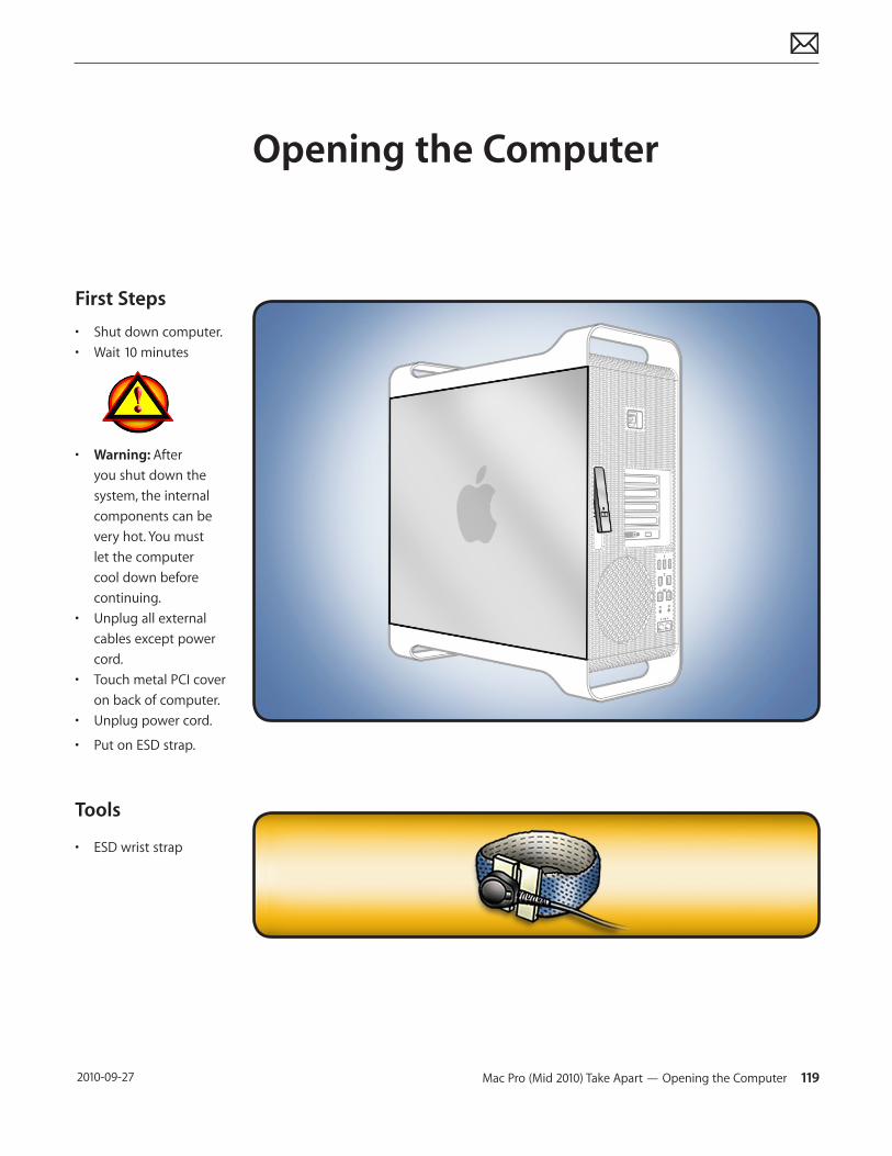
Mac Pro (Mid 2010) Take Apart — Opening the Computer 119 2010-09-27
First Steps
• Shut down computer.• Wait 10 minutes
• Warning: After you shut down the system, the internal components can be very hot. You must let the computer cool down before continuing.
• Unplug all external cables except power cord.
• Touch metal PCI cover on back of computer.
• Unplug power cord.
• Put on ESD strap.
Tools
• ESD wrist strap
Opening the Computer
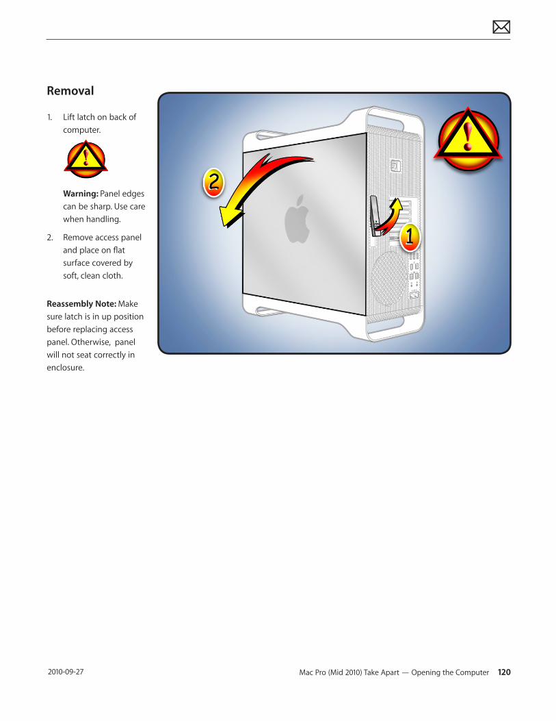
Mac Pro (Mid 2010) Take Apart — Opening the Computer 120 2010-09-27
Removal
1. Lift latch on back of computer.
Warning: Panel edges can be sharp. Use care when handling.
2. Remove access panel and place on flat surface covered by soft, clean cloth.
Reassembly Note: Make sure latch is in up position before replacing access panel. Otherwise, panel will not seat correctly in enclosure.
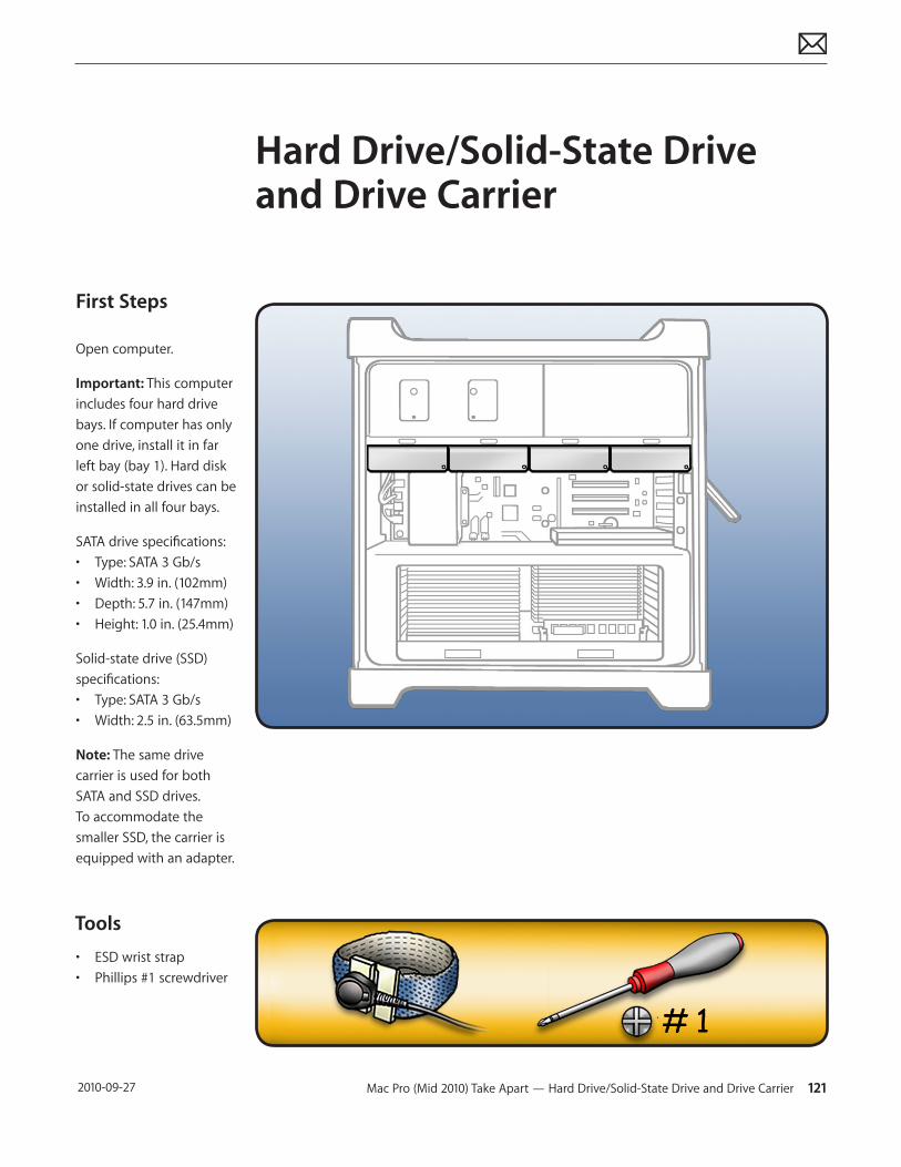
Mac Pro (Mid 2010) Take Apart — Hard Drive/Solid-State Drive and Drive Carrier 121 2010-09-27
First Steps
Open computer.
Important: This computer includes four hard drive bays. If computer has only one drive, install it in far left bay (bay 1). Hard disk or solid-state drives can be installed in all four bays.
SATA drive specifications:• Type: SATA 3 Gb/s• Width: 3.9 in. (102mm)• Depth: 5.7 in. (147mm)• Height: 1.0 in. (25.4mm)
Solid-state drive (SSD) specifications:• Type: SATA 3 Gb/s• Width: 2.5 in. (63.5mm)
Note: The same drive carrier is used for both SATA and SSD drives. To accommodate the smaller SSD, the carrier is equipped with an adapter.
Tools
• ESD wrist strap• Phillips #1 screwdriver
Hard Drive/Solid-State Drive and Drive Carrier
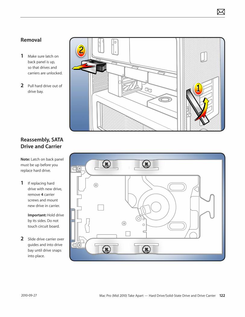
Mac Pro (Mid 2010) Take Apart — Hard Drive/Solid-State Drive and Drive Carrier 122 2010-09-27
Removal
1 Make sure latch on back panel is up, so that drives and carriers are unlocked.
2 Pull hard drive out of drive bay.
Reassembly, SATA Drive and Carrier
Note: Latch on back panel must be up before you replace hard drive.
1 If replacing hard drive with new drive, remove 4 carrier screws and mount new drive in carrier.
Important: Hold drive by its sides. Do not touch circuit board.
2 Slide drive carrier over guides and into drive bay until drive snaps into place.
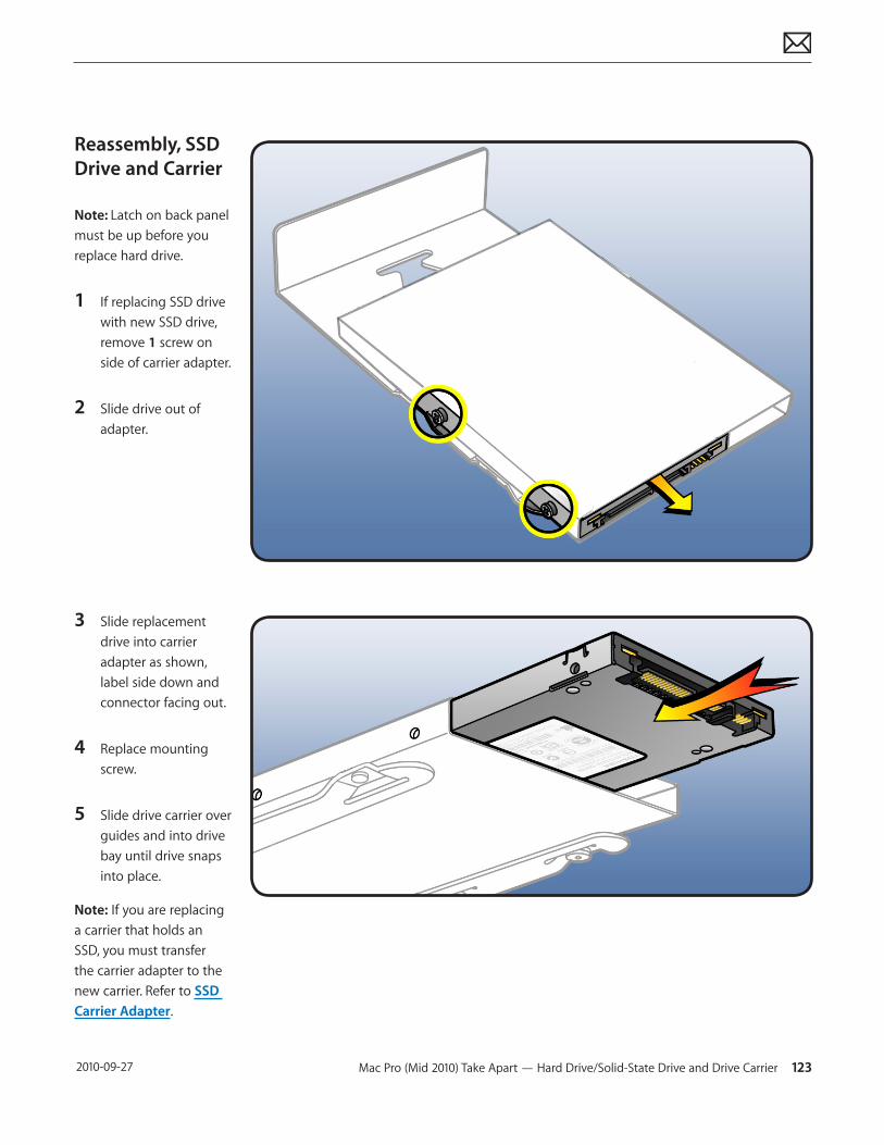
Mac Pro (Mid 2010) Take Apart — Hard Drive/Solid-State Drive and Drive Carrier 123 2010-09-27
Reassembly, SSD Drive and Carrier
Note: Latch on back panel must be up before you replace hard drive.
1 If replacing SSD drive with new SSD drive, remove 1 screw on side of carrier adapter.
2 Slide drive out of adapter.
3 Slide replacement drive into carrier adapter as shown, label side down and connector facing out.
4 Replace mounting screw.
5 Slide drive carrier over guides and into drive bay until drive snaps into place.
Note: If you are replacing a carrier that holds an SSD, you must transfer the carrier adapter to the new carrier. Refer to SSD Carrier Adapter.
Mac Pro (Mid 2010) Take Apart — Hard Drive/Solid-State Drive and Drive Carrier 124 2010-09-27
Formatting a New Drive
After installing a new (replacement) drive, format it using these steps:
1. Open Disk Utility and select the drive in list to the left. Note: If you are formatting the primary drive, use Disk Utility program on Install Disk.
2. Click on Partition tab.
3. Click on “Options” and verify GUID is selected if this is a bootable drive.
4. Apply change by clicking on “Partition” button.
Reinstalling Software that Came with the Computer
Use the software install discs that came with the computer to reinstall Mac OS X and any applications that came with the computer.
Important: Apple recommends backing up data on the hard disk before restoring software. Back up essential files before installing Mac OS X and other applications. Apple is not responsible for any lost data.
For more details, refer to http://support.apple.com/kb/HT3910.
This procedure has four parts:• Erasing the hard drive/formatting the hard drive• Installing the Mac OS X operating system using the Mac OS X Install DVD.• Completing the Mac OS X Setup Assistant.• Restoring the bundled applications using the Applications Install Disc.
Important: This procedure will completely erase your hard drive. If you have installed Microsoft Windows using Boot Camp, or have multiple partitions, this procedure will erase the partition you select.
Part One: Erasing the hard drive/formatting the hard drive
1. Turn on the computer.
2. Insert the Mac OS X Install DVD into the optical drive.
3. Press and hold the “C” key while the computer starts up. The computer will start up using the Mac OS X Install DVD.
4. If your are using a wireless mouse, a mouse icon should appear asking you to turn the mouse on so that the computer can discover it.
5. Select a language, then press the right arrow key.
6. Click the Utilities menu, the choose Disk Utility.
7. Select a volume to erase (usually called Macintosh HD).
8. Click the Erase tab.
Mac Pro (Mid 2010) Take Apart — Hard Drive/Solid-State Drive and Drive Carrier 125 2010-09-27
9. Click Erase... Important: This step will completely erase your hard drive. If you have installed Microsoft Windows using Boot Camp, or have multiple partitions, this procedure will erase the partition you select.
10. A dialog box appears asking if you want to erase the partition: click Erase.
11. After the partition is erased, choose Quit Disk Utility from the Disk Utility menu.
Part Two: Installing the operating system
1. When the Mac OS X Installer screen appears, click Continue.
2. When the license agreement appears, click Agree.
3. Select the disk you erased. It should now be highlighted with a green arrow.
4. Click Install. A status bar appears on the bottom of the screen while Mac OS X installs.
5. An Additional Information screen appears, advising you that you operating system has been installed. Click Continue.
6. An Install Succeeded screen appears. Click Restart.
Part Three: Completing the Mac OS X Setup Assistant
1. When the restart has completed, a welcome video plays, then country/region selection screen appears.
2. Select your country or region and click Continue.
3. Select a keyboard layout and click Continue.• A migration screen appears. If you wish to migrate your data from another Macintosh,
see Migration tips and tricks http://support.apple.com/kb/HT1291. If you do not wish to migrate, or want to migrate later, select “Do not transfer my information now” and click Continue.
4. A Wireless Service screen appears if you have wireless services available within range of your computer. Select “On” and click Continue.
5. If the network is password protected, you be asked for a password when you select it. Type the password and click Continue.
6. An Apple ID screen appears. This is used to purchase content from the iTunes store. You can use MobileMe or .Mac usernames here as well. When complete, click Continue.
7. If you do not have an Apple ID or MobileMe account, click Continue to move to the next screen.
8. A Registration Information screen appears. You are not required to fill this out, but it is helpful if you do. When complete, click Continue and your product registration will be sent immediately.
9. If Mac OS X servers are available on your network, you’ll be asked if you’d like to log on to them. If not, click Continue.
10. A Create Your Account screen appears. This will be used to create a User Account with Login ID and Password for you computer. You should remember this password. You’ll be
Mac Pro (Mid 2010) Take Apart — Hard Drive/Solid-State Drive and Drive Carrier 126 2010-09-27
asked for it when you install new software or perform other administrative tasks on your computer. When complete, click Continue and your account will be created immediately.
11. A screen to select your user picture appears. Take a snapshot with the built-in camera or select a picture from your Library. When complete, click Continue.
12. A MobileMe screen appears. Select an option and click Continue.
13. A Thank You screen appears. Click Go to complete the Mac OS X Setup Assistant.
14. Eject the Mac OS X Install DVD by dragging its icon to the Trash.
Part Four: Restoring the bundled applications
1. To install the bundled applications, locate the Applications Install Disc that came with your computer.
Note: You may see a Software Update icon bouncing up and down in your dock. You can quit this for now.
2. Insert the Applications Install Disc into the optical drive.
3. The disc will mount and an Applications Install Disk dialog appears. Double-click on Install Bundled Software to install your iLife applications.
4. A dialog appears asking if you want to run the package. Click Continue.
5. The Bundled Software Applications Installer screen appears. Click Continue.
6. A software license screen appears. Click Continue, then click Agree to accept the terms.
7. A select destination dialog appears. Make sure the partition with the green arrow is the correct destination, then click Continue.
8. To install all the bundled applications, click Install.
9. To select individual applications, click Customize. Click the disclosure triangle next to Bundled Applications to select individual applications, then click Install. Clicking Standard Install on the Customize screen installs all the applications.
10. Type the password you created in Part Three, step 11 to start the installation.
11. A restart dialog appears. Click Continue Installation.
12. An Install was Successful screen appears. Click Restart.
The restore process is now complete.
It is a good idea to make sure you’ve updated all the software after performing this procedure. From the Apple () menu, choose Software Update to find the updates currently available for your computer.
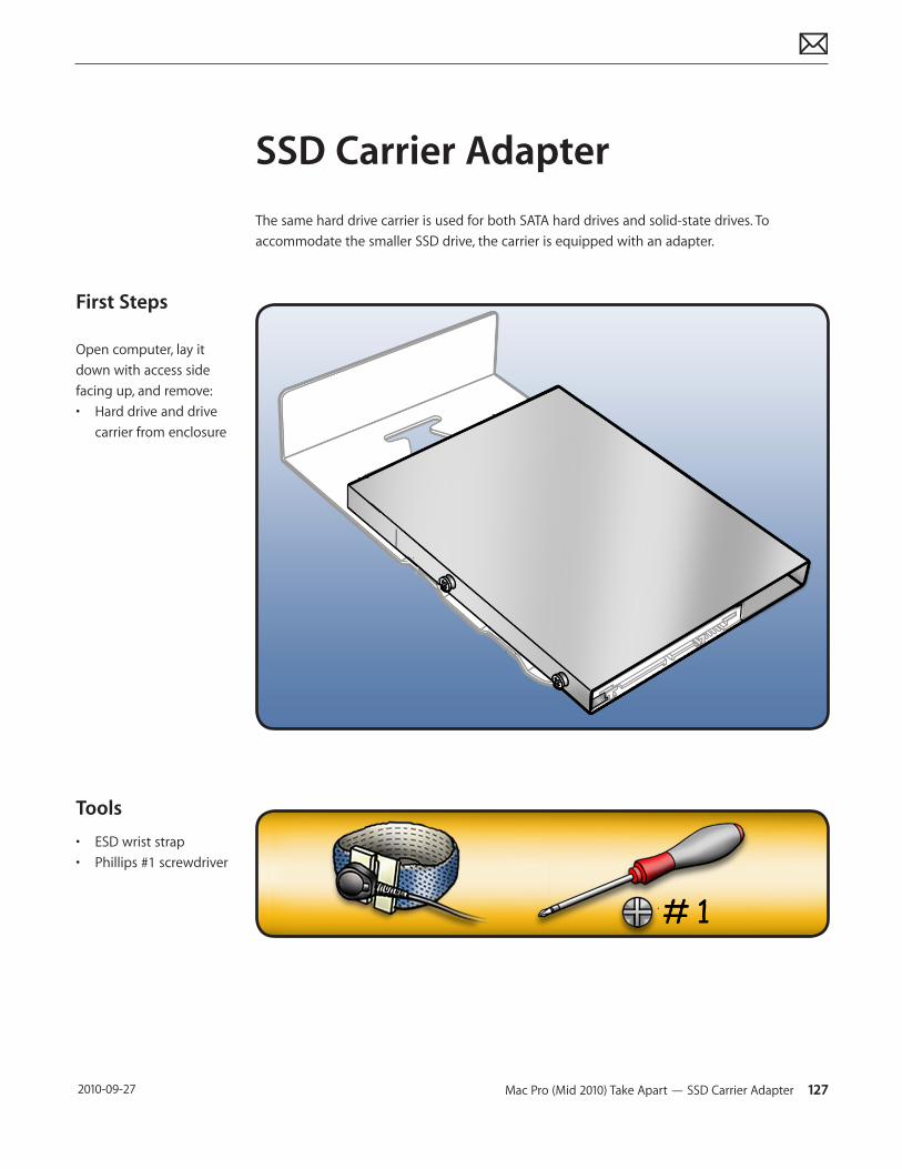
Mac Pro (Mid 2010) Take Apart — SSD Carrier Adapter 127 2010-09-27
First Steps
Open computer, lay it down with access side facing up, and remove:• Hard drive and drive
carrier from enclosure
Tools
• ESD wrist strap• Phillips #1 screwdriver
SSD Carrier AdapterThe same hard drive carrier is used for both SATA hard drives and solid-state drives. To accommodate the smaller SSD drive, the carrier is equipped with an adapter.
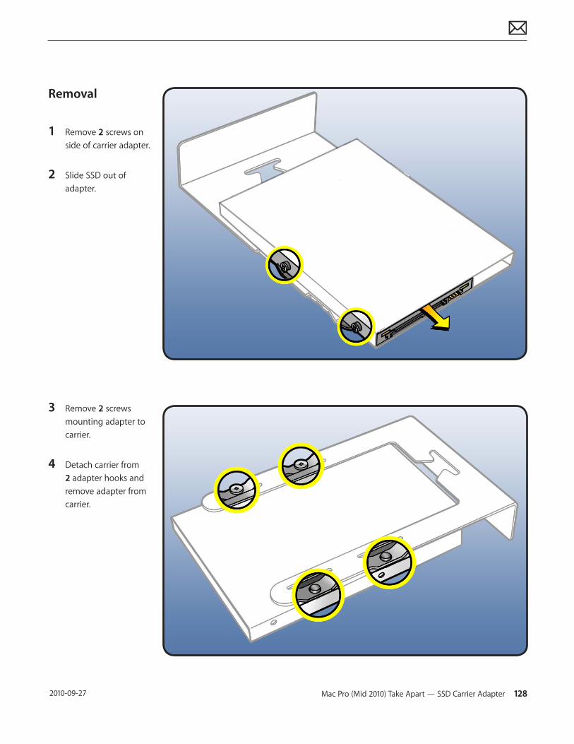
Mac Pro (Mid 2010) Take Apart — SSD Carrier Adapter 128 2010-09-27
Removal
1 Remove 2 screws on side of carrier adapter.
2 Slide SSD out of adapter.
3 Remove 2 screws mounting adapter to carrier.
4 Detach carrier from 2 adapter hooks and remove adapter from carrier.
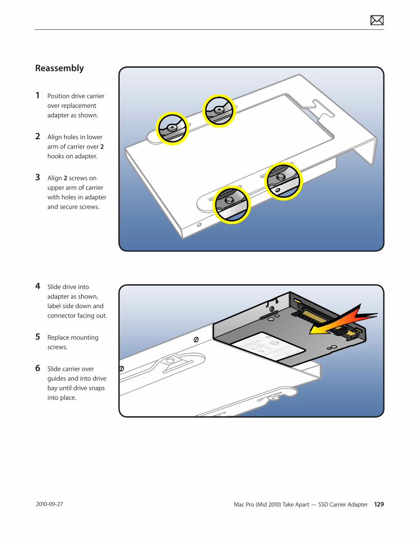
Mac Pro (Mid 2010) Take Apart — SSD Carrier Adapter 129 2010-09-27
Reassembly
1 Position drive carrier over replacement adapter as shown.
2 Align holes in lower arm of carrier over 2 hooks on adapter.
3 Align 2 screws on upper arm of carrier with holes in adapter and secure screws.
4 Slide drive into adapter as shown, label side down and connector facing out.
5 Replace mounting screws.
6 Slide carrier over guides and into drive bay until drive snaps into place.
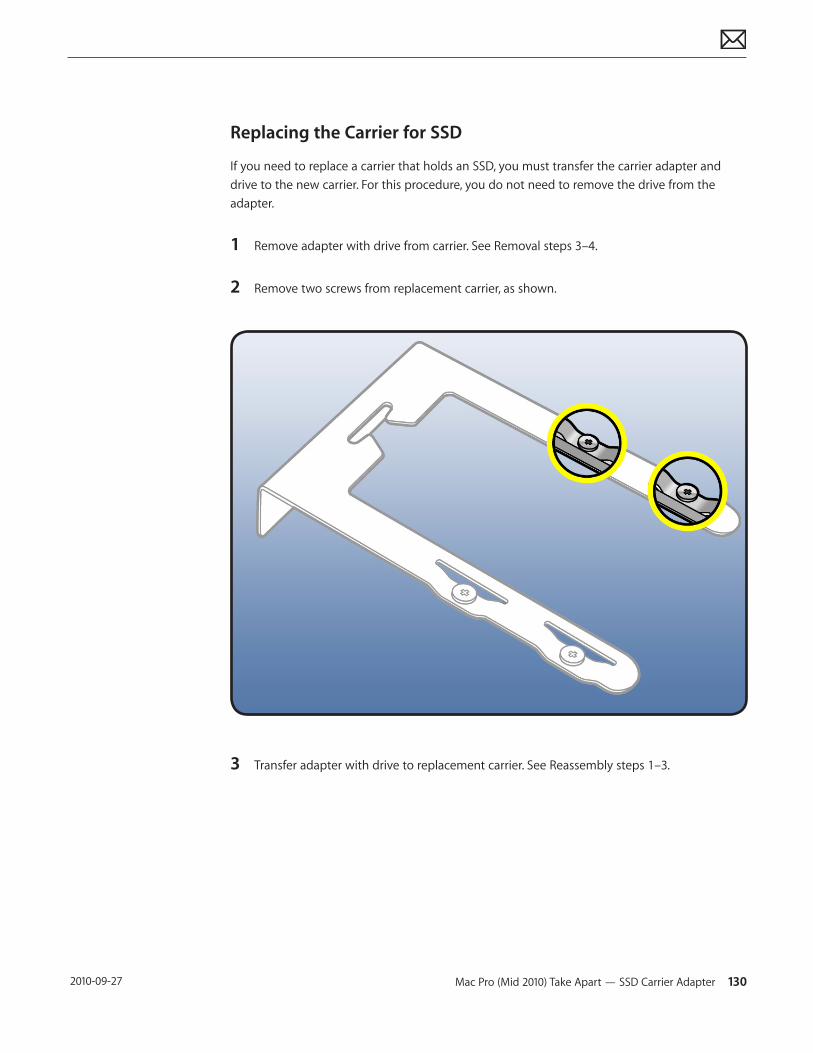
Mac Pro (Mid 2010) Take Apart — SSD Carrier Adapter 130 2010-09-27
Replacing the Carrier for SSD
If you need to replace a carrier that holds an SSD, you must transfer the carrier adapter and drive to the new carrier. For this procedure, you do not need to remove the drive from the adapter.
1 Remove adapter with drive from carrier. See Removal steps 3–4.
2 Remove two screws from replacement carrier, as shown.
3 Transfer adapter with drive to replacement carrier. See Reassembly steps 1–3.
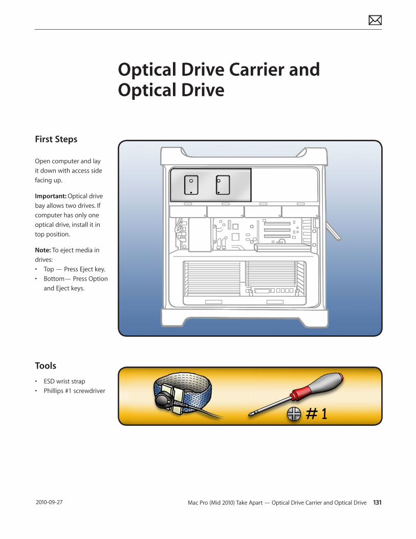
Mac Pro (Mid 2010) Take Apart — Optical Drive Carrier and Optical Drive 131 2010-09-27
First Steps
Open computer and lay it down with access side facing up.
Important: Optical drive bay allows two drives. If computer has only one optical drive, install it in top position.
Note: To eject media in drives: • Top — Press Eject key.• Bottom— Press Option
and Eject keys.
Tools
• ESD wrist strap • Phillips #1 screwdriver
Optical Drive Carrier and Optical Drive
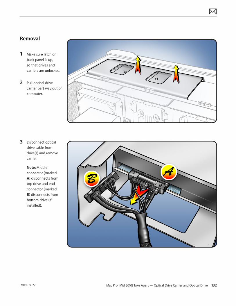
Mac Pro (Mid 2010) Take Apart — Optical Drive Carrier and Optical Drive 132 2010-09-27
Removal
1 Make sure latch on back panel is up, so that drives and carriers are unlocked.
2 Pull optical drive carrier part way out of computer.
3 Disconnect optical drive cable from drive(s) and remove carrier.
Note: Middle connector (marked A) disconnects from top drive and end connector (marked B) disconnects from bottom drive (if installed).
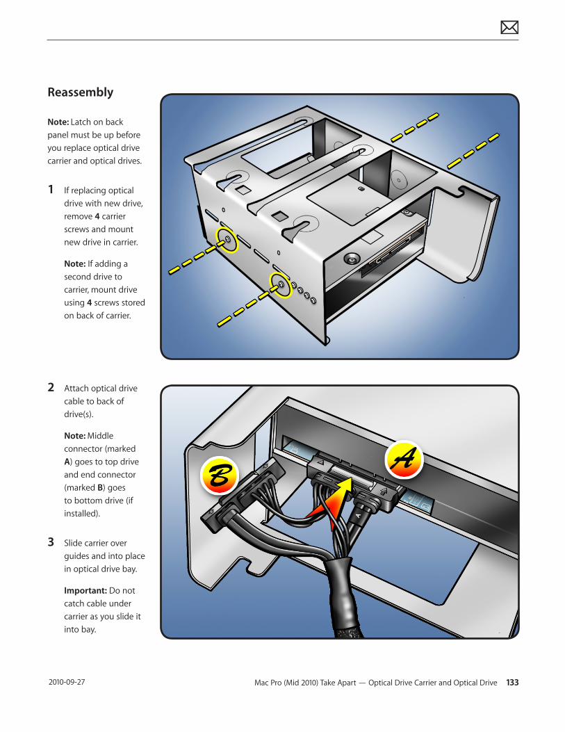
Mac Pro (Mid 2010) Take Apart — Optical Drive Carrier and Optical Drive 133 2010-09-27
Reassembly
Note: Latch on back panel must be up before you replace optical drive carrier and optical drives.
1 If replacing optical drive with new drive, remove 4 carrier screws and mount new drive in carrier.
Note: If adding a second drive to carrier, mount drive using 4 screws stored on back of carrier.
2 Attach optical drive cable to back of drive(s).
Note: Middle connector (marked A) goes to top drive and end connector (marked B) goes to bottom drive (if installed).
3 Slide carrier over guides and into place in optical drive bay.
Important: Do not catch cable under carrier as you slide it into bay.
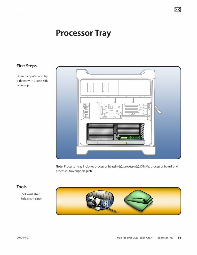
Mac Pro (Mid 2010) Take Apart — Processor Tray 134 2010-09-27
First Steps
Open computer and lay it down with access side facing up.
Tools
• ESD wrist strap • Soft, clean cloth
Processor Tray
Note: Processor tray includes processor heatsink(s), processor(s), DIMMs, processor board, and processor tray support plate.
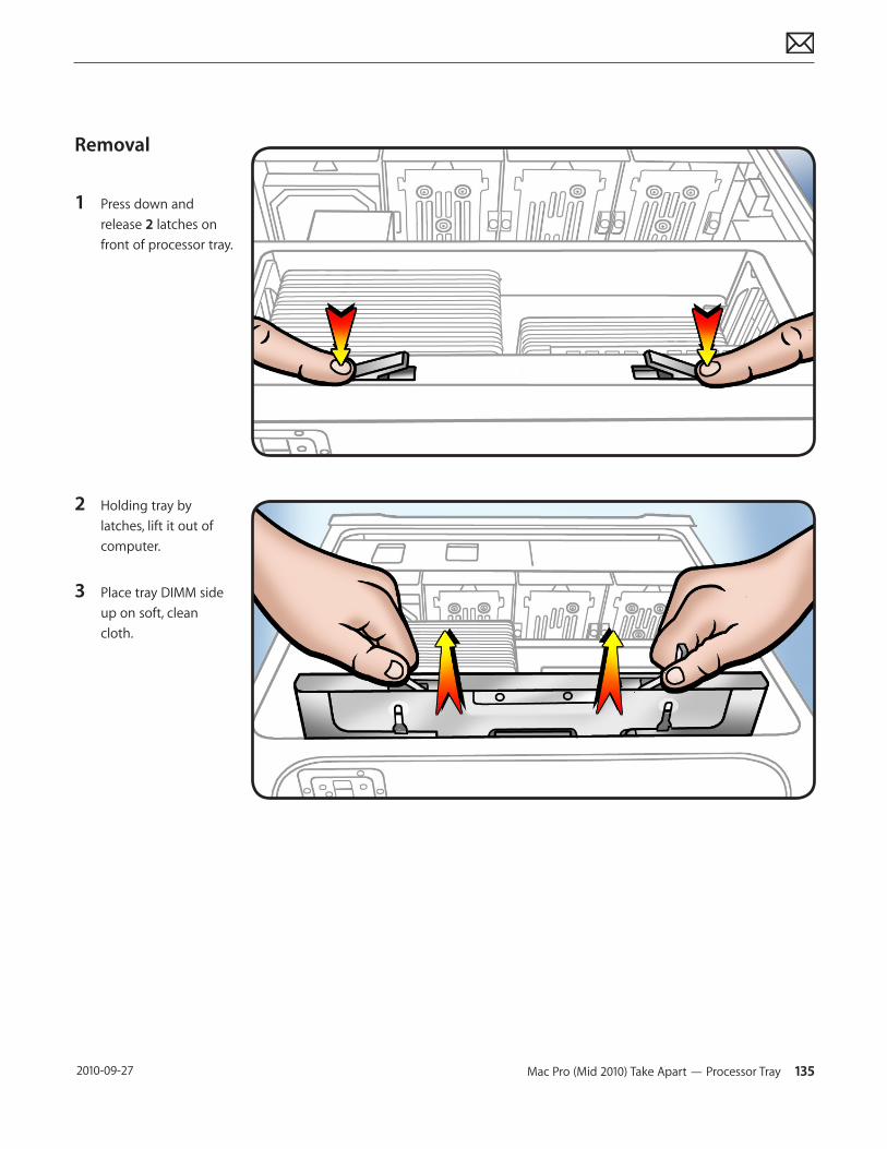
Mac Pro (Mid 2010) Take Apart — Processor Tray 135 2010-09-27
Removal
1 Press down and release 2 latches on front of processor tray.
2 Holding tray by latches, lift it out of computer.
3 Place tray DIMM side up on soft, clean cloth.
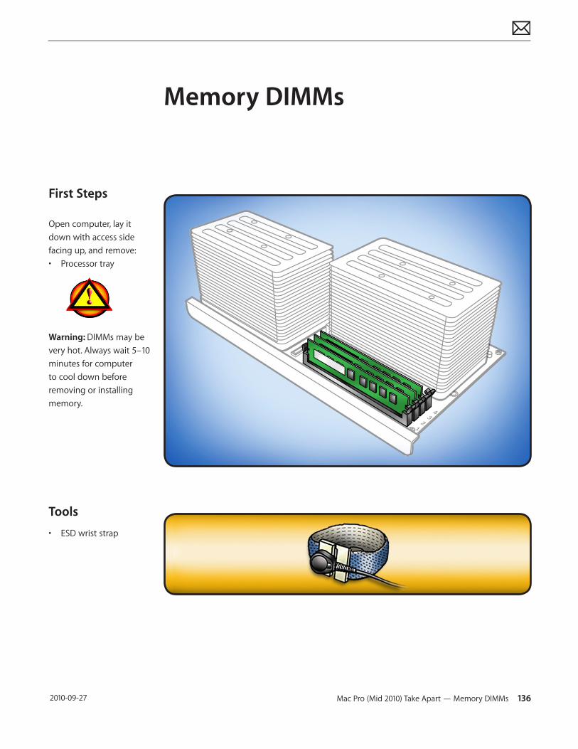
Mac Pro (Mid 2010) Take Apart — Memory DIMMs 136 2010-09-27
First Steps
Open computer, lay it down with access side facing up, and remove:• Processor tray
Warning: DIMMs may be very hot. Always wait 5–10 minutes for computer to cool down before removing or installing memory.
Tools
• ESD wrist strap
Memory DIMMs
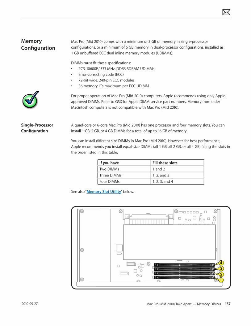
Mac Pro (Mid 2010) Take Apart — Memory DIMMs 137 2010-09-27
Memory Configuration
Single-Processor Configuration
Mac Pro (Mid 2010) comes with a minimum of 3 GB of memory in single-processor configurations, or a minimum of 6 GB memory in dual-processor configurations, installed as 1 GB unbuffered ECC dual inline memory modules (UDIMMs).
DIMMs must fit these specifications:• PC3-10600E,1333 MHz, DDR3 SDRAM UDIMMs• Error-correcting code (ECC)• 72-bit wide, 240-pin ECC modules• 36 memory ICs maximum per ECC UDIMM
For proper operation of Mac Pro (Mid 2010) computers, Apple recommends using only Apple-approved DIMMs. Refer to GSX for Apple DIMM service part numbers. Memory from older Macintosh computers is not compatible with Mac Pro (Mid 2010).
A quad-core or 6-core Mac Pro (Mid 2010) has one processor and four memory slots. You can install 1 GB, 2 GB, or 4 GB DIMMs for a total of up to 16 GB of memory.
You can install different size DIMMs in Mac Pro (Mid 2010). However, for best performance, Apple recommends you install equal-size DIMMs (all 1 GB, all 2 GB, or all 4 GB) filling the slots in the order listed in this table.
If you have Fill these slotsTwo DIMMs 1 and 2Three DIMMs 1, 2, and 3Four DIMMs 1, 2, 3, and 4
See also “Memory Slot Utility” below.
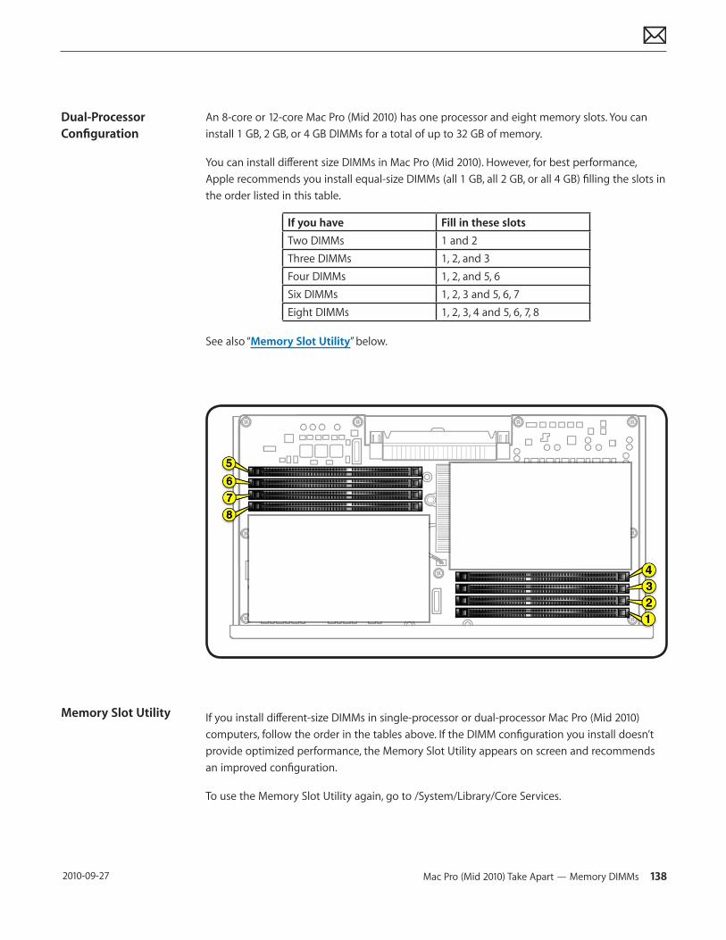
Mac Pro (Mid 2010) Take Apart — Memory DIMMs 138 2010-09-27
Dual-Processor Configuration
Memory Slot Utility
An 8-core or 12-core Mac Pro (Mid 2010) has one processor and eight memory slots. You can install 1 GB, 2 GB, or 4 GB DIMMs for a total of up to 32 GB of memory.
You can install different size DIMMs in Mac Pro (Mid 2010). However, for best performance, Apple recommends you install equal-size DIMMs (all 1 GB, all 2 GB, or all 4 GB) filling the slots in the order listed in this table.
If you have Fill in these slotsTwo DIMMs 1 and 2Three DIMMs 1, 2, and 3Four DIMMs 1, 2, and 5, 6Six DIMMs 1, 2, 3 and 5, 6, 7Eight DIMMs 1, 2, 3, 4 and 5, 6, 7, 8
See also “Memory Slot Utility” below.
If you install different-size DIMMs in single-processor or dual-processor Mac Pro (Mid 2010) computers, follow the order in the tables above. If the DIMM configuration you install doesn’t provide optimized performance, the Memory Slot Utility appears on screen and recommends an improved configuration.
To use the Memory Slot Utility again, go to /System/Library/Core Services.
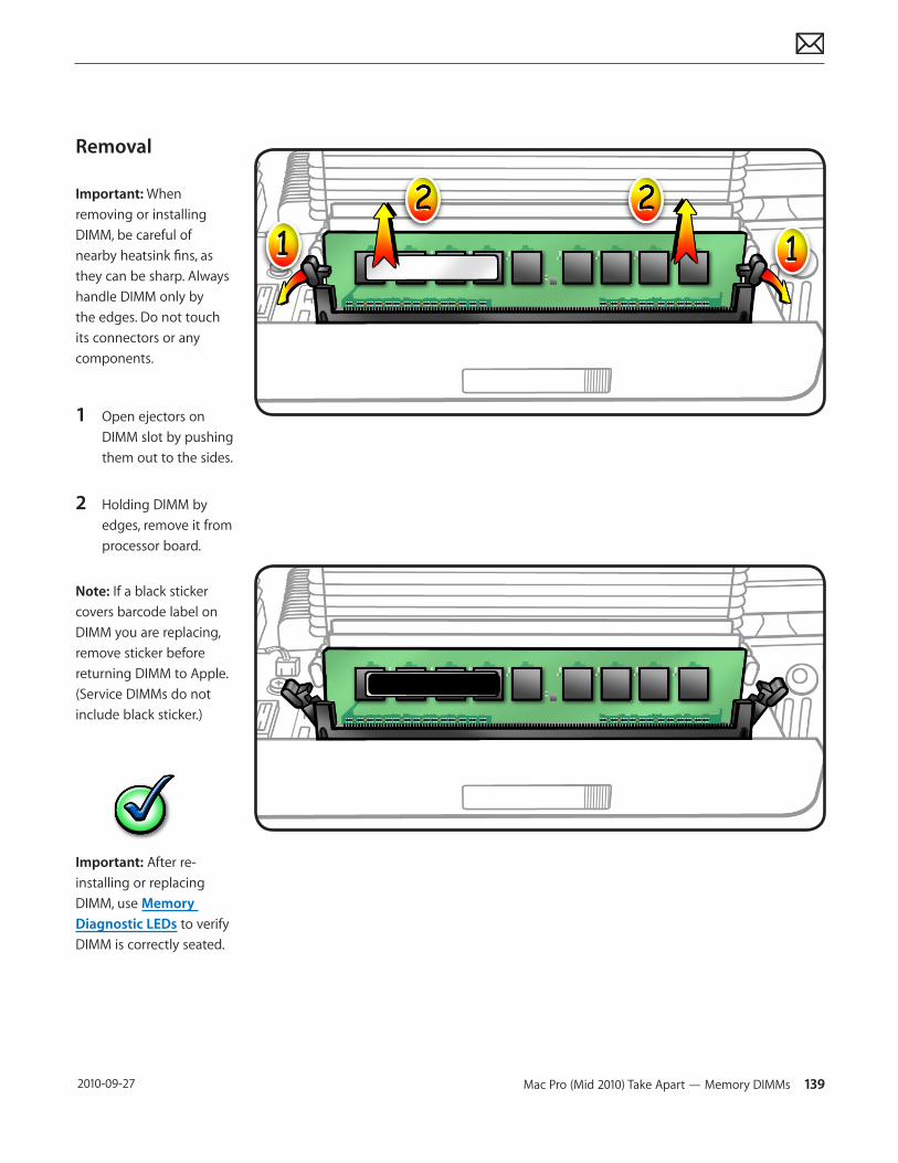
Mac Pro (Mid 2010) Take Apart — Memory DIMMs 139 2010-09-27
Removal
Important: When removing or installing DIMM, be careful of nearby heatsink fins, as they can be sharp. Always handle DIMM only by the edges. Do not touch its connectors or any components.
1 Open ejectors on DIMM slot by pushing them out to the sides.
2 Holding DIMM by edges, remove it from processor board.
Note: If a black sticker covers barcode label on DIMM you are replacing, remove sticker before returning DIMM to Apple. (Service DIMMs do not include black sticker.)
Important: After re-installing or replacing DIMM, use Memory Diagnostic LEDs to verify DIMM is correctly seated.
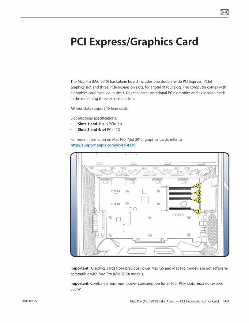
Mac Pro (Mid 2010) Take Apart — PCI Express/Graphics Card 140 2010-09-27
PCI Express/Graphics Card
The Mac Pro (Mid 2010) backplane board includes one double-wide PCI Express (PCIe) graphics slot and three PCIe expansion slots, for a total of four slots. The computer comes with a graphics card installed in slot 1. You can install additional PCIe graphics and expansion cards in the remaining three expansion slots.
All four slots support 16-lane cards.
Slot electrical specifications:• Slots 1 and 2: x16 PCIe 2.0• Slots 3 and 4: x4 PCIe 2.0
For more information on Mac Pro (Mid 2010) graphics cards, refer to http://support.apple.com/kb/HT4279.
Important: Graphics cards from previous Power Mac G5 and Mac Pro models are not software-compatible with Mac Pro (Mid 2010) models.
Important: Combined maximum power consumption for all four PCIe slots must not exceed 300 W.
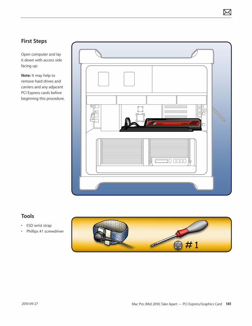
Mac Pro (Mid 2010) Take Apart — PCI Express/Graphics Card 141 2010-09-27
First Steps
Open computer and lay it down with access side facing up:
Note: It may help to remove hard drives and carriers and any adjacent PCI Express cards before beginning this procedure.
Tools
• ESD wrist strap• Phillips #1 screwdriver
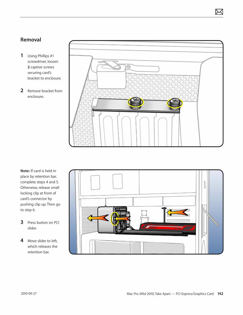
Mac Pro (Mid 2010) Take Apart — PCI Express/Graphics Card 142 2010-09-27
Removal
1 Using Phillips #1 screwdriver, loosen 2 captive screws securing card’s bracket to enclosure.
2 Remove bracket from enclosure.
Note: If card is held in place by retention bar, complete steps 4 and 5. Otherwise, release small locking clip at front of card’s connector by pushing clip up. Then go to step 6.
3 Press button on PCI slider.
4 Move slider to left, which releases the retention bar.
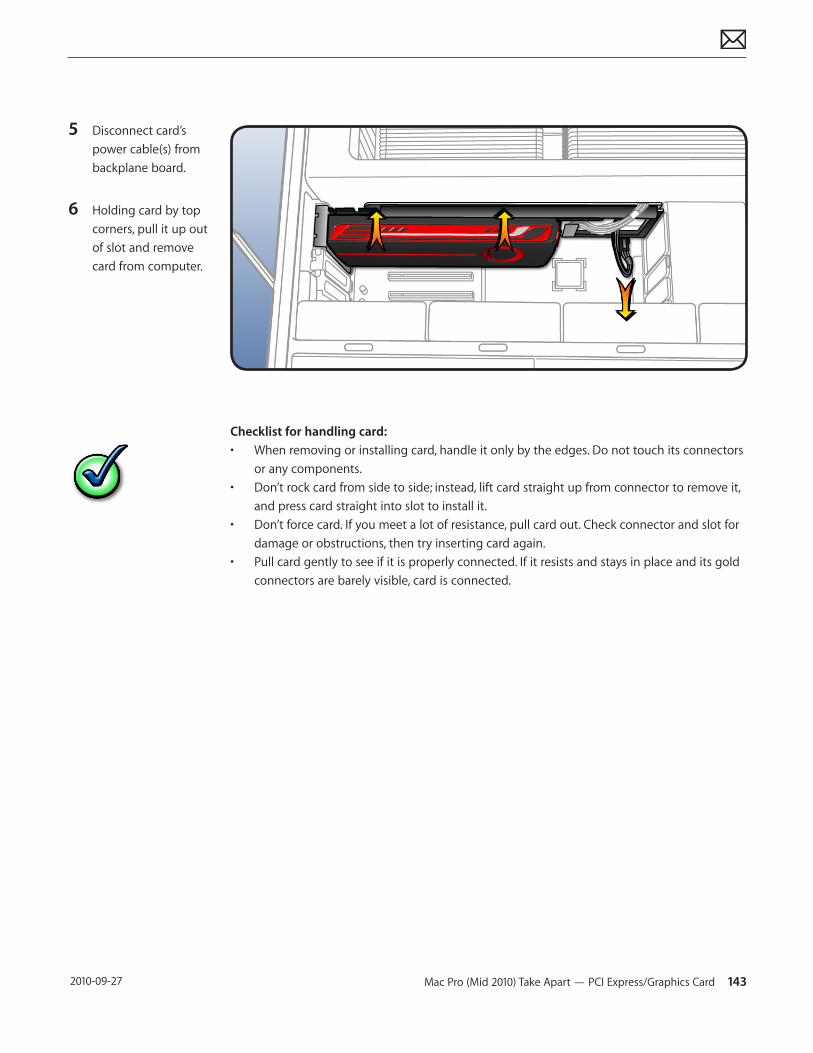
Mac Pro (Mid 2010) Take Apart — PCI Express/Graphics Card 143 2010-09-27
5 Disconnect card’s power cable(s) from backplane board.
6 Holding card by top corners, pull it up out of slot and remove card from computer.
Checklist for handling card:• When removing or installing card, handle it only by the edges. Do not touch its connectors
or any components. • Don’t rock card from side to side; instead, lift card straight up from connector to remove it,
and press card straight into slot to install it. • Don’t force card. If you meet a lot of resistance, pull card out. Check connector and slot for
damage or obstructions, then try inserting card again.• Pull card gently to see if it is properly connected. If it resists and stays in place and its gold
connectors are barely visible, card is connected.
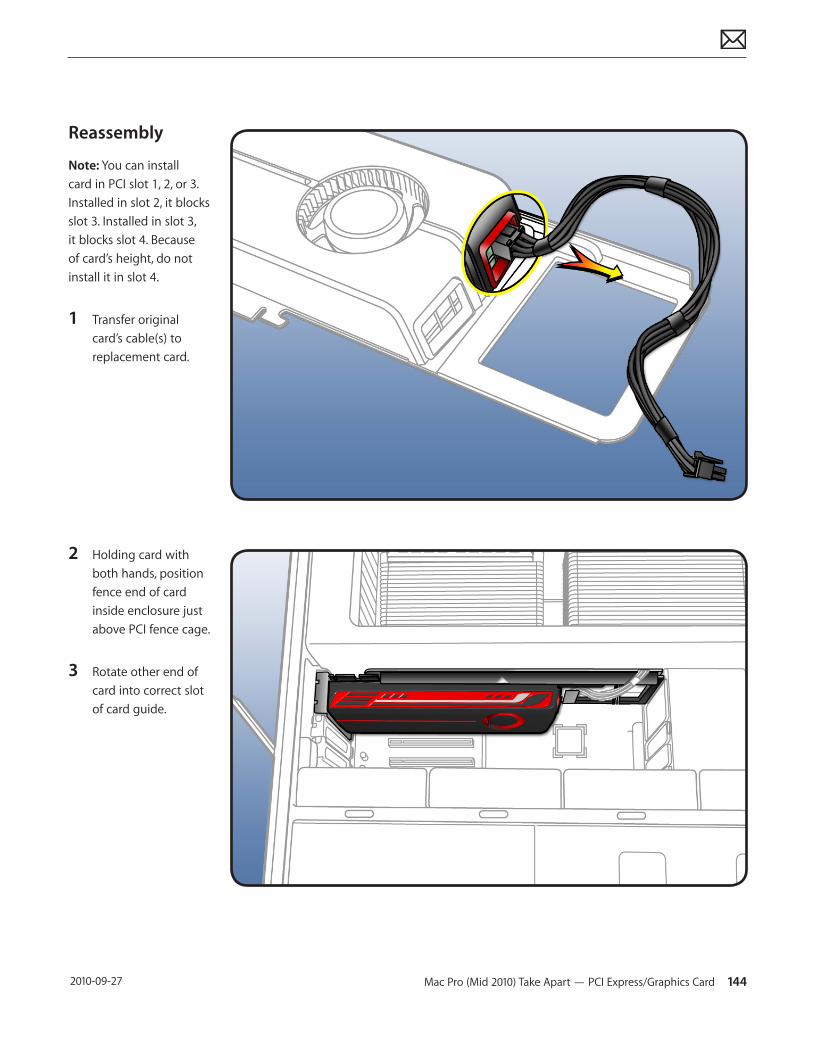
Mac Pro (Mid 2010) Take Apart — PCI Express/Graphics Card 144 2010-09-27
Reassembly
Note: You can install card in PCI slot 1, 2, or 3. Installed in slot 2, it blocks slot 3. Installed in slot 3, it blocks slot 4. Because of card’s height, do not install it in slot 4.
1 Transfer original card’s cable(s) to replacement card.
2 Holding card with both hands, position fence end of card inside enclosure just above PCI fence cage.
3 Rotate other end of card into correct slot of card guide.
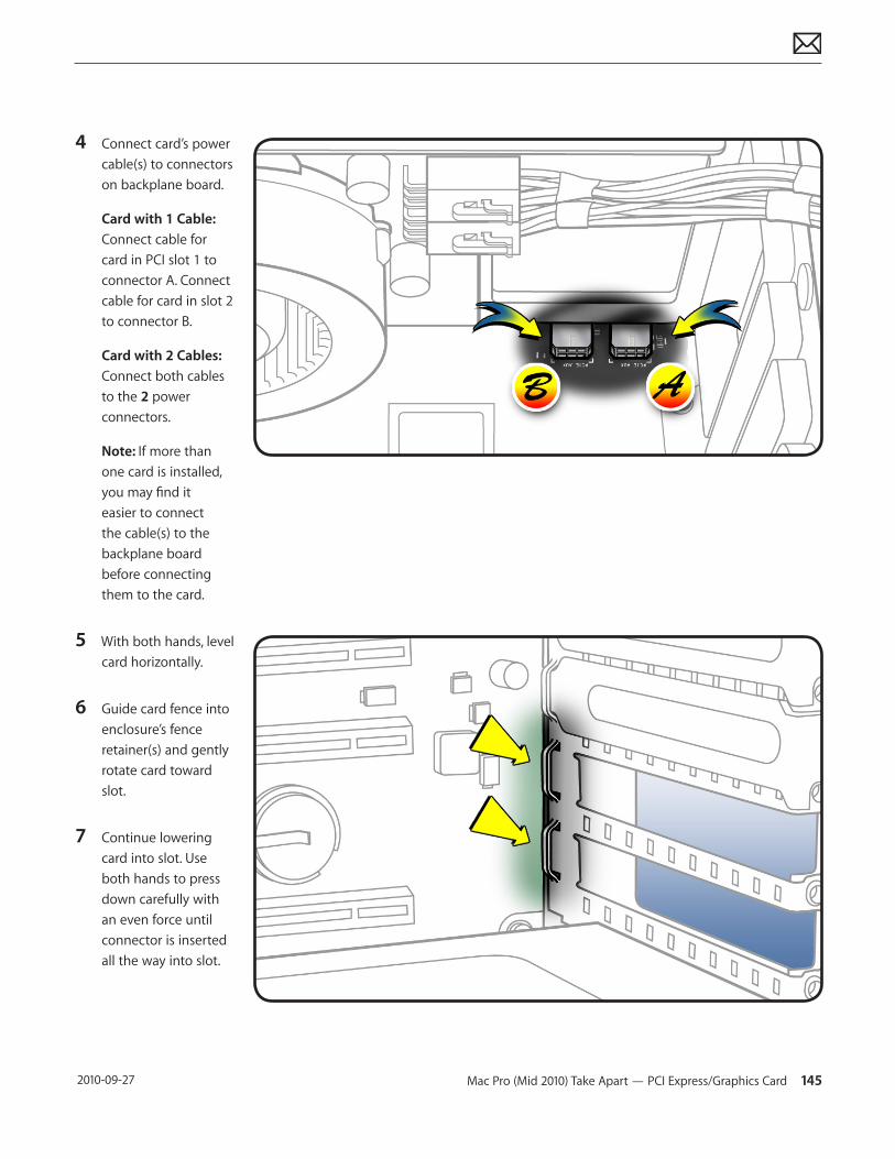
Mac Pro (Mid 2010) Take Apart — PCI Express/Graphics Card 145 2010-09-27
4 Connect card’s power cable(s) to connectors on backplane board.
Card with 1 Cable: Connect cable for card in PCI slot 1 to connector A. Connect cable for card in slot 2 to connector B.
Card with 2 Cables: Connect both cables to the 2 power connectors.
Note: If more than one card is installed, you may find it easier to connect the cable(s) to the backplane board before connecting them to the card.
5 With both hands, level card horizontally.
6 Guide card fence into enclosure’s fence retainer(s) and gently rotate card toward slot.
7 Continue lowering card into slot. Use both hands to press down carefully with an even force until connector is inserted all the way into slot.
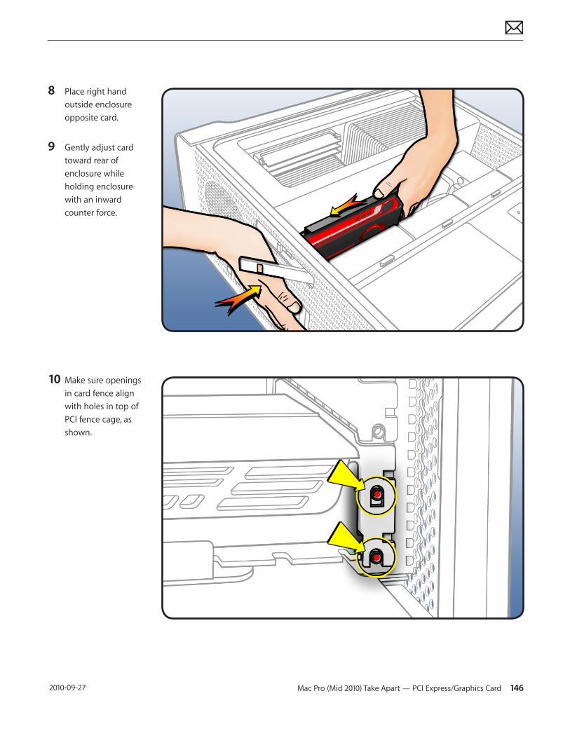
Mac Pro (Mid 2010) Take Apart — PCI Express/Graphics Card 146 2010-09-27
8 Place right hand outside enclosure opposite card.
9 Gently adjust card toward rear of enclosure while holding enclosure with an inward counter force.
10 Make sure openings in card fence align with holes in top of PCI fence cage, as shown.
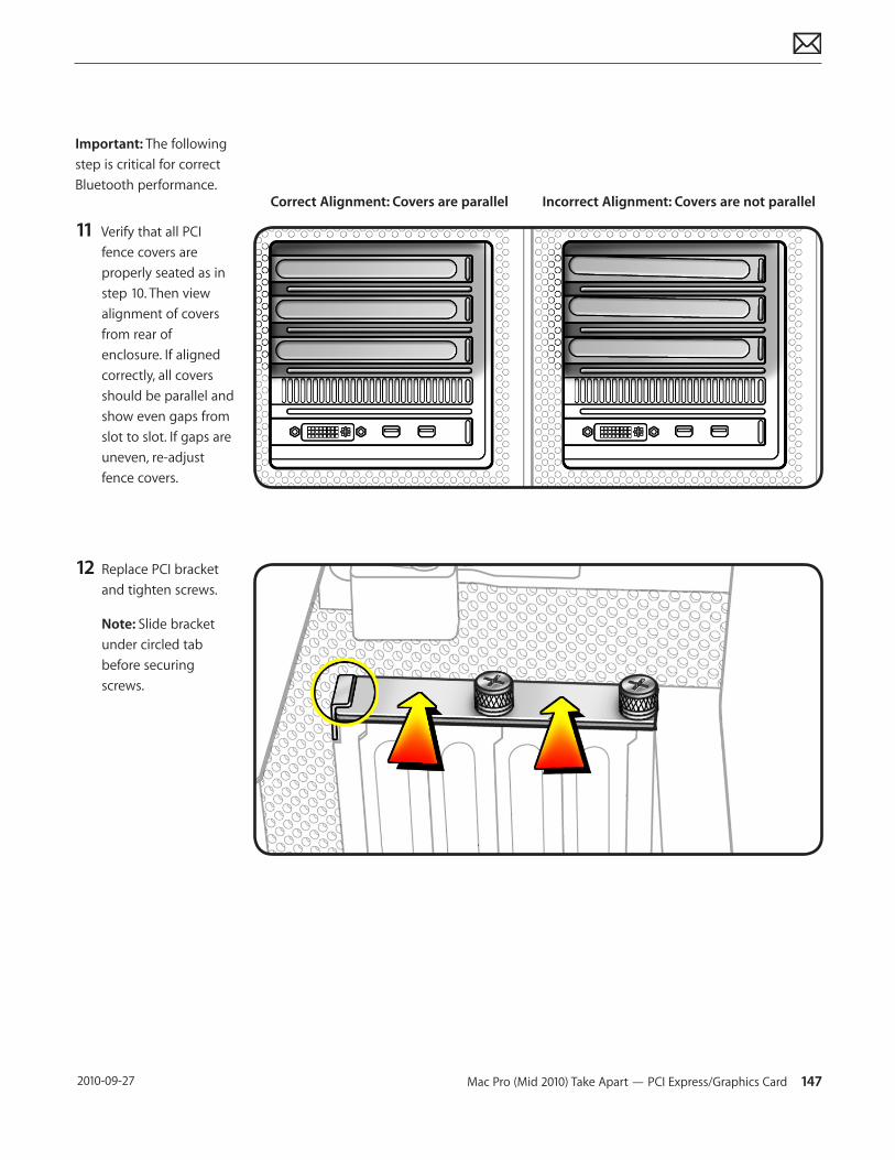
Mac Pro (Mid 2010) Take Apart — PCI Express/Graphics Card 147 2010-09-27
Important: The following step is critical for correct Bluetooth performance.
11 Verify that all PCI fence covers are properly seated as in step 10. Then view alignment of covers from rear of enclosure. If aligned correctly, all covers should be parallel and show even gaps from slot to slot. If gaps are uneven, re-adjust fence covers.
12 Replace PCI bracket and tighten screws.
Note: Slide bracket under circled tab before securing screws.
Correct Alignment: Covers are parallel Incorrect Alignment: Covers are not parallel
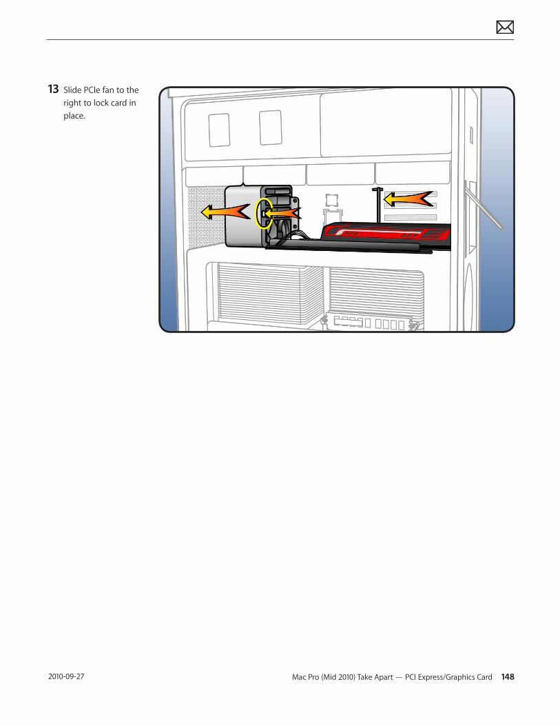
Mac Pro (Mid 2010) Take Apart — PCI Express/Graphics Card 148 2010-09-27
13 Slide PCIe fan to the right to lock card in place.
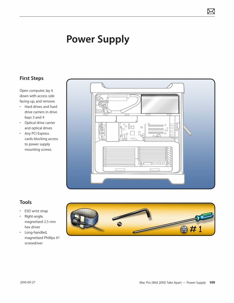
Mac Pro (Mid 2010) Take Apart — Power Supply 149 2010-09-27
First Steps
Open computer, lay it down with access side facing up, and remove:• Hard drives and hard
drive carriers in drive bays 3 and 4
• Optical drive carrier and optical drives
• Any PCI Express cards blocking access to power supply mounting screws
Tools
• ESD wrist strap • RIght-angle,
magnetized 2.5 mm hex driver
• Long-handled, magnetized Phillips #1 screwdriver
Power Supply
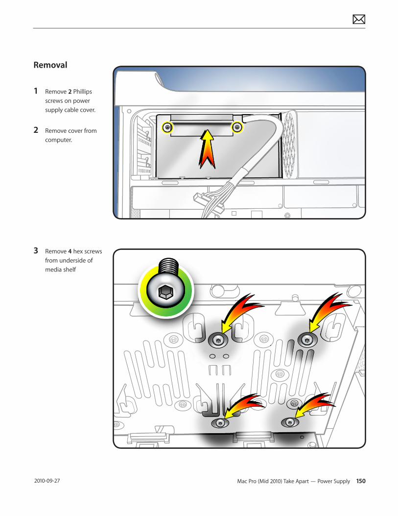
Mac Pro (Mid 2010) Take Apart — Power Supply 150 2010-09-27
Removal
1 Remove 2 Phillips screws on power supply cable cover.
2 Remove cover from computer.
3 Remove 4 hex screws from underside of media shelf
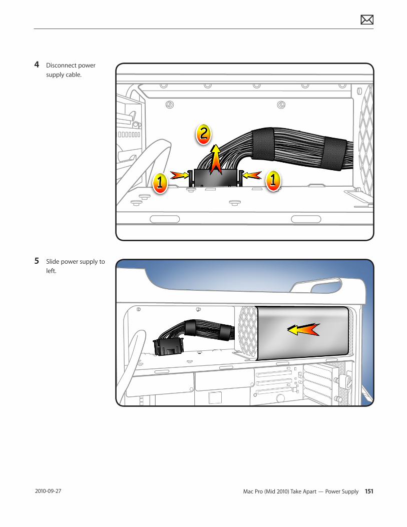
Mac Pro (Mid 2010) Take Apart — Power Supply 151 2010-09-27
4 Disconnect power supply cable.
5 Slide power supply to left.
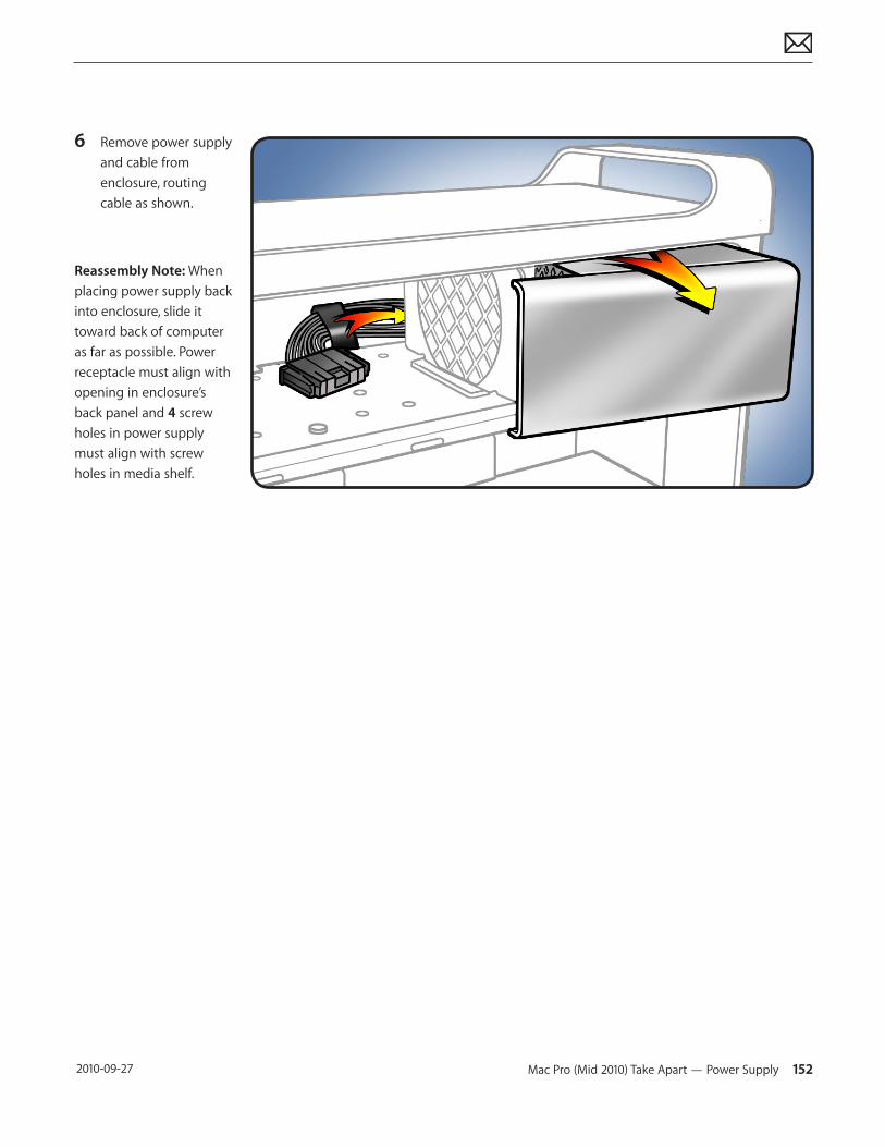
Mac Pro (Mid 2010) Take Apart — Power Supply 152 2010-09-27
6 Remove power supply and cable from enclosure, routing cable as shown.
Reassembly Note: When placing power supply back into enclosure, slide it toward back of computer as far as possible. Power receptacle must align with opening in enclosure’s back panel and 4 screw holes in power supply must align with screw holes in media shelf.
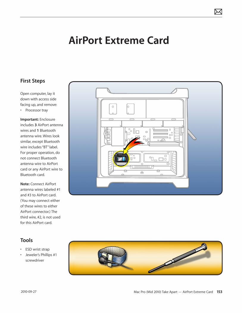
Mac Pro (Mid 2010) Take Apart — AirPort Extreme Card 153 2010-09-27
First Steps
Open computer, lay it down with access side facing up, and remove:• Processor tray
Important: Enclosure includes 3 AirPort antenna wires and 1 Bluetooth antenna wire. Wires look similar, except Bluetooth wire includes “BT” label. For proper operation, do not connect Bluetooth antenna wire to AirPort card or any AirPort wire to Bluetooth card.
Note: Connect AirPort antenna wires labeled #1 and #3 to AirPort card. (You may connect either of these wires to either AirPort connector.) The third wire, #2, is not used for this AirPort card.
Tools
• ESD wrist strap• Jeweler’s Phillips #1
screwdriver
AirPort Extreme Card
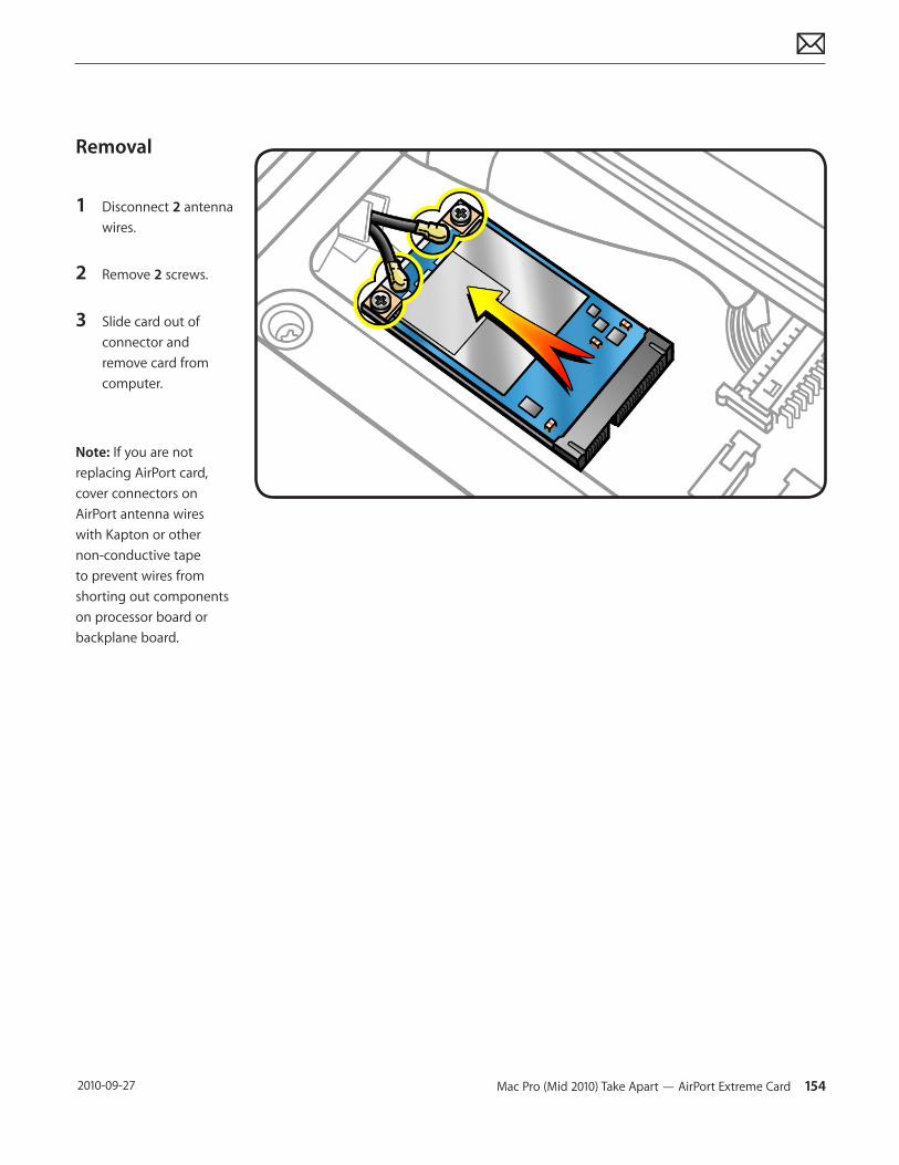
Mac Pro (Mid 2010) Take Apart — AirPort Extreme Card 154 2010-09-27
Removal
1 Disconnect 2 antenna wires.
2 Remove 2 screws.
3 Slide card out of connector and remove card from computer.
Note: If you are not replacing AirPort card, cover connectors on AirPort antenna wires with Kapton or other non-conductive tape to prevent wires from shorting out components on processor board or backplane board.
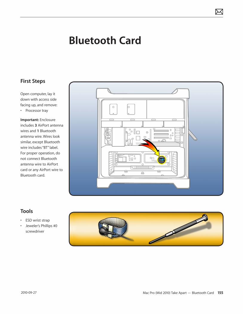
Mac Pro (Mid 2010) Take Apart — Bluetooth Card 155 2010-09-27
First Steps
Open computer, lay it down with access side facing up, and remove:• Processor tray
Important: Enclosure includes 3 AirPort antenna wires and 1 Bluetooth antenna wire. Wires look similar, except Bluetooth wire includes “BT” label. For proper operation, do not connect Bluetooth antenna wire to AirPort card or any AirPort wire to Bluetooth card.
Tools
• ESD wrist strap• Jeweler’s Phillips #0
screwdriver
Bluetooth Card
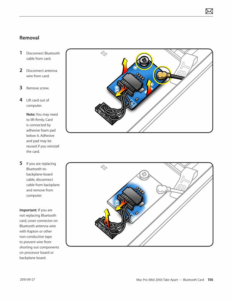
Mac Pro (Mid 2010) Take Apart — Bluetooth Card 156 2010-09-27
Removal
1 Disconnect Bluetooth cable from card.
2 Disconnect antenna wire from card.
3 Remove screw.
4 Lift card out of computer.
Note: You may need to lift firmly. Card is connected by adhesive foam pad below it. Adhesive and pad may be reused if you reinstall the card.
5 If you are replacing Bluetooth-to-backplane-board cable, disconnect cable from backplane and remove from computer.
Important: If you are not replacing Bluetooth card, cover connector on Bluetooth antenna wire with Kapton or other non-conductive tape to prevent wire from shorting out components on processor board or backplane board.
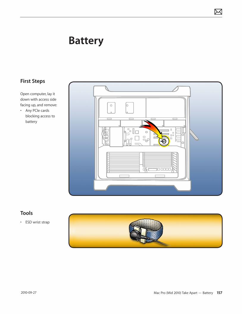
Mac Pro (Mid 2010) Take Apart — Battery 157 2010-09-27
First Steps
Open computer, lay it down with access side facing up, and remove:• Any PCIe cards
blocking access to battery
Tools
• ESD wrist strap
Battery
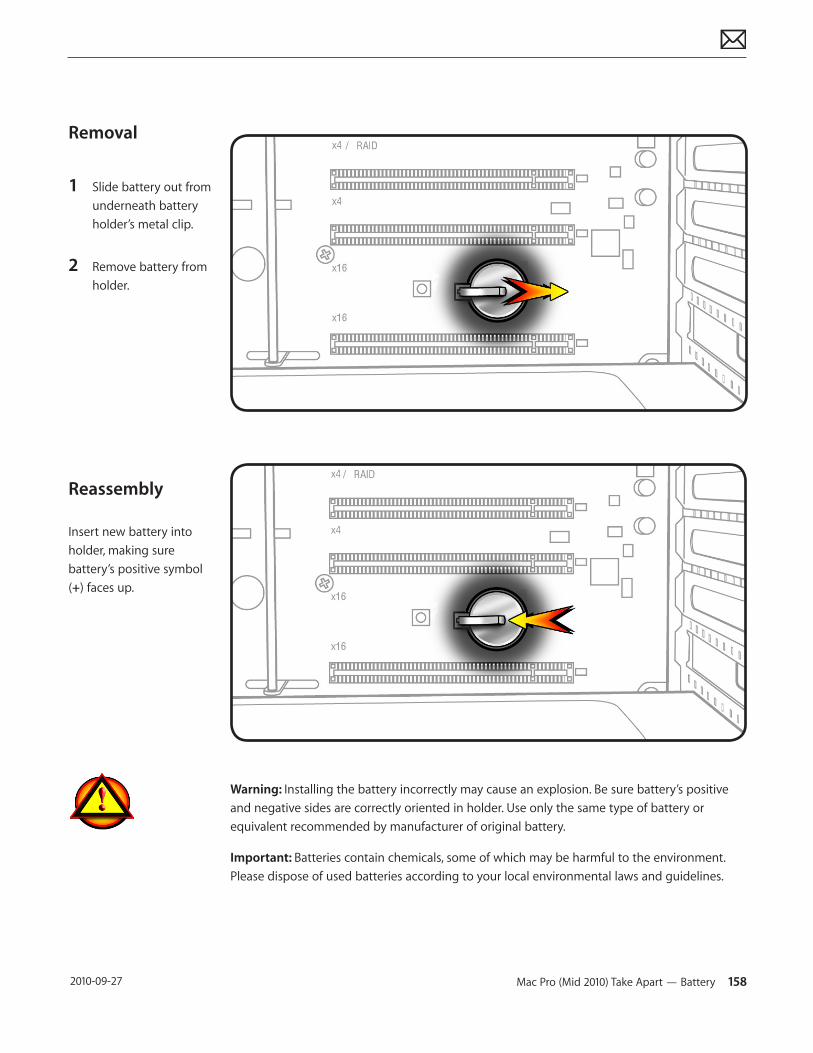
Mac Pro (Mid 2010) Take Apart — Battery 158 2010-09-27
Removal
1 Slide battery out from underneath battery holder’s metal clip.
2 Remove battery from holder.
Reassembly
Insert new battery into holder, making sure battery’s positive symbol (+) faces up.
Warning: Installing the battery incorrectly may cause an explosion. Be sure battery’s positive and negative sides are correctly oriented in holder. Use only the same type of battery or equivalent recommended by manufacturer of original battery.
Important: Batteries contain chemicals, some of which may be harmful to the environment. Please dispose of used batteries according to your local environmental laws and guidelines.
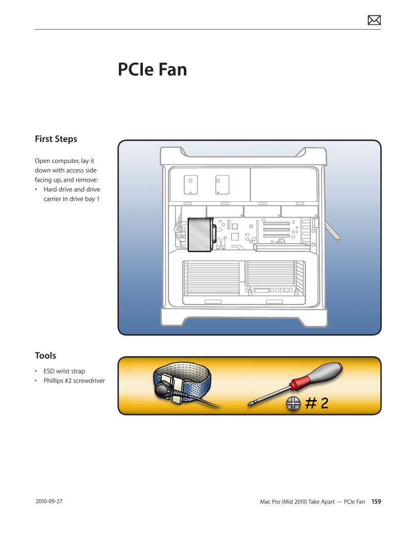
Mac Pro (Mid 2010) Take Apart — PCIe Fan 159 2010-09-27
First Steps
Open computer, lay it down with access side facing up, and remove:• Hard drive and drive
carrier in drive bay 1
Tools
• ESD wrist strap• Phillips #2 screwdriver
PCIe Fan
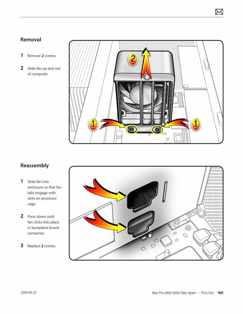
Mac Pro (Mid 2010) Take Apart — PCIe Fan 160 2010-09-27
Removal
1 Remove 2 screws.
2 Slide fan up and out of computer.
Reassembly
1 Slide fan into enclosure so that fan tabs engage with slots on processor cage.
2 Press down until fan clicks into place in backplane board connector.
3 Replace 2 screws.
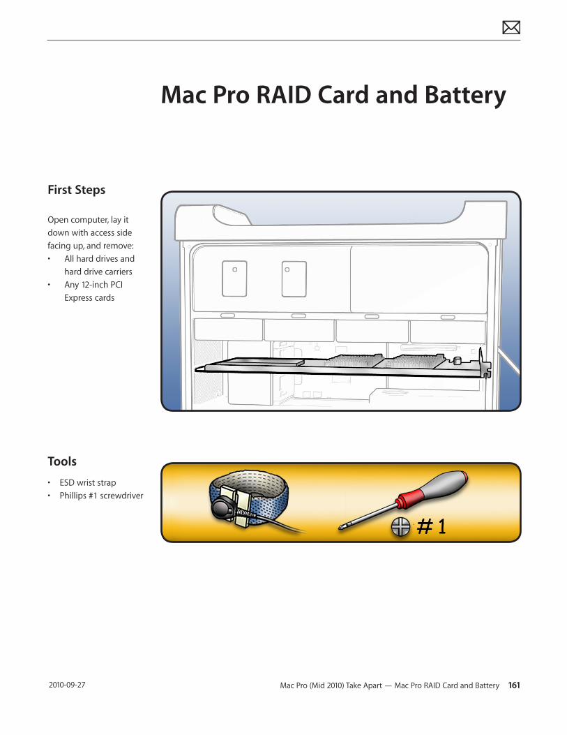
Mac Pro (Mid 2010) Take Apart — Mac Pro RAID Card and Battery 161 2010-09-27
First Steps
Open computer, lay it down with access side facing up, and remove:• All hard drives and
hard drive carriers• Any 12-inch PCI
Express cards
Tools
• ESD wrist strap• Phillips #1 screwdriver
Mac Pro RAID Card and Battery
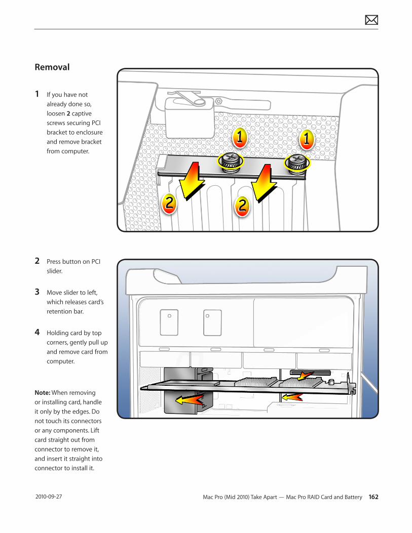
Mac Pro (Mid 2010) Take Apart — Mac Pro RAID Card and Battery 162 2010-09-27
Removal
1 If you have not already done so, loosen 2 captive screws securing PCI bracket to enclosure and remove bracket from computer.
2 Press button on PCI slider.
3 Move slider to left, which releases card’s retention bar.
4 Holding card by top corners, gently pull up and remove card from computer.
Note: When removing or installing card, handle it only by the edges. Do not touch its connectors or any components. Lift card straight out from connector to remove it, and insert it straight into connector to install it.
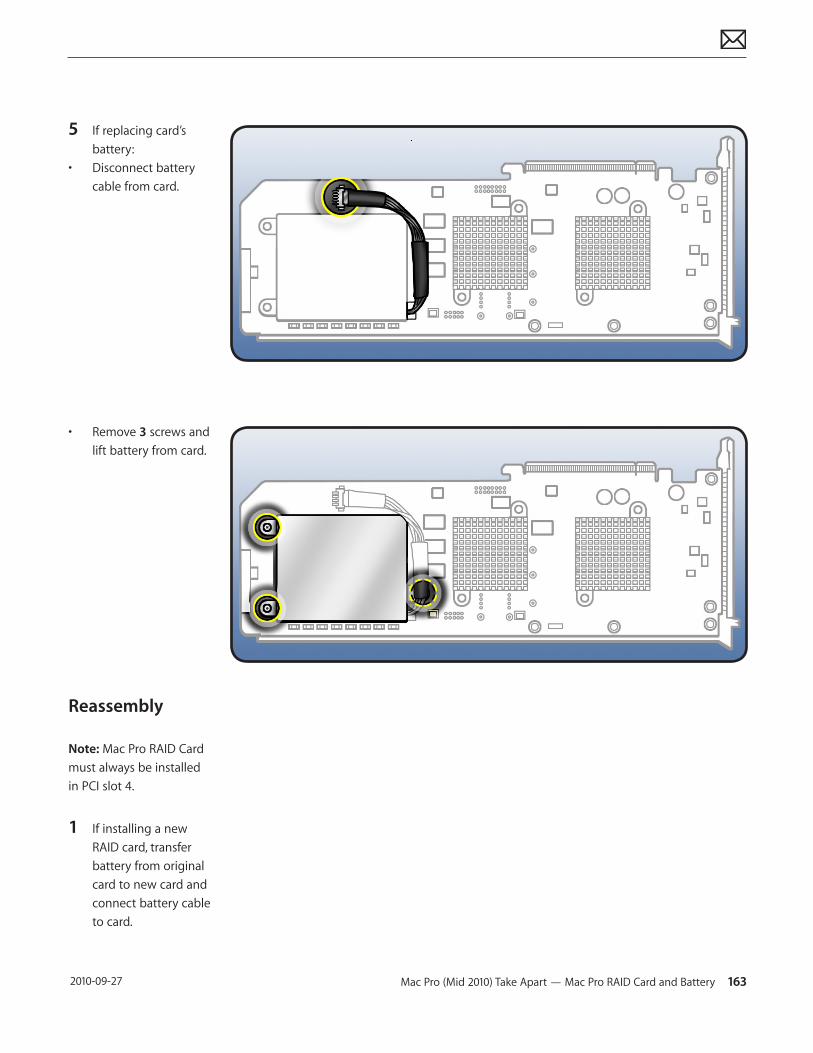
Mac Pro (Mid 2010) Take Apart — Mac Pro RAID Card and Battery 163 2010-09-27
5 If replacing card’s battery:
• Disconnect battery cable from card.
• Remove 3 screws and lift battery from card.
Reassembly
Note: Mac Pro RAID Card must always be installed in PCI slot 4.
1 If installing a new RAID card, transfer battery from original card to new card and connect battery cable to card.
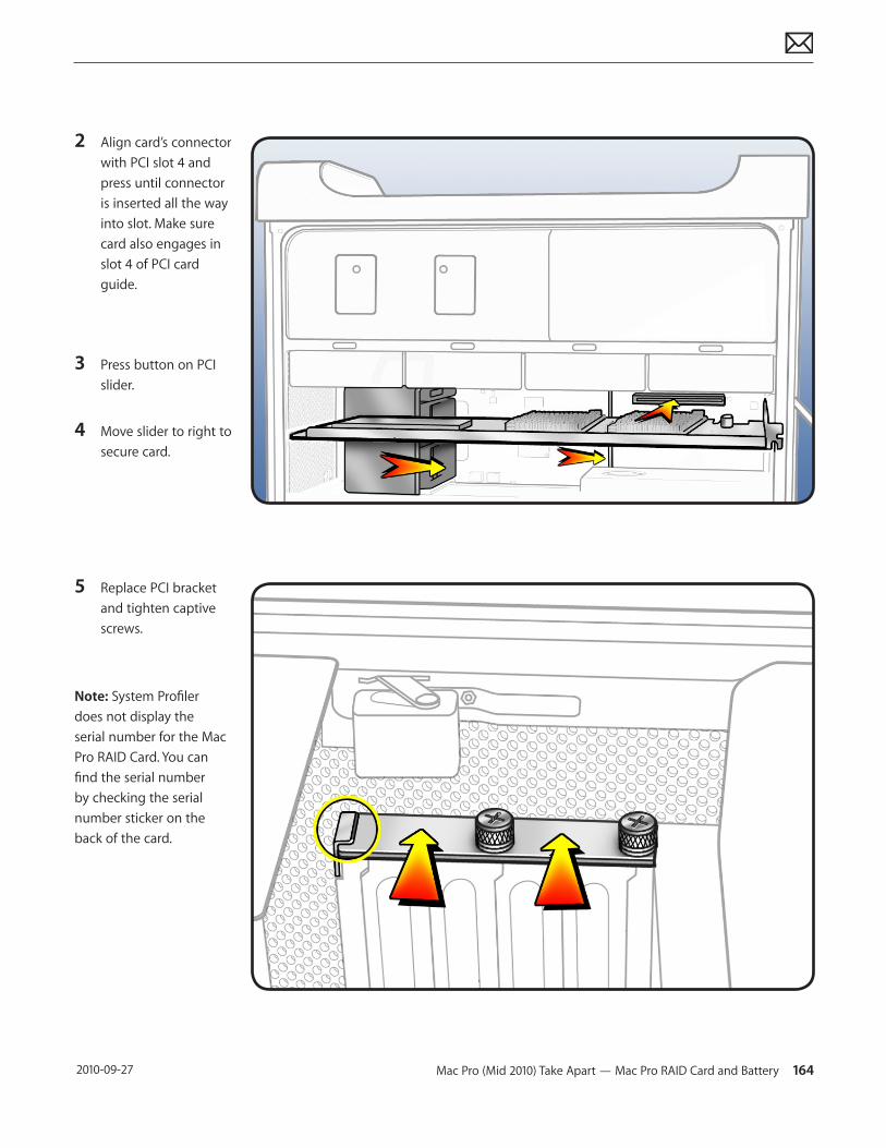
Mac Pro (Mid 2010) Take Apart — Mac Pro RAID Card and Battery 164 2010-09-27
2 Align card’s connector with PCI slot 4 and press until connector is inserted all the way into slot. Make sure card also engages in slot 4 of PCI card guide.
3 Press button on PCI slider.
4 Move slider to right to secure card.
5 Replace PCI bracket and tighten captive screws.
Note: System Profiler does not display the serial number for the Mac Pro RAID Card. You can find the serial number by checking the serial number sticker on the back of the card.
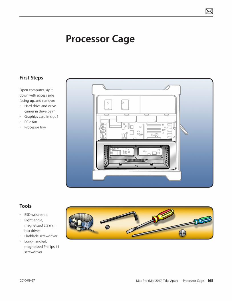
Mac Pro (Mid 2010) Take Apart — Processor Cage 165 2010-09-27
First Steps
Open computer, lay it down with access side facing up, and remove:• Hard drive and drive
carrier in drive bay 1• Graphics card in slot 1• PCIe fan• Processor tray
Tools
• ESD wrist strap • RIght-angle,
magnetized 2.5 mm hex driver
• Flatblade screwdriver• Long-handled,
magnetized Phillips #1 screwdriver
Processor Cage
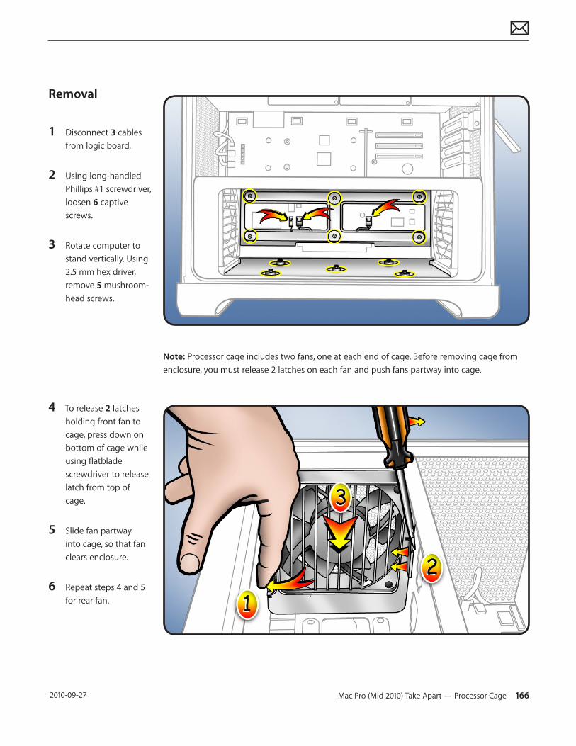
Mac Pro (Mid 2010) Take Apart — Processor Cage 166 2010-09-27
Removal
1 Disconnect 3 cables from logic board.
2 Using long-handled Phillips #1 screwdriver, loosen 6 captive screws.
3 Rotate computer to stand vertically. Using 2.5 mm hex driver, remove 5 mushroom-head screws.
4 To release 2 latches holding front fan to cage, press down on bottom of cage while using flatblade screwdriver to release latch from top of cage.
5 Slide fan partway into cage, so that fan clears enclosure.
6 Repeat steps 4 and 5 for rear fan.
Note: Processor cage includes two fans, one at each end of cage. Before removing cage from enclosure, you must release 2 latches on each fan and push fans partway into cage.
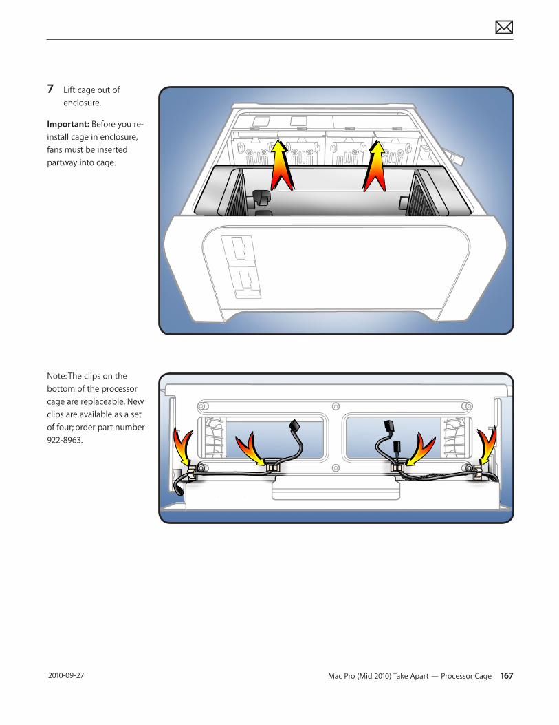
Mac Pro (Mid 2010) Take Apart — Processor Cage 167 2010-09-27
7 Lift cage out of enclosure.
Important: Before you re-install cage in enclosure, fans must be inserted partway into cage.
Note: The clips on the bottom of the processor cage are replaceable. New clips are available as a set of four; order part number 922-8963.
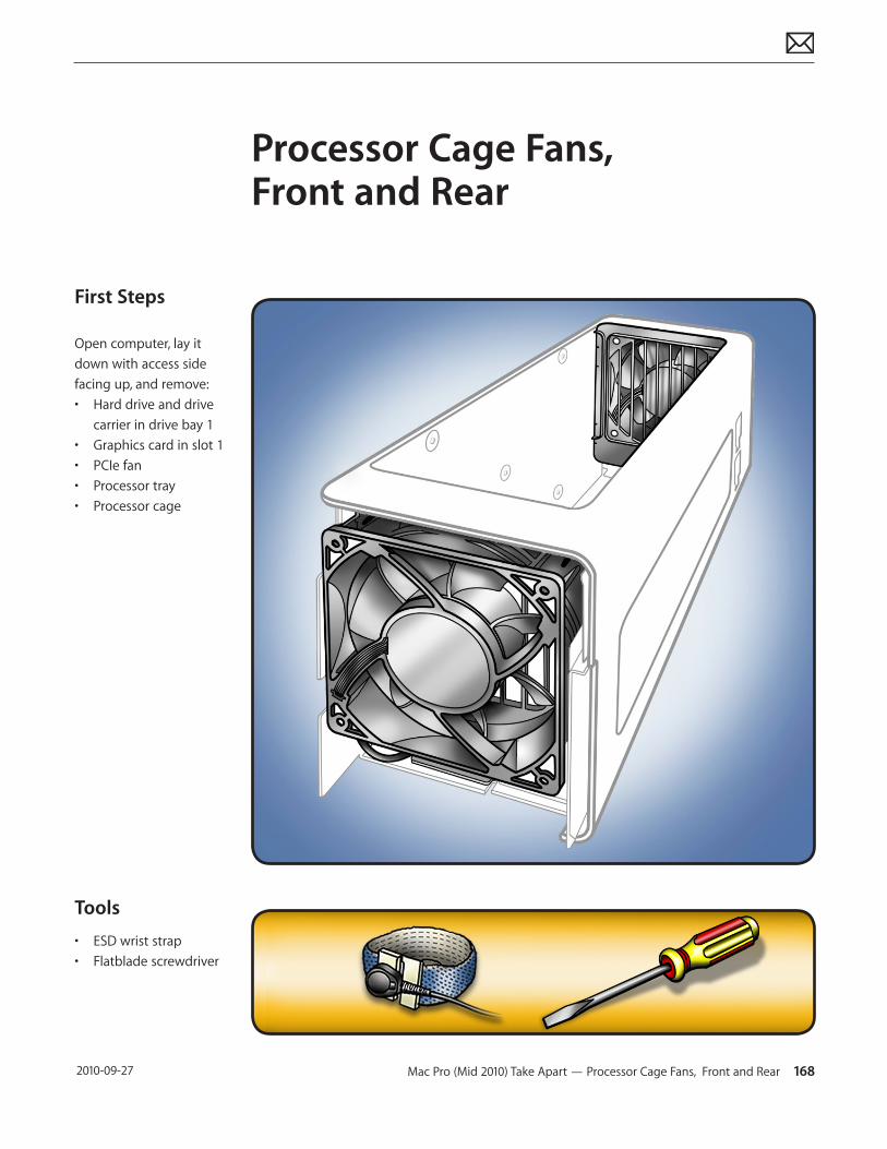
Mac Pro (Mid 2010) Take Apart — Processor Cage Fans, Front and Rear 168 2010-09-27
First Steps
Open computer, lay it down with access side facing up, and remove:• Hard drive and drive
carrier in drive bay 1• Graphics card in slot 1• PCIe fan• Processor tray• Processor cage
Tools
• ESD wrist strap• Flatblade screwdriver
Processor Cage Fans, Front and Rear
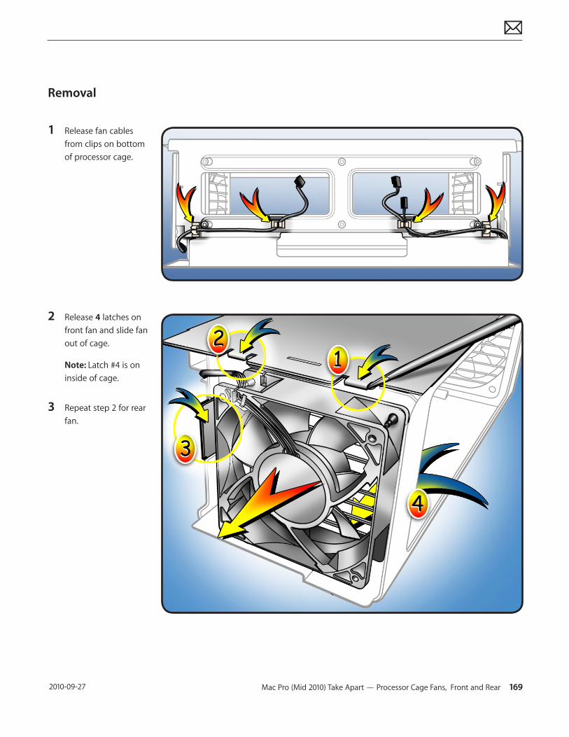
Mac Pro (Mid 2010) Take Apart — Processor Cage Fans, Front and Rear 169 2010-09-27
Removal
1 Release fan cables from clips on bottom of processor cage.
2 Release 4 latches on front fan and slide fan out of cage.
Note: Latch #4 is on inside of cage.
3 Repeat step 2 for rear fan.
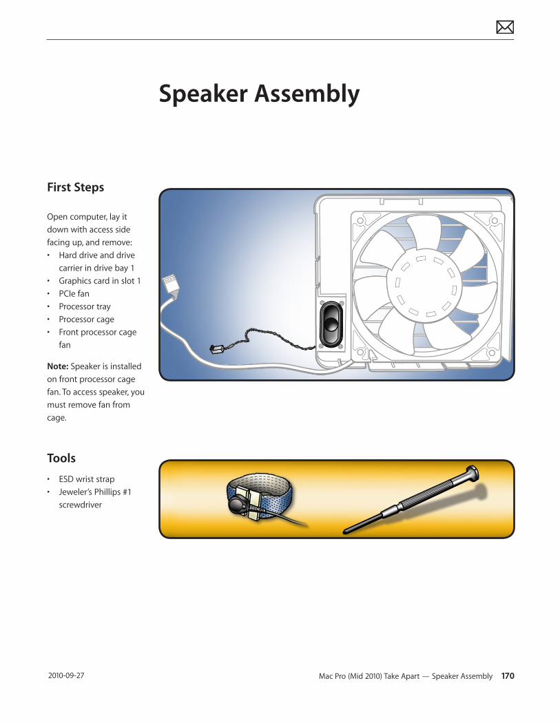
Mac Pro (Mid 2010) Take Apart — Speaker Assembly 170 2010-09-27
First Steps
Open computer, lay it down with access side facing up, and remove:• Hard drive and drive
carrier in drive bay 1• Graphics card in slot 1• PCIe fan• Processor tray• Processor cage• Front processor cage
fan
Note: Speaker is installed on front processor cage fan. To access speaker, you must remove fan from cage.
Tools
• ESD wrist strap• Jeweler’s Phillips #1
screwdriver
Speaker Assembly
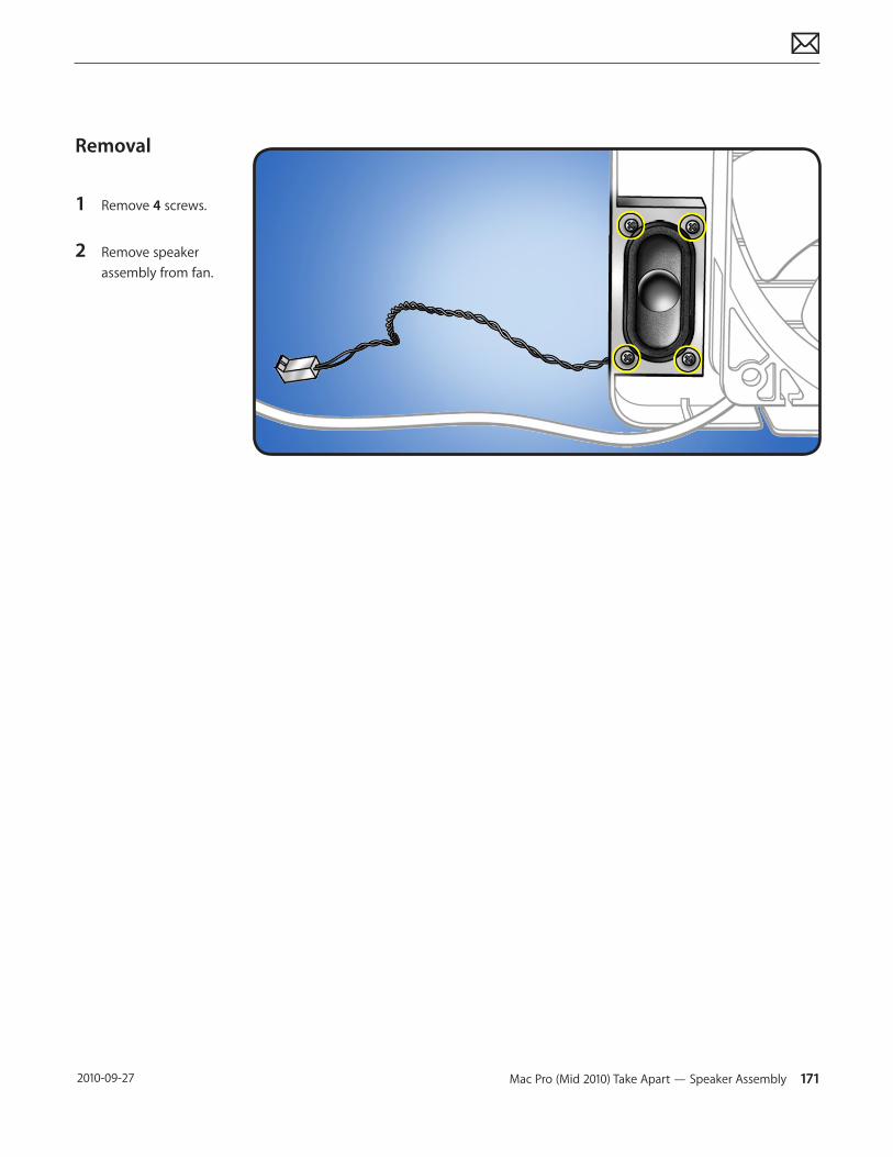
Mac Pro (Mid 2010) Take Apart — Speaker Assembly 171 2010-09-27
Removal
1 Remove 4 screws.
2 Remove speaker assembly from fan.
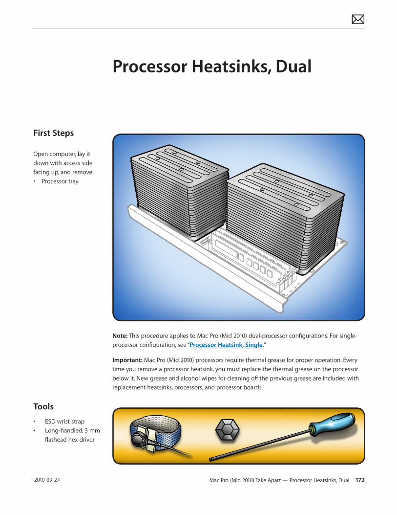
Mac Pro (Mid 2010) Take Apart — Processor Heatsinks, Dual 172 2010-09-27
First Steps
Open computer, lay it down with access side facing up, and remove:• Processor tray
Tools
• ESD wrist strap• Long-handled, 3 mm
flathead hex driver
Processor Heatsinks, Dual
Note: This procedure applies to Mac Pro (Mid 2010) dual-processor configurations. For single-processor configuration, see “Processor Heatsink, Single.”
Important: Mac Pro (Mid 2010) processors require thermal grease for proper operation. Every time you remove a processor heatsink, you must replace the thermal grease on the processor below it. New grease and alcohol wipes for cleaning off the previous grease are included with replacement heatsinks, processors, and processor boards.
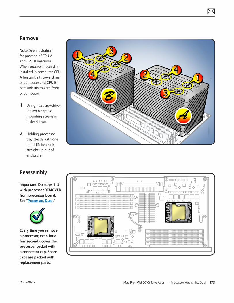
Mac Pro (Mid 2010) Take Apart — Processor Heatsinks, Dual 173 2010-09-27
Removal
Note: See illustration for position of CPU A and CPU B heatsinks. When processor board is installed in computer, CPU A heatsink sits toward rear of computer and CPU B heatsink sits toward front of computer.
1 Using hex screwdriver, loosen 4 captive mounting screws in order shown.
2 Holding processor tray steady with one hand, lift heatsink straight up out of enclosure.
Reassembly
Important: Do steps 1–3 with processor REMOVED from processor board. See “Processor, Dual.”
Every time you remove a processor, even for a few seconds, cover the processor socket with a connector cap. Spare caps are packed with replacement parts.
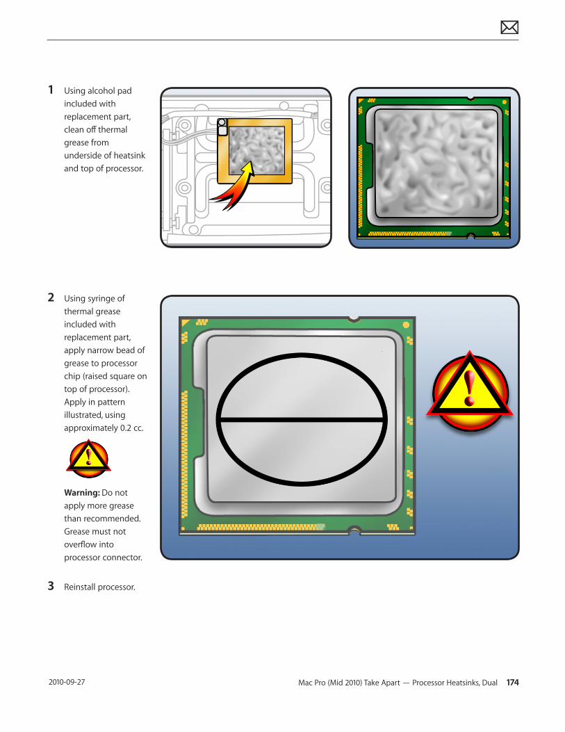
Mac Pro (Mid 2010) Take Apart — Processor Heatsinks, Dual 174 2010-09-27
1 Using alcohol pad included with replacement part, clean off thermal grease from underside of heatsink and top of processor.
2 Using syringe of thermal grease included with replacement part, apply narrow bead of grease to processor chip (raised square on top of processor). Apply in pattern illustrated, using approximately 0.2 cc.
Warning: Do not apply more grease than recommended. Grease must not overflow into processor connector.
3 Reinstall processor.
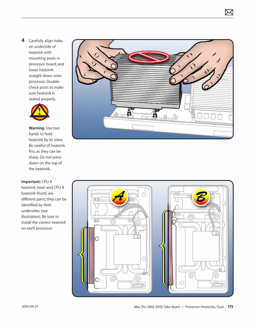
Mac Pro (Mid 2010) Take Apart — Processor Heatsinks, Dual 175 2010-09-27
4 Carefully align holes on underside of heatsink with mounting posts in processor board, and lower heatsink straight down onto processor. Double-check posts to make sure heatsink is seated properly.
Warning: Use two hands to hold heatsink by its sides. Be careful of heatsink fins, as they can be sharp. Do not press down on the top of the heatsink.
Important: CPU A heatsink (rear) and CPU B heatsink (front) are different parts; they can be identified by their undersides (see illustration). Be sure to install the correct heatsink on each processor.
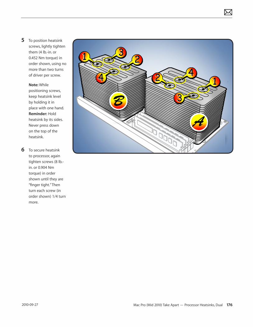
Mac Pro (Mid 2010) Take Apart — Processor Heatsinks, Dual 176 2010-09-27
5 To position heatsink screws, lightly tighten them (4 lb.-in. or 0.452 Nm torque) in order shown, using no more than two turns of driver per screw.
Note: While positioning screws, keep heatsink level by holding it in place with one hand. Reminder: Hold heatsink by its sides. Never press down on the top of the heatsink.
6 To secure heatsink to processor, again tighten screws (8 lb.- in. or 0.904 Nm torque) in order shown until they are “finger tight.” Then turn each screw (in order shown) 1/4 turn more.
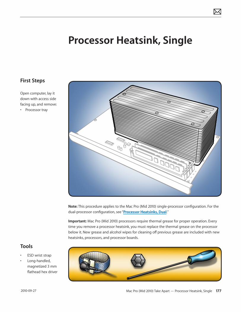
Mac Pro (Mid 2010) Take Apart — Processor Heatsink, Single 177 2010-09-27
First Steps
Open computer, lay it down with access side facing up, and remove:• Processor tray
Tools
• ESD wrist strap• Long-handled,
magnetized 3 mm flathead hex driver
Processor Heatsink, Single
Note: This procedure applies to the Mac Pro (Mid 2010) single-processor configuration. For the dual-processor configuration, see “Processor Heatsinks, Dual.”
Important: Mac Pro (Mid 2010) processors require thermal grease for proper operation. Every time you remove a processor heatsink, you must replace the thermal grease on the processor below it. New grease and alcohol wipes for cleaning off previous grease are included with new heatsinks, processors, and processor boards.
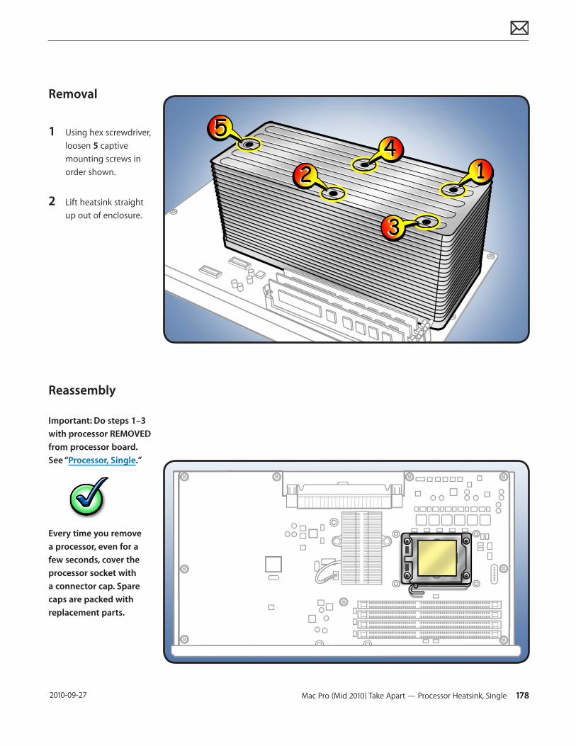
Mac Pro (Mid 2010) Take Apart — Processor Heatsink, Single 178 2010-09-27
Removal
1 Using hex screwdriver, loosen 5 captive mounting screws in order shown.
2 Lift heatsink straight up out of enclosure.
Reassembly
Important: Do steps 1–3 with processor REMOVED from processor board. See “Processor, Single.”
Every time you remove a processor, even for a few seconds, cover the processor socket with a connector cap. Spare caps are packed with replacement parts.
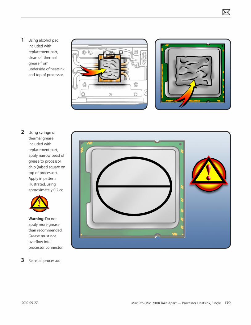
Mac Pro (Mid 2010) Take Apart — Processor Heatsink, Single 179 2010-09-27
1 Using alcohol pad included with replacement part, clean off thermal grease from underside of heatsink and top of processor.
2 Using syringe of thermal grease included with replacement part, apply narrow bead of grease to processor chip (raised square on top of processor). Apply in pattern illustrated, using approximately 0.2 cc.
Warning: Do not apply more grease than recommended. Grease must not overflow into processor connector.
3 Reinstall processor.
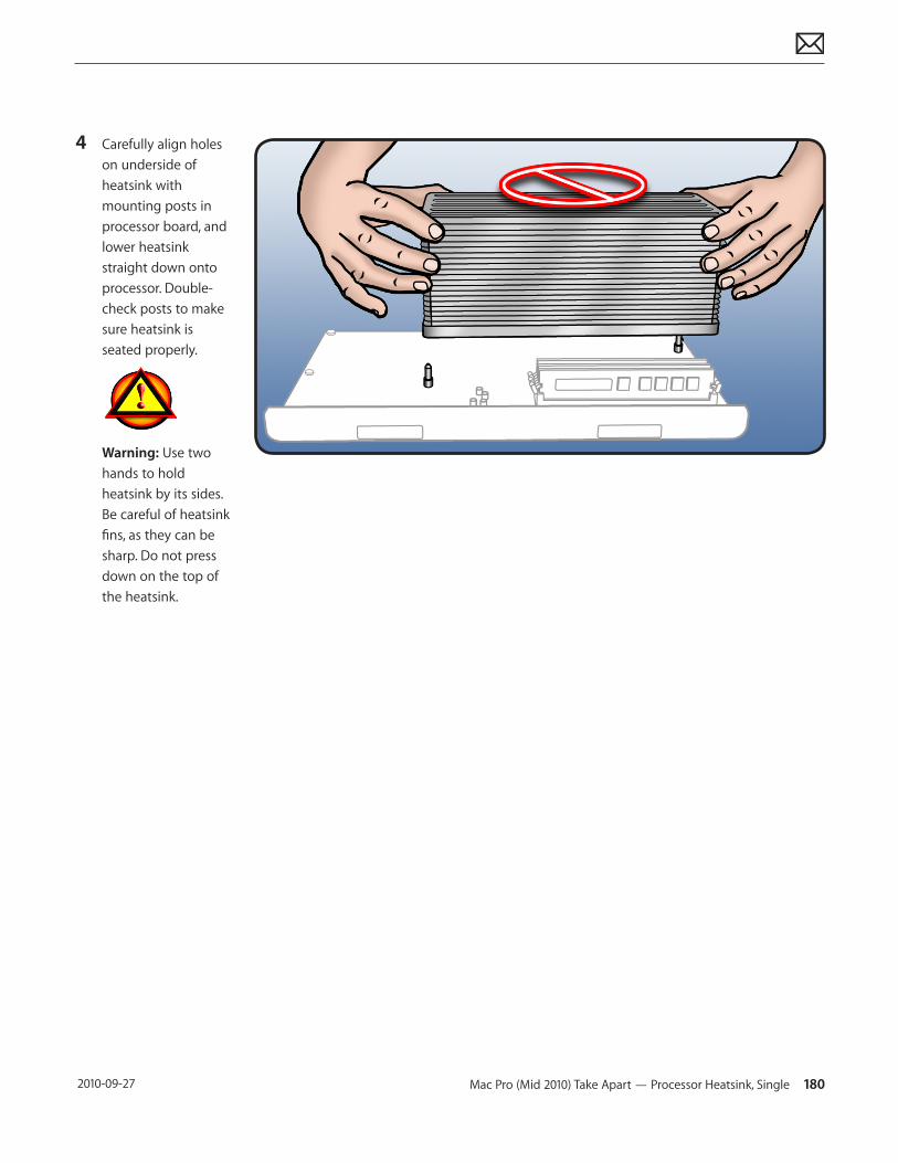
Mac Pro (Mid 2010) Take Apart — Processor Heatsink, Single 180 2010-09-27
4 Carefully align holes on underside of heatsink with mounting posts in processor board, and lower heatsink straight down onto processor. Double-check posts to make sure heatsink is seated properly.
Warning: Use two hands to hold heatsink by its sides. Be careful of heatsink fins, as they can be sharp. Do not press down on the top of the heatsink.
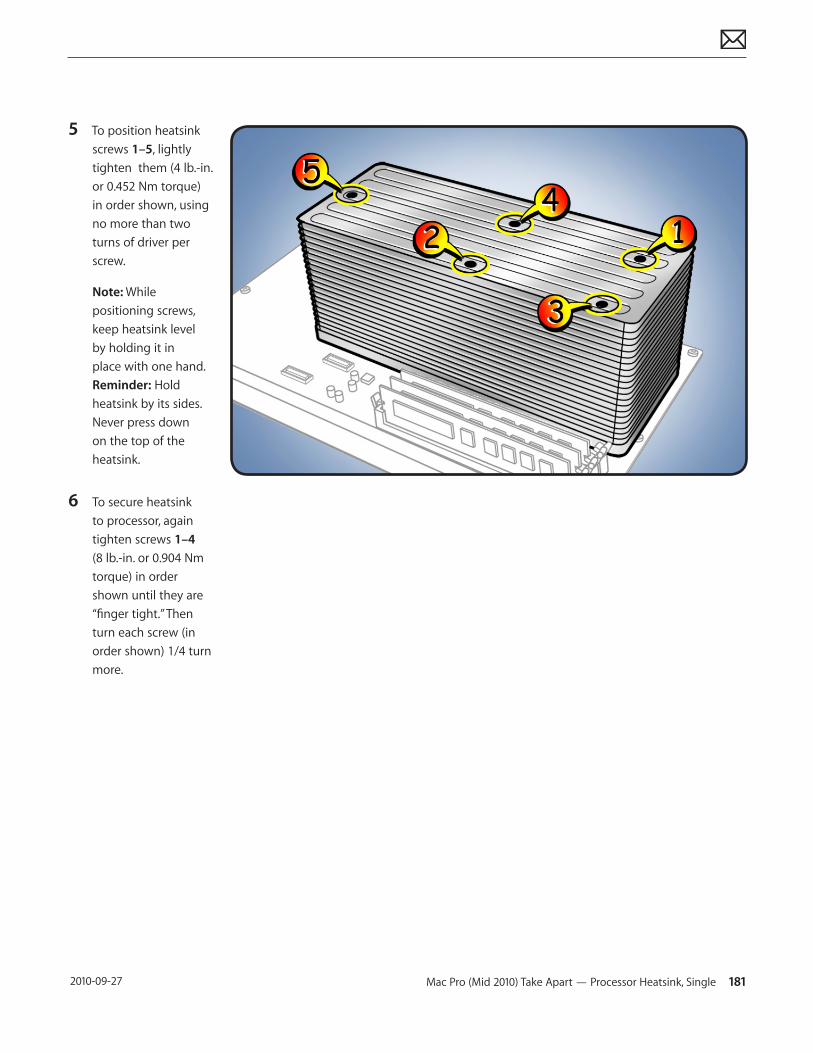
Mac Pro (Mid 2010) Take Apart — Processor Heatsink, Single 181 2010-09-27
5 To position heatsink screws 1–5, lightly tighten them (4 lb.-in. or 0.452 Nm torque) in order shown, using no more than two turns of driver per screw.
Note: While positioning screws, keep heatsink level by holding it in place with one hand. Reminder: Hold heatsink by its sides. Never press down on the top of the heatsink.
6 To secure heatsink to processor, again tighten screws 1–4 (8 lb.-in. or 0.904 Nm torque) in order shown until they are “finger tight.” Then turn each screw (in order shown) 1/4 turn more.
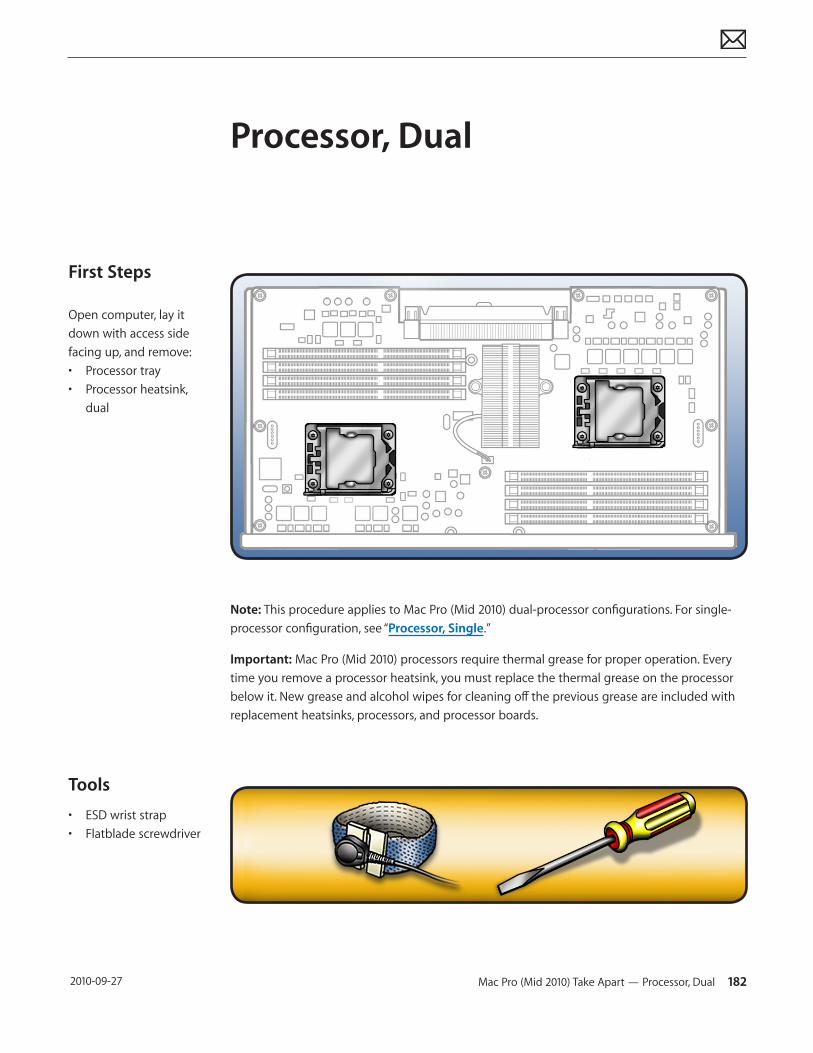
Mac Pro (Mid 2010) Take Apart — Processor, Dual 182 2010-09-27
First Steps
Open computer, lay it down with access side facing up, and remove:• Processor tray• Processor heatsink,
dual
Tools
• ESD wrist strap• Flatblade screwdriver
Processor, Dual
Note: This procedure applies to Mac Pro (Mid 2010) dual-processor configurations. For single-processor configuration, see “Processor, Single.”
Important: Mac Pro (Mid 2010) processors require thermal grease for proper operation. Every time you remove a processor heatsink, you must replace the thermal grease on the processor below it. New grease and alcohol wipes for cleaning off the previous grease are included with replacement heatsinks, processors, and processor boards.
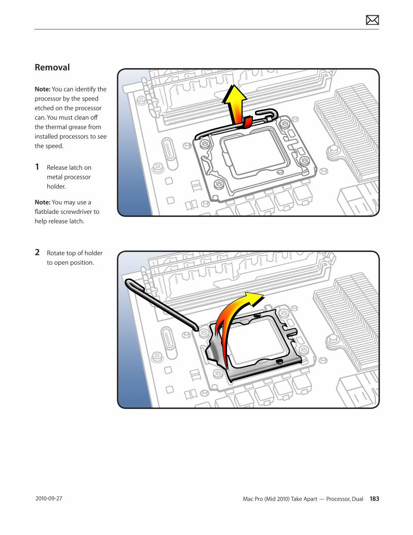
Mac Pro (Mid 2010) Take Apart — Processor, Dual 183 2010-09-27
Removal
Note: You can identify the processor by the speed etched on the processor can. You must clean off the thermal grease from installed processors to see the speed.
1 Release latch on metal processor holder.
Note: You may use a flatblade screwdriver to help release latch.
2 Rotate top of holder to open position.

Mac Pro (Mid 2010) Take Apart — Processor, Dual 184 2010-09-27
3 Lift processor straight up out of holder.
Important: Do not touch components on processor top or bottom. Hold processor only by the edges.
Also be careful not to touch gold pins in processor connector on processor board.
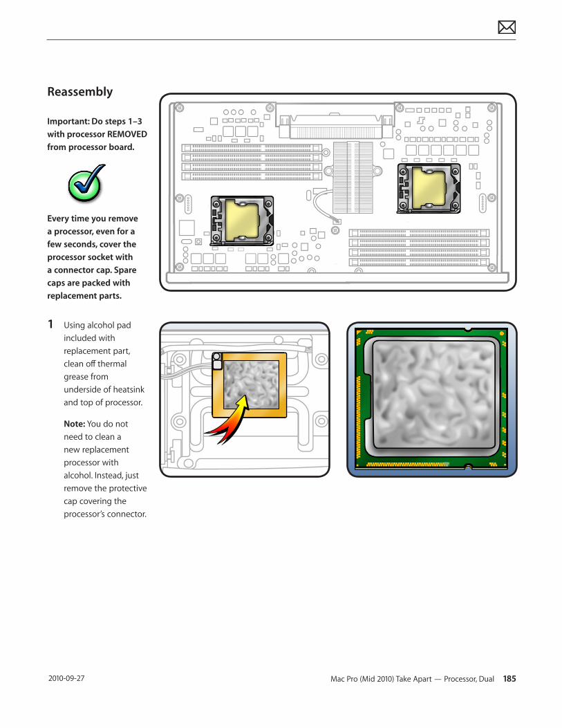
Mac Pro (Mid 2010) Take Apart — Processor, Dual 185 2010-09-27
Reassembly
Important: Do steps 1–3 with processor REMOVED from processor board.
Every time you remove a processor, even for a few seconds, cover the processor socket with a connector cap. Spare caps are packed with replacement parts.
1 Using alcohol pad included with replacement part, clean off thermal grease from underside of heatsink and top of processor.
Note: You do not need to clean a new replacement processor with alcohol. Instead, just remove the protective cap covering the processor’s connector.
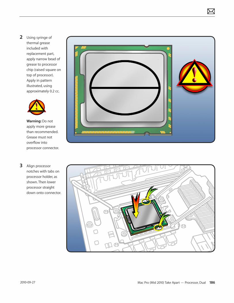
Mac Pro (Mid 2010) Take Apart — Processor, Dual 186 2010-09-27
2 Using syringe of thermal grease included with replacement part, apply narrow bead of grease to processor chip (raised square on top of processor). Apply in pattern illustrated, using approximately 0.2 cc.
Warning: Do not apply more grease than recommended.Grease must not overflow into processor connector.
3 Align processor notches with tabs on processor holder, as shown. Then lower processor straight down onto connector.

Mac Pro (Mid 2010) Take Apart — Processor, Dual 187 2010-09-27
4 Rotate top of holder to closed position.
5 Close latch on metal processor holder.
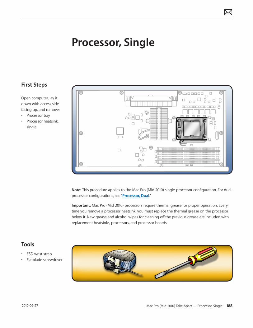
Mac Pro (Mid 2010) Take Apart — Processor, Single 188 2010-09-27
First Steps
Open computer, lay it down with access side facing up, and remove:• Processor tray• Processor heatsink,
single
Tools
• ESD wrist strap• Flatblade screwdriver
Processor, Single
Note: This procedure applies to the Mac Pro (Mid 2010) single-processor configuration. For dual-processor configurations, see “Processor, Dual.”
Important: Mac Pro (Mid 2010) processors require thermal grease for proper operation. Every time you remove a processor heatsink, you must replace the thermal grease on the processor below it. New grease and alcohol wipes for cleaning off the previous grease are included with replacement heatsinks, processors, and processor boards.

Mac Pro (Mid 2010) Take Apart — Processor, Single 189 2010-09-27
Removal
Note: You can identify the processor by the speed etched on the processor can. You must clean off the thermal grease from installed processors to see the speed.
1 Release latch on metal processor holder.
Note: You may use a flatblade screwdriver to help release latch.
2 Rotate top of holder to open position.
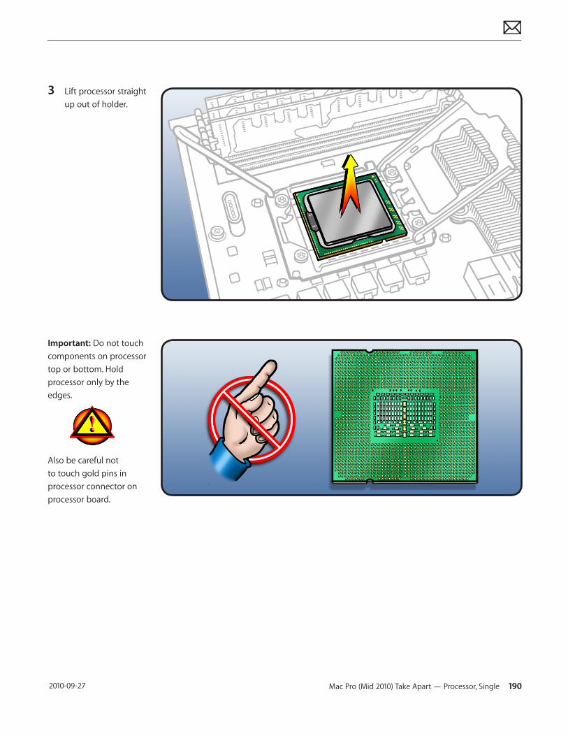
Mac Pro (Mid 2010) Take Apart — Processor, Single 190 2010-09-27
3 Lift processor straight up out of holder.
Important: Do not touch components on processor top or bottom. Hold processor only by the edges.
Also be careful not to touch gold pins in processor connector on processor board.
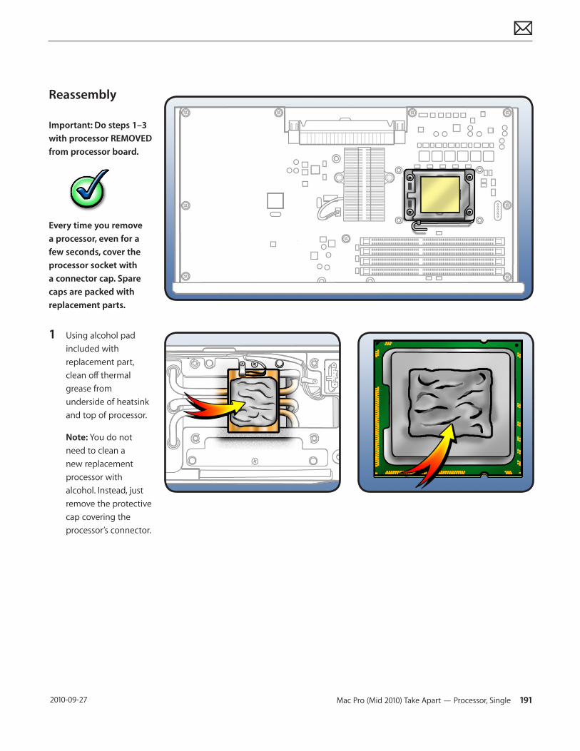
Mac Pro (Mid 2010) Take Apart — Processor, Single 191 2010-09-27
Reassembly
Important: Do steps 1–3 with processor REMOVED from processor board.
Every time you remove a processor, even for a few seconds, cover the processor socket with a connector cap. Spare caps are packed with replacement parts.
1 Using alcohol pad included with replacement part, clean off thermal grease from underside of heatsink and top of processor.
Note: You do not need to clean a new replacement processor with alcohol. Instead, just remove the protective cap covering the processor’s connector.
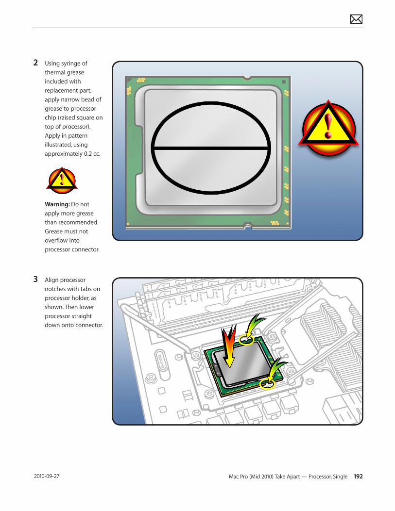
Mac Pro (Mid 2010) Take Apart — Processor, Single 192 2010-09-27
2 Using syringe of thermal grease included with replacement part, apply narrow bead of grease to processor chip (raised square on top of processor). Apply in pattern illustrated, using approximately 0.2 cc.
Warning: Do not apply more grease than recommended.Grease must not overflow into processor connector.
3 Align processor notches with tabs on processor holder, as shown. Then lower processor straight down onto connector.
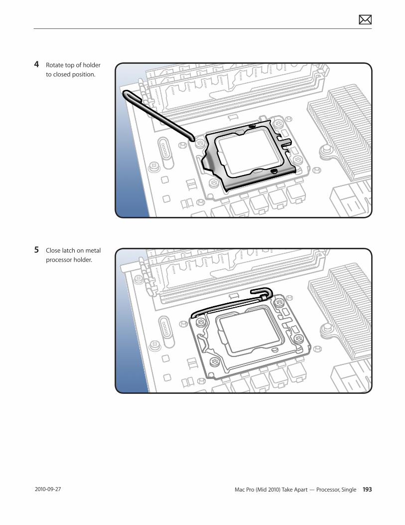
Mac Pro (Mid 2010) Take Apart — Processor, Single 193 2010-09-27
4 Rotate top of holder to closed position.
5 Close latch on metal processor holder.
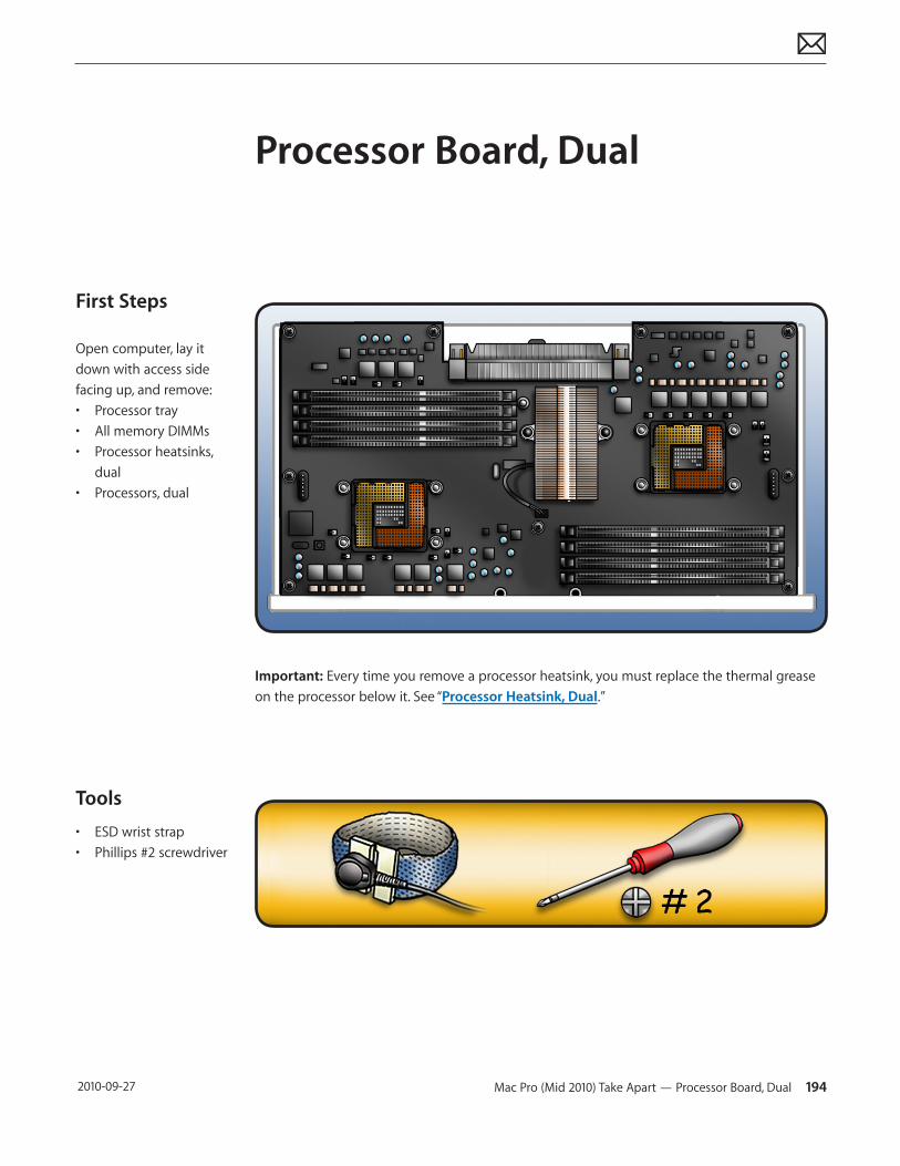
Mac Pro (Mid 2010) Take Apart — Processor Board, Dual 194 2010-09-27
First Steps
Open computer, lay it down with access side facing up, and remove:• Processor tray• All memory DIMMs• Processor heatsinks,
dual• Processors, dual
Tools
• ESD wrist strap• Phillips #2 screwdriver
Processor Board, Dual
Important: Every time you remove a processor heatsink, you must replace the thermal grease on the processor below it. See “Processor Heatsink, Dual.”
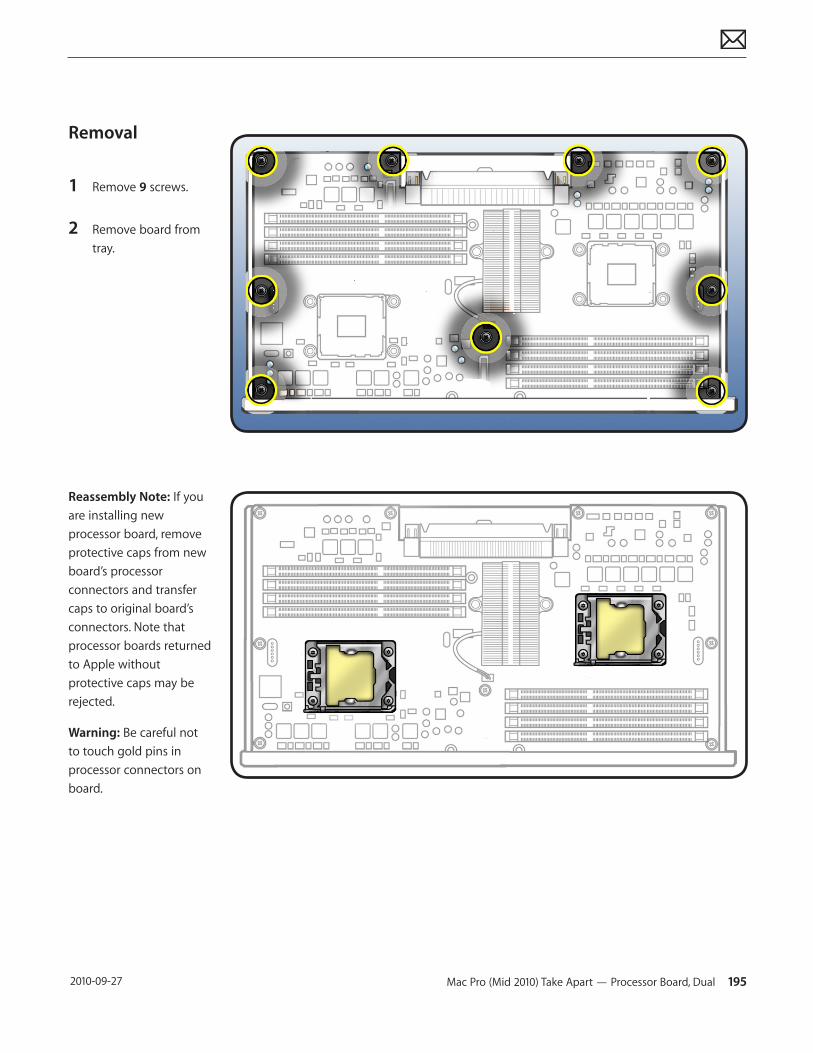
Mac Pro (Mid 2010) Take Apart — Processor Board, Dual 195 2010-09-27
Removal
1 Remove 9 screws.
2 Remove board from tray.
Reassembly Note: If you are installing new processor board, remove protective caps from new board’s processor connectors and transfer caps to original board’s connectors. Note that processor boards returned to Apple without protective caps may be rejected.
Warning: Be careful not to touch gold pins in processor connectors on board.
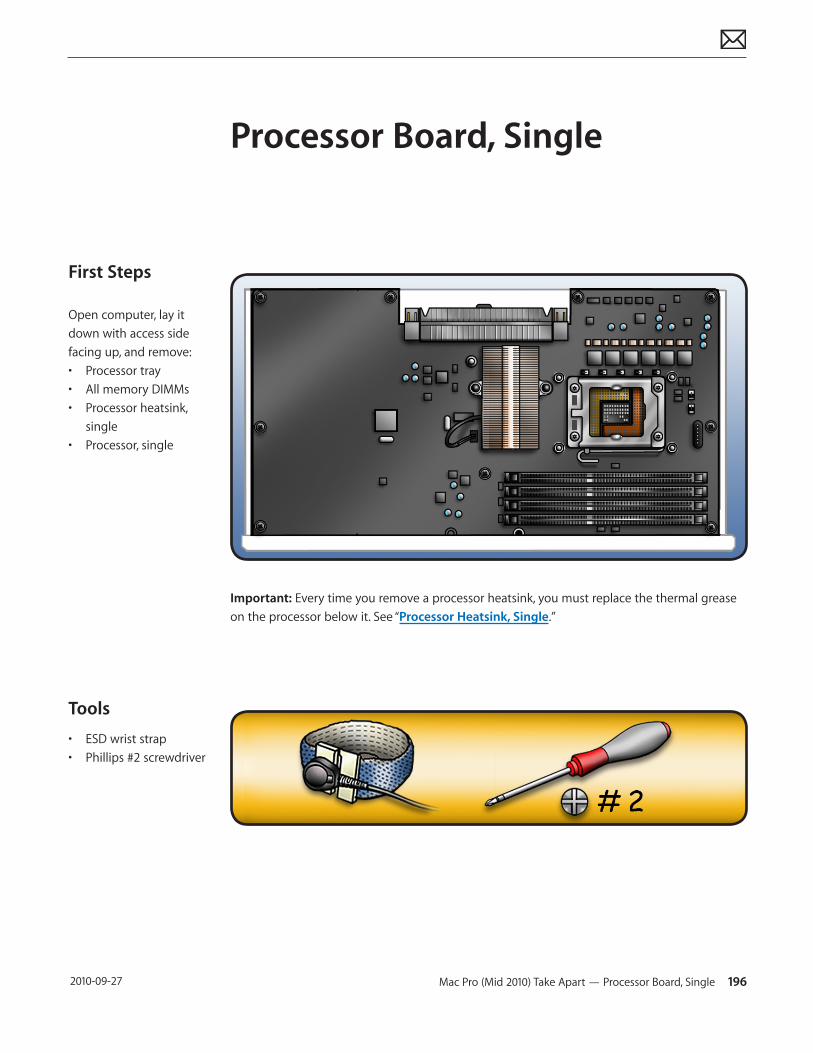
Mac Pro (Mid 2010) Take Apart — Processor Board, Single 196 2010-09-27
First Steps
Open computer, lay it down with access side facing up, and remove:• Processor tray• All memory DIMMs• Processor heatsink,
single • Processor, single
Tools
• ESD wrist strap• Phillips #2 screwdriver
Processor Board, Single
Important: Every time you remove a processor heatsink, you must replace the thermal grease on the processor below it. See “Processor Heatsink, Single.”
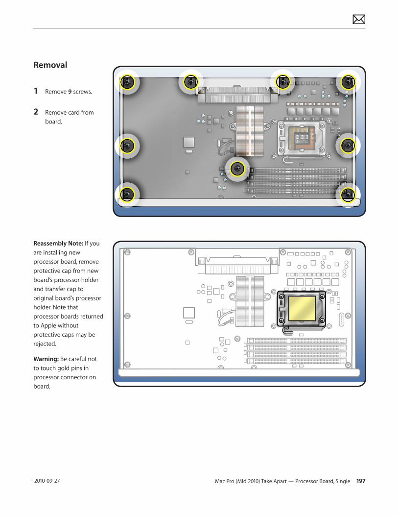
Mac Pro (Mid 2010) Take Apart — Processor Board, Single 197 2010-09-27
Removal
1 Remove 9 screws.
2 Remove card from board.
Reassembly Note: If you are installing new processor board, remove protective cap from new board’s processor holder and transfer cap to original board’s processor holder. Note that processor boards returned to Apple without protective caps may be rejected.
Warning: Be careful not to touch gold pins in processor connector on board.
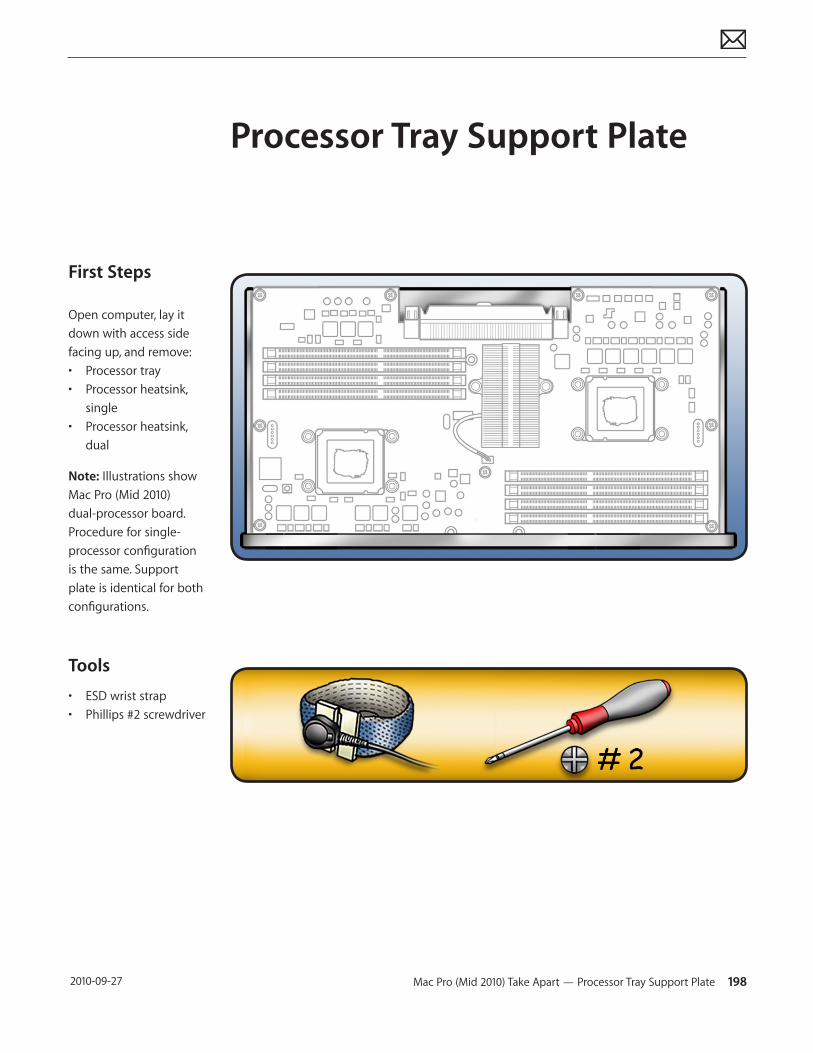
Mac Pro (Mid 2010) Take Apart — Processor Tray Support Plate 198 2010-09-27
First Steps
Open computer, lay it down with access side facing up, and remove:• Processor tray• Processor heatsink,
single• Processor heatsink,
dual
Note: Illustrations show Mac Pro (Mid 2010) dual-processor board. Procedure for single-processor configuration is the same. Support plate is identical for both configurations.
Tools
• ESD wrist strap• Phillips #2 screwdriver
Processor Tray Support Plate
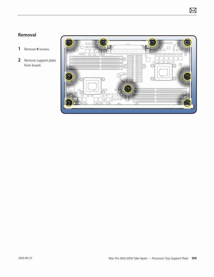
Mac Pro (Mid 2010) Take Apart — Processor Tray Support Plate 199 2010-09-27
Removal
1 Remove 9 screws.
2 Remove support plate from board.
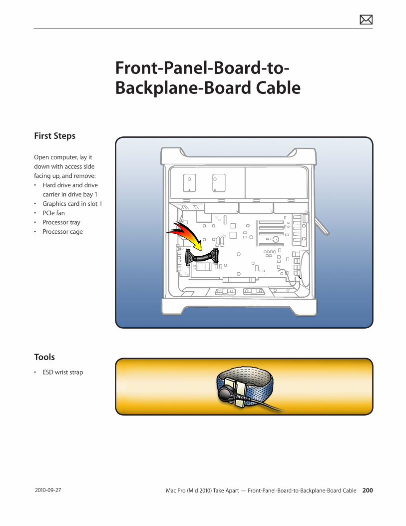
Mac Pro (Mid 2010) Take Apart — Front-Panel-Board-to-Backplane-Board Cable 200 2010-09-27
First Steps
Open computer, lay it down with access side facing up, and remove:• Hard drive and drive
carrier in drive bay 1• Graphics card in slot 1• PCIe fan• Processor tray• Processor cage
Tools
• ESD wrist strap
Front-Panel-Board-to-Backplane-Board Cable
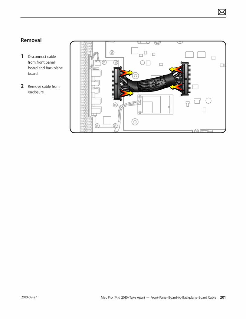
Mac Pro (Mid 2010) Take Apart — Front-Panel-Board-to-Backplane-Board Cable 201 2010-09-27
Removal
1 Disconnect cable from front panel board and backplane board.
2 Remove cable from enclosure.
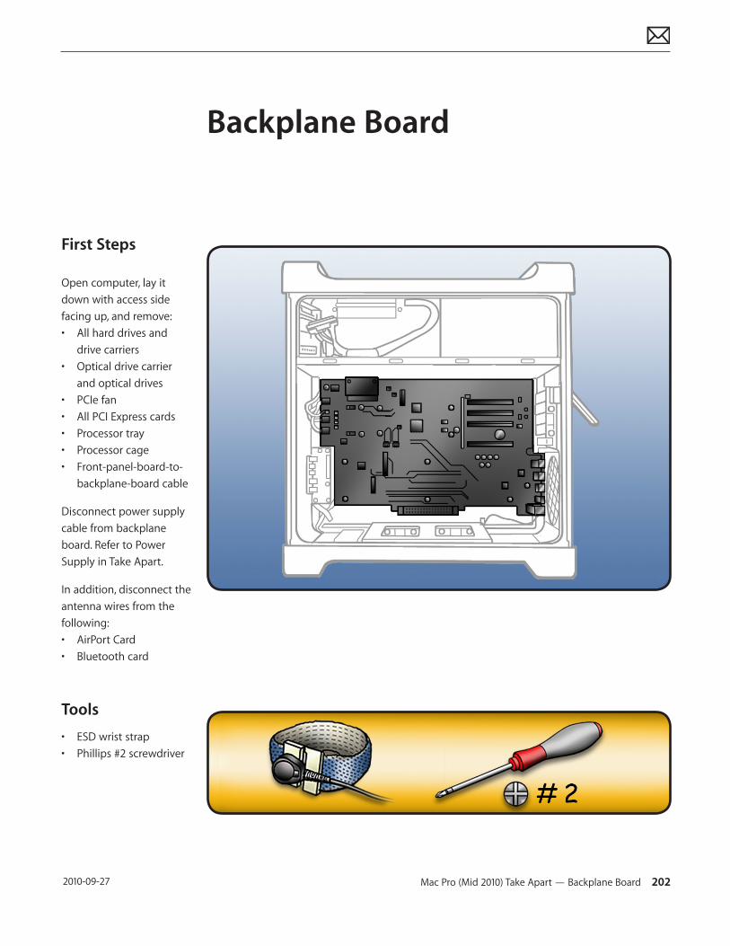
Mac Pro (Mid 2010) Take Apart — Backplane Board 202 2010-09-27
First Steps
Open computer, lay it down with access side facing up, and remove:• All hard drives and
drive carriers• Optical drive carrier
and optical drives• PCIe fan• All PCI Express cards• Processor tray• Processor cage• Front-panel-board-to-
backplane-board cable
Disconnect power supply cable from backplane board. Refer to Power Supply in Take Apart.
In addition, disconnect the antenna wires from the following:• AirPort Card• Bluetooth card
Tools
• ESD wrist strap• Phillips #2 screwdriver
Backplane Board
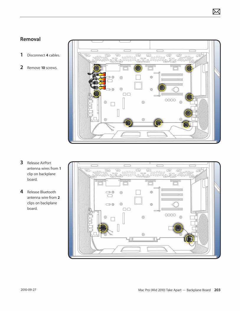
Mac Pro (Mid 2010) Take Apart — Backplane Board 203 2010-09-27
Removal
1 Disconnect 4 cables.
2 Remove 10 screws.
3 Release AirPort antenna wires from 1 clip on backplane board.
4 Release Bluetooth antenna wire from 2 clips on backplane board.
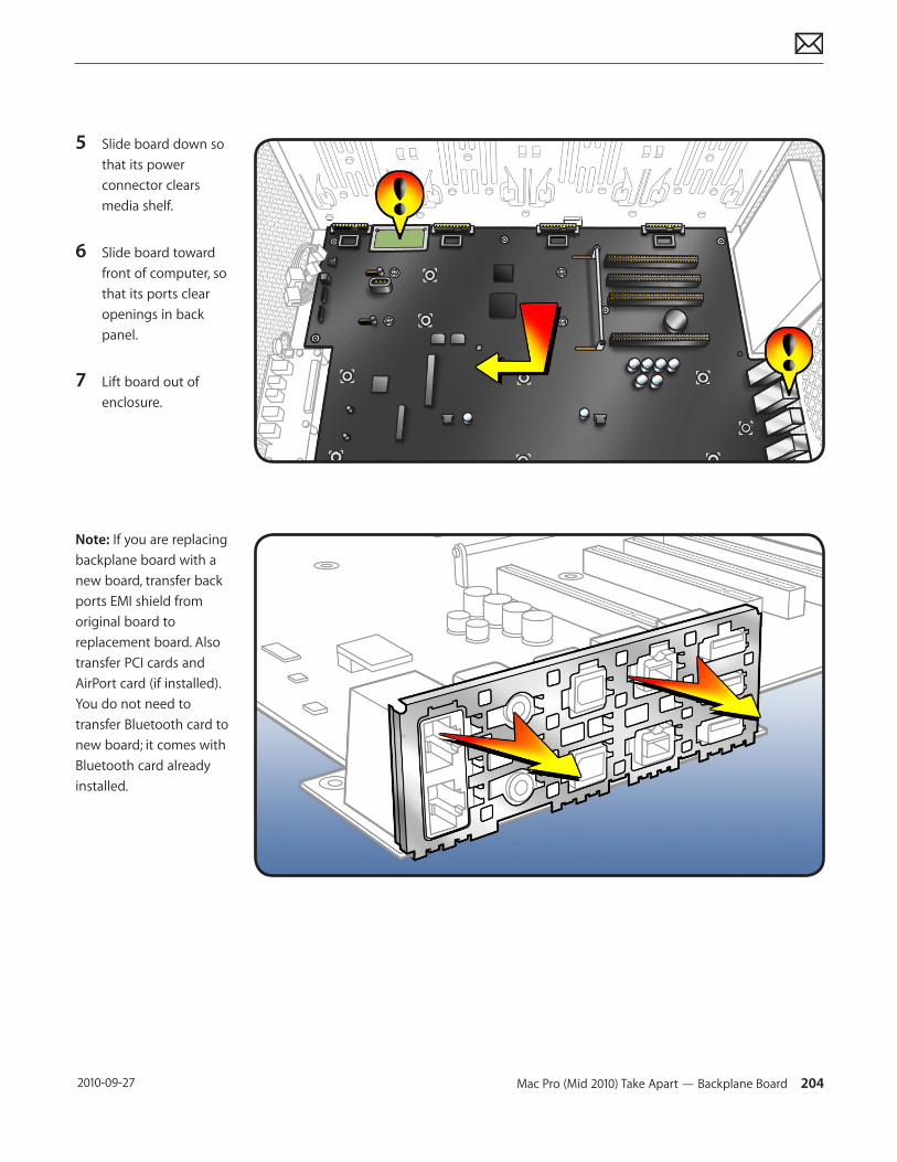
Mac Pro (Mid 2010) Take Apart — Backplane Board 204 2010-09-27
5 Slide board down so that its power connector clears media shelf.
6 Slide board toward front of computer, so that its ports clear openings in back panel.
7 Lift board out of enclosure.
Note: If you are replacing backplane board with a new board, transfer back ports EMI shield from original board to replacement board. Also transfer PCI cards and AirPort card (if installed). You do not need to transfer Bluetooth card to new board; it comes with Bluetooth card already installed.
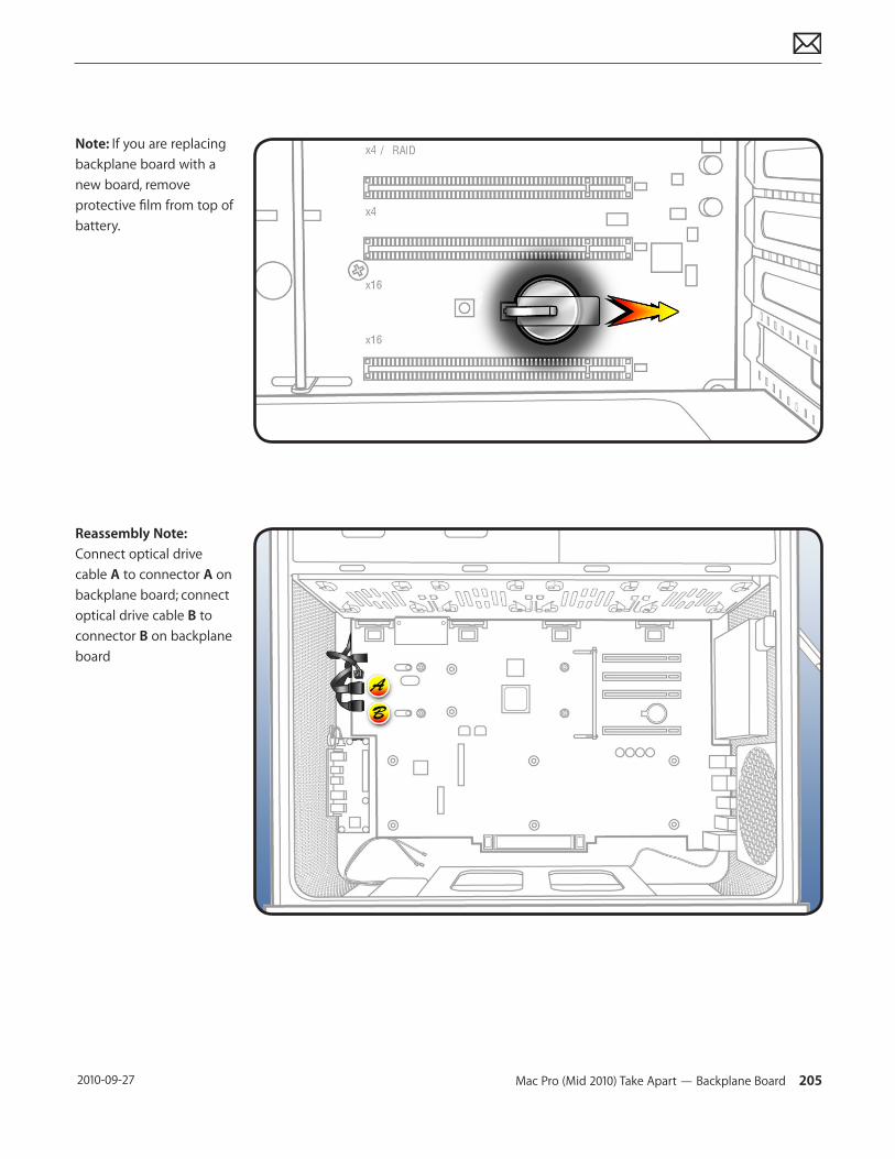
Mac Pro (Mid 2010) Take Apart — Backplane Board 205 2010-09-27
Note: If you are replacing backplane board with a new board, remove protective film from top of battery.
Reassembly Note: Connect optical drive cable A to connector A on backplane board; connect optical drive cable B to connector B on backplane board
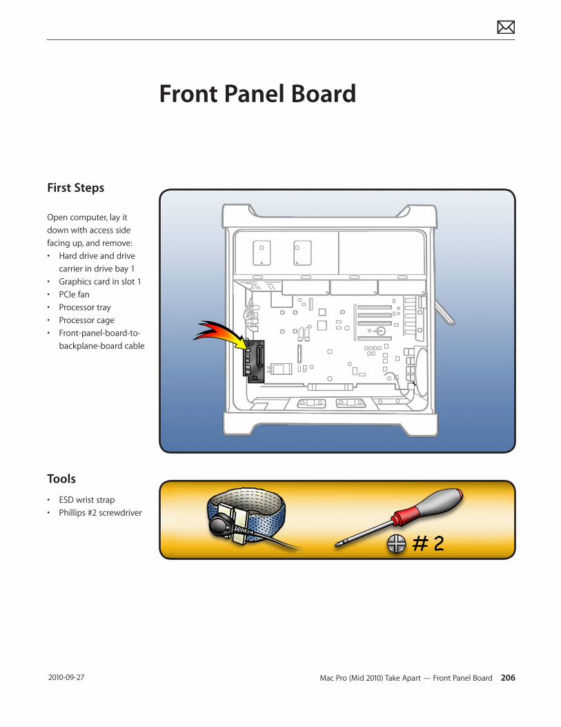
Mac Pro (Mid 2010) Take Apart — Front Panel Board 206 2010-09-27
First Steps
Open computer, lay it down with access side facing up, and remove:• Hard drive and drive
carrier in drive bay 1• Graphics card in slot 1• PCIe fan• Processor tray• Processor cage• Front-panel-board-to-
backplane-board cable
Tools
• ESD wrist strap• Phillips #2 screwdriver
Front Panel Board
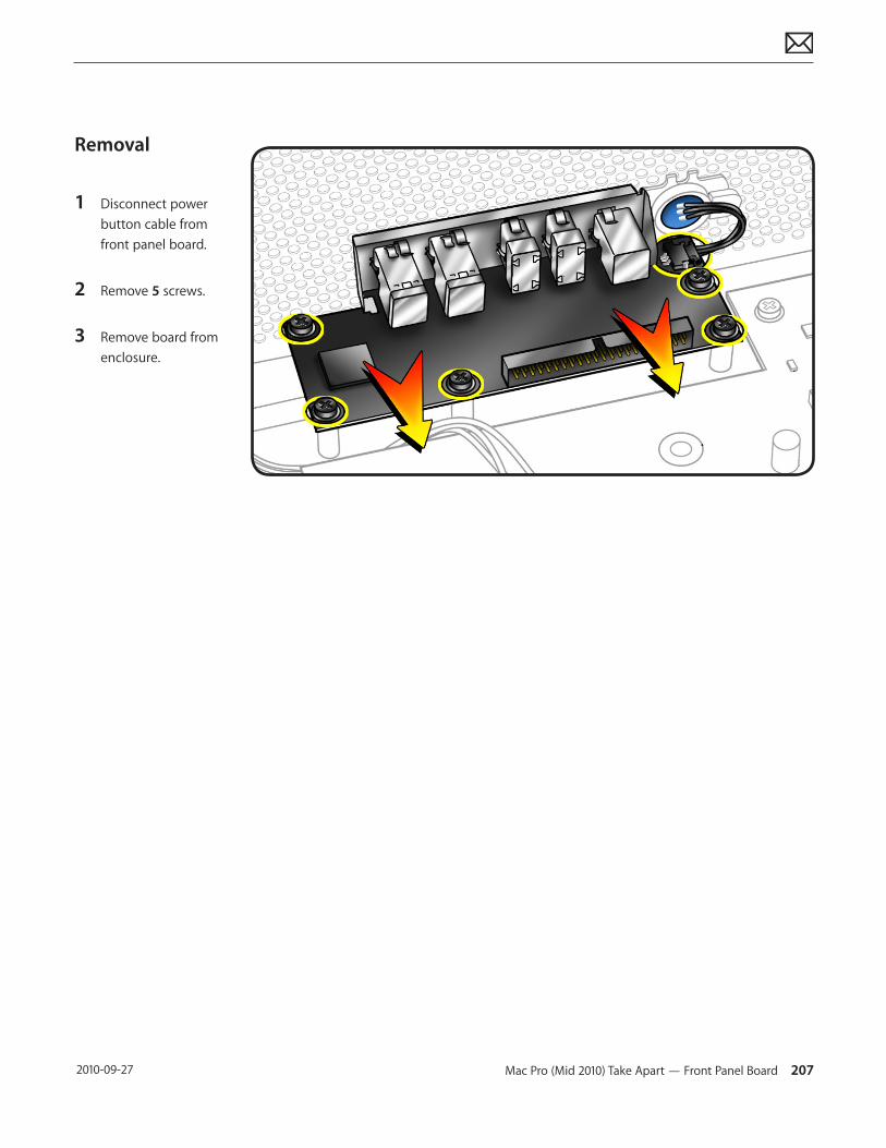
Mac Pro (Mid 2010) Take Apart — Front Panel Board 207 2010-09-27
Removal
1 Disconnect power button cable from front panel board.
2 Remove 5 screws.
3 Remove board from enclosure.
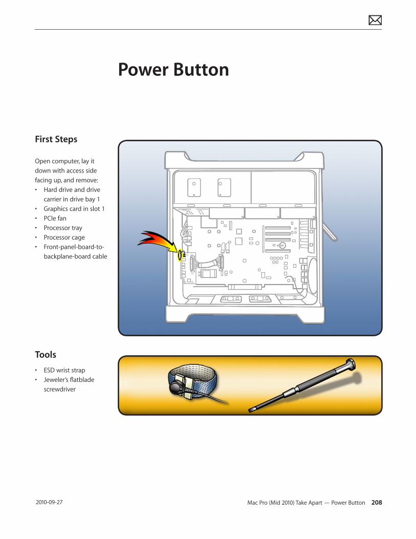
Mac Pro (Mid 2010) Take Apart — Power Button 208 2010-09-27
First Steps
Open computer, lay it down with access side facing up, and remove:• Hard drive and drive
carrier in drive bay 1• Graphics card in slot 1• PCIe fan• Processor tray• Processor cage• Front-panel-board-to-
backplane-board cable
Tools
• ESD wrist strap• Jeweler’s flatblade
screwdriver
Power Button
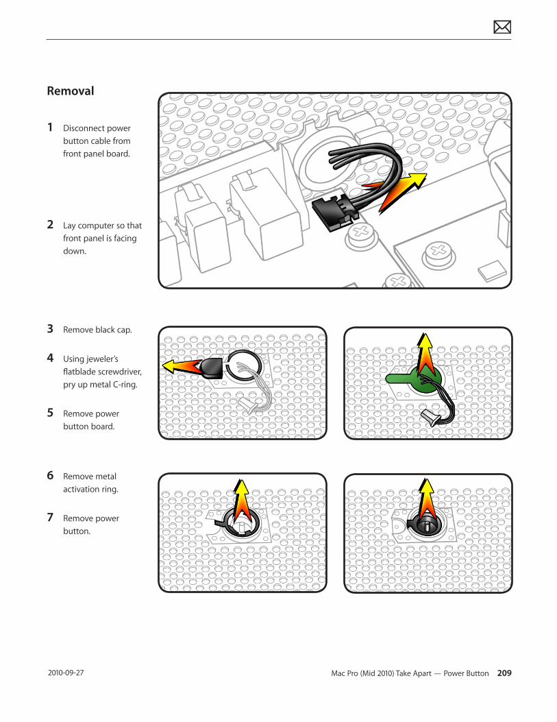
Mac Pro (Mid 2010) Take Apart — Power Button 209 2010-09-27
Removal
1 Disconnect power button cable from front panel board.
2 Lay computer so that front panel is facing down.
3 Remove black cap.
4 Using jeweler’s flatblade screwdriver, pry up metal C-ring.
5 Remove power button board.
6 Remove metal activation ring.
7 Remove power button.
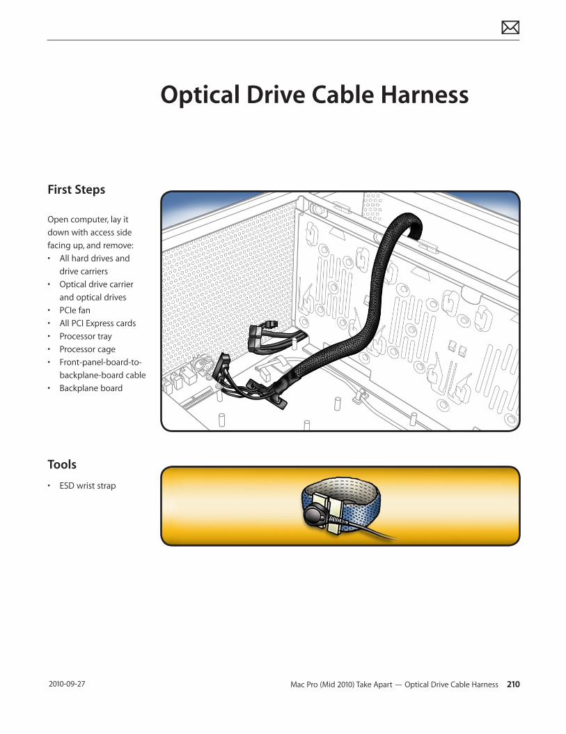
Mac Pro (Mid 2010) Take Apart — Optical Drive Cable Harness 210 2010-09-27
First Steps
Open computer, lay it down with access side facing up, and remove:• All hard drives and
drive carriers• Optical drive carrier
and optical drives• PCIe fan• All PCI Express cards• Processor tray• Processor cage• Front-panel-board-to-
backplane-board cable• Backplane board
Tools
• ESD wrist strap
Optical Drive Cable Harness
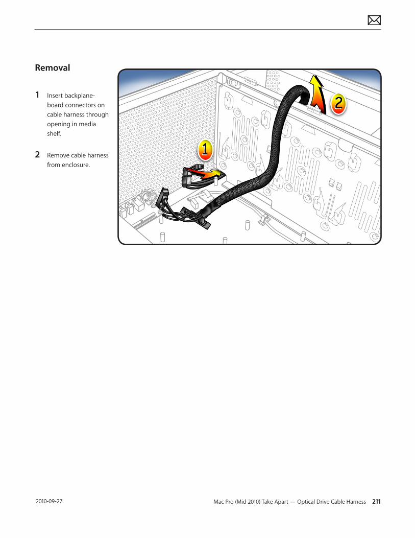
Mac Pro (Mid 2010) Take Apart — Optical Drive Cable Harness 211 2010-09-27
Removal
1 Insert backplane-board connectors on cable harness through opening in media shelf.
2 Remove cable harness from enclosure.
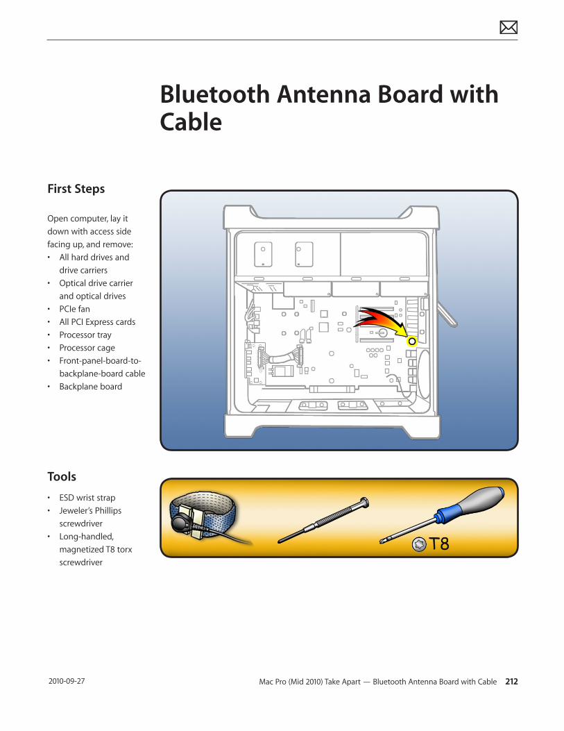
Mac Pro (Mid 2010) Take Apart — Bluetooth Antenna Board with Cable 212 2010-09-27
First Steps
Open computer, lay it down with access side facing up, and remove:• All hard drives and
drive carriers• Optical drive carrier
and optical drives• PCIe fan• All PCI Express cards• Processor tray• Processor cage• Front-panel-board-to-
backplane-board cable• Backplane board
Tools
• ESD wrist strap• Jeweler’s Phillips
screwdriver• Long-handled,
magnetized T8 torx screwdriver
Bluetooth Antenna Board with Cable
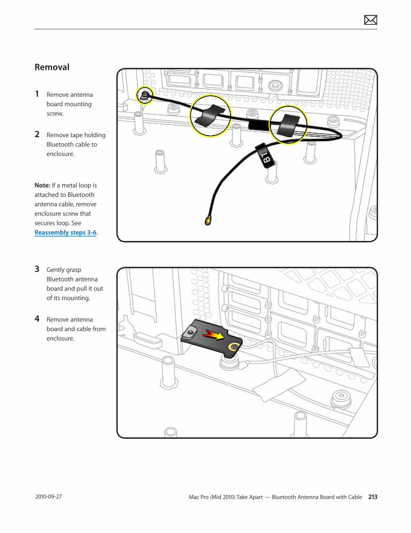
Mac Pro (Mid 2010) Take Apart — Bluetooth Antenna Board with Cable 213 2010-09-27
Removal
1 Remove antenna board mounting screw.
2 Remove tape holding Bluetooth cable to enclosure.
Note: If a metal loop is attached to Bluetooth antenna cable, remove enclosure screw that secures loop. See Reassembly steps 3-6.
3 Gently grasp Bluetooth antenna board and pull it out of its mounting.
4 Remove antenna board and cable from enclosure.
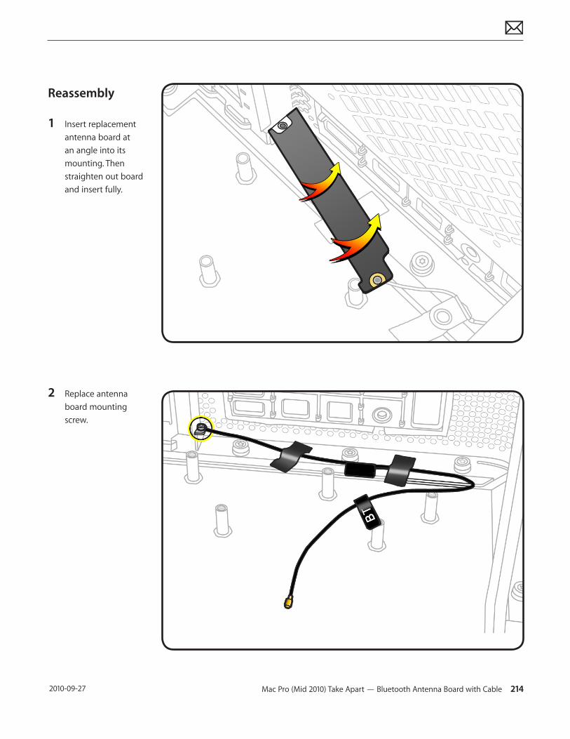
Mac Pro (Mid 2010) Take Apart — Bluetooth Antenna Board with Cable 214 2010-09-27
Reassembly
1 Insert replacement antenna board at an angle into its mounting. Then straighten out board and insert fully.
2 Replace antenna board mounting screw.
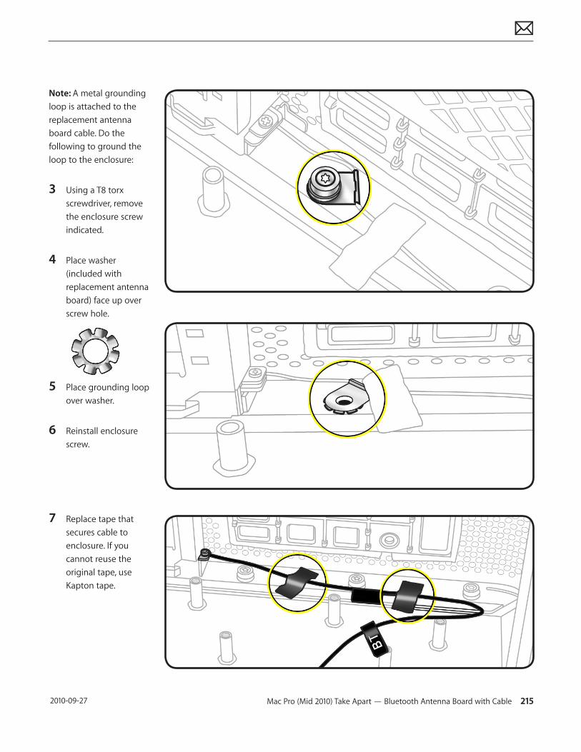
Mac Pro (Mid 2010) Take Apart — Bluetooth Antenna Board with Cable 215 2010-09-27
Note: A metal grounding loop is attached to the replacement antenna board cable. Do the following to ground the loop to the enclosure:
3 Using a T8 torx screwdriver, remove the enclosure screw indicated.
4 Place washer (included with replacement antenna board) face up over screw hole.
5 Place grounding loop over washer.
6 Reinstall enclosure screw.
7 Replace tape that secures cable to enclosure. If you cannot reuse the original tape, use Kapton tape.
© 2010 Apple Inc. All rights reserved.
Apple Technician Guide
ViewsMac Pro (Mid 2010)
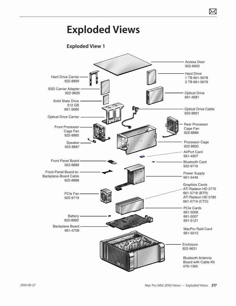
Mac Pro (Mid 2010) Views — Exploded Views 217 2010-09-27
Exploded ViewsExploded View 1
Hard Drive Carrier922-8899
Optical Drive Carrier
Access Door922-8902
Hard Drive1 TB 661-56782 TB 661-5679
Optical Drive661-5681
Optical Drive Cable922-8891
Rear ProcessorCage Fan922-8886
Processor Cage922-8893AirPort Card661-4907Bluetooth Card922-9716
Power Supply661-5449
PCIe Cards661-5006661-5007661-5121
MacPro Raid Card661-5012
Enclosure922-9631
Front ProcessorCage Fan922-8885
Speaker922-8887
Front Panel Board922-8889
Front-Panel-Board-to-Backplane-Board Cable
922-8888
PCIe Fan922-9719
Battery922-8892
Backplane Board661-5706
Graphics CardsATI Radeon HD 5770661-5718 (BTR)ATI Radeon HD 5780661-5719 (CTO)
Bluetooth AntennaBoard with Cable Kit076-1365
SSD Carrier Adapter922-9629
Solid State Drive512 GB
661-5680
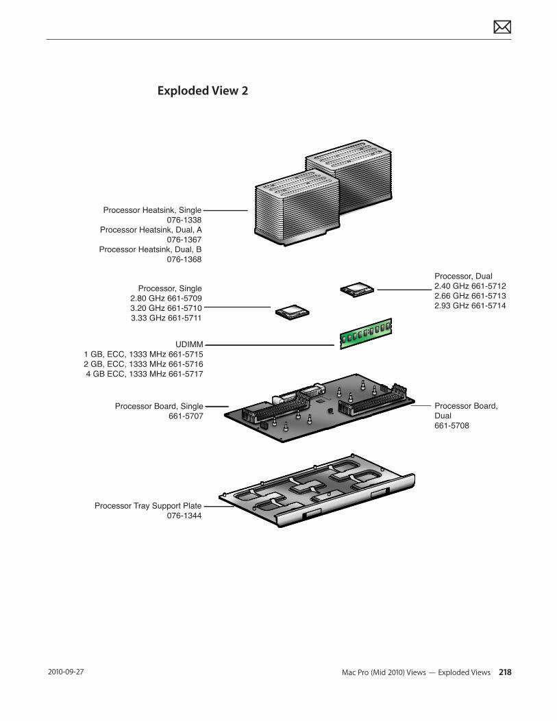
Mac Pro (Mid 2010) Views — Exploded Views 218 2010-09-27
Exploded View 2
Processor Heatsink, Single076-1338
Processor Heatsink, Dual, A076-1367
Processor Heatsink, Dual, B076-1368
Processor, Dual2.40 GHz 661-57122.66 GHz 661-57132.93 GHz 661-5714
Processor Board, Dual661-5708
Processor, Single2.80 GHz 661-57093.20 GHz 661-57103.33 GHz 661-5711
Processor Board, Single661-5707
Processor Tray Support Plate076-1344
UDIMM1 GB, ECC, 1333 MHz 661-57152 GB, ECC, 1333 MHz 661-57164 GB ECC, 1333 MHz 661-5717
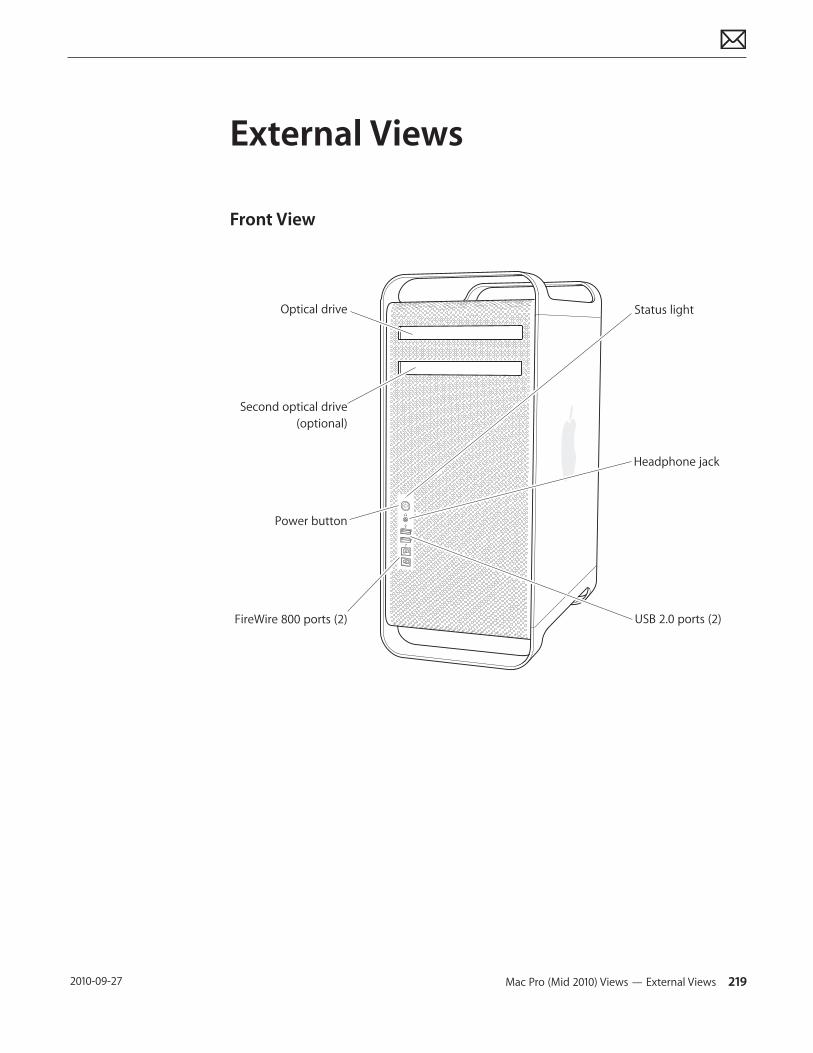
Mac Pro (Mid 2010) Views — External Views 219 2010-09-27
External Views
Front View
Optical drive
Headphone jack
Status light
Power button
FireWire 800 ports (2)
Second optical drive(optional)
USB 2.0 ports (2)
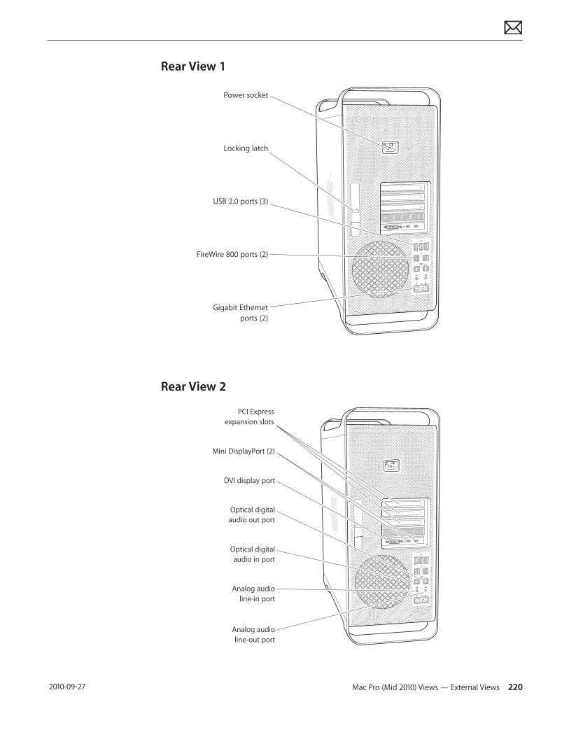
Mac Pro (Mid 2010) Views — External Views 220 2010-09-27
Rear View 1
Power socket
Locking latch
USB 2.0 ports (3)
FireWire 800 ports (2)
Gigabit Ethernetports (2)
Rear View 2
PCI Expressexpansion slots
Mini DisplayPort (2)
Optical digitalaudio out port
Analog audioline-in port
Analog audioline-out port
Optical digitalaudio in port
DVI display port
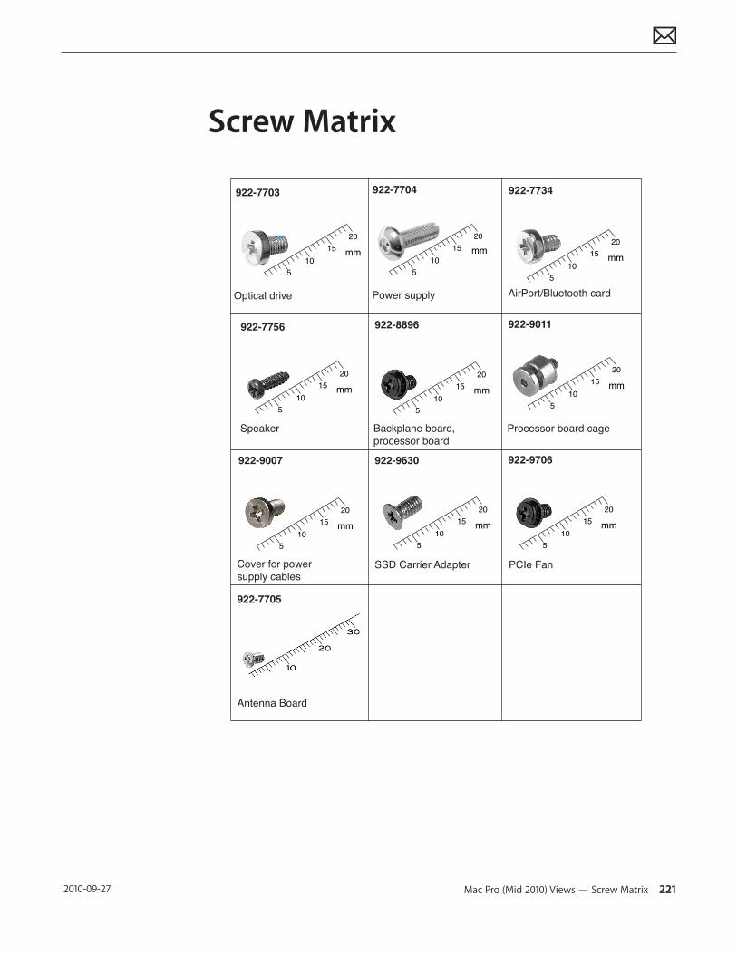
Mac Pro (Mid 2010) Views — Screw Matrix 221 2010-09-27
Screw Matrix
922-7703
Optical drive
105
2015 mm
922-8896
Backplane board,processor board
922-7704
Power supply
105
2015 mm
922-7734
AirPort/Bluetooth card
105
2015 mm
922-7756
Speaker
105
2015 mm
105
2015 mm
Processor board cage
105
2015 mm
922-9007
Cover for power supply cables
105
2015 mm
922-9011
922-9630
SSD Carrier Adapter
105
2015 mm
922-9706
PCIe Fan
922-7705
105
2015 mm
Antenna Board