Embed Size (px)
Citation preview

MADE IN JAPAN
C 2003
No.104471
主要諸元ギヤ比無線機
適合エンジン
/ 9.625 : 1 : 5.5 / ヘリ用プロポセット (別売) Programmable transmitter set for model helicopters (Sold separately) / 30~46クラス (別売) 30-46 class engine (Sold separately)※46クラスエンジンの搭載には別途購入品が必要です。� (ご注意:50クラスエンジンの搭載はできません)�※Additional parts must be purchased in order to mount � 46 class engines. (Note that the 50 class engines � can not be mounted.)
Main featuresGear ratioRadio control device
Compatible engine
組立前に必ずこの説明書を最後まで、よくお読みになり、正しくお使い下さい。特に、「安全のために必ずお守り下さい」は、飛行前に必ず読んで下さい。この説明書は、大切にお手元に保管して下さい。製品改良のため、予告なく仕様を変更する場合があります。
Before assembly, make sure to completely read this instruction manual. In particular, make sure to read the "Follow these rules to ensure safety" section before operating the unit. Keep this instruction manual in a handy, safe place.In order to make improvements to this product, specifications may be altered without prior notice.
1190mm
404mm
262mm
1244mm
225m
m

1
1.組立を始める前に必ずお読み下さい ................................................ 1
2.組立編 .................................................................................................. 11
3.フライト編 .......................................................................................... 43
4.メンテナンス編 .................................................................................. 53
5.補修パーツについて .......................................................................... 56
目 次Table of Contents
1. Read before assembly ............................................................................. 1
2. Assembly ............................................................................................... 11
3. Flight .................................................................................................... 43
4. Maintenance ......................................................................................... 53
5. Repair parts ........................................................................................... 56
このたびは、ヒロボー製品をお買上げいただき、ありがとうございます。 安全にお使いいただくために、飛行前にこの取扱説明書を最後までよくお読みください。 飛行上の注意事項、本機の能力、飛行方法などを十分にご理解のうえ正しく、安全にルールやマナーを守って飛行くださるようお願いいたします。
『シンボルとシグナル用語』の意味について 注意文の頭部に表示の「シンボルとシグナル用語」の意味を説明します。 なお、 注意 に記載した事項でも、状況によっては重大な結果に結びつく可能性があります。
(注):製品の組立、操作、メンテナンスに関する重要なご注意。
1. 組立る前に説明書を良く読んで、おおよその構造及び組立手順を理解してから組立に入ってください。
2. 組立る前に、部品の数・内容をお確かめください。パック開封の後は、部品の交換、返品等については応じかねます。万一部品の不足・不良があった場合には、お手数ですが、愛用者カードに販売店の印をもらい、ヒロボー株式会社・営業部まで、部品名と内容を明記の上ご連絡ください。
Thank you very much for purchasing a Hirobo product. In order to beable to use this product safely, please read this manual before flying thehelicopter. Please fly the helicopter safely observing all rules andmanners after having fully understood the flight precautions, the unitÅfscapabilities, and the best way to fly it.
The meaning of symbols and signal words.The meaning of symbols and signal words indicated at the head ofcautionary notes are as explained below. Even comments marked with
may result in serious harm depending on thecircumstances.
Mishandling due to failure to followthese instructions may result in severeinjury or death.
Mishandling due to failure to followthese instructions may result in seriousharm.
Do not attempt under any circumstances.
(NOTE) : Implies important information regarding this product’sassembly, operation, or maintenance.
1. Before assembly, read the instruction manual thoroughly familiarizing
yourself with the unit’s structure and assembly procedures.
2. Before assembly, check the quantity of parts and their descriptions.
After the packaging has been opened, parts cannot be exchanged or
returned. In the event of any missing or defective parts, have the
store from where you purchased the product stamp your user’s card
and send it with the name and description of the part(s) to Hirobo’s
Sales Department.
誤った取扱をしたときに、死亡や重傷等の重大な結果に結び付く可能性が大きいもの。
誤った取扱をしたときに、状況によっては重大な結果に結び付く可能性があるもの。
絶対に行わないでください。
組立を始める前に安全のために必ずお守り下さい。
For safety reasons, observe the followingprecautions before assembly.
WARNING
CAUTION
警告
注意
禁止 FORBIDDEN
1.組立を始める前に必ずお読み下さい Read before assembly
CAUTION

2
エンジン始動の前に Before starting the engine
1. 可能な限り、飛行場を清掃してください。◆ 小石、ガラス、くぎ、針金、ひも、浮遊物等の異物を飛行場から
取り除いてください。2. 周囲の状況を考慮してください。
◆ 強風、雨のとき、及び夜間は飛行させないでください。◆ 人が多い場所では飛行させないでください。◆ 家、学校、病院などの近くでは飛行させないでください。◆ 道路、線路、電線などの近くでは飛行させないでください。◆ 同じ周波数の無線操縦模型が近くにいる時は飛行させないでくだ
さい。3. 次のような人、または状況下では飛行させないでください。
◆ 子供。◆ 生理中、妊娠中の人。◆ 疲れている時、病気の時、酔っている時。◆ 薬物の影響、その他の理由で正常な操作ができない人。◆ 初心者の方や、他人の機材を借りる場合、あらかじめ模型を良く
知っている人から安全指導を受けてから始めてください。4. 無理して使用しないでください。
◆ 機能に適さない改造や加工をしないでください。◆ 使用限界が示されている物は、必ずその範囲で使用してください。◆ 空中撮影や農薬散布には使用しないでください。
5. きちんとした服装ではじめてください。◆ 長そで、長ズボンを着用してください。◆ 宝石や、物に引っ掛かりやすいものは、身につけないでください。◆ 長い髪は、肩までの長さに結わえてください。◆ 足下保護のため、必ず靴を着用してください。◆ 高温部に触る場合等は、必要に応じて手袋をしてください。
6. ドライバーやレンチ等の工具は取り外してください。◆ 始動する前に組立、取付、整備等に用いた工具類が取り外してあ
ることを確認してください。7. 各部の点検をしてください。
◆ 始動前に、各部品に損傷がないか十分点検し、正常に作動するか、また所定の機能を発揮するか確認してください。
◆ 可動部分の位置調整、及び各部のボルト、ナットの締付状態、部品の損傷、取付状態、その他飛行に影響を及ぼす全ての箇所に異常がないか確認してください。
◆ 無線機器の電源電圧(電池の量)は十分か確認してください。◆ 損傷した部品、その他部品交換や修理は、説明書の指示に従って
ください。説明書に指示されていない場合は、お買上げ販売店、またはヒロボー(株)営業本部エンジニアリングサービスで修理を行なってください。
◆ 始動前に、必ず各部のネジがゆるんでいないか、指定部への給油(オイル /グリス)、送・受信機用バッテリーが充分に充電されているかを点検してください。
8. 純正部品を使用してください。◆ 本説明書、及びヒロボーカタログに記載されている、純正部品以
外のものを使用しないでください。事故やけがの原因となる恐れがあります。
9. エンジンを回さないで、各部の操作方法を練習してください。◆ エンシンを始動させる前に、各部の操作方法を練習してください。◆ 操作を充分に修得するまではエンジンを始動させないでください。◆ 機械の動きに異常がみられる場合もエンジンを始動させないでく
ださい。
1. Clear as much debris from the airfield as possible.
Clear away pebbles, glass, nails, wire, rope, floating objects, or other trash from
the airfield.
2. Consider the circumstances of the surrounding area.
Do not fly in strong winds, rain, or at night.
Do not fly in a crowded area.
Do not fly near homes, schools, or hospitals.
Do not fly near roads, railways, or power lines.
Do not fly near another radio controlled unit that uses the same frequency.
3. This unit must not be operated by:
Children.
Menstruating or pregnant women.
Tired, sick, or inebriated individuals.
Individuals under the influence of drugs or for some other reason incapable of
operating the unit normally.
Beginners or individuals operating a borrowed unit should proceed only after
having received safety instructions from someone familiar with the model.
4. Do not use the unit improperly.
Do not perform any remodeling or configuration unsuitable for the unit’s
functions.
Make sure to use within the range of the limitations indicated for the unit.
Do not use for aerial photography or crop dusting.
5. Wear appropriate clothing.
Wear a long-sleeve top and trousers.
Do not wear jewelry or objects that may get easily entangled.
Long hair should be bound to shoulder length.
Wear shoes for solid footing.
Wear gloves should it become necessary to touch hot components.
6. Put away screwdrivers, wrenches, or other tools.
Before starting the engine, check that any tools used in the assembly, installation,
or maintenance of the unit have been put away.
7. Inspect each part.
Before starting the engine, check for any damaged parts and make sure that the
unit operates normally with all its functions in order.
Adjust the positioning of moveable parts and check that all nuts and bolts and
nuts are fastened, that there are no damaged or improperly installed parts, and
that there are no abnormalities that would adversely affect the flight of the unit.
Check that the power supply voltage (charge of the batteries) in the remote control
is sufficient.
The exchange or repair of damaged parts should be performed according to the
instruction manual. In the event that the desired operation is not indicated in the
manual, ask for repair service at the store from where you purchased the product
or at the engineering services section of Hirobo’s Sales Department.
Before starting the engine, make sure that there are no loose screws, that all
specified locations are properly lubricated with grease or oil, and that the
transmitter and receiver batteries are properly charged.
8. Use genuine parts.
To reduce the risk of accidents and injuries, do not use parts other those shown
in this instruction manual or in Hirobo catalogs.
9. With the engine off, practice how to operate each part.
Before starting the engine, practice how to operate each part.
Do not start the engine before having acquired sufficient handling skill.
Do not start the engine in the event that any abnormalities are noticed in the
movement of the mechanisms.
警告 WARNING
無線操縦エンジン模型の安全について For the safe operation of radio controlled engines

3
警告 WARNING
燃料について FUEL
1. Only use GLOW fuel for model engines.
Gasoline or kerosene may cannot be used.
GLOW fuel is highly volatile and flammable. Handle with care.
Use properly in accordance with the type of engine. (ABC or ring fitted)
2. If the engine uses gasoline, make sure to use a 1:25 mixture of 2-cycle
engine oil and gasoline.
3. Stop the engine and let it cool down sufficiently before refueling.
4. Do not refuel near a naked flame and especially not while smoking.
Refuel in a way as to prevent spilling and make sure to wipe up any
spilled fuel.
Because fuel vapors and exhaust gas are hazardous, make sure to use the
product outdoors.
To reduce the risk of explosions, do not incinerate empty fuel cans.
5. It is harmful to drink the fuel or get it in the eyes.
In the event of an accident, induce vomiting or thoroughly wash out the
eyes and see a doctor immediately.
6. After refueling, start the engine at a distance of 3m or more away from
where the refueling took place.
7. Fasten the cap on the fuel can tightly and keep it in a cool, dark place out of
the reach of children.
1. 模型用エンジンは模型専用のグロー燃料が必要です。◆ ガソリンや灯油は使用できません。◆ グロー燃料は揮発性が高く引火しやすいので取り扱いには十分注
意してください。◆ エンジンのタイプ(ABC又はリング付/用途別)により使い分けを
してください。2. ガソリンエンジンの場合は、ガソリン25に対し2サイクルエンジンオ
イル1の割合で混合させたものを、必ず使用してください。3. 燃料を補給するときは、必ずエンジンを停止させて、十分冷えてか
ら行なってください。4. 火気の近くでは、絶対に燃料補給しないでください。特にタバコを
吸いながらの作業は行なわないでください。◆ 燃料はこぼさないように補給し、こぼれた時は必ず拭き取ってく
ださい。◆ 燃料の蒸気、排気ガスは有害ですので、必ず屋外で取り扱ってく
ださい。◆ 空缶は火中には投入しないでください。爆発の恐れがあります。
5. 燃料は間違えて、飲んだり目に入ると有害です。◆ 万一事故が起きた場合には、吐かせる、洗眼するなどをした後す
ぐに医師の診察をうけてください。6. 給油後は、給油場所から3m以上離れて、エンジンを始動してくだ
さい。7. 燃料はキャップをしっかりしめ、幼児の手の届かない冷暗所に保管
してください。
飛行中は While in flight
1. 無理な姿勢で操縦しないでください。◆ 寝転んだり、座り込んだりした姿勢で操縦しないでください。◆ 傾斜地は、滑りやすいので足下に十分注意してください。
2. 次の場合は、エンジンを停止させてください。◆ 機体の調整および、送信機の調整を行なうとき。◆ 付属品および部品を交換するとき。◆ 機体の調子が悪かったり、異常音や異常振動を発生したとき。◆ その他危険が予想されるとき。
3. エンジンを始動するときは、次のことに注意してください。◆ 周囲に人、動物、障害物がないか十分に確認してから始動して
ください。◆ しっかりと機体を固定または保持してください。◆ 送信機のスロットルのスティック位置及び、エンジンのキャブ
レター開度が、最スローの位置(アイドリング状態)にあることを確認してください。
4. 怪我の恐れがありますので回転部分に手や物を入れないでください。
5. 飛行はゆとりとマナーを守ってお楽しみください。◆ 一度に長時間の操縦や、連続して長時間の操縦は、疲労により
判断力を鈍らせ、思わぬ事故の原因となりますので、適当に休憩を取るようにしてください。
◆ 操縦しているときは、あまり機体に近づかないでください。◆ 本人の技量にあった飛行をしてください。無理な飛行は思わぬ
事故や怪我につながります。6. エンジン始動後はもとより停止直後は、マフラーやエンジン本体は
高温になっております。火傷防止のためマフラーやエンジンに降れないようにしてください。
1. Do not operate in an awkward posture.
Do not operate seated or lying down.
Because slopes are slippery, exercise caution so as to not loose your
footing.
2. Stop the engine in the following situations:
When adjusting the unit’s body or the transmitter.
When replacing accessories or parts.
When the body of the unit is out of alignment or when abnormal noises
or vibrations occur.
Whenever some kind of danger is anticipated.
3. Exercise the following precautions when starting the engine.
Check that there are no people, animals, or obstructions in the surrounding
area.
Hold the unit securely in a stationary position.
Check that the position of the transmitter’s throttle stick and the engine
carburetor are at their lowest positions (idling).
4. To reduce the risk of injury, do not insert hands or objects in rotating parts.
5. Enjoy the flight while observing safety rules and manners.
Fatigue brought upon by continuous operation for long periods at a time
may result in impaired judgment or accidents. Be sure to take sufficient
rests.
When operating, do not get too close to the unit.
Operate the unit within the limits of your ability. Operating the unit
improperly increases the risk of accidents or injury.
6. The engine and muffler become very hot after starting the engine and remain
hot immediately after shut down. To prevent burns, do not touch the engine
or muffler.

4
警 告 WARNING
1. 注意深く点検をしてください。◆ すぐに各部の点検を行ない、ネジのゆるみや脱落があれば必ず補
修してください。◆ 油、よごれ、水滴等はすぐに拭き取ってください。◆ 長時間保管する場合には燃料タンク、キャブレター内の燃料をす
べて抜き取ってください。◆ 注油や部品の交換は、説明書に従ってください。
2. きちんと保管してください。◆ 乾燥した場所で、幼児の手の届かないところに保管してくださ
い。3. 修理は、お買上げの販売店、またはヒロボー(株)営業本部エンジニ
アリングサービスにお申し付けください。◆ 修理の知識のない方や専用工具を持っていない方が修理をする
と、十分な性能を発揮しないだけでなく、事故や怪我の原因となります。
◆ 修理、調整をするときは、エンジンを停止して行なってください。
◆ 損傷、故障箇所がある場合には、修理してから保管してください。この場合、部品は、指定の純正部品を必ず使用してください。
◆ 本体及び周辺機器の加工や改造は、本来の性能を発揮できなくなる場合がありますので行なわないでください。
◆ 保管時や輸送時は、燃料の損失、破損や怪我を防ぐため、機体をしっかりと固定してください。
騒音について飛行に際し、周囲に迷惑をかけないように十分に消音効果のあるマフラー(サイレンサー)を必ず装着してください。
1. Conduct a thorough inspection.
Immediately inspect each part and retighten or replace any screws that
may have become loose or fallen out.
Wipe away any oil, dirt, or water.
If storing for an extended period of time, completely remove the fuel
from the tank and carburetor.
Lubricate or replace parts according to the instruction manual.
2. Store the unit properly.
Store in a dry place out of the reach of children.
3. Inquire about repairs at the store from where you purchased the product or
at the engineering services section of Hirobo’s Sales Department.
Individuals lacking proper knowledge or tools necessary for repairs may
not only impair the performance of the unit but may also increase the
risk of accidents or injury.
Turn off the engine before performing any repairs or adjustments.
Repair all damaged parts before storage. Make sure to use only
designated, genuine parts.
Do not perform any remodeling or reconfiguration of the unit’s body or
peripheral equipment. Doing so may impair the unit’s performance.
When storing or transporting the unit, secure it firmly so as to prevent
fuel loss, damage, or injury.
Noise
When flying the unit be sure have the muffler (silencer) attached in order to
avoid disturbing people in the surrounding area.
飛行後は After a flight

5
警告 WARNING
無線操縦ヘリコプターを安全にお取り扱いいただくために
先に、無線操縦エンジン模型として共通の注意事項を述べましたが、ヘリコプターの場合、さらに次に述べる注意事項を守ってください。
実機の場合、飛行前には厳しい点検が義務付けられています。無線操縦(R/C)ヘリコプターは小型で手軽に飛行させることができますが、空を飛ぶことは実機と何ら変わりがありません。万一、人や車などにぶつかれば、大けがや破損につながり、多大な迷惑を与えます。飛行中の事故は操縦者が責任者扱いされる場合がありますので、必ずラジコン保険に加入してください。詳しくは本機をお買い求めになった販売店へお問合せください。飛行の前や異常が発生した時には、必ず点検をしてください。飛行中に、ローターブレードで地面をたたいた場合、何も損傷がないようでも、各部に微細な亀裂やゆるみが発生していることがあります。そのままで飛行していると、ローターの亀裂が大きくなり、毎分1200~2000回前後の高速回転をしているローターの内部からウエイトが飛び出したり、ローターがブレードホルダーから抜けたりする大事故になります。少しでも疑わしい状態が発生したら、すぐに部品交換をしてください。部品は必ず純正部品を使用してください。
1. 初心者の方は、指導できる方から安全及び技術指導を受けてください。独学は非常に危険です。
2. 各部のナットやボルトにゆるみ、脱落がないか確認してください。3. リンケージのロッドやアジャスターにガタやゆるみがないか確認し
てください。4. エンジンマウントのボルトにゆるみがないか確認してください。5. ローターブレードに傷や亀裂がないか、ブレードホルダー周辺は入
念に確認してください。6. ローターブレードのウェイトは安全に固定されているか確認してく
ださい。7. 送信機、受信機、スターター、プラグヒート用のバッテリー容量は
十分か確認してください。8. 燃料及び配管の状態を確認してください。燃料チューブの折れ曲が
りやフィルターの目づまり、又、特に古くなった燃料等は始動性が悪いばかりではなく、飛行中のエンジン停止から墜落事故につながる場合があります。
9. グロープラグの状態を確認してください。特に古くなったプラグは始動性が悪いばかりではなく、飛行中のエンジン停止から墜落事故につながる場合があります。
10. 電波の届く距離を確認してください。11. 全てのサーボがスムーズに動作するか確認してください。誤動作や
ムリな動作は操縦不能の原因となり、たいへん危険です。12. ジャイロは正しく作動するか確認してください。特に初期状態にお
いては動作方向を確認してください。13. テールローターの駆動ベルトのテンションは適当か確認してくださ
い。14. 機体各部の潤滑油の給油を確認してください。
In addition to the standard precautions previously mentioned regarding radio
controlled engines, please observe also the following precautionary items which
are specific to helicopters.
For real aircraft, strict pre-flight inspections are mandatory. The radio controlled
helicopter when in flight is essentially no different from a real aircraft even
though it is small and can be flown easily. It may be a great nuisance to others
and, should it strike a person or vehicle, may cause severe injury or damage.
The operator of a radio controlled unit may be held liable for accidents occurring
during flight. For this reason, inquire at the store of purchase about special
insurance that may be taken out for radio controlled devices.
Make sure to inspect the unit thoroughly before flight and in the case of any
abnormality. If the rotor blades should strike the ground during flight, there
may be tiny cracks or loosening in various places even though there may not be
any visible damage. If flown in this condition, the cracks may increase in size
and cause severe accidents such as the weight flying off from the rotor’s interior
or the rotor itself, which spins at a speed of 1200~2000 rpm, may fly off from
the blade holder.
If in doubt about the condition of any part, replace it immediately using only
genuine parts.
1. Beginners should have safety and technical guidance from an experienced
individual. Teaching yourself is extremely dangerous.
2. Check that there are no missing or loose nuts or bolts.
3. Check that there is no rattle or loosening in the linkage rods or adjusters.
4. Check that there are no loose bolts in the engine mount.
5. Carefully check that the rotor blades are not damaged or cracked, especially
in the vicinity of the blade holder.
6. Check that the rotor blade weight is safely fastened.
7. Check that the batteries for the transmitter, receiver, starter, and the plug
heat are sufficiently charged.
8. Check the condition of the fuel and fuel line. Bent tubes, clogged filters,
and especially old fuel may not only render the engine difficult to start but
may also cause it to stall mid-flight resulting in crashes.
9. Check the condition of the glow plugs. Old plugs may not only render the
engine difficult to start but may also cause it to stall mid-flight resulting in
crashes.
10. Check the reach of the radio waves.
11. Check that the servos operate smoothly. Their malfunction may cause a
loss of control and increase the risk of danger.
12. Check that the gyro is operating properly and, especially, in the right
direction while starting the engine.
13. Check the tension of the tail rotor belt drive.
14. Check that each part of the unit’s body is sufficiently lubricated.
フライト前の始業点検 Pre-flight inspection
For safe handling of the radio controlled helicopter

6
警告 WARNING
注 意 CAUTION
フライト中の安全確認 In-flight safety check
保管場所 Storage area
フライト後の安全点検 After-flight safety inspection
1. エンジンを始動するときは周辺に当たるものや、巻き込まれそうなものがないか確認してください。
2. 周囲に同じ周波数の使用者がいないことを確認して、送信機→受信機の順番にスイッチを入れ、送信機のスロットルスティック及びトリムをエンシン始動の位置にセットしてください。このとき送信機によっては、アイドルアップ/スロットルホールド/フライトモード等のスイッチ位置によりキャブレターの開度がエンジン始動位置にいない場合がありますので、必ず始動位置に戻してください。
3. エンジン始動には、必ずローターヘッドをしっかりと回転しないように手で押さえてください。
4. エンジン始動後は、エンジン及びマフラー部が高温になりますので、火傷に注意してください。
5. 飛行をはじめるヘリコプターの位置は、エンジン始動位置および、操縦者より15m以上離れた場所で行なってください。また、周囲の状況を十分把握し、飛行場内に他の人や危険物、障害物がないか確認してください。
6. 機体が浮かび上がる直前に、トラッキング(各ローターの軌跡)調整を行なってください。トラッキングを確認する場合でも、機体から5m以内に近づかないでください。
7. 飛行中に異常な振動や、異常な音が発生した場合、すぐに着陸させ、エンジンを停止させ原因を確認してください。
8. 無理な飛行や無謀な操縦は、事故や怪我の原因となりますので、ルールやマナーを守り、安全に責任をもってお楽しみください。
1. 飛行が終わったら、すぐに各部の点検を行ってください。ネジのゆるみや脱落があれば、必ず補修してください。各部に傷や破損があれば、交換してください。
2. 油汚れ等をきれいに拭き取ってください。3. 長時間(期間)飛行させない場合は、燃料タンク及びキャブレター内
の燃料を抜き取ってください。
1. 直射日光のあたる場所、高温になる場所(車内等)に放置しないでください。必ず風通しのよい日陰で保管してください。
2. タンクに燃料を補給したままヘリコプターを保管しないでください。
1. エンジン始動後は、必ず送信機のスロットルトリム最スローの位置でエンジン停止が行なえることを確認してください。
2. エンジンのスロー絞りの調整をアイドリング中に行なう場合は、必ずローターヘッドが回転しないようにしっかりと押さえて、行なってください。また、排気ガスには十分注意してください。
1. Check that there are no objects in the surrounding area that may get
entangled or struck by the unit.
2. Check that there are no other operators in the surrounding area using the
same frequency and, after turning on first the transmitter and then the
receiver consecutively, set the transmitter’s throttle stick and trim to their
engine start-up positions. Depending on the transmitter unit, the carburetor
may not be in its engine start-up position due to the positioning of the idle-
up, throttle-hold, or flight-mode switches. Make sure to return them to
their start-up positions.
3. When starting the engine, make sure to hold the rotor head firmly by hand
so as to not let it rotate.
4. Because the engine and muffler become hot immediately after the engine
is started, exercise caution so as to prevent burns.
5. When taking off, the unit should be positioned 15 meters or more away
from the operator. Be aware of the conditions of the surrounding area and
check that there are no other people or dangerous obstacles.
6. Just before take-off, adjust the tracking (each rotor’s track). Even when
checking the tracking, do not get nearer than 5 meters from the unit.
7. In the event that abnormal noises or vibrations should occur, land the unit
immediately, stop the engine, and check the cause of the problem.
8. Because operating the unit improperly or recklessly may cause accidents
or injury, observe all safety rules and manners and enjoy operating the unit
safely and responsibly.
1. Immediately inspect each part after every flight. Be sure to replace or
retighten missing or loose screws and replace any damaged parts.
2. Wipe away any oil or dirt.
3. If the unit will not be flown for a long period of time, empty the fuel from
the tank and carburetor.
1. Do not store in an area exposed to direct sunlight or where temperatures
may rise (i.e. in a car). Instead, store it in a shaded, well ventilated area.
2. Do not store the unit with fuel in its tank.
1. After starting the engine, check if the engine stalls when the transmitter’s
throttle trim is at its lowest position.
2. When adjusting the engine’s low throttle speed while idling, be sure to
hold down the rotor head firmly so as to prevent it from rotating. Be
careful of exhaust fumes.

7
Due to a lack of proper testing, please acknowledge that Hirobo
will not take responsibility for accidents resulting from
remodeling the unit or from the replacement of parts with those
not manufactured by Hirobo.
本製品の改造、又、弊社以外の部品交換について、十分なテストを
行っていませんので、事故発生の可能性もあります。その場合、一
切の責任を負いかねますのでご了承ください。
この説明書の見方 How to use this instruction manual
1. 組立る前に説明書を良く読んで、おおよその構造及び組立手順を理解してから組立に入ってください。正しい組立を行わないと、本来の性能を発揮できなくなるばかりでなく、大変危険です。
2. 組立てる前に、部品の数 ・ 内容をお確かめください。パック開封の後は、部品の交換、返品等については応じかねます。万一部品の不足 ・ 不良があった場合には、お手数ですが、愛用者カードに販売店の印をもらい、ヒロボー株式会社 ・ 営業本部まで、部品名と内容を明記の上ご連絡ください。
1 Lock のマークがある箇所は、ホビータイト(ネジロック剤)を
使用してください。
2 説明書の左欄を参考にして、小物類の数量チェックを行ってください。
1. Before assembly, read the instruction manual thoroughly and familiarize
yourself with the unit’s structure and assembly procedures. Failure to
assemble the unit properly may not only result in impaired performance
but may also increase the risk of danger.
2. Before assembly, check the quantity of parts and their descriptions. After
the packaging has been opened, parts cannot be exchanged or returned. In
the event of any missing or defective parts, have the store from where you
purchased the product stamp your user’s card and send it with the name
and description of the part(s) to Hirobo’s Sales Department.
1 Apply Hobby Tight (thread locking agent) at each location indicated with
Lock .
2 In the instruction manual, refer to the column on the left-hand side to check
the type and quantity of small parts.
組立前の注意 Pre-assembly precautions
警告 WARNING
小物部品の名前、原寸図、使用数Part name, full-scale illustration, and quantity.
2
シーソー部の組立Seesaw assembly14
M3X12PH ............................. 2
M3X6PH ............................... 2
M2X8PH ............................... 4
ø5ボール .............................. 4ø5 ball
Brg.ø3X7X3 ......................... 2
Brg.ø3X6X2.5F .................... 6
FW ø3X4.5X0.5 ................... 8シーソーの取付向きにご注意くださいNote the installation orientation of the
seesaw.
注 意 Caution
ø3X4.5X0.5FW
ø3X4.5X0.5FW
センターハブCenter hub
ミキシングアームMixing arm
Lock
M3X12PH
M3X6PH
M2X8PH
ø5ボールø5 Ball
Brg.ø3X6X2.5F ZZ
Brg.ø3X6X2.5F ZZ
Brg.ø3X6X2.5F ZZ
Brg.ø3X7X3ZZ
1

8
本説明書の文中に記載している記号は、次の約束になっています。● 単位はミリメートルです。以下、文中で長さなどに表示されてい
る単位はミリメートルです。
ネジの種類とサイズの見方 How to read part types and sizesThe symbols shown in this instruction manual are shown as below: The unit of measurement is the millimeter. The lengths, etc. shown
in the following are indicated in millimeters.
TPビスは、部品にネジを切りながらしめつけるビスです。しめこみが固い場合がありますが、部品が確実に固定されるまでしめこんでください。ただし、しめすぎるとネジがきかなくなりますので、部品が変形するまでしめないでください。Tapping screws cut threads in the holes of the parts. When screws are difficult totighten, fasten the screw until the part is properly set. However, do not over-tightenthe screw to the point of stripping the threads or warping the part.
セットスクリュー�Set screw
M3X4SS
段付ビス�Shoulder screw
M2X4.5段付M2X4.5
shoulder screw
タッピングビス1種�Tapping screw 1
M3X10TS-1
タッピングビス2種�Tapping screw 2
M3X8TS-2
皿ビス�Countersunk screw
M3X12皿ビス�M3X12
countersunk screw
皿タッピングビス�Countersunk tapping
screw
M3X10皿TS-1M3X10
countersunk TS-1
フラットワッシャー�Flat washer
ベアリング�Bearing
Brg. ø4Xø8X4Brg. ø4Xø8X2.5F
FW ø3X9X1T
ナット�Nut
M3 ナットM3 nut
ø5ボール�ø5 ball
ø5ボール�ø5 ball
ナイロンナット�Nylon nut
GroovedM3 ナイロンナット
M3 nylon nut
Eリング�E-ring
ø6 Eリング�ø6 e-ring
メタル�Bushing
S3X6X7
キャップスクリュー�Cap screw
M3X8CS
ナベ頭ビス�Pan-head screw
M3X12PH
3mm
5.5mm
3mm
3mm
8mm
6mm
3mm
9mm
1mm
3mm
4mm
3mm
12mm
カラー�Collar
C ø5Xø8X5.5
スラストベアリング�Thrust bearing
Brg. ø6Xø12
ボタンボルト�Button bolt
M3X8ボタンボルト�M3X8 button bolt
3mm
10mm
3mmミゾ付
8mm
3mm
12mm
3mm
10mm
2mm
4.5mm
4mm
4mm
8mm4mm
2.5mm
8mm
5mm
3mm
7mm
6mm
5.5mm
8mm
5mm
12mm
6mm
3mm
8mm
しめすぎOver-tightened.
ネジがきかないStripped threads.
Correct
Wrong

9
当機を楽しむためには、以下のものが必要です。(別売)
フライトするためにキット以外に必要なもの(別売)
Tools necessary for assembly組立に必要な工具
The following items are necessary in order to use the unit. (sold separately)
Items necessary for flying this model notincluded in this kit (Sold separately)
+ドライバー大・小Large and smallPhillips screwdrivers
十字レンチCross wrench
ハサミScissors
ピンドライバーPin driver
ロッドエンドペンチRod-end(ball link) pliers
ハードタイプネジロック剤Z-42 hard typethread lockingagent
ロッドエンドドライバーRod-end(ball link) driver
カッターナイフCutter knife
ラジオペンチLong-nose pliers
2513-041 ¥3,5002513-024 ¥6002515-016 ¥500
5分5 minute2515-019¥1,300
高粘度 high viscosity2515-011 ¥1,000
30分30 minute2515-020¥1,900
エポキシ樹脂Epoxy-resin(Z-POXY)
送信機Transmitter
ニッパーNipper
エンジンスターター用バッテリー 12V12V engine starterbattery
ヒロボーRC 燃料HIROBO RC Fuel For Helicopter & Airplane
15%ニトロメタン(オイル約20%)15%Nitromethan (approx.20%oil)2515-200 ¥4,00023%ニトロメタン(オイル約20%)23%Nitromethan (approx.20%oil)2515-201 ¥5,00030%ニトロメタン(オイル約20%)30%Nitromethan (approx.20%oil)2515-202 ¥6,00030%ニトロメタンF3C コンテスト(オイル量約10%、低オイル仕様)30%Nitromethan F3C Contest(approx.10% oil, low oil specification)2515-203 ¥6,000
エンジンプラグヒート用バッテリーEngine plug heatingbattery
2401-004¥1,400
グロープラグコードBooster cables
エンジン始動用スターターEngine starter
エンジン30クラス30 class engine
プロポセット Radio set
2513-042 ¥800
低粘度 low viscosity2515-010 ¥1,000
六角レンチAllen hex socketdriver1.5mm 2513-054 ¥9002mm 2513-055 ¥9002.5mm 2513-056 ¥9003mm 2513-057 ¥900
瞬間接着剤Instant adhesive(ZAP A GAP CA +)
受信機Receiver
エルロンサーボAileron servo
エレベーターサーボElevator servo
ピッチサーボPitch servo
スロットルサーボThrottle servo
スイッチSwitch
Ni-cdバッテリーNickel-cadmium battery
ジャイロGyro
ラダーサーボRudder servo
延長コードExtension cord(200mm)
2513-065 ¥6,500
2513-045 ¥800(曲面 / Curve)2513-046 ¥600(ミニ / Mini) 2513-044 ¥300
モリブデングリスMolybdenum grease
2515-127 ¥1,000
燃料ポンプFuel pump
ピッチゲージPitch gauge
2513-040 ¥2,800
2513-066¥1,000

10
各部の名称 Names of each component
Useful toolsあると便利な周辺用具
フライホイールレンチFly wheel wrench
2513-035 ¥980
燃料フィルターFuel filter
2513-038 ¥300
プラグレンチPlug wrench 2513-025
¥2,500
ブレードサポートBlade support
2513-039 ¥500
RCメカクッションパッドRC mechanical cushion pad
2513-052 (ピンク /Pink) ¥5002513-062 (キイロ /Yellow) ¥500
2513-026¥1,000
バッテリーチェッカーBattery checker
2510-003 ¥3,300
コード� 価格(円)� 備 考�Code Unit price in yen
品 名�Name Remarks
2515-118 RCグラスター�R/C Glaster
1,000 汚れの除去とつや出しが一度にできるワックス入りクリーナー�A cleaner that includes wax that lets you wash off the dirt and polish all at once
2515-119 RC脱脂クリーナー�R/C Degreasing Cleaner
1,000 グローエンジン内部及びシリコン部品の洗浄には使用出来ません�Cannot be used inside the glow engine or on silicon components.
2515-120 RCアルコールスプレー�R/C Alcohol Spray
1,200 グローエンジン内部及びシリコン部品にも使用出来ます(飲用不可)�Can be used inside the glow engine and on silicon components. (Not fit for drinking.)
2515-121 RCほこりとばしスプレー�R/C Dust Blower Spray
1,800 強力エアーでほこりを一発除去�A strong jet of air that blows away dust in a single shot.
2515-122 RC冷却スプレー�R/C Cooling Spray
1,800瞬間的にマイナス温度に冷却、エンジンのオーバーヒート、ニッカドバッテリーの急速冷却に有効�Cools down to below zero in just a few seconds. Perfect for the quick cooling of overheated engines or nickel-cadmium batteries.
2515-123 RCグリススプレー�R/C Grease Spray
800 たれ落ちないグリス、垂直面にもOK!�Grease that doesn't drip. Great for vertical surfaces too!
2515-124RC防錆潤滑スプレー�R/C Anti-rust Lubricating Spray
800 さらっとした防錆潤滑剤�Anti-rust lubricant that leaves the surface smooth and not greasy.
メインブレードMain blade
スタビライザーブレードStabilizer blade
ブレードホルダーBlade holder
ダミーエンジンDummy engine
キャビン・キャノピーCabin and windshield
ランディングギヤLanding gear
マフラーMuffler
サイドカバーLSide cover L
サイドカバーRSide cover R
テールブレードTail blade
テールミッションTail transmission
水平尾翼Horizontal stabilizer
ブームトラスBoom truss

11
M2X8PH ............................... 4
M2X10CS ............................. 3
ø5ボール .............................. 4ø5 ball
ø3X4.5X0.5FW .................... 4
Brg.ø3X6X2.5F .................... 4
Eリングø4 ............................ 1E-ring ø4
Brg.ø5Xø8X2.5 .................... 2
エレベーターレバー・エルロンレバーの組立Elevator, aileron lever assembly1
2.組立編 Assembly
2 クラッチベルの組立Clutch bell assembly
M2X10CSM2ロッドエンドM2 rod end
M2ロッドエンドM2 rod end
LMエレベーターレバーLM elevator lever
LMエレベーターシャフトLM elevator shaft
Brg. ø5X8X2.5ø4Eリングø4 E ring
ø5ボールø5 ball
ø3X4.5X0.5FW
M2X10CS
Brg. ø3X6X2.5F
Brg. ø3X6X2.5F
M2X8PH
LMエレベーターロッドLM elevator rod
ロック
Apply greaseスターターシャフトStarter shaft
ø4X6X0.5FW
クラッチベルClutch bell
Brg. ø8X16X5ZZ
スターターカップリングStarter coupling
Brg. ø4X9X4ZZ
ø16Xø17X6カラーø16Xø17X6 collar圧入済Pressure fit
M4X4SS
ネジロックを使用しないで下さい。Do not use a thread locking agent.
仮止めTemporarily set
グリス
M4X4SS ............................... 1
Brg.ø4X9X4ZZ ..................... 1
Brg.ø8X16X5ZZ ................... 1
カラー ø16Xø17X6 ............. 1Collar ø16Xø17X6
FW ø4X6X0.5 ...................... 1

12
4 メインフレームの組立Main frame assembly
M3X25PH ........................... 11
M3X20PH ............................. 2
M3X12TS-2 .......................... 6
M2.6X6CS ............................ 1
M3ナット ........................... 11M3 nut
3 燃料タンクの組立Fuel tank assembly
FWø5Xø10X1 ...................... 1
FWø5Xø12X0.8 ................... 1
M5ナット ............................. 1M5 nut
ø2.5X5のシリコンパイプは図を参考に切って、使用してください。Cut the ø2.5X5 silicon pipe as shown in this figure.
シリコンパイプø2.5X5X180Silicon pipe ø2.5X5X180
シリコンパイプø2.3X3.6X75Silicon pipe ø2.3X3.6X75
シリコンパイプø2.5X5X90Silicon pipe ø2.5X5X90
ジョイントパイプJoint pipe
燃料タンクニップルFuel tank nipple
燃料タンクFuel tank
燃料タンクキャップFuel tank cap
M5ナットM5 nut
燃料タンクオモリFuel tank sinker
FW ø5X10X1
FW ø5X12X0.8
Brg. ø8X19X6ZZ
M3ナットM3 nut
M3ナットM3 nut
Brg. ø8X19X6ZZ
Brg. ø5X11X5ZZ
M3X20PH
M3X20PH
M2.6X6CS
金属製ベベルピニオンギヤMetal bevel pinion gear
クラッチベルClutch bell
M3X25PH
燃料タンクFuel tank
クロスメンバーACross member A
M3X25PH
M3X12TS-2
M3X12TS-2
M3X12TS-2
M3X12皿TS M3X12 countersunk TS
M3X12皿TS M3X12 countersunk TS
M3X12皿TS M3X12 countersunk TS
M3X12皿TS M3X12 countersunk TS
To BB へ�
A へ�To A
Lock
クラッチベルとメインフレームが接触する場合は、ヤスリでメインフレームを削って下さい。When the clutch bell comes in contact with the main frame, grind the main frame with a file.
Brg.ø5Xø11X5ZZ ................. 2
Brg.ø8Xø19X6 ..................... 2
しっかりと締付けてください。Tightly fasten.
注 意 Caution

13
5
コレクトピッチレバーの組立Collective pitch lever assembly
ø3X9X1FW
ø3X9X1FW
ø5X7X0.4FW
Brg. ø6X10X3ZZ
Brg. ø6X10X3ZZ
M3X18PH
M3X18PH
M3X8PH
M3X8PH
M2X8PH
ø5ボールø5 ball
M2ナットM2 nut
S3X5X5カラーS3X5X5 collar
S3X5X5カラーS3X5X5 collar
ø6X8X4.7カラーø6X8X4.7 collar
ø6X8X4.7カラーø6X8X4.7 collar
コレクトピッチレバーLCollective pitch lever L
コレクトピッチレバーRCollective pitch lever R
Lock
Lock
M3X3SS
M3X3SS
M3X3SS
M3X3SSはスキマに合わせます。�Align the M3X3SS with the gap.
M3X3SSの取付状態 Mounting M3X3SS0.3mm
スターター軸Starter shaft
ジョイント軸カバーJoint shaft cover
カウンタージョイント軸Counter joint shaft
スキ間Gap
ジョイント軸カバーJoint shaft cover
カウンタージョイント軸Counter joint shaft
Lock
Lock
M3X3SS ............................... 2
M3X18PH ............................. 2
M3X8PH ............................... 2
M2X8PH ............................... 1
ø5ボール .............................. 1ø5 ball
M2ナット............................. 1M2 nut
FW ø3X9X1 ......................... 2
FW ø5X7X0.4 ...................... 1
Brg.ø6X10X3ZZ ................... 2
Sø3X5X5 .............................. 2
Sø6X8X4.7 ........................... 2
カウンタージョイント軸を矢印の方向へ一杯押しつけ、ガタを無くした状態でジョイント軸カバーを通し、Brg.に接触する位置に合わせます。Push the counter joint shaft as far as itwill go in the direction of the arrow, passit through the joint shaft cover and ensurethat there is no play, and locate the coverin a position where it is in contact withthe bearing.

14
サーボフレームの組立Servo frame assembly6
M3X12皿TS ....................... 16M3x12countersunk TS
M3X12皿TSM3X12 countersunk TS
M3X12皿TSM3X12 countersunk TS
M3X12皿TSM3X12 countersunk TS
M3X12皿TSM3X12 countersunk TS

15
エンジンの組立Engine assembly7
M3X12CS ............................. 4
M3X8CS ............................... 2
M3X6皿ネジ........................ 4M3X6 countersunk screw
FWø6Xø13X1 ...................... 1
M2X12PH ............................. 1
ø5ボール .............................. 1ø5 ball
M2ナット ............................. 1M2 nut
DAボール台 ........................ 1DA ball stand
FW ø6Xø13X1T
M3X8CS
エンジンEngine
フライホイール30クラスエンジン用Flywheel for 30 class engine
M3X6皿ネジ
M3X12CS
M2X12PH
M3X6 countersunk screw
クーリングファンCooling fan
クラッチシューClutch shoe
エンジンマウントEngine mount
M3X12CS
M2ナットM2 nutニードル延長レバー
Needle extension lever
M3セットスクリュー(エンジン付属)M3 set screw (included with engine)
ø5ボールø5 ball
レバーLever
DAボール台DA ball stand
ドライブナット(エンジン付属)Drive nut (included with engine)
Lock
LockLock
Lockエンジンに付属のワッシャーを使用してください。Use the supplied washer for theengine.
別売のクランクロックを使用して締め込みます。Fasten by using a crankl o c k w h i c h i s s o l dseparately.
スロットルロッドがメインフレームに干渉する場合に使用し、高さを調整します。Use this parts when throttle rodinterferes with main frame toadjust height.

16
8 エンジンの取付Engine installation
FWø3X9X1
M3X12皿TSM3X12 countersunk TS
M3X14CS
M3X28CS
マフラースペーサー�Muffler spacer
M3X28CS ............................. 2
M3X14CS ............................. 4
M3X12皿TS ......................... 8M3X12 countersunk TS
FWø3X9X1 .......................... 4
エンジンを上に押し付けた状態から約1mm下げて固定します。Set the engine approximately 1mm lower than the fully raisedposition.
クラッチベルの軸とエンジンのシャフトが一直線となるように調整します。Adjust so that the clutch bell’s axle is aligned with theengine’s shaft.
注 意 Caution
注 意 Caution

17
ランディングギヤの組立Landing gear installation9
M3X20TS ............................. 4
M3X5SS ............................... 4
M3X16TS ............................. 2
M3X5SS
M3X5SS
M3X20TS
M3X20TS
M3X16TS
クロBlack
ダークグレーDark gray
タイヤTire
10 メインギヤの取付Main gear installation
M3X16CS ............................. 1
M3ナイロンナット ............. 1M3 nylon nut
M3X3SS ............................... 2
メインマストMain mast
マストロックMast lock
M3X16CSM3ナイロンナットM3 nylon nut
M3X3SS
M3X3SS
注 意 Caution
メインマストをいっぱい引っぱり上げ、マストロックを通しM3X3SSで締め付けます。Completely raise the main mast, insert the mast lock, and fasten withan M3X3SS screw.
注: マストが上下にあそびがない事。Note : There is to be no vertical play in the mast.
しっかりと締付けてください。Tightly fasten.
注 意 Caution
メインマストを引っぱり上げる。Raise the main mast.マストロックをいっぱい
下げる。Completely lower the mast lock.
マストロックMast lock

18
11 ウォッシュアウト部の組立Wash-out assembly
M2X8PH ............................... 2
ø5ボール .............................. 2ø5 ball
M3X10PH ............................. 2
ニードルピン ø2X11.8 ....... 2Needle pin ø2X11.8
FW ø3X4.5X0.5 ................... 6
Brg. ø3Xø6X2.5F ................. 4
ウォッシュアウトコントロールアームの向きに注意してください。Note the direction of the wash-out control arm.
注 意 Caution
ラジアスアームRadius arm
コントロールアームControl arm
ø5ボールø5 ball
ø2X11.8ニードルピンø2X11.8 needle pin
M3X10PH
Brg. ø3X6X2.5F
Brg. ø3X6X2.5F
ø3X4.5X0.5FW
ø3X4.5X0.5FW
M2X8PH
上 Upper
下 Lower
12 ブレードホルダーの組立Blade holder assembly
M2X10CS ............................. 2
ø5ボール .............................. 2ø5 ball
M3X8TSトラス-2 ................ 4M3X8TS truss-2
Brg.ø5Xø13X4ZZ ................. 4
Cø9Xø13X6 .......................... 2
※2個組み立てます。 Two must be assembled.
注 意 Caution
φ5ボール取り付け位置ø5 ball mounting position
ブレードホルダーBlade holder
ø5ボールø5 Ball
M2X10CS
Brg.ø5Xø13X4ZZ
M3X8TSトラス-2M3X8TS truss-2
C ø9Xø13X6
Brg. ø5Xø13X4ZZ

19
ヨーク/ブレードホルダー部の組立Yoke and blade holder assembly13
FW ø4Xø9X0.8 .................... 2
M4ナイロンナット............. 2M4 nylon nut
Cø5Xø8X5.5 ......................... 2
M3X8CS ............................... 2
M4ナイロンナットは両側から最後までしっかりと締めこみます。Tightly fasten the M4 nylon nuts fromboth ends.
警 告 Warning
注 意 Caution
ダンパーゴムがヨークから出っ張らないように少量のオイルをつけて、しっかりと押し込みます。Apply a small amount of oilto the damper rubber andinsert it completely into theyoke.
ヨークYoke
センターハブCenter hub
ダンパーゴムDamper rubber
M4ナイロンナットM4 nylon nut
M3X8CS
C ø5X8X5.5
FW ø4X9X0.8
Lock
Lock
シーソー部の組立Seesaw assembly14
M3X12PH ............................. 2
M3X6PH ............................... 2
M2X8PH ............................... 4
ø5ボール .............................. 4ø5 ball
Brg.ø3X7X3 ......................... 2
Brg.ø3X6X2.5F .................... 6
FW ø3X4.5X0.5 ................... 8 シーソーの取付向きにご注意ください。Note the installation direction of the
seesaw.
注 意 Caution
ø3X4.5X0.5FW
ø3X4.5X0.5FW
センターハブCenter hub
ミキシングアームMixing arm
Lock
M3X12PH
M3X6PH
M2X8PH
ø5ボールø5 Ball
Brg.ø3X6X2.5F ZZ
Brg.ø3X6X2.5F ZZ
Brg.ø3X6X2.5F ZZ
Brg.ø3X7X3ZZ

20
スタビライザー部の組立Stabilizer assembly15
ø5ボール .............................. 2ø5 ball
M2X8PH ............................... 2
M4X4SS ............................... 2
M3ナット ............................. 2M3 nut
The stabilizer blade and thestabilizer control arm must beparallel.
スタビライザーブレードとスタビライザーコントロールアームは平行であること。
注 意 Caution
位置が決まったら瞬間接着剤で固定します。
After adjustment,set wi th instantadhesive.
注 意 Caution
スタビライザーブレードのバランスを取り、軽い方にテープなどを巻いて調整してください。
Balance the stabilizer blade and apply tape on the lighterside to adjust.
瞬間接着剤Instant adhesive
M2X8PH
M4X4SS
スタビコントロールアームStabilizer control arm
ø5ボールø5 Ball
M3ナットM3 nut
カバーフィルムCover film
スタビライザーバーStabilizer bar
スタビストッパーStabilizer stopper
M4X4SS
B
A
A=B=132mm
スワッシュプレートの組立Swashplate assembly16
ピボットボルト(E)Pivot bolt (E)
ピボットボルト(E)Pivot bolt (E)
ピボットボルト(D)Pivot bolt (D)
ピボットボルト(D)Pivot bolt (D)
スワッシュロアプレート Lower swash plate
スワッシュアッパープレート Upper swash plate
Lock
Lock
LockLock
Lock
Lock
Lock
ピボットボルト(D) ..............5Pivot bolt (D)
ピボットボルト(E) ..............2Pivot bolt (E)
ピボットボルトの見分け方How to distinguish between pivotbolts (E) and (D).
ピボットボルト (D)Pivot bolt (D)
ピボットボルト (E)Pivot bolt (E)
4mm 7mm
注 意 Cautionピボットボルトがスワッシュプレートに締めにくい場合は、はじめにM3CSなどのネジを使い、ネジ山を切っておくと、締め込み易くなります。If the pivot bolts are difficult to fasten onto the swash plate, use an M3CSscrew or other type of screw beforehand to cut threads which will makefastening easier.

21
ロータヘッド部/ウォッシュアウト部/スワッシュプレート部の取付Rotor head, wash-out and swash plate installation17
M3X18CS ............................. 1
M3ナイロンナット ............. 1M3 nylon nut
M3X14皿TS ......................... 1M3X14 countersunk TS
ラジアスアームを必ずスワッシュアッパープレートの長い方のピボットに取り付けてください。Make sure to install the radius armto the longer pivot of the swashupper plate.
注 意 Caution
M3X18CS
センターハブCenter hub
M3 ナイロンナットM3 nylon nut
ラジアスブロックRadius block
ラジアスアームRadius arm
スワシュプレートSwash plate
M3X14 countersunk TS
ウォッシュアウトWash-out
メインマストMain mast
M3X14皿TS
12mm
8mm 90°
マスト穴Mast hole

22
18 テールユニットの組立Tail unit assembly
テールギヤケース(R)Tail gear case (R)
M3X3SS
M2X20CS
M4X4SS
M4X4SS仮止めしておきます。�Set temporarily
アジャストストッパーAdjustment stopper
ø4 Eリングø4 E ring
ø1.5 Eリングø1.5 E ring
組立済Pre-assembled
ジョイントJoint
テール第一軸Tail 1st shaft
Brg. ø5X11X5ZZ
ø5X7X0.2FW3X8X11カラー3X8X11 collar
Brg. ø5X11X5ZZ
ø2X6X0.4FW
テールギヤケース(L)Tail gear case (L)
M2.6X8TS-1
テール第二軸Tail 2nd shaftテールピッチレバー
Tail pitch lever
テールピッチプレートAssy(組立済)Tail pitch plate assembly(Pre-assembled)
ロッドエンドピン2X4.5Rod end pin 2X4.5
M3X16CS
M2X10TS
スラストベアリング�Thrust bearing CRT-4-9
M3X5SS
テールハウジング部�Tail housing section
M3ナイロンナット�M3 nylon nut
M3ナイロンナット�M3 nylon nut
スムーズな動きになる様に組み立てます。Assemble so that the movement is smooth.
注 意 Caution
テールシャフトの内側のくぼみに合わせて締めこんでください。必ずネジロック剤を使用してください。Align with the tail shaft’sindentation and fasten.Make sure to apply threadlocking agent.
注 意 Caution
M2X4.5ロッドエンドピンの挿入方向に注意してください。Note the insertiondirection of theM2X4.5 rod end pin.
締め過ぎないように注意してください。Do not over fasten.
M3X5SS
テールハウジングTail housing
テールプーリーシャフトTail pulley shaft
注 意 Caution
Brg. ø4Xø9 スラストBearing ø4Xø9 thrust
内径の大きい方Larger inner diameter
テールハウジングTail housing
内径の小さい方Smaller inner diameter
ミゾが内側Grooves are on the inside
必ずグリスを塗ってください。Make sure to apply grease.
テールブレードの向きに注意してください。Note the direction of the tail blade.
テールブレードが軽く動く程度に締めこんでください。Fasten in a way so as to let the tail blademove slightly.
注 意 Caution
注 意 Caution
M2X20CS ............................. 1
M3X16CS ............................. 2
M2X10TS-2 .......................... 4
M3X3SS ............................... 1
M3X5SS ............................... 1
M4X4SS ............................... 5
M3ナイロンナット ............. 4M3 nylon nut
カラーø3X8X11 ................... 1Collar ø3X8X11
FW ø2X6X0.4 ...................... 1
Brg.ø4X9スラスト .............. 2Bearing ø4X9 thrust
ロッドエンドピン2X4.5 .... 4Rod end pin 2X4.5
ø1.5 Eリング........................ 1ø1.5 E ring

23
19 テールブームトラスの組立Tail boom truss assembly
M2X10TS-2
M2X10TS-2
M2X15PHX8
M2X10TSX8
M2X10TSX8
M2X15PHX8
M2X10TS-2
ブームトラスLBoom truss L
ブームトラスRBoom truss R
M2ナットM2 nut
M2ナットM2 nut
瞬間接着剤Instant adhesive
テールブームトラス上部Tail boom trass upper side
テールブームトラス下部Tail boom trass lower side
Use thread locking agent.
M2X10TS-2 ........................ 16
M2X15PH ............................. 8
M3X10TS ............................. 2
M2ナット ............................. 8M2 nut
結束バンドLinkage band
ラダーコントロールパイプRudder control pipe
テールドライブパイプTail drive pipe
1. テールブームトラス下部とブームトラス R, Lを取り付け、M2X15PH とM2ナット 8本で締め込みます。このときネジ止めにネジロックまたは瞬間接着剤を使用します。
※瞬間接着剤をご使用の際は組立後、M2ナットに塗布して下さい。
2. テールブームトラス上部とブームトラス R, Lを組み合わせ、M2X10TS 16 本で締め込みます。
3. 塗装の際はウレタン塗料をご使用下さい。
1. Combine the tail boom truss lower part and boom trussesR and L. Then, tighten them with eight M2X15PH andM2 nuts.In order to fix the screws, use a thread locking agent orinstant adhesive.
* When using instant adhesive, apply it to the M2 nut afterassembly.
2. Combine the tail boom truss upper part and boom trussesR and L. Then, tighten them with sixteen pieces ofM2X10TS.
3. For painting the tail truss, use urethane paint.
トラスAssyTruss assembly
M3X10TS
水平尾翼Horizontal stabilizer

24
20 テールトラス・リヤフレームの組立Tail truss and rear frame assembly
リヤフレームRRear frame R
リヤフレームLRear frame L
クロスメンバーBCross member B
トラスAssyTruss assembly
フレームAssyFrame assembly
M3X10TS-1
ø3X8X0.5FW
M3X3SS
M3X12TS-2
M3X12TS-2
M3X12TS-2
M3X8PH
M2.6X12TS-2-M
M2.6X12TS-2-M
M3X12PH
M3X12TS-2テールトラスTail truss
M3ナットM3 nut
テールホルダーTail holder
21 テールユニットの取付Tail unit installation
テールギヤAssyTail gear assembly
M4X4SS
ø2X612ドライブシャフトø2X612 drive shaft
仮止Temporarily set
M3X10TS-1 .......................... 2
M3X12TS-2 .......................... 9
M3X8PH............................... 2
M3X3SS ............................... 3
FWø3X8X0.5 ....................... 2
M3X12TS-2 .......................... 2
M2.6X12TS-2-M .................. 2
M3X12PH ............................. 2
M4X4SS ............................... 4
M3ナット ............................. 2M3 nut

25
サーボの取付Servo installation22
M2.6X16TS(座金付)........ 20M2.6X16TS (with washer)
注 意 Caution
ネジの締め付けはグロメットがつぶれないように、注意してください。Fasten the screws making sure not tobreak the grommet.
注 意 Caution
サーボの向きに注意してください。Note the direction of the servo.
M2.6X16TS (座金付)M2.6X16TS (with washer)
エレベーターElevator
エルロンAileron
ラダーRudder
M2.6X16TS (座金付)M2.6X16TS (with washer)
ピッチPitch
スロットルThrottle
ø2ジョイントø2 joint
M4X4SS
ø2ジョイントと接触する場合はトラスAssyを削ってください。In the case of contact with the ø2 joint, file the truss assembly.
Lock
Lock
Lock
本締め�Fully tighten.
いっぱい奥まで入れるø2 drive shaft insert fullyベベルピニオンギヤ
Bevel pinion gear
注 意 CautionM4X4SSはネジロック剤を付け、しっかりと締め付けて下さい。飛行中にゆるんだ場合、テールのコントロールがきかなくなり大変危険です。Apply thread-locking agent to the M4X4SS and firmly tightenthem. If they become loose during flight, you may losecontrol of the tail which is a very dangerous.
テールドライブシャフトの取付はまず最初に下図の位置を決めて下さい。その次にテールギヤ Assy のテールジョイントのM4X4SSを増締めします。When installing the trail drive shaft, first position the parts as shownin the diagram below. Then firmly tighten the M4X4SS screw of thetail gear assembly tail joint.
26
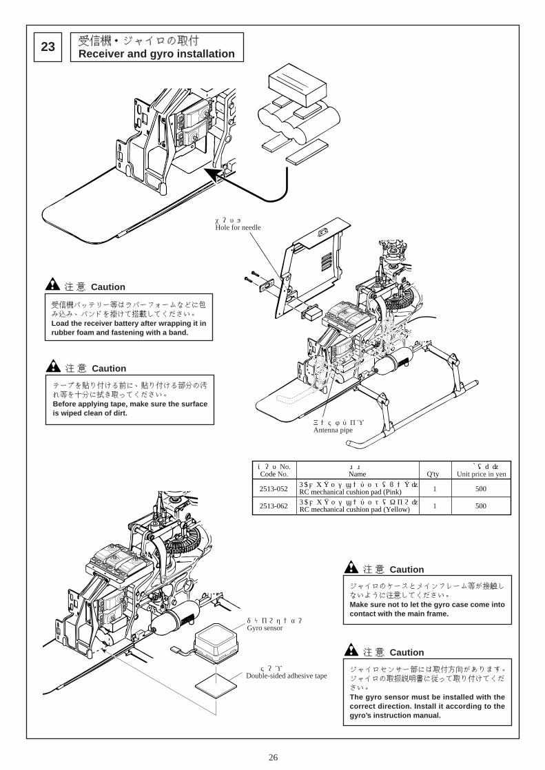
ニードル用穴Hole for needle
アンテナパイプAntenna pipe
受信機・ジャイロの取付Receiver and gyro installation23
注 意 Caution
テープを貼り付ける前に、貼り付ける部分の汚れ等を十分に拭き取ってください。Before applying tape, make sure the surfaceis wiped clean of dirt.
注 意 Caution
受信機バッテリー等はラバーフォームなどに包み込み、バンドを掛けて搭載してください。Load the receiver battery after wrapping it inrubber foam and fastening with a band.
両面テープ Double-sided adhesive tape
ジャイロセンサー部 Gyro sensor
注 意 Caution
ジャイロセンサー部には取付方向があります。ジャイロの取扱説明書に従って取り付けてください。The gyro sensor must be installed with thecorrect direction. Install it according to thegyro’s instruction manual.
注 意 Caution
ジャイロのケースとメインフレーム等が接触しないように注意してください。Make sure not to let the gyro case come intocontact with the main frame.
コードNo.Code No.
価格(円)Unit price in yen
入数Q'ty
品 名Name
2513-052RCメカクッションパット(ピンク)RC mechanical cushion pad (Pink) 500
2513-062 5001
1
RCメカクッションパット(キイロ)RC mechanical cushion pad (Yellow)

27
サーボの動作確認Servo movement check24
作業に入る前に送信機用のバッテリーの充電を行ってください。Before starting, recharge the transmitterbattery.
回転方向が逆の場合は、送信機のリバーススイッチを切り替えて、指定の通り動くようにセットしてください。If the rotational direction is reversed, changethe transmitter’s reverse switch and set it tomove as indicated.
サーボ、ジャイロ、電源等の受信機への配線はメーカー、及び製品の組合せにより異なります。各説明書に従って配線を行ってください。The wiring of the servo, gyro, and powersource to the receiver varies depending ontheir respective makers as well as the way theyare assembled. Install the wiring accordingto each instruction manual.
モードIとモードIIの違いは、スロットル&ピッチとエレベータの操作スティックの位置に違いがあります。Modes I and II differ in the positioning of thethrottle, pitch, and the elevator’s operationstick.
注 意 Caution 注 意 Caution
注 意 Caution
スロットル&ピッチ
ラダーエレベーター
エレベーター
エルロン
ロー(スロー)
モード I
MODE II
Elevator
High
Aileron
Right
Down
Left
Right
Left
Rudder
Throttole and pitch
Low (slow)
Up
アップ
ハイ
ダウン
左
左右
右
エルロンサーボAileron servo
エレベーターサーボElevator servo アップ
Up
スロットルサーボThrottle servo
ダウンDown
左Left
ラダーサーボRudder servo
右Right
ピッチサーボPitch servo
スローSlow
ハイHigh
左Left
右Right
ハイHigh
ローLow

28
ローターヘッド部のリンケージRotor head linkage25
ロッドエンド ...................... 8Rod end
ロッドエンドM2X12.5 ....... 4Rod end M2X12.5
25mm
約11mm
Approx. 11mm
12mmロッドエンドM2X12.5Rod end M2X12.5
約 3mmApprox. 3mm
40mm
約29mmApprox. 29mm
ミキシングアームロッド(2セット)Mixing arm rod (2 sets)
スタビライザーコントロールロッド(2セット)Stabilizer control rod (2 sets)
ピッチロッド(2セット)Pitch rod (2 sets)ピッチロッドはメインブレードを取付後、実際に
ピッチを測って再調整をします。After installing the main blade, measure thepitch and readjust the pitch rod.
注 意 Caution
ダブルリンクDouble link
ミキシングアームロッドMixing arm rod
ミキシングアームロッドMixing arm rod
スタビライザーコントロールロッドStabilizer control rod
スタビライザーコントロールロッドStabilizer control rod
ピッチロッドPitch rod
ピッチロッドPitch rod
ダブルリンクDouble link

29
エルロンのリンケージAileron linkage26
エルロンロッド(2セット)Aileron rod (2 sets)
ロッドエンド ...................... 4Rod end
M2X10PH ............................. 2
M2ナット ............................. 4M2 nut
ø5ボール .............................. 2ø5 ball
90mm
約81mmApprox. 81mm
送信機のエルロンスティックとトリムがニュートラルにあることを確認してください。Check that the transmitter’s aileron stick and trim are in neutral.
送信機のスティックとトリムがニュートラルの時、機体前方から見てスワッシュプレートが水平になるように、エルロンロッドの長さを調整してください。With the transmitter’s stick andtrim in neutral, view the unit fromthe front and adjust the length ofthe aileron rod so that the swashplate is horizontal.
Futaba JR SANWA
大Large
大Large
モードI Mode I
モードII Mode II
約13mmApprox. 13mm
M2X10PH
φ5ボールø5 ball
不要な部分はカットするCut out any unnecessary parts.
M2ナットM2 nut
M2ナットM2 nut
90°
エルロンロッドAileron rod
エルロンロッドAileron rod
水平Horizontal
水平Horizontal

30
27
送信機のエレベータスティックとトリムがニュートラルにあることを確認してください。Check that the transmitter’s elevator stickand trim are in neutral.
ロッドエンド ...................... 1Rod end
エレベーターのリンケージElevator linkage
送信機のスティックとトリムがニュートラルのとき、機体側面から見てスワッシュプレートが水平になるようにエレベータロッドの長さを調整してください。With the transmitter’s stick and trim in neutral,view the unit from the side and adjust the lengthof the elevator rod so that the swash plate ishorizontal.
83mm
約76.5mmApprox.76.5mm
エレベーターロッドElevator rod
ø1.8ピンバイスで穴を開ける。Make holes with the ø1.8 pin vise.
ロッドは、サーボホーン下面より差し込みます。Insert the rod from the bottom of the servo horn.
水平Horizontal
Futaba JR SANWA
小Small
モード IMode I
モード IIMode II
約11mmApprox. 11mm
不要な部分はカットするCut out any unnecessary parts.
90°
エレベーターロッドElevator rod
31
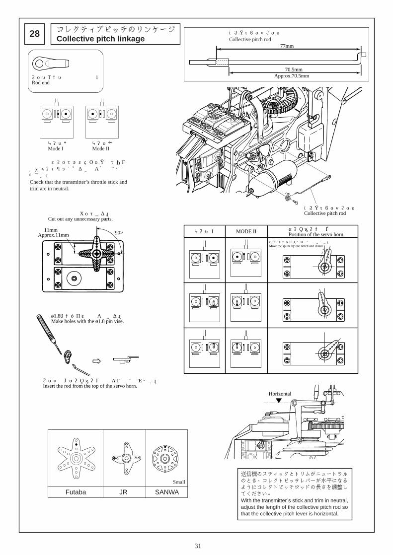
コレクティブピッチのリンケージCollective pitch linkage28
送信機のスロットルスティックとトリムがニュートラルにあることを確認してください。Check that the transmitter’s throttle stick andtrim are in neutral.
コレクトピッチロッドCollective pitch rod
ロッドエンド ...................... 1Rod end
送信機のスティックとトリムがニュートラルのとき、コレクトピッチレバーが水平になるようにコレクトピッチロッドの長さを調整してください。With the transmitter ’s stick and trim in neutral,adjust the length of the collective pitch rod sothat the collective pitch lever is horizontal.
77mm
約70.5mmApprox.70.5mm
水平Horizontal
ø1.8ピンバイスで穴を開ける。Make holes with the ø1.8 pin vise.
ロッドは、サーボホーン上面より差し込みます。Insert the rod from the top of the servo horn.
不要な部分はカットする。Cut out any unnecessary parts.
90°約11mmApprox.11mm
Futaba JR SANWA
小Small
モードIMode I
モードII Mode II
コレクトピッチロッドCollective pitch rod
モード I サーボホーンの位置Position of the servo horn.
スプラインを1コマずらして取付けます。Move the spline by one notch and install.
MODE II

32
スロットルのリンケージThrottle linkage29
スロットルロッドThrottle rod
83mm
約80mmApprox. 80mm
送信機のスロットルスティックとトリムがニュートラルにあることを確認してください。Check that the transmitter’s throttle stick andtrim are in neutral.
モード IMode I
モード IIMode II
スロットルレバーにスロットルロッドを取り付け、キャブレターを全閉ににしたとき、スロットルロッドがクーリングファンカバーに接触しないように、M5ナットをゆるめて調整してください。(調整後は、M5ナットをしっかりと締めてください。)Install the throttle rod to the throttle lever and, by loosening the M5 nuts,check that the throttle rod does not come into contact with the cooling fancover with the carburetor fully closed. (After adjusting, completely retightenthe M5 nuts.)
不要な部分はカットする。Cut out any unnecessary parts.
約13mmApprox. 13mm
90°
Futaba JR SANWA
大Large
スロットルレバーThrottle lever
キャブレターCarburetor
全開の位置
全閉の位置
スロットルレバーThrottle lever
M5ナットM5 nut
Fully-open position
Fully-closed position
モード I サーボホーンの位置Servo horn position
スロットルレバーの位置Throttle lever position
スロットルロッドと送信機の調整
送信機のスティックがフルハイのとき、サーボに負担がかからないようロッドの長さを調整してください。With the transmitter’s stick at full high, adjust the length of the rods without putting any burden on the servos.
送信機のスティックとトリムがフルスローのとき、サーボに負担がかからないよう送信機の舵角調整機能(ATV,TRVL ADJ,EPAなど)を使ってスロー側の舵角を調整してください。標準値70~80%With the transmitter’s stick and trim at full slow and without putting any burden on the servos, use the rudder-angle adjustment functions (ATV, TRVL, ADJ, EPA, etc.) to adjust the rudder-angle on the slow side. Standard value is 70 to 80%.
MODE II
全開の位置
全閉の位置
Adjust the throttle rod and the transmitter.
Fully-open position
Fully-closed position
スロットルロッドThrottle rod
ø1.8ピンバイスで穴を開ける。Make holes with the ø1.8 pin vise.
ロッドは、サーボホーン上面より差し込みます。Insert the rod from the top of the servo horn.

33
ラダーのリンケージRudder linkage30
モードI Mode I
モードII Mode II
ø1.8ピンバイスで穴を開ける。Make holes with the ø1.8 pin vise.
ロッドは、サーボホーン下面より差し込みます。Insert the rod from the bottom of the servo horn.
約11mmApprox. 11mm
M3X3SS
Cut out any unnecessary parts.
90°
90°
不要な部分はカットする
送信機のエレベータとスロットルのスティックとトリムがニュートラルにあることを確認してください。Check that the stick and trim of the transmitter’selevator and throttle are in neutral.
Futaba JR SANWA
小Small
しっかりと締付けてください。Tightly fasten.
注 意 Caution

34
各舵の動作確認Rudder movement check31
メインブレードの取付Main blade installation32
確認する場所Check points
機首方向Nose direction
スワッシュプレートを機体後方から見たとき。When viewing the swash plate from the rear of the unit.
When viewing the swash plate from the side of the unit.
テールケースを上から見たときWhen viewing the tail case from the top.
スワッシュプレートを見たときWhen viewing the swash plate.
スロットルレバーを見たときWhen viewing the throttle lever.
モード I Mode II
スワッシュプレートを機体側面から見たとき。
左図と動きが一致しないときは、サーボの回転方向が逆になっています。送信機のリバース機能で回転方向を合わせましょう。(各送信機の説明書を参考にしてください。)If the movement does not match the illustration on the left, the rotational orientation of the servosis reversed. Switch the rotational orientation with the transmitter’s reverse function. (Refer to the instruction manual for each transmitter.)
ナットはゆるみ防止のため ,ナイロンナットになっています。キャップスクリューのねじがナイロン部分まで届くまで締めこんでください。ネジがゆるむと飛行中にメインブレードが外れて飛んでしまうなど、思わぬ事故を起こす可能性がありますので入念に確認してください。Nylon nuts are used in order to prevent loosening.Completely tighten the cap screws so that they touch thenylon part. Loose screws could cause the main blade tofly off when the unit is in flight greatly increasing thepossibility of a serious accident. Please exercise caution.
キャップボルトは、メインブレードが軽く動く程度に、左右の
均等に締付けてください。Fasten the cap bolts evenly on the left and right so as to letthe main blade move freely.
M4X28CS ............................. 2
M4ナイロンナット ............. 2M4 nylon nut
M4X28CS
M4ナイロンナットM4 nylon nut
注 意 Caution
注 意 Caution

35
メインブレードMain blade
スタビライザーStabilizer
ピッチの測り方Pitch measurement33
1. メインブレードの先端から約 80mmのところにピッチゲージを取付け、機体の前方に向けてください。Install the pitch gage at about 80mm from the tip ofthe main blade and point it towards the front of theunit.
ラジアスブロックRadius block
スライドブロックSlide block
スロットルスティックがフルハイのとき、スライドブロックとラジアスブロックが干渉しませんか?Does the slide block interfere withthe radius block when the throttlestick is at full high?
スロットルスティックがフルスローのとき、ピンがスライドブロックから抜けることはありませんか?Does the pin fall out of the slideblock when the throttle stick isat full slow?
不具合があるときは、ラジアスブロックを上下に移動させ調整してください。In case of a malfunction, move the radiusblock vertically and adjust.
Checkチェック Checkチェック
⇦⇨
注 意 Caution
ぶつかるTouches.
ぬけるComes out.
平行Aligned
2. 送信機のスロットルスティックを動かし、スタビライザーバーとピッチゲージを平行にし、指された目盛りを読んでください。測定するときは実際に飛行しているときのようにメインブレードの先端を軽く持ち上げて測るとより正確に測れます。Move the transmitter’s throttle stick, make the stabilizer barand pitch gage horizontal, and read the indicated graduations.When measuring, hold the tip of the main blade up slightly tosimulate its position during flight for a more accuratemeasurement.

36
ピッチ/スロットルの設定Pitch and Throttle Setting34
※ 1別頁 送信機別データシートを参照してください。See attachment for transmitter data.
ピッチの設定(このデーターはコンピュータプロポを使用したものです。)※エンジン、燃料、マフラー等により変化します。 一般的な目安です。
注 意 Cautionこの設定は一般的なピッチカーブです。(コンピュータプロポ使用時のものです。)エンジン、機体、燃料、マフラー等によっては異なる場合があります。フライトをして調整してください。
ピッチゲージをメインブレードの先端から約80mmにとりつけ、スタビライザーバーを水平にしてピッチゲージで測ります。
(メインブレードを少し持ち上げて測ります。)Install the pitch gage at approx. 80 mm from the end of the main blade having thestabilizer bar horizontal and measure with the pitch gage.(Lift the main blade slightly and measure.)
ピッチカーブの設定設定の行い方はご使用の送信機の説明書をご覧ください。
スロットルの設定(このデーターはコンピュータプロポを使用したものです。)※エンジン、燃料、マフラー等により変化します。 一般的な目安です。
注 意 Caution必ずヒロボー製ピッチゲージ (2513-040) を使用してください。Make sure to use only Hirobo manufactured pitch gages (2513-040).
Pitch setting(This data originated from the use of a programmable transmitter.)*Varies depending on the engine, fuel, muffler, etc.
General guidelines.
Pitch curve settingFor the setting method, refer to the instruction manual of the transmitter used.
Throttle setting(This data is for when a programmable transmitter is used.)*Varies depending on the engine, fuel, muffler, etc.General guidelines.
This setting is for a common pitch curve.(Obtained when using a programmable transmitter.)May vary depending on the engine, fuel, muffler, etc.First fly the unit and then adjust.
注 意 Caution
ローター回転数は2000rpm以下で使用してください。Use with a rotor speed of 2,000 rpm or less.
少し持ち上げて測ります。Lift slightly and measure.
約80mmApprox. 80mm
オートローテーションAuto-rotation
ローピッチLow pitch
ハイピッチHigh pitch
ホバリングHovering
コンディションCondition
ホバリングHovering
アイドルUP1Idle UP1
8˚ ~ 9˚ 8˚ ~ 9˚
5˚ ~ 6˚ 3˚
10˚
-3˚ -5˚ -5˚
モード I Mode II
100%
50%
0%
50%
0%
100%
50%
0%
ホバリングHovering
アイドルUP1Idle UP1
オートローテーションAuto-rotation
スティック:ローStick : Low
スティック:中立Stick : Center
スティック:ハイStick : High
スティック:ローStick : Low
スティック:中立Stick : Center
スティック:ハイStick : High
スティック:ローStick : Low
スティック:中立Stick : Center
スティック:ハイStick : High
100%
エンジンがアイドリングまたはエンジンカットの位置であることEngine is in idle position or off.
100%
50%
0%
100%
50%
0%
100%
50%
0%
ホバリングHovering
オートローテーションAuto-rotation
アイドルUP1Idle UP1
スティック:ローStick : Low
スティック:中立Stick : Center
スティック:ハイStick : High
スティック:ローStick : Low
スティック:中立Stick : Center
スティック:ハイStick : High

37
サイドカバーの取付Side cover installation35
サイドカバーRSide cover R
サイドカバーLSide cover L
M3X8PH
M3X8PH
M3X12TS-2
M3X8TS
オイルタンクOil tank
黒Black
白White
ジョイントパイプJoint pipe
燃料フィルター(別売)Fuel filter (Sold separately)2513-038 ¥300
マフラーニップルへTo the muffler nipple
キャブレターニップルへTo the carburetor nipple
M3X8PH ............................... 2
M3X12TS-2 .......................... 4
M3X8TS ............................... 2
燃料フィルターの使用をおすすめします。The use of a fuel filter is recommended.
配管図Piping diagram

38
ダミーブレースの組立Dummy brace assembly36
ダミーエンジンの組立Dummy engine assembly37
ダミーブレース前Dummy brace (Front)
ダミーダンパーDummy damper
ダミーブレース後Dummy brace (Rear)
M2X12PH
M3X8TS
M3ナットM3 nut
M3X8TS
ダミーブレース後Dummy brace (Rear)
ダミーブレース前Dummy brace (Front)
M3X8PH
M3X8TS
M2X10TS-2
M2X10TS-2
M3X10TS-1
M3X30TS-1
黒Black 黒
Black
白White
エアーダクトAir duct
ゴールドGold
ダミーエンジン本体Dummy engine
ガンメタGun metallic
ギヤボックスGear box
ダークグレーDark gray
ダークグレーDark gray
配電ボックスWiring box
位置決め後、下穴をø2程度あけます。�After positioning, open a hole of about ø2 in the bottom of the dummy engine.
M3X10TS-1
M3X8TSM3X8TS
エアーインテークAir intake
白White
ガンメタGun metallic
位置決め後、下穴をø2程度あけます。�After positioning, open a hole of about ø2 in the bottom of the dummy engine.
ダークグレーDark gray
水平ラインLevel line
前側Front
M2X12PH ............................. 4
M3X8TS ............................... 6
M3X8PH ............................... 2
M3ナット ............................. 2M3 nut
M2X10TS-2 .......................... 9
M3X30TS-1 .......................... 1
M3X10TS-1 .......................... 6
M3X8TS ............................... 3
ネジ止め後、各部に瞬間接着剤を流します。塗装をするとさらにスケール感が増します。塗装はウレタン塗料を使い、各単体パーツで行います。After locking the screw threads, applyinstant adhesive to each part. The senseof scale can be further increased bypainting. Use urethane paint and painteach part separately.
穴の大きさが違います。ネジの入りやすい方と入りにくい方を組み合わせて下さい。The holes have different sizes. Fit the holeinto which it is easy to insert the screwtogether with the hole into which it isdifficult to insert the screw.
ネジの入りやすい方からネジを入れます。Insert the screw from the side of the hole intowhich it is easy to insert the screw.

39
コクピットの組立Cockpit assembly38
LMメーターデカールLM meter decal
白紙White paper
メーターパネルMeter panel
ダークグレーDark gray
計器盤Instrument panel
ダークグレーDark gray
瞬間接着剤Instant adhesive
計器盤Instrument panel
椅子RSeat R
スティックStick
椅子LSeat L
コクピット基台Cockpit base portion
白White
ダークグレーDark gray
瞬間接着剤Instant adhesive
グレーGray
ダークグレーDark gray
ダークグレーDark gray
瞬間接着剤Instant adhesive
メーターパネルの形に合わせ、はみ出さない様にカットします。後ろに白い紙を貼り付けます。Align it with the meter panel and cut sothat there are no protruding parts. Affix apiece of white paper to the back.
塗装はウレタン塗料を使い、各単体パーツで行います。内装色は機体のカラーリングによって異なりますので、より実機に忠実に塗装されたい方は実機の写真などを参考にして下さい。Use urethane paint and paint each partseparately.Since the colors used inside differdepending on the coloring of the fuselage,those who would like a finished productwhich is as close to the real thing aspossible should refer to photographs ofan actual helicopter.
40
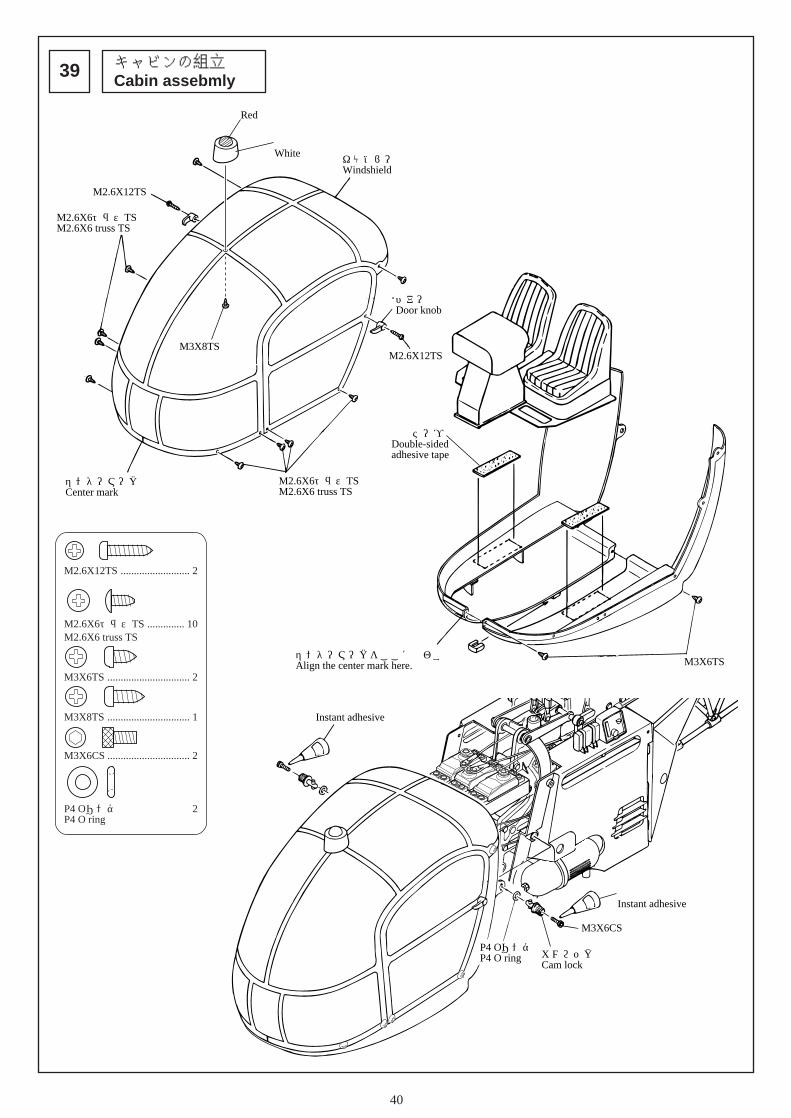
キャビンの組立Cabin assebmly39
キャノピーWindshield
センターマークCenter mark
ドアー取手Door knob
M2.6X12TS
M2.6X12TSM3X8TS
M3X6TSセンターマークをここに合わすAlign the center mark here.
両面テープDouble-sided adhesive tape
M2.6X6トラスTSM2.6X6 truss TS
M2.6X6トラスTSM2.6X6 truss TS
赤Red
白White
M2.6X12TS .......................... 2
M2.6X6トラスTS .............. 10M2.6X6 truss TS
M3X6TS ............................... 2
M3X8TS ............................... 1
M3X6CS ............................... 2
P4 Oリング .......................... 2P4 O ring
M3X6CS
カムロックCam lock
P4 OリングP4 O ring
瞬間接着剤Instant adhesive
瞬間接着剤Instant adhesive

41
デカールの貼付け、塗装についてAffixing the decals and painting40
キャビン、サイドカバー、リヤカバー、テールトラス、ダミーブレース、スキッドをオリジナルのカラーで塗装をされたい場合は、ウレタン塗料をご使用下さい。ただし、材料の性質上、時間の経過とともにはがれる場合があります。
まず、15、16のドアーサッシ部をラインに合わせて貼ります。8、9、10、11を今貼った15、16のデカールの合わせ部に合わせて貼ります。10、11は中心で左右に分かれています。また、7デカールはセンターマークが中心ですので中心を合わせて貼って下さい。キャノピーデカールの前部の位置関係は図の通りです。No.10, 11はセンターを合わせます。14デカールは上下位置を注意して下さい。貼る前にラインデカールのセンターマーク(黒色)をよく確かめて下さい。
First, affix the door sashes (15, 16) along the line. Affix decals 8, 9, 10 and 11in alignment with 15 and 16. Decals 10 and 11 are split into left and right sides.Affix decal center after aligning the center mark.The decals at the front of the canopy are arranged as shown in the diagram.Align the center marks of decals 10 and 11. Pay attention to the vertical level ofdecal 14. Before affixing, check with the center mark of the line decal (black).
1311
1622
18
1417
1521
1920
7
8
12 10
9
9
15
8
7 11
10
14
18
17
21
13
12
19
20
22
16
Those who would like to paint the cabin, side cover, rear cover, tail truss, dummybrace and skid in the original color should use a urethane paint. However, dueto the properties of the material, the paint may begin to peel with time.

42
完成チェックChecking final assembly41
OIL (第1軸ベアリング)(1st shaft bearing)
OIL (テ-ルピッチプレート)(Tail pitch plate)OIL (メインギヤベベル部)
(Main gear bevel section)
① サーボの取付方向は間違っていませんか?② スティックの操作通り各舵は動いていますか?(サーボの回転方向と各ロッドとの接続を確認して下さい。)
③ ジャイロのケースが本体に触れていませんか?④ スキッドはしっかり取り付けられていますか?⑤ テールドライブシャフトは確実にネジ止めされていますか?
※ 排油もれ対策としてエンジン・マフラーにコーキング剤でシールして下さい。
※ メインギヤのベベルギヤ、ベベルピニオンギヤに付属のプラスチック用グリースを給油して下さい。
① Check that the servos mounted in the correct directions.② Check that each rudder moves in accordance with the stick operation. (Check
the servo rotation direction and connection of each rod.)③ Check that the gyro case is not touching the body or canopy.④ Check the skids are firmly mounted in the correct positions.⑤ Check that the screws of the tail shaft have been tightened.
※ Seal the engine muffler with a caulking agent as a countermeasure againstleakage of waste oil.
※ Lubricate the bevel gear and bevel pinion gear of the main gear with thesupplied plastic grease.

43
3.フライト編 Flightヘリコプターは、メインローター、テールローターが高速で回転します。飛行には次の事に十分注意し、安全なフライトをお楽しみ下さい。
機体の運搬
飛行場までの機体の運搬で、車内で機体が倒れたりすることのないよう、きちんと固定して下さい。きちんと固定していないと、部品の破損につながり、安全なフライト性能が得られなくなる可能性があります。
注意
飛行の場所 飛行させてはいけない所
○ 近くに人がいる○ 近くに建物がある○ 線路、幹線道路、電線などに近い所
Caution
The airfield Places where the unitshould not be flown.
○ Near people ○ Near buildings ○ Near roads, railway tracks, or power lines
○ ネジが確実に締まっているか、もう一度確認して下さい。新しいうちは、ビス類もゆるみがちです。フライトごとに必ずチェックして下さい。
○ 送信機の電池及び受信機用バッテリーの充電、電圧は十分か確認して下さい。
万が一に備えて、「ラジコン保険」の加入をおすすめします。詳しくは本製品をお買い求めになった販売店へお問い合わせ下さい。
Transporting the unit
飛行前の機体の点検
安全対策
Checking the unit before flight
Safety measures
注意 Caution
The helicopter’s main and tail rotors spin at very high speeds. Make sure tofollow these instructions for a safe and enjoyable flight.
When transporting the unit to an airfield, secure it in a way so as to prevent itfrom falling over. Failure to do so may result in the breakage of componentswhich may compromise flight performance and safety.
○ Check that all of the screws are firmly tightened. New units tend to havemany loose screws. Make sure to check them before every flight.
○ Check that the transmitter and receiver batteries are fully charged.
To be prepared in the event of an accident, we recommend that you take out aninsurance policy for radio controlled model aircraft. For more details, contactyour dealer.

44
出かける前に Before leaving for the airfield
☆ まずは、イメージフライト
● ここでは操縦の基本となる各舵の動きを指先に覚え込ませます。自然に指が動くようになるまで反復練習!!
1. 部屋の真ん中に機体を置きます。(電源は“OFF”の状態)2.「エルロン左右、ラダー右 ・ 左、エレベーターアップ ・ ダウン、
スロットルハイ ・ スロー・・・」と声を出しながらスティック操作を練習します。
3. このイメージ練習は後のフライトで必ず目に見えない効果を発揮します。くどい位に反復練習しましょう。
4. カセットレコーダーに操作を吹き込んでおき、それに従って練習するのも効果的です。
モード I
エレベーターElevator
Mode II
アップUp
ダウンDown
スロットルThrottle
スローSlow
ハイHigh
エルロンAileron
右Right
左Left
ラダーRudder
右Right
左Left
Do an imaginary flight first.
Familiarize your fingers with the movement of the rudders. Thisis the basics for maneuvering the unit. Practice repeatedly untilyour fingers move naturally.
1. Place the unit in the center of the room. (Make sure the power is turnedoff.)
2. Practice the operation of the stick while saying out loud, “aileron left/right”, “rudder left/right”, “elevator up/down”, “throttle high/low”, etc.
3. This imaginary flight practice method is very effective and should be donerepeatedly until reaching perfection.
4. An effective practice method is to record some operation commands inany order with a cassette recorder and to play them back moving the controlsas you hear them being called out.

45
シリコンチューブのジョイント部分をはずし、給油します。ゴミが入らないように注意します。燃料タンクがいっぱいになったら、給油をやめジョイント部分をつなぎます。
① ニードルをいっぱいしめます。② つぎに1・1/4~ 1・1/2 回転開きます。
(開閉度合は、エンジン、燃料によって異なります。)
1 Completely close the needle valve.2 Open the needle valve 1.25 to 1.5 turns. (The extent
to which it is opened depends on the engine, fuel,etc.)
ニードルが開き過ぎると燃料が入りすぎ、エンジンがかぶります。逆に閉じすぎると燃料が薄くなり、エンジンが焼けます。
エンジン始動の準備 Preparations prior to starting the engine
< 給油 ><Filling the fuel tank>
< ニードル調整 ><Needle valve adjustment>
Let’s go to the airfield!
Check again Are the screws firmly tightened?
Are the transmitter and receiver batteries fully charged?
Caution☆ もう一度チェック → ネジは確実に締まっていますか?☆ プロポ及び受信機用のニッカドバッテリーは充分に充電されてい
ますか?
注意
フライトに出かけよう
近くにラジコン模型で遊んでいる人がいたら、
必ず使っている周波数のチェックをしてください。
また、自分の使うバンドを相手に伝えておきます。同じ周波数が、混信した場合、誤動作が発生し大変危険です。
☆ 各舵は、スティック通りに動いていますか。Are the rudders moving in accordance with the controls?
☆ プロポの説明書に従って距離テストを行ないます。
送信機の電源スイッチをON!Turn on the transmitter
受信機 ・ ジャイロの電源スイッチをONTurn on the receiver and gyro
飛行場に着いたら When arriving at the airfield
注意 Caution
動作確認 Check the movement
OFFは、逆の順序Reverse the above order to turn off
エンジンへTo engine
ポンプへ To fuel pump
燃料タンクへTo fuel tank
Perform a range test following the transmitter’s instruction manual.
Separate the silicon tube at its joint and proceed with refueling.Be careful to prevent dirt from entering the tube. When thetank is full, stop refueling and reconnect the joint.
If there are others operating radio controlled model aircraft atthe airfield, make sure to check their frequency and tell themwhat frequency you’re using. Identical frequencies will causeinterference which may result in mishandling and drasticallyincrease the risk of danger.
Opening the needle valve too muchwill flood the engine and closing ittoo much will burn-up the engine.
46
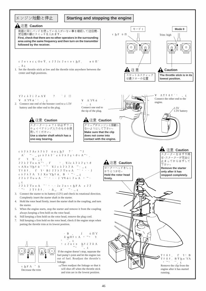
1. スロットルスティックがスロー、スロットルトリムが中立~ハイにする。
1. Set the throttle stick at low and the throttle trim anywhere between thecenter and high positions.
エンジン始動と停止 Starting and stopping the engine
周囲に同じバンドを使っている人がいない事を確認して送信機、受信機の順にスイッチを入れます。Only turn on y
モード I
スロットルスティックは最スローの位置
注 意
トリム: ハイ
3. スターターをスターター用バッテリー(12V)に接続し、回転方向を確認します。スターターにスターターシャフトをしっかりとはめ込みます。
4. ローターヘッドをしっかりと手でつかみ、スターターシャフトをカップリングにさし込み、スターターを回します。
5. エンジンが回り始めたら、ローターヘッドを押さえたまま、スターターを止め、カップリングからはずします。
6. ローターヘッドを押さえたまま、プラグコードをはずします。
7. ローターヘッドを押さえたまま、スロットトリムを最スローにした時、エンジンが止まることを確認します。
スターターをはずす時は、スターターが完全に止まってからはずして下さい。Remove the starteronly after it hasstopped completely.
注意 Caution
ローターヘッドをしっかりとつかむ。Hold the rotor headfirmly.
注意 Caution
エンジンが回り始めたらエンジンからクリップをはずして下さい。Remove the clip from theengine after it has startedrunning.
止まらない時は、燃料パイプのジョイントをはずして止めて下さい。→ スロットルのリンケージを
再調整して下さい。
一方をプラグの頭につなぐ。Connect one end tothe tip of the plug.
クリップがエンジンと接触しないようにして下さい。Make sure that the clipdoes not come intocontact with the engine.
注意 Caution
注意 CautionMode II
The throttle stick is in itslowest position.
Caution
Trim: high
一方をエンジンにつなぐ。Connect the other end to theengine.
1.5V電池1.5V battery
トリムを下げるDecrease the trim
2. ブースターコードを一方1.5V 電池に、もう一方をプラグにつなぐ。
First, check that there are no other operators in the surroundingarea using the same frequency and then turn on the transmitterfollowed by the receiver.
2. Connect one end of the booster cord to a 1.5Vbattery and the other end to the plug.
3. Connect the starter to its battery (12V) and check its rotational direction.Completely insert the starter shaft in the starter.
4. Hold the rotor head firmly, insert the starter shaft in the coupling, and turnthe starter.
5. When the engine starts, stop the starter and remove it from the couplingalways keeping a firm hold on the rotor head.
6. Still keeping a firm hold on the rotor head, remove the plug cord.7. Still keeping a firm hold on the rotor head, check if the engine stops when
putting the throttle trim at its lowest position.
If the engine doesn’t stop, separate thefuel pump’s joint and let the engine runout of fuel. Readjust the throttle’slinkage. Then readjust the linkage so that it
will shut off when the throttle stickand trim are in the lowest position.
スターターシャフトは必ずワンウェイベアリング入りのものを使用してください。Use a starter shaft which has aone-way bearing.
注意 Caution

47
トラッキングの調整は危険ですので、機体から10m程離れて行ないます。
1. スロットルスティックをゆっくりとハイ側に動かし機体が浮かび上がる直前に止めます。ローターの回転面を真横から見ます。
2. ローターの軌跡をよく見て下さい。2 枚のローターが同じ所を通っていればOK ですが、上下にずれている場合、トラッキング調整が必要です。
3. トラッキング調整はピッチロッドのロッドエンドを回して調整します。
A: 軌跡の高いブレード側 ロッドの長さを伸ばす
のピッチロッド
B: 軌跡の低いブレード側 ロッドの長さを縮める
のピッチロッド
Since adjusting the tracking is dangerous, do so at a distanceof at least 10m away from the unit.
トラッキング調整 Adjusting the tracking
注意 Caution
注意
トラッキングがずれていると振動の原因になります。確実に合うまで何度も繰り返します。トラッキング調整を行ったあとでもう一度、ホバリングでのピッチ角が約5.5 となっているか確認して下さい。
Caution
A
1. Slowly raise the throttle stick to its high position and stop just beforethe unit lifts-off the ground.Observe the rotation of the rotor from the side of the unit.
2. Carefully observe the path of the rotor.If both blades appear to move through the same path, it does not needadjustment. However, if one blade is higher or lower than the other,immediate adjustment of the tracking is necessary.
3. The tracking is adjusted by turning the rod end of the pitch rod.A: Pitch rod of the blade spinning with a higher path
Increase the length of the rod.B: Pitch rod of the blade spinning with a lower path
Reduce the length of the rod.
Incorrect tracking causes vibrations. Repeat trackingadjustments over and over until the rotor is correctly aligned.After having adjusted the tracking, check once more that the pitchangle is approx. 5.5º when the unit is hovering.
B
ピッチロッド�Pitch rod

48
周囲に人のいないことを確認して下さい。周囲に障害物がないことを確認して下さい。
☆ 初めにヘリコプターを安全に飛行させるために、操作の基本となるホバリングを確実に行えるよう十分に練習して下さい。
(ホバリングとは機体を一定の位置に保ち、飛行させる事です。)
Make sure that there are no people or obstructions in thevicinity.
ホバリングの練習 Hovering practice
注意 Caution
Step. 1
練習するときは機体の斜め後方10mぐらい離れたところに立ちます。When practicing, stand approximately 10m diagonally behindthe unit.
機体が少し上昇したら、スロットルスティックをゆっくりと下げ、機体を着陸させて下さい。When the unit begins to lift-off the ground,slowly lower the throttle stick and bring theunit back down.
モードI Mode II
機体を上下させ、スロットル操作の感覚を身につけましょう。Continue to practice raising and loweringthe unit from the ground until you feelcomfortable with the operation of thethrottle.
ゆっくりとスロットルスティックをハイ側に上げて下さい。
スロットル操作の練習Throttle operation practice
アンテナは完全に伸ばして下さい。Completely extend the antenna.
Slowly raise the throttlest ick towards i ts highposition.
In order to fly the unit safely, you must first practice hoveringextensively. This constitutes the basis of flight operation. (“Hovering”means keeping the unit in mid-air in a fixed position.)

49
Step. 2 エルロン・エレベーター操作の練習Aileron and elevator operation practice
Step. 3 ラダー操作の練習Rudder operation practice
1. スロットルスティックをゆっくりと上げます。2. 機体が前後左右に動いたら、動いた方向と逆に
エルロン、エレベータースティックを少しずつ動かし、元の位置にもどるようにしましょう。
1. Slowly raise the throttle stick.2. When the unit moves in any direction back, forth,
left, or right, gently move the aileron and elevatorsticks in the opposite direction to return the unit toits original position.
注意 Caution機首が動いてしまったときは、必ずスロットルスティックを下げ、着地させ、立ち位置を機体の斜め後方に移動して練習を再開しましょう。また、機体が遠くに離れてしまった時も一旦、機体を着地させ、機体から10mぐらいのところに近づき、練習を再開しましょう。 If the nose of the unit moves, lower the throttle stickand land the unit. Reposition yourself diagonallybehind the unit and continue practicing. If the unit fliestoo far away from you, land the unit, get to about 10mbehind it, and continue practicing.
1. スロットルスティックをゆっくりと上げます。2. 機首が左右に動いたら、動いた方向と逆にラダー
スティックを少しずつ動かし、元の位置にもどるようにしましょう。
Step. 4
STEP. 1~3 の操作に十分慣れたら更に操作の精度を上げる為、地面に円などを描き、その円中で移動したりとどまる練習をしましょう。
円運動など移動の練習をするPractice circular movement
Step. 5 ヘリの方向を変えて、ホバリングの練習をするChange the unit’s direction and practice hovering
STEP. 1 ~ 4 を十分に練習したら、機体側面に立ち、 STEP. 1 ~ 4 と同じ練習をします。その後、機体の正面に立ち、同じように STEP.1~ 4 を繰り返し練習しましょう。
STEP 5-1 STEP 5-2
慣れたらだんだん円を小さくするThe more you feel accustomed to the maneuvers, thesmaller you can make the circle.
1. Slowly raise the throttle stick.2. If the nose of the unit moves left or right, gently move the
rudder stick in the opposite direction to get the unit back inits original position.
After you feel comfortable with the maneuvers in steps 1 to 3, increase youraccuracy by drawing a circle on the ground and practice flying the unit withinthat circle.
After you feel comfortable with the maneuvers in steps 1 to 4, stand facing theside of the unit and continue practicing steps 1 to 4. Afterwards, repeat thesame steps standing right in front of the unit’s nose.

50
スロットルスティックをゆっくりと上げていき、機体が浮き上がろうとする時、機体はいろんな方向へ傾きます。これを修正するのがトリムです。
1. ラダーのトリム調整機体が浮き上がろうとする直前に機首が
1. Adjust the rudder’s trim
Just before the unit lifts-off, the nose…
2. エレベーターのトリム調整機体が浮き上がろうとする直前に機体が
2. Adjust the elevator’s trim
Just before the unit lifts-off, the body…
3. エルロンのトリム調整機体が浮き上がろうとする直前に機体が
3. Adjust the aileron’s trim
Just before the unit lifts-off, the body…
各トリムの調整 Adjustment of each trim
症 状Symptom
a の方向へ向くTurns towards a
b の方向へ向くTurns towards b
トリム調整Trim adjustment
トリムを a(左)に動かす。Move the trim towards a (left)
トリムを b(右)に動かす。Move the trim towardsb (right)
症 状 Symptom
c の方向へ向くTurns towards c
d の方向へ向くTurns towards d
トリム調整Trim adjustment
トリムを c(アップ)に動かす。Move the trim towards c (up)
トリムを d(ダウン)に動かす。Move the trim towards d (down)
症 状Symptom
e の方向へ向くTurns towards e
f の方向へ向くTurns towards f
トリム調整Trim adjustment
トリムを e(左)に動かす。Move the trim towards e (left)
トリムを f(右)に動かす。Move the trim towards f (right)
c d
e f
Slowly raise the throttle stick and just as the unit lifts off the ground, you maynotice the unit leaning in different directions. Use the trims to correct this.
モードI Mode II
a b a b
a
b
モードI Mode II
c
d
c
d
モードI Mode II
e f e f

51
以上のことをお調べになって、それでも不具合があるときは使用を中止し、お買上げの販売店または、当社エンジニアリングサービスにご相談下さい。
Should you still have some doubts even after having tried the above,stop using the unit and consult your dealer or Hirobo’s EngineeringService Section.
フライト時のトラブル脱出法 How to eliminate troubles during flight
トラッキングTracking
ホバリング時のローター回転数Rotation of therotor duringhovering
ジャイロ感度Sensitivity of thegyro
症状Symptom
合わないOut of alignment
回転が低いLow rotation
回転が高いHigh rotation
ホバリング時にテールが左右にふらつくThe tail sways left and rightduring hovering.
全速飛行中にテールが左右にふれるThe tail sways left and rightduring flight at full speed.
原因Cause
ピッチロッドによる調整ができていない。Adjustment using the pitch rods hasnot been done.
メインブレードのピッチ角が高い。Pitch of the main blade is high.
メインブレードのピッチ角が低い。Pitch of the main blade is low.
ジャイロ感度が低いThe sensitivity of the gyro is low.
ジャイロ感度が高いThe sensitivity of the gyro is high.
対策What you should do
ピッチロッドの長さを調整してトラッキング調整を行ないます。Adjust the length of the pitch rods.
ピッチロッドの調整(ホバリングでローター回転 1,450rpm くらい)Adjust the pitch rod. (The rotor should rotate atabout 1,450rpm during hovering.)
ピッチロッドの調整(ホバリングでローター回転 1,450rpm くらい)Adjust the pitch rod. (The rotor should rotate atabout 1,450rpm during hovering.)
感度を上げますIncrease the sensitivity
感度を下げますDecrease the sensitivity
部品交換等で、いらなくなった部品の処分は、次の点に注意して下さい。○ 石油燃焼機器類(燃料タンク等)は、必ず燃料を抜いてから、廃却す
る。○ 素材によって分別して廃却する。○ 使用済みのニカド電池は、貴重な資源です。
廃棄に際しては、ニカド電池リサイクル協力店へ持参し、再利用にご協力下さい。
① 1日のフライトが終了し、清掃をする際は次の点に注意して行って下さい。
② 機体の油汚れ等は、決して水洗いはしないで下さい。無線機器の故障や金属部品のサビの原因となります。ウエスで拭き取るか、アルコールを霧状に散布して、かるくウエスで拭き取るようにして下さい。
③ タンクに残った燃料は、全て排出して下さい。また、キャブレターは閉まった状態で保管して下さい。
④ 保管の際、メインブレードは取り外し、またスイッチが、OFFの状態である事を確認して下さい。
⑤ 日の当たる場所、また車内の長時間の放置は変色、変形の原因になりますので、注意して下さい。
⑥ 長期保管をする場合は、上記の状態で、風通しのよい場所で保管して下さい。
1 After finishing your flight for the day, follow these steps when cleaningyour model.
2 Never use water to wash any oil stains etc from the unit. It may result in theradio controlled device malfunctioning or the rusting of metal parts. Wipewith a soft cloth or spray the surface with alcohol and wipe the stains offlightly with a soft cloth.
3 Remove all remaining fuel from the tank and store the unit with the carburetorclosed.
4 Make sure to remove the main blade and turn the switch to the OFF positionwhen storing the unit.
5 To reduce the risk of discoloration or distortion of the body, make sure notto store the unit in direct sunlight or in a car for long periods of time.
6 When storing the unit for long periods of time, follow the steps above andstore in a well-ventilated area.
Make sure to follow these steps for the disposal of old parts when replacingwith new ones.- Remove all remaining fuel from the tank and fuel line, etc.- Separate objects according to the substances they are made of.- Used nickel-cadmium batteries are a valuable resource. When disposing them,
make sure to take them to a recycle shop.
廃棄方法とリサイクル Disposal and recycling
清掃・保管方法 Cleaning and storage

52
チェック Check
1. スロー絞りの調整2. ヘッドをしっかりと押さえて カラぶかしをする。3. 燃料又はプラグの変換1. Adjust the slow throttle.2. Firmly hold the rotor head down and let the engine idle.3. Replace the plug or fuel.
チェック Check
1. スロットルスティック又はトリムを少し上げる。2. スロー絞りの調整3. 燃料又はプラグの変換1. Slightly raise the throttle stick or trim.2. Adjust the slow throttle.3. Replace the plug or fuel.
基本的なチェックBasic items to be checked
1. 始動用電池はありますか?また、ブースターコードが接触不良になっていないかチェック2. スターター用バッテリーは、充電されているかチェック3. スターターの回転方向が正しいかチェック4. ニードルの開度のチェック5. スロットルレバーの動きをチェック
(スロットルホールドになっていないか)6. プラグが切れていないかチェック7. シリコンチューブが破損していないか、また圧迫されて、燃料が流れなくなっていないか
チェック8. 燃料フィルターにゴミが貯まっていないかチェック9. 燃料がエンジン内へ行き過ぎていないかチェック
プラグをはずし、スターターでエンジンを回し、燃料を出します。
1. Is there a starter battery? Are the booster cords correctly connected?2. Is the starter battery fully charged?3. Is the starter turning in the correct direction?4. Check the opening of the needle valve.5. Is the throttle lever moving correctly?6. Check that the engine plug is working correctly?7. Check if there’s any damage to the silicon tubing or if there’s any pressure in them that would
hinder the smooth flow of fuel.8. Is the fuel filter clean?9. Is there too much fuel flowing into the engine?
Remove the engine plug and turn the engine using the starter to blow all the fuel out.
エンジン始動からホバリングまでがスムーズでない場合は、次の項目をチェックしてください。Should the unit not operate smoothly from engine start-up to hovering, check the following items.
どうしてもダメな時はIf it doesn’t work no matter whatyou do
もう一度チャレンジTry again.
チェック Check
1. スロー絞りの調整2. 燃料またはプラグの交換3. メインニードル開度のチェック1. Adjust the slow throttle2. Replace the plug or fuel3. Check the opening of the main needle
valve
((
((
お買上げ店へご相談下さい。Consult your dealer
症状1 Symptom 1
プラグヒートをはずすと止まる。Engine stops when the plug heating isremoved.
エンジンは始動しますか?Does the engine start?
症状 Symptom
ホバリングの直前でエンジンが止まる。Engine stops just before hovering
連続で回転しますか?Does the engine run continuously?
YES NO
YES NO
症状2 Symptom 2
しばらく回転して止まる。Engine stops after running a short time.

53
4.メンテナンス編 Maintenance
各部の点検Check each section.
メインマストの交換Replace the main mast.
ローターヘッドの点検Check the rotor head.
メインマストの点検Check the main mast.
その他の原因(チェック及び交換を必要とします。)ダンパーゴムの摩擦・劣化エンジンクランクシャフトの曲がりブレードのそり
Other causes(Requires checking and/or replacement.)Wear or ageing of the damper rubber,bent crankshaft, warped main rotorblade.
センターハブ交換Replace the center hub.
お買上げ店へご相談下さい。Consult your local distributor.
部品交換Replace the parts.
ホバリングフライトHovering flight
O K
メインブレードの点検Check the main rotor blade.
テールブレードのバランスCheck the tail rotor blade.
バランスを取る(交換)Balance (replace) the tail rotor blade.
センターハブ点検Check the center hub.
YES NO
YES
YES
YES
YES
YES
YES
NO
NO
NO
NO
NO
NO
チェック!部品にキズ、破損があるCheck!Parts are scratched or broken.
チェック!振動があるCheck!There isvibration.
(トラッキングを合わせます)(Set the tracking.)
チェック!バランスが合っているかCheck!The main rotor blade is balanced.
チェック!カケ、ワレ、キズがあるかバランスが合っているかCheck!There are no chips, cracks or scratches.The tail rotor blade is balanced.
チェック!フェザリングスピンドルが曲がっているCheck!The feathering spindle is bent.
チェック!センターハブが曲がっているCheck!The center hub is bent.
チェックポイントCheck point
・スタビライザーバーの曲がり・テールブームの曲がり、へこみ・ラダーコントロールロッドの曲がり - Bent stabilizer bar - Bent or dented tail boom pipe - Bent rudder control rod
バランスを取るBalance the main rotor blade.
必ずメインローターを交換してくださいAlways replace the main rotor.
墜落 ・ 横転した場合In the case of a fall or crash
スピンドル交換Replace the feathering spindle.

54
M3ナイロンナットM3 nylon nut
M3X3SS
M3X16CS
M3ナイロンナットM3 nylon nut
ミキシングアームロッドMixing arm rod
ミキシングアームロッドMixing arm rod
スタビライザーコントロールロッドStabilizer control rod
スタビライザーコントロールロッドStabilizer control rod
II. スタビライザーバーの交換 II. Stabilizer bar replacement
I. メインマストの交換
Lock マークが付いているネジは、ネジロック剤をつけてください。
Apply thread locking agent to the screws indicated with Lock
when assembling.
I. Main mast replacement
1. ローターヘッド部とウォッシュアウト部をつなぐリンケージロッドを取外します。
1. Remove the linkage rod between therotor head and wash-out.
2. ローターヘッドAssyのM3X18CSを取外します。
2. Remove the rotor head assemblyM3X18CS.
4. メインギヤAssyのM3X16CSを取外します。4. Remove the main gear assembly M3X16CS.
5. スワッシュプレート、ウォッシュアウト部は残して、マストを引き上げて取外します。
5. Pull out the main mast leaving theswash plate and wash-out.
キズがある場合は、ヤスリで削ってください。Use a file to remove any scratches.
1. スタビストッパーのM4X4SSを取外します。
1. Remove the stabilizer stopperM4X4SS.
2. スタビブレードの片方を取外します。2. Remove one of the stabilizer blades.
曲がり方がひどい時は、手前でカットすると抜きやすくなります。その時、切断面にバリが残ったら、ヤスリで取除きます。If the stabilizer bar is badly bent, cutting the end nearest will make it easierto remove. Use a file to remove any burrs that may be left after the cutting.
3. マストロックのM4X4SSを取外します。
3. Remove the mast lock M4X4SS.
マストロックMast lock
M4X4SSの取付個所がキズとなっている時は、ヤスリで削ります。Use a file to remove any scratches near theM4X4SS.
M4X4SS

55
M4ナイロンナットM4 nylon nut
M4ナイロンナットM4 nylon nut
ピッチロッドPitch rod
ピッチロッドPitch rod
FW ø4X9X0.8T
FW ø4X9X0.8T
III. スピンドルの交換 III. Spindle replacement
IV. センターハブの交換 IV. Center hub replacement
V. エンジンの脱着 V. Engine replacement
2. ブレードホルダーのM4ナイロンナットを取外します。2. Remove the blade holder M4 nylon nuts.
1. リンケージロッドを外します。1. Remove the linkage rod.
3. ブレードホルダーをはずし、スピンドルを引き抜きます。3. Remove the blade holders and pull out the spindle.
1. IIを参考にスタビライザーバー、スタビアームを取外します。
1. Remove the stabilizer bar and stabilizer armin accordance with II.
2. IIIを参考にブレードホルダー、スピンドルを取外します。
2. Remove the blade holders and spindle inaccordance with III.
3. M3X6PHをゆるめ、シーソーをはずします。
3. Loosen the M3X6PH and remove theseesaw.
4. ヨークのM3X8CSをゆるめ、ヨークを取出します。
4. Loosen the yoke M3X8CS and remove theyoke.
1. マフラー取外します。1. Remove the muffler. 2. エンジンブロックを留めているM3X14CS取り外します。
2. Remove the engine block M3X14CS.
スピンドルSpindle
ヨークYoke
センターハブCenter hub
M3X8CS
M3X8CS
ミキシングアームMixing arm
ミキシングアームMixing arm
M3X6PH
M3X12PH
ø3X4.5X0.5FWø3X4.5X0.5FW
ø3X4.5X0.5FW
ø3X4.5X0.5FW
ø3X4.5X0.5FW
M3X12PHM3X6PH
Brg.ø3X6X2.5F ZZBrg.ø3X6X2.5F ZZ
Brg.ø3X6X2.5F ZZBrg.ø3X6X2.5F ZZ
Brg.ø3X6X2.5F ZZ
Brg.ø3X6X2.5F ZZ
M3X28CS
マフラーMuffler
M3X14CS
M3X14CS
M3X12皿TSM3X12 countersunk TS
FW ø3X9X1
FW ø3X9X1

56
5.補修パーツについて Repair parts
注文書同封の上、お申し込みください。�
消費税(5%)、送料が必要です。�
(お釣りのいらないようにお願いします)�
※切手でのご注文はお受けできません。�
�
FAX、封書、お電話でお申し込みください。�
消費税(5%)、代引送料(代引手数料込)が必要です。�
�
品代金�
一律�
一律�
沖縄・離島�
525�
1,260�
2,520
500円未満�
500円以上�
2,310�1,575�1,470�1,365�1,470�2,310
2,415�1,680�1,575�1,470�1,575�2,415
2,625�1,890�1,780�1,680�1,785�2,625
北海道�東北、関東、信越�北陸、東海�近畿、中四国�九州�沖縄�
1 現金書留� 2 代金引換�
1万円未満�品代金�
地区� 3万円以上�1万円以上�3万円未満�
●注文書(コピーしてお使いください)�
�
品 名�
都・道�
府・県�
市・郡�
区�
( )� ( )�
単 価� 数 量� 金 額�コードNo.
お名前�
お申し込み年月日� 年 月 日�
ご住所�
T E L F A X
指定時間�
ご注文回数�はじめて ・ 2回目以上�
日祝日配達�希望する ・ 希望しない�
無 ・ 有( 時頃)�
フリガナ�
①パーツ代金の合計�
②消費税(5%)�
③送料/代引送料(代引手数料込)�
お支払金額(①+②+③)�
〒�
広島県府中市府川町138 〒726-0004�TEL:(0847 )40-0088 (代) FAX:45-7670�http://model.hirobo.co.jp/
(パーツ係)�
●補修パーツのご購入につきましては、キットを購入された模型店へコード番号と名称を言ってお買い求めください。�●上記の方法で購入が困難な場合は、直接当社へ下記要領にてお申し込みください。��●お届け�商品は小包にて、ご注文受付日から3日~7日後にお届けいたします。�週末・年末年始・ゴールデンウィーク・お盆休み中のご注文は、休み明けから3日~7日後とさせていただきます。�月初めは棚卸しのため1日~3日ほど余分にお時間をいただくこともあります。あらかじめご了承ください。��●商品の交換�商品の不良、配送上の破損、ご注文と違う商品が届いた場合は、お手数ですが商品到着8日以内にお電話�(0847-40-0088)パーツ係までご連絡のうえ、ご返送ください。返送料は当社で負担いたします。�お客様のご都合による返品・交換は受け付けておりませんので、コードNo・品名・数量をご確認のうえ、ご注文ください。��
※ コードNo・品名は商品に表示してあります。商品が届いてすぐに内容をご確認ください。�

57
パーツリストParts list
0402-510
2530-005
2530-0052530-004
2530-004
2506-019
2506-019
2500-086
2506-019
2500-057
2500-057
0402-640
0402-202
2532-029
2532-002
2505-006
2525-0092521-103
2532-047
2505-007
0402-502オプション Optional
オプション Optional
0402-272
2500-082
0402-545
0402-641
2533-005
2525-009
0402-5072533-014
2506-019
0402-208
2505-002
0402-503
2500-068
0402-006
2532-002
0402-505
2532-038
0402-508
2531-003
0402-506
0402-509
0402-055
0402-545
2536-001
2505-007
2533-0052525-009
2500-057
0404-023
2533-031
2509-003

58
コードNo.Code No.
品名Particulars
入数Q'ty
価格(円)Price (Yen)
備考Remarks
0402-006 ダンパーゴムDamper rubber 4 400
0402-055 スタビライザーバーStabilizer bar 2 800
0402-202 ZSヨークZS yoke 1 700
0402-208 スタビライザーブレードStabilizer blade 2 1,200 ナット,スタビブレードフィルム付
Nuts and stabilizer blade film attached
0402-272 スタビブレードフィルムStabilizer blade film 4 400
0402-502 スラストワッシャーThrust washer 2 500 オプション Brg.ø5X10スラストと共に使用可
May be used with option brg. ø5X10 thrust
0402-503 BRG.カラーø9X13X6Brg. collar ø9X13X6 2 300
0402-505 SFセンターハブ H=58SF center hub H=58 1 1,000 ネジ,ナイロンナット付
Screws and nylon nuts attached
0402-506 SFシーソーSF seesaw 1 700 ネジ,ワッシャ-,メタル付
Screws, washers, and metal attached
0402-507 SFミキシングアームSF mixing arm 2 600 ボール,ネジ,ワッシャ-,メタル付
Ball, screws, washers, and metal attached
0402-508 SFスタビコントロールアームセットSF stabilizer control arm set 1 600 スタビストッパー,ボール,ネジ付
Stabilizer stopper, ball, and screws attached
0402-509 SFウォッシュアウトセットSF wash-out set
1式1 set 1,400 ボール,ネジ,ワッシャ-,メタル付
Ball, screws, washers, and metal attached
0402-510 SFスワッシュプレートAssySF swashplate Assembly 1 4,500
0402-545 SFフェザリングスピンドルSF feathering spindle 1 300 ワッシャ-,ナイロンナット付
Washers and nylon nuts attached
0402-640 BE2メインブレード L=550BE2 main blade L=550 2 2,800 取り付け穴ø4ルートエンド組立済
Pre-assembled root end with ø4 holes
0402-641 SF2ブレードホルダーSF2 blade holder 2 1,200 メインブレード取付け穴φ4
Main blade with ø4 holes
0404-023 ラジアスアームRadius arm 2 300
2500-057 Brg. ø3Xø6X2.5F ZZ 2 1,200 オプションOption
2500-068 Brg. ø5Xø13X4ZZ 2 1,200
2500-082 Brg. ø 5X ø 10X4HスラストBrg. ø 5X ø 10X4H thrust 2 1,600 オプション 0402-502 別途必要
Must have option 0402-502 (sold separately)
2500-086 Brg. ø3Xø7X3ZZ 2 1,200 オプションoption
2505-002 M3ナットM3 nut 20 200
2505-006 M3ナイロンナットM3 nylon nut 10 200
2505-007 M4ナイロンナットM4 nylon nut 10 200
2506-019 FW3X4.5X0.5T 10 200
2509-003 ニードルピンø 2X11.8Needle pin ø 2X11.8 2 300
2521-103 カラー 5X8X5.5Collar 5X8X5.5 2 500
2525-009 ø5ボール(AL)ø5 ball (AL) 10 500
2530-004 ピボットボルト(D) ø5X5XM3Pivot bolt (D) ø5X5XM3 2 400
2530-005 ピボットボルト(E) ø5X7XM3Pivot bolt (E) ø5X7XM3 2 300
2531-003 セットスクリュー M4X4Set screw M4X4 10 300
2532-002 キャップスクリュー M3X8Cap screw M3X8 10 400
2532-029 キャップスクリュー M2X10Cap screw M2X10 10 800
2532-038 キャップスクリュー M3X18Cap screw M3X18 10 400
2532-047 キャップスクリュー M4X28Cap screw M4X28 10 600
2533-005 ナベ頭ビス M2X8Pan-head screw M2X8 20 100
2533-014 ナベ頭ビス M3X12Pan-head screw M3X12 20 100
2533-031 ナベ頭ビス M3X10Pan-head screw M3X10 20 100
2536-001 タッピングスクリュー M3X8 トラスTapping screw M3X8 truss 10 100

59
0402-050(30用)
0402-320
2532-004
2532-0102532-012(46用) (For 46 engine)
2532-004
2532-004
2532-004
2532-002
0402-318
2500-048
0402-014
0402-254
2506-010
0402-0232506-010
2538-002
0412-121(30用)
0402-324
0402-642
2500-081
0400-004
0402-310
0402-326
0402-327
2500-048
0402-591
2533-012
2508-003
0402-016
2500-061
0402-207
2508-0032531-003
0412-205
0402-302
0402-321
0402-324
0402-016
2500-080
0402-319
0402-574
オプションOptional0402-378(46用)
オプション Optional0403-232(OS46SF-H用)(For OS46SF-H)0403-211(OS46FX-H用)(For OS46FX-H)
オプション Optional0412-122(46用)(For 46 engine)
オプション Optional
オプション Optional
(For 46 engine)

60
コード�No.Code No.
品名�Particulars
入数�Q'ty
価格�(円�)Price (Yen)
備考�Remarks
0400-004 金属製クラッチベルライニング�Metal clutch bell lining 2 200
0402-014 マストロック�ø8Mast lock ø8 1 300
0402-016 オートロクラッチセット�Auto-rotation clutch set
1 式�1 set 3,000
0402-023 32 用エンジンマウント�Engine mount for 32 engine 1 1,400 ネジ、�FW付�
With screws and FWs
0402-050 マフラーセット�Muffler set
1 式�1 set 2,000
0402-207 ZS メインマスト� P=170ZS main mast P=170 2 1,000
0402-254 SE スターターカップリング�SE starter coupling 1 500
0402-302 S-30 エンジンプレート�S-30 engine plate 1 2,800
0402-310 S-30スターターシャフト�S-30 starter shaft 1 800
0402-318 S-30 メインギヤ�S-30 main gear 1 700
0402-319 SE ベベルギヤ�SE bevel gear 1 500
0402-320 S-30 マフラースペーサー� T=2.0S-30 muffler spacer T=2.0 1 500
0402-321 S-30 金属製ベベルピニオン�S-30 metal bevel pinion gear 1 2,000
0402-324 S-30 メインフレームセット�S-30 main frame set
1 式�1 set 3,300
0402-326 S-30 SE クラッチベル�S-30 SE clutch bell 1 4,000
0402-327 S-30 クラッチ用�Brg.(カラー付)�S-30 clutch bearing (with collar) 1 700
0402-378 S-30 46用エンジンマウント�S-30 engine mount for 46 engine
1 式�1 set 1,500
0402-574 SE メインギヤ�AssySE main gear assembly
1 式�1 set 7,800
0402-591 SE メインギヤ�(77T)SE main gear (77T) 1 3,800
0402-642 SE2クラッチシュー�SE2 clutch shoe 1 3,200
0403-211 46用マフラー�(OS46 FX-H用�)Muffler for 46 engine (for OS46 FX-H) 1 2,000
0403-232 46用マフラー�(OS46 SF-H用�)Muffler for 46 engine (for OS46 SF-H) 1 2,000
0412-121 SDフライホイール�30用�SD flywheel for 30 engine 1 2,000
0412-122 SDフライホイール�50用�SD flywheel for 50 engine 1 2,500 46エンジン使用可�
Usable with a 46 engine
0412-205 SD クーリングファン�SD cooling fan 1 500 0402-518 SFクーリングファン使用可�
0402-518 SF cooling fan usable
2500-048 Brg. ø12 X 16Lワンウエイ�Brg. ø12 X 16L one-way 1 1,500
2500-061 Brg. ø4 X ø9 X 4 ZZ 2 1,200
2500-080 Brg. ø8 X ø19 X 6 ZZ 2 1,200
2500-081 Brg. ø6 X 12Lワンウエイ�Brg. ø6 X 12L one-way 1 1,200
2506-010 FW 3 X 9 X 1T 20 100
2508-003 ストップリング�S-12Stop ring S-12 5 500
2531-003 セットスクリュー�M4 X 4Set screw M4 X 4 10 300
2532-002 キャップスクリュー�M3 X 8Cap screw M3 X 8 10 400
2532-004 キャップスクリュー�M3 X 12Cap screw M3 X 12 10 400
2532-010 キャップスクリュー�M3 X 28Cap screw M3 X 28 10 400
2532-012 キャップスクリュー�M3 X 35Cap screw M3 X 35 10 400 0403-232, 0403-211取付の場合�
For 0403-232, 0403-211 attaching.
2533-012 ナベアタマビス�M3 X 8Pan head screw M3 X 8 20 100
2538-002 サラビス�M3 X 6Countersunk screw M3 X 6 10 200

61
2500-057
2506-0190402-107
0402-524
0402-3062500-054 0402-107
2506-0192500-057
0402-524
0402-308
2506-0322532-029
2500-056
2507-002
2538-003
2500-054
2505-001
2525-009
2525-0090402-107
2533-0122506-010
2533-016
2533-005
0402-307
2524-001
0402-512
0402-025
0402-0250402-512
0402-322
2522-011
2524-014
0402-606
2505-0072506-007
2532-010
2500-0680402-801
0402-0062532-003
2506-004
0402-610
0406-002
2522-009
2534-004
2505-006
0406-003
2524-001
0402-609
2509-006
0402-612
0402-611
0402-607(シュワイザー)0402-131
(ラマ/シャトル)
2509-006
2521-039
2533-005
2530-004
2525-005
0402-673
(オプション3枚ローターヘッド) (Optional three-blade rotor head)
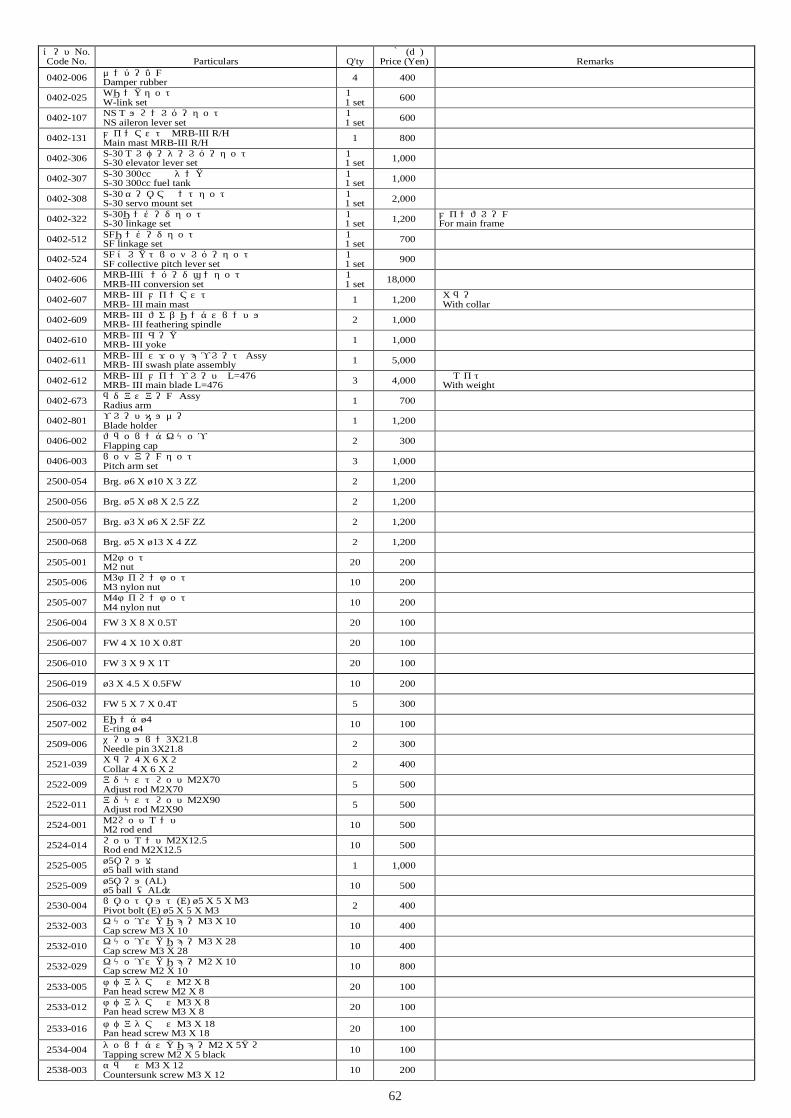
62
コード�No.Code No.
品名�Particulars
入数�Q'ty
価格�(円�)Price (Yen)
備考�Remarks
0402-006 ダンパーゴム�Damper rubber 4 400
0402-025 Wリンクセット�W-link set
1 式�1 set 600
0402-107 NS エルロンレバーセット�NS aileron lever set
1 式�1 set 600
0402-131 メインマスト� MRB-III R/HMain mast MRB-III R/H 1 800
0402-306 S-30 エレベーターレバーセット�S-30 elevator lever set
1 式�1 set 1,000
0402-307 S-30 300cc 燃料タンク�S-30 300cc fuel tank
1 式�1 set 1,000
0402-308 S-30 サーボマウントセット�S-30 servo mount set
1 式�1 set 2,000
0402-322 S-30リンケージセット�S-30 linkage set
1 式�1 set 1,200 メインフレーム用�
For main frame
0402-512 SFリンケージセット�SF linkage set
1 式�1 set 700
0402-524 SF コレクトピッチレバーセット�SF collective pitch lever set
1 式�1 set 900
0402-606 MRB-IIIコンバージョンセット�MRB-III conversion set
1 式�1 set 18,000
0402-607 MRB- III メインマスト�MRB- III main mast 1 1,200 カラー付�
With collar
0402-609 MRB- III フェザリングスピンドル�MRB- III feathering spindle 2 1,000
0402-610 MRB- III ヨーク�MRB- III yoke 1 1,000
0402-611 MRB- III スワッシュプレート�AssyMRB- III swash plate assembly 1 5,000
0402-612 MRB- III メインブレード� L=476MRB- III main blade L=476 3 4,000 ウエイト付�
With weight
0402-673 ラジアスアーム�AssyRadius arm 1 700
0402-801 ブレードホルダー�Blade holder 1 1,200
0406-002 フラッピングキャップ�Flapping cap 2 300
0406-003 ピッチアームセット�Pitch arm set 3 1,000
2500-054 Brg. ø6 X ø10 X 3 ZZ 2 1,200
2500-056 Brg. ø5 X ø8 X 2.5 ZZ 2 1,200
2500-057 Brg. ø3 X ø6 X 2.5F ZZ 2 1,200
2500-068 Brg. ø5 X ø13 X 4 ZZ 2 1,200
2505-001 M2ナット�M2 nut 20 200
2505-006 M3ナイロンナット�M3 nylon nut 10 200
2505-007 M4ナイロンナット�M4 nylon nut 10 200
2506-004 FW 3 X 8 X 0.5T 20 100
2506-007 FW 4 X 10 X 0.8T 20 100
2506-010 FW 3 X 9 X 1T 20 100
2506-019 ø3 X 4.5 X 0.5FW 10 200
2506-032 FW 5 X 7 X 0.4T 5 300
2507-002 Eリング�ø4E-ring ø4 10 100
2509-006 ニードルピン�3X21.8Needle pin 3X21.8 2 300
2521-039 カラー�4 X 6 X 2Collar 4 X 6 X 2 2 400
2522-009 アジャストロッド�M2X70Adjust rod M2X70 5 500
2522-011 アジャストロッド�M2X90Adjust rod M2X90 5 500
2524-001 M2ロッドエンド�M2 rod end 10 500
2524-014 ロッドエンド�M2X12.5Rod end M2X12.5 10 500
2525-005 ø5ボール台付�ø5 ball with stand 1 1,000
2525-009 ø5ボール�(AL)ø5 ball (�AL)� 10 500
2530-004 ピボットボルト�(E) ø5 X 5 X M3Pivot bolt (E) ø5 X 5 X M3 2 400
2532-003 キャップスクリュー�M3 X 10Cap screw M3 X 10 10 400
2532-010 キャップスクリュー�M3 X 28Cap screw M3 X 28 10 400
2532-029 キャップスクリュー�M2 X 10Cap screw M2 X 10 10 800
2533-005 ナベアタマビス�M2 X 8Pan head screw M2 X 8 20 100
2533-012 ナベアタマビス�M3 X 8Pan head screw M3 X 8 20 100
2533-016 ナベアタマビス�M3 X 18Pan head screw M3 X 18 20 100
2534-004 タッピングスクリュー�M2 X 5クロ�Tapping screw M2 X 5 black 10 100
2538-003 サラビス�M3 X 12Countersunk screw M3 X 12 10 200

63
2523-009
0402-059
0404-336
2500-003
0402-347(赤)(Red)0402-371(白)(White)
0402-313
0402-217
0402-216
0402-312
2526-0032500-003
0402-3142500-003
0402-205
2524-004
2524-003
0402-5280402-529
0402-351(赤)(Red)0402-337(白)(White)
0402-331
0402-346(赤)(Red)
0402-354(赤)(Red)0402-376(白)(White)
0402-330(白)(White)
2532-006
0402-639 0402-532
2531-002
2505-006

64
コード�No.Code No.
品名�Particulars
入数�Q'ty
価格�(円�)Price (Yen)
備考�Remarks
0402-059 ラダーコントロールシャフトセット�Rudder control shaft set
1 式�1 set 400
0402-205 ZS テールピッチプレートセット�ZS tail pitch plate set
1 式�1 set 1,600
0402-216 テールハウジング�AssyTail housing assembly
1 式�1 set 2,500
0402-217 ZS テールハウジング�ZS tail housing 1 600
0402-312 S-30 テールギヤセット�S-30 tail gear set
1 式�1 set 1,300
0402-313 S-30 テールピッチレバーセット�S-30 tail pitch lever set
1 式�1 set 500
0402-314 S-30 テールギヤ�BOX セット�S-30 tail gear box set
1 式�1 set 500
0402-330 LM ランディングギヤ�Assy(白)�LM landing gear assembly (white)
1 式�1 set 2,200
0402-331 LM テールホルダーセット�LM tail holder set
1 式�1 set 500
0402-337 LM 水平尾翼(白)�LM horizontal stabilizer (white) 1 800
0402-346 LM ランディングギヤ�Assy(赤)�LM landing gear assembly (red)
1 式�1 set 2,200
0402-347 LM テールブームトラス�Assy(赤)�LM tail boom truss (red)
1 式�1 set 3,000
0402-351 LM 水平尾翼(赤)�LM horizontal stabilizer (red) 1 800
0402-354 LM ランディングブレースセット(赤)�LM landing gear brace set (red)
1 式�1 set 1,200
0402-371 LM テールブームトラス�Assy(白)�LM tail boom truss (white)
1 式�1 set 3,000
0402-376 LM ランディングブレースセット(白)�LM landing gear brace set (white)
1 式�1 set 1,200
0402-528 SF テールブレード� L=77SF tail blade L=77 2 500
0402-529 SF テールブレードホルダー�SF tail blade holder 1 400
0402-532 スキッドパイプ(アルミ生地)�Skid pipe (aluminum) 2 800
0402-639 スキッドパイプキャップ�ø8Skid pipe cap ø8 4 300
0404-336 テールジョイント�2øTail joint 2ø 1 700
2500-003 Brg. ø5 X ø11 X 5 ZZ 2 1,200
2505-006 M3ナイロンナット�M3 nylon nut 10 200
2523-009 テールドライブシャフトセット�Tail drive shaft set 1 1,500
2524-003 ロッドエンドピン�M2 X 4.5Rod end pin M2 X 4.5 10 300
2524-004 ダブルリンクピンタイプ�Double link pin type 2 300
2526-003 アジャストストッパー�Adjustment stopper 2 300
2531-002 セットスクリュー� M3X5Set screw M3X5 10 300
2532-006 キャップスクリュー�M3 X 20Cap screw M3 X 20 10 400

65
MADE IN JAPAN
C 2003
No.104471
主要諸元ギヤ比無線機
適合エンジン
/ 9.625 : 1 : 5.5 / ヘリ用プロポセット (別売) Programmable transmitter set for model helicopters (Sold separately) / 30~46クラス (別売) 30-46 class engine (Sold separately)※46クラスエンジンの搭載には別途購入品が必要です。� (ご注意:50クラスエンジンの搭載はできません)�※Additional parts must be purchased in order to mount � 46 class engines. (Note that the 50 class engines � can not be mounted.)
Main featuresGear ratioRadio control device
Compatible engine
組立前に必ずこの説明書を最後まで、よくお読みになり、正しくお使い下さい。特に、「安全のために必ずお守り下さい」は、飛行前に必ず読んで下さい。この説明書は、大切にお手元に保管して下さい。製品改良のため、予告なく仕様を変更する場合があります。
Before assembly, make sure to completely read this instruction manual. In particular, make sure to read the "Follow these rules to ensure safety" section before operating the unit. Keep this instruction manual in a handy, safe place.In order to make improvements to this product, specifications may be altered without prior notice.
1190mm
404mm
262mm
1244mm
225m
m
0402-335
0402-342
0402-349(赤)(Red)0402-373(白)(White)
0402-348(赤)(Red)0402-372(白)(White)
0402-355(赤)(Red)0402-375(白)(White)
0402-355
0402-350(赤)(Red)0402-374(白)(White)
0402-352(イエローライン)(Yellow line)
0402-339(ブルーライン)(Blue line)
0402-311
0402-377
0402-353
0402-345

66
コードNo.Code No.
品名Particulars
入数Q'ty
価格(円)Price (Yen)
備考Remarks
0402-311 S-30 フレームクロスメンバーS-30 frame cross member
1 式1 set 1,200
0402-335 LM ダミーエンジンセットLM dummy engine set
1 式1 set 900
0402-339 LM デカール(ブルーライン)LM decal (blue line) 1 1,800
0402-342 LM コックピット偽装品LM cockpit accessory set
1 式1 set 3,000
0402-345 LM エクステリアセットLM exterior set
1 式1 set 2,800
0402-348 LM サイドカバーセット(赤)LM side cover set (red)
1 式1 set 800
0402-349 LM リヤーフレームセット(赤)LM rear frame set (red)
1 式1 set 800
0402-350 LM キャビンセット(赤)LM cabin set (red)
1 式1 set 7,500
0402-352 LM デカール(イエローライン)LM decal (yellow line) 1 1,800
0402-353 LM キャノピーLM canopy 1 2,500
0402-355 LM カムロックセット(赤)LM cam lock set (red)
1 式1 set 300
0402-372 LM サイドカバーセット(白)LM side cover set (white)
1 式1 set 800
0402-373 LM リヤーフレームセット(白)LM rear frame set (white)
1 式1 set 800
0402-374 LM キャビンセット(白)LM cabin set (white)
1 式1 set 7,500
0402-375 LM カムロックセット(白)LM cam lock set (white)
1 式1 set 300
0402-377 LM 取扱説明書LM instruction manual 1 2,000

67
FUTABA FF9-H1ch(AIL) 2ch(ELE) 3ch(THR) 4ch(RUD) 5ch(GYR) 6ch(PIT) SW
(R/U) 100% 140% 100% 100% 100% 100%(L/D) 100% 140% 70% 100% 100% 100%UP 100% 100% 100%DN 80% 80% 100%UP 0% 0% 0%DN 0% 0% 0%
(NORM)(F/S) 60%
REVERS NORM REV REV NORM NORM NORM
POS1 POS2 POS3 POS4 POS5NORM 0.0% 30.0% 50.0% 75.0% 100.0%IDL1 75.0% 65.0% 65.0% 80.0% 100.0%
NORM 20.0% 45.0% 65.0% 80.0% 90.0%IDL1 10.0% 25.0% 50.0% 72.5% 85.0%
HOLD 25.0% 42.0% 60.0% 80.0% 100.0%
REVO.MIX INHACT
ACT 0% -20%
AIL ELE RUDOFST-1 0% 0% 0%OFST-2 0% -20% 0%OFST-3 0% -7% 0%
NORM NOR 100%IDL1 NOR 70%IDL2 NOR 70%
HOLD NOR 80%
※1.ジャイロはGY401を使用しています� GY401 is applied to the gyro.※2.オフセットは実際の飛行に合わせて調整して下さい。� Adjust the offset to match actual flight conditions.※3.各コンディションは以下のような設定になっています。� The setting for each condition is as shown below.
AIL:DELE:A
Cond
オートローテーション�
上空飛行�Hovering
During flight
ラダーオフセット�
スイッチ�:�Cond
HOLDAutorotation
IDL1
E.POINT
F/S
ACT
TH-HLD
GYRO
NORM
EXP
ACT
スイッチ�:�Cond
TH-CRV
PI-CRV
ラダーオフセット量�ホールドポジション�
---------------
D/R ----- ----- -----
ホバリング�

68
JR X-3810AIL ELEV RUDD
D/R 80% 80% 60%EXP LIN LIN 40%D/R 100% 100% 80%EXP LIN LIN 40%
0 0 00 D20 00 D7 00 0 0
THRO AIL ELEV RUDD GEAR PITREV NORM REV NORM NORM100% 100% 100% 85% 110%70% 100% 100% 100% 110%F.S. HOLD HOLD HOLD HOLD HOLD
EXP L 1 2 3 HN OFF 0% 30% 50% 75% 100%1 OFF 80% 65% 65% 85% 100%N OFF 17% LIN 65% LIN 90%1 OFF 0% LIN 50% LIN 90%H OFF 0% LIN 55% LIN 100%
ACT 0 90%ACT 1 60%ACT NORM 0POS STNT 10% HOLD 0
G460T is applied to the gyro.※2.A.D.Tは実際の飛行に合わせて調整して下さい。� Adjust the ADT to match actual flight conditions.※3.各コンディションは以下のような設定になっています。� The setting for each condition is as shown below.
H オートローテーション�
N
1 上空飛行�
※1.ジャイロはG460Tを使用しています�
HLD
ACT
PITCHCURVE
(POS.1)
THROHOLD
GYROSENS AUTO
ST1ST2
FAIL SAFE (SPCM)
THROCURVE
0
1
DUAL-RATE・�
EXP
TRAVELADJUST
REVERSE SW
A.D.T
NORMST-1ST-2
HOLD
ホバリング�
Autorotation
Hovering
During flight
AUTO D/R
(H/L/D)�(L/R/U)
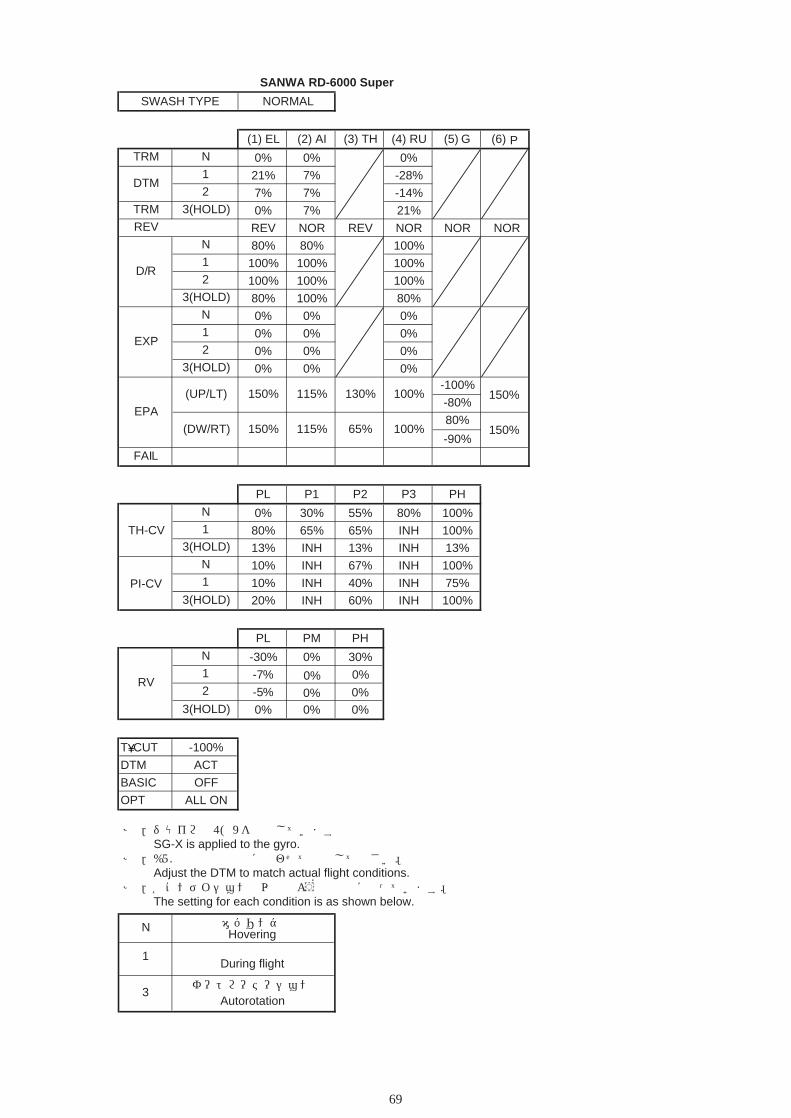
69
SANWA RD-6000 Super
SWASH TYPE NORMAL
(1) EL (2) AI (3) TH (4) RU (5) G (6) PTRM N 0% 0% 0%
1 21% 7% -28%2 7% 7% -14%
TRM 3(HOLD) 0% 7% 21%REV REV NOR REV NOR NOR NOR
N 80% 80% 100%1 100% 100% 100%2 100% 100% 100%
3(HOLD) 80% 100% 80%N 0% 0% 0%1 0% 0% 0%2 0% 0% 0%
3(HOLD) 0% 0% 0%-100%
-80%
80%
-90%FAIL
PL P1 P2 P3 PH
N 0% 30% 55% 80% 100%1 80% 65% 65% INH 100%
3(HOLD) 13% INH 13% INH 13%N 10% INH 67% INH 100%1 10% INH 40% INH 75%
3(HOLD) 20% INH 60% INH 100%
PL PM PH
N -30% 0%
0%0%
0%
30%1 -7%2 -5%
3(HOLD) 0% 0% 0%0%
T CUT -100%
DTM ACT
BASIC OFF
OPT ALL ON
※1.ジャイロはSG-Xを使用しています� SG-X is applied to the gyro.※2.DTMは実際の飛行に合わせて調整して下さい。� Adjust the DTM to match actual flight conditions..※3.各コンディションは以下のような設定になっています。� The setting for each condition is as shown below.
(DW/RT) 65%
150%
150%
115%
115%
130%
EPA
100%
100%
150%
150%
(UP/LT)
DTM
3オートローテーション�
Autorotation
NHovering
During flight1 上空飛行�
D/R
RV
EXP
TH-CV
PI-CV
ホバリング�
¥


①本書の内容の一部または全部を無断で転載することは禁止されています。②本書の内容については、将来予告なしに変更することがあります。③本書の内容について万全を期しておりますが、万一ご不審な点や誤り、記載もれなどお気付 きのことがありましたら、ご一報くださいますようお願いいたします。④運用した結果については③項にかかわらず責任を負いかねますので、ご了承ください。①Reproduction of this manual, or any part thereof is strictly prohibited.②The contents of this manual are subject to change without prior notice.③Every effort has been made to ensure that this manual is complete and correct. Should there, however, be any oversights, mistakes or omissions that come to your attention, please inform us.④Item ③ not withstanding, we cannot be responsible for events related to the operation of your model.
注意 Note
平成15年2月�平成15年3月�First printingSecond printing
初版発行� 第2版発行�
February 2003March 2003
138 FUKAWA-CHO, FUCHU-SHI,HIROSHIMA-PREF., JAPAN. 〒726-0004TEL:0847-40-0088 FAX:0847-45-7670http//model.hirobo.co.jp/
広島県府中市府川町138 〒726-0004TEL:(0847)40-0088(代) FAX:45-7670http://model.hirobo.co.jp/


![I N D E X [ninomiya-ew.co.jp]ニッケル覆銅導体シリカガラス編組電線 NPC-MS500 ニッケル導体シリカガラス編組電線 TM450 - ~+400 ニッケル導体シリカガラス編組電線](https://img.pdfslide.net/doc/110x75/60d6bb313bc40d60cd1ead1c/i-n-d-e-x-ninomiya-ewcojp-ffffeeffccec.jpg)


![障害未然防止のための教訓化ガイドブック(組込みシステム編) … · ための実践ガイドブック(組込みシステム編)」[2]なども参考にされたい。](https://img.pdfslide.net/doc/110x75/5f01dcde7e708231d401669d/eoeoeceeoefffficeffci.jpg)