Embed Size (px)
Citation preview
MAE 4700/5700 (Fall 2009) Homework 2 Plane and space trusses
Finite Element Analysis for Mechanical & Aerospace Design Page 1 of 13
Due Monday, September 14th
, 12:00 midnight
This homework is considering the analysis of plane and space (3D) trusses as discussed
in class. A list of MatLab programs that were discussed in class is provided that contain
all essential elements for the analysis of trusses. An example problem is given.
Start this work by investing considerable time to review the structure and fine details of the
provided programs. It is important that all tasks that have been programmed clearly provide
you a direct one-to-one link with the theory you learned in lectures.
Problem 1 - Analysis and design of a plane truss (MatLab)
Consider a plane truss as shown in the figure. The horizontal and vertical members have
length L, while inclined members have length 2L . Assume the Young’s modulus
100E GPa, cross-sectional area21.0 cmA , and 0.3L m.
1. Use the finite element (MatLab) program to determine the tip deflections for the
following three load cases (the subscripts refer to finite element nodes).
Load Case (A) 13 14 10,000x xF F N
Load Case (B) 13 14 10,000y yF F N
Load Case (C) 13 1410,000 and 10,000x xF N F N
2. Assuming that the truss behaves like a cantilever beam, one can determine the
equivalent cross sectional properties of the beam from the results for Cases A
through C above. The three beam properties are: axial rigidity ( )eqEA (this is
different from the AE of the truss member), flexural rigidity ( )eqEI and shear
rigidity ( )eqGA . Let the beam length be equal to l . ( 6 0.3 1.8 )l m
The axial deflection of a beam due to an axial force F is given by:
( )
tip
eq
Flu
EA (1)
The transverse deflection due to a transverse force F at the tip

MAE 4700/5700 (Fall 2009) Homework 2 Plane and space trusses
Finite Element Analysis for Mechanical & Aerospace Design Page 2 of 13
3
3( ) ( )tip
eq eq
Fl Flv
EI GA (2)
In Eq. (2) the first term on the RHS represents the deflection due to flexure and
the second term due to shear deformation. In the elementary beam theory (Euler-
Bernoulli beam theory) we neglect the shear deformation, as it is usually much
smaller than the flexural deflection.
The transverse deflection due to an end couple C is given by
2
2( )tip
eq
Clv
EI (3)
Substitute the average tip deflections obtained in Part 1 in Eqs. (1)-(3) to compute
the equivalent section properties: ( )eqEA , ( )eqEI and ( )eqGA .
You may use the average of deflections at Nodes 13 and 14 to determine the
equivalent beam deflections.
3. Verify the beam model by adding two more bars to the truss ( 8 0.3 2.4 )l m .
Compute the tip deflections of the extended truss for the three load cases A-C at
the end nodes 17 and 18 using the FE program. Compare the FE results with
deflections obtained from the equivalent beam model (Eqs. (1)-(3)).
Solution:
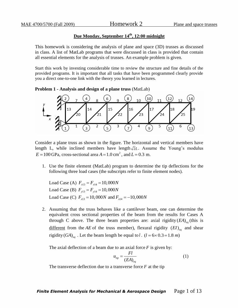
1. The tip deflections are:
Load Case (A): 3 3
13 14 13 141.8 10 m, 1.8 10 mx x y y . The plot of deflection is:
Load Case (B): 3 2
13 149 10 m, 1.26 10 mx x .
1 1
13 141.02 10 m, 1.01 10 my y
The plot of deflection is
0 0.5 1 1.5 2 2.5-0.4
-0.2
0
0.2
0.4
1 33 55 77 99 1111 13
2 44 66 88 1010 1212 14
1
2
3
4
5
6
7
8
9
10
11
12
13
14
1
4
3
6
5
8
7
10
9
12
11
14
Truss Plot
Initial shape
Deformed shape
MAE 4700/5700 (Fall 2009) Homework 2 Plane and space trusses
Finite Element Analysis for Mechanical & Aerospace Design Page 3 of 13
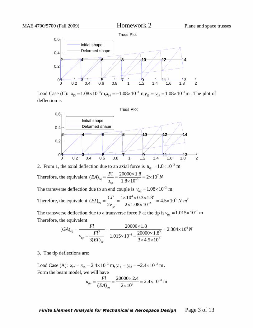
Load Case (C): 3 3 2
13 14 13 141.08 10 m, 1.08 10 m, 1.08 10 mx x y y . The plot of
deflection is
2. From 1, the axial deflection due to an axial force is
31.8 10 mtipu
Therefore, the equivalent 7
3
20000 1.8( ) 2 10
1.8 10eq
tip
FlEA N
u
The transverse deflection due to an end couple is 21.08 10 mtipv
Therefore, the equivalent 2 4 2
5 2
2
1 10 0.3 1.8( ) 4.5 10
2 2 1.08 10eq
tip
ClEI N m
v
The transverse deflection due to a transverse force F at the tip is11.015 10 mtipv
Therefore, the equivalent
6
3 31
5
20000 1.8( ) 2.384 10
20000 1.81.015 10
3( ) 3 4.5 10
eq
tip
eq
FlGA N
Flv
EI
3. The tip deflections are:
Load Case (A): 3 3
17 18 17 182.4 10 m, 2.4 10 mx x y y .
Form the beam model, we will have
3
7
20000 2.42.4 10 m
( ) 2 10tip
eq
Flu
EA
0 0.2 0.4 0.6 0.8 1 1.2 1.4 1.6 1.8 20
0.2
0.4
0.6
1 33 55 77 99 1111 13
2 44 66 88 1010 1212 14
1
2
3
4
5
6
7
8
9
10
11
12
13
14
1
4
3
6
5
8
7
10
9
12
11
14
Truss Plot
Initial shape
Deformed shape
0 0.2 0.4 0.6 0.8 1 1.2 1.4 1.6 1.8 20
0.2
0.4
0.6
1 33 55 77 99 1111 13
2 44 66 88 1010 1212 14
1
2
3
4
5
6
7
8
9
10
11
12
13
14
1
4
3
6
5
8
7
10
9
12
11
14
Truss Plot
Initial shape
Deformed shape
MAE 4700/5700 (Fall 2009) Homework 2 Plane and space trusses
Finite Element Analysis for Mechanical & Aerospace Design Page 4 of 13
Load Case (B): 2 2
17 181.68 10 m, 2.16 10 mx x .
1 1
17 182.25 10 m, 2.25 10 my y
Form the beam model, we will have 3 4 3 4
1
5 6
2 10 2.4 2 10 2.42.25 10 m
3( ) ( ) 3 4.5 10 2.38 10tip
eq eq
Fl Flv
EI GA
Load Case (C):
3 3
13 14
2
13 14
2.4 10 m, 2.4 10 m
1.92 10 m
x x
y y
.
Form the beam model, we will have 2 4 2
2
5
1 10 0.3 2.41.92 10 m
2( ) 2 4.5 10tip
eq
Clv
EI
Therefore, the beam model is indeed very accurate in this case.
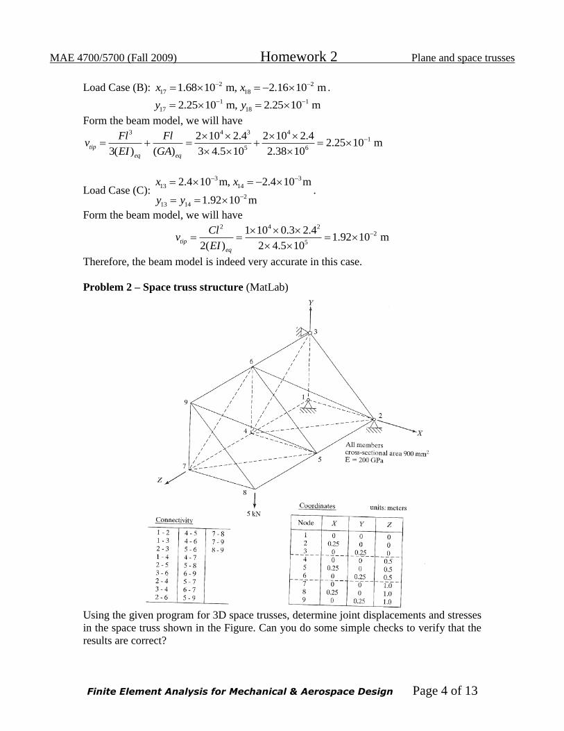
Problem 2 – Space truss structure (MatLab)
Using the given program for 3D space trusses, determine joint displacements and stresses
in the space truss shown in the Figure. Can you do some simple checks to verify that the
results are correct?
MAE 4700/5700 (Fall 2009) Homework 2 Plane and space trusses
Finite Element Analysis for Mechanical & Aerospace Design Page 5 of 13
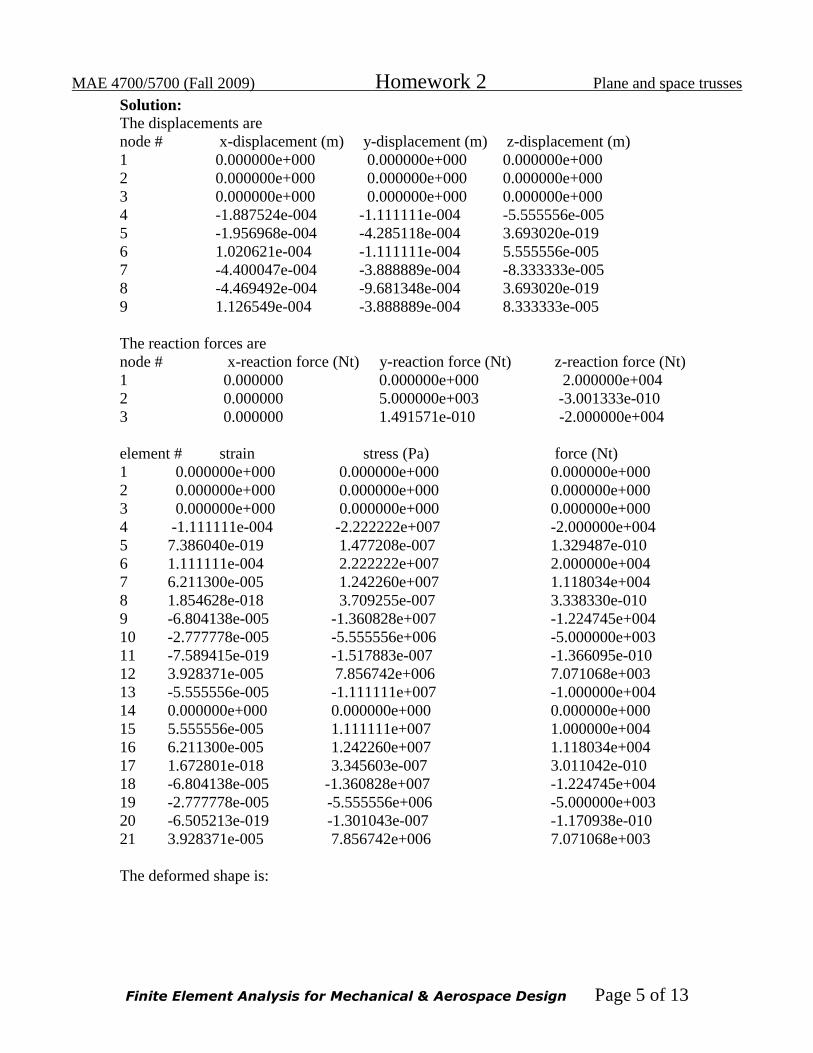
Solution:
The displacements are
node # x-displacement (m) y-displacement (m) z-displacement (m)
1 0.000000e+000 0.000000e+000 0.000000e+000
2 0.000000e+000 0.000000e+000 0.000000e+000
3 0.000000e+000 0.000000e+000 0.000000e+000
4 -1.887524e-004 -1.111111e-004 -5.555556e-005
5 -1.956968e-004 -4.285118e-004 3.693020e-019
6 1.020621e-004 -1.111111e-004 5.555556e-005
7 -4.400047e-004 -3.888889e-004 -8.333333e-005
8 -4.469492e-004 -9.681348e-004 3.693020e-019
9 1.126549e-004 -3.888889e-004 8.333333e-005
The reaction forces are
node # x-reaction force (Nt) y-reaction force (Nt) z-reaction force (Nt)
1 0.000000 0.000000e+000 2.000000e+004
2 0.000000 5.000000e+003 -3.001333e-010
3 0.000000 1.491571e-010 -2.000000e+004
element # strain stress (Pa) force (Nt)
1 0.000000e+000 0.000000e+000 0.000000e+000
2 0.000000e+000 0.000000e+000 0.000000e+000
3 0.000000e+000 0.000000e+000 0.000000e+000
4 -1.111111e-004 -2.222222e+007 -2.000000e+004
5 7.386040e-019 1.477208e-007 1.329487e-010
6 1.111111e-004 2.222222e+007 2.000000e+004
7 6.211300e-005 1.242260e+007 1.118034e+004
8 1.854628e-018 3.709255e-007 3.338330e-010
9 -6.804138e-005 -1.360828e+007 -1.224745e+004
10 -2.777778e-005 -5.555556e+006 -5.000000e+003
11 -7.589415e-019 -1.517883e-007 -1.366095e-010
12 3.928371e-005 7.856742e+006 7.071068e+003
13 -5.555556e-005 -1.111111e+007 -1.000000e+004
14 0.000000e+000 0.000000e+000 0.000000e+000
15 5.555556e-005 1.111111e+007 1.000000e+004
16 6.211300e-005 1.242260e+007 1.118034e+004
17 1.672801e-018 3.345603e-007 3.011042e-010
18 -6.804138e-005 -1.360828e+007 -1.224745e+004
19 -2.777778e-005 -5.555556e+006 -5.000000e+003
20 -6.505213e-019 -1.301043e-007 -1.170938e-010
21 3.928371e-005 7.856742e+006 7.071068e+003
The deformed shape is:
MAE 4700/5700 (Fall 2009) Homework 2 Plane and space trusses
Finite Element Analysis for Mechanical & Aerospace Design Page 6 of 13
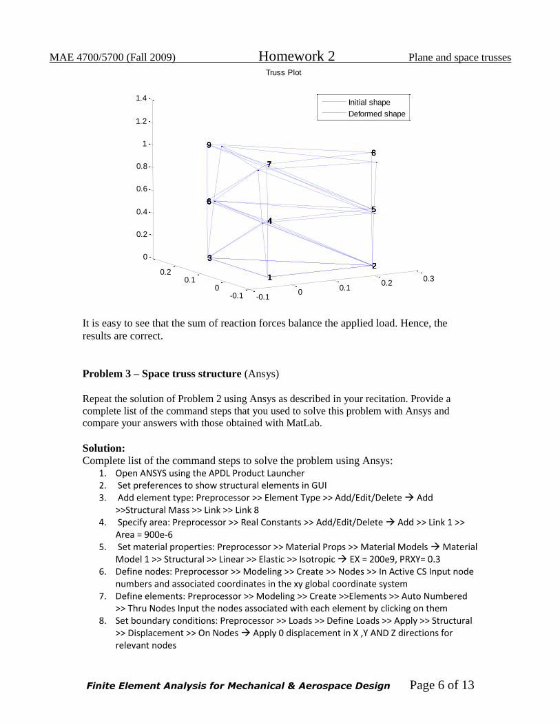
It is easy to see that the sum of reaction forces balance the applied load. Hence, the
results are correct.
Problem 3 – Space truss structure (Ansys)
Repeat the solution of Problem 2 using Ansys as described in your recitation. Provide a
complete list of the command steps that you used to solve this problem with Ansys and
compare your answers with those obtained with MatLab.
Solution:
Complete list of the command steps to solve the problem using Ansys: 1. Open ANSYS using the APDL Product Launcher 2. Set preferences to show structural elements in GUI 3. Add element type: Preprocessor >> Element Type >> Add/Edit/Delete Add
>>Structural Mass >> Link >> Link 8 4. Specify area: Preprocessor >> Real Constants >> Add/Edit/Delete Add >> Link 1 >>
Area = 900e-6 5. Set material properties: Preprocessor >> Material Props >> Material Models Material
Model 1 >> Structural >> Linear >> Elastic >> Isotropic EX = 200e9, PRXY= 0.3 6. Define nodes: Preprocessor >> Modeling >> Create >> Nodes >> In Active CS Input node
numbers and associated coordinates in the xy global coordinate system 7. Define elements: Preprocessor >> Modeling >> Create >>Elements >> Auto Numbered
>> Thru Nodes Input the nodes associated with each element by clicking on them 8. Set boundary conditions: Preprocessor >> Loads >> Define Loads >> Apply >> Structural
>> Displacement >> On Nodes Apply 0 displacement in X ,Y AND Z directions for relevant nodes
-0.10
0.10.2
0.3
-0.10
0.10.2
0
0.2
0.4
0.6
0.8
1
1.2
1.4
22222
555555
888
Truss Plot
111
444444
77777
3333
666666
9999
Initial shape
Deformed shape

MAE 4700/5700 (Fall 2009) Homework 2 Plane and space trusses
Finite Element Analysis for Mechanical & Aerospace Design Page 7 of 13
9. Apply forces: Preprocessor >> Loads >> Define Loads >> Apply >> Structural >> Force/Moment >> On Nodes Input force value and direction
10. Solve: Solution >> Solve >> Current LS 11. Plot deformed shape: General Postproc >> Plot Results >> Deformed Shape 12. List displacements: General Postproc >> List Results >> Nodal Solution 13. Nodal Solution >> DOF Solution >> Displacement vector sum 14. List Reaction solutions for nodes 15. List stress values for the nodes
List axial stresses:
General Postproc >> Element Table >> Define Table >> Add >> By Sequence No >>
LS, 1
General Postproc >> Element Table >> List Elem Table >> LS, 1
Problem 4a: Analysis of a plane truss structure (Ansys)
Solution:
The inputs to the Ansys program are:
Load (P) acting at node 8 = 5000N
Young’s Modulus (E) = 200e9 N/m2
Area of cross-section (A) = 900e-6 m2
Fixed boundary conditions are applied on nodes 1, 2 and 3.
The deformed structure of the matrix obtained from MATLAB is as shown below:
Table 1: Nodal displacements as obtained from Ansys
Node number x-displacement y-displacement z-displacement Total
displacement
1 0 0 0 0
2 0 0 0 0
3 0 0 0 0
4 -0.18875E-03 -0.11111E-03 -0.55556E-04 0.22596E-03
5 -0.19570E-03 -0.42851E-03 -0.40996E-18 0.47108E-03
6 0.10206E-03 -0.11111E-03 0.55556E-04 0.16078E-03
7 -0.44000E-03 -0.38889E-03 -0.83333E-04 0.59311E-03
8 -0.44695E-03 -0.96813E-03 -0.40996E-18 0.10663E-02
9 0.11265E-03 -0.38889E-03 0.83333E-04 0.41336E-03
MAE 4700/5700 (Fall 2009) Homework 2 Plane and space trusses
Finite Element Analysis for Mechanical & Aerospace Design Page 8 of 13
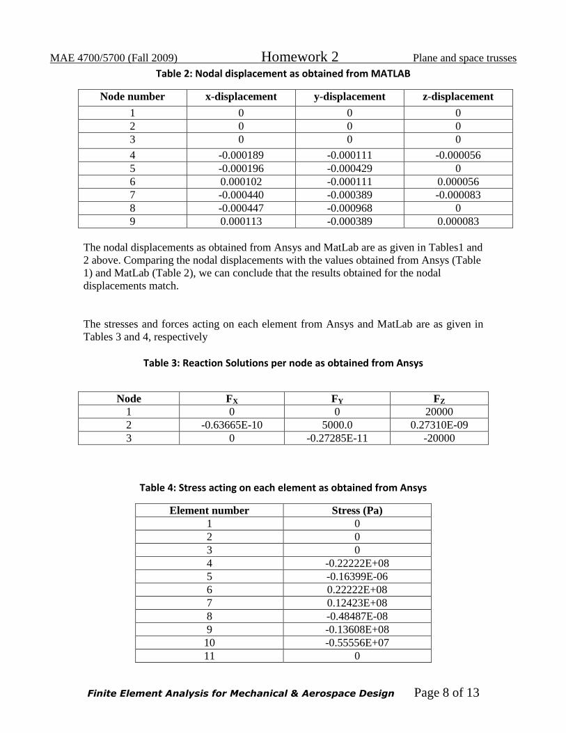
Table 2: Nodal displacement as obtained from MATLAB
Node number x-displacement y-displacement z-displacement
1 0 0 0
2 0 0 0
3 0 0 0
4 -0.000189 -0.000111 -0.000056
5 -0.000196 -0.000429 0
6 0.000102 -0.000111 0.000056
7 -0.000440 -0.000389 -0.000083
8 -0.000447 -0.000968 0
9 0.000113 -0.000389 0.000083
The nodal displacements as obtained from Ansys and MatLab are as given in Tables1 and
2 above. Comparing the nodal displacements with the values obtained from Ansys (Table
1) and MatLab (Table 2), we can conclude that the results obtained for the nodal
displacements match.
The stresses and forces acting on each element from Ansys and MatLab are as given in
Tables 3 and 4, respectively
Table 3: Reaction Solutions per node as obtained from Ansys
Node FX FY FZ
1 0 0 20000
2 -0.63665E-10 5000.0 0.27310E-09
3 0 -0.27285E-11 -20000
Table 4: Stress acting on each element as obtained from Ansys
Element number Stress (Pa)
1 0
2 0
3 0
4 -0.22222E+08
5 -0.16399E-06
6 0.22222E+08
7 0.12423E+08
8 -0.48487E-08
9 -0.13608E+08
10 -0.55556E+07
11 0
MAE 4700/5700 (Fall 2009) Homework 2 Plane and space trusses
Finite Element Analysis for Mechanical & Aerospace Design Page 9 of 13
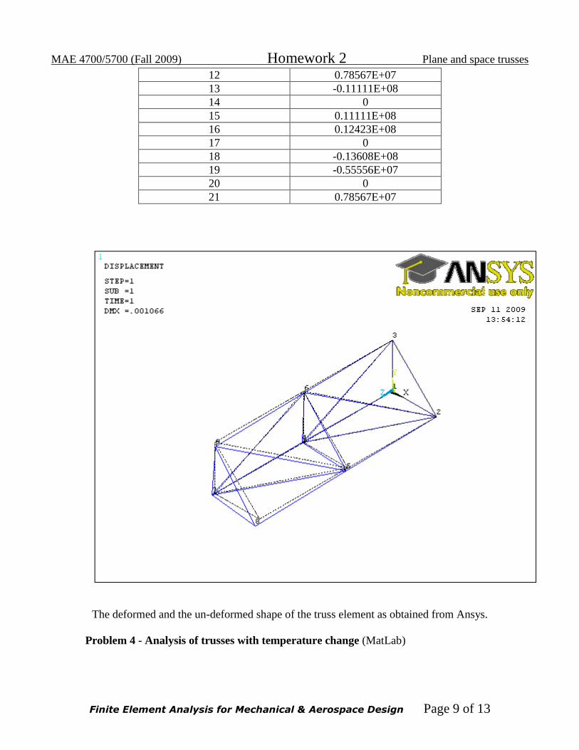
12 0.78567E+07
13 -0.11111E+08
14 0
15 0.11111E+08
16 0.12423E+08
17 0
18 -0.13608E+08
19 -0.55556E+07
20 0
21 0.78567E+07
The deformed and the un-deformed shape of the truss element as obtained from Ansys.
Problem 4 - Analysis of trusses with temperature change (MatLab)
MAE 4700/5700 (Fall 2009) Homework 2 Plane and space trusses
Finite Element Analysis for Mechanical & Aerospace Design Page 10 of 13
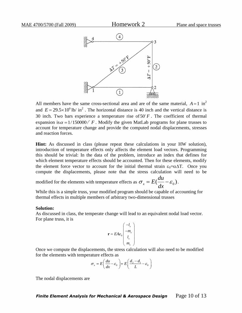
All members have the same cross-sectional area and are of the same material, 1A in
2
and 629.5 10E lb/ in
2 . The horizontal distance is 40 inch and the vertical distance is
30 inch. Two bars experience a temperature rise of50 F . The coefficient of thermal
expansion is 1/150000 / F . Modify the given MatLab programs for plane trusses to
account for temperature change and provide the computed nodal displacements, stresses
and reaction forces.
Hint: As discussed in class (please repeat these calculations in your HW solution),
introduction of temperature effects only affects the element load vectors. Programming
this should be trivial: In the data of the problem, introduce an index that defines for
which element temperature effects should be accounted. Then for these elements, modify
the element force vector to account for the initial thermal strain 0=T. Once you
compute the displacements, please note that the stress calculation will need to be
modified for the elements with temperature effects as 0( )x
duE
dx .
While this is a simple truss, your modified program should be capable of accounting for
thermal effects in multiple members of arbitrary two-dimensional trusses
Solution:
As discussed in class, the temperate change will lead to an equivalent nodal load vector.
For plane truss, it is
0
s
s
s
s
l
mEA
l
m
r
Once we compute the displacements, the stress calculation will also need to be modified
for the elements with temperature effects as
2 1
0 0x
d dduE E
dx L
The nodal displacements are
MAE 4700/5700 (Fall 2009) Homework 2 Plane and space trusses
Finite Element Analysis for Mechanical & Aerospace Design Page 11 of 13
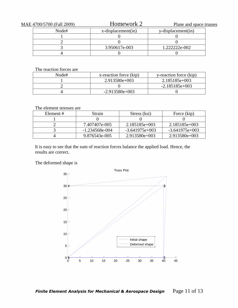
Node# x-displacement(in) y-displacement(in)
1 0 0
2 0 0
3 3.950617e-003 1.222222e-002
4 0 0
The reaction forces are
Node# x-reaction force (kip) y-reaction force (kip)
1 2.913580e+003 2.185185e+003
2 0 -2.185185e+003
4 -2.913580e+003 0
The element stresses are
Element # Strain Stress (ksi) Force (kip)
1 0 0 0
2 7.407407e-005 2.185185e+003 2.185185e+003
3 -1.234568e-004 -3.641975e+003 -3.641975e+003
4 9.876543e-005 2.913580e+003 2.913580e+003
It is easy to see that the sum of reaction forces balance the applied load. Hence, the
results are correct.
The deformed shape is
0 5 10 15 20 25 30 35 40 450
5
10
15
20
25
30
35
1 22
3
1
334
Truss Plot
Initial shape
Deformed shape
MAE 4700/5700 (Fall 2009) Homework 2 Plane and space trusses
Finite Element Analysis for Mechanical & Aerospace Design Page 12 of 13
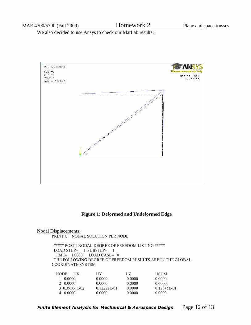
We also decided to use Ansys to check our MatLab results:
Figure 1: Deformed and Undeformed Edge
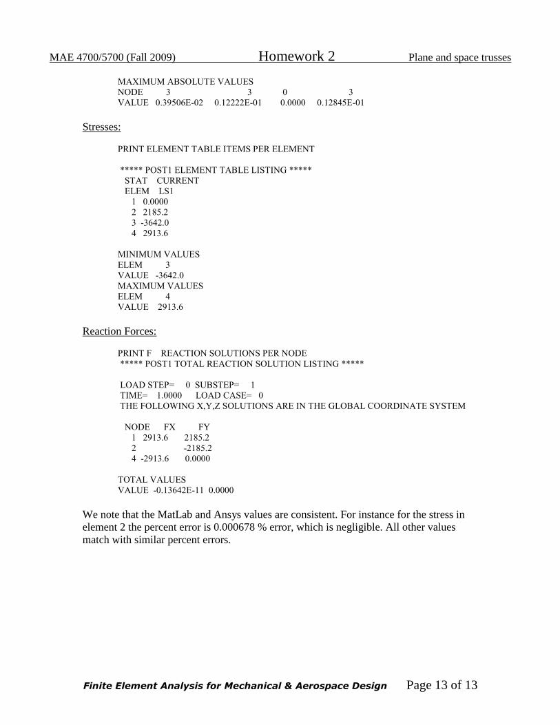
Nodal Displacements: PRINT U NODAL SOLUTION PER NODE
***** POST1 NODAL DEGREE OF FREEDOM LISTING *****
LOAD STEP= 1 SUBSTEP= 1
TIME= 1.0000 LOAD CASE= 0
THE FOLLOWING DEGREE OF FREEDOM RESULTS ARE IN THE GLOBAL
COORDINATE SYSTEM
NODE UX UY UZ USUM
1 0.0000 0.0000 0.0000 0.0000
2 0.0000 0.0000 0.0000 0.0000
3 0.39506E-02 0.12222E-01 0.0000 0.12845E-01
4 0.0000 0.0000 0.0000 0.0000
MAE 4700/5700 (Fall 2009) Homework 2 Plane and space trusses
Finite Element Analysis for Mechanical & Aerospace Design Page 13 of 13
MAXIMUM ABSOLUTE VALUES
NODE 3 3 0 3
VALUE 0.39506E-02 0.12222E-01 0.0000 0.12845E-01
Stresses:
PRINT ELEMENT TABLE ITEMS PER ELEMENT
***** POST1 ELEMENT TABLE LISTING *****
STAT CURRENT
ELEM LS1
1 0.0000
2 2185.2
3 -3642.0
4 2913.6
MINIMUM VALUES
ELEM 3
VALUE -3642.0
MAXIMUM VALUES
ELEM 4
VALUE 2913.6
Reaction Forces:
PRINT F REACTION SOLUTIONS PER NODE
***** POST1 TOTAL REACTION SOLUTION LISTING *****
LOAD STEP= 0 SUBSTEP= 1
TIME= 1.0000 LOAD CASE= 0
THE FOLLOWING X,Y,Z SOLUTIONS ARE IN THE GLOBAL COORDINATE SYSTEM
NODE FX FY
1 2913.6 2185.2
2 -2185.2
4 -2913.6 0.0000
TOTAL VALUES
VALUE -0.13642E-11 0.0000
We note that the MatLab and Ansys values are consistent. For instance for the stress in
element 2 the percent error is 0.000678 % error, which is negligible. All other values
match with similar percent errors.