Embed Size (px)
Citation preview
IJR International Journal of Railway
Vol. 8, No. 1 / March 2015, pp. 30-34
Vol. 8, No. 1 / March 2015 − 30 −
The Korean Society for Railway
Maglev(UTM-02) Brake System Change from
Pneumatic Bake System to Hydraulic Brake System
Kinam Kim†, Sungwoon Hwang* and Heekwon Jeon*
Abstract
The Maglev(UTM-02) project is leading by Korea Institute of Machinery & Materials and financially supported from the
ministry of Commerce, Industry and Energy. The early development stagy of Maglev(UTM-02) was adopted the general
urban railway pneumatic brake system due to the Korea domestic industrial environment. Currently there is two com-
mercial operation Light Railway Train(LRT) system in Korea. One is U-Line in Uijungbu, and the other is Everline in
Yongin. Both LRT systems are adopting high performance light weight hydraulic brake system. But those design and
manufacturing core technology of the brake system is came from a major brake system companies located from aboard.
Currently various studies have been continued to increase practical application and to improve competitiveness on per-
formance for each sub-system of Maglev. Also in case of brake system, developing competitive hydraulic brake system
is required. In this study, we have introduced the development process and performance evaluation of the new hydraulic
brake system of Maglev.
Keywords: Pneumatic brake system, Hydraulic brake system, Brake system
1. Introduction
UTM-02 was developed in 2005 based on previous
UTM-01 technology. Beginning stage of hydraulic brake
system development, LINIMO system in Japan or LRT
system in Europe was considered in application, but
finally the optimized conventional pneumatic brake sys-
tem was adopted due to Korea domestic environment.
However, recently most of LRT system is adopting a
hydraulic brake system due to benefit of high perfor-
mance, light weight and compact optimized design. To
improve performance and competitiveness of the previ-
ous maglev brake system, we have studied to change the
pneumatic brake system to new developed hydraulic
brake system in UTM-02. It is the first time to intro-
duce a hydraulic brake system in train by domestic com-
pany in Korea. There was partially applied semi-
hydraulic brake system which used pneumatic-hydrau-
lic converter.
2. Configuration of theNew Hydraulic Brake System
2.1 System modification review
A review of previous installed hardware of UTM-02
brake system had to be conducted to modify from the pneu-
matic brake system to the new hydraulic brake system.
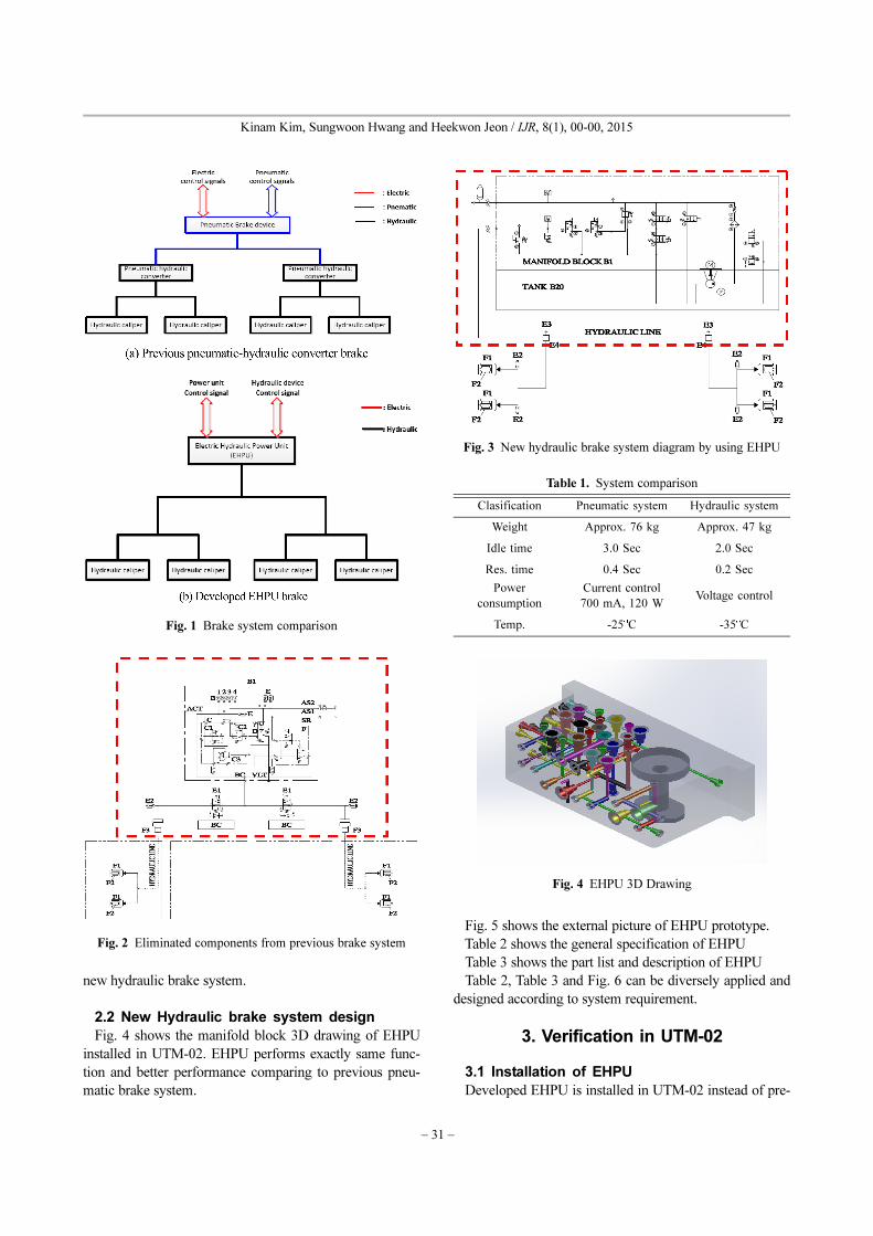
Fig. 1 (a) shows the schematic diagram of the previous
pneumatic-hydraulic converter, and Fig. 1(b) shows the
schematic diagram of the developed Electric Hydraulic
Power Unit(EHPU).
Also new developed EHPU and brake control unit
should be installed in UTM-02 instead of previous pneu-
matic pipe line, bake system, brake controller and pneu-
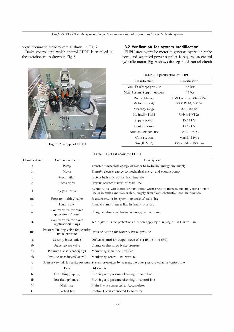
matic-hydraulic converter. Fig. 2 shows the eliminated
components in the previous pneumatic brake system. Fig.
3 shows the new components of hydraulic brake system by
using EHPU.
Table 1. shows the expected improving performance by
modification from previous pneumatic brake system to
†
*
Corresponding author: Yujin Machinery Ltd, R&D Center, Korea
E-mail : [email protected]
Yujin Machinery Ltd, R&D Center, Korea
ⓒThe Korean Society for Railway 2015
http://dx.doi.org/10.7782/IJR.2015.8.1.030
− 31 −
Kinam Kim, Sungwoon Hwang and Heekwon Jeon / IJR, 8(1), 00-00, 2015
new hydraulic brake system.
2.2 New Hydraulic brake system design
Fig. 4 shows the manifold block 3D drawing of EHPU
installed in UTM-02. EHPU performs exactly same func-
tion and better performance comparing to previous pneu-
matic brake system.
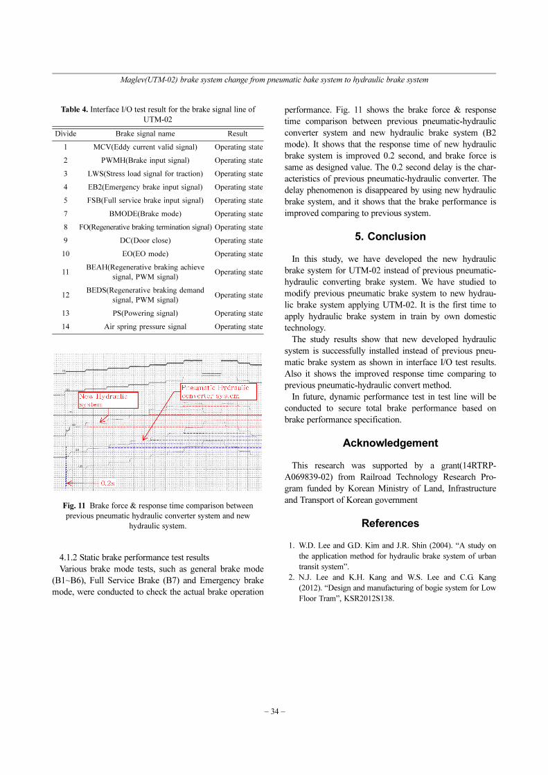
Fig. 5 shows the external picture of EHPU prototype.
Table 2 shows the general specification of EHPU
Table 3 shows the part list and description of EHPU
Table 2, Table 3 and Fig. 6 can be diversely applied and
designed according to system requirement.
3. Verification in UTM-02
3.1 Installation of EHPU
Developed EHPU is installed in UTM-02 instead of pre-
Fig. 1 Brake system comparison
Fig. 2 Eliminated components from previous brake system
Fig. 3 New hydraulic brake system diagram by using EHPU
Table 1. System comparison
Clasification Pneumatic system Hydraulic system
Weight Approx. 76 kg Approx. 47 kg
Idle time 3.0 Sec 2.0 Sec
Res. time 0.4 Sec 0.2 Sec
Power
consumption
Current control
700 mA, 120 WVoltage control
Temp. -25oC -35oC
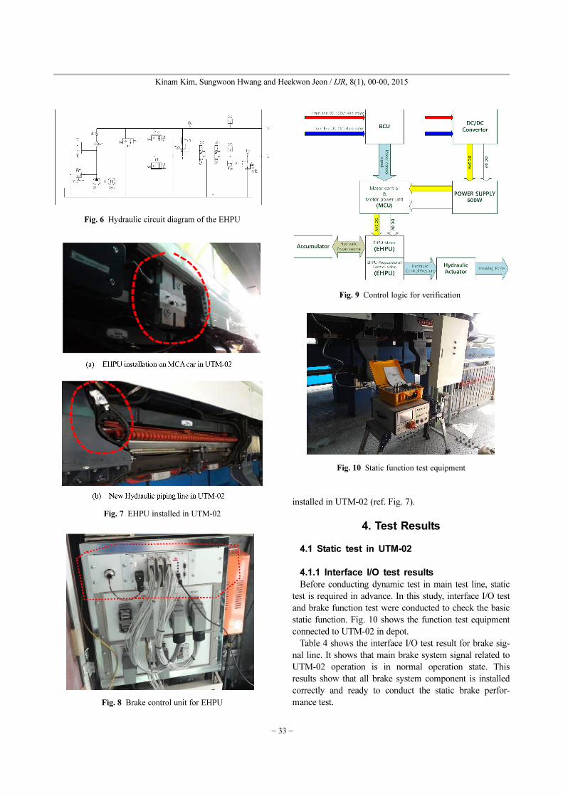
Fig. 4 EHPU 3D Drawing
Maglev(UTM-02) brake system change from pneumatic bake system to hydraulic brake system
− 32 −
vious pneumatic brake system as shown in Fig. 7
Brake control unit which control EHPU is installed in
the switchboard as shown in Fig. 8
3.2 Verification for system modification
EHPU uses hydraulic motor to generate hydraulic brake
force, and separated power supplier is required to control
hydraulic motor. Fig. 9 shows the separated control circuit
Fig. 5 Prototype of EHPU
Table 2. Specification of EHPU
Classification Specification
Max. Discharge pressure 162 bar
Max. System Supply pressure 140 bar
Pump delivery 1.89 L/min at 3000 RPM
Motor Capacity 3000 RPM, 500 W
Viscosity range 20 ... 80 cst
Hydraulic Fluid Univis HVI 26
Supply power DC 24 V
Control power DC 24 V
Ambient temperature -35oC ~ 50oC
Construction Manifold type
Size(HxVxZ) 435 × 350 × 180 mm
Table 3. Part list about the EHPU
Classification Component name Description
a Pump Transfer mechanical energy of motor to hydraulic energy and supply
bc Motor Transfer electric energy to mechanical energy and operate pump
c Supply filter Protect hydraulic device from impurity
d Check valve Prevent counter current of Main line
i By pass valveBypass valve will dump for monitoring when pressure transducer(supply port)in main
line is in fault condition such as supply filter fault, obstruction and malfunction
mb Pressure limiting valve Pressure setting for system pressure of main line
n Hand valve Manual dump in main line hydraulic pressure
raControl valve for brake
application(Charge)Charge or discharge hydraulic energy in main line
rbControl valve for brake
application(Dump)WSP (Wheel slide protection) function apply by dumping oil in Control line
maPressure limiting valve for security
brake pressurePressure setting for Security brake pressure
sa Security brake valve On/Off control for output mode of ma (B11) in ra (B9)
sb Brake release valve Charge or discharge brake pressure
ea Pressure transducer(Supply) Monitoring main line pressure
eb Pressure transducer(Control) Monitoring control line pressure
p Pressure switch for brake pressure System protection by sensing the over pressure value in control line
u Tank Oil storage
fa Test fitting(Supply) Flushing and pressure checking in main line
fb Test fitting(Control) Flushing and pressure checking in control line
M Main line Main line is connected to Accumulator
C Control line Control line is connected to Actuator
− 33 −
Kinam Kim, Sungwoon Hwang and Heekwon Jeon / IJR, 8(1), 00-00, 2015
installed in UTM-02 (ref. Fig. 7).
4. Test Results
4.1 Static test in UTM-02
4.1.1 Interface I/O test results
Before conducting dynamic test in main test line, static
test is required in advance. In this study, interface I/O test
and brake function test were conducted to check the basic
static function. Fig. 10 shows the function test equipment
connected to UTM-02 in depot.
Table 4 shows the interface I/O test result for brake sig-
nal line. It shows that main brake system signal related to
UTM-02 operation is in normal operation state. This
results show that all brake system component is installed
correctly and ready to conduct the static brake perfor-
mance test.
Fig. 6 Hydraulic circuit diagram of the EHPU
Fig. 7 EHPU installed in UTM-02
Fig. 8 Brake control unit for EHPU
Fig. 9 Control logic for verification
Fig. 10 Static function test equipment
Maglev(UTM-02) brake system change from pneumatic bake system to hydraulic brake system
− 34 −
4.1.2 Static brake performance test results
Various brake mode tests, such as general brake mode
(B1~B6), Full Service Brake (B7) and Emergency brake
mode, were conducted to check the actual brake operation
performance. Fig. 11 shows the brake force & response
time comparison between previous pneumatic-hydraulic
converter system and new hydraulic brake system (B2
mode). It shows that the response time of new hydraulic
brake system is improved 0.2 second, and brake force is
same as designed value. The 0.2 second delay is the char-
acteristics of previous pneumatic-hydraulic converter. The
delay phenomenon is disappeared by using new hydraulic
brake system, and it shows that the brake performance is
improved comparing to previous system.
5. Conclusion
In this study, we have developed the new hydraulic
brake system for UTM-02 instead of previous pneumatic-
hydraulic converting brake system. We have studied to
modify previous pneumatic brake system to new hydrau-
lic brake system applying UTM-02. It is the first time to
apply hydraulic brake system in train by own domestic
technology.
The study results show that new developed hydraulic
system is successfully installed instead of previous pneu-
matic brake system as shown in interface I/O test results.
Also it shows the improved response time comparing to
previous pneumatic-hydraulic convert method.
In future, dynamic performance test in test line will be
conducted to secure total brake performance based on
brake performance specification.
Acknowledgement
This research was supported by a grant(14RTRP-
A069839-02) from Railroad Technology Research Pro-
gram funded by Korean Ministry of Land, Infrastructure
and Transport of Korean government
References
1. W.D. Lee and G.D. Kim and J.R. Shin (2004). “A study on
the application method for hydraulic brake system of urban
transit system”.
2. N.J. Lee and K.H. Kang and W.S. Lee and C.G. Kang
(2012). “Design and manufacturing of bogie system for Low
Floor Tram”, KSR2012S138.
Table 4. Interface I/O test result for the brake signal line of
UTM-02
Divide Brake signal name Result
1 MCV(Eddy current valid signal) Operating state
2 PWMH(Brake input signal) Operating state
3 LWS(Stress load signal for traction) Operating state
4 EB2(Emergency brake input signal) Operating state
5 FSB(Full service brake input signal) Operating state
7 BMODE(Brake mode) Operating state
8 FO(Regenerative braking termination signal) Operating state
9 DC(Door close) Operating state
10 EO(EO mode) Operating state
11BEAH(Regenerative braking achieve
signal, PWM signal) Operating state
12BEDS(Regenerative braking demand
signal, PWM signal) Operating state
13 PS(Powering signal) Operating state
14 Air spring pressure signal Operating state
Fig. 11 Brake force & response time comparison between
previous pneumatic hydraulic converter system and new
hydraulic system.