Embed Size (px)
Citation preview

Bulletin of the Transilvania University of BraşovCIBv 2015 • Vol. 8 (57) Special Issue No. 1 - 2015
MAGNETIC SUSTENTATION APPLICATIONSON THE RAILWAY TRACTION FOR HIGH
SPEED MAGLEV TRAINS
M. DUMITRESCU1 V. ŞTEFAN2 C. PLEŞCAN3
C. I. BOBE4 G. M. DRAGNE5 C. N. BADEA6 G. DUMITRU7
Abstract: The term "maglev" refers not only to vehicles but also theinteraction between them and race. This interaction is very importantbecause each component is designed according to the other to create andcontrol the levitation (sustentation) magnetic. One of these ideas is to trainby lifting push and pull forces generated by magnets with the same polarityor with opposite polarities. The train can be driven by a linear motorinstalled on the rails and / or vehicle.
Key words: sustentation, levitation, magnetism, pulses, linear electricmachines.
1 Politechnica University of Bucharest, Regional Safety Traffic Reviser, SNTFC “CFR Călători” SA.2 Railway Territorial State Inspectorate Braşov - ASFR3 Civil Engineering Department, Transilvania University of Braşov.4 Politechnica University of Bucharest - ASFR.5 Politechnica University of Bucharest, SNTFM „CFR Goods” SA.6 The National Railway Freight Company - SNTFM “CFR Goods” SA.7 Control Traffic Safety Department, National Railway Safety Agency.
1. Introduction to the History ofMagnetic Suspension Technology
The first technology based on thephenomenon known as levitation ormagnetic took practical application in railtransport phenomenon was subsequentlydeveloped and implemented successfullyby railway.
The Maglev trains use powerful magnetsto provide lifting and advance. Whatmakes them special is that there is nocontact with the rail, reducing friction andallowing forces train to reach very highspeeds.
The Maglev trains can reach speedsabove the threshold 1000 [km/h]. But do
not get an airplane to speeds because offriction forces at altitude are lower thanthose at ground level.
In 1983 was built a subway line based onmagnetic levitation in Berlin. The projectproved to be a success, but the line wasclosed in 1992.
The world record speed for passengertrains Maglev trains was 531 [km/h] in1997 and this year to reach a record 603[km/h].
In the 1980s they were made atElectroputere Factory of Craiova, twopractical achievements that have usedmagnetic suspension for the first time inRomania [3]. The first experience is to builda mini vehicle sustentation contactless

234 Bulletin of the Transilvania University of Brasov• Vol. 8 (57) Special Issue No.1 - 2015
magnetic floating, moving on a line lengthof 2 [m] of length for financial reasonscould not be increased. This vehicle calledVEMAG 01 could carry a load of approx.80 [kg]. It was subsequently designed andmanufactured a magnetic suspension bogie,which floated stable sustentation force is2[t]. But political and economic problemssince the beginning of the eighth decade ofthe last century in our country, Romaniastopped further research into specific areas,but who continued theoretically [1]. Therewere thus developed under the guidance ofspecialized teachers even two doctoraltheses in this field. A magnetic levitation ormaglev train is a train that uses powerfulmagnetic fields to ensure sustentation andadvance. As opposed to conventional train,there is no contact with the rail, thusreducing the frictional forces and allows theattainment of high speed. From Earnshawtheorem is known that only usingelectromagnets and permanent magnetscannot ensure system stability. On the otherhand, the diamagnetic and thesuperconducting magnets, can stabilize thetrain. Some conventional systems useelectromagnetic electronic stabilization,continuously measuring the distance to trainand adjust the current in the electromagnetaccordingly.
The weight of the large electromagnet is amajor problem. It takes such a strongmagnetic field to levitate a train large andtherefore usually use superconductingmaterials for efficient electromagnets.
The first automatic trading system in theworld was a low speed maglev shuttlebetween the airport terminal andBirmingham International train station inBirmingham, in the immediate vicinity. Theshuttle operated between 1984 and 1995[5]. The track length was 600 m, and trains"were flying" at a height of 15 [mm] rails.At the end of the operation, the system hadbecome unsafe due to aging electroniccomponents and was replaced by a
funicular.West Berlin was built in the 80s, M-Bahn
system (Figure 1).
Fig. 1. The German trains with magneticsuspension M-Bahn
Maglev train was automated with a pathlength of 1,6 [km] and 3 stops. The testsbegan into August 1989 and the system wasinaugurated in July 1991 [6].
2. The Peculiarities of Linear RailMotorization Technology
Lifting is the property of a body tomaintain a certain level into the mass of afluid (in this case air). A magneticsuspension train, or maglev, is a train thatuses powerful magnetic fields to ensuresustentation and advance. Raising the trainis achieved by push and pull forcesgenerated by magnets with the samepolarity or with opposite polarities.
Mach number (named after the Austrianphysicist Ernst Mach) is a unit ofmeasurement used to express aerodynamicspeed of a body moving in a fluid:projectile, aircraft, missile etc. The Machnumber is a dimensionless value thatshows how many times higher the speed ofthe mobile than the speed of sound in thatmedium [8]. Mach 1 is equal to the speedof sound into the fluid. In standard Mach 1equals 1225 [km/h].
The magnetised coils at the bottom of thetrack, which was rejected magnets underthe train, allowing it to levitate between 1and 10 [cm] above the runway. Once the

DUMITRESCU et al.: Magnetic Sustentation Applications on the Railway Tractions ... 235
train is in levitation, loaded coils insidevertical walls to create a unique magneticfields that pull and push the train.
Constantly alternating electric currentsupplied coils to change the polarity of Themagnetised the turns. This change inpolarity determine the magnetic fieldlocated in front of the train to pull thevehicle forward, while the rear magneticfield adds an additional force in the samedirection.
The Transrapid, a German company, hasa test track in Emsland district of 31,5[km] in the federal state of Lower Saxony(Niedersachsen). On 22 September 2006around 10 o'clock mornings here there wasa big accident: a Transrapid train collidedwith a car workshop which is on the sameroute of human error. The accident resultedin 23 dead people and 10 wounded.
On 31 December 2000, the first mannedmaglev high temperature was tested atJiaotong University, Chengdu, China. Thissystem is based on the principle that high-temperature superconductors can belevitated with over a permanent magnet.Vertical load train set was 530 [kg]levitation distance was 20 [mm] above thetread. The system uses liquid nitrogen tocool the superconductor electric [7].
Transrapid has launched also the firstcommercial service with a high-speedmaglev in the world, between downtownShanghai and the city's airport. The linewas inaugurated in 2002. The highestspeed was 501 [km/h], the line having alength of 30 [km]. Transrapid uses EMStechnology. The line was later extended to160 [km] in 2010 with the inauguration bythe Chinese state events occasioned by thecommencement of the exhibition inShanghai in the same year.
This technology would enable virtuallytrain speeds exceeding 6437 [km/h] in avacuum tunnel. The "maglev" term refersnot only to vehicles but also to railroadsystems, specifically designed for
magnetic levitation and propulsion.Sustentation train technology builtmagnetic levitation is made usingpermanent magnets mounted on trainsinteract via the electromagnetic field linegenerated path (Figure 2). This is basicallya train engine .
Fig. 2. Schematic diagram of the vehiclemagnetic sustentation
Japan has a test track into Yamanashi,where trains are tested maglev MLX01series (Figure 3) JR is the acronym forJapan Railways - Railways Japan).
Fig. 3. Map of Shinkansen high speed railwaynetwork.
Lines in green: Operated by JR EastLines in yellow: Operated by JR CentralLines in blue: Operated by JR WestLines in red: Operated by JR KyūshūLines in gray: Planned

236 Bulletin of the Transilvania University of Brasov• Vol. 8 (57) Special Issue No.1 - 2015
These trains using EMS technology.These magnetic trains and theircounterparts on wheel, known as theShinkansen. They are designed anddeveloped by Central Japan Railway Co.institute - "JR Central - Railways centralJapan" and the consortium KawasakiHeavy Industries, which are currently thefastest trains in the world, reaching arecord speed of 581 [km/h] on December2, 2003 and respectively, 603 [km/h] thisyear.
The first commercial service maglevautomatic type came into use in March2005 into Aichi, Japan. It Tobu line -Kyuryo, known as Linimo bus. The line is8.9 [km], 9 stations and is able to supportmagnetic suspension trains running withmaximum speed of 100 [km/h]. Theminimum radius of transition curves is 75[m] and the maximum permitted gradientsof this line was only 6%. This line servesthe local communities and sites where theExpo was held in 2005. The trains weredesigned by the Japanese consortiumChubu hsst Development Corporation,operating and test track in Nagoya (Figure4).
Fig. 4. Japanese trains maglev series MLX01
2.1. The operating principle of magneticsustentation - Maglev Turbine
The movement of vehicles is subject tothe general laws of physics (especiallythose of the movement). Because a means
of transport can be set in motion on hisforce must act F, oriented in the directionof movement, which has a value largeenough to transmit its acceleration - zeroand positive, and to overcome the drag R(the rudiments of action and reaction) dueto friction. The transmission speed andtorque (generally power) plants developedby bodies that driving the moving meansof transportation and realization oftraction, meaning they capitalization, iswhat is called a propulsion problem. Alongwith this problem, for the transport means,there is another problem, that ofsustentation, which consists in forces thatensure permanent stable position of themeans of transport or the environment inwhich it operates. The current carryingcoils repel magnets, and just train tolevitate at a distance of 1-10 [cm] abovethe rolling track. Once the train issuspended coil creates a magnetic systemthat pulling and pushing on the guide railtracks [4].
Alternating electrical current applied tothe coils to change their polarity. It makesalternating magnetic field in front of thetrain to pull in front of train, while themagnetic field behind it pushes ahead.
Due to non-contact forces acting systemoffers superior quality classical systemrunning without excitation (mechanical)from the guide way, together with higherflow speeds while providing full trafficsafety. Thus, with regard to passengertransport, non-conventional transportsystems Maglev type still has an advantageover conventional system.
But here it must be mentioned limitshigher travel speeds due to aerodynamicdrag resistance. In terms of freighttransport capacity of maglev systems arecurrently low, in this case the conventionalsystem due to long liners and largetransport capacity (250 kN/wheel). It has aclear advantage over maglev system.
Motion Magnet Maglev system, called
DUMITRESCU et al.: Magnetic Sustentation Applications on the Railway Tractions ... 237
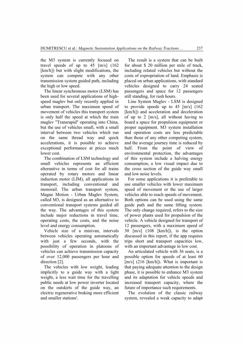
the M3 system is currently focused ontravel speeds of up to 45 [m/s] (162[km/h]) but with slight modifications, thesystem can compete with any othertransmission system guided path, includingthe high or low speed.
The linear synchronous motor (LSM) hasbeen used for several applications of high-speed maglev but only recently applied inurban transport. The maximum speed ofmovement of vehicles this transport systemis only half the speed at which the trainmaglev "Transrapid" operating into China,but the use of vehicles small, with a smallinterval between two vehicles which runon the same thread way and quickaccelerations, it is possible to achieveexceptional performance at prices muchlower cost.
The combination of LSM technology andsmall vehicles represents an efficientalternative in terms of cost for all trainsoperated by rotary motors and linearinduction motor (LIM), all applications intransport, including conventional andmonorail. The urban transport system,Magne Motion - Urban Maglev System,called M3, is designed as an alternative toconventional transport systems guided allthe way. The advantages of this systeminclude major reductions in travel time,operating costs, the costs, and the noiselevel and energy consumption.
Vehicle size of a minivan, intervalsbetween vehicles operating automaticallywith just a few seconds, with thepossibility of operation in platoons ofvehicles can achieve transmission capacityof over 12,000 passengers per hour anddirection [2].
The vehicles with low weight, leadingimplicitly to a guide way with a lightweight, a less wait time for the travellingpublic needs at low power inverter locatedon the outskirts of the guide way, anelectric regenerative braking more efficientand smaller stations'.
The result is a system that can be builtfor about $ 20 million per mile of track,including related vehicles but without thecosts of expropriation of land. Emphasis isplaced on urban applications, with standardvehicles designed to carry 24 seatedpassengers and space for 12 passengersstill standing, for rush hours.
Line System Maglev - LSM is designedto provide speeds up to 45 [m/s] (162[km/h]) and acceleration and decelerationof up to 2 [m/s], all without having toboard a space for propulsion equipment orproper equipment. M3 system installationand operation costs are less predictablethan those of any other competing system,and the average journey time is reduced byhalf. From the point of view ofenvironmental protection, the advantagesof this system include a halving energyconsumption, a low visual impact due tothe cross section of the guide way smalland low noise levels.
For some applications it is preferable touse smaller vehicles with lower maximumspeed of movement or the use of largervehicles able to reach speeds of movement.Both options can be used using the sameguide path and the same lifting system.The only change required, refers to the sizeof power plants used for propulsion of thevehicle. A vehicle designed for transport of12 passengers, with a maximum speed of30 [m/s] (108 [km/h]), is the optiondiscussed in this report, if the app requirestrips short and transport capacities low,with an important advantage in low cost.
An articulated vehicle with 36 seats, is apossible option for speeds of at least 60[m/s] (216 [km/h]). What is important isthat paying adequate attention to the designphase, it is possible to enhance M3 systemand its adaptation for vehicle speeds andincreased transport capacity, where thefuture of importance such requirements.
The evolution of the classic railwaysystem, revealed a weak capacity to adapt

238 Bulletin of the Transilvania University of Brasov• Vol. 8 (57) Special Issue No.1 - 2015
it to the necessary changes with time.The calculations made by specialists
Magne Motion revealed that thetransmission system powered using LSMhas investment costs are much lower thantransport systems Conventional-basedvehicles electrically operated, whetheroperated by electric motors for tractionrotary or linear induction motor systems(LIM).
Vehicles are greatly simplified, energyand maintenance costs are reduced, and themost important aspect is the fact that thistransport system users benefit from greatlyreduced the journey time. In fact, theenergy the train uses to levitate above thetread is less than the energy consumed byits air-conditioning system.
The electromagnets with electronicstabilization (1) at the bottom of eachvehicle of the train set, and thecomposition of the magnetic coils at thebottom of the tread (2) raise the train untilthe distance between the two sets ofmagnets is approximately 1 [cm].
Other magnets (3) ensure alignment ofthe train along the vertical walls of thetrack (Figure 5). The spool coils (4)installed in the raceway produce amagnetic field that propels the train.
Fig. 5. Operating diagram magnetically theLevites
To reduce electricity consumption,central control point that sends electricity
sector tread (5) where the train. It takesmore energy in areas where the train mustaccelerate to climb a slope. When the trainmust slow down or to go in the reversedirection, the polarity of the coils of thetread.
Although the maglev train travels at ahigh speed in the bottom of the vehicle inthe train gasket surrounds (6) making italmost impossible path train derailment.
The passengers do not need to put hisseatbelt, but can rise from their seats evenwhen travelling at maximum speed train. Ifa power outage, special brakes powered bybatteries on board the train which producesa magnetic field opposite reduce trainspeed to 10 [km/h], and finally it stops.
Maglev trains use powerful magnets toprovide lifting and advance. They are usedin Scheme systems (Figure 6) a number ofdevices such as generator homopolargenerator electrostatic capacitive(operating in vacuum under pulses),chambers of plasma radio HF withoutelectrode inside, klystrone, facilityelectrolytic regenerative microclimate andthe discharge chamber of Z-pinch [4].
Fig. 6. Scheme operating principle of linearelectric machine
3. Determination the MathematicalModel and Transfer Function onMagnetic Suspension
The characteristic equation of verticalmovement trains. It is desirable that liftingdistance d to be controlled so that it doesnot exceed the limits of proper operation oftrain.

DUMITRESCU et al.: Magnetic Sustentation Applications on the Railway Tractions ... 239
The lifting distance d, between the trackand the train magnets is determined byequation (1).
d=z-h (1)
The magnet produces a force which isdependent on the residual magnetism andthe current that runs through magnetizedcircuit.
For small changes in distance d andcurrent magnetized i, that strength iscalculated by equation (2), where G and Hare positive constants.
f1= - Gi+Hd (2)
The force necessary to accelerate thetrain mass M in the vertical direction beingshown by the equation (3).
f1=M = - Gi+Hd (3)
For higher current distance d diminishesand z decreases as a result of attractiontowards the rail track train according to therelation (4).
Ri+Li=v (4)
A network model for magnetic circuit isdefined by its magnetic circuit primarily.This circuit is a generator that controls acoil wrapped around the magnet out on thetrain (equation 5).
Ri + Li – (LH/G)d = v (5)
The induced voltage in the coil of thetrain movement is represented by term(LH/G).d, which presumably magnetic fluxlosses are negligible.
For this type of circuit is valid equationof state (6) and three state variables areshown in relations (7).
x1=d and x3=i (6)- Tc-zinc =0.88 K, (7)
The superconductors (Figure 7) areelectrical conductors whose resistancebecomes practically zero at certaintemperatures.
Fig. 7. Scheme magnetic polarity magneticsuspension trains
This property allows the development oftechnologies that, for instance, propelledby magnetic levitation trains.
Some ceramic materials and somemetals, when they are brought to atemperature between absolute zero, and thetemperature of liquefaction of nitrogen (77K) completely lose their electricalresistivity.
The temperature at which the electricalresistance becomes zero is called thecritical temperature (Tc) varies from onematerial to another.
The state of superconductivity isachieved by cooling various materialsusually helium or liquid nitrogen. Somecritical temperatures ranging from metalsused are shown in relations (8 and 9) andcategory ceramics, temperatures are givenin (10).
Tc-aluminiu = 1.19 K (8)Tc-mercur = 4.15 K (9)
For if the compound, the relation (11)gives operating temperatures that are

240 Bulletin of the Transilvania University of Brasov• Vol. 8 (57) Special Issue No.1 - 2015
designed to are functioning optimally.
u1=U1cos2ωt; u2=U2cos(4ωt+α) (12)
When rising magnet superconductor andhe will leave the container, remainingsuspended and stable under magnet. Thisphenomenon is called magneticsuspension.
Both levitation and suspension magneticclamping effect generated by the magneticflux. When separating superconductingmagnet forced to close then again, veryslowly magnets, superconductors will beattracted by the magnet and brought itclose. However, it is the same behaviour asin the case of two magnets whose oppositepoles attract leading to sticking together.
Superconducting magnet attract eachother, but also opposed to each otherkeeping a constant distance from eachother. If returning to the superconductingmagnet and put the other pole of thisapproach, the latter will be pushed awayfrom the magnet. Furthermore,superconductors will tend to overthrow torealign and can thus be attracted by themagnet again. After various processes ofmagnetization, superconductors behavedifferently, highlighting various effectsand phenomena as Meissner effect,magnetic levitation and suspension, andthe effect of magnetic flux fixings.
Based on these characteristics ofsuperconductors, many technologies are inthe design phase, both for large-scaleapplications as if the train Maglev fortransport, but also for applications smallerscale, as is the case in the industrysemiconductor manufacturing.
The operating principle underlying theobject circuit is applying a magnetic forceequal to the gravitational force, and theopposite at the same time. The two forcescancel each other and the object remainssuspended.
Basically this is done by a circuit that
reduces the electromagnetic force when anobject gets too close, but a larger and whenthe subject comes within range.
This circuit works by magnetic levitationcomparing the sensor signals with the firstoperational amplifier and emitting avoltage proportional to the difference(error) them.
The error signal is then sent through anetwork of compensation which plays ahigh pass filter, allowing fast changes oferror for the flow more easily than slowchanges.
This is needed for establishing thecontinuity of control and without it justwould brandish objects near theelectromagnet due to system instability.
The signal is then amplified to itsoriginal value after compensation mitigatenetwork after reaching TIP122 Darlingtontransistor that controls the currentelectromagnet.
Further around the transistor diodes aredesigned to prevent damage. The diodeprevents the signal based on the polarityreversal of the base to be damaged, whilethe two 1N4001 provides a path for themagnetic current when the electromagnetis switched off [6].
Optical components used are notessential as long as the wavelengths fitwell and how the angles of detection /emission are not too narrow. IR LEDs areTIL38 that are up 940 [km] have openingof 15 degrees, 35 [MW] and a maximum100 mA. The detectors are type PT204-6Bthat are phototransistors IR. In addition,there are magneto dynamic suspension(MDS) recently invented and least testedyet.
3.1. Stability of Movement with MagneticSuspension Systems
Using only electromagnets andpermanent magnets cannot ensure systemstability. On the other hand, the
DUMITRESCU et al.: Magnetic Sustentation Applications on the Railway Tractions ... 241
diamagnetic and the superconductingmagnets, can stabilize the train.
Using only electromagnets andpermanent magnets cannot ensure systemstability. On the other hand, thediamagnetic and the superconductingmagnets, can stabilize the train.
Stability and magnet causes weightbased on the great, whose size is a majorissue for planners. It takes a very strongmagnetic field to levitate a train large, sothey are usually used for superconductingelectromagnets efficient materials.
The superconductors are a type ofelectrical conductors whose resistancebecomes practically zero at temperatureslower than specified amount of materialsthey are made of.
This property allows the development oftechnologies such as vehicles powered bymagnetic levitation and operated using ahigher superconductivity temperatures,quieter vehicles, moving without frictionand are very easy to accelerated.
After various processes ofmagnetization, superconductors behavedifferently, highlighting various effectsand phenomena such as Meissner effect,magnetic levitation and suspension, andthe effect of magnetic flow fixings.
The Meissner Effect describes how amaterial that undergoes the transformationfrom normal to superconducting state -exclude magnetic field inside it.
3.2. Practical Application - Results andDiscussions
The distance between the magnets fixed -within the array of magnets, according tothis aspect are a series of magnetic forces -the interaction between two magnet fittedforces "parasite" that occur when theyinteract with a moving magnetic repulsiveforce, but the possible interaction of theseforces with areas of two magnetic polesmobile, the more evident and depending on
the angle to the plane of plan freely magnetfitted, open plan angle to the plane of themagnet fitted. Tesla envisioned a newsituation taking fixed magnet wire andwrapped, resulting in a cylinder withmagnets fixed to the inside and asatisfactory diameter. Specifically, theseapplications rely on energy conservationbut also the conservation of momentumthrough a very simple magnet phone is sopositioned relative to the mounting magnetfitted that when the balance is always afew millimetres before the position wherethey are. There are areas in whichequilibrium is reached when, but therecomes inertial conservation of momentum,which help to overcome their impulse justbecause gained during the interactionforces were maximum. Calculating thepoint of balance can be done ifdecomposition is appropriate forces"crude" acting between magnetsparticipants.
The calculation can be done bycalculating weights momentum, frictionforces and comparing them to the above. Itis also obvious that when such anapplication under load, the aforementionedparameters and change them. This is anissue closely related to the fact that thereare a number of demonstrations ofapplications that "revolve" but actuallyrevolve alone, doing nothing else than todemonstrate the existence of thesephenomena.
The oscillation in the contact area can beachieved with one or two elements. Option"a" involves feeding the two electrodes ofthe piezoceramic converter 3 out of phase"α" so that the item. In step 2 is an overlaplongitudinal oscillations at a resonantfrequency (12).
v0 = 2r/T = ω r/π = f1l/p = 2rf1 (12)
The DC linear motor has armaturewindings and ferromagnetic equipped with

242 Bulletin of the Transilvania University of Brasov• Vol. 8 (57) Special Issue No.1 - 2015
linear collector and inductor with poles,put on one or both sides of the armature.
The synchronous linear motor can beheteropolar or homopolar withconventional or superconducting excitation(Figures 8 and 9).
Fig. 8. Modelling scheme moving the vehiclemagnetic suspension
The fact that mobile magnets are placedin the magnetic field energy movementsare participants and the law ofconservation of energy conservation butthe moment.
Fig. 9. Scheme interaction runway vehicle whenthe pulse levitation
The most common asynchronous linearmotor is a linear motor (induction),corresponding rotary asynchronous motorwith squirrel cage.
The balance between the forces ofinteraction between magnets data - fixedand mobiles - It is highly precarious. Therecan calculate the optimal angle obtain a
force that mobilizes mobile magnet so thatit always be pushed forward. It also uses arange of materials that are permeable toobstruct the magnetic field or field guideso as to achieve maximum effect andattenuation of the interaction forces"parasitic" areas between the magneticpoles generated at each magnetic pieces.
There are a number of configurationspositioning magnet fitted so if we addinertia, mobile magnet to pass repeatedlyin areas with high intensity of interaction -thus obtaining the moving force tops.
The magnetic field produced by the coilhas a constant amplitude and is travellingalong the inductor, for the purposes of therotating with the speed given in equation(13), where r It is the polar step, l is thelength of the inductor, p is the number ofpairs of poles, f1, T, ω is the frequency,timing periods and voltage pulsation.
dF = (JxB)dv (13)
The alteration of energy level of themagnet components - exhaustion while,due to the consumption resulting fromstress during operation or due tointeractions with the environment - lead tochanges in initial conditions that cause andmaintain phenomena therefore andsignificant changes in operation. Bymoving the magnetic induction field B tothe armature consists of a plate of copper,aluminium, steel or a combination thereof,the induced electromotive voltage, whichgives rise to eddy currents density J.
On the volume element of the armature(valve) is exercising a basic electro-magnetic force (14).
s = (v0 - v) / v0 < 1 (14)
The three-phase variant inductor(improperly stator as it can be phone),located in notches practiced wrappingstacks of sheets, symmetrical three-phase

DUMITRESCU et al.: Magnetic Sustentation Applications on the Railway Tractions ... 243
voltage is supplied. The driving force set inmotion induced or inductor (if the armatureis fixed). The velocity v of the armaturemust be less than the synchronous speed(15) thus sliding s. In generator conditions(regenerative braking over-synchronous),s<0; under the brake (by reverseconnection), s>1.
YBa2Cu3O7 (YBCO) have Tc=91K (15)
The operating characteristics differ fromthose of rotary asynchronous motor due tounbalanced magnetic circuit, whichproduces undesirable effects.
The effect of the longitudinal or endimportant, in particular, at a speed close tothe synchronous, is the non-uniformity anddistortion of the distribution of magneticflux density across the inductor, comparedto the case of a rotary engine, due toestablishment or extinction of eddycurrents in the input and fitting outportions of the field, seeking to delay theestablishment of magnetic induction.
The longitudinal effect lead to parasiticforces (opposite thrust) and additional heat.The transverse or the marginal effectconsists in the fact that induced in theedges of the inductor currents havelongitudinal components which do notcontribute to the production of force, butthe distribution of magnetic flux density inthe air gap deformed transversely. Botheffects are negative, causing decreasedperformance linear motors.
To reduce the effect of special endwindings can be used (in stages), the morecomplicated technology, or increases thelength of the inductor. The margin effectscan be limited by choosing the optimalratio of the width and pace polar inductor.
4. Conclusions
The operating mechanism of the railwaypath "running" magnet suspended relies on
the magnetic properties, that oppositesattract and rejection poles with identicaltasks. The magnetic fields are generatedallowing trains to travel with the help ofcoils located on runway.
The Maglev system to operation, theessential elements are a source of verystrong current, magnetic coils, which arearranged in the path of travel and largemagnets, positioned below the high-speedtrain. The Shanghai Maglev train operatesregularly EMS speed of 430 [km/h] and aJapanese prototype, JR Central EDS theMaglev can run more than 500 [km/h].There are even the Maglev technology thatcan push the speed up to 600 [km/h]. Thesystem works by sequential supply ofelectromagnetic aboard the vehicle. Inturn, these passive electromagnets coilsinduce a magnetic rail structure opposite.
The resulting magnetic repulsion is whatdrives the vehicle forward.
The sensors monitor the exact position ofelectromagnetic coils relative to passiverail, controlling their power and, implicitly,the propulsion force or, respectively, thebrake.
Acknowledgements
This work was partially supported by the“Strategic grant POSDRU / 159 / 1.5 / S /137070 (2014) of the Ministry of NationalEducation, Romania, co-financed by theEuropean Social Fund - Investing inPeople, within the Sector OperationalProgram Human Resources Development2007-2013.
References
1. Dósa, A, Ungureanu, V. V. - SCFJ –model discret de pierdere a stabilităţiicăii fără joante (SCFJ – discretemodel for continuous welded railbuckling), “Timisene AcademicalDays: 10th Edition, Timisoara,

244 Bulletin of the Transilvania University of Brasov• Vol. 8 (57) Special Issue No.1 - 2015
Romania, 24th –25th of May 2007 -Symposium: Efficient infrastructurefor the terrestrial transport” – SolnessPublishing House, Timisoara, ISBN978-973-729-101-1.
2. Dumitru, G. and al: “DynamicCharacteristics of InterractionBetween Railway Vehicles andRailway Track Path”, in RailwayPROScience & Technology - OfficialMagazine For Club FeroviarConferences & Technical Colloquia,ISSN 2284-7057, pp. 61 - 70, April 25- 26, 2012, Constanţa.
3. Mazilu, T., Vibraţii (Vibrations),Editura Matrix Rom, Bucureşti, 2012.
4. Sebeşan, I., Mazilu, T., Vibraţiilevehiculelor feroviare (Vibrations ofthe railway vehicles), Editura MatrixRom, Bucureşti, 2010.
5. Ungureanu, V. V., Comănici, M. -Sensitivity study of a model for thestability analysis of continuous weldedrail, Intersections / Intersecţii, Vol.4,2007, No.1, “TransportationInfrastructure Engineering”, ISSN1582 – 3024.
6. Ungureanu, V. V., Dósa, A. -Parametrical study of the effect of thetorsional resistance of the fasteningson the stability of continuous weldedrail, Intersections / Intersecţii, Vol.4,2007, No.1, “TransportationInfrastructure Engineering”, ISSN
1582 – 3024.7. Ungureanu, V. V. - On Elimination of
Interior Rail Joints and the Includingof Welded Railway Switches inContinuous Welded Rail Track (2009),SUSTAINABILITY in SCIENCEENGINEERING, Volume II,Proceedings of the 11th WSEASInternational Conference onSustainability in Science Engineering(SSE '09), Timisoara, Romania, May27 - 29, 2009, ISSN: 1790-2769,ISBN: 978-960-474-080-2, WSEASPress.
8. Ungureanu, V. V., Dósa, A. -Algoritm pentru determinareaprobabilităţii de pierdere a stabilităţiicadrului şine - traverse (Algorithm fordetermining the probability ofcontinuous welded rail trackbuckling), Proceedings of ScientificConference Civil Engineering –Building Services CIB 2007, 15th –16th of November, Braşov, România,Transilvania University PublishingHouse – Braşov 2007, ISSN 1843-6617.
9. Ungureanu, V. V. - Cercetări privindsimularea pierderii stabilităţii căiifără joante (Research aboutsimulation of continuous welded railbuckling), Ph.D. Thesis, TransilvaniaUniversity of Braşov, Braşov,Romania, 2007.


![Magnetic Suspension – Sustentation magnétique - … · 2015. 8. 14. · 7651. Kurzfassung (FRIEDRICHSHAFEN : Dornier SystemProjektbegleitung, 1981-12, 45P.) DE [38 P 9] Union Internationale](https://img.pdfslide.net/doc/110x75/60e5471f4750d9218573fb0f/magnetic-suspension-a-sustentation-magntique-2015-8-14-7651-kurzfassung.jpg)