Embed Size (px)
DESCRIPTION
Magnum User's Manual
Citation preview

TABLE OF CONTENTS
TERMS AND CONDITIONS . . . . . . . . . . . . . . . . . . . . . . . . . . . . . . . . . . . . . . . . . . . . . . . . . 1
SAFETY RULES . . . . . . . . . . . . . . . . . . . . . . . . . . . . . . . . . . . . . . . . . . . . . . . . . . . . . . . . . . . 3
IDENTIFYING YOUR NEW MASABA MAGNUM. . . . . . . . . . . . . . . . . . . . . . . . . . . . . . . 7CONVEYOR DEFINITIONS . . . . . . . . . . . . . . . . . . . . . . . . . . . . . . . . . . . . . . . . . . . . . . . . . . . . . . . . . . . . 7
SETTING UP YOUR MAGNUM . . . . . . . . . . . . . . . . . . . . . . . . . . . . . . . . . . . . . . . . . . . . . 10SITE PREPARATION . . . . . . . . . . . . . . . . . . . . . . . . . . . . . . . . . . . . . . . . . . . . . . . . . . . . . . . . . . . . . . . . . 10UNLOADING YOUR MAGNUM . . . . . . . . . . . . . . . . . . . . . . . . . . . . . . . . . . . . . . . . . . . . . . . . . . . . . . . 11
OPERATING YOUR MAGNUM . . . . . . . . . . . . . . . . . . . . . . . . . . . . . . . . . . . . . . . . . . . . . 14POWER CONNECTION . . . . . . . . . . . . . . . . . . . . . . . . . . . . . . . . . . . . . . . . . . . . . . . . . . . . . . . . . . . . . . . 14CONVEYOR PREPARATION . . . . . . . . . . . . . . . . . . . . . . . . . . . . . . . . . . . . . . . . . . . . . . . . . . . . . . . . . . 14POSITIONING YOUR MAGNUM FOR RADIAL TRAVEL . . . . . . . . . . . . . . . . . . . . . . . . . . . . . . . . . . 16LOWERING THE MAGNUM LIFTING JACKS. . . . . . . . . . . . . . . . . . . . . . . . . . . . . . . . . . . . . . . . . . . . 16POSITIONING THE SWING AXLE FOR RADIAL TRAVEL. . . . . . . . . . . . . . . . . . . . . . . . . . . . . . . . . 17INSTALLING OPTIONAL SAFETY STOPS. . . . . . . . . . . . . . . . . . . . . . . . . . . . . . . . . . . . . . . . . . . . . . . 20
RADIAL POWER TRAVEL . . . . . . . . . . . . . . . . . . . . . . . . . . . . . . . . . . . . . . . . . . . . . . . . . 22
POSITIONING YOUR MAGNUM FOR ROAD TRAVEL . . . . . . . . . . . . . . . . . . . . . . . . . 23
MAGNUM OPERATION MODES . . . . . . . . . . . . . . . . . . . . . . . . . . . . . . . . . . . . . . . . . . . . 27PROGRAMMABLE LOGIC CONTROLLER (PLC) . . . . . . . . . . . . . . . . . . . . . . . . . . . . . . . . . . . . . . . . . 27PLC INPUT DEFINITIONS . . . . . . . . . . . . . . . . . . . . . . . . . . . . . . . . . . . . . . . . . . . . . . . . . . . . . . . . . . . . 29
MANUAL & AUTO SYSTEM CONTROL . . . . . . . . . . . . . . . . . . . . . . . . . . . . . . . . . . . . . 30
PLC OPERATIONAL PROCEDURES . . . . . . . . . . . . . . . . . . . . . . . . . . . . . . . . . . . . . . . . . 30
ADJUSTING CONVEYOR HEIGHT (MANUAL MODE) . . . . . . . . . . . . . . . . . . . . . . . . . 36
MAINTENANCE . . . . . . . . . . . . . . . . . . . . . . . . . . . . . . . . . . . . . . . . . . . . . . . . . . . . . . . . . . 37BELT TRACKING. . . . . . . . . . . . . . . . . . . . . . . . . . . . . . . . . . . . . . . . . . . . . . . . . . . . . . . . . . . . . . . . . . . . 37OPTIONAL GREASE BANK SYSTEM. . . . . . . . . . . . . . . . . . . . . . . . . . . . . . . . . . . . . . . . . . . . . . . . . . . 39TROUBLESHOOTING BELT CONVEYORS . . . . . . . . . . . . . . . . . . . . . . . . . . . . . . . . . . . . . . . . . . . . . . 39VENDOR SPECIFIC MAINTENANCE SCHEDULES . . . . . . . . . . . . . . . . . . . . . . . . . . . . . . . . . . . . . . . 41TROUBLESHOOTING MAGNUM CONVEYORS . . . . . . . . . . . . . . . . . . . . . . . . . . . . . . . . . . . . . . . . . 42INSTALLING/TENSIONING V-DRIVES . . . . . . . . . . . . . . . . . . . . . . . . . . . . . . . . . . . . . . . . . . . . . . . . . 43CHECK CONDITION OF SHEAVES. . . . . . . . . . . . . . . . . . . . . . . . . . . . . . . . . . . . . . . . . . . . . . . . . . . . . 43CHECK SHEAVE ALIGNMENT . . . . . . . . . . . . . . . . . . . . . . . . . . . . . . . . . . . . . . . . . . . . . . . . . . . . . . . . 43V-BELT INSTALLATION . . . . . . . . . . . . . . . . . . . . . . . . . . . . . . . . . . . . . . . . . . . . . . . . . . . . . . . . . . . . . 44BELT SELECTION . . . . . . . . . . . . . . . . . . . . . . . . . . . . . . . . . . . . . . . . . . . . . . . . . . . . . . . . . . . . . . . . . . . 44GENERAL RULES OF TENSIONING. . . . . . . . . . . . . . . . . . . . . . . . . . . . . . . . . . . . . . . . . . . . . . . . . . . . 44
APPENDIX A. . . . . . . . . . . . . . . . . . . . . . . . . . . .Fenner Dunlop Belt Storage and Installation
APPENDIX B . . . . . . . . . . . . . . . . . . . . . . . . . . . . . . . . . . . Flexco Bolt Solid Plate Belt Splice
APPENDIX C . . . . . . . . . . . . . . . . . . . . . . . . . . . . . . . . . . . . . . . Fenner Dunlop Belt Tracking
APPENDIX D. . . . . . . . . . . . . . . . . . . . . . . . . . . . . . . . . . . . Fenner Dunlop Belt Maintenance
APPENDIX E . . . . . . . . . . . . . . . . . . . . . . . . . . . . . . . . . . . . . Fenner Dunlop Troubleshooting
APPENDIX F . . . . . . . . . . . . . . Dodge Torque-Arm Shaft Mount Speed Reducer Lubrication

TABLE OF CONTENTS
APPENDIX G. . . . . . .Dodge Installation and Parts Replacement Manual for Speed Reducers
APPENDIX H. . . . . . . Dodge Instruction Manual for Torque-Arm Speed Reducer Backstops
APPENDIX I . . . . . . . . . . . . . . . . . . . . Dodge Instruction Manual for Mounted Ball Bearings
APPENDIX J . . . . . . . . . . . . . . . . . . . . . . . . . Dodge Instruction Manual for Type E Bearings
APPENDIX K. . . . . . . . . . . .Dodge Instruction Manual for S-2000 Spherical Roller Bearings
APPENDIX L . . . . . . . . . . Rexnord Instructions for 2000, 5000, 9000 Series Roller Bearings
APPENDIX M . . . . . . . . . . . . . . . . . . . . . .WEG Electric Motor Installation and Maintenance
APPENDIX N. . . . . . . . . . . . . . . . . . . . . . . . . . . . . . . . . MASABA Hydraulic System Service
APPENDIX O. . . . . . . . . . . . . . . . . . . . . . . . . . . . . . . MASABA Hydraulic System Schematic
APPENDIX P . . . . . . . . . . . . . . . . . . . . . . . . . . . . . . . . .Allied Oil and Supply Material Safety

MASABA, INC. (d/b/a MASABA Mining Equipment)
TERMS AND CONDITIONS
1. OFFER & ACCEPTANCE: MASABA, Inc. (“Seller”) acceptance of Buyer’s order to purchase products is expressly made conditional on assent to these Terms and Conditions, which along with the Sales Order constitute a binding “Contract” between the parties. This Contract constitutes the complete and final agreement between Seller and Buyer for the products. Any additional or different terms or conditions contained in any document furnished by Buyer, including but not limited to, any purchase order or any acknowledgement, are deemed to be material and are herby objected to and rejected by Seller. If such agreement shall be deemed an offer or counter-offer by Buyer, Seller expressly rejects such offer or counter-offer and limits acceptance to these Contract terms and expressly objects to any different or additional terms proposed by Buyer. Any actually performance by Buyer or Seller thereafter shall be deemed a renewal of the offer contained in this Contract and acceptance of this Contract without change. In the event of a conflict between the terms of this Contract and the terms of any other document, the terms of this Contract shall control. This offer to purchase Seller’s products is valid for thirty (30) days form the date of the Sales Order.
2. PAYMENT TERMS: All prices specified in this Contract are FOB Seller’s designated location which constitutes delivery. All risk of damage to or loss of the products from any cause whatsoever shall pass to Buyer upon delivery, even if Seller arranges for shipment of the product. Unless otherwise expressly provide on the reverse hereof, payment shall be made within thirty (30) days form the earlier of the date of delivery or the date of an invoice, without discount. Any discount which may be expressly provide on the reverse hereof applies to the sale price of the products at the shipping point, and does not apply to any charges made for taxes, storage, loading or transportation. All payments shall be made in United States dollars. Interest will be charged at the rate of eighteen percent (18 %) per annum, or the maximum interest rate allowable by applicable law, whichever is lower, on all unpaid invoices. Buyer shall pay all taxes and charges of any nature imposed by any federal, state, or local governmental authority by reason of the sale or delivery of the products whether levied or assessed against Seller, Buyer, or the products. Such applicable taxes or charges, if not included in this Contract, shall be invoiced separately. If, in Seller’s opinion, reasonable doubt exists as to Buyer’s financial condition, Seller may, at any time and without prejudice to any other remedies, suspend or terminate performance of any order, decline to ship, stop any material in transit, or require full or partial payment by Seller in advance.
3. DELIVERY: Any delivery of promise date indicated on the Sales Order is an estimate of the date Seller believes the products will be available for delivery, pro-vided, however, Seller shall not be responsible for any delays in delivery.
4. WARRANTY:
• Limited Warranty; Exclusion of Third Party Components: Subject to the terms, conditions and limitations contained herein, Seller warrants only to the orig-inal Buyer that (a) Seller’s new equipment products and Seller’s new component products will not fail to operate in accordance with their respective specifica-tions due to the defects in material or workmanship during the period which ends two (2) years form the date of delivery, normal wear and tear excluded, and (b) Seller’s new equipment products will not incur a failure of their respective structural components (i.e. , trusses) due to defects in material or workmanship at any time during the period which ends five (5) years form the date of delivery, normal wear and tear excluded. The foregoing periods are sometimes referred to as “original warranty periods.” THE FOREGOING LIMITED WARRANTY DOES NOT APPLY TO ANY PART, PORTION OR COMPONENT OF ANY PRODUCT WHICH IS MANUFACTURED BY A THIRD PARTY (“Third -Party Component”).
• DISCLAIMER OF ALL OTHER WARRANTIES, EXPRESS, IMPLIED OR STATUTORY: THE LIMITED WARRANTY SET FORTH IN THE FORE-GOING PARAGRAPH IS THE SOLE AND EXCLUSIVE WARRANTY. WITH RESPECT TO THE PRODUCTS, SELLER MAKES NO OTHER EXPRESS WARRANTY OF ANY KIND OR NATURE AS TO THE PRODUCTS OR THEIR PERFORMANCE EXCEPT FOR THOSE LIMITED WARRANTIES EXPRESSLY SET FORTH IN THE FOREGOING PARAGRAPH AND SPECIFICALLY DISCLAIMS ANY AND ALL REPRESENTATIONS OR WAR-RANTIES OF ANY KIND OR NATURE CONCERING THE PRODUCTS, INCLUDING, BUT NOT LIMITED TO, ANY REPRESTATIONS OR WAR-RANTY THAT THE PRODUCTS COMPLY WITH ANY LAW, RULE OR REGULATION. SELLER MAKES NO WARRANTIES WITH RESPECT TO ANY THIRD PARTY COMPONENT AND SELLER SPECIFICALLY SELLS SUCH THIRD-PARTY COMPONENTS “AS IS” WITHOUT ANY WAR-RANTY. FURTHER, SELLER MAKES NO IMPLIED WARRANTY OF ANY KIND OR NATURE WITH RESPCT TO ITS PRODUCTS OR ANY THIRD-PARTY COMPONENTS AND SPECIFICALLY DISCLAIMS ANY AND ALL IMPLIED WARRANTIES, INCLUDING, BUT NOT LIM-ITED TO, ANY AND ALL IMPLIED WARRANTIES OF MERCHANTABILITY, FITNESS FOR A PARTICULAR PURPOSE, NON-INFRINGE-MENT, OR COMPLIANCE WITH ANY FEDERAL, STATE OR LOCAL LAW, RULE OR REGULATION. IN ADDITION, SELLER EXPRESSLEY DISCLAIMS TO THE FULLEST ALLOWED BY LAW, RULE OR REGULATION ANY WARRANTY PROVIDED UNDER ANY FEDERAL, STATE OR LOCAL LAW, RULE OR REGULATION.
• Terms and Conditions of Warranty; Voiding of Warranty; Notice Requirements: The limited warranties set forth above shall be null and void if (a) any alternations or modifications are made to a product, (b) a product is not maintained in strict compliance with the maintenance requirements set forth in the main-tenance manual for such product or otherwise provided to Buyer of such product, (c) any repairs are made to a product which are not authorized by Seller in writ-ing, (d) any failure of a product to comply with the above limited warranty is not reported to Seller in writing within thirty (30) days of the date such failure first occurs, (e) a product is operated after the failure covered by warranty first occurs, (f) a product is used for any purpose other than for the purpose for which it was manufactured, (g) a product is not operated in strict compliance with the terms and conditions set forth in any operating manual for the product (including, but not limited to exceeding the load bearing capacity of the product), (h) a product is abused or damaged, (i) Buyer fails to deliver the product to Seller for inspection
and testing if requested by Seller or Buyer disposes of the product or any part of component on or before the sixtieth (60th) day after sending a written claim to Seller, or (j) such failure of the limited warranty results from a failure of any Third-Party Component.
• Course of Dealing; Course of Performance; Usage of Trade: No course of dealing or course of performance of Seller with respect to the products sold under this Contract or with respect to any of its products to whomever sold and no usage of trade shall be considered in interpreting this Contract or any part thereof and none of the foregoing shall be considered a waiver or modification of any such terms, conditions, disclaimers, or limitation of the limited warranties or disclaim-ers contained in this Contract. No statement, whether written or oral, made by any employee, sales person, distributor, agent or contractor of Seller which is not set forth in this Contract shall be considered a representation or warranty with respect to any product, its specifications or its performance sand all such statements are hereby disclaimed.
• Exclusive Remedies for Breach of Warranty: The sole and exclusive remedy for any failure of any product to comply with the limited warranty set forth above or any other warranty imposed upon Seller by law, if any, shall, at the election of Seller, in its sole discretion, be either (a) the repair or replacement of the product or component which failed to comply with such warranty or (b) the refund of the purchase price of the product. Buyer is responsible for all labor costs in connec-tion with the repair or replacement of any equipment or component product; however, Seller will be responsible for its own labor performed in connection with any repair of equipment products at Seller’s location. Except as provideD below, any repair or replacement shall carry the same warranty as the original product but only for the remainder of the original warranty period. Buyer’s exclusive remedy with respect to any claim arising out of or as a result of Third-Party Com-ponent shall be against the third-party manufacturer.
• Warranty Claims; Notice Requirement; Limited Time to ring Claims: Any and all claims under the above limited warranty shall be made to Seller only in writing and not later than thirty (30) days after the date the product first fails to comply with the above limited warranty but in no event later than the expiration of the original warranty period with respect to which the claim is being made. Any claim under the above limited warranty made after such period for making a claim shall be null and void. After receipt of written notice of the warranty claim, Seller shall determine whether to (a) repair or replace the product or part or (b)
1

refund the purchase price of the product. Seller may require Buyer to return any product or part thereof which Buyer claims to be defective to Seller at Buyer’s cost for inspection as a condition to any claim under the above limited warranty. No product or part may be returned to Seller without Seller’s prior written autho-rization. If a product which is returned is determined by Seller in its sole discretion not to have failed to comply with the limited warranty, Buyer shall pay costs of removal, repair and/or replacement for such product. If a product which is returned is determined by Seller in its sole discretion to have failed to comply with the limited warranty, Seller shall pay for all repair and/or replacement costs for such product (or refund the purchase price if so elected by Seller) and Seller shall reimburse Buyer for the reasonable costs of shipping the product or component to Seller.
• Limitation on Liability for Breach of Warranty and Other Claims: If the warranty and the remedy for any failure of any product to comply with any war-ranty are deemed for any reason to fail their intended purpose, Seller’s liability for any failure of any product to comply with any such warranty, together with any and all other liability, if any, arising out of or in connection with such product, including, but not limited to, all claims, whether in Contract, tort, or otherwise, arising out of, connected with, or resulting for the manufacture, sale, delivery, resale, repair, replacement, or use of the product, shall not exceed the purchase price for such product. In no event shall Seller be responsible or liable to Buyer or any third party under any circumstances for any indirect, consequential, spe-cial, punitive or exemplary, damages or losses, including, but not limited to, damages for loss of profits, goodwill, use of the product or any other equipment or other intangible losses which may be incurred in connection with the product regardless of the type of claim or the nature of the cause of action, even if Seller has been advised of the possibility of such damage or loss. Any and all claims that Buyer has against Seller, whether or not Buyer is aware of such claims, must be brought by Buyer within the applicable thirty (30) days after the date that such claim first arose, but in any event within the applicable warranty period set forth above. Any claim not brought by Buyer within the applicable thirty (30) day period shall be deemed null and void.
5. IMDEMNIFICATION: Buyer will indemnify and hold harmless Seller, its affiliates and their respective officers, directors, employees, agents and other repre-sentatives and defend any action brought against same with respect to any claims, judgments, actions, suites, demands, damages, liabilities, costs or expenses (including, but not limited to, reasonable attorneys’ fees and legal expenses) associated with or arising from the ownership, use or operation of the products by Buyer or any third party, including without limitation, product liability, an international, federal or state occupational safety and health statute, or any other gov-ernmental regulations or laws, and also with respect to any fault or negligence of the seller. If buyer fails to fulfill any of its obligations under this paragraph or any other part of this agreement, buyer agrees to pay seller's costs, expenses, and attorney fees incurred by seller to enforce or establish its rights under this para-graph or any other part of this agreement.
6. TERMINATION OF PERFORMANCE: Buyer may cancel its order only with the written consent of Seller and upon terms that will indemnify Seller for any loss, damage and expense arising from such cancellation. Seller may terminate this Contract pursuant to Sections 2 and/or 11 hereof, and in such event, Seller shall have no further reliability to produce or ship any products hereunder and shall have no liability for damages to Buyer or any third party.
7. TECHNICAL ADVICE: No obligation or liability shall arise out of Seller’s rendering of technical advice in the connection with Buyers’ order or products. Any technical advice furnished, or recommendation made by Seller or any employee or representative of Seller, concerning any use or application of any prod-ucts or parts furnished under this Contract is believed to be reliable, but Seller makes no warranty, express or implied of results to be obtained. Buyer assumes all reasonability for loss or damage resulting form the handling or use of any such products or part is accordance with such technical advice or recommendation. The selection of the products ordered, or design of any customer products, shall be Buyer’s sole and ultimate responsibility, and Seller shall have no liability whatso-ever for any design defects of custom products, or if the products ordered are unsuitable for Buyer’s intended use. Any advice or assistance provided by Seller to Buyer in connection with Buyer’s selection or design of the products is at Buyer’s risk, and Seller makes no representation or warranty whatsoever in connection with such advice or assistance.
8. ASSIGNMENT: Buyer shall not assign its rights or obligations under this Contract without the prior written consent of Seller, which consent may be withheld for any reason in the sole discretion of Seller. Any attempt at such assignment by Buyer without the prior written consent of Seller shall be deemed null and void. This Contract will be binding upon the parties hereto, and the successors and permitted assigns.
9. SECURITY INTEREST OF SELLER: Title to the products will not pass to Buyer until all required payments have been made to Seller. Until the purchase price and all other applicable costs and expenses are paid in full, Seller reserves a purchase money security interest in the products and the proceeds therefrom, and Seller thereby possesses the rights of a secured party under the Uniform Commercial Code. Upon Seller’s request, Buyer shall execute all necessary financ-ing statements and other documents evidencing this security interest with the appropriate sate and local authorities. Seller is entitled to and is hereby granted rea-sonable access to Buyer’s locations as necessary to exercise its remedies as a secured party.
10. GOVERNING LAW: This Contract shall be construed, interpreted, and governed by the laws of the State of South Dakota without regard to its conflict of laws principles. The exclusive forum for any disputes arising out of or relating to this Contract shall be any federal or state court sitting in the State of South Dakota. The parties irrevocably consent to such exclusive jurisdiction in such courts and to the proper venue therein.
11. FORCE MAJEURE: Seller does not assume the risk of and shall not be liable for failure to perform any obligation relating to the products caused by civil insurrection, war, fire, strike, labor disturbances, acts of God, acts or omissions of Buyer, acts or omissions of the United States Government, floods, epidemics, freight embargoes, shortages of fuel, energy or materials, failure of suppliers or subcontractors to satisfactorily meet scheduled deliveries, or any other cause beyond the reasonable commercial control of Seller
12. NOTICES: Any notices, consents or other communications required or permitted under this Contract must be in writing and delivered personally, overnight air courier, registered or certified mail or facsimile. Unless otherwise stated in this Contract, notices, consents or other communication will be deemed received (a) on the date delivered, if delivered personally or by facsimile transmission; (b) on the next business day if sent via overnight air courier; or (c) three (3) business days after being sent, if sent by registered or certified mail.
13. SEVERABILITY; WAIVER: The invalidity or unenforceability of any provision of this Contract shall not affect the validity or enforceability of any other pro-vision of this Contract. No waiver of any of the provisions of this Contract shall be deemed, or shall constitute a waiver of any other provision, whether or not similar, nor shall any waiver constitute a continuing waiver. No waiver shall be binding unless executed in writing by the party making the waiver. The Section headings included herein are for the convenience of the parties only and no way alter, modify, amend, limit or restrict the contractual obligations of the parties.
14. NO THIRD PARTY BENEFICIARIES; SETOFF: Nothing in this Contract is intended to, or shall, create any third-party beneficiaries, whether intended or incidental and neither party shall make any representations to the contrary. Seller shall have the right to deduct from any sums it owes to Buyer, and sums or the value of any obligation owed by Buyer to Seller.
15. ENTIRE AGREEMENT: The terms set forth herein constitute the sole terms and conditions of the Contract between Buyer and Seller. Notwithstanding the foregoing or any other term of this Contract, to the extent this Contract conflicts with the terms or conditions of any written distributor agreement between the parties, the written distributor agreement shall control. No other warranty, term, condition or understanding, whether oral or written shall be binding upon Seller, unless hereafter expressed in writing, approved and signed by Seller.
16. SURVIVAL: The provisions of Sections 3, 4, 5, and 7 through 16 shall survive the termination and performance of this Contract.
2

SAFETY RULESREAD CAREFULLY BEFORE OPERATING EQUIPMENT
WHEEL LUGS MUST BE CHECKED AND RE-TORQUED AFTER FIRST 30 MILES
IMPORTANT
Wheel lugs must be properly torqued before using your conveyor in radial travel mode.
Safety must be a primary consideration when operating any type of machinery. Accidents are the result of carelessness or negligence on the part of the operator. The following safety considerations are not meant to cover every possible condition or situation that may occur. Common sense and precaution must be practiced at all times when installing, operating and maintaining any MASABA machinery.
IMPORTANT
It is the responsibility of the owner to establish and maintain a safety training program that covers equipment operation and maintenance in accordance with all MSHA, OSHA, and local, state, and federal guidelines. All personnel operating this equipment MUST read and understand this Owner’s Manual and all warnings and safety precautions. Be aware of all posted warning, caution, or danger decals on your equipment. Compliance with these warnings is mandatory to prevent serious injury or death.
IMPORTANT
Guards and safety devices have been factory installed. Any additional guards or safety devices required to meet local, state or federal guidelines are the responsibility of the end user.
• ALWAYS RESPECT HEAVY MACHINERY FOR WHAT IT IS.
• ONLY QUALIFIED PERSONNEL MAY OPERATE OR MAINTAIN EQUIPMENT. ALL PERSONNEL OPERATING THIS EQUIPMENT MUST READ AND UNDER-STAND THIS OWNER’S MANUAL AND ALL WARNINGS AND SAFETY PRECAU-TIONS.
• NEVER OPERATE ANY MACHINERY WITHOUT ALL GUARDS AND HOUSINGS PROPERLY INSTALLED AND IN GOOD WORKING CONDITION. NEVER OPER-ATE ANY EQUIPMENT WHILE UNDER THE INFLUENCE OF DRUGS OR ALCO-HOL.
• NEVER LEAVE THE MACHINE RUNNING AND UNATTENDED.
• NEVER ATTEMPT TO ADJUST, LUBRICATE, REPAIR, MAINTAIN, ETC. ANY MACHINERY WHILE IT IS MOVING OR OPERATING. ALWAYS USE “LOCK-
3
OUT/TAGOUT” PROCEDURES ESTABLISHED BY YOUR COMPANY BEFORE WORKING ON ANY EQUIPMENT.
• NEVER ATTEMPT TO RIDE ON A MOVING PIECE OF MACHINERY.
• DO NOT WALK ON MACHINERY GUARDS, GRATINGS, OR COVERS.
• DO NOT PLACE HANDS, FEET OR ANY PART OF THE BODY NEAR MOVING PARTS.
• NEVER WEAR LOOSE CLOTHING, NECKTIES, OR JEWELRY AROUND MOV-ING PARTS. LONG HAIR SHOULD BE SECURED UNDER A CAP OR HAT.
• ALWAYS WEAR EYE PROTECTION, HEARING PROTECTION, RESPIRATORS, GLOVES, HARD HATS, SAFETY SHOES AND OTHER PROTECTIVE CLOTHING WHEN REQUIRED. MATERIAL CAN AND WILL FALL OFF AT ANY POINT AND CAN CAUSE SERIOUS INJURY.
• KEEP ALL OPERATING PERSONNEL ADVISED OF THE LOCATION AND OPERATION OF ALL EMERGENCY STOPS AND CONTROLS. CLEAR ACCESS MUST BE PROVIDED TO THESE STOPS AND CONTROLS MUST BE MAIN-TAINED AT ALL TIMES.
• FREQUENT INSPECTIONS OF ALL EMERGENCY STOPS, CONTROLS, GUARDS, GRATINGS OR COVERS MUST BE MAINTAINED AT ALL TIMES.
• ALWAYS FOLLOW “LOCKOUT/TAGOUT” PROCEDURES ETABLISHED BY YOUR COMPANY WHEN PERFORMING ANY TYPE OF MAINTENANCE OR REPAIR.
• BEFORE STARTING ANY EQUIPMENT, MAKE SURE THAT THE OPERATOR HAS READ AND UNDERSTANDS ALL OPERATION AND SAFTEY GUIDELINES. VERIFY THAT THE AREA AND EQUIPMENT ARE SAFE FOR OPERATION AND ALL GUARDS ARE IN PLACE AND SECURE. OPERATORS MUST PERFORM A PRE-OPERATION SAFETY INSPECTION.
• NEVER ALTER, MODIFY OR ATTEMPT TO USE THE CONVEYOR FOR ANY-THING OTHER THAN ITS INTENDED USE.
HYDRAULIC SYSTEMS SAFETY (IF EQUIPPED)
• CHECK ALL HOSES FOR SIGNS OF WEAKNESS OR CRACKS BEFORE USING EQUIPMENT.
4

• CHECK FLOW DIAGRAM TO BE CERTAIN THE SYSTEM IS DEPRESSURIZED BEFORE ATTEMPTING REPAIRS. SEE APPENDIX O FOR THE HYDRAULIC SCHEMATIC.
• BE AWARE OF HEAT BUILDUP IN SYSTEM AND ALLOW COOLING BEFORE BEGINNING REPAIR OR MAINTENANCE.
• SQUEEZE OR FLEX FLEXIBLE HOSES TO CHECK FOR PRESSURE BEFORE LOOSENING FITTINGS.
• USE “WHIP-CHECKS” TO MOUNT AND SECURE HYDRAULIC LINES TO PRE-VENT INJURIES FROM WHIPPING OR FLAILING HOSES.
GENERAL
Successful operation of a machine depends upon good maintenance. Machinery must be inspected regularly to make sure that all moving parts are in good operating condition and that all bolts are tight. During the first week of operation, check the bolts for tightness daily and then periodically thereafter. This procedure also applies to parts and components that have been disas-sembled and reassembled during normal maintenance periods.
Caution must be used when operating your equipment in high winds. If possible lower your con-veyor to its lowest setting during periods of high wind. If lowering you conveyor is not possible, secure it to the ground at the axle. High winds can blow your conveyor over causing serious injury and equipment damage.
Statements used throughout this user manual to draw attention to important safety measures include but are not limited to the following:
IMPORTANT
IMPORTANT is used to identify a procedure that needs to be followed to prevent machine dam-age or personal injury.
The instructions that follow this level of warning draw attention to a safe operating procedure. If the instructions are ignored the possibility of personal injury may exist.
The instructions that follow this level of warning draw attention to the possibility of a serious haz-ard. Failure to follow these instructions may put an individual at risk of serious injury or death.
5

The instructions that follow this level of warning are the most serious. Failure to follow these instructions will most likely result in serious injury or death.
SAFETY DECALS
The decals shown below are a representation of the types of decals you may find on your equip-ment. It is the responsibility of the operator to replace any worn, torn, hard to read or missing decals.
6

IDENTIFYING YOUR NEW MASABA MAGNUM
CONVEYOR DEFINITIONS
Your MAGNUM Telescoping conveyor includes two conveyor systems. They are identified as follows:
• Main Conveyor: The main conveyor is the outer conveyor onto which material is initially fed.
• Extension Conveyor: The extension conveyor, also referred to as the stinger conveyor, is the inner conveyor which extends from within the main conveyor.
• Proximity Switches: There are several proximity switches on the MAGNUM Telescoping Conveyor which are used to communicate the current state of certain components within the conveyor. There is a “Whisker Switch” located in the middle of the main frame that commu-nicates to the PLC when the Extension/Stinger Conveyor is either fully extended or fully retracted. This switch also acts as a back up/safety switch to ensure the conveyor stops in the event of an encoder misread. If the “Whisker Switch” is engaged, the emergency horn will sound and the conveyor will immediately stop to prevent damage.
7

• Rotary Encoders: Three (3) encoders are used on the MAGNUM conveyor to relay to the PLC the conveyor’s position throughout the operating programs. Unlike many other telescop-ing conveyors, the MAGNUM allows the user to know exactly where the material discharge point is at all times (i.e. Left/Right, Up/Down, In/Out).
• Radial Travel Encoder: There is an encoder located at the tail of the MAGNUM Conveyor above the base plate. This encoder lets the PLC know where the conveyor is positioned within its radial arc. This encoder also tells the PLC program to shut down in the event that the conveyor’s drive wheels lose traction and spin in one place for a period of time.
• Extension/Stinger Conveyor Encoder: Another rotary encoder is located on the end of the Track Technology drive shaft. This encoder relays to the PLC the extension/stinger con-veyor’s travel location during the operation program.
• Hydraulic Lift Encoder: Another rotary encoder is located under one of the undercarriage lift cylinders. This encoder relays to the PLC the stroke position of the undercarriage lift cyl-inders.
• Material Flow Sensor: Each MAGNUM Telescoping conveyor is equipped with a Material Flow Sensor which communicates to the PLC that material is no longer being fed onto the conveyor. When activated, the PLC will pause all radial and extension movement of the con-veyor until material flow is restored. The Material Flow Sensor is located on a stand on top of
8

the main conveyor towards the tail end of the MAGNUM. This feature ensures the most uni-form pile possible.
• Pile Height Switch: The Pile Height Switch indicated in the photo below will need to be un-clipped from its travel position on the conveyor before use. The Pile Height Switch, located at the head end of the extension/stinger conveyor, will tilt when discharged material reaches its height. This sends a signal to the PLC which automatically raises the conveyor a predeter-mined distance to allow for continued material flow.
• Optional Auxiliary Power Unit: Your MAGNUM Telescoping conveyor may have been purchased with an optional gas powered hydraulic pump. This pump has the option of fully extending the Extension/Stinger conveyor to transfer a significant amount of weight off the kingpin, allowing easier removal from the transport truck. A user can also operate the under-carriage lift cylinders, as well as operate the optional hydraulic landing jacks used to lift the MAGNUM off the transport truck.
9

• Undercarriage Lift Cylinder: During Operational Setup and Travel Preparation, these cyl-inders are used to raise and lower the conveyor undercarriage to allow the axles to swing into Radial Travel Mode or Road Travel Mode.
SETTING UP YOUR MAGNUM
SITE PREPARATION
• Location of the MAGNUM is generally determined by the location of intake and discharge of material to be conveyed. Improper site conditions can adversely affect the operation and maintenance of your MAGNUM.
• The area around the MAGNUM should be kept clear and level to make the loading of the MAGNUM and discharge of material as convenient as possible.
• The MAGNUM tail section must have adequate clearance all around to allow for maintenance and the removal of material spillage.
• The MAGNUM work site must have solid compacted ground with no more than one degree slope to ensure proper operation. This will prevent the MAGNUM from rolling down hill and will increase power travel operating life.
• The MAGNUM must be kept level to maintain balance and performance. If operated in non-level conditions, the frame could develop a permanent twist. Level should be checked across the main axle.
10

UNLOADING YOUR MAGNUM
It is recommended that you unload your MAGNUM at the site it will be used. See page ten (10) for instructions on site preparation.
Your MAGNUM conveyor was delivered fully assembled and can be disconnected from the delivery truck at the designated site.
To disconnect your conveyor from the delivery truck:
1. Set the air brakes or block the wheels on the MAGNUM.
2. Lower the landing legs. Depending on the option you chose, these could be hydraulic or man-ually activated. If you have hydraulic landing legs you must start the gas powered motor located near the hydraulic control center to activate the hydraulic levers. Once you have the gas powered motor running, locate the hydraulic lever labeled “LANDING LEGS” and oper-ate it in the corresponding direction.
Hydraulic landing legs can crush hands and feet. Make sure the area beneath the landing leg is clear before operating the hydraulic levers or manual crank. Failure to do so can result in serious injury.
3. Disconnect the air brakes from the tractor.
4. Disconnect the king pin from the tractor.
5. Drive tractor away from the MAGNUM.
11

Be sure to inspect all lifting equipment for extreme wear or damage and maintain according to manufacturer’s guidelines.
If your conveyor was not delivered to the site of operation, you will need to carefully transport it to the desired location.
IMPORTANT
It is important to use the designated lifting eye for moving your conveyor. Failure to do so can result in equipment damage.
1. Attach a chain to the lifting eye located in the center of the conveyor tail.
2. Carefully lift the MAGNUM until the landing legs are off the ground.
3. With the MAGNUM supported by a chain, retract the landing legs. Depending on the option you chose, this will either be hydraulic or manual.
4. Carefully transport your MAGNUM to the desired operating location.
IMPORTANT
The MAGNUM Extension/Stinger conveyor must be returned to the “Home” position before moving. Failure to do so can result in equipment damage.
Your MAGNUM conveyor will need to be attached to the base plate, also referred to as the pivot stand, before operation. The base plate/pivot stand was shipped attached to the side of the MAG-NUM tail.
5. Remove the base plate by removing the retention pin indicated below. Secure the base plate to the ground using the four (4) spikes shown on the right of the photo below. These spikes pre-vent the base plate/pivot stand from moving and affecting the encoder that will be installed later.
12

6. Once the base plate/pivot stand is in place, pull the Fifth Wheel retention pins located on both sides of the tail and rotate the Fifth Wheel 90 degrees to accept the king pin.
7. Carefully lower the MAGNUM until the king pin rests on the center post of the base plate.
Make sure all personnel are kept clear of the MAGNUM tail section during installation. Failure to do so can result in serious injury.
13

OPERATING YOUR MAGNUM
POWER CONNECTION
Proper “Lockout/Tagout” procedures should be followed before attempting to connect your conveyor to any power source. Failure to follow your company designed “Lockout/Tagout” procedure can result in serious injury or death.
Before operating your conveyor you will need to connect it to an external power supply. Be sure your power supply has the proper voltage. Improper voltage and/or power surges can damage the electronic systems and will void warranty.
IMPORTANT
It is important to inspect the power supply cord for cuts or other damage. Use of a damaged cord can result in equipment damage and/or personal injury.
The Power Lead Cord must be laid out along all five (5) cord holders on the MAGNUM frame so that the electrical lead is located at the tail of the conveyor. This will ensure that excess tension is not put on the cord or electrical panel during radial travel operation. The Power Lead Cord is optional equipment.
CONVEYOR PREPARATION
Prior to running your MAGNUM for the first time perform the following tasks:
• Confirm that all shipping brackets and straps have been removed and that there are no obstructions to impede the operation of the conveyor belt.
14

• Always track belts prior to running material, belts may need to be adjusted once material starts running. See page 37 for belt tracking instructions.
• Minimize side load/feed of belt in hopper area to minimize tracking issues.
• Make sure material is being fed on the center of the belt as much as possible.
• Check all conveyor flashing to make sure it is in the proper position and fully tightened to reduce spillage.
• Check “V-Belts” on belt drive for proper tensioning. See page 44 for “V-belt” tensioning instructions.
• Check “Belt Cleaner” for proper tensioning.
15

POSITIONING YOUR MAGNUM FOR RADIAL TRAVEL
To prepare your MAGNUM for radial travel you will need to locate and start the gas powered motor on the side of the undercarriage.
LOWERING THE MAGNUM LIFTING JACKS
1. Once you have started the gas powered motor, locate the hydraulic levers labeled “LIFT JACK LEFT” and “LIFT JACK RIGHT”.
Hydraulic lifting jacks can crush hands and feet. Make sure the area beneath the lifting jack is clear before operating the hydraulic levers. Failure to do so can result in serious injury.
2. Operate these levers one at a time in the “Down” direction to raise the conveyor.
IMPORTANT
It is important to operate each lever a little at a time, alternating from left to right fre-quently to keep the MAGNUM level as you raise it off the ground.
3. Lower the lifting jacks until both sets of wheels are slightly off the ground.
16

POSITIONING THE SWING AXLE FOR RADIAL TRAVEL
1. Remove the swing axle retention pin located on the inside of walking beam.
2. Place that retention pin in the open slot on the walking beam to prevent it from tilting while lifting the MAGNUM off the ground.
3. Remove the swing axle brace retention pin on the outside of the swing axle.
17
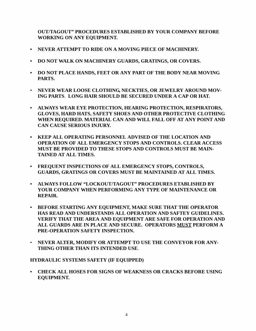
4. Manually swing the axle into the radial travel position. Once in the radial travel position, place the swing axle brace retention pin in the new position.
5. Repeat steps 4-6 on the opposite side of the MAGNUM.
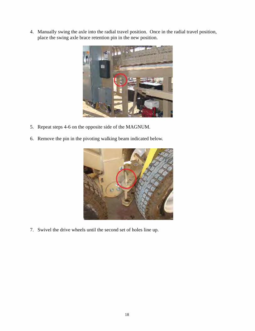
6. Remove the pin in the pivoting walking beam indicated below.
7. Swivel the drive wheels until the second set of holes line up.
18

8. Replace the pin in the new set of holes indicated below.
9. Remove the retention pin that prevents the walking beam from tilting and place it in the swing arm brace for storage.
10. Repeat steps six (6) and seven (7) on the opposite side.
IMPORTANT
Before operating the conveyor in radial travel mode, the air brakes MUST be released. Failure to do so will result in serious damage to power travel components.
Make sure the MAGNUM is on level ground or block the wheels so the conveyor cannot roll unexpectedly. Locate the air tank and open the release valve. When all air pressure has been released, close the valve.
19

Raise right and left Axle Jacks to lower the undercarriage back to the ground. Ensure that all per-sonnel are clear from all equipment before lowering the MAGNUM.
INSTALLING OPTIONAL SAFETY STOPS
If you purchased the optional safety stops, they will need to be installed now. Use the following steps to setup your safety stops:
1. The optional safety stops were bolted to the undercarriage for shipping. You will need to remove the safety stops from the undercarriage.
20

2. Once you have the safety stops free from the undercarriage, each will need to be inserted into a receiver on the underside of the travel axle.
21

22
RADIAL POWER TRAVEL
Your MAGNUM conveyor was shipped with the radial power travel drive chain(s) removed. The chain(s) will need to be attached to allow for radial travel.
Be sure to follow your company lockout/tagout procedures before removing the drive chain safety guard and attempting to attach the drive chain. Failure to do so can result in serious injury.
1. Remove the bolts that hold the drive chain guard in place and remove the guard.
2. Wrap the chain around the upper and lower sprockets.
3. Bring the two ends of chain together and insert the connecting link.
4. Place the outer link plate over the connecting link and insert the retaining pins.
5. Check chain deflection by placing a straight edge against the chain and applying pressure to the chain. Adjust the motor mount tensioner or add/remove links as needed for proper chain tension. To properly tighten the chain, lift the wheels off the ground. It is important to check both sides of the chain for tightness.
6. Replace the drive chain guard cover.
It is important to remove the drive chain before moving your MAGNUM to a new location. Failure to do so may result in equipment damage.

POSITIONING YOUR MAGNUM FOR ROAD TRAVEL
To prepare your MAGNUM for road travel, use the following procedures:
1. Turn on the main power to the electrical panel and switch to “Manual Mode”.
2. Start the Hydraulic Pump by pressing the button indicated below.
23

3. Verify that the extension/stinger conveyor is fully retracted to its “Home” position. The extension/stinger conveyor can be retracted using the button indicated below.
4. Locate the hydraulic levers labeled “LIFT JACK LEFT” and “LIFT JACK RIGHT”.
Hydraulic lifting jacks can crush hands and feet. Make sure the area beneath the lifting jack is clear before operating the hydraulic levers. Failure to do so can result in serious injury.
5. Operate these levers one at a time in the “DOWN” direction to raise the conveyor.
IMPORTANT
It is important to operate each lever a little at a time, alternating from left to right fre-quently to keep the MAGNUM level as you raise it off the ground.
24

Lower the lifting jacks until both sets of wheels are slightly off the ground.
Be sure to follow your company lockout/tagout procedures before removing the drive chain safety guard and attempting to remove the drive chain. Failure to do so can result in serious injury.
6. Disengage the wheels by loosening the chain tightening mechanism on the power travel unit.
7. Remove the drive chain safety guard.
8. Remove the drive chain and place it in the storage box.
9. Remove the pin from the pivoting walking beam and swivel it into road travel position
10. Re-pin the pivoting walking beam in road travel position.
11. Remove the pin from the right swing axle support brace.
12. Move the right swing axle towards the undercarriage to road travel position.
25

13. Re-pin the swing axle to the undercarriage.
14. Repeat steps 6-13 on the opposite side of the MAGNUM.
26

MAGNUM OPERATION MODES
Your MAGNUM has three operational modes. They are defined as follows:
• MANUAL MODE: All functions of the conveyor are operated by interacting with the switches on the main electrical panel.
• AUTOMATED MODE: All functions of the conveyor are controlled by an automated pro-gram inside the “PROGRAMMABLE LOGIC CONTROLLER (PLC)”. See below for infor-mation on using the PLC.
• REMOTE MODE: Similar to Manual Mode except that all functions of the conveyor are operated by interaction with remote control (instead of main electrical panel). NOTE: The user can still interact fully with the switches on the main electrical panel.
PROGRAMMABLE LOGIC CONTROLLER (PLC)
A PLC is a digital computer used for automation of conveyor processes such as radial travel, con-veyor extension, and raise/lower functions. The PLC is designed for multiple input and output arrangements, extreme temperature ranges, immunity to electrical noise, and resistance to vibra-tion and impact. The PLC on the MAGNUM Telescoping conveyor is located inside the main electrical panel.
27

MASABA utilizes a 10” color touch screen interface to interact with the conveyor’s PLC.
MASABA’s PLC gives users the ability to easily set up automatic operations by enabling the user to enter values for several key operating parameters. There are four (4) default programs that can be set by the user based on your stockpiling preference.
An example of the input parameter screen for the most common program (Radial Windrow) is shown below. If the user has a question on a definition of these values, they can press and hold one of the input variables, i.e. Radial Distance (ft):
28

PLC INPUT DEFINITIONS
• RADIAL DISTANCE: Radial arc distance is measured at the tires. This value is entered into the PLC during the set up stage of “Automated Mode”. This distance communicates to the PLC how large of a radial pile you want to make.
• MINIMUM EXTENSION DISTANCE: The minimum extension distance refers to the minimum distance (from the fully retracted position) that you want the extension/stinger con-veyor to travel when creating a pile in “Automated Mode”.
• MAXIMUM EXTENSION DISTANCE: The maximum extension distance refers to the maximum distance (from the fully retracted position) that you want the extension/stinger con-veyor to travel when creating a pile in “Automated Mode”.
• ELEVATION DISTANCE: Time set that the conveyor will rise once the pile height switch has been activated. Each MAGNUM is set at a predetermined amount, but can be adjusted by calling MASABA and requesting instructions.
• MATERIAL DESEGREGATION: Desegregation of stockpiled material is very important in developing stockpiles for applications such as concrete or asphalt. The MAGNUM’s auto-mated stockpiling configurations allow users to stockpile material in a desegregated manner.
A Fully Desegregated pile does not allow any overrun in the pile.
A Partially Desegregated pile allows overrun along the edges.
29

MANUAL & AUTO SYSTEM CONTROL
The manual system control allows the operator to control each individual function manually. The auto system control allows the operator to choose a program that will allow the machine to make windrows automatically. When operating the MAGNUM in “Manual Mode” (after setup or movements are complete), TURN THE HYDRAULIC PUMP SWITCH TO “OFF” on the electrical panel. Allowing the hydraulic pump to continuously run or “idle” when not in use may result in hydraulic pump failure.
PLC OPERATIONAL PROCEDURES
To begin using your MAGNUM conveyor, use the following procedures.
1. Make sure the MAGNUM conveyor is in the home position. The home position is defined as having the Extension/Stinger Conveyor in the fully retracted position, the Main Conveyor in the fully lowered position, and the undercarriage in the left most position.
2. The System Control switch must be set to “Auto”.
30

3. You should now see the home screen.
4. Touch anywhere on the home screen to access the Main Menu screen.
31
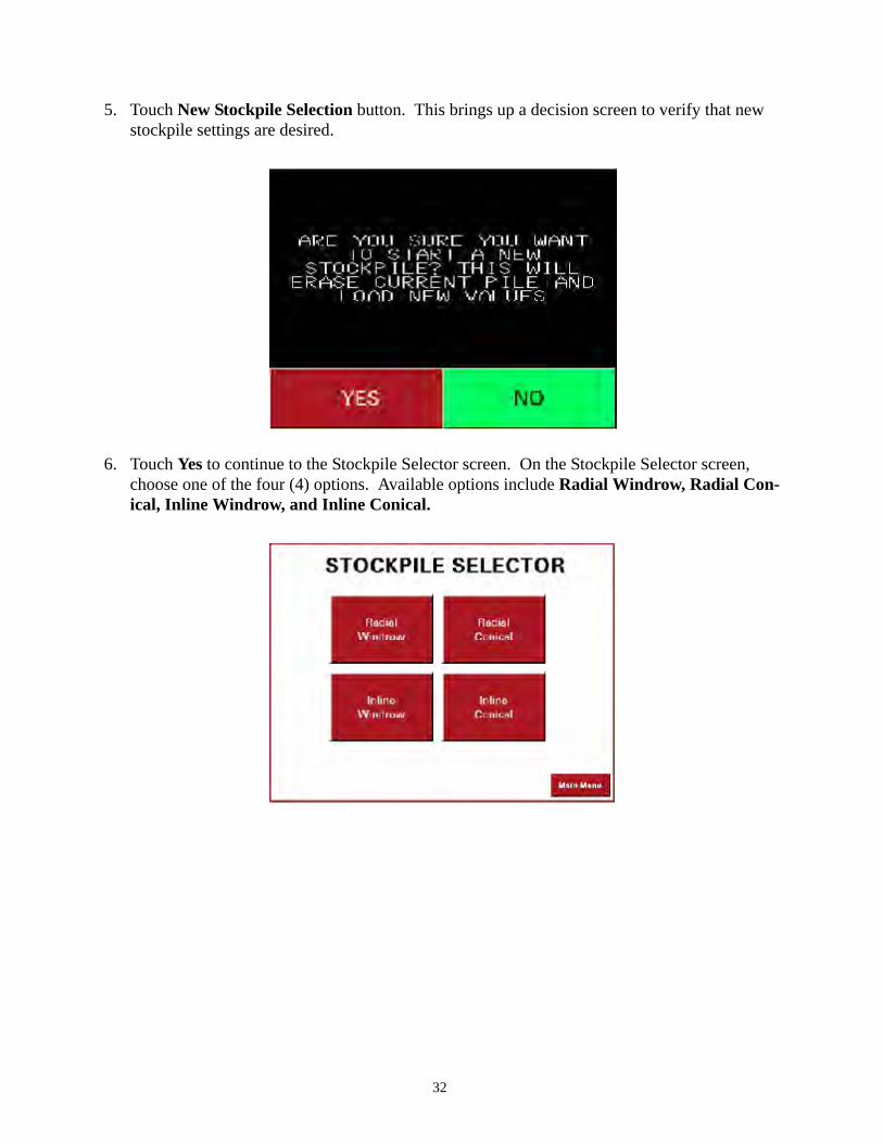
5. Touch New Stockpile Selection button. This brings up a decision screen to verify that new stockpile settings are desired.
6. Touch Yes to continue to the Stockpile Selector screen. On the Stockpile Selector screen, choose one of the four (4) options. Available options include Radial Windrow, Radial Con-ical, Inline Windrow, and Inline Conical.
32

Once selected the corresponding Stockpile screen appears.
Be sure to verify that all obstacles and personnel are clear of the MAGNUM travel area. Failure to do so can result in equipment damage and/or serious injury.
7. Once desired parameters are set, touch Begin Cycle to start stockpile program. The MAG-NUM is now ready to begin moving in cycle. The warning horn will sound for five (5) sec-onds prior to startup. When warning horn quits sounding, the extension/stinger conveyor will start moving. Three (3) seconds later, the main conveyor will start moving.
33

8. To stop a program at anytime during the cycle, touch Stop/Pause on the Stockpile Screen. The wheel movement is paused immediately and the Resume Previous Program screen appears.
9. Follow the on screen prompts for moving the conveyor to its previous position.
10. Once the conveyor is in its previous position, the following screen will appear. This screen gives the operator the ability to Resume Cycle or Stop/Terminate Program.
34

The table below is provided to assist users during setup of the Traverse Distance or Radial Arc Travel Distance. The Radial Distance, measured in feet, corresponds to the conveyor’s degree (estimated) of radial arc represented in the table for each figure.
35

36
ADJUSTING CONVEYOR HEIGHT (MANUAL MODE)
Adjusting conveyor height can be done by either manually operating the switches on the electrical panel or through the use of the PLC.
Use the following procedures to adjust the conveyor height in Manual Mode:
1. On the electrical panel, turn the “OPERATION MODE” switch to the manual position.
2. Locate the switch labeled “MAIN CONVEYOR”. Operate this switch in the proper direction for the desired action.

MAINTENANCE
BELT TRACKING
Prior to running the conveyor loaded with material, the belt tracking should be checked. Belt training is the process of adjusting idlers to insure that the belt travels over the center of the idlers, return rollers, and pulleys.
DO NOT ATTEMPT TO TRAIN THE BELT BY ADJUSTING THE SCREW TAKE-UPS. The take-ups are used for belt tension, and to keep the tail pulley square with the frame.
A normal sequence of training is to start with the return run working toward the tail pulley and then follow with the top run in the direction of belt travel. The primary rule which must be kept in mind when tracking a conveyor belt is simply: “THE BELT MOVES TOWARD THAT END OF THE ROLL/IDLER IT CONTACTS FIRST”.
The following steps should be taken to properly train the belt to run over the center of the pulleys, troughing idlers, and return rollers:
• Ensure that all frames are level. If the frames are not level, the belt will be forced to one side or the other.
• Square the tail pulley by measuring from a fixed point on both sides of the MAGNUM.
• Check the belt splice for squareness. The belt ends should be squared from a center line at least 15 feet long and accurately derived from center point measurements along the belt. Do not use the edge of the belt for reference.
37

• Square all troughing and return rollers with the frame and tighten the attachment bolts.
• Run the conveyor empty and at reduced speed if possible. Look for a side creep at any point along the frame. Check the return travel for side creep. Make adjustments where side creep occurs as follows:
The conveyor must be powered off before attempting to adjust any return rollers or idlers. Failure to do so can result in serious injury.
1. The point of maximum side creep requires adjustment of a preceding roller when you are fac-ing in the direction toward which the belt is moving.
2. Loosen the bolts and pivot the roller around its midpoint, making these adjustments in small increments. Tighten the bolts and make a test run after each adjustment to see the effect on side creep. If the point of maximum side creep changes, adjust the roller that precedes that new point.
3. Load the belt with material and continue testing until belt is running centered.
4. If the belt should show a side creep only at the splice point as it runs along the conveyor, rather than at one point, the splice is not square and should be re-done. See appendix B for detailed instructions on proper belt splicing.
38

OPTIONAL GREASE BANK SYSTEM
Your MAGNUM Telescoping Conveyor can be purchased with on optional Grease Bank System making servicing your conveyor much easier.
TROUBLESHOOTING BELT CONVEYORS
1. ALL PORTIONS OF CONVEYOR BELT RUNNING TO ONE SIDE AT A GIVEN POINT ON STRUCTURE.
PROBLEM CORRECTIONOne or more idlers immediately preceding Advance, in the direction of belttrouble point not at right angles to direc- travel, the end of the idler towardtion of belt travel. which the belt has shifted.
One or more idler stands not centered Center them.under belt.
Belt runs off terminal pulley. Check terminal pulley alignment.Check alignment of idlersapproaching terminal pulley.
Buildup of material on idlers. Improve maintenance. Install brushesor other cleaning device.
Structure not level and belt tends to Level Structure.shift to low side.
39

2. PARTICULAR SECTION OF BELT RUNS TO ONE SIDE AT ALL POINTS OF CON-VEYOR.
PROBLEM CORRECTIONBelt not joined squarely. Square ends & re-splice.
Cambered belt. Tension it or replace it.
3. CONVEYOR BELT RUNS TO ONE SIDE FOR LONG DISTANCE ALONG BED.
PROBLEM CORRECTIONLoad being placed on belt off-center. Adjust chute and loading conditions so
as to place in center.
Conveyor frame or structure crooked. Straighten it.
4. SEVERE WEAR ON PULLEY SIDE OF CONVEYOR BELT.
PROBLEM CORRECTIONSlippage on drive pulley. Increase tension if belt
construction permits.Lag drive pulley (groove if wet)
Spillage of material between belt and Improve loading conditions withpulley, or material builds up at loading chutes.point until belt is dragging. If belt loaded too full, increase
belt speed or decrease feed.Install plows or scrapers in front of tail pulleyon return run.
Excessive tilt to troughing idlers. Adjust to not more than 2 degreesfrom line perpendicular to belt.
Sticking idlers. Improve maintenance and lubrication.
5. PRODUCT SLIPS ON INCLINE.
PROBLEM CORRECTIONBelt dirty. Clean it.
Incline too steep. Decrease incline.
6. COVER BLISTERS OR SAND BLISTERS.
PROBLEM CORRECTIONCover cuts or very small cover punctures Make spot repair with vulcanizer allow fine particles of sand to work or repair dough, after removing under the cover and cut cover away from and cleaning the carcass.underneath blister area.
40

Oil either in material or from outside Remove source of oil, if possible.source. Check lubrication.
VENDOR SPECIFIC MAINTENANCE SCHEDULES
For maintenance schedules that are specific to the parts installed on your Masaba Conveyor, please refer to the corresponding appendix.
41

42
TROUBLESHOOTING MAGNUM CONVEYORS
1. WHEN IN INITIAL START UP IN AUTO MODE, CONVEYOR SYSTEM DOES NOT START AFTER PRESSING START BUTTON.
PROBLEM CORRECTIONExtension conveyor not in Home Position Ensure Extension Conveyor is in fully retracted
position. In Main Menu, press Bring Stinger Home.
Conveyor not in Auto Mode Change Mode Switch to Auto
2. WARNING HORN AND/OR LIGHT ACTIVATED.
PROBLEM CORRECTIONA system malfunction has occurred Identify malfunction by going to Main Menu, press
the alarm log screen. This screen identifies the lastten (10) alarms. Once you have identified theproblem, see next steps within this section.
Extension Conveyor has traveled too far Move mode switch to manual, turn on hydraulicpast proximity switch at either tail end or pump, operate the Stinger extension control manuallyhead end of conveyor. Emergency switch to navigate Stinger back to normal operating position.has been activated. Navigate user interface to Main Menu, press Bring
Stinger Home, Restart Program.
Wheel drives are spinning/no traction. Shut down conveyor, move conveyor out of operating position and repack surface.
3. DURING NORMAL OPERATION, CONVEYOR SYSTEM SHUTS DOWN.
PROBLEM CORRECTIONLoss of power source. Check power leads to ensure proper connection.
Loss of drive wheel traction. If conveyor Ensure the conveyor work site has solid compacteddrive wheels spin out, conveyor program ground with no more than one (1) degree slope. Thiswill stop system. will prevent the conveyor from rolling down hill and
will increase power travel life.
4. DURING OPERATION, CONVEYOR DOES NOT TRAVEL PROPER RADIAL TRAVEL DISTANCE.
PROBLEM CORRECTIONRadial Travel Encoder may not be Contact MASABA for assistance.functioning properly.
INSTALLING/TENSIONING V-DRIVES
CHECK CONDITION OF SHEAVES
Before installing a new set of V-Belts, examine the sheaves. Dirty or rusty sheaves impair the drive’s efficiency and abrade the belts, which results in pre-mature failure. Worn sheaves shorten V-Belt life by as much as 50%. If the grooves are worn to where the belt bottoms, slippage may result and burn the belts. If the sidewalls are “dished out”, the bottom shoulder ruins the V-Belts pre-maturely by wearing off the bottom corners.
The conveyor must be powered off before removing safety guards and must remain off while performing any maintenance function. Failure to do so can result in serious injury.
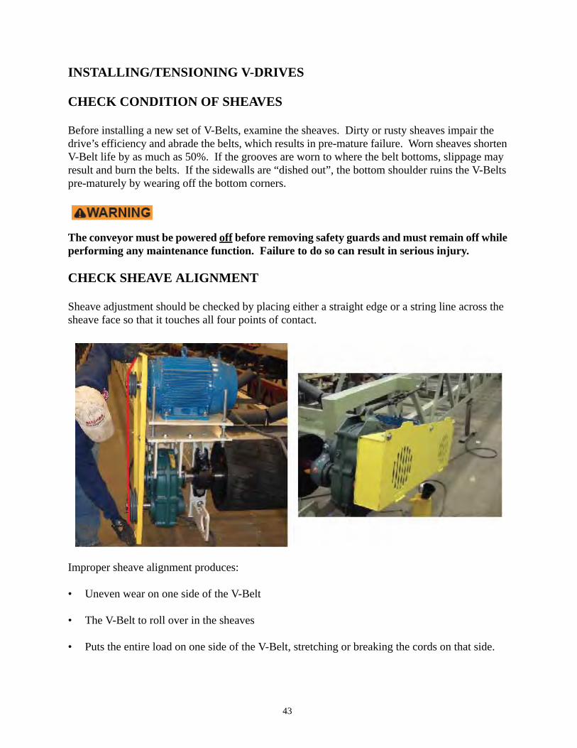
CHECK SHEAVE ALIGNMENT
Sheave adjustment should be checked by placing either a straight edge or a string line across the sheave face so that it touches all four points of contact.
Improper sheave alignment produces:
• Uneven wear on one side of the V-Belt
• The V-Belt to roll over in the sheaves
• Puts the entire load on one side of the V-Belt, stretching or breaking the cords on that side.
43

V-BELT INSTALLATION
Shorten the center distance of the drive until the V-Belts can be put on the sheaves without stretching. Stretching the V-Belts can cause internal damage to the belts. Center distance can be decreased by adjusting the belt tensioner shown below.
BELT SELECTION
For maximum service, replace V-Belt drives with a complete new matched set of belts. Never employ a used V-Belt as a replacement for one of a set of new V-Belts. Used belts normally are worn in cross-section and stretched, and will cause the new belts to accept its load. A new belt used with old belts will ride higher in the sheave, travel faster and operate at a much higher ten-sion than the used belts. The cord center may be ruptured, allowing the new belt to elongate. Shortly after this occurs it will cease to accept its full share of the load, leaving the drive under-belted. Belts of different manufactures should not be mixed for the same reasons.
GENERAL RULES OF TENSIONING
• IDEAL TENSION IS THE LOWEST TENSION AT WHICH THE BELT WILL NOT SLIP UNDER PEAK LOAD CONDITIONS.
• CHECK TENSION FREQUENTLY DURING THE FIRST 24-48 HRS OF RUN-IN OPER-ATION.
• OVER TENSIONING SHORTENS BELT AND BEARING LIFE.
• TENSION BELTS WHEN SLIPPING. NEVER APPLY BELT DRESSING AS THIS WILL DAMAGE THE BELT AND CAUSE EARLY FAILURE.
44

Conveyor Belt Storage and Installation
APPENDIX A

2
Receiving the Roll
Upon delivery, check the factory packaging fordamage, punctures, etc. Make any appropriateclaim against the carrier at that time.
Handling the Roll
Factory packaging is designed to protect yourconveyor belt during normal shipping andhandling. When a belt arrives, be carefulunloading it. Don’t drop it or handle itroughly. This could break the packaging andcause the belt to telescope. Once a belt tele-scopes, it is almost impossible to re-roll.
Try not to roll it, but if you must, roll in thedirection the belt is wound. Rolling a belt inthe opposite direction can cause it to loosenand telescope.
The best way to move a belt is to slip a sturdyhoisting bar through the center core. Then, liftit with a sling or with strong cables. Be carefulthat these hoist cables don’tdamage the outer wraps atthe belt edges. Protect theedges with special“spreader bars,” or shortwooden planks. Neverapply a sling around thecircumference of a roll ofbelting. . .it isn’t safe!
You can also move abelt safely bylaying the rollflat on a skidand hoistingthe skid witha forklift. Justbe sure theforks on thelift don’tcome incontact withthe belt itself.
Storage
When storing a new conveyor belt, leave ithoisted or stand it upright, preferably on a drysurface (do not lay the roll on its side). Awooden skid is best. Block it safely so it can’taccidentally roll.
Extreme temperature variations can have anadverse affect on a belt over long periods oftime. The ideal storage range is between 50°Fand 70°F.
Long exposure at temperatures even slightlybelow 40°F can harden or stiffen the com-pounds. If installed on a conveyor in thisstiffened state, the belt may not train welluntil it adjusts or “warms up” to the system.Neoprene, for example, is especially sensitiveto low temperatures and should never bestored at less than 40°F. Stiffened neoprenebelting is different than other constructions. Itwon’t loosen up until it’s had a lengthy expo-sure to relatively mild temperatures.
Temperatures over 90°F have an adverseeffect, too, and should be avoided.
Sunlight and ozone can also deteriorate anyexposed rubber over time. Store your belt outof the direct sunlight whenever possible.Electrical generators or arc welders cansometimes generate ozone. It is best to storeyour belt some distance away from this typeof equipment.
In general, it’s wise to keep any unused beltstored in its protective factory packaging until
it’s ready for installation.
Used belt should be thoroughly cleaned anddried prior to storage.
A dry place out of direct sunlight is pre-ferred for storage, excessive temperaturevariations or extremes being avoided. Beltsshould not be stored in excessively wetplaces or in areas where oils, gasoline, paint
Conveyor Belt Storage and Installation

3
materials, acids and chemicals are also storedor used. Motor-control rooms, welding shops,and other places where ozone is generatedshould likewise be avoided. A belt should notbe permitted to rest on a concrete floor. If it isnecessary to lay a belt on the floor, use apallet or a cradle.
Belts which are not endless should be storedin rolls. Once thoroughly cleaned and dried, itis good practice to dust a belt with tire talc orto insert kraft paper between the layers whenrolling it up. Care should be taken not to roll abelt too tightly. Be sure the interior diameterof the roll is sufficiently large to avoid anypossible carcass damage or warping.The belt should be rolled evenly toavoid telescoping and warping. Exces-sive flexing or sharp bends of any sortare to be avoided. Rolls should not bestood on edge or leaned against a wall.
Small endless belts may be hung up on adowel or a peg for storage. It is advisableto rotate the belt occasionally to avoid aconstant flex or bend at one point. Largerendless belts may be stored flat, doublingthem over as necessary. It is advisablewhen doubling a belt over to be sure thatthe edges of the belt are in line to avoidany warping. As above, it is good practice torotate and repile the belt occasionally to avoidconstant flexing or bending at any point.Bends should be made as large as possible toavoid cracking the carcass.
Installation
Once the roll of belting has been transportedto the point of installation it should bemounted on a suitable shaft for unrolling andthreading onto the conveyor. Conveyor belt-ing is normally rolled at the factory with thecarrying side out. Consequently, in mountingthe roll, the belt must lead off the top of theroll if it is being pulled onto the troughing orcarrying idlers but off the bottom of the roll ifit is being pulled onto the return idlers. Theillustrations below represent suitable methodsof mounting and stringing belt for each case.
Note: Temporary flat roll atbend point, as roll is pulledonto troughing idlers
In some cases, such as in the mines wherehead room does not permit maneuvering aroll, the belt may have to be pulled off the rolland reefed (Left). Extreme care should beexercised to see that the loops have largebends to avoid kinking or placing undue strainon the belt. No weight should ever be placedon the belt when it is in this position. Anothermethod of handling belting under such condi-tions is to lay the roll on a turntable with avertical spindle.
No weight to be placed on top
Keep bends large to preventbreaking carcass
Reefing the Belt
Left: Temporary flat roll atbend point
Below: Threading throughreturn strand

21 Laredo DriveScottdale, Georgia 30079 • USA
Phone: (404) 297-3170Fax: (404) 296-5165
www.fennerdunlopamericas.com 10/03
IS O 9001: 2000 C ertified
C O N V E Y O R B E L T I N G A M E R I C A S

Installing Flexco® Bolt Solid Plate
1. Square belt ends using centerline method. Cut belt ends using Flexco 840 Series Belt Cutter.
2. Support belt ends with wood plank. Nail Flexco Templet in position with belt ends tight against lugs.
3. Spray templet holes with Flexco Silicone Lubricant. Punch or bore bolt holes. Remove templet.
NOTE: A ½” square drive electric impact wrench with Flexco 5552 Quick Change Chuck will speed hole boring operation.
4. For 2-1/2, 3, 1-1/2FP, 2FP, RP1, and RP2, assemble bottom plate. Insert 2 bolts and attach clip.
5. Fold one belt end back and insert bolts in one row of holes.
6. Align bolts with templet teeth and place the other belt end over bolts. Remove templet.
7. Place top plates over bolts using bolt horn.
Instructions for Installation
8. Start nuts on bolts by hand.
9. Cut Flexco-Lok® Tape 3-1/2 times the belt width and feed tape under top plates, under the bottom plates, then back under top plates.
10. Pull tape tight and hold in position by en tighten all
other plates.NOTE: A Flexco
11. Tighten all fasteners from edges to center. Tighten all nuts uniformly. Power Wrench used with an impact tool will speed this step considerably.
12. Hammer plates in belt with wood block. Retighten nuts.
13. excess bolt ends using two bolt nish.
APPENDIX B

Belt Tracking
APPENDIX C

1
Table of Contents
I. Conveyor Components . . . . . . . . . . . . . . . . . . . . . . . . . . . . . . . . . . . . . . . . . . . . . . . . . . . . 3
Supporting Structure . . . . . . . . . . . . . . . . . . . . . . . . . . . . . . . . . . . . . . . . . . . . . . . . . . . 3
Pulleys, Rollers, Idlers . . . . . . . . . . . . . . . . . . . . . . . . . . . . . . . . . . . . . . . . . . . . . . . . . . . 3
Crowns . . . . . . . . . . . . . . . . . . . . . . . . . . . . . . . . . . . . . . . . . . . . . . . . . . . . . . . . . . . . . . 3
Take-up . . . . . . . . . . . . . . . . . . . . . . . . . . . . . . . . . . . . . . . . . . . . . . . . . . . . . . . . . . . . . . 4
II. Non Structural Components . . . . . . . . . . . . . . . . . . . . . . . . . . . . . . . . . . . . . . . . . . . . . . . . 5
Cleanliness . . . . . . . . . . . . . . . . . . . . . . . . . . . . . . . . . . . . . . . . . . . . . . . . . . . . . . . . . . . 5
Neutral Belt Stresses . . . . . . . . . . . . . . . . . . . . . . . . . . . . . . . . . . . . . . . . . . . . . . . . . . . . 5
Camber . . . . . . . . . . . . . . . . . . . . . . . . . . . . . . . . . . . . . . . . . . . . . . . . . . . . . . . . . . . . . . 5
Skew (Bow) . . . . . . . . . . . . . . . . . . . . . . . . . . . . . . . . . . . . . . . . . . . . . . . . . . . . . . . . . . . 6
Belt Tension. . . . . . . . . . . . . . . . . . . . . . . . . . . . . . . . . . . . . . . . . . . . . . . . . . . . . . . . . . . 6
Square Belt Ends. . . . . . . . . . . . . . . . . . . . . . . . . . . . . . . . . . . . . . . . . . . . . . . . . . . . . . . 6
III. General Training Procedures . . . . . . . . . . . . . . . . . . . . . . . . . . . . . . . . . . . . . . . . . . . . . . . . 9
IV. Training Package or Unit Handling Belting . . . . . . . . . . . . . . . . . . . . . . . . . . . . . . . . . . . . . 12
V. Training Bulk Haulage Belting. . . . . . . . . . . . . . . . . . . . . . . . . . . . . . . . . . . . . . . . . . . . . . . 18

2
“Tracking” or training is defined as the procedure required tomake the conveyor belt run “true” when empty and also whenfully loaded.
Tracking conveyor belt should be approached from a systemspoint of view. We should first examine some of the compo-nents of the conveyor system and see how they effect belttracking before we discuss the actual methods used to train abelt.
We also need to look at a few non-structural components suchas conveyor house keeping, the belt itself and the splice,before we discuss recommended training procedures.

Supporting StructureThe supporting structure is designed to hold con-veyor sections firmly and in proper alignment. If itdoes not, for whatever reason, it is likely to havean effect on belt tracking. Support structure shouldbe checked as a first step in belt tracking. Has aforklift run into the supporting structure and buck-led it? Are the anchors firm?
Conveyor sections are bolted to the supportingstructure. They should be “square” and “horizon-tal” (side to side). If the section is “racked” it must be straightened. Measure diagonals across the frame. They should be equal. Repeat for total,assembled bed.
Conveyor bed sections (slider or roller) must beproperly aligned with no vertical off-set betweensections. A taut line should be stretched over thetop surface of the bed and adjustments made sothat all points are in contact. The entire bed (andeach section) must be horizontal (across thewidth). If they are not, the belt will be pulled bygravity and will “drift” toward the low side unless acompensating force of some kind is exerted onthat belt.
Pulleys/Rollers/IdlersAll pulleys, snub rollers, carrying idlers, and returnidlers must be square with the frame (perpendicu-lar to belt center line), parallel to each other andlevel.
“Squaring” with the frame is a good preliminaryadjustment. The final adjustment, however,requires that this “squaring” be done with the beltcenter line as the reference. All pulleys must be atright angles to the direction of belt travel (belt cen-ter line).
CrownsCrowned pulleys for lightweight conveyor beltcan be trapezoidal or radial shaped. Georgia Duckhas products to accommodate both styles, howev-er the amount of crown in either case should notexceed 1/8" per foot on the diameter, and shouldnot exceed 1/8" total. The rate of crown seems tobe very important as well as the total amount ofcrown in the system.
On short center conveyors, we recommend nocrown on the drive (avoid crowns on drive in everycase, unless the drive is an end pulley), and tocrown the end pulleys. In a few cases we wouldalso crown additional pulleys, but that will dependon the entire design and the amount of crownused.
Remember, for crowns to be effective, there mustbe enough free span/transition for the belt to elon-gate and conform. Pretension to get pulley crownconformation is very important, too much preten-sion can cause pulley deflection and bearing prob-lems. Georgia Duck has specific carcass construc-tions to meet very short center, wide belt applica-tions in the 1:1 ratio of length to width, and evenless. Please consult factory if you have needs inthis area.
Crowned pulleys are not recommended for highmodulus bulk haulage belting. Steel Cord beltingrequires fully machined straight faced pulleysthrough out the system. If a crowned pulley is usedon nylon, polyester or aramid style belting thecrown should only be placed in a low tension areasuch as the tail on a conventional head drive con-veyor. The tracking forces that the crown exhibitsdoes not effect high modulus bulk haulage beltingbecause the system lacks enough tension to makethe crown effective. If you could exert enough ten-sion on the belt to force the belt to conform to thecrown, the belt would be subjected to excessivestretch and splice failure could result.
3
I. Conveyor Components

Take-upThe take-up device in a conveyor belt system hasthree major functions:
1. To establish, and preferably to maintain a pre-determined tension in the belt.
2. To remove the accumulation of slack in the beltat startup or during momentary overloads–inaddition to maintaining the correct operatingtension.
3. To provide sufficient reserve belt length toenable resplicing, if necessary.
Manual, as well as automatic, take-up devices arenormally used in a typical conveyor belt system.The manual or screw take-up consists of a ten-sion pulley (frequently the tail) which can be movedto tighten the belt by means of threaded rods or bysteel cables which can be wound on a winch.These give no indication of the tension they estab-lish and are adjusted by trial methods until slip-page is avoided. They are unable to compensatefor any length changes in the belt between adjust-ments and thus, permit wide variation in belt ten-sion. Use is generally restricted to short and/orlightly stressed conveyors–widely used in unithandling.
The manual take-up must be such that when ten-sion is applied to the pulley, the pulley remains atright angles to the direction of belt travel. Also the
tension must be high enough to allow elasticrecovery of elongation due to starting forces, loadchanges, etc.
Automatic take-ups depend upon suspending apredetermined weight (gravity), by activation of atorque motor, by hydraulic pressure, or by springloading. These devices maintain a predeterminedtension at the point of take-up regardless of lengthchanges resulting from load change, start-up,stretch, etc. This permits running the belt at theminimum operating tension and should be used onall long length conveyors and moderate to highlystressed conveyors.
The automatic take-up alignment must be suchthat the pulley or pulleys are maintained at rightangles to the direction of belt travel. In a gravity orspring loaded take-up, the carriage must be guid-ed to maintain the pulley axis on a line perpendicu-lar to the belt center line.
Adequate take-up is essential to satisfactoryoperation of a belt conveyor. The amount requireddepends on type of belting and on service con-ditions. Please refer to belt manufacturer forrecommendations.
Normally, when a new belt has been properlyinstalled and tensioned, the take-up roll or pulley(automatic take-up) will be initially set at a positionof 25% along the line of travel, leaving 75% of thetake-up area available for elongation.
4

CleanlinessCleanliness is essential to good belt tracking. Abuildup (of whatever material) on pulleys and rollscan easily destroy the “perpendicularity” of the rollor pulley face. Foreign matter in essence creates anew roll or pulley crown–adversely affecting tracking.
Likewise, cleanliness is essential to slider bedoperation. A buildup of foreign materials (or aroughened portion of the slider bed face) can veryeasily throw a belt off-center since this will result ina differential of warp tensions across the width ofthe belt. This can seriously effect training.
Scrapers can be applied directly to bend rolls atthe take-up area, on a gravity take-up system, tokeep the rolls free from build up. Ploughs installedprior to the tail roll, under the loading section, willprevent belt and pulley damage due to carry back.
Balanced/NeutralIt is extremely important that the final belt con-struction be “balanced” or “neutral” in terms of theinternal stresses imparted to the belt during manu-facture. Any unbalanced stress remaining in thebelt will likely cause problems in tracking.
Typical belt carcass designs usually utilize a plainweave or twill weave. The “crimp” imposed uponthe warp yarns (length-wise yarns) in these types of weaves, as well as the warp tension necessaryat the loom are difficult to control. Unbalancedstresses can result. Georgia Duck has a patentedtensioning system to minimize this problem.
The resulting “straight/balanced” carcass is keptstraight by tensioning during the impregnation andcuring steps of manufacture, resulting in a straightbelt which is balanced and therefore, easy to track.
CamberIf unbalanced warp tensions exist in a conveyor belt,that belt will usually assume a “crescent” or“banana” shape when laid flat upon a horizontalsurface. This deviation from a straight line is here-by defined as “camber.”
To measure belt camber, it is recommended thatthe belt be unrolled on a flat surface like the ware-house floor, a flat horizontal driveway, etc. Next,one end of that belt should be grasped (and one endonly) and the belt dragged in a perfectly straightline for approximately 10 feet. If the belt is tooheavy for one man to move, then one end shouldbe clamped to a forklift and the same procedure performed. At this point, the belt should lie flat. Unequal and unresolved warp tensions in the belt will cause it to assume a “crescent” or “banana” shape.
Camber is measured by drawing a taut line alongone edge of the belt and measuring maximumdeviation from that taut line to the belt at the pointof maximum deviation. Compute % camber as follows:
% Camber = Maximum Deviation (Inches) x 100Length of taut line (Inches)
It is recommended that if the percent camberexceeds one-half of 1%, the belt manufacturer be contacted. In lightweight, unit/package handling.25% is the maximum.
Camber can be instilled into a belt during the slittingoperation if one of the slitting knives is dull. A dullslitting knife will tear the fill yarns (cross-wise yarns)rather than cut them. (While the belt is in roll formthe side of the belt which had gone through the dullknife will exhibit a “fuzzy” appearance due to thetorn fill yarns.) Usually this type of camber will beless than one-quarter of 1% and can be pulled outhandily when the belt is properly tensioned.
5
II. Non Structural Components

Skew (Bow)The fill yarns (weft yarns) in the belt carcass willusually lie along the perpendicular to the belt cen-ter line. Any deviation from this perpendicular lineby the fill yarn is hereby defined as “skew” or“bow.”
A skewed pick in a plain weave or twill weave iscause for concern since it is generally indicative of unbalanced warp tensions and will usually gohand-in-hand with a significant camber.
In a straight warp or solid woven carcassdesign, however, skew is of little significance.It is a cosmetic defect and is not indicative of acambered belt.
Belt TensionBelt tension must be great enough to prevent slip-page between the drive pulley and belt. Tensionmust also be enough to cause the belt to conformto the crowns, if present.
Slippage will cause excessive wear to both drivepulley lagging and the belt. Further, an excessiveheat buildup on the drive pulley lagging can resultin rubber reversion. (Reversion is the softening ofvulcanized rubber when it is heated too long orexposed to elevated temperatures. It is a deteriora-tion in physical properties, and frequently results intackiness.) Once the pulley lagging has reverted, it frequently will offset onto the bottom side of theconveyor belt which will then distribute the reverted
rubber throughout the slider or roller bed of thesystem. The resulting tackiness between the bedand the belt will certainly drive horsepower con-sumption up; can actually result in a stalled sys-tem, and can cause severe tracking problems.
Square EndsAccurate squaring of the belt ends prior to splicingis essential to belt tracking, and helps distributestress evenly throughout the splice.
To properly square the belt ends, we recommendthe center line method.
To establish the belt center line, start near the beltend as shown on the next page. Measure the beltwidth at seven points approximately 1 foot apart.Divide each measurement in two and mark thesecenter points as shown.
Using these seven “center points,” pop a chalk lineto form the belt’s center line. Next, using a carpen-ter square or “T” square, draw a “cut line” acrossthe width of the belt near the belt end as shown.Repeat this for the other belt end.
Using the “cut line” as the guide, cut off the end ofthe belt with a sharp razor knife. Make sure thatthe cut is clean and vertical. This operation shouldthen be repeated on the other end of the belt.(Keep in mind that the final belt length may need toinclude an allowance for such things as diagonalsplice, skive taper length, skive overlap, fingerpunching loss, fastener extension, etc.–dependingupon what kind of splice is being performed.)
6

7
BELT CENTER LINE
MARKING OF CUT LINE AND OTHERRIGHT ANGLE GUIDE LINES
T-SQUAREOR FRAMING SQUARE
BELTEND
BELTEND
CUT LINE
1 FOOT1 FOOT1 FOOT 1 FOOT 1 FOOT 1 FOOT

An alternative method of squaring belt ends iscalled the “double intersecting arc” method.
First establish the center line as indicated previ-ously. Once that center line has been established,pick a point on the center line and approximately 2or 3 times the belt width from the belt end. An arcis now struck, as shown in the following sketch.
On bulk haulage belting, a nail can be used as thepivot point and an arc is struck with a steel tape.Always mark the edge of the belt with the sameside of the tape.
A second arc is now struck as shown. The pivotpoint in this case is on the center line and is closeto the belt end. The arc length is slightly less thanone-half of the belt width. Now draw a line from onepair of intersecting arcs to the other. This is the “cutline.” This line is perpendicular to the center line ofthe belt. The reason for this may be edge wear ordamage or to eliminate slitting alignment errors.Never assume both edges are straight and parallel.
Double Check Squareness
It is always a good idea to double-check the accu-racy of the squared and cut end. Measure 5 feetalong each edge from the end of the belt, thenutilizing a tape measure, check the two diagonals.They should be equal and further, should intersecton the belt center line.
8
PIVOT
NAIL
PIVOT
NAIL
STEEL TAPE
LONG ARC
SHORTERARC
ALTERNATIVE ARC METHOD OF SQUARING ENDSJOINING OF THE POINTS WHERE THE ARCS INTERSECT
GIVES THE RIGHT ANGLE CUT LINE
5’
5
A
C
D
B
PROVING ACCURACY OF SQUARED-CUT END
LENGTH OF DIAGONAL AB IS EQUAL TO LENGTH OF DIAG-ONAL DC. ALSO AB AND DC INTERSECT ON THE BELT
CENTER LINE.
CUTLINE
CUTLINE
BELTEND

Tracking the belt is a process of adjusting idlers,pulleys, and loading conditions in a manner that will correct any tendencies of the belt to run otherthan true.
A normal sequence of training is to start with the return run working toward the tail pulley andthen follow with the top run in the direction of belttravel. Start with the belt empty. After tracking iscompleted, run the belt with a full load and recheck tracking.
Tracking adjustment is done while the belt is run-ning and should be spread over some length of the conveyor preceding the region of trouble. Theadjustment may not be immediately apparent, sopermit the belt to run for several minutes and atleast three full belt revolutions after each idleradjustment to determine if additional “tracking” is required.
After adjustment, if the belt has overcorrected, itshould be restored by moving back the same idler,and not by shifting additional idlers or rollers.
If the belt runs to one side at a particular point orpoints on the conveyor structure, the cause willprobably be due to the alignment, or leveling of thestructure, or to the idlers and pulleys immediatelypreceding that particular area, or a combination ofthese factors.
If a section or sections of the belt run off at allpoints along the conveyor, the cause is possibly inthe belt itself, in the belt not being joined squarely,or in the loading of the belt. With regard to the belt,this will be due to camber. Its condition shouldimprove after it is operated under full load tension.It is a rare occasion when a cambered belt (lessthan 1/2%) needs to be replaced.
These basic rules can be used to diagnose a beltrunning poorly. Combinations of these rules some-times produce cases which do not appear clear-cut as to cause, but if there is a sufficient numberof belt revolutions, the running pattern will becomeclear and the cause disclosed. In those unusualcases where a running pattern does not emerge, itis quite likely that at some point the belt is running
so far off that it is fouling structure or mountingbrackets, bolts, etc. This results in highly erratic performance and can be a real problem. We wouldsuggest that in this event the full tracking proce-dure be employed. It is quite likely that the erraticperformance will be resolved in the process.
When replacing a used belt, go through the systemand square and level all rollers, idlers, pulleys andbed before training a new belt.
Basic/Primary Rule of Tracking
The basic and primary rule which must be kept inmind when tracking a conveyor belt is simple,“THE BELT MOVES TOWARD THAT END OFTHE ROLL/IDLER IT CONTACTS FIRST.”
The reader can demonstrate this for himself verysimply by laying a small dowel rod or round pencilon a flat surface in a skewed orientation. If a bookis now laid across the dowel rod and gentlypushed by one’s finger in a line directly away fromthe experimenter, the book will tend to shift to theleft or right depending upon which end of thatdowel rod the moving book contacts first.
9
III. General Tracking/Training Procedures
BOOK MOVES LIKE SO
PENCIL
BOOK
PUSH

Pulley Crown on Lightweightand Monofilament BeltA crowned pulley can be regarded as a specialcase of our primary rule of tracking as statedabove. The right half of the belt is contacting thecenter of the pulley sooner than it contacts theright edge of that pulley and therefore will tend tomove toward the center. The reverse is true of theleft half of the belt. The two forces tend to balanceone another by centering the belt.
In addition to this surface effect, however, there isa strong internal “balancing of warp tensionsoccurring.” Consider any warp yarn not directly onthe center line. If the belt is forced off-center andthis warp yarn is drawn toward the mid-point ofthe crown, tension will be increased on that yarn.As the belt revolves and that yarn seeks to moveback to its normal position, this tension will dimin-ish. Yarns on both sides of the belt seek that posi-tion which results in the least stress to themselves,consistent with the physical structure across whichthey are stressed and consistent with their individ-ual position within the matrix of the belt carcass.Accordingly, the belt will shift on the crowned pul-ley until these stressing forces are balanced andminimized–centering the belt.
Experiment has shown that a crown is most effec-tive when it has a long unsupported span of beltapproaching the pulley. The lateral position of thebelt can be influenced by the crown more easilywhen there is a minimum of resistance beingoffered by a supporting slider bed or by supportingidlers.
Georgia Duck goes to great lengths to manufacturebalanced carcass belts so that the belt will selfcenter and track on the crown.
In most non-unit-handling conveyors this opti-mum condition does not exist on the top runand consequently, crown on the head pulley isof little value in training the belt. Further, it is adistinct detriment as far as lateral distributionof tension in the belt is concerned. Head pul-leys therefore, should be uncrowned in normalcircumstances. Tail pulleys and take-up pulleyswhich may have a fairly long approaching spanwithout support can be crowned with somebeneficial results.
The effectiveness of the crown is increased to alength of approximately 10 feet. Lengthening theunsupported span beyond 10 feet does not seemto increase the effectiveness of the crown.Diminishing the length of the unsupported span onthe other hand, does diminish the effectiveness ofthe crown. The shorter the unsupported span, theless effective the crown will be. Snub pulleys canreduce effectiveness by 50% or more.
We recommend a standard pulley crown of 1/16"on radius per foot of pulley face. This results in anincrease in pulley diameter at a point 12" from theedge of the pulley of 1/8" above the edge diame-ter. A crown of 1/8" per foot should be consideredmaximum. Crowns may be trapezoidal or radius.
It is further recommended that the crown not becarried beyond a point 18" in from the edge of thepulley. If the pulley width is greater than 36" it isrecommended that a trapezoidal pulley be used. Inother words, that pulley will have a flat face in itscenter equivalent to the amount that the pulleywidth exceeds 36". Radius crowns work, but maytake a few minutes longer to stabilize.
With the advent of CNC Machining, we see moreuse of radial crowns, but the same rule regardingmaximum crown should apply. Special Note: Thebelt must stretch to conform to the crown or it willnot be effective.
10

Equipment Induced Camber
Camber can be induced into a perfectly straightbelt by the roll or rolls preceding the camber. If theroll is cocked, the belt will react and will movetoward that end of the roll which it contacts first.This, of course, throws the belt off-center. If now,subsequent structural adjustments center that roll,the belt installation will be left with a camberedappearance. This camber may be removed by sim-ply aligning the roll or rolls which are cocked.
Specific Training Sequence
Emergency
If the conveyor system, including the belt, hasbeen designed, built and installed according togood engineering and manufacturing practice, thebelt should track at start-up. There may be minorvariations from the ideal because of manufacturingtolerance–this will simply result in a system inwhich the belt is not tracking absolutely perfectly,but one in which the belt can be operated withoutbelt damage long enough for the trackingsequence to take place. Normally belt width is lessthan pulley face width and a small amount of beltmovement will not cause any damage.
Occasionally, there may be a serious maladjust-ment or defect in the system which will throw the
belt off to such a degree as to threaten belt dam-age. It may actually be necessary to station men ateach end of the conveyor and physically force thebelt back in line by means of a smooth, steel bar.In extreme cases it may even be necessary to shutthe conveyor down, make any adjustment indicat-ed, and then restring and reposition the belt beforestart-up. In any case, it is extremely important toavoid belt damage. Once a belt is damaged, it willnot necessarily recenter itself.
If the conveyor structure has been checked,appears to be true, and all rolls appear to be per-pendicular to the system center line and severebelt tracking problems still persist, it is advisable toshut the system down and establish a belt centerline as a frame of reference. (Use the technique outlinedpreviously in this discussion.) Now that a beltcenter line has been established. Use this line asthe reference for the adjustment of each individualpulley, snubber, roll, etc. Once all rolls are perpen-dicular to the belt center line, the belt will trackwell enough so that the specific training sequencecan commence.
(If it was necessary to establish the belt center line,double-check the system structure. Normally, thesystem center line and belt center line are equiva-lent. A variance suggests that something has beenoverlooked in examination of the structure, pulleys,idlers, etc.)
11

At this point, let us assume that we have a systemwhich is at least operating and with a belt runningwell enough so that it is not a danger of beingdamaged. For purposes of our study, let us use the hypothetical conveyor design which follows.Keep in mind that we will follow the general train-ing sequence previously outlined, namely:
1. Return run-working from head toward tail, lowtension side.
2. Top run-working from tail toward head, hightension side.
3. First empty, then full; with belt running.
Return Run
Considering the hypothetical conveyor system wehave outlined (See Figure #1, page 13), our firstconsideration will be the first item in the returnrun–namely, the head pulley snubber (roll #1). Fromour previous discussion, it is obvious that cockingthe head pulley snubber will have very little effecton the tracking since there is essentially no unsup-ported belt span available to allow the belt to react.However, cocking snubber #1 will tend to throw acamber into the belt which will tend to throw thebelt off-center and become apparent at roll #2.
The return idler #2 does have a sufficiently longunsupported span for belt reaction and therefore,cocking idler #2 in a horizontal plane, can have abeneficial tracking effect. (If after we have adjustedidler #2 to the point where the belt is centered onidler #2, examination shows a camber betweenrolls 1 and 2, this is an indication that roll #1 is notperpendicular to the belt center line and is impart-ing the camber to the belt in this section.)
If it is necessary to adjust roll #2 to an off-perpen-dicular position in order to center the belt on roll #2,this off-perpendicular position of roll #2 can causea subsequent cambering effect. In this particularconveyor design, this cambering effect will bealmost totally eliminated by the proximity of roll #3.
If the distance between roll #2 and roll #3 were 8 feet (let us say) this cambering effect could be pronounced. Under these circumstances it may
be necessary to compromise and not cock the roll quite as much as we would like. (“Tracking” can be considered a physical embodiment of theart of compromise.)
For purpose of completeness, it should be notedthat if one end of roll #2 is lower than the other, thebelt will favor that side due to the pull of gravity.This effect may, or may not, be masked by thetracking effect of roll #2.
Idler #3 has little or no tracking effect due to thelack of unsupported span between itself and roll#2. It can, however, be used to control the positionof the belt since it does have a cambering effect.
It is important to note at this point that virtually anyadjustment you make to these rolls will be slight.
Idler #4 is highly effective as a tracking roll because it does have a good unsupported beltspan approaching it. It will induce very little, if any,camber to the belt because of its proximity to roll #5.
Roll #5 on this particular conveyor is our drivepulley and will be a high tension region for the belt.This, coupled with the fact that there is little or nounsupported belt span between itself and roll #4,suggests that this is a poor tracking pulley andshould not be crowned. This pulley should besquared to the belt center line and left there.The same is true for roll #6–the snubber pulley.
Roll #7 will not be very effective for tracking pur-poses because of the short unsupported belt span,but can be a problem camber-wise if it is not per-pendicular to the belt center line. This pulleyshould be square and left there.
The take-up pulley (#8) does have potential fortracking, as well as for camber, due to the unsup-ported belt span between itself and rolls #7 and 9.
If, however, we adjust roll #8 so it is off-perpendicu-lar in order to achieve a tracking effect on the beltas it approaches roll #8 from roll #7, that sameadjustment will tend to impart camber to the belt asit leaves roll #8 and approaches roll #9. Accordingly,compromise is called for and roll #8 should be per-pendicular to the belt center line. Unfortunately, this
12
IV. Training Belt on Package or Unit Conveyors

13
BE
LT T
RA
VE
LC
AR
RY
ING
RU
N
RE
TU
RN
RU
N
11
10
1213
1415
16
12
34
8
9
7
8’8’
6’4’
TR
AC
KIN
GH
YP
OTH
ETI
CA
L C
ON
VE
YO
RFI
GU
RE
#1
6
5

may not always be possible since roll #8 is a take-up roll and in this case, is spring-loaded. Roll #8will move from time to time as tensions increaseand decrease in the system due to the normaloperating cycle. Good engineering practice dictatesthat roll #8 be constrained in some sort of carriageconstruction designed to keep it perpendicular tothe belt center line at all times. However, there canbe tolerance differences, corrosion effects, lack oflubrications, etc., as well as other problems whichmay, at least momentarily, throw the take-up rolloff-square. To avoid the “mistracking effect” thiswould have, it would be a good idea to impart aself-aligning feature to the take-up roll by crowningit. Further, it is in a low tension portion of the beltcircuit and does have a reasonably effectiveunsupported belt span preceding it.
Roll #9 can exert a reasonable amount of trackingforce on the belt because of the unsupported beltspan preceding it, but it can also exert a consider-able cambering effect since the unsupported beltspan between roll 9 and 10 is so large. Here again,compromise is called for–the ideal situation beingto simply square pulley #9.
Roll #10 in this design is a snubber and is veryimportant from a tracking point of view. First of all, it has a long unsupported belt span preceding itand therefore is capable of exerting a strong cen-tering influence on the belt. Secondly, the positionof this snubber means that it will feed the beltimmediately onto the tail pulley and will, in essence, be responsible for positioning of the beltrelative to loading. Roll #10 will obviously have littleor no cambering effect.
Because of the importance of presenting the belt in a centered manner to the tail pulley, it might bewise to impart a self-aligning feature to roll #10 bycrowning it. (Incidentally, this is also a low tensionportion of the belt circuit.) Note that the crown willnot be as effective as normal due to close proximi-ty of roll #11.
Unless a snub pulley is needed to maintain beltwithin framework, a snub pulley doesn’t serve uswell. The snub causes loss of tracking effectivenesswith the tail, more belt flex and costs more. Avoidif at all possible.
The tail pulley (roll #11) should be perpendicular tothe belt center line. In this particular design adjust-ing the tail pulley will have very little, if any,
tracking effect due to the fact that there is nounsupported belt span between itself and roll #10.The snubber roll (#10) in this particular case hastaken over the tracking function of the system. If,on the other hand, there were no roll #10, then thetail pulley would in truth have a tracking functionand could effectively be crowned.
The tail pulley (#11) does have a marked camber-ing effect because of the long span between itselfand roll #13. It’s true that this span is supported bya slider bed which tends to modify the camberingeffect. However, since the loading point or pointswill occur somewhere on this section of the beltand probably quite close to the tail pulley, it isimportant that the tail pulley be squared relative tothe center line so as to avoid any camber whatso-ever.
The slider bed (#12) can have a marked effect onbelt tracking. The slider bed must be level (side toside) since if it is not level the belt will tend to runtoward the low side as it is being pulled by gravity.Further, the slider bed needs to be clean andsmooth. If it is rough on one side or it has a layer of gummy, sticky, reverted rubber on one side, itwill tend to pull the belt toward that side. In thisevent, the slider bed should be thoroughly cleanedand buffed. The underside of the belt must also becleaned ( do not use solvent based cleaners onbelt).
Carrying idlers #13, #14 and #15 do have trackingand cambering effects based upon their distancefrom each other, and their distance relative to theslider bed and head pulley. The standard roller bedwill have the carrying idlers so close together thatindividually the rolls will have very little tracking orcambering effects. If, however, they are all cockedin one direction, the effect can be marked. Accord-ingly, we would urge that carrying idlers not beused for tracking unless absolutely necessary andsimply be squared relative to the belt center line.
The discharge pulley (#16) is located in a high ten-sion portion of the belt circuit. Further, there is usu-ally little or no unsupported belt span preceding it, which severely limits any tracking effect which can be obtained from the head pulley. Accordingly, it is good practice not to crown the head pulley noruse it for tracking adjustments. If you find that youmust adjust the head pulley in order to center thebelt, you will, in all likelihood, find that you havemerely realigned an off-square head pulley.
14
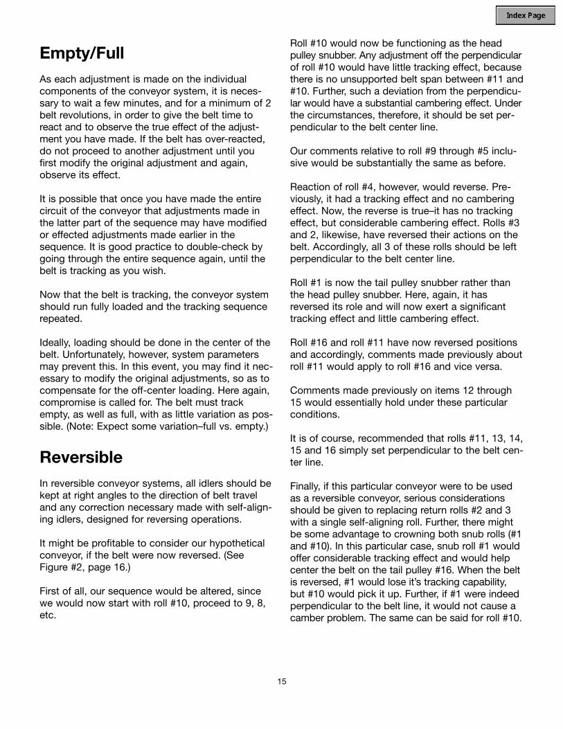
15
Empty/FullAs each adjustment is made on the individualcomponents of the conveyor system, it is neces-sary to wait a few minutes, and for a minimum of 2belt revolutions, in order to give the belt time toreact and to observe the true effect of the adjust-ment you have made. If the belt has over-reacted,do not proceed to another adjustment until youfirst modify the original adjustment and again,observe its effect.
It is possible that once you have made the entirecircuit of the conveyor that adjustments made inthe latter part of the sequence may have modifiedor effected adjustments made earlier in thesequence. It is good practice to double-check bygoing through the entire sequence again, until thebelt is tracking as you wish.
Now that the belt is tracking, the conveyor systemshould run fully loaded and the tracking sequencerepeated.
Ideally, loading should be done in the center of thebelt. Unfortunately, however, system parametersmay prevent this. In this event, you may find it nec-essary to modify the original adjustments, so as tocompensate for the off-center loading. Here again,compromise is called for. The belt must trackempty, as well as full, with as little variation as pos-sible. (Note: Expect some variation–full vs. empty.)
ReversibleIn reversible conveyor systems, all idlers should bekept at right angles to the direction of belt traveland any correction necessary made with self-align-ing idlers, designed for reversing operations.
It might be profitable to consider our hypotheticalconveyor, if the belt were now reversed. (SeeFigure #2, page 16.)
First of all, our sequence would be altered, sincewe would now start with roll #10, proceed to 9, 8,etc.
Roll #10 would now be functioning as the headpulley snubber. Any adjustment off the perpendicularof roll #10 would have little tracking effect, becausethere is no unsupported belt span between #11 and#10. Further, such a deviation from the perpendicu-lar would have a substantial cambering effect. Underthe circumstances, therefore, it should be set per-pendicular to the belt center line.
Our comments relative to roll #9 through #5 inclu-sive would be substantially the same as before.
Reaction of roll #4, however, would reverse. Pre-viously, it had a tracking effect and no camberingeffect. Now, the reverse is true–it has no trackingeffect, but considerable cambering effect. Rolls #3and 2, likewise, have reversed their actions on thebelt. Accordingly, all 3 of these rolls should be leftperpendicular to the belt center line.
Roll #1 is now the tail pulley snubber rather thanthe head pulley snubber. Here, again, it hasreversed its role and will now exert a significanttracking effect and little cambering effect.
Roll #16 and roll #11 have now reversed positionsand accordingly, comments made previously aboutroll #11 would apply to roll #16 and vice versa.
Comments made previously on items 12 through 15 would essentially hold under these particularconditions.
It is of course, recommended that rolls #11, 13, 14,15 and 16 simply set perpendicular to the belt cen-ter line.
Finally, if this particular conveyor were to be usedas a reversible conveyor, serious considerationsshould be given to replacing return rolls #2 and 3with a single self-aligning roll. Further, there mightbe some advantage to crowning both snub rolls (#1and #10). In this particular case, snub roll #1 wouldoffer considerable tracking effect and would helpcenter the belt on the tail pulley #16. When the beltis reversed, #1 would lose it’s tracking capability,but #10 would pick it up. Further, if #1 were indeedperpendicular to the belt line, it would not cause acamber problem. The same can be said for roll #10.

16
BE
LT T
RA
VE
L
RE
TU
RN
TAK
E-U
P
DR
IVE
PU
LLE
Y
11
10
1213
1415
16
12
34
68
7
TR
AC
KIN
GH
YP
OTH
ETI
CA
L C
ON
VE
YO
RFI
GU
RE
#2
95

Short Center-Wide BeltConveyorsShort center-wide belt conveyors offer a specialtracking challenge, simply because there usually is not enough belt length to stretch the necessarydistance for crown conformation. If belt centers are10 times belt width, these problems do not normal-ly show up; below 5:1 ratio you must be aware ofseveral factors: (1) Amount and type of crown, (2) belt stress/strain curve, (3) tension on belt and(4) location of crowns in the system.
Georgia Duck has products for lightweight materialhandling systems for length to width ratios of 1:1and even below, but these are special and all
details of conveyors must be discussed with aGeorgia Duck distributor or Georgia Duck repre-sentative.
Tracking PriorityFinally, we would like to suggest that when track-ing a conveyor belt, number one priority should begiven to adjusting return idlers followed by adjust-ment of snubber rolls. If there is no snubber on thetail pulley, then adjusting the tail pulley doesbecome effective and should be used. The headpulley is normally a flat pulley and should be set ona perpendicular to the belt center line. The headpulley should be adjusted for tracking purposesonly as a last resort.
17

Training a heavy duty belt is similar in a lot of waysto training a light weight belt.
The major difference is that the troughed idlers onthe carry side exert a natural gravitational trainingforce. The edges of the belt that are turned up tend to gravitate toward the center of the conveyor,thereby exerting a powerful training action. Manybulk haulage conveyor operators do not attempt toadd any other training devices to the carry side ofthe conveyor, as the troughers do a fine job bythemselves.
As with training light weight belt, all major pulleys:head, tail, drive, snubs, bends, and take-up shouldbe parallel, level and square. All idlers and pulleysneed to be clean and functioning properly. All load-ing stations have to be centered so that product isintroduced to the center of the belt. Any belt train-ing idlers that are on the system must be in properworking order and be installed in the proper direc-tion. The lagging on the drive pulley should beinspected and replaced, if the lagging is damagedor if the surface is smooth and hard, which canresult in slippage. It is good practice to replacerubber lagging when a new belt is installed, par-ticularly if the lagging is old, as the rubber tends to harden with age and become less effective.
The new belt may have some internal stresses frommanufacturing; therefore, the best procedure for anew belt is to run it for a while before making anyadjustments. This run-in period will relieve mostmanufacturing stresses that can occur duringweaving, treating, calendering, assembly, curing,and slitting. Some belts, after installation, may runperfectly from the beginning. If the new belt willstay out of the frame on the return side, then run it empty for an hour or two, then begin introducinga load to the belt. The belt should be constantlyinspected during this break-in period. Full belt con-tact with all carry side idlers is important due to thetraining forces that are present with the troughedidler sets.
As stated in the beginning of this brochure,crowned pulleys are not required for bulk haulagebelting. Crowned pulleys may offer a minor contri-bution towards training when the crowned face is
used on a low-tension pulley like the take-up orthe tail pulley. The crown will have no effect if usedon the high tension head pulley or drive pulley.High modulus belt fabrics like nylon, polyester, andaramid do not respond to the centering forces ofcrowned pulleys; and in some cases, can actuallyhave an adverse effect on the belt. Steel cord beltsmust have fully machined straight faced pulleys tooperate around, because a crown will createadverse stresses in the belt and in the splice.
The theory of training a heavy duty belt is to feedthe carry side square, use the troughers to keepthe belt centered through the discharge, then trainthe empty belt on the return (slack side).
Self-training idlers should be on 100' centers onthe return side, unless the conveyor is out ofsquare, then 50' centers may be required in areaswhere the frame is out of square. The locations ofthe self-trainers are very important, as they can notfunction properly if installed in the wrong place.
The first self-training idler on the return should beplaced about 30' behind the head. This allows thetraining idler to align the belt coming out of the head(into the trainer). . .then 30' past the trainer. Self-training idlers do not work when placed too close toa terminal pulley, snub, bend or take-up. These pul-leys have more belt wrap than the training idler,which off-sets any training forces that the idler has.You need at least 30' of free run on each side of thetraining idler to make it effective. On slow-movingbelts, 20' of free area on each side will work. At 800' per minute, the self-training idlershould be placed 40' from a major pulley. The trainerscan then be spread out over the return. If the take-up is 80' behind the head, place one self-trainerbetween the head and take-up areas, after the take-up area (20' to 40'); then place the trainers on 100'centers back to within 20' to 40' of the tail. If theself-training return idlers are still not effective, shimthe return trainers up to present the trainer withmore belt surface area. Equally effective is to usethe next size up return run self-trainer–a 5" dia. to a6" dia. trainer. A good rule of thumb is never skewan idler that has over 90° of wrap, to ensure that thehigh modulus belt fabric will not be stretched out ofsquare. This method will train the slack side belt,
18
V. Training Bulk Haulage Belting

feed the tail square, then run true on the carry sidebecause of the centering forces from the troughers.Self-training troughing idlers should not be shimmedup because the additional pressure that is createdon the belt in the idler gap area can cause prematurebelt failure in the idler junction area.
Another approach to training the slack side of longcentered conveyors is the use of 2 roll “V” returnidlers. With this type idler (generally 10°), gravitybecomes the training force, and the belt edges arenot subject to wear from the vertical arms on self-trainers. It should be noted that due to the smalldegree of angle with this type of return idler, if theframe is severely out of square the belt can run out of the “V” and into the return frame.
In areas along the carry side where the frame is not level and true, the following additional trainingmethod can be used. Each individual idler standcan be tilted in the line of travel by placing a wash-er under the rear legs of the idler stand. This for-ward tilt is not to exceed 2° from vertical. This isNOT to be done with reversing conveyors. Thenegative side of this training method is that exces-sive wear on the pulley cover and on the idler canresult since the idler is no longer rotating on anaxis 90° to the belt path.
Feeder Belts
Short centered feeder belts should be double-checked for squareness with a steel tape. The two terminal pulleys need to be parallel, level and square.
All training should be done on the return, or slackside. On a short conveyor (50' centers, or so) placeone large diameter self-trainer on the return side inthe middle of the conveyor. This roll can beshimmed up to increase the effectiveness of theroll.
The most important part of the tracking is not touse major pulleys for training; and to allow thetrainer to have slack belt feeding into and out ofthe trainer.
Bi-Directional Belts
Bi-directional belts should only use carry sidetroughers that are vertical and do not have any tiltadded in. All return run self-trainers should be ofthe bi-directional type.
Bi-directional hardware, such as pulleys, top sideidlers and return side idlers must be level, paralleland square.
When pulling the load towards the drive pulley, thetight side is on the carry side and the slack side ison the return. When pulling from the return side,ie., pushing the load, the tight side is on the returnand the slack side is on the carry side.
The slack side of the belt will have more catenary,ie., loose belt, to drape over the idlers than thetight side; therefore the idlers on the slack side willhave a more influential training effect than idlers onthe tight side, ie., less drape over the idler.Therefore it is mandatory that all idlers be level andsquare.
Skewing an idler on the tight side will allow certaintraining advantages. When the conveyor reverses,this same idler is now on the slack side, and willhave more catenary, or drape, and will now have a greater influence than before.
The reader should also keep in mind anotherpotential problem, when trying to train a bi-direc-tional bulk haulage conveyor. A carry side trougher,when skewed, will have minimum effect when thebelt is run empty and pulled over the idler. Thissame trougher with a load being pulled over it, nowbecomes even more influential, due to the weight on the belt forcing the belt down on the idler. If you now push the belt in the opposite direction with a load on it, this same idler has an even greater training effect.
These are some of the reasons that make trainingbi-directional conveyors so difficult. Therefore, allhardware must remain level and square and the use of bi-directional self-trainers is a must.
19
MaximumDirection of travel
Top idler standWasher
2°

21 Laredo DriveScottdale, Georgia 30079 • USA
Phone: (404) 297-3170Fax: (404) 296-5165
www.fennerdunlopamericas.com 10/03
IS O 9001: 2000 C ertified
C O N V E Y O R B E L T I N G A M E R I C A S

Conveyor Belt Maintenance
APPENDIX D

Conveyor belt maintenance not only includes proper care of thebelt itself but also includes care and maintenance of the frameand accessories.
The first step in the process is to design an inspection form toencompass all aspects of each conveyor. This brochure isdesigned to assist in the actual design of the inspection reportand the steps needed to correct any problems that you see whenmaking this inspection.
This inspection form will take into account various types ofconveyors from package handling to bulk haulage, thereforesome of the items covered in our inspection and repair reportmay not apply to your particular conveyor.

Table of Contents
I. Belt Shut Down and Empty...................3
II. Belt Running Empty...............................4
III. Belt Running Loaded.............................4
IV. Corrective Action....................................4
V. Inspection Form and Checklist.......7 & 8

I. Belt Shut Down and EmptyThe first step is to inspect the conveyor beltwhen the system is shut down and empty. Thisallows the opportunity to check for any damageto the belt or splice. The conveyor shouldbe locked out while making this inspection.
Rubber belt damage should be repaired usingthe hot vulcanized repair method or the coldrepair method. Belt fabrics that are exposed tothe weather or to product contamination shouldbe properly cleaned, dried, then covered withnew rubber. These repairs are critical to pre-vent moisture from penetrating the belt andbreaking down the cover adhesions, and to pre-ventproduct contamination from abrading the car-cass and also breaking down the adhesions.Very few, if any repairs can be made to light-weight belts.
The splice can also be inspected and if damagein the splice is visible it is suggested that thesplice be repaired or replaced.
This is also a good time to walk the conveyorand check the following components.
A) Tail Pulley free from build-up and trapped material
B) Tail Pulley damage
C) Skirting in the loading area
D) Impact Bed or Impact Idler damageE) Slider Bed clean and smooth
F) Carrying Side Idler damage
G) Carrying Side Self Trainers - operational and not tied off
H) Secondary Loading Stations
a) Skirting
b) Impact Bed or Impact Idler damage
I) Tripper Frame damage
J) Tripper Discharge Pulley - clean
K) Tripper Bend Pulleys - clean
L) Head Pulley and/or Drive Pulley
a) Clean
b) Check for worn lagging
c) Re-lag Drive Pulley if rubber is old, worn, smooth and hard
M) Head Pulley cleaner or scraper -operational
N) Head Pulley Snub - clean
O) Return Idlers - clean & turning freely
P) Bend Pulleys - clean
Q) Take-Up - clean
R) Return Side Self Trainers - operational and not tied off
S) Damage to return side frame due to mistraining
T) Plow or Scraper in front of Tail Pulley - operational
The preceding list should be used as a guidewhen inspecting the conveyor while it is empty
3

and shut down.Numerous items in the preceding list containedthe words clean or operational. Pulleys or idlersthat have build up on them will cause trackingproblems. The same can be said for pulleysthat have some of the rubber lagging worn off.
Scrapers, plows and self-trainers must be operational to perform their tasks. Belt dam-age, pulley damage and tracking problems willresult if these accessory pieces of hardware arenotmaintained.
II. Belt Running EmptyThe conveyor should be turned on and runempty. The purpose of this is to walk the con-veyor, while running empty, to check for anytracking problems. Before any adjustments aremade to correct a tracking problem, the systemwill need to be inspected under running condi-tions when loaded, because empty belts andloaded belts do not necessarily track the sameway. For more information on tracking, refer tothe Georgia Duck Tracking Brochure.
III. Belt Running LoadedThe next step in our inspection process is torun the belt in a loaded condition. We will adda few new steps in the inspection process andrepeat a few of the previous steps.
The following is our check list for operating theconveyor while loaded:
A) Tail Pulley - Turning freely without bearing noise, product build up or carryback; belt tracking satisfactorily
B) Load area spillage
C) Carry Side Idlers - turning freely
D) Carry Side Self-Trainers - functioning
E) Secondary Loading Station spillage
F) Tripper Area
a) Tracking
b) Spillage
G) Head Pulley and or Drive Pulley
a) Smoothly running
b) Slippage when starting or running
c) Belt Cleaners - functioning
d) Belt Tracking
H) Head Pulley Snub - turning freely without bearing noise and clean
I) Return Idlers - clean and turning freely
J) Bend Pulleys - turning freely without bearing noise and clean
K) Take-up Pulley - turning freely withoutbearing noise, clean, moving freely in the frame
L) Return Side Self Trainers - functioning
M) General Belt Tracking
N) Plow or Scraper in front of Tail Pulley - functioning
IV. Corrective ActionThe last step is to take the corrected actionrequired on the conveyor in addition to:
A) Clean Up
B) Lubrication
C) Safety Concerns - such as installing orrepairing conveyor crossovers, safety stopcables, holdbacks on incline conveyors, edgelimit switches, motor guards, hand rails, etc.
We have mentioned the word cleanlinessthroughout this brochure. Maintaining a cleansystem can not be stressed enough.
4

A conveyor system with carryback on the returnside is the single biggest reason that conveyorbelts are replaced, return idlers and pulleys arereplaced and structure is worn through. Materialbuild up on the belt and hardware causes track-ing problems, that will lead to edge damage,that leads to new belt and new idlers.
We urge you to use scrapers on the head pulleyand plows in front of the tail pulley as preven-
tion for damage in your maintenance planning.
Some sticky materials present a real challengewhen it comes to preventing carryback. Wewould like to offer a few additional suggestionsas to handling these products.
Cleated belts may be reversed to allow betterrelease at the discharge point.
A dual scraper system on the head pulley is themost common way to eliminate product carry-back.
A water spray on the belt cover along withwiper blades will effectively remove most prod-ucts from sticking to the cover.
A series of out of round (cam shaped) returnidlers will also assist in cleaning. These idlersare spiral wound from the edges towards thecenter of the idler and work on the premise ofa turning beater bar arrangement.
A compressed air blast has been successfullyused on material like coal and fine wet sand.
A power driven revolving brush will help removeproduct from the belt. This method is rarelyused because the bristles tend to clog up with
material and wear out quickly. A brush may bethe only solution for cleated belts.Product build up on return side pulleys is amajor concern. If your belt is not effectivelyclean on the return run, then any bend pulleys or head snub pulley that come in contact withthe carry side of the belt will accumulate prod-uct. We would like to offer a few hints on pulleyand idler cleaning.
All return side pulleys that come in contact withthe carry cover can be lagged with a soft rub-ber vulcanized to the pulley. The constant flex-ing action of the soft lagging will cause materialto fall off and reduce material accumulation.
A lever weighted urethane scraper pressedagainst the pulley face, is an excellent way toremove build up. This system causesadditional wear on the pulley face so it is sug-gested to use heavier walled return bend pul-leys when using a scraper. If a scraper isapplied to a head snub or bend pulleys at thetake-uparea then deflector plates will have to beinstalled to deflect he build up away from thebelt.
5

Return idlers can be rubber covered and willhelp prevent product from sticking to the returnidlers.
Return idlers can be purchased that are nothingmore than discs mounted on a shaft. Thesediscs can be made of soft rubber, urethane, orceramics. This type of return idler can be veryeffective to prevent build up. The major prob-lem when using this style of return roller is thatthe manufacturers do not put enough discs onthe shaft to effectively support the belt in themiddle, and support the edges of the belt if anymis-tracking occurs.
Another effective measure is called a turnoversystem. By the use of a series of rollers thebelt is flipped over at the head and tail on thereturn side. This allows the belt to run thereturn side with the carry (dirty side) side upand the pulley(clean side) side down in contact with the returnrollers. Any spillage from the product carrybackwill be limited to the two twist areas. For moreinformation on turnover systems, refer to ourbrochure on Conveyor Design Tips.
The following inspection form andchecklist should be used as aguide for your conveyor systems.There may be additions or deletionsdepending on your particular conveyor designs.
6

CONVEYOR INSPECTION FORM AND CHECKLIST
Inspection Date _____________________ Conveyor Number_____________
I. Belt Shut down and Empty Corrective Action
_____ Belt Condition
_____ Splice Condition
_____ Tail Pulley
_____ Skirting
_____ Impact Bed/Idlers
_____ Slider Bed
_____ Carry Side Idlers
_____ Carry Side Self Trainers
_____ Secondary Loading Station
_____ Tripper Frame
_____ Tripper Discharge Pulley
_____ Tripper Bends
_____ Head / Drive Pulley
_____ Head Pulley Cleaner
_____ Head / Drive Pulley Snub If Present
_____ Return Run Drive
_____ Return Idlers
_____ Bend Pulleys
_____ Take-Up Pulley
_____ Return Side Self Trainers
_____ Return Side Frame
_____ Tail Pulley Plow / Scraper7

II. Belt Running Empty Corrective Action
_____Tracking
III. Belt Running Loaded
_____ Tail Pulley
_____ Spillage in Load Area
_____ Carry Side Self trainers
_____ Secondary Load Station Spillage
_____ Tripper Area
_____ Tracking
_____ Spillage
_____ Head Pulley
_____ Drive Pulley
_____ Head Pulley Cleaner
_____ Head / Drive Pulley Cleaner
_____ Head / Drive Pulley Snub
_____ Return Idlers
_____ Bend Pulleys
_____ Take-Up Pulley
_____ Return Side Self Trainers
_____ Belt Tracking
_____ Tail Pulley Plow / Scraper
IV. Corrective Action
_____ Clean Up
_____ Lubrication
_____ Safety
8

21 Laredo DriveScottdale, Georgia 30079 • USA
Phone: (404) 297-3170Fax: (404) 296-5165
www.fennerdunlopamericas.com 10/03
IS O 9001: 2000 C ertified
C O N V E Y O R B E L T I N G A M E R I C A S

Trouble Shooting
Spill
Edge Wear
E�ects of O�-Center Loading
APPENDIX E

The enclosed conveyor belt trouble shootingchart can serve as a general guide for some ofthe more common conveyor belt problems.
If your belt problem does not seem to resolveitself with these corrective measures, or if yourbelt problem is not found on this list, then contact Georgia Duck and request a visit byone of our factory representatives.
* The idler junction is the gap between the functioning surfaces of the center roll andone of the side rolls of the idler (See Fig. 1). This gap poses a potential hazard for thebelt by providing a narrow space in which the belt can settle experiencing highlydetrimental flex and possible exposure to oil or grease from the idler bearings (Fig. 2).When slipping of the belt into the idler junction is the cause of belt damage, it iscalled idler junction failure. The idler gap should be less than .4” or twice belt thick-ness-whichrever is less.
Fig. 1 Fig. 2

Trouble ShootingProblem/Cause For Solutions Refer to Answer #
A. Belt runs off at tail pulley. 39 10 1 19 31
B. Belt runs to one side for long distance or entire length of conveyor. 39 8 5 1
C. Particular section of belt runs to one side at all points on conveyor. 6 7 46
D. Belt runs off at head pulley. 33 10 1 3
E. Conveyor runs to one side at given point on structure. 5 4 1 2 3 44
F. Belt runs true when empty, crooked when loaded. 8 51 52
G. Belt slips. 34 33 31 10 4 30
H. Belt slips on starting. 34 31 33 30 42 43
I. Excessive belt stretch. 12 35 32 43
J. Grooving, gouging or stripping of top cover. 13 4 15 16 53
K. Excessive top cover wear, uniform around belt. 19 20 10 8 36
L. Severe pulley cover wear. 4 9 10 17 1 27
M. Longitudinal grooving or cracking of bottom cover. 4 10 9 33 36
N. Covers harden or crack. 23 37
O. Cover swells in spots or strreaks. 21
P. Belt breaks at or behind fasteners; fasteners pull out. 24 22 48 30 47 49
Q. Vulcanized splice separation. 38 30 12 17 25
R. Excessive edge wear, broken edges. 8 10 40 7 50 38
S. Transverse breaks at belt edge. 18 25 26
T. Short breaks in carcass parallel to belt edge, star breaks in carcass. 16 17
U. Ply separation. 29 30 23
V. Carcass fatigue at idler junction.* 25 26 27 28 29 36
W. Cover blisters or sand blisters. 45 21
X. Belt Cupping-Old Belt (was OK when new). 21 23

Conveyor System Problems/Causes andTheir Solutions
1. Idlers or pulleys out-of square with center line of belt: readjust idlers in affected area.
2. Conveyor frame or structure crooked: straighten in affected area.
3. Idler stands not centered on belt: readjust idlers in affected area.
4. Sticking idlers: free idlers and improve maintenance and lubrication.
5. Build-up of material on idlers: remove accumulation; improve maintenance. Install scrapers or other cleaning devices.
6. Belt not joined squarely: remove affected splice and resplice.
7. Bowed belt: for new belt this condition should disappear during break-in; in rare instances belt must be straightened of replaced; check storage and handling of belt rolls.
8. Off-center loading or poor loading: adjust chute to place load on center of belt; discharge material in direction of belt travel at or near belt speed.
9. Slippage on drive pulley: increase tension through screw take-up or add counterweight; lag drive pulley; increase arc of contact.
10. Material spillage and build-up: improve loading and transfer conditions; install cleaning devices; improve maintenance.
11. Bolt heads protruding above lagging: tighten bolts; replace lagging; use vulcanized-on lagging.
12 Tension too high: increase speed, same tonnage, same speed; reduce friction with bettermaintenance and replacement of damaged idlers; decrease tension by increasing arc ofcontact or go to lagged pulley; reduce CWT to minimum amount.
13. Skirt boards improperly adjusted or of wrong material: adjust skirt board supports tominimum 1” between metal and belt with gap increasing in direction of belt travel; use skirt board rubber (not old belt).
14. Load jams in chute: redesign chute for proper angle and width.
15. Material hanging up in or under chute: improve loading to reduce spillage; install baffles; widen chute.
16. Impact of material on belt; reduce impact by improving chute design; install impact idlers, or impact bed.
17. Material trapped between belt and pulley: install plows or scrapers on return run ahead of tail pulley.
18. Belt edges folding up on structure: same corrections as for 1, 2, 3; install limit switches; provide more clearance.

19. Dirty, stuck, or misaligned return rolls: remove accumulations; install cleaning devices; use self-cleaning return rolls; improve maintenance and lubrication.
20. Cover quality too low: replace with belt of heavier cover gauge or higher quality rubber orother elastomer.
21. Spilled oil or grease: over-lubrication of idlers: improve housekeeping; reduce quantity of grease used; check grease seals
22. Wrong type of fastener, fasteners too tight or too loose: use proper fastener and splice technique; set up schedule for regular fastener inspection.
23. Heat or chemical damage: use belt designed for specific condition.
24. Fastener plates too long for pulley size: replace with smaller fasteners; increase pulley size.
25. Improper transition between troughed belt and terminal pulleys: adjust transition in accordance with Georgia Duck Belting Catalog.
26. Severe convex (hump) vertical curve: decrease idler spacing in curve; increase curve radius.
27. Excessive forward tilt of trough rolls: reduce forward tilt of idlers to no more than 2° fromvertical.
28. Excess gap between idler rolls: replace idlers; replace with heavier belt.
29. Insufficient transverse stiffness: replace with the proper belt.
30. Pulleys too small: use larger diameter pulleys.
31. Counterweight too light: add counterweight or increase screw take-up tension to value determined from calculations.
32. Counterweight too heavy: lighten counterweight to value required by calculations.
33. Pulley lagging worn: replace pulley lagging.
34. Insufficient traction between belt and pulley: lag drive pulley; increase belt wrap; install belt cleaning devices.
35. System underbelted: recalculate belt tensions and select proper belt.
36. Excessive sag between idlers causing load to work and shuffle on belt as it passes over idlers: increase tension if unnecessarily low; reduce idler spacing.
37. Improper storage or handling: refer to Georgia Duck for proper storage or handling instructions.
38. Belt improperly spliced: resplice using proper method as recommended by Georgia Duck.
39. Belt running off-center around the tail pulley and through the loading area: install training idlers on the return run prior to tail pulley.
40. Belt hitting structure: install training idlers on carrying and return run.

41. Improper belt installation causing apparent excessive belt stretch: pull belt through counterweight with a tension equal to at least empty running tension; run belt in with mechanical fasteners.
42. Improper initial positioning of counterweight in its carriage causing apparent excessive belt stretch; check with Georgia Duck for recommended initial position.
43. Insufficient counterweight travel: consult Georgia Duck for recommended minimum distances.
44. Structure not level: level structure in affected area.
45. Cover cuts or very small cover punctures allow fines to work under cover and cutcover away from carcass: make spot repair with vulcanizer or self-curing repair material.
46. Worn edge: ”press” edge.
47. Interference from belt scrapers: adjust belt scrapers.
48. Tension too high for fasteners: use vulcanized splice.
49. Belt carcass too light: select stronger carcass.
50. Belt misalignment: see training recommendations.
51. Variations in nature and formation of load: use notched chute to keep load peak in exact center of belt.
52. Belt not making good contact with all idlers: adjust height so all idlers contact belt.
53. Sharp edges of material or tramp iron coming in contact with cover: use jingle bars,impact idlers, magnetic removal equipment.

21 Laredo DriveScottdale, Georgia 30079 • USA
Phone: (404) 297-3170Fax: (404) 296-5165
www.fennerdunlopamericas.com 10/03
IS O 9001: 2000 C ertified
C O N V E Y O R B E L T I N G A M E R I C A S

APPENDIX F
1

2

1
INSTALLATION:
1. Use lifting bracket where applicable to lift reducer.2. Determine the running positions of the reducer. (See Fig. 1)
Note that the reducer is supplied with six plugs; four around the sides for horizontal installations and one on each face for vertical installations. These plugs must be arranged relative to the running positions as follows:
Horizontal Installations - Install the magnetic drain plug in the hole closest to the bottom of the reducer. Install the
plug in topmost hole. Of the two remaining plugs on the sides of the reducer, the lowest plug is the minimum oil level plug.
Vertical Installations - Install the plug in the hole provided in the upper face of the reducer housing. If space is restricted on the upper face, install the vent in the highest hole on the side of the reducer per Figure 1 using the optional vertical vent kit. Install a plug in the hole in the bottom face of the reducer. Do not use this hole for the magnetic drain plug. Install the magnetic drain plug in the lowest hole on the sides of the reducer. Of the remaining holes on the sides of the reducer, use the plug in the upper housing half for the minimum oil level plug,
Figure 1 - Mounting Positions
WARNING Because of the possible danger to persons(s) or property from accidents which may result from the improper use of products, it is important that correct procedures be followed. Products must be used in accordance with the engineering information specified in the catalog. Proper installation, maintenance and operation procedures must be observed. The instructions in the instruction manuals must be followed. Inspections should be made as necessary to assure safe operation under prevailing conditions. Proper guards and other suitable safety devices or procedures as may be desirable or as may be specified in safety codes should be provided, and are neither provided by Baldor Electric Company nor are the responsibility of Baldor Electric Company. This unit and its associated equipment must be installed, adjusted and maintained by qualified personnel who are familiar with the construction and operation of all equipment in the system and the potential hazards involved. When risk to persons or property may be involved, a holding device must be an integral part of the driven equipment beyond the speed reducer output shaft.
Installation and Parts Replacement Manual for DODGE
Torque-Arm ™ TXT Double Reduction Taper Bushed and Straight Bore Speed Reducers
TXT/HXT 1ATXT/HXT 2ATXT/HXT 3BTXT/HXT 4B
TXT/HXT 5CTXT/HXT 6ATXT/HXT 7A
TXT 8ATXT 9A
TXT 10A
Includes Char-Lynn 6B Hydroil ReducersHXT 3B – 6BHXT 4B – 6B
HXT 5C – 6BHXT 6A – 6B
HXT 7A – 6B
These instructions must be read thoroughly before installation or operation.
Below 15 RPM output speed, oil level must be adjusted to reach the highest oil level plug. If reducer position is to vary from those shown in Figure 1, either more or less oil may be required. Consult Dodge.
The running position of the reducer in a horizontal application is not limited to the four positions shown in Fig. 1. However, if running position is over 20° in position “B” & “D” or 5° in position“A” & “C”, either way from sketches, the oil level plug cannot be used safely to check the oil level, unless during the checking, the torque arm is disconnected and the reducer is swung to within 20° for position “B” & “D” or 5° for position “A” & “C” of the positions shown in Fig. 1. Because of the many possible positions of the reducer, it may be necessary or desirable to make special adaptations using the lubrication holes furnished along with other standard pipe stand pipes and oil level gauges as required.
3. Mount reducer on driven shaft as follows:
WARNING: To ensure that drive is not unexpectedly started, turn o� and lock out or tag power source before proceeding. Remove all external loads from drive before removing or servicing drive or accessories. Failure to observe these precautions could result in bodily injury.
For Taper Bushed Reducer: Mount the reducer on the driven shaft per instruction sheet for the tapered bushing kit.
4. Install sheave on input shaft as close to reducer as practical.(See Fig. 2)
5. If not using a Dodge Torque-Arm motor mount, install motor and V-belt drive so belt will approximately be at right angles to the centerline between driven and input shaft. (See Fig. 3) This will permit tightening the V-belt with the torque arm.
6. Install torque arm and adapter plates using the long reducer bolts. The adapter plates may be installed in any position around the input end of the reducer.
7. Install torque arm fulcrum on a and rigid support so that the torque arm will be approximately at right angles to the centerline through the driven shaft and the torque arm anchor screw. (See Fig. 4) Make sure that there is take-up in the turnbuckle for belt tension adjustment when using V-belt drive.
CAUTION: Unit is shipped without oil. Add proper amount ofrecommended lubricant before operating. Failure to observethis precaution could result in damage to or destruction of the equipment.
8. Fill gear reducer with the recommended volume of lubricant.
APPENDIX G

2
Figure 2 - Reducer and Sheave Installation
Figure 3 - Angle of V-Drive
Figure 4 - Angle of Torque Arm
TXT TAPERED BUSHING INSTALLATION
WARNING: To ensure that drive is not unexpectedly started, turn off and lock out or tag power source before proceeding. Remove all external loads from drive before removing or servicing drive or accessories. Failure to observe these precautions could result in bodily injury.
Taper Bore Bushings:
1. Onebushingassemblyisrequiredtomountthereduceronthedrivenshaft.Anassemblyconsistsoftwotaperedbushings,bushingscrewsandwashers,andnecessaryshaftkeysorkey.
Thedrivenshaftmustextendthroughthefulllengthofthereducer.Theminimumshaftlength,asmeasuredfromtheendoftheshafttotheouteredgeofthebushingflange(seeFigure5),isgiveninTable1.Thisdimensiondoesnotincludedimension“A”.Dimension“A”shouldbeaddedtotheminimumshaftlengthtoallowfortheremovalofthebushingsatdisassembly.
2. Placeonebushing,flangeendfirst,ontothedrivenshaftandpositionperdimension“A”,asshowninTable1.Thiswillallowtheboltstobethreadedintothebushingandforfuturebushingandreducerremoval.Ifthereducermustbepositionedclosertotheequipmentthandimension“A”,placethescrews,withwashersinstalled,intotheunthreadedholesofthebushingflangepriortoplacingthebushingontheshaftandpositionasrequired.
3. Inserttheoutputkeyintheshaftandbushing.Foreaseofinstallation,rotatethedrivenshaftsothattheshaftkeyseatisatthetopposition.
4. Mountthereduceronthedrivenshaftandaligntheshaftkeywiththereducerhubkeyway.Maintaintherecommendedminimumdistance“A”fromtheshaftbearing.
5. Insertthescrews,withwashersinstalled,intheunthreadedholesinthebushingflangeandalignwiththethreadedholesinthebushingbackupplate.Ifnecessary,rotatethebushingbackupplatetoalignwiththebushingscrews.Tightenthescrewslightly.Ifthereducermustbepositionedcloserthandimension“A”,placethescrewswithwashersinstalled,intheunthreadedholesinthebushingbeforepositioningreducermakingsuretomaintainatleast1/8”betweenthescrewheadsandthebearing.
6. Placethesecondtaperedbushinginpositionontheshaftandalignthebushingkeywaywiththeshaftkey.Aligntheunthreadedholesinthebushingwiththethreadedholesinthebushingbackupplate.Ifnecessary,rotatethebushingbackupplatetoalignwiththebushingholes.Insertbushingscrews,withwashersinstalledintheunthreadedholesinthebushing.Tightenscrewslightly.
7. AlternatelyandevenlytightenthescrewsinthebushingnearesttheequipmenttotherecommendedtorquegiveninTable1.Repeatprocedureonouterbushing.
AMINIMUM SHAFT LENGTH
Figure 5 - Minimum Recommended Dimensions
Table 1 - Minimum Mounting Dimensions and Bolt Torques
Minimum Required Shaft Length
Reducer Size Taper Bushing Straight Bushing
TXT1A 6-1/2 5-5/8
TXT2A 6-3/4 5-13/16
TXT3B 8-9/16 7-11/16
TXT4B 9-5/16 8-1/4
TXT5C 9-3/4 8-11/16
TXT6A 10-3/4 9-5/8
TXT7A 11-15/16 10-3/4
TXT8A 13-1/8 11-3/8
TXT9A 13-0 11-3/8
TXT10A 14-3/16 12-3/8
Bushing Screw Information and Minimum Clearance for Removal
Reducer Size Fastener Size Torque in In.-Lbs. Dim. “A”
TXT1A 5/16-18 200 1-1/4
TXT2A 5/16-18 200 1-1/4
TXT3B 3/8-16 200 1-1/2
TXT4B 3/8-16 360 1-3/4
TXT5C 3/8-16 360 1-13/16
TXT6A 1/2-13 360 1-13/16
TXT7A 1/2-13 800 2-1/16
TXT8A 1/2-13 800 2-1/16
TXT9A 1/2-13 900 2-7/16
TXT10A 5/8-11 900 2-7/16

3
Straight Bore Bushings:
1. Onebushingassemblyisrequiredtomountthereduceronthedrivenshaft.Anassemblyconsistsofonekeyedstraightbushing,oneplainstraightbushing,requiredsetscrews,andnecessaryshaftkeyorkeys.Thedrivenshaftmustextentthroughthereducertooperateproperly.Theminimumshaftlength,asmeasuredfromtheendoftheshafttotheouteredgeoftheretainingcollar,isgiveninTable1.
2. Installtheplainbushingintothereduceroutputhubonthesidetowardtheequipmentorbearing.Removetwoshortsetscrewsfromtheretainingcollarandinstalltwoofthelongersetscrewssuppliedwiththebushingkit.Lineupthebushingholeswiththesetscrews.Threadthesetscrewsinuntiltheylocateintothebushingholes.Makesurethesetscrewsarethreadedinonlyenoughtolocatethebushinginthereducerhubanddoesnotextendthruthebushing.
3. Installthekeyedbushingintotheoppositeendofthereducerhubastheplainbushing.Removeoneshortsetscrewfromtheretainingcollarandinstalltheremainingsetscrewfromthebushingkitintothecollar.Lineupthebushingholewiththesetscrew.Threadthesetscrewinuntilitlocatesintothebushinghole.Makesurethesetscrewisthreadedinonlyenoughtolocatethebushinginthereducerhubanddoesnotextendthroughthebushing.
4. Mountthereduceronthedrivenshaftasclosetotheequipmentorbearingaspractical.
5. Lineupthekeywayinthebushingwiththekeywayinthedrivenshaft.Insertthekeysuppliedwiththebushingkitintothekeyway.Gentlytapthekeyintopositionuntilthekeyisflushwiththeedgeofthereducer.Securelytightenallsetscrews.
Standard Tapered Bushings Removal:
1. Removebushingscrews.2. Placethescrewsinthethreadedholesprovidedinthe
bushingflanges.Tightenthescrewsalternatelyandevenlyuntilthebushingsarefreeontheshaft.Foreaseoftighteningscrewsmakesurescrewthreadsandthreadedholesinthebushingflangesareclean.Ifthereducerwaspositionedcloserthantherecommendedminimumdistance“A”asshowninTable1,loosentheinboardbushingscrewsuntiltheyareclearofthebushingflangeby1/8”.Locatetwo(2)wedgesat180degreesbetweenthebushingflangeandthebushingbackupplate.Drivethewedgesalternatelyandevenlyuntilthebushingisfreeontheshaft.
3. Removetheoutsidebushing,thereducer,key(s),andinboardbushing.
LUBRICATIONIMPORTANT: Because Torque-Arm reducers are shipped without oil, it is extremely important to add the proper amount of lubricant prior to operating reducer. For most applications a high-grade petroleum-base rust and oxidation inhibited (R&O) gear oil is suitable. See Table 2 and Table 3 for proper oil volume and viscosity requirements.
UndersevereconditionsEPoilcanbeusedprovidedthereducerisnotequippedwithaninternalbackstop.Internalbackstopsaredesignedtorelyonfrictiontooperatecorrectly.EPlubricantscontainfrictionmodifiersthatwillalterbackstopperformanceandthereforemustnottobeusedonreducersequippedwithinternalbackstops.
Followinstructionsonreducerwarningtags.
Lubricationisveryimportantforsatisfactoryoperation.Theproperoillevelmustbemaintainedatalltimes.Frequentinspection,atleastmonthly,withtheunitnotrunningandallowingsufficienttimefortheoiltocoolandtheentrappedairtosettleoutoftheoilshouldbemadebyremovingthelevelplugandverifyingthelevelisbeingmaintained.Ifoillevelislow,addtheproperlubricantuntiltheoilvolumeisincreasedtothecorrectlevel.Afteraninitialoperationofabouttwoweeks,theoilshouldbechanged.Ifdesired,thisoilmaybefilteredandreused.Aftertheinitialbreakinperiod,underaverageindustrialoperatingconditions,thelubricantshouldbechangedevery2500hoursofoperation.Ateveryoilchange,drainreducerandflushwithkerosene,cleanmagneticdrainplugandrefilltoproperlevelwithnewlubricant.
Underextremeoperatingconditions,suchasrapidriseandfalloftemperature,dust,dirt,chemicalparticles,chemicalfumes,oroilsumptemperaturesabove200°F,theoilshouldbechangedevery1to3months,dependingonseverityofconditions.
CAUTION: Too much oil will cause overheating and too little will result in gear failure. Check oil level regularly. Failure to observe this precaution could result in equipment damage and/or bodily injury.
Heatingisanaturalcharacteristicofenclosedgearing.Amaximumgearcasetemperatureapproaching200°Fisnotuncommonforsomeunitsoperatinginnormalambienttemperaturesof80°F.Whenoperatingattheratedcapacitywithproperlubrication,nodamagewillresultfromthistemperature.Thismaximumtemperaturewastakenintoconsiderationduringthedesignofthereducer.
Table 2 - Oil Volumes
ReducerApproximate Volume of Oil to Fill Reducer to Oil Level Plug ⑥
② Position A ② Position B ② Position C ② Position D ② Position E ② Position F
Size Ratio ③ Qt ④ L ③ Qt ④ L ③ Qt ④ L ③ Qt ④ L ③ Qt ④ L Qt L
TXT1A 9,15,25 1/2 1/2 1/2 1/2 5/8 5/8 3/4 3/4 1 1 1-1/4 1-1/8
TXT2A 9,15,25 7/8 7/8 1 1 5/8 5/8 1 1 1-5/8 1-1/2 1-3/4 1-5/8
TXT3B 9,15,25 1-1/2 1-3/8 1-1/2 1-3/8 3/4 3/4 2-1/4 2-1/8 2-5/8 2-1/2 3 2-7/8
TXT4B 9,15,25 1-7/8 1-3/4 2-1/4 2-1/8 1-1/4 1-1/8 1-3/4 1-5/8 3-3/8 3-1/8 4-1/4 4
TXT5C 9,15,25 3-1/4 3-1/8 4 3-3/4 3-1/4 3-1/8 4 3-3/4 7 6-5/8 8-5/8 8-1/8
TXT6A 9,15,25 4-1/4 4 5 4-3/4 4-1/4 4 5 4-3/4 8-5/8 8-1/8 9-1/8 8-5/8
TXT7A 9,15,25 6-1/2 6-1/8 8 7-1/2 7-1/4 6-7/8 9-1/4 8-3/4 15-3/8 14-1/2 16-3/8 15-1/2
TXT8A 15,25 8-1/2 8 11 10-3/8 10-1/2 9-7/8 8-1/2 8 19-1/8 18-1/8 19-1/8 18-1/8
TXT9A 15,26 13 12-1/4 13 12-1/4 12-1/2 11-7/8 14-1/4 13-1/2 25-3/8 24 25-3/8 24
TXT10A 15,24 23 21-3/4 14 13-1/4 15-3/4 14-7/8 18-3/4 17-3/4 41 38-3/4 41 38-3/4
① Oil quantity is approximate. Service with lubricant until oil runs out of oil level hole.② Refer to Figure 1 for mounting positions.③ US measure: 1 quart = 32 fluid ounces = .94646 liters.④ Conversion from quarts rounded values.⑤ Below 15 RPM output speed, oil level must be adjusted to reach the highest oil level plug. If reducer position is to vary from those shown in Figure 1, either more or less oil may
be required. Consult Dodge.⑥ Consult Dodge for proper oil level for reducers equipped with backstops and which are mounted in either the C position or D position.

4
Table 3 - Oil Recommendations
ISO Grades For Ambient Temperatures of 50°F to 125°F (Refer to Notes below)
OutputRPM
Torque-Arm Reducer Size
TXT1A TXT2A TXT3B TXT4B TXT5C TXT6A TXT7A TXT8A TXT9A TXT10A
301 – 400 320 320 220 220 220 220 220 220 220 220
201 – 300 320 320 220 220 220 220 220 220 220 220
151 – 200 320 320 220 220 220 220 220 220 220 220
126 – 150 320 320 320 220 220 220 220 220 220 220
101 – 125 320 320 320 320 220 220 220 220 220 220
81 – 100 320 320 320 320 320 220 220 220 220 220
41 – 80 320 320 320 320 320 220 220 220 220 220
11 – 40 320 320 320 320 320 320 320 320 320 320
1 – 10 320 320 320 320 320 320 320 320 320 320
ISO Grades For Ambient Temperatures of 15°F to 60°F (Refer to Notes below)
OutputRPM
Torque-Arm Reducer Size
TXT1A TXT2A TXT3B TXT4B TXT5C TXT6A TXT7A TXT8A TXT9A TXT10A
301 – 400 220 220 150 150 150 150 150 150 150 150
201 – 300 220 220 150 150 150 150 150 150 150 150
151 – 200 220 220 150 150 150 150 150 150 150 150
126 – 150 220 220 220 150 150 150 150 150 150 150
101 – 125 220 220 220 220 150 150 150 150 150 150
81 – 100 220 220 220 220 220 150 150 150 150 150
41 – 80 220 220 220 220 220 150 150 150 150 150
11 – 40 220 220 220 220 220 220 220 220 220 220
1 – 10 220 220 220 220 220 220 220 220 220 220
Notes:1. Assumes auxiliary cooling where recommended in the catalog.2. Pour point of lubricant selected should be at least 10°F lower than expected minimum ambient starting temperature.3. Extreme pressure (EP) lubricants are not necessary for average operating conditions. TORQUE-ARM internal backstops are not suitable for use with EP lubricants.4. Special lubricants may be required for food and drug industry applications where contact with the product being manufactured may occur. Consult a lubrication
manufacturer’s representative for his recommendations .5. For reducers operating in ambient temperatures between -22°F (-30°C) and 20°F (–6.6°C) use a synthetic hydrocarbon lubricant, 100 ISO grade or AGMA 3 grade (for
example, Mobil SHC627) . Above 125°F (51°C), consult DODGE Gear Application Engineering (864) 284-5700 for lubrication recommendation .6. Mobil SHC630 Series oil is recommended for high ambient temperatures.
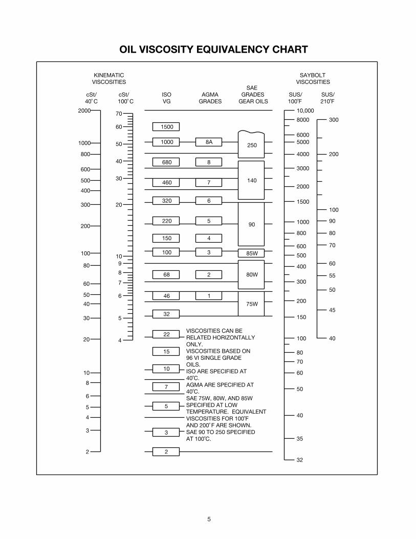
5
OIL VISCOSITY EQUIVALENCY CHART
2000
1000
800
600
500
400
300
200
100
80
60
50
40
30
20
10
8
6
5
4
3
2
70
60
50
40
30
20
10
8
5
4
9
7
6
1500
1000
680
460
320
220
150
100
68
8A
8
7
6
5
4
3
2
85W
250
140
90
80W
46
32
22
15
10
7
5
175W
3
2
300
200
150
100
80
70
60
50
40
35
32
400
500
600
800
1000
1500
2000
3000
4000
50006000
8000
10,000
cSt/40˚ C 100˚ C
cSt/ ISOVG
AGMAGRADES
GRADESGEAROILS
SUS/100˚F
SUS/210˚F
SAE
KINEMATICVISCOSITIES
SAYBOLTVISCOSITIES
200
300
100
90
80
70
60
55
50
45
40VISCOSITIESCANBERELATEDHORIZONTALLYONLY.VISCOSITIESBASEDON96VISINGLEGRADEOILS.ISOARESPECIFIEDAT40˚C.AGMAARESPECIFIEDAT40˚C.SAE75W,80W,AND85WSPECIFIEDATLOWTEMPERATURE.EQUIVALENTVISCOSITIESFOR100˚FAND200˚ FARESHOWN.SAE90TO250SPECIFIEDAT100˚C.

6
GUIDELINES FOR TXT REDUCER LONG-TERM STORAGE
Duringperiodsoflongstorage,orwhenwaitingfordeliveryorinstallationofotherequipment,specialcareshouldbetakentoprotectagearreducertohaveitreadytobeinthebestconditionwhenplacedintoservice.
Bytakingspecialprecautions,problemssuchassealleakageandreducerfailureduetolackoflubrication,improperlubricationquantity,orcontaminationcanbeavoided.Thefollowingprecautionswillprotectgearreducersduringperiodsofextendedstorage:
Preparation:
1. Drainoilfromtheunit.Addavaporphasecorrosioninhibitingoil(VCI-105oilbyDaubertChemicalCo.)inaccordancewithTable4.
2. Sealtheunitairtight.Replacetheventplugwithastandardpipeplugandwiretheventtotheunit.
3. Coverallunpaintedexteriorpartswithawaxyrustpreventativecompoundthatwillkeepoxygenawayfromthebaremetal.(Non-RustX-110byDaubertChemicalCo.orequivalent)
4. Theinstructionmanualsandlubricationtagsarepaperandmustbekeptdry.Eitherremovethesedocumentsandstoretheminside,orcovertheunitwithadurablewaterproofcoverwhichcankeepmoistureaway.
5. Protectreducerfromdust,moisture,andothercontaminantsbystoringtheunitinadryarea.
6. Indampenvironments,thereducershouldbepackedinsideamoisture-proofcontaineroranenvelopeofpolyethylenecontainingadesiccantmaterial.Ifthereduceristobestoredoutdoors,covertheentireexteriorwitharustpreventative.
When placing the reducer into service:
1. Filltheunittotheproperoillevelusingarecommendedlubricant.TheVCIoilwillnotaffectthenewlubricant.
2. Cleantheshaftextensionswithpetroleumsolvents.3. Assembletheventplugintotheproperhole.
Followtheinstallationinstructionsprovidedinthismanual.
Table 4 - Quantities of VCI #105 Oil
Reducer Size Quantity (Ounces / Mililiter)
TXT1A 1 / 30
TXT2A 1 / 30
TXT3B 1 / 30
TXT4B 1 / 30
TXT5C 1 / 30
TXT6A 2 / 59
TXT7A 2 / 59
TXT8A 3 / 89
TXT9A 4 / 118
TXT10A 6 / 177
VCI #105 and #10 are interchangeable.VCI #105 is more readily available.
Motor Mounts
Figure 6 - Motor Mounts
Warning: Belt guard removed for illustration purposes. Do not operate if belt guard is not in place.
Motor Mount Installation:
TheTAmotormountisdesignedtobeinstalledontheoutputendofthereducerasshowninFigure6.Ifbottommountingisdesired,usetheoptionalTABstyle.
TA1M thru TA7M Motor Mount:
Removetherequiredhousingboltsontheoutputendofthereducer.Placethemotormountbracketsinpositionandinstallthelongerhousingboltssuppliedwiththemotormountassembly.Donotfullytightenthehousingboltsatthistime.
Installthebottomplatetothemotormountbracketsandtightenwiththehardwareprovided.Next,tightenthehousingboltstothetorquevalueslistedinTable6.
Installthefouradjustingstudstothebottomplateusingthejamnutsprovidedandsecurelytighten.Thesenutswillnotrequireanyfurtheradjustment.Addoneadditionaljamnuttoeachstudandthreadapproximatelytothemiddleofthestud.Installthetopmotorplateontopofthejamnuts.Assembletheremainingjamnutsonstudstosecuretopmotorplate.Donotfullytightenthesenutsyet.
Mountmotor,driveanddrivensheaves,andv-belts.
Note: Mount driven sheave as close to the reducer housing as practical.
Adjustv-beltstothepropertensionbyadjustingthejamnutsandsecurelytighten.
Checkallboltstoinsurethattheyaresecurelytightened.
TA8 thru TA10 Motor Mount:
Removetherequiredhousingboltsontheoutputendofthereducer.Placethemotormountbracketsinpositionandinstallthelongerhousingboltssuppliedwiththemotormountassembly.Donotfullytightenthehousingboltsatthistime.
Installthefouradjustingstudstothetopplateasshownusingthejamnutsprovidedandsecurelytighten.Addoneadditional

7
jamnuttoeachstudandthreadapproximatelytothemiddleofthestud.Installthisassemblytothemotormountbracketsandinstalltheremainingjamnutsontothestudstosecurethetopplatetothebrackets.TightenthehousingboltstothetorquevalueslistedinTable6.
Looselyinstallthefrontmotorrailtothetopplate.Measurethedistancebetweenthefrontandrearmountingholesonthemotorandpositiontherearmotorrailatthisdistanceandlooselybolttothetopplate.
Centerthemotoronthemotorrailsandsecurelyboltthemotortothemotorrails.
Installthemotorsheaveandreducersheaveontheirshafts.Mountthereducersheaveasclosetothehousingsaspractical.Installthev-beltsandadjustthemotorrailstopermitproperalignmentofthev-beltstothesheaves.Securelytightenthemotorrailstothemountingplate.
Adjustthev-beltstothepropertensionandsecurelytightentheadjustingnuts.
Checkallboltstoseethattheyaresecurelytightened.
WARNING: To ensure that drive is not unexpectedly started, turn off and lock out or tag power source before proceeding. Remove all external loads from drive before removing or servicing drive or accessories. Failure to observe these precautions could result in bodily injury.
REPLACEMENT OF PARTS
NOTE: Using tools normally found in a maintenance department, a Dodge Torque-Arm speed reducer can be disassembled and reassembled by careful attention to the instructions following.
Cleanlinessisveryimportanttopreventtheintroductionofdirtintothebearingsandotherpartsofthereducer.Atankofcleansolvent,anarborpress,andequipmentforheatingbearingsandgears(forshrinkingthesepartsonshafts)shouldbeavailable.
Theoilsealsaredesignedwithacontactlip.Considerablecareshouldbeusedduringdisassemblyandreassemblytoavoiddamagetothesurfaceonwhichthesealsrub.
Thekeyseatintheinputshaft,aswellasanysharpedgesontheoutputhubshouldbecoveredwithtapeorpaperbeforedisassemblyorreassembly.Also,becarefultoremoveanyburrsornicksonsurfacesoftheinputshaftoroutputhubbeforedisassemblyorreassembly.
Ordering Parts:
WhenorderingpartsforaDodgeTorqueArmreducer,specifyreducerpartnumber,partname,andquantityrequired.
Itisstronglyrecommendedthat,whenapinionorgearisreplaced,thematingpinionorgearisreplacedalso.
Ifthelargegearontheoutputhubmustbereplaced,itisrecommendedthatanoutputhubassemblyconsistingofagearassembledonahubbeorderedtoensureundamagedsurfacesontheoutputhubwheretheoutputsealsrub.However,ifitisdesiredtousetheoldoutputhub,pressthegearandbearingoffandexaminetherubbingsurfaceundertheoilsealcarefullyforpossiblescratchingorotherdamageresultingfromthepressingoperation.Topreventoilleakageattheshaftoilseals,thesmoothsurfaceoftheoutputhubmustnotbedamaged.
Ifanypartsmustbepressedfromashaftorfromtheoutputhub,thisshouldbedonebeforeorderingpartstomakesurethatnoneofthebearingsorotherpartsaredamagedinremoval.Donotpressagainstrollersorcageofanybearing.Becauseoldshaftoilsealsmaybedamagedindisassembly,itisadvisabletoorderreplacementsfortheseparts.
Removing Reducer from Shaft:
WARNING: To ensure that drive is not unexpectedly started, turn off and lock out or tag power source before proceeding. Remove all external loads from drive before removing or servicing drive or accessories. Failure to observe these precautions could result in bodily injury.
Taper Bushed Reducer:
1. Disconnectandremovebeltguard,v-drive,andmotormountasrequired.Disconnecttorquearmrodfromreduceradapter.
2. Removebushingscrews.3. Placethescrewsinthethreadedholesprovidedinthe
bushingflanges.Tightenthescrewsalternatelyandevenlyuntilthebushingsarefreeontheshaft.Foreaseoftighteningscrews,makesurescrewthreadsandthreadedholesinbushingflangesareclean.Atapcanbeusedtocleanoutthethreads.Usecautiontousethepropersizetaptopreventdamagetothethreads.
4. Removetheoutsidebushing,thereducer,andthentheinboardbushing.
Straight Bore Reducer:
1. Disconnectandremovebeltguard,v-drive,andmotormountasrequired.Disconnecttorquearmrodfromreduceradapter.
2. Loosenandremovethesetscrewsinbothoutputhubcollars.
3. Removethecollarfromtheoutputhubclosesttotheendoftheshaft.Thiswillexposethreepullerholesintheoutputhubtopermittheuseofathreeprongpuller.Inremovingthereducerfromtheshaft,usecarenottodamagethereduceroutputhub.
Disassembly:
1. Drainalloilfromthereducer.2. Removealllockingcollars,retainingrings,andbushing
backupplatedasrequired.Positionthereduceronitssideandremoveallhousingbolts.Usingthethreepryslotsaroundtheperipheryoftheflange,gentlyseparatethehousinghalvesandopenevenlytopreventdamagetothepartsinside.Removethetwodowelpins.
3. Liftinputshaft,allgearassemblies,andbearingassembliesfromhousing.
4. Removesealsfromhousing.5. Removebearingsfromshaftsandhubs.Becarefulnotto
scratchordamageanyassemblyorsealareaduringbearingremoval.Thehubassemblycanbedisassembledforgearreplacementbutifscratchingorgroovingoccursonthehub,sealleakagewilloccurandthehubwillneedtobereplaced.
TXT Reassembly:
1. OutputHubAssembly:Heatgearto325°Fto350°Ftoshrinkontohub.Heatbearingsto270°Fto290°Ftoshrinkontohub.Anydamagetothehubsurfaceswheretheoilsealsrubwillcauseleakage,makingitnecessarytoreplacethehub.
2. CountershaftAssembly:Heatgearto325°Fto350°Fandbearingsto270°Fto290°Ftoshrinkontoshaft.
3. InputShaftAssembly:Heatbearings270°Fto290°Ftoshrinkontoshaft.Pressbearingsonshaft.
4. Drivethetwodowelpinsintoplaceintheright-handhousinghalf(backstopside).
5. PlaceR.H.housinghalfonblockstoallowforprotrudingendofoutputhub.
6. InstallallbearingcupsonTXT3BthruTXT10Ainright-handhousinghalf,makingsuretheyareproperlyseated.TXT1AandTXT2Areducersuseballbearingsonallshaftsanddonotincorporatebearingcups.
7. Meshoutputhubgearandsmallcountershaftgeartogetherandsetinplaceinhousing.Setinputshaftassemblyin

8
placeinthehousing.Makesurebearingrollers(cones)areproperlyseatedintheircups.
8. Makesurebothhousinghalvesareclean.Applyacontinuous1/8”diameterbeadofDowCorningRTV732sealantontheflangesurfaceoftheR.H.housing(makesureRTVisplacedaroundallboltholes).Settheleft-handhousinghalfintopositionontothedowelpinsandgentlytapwithasofthammer(rawhide,notleadhammer)untilhousingboltscanbeusedtodrawhousinghalvestogether.Makesurereducershaftsdonotbindwhiletighteninghousingbolts.TorquehousingboltspertorquevalueslistedinTable6.
9. OnTXT1AandTXT2Areducers,skiptostepnumber12.10. Placetheoutputbearingcupintothehousingandtapinto
place.Installtheoutputsealcarrieranddrawdownwithtwobolts180°apartto50inchpoundsoftorque.Loosenbothboltsthenretightenfingertightonly.Measuretheclearancebetweenthehousingandcarrierflangeateachboltandaveragethetwovalues.Add0.010”totheaveragereadingandmakeupshimpack.Installshimpackbetweenthecarrierflangeandthereducerhousing.TorquetheboltstothevalueshowninTable6.Usingamagneticbaseanddialindicator,checktheaxialendplay.AddorremoveshimsuntiltheaxialendplayreadingoftheoutputhubisperTable5.
11. Repeatstep9aboveforinstallingandadjustingthecountershaftandinputbearings.AdjusttheaxialendplayperTable5.
12. Installinputandoutputseals.LightlycoattheseallipswithMobilithAW2All-Purposegreaseorequivalent.Thepossibilityofdamageandconsequentoilleakagecanbedecreasedbycoveringallsharpedgeswithtapepriortosealinstallation.Sealsshouldbepressedortappedwithasofthammerevenlyintoplaceinthereducerhousing,applyingpressureonlyontheouteredgeoftheseals.Extremecareshouldbeusedwheninstallingsealstoavoiddamageduetocontactwithsharpedgesontheinputshaftoroutputhub.Aslightoilleakatthesealsmaybeevidentduringinitialrunning,butshoulddisappearunlesssealshavebeendamaged.
13. InstallbushingbackupplatesandsnapringsonTaperBushedreducersorhubcollarsonstraightborereducersandinstallbackstopcover.MakesureallboltsaretightenedtothecorrecttorquevalueslistedinTable6.
Table 5 - Bearing Adjustment Tolerances
Reducer SizeBearing Endplay Values
Input Countershaft Ouput
TXT1A N / A N / A N / A
TXT2A N / A N / A N / A
TXT3B .002-.004 Loose .0005-.003 Loose .0005-.003 Loose
TXT4B .002-.004 Loose .0005-.003 Loose .0005-.003 Loose
TXT5C .002-.004 Loose .0005-.003 Loose .0005-.003 Loose
TXT6A .002-.004 Loose .0005-.003 Loose .0005-.003 Loose
TXT7A .002-.004 Loose .0005-.003 Loose .0005-.003 Loose
TXT8A .002-.004 Loose .0005-.003 Loose .0005-.003 Loose
TXT9A .002-.004 Loose .0005-.003 Loose .0005-.003 Loose
TXT10A .002-.004 Loose .0005-.003 Loose .0005-.003 Loose
Table 6 - Recommended Bolt Torque Values
Recommended Torque Values (lbs.-ft.)
Reducer Size
Housing Bolts
Output Seal Carrier
C/S Bearing Cover
Input Seal Carrier
TXT1A 30 - 27 N/A N/A N/A
TXT2A 30 - 27 N/A N/A N/A
TXT3B 50 - 45 17 – 15 17 – 15 17 – 15
TXT4B 50 - 45 30 – 27 30 – 27 30 – 27
TXT5C 75 - 68 30 – 27 30 – 27 30 – 27
TXT6A 75 - 68 30 – 27 30 – 27 30 – 27
TXT7A 150 - 135 30 – 27 50 - 45 50 - 45
TXT8A 150 - 135 30 – 27 30 – 27 30 – 27
TXT9A 150 - 135 30 – 27 30 – 27 30 – 27
TXT10A 150 - 135 30 – 27 30 – 27 30 – 27
Backstop Cover Bolt Recommended Torque Values
Reducer Size Fastener Size Torque in Ft.-Lbs.
TXT1A 10 - 24 x 3/8 5 – 4
TXT2A 10 - 24 x 3/8 5 – 4
TXT3B 10 - 24 x 3/8 5 – 4
TXT4B ¼ - 20 x ½ 8 – 7
TXT5C ¼ - 20 x ½ 8 – 7
TXT6A ¼ - 20 x ½ 8 – 7
TXT7A ¼ - 20 x ½ 8 – 7
TXT8A ¼ - 20 x ½ 8 – 7
TXT9A ¼ - 20 x ½ 8 – 7
TXT10A ¼ - 20 x ½ 8 – 7

9
Replacement Part and Kit Numbers
Table 7 – Part Numbers for ReplacementBearings, Double Reduction Reducers
ReducerSize
Output Hub Bearing – LH and RH SidesPart Number
TXT1A 424020
TXT2A 424022
TXT3B 402272/403127
TXT4B 402268/403163
TXT5C 402193/403016
TXT6A 402050/403140
TXT7A 402058/403111
TXT8A 402147/403105
TXT9A 402160/403110
TXT10A 402168/403116
ReducerSize
Countershaft Bearing – LH Input SidePart Number
TXT1A 424006
TXT2A 424000
TXT3B 402273/403094
TXT4B 402000/403000
TXT5C 402203/403027
TXT6A 402054/403159
TXT7A 402256/403053
TXT8A 402057/403143
TXT9A 402109/403078
TXT10A 402232/402231
ReducerSize
Countershaft Bearing – RH Backstop SidePart Number
TXT1A 424006
TXT2A 424000
TXT3B 402273/403094
TXT4B 402000/403000
TXT5C 402203/403027
TXT6A 402052/403142
TXT7A 402256/403053
TXT8A 402148/403106
TXT9A 402109/403078
TXT10A 402232/402231
ReducerSize
Input Shaft Bearing – LH Input SidePart Number
TXT1A 424112
TXT2A 424019
TXT3B 402204/403139
TXT4B 402280/403027
TXT5C 402144/403104
TXT6A 402196/403091
TXT7A 402150/403106
TXT8A 402098/403072
TXT9A 402114/403080
TXT10A 402114/403080
ReducerSize
Input Shaft Bearing – RH Backstop SidePart Number
TXT1A 424111
TXT2A 424090
TXT3B 402273/403094
TXT4B 402142/403102
TXT5C 402266/403073
TXT6A 402197/403091
TXT7A 402088/403047
TXT8A 402097/403072
TXT9A 402107/403076
TXT10A 402112/403080
Note: Bearing part numbers refer to Cup/Cone combinations, respectively, and apply to all ratios unless otherwise specified. For actual reducer ratios, refer to Table 9.

10
Table 8 - Replacement Parts Kit Numbers
Reducer Size Ratio Seal KitOutput Hub Assembly Countershaft
Assembly Bearing Kit(s)Taper Hub Straight Hub
TXT1A
9:1
392119 390878 390151
392100
389905 All15:1 392090
25:1 392091
TXT2A
9:01
392120 392111 392110
392101
389906 All15:1 392092
25:1 392093
TXT3B
9:1
389720 389703 389702
389729
392345 All15:1 389700
25:1 389701
TXT4B
9:1
389721 389710 389709
389730
392347 All15:1 389707
25:1 389708
TXT5C
9:1
389722 389717 389716
389731
392350 All15:1 389714
25:1 389715
TXT6A
9:1
246340 390935 390988
392140
335368 All15:1 391171
25:1 391186
TXT7A
9:1
247345 390941 390990
392141
392353 All15:1 391196
25:1 391197
TXT8A15:1
248340 390944 390993391184
392355 All25:1 391185
TXT9A15:1
249340 390949 390159390124
392357 All26:1 390139
TXT10A15:1
272460 390954 390160390983
392359 All24:1 390998
Notes:Seal Kit consists of Input Seal, Output Seals, Backstop Cover Gasket and RTV Sealant.Output Hub Assembly consists of Output Hub, Output Gear and Gear Key.Countershaft Assembly consists of Countershaft Pinion, Countershaft Gear and Gear Key.Bearing Kit consists of LH and RH Output Bearing Cup/Cone, LH and RH Countershaft Bearing Cup/Cone (double reduction only) and LH and RH Input Bearing Cup/Cone.

11
Parts for TXT/HXT 1A & 2A Straight and Tapered Bushed Double Reduction Reducers

12
Parts for TXT/HXT 1A & 2A Straight and Tapered Bushed Double Reduction Reducers
Ref. Description Qty. TXT/HXT 1 TXT/HXT 2
1212
3①①16182022①①253438
Backstop AssemblyHousing-LHHousing-RHHousing-RH, Flange Mount DrilledHousing-Hydroil LHRTV Sealant, TubeAir VentHousing BoltHousing Bolt-AdapterLock-WasherHex NutDowel PinMagnetic Oil PlugOil PlugBackstop Shaft CoverBackstop Cover Screw
1111111⑦2⑧⑧21414
242101241358241359241387241064465044900287411418411420419011407087420145430060430031242221415022
252101242353242354242393242067465044900287411418411420419011407087420145430060430031243221415022
364278
Seal Kit ②Backstop Cover Gasket ④Input Oil Seal ④Output Hub Oil Seal ④
1112
392119242220241457241210
392120243220242211242210
40
130
Input Pinion9:1 Ratio ⑥15:1 Ratio ⑥25:1 Ratio ⑥Hydroil Input Pinion15:1 Ratio ⑥25:1 Ratio ⑥
111
11
241481241302241200
241455241449
242481242186242187
242188242189
41 Input Pinion Key 1 443008 443014
44465480
Bearing Replacement Kit ②Input Pinion Bearing-LH, Input Side ④Input Pinion Bearing-RH, Backstop Side ④Countershaft Pinion Bearing ④Output Hub Bearings ④
11122
389905424112424111424006424020
389906424019424090424000424022
4850
52
Countershaft Pinion Assembly ②9:1 Ratio ⑥15:1 Ratio ⑥25:1 Ratio ⑥Countershaft Pinion ④First Reduction Gear ④9:1 Ratio ⑥15:1 Ratio ⑥25:1 Ratio ⑥Countershaft to First Gear Key ④
1111
1111
392100392090392091241216
241482241170241171241309
392101392092392093242185
242482242008242005242218
Taper Bore Output Hub Assembly ② 1 390878 392111
Straight Bore Output Hub Assembly ③ 1 390151 392110
60
62645961
Output HubStraight Bore ⑤Taper Bore ④
Output Gear ④ ⑤Output Gear Key ④ ⑤Output Hub Snap Ring ④Straight Bore Output Hub Key ⑤
111122
241208241265241007241217421013241296
242208242134242181443399421017242296
68707274
Straight Bore Output Hub CollarStraight Bore Output Hub Collar ScrewTaper Bore Bushing Backup PlateBushing Backup Plate Retaining Ring
2422
241209400062241266421111
242209400094242137421112
84 Taper Bore Bushing Assembly ②Bushing ④1” Bore1-1/16” Bore1-1/8” Bore1-3/16” Bore1-1/4” Bore1-5/16” Bore1-3/8” Bore1-7/16” Bore1-11/16” Bore1-1/2” Bore1-5/8” Bore1-3/4” Bore1-15/16” Bore
1111111111111
241278241280241282241286241288241290241294241292
N/A N/AN/AN/AN/A
N/AN/A
242146242148242150242152242154242156242164242158242162242166242168
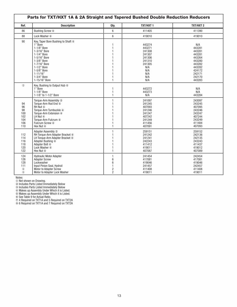
13
Parts for TXT/HXT 1A & 2A Straight and Tapered Bushed Double Reduction Reducers
Ref. Description Qty. TXT/HXT 1 TXT/HXT 2
86 Bushing Screw ④ 6 411405 411390
88 Lock Washer ④ 6 419010 419010
90 Key, Taper Bore Bushing to Shaft ④1” Bore1-1/8” Bore1-3/16” Bore1-1/4” Bore1-5/16” Bore1-3/8” Bore1-7/16” Bore1-1/2” Bore1-5/8” Bore1-11/16”1-3/4” Bore1-15/16” Bore
111111111111
443274443271241308241307241306241310241305
N/AN/AN/AN/AN/A
N/A443281443281443281443264443280443282443282424172242171242170443283
① Key, Bushing to Output Hub ④1” Bore1-1/8” Bore1-1/8” to 1-1/2” Bore
111
443272443273
N/A
N/AN/A
443284
949698100102104106110
Torque-Arm Assembly ②Torque-Arm Rod End ④RH Nut ④Torque-Arm Turnbuckle ④Torque-Arm Extension ④LH Nut ④Torque-Arm Fulcrum ④Fulcrum Screw ④Hex Nut ④
111111111
241097241245407093241246241247407242241249411456407091
243097243245407095243246243247407244243249411484407093
112114116118120122
Adapter Assembly ②RH Torque-Arm Adapter Bracket ④LH Torque-Arm Adapter Bracket ④Adapter Bushing ④Adapter Bolt ④Lock Washer ④Hex Nut ④
1111111
259151241242241241242243411412419011407087
259152242136242135243243411437419012407089
124126128111①①
Hydraulic Motor AdapterAdapter ScrewLockwasherInput Pinion Seal, HydroilMotor to Adapter ScrewMotor to Adapter Lock Washer
166122
241454417081419046241457411408419011
242454417081419046242457411408419011
Notes:① Not shown on Drawing.② Includes Parts Listed Immediately Below③ Includes Parts Listed Immediately Below④ Makes up Assembly Under Which it is Listed.⑤ Makes up Assembly Under Which it is Listed.⑥ See Table 9 for Actual Ratio.⑦ 4 Required on TXT1A and 5 Required on TXT2A⑧ 6 Required on TXT1A and 7 Required on TXT2A

14
Parts for TXT3B thru TXT5C Straight and Tapered Bushed Double Reduction Reducers

15
Parts for TXT3B thru TXT5C Straight and Tapered Bushed Double Reduction Reducer
Ref. Description Qty. TXT3BHXT3B
TXT4BHXT4B
TXT5CHXT5C
1212
①①16182022①①2528303233343839
Backstop AssemblyHousing - TXT and Hydroil LHHousing-RHHousing-RH, Flange Mount DrilledRTV Sealant, TubeAir VentHousing BoltHousing Bolt-AdapterLock-WasherHex NutDowel PinMagnetic Oil PlugOil PlugInput Shaft Seal CarrierInput Shaft Bearing Shim PackInput Seal Carrier ScrewLock WasherBackstop CoverBackstop Shaft CoverBackstop Cover Screw
11111162882141⑧⑦⑦144
243106243228243229243384465044900287411440411442419012407089420146430060430031243543389704411390419010243560416524
N/A
244106244365244366244387465044900287411442411444419012407089420146430060430031244577389711411407419011244493411035
N/A
245154245369245370245373465044904287411464411466419013407091420147430062430033245597389732411407419011245226411394419009
364278
Seal Kit ②Backstop Cover Gasket ④Input Pinion Shaft Seal ④Output Hub Oil Seal ④
1112
389720243561243558243578
389721244593244524244673
389722245220355011245545
40
130
Input Pinion9:1 Ratio ⑥15:1 Ratio ⑥25:1 Ratio ⑥15:1 Ratio Hydroil Pinion ⑥25:1 Ratio Hydroil Pinion ⑥15:1 Ratio Hydroil 6-B Pinion ⑥ 25:1 Ratio Hydroil 6-B Pinion ⑥
1111111
243549243550243551243553243554
N/A243498
244579244580244581244583244584244586244587
245599245600245601245603245604
N/A245641
41 Input Pinion Shaft Key 1 443032 443082 443096
44454647
Input Bearing Kit ②Input Shaft Bearing Cone, Input Side ④Input Shaft Bearing Cup, Input Side ④Input Shaft Bearing Cone, Backstop Side ④Input Shaft Bearing Cup, Backstop Side ④
11111
389587402204403139402273403094
389590402280403027402142403102
389594402144403104402266403073
4850
52
Countershaft Pinion Assembly ②9:1 Ratio ⑥15:1 Ratio ⑥25:1 Ratio ⑥Countershaft Pinion ④First Reduction Gear ④9:1 Ratio ⑥15:1 Ratio ⑥25:1 Ratio ⑥First Stage Gear Key ④
1111111111
389729389700389701243555
243237243238243239D8242
389730389707389708244590
244482244214244212D8243
389731389714389715245596
245482245214245212D8243
545556575859
Countershaft Bearing Kit ②Countershaft Bearing Cone, Input Side ④Countershaft Bearing Cup, Input Side ④Countershaft Bearing Cone, Backstop Side ④Countershaft Bearing Cup, Backstop Side ④Countershaft Bearing Cover, Input Side ④Countershaft Bearing Shim Pack
111111⑧
389588402273403094402273403094243545389705
389591402000403000402000403000244578389712
389595402203403027402203403027245594389718
60 6264
Taper Bore Output Hub Assembly ②Straight Bore Output Hub Assembly ③Output HubStraight Bore ⑤Taper Bore ④Output Gear ④ ⑤Output Gear Key ④ ⑤
11 1111
389703389702
243557243556243570243216
389710389709
244589244588244188354087
389717389716
245591245590245186355064
68707274
Output Hub Collar, Straight BoreOutput Hub Collar ScrewBushing Backup Plate, Taper BoreBushing Backup Plate Retaining Ring
2422
243572400098243308421109
244658400150244099421108
245598400154245114421107
76 808182
Output Hub Seal Carrier, Input SideOutput Hub Bearing Kit ♦Output Hub Bearing, Cone ④Output Hub Bearing, Cup ④Output Hub Bearing Shim Kit
1122⑧
243547389589402272403127389706
244591389592402268403163389713
245592389596402193403016389719

16
Parts for TXT3B thru TXT5C Straight and Tapered Bushed Double Reduction Reducer, continued
Ref. Description Qty. TXT3BHXT3B
TXT4BHXT4B
TXT5CHXT5C
84
8688
Taper Bore Bushing Assembly ②Bushing ④1-5/16” Bore1-3/8” Bore1-7/16” Bore1-1/2” Bore1-5/8” Bore1-11/16” Bore1-3/4” Bore1-7/8” Bore1-15/16” Bore2” Bore2-1/8” Bore2-3/16” Bore2-1/4” Bore2-7/16” Bore2-1/2” Bore2-11/16” Bore2-15/16” BoreTaper Bushing Screw ④Taper Bushing Lockwasher ④
1111111111111111166
243282243284243260243262243264243268243266243270243272243274
N/A243276
N/AN/AN/AN/AN/A
411407419011
N/AN/A
244079244081244083244085244087244089244093244095244109244111244113244115
N/AN/AN/A
411408419011
N/AN/AN/AN/AN/AN/AN/A
245084245086245088
N/A245090245092245094245099245110245112411435419012
90 Key, Bushing to Shaft ④1-5/16” Bore1-3/8” Bore1-7/16” Bore1-1/2” Bore1-5/8” Bore1-11/16” Bore1-3/4” Bore1-7/8” Bore1-15/16” Bore2” Bore2-1/8” Bore2-3/16” Bore2-1/4” Bore2-7/16” Bore2-1/2” Bore2-11/16” Bore2-15/16” Bore
11111111111111111
443264443264443265443265443265443266443266443267443269443268
N/A443270
N/AN/AN/AN/AN/A
N/AN/A
443254443254443254443254443254443255443255443255443258443259443260443261
N/AN/AN/A
N/AN/AN/AN/AN/AN/AN/A
443251443251443251
N/A443251443251443243443244443245443250
① Key, Bushing to Output Hub ④1-3/4” thru 1-15/16” Bore Bushing1-7/16” thru 2-1/4” Bore Bushing2-3/16” thru 2-15/16” Bore Bushing
111
443262N/AN/A
N/AN/A
443257
N/A443202
N/A
949698100102104106110
Torque-Arm Rod Kit ②Torque-Arm Rod End ④RH Nut ④Torque-Arm Turnbuckle ④Torque-Arm Extension ④LH Nut ④Fulcrum ④Fulcrum Screw ④Hex Nut ④
111111111
243097243245407095243246243247407244243249411484407093
243097243245407095243246243247407246243249411484407093
243097243245407095243246243247407246243249411484407093
112114116118120122
Adapter Assembly ②RH Adapter Plate ④LH Adapter Plate ④Adapter Bushing ④Adapter Bolt ④Lockwasher ④Hex Nut ④
1111111
259153243242243241243243411437419012407089
259154244244244243245243411460419013407091
259155245242245241245243411460419013407091
124126128§§
Hydroil Motor Adapter15:1 Ratio Motor Adapter25:1 Ratio Motor AdapterHydroil 6-B Motor Adapter, 15:1 and 25:1 RatioAdapter ScrewLockwasherMotor to Adapter ScrewMotor to Adapter Lock Washer
111⑦⑦
243539243541243467417081419046
244572244572244573417108419047
245606245607245643415023419047
Notes: Not shown on drawing.② Includes parts listed immediately below ③ Includes parts listed immediately below④ Makes up assembly under which it is listed.⑤ Makes up assembly under which it is listed.⑥ See Table 9 for actual ratio.⑦ 4 required on TXT3B and TXT4B, 5 required on TXT5C⑧ Two sets recommended.

17
Parts for TXT6A thru TXT10A Straight and Tapered Bushed double Reduction Reducers

18
Parts for TXT6A thru TXT10A Straight and Tapered Bushed double Reduction Reducers
Ref. Description Qty. TXT6AHXT6A
TXT7AHXT7A
TXT8A TXT9A TXT10A
1212
①①16182022①25①2830323334353839
Backstop AssemblyHousing-TXT and Hydroil LHHousing-RHHousing-RH, Flange Mount DrilledRTV Sealant, TubeAir VentHousing BoltHousing Bolt-AdapterLock-WasherHex NutDowel PinMagnetic Oil PlugOil PlugInput Shaft Seal CarrierInput Shaft Bearing Shim PackCarrier and Cover ScrewLock WasherBackstop CoverBackstop Retaining RingBackstop Cover ScrewBackstop Cover Lock Washer
11111122142141⑧⑨⑨1⑦66
246092246358246359465044904287411466411468419013407091420147430062430033246184391164411408419011246226421029411394419009
247260247358247359465044904287411498411499419016407095420148430064430035247320390420411433419012246226421029411394419009
249260248358248359465044904287411499411502419016407095420148430064430035258023390038411408419011248226421034411394419009
249260249358249359465044904287411500411502419016407095420148430064430035249211390168 411408419011248226421034411394419009
250260250358250359
465044904287411502411506419016407095420148430064430035249211390168411408419011248226421034411394419009
364278
Seal Kit ②Backstop Cover Gasket ③Input Pinion Shaft Seal ③Output Hub Oil Seal ③
1112
246340246220242210246310
247345246220242210247310
248340248220248211258019
249340248220248211249210
272460248220248211250010
40
130
Input Pinion9:1 Ratio ⑥15:1 Ratio ⑥25:1 Ratio ⑥ ⑩15:1 Ratio Hydroil Pinion ⑥25:1 Ratio Hydroil Pinion ⑥15:1 Ratio 6B Hydroil Pinion ⑥25:1 Ratio 6B Hydroil Pinion ⑥
1111111
246481246290246291246230246286
N/A246521
247479247370247371247463247462
N/A247521
N/A
248370248371
N/AN/AN/AN/A
N/A
272074272106
N/AN/AN/AN/A
N/A
250300250004
N/AN/AN/AN/A
41 Input Pinion Shaft Key 1 443113 443127 443133 443123 443123
44454647
Input BearingsInput Shaft Bearing Cone, Input SideInput Shaft Bearing Cup, Input SideInput Shaft Bearing Cone, Backstop SideInput Shaft Bearing Cup, Backstop Side
1111
402196403091402197403091
402150403106402088403047
402098403072402097403072
402114403080402107403076
402114403080402112403080
4850
52
Countershaft Pinion Assembly ②9:1 Ratio ⑥15:1 Ratio ⑥25:1 Ratio ⑥ ⑩Countershaft Pinion ③First Reduction Gear ③9:1 Ratio ⑥15:1 Ratio ⑥25:1 Ratio ⑥ ⑩First Stage Gear Key ③
1111 1111
392140391171391186246294
246482246492246293245218
392141391196391197247002
247478247008247005247218
N/A391184391185248002
N/A248213248214248218
N/A390124390139249006
N/A249008249005248218
N/A390983390998272249
N/A250301250005248218
545556575859
Countershaft BearingsCountershaft Bearing Cone, Input SideCountershaft Bearing Cup, Input SideCountershaft Bearing Cone, Backstop SideCountershaft Bearing Cup, Backstop SideCountershaft Bearing Cover, Input SideCountershaft Bearing Shim Pack
11111⑧
402054403159402052403142246185391165
402256403053402256403053247194390429
402057403143402148403106248223391182
402109403078402109403078249225390168
402232402231402232402231272251390575
60
6264
Taper Bore Output Hub Assembly ②Straight Bore Output Hub Assembly ④Straight Bore Hub ⑤Taper Bore Hub ③Output Gear ③ ⑤Output Gear Key ③ ⑤
111112
390935390988246338246269246295245217
390941390990247338272137247215245217
390944390993248332272036248215248217
390949390159250090249140021764443413
390954390160250008272241250007250017
6870
Output Hub Collar, Straight Bore Output Hub Collar Screw
24
246309 400154
247309 400190
248209 400190
249209 400194
250009400194
727476
Bushing Backup Plate, Taper BoreOutput Hub Retaining RingOutput Hub Seal Carrier, Input Side
221
246270421055 246187
272138421099 247315
272037421098 258021
272082421097 249221
272242421069250011
808182
Output Hub Bearing Kit 1Output Hub Bearing, ConeOutput Hub Bearing, CupOutput Hub Bearing Shim Kit
122⑧
402050403140391187
402058403111390044
402147403105390048
402160403110390171
402168403116390172

19
Parts for TXT6A thru TXT10A Straight and Tapered Bushed double Reduction ReducersRef. Description Qty. TXT6A TXT7A TXT8A TXT9A TXT10A
84
8688
Taper Bore Bushing Assembly ②Bushing ③2-3/16” Bore2-1/4” Bore2-7/16” Bore 2-1/2” Bore2-11/16” Bore2-13/16” Bore2-7/8” Bore2-15/16” Bore3” Bore3-3/16” Bore3-7/16” Bore3-15/16” Bore4-3/16” Bore4-7/16” Bore4-15/16” Bore5-7/16” BoreTaper Bushing Screw ③Taper Bushing Lockwasher ③
111111111111111166
246261 246262246263 246264246265
N/A246266246267246283
N/A246268
N/AN/AN/AN/AN/A
411435419012
N/AN/A
272125N/A
272147272130272131272132272133272134272135272136
N/AN/AN/AN/A
411456419013
N/AN/AN/A N/AN/A N/AN/A
272048N/AN/A
272032272033272034272035
N/AN/A
411457419013
N/AN/AN/A N/AN/AN/AN/AN/AN/AN/A
N/A272056272077
N/A272079272080
N/A411484419014
N/AN/AN/AN/AN/AN/AN/AN/AN/AN/AN/A
272214N/A
272238272239272240411484419014
90 Key, Bushing to Shaft ③2-3/16” Bore2-1/4” Bore2-7/16” Bore 2-1/2” Bore2-11/16” Bore2-13/16” Bore2-7/8” Bore2-15/16” Bore3” Bore3-3/16” Bore3-7/16” Bore3-15/16” Bore4-3/16” Bore4-7/16” Bore4-15/16” Bore5-7/16” Bore
11111111111111111
443211443211443214443214443238
N/A443236443237443252
N/A443213
N/AN/AN/AN/AN/AN/A
N/AN/A
443248N/A
443248443199443199443199443199443216443235443217443218
N/AN/AN/AN/A
N/AN/AN/AN/AN/AN/AN/AN/A
443247N/AN/A
443171443173443174443196
N/AN/A
N/AN/AN/AN/AN/AN/AN/AN/AN/AN/AN/A
443249272119
N/A272066443161
N/A
N/AN/AN/AN/AN/AN/AN/AN/AN/AN/AN/AN/A
443192N/A
443193443194443195
① Key, Bushing to Output Hub ③2-3/16” thru 2-1/2” Bore Bushing2-7/16” thru 3” Bore Bushing2-3/16” thru 2-15/16” Bore Bushing2-15/16” thru 3-7/16” Bore Bushing3-7/16” thru 4-3/16” Bore Bushing3-15/16” thru 4-7/16” Bore Bushing
111111
443212N/AN/AN/AN/AN/A
N/A443198
N/AN/AN/AN/A
N/AN/AN/A
443162N/AN/A
N/AN/AN/AN/A
443121N/A
N/AN/AN/AN/AN/A
443191
949698100102104106108110
Torque-Arm Rod Kit ②Torque-Arm Rod End ③RH Nut ③Torque-Arm Turnbuckle ③Torque-Arm Extension ③LH Nut ③Fulcrum ③Fulcrum Screw ③Lockwasher ③Hex Nut ③
1111111111
246097245245407097245246245247407246247248411489419014407093
247098247239407099247246247240407248247248411489419014407093
390129271050407104271051271052407250271054411516419020407099
390129271050407104271051271052407250271054411516419020407099
390129271050407104271051271052407250271054411516419020407099
112114116118120122
Adapter Assembly ②RH Adapter Plate ③LH Adapter Plate ③Adapter Bushing ③Adapter Bolt ③Lockwasher ③Hex Nut ③
1111111
259156246242246241245243411460419013407091
259157247242247241247244411489419014407093
248110272053272053271046411510419020407099
249110249241249241271046411512419020407099
250110250041250041211046411512419020407099
124
126128①①
Hydroil Motor AdapterHydroil 6B Motor AdapterHydroil Adapter ScrewLockwasherMotor to Adapter ScrewMotor to Adapter Lock Washer
1166
246465246522417108906406
247464247522417141907406
N/AN/AN/AN/A
N/AN/AN/AN/A
N/AN/AN/AN/A
Notes:① Not shown on drawing② Includes parts listed immediately below ③ Makes up assembly under which it is listed④ Includes parts listed immediately below marked ⑤ Makes up assembly under which it is listed⑥ See Table 9 for actual ratio⑦ Required only with optional backstop, 1 required on TXT6A and TXT7A, 2 required on TXT8A, TXT9A, & TXT10A.⑧ 2 sets recommended⑨ 18 Required on TXT6A, 20 Required on TXT7A, and 24 Required on TXT8A, TXT9A, & TXT10A⑩ Nominal Ratio on TXT6A, TXT7A, and TXT8A is 25:1, Nominal Ratio on TXT9A is 26:1, and Nominal Ratio on TXT10A is 24:1

World Headquarters
P.O.Box2400,FortSmith,AR72902-2400U.S.A.,Ph:(1)479.646.4711,Fax(1)479.648.5792,InternationalFax(1)479.648.5895
Dodge Product Support
6040PondersCourt,Greenville,SC29615-4617U.S.A.,Ph:(1)864.297.4800,Fax:(1)864.281.2433
www.baldor.com
©BaldorElectricCompanyMN1610 (Replaces499304)
AllRightsReserved.PrintedinUSA.3/10FARR25,000*1610-0310*
ACTUAL RATIOS
Table 9 – Actual Ratios
Reducer SizeNominal Ratios
9:1 15:1 25:1*
TXT1A 9.44 15.35 25.64
TXT2A 9.25 14.10 23.46
TXT3B 8.91 14.88 24.71
TXT4B 9.67 15.13 24.38
TXT5C 8.95 15.40 25.56
TXT6A 9.20 15.33 25.13
TXT7A 9.61 15.23 24.59
TXT8A N/A 15.08 24.62
TXT9A N/A 15.12 25.66
TXT10A N/A 15.16 24.30
*TXT9Ais26:1NominalRatioandTXT10Ais24:1NominalRatio

1
WARNING: To ensure that drive is not unexpectedly started, turn o� and lock out or tag power source before proceeding. Failure to observe these precautions could result in bodily injury.
WARNING: Do not use Dodge backstops in any reducers other than Dodge brand reducers.
CAUTION: Do not use EP oils or oils containing slippery additives such as graphite or molybdenum disulphide in the reducer when backstop is used. These additives will destroy sprag action.
INSTALLATION OF BACKSTOP
1. Remove backstop cover plate. This plate is directly opposite the extended end of the input shaft.
2. Face reducer looking at the side from which the cover plate was removed. Determine carefully the direction of rotation desired. The directions of rotation of input and output shafts are identical in double reduction reducers (Nos. TXT115 thru TXT1225 and TDT1325 thru TDT1530) and opposite in single reduction reducers (Nos. TXT105 to TXT905). It is important that the direction be correctly determined because to reverse the direction after the backstop is installed, it is necessary to remove the backstop, turn it end for end and reinstall it.
3. Match arrow on backstop to direction of rotation desired for input shaft. Note that reversing backstop end for end changes direction of arrow. The input shaft will rotate in the same direction as the arrow on the backstop.
4. Proceed as follows: Nos. TXT1A to TXT5C and Nos. TXT105 to TXT505A Reducers —For ease of installation, a light coating of oil on the O.D. of backstop will help to rotate backstop for key installation. Slowly rotate input shaft in same direction as arrow on backstop. Without removing cardboard retainer from backstop, push backstop into reducer. When pushing backstop into reducer, it is very important not to hammer on backstop although it can be tapped gently if necessary. Cardboard retainer will be pushed out automatically as backstop is pushed into reducer. If backstop has to be
WARNING: Because of the possible danger to person(s) or property from accidents which may result from the improper use of products, it is important that correct procedures be followed: Products must be used in accordance with the engineering information specified in the catalog. Proper installation, maintenance and operation procedures must be observed. The instructions in the instruction manuals must be followed. Inspections should be made as necessary to assure safe operation under prevailing conditions. Proper guards and other suitable safety devices or procedures as may be desirable or as may be specified in safety codes should be provided, and are neither provided by Baldor Electric Company nor are the responsibility of Baldor Electric Company. This unit and its associated equipment must be installed, adjusted and maintained by qualified personnel who are familiar with the construction and operation of all equipment in the system and the potential hazards involved. When risk to persons or property may be involved, a failsafe device must be an integral part of the driven equipment beyond the speed reducer output shaft.
INSTRUCTION MANUAL FOR DODGE® TORQUE-ARM™ SPEED REDUCER BACKSTOPS
These instructions must be read thoroughly before installing or operating this product.
removed for any reason, pull backstop from bore and insert cardboard retainer into I.D. of backstop to retain position of
Ensure backstop cover does not bind backstop.
Install Lockring in Outer Groove of Backstop Assembly
Figure 1 - TXT3B
NOTE: A locking ring is required on TXT3B to position backstop in housing.
Nos. TXT6A, TXT7A and No. TXT605 Reducers —For ease of installation, a light coating of oil on the O.D. of backstop will help to rotate backstop for key installation. Some of the backstops have keys of di�erent lengths. Place the longer key in the input shaft keyseat. For ease of installation, backstop complete with inner race must be pushed into reducer as a unit. When pushing backstop into reducer, it is very important not to hammer on backstop although it can be tapped gently if necessary. Place small snap ring in snap ring groove on input shaft, and place large snap ring in groove in housing outboard of backstop.
Nos. TXT8 to TXT12, TDT13 thru TDT15, TXT705 to TXT905 Reducers — Place large snap ring in I.D. of housing or bacsktop carrier. For ease of installation, a light coating of oil on the O.D. of backstop will help to rotate backstop for key installation. Backstop complete with inner race must be pushed into reducer as a unit. When pushing backstop into Reducer, it is very important not to hammer on backstop although it can be tapped gently if necessary. Place the small snap ring in snap ring groove on input shaft, and place second large snap ring in housing outboard of backstop for sizes TXT8A, TXT9A and TXT10A.
APPENDIX H

2
HOUSING
INPUTSHAFT
BACKSTOP
LARGE SNAP RING
SMALL SNAP RING
Figure 2 - TXT8A, 9A, 10A
Housing Carrier
Cover Plate
Input Shaft
Back-stop
Large Snap RingSmall Snap Ring
Figure 3 - TXT12, TDT 13-15, TXT805-905
Some of the backstops require two keys on the input pinion. Dispose of extra key with units that require only one key. Line up keyways between backstop and input pinion. Install key(s).
5. Insert key between housing and backstop O.D. and replace gasket, cover plate and screws. When input shaft will be located higher than output shaft, put some non-EP grease in cover plate for the purpose of lubricating backstop. Use a high grade non-EP grease made especially for roller bearing service.
NOTE: Some backstops have keys that are rectangular in cross section. Keys should fit freely into respective keyways. Forcing keys into place could result in premature failure of backstop.
TO REMOVE BACKSTOP
WARNING: To ensure that drive is not unexpectedly started, turn off and lock out or tag power source before proceeding. Failure to observe these precautions could result in bodily injury.
WARNING: Removal of backstop may cause unexpected machine movement. Remove or block all external loads before servicing unit. Failure to observe these precautions could result in bodily injury.
1. Remove backstop cover plate.2. Remove snap ring from end of shaft (snap ring is used only
on Nos. TXT609 to TXT1225 and TDT1325 thru TDT1530 and Nos. TXT605 to TXT905 reducers).
3. Insert tool, such as a screwdriver, in groove around O.D. of backstop and pry backstop from retainer housing. If backstop hs tapped holes in outer race, install two #10-24 machine screws in holes and use them to pry backstop from housing.
DIMENSIONAL CHECKS FOR REPLACEMENT UNITS IN REDUCERS WITH TAPERED ROLLER BEARINGSShaft Endplay: While the backstop is removed check the amount of endplay in the shaft if tapered roller bearings are used. It is possible that bearing wear or looseness might have increased the amount of endplay to an unacceptable level. Shaft endplay should not exceed .003”. Endplay is measured with a dial indicator at the end of the backstop shaft. The base of the indicator is attached to the reducer housing. From the other end of the shaft, an axial force must be applied in both directions. While rotating shaft, push and pull.
CONCENTRICITY:The amount of Total Indicated Run Out (T.I.R.) between the inner race (shaft) and the backstop bore in the housing is a critical measurement. It takes into consideration the effects of bearing endplay as well as machining eccentricities. The T.I.R. should not exceed .003” on TXT309B to TXT1225 and .004” T.I.R. on TDT1325 to TDT1530. The base of the dial indicator can be mounted on the end of the shaft as shown, with the needle at the backstop bore in the housing. Rotate the shaft, sweeping the bore 360° which will give T.I.R.
DIMENSIONS:Verify input shaft diameter at the backstop journal. See chart for correct dimensions.
NOTES:1. TXT1 thru TXT6 — When replacing failed backstop, inspect
shaft end for condition. Journal should be smooth and free of damage. See Fig. 1.
2. On older TXT12 thru TDT15, it is suggested that external backstop carrier be doweled to housing after concentricity is verified.
3. If reducer must be positioned with backstop above static level of oil, contact factory for lubrication recommendations before placing reducer in service.
ShaftDiameter
BackstopJournal
Figure 4

3
TORQUE-ARM SPEED REDUCER BACKSTOP
PARTNUMBER
CURRENT TXT SERIES HOUSING REDESIGN 2005
TXT SERIESBEARING
REDESIGN 1991
TXT SERIESINTRO 1985 TDT SERIES TD SERIES NUMBER
SERIESSHAFT
DIMENSIONS
241101 TDT 115TDT 125
TDT 115TDT 125
No. 1 .6315/.6310
242101 TXT109ATXT115ATXT125A
TXT 105TXT 109TXT 115TXT 125
TDT 215TDT 225
T 11
TDT 215TDT 225
No. 2No. 3No. 11
.7383/.7378
243101 TDT 315TDT 325
TDT 315TDT 325
.9706/.9696
243102 TXT 309TXT 315TXT 325
.8891/.8881
243106 TXT309BTXT315BTXT325B
TXT 309ATXT 315ATXT 325A
.7383/.7378
244092 TDT 415TDT 425
TDT 415TDT 425
.9706/.9696
244101 No. 4No. 5
1.1355/1.1325
244106 TXT409BTXT415BTXT425B
TXT 409ATXT 415ATXT 425A
.8891/.8881
244148 TXT 405TXT 409TXT 415TXT 425
1.0521/1.0511
245101 TDT 515TDT 525
TDT 515TDT 525
1.2965/1.2955
245154 TXT509CTXT515CTXT525C
TXT 509BTXT 515BTXT 525B
TXT 509, 509ATXT 515, 515ATXT 525, 525A
1.2150/1.2140
246092 TXT609ATXT615ATXT625A
TXT 605TXT 609TXT 615TXT 625
TDT 615TDT 625
T 16
TDT 615TDT 625
TDT 615ATDT 625A
No. 16A 1.5005/1.5000
246101 TXT 505A TXT 505 T 15 No. 6 1.2965/1.2955
247092 Use Part Number 247260
247101 No. 7A 1.5405/1.5400
247260 TXT709ATXT715ATXT725A
TXT 705TXT 709TXT 715TXT 725
TDT 715TDT 725
T 17
TDT 715TDT 725
TDT 715ATDT 725A
No. 17A 1.5005/1.5000
248101 Use Part Number 249260
249260 TXT815ATXT825ATXT15ATXT926A
TXT 815TXT 825TXT 915TXT 926
TXT 815TXT 825TXT 915TXT 926TDT 1115TDT 1125
TD 815TD 825
TD 815ATD 825ATD 915TD 1115TD 1125
No. 8No. 9
No. 18
1.7505/1.7500
250101 Use Part Number 249260
250260 TXT1015ATXT1024A
TXT 805TXT 1015TXT 1024TXT 1215TXT 1225
TD 1015TDT 1024
T 18TDT 1215TDT 1225
TD 1015TD 1024TD 1215TD 1225
1.7505/1.7500
252101 TXT209ATXT215ATXT225A
TXT 305A TXT 205TXT 209TXT 215TXT 225TXT 305
T 12T 13
No. 13 .9706/.9696
254101 T 14 No. 14 1.1335/1.1325
255101 No. 15 1.5405/1.5400
256101 No. 16 1.7505/1.7500
257101 No. 17 1.7505/1.7500
272259 TXT 905 TDT 1325; T 19 1.9370/1.9360
272293 TDT 1425TDT 1530
2.7495/2.7490

P.O. Box 2400, Fort Smith, AR 72902-2400 U.S.A., Ph: (1) 479.646.4711, Fax (1) 479.648.5792, International Fax (1) 479.648.5895
Dodge Product Support
6040 Ponders Court, Greenville, SC 29615-4617 U.S.A., Ph: (1) 864.297.4800, Fax: (1) 864.281.2433
www.baldor.com
All Rights Reserved. Printed in USA.3/11 Printshop 5000
© Baldor Electric CompanyMN1606 (Replaces 499838) *1606-0311*

APPENDIX I
1
WARNING: To ensure that drive is not unexpectedly started, turn o� and lock out or tag power source before proceeding. Failure to observe these precautions could result in bodily injury.CAUTION: Under certain operating conditions. It is possible for static electric charge to build up on EZ-KLEEN Polymer Housings. Do not operate these bearings in an environment where a sudden static discharge may cause either an operating hazard or personnel discomfort.
INSTALLATION:1. Clean shaft and bearing bore thoroughly.
locations to permit easy removal of bearing.
2. Slip bearing into position. Be sure that bearing is not on a worn section of the
only with soft driver. DO NOT HAMMER ON HOUSING.
3. The bearing outer ring OD is spherical and swivels in the housing to accommodate misalignment. Snug holddown bolts and
position is in the center of free movement top to bottom as well as side to side. Pass shaft through both bearings without forcing. This will prevent preloading of the bearings. Housing slippage depends on the mounting hold-down bolt tightening torque, number of bolts and friction characteristics between mounting surfaces. Auxiliary load carrying devices such as shear bars are advisable for side or end loading of pillow
where normal to heavy loading or shock loading is encountered.
NOTE: On coated and non-metallic housings, hold-down bolts should be tightened carefully with flat washers to prevent damage to the coating. Coated housings have reduced friction characteristics, so auxiliary load carrying devices are even more important in those applications. WARNING Because of the possible danger to persons(s) or property from accidents which may result from the improper use of products, it is important that correct procedures be followed: Products must be used in accordance with the engineering information specified in the catalog. Proper installation, maintenance and operation procedures must be observed. The instructions in the instruction manuals must be followed. Inspections should be made as necessary to assure safe operation under prevailing conditions. Proper guards and other suitable safety devices or procedures as may be desirable or as may be specified in safety codes should be provided, and are neither provided by Baldor Electric Company nor are the responsibility of Baldor Electric Company. This unit and its associated equipment must be installed, adjusted and maintained by qualified personnel who are familiar with the construction and operation of all equipment in the system and the potential hazards involved. When risk to persons or property may be involved, a holding device must be an integral part of the driven equipment beyond the speed reducer output shaft.
Instruction Manual for DODGE ®
Setscrew, Eccentric Collar, D-Lok, H-E Series & EZ-KleenMounted Ball Bearings
These instructions must be read thoroughly before installation or operation.4. Tighten hold-down bolts to proper torque
(Table 1). Turn shaft by hand. Resistance to turning should be the same as before full tightening of hold-down bolts.
5.
For setscrew mounted bearings: After final alignment of the shaft, tighten both setscrews hand tight, then the setscrews should be tightened alternately and in small
1. After 24 hours operation, the setscrews should be retightened to the torque in Table 1 to assure full locking of the inner race to the shaft. Care should be taken that the socket key or driver is in good condition with no rounded corners and the key is fully engaged in the setscrew and held square with the setscrew to prevent rounding out of the setscrew socket when applying maximum torque. Do not drill through the setscrew holes for spot drilling of the shaft. (Some inner rings have tempered setscrew threads and can be damaged by a drill.) If spot drilling is required, locate bearings on the shaft and center punch through the setscrew hole. Remove bearing and spot drill the shaft, then reassemble over the spot drilled position and assemble as
spot drilling.
NOTE: On all Setscrew Product the setscrews can be re-torqued many times without damage to the bearing system. To achieve maximum shaft holding power it is highly recommended that setscrews be replaced with new hardware after any disassembly operation.
6.
For eccentric collar mounted bearings, slide collar against cam end of inner race. Use a punch in the hole provided in the collar, tap collar smartly in the direction of shaft rotation. Tighten setscrews to proper torque (Table 1). To remove bearings, loosen setscrew and tap collar in the direction opposite of shaft rotation.
7.
For D-LOK mounted bearings, be sure collar is square and tight against shoulder on inner ring. Tighten cap screw to recommended torque shown in Table 1.
8.
For expansion bearings (H-E Series), locate inner unit in housing to allow expansion in the desired direction before locking to the shaft.

P.O. Box 2400, Fort Smith, AR 72902-2400 U.S.A., Ph: (1) 479.646.4711, Fax (1) 479.648.5792, International Fax (1) 479.648.5895 Dodge Product Support
6040 Ponders Court, Greenville, SC 29615-4617 U.S.A., Ph: (1) 864.297.4800, Fax: (1) 864.281.2433www.baldor.com
All Rights Reserved. Printed in USA.07/11 PRINTSHOP 200
© Baldor Electric CompanyMN3016 (Replaces 499498)
*3016-0711*
Table 1 - Recommended Torque
Setscrews D-LOK Mounting Bolts
Set-screw Size
KeyHex
Across Flats
Recommended Torque
Cap Screw Size
Recom.Torque
EZ-Kleen Recom. Torque
Metal Housings EZ-KLEEN Housed Bearings
Standard Ball Bearing Insert
Corrosion Resistant Stainless
Steel
Bolt Size
Recom.Dry
Torque(Grade 2)
2-Bolt PB, 2 & 4 Bolt
Flg. and Flg. Brackets
Tapped-Base PB
Min MaxBolt Size
Torque
Bolt Size
Torque
(in.) (in.) (in-lbs.) (in-lbs.) (in-lbs.) (in.) (in-lbs.) (in-lbs.) (in.) (in-lbs.) (in.) (in-lbs.) (in.) (in-lbs.)
#101/4
5/163/8
7/16
3/321/8
5/323/167/32
2866
126228342
3380
156275428
2560
117206321
#8-32#10-321/4-28
5/16-243/8-24
5890
180400750
4672
144320600
3/8-167/16-141/2-135/8-113/4–107/8–9
240384600
120019502890
3/8-167/16-141/2-13
9/16-125/8-11
225350500650
1000
3/8-167/16-141/2-13
175350400
(mm) (mm) (N-m) (N-m) (N-m) (mm) (N-m) (N-m) (mm) (N-m) (mm) (N-m) Torque for Austenitic (18-8) Stainless
Max. torque values published. Do not exceed.
M5M6M8
M10M12
2.53456
3.26.2
14.22646
3.77.7
17.83157
2.85.8
13.42343
M4M5M6M8
5.8510.7520.545
4.688.6
16.436
M10M12M16M20M22
2950
124238322
M8M10M12M14M18
15255075
125
Lubrication
High Speed Operation - In the higher speed ranges, too much grease will cause over-heating. The amount of grease that the bearing will take for a particular high speed application can only be determined by experience. If excess grease in the bearing causes overheating, it will be necessary to
and is ready to run. When establishing a relubrication schedule, note that a small amount of grease at frequent intervals is preferable to a large amount at infrequent intervals.
Lubrication GuideUse a No. 2 Lithium complex base grease or equivalent*
Hours Run per Day
Suggested Lubrication Period in Weeks
1to 250 RPM
251to 500 RPM
501to 750 RPM
751to 1000
RPM
1001to 1500
RPM
1501to 2000
RPM
2001to 2500
RPM
2501to 3000
RPM
8 12 12 10 7 5 4 3 2
16 12 7 5 4 2 2 1 1
24 10 5 3 2 1 1 1 1
*For EZ-Kleen series bearings, use an aluminum complex base grease.
Lubrication recommendations are intended for standard products applied in general operating
contact product engineering at 864-284-5700.

INSTRUCTION MANUAL
DODGE ® TYPE E BEARINGSfor 1 3/16 ” to 3” and 35mm to 75mm Bore
Kind of Grease — Many ordinary cup greases will disintegrate atspeeds far below those at which DODGE ® bearings will operatesuccessfully if proper grease is used. DODGE ® bearings havebeen lubricated at the factory with No. 2 consistency lithium com-plex-base grease which is suitable for normal operating condi-tions. Relubricate with lithium complex-base grease or a greasewhich is compatible with original lubricant and suitable for rollerbearing service. In unusual or doubtful cases the recommendationof a reputable grease manufacturer should be secured.
APPENDIX J
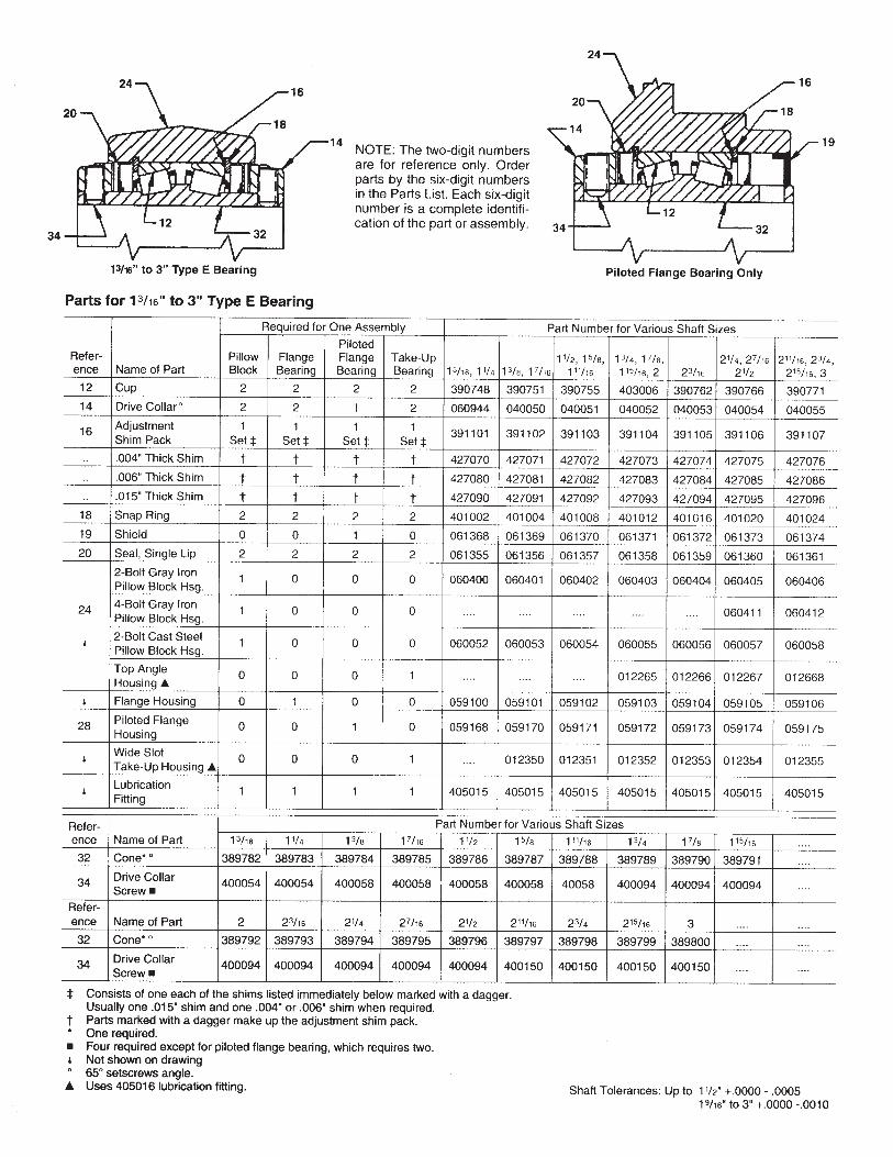


2/04 16M-K
www.rockwellautomation.com www.ptplace.com www.dodge-pt.com www.reliance.com www.ptplace.ca
Corporate HeadquartersRockwell Automation, 777 East Wisconsin Avenue, Suite 1400, Milwaukee, WI, 53202-5302 USA, Tel: (1) 414.212.5200, Fax: (1) 414.212.5201
Headquarters for Dodge and Reliance Electric ProductsAmericas: Rockwell Automation, 6040 Ponders Court, Greenville, SC 29615-4617 USA, Tel: (1) 864.297.4800, Fax: (1) 864.281.2433Canada: Rockwell Automation Canada, 296 Walker Drive, Bramalea, Ontario, Canada L6T 4B3, Tel: (1) 905.792.1722Europe: Rockwell Automation, Brühlstraße 22, D-74834 Elztal-Dallau, Germany, Tel: (49) 6261 9410, Fax: (49) 6261 1771Asia Pacific: Rockwell Automation, 55 Newton Road, #11-01/02 Revenue House, Singapore 307987, Tel: (65) 351 6723, Fax: (65) 355 1733
Headquarters for Allen-Bradley Products, Rockwell Software Products and Global Manufacturing SolutionsAmericas: Rockwell Automation, 1201 South Second Street, Milwaukee, WI 53204-2496 USA, Tel: (1) 414.382.2000, Fax: (1) 414.382.4444
Copyright © 2004 Rockwell Automation. All rights reserved. Printed in USA.DODGE is a trademark of Rockwell Automation.
IM499791

INSTRUCTION MANUAL FOR DODGE
® S-2000 SPHERICAL ROLLER BEARINGS
GENERAL INFORMATION
DODGE S-2000 Spherical Roller Bearing mounted units incor-porate a unique way of sealing the internal components of the bearing while still allowing a full + or - 1 degree of misalignment. The patented sealing system (Pat. #5,908,249) has proven e�ective, due to its constant contact pressure, in protecting the internal bearing components under maximum allowable misaligned conditions.
INSTALLATION INSTRUCTIONS
NON-EXPANSION BEARING
WARNINGTO ENSURE THAT DRIVE IS NOT UNEXPECTEDLY STARTED, TURN OFF AND LOCK OUT OR TAG POWER SOURCE BEFORE PROCEEDING. FAILURE TO OBSERVE THESE PRECAUTIONS MAY RESULT IN BODILY INJURY.
1. Clean shaft and bore of bearing. The shaft should be straight, free of burrs and nicks, and correct size (see shaft tolerance table). If used shafting is utilized, then the bearing should be mounted on unworn section of shafting.
2. Lubricate shaft and bearing bore with grease or oil to facilitate assembly. Slip bearing into position. When light press fit is required, press against the end of the inner ring of bearing. Do not strike or exert pressure on the housing or seals.
3. Bolt bearing to support, using shims where necessary to align bearing so inner ring does not rub on seal carrier. Use full shims which extend across the entire housing base.
4. Determine final shaft postion and tighten setscrews in the locking collar(s) of non-expansion bearing to recom-mended torque while the other bearings remain free. Rotate the shaft slowly under load, if possible, to prop-erly center the rolling elements with respect to the raceways. Then tighten setscrews into the locking collar of the remaining bearings to the recommended torque.
5. Check rotation. If there is any strain, irregular rotational torque or vibration, it could be due to incorrect alignment, bent shaft or bent supports. Installation should be rechecked and correction made where necessary.
EXPANSION BEARING Steps (1, 2, 3) Same as Non-Expansion Bearing. 4. Position expansion bearing in the housing. For normal
expansion conditions, the bearing insert should be posi-tioned in the center of the housing. To center bearing insert in housing, move bearing insert to extreme posi-tion and mark shaft. Then using bearing maximum total expansion table, move bearing insert in opposite direc-tion one-half the total expansion to center bearing in the housing. If maximum expansion is required, move bearing insert to the extreme position in the housing to permit full movement in direction of expansion. After expansion bearing has been positioned in the housing, tighten the setscrews in the locking collar to the recommended torque.
5. Same as Non-Expansion Bearing.
FIELD CONVERSION (RE-OP) OF A NON-EXPANSION BEARING INTO AN EXPANSION BEARING All non-expansion bearing sizes can be re-oped to become expansion bearings. To re-op a non-expansion to an expansion bearing follow these steps: 1. Move the snap ring, opposite from the collar side of
bearing, to the outermost snap ring groove. 2. Install bearing per Expansion Bearing instructions listed
above. NOTE: Bearing nameplate has a non-expansion Part Number. When bearing is re-oped the bearing should be marked as expansion for future reference.
BEARING MAXIMUM TOTAL EXPANSION TABLE
SHAFT SIZE TOTALEXPANSION
in. in.13/8 - 11/ 3 2 /16
111/16 - 37/16 1/4315/ 5 61 /16
47/16 - 415/16 3/8
WARNING: Because of the possible danger to persons(s) or property from accidents which may result from the improper use of products, it is important that correct procedures be followed: Products must be used in accordance with the engineering information specified in the catalog. Proper installation, maintenance and operation procedures must be observed. The instructions in the instruction manuals must be followed. Inspections should be made as necessary to assure safe operation under prevailing conditions. Proper guards and other suitable safety devices or procedures as may be desirable or as may be specified in safety codes should be provided, and are neither provided by Baldor Electric Company nor are the responsibility of Baldor Electric Company. This unit and its associated equipment must be installed, adjusted and maintained by qualified personnel who are familiar with the construction and operation of all equipment in the system and the potential hazards involved. When risk to persons or property may be involved, a holding device must be an integral part of the driven equipment beyond the speed reducer output shaft.
APPENDIX K

LUBRICATION INSTRUCTIONS
OPERATION IN PRESENCE OF DUST, WATER OR CORROSION VAPORS This bearing is factory lubricated with No. 2 consistency lithium complex base grease which is suitable for most applications. However, extra protection is necessary if bearing is subjected to excessive moisture, dust, or corrosive vapor. In these cases, bearing should contain as much grease as speed will permit (a full bearing with consequent slight leakage through the seal is the best protection against contaminant entry).
In extremely dirty environments, the bearing should be purged daily to flush out contaminants. For added protection, it is advisable to shroud the bearing from falling material.
HIGH SPEED OPERATION At higher operation speeds, too much grease may cause overheating. In these cases, the amount of lubrication can only be determined by experience. If excess grease causes overheating, remove grease fittings and run for ten minutes. This will allow excess grease to escape. Then wipe off excess grease and replace grease fittings.
In higher speed applications, a small amount of grease at frequent intervals is preferable to a large amount at infrequent intervals. However, the proper volume and interval of lubrication can best be determined by experience.
AVERAGE OPERATIONS The following table is a general guide for normal operating conditions. However, some situations may require a change in lubricating periods as dictated by experience. If the bearing is exposed to unusual operating conditions, consult a reputable grease manufacturer.
Lubrication Guide Read Preceding Paragraphs Before Establishing Lubrication Schedule
Suggested Lubrication Period in Weeks Hours
run per day
1 to 250 rpm
251 to 500 rpm
501 to 750 rpm
751 to 1000 rpm
1001 to 1500 rpm
1501 to 2000 rpm
2001 to 2500 rpm
2501 to 3000 rpm
8 16 24
12 12 10
12 7 5
10 5 3
7 4 2
5 2 1
4 2 1
3 2 1
2 1 1
OPERATING TEMPERATURE Abnormal bearing temperatures may indicate insufficient lubrication. If the housing is too hot to touch for more than a few seconds, check the temperature by applying a thermom-eter at the top of the pillow block with the thermometer tip surrounded by putty.
Because the thermometer reading will be approximately 10°F lower than the actual bearing temperature, add ten degrees to the reading and compare to the temperature rating of your grease. If the bearing temperature reading is consistent and operating within the recommended limits of your grease, the bearing is operating satisfactorily.
The recommended maximum operating temperature for S-2000 Spherical Roller Bearings is 200 °F.
STORAGE OR SPECIAL SHUT DOWN If equipment will be idle for some time, before shutting down, add grease to the bearing until grease purges from the seals. This will ensure protection of the bearing, particularly when exposed to severe environmental conditions. After storage or idle period, add fresh grease to the bearing before starting.
SET SCREW TORQUE TABLE
Shaft Size
Socket Set Screw
Size Tightening
Torque 13/8 - 13/4 inches
1115/16 - 27/16 inches 1211/16 - 37/16 inches
1315/16 - 415/16 inches
5/16 inches 3/8 inches 1/2 inches 5/8 inches
165 Inch Pounds 290 Inch Pounds 620 Inch Pounds 1325 Inch Pounds
RECOMMENDED SHAFT TOLERANCE TABLE
Low to Normal Equivalent Normal Load and Catalog
Shaft Size Speed* Up to 11/2 inches +.000 inches –.0005 inches
Over 11/2 to 21/2 inches +.000 inches –.001 inches Over 21/2 to 4 inches +.000 inches –.001 inches
Over 4 to 5 inches +.000 inches –.0015 inches
On severe applications and where dynamic balance and minimum runout are important, a snug to light press fit may be required to obtain optimum bearing performance. Consult factory.
*Normal equivalent load .08C to .18C.

3

COMPONENT PART NUMBERS (1 3/8" - 4 15/16")
ITEM 1 1A 2 3 4 5 Shaft Size Bearing Insert Assembly Bearing Insert Assembly * Collar * Set Snap ** Grease
Size (R) Seal (L) Seal Screw Ring Fitting 1 3/8 070000 070016 040050 400058 069276 405015
1 7/16 070001 070017 040050 400058 069276 405015 1 1/2 070002 070018 040050 400058 069276 405015
1 11/16 070003 070019 040051 400058 069277 405015 1 3/4 070004 070020 040051 400058 069277 405015
1 15/16 070005 070021 070587 400094 069278 405015
2 070006 070022 070587 400094 069278 405015 2 3/16 070007 070023 070588 400094 069279 405015 2 7/16 070008 070024 040054 400094 069280 405015
2 11/16 070009 070025 070589 400150 069281 405015 2 15/16 070010 070026 070589 400150 069281 405015
3 070011 070027 070589 400150 069281 405015 3 7/16 070012 070028 040056 400154 069282 405015
3 15/16 070013 070029 060946 400186 069283 405015 4 7/16 070014 070030 * 060947 * 400186 069284 405015
4 15/16 070015 070031 * 040059 * 400190 069285 405015 QTY/PER 1 1 1 2 1 1
*Shaft sizes 4 7/16" - 4 15/16" have two collars a ** WSTU and TPHU TU take a 405016 grease fitting.
www.baldor.com www.ptplace.com www.dodge-pt.com www.reliance.com
Baldor Electric Company Headquarters
P.O. Box 2400, Fort Smith, AR 72902-2400 U.S.A., Ph: (1) 479.648.5792, Fax (1) 479.648.5792, International Fax (1) 479.648.5895 DODGE/Reliance Division
6040 Ponders Court, Greenville, SC 29615-4617 U.S.A., Ph: (1) 864.297.4800, FAX: (1) 864.281.2433
IM499330 04/07-16M-K Copyright © 2007 Baldor Electric Company All Rights Reserved. Printed in USA. This material is not intended to provide operational instructions. Appropriate instruction
manuals and precautions should be studied prior to installation, operation or maintenance of equipment.

Mounted Roller Bearings Installation Instructions 2000, 5000, 9000 Series
(See other side for Bearing Kit Replacement and Maintenance Instructions) (See separate sheet for 3000 install)BEARING MOUNTING PROCEDURE
SET COLLAR-FIXED UNITS ONLY (2000, 5000) 1. Inspect shaft size (see shaft tolerance table). Clean shaft and
mounting surface as needed 2. Position bearings on the shaft, applying all driving pressure to the
face of the inner ring 3. Align the bearing housing to its mounting base by measuring from
the face of the inner ring to the face of the threaded cover. Where shimming is required – use full shims across the housing base – not just at the bolt holes. All four measurements must be within .060” inches of one another
4. Bolt housing securely to mounting base 5. Tighten the set collar set screws on the bearing closest to the drive
(or most important to axial position of shaft) to the shaft. Proper tightening torque can be found in the SET SCREW TORQUE TABLE. The remaining bearings should not be secured to the shaft at this time. Alternate torquing the screws to prevent unequal loading. If an Allen wrench is used as a torque wrench, place a length of pipe over the long end and pull until the wrench begins to twist.
6. Rotate the shaft under power to permit the remaining bearings to seek their natural running position on the shaft.
7. Shut off the power and torque down set screws in remaining bearings using procedure in Step 5
SET COLLAR-EXPANSION UNITS ONLY (2000, 5000) 1. Center cartridge in outer housing. If maximum expansion capability
is required, place cartridge in extreme position of housing to permit full movement of the cartridge in direction of expansion
2. The remainder of the installation is the same as Fixed units, following steps 3,4, and 5
ADAPTER UNITS (9000) 1. Free tapered split sleeve in bore by backing off locknut and rapping the face
of the locknut 2. Position bearing on shaft with fixed unit closest to drive (or most important to
axial location of shaft) 3. Position and loosely bolt housing to mounting base. 4. Secure fixed bearing to shaft by tightening locknut until sleeve grips the
shaft. Tighten locknut ½ to ¾ more and bend one of the lock washer tangs into one of the slots on the outside diameter of locknut
5. Align each bearing housing as accurately as possible to its mounting base or frame by measuring from the face of the inner ring to the face of the threaded cover. All four measurements must be within .060 inches of one another
6. Operate bearing under full load for several days to permit seating of bearing and sleeve on the shaft. Then shut down the system and retighten locknuts on all bearings
ADAPTER UNITS- EXPANSION UNITS ONLY (9000) 1. Center cartridge in outer housing. If maximum expansion capability is
required, place cartridge in extreme position of housing to permit full movement of the cartridge in direction of expansion.
2. The remainder of the installation is the same as Fixed units, following steps 2, 3,4, 5 and 6
DUPLEX UNITS (ZD) When mounting Duplex units, place end plate (bolted cover with pilot) into bore of housing. Press first outer ring until it seats against the pilot, then insert inner ring assembly and turn to free rollers. Press in second outer ring, turn inner ring assembly so rollers are free, and then seat second outer ring. Using shims as a feeler, determine exact amount required to fill space between housing face and bolted cover. See ADJUSTMENT TABLE and add shims to obtain proper bearing clearance. After unit is bolted together, free the bearing by pressing or striking inner ring on the side opposite the shim adjustment
GENERAL INSTALLATION COMMENTS1. Shaft Journal areas must be free of burrs, cleaned of fretting corrosion and within the tolerance range shown in the SHAFT TOLERANCE TABLE. 2. Mounted units are prelubricated at the factory with multipurpose lithium soap grease. No additional grease is required at time of installation. 3. Position housings for
a. Accessibility of grease fittings b. If thrust is present – place thrust force against shoulder of housing, not against threaded cover side
4. If spacer shims are used for alignment they must cover the entire housing base 5. Spot drill or mill flats on shaft for increased holding power of set screws or ease of removal 6. When a eccentric load condition exists, position set screws directly opposite from eccentric weight 7. Shaft shoulders are recommended for support vertical shafts and high thrust loads. The shoulder diameter should not exceed the outside diameter of
the inner ring 8. When pillow blocks are mounted on an inclined plane or the work force is parallel with the base, either lateral bolts or welded stop blocks should be used
to prevent shifting 9. Avoid direct hammer blows to the bearing and its components by using a soft drift or block 10. New seals should be used whenever a bearing is rebuilt
SET SCREW TORQUE TABLE Shaft Size (Inches)
Normal Duty 2000 Series
Heavy Duty 5000 Series
Set Screw Size Tightening Torque (Inch- Pounds)
3/4 – 1 1/4 ….. 5/16 1851 7/16 - 2 1 7/16 – 1 15/16 3/8 325
2 3/16 – 2 1/4 2 – 2 3/16 7/16 4602 3/8 – 3 1/2 2 7/16 – 3 7/16 1/2 6803 11/16 - 4 3 11/16 – 5 7/16 5/8 1350
….. 5 15/16 – 7 3/4 1600For more detailed instructions refer to latest REXNORD Catalog
SHAFT TOLERANCE TABLE - INCHESRECOMMENDED SHAFT TOLERANCES*
Set Collar Mounting Nominal Shaftsizes
Commercial Shaft Tolerance* (Cold
Finished Steel, Low Carbon)
Severe Loading or High Speed
Adapter Mounting
Press Fit Mounting
1-2 +.000 -.003 +.000 -.001 +.000 -.003 2-4 +.000 -.004 +.000 -.001 +.000 -.004 4-6 +.000 -.005 +.000 -.0015 +.000 -.005 6-8 +.000 -.006 +.000 -.0015 +.000 -.005
ConsultRexnord
*Recommended shaft tolerances are generally satisfactory for loads up to 15% of C (see load ratings in catalog). High load applications will require a press fit to the shaft.
1. Housing 2. Inner Race 3. Threaded
Cover 4. Microlock
Assembly 5. Seal 6. Cartridge 7. Roller 8. Outer Ring 9. Set Collar
APPENDIX L

Mounted Roller Bearings Bearing Replacement and
Maintenance Instructions (See other side for installation instructions)
DISASSEMBLY LUBRICATION INSTRUCTIONS GENERAL INFORMATION AND SELECTION 1. Remove set collars or other shaft locking device
2. Remove seals 3. Remove MICROLOCK screw and key. (Do not loose nylon washer) 4. Remove threaded cover by turning counter clockwise 5. Place housing threaded cover side down on arbor press with spacer
blocks under housing 6. Place a soft metal bar or wood block on face of inner ring and press
bottom outer ring and inner ring assembly from housing 7. To remove the back outer ring, large bore bearings 4 7/16” thru 7” have
drive pin holes. The back outer ring of smaller size units may be removed with a bearing puller or hammer and drift.
This information is to aid in the proper lubrication of Rexnord bearings for the majority of applications. Standard bearings come pre-lubricated from the factory with Exxon Ronex MP grease. Exxon Ronex MP is an N.L.G.I. Grade 2. EP (extreme pressure) grease with a lithium complex thickener. It can be used for high loads, and in some cases at temperatures as low as -40°F or as high as +350°F. For high speeds, other special service conditions, or for inquires on other acceptable greases, please consult your local Rexnord representative or the Rexnord Bearing Engineering Department. When rebuilding Rexnord bearings for use in average operating conditions, the bearing should be lubricated with the amount of grease by weight as shown in the LUBRICATION TABLE.
REASSEMBLY RELUBRICATION Bearings should be re-lubricated at regular intervals. The frequency and amount of lubricant will be determined by the type of service. General guidelines for re-lubrication frequency and amount are based upon average application conditions. See LUBRICATION TABLE At High temperatures, greases tend to degrade more rapidly and thus require fresh grease more frequently. In general, small amounts of grease added frequently provide better lubrication. Most grease will eventually harden, causing re-lubrication to become less effective. When this occurs, the bearing should be disassembled, cleaned and lubricated per LUBRICATION TABLE. When equipment will not be in operation for some time, grease should be added to provide corrosion protection. This is particularly important for equipment exposed to severe weather. AUTOMATIC LUBRICATION SYSTEMS A variety of automatic re-lubrication systems are available for use with roller bearings. Key considerations are: 1. NLGI grade of grease used, consistent with system layout 2. An amount/frequency combination necessary to replenish the grease MIXING OF GREASES Mixing of any 2 greases should be checked with the lubricant manufacturer. If the grease bases are different they should never be mixed OIL LUBRICATION
1. Place housing cover side up on arbor press with spacer blocks under housing.
2. Press in back outer ring and seat against housing shoulder. 3. Insert inner ring assembly and rotate to seat rollers against back outer
ring. 4. Press in front outer ring. 5. Install threaded cover, turning clockwise until inner ring resists rotation or
misalignment. 6. Back off threaded cover one quarter turn – align cover slot with the
nearest counter bored hole in housing. See ADJUSTMENT TABLE. 7. Install microlock key with nylon washer under the head of the screw. 8. Using a soft drift or block, rap face of inner ring on side opposite
threaded cover to seat front outer ring. Inner ring assembly should rotate freely.
9. Install seals. Z-Seal – Place centering spring in seal groove with fingers facing up. Place U-shaped element on fingers. Place centering ring on element with projection on face up. Install snap ring so that projection on centering ring is between ends of snap ring. K-Seal – Place seal into the seal groove with anti rotation boss sticking up. Install snap ring so that the raised boss is between the snap ring ends. M-Seal – Place seal into seal groove with spring facing out. No snap ring is required with M-Seal.
10. Install collars 11. Lubricate bearing with amount of grease shown in LUBRICATION
TABLE. Rotate inner ring assembly during lubrication to assure distribution of grease in bearing
Rexnord housing designs do not include oil sumps, thus they are not readily used with static oil lubrication. However, they can be adapted to recirculating oil systems provided an adequate drain size and proper seals are incorporated
LUBRICATION TABLE SHAFT SIZE - INCHES GREASE WT. REQUIRED (OZ) RECOMMENDED NUMBER OF MONTHS BEWEEN RELUBRICATION*
(BASED ON 40 HR. WK.) RPM Single Collar
2000, 3000 Series Double Collar 5000 Series
Adapter 9000 Series
To Lubricate Rebuilt Units
To Relubricate Units 100 300 500 1000 1750 3000
3/4 -1 1 1/8 – 1 1/4 1 7/16 – 1 1/2
…… …… 1 7/16
…… …… ……
0.4 0.5 0.6
0.1 0.1 0.1
12 8 5 2 1 1/2
1 11/16 -1 3/4 1 15/16 -2 2 3/16 – 2 1/4 2 3/8 - 2 1/2 2 11/16 – 3
1 1/2 – 1 11/16 1 15/16 2 – 2 3/16 2 7/16 2 1/2 – 2 15/16
…… …… 1 15/16 – 2 2 3/16 2 7/16 – 2 1/2
0.8 0.9 1.1 1.5 2.8
0.2 0.2 0.2 0.3 0.5
8 5 3 1 1/2 …..
3 3/16 – 3 1/2 3 11/16 – 4 ……
3 3/16 – 3 7/16 3 11/16 – 4 4 3/16 – 4 1/2
2 11/16 -3 3 3/16 – 3 7/16 3 11/16 – 4
3.7 6.9 8.4
0.6 1.1 1.5
6 4 2 1 1/2 …..
…… …… …… ……
4 15/16 – 5 5 7/16 5 15/16 – 6 6 7/16 - 7
4 3/16 – 4 7/16 4 15/16 – 5 5 3/16 – 5 7/16 5 15/16 – 6 7/16
14.3 22.1 25.3 33.0
2.5 4.0 4.5 6.0
4 2 1 1/2 ….. …..
*Relubrication amounts and frequencies shown in the table are based on standard clearance, moderate loads, etc., which yield housing temperatures of 150°F or less. Lubrication practices indicate that the relubrication frequency should be doubled for every 20°f above that level
ADJUSTMENT TABLE (AXIAL AND RADIAL CLEARANCES)
SHAFT SIZE (INCHES) FACTORY ADJUSTMENT (Average Speeds)
RECOMMENDED ADJUSTMENT HIGH SPEEDS
CLEARANCE ADJUSTMENT INCHES
PER 1/12 TURN Size Code 2000
SERIES 3000
SERIES 5000
SERIES 9000
SERIES STD AXIAL
CLEARANCE STD RADIAL CLEARANCE
SPEED OVER
AXIAL CLEARANCE
RADIAL CLEARANCE AXIAL RADIAL
2-4 3/4 – 1 1/2 1 7/16 1 7/16 …… .007-.012 .0022-.0037 2000 .012-.017 .0037-.0053 0.005 0.0016 5-6 1 11/16 - 2 1 11/16 – 1 15/16 1 1/2 – 1 15/16 …… .007-.012 .0020-.0034 1500 .012-.017 .0034-.0049 0.005 0.0014 7-9 2 3/16 – 3 2 3/16 – 2 15/16 2 – 2 15/16 1 15/16 – 2 1/2 .010-.017 .0026-.0044 1250 .017-.024 .0044-.0062 0.007 0.0018
10-11 3 3/16 - 4 3 7/16 – 3 15/16 3 3/16 - 4 2 11/16 -3 7/16 .010-.017 .0025-.0043 1000 .017-.024 .0043-.0060 0.007 0.0018 12-13 …… …… 4 3/16 – 5 3 11/16 – 4 7/16 .015-.025 .0032-.0054 750 .025-.035 .0054-.0076 0.010 0.0022 14-16 …… …… 5 7/16 - 7 4 15/16 – 6 7/16 .015-.025 .0032-.0054 500 .025-.035 .0054-.0076 0.010 0.0022
Rexnord Industries, LLC Bearing Group
Phone: 317-273-5500 www.rexnord.com
105-99501-07 ECN 5-43431
5-12-08

Mounted Roller Bearings Twist Lock™ 3000 Series
Installation Instructions ( This sheet provides install information for the 3000 series, see 2000, 5000, 9000 sheet for more info)
Twist Lock™ 3000 Series Roller Bearing This bearing is equipped with an eccentric locking set collar that should be tightened in the direction of
shaft rotation
BEARING MOUNTING PROCEDURE 8. Position bearings on the shaft, applying the driving pressure to the face of the inner ring. 9. Align the bearing housing to its mounting base by measuring from the face of the inner ring to the face of the threaded cover. Where shimming is
required – use full shims across the housing base – not just at the bolt holes. All four measurements must be within .060” inches of one another 10. Bolt housing securely to mounting base 11. Slide collar over the shaft until it nests over the cam of the inner ring. Do this on the bearing closest to the drive (or the most important to axial position
of shaft). Rotate the collar in the direction of normal shaft rotation until snug. Utilizing a hammer and punch, rotate the collar until tight. Tighten set screws securely. Utilize torque values from the SET SCREW TABLE PER “SET SCREW SIZE”. If an Allen wrench is used as a torque wrench, place a length of pipe over the long end and pull until the wrench begins to twist.
12. The remaining bearings should not be secured to the shaft at this time 13. Rotate the shaft under power to permit the remaining bearings to seek their natural running position on the shaft. 14. Shut off the power and torque down set screws in remaining bearings using procedure in Step 4.
BEARING REMOVAL PROCEDURE 7. Use a hammer and punch to rotate the collar in the direction opposite the shaft rotation until it loosens. If the rotation direction is unknown, look for prior
punch marks on the collar. Then rotate the collar in the opposite direction until it loosens. 8. Remove the collar from the shaft of the and inner ring. The bearing may now be removed from the shaft. To eliminate bearing damage, apply all driving
force to the face of the inner ring.
Rexnord Industries, LLC Bearing Group
Phone: 317-273-5500 www.rexnord.com
105-99501-16 ECN 5-43431
5-12-08

INSTALLATION AND
MAINTENANCE
INSTRUCTIONS FOR
ELECTRIC MOTORS
Frames 143/5T - 586/7T
APPENDIX M

Check if any damage has occured during transportation. Check nameplate data. Remove shaft locking device (if any) before operating the
motor. Turn the shaft with the hand to make sure if it is turning freely.
1 - General
Lifting devices, when supplied, are designed only to supportthe motor. If the motor has two lifting devices then a doublechain must be used to lift it.
Lifting and lowering must be done gently without anyshocks, otherwise the bearings can get damaged.
DURING TRANSPORTATION, MOTORS FITTEDWITH ROLLER OR ANGULAR CONTACT
BEARINGS ARE PROTECTED AGAINST BEARINGDAMAGES WITH A SHAFT LOCKING DEVICE.
HANDLING AND TRANSPORTATION
RECEIVING CHECK
READ CAREFULLY THIS MANUAL BEFOREINSTALLING THE MOTOR.
MOTORS MUST NOT BE LIFTED BY THE SHAFT,BUT BY THE EYE BOLTS WHICH ARE PROPERLYDESIGNED TO SUPPORT THE MOTOR WEIGHT.
THIS LOCKING DEVICE MUST BE USED ON ANYFURTHER TRANSPORT OF THE MOTOR, EVEN
WHEN THIS MEANS TO UNCOPULE THE MOTORFROM THE DRIVEN MACHINE.

If motors are not immediately installed, they must be storedin dry places, free of dust, vibrations, gases, corrosive smokes,under constant temperature and in normal position free fromother objects.
In case the motors are stored for more than two years, thebearings must be changed or the lubrication grease must betotally replaced after cleaning.
Single phase motors when kept in stock for 2 years or moremust have their capacitors replaced (if any).
We recommend to turn the shaft (by hands) at least once amonth, and to measure the insulation resistance beforeinstalling it, in cases of motors stored for more than 6 monthsor when subject to high humidity areas.
If motor is �tted with space heaters, these should beswitched on.
Insulation Resistance CheckInsulation Resistance CheckInsulation Resistance CheckInsulation Resistance CheckInsulation Resistance Check
Measure the insulation resistance before operating themotor and/or when there is any sign of humidity in the winding.
The resistance measured at 25°C (77 oF) must be:
Ri > (20 x U) / (1000 + 2P) [Mohm] (measured with aMEGGER at 500 V d.c.); where U = voltage (V); P = power(kW).
If the insulation resistance is less than 2 megaohms, thewinding must be dried according to the following:
Warm it up inside an oven at a minimum temperature of80°C (176 oF) increasing 5°C (41 oF) every hour until 105°C(221 oF), remaining under this temperature for at least one hour.Check if the stator insulation resistance remains constant withinthe accepted values. If not, stator must be reimpregnated.
STORAGE

1 - Safety
All personnel involved with electrical installations, eitherhandling, lifting, operation or maintenance must be wellinformed and up-to-dated concerning the safety standard andprinciples that govern the work and carefully follow them.
We strongly recommend that these jobs are carried out byquali�ed personnel.
INSTALLATION
MAKE SURE THAT THE ELECTRIC MOTORS ARESWITCHED OFF BEFORE STARTING ANY
MAINTENANCE SERVICE.
2 - Operating Conditions
Electric motors, in general, are designed for operation atan altitude of 1000m above sea level for an ambienttemperature between 25°C (77°F) and 40°C (104°F). Anyvariation is stated on the nameplate.
Motors must be protected against accidental starts.When performing any maintenance service, disconnect the
motor from the power supply. Make sure all accessories havebeen switched o� and disconnected.
Do not change the regulation of the protecting devices toavoid damaging.
LEAD CONNECTION IN SULATION INSIDE THETERMINAL BOX MUST BE DONE WITH AN
INSULATING MATERIAL COMPATIBLE WITHMOTOR THERMAL CLASS WHICH IS SHOWN
ON THE MOTOR NAMEPLATE.

Motors supplied for hazardous locations must beinstalled in areas that comply with that speci�ed on the motornameplate.
KEEP AIR INLET AND OUTLET FREE AND CLEAN.THE AIR BLOWN OUT BY THE MOTOR SHALLNOT ENTER AGAIN. THE DISTANCE BETWEEN
THE AIR INLET AND THE WALL MUST BEAROUND ¼ OF THE INLET OPENING DIAMETER.
COMPARE THE CURRENT, VOLTAGE,FREQUENCY, SPEED, OUTPUT AND OTHER
VALUES DEMANDED BY THE APPLICATION WITHTHE DATA GIVEN ON THE NAMEPLATE.
3 - Foundation
Motors provided with feet must be installed on thoughfoundations to avoid excessive vibrations.
The purchaser is fully responsible for the foundation.
Metal parts must be painted to avoid corrosion.
The foundation must be uniform and su�ciently tough tosupport any short circuit strengths. It must be designed insuch a way to stop any vibration originated from resonance.
4 - Drain Holes
Make sure the drains are placed in the lower part of themotor when the mounting con�guration di�ers from thatspeci�ed on the motor purchase order.

WEG MOTORS ARE DYNAMICALLYBALANCED, WITH HALF KEY AT NO LOAD
AND UNCOUPLED.
Ensure that the motor mounting devices do not allowmodi�cations on the alignment and further damages to thebearings.
When assembling a half-coupling, be sure to use suitableequipment and tools to protect the bearings.
Suitable assembly of half-coupling: check that clearance Yis less than 0.05mm and that the di�erence X1 to X2 is lessthan 0.05m as well.
Transmission elements such as pulleys, couplings, etc mustbe dynamically balanced with half key before installation. Usealways appropriate tools for installation and removal.
6 - Alignment
ALIGN THE SHAFT ENDS AND USE FLEXIBLECOUPLING, WHENEVER POSSIBLE.
5 - Balancing
Note: The“X” dimension must be at least 3mm.

7 - Belt Drive
When using pulley or belt coupling the following must beobserved:
Belts must be tighten just enough to avoid slippage whenrunning, according to the speci�cations stated on the beltsupplier recommendation.
8 - Connection
WWWWWARNINGARNINGARNINGARNINGARNING: V oltage may be connected at standstill inside theterminal box for heating elements or direct winding heating.
WWWWWARNINGARNINGARNINGARNINGARNING : The capacitor on single-phase motors can retaina charge which appears across the motor terminals, even whenthe motor has reached standstill.
WWWWWARNING:ARNING:ARNING:ARNING:ARNING:Excessive tension on the pulleys
will damage the bearings and lead toa probable shaft rupture.
Voltage and connection are indicated on the nameplate.The acceptable voltage variation is ± 10%, the acceptablefrequency variation is ± 5% and the total acceptable variationis ± 10%.
9 - Starting Methods
The motor is rather started through direct starting. All Wegmotors must be connected as shown on the motor nameplate,failure to follow the motor nameplate could lead to motor failure.
A WRONG CONNECTION CAN BURN THEMOTOR.

In case this is not possible, use compatible methods to themotor load and voltage.
3 lead single voltage and 9 lead dual voltage motors can bestarted as follows:Full Voltage Direct On Line.Auto-Transformer Starting.Electronic Soft-Starting.VFD Starting - subject to veri�cation and application analysis.
6 lead single voltage motors and 12 lead dual voltage motorscan be connected as follows:Full Voltage Direct On Line.WYE/DELTA Starting.Auto-Transformer Starting.Electronic Soft-Starting.VFD Starting - subject to veri�cation and application analysis.
The rotation direction is clockwise if the motor is viewedfrom DE side and if the phases are connected according tothe sequence L1, L2, L3.
To change the rotation direction, interchange two of theconnecting leads.
Make sure to use the correct cable dimension, based onthe rated current stamped on the motor nameplate.
BEFORE ENERGIZING THE TERMINALS, CHECKIF THE EARTHING IS MADE ACCORDING TO THE
ACTUAL STANDARDS. THIS IS ESSENTIALAGAINST ACCIDENT RISKS.
THE CONNECTION TO THE POWER SUPPLYMUST BE DONE BY QUALIFIED PERSONNEL
AND WITH FULL ATTENTION TO ASSURE A SAFEAND PERMANENT CONNECTION. AFTER
CONNECTING THE MOTOR, CHECK FOR ANYSTRANGE BODY INSIDE THE TERMINAL BOX.
THE CABLE INLETS NOT IN USE MUST BECLOSED.

When the motor is supplied with protective or monitortemperature device such as thermostats, thermistors, thermalprotector, etc, connect their terminals to the correspondingdevices on the control panel.
10- Start-Up
THE KEY MUST BE FASTENED OR REMOVEDBEFORE STARTING THE MOTOR.
a) The motor must start and operate smoothly. In case thisdoes not occur, turn it o� and check the connections and themounting before starting it again.
b) If there is excessive vibration, check if the fasteningscrews are correctly fastened. Check also if the vibration comesfrom a neighbour machine. Periodical vibration checks mustbe done.
c) Run the motor under rated load for a short period oftime and compare if the running current is equal to thatstamped on the nameplate.
1 - General Inspection
Check the motor periodically.Keep the motor clean and assure free air �ow.Check the seals or V Ring and replace them, if required.Check the connections as well as supporting screws.Check the bearings and observe:Any excessive noise, bearing temperature and greasecondition.When a changing, under normal conditions, is detected,check the motor and replace the required parts.The frequency of the inspections depends on the motortype and on the application conditions.
MAINTENANCE
WARNING:SAFETY CHECK LIST.

1 - Machines without Grease Nipples
Motors up to frame 324/6T are normally �tted without greasenipples. In these cases the regreasing shall be done at thepreventive maintenance job observing the following aspects:
Disassemble carefully the motors. Take all the grease out. Wash the bearing with querosene or diesel. Regrease the bearing immediately.
2 - Machines Fitted with Grease Nipples
It is strongly recommended to grease the machine whilerunning. This allows the grease renewal in the bearing housing.When this is not possible due to turning parts by the greasedevice (pulleys, bushing, etc) that o�er some risk to thephysical integrity of the operator, proceed as follows:
Clean the area near to the grease nipple.Put approximately half of the total grease and run the motorfor 1 minute at full speed. Then turn o� the motor and pumpthe rest of the grease.
The injection of all the grease with the motor in standstillcan make the grease penetrate into the motor, through theinner seal of the bearing housing.
When regreasing, use only special bearing grease with thefollowing properties:
LUBRICATION
FOLLOW THE REGREASING INTERVALS. THIS ISFUNDAMENTAL FOR PROPER MOTOR
OPERATION.

Rel
ubric
atio
n in
terv
als
in h
ours
- b
all b
earin
gs
254/
6T13
1570
018
100
2000
020
000
2000
020
000
2000
020
000
2000
020
000
2000
0
284/
6T18
1150
013
700
2000
020
000
2000
020
000
2000
020
000
2000
020
000
2000
0
324/
6T21
9800
1190
020
000
2000
020
000
2000
020
000
2000
020
000
2000
020
000
364/
5T27
3600
4500
9700
1160
014
200
1640
017
300
1970
020
000
2000
020
000
404/
5TS
2736
0045
0097
0011
600
1420
016
400
1730
019
700
2000
020
000
2000
0
444/
5TS
2736
0045
0097
0011
600
1420
016
400
1730
019
700
2000
020
000
2000
0
504/
5TS
2736
0045
0097
0011
600
1420
016
400
1730
019
700
2000
020
000
2000
0
586/
7TS
2736
0045
0097
0011
600
1420
016
400
1730
019
700
2000
020
000
2000
0
Rel
ubric
atio
n in
terv
als
in h
ours
- c
ylin
dric
al r
olle
r be
arin
gs
324/
5T21
9800
1190
020
000
2000
020
000
2000
020
000
2000
020
000
2000
020
000
364/
5T00002
0000200002
0079100371
0046100241
006110079
72
404/
5T00002
0087100551
0055100831
006110059
00670006
43
444/
5T00002
0075100731
0073100221
00890067
00060074
54
447/
5T00002
0075100731
0073100221
00890067
00060074
54
504/
5T00002
0075100731
0073100221
00890067
00060074
54
586/
7T00371
0043100511
0051100701
00870095
00440033
06
RE
LUB
RIC
ATI
ON
IN
TER
VA
LS R
EC
OM
ME
ND
ED
- P
OLY
RE
X® E
M G
RE
AS
E (
ES
SO
/EX
XO
N)
3600
rpm
3000
rpm
1800
rpm
1500
rpm
1200
rpm
1000
rpm
900
rpm
750
rpm
720
rpm
Fram
eA
mo
unt o
fg
reas
e (g
)60
0rp
m50
0rp
m

WARNING:The table above is speci�cally intended for relubrication
with Polyrex ® EM grease and bearing absolute operatingtemperature of:
70 oC (158 oF) for 254/6T to 324/6T frame motors; 85 oC (185 oF) for 364/5T to 586/7T frame motors.
For every 15 oC (59 oF) above these limits, relubricationinterval must be reduced by half.
Shielded bearing (ZZ) are lubricated for berings life as longas they operate under normal ambient conditions andtemperature of 70°C(158 oF ).
WE RECOMMEND TO USE BALL BEARINGS FORMOTORS DIRECTLY COUPLED TO THE LOAD.
WARNING:EXCESS OF GREASE CAN CAUSE BEARINGOVERHEATING RESULTING IN COMPLETE
DAMAGE.

THE USE OF STANDARD MOTORS IN SPECIFICAREAS OR SPECIAL APPLICATIONS MUST BE
DONE BY CONSULT TO THE GREASEMANUFACTURER OR WEG.
Compatibility of PCompatibility of PCompatibility of PCompatibility of PCompatibility of P olyrexolyrexolyrexolyrexolyrex ®®®®® EM grease EM grease EM grease EM grease EM grease with other types of grease: with other types of grease: with other types of grease: with other types of grease: with other types of grease:
Containing polyurea thickener and mineral oil, the Polyrex ®
EM grease is compatible with other types of grease thatcontain:
Lithium base or complex of lithium or polyurea and highlyre�ned mineral oil;
Inhibitor additive against corrosion, rust and anti-oxidantadditive.
Notes:Notes:Notes:Notes:Notes: Although Polyrex ® EM is compatible with the types of greasegiven above, we do no recommend to mix it with any othergreases.
If you intend to use a type of grease di�erent than thoserecommended above, �rst contact WEG.
On applications (with high or low temperatures, speedvariation, etc), the type of grease and relubrication intervalare given on an additicional nameplate attached to the motor.
Vertical mounted motors must have the relubrication intervalsreduced by half.
Disassembly and assembly must be done by quali�edpersonnel using only suitable tools and appropriated methods.The stator grips must be applied over the side face of the innerring to be disassembled or over and adjacent part.
It is essential that the bearings disassembly and assemblybe done under cleanning conditions to ensure good operation
ASSEMBLY AND DISASSEMBLY

SPARE PARTS
When ordering spare parts, please specify the full typedesignation and product code as stated on the motornameplate.
Please also inform the motor serial number stated on thenameplate.
MOTORS FOR HAZARDOUS LOCATIONS
Besides the recommendations given previously, these onesmust be also followed:
THE SPECIFICATION OF THE MOTORINSTALLATION PLACE IS FOR CUSTOMER’S
RESPONSIBILITY, WHO WILL ALSO DETERMINETHE ENVIRONMENT CHARACTERISTICS.
Motors for hazardous locations are manufactured accordingto speci�c standards for such environments and they arecerti�ed by worldwide certifying entities.
1 - Installation
The complete installation must follow procedures given bythe local legislation in e�ect.
and to avoid damages. New bearings shall only be taken outfrom their cases when assembling them.
Before installing a new bearing it is required to check theshaft �tting for any sharp edge or strike signals.
For bearing assembly, warm their inner parts with suitableequipment - inductive process - or use suitable tools.

2 - Maintenance
Maintenance must be carried out by repair shops authorizedby WEG.
Repair shops and people without WEG’s authorization whowill perform any service or hazardous location motors will befully responsible for such service as well as for anyconsequential damage.
THE INSTALLATION OF HAZARDOUS LOCATIONMOTORS MUST BE CARRIED OUT BY SKILLED
PEOPLE, AND THE THERMAL PROTECTIONMUST BE ALWAYS INSTALLED, EITHER INSIDEOR OUTSIDE THE MOTOR, OPERATING AT THE
RATED CURRENT.
ANY ELECTRICAL OR MECHANICALMODIFICATION MADE ON HAZARDOUS
LOCATION MOTORS WILL VOID THECERTIFICATION.
DO NOT REUSE DAMAGED OR WORN PARTS.REPLACE THEM BY NEW ONES SUPPLIED BY
THE FACTORY.
When performing maintenance, installation or relubrication,follow these instructions:
Check if all components are free of edges, knocks or dirt. Make sure all parts are in perfect conditions. Lubricate the surfaces of the endshield �ttings with protectiveoil to make the assembly easier. Use only rubber hammer to �t the parts. Check for correct bolts tightening. Use clearance calibrator for correct T-box �tting (smallerthan 0.05mm).

IF SUCH RECOMMENDATIONS ARE NOTFOLLOWED ACCORDINGLY, MOTOR WARRANTY
WILL BE VOID.
2 - Inverter Duty Motors
Check power supply voltage of the forced cooling set. Filters are not required.
Applications using VFD´s without �lter can a�ect motorperformance as follows:
Lower e�ciency. Higher vibration. Higher noise level. Higher rated current. Higher temperature rise. Reduced motor insulation. Reduced bearing life.
1 - Standard Motors
Voltages lower than 440V do not require �lter. Voltages equal or higher than 440V or lower than 575V
require �lter for motor power supply cables longer than 20 meters.
Voltages equal or higher than 575V require �lter for any size of power supply cables.
MOTORS DRIVEN BY VFD

WARRANTY TERMSSERIES AND ENGINEERING PRODUCTS
WEG warrants its products against defects in workmanshipand materials for 18 months from the invoice date issued by thefactory, authorized distributor or agent limited to 24 months frommanufacturing date independent of installation date as long asthe following items are ful�lled accordingly:- Proper transportation, handling and storage;- Correct installation based on the speci�ed ambient conditionsand free of corrosive gases;- Operation under motor capacity limits;- Observation of the periodical maintenance services;- Repair and/or replacement e�ected only by personnel dulyauthorized in writing by WEG;- The failed product be available to the supplier and/or repair shopfor a required period to detect the cause of the failure andcorresponding repair;- Immediate notice by the purchaser about failures occured andthat these are accepted by WEG as manufacturing defects.
This warranty does not include disassembly services at theurchaser facilities, transportation costs with product, tickets,accomodation and meals for technical personnel when requestedby the customer. The warranty service will be only carried out atWEG Authorized Repair Shops or at WEG´s facilities.
Components whose useful life, under normal use, is shorterthan the warranty period are not covered by these warranty terms.
The repair and/or replacement of parts or components, whene�ected by WEG and/or any WEG Authorized Repair Shop, will notgive warranty extension.
This constitutes WEG´s only warranty in connection with thissale and the company will have no obligation or liability whatsoeverto people, third parties, other equipment or installations, includingwithout limitation, any claims for consequential damages or laborcosts.

Daily Inspection:
� With the conveyor down check hydraulic fluid level, Add an ISO-30 oil if required.
� Inspect all hoses, inspect for any rubbing and or cracking-replace if needed.
� Inspect entire machine for any hydraulic leaks-repair if needed.
� Inspect cooler to make sure it is free of any type of debris, clean if required.
� Check main system pressure is at 3,000 PSI- if pressure is not please contact MASABA for further instructions.
6 Month Inspection/Maintenance:
� Loosen love joy coupling and slide back to inspect rubber spider, Replace if worn.
� Remove and replace hydraulic filter.
� Inspect cylinders and motors for any leaks at the shafts-remove and repair if
required. 12month maintenance:
� Pressure wash any debris from power unit.
� Drain hydraulic oil from tank, remove clean out cover and wipe out tank with clean non-lint bearing rags.
� Install clean out cover, fill with oil.
SERVICE RECOMMENDATIONSFOR MASABA HUDRAULIC SYSTEMS (PUMPS & TANKS)
APPENDIX N

Page 1 of 4
ALLIED OIL & SUPPLY, INC.2209 S. 24th StreetOmaha, NE 68108402-344-4343800-333-3717FAX: 402-344-4360
MATERIAL SAFETY DATA SHEET
IDENTITY (As used on label and list): ALLIED AW HYDRAULIC OIL ISO 32, GROUP I
PRODUCT CODE: 900AN0032BU
NFPA Hazard Identification 0 – Least 1 – Slight 2– Moderate 3 – High 4 - Extreme
0 :ytivitcaeR 1 :eriF 0 :htlaeH
Section I - General Information
Allied Oil & Supply, Inc.2209 S. 24th StreetOmaha, NE 68108Information (402) 344-4343
Emergency/ Chemtrec (800) 424-9300 Reviewed: 12/29/03
Section II - Composition/Informationon Ingredients
COMPONENT NAME % CAS OSHA PEL ACGIH TLVLubricating Oil Base Stock 95-99 MIXTURE 5mg/m3* 5mg/m3*Proprietary Additives 1-5 MIXTURE 5mg/m3* 5mg/m3**Numbers are for oil mist.
No IARC, NTP, OSHA and ACGIH listed carcinogens
Section III - Hazards Identification
EYE CONTACT: Contact with eyes may cause eye irritation.
SKIN CONTACT: Prolonged or repeated contact may result in skin irritation or dermatitis.
INHALATION: Breathing oil mist in concentrations that exceed the TLV and PEL may result in respiratorydiscomfort and irritation.
INGESTION: Although this product is not expected to be acutely toxic, aspiration of liquid into the lungs duringingestion or vomiting may cause chemical pneumonitis.
CARCINOGENICITY: This product has not been classified as a carcinogen or probable carcinogen by OSHA,NTP, or IARC.
SIGNS AND SYMPTOMS OF OVEREXPOSURE: May cause skin, eye, or respiratory irritation.
APPENDIX P

Page 2 of 4
MEDICAL CONDITIONS GENERALLY AGGRAVATED BY EXPOSURE: None recognized
OTHER HEALTH INFORMATION: None
Section IV - First Aid Procedures
EYE CONTACT: If splashed into eyes, flush with water for 15 minutes or until irritation subsides. Get medicalattention if irritation persists.
SKIN CONTACT: Remove contaminated clothing. Wash skin thoroughly with soap and water. Get medicalattention if irritation persists.
INHALATION: If overcome by vapor from hot product, immediately remove victim to fresh air. If breathing hasstopped, administer artificial respiration. Call for medical attention. If overexposed to oil mist, remove fromfurther exposure.
INGESTION: DO NOT induce vomiting, call medical attention immediately.
Section V - Fire and Explosion Hazard Data
Flash Point (deg F): > 425 Method Used: COCFlammable or Explosive Limits (approximate % by volume in air) LEL: n/a UEL: n/a
EXTINGUISHING MEDIA: Use water spray, dry chemical, foam, or carbon dioxide. Use water to keep fire-exposed containers cool. Water spray may be used to flush spills away from exposures.
SPECIAL FIRE FIGHTING PROCEDURES: Self-contained breathing apparatus may be required.
UNUSUAL FIRE AND EXPLOSION HAZARDS: None known
Section VI - Accidental Release Measures
STEPS TO BE TAKEN IN CASE MATERIAL IS RELEASED OR SPILLED: Add sand, earth, or othersuitable absorbent to spill area. Keep product out of sewers and waterways by damming or impounding.
Section VII - Handling and Storage
PRECAUTIONS TO BE TAKEN IN HANDLING AND STORAGE: Store in a cool, dry place with adequateventilation. Do not expose to extreme temperatures or flames.
OTHER PRECAUTIONS: None
Section VIII -Exposure Controls/Personal Protection
RESPIRATORY PROTECTION: Use supplied-air respiratory protection in confined or enclosed space, ifneeded.
VENTILATION: Use local exhaust to capture vapor, mists or fumes, if necessary. Provide ventilation sufficientto prevent exceeding recommended exposure limit or buildup of explosive concentrations of vapor in air. Useexplosion-proof equipment.
PROTECTIVE GLOVES: Use neoprene gloves, if needed, to avoid prolonged or repeated skin contact.
EYE PROTECTION: Wear goggles if there is likelihood of contact with eye(s).

Page 3 of 4
OTHER PROTECTIVE EQUIPMENT: Use neoprene apron or other clothing, if needed, to avoid prolonged orrepeated skin contact.
WORK PRACTICES/ENGINEERING CONTROL: Keep containers closed when not in use.
PERSONAL HYGIENE: Wash skin thoroughly after contact, before breaks and meals, and at the end of the workperiod. Thoroughly clean contaminated clothing, including shoes, before re-use.
Section IX- Physical/Chemical Characteristics
Boiling Point (deg F): n/a Specific Gravity (H2O=1): .876 Vapor Pressure (mm Hg): n/aMelting Point (deg F): ND Vapor Density (Air=1): n/a Solubility in Water : insolubleEvaporation Rate (n-butyl Acetate=1): n/a
APPEARANCE AND ODOR: Light amber liquid, mild petroleum odor.
Section X - Reactivity Data
STABILITY: Stable
INCOMPATIBILITY (MATERIALS TO AVOID): Strong oxidants such as liquid chlorine, concentratedoxygen, sodium hypochlorite or calcium hypochlorite.
HAZARDOUS DECOMPOSITION OR BYPRODUCTS: Carbon monoxide, aldehydes, and other petroleumdecomposition products. Oxides of sulfur, phosphorus, calcium, zinc, and hydrogen sulfide may also be present.
HAZARDOUS POLYMERIZATION: Will not occur
CONDITIONS TO AVOID: None
Section XI - Toxicological Information
See Section IV
Section XII - Ecological Information
Section XIII - Disposal Considerations
WASTE DISPOSAL METHOD: Place in an appropriate disposal facility in compliance with local regulations.
Section XIV - Transport Information
NOT A REGULATED ITEM ACCORDING TO DOT.
Section XV-Regulatory Information
SARA SECTION 313: This product does not contain greater than 1.0% (greater than 0.1% for carcinogenicsubstances) of any chemical substance listed under SARA Section 313.WHMIS classification for product: This product has been classified in accordance with the hazard criteria of theCPR and the MSDS contains all the information required by the CPR.

Page 4 of 4
This material safety data sheet and the information it contains is offered to you in good faith as accurate. We havereviewed any information contained in the data sheet which we received from sources outside our company and webelieve that information to be correct, but cannot guarantee its accuracy or completeness. Health and safetyprecautions in this data sheet may not be adequate for all individuals and/or situations. It is the user's obligation toevaluate and use this product safely and to comply with all applicable laws and regulations. No statement made inthis data sheet shall be construed as permission or recommendation for the use of any product in a manner thatmight infringe existing patents. No warranty is made, either expressed or implied.