Embed Size (px)
Citation preview
MAGNUM MASONRY MANUAL – MAY 1999 PAGE - 1 -
MAGNUM®
BUILD-IN FACTORY BUILT MASONRY FIREPLACE
OWNERS MANUAL Installation, Operation and Maintenance Guide
Models 2824 – 2832ST – 3224 – 3228 – 3528 – 3536ST – 6028TV
KEEP THESE INSTRUCTIONS FOR FUTURE USE
WARNING Read entire manual before installation and operation of the Magnum Fireplace. Failure to follow these instructions may result in product warranty being voided, property damage, bodily harm or even death. Always disconnect the power to the blowers (if you have the blower option) before attempting service work. DO NOT connect the Fireplace to a chimney serving another appliance. ALL MINIMUM CLEARANCES TO COMBUSTIBLES MUST BE FOLLOWED.
FOR YOUR SAFETY When installing your Magnum Fireplace, particular attention needs to be paid to fire protection. If the fireplace is not properly installed, a house fire may result. For your safety, follow the installation and operations instructions provided. If you have a question, contact local building officials about restrictions and installation requirements in your area.
CAUTION Never use gasoline, gasoline-type lantern fuel, kerosene, charcoal lighter fluid, or similar liquids to start or “freshen” up a fire in this fireplace. Keep all such liquids well away from the fireplace at all times. If you are using processed solid fuel fire logs, use only fire logs that have been evaluated for use in this type of fireplace. Do not poke or stir the logs while they are burning. Refer to the package instructions for their proper use and warnings. DO NOT USE A FIREPLACE INSERT OR OTHER PRODUCTS NOT SPECIFIED FOR USE IN THIS PRODUCT
NOTE OUTSIDE COMBUSTION AIR MUST BE USED ON THIS FIREPLACE TO AVOID
DEPRESSURIZATION OF YOUR HOME. The Magnum Fireplace has been tested with our air-tight door system. The model ACI-B Cast Iron Door system must be used on this product.
AMERICAN ENERGY SYSTEMS, INC. GRANTS NO WARRANTY, IMPLIED OR STATED, FOR THE INSTALLATION OR MAINTENANCE OF THE FIREPLACE AND ASSUMES NO
RESPONSIBILITY FOR ANY CONSEQUENTIAL DAMAGE(S).
American Energy Systems, Inc. A FAMILY OF HEARTH PRODUCTS
. – 150 MICHIGAN ST SE – HUTCHINSON, MINNESOTA 55350 TECHNICAL SERVICES (320)-234-0743 PHONE (320) 587-6565 FAX – (320) 587-8872
[email protected] - www.hearthdirect.com

MAGNUM MASONRY MANUAL – MAY 1999 PAGE - 2 -
TABLE OF CONTENTS
PAGE
MAGNUM MASONRY MANUAL – MAY 1999 PAGE - 3 -
Dear Valued Magnum Customer, I would like to take this time to thank you personally for the purchase of your Magnum Fireplace. You have purchased a product that has over the past 30 years earned its reputation for unmatched quality and efficiency. The added features of this fireplace will enable you to have years of trouble-free operation. Please read this manual completely through before attempting to install this unit. It will give you step by step instructions for proper installation and operation. Sincerely,
Mike Haefner Owner American Energy Systems, Inc.
MAGNUM MASONRY MANUAL – MAY 1999 PAGE - 4 -
SAFETY FIRST
• Consult your local building codes first. Failure to comply with these requirements can result in an installation being denied by the local building inspector. A non-combustible fireplace hearth extension must extend at least 16” in front and at least 8” beyond the sides of the fireplace opening.
• All framing supports such as plywood or dimensional lumber must be removed from the chamber
before installing facing material. • Never use rigid insulation (Styrofoam). Always use fiberglass insulation with all paper backing
removed. • Outside the block chamber any combustible framing or header support materials must be 6” from
block wall on sides and back and must be positioned at least 12” above the top chamber slab. This entire outer area should be insulated with fiberglass batts with paper backing removed.
• The chamber slab height is determined by the height of the ceiling. Allow 17” minimum from bottom
of slab to ceiling. • The top of the upper heat vent must be installed directly under the slab to prevent a heat trap. • Only masonry products or authorized components may be used in the construction of this fireplace. COLD AIR PREVENTION
• In cold or higher elevation climates, greater precautions against cold air infiltration must be taken. • Never consider that an uninsullated masonry wall will take the place of a standard properly insulated
outside wall. • On an outside installation, the wall directly behind or on either side of the fireplace must have
insulated properties equal to or greater than any other outside wall of the building. This insulation must also extend down to completely surround the foundation slab. (See figure _____) IMPORTANT NOTE: Never extend the foundation slab or upper heat chamber slab outside insulated walls or severe cold air conduction will result on facebrick, hearth area, (See figure ____) and through the lower grill.
• NOTE: Insulate at the point where the outside air vent penetrates masonry wall. A positive outside
shut-off is available through your Magnum Reseller. • If outside combustion air runs outside the heat chamber for any distance, double wrap the pipe to
avoid frost or condensation. • Always secure all outside air components with screws so that no leakage can occur at the seams.
INSTALLATION
MAGNUM MASONRY MANUAL – MAY 1999 PAGE - 5 -
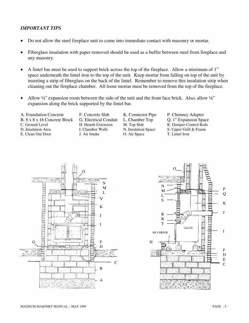
IMPORTANT TIPS • Do not allow the steel fireplace unit to come into immediate contact with masonry or mortar. • Fiberglass insulation with paper removed should be used as a buffer between steel from fireplace and
any masonry. • A lintel bar must be used to support brick across the top of the fireplace. Allow a minimum of 1”
space underneath the lintel iron to the top of the unit. Keep mortar from falling on top of the unit by inserting a strip of fiberglass on the back of the lintel. Remember to remove this insulation strip when cleaning out the fireplace chamber. All loose mortar must be removed from the top of the fireplace.
• Allow ¼” expansion room between the side of the unit and the front face brick. Also, allow ¼”
expansion along the brick supported by the lintel bar. A. Foundation Concrete F. Concrete Slab K. Connector Pipe P. Chimney Adapter B. 8 x 8 x 16 Concrete Block G. Electrical Conduit L. Chamber Top Q. 1” Expansion Space C. Ground Level H. Hearth Extension M. Top Slab R. Damper Control Rods D. Insulation Area I. Chamber Walls N. Insulation Space S. Upper Grill & Frame E. Clean Out Door J. Air Intake O. Air Space T. Lintel Iron
A
B
C
F D
I
J
K
Q
N M L
O
G
O
P Q K J I F D E C
N M L S R R T
H
BLOWER
MAGNUM MASONRY MANUAL – MAY 1999 PAGE - 6 -
CAUTION: The Magnum fireplace and its components have been tested for safety when installed in accordance with this installation manual. IT IS YOUR RESPONSIBILITY to read all instructions carefully before and during the installation to assure safe operation and maximum performance of the unit. • WARNING: Do not pack the required air space with insulation or other materials.
• NOTE: The lower grill is recommended with every installation. If it is not used, the same 150 square inches of open area is required.
INSTALLING BLOWERS Two different styles of blowers are available for Magnum Fireplaces. A hearth mount 465 cfm squirrel-cage design or an interior mount low profile design. NOTE: Low profile fans tend to create more noticeable air turbulence noise; therefore should be mounted underneath the fireplace toward the back of the fireplace.
Always allow service access for periodic oiling or motor replacement.
MAGNUM MASONRY MANUAL – MAY 1999 PAGE - 7 -
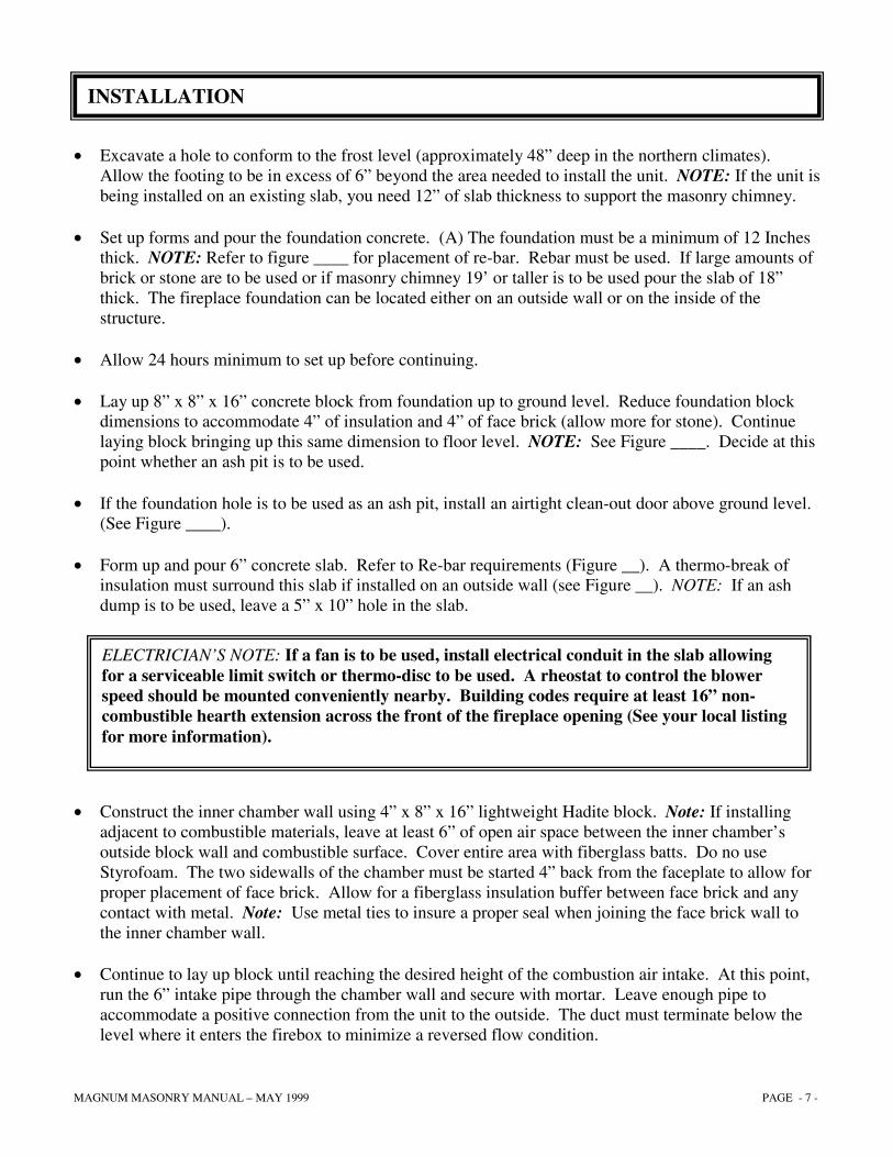
• Excavate a hole to conform to the frost level (approximately 48” deep in the northern climates).
Allow the footing to be in excess of 6” beyond the area needed to install the unit. NOTE: If the unit is being installed on an existing slab, you need 12” of slab thickness to support the masonry chimney.
• Set up forms and pour the foundation concrete. (A) The foundation must be a minimum of 12 Inches
thick. NOTE: Refer to figure ____ for placement of re-bar. Rebar must be used. If large amounts of brick or stone are to be used or if masonry chimney 19’ or taller is to be used pour the slab of 18” thick. The fireplace foundation can be located either on an outside wall or on the inside of the structure.
• Allow 24 hours minimum to set up before continuing. • Lay up 8” x 8” x 16” concrete block from foundation up to ground level. Reduce foundation block
dimensions to accommodate 4” of insulation and 4” of face brick (allow more for stone). Continue laying block bringing up this same dimension to floor level. NOTE: See Figure ____. Decide at this point whether an ash pit is to be used.
• If the foundation hole is to be used as an ash pit, install an airtight clean-out door above ground level.
(See Figure ____). • Form up and pour 6” concrete slab. Refer to Re-bar requirements (Figure __). A thermo-break of
insulation must surround this slab if installed on an outside wall (see Figure __). NOTE: If an ash dump is to be used, leave a 5” x 10” hole in the slab.
• Construct the inner chamber wall using 4” x 8” x 16” lightweight Hadite block. Note: If installing adjacent to combustible materials, leave at least 6” of open air space between the inner chamber’s outside block wall and combustible surface. Cover entire area with fiberglass batts. Do no use Styrofoam. The two sidewalls of the chamber must be started 4” back from the faceplate to allow for proper placement of face brick. Allow for a fiberglass insulation buffer between face brick and any contact with metal. Note: Use metal ties to insure a proper seal when joining the face brick wall to the inner chamber wall.
• Continue to lay up block until reaching the desired height of the combustion air intake. At this point,
run the 6” intake pipe through the chamber wall and secure with mortar. Leave enough pipe to accommodate a positive connection from the unit to the outside. The duct must terminate below the level where it enters the firebox to minimize a reversed flow condition.
INSTALLATION
ELECTRICIAN’S NOTE: If a fan is to be used, install electrical conduit in the slab allowing for a serviceable limit switch or thermo-disc to be used. A rheostat to control the blower speed should be mounted conveniently nearby. Building codes require at least 16” non-combustible hearth extension across the front of the fireplace opening (See your local listing for more information).
MAGNUM MASONRY MANUAL – MAY 1999 PAGE - 8 -
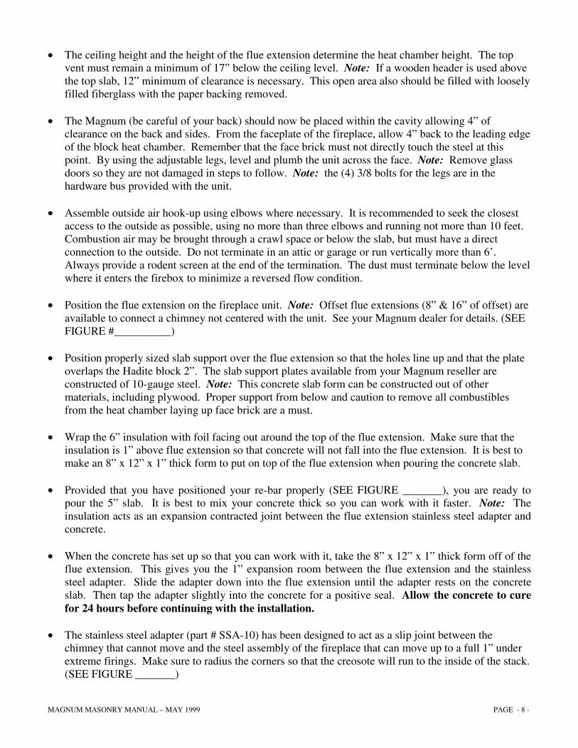
• The ceiling height and the height of the flue extension determine the heat chamber height. The top vent must remain a minimum of 17” below the ceiling level. Note: If a wooden header is used above the top slab, 12” minimum of clearance is necessary. This open area also should be filled with loosely filled fiberglass with the paper backing removed.
• The Magnum (be careful of your back) should now be placed within the cavity allowing 4” of
clearance on the back and sides. From the faceplate of the fireplace, allow 4” back to the leading edge of the block heat chamber. Remember that the face brick must not directly touch the steel at this point. By using the adjustable legs, level and plumb the unit across the face. Note: Remove glass doors so they are not damaged in steps to follow. Note: the (4) 3/8 bolts for the legs are in the hardware bus provided with the unit.
• Assemble outside air hook-up using elbows where necessary. It is recommended to seek the closest
access to the outside as possible, using no more than three elbows and running not more than 10 feet. Combustion air may be brought through a crawl space or below the slab, but must have a direct connection to the outside. Do not terminate in an attic or garage or run vertically more than 6’. Always provide a rodent screen at the end of the termination. The dust must terminate below the level where it enters the firebox to minimize a reversed flow condition.
• Position the flue extension on the fireplace unit. Note: Offset flue extensions (8” & 16” of offset) are
available to connect a chimney not centered with the unit. See your Magnum dealer for details. (SEE FIGURE #__________)
• Position properly sized slab support over the flue extension so that the holes line up and that the plate
overlaps the Hadite block 2”. The slab support plates available from your Magnum reseller are constructed of 10-gauge steel. Note: This concrete slab form can be constructed out of other materials, including plywood. Proper support from below and caution to remove all combustibles from the heat chamber laying up face brick are a must.
• Wrap the 6” insulation with foil facing out around the top of the flue extension. Make sure that the
insulation is 1” above flue extension so that concrete will not fall into the flue extension. It is best to make an 8” x 12” x 1” thick form to put on top of the flue extension when pouring the concrete slab.
• Provided that you have positioned your re-bar properly (SEE FIGURE _______), you are ready to
pour the 5” slab. It is best to mix your concrete thick so you can work with it faster. Note: The insulation acts as an expansion contracted joint between the flue extension stainless steel adapter and concrete.
• When the concrete has set up so that you can work with it, take the 8” x 12” x 1” thick form off of the
flue extension. This gives you the 1” expansion room between the flue extension and the stainless steel adapter. Slide the adapter down into the flue extension until the adapter rests on the concrete slab. Then tap the adapter slightly into the concrete for a positive seal. Allow the concrete to cure for 24 hours before continuing with the installation.
• The stainless steel adapter (part # SSA-10) has been designed to act as a slip joint between the
chimney that cannot move and the steel assembly of the fireplace that can move up to a full 1” under extreme firings. Make sure to radius the corners so that the creosote will run to the inside of the stack. (SEE FIGURE _______)
MAGNUM MASONRY MANUAL – MAY 1999 PAGE - 9 -
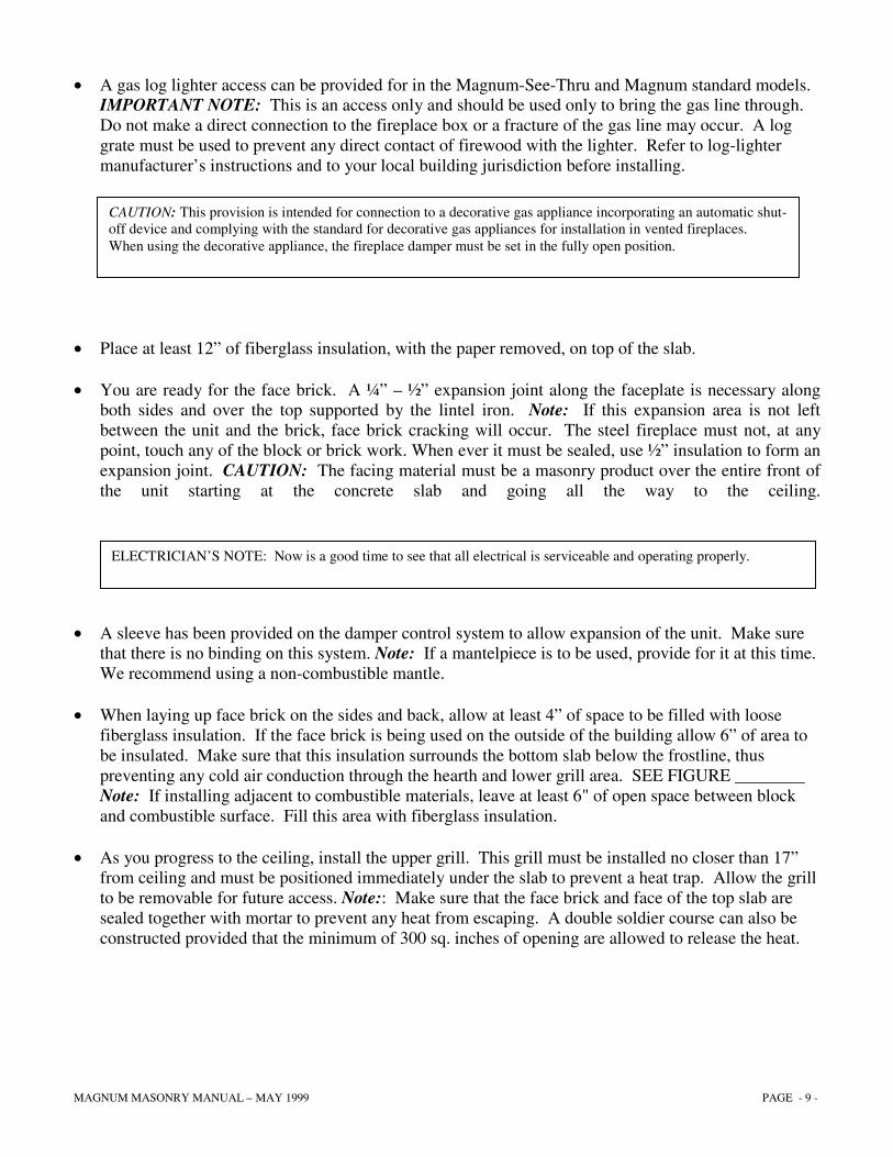
• A gas log lighter access can be provided for in the Magnum-See-Thru and Magnum standard models. IMPORTANT NOTE: This is an access only and should be used only to bring the gas line through. Do not make a direct connection to the fireplace box or a fracture of the gas line may occur. A log grate must be used to prevent any direct contact of firewood with the lighter. Refer to log-lighter manufacturer’s instructions and to your local building jurisdiction before installing.
• Place at least 12” of fiberglass insulation, with the paper removed, on top of the slab.
• You are ready for the face brick. A ¼” – ½” expansion joint along the faceplate is necessary along
both sides and over the top supported by the lintel iron. Note: If this expansion area is not left between the unit and the brick, face brick cracking will occur. The steel fireplace must not, at any point, touch any of the block or brick work. When ever it must be sealed, use ½” insulation to form an expansion joint. CAUTION: The facing material must be a masonry product over the entire front of the unit starting at the concrete slab and going all the way to the ceiling.
• A sleeve has been provided on the damper control system to allow expansion of the unit. Make sure that there is no binding on this system. Note: If a mantelpiece is to be used, provide for it at this time. We recommend using a non-combustible mantle.
• When laying up face brick on the sides and back, allow at least 4” of space to be filled with loose fiberglass insulation. If the face brick is being used on the outside of the building allow 6” of area to be insulated. Make sure that this insulation surrounds the bottom slab below the frostline, thus preventing any cold air conduction through the hearth and lower grill area. SEE FIGURE ________ Note: If installing adjacent to combustible materials, leave at least 6" of open space between block and combustible surface. Fill this area with fiberglass insulation.
• As you progress to the ceiling, install the upper grill. This grill must be installed no closer than 17” from ceiling and must be positioned immediately under the slab to prevent a heat trap. Allow the grill to be removable for future access. Note:: Make sure that the face brick and face of the top slab are sealed together with mortar to prevent any heat from escaping. A double soldier course can also be constructed provided that the minimum of 300 sq. inches of opening are allowed to release the heat.
CAUTION: This provision is intended for connection to a decorative gas appliance incorporating an automatic shut-off device and complying with the standard for decorative gas appliances for installation in vented fireplaces. When using the decorative appliance, the fireplace damper must be set in the fully open position.
ELECTRICIAN’S NOTE: Now is a good time to see that all electrical is serviceable and operating properly.
MAGNUM MASONRY MANUAL – MAY 1999 PAGE - 10 -
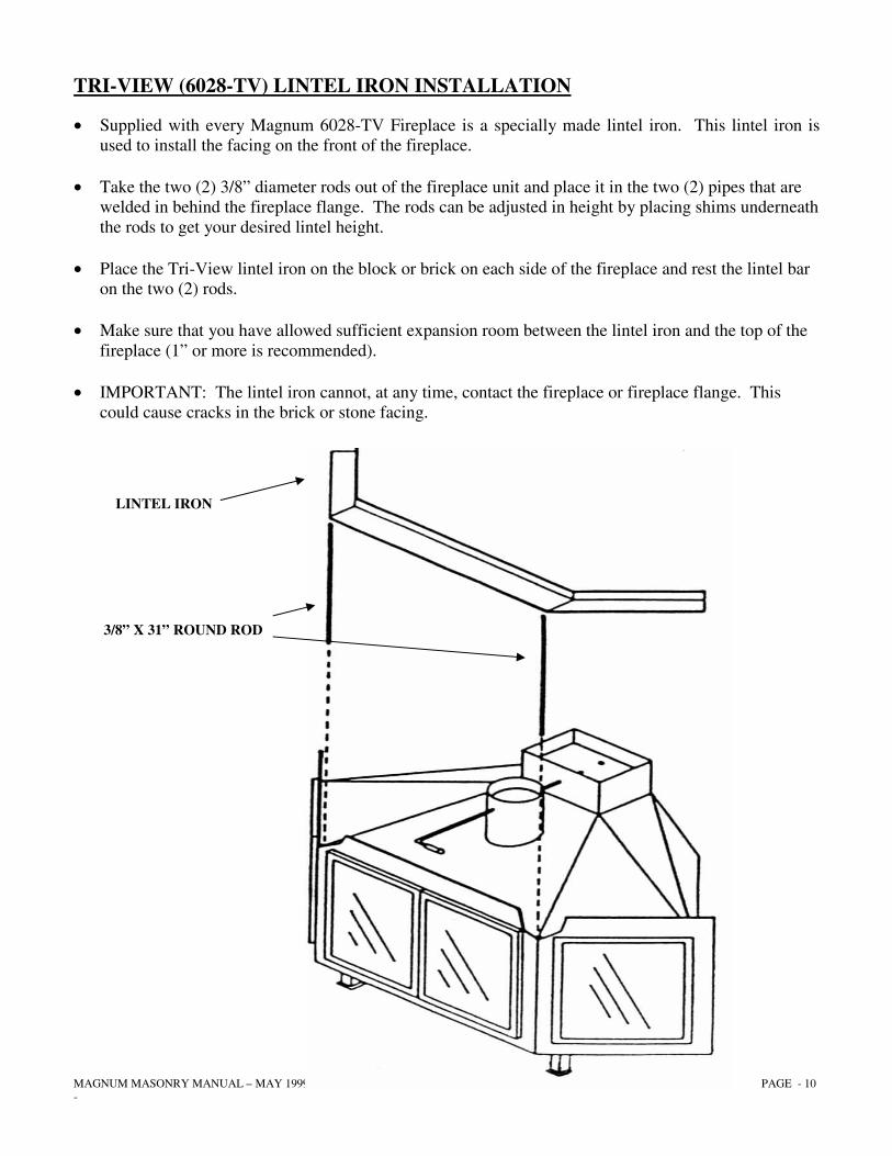
TRI-VIEW (6028-TV) LINTEL IRON INSTALLATION
• Supplied with every Magnum 6028-TV Fireplace is a specially made lintel iron. This lintel iron is used to install the facing on the front of the fireplace.
• Take the two (2) 3/8” diameter rods out of the fireplace unit and place it in the two (2) pipes that are
welded in behind the fireplace flange. The rods can be adjusted in height by placing shims underneath the rods to get your desired lintel height.
• Place the Tri-View lintel iron on the block or brick on each side of the fireplace and rest the lintel bar
on the two (2) rods. • Make sure that you have allowed sufficient expansion room between the lintel iron and the top of the
fireplace (1” or more is recommended). • IMPORTANT: The lintel iron cannot, at any time, contact the fireplace or fireplace flange. This
could cause cracks in the brick or stone facing.
LINTEL IRON
3/8” X 31” ROUND ROD
MAGNUM MASONRY MANUAL – MAY 1999 PAGE - 11 -
• Ducting the Magnum to remote locations is not allowed. A cold air return positioned on the ceiling above the heat outlet grill as a rule would be the easiest. CAUTION: Temperatures exceeding 400 will be common and cannot be handled by ordinary ductwork. Under no circumstances may this heat be ducted into existing furnace ductwork.
• Next, complete your chimney system. It is recommended that the chimney be built to a height of at
least two feet taller than the peak of the building. Note: A listed type HT per UL 103 chimney or an all fuel masonry chimney is necessary. Never run a single wall steel pipe above the slab. There may be some exceptions, but a chimney termination should always remain at least three feet above a combustible roof and should never be less than 12 feet from the top of the fireplace. If using a listed type HT Chimney, the chimney installation procedures may be generally stated, and instruct the installer to follow the procedures specified in the chimney manufacturer’s installation manual, and use all necessary parts specified for use with the listed chimney system.
• A chimney cap must be installed on top of the chimney. (See Fig. 7) • After the installation is completed and the brick washed down, install glass doors and wood handles.
Install firebrick baffle inside unit just below flue opening. Position grills into their proper places. Note: Remove doors before washing brick to prevent finish from being permanently damaged.
• A minimum of 10 days should be allowed for the masonry products to set up before using. Consult
with your brick or block layer for directions.
MAGNUM MASONRY MANUAL – MAY 1999 PAGE - 12 -
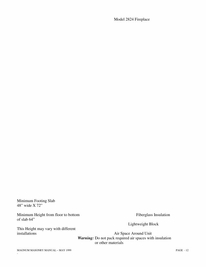
Model 2824 Fireplace Minimum Footing Slab 48” wide X 72” Minimum Height from floor to bottom Fiberglass Insulation of slab 64” Lightweight Block This Height may vary with different installations Air Space Around Unit Warning: Do not pack required air spaces with insulation or other materials

MAGNUM MASONRY MANUAL – MAY 1999 PAGE - 13 -
MODEL 2824 ARCHED SERIES FIREPLACE
DIMENTIONAL CHART
Denotes Foundation Minimum Dimensions and Masonry Facing Applications. Note: Footings must be 6” larger per side of area needed for fireplace enclosure. Footings must be a minimum of 12” thick. Note: Installation Dimensions may vary with different customer needs. Lay out your installation before figuring footing and slab sizes. Warning: Do not pack required air spaces with insulation of other materials
MAGNUM MASONRY MANUAL – MAY 1999 PAGE - 14 -
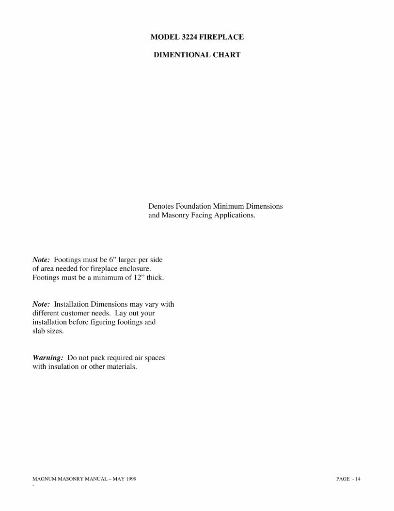
MODEL 3224 FIREPLACE
DIMENTIONAL CHART
Denotes Foundation Minimum Dimensions and Masonry Facing Applications. Note: Footings must be 6” larger per side of area needed for fireplace enclosure. Footings must be a minimum of 12” thick. Note: Installation Dimensions may vary with different customer needs. Lay out your installation before figuring footings and slab sizes. Warning: Do not pack required air spaces with insulation or other materials.
MAGNUM MASONRY MANUAL – MAY 1999 PAGE - 15 -
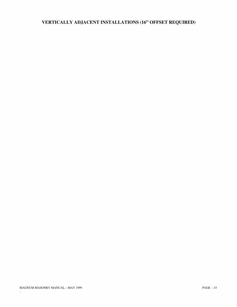
VERTICALLY ADJACENT INSTALLATIONS (16” OFFSET REQUIRED)
MAGNUM MASONRY MANUAL – MAY 1999 PAGE - 16 -
OPERATION AND MAINTENANCE TIPS Congratulations! You are now ready to sit back, relax and admire the beautiful work! But before you use your fireplace, please read the following instructions for the best results. BEFORE STARTING THE FIRST FIRE: Note: The Magnum fireplace has been designed for use without a fireplace grate. If a gas starter is used, a grate must be used to prevent any direct contact of wood with gas element. Inspect the glass enclosure making sure its doors are adjusted to open and close smoothly. Turn to open (counterclockwise) and close (clockwise) damper and combustion control (wood handle) making sure all parts are working smoothly. Note: In cold climates only – If a Posi-Seal outside air-lock system has been installed (brass knob), push in and out to make sure all parts are operating smoothly. Do not store clothing, paper, furniture or any combustibles within 36” of this fireplace. STARTING THE FIRST FIRE:
1) Open Damper and Combustion Air Controls (wood handle) by pushing in slightly and turning counterclockwise. When controls are open the handle will stop. See Fig. 6—for the best air wash to help keep your glass clean –leave the Combustion Air Control fully open after the unit is burning. The damper control will adjust the fire burn rate.
2) Crumple 8 to 10 pages of newspaper and place a small amount of kindling on top of this
newspaper. Then light the newspaper in a couple of places.
3) After the kindling is well started, place two or three small split logs on top. These logs, like any additional fuel, should be placed at slight angles to one another keeping an airspace between the logs. Make sure to keep logs back a minimum of 10” from glass enclosure.
4) You may want to leave the doors slightly ajar to help your fuel load start more rapidly. This also
allows your glass to warm slightly preventing thermal shock breakage. Note: Never leave the fireplace unattended during this method of firing.
5) Warning: Breaking glass, warping or discoloration of glass door frames may occur by over
firing your unit. Do not use excessive amounts of kiln-dried lumber.
6) After split logs are burning nicely (usually 30-40 minutes), push in slightly and turn the damper control (wood handle) clockwise approximately 2/3 closed or until unit starts to smoke. Back off about 1/3 distance or until unit quits smoking. This is your optimum or most efficient level of burning. Note: Because of the masonry enclosure mass and the steel in the unit itself, it takes at least an hour for the fireplace to generate the maximum heat output. Do not overload the fireplace. This fireplace needs only 4-6 pieces of wood to maintain a constant flow of heat. There is no need to burn large amounts of wood.

MAGNUM MASONRY MANUAL – MAY 1999 PAGE - 17 -
7) When hot air flows from your heat output grill (approximately 40 minutes), you can start your fan. Remember, this fireplace is a good heat exchanger, so run your fan at a speed to maintain hot air at the heat outlet grill. By reducing the fan speed, you are not producing less heat, but are simply receiving less circulation.
8) When opening doors to refuel, first open damper completely, shut off the fan, and slowly open
both doors at the same time. This will prevent you from drawing smoke into the house. Important Note: Never throw or drop logs onto the firebrick floor. This will cause early deterioration or cracking of this protective surface.
9) Now enjoy “America’s Hottest Fireplace Technology”!
MAGNUM MASONRY MANUAL – MAY 1999 PAGE - 18 -
SPECIAL NOTES • Never completely close Damper/Combustion Controls until you are certain that there are no warm
embers or coals. • If a Posi-Seal shutoff is used (brass knob), make sure that this is closed (pushed in) when fireplace
is not in use. Remember to turn the fan off before leaving for an extended period of time. • It is best to burn in your fireplace with small to medium fires during initial use. A slight odor,
caused by the curing of the treated steel firebox, will be noticed during the first few fires. Burn only dry seasoned wood. This wood burns easiest and prevents the build-up of creosote.
• Never use flammable liquids to light the fire. • Ventilating fans, exhaust hoods or central heating systems can cause fireplaces to smoke by
stealing the fireplace’s combustion air. If the volume is enough, they can reverse the flow of air in the fireplace and cause smoke.
• Always use a rain cap to prevent any moisture from entering down into the chimney. (Fig. 7)
CARE OF GLASS DOORS
• Heat the ceramic glass doors slowly the first time. • Both doors should be opened slowly and at the same time to prevent drawing smoke into the room. Never slam doors closed as they are not shatterproof. • Avoid large fires. In the event of too large a fire causing flames to play on the glass, open doors
until the fire dies down. Warning: Breakage of glass or discoloration of glass door frames may occur by over firing your unit. Do not use excessive amounts of kiln-dried construction lumber as kindling or firewood.
MAGNUM MASONRY MANUAL – MAY 1999 PAGE - 19 -
• Keep the glass doors clean. Dirty glass doors will heat unevenly and may break. Use a special cleaning solution available from your dealer to remove any stain that may accumulate on the glass. Clean doors only when cold. Do not use glass wax or any oil base cleaners.
• If doors are removed, they must be replaced with a fire screen over the fireplace opening.
Caution: Glass enclosures under extensive use or upon over-firing may need to be adjusted or replaced periodically. If door frames appear to be weak or loose, repair or replace immediately.
PERIODIC MAINTENANCE
1) Keep the hearth and firebox clean. Any accumulation of ashes will act as an insulator and will decrease heat efficiency. When removing ashes make sure all ashes are cold. Dispose of properly using metal ash buckets, garbage cans, etc.
2) Keep glass doors clean and properly adjusted. Dirty glass doors will heat unevenly and may cause breakage.
3) Always ensure that there are no obstructions in the heat or outside air ductwork. 4) Keep the chimney free of creosote build-up. 5) It is important to clean the ashes from the firebox during the summer to prevent moisture accumulation. Over long
periods of time, if moisture is allowed to mix with the chemical make-up of the ash, deterioration of the metal may occur. Disposal of Ashes Ashes should be placed in a metal container with a tight-fitting lid. The closed container of ashes should be placed on a noncombustible floor or on the ground, well away from all combustible materials, pending final disposal. If the ashes are disposed of by burial in soil or otherwise locally dispersed, they should be retained in the closed container until all cinders have thoroughly cooled.
CREOSOTE Controlling the rate of burn in an efficient fireplace, stove or insert allows in many cases improper flue or chimney temperatures. When wood is burned slowly, any excess moisture that can not be burned off inside the stove mixes with carbon and other organic materials to form creosote. Creosote forms on the inside of the chimney as tiny water droplets, mixed with a black tar-like substance. This sticky black substance hardens and continues to build up in layers until either cleaned or burned out. Inspect chimneys at least twice monthly during the heating season to determine how much creosote is forming. If creosote has accumulated, it must be removed to prevent a possible chimney fire. Visit your local retailer to secure brushes and information on chimney maintenance or contact your local chimney sweep. To prevent creosote buildup, let the fireplace, stove, or insert “Liven Up” for about five minutes each morning after refueling. A few pieces of dry kindling will do the job. Proceed back to normal burning. EXTERIOR/INTERIOR To touch up, use proper high temperature paint available from any “MAGNUM” professional. For summertime or off-season maintenance, always keep unit free from moisture and ashes. Acidic compounds will be anxious to rust and ultimately shorten the life of your unit. High temperatures sometimes cause brass to tarnish. A mild non-abrasive metal polish should be used if attempting to “Brighten Up” the finish. A natural antique will occur with time due to the variations of heating temperatures. CHIMNEY MAINTENANCE The chimney system should be checked twice a year for creosote buildup. (We recommend that a trained chimney specialist clean the chimney system). To clean the chimney, take the chimney cap off the top of the chimney, open the damper on the fireplace wide open and remove the fire brick baffle inside the fireplace. Clean chimney and replace all parts.
MAGNUM MASONRY MANUAL – MAY 1999 PAGE - 20 -
INSTALLATION INSTRUCTIONS
Parts List
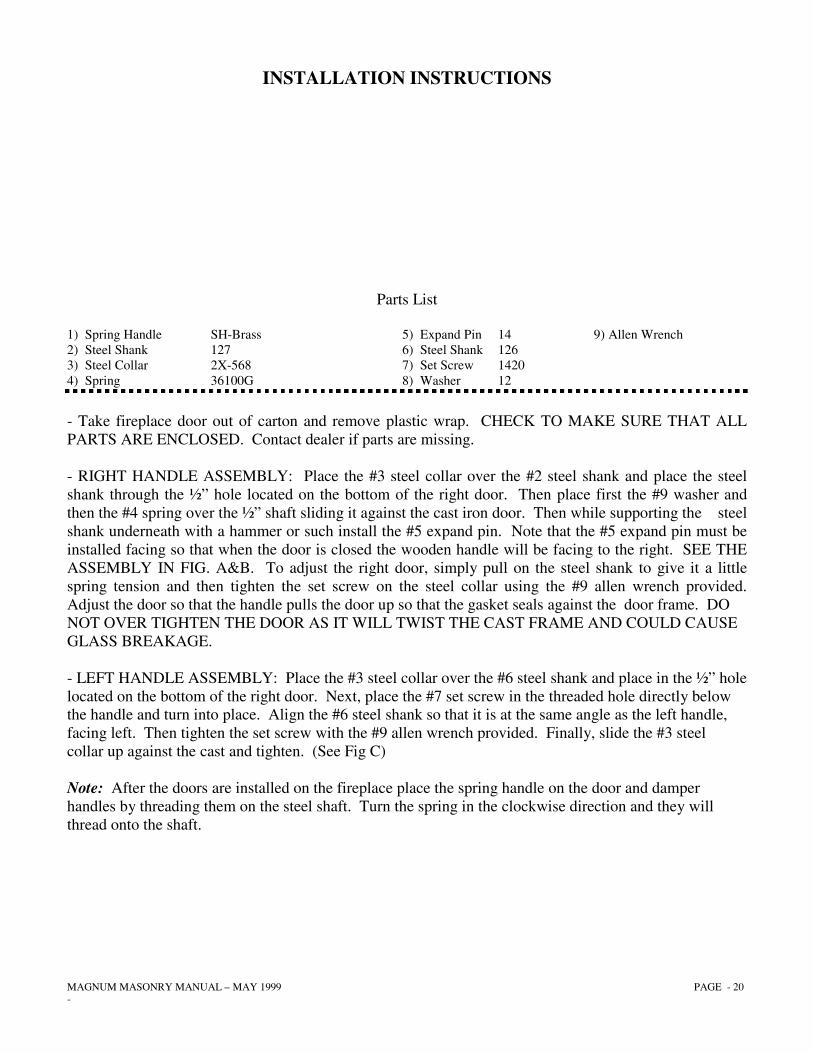
1) Spring Handle SH-Brass 5) Expand Pin 14 9) Allen Wrench 2) Steel Shank 127 6) Steel Shank 126 3) Steel Collar 2X-568 7) Set Screw 1420 4) Spring 36100G 8) Washer 12
- Take fireplace door out of carton and remove plastic wrap. CHECK TO MAKE SURE THAT ALL PARTS ARE ENCLOSED. Contact dealer if parts are missing. - RIGHT HANDLE ASSEMBLY: Place the #3 steel collar over the #2 steel shank and place the steel shank through the ½” hole located on the bottom of the right door. Then place first the #9 washer and then the #4 spring over the ½” shaft sliding it against the cast iron door. Then while supporting the steel shank underneath with a hammer or such install the #5 expand pin. Note that the #5 expand pin must be installed facing so that when the door is closed the wooden handle will be facing to the right. SEE THE ASSEMBLY IN FIG. A&B. To adjust the right door, simply pull on the steel shank to give it a little spring tension and then tighten the set screw on the steel collar using the #9 allen wrench provided. Adjust the door so that the handle pulls the door up so that the gasket seals against the door frame. DO NOT OVER TIGHTEN THE DOOR AS IT WILL TWIST THE CAST FRAME AND COULD CAUSE GLASS BREAKAGE. - LEFT HANDLE ASSEMBLY: Place the #3 steel collar over the #6 steel shank and place in the ½” hole located on the bottom of the right door. Next, place the #7 set screw in the threaded hole directly below the handle and turn into place. Align the #6 steel shank so that it is at the same angle as the left handle, facing left. Then tighten the set screw with the #9 allen wrench provided. Finally, slide the #3 steel collar up against the cast and tighten. (See Fig C) Note: After the doors are installed on the fireplace place the spring handle on the door and damper handles by threading them on the steel shaft. Turn the spring in the clockwise direction and they will thread onto the shaft.
MAGNUM MASONRY MANUAL – MAY 1999 PAGE - 21 -
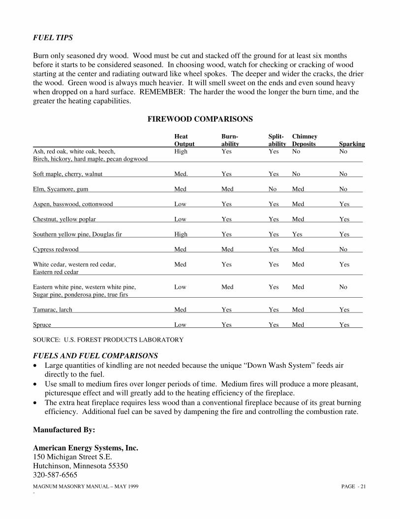
FUEL TIPS Burn only seasoned dry wood. Wood must be cut and stacked off the ground for at least six months before it starts to be considered seasoned. In choosing wood, watch for checking or cracking of wood starting at the center and radiating outward like wheel spokes. The deeper and wider the cracks, the drier the wood. Green wood is always much heavier. It will smell sweet on the ends and even sound heavy when dropped on a hard surface. REMEMBER: The harder the wood the longer the burn time, and the greater the heating capabilities.
FIREWOOD COMPARISONS
Heat Burn- Split- Chimney Output ability ability Deposits Sparking Ash, red oak, white oak, beech, High Yes Yes No No Birch, hickory, hard maple, pecan dogwood Soft maple, cherry, walnut Med. Yes Yes No No Elm, Sycamore, gum Med Med No Med No Aspen, basswood, cottonwood Low Yes Yes Med Yes Chestnut, yellow poplar Low Yes Yes Med Yes Southern yellow pine, Douglas fir High Yes Yes Yes Yes Cypress redwood Med Med Yes Med No White cedar, western red cedar, Med Yes Yes Med Yes Eastern red cedar Eastern white pine, western white pine, Low Med Yes Med No Sugar pine, ponderosa pine, true firs Tamarac, larch Med Yes Yes Med Yes Spruce Low Yes Yes Med Yes SOURCE: U.S. FOREST PRODUCTS LABORATORY FUELS AND FUEL COMPARISONS • Large quantities of kindling are not needed because the unique “Down Wash System” feeds air directly to the fuel. • Use small to medium fires over longer periods of time. Medium fires will produce a more pleasant, picturesque effect and will greatly add to the heating efficiency of the fireplace. • The extra heat fireplace requires less wood than a conventional fireplace because of its great burning efficiency. Additional fuel can be saved by dampening the fire and controlling the combustion rate. Manufactured By: American Energy Systems, Inc. 150 Michigan Street S.E. Hutchinson, Minnesota 55350 320-587-6565
MAGNUM MASONRY MANUAL – MAY 1999 PAGE - 22 -
FIREPLACE
LIMITED WARRANTY AND 25 YEAR PROTECTION PLAN LIMITED WARRANTY
This limited warranty will not become effective unless you have returned card within 30 days of purchase. If you fail to do so you may make no claim under this warranty. American Energy Systems, Inc. excludes and disclaims all implied warranties including, but not limited to, the implied warranty of merchantability. This American Energy Systems, Inc. MAGNUM fireplace was manufactured by American Energy Systems, Inc. For a period of five (5) years from the date of purchase, American Energy Systems, Inc. will warrant to the original consumer-purchaser that all steel components are free of defects in material and workmanship. Warranty of grates, baffles, glass doors, glass fan assemblies, wiring, paint, or gasketing material is not provided for in this warranty. In the event of a defect within warranty the first year, American Energy Systems, Inc. will repair or at its option, replace the defective part entirely at its own expense. Within the second year through the fifth year after purchase, American Energy Systems, Inc. will, at its option, repair or supply replacement parts on this schedule: Second year, customer must pay one-fifth (1/5) of the current retail cost of repair or replacement; Third year, two-fifths (2/5); Fourth year, three-fifths (3/5), Fifth year, four-fifths (4/5). American Energy Systems, Inc. will pay the balance of the expenses. After expiration of the above five-year warranty and through the 25th year, American Energy Systems Inc. will sell to you F.O.B. its factory, a replacement part or parts (if available) at its then current minimum list price. AMERICAN ENERGY SYSTEMS, INC. SHALL NOT BE REPSONSIBLE FOR ANY LABOR, TRANSPORTATION OR OTHER COSTS OR EXPENSES. Repair or replacement may be obtained by returning part or parts freight prepaid to the nearest MAGNUM dealer or if you require additional information regarding performance under this warranty you may contact American Energy Systems, Inc. at the address stated below. Magnum fireplaces have been designed for use with wood and coal only. American Energy Systems, Inc. will not warrant performance of unit with manufactured or pressed logs. Discoloration and distortion of the inner firebox should be expected under normal use. American Energy Systems, Inc. shall not be responsible for this natural occurrence. All warranties are null and void if components specified in installation manuals are not used and if installations are not in accordance with instructions furnished with units. American Energy Systems, Inc. makes no representations or warranty regarding, and shall not be responsible for, any building code compliance. The warranties shall not apply to the product or any component of the product which has been moved from its original place of installation. American Energy Systems, Inc. makes only the limited warranty stated herein. The Purchase’s sole, exclusive remedy shall repair or replacement. IN NO EVENT SHALL AMERICAN ENERGY SYSTEMS, INC. BE LIABLE FOR ANY COSTS, EXPENSES OR DAMAGES INDIRECT, INCIDENTAL OR CONSEQUENTIAL. Any implied warranties including, but not limited to the implied warranty or merchantability, shall extend only to the original consumer\purchaser and are here-by limited to the same duration, extend, and remedy, as the limited warranty provided herein. Some states do not allow limitations on how long an implied warranty lasts, or allow the exclusion or limitation of incidental or consequential damages, so the above limitations or exclusions may not apply to you. This warranty gives specific legal rights. You may have other rights that vary from state to state. AMEREICAN ENERGY SYSTEMS, INC. 150 Michigan Street SE Hutchinson, MN 55350