Embed Size (px)
Citation preview

SSttainless Sainless StteelseelsAUSTENITIC, FERRITIC AND MARTENSITIC STAINLESS STEEL
4 General CatalogueGeneral Catalogue
Austenitic Stainless Steel TubesMaterial Standard: ASTM A 213 / 249 / 269 / 688Manufacturing Process Seamless or welded
Grade UNSNo C Si Mn P S
TP 304 S30400 0.08 max 0.75 max 2.00 max 0.040 max 0.030 maxTP 304 H S30409 0.04-0.10 0.75 max 2.00 max 0.040 max 0.030 maxTP 304 N S30451 0.08 max 0.75 max 2.00 max 0.040 max 0.030 maxTP 304 LN S30453 0.035 max 0.75 max 2.00 max 0.040 max 0.030 maxTP 304 L S30403 0.035 max 0.75 max 2.00 max 0.040 max 0.030 maxTP 309 S S30908 0.08 max 0.75 max 2.00 max 0.045 max 0.030 maxTP 310 S S31008 0.08 max 0.75 max 2.00 max 0.045 max 0.030 maxTP 316 S31600 0.08 max 0.75 max 2.00 max 0.040 max 0.030 maxTP 316 H S31609 0.04-0.10 0.75 max 2.00 max 0.040 max 0.030 maxTP 316 L S31603 0.035 max 0.75 max 2.00 max 0.040 max 0.030 maxTP 316 N S31651 0.08 max 0.75 max 2.00 max 0.040 max 0.030 maxTP 316 LN S31653 0.035 max 0.75 max 2.00 max 0.040 max 0.030 maxTP 317 S31700 0.08 max 0.75 max 2.00 max 0.040 max 0.030 maxTP 317 L S31703 0.035 max 0.75 max 2.00 max 0.040 max 0.030 maxTP 321 S32100 0.08 max 0.75 max 2.00 max 0.040 max 0.030 maxTP 321 H S32109 0.04-0.10 0.75 max 2.00 max 0.040 max 0.030 maxTP 347 S34700 0.08 max 0.75 max 2.00 max 0.040 max 0.030 maxTP 347 H S34709 0.04-0.10 0.75 max 2.00 max 0.040 max 0.030 max
Ferritic and Martensitic Stainless Steel TubesMaterial Standard ASTM-A 268Manufacturing Process seamless or weldedGrade UNSNo C Si Mn P S
TP 405 S40500 0.08 max 0.75 max 1.00 max 0.040 max 0.030 maxTP 410 S41000 0.15 max 0.75 max 1.00 max 0.040 max 0.030 maxTP 429 S42900 0.12 max 0.75 max 1.00 max 0.040 max 0.030 maxTP 430 S43000 0.12 max 0.75 max 1.00 max 0.040 max 0.030 maxTP 446-1 S44600 0.20 max 0.75 max 1.50 max 0.040 max 0.030 maxTP 446-2 S44600 0.12 max 0.75 max 1.50 max 0.040 max 0.030 maxTP 409 S40900 0.08 max 1.00 max 1.00 max 0.045 max 0.045 maxTP 430 TI S43036 0.10 max 1.00 max 1.00 max 0.040 max 0.030 max
Ferritic and Martensitic Stainless Steel TubesMaterial Standard ASTM A 789Manufacturing Process Seamless or welded
UNSNo C Si Mn P S Ni Cr Mo
S31803 0.03 max 1.00 max 2.00 max 0.030 max 0.020 max 4.50-6.50 21.0-23.0 2.50-3.50S31500 0.03 max 1.40-2.00 1.20-2.00 0.030 max 0.030 max 4.25-5.25 18.0-19.0 2.50-3.00S32550 0,04 max 1.00 max 1.50 max 0.040 max 0.030 max 4.50-6.50 24.0-27.0 2.90-3.90S31200 0.030 max 1.00 max 2.00 max 0.045 max 0.030 max 5.50-6.50 24.0-26.0 1.20-2.00S31260 0.030 max 0.75 max 1.00 max 0.030 max 0.030 max 5.50-7.50 24.0-26.0 2.50-3.50S32304 0.030 max 1.00 max 2.50 max 0.040 max 0.040 max 3.0-5.5 21.5-24.5 0.05-0.60OD 1 in [25mm] and UnderOD over 1 in. [25 mm]S32750 0.030 max 0.80 max 1.20 max 0.035 max 0.020 max 6.0-8.0 24.0-26.0 3.0-5.0S32760 0.05 max 1.00 max 1.00 max 0.030 max 0.010 max 6.00-8.00 24.0-26.0 3.00-4.00
www.MAGVANT.com

SSttainless Sainless StteelseelsCOMPARISON OF INTERNATIONAL STANDARDS FOR STAINLESS STEEL
6 General CatalogueGeneral Catalogue
Werkstoff-Nr. DIN. AISI. UNS. AFNOR. BS. JIS SS. GOST
1.4000 X6Cr13 403(410S) S 41008 Z6C13 403 S17 SUS 403 2301 08Ch13
(X7Cr13)
1.4002 X6CrAI13 405 S40500 Z6CAl13 405 S17 SUS 405 08Ch11NYU
(X7CrAl13)
1.4006 X10Cr13 410 S 41000 Z12C13 410 S21 SUS 410 2302 12Ch13
1.4016 X6Cr17 430 S43000 Z8C17 430 S15 SUS 430 2320 12Ch17
(X8Cr17] 430 S17
1.4021 X20Cr13 420 S42000 Z20C13 420 S29 SUS 420J1 2303 20Ch13
420 S37 SUS 420J2
420 S45
1.4024 X15Cr13 410 S 41000 ... 420 S29 SUS 410J1 ... ...
410 S21
1.4028 X30Cr13 420 S 42000 Z30C13 420 S45 SUS 420J2 2304 30Ch13
1.4031 X38Cr13 420 S 42000 Z40C14 ... SUS 420J2 2304 40Ch13
(X40Cr13)
1.4034 X46Cr13 420 S42000 Z40C14 420 S45 ... ... 40Ch13
Z38C13M
1.4057 X20CrNi172 431 S43100 Z15CN 16-02 431 S29 SUS 431 2321 20Ch17N2
(X22CrNi17)
1.4510 X6CrTi17 XM8 ... Z8CT17 ... SUS 430LX ... 08Ch17T
(X8CrTi17) 430Ti
1.4512 X6CrTi12 409 S 40900 Z6CT12 409 S19 SUH 409 ... ...
409 S17
1.4301 X5CrNi1810 304/304H S 30400 Z6CN18-09 304 S31 SUS 304 2332 08Ch18N10
(X5CrNi189)
1.4305 X10CrNiS189 303 S 30300 Z10CNF 18-09 303 S21 SUS 303 2346 ...
(X12CrNiS188)
1.4306 X2CrNi1911 304L S 30403 Z2CN18-10 304 S12 SCS 19 2352 03Ch18N11
(X2CrNi 189) Z3CN19-10M 304 C12 SUS 304L 2333
(G-X2Cr189) Z2CN 18-09 304 S11
1.4310 X12CrNi177 301 S 30100 Z12CN17-07 301 S21 SUS 301 ... ...
Z12Cn18-07
1.4311 X2CrNiN 1810 304LN S 30453 Z2CN18-10Az 304 S62 SUS 304LN 2371 ...
1.4401 X5CrNiMo17122 316 S 31600 Z6CND17-11 316 S16 SUS 316 2347 ...
www.MAGVANT.com

SSttainless Sainless StteelseelsCOMPARISON OF INTERNATIONAL STANDARDS FOR STAINLESS STEEL
General CatalogueGeneral Catalogue 7
Werkstoff- DIN. AISI. UNS. AFNOR. BS. JIS SS. GOST
1.4404 X2CrNiMo17132 316L S 31603 Z2CND 18-13 316 S14 SUS 316L 2348 ...
(X2CrNiMo1810) Z2CND 17-12
(G-X2CrNiMo1810)
1.4429 X2CrNiMoN17133 316LN S31653 Z2CND 17-13 ... SUS 316LN 2375 ...
(X2CrNiMoN1813)
1.4435 X2CrNiMo18143 316L S 31603 Z2CND 17-13 316 S11 SCS 16 2353 03Ch17N14M2
(X2CrNiMo1812) 316 S12 SUS 316L
316 S13
1.4436 X5CrNiMo17133 316 S 31600 Z6CND 17-12 316 S16 SUS 316 2343 ...
(X5CrNiMo1812) 316 S33
1.4438 X2CrNiMo18164 317L S31703 Z2CND 19-15 317 S12 SUS 317L 2367 ...
(X2CrNiMo1816)
1.4439 X2CrNiMoN17135 317LNM S 31726 Z2CND 19-15 317 S16 ... ... ...
1.4449 X5CrNiMo 1713 317 ... ... 317 S16 SUS 317 ... ...
1.4465 X1CrNiMoN25252 ... N 08310 ... ... ... ... ...
1.4505 X5CrNiMoCuNb2018 ... ... ... ... ... ... 07Ch17N20M2D2T
1.4521 X2CrMoTi182 440 S44400 ... ... ... 2326 ...
1.4529 X1NiCrMoCuN25206 ... N 08925 ... ... ... ... ...
1.4539 X1NiCrMoCu25205 904L N 08904 Z1NCDU25-2004 ... ... 2562 ...
1.4541 X6CrNiTi1810 321 S 32100 Z6CNT18-10 321 S12 SUS 321 2337 1Ch18N12T
(X10CrNiTi189) 321 S20
(321 S31)
1.4550 X6CrNiNb1810 347 S 34700 Z6CNNb 18-10 347 S17 SUS 347 2338 08Ch 18N12B
(X10CrNiNb189) 347 S31
1.4558 X2NiCrAITi3220 ... N 08800 ... ... ... ... ...
1.4563 X1NiCrMoCuN31274 ... N 08028 Z1NCDU31273Az ... ... ... ...
1.4571 X6CrNiMoTi17122 316Ti S 31635 Z6CNDT 17-12 320 S31 ... 2350 10Ch17N13M2T
(X10CrNiMo Ti1810) 320 S17
1.4580 X6CrNiMoNb17122 316 Cb ... Z6CNDNb17-12 ... ... ... 08Ch16N13M2B
(X10CrNiMoNb 1810) Z6CNDNb19-13
1.4583 X10CrNiMoNb1812 318 ... ... ... ... ... ...
1.4586 X5CrMoCuNb2218 ... ... ... ... ... ... ...
Nr.
www.MAGVANT.com

Werkstoff- DIN. AISI. UNS. AFNOR. BS. JIS SS. GOST
1.4335 X1CrNi2521 310LC ... Z2CN25-20 ... ... ... ...
1.4713 X10CrAI7 ... ... Z8CA7 ... ... ... ...
1.4718 X45CrSi93 HNV3 ... Z45CS9 401 S45 SUH 1 ... ...
1.4724 X10CrAl13 (405) ... Z10C13 403 S17 ... ... ...
1.4742 X10CrAl18 (430) ... Z10CAS18 430 S15 SUS 430 ... ...
SUH 21
1.4749 X18CrN28 446-1 ... .. ... ... ... Ch25
1.4762 X10CrAI24 (446) ... Z10CAS24 ... ... ... ...
1.4821 X20CrNiSi254 327 ... Z20CNS25-04 ... ... ... ...
1.4828 X15CrNiSi2012 309 ... Z15CNS20_12 309 S24 SUH 309 ... Ch24N12S1
1.4833 X7CrNi2314 309S ... Z15CN24-13 ... SUS 309S ... ...
1.4841 X15CrNiSi2520 314/310 ... Z12CNS25-20 ... SUH 310 ... 20Ch25N20S2
1.4845 X12CrNi2521 310S ... Z12CN25-20 310 S24 SUH 310 2361 10Ch23N18
SUS 310S
1.4848 (G-X40CrNiSi2520) ... ... ... 310 C40 SCH 21 ... ...
1.4864 X12NiCrSi3616 330 N 08330 Z12NCS37-18 Na 17 SUH 330 ... ...
Z12NCS35-16
Z12NC37-18
1.4871 X53CrMnNiN219 EV8 ... Z52CMN21-09 349 S54 SUH 35 ... ...
SUH 36
1.4876 X10NiCrAITi3320 B163 N 08800 Z8NC32-21 NA 15(H) NCF 8000 ... ...
1.4876 X10CrNiAIti3320 B163 N 08810 Z8NC32-21 NA 15 ... ... ...
1.4878 X12CrNiTi189 321H ... Z6CNT18-12(B) 321 S20 SUS 321 2337 ...
(321 S12)
1.4893 ... ... S 30815 ... ... ... 2368 ...
... ... ... S 32750 ... ... ... ... ...
1.4362 ... ... S 32304 ... ... ... ... ...
1.4417 ... ... S 31500 ... ... ... ... ...
1.4460 X4CrNiMo2751 329 S 32900 ... ... SUS 329J1 2324 ...
(X8CrNiMo275) SCH 11
SCS 11
1.4462 X2CrNiMoN2253 ... S 31803 Z2CND22-05Az ... ... ... ...
... ... ... S 31200 ... ... ... ... ...
... ... ... S 31260 ... ... ... ... ...
... ... ... S 32550 ... ... ... ... ...
... ... ... S 32950 ... ... ... ... ...
(...) hitherto existing DIN-designation
SSttainless Sainless StteelseelsCOMPARISON OF INTERNATIONAL STANDARDS FOR STAINLESS STEEL
8 General CatalogueGeneral Catalogue
Nr.
www.MAGVANT.com

TTititanium and Tanium and Tititanium Alloanium Alloyyss
30 General CatalogueGeneral Catalogue
Titanium tubesChemical Composition
ASTM Grade N C H Fe O Al V Pa Mo Ni(sim. DIN Grade) % max % max % max % max % max % max % maxASTM B 338 Grade 1 0,03 0,08 0,015 0,20 0,18 - - - - -DIN 17861 Ti 1 - 3.7025 0,05 0,06 0,013* 0,15 0,12 - - - - -VdTÜV 230/2
ASTM B 338 Grade 2 0,03 0,08 0,015 0,30 0,25 - - - - -DIN 17861 Ti2 - 3.7035 0,05 0,06 0,013* 0,20 0,18 - - - - -VdTÜV 230/2
ASTM B 338 Grade 3 0,05 0,08 0,015 0,30 0,35 - - - - -DIN 17861 Ti 3 - 3.7055 0,05 0,06 0,013* 0,25 0,25 - - - - -VdTÜV 230/2
ASTM B 338 Grade 7 0,03 0,08 0,015 0,30 0,25 - - 0,12 - 0,25 - -DIN 17861 Ti 2 Pd - 3.7235 0,05 0,06 0,013* 0,20 0,18 - - 0,05 - 0,25 - -VdTÜV 230/2
ASTM B 338 Grade 9 0,02 0,08 0,015 0,25 0,15 2,5 - 3,5 2,0 - 3,0 - - -
ASTM B 338 Grade 11 0,03 0,08 0,015 0,20 0,18 - - 0,12 - 0,25 - -DIN 17861 Ti1 Pd - 3.7225 0,05 0,06 0,013* 0,20 0,18 - - 0,15 - 0,25 - -VdTÜV 230/2
ASTM B 338 Grade 12 0,03 0,08 0,015 0,30 0,25 - - - 0,2 - 0,4 0,6 - 0,9DIN 17861 Ti AL3V2,5 0,04 0,05 0,015 0,30 0,12 2,5 - 3,5 2,0 - 3,0 - - -3.7195* In case wallthickness is under 2 mm, the Hydrogen content up to 0,015% is allowed.
Chemical composition, mechanical properties and heat treatment
www.MAGVANT.com

General CatalogueGeneral Catalogue 37
SuperSuper -Duple-Duplex Sx Sttainless Sainless StteelseelsTUBING, PIPE, FLANGES, FITTINGS, ROUND BAR & PLATE
Super-Duplex Stainless Steels and their characteristics
The first-generation Duplex stainless steels were developed more than 70 years ago in Sweden for use in the sulfite paper industry. Duplex
alloy were originally created to combat corrosion problems caused by chloride-bearing cooling waters and other aggressive chemical process
fluids.
Called Duplex because of its mixed microstructure with about equal proportions of ferrite and austenite, Duplex stainless steels are a family
of grades, which range in corrosion performance depending on their alloy content. The term "Super-Duplex" was first used in the 1980`s to
denote highly alloyed, high-performance Duplex steel with a pitting resistance equivalent of >40 (based on Cr% + 3.3 Mo% + 16N%)
With its high level of chromium, Super-Duplex steel provides outstanding resistance to acids, acid chlorides, caustic solutions and other
environments in the chemical / petrochemical, pulp and paper industries, often replacing 300 series stainless steel, high nickel
superaustenitic steels and nickel-based alloys.
The chemical composition based on high contents of chromium, nickel and molybdenum improves intergranular and pitting corrosion
resistance Additions of nitrogen promote structural hardening by interstitialsolid solution mechanism, which raises the yield strength and
ultimate strength values without impairing toughness. Moreover, the two-phase microstructureguarantees higher resistance to pitting and
stress corrosion cracking in comparison with conventional stainless steels.
From the introduction of its first-generation, Duplex steel has seen a steady increase in popularity. Recently, the production of highstrength,
corrosion resistant super-duplex coil has been implemented in the marine and chemical industries, architecture and mast riggings, wire lines,
lifting and pulley equipment and well service strands. In fact, development of wire processing techniques has enabled the production of steel
wires down to 1 mm in diameter.
The various Alloys
Super-Duplex falls under the Duplex stainless steel grouping. Duplex stainless steels are graded for their corrosion performance depending
on their alloy content. Today, modern Duplex stainless steel can be divided into four groups:
• . . . . . .Lean Duplex such as 2304, which contains no deliberate Mo addition:
• . . . . . .2205, the work-horse grade accounting for more than 80% of duplex usage;
• . . . . . .25Cr duplex such as Alloy 255 and DP-3;
• . . . . . .Super-Duplex; with 25-26 Cr and increased Mo and N compared 25 Cr grades, including such as 2507, Zeron 100, UR 52N+, and
DP-3W
www.MAGVANT.com

38 General CatalogueGeneral Catalogue
SuperSuper -Duple-Duplex Sx Sttainless Sainless StteelseelsTUBING, PIPE, FLANGES, FITTINGS, ROUND BAR & PLATE
Composition of Duplex Stainless Steels a
The Table lists the duplex stainless steel covered in ASTM specifications for plate, sheet and bar products.
UNS Number Type b C Mn P S Si Cr Ni Mo N Cu Other
Duplex Grades
S31200 . . . 0.030 2.00 0.045 0.030 1.00 24.0-26.0 5.5-6.5 1.20-2.00 0.14-0.20 . . . . . .
S31260 . . . 0.03 1.00 0.030 0.030 0.75 24.0-26.0 5.5-7.5 2.5-3.5 0.10-0.20 0.20-0.80 W0.10-0.20
S31803 . . . 0.030 2.00 0.030 0.020 1.00 21.0-23.0 4.5-6.5 2.5-3.5 0.08-0.20 . . .
S32001 . . . 0.030 4.0-6.0 0.040 0.030 1.00 22.0-23.0 1.00-3.00 0.60 0.05-0.17 1.00
S32205 2205 0.030 2.00 0.030 0.020 1.00 19.5-21.5 4.5-6.5 3.0-3.5 0.14-0.20 . . .
S32304 2304 0.030 2.50 0.040 0.030 1.00 21.5-24.5 3.0-5.5 0.05-0.60 0.05-0.20 0.05-0.60
S32520 . . . 0.030 1.50 0.035 0.020 0.80 24.0-26.0 5.5-8.0 3.0-4.0 0.20-0.35 0.50-2.00
S32550 255 0.04 1.50 0.040 0.030 1.00 24.0-27.0 4.5-6.5 2.9-3.9 0.10-0.25 1.5-2.5
S32750 2507 0.030 1.20 0.035 0.020 0.80 24.0-26.0 6.0-8.0 3.0-5.0 0.24-0.32 0.50
S32760 . . . 0.030 1.00 0.030 0.010 1.00 24.0-26.0 6.0-8.0 3.0-4.0 0.20-0.30 0.50-1.00 c
S32900 329 d
0.06 1.00 0.040 0.030 0.75 23.0-28.0 2.5-5.0 1.0-2.0 . . . . . .
S32950 . . . 0.03 2.00 0.035
a . . .Weight percent, maximum unless otherwise noted.b . . .Unless otherwise indicated, a common name, not a trademark, widely used, not
associated with any one producer, as liste in ASTM A240.c . . .W 0.50-1.00; Cr+3.3 Mo + 16N=40 mind . . .AISI designation
BENEFITS
• High strength
• High resistance pitting, crevice corrosion resistance
• High resistance stress corrosion cracking, corrosion fatigue and erosion
• Excellent resistance to chloride stress-corrosion cracking
• High thermal conductivity
• Low coefficient of thermal expansion
• Good sulfide stress corrosion resistance
• Low thermal expansion and higher heat conductivity than austenitic steels
• Good workability and weldability
• High energy absorption
APPLICATIONS
• Heat exchangers, tubes and pipes for production and handling of gas and oil
• Heat exchangers and pipes in desalination plants
• Mechanical and structural components
• Power industry FGD systems
• Pipes in process industries handling solutions containing chlorides
• Utility and industrial systems, rotors, fans, shafts and press rolls where thehigh corrosion fatigue strength can be utilized
• Cargo tanks, vessels, piping and welding consumables for chemical tankers
• High-strength, highly resistant wiring
www.MAGVANT.com

General CatalogueGeneral Catalogue 39
Special SSpecial Sttainless Sainless StteelseelsFOR THE UREA/FERTILIZER INDUSTRY • MATERIAL NO. 1.4429
Material No. 1.4429 is a fullyaustenitic steel with an extremely low Carbon content. Like Material No. 1.4465 this steel has a guaranteed
low Ferrite content, and it is used particularly in equipment of Urea plants which is likely to be subjected to corrosion.
1. Material description DIN X 2 Cr Ni Mo N 17-13-3
Material No. (1.4429)
AISI (316L)
BS 316 S 12
2. Supply form and condition seamless tubes, pickled
sheets, strips, rods, forgings
3. Range of dimension (Tubes) Outside diameter . . . . . . . . . . . . . . . . . . . . . . . . . . . . . . .10-114 mm
Wall Thickness . . . . . . . . . . . . . . . . . . . . . . . . . . . . . . . . . . .1-12 mm
Length . . . . . . . . . . . . . . . . . . . . . . . . . . . . . . . . . . . . . . . .max. 18 m
(depending on diameter and wall)
4. Chemical composition (nominal analysis in %)
5. Mechanical properties
a. at room temperature
b. at increased temperatures (minimum values)
C Si Mn Cr Ni Mo N
≤ 0.03 ≤ 1.0 ≤ 2.0 16.5-18.5 12.0-14.5 2.5-3.0 0.14-0.22
0.2 proof stress N/mm2 Tensile strength N/mm2 Elongation (A5) %
≥ 300 600-800 ≥ 35
Temperature °C 50 100 150 200 250 300 350 400 450 500 550
0.2-proof stress 265 225 197 178 165 155 150 145 140 138 136N/MM2
1%-proof stress 300 260 227 208 195 185 180 175 170 168 166N/MM2
www.MAGVANT.com

40 General CatalogueGeneral Catalogue
Special SSpecial Sttainless Sainless StteelseelsFOR THE UREA/FERTILIZER INDUSTRY • MATERIAL NO. 1.4429
6. Physical properties
Density 7.95 g/cm_
Electrical resistance 0.75 Ohm – mm_/m
Thermal conductivity 15 W/m°C
7. Heat treatment
Quench annealing: 1150-1050 °C/water
8. Welding
The weldability of Material No. 1.4429 is as good as that of the known austenitic Cr-Ni-Mo steels. The TIG process and welding withrod electrodes are mainly used as welding processes. Welding additives, specially designed for this steel, are available, which producea weld with limited, Ferrite content and low corrosion rates at the Huey-test. Heat treatment (pre-or subsequent heating) is generallynot necessary.
The heat input during welding should be kept to a miniumum.
9. Cold bending
After cold bending to the usual bending radii heat treatment is not necessary.
At a higher degree of deformation and operational conditions, which may suggest danger of stress corrosion cracking, heat treatmentat 1150-1050 °C with quenching is recommended.
10. Hot bending
The working tempertures should be in the region of 1150-750 °C and the parts should be quenched as quickly as possible after hotforming. Annealing is generally not necessary after the bending.
11. Corrosion resistance
a) Because of the special chemical composition and special procedures during production a better intercrystalline corrosionperformance and a lesser corrosion rate in Carbamate solutions and at the Huey-test are obtained than with 316 L. The very lowFerrite content has also a decisive influence on the good corrosion performance.
b) Huey (Test Corrosion Rate)max. 0,6 mm/y (13 g/m2 24 h)
12. Application
In Urea plants Material No. 1.4429 is used in particular for the scrubber, condenser and line pipes.
Temperature °C 20 100 200 300 400 500
Linear coefficient 16.5 17.5 17.5 18.5 18.5(106 m/m °C)of expansion
Modulus of elasticity 200 194 186 179 172 165(103 N/mm_)
www.MAGVANT.com

General CatalogueGeneral Catalogue 41
Special SSpecial Sttainless Sainless StteelseelsFOR THE UREA / FERTILIZER INDUSTRY • MATERIAL NO. 1.4439
Material No. 1.4439 is a fully austenitic chromium-nickel-molybdenum-steel with increased resistance to pitting corrosion
1. Material description X2CrNiMoN 17135
Material No. 1.4439
(SEW 400)
2. Supply form and condition seamless tubes, annealed
(plates, strips, rods, forgings)
3. Range of dimensions (Tubes) Outside Diameter: . . . . . . . . . . . . . . . . . . . . . . . . . . .10-114 mm
Wall Thickness: . . . . . . . . . . . . . . . . . . . . . . . . . . . . . . .1-12 mm
Length: . . . . . . . . . . . . . . . . . . . . . . . . . . . . . . . . . . .max. 26.5 m
(depending on diameter and wall)
4. Chemical composition (nominal analysis in %)
5. Mechanical propertiesa. at room temperature
b. at increased temperature
(minimum values)
C Si Mn P S Cr Ni Mo N
≤0.04 ≤1.00 ≤2.00 ≤0.045 ≤0.03 16.5-18.5 12.5-14.5 4.0-5.0 0.10-0.20
0.2 proof stress 1%-proof stress Tenile Strength ElongationN/mm2 N/mm2 N/mm2 (A5) %
≥ 285 ≥ 315 590-780 ≥40
Temperature in °C 100 150 200 250 300 350 400
0.2-proof stress 225 200 185 175 165 155 150N/mm2
1%-proof stress 255 230 210 200 190 180 175N/mm2
www.MAGVANT.com

42 General CatalogueGeneral Catalogue
Special SSpecial Sttainless Sainless StteelseelsFOR THE UREA / FERTILIZER INDUSTRY • MATERIAL NO. 1.4439
6. Physical properties
Density 7.9 g/cm_
Electrical resistance 0.85 Ohm mm_/m
Thermal conductivity 15 W/M°C
Linear coefficient of expansion 20-100°C 16.5 106 m/m°C
20-200°C 17.5 106 m/m°C
20-300°C 17.5 106 m/m°C
20-400°C 18.5 106 m/m°C
Modulus of elasticity 200 103 N/mm2
7. Heat treatment
Recrystallization 1050-1150 °C/air/water
Stress-relieving 500-600 °C/air
3. Range of dimensions (Tubes) Outside Diameter: . . . . . . . . . . . . . . . . . . . . . . . . . . .10-114 mm
Wall Thickness: . . . . . . . . . . . . . . . . . . . . . . . . . . . . . . .1-12 mm
Length: . . . . . . . . . . . . . . . . . . . . . . . . . . . . . . . . . . .max. 26.5 m
(depending on diameter and wall)
8. WeldingElectrode rod welding as well as the WIG (TIG)-method is suitable for welding tubes into tube plates. The use of additives of the sametype is recommended in order to obtain a weld free of ferrites and with the favourable properties of the basic material. Welding shouldbe carried out with as little heat as possible. There is usually no need for further heat treatment.
9. Cold bendingHeat treatment is in most cases not necessary after cold bending to normal bending radii. At a higher degree of forming and atoperational conditions which could cause stress corrosion in austenitic steels, a stress-relieving annealing is recommended.
10. Corrosion resistanceThe addition of nitrogen provides a good austenitic stability for Material No. 1.4439 giving it a superior corrosion resistance to that of1.4435. Even after heat treatment e.g. welding, a good corrosion resistance is maintained as there is no possiblity of the formation ofharmful phases e.g. the sigma phase. The increased molybdenum content affords a high corrosion resistance in chlorine-ion-containing media. Pitting corrosion resistance is particularly improved.
Material No. 1.4439 is characterized by good resistance in
Mixed acids -sulphuric acid / nitric acid,Hydrofluoric acid / nitric acid
Bleaching solutions -sodium chlorite, sodium-hypochlorite
Sea and brackish water -sodium chloride
11. ApplicationPositive experiences with Material No. 1.4439 can be expected amongst others in the following applications:
Fatty acid plants
Bleaching plants
Nuclear evaporation plants
Plants admitting aqueous chloride solutions
www.MAGVANT.com

General CatalogueGeneral Catalogue 43
Special SSpecial Sttainless Sainless StteelseelsFOR THE UREA / FERTILIZER INDUSTRY • MATERIAL NO. 1.4417
Material No. 1.4417 is a ferritic-austenitic chromium-nickel-molybdenum steel of increased yield point and increased resistance againststress corrosion.
1. Material description X2 CrNiMoSi 2 5-7-3Material No. 1.4417ASTM A 669Vd TÜV-Data Sheet 1.79 385Equivalent SANDVIC 3RE60
2. Supply form and condition seamless tubes, annealed
3. Range of dimensions (Tubes) Outside Diameter: . . . . . . . . . . . . . . . . . . . . . . . . . . .10-50 mmWall Thickness: . . . . . . . . . . . . . . . . . . . . . . . . . . . . . . . .1-4 mmLength: . . . . . . . . . . . . . . . . . . . . . . . . . . . . . . . . .max. 12.5 mm(depending on diameter and wall)
4. Chemical composition (nominal analysis in %)
5. Mechanical properties(minimum values)
6. Physical propertiesDensity 7.7 g/cm2
Electrical resistance 0.25 Ohm mm2/mThermal conductivity at 20°C 20.9 W/m°Cat 300°C 25.5 W/m°C
Linear coefficient of at 20-100°C 11.2 10 6 m/m °Cexpansion at 20-200°C 13.0 10 6 m/m °Cat 20-300°C 13.6 10 6 m/m °Cat 20-400°C 14.2 10 6 m/m °C
Modulus of elasticity at 20°C 198 10 3 m/m °Cat 250°C 174 10 3 m/m °Cat 300°C 169 10 3 m/m °C
C Si Mn Cr Ni Mo
≤ 0.03 1.5-2.0 1.3-2.0 18.0-20.0 4.5-5.0 2.5-3.0
0.2 proof stress at a temperature tensile strength Elongationin °C N/mm2 N/mm2 (A5) %
20 100 150 200 250 285 300 325min.500 370 350 330 325 320 315 310 700-900 ≥ 30
www.MAGVANT.com

44 General CatalogueGeneral Catalogue
Special SSpecial Sttainless Sainless StteelseelsFOR THE UREA / FERTILIZER INDUSTRY • MATERIAL NO. 1.4417
7. Heat treatment
Quench annealing 950-1050°C/air or water
3. Range of dimensions (Tubes) Outside Diameter: 10-114 mmWall Thickness: 1-12 mmLength: max. 26.5 m(depending on diameter and wall)
8. Welding
Weldability of Material No. 1.4417 is good. Due to the danger of carburizing, gas fusion welding should be avoided. For wall thicknessfrom 0.8 mm up TIG-welding is recommended; from 1.5 mm up especially in case of fillet welds-arc welding with sheated barelectrodes is possible. After welding no heat treatment is required.
For the design of heat exchangers, tubes of Material No. 1.4417 are normally connected with tube sheets of fully austenitic steel orboiler construction steel. For these cases the following welding filler metals may be recommended:
a. to austenitic steel, e.g. (1.4571
Nominal analysis20% Cr 67 % Ni 3 % Fe19% Cr 10 % Ni 2.5 % Mo19% Cr 11.5 % Ni 2.8 % Mo
b. to low-alloyed steel, e.g. boiler plate 17Mn4Nominal analysis24 % Cr 13 % Ni20 % Cr 67 % Ni 3 % Fe18 % Cr 8 % Ni 6 % Mn
The welding filler metals mentioned under a. and b. have a C-content of max. 0.03% with the exception of alloy-type 18/8/6 having aC-content of approx 0.10%. If high stress of the welding joints has to be taken into account, welding filler metals of LC-quality shouldbe used. In case of using Mo-free filler metal, the corrosion characteristics of the weld metal have to be taken into account.
9. Cold bendingGenerally, in case of usual bending radii, post heating will not be required. In case of a higher degree of deformation at lowtemperatures ( > 10% ) annealing as indicated under 7. is necessary.
10. Hot bendingHot bending should be performed in the temperature range from 1100-900°C. Afterwards, quench annealing as described under 7. willhave to be carried out.
11. Corrosion behaviourDue to its two-phase structure, Material No. 1.4417 has a higher resistivity against stress corrosion cracking than comparable fullyaustenitic CrNi-steels. Its use in media containing chloride, e.g. brackish water, is to be recommended, when austenitic steels havefailed because of stress corrosion cracking. Its resistance against pitting is similar to that of X2CrNiMo 1812. In non-oxidizing solutions,e.g. formic acid and oxalic acid, a good continuity is noted.
12. ApplicationDue to its favourable physical-technological and corrosion-chemical characteristics, Material No. 1.4417 is preferably used in thefollowing fields:
High pressure processes of the chemical industryDue to its increased yield point there are advantages regarding wall thickness design.
13. ApplicationApplication over long periods exceeding 325°C should be avoided. For pressure vessels according to AD-W2 the service temperatureshould range between-10°C up to + 285°C(VdTÜV-Data Sheet)
www.MAGVANT.com

General CatalogueGeneral Catalogue 45
Special SSpecial Sttainless Sainless StteelseelsFOR THE UREA / FERTILIZER INDUSTRY • MATERIAL NO. 1.4465
Material No. 1.4465 is a fully austenitic Chromium-Nickel-Molybdenum steel with an extremely low Carbon content. The material isdistinguished by very low corrosion rates at the Huey-test, and it is applied especially in those parts of Urea plants which are subjected tothe most corrosive conditions.
1. Material description X2CrNiMoN 25-25-2Material No. (1.4465)
2. Supply form and condition seamless tubes, pickled(sheets, strips, rods, forgings)
3. Range of dimensions (Tubes) Outside Diameter: . . . . . . . . . . . . . . . . . . . . . . . . . . .10-114 mmWall thickness: . . . . . . . . . . . . . . . . . . . . . . . . . . . . . . .1-12 mmLength: . . . . . . . . . . . . . . . . . . . . . . . . . . . . . . . . . . .max. 26.5 m(depending on diameter and wall)
4. Chemical composition (nominal analysis in %)
5. Mechanical properties
a) at room temperature
b) at increased temperature(minimum values)
C Si Mn Cr Ni Mo N
≤ 0.020 ≤ 0.40 1.5-2.0 24.5-25.5 21.5-22.5 1.9-2.3 0.10-0.14
0,2% proof stress Tensile strength ElongationN/mm2 N/mm2 (A5)
min. 255 min. 540 > 30
Temperature °C 100 200 300 400 500
0,2-proof stress 230 210 185 160 140N/mm2
1%-proof stress 270 240 220 195 170N/mm2
www.MAGVANT.com

46 General CatalogueGeneral Catalogue
Special SSpecial Sttainless Sainless StteelseelsFOR THE UREA / FERTILIZER INDUSTRY • MATERIAL NO. 1.4465
6. Physical propertiesDensity 7,9 g/cm2
Spec. electrical resistance 0,90 Ohm mm2/mThermal conductivity 15 W/m °C
7. Heat treatmentQuench annealing: 1050-1150 °C/water
Bright annealed: 1050-1150 ° C/gas
8. Welding
The weldability of Material No. 1.4465 can be described as good. For welding into tube sheets welding rods as well as the TIG weldingprocess can be used.
As welding additives we recommend for the above processes S-NiCrFe27MoCu Material No. 1.4455, depending on application. Heattreatment (pre-or subsequent heating, resp) is generally not required.
As usual with austenitic Cr-Ni-steels, Material No. 1.4465 must also be welded with the least possible heat input.
9. Cold bending
There is generally no need for heat treatment after cold bending to usual bending radii. At a higher degree of deformation andoperational conditions, which may suggest danger of stress corrosion cracking, heat treatment at 1050-1150 °C is recommended.
10. Hot bending
Hot bending should be carried out at a temperature range of 1150-850 °C. A quenching after hot forming can be advisable in somecases for maintaining the optimum corrosion performance. At rapid quenching from the hot forming temperature a subsequentannealing is generally not necessary.
11. Corrosion resistance
Material No. 1.4465 is distinguished from similar alloy steels not only by a better performance is respect of the corrosion rate, but alsoby higher resistance when subjected to pitting, stress corrosion cracking and inter-crystalline corrosion.
a. Intercrystalline corrosion
The excellent resistance to inter crystalline corrosion is proved by the Strauss-test
(SEP 1875-61 / DIN 50914) as well as the Huey-test (ASTM A 262, Practice C.)
Temperature °C 20 100 200 300 400 500
Linerar coefficient 15,0 15,7 16,0 16,6 16,8(10 6 m/m °C)of expansion
Modulus of elasticity 200 195 180 178 170 164(10 3 N/mm2)
www.MAGVANT.com

General CatalogueGeneral Catalogue 47
Special SSpecial Sttainless Sainless StteelseelsFOR THE UREA / FERTILIZER INDUSTRY • MATERIAL NO. 1.4465
b.Huey-testApart from the testing for resistance to grain disintegration the Huey-test also serves for investigating whether there are any furtherinhomogeneities such as precipitations within the grain, sigma phase and inclusions of Ferrite. For this reason the Huey-test representsa very strict testing method, which includes a great number of parameters.
Material No. 1.4465 has a max. corrosion rate of 1,5 µm/48h=
5,91 g/m2 24h=0.27 mm/year at the Huey-test. This extraordinarily low value can only be guaranteed by special provisions at theproduction of the steel and by extensive quality control during the various of production.
c.Pitting corrosionDue to the Molybdenum content and the increased Chromium content there is a good corrosion resistance to flowing waterscontaining Chlorides.
d.Stress corrosion crackingDue to the increased Nickel content, Material No. 1.4465 has a considerably higher range of resistance to stress corrosion crackingthan e.g. X2CrNiMo 1812 (TP 316 L)
e.Special environmentsMaterial No. 1.4465 offers excellent corrosion resistance to a great number of corrosion environments. Especially worth noting here isthe good performance in Nitric acid, Phosphoric acid and the Ammonium carbamate solution occurring in the Urea process.
12. Application
Urea plantsMaterial No. 1.4465 has been developed for the especially high requirements in strippers of Urea plants to the Stamicarbon processroute.
This steel can also be successfully used, however, for other processes, where similar operational conditions exist as in the strippingprocess.
Nitric acid plantsDue to the very small corrosion rates at the Huey-test, Material No. 1.4465 is suitable for the application in Nitric acid plants and inequipment that is subjected to Nitric acid.
Other plantsBecause of the increased corrosion performance as against comperable steels such as
X3CrNiMoN 2525, X2CrNiMo 1810 and X2CrNi 189 the application of Material No. 1.4465 should be also considered, if the formersteels have failed to produce satisfactory results.
www.MAGVANT.com

48 General CatalogueGeneral Catalogue
Special SSpecial Sttainless Sainless Stteel Ueel Urrea Tea TubesubesAISI 316 L (1.4435) / 1.4466 MATERIAL DATA
Material Data 1.4435 X 2 CrNiMo 18-14-3 W. No. 1.4435AISI TYPE 316 LStamicarbon nv: Spez. 18005 Section I Material
Chemical composition in wt.%
Mechanical properties at 20°C
Mechanical properties at elevated temperatures in N/mm2
Characteristics:Material No. 1.4466 and Mat. No. 1.4435 are austenitic, stainless and acidresisting nickel, chromium, molybdenum steels with a very low carboncontent (ELC type).
Both grades have a fully austenitic structure. Material No. 1.4466 featuresimproved strength due to its nitrogen addition, which is of particularimportance for the 0,2% proof stress to be used as design basis. Material No.1.4435 was mainly developed for urea plant applications.
Applications:Material No. 1.4466 and Material No. 1.4435 are mainly used for parts andequipment in urea plant subjected to high pressures and temperatures, andto severe corrosion (steam separator, condenser, reactor, stripper, scrubber).Both grades are also suitable for applications involving the attack of a varietyof chemicals in dyemills, in the textile, paper and leather industries, as wellas the chemical, pharmaceutical and plastics industries.
The steels are not magnetic.
Corrosion resistance Intergranular corrosionOwing to their alloying elements and to the melting technique employed.
Material No. 1.4466 and 1.4435 feature very good resistance to intergranular
corrosion when tested according to DIN 50914. Their corrosion resistance isalso found to be excellent when subjected to a Huey test according to ASTMA 252 Practice C – a maximum corrosion rate of 0.247 g/m_hr (1.4466) and0.54 g/m_hr (1.4435) obtained as an average of 5 bolling periods of 48hours each can be guaranteed.
Stress corrosion cracking and pittingThe alloying elements of Material No. 1.4466 give this grade improvedresistance to stress corrosion cracking and pitting in high-chloride media(e.g. sea water) compared to that of conventional 18/8 steels.
Forming propertiesBoth grades can conveniently be cold formed, hot formed and machined.
Welding propertiesWelding presents no difficulties. With an approved welding technique forfully austenitic filler metals sound weld joints can be achieved up to a platethickness of 80 mm. Welding should be carried out with a short arc andmean amperage taking care to prevent weave beads exeeding two times theelectrode diameter. Thick layers are to be avoided. It is recommended to chipout the end craters. Interpass temperature should not exceed 150°. Quite ongeneral, no postheat-treatment is required.
C Si Mn P S Cr Mo Ni
max.0,020 0,50 1,70 max.0,015 max.0,010 17,5 2,5 14,5
0,2% proof stress 1% proof stress tensile strength elongation afterN/mm2 min. N/mm2 N/mm2 fracture (Lo=5do)
min.
195 235 450-700 40
Temperature °C 100 150 200 250 300 350 400 450 5000,2% proof stress 165 150 137 127 119 113 108 103 1001% proof stress 200 180 165 153 145 139 135 130 128
Physical propertiesSpecific gravity at 20°C . . . . . . . . . . .7,95 g/cm2Thermal conductivity at 20°C . . . . . .15 W/mKSpecific heat at 20°C . . . . . . . . . . . . .500 J/kgKModulus of elasticity at 20°C . . . . . .200000 N/mm2
Thermal expansion in 10-6 m/m °C . . . . . . .20 to 100°C 16,5 . . . . . . . . . . . . . . . . . . . . . . . . . . . . . . . . .20 to 200°C 17,5 . . . . . . . . . . . . . . . . . . . . . . . . . . . . . . . . .20 to 300°C 17,5 . . . . . . . . . . . . . . . . . . . . . . . . . . . . . . . . .20 to 400°C 18,5 . . . . . . . . . . . . . . . . . . . . . . . . . . . . . . . . .20 to 500°C 18,5
www.MAGVANT.com

General CatalogueGeneral Catalogue 49
Material Data 1.4466
X 1 CrNiMoN 25-25-2
W.Nr. 1.4466
Stamicarbon nv: Spez: 53930-X 2 CrNiMo 25 22 2*
Chemical composition in wt.%
Size range*) Approval already abtained
Mechanical properties at 20°C
Mechanical properties at elevated temperature in N/mm2
Lenghts available, finish and size rangeThe seamless tubes are supplied cold finished and hot finished.The standard finish is in accordance with ASTM A 213, ASTM A 312 and DIN 2462 or DIN 2464.
Abbreviations according to DIN 17440C2 . . . . . . . . . . . . . . . . . . . . . . . . . . . .hot finished, heat treated, pickledh . . . . . . . . . . . . . . . . . . . . . . . . . . . . .descaled, cold finished, heat treated, pickledm . . . . . . . . . . . . . . . . . . . . . . . . . . . . .descaled, cold finished, bright annealed
Tubes are supplied in random lenghts, restricted lengths, multiple lengths, approximate lengths, fixed lengths and bent as U-tubes. Thegreatest lengths available are 30 m and differ according to grade, size and finish. Detailed information can be given upon request.
C Si Mn P S Cr Mo Ni N
max. 0.020 max. 0.40 1,7 max. 0.015 max. 0.015 25 2,15 22 0,12
Special SSpecial Sttainless Sainless Stteel Ueel Urrea Tea TubesubesAISI 316L (1.4435) / 1.4466
0.2% proof stress 1% proof stress tensile strength elongation after fractureN/mm2 min. N/mm2 min. N/mm2 (Lo=5do) % min.
255 295 540-740 35
Temperature °C 100 150 200 250 300 350 4000.2% proof stress 226 216 206 191 177 167 1621% proof stress 255 235 226 216 206 196 182
Physical propertiesSpecific gravity at 20°C . . . . . . . . . . . . . . . .7.95 g/cm2Thermal conductivity at 20°C . . . . . . . . . . . .15W/mkSpecific heat at 20°C . . . . . . . . . . . . . . . . . .500 J/kg KModulus of elasticity at 20°C . . . . . . . . . . . .200000 N/mm2
Thermal expansion in 10 6 m/m °C . . .20 to 100°C . . . . . . . . . . . . . . . . . . . .16.520 to 200°C . . . . . . . . . . . . . . . . . . . .17,520 to 300°C . . . . . . . . . . . . . . . . . . . .18.520 to 400°C . . . . . . . . . . . . . . . . . . . .18.5
www.MAGVANT.com

50 General CatalogueGeneral Catalogue
MATERIAL NUMBER 1.4713 – X 10 CRAL7
Composition in %:
Range of application and heat treatment:
Stainless Steel: beams and pipes in the furnace making, mains cable and widing components
soft annealing: 780-840°C
MATERIAL NUMBER 1.4724 – X10 CRAL 13
Composition in %:
Range of application and heat treatment:
Stainless steel: stove-and boiler engineering, mains cable and widing ropes
Soft annealing: 800-860°C
MATERIAL NUMBER 1.4762 – X 10 CRAL 24
Composition in %:
Range of application and heat treatment:
Heat resisting steel: components for high temperatures at lower mechanical load, convector
Soft annealing: 800-860°
C Si Mn P S Cr Mo Ni
Max.0,12 0,70-1,40 max.1,00 max.0,040 max.0,030 23,00-26,00
V W Ti Cu Al Nb B N
1,20-1,70
Heat rHeat resisesisting Sting Sttainless sainless stteel Greel Gradesades
C Si Mn P S Cr Mo Ni
Max.0,12 0,50-1,00 max.1,00 max.0,040 max.0,030 6,00-8,00
V W Ti Cu Al Nb B N
0,50-1,00
C Si Mn P S Cr Mo Ni
max.0,12 0,70-1,40 max.1,00 max.0,040 max.0,030 12,00-14,00
V W Ti Cu Al Nb B N
0,70-1,20
www.MAGVANT.com

General CatalogueGeneral Catalogue 51
Heat rHeat resisesisting Sting Sttainless sainless stteel Greel Gradesades
MATERIAL NUMBER 1.4742 – X 10 CRAL 18
Composition in %:
Range of application and heat treatment:
Heat resisting steel: stove accessories, annealing tubes, annealing pots
Soft annealing: 800-860°C
MATERIAL NUMBER 1.4828 – X 15 CRNISI 20-12
Composition in %:
Range of application and heat treatment:
Heat resisting steel: stove-and apparatus construction, beams, plates, annealing bells
Solution annealing: 1050-1150°C
MATERIAL NUMBER 1.4841 – X 15 CRNISI 25-20
Composition in %:
Range of application and heat treatment:
Heat resisting steel: heating conductor, burning baskets, suspensions
Solution annealing: 1050-1150 °C
C Si Mn P S Cr Mo Ni
max.0,20 1,50-2,50 max.2,00 max.0,045 max.0,030 24,00-26,00 19,00-22,00
V W Ti Cu Al Nb B N
C Si Mn P S Cr Mo Ni
max.0,12 0,70-1,40 max.1,00 max.0,040 max.0,030 17,00-19,00
V W Ti Cu Al Nb B N
0,70-1,20
C Si Mn P S Cr Mo Ni
Max.0,20 1,50-2,50 max.2,00 max.0,045 max.0,030 19,00-21,00 11,00-13,00
V W Ti Cu Al Nb B N
www.MAGVANT.com

General CatalogueGeneral Catalogue 61
Line Pipes fLine Pipes for Loor Low Tw Tememperperaturature Sere ServiceviceASTM-A333/SEAMLESS AND WELDED
Chemical Composition
Tensile Requirement
Element Composition %
Grade 1 Grade 3 Grade 4 Grade 6 Grade 7 Grade 8 Grade 9 Grade 10 Grade 11
Carbon, max. 0.30 0.19 0.12 0.30 0.19 0.13 0.20 0.20 0.10
Manganese 0.40-1.06 0.31-0.64 0.50-1.05 0.29-1.06 0.90 max 0.90 max 0.40-1.06 1.15-1.50 0.60 max
Phosphorus, max 0.025 0.025 0.025 0.025 0.025 0.025 0.025 0.035 0.025
Sulfur, max 0.025 0.025 0.025 0.025 0.025 0.025 0.025 0.015 0.025
Silicon - 0.18-0.37 0.08-0.37 0.10 min 0.13-0.32 0.13-0.32 - 0.10-0.35 0.35 max
Nickel - 3.18-3.82 0.47-0.98 - 2.03-2.57 8.40-9.60 1.60-2.24 0.25 max 35.0-37.0
Chromium - - 0.44-1.01 - - - - 0.15 max 0.50 max
Copper - - 0.40-0.75 - - - 0.75-1.25 0.15 max -
Aluminium - - 0.04-0.30 - - - - 0.06 max -
Vanadium, max - - - - - - - 0.12 -
Columbium, max - - - - - - - 0.05 -
Molybdenum, max - - - - - - - 0.05 0.50 max
Cobalt - - - - - - - - 0.50 max
Grade 1 Grade 3 Grade 4 Grade 6 Grade 7 Grade 8 Grade 9 Grade 10 Grade 11
psi MPa psi MPa psi MPa psi MPa psi MPa psi MPa psi MPa psi MPa psi Mpa
Tensile strength, min 55 000 380 65 000 450 60 000 415 60 000 415 65 000 450 100 000 690 63 000 435 80 000 550 65 000 450
Yield strength, min 30 000 205 35 000 240 35 000 240 35 000 240 35 000 240 75 000 515 46 000 315 65 000 450 35 000 240
Longi- Trans- Longi- Trans- Longi- Trans- Longi- Trans- Longi- Trans- Longi- Trans- Longi- Trans- Longi- Trans- Longi-tudinal verse tudinal verse tudinal verse tudinal verse tudinal verse tudinal verse tudinal verse tudinal verse tudinal
35 25 30 20 30 16.5 30 16.5 30 22 22 - 28 - 22 - 18A
28 20 22 14 22 12 22 12 22 14 16 - - - 16 - -
1.75 1.25 1.50 1.00 1.50 1.00 1.50 1.00 1.50 1.00 1.25 - 1.50 - 1.25 - -
Elongation in 2 in. or50 mm, (or 4D), min.% Basic minimumelongation for walls5/16 in. (8mm) andover in thickness, striptests, and for all smallsizes tested in full section When standard round2-in. or 50-mm gage-length or proportion-ally smaller size testspecimen with thegage length equal to4D (4 times the dia-meter) is usedFor strip tests, a de-duction for each 1/32in. (0.8 mm) decreasein wall thicknessbelow 5/16 in. (8 mm)from the basic mini-mum elongation of thefollowing percentage
www.MAGVANT.com

62 General CatalogueGeneral Catalogue
Line Pipes fLine Pipes for Loor Low Tw Tememperperaturature Sere ServiceviceASTM-A333/SEAMLESS AND WELDED
Tensile Requirements (continued)
Where
E = elongation in 2 in. or 50 mm, in %, and
t = actual thickness of specimen, in . (mm)
Grade Direction of Test Equation
1 Longitudinal E = 56t + 17.50 (E = 2.19t + 17.50)
Transverse E = 40t + 12.50 (E = 1.56t + 12.50)
3 Longitudinal E = 48t + 15.00 (E = 1.87t + 15.00)
Transverse E = 32t + 10.00 (E = 1.25t + 10.00)
4 Longitudinal E = 48t + 15.00 (E = 1.87t + 15.00)
Transverse E = 32t + 6.50 (E = 1.25t + 6.50)
6 Longitudinal E = 48t + 15.00 (E = 1.87t + 15.00)
Transverse E = 32t + 6.50 (E = 1.25t + 6.50)
7 Longitudinal E = 48t + 15.00 (E = 1.87t + 15.00)
Transverse E = 32t + 11.00 (E = 1.25t + 11.00)
8 and 10 Longitudinal E = 40t + 9.50 (E = 1.56t + 9.50)
9 Longitudinal E = 48t + 13.00 (E = 1.87t + 13.00)
Wall Thickness Elongation in 2 in. or 50 mm, min, %C
Grade 1 Grade 3 Grade 4 Grade 6 Grade 7 Grade 8 Grade 9 Grade 10
in mm Longi- Trans- Longi- Trans- Longi- Trans- Longi- Trans- Longi- Trans- Longi- Trans- Longi- Trans- Longi- Trans-tudinal verse tudinal verse tudinal verse tudinal verse tudinal verse tudinal verse tudinal verse tudinal verse
5/16 (0.312) 8 35 25 30 20 30 16 30 16 30 22 22 - 28 - 22 -
9/32 (0.281) 7.2 33 24 28 19 28 15 28 15 28 21 21 - 26 - 21 -
1/4 (0.250) 6.4 32 23 27 18 27 15 27 15 27 20 20 - 25 - 20 -
7/32 (0.219) 5.6 30 - 26 - 26 - 26 - 26 - 18 - 24 - 18 -
3/16 (0.188) 4.8 28 - 24 - 24 - 24 - 24 - 17 - 22 - 17 -
5/32 (0.156) 4 26 - 22 - 22 - 22 - 22 - 16 - 20 - 16 -
1/8 (0.125) 3.2 25 - 21 - 21 - 21 - 21 - 15 - 19 - 15 -
3/32 (0.094) 2.4 23 - 20 - 20 - 20 - 20 - 13 - 18 - 13 -
1/16 (0.062) 1.6 21 - 18 - 18 - 18 - 18 - 12 - 16 - 12
www.MAGVANT.com

General CatalogueGeneral Catalogue 63
Line Pipe AlloLine Pipe Alloy Sy StteeleelASTM-A335/SEAMLESS
P1 K11522 0.10-0.20 0.30-0.80 0.025 0.025 0.10-0.50 — 0.44-0.65 —P2 K11547 0.10-0.20 0.30-0.61 0.025 0.025 0.10-0.30 0.50-0.81 0.44-0.65 —P5 K41545 0.15 max 0.30-0.60 0.025 0.025 0.50 max 4.00-6.00 0.45-0.65 —P5b K51545 0.15 max 0.30-0.60 0.025 0.025 1.00-2.00 4.00-6.00 0.45-0.65 —P5c K41245 0.12 max 0.30-0.60 0.025 0.025 0.50 max 4.00-6.00 0.45-0.65 —P9 S50400 0.15 max 0.30-0.60 0.025 0.025 0.25-1.00 8.00-10.00 0.90-1.10 —P11 K11597 0.05-0.15 0.30-0.60 0.025 0.025 0.50-1.00 1.00-1.50 0.44-0.65 —P12 K11562 0.05-0.15 0.30-0.61 0.025 0.025 0.50 max 0.80-1.25 0.44-0.65 —P15 K11578 0.05-0.15 0.30-0.60 0.025 0.025 1.15-1.65 — 0.44-0.65 —P21 K31545 0.05-0.15 0.30-0.60 0.025 0.025 0.50 max 2.65-3.35 0.80-1.06 —P22 K21590 0.05-0.15 0.30-0.60 0.025 0.025 0.50 max 1.90-2.60 0.87-1.13 —P91 K91560 0.08-0.12 0.30-0.60 0.020 0.010 0.20-0.50 8.00-9.50 0.85-1.05 V0.18-0.25
N 0.030-0.070Ni 0.40 maxAl 0.04 maxCb 0.06-0.10
P92 K92460 0.07-0.13 0.30-0.60 0.020 0.010 0.50 max 8.50-9.50 0.30-0.60 V0.15-0.25N 0.03-0.07Ni 0.40 maxAl 0.04 maxCb 0.04-0.09W 1.5-2.00
B 0.001-0.006P122 K92930 0.07-0.14 0.70 max 0.020 0.010 0.50 max 10.00-12.50 0.25-0.60 V0.15-0.30
W 1.50-2.50Cu 0.30-1.70Cb 0.04-0.10B 0.0005-0.005N 0.040-0.100Ni 0.50 max
Al 0.040 max
Composition, %
Grade UNS Carbon Manganese Phosphorus Sulfur Silicon Chromium Molybdenum OthersDesignation max. max
Chemical Composition
Tensile Requirements
Elongation requirements
Identification Symbol P1, P2 P12 P91 P92 P122 All Others
Tensile sgrength, min:ksi 55 60 85 90 90 60MPa 380 415 585 620 620 415Yield strength, min:ksi 30 32 60 64 58 30MPa 205 220 415 440 400 205
All grades except P91 and P92 P91 and P122Longitudinal Transverse Longitudinal Transverse
30 20 20 -
22 14 20 13
1.50 1.00 1.00 -
Elongation in 2 in. or 50 mm, (or 4D), min, %:
Basic minimum elongation for wall 5/16 in. (8 mm) and over in thickness, strip tests,and for all small sizes tested in full section.
When standard round 2-in. proportionally smaller size specimen with the gage length equalto 4D (4 times the diameter) is use.
For strip tests a deduction for each 1/32-in. (0.8 mm) decrease in wall thickness below in. (8 mm) from the basic minimum elongation of, the following percentagepoints shall be made
www.MAGVANT.com

GeneraGenera
Chemica
Open heaelectric-fuor basic-oGrade AGrade BOpen-heelectric-for basic-Grade AGrade BOpen-heelectric-for basic Grade A
A The minimu
e = 625 000 [
where:
e =
A =
U =
B See Table X4tension spec
Tensile R
TensileYield sElonga
l Cataloguel Catalogue 67
Line Pipe Carbon SLine Pipe Carbon Stteel eel ASTM A53 • WELDED AND SEAMLESS
l Composition
rth, Type S (seamless pipe)rnacexygen:
0.25 0.95 0.05 0.045 0.40 0.40 0.40 0.15 0.080.30 1.20 0.05 0.045 0.40 0.40 0.40 0.15 0.08
art, Type E (Electric-resistance-welded)urnaceoxygen:
0.25 0.95 0.05 0.045 0.40 0.40 0.40 0.15 0.080.30 1.20 0.05 0.045 0.40 0.40 0.40 0.15 0.08
arth, Type F (furnace-welded pipe)urnace,oxygen
0.30 1.20 0.05 0.045 0.40 0.40 0.40 0.15 0.08
Composition, %
Carbon Manganese Phosphorus Sulfur Copper Nickel Chromium Molybdenum Vanadium
m elongation in 2 in. (50 mm) shall be that determined by the following equation:
1940] A0.2 IU0.9
minimum elongation in 2 in. (50 mm) in percent rounded to the nearest percent,
cross-sectional area of the tension specimen, rounded to the nearest
0.01 in.2 (1 mm2), based on the specified outside diameter or the nominal
specimen width and specified wall thickness. If the area calculated is
equal to or greater than 0.75 in.2 (500 mm2), then the value 0.75 in.2 (500
mm 2) shall be used , and
specified tensile strength, psi (MPa).
.1 or Table X4.2, whichever is applicable, for minimum elongation values for various sizeimens and grades.
equirements
Type F Open-Hearth, Basic Types E and S Oxygen, or Electric-Furnace,
Grade A Grade A Grade B strength, min, psi (MPa) 48 000 (330) 48 000 (330) 60 000 (415)trength, min, psi, (MPa) 30 000 (205) 30 000 (205) 35 000 (240)tion in 2 in. (50 mm)
www.MAGVANT.com

68 General CatalogueGeneral Catalogue
Line Pipe Carbon SLine Pipe Carbon Stteel eel ASTM-A106 • SEAMLESS
Chemical Composition
A This table gives the computed minimum elongation values for each 1/32-in. (0.8 mm) decrea-se in wall thickness. Where the wall thickness lies between two values shown above, theminimum elongation value is determined by the following equation:
Grade Direction of Test EquationA Transverse E = 40t + 12.50B and C Transverse E = 32t + 6.50
where:E = elongation in 2 in. or 50 mm, %, andt = actual thickness of specimen, in.
A The minimum elongation in 2 in. (50.8 mm) shall be determinedby the following equation:
e = 625 000A0.2 / U0.9
where:e = minimum elongation in 2 in. (50.8 mm), %, rounded to
the nearest 0.5%.
A = cross-sectional area of the tension test specimen, in.2,based on specified outside diameter or nominal speci-men width and specified wall thickness rounded to thenearest 0.01 in.2
(if the area thus calculated is greater than the value 0.75 in. 2 shall be used), and
U = specified tensile strength, psi.B See Table number 4 for minimum elongation values for various
size tension specimens and grades.C Table number 3 gives the computed minimum values:
Tensile Requirements
Transverse Elongation
Composition %
Grade A Grade B Grade C
Carbon, max 0.25 0.30 0.35
Manganese 0.27-0.93 0.29-1.06 0.29-1.06
Phosphorus, max 0.035 0.035 0.035
Sulfur, max 0.035 0.035 0.035
Silicon, min 0.10 0.10 0.10
Chrome, max 0.40 0.40 0.40
Copper, max 0.40 0.40 0.40
Molybdenum, max 0.15 0.15 0.15
Nickel, max 0.40 0.40 0.40
Vanadium, max 0.08 0.08 0.08
Wall Thickness Elongation in 2 in. or 50 mm, min, %
in mm Grade A, Grade B and C,Transverse Transverse
5/16 (0.312) 7.9 25.00 16.50
9/32 (0.281) 7.1 23.75 15.50
1/4 (0.250) 6.4 22.50 14.50
Grade A Grade B Grade C(Explanatory Note 2)
Tensile strength, min, psi (MPa) 48 000 (330) 60 000 (415) 70 000 (485)Yield strength, min, psi (MPa) 30 000 (205) 35 000 (240) 40 000 (275)
Longitudinal Transverse Longitudinal Transvers Longitudinal Transvers
35 25 30 16.5 30 16.5
28 20 22 12 20 12
1.25C 1.00C 1.00C
Elongation in 2 in. or 50 mm, min, %:Basic minimum elongation transverse strip tests, and for all small sizes tested in full sectionWhen standard round 2-in. or 50-mm gage length test specimen is usedFor longitudinal strip testsFor transverse strip tests, a deduction for each1/32-in. (0.8 mm) decrease inwall thickness below 5/16in. (7.9 mm) from the basic minimum elongationof the following percentage shall be made
www.MAGVANT.com

General CatalogueGeneral Catalogue 69
Line Pipe Carbon SLine Pipe Carbon StteeleelAPI 5L • SEAMLESS/ERW/SAW
PSL 1 Chemical Composition for Heat and Product Analyses
SeamlessA25, Cl I 0.21 0.60 0.030 0.030A25, Cl II 0.21 0.60 0.045 0.080 0.030A 0.22 0.90 0.030 0.030B 0.28 1.20 0.030 0.030X42 0.28 1.30 0.030 0.030
X46, X52, X56 0.28 1.40 0.030 0.030X60, X65, 0.28 1.40 0.030 0.030X70
WeldedA25, Cl I 0.21 0.60 0.030 0.030A25, Cl II 0.21 0.60 0.045 0.080 0.030A 0.22 0.90 0.030 0.030B 0.26 1.20 0.030 0.030X42 0.26 1.30 0.030 0.030
X46, X52, X56 0.26 1.40 0.030 0.030X60 0.26 1.40 0.030 0.030X65 0.26 1.45 0.030 0.030X70 0.26 1.65 0.030 0.030
(1) (2) (3) (4) (5)
Carbon, Manganese, Phosphorus Sulfur,Grade & Class Maximum Maximum Minimum Maximum Maximum
SeamlessB 0.24 1.20 0.025 0.015X42 0.24 1.30 0.025 0.015X46,X52,X56 0.24 1.40 0.025 0.015X60,X65,X70,X800 0.24 1.40 0.025 0.015
WeldedB 0.22 1.20 0.025 0.015X42 0.22 1.30 0.025 0.015X46,X52,X56 0.22 1.40 0.025 0.015X60e 0.22 1.40 0.025 0.015X65e 0.22 1.45 0.025 0.015X70e 0.22 1.65 0.025 0.015X80e 0.22 1.85 0.025 0.015
(1) (2) (3) (4) (5)Carbon, Manganese, Phosphorus, Sulfur,
Grade Maximuma Maximuma Maximum Maximum
PSL 2 Chemical Composition for Heat and Product Analyses
www.MAGVANT.com

70 General CatalogueGeneral Catalogue
Line Pipe Carbon SLine Pipe Carbon StteeleelAPI 5L • SEAMLESS/ERW/SAW
Tensile Requirements for PSL 1
Tensile Requirements for PSL 2
A25 25.000 (172) 45.000 (310) aA 30.000 (207) 48.000 (331) aB 35.000 (241) 60.000 (414) aX42 42.000 (290) 60.000 (414) aX46 46.000 (317) 63.000 (434) aX52 52.000 (359) 66.00 (455) aX56 56.000 (386) 71.000 (490) aX60 60.000 (414) 75.000 (517) aX65 65.000 (448) 77.000 (531) aX70 70.000 (483) 82.000 (565) a
(1) (2) (3) (4)Ultimate
Yield Strength, Tensile Strength, ElongationMinimum Minimum in 2 in. (50.8 mm),
Grade psi MPa psi MPa Minimum, Percent
Footnotes to Tables 3A and 3B:
a = The minimum elongation in 2 in. (50.8mm) shall be that determined by the following equation:
U.S. Customary Unit Equation SI Unit Equation
B 35.000 (241) 65.000d (448) 60.000 (414) 110.000 (758) aX42 42.000 (290) 72.000 (496) 60.000 (414) 110.000 (758) aX46 46.000 (317) 76.000 (524) 63.000 (434) 110.000 (758) aX52 52.000 (359) 77.000 (531) 66.000 (455) 110.000 (758) aX56 56.000 (386) 79.000 (544) 71.000 (490) 110.000 (758) aX60 60.000 (414) 82.000 (565) 75.000 (517) 110.000 (758) aX65 65.000 (448) 87.000 (600) 77.000 (531) 110.000 (758) aX70 70.000 (483) 90.000 (621) 82.000 (565) 110.000 (758) aX80 80.000 (552) 100.000e (690) 90.000 (621) 120.000 (827) a
(1) (2) (3) (4) (5) (6)Ultimate Ultimate
Yield Strength, Yield Strength, Tensile Strength, Tensile Strength,Minimum Maximumb Minimum Maximumc Elongation
in 2 in. (50.8 mm),Grade psi MPa psi MPa psi MPa psi MPa Minimum, Percent
e = 625.000 e = 1.944 U0.9
A0.2
U0.9
A0.2
where
e = minimum elongation in 2 in. (50.8 mm) in percent rounded to the nearest percent.
A = applicable tensile test specimen area, as follows:
a. For both sizes of round bar specimens, 0.20 in.2 (130 mm2);
b. For full section specimens, the smaller of (i) 0.75 in.2 (485 mm2) and (ii) the cross-sectional area of the testspecimen, calculated using the specified outside diameter of the pipe and the specified wall thickness of thepipe, rounded to the nearest 0.01 in.2 (10 mm2); and
c. For strip specimens, the smaller of (i) 0.75 in.2 (485 mm2) and (ii) the cross-sectional area of the test speci-men, calculated using the specified width of the test specimen and the specified wall thickness of the pipe,rounded to the nearest 0.01 in.2 (10 mm2).
U = specified minimum ultimate tensile strength in psi (MPa).
See Appendix D for the specified minimum elongation values for various tensile specimen sizes and grades.
b = Maximum yield strength for an intermediate grade shall be the maximum for the next higher listed grade.
c = All intermediate grades have a maximum ultimate tensile strength of 110.000 psi (758 MPa).
d = Maximum yield strength for Grade B pipe in sizes subject to longitudinal testing is 72.000 psi (496 MPa).
e = For wall thickness greater than 0.984 inch (25.0 mm), the maximum yield strength shall be determined by agreementbetween the purchaser and the manufacturer.
www.MAGVANT.com

General CatalogueGeneral Catalogue 71
Line Pipe ComLine Pipe Comparparison - Tison - Tableable
Comparison of steel grades
API 5L ISO 3183 NFA 49.211 DNV OS-F101 EEMUA 166 BS 3602 ASTM A 53 ASTM 333 ASTM 106
EN 10208 NFA 49.411
Grade A Steel 360 Grade A Grade 1 Grade A
TUE 220
Grade B L245NB TUE 250 245 EP 240 Grade B Grade 3/ Grade B
Grade 6
TUE 275 Steel 430 Grade C
X 42 L290NB TUE 290 290 EP290
X 46 TUE 320
X 52 L360NB/ TUE 360 360 EP 360
L360QB
X 56
X 60 L415QB TUE 415 415 EP 415
X 65 L450QB TUE 450 450 EP 450
X 70 L485QB 485 EP 485
X 80 L555QB 555
*latest issue each
www.MAGVANT.com
General CatalogueGeneral Catalogue 75
Seamless TSeamless TubesubesSTAINLESS STEEL · NICKEL ALLOYS · TITANIUM · TITANIUM ALLOYS
The Standards
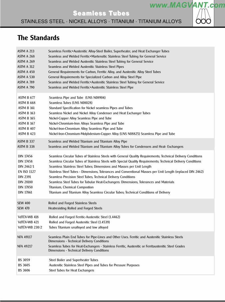
ASTM A 213 Seamless Ferritic+Austenitic Alloy-Steel Boiler, Superheater, and Heat Exchanger Tubes
ASTM A 268 Seamless and Welded Ferritic+Martensitic Stainless Steel Tubing for General Service
ASTM A 269 Seamless and Welded Austenitic Stainless Steel Tubing for General Service
ASTM A 312 Seamless and Welded Austenitic Stainless Steel Pipes
ASTM A 450 General Requirements for Carbon, Ferritic Alloy, and Austenitic Alloy Steel Tubes
ASTM A 530 General Requirements for Specialized Carbon and Alloy Steel Pipe
ASTM A 789 Seamless and Welded Ferritic+Austenitic Stainless Steel Tubing for General Service
ASTM A 790 Seamless and Welded Ferritic+Austenitic Stainless Steel Pipe
ASTM B 677 Seamless Pipe and Tube (UNS N08904)
ASTM B 668 Seamless Tubes (UNS N08028)
ASTM B 161 Standard Specification for Nickel seamless Pipes and Tubes
ASTM B 163 Seamless Nickel and Nickel Alloy Condenser and Heat Exchanger Tubes
ASTM B 165 Nickel-Copper Alloy Seamless Pipe and Tube
ASTM B 167 Nickel-Chromium-Iron Alloys Seamless Pipe and Tube
ASTM B 407 Nickel-Iron-Chromium Alloy Seamless Pipe and Tube
ASTM B 423 Nickel-Iron-Chromium-Molybdenium-Copper Alloy (UNS N08825) Seamless Pipe and Tube
ASTM B 337 Seamless and Welded Titanium and Titanium Alloy Pipe
ASTM B 338 Seamless and Welded Titanium and Titanium Alloy Tubes for Condensers and Heat- Exchangers
DIN 17456 Seamless Circular Tubes of Stainless Steels with General Quality Requirements; Technical Delivery Conditions
DIN 17458 Seamless Circular Tubes of Stainless Steels with Special Quality Requirements; Technical Delivery Conditions
DIN 2462/1 Seamless Stainless Steel Tubes; Dimensions and Masses per Unit Length
EN ISO 1127 Stainless Steel Tubes - Dimensions, Tolerances and Conventional Masses per Unit Length (replaced DIN 2462)
DIN 2391 Seamless Precision Steel Tubes, Technical Delivery Conditions
DIN 28180 Seamless Steel Tubes for Tubular Heat-Exchangers: Dimensions, Tolerances and Materials
DIN 17850 Titanium, Chemical Compostion
DIN 17861 Titanium and Titanium Alloy Seamless Circular Tubes; Technical Conditions of Delivery
SEW 400 Rolled and Forged Stainless Steels
SEW 470 Heatresisting Rolled and Forged Steels
VdTÜV-WB 418 Rolled and Forged Ferritic-Austenitic Steel (1.4462)
VdTÜV-WB 421 Rolled and Forged Austenitic Steel (1.4539)
VdTÜV-WB 230/2 Tubes Titanium unalloyed and low alloyed
NFA 49117 Seamless Plain End Tubes for Pipe-Lines and Other Uses. Ferritic and Austenitic Stainless SteelsDimensions - Technical Delivery Conditions
NFA 49217 Seamless Tubes for Heat-Exchangers - Stainless Ferritic, Austenitic or Ferritaustenitic Steel GradesDimensions - Technical Delivery Conditions
BS 3059 Steel Boiler and Superheater Tubes
BS 3605 Austenitic Stainless Steel Pipes and Tubes for Pressure Purposes
BS 3606 Steel Tubes for Heat Exchangers
www.MAGVANT.com

80 General CatalogueGeneral Catalogue
Seamless TSeamless TubesubesSTAINLESS STEEL · NICKEL ALLOYS · TITANIUM · TITANIUM ALLOYS
Chemical composition, mechanical properties and heat treatment
1. Austenitic SteelsC h e m i c a l c o m p o s i t i o n
Norm Grade C Si Mn P S Cr Ni Mo Timax. max. max. max. max. min-max min-max min-max
ASTM A 213 TP 304 0,080 1,00 2,00 0,040 0,030 18,0 - 20,0 8,0 - 10,5 - -DIN 17456/17458 1. 4301 0,070 1,00 2,00 0,045 0,030 17,0 - 19,0 8,5 - 10,5 - -NF A 49217 Z 6 CN1809 0,080 1,00 2,00 0,040 0,030 17,0 - 20,0 8,0 - 11,0 - -BS 3606 304 S31 0,070 1,00 2,00 0,040 0,030 17,0 - 19,0 8,0 - 11,0 - -
ASTM A 213 TP 304H 0,04 - 0,10 0,75 2,00 0,040 0,030 18,0 - 20,0 8,0 - 11,0 - -
ASTM A 213 TP 304 L 0,030 1,00 2,00 0,040 0,030 18,0 - 20,0 8,0 - 12,0 - -DIN 17456/17458 1. 4306 0,030 1,00 2,00 0,045 0,030 18,0 - 20,0 10,0 - 12,5 - -NF A 49217 Z 2 CN1810 0,030 1,00 2,00 0,040 0,030 17,0 - 20,0 9,0 - 12,0 - -BS 3606 304 S11 0,030 1,00 2,00 0,040 0,030 17,0 - 19,0 9,0 - 12,0 - -
ASTM A 213 TP 316 0,080 1,00 2,00 0,040 0,030 16,0 - 18,0 10,0 - 14,0 2,0 - 3,0 -DIN 17456/17458 1. 4401 0,070 1,00 2,00 0,045 0,030 16,5 - 18,5 10,5 - 13,5 2,0 - 2,5 -NF A 49217 Z 2 CND1711 0,070 1,00 2,00 0,040 0,030 16,0 - 18,0 10,0 - 12,5 2,0 - 2,4 -BS 3606 316 S31 0,070 1,00 2,00 0,040 0,030 16,5 - 18,5 10,5 - 13,5 2,0 - 2,5 -
ASTM A 213 TP 316 L 0,030 1,00 2,00 0,040 0,030 16,0 - 18,0 10,0 - 14,0 2,0 - 3,0 -DIN 17456/17458 1. 4404 0,030 1,00 2,00 0,045 0,030 16,5 - 18,5 11,0 - 14,0 2,0 - 2,5 -NF A 49217 Z 2 CND1712 0,030 1,00 2,00 0,040 0,030 16,0 - 18,0 10,5 - 13,0 2,0 - 2,4 -BS 3606 316 S11 0,030 1,00 2,00 0,040 0,030 16,5 - 18,5 11,0 - 14,0 2,0 - 2,5 -
ASTM A213/A240 TP 316L-Mo 0,030 0,75 2,00 0,040 0,030 16,0 - 18,0 10,0 - 14,0 2,0 - 3,0 -DIN 17456/17458 1. 4435 0,030 1,00 2,00 0,045 0,025 17,0 - 18,5 12,5 - 15,0 2,5 - 3,0 -*NF A 35575 Z 2 CND1713 0,030 1,00 2,00 0,040 0,030 16,0 - 18,0 10,5 - 13,0 2,0 - 2,4 -BS 3606 316 S33 0,030 1,00 2,00 0,040 0,030 16,5 - 18,5 11,0 - 14,0 2,5 - 3,0 -
ASTM A 213 TP 321 0,080 1,00 2,00 0,040 0,030 17,0 - 19,0 9,0 - 12,0 - ����
DIN 17456/17458 1. 4541 0,080 1,00 2,00 0,045 0,030 17,0 - 19,0 9,0 - 12,0 - ���� ������
NF A 49217 Z 6 CNT1810 0,080 1,00 2,00 0,040 0,030 17,0 - 20,0 9,0 - 12,0 - ���� ������
BS 3606 321 S31 0,080 1,00 2,00 0,040 0,030 17,0 - 19,0 9,0 - 12,0 - ���� ������
ASTM A 213 TP 321H 0,04 - 0,10 1,00 2,00 0,040 0,030 17,0 - 19,0 9,0 - 13,0 - ���� ������
**SEW 470 1. 4878 0,120 1,00 2,00 0,045 0,030 17,0 - 19,0 9,0 - 12,0 - ���� ������
*ASTM A 240 TP 316 Ti 0,080 0,75 2,00 0,045 0,030 16,0 - 18,0 10,0 - 14,0 2,0 - 3,0 ����
DIN 17456/17458 1. 4571 0,080 1,00 2,00 0,045 0,030 16,5 - 18,5 10,5 - 13,5 2,0 - 2,5 ����
NF A 49217 Z 6 CNDT1712 0,080 1,00 2,00 0,040 0,030 16,0 - 18,0 10,5 - 13,0 2,0 - 2,4 ���� ������
* tubes manufactured and tested according to ASTM A 213** tubes manufactured and tested according to DIN 17456
2. Super-Austenitic SteelsC h e m i c a l c o m p o s i t i o n
Norm Grade C Si Mn P S Cr Ni Mo Timax. max. max. max. max. min-max min-max min-max
ASTM B 677 UNS 8904 0,020 1,00 2,00 0,045 0,035 19,0 - 23,0 23,0 - 28,0 4,0 - 5,0 -VDTÜV 421 1. 4539 0,020 0,70 2,00 0,030 0,015 19,0 - 21,0 24,0 - 26,0 4,0 - 5,0 -NF A 49217 Z 1 NCDU25.2 0,020 1,05 2,04 0,035 0,025 19,0 - 22,2 24,0 - 27,2 4,0 - 5,1 -
*** tubes manufactured and tested acc. to NFA 49217
www.MAGVANT.com

82 General CatalogueGeneral Catalogue
Seamless TSeamless TubesubesSTAINLESS STEEL · NICKEL ALLOYS · TITANIUM · TITANIUM ALLOYS
Chemical composition, mechanical properties and heat treatment3. Ferritic and Martensitic Steel
C h e m i c a l c o m p o s i t i o nNorm Grade C Si Mn P S Cr Ni Mo Ti
max. max. max. max. max. min-max min-max min-maxASTM A 268 TP 405 0,080 1,00 1,00 0,040 0,030 11,5 - 14,5 0,500 - -DIN 17456 1. 4002 0,080 1,00 1,00 0,045 0,030 12,0 - 14,0 - - - *NF A 35574 Z 6 CA13 0,080 1,00 1,00 0,040 0,030 11,5 - 13,5 - - -
ASTM A 268 TP 410 0,150 1,00 1,00 0,040 0,030 11,5 - 13,5 - - -DIN 17456 1. 4006 0,08 - 0,12 1,00 1,00 0,045 0,030 12,0 - 14,0 - - -NF A 49217 Z 12 C13 0,150 1,00 1,00 0,040 0,030 11,5 - 13,5 0,500 - -
**ASTM A 240 TP 410S 0,080 1,00 1,00 0,040 0,030 11,5 - 13,5 - - -* tubes manufactured and tested according to NFA 49217** tubes manufactured and tested according to ASTM A 268
4. DuplexC h e m i c a l c o m p o s i t i o n
Norm Grade C Si Mn P S Cr Ni Mo Timax. max. max. max. max. min-max min-max min-max
ASTM A789 UNS S31803 0,030 1,00 2,00 0,030 0,020 21,0 - 23,0 4,5 - 6,5 2,5 - 3,5 -VDTÜV 418 1. 4462 0,030 1,00 2,00 0,030 0,020 21,0 - 23,0 4,5 - 6,5 2,5 - 3,5 -NF A 49217 Z 2 CND22.05 0,030 1,05 2,04 0,035 0,025 21,0 - 23,2 4,5 - 6,7 2,5 - 3,6 -
5. Super DuplexC h e m i c a l c o m p o s i t i o n
Norm Grade C Si Mn P S Cr Ni Mo Timax. max. max. max. max. min-max min-max min-max
ASTM-A 789/790 UNS S32760 0,030 1,00 1,00 0,030 0,010 24,0 - 26,0 6,0 - 8,0 3,0 - 4,0 -
6. Nickel AlloysC h e m i c a l c o m p o s i t i o n
Norm Grade C Si Mn P S Cr Ni Mo Timax. max. max. max. max. min-max min-max min-max
ASTM B 161/163 Alloy 200 0,15 0,35 0,35 - 0,01 - 99,0 min. - -DIN 17751 2. 4066 0,08 - - - - - 99,2 min. - -UNS Grade N02200 0,15 0,35 0,35 - 0,01 - 99,0 min. - -
ASTM B 163/165 Alloy 400 0,300 0,50 2,00 - 0,024 - 63,0 min. - -DIN 17743/17751 2. 4360 0,150 0,50 2,00 - 0,020 - 63,0 min. - -UNS-Grade N 04400 0,300 0,50 2,00 - 0,024 - 63,0 min. - -
ASTM B 163/167 Alloy 600 0,150 0,50 1,00 - 0,015 14,0 - 17,0 72,0 min. - -DIN 17742/17751 2. 4816 ����������� 0,50 1,00 0,020 0,015 14,0 - 17,0 72,0 min. - 0,30 max.UNS-Grade N 06600 0,150 0,50 1,00 - 0,015 14,0 - 17,0 72,0 min. - -
ASTM B 163/407 Alloy 800 0,100 1,00 1,50 0,030 0,015 19,0 - 23,0 30,0 - 35,0 - 0,15 - 0,60*SEW 470 1. 4876 0,120 1,00 2,00 0,030 0,020 19,0 - 23,0 30,0 - 34,0 - -UNS-Grade N 08800 0,100 1,00 1,50 0,030 0,015 19,0 - 23,0 30,0 - 35,0 - 0,15 - 0,60
ASTM B 163/423 Alloy 825 0,050 0,50 1,00 - 0,030 19,5 - 23,5 38,0 - 46,0 2,5 - 3,5 0,60 - 1,20DIN 17744/17751 2. 4858 0,025 0,50 1,00 0,025 0,015 19,5 - 23,5 38,0 - 46,0 2,5 - 3,5 0,60 - 1,20UNS-Grade N 08825 0,050 0,50 1,00 - 0,030 19,5 - 23,5 38,0 - 46,0 2,5 - 3,5 ������� � ���
ASTM B 729/829 Alloy 8020 0,070 1,00 2,00 0,045 0,035 19,0 - 21,0 32,0 - 38,0 2,0 - 3,0DIN E 17744 2.4660 0,070 1,00 2,00 0,025 0,015 19,0 - 21,0 32,0 - 38,0 2,0 - 3,0 Co 1,50UNS-Grade N 08020 0,070 1,00 2,00 0,045 0,035 19,0 - 21,0 32,0 - 38,0 2,0 - 3,0* tubes manufactured and tested according to DIN 17456
www.MAGVANT.com

84 General CatalogueGeneral Catalogue
Seamless TSeamless TubesubesSTAINLESS STEEL · NICKEL ALLOYS · TITANIUM · TITANIUM ALLOYS
ASTM GRADESALLOY FEATURES
Grade 1 (unalloyed Titanium): used to increase formability.
Grade 2 (unalloyed Titanium): the most common Titanium grade for cooling water systems; good strength with high
ductility, formability, weldability and corrosion resistance.
Grade 3 (unalloyed Titanium): specified when higher levels of strength are required.
Grade 7 (unalloyed Titanium): enhanced resistance to hot brine crevice corrosion and reducing acids, mechanical
properties similar to grade 2 alloy.
Grade 9 (Titanium alloy): offers excellent corrosion resistance to sea water and is medium-high strength alloy with
highest code design allowables.
Grade 11 (unalloyed Titanium): mechanical properties are the same as those of grade 1 however, with greater resistance
to corrosion against acid chlorides.
Grade 12 (Titanium alloy): more resistant even at temperatures up to 300 C with improved strength and code design
allowables over grade 2.
ASTM Grade Chemical composition(sim. DIN Grade)
N C H Fe O Al V Pa Mo Ni
% max % max % max % max % max % max % max
ASTM B 338 Grade 1 0,03 0,08 0,015 0,20 0,18 - - - - -DIN 17861 Ti 1 - 3.7025 0,05 0,06 0,013* 0,15 0,12 - - - - -VdTÜV 230/2
ASTM B 338 Grade 2 0,03 0,08 0,015 0,30 0,25 - - - - -DIN 17861 Ti2 - 3.7035 0,05 0,06 0,013* 0,20 0,18 - - - - -VdTÜV 230/2
ASTM B 338 Grade 3 0,05 0,08 0,015 0,30 0,35 - - - - -DIN 17861 Ti 3 - 3.7055 0,05 0,06 0,013* 0,25 0,25 - - - - -VdTÜV 230/2
ASTM B 338 Grade 7 0,03 0,08 0,015 0,30 0,25 - - 0,12 - 0,25 - -DIN 17861 Ti 2 Pd - 3.7235 0,05 0,06 0,013* 0,20 0,18 - - 0,05 - 0,25 - -VdTÜV 230/2
ASTM B 338 Grade 9 0,02 0,08 0,015 0,25 0,15 2,5 - 3,5 2,0 - 3,0 - - -
ASTM B 338 Grade 11 0,03 0,08 0,015 0,20 0,18 - - 0,12 - 0,25 - -DIN 17861 Ti1 Pd - 3.7225 0,05 0,06 0,013* 0,20 0,18 - - 0,15 - 0,25 - -VdTÜV 230/2
ASTM B 338 Grade 12 0,03 0,08 0,015 0,30 0,25 - - - 0,2 - 0,4 0,6 - 0,9DIN 17861 Ti AL3V2,5 - 0,04 0,05 0,015 0,30 0,12 2,5 - 3,5 2,0 - 3,0 - - -3.7195* In case wallthickness is under 2 mm, the Hydrogenium-content up to 0,015 % is allowed.
Chemical composition, mechanical properties and heat treatment
www.MAGVANT.com

General CatalogueGeneral Catalogue 87
Cold Finished Pipes and Tubes
Seamless TSeamless TubesubesSTAINLESS STEEL · NICKEL ALLOYS · TITANIUM · TITANIUM ALLOYS
Specification Outside Diameter WallthicknessASTMA 450 < 25,4mm < 38,1mm < 50,8mm > 50,8 mm
+/- 0,10mm +/- 0,15mm +/- 0,20mm +/-0,25mm -0/+20% (min. wall)(average wall +/-10% not included)
A 530 < 48,3mm > 48,3mm +0,4/-0,8mm +/-0,8mm +/-12,5%
A 269 < 38,1mm < 63,5mm +/- 0,13mm +/-0,25mm +/-10%
EN-ISO 1127 (previously: DIN 2462)Tol.class TC D2 +/-1,00% min.+/-0,5mm T 2 +/-12,5% min. +/-0,40 mm
TC D3 +/-0,75% min. +/-0,3mm T 3 +/-10% min. +/-0,20 mm
TC D4 +/-0,50% min. +/-0,1mm T 4 +/-7,5% min. +/-0,15 mm
DIN 28180 (valid only for heatexchanger dimensions)Tol.class 16-20mm 25mm 30mm 38mm < 2 mm > 2 mm
TC 1 +/-0,10mm 0,12mm 0,15mm 0,20mm +/-0,2mm +/-10%TC 2 0,30mm 0,30mm 0,30mm 0,40mm +/-0,2mm +/-10%TC 3 - - - - +/-0,2mm +15/-10%
NFA Quality F (cold finished)49117 Quality F (cold finished) +/-0,75% with a minimum tolerances of +/-0,30mm +/-10% with a minimum of +/-0,20 mm
49217 < 25,4mm < 38,1mm < 50,8mm >50,8mmFerritic +/-0,10mm +/-0,15mm +/-0,20mm +/-0,50% normally +/-10%Austenitic+Austenitic-Ferritic +/-0,25mm +/-0,25mm +/-0,25mm +/-0,50% (on request:-0+20% min. wall)
BS CFS3059 Part 2 Austenitic +/-0,50% with a minimum tolerances of +/-0,15mm +/-10%(<3,25 mm) +/-7,5%(>3,25 mm)
3605 Part 1 Austenitic +/-0,75% with a minimum tolerances of +/-0,20mm +/- 10% min. +/- 0,15 mm
3606 < 25mm < 38mm < 50mmFerritic +/-0,10mm +/-0,15mm +/-0,20mm +/-10%Austenitic +/-0,15mm +/-0,15mm +/-0,20mm (on request:-0/+20% or -0/+22%)
COMPARISON OF TOLERANCES
www.MAGVANT.com

88 General CatalogueGeneral Catalogue
Seamless TSeamless TubesubesSTAINLESS STEEL · NICKEL ALLOYS · TITANIUM · TITANIUM ALLOYS
BWG AND SWG DIMENSIONS AND WEIGHTSFor stainless steel only
BWG (Birmingham wire gauge)
Wall thickness
BWG 22 20 18 16 14 12 11 10
mm 0.711 0.889 1.245 1.651 2.108 2.769 3.048 3.404
Weight in kg/m
outside diameter
inches mm
1/4“ 6.350 0.122 0.159 0.194
5/16“ 7.950 0.157 0.209 0.260
3/8“ 9.525 0.192 0.258 0.326 0.392
1/2“ 12.700 0.213 0.263 0.357 0.457 0.559 0.688 0.737
5/8“ 15.875 0.270 0.334 0.456 0.588 0.727 0.908 0.979
3/4“ 19.050 0.404 0.555 0.719 0.894 1.130 1.220 1.330
7/8“ 22.225 0.383 0.475 0.654 0.851 1.060 1.350 1.460 1.600
1“ 25.400 0.440 0.546 0.752 0.982 1.230 1.570 1.710 1.870
1 1/4“ 31.750 0.553 0.687 0.950 1.240 1.570 2.010 2.190 2.420
1 1/2“ 38.100 0.666 0.828 1.150 1.510 1.900 2.450 2.680 2.960
1 3/4“ 44.450 0.779 0.970 1.350 1.770 2.240 2.890 3.160 3.500
2“ 50.800 0.892 1.110 1.540 2.030 2.570 3.330 3.650 4.040
2 1/2“ 63,500 1.940 2.560 3.240 4.210 4.610 5.120
SWG (Standard wire gauge)
Wall thickness
SWG 22 20 18 16 14 12 11 10
mm 0.711 0.914 1.219 1.626 2.032 2.642 2.946 3.251
Weight in kg/m
outside diameter
inches mm
1/4“ 6.350 0.124 0.157 0.192
5/16“ 7 950 0.161 0.205 0.257
3/8“ 9.525 0.197 0.253 0.321 0.381
1/2“ 12.700 0.213 0.270 0.350 0.451 0.543 0.665 0.720
5/8“ 15.875 0.270 0.342 0.447 0.580 0.704 0.875 0.954
3/4“ 19.050 0.415 0.544 0.709 0.866 1.090 1.190 1.290
7/8“ 22.225 0.383 0.488 0.641 0.838 1.030 1.300 1.420 1.550
1“ 25.400 0.440 0.560 0.738 0.967 1.190 1.510 1.660 1.800
11/4“ 31.750 0.553 0.706 0.931 1.230 1.510 1.930 2.130 2.320
11/2“ 38.100 0.666 0.851 1.130 1.480 1.840 2.350 2.590 2.840
13/4“ 44.450 0.779 0.996 1.320 1.740 2.160 2.770 3.060 3.350
2“ 50.800 0.892 1.140 1.510 2.000 2.480 3.190 3.530 3.870
2 1/2“ 63.500 1.900 2.520 3.130 4.030 4.470 4.910
www.MAGVANT.com
90 General CatalogueGeneral Catalogue
Seamless TSeamless TubesubesSTAINLESS STEEL · NICKEL ALLOYS · TITANIUM · TITANIUM ALLOYS
stainless steel, nickel and titanium alloy tubes are manufactured on most modern production equipment, whereby the appliedproduction methods assure the highest possible standard of quality (certified acc. to ISO 9002). Morever, for continuous quality assurance and-control, our independent testing department is equipped with most modern testing facilities, i.e. tensile test machinery, hardness measuringapparatus, ultrasonic and eddy-current testing line, coldwater-pressure test equipment and many other modern destructive and non-destructivetest instruments.All tests carried out on material or finished products can be split into three major categories: Mechanical tests, Non-Destructive tests andCorrosion tests.
The tests mentioned below will be carried out according to the relevant material specification or on special request to be agreed upon in thepurchase order.
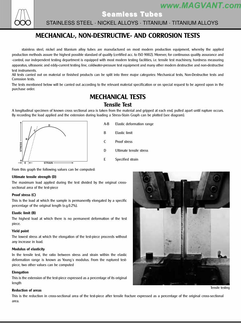
MECHANICAL TESTSTensile Test
A longitudinal specimen of known cross sectional area is taken from the material and gripped at each end, pulled apart until rupture occurs.By recording the load applied and the extension during loading a Stress-Stain Graph can be plotted (see diagram).
A-B Elastic deformation range
B Elastic limit
C Proof stress
D Ultimate tensile stress
E Specified strain
From this graph the following values can be computed:
Ultimate tensile strength (D)
The maximum load applied during the test divided by the original cross-sectional area of the test-piece
Proof stress (C)
This is the load at which the sample is permanently elongated by a specificpercentage of the original length (e.g.0.2%).
Elastic limit (B)
The highest load at which there is no permanent deformation of the testpiece.
Yield point
The lowest stress at which the elongation of the test-piece proceeds withoutany increase in load.
Modulus of elasticity
In the tensile test, the ratio between stress and strain within the elasticdeformation range is known as Young´s modulus. From the ruptured test-piece, two other values can be computed
Elongation
This is the extension of the test-piece expressed as a percentage of its originallength
Reduction of areas
This is the reduction in cross-sectional area of the test-piece after tensile fracture expressed as a percentage of the original cross-sectionalarea.
MECHANICAL-, NON-DESTRUCTIVE- AND CORROSION TESTS
Tensile testing
www.MAGVANT.com

General CatalogueGeneral Catalogue 91
Seamless TSeamless TubesubesSTAINLESS STEEL · NICKEL ALLOYS · TITANIUM · TITANIUM ALLOYS
MECHANICAL-, NON-DESTRUCTIVE- AND CORROSION TESTS
Flattening TestThis is usually applied to tube and involves flattening sample of tube between two parallel faces without showing flaws orcracks. The length of the test-piece and degree to which it is to be flattened is specified. The latter usually expressed in termsof the wall thickness of the tube.
Flare or Drift TestThis is a form of ductility test and applies to tube. The end of the tube is required to be expanded by a specifiedincrease in diameter without splits or cracks. The included angle of drift is also specified.
Hardness TestsThese tests determine the resistance of material to indentation.
Brinell hardness testA standard size hardened steel ball is indented into the surface of material by an applied standard loadfor a duration of 15 seconds. The diameter of the impression is measured accurately by microscope andthe hardness value calculated.
Rockwell hardness testThis determines hardness by measuring the depth to which a diamont cone or hardened steel ball, underspecific load, penetrates the material. The hardness number is indicated on a scale according to the loadapplied.
Vickers diamond hardness testThis determines hardness by measuring the impression left in material by diamond pyramid under astandard load for a specified time. The square impression is measured, accurately, diagonally and is areacalculated. The hardness value is calculated.
NON-DESTRUCTIVE TESTSUltrasonic Testing
acc. to ASTM-E213 / SEP1915; 1918; 1919This test involves ultrasonic sound waves being aimed, via a coupling medium, at the material to be tested. A proportion sound is bouncedback at the coupling medium/material interface but the remainder enters the material and is bounced back from the internal surface, to theexternal surface, where a transducer converts the sound into electrical energy. This is then monitored on a cathode
www.MAGVANT.com

92 General CatalogueGeneral Catalogue
Seamless TSeamless TubesubesSTAINLESS STEEL · NICKEL ALLOYS · TITANIUM · TITANIUM ALLOYS
Micro structure photography
MECHANICAL-, NON-DESTRUCTIVE- AND CORROSION TESTS
ray tube. If a calibrated standard is shown on the tube, any deviation from the standard will be immediately visible, thus indicating cracks orinternal defects.
Eddy-Current Testingacc. to ASTM-E426 / SEP1925
This involves inducing eddy currents into the material by exciting a coil which surmounts two narrow search coils surrounding the material.Any discontinuities in material are found by comparing the electrical conditions that exist in the two search coils. The fault signals areamplified and can be shown on a cathode ray tube or as an audible signal.
Hydrostatic Testacc. to tube specification
This is used to test the manufactured items under a test pressure equivalent or greater than pressure encountered in operation. It involvesfilling the tube with demineralized water, which cannot be compressed, and increasing the pressure, to that specified, inside the tube. Thepressure is transmitted to the tube by the water and therefore a pressure to which the tube has been tested is obtained.
Dye-penetrant Testacc. to ASTM-E165 / DIN 54152
This is used to detect cracks and involves spraying a dye on the area to be tested. After allowing time for penetration the surplus dye is removedand the area is then sprayed with a white developer. Any faults are releaved as coloured lines or spots caused by the developer absorbing thedye seeping from the cracks.
PMI ( positive material identification) - Mix-Up Control PMI / Mix-Up Control is carried out by spectrotest. Spectrotest is used for "Mix-Up Control" work, testing of a material quality is carried out ona Yes / No basis in relation to the quality of the reference material.
The operator is prompted to "Recalibrate", "Test the reference material" and " Carry out mix-up control" by the instrument.
Microstructure test according to ASTM E 112 / DIN 50601.
These test methods of determination of average grain size in metallicmaterials are primarily measuring procedures and, because of their purelygeometric basis, are independent of the metal or alloy concerned. Thebasis procedures may also be used for the estimation of average grain,crystal or cell size in nonmetallic materials. The comparison method byplanimetric (or Jeffries) procedure is used if the structure to the materialapproaches the appearance of one of the standard comparison charts.
www.MAGVANT.com

94 General CatalogueGeneral Catalogue
Seamless TSeamless TubesubesSTAINLESS STEEL · NICKEL ALLOYS · TITANIUM · TITANIUM ALLOYS
Types of Inspection Documents DIN EN 10204(previously DIN 50.049)
1 GeneralThis European Standard defines the different types of inspection documents supplied to the purchaser, in accordance with the requirementsof the order, for the delivery of metallic products.
2 Inspection documents drawn up from inspection and tests carried out by personnel authorized by the manufacturer and who maybe involved in the manufacturing department
Certificate of compliance with the order 2.1/EN 10204 Document in which the manufacturer certifies that the products supplied are in compliance with the requirements of the order, withoutmention of any test results.
The certificate of compliance with the order is a document drawn up on the basis of non-specific inspection and testing.
Test report 2.2/EN 10204 Document in which the manufacturer certifies that the products supplied are in compliance with the requirements of the order and inwhich he supplies test results based on non-specific inspection and testing.
Specific test report 2.3/EN 10204 Document in which the manufacturer certifies that the products supplied are in compliance with the specifications of the order and inwhich he supplies test results based on specific inspection and testing.
(The specific test report is only used by a manufacturer who does not have an authorized quality control department operatingindependently of the manufacturing department).
3 Inspection documents drawn up from inspection and tests carried out or supervised by authorized personnel independent of themanufacturing department, and based on specific testing
Inspection certificate 3.1.Document issued on the basis of inspection and tests carried out in accordance with the technical specifications of the order or theofficial regulations and the corresponding technical rules. The tests shall be carried out on the products supplied or the products in theinspection unit, of which the consignment constitutes a part.
The inspection unit is set by the product standard, the official regulations and corresponding technical rules or by the order.
There are different types:
Inspection certificate 3.1.B/EN 10204is issued by the department independent of the manufacturing department and validated by an authorized representative of thestaff independent of the manufacturing department.
Inspection certificate 3.1.C/EN 10204is issued and validated by an authorized representative of the purchaser, in accordance with the specifications of the order.
Inspection report 3.2/EN 10204 Where the inspection certificate is validated, following special agreement, both by the manufacturer´s authorized representative and thepurchaser´s authorized representative, it is known as the inspection report.
INSPECTION DOCUMENTS
www.MAGVANT.com

General CatalogueGeneral Catalogue 95
Seamless TSeamless TubesubesSTAINLESS STEEL · NICKEL ALLOYS · TITANIUM · TITANIUM ALLOYS
PRODUCTION PROCESS
Stroke of Rolling Stand
Mandrel
LuppeMother TubeHollow bar
Reducing Section
Roll Groove
Ring-shaped Die
Axis of Roll
Smoothing Section
Tube
Cold pilger rolling
Degreasing
Mechanicaltesting
Straightening
US-testing
Eddy current test
Marking
Finished straight tubes
U-bending
Finished U-bend tubes
Non-destructive tests
Drawing
Hydraulic pressuretesting
Mothertube
Cutting tolength
Inspection
Packing
Shipping
Dimensionalchecks
Inspection
Packing
Shipping
Optionally
Hydraulic pressuretesting
and / or
Stress-relievingannealing
Swage
Hollowbar
Drawing with Stationary Plug �
Drawing with Floating Plug �
Hollow Drawing �
www.MAGVANT.com

LoLow Carbon Sw Carbon Stteel Teel Tubesubesffor Heator Heateexxcchanghanger and Boilerer and Boilerss
96 General catalogueGeneral catalogue
STANDARD ASTM-A 179 214 192 226
Manufacturing Process Seamless ERW Seamless ERW
Chemical Analysis
C % 0.06-0.18 0.18 max 0.06-0.18 0.06-0.18
Mn % 0.27-0.63 0.27-0.63 0.27-0.63 0.27-0.63
P max % 0.035 0.035 0.035 0.035
S max % 0.035 0.035 0.035 0.035
Si max % 0.25 0.25
Chemical composition and mechanical properties
Mechanical Properties
Tensile Strength min KSI [MPA] 47 [325] 47 [325] 47 [325] 47 [325]
Yield Strength min KSI [MPA] 26 [180] 26 [180] 26 [180] 26 [180]
Elongation in 2 in. min % 35 35 35 35
Comparison of International Specifications & Grades
ASTM DIN BS NFA JIS
A 179 17175 3602 Pt1 A 49215 G 3461
ST 35.8/I 3059 Pt2 St 360 TU 37C STB 340
CAT2
A 192 17175 3602 Pt1 A 49215 JIS
ST 35.8/I 3059 Pt2 TU 37C G3461
ST 360 CAT2 STB 340
A 214 17177 BS 3059 Pt2 A 49242 G 3461
ST 37.8/I 3602 Pt1 A 49245 STB 340
ERW 360 CAT2 TS 37C
A 226 17177 BS 3059 Pt2 A 49242 G 3461
ST 37.8/I BS 3602 Pt1 A 49245 STB 340
ERW 360 CAT2 TS 37C
www.MAGVANT.com

Medium Carbon SMedium Carbon Stteel Teel Tubesubesffor Heator Heateexxcchanghanger and Boilerer and Boilerss
General catalogueGeneral catalogue 97
AlloAlloy Sy Stteel Teel Tubes fubes for Heator Heateexxcchanghanger and Boilerer and Boilerss
Material Standard ASTM-A 210
Manufacturing Process Seamless
Grade C max Mn P max S max Si min min YS KSI [MPA] min TS KSI [MPA] El (%)
A1 0.27 0.93 max 0.035 0.035 0.1 37 [255] 60 [415] 30
C 0.35 0.29-1.06 0.035 0.035 0.1 40 [275] 70 [485] 30
Material Standard ASTM-A 556
Manufacturing Process Seamless
Grade C max Mn P max S max Si min min YS KSI [MPA] min TS KSI [MPA] El (%)
A2 0.18 0.27-0.63 0.035 0.035 ... 26[180] 47[320] 35
B2 0.27 0.29-0.93 0.035 0.035 0.10 37[260] 60[410] 30
C2 0.30 0.29-1.06 0.035 0.035 0.10 40[280] 70[480] 30
Chemical composition and mechanical properties
Chemical composition and mechanical properties
Comparison of International Specifications & Standards
ASTM-A BS DIN NFA JIS
210 A1 3602 Pt1 17175 A 49215/9 G 3461
A556 B2 ST 430 Cat2 St 45.8/I T 442 b/F ST B 410
210 Gr. C 3606 DIN 17175 ... ...
A 556 Gr. C2 St 440 Cat.2 17 Mn 4 ... ...
Material Standard ASTM-A 209
Manufacturing Process Seamless
Chemical Requirements
Grade Element
C Mn P S Si Mo
T1 0.10-0.20 0.30-0.80 0.025 0.025 0.10-0.50 0.44-0.65
T1a 0.15-0.25 0.30-0.80 0.025 0.025 0.10-0.50 0.44-0.65
T1b 0.14 max 0.30-0.80 0.025 0.025 0.10-0.50 0.44-0.65
Tensile Requirements
Tensile Strength, Yield Strength, min Elongation
min (0.2% offset), min, in 2 in. or 50 mm,
KSI (MPa) KSI (MPa) (or 4D), min, %
Grade
T1 55 [380] 30 [205] 30
T1a 60 [415] 32 [220] 30
T1b 53 [365] 28 [195] 30
www.MAGVANT.com

AlloAlloy Sy Stteel Teel Tubesubesffor Heator Heateexxcchanghanger and Boilerer and Boilerss
98 General catalogueGeneral catalogue
Material Standard ASTM-A 199 (94)
Manufacturing Process Seamless
Chemical Requirements
Element C Mn P S Si Cr Mo Others
Grade
T4 0.05 - 0.15 0.30-0.60 0.025 0.025 0.50-1.00 2.15-2.85 0.44-0.65 ...
T5 0.15 max 0.30-0.60 0.025 0.025 0.50 max 4.00-6.00 0.45-0.65 ...
T9 0.15 max 0.30-0.60 0.025 0.025 0.25-1.00 8.00-10.00 0.90-1.10 ...
T11 0.05 - 0.15 0.30-0.60 0.025 0.025 0.50-1.00 1.00-1.50 0.44-0.65 ...
T21 0.05 - 0.15 0.30-0.60 0.025 0.025 0.50 max 2.65-3.35 0.80-1.06 ...
T22 0.05 - 0.15 0.30-0.60 0.025 0.025 0.50 max 1.90-2.60 0.87-1.13 ...
T91 0.08 - 0.12 0.30-0.60 0.020 0.010 0.20-0.50 8.00-9.50 0.85-1.05 *
* Ni 0.40 max; V 0.18-0.25; Cb 0.06-0.10; N 0.03-0.07; Al 0.04 max
Chemical composition and mechanical properties
Tensile RequirementsTensile Strength, min Yield Strength, min Elongation
(0.2% offset), min, in 2 in. or 50 mm,
Grade KSI (MPa) KSI (MPa) (or 4D), min, %
All Grades
Except T91 60 [415] 25 [170] 30
Grade T91 85 [585] 60 [415] 20
Material Standard: ASTM A 213
Manufacturing Process Seamless
Grade C Si Mn P S Cr Mo V YS min TS min El (%)
KSI [MPa] KSI [MPa]
T2 0.10-0.20 0.10-0.30 0.30-0.61 0.025 0.025 0.50-0.81 0.44-0.65 ... 30[205] 60[415] 30
T5 0.15 max 0.50 max 0.30-0.60 0.025 0.025 4.00-6.00 0.45-0.65 ... 30[205] 60[415] 30
T5b 0.15 max 1.00-2.00 0.30-0.60 0.025 0.025 4.00-6.00 0.45-0.65 ... 30[205] 60[415] 30
T5c1 0.12 max 0.50 max 0.30-0.60 0.025 0.025 4.00-6.00 0.45-0.65 ... 30[205] 60[415] 30
T9 0.15 max 0.25-1.00 0.30-0.60 0.025 0.025 8.00-10.00 0.90-1.10 ... 30[205] 60[415] 30
T11 0.05-0.15 0.50-1.00 0.30-0.60 0.025 0.025 1.00-1.50 0.44-0.65 ... 30[205] 60[415] 30
T12 0.05-0.15 0.50 max 0.30-0.61 0.025 0.025 0.80-1.25 0.44-0.65 ... 32[220] 60[415] 30
T17 0.15-0.25 0.15-0.35 0.30-0.61 0.025 0.025 0.80-1.25 ... 0.15 30[205] 60[415] 30
T21 0.05-0.15 0.50 max 0.30-0.60 0.025 0.025 2.65-3.35 0.80-1.06 ... 30[205] 60[415] 30
T22 0.05-0.15 0.50 max 0.30-0.60 0.025 0.025 1.90-2.60 0.87-1.13 ... 30[205] 60[415] 30
T912 0.08-0.12 0.20-0.50 0.30-0.60 0.020 0.010 8.00-9.50 0.85-1.05 0.18-0.25 60[415] 85[585] 20
T923 0.07-0.13 0.50 max 0.30-0.60 0.020 0.010 8.50-9.50 0.30-0.60 0.15-0.25 64[440] 90[620] 20
18Cr-2Mo4 0.025 max 1.00 max 0.30-0.60 0.040 0.030 17.5-19.5 1.75-2.50 ... 40[275] 60[415] 201 Grade T5c shall have a titanium content of not less than 4 times the carbon content and not more than 0.70%.2 Grade T91 - other elements: Cb 0.06 - 0.10 • N 0.030 - 0.070 • Ni 0.40 max • Al 0.04 max.3 Grade T92 - other elements: W 1.50 - 2.00 • Cb 0.04 - 0.09 • B 0.001 - 0.006 • N 0.03 - 0.07 • Ni 0.40 max • Al 0.04 max.4 Grade 18Cr-2Mo shall have Ti + Cb = 0.20 + 4(C + N) min, 0.80 max, other elements N max 0.035 • (Ni + Cu) max 1.00.
www.MAGVANT.com

LoLow Tw Tememperperaturature Te Tubes / Alloubes / Alloy Sy Stteeleelffor Heator Heateexxcchanghanger and Boilerer and Boilerss
General catalogueGeneral catalogue 99
Chemical composition and mechanical propertiesMaterial Standard ASTM-A 334
Manufacturing Processs: Seamless or Welded
Chemical AnalysisGrade C max Mn P max S max Si Ni min YS KSI [MPA] min TS KSI [MPA] El (%)
1 0.30 0.40-1.06 0.025 0.025 30 [205] 55 [380] 35
3 0.19 0.31-0.64 0.025 0.025 0.18-0.37 3.18-3.82 35 [240] 65 [450] 30
6 0.30 0.29-1.06 0.025 0.025 0.10 min 35 [240] 60 [415] 30
7 0.19 0.90 max 0.025 0.025 0.13-0.32 2.03-2.57 35 [240] 65 [450] 30
8 0.13 0.90 max 0.025 0.025 0.13-0.32 8.40-9.60 75 [520] 100 [690] 22
91 0.20 0.40-1.06 0.025 0.025 1.60-2.24 46 [315] 63 [435] 28
112 0.10 0.60 max 0.025 0.025 0.35 max 35.0-37.0 35 [240] 65 [450] 18
1 Cu 0.75-1.25
2 Cr 0.50 max • Co 0.50 max • Mo 0.50 max
Comparison of International Specifications & GradesASTM DIN BS NFA JIS
A209 T1/a/b VD-TÜV 3606 ... G 3462
A161 T1/A335 P1 16Mo5 St 245 ... ST BA 12
A213 T2 ... ... A 49-213 ...
15 CD 2-05
A 199 T4 ... ... ... ...
A 199/213 T5/P5 17176 3604/6 A 49 213 G3462
A 200/A 335 12 Cr Mo 195 ST 625 TU Z 10CD505 ST BA 25
A 199/213 T9/P9 17176 3604 A 49213 ...
A 200/A 335 X 12CrMo9.1 ST 629 Z 10CD9 ...
A 199 T11/ 17176 3059 A49213/5/9 G 3462
A 213 T11/12/P11/12 13CrMo44 3604/6 TU 13 CD 4.04 STBA 22,33
A 200/A335 ST 620-460 TU 10 CD 505 ...
A 213 T17 ... ... ... ...
A 199/A213/A200/T21 ... ... ... ...
A 199/A213 T22/P212 DIN 17176 3059 A 49213/5/9 G 3462
A 200/A335 10 Cr Mo 910 3604/6 TU 10CD 910 STBK 24
ST 620-490
A 199/A213 T91/P91 17175 ... A 49213 ...
A 200/A 335 X10CrMoYNb 9.1 .... Z 10 CD Nb Y09-01 ...
A 213 T92 ... ... ... ...
A213 18Cr2Mo ... ... ... ...
A 334 DIN BS NFA JIS
Gr.1 17173 3603 ... G 3464
TTSt 35 N STBL 39
Gr.3 10 Ni 14 503LT 49215/30/330 STBL 46
TU 10 N 14
Gr.6 DIN 17179 430 LT TU 42 BT ...
TST E285
www.MAGVANT.com

Copper NicCopper Nickkel 90/1el 90/100ALLOY 706
102 General catalogueGeneral catalogue
STANDARD BS 2871/PART 3 ASTM B 111 DIN 17664/1785 NFA 51102 JIS H3300
GRADE CN 102 C 70600 CuNi10Fe1Mn CuNi10Fe1Mn C 7060
Cu Rem. Rem. Rem. Rem. Rem.
Pb 0,01 max. 0,05 max. 0,03 max. 0,05 Sn+Pb max. 0,05 max.
Ni 10,0 - 11,0 9,0 - 11,0 9,0 - 11,0 9,0 - 11,0 9,0 - 11,0
Fe 1,0 - 2,0 1,0 - 1,8 1,0 - 1,8 1,0 - 2,0 1,0 - 1,8
Mn 0,5 - 1,0 1,0 max. 0,5 - 1,0 0,3 - 1,0 0,2 - 1,0
Zn 1,0 max. 0,5 max. 0,5 max. 0,5 max.
S 0,05 max. 0,05 max. 0,02 max.
C 0,05 max. 0,05 max. 0,05 max.
Cu+Ni+Fe+Mn 99,5 min.
Total Impurities 0,3 max. Others Total
0,1 max.
CONDITION M 061 F29 Annealed (X690) O
O H55 — —
Yield Strength — 105 min. 90 - 180 — —
N/mm2 — 240 min. — — —
Tensile Strength — 275 min. 290 min. — 275 min.
N/mm2 — 310 min. — —
Elongation (%) — — 30 min. — 30 min.
— — — — —
Hardness Hv5 150 min. — — 70 - 100 —
80 - 110 — — — —
Grain Size (mm) 0,050 max. 0,010 - 0,045 0,010 - 0,050 0,010 - 0,045 0,010 - 0,045
(Condition O)
Typical use: Used for the working in sea water, mainly for shipbuilding and sea water pipelines, stations, desalination, because
of its very good corrosive resistance.
Melting Point: 1150° C • Hot Working Properties: Good
Density (20° C): 8,94 g/cm3 • Cold Working Properties: Good
Weight Average wall: (OD-WT) x WT x 0,0284 = Kg/m (all sizes in mm)
formula: Minium wall: (OD-WT) x WT x 0,0295 = Kg/m (all sizes in mm)
www.MAGVANT.com

Copper NicCopper Nickkel 70/30el 70/30ALLOY 715
General catalogueGeneral catalogue 103
STANDARD BS 2871/PART 3 ASTM B 111 DIN 17664/1785 NFA 51102 JIS H3300
GRADE CN 107 C 71500 CuNi30Mn1Fe CuNi30Mn1Fe C 7150
Cu Rem. Rem. Rem. Rem. Rem.
Pb 0,01 max. 0,05 max. 0,03 max. 0,05 Sn+Pb max. 0,05 max.
Ni 30,0 - 32,0 29,0 - 33,0 30,0 - 32,0 29,0 - 32,0 29,0 - 33,0
Fe 0,4 - 1,0 0,4 - 1,0 0,4 - 1,0 0,4 - 0,7 0,4 - 0,7
Mn 0,5 - 1,5 1,0 max. 0,5 - 1,5 0,5 - 1,5 0,2 - 1,0
Zn 1,0 max. 0,5 max. 0,5 max. 0,5 max.
S 0,08 max. 0,06 max. 0,02 max.
C 0,06 max. 0,06 max. 0,06 max.
Cu+Ni+Fe+Mn 99,5 min.
Total Impurities 0,3 max. Others Total 0,1 max.
0,1 max.
CONDITION M 061 F37 Annealed (X690) O
O HR50 — — —
Yield Strength — 125 min. 120 - 220 — —
N/mm2 — 345 min. — — —
Tensile Strength — 360 min. 370 min. — 363 min.
N/mm2 — 495 min. — — —
Elongation (%) — — 35 min. — 30 min.
— 12 min. (WT≤1,21 mm) — — —
15 min. (WT>1,21 mm)
Hardness Hv5 150 min. — — 90 - 130 —
90 - 120 — — — —
Grain Size (mm) 0,050 max. 0,010 - 0,045 0,010 - 0,050 0,010 - 0,045 0,010 - 0,045
(Condition O)
Typical use: This alloy has all the characteristics of CuNi 90/10, but also offers excellent corrosion
resistance in high velocity sea water. Also the operating temperature is much higher than
of CuNi 90/10. Can assure a long service life and reliability.
Melting Point: 1240° C • Hot Working Properties: Good
Density (20° C): 8,94 g/cm3 • Cold Working Properties: Good
Weight Average wall: (OD-WT) x WT x 0,0284 = Kg/m (all sizes in mm)
formula: Minium wall: (OD-WT) x WT x 0,0295 = Kg/m (all sizes in mm)
www.MAGVANT.com

U-U-TTubes fubes for Heat Exor Heat Excchanghangererss
108 General catalogueGeneral catalogue
A LEG LENGTH DIFFERENCE
E (2R + D) 2X RADIUS PLUS OUTSIDE DIAMETER
D NOMINAL OUTSIDE DIAMETER
Dmax. MAX. OUTSIDE DIAMETER
Dmin. MIN. OUTSIDE DIAMETER
LD LEG LENGTH DISTANCE MEASURED FROM
POINTS OF TANGENCY
LL LEG LENGTH
TL TOTAL LENGTH
R CENTERLINE BEND RADIUS
Rmin. MIN. RADIUS
T WALL THICKNESS
Tmin. MIN. WALL THICKNESS IN OUTSIDE BENDING AREA
SW SMALLEST WALL THICKNESS OF STRAIGHT TUBE
O OVALITY
DP DEVIATION FROM PLANE OF BEND
Z Section
A
LDE
T DZ Z
R
Tmin
Hairpin U-bend tube with one 180 deg. bend
Points of tangency
TL
LL
Square U-bend tube with two 90 deg. bends
LD
R
LL
Z - Z
DP
DefinitionU-Tubes as per this technical delivery standard are bend hairpin tubes which are usually used in heat exchangers.
ScopeThis technical delivery standard refers to U-bend tubes with radii from 1,5 D. Tolerances for smaller radii have to be agreed with the customer.
section Z - Z
The meaning of measurements and symbols:
www.MAGVANT.com

• Wall thinning of bending area
Wall thinning refers to the minimum wall thickness of straight tubeRadius ≥ 1,5 D: max. 17 % wall thinning
• Flattening on bend (TEMA R.C.B. 2.31 only)
Flattening does not exceed 10 % of nominal diameter
• Tolerance for leg spacing
( 2 R - D ) = 1,5 mm
• Tolerance on ovality
Allowable deviation from ovality in %
> 4 D ≤ 5%The deviation O of the ovality will be calculated as follows:
• Tolerance on straight leg length
straight leg ≤ 6000 mm -0 / +3 mmstraight leg > 6000 mm - 9000mm -0 / +4 mmstraight leg > 9000 mm -0 / +5 mm
• Difference in leg length
leg length ≤ 5000 mm -0 / +3 mmleg length > 5000 mm -0 / +5 mm
• Tolerance on total length
The total length specifies the length of the external bend tangent line to the end of straight leg.TL = LL + 0,5 D + RTolerances ≤ 6000 mm -0/+5 mm
> 6000 mm -0/+8 mm
• Deviation from plane of bend
DP max 1/16" = 1,5 mm
U-U-TTubes fubes for Heat Exor Heat Excchanghangererss
General catalogueGeneral catalogue 109
www.MAGVANT.com

110 General catalogueGeneral catalogue
U-U-TTubes fubes for Heat Exor Heat Excchanghangererss
Packing in layers and seaworthy wooden boxes Packing on pallets protected with sheet plastic.
Packing in layers, each radius marked with labels
Types of packing
Packing in wooden “combs” on pallets
www.MAGVANT.com

WWeight Liseight Listt
208 General CatalogueGeneral Catalogue
(Unit kg)
WEIGHT (KGS) SIZE 1/8" 1/4" 3/8" 1/2" 3/4" 1" 1-1/4" 1-1/2" 2" 2-1/2" 3" 4"
2000LBS SCREWED90° ELBOW 0.10 0.08 0.13 0.22 0.32 0.47 0.74 0.93 1.53 2.98 4.54 10.2145° ELBOW 0.08 0.06 0.10 0.20 0.27 0.41 0.64 0.75 1.19 3.46 5.44 8.9TEE 0.13 0.12 0.15 0.31 0.43 0.61 0.95 1.25 1.93 4.11 6.12 14.74
3000LBS SCREWED90° ELBOW 0.10 0.14 0.27 0.41 0.72 1.03 1.31 2.21 2.47 4.53 7.77 13.2745° ELBOW 0.08 0.12 0.24 0.34 0.54 0.92 0.97 1.84 1.93 3.46 5.44 8.96TEE 0.13 0.13 0.38 0.56 0.84 1.70 1.95 3.18 3.63 6.24 9.53 17.24COUPLING 0.05 0.05 0.06 0.13 0.19 0.39 0.68 0.99 1.37 2.07 3.08 5.44HALF COUPLING 0.03 0.03 0.03 0.06 0.10 0.20 0.34 0.50 0.68 1.03 1.54 2.72RED-COUPLING 0.05 0.05 0.06 0.13 0.19 0.39 0.68 0.99 1.37 2.07 3.08 5.44CAP 0.04 0.04 0.05 0.11 0.18 0.35 0.60 0.70 1.06 1.84 2.65 4.57STREET ELBOW 0.10 0.14 0.27 0.41 0.66 0.97 1.31 2.21 2.47UNION 0.28 0.28 0.28 0.31 0.46 0.67 1.03 1.51 2.43 3.48 5.25 12
6000 LBS SCREWED 90° ELBOW 0.17 0.30 0.45 0.72 1.15 1.61 2.67 3.20 5.90 9.88 16.4345° ELBOW 0.11 0.27 0.39 0.61 1.02 1.17 2.67 2.61 4.37 7.01 14.16TEE 0.20 0.42 0.63 0.98 1.65 2.19 3.52 4.42 7.88 13.11 22.50COUPLING 0.08 0.06 0.18 0.31 0.41 0.85 1.05 1.87 3.40 4.20 6.10 10.04HALF COUPLING 0.04 0.04 0.09 0.16 0.20 0.43 0.53 0.91 1.70 2.10 3.05 5.02RED-COUPLING 0.08 0.06 0.18 0.31 0.41 0.85 1.05 1.81 3.40 4.20 6.10 10.04CAP 0.06 0.06 0.09 0.14 0.20 0.34 0.59 0.77 1.47
PLUGS & BUSHING2000 / 3000 / 6000LBSSQUARE HEAD 0.01 0.01 0.03 0.05 0.09 0.16 0.27 0.38 0.63 0.96 1.53 3.83HEX HEAD 0.01 0.03 0.05 0.07 0.14 0.25 0.47 0.62 1.10 1.73 2.15 5.90ROUND HEAD 0.02 0.05 0.07 0.12 0.20 0.34 0.55 0.72 1.41 2.21 3.26 6.01BUSHING 0.01 0.01 0.03 0.05 0.09 0.25 0.34 0.45 0.60 1.16 3.20
3000LBS SOCKET WELD90° ELBOW 0.09 0.10 0.10 0.22 0.31 0.53 0.72 0.97 1.71 3.80 5.50 10.9545° ELBOW 0.07 0.06 0.09 0.20 0.26 0.40 0.64 0.77 1.22 3.57 5.10 9.41TEE 0.11 0.09 0.15 0.32 0.42 0.65 0.99 1.35 2.07 3.90 5.90 14.20COUPLING 0.04 0.05 0.07 0.13 0.19 0.27 0.49 0.59 0.97 1.42 1.88 3.31HALF COUPLING 0.04 0.05 0.07 0.13 0.19 0.27 0.49 0.59 0.97 1.42 1.88 3.31RED COUPLING 0.04 0.05 0.07 0.13 0.19 0.27 0.49 0.59 0.97 1.42 1.88 3.31CAP 0.03 0.04 0.05 0.10 0.16 0.22 0.41 0.51 0.85 1.24 1.94 3.31UNION 0.28 0.28 0.28 0.31 0.46 0.67 1.03 1.51 2.43 3.48 5.25 12
6000LBS SOCKET WELD90°ELBOW 0.40 0.63 1.19 1.36 2.41 2.72 4.75 8.55 14.3145°ELBOW 0.30 0.57 0.88 1.11 2.01 2.15 4.05 6.02 11.17TEE 0.54 0.88 1.44 1.85 3.27 3.60 6.94 10.61 16..92COUPLING 0.24 0.33 0.65 0.75 1.20 2.12 2.86 4.01 6.35HALF COUPLING 0.24 0.33 0.65 0.75 1.20 2.12 2.86 4.01 6.35RED COUPLING 0.24 0.33 0.65 0.75 1.20 2.12 2.86 4.01 6.35CAP 0.19 0.26 0.53 0.64 0.97 1.64 2.22 3.45 6.03
www.MAGVANT.com

GrGroup of ASoup of ASTM STM Sttandarandards fds for Sor Stteel Pipes, eel Pipes, TTubes and Fubes and Fittingsittings
General CatalogueGeneral Catalogue 329
This group of ASTM standard specifications covers various types of steel pipes, tubes and fittings for high-temperature service, ordinary use andspecial applications such as fire protection use. Specifications for steel tubes list standard requirements for boiler and superheater tubes, gene-ral service tubes, steel tubes in refinery service, heat exchanger and condenser tubes, mechanical and structural tubing.
This article contains ASTM standards for various types of steel pipes which specify requirements for high-temperature service, ordinary use andspecial applications such as fire protection use.
Specifications for steel tubes list standard requirements for:
• Boiler and superheater tubes• General service tubes• Still tubes in refinery service• Heat exchanger and condenser tubes• Mechanical tubing and• Structural tubing.
New standards, which cover the general requirements for alloy and stainless steel pipes, and editorial form and style for writing product specifi-cations are also included.
STEEL PIPES
A53 A53/A53M-99b Specification for Pipe, Steel, Black and Hot-Dipped, Zinc-Coated, Welded and Seamless
A74 A74-98 Specification for Cast Iron Soil Pipe and Fittings
A106 A106-99e1 Specification for Seamless Carbon Steel Pipe for High-Temperature Service
A126 A126-95e1 Specification for Grey Iron Castings for Valves, Flanges, and Pipe Fittings
A134 A134-96 Specification for Pipe, Steel, Electric-Fusion (Arc)-Welded (Sizes NPS 16 and Over)
A135 A135-97c Specification for Electric-Resistance-Welded Steel Pipe
A139 A139-96e1 Specification for Electric-Fusion (Arc)-Welded Steel Pipe (NPS 4 and Over)
A182 A182/A182M-99 Specification for Forged or Rolled Alloy-Steel Pipe Flanges, Forged Fittings, and Valves and Parts for High-Temperature Service
A252 A252-98 Specification for Welded and Seamless Steel Pipe Piles
A312 A312/A312M-00 Specification for Seamless and Welded Austenitic Stainless Steel Pipes
A333 A333/A333M-99 Specification for Seamless and Welded Steel Pipe for Low-Temperature Service
A335 A335/A335M-99 Specification for Seamless Ferritic Alloy-Steel Pipe for High-Temperature Service
A338 A338-84 (1998) Specification for Malleable Iron Flanges, Pipe Fittings, and Valve Parts for Railroad, Marine, and Other HeavyDuty Service at Temperatures Up to 650°F (345°C)
A358 A358/A358M-98 Specification for Electric-Fusion-Welded Austenitic Chromium-Nickel Alloy Steel Pipe for High-TemperatureService
A369 A369/A369M-92 Specification for Carbon and Ferritic Alloy Steel Forged and Bored Pipe for High-Temperature Service
A376 A376/A376M-98 Specification for Seamless Austenitic Steel Pipe for High-Temperature Central-Station Service
A377 A377-99 Index of Specifications for Ductile-Iron Pressure Pipe
A409 A409/A409M-95ae1 Specification for Welded Large Diameter Austenitic Steel Pipe for Corrosive or High-Temperature ServiceA426 A426-92 (1997) Specification for Centrifugally Cast Ferritic Alloy Steel Pipe for High-Temperature Service
A451 A451-93 (1997) Specification for Centrifugally Cast Austenitic Steel Pipe for High-Temperature Service
A523 A523-96 Specification for Plain End Seamless and Electric-Resistance-Welded Steel Pipe for High-Pressure Pipe-TypeCable Circuits
A524 A524-96 Specification for Seamless Carbon Steel Pipe for Atmospheric and Lower Temperatures
A530 A530/A530M-99 Specification for General Requirements for Specialized Carbon and Alloy Steel Pipe
A648 A648-95e1 Specification for Steel Wire, Hard Drawn for Prestressing Concrete Pipe
A674 A674-95 Practice for Polyethylene Encasement for Ductile Iron Pipe for Water or Other Liquids
A691 A691-98 Specification for Carbon and Alloy Steel Pipe, Electric-Fusion-Welded for High-Pressure Service at HighTemperatures
www.MAGVANT.com

A694 A694/A694M-00 Specification for Carbon and Alloy Steel Forgings for Pipe Flanges, Fittings, Valves, and Parts for High-Pressure Transmission Service
A716 A716-99 Specification for Ductile Iron Culvert Pipe
A733 A733-99 Specification for Welded and Seamless Carbon Steel and Austenitic Stainless Steel Pipe Nipples
A742 A742/A742M-98 Specification for Steel Sheet, Metallic Coated and Polymer Precoated for Corrugated Steel Pipe
A746 A746-99 Specification for Ductile Iron Gravity Sewer Pipe
A760 A760/A760M-99 Specification for Corrugated Steel Pipe, Metallic-Coated for Sewers and Drains
A761 A761/A761M-98 Specification for Corrugated Steel Structural Plate, Zinc-Coated, for Field-Bolted Pipe, Pipe-Arches, andArches
A762 A762/A762M-98 Specification for Corrugated Steel Pipe, Polymer Precoated for Sewers and Drains
A790 A790/A790M-99 Specification for Seamless and Welded Ferritic/Austenitic Stainless Steel Pipe
A796 A796/A796M-99 Practice for Structural Design of Corrugated Steel Pipe, Pipe-Arches, and Arches for Storm and SanitarySewers and Other Buried Applications
A798 A798/A798M-97a Practice for Installing Factory-Made Corrugated Steel Pipe for Sewers and Other Applications
A807 A807/A807M-97 Practice for Installing Corrugated Steel Structural Plate Pipe for Sewers and Other Applications
A810 A810-94 Specification for Zinc-Coated (Galvanized) Steel Pipe Winding Mesh
A813 A813/A813M-95e2 Specification for Single- or Double-Welded Austenitic Stainless Steel Pipe
A814 A814/A814M-96 (1998) Specification for Cold-Worked Welded Austenitic Stainless Steel Pipe
A849 A849-99 Specification for Post-Applied Coatings, Pavings, and Linings for Corrugated Steel Sewer and DrainagePipe
A861 A861-94e1 Specification for High-Silicon Iron Pipe and Fittings
A862 A862/A862M-98 Practice for Application of Asphalt Coatings to Corrugated Steel Sewer and Drainage Pipe
A865 A865-97 Specification for Threaded Couplings, Steel, Black or Zinc-Coated (Galvanized) Welded or Seamless, forUse in Steel Pipe Joints
A872 A872-91 (1997) Specification for Centrifugally Cast Ferritic/Austenitic Stainless Steel Pipe for Corrosive Environments
A885 A885/A885M-96 Specification for Steel Sheet, Zinc and Aramid Fiber Composite Coated for Corrugated Steel Sewer,Culvert, and Underdrain Pipe
A888 A888-98e1 Specification for Hubless Cast Iron Soil Pipe and Fittings for Sanitary and Storm Drain, Waste, and VentPiping Applications
A926 A926-97 Test Method for Comparing the Abrasion Resistance of Coating Materials for Corrugated Metal Pipe
A928 A928/A928M-98 Specification for Ferritic/Austenitic (Duplex) Stainless Steel Pipe Electric Fusion Welded with Addition ofFiller Metal
A929 A929/A929M-97 Specification for Steel Sheet, Metallic-Coated by the Hot-Dip Process for Corrugated Steel Pipe
A930 A930-99 Practice for Life-Cycle Cost Analysis of Corrugated Metal Pipe Used for Culverts, Storm Sewers, and OtherBuried Conduits
A943 A943/A943M-95e1 Specification for Spray-Formed Seamless Austenitic Stainless Steel Pipes
A949 A949/A949M-95e1 Specification for Spray-Formed Seamless Ferritic/Austenitic Stainless Steel Pipe
A954 A954-96 Specification for Austenitic Chromium-Nickel-Silicon Alloy Steel Seamless and Welded Pipe
A972 A972/A972M-99 Specification for Fusion Bonded Epoxy-Coated Pipe Piles
A978 A978/A978M-97 Specification for Composite Ribbed Steel Pipe, Precoated and Polyethylene Lined for Gravity Flow SanitarySewers, Storm Sewers, and Other Special Applications
A984 A984/A984M-00 Specification for Steel Line Pipe, Black, Plain-End, Electric-Resistance-Welded
A998 A998/A998M-98 Practice for Structural Design of Reinforcements for Fittings in Factory-Made Corrugated Steel Pipe forSewers and Other Applications
A999 A999/A999M-98 Specification for General Requirements for Alloy and Stainless Steel Pipe
A1005 A1005/A1005M-00 Specification for Steel Line Pipe, Black, Plain End, Longitudinal and Helical Seam, Double Submerged-ArcWelded
A1006 A1006/A1006M-00 Specification for Steel Line Pipe, Black, Plain End, Laser Beam Welded
GrGroup of ASoup of ASTM STM Sttandarandards fds for Sor Stteel Pipes, eel Pipes, TTubes and Fubes and Fittingsittings
330 General CatalogueGeneral Catalogue
www.MAGVANT.com

GrGroup of ASoup of ASTM STM Sttandarandards fds for Sor Stteel Pipes, eel Pipes, TTubes and Fubes and Fittingsittings
General CatalogueGeneral Catalogue 331
A178 A178/A178M-95 Specification for Electric-Resistance-Welded Carbon Steel and Carbon-Manganese Steel Boiler andSuperheater Tubes
A179 A179/A179M-90a (1996) e1 Specification for Seamless Cold-Drawn Low-Carbon Steel Heat-Exchanger and Condenser Tubes
A192 A192/A192M-91 (1996) e1 Specification for Seamless Carbon Steel Boiler Tubes for High-Pressure Service
A209 A209/A209M-98 Specification for Seamless Carbon-Molybdenum Alloy-Steel Boiler and Superheater Tubes
A210 A210/A210M-96 Specification for Seamless Medium-Carbon Steel Boiler and Superheater Tubes
A213 A213/A213M-99a Specification for Seamless Ferritic and Austenitic Alloy-Steel Boiler, Superheater, and Heat-ExchangerTubes
A249 A249/A249M-98e1 Specification for Welded Austenitic Steel Boiler, Superheater, Heat-Exchanger, and Condenser Tubes
A250 A250/A250M-95 Specification for Electric-Resistance-Welded Ferritic Alloy-Steel Boiler and Superheater Tubes
A254 A254-97 Specification for Copper-Brazed Steel Tubing
A268 A268/A268M-96 Specification for Seamless and Welded Ferritic and Martensitic Stainless Steel Tubing for General ServiceA269 A269-98 Specification for Seamless and Welded Austenitic Stainless Steel Tubing for General Service
A270 A270-98ae1 Specification for Seamless and Welded Austenitic Stainless Steel Sanitary Tubing
A334 A334/A334M-99 Specification for Seamless and Welded Carbon and Alloy-Steel Tubes for Low-Temperature Service
A423 A423/A423M-95 Specification for Seamless and Electric-Welded Low-Alloy Steel Tubes
A450 A450/A450M-96a Specification for General Requirements for Carbon, Ferritic Alloy, and Austenitic Alloy Steel Tubes
A608 A608-91a (1998) Specification for Centrifugally Cast Iron-Chromium-Nickel High-Alloy Tubing for Pressure Application atHigh Temperatures
A618 A618-99 Specification for Hot-Formed Welded and Seamless High-Strength Low-Alloy Structural Tubing
A632 A632-98 Specification for Seamless and Welded Austenitic Stainless Steel Tubing (Small-Diameter) for GeneralService
A688 A688/A688M-98 Specification for Welded Austenitic Stainless Steel Feedwater Heater Tubes
A771 A771/A771M-95 Specification for Seamless Austenitic and Martensitic Stainless Steel Tubing for Liquid Metal-CooledReactor Core Components
A778 A778-98 Specification for Welded, Unanneled Austenitic Stainless Steel Tubular Products
A789 A789/A789M-00 Specification for Seamless and Welded Ferritic/Austenitic Stainless Steel Tubing for General Service
A803 A803/A803M-98 Specification for Welded Ferritic Stainless Steel Feedwater Heater Tubes
A822 A822-90 (1995) e1 Specification for Seamless Cold-Drawn Carbon Steel Tubing for Hydraulic System Service
A826 A826/A826M-95 Specification for Seamless Austenitic and Martensitic Stainless Steel Duct Tubes for Liquid Metal-CooledReactor Core Components
A847 A847-99a Specification for Cold-Formed Welded and Seamless High Strength, Low Alloy Structural Tubing withImproved Atmospheric Corrosion Resistance
A908 A908-91 (1998) Specification for Stainless Steel Needle Tubing
A953 A953-96 Specification for Austenitic Chromium-Nickel-Silicon Alloy Steel Seamless and Welded Tubing
A179 A179/A179M-90a (1996) e1 Specification for Seamless Cold-Drawn Low-Carbon Steel Heat-Exchanger and Condenser Tubes
A213 A213/A213M-99a Specification for Seamless Ferritic and Austenitic Alloy-Steel Boiler, Superheater, and Heat-ExchangerTubes
A214 A214/A214M-96 Specification for Electric-Resistance-Welded Carbon Steel Heat-Exchanger and Condenser Tubes
A249 A249/A249M-98e1 Specification for Welded Austenitic Steel Boiler, Superheater, Heat-Exchanger, and Condenser Tubes
A498 A498-98 Specification for Seamless and Welded Carbon, Ferritic, and Austenitic Alloy Steel Heat-Exchanger Tubeswith Integral Fins
A851 A851-96 Specification for High-Frequency Induction Welded, Unannealed, Austenitic Steel Condenser Tubes
Mechanical Tubes
STEEL TUBES - Boiler, Superheater, and Miscellaneous Tubes
www.MAGVANT.com
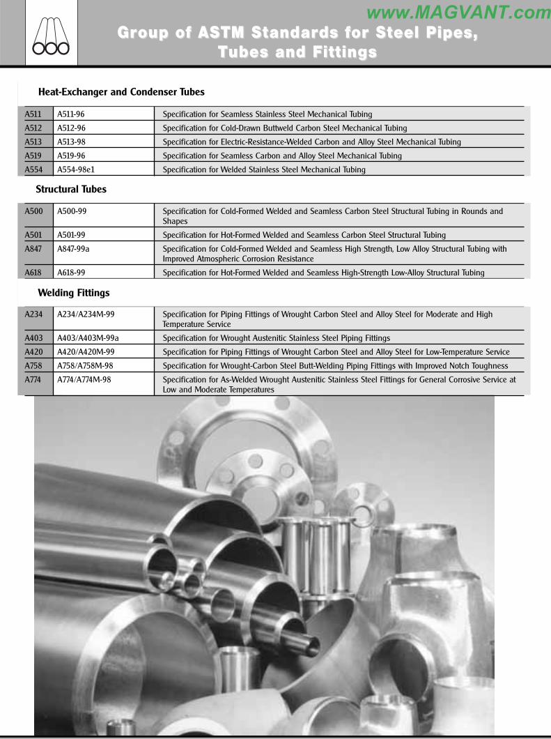
A511 A511-96 Specification for Seamless Stainless Steel Mechanical Tubing
A512 A512-96 Specification for Cold-Drawn Buttweld Carbon Steel Mechanical Tubing
A513 A513-98 Specification for Electric-Resistance-Welded Carbon and Alloy Steel Mechanical Tubing
A519 A519-96 Specification for Seamless Carbon and Alloy Steel Mechanical Tubing
A554 A554-98e1 Specification for Welded Stainless Steel Mechanical Tubing
A500 A500-99 Specification for Cold-Formed Welded and Seamless Carbon Steel Structural Tubing in Rounds andShapes
A501 A501-99 Specification for Hot-Formed Welded and Seamless Carbon Steel Structural Tubing
A847 A847-99a Specification for Cold-Formed Welded and Seamless High Strength, Low Alloy Structural Tubing withImproved Atmospheric Corrosion Resistance
A618 A618-99 Specification for Hot-Formed Welded and Seamless High-Strength Low-Alloy Structural Tubing
A234 A234/A234M-99 Specification for Piping Fittings of Wrought Carbon Steel and Alloy Steel for Moderate and HighTemperature Service
A403 A403/A403M-99a Specification for Wrought Austenitic Stainless Steel Piping Fittings
A420 A420/A420M-99 Specification for Piping Fittings of Wrought Carbon Steel and Alloy Steel for Low-Temperature Service
A758 A758/A758M-98 Specification for Wrought-Carbon Steel Butt-Welding Piping Fittings with Improved Notch Toughness
A774 A774/A774M-98 Specification for As-Welded Wrought Austenitic Stainless Steel Fittings for General Corrosive Service atLow and Moderate Temperatures
Heat-Exchanger and Condenser Tubes
Structural Tubes
Welding Fittings
GrGroup of ASoup of ASTM STM Sttandarandards fds for Sor Stteel Pipes, eel Pipes, TTubes and Fubes and Fittingsittings
332 General CatalogueGeneral Catalogue
www.MAGVANT.com

A682 A682/A682M-98a Specification for Steel, Strip, High-Carbon, Cold-Rolled, General Requirements For
A684 A684/A684M-86 (1998) Specification for Steel, Strip, High-Carbon, Cold-Rolled
A693 A693-93 (1999) Specification for Precipitation-Hardening Stainless and Heat-Resisting Steel Plate, Sheet, and Strip
A700 A700-99 Practices for Packaging, Marking, and Loading Methods for Steel Products for Domestic Shipment
A702 A702-89 (1994) e1 Specification for Steel Fence Posts and Assemblies, Hot Wrought
A715 A715-98 Specification for Steel Sheet and Strip, High-Strength, Low-Alloy, Hot-Rolled, and Steel Sheet, Cold-Rolled,High-Strength, Low-Alloy, with Improved Formability
A749 A749/A749M-97 Specification for Steel, Strip, Carbon and High-Strength, Low-Alloy, Hot-Rolled, General Requirements for
A751 A751-96 Test Methods, Practices, and Terminology for Chemical Analysis of Steel Products
A763 A763-93 (1999) e1 Practices for Detecting Susceptibility to Intergranular Attack in Ferritic Stainless Steels
A793 A793-96 Specification for Rolled Floor Plate, Stainless Steel
A794 A794-97 Specification for Commercial Steel (CS), Sheet, Carbon (0.16% Maximum to 0.25% Maximum), Cold-Rolled
A829 A829/A829M-95 Specification for Alloy Structural Steel Plates
A227 A227/A227M-99 Specification for Steel Wire, Cold-Drawn for Mechanical Springs
A228 A228/A228M-93 Specification for Steel Wire, Music Spring Quality
A229 A229/A229M-99 Specification for Steel Wire, Oil-Tempered for Mechanical Springs
A230 A230/A230M-99 Specification for Steel Wire, Oil-Tempered Carbon Valve Spring Quality
A231 A231/A231M-96 Specification for Chromium-Vanadium Alloy Steel Spring Wire
A232 A232/A232M-99 Specification for Chromium-Vanadium Alloy Steel Valve Spring Quality Wire
A313 A313/A313M-98 Specification for Stainless Steel Spring Wire
A368 A368-95a Specification for Stainless Steel Wire Strand
A401 A401/A401M-98 Specification for Steel Wire, Chromium-Silicon Alloy
A407 A407-93 (1998) Specification for Steel Wire, Cold-Drawn, for Coiled-Type Springs
A478 A478-97 Specification for Chromium-Nickel Stainless Steel Weaving and Knitting Wire
A492 A492-95 Specification for Stainless Steel Rope Wire
A493 A493-95 Specification for Stainless Steel Wire and Wire Rods for Cold Heading and Cold Forging
A510M A510M-00 Specification for General Requirements for Wire Rods and Coarse Round Wire, Carbon Steel [Metric]
A510 A510-00 Specification for General Requirements for Wire Rods and Coarse Round Wire, Carbon Steel
A555 A555/A555M-97 Specification for General Requirements for Stainless Steel Wire and Wire Rods
A580 A580/A580M-98 Specification for Stainless Steel Wire
A581 A581/A581M-95b Specification for Free-Machining Stainless Steel Wire and Wire Rods
A679 A679/A679M-00 Specification for Steel Wire, High Tensile Strength, Cold Drawn
A713 A713-93 (1998) Specification for Steel Wire, High-Carbon Spring, for Heat-Treated Components
A752M A752M-93 (1998) Specification for General Requirements for Wire Rods and Coarse Round Wire, Alloy Steel [Metric]
A752 A752-93 (1998) Specification for General Requirements for Wire Rods and Coarse Round Wire, Alloy Steel
A764 A764-95 Specification for Metallic Coated Carbon Steel Wire, Coated at Size and Drawn to Size for MechanicalSprings
A805 A805-93 (1998) Specification for Steel, Flat Wire, Carbon, Cold-Rolled
STEEL WIRE
GrGroup of ASoup of ASTM STM Sttandarandards fds for Sor Stteel Plateel Plate, e, SheeSheet, St, Strtrip and Wip and Wiriree
334 General CatalogueGeneral Catalogue
www.MAGVANT.com


![Catalogue > complete catalogue [(] radicalmatters.com](https://img.pdfslide.net/doc/110x75/616fb57120885b2db26f2304/catalogue-gt-complete-catalogue-.jpg)