Embed Size (px)
Citation preview
MAHARASHTRA STATE BOARD OF TECHNICAL EDUCATION (Autonomous)
(ISO/IEC - 27001 - 2013 Certified)
WINTER– 17 EXAMINATION Subject Name: DME Model Answer Subject Code: 17610
_________________________________________________________________________________________________
Page 1 of 22
Important Instructions to examiners:
1) The answers should be examined by key words and not as word-to-word as given in the model answer scheme.
2) The model answer and the answer written by candidate may vary but the examiner may try to assess the
understanding level of the candidate.
3) The language errors such as grammatical, spelling errors should not be given more Importance (Not applicable for
subject English and Communication Skills.
4) While assessing figures, examiner may give credit for principal components indicated in the figure. The figures
drawn by candidate and model answer may vary. The examiner may give credit for any equivalent figure drawn.
5) Credits may be given step wise for numerical problems. In some cases, the assumed constant values may vary and
there may be some difference in the candidate’s answers and model answer.
6) In case of some questions credit may be given by judgement on part of examiner of relevant answer based on
candidate’s understanding.
7) For programming language papers, credit may be given to any other program based on equivalent concept.
Q.
No.
Sub
Q.
No.
Answer Marking
Scheme
01.
(a)
(b)
(c)
(d)
Define machine design.
Machine design is the process of selection of the materials, shapes, sizes and arrangements of
mechanical elements so that the resultant machine will perform the prescribed task. OR
Machine Design is the creation of new and better machines and improving the existing ones.
Give the composition of
(i) FeE220: Steel having yield strength of 220 N/mm2.
(ii) 20C8 : Carbon steel containing 0.15 to 0.25 percent (0.2 percent on average) carbon and 0.60 to
0.90 percent (0.80 percent on average) manganese.
State four types of loads acting on machine elements.
(i) Dead or steady load
(ii) Live or variable load
(iii) Suddenly applied or shock load
(iv) Impact load
What do you mean by creep?
When a machine part is subjected to a constant stress at high temperature for a long period of time, it
will undergo a slow and permanent deformation called ‘creep’. This property is considered in designing
internal combustion engines, boilers and turbines.
2
1
1
½
½
½
½
2
MAHARASHTRA STATE BOARD OF TECHNICAL EDUCATION (Autonomous)
(ISO/IEC - 27001 - 2013 Certified)
WINTER– 17 EXAMINATION Subject Name: DME Model Answer Subject Code: 17610
_________________________________________________________________________________________________
Page 2 of 22
(e)
(f)
(g)
(h)
(i)
Define Ergonomics.
Ergonomics is defined as the scientific study of the man – machine working environment relationship
and the application of anatomical, physiological, psychological principles to solve the problems arising
from this relationship.
Give two applications of knuckle joint.
(i) A knuckle joint is used to connect two rods which are under the action of tensile loads. However, if
the joint is guided, the rods may support a compressive load.
(ii) Its use may be found in the link of a cycle chain, tie rod joint of roof truss, valve rod joint with
eccentric rod, pump rod joint, tension link in bridge structure and lever and rod connections of
various types.
Define following terms of spring:
(i) Spring rate: The spring rate is defined as the load required per unit deflection of the spring. It is also
known as spring stiffness or spring constant. Mathematically,
Spring rate, k = W / 𝛿
Where, W = Load
𝛿 = Deflection of the spring
(ii) Spring index: The spring index is defined as the ratio of the mean diameter of the coil to the
diameter of the wire. Mathematically,
Spring index, C = D / d
Where, D = Mean diameter of the coil
d = Diameter of the wire
How do you express the life of bearings?
The life of an individual bearing is defined as the total number of revolutions (or the number of hours
at a given constant speed) which the bearing can complete before the evidence of fatigue failure
develops on the balls or races.
The bearing life can be defined by rating life.
The rating life of a group of apparently identical bearing is defined as the number of revolutions (or
the number of hours at a given constant speed) that 90 percent of a group of bearings will complete or
exceed before the first evidence of fatigue failure develops. It is also known as L10 life.
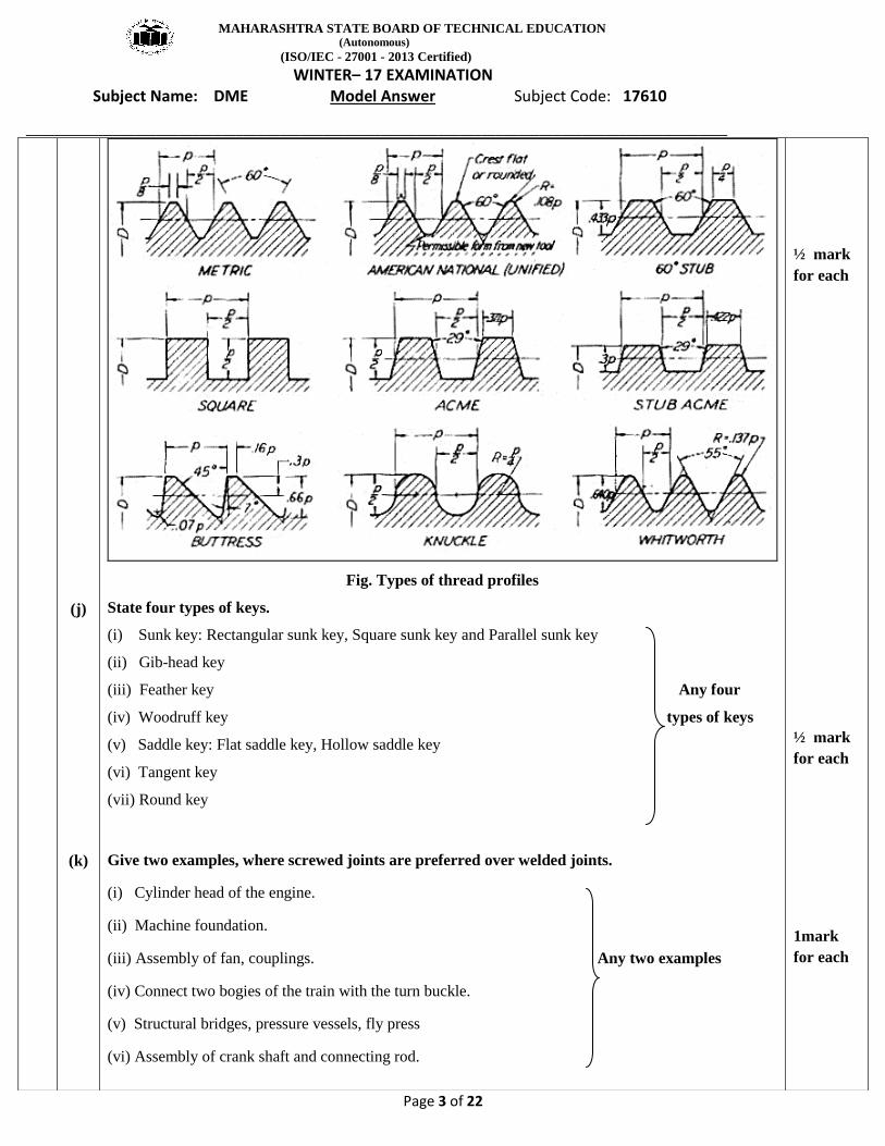
Draw the different thread profiles used for power screws.(Draw any four thread profiles)
2
2 mark
for any 2
applicati
on
1
1
1
1
1
MAHARASHTRA STATE BOARD OF TECHNICAL EDUCATION (Autonomous)
(ISO/IEC - 27001 - 2013 Certified)
WINTER– 17 EXAMINATION Subject Name: DME Model Answer Subject Code: 17610
_________________________________________________________________________________________________
Page 3 of 22
(j)
(k)
Fig. Types of thread profiles
State four types of keys.
(i) Sunk key: Rectangular sunk key, Square sunk key and Parallel sunk key
(ii) Gib-head key
(iii) Feather key Any four
(iv) Woodruff key types of keys
(v) Saddle key: Flat saddle key, Hollow saddle key
(vi) Tangent key
(vii) Round key
Give two examples, where screwed joints are preferred over welded joints.
(i) Cylinder head of the engine.
(ii) Machine foundation.
(iii) Assembly of fan, couplings. Any two examples
(iv) Connect two bogies of the train with the turn buckle.
(v) Structural bridges, pressure vessels, fly press
(vi) Assembly of crank shaft and connecting rod.
½ mark
for each
½ mark
for each
1mark
for each
MAHARASHTRA STATE BOARD OF TECHNICAL EDUCATION (Autonomous)
(ISO/IEC - 27001 - 2013 Certified)
WINTER– 17 EXAMINATION Subject Name: DME Model Answer Subject Code: 17610
_________________________________________________________________________________________________
Page 4 of 22
02.
(l)
(m)
(n)
(a)
State any four applications of rolling contact bearings.
(i) Industrial and automotive gear boxes.
(ii) Electric motors and machine tool spindles.
(iii) Small size centrifugal pumps.
(iv) Automobile front and rear axles.
What are the requirement of a good coupling?(Any four)
A good coupling should have the following requirements:
(i) It should be easy to connect and disconnect.
(ii) It should transmit the full power from one shaft to another shaft without losses.
(iii) It should hold the shafts in perfect alignment.
(iv) It should reduce the transmission of shock loads from one shaft to another shaft.
(v) It should have no projecting parts.
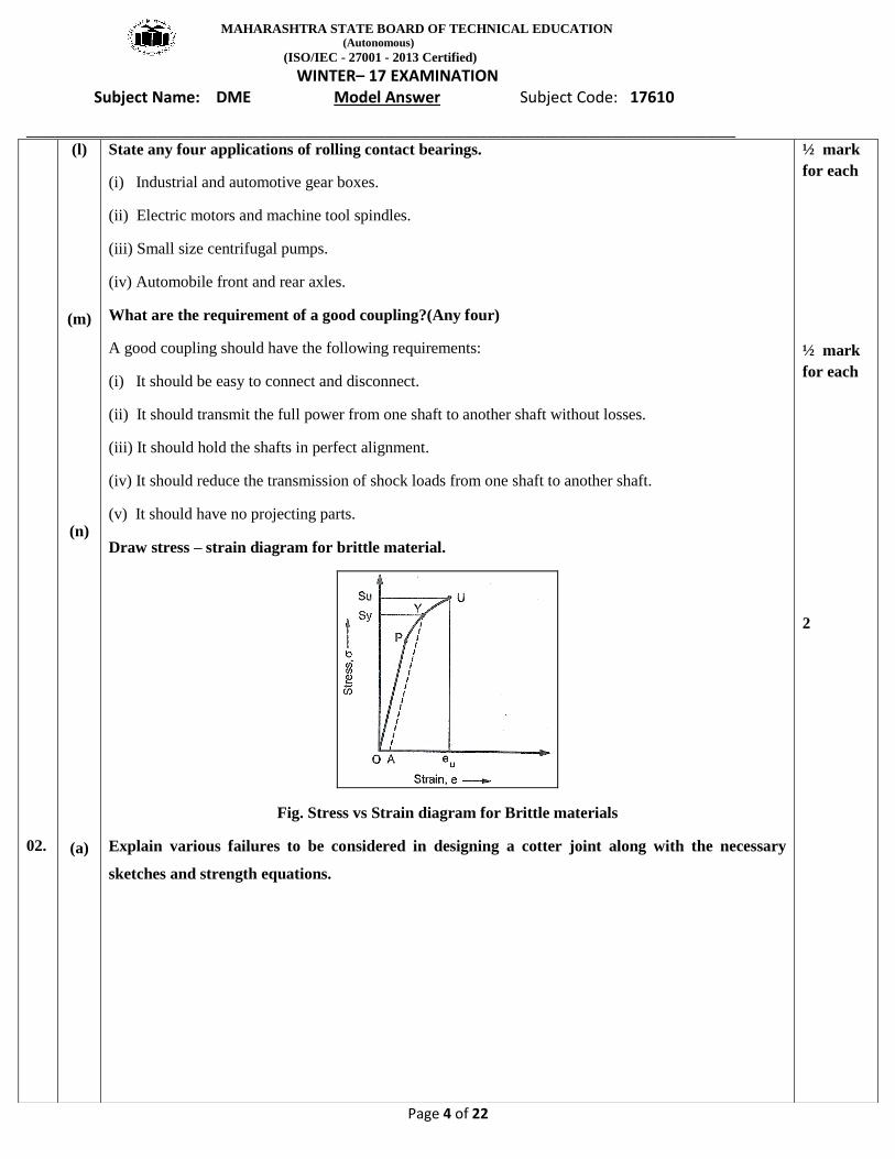
Draw stress – strain diagram for brittle material.
Fig. Stress vs Strain diagram for Brittle materials
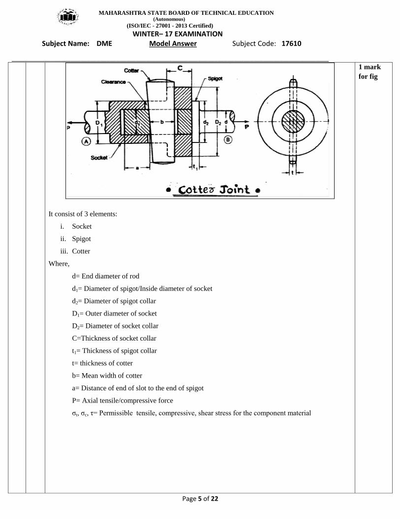
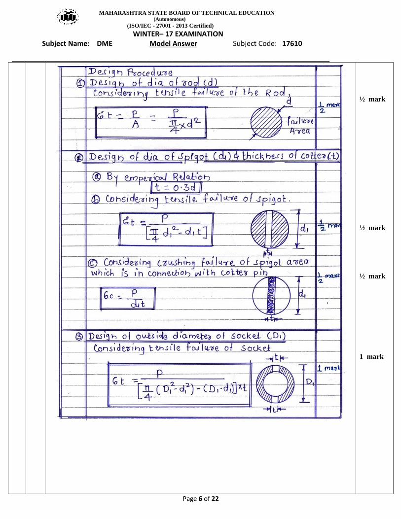
Explain various failures to be considered in designing a cotter joint along with the necessary
sketches and strength equations.
½ mark
for each
½ mark
for each
2
MAHARASHTRA STATE BOARD OF TECHNICAL EDUCATION (Autonomous)
(ISO/IEC - 27001 - 2013 Certified)
WINTER– 17 EXAMINATION Subject Name: DME Model Answer Subject Code: 17610
_________________________________________________________________________________________________
Page 5 of 22
It consist of 3 elements:
i. Socket
ii. Spigot
iii. Cotter
Where,
d= End diameter of rod
d1= Diameter of spigot/Inside diameter of socket
d2= Diameter of spigot collar
D1= Outer diameter of socket
D2= Diameter of socket collar
C=Thickness of socket collar
t1= Thickness of spigot collar
t= thickness of cotter
b= Mean width of cotter
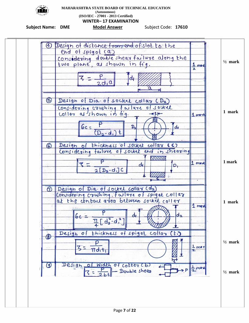
a= Distance of end of slot to the end of spigot
P= Axial tensile/compressive force
σt, σc, τ= Permissible tensile, compressive, shear stress for the component material
1 mark
for fig
MAHARASHTRA STATE BOARD OF TECHNICAL EDUCATION (Autonomous)
(ISO/IEC - 27001 - 2013 Certified)
WINTER– 17 EXAMINATION Subject Name: DME Model Answer Subject Code: 17610
_________________________________________________________________________________________________
Page 6 of 22
½ mark
½ mark
½ mark
1 mark
MAHARASHTRA STATE BOARD OF TECHNICAL EDUCATION (Autonomous)
(ISO/IEC - 27001 - 2013 Certified)
WINTER– 17 EXAMINATION Subject Name: DME Model Answer Subject Code: 17610
_________________________________________________________________________________________________
Page 7 of 22
½ mark
1 mark
1 mark
1 mark
½ mark
½ mark
MAHARASHTRA STATE BOARD OF TECHNICAL EDUCATION (Autonomous)
(ISO/IEC - 27001 - 2013 Certified)
WINTER– 17 EXAMINATION Subject Name: DME Model Answer Subject Code: 17610
_________________________________________________________________________________________________
Page 8 of 22
(b)
State the theories of elastic failure. Explain maximum normal stress theory and maximum shear
stress theory with equations.
The principal theories of failure for a member are as follows:(Any four)
(i) Maximum principal or normal stress theory
(ii) Maximum shear stress theory
(iii) Maximum principal or normal strain theory
(iv) Maximum strain energy theory
(v) Maximum distortion energy theory
Maximum normal stress theory
According to this theory, the elastic failure occurs when the greatest principal stress reaches the
elastic limit value in a simple tension test irrespective of the value of other two principal stresses.
Taking factor of safety (F. S.) into consideration, the maximum principal or normal stress (σt) is given
by,
σt = σyt / F. S. (for ductile materials)
σt = σu / F. S. (for brittle materials)
where, σyt = Yield point stress in tension as determined from simple tension test
σu = Ultimate stress
This theory ignores the possibility of failure due to shear stress, therefore it is not used for ductile
materials.
2 marks
½ mark
each
3
MAHARASHTRA STATE BOARD OF TECHNICAL EDUCATION (Autonomous)
(ISO/IEC - 27001 - 2013 Certified)
WINTER– 17 EXAMINATION Subject Name: DME Model Answer Subject Code: 17610
_________________________________________________________________________________________________
Page 9 of 22
(c)
However, for brittle materials which are relatively strong in shear but weak in tension and
compression, this theory is generally used.
This theory is also known as maximum principal stress theory or Rankine’s theory.
Maximum Shear Stress Theory
According to this theory, the failure or yielding occurs at a point in a member when the maximum
shear stress reaches a value equal to the shear stress at yield point in a simple tension test.
Mathematically,
τmax = τyt / F. S.
where, τmax = Maximum shear stress
τyt = Shear stress at yield point as determined from simple tension test
F. S = Factor of safety
Since the shear stress at yield point in a simple tension test is equal to one half the yield stress in
tension, therefore
τmax = σyt / (2 x F. S.)
This theory is mostly used for designing members of ductile materials.
This theory is also known as Guest’s theory or Tresca’s theory.
(i) State and describe in brief about four ergonomic considerations in the designing of machine
elements.
The different areas covered under the ergonomics are:
1. Communication between the man (user) and the machine.
2. Working environment.
3. Human anatomy and posture while using the machine.
4. Energy expenditure in hand and foot operations.
Communication between man and machine
The machine has a display unit and a control unit.
A man (user) receives the information from the machine display through the sense organs.
He (or she) then takes the corrective action on the machine controls using the hands or feet.
This man-machine closed loop system in influenced by the working environmental factors such
3
1 mark
for each
cosiderati
on
MAHARASHTRA STATE BOARD OF TECHNICAL EDUCATION (Autonomous)
(ISO/IEC - 27001 - 2013 Certified)
WINTER– 17 EXAMINATION Subject Name: DME Model Answer Subject Code: 17610
_________________________________________________________________________________________________
Page 10 of 22
as: lighting, noise, temperature, humidity, air circulation, etc.
Working Environment
The working environment affects significantly the man-machine relationship.
It affects the efficiency and possibly the health of the operator.
The major working environmental factors are: Lighting, Noise, Temperature, Humidity and air
circulation.
Ergonomics Considerations in Design of Controls
The control devices should be logically positioned and easily accessible.
The control operation should involve minimum and smooth moments.
The control operation should consume minimum energy.
The controls should be painted in proper colour to attract the attention.
Ergonomics Considerations in the Design of Displays
The scale should be clear and legible.
The size of the numbers or letters on the scale should be taken appropriate.
The pointer should have a knife-edge with a mirror in a dial to minimize the parallax
error while taking the readings.
The scale should be divided in a linear progression such as 0 – 10 – 20 – 30… and not
as 0 – 5 – 25 – 45…..
The number of subdivisions between the numbered divisions should be as less as
possible.
The numbering should be in clockwise direction on a circular scale, from left to right
on a horizontal scale and from bottom to top on a vertical scale.
(ii) How will select bearing from manufacturer catalogue?
The following steps must be adopted in selecting the bearing from the manufacturer’s catalogue:
1. Calculate the radial and axial load reaction (Fa and Fr) acting on the bearing.
2. Decide the diameter of the shaft on which the bearing is to be mounted.
3. Select the proper size of bearing suitable for given application, specified with speed and available
space.
4. Find the basic static rating Co of the selected bearing from the catalogue.
5. Calculate the ratio (Fa / VFr) and (Fa / Co).
6. Find the value of x and y i. e. radial and thrust factor from the catalogue. These values depend upon
(Fa / VFr) and (Fa / Co).
4 marks
MAHARASHTRA STATE BOARD OF TECHNICAL EDUCATION (Autonomous)
(ISO/IEC - 27001 - 2013 Certified)
WINTER– 17 EXAMINATION Subject Name: DME Model Answer Subject Code: 17610
_________________________________________________________________________________________________
Page 11 of 22
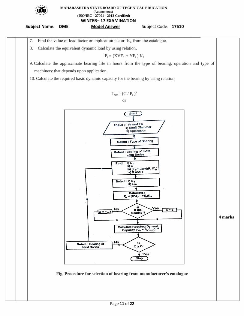
7. Find the value of load factor or application factor ‘Ka‘from the catalogue.
8. Calculate the equivalent dynamic load by using relation,
Pe = (XVFa + YFa ) Ka
9. Calculate the approximate bearing life in hours from the type of bearing, operation and type of
machinery that depends upon application.
10. Calculate the required basic dynamic capacity for the bearing by using relation,
L10 = (C / Pe )a
or
Fig. Procedure for selection of bearing from manufacturer’s catalogue
4 marks
MAHARASHTRA STATE BOARD OF TECHNICAL EDUCATION (Autonomous)
(ISO/IEC - 27001 - 2013 Certified)
WINTER– 17 EXAMINATION Subject Name: DME Model Answer Subject Code: 17610
_________________________________________________________________________________________________
Page 12 of 22
03.
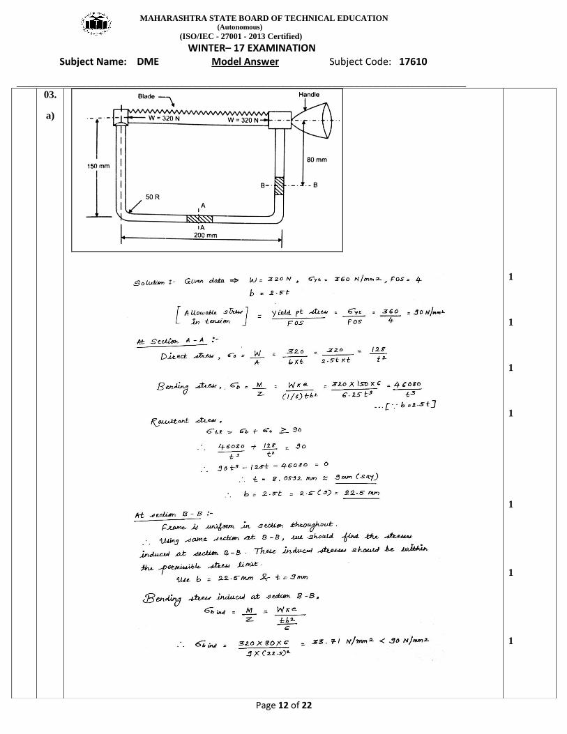
a)
1
1
1
1
1
1
1
MAHARASHTRA STATE BOARD OF TECHNICAL EDUCATION (Autonomous)
(ISO/IEC - 27001 - 2013 Certified)
WINTER– 17 EXAMINATION Subject Name: DME Model Answer Subject Code: 17610
_________________________________________________________________________________________________
Page 13 of 22
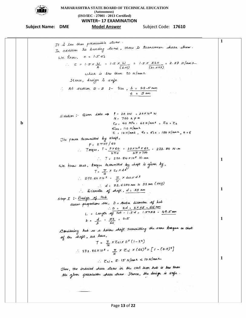
b
1
1
1
1
1
MAHARASHTRA STATE BOARD OF TECHNICAL EDUCATION (Autonomous)
(ISO/IEC - 27001 - 2013 Certified)
WINTER– 17 EXAMINATION Subject Name: DME Model Answer Subject Code: 17610
_________________________________________________________________________________________________
Page 14 of 22
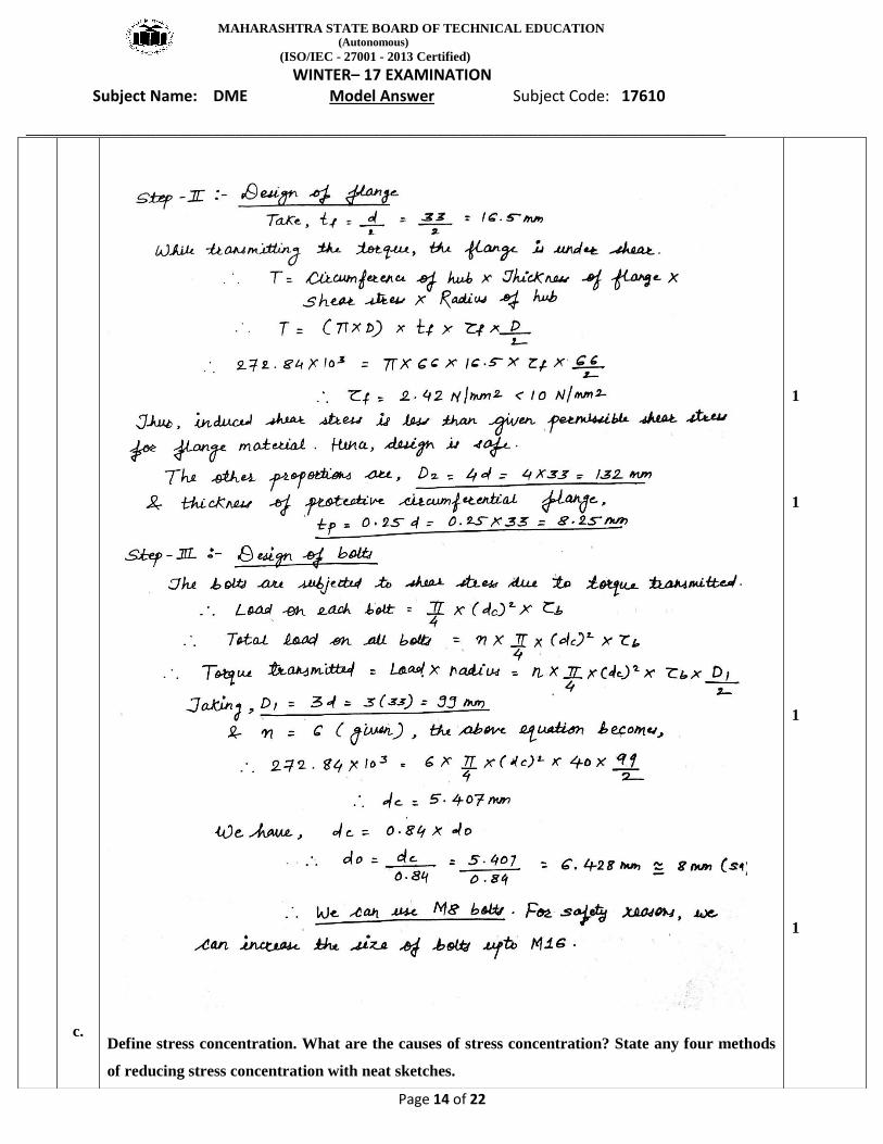
c.
Define stress concentration. What are the causes of stress concentration? State any four methods
of reducing stress concentration with neat sketches.
1
1
1
1
MAHARASHTRA STATE BOARD OF TECHNICAL EDUCATION (Autonomous)
(ISO/IEC - 27001 - 2013 Certified)
WINTER– 17 EXAMINATION Subject Name: DME Model Answer Subject Code: 17610
_________________________________________________________________________________________________
Page 15 of 22
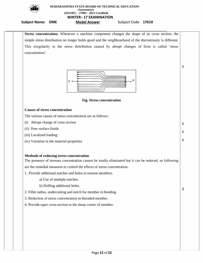
Stress concentration: Whenever a machine component changes the shape of its cross section, the
simple stress distribution no longer holds good and the neighbourhood of the discontinuity is different.
This irregularity in the stress distribution caused by abrupt changes of form is called ‘stress
concentration’.
Fig. Stress concentration
Causes of stress concentration
The various causes of stress concentration are as follows:
(i) Abrupt change of cross section
(ii) Poor surface finish
(iii) Localized loading
(iv) Variation in the material properties
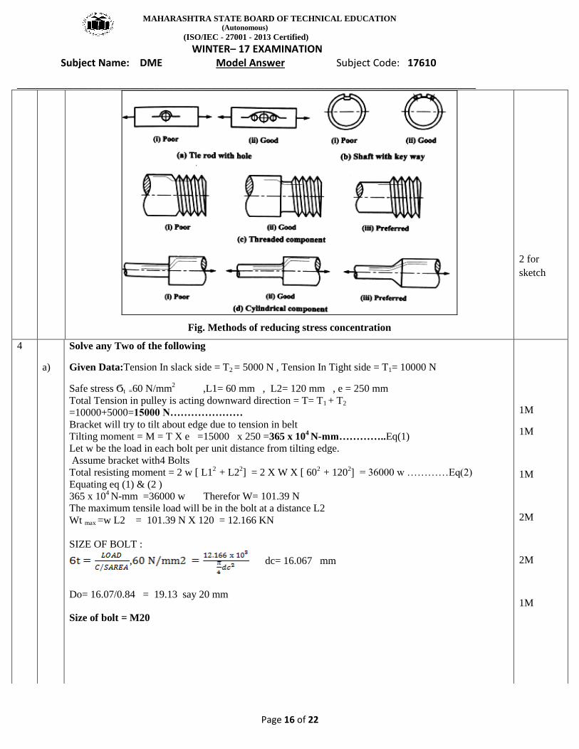
Methods of reducing stress concentration
The presence of stresses concentration cannot be totally eliminated but it can be reduced, so following
are the remedial measures to control the effects of stress concentration.
1. Provide additional notches and holes in tension members.
a) Use of multiple notches.
b) Drilling additional holes.
2. Fillet radius, undercutting and notch for member in bending.
3. Reduction of stress concentration in threaded member.
4. Provide taper cross-section to the sharp corner of member.
1
1
1
1
2
MAHARASHTRA STATE BOARD OF TECHNICAL EDUCATION (Autonomous)
(ISO/IEC - 27001 - 2013 Certified)
WINTER– 17 EXAMINATION Subject Name: DME Model Answer Subject Code: 17610
_________________________________________________________________________________________________
Page 16 of 22
Fig. Methods of reducing stress concentration
2 for
sketch
4
a)
Solve any Two of the following
Given Data:Tension In slack side = T2 = 5000 N , Tension In Tight side = T1= 10000 N
Safe stress Ϭt =60 N/mm2 ,L1= 60 mm , L2= 120 mm , e = 250 mm
Total Tension in pulley is acting downward direction = T= T1 + T2
=10000+5000=15000 N…………………
Bracket will try to tilt about edge due to tension in belt
Tilting moment = M = T X e =15000 x 250 =365 x 104 N-mm…………..Eq(1)
Let w be the load in each bolt per unit distance from tilting edge.
Assume bracket with4 Bolts
Total resisting moment = 2 w [ L12
+ L22] = 2 X W X [ 60
2 + 120
2] = 36000 w …………Eq(2)
Equating eq (1) & (2 )
365 x 104 N-mm =36000 w Therefor W= 101.39 N
The maximum tensile load will be in the bolt at a distance L2
Wt max =w L2 = 101.39 N X 120 = 12.166 KN
SIZE OF BOLT :
, dc= 16.067 mm
Do= 16.07/0.84 = 19.13 say 20 mm
Size of bolt = M20
1M
1M
1M
2M
2M
1M
MAHARASHTRA STATE BOARD OF TECHNICAL EDUCATION (Autonomous)
(ISO/IEC - 27001 - 2013 Certified)
WINTER– 17 EXAMINATION Subject Name: DME Model Answer Subject Code: 17610
_________________________________________________________________________________________________
Page 17 of 22
b Design of spring
Given Data:LOAD W= 500N , C= 8 τ =350 MPa = 350 N/m
G= 85 x 10 3 N/mm
2
= 1.184
,
say 6 mm
, , n =6.15 say 7
2 M
2M
1 M
2M
1M
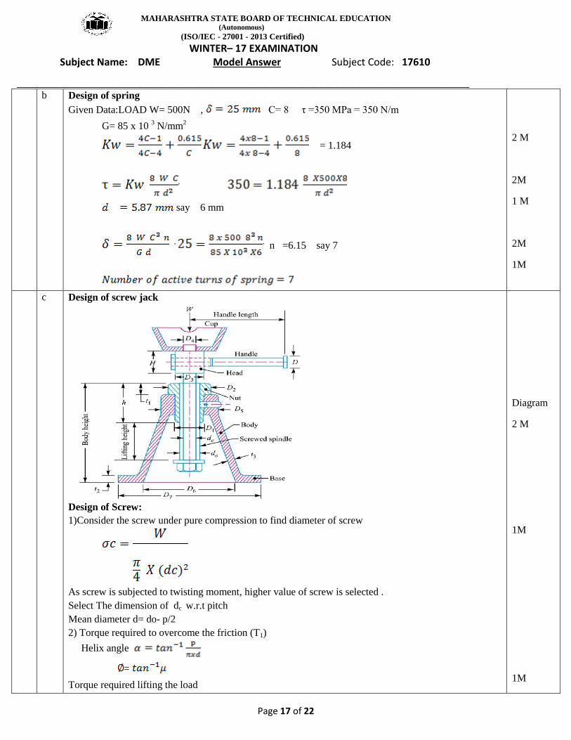
c Design of screw jack
Design of Screw:
1)Consider the screw under pure compression to find diameter of screw
As screw is subjected to twisting moment, higher value of screw is selected .
Select The dimension of dc w.r.t pitch
Mean diameter d= do- p/2
2) Torque required to overcome the friction (T1)
Helix angle
=
Torque required lifting the load
Diagram
2 M
1M
1M
MAHARASHTRA STATE BOARD OF TECHNICAL EDUCATION (Autonomous)
(ISO/IEC - 27001 - 2013 Certified)
WINTER– 17 EXAMINATION Subject Name: DME Model Answer Subject Code: 17610
_________________________________________________________________________________________________
Page 18 of 22
T1= W. tan (
As collar friction is Neglecting, T2=0
Total Torque required to lift the load = T1
For Checking:
Direct compressive stress in screw:
,
Torsional shear stress τ ,
According to Maximum shear stress theory, the maximum shear stress in the screw
τmax
Permissible shear stress for a screw τ =
τmax<allowable , So screw is safe
Design of Nut:
The bearing pressure between the thread
Height of Nut: H= n X P
Check: Shear stress induced in the screw thread
as t= p/2
calculated< allowable , So screw is safe .
1 M
1M
1M
1M
5 A
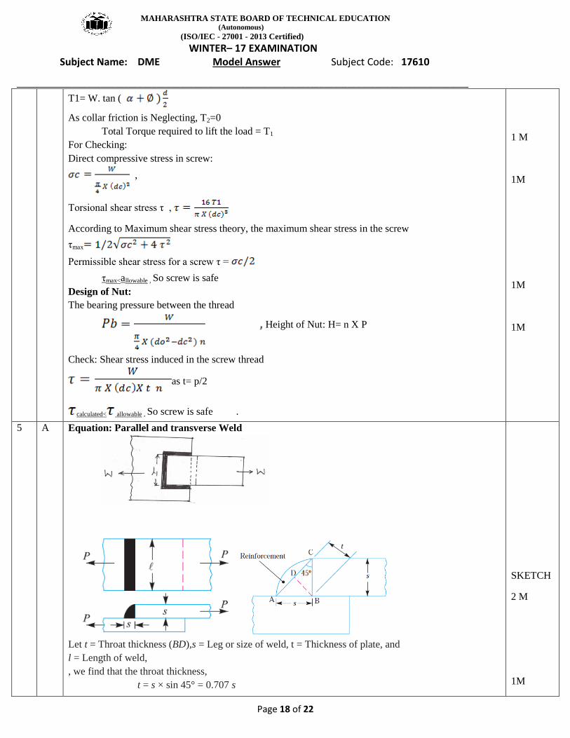
Equation: Parallel and transverse Weld
Let t = Throat thickness (BD),s = Leg or size of weld, t = Thickness of plate, and
l = Length of weld,
, we find that the throat thickness,
t = s × sin 45° = 0.707 s
SKETCH
2 M
1M
MAHARASHTRA STATE BOARD OF TECHNICAL EDUCATION (Autonomous)
(ISO/IEC - 27001 - 2013 Certified)
WINTER– 17 EXAMINATION Subject Name: DME Model Answer Subject Code: 17610
_________________________________________________________________________________________________
Page 19 of 22
b)
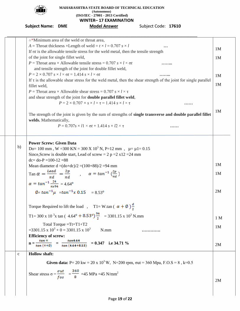
∴*Minimum area of the weld or throat area,
A = Throat thickness ×Length of weld = t × l = 0.707 s × l …
If σt is the allowable tensile stress for the weld metal, then the tensile strength
of the joint for single fillet weld,
P = Throat area × Allowable tensile stress = 0.707 s × l × σt ……..
and tensile strength of the joint for double fillet weld,
P = 2 × 0.707 s × l × σt = 1.414 s × l × σt ……..
If τ is the allowable shear stress for the weld metal, then the shear strength of the joint for single parallel
fillet weld,
P = Throat area × Allowable shear stress = 0.707 s × l × τ
and shear strength of the joint for double parallel fillet weld,
P = 2 × 0.707 × s × l × τ = 1.414 s × l × τ ……
The strength of the joint is given by the sum of strengths of single transverse and double parallel fillet
welds. Mathematically,
P = 0.707s × l1 × σt + 1.414 s × l2 × τ ……
Power Screw: Given Data
Do= 100 mm , W =300 KN = 300 X 103 N, P=12 mm , µ= µ1= 0.15
Since,Screw is double start, Lead of screw = 2 p =2 x12 =24 mm
dc= do-P =100-12 =88
Mean diameter d =(do+dc)/2 =(100+88)/2 =94 mm
Tan ,
= 4.64
= = = 8.53
Torque Required to lift the load , T1= W.tan (
T1= 300 x 10 3x tan ( 4.64 = 3301.15 x 10
3 N.mm
Total Torque =Tt=T1+T2
=3301.15 x 103 + 0 = 3301.15 x 10
3 N.mm ………….
Efficiency of screw:
n = = = 0.347 i.e 34.71 %
1M
1M
1M
1M
1M
1M
1M
2M
1 M
1M
2M
c Hollow shaft:
Given data: P= 20 kw = 20 x 103 W, N=200 rpm, σut = 360 Mpa, F.O.S = 8 , k=0.5
Shear stress σ = = =45 MPa =45 N/mm2
2M
MAHARASHTRA STATE BOARD OF TECHNICAL EDUCATION (Autonomous)
(ISO/IEC - 27001 - 2013 Certified)
WINTER– 17 EXAMINATION Subject Name: DME Model Answer Subject Code: 17610
_________________________________________________________________________________________________
Page 20 of 22
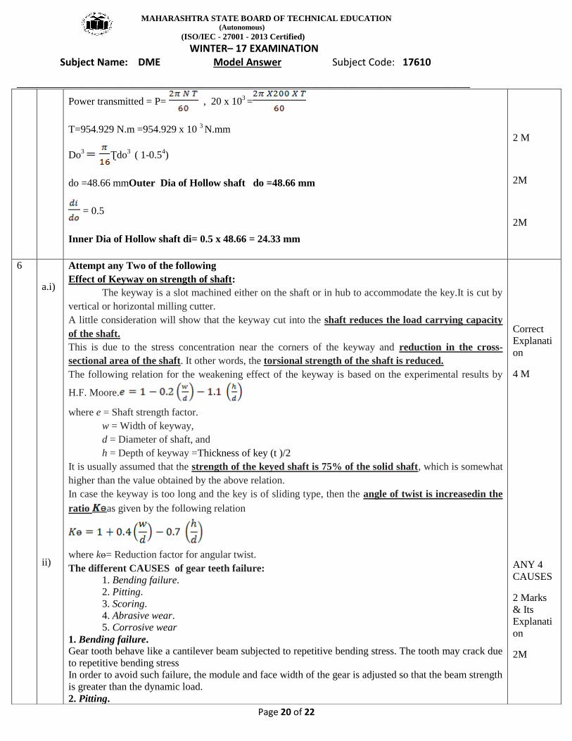
Power transmitted = P= , 20 x 103 =
T=954.929 N.m =954.929 x 10 3 N.mm
Do3
Ʈdo3 ( 1-0.5
4)
do =48.66 mmOuter Dia of Hollow shaft do =48.66 mm
= 0.5
Inner Dia of Hollow shaft di= 0.5 x 48.66 = 24.33 mm
2 M
2M
2M
6
a.i)
ii)
Attempt any Two of the following
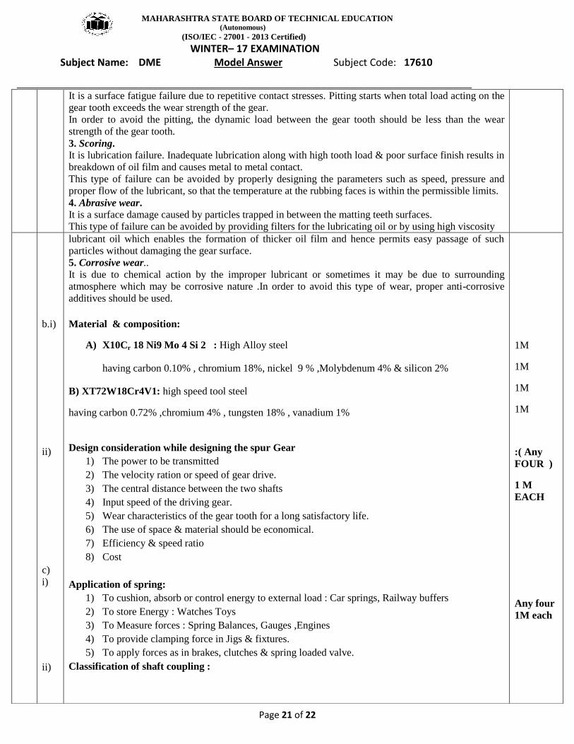
Effect of Keyway on strength of shaft:
The keyway is a slot machined either on the shaft or in hub to accommodate the key.It is cut by
vertical or horizontal milling cutter.
A little consideration will show that the keyway cut into the shaft reduces the load carrying capacity
of the shaft.
This is due to the stress concentration near the corners of the keyway and reduction in the cross-
sectional area of the shaft. It other words, the torsional strength of the shaft is reduced.
The following relation for the weakening effect of the keyway is based on the experimental results by
H.F. Moore.
where e = Shaft strength factor.
w = Width of keyway,
d = Diameter of shaft, and
h = Depth of keyway =Thickness of key (t )/2
It is usually assumed that the strength of the keyed shaft is 75% of the solid shaft, which is somewhat
higher than the value obtained by the above relation.
In case the keyway is too long and the key is of sliding type, then the angle of twist is increasedin the
ratio as given by the following relation
where kѳ= Reduction factor for angular twist.
The different CAUSES of gear teeth failure: 1. Bending failure.
2. Pitting.
3. Scoring.
4. Abrasive wear.
5. Corrosive wear
1. Bending failure.
Gear tooth behave like a cantilever beam subjected to repetitive bending stress. The tooth may crack due
to repetitive bending stress
In order to avoid such failure, the module and face width of the gear is adjusted so that the beam strength
is greater than the dynamic load.
2. Pitting.
Correct
Explanati
on
4 M
ANY 4
CAUSES
2 Marks
& Its
Explanati
on
2M
MAHARASHTRA STATE BOARD OF TECHNICAL EDUCATION (Autonomous)
(ISO/IEC - 27001 - 2013 Certified)
WINTER– 17 EXAMINATION Subject Name: DME Model Answer Subject Code: 17610
_________________________________________________________________________________________________
Page 21 of 22
It is a surface fatigue failure due to repetitive contact stresses. Pitting starts when total load acting on the
gear tooth exceeds the wear strength of the gear.
In order to avoid the pitting, the dynamic load between the gear tooth should be less than the wear
strength of the gear tooth.
3. Scoring.
It is lubrication failure. Inadequate lubrication along with high tooth load & poor surface finish results in
breakdown of oil film and causes metal to metal contact.
This type of failure can be avoided by properly designing the parameters such as speed, pressure and
proper flow of the lubricant, so that the temperature at the rubbing faces is within the permissible limits.
4. Abrasive wear.
It is a surface damage caused by particles trapped in between the matting teeth surfaces.
This type of failure can be avoided by providing filters for the lubricating oil or by using high viscosity
b.i)
ii)
c)
i)
ii)
lubricant oil which enables the formation of thicker oil film and hence permits easy passage of such
particles without damaging the gear surface.
5. Corrosive wear..
It is due to chemical action by the improper lubricant or sometimes it may be due to surrounding
atmosphere which may be corrosive nature .In order to avoid this type of wear, proper anti-corrosive
additives should be used.
Material & composition:
A) X10Cr 18 Ni9 Mo 4 Si 2 : High Alloy steel
having carbon 0.10% , chromium 18%, nickel 9 % ,Molybdenum 4% & silicon 2%
B) XT72W18Cr4V1: high speed tool steel
having carbon 0.72% ,chromium 4% , tungsten 18% , vanadium 1%
Design consideration while designing the spur Gear
1) The power to be transmitted
2) The velocity ration or speed of gear drive.
3) The central distance between the two shafts
4) Input speed of the driving gear.
5) Wear characteristics of the gear tooth for a long satisfactory life.
6) The use of space & material should be economical.
7) Efficiency & speed ratio
8) Cost
Application of spring:
1) To cushion, absorb or control energy to external load : Car springs, Railway buffers
2) To store Energy : Watches Toys
3) To Measure forces : Spring Balances, Gauges ,Engines
4) To provide clamping force in Jigs & fixtures.
5) To apply forces as in brakes, clutches & spring loaded valve.
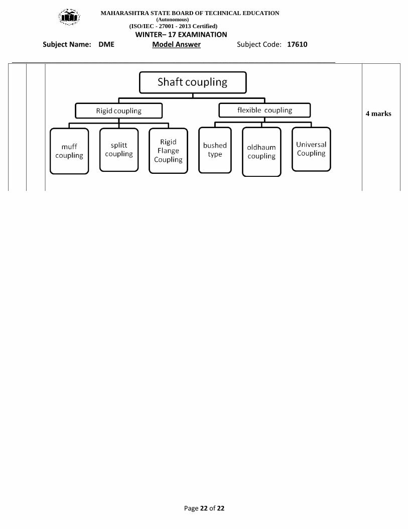
Classification of shaft coupling :
1M
1M
1M
1M
:( Any
FOUR )
1 M
EACH
Any four
1M each
MAHARASHTRA STATE BOARD OF TECHNICAL EDUCATION (Autonomous)
(ISO/IEC - 27001 - 2013 Certified)
WINTER– 17 EXAMINATION Subject Name: DME Model Answer Subject Code: 17610
_________________________________________________________________________________________________
Page 22 of 22
4 marks