Embed Size (px)
Citation preview

7828 TETRA TECH ● MARTIN STATE AIRPORT ● MAIN TERMINAL SUPPLEMENTAL PHASE II SITE INVESTIGATION WORK PLAN
Main Terminal Supplemental Phase II Site Investigation Work Plan
Martin State Airport 701 Wilson Point Road Middle River, Maryland
Prepared for:
Lockheed Martin Corporation
Prepared by:
Tetra Tech, Inc.
May 2012
Michael Martin, P.G. Regional Manager
Anthony Apanavage, P.G. Project Manager
7828 TETRA TECH • MARTIN STATE AIRPORT • MAIN TERMINAL• SUPPLEMENTAL PHASE II SITE INVESTIGATION WORK PLAN PAGE i
TABLE OF CONTENTS
Section Page ACRONYMS ................................................................................................................................ iii 1 INTRODUCTION .................................................................................................... 1-1
2 SITE BACKGROUND ............................................................................................. 2-1
2.1 SITE DESCRIPTION ..................................................................................................... 2-1 2.1.1 Location ............................................................................................................... 2-1 2.1.2 History.................................................................................................................. 2-1 2.1.3 Current Conditions ............................................................................................... 2-2 2.1.4 Land Use .............................................................................................................. 2-2 2.1.5 Climate ................................................................................................................. 2-3 2.1.6 Physiography........................................................................................................ 2-3 2.1.7 Topography .......................................................................................................... 2-4 2.1.8 Surface Water Hydrology ..................................................................................... 2-4 2.1.9 Geology and Hydrogeology ................................................................................. 2-5 2.1.10 Vicinity Subsurface Conditions ........................................................................... 2-6
2.2 PREVIOUS INVESTIGATIONS ................................................................................... 2-6 2.2.1 Preliminary Assessment ....................................................................................... 2-7 2.2.2 Main Terminal Environmental Evaluations ......................................................... 2-7 2.2.3 Main Terminal Phase II Investigation (2011) .................................................... 2-15
3 INVESTIGATION APPROACH AND METHODOLOGY ......................................... 3-1
3.1 MOBILIZATION/DEMOBILIZATION ......................................................................... 3-2 3.2 SITE ACCESS, PERMITS, AND UTILITY CLEARANCE ......................................... 3-2 3.3 FIELD METHODOLOGY ............................................................................................. 3-5
3.3.1 Soil Investigation ................................................................................................. 3-5 3.3.2 Groundwater Investigation................................................................................... 3-6 3.3.3 Surveying ........................................................................................................... 3-11 3.3.4 General Sampling Procedures, Nomenclature, and Handling ........................... 3-11 3.3.5 Equipment Decontamination ............................................................................. 3-12

7828 TETRA TECH • MARTIN STATE AIRPORT • MAIN TERMINAL• SUPPLEMENTAL PHASE II SITE INVESTIGATION WORK PLAN PAGE ii
TABLE OF CONTENTS (continued)
Section Page 3.3.6 Waste Management ............................................................................................ 3-13 3.3.7 Site Restoration .................................................................................................. 3-13
3.4 DATA MANAGEMENT............................................................................................... 3-13 3.4.1 Data Tracking and Control ................................................................................. 3-14 3.4.2 Sample Information ........................................................................................... 3-14 3.4.3 Project Data Compilation ................................................................................... 3-14 3.4.4 Geographical Information System ..................................................................... 3-15 3.4.5 Data Review ....................................................................................................... 3-15
4 PROJECT DELIVERABLES .................................................................................. 4-1
5 REFERENCES ....................................................................................................... 5-1
APPENDICES
APPENDIX A—HEALTH AND SAFETY PLAN
APPENDIX B—WASTE MANAGEMENT PLAN
LIST OF FIGURES Page
Figure 1-1 Martin State Airport and Main Terminal Area Location Map .................................. 1-3
Figure 1-2 Martin State Airport Main Terminal Buildings and Surrounding Features .............. 1-4
Figure 2-1 Recognized Environmental Conditions at MSA Main Terminal ............................ 2-18
Figure 3-1 Proposed Soil Borings and Groundwater Monitoring Wells— Supplemental Phase II Investigation—North MSA Main Terminal Area .............. 3-19
Figure 3-2 Proposed Soil Borings and Groundwater Monitoring Wells— Supplemental Phase II Investigation—South MSA Main Terminal Area .............. 3-20
LIST OF TABLES
Page Table 3-1 Soil Sampling Details and Rationale ................................................................. 3-16
Table 3-2 Groundwater Monitoring Well Details and Rationale ....................................... 3-17

7828 TETRA TECH • MARTIN STATE AIRPORT • MAIN TERMINAL• SUPPLEMENTAL PHASE II SITE INVESTIGATION WORK PLAN PAGE iii
ACRONYMS
BWI Baltimore/Washington Thurgood Marshall International Airport
COC chain of custody
DO dissolved oxygen
DPT direct push technology
DRO diesel range organics
EESH Energy, Environment, Safety, and Health
EGIS environmental geographic information system
EM electromagnetic
FAA Federal Aviation Administration
GIS geographic information system
GPR ground penetrating radar
GPS global positioning system
GRO gasoline range organics
GSP Greater Strawberry Point
HASP health and safety plan
IDW investigation-derived waste
Lockheed Martin Lockheed Martin Corporation
MAA Maryland Aviation Administration
MDE Maryland Department of the Environment
MDOT Maryland Department of Transportation
µg/kg microgram(s) per kilogram
MIP membrane interface probe
MSA Martin State Airport
msl mean sea level
MTB Main Terminal Building
MW monitoring well
ORP oxidation reduction potential
PCB polychlorinated biphenyl
PDF portable document format
PID photoionization detector
PM project manager
PPE personal protective equipment

7828 TETRA TECH • MARTIN STATE AIRPORT • MAIN TERMINAL• SUPPLEMENTAL PHASE II SITE INVESTIGATION WORK PLAN PAGE iv
PVC polyvinyl chloride
REC Recognized Environmental Condition
SB soil boring
SG soil gas
SP Strawberry Point
SPCCP spill prevention control and countermeasures plan
SS surface soil
SVOC semivolatile organic compound
TB trip blank
Tetra Tech Tetra Tech, Inc.
TPH total petroleum hydrocarbons
USDOT U.S. Department of Transportation
USEPA U.S. Environmental Protection Agency
UST underground storage tank
VOC volatile organic compound

7828 TETRA TECH ● MARTIN STATE AIRPORT ● MAIN TERMINAL SUPPLEMENTAL PHASE II SITE INVESTIGATION WORK PLAN PAGE 1-1
Section 1
Introduction
On behalf of Lockheed Martin Corporation (Lockheed Martin), Tetra Tech, Inc. (Tetra Tech) has
prepared the following work plan for conducting a supplemental Phase II environmental
investigation at the Main Terminal Area of Martin State Airport (MSA) in Middle River,
Maryland. This investigation will supplement a previous Phase II site investigation of the Main
Terminal Area in 2011. The Main Terminal Area includes the northwestern portion of Martin
State Airport and covers approximately 280 acres. The area is east of Wilson Point Road and
Dark Head Cove. The locations of Martin State Airport and the Main Terminal Area are shown in
Figures 1-1 and 1-2.
The supplemental Phase II investigation will perform additional subsurface explorations and
testing to assess environmental conditions near the Main Terminal, which may have resulted
from the operations of predecessors to Lockheed Martin Corporation (i.e., Glenn L. Martin Co.
and Martin Marietta Corporation). This study is intended to further evaluate soil and
groundwater conditions assessed during initial Phase II activities at the Main Terminal, in
accordance with the Main Terminal Phase II Site Investigation Work Plan (Tetra Tech, 2011a).
The 2011 investigation focused on several Recognized Environmental Condition (REC) areas at
the Main Terminal that were first documented in the 2010 Main Terminal Environmental
Evaluation Report (Tetra Tech, 2010a) and the 2010 Main Terminal Environmental Evaluation
Addendum Report (Tetra Tech, 2010b). Specifically, the Recognized Environmental Conditions
being investigated in this additional Phase II work include:
• Recognized Environmental Condition #2 (Former Fueling Station B at Hangar 6 Apron)
• Recognized Environmental Condition #3 (Former Fueling and Defueling Pits and Fuel Oil Underground Storage Tanks [USTs] at Hangar 1)
• Recognized Environmental Condition #9 (Hangars 4 and 5 Heating/Boiler Rooms)
• Recognized Environmental Condition #21 (Hangar 5 Painting/Stripping Area and Acid Neutralization System)
7828 TETRA TECH ● MARTIN STATE AIRPORT ● MAIN TERMINAL SUPPLEMENTAL PHASE II SITE INVESTIGATION WORK PLAN PAGE 1-2
The investigation objective will be achieved through a series of field activities:
• obtaining utility clearances and an access agreement and associated permits for intrusive investigations from Lockheed Martin, Martin State Airport, and the Maryland Aviation Administration (MAA), and the Federal Aviation Administration (FAA), if required, to conduct the planned field activities
• advancing five soil borings and collect soil samples for chemical analysis using direct push technology (DPT)
• installing six two-inch-diameter groundwater monitoring wells using a low-profile Mini-Sonic rig
• collecting and analyzing groundwater samples and water levels from the six new wells
• collecting synoptic groundwater level measurements from the six new and six existing monitoring wells in the Main Terminal Area
• collecting, storing, and characterizing investigation-derived waste (IDW) and disposing of the waste at an off-site Lockheed Martin-approved treatment or disposal facility
• performing laboratory chemical analyses and chemical data validation on soil and groundwater samples
• evaluating environmental sampling data
• reporting the investigation results
This work plan is organized as follows:
Section 2—Site Background: Briefly describes site history, subsurface conditions, and
previous investigations.
Section 3—Investigation Approach and Methodology: Presents the technical approach to be
used for the soil and groundwater investigations and describes the field methodologies to be
employed.
Section 4—Project Deliverables: Describes the data evaluation and final report summarizing
the findings of the investigation program.
Section 5—References: Cites references used to compile this work plan.

Martin State Airport
Stansbury Creek
Middle River
Frog Mortar C
reek
ChesapeakeBay
Town of Middle River
Main Terminal Area
0 60 12030Miles
Source: Google Earth Pro, 2008
!(
Washington D.C.
MARYLANDBaltimore
!(
Middle River
±DATE MODIFIED: CREATED BY:
1/27/12 MP
Lockheed Martin Martin State AirportMiddle River, Maryland
FIGURE 1-1
MARTIN STATE AIRPORT ANDMAIN TERMINAL AREALOCATION MAP
±
Map Document: (K:\GProject\MartinStateAirport-LMC\MapDocs\MXD\Maps\Martin State Airport and Main Terminal Area_2 10 11.mxd)8/31/2011 -- 12:19:58 PM
0 0.5 1 1.5Miles

Stansbury Creek
Plant 2
MarylandAir National Guard
Main Terminal
Corporate HangarsHangars
32
1
6
5
4
Hangars
Eastern Blvd
Black and Decker Hangar
LockheedMartin Hangar
Runway 15-33
Taxiway C
Taxiway TTaxiway F
Taxiway B
Taxiw
ay A
Wilson P
o int Rd
Dark H
ead C
ove
Cow Pen Creek
Dump RoadArea
Main Terminal Area
Middle River Complex
Amtrak Railroad
Hawthorne Park
Strawberry Point
Greater Strawberry
Point
Bengies Corner
Frog Mortar Creek
0 60 12030Miles
Source: Google Earth Pro, 2010
!(
Washington D.C.
MARYLAND
Baltimore
Martin StateAirport
!( ±DATE MODIFIED: CREATED BY:
1/27/12 MP
Lockheed Martin Martin State AirportMiddle River, Maryland
FIGURE 1-2
MARTIN STATE AIRPORTMAIN TERMINAL BUILDINGSAND SURROUNDING FEATURES
±Map Document: (K:\GProject\MartinStateAirport-LMC\MapDocs\MXD\Maps\MSA Main Terminal and Surrounding Features.mxd)8/31/2011 -- 12:24:27 PM
0 900 1,800 2,700 3,600Feet

7828 TETRA TECH ● MARTIN STATE AIRPORT ● MAIN TERMINAL SUPPLEMENTAL PHASE II SITE INVESTIGATION WORK PLAN PAGE 2-1
Section 2
Site Background
2.1 SITE DESCRIPTION
2.1.1 Location
Martin State Airport (MSA) is at 701 Wilson Point Road in Middle River, Maryland, and is
bounded by Frog Mortar Creek to the east and Stansbury Creek to the west (see Figures 1-1 and
1-2). Both creeks are tidal tributaries of the Chesapeake Bay. The area under investigation is the
Main Terminal Area of MSA. The Main Terminal Area covers approximately 280 acres and is at
the northwestern portion of Main Terminal Building (MTB), aircraft hangars, aircraft fueling
stations, several taxiways, and the northern portion of the airport runway.
2.1.2 History
The current MSA property, comprised of approximately 775 acres, was originally part of the
Glenn L. Martin Company’s 1,260-acre property, which previously included the areas of MSA
and the manufacturing portion of the facility now known as Lockheed Martin’s Middle River
Complex (MRC). The Glenn L. Martin Company purchased six parcels of undeveloped land
from private landowners during the spring and summer of 1929. During the 1940s and 1950s,
nine additional parcels were acquired from private landowners. Three runways, Hangars 1–3, and
the airport administration building were built in 1939 and 1940. Hangars 4–6 and the Strawberry
Point Hangar were completed in 1940 and 1941.
In July 1955, the Maryland Air National Guard 104th Tactical Fighter Group began leasing
property in the northwestern portion of MSA from the Glenn L. Martin Company. On
April 1, 1960, the 135th Tactical Airlift, previously based in Baltimore, transferred to MSA, and
by October 1962, the 104th Tactical Fighter Group was reorganized and designated the
175th Tactical Fighter Group. The Glenn L. Martin Company consolidated with American
Marietta Corporation in September 1961 to form Martin Marietta Corporation. In 1975, Martin
Marietta Corporation transferred the properties that currently make up MSA to the State of

7828 TETRA TECH ● MARTIN STATE AIRPORT ● MAIN TERMINAL SUPPLEMENTAL PHASE II SITE INVESTIGATION WORK PLAN PAGE 2-2
Maryland. Currently, the United States government (through the National Guard Bureau) leases
land from MAA for use by the Maryland Air National Guard.
A 1959 Factory Insurance Association map of the Main Terminal Area (Tetra Tech, Inc.
[Tetra Tech], 2010a) shows operations occurring in the hangars at that time, as well as utilities,
oil-burning equipment, and petroleum storage facilities. The map also shows cross-sectional
views of the hangars. Hangars 1–6 are shown with dimensions and layouts almost consistent
with their current configuration. Concrete aprons are shown along the northeastern edge of
Hangars 1–3 and the southeastern edge of Hangars 4–6. Fueling stations are on the opposite sides
of the concrete aprons, each listing five 5,000-gallon gasoline underground storage tanks (UST).
Other petroleum storage areas outside the hangars are also shown on the 1959 map. A fueling pit
and de-fueling pit are shown near the northernmost corner of Hangar 1, next to two fuel oil
USTs. Two USTs are also shown near the southern corner of Hangar 3, and Hangars 4–6 housed
two additional fuel oil USTs. The 1959 map also shows a propeller cleaning area at Hangar 1.
Hangar 4 housed a parachute drying area and a machine gun cleaning and assembly area.
2.1.3 Current Conditions
The Maryland Aviation Administration (MAA) currently operates MSA on behalf of the
Maryland Department of Transportation (MDOT). MSA occupies the administration building
(Main Terminal building), aircraft hangars, a 7,000-foot long runway, several taxiways, and the
Strawberry Point (Maryland State Police) Hangar. MAA manages more than 130,000 square feet
of heated hangar space and 190 smaller aircraft T-hangars. The southwestern portion of MSA
contains numerous aboveground fuel storage tanks for Jet A and Avgas 100LL fuels. MSA is also
home to more than 20 commercial tenants providing fuels and lubricants, helicopter avionics
repair, and flight instruction, in addition to hosting Baltimore County Police aviation and marine
units and the Glenn L. Martin Museum (MAA, 2009).
2.1.4 Land Use
MSA is generally characterized as a moderately developed tract in a largely suburbanized,
moderate-density, populated setting. Land use surrounding MSA is a mixed combination of
lightly to moderately developed suburban, industrial, and commercial tracts, as well as woodland

7828 TETRA TECH ● MARTIN STATE AIRPORT ● MAIN TERMINAL SUPPLEMENTAL PHASE II SITE INVESTIGATION WORK PLAN PAGE 2-3
tracts (see Figures 1-1 and 1-2). MSA is bordered on the north by Eastern Boulevard (Maryland
Route 150) and AMTRAK railroad lines.
Undeveloped woodland tracts and low-density residential properties are north of Eastern
Boulevard and the AMTRAK line. MSA’s eastern, southern, and western boundaries are
bordered by Frog Mortar Creek and Stansbury Creek, which are wide, brackish, tidal tributaries
of the middle Chesapeake Bay. Lockheed Martin’s MRC, which currently assembles military
launch electronics and aircraft parts, lies along MSA’s northwestern boundary. Low- to
medium-density residential and light commercial land uses (e.g., shopping centers, convenience
stores, restaurants, etc.) lie beyond the creeks east, south, and west of MSA. The high-density
residential community of Bengies Corner lies farther east, and Hawthorne Park, a similarly
high-density residential community, lies farther west. The town of Middle River is approximately
1.5 miles northwest of MSA.
2.1.5 Climate
The climate at MSA is characterized as humid temperate, with hot, humid summers and
relatively mild winters. The Middle River, Maryland area receives an average of 42 inches of
precipitation annually, distributed evenly throughout the year. Rainfall normally occurs in the
summer as showers and thunderstorms. In winter, precipitation is typically light to heavy rainfall
or snow. Tropical storms in late summer and fall and occluded meso-scale frontal systems
(i.e., coastal low pressure systems) in winter and spring occasionally provide short-term above
average precipitation.
2.1.6 Physiography
MSA is in the western shore of the Coastal Plain physiographic province. The Coastal Plain
consists of sediments composed of alluvium from the Pleistocene Epoch and the Potomac Group
(from the Cretaceous Period). Coastal Plain sediments begin at the Fall Line and follow a
regional dip to the southeast at approximately 110 feet per mile (Hansen and Edwards, 1986).
(The Fall Line is the division between the Piedmont and Atlantic Coastal physiographic
provinces; its name refers to an imaginary line connecting waterfalls or changes in stream flow
between the hard-rock upland areas of the Piedmont and the unconsolidated-sediment lowland
areas of the Coastal Plain.) The Coastal Plain is generally characterized by low topographic

7828 TETRA TECH ● MARTIN STATE AIRPORT ● MAIN TERMINAL SUPPLEMENTAL PHASE II SITE INVESTIGATION WORK PLAN PAGE 2-4
relief. However, steep embankments and hills can be found along stream channels, rivers, and
the Chesapeake Bay.
2.1.7 Topography
Most of the MSA’s land surface is generally flat to gently sloping in the areas of the runway,
taxiways, and surrounding support operations. The runway forms a northwest–southeast trending
topographic ridge, or drainage divide, that gently slopes from the northwest end to the southeast
end. Runway elevations range from slightly more than 20 feet above mean sea level (msl) at the
northern end of the runway to slightly more than 10 feet above msl at the southern end of the
runway. The land slopes away from the runway toward Frog Mortar Creek to the northeast and
Stansbury Creek to the southwest. The Main Terminal Area is south of the runway. Site
topography ranges from flat to gently sloping north, east, and south of Hangars 1–6, and steeply
sloping along the sides of the administration building and hangars.
2.1.8 Surface Water Hydrology
The eastern, southern, and western boundaries of MSA are bordered by Frog Mortar Creek and
Stansbury Creek, which are wide, brackish, tidal tributaries of the middle Chesapeake Bay.
Surface water runoff from MSA enters these creeks via localized gullies in the eastern and
western undeveloped portions of the site, or via storm sewers that drain the airport runway,
taxiways, and developed portions of the facility. MSA encompasses 47 drainage areas in three
watersheds, forming a total drainage area of 700 acres (MAA, 2008). The airport drainage areas
range in size from seven acres to more than 170 acres.
Surface drainage from the Main Terminal Area is discharged via multiple outfalls into Dark Head
Cove. Outfall 07 has a drainage area of 30 acres and drains runway access, parking, commercial
tenant buildings, private tenant hangars, and a wetland mitigation site. The drainage area also
includes grassy surfaces along Wilson Point Road and Strawberry Point Road. Impervious areas
include Taxi-lane B and aircraft and vehicle parking areas. The airport’s wetland mitigation site
and bordering vegetated areas cover this drainage area.
Outfall 07, one of nine outfalls for MSA, is at the exit of an existing 24-inch storm drain system.
These facility outfalls are monitored monthly to ensure that no oil discharges to surface water.
Secondary containment drains are also routinely inspected and emptied of storm water. All storm

7828 TETRA TECH ● MARTIN STATE AIRPORT ● MAIN TERMINAL SUPPLEMENTAL PHASE II SITE INVESTIGATION WORK PLAN PAGE 2-5
water runoff originating from MSA discharges to outfall areas, as specified in the facility’s
General National Pollutant Discharge Elimination System permit No. MDR 05501, General
Discharge permit No. 05-SF-5501. The permit has an effective date of November 12, 2004 and
an expiration date of November 12, 2009. However, the Maryland Department of the
Environment (MDE) has administratively extended the permit until they issue a new general
permit; therefore, the current permit remains in effect.
The MSA’s general industrial permit has no monitoring requirements. However, limited
monitoring is performed as part of the Municipal Separate Storm Sewer System permit required
for the (federal) Illicit Discharge Detection and Elimination program. This limited monitoring
includes laboratory analysis for ammonia, dissolved oxygen, surfactants, fecal coliform,
potassium, water temperature, conductivity, pH, and fluoride concentrations in monitored
outfalls during annual inspections. Visual inspections are performed routinely and annual reports
are submitted to MDE.
2.1.9 Geology and Hydrogeology
MSA is in the western shore of the Coastal Plain physiographic province. Regional and local
studies (Vroblesky and Fleck, 1991; Chapelle, 1985) indicate that the MSA lies on the Patapsco
Formation, which consists of complex and inter-bedded mixtures of gray, brown, and red sands,
silts, and clays originating from sediment deposition in a low coastal plain traversed by
low-gradient, meandering streams. Below the Patapsco Formation lies a regionally extensive,
thick, clay confining unit known as the Arundel Formation. This massive and probably
impermeable unit underlies the site and surrounding area, outcrops northwest of the site, and dips
and thickens to the southeast.
The Arundel Formation extends as far east as Cambridge, Maryland, where it is more than
600 feet thick. Regional lithologic information suggests that the Arundel Formation may be
150 feet thick at MSA (Vroblesky and Fleck, 1991; Chapelle, 1985). The formation probably acts
as an impermeable barrier to the downward movement of any constituents found in the surficial
aquifer. The base of the Arundel Formation (i.e., the top surface of the deeper Patuxent
Formation) is approximately 225 feet below msl near MSA (Vroblesky and Fleck, 1991;
Chapelle, 1985). Consequently, the depth to the base of the Arundel Formation may range from
235–255 feet below grade at MSA.
7828 TETRA TECH ● MARTIN STATE AIRPORT ● MAIN TERMINAL SUPPLEMENTAL PHASE II SITE INVESTIGATION WORK PLAN PAGE 2-6
Below the Arundel Formation is the Patuxent Formation. The multi-aquifer Patuxent Formation
is comprised of various interbedded sand and silt/clay layers, with abrupt changes of deposited
material types over short distances. Permeable, sand rich units range from bounded sand sheets
to isolated sand bodies (Glaser, 1969). In the MSA area, potentiometric maps of the formation
indicate that groundwater flows to the south and southwest, responding to industrial wells
withdrawing water southwest and west of the site (Chapelle, 1985 and Curtin, 2006). At the Main
Terminal Area, groundwater generally flows to the west and southwest, toward Dark Head Cove.
2.1.10 Vicinity Subsurface Conditions
An extensive subsurface investigation, which is ongoing, has been conducted at MSA’s Dump
Road Area, east of the Main Terminal Area and adjacent to Frog Mortar Creek. Less extensive
environmental investigations have been conducted at Strawberry Point (SP) and Greater
Strawberry Point (GSP), southeast of the Main Terminal Area. As part of the Dump Road Area
investigation, numerous shallow and deep soil borings have been advanced to collect soil
samples for subsurface lithologic information. Synoptic water levels, single well permeability
tests, and pumping tests were conducted to characterize the subsurface hydraulic conditions at
the Dump Road Area.
Studies at the Dump Road Area (Tetra Tech, 2010c) indicate that the subsurface hydrogeology
consists of a surficial aquifer (i.e., the Patapsco Formation) containing highly heterogeneous
mixtures of unconsolidated sand, silt, gravel/sand mixtures, and clay. A layer of fill, consisting of
heterogeneous sand, silt, and clay, overlies these native sediments. For data evaluation and
correlation, the surficial aquifer was divided into the upper, intermediate, and lower surficial
aquifer zones. The lower surficial aquifer zone was encountered up to approximately 45–73 feet
below msl and overlies at least several feet of stiff, dense clay. In a recent lithologic study of the
area beneath the lower surficial aquifer in the Dump Road Area (Tetra Tech, 2009), data from
four deep wells indicate clay layers 6–40 feet thick, as well as alternating sand and silt aquifers
and clay aquitards, referred to as deep confined aquifer zones.
2.2 PREVIOUS INVESTIGATIONS
Numerous environmental investigations have been conducted at the Dump Road Area, SP, GSP,
and Main Terminal Areas of MSA. Investigations related directly to the Main Terminal Area
include the Main Terminal Environmental Evaluation Report (Tetra Tech, 2010a), the Main

7828 TETRA TECH ● MARTIN STATE AIRPORT ● MAIN TERMINAL SUPPLEMENTAL PHASE II SITE INVESTIGATION WORK PLAN PAGE 2-7
Terminal Environmental Evaluation Addendum Report (Tetra Tech, 2010b), and the Main Terminal
Phase II Site Investigation Report (Tetra Tech, 2011b). These reports are summarized below.
2.2.1 Preliminary Assessment
The earliest environmental investigation of MSA was MDE’s preliminary assessment in 1989
that identified areas of concern near a sand pit under the current Taxiway Tango. These areas
were used from the 1930s through the 1950s by the Glenn L. Martin Aircraft Company to dump
spent battery acid, acid type strippers, and other acidic solutions, as well as dredge spoils and
construction debris (MAA, 2009). In 1956, a second pit was constructed closer to Frog Mortar
Creek, and the first pit was filled during construction of Taxiway Tango. These areas became
subject to federal Resource Conservation and Recovery Act regulations, which were in effect at
the time of the preliminary assessment. Also at the time of the preliminary assessment, the U.S.
Environmental Protection Agency (USEPA) found no signs of waste disposal, and the site was
classified as No Further Remedial Action Planned (MAA, 2009).
In July 1991, four drums were uncovered during installation of underground electric cables
adjacent to Taxiway Tango and north of the Main Terminal Area. These drums contained dried
zinc chromate paint and were removed by the MAA. The discovery of these drums and
subsequent environmental sampling indicating chemical impacts to soil and groundwater were
the basis of the additional investigations conducted at the Dump Road Area to date.
2.2.2 Main Terminal Environmental Evaluations
Two environmental studies of the Main Terminal Area were conducted in 2010 and documented
in the following reports: the Main Terminal Environmental Evaluation Report (Tetra
Tech, 2010a) and the Main Terminal Environmental Evaluation Addendum Report (Tetra
Tech, 2010b). These evaluations concentrated on the years 1929–1975, when the Glenn L.
Martin Company and Martin Marietta owned and operated on the property, manufacturing
military aircraft and associated military materials. Possible areas of environmental concern at
the Main Terminal Area were identified through review of historical aerial photographs, facility
records, local and federal library documents, museum records, regulatory agency data,
environmental database reviews, interviews with former employees, and by locating and
reviewing environmental reports and data. Recognized Environmental Conditions (REC) were
identified based on the presence or likely presence of any hazardous substances or petroleum

7828 TETRA TECH ● MARTIN STATE AIRPORT ● MAIN TERMINAL SUPPLEMENTAL PHASE II SITE INVESTIGATION WORK PLAN PAGE 2-8
products under conditions that could indicate a historical, existing, or possible release to the
property’s structures, soil, groundwater, or surface water.
The Environmental Evaluation Report identified nine RECs (REC #1–9) and five possible
RECs (RECs #10–14) in the Main Terminal Area. The Addendum identified eight additional
RECs (RECs #15–22), and provided supplemental details on 10 of the initial RECs. Additional
information obtained during development of the Addendum led to the upgrading of possible
REC #14 to a full REC due to the identification of a UST that had once been at this location.
Locations of the Main Terminal Area RECs, exclusive of potential RECs #10–13, are shown in
Figure 2-1.
Four RECs pertain to former aircraft fueling operations (RECs #1, 2, 3, and 4). Two RECs were
identified in connection with former (before 1975) hangar operations (RECs #5 and 6), and four
RECs relate to former heating equipment and related oil storage facilities for the hangars
(RECs #8, 9, 14, 15, and part of REC #3). REC #7 pertains to a historical missile engine testing
area. REC #18 is associated with testing operations conducted in the hangars.
RECs #16 and 17 were identified because at some time solvents and petroleum products may
have been stored, disposed of, or used in those areas. Part of REC #19 and REC #20 are
associated with equipment housed in the hangars. RECs #19 and 21 relate to historical site
operations that involved equipment and chemical usage in the hangars. REC #22 relates to the
materials and operations involved in cleaning and drying parachutes, although the exact nature of
those materials and operations remains unclear. Lastly, RECs #10, 11, 12 and 13 pertain to
historical storage buildings referenced in a 1968 demolition record on file with the Maryland
Waste Management Administration. Other records identifying these structures were not found,
and due to the unknown nature of materials stored in these buildings, they are considered
potential RECs. The following sections present details of the RECs identified by the
environmental evaluations.
2.2.2.1 REC #1—Former Fueling Station “A” at Hangar 1 Apron
This REC area contained five 5,000-gallon USTs storing gasoline or aviation gasoline.
Presumably, a fuel pump island or similar dispensing equipment was also at this site. A 1977 spill
prevention control and countermeasures plan (SPCCP) letter indicates that the North Ramp Fuel

7828 TETRA TECH ● MARTIN STATE AIRPORT ● MAIN TERMINAL SUPPLEMENTAL PHASE II SITE INVESTIGATION WORK PLAN PAGE 2-9
Storage Area had 14 USTs at that time. Whether the fuel storage area referenced in the 1977
SPCCP is consistent with fueling station “A” is unclear. No tank closure or removal records were
identified for the fueling station USTs. No evidence of former fueling station “A” was identified
during site reconnaissance. Former fuel station “A” is designated a REC due to the unknown
status of the USTs, their age (installed before 1942), and the possibility of historical spills during
former refueling activities.
2.2.2.2 REC #2—Former Fueling Station “B” at Hangar 6 Apron
The 1959 facility drawing shows former Fueling Station “B” approximately 295 feet
east-southeast of the center of Hangars 4–6, just beyond the concrete apron present at that time
(currently the edge of the asphalt pavement). This area contained five 5,000-gallon USTs storing
gasoline or aviation gasoline. Presumably, a fuel pump island or similar dispensing equipment
was also at this site. A 1977 SPCCP letter indicates that the North Ramp Fuel Storage Area had
14 USTs at that time. Whether the fuel storage area referenced in the 1977 SPCCP is consistent
with fueling station “B” is not clear from the records reviewed. No tank closure or removal
records were identified for the fueling station USTs. However, during the site reconnaissance, the
asphalt surface was seen as compromised, which may indicate void space reflecting the former
UST system. Former fuel station “B” is considered a REC due to the unknown status of the
USTs, their age (installed before 1942), and the possibility of historical spills during former
refueling activities.
2.2.2.3 REC #3—Former Fueling and Defueling Pits and Fuel Oil USTs at Hangar 1
The 1959 facility drawing shows these pits approximately 50 feet northeast of the northern
corner of Hangar 1. Two fuel oil USTs, a 1,000-gallon tank and a 10,000-gallon tank, are shown
adjacent to the fuel pits. No tank closure or removal records were identified for the fuel oil USTs
at the Hangar 1 fuel pit area. An active UST system capped with a concrete pad was identified
during site reconnaissance in the approximate location of the former fueling and defueling pits.
An asphalt patch was observed surrounding the concrete pad; this area appears to be the location
of the former fueling and defueling pits. The Hangar 1 fueling and defueling pits and nearby
USTs are considered a REC due to the unknown status of the USTs, their age (installed before
1942), and the possibility of historical environmental releases.

7828 TETRA TECH ● MARTIN STATE AIRPORT ● MAIN TERMINAL SUPPLEMENTAL PHASE II SITE INVESTIGATION WORK PLAN PAGE 2-10
2.2.2.4 REC #4—Hangar 3 Historical Gasoline USTs
The 1959 facility drawing shows two gasoline USTs (a 1,000-gallon tank and a 2,000-gallon tank)
near the southern corner of Hangar 3. An architect’s drawing by Albert Kahn Associates, dated
April 18, 1941 and updated in November 1945, shows two 4,000-gallon gasoline USTs at this
location. A February 1979 letter from MDE to MAA indicates that the gasoline USTs at Hangar 3
have “probably leaked.” No tank closure or removal records for these USTs were identified. A
depression in the ground was identified near the former USTs, as was a monitoring well. The
Hangar 3 historical gasoline USTs are considered a REC due to the unknown status of the USTs,
their age (installed before 1945), and the possibility of historical environmental releases.
2.2.2.5 REC #5—Hangar 1 Former Propeller Cleaning Area
The 1959 facility drawing shows a propeller hoist and cleaning area in the northwest corner of
Hangar 1. Although records documenting the dates or details of these activities are not available,
industrial detergents and solvents and dip tanks were probably used to clean propellers. Although
the 2008 SPCCP letter reports that the hangars had no floor drains, they now have trench drains
at the openings to the garage bays. No evidence of these historical activities was noted during
site reconnaissance and the area is currently used for storage. No cracks or floor drains were
observed in the concrete flooring; however, the floor may have been re-coated following
Lockheed Martin operations. The former propeller cleaning area is considered a REC due to the
possibility of historical solvent spills and possible seepage through historical subsurface
structures (trench drains, utilities, etc.).
2.2.2.6 REC #6—Hangar 4 Former Machine Gun Cleaning and Assembly Area
The 1959 facility drawing shows a machine gun cleaning and assembly operation in Hangar 4.
Although records documenting the dates or details of these activities are not available, industrial
detergents and solvents and dip tanks were probably used to clean the guns. The probable location
of the former machine gun cleaning area was identified during site reconnaissance, but the area
could not be inspected because it is currently occupied by a medical urgent care facility. The
former machine gun cleaning area is considered a REC due to the possibility of historical releases
of solvents, and possibly heavy metals and explosive compounds related to this operation.

7828 TETRA TECH ● MARTIN STATE AIRPORT ● MAIN TERMINAL SUPPLEMENTAL PHASE II SITE INVESTIGATION WORK PLAN PAGE 2-11
2.2.2.7 REC #7—Missile Engine Test Area Circa 1959
The 1959 facility drawing shows a missile engine test area at the northern beginning of the
taxiway, exiting the southern end of the apron east of Hangars 4–6. The 1959 drawing shows that
the test area was approximately 70×20 feet and was approximately 230 feet east–southeast of the
southeastern corner of Hangar 6. Although records documenting the dates or details of these
activities are not available, propellants and explosive compounds may have been released in this
area. This area was identified during site reconnaissance and has a concrete pad, which is
consistent with other missile engine testing facilities. This area is considered a REC due to the
possible release of propellant fuels and combustion byproducts.
2.2.2.8 REC #8—Hangar 2 Heating Room/Boiler
The condition and status of the Hangar 2 boiler room cannot be determined from available
records. However, oil burning equipment was used in this area for approximately 35 years during
Lockheed Martin’s tenancy. Deterioration or replacement of this equipment during this time is
likely. A release of 800-gallons of fuel oil in this boiler room was reported in February 2005
during removal or replacement of a section of pipe, supporting the conclusion that the equipment
had deteriorated (MAA, 2008). This area could not be located during site reconnaissance because
access was not available. This area is considered a REC due to the possibility of fuel oil releases
and the room’s unknown status. However, distinguishing between the 2005 release and any that
occurred previously would be difficult.
2.2.2.9 REC #9—Hangars 4 and 5 Heating/Boiler Rooms
The condition and status of the Hangar 4 and 5 boiler rooms could not be determined from the
records reviewed. However, oil burning equipment was operated in these rooms for
approximately 35 years during Lockheed Martin’s tenancy, and deterioration or replacement of
the equipment during this time is likely. The Hangar 5 heating/boiler room could not be located
during site reconnaissance because access was not available. The heating/boiler room in
Hangar 4 was located during site reconnaissance and is still in operation. Hangars 4 and 5
heating/boiler rooms are considered a REC due to the possibility of fuel oil releases during
operation and maintenance of this equipment, and the room’s unknown status.

7828 TETRA TECH ● MARTIN STATE AIRPORT ● MAIN TERMINAL SUPPLEMENTAL PHASE II SITE INVESTIGATION WORK PLAN PAGE 2-12
2.2.2.10 Potential REC #10—Former Maintenance Storage
This former building may have contained materials associated with activities that would normally
require the storage of petroleum, oil, or lubricant products. Other hazardous materials that may
have been stored at this facility include antifreeze/coolant, cleaning solvents, parts washers,
detergents, and herbicides. The building was reportedly demolished before 1970; however,
records indicating the use and condition of this building before demolition were not identified.
2.2.2.11 Potential REC #11—Former Organic Material Storage Shed
This former building may have contained unknown chemicals or other hazardous materials. The
building was reportedly demolished before 1970; however, records indicating the use and
condition of this building before demolition were not identified.
2.2.2.12 Potential REC #12—Former Surplus Storage Shed
The contents of this former building are unknown. The building was reportedly demolished
before 1970; however, records indicating the use and condition of this building before demolition
were not identified.
2.2.2.13 Potential REC #13—Former Plating Material Storage
This former building may have contained hazardous materials and chemicals. The building was
reportedly demolished before 1970; however, records indicating the use and condition of this
building before demolition were not identified.
2.2.2.14 REC #14—MAA Self Fueling Station and Historical Oil UST
The current MAA self fueling station was identified as a possible REC in the Main Terminal
environmental evaluation report due to the possibility that this fueling station was in use before
1975. Additional records searched in preparation of the Addendum report include the architect’s
April 18, 1941 drawing by Albert Kahn Assoc. (updated in November 1945), which shows a
1,000-gallon oil UST at this location. Possible REC #14 has been updated to a REC due to the
historical presence of a UST at this location and its unknown status.
2.2.2.15 REC #15—Former Fuel Oil USTs at Hangar 6
The 1959 facility drawing shows two fuel oil USTs (a 1,000-gallon and a 10,000-gallon tank)
approximately 80 feet southeast of the southern corner of Hangar 6. No tank closure or removal

7828 TETRA TECH ● MARTIN STATE AIRPORT ● MAIN TERMINAL SUPPLEMENTAL PHASE II SITE INVESTIGATION WORK PLAN PAGE 2-13
records were identified for the fuel oil USTs. A concrete drum storage area was identified near the
former fuel oil USTs during site reconnaissance. In addition, apparent vent pipes were observed
on the southern exterior wall of Hangar 6, near the former fuel oil USTs. The Hangar 1 fueling
and defueling pits and nearby USTs are considered a REC due to the unknown status of the USTs,
their age (installed before 1959), and the possibility of historical environmental releases.
2.2.2.16 REC #16—Hangar 2 Oil Room
Specific operations conducted in this room could not be determined through historical site
research. However, as the name of the room indicates, petroleum products were either stored or
disposed of in this room. A metal fabrication company currently uses the former oil room. No
cracks or floor drains were identified in the concrete floor of these areas during site
reconnaissance; however, this floor may have been re-coated following Lockheed Martin
operations. This area is considered a REC due to the likely presence of petroleum products and
possible pathways to the subsurface (i.e., possible historical cracks and floor drains).
2.2.2.17 REC #17—Hangar 2 Solvent Booth
Specific operations conducted in this room could not be determined during historical site
research. However, the use or storage of solvents in this room is likely, as the name implies. A
metal fabrication company currently uses the former solvent booth. No cracks or floor drains
were identified in the concrete floor of these areas during site reconnaissance; however, this floor
may have been re-coated following Lockheed Martin operations. This area is considered a REC
due to the likely presence of solvents and possible pathways to the subsurface (i.e., possible
historical cracks and floor drains).
2.2.2.18 REC #18—Hangar 2 Radar and Shielded Rooms
Specific operations conducted in these rooms could not be determined during historical site
research. The former radar room is currently used as an office and shop. The former shielded
room could not be inspected because access was not available during the October 14, 2010 site
reconnaissance. Carpeting was found in the former radar room, so the presence of cracks or floor
drains in the sub-floor is unknown. This area is considered a possible REC due to the lack of
historical information.

7828 TETRA TECH ● MARTIN STATE AIRPORT ● MAIN TERMINAL SUPPLEMENTAL PHASE II SITE INVESTIGATION WORK PLAN PAGE 2-14
2.2.2.19 REC #19—Hangar 3 Washing Area and Rotating Lift
Specific operations conducted in this room could not be determined through historical site
research. However, the washing area is suspected of having been used to wash parts and
equipment; consequently, hazardous substances or petroleum products were likely transported
via wash water to floor drains in the area. Furthermore, the former rotating lift in this area is
suspected of having used hydraulic oil in its operation. The approximate location of the rotating
lift was identified during site reconnaissance and is currently used for storage. Access to the
washing area was not available. This area is considered a REC due to the likely transport of
hazardous substances and petroleum products to the subsurface, possibly via wash water through
historical cracks and floor drains, and the likely use of hydraulic oil in the rotating lift.
2.2.2.20 REC #20—Hangar 3 Compressor and Motor Room
Maintenance schedules or details of this equipment were not available during historical site
research; however, routine maintenance and equipment malfunction are suspected to have
occurred during the use of this equipment. Access to this area was not available during site
reconnaissance. This area is considered a REC due to the possibility that petroleum products
were released from this equipment during routine maintenance and equipment malfunctions.
2.2.2.21 REC #21—Hangar 5 Painting/Stripping Area and Acid Neutralization System
Details regarding chemicals used in this area were not identified through historical site research;
however, solvents and industrial detergents were probably used in the stripping area. In addition,
some type of caustic material is suspected of having been used in the acid neutralization system.
The acid neutralization system was in the basement of Hangar 5, and appears to have been
connected via piping to the main level, where the painting and stripping area were located.
Floor drains or cracks were not observed in the main level of Hangar 5; however, an employee
noted that in the past water has been observed leaking from the main level into the basement.
Floor drains were observed in the former acid neutralization system area. The main level and
basement of Hangar 5 are currently used as an aircraft hangar and storage/utility room,
respectively. This area is considered a REC due to the possibility that solvents, industrial
detergents, and caustic materials may have been released from possibly deteriorating piping into

7828 TETRA TECH ● MARTIN STATE AIRPORT ● MAIN TERMINAL SUPPLEMENTAL PHASE II SITE INVESTIGATION WORK PLAN PAGE 2-15
the subsurface via basement floor cracks and drains, or via surface runoff from the main level
and from faulty equipment.
2.2.2.22 REC #22—Hangar 4 Parachute Drying Area
The 1959 facility drawing shows a parachute drying area in the basement of Hangar 4. No details
were obtained during historical site research regarding the cleaning methods used. Parachutes
were most likely cleaned with an unknown product and then air dried in the basement of
Hangar 4. The approximate location of the parachute drying area was identified during site
reconnaissance, but the area could not be inspected because it is currently occupied by a medical
urgent care facility. This area is considered a REC due to the lack of records concerning the
cleaning methods used and the engineered controls used in the drying method.
2.2.3 Main Terminal Phase II Investigation (2011)
From May through July 2011 a Phase II investigation was completed at the Main Terminal Area
in accordance with the Main Terminal Phase II Site Investigation Work Plan (Tetra Tech, 2011a).
Phase II activities consisted of surface and subsurface explorations and testing to investigate
possible impacts from historical operations at 18 different RECs in the Main Terminal Area.
Geophysical surveys were performed to locate USTs and other UST-related appurtenances
(e.g., piping, sumps, etc.) in the areas of RECs #1–4, 7, and 14–15. Active soil gas sampling was
conducted at 25 locations throughout the Main Terminal RECs, exterior to the hangar structures.
Soil gas samples were analyzed for volatile organic compounds (VOCs). Membrane interface
probe (MIP) profiling was completed at 25 locations near standalone RECs (e.g., RECs #1, 2, 4,
7, 14, and 15) and RECs near Hangers 1–6 to investigate the possible presence of VOCs and
petroleum hydrocarbons that may have been released to subsurface soils and groundwater from
fuel USTs and hangar operations.
Sixteen soil borings were also advanced throughout these areas and soil samples collected and
analyzed for VOCs, semivolatile organic compounds (SVOCs), polychlorinated biphenyls
(PCBs), total Priority Pollutant metals (including mercury), total petroleum hydrocarbon
(TPH)-gasoline range organics (GRO), and TPH-diesel range organics (DRO). MIP profiles, soil
gas results, and soil boring observations led to the installation of six shallow groundwater
monitoring wells (MW-01S through MW-06S) to monitor groundwater quality in the areas of the
standalone RECs around the perimeters of Hangars 1–6. Groundwater samples from the six newly
7828 TETRA TECH ● MARTIN STATE AIRPORT ● MAIN TERMINAL SUPPLEMENTAL PHASE II SITE INVESTIGATION WORK PLAN PAGE 2-16
installed monitoring wells were analyzed for VOCs, SVOCs, 1,4-dioxane, PCBs, TPH-DRO,
TPH-GRO, total and dissolved Priority Pollutant metals, perchlorate, and hexavalent chromium.
The 2011 Phase II results indicate petroleum hydrocarbon impacts to subsurface media in the
area of REC #3, the Former Fueling/Defueling Pits and Fuel Oil Underground Storage Tanks at
the northwestern corner of Hangar 1. MIP screening results at MT-MIP04 indicate elevated
petroleum hydrocarbons in the subsurface at depths from 4–30 feet below grade. Gasoline range
petroleum hydrocarbons ranging from 2,480–9,710 micrograms per kilogram (µg/kg) were also
detected in soil samples collected at MT-SB01 (to the north, at REC #1) and MT-SB02, at depths
of six and 12 feet below grade. At REC #3 monitoring well MT-MW02S, the detected
concentrations of TPH-DRO and TPH-GRO (4,900 and 1,540 micrograms per liter [µg/L],
respectively) exceeded their MDE comparison criteria, and benzene (50.5 µg/L) exceeded its
MDE standard of 5 µg/L.
The results of the Phase II investigation also indicate petroleum hydrocarbon impacts to
subsurface media in the area of REC #2. MIP screening results indicating highly elevated levels
of petroleum hydrocarbons were detected at depths of 3.5–16 feet below grade at MT-MIP22 and
MT-MIP23. Gasoline range petroleum hydrocarbons, ranging from 2,270–3,330 µg/kg, were also
detected in soil samples collected at MT-SB15 at depths of six and 14 feet below grade. The MIP
readings and TPH concentrations in soil are similar to levels reported for locations at REC #3. A
groundwater monitoring well was not installed in the REC #2 area during the 2011 Phase II
investigation. At REC #15, highly elevated levels of petroleum hydrocarbons were detected in
the subsurface at depths from 5.5–29 feet below grade based on MIP screening results at
MT-MIP16. Petroleum hydrocarbons were not detected at significant levels in a monitoring well
installed approximately 100 feet downgradient (MT-MW04S).
The 2011 Phase II results also indicate petroleum hydrocarbon impacts to subsurface media in
the areas of RECs #9 (Hangar 4 and 5 former boiler rooms) and #21 (Hangar 5, the former
painting, stripping and acid neutralization area). The results of two MIPs (MT-MIP19 and
MT-MIP20) at these RECs indicate elevated petroleum hydrocarbon levels in the subsurface soil
at depths from 10–31 feet below grade. Petroleum hydrocarbon (as TPH-GRO) concentrations in
soils ranging from 1,700–7,090 µg/kg were detected in borings MT-SB13 and MT-SB14, at
depths ranging from 6–20 feet below grade. These concentrations are similar to those reported

7828 TETRA TECH ● MARTIN STATE AIRPORT ● MAIN TERMINAL SUPPLEMENTAL PHASE II SITE INVESTIGATION WORK PLAN PAGE 2-17
for soil samples at REC #3. No groundwater monitoring wells were installed near the Hangar 5
REC areas during the 2011 Phase II investigation.

#0
#0
#0#0#0
#0
#0
#0
#0
#0#0
#0
#0
#0
c
ccc
ccc
ccc
c
c
c
c
c
cccc
c
c
c
c
c
c##
#
#
#
#
#
#
#
#
#
#
##
#
#
#
#
#
#
#
#
#
#
#
#
#
#
# #
#
#
#
#
#
#
#
#
#
#
#
#
##
##
####
##
#
#
##
#
hh
")1
")1
")1
")1
")1
")1
")1
")1
")1
")1
")1
")1
")1
")1
")1
")1
")1
")1
")1
")D
")D
")D
")D
")D
")D
")D
")D
")1
")5
")3
")8
")4
")9
")9
")41
")6
")2
")7
RUN WAYTWY F
REC 18
REC 15
H-1
H-2
H-3
H-4
H-5
H-6
REC 21
REC 22
REC 19
REC 20
REC 16,17
Dark Head Cove
FIGURE 2-1
RECOGNIZED ENVIRONMENTAL CONDITIONS AT MSAMAIN TERMINAL
DATE MODIFIED: CREATED BY:
1/27/12 MP
±0 200 400100Feet
MSA – Martin State AirportUST - Underground Storage TankMTN – Main TerminalREC – Recognized Environmental ConditionMH - Manhole
REC # REC NameREC 1 - Former Fueling Station “A” near Hangar 1REC 2 - Former Fueling Station “B” near Hangar 6REC 3 - Former Fueling/De-Fueling Pits and Fuel Oil USTsREC 4 - Hangar 3 Historic Gasoline USTsREC 5 - Hangar 1 Former Propeller Cleaning AreaREC 6 - Hangar 4 Former Machine Gun Cleaning/AssemblyREC 7 - Missile Engine Test Area c. 1959 (estimated location)REC 8 - Hangar 2 Heating Room/BoilerREC 9 - Hangar 4 and 5 Heating/Boiler RoomsREC 14 - Current MAA Self-Fueling Station and 1,000 - gal oil USTREC 15 - Hangar 6 Former Fuel Oil USTsREC 16 - Hangar 2 Oil RoomREC 17 - Hangar 2 Solvent BoothREC 18 - Hangar 2 Radar/shielded RoomsREC 19 - Hangar 3 Washing Area/Rotating LiftREC 20 - Hangar 3 Compressor/Motor RoomREC 21 - Hangar 5 Painting/Stripping, and Acid Neutralization Areas REC 22 - Hangar 4 Parachute Drying Area
Map Document: (K:\GProject\MartinStateAirport-LMC\MapDocs\MXD\Maps\Terminal One Recs 01 27 12.mxd)1/27/2012 -- 12:36:32 PM
Tetra Tech, Inc.
Main TerminalLockheed Martin Martin State Airport
Middle River, Maryland
Legend
")1
REC Identified in Main Terminal Environmental Evaluation Report (Tetra Tech, 2010)
")D Addendum REC&< TTNUS MSA 2008 Wells
h MTN_Infiltration_Trenches# MSA Inletsc MSA Manholes#0 MSA Outfalls") Sediment_Basin
Subject Property BoundariesCurrent Structures
!@ Trench DrainSanitary MH
"/ MTN_TanksMTN_WellsPipesSanitary PipesStorm PipesElectric Utilities
H-1 Hangar No.

7828 TETRA TECH ● MARTIN STATE AIRPORT ● MAIN TERMINAL SUPPLEMENTAL PHASE II SITE INVESTIGATION WORK PLAN PAGE 3-1
Section 3
Investigation Approach and Methodology
The 2010 Main Terminal records search and historical review identified 22 Recognized
Environmental Conditions (RECs), four of which are considered potential RECs
(RECs #10-13). The investigation proposed in this work plan includes surface and subsurface
explorations and testing to evaluate the presence of hazardous materials that may have been
placed, leaked, or spilled in RECs #1–9 and 14–22 of the Main Terminal Area as a result of
operations by Lockheed Martin Corporation’s (Lockheed Martin’s) predecessor firms (herein
referred to collectively as Lockheed Martin). The following Phase II activities are proposed:
• obtain utility clearances and an access agreement and associated permits for intrusive investigations from Lockheed Martin, Martin State Airport (MSA), and Maryland Aviation Administration (MAA) (as applicable)
• advance five soil borings and collect soil samples using direct push technology (DPT) to assess chemicals in soil. The proposed soil boring locations were selected based on a review of soil gas and membrane interface probe (MIP) data collected in connection with the RECs (RECs #2, 3, 9, and 21) evaluated in the 2011 Phase II investigation. Soil samples will be collected for chemical analyses
• install six two-inch-diameter groundwater monitoring wells using a low-profile Mini-Sonic rig
• collect and analyze groundwater samples and water levels from the six new wells
• survey soil boring and monitoring well locations using a Maryland-licensed surveyor
• collect, store, and characterize investigation-derived waste (IDW) and dispose of the waste at an off-site, Lockheed Martin-approved treatment or disposal facility
• perform laboratory chemical analyses and chemical data validation on soil and groundwater samples
• evaluate environmental sampling data
• report results

7828 TETRA TECH ● MARTIN STATE AIRPORT ● MAIN TERMINAL SUPPLEMENTAL PHASE II SITE INVESTIGATION WORK PLAN PAGE 3-2
These activities are described in more detail in the following sections.
3.1 MOBILIZATION/DEMOBILIZATION
Following approval of this work plan, Tetra Tech, Inc. (Tetra Tech) will procure the required
subcontractors and begin mobilization. The Tetra Tech field operations leader will coordinate
mobilization and demobilization, including purchasing or leasing necessary equipment as
required for all field tasks and staging equipment for efficient loading and transportation to the
site. Mobilization is anticipated to begin in June 2012 and includes the following:
• coordination with Lockheed Martin and MSA facilities personnel
• obtaining utility clearance for the proposed soil borings and monitoring wells using both Miss Utility and a private utility locating firm, as described in Section 3.2
• mobilizing subcontractors, equipment, and materials to the site
• implementing the activities described in Section 3.3
• organizing a decontamination area
• demobilizing equipment and materials from the site at work completion
• cleaning up the site and removing trash at work completion
• restoring surfaces and repairing landscaping as necessary at work completion
• managing IDW as described in Section 3.3.6
Before field operations begin, appropriate Tetra Tech personnel will review the site-specific
health and safety plan (HASP) and its respective Safe Work permits. Before daily field events,
Tetra Tech will conduct a mandatory health and safety tailgate meeting for all subcontractors and
Tetra Tech personnel that will be involved in that day’s field activities. The Tetra Tech field
operations leader will document the topics covered and personnel in attendance. Safety
requirements are addressed in detail in the site-specific Tetra Tech HASP, included as
Appendix A.
3.2 SITE ACCESS, PERMITS, AND UTILITY CLEARANCE
Before starting any fieldwork, all required access agreements and permits necessary to conduct
the proposed field activities will be secured by Tetra Tech. All required utility clearance activities

7828 TETRA TECH ● MARTIN STATE AIRPORT ● MAIN TERMINAL SUPPLEMENTAL PHASE II SITE INVESTIGATION WORK PLAN PAGE 3-3
will be completed. The proposed locations of the work may require additional permitting
requirements through the Federal Aviation Administration (FAA), some of which may take up to
three months and may require an FAA form 7460-1 (Notice of Proposed Construction or
Alteration). The MAA will determine the need for FAA permits based on the proposed locations.
Previous experience at the site suggests that FAA permits will not be required due to coordinated
efforts with MSA and because field activities will be conducted during localized taxiway closures
and overnight during airport shutdowns. Tetra Tech will secure the proper permits (Airport Zoning
permit, Building permit, and Digging Authorization permit) through the MAA.
Before beginning any intrusive field activities related to this investigation, Tetra Tech will obtain
all required clearances and permits, including the following steps:
• notifying the underground utility location center Miss Utility (1-800-257-7777; www.missutility.net)
• reviewing facility and site utility maps
• following Enterprise Operations-28 and Lockheed Martin Minimum Requirements for Intrusive Fieldwork Work Plans, complete the Digging Authorization form, and obtaining the required signatures. Activities described in this work plan will not occur on Lockheed Martin-owned or -operated property, so signatures of Lockheed Martin representatives will be obtained at the discretion of the approving personnel.
• obtaining FAA approval, if required
• completing the Airport Zoning permit, the Building Inspection permit, and the Digging Authorization form through MAA
• obtaining monitoring well permits
• using a private utility locating firm (Enviroscan, Inc. of Lancaster, Pennsylvania) to identify any subsurface utilities/anomalies. As part of the subcontract, Enviroscan will submit a full report of the utility clearance activities.
Tetra Tech will obtain required permits from the State of Maryland, MSA, MAA, and
Baltimore/Washington International Thurgood Marshall Airport (BWI) for the proposed work
before beginning any drilling. Previous correspondence with BWI/MAA personnel indicates that
the time required to obtain a permit is based largely on the meeting schedule and workload of the
BWI/MAA permit committee and will likely take three to four weeks. The MAA will determine
the need for FAA permits based on the proposed locations. Previous experience at the site

7828 TETRA TECH ● MARTIN STATE AIRPORT ● MAIN TERMINAL SUPPLEMENTAL PHASE II SITE INVESTIGATION WORK PLAN PAGE 3-4
suggests that FAA permits will not be required due to coordinated efforts with MSA and MAA.
The MAA permit may include additional conditions such as requiring the work to be done only
at night to minimize air traffic disruptions and risk, and to ensure safe airport operations.
We assume that the proposed work will not be affected by any MSA restrictions and that no
significant work restrictions will be imposed due to airport operations that could interfere with the
proposed tasks. Following the same procedures as past projects, Tetra Tech will work closely with
MSA, MAA, and their tenants to make all parties aware of the field schedule. The project team
will conduct a site walk to observe current operations, structures, and ground conditions,
including topography, vegetation, and ground surface anomalies that represent possible
constraints on field activities. Access to the area for the site walk will be arranged through MSA
and MAA, at Lockheed Martin’s direction. Tetra Tech may also include select subcontractors to
attend the site walk so that they can view site conditions before mobilizing for the proposed work.
Before starting any intrusive field activities, each soil boring and monitoring well location will
be cleared of subsurface utilities. In addition to Tetra Tech calling in a Miss Utility ticket,
Enviroscan, under contract to Tetra Tech, will mark subsurface metallic and non-metallic utilities
and anomalies using standard utility locating equipment representing the best available
technology. Examples of such commonly used equipment include a Fisher TW-6 electromagnetic
(EM) pipe and cable locator/tracer; a radio detection cable avoidance tool and Genny pipe and
cable locator/tracer, a radio detection RD4000 multi-frequency pipe and cable tracer, and a Geophysical Survey Systems Inc. Subsurface Interface Radar System (GSSI SIR-2000) ground
penetrating radar (GPR). Once located, all utilities in a 30-foot radius of each designated drilling
location will be marked on the ground surface with paint appropriate to the type of utility.
Soil boring and monitoring well locations may be offset from their originally intended locations
based on the location of subsurface utilities. Borings will be located a minimum distance from
underground utilities, as detailed in the HASP. Miss Utility will clear and locate utilities in the
investigation area near the hangars and Main Terminal building, as shown in the Section 3
figures. Borings relocated out of this area will require a new Miss Utility ticket as well as MSA
approval and possibly an MAA permit. Miss Utility tickets are valid for 12 days and will be
updated if necessary. Access to the Main Terminal Area will be coordinated through MSA
7828 TETRA TECH ● MARTIN STATE AIRPORT ● MAIN TERMINAL SUPPLEMENTAL PHASE II SITE INVESTIGATION WORK PLAN PAGE 3-5
Operations. Tetra Tech will maintain radio communication with the MSA Air Traffic Control
Tower regarding the daily field schedule during field activities.
3.3 FIELD METHODOLOGY
3.3.1 Soil Investigation
The soil investigation will advance soil borings using direct push technology (DPT) and collect
soil samples for chemical analyses. Soil samples will be collected from five proposed soil
borings. Refer to Figures 3-1 and 3-2 for the proposed soil boring locations and Table 3-1 for
additional sampling details and rationale. The final locations of the soil borings will be
determined based on the locations of underground utilities, field observations, and airport permit
restrictions. Depending on MAA’s permit requirements, soil sampling for locations near the
airport runway may require night work using portable floodlights.
A Maryland-licensed driller will advance the soil borings in the targeted areas to approximately
25 feet below grade. Continuous soil samples will be collected from each boring using a 1.5-inch
diameter, four-foot-long stainless steel macro-core sampler fitted with a disposable acetate liner.
The probe sampler will be advanced in four-foot increments and the retrieved samples will be
collected for soil screening, including lithologic characterization, visual observations
(e.g., staining, discolorations, etc.), and odors.
Soil samples will be screened for volatile organic compounds (VOCs) using a portable
photoionization detector (PID) and a consistent headspace screening methodology (i.e., glass jar
headspace technique). Two samples from each of the proposed borings will be collected for the
laboratory chemical analyses specified below and in Table 3-1. Samples will be collected for
chemical analyses based on water table depth, field screening results, or other evidence of
possible contamination such as staining, discoloration, or odor.
Sample aliquots for VOCs will be collected from that portion of the selected sampling interval
with the highest PID reading. VOC samples will be collected from discrete locations in the core
and will not be mixed or composited. If no contamination is evident, soils from the depth interval
near the ground surface (e.g., 0–2 feet) and the depth interval immediately above the groundwater
interface (e.g., 8–10 feet), will be submitted for laboratory chemical analyses.

7828 TETRA TECH ● MARTIN STATE AIRPORT ● MAIN TERMINAL SUPPLEMENTAL PHASE II SITE INVESTIGATION WORK PLAN PAGE 3-6
Depths of the subsurface soil samples (i.e., those at depths greater than two feet) may vary
depending on the presence of elevated PID readings, stained soil, or odor. A qualified Tetra Tech
field geologist will log lithologic data. All pertinent information, including boring location,
soil/lithology description, sample designation and depth, PID readings, sample collection time,
etc., will be recorded on a soil sample log sheet and boring log form.
Boreholes will be backfilled up to a depth of approximately one-foot below grade using granular
bentonite that will be hydrated with project-approved water to provide a seal. In grass or
landscaped areas, the remainder of the borehole annulus will be finished flush with soil to the
existing grade. Locations where existing concrete or pavement has been penetrated for sampling
will be restored with low shrinkage concrete or an asphalt patch upon completion of backfilling.
Soil samples from soil borings will be submitted to the laboratory for the following analyses:
• VOCs by SW846 Method 8260B
• semi-volatile organic compounds (SVOCs) by SW846 Method 8270D
• polychlorinated biphenyls (PCBs) by SW846 Method 8082A
• total petroleum hydrocarbons (TPH), gasoline range organics (GRO), and diesel range organics (DRO) by Method 8015D
• Priority Pollutant metals by SW846 Methods 6010C/7471A
One soil sample will be submitted to undergo the Toxicity Characteristics Leaching Procedure
via United States Environmental Protection Agency (USEPA) Method 1311.
3.3.2 Groundwater Investigation
The groundwater investigation will install, develop, and sample six groundwater monitoring
wells to further define the nature and extent of VOC and petroleum impacts identified in
groundwater based on the 2011 MIP profiles and analysis of groundwater samples from the six
existing wells. (Refer to Figures 3-1 and 3-2 for the proposed groundwater monitoring well
locations.) Table 3-2 presents additional details and describes the rationale for the proposed
groundwater monitoring well installation and sampling program. The final locations of the wells
will be determined based on the locations of underground utilities and any airport permit
restrictions. Depending on MAA’s permit requirements, drilling at locations near the airport

7828 TETRA TECH ● MARTIN STATE AIRPORT ● MAIN TERMINAL SUPPLEMENTAL PHASE II SITE INVESTIGATION WORK PLAN PAGE 3-7
runway may require working at night under portable floodlights. Groundwater samples from the
new wells will be submitted to an off-site laboratory for chemical analyses as discussed in
Section 3.3.2.5 and in Table 3-2.
3.3.2.1 Borehole Drilling and Monitoring Well Installation/Construction
Well boreholes will be advanced using a low-profile Mini-Sonic rig operated by a
Maryland-licensed well driller to characterize groundwater conditions in the areas of study. The
rotasonic method uses a four-inch by six-inch drill rod/override casing set up with temporary
casing to install the well to its total depth. The actual depth of monitoring wells will be
determined in the field based upon geologic profiles, screening results, and the depths of
subsurface impacts observed in previous (2011) Phase II borings and MIPs. Wells will be
installed to an estimated maximum depth of 35 feet below ground surface.
Soil will be continuously sampled during drilling using a 10-foot core barrel. Soil samples will be
collected for soil screening, including lithologic characterization, visual observation (e.g., staining,
discolorations, etc.), and odors. Soil samples will be screened for VOCs using a portable PID and a
consistent headspace screening methodology (e.g., glass jar headspace technique). A qualified Tetra
Tech field geologist will log lithologic data. All pertinent information, including boring location,
soil/lithology descriptions, and PID readings will be recorded on a soil boring log form.
Monitoring wells will be constructed of two-inch-diameter flush threaded Schedule 40 polyvinyl
chloride (PVC) well casing and manufactured PVC well screens. Stainless steel wire wrapped
well screens will be installed with 0.010-inch slotted openings. Approximately two feet of screen
will be installed above the top of the static groundwater surface to assess the possible presence of
light non-aqueous phase liquids (e.g., floating petroleum product). The estimated screen length to
be installed is 10 feet, although the screen length may be adjusted in the field to address the
actual depth to groundwater, formation material, type/thickness, or installation of a surface seal.
A minimum of five feet of well screen will be installed in each well. If a shorter five-foot screen
is installed, approximately one foot of screen will be installed above the top of the static
groundwater surface. A sand filter pack of washed #1 filter sand will be placed around the well
screen to a minimum of two feet above the top of the well screen.

7828 TETRA TECH ● MARTIN STATE AIRPORT ● MAIN TERMINAL SUPPLEMENTAL PHASE II SITE INVESTIGATION WORK PLAN PAGE 3-8
Following placement of the sand pack, the well will be pre-developed by a combination of
surging and air lifting via the drill rig to settle the sand pack around the well screen. The depth to
sand will be measured using a weighted tape. If settlement of the sand pack is noticed, additional
sand will be added to bring the sand pack back to the desired depth.
A two-foot thick bentonite seal will be installed above the sand pack and allowed to hydrate
during installation. Grout consisting of Type II Portland cement and powdered bentonite will be
placed above the bentonite seal to approximately two feet below the ground surface. Grout will
be made by mixing a 94-pound bag of Type II Portland cement, nine pounds of powdered sodium
bentonite, and no more than eight gallons of water per bag of cement. The relative thicknesses of
the bentonite seal and surface seal and grout may be adjusted to accommodate the well depth
relative to ground surface.
A protective stick-up steel casing or a flush mounted well cover will be secured over the well
casing to protect the well, depending upon well location. Flush mounted well covers will be
installed for wells in high traffic or taxiway/runway areas, and locked stick-up casings may be
installed for wells in no-traffic areas. If a flush mount cover is used, the PVC well casing will be
cut below grade and made watertight by installing a locking expandable sanitary seal in the well
casing top. At these locations, concrete will be installed above the grout in the annular space
between the well borehole and outer well casing up to approximately six inches below grade to
provide a surface seal for the well and support for the flush mount cover.
The highest point of the PVC well casing will be marked either by filing a small groove in the
casing or with an indelible marker. The marked location of each well will be surveyed by the land
surveyor (see Section 3.3.3) and will be used to measure the depth to groundwater at the well.
Well construction details will be recorded in the field logbook and on a well construction form.
3.3.2.2 Monitoring Well Development
Following well installation, each monitoring well will be developed to remove fines from the
well filter pack and casing and to ensure a hydraulic connection between the well and the
geologic formation. Well development will be scheduled as soon as possible following
installation, but not before a minimum of 24 hours has elapsed to allow the grout to set up. The
wells will be developed by hand bailing to remove heavy sediments, then by gentle surging and

7828 TETRA TECH ● MARTIN STATE AIRPORT ● MAIN TERMINAL SUPPLEMENTAL PHASE II SITE INVESTIGATION WORK PLAN PAGE 3-9
purging with a submersible pump, or equivalent, to remove fines and sediment from the sand
pack and well screen. Air lifting via the drill rig may be employed if required to remove the
fines. Development will begin at the bottom of the well screen, working up to the top of the
screened interval, and then incrementally back down to the bottom of the well.
During well development, water level drawdown measurements and groundwater parameters
(including pH, temperature, specific conductance, dissolved oxygen [DO], and oxidation
reduction potential [ORP]) will be collected every three to five minutes until pumping is
complete and then recorded in the appropriate site-specific logbook and on a well development
record. Water quality parameters will be measured using a water quality meter. Water turbidity
readings will also be collected using a separate turbidity meter and will be recorded in the field
logbook and on a well development record. Development will be considered complete when the
monitored water quality parameters have stabilized (in accordance with the description in the
next paragraph), or when three saturated well casing volumes have been removed, or when the
well is purged dry. Well development pumping/surging will not exceed two hours.
Stabilization will be considered achieved when three consecutive readings, taken at five-minute
intervals, are within ±0.1 standard units for pH, ±3% for specific conductance and temperature,
±10% for DO and ORP, and less than 50 nephalometric turbidity units for turbidity. If a well is
purged dry, the water level will be allowed to recover a minimum of 80% of its initial static
water level before re-initiating development. All development water will be collected in U.S.
Department of Transportation (USDOT)-approved 55-gallon steel drums, stored in a
facility-approved location, and managed in accordance with Section 3.3.6
3.3.2.3 Synoptic Water Level Measurements
One round of water levels will be measured from the six existing and six new monitoring wells
(12 wells total) before sampling and after groundwater levels in the wells have returned to static
conditions following well development. Water level data will provide information on
groundwater flow characteristics and will be used to create groundwater contour maps. The static
water level will be determined by lowering the meter’s probe into the well until the liquid level
indicator emits an audible tone, indicating the air/water interface. The water level is read from
the probe cable and recorded to the nearest 0.01 foot as the depth to water from the marked
location on the top of the PVC well casing (see Section 3.3.2.1) or the highest point of the PVC

7828 TETRA TECH ● MARTIN STATE AIRPORT ● MAIN TERMINAL SUPPLEMENTAL PHASE II SITE INVESTIGATION WORK PLAN PAGE 3-10
well casing if it is not marked. Water level measurements will be recorded in the appropriate
site-specific field logbook and on a groundwater level measurement field form. The depth of
each well will also be recorded when synoptic water level measurements are collected.
3.3.2.4 Monitoring Well Groundwater Sampling
One round of groundwater samples will be collected from each of the six existing monitoring
wells and the six new monitoring wells after the wells have been allowed to equilibrate with the
aquifer for a minimum of one week following development. The wells will be sampled using
low-flow methods, whereby water quality parameters (pH, temperature, conductivity, ORP, DO,
and turbidity) will be monitored and recorded every five minutes or after each purge volume,
whichever is quicker. Purging will continue until parameters have stabilized, which will be
considered achieved when three consecutive readings are within ±0.1 standard units for pH, ±3%
for conductivity, ±10 milliVolt for ORP, and ±10% for turbidity, or for a maximum of
90 minutes. Water quality parameters may not be collected for select wells that do not produce an
adequate volume of water or recharge properly.
3.3.2.5 Groundwater Chemical Analyses
Groundwater samples will be analyzed for the following parameters (also see Table 3-4):
• VOCs by SW846 Method 8260B
• SVOCs and 1,4-dioxane by SW846 Method 8270D
• TPH-GRO and TPH-DRO by SW846 Method 8015D
• total and dissolved Priority Pollutant metals by SW846 Method 6010C/7470A
Groundwater samples for VOCs and TPH-GRO will be collected first, followed by
SVOCs/1,4-dioxane, TPH-DRO, and metals. Each groundwater sample to be analyzed for
dissolved metals will be filtered in the field before sample preservation using a dedicated,
disposable, 0.45-micron filter and a peristaltic pump. Trip blanks will be analyzed at a rate of one
per cooler containing VOC samples; no other quality assurance/quality control samples will be
collected. Turnaround time for samples will be a standard 21 calendar days.

7828 TETRA TECH ● MARTIN STATE AIRPORT ● MAIN TERMINAL SUPPLEMENTAL PHASE II SITE INVESTIGATION WORK PLAN PAGE 3-11
3.3.3 Surveying
After the monitoring wells have been installed, each well location will be identified by a
Maryland-licensed surveyor. Horizontal locations (i.e., easting and northing coordinates) will be
accurate to the nearest 0.1 foot in the North American Datum 1983. Elevations (i.e., vertical
locations) will be accurate to the nearest 0.1 foot in the North American Vertical Datum 1988.
Horizontal coordinates for soil borings will also be determined using global positioning system
(GPS) coordinates, or by measuring the distance of the boring from three permanent objects such
as buildings, building corners, corners of concrete pads, surveyed monitoring wells, etc. This
information will be used to update the MSA environmental geographic information system (EGIS).
3.3.4 General Sampling Procedures, Nomenclature, and Handling
A master site-logbook will be maintained at the site as an overall record of field activities. Each
sample will receive a unique sample identification consisting of the site location, the boring or
well number, a sampling depth for soil samples, and a six-digit sampling date for groundwater
samples as follows:
• For soil samples, the sample identification tag will consist of the designation Main Terminal soil borings (MT-SB), followed by the boring number. Surface soils (zero to two feet below grade) will be designated SS. Samples from other depths will have a two-digit suffix indicating the bottom depth of the boring. For example, MT-SB19-14 would designate that the soil sample was collected from the Main Terminal Area at SB location 19 from 12–14 feet below grade.
• Groundwater monitoring well samples will be designated by Main Terminal monitoring well (MT-MW) followed by the location number and a six-digit number indicating the date the sample was collected. For example, a groundwater sample collected on April 20, 2012 from the Main Terminal Area monitoring well MT-MW08 would be labeled MT-MW08-042012.
• Trip blanks (TB) will be labeled with a TB prefix followed by a six-digit submittal date (e.g., TB-042012).
Sample handling includes field related considerations concerning the selection of sample
containers, preservatives, allowable holding times and analyses requested. Proper custody
procedures will be followed throughout all phases of sample collection and handling. Chain of
custody (COC) protocols will be used throughout sample handling to establish the evidentiary
integrity of sample containers. These protocols will demonstrate that the samples were handled
and transferred in a manner that would eliminate or detect possible tampering.

7828 TETRA TECH ● MARTIN STATE AIRPORT ● MAIN TERMINAL SUPPLEMENTAL PHASE II SITE INVESTIGATION WORK PLAN PAGE 3-12
Sample containers will be released under signature from the laboratory and will be accepted
under signature by the samplers or an individual responsible for maintaining custody until the
sample containers are transferred to the sampling team. Each sample container will be placed on
ice in a cooler immediately after being filled. Trip blanks will be placed on ice in a cooler at the
beginning of each day and will remain in the cooler along with the VOC samples at all times.
Coolers being returned to the laboratory will be sealed with strapping tape and a tamper proof
custody seal. The custody seal will include the signature of the individual releasing the transport
container, along with the date and time.
3.3.5 Equipment Decontamination
A decontamination area and clean zone will be established at the perimeter of the restricted work
zone to prepare and break down sampling equipment and collect decontamination rinsate
solution for subsequent disposal. Dedicated or disposable equipment will be used whenever
possible. Reusable equipment (e.g., samplers, DPT drill rods, water level meters) will be
decontaminated before and after each use. Decontamination of reusable small equipment will
include the following steps:
• laboratory grade, phosphate free, ionic/anionic surfactant (Alconox®, Liquinox®, or equivalent) and potable water wash
• potable water rinse
• analyte free water rinse
• air drying
• decontamination solutions will be collected in USDOT-approved 55-gallon drums for waste characterization and disposal
All downhole drilling equipment, including the rear of the DPT rig, drill rig, and other related
equipment, will be cleaned before arriving on-site, using heated high pressure water. The
equipment will then be cleaned using heated high pressure water before beginning work;
between drilling locations; any time the rig leaves and returns to a hole; any time the drill rig
leaves the site; and at the conclusion of the drilling program. All decontamination of large pieces
of equipment will be conducted on a temporary decontamination pad. The decontamination pad
7828 TETRA TECH ● MARTIN STATE AIRPORT ● MAIN TERMINAL SUPPLEMENTAL PHASE II SITE INVESTIGATION WORK PLAN PAGE 3-13
will be removed after field activities have been completed. Decontamination rinsate and the pad
will be collected in USDOT-approved 55-gallon drums for waste characterization and disposal.
3.3.6 Waste Management
A waste management plan conforming to Lockheed Martin EESH Remediation Waste
Management Procedure No. EROP-03, Revision 4 (effective April 17, 2009) is included as
Appendix B. This plan will be followed during this investigation to store, manage, test and
dispose of project IDW. IDW for this project will consist of soil cuttings from drilling and soil
sampling, decontamination rinsate water, well development water, groundwater sampling purge
water, and used personal protective equipment (PPE). PPE IDW will be brushed off, placed in
trash bags, and disposed of in an MSA trash receptacle designated by facility personnel. Soil
cuttings from drilling, decontamination rinsates, well development water, and groundwater
sampling purge water will be stored in USDOT-approved, 55-gallon steel drums. All drums will
be labeled and logged on a drum inventory form in accordance with Appendix B. After task
completion, drums will be moved to a staging area identified by MSA facility personnel.
After completing the field investigation, samples of IDW will be collected and submitted for
waste profiling. Soil samples will be submitted to undergo the Toxicity Characteristics Leaching
Procedure via USEPA Method 1311. Upon receipt of the IDW analytical data, the IDW will be
removed from the facility by a Lockheed Martin-approved waste contractor and properly
disposed of in accordance with federal, state, and local regulations.
3.3.7 Site Restoration
Site restoration to match original site conditions will be completed as necessary and as required
by MSA operations or the MAA following completion of the field investigation. Site restoration
may include such activities as filling vehicle tire ruts to grade with soil and grass seed and
patching boreholes advanced through asphalt or concrete.
3.4 DATA MANAGEMENT
Data handling procedures to be followed by the laboratory will meet the requirements set forth in
the laboratory subcontract. All analytical and field data will be maintained in Tetra Tech project
files and will include copies of COC forms, sample log forms, sampling location maps, and
documentation of quality assurance and quality control measures.
7828 TETRA TECH ● MARTIN STATE AIRPORT ● MAIN TERMINAL SUPPLEMENTAL PHASE II SITE INVESTIGATION WORK PLAN PAGE 3-14
3.4.1 Data Tracking and Control
A cradle to grave sample tracking system will be used from the beginning to the end of the
sampling event. Before field mobilization, the field operations leader will coordinate and begin
sample tracking. Sample labels will be handwritten in the field or preprinted before entering the
field. Labels will be reviewed for accuracy and to ensure that they adhere to the work plan. The
project manager (PM) will coordinate with the analytical laboratory to ensure that they are aware
of the number and type of samples and analyses to expect.
When field sampling is underway, the field operations leader will forward COC forms to the PM
or their designee and to the laboratory for each day that samples are collected; the PM or their
designee will confirm that the COC forms provide the information required by the work plan.
This data tracking system will ensure early detection of field errors so that adjustments can be
made while the field team is still mobilized. After completion of all requested analyses, the
laboratory will submit an electronic deliverable for every sample delivery group. When all
electronic deliverables have been received from the laboratory, the PM or their designee will
ensure that the laboratory performed all the requested analyses, noting discrepancies early
enough so that all samples can be analyzed in the prescribed holding times.
3.4.2 Sample Information
Field measurement data will be recorded on appropriate log sheets. Reduction of field data entails
summarizing and presenting these data in tabular form. The reduction of laboratory data entails
manipulation of raw data instrument output into reportable results. Field data such as temperature
readings will be verified daily by the field operations leader. Laboratory data will be verified by
the group supervisor and then by the laboratory’s quality control/documentation department.
3.4.3 Project Data Compilation
The analytical laboratory will generate an Adobe® portable document file (PDF) of the analytical
data packages, as well as the electronic database deliverables. The electronic database will be
checked against the PDF file provided by the laboratory and updated as required, based on data
qualifier flags applied during data validation. Groundwater monitoring data generated by this
investigation will be incorporated into the MSA environmental geographical information system

7828 TETRA TECH ● MARTIN STATE AIRPORT ● MAIN TERMINAL SUPPLEMENTAL PHASE II SITE INVESTIGATION WORK PLAN PAGE 3-15
(EGIS) database. All data, such as units of measure and chemical nomenclature, will be
organized to assure consistency across the project database.
3.4.4 Geographical Information System
Data pertaining to the MSA sites (Dump Road Area, Strawberry Point [SP], Greater Strawberry
Point [GSP], and Main Terminal Area) are being managed to relate environmental information
with a geographical information system (GIS). The relational database stores chemical,
geological, hydrogeologic, and other environmental data collected during environmental
investigations. The GIS is derived from the relational database and contains subsets of the larger
data pool. Using the GIS, environmental data can be posted onto base maps to represent the
information graphically. Sample, chemical, and positional data are compiled and incorporated
into the EGIS. The EGIS can also be used to generate a variety of maps depicting Main Terminal
data, including site locations, sampling locations, and contaminant tags, as needed.
3.4.5 Data Review
Definitive data from this investigation will consist of chemical data for the soil and groundwater
samples collected that will help us better understand the nature and extent of soil and
groundwater quality, and that will be used for human health and ecological risk screening and
evaluations. Upon receipt of chemical data from the laboratory, data will be entered into a
sample database and evaluated against risk based criteria or standards. Data will be evaluated
and validated according to completeness, holding time, calibrations, laboratory and field blank
contamination, field duplicate precision, and detection limits. This review will be based on the
USEPA Region 3 Modifications to the National Functional Guidelines for Data Review
(USEPA, 1993 and 1994) and the specifics of the analytical method used.

7828 TETRA TECH ● MARTIN STATE AIRPORT ● MAIN TERMINAL SUPPLEMENTAL PHASE II SITE INVESTIGATION WORK PLAN PAGE 3-16
Table 3-1 Soil Sampling Details and Rationales
Main Terminal Area Phase II Investigation Martin State Airport, Middle River, Maryland
Soil boring number
Soil boring location1
Number of borings/number
of samples
Sampling depth
(feet below grade2)
Analysis (method)3 Rationale/purpose
MT-SB17 South of REC #3; northwest of Hangar 1
1/2 0–2 8–10
VOCs (8260B); SVOCs (8270D); PCBs (8082A); TPH-GRO/DRO (8015D); Priority Pollutant metals (6010C, 7471A);Toxicity Characteristic Leaching Procedure (TCLP; 1311)
To further delineate spatial distribution of petroleum hydrocarbons and benzene detected in REC #3 area based on 2011 MIP screening (MT-MIP04) and groundwater sample (MT-MW02S) results. Boring will be downgradient of the former fueling/defueling pits and fuel oil USTs, and further downgradient from existing well MT-MW02S. To provide definitive chemical soil data to screen against human health and ecological risk criteria.
MT-SB18 Southwest of REC #2; east of Hangar 5
1/2 0–2 8–10
VOCs (8260B); SVOCs (8270D); PCBs (8082A); TPH GRO/DRO (8015D); Priority Pollutant metals (6010C, 7471A); Toxicity Characteristic Leaching Procedure (TCLP; 1311)
To further delineate spatial distribution of petroleum hydrocarbons detected in REC #2 area based on 2011 MIP screening (MT-MIP22 and MT-MIP23) results. Boring will be downgradient of the former fueling station and the 2011 MIP explorations. To provide definitive chemical soil data to screen against human health and ecological risk criteria.
MT-SB19 Southwest of REC #21; southwest corner of Hangar 5
1/2 0–2 8–10
VOCs (8260B); SVOCs (8270D); PCBs (8082A); TPH GRO/DRO (8015D); Priority Pollutant metals (6010C, 7471A); Toxicity Characteristic Leaching Procedure (TCLP; 1311)
To further delineate spatial distribution of petroleum hydrocarbons based on 2011 MIP screening (MT-MIP19) and BTEX in soil gas (MT-SG19) downgradient of REC #21. To provide definitive chemical soil data to screen against human health and ecological risk criteria.
MT-SB20 MT-SB21
West and southwest of Hangar 4 boiler room (REC #9)
2/4 0–2 8–10
VOCs (8260B); SVOCs (8270D); PCBs (8082A); TPH GRO/DRO (8015D); Priority Pollutant metals (6010C, 7471A); Toxicity Characteristic Leaching Procedure (TCLP; 1311)
To further delineate spatial distribution of VOCs detected in northern REC #9 (Hangar 4 boiler room) and REC #22 (parachute drying) areas based on a 2011 MIP screening elevated result (MT-MIP21). Also to help define the source of elevated TPH levels detected in groundwater downgradient of this area (MT-MW06S) and elevated soil gas volatiles (MT-SG20). To provide definitive chemical soil data to screen against human health and ecological risk criteria.
Abbreviations: BTEX— benzene, toluene,
ethylbenzene, xylenes DRO— diesel range organics GRO— gasoline range organics MIP— membrane interface probe
PCBs— polychlorinated biphenyls REC— Recognized Environmental
Condition SB— soil boring SG— soil gas
SVOC— semivolatile organic compound
TCLP— Toxicity Characteristic Leaching Procedure
TPH— total petroleum hydrocarbons
VOC— volatile organic compound
UST— underground storage tank
1Sampling locations adjusted in the field based on the results of the soil gas sampling and MIPs. 2Sampling depths adjusted in the field based on indications of contamination based on elevated PID readings, or the presence of sludge, debris, stained soils, or chemical odors. 3TCLP analysis will be performed on one select soil sample only. Soil samples will be obtained and containers for TCLP filled from each boring. The sample exhibiting the greatest evidence of
contamination based on field observations (e.g., staining, odors, etc.) will be selected and submitted for TCLP analysis (one sample/one depth from one boring only).

7828 TETRA TECH ● MARTIN STATE AIRPORT ● MAIN TERMINAL SUPPLEMENTAL PHASE II SITE INVESTIGATION WORK PLAN PAGE 3-17
Table 3-2 Groundwater Monitoring Well Details and Rationales
Main Terminal Area Phase II Investigation Martin State Airport, Middle River, Maryland
Page 1 of 2
Well number1 Location
Bottom well
depth (feet)
Sample analysis (method) Rationale/purpose
MT-MW07S MT-MW08S
REC #3 area northwest of Hangars 1-3
35 VOCs (8260B) SVOCs (8270D) 1,4-dioxane (8270D) Priority Pollutant metals—total and dissolved (6010C and 7470A) TPH-GRO/DRO (8015D)
Provide risk assessment level groundwater monitoring chemical data in the REC#3 area northwest of Hangars 1–3. One well northwest of the former fueling/de-fueling pits and monitoring well MT-MW02S was installed in 2011. The well location is considered hydraulically upgradient and is expected to provide background groundwater quality data relative to MT-MW02S, REC #3, and Hangars 1–3. A second well is to provide additional data on groundwater quality cross-gradient of MT-MW02S and downgradient of the former REC #3 USTs and pits. These wells will supplement the existing monitoring well network at the Main Terminal Area to help estimate groundwater flow direction and rates.
MT-MW09S West of REC #2; east of Hangars 5
25 VOCs (8260B) SVOCs (8270D) 1,4-dioxane (8270D) Priority Pollutant metals—total and dissolved (6010C and 7470A) TPH-GRO/DRO (8015D)
Provide risk assessment level groundwater monitoring chemical data west (downgradient) of REC #2. This well is expected to provide data on groundwater potentially impacted by the former Fueling Station “B,” based on elevated petroleum hydrocarbon levels detected in 2011 MIP explorations (MT-MIP22 and MT-MIP23). This well will supplement the existing monitoring well network at the Main Terminal Area, to help estimate groundwater flow direction and rates.
MT-MW10S REC #15 area, south of Hangar 6
35 VOCs (8260B) SVOCs (8270D) 1,4-dioxane (8270D) Priority Pollutant metals—total and dissolved (6010C and 7470A) TPH-GRO/DRO (8015D)
Provide risk assessment level groundwater monitoring chemical data near MIP-16, a 2011 MIP location where highly elevated petroleum hydrocarbon levels were detected. The well will be used to help estimate groundwater flow direction and rates, in conjunction with existing Main Terminal Area monitoring wells.

7828 TETRA TECH ● MARTIN STATE AIRPORT ● MAIN TERMINAL SUPPLEMENTAL PHASE II SITE INVESTIGATION WORK PLAN PAGE 3-18
Table 3-2 Groundwater Monitoring Well Details and Rationales
Main Terminal Area Phase II Investigation Martin State Airport, Middle River, Maryland
Page 2 of 2
Well number1 Location Bottom
well depth (feet)
Sample analysis (method) Rationale/purpose
MT-MW11S West of REC #21 25 VOCs (8260B) SVOCs (8270D) 1,4-dioxane (8270D) Priority Pollutant metals—total and dissolved (6010C and 7470A) TPH-GRO/DRO (8015D)
Provide risk assessment level groundwater monitoring chemical data downgradient of Hangar 5 and REC #21. This well is to provide groundwater quality data in an area where 2011 MIP screening results (MT-MIP19) indicate elevated levels of petroleum hydrocarbons. This well will supplement the existing monitoring well network at the Main Terminal Area to help estimate groundwater flow direction and rates.
MT-MW12S West of Hangar 5 Boiler
Room/REC #9
25 VOCs (8260B) SVOCs (8270D) 1,4-dioxane (8270D) Priority Pollutant metals—total and dissolved (6010C and 7470A) TPH-GRO/DRO (8015D)
Provide risk assessment level groundwater monitoring chemical data downgradient of Hangar 5 and REC #9. This well will provide groundwater quality data in an area where 2011 Phase II data indicate elevated levels of VOCs in soil gas (MT-SG20) and of petroleum hydrocarbons (MT-MIP20). This well will supplement the existing monitoring well network at the Main Terminal Area to help estimate groundwater flow direction and rates.
Abbreviations: DRO— diesel range organics GRO— gasoline range organics MIP— membrane interface
probe
PCBs— polychlorinated biphenyls
REC— Recognized Environmental Condition
SB— soil boring
SG— soil gas SVOC— semivolatile organic
compound TCLP— Toxicity Characteristic
Leaching Procedure
TPH— total petroleum hydrocarbons
UST— underground storage tank VOC— volatile organic
compound 1Well locations may be adjusted in the field based on utility locations and/or permit restrictions.

$K
$K
$K
$K
$K$K$K
#0
#0
#0 c
c
c
c
c
c
#
#
##
#
#
#
#
#
#
#
#
#
##
##
##
#
h
h
")1
")1
")1
")1
")1
")1
")1
")1
")1
")1
")
")81
")91
")02")81
")1
")5
")3
")8
")4
&<
&<
&<
!.
!.
!.
!.!.
!.
!.
!.
#0#0
#0#0
#0#0
#0#0
#0#0
#0
&-&-
&-&-
&-&-
&-
&-
&-&-
&-
!?&<
&<Airport
RunwayRamp
RampREC 16,17
H-1
H-2
H-3
REC 4
MT- SB07
MT- SB06MT- SB03
MT- MW02S
MT- SB02
MT- MW01S
MT- SB01
MT- MIP10
MT- MIP06MT- MIP05
MT- MIP04
MT- MIP02
MT- MIP01
MT- SB08
MT- MW03S
MT- SB04
MT- SB05
MT- MIP11
MT- MIP09
MT- MIP08
MT- MIP07
MT- MIP03
MT- SG01MT- SG02
MT- SG03
MT- SG04
MT- SG06 MT- SG07
MT- SG08
MT- SG05
MT- SG11
MT- SG10
MT- SG09
MT- SB17
MT- MW08S
MT- MW07S
FIGURE 3-1
PROPOSED SOIL BORINGS AND GROUNDWATER MONITORING WELLS - SUPPLEMENTAL PHASE II INVESTIGATION - NORTHMSA MAIN TERMINAL AREA
DATE MODIFIED: CREATED BY:
2/1/12 MP
±0 80 16040Feet
MSA – Martin State AirportUST - Underground Storage TankMTN – Main TerminalREC – Recognized Environmental ConditionMH - ManholeMIP - Membrane Interface Probe
REC # REC NameREC 1 - Former Fueling Station “A” near Hangar 1REC 3 - Former Fueling/De-Fueling Pits and Fuel Oil USTsREC 4 - Hangar 3 Historic Gasoline USTsREC 5 - Hangar 1 Former Propeller Cleaning AreaREC 8 - Hangar 2 Heating Room/BoilerREC 16 - Hangar 2 Oil RoomREC 17 - Hangar 2 Solvent BoothREC 18 - Hangar 2 Radar/shielded RoomsREC 19 - Hangar 3 Washing Area/Rotating LiftREC 20 - Hangar 3 Compressor/Motor Room
Map Document: (K:\GProject\MartinStateAirport-LMC\MapDocs\MXD\Maps\Main Terminal Proposed SBs_ and GW wells - North 2 1 12.mxd)2/1/2012 -- 3:29:34 PM
Main Terminal AreaLockheed Martin Martin State Airport
Middle River, Maryland
Legend&< Proposed Groundwater Monitoring
Well (2012)!? Proposed Soil Boring (2012)&- 2011 Soil Gas Location#0 2011 MIP Location !. 2011 Soil Boring Location &< 2011 Groundwater Monitoring
Well Location")1 REC and REC Numberh MTN_Infiltration_Trenches# MSA Inletsc MSA Manholes#0 MSA Outfalls") Sediment_Basin
Gas
Sanitary Line
Storm
Water
Electricity
Telephone LineSubject Property Boundaries
!@ Trench DrainSanitary MH
"/ MTN_TanksMTN_WellsPipesElectric Utilities
H-1 Hangar No.
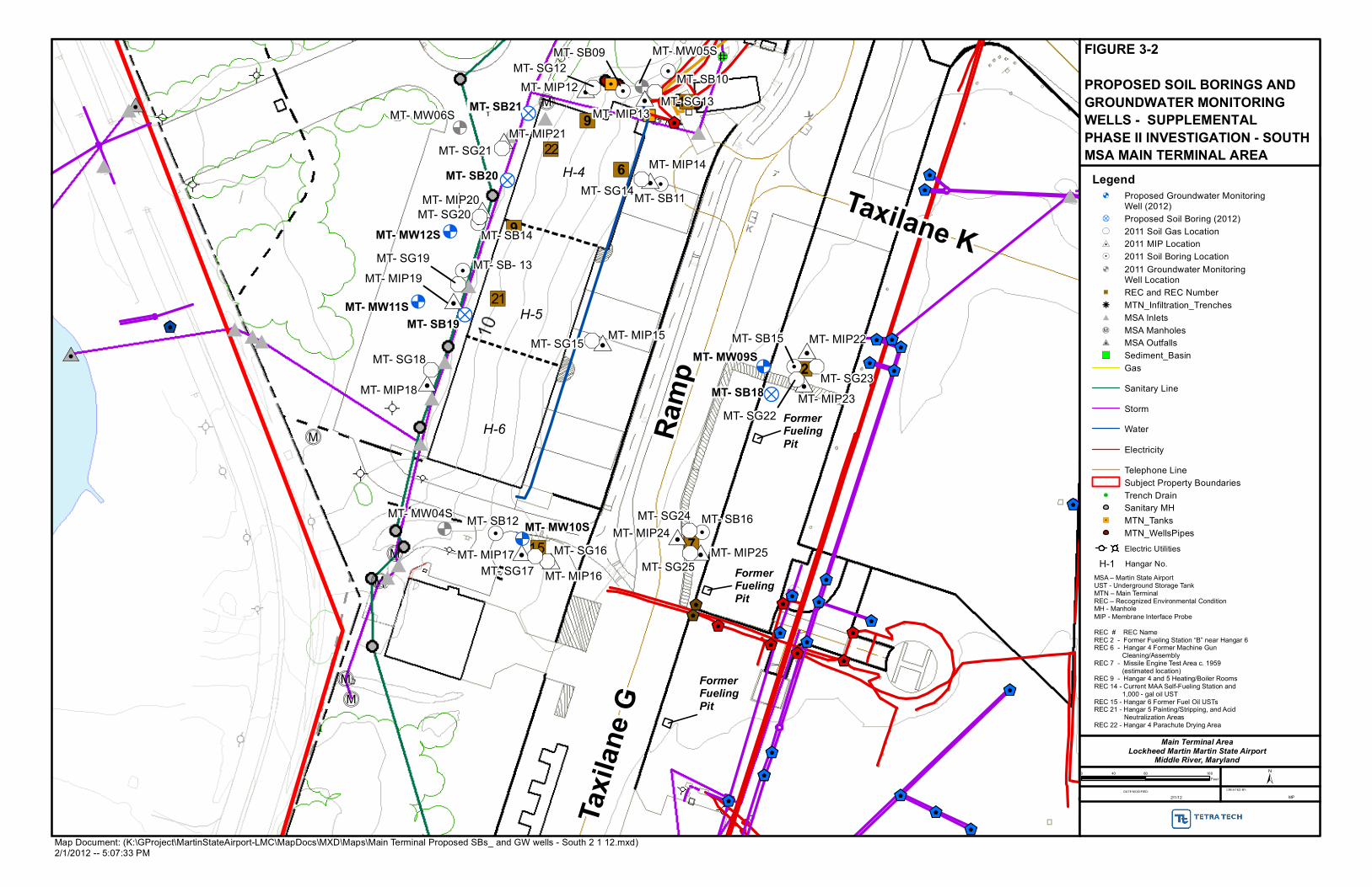
$K$K
$K
$K
$K
$K$K
$K $K
$K
$K
$K
$K
$K
$K
$K
$K
$K
$K
$K
$K
$K
$K
$K
$K
$K
$K
$K
$K$K
$K
$K
$K
#0
#0
c
c
cc
c
c
##
#
#
#
#
#
#
#
##
#
#
#
#
")1
")1
")1
")1
")1
")1
")1
")1
")1
")12
")22
")51
")9
")9
")41
")6
")2
")7&<
&<
&<
!.!.
!.
!.
!.
!.
!.
!.
#0 #0
#0
#0
#0#0
#0
#0
#0
#0
#0
#0
#0#0
&- &-
&-
&-
&-&-
&-
&-
&-
&-
&-&-
&-
&-
!?
!?
!?
!?
&<
&<
&<
&<
H-4
H-5
H-6 Ram
p
Taxilane K
Taxi
lane
G
FormerFueling Pit
FormerFueling Pit
FormerFueling Pit
MT- SB10
MT- MW05S
MT- SB11
MT- SB15
MT- MW04S MT- SB12 MT- SB16
MT- MW06S
MT- SB- 13
MT- SB14
MT- SB09
MT- MIP13
MT- MIP14
MT- SG15
MT- SG23
MT- SG16MT- SG25
MT- SG18
MT- MIP21
MT- MIP22
MT- SG24
MT- MIP19
MT- SG20
MT- MIP12
MT- SG17
MT- SG13
MT- SG12
MT- SG21
MT- MIP20
MT- SG19
MT- MIP18
MT- MIP17
MT- MIP16
MT- MIP24
MT- MIP25
MT- SG22MT- MIP23
MT- MIP15
MT- SG14MT- SB20
MT- SB19
MT- SB21
MT- SB18
MT- MW12S
MT- MW11S
MT- MW09S
MT- MW10S
DATE MODIFIED: CREATED BY:
2/1/12 MP
±0 80 16040Feet
MSA – Martin State AirportUST - Underground Storage TankMTN – Main TerminalREC – Recognized Environmental ConditionMH - ManholeMIP - Membrane Interface Probe
REC # REC NameREC 2 - Former Fueling Station “B” near Hangar 6REC 6 - Hangar 4 Former Machine Gun Cleaning/AssemblyREC 7 - Missile Engine Test Area c. 1959 (estimated location)REC 9 - Hangar 4 and 5 Heating/Boiler RoomsREC 14 - Current MAA Self-Fueling Station and 1,000 - gal oil USTREC 15 - Hangar 6 Former Fuel Oil USTsREC 21 - Hangar 5 Painting/Stripping, and Acid Neutralization Areas REC 22 - Hangar 4 Parachute Drying Area
Map Document: (K:\GProject\MartinStateAirport-LMC\MapDocs\MXD\Maps\Main Terminal Proposed SBs_ and GW wells - South 2 1 12.mxd)2/1/2012 -- 5:07:33 PM
Main Terminal AreaLockheed Martin Martin State Airport
Middle River, Maryland
FIGURE 3-2
PROPOSED SOIL BORINGS AND GROUNDWATER MONITORING WELLS - SUPPLEMENTAL PHASE II INVESTIGATION - SOUTHMSA MAIN TERMINAL AREA
Legend&< Proposed Groundwater Monitoring
Well (2012)!? Proposed Soil Boring (2012)&- 2011 Soil Gas Location#0 2011 MIP Location !. 2011 Soil Boring Location &< 2011 Groundwater Monitoring
Well Location")1 REC and REC Numberh MTN_Infiltration_Trenches# MSA Inletsc MSA Manholes#0 MSA Outfalls") Sediment_Basin
Gas
Sanitary Line
Storm
Water
Electricity
Telephone LineSubject Property Boundaries
!@ Trench DrainSanitary MH
"/ MTN_TanksMTN_WellsPipes
Electric Utilities
H-1 Hangar No.

7828 TETRA TECH ● MARTIN STATE AIRPORT ● MAIN TERMINAL SUPPLEMENTAL PHASE II SITE INVESTIGATION WORK PLAN PAGE 4-1
Section 4
Project Deliverables
The Supplemental Phase II Site Investigation Report will describe field activities pursuant to this
work plan, including field procedures (wells sampled, soil boring locations, groundwater
elevations), analytical results, and data validation. The report will include maps depicting the
extent of any groundwater and soil contamination, as well as a groundwater elevation map. Data
will be entered and maintained in the Martin State Airport (MSA) environmental geographic
information system (EGIS). The report will be prepared in a format and at a sufficient level of
detail to achieve final approval from all project stakeholders, including the Maryland Department
of the Environment (MDE). Recommendations for future investigation, as warranted, will be
provided based upon interpretation of the results.

7828 TETRA TECH ● MARTIN STATE AIRPORT ● MAIN TERMINAL SUPPLEMENTAL PHASE II SITE INVESTIGATION WORK PLAN PAGE 4-2
This page intentionally left blank.

7828 TETRA TECH ● MARTIN STATE AIRPORT ● MAIN TERMINAL SUPPLEMENTAL PHASE II SITE INVESTIGATION WORK PLAN PAGE 5-1
Section 5
References
1. Chapelle, F. M., 1985. “Hydrogeology, Digital Solute Transport Simulation, and Geochemistry of the Lower Cretaceous Aquifer System near Baltimore, Maryland,” Maryland Geological Survey Report of Investigations No. 43. Maryland Geological Survey, Baltimore, Maryland. 120 pp.
2. Curtin, S., 2006. Personal communication and draft potentiometric map of the Patuxent Aquifer-2004, Mr. Fred Kolberg of Tetra Tech with Mr. Steve Curtin of the U.S. Geological Survey, Baltimore, Maryland. May 5.
3. Geoprobe® (Geoprobe Systems®, Inc.), 2006. “Direct Push Installation of Devices for Active Soil Gas Sampling and Monitoring.” Technical Bulletin MK3098. Kejr, Inc. Salina, Kansas. May. http://www.geoprobe.com.
4. Glaser, J.D., 1969. Petrology and Origin of Potomac and Magothy (Cretaceous) Sediments, Middle Atlantic Coastal Plain. Maryland Geological Survey Reports of Investigations No. 11. Maryland Geological Survey, Baltimore, Maryland. 102 pp.
5. Glenn L. Martin Museum, 2009: review of photographs and maps. November.
6. Hansen, H. J., and J. Edwards, 1986. The Lithology and Distribution of Pre-Cretaceous Basement Rocks beneath the Maryland Coastal Plain. Maryland Geological Survey Report of Investigations 44. 27 pp.
7. MAA (Maryland Aviation Administration), 2008. Spill Prevention, Control, and Countermeasure Plan for Martin State Airport, prepared for MAA, Facilities Development and Engineering, Linthicum, Maryland by EA Engineering, Science, and Technology, Inc., Sparks, Maryland. December.
8. MAA (Maryland Aviation Administration), 2009. History and tenant pages from Martin State Airport Website: http://www.martinstateairport.com/content/airserv.
9. Tetra Tech, 2009. Deep Groundwater Investigation Report, Martin State Airport, Middle River, Maryland. Report prepared by Tetra Tech, Inc., Germantown, Maryland for Lockheed Martin Corporation, Bethesda, Maryland. April.
10. Tetra Tech, 2010a. Environmental Evaluation Report for Martin State Airport Main Terminal, 701 Wilson Point Road, Middle River, Maryland. Report prepared by Tetra Tech, Inc., Germantown, Maryland for Lockheed Martin Corporation, Bethesda, Maryland. September.

7828 TETRA TECH ● MARTIN STATE AIRPORT ● MAIN TERMINAL SUPPLEMENTAL PHASE II SITE INVESTIGATION WORK PLAN PAGE 5-2
11. Tetra Tech, 2010b. Environmental Evaluation Addendum, Martin State Airport Main Terminal, 701 Wilson Point Road, Middle River, Maryland. Report prepared by Tetra Tech, Inc., Germantown, Maryland for Lockheed Martin Corporation, Bethesda, Maryland. December.
12. Tetra Tech, 2010c. Remedial Investigation Report, Martin State Airport, 701 Wilson Point Road, Middle River, Maryland. Report prepared by Tetra Tech, Inc., Germantown, Maryland for Lockheed Martin Corporation, Bethesda, Maryland. November.
13. Tetra Tech, 2011a. Main Terminal Phase II Site Investigation Work Plan, Martin State Airport, 701 Wilson Point Road, Middle River, Maryland. Report prepared by Tetra Tech, Inc., Germantown, Maryland for Lockheed Martin Corporation, Bethesda, Maryland. April.
14. Tetra Tech, 2011b. Main Terminal Phase II Site Investigation Report, Martin State Airport, 701 Wilson Point Road, Middle River, Maryland. Report prepared by Tetra Tech, Inc., Germantown, Maryland for Lockheed Martin Corporation, Bethesda, Maryland. October.
15. USEPA (U.S. Environmental Protection Agency), 2002. OSWER Draft Guidance for Evaluating the Vapor Intrusion to Indoor Air Pathway from Groundwater and Soils (Subsurface Vapor Intrusion Guidance), EPA530-D-02-4. OSWER, U.S. Environmental Protection Agency, Washington, D.C. November, http://www.epa.gov/osw/hazard/correctiveaction/eis/vapor/ complete.pdf.
16. USEPA (U.S. Environmental Protection Agency), Region III, 1993. Region III Modifications to the Laboratory Data Validation Functional Guidelines for Evaluating Inorganics Analyses. April.
17. USEPA (U.S. Environmental Protection Agency), Region III, 1994. Region III Modifications to the National Functional Guidelines for Organic Data Review. September.
18. Vroblesky, D. A. and W. B. Fleck, 1991. Hydrogeologic Framework of the Coastal Plain of Maryland, Delaware, and the District of Columbia, Regional Aquifer System Analysis—Northern Atlantic Coastal Plain. U.S. Geological Survey Professional Paper 1404-E. U.S. Government Printing Office, Washington, D.C. 45 pp.

7828 TETRA TECH ● MARTIN STATE AIRPORT ● MAIN TERMINAL SUPPLEMENTAL PHASE II SITE INVESTIGATION WORK PLAN
APPENDIX A—HEALTH AND SAFETY PLAN

HEALTH AND SAFETY PLANFOR
LOCKHEED MARTIN CORPORATION
SOIL AND GROUNDWATER CHARACTERIZATION
MARTIN STATE AIRPORT
MIDDLE RIVER, MARYLAND
TETRA TECH , INC.20251 Century Boulevard Suite 200Germantown, Maryland 20874-7114
MARCH 2012

HEALTH AND SAFETY PLANFOR
LOCKHEED MARTIN CORPORATION
SOIL AND GROUNDWATER CHARACTERIZATIONMARTIN STATE AIRPORT
701 WILSON POINT ROADMIDDLE RIVER, MARYLAND
Submitted by:Tetra Tech NUS, Inc.
20251 Century Boulevard, Suite 200Germantown, MD 20874
MARCH 2012
PREPARED UNDER THE SUPERVISION OF: PREPARED AND APPROVED BY:
MICHAEL MARTIN, P.G. MATTHEW M. SOLTIS, CIH, CSPPROGRAM MANAGER CORPORATE HEALTH AND SAFETY MANAGERGERMANTOWN, MARYLAND PITTSBURGH, PENNSYLVANIA
March 2012
iii
TABLE OF CONTENTS
SECTION PAGE
1.0 INTRODUCTION...........................................................................................................................1-11.1 KEY PROJECT PERSONNEL AND ORGANIZATION................................................1-11.2 STOP WORK ...............................................................................................................1-31.3 SITE INFORMATION AND PERSONNEL ASSIGNMENTS........................................1-4
2.0 EMERGENCY ACTION PLAN .....................................................................................................2-12.1 INTRODUCTION..........................................................................................................2-12.2 EMERGENCY PLANNING...........................................................................................2-12.3 EMERGENCY RECOGNITION AND PREVENTION ..................................................2-22.3.1 Recognition ..................................................................................................................2-22.3.2 Prevention ....................................................................................................................2-32.3.3 Fire Prevention / Flammable Liquids ...........................................................................2-32.4 EVACUATION ROUTES, PROCEDURES, AND PLACES OF REFUGE ...................2-32.5 EMERGENCY CONTACTS .........................................................................................2-42.6 EMERGENCY ROUTE TO HOSPITAL .......................................................................2-62.7 EMERGENCY ALERTING AND ACTION/RESPONSE PROCEDURES....................2-72.8 PPE AND EMERGENCY EQUIPMENT.......................................................................2-72.9 HAZARDOUS WASTE OPERATIONS AND EMERGENCY RESPONSE..................2-82.10 DECONTAMINATION PROCEDURES / EMERGENCY MEDICAL TREATMENT.....2-82.11 INJURY/ILLNESS REPORTING..................................................................................2-92.10.1 TOTAL Incident Reporting System ..............................................................................2-92.11 DRILL/INCIDENT AFTER ACTION CRITIQUE .........................................................2-10
3.0 SITE BACKGROUND...................................................................................................................3-13.1 SITE HISTORY ............................................................................................................3-13.2 STRAWBERRY POINT AND GREATER STRAWBERRY POINT FACILITY.............3-1
4.0 SCOPE OF WORK .......................................................................................................................4-1
5.0 IDENTIFYING AND COMMUNICATING TASK-SPECIFIC HAZARDS ANDSAFE WORK PRACTICES ..........................................................................................................5-15.1 GENERAL SAFE WORK PRACTICES........................................................................5-15.2 DRILLING (HSA/DPT/LITTLE BADGER UNIT/ROTOSONIC) SAFE WORKPRACTICES..................................................................................................................................5-25.2.1 Before Drilling...............................................................................................................5-25.2.2 During Drilling...............................................................................................................5-35.2.3 After Drilling..................................................................................................................5-45.2.4 Concrete Coring Operations ........................................................................................5-45.3 EXCAVATION –SAFE WORK PRACTICES................................................................5-55.4 PERMANENT SOIL GAS VAPOR MONITORING POINTS WITHIN BUILDINGS......5-55.5 HAND AND POWER TOOL SAFE WORK PRACTICES ............................................5-75.6 HOUSEKEEPING / CLEANUP ....................................................................................5-75.7 WATER HAZARDS ......................................................................................................5-85.7.1 U.S.C.G. Flotation Device Types .................................................................................5-85.7.2 U.S.C.G Boat Regulations ...........................................................................................5-95.7.3 Strain/Muscle Pulls from Heavy Lifting ........................................................................5-95.7.4 Proper Canoe Lifting and Carrying Techniques.........................................................5-105.8 WETLAND SAFE WORK PROCEDURES ................................................................5-11

March 2012
iv
TABLE OF CONTENTS (Continued)
SECTION PAGE
6.0 HAZARD ASSESSMENT AND CONTROLS...............................................................................6-16.1 CHEMICAL HAZARDS ................................................................................................6-16.1.1 Volatile Organic Compounds (VOCs) ..........................................................................6-46.1.2 Metals...........................................................................................................................6-46.1.3 Inhalation......................................................................................................................6-46.1.4 Ingestion and Skin Contact ..........................................................................................6-56.2 PHYSICAL HAZARDS .................................................................................................6-56.2.1 Slips, Trips, and Falls...................................................................................................6-66.2.2 Strain/Muscle Pulls from Heavy Lifting ........................................................................6-66.2.3 Heat/Cold Stress ..........................................................................................................6-66.2.4 Pinch/Compression Points ...........................................................................................6-66.2.5 Natural Hazards ...........................................................................................................6-76.2.6 Vehicular and Equipment Traffic ..................................................................................6-76.2.7 Inclement Weather .......................................................................................................6-76.2.8 Contact with Underground or Overhead Utilities/Electrical Safety...............................6-86.2.9 Heavy Equipment/Excavation Hazards........................................................................6-86.2.10 Compressed Gas Cylinders .........................................................................................6-96.2.11 Noise ............................................................................................................................6-9
7.0 AIR MONITORING........................................................................................................................7-17.1 METALS.......................................................................................................................7-17.1.1 Instruments and Use for Dust ......................................................................................7-27.1.2 Hazard Monitoring Frequency......................................................................................7-37.2 ORGANICS VAPORS INSTRUMENTS AND USE......................................................7-37.2.1 Photoionization Detector ..............................................................................................7-37.2.2 Hazard Monitoring Frequency......................................................................................7-37.3 INSTRUMENT MAINTENANCE AND CALIBRATION ................................................7-47.4 DOCUMENTING INSTRUMENT READINGS .............................................................7-4
8.0 TRAINING/MEDICAL SURVEILLANCE REQUIREMENTS........................................................8-18.1 INTRODUCTORY/REFRESHER/SUPERVISORY TRAINING ...................................8-18.2 SITE-SPECIFIC TRAINING .........................................................................................8-18.3 MEDICAL SURVEILLANCE.........................................................................................8-2
9.0 SITE CONTROL ...........................................................................................................................9-19.1 EXCLUSION ZONE .....................................................................................................9-19.1.1 Exclusion Zone Clearance ...........................................................................................9-19.2 CONTAMINATION REDUCTION ZONE .....................................................................9-29.3 SUPPORT ZONE.........................................................................................................9-39.4 SAFE WORK PERMITS...............................................................................................9-39.5 SITE SECURITY ..........................................................................................................9-39.6 SITE VISITORS ...........................................................................................................9-49.7 SITE MAP.....................................................................................................................9-59.8 BUDDY SYSTEM.........................................................................................................9-59.9 COMMUNICATION ......................................................................................................9-59.10 SELF-AUDITS..............................................................................................................9-5
10.0 SPILL CONTAINMENT PROGRAM AND WASTE MANAGEMENT PLAN .............................10-110.1 SCOPE AND APPLICATION .....................................................................................10-110.2 POTENTIAL SPILL AREAS .......................................................................................10-110.3 LEAK AND SPILL DETECTION.................................................................................10-110.4 PERSONNEL TRAINING AND SPILL PREVENTION...............................................10-210.5 SPILL PREVENTION AND CONTAINMENT EQUIPMENT ......................................10-210.6 SPILL CONTROL PLAN ............................................................................................10-210.7 WASTE MANAGEMENT PLAN .................................................................................10-3

March 2012
v
TABLE OF CONTENTS (Continued)
SECTION PAGE
11.0 CONFINED-SPACE ENTRY ......................................................................................................11-1
12.0 HOT WORK ................................................................................................................................12-1
13.0 USE OF LOCKHEED MARTIN MATERIALS AND EQUIPMENT.............................................13-1
14.0 ELEVATED LOCATIONS / LADDERS / SCAFFOLDS .............................................................14-1
15.0 DANGEROUS OPERATIONS....................................................................................................15-1
16.0 EXCAVATIONS, TRENCHES, AND EARTHWORK .................................................................16-116.1 EXCAVATION SAFE WORK PRACTICES................................................................16-116.2 EMPLOYER DESIGNATED “COMPETENT PERSON” ............................................16-216.2.1 Pre-Excavation Activities............................................................................................16-216.2.2 During Excavation Activities.......................................................................................16-216.2.3 Post Excavation Activities ..........................................................................................16-216.2.4 Competent Persons Qualifications.............................................................................16-316.3 LM EXCAVATION REQUIREMENTS........................................................................16-3
17.0 ASBESTOS ................................................................................................................................17-1
18.0 NANOTECHNOLOGY ................................................................................................................18-1
19.0 WORK INVOLVING AIR EMISSIONS........................................................................................19-1
20.0 WORK INVOLVING WATER DISCHARGES.............................................................................20-1
21.0 MATERIALS AND DOCUMENTATION .....................................................................................21-121.1 MATERIALS TO BE POSTED AT THE SITE ............................................................21-121.2 HAZARD COMMUNICATION – USE OF HAZARDOUS MATERIALS .....................21-2
22.0 ACRONYMS / ABBREVIATIONS ..............................................................................................22-1
ATTACHMENT I LOCKHEED MARTIN REMEDIATION CONTRACTOR’S ESH HANDBOOKATTACHMENT II INCIDENT REPORT FORMATTACHMENT III MEDICAL DATA SHEETATTACHMENT IV SAFE WORK PERMITSATTACHMENT V EQUIPMENT CHECKLIST FOR DPT RIGSATTACHMENT VI TETRA TECH EXCAVATION SAFETY PROCEDURESATTACHMENT VII TRENCHING AND EXCAVATION COMPETENT PERSON CHECKLISTATTACHMENT VIII TETRA TECH CONFINED SPACE PROGRAMATTACHMENT IX HEAVY EQUIPMENT INSPECTION CHECKLISTATTACHMENT X OSHA HEALTH & SAFETY CONSTRUCTION-RELATED REGULATIONS –
P - 650 TO 699 SUBPART P - EXCAVATIONSATTACHMENT XI TETRA TECH DECONTAMINATION OF FIELD EQUIPMENT AND WASTE
HANDLING STANDARD OPERATING PROCEDUREATTACHMENT XII OSHA POSTER

March 2012
vi
TABLE OF CONTENTS (CONTINUED)
LIST OF TABLES
TABLE PAGE
2-1 Emergency Contacts.....................................................................................................................2-5
6-1 Comparison Of COPCs and Worst-Case Air Concentrations, With CurrentOccupational Exposure Limits ......................................................................................................6-1
6-2 Metals Current Occupational Exposure Limits..............................................................................6-3
LIST OF FIGURES
FIGURE PAGE
2-1 Route to Hospital...........................................................................................................................2-6
7-1 Documentation of Field Calibration...............................................................................................7-5
8-1 Site-Specific Training Documentation...........................................................................................8-3
9-1 Example Safe Work Permit ...........................................................................................................9-7

March 2012
1-1
1.0 INTRODUCTION
This Health and Safety Plan (HASP) has been developed to provide the minimum practices and
procedures for Tetra Tech, Inc. (Tetra Tech) and subcontractor personnel engaged in the Martin State
Airport at the Lockheed Martin Corporation (LMC), in Middle River, Maryland.
This HASP must be used in conjunction with the Tetra Tech Health and Safety Guidance Manual
(HSGM). The HSGM contains Tetra Tech Health and Safety Standard Operating Procedures (SOPs), as
well as detailed reference information on a variety of topics referenced in this HASP. This HASP and the
contents of the Guidance Manual were developed to comply with the requirements stipulated in 29 CFR
1910.120 (OSHA’s Hazardous Waste Operations and Emergency Response Standard) and applicable
sections of 29 CFR 1926 (Safety and Health Regulations for Construction).
All contractor responsibilities stipulated in Section 1 of the Lockheed Martin Remediation Contractor’s
ESH Handbook (LM Handbook) will be adhered to. The LM Handbook can be found in Attachment I of
this HASP.
Copies of all pertinent environmental, safety and health (ESH) records must be maintained at the job site.
This includes, but is not limited to, this site-specific HASP, the Tetra Tech Health and Safety Guidance
Manual, personnel training documentation, evidence of enrollment in a medical surveillance program,
accident/injury reporting, work area inspections, periodic safety meetings, MSDS’s, air monitoring data,
waste container inspections, etc. These records must also be provided electronically to the Lockheed
Martin Project Lead.
This HASP has been developed using the latest available information regarding known or suspected
chemical contaminants and potential physical hazards associated with the proposed work and site. The
HASP will be modified if the scope of work changes or if new information regarding site conditions,
hazards, or contaminants of concern becomes available. If deviations are encountered from the field
work plan, the contractor shall A) notify to the Lockheed Martin Project Lead and B) suspend work to
assess changes to the work plan(s) and the HASP. Changes to the work plan(s) and the HASP shall be
reviewed by the Project Lead. Procedures addressing changes to this HASP as described in Section 6 of
the LM Handbook (Attachment I) will be followed.
1.1 KEY PROJECT PERSONNEL AND ORGANIZATION
This section defines responsibilities for site safety and health for Tetra Tech employees conducting field
activities under this field effort. All personnel assigned to participate in the field work have the primary
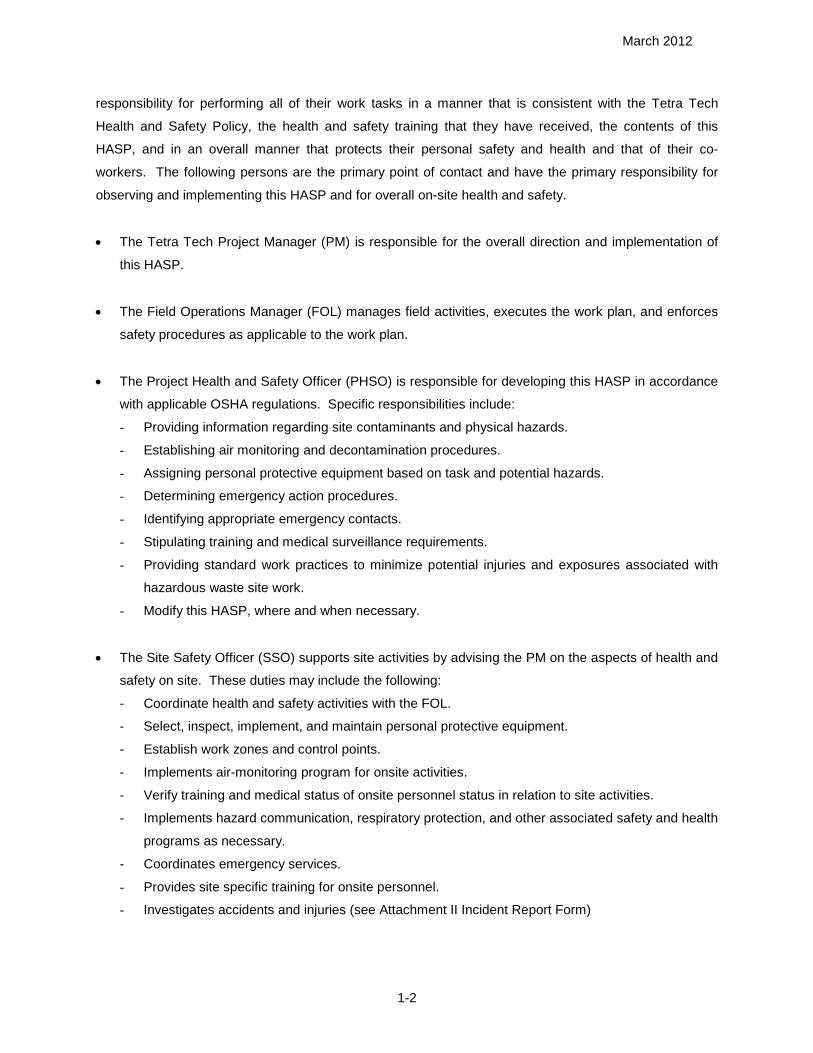
March 2012
1-2
responsibility for performing all of their work tasks in a manner that is consistent with the Tetra Tech
Health and Safety Policy, the health and safety training that they have received, the contents of this
HASP, and in an overall manner that protects their personal safety and health and that of their co-
workers. The following persons are the primary point of contact and have the primary responsibility for
observing and implementing this HASP and for overall on-site health and safety.
The Tetra Tech Project Manager (PM) is responsible for the overall direction and implementation of
this HASP.
The Field Operations Manager (FOL) manages field activities, executes the work plan, and enforces
safety procedures as applicable to the work plan.
The Project Health and Safety Officer (PHSO) is responsible for developing this HASP in accordance
with applicable OSHA regulations. Specific responsibilities include:
- Providing information regarding site contaminants and physical hazards.
- Establishing air monitoring and decontamination procedures.
- Assigning personal protective equipment based on task and potential hazards.
- Determining emergency action procedures.
- Identifying appropriate emergency contacts.
- Stipulating training and medical surveillance requirements.
- Providing standard work practices to minimize potential injuries and exposures associated with
hazardous waste site work.
- Modify this HASP, where and when necessary.
The Site Safety Officer (SSO) supports site activities by advising the PM on the aspects of health and
safety on site. These duties may include the following:
- Coordinate health and safety activities with the FOL.
- Select, inspect, implement, and maintain personal protective equipment.
- Establish work zones and control points.
- Implements air-monitoring program for onsite activities.
- Verify training and medical status of onsite personnel status in relation to site activities.
- Implements hazard communication, respiratory protection, and other associated safety and health
programs as necessary.
- Coordinates emergency services.
- Provides site specific training for onsite personnel.
- Investigates accidents and injuries (see Attachment II Incident Report Form)

March 2012
1-3
- Provides input to the PHSO regarding the need to modify, this HASP, or other applicable health
and safety associated documents as per site-specific requirements.
Compliance with the requirements of this HASP are monitored by the SSO and coordinated through
the Tetra Tech Health and Safety Manager (HSM).
Note: In some cases one person may be designated responsibilities for more than one position. For
example, the FOL may also be responsible for the SSO duties. This action will be performed only
as credentials, experience, and availability permits.
1.2 STOP WORK
ALL employees are empowered, authorized, and responsible to STOP WORK at any time when an
imminent and uncontrolled safety or health hazard is perceived. In a Stop Work event (immediately after
the involved task has been shut down and the work area has been secured in a safe manner) the
employee shall contact the Project Manager and the Corporate Health and Safety Manager. Through
observations and communication, all parties involved shall then develop, communicate, and implement
corrective actions necessary and appropriate to modify the task and to resume work.
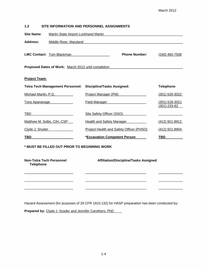
March 2012
1-4
1.3 SITE INFORMATION AND PERSONNEL ASSIGNMENTS
Site Name: Martin State Airport Lockheed Martin
Address: Middle River, Maryland
LMC Contact: Tom Blackman Phone Number: (240) 460-7508
Proposed Dates of Work: March 2012 until completion
Project Team:
Tetra Tech Management Personnel: Discipline/Tasks Assigned: Telephone
Michael Martin, P.G. Project Manager (PM) (301) 528-3022
Tony Apanavage Field Manager (301)-528-3021(301)-233-82
TBD Site Safety Officer (SSO)
Matthew M. Soltis, CIH, CSP Health and Safety Manager (412) 921-8912
Clyde J. Snyder Project Health and Safety Officer (PHSO) (412) 921-8904
TBD *Excavation Competent Person TBD
* MUST BE FILLED OUT PRIOR TO BEGINNING WORK
Non-Tetra Tech Personnel Affiliation/Discipline/Tasks AssignedTelephone
Hazard Assessment (for purposes of 29 CFR 1910.132) for HASP preparation has been conducted by:
Prepared by: Clyde J. Snyder and Jennifer Carothers, PhD

March 2012
2-1
2.0 EMERGENCY ACTION PLAN
2.1 INTRODUCTION
This section has been developed as part of a planning effort to direct and guide field personnel in the
event of an emergency. In the event of an emergency, the field team will primarily evacuate and
assemble to an area unaffected by the emergency and notify the appropriate local emergency response
personnel/agencies. Workers who are ill or who have suffered a non-serious injury may be transported
by site personnel to nearby medical facilities, provided that such transport does not aggravate or further
endanger the welfare of the injured/ill person. The emergency response agencies listed in this plan are
capable of providing the most effective response, and as such, will be designated as the primary
responders. These agencies are located within a reasonable distance from the area of site operations,
which ensures adequate emergency response time.
Tetra Tech personnel may participate in minor event response and emergency prevention activities such
as:
Initial fire-fighting support and prevention
Initial spill control and containment measures and prevention
Removal of personnel from emergency situations
Provision of initial medical support for injury/illness requiring only first-aid level support
Provision of site control and security measures as necessary
2.2 EMERGENCY PLANNING
Through the initial hazard/risk assessment effort, emergencies resulting from chemical, physical, or fire
hazards are the types of emergencies which could be encountered during site activities. To minimize or
eliminate the potential for these emergency situations, pre-emergency planning activities will include the
following (which are the responsibility of the SSO and/or the FOL):
Coordinating with Lockheed Martin MSA and/or local emergency response personnel to ensure that
Tetra Tech emergency action activities are compatible with existing emergency response procedures.
Establishing and maintaining information at the project staging area (support zone) for easy access in
the event of an emergency. This information will include the following:
- Chemical Inventory (of chemicals used onsite), with Material Safety Data Sheets.
- Onsite personnel medical records (Medical Data Sheets).

March 2012
2-2
- A log book identifying personnel onsite each day.
- Hospital route maps with directions (these should also be placed in each site vehicle).
- Emergency Notification - phone numbers.
The Tetra Tech FOL will be responsible for the following tasks:
Identifying a chain of command for emergency action.
Educating site workers to the hazards and control measures associated with planned activities at the
site, and providing early recognition and prevention, where possible.
Periodically performing practice drills to ensure site workers are familiar with incidental response
measures.
Providing the necessary equipment to safely accomplish identified tasks.
2.3 EMERGENCY RECOGNITION AND PREVENTION
2.3.1 Recognition
Emergency situations that may be encountered during site activities will generally be recognized by visual
observation. Visual observation will also play a role in detecting potential exposure events to some
chemical hazards. To adequately recognize chemical exposures, site personnel must have a clear
knowledge of signs and symptoms of exposure associated with the principle site contaminants of concern
as presented in this HASP. Tasks to be performed at the site, potential hazards associated with those
tasks and the recommended control methods are discussed in detail in Sections 5.0 and 6.0.
Additionally, early recognition of hazards will be supported by daily site surveys to eliminate any situation
predisposed to an emergency. The FOL and/or the SSO will be responsible for performing surveys of
work areas prior to initiating site operations and periodically while operations are being conducted.
Survey findings are documented by the FOL and/or the SSO in the Site Health and Safety logbook,
however, site personnel will be responsible for reporting hazardous situations. Where potential hazards
exist, Tetra Tech will initiate control measures to prevent adverse effects to human health and the
environment.
The above actions will provide early recognition for potential emergency situations, and allow Tetra Tech
to instigate necessary control measures. However, if the FOL and the SSO determine that control
measures are not sufficient to eliminate the hazard, Tetra Tech will withdraw from the site and notify the
appropriate response agencies listed in Table 2-1.

March 2012
2-3
2.3.2 Prevention
Tetra Tech and subcontractor personnel will minimize the potential for emergencies by following the
Health and Safety Guidance Manual and ensuring compliance with the HASP and applicable OSHA
regulations. Daily site surveys of work areas, prior to the commencement of that day’s activities, by the
FOL and/or the SSO will also assist in prevention of illness/injuries when hazards are recognized early
and control measures initiated.
2.3.3 Fire Prevention / Flammable Liquids
Tetra Tech and subcontractor personnel are responsible for fire protection in all of their work areas at all
times during the duration of this field effort (24 hours per day/seven days per week). Approved fire-
fighting equipment and extinguishers, in adequate quantities for their work activates must be provided.
The Lockheed Martin Project Lead will be notified as soon as possible of any fire, if Tetra Tech or
subcontractor personnel use a Lockheed Martin fire extinguisher, and of any and all fires that are
extinguished. In case of fire, Tetra Tech and subcontractor personnel will call 9-1-1.
All flammable and combustible liquids must be stored, dispensed and used in accordance with OSHA
regulations and the Uniform Fire Code. Bonding and grounding of containers containing flammable
liquids will be required.
All fire prevention/flammable liquids safety procedures and requirements stipulated in Section 3.15 of the
LM Handbook (Attachment I) will also be adhered to.
2.4 EVACUATION ROUTES, PROCEDURES, AND PLACES OF REFUGE
An evacuation will be initiated whenever recommended hazard controls are insufficient to protect the
health, safety or welfare of site workers. Specific examples of conditions that may initiate an evacuation
include, but are not limited to the following: severe weather conditions; fire or explosion; monitoring
instrumentation readings which indicate levels of contamination are greater than instituted action levels;
and evidence of personnel overexposure to potential site contaminants.
In the event of an emergency requiring evacuation, personnel will immediately stop activities and report to
the designated safe place of refuge unless doing so would pose additional risks. When evacuation to the
primary place of refuge is not possible, personnel will proceed to a designated alternate location and
remain until further notification from the Tetra Tech FOL. Safe places of refuge will be identified prior to
the commencement of site activities by the SSO and will be conveyed to personnel as part of the pre-
activities training session. This information will be reiterated during daily safety meetings. Whenever

March 2012
2-4
possible, the safe place of refuge will also serve as the telephone communications point for that area.
During an evacuation, personnel will remain at the refuge location until directed otherwise by the Tetra
Tech FOL or the on-site Incident Commander of the Emergency Response Team. The FOL or the SSO
will perform a head count at this location to account for and to confirm the location of site personnel.
Emergency response personnel will be immediately notified of any unaccounted personnel. The SSO will
document the names of personnel onsite (on a daily basis) in the site Health and Safety Logbook. This
information will be utilized to perform the head count in the event of an emergency.
Evacuation procedures will be discussed during the pre-activities training session, prior to the initiation of
project tasks. Evacuation routes from the site and safe places of refuge are dependent upon the location
at which work is being performed and the circumstances under which an evacuation is required.
Additionally, site location and meteorological conditions (i.e., wind speed and direction) may dictate
evacuation routes. As a result, assembly points will be selected and communicated to the workers
relative to the site location where work is being performed. Evacuation should always take place in an
upwind direction from the site.
2.5 EMERGENCY CONTACTS
Prior to initiating field activities, personnel will be thoroughly briefed on the emergency procedures to be
followed in the event of an accident. Table 2-1 provides a list of emergency contacts and their associated
telephone numbers. This table must be posted where it is readily available to site personnel. Facility
maps should also be posted showing potential evacuation routes and designated meeting areas.
Any pertinent information regarding allergies to medications or other special conditions will be provided to
medical services personnel. This information is listed on Medical Data Sheets filed onsite (See
Attachment III). If an exposure to hazardous materials has occurred, provide hazard information from
Table 6-1 to medical service personnel.
The Lockheed Martin Project Lead shall be contacted immediately in the event of a fatal or serious injury,
and unpermitted environmental release, or any ESH incident that is likely to generate significant publicity
or an adverse situation for Lockheed Martin. Detailed requirements are describe in Section 1.15 of the
LM Handbook (Attachment I).
In the event of an emergency not requiring 9-1-1, LMC facility personnel should be contacted in the order
presented on Table 2-1.

March 2012
2-5
TABLE 2-1
EMERGENCY CONTACTSLMC MARTIN STATE AIRPORT
MIDDLE RIVER, MARYLAND
AGENCY TELEPHONE
EMERGENCY (Police, Fire, and Ambulance) 911LMC Contact, Tom Blackman (240) 460-7508
LMC Martin State Airport Site Contact,Abel Folarin
(410) 918-6062
Airport Operations ManagerCharles M. Baublitz
(410) 682-8831
DirectorAl Pollard, A.A.E
(410) 682-8800
Mike Musheno(410) 682-1315 (Office)(856) 842-2590 (Cell)
Lt. Colonel Peter Leobach(410) 918-6486 office(443) 992-8303 cell
SMSGT Jeff MorseMunitions Storage Supervisor
(410) 918-6256
Franklin Square Hospital (443) 777-7000
Chemtrec (800) 424-9300
National Response Center (800) 424-8802
Poison Control Center (800) 222-1222
WorkCare (800) 229-3674
PM, Michael Martin (301) 528-3022
HSM, Matthew M. Soltis, CIH, CSP (412) 921-8912
PHSO, Clyde Snyder (412) 921-8904
Miss Utility Maryland/DC (800) 257-7777

March 2012
2-6
2.6 EMERGENCY ROUTE TO HOSPITAL
Franklin Square Hospital9000 Franklin Square DriveBaltimore, Maryland 21237(410) 682-7000
Driving Directions:
1) From Eastern Boulevard, take the Interstate 695.
2) Exit at exit number 34 (Philadelphia Road) and turn right.
3) Proceed on Philadelphia Road and turn left on Rossville Boulevard.
4) Proceed on Rossville Boulevard and take a right on Franklin Square Drive.
5) Proceed on Franklin Square Boulevard to 9000 and the hospital will be on the left hand side.
Routes and directions to the hospital are provided in Figure 2-1.
FIGURE 2-1
ROUTE TO HOSPITAL

March 2012
2-7
2.7 EMERGENCY ALERTING AND ACTION/RESPONSE PROCEDURES
Tetra Tech personnel will be working in close proximity to each other at Lockheed Martin MSA. As a
result, hand signals, voice commands, and line of site communication will be sufficient to alert site
personnel of an emergency.
If an emergency warranting evacuation occurs, the following procedures are to be initiated:
Initiate the evacuation via hand signals, voice commands, or line of site communication
Report to the designated refuge point where the FOL will account for all personnel
Once non-essential personnel are evacuated, appropriate response procedures will be enacted to
control the situation.
Describe to the FOL (FOL will serve as the Incident Coordinator) pertinent incident details.
In the event that site personnel cannot mitigate the hazardous situation, the FOL and SSO will enact
emergency notification procedures to secure additional assistance in the following manner:
Dial 911 and call other pertinent emergency contacts listed in Table 2-1 and report the incident. Give the
emergency operator the location of the emergency, the type of emergency, the number of injured, and a
brief description of the incident. Stay on the phone and follow the instructions given by the operator. The
operator will then notify and dispatch the proper emergency response agencies.
2.8 PPE AND EMERGENCY EQUIPMENT
A first-aid kit, eye wash units (or bottles of disposable eyewash solution) and fire extinguishers
(strategically placed) will be maintained onsite and shall be immediately available for use in the event of
an emergency. This equipment will be located in the field office as well as in each site vehicle. At least
one first aid kit supplied with equipment to protect against bloodborne pathogens will also be available on
site. Personnel identified within the field crew with bloodborne pathogen and first-aid training will be the
only personnel permitted to offer first-aid assistance.
Safety eyewear meeting ANSI Z87.1 is required in areas designated as “Eye Projection Required” and is
also required on all jobs where a potential injury to the eye is possible whether or not the area is posted.
Safety shoes and boots which meet the ANSI Z41 Standard shall be provided when impact and/or
compression hazards exist.
Appropriate MSHA/NIOSH-approved respiratory protective devices must be worn when applicable state
and/or federal action levels or OSHA permissible exposure levels are exceeded. Appropriate air
March 2012
2-8
monitoring and respiratory protection equipment will be supplied and maintained if inhalation hazards are
anticipated and a respiratory protection adhering to all state and federal regulations implemented.
Hearing protection must be worn in all areas posted to indicate high noise level or where employees are
exposed to noise levels in excess of the OSHA action level (85 dBA over an 8-hour time-weighted
average or a dose of fifty percent).
Protective clothing such as suits, aprons, boots or gloves shall be worn where there is a hazard to the
body through dermal contact with chemicals, dusts, heat or other harmful agents or conditions.
Hard hats meeting the ANSI Z89.1 Standard will be worn in all areas where there is danger of impact to
the head or hazard from falling or moving objects.
All personal protective clothing and equipment will be used and approved as detailed in Section 3.1 of the
LM Handbook (Attachment I).
2.9 HAZARDOUS WASTE OPERATIONS AND EMERGENCY RESPONSE
Tetra Tech and subcontractor personnel conducting work at Lockheed Martin will adhere to Title 29, Code
of Federal Regulations, Section 1910.120 – Hazardous Waste Operations and Emergency Response or
the applicable state OSHA standards.
Tetra Tech and/or subcontractor personnel will to perform periodic work area inspections to determine the
effectiveness of the site safety and health plan and to identify and correct unsafe conditions in the work
area. These inspections shall be documented and available to Lockheed Martin upon request for review.
The requirements and regulations described in Section 3.20 of the LM Handbook (Attachment I) will be
adhered to.
2.10 DECONTAMINATION PROCEDURES / EMERGENCY MEDICAL TREATMENT
During any site evacuation, decontamination procedures will be performed only if doing so does not
further jeopardize the welfare of site workers. Decontamination will be postponed if the incident warrants
immediate evacuation. However, it is unlikely that an evacuation would occur which would require
workers to evacuate the site without first performing the necessary decontamination procedures.
Tetra Tech personnel will perform rescue operations from emergency situations and may provide initial
medical support for injury/illnesses requiring only "Basic First-Aid" level support, and only within the limits
of training obtained by site personnel. Basic First-Aid is considered treatment that can be rendered by a

March 2012
2-9
trained first aid provider at the injury location and not requiring follow-up treatment or examination by a
physician (for example; minor cuts, bruises, stings, scrapes, and burns). Personnel providing medical
assistance are required to be trained in First-Aid and in the requirements of OSHA's Bloodborne
Pathogen Standard (29 CFR 1910.1030). Medical attention above First-Aid level support will require
assistance from the designated emergency response agencies. Attachment II provides the procedure to
follow when reporting an injury/illness, and the form to be used for this purpose.
2.11 INJURY/ILLNESS REPORTING
If any Tetra Tech personnel are injured or develop an illness as a result of working on site, the Tetra Tech
“Incident Report Procedure” (Attachment II) must be followed. Following this procedure is necessary for
documenting of the information obtained at the time of the incident.
Any pertinent information regarding allergies to medications or other special conditions will be provided to
medical services personnel. This information is listed on Medical Data Sheets filed onsite. If an exposure
to hazardous materials has occurred, provide information on the chemical, physical, and toxicological
properties of the subject chemical(s) to medical service personnel.
Tetra Tech personnel will contact the LMC personnel in the order presented in Table 2-1 in the event of a
fatality injury, environmental release (spill), near-miss incident, or an ESH incident that is likely to
generate significant publicity. A written report of the incident/injury/spill and corrective action(s) must be
submitted to LMC personnel within one (1) day of the incident.
Section 8.1 of the LM Handbook (Attachment I) describing the requirements of accident, injury, illness
and incident reporting will be addressed.
2.10.1 TOTAL Incident Reporting System
TOTAL is Tetra Tech’s new online incident reporting system. Use TOTAL to directly report health and
safety incidents, notify key personnel, and initiate the process for properly investigating and addressing
the causes of incidents, including near-miss events. An incident is considered any unplanned event. It
may include several types of near misses, events where no loss was incurred, or incidents that resulted in
injuries or illness, property or equipment damage, chemical spills, fires, or damage to motor vehicles.
TOTAL looks like the incident reporting form in Attachment II. TOTAL is an intuitive system that will guide
you through the necessary steps to report an incident within 24 hours of its occurrence. Behind the
scenes, TOTAL is a powerful tool for H&S professionals, and will help Tetra Tech to better track incidents,
analyze root causes, implement corrective action plans, and share lessons learned. The ultimate result is
a more safe and healthy working environment for us all.
March 2012
2-10
TOTAL is maintained on the Tetra Tech Intranet site at https://my.tetratech.com/
Once on the “My Tetratech” site, TOTAL can be found under the Health and Safety tab, Incident
Reporting section, select “Report an Incident (TOTAL)”. This will connect you directly to TOTAL. TOTAL
can also be accessed directly from the internet using the following web address:
http://totalhs.tetratech.com/
Note: When using the system outside the Tetra Tech intranet system or when operating in a wireless
mode, a VPN connection will be required. The speed of the application may be affected dependent upon
outside factors such as connection, signal strength, etc. Enter the system using your network user name
and password. The user name should be in the following format - TT\nickname.lastname.
2.11 DRILL/INCIDENT AFTER ACTION CRITIQUE
The FOL will conduct a drill or exercise to test the Emergency Action Plan. A critique with the site
personnel after each drill or incident will be conducted. This critique provides a mechanism to review the
incidents and exercises or drills to determine where improvements can be made. For incidents recorded in
TOTAL, the FOL will utilize the Lessons Learned component for the critique.
March 2012
3-1
3.0 SITE BACKGROUND
3.1 SITE HISTORY
The LMC MRC is located at 2323 Eastern Boulevard in Middle River, Maryland. The site consists of
approximately 180 acres of land and twelve main buildings. The subject property also includes perimeter
parking lots, an athletic field, Lot D (presently a vacant lot with a concrete foundation for former
Building D), a trailer and parts storage lot, and a vacant waterfront lot. The site is bounded by Eastern
Boulevard (Route 150) to the north, Dark Head Creek to the south, Cow Pen Creek to the west, and
Martin State Airport to the east.
The Martin State Airport (MSA) is located at 701 Wilson Point Road in Middle River, Maryland, and is
bounded by Frog Mortar Creek to the east and Stansbury Creek to the west. Both creeks join into
Chesapeake Bay to the south of the airport. With surface water bodies surrounding most of MSA, the site
can be considered a small peninsula.
Historically, MSA was owned and operated by the Glenn L. Martin Company from approximately 1929 to
1975. Glenn L. Martin Company is the predecessor to Martin Marietta; Lockheed and Martin Marietta
merged in 1996 to form Lockheed Martin Corporation. Since the 1950’s the Maryland Air National Guard
has leased land at the northeastern portion of the airport just north of the MSA site being investigated by
LMC. In 1975, the airport was sold to the Maryland Aviation Administration (MAA), an agency within the
Maryland Department of Transportation.
Currently, LMC is completing voluntary investigations conducted under the Maryland Department of the
Environment (MDE) Environmental Restoration and Redevelopment program on a 50 acre portion of the
MSA. This study is in support of the characterization of the 50 acre area.
Martin State Airport is an active airport, operated by the Maryland Aviation Administration. It is comprised
of 747 acres, and is described by the MAA as a General Aviation Reliever Airport.
3.2 STRAWBERRY POINT AND GREATER STRAWBERRY POINT FACILITY
Strawberry Point (SP) is located within the confines of the MSA at the southern tip of the peninsula
between the confluence of Stansbury Creek and Frog Mortar Creek. SP can be accessed from Eastern
Avenue by traveling on Wilson Point Road and entering through a secured unmanned gate. The
previously investigated, SP wooded area is located at the southwest terminus of the peninsula and covers
approximately 25 acres. The wooded area is bounded by earthen berms near the water line with thick

March 2012
3-2
brush and trees covering the entire area. Much of the SP wooded area was filled during the 1940’s
reportedly from deposition of dredge spoils from Stansbury Creek and Frog Mortar Creek. A locked gate
controls the entrance to the wooded area. The remainder of the area is currently being investigated,
referred to as GSP, is a cleared and partially developed 75-acre area that houses a seaplane ramp,
hangar, tank farm, police building and other maintenance buildings extending from the southern end of
peninsula to the northern end bordering Taxiway J and eastward from Stansbury Creek to the Taxiway F.
The airport runway is located northeast of the GSP.
Greater Strawberry Point was leased from the Glenn L. Martin Company by the Department of Navy on
December 23, 1943. At that time, the Navy used the facility and the supporting structures, including a
large hangar, for seaplane maintenance, launching, and recovery operations. During Navy occupancy,
the former hangar and surrounding GSP area was known as the Naval Weapons Industrial Reserve Plant
No. 148. Beginning on December 16, 1963, the Air Force occupied the facility (Permit No.1-N-MD-714)
for a brief period. During the Department of Defense (DOD) usage (Navy and Air Force operations), the
southern portion of the GSP near the wooded portion of the site contained more than 10 buildings. These
included the Beach House (Building No. 3), the Pumping Station (Building No. 4), the Chlorination Station
(Building No. 5), two Power Fence Service Houses (Building No. 6 and No. 9), Solvent Storage (Building
No. 7), Equipment Storage Building (Building No. 8), Power Fence Switch House (Building No. 10),
Delivery Hangar (Building ND/No. 11), and a general Storage Building (Building No. 12). A tank farm
containing aboveground storage tanks (ASTs), used for the storage of aircraft fuels, was located adjacent
to the wooded area near the southernmost tip of the developed area.
During the same time period (1940s to 1960s), the northern portion of greater GSP was developed with
several improvements related to the Naval weapons research. These structures included the Induction
Test Building (Building No. 13), Control House (Building No. 14), Noise Suppression Building (Building
No. 15), Jet Test Shed (Building No. 16), Storage Building (Building No. 17), Propulsion Test Building
(Building No. 22), Compressor Shed (Building No. 23), Engine Test Building (Building No. 24), and
Vibration Slosh Test Building (near location of current ground surface mounding). A missile testing area
was located along a straight road northwest of the Propulsion Test Building that included the Hyper-therm
Test Facility (Building No. 25), Propellant Storage Shed (Building No. 18), Furnace Building (Building
No. 19), Acetylene Storage Shed (Building No. 20), Vanguard Tower (Building No. 21), Block House
(Building No. 26), and three Coupon Test Sheds (Building No. 27, No. 28, and No. 29).
Further to the northwest, along a former dirt road connecting Strawberry Point Road to the historic airfield
maintenance storage building (Building No. 37), several buildings dedicated to nuclear research and
testing were constructed. Two main research buildings were designated as the Critical Test Building
(Building No. 36/Building. KC) and the Radioisotope Lab (Building No. 35/Building KJ). These research

March 2012
3-3
labs operated under Nuclear Regulatory Commission (NRC) permits. These buildings were
decontaminated in the late 1980s and NRC terminated the licenses in 1995. A third building was located
just south of the labs and was known as the Liquid Metal Test Facility (Building No. 34). Additional
buildings near the nuclear labs included several sheds that were removed by Martin-Marietta Corporation
to construct Taxiway J, including an organic material storage shed.
Available records indicate that two underground storage tanks (USTs) were installed during DOD’s usage
of the southern GSP facilities. A 10,000-gallon, heating oil UST was located adjacent to the hangar
(Building ND) to provide fuel to the hangar’s heating system. This UST was closed-in-place in 1987
(post-DOD period) as the hangar’s heating system was converted from fuel oil to natural gas. Both the
lease and permit expired on November 30, 1967.
Just prior to that date, the Glenn L. Martin Company merged with Marietta Corporation to form Martin-
Marietta Corporation. On June 30, 1975, MSA was conveyed to the MDOT. The State of Maryland
currently uses MSA to house and maintain Medivac Units and Helicopters. The southern portion of GSP
is occupied by the Baltimore County Marine Police. Eleven USTs have been removed from MSA since
1983 and no evidence of leakage was reported. The large hangar (designated as Building ND) was
demolished in 1989, and another hangar that currently houses the Maryland State Police was constructed
in 1989 and 1990. GSP currently contains a tank farm consisting of 12 ASTs containing jet fuel, fuel oil,
and gasoline along with a pump house and other ancillary buildings currently used by the airport. In
addition, as many as six ASTs present at the tank farm are in use by other tenants. An oil spill was
reported during the construction of the new hangar in 1989 and 1990, when a fuel oil return and receiving
line to two 12,000-gallon ASTs located in the tank farm was severed.

March 2012
4-1
4.0 SCOPE OF WORK
This section summarizes the specific tasks that are to be conducted as part of this scope of work and
covered by this HASP. Any modifications (additions, or substantive changes) to these specified tasks will
be a change in scope, which will require a review and appropriate modification of this HASP. In such an
event, the PM is responsible for communicating the nature of the change to the HSM prior to the initiation
of any onsite activity associated with the scope of work change. The HSM is then responsible for
assuring that appropriate changes to this HASP are made.
The planned tasks covered by this HASP include the following:
Mobilization/demobilization activities
Soil lithology and groundwater assessment using Cone Penetrometer Testing (CPT) equipped with a
Membrane Interface Probe (MIP)
Confirmatory Direct Push Technology (DPT) soil and groundwater assessment
Installation and development of groundwater monitoring wells and well points via Direct Push
Technology
Surveying new monitoring wells
Multi-media Sampling
- Groundwater Samples
- Soil Samples
- Sediment Samples
- Storm Water Samples
Wetland Survey
Concrete Coring
Passive Soil Gas survey
Aquifer pump testing
Geophysical Surveying
Test pit excavation and soil sampling
Decontamination of heavy equipment and sampling equipment
IDW Management
For more detailed description of the planned tasks associated with LMC MSA, refer to the Work Plan
(WP). Any tasks to be conducted outside of the elements listed here will be considered a change in
scope requiring modification of this document. All requested modifications to this document will be
submitted to the HSM by the PM or a designated representative.

March 2012
4-2
No other activities are anticipated to be necessary. If it becomes apparent that additional or modified
tasks must be performed beyond those listed above, the work is not to proceed until the FOL or SSO
notifies the Project Manager and the HSM, so that any appropriate modifications to this HASP can first be
developed and communicated to the intended task participants.

March 2012
5-1
5.0 IDENTIFYING AND COMMUNICATING TASK-SPECIFIC HAZARDS ANDSAFE WORK PRACTICES
The purpose of this section is to identify the anticipated hazards and appropriate hazard
prevention/hazard control measures that are to be observed for each planned task or operation. These
topics have been summarized for each planned task through the use of task-specific Safe Work Permits
(SWPs), which are to be reviewed in the field by the SSO with all task participants prior to initiating any
task. Additionally, potential hazard and hazard control matters that are relevant but are not necessarily
task-specific are addressed it the following portions of this section.
Section 6.0 presents additional information on hazard anticipation, recognition, and control relevant to the
planned field activities.
In the event of an emergency, not requiring 911, LMC facility personnel should be contacted in the order
presented on Table 2-1.
5.1 GENERAL SAFE WORK PRACTICES
In addition to the task-specific work practices and restrictions identified in the SWPs (Attachment IV) the
following general safe work practices are to be followed when conducting work on-site.
Eating, drinking, chewing gum or tobacco, taking medication, or smoking in contaminated or
potentially contaminated areas or where the possibility for the transfer of contamination exists is
prohibited.
Wash hands and face thoroughly upon leaving a contaminated or suspected contaminated area. If a
source of potable water is not available at the work site that can be used for hands-washing, the use
of waterless hands cleaning products will be used, followed by actual hands-washing as soon as
practicable upon exiting the site.
Avoid contact with potentially contaminated substances including puddles, pools, mud, or other such
areas. Avoid, kneeling on the ground or leaning or sitting on equipment. Keep monitoring equipment
away from potentially contaminated surfaces.
Plan and mark entrance, exit, and emergency evacuation routes.
Rehearse unfamiliar operations prior to implementation.

March 2012
5-2
Buddies should maintain visual contact with each other and with other on-site team members by
remaining in close proximity to assist each other in case of emergency.
Establish appropriate safety zones including support, contamination reduction, and exclusion zones.
Minimize the number of personnel and equipment in contaminated areas (such as the exclusion
zone). Non-essential vehicles and equipment should remain within the support zone.
Establish appropriate decontamination procedures for leaving the site.
Immediately report all injuries, illnesses, and unsafe conditions, practices, and equipment to the SSO.
Observe co-workers for signs of toxic exposure and heat or cold stress.
Inform co-workers of potential symptoms of illness, such as headaches, dizziness, nausea, or blurred
vision.
5.2 DRILLING (HSA/DPT/LITTLE BADGER UNIT/ROTOSONIC) SAFE WORK PRACTICES
The following Safe Work Practices are to be followed when working near operating drilling equipment.
5.2.1 Before Drilling
Identify underground utilities, buried structures, and aboveground utility lines before drilling. Tetra
Tech , Inc. personnel will use the Utility Locating and Excavation Clearance Standard Operating
Procedure provided in the Tetra Tech Health and Safety Guidance Manual.
Drill rigs will be inspected by the SSO or designee, prior to the acceptance of the equipment at the
site and prior to the use of the equipment. Needed repairs or identified deficiencies will be corrected
prior to use. The inspection will be accomplished using the Equipment Inspection Checklist provided
in Attachment V. Additional inspections will be performed at least once every 10-day shift or following
repairs.
Check operation of the Emergency Stop/Kill Switch and/or the "Dead Man's” operational controls.
These operational checks are required initially as part of the equipment pre-use inspection, and then
periodically thereafter. Periodic checks are required at least weekly, or more frequently if
recommended by the rig manufacturer.

March 2012
5-3
Ensure that machine guarding is in place and properly adjusted.
Block drill rig and use out riggers/levelers to prevent movement of the rig during operations.
The work area around the point of operation will be graded to the extent possible to remove any trip
hazards near or surrounding operating equipment.
The driller’s helper will establish an equipment staging and lay down plan. The purpose of this is to
keep the work area clear of clutter and slips, trips, and fall hazards. Mechanisms to secure heavy
objects such as drill flights will be provided to avoid the collapse of stacked equipment.
Potentially contaminated tooling will be wrapped in polyethylene sheeting for storage and transport to
the centrally located equipment decontamination unit.
Prior to each instance of engaging the HSA drill rig, the Driller will look to ensure that the drilling area
is clear of personnel and obstructions, and verbally alert everyone in the area that the rig is about to
be engaged.
Prior to the start of boring operations, one individual will be designated at the person responsible for
immediate activation of the emergency stop device (if applicable) in the event of an emergency. This
individual will be made known to the field crew and will be responsible for visually checking the work
area and verbally alerting everyone of boring operations prior to engaging the equipment.
5.2.2 During Drilling
The Driller will ensure that an individual is constantly stationed at a location were the drill rig
emergency stop switch can be immediately engaged.
Minimize contact to the extent possible with contaminated tooling and environmental media.
Support functions (sampling and screening stations) will be maintained a minimum distance from the
drill rig of the height of the mast plus five feet or 35-feet for Rotosonic/HSA, 25-feet for DPT
operations whichever is greater to remove these activities from within physical hazard boundaries.
Only qualified operators and knowledgeable ground crew personnel will participate in the operation of
the drill rig.

March 2012
5-4
During maintenance, use only manufacturer provided/approved equipment (i.e. auger flight
connectors, etc.)
In order to minimize contact with potentially contaminated tooling and media and to minimize lifting
hazards, multiple personnel should move auger flights and other heavy tooling.
Only personnel absolutely essential to the work activity will be allowed in the exclusion zone.
5.2.3 After Drilling
Equipment used within the exclusion zone will undergo a complete decontamination and evaluation
by the SSO to determine cleanliness prior to moving to the next location, exiting the site, or prior to
down time for maintenance.
Motorized equipment will be fueled prior to the commencement of the day’s activities. During fueling
operations equipment will be shutdown and bonded to the fuel source.
When not in use drill rigs will be shutdown, and emergency brakes set and wheels will be chocked to
prevent movement.
The mast will be completely lowered and outrigger completely retracted during movement to
decontamination or the next location.
Areas subjected to subsurface investigative methods will be restored to equal or better than original
condition. Any contamination that was brought to the surface by drilling or DPT operations will be
removed and containerized. Physical hazards (debris, uneven surfaces, ruts, etc.) will be removed,
repaired or otherwise corrected. In situations where these hazards cannot be removed these areas
will be barricaded to minimize the impact on field crews working in the area.
5.2.4 Concrete Coring Operations
The following safe work practices will be employed during concrete coring operations:
The coring machine will be inspected to insure housings; plugs; guards are intact, and the coring
machine is in good operating order.

March 2012
5-5
If the power source to be employed is not through a Ground Fault Circuit Interrupter (GFCI) then a
temporary GFCI plug extension shall be put in place.
A shop vac or similar device also connected to the GFCI will be used to collect the water employed
during the coring process. All water in the coring area will be cleaned to reduce the potential for slip,
trip and falls. Place floor wet signs as necessary from all approach venues.
The preferred method is to bolt the coring machine to the floor during coring operations. It is however
acceptable to utilize sand bags or similar weighted devices to control movement during this activity.
No open core holes will be permitted after the termination of the shift. All cores will be placed back in
the holes or the holes will be fitted for their permanent casings for the sub-slab soil gas vapor
monitoring points.
All core holes finished with protective casings or finished using concrete will be finished to grade
again to prevent slip, trips, and/or falls.
5.3 EXCAVATION –SAFE WORK PRACTICES
See Section 16.0 of this HASP.
5.4 PERMANENT SOIL GAS VAPOR MONITORING POINTS WITHIN BUILDINGS
If installation of permanent soil gas vapor monitoring points is conducted within buildings on site, soil gas
monitoring points may need to be installed at various locations using a diesel powered DPT rig. If
necessary, a gasoline or electric powered concrete coring machine may used if the DPT rig cannot push
through the concrete floor.
Operation of diesel/gasoline powered equipment within enclosed areas such as buildings presents unique
hazards particularly the inhalation of exhaust gasses, fumes, and dusts generated during concrete coring
or soil boring. Additional hazards that may be present during these operations include, increased noise
levels, contact with utilities, electrocution hazards (particularly if water is present), and the movement of
heavy equipment.
The major gaseous products of both diesel and gasoline fueled engines are carbon monoxide and water,
but lower percentages of carbon monoxide, sulfur dioxide, and nitrogen dioxides as well as low molecular
weight hydrocarbons and their derivatives are also formed. Submicron-size particles are present in the
exhaust emissions of internal combustion engines. The particles present in diesel engine exhaust are

March 2012
5-6
composed mainly of elemental carbon, absorbed organic material, and traces of metallic compounds.
The particles emitted from gasoline engines are composed primarily of metallic compounds, elemental
carbon and adsorbed organic material. However, the composition and quantity of the emissions from an
engine depend mainly on the type and condition of the engine, fuel composition and additives, operating
conditions, and emission control devices.
Short-term (acute) effects of workers exposed to high concentrations of exhaust gasses/fumes may
include irritation of the eyes, nose, and throat; lightheadedness; heartburn; headache; weakness,
numbness and tingling in the extremities; chest tightness; wheezing; and vomiting. Although there have
been relatively few studies on the long-term health effects of exhaust gasses/fumes, the available studies
indicate that they can be harmful to your health. According to the National Institute for Occupational
Safety and Health (NIOSH), human and animal studies show that diesel/gasoline exhaust should be
treated as a human carcinogen. Exposure to diesel/gasoline exhaust in combination with other cancer
causing substances may increase your risk of developing lung or other forms of cancer. Some studies
have suggested that workers exposed to diesel/gasoline exhaust are more likely to have chronic
respiratory symptoms such as persistent cough and mucous, bronchitis, and reduced lung capacity than
unexposed workers.
The follow controls may be used to minimize potential exposures to exhaust gases/fumes:
Use flexible tailpipe or stack exhaust hoses to vent equipment exhaust gases/fumes to the outside.
Use of general ventilation (roof vents, open doors and windows, roof fans, rollup doors, floor fans,
etc.) to move air through the work area to facilitate dilution of airborne exhaust gases/fumes. If
exhaust gas/fume concentrations cannot be diluted with existing general ventilation methods, use
local exhaust ventilation devices (portable axial blowers, coppus blowers) to vent exhaust
gases/fumes to the outside.
If feasible, use grade 1K diesel fuels which burns more clearly than Diesel 1 fuels.
All equipment must have regular maintenance and frequent tune ups including checks of the exhaust
system to determine if leaks exist. All equipment will be inspected using the Equipment Inspection
Checklist provided in Attachment V.
Prolonged idling of machinery should be avoided.
March 2012
5-7
Minimize the number of personnel in the area where internal combustion engines are operating.
Observe workers for signs and symptoms of exposure.
Monitor the work area for airborne concentrations of carbon monoxide which will be used to control
exposures to carbon monoxide and other exhaust gases – follow established action levels.
Use wetting methods to suppress airborne dusts generated during concrete coring or soil boring
within the building.
5.5 HAND AND POWER TOOL SAFE WORK PRACTICES
The following safe work practices will be employed during hand and power tool usage:
All hand and power tools will be maintained in a safe condition.
Electrical power tools shall be grounded or double insulated with proper assured equipment
grounding inspections or Ground Fault Interrupter (GFI) circuit protection provided.
Pneumatic power tools shall be secured to the hose or whip by some positive means.
Only properly trained Contractor employees shall operate power-actuated tools.
All grinding machines shall conform to OSHA and ANSI requirements.
Hand and power tool use procedures are detailed in Section 3.16 of the LM handbook and will be
followed.
5.6 HOUSEKEEPING / CLEANUP
Housekeeping procedures described in Section 5 of the LM Handbook (Attachment I) will be addressed
and the following housekeeping practices will be employed during this field effort:
Ensure discharge permits and/or Stormwater Pollution Prevention Plans (if applicable) are available
at the project job site.
Tetra Tech and/or subcontractor personnel will clean up its respective work area(s) and maintain
work areas free from all slip, trip, and fall hazards at all times.

March 2012
5-8
Debris shall be kept cleared from work areas, passageways, stairs, and in and around buildings or
other structures. The work area must be left free from accumulation of waste and rubbish at the end
of each work shift.
Combustible scrap and debris shall be removed at regular intervals during the course of work. Safe
means shall be provided to facilitate such removal.
At the end of each working day and/or the conclusion of work being performed, the work area will be
restored to the same degree of neatness as when work commenced.
Tetra Tech and/or subcontractor will furnish necessary equipment and/or receptacles to remove
waste and rubbish from the job site unless otherwise specified by Lockheed Martin.
5.7 WATER HAZARDS
Planned activities involve locations that are near bodies or on bodies of water. Sampling activities will
be conducted from a flat bottom motor boat. Other tasks, such as depth measurement, will be
conducted from a canoe. To avoid potential hazards associated with working near water (drowning),
the field team shall employ lifelines (tie-off procedure), safety harnesses, when within 4 feet of the
water’s edge. When working out of a canoe or other boat, U.S. Coast Guard (USCG) approved
personal flotation devices (PFD) will be used. Due to the obvious hazards associated with working on
or near water’s edge during inclement weather, all field activities may be temporarily suspended or
terminated at the discretion and direction of the FOL or SSO.
5.7.1 U.S.C.G. Flotation Device Types
Use the following information to determine the proper type of U.S.C.G. PFD.
Off Shore Life Jacket (type I, 22lbs buoyancy)
Type I life jacket is the best choice for rough or open waters. This type will float you the best and is
favorable if rescue may be long in coming. This type will turn an unconscious person upright in the
water. Though is bulky it does have a highly visible color for easier detection.
Near Shore Buoyant Vest (Type II, 15.5lbs buoyancy)

March 2012
5-9
Type II is a good choice for calmer waters. It will turn most unconscious persons face-up in the water.
Though it is less bulky than Type I, it is not intended for long hours in calm or rough water.
Flotation Aid (Type III, 15.5lbs buoyancy)
Type III is probably the most comfortable device offering more freedom of movement, such as water
skiing or fishing, but is not intended for rough water. Also, an unconscious person may end up face-
down in the water.
Throwable Devices (Type IV)
Throwable devices are intended for calm waters with heavy boat traffic where help is always close. It
is not intended for unconscious persons or non-swimmers or long hours in the water. They are good
backups for the other devices.
5.7.2 U.S.C.G Boat Regulations
A flat bottom (Jon) boat can be used to collect the surface and sediment samples. These boats
generally have a shallow draft and can get up on plane easily but unless the water surface is perfectly
calm they tend to give a rough ride because of the flat bottom pounding on each wave. They also
tend to be less stable and require careful balancing of cargo and crew. The U.S.C.G. requires these
types of boats to have the following equipment on board:
One personal flotation device per person
A sound producing device such as an air horn or whistle which can be heard one half mile.
5.7.3 Strain/Muscle Pulls from Heavy Lifting
During execution of planned activities there is some potential for strains, sprains, and/or muscle pulls
due to the physical demands and nature of this site work. To avoid injury during lifting tasks
personnel are to lift with the force of the load carried by their legs and not their backs. When lifting or
handling heavy material or equipment use an appropriate number of personnel. Keep the work area
(e.g., inside of boat) free from clutter to avoid unnecessary twisting or sudden movements while
handling loads.

March 2012
5-10
5.7.4 Proper Canoe Lifting and Carrying Techniques
Some tasks such as depth level determination may be taken from a canoe. Therefore, it is important
to know how to transport a canoe to and from the water. This includes carrying the canoe by hand
and transporting it on your vehicle.
Lift the canoe with another person (or persons) whenever possible. Canoes are often carried by
single individuals, but lifting is almost always easier with more than one person. Empty the
canoe of all water and equipment before you lift it. Extra weight is harder to lift and it can damage
the hull. Lift using the muscles in your legs as much as possible, keeping your back straight and
your knees bent. Lifting and carrying techniques designed for two or more people require
communication and coordination.
Two-person lifts and carries are commonly used to carry boats short distances or to lift them up
onto roof-top car racks.
The Underhand Lift And Carry
To carry the canoe a short distance, use a basic underhand lift. Stand on the opposite side and
opposite end of the canoe from your partner. Grab the closest carrying handle or gunwale edge
with your boat-side hand (while your partner does the same) and lift straight upwards. Don't use
your boat's deck plates for lifting unless they have a built-in carrying handle.
Face in the direction of travel so you can see where you're going and avoid obstacles in your
path. Communicate with your partner, so they know if you need to stop and set the canoe down.
The person in front should act as the eyes for the rear person, warning them of any obstacles in
the path.
The Overhead Lift And Carry
- When transporting the canoe over longer distances, you can reduce arm and shoulder strain by
carrying the boat overhead on your shoulders. The following lift procedure can also be used when
lifting a canoe to place it on a roof-top car rack:
- Begin by standing at the opposite end (but the same side) of the canoe as your partner, both of
you facing the boat.

March 2012
5-11
- Grab both gunwales (one in each hand) just in front of the seat closest to you. Have your partner
do the same. Make sure your hand closest to the bow is on the far gunwale, while your hand
closest to the stern is on the near gunwale.
- Working in conjunction with your partner, lift upwards simultaneously (being careful to lift with
your legs and keep your backs as straight as possible) until the boat is resting right-side-up
against your thighs.
- Pause briefly to make sure your partner is ready to proceed, then lift and roll the canoe up over
your heads in a single, smooth motion, using one thigh to thrust the canoe hull upwards if
necessary. NOTE: You may find that cupping the hull of the canoe with your stern-side arm as
you rotate it helps you control the boat.
- Once the canoe is directly overhead, carefully lower the boat until the gunwales are resting
comfortably on your (and your partner's) shoulders.
- The two-person overhead carry is most effective when the ground is relatively flat and the
distance to be covered is not too long. On rough terrain and long trails, it can be somewhat
difficult to stay coordinated.
- The two-person overhead technique can also make seeing the trail ahead somewhat difficult,
especially if the person in front is the same size or shorter than the rear person. If this is the
case, the front person may wish to scoot forward until they can rest the deck of the canoe on one
shoulder or the other, so that their head is not under the hull.
5.8 WETLAND SAFE WORK PROCEDURES
This investigation entails a wetland survey to conduct work safely field crews will know the wetland where
the survey is being conducted:
Depth of water in area where survey is being conducted
Species (both plant and animal) that could be encountered relevant to the body of water where the
survey is being conducted.
Protective equipment required for a survey including:
- Ranging pole to check water depths and bottom surface configuration in murky waters
- Life jacket as specified in Section 5.7
March 2012
5-12
- Chest waders
- Binoculars
- Workers will work in groups of no less than two people for safety
- Notify the guard station or site contact when working in or near water. In the event of an
emergency site personnel are required to have a contact and or control point.
This wetland survey may possibly be performed from a water craft. In order to avoid potential hazards
associated with working on water (drowning), the field team will follow the safety procedures outlined in
Section 5.7 of this HASP

March 2012
6-1
6.0 HAZARD ASSESSMENT AND CONTROLS
This section provides information regarding the chemical, physical, and natural hazards associated with
the sites to be investigated and the activities that are to be conducted as part of the scope of work.
Table 6-1 provides information on potential chemical contaminants, including exposure limits, symptoms
of exposure, physical properties, and air monitoring and sampling data.
6.1 CHEMICAL HAZARDS
Based on historical information and previous site data, VOCs and metals (particularly lead) were found to
exist at the site. Tables 6-1 and 6-2 indicates the specific chemicals that are the primary contaminants of
concern to site personnel performing intrusive work and a comparison of potential worst case air
concentrations with current Occupational Exposure Limits (OELs).
TABLE 6-1COMPARISON OF VOCs AND WORST-CASE AIR CONCENTRATIONS
WITH CURRENT OCCUPATIONAL EXPOSURE LIMITS
Contaminant ofConcern (in soil)
MaximumConcentration
Worst-Case AirConcentration That Could
Be EncounteredCurrent OELs
Benzene 39 mg/kg in soil 2443.24 ppm
ACGIH: 0.5 ppm TWA8
2.5 ppm STELOSHA 2.0 ppm TWA
5.0 ppm STEL
Acetonitrile 0.2 mg/kg in soil 44.8 ppmACGIH 20 ppmOSHA: 40 ppm
Carbon Tetrachloride 4900 ug/l in water 879.21 ppmACGIH: 5.0 ppm TWA8
10 ppm STELOSHA NA
Chlorobenzene 50000 ug/l in water 1674.66 ppmACGIH: 10 ppm TWA8
OSHA: 75 ppm TWA
Chloroform 2300 ug/l in water 70.71 ppmACGIH 10 ppm TWAOSHA: NA
1,4-Dichlorobenzene 66 mg/kg in soil 44.82 ppmACGIH: 10 ppm TWA8
OSHA 75 ppm TWA
1,2-Dichloroethane 0.23 mg/kg in soil 592.33 ppmACGIH: 10 ppm TWA8
OSHA 50 ppm TWA100 ppm STEL
1,1-Dichloroethene 2200 ug/l in water 26.77ppmACGIH: 5.0 ppm TWA8
OSHA: NA
Ethylbenzene 75 mg/kg in soil 480.59 ppmACGIH: 100 ppm TWA8
125 ppm STELOSHA 100 ppm TWA

March 2012
6-2
TABLE 6-1COMPARISON OF VOCs AND WORST-CASE AIR CONCENTRATIONS
WITH CURRENT OCCUPATIONAL EXPOSURE LIMITS
Contaminant ofConcern (in soil)
MaximumConcentration
Worst-Case AirConcentration That Could
Be EncounteredCurrent OELs
Propane 1300 ug/l in water 2080 ppmACGIH: 1000 ppm TWA8
OSHA 1000 ppm TWA
1,2-Dichloroethene 190,000 ug/l in water 7996.7 ppmACGIH: 200 ppm TWA8
OSHA: 200 ppm TWA
Naphthalene 230 mg/kg in soil 52.97 ppmACGIH: 10 ppm TWA8
15 ppm STELOSHA 10 ppm TWA
Toluene 2000 mg/kg in soil 31,984.24 ppmACGIH: 20 ppm TWA8
OSHA 200 ppm TWA300 ppm STEL
Trichloroethene 11 mg/kg in soil 382,284 ppm
ACGIH: 10 ppm TWA8
25 ppm STELOSHA 100 ppm TWA
200 ppm STEL
Trichlorobenzene 1900 ug/l in water 14.9 ppmACGIH: C5 ppm STELOSHA NA
Xylenes 250 mg/kg in soil 1261.54 ppmACGIH: 100 ppm TWA8
150 ppm STELOSHA 100 ppm TWA
1,1,1-Trichloroethane 6000 ug/l in water 773.56 ppm
ACGIH: 350 ppm TWA8
450 ppm STELOSHA 350 ppm TWA
1,2,4-Trimethylbenzene
42 mg/kg in soil 43.6 ppmACGIH: 25 ppm TWA8
OSHA NA TWA
1,2,3-Trimethylbenzene
15 mg/kg in soil 14.5 ppmACGIH: 25 ppm TWA8
OSHA NA TWA
Vinyl Chloride 56,000 ug/l in water 24,908.8 ppmACGIH: 1.0 ppm TWA8
OSHA 1.0 ppm TWA

March 2012
6-3
TABLE 6-2COMPARISON OF METALS
WITH CURRENT OCCUPATIONAL EXPOSURE LIMITS
Table Notes:TWA8: Time-weighted average exposure concentration for a conventional 8-hour work period that is not to be
exceeded.mg/kg: milligrams per kilogrammg/m
3: milligrams per cubic meter
Based on current site information and these calculations, the amount of dust-in-air that would have to be
generated to reach current OELs is not visible to the naked eye (<2.5 mg/m3). Therefore, a dust monitor
will be necessary to use at this site, and area wetting methods will be used to control dust if visible dust
generation is observed.
COCHighest ConcentrationPreviously Detected in
Soil
Amount of Dust-In-Airthat would have to begenerated to reach the
OEL (mg/m3)Current OELs
Aluminum 140 mg/kg 8929.57ACGIH 1 mg/m3OSHA 15 mg/m3
Antimony 3600 mg/kg 34.72ACGIH 0.5 mg/m3OSHA 0.5 mg/m3
Arsenic 382 mg/kg 6.542.43ACGIH 0.01 mg/m3
OSHA 0.5 mg/m3
Barium 2080 mg/kg 60.1ACGIH 0.5 mg/m3
OSHA 0.5 mg/m3
Cadmium 2400 mg/kg 0.52ACGIH 0.01 mg/m3OSHA 0.005 mg/m3
Chromium 9300 mg/kg 13.44ACGIH NA
OSHA 0.5 mg/m3
Cobalt 182 mg/kg 27.47ACGIH 0.02 mg/m3
OSHA 0.1 mg/m3
Copper 130,000 mg/kg 1.92ACGIH 1 mg/m3OSHA 1 mg/m3
Lead 66,000 mg/kg 0.19ACGIH 0.05 mg/m3OSHA 0.05 mg/m3
Manganese 8030 mg/kg 6.23ACGIH NA
OSHA NA
Mercury 23 mg/kg 276.55ACGIH 0.025 mg/m3OSHA NA
Nickel 42,000 mg/kg 5.95ACGIH 1.5 mg/m3
OSHA 1.0 mg/m3
Selenium 701 mg/kg 71.33ACGIH 0.2 mg/m3
OSHA 0.2 mg/m3
Silver 290 mg/kg 8.62ACGIH 0.1 mg/m3
OSHA 0.01 mg/m3
Vanadium 339 mg/kg 36.87ACGIH NA
OSHA NA
Zinc 36,000 mg/kg 34.72ACGIH NA
OSHA NA

March 2012
6-4
6.1.1 Volatile Organic Compounds (VOCs)
The majority of VOCs are often related to chlorinated solvents and associated degradation products, paint
thinners, dry cleaning solvents, constituents of petroleum fuels (e.g. gasoline and natural gas), and crude
oil tanking. Symptoms of exposure to VOCs can include abdominal pain, irritation of the skin, eyes, nose,
and throat, dizziness, tremors, vomiting, GI bleeding, enlarged liver, pallor of the extremities, and frostbite
like-symptoms.
Short-term exposure to VOCs can cause irritation of the nose and throat and central nervous system
(CNS) depression, with symptoms such as drowsiness, dizziness, giddiness, headache, loss of
coordination. High concentrations have caused numbness and facial pain, reduced eyesight,
unconsciousness, irregular heartbeat and death. Very high concentrations have produced death due to
CNS effects, and, in rare cases, irregular heart beat. Permanent nervous system damage and/or liver
injury have resulted from severe overexposure.
6.1.2 Metals
The physical effects of poisoning from the heavy metals tend to be a very slow process and occur over a
long period of continued exposure to the source of the toxic metal. The physical symptoms which are
typically induced by the presence of toxic metals in the body tend to be very vague and can include
symptoms such as persistent fatigue, the appearance of splitting and blinding headaches, the presence of
an upset stomach, disorders such as colic and even anemia in some cases. The central nervous system
is the main part of the human body likely to be affected by the presence of toxic metals. Symptoms of a
disrupted central nervous system include the appearance of muscular tremors, the development of spells
of dizziness, the presence of insomnia, the poor concentration abilities in the person and a sudden lack of
muscular coordination in the body.
6.1.3 Inhalation
From a worst-case scenario, COC concentrations immediately above a captured air phase above
contaminated groundwater or soil would be of greatest concern. However, in regarding the results of this
data evaluation, it is important to recognize the following:
the planned work area is outdoors, with ample natural ventilation that will reduce any airborne COCs
through dilution and dispersion,
the groundwater value used in this evaluation was the highest concentration detected during the most
recent groundwater monitoring event,

March 2012
6-5
Based on a evaluation of site data, it is possible that workers participating in on-site activities could
encounter airborne concentrations of COCs that would represent an occupational exposure concern.
Therefore, to monitor this route, real-time direct reading monitoring instruments will be used (as described
in Section 7.0). This will be performed during intrusive tasks, as these tasks are the most likely to involve
encountering/releasing any COCs into the air phase.
6.1.4 Ingestion and Skin Contact
Potential exposure concerns to the COCs may also occur through ingestion, or coming into direct skin
contact with contaminated groundwater. The likelihood of worker exposure concerns through these two
routes are also considered very unlikely, provided that workers follow good personal hygiene and
standard good sample collection/sample handling practices, and wear appropriate PPE as specified in
this HASP. Examples onsite practices that are to be observed that will protect workers from exposure via
ingestion or skin contact include the following:
No hand-to-mouth activities on site (eating, drinking, smoking, etc.)
Washing hands upon leaving the work area and prior to performing any hand to mouth activities
Wearing surgeon's-style gloves whenever handling potentially-contaminated media, including
groundwater and any potential free product, sampling equipment, and sample containers.
6.2 PHYSICAL HAZARDS
The following is a list of physical hazards that may be encountered at the site or may be present during
the performance of site activities.
Slips, trips, and falls
Cuts (or other injuries associated with hand tool use)
Lifting (strain/muscle pulls)
Ambient temperature extremes (heat stress)
Pinches and compressions
Vehicular and foot traffic
Noise in excess of 85 dBA
Flying projectiles
Contact with underground or overhead utilities/electrical safety
Heavy equipment hazards (rotating equipment, hydraulic lines, etc.)
Compressed gas cylinders
March 2012
6-6
Specific hazards are discussed further below, and are presented relative to each task in the task-specific
Safe Work Permits.
6.2.1 Slips, Trips, and Falls
During various site activities there is a potential for slip, trip, and fall hazards associated with wet, steep,
or unstable work surfaces. To minimize hazards of this nature, personnel required to work in and along
areas prone to these types of hazards will be required to exercise caution, and use appropriate
precautions (restrict access, guardrails, life lines and/or safety harnesses) and other means suitable for
the task at hand. Site activities will be performed using the buddy system.
6.2.2 Strain/Muscle Pulls from Heavy Lifting
During execution of planned activities there is some potential for strains, sprains, and/or muscle pulls due
to the physical demands and nature of this site work. To avoid injury during lifting tasks personnel are to
lift with the force of the load carried by their legs and not their backs. When lifting or handling heavy
material or equipment use an appropriate number of personnel. Keep the work area free from ground
clutter to avoid unnecessary twisting or sudden movements while handling loads.
6.2.3 Heat/Cold Stress
Because of the length of planned project activities, the likely seasonal weather conditions that will exist
during the planned schedule, and the physical exertion that can be anticipated with some of the planned
tasks, it will be necessary for the field team to be aware of the signs and symptoms and the measures
appropriate to prevent cold stress. This is addressed in detail in Section 4.0 of the Tetra Tech Health and
Safety Guidance Manual, which the SSO is responsible for reviewing and implementing as appropriate on
this project.
6.2.4 Pinch/Compression Points
Handling of tools, machinery, and other equipment on site may expose personnel to pinch/compression
point hazards during normal work activities. Where applicable, equipment will have intact and functional
guarding to prevent personnel contact with hazards. Personnel will exercise caution when working
around pinch/compression points, using additional tools or devices (e.g., pinch bars) to assist in
completing activities.

March 2012
6-7
6.2.5 Natural Hazards
Natural hazards such as poisonous plants, bites from poisonous or disease carrying animals or insects
(e.g., snakes, ticks, mosquitoes) are often prevalent at sites that are being investigated as part of
hazardous waste site operations. To minimize the potential for site personnel to encounter these
hazards, nesting areas in and about work areas will be avoided to the greatest extent possible. Work
areas will be inspected to look for any evidence that dangerous animals may be present. Based on the
planned location for the work covered by this HASP, encountering wild animals is not a likely probability.
During warm months (spring through early fall), tick-borne Lyme Disease may pose a potential health
hazard. The longer a disease carrying tick remains attached to the body, the greater the potential for
contracting the disease. Wearing long sleeved shirts and long pants (tucked into boots and taped) will
prevent initial tick attachment, while performing frequent body checks will help prevent long term
attachment. Site first aid kits should be equipped with medical forceps and rubbing alcohol to assist in
tick removal. For information regarding tick removal procedures and symptoms of exposure, consult
Section 4.0 of the Health and Safety Guidance Manual.
Contact with poisonous plants and bites or stings from poisonous insects are other potential natural
hazards. Long sleeved shirts and long pants (tucked into boots), and avoiding potential nesting areas,
will minimize the potential for exposure. Additionally, insect repellents may be used by site personnel.
Personnel who are allergic to stinging insects (such as bees, wasps and hornets) must be particularly
careful since severe illness and death may result from allergic reactions. As with any medical condition or
allergy, information regarding the condition must be listed on the Medical Data Sheet (see Attachment III
of this HASP), and the FOL or SSO notified.
6.2.6 Vehicular and Equipment Traffic
If working in or near streets or roadways, hazards associated with vehicular and equipment traffic are
likely to exist during various site activities and whenever site personnel performed work on or near
roadways. Site personnel will be instructed to maintain awareness of traffic and moving equipment when
performing site activities. When working near roadways, site personnel will wear high visibility vests.
6.2.7 Inclement Weather
Project tasks under this Scope of Work will be performed outdoors. As a result, inclement weather may
be encountered. In the event that adverse weather (electrical storms, tornadoes, etc.) conditions arise,
the FOL and/or the SSO will be responsible for temporarily suspending or terminating activities until
hazardous conditions no longer exist.

March 2012
6-8
6.2.8 Contact with Underground or Overhead Utilities/Electrical Safety
Contact with energized sources can result in severe injury and even death. There are two areas of
concern with this potential hazard: contact with energized processing equipment and contact with
energized utilities including underground utilities (i.e., electrical transmission lines, gas lines, water lines,
etc.) and overhead utilities (i.e., power lines, etc.).
Use and application of the Tetra Tech Standard Operating Procedure (SOP) for Utility Locating and
Excavation Clearance found in the Tetra Tech Health and Safety Guidance Manual will be employed.
This procedure provides step-by-step instructions for clearance of underground utilities, as well as
avoidance techniques, and required documentation.
Establishment of a suitable clearance distance (20-feet) from overhead utilities will be the primary
method to control hazards conveyed through contact with these power sources.
Identify underground utilities and buried structures before commencing any DPT operations. Follow
the Tetra Tech Utility Locating and Excavation Clearance Standard Operating Procedure.
In addition, the electrical safety procedures stipulated in Section 3.9 of the LM Handbook and the
overhead power line safety procedures in Section 3.14 of the LM Handbook will also be followed.
No hazardous energy work is being conducted as part of this field effort. However, should activities
associated with lockout/tagout be required, the requirements stipulated in Section 3.5 of the LM
Handbook (Attachment I) will also be adhered to.
6.2.9 Heavy Equipment/Excavation Hazards
Ensure that workers are thoroughly trained and competent to perform their assigned task with the
equipment used in investigation. Ensure that back-up alarms are functional on equipment. Heavy
equipment will be subjected to an equipment inspection, upon arrival on-site and prior to leaving. This
inspection will be recorded on the Equipment Inspection Checklist provided in Attachment V of this HASP.
The equipment operators and on-site Supervisors responsible for the equipment are to ensure that the
Equipment Inspection Checklist has been reviewed and completed, and that all moving parts are guarded
if such parts are exposed. Check/test all emergency stop controls. Use escort vehicles with flashing
lights to ward and control local traffic when moving large equipment to support area. Only trained and
authorized workers may operate heavy equipment, industrial vehicles and/or cranes. All manufacturer’s
specifications and limitations will be adhered to. Utility clearances should be in place prior to the

March 2012
6-9
beginning of excavation (in accordance with the Tetra Tech Utility Locating SOP in the Health and Safety
Guidance Manual Section 7.0).
An Excavation Competent Person must be specifically identified to handle this responsibility prior to work
beginning in the specified space provided (Section 1.3) in this HASP. Detailed Tetra Tech Excavation
Safety Procedures, the Excavation Competent Person Checklist, the Tetra Tech Confined Space Entry
Program and Procedures, and the Heavy Equipment Inspection Checklist are included in Attachments VI,
VII, VIII, and IX, and must be completed prior to beginning work. The OSHA Health and Safety
Construction-Related regulations P-650 to 699 – Subpart P – Excavations are included in Attachment X
and must be followed during all excavation work.
In addition, the heavy equipment, industrial vehicle, and crane operation safety procedures and
excavation procedures stipulated in Section 3.13 and 3.8 of the LM Handbook and will be followed.
6.2.10 Compressed Gas Cylinders
Work utilizing compressed gas cylinders is not anticipated as part of this field effort. However, if work
utilizing compressed gas cylinders is required, this HASP will be updated/amended as necessary and the
procedures in Section 3.17 of the LM Handbook (Attachment I) will be followed.
6.2.11 Noise
Hearing protection must be worn in all areas posted to indicate high noise level or where employees are
exposed to noise levels in excess of the OSHA action level (85 dBA over an 8-hour time-weighted
average or a dose of fifty percent).

March 2012
7-1
7.0 AIR MONITORING
Direct reading instrument will be used for onsite activities to screen source areas (i.e., monitoring wells)
and worker breathing zones for the presence of volatile site contaminants and dusts. At least twice each
day (e.g., at the beginning and end of each work day), the SSO will establish background levels by
operating the instrument at locations that are at the perimeter of the site property, and that are upwind of
planned or ongoing site activities, unlikely to be affected by any intrusive site activities performed as part
of this investigation. These daily-established background levels will be the baseline for comparing all
other direct reading instrument readings noted during the performance of intrusive activities. If instrument
readings indicate airborne levels (lasting five minutes or longer) in BZ areas that are higher than the daily
established background levels, this will require site activities to be suspended and workers to retreat
upwind to the pre-determined emergency congregation point. Work may not resume until and unless
readings return to background levels. The use of personal protective equipment and the observance of
the other control requirements presented in this HASP have been selected to minimize potential for
personnel exposures to hazardous concentrations of the site contaminants of concern presented in
Section 6.0.
7.1 METALS
Worker exposure to airborne concentrations of metals of concern, although unlikely, could represent a
health concern at Martin State Airport. Therefore, a dust particulate monitor will be required for intrusive
activities. In addition, area wetting techniques will be employed through all intrusive activities to suppress
dust generation.
Data at Martin State Airport has indicated the contaminants may be present in concentrations that could
present an inhalation hazard during planned site activities, as a precautionary measure to assure that
such exposures are avoided and documented, a dust particulate monitor will be used to monitor worker
dust particulate exposures present at the site. Real-time monitoring instrumentation, action levels, and
identified PPE will be used to control exposures to potentially contaminated media. According to the
standard for Particulates Not Otherwise Regulated (PNOR) in OSHA 29 CFR 1910.1000, the PEL for total
dust is 15 mg/m3.
Generation of dusts should be minimized. If airborne dusts are observed, use area wetting methods.
Site contaminants may adhere to or be part of airborne dusts or particulates. Although unlikely to be
present, the generation of dusts should be minimized to avoid inhalation of contaminated dusts or
particulates. For this project, evaluation of dust concentrations will be performed by using a MiniRAM (or
equivalent) dust particulate meter and by observing work conditions for visible dust. The HSGM,

March 2012
7-2
Section 1.0, also contains detailed information regarding direct reading instrumentation, as well as
general calibration procedures of various instruments.
7.1.1 Dust Monitor
The MiniRAM is a portable, Nephelometric, airborne particle monitor/dust monitor. This instrument
measures the concentration of airborne particles (both solid and liquid). The ranges are 0.01 to 10 mg/m3
and 0.1 to 100 mg/m3. Powered by a 10-hour internal rechargeable battery, the MiniRAM can be used to
measure all forms of aerosols including dust, fumes, smokes, and fogs.
Instruments will be used primarily to monitor source points and worker breathing zones (BZ) in work
locations, while observing instrument action levels. The SSO shall obtain and document the daily
background reading at an upwind, unaffected area and observe for readings above that background level.
The SSO shall monitor source areas (e.g., above collected samples and confined areas, etc.) for the
presence of any reading above the daily-established background level. If elevated readings are observed
above the PEL of 15 mg/m3, the SSO shall monitor the workers’ BZ areas with the dust monitor. If
elevated readings are observed, the following process will be followed:
The SSO shall order site personnel to stop work and retreat upwind to a safe, unaffected area, where
they will remain until further directed by the SSO.
The SSO shall begin wetting procedures to control dust and then re-approach the work area while
continuously monitoring the BZ areas.
Only when levels are below the PEL standard in BZ areas will work be permitted to resume.
If background levels are not regained, the SSO will contact the HSM for additional direction.
Generation of dusts should be minimized. If airborne dusts are observed, area wetting methods will
be used. If area wetting methods are not feasible, termination of activities may be used to minimize
exposure to observed airborne dusts.
OSHA General Dust Standard
PNOR, total dust: 15 mg/m3.
OSHA Lead Standard
No worker can be exposed to lead at concentrations greater than 50 micrograms per cubic meter of air
averaged over an 8-hour period.

March 2012
7-3
7.1.2 Hazard Monitoring Frequency
During dust generating activities monitoring will be continuous at sample locations S17, S54, and S55. At
no point will the frequencies be decreased without collaboration with the PM, HSM and PHSO. Reduction
will require sample results supporting that this reduction will not impact the safety of the worker.
7.2 VOCS
Instruments will be used primarily as described below to monitor source points and worker breathing zone
areas, observing instrument action levels. Action levels are discussed in Section 7.2.1 as they may apply
to a specific task or location.
7.2.1 Photoionization Detector
Based on the properties of the identified contaminants of concern, a Photoionization Detector (PID)
equipped with a lamp strength of at least 11.7 eV lamp will be appropriate to screen source areas
(sampling locations, monitoring wells, bore holes, etc.) during intrusive site activities at the two planned
site work areas. This instrument will also be used to periodically (e.g., at least 3-4 times each day) to
monitor the breathing zones of employees during site activities for elevated readings above the daily-
established background level. The PID suitably equipped with the appropriate lamp strength has been
selected because it is capable of detecting all of the identified contaminants of concern at the site.
As previously mentioned, daily background level readings will be taken away from any areas of potential
contamination. These readings must be documented in the field operations logbook or other site
documentation (e.g., sample log sheet).
Instrument Action Levels: The use of a PID will be acceptable, provided that the following action levels
are observed:
PID Action Level: any reading >1 for 4 exposures of 5 minutes each in any one work day
7.2.2 Hazard Monitoring Frequency
The frequency that hazard monitoring will be performed as well as the action levels will be determined by
the PHSO who will also initiate the use of elevated levels of protection. The SSO may decide to
increases these frequencies based on instrument responses and site observations. The frequency at
which monitoring is performed will not be reduced without the prior consent of the PHSO or HSM.

March 2012
7-4
7.3 INSTRUMENT MAINTENANCE AND CALIBRATION
Hazard monitoring instruments will be maintained and pre-field calibrated by the equipment provider (i.e.,
rental agency used). Operational checks and field calibration will be performed on site instruments each
day prior to their use. Field calibration will be performed on instruments according to manufacturer’s
recommendations. These operational checks and calibration efforts will be performed in a manner that
complies with the employees health and safety training, the manufacturer's recommendations, and with
the applicable manufacturer standard operating procedure (which the SSO must assure are included with
the instrument upon its receipt onsite). Field calibration efforts must be documented. Figure 7-1 is
provided for documenting these calibration efforts. This information may instead be recorded in a field
operations logbook, provided that the information specified in Figure 7-1 is recorded. This required
information includes the following:
Date calibration was performed
Individual calibrating the instrument
Instrument name, model, and serial number
Any relevant instrument settings and resultant readings (before and after) calibration
Identification of the calibration standard (lot no., source concentration, supplier)
Any relevant comments or remarks
7.4 DOCUMENTING INSTRUMENT READINGS
The SHSO is responsible for ensuring that air monitoring instruments are used in accordance with the
specifications of this HASP and with manufacturer’s specifications/recommendations. In addition, the
SHSO is also responsible for ensuring that all instrument use is documented. This requirement can be
satisfied either by recording instrument readings on pre-printed sampling log sheets or in a field log book.
This includes the requirement for documenting instrument readings that indicate no elevated
readings above noted daily background levels (i.e., no-exposure readings). At a minimum, the
SHSO must document the following information for each use of an air monitoring device:
Date, time, and duration of the reading
Site location where the reading was obtained
Instrument used (e.g., PID, dust monitor, etc.)
Personnel present at the area where the reading was noted
Other conditions that are considered relevant to the SHSO (such as weather conditions, possible
instrument interferences, etc.)
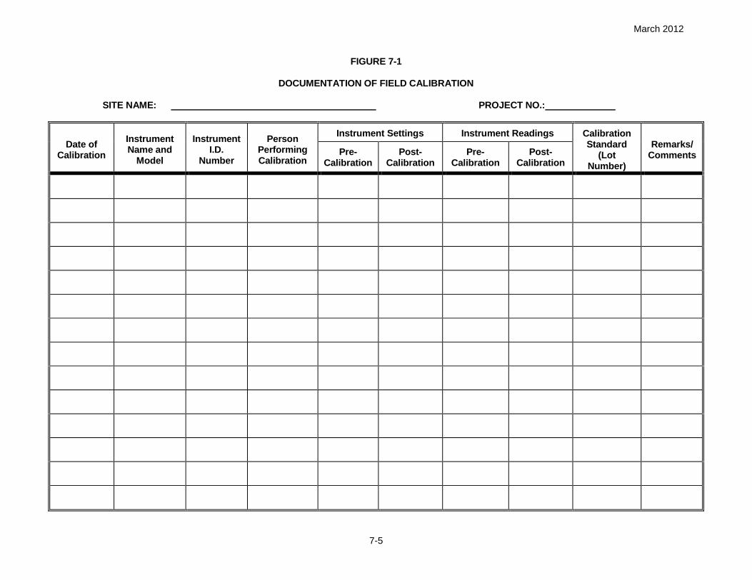
March 2012
7-5
FIGURE 7-1
DOCUMENTATION OF FIELD CALIBRATION
SITE NAME: PROJECT NO.:
Date ofCalibration
InstrumentName and
Model
InstrumentI.D.
Number
PersonPerformingCalibration
Instrument Settings Instrument Readings CalibrationStandard
(LotNumber)
Remarks/CommentsPre-
CalibrationPost-
CalibrationPre-
CalibrationPost-
Calibration

March 2012
8-1
8.0 TRAINING/MEDICAL SURVEILLANCE REQUIREMENTS
8.1 INTRODUCTORY/REFRESHER/SUPERVISORY TRAINING
This section is included to specify health and safety training and medical surveillance requirements for
Tetra Tech personnel participating in on site activities. Tetra Tech personnel must complete 40 hours of
introductory hazardous waste site training prior to performing work at the LMC MRC. Tetra Tech
personnel who have had introductory training more than 12 months prior to site work must have
completed 8 hours of refresher training within the past 12 months before being cleared for site work. In
addition, 8-hour supervisory training in accordance with 29 CFR 1910.120(e)(4) will be required for site
supervisory personnel. Tetra Tech and subcontractor personnel working on site who are potentially
exposed to hazardous substances shall receive initial and annual refresher training in accordance with 29
CFR 1910.120(e) – Hazardous Waste Operations and Emergency Response or the applicable state
OSHA standard. Lockheed Martin shall be provided with electronic copies of the training certificates.
Documentation of Tetra Tech introductory, supervisory, and refresher training as well as site-specific
training will be maintained at the site. Copies of certificates or other official documentation will be used to
fulfill this requirement.
The requirements described in Section 3.20.3 of the LM Handbook (Attachment I) addressing training will
be followed.
8.2 SITE-SPECIFIC TRAINING
Tetra Tech SSO will provide site-specific training to Tetra Tech employees who will perform work on this
project. Figure 8-1 will be used to document the provision and content of the project-specific and
associated training. Site personnel will be required to sign this form prior to commencement of site
activities. This training documentation will be employed to identify personnel who through record review
and attendance of the site-specific training are cleared for participation in site activities. This document
shall be maintained at the site to identify and maintain an active list of trained and cleared site personnel.
The Tetra Tech SSO will also conduct a pre-activities training session prior to initiating site work. This will
consist of a brief meeting at the beginning of each day to discuss operations planned for that day, and a
review of the appropriate Safe Work Permits with the planned task participants. A short meeting may also
be held at the end of the day to discuss the operations completed and any problems encountered.

March 2012
8-2
8.3 MEDICAL SURVEILLANCE
Tetra Tech personnel participating in project field activities will have had a physical examination meeting
the requirements of Tetra Tech's medical surveillance program. Documentation for medical clearances
will be maintained in the Tetra Tech Pittsburgh office and made available, as necessary, and will be
documented using Figure 8-1 for every employee participating in onsite work activities at this site. Tetra
Tech shall provide evidence of employee enrollment in a medical surveillance program. Lockheed Martin
does not provide medical surveillance examinations to contractor employees.
The medical surveillance requirements described in Section 3.20.4 of the LM Handbook (Attachment I)
will be followed.
Each field team member, including visitors, entering the exclusion zone(s) shall be required to complete
and submit a copy of the Medical Data Sheet (see Attachment III of this HASP). This shall be provided to
the SSO, prior to participating in site activities. The purpose of this document is to provide site personnel
and emergency responders with additional information that may be necessary in order to administer
medical attention.

March 2012
8-3
FIGURE 8-1
SITE-SPECIFIC TRAINING DOCUMENTATION
My signature below indicates that I am aware of the potential hazardous nature of performing fieldactivities at LCM MSA and that I have received site-specific training which included the elementspresented below:
Names of designated personnel and alternates responsible for site safety and health Safety, health, and other hazards present on site Use of personal protective equipment Safe use of engineering controls and equipment Medical surveillance requirements Signs and symptoms of overexposure Emergency response procedures (evacuation and assembly points) Incipient response procedures Review of the contents of relevant Material Safety Data Sheets Review of the use of Safe Work Permits Stop Work Procedures
I have been given the opportunity to ask questions and all of my questions have been answered to mysatisfaction. The dates of my training and medical surveillance requirements indicated below areaccurate.
Name(Printed and Signature)
Site-SpecificTraining
Date
40-HourTraining
(Date)
8-HourRefresherTraining
(Date)
8-HourSupervisory
Training (Date)MedicalExam

March 2012
9-1
9.0 SITE CONTROL
This section outlines the means by which Tetra Tech will delineate work zones and use these work zones
in conjunction with decontamination procedures to prevent the spread of contaminants into previously
unaffected areas of the site. It is anticipated that a three-zone approach will be used during work at this
site. This approach will be comprised of an exclusion zone, a contamination reduction zone, and a
support zone. It is also anticipated that this approach will control access to site work areas, restricting
access by the general public, minimizing the potential for the spread of contaminants, and protecting
individuals who are not cleared to enter work areas.
9.1 EXCLUSION ZONE
The exclusion zone will be considered the areas of the site of known or suspected contamination. It is
anticipated that the areas around active/intrusive activates will have the potential for contaminants
brought to the surface. These areas will be marked and personnel will maintain safe distances. Once
active/intrusive activities have been completed and any surface contamination has been removed, the
potential for exposure is again diminished and the area can then be reclassified as part of the
contamination reduction zone. The exclusion zones for this project are those areas of the site where
active work (DPT work areas, drilling, installation, and sample collection, etc.) is being performed plus a
designated area of at least 25 feet surrounding the work area. Exclusion zones will be delineated as
deemed appropriate by the FOL, through means such as erecting visibility fencing, barrier tape, cones,
and/or postings to inform and direct personnel.
9.1.1 Exclusion Zone Clearance
An Exclusion Zone (EZ) will be established at each well installation/sampling location. The purpose of
establishing and maintaining these localized exclusion zones is to define areas where more rigorous
safety and health protection measures will be required and to designate areas restricted to non-essential
and unauthorized personnel. The size and dimensions of these EZs will vary based on the nature of the
planned activities, and may be subject to change at the SSO's discretion based on factors such as visual
observations, nearby concurrent operations, and other factors. However, the following dimensions
represent basic considerations for establishing EZs:
DPT and associated concurrent sampling activities. The EZ for this activity will be set at the height of
the mast, plus five feet surrounding the point of operation, with a minimum of 25-feet. This distance
will also apply when surface and subsurface soil sampling from behind these type rigs.

March 2012
9-2
Monitoring well development, purging, piezometer construction and use, and collecting groundwater
samples and water level readings. The EZ for these activities will be set to encompass an area of at
least 10-feet surrounding the well head.
Decontamination operations. The EZ for this activity will be set at 25 feet surrounding the gross
contamination wash and rinse as well as 25-feet surrounding the heavy equipment decontamination
area. Sample equipment decontamination boundaries will be set at 10-feet surrounding hand wash
and rinse areas.
Investigative Derived Waste (IDW) area will be constructed and barricaded. Only authorized
personnel will be allowed access.
EZs will be marked using barrier tape, traffic cones and/or drive pole, or other readily-visible devices.
Signs may also be posted at the SSO's discretion to inform and direct site personnel and site visitors.
EZs shall remain marked until the SSO has evaluated the restoration effort and has authorized changing
the zone status.
9.2 CONTAMINATION REDUCTION ZONE
Contamination Reduction Zones (CRZs) will be established to minimize the potential for the spread of
contaminated media from being spread into previously-unaffected areas. The primary function of a CRZ
is to provide an adequate area for decontamination activities. For personal and small item (e.g., sampling
equipment) decontamination activities, a CRZ will be established at the perimeter of each EZ. For
decontamination activities that will require specialized equipment, larger areas, and more significant
containment, a heavy equipment decontamination pad CRZ will be established in one or more areas to
support the two work areas...
In order to move from on EZ to another, the following activities will be performed in the localized CRZs:
As samplers move from location to location, dedicated sampling devices and PPE will be washed to
remove visible gross contamination, and then these items will be bagged and removed. Personnel
will use hygienic wipes (such as "baby wipes") as necessary for interim personnel decontamination
until they can access a facility equipped with hands washing and rinsing capabilities. At the first
available opportunity personnel will wash their face and hands. This is critical prior to breaks and
lunch when contamination may be transferred to the mouth through hand to mouth contact.
Disposable PPE, sampling equipment, and other items are to be sequentially removed/deposited and
double-bagged. Such waste is to be disposed of in accordance with the direction of the client.

March 2012
9-3
Reusable items that are grossly contaminated (such as muddy over-boots, hardhats, etc.) will be
required to be removed, bagged, and taken to the established decontamination pad for washing and
rinsing prior to being used at another EZ. .
Potentially contaminated tooling will be wrapped, as necessary, for transport to the decontamination
area for cleaning.
9.3 SUPPORT ZONE
The support zone for this project will include a staging area where site vehicles will be parked, equipment
will be unloaded, and where food and drink containers will be maintained. The support zones will be
established at areas of the site where away from potential exposure to site contaminants during normal
working conditions or foreseeable emergencies.
9.4 SAFE WORK PERMITS
Exclusion Zone work conducted in support of this project will be performed using Safe Work Permits
(SWPs) to guide and direct field crews on a task by task basis. An example of the SWP to be used is
provided in Figure 9-1. Partially completed SWPs for the work to be performed are attached
(Attachment IV) to this HASP. These permits were completed to the extent possible as part of the
development of this HASP. It is the SSO's responsibility to finalize and complete all blank portions of the
SWPs based on current, existing conditions the day the task is to be performed, and then review that
completed permit with all task participants as part of a pre-task tail gate briefing session. This will ensure
that site-specific considerations and changing conditions are appropriately incorporated into the SWP,
provide the SSO with a structured format for conducting the tail gate sessions, as well will also give
personnel an opportunity to ask questions and make suggestions. All SWPs require the signature of the
FOL or SSO.
9.5 SITE SECURITY
As this activity will take place at an active facility, the first line of security will be provided by the facility
entrance/gate restricting the general public. The second line of security will take place at the work site
referring interested parties to the FOL and LMC Contact.
Security at the work areas will be accomplished using field personnel. This is a multiple person
operation, involving multiple operational zones. Tetra Tech personnel will retain complete control over
active operational zones.

March 2012
9-4
The site contact will serve as the focal point for facility personnel and interested parties and will serve as
the primary enforcement contact.
9.6 SITE VISITORS
Site visitors for the purpose of this document are identified as representing the following groups of
individuals:
Personnel invited to observe or participate in operations by Tetra Tech
Regulatory personnel (i.e. EPA, MDEP, OSHA)
Property Owners
Authorized Personnel
Other authorized visitors
Non Tetra Tech personnel working on this project are required to gain initial access to the facility by
coordinating with the Tetra Tech FOL or designee and following established facility access procedures.
Once access to the base is obtained, personnel who require site access into areas of ongoing operations
will be required to obtain permission from the PM. In addition, site visitors wishing to observe operations
in progress will be escorted by a Tetra Tech representative and shall be required to meet the minimum
requirements discussed below:
Site visitors will be directed to the FOL/SSO, who will sign them into the field logbook. Information to
be recorded in the logbook will include the individual's name (proper identification required), the entity
which they represent, and the purpose of the visit.
Site visitors must be escorted and restricted from approaching any work areas where they could be
exposed to hazards from Tetra Tech operations. If a visitor has authorization from the client and from
the Tetra Tech Project Manager to approach our work areas, the FOL must assure that the visitor first
provides documentation indicating that he/she/they have successfully completed the necessary
OSHA introductory training, receive site-specific training from the SSO, and that they have been
physically cleared to work on hazardous waste sites. Site visitors wishing to enter the exclusion zone
will be required to produce the necessary information supporting clearance to the site. This shall
include information attesting to applicable training and medical surveillance as stipulated in
Section 8.0 of this document. In addition, to enter the site operational zones during planned activities,
visitors will be required to first go through site-specific training covering the topics stipulated in

March 2012
9-5
Section 8.2 of this HASP. All jobsite visitors must have a safety orientation prior to commencing work
or touring the site. A visitor log will be kept to document the orientation.
Once the site visitors have completed the above items, they will be permitted to enter the operational
zone. Visitors are required to observe the protective equipment and site restrictions in effect at the
site at the time of their visit. Visitors entering the exclusion zones during ongoing operations will be
accompanied by a Tetra Tech representative. Visitors not meeting the requirements, as stipulated in
this plan, for site clearance will not be permitted to enter the site operational zones during planned
activities. Any incidence of unauthorized site visitation will cause the termination of on site activities
until the unauthorized visitor is removed from the premises. Removal of unauthorized visitors will be
accomplished with support from local law enforcement personnel.
9.7 SITE MAP
Once the areas of contamination, access routes, topography, and dispersion routes are determined, a
site map will be generated and adjusted as site conditions change. These maps will be posted to
illustrate up-to-date collection of contaminants and adjustment of zones and access points.
9.8 BUDDY SYSTEM
Personnel engaged in on site activities will practice the "buddy system" to ensure the safety of personnel
involved in this operation.
9.9 COMMUNICATION
As personnel will be working in proximity to one another during field activities, a supported means of
communication between field crew members will not be necessary.
External communication will be accomplished by using the cell phones/telephones at predetermined and
approved locations. External communication will primarily be used for the purpose of resource and
emergency resource communications. Prior to the commencement of activities at the LCM MRC, the FOL
will determine and arrange for telephone communications.
9.10 SELF-AUDITS
The procedures outlined in Section 7 of the LM Handbook (Attachment I) addressing self-audits will be
adhered to.

March 2012
9-6
Tetra Tech and/or subcontractor personnel will perform periodic work area/project field inspections to
monitor compliance with project environmental, safety and health requirements. The name of Tetra
Tech’s jobsite health and safety (H&S) representative will be provided to Lockheed Martin prior to starting
work at the jobsite.
For jobs that are ongoing, an annual H&S audit shall be conducted and for jobs with a duration of less
than one year at least one audit shall occur. A competent H&S representative designated by the Tetra
Tech shall perform the audit. Unsafe acts and/or non-compliance conditions noted during inspections
shall be corrected immediately.
The documentation related to the audits and inspections shall be submitted electronically to the Lockheed
Martin Project Lead.

March 2012
9-7
FIGURE 9-1SAFE WORK PERMIT
Permit No. Date: Time: From to
I. Work limited to the following (description, area, equipment used):
II. Primary Hazards: Potential hazards associated with this task:
III. Field Crew:IV. On-site Inspection conducted Yes No Initials of Inspector Tetra Tech
Equipment Inspection required Yes No Initials of Inspector Tetra Tech
V. Protective equipment required Respiratory equipment required
Level D Level B Yes Specify on the reverseLevel C Level A No
Modifications/Exceptions:
VI. Chemicals of Concern Hazard Monitoring Action Level(s) Response Measures
Primary Route(s) of Exposure/Hazard:
(Note to FOL and/or SHSO: Each item in Sections VII, VIII, and IX must be checked Yes, No, or NA)VII. Additional Safety Equipment/Procedures
Hard-hat..................................... Yes No Hearing Protection (Plugs/Muffs) .... Yes NoSafety Glasses .......................... Yes No Safety belt/harness ......................... Yes NoChemical/splash goggles........... Yes No Radio/Cellular Phone ...................... Yes NoSplash Shield............................. Yes No Barricades....................................... Yes NoSplash suits/coveralls ................ Yes No Gloves (Type – )........... Yes NoImpermeable apron.................... Yes No Work/rest regimen........................... Yes NoSteel toe Work shoes or boots... Yes No Chemical Resistant Boot Covers..... Yes NoHigh Visibility vest...................... Yes No Tape up/use insect repellent .......... Yes NoFirst Aid Kit ................................ Yes No Fire Extinguisher ............................. Yes NoSafety Shower/Eyewash............ Yes No Other ............................................... Yes NoModifications/Exceptions:
VIII. Site Preparation Yes No NAUtility Locating and Excavation Clearance completed ........................................................Vehicle and Foot Traffic Routes Established/Traffic Control Barricades/Signs in Place .....Physical Hazards Identified and Isolated (Splash and containment barriers) .....................Emergency Equipment Staged (Spill control, fire extinguishers, first aid kits, etc)..............
IX. Additional Permits required (Hot work, confined space entry, excavation etc.)................... Yes NoIf yes, SHSO to complete or contact Health Sciences, Pittsburgh Office (412)921-7090
X. Special instructions, precautions:
Permit Issued by: Permit Accepted by:
March 2012
10-1
10.0 SPILL CONTAINMENT PROGRAM AND WASTE MANAGEMENT PLAN
10.1 SCOPE AND APPLICATION
It is not anticipated that bulk hazardous materials (over 55-gallons) will be generated or handled at any
given time as part of this scope of work. It is also not anticipated that such spillage would constitute a
danger to human health or the environment.
This Spill Prevention and Containment Program applies to the potential release from one or more
containers on the work site involving a single or aggregate accumulation of bulk storage materials (over
55-gallons). As the classification of certain materials such as IDW is unknown, these materials will be
treated as hazardous, pending laboratory certification to the contrary.
However, as the job progresses, some potential may exist for accumulating Investigative Derived Wastes
(IDW) such as decontamination fluids, soil cuttings, disposable sampling equipment and PPE.
The spill containment and control will be engaged any time there is a release of the above-identified
materials from a containment system or vessel. This spill containment program will be engaged in order
to minimize associated hazards.
10.2 POTENTIAL SPILL AREAS
Potential spill areas will be periodically monitored in an ongoing attempt to prevent and control further
potential contamination of the environment. Currently, limited areas are vulnerable to this hazard
including:
Resource deployment
Waste transfer
Central staging
It is anticipated that the IDW generated as a result of this scope of work will be containerized, labeled,
and staged to await further analyses. The results of these analyses will determine the method of
disposal.
10.3 LEAK AND SPILL DETECTION
To establish an early detection of potential spills or leaks, a periodic walk-around by the personnel
staging or disposing of drums area will be conducted during working hours to visually determine that
storage vessels are not leaking. If a leak is detected, the contents will be transferred, using a hand pump,

March 2012
10-2
into a new vessel. The leak will be collected and contained using absorbents such as Oil-Dry,
vermiculite, or sand, which are stored at the vulnerable areas in a conspicuously marked drum. This
used material, too, will be containerized for disposal pending analysis. Inspections will be documented in
the project logbook.
In case of a spill or release of hazardous chemicals, Tetra Tech shall immediately notify the Lockheed
Martin Project Lead, and/or if the severity of the spill warrants, the local fire department by calling 9-1-1.
Tetra Tech shall take all necessary steps to control the spread of the release and to provide site control to
prevent unauthorized personnel from entering the affected area.
Section 8.2 of the LM Handbook (Attachment I) pertaining to spill reporting will be addresses.
10.4 PERSONNEL TRAINING AND SPILL PREVENTION
Personnel will be instructed in the procedures for incipient spill prevention, containment, and collection of
hazardous materials in the site-specific training. The FOL and the SSO will serve as the Spill Response
Coordinators for this operation, should the need arise.
10.5 SPILL PREVENTION AND CONTAINMENT EQUIPMENT
The following represents the types of equipment that should be maintained at the staging areas for the
purpose of supporting this Spill Prevention/Containment Program.
Sand, clean fill, vermiculite, or other non combustible absorbent (Oil-dry)
Drums (55-gallon U.S. DOT 1A1 or 1A2)
Shovels, rakes, and brooms
Container labels
Hazardous materials shall be stored in designated areas and all containers effectively closed. Spill
equipment/supplied shall be readily available to contain and/or mitigate accidental spills of hazardous
materials.
10.6 SPILL CONTROL PLAN
This section describes the procedures the Tetra Tech field crew members will employ upon the detection
of a spill or leak.
Notify the SSO or FOL immediately upon detection of a leak or spill. Activate emergency alerting
procedures for that area to remove non-essential personnel.

March 2012
10-3
Employ the personal protective equipment stored at the staging area. Take immediate actions to stop
the leak or spill by plugging or patching the container or raising the leak to the highest point in the
vessel. Spread the absorbent material in the area of the spill, covering it completely.
Transfer the material to a new vessel; collect and containerize the absorbent material. Label the new
container appropriately. Await analyses for treatment and disposal options.
Re-containerize spills, including 2-inch of top cover impacted by the spill. Await test results for
treatment or disposal options.
It is not anticipated that a spill will occur that the field crew cannot handle. Should this occur, notification
of the appropriate Emergency Response agencies will be carried out by the FOL or SSO in accordance
with the procedures discussed in Section 2.0 of this HASP.
As mentioned above, in the event of a spill or release of hazardous chemicals, Tetra Tech will
immediately notify the LMC personnel in the order presented in Table 2-1, and/or if the severity of the spill
warrants, the local fire department by calling 9-1-1.
10.7 WASTE MANAGEMENT PLAN
Tetra Tech personnel will adhere to the decontamination and waste management procedures laid out the
Tetra Tech HSGM and the Tetra Tech Decontamination of Field Equipment and Waste Handling
Standard Operating Procedure (Attachment XI).
In addition, all requirements described in Sections 4.1 and 4.2 of the LM Handbook (Attachment I) will be
addressed.

March 2012
11-1
11.0 CONFINED-SPACE ENTRY
It is not anticipated, under the proposed scope of work, that confined space and permit-required confined
space activities will be conducted. Therefore, personnel under the provisions of this HASP are not
allowed, under any circumstances, to enter confined spaces. A confined space is defined as an area
which has one or more of the following characteristics:
Is large enough and so configured that an employee can bodily enter and perform assigned work.
Has limited or restricted means for entry or exit (for example, tanks, manholes, sewers, vessels, silos,
storage bins, hoppers, vaults, and pits are spaces that may have limited means of entry).
Is not designed for continuous employee occupancy.
Additionally, a Permit-Required Confined Space must also have one or more of the following
characteristics:
Contains or has a potential to contain a hazardous atmosphere.
Has an internal configuration such that an entrant could be trapped or asphyxiated by inwardly caving
walls or by a floor that slopes downward and tapers to a smaller cross-section.
Contains any other recognized, serious, safety or health hazard.
For further information on confined space, consult the Health and Safety Guidance Manual or call the
PHSO. If confined space operations are to be performed as part of the scope of work, detailed
procedures and training requirements will have to be addressed and this HASP will be updated/amended
as necessary to address the confined space entry requirements detailed in Section 3.3 of the LM
Handbook (Attachment I).

March 2012
12-1
12.0 HOT WORK
No hot work activities are being conducted as part of this field effort. Should hot work be required, this
HASP will be amended/updated as necessary to include the requirements stipulated in Section 3.4 of the
LM Handbook (Attachment I).

March 2012
13-1
13.0 USE OF LOCKHEED MARTIN MATERIALS AND EQUIPMENT
No Lockheed Martin materials, tools, equipment, PPE shall be used until authorized by Lockheed Martin.
No Tetra Tech personnel will start, stop, relocate, or adjust any Lockheed Martin process or production
equipment without approval of the Lockheed Martin Project Lead. Details of these requirements are
described in Section 3.6 of the LM Handbook.

March 2012
14-1
14.0 ELEVATED LOCATIONS / LADDERS / SCAFFOLDS
No elevated location work, ladder work, or scaffolding activities are being conducted as part of this field
effort. Should any of these activities be required, this HASP will be amended/updated as necessary to
include the requirements stipulated in Sections 3.10, 3.11, and 3.12 of the LM Handbook (Attachment I).

March 2012
15-1
15.0 DANGEROUS OPERATIONS
Tetra Tech and subcontractor personnel will isolate their work areas from Lockheed Martin operations,
employees, and the public. Barricades, signs, and signals will be employed as necessary and will be
visible at all times where hazards exist.
Tetra Tech and subcontractors will effectively barricade excavations, floor openings, etc. as required by
OSHA regulations.
Prior to beginning work, Tetra Tech and subcontractors must inform the Lockheed Martin Project Lead of
any potentially dangerous operations.
All requirements addressing dangerous operations are detailed in Section 3.7 of the LM Handbook and
will be adhered to.

March 2012
16-1
16.0 EXCAVATIONS, TRENCHES, AND EARTHWORK
This field effort includes the excavation of test pits, therefore the following excavation procedures will
apply to the excavation work.
16.1 EXCAVATION SAFE WORK PRACTICES
Utility clearances should be in place prior to the beginning of excavation (in accordance with the Tetra
Tech Utility Locating SOP in the Health and Safety Guidance Manual Section 7.0).
Excavation boundaries should be demarcated with appropriate warning signs (e.g., construction
activities in progress).
Traffic patterns for equipment and the loading of trucks should be established. This pattern should
form a loop to minimize backing, an activity which causes many accidents.
Traffic patterns for foot and small vehicular traffic should keep workers away from heavy equipment.
Traffic patterns for heavy equipment should be constructed to maintain traffic flow a minimum of 10
feet from unsupported walls or excavation boundaries.
Excavation along thoroughfares will require the use of warning signs, barricades and flag-persons for
alteration of traffic patterns, as necessary.
Ground personnel should be provided with reflective vests to increase visibility and air horns to signal
loud trucks and heavy equipment.
Ground activities with heavy equipment should be supported with a ground spotter. The operators
should be instructed that they are to follow the instructions provided by the ground spotter unless
another party is otherwise authorized.
Surface encumbrances within the intended work area of the excavation will be removed or supported,
as necessary, in accordance with OSHA 1926.651(a).
Prior to being put into service at the site, the excavator will be inspected by the SSO, and this
inspection will be documented using the applicable forms in Attachment V.

March 2012
16-2
Heavy equipment will be positioned and operated so that it never approaches closer than 4 feet from
the edge of an open excavation (other than the boom and bucket portion of the excavator).
A decontamination station should be established at the loading and off-loading areas to flush mud
and dirt from the wheels and tires as well as any areas of the vehicle impacted during the loading
operation.
16.2 EMPLOYER DESIGNATED “COMPETENT PERSON”
The Employer Designated “Competent Person” is responsible for all aspects of excavation safety. This
includes:
16.2.1 Pre-Excavation Activities
Utility Clearance identification and marking
Establishment of site control measures (temporary utilities, temporary traffic patterns, barricades,
signs, etc.)
Removal and/or control of Surface and Subsurface Encumbrances
Traffic (Foot/Vehicular) Impact and routing
Surface drainage patterns and impact
16.2.2 During Excavation Activities
Utility sweeps
Review and evaluation of entry/egress systems
Installing support systems for surface and subsurface encumbrances as necessary (i.e. supporting
building foundations, sidewalks, utility runs, etc.)
Soil classification – Visual and Manual Analysis
Hazardous atmosphere evaluation (initial and periodic monitoring)
Recommendation/Installation/Evaluation of protective system (in and out of the excavation)
16.2.3 Post Excavation Activities
Evaluation of the protective systems installed (sloping, benching, shielding, etc.)
Soil conditions (Moisture content, fissures developing, horizontal cracks, etc.)
Loading the excavation walls (Spoils piles, resource/fill materials stock piling, traffic, etc.)
Atmospheric monitoring
Backfill
March 2012
16-3
16.2.4 Competent Persons Qualifications
The employer designates Competent Person(s) based on knowledge and training.
Capable of identifying existing or predictable hazards associated with excavated cuts or cavities in
the earth.
Has the authority to take prompt action to abate these hazards.
Working knowledge of Soil Analysis/Soil Classification.
Knowledgeable in the area of Protective Systems.
Working knowledge of the requirements of 29 CFR 1926 Subpart P.
This position will typically be filled by Site Safety Officer (SSO), Field Operations Leader (FOL), or a
Registered Professional Engineer (PE). The Excavation Competent Person must be specifically identified
to handle this responsibility prior to work beginning in the specified space provided (Section 1.3) in this
HASP.
Detailed Tetra Tech Excavation Safety Procedures, the Excavation Competent Person Checklist, the
Tetra Tech Confined Space Entry Program and Procedures, and the Heavy Equipment Inspection
Checklist are included in Attachments VI, VII, VIII and IX, and must be completed prior to beginning work.
The OSHA Health and Safety Construction-Related regulations P-650 to 699 – Subpart P – Excavations
are included in Attachment X and must be followed during all excavation work.
16.3 LM EXCAVATION REQUIREMENTS
In addition, the requirements stipulated in Section 3.8 of the LM Handbook (Attachment I) will be reviewed
and adhered to during the excavation work and a trained, competent person will be designated to oversee
the activities. These requirements include:
Review the Lockheed Martin intrusive fieldwork requirements in Appendix A of the LM Handbook.
If workers are to enter excavations, a competent person must be designated and trained in soil
classification and the recognition of trenching and excavation hazards.
Excavations and trenches shall be inspected by a competent person daily and after every rainstorm,
earthquake, or other hazard-increasing occurrence.
Inspect the face, banks, and top daily when workers are exposed to falling or rolling materials.

March 2012
16-4
Shore, bench, slope, or use equivalent methods to protect workers in excavations four feet deep or
more.
Locate soil at least two feet from the edge of the excavation, or one foot from the edge when the
excavation is less than five feet deep.
Ladders or steps shall be provided and secured in all trenches four feet or more in depth. Ladders
shall be located to require no more than twenty-five feet of lateral travel before having access or
egress and shall extend three feet above the top of the trench bank.
Install crossings with standard guardrails and toeboards when the excavation is more than 7½ feet
deep.
All open trenches and other excavations shall be provided with suitable barriers, signs, and lights to
the extent that adequate protection is provided to the public.
Do not excavate beneath the level of adjacent foundations, retaining walls, or other structures until a
qualified person has determined that the work will not be hazardous. Support undermined sidewalks.

March 2012
17-1
17.0 ASBESTOS
No asbestos abatement work is being conducted as part of this field effort. Should it be required, this
HASP will be amended/updated as necessary to include the requirements stipulated in Section 3.19 of
the LM Handbook (Attachment I).
It is not anticipated during this field effort, but should asbestos containing material (ACM) or presumed
asbestos containing material (PACM) be disrupted, Tetra Tech and/or subcontractor personnel shall
immediately report to the Lockheed Martin Project Lead and to other employers of employees working at
the job site any discovery, disturbance, and/or spill of ACM and/or PACM. All operations will cease in the
immediate area of the suspect ACM and/or PACM and demarcate the area. The approval of the
Lockheed Martin Project Lead is required before resuming operations.
Tetra Tech and/or subcontractor personnel shall not disturb any pipe insulation, boiler insulation, or any
other material reasonably suspected of containing asbestos until the Lockheed Martin is notified and
approval is obtained.
Abatement of asbestos can be performed only by persons properly trained and licensed to perform such
activities.
All requirements addressed in Section 3.18 of the LM Handbook pertaining to incidental asbestos
exposure will be followed.

March 2012
18-1
18.0 NANOTECHNOLOGY
No nanotechnology work is being conducted as part of this field effort. Should it be required, this HASP
will be amended/updated as necessary to include the requirements stipulated in Section 3.21 of the LM
Handbook (Attachment I).

March 2012
19-1
19.0 WORK INVOLVING AIR EMISSIONS
No work involving air emissions is being conducted as part of this field effort. Should it be required, this
HASP will be amended/updated as necessary to include the requirements stipulated in Section 4.3 of the
LM Handbook (Attachment I).

March 2012
20-1
20.0 WORK INVOLVING WATER DISCHARGES
No work involving water discharges is being conducted as part of this field effort. Should it be required,
this HASP will be amended/updated as necessary to include the requirements stipulated in Section 4.4 of
the LM Handbook (Attachment I).

March 2012
21-1
21.0 MATERIALS AND DOCUMENTATION
The Tetra Tech Field Operations Leader (FOL) shall ensure the following materials/documents are taken
to the project site and used when required.
A complete copy of this HASP
Health and Safety Guidance Manual
Incident Reports
Medical Data Sheets
Material Safety Data Sheets for chemicals brought on site, including decontamination solutions, fuels,
sample preservatives, calibration gases, etc.
A full-size OSHA Job Safety and Health Poster (posted in the site trailer)
Training/Medical Surveillance Documentation Form (Blank)
First-Aid Supply Usage Form
Emergency Reference Form (Section 2.0, extra copy for posting)
Directions to the Hospital
21.1 MATERIALS TO BE POSTED AT THE SITE
The following documentation is to be posted or maintained at the site for quick reference purposes. In
situations where posting these documents is not feasible (such as no office trailer), these documents
should be separated and immediately accessible.
Chemical Inventory Listing (posted) - This list represents all chemicals brought on-site, including
decontamination solutions, sample preservations, fuel, etc. This list should be posted in a central
area.
MSDSs (maintained) - The MSDSs should also be in a central area accessible to all site personnel.
These documents should match all the listings on the chemical inventory list for all substances
employed on-site. It is acceptable to have these documents within a central folder and the chemical
inventory as the table of contents.
The OSHA Job Safety & Health Protection Poster (posted – Attachment XII) - This poster should
be conspicuously posted in places where notices to employees are normally posted, as directed by
29 CFR 1903.2 (a)(1). Each FOL shall ensure that this poster is not defaced, altered, or covered by
other material. The law also states that reproductions or facsimiles of the poster shall be at least 8
1/2 by 14 inches with 10 point type.

March 2012
21-2
Site Clearance (maintained) - This list is found within the training section of the HASP (Figure 8-1).
This list identifies all site personnel, dates of training (including site-specific training), and medical
surveillance. The list indicates not only clearance, but also status. If personnel do not meet these
requirements, they do not enter the site while site personnel are engaged in activities.
Emergency Phone Numbers and Directions to the Hospital(s) (posted) - This list of numbers and
directions will be maintained at all phone communications points and in each site vehicle.
Medical Data Sheets/Cards (maintained) - Medical Data Sheets will be filled out by on-site
personnel and filed in a central location. The Medical Data Sheet will accompany any injury or illness
requiring medical attention to the medical facility. A copy of this sheet or a wallet card will be given to
all personnel to be carried on their person.
Personnel Monitoring (maintained) - All results generated through personnel sampling (levels of
airborne toxins, noise levels, etc.) will be posted to inform individuals of the results of that effort.
Placards and Labels (maintained) - Where chemical inventories have been separated because of
quantities and incompatibilities, these areas will be conspicuously marked using DOT placards and
acceptable [Hazard Communication 29 CFR 1910.1200(f)] labels.
The purpose of maintaining or posting this information, as stated above, is to allow site personnel quick
access. Variations concerning location and methods of presentation are acceptable providing the
objective is accomplished.
21.2 HAZARD COMMUNICATION – USE OF HAZARDOUS MATERIALS
All hazardous substance (as defined by OSHA) brought onto Lockheed Martin remediation sites must
be accompanied by a MSDS and the containers labeled in accordance with the Red OSHA Hazard
Communication Standard, 29 CFR 1910.1200 or applicable state OSHA standard. Tetra Tech and
subcontractor personnel will provide MSDSs for chemicals brought on site. The contents of these
documents will be reviewed by the SSO with the user(s) of the chemical substances prior to any
actual use or application of the substances on site. A chemical inventory of the chemicals used on
site will be developed using the Health and Safety Guidance Manual. The MSDSs will then be
maintained in a central location (i.e., temporary office) and will be available for anyone to review upon
request.

March 2012
21-3
The Lockheed Martin Project Lead shall be notified prior to bringing ay quantity of hazardous materials
onto Lockheed Martin remediation sites. Hazardous materials shall be stored in designated areas and all
containers effectively closed. Spill equipment/supplied shall be readily available to contain and/or
mitigate accidental spills of hazardous materials.
All other hazard communication requirements are detailed in Section 3.2 and Section 4.1 of the LM
Handbook (Attachment I) and will be adhered to.

March 2012
22-1
22.0 ACRONYMS / ABBREVIATIONS
CFR Code of Federal Regulations
CIH Certified Industrial Hygienist
CSP Certified Safety Professional
DRI Direct Reading Instrument
FID Flame Ionization Detector
FOL Field Operations Leader
HASP Health and Safety Plan
HAZWOPER Hazardous Waste Operations and Emergency Response
HSM Health and Safety Manager
IDW Investigation Derived Waste
MDEP Maryland Department of Environmental Protection
N/A Not Available
NIOSH National Institute for Occupational Safety and Health
OSHA Occupational Safety and Health Administration (U.S. Department of Labor)
PHSO Project Health and Safety Officer
PID Photoionization Detector
PM Project Manager
PPE Personal Protective Equipment
SSO Site Safety Officer
TBD To be determined
TCE Trichloroethene
Tetra Tech Tetra Tech , Inc.
VC Vinyl Chloride
VOCs Volatile Organic Compounds

ATTACHMENT ILOCKHEED MARTIN’S
REMEDIATION CONTRACTOR’S ESHHANDBOOK

Lockheed Martin Remediation 1 RESH-05A Contractor’s ESH Handbook
REMEDIATION CONTRACTOR’S ESH HANDBOOK
June 10, 2009
Revision 1
Lockheed Martin Corporation Energy, Environment, Safety & Health
A COPY OF THE JOB SPECIFIC HASP SHALL BE AVAILABE AT THE JOB SITE FOR THE DURATION OF THE PROJECT

Lockheed Martin Remediation 2 RESH-05A Contractor’s ESH Handbook
REVISION STATUS
REVISION DATE COMMENTS
1 06/10/2009

Lockheed Martin Remediation 3 RESH-05A Contractor’s ESH Handbook
CONTRACTOR’S ESH HANDBOOK
TABLE OF CONTENTS
Table of Contents 1 CONTRACT RESPONSIBILITIES ..................................................................................................................................... 4 2 DEFINITION........................................................................................................................................................................ 6 3 SAFETY & HEALTH .......................................................................................................................................................... 7
3.1 PERSONAL PROTECTIVE CLOTHING AND EQUIPMENT.................................................................................. 7 3.2 HAZARD COMMUNICATION - USE OF HAZARDOUS MATERIALS................................................................ 8 3.3 CONFINED SPACE ENTRY ...................................................................................................................................... 9 3.4 HOT WORK REQUIREMENTS (i.e., welding, torch cutting, brazing, etc.) ............................................................ 10 3.5 LOCKOUT / TAGOUT - Control of Hazardous Energy ........................................................................................... 10 3.6 USE OF LOCKHEED MARTIN MATERIALS AND EQUIPMENT ...................................................................... 11 3.7 DANGEROUS OPERATIONS - WARNINGS AND BARRICADES ..................................................................... 11 3.8 EXCAVATIONS, TRENCHES, EARTHWORK...................................................................................................... 11 3.9 ELECTRICAL SAFETY............................................................................................................................................ 12 3.10 ELEVATED LOCATIONS / FALL PROTECT ........................................................................................................ 13 3.11 LADDERS ................................................................................................................................................................. 13 3.12 SCAFFOLDS ............................................................................................................................................................. 14 3.13 HEAVY EQUIPMENT, INDUSTRIAL VEHICLES, AND CRANES ..................................................................... 14 3.14 OVERHEAD POWER LINES................................................................................................................................... 15 3.15 FIRE PREVENTION / FLAMMABLE LIQUIDS..................................................................................................... 15 3.16 HAND AND POWER TOOLS .................................................................................................................................. 16 3.17 COMPRESSED GAS CYLINDERS.......................................................................................................................... 17 3.18 INCIDENTAL CONTACT WITH ASBESTOS........................................................................................................ 17 3.19 ASBESTOS ABATEMENT CONTRACTORS......................................................................................................... 18 3.20 HAZARDOUS WASTE OPERATIONS and EMERGENCY RESPONSE .............................................................. 20 3.21 MANAGEMENT OF NANOTECHNOLOGY.......................................................................................................... 22
4 ENVIRONMENTAL.......................................................................................................................................................... 23 4.1 HAZARD COMMUNICATION - USE OF HAZARDOUS MATERIALS.............................................................. 23 4.2 NON-HAZARDOUS WASTE DISPOSAL............................................................................................................... 24 4.3 WORK INVOLVING AIR EMISSIONS................................................................................................................... 24 4.4 WORK INVOLVING WATER DISCHARGES ....................................................................................................... 24
5 HOUSEKEEPING / CLEANUP......................................................................................................................................... 25 6 CHANGE MANAGEMENT.............................................................................................................................................. 25 7 REQUIREMENT TO PERFORM & DOCUMENT SELF-AUDITS................................................................................. 26 8 ACCIDENT, INJURY, ILLNESS, INCIDENT and SPILL REPORTING ........................................................................ 26 9 FINES, PENALTIES AND COSTS ................................................................................................................................... 26 10 LOCKHEED MARTIN ESH MANAGER......................................................................................................................... 27 Appendix A – LMC Requirements for Invasive Fieldwork ......................................................................................................... 27 Appendix B – LMC Waste Management Procedure .................................................................................................................... 27

Lockheed Martin Remediation 4 RESH-05A Contractor’s ESH Handbook
CONTRACTOR’S ESH HANDBOOK
GENERAL Lockheed Martin Corporation management at all levels is committed to conducting operations and activities in a manner that provides and maintains safe and healthful working conditions, protects the environment, and conserves natural resources. This Contractor’s ESH Handbook has been prepared to assist each project jobsite employer/contractor in satisfying its’ contractual and legal accident prevention responsibilities, in such a manner that a safe, efficient operation is assured. All applicable requirements outlined in this handbook shall be incorporated into the contractor’s site specific Safety and Health Plan The site specific Safety and Health plan shall be submitted to the Lockheed Martin Project Lead at least two weeks prior to starting work on any Lockheed Martin remediation projects. This material must not be considered to be all inclusive as to the hazards that might be encountered, safe practices that should be performed, or safe conditions that should be maintained during the course of any project. Moreover, this handbook does not replace the contractor’s legal obligation to its employees under all relevant environmental, safety and health requirements and laws. All legal standards not specifically referenced in this handbook shall apply when applicable. 1 CONTRACT RESPONSIBILITIES
The Contractor agrees to comply with all rules and procedures contained in this document, known as the Remediation Contractor’s ESH Handbook, unless Lockheed Martin specifically agrees, in writing, to a modification or exemption. In addition, the Contractor and subcontractors, at any tier, shall:
1.1 Lockheed Martin is a drug free-work workplace. This requirement extends to
contractors working on Lockheed Martin remediation projects. Additionally, the use of tobacco is not permitted on Lockheed Martin owned property.
1.2 Take all prudent and proper environmental, safety and health (ESH) precautions to
protect Lockheed Martin employees, all other workers, and the public from ESH hazards associated with contractor activities.
1.3 Comply with all applicable Federal, State, municipal, local, and any other applicable occupational safety and health statutes, rules, ordinances, regulations, and requirements issued or imposed by any governmental authority (including, but not limited to Title 29, Code of Federal Regulations Parts 1903, 1904, 1910 and 1926).
1.4 Comply with all applicable Federal, State, municipal, local, and any other applicable air pollution statutes, rules, ordinances, regulations, and requirements issued or imposed by any governmental authority.

Lockheed Martin Remediation 5 RESH-05A Contractor’s ESH Handbook
1.5 Comply with all Federal, State, municipal, local and Lockheed Martin hazardous materials, hazardous waste, and non-hazardous waste statutes, rules, ordinances, regulations, and requirements (including, but not limited to Title 40, Code of Federal Regulations).
1.6 Obtain the applicable ESH permits to conduct the work in compliance with local, state, federal ESH regulations and site requirements (including, but not limiting to Title 29, Code of Federal Regulations, 1910 and 1926).
1.7 Ensure that all employees and subcontractors have received the appropriate level of ESH training in accordance with applicable ESH regulations necessary for the performance of the work requested by Lockheed Martin.
1.8 To instruct, prior to commencement of operations, all employees on the jobsite about relevant governmental laws and regulations, specific hazards expected to be encountered and proper safety precautions to be observed. In addition, jobsite employees shall read and certify that they have read and understand the job specific health and safety plan (HASP). The certification forms provided by the contractor within the HASP shall be electronically sent to the Lockheed Martin Project Lead.
1.9 Provide all jobsite visitors with a safety orientation prior to commencing work or touring
the site. A visitor log shall be kept to document the orientation.
1.10 To ensure Contractor's job specific health and safety plan (HASP) encompasses Federal, State, municipal, local and the Lockheed Martin requirements found within this document the HASP should contain a section on crisis management / emergency response. A copy of the job specific HASP shall be maintained at the job site where jobsite employees have access to a copy. All Contractor Project Managers shall be provided a copy of the Contractor's ESH Handbook found within the Lockheed Martin Request for Proposal or as an appendix of the Key National Contractor Agreement. Contractors shall flow these requirements down to their subcontractors.
1.11 Contractor understands that Lockheed Martin may immediately stop Contractor's work if Contractor violates any applicable Federal, State, municipal, local, or any other rules, regulations, and requirements, Remediation Contractor’s ESH Handbook provisions, or other contract terms and conditions regarding environmental, safety and health compliance. Lockheed Martin shall not incur work stoppage charges unless the contractor demonstrates that the work stoppage was unwarranted for any of the reasons stated above. Any dispute regarding work stoppage charges must be resolved through binding arbitration.
1.12 Contractor is advised that the Project may be inspected from time to time by Lockheed
Martin or a representative of Lockheed Martin. Periodic Lockheed Martin inspections in no way relieve the Contractor of their obligation to maintain its own inspection program to identify unsafe conditions or acts. ESH violations will be considered in evaluation of Contractor’s performance.

Lockheed Martin Remediation 6 RESH-05A Contractor’s ESH Handbook
1.13 Lockheed Martin is not responsible for training or supervising Contractor employees or abating workplace hazards created by the Contractor or to which the Contractor’s employees are exposed.
1.14 Contractor agrees to maintain copies of all pertinent ESH records at the job site. Pertinent records include, but is not limited to, personnel training documentation, evidence of enrollment in a medical surveillance program, accident/injury reporting, work area inspections, periodic safety meetings, MSDS's, air monitoring data, waste container inspections, etc. These records shall also be provided electronically to the Lockheed Martin Project Lead.
1.15 Contractor shall contact the Lockheed Martin Project Lead immediately in the event of a
fatal or serious injury, an unpermitted environmental release, or any ESH incident that is likely to generate significant publicity or an adverse situation for Lockheed Martin (e.g., alleged releases of contaminants beyond property boundaries, purported fish or wildlife impacts, allegations of adverse community health or property impacts, etc.)
2 DEFINITION
2.1 Contractor: any agent/agency engaged by Lockheed Martin through written contract (or other written agreement) to perform work on Lockheed Martin Remediation Sites. For the purposes of this Remediation Contractor's ESH Handbook, "Contractor" shall also include Contractor's subcontractors at any tier.
2.2 EPA: the Environmental Protection Agency.
2.3 Fed/OSHA: the Federal Occupational Safety and Health Administration
2.4 Hazard Communication Program: a written program meeting the requirements of Title 29, Code of Federal Regulations, Section 1910.1200 - Hazard Communication.
2.5 Lockheed Martin: Lockheed Martin Corporation, Corporate Energy, Environment,
Safety & Health
2.6 Lockheed Martin Project Lead: the Lockheed Martin Corporate Environment, Safety & Health individual that has been designated to manage a specific project.
2.7 Lockheed Martin Contract Representative: the Lockheed Martin Corporate Environment,
Safety & Health contract representative (Contract Administrator/Buyer) for the project.
2.8 RCRA: the Federal Resource Conservation and Recovery Act and all amendments or revisions.

Lockheed Martin Remediation 7 RESH-05A Contractor’s ESH Handbook
3 SAFETY & HEALTH
Contractor shall comply with applicable provisions of Federal, State, municipal, local, and any other applicable occupational safety and health statutes, rules, ordinances, regulations and requirements. Contractor shall take all precautions for the protection of the safety and health of Contractor employees, subcontractor employees, and Lockheed Martin employees to prevent accidents or injury to them or to other persons on, about, or adjacent to site of work performance. Notwithstanding this handbook, Contractor will hold harmless Lockheed Martin for any incident, violation, regulatory agency inspection resulting in a finding, or any other ESH issue that occurs to a Contractor employee.
Within Section 3.0, Lockheed Martin is identifying specific requirements within the Federal regulations that need extra attention. These are not all encompassing and adherence to the all rules and regulations must be followed.
3.1 PERSONAL PROTECTIVE CLOTHING AND EQUIPMENT
1926 Subpart E or 1910 Subpart I 1910.139 / 1926.103 ANSI Z87.1 ANSI Z41 Standard ANSI Z89.1 Standard
3.1.1 Protective equipment, including personal protective equipment for eyes, face, head,
and extremities, protective clothing, respiratory devices, and protective shields and barriers, shall be provided, used, and maintained in a sanitary and reliable condition wherever it is necessary by reason of hazards of processes or environment, chemical hazards, radiological hazards, or mechanical irritants encountered in a manner capable of causing injury or impairment in the function of any part of the body through absorption, inhalation or physical contact. • Eye Protection. Safety eyewear meeting ANSI Z87.1 shall be worn in areas
designated as "Eye Protection Required" and on all jobs where a potential injury to the eyes is possible whether or not the area is posted.
• Foot Protection. Affected employee(s) shall wear protective footwear when working in areas where there is a danger of foot injuries due to falling or rolling objects, or objects piercing the sole, and where such employee's feet are exposed to electrical hazards. Safety shoes and boots which meet the ANSI Z41 Standard shall be provided when impact and/or compression hazards exist. Soft-shoes, including but not limited to, tennis shoes, athletic shoes, moccasins, sandals, and open-toed or open-heeled shoes shall not be worn.
• Respiratory Protection Devices. Appropriate, MSHA/NIOSH-approved respiratory protective devices must be worn when applicable state and/or federal action levels or OSHA permissible exposure levels (PELs) are exceeded. Contractor must have fully implemented a respiratory protection program meeting the requirements of Title 29, Code of Federal Regulations, Section 1910.139 / 1926.103 or applicable state OSHA regulations prior to issuing and using respiratory equipment. Contractor shall supply and maintain

Lockheed Martin Remediation 8 RESH-05A Contractor’s ESH Handbook
appropriate air monitoring and respiratory protection equipment if inhalation hazards are anticipated.
• Protective Clothing such as suits, aprons, boots, or gloves shall be worn where there is a hazard to the body through dermal contact with chemicals, dusts, heat or other harmful agents or conditions.
• Hearing Protection (muffs and/or plugs) must be worn in all areas posted to indicate high noise level or where Contractor employees are exposed to noise levels in excess of the OSHA action level (85 dBA over a 8-hour time-weighted average or a dose of fifty percent).
• Hard Hats will be worn in all areas where there is a danger of impact to the head or hazard from falling or moving objects. Hard hats must meet the ANSI Z89.1 Standard.
3.1.2 Contractor will issue or cause to be issued prior to commencing the job all necessary personal protective equipment and air monitoring equipment to all its agents and employees, together with full instructions and training on the use of said equipment.
3.1.3 Contractor will meet all applicable Federal, Sate, municipal, local, and Lockheed Martin requirements for protective clothing and equipment. Contractor will properly supervise all its agents and employees to ensure protective clothing and equipment are used in conformance with applicable rules and regulations.
3.2 HAZARD COMMUNICATION - USE OF HAZARDOUS MATERIALS
Title 29, Code of Federal Regulations, Section 1926.59 Hazard Communication Title 29, Code of Federal Regulations, Section 1910.1200 Hazard Communication
3.2.1 Contractor personnel shall not bring any hazardous substances (as defined by
OSHA) onto Lockheed Martin remediation sites unless accompanied by a Material Safety Data Sheet (MSDS) and the containers are appropriately labeled. MSDS's must be maintained at the job site.
3.2.2 Contractor shall notify the Lockheed Martin Project Lead prior to bringing onto Lockheed Martin remediation sites any quantity of hazardous materials.
3.2.3 Contractor shall ensure all containers of hazardous materials are labeled in
accordance with the Fed OSHA Hazard Communication Standard, 29 CFR 1910.1200 or applicable state OSHA standard.
3.2.4 Do not handle or use any hazardous material that does not have adequate safety
warning labels.
3.2.5 Do not dump, drain or discharge any hazardous materials or wastes into any sink, drain or sewer.
3.2.6 The Lockheed Martin Project Lead shall inform the Contractor(s) of the identity of
hazardous chemicals to which Contractor's employees may be exposed from
Lockheed Martin Remediation 9 RESH-05A Contractor’s ESH Handbook
Lockheed Martin operations, if applicable. The Lockheed Martin Project Lead shall provide the following information: • Where to obtain information concerning any hazardous substances used in
Lockheed Martin operations that the Contractor's employees may come in contact with while performing their work;
• If Lockheed Martin owns or uses chemicals on a remediation site for any process where contractors could be exposed, Lockheed Martin shall make available to the Contractor Material Safety Data Sheets (MSDS) and sufficient information to permit the Contractor to train its employees on the hazards of the chemical Appropriate protective measure Contractor employees may take to protect themselves from exposure to known hazards from Lockheed Martin operations; and
• Appropriate work practice procedures (safety rules) for the location where work is to be performed.
3.2.7 Contractor shall ensure its employees are trained in the safe handling and use of
hazardous materials in accordance with 29 CFR 1910.1200 - Hazard Communication or the applicable state-OSHA hazard communication standard.
3.2.8 Contractor shall ensure that all applicable employees are medically qualified (as defined by OSHA) to perform the work assigned.
3.2.9 Hazardous materials shall be stored in designated areas and all containers
effectively closed. Spill equipment/supplies shall be readily available to contain and/or mitigate accidental spills of hazardous materials.
3.3 CONFINED SPACE ENTRY
Title 29, Code of Federal Regulations, Section 1910.146 Permit-Required Confined Spaces
3.3.1 If Contractor or any other employee must enter a confined space (tank, vat, pit, sewer, etc.), the entry must be performed in accordance with the applicable state OSHA or federal OSHA regulations.
3.3.2 Before Contractor’s employees are permitted entry into any confined space, the internal atmosphere shall be tested with a calibrated direct-reading instrument for the following conditions in the order given: 1) Oxygen content, 2) Flammable gases & vapors, and 3) Potential toxic air contaminants. Contractor shall furnish the air testing equipment and a person competent in the use of the testing equipment.
3.3.3 When possible, the Contractor shall notify the Lockheed Martin Project Lead prior
to entering a permit required confined space. A permit shall be issued by the contractor prior to entry and electronically submit a copy to the Lockheed Martin Project Lead.

Lockheed Martin Remediation 10 RESH-05A Contractor’s ESH Handbook
3.3.4 To ensure the safety of Contractor personnel during entry into confined spaces, the Contractor shall have a written confined space entry program.
3.4 HOT WORK REQUIREMENTS (i.e., welding, torch cutting, brazing, etc.)
Title 29, Code of Federal Regulations, Section 1910 Subpart Q Title 29, Code of Federal Regulations, Section 1926 Subpart J
3.4.1 All hot work activities shall be conducted in accordance with the hot work permit
requirements outlined in the site specific HASP (i.e., fire suppression equipment availability, removal of combustibles, fire watch, etc.).
3.4.2 Contractor personnel must secure all oxygen and acetylene cylinders in a manner that will prevent them from falling or tipping over. Oxygen and acetylene cylinders must be stored separately. Oxygen cylinders in storage must be separated from fuel gas cylinders a distance of 20 feet or by a noncombustible barrier 5 feet high. Acetylene cylinders shall not be stored horizontally, lying on their side.
3.4.3 When welding, Contractor personnel shall use welding curtains and/or suitable
protective devices to protect persons from indirect exposure to welding flashes.
3.5 LOCKOUT / TAGOUT - Control of Hazardous Energy
Title 29, Code of Federal Regulations, Section 1910.147
3.5.1 Contractors are required to establish a written program and utilize procedures for affixing appropriate lockout devices or tagout devices to energy isolating devices, and to otherwise disable machines or equipment to prevent unexpected energization, start-up or release of stored energy in order to prevent injury to employee.
3.5.2 Contractor shall not service and/or maintain machines and equipment in which the
unexpected energization or start up of the machines or equipment, or release of stored energy could cause injury to employees. Servicing and/or maintaining such equipment shall not be conducted until appropriate energy control methods have been initiated.
The Contractor shall provide training to ensure that the purpose and function of the energy control program are understood by their employees and that the knowledge and skills required for the safe application, usage, and removal of the energy controls are acquired by the employees.
3.5.3 If Contractor needs to service or maintain Lockheed Martin equipment, Contractor(s) shall notify the Lockheed Martin Project Lead and/or on-site facility operator (if applicable) of the intended equipment service for any unscheduled maintenance.
3.5.4 Upon completion of the job, Contractor is to notify the Lockheed Martin Project

Lockheed Martin Remediation 11 RESH-05A Contractor’s ESH Handbook
Lead and/or on-site facility operator (if applicable) so power can be resumed to the equipment after the lock-outs and tags have been removed.
3.6 USE OF LOCKHEED MARTIN MATERIALS AND EQUIPMENT
3.6.1 Contractor's employees shall not use Lockheed Martin tools, equipment, materials,
or personal protective equipment unless otherwise authorized by Lockheed Martin.
3.6.2 Contractor shall not start or stop any production equipment without the approval of the Lockheed Martin Project Lead.
3.6.3 Contractor shall not adjust or relocate any Lockheed Martin process equipment without the approval of the Lockheed Martin Project Lead.
3.7 DANGEROUS OPERATIONS - WARNINGS AND BARRICADES
Title 29, Code of Federal Regulations, Section 1926, Subpart G-Signs, signals and barricades
3.7.1 Contractor shall isolate their work areas from Lockheed Martin operations,
employees, and the public by using barricades or other effective means of isolation. Signs, signals and barricades shall be visible at all times where a hazard exists.
3.7.2 Contractor personnel shall erect and properly maintain, at all times, all necessary safeguards for the protection of Contractor personnel, Lockheed Martin employees and the public. This includes:
• If doing any overhead work, Contractor must utilize warning signs and barricades, or station someone on the ground to prevent passers-by from entering the area below the overhead work;
• Contractor must effectively barricade excavations, floor openings, etc., as required by OSHA regulations;
• Contractor must construct and maintain all scaffolds and working platforms in accordance with OSHA regulations; and
• If Contractor's equipment, barricades or other safeguards restrict fire lanes or fire equipment access, the Contractor shall notify the Lockheed Martin Project Lead about its notification to the local fire department.
3.7.3 Prior to commencing work, Contractor must inform Lockheed Martin Project Lead
of any work posing a potential danger to personnel.
3.8 EXCAVATIONS, TRENCHES, EARTHWORK
Title 29, Code of Federal Regulations, Section 1926 Subpart P
3.8.1 Review the Lockheed Martin intrusive fieldwork requirements in Appendix A.
Lockheed Martin Remediation 12 RESH-05A Contractor’s ESH Handbook
3.8.2 If workers are to enter excavations, a competent person must be designated and trained in soil classification and the recognition of trenching and excavation hazards.
3.8.3 Excavations and trenches shall be inspected by a competent person daily and after
every rainstorm, earthquake, or other hazard-increasing occurrence.
3.8.4 Inspect the face, banks, and top daily when workers are exposed to falling or rolling materials.
3.8.5 Shore, bench, slope, or use equivalent methods to protect workers in excavations
four feet deep or more. 3.8.6 Locate soil at least two feet from the edge of the excavation, or one foot from the
edge when the excavation is less than five feet deep. 3.8.7 Ladders or steps shall be provided and secured in all trenches four feet or more in
depth. Ladders shall be located to require no more than twenty-five feet of lateral travel before having access or egress and shall extend three feet above the top of the trench bank.
3.8.8 Install crossings with standard guardrails and toeboards when the excavation is
more than 7½ feet deep.
3.8.9 All open trenches and other excavations shall be provided with suitable barriers, signs, and lights to the extent that adequate protection is provided to the public.
3.8.10 Do not excavate beneath the level of adjacent foundations, retaining walls, or other
structures until a qualified person has determined that the work will not be hazardous. Support undermined sidewalks.
3.9 ELECTRICAL SAFETY
Title 29, Code of Federal Regulations, Section 1926 Subpart K-Electrical Title 29, Code of Federal Regulations, Section 1910.269 Electrical Power Generation, Transmission and Distribution
3.9.1 Only qualified persons are permitted to work on electrical systems, as defined by
Title 29, Code of Federal Regulations Section 1910.269(a)(2). Qualified persons shall be trained and competent in:
• The skills and techniques necessary to distinguish exposed live parts from other
parts of electrical equipment; • The skills and techniques necessary to determine the nominal voltage of
exposed live parts; • The minimum approach distances specified by OSHA corresponding to the
voltages to which the qualified employee will be exposed; and
Lockheed Martin Remediation 13 RESH-05A Contractor’s ESH Handbook
• The proper use of the special precautionary techniques, personal protective equipment, insulating and shielding materials, and insulated tools for working on or near exposed energized parts of electrical equipment.
3.9.2 Contractor personnel shall properly ground all electrical tools, mechanical digging
or concrete breaking equipment and all other electrical equipment while in use. 3.9.3 All electrical work, installation and wire capacities shall be in accordance with the
pertinent provisions of the National Electrical Code, ANSI and OSHA. 3.9.4 Covers or barriers must be installed on boxes, fittings, and enclosures to prevent
accidental contact with live parts. 3.9.5 Temporary wiring installations must be grounded. 3.9.6 Electrical systems shall be de-energized utilizing appropriate lockout/tagout
procedures prior to conducting work.
3.10 ELEVATED LOCATIONS / FALL PROTECT Cal/OSHA General Industry Safety Orders, 8 CCR 3210 Title 29, Code of Federal Regulations, Section 1926 Subpart M – Fall Protection
3.10.1 California employers: Guardrails shall be provided on all open sides of unenclosed
room openings, open and glazed sides of landings, balconies or porches, platforms, runways, ramps, or working levels more than 30 inches above the floor, ground, or other working areas. The railing must be provided with a toeboard where the platform, runway, or ramp is 6 feet or more above places where employees normally work or pass and the lack of a toeboard could create a hazard from falling tools, material, or equipment.
3.10.2 Contractor must provide fall protection systems whenever a worker is exposed to a fall of four feet or more (in construction the threshold is six feet). Guardrails are the most common forms of fall protection systems. If guardrail systems are not feasible, safety nets, personal fall arrest systems, positioning device systems, warning line systems, or some other demonstrated, effective means of fall protection shall be used. Fall protection systems and devices shall be inspected prior to each use Title 29, Code of Federal Regulations, Section 1926 Subpart M.
3.11 LADDERS Title 29, Code of Federal Regulations, Section 1910 Subpart D – Walking and Working Surfaces Title 29, Code of Federal Regulations, Section 1926 Subpart X - Ladders
3.11.1 The use of ladders with broken or missing rungs or steps, broken or split rails or
other defective construction is prohibited.
3.11.2 Ladders shall extend no less than 36 inches above landing and be secured to

Lockheed Martin Remediation 14 RESH-05A Contractor’s ESH Handbook
prevent displacement.
3.11.3 Portable ladders must be equipped with safety shoes.
3.11.4 Wooden ladders shall not be painted.
3.11.5 Do not use metal ladders for electrical work or near live electrical parts.
3.12 SCAFFOLDS Title 29, Code of Federal Regulations, Section 1910.28 – Safety Requirements for Scaffolding Title 29, Code of Federal Regulations, Section 1926 Subpart L - Scaffolds
3.12.1 Scaffolds must be provided for all work that cannot be done safely by employees
standing on solid construction at least 20 inches wide, except where such work can be safely done from ladders.
3.12.2 Erection and dismantling of scaffolds shall be performed in accordance with good engineering practice.
3.12.3 Footings or anchorage for any scaffold shall be sound, rigid and capable of carrying
the maximum intended load without settling or displacement.
3.12.4 No unstable objects such as concrete blocks shall be used to support scaffolds or planks.
3.12.5 Any part of a scaffold weakened or damaged shall be repaired or replaced
immediately.
3.12.6 All scaffold planking shall be free of knots and cracks (Class A number) and shall completely cover the work platform.
3.12.7 Scaffold planks shall be laid tight, cleated at both ends or overlapped a minimum of
12 inches and nailed or bolted to prevent movement. Overlaps to occur directly above scaffold supports.
3.12.8 A safe and unobstructed means of access, such as a walkway, stair, or ladder shall
be provided to all scaffold platforms.
3.13 HEAVY EQUIPMENT, INDUSTRIAL VEHICLES, AND CRANES Title 29, Code of Federal Regulations, Section 1926 Subparts N, O and W
3.13.1 Only trained and authorized workers may operate heavy equipment, industrial
vehicles, and/or cranes.
3.13.2 The Contractor shall designate a competent person who shall inspect all machinery and equipment prior to each use to make sure it is in safe operating condition.
Lockheed Martin Remediation 15 RESH-05A Contractor’s ESH Handbook
3.13.3 The Contractor shall comply with the manufacturer’s specifications and limitations applicable to the operation of any and all heavy equipment, industrial vehicles, and cranes.
3.13.4 Seatbelts are required to be worn if the vehicle has Roll-Over Protection Structures
(ROPS). 3.13.5 The swing radius of cranes shall be barricaded. 3.13.6 Equipment shall not be lubricated while in use. 3.13.7 Rated load capabilities, recommended operating speeds, special hazard warning,
specific hand signal diagrams and special instructions shall be visible to the operator while he is at the control station.
3.13.8 Contractor’s employees shall not be allowed to work under the load of cranes. Tag
lines shall be used on all loads.
3.14 OVERHEAD POWER LINES Title 29, Code of Federal Regulations, Section 1926.550 (a) (15)
3.14.1 If work is to be performed near overhead power lines, the lines must be de-
energized and grounded by the owner or operator of the lines, or other protective measures must be provided before work is started. Protective measures (such as guarding or insulating the lines) must be designed to prevent employees from contacting the lines.
3.14.2 Unqualified employees and mechanical equipment must stay at least 10 feet away from overhead power lines. If the voltage is over 50,000 volts, the clearance should be increased by four inches for each additional 10,000 volts.
3.14.3 When mechanical equipment is being operated near overhead lines, employees
standing on the ground may not contact the equipment unless it is located so that the required clearance cannot be violated even at the maximum reach of the equipment.
3.14.4 A person shall be designated to observe clearance of the equipment and give timely
warning for all operations where it is difficult for the operator to maintain the desired clearance by visual means.
3.14.5 Any overhead wire shall be considered to be an energized line unless and until the
person owning such line or the electrical utility authorities indicates that it is not energized.
3.15 FIRE PREVENTION / FLAMMABLE LIQUIDS Title 29, Code of Federal Regulations, Section 1926 Subpart F or 1910 Subpart E
3.15.1 Contractor shall be responsible for fire protection in its work and operational areas,
Lockheed Martin Remediation 16 RESH-05A Contractor’s ESH Handbook
including offices, tool rooms, and storage areas 24 hours per day, seven days per week through the duration of this Contract. Approved fire-fighting equipment, in adequate quantities, must be provided.
3.15.2 Contractor shall familiarize Contractor's employees with the locations of fire extinguishers in their respective work areas and ensure they are prepared to use them safely if necessary. In certain remote field locations or within abandoned (discontinued) facilities where fire extinguishers may not exist in the immediate work area, contractor shall provide and locate fire extinguisher(s) in close proximity to the active work area(s).
3.15.3 In case of fire, Contractor shall call 9-1-1. Contractor shall also inform all Contractor and Lockheed Martin employees in the area to evacuate to a safe place and direct arriving fire response personnel to the fire. Notify the Lockheed Martin Project Lead as soon as reasonably possible.
3.15.4 Contractor employees shall only attempt to put out a fire when such action can be performed safely.
3.15.5 If a Contractor employee uses a Lockheed Martin fire extinguisher, Contractor
shall report its use to the Lockheed Martin Project Lead.
3.15.6 Contractor shall report all fires extinguished by the Contractor to the Lockheed Martin Project Lead.
3.15.7 Contractors are to store, dispense, and use flammable and combustible liquids in accordance with OSHA regulations and the Uniform Fire Code. Bonding and grounding of containers containing flammable liquids will be required.
3.15.8 Open flames and smoking shall not be permitted in flammable or combustible liquid storage areas.
3.15.9 Contractor shall provide sufficient fire extinguishers necessary for their work activities.
3.16 HAND AND POWER TOOLS
Title 29, Code of Federal Regulations, Section 1910 Subpart P – Hand and Portable Powered Tools and Other Hand-Held Equipment Title 29, Code of Federal Regulations, section 1926 Subpart I – Tools Hand and Power
3.16.1 All hand and power tools, whether furnished by Contractor, or by Contractor’s
employee, shall be maintained in a safe condition.
3.16.2 Electrical power tools shall be grounded or double insulated with proper assured equipment grounding inspections or Ground Fault Interrupter (GFI) circuit protection provided.

Lockheed Martin Remediation 17 RESH-05A Contractor’s ESH Handbook
3.16.3 Pneumatic power tools shall be secured to the hose or whip by some positive
means.
3.16.4 Only properly trained Contractor employees shall operate power-actuated tools.
3.16.5 All grinding machines shall conform to OSHA and ANSI requirements.
3.17 COMPRESSED GAS CYLINDERS Title 29, Code of Federal Regulations, Section 1910.101 – Compressed Gases Title 29, Code of Federal Regulations, Section 1926.350 – Gas Welding and Cutting
3.17.1 Compressed gas cylinders shall be secured in an upright position at all times.
3.17.2 When transporting, moving and storing cylinders, valve protection caps shall be in
place and secured.
3.17.3 Compressed gas cylinders shall be kept away from excessive heat, shall not be stored where they might be damaged or knocked over by passing or falling objects, and shall be stored at least 20 feet away from highly combustible materials.
3.17.4 Cylinders shall be labeled as to the nature of their contents.
3.17.5 Oxygen cylinders in storage shall be separated from fuel gas cylinders or
combustible materials a minimum of 20 feet or by a noncombustible barrier at least five feet high having a fire-resistant rating of at least one-half hour.
3.17.6 Acetylene cylinders shall be stored and used in a vertical, valve-end-up position
only.
3.17.7 Anti-flashback arrestors shall be installed on all oxygen and acetylene cylinders.
3.18 INCIDENTAL CONTACT WITH ASBESTOS
3.18.1 This section applies to all contractors who incidentally disrupt the matrix of asbestos containing material (ACM) or presumed asbestos containing material (PACM); i.e., contractors who have not been specifically hired to perform ACM abatement.
3.18.2 Contractor shall immediately report to the Lockheed Martin Project Lead and to other employers of employees working at the job site any discovery, disturbance, and/or spill of ACM and/or PACM. Contractor(s) is to cease all operations in the immediate area of the suspect ACM and/or PACM and demarcate the area. The approval of the Lockheed Martin Project Lead is required before resuming operations.
Lockheed Martin Remediation 18 RESH-05A Contractor’s ESH Handbook
3.18.3 Contractor shall not disturb any pipe insulation, boiler insulation, or any other material reasonably suspected of containing asbestos until the Contractor notifies the Lockheed Martin Project Lead. Lockheed Martin approval is required before operations may commence.
3.18.4 Abatement of asbestos can be performed only by persons properly trained and
licensed to perform such activities
3.19 ASBESTOS ABATEMENT CONTRACTORS
3.19.1 This section applies to Contractors performing maintenance, construction, repair, renovation, demolition, salvage, or any other operation in which any material containing more than 1% asbestos is sanded, abrasive blasted, sawed, shoveled, removed, or otherwise handled in a manner that would generate airborne asbestos fibers. These requirements are in addition to any requirements contained in Contractor's scope of work.
3.19.2 All Contractors working with asbestos shall comply with applicable federal and state OSHA, EPA, local air district, and other applicable Federal, State, municipal, and local statutes, regulations, rules, and ordinances; and specific contract terms and conditions regarding the handling of, use of, and work involving asbestos.
3.19.3 The contractor shall ensure that a competent person, as defined by OSHA supervises all asbestos work performed within regulated areas.
3.19.4 Before commencing work, all asbestos abatement contractors shall supply to
Lockheed Martin proof of: • Asbestos abatement contractor certification by the state Contractor's License
Board • Liability insurance for Contractor employees engaged in asbestos work
operations • Copies of asbestos work notification letters to state OSHA • Local air district Asbestos Demolition/Renovation Notification
3.19.5 Contractors shall minimize the creation and spread of airborne asbestos fibers by using appropriate work practices, engineering controls, and established procedures (i.e., wet methods, HEPA filter vacuums, negative pressure enclosure, local exhaust ventilation equipped with HEPA filter dust collection system, etc.).
3.19.6 All Class I, II and III asbestos work shall be conducted within regulated areas. The regulated area shall be demarcated in any manner that minimizes the number of persons within the area and protects persons outside the area from exposure to airborne asbestos. Where critical barriers or negative pressure enclosures are used, they may demarcate the regulated area. Signs shall be provided and displayed at each location where a regulated area is required to be established. Signs shall be posted at such a distance from such a location that an employee may read the signs

Lockheed Martin Remediation 19 RESH-05A Contractor’s ESH Handbook
and take necessary protective steps before entering the area marked by the signs. Warning signs shall bear the following information:
DANGER ASBESTOS
CANCER AND LUNG DISEASE HAZARD AUTHORIZED PERSONNEL ONLY
3.19.7 On multiple employer worksites requiring the establishment of a regulated area, the
asbestos Contractor shall inform other employers on the site of the nature of the work with asbestos and/or PACM, of the existence of and requirements pertaining to regulated areas, and the measures taken to ensure that employees of such other employers are not exposed to asbestos.
3.19.8 Contractors shall package and label asbestos waste in accordance with federal and or applicable state OSHA requirements and federal or applicable state hazardous waste regulations. Labels shall be affixed to all products containing asbestos and to all containers containing such products, including waste containers. Labels shall be printed in large, bold letters on a contrasting background and shall contain the following information:
DANGER
CONTAINS ASBESTOS FIBERS AVOID CREATING DUST
CANCER AND LUNG DISEASE HAZARD
3.19.9 Contractors shall properly dispose of all asbestos waste. Proper disposal includes the use of hazardous waste manifests and Lockheed Martin approved and licensed waste haulers, and disposal facilities according to federal RCRA law and applicable state hazardous waste regulations. Contractor shall contact the Lockheed Martin Project Lead before transporting or disposing of any hazardous waste. Lockheed Martin must review all hazardous waste manifests prior to shipment.
3.19.10 Contractors shall ensure that employee exposure air monitoring is conducted as required by federal or applicable state OSHA regulations. All other air monitoring (i.e. clearance sampling) shall be conducted by a third-party contracted air monitoring firm not affiliated with the Contractor.
3.19.11 Contractor shall, at no cost to the employee, institute a training program for and ensure the participation of all employees engaged in asbestos-related work who may reasonably be expected to be exposed to asbestos fibers from asbestos containing construction materials.
3.19.12 Contractor shall institute a medical surveillance program for all employees who are or will be exposed to airborne concentrations of fibers of asbestos at or above the TWA and/or excursion limit.

Lockheed Martin Remediation 20 RESH-05A Contractor’s ESH Handbook
3.20 HAZARDOUS WASTE OPERATIONS and EMERGENCY RESPONSE
(HAZWOPER) Title 29, Code of Federal Regulations, Section 1910.120 - Hazardous Waste Operations and Emergency Response Title 29, Code of Federal Regulations, Section 1926.65 – Hazardous Waste Operations and Emergency Response
This section applies to Contractors performing hazardous waste-type activities. This includes operations that pose a potential or reasonable possibility for employee exposure to hazardous waste/chemical contaminants during site investigations, clean-up operations, abatement, or hazardous substance removal work (remedial actions). These requirements are in addition to any requirements contained in Contractor's scope of work.
3.20.1 Contractor shall provide a site-specific safety and health plan at least two (2)
weeks prior to field mobilization to the Lockheed Martin Project Lead (global statement – move to the beginning). Contractor shall provide a safety and health plan in accordance with Title 29, Code of Federal Regulations, Section 1910.120 - Hazardous Waste Operations and Emergency Response or the applicable state OSHA standard and, at a minimum, shall contain the following elements:
• Safety and health risk or hazard analysis for each anticipated site task • Employee training requirements • Personal protective equipment to be used by employees for each of the site
tasks and operations • Medical surveillance requirements • Frequency and types of air monitoring, personnel monitoring, and
environmental sampling techniques and instrumentation to be used, including methods of maintenance and calibration of monitoring and sampling equipment to be used
• Site control measures • Decontamination requirements and procedures • Emergency response plan • Confined space procedures (if applicable) • Emergency response plan • Confined space procedures (if applicable) • Spill containment program • Periodic documented safety meetings • Periodic documented work area safety inspections and corrective actions
3.20.2 Contractors performing hazardous waste-type operations shall adhere to the
requirements specified in 29 CFR 1910.120 - Hazardous Waste Operations and Emergency Response or the applicable state OSHA standard.
3.20.3 Training: All Contractor and subcontractor employees working on site who are potentially exposed to hazardous substances shall receive initial and annual

Lockheed Martin Remediation 21 RESH-05A Contractor’s ESH Handbook
refresher training in accordance with 29 CFR 1910.120(e) – Hazardous Waste Operations and Emergency Response or the applicable state OSHA standard. Lockheed Martin shall be provided with electronic copies of the training certificates.
3.20.4 Medical Surveillance: Contractor employees must be enrolled in a medical surveillance program prior to performing hazardous waste operations. Upon Lockheed Martin request, Contractor shall provide evidence of employee enrollment in a medical surveillance program. Lockheed Martin does not provide medical surveillance examinations to Contractor employees.
3.20.5 Periodic work area inspections: Contractor agrees to perform periodic work area inspections to determine the effectiveness of the site safety and health plan and to identify and correct unsafe conditions in contractor's responsible work area. These inspections shall be documented and available to Lockheed Martin upon request for review.

Lockheed Martin Remediation 22 RESH-05A Contractor’s ESH Handbook
3.21 MANAGEMENT OF NANOTECHNOLOGY
3.21.1 The Lockheed Martin Project Lead shall work with the designated contractor
responsible for nanotechnology to implement this procedure and ensure areas where nanomaterials (materials incorporating engineered nanoparticles or nanoscale features that exhibit unique physical and chemical properties as a result of the nanoparticles or nanoscale features) will be used meet engineering control requirements of this procedure.
3.21.2 The contractor shall ensure that the safety and environmental hazards of
nanomaterials are managed as described in the requirements of this section.
3.21.3 A plan must be developed and executed that addresses the following requirements:
3.21.3.1 Hazard Analysis: Identify potential adverse health effects and environmental impacts that could result from the chemical and physical properties exhibited by the nanomaterials and/or nanoparticles in use, to be used, under development, or to be developed at the site.
3.21.3.2 Exposure Assessment: Evaluate all tasks involving nanomaterials and
identify where exposures could occur. The evaluation must include at a minimum, an evaluation of materials; chemical intermediates; by-products; end-products; waste products; processes; process equipment; the amount of material used; material form; degree of containment; duration of use; and work space including laboratory and manufacturing space.
3.21.3.3 Exposure Control
• Implement appropriate controls to mitigate worker exposure and
environmental emissions identified in sections 3.21.2.1 and 3.21.2.2 of this procedure.
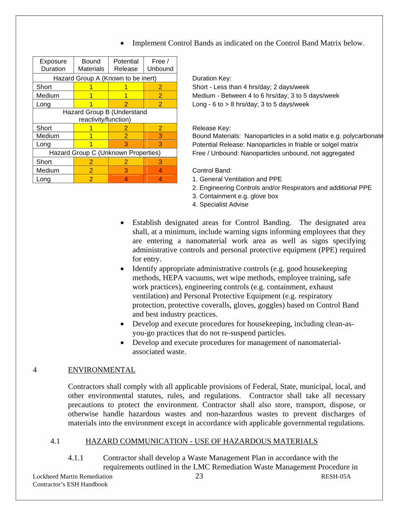
Lockheed Martin Remediation 23 RESH-05A Contractor’s ESH Handbook
• Implement Control Bands as indicated on the Control Band Matrix below.
Exposure Duration
Bound Materials
Potential Release
Free / Unbound
Hazard Group A (Known to be inert) Duration Key: Short 1 1 2 Short - Less than 4 hrs/day; 2 days/week Medium 1 1 2 Medium - Between 4 to 6 hrs/day; 3 to 5 days/week Long 1 2 2 Long - 6 to > 8 hrs/day; 3 to 5 days/week
Hazard Group B (Understand reactivity/function)
Short 1 2 2 Release Key: Medium 1 2 3 Bound Materials: Nanoparticles in a solid matix e.g. polycarbonate Long 1 3 3 Potential Release: Nanoparticles in friable or solgel matrix
Hazard Group C (Unknown Properties) Free / Unbound: Nanoparticles unbound, not aggregated Short 2 2 3 Medium 2 3 4 Control Band: Long 2 4 4 1. General Ventilation and PPE 2. Engineering Controls and/or Respirators and additional PPE 3. Containment e.g. glove box 4. Specialist Advise
• Establish designated areas for Control Banding. The designated area
shall, at a minimum, include warning signs informing employees that they are entering a nanomaterial work area as well as signs specifying administrative controls and personal protective equipment (PPE) required for entry.
• Identify appropriate administrative controls (e.g. good housekeeping methods, HEPA vacuums, wet wipe methods, employee training, safe work practices), engineering controls (e.g. containment, exhaust ventilation) and Personal Protective Equipment (e.g. respiratory protection, protective coveralls, gloves, goggles) based on Control Band and best industry practices.
• Develop and execute procedures for housekeeping, including clean-as-you-go practices that do not re-suspend particles.
• Develop and execute procedures for management of nanomaterial-associated waste.
4 ENVIRONMENTAL
Contractors shall comply with all applicable provisions of Federal, State, municipal, local, and other environmental statutes, rules, and regulations. Contractor shall take all necessary precautions to protect the environment. Contractor shall also store, transport, dispose, or otherwise handle hazardous wastes and non-hazardous wastes to prevent discharges of materials into the environment except in accordance with applicable governmental regulations.
4.1 HAZARD COMMUNICATION - USE OF HAZARDOUS MATERIALS
4.1.1 Contractor shall develop a Waste Management Plan in accordance with the
requirements outlined in the LMC Remediation Waste Management Procedure in

Lockheed Martin Remediation 24 RESH-05A Contractor’s ESH Handbook
Appendix B. Lockheed Martin shall approve the Waste Management Plan prior to work commencement.
4.1.2 Contractor must segregate hazardous from non-hazardous waste; all hazardous waste generated by its operations must be labeled in accordance with all governmental regulations.
4.1.3 Contractor shall dispose of all hazardous waste within the time frame stipulated by local, state, or federal regulations. Contractor shall not leave behind on Lockheed Martin remediation sites any containers of hazardous materials or waste (including drums, roll-offs, maintenance chemicals, etc.), empty or not, after the termination of operations.
4.1.4 In case of a spill or release of hazardous materials or waste, Contractor shall
immediately notify the Lockheed Martin Project Lead and if the severity of the spill warrants, notify the local fire department (Call 9-1-1). The Contractor shall be liable for the costs of any spill resulting from Contractor's actions, including, but not limited to, costs of containment, cleanup, and disposal.
4.2 NON-HAZARDOUS WASTE DISPOSAL
4.2.1 Contractor shall develop a Waste Management Plan in accordance with the
requirements outlined in the LMC Remediation Waste Management Procedure in Appendix B. This plan must be approved by the Lockheed Martin Project Lead.
4.3 WORK INVOLVING AIR EMISSIONS
4.3.1 Contractor shall work with the Lockheed Martin Project Lead to identify applicable Federal, state, and/or local permit application requirements for air emission sources (i.e., stationary point source, fugitive emissions, etc.) associated with the anticipated project.
4.3.2 Contractor shall submit permit applications and/or notifications to the Lockheed Martin Project Lead for review prior to submittal to the applicable regulatory agency.
4.3.3 Contractor shall abide by the requirements of the permit(s) and gather emissions
data (as applicable) to document compliance. This data shall be electronically submitted to the Lockheed Martin Project Lead.
4.3.4 Contractor shall immediately contact the Lockheed Martin Project Lead in the event permit conditions are not met.
4.3.5 Ensure permits are posted on permitted equipment (or in close proximity) as required by the respective permit.
4.4 WORK INVOLVING WATER DISCHARGES

Lockheed Martin Remediation 25 RESH-05A Contractor’s ESH Handbook
4.4.1 At no time is an unauthorized, unpermitted release allowed. Contractor shall notify the Lockheed Martin Project Lead in the event of a release and obtain the approval of Lockheed Martin before discharging any material into storm drains or sewers.
4.4.2 Contractor shall work with the Lockheed Martin Project Lead to identify applicable National Pollutant Discharge Elimination System (NPDES), Stormwater Pollution Prevention Plans (SWPPP), and POTW requirements associated with the anticipated project.
4.4.3 Contractor shall submit permit applications and/or Notice of Intent forms to the Lockheed Martin Project Lead for review prior to submittal to the applicable regulatory agency.
4.4.4 Contractor shall abide by the requirements of the discharge permit(s) and maintain
discharge monitoring information and inspection data to document compliance. This documentation shall be electronically provided to the Lockheed Martin Project Lead.
4.4.5 Contractor shall immediately contact the Lockheed Martin Project Lead in the
event permit conditions are not met.
5 HOUSEKEEPING / CLEANUP
5.1 Ensure discharge permits and/or SWPPP plans (as applicable) are available at the project job site.
5.2 Contractor shall continuously clean up its respective work area(s). Contractor shall maintain its work areas free from all slip, trip, and fall hazards at all times.
5.3 Debris shall be kept cleared from work areas, passageways, stairs, and in and around buildings or other structures. The work area must be left free from accumulation of waste and rubbish at the end of each work shift.
5.4 Combustible scrap and debris shall be removed at regular intervals during the course of work performed by Contractor. Safe means shall be provided to facilitate such removal.
5.5 At the end of each working day and/or the conclusion of work being performed, Contractor shall restore the work area to the same degree of neatness as when work commenced.
5.6 Contractor shall furnish necessary equipment and/or receptacles to remove waste and rubbish from the job site unless otherwise specified by the Lockheed Martin.
6 CHANGE MANAGEMENT

Lockheed Martin Remediation 26 RESH-05A Contractor’s ESH Handbook
If deviations are encountered from the field work plan, the contractor shall A) notify to the Lockheed Martin Project Lead and B) suspend work to assess changes to the work plan(s) and the HASP. Changes to the work plan(s) and the HASP shall be reviewed by the PL.
7 REQUIREMENT TO PERFORM & DOCUMENT SELF-AUDITS
7.1 Contractor agrees to perform periodic work area/project field inspections to monitor
compliance with project environmental, safety and health (ESH) requirements. The name of Contractor’s jobsite ESH representative will be provided to Lockheed Martin prior to the Contractor starting work at the jobsite.
7.2 For jobs that are ongoing, an annual ESH audit shall be conducted and for jobs with a duration of less than one year at least one audit shall occur. A competent ESH representative designated by the Contractor shall perform the audit. Unsafe acts and/or non-compliance conditions noted during inspections shall be corrected immediately.
7.3 The documentation related to the audits and inspections shall be submitted electronically to the Lockheed Martin Project Lead.
8 ACCIDENT, INJURY, ILLNESS, INCIDENT and SPILL REPORTING
8.1 Contractor shall immediately contact the Lockheed Martin Project Lead and/or Lockheed Martin Safety & Health Manager in the event of a fatality, injury, environmental release (spill), near-miss incident, or any ESH incident that is likely to generate significant publicity. A written report of the incident/injury/spill and corrective action(s) taken shall be submitted to the Lockheed Martin Project Lead within one (1) day of the incident. Representatives from Lockheed Martin may conduct joint investigations with the contractor if deemed necessary.
8.2 In case of a spill or release of hazardous chemicals, Contractor shall immediately notify the Lockheed Martin Project Lead, and/or if the severity of the spill warrants, the local fire department by calling 9-1-1. Contractor shall take all necessary steps to control the spread of the release and to provide site control to prevent unauthorized personnel from entering the affected area. The Contractor shall be liable for the costs of any spill resulting from Contractor's actions, including, but not limited to, costs of containment, cleanup, and disposal.
9 FINES, PENALTIES AND COSTS
9.1 Contractor shall indemnify and hold Lockheed Martin harmless from any and all liability (including but not limited to fines and penalties), loss, cost, damage, or expense (including attorney's fees) suffered or incurred by Lockheed Martin by reason of Contractor's failure to comply with Federal, State, municipal, local or other laws, rules, regulations, ordinances and requirements, or failure to comply with generally accepted environmental safety and health practices.

Lockheed Martin Remediation 27 RESH-05A Contractor’s ESH Handbook
10 LOCKHEED MARTIN ESH MANAGER
10.1 The Lockheed Martin ESH Manager is Jimmy Yeager. Contact Jimmy regarding any questions or concerns at (301) 873-1444 or via email at [email protected].
Appendix A – LMC Requirements for Invasive Fieldwork
LMC Minimum Requirements for Inv
Appendix B – LMC Waste Management Procedure
LMC Waste Mgmt Procedure Rev 4

Lockheed Martin Remediation 28 RESH-05A Contractor’s ESH Handbook
Corporate Environment, Safety & Health
CONTRACTOR'S ESH HANDBOOK
COMPLIANCE AGREEMENT The Key National Contractor Program Manager has read and understands the contents of the Contractor's ESH Handbook. Contractor agrees while performing work on Lockheed Martin-owned or Lockheed Martin-controlled premises, that the Contractor shall require its employees and subcontractors at any tier to comply with the contents of this Contractor's ESH Handbook and the job specific HASP. A copy of the HASP shall be maintained at the job site and made readily available to contractor and subcontractor employees for their information. All contractor employees and subcontractors shall read and certify that they have read and understand the job specific health and safety plan (HASP). The certification forms shall be electronically sent to the Lockheed Martin Project Lead. I further understand that this handbook and the rules and regulations it contains do not in any way relieve the Contractor (employer) of its responsibility to comply with the applicable environmental safety and health (ESH) regulations and its obligation to implement and enforce its own written ESH programs while working on this project. Company: _____________________________________________ Name: _____________________________________________ Signature: _____________________________________________ Title: _____________________________________________ Date: _____________________________________________ COMPLETE, SIGN AND RETURN THIS CERTIFICATE TO THE LOCKHEED MARTIN
ESH MANAGER.
ATTACHMENT IIINCIDENT REPORT FORM

Tetra Tech.Incident Report
Report Date Report Prepared By Incident Report Number
INSTRUCTIONS:All incidents (including those involving subcontractors under direct supervision of Tetra Tech
personnel) must be documented on the IR Form.Complete any additional parts to this form as indicated below for the type of incident selected.
TYPE OF INCIDENT (Check all that apply) Additional Form(s) Required for this type of incidentNear Miss (No losses, but could have resulted in injury, illness, ordamage)
Complete IR Form Only
Injury or Illness Complete Form IR-A; Injury or Illness
Property or Equipment Damage, Fire, Spill or ReleaseComplete Form IR-B; Damage, Fire, Spill orRelease
Motor Vehicle Complete Form IR-C; Motor Vehicle
INFORMATION ABOUT THE INCIDENTDescription of Incident
Date of Incident Time of Incident
AM PM OR Cannot be determined
Weather conditions at the time of the incident Was there adequate lighting?
Yes No
Location of Incident
Was location of incident within the employer’s work environment? Yes No
Street Address City, State, Zip Code and Country
Project Name / Project # Client:
Tt Supervisor or Project Manager Was supervisor on the scene?
Yes No
WITNESS INFORMATION (attach additional sheets if necessary)Name Company
Street Address City, State and Zip Code
Telephone Number(s)

Tetra Tech.Incident Report
CORRECTIVE ACTIONSCorrective action(s) immediately taken by unit reporting the incident:
Corrective action(s) still to be taken (by whom and when):
ROOT CAUSE ANALYSIS LEVEL REQUIRED
Root Cause Analysis Level Required: Level - 1 Level - 2 None
Root Cause Analysis Level Definitions
Level - 1
Definition: A Level 1 RCA is conducted by an individual(s) with experience or training in root cause analysistechniques and will conduct or direct documentation reviews, site investigation, witness and affected employeeinterviews, and identify corrective actions. Activating a Level 1 RCA and identifying RCA team members will be atthe discretion of the Corporate Administration office.
The following events may trigger a Level 1 RCA: Work related fatality Hospitalization of one or more employee where injuries result in total or partial permanent disability Property damage in excess of $75,000 When requested by senior management
Level - 2
Definition: A Level 2 RCA is self performed within the operating unit by supervisory personnel with assistance ofthe operating unit HSR. Level 2 RCA will utilize the 5 Why RCA methodology and document the findings on thetools provided.
The following events will require a Level 2 RCA: OSHA recordable lost time incident Near miss incident that could have triggered a Level 1 RCA When requested by senior management
Complete the Root Cause Analysis Worksheet and Corrective Action form. Identify a corrective action(s) for each root causeidentified within each area of inquiry.
NOTIFICATIONS
Title Printed Name Signature TelephoneNumber Date
Project Manager or Supervisor
Site Safety Coordinator or Office H&SRepresentative
Operating Unit H&S Representative
Other: __________________________
The signatures provided above indicate that appropriate personnel have been notified of the incident.

TETRA TECH, INC.INCIDENT FORM IR-A
INSTRUCTIONS:Complete all sections below for incidents involving injury or illness.
Do NOT leave any blanks.Attach this form to the IR FORM completed for this incident.
Incident Report Number: (From the IR Form)
EMPLOYEE INFORMATIONCompany Affiliation
Tetra Tech Employee? TetraTech subcontractor employee (directly supervised by Tt personnel)?
Full Name Company (if not Tt employee)
Street Address, City, State and Zip Code Address Type
________________________________________________
________________________________________________
Home address (for Tt employees)
Business address (for subcontractors)
Telephone Numbers
Work: Home: Cell:
Occupation (regular job title) Department
Was the individual performing regular job duties? Time individual began work
Yes No AM PM OR Cannot be determined
Safety equipment
Provided? Yes No
Used? Yes No If no, explain why
Type(s) provided: Hard hat Protective clothing
Gloves High visibility vest
Eye protection Fall protection
Safety shoes Machine guarding
Respirator Other (list)
NOTIFICATIONSName of Tt employee to whom the injury or illness was firstreported Was H&S notified within one hour of injury or illness?
Yes No
Date of report H&S Personnel Notified
Time of report Time of Report
If subcontractor injury, did subcontractor’s firm perform their own incident investigation?
Yes No If yes, request a copy of their completed investigation form/report and attach it to this report.

TETRA TECH, INC.INCIDENT FORM IR-A
INJURY / ILLNESS DETAILSWhat was the individual doing just before the incident occurred? Describe the activity as well as the tools, equipment, or material theindividual was using. Be specific. Examples: “Climbing a ladder while carrying roofing materials”; “Spraying chlorine from a hand sprayer”;“Daily computer key-entry”
What Happened? Describe how the injury occurred. Examples: “When ladder slipped on wet floor and worker fell 20 feet”; “Worker wassprayed with chlorine when gasket broke during replacement”; Worker developed soreness in wrist over time”
Describe the object or substance that directly harmed the individual: Examples: “Concrete floor”; “Chlorine”; “Radial Arm Saw”. If thisquestion does not apply to the incident, write “Not Applicable”.
MEDICAL CARE PROVIDED
Was first aid provided at the site: Yes No If yes, describe the type of first aid administered and by whom?
Was treatment provided away from the site: Yes No If yes, provide the information below.
Name of physician or health care professional Facility Name
Street Address, City State and Zip Code Type of Care?
________________________________________________
________________________________________________
Was individual treated in emergency room? Yes No
Was individual hospitalized overnight as an in-patient? Yes No
Did the individual die? Yes No If yes, date:
Will a worker’s compensation claim be filed? Yes No
Telephone Number
NOTE: Attach any police reports or related diagrams to this report.
SIGNATURESI have reviewed this report and agree that all the supplied information is accurate
Affected individual(print) Affected individual (signature) Telephone Number Date
This form contains information relating to employee health and must be used in a manner that protects the confidentiality
of the employee to the extent possible while the information is being used for occupational safety and health purposes.

TETRA TECH, INC.INCIDENT FORM IR-B
INSTRUCTIONS:Complete all sections below for incidents involving property/equipment damage, fire, spill or release.
Do NOT leave any blanks.Attach this form to the IR FORM completed for this incident.
Incident Report Number: (From the IR Form)
TYPE OF INCIDENT (Check all that apply)
Property Damage Equipment Damage Fire or Explosion Spill or Release
INCIDENT DETAILSResults of Incident: Fully describe damages, losses, etc.
Response Actions Taken:
Responding Agency(s) (i.e. police, fire department, etc.) Agency(s) Contact Name(s)
DAMAGED ITEMS (List all damaged items, extent of damage and estimated repair cost)Item: Extent of damage: Estimated repair cost
SPILLS / RELEASES (Provide information for spilled/released materials)Substance Estimated quantity and duration Specify Reportable Quantity (RQ)
Exceeded? Yes No NA
FIRES / EXPLOSIONS (Provide information related to fires/explosions)
Fire fighting equipment used? Yes No If yes, type of equipment:
NOTIFICATIONSRequired notifications Name of person notified By whom Date / Time
Client: Yes No
Agency: Yes No
Other: Yes No
Who is responsible for reporting incident to outside agency(s)? Tt Client Other Name:
Was an additional written report on this incident generated? Yes No If yes, place in project file.

TETRA TECH, INC.INCIDENT FORM IR-C
INSTRUCTIONS:Complete all sections below for incidents involving motor vehicle accidents. Do NOT leave any blanks.
Attach this form to the IR FORM completed for this incident.
Incident Report Number: (From the IR Form)
INCIDENT DETAILSName of road, street, highway or location where accidentoccurred Name of intersecting road, street or highway if applicable
County City State
Did police respond to the accident? Did ambulance respond to the accident?
Yes No Yes No
Name and location of responding police department Ambulance company name and location
Officer’s name/badge #
Did police complete an incident report? Yes No If yes, police report number:Request a copy of completed investigation report and attach to this form.
VEHICLE INFORMATIONHow many vehicles were involved in the accident? (Attach additional sheets as applicable for accidents involving morethan 2 vehicles.)
Vehicle Number 1 – Tetra Tech Vehicle Vehicle Number 2 – Other Vehicle
Vehicle Owner /ContactInformation
Vehicle Owner /ContactInformation
Color Color
Make Make
Model Model
Year Year
License Plate # License Plate #
Identification # Identification #
Describe damage to vehicle number 1 Describe damage to vehicle number 2
Insurance Company Name and Address Insurance Company Name and Address
Agent Name Agent Name
Agent Phone No. Agent Phone No.
Policy Number Policy Number
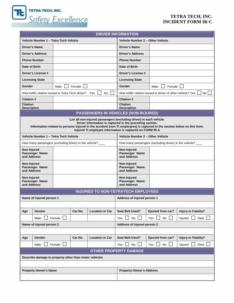
TETRA TECH, INC.INCIDENT FORM IR-C
DRIVER INFORMATIONVehicle Number 1 – Tetra Tech Vehicle Vehicle Number 2 – Other Vehicle
Driver’s Name Driver’s Name
Driver’s Address Driver’s Address
Phone Number Phone Number
Date of Birth Date of Birth
Driver’s License # Driver’s License #
Licensing State Licensing State
Gender Male Female Gender Male Female
Was traffic citation issued to Tetra Tech driver? Yes No Was traffic citation issued to driver of other vehicle? Yes No
Citation # Citation #CitationDescription
CitationDescription
PASSENGERS IN VEHICLES (NON-INJURED)List all non-injured passengers (excluding driver) in each vehicle.
Driver information is captured in the preceding section.Information related to persons injured in the accident (non-Tt employees) is captured in the section below on this form.
Injured Tt employee information is captured on FORM IR-A
Vehicle Number 1 – Tetra Tech Vehicle Vehicle Number 2 – Other Vehicle
How many passengers (excluding driver) in the vehicle? How many passengers (excluding driver) in the vehicle?
Non-InjuredPassenger Nameand Address
Non-InjuredPassenger Nameand Address
Non-InjuredPassenger Nameand Address
Non-InjuredPassenger Nameand Address
Non-InjuredPassenger Nameand Address
Non-InjuredPassenger Nameand Address
INJURIES TO NON-TETRATECH EMPLOYEESName of injured person 1 Address of injured person 1
Age Gender Car No. Location in Car Seat Belt Used? Ejected from car? Injury or Fatality?
Male Female Yes No Yes No Injured Died
Name of injured person 2 Address of injured person 2
Age Gender Car No. Location in Car Seat Belt Used? Ejected from car? Injury or Fatality?
Male Female Yes No Yes No Injured Died
OTHER PROPERTY DAMAGEDescribe damage to property other than motor vehicles
Property Owner’s Name Property Owner’s Address

TETRA TECH, INC.INCIDENT FORM IR-C
COMPLETE AND SUBMIT DIAGRAM DEPICTING WHAT HAPPENED

ATTACHMENT IIIMEDICAL DATA SHEET
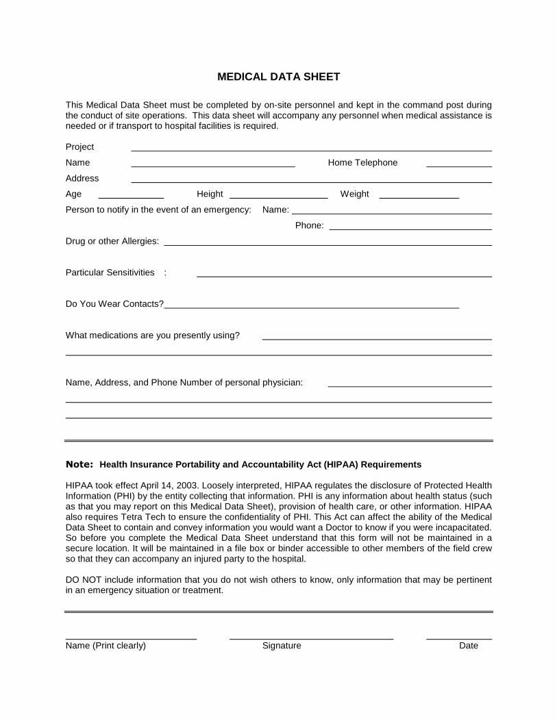
MEDICAL DATA SHEET
This Medical Data Sheet must be completed by on-site personnel and kept in the command post duringthe conduct of site operations. This data sheet will accompany any personnel when medical assistance isneeded or if transport to hospital facilities is required.
Project
Name Home Telephone
Address
Age Height Weight
Person to notify in the event of an emergency: Name:
Phone:
Drug or other Allergies:
Particular Sensitivities :
Do You Wear Contacts?
What medications are you presently using?
Name, Address, and Phone Number of personal physician:
Note: Health Insurance Portability and Accountability Act (HIPAA) Requirements
HIPAA took effect April 14, 2003. Loosely interpreted, HIPAA regulates the disclosure of Protected HealthInformation (PHI) by the entity collecting that information. PHI is any information about health status (suchas that you may report on this Medical Data Sheet), provision of health care, or other information. HIPAAalso requires Tetra Tech to ensure the confidentiality of PHI. This Act can affect the ability of the MedicalData Sheet to contain and convey information you would want a Doctor to know if you were incapacitated.So before you complete the Medical Data Sheet understand that this form will not be maintained in asecure location. It will be maintained in a file box or binder accessible to other members of the field crewso that they can accompany an injured party to the hospital.
DO NOT include information that you do not wish others to know, only information that may be pertinentin an emergency situation or treatment.
Name (Print clearly) Signature Date

ATTACHMENT IVSAFE WORK PERMITS

SAFE WORK PERMITMOBILIZATION AND DEMOBILIZATION ACTIVITIES
LOCKHEED MARTIN MSAMIDDLE RIVER, MARYLAND
Permit No. Date: Time: From to
I. Work limited to the following (description, area, equipment used): Mobilization and demobilizationactivities
II. Primary Hazards: Lifting; slips, trips and falls; vehicular and foot traffic; insect/animal bites and stings;poisonous plants; inclement weather.
III. Field Crew:IV. On-site Inspection conducted Yes No Initials of Inspector Tetra Tech
Equipment Inspection required Yes No Initials of Inspector Tetra Tech
V. Protective equipment required Respiratory equipment requiredLevel D Level B Yes Specify on the reverseLevel C Level A No
Modifications/Exceptions: Minimum requirement include sleeved shirt and long pants, or coveralls, safety,glasses and safety footwear. Hard hats and hearing protection will be worn when working near operatingequipment.
VI. Chemicals of Concern Hazard Monitoring / Action Level(s) Response MeasuresNone anticipated None None
Primary Route(s) of Exposure/Hazard: NA
(Note to FOL and/or SHSO: Each item in Sections VII, VIII, and IX must be checked Yes, No, or NA)VII. Additional Safety Equipment/Procedures
Hard-hat..................................... Yes No Hearing Protection (Plugs/Muffs) ..... Yes NoSafety Glasses .......................... Yes No Safety belt/harness .......................... Yes NoChemical/splash goggles........... Yes No Radio/Cellular Phone....................... Yes NoSplash Shield............................. Yes No Barricades ....................................... Yes NoSplash suits/coveralls ................ Yes No Gloves (Type – Work).................... Yes NoImpermeable apron.................... Yes No Work/rest regimen ........................... Yes NoSteel toe work shoes/boots........ Yes No Chemical Resistant Boot Covers ..... Yes NoHigh visibility vest ...................... Yes No Tape up/use insect repellent ........... Yes NoFirst Aid Kit ................................ Yes No Fire Extinguisher.............................. Yes NoSafety Shower/Eyewash............ Yes No Other................................................ Yes NoModifications/Exceptions: Tyvek coverall to protect against natural hazards (e.g., ticks) if working/walkingthrough areas of high grass. Use insect repellants containing at least 10% DEET and tape up in such areas.Follow manufacturer's recommendations for proper application and reapplication. Hard hat when overheadhazards exist. Safety glasses when near eye hazards. Hearing protection when in high noise areas.
VIII. Site Preparation Yes No NAUtility Locating and Excavation Clearance completed ........................................................Vehicle and Foot Traffic Routes Established/Traffic Control Barricades/Signs in Place .....Physical Hazards Identified and Isolated (Splash and containment barriers) .....................Emergency Equipment Staged (Spill control, fire extinguishers, first aid kits, etc)..............
IX. Additional Permits required (Hot work, confined space entry, excavation etc.)................... Yes NoIf yes, SHSO to complete or contact Health Sciences, Pittsburgh Office (412)921-7090
X. Special instructions, precautions: Preview work locations to identify potential hazards (slips, trips, andfalls, natural hazards, etc.) Review PPE needs based on activities being performed and the associatedhazards. Use safe lifting procedures and obtain assistance when handling heavy or awkward objects.Suspend site activities in the event of inclement weather. Observe site workers for signs and symptoms ofheat/cold stress. Use sun block (SPF > 15) to prevent sunburn if necessary.
Permit Issued by: Permit Accepted by:

SAFE WORK PERMITTEST PIT EXCAVATION AND SAMPLING ACTIVITIES
LOCKHEED MARTIN MSAPermit No. Date: Time: From to
I. Work limited to the following (description, area, equipment used): Test pit excavation and sampling activities –may include confined space entry and step trenching (if necessary)
II. Primary Hazards: Contact with site contaminants; transfer of contamination; heavy lifting; slip, trip and fall; cuts andlacerations; vehicular and foot traffic; ambient temperature extremes; insect/animal bites and stings, poisonous plants,inclement weather, heavy equipment and excavation hazards, possible confined space entry
III. Field Crew:IV. On-site Inspection conducted Yes No Initials of Inspector Tetra Tech
Equipment Inspection required Yes No Initials of Inspector Tetra Tech
V. Protective equipment required Respiratory equipment requiredLevel D Level B Yes Specify on the reverseLevel C Level A No
Modifications/Exceptions: Minimum requirement include sleeved shirt and long pants, or coveralls, safety, glasses andsafety footwear. Hard hats and hearing protection will be worn when working near operating equipment.
VI. Chemicals of Concern Hazard Monitoring /Action Level(s) Response MeasuresVOC’s, SVOC’s PID with 11.7 eV >1 ppm above BGL in BZ Monitor Breathing zone (BZ) areas
(or greater) probe no more than 4 exposures of Retreat upwind to unaffected area5 minutes a day
Metals Dust monitor Visible dust > 15 mg/m3
Retreat upwind to unaffected areasuppress dust generation
Primary Route(s) of Exposure/Hazard: inhalation, dermal, ingestion
(Note to FOL and/or SHSO: Each item in Sections VII, VIII, and IX must be checked Yes, No, or NA)VII. Additional Safety Equipment/Procedures
Hard-hat..................................... Yes No Hearing Protection (Plugs/Muffs) .... Yes NoSafety Glasses .......................... Yes No Safety belt/harness/lifeline .............. Yes NoChemical/splash goggles ........... Yes No Radio/Cellular Phone...................... Yes NoSplash Shield ............................. Yes No Barricades....................................... Yes NoSplash suits/coveralls ................ Yes No Gloves (Type – Work) ................... Yes NoImpermeable apron.................... Yes No Work/rest regimen........................... Yes NoSteel toe work shoes/boots........ Yes No Chemical Resistant Boot Covers .... Yes NoHigh visibility vest....................... Yes No Tape up/use insect repellent .......... Yes NoFirst Aid Kit................................. Yes No Fire Extinguisher............................. Yes NoSafety Shower/Eyewash ............ Yes No Other............................................... Yes NoModifications/Exceptions: Minimum requirement include sleeved shirt and long pants, safety footwear, and nitrilegloves Tyvek coverall to protect against natural hazards (e.g., ticks) if working/walking through areas of high grass.Use insect repellants containing at least 10% DEET and tape up in such areas. Follow manufacturer'srecommendations for proper application and reapplication. Complete Heavy Equipment Inspection Checklist must becompleted prior to work beginning. An Excavation Competent Person must be specifically identified to handle thisresponsibility prior to work beginning in the specified space provided (Section 1.3) in this HASP. Detailed ExcavationSafety Procedures and the Excavation Competent Person Checklist and Heavy Equipment Inspection Checklist areincluded in Attachments IV, V, and VI and must be completed prior to beginning work. The OSHA Health and SafetyConstruction-Related regulations P-650 to 699 – Subpart P – Excavations are included in Attachment VII and must befollowed during all excavation work. See Section 5 of the HASP for further details. If confined space entry isnecessary, review the Tetra Tech Confined Space Entry Program and Procedures in Attachment VIII and complete theConfined Space Checklist in Attachment VIII prior to beginning work.
VIII. Site Preparation Yes No NAUtility Locating and Excavation Clearance completed ........................................................Vehicle and Foot Traffic Routes Established/Traffic Control Barricades/Signs in Place .....Physical Hazards Identified and Isolated (Splash and containment barriers) .....................Emergency Equipment Staged (Spill control, fire extinguishers, first aid kits, etc). .............
IX. Additional Permits required (Hot work, confined space entry, excavation etc.)................... Yes NoIf yes, SHSO to complete or contact Health Sciences, Pittsburgh Office (412)921-7090
X. Special instructions, precautions: Preview work locations to identify potential hazards (slips, trips, and falls, naturalhazards, etc.) Review PPE needs based on activities being performed and the associated hazards. Use safe liftingprocedures and obtain assistance when handling heavy or awkward objects. Suspend site activities in the event ofinclement weather. Observe site workers for signs and symptoms of heat/cold stress. Use sun block (SPF > 15) toprevent sunburn if necessary.
Permit Issued by: Permit Accepted by:

SAFE WORK PERMITSOIL BORING MONITORING WELL INSTALLATION
CPT/MP INVESTIGATIONLOCKHEED MARTIN AT MARTIN STATE AIRPORT
MIDDLE RIVER, MARYLAND
Permit No. Date: Time: From to
I. Work limited to the following (description, area, equipment used): Soil Boring and Monitoring well installation viaDPT Drill Rigs. This task includes MIP/CPT Investigation and sampling soil sampling will occur concurrently with theseoperations. Also includes concrete coring.
II. Primary Hazards: Contact with contaminated soil or groundwater; transfer of contamination; heavy equipmenthazards; noise exposures; contact with energized systems/utilities; heavy lifting; slip, trip and fall; cuts and lacerations;vehicular and foot traffic; insect/animal bites and stings, , inclement weather
III. Field Crew:IV. On-site Inspection conducted Yes No Initials of Inspector Tetra Tech
Equipment Inspection required Yes No Initials of Inspector Tetra Tech
V. Protective equipment required Respiratory equipment requiredLevel D Level B Yes Specify on the reverseLevel C Level A No
Modifications/Exceptions:
VI. Chemicals of Concern Hazard Monitoring /Action Level(s) Response MeasuresVOC’s, SVOC’s PID with 11.7 eV >1 ppm above BGL in BZ Monitor Breathing zone (BZ) areas
(or greater) probe no more than 4 exposures of Retreat upwind to unaffected area5 minutes a day
Metals Dust monitor Visible dust > 15 mg/m3
Retreat upwind to unaffected areasuppress dust generation
Primary Route(s) of Exposure/Hazard: Airborne concentrations of VOCs will be monitored through the use of thePID to prevent exposures via inhalation. Incidental ingestion and contact with contaminants will be prevented throughthe use of PPE and safe work practices. Exposure symptoms can include irritation of eyes, skin, mucous membranes,dizziness, nausea, blurred vision, or narcotic effects,
(Note to FOL and/or SSO: Each item in Sections VII, VIII, and IX must be checked Yes, No, or NA)VII. Additional Safety Equipment/Procedures
Hard-hat..................................... Yes No Hearing Protection (Plugs/Muffs) ...... Yes NoSafety Glasses .......................... Yes No Safety belt/harness ........................... Yes NoChemical/splash goggles ........... Yes No Radio/Cellular Phone........................ Yes NoSplash shield.............................. Yes No Barricades......................................... Yes NoSplash suits/coveralls ................ Yes No Gloves (Type – nitrile/work ) ............. Yes NoImpermeable apron.................... Yes No Work/rest regimen............................. Yes NoSteel toe work shoes/boots........ Yes No Chemical resistant boot covers......... Yes NoHigh visibility vest....................... Yes No Tape up/use insect repellent ............ Yes NoFirst Aid Kit................................. Yes No Fire extinguisher ............................... Yes NoSafety Shower/Eyewash ............ Yes No Other................................................. Yes NoModifications/Exceptions: Coveralls if the potential for soiling work clothing exists. Other PPE may be specified bythe SSO based on conditions (rain gear, rubber boots, etc.), cut resistant gloves during soil sampling, reflective vestsin thigh traffic areas.
VIII. Site Preparation Yes No NAUtility Locating and Excavation Clearance completed ........................................................Vehicle and Foot Traffic Routes Established/Traffic Control Barricades/Signs in Place .....Physical Hazards Identified and Isolated (Splash and containment barriers) .....................Emergency Equipment Staged (Spill control, fire extinguishers, first aid kits, etc). .............
IX. Additional Permits required (Hot work, confined space entry, excavation etc.)................... Yes NoIf yes, SSO to complete or contact Health Sciences, Pittsburgh Office (412)921-7090 (Excavation Permit is Required)
X. Special instructions, precautions: Use safe lifting/carrying techniques. Inspect equipment prior to use. Ensureemergency stop devices are functional and initially and then at least weekly thereafter. Minimize contact withpotentially contaminated media. Tape up and use insect repellants in high grass or brush areas.
Permit Issued by: Permit Accepted by:

SAFE WORK PERMITMONITORING WELL DEVELOPMENT AND MULTIMEDIA SAMPLING
LOCKHEED MARTIN AT MARTIN STATE AIRPORTMIDDLE RIVER, MARYLAND
Permit No. Date: Time: From to
I. Work limited to the following (description, area, equipment used): Monitoring well development, surface,sediment, and groundwater sampling, synoptic water levels and aquifer pump testing are part of this task.
II. Primary Hazards: Contact with site contaminants; transfer of contamination; heavy lifting; slip, trip and fall; ambienttemperature extremes; insect/animal bites and stings, inclement weather.
III. Field Crew:IV. On-site Inspection conducted Yes No Initials of Inspector Tetra Tech
Equipment Inspection required Yes No Initials of Inspector _ Tetra Tech
V. Protective equipment required Respiratory equipment requiredLevel D Level B Yes Specify on the reverseLevel C Level A No
Modifications/Exceptions:
VI. Chemicals of Concern Hazard Monitoring /Action Level(s) Response MeasuresVOC’s, SVOC’s PID with 11.7 eV >1 ppm above BGL in BZ Monitor Breathing zone (BZ) areas
(or greater) probe no more than 4 exposures of Retreat upwind to unaffected area5 minutes a day
Metals Dust monitor Visible dust > 15 mg/m3
Retreat upwind to unaffected areasuppress dust generation
Primary Route(s) of Exposure/Hazard: Airborne concentrations of VOCs will be monitored through the use of thePID to prevent exposures via inhalation. Incidental ingestion and contact with contaminants will be prevented throughthe use of PPE and safe work practices. Exposure symptoms can include irritation of eyes, skin, mucous membranes,dizziness, nausea, blurred vision, or narcotic effects
(Note to FOL and/or SSO: Each item in Sections VII, VIII, and IX must be checked Yes, No, or NA)
VII. Additional Safety Equipment/ProceduresHard-hat..................................... Yes No Hearing Protection (Plugs/Muffs) ...... Yes NoSafety Glasses .......................... Yes No Safety Belt/Harness .......................... Yes NoChemical/Splash Goggles.......... Yes No Radio/Cellular Phone........................ Yes NoSplash Shield ............................. Yes No Barricades......................................... Yes NoSplash Suits/Coveralls ............... Yes No Gloves (Type – Nitrile) ...................... Yes NoImpermeable Apron ................... Yes No Work/rest regimen............................. Yes NoSteel Toe Work Shoes or Boots. Yes No Chemical Resistant Boot Covers .... Yes NoHigh Visibility Vest ..................... Yes No Tape/Insect Repellent ...................... Yes NoFirst Aid Kit................................. Yes No Fire Extinguisher............................... Yes NoSafety Shower/Eyewash ............ Yes No Other................................................. Yes NoModifications/Exceptions: Boot covers may be specified if work area is muddy. Reflective vests may be required ifworking near or high traffic areas.
VIII. Site Preparation Yes No NAUtility Locating and Excavation Clearance completed ........................................................Vehicle and Foot Traffic Routes Established/Traffic Control Barricades/Signs in Place .....Physical Hazards Identified and Isolated (Splash and containment barriers) .....................Emergency Equipment Staged (Spill control, fire extinguishers, first aid kits, etc). .............
IX. Additional Permits required (Hot work, confined space entry, excavation etc.)................... Yes NoIf yes, SSO to complete or contact Health Sciences, Pittsburgh Office (412)921-7090
X. Special instructions, precautions: Use safe lifting/carrying techniques. Inspect equipment prior to use. Minimizecontact with potentially contaminated media. Tape up and use insect repellants in high grass or brush areas.
Permit Issued by: Permit Accepted by:

SAFE WORK PERMITLAND, EM GEOPHYSICAL WETLAND SURVEYING
LOCKHEED MARTIN MSAMIDDLE RIVER, MARYLAND
Permit No. Date: Time: From to
I. Work limited to the following (description, area, equipment used): Surveying activities both geophysical,geographical and wetland.
II. Primary Hazards: Potential hazards associated with this task: slip, trip and fall; vehicular and foot traffic; temperatureextremes; inclement weather; insect /animal bites or stings, poisonous plants, etc.
III. Field Crew:IV. On-site Inspection conducted Yes No Initials of Inspector Tetra Tech
Equipment Inspection required Yes No Initials of Inspector Tetra Tech
V. Protective equipment required Respiratory equipment requiredLevel D Level B Yes Specify on the reverseLevel C Level A No
Modifications/Exceptions:
VI. Chemicals of Concern Hazard Monitoring Action Level(s) Response MeasuresNone expected during this NA NA NAtask
Primary Route(s) of Exposure/Hazard:
(Note to FOL and/or SSO: Each item in Sections VII, VIII, and IX must be checked Yes, No, or NA)VII. Additional Safety Equipment/Procedures
Hard-hat..................................... Yes No Hearing Protection (Plugs/Muffs) ...... Yes NoSafety Glasses .......................... Yes No Safety belt/harness ........................... Yes NoChemical/splash goggles ........... Yes No Radio/Cellular Phone........................ Yes NoSplash Shield ............................. Yes No Barricades......................................... Yes NoSplash suits/coveralls ................ Yes No Gloves (Type – Work ) ...................... Yes NoImpermeable apron.................... Yes No Work/rest regimen............................. Yes NoSteel toe work shoes or boots.... Yes No Chemical Resistant Boot Covers .... Yes NoHigh Visibility vest ...................... Yes No Tape up/use insect repellent ............ Yes NoFirst Aid Kit................................. Yes No Fire Extinguisher............................... Yes NoSafety Shower/Eyewash ............ Yes No Other................................................. Yes NoModifications/Exceptions: Tape up, use insect repellents. Follow manufacturer's label directions for application and re-application of these products. Wear snake chaps in any high grass or brush areas. Wetland Servey use hip wadersand a ranging pole.
VIII. Site Preparation Yes No NAUtility Locating and Excavation Clearance completed ........................................................Vehicle and Foot Traffic Routes Established/Traffic Control Barricades/Signs in Place .....Physical Hazards Identified and Isolated (Splash and containment barriers) .....................Emergency Equipment Staged (Spill control, fire extinguishers, first aid kits, etc). .............
IX. Additional Permits required (Hot work, confined space entry, excavation etc.)................... Yes NoIf yes, SSO to complete or contact Health Sciences, Pittsburgh Office (412)921-7090
X. Special instructions, precautions: Suspend activities in the event of inclement weather. For wetland surveysconducted in water follow the procedures outlined in Section 5.8 . For the wetland survey follow the procedureoutlined in Section 5.4 of this HASP for safe work procedures.
Permit Issued by: Permit Accepted by:

SAFE WORK PERMITSOIL BORING AND MONITORING/DEEP WELL INSTALLATION
LOCKHEED MARTIN MSAMIDDLE RIVER, MARYLAND
PAGE 1 OF 2
Permit No. Date: Time: From to
I. Work limited to the following (description, area, equipment used): Soil boring and monitoring well installation.Soil boring will generally be performed using DPT and HSA Rigs, while the monitoring wells will be installed via HSA.This task includes well development and the installation of vapor monitoring points and installation of membraneinterface probes. Deep well installation via Rotosonic drill rig from a barge will be part of this activity.
II. Primary Hazards: Contact and transfer of site contaminants; heavy equipment hazards; elevated noise; energizedsystems/utilities; heavy lifting; slip, trip and fall; cuts and lacerations; vehicular and foot traffic; ambient temperatureextremes; flying projectiles; insect/animal bites and stings, poisonous plants, inclement weather, drowning.
III. Field Crew:IV. On-site Inspection conducted Yes No Initials of Inspector Tetra Tech
Equipment Inspection required Yes No Initials of Inspector Tetra Tech
V. Protective equipment required Respiratory equipment requiredLevel D Level B Yes Specify on the reverseLevel C Level A No
Modifications/Exceptions:
VI.Chemicals of Concern Hazard Monitoring /Action Level(s) Response MeasuresVOC’s, SVOC’s PID with 11.7 eV >1 ppm above BGL in BZ Monitor Breathing zone (BZ) areas
(or greater) probe no more than 4 exposures of Retreat upwind to unaffected area5 minutes a day
Metals Dust monitor Visible dust > 15 mg/m3
Retreat upwind to unaffected areasuppress dust generation
Dust components may include metals, sand, grout. Encountering airborne concentrations above background levels in thebreathing zone (BZ) during this activity is not anticipated based on historical source concentrations. SSO to take and recordbackground levels at least daily.
Primary Route(s) of Exposure/Hazard: Inhalation, ingestion and skin contact. Controls include monitoring instrument use,dust control, use of PPE, and following safe work practices. VOCs – irritating at all points of contact; CNS effects (blurredvision, narcotic effects, dizziness); Extremely high concentrations may result in Irregular heartbeats, possible cardiac arrest.Sand, bentonite, grout may cause mechanical irritation (eyes) as well as potential alkali burns; respiratory, eye, and mucousmembrane irritation.
Note to FOL and/or SSO: Each item in Sections VII, VIII, and IX must be checked Yes, No, or NA)VII. Additional Safety Equipment/Procedures
Hard-hat..................................... Yes No Hearing Protection (Plugs/Muffs) ...... Yes NoSafety Glasses .......................... Yes No Safety belt/harness ........................... Yes NoChemical/splash goggles ........... Yes No Radio/Cellular Phone........................ Yes NoSplash shield.............................. Yes No Barricades......................................... Yes NoSplash suits/coveralls ................ Yes No Gloves (Type – nitrile/work ) ............ Yes NoImpermeable apron.................... Yes No Work/rest regimen............................. Yes NoSteel toe work shoes or boots.... Yes No Chemical resistant boot covers......... Yes NoHigh visibility vest....................... Yes No Tape up/use insect repellent ............ Yes NoFirst Aid Kit................................. Yes No Fire extinguisher ............................... Yes NoSafety Shower/Eyewash ............ Yes No Other................................................. Yes NoModifications/Exceptions: Coveralls if the potential for soiling work clothing exists. Other PPE is possible basedon conditions (rain gear, rubber boots, etc.)

SAFE WORK PERMITSOIL BORING AND MONITORING/DEEP WELL INSTALLATION
LOCKHEED MARTIN MSAMIDDLE RIVER, MARYLAND
PAGE 2 OF 2
VIII. Site Preparation Yes No NAUtility Locating and Excavation Clearance completed ........................................................Vehicle and Foot Traffic Routes Established/Traffic Control Barricades/Signs in Place .....Physical Hazards Identified and Isolated (Splash and containment barriers) .....................Emergency Equipment Staged (Spill control, fire extinguishers, first aid kits, etc). .............
IX. Additional Permits required (Hot work, confined space entry, excavation etc.)................... Yes NoIf yes, SSO to complete or contact Health Sciences, Pittsburgh Office (412)921-7090 (Excavation Permit is Required)
X. Special instructions, precautions: Use safe lifting/carrying techniques. Inspect equipment prior to use. Ensureemergency stop devices are functional and test daily. Minimize contact with potentially contaminated media andassume soils/groundwater are contaminated. Use waterless hand cleaner products or disinfecting wipes on boat aftersampling until access to proper hands washing facilities on shore can be reached. Heavy Equipment InspectionChecklist must be completed prior to beginning work.
Permit Issued by: Permit Accepted by:
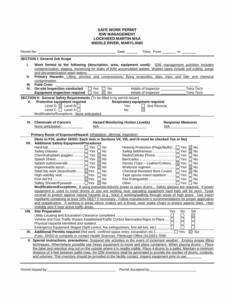
SAFE WORK PERMITIDW MANAGEMENT
LOCKHEED MARTIN MSAMIDDLE RIVER, MARYLAND
Permit No. Date: Time: From to
SECTION I: General Job Scope
I. Work limited to the following (description, area, equipment used): IDW management activities includescontainerization, staging, monitoring for leaks of IDW accumulated wastes. Wastes types include soil cutting, purgeand decontamination wash waters.
II. Primary Hazards: Lifting, pinches and compressions; flying projectiles; slips, trips, and falls and chemicalcontamination.
III. Field Crew:IV. On-site Inspection conducted Yes No Initials of Inspector Tetra Tech
Equipment Inspection required Yes No Initials of Inspector Tetra Tech
SECTION II: General Safety Requirements (To be filled in by permit issuer)V. Protective equipment required Respiratory equipment required
Level D Level B Yes See ReverseLevel C Level A No
Modifications/Exceptions: None anticipated
VI. Chemicals of Concern Hazard Monitoring /Action Level(s) Response MeasuresNone anticipated N/A N/A
Primary Route of Exposure/Hazard: inhalation, dermal, ingestion(Note to FOL and/or SHSO: Each item in Sections VII, VIII, and IX must be checked Yes or No)
VII. Additional Safety Equipment/ProceduresHard-hat..................................... Yes No Hearing Protection (Plugs/Muffs) ... Yes NoSafety Glasses .......................... Yes No Safety belt/harness ........................ Yes NoChemical/splash goggles ........... Yes No Radio/Cellular Phone..................... Yes NoSplash Shield ............................. Yes No Barricades...................................... Yes NoSplash suits/coveralls ................ Yes No Gloves (Type – Leather/Cotton)..... Yes NoImpermeable apron.................... Yes No Work/rest regimen.......................... Yes NoSteel toe work shoes/boots........ Yes No Chemical Resistant Boot Covers Yes NoHigh visibility vest....................... Yes No Tape up/use insect repellent ......... Yes NoFirst Aid Kit................................. Yes No Fire Extinguisher............................ Yes NoSafety Shower/Eyewash ............ Yes No Other.............................................. Yes NoModifications/Exceptions: If using pneumatic/electric power to open drums – Safety glasses are required. If powerequipment is used to move drums or you are working near operating equipment hard hats will be worn. Tyvekcoverall to protect against natural hazards (e.g., ticks) if working/walking through areas of high grass. Use insectrepellants containing at least 10% DEET if necessary. Follow manufacturer's recommendations for proper applicationand reapplication. If working in areas where snakes are a threat, wear snake chaps to protect against bites. Highvisibility vest if near active traffic areas.
VIII. Site Preparation Yes No NAUtility Locating and Excavation Clearance completed ........................................................Vehicle and Foot Traffic Routes Established/Traffic Control Barricades/Signs in Place .....Physical Hazards Identified and Isolated ............................................................................Emergency Equipment Staged (Spill control, fire extinguishers, first aid kits, etc). .............
IX. Additional Permits required (Hot work, confined space entry, excavation etc.)................... Yes NoIf yes, SHSO to complete or contact Health Sciences, Pittsburgh Office (412)921-7090
X. Special instructions, precautions: Suspend site activities in the event of inclement weather. Employ proper liftingtechniques. When/where possible use heavy equipment to move and place containers. When placing drums – Placethe label and retention ring nut on the outside where it is readily visible. Place 4-drums to a pallet. Maintain a minimumdistance of 4-feet between pallet rows. An IDW inventory shall be generated to provide the number of drums, contents,and volumes. This inventory should be provided to the facility contact. Inspect equipment prior to use.
Permit Issued by: Permit Accepted by:

SAFE WORK PERMITDECONTAMINATION ACTIVITIES
LOCKHEED MARTIN MSAMIDDLE RIVER, MARYLAND
Permit No. Date: Time: From to
I. Work limited to the following (description, area, equipment used): Decontamination of Split Spoons, MacroCoreSamplers (or similar equipment) DPT drive rods, associated heavy equipment and CPT/MIB Probes and equipment.Personal decon activities. Decontamination of heavy equipment and machinery with pressure washers and/or steamcleaning units. This will be accomplished at a constructed temporary decontamination pad at the work site.
II. Primary Hazards: Contact with site contaminants; decon fluids; elevated noise; heavy lifting; slip, trip and fall; cuts;flying projectiles; inclement weather
III. Field Crew:IV. On-site Inspection conducted Yes No Initials of Inspector Tetra Tech
Equipment Inspection required Yes No Initials of Inspector Tetra Tech
V. Protective equipment required Respiratory equipment requiredLevel D Level B Yes Specify on the reverseLevel C Level A No
Modifications/Exceptions:
VI. Chemicals of Concern Hazard Monitoring Action Level(s) Response MeasuresVolatile Organics Compounds (VOCs) PID Any detection above bkgd Repeat decontamination procedureLiquinox (soap) None Required None Eye irritant/flush with clean water
Primary Route(s) of Exposure/Hazard: During this activity the primary concern is contact and potential absorption.Soap – Contact - eye/skin/mucous membrane irritation upon direct contact...
(Note to FOL and/or SSO: Each item in Sections VII, VIII, and IX must be checked Yes, No, or NA)VII. Additional Safety Equipment/Procedures
Hard-Hat .................................... Yes No Hearing Protection (Plugs/Muffs) ...... Yes NoSafety Glasses .......................... Yes No Safety Belt/Harness .......................... Yes NoChemical/Splash Goggles.......... Yes No Radio/Cellular Phone........................ Yes NoSplash Shield ............................. Yes No Barricades......................................... Yes NoSplash Suits/Coveralls ............... Yes No Gloves (Type – Nitrile) ...................... Yes NoImpermeable apron.................... Yes No Work/rest Regimen ........................... Yes NoSteel Toe Work Shoes or Boots. Yes No Chemical Resistant Boot Covers ...... Yes NoHigh Visibility Vest ..................... Yes No Tape/Insect Repellent ...................... Yes NoFirst Aid Kit................................. Yes No Fire Extinguisher............................... Yes NoSafety Shower/Eyewash ............ Yes No Other................................................. Yes No
Modifications/Exceptions: Impermeable aprons may be used to control splashing/overspray. If this is inadequatereplace with rainsuit or PE coated Tyvek. Hard hat, splash shield, and hearing protection will be worn when workingnear operating equipment or during pressure washer/steam cleaner operation. Gloves – Nitrile (surgeons style) ornitrile type outer gloves for deconning associated sampling equipment. Overboots will be used when working in thetemporary decontamination pad.
VIII. Site Preparation Yes No NAUtility Locating and Excavation Clearance completed ........................................................Vehicle and Foot Traffic Routes Established/Traffic Control Barricades/Signs in Place .....Physical Hazards Identified and Isolated (Splash and containment barriers) .....................Emergency Equipment Staged (Spill control, fire extinguishers, first aid kits, etc). .............
IX. Additional Permits required (Hot work, confined space entry, excavation etc.)................... Yes NoIf yes, SSO to complete or contact Health Sciences, Pittsburgh Office (412)921-7090
X. Special instructions, precautions: Suspend site activities in the event of inclement weather (storms, high winds, etc.).In addition, do NOT point the Pressure washer wand at other people or place it against any part of your body. Accidentalcompression of the trigger can cause serious lacerations or burns. All hoses and fittings will be inspected to ensurestructural integrity prior to use. For pressure washers or steam cleaners in excess of 3,000 psi, a fan tip of 25 or greaterwill be used to control potential for water cuts or lacerations. A light coating of sand should be applied to the plastic linershould the surface becomes too slippery to prevent slips. Keep hoses gathered to prevent trips and falls. A site controlboundary for this activity is 25-feet surrounding the point of operation. Follow directions provided in the MSDSs for anydecontamination solvents/solutions used in the decontamination procedure.
Permit Issued by: Permit Accepted by:

ATTACHMENT VEQUIPMENT INSPECTION CHECKLIST
FOR DRILL/DPT RIGS

Equipment Inspection Checklist for Drill/DPT Rigs
Company: Unit/Serial No#:
Inspection Date: / / Time: : Equipment Type:(e.g., Drill Rigs Hollow Stem, Mud Rotary, Direct Push, HDD)
Project Name: Project No#:
Yes No NA Requirement CommentsEmergency Stop Devices
Emergency Stop Devices (At points of operation) Have all emergency shut offs identified been communicated to the
field crew? Has a person been designated as the Emergency Stop Device
Operator?
Highway Use Cab, mirrors, safety glass? Turn signals, lights, brake lights, etc. (front/rear) for equipment
approved for highway use? Seat Belts? Is the equipment equipped with audible back-up alarms and back-
up lights? Horn and gauges Brake condition (dynamic, park, etc.) Tires (Tread) or tracks Windshield wipers Exhaust system Steering (standard and emergency) Wheel Chocks? Are tools and material secured to prevent movement during
transport? Especially those within the cab? Are there flammables or solvents or other prohibited substances
stored within the cab? Are tools or debris in the cab that may adversely influence
operation of the vehicle (in and around brakes, clutch, gas pedals)
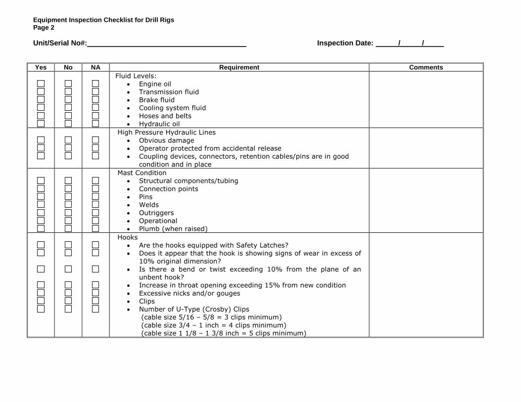
Equipment Inspection Checklist for Drill RigsPage 2
Unit/Serial No#: Inspection Date: / /
Yes No NA Requirement CommentsFluid Levels:
Engine oil Transmission fluid Brake fluid Cooling system fluid Hoses and belts Hydraulic oil
High Pressure Hydraulic Lines Obvious damage Operator protected from accidental release Coupling devices, connectors, retention cables/pins are in good
condition and in place
Mast Condition Structural components/tubing Connection points Pins Welds Outriggers Operational Plumb (when raised)
Hooks Are the hooks equipped with Safety Latches? Does it appear that the hook is showing signs of wear in excess of
10% original dimension? Is there a bend or twist exceeding 10% from the plane of an
unbent hook? Increase in throat opening exceeding 15% from new condition Excessive nicks and/or gouges Clips Number of U-Type (Crosby) Clips
(cable size 5/16 – 5/8 = 3 clips minimum)(cable size 3/4 – 1 inch = 4 clips minimum)(cable size 1 1/8 – 1 3/8 inch = 5 clips minimum)

Equipment Inspection Checklist for Drill RigsPage 3
Unit/Serial No#: Inspection Date: / /
Yes No NA Requirement CommentsPower cable and/or hoist cable
Reduction in Rope diameter π(5/16 wire rope>1/64 reduction nominal size -replace)(3/8 to 1/2 wire rope>1/32 reduction nominal size-replace)(9/16 to 3/4 wire rope>3/64 reduction nominal size-replace)
Number of broken wires(6 randomly broken wires in one rope lay)(3 broken wires in one strand)
Number of wire rope wraps left on the Running Drum at nominaluse (>3 required)- Lead (primary) sheave is centered on the running drum
Lubrication of wire rope (adequate?) Kinks, bends – Flattened to > 50% diameter
Hemp/Fiber rope (Cathead/Split Spoon Hammer) Minimum ¾; maximum 1 inch rope diameter (Inspect for
physical damage) Rope to hammer is securely fastened
Safety Guards – Around rotating apparatus (belts, pulleys, sprockets, spindles,
drums, flywheels, chains) all points of operations protected fromaccidental contact?
Hot pipes and surfaces exposed to accidental contact? High pressure lines Nip/pinch points
Operator Qualifications Does the operator have proper licensing where applicable, (e.g.,
CDL)? Does the operator, understand the equipment’s operating
instructions? Is the operator experienced with this equipment? Is the operator 21 years of age or more?
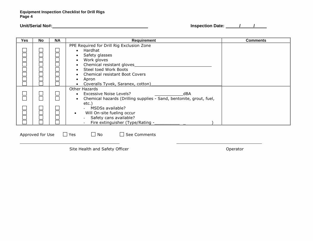
Equipment Inspection Checklist for Drill RigsPage 4
Unit/Serial No#: Inspection Date: / /
Yes No NA Requirement CommentsPPE Required for Drill Rig Exclusion Zone
Hardhat Safety glasses Work gloves Chemical resistant gloves Steel toed Work Boots Chemical resistant Boot Covers Apron Coveralls Tyvek, Saranex, cotton)
Other Hazards Excessive Noise Levels? dBA Chemical hazards (Drilling supplies - Sand, bentonite, grout, fuel,
etc.)- MSDSs available?
Will On-site fueling occur- Safety cans available?- Fire extinguisher (Type/Rating -__________ _ )
Approved for Use Yes No See Comments
Site Health and Safety Officer Operator

ATTACHMENT VI
EXCAVATION SAFETY PROCEDURES

Revision Date: Revision Date: Revision Date: Revision Date: 10/1/200810/1/200810/1/200810/1/2008
Document Control NumberDocument Control NumberDocument Control NumberDocument Control Number::::
4444----5555
TETRA TECH, INC.TETRA TECH, INC.TETRA TECH, INC.TETRA TECH, INC.
TRENCHING AND TRENCHING AND TRENCHING AND TRENCHING AND EXCAVATION EXCAVATION EXCAVATION EXCAVATION
SAFETYSAFETYSAFETYSAFETY Page Page Page Page 1111 of of of of 5555
The online version of this document supersedes all other versions. Paper copies of this document are uncontrolled.
The controlled version of this document can be found on the Tetra Tech Intranet.
This program outlines minimum requirements to protect employees who may be exposed to
hazards during trenching and excavation activities and to provide general guidance for
compliance with Title 29 of the Code of Federal Regulations (CFR), Part 1926, Subpart P,
“Excavations.”
1.1.1.1.0000 SCOPESCOPESCOPESCOPE
This program and procedures applies to all sites and activities involving excavation or trenching
as defined in 29 CFR 1926 Subpart P.
2.2.2.2.0000 RESPONSIBILITIESRESPONSIBILITIESRESPONSIBILITIESRESPONSIBILITIES
Project managers (PMs) shall ensure that all excavation, shoring, and trenching activities are
conducted in accordance with the requirements outlined in this document and Subpart P of
29 CFR 1926. Project managers must also ensure that projects involving trenching and
excavation are staffed by an individual trained and qualified to perform “competent person”
duties as described in this procedure. Operating unit health and safety managers (HSMs) will
provide assistance to PMs in implementing this SWP.
The site safety coordinator (SSC) is responsible for on-site enforcement of this SWP.
3.3.3.3.0000 DEFINITIONSDEFINITIONSDEFINITIONSDEFINITIONS
The following definitions apply to this SWP:
Benching:Benching:Benching:Benching: Forming one or a series of horizontal levels or steps in the sides of an excavation to
protect employees from cave-ins.
Competent Person:Competent Person:Competent Person:Competent Person: One capable of identifying existing or predictable hazards in the work
environment that are unsanitary or dangerous to employees and who has authorization to take
prompt corrective measures to eliminate the hazards.
Excavation:Excavation:Excavation:Excavation: Any manmade cut, cavity, trench, or depression in an earth surface formed by
earth removal.

Revision Date: Revision Date: Revision Date: Revision Date: 10/1/200810/1/200810/1/200810/1/2008
Document Control NumberDocument Control NumberDocument Control NumberDocument Control Number::::
4444----5555
TETRA TECH, INC.TETRA TECH, INC.TETRA TECH, INC.TETRA TECH, INC.
TRENCHING AND TRENCHING AND TRENCHING AND TRENCHING AND EXCAVATION EXCAVATION EXCAVATION EXCAVATION
SAFETYSAFETYSAFETYSAFETY Page Page Page Page 2222 of of of of 5555
The online version of this document supersedes all other versions. Paper copies of this document are uncontrolled.
The controlled version of this document can be found on the Tetra Tech Intranet.
Shoring:Shoring:Shoring:Shoring: Metal, hydraulic, mechanical, or timber system that supports the sides of an
excavation and that is designed to prevent cave-ins.
Sloping:Sloping:Sloping:Sloping: Sloping the sides of an excavation at an incline away from the excavation to protect
employees from cave-ins.
Trench:Trench:Trench:Trench: A narrow excavation (in relation to its length) that is usually deeper than it is wide but
less than 15 feet wide.
4.4.4.4.0000 PROCEDURESPROCEDURESPROCEDURESPROCEDURES
Described below are the general safety requirements and protective system requirements for
trenching and excavation activities.
4.14.14.14.1 General Safety RequirementsGeneral Safety RequirementsGeneral Safety RequirementsGeneral Safety Requirements
General safety requirements that must be in place before work begins are as follows:
• Utility companies or a utilities locating service in the area must be notified before before before before
excavation oexcavation oexcavation oexcavation or trenching activities begin r trenching activities begin r trenching activities begin r trenching activities begin to arrange for locating and protecting
underground utilities.
• Access to trenching areas must be controlled and limited to authorized personnel.
Prior to entering a trench or excavation, workers must notify the project manager,
SSC, and nearby equipment operators whose activities could affect the trench or
excavation.
• No person may enter a trench or work at the foot of the face of an excavation
until a qualified, competent person has inspected the excavation and determined
whether sloping or shoring is required to protect against cave-in or subsidence
and the appropriate protection has subsequently been installed.
• Trenches and excavations must be assessed by a qualified, competent person,
even in the absence of working personnel, whenever heavy equipment will be
operating nearby in order to ensure that the trench or excavation will support the
weight of the equipment without subsistence or causing the accidental
overturning of machinery.

Revision Date: Revision Date: Revision Date: Revision Date: 10/1/200810/1/200810/1/200810/1/2008
Document Control NumberDocument Control NumberDocument Control NumberDocument Control Number::::
4444----5555
TETRA TECH, INC.TETRA TECH, INC.TETRA TECH, INC.TETRA TECH, INC.
TRENCHING AND TRENCHING AND TRENCHING AND TRENCHING AND EXCAVATION EXCAVATION EXCAVATION EXCAVATION
SAFETYSAFETYSAFETYSAFETY Page Page Page Page 3333 of of of of 5555
The online version of this document supersedes all other versions. Paper copies of this document are uncontrolled.
The controlled version of this document can be found on the Tetra Tech Intranet.
• Trenches and excavations must be inspected regularly (daily at a minimum) to
ensure that changes in temperature, precipitation, shallow groundwater,
overburden, nearby building weight, vibration, or nearby equipment operation
have not caused weakening of the sides, faces, and floors and to ensure that
personnel protection is being maintained. Form TEC – Trenching and Excavation
Checklist or its equivalent is to be used to document inspections.
• When subsidence or tension cracks are apparent anywhere in an excavation, all
work should be stopped until the problem is corrected.
• The competent person must inspect trenches or excavations after any
precipitation event to ensure integrity has been maintained.
• Sufficient ramps or ladders must be provided in excavations 4 or more feet deep
to allow quick egress. Ramps or ladders may be placed no more than 25 feet
apart, must be secured from shifting, and must extend at least 3 feet above the
top of the trench or excavation. Structural ramps must be designed by a
competent person.
• Material removed from an excavation or trench must be placed far enough from
the edge (at least 2 feet) to prevent it from sliding into the excavation or trench or
from stressing the trench or excavation walls. Worker protection must also be
provided from loose rock or soil on the excavation faces.
• If trenches or excavations are near walkways or roadways, guards or warning
barriers must be placed to alert pedestrians and drivers of the presence of the
trench or excavation.
• If possible, trenches or excavations should be covered or filled in when
unattended. Otherwise, strong barriers must be placed around the trench or
excavation and lighting must be provided at night if the trench or excavation is
near a walkway or roadway.
• When a hazardous atmosphere could exist, the excavation must be tested for
appropriate hazardous substances and oxygen level before personnel entry.
Excavation where hazardous atmospheres exist must be treated as a confined
space. Entry must follow procedures outlined in “Confined Spaced Entry
Program,” Document Control No. 2-5.
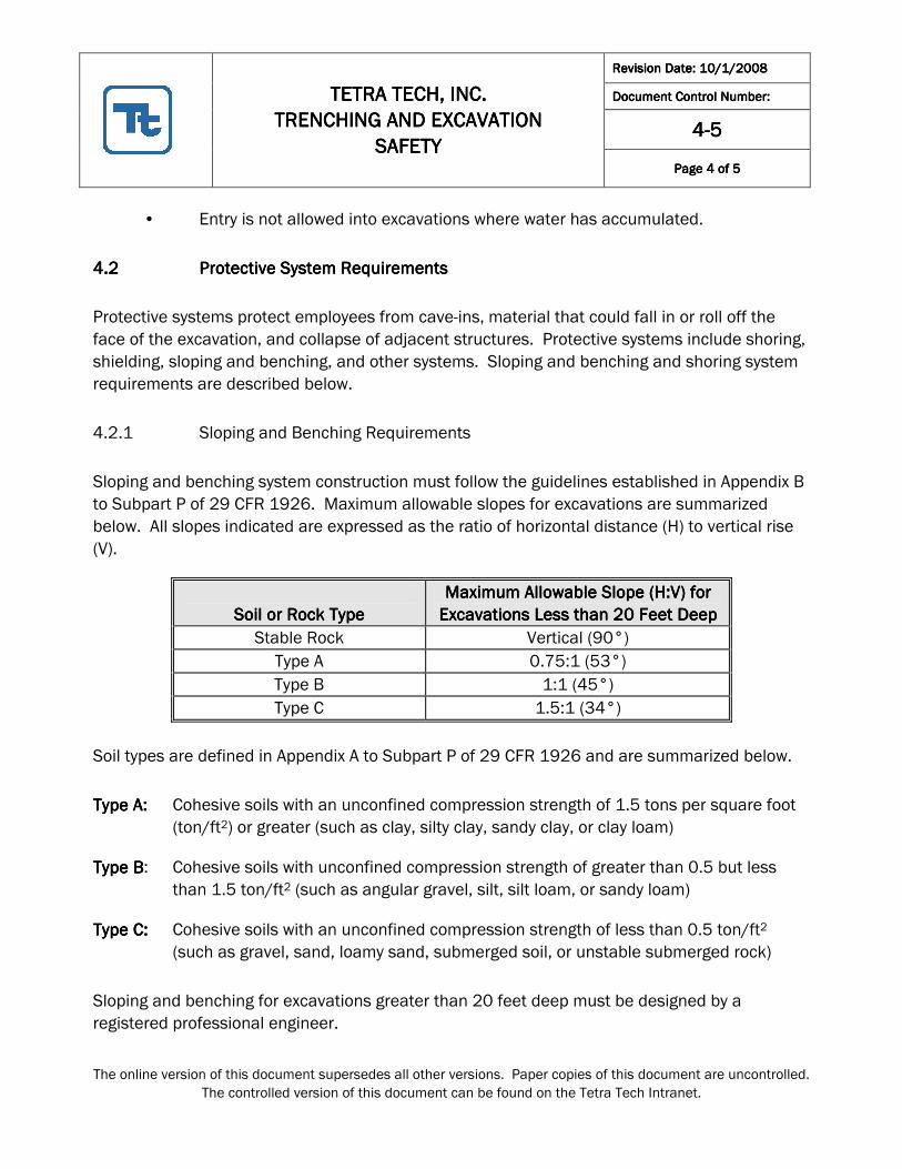
Revision Date: Revision Date: Revision Date: Revision Date: 10/1/200810/1/200810/1/200810/1/2008
Document Control NumberDocument Control NumberDocument Control NumberDocument Control Number::::
4444----5555
TETRA TECH, INC.TETRA TECH, INC.TETRA TECH, INC.TETRA TECH, INC.
TRENCHING AND TRENCHING AND TRENCHING AND TRENCHING AND EXCAVATION EXCAVATION EXCAVATION EXCAVATION
SAFETYSAFETYSAFETYSAFETY Page Page Page Page 4444 of of of of 5555
The online version of this document supersedes all other versions. Paper copies of this document are uncontrolled.
The controlled version of this document can be found on the Tetra Tech Intranet.
• Entry is not allowed into excavations where water has accumulated.
4.24.24.24.2 ProtectiveProtectiveProtectiveProtective S S S System ystem ystem ystem RequirementsRequirementsRequirementsRequirements
Protective systems protect employees from cave-ins, material that could fall in or roll off the
face of the excavation, and collapse of adjacent structures. Protective systems include shoring,
shielding, sloping and benching, and other systems. Sloping and benching and shoring system
requirements are described below.
4.2.1 Sloping and Benching Requirements
Sloping and benching system construction must follow the guidelines established in Appendix B
to Subpart P of 29 CFR 1926. Maximum allowable slopes for excavations are summarized
below. All slopes indicated are expressed as the ratio of horizontal distance (H) to vertical rise
(V).
Soil or RocSoil or RocSoil or RocSoil or Rock Typek Typek Typek Type
Maximum Allowable Slope (H:V) for Maximum Allowable Slope (H:V) for Maximum Allowable Slope (H:V) for Maximum Allowable Slope (H:V) for
Excavations Less than 20 Feet DeepExcavations Less than 20 Feet DeepExcavations Less than 20 Feet DeepExcavations Less than 20 Feet Deep
Stable Rock Vertical (90°)
Type A 0.75:1 (53°)
Type B 1:1 (45°)
Type C 1.5:1 (34°)
Soil types are defined in Appendix A to Subpart P of 29 CFR 1926 and are summarized below.
Type A:Type A:Type A:Type A: Cohesive soils with an unconfined compression strength of 1.5 tons per square foot
(ton/ft2) or greater (such as clay, silty clay, sandy clay, or clay loam)
Type BType BType BType B: Cohesive soils with unconfined compression strength of greater than 0.5 but less
than 1.5 ton/ft2 (such as angular gravel, silt, silt loam, or sandy loam)
Type C:Type C:Type C:Type C: Cohesive soils with an unconfined compression strength of less than 0.5 ton/ft2
(such as gravel, sand, loamy sand, submerged soil, or unstable submerged rock)
Sloping and benching for excavations greater than 20 feet deep must be designed by a
registered professional engineer.

Revision Date: Revision Date: Revision Date: Revision Date: 10/1/200810/1/200810/1/200810/1/2008
Document Control NumberDocument Control NumberDocument Control NumberDocument Control Number::::
4444----5555
TETRA TECH, INC.TETRA TECH, INC.TETRA TECH, INC.TETRA TECH, INC.
TRENCHING AND TRENCHING AND TRENCHING AND TRENCHING AND EXCAVATION EXCAVATION EXCAVATION EXCAVATION
SAFETYSAFETYSAFETYSAFETY Page Page Page Page 5555 of of of of 5555
The online version of this document supersedes all other versions. Paper copies of this document are uncontrolled.
The controlled version of this document can be found on the Tetra Tech Intranet.
Soil types must be determined by the competent person using at least one visual and one
manual test. Manual tests include plasticity, dry strength, thumb penetration, and drying tests.
4.2.2 Shoring System Requirements
Appendixes C, D, and E to Subpart P of 29 CFR 1926 outline requirements for timber shoring for
trenches, aluminum hydraulic shoring for trenches, and alternatives to timber shoring,
respectively. Guidelines for shoring systems are listed below.
• If it is not economically feasible or there are space restrictions to prevent cutting
the trench or excavation walls back to a safe angle of repose, all trenches or
excavations 5 feet deep or more must be shored.
• Shoring should be erected as trenching or excavation progresses and as closely
as possible to the excavation floor.
• Shoring timber dimensions must meet the minimum timber requirements
specified in Tables C1.1 through C1.3 of Appendix C to Subpart P 29 CFR 1926.
Aluminum hydraulic shoring must be constructed using the guidelines and
dimension requirements specified in Appendix D of the same standard.
• Trench shields may be used instead of shoring or bracing. Shields must be
constructed of steel flat sides welded to a heavy framework of structural pipe.
Shields should be moved along by the excavator as trenching or excavation
proceeds.
Revision DateRevision DateRevision DateRevision Date Document AuthorizerDocument AuthorizerDocument AuthorizerDocument Authorizer Revision DetailsRevision DetailsRevision DetailsRevision Details
10/1/2008
Chris McClain
Update from 1998 format

ATTACHMENT VII
TRENCHING AND EXCAVATIONCOMPETENT PERSON CHECKLIST

TRENCHING AND EXCAVATION COMPETENT PERSON CHECKLIST
Contract Name and Number: Contractor/Subcontractor:
Government Inspector: Location:
Contractor Inspector: Date:
Weather (circle one) Dry Raining Previous Rain Freezing
COMPETENT PERSON INFORMATION Yes No N/A
Competent Persons Name: _______________________________________
Length of experience in this occupation: _________________
Length of experience with this employer: ________________
Does the designated individual have training in:Soil Analysis?Use of protective Systems?Requirements of 29 CFR 1926.650-652?
List Training Experience:
Does the designated individual have knowledge about:Soil Analysis? (Describe types of soils and properties)
Use of protective systems? (What method is being used and how was it determined)
Requirements of 29 CFR 1926.650-652?
Does the designated individual have authority to:Take prompt corrective action to eliminate existing and predictable hazards?Stop work?
GENERAL
When was the last inspection of the excavation conducted?
Was an inspection done and documented prior to the start of work?Were inspections done and documented as needed throughout the work shift?
This checklist is based on OSHA requirements. Use of this checklist is optional.

2
TRENCHING AND EXCAVATION COMPETENT PERSON CHECKLIST (con.)
GENERAL (con.) Yes No N/A
Were inspections done and documented after rainstorms or other hazard-increasingoccurrence?Is the excavation deeper than 4 feet?
WATER CONDITIONS
Is dewatering equipment being used on the site?If yes is the competent person monitoring the equipment and it’s properoperation?
Has the excavation been subject to water accumulation?Has the soil in the trench been adversely affected?If yes has the competent person inspected the excavation and taken action?
EGRESS
Is a means of egress provided every 25 feet?Is a ramp used for access or egress to the excavation? (if no skip to the nextsection.Is the ramp used solely for employee access?
If yes was it designed by competent person for safe access and egress?If yes, is the competent person who designed the ramp qualified?
Does the ramp meet specifications?
CONFINED SPACES
Is there a potential for a hazardous atmosphere in the trench? If not, why?
Is air monitoring equipment on site?Has a qualified person been assigned to assess the hazards of confined space?(OSHA Definition: A Qualified Person is designed by the employer in writing, as capable (by educationand/or specialized training) of anticipating, recognizing and evaluating employee exposure to hazardoussubstances or other unsafe conditions in a confined space. This person shall be capable of specifyingnecessary control and/or protective section to ensure safety.)
Is emergency rescue equipment as outlined in 29 CFR 1926.651(g)(2)(I) readilyaccessible to employees?
__________________________________________________________Government Inspector
_______________Date
__________________________________________________________Signature of Competent person (contractor
_______________Date
__________________________________________________________Printed Name of Competent person
This checklist is based on OSHA requirements. Use of this checklist is optional.

ATTACHMENT VIII
TETRA TECH , INC.
CONFINED SPACE ENTRY
PROGRAM
TABLE OF CONTENTS
SECTION PAGE
1.0 PURPOSE .................................................................................................................................. 1
2.0 SCOPE .................................................................................................................................... 1
3.0 RESPONSIBILITIES................................................................................................................... 1
4.0 PROCEDURES........................................................................................................................... 6
4.1 INTRODUCTION ........................................................................................................ 6
4.2 GENERAL REQUIREMENTS..................................................................................... 6
4.3 EMPLOYEE TRAINING............................................................................................ 10
4.4 COORDINATION WITH CLIENTS ........................................................................... 12
4.5 PROJECT SITES INVOLVING CONFINED SPACES WHERE ENTRIES
WILL NOT BE PERFORMED ................................................................................... 13
4.6 CONFINED SPACE ENTRY OPERATINS INVOLVING
SUBCONTRACTORS............................................................................................... 13
4.7 PROGRAM EVALUATIONS AND AVAILABILITY.................................................... 13
4.7.1 Equipment Inspections Supporting Confined Space Operations ............................. 14
4.7.2 Confined Space Signage .......................................................................................... 14
5.0 DEFINITIONS ........................................................................................................................... 14
ATTACHMENT I - TETRA TECH , INC. CONFINED SPACE ENTRY PROGRAM
ATTACHMENT II - CONFINED SPACE ENTRY PROGRAM FOR PROJECT SITES INVOLVINGCONFINED SPACES WHERE ENTRIES WILL NOT BE PERFORMED
ATTACHMENT III - SUBCONTRACTOR PERMIT REQUIRED CONFINED SPACE ENTRY
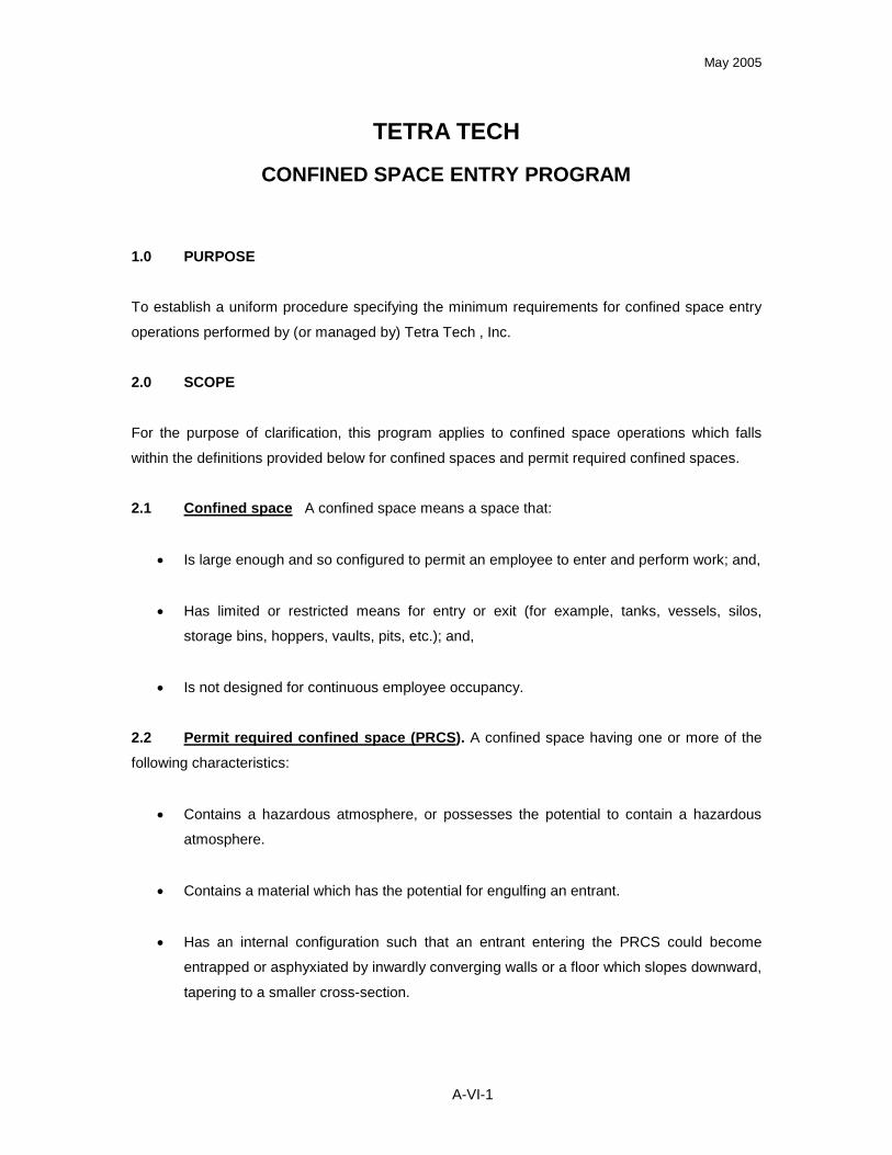
May 2005
A-VI-1
TETRA TECH
CONFINED SPACE ENTRY PROGRAM
1.0 PURPOSE
To establish a uniform procedure specifying the minimum requirements for confined space entry
operations performed by (or managed by) Tetra Tech , Inc.
2.0 SCOPE
For the purpose of clarification, this program applies to confined space operations which falls
within the definitions provided below for confined spaces and permit required confined spaces.
2.1 Confined space A confined space means a space that:
Is large enough and so configured to permit an employee to enter and perform work; and,
Has limited or restricted means for entry or exit (for example, tanks, vessels, silos,
storage bins, hoppers, vaults, pits, etc.); and,
Is not designed for continuous employee occupancy.
2.2 Permit required confined space (PRCS). A confined space having one or more of the
following characteristics:
Contains a hazardous atmosphere, or possesses the potential to contain a hazardous
atmosphere.
Contains a material which has the potential for engulfing an entrant.
Has an internal configuration such that an entrant entering the PRCS could become
entrapped or asphyxiated by inwardly converging walls or a floor which slopes downward,
tapering to a smaller cross-section.
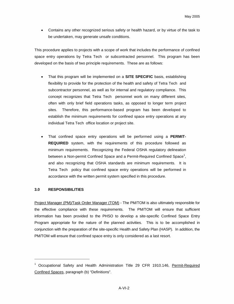
May 2005
A-VI-2
Contains any other recognized serious safety or health hazard, or by virtue of the task to
be undertaken, may generate unsafe conditions.
This procedure applies to projects with a scope of work that includes the performance of confined
space entry operations by Tetra Tech or subcontracted personnel. This program has been
developed on the basis of two principle requirements. These are as follows:
That this program will be implemented on a SITE SPECIFIC basis, establishing
flexibility to provide for the protection of the health and safety of Tetra Tech and
subcontractor personnel, as well as for internal and regulatory compliance. This
concept recognizes that Tetra Tech personnel work on many different sites,
often with only brief field operations tasks, as opposed to longer term project
sites. Therefore, this performance-based program has been developed to
establish the minimum requirements for confined space entry operations at any
individual Tetra Tech office location or project site.
That confined space entry operations will be performed using a PERMIT-REQUIRED system, with the requirements of this procedure followed as
minimum requirements. Recognizing the Federal OSHA regulatory delineation
between a Non-permit Confined Space and a Permit-Required Confined Space1,
and also recognizing that OSHA standards are minimum requirements. It is
Tetra Tech policy that confined space entry operations will be performed in
accordance with the written permit system specified in this procedure.
3.0 RESPONSIBILITIES
Project Manager (PM)/Task Order Manager (TOM) - The PM/TOM is also ultimately responsible for
the effective compliance with these requirements. The PM/TOM will ensure that sufficient
information has been provided to the PHSO to develop a site-specific Confined Space Entry
Program appropriate for the nature of the planned activities. This is to be accomplished in
conjunction with the preparation of the site-specific Health and Safety Plan (HASP). In addition, the
PM/TOM will ensure that confined space entry is only considered as a last resort.
1Occupational Safety and Health Administration Title 29 CFR 1910.146, Permit-Required
Confined Spaces, paragraph (b) “Definitions”.

May 2005
A-VI-3
Tetra Tech Health and Safety Manager (HSM): Provide technical management and oversight of
this program, and to aid Tetra Tech employees in effectively implementing these requirements.
The Tetra Tech HSM will also be responsible for monitoring the overall effectiveness of this
program. This will be accomplished by:
Reviewing completed permits on an annual basis.
Performing field audits of select project sites where confined space entry operations are
performed.
Maintaining proficiency in regulatory requirements on confined space entry matters.
Modifying elements of this program, when or as appropriate.
Establishing minimum components of confined space entry training course material, both
for in-house and subcontractor-provided training courses
Maintaining appropriate record-keeping for this program.
Project Health and Safety Officer (PHSO) - The PHSO shall ensure that confined space activities
are adequately addressed in the Site Specific Health and Safety Plan for assigned projects. In
addition, it is the PHSO responsibility to provide technical assistance to the SSO and/or the Field
Operations Leader. The PHSO must also ensure that the requirements of this program are
satisfied for confined space entry operations performed or managed at their location, whether by
Tetra Tech personnel or by subcontractors. Other responsibilities include ensuring that:
If training is provided by subcontractors, that an appropriate organization is selected, and
that the training course material satisfies the Tetra Tech requirements.
No individual participates in any confined space entry operations unless they are fully
compliant with program requirements.
The HSM is alerted when activities at a project site will involve confined space entry
operations.
A properly completed written program is present at every site where confined spaces
exist.
Appropriate documentation is maintained for that office, and that written permits are
submitted to the HSM at the conclusion of project activities to facilitate the annual permit
review requirement.
Site Safety Officers (SSO): Ensure that the requirements of this program are satisfied for
confined space entry operations performed or managed at their site location, whether by Tetra
Tech personnel or by subcontractors. Other responsibilities include ensuring that:

May 2005
A-VI-4
Confined spaces are identified and labeled as such.
Personnel to participate in confined space are trained to the appropriate level for the
tasks to be performed and documentation certifying this training is obtained and
maintained on site. In addition, ensure drilling/practice requirements to establish
proficiency are up to date.
Personnel meet the necessary medical qualifications for this type of activity.
Rescue services are established and confirmed on the dates the confined space
operations will be conducted.
Provide the intended rescue services, the necessary information concerning the hazards
associated with the confined space operations. This includes Material Safety Data
Sheets, where available, information concerning hazard atmospheres and any associated
physical hazards.
The duties of the Entry Supervisor is completed in their entirety. In many cases the SSO
will serve as the Entry Supervisor.
The site-specific program for confined space operations is completed at each site, where
applicable.
Field Operations Leader (FOL) – The FOL may share responsibility with the SSO or in the absence
of an SSO ensure the implementation of this program for operations conducted under their
direction. Substitution for the SSO will depend on the nature of the confined space operations and
the anticipated severity of the hazards conveyed in the confined space. Substitution shall proceed
based on the PHSO recommendation.
Tetra Tech Employees - The employees are responsible for following the tenets of this Confined
Space Entry Program and/or conditions or modifications of this program, that may be site-specific in
nature. In addition the employees are responsible for reporting any deficiencies or inadequacies of
these program or site-specific elements to the SSO and/or the FOL.
4.0 PROCEDURES
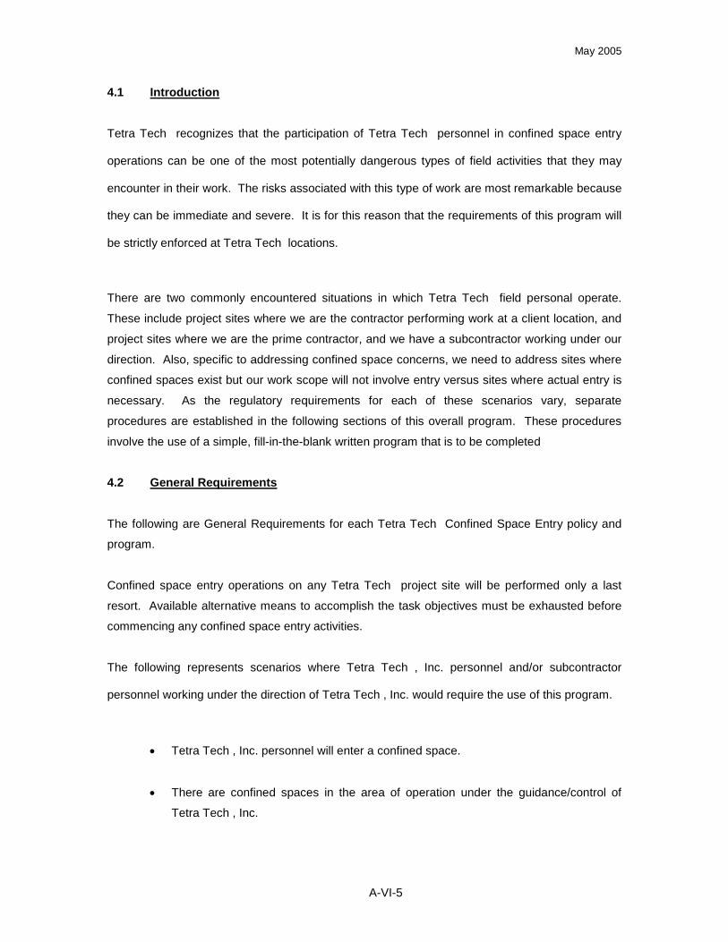
May 2005
A-VI-5
4.1 Introduction
Tetra Tech recognizes that the participation of Tetra Tech personnel in confined space entry
operations can be one of the most potentially dangerous types of field activities that they may
encounter in their work. The risks associated with this type of work are most remarkable because
they can be immediate and severe. It is for this reason that the requirements of this program will
be strictly enforced at Tetra Tech locations.
There are two commonly encountered situations in which Tetra Tech field personal operate.
These include project sites where we are the contractor performing work at a client location, and
project sites where we are the prime contractor, and we have a subcontractor working under our
direction. Also, specific to addressing confined space concerns, we need to address sites where
confined spaces exist but our work scope will not involve entry versus sites where actual entry is
necessary. As the regulatory requirements for each of these scenarios vary, separate
procedures are established in the following sections of this overall program. These procedures
involve the use of a simple, fill-in-the-blank written program that is to be completed
4.2 General Requirements
The following are General Requirements for each Tetra Tech Confined Space Entry policy and
program.
Confined space entry operations on any Tetra Tech project site will be performed only a last
resort. Available alternative means to accomplish the task objectives must be exhausted before
commencing any confined space entry activities.
The following represents scenarios where Tetra Tech , Inc. personnel and/or subcontractor
personnel working under the direction of Tetra Tech , Inc. would require the use of this program.
Tetra Tech , Inc. personnel will enter a confined space.
There are confined spaces in the area of operation under the guidance/control of
Tetra Tech , Inc.

May 2005
A-VI-6
Subcontractor personnel will enter a confined space under the guidance and/or
direction of Tetra Tech , Inc.
Therefore, any project site where planned activities may involve work in or near a confined space
must have a written Confined Space Entry Program completed on site and available prior to the
commencement of site activities. The program must be attached to the Health and Safety Plan
prepared for that project. The written program shall be completed by the assigned SSO, and will
be kept current and available for review by the Tetra Tech HSM.
Work involving entry into a confined space will be performed by written permit only. There will be
no exceptions to this requirement without the express, written consent of the Tetra Tech HSM.
4.2.1 Role and Responsibility of the Site Safety Officer
For applicable projects, the assigned SSO must be thoroughly familiar with this procedure and
with the OSHA regulation on Permit-Required Confined Spaces, and will be responsible for
completing the on-site elements of this program. The SSO will also be responsible for
implementing the specific requirements of the program on his/her site, including ensuring that:
Confined spaces at the site are properly identified, labeled, and inventoried. Signs
should be appropriate size (12x18 minimum or greater) and color designation
Site personnel are made aware of these spaces, and that unauthorized entry is
prohibited. This is to be covered as part of the site-specific health and safety training.
Entries are performed using the written permit system specified in the site written
program.
Necessary training requirements are satisfied, and that appropriate training documents
are collected and maintained.
Personnel participating in the confined space operation are medically (physically and
psychologically) qualified to do so. Documentation to be provided are the medical
surveillance clearance and the ability to wear respiratory protection.

May 2005
A-VI-7
Necessary entry equipment is on hand, and maintained in proper working order.
Equipment will be inspected by the SSO to ensure operation status.
Permits are completed specifying a duration only long enough to perform the job.
A trained and equipped rescue team is on standby prior to the beginning of the
confined space activity. It will be the SSO responsibility to ensure the rescue teams
capabilities and equipment resources to support the planned operation.
The rescue team is fully aware of the potential hazards which may be encountered and
pertinent information has been provided by the SSO.
The SSO will, in the majority of cases, serve as the Entry Supervisor. This means that he/she is
responsible for determining that acceptable entry conditions are present before and during entry,
for authorizing (by completing and signing the written permits) and overseeing entries, and for
terminating entries and canceling permits.
4.2.2 Testing and Monitoring of Confined Spaces
Air monitoring in the confined space must be performed before and periodically during entry
operations. The frequency, types, and sequence of air monitoring are clearly specified in the site
specific program included as Attachment I. While that program specifies that periodic air
monitoring during an entry may be acceptable for an isolated space, it is recommended that
continuous monitoring always be performed, even for a completely isolated space. Acceptable
entry conditions are as specified in Table 1, below.

May 2005
A-VI-8
Table 1
Acceptable Entry Conditions
TestingSequence
Atmospheric Parameter Acceptable Entry Condition
1st
Oxygen content in air 19.5% and 23.5%
2nd
Flammable or explosive conditions
10% of an LEL* for gases, vapors or
mists
LEL for airborne combustible dusts
3rd
Toxic concentrations of chemical hazards
Any exposure reaching a substances
published Action Level, Permissible
Exposure Limit, Threshold Limit Value, or
Recommended Exposure Limit. These will
be specified in the site Health and Safety
Plan
4th
Any other atmospheric condition that is
Immediately Dangerous to Life or HealthVaries by specific parameter
*LEL = Lower Explosive Limit, sometimes also referred to as LFL for Lower Flammability Limit.
For dusts, this may be approximated as a visual condition where the dust obscures vision at a
distance of 5 feet or less.
If the acceptable entry conditions do not exist, or appear that they may not be constant
throughout the entry, the SSO can use the following approach:
Ensure that the space is properly isolated (block and bleed lines, use Lockout/Tagout
procedures, etc.
Purge, inert, flush, or ventilate the space to control or eliminate the hazard.
If acceptable entry conditions still do not exist due to flammability or explosive concerns, the entry
must not be authorized. If the limiting factor is toxic airborne concerns, appropriate PPE may be
used to allow the entry (Note: PPE is chosen as a control option always only as a last resort.
Efforts should be made to control hazards through engineering controls).
4.2.3 Rescue
When confined space entry operations are performed, personnel and equipment must be
adequate and available to effect non-entry rescue operations in the event of an emergency. This
May 2005
A-VI-9
shall include items such as body harnesses (or wristlets, as a second choice), tie-offs,
mechanical retrieval apparatus, etc. This equipment must be available and in use during entry
operations. This will enable the Attendant and other authorized personnel to perform an
emergency rescue and extract an injured person from outside of the space. Rescue procedures
requiring other personnel to enter a space to assist or evacuate an injured or incapacitated
entrant are expressly prohibited. Also, unauthorized personnel must be prohibited from
participating in emergency rescue operations.
It is anticipated that in most instances, we will be prepared to provide non-entry emergency
rescue services ourselves, at least to the point of removing an injured person and stabilizing them
until professional emergency services can be summoned. The identity of the specific emergency
response service and the method for contacting them will be clearly identified on the permit
completed by the SSO. At least one member of the team serving in the role of Attendant or
Rescue member (a non-entrant) must have current certification in First Aid and CPR. (Note:
The person of choice must ensure that Bloodborne Pathogen Program requirements are satisfied
whenever First Aid or CPR practice is authorized.)
4.3 Employee Training
Personnel must be adequately trained in order to be authorized to participate in confined space
operations. Training must be performance-based so that participants can successfully
demonstrate proficiency in performing their assigned duties. Training shall take place before an
individuals first assignment, when their assigned duties change, or when changes occur in the
site’s written program. Also, if a new hazard is suspected that was not addressed in the
employee’s training, supplemental training will be required. Retraining may also be conducted
when through periodic inspections or reviews identify deficiencies in confined space operations.
Whether training is provided in-house or by a training contractor, the contents of the training must
satisfy the requirements of this program, and will be held to the criteria published by the
Hazardous Waste Action Coalition Risk Management Committee, Health and Safety
Subcommittee (entitled “Confined Space Entry Training Courses”, published in 1996). A copy of
these criteria are available from the Tetra Tech HSM. These criteria are directly applicable as
they have been specifically developed by health and safety representatives of firms from within
our industry (hazardous waste/environmental consulting).
The SSO will ensure that appropriate training has taken place for authorized individuals, and will
have on-hand at the site documentation for each involved employee attesting to:

May 2005
A-VI-10
Employee name
Signature or initials of the instructor
Dates of training
Site-specific training for authorized individuals will cover the duties of the entrants and attendants.
This will address the aspects for each of these positions as presented below.
4.3.1 Authorized Entrants Training
Hazards that may be encountered in the space
How to properly use the necessary equipment
Communication methods with the Attendant
Recognizing when emergency exit of the space is necessary
4.3.2 Attendant Training
Hazards that may be encountered in the space
Behavioral effects of hazard exposure
To continuously maintain an accurate count of entrants and know their identity
To never leave the space unless relieved by another attendant
Communication methods and aspects with Entrants
Monitoring of the space
How and when to summon emergency services
Control unauthorized personnel issues
Performance of non-entry rescues
4.3.3 Entry Supervisor Training
Hazards that may be encountered in the space
Verifies that tests have been conducted (by checking permit entries)
Verifies that procedures and equipment specified in the permit are in place before signing
it and putting it into effect
When and how to terminate the entry and cancel the permit
May 2005
A-VI-11
Verify that rescue services are available at the time of the entry and that the means for
summoning them are operable
Removes or prevents unauthorized personnel from entering the space
4.4 Coordination with Clients
Tetra Tech operations will involve arrangements where we are serving as a contractor to a client
facility. That is, we will not be addressing entering spaces that we own or control. Therefore,
appropriate coordination with the client representative will be essential to properly understand the
nature of any confined spaces and to successfully perform the work. When the scope of work
entails (or may entail) working in or near confined spaces, the PM/TOM must gather the following
information as part of the initial data gathering process:
Obtain any available information regarding confined spaces, including descriptions,
potential or known hazards, and the client’s confined space entry program information.
Determine, if the client has located and designated confined spaces in the work area.
Establish how the client desires to coordinate our work with their operations, relative to
the confined spaces.
If the scope of work will involve actual entry by Tetra Tech personnel, inform the client of
our program.
Gathered information is to be provided to the PHSO responsible for preparing the site-specific
Health and Safety Plan.
At the conclusion of any confined space entry work done at a client location, the PM/TOM is to
request a debriefing meeting, so that a representative from the project team can communicate
hazards that were encountered in the work.
4.5 Project Sites Involving Confined Spaces Where Entries Will Not Be Performed
In many instances, we may be performing work at sites where confined spaces exist and our
scope of work does not involve any entry into those spaces. In this application, the SSO has only
to ensure that spaces in our work area are adequately identified and posted, and complete the
one-page written program in Attachment II and post it on site in the work area.

May 2005
A-VI-12
4.6 Confined Space Entry Operations Involving Subcontractors
For some projects, the scope of work may require a specialized of a subcontractor. When the
work involves requiring a subcontractor to perform a confined space entry, the SSO must
complete and utilize the written program included as Attachment III. We must provide our
subcontractor with the following information:
Information regarding the confined space(s), including descriptions, potential or known
hazards, and the details of our confined space entry program.
Information on the location and designations (postings) of the confined spaces in the
work area.
Establish how we desire to coordinate our work with their operations, relative to the
confined spaces.
If the scope of work will involve actual entry by subcontractor personnel, inquire if they
have their own Permit-Required Confined Space Program and obtain it for our review.
If the nature of the work is such that Tetra Tech and subcontractor personnel will have to
perform concurrent operations in or near a confined space, very close coordination will be
necessary and the Tetra Tech HSM must be contacted for guidance.
At the conclusion of any confined space entry work done by a subcontractor, a debriefing meeting
will be held by the SSO to learn of any hazards that were encountered in the work.
4.7 Program Evaluations and Availability
The Tetra Tech HSM is responsible for performing evaluations of this overall Program to ensure
its continued effectiveness. These reviews will be properly documented, and will occur as
follows:
Annually, at the end of each calendar year.
At any time when an indication is discovered that a component of the program is not
effective.
In the event of any modifications in the regulatory requirements for confined space
operations.
If the event of changes or mandates from Tetra Tech, Inc. Corporate Health and Safety.
Annual Program evaluations will entail a review of canceled written permits prepared and used
during the course of that year by Tetra Tech locations. The various site-specific written

May 2005
A-VI-13
programs that these permits were prepared under are also subject to review. Canceled permits
will be retained by the Tetra Tech HSM for no less than one calendar year.
Field audits of project work sites where confined space operations are conducted will also be
performed. These will be coordinated through the Tetra Tech HSM , and will do on an
unannounced, random basis.
Information gathered and program modifications that become necessary will be communicated to
Tetra Tech personnel by the Tetra Tech HSM.
4.7.1 Equipment and Evaluation of Confined Spaces
Spaces must be properly evaluated before and during entry operations. Figure 2 specifies the
criteria for equipment inspections that will be maintained on this site to evaluate and support
Confined Space Entry operations.
4.7.2 Confined Spaced Signage
Each of these spaces have been (or will be, upon creation) clearly posted with signs stating
“DANGER - PERMIT REQUIRED CONFINED SPACE - DO NOT ENTER” or “DANGER -
CONFINED SPACE - DO NOT ENTER” as applicable.. Unauthorized entry into any of these
spaces is strictly prohibited.
The remaining text represents the site-specific portion of this program and the activities to be
conducted when involved in one or more of the scenarios defined above.

May 2005
A-VI-14
5.0 DEFINITIONS
Acceptable entry conditions - The conditions that must exist and be maintained in a confined
space in order to allow entry and work activities to be performed by personnel. For purposes of
this program, this definition will also reflect those conditions which must be maintained and must
not be compromised. Therefore, acceptable entry conditions are defined as, but not limited to,
the following:
A "hazardous atmosphere" either does not exist, or it can be adequately controlled to
allow entry. Examples of control measures may include ventilating, purging, or inerting
the PRCS, or a combination of these measures. Additionally, the use of appropriate
personal protective equipment may be considered a control measure when other
engineering and administrative controls are not feasible or are unable to be adequately
controlled.
The space to be entered has been properly isolated. This involves ensuring that energy
sources have been identified and secured in a zero energy state to the greatest possible
extent. This is accomplished through the use of energy control measures such as lockout
procedures, blanking or blinding techniques, double block and bleed procedures, or other
appropriate energy control methods. This effort must be documented, and members
associated with the entry must concur that control sources have been identified, tested,
and are disabled.
The space to be entered does not contain a material that could engulf an entrant. If such
a material is involved, adequate control methods such as shoring or sloping of the
material must be adequately implemented prior to initiation of the entry.
The space to be entered does not contain any other serious hazard potential(s) which
cannot be contained or controlled to the satisfaction of the entry supervisor.
Attendant - An individual stationed outside one or more permit spaces who monitors the
authorized entrants and who performs attendant's duties assigned by this Confined Space Entry
Program.
Authorized entrant - An employee who is authorized by Tetra Tech to enter a confined space or a
permit required confined space.

May 2005
A-VI-15
Blanking or blinding - The absolute closure of a pipe, line, or duct by the fastening of a solid plate
that completely covers the bore, which ensures no leakage occurs beyond the plate.
Confined space. A confined space means a space that:
Is large enough and so configured to permit an employee to enter and perform work; and,
Has limited or restricted means for entry or exit (for example, tanks, vessels, silos,
storage bins, hoppers, vaults, pits, etc.); and,
Is not designed for continuous employee occupancy.
Double block and bleed - The closure of a line, duct, or pipe by closing and locking two in line
valves and by opening and locking a drain or vent valve in the line between the two closed
valves.
Emergency - Any occurrence (including any failure of hazard control or monitoring equipment) or
event internal and/or external of the confined space and/or permit-required confined space, that
could endanger entrants.
Entry - The action by which a person passes through an opening into a confined space. Entry
includes ensuing work activities that are performed in the confined space. Entry is considered to
have occurred as soon as any part of the entrant's body breaks the plane of an opening into the
confined space.
Entry permit - The written or printed document which is provided by the employer to allow and
control entry into a confined space and/or a permit required confined space. The permit contains
pertinent information regarding the space to be entered.
Entry supervisor - The person responsible for determining if acceptable entry conditions are
present the confined space and/or the permit required confined space where entry is planned.
The Entry supervisor is also responsible for authorizing entry, overseeing entry operations, and
for terminating the entry as conditions dictate.
Hazardous atmosphere - An atmosphere that may expose employees to the risk of death,
incapacitation, impairment of ability to self rescue, injury, or acute illness from one or more of the
following causes:

May 2005
A-VI-16
Flammable gas, vapor, or mist in excess of 10 percent of its lower explosive limit -LEL
(sometimes referred to as the lower flammable limit - LFL).
Airborne combustible dust at a concentration that meets or exceeds 10 percent of its
LEL/LFL.
Atmospheric oxygen concentration below 19.5 percent or above 23.5 percent.
Atmospheric concentration of any substance for which a dose or a permissible exposure
limit is established. Also an atmospheric concentration which could impede the entrant's
ability to self rescue resulting in employee exposure and adverse health effects
associated with that exposure.
Any other atmospheric condition that is immediately dangerous to life or health.
Hot Work Permit - The employer's written authorization to perform operations (e.g., welding,
cutting, burning, heating, etc.) capable of providing a source of ignition.
Immediately Dangerous to Life or Health (IDLH) - Any condition which poses an immediate or
delayed threat to life, or a condition that would cause irreversible adverse health effects. In
addition, an IDLH condition includes any condition which would interfere or impede an individual's
ability to escape unaided from a confined space and/or a permit-required confined space.
Inerting - The displacement of the hazardous atmosphere in a permit-required confined space by
introducing a non-reactive gas (such as nitrogen) to such an extent that the resulting hazardous
atmosphere would be pushed from the permit-required confined space rendering that permit-
required confined space non-reactive. Inert spaces are still considered hazardous due to the
displacement of oxygen.
Isolation - The process by which a permit space is removed from service and completely
protected against the release of energy and material into the space by such means as:
blanking or binding;
misaligning or removing sections of lines, pipes, or ducts;
a double block and bleed system;
lockout of energy sources, and the reduction of potential energy sources to their zero
mechanical state;

May 2005
A-VI-17
blocking or disconnecting mechanical linkages.
Line breaking - The intentional opening of a pipe, line, or duct that is or has been carrying
flammable, corrosive, or toxic material, an inert gas, or any fluid at a volume, pressure, or by the
SSO.
Lockout - [As defined by OSHA 29 CFR 1910.147 (b)] The placement of a lockout device on an
energy isolating device, in accordance with an established procedure, which ensures that the
energy isolating device and the equipment being controlled cannot be operated until the lockout
device is removed.
Permit required confined space (PRCS). A confined space having one or more of the following
characteristics:
Contains a hazardous atmosphere, or possesses the potential to contain a hazardous
atmosphere.
Contains a material which has the potential for engulfing an entrant.
Has an internal configuration such that an entrant entering the PRCS could become
entrapped or asphyxiated by inwardly converging walls or a floor which slopes downward,
tapering to a smaller cross-section.
Contains any other recognized serious safety or health hazard, or by virtue of the task to
be undertaken, may generate unsafe conditions.
Permit system - The employer's written procedure for preparing and issuing permits for entry and
for returning the permit space to service following termination of entry.
Prohibited condition - Any condition in a confined space and/or a permit-required confined space
that is not allowed by the permit during the period when entry is authorized.
Tagout - [As defined by OSHA 29 CFR 1910.147 (b)] The placement of a tagout device on an
energy isolating device, in accordance with an established procedure, to indicate that the energy
isolating device and the equipment being controlled may not be operated until the tagout device is
removed. It should be emphasized that any time tagout is employed as an energy control
measure, it must offer the same level of protection as its energy control measure counterpart
lockout.

May 2005
A-VI-18
Testing - The process by which the hazards that may confront entrants of a permit space are
identified and evaluated. Testing includes specifying the tests that are to be performed in the
permit space. Details pertaining to testing methods and procedures are discussed in Section 4.4
of this program.

May 2005
ATTACHMENT I
TETRA TECH , INC.CONFINED SPACE
ENTRY OPERATIONS

May 2005
PROJECTS SITES INVOLVING CONFINED SPACE ENTRY OPERATIONS
The written program presented will be used at Tetra Tech project sites where confined space
entry operations are planned. That program has been developed to provide the SSO with a
standardized tool to serve two purposes:
To protect the health and safety of Tetra Tech and subcontractor personnel working in or
near confined spaces.
To comply with Federal regulatory requirements.
PERSONNEL RESPONSIBLE FOR PROGRAM COMPLETION
The following persons are available to provide assistance in elements of this program including
question/conflict resolution and modification variances. These persons exercise the primary
responsibility for the implementation of this site-specific program.
Site Safety Officer: Phone #:
Field Operations Leader: Phone #:Project Health and Safety Officer: Phone #:
Health and Safety Manager: Phone #:
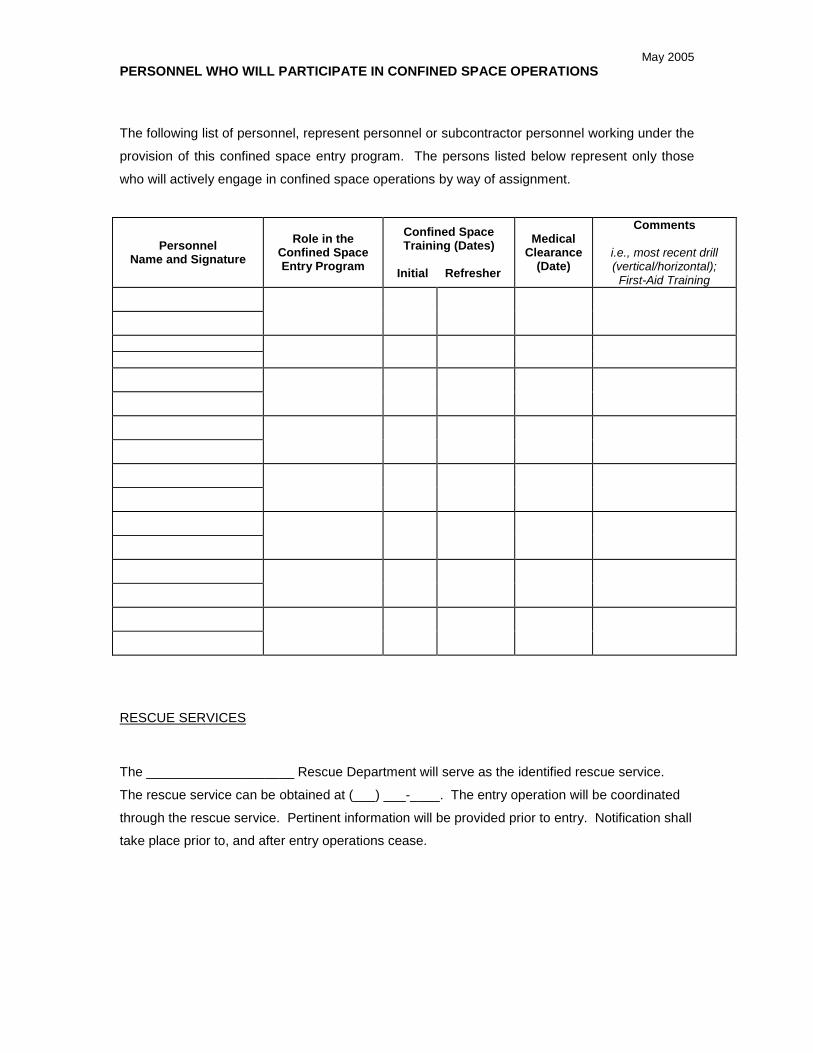
May 2005PERSONNEL WHO WILL PARTICIPATE IN CONFINED SPACE OPERATIONS
The following list of personnel, represent personnel or subcontractor personnel working under the
provision of this confined space entry program. The persons listed below represent only those
who will actively engage in confined space operations by way of assignment.
PersonnelName and Signature
Role in theConfined SpaceEntry Program
Confined SpaceTraining (Dates)
Initial Refresher
MedicalClearance
(Date)
Comments
i.e., most recent drill(vertical/horizontal);First-Aid Training
RESCUE SERVICES
The ____________________ Rescue Department will serve as the identified rescue service.
The rescue service can be obtained at (___) ___-____. The entry operation will be coordinated
through the rescue service. Pertinent information will be provided prior to entry. Notification shall
take place prior to, and after entry operations cease.

May 2005CONFINED SPACE INVENTORY/STATUS
The following inventory represents the confined spaces at this project site. These spaces are
listed by way of planned entry or proximity. This list will be updated by the SSO and/or the FOL
as necessary.
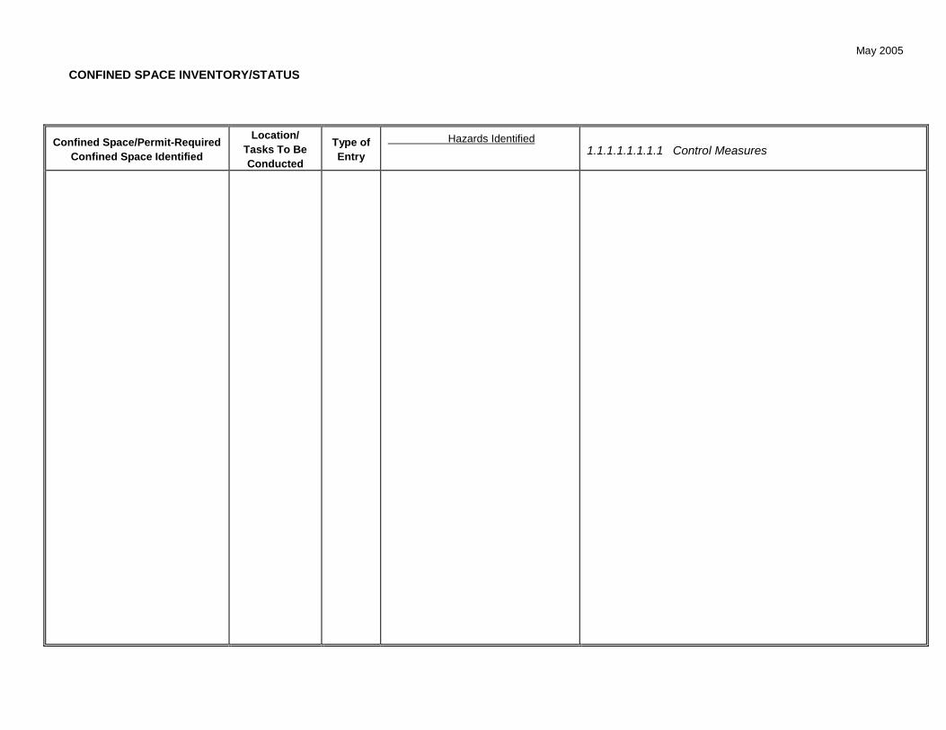
May 2005
CONFINED SPACE INVENTORY/STATUS
Confined Space/Permit-RequiredConfined Space Identified
Location/Tasks To BeConducted
Type ofEntry
Hazards Identified1.1.1.1.1.1.1.1 Control Measures

May 2005
CONFINED SPACE ENTRY PERMIT
Entries into Identified Confined Spaces Will Be By Written Permit Only.
The Confined Space Entry Permit will guide and direct field personnel regarding aspects of the entry by
using the permit as a checklist. It is based on this application that no spaces on the permit be left
unchecked.
The assigned authorized entrant(s) and attendant(s) will complete the Confined Space Entry Permit.
However, entry is not permitted until the Entry Supervisor reviews the permit and signs off.
Figure 1 will be used as the written permit on this site. Permits will be reviewed, issued, and canceled by the
SSO, who will also serve in the role of Entry Supervisor. Permits must be completed before any entry
operations begin. Completed permits will be reviewed with involved personnel as part of their task-specific
training, and then posted at or near the entrance to the space.
HAZARD MONITORING
Spaces will be initially evaluated by the Authorized Entrant and Attendant as follows:
Pre-entry, to determine that satisfactory entry conditions exist
Continuously, if the space cannot be isolated – For activities at _____
Periodically, if the space can be isolated (at least once every __ minutes)
The sequence for conducting these evaluations will be (from first to last):
1. Oxygen level
2. Lower Explosive Level (for gases, vapors, mists, or particulates)
3. Toxic gases or vapors
Specific equipment and instrument action levels are specified on the permit.
Information derived from the monitoring activity will be recorded on the Entry Permit. This information will be
used to determine if acceptable entry conditions exist and whether entry is permitted. The SSO will review
the information collected and authorize entry, if conditions are determine to be acceptable.

May 2005
Figure 1
CONFINED SPACE ENTRY PERMIT
CONFINED SPACE ENTRY PERMIT No:
INITIAL ATMOSPHERIC TESTS PERFORMEDCAUTION: Toxic or flammable gasses or vapors may _________ in the confined space. Be sure to vent at various intervals and
locations within the confined space. Always check the oxygen content first.
INITIAL TESTINGHAZARD ACCEPTABLE DATE AND TESTER ACCEPTABLETESTED RANGE READING TIME INITIALS YES NO
%Oxygen 19.5-23.5% %
%LEL 10% or less %
PEL= PPM=
PEL= PPM=
PEL= PPM=
EVACUATION PROCEDURERoute:
Assembly Points:
RESCUE PROCEDURE – Initiate self rescue, if incapacitated; initiate external extraction; If unable to facilitate external extraction;notify the Fire Dept. for entry and removal
PLAN DESCRIPTION
ON-SITE RESCUE CONTACTSPHONE NUMBER RADIO NUMBER PAGER NUMBER OUTSIDE SOURCES AND PHONE
(252) 335-6222 FIRE DEPARTMENT
AMBULANCE
HOSPITAL
OTHER
SPECIAL EQUIPMENT NEEDED
RESPIRATORS (Type):
SAFETY HARNESSES/WRISTLETS
LIFELINES
HOISTING APPARATUS
VENTILATION EQUIPMENT:
TEMPORARY LIGHTING (Type/voltage):
NON-SPARKING TOOLS
PROTECTIVE CLOTHING:
OTHER:
ENTRY SUPERVISOR’S SIGNATURE DATE PERMIT RECEIVER SIGNATURE DATE

May 2005
CONFINED SPACE ENTRY PERMIT No:GENERAL INFORMATION:DESCRIPTION OF THE CONFINED SPACE:
DATE ISSUED TIME ISSUED DATE EXPIRES TIME EXPIRES
: :ENTRY SUPERVISOR
ATTENDANT(S)
COMMUNICATION BETWEEN ATTENDANT(S) – ENTRANTS
‘ VOICE ‘ LIGHT ‘ RADIO ‘ OTHERDESCRIPTION OF WORK:
CHECKLIST FOR ISOLATION AND UNAUTHORIZED ACCESS PREVENTION
Yes NO NA INITIAL
External Battery(ies) in Place __________
Mechanical Lockout/Tagout __________
Lines/Pipes Disconnected __________
Lines/Pipes Blocked __________
Lines/Pipes Capped __________
Lines/Pipes Blinded __________
Warning Signs __________
Other:_______________________________________ __________REPORT ANY UNAUTHORIZED ENTRY TO:Health Sciences Department and ProjectManagement
PHONE NO. RADIO NO. PAGER NO.
PRE-ENTRY CHECKLISTPURGING, INERTING, OR FLUSHING MECHANICAL VENTILATION
PERFORMED YES NO NA Estimated Confined Space Volume:Air Exchange Rate Required:
METHOD USED Nitrogen steam Initial Continuous Partial Description
Water Other (specify) Fresh Air Injection ____hrs.
General ____hrs.Local Exhaust ____hrs.
SPECIFIC HAZARDOUS TASKSCertain tasks performed in confined spaces greatly increase the risks to entrants. Check tasks to be performed.
WELDING/GRINDING PAINTING OR CLEANING WITH SOLVENTS
THERMAL CUTTING CLEANING/SWEEPING/VACUUMING
SOLDERING/BRAZING SCRAPING/REMOVING RESIDUE
ELECTRICAL CHEMICAL USE
OTHER, EXPLAIN:
Additional Permits Required Hot Work Permit Utility Locating/Excavation ClearanceENTRY SUPERVISOR’S SIGNATURE DATE PERMIT RECEIVER SIGNATURE DATE
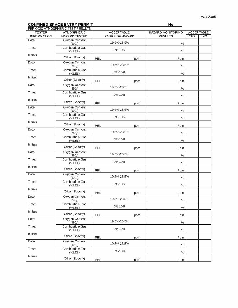
May 2005
CONFINED SPACE ENTRY PERMIT No:PERIODIC ATMOSPHERIC TEST RESULTS
TESTER ATMOSPHERIC ACCEPTABLE HAZARD MONITORING ACCEPTABLEINFORMATION HAZARD TESTED RANGE OF HAZARD RESULTS YES NO
Date Oxygen Content(%02)
19.5%-23.5% %Time: Combustible Gas
(%LEL) 0%-10% %Initials:
Other (Specify) PEL ppm PpmDate Oxygen Content
(%02)19.5%-23.5% %
Time: Combustible Gas(%LEL) 0%-10% %
Initials:Other (Specify) PEL ppm Ppm
Date Oxygen Content(%02)
19.5%-23.5% %Time: Combustible Gas
(%LEL) 0%-10% %Initials:
Other (Specify) PEL ppm PpmDate Oxygen Content
(%02)19.5%-23.5% %
Time: Combustible Gas(%LEL) 0%-10% %
Initials:Other (Specify) PEL ppm Ppm
Date Oxygen Content(%02)
19.5%-23.5% %Time: Combustible Gas
(%LEL) 0%-10% %Initials:
Other (Specify) PEL ppm PpmDate Oxygen Content
(%02)19.5%-23.5% %
Time: Combustible Gas(%LEL) 0%-10% %
Initials:Other (Specify) PEL ppm Ppm
Date Oxygen Content(%02)
19.5%-23.5% %Time: Combustible Gas
(%LEL) 0%-10% %Initials:
Other (Specify) PEL ppm PpmDate Oxygen Content
(%02)19.5%-23.5% %
Time: Combustible Gas(%LEL) 0%-10% %
Initials:Other (Specify) PEL ppm Ppm
Date Oxygen Content(%02)
19.5%-23.5% %Time: Combustible Gas
(%LEL) 0%-10% %Initials:
Other (Specify) PEL ppm PpmDate Oxygen Content
(%02)19.5%-23.5% %
Time: Combustible Gas(%LEL) 0%-10% %
Initials:Other (Specify) PEL ppm Ppm

May 2005
CONFINED SPACE ENTRY PERMIT No:PERSONNEL ENTRY LOGDESCRIPTIONOF CONFINED SPACE
ENTRY SUPERVISOR DATE
ATTENDANT(S)
TIMES IN AND OUT
AUTHORIZED ENTRANT’S NAME IN OUT IN OUT IN OUT IN OUT

May 2005
EQUIPMENT INSPECTION
Equipment to be used in support of the confined space operation(s) will be inspected by the SSO or duly
appointed representative, prior to initial use. Inspections will entail a physical examination and an
operational check. The Confined Space Equipment Inspection Record will be used to document these
inspections. Where appropriate existing inspection records for instance Respiratory Equipment Checklist will
be used in place of the Confined Space Equipment Inspection Record.
PERMIT TERMINATION
A confined space entry permit can be terminated for a number of reasons. These include, but not limited to,
the following:
Scope of work change
Acceptable conditions within the space change
Time limit expires
Planned activities are completed
Upon termination of an active permit the following steps will take place.
The Confined Space Permit and any other associated permit (Safe Work Permit, Hot Work Permit,
etc.) or hazard monitoring results will be copied. The copies will be forwarded to the PHSO for
evaluation.
Upon evaluation the PHSO will forward the copied permits to the HSM for record-keeping and
review. The PHSO will include any relevant comments for the HSM to be considered during his/her
review.
The HSM will maintain the completed permits and associated materials for a period of one year
from the date of issue.
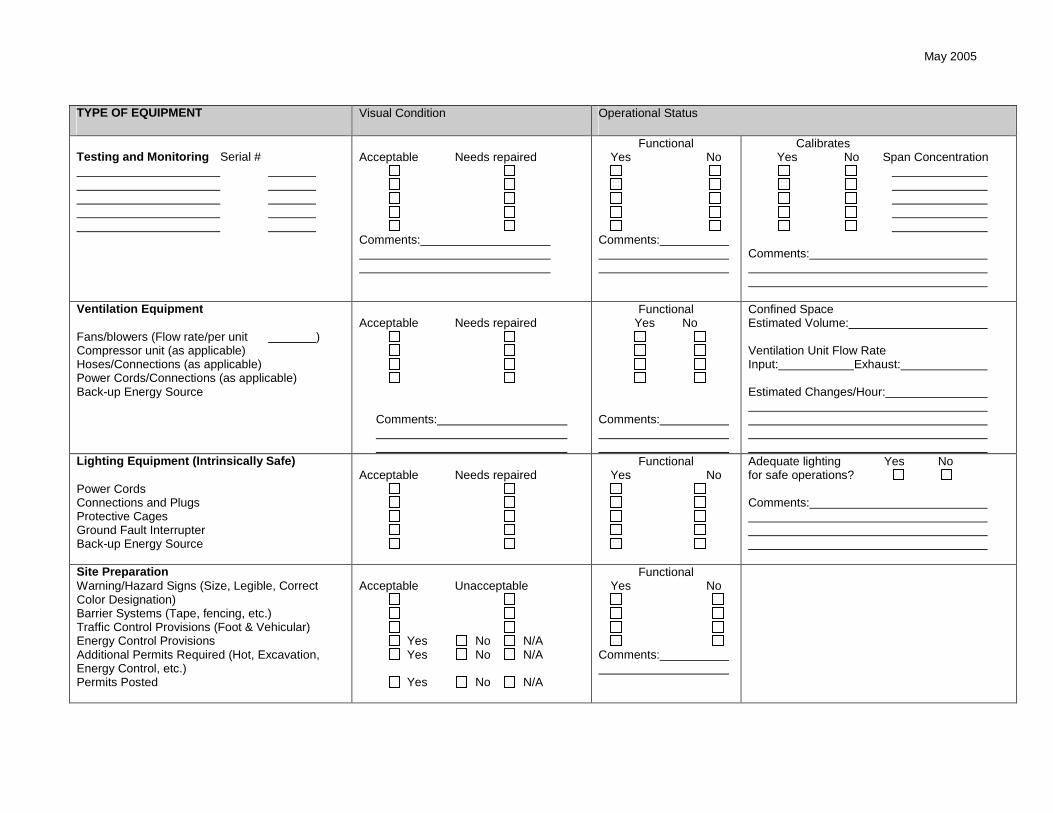
May 2005
TYPE OF EQUIPMENT Visual Condition Operational Status
Testing and Monitoring Serial # Acceptable Needs repaired
Comments:
FunctionalYes No
Comments:
CalibratesYes No Span Concentration
Comments:
Ventilation Equipment
Fans/blowers (Flow rate/per unit )Compressor unit (as applicable)Hoses/Connections (as applicable)Power Cords/Connections (as applicable)Back-up Energy Source
Acceptable Needs repaired
Comments:
FunctionalYes No
Comments:
Confined SpaceEstimated Volume:
Ventilation Unit Flow RateInput: Exhaust:
Estimated Changes/Hour:
Lighting Equipment (Intrinsically Safe)
Power CordsConnections and PlugsProtective CagesGround Fault InterrupterBack-up Energy Source
Acceptable Needs repairedFunctional
Yes NoAdequate lighting Yes Nofor safe operations?
Comments:
Site PreparationWarning/Hazard Signs (Size, Legible, CorrectColor Designation)Barrier Systems (Tape, fencing, etc.)Traffic Control Provisions (Foot & Vehicular)Energy Control ProvisionsAdditional Permits Required (Hot, Excavation,Energy Control, etc.)Permits Posted
Acceptable Unacceptable
Yes No N/AYes No N/A
Yes No N/A
FunctionalYes No
Comments:

May 2005
TYPE OF EQUIPMENT Visual Condition Operational Status
Communications Equipment
TypeIntrinsically Safe?Back-up Communication method?Will line of sight be maintained during the entryoperations?Will relay points be established to support radiocommunications?
Acceptable Unacceptable
Yes No
Yes No N/A
FunctionalYes No
Comments:
Rescue/Emergency EquipmentRetrieval/Fall Arresting Systems [Tripods,Hoist(extraction cables, connections), lifeline,harnesses]StretcherFire Extinguishment -Type RatingFirst-Aid Equipment/Supplies
Acceptable Needs repairedFunctional
Yes No
Method/Means to summonRescue Team provided? Yes No
Hazard Information regardingThe space to be entered beenProvided to the RescueTeam? Yes ‘ NoProcedures for Self orNon-Entry rescue beenAccomplished? Yes NoIf no why not?
Comments:
Personal Protective Equipment
Hard HatSafety GlassesSplash ShieldSplash Suits TypeSteel Toe Work BootsChemically Resistant OverbootsHearing ProtectionGloves – TypeHeat Shielding
Acceptable Unacceptable N/AComments:
Respiratory Protection: Attach Respiratory Protection Checklist.

May 2005
RECORD KEEPING
The following represent records to be maintained on-site supporting confined space entry operations. As
stated in the administrative guidelines, these records will be copied upon completion and submitted to the
PHSO and/or the HSM for review and evaluation. Records to be maintained are as follows:
Completed Elements of this Program
Completed Confined Space Entry Permits
Associated Safe Work Permits, Hot Work Permits, Excavation Permits, as applicable.
Training Records
- Confined Space Training Records (To define level of training – Entry Supervisor, Authorized
Entrant, Attendant, Rescue). These records should identify initial and refresher dates and be
accompanied by official Certificates of Training.
- Site Specific Training Documentation of this completed Program.
Medical Surveillance Evaluations
GENERAL REQUIREMENTS AND RESPONSIBILITIES
Only properly authorized and trained personnel will be permitted to participate in entry operations. The Entry
Supervisor (the site Health and Safety Officer) will be responsible for conducting these authorizations and for
ensuring that training requirements are satisfied. Persons involved with entry operations will be properly
designated on the Permit. At least one Entry Attendant will be stationed outside of the space at all times
during any confined space entry operation. The identity of the Attendant(s) will be clearly indicated on the
entry permit. Attendants will not be assigned any additional duties that could interfere with fulfilling their
responsibilities as space Attendants. Multiple spaces will not be monitored by a single attendant. This
type of approach is strictly prohibited.
Emergency rescue operations will be non-entry means only. Emergency procedures will be specified on the
entry permit.
May 2005
If entry operations will involve the use of contractor personnel, the Subcontractor Permit Required Confined
Space Program (See Attachment III of the Tetra Tech Confined Space Entry Operations Program) must be
completed by the site Health and Safety Officer and maintained onsite.
At the conclusion of entry operations, the SSO will ensure that personnel and equipment have been removed
from the space, that a final space evaluation is performed, and the permit will be canceled and filed. A copy
of the canceled permit must be sent to the Tetra Tech Health and Safety Manager at the conclusion of the
project, and not later than by November 30 for projects where work continues toward the end of a calendar
year in order to facilitate the annual program evaluation process.

ATTACHMENT II
CONFINED SPACE ENTRY PROGRAMFor
Project Sites Involving Confined SpacesWhere Entries Will Not be Performed

CONFINED SPACE ENTRY PROGRAMFor
Project Sites Involving Confined SpacesWhere Entries Will Not be Performed
Site Name and Address: Project No.
Project Manager/Task Order Manager:
Site Manager:
Site Safety Officer:
Confined spaces that exist (or that may be created by project activities) at this site include the
following:
Each of these spaces have been (or will be, upon creation) clearly posted with signs stating“DANGER - PERMIT REQUIRED CONFINED SPACE - DO NOT ENTER”.
Entry into any of these spaces is NOT permitted by site personnel is for any reason.
Site Manager: Date / /
Site Safety Officer: Date / /
POST THIS ON SITE

ATTACHMENT III
SUBCONTRACTOR PERMIT-REQUIRED CONFINEDSPACE ENTRY OPERATIONS
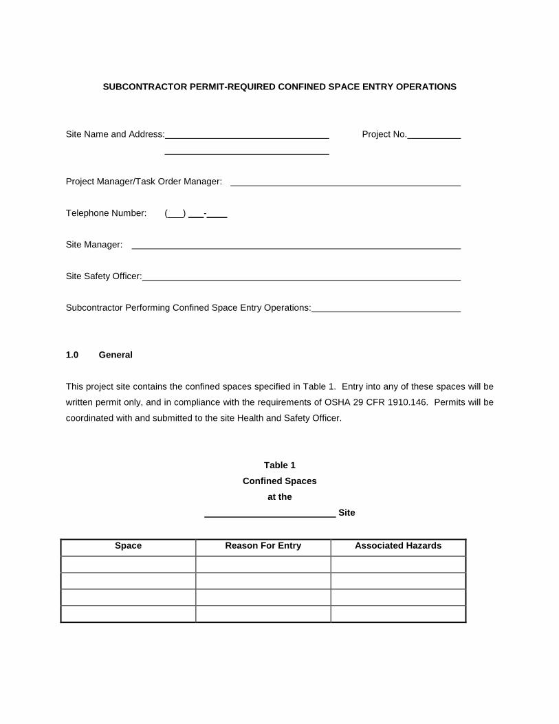
SUBCONTRACTOR PERMIT-REQUIRED CONFINED SPACE ENTRY OPERATIONS
Site Name and Address: Project No.
Project Manager/Task Order Manager:
Telephone Number: (___) ___-____
Site Manager:
Site Safety Officer:
Subcontractor Performing Confined Space Entry Operations:
1.0 General
This project site contains the confined spaces specified in Table 1. Entry into any of these spaces will be
written permit only, and in compliance with the requirements of OSHA 29 CFR 1910.146. Permits will be
coordinated with and submitted to the site Health and Safety Officer.
Table 1
Confined Spaces
at the
Site
Space Reason For Entry Associated Hazards

2.0 Space Description and History (Note to SSO: this section must be filled out for EACH space to
be entered by the subcontractor personnel. Attach additional pages to this program as appropriate.)
The nature of the work to be performed by
(name of subcontractor)
is
This will involve/require entry into
(description of space)
The hazards recognized or anticipated with this space include or may include (check and describe at
apply):
a hazardous atmosphere involving
Material that could engulf an entrant, specifically
An internal configuration such that an entrant could be trapped or asphyxiated by inwardly
converging walls or by a floor which slopes downward and tapers to a smaller cross-section
Other serious safety or health hazards
Tetra Tech has implemented the following precautions/procedures for the protection of our employees in
or near this space:
Education and training on confined space recognition Posting with “DANGER - PERMIT REQUIRED CONFINED SPACE - DO NOT ENTER” or
“DANGER - CONFINED SPACE - DO NOT ENTER” signs Other means as follows:
If Tetra Tech and will need to perform concurrent operations in or
near the space, activities will be conducted in accordance with the following coordinated system:

3.0 Subcontractor Debrief
Work was concluded on / / . The following confined space hazards were confronted or
created during entry operations.
Problems encountered in administering or complying with the site Confined Space Entry Program were as
follows:
Suggestions for improvements of this program discussed during the debrief included
Signature of Subcontractor Agent SSO Signature

ATTACHMENT IX
HEAVY EQUIPMENT INSPECTIONCHECKLIST

Heavy Equipment Inspection Checklist
Company: Unit/Serial No#:
Inspection Date: / / Time: : Equipment Type:(e.g., earthmoving equipment - tractors backhoes, bulldozers, etc.)
Project Name: Project No#:
Yes No NA Requirements Comments
Seat Belts Are available for intended operator and passengers (where applicable) Seat Belts are operational?
Roll-Over Protection (ROPS) Roll-over protection structures (ROPS) are provided on vehicles and heavy
equipment (including scrapers, tractors, loaders, bulldozers, carryalls, etc.)
Brakes Brake systems capable of stopping and holding fully loaded equipment Parking Brake functions properly Wheel Chocks available (where and as applicable)
Access Non-slip steps Grab Handles (3-Point Grab/Step Mounting Points)
Audible Alarms Audible alarms – All bidirectional machines, such as rollers, compacters, front-
end loaders, bulldozers, and similar equipment, shall be equipped with a horn,distinguishable from the surrounding noise level, which shall be operated asneeded when the machine is moving in either direction.
Back up Alarms – All self propelled equipment with an obstructed view to the rearwill be equipped with a reverse gear signal alarm distinguishable from thesurrounding noise level.
Horn functioning properly

Yes No NA Requirements Comments
Highway Use Fenders for equipment that can exceed 15mph Fire Extinguisher Are exhaust emissions directed away from the Operator? Cab
- Clean, free from debris, tools or equipment that can interfere with footControl.
- Free from storage of flammable material/solvents Mirrors, Safety glass
- Equipped with defrosters- Windshield wipers
Turn signals, lights, brake lights, etc. (front/rear) for equipment approved forhighway use?
Gauges functioning properly Tires (Tread) or tracks Steering (standard and emergency) Are tools and material secured to prevent movement during transport?
Fluid Levels: Engine oil Transmission fluid Brake fluid Cooling system fluid Hoses and belts Hydraulic oil
Fueling Fueling of vehicles and heavy equipment is done with the engine off. No smoking is permitted at or near the fuel storage or refueling area. A sign is
posted stating: NO SMOKING WITHIN 50 FEET. No sources of ignition are present near the fuel storage or refueling area. A dry chemical or carbon dioxide fire extinguisher (rated 6:BC or larger) is in a
location accessible to the fueling area, no closer than 50-feet. Safety cans available?

Yes No NA Requirements Comments
Safety Guards – Around rotating apparatus (belts, pulleys, sprockets, spindles, drums, flywheels,
chains) all points of operations protected from accidental contact? Hot pipes and surfaces are protected from accidental contact? High pressure pneumatic lines have safety cable to prevent thrashing should it
become disconnected?Attachments
Have the attachments designed for use (as per manufacturer’s recommendation)with this equipment been inspected and are considered suitable for use?
Operator Qualifications Does the operator have proper licensing where applicable, (e.g., CDL)? Does the operator, understand the equipment’s operating instructions? Is the operator experienced with this equipment? Is the operator 21 years of age or more?
PPE Required Hardhat Safety glasses Work gloves Chemical resistant gloves Steel toed Work Boots Chemical resistant Boot Covers Apron Coveralls Tyvek, Saranex, cotton)
Key(s)?Operating Manual?Other Hazards
Excessive Noise Levels dBA Chemical hazards (Drilling supplies - Sand, bentonite, grout, fuel, etc.)
- MSDSs available?
Approved for Use Yes No See Comments
Site Health and Safety Officer Operator

ATTACHMENT X
OSHA HEALTH & SAFETYCONSTRUCTION-RELATED
REGULATIONS - P - 650 TO 699SUBPART P - EXCAVATIONS

OSHA Health & Safety Construction-related
Regulations - P - 650 to 699
Subpart P - Excavations
§ 1926.650 - Scope, application, and definitions applicable to this subpart.
(a) Scope and application. This subpart applies to all open excavations made in the earth's surface. Excavations are defined to include trenches.
(b) Definitions applicable to this subpart.
Accepted engineering practices means those requirements which are compatible with standards of practice required by a registered professional engineer.
Aluminum Hydraulic Shoring means a pre-engineered shoring system comprised of aluminum hydraulic cylinders (crossbraces) used in conjunction with vertical rails (uprights) or horizontal rails (wales). Such system is designed specifically to support the sidewalls of an excavation and prevent cave-ins.
Bell-bottom pier hole means a type of shaft or footing excavation, the bottom of which is made larger than the cross section above to form a belled shape.
Benching (Benching system) means a method of protecting employees from cave-ins by excavating the sides of an excavation to form one or a series of horizontal levels or steps, usually with vertical or near-vertical surfaces between levels.
Cave-in means the separation of a mass of soil or rock material from the side of an excavation, or the loss of soil from under a trench shield or support system, and its sudden movement into the excavation, either by falling or sliding, in sufficient quantity so that it could entrap, bury, or other wise injure and immobilize a person.
Competent person means one who is capable of identifying existing and predictable hazards in the surroundings, or working conditions which are unsanitary, hazardous, or dangerous to employees, and who has authorization to take prompt corrective measures to eliminate them.
Cross braces mean the horizontal members of a shoring system installed perpendicular to the sides of the excavation, the ends of which bear against either uprights or wales.
Excavation means any man-made cut, cavity, trench, or depression in an earth surface, formed by earth removal.

Faces or sides means the vertical or inclined earth surfaces formed as a result of excavation work.
Failure means the breakage, displacement, or permanent deformation of a structural member or connection so as to reduce its structural integrity and its supportive capabilities.
Hazardous atmosphere means an atmosphere which by reason of being explosive, flammable, poisonous, corrosive, oxidizing, irritating, oxygen deficient, toxic, or otherwise harmful, may cause death, illness, or injury.
Kickout means the accidental release or failure of a cross brace.
Protective system means a method of protecting employees from cave-ins, from material that could fall or roll from an excavation face or into an excavation, or from the collapse of adjacent structures. Protective systems include support systems, sloping and benching systems, shield systems, and other systems that provide the necessary protection.
Ramp means an inclined walking or working surface that is used to gain access to one point from another, and is constructed from earth or from structural materials such as steel or wood.
Registered Professional Engineer means a person who is registered as a professional engineer in the state where the work is to be performed. However, a professional engineer, registered in any state is deemed to be a "registered professional engineer" within the meaning of this standard when approving designs for "manufactured protective systems" or "tabulated data" to be used in interstate commerce.
Sheeting means the members of a shoring system that retain the earth in position and in turn are supported by other members of the shoring system.
Shield (Shield system) means a structure that is able to withstand the forces imposed on it by a cave-in and thereby protect employees within the structure. Shields can be permanent structures or can be designed to be portable and moved along as work progresses. Additionally, shields can be either premanufactured or job-built in accordance with 1926.652(c)(3) or (c)(4). Shields used in trenches are usually referred to as "trench boxes" or "trench shields."
Shoring (Shoring system) means a structure such as a metal hydraulic, mechanical or timber shoring system that supports the sides of an excavation and which is designed to prevent cave-ins.
Sides. See "Faces."
Sloping (Sloping system) means a method of protecting employees from cave-ins by excavating to form sides of an excavation that are inclined away from the excavation so as to prevent cave-ins. The angle of incline required to prevent a cave-in varies with differences in such factors as the soil type, environmental conditions of exposure, and application of surcharge loads.
Stable rock means natural solid mineral material that can be excavated with vertical sides and will remain intact while exposed. Unstable rock is considered to be stable when the rock material on the side or sides of the excavation is secured against caving-in or movement by rock bolts or by another protective system that has been designed by a registered professional engineer.
Structural ramp means a ramp built of steel or wood, usually used for vehicle access. Ramps made of soil or rock are not considered structural ramps.

Support system means a structure such as underpinning, bracing, or shoring, which provides support to an adjacent structure, underground installation, or the sides of an excavation.
Tabulated data means tables and charts approved by a registered professional engineer and used to design and construct a protective system.
Trench (Trench excavation) means a narrow excavation (in relation to its length) made below the surface of the ground. In general, the depth is greater than the width, but the width of a trench (measured at the bottom) is not greater than 15 feet (4.6 m). If forms or other structures are installed or constructed in an excavation so as to reduce the dimension measured from the forms or structure to the side of the excavation to 15 feet (4.6 m) or less (measured at the bottom of the excavation), the excavation is also considered to be a trench.
Trench box. See "Shield."
Trench shield. See "Shield."
Uprights means the vertical members of a trench shoring system placed in contact with the earth and usually positioned so that individual members do not contact each other. Uprights placed so that individual members are closely spaced, in contact with or interconnected to each other, are often called "sheeting."
Wales means horizontal members of a shoring system placed parallel to the excavation face whose sides bear against the vertical members of the shoring system or earth.
§ 1926.651 - Specific excavation requirements.
(a) Surface encumbrances. All surface encumbrances that are located so as to create a hazard to employees shall be removed or supported, as necessary, to safeguard employees.
(b) Underground installations.
(b)(1) The estimated location of utility installations, such as sewer, telephone, fuel, electric, water lines, or any other underground installations that reasonably may be expected to be encountered during excavation work, shall be determined prior to opening an excavation.
(b)(2) Utility companies or owners shall be contacted within established or customary local response times, advised of the proposed work, and asked to establish the location of the utility underground installations prior to the start of actual excavation. When utility companies or owners cannot respond to a request to locate underground utility installations within 24 hours (unless a longer period is required by state or local law), or cannot establish the exact location of these installations,the employer may proceed, provided the employer does so with caution, and provided detection equipment or other acceptable means to locate utility installations are used.
(b)(3) When excavation operations approach the estimated location of underground installations, the exact location of the installations shall be determined by safe and acceptable means.
(b)(4) While the excavation is open, underground installations shall be protected, supported or removed as necessary to safeguard employees.
(c)(2) Means of egress from trench excavations. A stairway, ladder, ramp or other safe means of egress shall be located in trench excavations that are 4 feet (1.22 m) or more in depth so as to require no more than 25 feet (7.62 m) of lateral travel for employees.
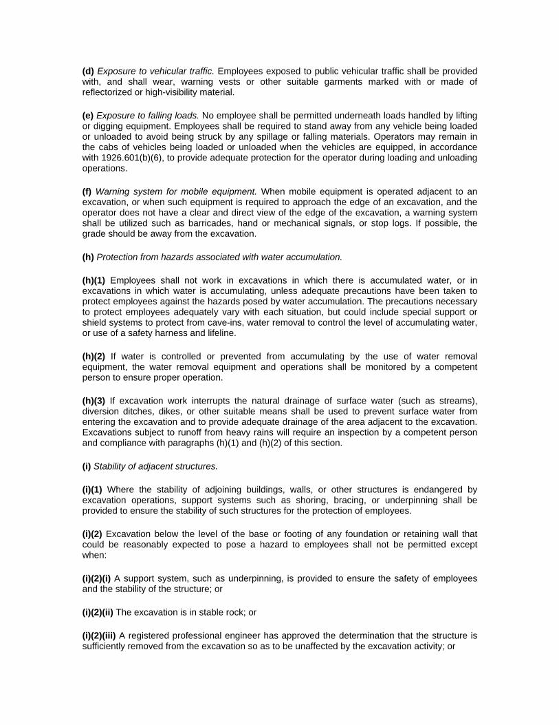
(d) Exposure to vehicular traffic. Employees exposed to public vehicular traffic shall be provided with, and shall wear, warning vests or other suitable garments marked with or made of reflectorized or high-visibility material.
(e) Exposure to falling loads. No employee shall be permitted underneath loads handled by lifting or digging equipment. Employees shall be required to stand away from any vehicle being loaded or unloaded to avoid being struck by any spillage or falling materials. Operators may remain in the cabs of vehicles being loaded or unloaded when the vehicles are equipped, in accordance with 1926.601(b)(6), to provide adequate protection for the operator during loading and unloading operations.
(f) Warning system for mobile equipment. When mobile equipment is operated adjacent to an excavation, or when such equipment is required to approach the edge of an excavation, and the operator does not have a clear and direct view of the edge of the excavation, a warning system shall be utilized such as barricades, hand or mechanical signals, or stop logs. If possible, the grade should be away from the excavation.
(h) Protection from hazards associated with water accumulation.
(h)(1) Employees shall not work in excavations in which there is accumulated water, or in excavations in which water is accumulating, unless adequate precautions have been taken to protect employees against the hazards posed by water accumulation. The precautions necessary to protect employees adequately vary with each situation, but could include special support or shield systems to protect from cave-ins, water removal to control the level of accumulating water, or use of a safety harness and lifeline.
(h)(2) If water is controlled or prevented from accumulating by the use of water removal equipment, the water removal equipment and operations shall be monitored by a competent person to ensure proper operation.
(h)(3) If excavation work interrupts the natural drainage of surface water (such as streams), diversion ditches, dikes, or other suitable means shall be used to prevent surface water from entering the excavation and to provide adequate drainage of the area adjacent to the excavation. Excavations subject to runoff from heavy rains will require an inspection by a competent person and compliance with paragraphs (h)(1) and (h)(2) of this section.
(i) Stability of adjacent structures.
(i)(1) Where the stability of adjoining buildings, walls, or other structures is endangered by excavation operations, support systems such as shoring, bracing, or underpinning shall be provided to ensure the stability of such structures for the protection of employees.
(i)(2) Excavation below the level of the base or footing of any foundation or retaining wall that could be reasonably expected to pose a hazard to employees shall not be permitted except when:
(i)(2)(i) A support system, such as underpinning, is provided to ensure the safety of employees and the stability of the structure; or
(i)(2)(ii) The excavation is in stable rock; or
(i)(2)(iii) A registered professional engineer has approved the determination that the structure is sufficiently removed from the excavation so as to be unaffected by the excavation activity; or
(i)(2)(iv) A registered professional engineer has approved the determination that such excavation work will not pose a hazard to employees.
(i)(3) Sidewalks, pavements and appurtenant structure shall not be undermined unless a support system or another method of protection is provided to protect employees from the possible collapse of such structures.
(j) Protection of employees from loose rock or soil.
(j)(1) Adequate protection shall be provided to protect employees from loose rock or soil that could pose a hazard by falling or rolling from an excavation face. Such protection shall consist of scaling to remove loose material; installation of protective barricades at intervals as necessary on the face to stop and contain falling material; or other means that provide equivalent protection.
(j)(2) Employees shall be protected from excavated or other materials or equipment that could pose a hazard by falling or rolling into excavations. Protection shall be provided by placing and keeping such materials or equipment at least 2 feet (.61 m) from the edge of excavations, or by the use of retaining devices that are sufficient to prevent materials or equipment from falling or rolling into excavations, or by a combination of both if necessary.
(k) Inspections.
(k)(1) Daily inspections of excavations, the adjacent areas, and protective systems shall be made by a competent person for evidence of a situation that could result in possible cave-ins, indications of failure of protective systems, hazardous atmospheres, or other hazardous conditions. An inspection shall be conducted by the competent person prior to the start of work and as needed throughout the shift. Inspections shall also be made after every rainstorm or other hazard increasing occurrence. These inspections are only required when employee exposure can be reasonably anticipated.
(k)(2) Where the competent person finds evidence of a situation that could result in a possible cave-in, indications of failure of protective systems, hazardous atmospheres, or other hazardous conditions, exposed employees shall be removed from the hazardous area until the necessary precautions have been taken to ensure their safety.
(l) Walkways shall be provided where employees or equipment are required or permitted to cross over excavations. Gurardrails which comply with 1926.502(b) shall be provided where walkways are 6 feet (1.8 m) or more above lower levels.
§ 1926.652 - Requirements for protective systems.
(a) Protection of employees in excavations.
(a)(1) Each employee in an excavation shall be protected from cave-ins by an adequate protective system designed in accordance with paragraph (b) or (c) of this section except when:
(a)(1)(i) Excavations are made entirely in stable rock; or
(a)(1)(ii) Excavations are less than 5 feet (1.52 m) in depth and examination of the ground by a competent person provides no indication of a potential cave-in.
(a)(2) Protective systems shall have the capacity to resist without failure all loads that are intended or could reasonably be expected to be applied or transmitted to the system.

(b) Design of sloping and benching systems. The slopes and configurations of sloping and benching systems shall be selected and constructed by the employer or his designee and shall be in accordance with the requirements of paragraph (b)(1); or, in the alternative, paragraph (b)(2); or, in the alternative, paragraph (b)(3); or, in the alternative, paragraph (b)(4), as follows:
(b)(1) Option (1) - Allowable configurations and slopes.
(b)(1)(i) Excavations shall be sloped at an angle not steeper than one and one-half horizontal to one vertical (34 degrees measured from the horizontal), unless the employer uses one of the other options listed below.
(b)(1)(ii) Slopes specified in paragraph (b)(1)(i) of this section, shall be excavated to form configurations that are in accordance with the slopes shown for Type C soil in Appendix B to this subpart.
(b)(2) Option (2) - Determination of slopes and configurations using Appendices A and B. Maximum allowable slopes, and allowable configurations for sloping and benching systems, shall be determined in accordance with the conditions and requirements set forth in appendices A and B to this subpart.
(b)(4) Option (4) - Design by a registered professional engineer.
(b)(4)(i) Sloping and benching systems not utilizing Option (1) or Option (2) or Option (3) under paragraph (b) of this section shall be approved by a registered professional engineer.
(b)(4)(ii) Designs shall be in written form and shall include at least the following:
(b)(4)(ii)(A) The magnitude of the slopes that were determined to be safe for the particular project;
(b)(4)(ii)(B) The configurations that were determined to be safe for the particular project;
(b)(4)(ii)(C) The identity of the registered professional engineer approving the design.
(b)(4)(iii) At least one copy of the design shall be maintained at the jobsite while the slope is being constructed. After that time the design need not be at the jobsite, but a copy shall be made available to the Secretary upon request.
(c) Design of support systems, shield systems, and other protective systems. Designs of support systems, shield systems, and other protective systems shall be selected and constructed by the employer or his designee and shall be in accordance with the requirements of paragraph (c)(2) as follows:
(c)(2) Option (2) - Designs Using Manufacturer's Tabulated Data.
(c)(2)(i) Design of support systems, shield systems, or other protective systems that are drawn from manufacturer's tabulated data shall be in accordance with all specifications, recommendations, and limitations issued or made by the manufacturer.
(c)(2)(ii) Deviation from the specifications, recommendations, and limitations issued or made by the manufacturer shall only be allowed after the manufacturer issues specific written approval.

(c)(2)(iii) Manufacturer's specifications, recommendations, and limitations, and manufacturer's approval to deviate from the specifications, recommendations, and limitations shall be in written form at the jobsite during construction of the protective system. After that time this data may be stored off the jobsite, but a copy shall be made available to the Secretary upon request.
(e) Installation and removal of support-
(e)(1) General.
(e)(1)(i) Members of support systems shall be securely connected together to prevent sliding, falling, kickouts, or other predictable failure.
(e)(1)(ii) Support systems shall be installed and removed in a manner that protects employees from cave-ins, structural collapses, or from being struck by members of the support system.
(e)(1)(iii) Individual members of support systems shall not be subjected to loads exceeding those which those members were designed to withstand.
(e)(1)(iv) Before temporary removal of individual members begins, additional precautions shall be taken to ensure the safety of employees, such as installing other structural members to carry the loads imposed on the support system.
(e)(1)(v) Removal shall begin at, and progress from, the bottom of the excavation. Members shall be released slowly so as to note any indication of possible failure of the remaining members of the structure or possible cave-in of the sides of the excavation.
(e)(1)(vi) Backfilling shall progress together with the removal of support systems from excavations.
(e)(2) Additional requirements for support systems for trench excavations.
(e)(2)(i) Excavation of material to a level no greater than 2 feed (.61 m) below the bottom of the members of a support system shall be permitted, but only if the system is designed to resist the forces calculated for the full depth of the trench, and there are no indications while the trench is open of a possible loss of soil from behind or below the bottom of the support system.
(e)(2)(ii) Installation of a support system shall be closely coordinated with the excavation of trenches.
(f) Sloping and benching systems. Employees shall not be permitted to work on the faces of sloped or benched excavations at levels above other employees except when employees at the lower levels are adequately protected from the hazard of falling, rolling, or sliding material or equipment.
(g) Shield systems.
(g)(1) General.
(g)(1)(i) Shield systems shall not be subjected to loads exceeding those which the system was designed to withstand.

(g)(1)(ii) Shields shall be installed in a manner to restrict lateral or other hazardous movement of the shield in the event of the application of sudden lateral loads.
(g)(1)(iii) Employees shall be protected from the hazard of cave-ins when entering or exiting the areas protected by shields.
(g)(1)(iv) Employees shall not be allowed in shields when shields are being installed, removed, or moved vertically.
(g)(2) Additional requirement for shield systems used in trench excavations. Excavations of earth material to a level not greater than 2 feet (.61 m) below the bottom of a shield shall be permitted, but only if the shield is designed to resist the forces calculated for the full depth of the trench, and there are no indications while the trench is open of a possible loss of soil from behind or below the bottom of the shield.
Subpart P Appendix A - Soil Classification
(a) Scope and application.
(a)(1) Scope. This appendix describes a method of classifying soil and rock deposits based on site and environmental conditions, and on the structure and composition of the earth deposits. The appendix contains definitions, sets forth requirements, and describes acceptable visual and manual tests for use in classifying soils.
(a)(2) Application. This appendix applies when a sloping or benching system is designed in accordance with the requirements set forth in 1926.652(b)(2) as a method of protection for employees from cave-ins. This appendix also applies when timber shoring for excavations is designed as a method of protection from cave-ins in accordance with appendix C to subpart P of part 1926, and when aluminum hydraulic shoring is designed in accordance with appendix D. This Appendix also applies if other protective systems are designed and selected for use from data prepared in accordance with the requirements set forth in 1926.652(c), and the use of the data is predicated on the use of the soil classification system set forth in this appendix.
(b) Definitions. The definitions and examples given below are based on, in whole or in part, the following; American Society for Testing Materials (ASTM) Standards D653-85 and D2488; The Unified Soils Classification System; The U.S. Department of Agriculture (USDA) Textural Classification Scheme; and The National Bureau of Standards Report BSS-121.
Cemented soil means a soil in which the particles are held together by a chemical agent, such as calcium carbonate, such that a hand-size sample cannot be crushed into powder or individual soil particles by finger pressure.
Cohesive soil means clay (fine grained soil), or soil with a high clay content, which has cohesive strength. Cohesive soil does not crumble, can be excavated with vertical sideslopes, and is plastic when moist. Cohesive soil is hard to break up when dry, and exhibits significant cohesion when submerged. Cohesive soils include clayey silt, sandy clay, silty clay, clay and organic clay.
Dry soil means soil that does not exhibit visible signs of moisture content.
Fissured means a soil material that has a tendency to break along definite planes of fracture with little resistance, or a material that exhibits open cracks, such as tension cracks, in an exposed surface.

Granular soil means gravel, sand, or silt (coarse grained soil) with little or no clay content. Granular soil has no cohesive strength. Some moist granular soils exhibit apparent cohesion. Granular soil cannot be molded when moist and crumbles easily when dry.
Layered system means two or more distinctly different soil or rock types arranged in layers. Micaceous seams or weakened planes in rock or shale are considered layered.
Moist soil means a condition in which a soil looks and feels damp. Moist cohesive soil can easily be shaped into a ball and rolled into small diameter threads before crumbling. Moist granular soil that contains some cohesive material will exhibit signs of cohesion between particles.
Plastic means a property of a soil which allows the soil to be deformed or molded without cracking, or appreciable volume change.
Saturated soil means a soil in which the voids are filled with water. Saturation does not require flow. Saturation, or near saturation, is necessary for the proper use of instruments such as a pocket penetrometer or sheer vane.
Soil classification system means, for the purpose of this subpart, a method of categorizing soil and rock deposits in a hierarchy of Stable Rock, Type A, Type B, and Type C, in decreasing order of stability. The categories are determined based on an analysis of the properties and performance characteristics of the deposits and the environmental conditions of exposure.
Stable rock means natural solid mineral matter that can be excavated with vertical sides and remain intact while exposed.
Submerged soil means soil which is underwater or is free seeping.
Type A means cohesive soils with an unconfined, compressive strength of 1.5 ton per square foot (tsf) (144 kPa) or greater. Examples of cohesive soils are: clay, silty clay, sandy clay, clay loam and, in some cases, silty clay loam and sandy clay loam. Cemented soils such as caliche and hardpan are also considered Type A. However, no soil is Type A if: (i) The soil is fissured; or (ii) The soil is subject to vibration from heavy traffic, pile driving, or similar effects; or (iii) The soil has been previously disturbed; or (iv) The soil is part of a sloped, layered system where the layers dip into the excavation on a slope of four horizontal to one vertical (4H:1V) or greater; or (v) The material is subject to other factors that would require it to be classified as a less stable material.
Type B means: (i) Cohesive soil with an unconfined compressive strength greater than 0.5 tsf (48 kPa) but less than 1.5 tsf (144 kPa); or (ii) Granular cohesionless soils including: angular gravel (similar to crushed rock), silt, silt loam, sandy loam and, in some cases, silty clay loam and sandy clay loam. (iii) Previously disturbed soils except those which would otherwise be classed as Type C soil. (iv) Soil that meets the unconfined compressive strength or cementation requirements for Type A, but is fissured or subject to vibration; or (v) Dry rock that is not stable; or (vi) Material that is part of a sloped, layered system where the layers dip into the excavation on a slope less steep than four horizontal to one vertical (4H:1V), but only if the material would otherwise be classified as Type B.
Type C means: (i) Cohesive soil with an unconfined compressive strength of 0.5 tsf (48kPa) or less; or (ii) Granular soils including gravel, sand, and loamy sand; or (iii) Submerged soil or soil from which water is freely seeping; or (iv) Submerged rock that is not stable, or (v) Material in a sloped, layered system where the layers dip into the excavation or a slope of four horizontal to one vertical (4H:1V) or steeper.

Unconfined compressive strength means the load per unit area at which a soil will fail in compression. It can be determined by laboratory testing, or estimated in the field using a pocket penetrometer, by thumb penetration tests, and other methods.
Wet soil means soil that contains significantly more moisture than moist soil, but in such a range of values that cohesive material will slump or begin to flow when vibrated. Granular material that would exhibit cohesive properties when moist will lose those cohesive properties when wet.
(c) Requirements
(c)(1) Classification of soil and rock deposits. Each soil and rock deposit shall be classified by a competent person as Stable Rock, Type A, Type B, or Type C in accordance with the definitions set forth in paragraph (b) of this appendix.
(c)(2) Basis of classification. The classification of the deposits shall be made based on the results of at least one visual and at least one manual analysis. Such analyses shall be conducted by a competent person using tests described in paragraph (d) below, or in other recognized methods of soil classification and testing such as those adopted by the American Society for Testing Materials, or the U.S. Department of Agriculture textural classification system.
(c)(3) Visual and manual analyses. The visual and manual analyses, such as those noted as being acceptable in paragraph (d) of this appendix, shall be designed and conducted to provide sufficient quantitative and qualitative information as may be necessary to identify properly the properties, factors, and conditions affecting the classification of the deposits.
(c)(4) Layered systems. In a layered system, the system shall be classified in accordance with its weakest layer. However, each layer may be classified individually where a more stable layer lies under a less stable layer.
(c)(5) Reclassification. If, after classifying a deposit, the properties, factors, or conditions affecting its classification change in any way, the changes shall be evaluated by a competent person. The deposit shall be reclassified as necessary to reflect the changed circumstances.
(d) Acceptable visual and manual tests.-
(d)(1) Visual tests. Visual analysis is conducted to determine qualitative information regarding the excavation site in general, the soil adjacent to the excavation, the soil forming the sides of the open excavation, and the soil taken as samples from excavated material.
(d)(1)(i) Observe samples of soil that are excavated and soil in the sides of the excavation. Estimate the range of particle sizes and the relative amounts of the particle sizes. Soil that is primarily composed of fine-grained material material is cohesive material. Soil composed primarily of coarse-grained sand or gravel is granular material.
(d)(1)(ii) Observe soil as it is excavated. Soil that remains in clumps when excavated is cohesive. Soil that breaks up easily and does not stay in clumps is granular.
(d)(1)(iii) Observe the side of the opened excavation and the surface area adjacent to the excavation. Crack-like openings such as tension cracks could indicate fissured material. If chunks of soil spall off a vertical side, the soil could be fissured. Small spalls are evidence of moving ground and are indications of potentially hazardous situations.
(d)(1)(iv) Observe the area adjacent to the excavation and the excavation itself for evidence of existing utility and other underground structures, and to identify previously disturbed soil.
(d)(1)(v) Observed the opened side of the excavation to identify layered systems. Examine layered systems to identify if the layers slope toward the excavation. Estimate the degree of slope of the layers.
(d)(1)(vi) Observe the area adjacent to the excavation and the sides of the opened excavation for evidence of surface water, water seeping from the sides of the excavation, or the location of the level of the water table.
(d)(1)(vii) Observe the area adjacent to the excavation and the area within the excavation for sources of vibration that may affect the stability of the excavation face.
(d)(2) Manual tests. Manual analysis of soil samples is conducted to determine quantitative as well as qualitative properties of soil and to provide more information in order to classify soil properly.
(d)(2)(i) Plasticity. Mold a moist or wet sample of soil into a ball and attempt to roll it into threads as thin as 1/8-inch in diameter. Cohesive material can be successfully rolled into threads without crumbling. For example, if at least a two inch (50 mm) length of 1/8-inch thread can be held on one end without tearing, the soil is cohesive.
(d)(2)(ii) Dry strength. If the soil is dry and crumbles on its own or with moderate pressure into individual grains or fine powder, it is granular (any combination of gravel, sand, or silt). If the soil is dry and falls into clumps which break up into smaller clumps, but the smaller clumps can only be broken up with difficulty, it may be clay in any combination with gravel, sand or silt. If the dry soil breaks into clumps which do not break up into small clumps and which can only be broken with difficulty, and there is no visual indication the soil is fissured, the soil may be considered unfissured.
(d)(2)(iii) Thumb penetration. The thumb penetration test can be used to estimate the unconfined compressive strength of cohesive soils. (This test is based on the thumb penetration test described in American Society for Testing and Materials (ASTM) Standard designation D2488 - "Standard Recommended Practice for Description of Soils (Visual - Manual Procedure).") Type A soils with an unconfined compressive strength of 1.5 tsf can be readily indented by the thumb; however, they can be penetrated by the thumb only with very great effort. Type C soils with an unconfined compressive strength of 0.5 tsf can be easily penetrated several inches by the thumb, and can be molded by light finger pressure. This test should be conducted on an undisturbed soil sample, such as a large clump of spoil, as soon as practicable after excavation to keep to a minimum the effects of exposure to drying influences. If the excavation is later exposed to wetting influences (rain, flooding), the classification of the soil must be changed accordingly.
(d)(2)(iv) Other strength tests. Estimates of unconfined compressive strength of soils can also be obtained by use of a pocket penetrometer or by using a hand-operated shearvane.
(d)(2)(v) Drying test. The basic purpose of the drying test is to differentiate between cohesive material with fissures, unfissured cohesive material, and granular material. The procedure for the drying test involves drying a sample of soil that is approximately one inch thick (2.54 cm) and six inches (15.24 cm) in diameter until it is thoroughly dry:
(d)(2)(v)(A) If the sample develops cracks as it dries, significant fissures are indicated.

(d)(2)(v)(B) Samples that dry without cracking are to be broken by hand. If considerable force is necessary to break a sample, the soil has significant cohesive material content. The soil can be classified as an unfissured cohesive material and the unconfined compressive strength should be determined.
(d)(2)(v)(C) If a sample breaks easily by hand, it is either a fissured cohesive material or a granular material. To distinguish between the two, pulverize the dried clumps of the sample by hand or by stepping on them. If the clumps do not pulverize easily, the material is cohesive with fissures. If they pulverize easily into very small fragments, the material is granular.
Subpart P Appendix B - Sloping and Benching
(a) Scope and application. This appendix contains specifications for sloping and benching when used as methods of protecting employees working in excavations from cave-ins. The requirements of this appendix apply when the design of sloping and benching protective systems is to be performed in accordance with the requirements set forth in 1926.652(b)(2).
(b) Definitions.
Actual slope means the slope to which an excavation face is excavated.
Distress means that the soil is in a condition where a cave-in is imminent or is likely to occur. Distress is evidenced by such phenomena as the development of fissures in the face of or adjacent to an open excavation; the subsidence of the edge of an excavation; the slumping of material from the face or the bulging or heaving of material from the bottom of an excavation; the spalling of material from the face of an excavation; and ravelling, i.e., small amounts of material such as pebbles or little clumps of material suddenly separating from the face of an excavation and trickling or rolling down into the excavation.
Maximum allowable slope means the steepest incline of an excavation face that is acceptable for the most favorable site conditions as protection against cave-ins, and is expressed as the ratio of horizontal distance to vertical rise (H:V).
Short term exposure means a period of time less than or equal to 24 hours that an excavation is open.
(c) Requirements -
(c)(1) Soil classification. Soil and rock deposits shall be classified in accordance with appendix A to subpart P of part 1926.
(c)(2) Maximum allowable slope. The maximum allowable slope for a soil or rock deposit shall be determined from Table B-1 of this appendix.
(c)(3) Actual slope.
(c)(3)(i) The actual slope shall not be steeper than the maximum allowable slope.
(c)(3)(ii) The actual slope shall be less steep than the maximum allowable slope, when there are signs of distress. If that situation occurs, the slope shall be cut back to an actual slope which is at least 1/2 horizontal to one vertical (1/2H:1V) less steep than the maximum allowable slope.
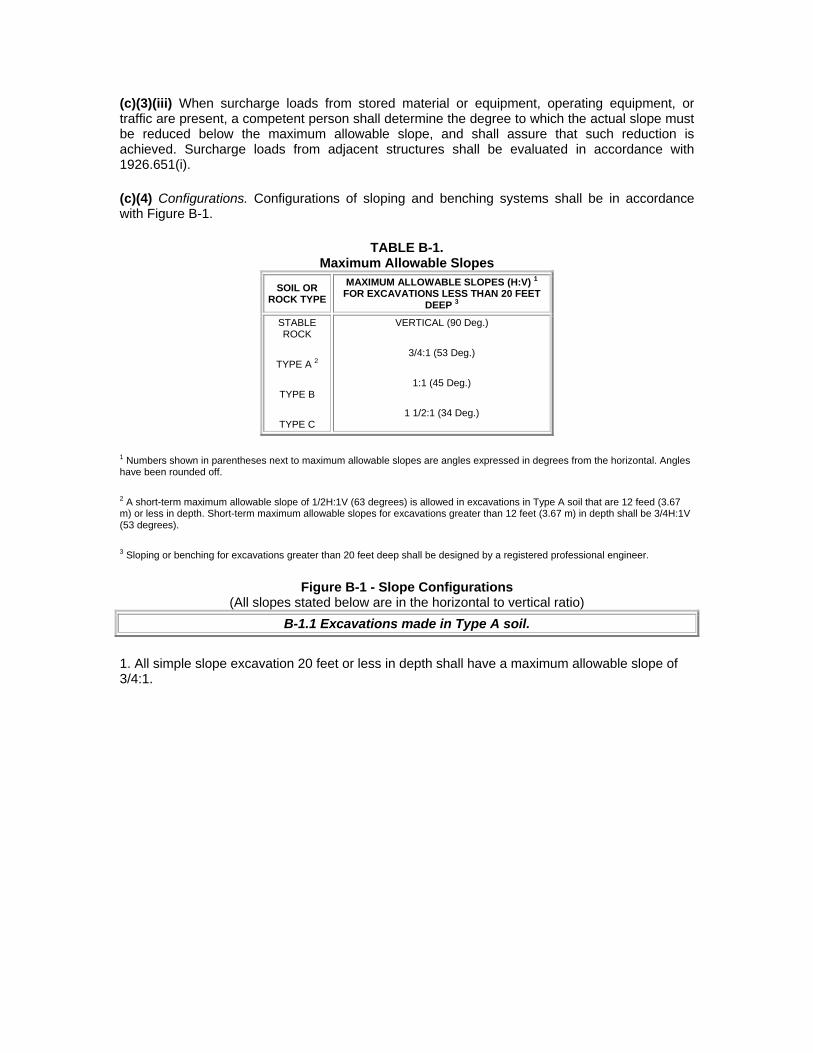
(c)(3)(iii) When surcharge loads from stored material or equipment, operating equipment, or traffic are present, a competent person shall determine the degree to which the actual slope must be reduced below the maximum allowable slope, and shall assure that such reduction is achieved. Surcharge loads from adjacent structures shall be evaluated in accordance with 1926.651(i).
(c)(4) Configurations. Configurations of sloping and benching systems shall be in accordance with Figure B-1.
TABLE B-1. Maximum Allowable Slopes
SOIL OR ROCK TYPE
MAXIMUM ALLOWABLE SLOPES (H:V) 1 FOR EXCAVATIONS LESS THAN 20 FEET
DEEP 3 STABLE ROCK
TYPE A 2
TYPE B
TYPE C
VERTICAL (90 Deg.)
3/4:1 (53 Deg.)
1:1 (45 Deg.)
1 1/2:1 (34 Deg.)
1 Numbers shown in parentheses next to maximum allowable slopes are angles expressed in degrees from the horizontal. Angles have been rounded off. 2 A short-term maximum allowable slope of 1/2H:1V (63 degrees) is allowed in excavations in Type A soil that are 12 feed (3.67 m) or less in depth. Short-term maximum allowable slopes for excavations greater than 12 feet (3.67 m) in depth shall be 3/4H:1V (53 degrees). 3 Sloping or benching for excavations greater than 20 feet deep shall be designed by a registered professional engineer.
Figure B-1 - Slope Configurations (All slopes stated below are in the horizontal to vertical ratio)
B-1.1 Excavations made in Type A soil.
1. All simple slope excavation 20 feet or less in depth shall have a maximum allowable slope of 3/4:1.
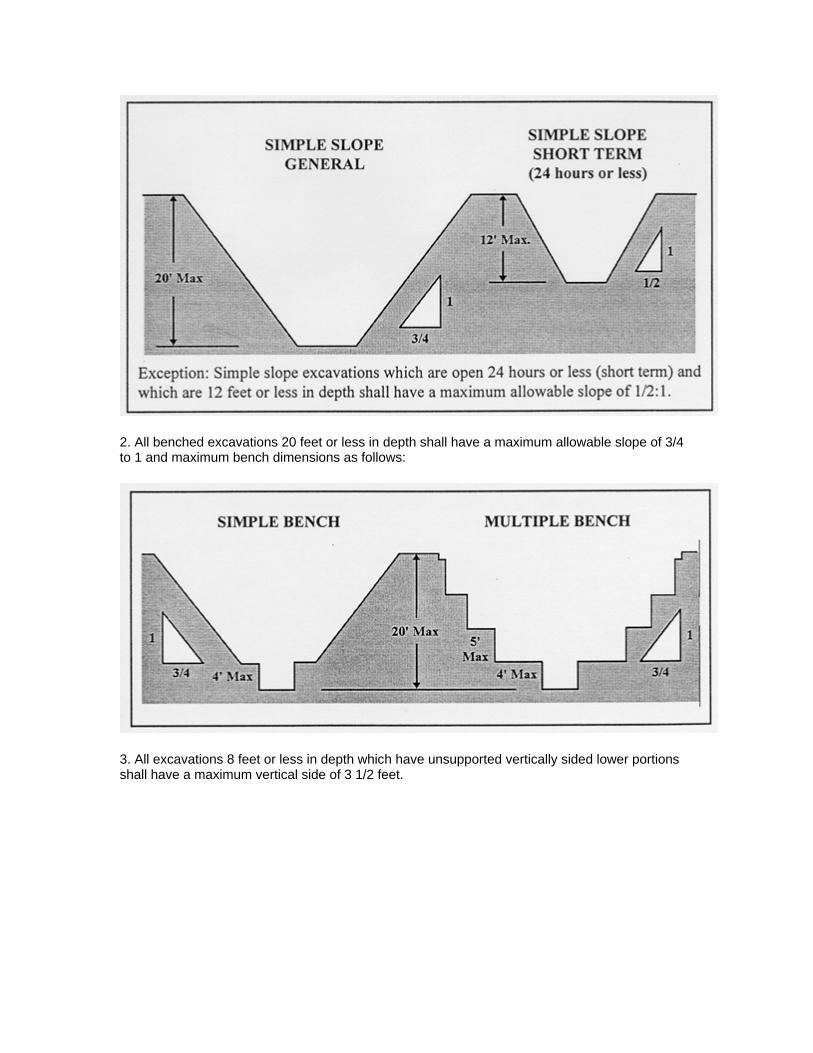
2. All benched excavations 20 feet or less in depth shall have a maximum allowable slope of 3/4 to 1 and maximum bench dimensions as follows:
3. All excavations 8 feet or less in depth which have unsupported vertically sided lower portions shall have a maximum vertical side of 3 1/2 feet.

4. All other simple slope, compound slope, and vertically sided lower portion excavations shall be in accordance with the other options permitted under 1926.652(b).
B-1.2 Excavations made in Type B soil.
1. All simple slope excavations 20 feet or less in depth shall have a maximum allowable slope of 1:1.

2. All benched excavations 20 feet or less in depth shall have a maximum allowable slope of 1:1 and maximum bench dimensions as follows:
3. All excavations 20 feet or less in depth which have vertically sided lower portions shall be shielded or supported to a height at least 18 inches above the top of the vertical side. All such excavations shall have a maximum allowable slope of 1:1.
4. All other sloped excavations shall be in accordance with the other options permitted in 1926.652(b).
B-1.3 Excavations made in Type C soil.
1. All simple slope excavations 20 feet or less in depth shall have a maximum allowable slope of 1 1/2:1.

2. All excavations 20 feet or less in depth which have vertically sided lower portions shall be shielded or supported to a height at least 18 inches above the top of the vertical side. All such excavations shall have a maximum allowable slope of 1 1/2:1.
3. All other sloped excavations shall be in accordance with the other options permitted in 1926.652(b).
B-1.4 Excavations made in Layered Soils
1. All excavations 20 feet or less in depth made in layered soils shall have a maximum allowable slope for each layer as set forth below.
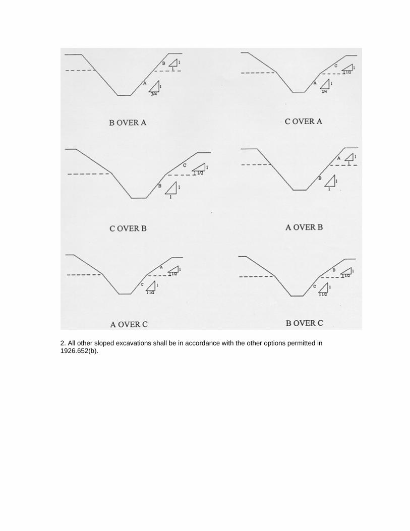
2. All other sloped excavations shall be in accordance with the other options permitted in 1926.652(b).

Insert OSHA regulations

ATTACHMENT XI
TETRA TECH DECONTAMINATION OFFIELD EQUIPMENT AND WASTE
HANDLING STANDARD OPERATINGPROCEDURE

TETRA TECH NUS. INC .
STANDARD Number Page
Effective Date Revision
SA-7.1 1 o f 8
09/03 3
Subject DECONTAMINATION OF FIELD EQUIPMENT
PROCEDURES
Approved a- D . Senovich
Tetra Tech NUS. Inc .
Earth Sciences DeDartment Prepared
TABLE OF CONTENTS
SECTION PAGE
1.0 PURPOSE ........................................................................................................................................ 2
2.0 SCOPE ............................................................................................................................................. 2
3.0 GLOSSARY ..................................................................................................................................... 2
4.0 RESPONSIBILITIES ........................................................................................................................ 3
5.0 PROCEDURES ................................................................................................................................ 3
5.1 DECONTAMINATION DESIGN/CONSTRUCTIONS CONSIDERATIONS .................... 3 5.1 . 1 5.1 . 2 Decontamination Activities at Drill Rigs/DPT Units ......................................................... 4 5.1 . 3 Decontamination Activities at Remote Sample Locations ............................................... 5 5.2 EQUIPMENT DECONTAMINATION PROCEDURES .................................................... 5 5.2.1 Monitoring Well Sampling Equipment ............................................................................. 5 5.2.2 Down-Hole Drilling Equipment ........................................................................................ 6 5.2.3 Soil/Sediment Sampling Equipment ................................................................................ 6 5.3 CONTACT W ASTE/M ATER I ALS ................................................................................... 7 5.3.1 Decontamination Solutions .............................................................................................. 7 5.4 DECONTAMINATION EVALUATION ............................................................................. 7
Temporary Decontamination Pads .................................................................................. 3
01 961 1 /P Tetra Tech NUS. Inc .

Subject DECONTAMINATION OF FIELD Number
Revision EQUIPMENT SA-7.1
3
1 .o PURPOSE
Page
Effective Date
2 of 8
09/03
Decontamination is the process of removing and/or neutralizing site contaminants that have contacted and/or accumulated on equipment. The objective/purpose of this SOP is intended to protect site personnel, general public, and the sample integrity through the prevention of cross contamination onto unaffected persons or areas. It is further intended through this procedure to provide guidelines regarding the appropriate procedures to be followed when decontaminating drilling equipment, monitoring well materials, chemical sampling equipment and field analytical equipment.
2.0 SCOPE
This procedure applies to all equipment including drilling equipment, heavy equipment, monitoring well materials, as well as chemical sampling and field analytical equipment decontamination that may be used to provide access/acquire environmental samples. Where technologically and economically feasible, single use sealed disposable equipment will be employed 'to minimize the potential for cross contamination. This procedure also provides general reference information on the control of contaminated materials.
3.0 GLOSSARY
Acid - For decontamination of equipment when sampling for trace levels of inorganics, a 10% solution of nitric acid in deionized water should be used. Due to the leaching ability of nitric acid, it should not be used on stainless steel.
Alconox/Liauinox - A brand of phosphate-free laboratory-grade detergent.
Decontamination Solution - Is a solution selectedhdentified within the Health and Safety Plan or Project- Specific Quality Assurance Plan. The solution is selected and employed as directed by the project chemistlhealth and safety professional.
Deionized Water (DI) - Deionized water is tap water that has been treated by passing through a standard deionizing resin column. This water may also pass through additional filtering media to attain various levels of analyte-free status. The DI water should meet CAP and NCCLS specifications for reagent grade, Type I water.
Potable Water - Tap water used from any municipal water treatment system. Use of an untreated potable water supply is not an acceptable substitute for tap water.
Pressure Washinq - Employs high pressure pumps and nozzle configuration to create a high pressure spray of potable water. High pressure spray is employed to remove solids.
Solvent - The solvent of choice is pesticide-grade Isopropanol. Use of other solvents (methanol, acetone, pesticide-grade hexane, or petroleum ether) may be required for particular projects or for a particular purpose (e.g. for the removal of concentrated waste) and must be justified in the project planning documents. As an example, it may be necessary to use hexane when analyzing for trace levels of pesticides, PCBs, or fuels. In addition, because many of these solvents are not miscible in water, the equipment should be air dried prior to use. Solvents should not be used on PVC equipment or well construction materials.
Steam Pressure Washinq - This method employs a high pressure spray of heated potable water. This method through the application of heat provides for the removal of various organic/inorganic compounds.
01 961 1/P Tetra Tech NUS, Inc.

Subject DECONTAMINATION OF FIELD EQUIPMENT
The decontamination processes are typically employed at:
0 Temporary Decontamination Pads/Facilities 0 Sample Locations 0 Centralized Decontamination Pad/Facilities 0 Combination of some or all of the above
The following discussion represents recommended site preparation in support of the decontamination process.
5.1 Decontamination Desiqn/Constructions Considerations
5.1.1 Temporary Decontamination Pads
Temporary decontamination pads are constructed at satellite locations in support of temporary work sites. These structures are generally constructed to support the decontamination of heavy equipment such as drill rigs and earth moving equipment but can be employed for smaller articles.
The purpose of the decontamination pad is to contain wash waters and potentially contaminated soils generated during decontamination procedures. Therefore, construction of these pads should take into account the following considerations
Number Page
Revision Effective Date
SA-7.1 3 of 8
3 09/03
01 961 1/P Tetra Tech NUS, Inc.

Subject DECONTAMINATION OF FIELD Number
Revision EQUIPMENT SA-7.1
3
0 Site Location -The site selected should be within a reasonable distance from the work site but should avoid:
Page
Effective Date
4 of 8
09/03
- PedestrianNehicle thoroughfares - -
- Areas potentially contaminated.
Areas where controVcustody cannot be maintained Areas where a potential releases may be compounded through access to storm water transport systems, streams or other potentially sensitive areas.
Pad - The pad should be constructed to provide the following characteristics
5.1.2
Size - The size of the pad should be sufficient to accept the equipment to be decontaminated as well as permitting free movement around the equipment by the personnel conducting the decontamination.
Slope - An adequate slope will be constructed to permit the collection of the water and potentially contaminated soils within a trough or sump constructed at one end. The collection point for wash waters should be of adequate distance that the decontamination workers do not have to walk through the wash waters while completing their tasks.
Sidewalls - The sidewalls should be a minimum of 6-inches in height to provide adequate containment for wash waters and soils. If splash represents a potential problem, splash guards should be constructed to control overspray. Sidewalls maybe constructed of wood, inflatables, sand bags, etc. to permit containment.
Liner - Depending on the types of equipment and the decontamination method the liner should be of sufficient thickness to provide a puncture resistant barrier between the decontamination operation and the unprotected environment. Care should be taken to examine the surface area prior to placing the liner to remove sharp articles (sticks, stones, debris) that could puncture the liner. Liners are intended to form an impermeable barrier. The thickness may vary from a minimum recommended thickness of 10 mil to 30 mil. Achieving the desired thickness maybe achieved through layering lighter constructed materials. It should be noted that various materials (rubber, polyethylene sheeting) become slippery when wet. To minimize this potential hazard associated with a sloped liner a light coating of sand maybe applied to provide traction as necessary.
Wash/drying Racks - Auger flights, driIVdrive rods require racks positioned off of the ground to permit these articles to be washed, drained, and dried while secured from falling during this process. A minimum ground clearance of 2-feet is recommended.
Maintenance - The work area should be periodically cleared of standing water, soils, and debris. This action will aid in eliminating slip, trip, and fall hazards. In addition, these articles will reduce potential backsplash and cross contamination. Hoses should be gathered when not in use to eliminate potential tripping hazards.
Decontamination Activities at Drill Rigs/DPT Units
During subsurface sampling activities including drilling and direct push activities decontamination of drive rods, Macro Core Samplers, split spoons, etc. are typically conducted at an area adjacent to the operation. Decontamination is generally accomplished using a soap/water wash and rinse utilizing buckets and brushes. This area requires sufficient preparation to accomplish the decontamination objectives.
019611/P Tetra Tech NUS, Inc.

Subject DECONTAMINATION OF FIELD EQUIPMENT
Buckets shall be placed within mortar tubs or similar secondary containment tubs to prevent splash and spills from reaching unprotected media. Drying racks will be employed as directed for temporary pads to permit parts to dry and be evaluated prior to usehe-use.
Number Page
Revision Effective Date
SA-7.1 5 of 8
3 09/03
5.1.3 Decontamination Activities at Remote Sample Locations
When sampling at remote locations sampling devices such as trowels, pumpdtubing should be evacuated of potentially contaminated media to the extent possible. This equipment should be wrapped in plastic for transport to the temporary/centralized decontamination location for final cleaning and disposition.
5.2 Equipment Decontamination Procedures
The following represents procedures to be employed for the decontamination of equipment that may have contacted and/or accumulated contamination through site investigation activities.
5.2.1 Monitoring Well Sampling Equipment
5.2.1 .I Groundwater samplinq pumps - This includes pumps inserted into the monitorinq well such as Bladder pumps, Whale pumps, Redi-Flo, reusable bailers, etc.
1)
2)
Evacuate to the extent possible, any purge water within the pump.
Scrub using soap and water and/or steam clean the outside of the pump and tubing, where applicable.
Insert the pump and tubing into a clean container of soapy water. Pump a sufficient amount of soapy water through the pump to flush any residual purge water. Once flushed, circulate soapy water through the pump to ensure the internal components are thoroughly flushed.
3)
4) Remove the pump and tubing from the container, rinse external components using tap water. Insert the pump and tubing into a clean container of tap water. Pump a sufficient amount of tap water through the pump to evacuate all of the soapy water (until clear).
5)
6)
Rinse equipment with pesticide grade isopropanol
Repeat item #4 using deionized water through the hose to flush out the tap water and solvent residue as applicable.
7 ) Drain residual deionized water to the extent possible, allow components to air dry.
8) Wrap pump in aluminum foil or a clear clean plastic bag for storage.
5.2.1.2 Electronic Water Level Indicators/Sounders/Tapes
During water level measurements, rinsing with the extracted tape and probe with deionized water and wiping the surface of the extracted tape is acceptable. However, periodic full decontamination should be conducted as indicated below.
- The solvent should be employed when samples contain oil, grease, PAHs, PCBs, and other hard to remove materials. If these are not of primary concern, the solvent step may be omitted. In addition, do not rinse PE, PVC, and associated tubing with solvents.
01961 1/P Tetra Tech NUS, Inc.

Subject DECONTAMINATION OF FIELD Number
Revision EQUIPMENT SA-7.1
3
Wash with soap and water Rinse with tap water Rinse with deionized water
1) 2) 3)
Page
Effective Date
6 of 8
09/03
Note: In situations where oil, grease, free product, other hard to remove materials are encountered probes and exposed tapes should be washed in hot soapy water.
5.2.1.3 Miscellaneous Equipment
Miscellaneous equipment including analytical equipment (water quality testing equipment) should be cleaned per manufacturer’s instructions. This generally includes wiping down the sensor housing and rinsing with tap and deionized water.
Coolers/Shipping Containers employed to ship samples are received from the lab in a variety of conditions from marginal to extremely poor. Coolers should be evaluated prior to use for
0 Structural integrity - Coolers missing handles or having breaks within the outer housing should be removed and not used. Notify the laboratory that the risk of shipping samples will not be attempted and request a replacement unit.
0 Cleanliness - As per protocol only volatile organic samples are accompanied by a trip blank. If a cooler’s cleanliness is in question (visibly dirty/stained) or associated with noticeable odors it should be decontaminated prior to use.
1) Wash with soap and water 2) Rinse with tap water 3) Dry
If these measures fail to clean the cooler to an acceptable level, remove the unit from use as a shipping container and notify the laboratory to provide a replacement unit.
5.2.2 Down-Hole Drilling Equipment
This includes any portion of the drill rig that is over the borehole including auger flights, drill stems, rods, and associated tooling that would extend over the borehole. This procedure is to be employed prior to initiating the drilling/sampling activity, then between locations.
1) 2)
3) Rinse with tap water. 4) 5) 6)
5.2.3 SoiVSediment Sampling Equipment
Remove all soils to the extent possible using shovels, scrapers, etc. to remove loose soils. Through a combination of scrubbing using soap and water and/or steam cleaning remove visible dirt/soils.
Rinse equipment with pesticide grade isopropanol To the extent possible allow components to air dry. Wrap or cover equipment in clear plastic until it is time to be used.
This consists of soil sampling equipment including but not limited to hand augers, stainless steel trowels/spoons, bowls, dredges, scoops, split spoons, Macro Core samplers, etc.
01 961 1/P Tetra Tech NUS, Inc.
Subject DECONTAMINATION OF FIELD EQUIPMENT
01 961 1/P Tetra Tech NUS, Inc.
Number Page
Revision Effective Date
SA-7.1 7 of 8
3 09/03

Subject DECONTAMINATION OF FIELD Number
Revision EQUIPMENT SA-7.1
3
0 Rinsate Blanks - It is recommended that Rinsate samples be collected to
Page
Effective Date
a of a
09/03
- Evaluate the decontamination procedure representing different equipment applications (pumps versus drilling equipment) and different decontamination applications.
- Single use disposable equipment - The number of samples should represent different types of equipment as well as different Lot Numbers of single use articles.
The collection and the frequency of collection of rinsate samples are as follows:
0 Per decontamination method Per disposable article/Batch number of disposable articles
It is recommended that an initial rinsate sample. be collected early in the project to ensure that the decontamination process is functioning properly and in an effort to avoid using a contaminated batch of single use articles. It is recommended that a follow up sample be collected during the execution of the project to insure those conditions do not change. Lastly, rinsate samples collection may be driven by types of and/or contaminant levels. Hard. to remove contaminants, oildgreases, some PAHs/PCBs, etc. may also support the collection. of additional rinsates due to the obvious challenges to the decontamination process. This is a field consideration to be determined by the FOL.
01961 1/P Tetra Tech NUS, Inc.

ATTACHMENT XII
OSHA POSTER


7828 TETRA TECH ● MARTIN STATE AIRPORT ● MAIN TERMINAL SUPPLEMENTAL PHASE II SITE INVESTIGATION WORK PLAN
APPENDIX B—WASTE MANAGEMENT PLAN

7643 TETRA TECH • LOCKHEED MARTIN WASTE MANAGEMENT PLAN FOR MARTIN STATE AIRPORT AND SATELLITE SITES
Waste Management Plan Martin State Airport and Satellite Sites
701 Wilson Point Road Middle River, Maryland
Prepared for:
Lockheed Martin Corporation
Prepared by:
Tetra Tech, Inc.
January 2011
Michael Martin, P.G. Regional Manager


7643 TETRA TECH • LOCKHEED MARTIN WASTE MANAGEMENT PLAN FOR MARTIN STATE AIRPORT AND SATELLITE SITES PAGE i
TABLE OF CONTENTS
Section Page
ACRONYMS .................................................................................................................. iii
1 PURPOSE ......................................................................................................... 1-1
2 RESPONSIBILITIES AND TRAINING REQUIREMENTS ................................. 2-1
3 HAZARDOUS WASTE DETERMINATION AND PROCESS ............................ 3-1
4 SHIPPING REQUIREMENTS ............................................................................ 4-1
4.1 PRE-SHIPMENT REQUIREMENTS .......................................................................... 4-1
4.1.1 Packing…………… .............................................................................................. 4-1
4.1.2 Labeling……… ................................................................................................... 4-1
4.1.3 Storing……..…. ................................................................................................... 4-2
4.1.4 Material Identification and Classification ............................................................ 4-3
4.1.5 Waste Shipment.................................................................................................... 4-3
4.1.6 Hazardous Waste Generator Identification Number ............................................ 4-3
4.2 SHIPPING REQUIREMENTS .................................................................................. 4-4
4.3 POST-SHIPPING REQUIREMENTS ....................................................................... 4-4
APPENDICES
Appendix A— Waste Identification and Classification Form
Appendix B— Hazardous Waste Manifest Signature-Authorization Form
Appendix C— Hazardous Material/Waste Shipment-Checklist
Appendix D— Drum Inventory Form
Appendix E— Site Contact Sheet
Appendix F— EESH Remediation Operating Procedure No: EROP-03, “EESH Remediation Waste Management”

7643 TETRA TECH • LOCKHEED MARTIN WASTE MANAGEMENT PLAN FOR MARTIN STATE AIRPORT AND SATELLITE SITES PAGE ii
This page intentionally left blank.
7643 TETRA TECH • LOCKHEED MARTIN WASTE MANAGEMENT PLAN FOR MARTIN STATE AIRPORT AND SATELLITE SITES PAGE iii
ACRONYMS
CFR Code of Federal Regulations
HAZWOPER hazardous waste operations
IDW investigation-derived waste
LMCPI LMC Properties, Inc.
Lockheed Martin Lockheed Martin Corporation
MDOT Maryland Department of Transportation
MSA Martin State Airport
OSHA (federal) Occupational Safety and Health Administration
PPE personal protective equipment
Tetra Tech Tetra Tech, Inc.
TSD treatment, storage, and disposal
USDOT United States Department of Transportation
USEPA United States Environmental Protection Agency

7643 TETRA TECH • LOCKHEED MARTIN WASTE MANAGEMENT PLAN FOR MARTIN STATE AIRPORT AND SATELLITE SITES PAGE iv
This page intentionally left blank.

7643 TETRA TECH • LOCKHEED MARTIN WASTE MANAGEMENT PLAN FOR MARTIN STATE AIRPORT AND SATELLITE SITES PAGE 1-1
Section1
Purpose
On behalf of Lockheed Martin Corporation (Lockheed Martin), Tetra Tech, Inc. (Tetra Tech) has
prepared this Waste Management Plan due to the potentially contaminated nature of the waste
that will be generated as part of the field investigations conducted at the Martin State Airport
(MSA) Dump Road and Strawberry Point locations and adjacent creeks (Figure 1-1). Waste
materials that will be generated will be both solid and liquid and will be handled as investigation
derived waste (IDW). Following proper IDW procedures, the IDW generated will be collected in
U.S. Department of Transportation approved steel drums, stored at a facility designated location
(considered a temporary, satellite accumulation area), sampled for waste profiling and
characterization and, once characterized, disposed of off-site at a Lockheed Martin approved
facility. IDW generated during MSA field investigations will include, but is not limited to, soil,
sediment, and water (surface, groundwater, purge and/or decontamination water).
A Tetra Tech geologist will be on-site for all field activities performed by Lockheed Martin at
MSA. All work conducted by a subcontractor will be performed under the direction of the Tetra
Tech geologist and in full compliance with the Maryland Department of Transportation (DOT),
and other local, state, and federal regulations, including the federal Resource Conservation and
Recovery Act, Toxic Substances Control Act, Occupational Safety and Health Administration
(OSHA) 1910.120, and Lockheed Martin’s EROP-03. IDW will be handled in accordance with
the U.S. Environmental Protection Agency (USEPA) guidance Management of Investigation
Derived Wastes During Site Inspections, OERR Directive 9345.3-02, May 1991. This plan is
organized as follows:
Section 2—Responsibilities and Training Requirements: Presents the requirements and
responsibilities of Tetra Tech and the appointed subcontractor
Section 3—Hazardous Waste Determinations: Briefly describes how the determination of
waste characterization is completed
Section 4—Shipping Requirements: Pre-shipment, shipping, and post-shipping requirements

7643 TETRA TECH • LOCKHEED MARTIN WASTE MANAGEMENT PLAN FOR MARTIN STATE AIRPORT AND SATELLITE SITES PAGE 1-2
This page intentionally left blank.
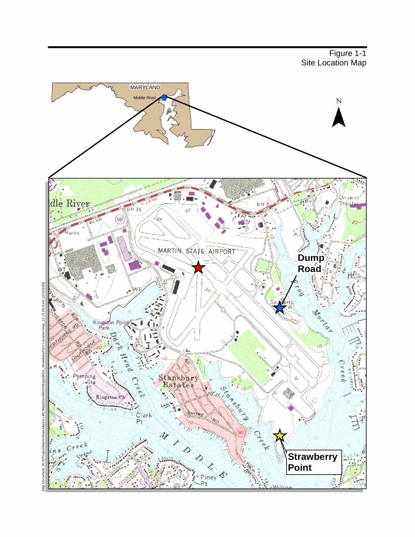
!(Middle River
MARYLAND
[_
[_
DumpRoad
[_
Strawberry Point
Figure 1-1Site Location Map
Map
Do
cum
ent:
(K
:\G
Pro
ject
\Ma
rtin
Sta
teA
irp
ort
-LM
C\M
ap
Docs\
MX
D\M
ap
s\M
SA
_S
traw
bery
Poin
t L
ocatio
n M
ap
_1
2 1
5 0
9.m
xd)
12
/15
/20
09
¯


7643 TETRA TECH • LOCKHEED MARTIN WASTE MANAGEMENT PLAN FOR MARTIN STATE AIRPORT AND SATELLITE SITES PAGE 2-1
Section 2
Responsibilities and Training Requirements
Training complying with all state and federal protocols is required for all Tetra Tech personnel
and subcontractors. All personnel will complete appropriate federal Occupational Safety and
Health Administration (OSHA) hazardous waste operations (HAZWOPER) training and annual
refresher training as specified in 29 Code of Federal Regulations (CFR) §1910.120. All
subcontractor-training certifications shall be provided electronically to the Lockheed Martin
project lead. Tetra Tech personnel certificates are maintained internally and can be provided to
Lockheed Martin upon request.
U.S. Department of Transportation (USDOT) HAZMAT employee training is required for anyone
involved in preparing hazardous waste for shipment and offering hazardous waste for transport
and transportation, including signing of hazardous waste manifests (see 49 CFR 172, Subpart H).
The waste management subcontractor will have completed HAZMAT employee training and will
renew the training as necessary to meet USDOT requirements for hazardous waste transportation.
Martin State Airport (MSA) is listed as a U.S. Environmental Protection Agency (USEPA) “large
quantity generator” (MDR000518760). Facilities that generate more than 1,000 kilograms per
month of hazardous waste must comply with the emergency preparedness and personnel training
requirements outlined in 40 CFR §265.16 (see 40 CFR §262.34[a][4]). This training is intended
for the generator’s contactors (Tetra Tech) and includes training by a person qualified in
hazardous waste management and emergency response procedures.

7643 TETRA TECH • LOCKHEED MARTIN WASTE MANAGEMENT PLAN FOR MARTIN STATE AIRPORT AND SATELLITE SITES PAGE 2-2
This page intentionally left blank

7643 TETRA TECH • LOCKHEED MARTIN WASTE MANAGEMENT PLAN FOR MARTIN STATE AIRPORT AND SATELLITE SITES PAGE 3-1
Section 3
Hazardous Waste Determination and Process
Hazardous waste determinations shall be made in accordance with 40 Code of Federal
Regulations (CFR) 262.11, using a combination of process knowledge and analytical evaluation
of waste sampling. Hazardous waste determinations shall be reevaluated whenever any of the
following occurs:
• a change in the process that produces the waste (e.g. a new chemical constituent is discovered, the treatment process changes, etc.)
• a change in the treatment media (e.g. new media vendor or media type)
• a waste is tainted by inadvertent mixing with another waste
• a change occurs to the hazardous waste regulations governing that waste
Waste generated during field investigations will include (but is not limited to) soil, sediment,
water (surface, groundwater, purge, and/or decontamination water), and disposable personal
protective equipment (PPE). PPE investigation derived waste (IDW) will be brushed off, placed
in trash bags, and disposed of in a facility trash receptacle designated by Martin State Airport
(MSA) personnel. IDW generated during field activities will be segregated into drums based
upon historical data, when applicable, labeled to indicate the wells and locations from which the
waste was generated, and the generation date. IDW generated during this activity will be further
characterized and disposed of in accordance with state regulations unless state requirements are
less stringent than federal requirements, in which case federal requirements shall apply.
When received from the analytical laboratory for the field investigations, the analytical data will
be provided to the subcontractor to facilitate IDW classification, i.e., non-hazardous versus
hazardous. IDW generated during previous sampling events were classified predominantly as
non-hazardous; however, since then, in some cases IDW has been classified as hazardous.

7643 TETRA TECH • LOCKHEED MARTIN WASTE MANAGEMENT PLAN FOR MARTIN STATE AIRPORT AND SATELLITE SITES PAGE 3-2
Therefore, IDW materials may be characterized as hazardous during future sampling events
conducted at MSA.
All analytical data shall be presented to the IDW subcontractor for classification of IDW
generated from the field project. The IDW subcontractor will determine whether additional IDW
sampling is required to complete the profiles based on the analytical data. If additional sampling
is required to satisfy waste characterization parameters, Tetra Tech will schedule a site visit and
oversee the sampling conducted by the IDW subcontractor.
Following receipt of the approved analytical data, the IDW subcontractor shall develop a profile
for the waste. In some cases, if the IDW is classified under a waste stream that has already been
profiled within the past year, a new profile will not be required and the IDW will be handled
under the existing profile. In this case, an “Annual Generator Waste Recertification” form will be
issued by the IDW subcontractor, which shall be signed and approved by Mike Musheno of LMC
Properties, Inc. (LMCPI). If no existing profile applies, the new profile shall be sent to the Tetra
Tech project manager for initial review. The Tetra Tech project manager will review and forward
the waste profile forms to the appropriate site contact. All forms related to IDW from Martin
State Airport will be signed and approved by Mike Musheno of LMCPI.
The “Waste Listing Assessment Form” is in Appendix A. This form will be completed by the
Tetra Tech project manager as the first step in the IDW classification/removal process. It serves
as first notification and is presented to the managing contractor for review. The form presents
pertinent information such as the project name, description of the waste, date generated, type and
classification of waste.
Lockheed Martin may choose to issue a Lockheed Martin “Hazardous-Waste-Manifest Signatory
Authorization Form,” presented in Appendix B. This form authorizes a Lockheed Martin
subcontractor to sign for the IDW and certifies that the representative has taken the USDOT
training delineated in 49 CFR Part 172 et seq. and is in compliance with all state and federal
requirements for hazardous waste manifesting. Lockheed Martin remains responsible and liable for
the hazardous waste being disposed regardless of the signatory authorization provided on the form.
Following signature of the waste profile forms by Lockheed Martin or an authorized
representative, the IDW will be scheduled for removal from the site. The Tetra Tech project
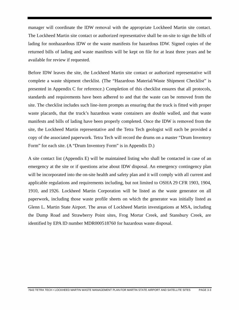
7643 TETRA TECH • LOCKHEED MARTIN WASTE MANAGEMENT PLAN FOR MARTIN STATE AIRPORT AND SATELLITE SITES PAGE 3-3
manager will coordinate the IDW removal with the appropriate Lockheed Martin site contact.
The Lockheed Martin site contact or authorized representative shall be on-site to sign the bills of
lading for nonhazardous IDW or the waste manifests for hazardous IDW. Signed copies of the
returned bills of lading and waste manifests will be kept on file for at least three years and be
available for review if requested.
Before IDW leaves the site, the Lockheed Martin site contact or authorized representative will
complete a waste shipment checklist. (The “Hazardous Material/Waste Shipment Checklist” is
presented in Appendix C for reference.) Completion of this checklist ensures that all protocols,
standards and requirements have been adhered to and that the waste can be removed from the
site. The checklist includes such line-item prompts as ensuring that the truck is fitted with proper
waste placards, that the truck’s hazardous waste containers are double walled, and that waste
manifests and bills of lading have been properly completed. Once the IDW is removed from the
site, the Lockheed Martin representative and the Tetra Tech geologist will each be provided a
copy of the associated paperwork. Tetra Tech will record the drums on a master “Drum Inventory
Form” for each site. (A “Drum Inventory Form” is in Appendix D.)
A site contact list (Appendix E) will be maintained listing who shall be contacted in case of an
emergency at the site or if questions arise about IDW disposal. An emergency contingency plan
will be incorporated into the on-site health and safety plan and it will comply with all current and
applicable regulations and requirements including, but not limited to OSHA 29 CFR 1903, 1904,
1910, and 1926. Lockheed Martin Corporation will be listed as the waste generator on all
paperwork, including those waste profile sheets on which the generator was initially listed as
Glenn L. Martin State Airport. The areas of Lockheed Martin investigations at MSA, including
the Dump Road and Strawberry Point sites, Frog Mortar Creek, and Stansbury Creek, are
identified by EPA ID number MDR000518760 for hazardous waste disposal.

7643 TETRA TECH • LOCKHEED MARTIN WASTE MANAGEMENT PLAN FOR MARTIN STATE AIRPORT AND SATELLITE SITES PAGE 3-4
This page intentionally left blank

7643 TETRA TECH • LOCKHEED MARTIN WASTE MANAGEMENT PLAN FOR MARTIN STATE AIRPORT AND SATELLITE SITES PAGE 4-1
Section 4
Shipping Requirements
4.1 PRE-SHIPMENT REQUIREMENTS
Waste generated during sampling will include but is not limited to drill cuttings from monitoring
well installation, decontamination water, purge water from monitoring wells, and sediment and
surface water sampling. Investigation derived waste (IDW) generated during previous
investigations has been characterized as both non-hazardous and hazardous waste. Pre-shipping
requirements have been discussed in detail in section 3.0.
4.1.1 Packing
All waste materials will be collected in new or reconditioned United States Department of
Transportation (USDOT)-approved 55-gallon drums that will be sealed at the end of daily
sampling. Special consideration will be made to manage certain wastes (such as bentonite grout)
separately from other IDW so as not to increase the volume of material that may be classified as
hazardous due to elevated pH.
4.1.2 Labeling
Drums will be marked with appropriate “Hazardous” or “Non-Hazardous” labels that include the
following information:
• site name where waste was generated (e.g. Martin State Airport)
• location where the waste was generated (i.e., well identification, soil boring, test pit, sediment and surface water location number)
• date when waste materials accumulation began
• drum number in the series of drums from this sampling event
• contents, i.e., sediment, soil cuttings, groundwater and surface water
• volume should be estimated and must not exceed three quarters of drum capacity

7643 TETRA TECH • LOCKHEED MARTIN WASTE MANAGEMENT PLAN FOR MARTIN STATE AIRPORT AND SATELLITE SITES PAGE 4-2
• site contact and emergency contact information for the designated authorized Lockheed Martin representative for the site and the telephone number of the local fire department.
4.1.3 Storing
IDW storage areas will meet the following specifications to permit access to the drums and to
conduct spill/leak monitoring, sampling, and extraction once the disposal route is determined:
• A temporary spill containment system, made of polyethylene sheeting and 2-inch by 6-inch boards creating a bermed edge, will be placed under the container to contain any spills or leaks. The dimensions of the temporary spill-containment area will depend on the number of 55-gallon drums at the site. For most jobs, the spill containment area will likely be 10-feet by 20-feet. The integrity of the containment system will be monitored periodically.
• 55-gallon drums will be stored on self-contained pallets, with four or fewer drums per pallet. Self-contained pallets will be stored on a hard, flat surface covered with polyethylene sheeting.
• The drum-retaining bolt and label will be readily visible
• Four feet of space will be between each row of pallets/drums to allow access for sampling, drum removal, and spill response
• Caution tape or temporary fencing will be placed around the drums to help identify and secure the area
• Signs will be posted in front of the IDW storage area identifying the site, location, date of collection, number of drums, drum contents, volume of contents, site and emergency contact information, and the location of spill control materials for the wastes.
• Appropriate authorities will be informed that hazardous waste materials are on-site and of emergency response procedures. The emergency coordinator will be identified and emergency planning documented.
• A copy of work plans, waste disposal forms, and the IDW inventory list will be maintained on-site and provided to the project manager at the end of each shift
• Spill response equipment will be readily available
• Appropriate equipment will be used to move containers whenever possible, to avoid injury. When not possible, personnel will obtain help to manipulate containers.
• All storage containers will be monitored weekly to ensure that they remain in original condition and to ensure that no leaks or spills have occurred. Weekly inspections will be documented in a field notebook dedicated to the site and will include photographs.

7643 TETRA TECH • LOCKHEED MARTIN WASTE MANAGEMENT PLAN FOR MARTIN STATE AIRPORT AND SATELLITE SITES PAGE 4-3
The IDW drum storage area at MSA is on a flat concrete pad area near Gate 12; an alternative
area may be used to minimize drum transportation. Airport personnel will determine IDW
storage areas at Dump Road and Strawberry Point at the start of field activities. Single drums
will be temporarily staged on a hard, flat surface overlain by polyethylene sheeting and
self-contained plastic pallets that will act as secondary containment, with sufficient capacity to
contain the contents of one 55-gallon drum. All IDW drums will be stored on secondary
containment until they can be removed from the site. Lockheed Martin has 90 days to remove
non-hazardous- and hazardous-waste drums from the facility. Access for the subcontractor’s
representative and IDW transport carrier will be coordinated by Tetra Tech.
4.1.4 Material Identification and Classification
All waste materials shall be identified and classified per USDOT requirements.
4.1.5 Waste Shipment
Tetra Tech will subcontract all IDW removal. Tetra Tech will ensure the use of Lockheed Martin
purchasing agreements and associated Lockheed Martin-approved waste-management vendors
and will ensure that hazardous waste is transported by an approved vendor to a treatment,
storage, and disposal (TSD) facility on the Lockheed Martin “Corporate Hazardous Waste
Approved Vendors “list. Non-hazardous waste is not required to be managed by Lockheed
Martin approved waste management vendors but shall be transported to an approved industrial
waste disposal facility. The Lockheed Martin “Hazardous Waste Manifest Signatory
Authorization” (Attachment D) must be filled out by the Lockheed Martin project lead in
coordination with the Tetra Tech project manager if the IDW is hazardous.
4.1.6 Hazardous Waste Generator Identification Number
The Lockheed Martin USEPA identification number for hazardous waste generation at MSA is
MDR000518760. All IDW will be removed from the site by a subcontractor adhering to the
shipping requirements in Section 4.2.
4.2 SHIPPING REQUIREMENTS
USDOT HAZMAT employee training is required for anyone involved in shipment preparation,
offering for transport and transportation of hazardous waste, including signing hazardous waste
manifests (see 49 CFR 172, Subpart H). The manifest for the waste to be shipped must be

7643 TETRA TECH • LOCKHEED MARTIN WASTE MANAGEMENT PLAN FOR MARTIN STATE AIRPORT AND SATELLITE SITES PAGE 4-4
certified as accurate. Non-hazardous materials do not require the signature of a USDOT
HAZMAT-trained individual. A waste manifest will be signed for all hazardous waste and a bill
of lading will be signed for all non-hazardous waste. For non-hazardous waste, Tetra Tech will
use the Lockheed Martin “Hazardous Material/Waste Shipment Checklist” (Attachment B)
during preparation and pre-transport review of waste shipments and will submit a completed
electronic copy to the Lockheed Martin Project Lead with the shipping documentation.
Detailed records of authorized work will be maintained by the subcontractor, including all
manifests of waste transported to the approved off-site disposal facility, receipt of waste
acceptance by the approved treatment/disposal facility, certification that the waste has been
disposed of at the approved facility, receipt of acceptance of waste containers by the approved
disposal facility, certification of disposal of waste containers by the approved disposal facility,
weighing slips, and any other documentation required by local, state, or federal requirements.
4.3 POST-SHIPMENT REQUIREMENTS
Waste characterization, chain of custody, transportation, and destruction records will be scanned
and submitted electronically to the Lockheed Martin project lead for records retention. This will
include profile sheets, the “Hazardous Material/Waste Checklist,” the generator copy of the
waste manifest, a copy of the treatment, storage, and disposal (TSD)- signed manifest, “Land
Disposal Restriction” forms, and certificates of waste destruction, when applicable. All
monitoring records will be submitted for each year’s waste generation activities in the first
quarter of the following year or per the project lead’s direction. The documentation noted above
must be kept for at least three years. All documents must be available for review if requested.

7643 TETRA TECH • LOCKHEED MARTIN WASTE MANAGEMENT PLAN FOR MARTIN STATE AIRPORT AND SATELLITE SITES
APPENDIX A—WASTE IDENTIFICATION AND CLASSIFICATION FORM

LMC Remediation Project State GeneratedDescription of Waste
Generic Name Solid, Liquid, GasAdditional Info.
Date of Waste Generation Ongoing (Y/N)?
Description of Process Generating Waste
Listed Waste ? (Y/N) F,K, P or U Codes, if applicable
Justification for Waste Classification (attach support documentation)
CompanyDate
Completed by
Waste Identification and Classification Form


7643 TETRA TECH • LOCKHEED MARTIN WASTE MANAGEMENT PLAN FOR MARTIN STATE AIRPORT AND SATELLITE SITES
APPENDIX B—HAZARDOUS WASTE MANIFEST SIGNATURE AUTHORIZATION FORM


1
Lockheed Martin Hazardous Waste Manifest Signatory Authorization
This Authorization Agreement, effective for the remediation site and period of performance written below, is entered into by and between: LOCKHEED MARTIN CORPORATION (hereinafter “Lockheed Martin”), having a business office at 6801 Rockledge Drive, Bethesda, Maryland 20817 USA, and incorporated in the State of Maryland, and ______________________________________________________________
(hereinafter "_____________________________")
having a business office at_________________________________________
______________________________________________________________. WHEREAS, _____________________________ (company representative) of __________ (company) will sign Hazardous Waste Manifests on behalf of Lockheed Martin for the project and hazardous waste, as defined at 40 CFR Pt. 261 et seq. indicated below. Remediation Site: ____________________________________ Site Address: ___________________________________________________________ Period of Performance: ____________________________________ Hazardous Waste Description: ________________________________________________________________________________________________________________________________________________ Hazardous Waste Disposal Facility and Location: ___________________________ ________________________________________________________________________________________________________________________________________________ This Authorization Agreement certifies that the representative signing on behalf of Lockheed Martin has taken the appropriate Department of Transportation training, as delineated at 49 CFR Part 172 t seq. to sign Hazardous Waste Manifests and is in compliance with all state and federal requirements for hazardous waste manifesting. Lockheed Martin shall remain responsible and liable for the hazardous waste being disposed regardless of the Signatory Authorization provided herein.
2
LOCKHEED MARTIN CORPORATION ___________________________ By:____________________________ By:________________________ Name:_________________________ Name:_____________________ Title:___________________________ Title:_______________________ Date:__________________________ Date:______________________

7643 TETRA TECH • LOCKHEED MARTIN WASTE MANAGEMENT PLAN FOR MARTIN STATE AIRPORT AND SATELLITE SITES
APPENDIX C—HAZARDOUS MATERIAL/WASTE SHIPMENT CHECKLIST


7643 TETRA TECH • LOCKHEED MARTIN WASTE MANAGEMENT PLAN FOR MARTIN STATE AIRPORT AND SATELLITE SITES
APPENDIX D—DRUM INVENTORY FORM


DRUM INVENTORY
PROJECT NAME: PROJECT NUMBER:
CLIENT: LOCATION:
Tt NUS PERSONNEL: DATE (START):
IDW CONTRACTOR: DATE (END):
DRUM ID GENERATION LOCATION
DATE GENERATED
AMOUNT (gal.) STORAGE LOCATION COMMENTS
Tetra Tech NUS, Inc.


7643 TETRA TECH • LOCKHEED MARTIN WASTE MANAGEMENT PLAN FOR MARTIN STATE AIRPORT AND SATELLITE SITES
APPENDIX E—SITE CONTACT SHEET


Site Contact List
1) Charles Baublitz: Airport Operations Manager Office 410-682-8831 2) Al Pollard: Director
Office 410-682-8800 3) Thomas Thompson: Airport Operations Engineer
Office: 410-682-8856 4) Mike Musheno: ESH / Projects
Office: 484-682-1315 5) Major Peter Loebach: Office: 410-918-6486
6) A&A Environmental / Spill Response: 1-800-404-8037 7) Tony Apanavage Project Manager 1-301-528-3021 (office) 1-301-233-8230 (cell) 8) Michael Martin Program Manager 1-301-528-3022 (office) 1-410-707-5259 (cell) 9) Baltimore County Police & Fire Department: 911 10) State of Maryland Emergency Response Center (410-974-3551)


7643 TETRA TECH • LOCKHEED MARTIN WASTE MANAGEMENT PLAN FOR MARTIN STATE AIRPORT AND SATELLITE SITES
APPENDIX F—“EESH REMEDIATION OPERATING PROCEDURE NO: EROP-03, “EESH REMEDIATION WASTE MANAGEMENT