Embed Size (px)
Citation preview
3rd POST COMBUSTION CAPTURE
CONFERENCE: PCC3
MAINTAINING THE POWER OUTPUT WITH THE ADDITION OF CO2
CAPTURE: A TECHNO-ECONOMIC ASSESSMENT OF INTEGRATED
RETROFITS WITH SEQUENTIAL COMBUSTION OF GAS TURBINE FLUE GAS
María Sánchez del Río*, Mathieu Lucquiaud, Hannah Chalmers,
Jon Gibbins
School of Engineering, The University of Edinburgh, United Kingdom
*contact e-mail: [email protected] / [email protected]
08 – 11 September 2015 • Regina, Canada
PRESENTATION OUTLINE
1.- Carbon capture retrofit options
2.- Estimation of carbon capture retrofit performance
3.- Technical analysis
4.- Economic analysis
5.- Sensitivity analysis
6.- Conclusion
3rd POST COMBUSTION CAPTURE
CONFERENCE: PCC3

PRESENTATION OUTLINE
1.- Carbon capture retrofit options
2.- Estimation of carbon capture retrofit performance
3.- Technical analysis
4.- Economic analysis
5.- Sensitivity analysis
6.- Conclusion
3rd POST COMBUSTION CAPTURE
CONFERENCE: PCC3
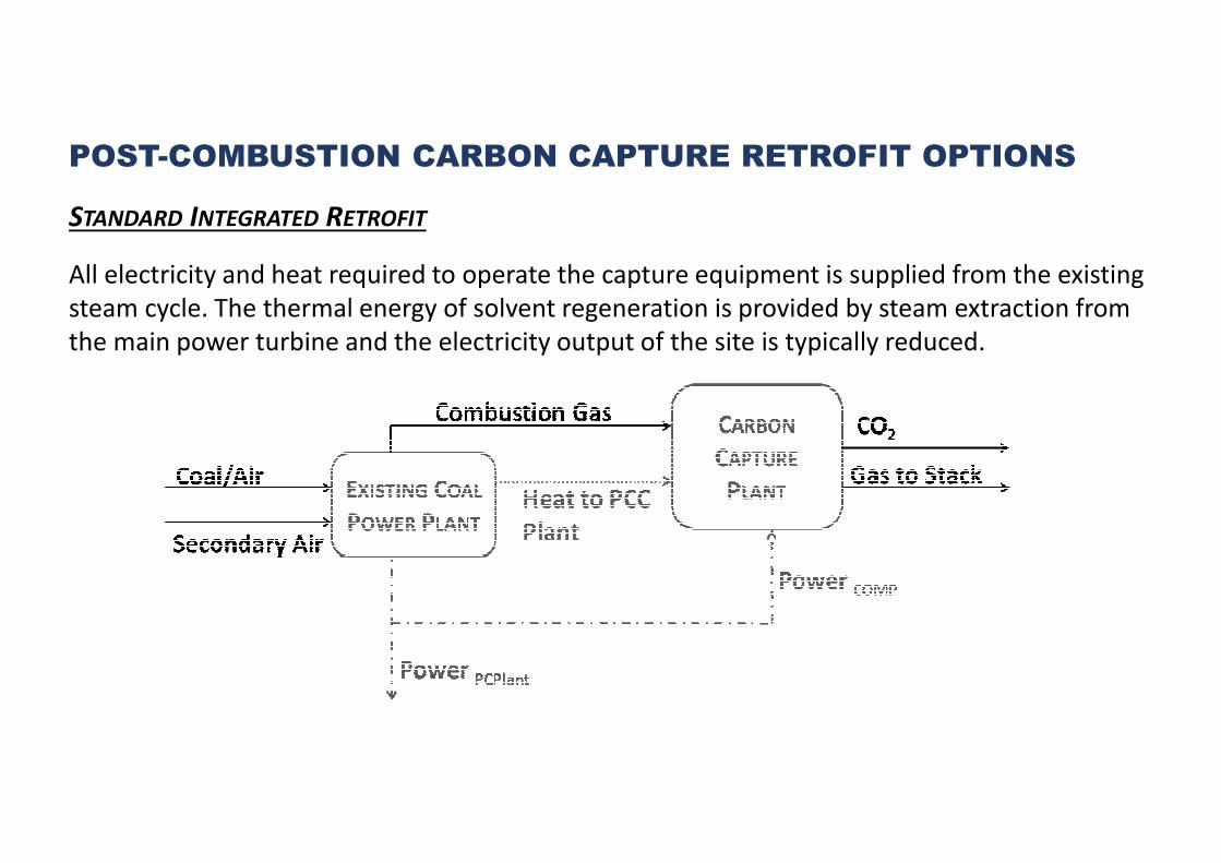
POST-COMBUSTION CARBON CAPTURE RETROFIT OPTIONS
STANDARD INTEGRATED RETROFIT
All electricity and heat required to operate the capture equipment is supplied from the existing
steam cycle. The thermal energy of solvent regeneration is provided by steam extraction from
the main power turbine and the electricity output of the site is typically reduced.
POST-COMBUSTION CARBON CAPTURE RETROFIT OPTIONS
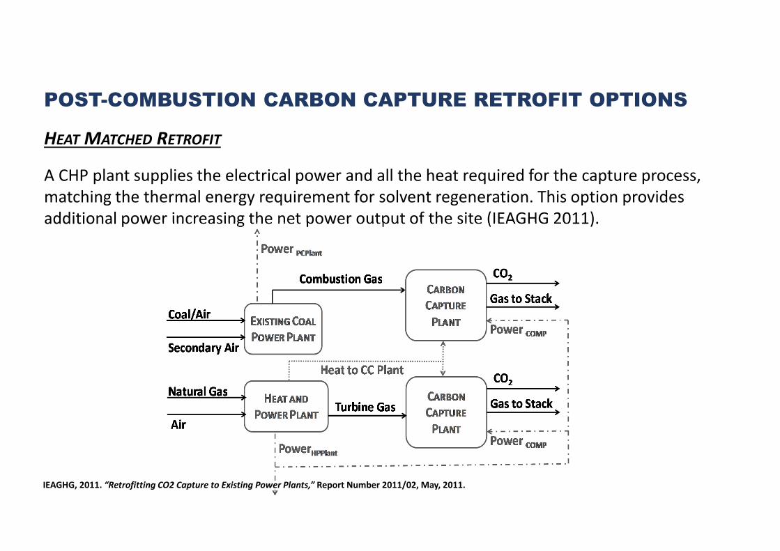
HEAT MATCHED RETROFIT
A CHP plant supplies the electrical power and all the heat required for the capture process,
matching the thermal energy requirement for solvent regeneration. This option provides
additional power increasing the net power output of the site (IEAGHG 2011).
IEAGHG, 2011. “Retrofitting CO2 Capture to Existing Power Plants,” Report Number 2011/02, May, 2011.
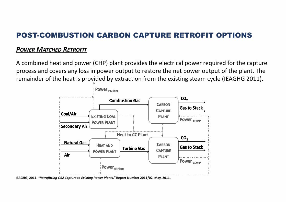
POST-COMBUSTION CARBON CAPTURE RETROFIT OPTIONS
POWER MATCHED RETROFIT
A combined heat and power (CHP) plant provides the electrical power required for the capture
process and covers any loss in power output to restore the net power output of the plant. The
remainder of the heat is provided by extraction from the existing steam cycle (IEAGHG 2011).
IEAGHG, 2011. “Retrofitting CO2 Capture to Existing Power Plants,” Report Number 2011/02, May, 2011.
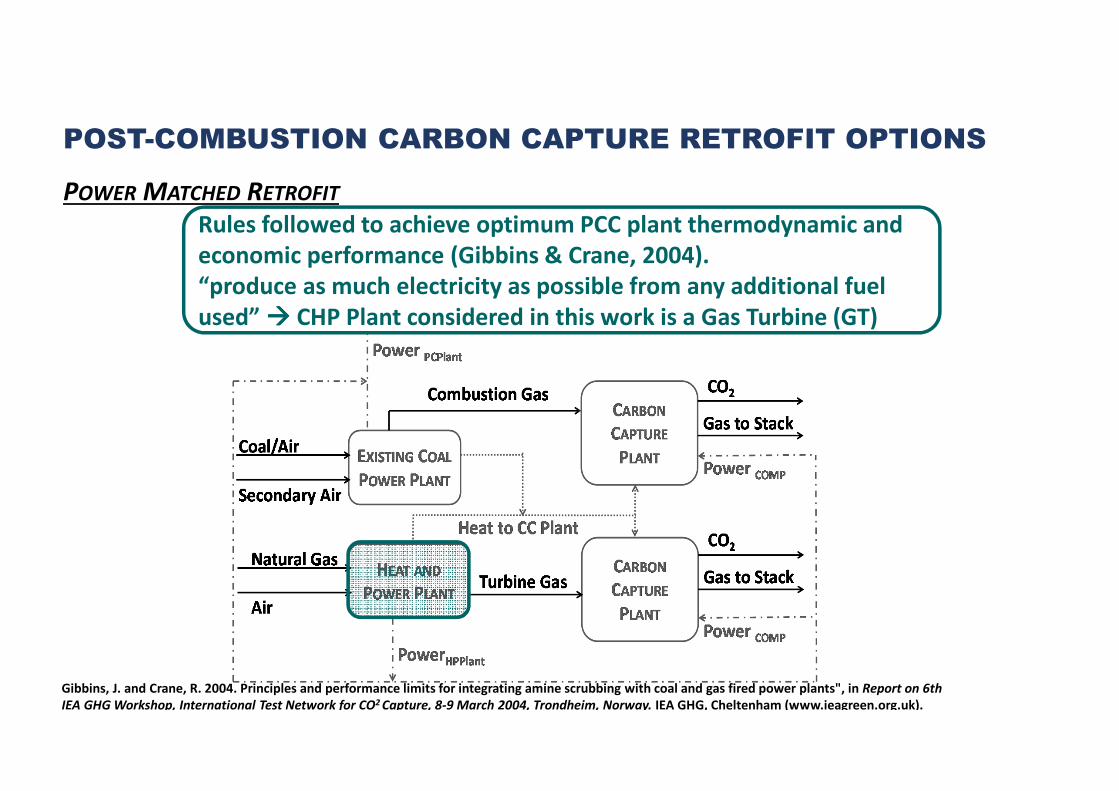
POST-COMBUSTION CARBON CAPTURE RETROFIT OPTIONS
POWER MATCHED RETROFIT
Rules followed to achieve optimum PCC plant thermodynamic and
economic performance (Gibbins & Crane, 2004).
“produce as much electricity as possible from any additional fuel
used” ���� CHP Plant considered in this work is a Gas Turbine (GT)
Gibbins, J. and Crane, R. 2004. Principles and performance limits for integrating amine scrubbing with coal and gas fired power plants", in Report on 6th
IEA GHG Workshop, International Test Network for CO2 Capture, 8-9 March 2004, Trondheim, Norway. IEA GHG, Cheltenham (www.ieagreen.org.uk).
POST-COMBUSTION CARBON CAPTURE RETROFIT OPTIONS
POWER MATCHED RETROFIT
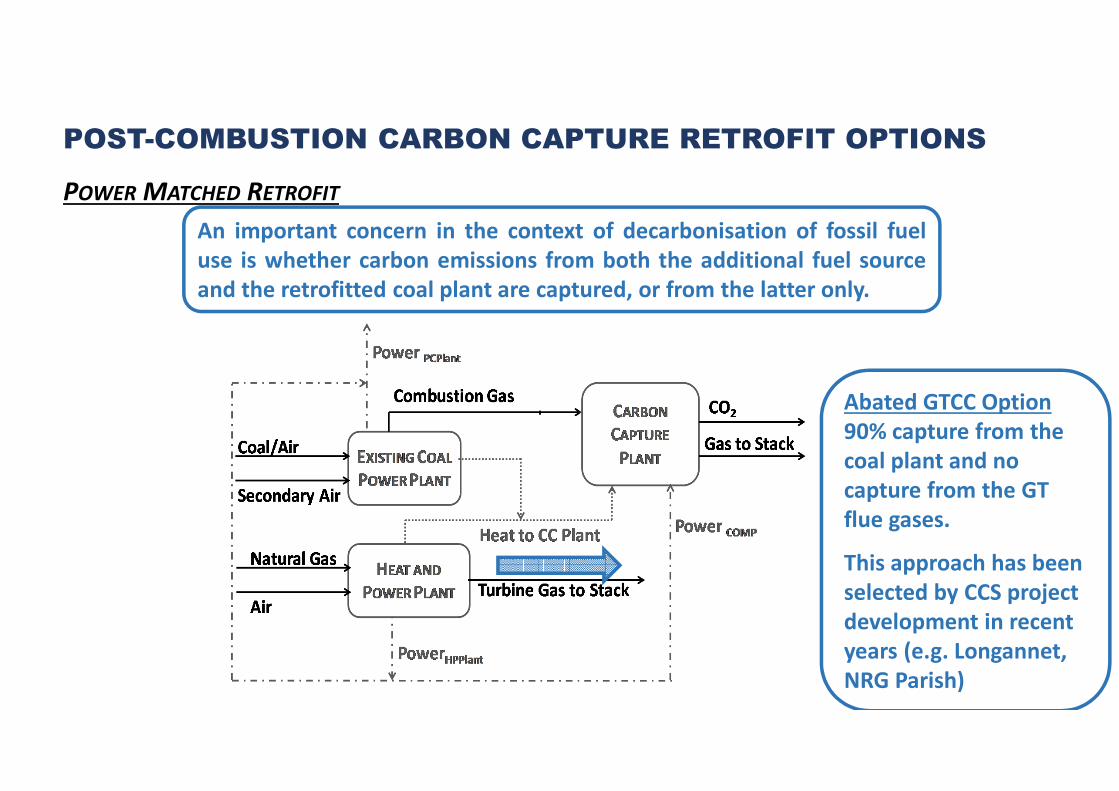
Abated GTCC Option
90% capture from the
coal plant and no
capture from the GT
flue gases.
This approach has been
selected by CCS project
development in recent
years (e.g. Longannet,
NRG Parish)
An important concern in the context of decarbonisation of fossil fuel
use is whether carbon emissions from both the additional fuel source
and the retrofitted coal plant are captured, or from the latter only.
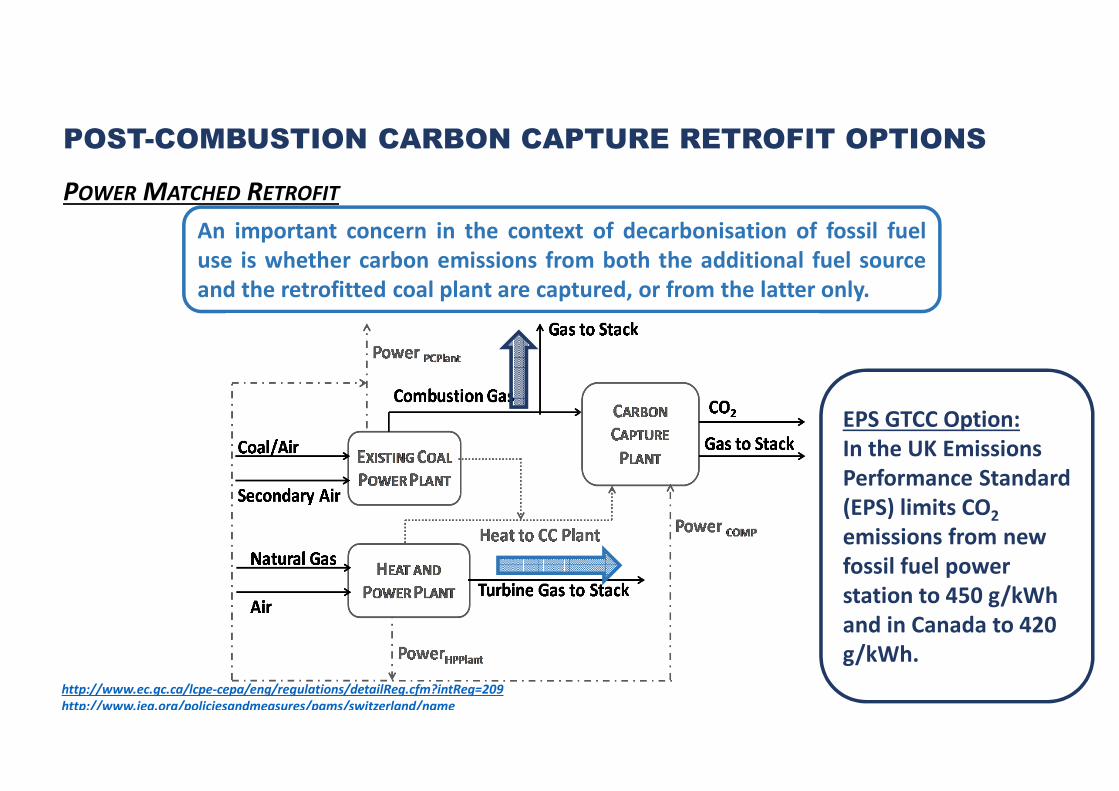
An important concern in the context of decarbonisation of fossil fuel
use is whether carbon emissions from both the additional fuel source
and the retrofitted coal plant are captured, or from the latter only.
POST-COMBUSTION CARBON CAPTURE RETROFIT OPTIONS
POWER MATCHED RETROFIT
EPS GTCC Option:
In the UK Emissions
Performance Standard
(EPS) limits CO2
emissions from new
fossil fuel power
station to 450 g/kWh
and in Canada to 420
g/kWh.
http://www.ec.gc.ca/lcpe-cepa/eng/regulations/detailReg.cfm?intReg=209
http://www.iea.org/policiesandmeasures/pams/switzerland/name
POST-COMBUSTION CARBON CAPTURE RETROFIT OPTIONS
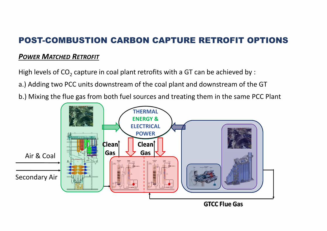
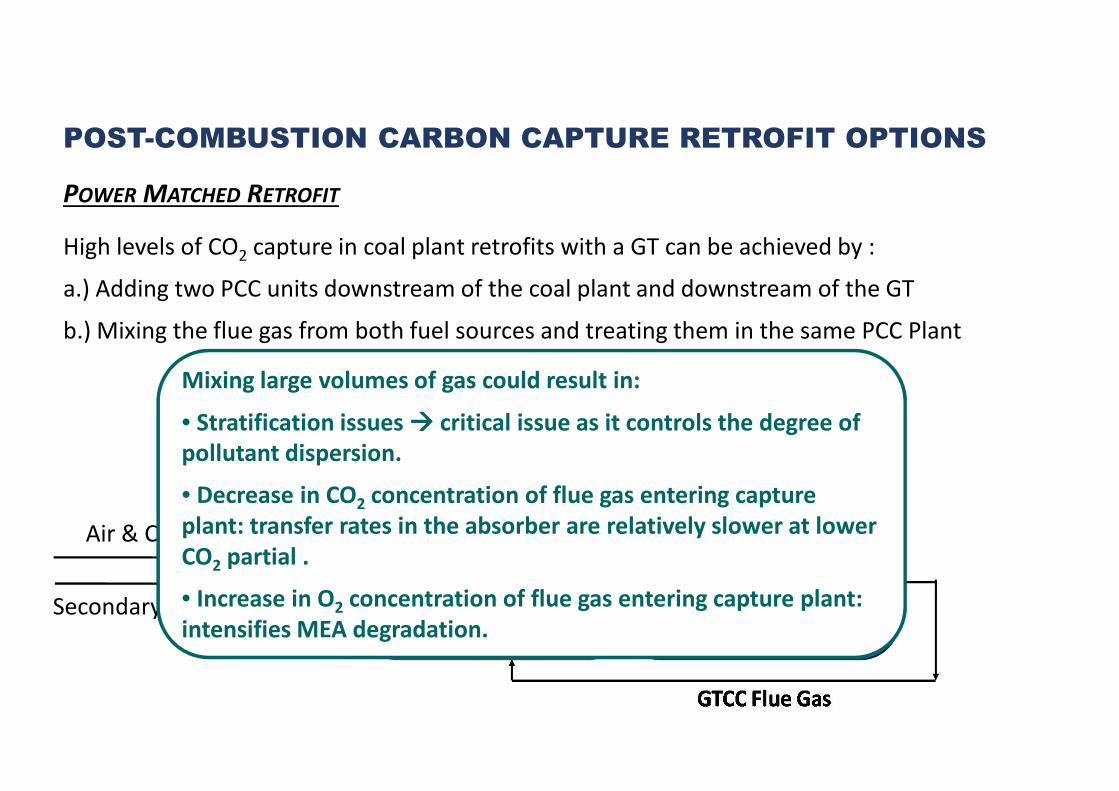
POWER MATCHED RETROFIT
High levels of CO2 capture in coal plant retrofits with a GT can be achieved by :
a.) Adding two PCC units downstream of the coal plant and downstream of the GT
b.) Mixing the flue gas from both fuel sources and treating them in the same PCC Plant
Air & Coal
Secondary Air
THERMAL
ENERGY &
ELECTRICAL
POWER
POST-COMBUSTION CARBON CAPTURE RETROFIT OPTIONS
POWER MATCHED RETROFIT
High levels of CO2 capture in coal plant retrofits with a GT can be achieved by :
a.) Adding two PCC units downstream of the coal plant and downstream of the GT
b.) Mixing the flue gas from both fuel sources and treating them in the same PCC Plant
Air & Coal
Secondary Air
THERMAL
ENERGY &
ELECTRICAL
POWER
Mixing large volumes of gas could result in:
• Stratification issues ���� critical issue as it controls the degree of
pollutant dispersion.
• Decrease in CO2 concentration of flue gas entering capture
plant: transfer rates in the absorber are relatively slower at lower
CO2 partial .
• Increase in O2 concentration of flue gas entering capture plant:
intensifies MEA degradation.
Air & Coal
THERMAL
ENERGY &
ELECTRICAL
POWER
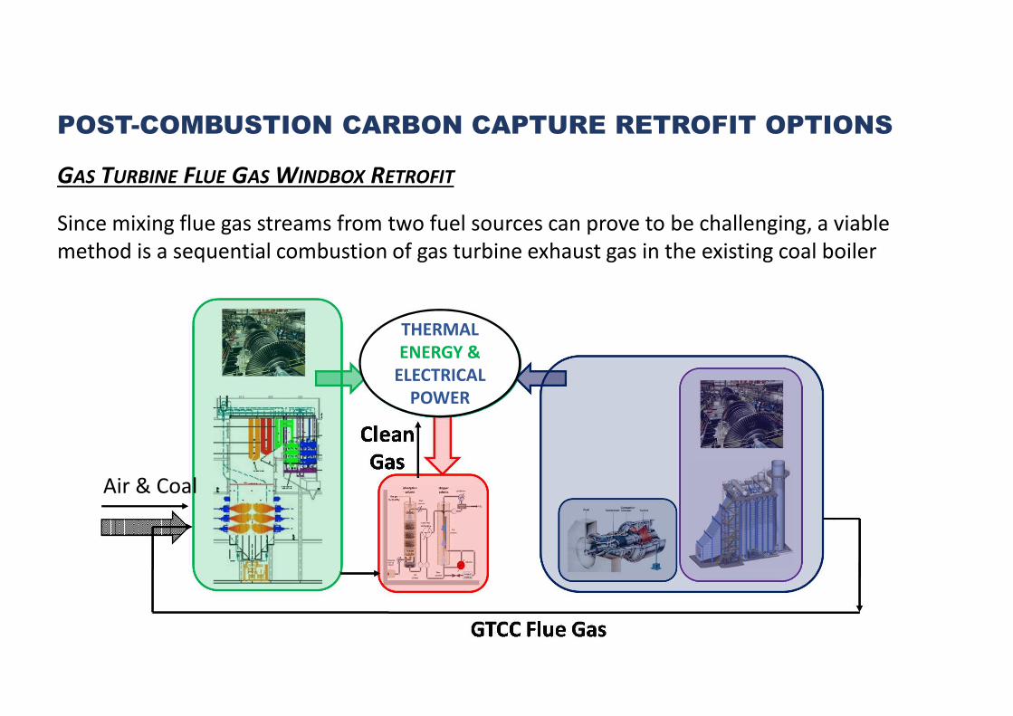
POST-COMBUSTION CARBON CAPTURE RETROFIT OPTIONS
GAS TURBINE FLUE GAS WINDBOX RETROFIT
Since mixing flue gas streams from two fuel sources can prove to be challenging, a viable
method is a sequential combustion of gas turbine exhaust gas in the existing coal boiler
Air & Coal
THERMAL
ENERGY &
ELECTRICAL
POWER
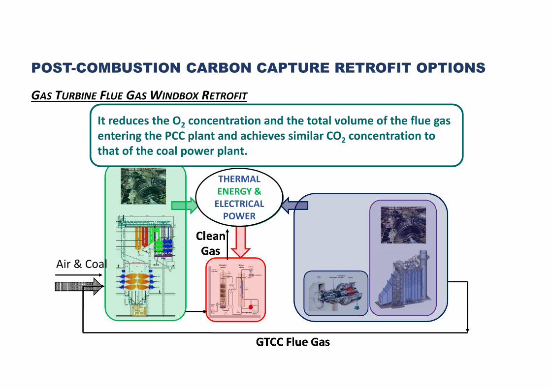
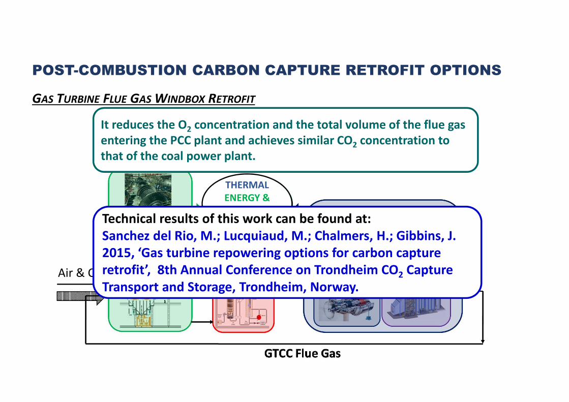
POST-COMBUSTION CARBON CAPTURE RETROFIT OPTIONS
GAS TURBINE FLUE GAS WINDBOX RETROFIT
It reduces the O2 concentration and the total volume of the flue gas
entering the PCC plant and achieves similar CO2 concentration to
that of the coal power plant.
Air & Coal
THERMAL
ENERGY &
ELECTRICAL
POWER
POST-COMBUSTION CARBON CAPTURE RETROFIT OPTIONS
GAS TURBINE FLUE GAS WINDBOX RETROFIT
It reduces the O2 concentration and the total volume of the flue gas
entering the PCC plant and achieves similar CO2 concentration to
that of the coal power plant.
Technical results of this work can be found at:
Sanchez del Rio, M.; Lucquiaud, M.; Chalmers, H.; Gibbins, J.
2015, ‘Gas turbine repowering options for carbon capture
retrofit’, 8th Annual Conference on Trondheim CO2 Capture
Transport and Storage, Trondheim, Norway.
POST-COMBUSTION CARBON CAPTURE RETROFIT OPTIONS
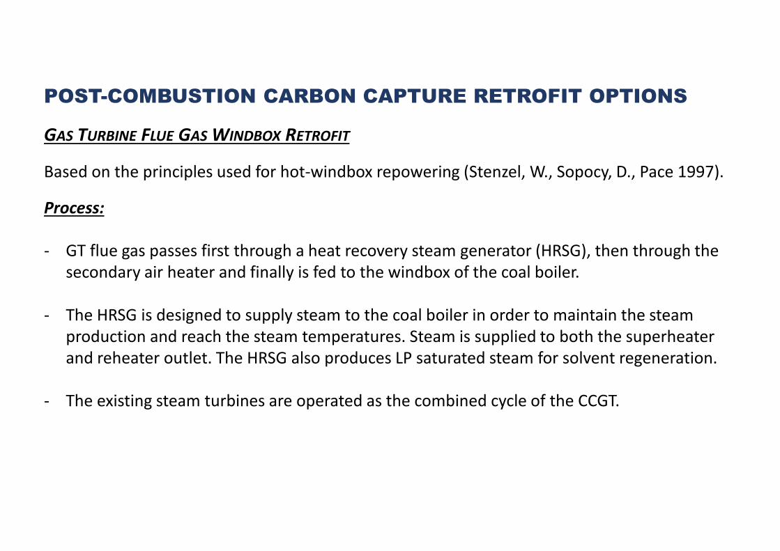
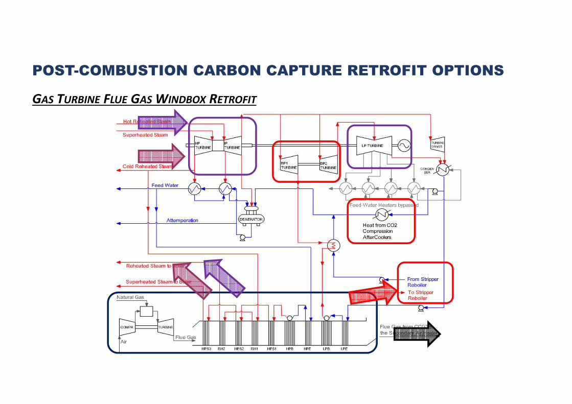
GAS TURBINE FLUE GAS WINDBOX RETROFIT
Based on the principles used for hot-windbox repowering (Stenzel, W., Sopocy, D., Pace 1997).
Process:
- GT flue gas passes first through a heat recovery steam generator (HRSG), then through the
secondary air heater and finally is fed to the windbox of the coal boiler.
- The HRSG is designed to supply steam to the coal boiler in order to maintain the steam
production and reach the steam temperatures. Steam is supplied to both the superheater
and reheater outlet. The HRSG also produces LP saturated steam for solvent regeneration.
- The existing steam turbines are operated as the combined cycle of the CCGT.
POST-COMBUSTION CARBON CAPTURE RETROFIT OPTIONS
GAS TURBINE FLUE GAS WINDBOX RETROFIT
PRESENTATION OUTLINE
1.- Carbon capture retrofit options
2.- Estimation of carbon capture retrofit performance
3.- Technical analysis
4.- Economic analysis
5.- Sensitivity analysis
6.- Conclusion
3rd POST COMBUSTION CAPTURE
CONFERENCE: PCC3
ESTIMATION OF CARBON CAPTURE RETROFIT PERFORMANCE
2.- Calibration Mode of the coal power plant
3.- Operational Mode of the coal power plant
4.- Carbon Capture Plant Design
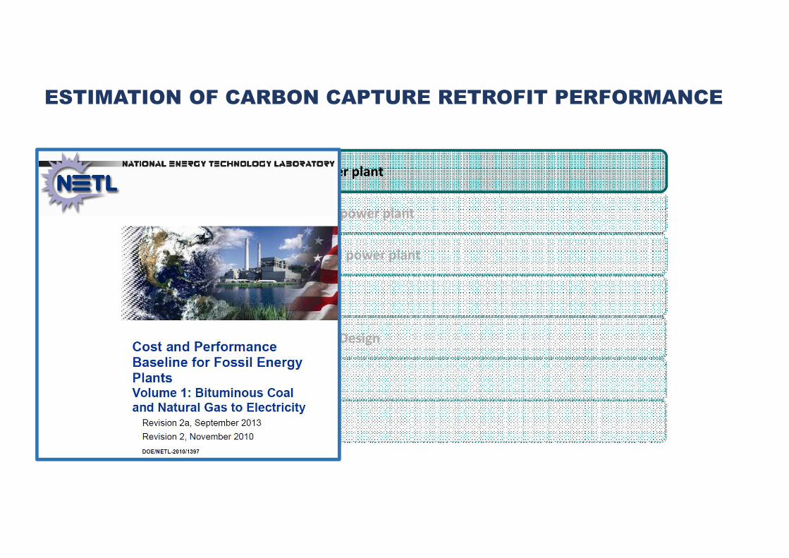
1.- Design Basis of the coal power plant
5.- Gas Turbine Combined Cycle Design
6.- Economic Analysis
7.- Sensitivity Analysis
2.- Calibration Mode of the coal power plant
3.- Operational Mode of the coal power plant
4.- Carbon Capture Plant Design
1.- Design Basis of the coal power plant
5.- Gas Turbine Combined Cycle Design
6.- Economic Analysis
7.- Sensitivity Analysis
ESTIMATION OF CARBON CAPTURE RETROFIT PERFORMANCE
2.- Calibration Mode of the coal power plant
3.- Operational Mode of the coal power plant
4.- Carbon Capture Plant Design
1.- Design Basis of the coal power plant
5.- Gas Turbine Combined Cycle Design
6.- Economic Analysis
7.- Sensitivity Analysis
ESTIMATION OF CARBON CAPTURE RETROFIT PERFORMANCE
2.- Calibration Mode of the coal power plant
3.- Operational Mode of the coal power plant
4.- Carbon Capture Plant Design
1.- Design Basis of the coal power plant
5.- Gas Turbine Combined Cycle Design
6.- Economic Analysis
7.- Sensitivity Analysis
ESTIMATION OF CARBON CAPTURE RETROFIT PERFORMANCE
2.- Calibration Mode of the coal power plant
3.- Operational Mode of the coal power plant
4.- Carbon Capture Plant Design
1.- Design Basis of the coal power plant
5.- Gas Turbine Combined Cycle Design
6.- Economic Analysis
7.- Sensitivity Analysis
ESTIMATION OF CARBON CAPTURE RETROFIT PERFORMANCE
2.- Calibration Mode of the coal power plant
3.- Operational Mode of the coal power plant
4.- Carbon Capture Plant Design
1.- Design Basis of the coal power plant
5.- Gas Turbine Combined Cycle Design
6.- Economic Analysis
7.- Sensitivity Analysis
ESTIMATION OF CARBON CAPTURE RETROFIT PERFORMANCE
2.- Calibration Mode of the coal power plant
3.- Operational Mode of the coal power plant
4.- Carbon Capture Plant Design
1.- Design Basis of the coal power plant
5.- Gas Turbine Combined Cycle Design
6.- Economic Analysis
7.- Sensitivity Analysis
ESTIMATION OF CARBON CAPTURE RETROFIT PERFORMANCE

2.- Calibration Mode of the coal power plant
3.- Operational Mode of the coal power plant
4.- Carbon Capture Plant Design
1.- Design Basis of the coal power plant
5.- Gas Turbine Combined Cycle Design
6.- Economic Analysis
7.- Sensitivity Analysis
ESTIMATION OF CARBON CAPTURE RETROFIT PERFORMANCE

2.- Calibration Mode of the coal power plant
3.- Operational Mode of the coal power plant
4.- Carbon Capture Plant Design
1.- Design Basis of the coal power plant
5.- Gas Turbine Combined Cycle Design
6.- Economic Analysis
7.- Sensitivity Analysis
ESTIMATION OF CARBON CAPTURE RETROFIT PERFORMANCE

2.- Calibration Mode of the coal power plant
3.- Operational Mode of the coal power plant
4.- Carbon Capture Plant Design
1.- Design Basis of the coal power plant
5.- Gas Turbine Combined Cycle Design
6.- Economic Analysis
7.- Sensitivity Analysis
ESTIMATION OF CARBON CAPTURE RETROFIT PERFORMANCE

2.- Calibration Mode of the coal power plant
3.- Operational Mode of the coal power plant
4.- Carbon Capture Plant Design
1.- Design Basis of the coal power plant
5.- Gas Turbine Combined Cycle Design
6.- Economic Analysis
7.- Sensitivity Analysis
ESTIMATION OF CARBON CAPTURE RETROFIT PERFORMANCE

ESTIMATION OF CARBON CAPTURE RETROFIT PERFORMANCE
2.- Calibration Mode of the coal power plant
3.- Operational Mode of the coal power plant
4.- Carbon Capture Plant Design
1.- Design Basis of the coal power plant
5.- Gas Turbine Combined Cycle Design
6.- Economic Analysis
7.- Sensitivity Analysis

ESTIMATION OF CARBON CAPTURE RETROFIT PERFORMANCE
2.- Calibration Mode of the coal power plant
3.- Operational Mode of the coal power plant
4.- Carbon Capture Plant Design
1.- Design Basis of the coal power plant
5.- Gas Turbine Combined Cycle Design
6.- Economic Analysis
7.- Sensitivity Analysis

ESTIMATION OF CARBON CAPTURE RETROFIT PERFORMANCE
2.- Calibration Mode of the coal power plant
3.- Operational Mode of the coal power plant
4.- Carbon Capture Plant Design
1.- Design Basis of the coal power plant
5.- Gas Turbine Combined Cycle Design
6.- Economic Analysis
7.- Sensitivity Analysis

PRESENTATION OUTLINE
1.- Carbon capture retrofit options
2.- Estimation of carbon capture retrofit performance
3.- Technical analysis
4.- Economic analysis
5.- Sensitivity analysis
6.- Conclusion
3rd POST COMBUSTION CAPTURE
CONFERENCE: PCC3

PRESENTATION OUTLINE
1.- Carbon capture retrofit options
2.- Estimation of carbon capture retrofit performance
3.- Technical analysis
3.1.- Technical metrics
3.2.- Technical performance results of the retrofits with high levels of CO2 capture
3.3.- Technical performance results of the retrofits with intermedium levels of CO2 capture
3rd POST COMBUSTION CAPTURE
CONFERENCE: PCC3

ELECTRICITY OUTPUT PENALTY ~ Overall energy requirement for CO2 capture
a.) Standard Integrated Retrofit
b.) With an additional fuel input to the site
b1.) Power / Heat Matched Retrofit
b2.) GT flue gas Windbox Retrofit
EOP = Power_LossST + PowerComp + PowerAncmCO 2
��� = ��������� ��!"# − ����� � #"& ���'��2
��� = ����� �/� #"& ��� + ������)��*"� − ����� � #"& ���'��2
��� = ����� � /� #"& ��� ��+�#�+ #�"* �" � + ������)��*"� − ����� � #"& ���'��2

NATURAL GAS MARGINAL EFFICIENCY ~ Effectiveness of the additional gas
consumption
Definition:
Maximum possible useful work for power regeneration recovered from the
combustion of the additional fuel source, before heat is supplied to the PCC process
b1.) Power / Heat Matched Retrofit
b2.) GT flue gas Windbox Retrofit
,"�-_�!! = ����� � #"& ��� − �����. �"'/� ��!0 1�&� 2" 3"4
,"�-_�!! = 5����� � #"& ��� + �����)/.3 _6�0*�� 7 − �����. �"'/� ��!0 1�&� 2" 3"4

PRESENTATION OUTLINE
1.- Carbon capture retrofit options
2.- Estimation of carbon capture retrofit performance
3.- Technical analysis:
3.1.- Technical metrics
3.2.- Technical performance results of the retrofits with high levels of CO2 capture
3.3.- Technical performance results of the retrofits with intermedium levels of CO2 capture
3rd POST COMBUSTION CAPTURE
CONFERENCE: PCC3

Standard
Integrated
Retrofit
GT Windbox
Retrofit with
capture(90% capture) (90% capture)
CASE A1 CASE D1 CASE B1 CASE C1Retrofitted PC Power Plant
Coal thermal input MWth 1517.9 1517.9 1348.6 1517.9 1517.9
Gas thermal input MWth - - 358.4 269.6 265.3
Net Power output MWe 600.3 473.9 600.3 600.3 600.3
Carbon intensity of electricity g CO2 / kWh 765.3 96.9 79.5 84.7 84.6
Thermal efficiency % LHV 39.5 31.2 35.2 33.6 33.7
Carbon Capture Plant
Overall carbon capture rate of two
fuel sources combinedw/w - 0.9 0.9 0.9 0.9
Gas flow rate to PCC Plant kg/s - 632.8 697.9 632.8 847.5
Gas flow rate to Gas PCC Plant kg/s - - - 218.2 -
Electricity output penalty kWh / tnCO2 - 305.8 291.5 315.8 311.3
Marginal efficiency of additional
gas combustion% LHV - - 53.9 46.9 47.7
POWER MATCHED RETROFIT
Existing
coal plant
w/o
capture
90% capture
from CCGT.
(mixing flue
gas streams)
90% capture
from CCGT

Standard
Integrated
Retrofit
GT Windbox
Retrofit with
capture(90% capture) (90% capture)
CASE A1 CASE D1 CASE B1 CASE C1Retrofitted PC Power Plant
Coal thermal input MWth 1517.9 1517.9 1348.6 1517.9 1517.9
Gas thermal input MWth - - 358.4 269.6 265.3
Net Power output MWe 600.3 473.9 600.3 600.3 600.3
Carbon intensity of electricity g CO2 / kWh 765.3 96.9 79.5 84.7 84.6
Thermal efficiency % LHV 39.5 31.2 35.2 33.6 33.7
Carbon Capture Plant
Overall carbon capture rate of two
fuel sources combinedw/w - 0.9 0.9 0.9 0.9
Gas flow rate to PCC Plant kg/s - 632.8 697.9 632.8 847.5
Gas flow rate to Gas PCC Plant kg/s - - - 218.2 -
Electricity output penalty kWh / tnCO2 - 305.8 291.5 315.8 311.3
Marginal efficiency of additional
gas combustion% LHV - - 53.9 46.9 47.7
POWER MATCHED RETROFIT
Existing
coal plant
w/o
capture
90% capture
from CCGT.
(mixing flue
gas streams)
90% capture
from CCGTThermal efficiency drops by 8 % points . The
best possible scenario for thermodynamic
integration is considered in this work, with
two back pressure turbines added to the
existing steam cycle

Standard
Integrated
Retrofit
GT Windbox
Retrofit with
capture(90% capture) (90% capture)
CASE A1 CASE D1 CASE B1 CASE C1Retrofitted PC Power Plant
Coal thermal input MWth 1517.9 1517.9 1348.6 1517.9 1517.9
Gas thermal input MWth - - 358.4 269.6 265.3
Net Power output MWe 600.3 473.9 600.3 600.3 600.3
Carbon intensity of electricity g CO2 / kWh 765.3 96.9 79.5 84.7 84.6
Thermal efficiency % LHV 39.5 31.2 35.2 33.6 33.7
Carbon Capture Plant
Overall carbon capture rate of two
fuel sources combinedw/w - 0.9 0.9 0.9 0.9
Gas flow rate to PCC Plant kg/s - 632.8 697.9 632.8 847.5
Gas flow rate to Gas PCC Plant kg/s - - - 218.2 -
Electricity output penalty kWh / tnCO2 - 305.8 291.5 315.8 311.3
Marginal efficiency of additional
gas combustion% LHV - - 53.9 46.9 47.7
POWER MATCHED RETROFIT
Existing
coal plant
w/o
capture
90% capture
from CCGT.
(mixing flue
gas streams)
90% capture
from CCGT
Thermal efficiency drops by 8 % points . The
best possible scenario for thermodynamic
integration is considered in this work, with
two back pressure turbines added to the
existing steam cycle

Standard
Integrated
Retrofit
GT Windbox
Retrofit with
capture(90% capture) (90% capture)
CASE A1 CASE D1 CASE B1 CASE C1Retrofitted PC Power Plant
Coal thermal input MWth 1517.9 1517.9 1348.6 1517.9 1517.9
Gas thermal input MWth - - 358.4 269.6 265.3
Net Power output MWe 600.3 473.9 600.3 600.3 600.3
Carbon intensity of electricity g CO2 / kWh 765.3 96.9 79.5 84.7 84.6
Thermal efficiency % LHV 39.5 31.2 35.2 33.6 33.7
Carbon Capture Plant
Overall carbon capture rate of two
fuel sources combinedw/w - 0.9 0.9 0.9 0.9
Gas flow rate to PCC Plant kg/s - 632.8 697.9 632.8 847.5
Gas flow rate to Gas PCC Plant kg/s - - - 218.2 -
Electricity output penalty kWh / tnCO2 - 305.8 291.5 315.8 311.3
Marginal efficiency of additional
gas combustion% LHV - - 53.9 46.9 47.7
POWER MATCHED RETROFIT
Existing
coal plant
w/o
capture
90% capture
from CCGT.
(mixing flue
gas streams)
90% capture
from CCGT
The GT windbox retrofit reaches the
lowest EOP and the highest marginal
efficiency due to:
• The CO2 concentration reaches 12.6%
v/v, in comparison to 4.0% v/v at the
exhaust gas of the turbine and 13.6%
v/v for the coal plant with air-firing ����
lower reboiler duty
• The lower flow rate entering the
capture plant ���� lower power
consumption of the flue gas blowers.
• The heat addition from the gas
turbine flue gas for steam generation is
more reversible than in a standard
HRSG, since the dedicated HRSG has no
IP evaporator.

Standard
Integrated
Retrofit
GT Windbox
Retrofit with
capture(90% capture) (90% capture)
CASE A1 CASE D1 CASE B1 CASE C1Retrofitted PC Power Plant
Coal thermal input MWth 1517.9 1517.9 1348.6 1517.9 1517.9
Gas thermal input MWth - - 358.4 269.6 265.3
Net Power output MWe 600.3 473.9 600.3 600.3 600.3
Carbon intensity of electricity g CO2 / kWh 765.3 96.9 79.5 84.7 84.6
Thermal efficiency % LHV 39.5 31.2 35.2 33.6 33.7
Carbon Capture Plant
Overall carbon capture rate of two
fuel sources combinedw/w - 0.9 0.9 0.9 0.9
Gas flow rate to PCC Plant kg/s - 632.8 697.9 632.8 847.5
Gas flow rate to Gas PCC Plant kg/s - - - 218.2 -
Electricity output penalty kWh / tnCO2 - 305.8 291.5 315.8 311.3
Marginal efficiency of additional
gas combustion% LHV - - 53.9 46.9 47.7
POWER MATCHED RETROFIT
Existing
coal plant
w/o
capture
90% capture
from CCGT.
(mixing flue
gas streams)
90% capture
from CCGT

PRESENTATION OUTLINE
1.- Carbon capture retrofit options
2.- Estimation of carbon capture retrofit performance
3.- Technical analysis
4.- Economic analysis
5.- Sensitivity analysis
6.- Conclusion
3rd POST COMBUSTION CAPTURE
CONFERENCE: PCC3

PRESENTATION OUTLINE
1.- Carbon capture retrofit options
2.- Estimation of carbon capture retrofit performance
3.- Technical analysis
4.- Economic analysis:
4.1.- Total revenue requirement
4.2.- Economic performance results of retrofits with high levels of CO2 capture
4.3.- Economic performance results of retrofits with intermedium levels of CO2 capture
3rd POST COMBUSTION CAPTURE
CONFERENCE: PCC3

TOTAL REVENUE REQUIREMENT
The economic model is based on a spreadsheet where the total revenue
requirement, defined as the revenue that makes the project break-even, is
calculated by annualizing the total capital cost and levelising the total operating
and maintenance costs and variable costs. This allows separate assessment of
levelised cost of electricity and other revenues, e.g. those generated by the sales
of CO2 for EOR.
8 �& = 9 ∙ ;1 − 9 �& =;1 − 9= ∙ �/> 9 = 1 + �0
1 + �
8 �? = 1 �?
∙ @ ;1 + �=A −0.5
;1 + 0=A −0.5
�?
A =1
>�> = ��* = ��&E ∙ �/>
F// + ��/ ∙ >��2�"& �40 �
∙ 8 �& = F�� ∙ >�> ∙ 8 �? + >�, ∙ 8 �&8> ∗ 365 ∗ 24 ∙ �40 �
+ KL�, + >� ∙ ))L�40 �
+ ��2F. ∙ >��2�"& �40 �
M ∙ 8 �&

Fossil Fuel Costs
UK US
Coal $/MWh th 12.24 8.09
Natural
Gas$/MWh th 34.18 16.5
As the results of any economic analysis very much depend on fossil fuel prices two
scenarios have been evaluated: a European scenario considering UK fossil fuel prices
and the North American one considering US fossil fuel prices.
Fuel costs are based on average cost of fuel delivered for electricity generation in
2014 (Government 2015; EIA 2015a).
TOTAL REVENUE REQUIREMENT
Government, 2015. Quarterly Energy Prices. Available at: https://www.gov.uk/government/collections/quarterly-energy-prices.
EIA, 2015a. Average costs for fossil fuel for electricity generation. Available at: http://www.eia.gov/electricity/data.cfm#avgcost.

PRESENTATION OUTLINE
1.- Carbon capture retrofit options
2.- Estimation of carbon capture retrofit performance
3.- Technical analysis
4.- Economic analysis:
4.1.- Total revenue requirement
4.2.- Economic performance results of retrofits with high levels of CO2 capture
4.3.- Economic performance results of retrofits with intermedium levels of CO2 capture
3rd POST COMBUSTION CAPTURE
CONFERENCE: PCC3

ECONOMIC PERFORMANCE RESULTS OF RETROFITS WITH
HIGH LEVEL OF CO2 CAPTURE
Existing
Coal Plant
Standard
Integ. Ret.
GT Windbox
Ret.
Ret. with
CCGT-mixing
Ret. with
CCGT

ECONOMIC PERFORMANCE RESULTS OF RETROFITS WITH
HIGH LEVEL OF CO2 CAPTURE
Existing
Coal Plant
Standard
Integ. Ret.
GT Windbox
Ret.
Ret. with
CCGT-mixing
Ret. with
CCGT
The GT windbox retrofit
has a good potential in
North America due to its
low TRR.

ECONOMIC PERFORMANCE RESULTS OF RETROFITS WITH
HIGH LEVEL OF CO2 CAPTURE
Existing
Coal Plant
Standard
Integ. Ret.
GT Windbox
Ret.
Ret. with
CCGT-mixing
Ret. with
CCGT
The cost of CO2 avoided
is equivalent to the
value of the carbon tax
at which the TRR of the
existing plant equals
that of the plant with
CCS.
Carbon tax could be
largely reduced if CO2 is
used for EOR.

ECONOMIC PERFORMANCE RESULTS OF RETROFITS WITH
HIGH LEVEL OF CO2 CAPTURE
Existing
Coal Plant
Standard
Integ. Ret.
GT Windbox
Ret.
Ret. with
CCGT-mixing
Ret. with
CCGT
Standard integrated
retrofits seems to
achieve a lower
TRR than other
opitions
BUT
actually it incurs
additional costs
related to the new
capacity needed to
re-store the power
output of the site

ECONOMIC PERFORMANCE RESULTS OF RETROFITS WITH HIGH LEVEL OF CO2 CAPTURE
New CCGT
+ Standard
GT Windbox
Ret.
Ret. with
CCGT-mixing
Ret. with
CCGT
New CCGT
+ Standard
GT Windbox
Ret.
Ret. with
CCGT-mixing
Ret. with
CCGT
When the additional investment and the associated running costs of the new capacity
are considered the GT Windbox retrofit reaches the lowest TRR.

ECONOMIC PERFORMANCE RESULTS OF RETROFITS WITH
HIGH LEVEL OF CO2 CAPTURE
Additionally, the GT flue gas windbox retrofit seems to be a promising alternative for
repowering standard integrated capture retrofits.
Boundary Dam 3 unit (0 to ~90% capture) - Operate at 90% capture
- Restore power output of the site
- Use the asset of the existing PCC plant

ECONOMIC PERFORMANCE RESULTS OF RETROFITS WITH
HIGH LEVEL OF CO2 CAPTURE

ECONOMIC PERFORMANCE RESULTS OF RETROFITS WITH
HIGH LEVEL OF CO2 CAPTURE

PRESENTATION OUTLINE
1.- Carbon capture retrofit options
2.- Estimation of carbon capture retrofit performance
3.- Technical analysis
4.- Economic analysis
5.- Sensitivity analysis
6.- Conclusion
3rd POST COMBUSTION CAPTURE
CONFERENCE: PCC3

CONCLUSION
• GT windbox retrofit could have a good potential in North America due to its low total
revenue requirement compared to other options. A similar outcome is achieved in Europe
although with a lower potential as natural gas is more expensive in the UK than in the USA.
• GT windbox retrofit seems to be a promising alternative for repowering standard
integrated capture retrofits without additional emissions by using the existing capture
plant without major modifications. This could be the case, for example of Boundary Dam 3
unit, where a standard integrated retrofit is designed for operation with zero to ~90%
capture. The addition of a GT flue gas windbox retrofit would allow full CO2 capture using
the original capture plant and restoring the power output of the site.
• The combination of a CO2 emission trading system with an EOR market would increase
the speed of CCS deployment for a fast-track emission mitigation strategy

3rd POST COMBUSTION CAPTURE
CONFERENCE: PCC3
THANKS FOR YOUR ATTENTION ☺☺☺☺
Technical and economic analysis are discussed in detail in:
Sanchez del Rio M. (2015), Gas turbine power cycles for retrofitting and repowering coal plants
with post-combustion carbon dioxide capture, Ph.D. Thesis, School of Engineering, University of
Edinburgh, United Kingdom of Great Britain and Northern Ireland (UK).
*contact e-mail: [email protected] / [email protected]
08 – 11 September 2015 • Regina, Canada