Embed Size (px)
Citation preview
(FOR OFFICIAL USE ONLY)
MAINTENANCE HANDBOOK FOR
ROLLER BEARING ON AXLE & TM
CAMTECH/99/E/RB/1.0
JULY 1999
Maharajpur, GWALIOR - 474 020
GOVERNMENT OF INDIA MINISTRY OF RAILWAYS
����entre for ����dvanced Maintenance ������������Hnology Excellence in Maintenance
PREFACE
The roller bearing on electric locomotive is a vital equipment and its proper upkeep and maintenance is necessary to ensure good reliability and availability of electric locomotives. This handbook on maintenance of roller bearing on axle and traction motor has been prepared by CAMTECH with the objective of making our maintenance personnel aware of correct maintenance and overhaul techniques to be adopted in field.
It is clarified that this handbook does not supersede any existing provisions laid down in the “Maintenance manual of electric locomotive” and “A.C. traction manual”.
I am sincerely thankful to electric loco directorate of RDSO/LKO and IRIEEN/NKRD for their valuable comments. I am also thankful to all field personnel who helped us in preparing this handbook.
Technological upgradation and learning is a continuous process. Hence feel free to write us for any addition/modification in this handbook or if you have any ideas. We shall highly appreciate your contribution in this direction.
CAMTECH, Gwalior Khushi Ram Date : 2nd July’ 99 Jt. Director
ISSUE OF CORRECTION SLIPS
The correction slips to be issued in future for this handbook will be numbered as follows : CAMTECH/99/E/RB/1.0/C.S. # XX date----------- Where “XX” is the serial number of the concerned correction slip (starting from 01 onwards). CORRECTION SLIPS ISSUED
Sr. No. of C.Slip
Date of issue
Page no. and Item no. modified
Remarks
CAMTECH/99/E/RB/1.0
Maintenance Handbook for Roller Bearing on Axle and TM July’99
CHAPTER 1
INTRODUCTION Roller bearings are a vital part of the traction system
provided on axle i.e. axle box & motor suspension unit as well as traction motor at both the ends. They are mainly grease lubricated cylindrical roller bearings and are used to support axle or wheel set of the locomotives and armature of traction motors. Thus these bearings carries the weight of the locomotive by allowing free movement to the wheels. They are also subjected to severe impact due to track irregularities, lateral thrust and sometimes, due to wheel skid. Bearings consist of steel shell with rollers in the brass cage. Bearing made of the right materials, dimensional accuracy, properly installed and lubricated give trouble free service for years. Roller bearings are robust mechanical components which will give long service life, particularly if they are correctly mounted and well maintained. Correct handling when mounting and dismounting bearings should not present any difficulties, cleanliness, accuracy and care are necessary. The maintenance of roller bearings simply means that they should be protected from dirt and moisture and correctly lubricated.
The consequences of a roller bearing failure on line are that the section is blocked for the traffic and if roller bearing seizes, then the locomotive can not be moved until the axle of the locomotive is lifted.
CAMTECH/99/E/RB/1.0 5
Maintenance Handbook for Roller Bearing on Axle and TM July’99
1.1 ROLLER BEARING ON AXLE 1.1.1 Roller bearing on motor suspension unit Axle suspension roller bearings have been used in
locomotives with Hitachi traction motors. In this arrangement taper roller bearings are used on either end of suspension tube.
1.1.2 Roller bearing on axle box These bearings are used on locomotives using
trimount Co-Co bogies or flexicoil bogies etc. The assembly consists of two cylindrical axle roller bearings which is capable of taking radial as well as axial thrust loads. The bearing is composed of inner and outer race along with rollers and cages. The cages while carrying no loads keep the rolling arrangements axially apart and also prevent the latter from calling out while handling. The outer ring is slide fit in axle box housing while the inner ring is an interference fit on the axle journal forming part of the axle when in place. The rollers are plain, straight, solid cylinders and flat on both ends. These bearings should be maintained as per RDSO’s maintenance instruction No. MPMT-98/81, March’1981.
The riding property of these locomotives fitted
with different type of bogies have been further improve upon by using axial resilient thrust unit on axle 1,3,4 & 6. The axle 2 and 5 are provided with float bearings so as to permit negotiability over sharp curves and turn outs. Axle box roller bearings fitted with resilient thrust units
CAMTECH/99/E/RB/1.0 6
Maintenance Handbook for Roller Bearing on Axle and TM July’99
should be maintained as per RDSO’s maintenance instruction No. MT.04.004.
1.2 ROLLER BEARING ON TRACTION MOTOR A cylindrical roller bearing is used at both
commutator and pinion side. At both sides of the roller bearings, ringed grease holding chambers are arranged. Sideways, and on the outer periphery of grease holding chamber of the outside bearing cover, a waste grease chamber is provided so that used grease in the roller bearing is post towards the waste grease chamber during intermediate grease re-filling.
CAMTECH/99/E/RB/1.0 7
Maintenance Handbook for Roller Bearing on Axle and TM July’99
CHAPTER 2
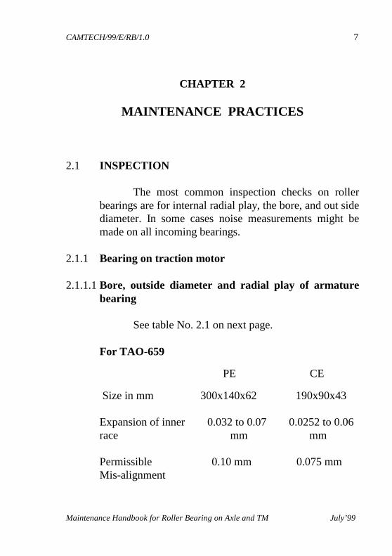
MAINTENANCE PRACTICES 2.1 INSPECTION The most common inspection checks on roller
bearings are for internal radial play, the bore, and out side diameter. In some cases noise measurements might be made on all incoming bearings.
2.1.1 Bearing on traction motor 2.1.1.1 Bore, outside diameter and radial play of armature
bearing See table No. 2.1 on next page.
For TAO-659
PE CE
Size in mm 300x140x62 190x90x43 Expansion of inner 0.032 to 0.07 0.0252 to 0.06 race mm mm Permissible 0.10 mm 0.075 mm Mis-alignment
CAMTECH/99/E/RB/1.0 8
Maintenance Handbook for Roller Bearing on Axle and TM July’99
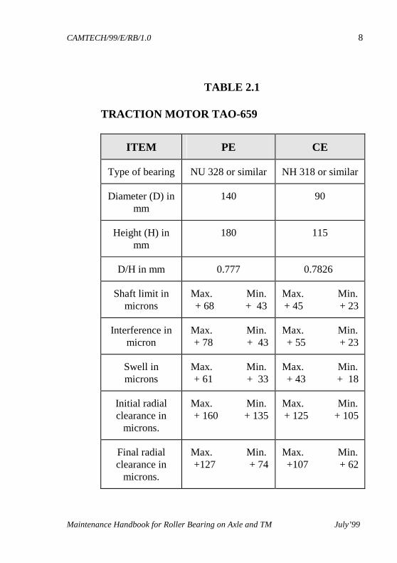
TABLE 2.1
TRACTION MOTOR TAO-659
ITEM PE CE
Type of bearing NU 328 or similar NH 318 or similar
Diameter (D) in mm
140 90
Height (H) in mm
180 115
D/H in mm 0.777 0.7826
Shaft limit in microns
Max. Min. + 68 + 43
Max. Min. + 45 + 23
Interference in micron
Max. Min. + 78 + 43
Max. Min. + 55 + 23
Swell in microns
Max. Min. + 61 + 33
Max. Min. + 43 + 18
Initial radial clearance in
microns.
Max. Min. + 160 + 135
Max. Min. + 125 + 105
Final radial clearance in
microns.
Max. Min. +127 + 74
Max. Min. +107 + 62
CAMTECH/99/E/RB/1.0 9
Maintenance Handbook for Roller Bearing on Axle and TM July’99
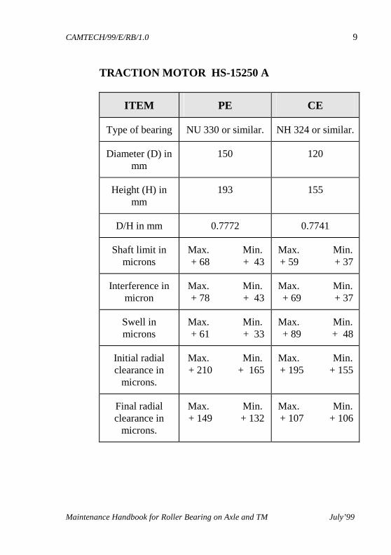
TRACTION MOTOR HS-15250 A
ITEM PE CE
Type of bearing NU 330 or similar. NH 324 or similar.
Diameter (D) in mm
150 120
Height (H) in mm
193 155
D/H in mm 0.7772 0.7741
Shaft limit in microns
Max. Min. + 68 + 43
Max. Min. + 59 + 37
Interference in micron
Max. Min. + 78 + 43
Max. Min. + 69 + 37
Swell in microns
Max. Min. + 61 + 33
Max. Min. + 89 + 48
Initial radial clearance in
microns.
Max. Min. + 210 + 165
Max. Min. + 195 + 155
Final radial clearance in
microns.
Max. Min. + 149 + 132
Max. Min. + 107 + 106
CAMTECH/99/E/RB/1.0 10
Maintenance Handbook for Roller Bearing on Axle and TM July’99
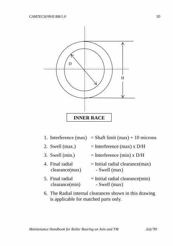
1. Interference (max) = Shaft limit (max) + 10 microns
2. Swell (max.) = Interference (max) x D/H
3. Swell (min.) = Interference (min) x D/H
4. Final radial = Initial radial clearance(max) clearance(max) - Swell (max)
5. Final radial = Initial radial clearance(min) clearance(min) - Swell (max)
6. The Radial internal clearances shown in this drawing is applicable for matched parts only.
D
H
INNER RACE
CAMTECH/99/E/RB/1.0 11
Maintenance Handbook for Roller Bearing on Axle and TM July’99
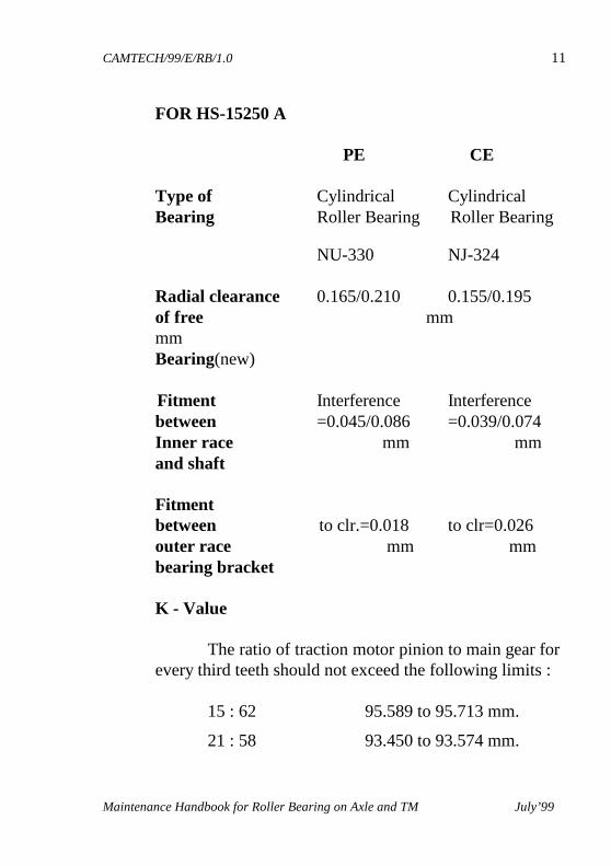
FOR HS-15250 A PE CE Type of Cylindrical Cylindrical Bearing Roller Bearing Roller Bearing
NU-330 NJ-324 Radial clearance 0.165/0.210 0.155/0.195 of free mm mm Bearing(new) Fitment Interference Interference between =0.045/0.086 =0.039/0.074 Inner race mm mm and shaft Fitment between to clr.=0.018 to clr=0.026 outer race mm mm bearing bracket K - Value The ratio of traction motor pinion to main gear for every third teeth should not exceed the following limits : 15 : 62 95.589 to 95.713 mm.
21 : 58 93.450 to 93.574 mm.
CAMTECH/99/E/RB/1.0 12
Maintenance Handbook for Roller Bearing on Axle and TM July’99
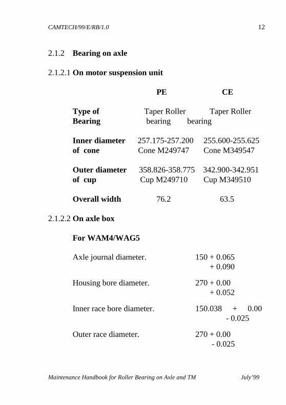
2.1.2 Bearing on axle 2.1.2.1 On motor suspension unit PE CE Type of Taper Roller Taper Roller Bearing bearing bearing
Inner diameter 257.175-257.200 255.600-255.625 of cone Cone M249747 Cone M349547
Outer diameter 358.826-358.775 342.900-342.951 of cup Cup M249710 Cup M349510
Overall width 76.2 63.5
2.1.2.2 On axle box
For WAM4/WAG5 Axle journal diameter. 150 + 0.065 + 0.090
Housing bore diameter. 270 + 0.00 + 0.052
Inner race bore diameter. 150.038 + 0.00 - 0.025
Outer race diameter. 270 + 0.00 - 0.025
CAMTECH/99/E/RB/1.0 13
Maintenance Handbook for Roller Bearing on Axle and TM July’99
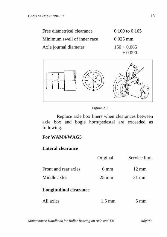
Free diametrical clearance 0.100 to 0.165
Minimum swell of inner race 0.025 mm
Axle journal diameter 150 + 0.065 + 0.090
Replace axle box liners when clearances between axle box and bogie horn/pedestal are exceeded as following.
For WAM4/WAG5
Lateral clearance
Original Service limit Front and rear axles 6 mm 12 mm
Middle axles 25 mm 31 mm
Longitudinal clearance All axles 1.5 mm 5 mm
Figure 2.1
CAMTECH/99/E/RB/1.0 14
Maintenance Handbook for Roller Bearing on Axle and TM July’99
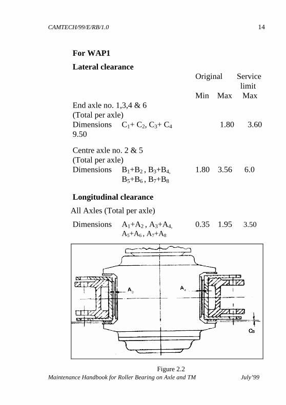
For WAP1
Lateral clearance Original Service
limit Min Max Max End axle no. 1,3,4 & 6 (Total per axle)
Dimensions C1+ C2, C3+ C4 1.80 3.60 9.50
Centre axle no. 2 & 5 (Total per axle) Dimensions B1+B2 , B3+B4, 1.80 3.56 6.0 B5+B6 , B7+B8
Longitudinal clearance
All Axles (Total per axle)
Dimensions A1+A2 , A3+A4, 0.35 1.95 3.50 A5+A6 , A7+A8
Figure 2.2
CAMTECH/99/E/RB/1.0 15
Maintenance Handbook for Roller Bearing on Axle and TM July’99
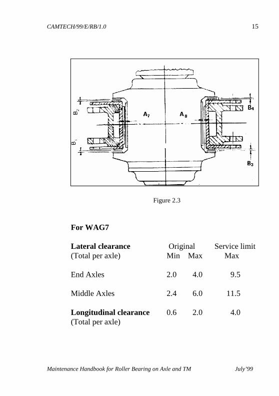
For WAG7
Lateral clearance Original Service limit (Total per axle) Min Max Max
End Axles 2.0 4.0 9.5 Middle Axles 2.4 6.0 11.5 Longitudinal clearance 0.6 2.0 4.0 (Total per axle)
Figure 2.3
CAMTECH/99/E/RB/1.0 16
Maintenance Handbook for Roller Bearing on Axle and TM July’99
Assembly Ensure that axle seating for thrower and inner
races are of correct size and of good finish. Shrink the thrower into the place on axle and check abutment face for squareness. This operation is accomplished by heating the thrower and races to 130 ±100C maximum in the oil bath. Remove the thrower from oil bath and wipe off the oil from inner surface as early as possible and immediately shrink fit thrower and allow to cool naturally. Similarly shrink fit the inner races and distance piece.
Assemble the axle box by fitting rear end cover,
bearing and outer distance piece. Charge bearing and cavities with specified grease. Lift the complete axle box and fit on axle gently. During the operation, care should be taken to avoid any possible damage of inner races resulting from scoring by the rollers due to unsquare mounted.
Fit dense lip and affix axle clamping plate locking
the screws in position. Follow on with the assembly of front end cover.
Dismantling
Procedure is reversed that of assembly but for
inspection and tyre turning don’t remove inner races or thrower.
CAMTECH/99/E/RB/1.0 17
Maintenance Handbook for Roller Bearing on Axle and TM July’99
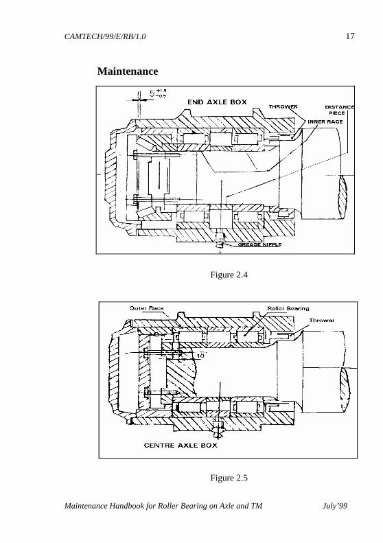
Maintenance
Figure 2.4
Figure 2.5
CAMTECH/99/E/RB/1.0 18
Maintenance Handbook for Roller Bearing on Axle and TM July’99
Remove end cover from one or more boxes per loco after the first 8000 kms. running and examine the grease near the bearing to see condition. If satisfactory, replace any grease lost in end cover during examination and reassemble end cover. Inject 15-50 CC (.0135 - .027 Kg) of specified grease into all boxes.
At four/six monthly periods or 8000 kms running which ever is earlier, inject 30-50 CC (.027 - .045 Kg) specified grease into all boxes. At twelve monthly periods remove axle boxes and clean out for inspection of bearing release as for first assembly. General instructions for storage and handling ■ Always store the bearing and axle boxes with
bearings in a clean and dry place in their original wrapping until required for actual installation. Avoid storage in appreciably hot surroundings.
■ Do not stack too many bearing on top of each other,
otherwise the bearing and its wrapping may lead to corrosion problems. Also never store bearing up right but lay them flat. Utilise old stock first.
■ While handling the bearings ensure that absolute
cleanliness is maintained. A smooth metal topped bench, which can be wiped will be great advantageous.
■ Do not leave the bearings unwrapped and exposed to
flying metal chips and other foreign particles.
CAMTECH/99/E/RB/1.0 19
Maintenance Handbook for Roller Bearing on Axle and TM July’99
■ Installation of roller bearings axle boxes on wheel sets should be done inside a separate dust proof shed.
■ Care should be taken while handling of wheel sets to
avoid any damage to the already mounted axle boxes before lowering the bogie frame over the wheel sets for final assembly. The free rotation of axle boxes must be ensured.
■ Whenever it is necessary to do any electric welding
on the loco/bogie frame the roller bearing should be avoided from electric circuit by connecting the earthing cable close to the spot being welded.
Type of Grease The following type of grease has been approved by R.D.S.O. for motor suspension unit of traction motor HS-15250, armature of both HS-15250 and TAO-659 as well as axle boxes of all type of electric locomotives. 1. Servogem. RR-3 (IOC)
3. Balmeral Multi Grease LL-3 (B&L)
CAMTECH/99/E/RB/1.0 20
Maintenance Handbook for Roller Bearing on Axle and TM July’99
2.2 ON LINE MAINTENANCE The first indication of a bearing failure is the accompanying rise in temperature. Hence the most important check that can be carried out when the bearing is in operation is to check the bearing temperature at various halting stations. If the temperature felt is higher than that of the other axle boxes, the loco may be withdrawn for further investigation. On line maintenance also cause for observation/ inspection of other aspects like :
■ Damaged axle box
■ Damaged front/rear cover.
■ Loosening of any of the fasteners/hardware. During on line maintenance, the operating temperature of freshly greased bearings should be monitored. It should be noted that freshly greased bearings run warmer than those bearings which have already been in operation. This is because of the extra grease in the axle box. A few trip will stabilise the temperature. In case of a loco which is withdrawn from service due to a defective axle box / traction motor, an investigation to inspect the bearing without dismounting may be carried out as suggested on next page.
CAMTECH/99/E/RB/1.0 21
Maintenance Handbook for Roller Bearing on Axle and TM July’99
■ Thoroughly clean all the exterior surfaces of the axle box with petrol/kerosene.
■ Remove the front cover of axle box housing.
■ Examine the grease for the following :
■ Consistency
■ Colour
■ Contamination with water
■ Any foreign particles. ■ Take off the axle box housing carefully.
■ Examine the bearing and the rear cover for defect.
■ Remove the grease from the bearing, wash the bearing and components with kerosene first and finally with petrol.
■ Care must be taken so that no hair from the brush sticks to any surface of the bearing. Use of cotton waste is undesirable.
■ During cleaning the bearing should be continuously rotated so that grease from every corner is taken out.
■ All surfaces, especially those in rolling contact, should be checked by swivelling the bearing.
CAMTECH/99/E/RB/1.0 22
Maintenance Handbook for Roller Bearing on Axle and TM July’99
■ Bearings may be rejected due to the defects given below:
■ Pitted/flaked rollers, raceways. ■ Inner ring/outer ring cracked. ■ Cage damaged ■ Rust/corrosion damage.
■ Measure the radial clearances in the unloaded zone,
using a long filler gauge simultaneously passing it over both the rows of rollers. If it exceeds the service limit.
■ In case the condition of the bearing is found all right
in all respects, the bearing may be reused. ■ Pack fresh grease into the bearing, space between the
rear cover and the bearing and V grooves of the rear cover.
■ Thoroughly clean the axle box front cover particularly
in V-grooves and carefully push it over the bearing. Tighten the axle box bolts and lock them with split pins. Check the axle box for free rotation by hand.
■ Operating personnel should always try to avoid
causes of wheel skidding because their is an adverse impact on the bearings of both motor suspension unit as well as axle boxes.
CAMTECH/99/E/RB/1.0 23
Maintenance Handbook for Roller Bearing on Axle and TM July’99
CHAPTER 3
INSPECTION SCHEDULE
3.1 ROLLER BEARINGS ON AXLE BOXES
3.1.1 Monthly schedule ■ Visually examine the axle box for any unusual
condition. ■ Investigate lubrication leakage at housing joints. ■ Check for missing or improper locking of cover studs. ■ Observe any sign for overheating on the outside
portion of the axle box. ■ Running temperature should not be more than 280 C
above ambient temperature. ■ Examine the shunt connection between traction motor
and under frame for looseness and tighten whenever necessary.
■ Check the fixation screws of bearing end plates. ■ Check function of the friction dampers.
■ Ensure that bolts having split pins and washers.
CAMTECH/99/E/RB/1.0 24
Maintenance Handbook for Roller Bearing on Axle and TM July’99
■ Check wear of pins and washers.
3.1.2 Bi-monthly schedule ■ Check and ensure proper fixation of front covers of
the axle boxes. ■ Axle boxes front covers to be removed and condition
of grease to be checked. Renew the grease, if necessary.
■ Check condition of earthing assembly.
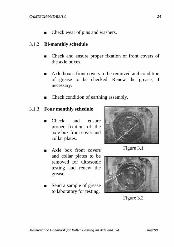
3.1.3 Four monthly schedule ■ Check and ensure
proper fixation of the axle box front cover and collar plates.
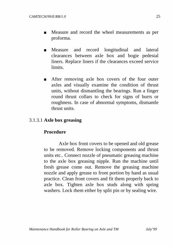
■ Axle box front covers
and collar plates to be removed for ultrasonic testing and renew the grease.
■ Send a sample of grease
to laboratory for testing.
Figure 3.1
Figure 3.2
CAMTECH/99/E/RB/1.0 25
Maintenance Handbook for Roller Bearing on Axle and TM July’99
■ Measure and record the wheel measurements as per proforma.
■ Measure and record longitudinal and lateral
clearances between axle box and bogie pedestal liners. Replace liners if the clearances exceed service limits.
■ After removing axle box covers of the four outer
axles and visually examine the condition of thrust units, without dismantling the bearings. Run a finger round thrust collars to check for signs of burrs or roughness. In case of abnormal symptoms, dismantle thrust units.
3.1.3.1 Axle box greasing
Procedure Axle box front covers to be opened and old grease to be removed. Remove locking components and thrust units etc.. Connect nozzle of pneumatic greasing machine to the axle box greasing nipple. Run the machine until fresh grease come out. Remove the greasing machine nozzle and apply grease to front portion by hand as usual practice. Clean front covers and fit them properly back to axle box. Tighten axle box studs along with spring washers. Lock them either by split pin or by sealing wire.
CAMTECH/99/E/RB/1.0 26
Maintenance Handbook for Roller Bearing on Axle and TM July’99
3.1.4 AOH
■ Remove axle box assembly. ■ Dismantle axle box and clean properly. ■ Inspect outer race for any evidence of spinning,
snalling or cracks. ■ Inspect inner race roller path for any sign of spalling
or flaking. ■ Clean and examine the bearing seating on the axle.
Pay attention to the shoulder of the thrower on the axle and all fillets.
■ Renew rubber seating rings. ■ Check the condition of grease nipple, replace if
required. ■ Check the condition of threads for all studs and bolts
on box as well as on axle. ■ Reassemble axle box for further service.
CAMTECH/99/E/RB/1.0 27
Maintenance Handbook for Roller Bearing on Axle and TM July’99
3.2 ROLLER BEARINGS ON MOTOR SUSPENSION UNIT (MSU) Following work to be carried out during IA, IB and IC inspection schedules.
3.2.1 Monthly and bi-monthly schedule ■ Ensure that there is no any burning smell or
blackishness in lubricant. If so, the supervisor incharge should be informed immediately.
■ Check the condition of bolts, locking wire and
washers, replace the damaged bolts and washers. ■ Ensure that suspension unit is secured rigidly to
magnet frame by tightening bolts size M 36 ■ Check suspension tube for cracks.
3.2.2 Four monthly schedule ■ Check the bearing temperature on suspension tube by
touching the outer surface of the bearing housing simply by hand. Compare and record them for any abnormality. If observed, replace complete wheel set.
■ Lubricate both the pinion end and commutator end
bearings on traction motor as well as motor suspension unit through greasing nipples.
■ Give sample of grease for testing.
CAMTECH/99/E/RB/1.0 28
Maintenance Handbook for Roller Bearing on Axle and TM July’99
■ Ensure proper fitment of abutment bolts of motor suspension unit.
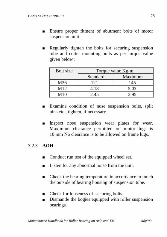
■ Regularly tighten the bolts for securing suspension
tube and cotter mounting bolts as per torque value given below :
Bolt size Torque value Kg-m
Standard Maximum M36 121 145 M12 4.18 5.03 M10 2.45 2.95
■ Examine condition of nose suspension bolts, split
pins etc., tighten, if necessary. ■ Inspect nose suspension wear plates for wear.
Maximum clearance permitted on motor lugs is 10 mm No clearance is to be allowed on frame lugs.
3.2.3 AOH
■ Conduct run test of the equipped wheel set.
■ Listen for any abnormal noise from the unit. ■ Check the bearing temperature in accordance to touch
the outside of bearing housing of suspension tube. ■ Check for looseness of securing bolts. ■ Dismantle the bogies equipped with roller suspension
bearings.
CAMTECH/99/E/RB/1.0 29
Maintenance Handbook for Roller Bearing on Axle and TM July’99
■ Ensure that there is no any overheating sign on roller
suspension tube. ■ Check Allen screws tightness at a torque value of
4.81 to 5.03 m kgs on motor suspension unit. ■ Lubricate both the ends. ■ Check end play to wheel suspension arrangement of
the wheel set. It should be 0.05 mm to 0.25 mm. ■ Ensure that there is no any crack or damage to tube. ■ Ensure that the greasing nipple is intact and no
leakage of grease is observed in the tube. If, leakage of grease is observed, it should be informed to the supervisor.
3.3 ROLLER BEARINGS ON TRACTION MOTOR
3.3.1 Monthly and bi-monthly schedule
■ An attention to be paid only if, there is an special
report from operating personnel.
3.3.2 Four monthly schedule ■ Inject specified grease to the both end of armature
bearings. 3.3.3 AOH
3.3.3.1 Disassembly of Armature Bearing
CAMTECH/99/E/RB/1.0 30
Maintenance Handbook for Roller Bearing on Axle and TM July’99
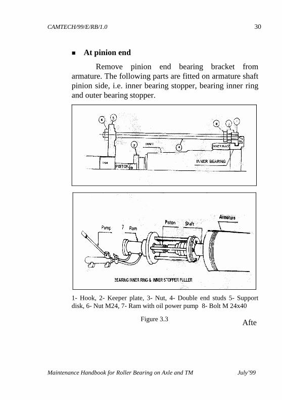
� At pinion end
Remove pinion end bearing bracket from armature. The following parts are fitted on armature shaft pinion side, i.e. inner bearing stopper, bearing inner ring and outer bearing stopper.
1- Hook, 2- Keeper plate, 3- Nut, 4- Double end studs 5- Support disk, 6- Nut M24, 7- Ram with oil power pump 8- Bolt M 24x40
Afte
Figure 3.3
CAMTECH/99/E/RB/1.0 31
Maintenance Handbook for Roller Bearing on Axle and TM July’99
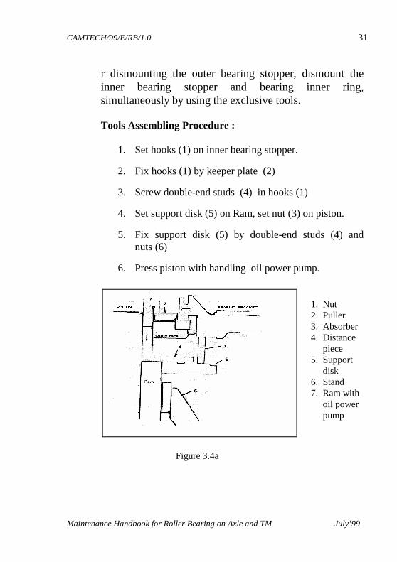
r dismounting the outer bearing stopper, dismount the inner bearing stopper and bearing inner ring, simultaneously by using the exclusive tools. Tools Assembling Procedure :
1. Set hooks (1) on inner bearing stopper.
2. Fix hooks (1) by keeper plate (2)
3. Screw double-end studs (4) in hooks (1)
4. Set support disk (5) on Ram, set nut (3) on piston.
5. Fix support disk (5) by double-end studs (4) and nuts (6)
6. Press piston with handling oil power pump.
1. Nut 2. Puller 3. Absorber 4. Distance piece 5. Support disk 6. Stand 7. Ram with oil power pump
Figure 3.4a
CAMTECH/99/E/RB/1.0 32
Maintenance Handbook for Roller Bearing on Axle and TM July’99
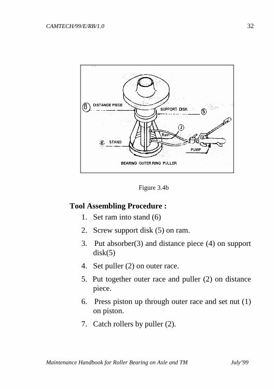
Tool Assembling Procedure : 1. Set ram into stand (6)
2. Screw support disk (5) on ram.
3. Put absorber(3) and distance piece (4) on support disk(5)
4. Set puller (2) on outer race.
5. Put together outer race and puller (2) on distance piece.
6. Press piston up through outer race and set nut (1) on piston.
7. Catch rollers by puller (2).
Figure 3.4b
CAMTECH/99/E/RB/1.0 33
Maintenance Handbook for Roller Bearing on Axle and TM July’99
8. Press piston downward with handling oil power pump.
■ At commutator end
Remove commutator end, end shield by using exclusive tool according to the procedure applied for pinion end bearing. Similarly dismount bearing inner ring, inner bearing stopper and bearing outer ring.
3.3.3.2 Cleaning of armature bearing
To clean the dismounted armature bearings, put them into a vessel containing kerosene heated up to about 60° without degreasing and leave them as they are in kerosene for more than 10 minutes. After that, blow away sticking grease with compressed air. Repeat the procedures more than twice. Wash the bearings finally with a clean kerosene and blow away adhering kerosene completely with dry air.
For the final washing, always use new kerosene and do not use heavily oxidised or foul one. Wash hands with a degreasing agent such as ethyl alcohol carefully for preventing the bearings from getting rusty.
3.3.3.3 Checking of armature bearings
Check visually for roughness, scratch, bruise, discoloration, rust etc. on inner and outer race. Check while moving the rollers for wear of retainer, looseness of rivets and make sure that there is no abnormality. If any abnormality observed in either inner or outer ring, replace with new set of bearings.
CAMTECH/99/E/RB/1.0 34
Maintenance Handbook for Roller Bearing on Axle and TM July’99
- Check for inner and outer ring of same serial number.
CAMTECH/99/E/RB/1.0 35
Maintenance Handbook for Roller Bearing on Axle and TM July’99
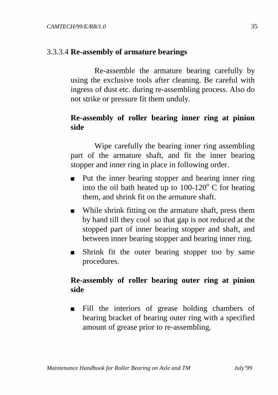
3.3.3.4 Re-assembly of armature bearings Re-assemble the armature bearing carefully by using the exclusive tools after cleaning. Be careful with ingress of dust etc. during re-assembling process. Also do not strike or pressure fit them unduly. Re-assembly of roller bearing inner ring at pinion side Wipe carefully the bearing inner ring assembling part of the armature shaft, and fit the inner bearing stopper and inner ring in place in following order.
■ Put the inner bearing stopper and bearing inner ring into the oil bath heated up to 100-120o C for heating them, and shrink fit on the armature shaft.
■ While shrink fitting on the armature shaft, press them by hand till they cool so that gap is not reduced at the stopped part of inner bearing stopper and shaft, and between inner bearing stopper and bearing inner ring.
■ Shrink fit the outer bearing stopper too by same procedures.
Re-assembly of roller bearing outer ring at pinion side ■ Fill the interiors of grease holding chambers of
bearing bracket of bearing outer ring with a specified amount of grease prior to re-assembling.
CAMTECH/99/E/RB/1.0 36
Maintenance Handbook for Roller Bearing on Axle and TM July’99
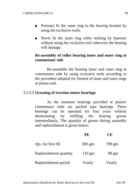
■ Pressure fit the outer ring to the bearing bracket by using the exclusive tools.
■ Never fit the outer ring while striking by hammer without using the exclusive tool otherwise the bearing will damage.
Re-assembly of roller bearing inner and outer ring at commutator side Re-assemble the bearing inner and outer ring at commutator side by using exclusive tools according to the procedure adopted for fitment of inner and outer rings at pinion end.
3.3.3.5 Greasing of traction motor bearings
As the armature bearings provided at pinion/ commutator ends are packed type bearings. These bearings can be operated for four years without dismounting by refilling the bearing grease intermediately. The quantity of grease during assembly and replenishment is given below: PE CE Qty. for first fill 805 gm 789 gm
Replenishment quantity 110 gm 98 gm
Replenishment period Yearly Yearly
CAMTECH/99/E/RB/1.0 37
Maintenance Handbook for Roller Bearing on Axle and TM July’99
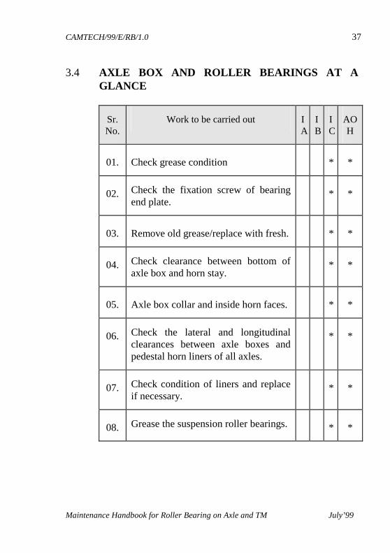
3.4 AXLE BOX AND ROLLER BEARINGS AT A GLANCE
Sr.No.
Work to be carried out IA
IB
IC
AOH
01. Check grease condition * *
02. Check the fixation screw of bearing end plate.
* *
03. Remove old grease/replace with fresh. * *
04. Check clearance between bottom of axle box and horn stay.
* *
05. Axle box collar and inside horn faces. * *
06. Check the lateral and longitudinal clearances between axle boxes and pedestal horn liners of all axles.
* *
07. Check condition of liners and replace if necessary.
* *
08. Grease the suspension roller bearings. * *
CAMTECH/99/E/RB/1.0 38
Maintenance Handbook for Roller Bearing on Axle and TM July’99
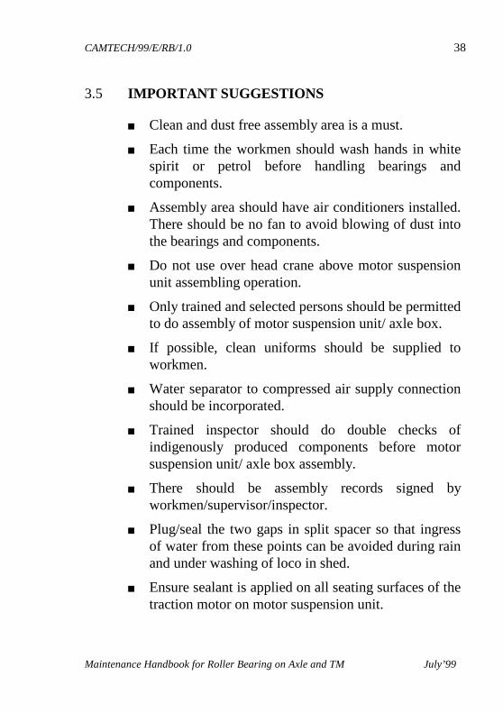
3.5 IMPORTANT SUGGESTIONS
■ Clean and dust free assembly area is a must.
■ Each time the workmen should wash hands in white spirit or petrol before handling bearings and components.
■ Assembly area should have air conditioners installed. There should be no fan to avoid blowing of dust into the bearings and components.
■ Do not use over head crane above motor suspension unit assembling operation.
■ Only trained and selected persons should be permitted to do assembly of motor suspension unit/ axle box.
■ If possible, clean uniforms should be supplied to workmen.
■ Water separator to compressed air supply connection should be incorporated.
■ Trained inspector should do double checks of indigenously produced components before motor suspension unit/ axle box assembly.
■ There should be assembly records signed by workmen/supervisor/inspector.
■ Plug/seal the two gaps in split spacer so that ingress of water from these points can be avoided during rain and under washing of loco in shed.
■ Ensure sealant is applied on all seating surfaces of the traction motor on motor suspension unit.
CAMTECH/99/E/RB/1.0 39
Maintenance Handbook for Roller Bearing on Axle and TM July’99
CHAPTER 4
TYPE OF DEFECTS
4.1 COMMON DEFECTS Any one of the following common defect can lead
to bearing troubles. ■ Error in machine design.
■ Faulty operation.
■ Faulty maintenance.
■ Improper environments.
■ Lack of adequate lubrication.
Other defects are as following : 4.1.1 FATIGUE
Other factors such as mis-alignment, internal pre- loading, or vibration may have been the underlying cause of high load.
The passage of electric current, fretting, corrosion, and defects in the bearing material itself may result in physical defects at which high stress concentration develop to cause early fatigue.
CAMTECH/99/E/RB/1.0 40
Maintenance Handbook for Roller Bearing on Axle and TM July’99
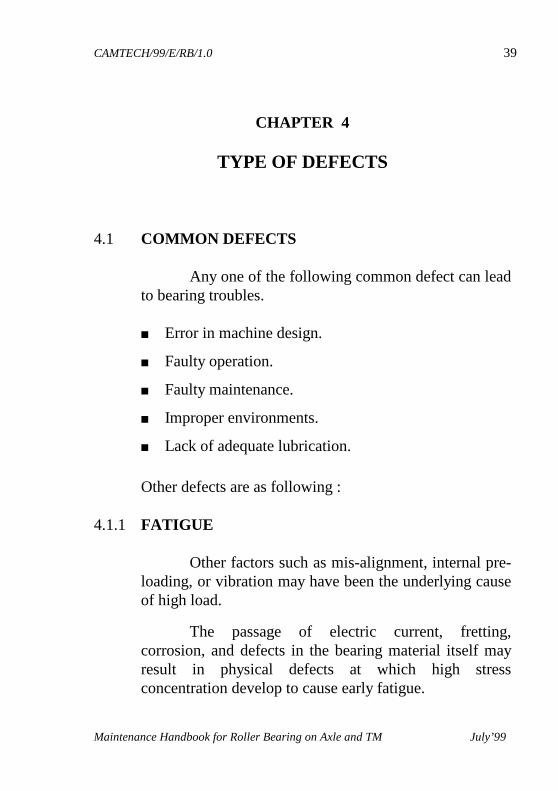
4.1.2 DIRT Presence of dirt in
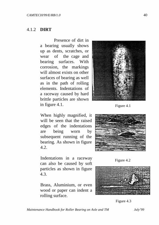
a bearing usually shows up as dents, scratches, or wear of the cage and bearing surfaces. With corrosion, the markings will almost exists on other surfaces of bearing as well as in the path of rolling elements. Indentations of a raceway caused by hard brittle particles are shown in figure 4.1. When highly magnified, it will be seen that the raised edges of the indentations are being worn by subsequent running of the bearing. As shown in figure 4.2.
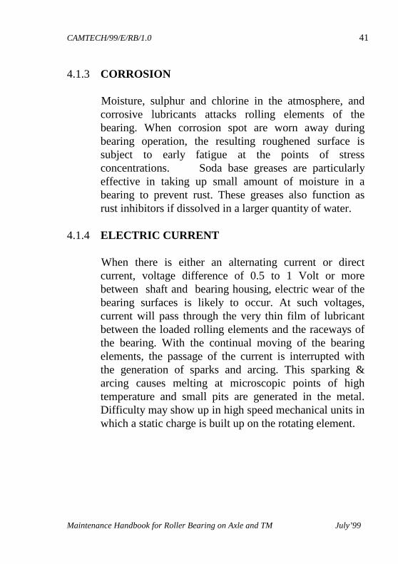
Indentations in a raceway
can also be caused by soft particles as shown in figure 4.3.
Brass, Aluminium, or even
wood or paper can indent a rolling surface.
Figure 4.1
Figure 4.2
Figure 4.3
CAMTECH/99/E/RB/1.0 41
Maintenance Handbook for Roller Bearing on Axle and TM July’99
4.1.3 CORROSION
Moisture, sulphur and chlorine in the atmosphere, and corrosive lubricants attacks rolling elements of the bearing. When corrosion spot are worn away during bearing operation, the resulting roughened surface is subject to early fatigue at the points of stress concentrations. Soda base greases are particularly effective in taking up small amount of moisture in a bearing to prevent rust. These greases also function as rust inhibitors if dissolved in a larger quantity of water.
4.1.4 ELECTRIC CURRENT When there is either an alternating current or direct
current, voltage difference of 0.5 to 1 Volt or more between shaft and bearing housing, electric wear of the bearing surfaces is likely to occur. At such voltages, current will pass through the very thin film of lubricant between the loaded rolling elements and the raceways of the bearing. With the continual moving of the bearing elements, the passage of the current is interrupted with the generation of sparks and arcing. This sparking & arcing causes melting at microscopic points of high temperature and small pits are generated in the metal. Difficulty may show up in high speed mechanical units in which a static charge is built up on the rotating element.
CAMTECH/99/E/RB/1.0 42
Maintenance Handbook for Roller Bearing on Axle and TM July’99
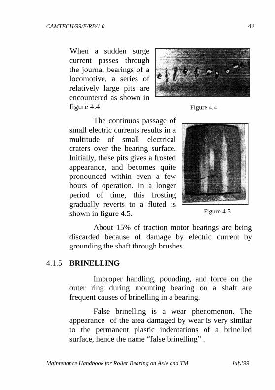
When a sudden surge current passes through the journal bearings of a locomotive, a series of relatively large pits are encountered as shown in figure 4.4
The continuos passage of small electric currents results in a multitude of small electrical craters over the bearing surface. Initially, these pits gives a frosted appearance, and becomes quite pronounced within even a few hours of operation. In a longer period of time, this frosting gradually reverts to a fluted is shown in figure 4.5.
About 15% of traction motor bearings are being discarded because of damage by electric current by grounding the shaft through brushes.
4.1.5 BRINELLING
Improper handling, pounding, and force on the outer ring during mounting bearing on a shaft are frequent causes of brinelling in a bearing. False brinelling is a wear phenomenon. The appearance of the area damaged by wear is very similar to the permanent plastic indentations of a brinelled surface, hence the name “false brinelling” .
Figure 4.4
Figure 4.5
CAMTECH/99/E/RB/1.0 43
Maintenance Handbook for Roller Bearing on Axle and TM July’99
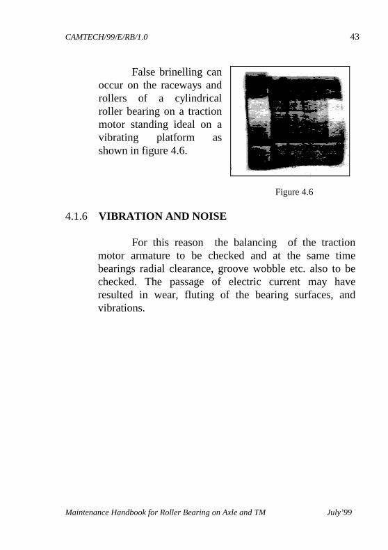
False brinelling can occur on the raceways and rollers of a cylindrical roller bearing on a traction motor standing ideal on a vibrating platform as shown in figure 4.6.
4.1.6 VIBRATION AND NOISE
For this reason the balancing of the traction
motor armature to be checked and at the same time bearings radial clearance, groove wobble etc. also to be checked. The passage of electric current may have resulted in wear, fluting of the bearing surfaces, and vibrations.
Figure 4.6
Figure 4.6
CAMTECH/99/E/RB/1.0 44
Maintenance Handbook for Roller Bearing on Axle and TM July’99
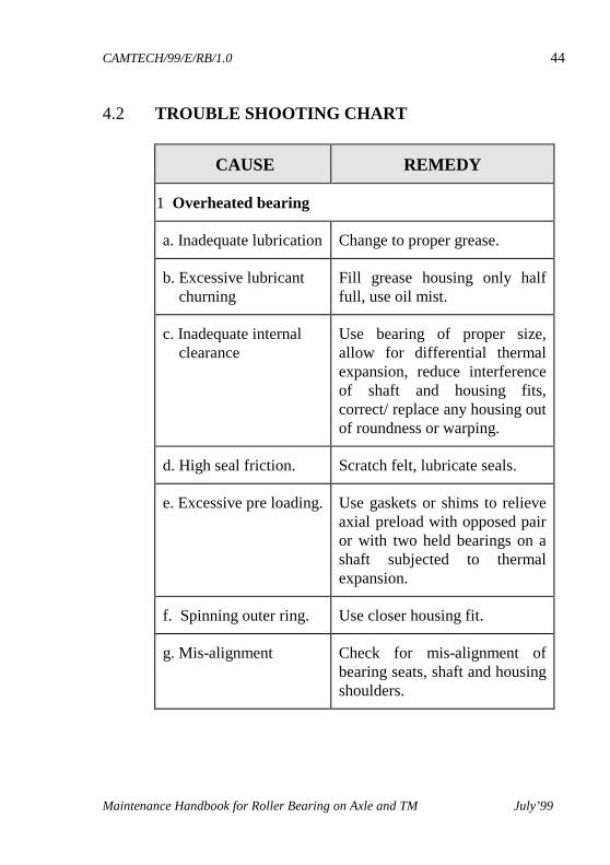
4.2 TROUBLE SHOOTING CHART
CAUSE REMEDY
1 Overheated bearing
a. Inadequate lubrication Change to proper grease.
b. Excessive lubricant churning
Fill grease housing only half full, use oil mist.
c. Inadequate internal clearance
Use bearing of proper size, allow for differential thermal expansion, reduce interference of shaft and housing fits, correct/ replace any housing out of roundness or warping.
d. High seal friction. Scratch felt, lubricate seals.
e. Excessive pre loading. Use gaskets or shims to relieve axial preload with opposed pair or with two held bearings on a shaft subjected to thermal expansion.
f. Spinning outer ring. Use closer housing fit.
g. Mis-alignment Check for mis-alignment of bearing seats, shaft and housing shoulders.
CAMTECH/99/E/RB/1.0 45
Maintenance Handbook for Roller Bearing on Axle and TM July’99
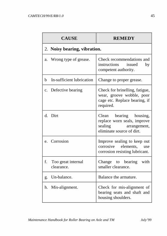
CAUSE REMEDY
2. Noisy bearing, vibration.
a. Wrong type of grease. Check recommendations and instructions issued by competent authority.
b In-sufficient lubrication Change to proper grease.
c. Defective bearing Check for brinelling, fatigue, wear, groove wobble, poor cage etc. Replace bearing, if required.
d. Dirt Clean bearing housing, replace worn seals, improve sealing arrangement, eliminate source of dirt.
e. Corrosion Improve sealing to keep out corrosive elements, use corrosion resisting lubricant.
f. Too great internal clearance.
Change to bearing with smaller clearance.
g. Un-balance. Balance the armature.
h. Mis-alignment. Check for mis-alignment of bearing seats and shaft and housing shoulders.
CAMTECH/99/E/RB/1.0 46
Maintenance Handbook for Roller Bearing on Axle and TM July’99
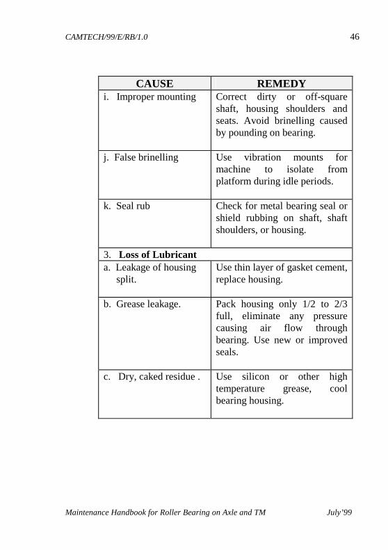
CAUSE REMEDY i. Improper mounting Correct dirty or off-square
shaft, housing shoulders and seats. Avoid brinelling caused by pounding on bearing.
j. False brinelling Use vibration mounts for machine to isolate from platform during idle periods.
k. Seal rub Check for metal bearing seal or shield rubbing on shaft, shaft shoulders, or housing.
3. Loss of Lubricant a. Leakage of housing split.
Use thin layer of gasket cement, replace housing.
b. Grease leakage. Pack housing only 1/2 to 2/3 full, eliminate any pressure causing air flow through bearing. Use new or improved seals.
c. Dry, caked residue . Use silicon or other high temperature grease, cool bearing housing.
CAMTECH/99/E/RB/1.0 47
Maintenance Handbook for Roller Bearing on Axle and TM July’99
CAUSE REMEDY
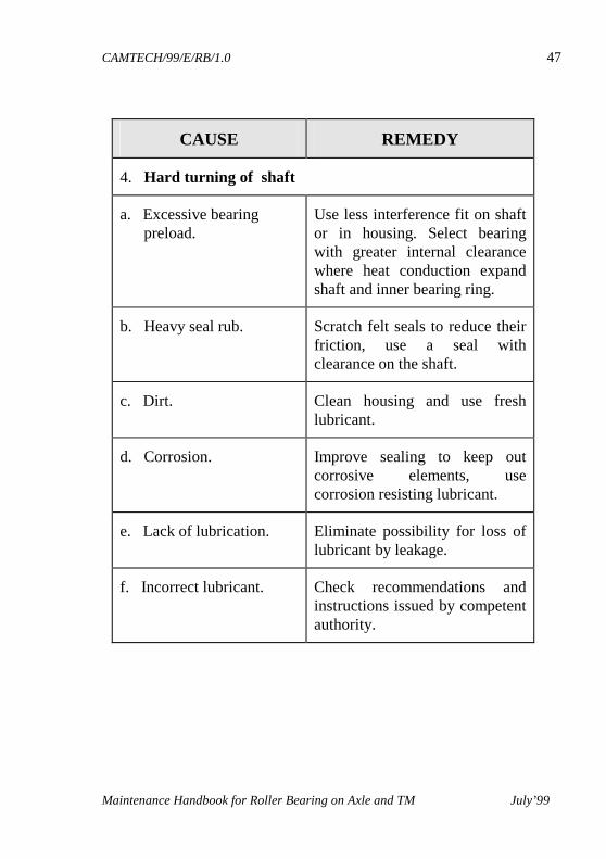
4. Hard turning of shaft
a. Excessive bearing preload.
Use less interference fit on shaft or in housing. Select bearing with greater internal clearance where heat conduction expand shaft and inner bearing ring.
b. Heavy seal rub. Scratch felt seals to reduce their friction, use a seal with clearance on the shaft.
c. Dirt. Clean housing and use fresh lubricant.
d. Corrosion. Improve sealing to keep out corrosive elements, use corrosion resisting lubricant.
e. Lack of lubrication. Eliminate possibility for loss of lubricant by leakage.
f. Incorrect lubricant. Check recommendations and instructions issued by competent authority.
CAMTECH/99/E/RB/1.0 48
Maintenance Handbook for Roller Bearing on Axle and TM July’99
CHAPTER 5
TESTING
5.1 OPTICAL CHECKING Optically examine the cleaned bearing during
overhauling by optical magnifying lens on the testing bench for indenting, burrs etc.
5.2 RADIAL CLEARANCE Measure the radial clearance with the help of a
dial gauge (refer table no. 1.1) 5.3 SHOCK PULSE MEASUREMENT The shock pulse method is an unique measuring
technique for condition control of rolling bearings. To give maintenance the ability to measure mechanical state of bearings at any stage of their service life. This method is very useful to avoid removing good bearings and to find damage bearings in time for a planned replacement.
All rotating rolling bearings emits shock pulses, i.e. pressure waves generated in the contact zone between the loaded rolling elements and the raceway. A specially tuned transducer amplifies high frequency shock signals and filters out machine vibrations.
CAMTECH/99/E/RB/1.0 49
Maintenance Handbook for Roller Bearing on Axle and TM July’99
The transducer output is a rapid sequence of electric pulses, proportional to the amplitude of the shock waves. Shock pulses are measured on a decibel scale (dB = decibel shock value). The carpet value dBc is a measurement of large number of relatively weak shock pulses, while the maximum value dBm represents a sample of the strong pulses in the pattern. Shock value readings and the green - yellow - red condition scale are the peak readings.
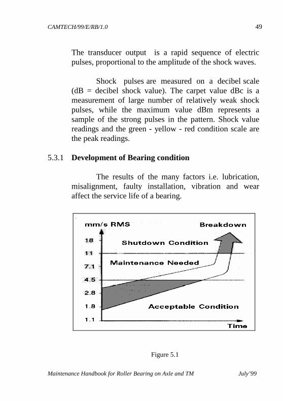
5.3.1 Development of Bearing condition The results of the many factors i.e. lubrication,
misalignment, faulty installation, vibration and wear affect the service life of a bearing.
Figure 5.1
CAMTECH/99/E/RB/1.0 50
Maintenance Handbook for Roller Bearing on Axle and TM July’99
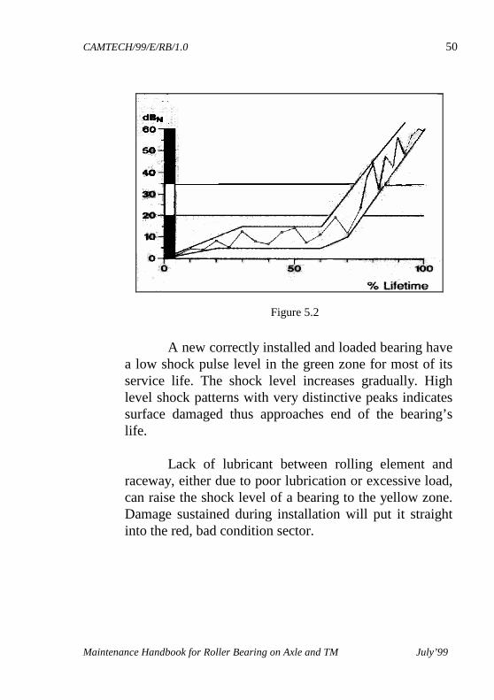
A new correctly installed and loaded bearing have
a low shock pulse level in the green zone for most of its service life. The shock level increases gradually. High level shock patterns with very distinctive peaks indicates surface damaged thus approaches end of the bearing’s life.
Lack of lubricant between rolling element and raceway, either due to poor lubrication or excessive load, can raise the shock level of a bearing to the yellow zone. Damage sustained during installation will put it straight into the red, bad condition sector.
Figure 5.2
CAMTECH/99/E/RB/1.0 51
Maintenance Handbook for Roller Bearing on Axle and TM July’99
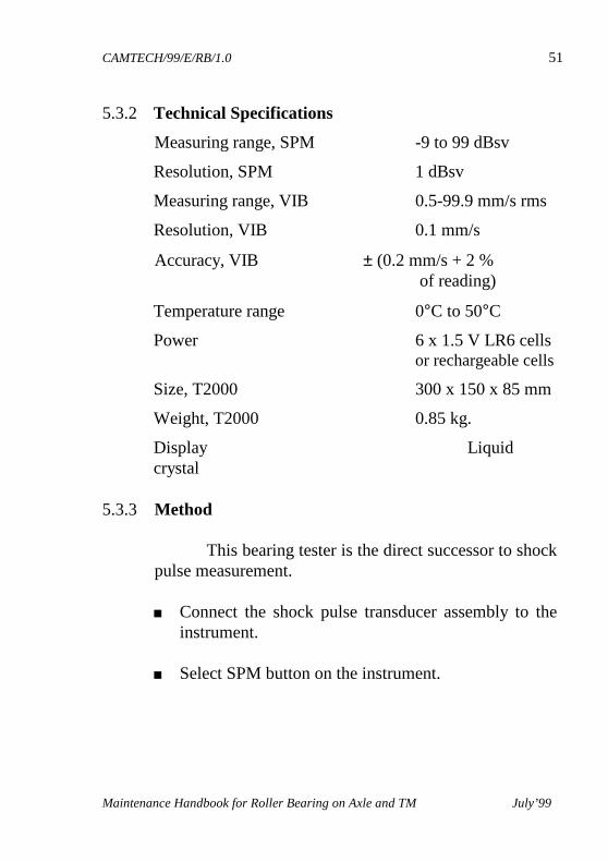
5.3.2 Technical Specifications
Measuring range, SPM -9 to 99 dBsv
Resolution, SPM 1 dBsv
Measuring range, VIB 0.5-99.9 mm/s rms
Resolution, VIB 0.1 mm/s
Accuracy, VIB ± (0.2 mm/s + 2 % of reading)
Temperature range 0°C to 50°C
Power 6 x 1.5 V LR6 cells or rechargeable cells
Size, T2000 300 x 150 x 85 mm
Weight, T2000 0.85 kg.
Display Liquid crystal
5.3.3 Method
This bearing tester is the direct successor to shock pulse measurement. ■ Connect the shock pulse transducer assembly to the
instrument.
■ Select SPM button on the instrument.
CAMTECH/99/E/RB/1.0 52
Maintenance Handbook for Roller Bearing on Axle and TM July’99
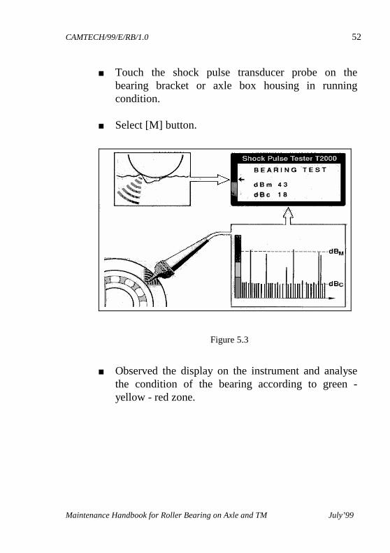
■ Touch the shock pulse transducer probe on the bearing bracket or axle box housing in running condition.
■ Select [M] button.
■ Observed the display on the instrument and analyse
the condition of the bearing according to green - yellow - red zone.
Figure 5.3
CAMTECH/99/E/RB/1.0 53
Maintenance Handbook for Roller Bearing on Axle and TM July’99
CHAPTER 6
CONDITION MONITORING Condition monitoring is the process of determining the
health of an equipment during service. Examples of condition monitoring are vibration in rotating machines, thermography, shock-pulse monitoring, wear debris monitoring, corrosion monitoring, ultrasonic testing, radiographic and spectrographic analysis. Such tests gives a pre-warning about the condition of the equipment or the machine to facilitate preventive maintenance before the breakdown occurs. Normally, the breakdown damages are more severe if preventive maintenance is not taken up in time.
6.1 NEED FOR WEAR DEBRIS MONITORING Normal practice followed by electric loco sheds
for maintenance of axle box is to open the axle box cover during IC inspection, check the physical condition of grease and bearing and replenish the old grease by new grease. Any major crack in the racers or damage to the bearings can only be detected by this visual inspection. However, any incipient flaw with any of these components in axle box can not be detected which may give rise to failure of axle box on line leading to hot axle.
CAMTECH/99/E/RB/1.0 54
Maintenance Handbook for Roller Bearing on Axle and TM July’99
The determination of ferrous content in grease is called Wear debris monitoring. Though there is no any guidelines available for the allowable ferrous content in the grease beyond which a locomotive is to be taken for lifting to remove the axle box. and find its physical condition. But based on the statistics the threshold value of ferrous content in the grease has been determined beyond which the axle box should be removed from the locomotive for checking.
6.2 SAMPLES AND DETERMINATION OF FERROUS CONTENTS
6.2.1 Methodology
� During IC/AOH, collect grease samples from all twelve axle boxes of a locomotive by thin metallic scoop from the area between racer and bearing rollers.
� Weigh 20 gms of sample for each axle box, transfer to a beaker and cover with glass.
� After 10 to 15 minutes, stir each sample vigorously for 5 minutes by electric stirred so that grease get dissolved completely with petrol.
� Allow the suspended metallic, non-metallic contaminants to settle down for 15 to 20 minutes.
� Separate the solids by decantation taking care that no metallic particle is drained out.
CAMTECH/99/E/RB/1.0 55
Maintenance Handbook for Roller Bearing on Axle and TM July’99
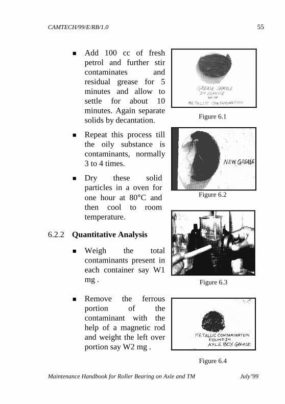
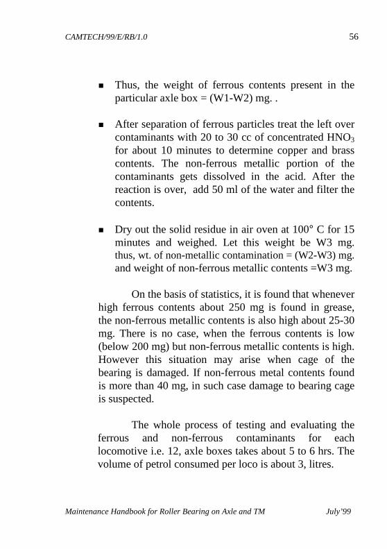
� Add 100 cc of fresh petrol and further stir contaminates and residual grease for 5 minutes and allow to settle for about 10 minutes. Again separate solids by decantation.
� Repeat this process till the oily substance is contaminants, normally 3 to 4 times.
� Dry these solid particles in a oven for one hour at 80°C and then cool to room temperature.
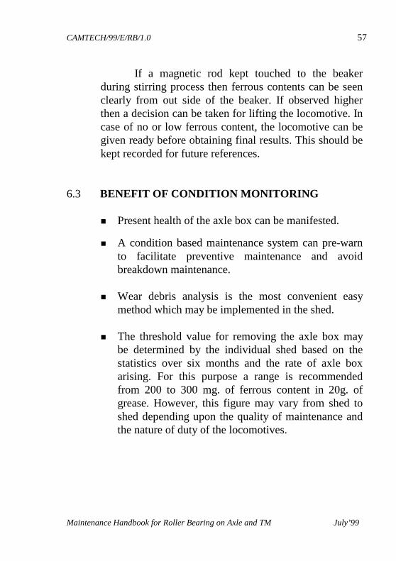
6.2.2 Quantitative Analysis
� Weigh the total contaminants present in each container say W1 mg .
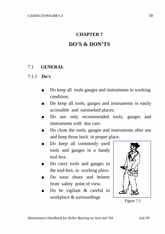
� Remove the ferrous portion of the contaminant with the help of a magnetic rod and weight the left over portion say W2 mg .
Figure 6.1
Figure 6.2
Figure 6.3
Figure 6.4
CAMTECH/99/E/RB/1.0 56
Maintenance Handbook for Roller Bearing on Axle and TM July’99
� Thus, the weight of ferrous contents present in the
particular axle box = (W1-W2) mg. .
� After separation of ferrous particles treat the left over contaminants with 20 to 30 cc of concentrated HNO3 for about 10 minutes to determine copper and brass contents. The non-ferrous metallic portion of the contaminants gets dissolved in the acid. After the reaction is over, add 50 ml of the water and filter the contents.
� Dry out the solid residue in air oven at 100° C for 15
minutes and weighed. Let this weight be W3 mg. thus, wt. of non-metallic contamination = (W2-W3) mg. and weight of non-ferrous metallic contents =W3 mg.
On the basis of statistics, it is found that whenever high ferrous contents about 250 mg is found in grease, the non-ferrous metallic contents is also high about 25-30 mg. There is no case, when the ferrous contents is low (below 200 mg) but non-ferrous metallic contents is high. However this situation may arise when cage of the bearing is damaged. If non-ferrous metal contents found is more than 40 mg, in such case damage to bearing cage is suspected.
The whole process of testing and evaluating the
ferrous and non-ferrous contaminants for each locomotive i.e. 12, axle boxes takes about 5 to 6 hrs. The volume of petrol consumed per loco is about 3, litres.
CAMTECH/99/E/RB/1.0 57
Maintenance Handbook for Roller Bearing on Axle and TM July’99
If a magnetic rod kept touched to the beaker during stirring process then ferrous contents can be seen clearly from out side of the beaker. If observed higher then a decision can be taken for lifting the locomotive. In case of no or low ferrous content, the locomotive can be given ready before obtaining final results. This should be kept recorded for future references.
6.3 BENEFIT OF CONDITION MONITORING
� Present health of the axle box can be manifested.
� A condition based maintenance system can pre-warn to facilitate preventive maintenance and avoid breakdown maintenance.
� Wear debris analysis is the most convenient easy
method which may be implemented in the shed.
� The threshold value for removing the axle box may be determined by the individual shed based on the statistics over six months and the rate of axle box arising. For this purpose a range is recommended from 200 to 300 mg. of ferrous content in 20g. of grease. However, this figure may vary from shed to shed depending upon the quality of maintenance and the nature of duty of the locomotives.
CAMTECH/99/E/RB/1.0 58
Maintenance Handbook for Roller Bearing on Axle and TM July’99
CHAPTER 7
DO’S & DON’TS
7.1 GENERAL
7.1.1 Do's
■ Do keep all tools gauges and instruments in working
condition.
■ Do keep all tools, gauges and instruments in easily
accessible and earmarked places.
■ Do use only recommended tools, gauges and
instruments with due care.
■ Do clean the tools, gauges and instruments after use
and keep those back in proper place.
■ Do keep all commonly used
tools and gauges in a handy
tool box.
■ Do carry tools and gauges in
the tool-box, to working place.
■ Do wear shoes and helmet
from safety point of view.
■ Do be vigilant & careful in
workplace & surroundings Figure 7.1
CAMTECH/99/E/RB/1.0 59
Maintenance Handbook for Roller Bearing on Axle and TM July’99
■ Do follow proper instructions for the use of
tools, gauges and instruments.
■ Do ensure, all the gauges are periodically checked for
their accuracy.
■ Do tighten nuts & bolts fully by applying proper
torque.
■ Do work with full of confidence.
■ Do protect bearings from dust/cotton/metal particles
by keeping it covered.
■ Do add a few drops of mineral oil to the bearings.
■ Do test the property/quality of new as well as
released grease.
■ Do fill new grease/oil for lubrication.
■ Do check all the tools, jigs & fixtures for any
deviation.
■ Do ensure use of torque wrench for tightening bolts,
whenever recommended.
■ Do follow recommended maintenance practices only.
CAMTECH/99/E/RB/1.0 60
Maintenance Handbook for Roller Bearing on Axle and TM July’99
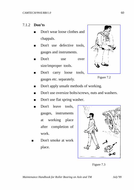
7.1.2 Don’ts
■ Don't wear loose clothes and
chappals.
■ Don't use defective tools,
gauges and instruments.
■ Don't use over
size/improper tools.
■ Don't carry loose tools,
gauges etc. separately.
■ Don't apply unsafe methods of working.
■ Don't use oversize bolts/screws, nuts and washers.
■ Don't use flat spring washer.
■ Don't leave tools,
gauges, instruments
at working place
after completion of
work.
■ Don't smoke at work
place.
Figure 7.2
Figure 7.3
CAMTECH/99/E/RB/1.0 61
Maintenance Handbook for Roller Bearing on Axle and TM July’99
If you have any suggestions and any specific comments, please write to us. Contact person : Joint Director (Elect.) Postal address : Indian Railways, Centre for Advanced Maintenance Technology, Maharajpur, Gwalior. Pin code - 474 020 Phone : 0751- 470740 0751- 470803 Fax : 0751- 470841
To upgrade maintenance technologies and methodologies and achieve improvement in productivity and performance of all Railway assets and man power which inter-alia would cover reliability, availability, utilisation and efficiency.
OUR