Embed Size (px)
Citation preview

MQP DCP 1-2012
Major Qualifying Project Final Report
Magnetic Braking
Author: Michael Scanlon Advisor: David C. Planchard
Co-advisor: Alexander E. Emanuel 4/26/2012

Michael E. Scanlon Advisor: David C. Planchard MQP - DCP 1-2012 (Magnetic Braking) Co-Advisor: Alexander Emanuel C – Term Report
1
Table of Contents:
1. Abstract ………………………………………………………………………………………………………..………………………2 2. Goal Statement ……………………………………………………………………………………………..……………………..3 3. Introduction …………………………………………………………………………………………………..……………………..3 4. Task Specifications …………………..…………………………………………………………………..…………………..…..4
a. Scope of Work (11-6-2011)………………………………………………………………………..……………...4 b. Tasks Completed (B – Term) …………..………………………………………………………………………...5 c. Scope of Work (12-12-2011) …………………………………………………………………………..……….10 d. Tasks Completed by Week ………………………………………………………………………………..…….11
i. Winter Break ……………………………………………………………………………………………….11 ii. C – Term ………………………………………………………………………………………………………16
iii. D – Term ……………………………………………………………………………………………………..33 5. Design Descriptions ………………………………………………………………………………………………………………45
a. Prototype #1 …………………………………………………………………………………………………………….45 b. Prototype #2 …………………………………………………………………………………………………………….47 c. Prototype #3……………………………………………………………………………………………………………..49
6. Experiment Expectations ………………………………………………………………………….…………………………..51 7. Future Applications ……………………………………………………………………………………………….………………52 8. Final Product ………………………………………………………………………………………………..………………..……..54 9. Acknowledgements ……………………………………………………………………………………………..………….……55 10. Citations ……………………………………………………………………………………………………………….…………….…56

Michael E. Scanlon Advisor: David C. Planchard MQP - DCP 1-2012 (Magnetic Braking) Co-Advisor: Alexander Emanuel C – Term Report
2
Abstract: This Major Qualifying Project (MQP) is directed at creating an integrated electric motor and eddy current brake. This combination is designed to be used in the automotive industry as an electric all-wheel drive system that can be managed by available traction and stability control technology. This project does not address the control aspect of the system; it addresses the physical concept of using an induced electromagnetic field to slow the proposed vehicle. The goal is lessening the lifetime maintenance of a vehicle and eliminating several high maintenance items. This system is designed as a “frictionless” system and although it is not completely frictionless it eliminates the need for standard hydraulic brake pads and rotors which wear and fail due to friction material loss. This saves the consumer time and money in maintenance.

Michael E. Scanlon Advisor: David C. Planchard MQP - DCP 1-2012 (Magnetic Braking) Co-Advisor: Alexander Emanuel C – Term Report
3
Goal Statement: The primary goal of this project was to create an eddy current brake that could be constructed easily, be controllable by current hardware and software, and be deployed in the automotive industry. This task was accomplished by intuitive thinking, many hours of research, and consulting with Professor Alexander Emanuel. Hundreds of hours of machining as well as tedious calculations gave rise to a simple design concept and execution. Simplicity is a key feature of the project, if the project was to be complicated it would not be completed in the time allotted and it would defeat the purpose of creating a better system. The simpler the system, the less parts there are that can fail, and thus there is a decrease in a replacement time (excellent for commercial applications). Introduction: There were many objectives to be completed over the course of this project. This project has undergone many changes since its inception and has made the assigned tasks change accordingly. This constant upkeep of the schedule was a difficult task for one individual. I have been through every single aspect of this project, from concept, to design, to machining, to construction, and to assembly. With the help of only a select few (whom I shall recognize later), I have personally accomplished every single aspect of this project. However, setbacks have loomed over my head and hindered my progress almost like clockwork. I have had to revise time tables and reschedule construction in order to meet others schedules and properly complete tasks. Many aspect of projects of this nature go unnoticed because the final products do not represent the time commitment that has been poured into it. Similarly there are many aspects of this project that would typically be overlooked. Planning and construction items such as creating CAD and CAM models and conceptualizing a new concept can take dozens of hours. An example of this was after my very first meeting with Professor Emanuel; he informed me that the force derived from this brake would be directly proportional to the velocity of the rotor. This made my heart drop because that would mean that this brake alone would not suit an automotive application – the brake would slow but never stop (explanation later). I spent the rest of that day attempting to regain control of the project. After several hours of deliberation I decided that in order to save this project the “brake alone” concept would have to be abandoned. I decided to create an integrated motor-eddy current brake design so that once the brake became ineffective the motor could bring the vehicle to a stop.
Hurdles such as this one were almost a weekly happening. From figuring out how to machine different parts with many different machines at my disposal to simplifying a dangerous design, each step I took to accomplish this project had obstacles. Each obstacle took time to overcome, and time was one of only two depreciating variables in this project, the other variable was my budget. Due to the time constraints on this project, coupled with setbacks I will describe later, I have not been able to run my designed tests. However Professor Emanuel has had experience with eddy current brakes before and he has described the possible outcomes for the designed tests.
This motor-eddy current brake system could be revolutionary and it could help diminish our dependence on oil. I hope that if anything comes out of this project it’s that a good idea is worth working for. This project may never leave the confines of WPI, but I hope that at least somewhere down the road someone decides to improve the design or add to it to make it better. Progress is key and electrical power is the future, so progress made towards electric vehicles is the largest aspect of this project.

Michael E. Scanlon Advisor: David C. Planchard MQP - DCP 1-2012 (Magnetic Braking) Co-Advisor: Alexander Emanuel C – Term Report
4
Task Specifications: Scope of Work – Submitted (11-6-2011):
Terms Weeks Objectives
B Nov. 6-12
Research – What’s been done (Patent Search) - Figure out what Industry Standards are in place and how/ what pertains to this project
Nov. 13-19 Research - Magnetic Properties of Aluminum - Contact a Magnetism Specialist
Nov. 20-26 Research - Power needed to run the system - Control Modules; Batteries; Systems; (Etc… odds and ends researched)
Nov. 27- Dec. 3 Have a clear scope of what Magnets and Aluminum are going to be used - Begin Design of the Braking System
Dec. 4-10 Solidworks Model of the System - All parts - Make a completed design
Dec. 11-15
ALL RESEARCH COMPLETED - Have a complete picture of what needs to be accomplished to build a functional prototype - Create a NEW Scope of Work for C and D Term
C Jan. 12-14 Solidworks Model of the System Completed - Begin work on the ESPRIT/ CAM software
Jan. 15-21
Completed ESPRIT/ CAM file - Have a complete Materials list and begin ordering materials (ALL MATERIALS; from the metals to the end-mills)
Jan. 22-28 Machine Work
Jan. 29- Feb. 4 Machine Work
Feb. 5-11 Machine Work Completed - Begin assembly of the testing system
Feb. 12-18 Assembly Completed - Battery testing
Feb. 19-25
Testing of the test rig (need to make sure it functions properly before testing) - Competitors rig (Generic hydraulic braking system) must be modified, assembled, and tested as well (Prior to testing)
Feb. 26- Mar. 3 Begin testing if both assemblies are properly completed, have been run, and can properly collect data
D Mar. 11-17 Testing
Mar. 18-24 ALL TESTING COMPLETED - Begin compiling Results
Mar. 25- 31 ALL DATA COMPILED - Begin work on paper
Apr. 1-7 Work on paper - Begin work on presentation
Apr. 8-14 PAPER COMPLETED - Work on presentation/ speech
Apr. 15-18 PRESENTAION COMPLETED
Apr. 19 Presentation

Michael E. Scanlon Advisor: David C. Planchard MQP - DCP 1-2012 (Magnetic Braking) Co-Advisor: Alexander Emanuel C – Term Report
5
Completed Tasks during B-Term: (From Scope of Work 11-6-2011)
I believe that the stems of my original plan were correct in their approach but with the little time and even fewer resources I had there needed to be some plan for this project. After many hours of deliberation I decided to start this project the way I have approached machining projects in the past, match the Scope of Work to the application. Basically I turn the project around, look at what I am attempting to accomplish with the final product, and modify the project accordingly to match. Motor Vehicle Standards:
Attacking this project meant figuring out what automotive industry standards I was going to be testing this assembly against. With week one I set out to find the industry standards for a standard vehicle. I found that an average vehicle weighs less than 4500 pounds; this weight is called its Gross Vehicle Weight Rating (GVWR). This class of vehicles contains almost all passenger cars and all Light Trucks. This is the largest classification with the exception of commercial vehicles (of which some still fall in this category). I chose this classification for its diversity and range of application due to the fact that I wanted this projects final product to be applicable to the aftermarket. This setup was to be a bolt on application of an electromagnetic braking system and its positives were that there is no friction inside the system. This means that the majority of the braking system would last "forever" due to the non-material loss (by "forever" I mean that the system will most likely outlast the vehicle and parts like rotors and pads will not have to be replaced periodically). In my naive mind I believed that the only possible way to need a replacement part would be to warp the rotor after extended periods of extreme heating and cooling. I thought this would revolutionize the automotive application of electronic controls.
FMV Standard No. 135 and Title 49: During that first and second week I found that the primary automotive standards were legalized
by an organization called the National Highway Traffic Safety Administration (the NHTSA). This organization works in partnership with the U.S. Department of Transportation (US DOT) to regulate the safety features of automobiles. The safety standards are written by the NHTSA then reviewed and printed by the DOT. The standard that is most relevant to this project is the Federal Motor Vehicle (FMV) Standard No. 135. Standard No. 135 contains all the specifications associated with the service brake (main braking system - typically hydraulic or air systems) and the parking brake (hand brake or similar mechanical leverage braking system) for "multi-purpose passenger vehicles with a GVWR of less than 3500 kg or 7716 lb [mainly light trucks and cars]" (Subpart - B). This standard applies to all vehicles in this weight classification, including vehicle with a GVWR of < 4500 pounds. This can be applicable to the project because it give me an insight into how the government conducts its safety inspections. The FMV Standard No. 135 document and the Title 49 of the U.S. Code of Federal Regulations (Title 49), which outlines the governments safety inspection requirements (this is the same inspection that all vehicles have to pass annually to get their sticker), and understand the classifications and the basic numerical standards provided in the document . From these formulas I have deduced that it is necessary to have a minimum deceleration rate of 9.8 𝑓𝑡
𝑠𝑒𝑐2 (Subpart - B) and that the vehicle must stop
in 25 feet or less from an initial velocity of 20 miles per hour and stay within a 12 foot lane (Title 49 part 570.5). These standards are the backbone of my project and allow me to define my test procedure and thus tailor my system to fit this test.
*NOTE: These documents have been instrumental to my project but there are better sources out there, such as the Society of Automotive Engineers (or SAE). The SAE has thousands of journals containing detailed accounts of experiments and tests they have conducted on all aspects of a vehicle.

Michael E. Scanlon Advisor: David C. Planchard MQP - DCP 1-2012 (Magnetic Braking) Co-Advisor: Alexander Emanuel C – Term Report
6
However these journals are not available to the public and need to be purchased, at a cost of around $500 each. Disappointing as it may be, these journals are out of my price range and are a necessity that I cannot afford.
Electromagnetism and Lorentz Forces: The third week of this project (11/20 - 11/26) the task of researching and comprehending electromagnetism and eddy currents became a priority. In order to calculate the necessary braking force and properly scale a model vehicle I needed to understand the complex world of Electrical and Computer Engineering (ECE). To do this I contacted Professor Alexander Emanuel of WPI's ECE department, he is a senior professor who has had many years of experience with electromagnetism, and held a meeting with him on Tuesday November 29 (during Week 4). Professor Emanuel has provided me with pivotal information regarding the properties of eddy currents. He informed me that: 𝐹 = 𝐵 ∗ 𝑙 ∗ 𝑖 (Lorentz Force Equation) Where: 𝐵(𝑑𝑒𝑛𝑠𝑖𝑡𝑦 𝑜𝑓 𝑚𝑎𝑔𝑛𝑒𝑡𝑖𝑐 𝑓𝑙𝑢𝑥) = 𝛥𝜙
𝛥𝐴
𝜙 = 𝑀𝑎𝑔𝑛𝑒𝑡𝑖𝑐 𝐹𝑙𝑢𝑥 𝐴 = 𝐴𝑟𝑒𝑎 𝑜𝑓 𝑚𝑒𝑡𝑎𝑙 𝑀𝑎𝑔𝑛𝑒𝑡𝑖𝑐 𝐹𝑙𝑢𝑥 𝑖𝑠 𝑎𝑐𝑡𝑖𝑛𝑔 𝑜𝑛 𝑙 = 𝑙𝑒𝑛𝑔𝑡ℎ 𝑜𝑓 𝑚𝑒𝑡𝑎𝑙 𝑎𝑐𝑡𝑖𝑛𝑔 (𝑚𝑜𝑣𝑖𝑛𝑔) 𝑎𝑐𝑟𝑜𝑠𝑠 𝑀𝑎𝑔𝑛𝑒𝑡𝑖𝑐 𝐹𝑙𝑢𝑥 This information was exciting to uncover and I finally felt that I was getting somewhere and could begin the design of my system until he told me: 𝑖 (𝐶𝑢𝑟𝑟𝑒𝑛𝑡) = 𝐵𝑙𝑢
𝑅
Where: 𝑅 = 𝑅𝑒𝑠𝑖𝑠𝑡𝑎𝑛𝑐𝑒 𝑜𝑓 𝑚𝑒𝑡𝑎𝑙𝑠 (𝑠𝑖𝑚𝑝𝑙𝑖𝑓𝑖𝑒𝑑) 𝑢 = 𝑣𝑒𝑙𝑜𝑐𝑖𝑡𝑦 𝑜𝑓 𝑚𝑒𝑡𝑎𝑙 𝑚𝑜𝑣𝑖𝑛𝑔 𝑡ℎ𝑟𝑜𝑢𝑔ℎ 𝑀𝑎𝑔𝑛𝑒𝑡𝑖𝑐 𝐹𝑙𝑢𝑥 𝐹𝑖𝑒𝑙𝑑 𝑢 = 𝜔(𝑡) ∗ 𝑟(𝑡) Where: 𝜔(𝑡) = 𝑎𝑛𝑔𝑢𝑙𝑎𝑟 𝑣𝑒𝑙𝑜𝑐𝑖𝑡𝑦 𝑜𝑓 𝑟𝑜𝑡𝑜𝑟 𝑎𝑡 𝑡𝑖𝑚𝑒 𝑡 𝑟(𝑡) = 𝑟𝑎𝑑𝑢𝑖𝑠 𝑜𝑓 𝑟𝑜𝑡𝑜𝑟 𝑎𝑡 𝑤ℎ𝑖𝑐ℎ 𝑚𝑎𝑔𝑛𝑒𝑡𝑖𝑐 𝑓𝑙𝑢𝑥 𝑖𝑠 𝑎𝑐𝑡𝑖𝑛𝑔 𝑎𝑡 𝑡𝑖𝑚𝑒 𝑡 *𝑟(𝑡) is provided as a function and not a constant because in circular motion the flux will act on different areas of the rotor at different times This information came as a shock because this meant that force is directly proportional to velocity of the rotor.
Force Equation for Magnetic Brakes: 𝐹 = 𝐵2𝑙2𝑢𝑅
This simple property was problematic, raised a lot of questions, and has made me re-think the application of my project. This property implies that the slower the vehicle is traveling the less braking force is provided.

Michael E. Scanlon Advisor: David C. Planchard MQP - DCP 1-2012 (Magnetic Braking) Co-Advisor: Alexander Emanuel C – Term Report
7
*Figure 1: Example velocity function - similar to what is described by the force equation for magnetic braking This then translates my proposed system to being an excellent deceleration device and not a good stopping device. On Wednesday November 30 (the day after my meeting with Professor Emanuel) I revised my application to apply to only electric vehicles. This meant combining the entire drive train and braking system into one. I came up with an electric motor - electromagnetic brake system that would eliminate my velocity problem. By combining the two systems I can use the eddy current brakes to slow the vehicle until they can no longer (or until a specified point defined by later testing and experiments) and then apply the electric motor in reverse to bring the vehicle to a complete stop.
Figure 2: First proposed assembly concept sketch. How the system will work:
The proposed system will work by using sophisticated hardware and software that is currently available in the automotive market (Remember: the hardware and software will not be addressed in this project) to slow the vehicle with the electromagnetic brakes until it can no longer provide a braking force. Once a velocity monitoring sensor relays a low velocity (resulting in a low force) the voltage to the motor will be reversed continually slowing the vehicle until its velocity is zero. The instances at which the system will switch from the electromagnetic brakes to the electric motor can be instantaneously calculated by the software with the collection of velocity data. Similar software is currently in use to control Anti-Lock Brake (ABS) and Stability Control systems, and can be modified to suit this setup. Once the "stopping" problem was addressed the "stationary" problem needed to be addressed. The "stationary" problem, as I call it, of this system is that once the vehicle has stopped the motor and brakes can provide no force because a force will result in movement of the vehicle. Also with no force
Michael E. Scanlon Advisor: David C. Planchard MQP - DCP 1-2012 (Magnetic Braking) Co-Advisor: Alexander Emanuel C – Term Report
8
holding the vehicle in place is could roll backwards or forwards (ex: if vehicle is on a hill). One solution to this problem is to use a 3-Phase motor to hold the shaft in place while the vehicle is stopped. This would work because a 3-Phase motor has much smaller magnets but much larger quantities than other motors, thus the force between the magnets has a greater controllability and can hold the shaft in place. Although this is a solution to the problem it is not a practical one because this means that while the car is stopped it is using electricity; is the owner going to want to be spending money by using electricity while the car is parked, most likely not. One final addition must be made to compensate for this inadequacy, a small mechanical emergency brake to hold the shaft in place while the vehicle is not moving. Week 5 brought the unfinished testing procedure into the forefront of my research. With the industry standards and basic understanding of my new magnetic braking system I had enough information to design a test that would allow me to calculate the braking force and deceleration of my proposed electromagnetic brake.
Designed Experiment #1:
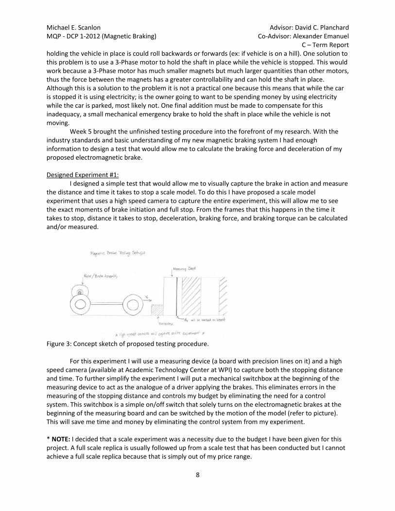
I designed a simple test that would allow me to visually capture the brake in action and measure the distance and time it takes to stop a scale model. To do this I have proposed a scale model experiment that uses a high speed camera to capture the entire experiment, this will allow me to see the exact moments of brake initiation and full stop. From the frames that this happens in the time it takes to stop, distance it takes to stop, deceleration, braking force, and braking torque can be calculated and/or measured.
Figure 3: Concept sketch of proposed testing procedure. For this experiment I will use a measuring device (a board with precision lines on it) and a high speed camera (available at Academic Technology Center at WPI) to capture both the stopping distance and time. To further simplify the experiment I will put a mechanical switchbox at the beginning of the measuring device to act as the analogue of a driver applying the brakes. This eliminates errors in the measuring of the stopping distance and controls my budget by eliminating the need for a control system. This switchbox is a simple on/off switch that solely turns on the electromagnetic brakes at the beginning of the measuring board and can be switched by the motion of the model (refer to picture). This will save me time and money by eliminating the control system from my experiment. * NOTE: I decided that a scale experiment was a necessity due to the budget I have been given for this project. A full scale replica is usually followed up from a scale test that has been conducted but I cannot achieve a full scale replica because that is simply out of my price range.
Michael E. Scanlon Advisor: David C. Planchard MQP - DCP 1-2012 (Magnetic Braking) Co-Advisor: Alexander Emanuel C – Term Report
9
Scale Calculations: Once the experiment was designed I needed a test rig to fit the experiment. This required scale calculations of size, power, and velocity. After researching how to perform scale calculations and attempting to use internet "scale conversion calculators" I deduced that scale calculations were as simple as: 𝑆𝐶𝐴𝐿𝐸 𝐶𝐴𝐿𝐶𝑈𝐿𝐴𝑇𝐼𝑂𝑁𝑆 ~ (𝑜𝑏𝑗𝑒𝑐𝑡 𝑏𝑒𝑖𝑛𝑔 𝑠𝑐𝑎𝑙𝑒𝑑) ∗ (𝑠𝑐𝑎𝑙𝑒 𝑓𝑎𝑐𝑡𝑜𝑟) 𝑤 = 𝑠𝑐𝑎𝑙𝑒 𝑤𝑒𝑖𝑔ℎ𝑡 𝑣𝑜 = 𝑠𝑐𝑎𝑙𝑒 𝑖𝑛𝑖𝑡𝑖𝑎𝑙 𝑣𝑒𝑙𝑜𝑐𝑖𝑡𝑦 𝑑𝑓 = 𝑠𝑐𝑎𝑙𝑒 𝑠𝑡𝑜𝑝𝑝𝑖𝑛𝑔 𝑑𝑖𝑠𝑡𝑎𝑛𝑐𝑒 (𝑛𝑜𝑡 𝑐𝑎𝑙𝑐𝑢𝑙𝑎𝑡𝑒𝑑 𝑢𝑠𝑒𝑑 25𝑓𝑡. 𝑏𝑒𝑛𝑐ℎ 𝑚𝑎𝑟𝑘) 𝑝𝑠 = 𝑠𝑐𝑎𝑙𝑒 𝑝𝑜𝑤𝑒𝑟 𝑜𝑓 𝑣𝑒ℎ𝑖𝑐𝑙𝑒 This was a relief and simplified my calculations for the moment. After running a few numbers through the formula I began to realize that my scale calculations were not necessarily achievable. With my test parameters as: 𝑊 = 𝐺𝑉𝑊𝑅 𝐿𝑖𝑔ℎ𝑡 𝑇𝑟𝑢𝑐𝑘 𝑐𝑙𝑎𝑠𝑠𝑖𝑓𝑖𝑐𝑎𝑡𝑖𝑜𝑛 𝑤𝑒𝑖𝑔ℎ𝑡 = 4500 𝑙𝑏𝑠 𝑉𝑜 = 𝑡𝑒𝑠𝑡 𝑖𝑛𝑖𝑡𝑖𝑎𝑙 𝑣𝑒𝑙𝑜𝑐𝑖𝑡𝑦 = 20 𝑚𝑝ℎ 𝐷𝑓 = 𝑡𝑒𝑠𝑡 𝑠𝑡𝑜𝑝𝑝𝑖𝑛𝑔 𝑑𝑖𝑠𝑡𝑎𝑛𝑐𝑒 = 25 𝑓𝑡 𝑃 = 𝑎𝑣𝑒𝑟𝑎𝑔𝑒 𝑝𝑜𝑤𝑒𝑟 𝑜𝑓 𝐿𝑖𝑔ℎ𝑡 𝑇𝑟𝑢𝑐𝑘 ≅ 200 ℎ𝑝 *NOTE: the 𝑃 ≅ 200 ℎ𝑝 is an over approximation to simplify my scale model numbers to whole numbers and make finding an electric motor with scale power easier. I figured that a Scale of 1:20 would give me a 𝑝𝑠 = 10 ℎ𝑝. A 10 hp electric motor is huge, extremely expensive, and requires massive amounts of power to run, so I needed to approach these calculations another way. I chose to define my motor first, with cost and simplicity as the defining characteristics I chose a typical household bench grinder. This simple motor design and power output between 3
4 ℎ𝑝
and 1 ℎ𝑝 was exactly what I needed. I could find one of these motors for relatively cheap or even find a discarded one and rebuild it to save money. With my 𝑝𝑠 = 1 ℎ𝑝 the scale calculations became almost achievable. Re-calculating the scale factor gave me: 𝑆𝐶𝐴𝐿𝐸 [1: 200] 𝑤 = 22.5 𝑙𝑏𝑠 𝑣𝑜 = 0.1 𝑚𝑝ℎ 𝑑𝑓 = 0.125 𝑓𝑡 But once again this gave me another problem; the scale factor needs to be multiplied by all relative dimensions. These relative dimensions include any portion on the vehicle that has either a friction or an "independent" velocity (by "independent" I mean that it is not the same as the velocity of the car). Thus I assumed the tires must be scaled down to match the experiment. With this assumption I used the average tire diameter of a Light Truck (Interco) from 𝐷 = 25 𝑖𝑛 to scale it [1: 200] and calculated 𝐷𝑠 = 0.125 𝑖𝑛. That tire is unbelievably small and relatively unachievable. This problem has not been tackled yet and is on the top of my new scope of work. I have several ideas of how to solve this problem, first is to check to see if scale tires are necessary for a scale experiment. I am assuming that they are and as such the second option that I have come up with is to scale up the power of the motor with a gearbox (thus reducing the scale of the experiment away
Michael E. Scanlon Advisor: David C. Planchard MQP - DCP 1-2012 (Magnetic Braking) Co-Advisor: Alexander Emanuel C – Term Report
10
from (1: 200). Although this is not what I wanted to be spending my budget on it might be a necessity to gain an achievable scale tire size. Scope of Work – Submitted (12-12-2011):
Terms Weeks Objectives
Winter Break Dec. 15-24
Complete formulation of the testing parameters along with completed calculations for the gearbox (research included)
Dec. 25-31 Research and find motor and tires - Begin work on SolidWorks model
Jan. 1-7
Have all necessary calculations completed - This includes power and voltage necessary to run system along with calculations for magnetic flux and flux density - Have a clear scope of what will be used for system power and setup
Jan. 8-12 Complete research any odds and ends necessary to construct test - Have the experiment completely defined and designed
C Jan. 12-14 SolidWorks Model of the System Completed - Begin work on the ESPRIT/ CAM software
Jan. 15-21
Completed ESPRIT/ CAM file - Have a complete Materials list and begin ordering materials (ALL MATERIALS; from the metals to the end-mills)
Jan. 22-28 Machine Work
Jan. 29- Feb. 4 Machine Work
Feb. 5-11 Machine Work Completed - Begin assembly of the testing system
Feb. 12-18 Assembly Completed -Power testing
Feb. 19-25
Testing of the test rig (need to make sure it functions properly before testing) - Competetors rig (Generic hydrolic braking system) must be modified, asssmebled, and tested as well (Prior to testing)
Feb. 26- Mar. 3 Begin testing if both assemblies are properly completed, have been run, and can properly collect data
D Mar. 11-17 Testing
Mar. 18-24 ALL TESTING COMPLETED - Begin compiling Results
Mar. 25- 31 ALL DATA COMPILED - Begin work on paper
Apr. 1-7 Work on paper - Begin work on presentation
Apr. 8-14 PAPER COMPLETED - Work on presentation/ speech
Apr. 15-18 PRESENTAION COMPLETED
Apr. 19 Presentation

Michael E. Scanlon Advisor: David C. Planchard MQP - DCP 1-2012 (Magnetic Braking) Co-Advisor: Alexander Emanuel C – Term Report
11
Completed Tasks by Week: (From Scope of Work 12-12-2011) Winter Break: Dec. 15-24 I began week six attempting to find the tires for the originally proposed cart design. I began at ABC Equipment Co. in Marshfield, MA; I chose ABC Equipment because they sell and service many industrial improvement equipment such as commercial lawn mowers and snow blowers. The owner, Matt Gorham, is good friends with several of my hometown neighbors and he was highly recommended. I visited him on Tuesday December 20th to discuss my tire constraints. I wanted to be as realistic as possible with my scale experiment and that called for pneumatic tires. After discussing with Matt the available sizes of pneumatic tires (ranging from an approximate 9 in. to 26 in. diameter) I concluded that any available tires would be too large for the scale of my experiment. If I were to use these 9in diameter tires the scale would be [1:2.778] and this would give my scale model a weight of approximately 1620 lbs. Also these 9 in. tires were designed to hold up to 200 lbs. and thus my experiment would far exceed the capacity for any of these tires. I concluded that my highest manageable weight would result from my previous calculations of a [1:10] scale model. This would make my model 450 lbs. which is a large but manageable weight. From this calculation I deduced that my tire diameter would have to be 2.5 in. When I researched possible tires that could manage this weight and be this size I concluded that it couldn't be done with a pneumatic tire. For the motor I needed to reach approximately 20 scale horsepower (from the average horsepower of GVWR <4500 lbs of 200 hp and an approximate [1:10] scale). This could be accomplished in a number of ways but for this week I chose to research gear reducing the electric motor to achieve this 20 hp. The gears I choose relied heavily on the motor found and this is where I concluded that my scope of work needed to be combined. I have chosen a good range of power for my motor, between 1 and 2 hp motor, and although this size motor is not commonly used it was an achievable goal. I chose this size motor because the more readily available 1/2 hp motors would take much longer to accelerate the 450 lb. model up to the desired 2 mph. With only so much shop floor space available to use during testing I have concluded that the larger motor would be better. The reason I have not made all my calculations based on either a 1 or 2 hp motor. Dec. 25-31 Week seven began with several phone calls and visits to local recycling centers (a list of contacted places is provided at the end of this report). I searched for machinery that would contain a range of 1-3 hp electric motors. This approach was futile and pointless because almost every large industrial machine contains a 1 hp electric motor somewhere inside of it; these motors have been an industry standard for a long time. This left me to finding a machine itself and this time of year is not the best time to be searching for something as specific as industrial machinery in a recycling center or scrap yard. Most scrap yards are typically inundated with old appliances around the holidays. Another problem I encountered when speaking to the employees was their lack of will to assist me. Most employees told me either no in the first sentence or explained that me searching through their piles was a liability for them and me having them search was a waste of their time. After this disappointment my father brought to my attention a very good point; he said that the motors themselves would be worthless to the recycling centers and that they most likely get ten times more money for the spun copper wiring inside the old motors.

Michael E. Scanlon Advisor: David C. Planchard MQP - DCP 1-2012 (Magnetic Braking) Co-Advisor: Alexander Emanuel C – Term Report
12
I adjusted my search back to people I know, mainly because they would be willing to assist me. My mother then gave me the idea of contacting my father's brother Richard Bird ("Richie") for information about local junk in Brocton, MA. He searched his garage while on the phone only to find a Leland-Faraday 1 hp electric motor. Once I acquired the motor from Richie I set about finishing the calculations for my test parameters. I decided to use my previous [1:10] scale experiment and as such my final parameters are: 𝑆𝐶𝐴𝐿𝐸 [1: 10] 𝑤 = 450 𝑙𝑏𝑠 𝑣𝑜 = 2.0 𝑚𝑝ℎ 𝑑𝑓 = 2.5 𝑓𝑡 𝑝𝑠 = 20 ℎ𝑝
Figure 4: Picture of the Leyland Faraday 1hp electric motor that will be used for this project. *NOTE: These calculations are based on the rolling cart design and not for the current flywheel design. Jan. 1-7 Week eight consisted of a meeting with my co-advising professor, Professor Emanuel, on Thursday January 5 at 11 am to discuss the electrical engineering component of this project. The meeting lasted two hours and was supremely informative. We discussed the design aspects of the coils and the stator (housing for the coils). He taught me about the conditions we would be attempting to replicate and how we could achieve them. We also discussed modifying the project itself to a simpler and safer method of testing the eddy current brake (which has been implemented).
During the meeting Professor Emanuel proposed a simple roller system to balance the rear wheels of the model. As the meeting progressed he then proposed a flywheel with the appropriate scale momentum, only in rotation not linear. This seems to me to be the very best way of accomplishing this project. Eliminating time and money spent on constructing a model cart to carry 450lbs, I would simply use my electric motor as the primary means of torque (no gear reduction) and scale the project down to [1:200]. This makes the rotational inertia only the approximate equivalent of 22.5lbs (the 22.5lbs is the [1:200] scale equivalent of my vehicle).
Professor Emanuel provided me with some notes and insight into the materials I would need to complete the project. He informed me that all of my calculations stem from one characteristic of the material that I will choose for the stator because the stator is what actually conducts the flow of magnetism. This property is its BH characteristic and that is its magnetic permeability. The higher it is the better the material is suited for this project; but it comes with a price, it will be a much harder

Michael E. Scanlon Advisor: David C. Planchard MQP - DCP 1-2012 (Magnetic Braking) Co-Advisor: Alexander Emanuel C – Term Report
13
material and thus tougher to machine. He also proposed using copper over aluminum for the rotor due to coppers high conductivity. These materials have to be researched and need to be chosen to finish the calculations. *NOTE: The notes Professor Emanuel provided me are cited and are available at the end of this paper. Jan. 8-12 During week nine I redesigned the experiment as Professor Emanuel proposed. This test is much safer than the previous test I proposed and there are fewer variables to account for. Also this design will allow me to save some money by eliminating one of the copper rotors and another set of the coils. The design will be composed of the 1hp electric motor I have, a single rotor/ coil set, and a flywheel (to simulate the load that would be applied to one wheel in an automobile brake application).
Figure 5: Final proposed design of electric motor and eddy current brake assembly (cut away view).
This setup will be mounted to a stand and will be supported by the motor on one end and a ball
bearing on the other with the stator mounted to the stand in between the motor and the flywheel (the bearing is added to take the bending load off the shaft).
Figure 6: The complete assembly of the test rig.
The way the test will be conducted is there will be markings on “Face A” (refer to Figure 6). The
markings will be equidistant as to be able to record how long it takes to stop the motion. There will be a high speed camera pointed at “Face A” to accurately record the initiation of the brake and when it has

Michael E. Scanlon Advisor: David C. Planchard MQP - DCP 1-2012 (Magnetic Braking) Co-Advisor: Alexander Emanuel C – Term Report
14
come to a complete stop. The time can be calculated by the number of high speed frames it takes to stop.
Jan. 12-21:(Combined Weeks 10-11) During week ten I held a meeting with professor Emanuel on Tuesday January 17 at 2pm. We
discussed the notes he gave me during our last meeting and he presented me with new ones. This meeting we discussed the brake system as a whole design. We did not delve into specific design features but seeing as professor Emanuel has had many years constructing magnet cores and stators I knew he would have valuable input. He suggested to accomplish this eddy current braking as simply as possible. His first design element was the size of the project he told me that anything over a 12-14in. rotor would be too big and too expensive to create. Next he told me that the number of coils per side of the braking unit should be between two and six (more than six is too expensive and two is the bare minimum; remember that the coils come in pairs, one on one side of the rotor and one on the other). Another design element we spoke about was the size of the stator. The stator is meant to be the magnetic conductive material and as such needs to be surrounding the coils on the inside. However the outside of the coils (refer to Figure 1) can be exposed if the material is too costly and the rotor is over approximately 10in (there will be a lot of conductive material without the extra couple diametrical inches).
Figure 7: Design Concept Sketch of half the Stator with 2 Coils shown (pictured from the view of the rotor) This is good for my understanding of how I will be machining the stator and how I will visualize the final product. I plan on machining several channels into the stator (size will be determined by my calculations) as to accommodate the coils. The coils will be in a quarter-circle shape with rounded inner and outer sides. I will construct those coils by first constructing a winding mold out of wood that will have the inner shape of the stator (refer to Figure 7: Area A) and tall sides as to wrap the coil wire around the shape for N turns (N is a calculated number that professor Emanuel has provided me the formulas for). The next design element we spoke about was the gap between the coils across the rotor (in the notes this is air gap “g” on Notes A (Specific Formulas).pdf file). Professor Emanuel has informed me that the magnetic resistance is inversely proportional to the gap “g” and thus should be as small as possible. This is due to one of the resistance formulas that have been provided to me: 𝑅 = 1
µ𝑎∗ 𝑔𝐴𝑐𝑜𝑛𝑑
*where: µ𝑎 = 4𝜋 ∗ 10−7( Ω𝑠𝑚
) and is the magnetic resistance of air

Michael E. Scanlon Advisor: David C. Planchard MQP - DCP 1-2012 (Magnetic Braking) Co-Advisor: Alexander Emanuel C – Term Report
15
𝐴𝑐𝑜𝑛𝑑 = 𝑡ℎ𝑒 𝑎𝑟𝑒𝑎 𝑡ℎ𝑎𝑡 𝑡ℎ𝑒 𝑚𝑎𝑔𝑛𝑒𝑡𝑖𝑐 𝑓𝑖𝑒𝑙𝑑 𝑝𝑎𝑠𝑠𝑒𝑠 𝑡ℎ𝑟𝑜𝑢𝑔ℎ *NOTE: Professor Emanuel has informed me that the magnetic resistance of either copper or aluminum is similar to that of air and can be used for preliminary calculations. Out of these last two meetings with Professor Emanuel he has come to tell me that there are three main variables that I need to worry about, the area 𝐴𝑐𝑜𝑛𝑑, the gap 𝑔, and the material property 𝐵 (of which 𝐵 ≤ 1000 𝐺 ∗ 𝑠 𝑜𝑟 1 𝑇𝑒𝑠𝑙𝑎 [𝑇]) of the stator. These are the three variables that I need to choose by picking a stator material to define 𝐵, machining a small air gap for the rotor to define 𝑔, and machining a preferential area 𝐴𝑐𝑜𝑛𝑑 by calculating the maximum effective area to conduct the magnetic field (this will be accomplished by using optimization functions for the completed calculations). Once these three variables have been determined we can dial in the produced braking torque according to the torque needed to stop the flywheel (this is done by either increasing the voltage or the current).

Michael E. Scanlon Advisor: David C. Planchard MQP - DCP 1-2012 (Magnetic Braking) Co-Advisor: Alexander Emanuel C – Term Report
16
C – Term: Jan. 22 – 28 (Week 11) The scheduled objective for the week of January 22 was machine work but seeing as I was not prepared to do machine work, none was completed. Instead, during this week I began working with the formulas Professor Emanuel gave me and on the TKSolver file.
TKSolver is a relatively easy program to use, you write in the formulas under the “Rules” window and you define your variables in the window labeled “Variables.” The program sorts the variables according to which formulas it can solve and does so. If a formula is missing a definition for a variable there is a box to the left of the “Rules” column that prints “Unsatisfied,” or if it is defined then it appears as “Satisfied.” If the variable has its value in the “Input” column then it is a set value, whereas if its variable is in the “Output” column then it is a calculated value. Here is the file I produced: Formulas:
Rules Formula’s for the Coils and Stator 2*N*icoil=R*ϕ R=(1/µa )*(g/A) Φ=A*B Nicoil=((10^7)*g*B)/(8*pi) y=(Nicoil/(0.5*j)) x=y µa=4*pi*10^(-7) A=((pi/4)*((Rad2^2)-(Rad1^2)))-((Rad2-Rad1)*x) Nicoil=N*icoil Formula’s for the Rotor irotor=V/Rr V=*B*(((Rad2^2)-(Rad1^2))/2) Rr=(ρ*l)/Ac Ac=ζ*Δ =(2*pi*RPM)/60 Formula’s for Force and Torque F=B*lcb*(V/Rr) Ftotal=2*p*F T=Ftotal*Rmean Rmean=(Rad2+Rad1)/2

Michael E. Scanlon Advisor: David C. Planchard MQP - DCP 1-2012 (Magnetic Braking) Co-Advisor: Alexander Emanuel C – Term Report
17
Variables with Definitions and Units: Status Input Name Output Unit Comment #Formulas for Coils and Stator N 3537.22159798064 Number of times Coiled 1 icoil A Current in the Coils R 151642.154 Ohm Resistance of the stator ϕ Magnetic Flux µa .000001256636 Ohm*s/m Constant
.00889 g m Gap between the two stators (rotor sits inside this gap)
A .04665222 m^2 Area of Stator conducting magnetic field
?1 B T Constant (Chosen) - Material property of the stator
Nicoil 3537.22159798064 A 3.14159 pi y .00235814773198709 m Height of Coil area 3000000 j A/m^2 Constant - Current Density x .00235814773198709 m Width of Coil area .25 Rad2 m Outter Radius .05 Rad1 m Inner Radius
#Formulas for Rotor (NOT COMPLETE YET - MISSING PROPER l FORMULA)
irotor V 8.9535315 V Voltage in the Rotor Rr Ohm Resistance in the Rotor 298.45105 rad/sec Angular Velocity of Rotor
?1.78E-8 ρ Ohm*m Magnetic conductivity of Copper
l m NEEDS TO BE REDEFINED Ac m^2 NEEDS TO BE REDEFINED ζ NEEDS TO BE REDEFINED Δ NEEDS TO BE REDEFINED 2850 RPM Motor Minimum RPM

Michael E. Scanlon Advisor: David C. Planchard MQP - DCP 1-2012 (Magnetic Braking) Co-Advisor: Alexander Emanuel C – Term Report
18
#Formulas for Force/Torque F N Force of 1 Pole (coil) lcb m NEEDS TO BE REDEFINED Ftotal N Total force exerted on Rotor p Number of poles (coils) Rmean .15 Mean radius of Rotor T Torque applied to rotor
This week I produced a working TKSolver file but there were several small problems with the
formulas I entered into the program and thus it gave me incorrect values. However the following week I produced a new TKSolver file which Professor Emanuel approved and I have since used to base my dimensions off of. Jan. 29 – Feb. 4 (Week 12)
In order to get back on schedule during week 12 I needed to research and find a stator material, price it, and begin the ordering process. Alongside of that I needed to find, price, and begin ordering rotor Copper. This began with finding the materials and obtaining their characteristics so that the calculations could be finished. Once I finished gathering data on the properties and met with professor Emanuel (to check that my calculations file was accurate) I finished the TKSolver file. I had run several sets of numbers that optimize the formulas. As such I have determined a set of values that will optimize my brake design output. From this optimization process I have come to learn that there are many variables in this project that either severely alters the braking toque or that barely have an impact at all. After altering individual variables to figure out which causes what reaction I have determined that there are three key variables that can optimize the output of this design. The current in the coils (“icoil”), the magnetic field B (“B”), and the thickness of the copper rotor (“Δ”) are these variables. Here is the Final TKSolver File: (NOTE: the following values reflect the final product and not the dimensions determined by the research done in week 12 but the formulas are the exact same) Formulas:
Rule Formula’s for the Coils and Stator A=((((RadM^2)-(Radm^2))*pi)/4)-x*(RadM-Radm) Reluctance=(1/µ(g/A) Nicoil=(Reluctance*A*B)/2 J=(icoil/Acond) Acond=(pi/4)*(Dw^2) y=1.5*x x=sqrt((N*((Dwire)^2))/(0.75)) µ=(4*pi)*(10^(-7))

Michael E. Scanlon Advisor: David C. Planchard MQP - DCP 1-2012 (Magnetic Braking) Co-Advisor: Alexander Emanuel C – Term Report
19
Nicoil=N*icoil Nicoil=((10^7)*g*B)/(8*pi) Dwire=Dw/1000 g=Δ+airgap Formula’s for the Rotor l=((RadM-(x/2))-(Radm+(x/2)))+(((pi*(RadM-(x/2)))/4)-x)+(((pi*(Radm+(x/2)))/4)-x) Rr=(ρ*l)/Arotor Arotor=x*Δ Vrotor=ω*B*((RadM-(x/2))^2-(Radm+(x/2))^2)/2 ω=(2*pi*RPM)/60 irotor=Vrotor/Rr ΔP=Rr*(irotor^2) Formula’s for Force and Torque F=numpoles*2*((RadM-(x/2))-(Radm+(x/2)))*B*irotor T=F*(RadM-Radm)/2 Variables with Definitions and Units: Status Input Name Output Unit Comment ### Stator Calculations
A .00181973477063638 m^2 Stator Area Inbetween Coils
.0635 RadM m Outter Radius .0323 Radm m Inner Radius 3.14159 pi
x .0169162481078085 m Width of the Pocket for the Coils
Reluctance 4963388.50872938 Ohm Magnetic Resistance of Stator
µ .000001256636 Ohm*s/m Constant g .01135 m Gap Between Stators (g
N 180.641012990237 Number of Times magnet wire is coiled
5 icoil A Current through the Coils

Michael E. Scanlon Advisor: David C. Planchard MQP - DCP 1-2012 (Magnetic Braking) Co-Advisor: Alexander Emanuel C – Term Report
20
.2 B T Magnetic Field B [Teslas](0.1 < B < 0.3)
J 5.35830578316432 A/mm^2 Current density Constant
Acond .93313076975 mm^2 Area of Conductive Material (Cross Sectional Area of Wire)
1.09 Dw mm Inner Diameter of the Wire (Diameter of Copper w/o Insulation)
y .0253743721617128 m Depth of Pocket for Coils
Nicoil 903.205064951187 A A single variable used to represent (N*icoil)
Dwire .00109 m
Inner Diameter of the Wire (Diameter of Copper w/o Insulation) in meters
.00135 airgap Total air gap between the stators and the rotor
### Rotor Calculations
l .0556923361765745 m
Lenght of Half the Current Path in the Rotor (Lenght ABCD from Notes)
Rr .00000586018588534081 Ohm Resistance of Copper Rotor
1.78E-8 ρ Magnetic Density of Copper
Arotor .000169162481078085 m^2
Cross Sectional Area of Rotor over x distance (area that magnetic field passes through)
.01 Δ m Thickness of Copper Rotor
Vrotor .0408395471865715 V Voltage in Rotor
298.45105 rad/s Angular Velocity of Rotor
2850 RPM RPM of the Motor

Michael E. Scanlon Advisor: David C. Planchard MQP - DCP 1-2012 (Magnetic Braking) Co-Advisor: Alexander Emanuel C – Term Report
21
### Power Loss in Rotor irotor 6968.98494102912 A Current in Rotor
ω 284.610189341665 W Change in Power in Rotor
### Force and Torque on Rotor
F 159.269202940926 N Force Applied to Rotor from Stator
4 numpoles Number of Magnetic Poles per Stator
T 2.48459956587844 N*m ***Torque of Both Stators***
In order to determine which materials I would need to order for the project I researched the
necessary properties of various materials. On Sunday January 29, I researched these material properties and deduced that the stator material has only one limitation, that it is steel. I found this by comparing some previously solved formulas to the calculated Bs (saturation of magnetic field B). In previous calculations our values for “B” were well below the Bs values, thus we would not reach the saturation density Bs (the Bs values for 1008, 1010, 1018, 1020 steels ranged from 1.8 – 2.08 T; see Excel file “Selected Steels Magnetic Properties (Data from Website)”). As such the material itself does not matter because almost all steels will conduct the determined magnetic field of B = 0.2 T. For ease of machining I have chosen to use 12x12x3 inch 1020 steel blocks or 12 inch diameter solid round stock (the ease of machining is due to 1020 steels ductility – it is not as hard as 1008 or 1018 – and it’s more readily available).
These dimensions came out of the optimization calculations. I have determined that the diameter of the stator has a significant role in the magnitude of the output braking torque but its effect is not as great as the current in the coils (“icoil”), the magnetic field B (“B”), and the thickness of the copper rotor (“Δ”). With this I have determined that the stator should be at least 10 inches and no higher than 12.
The initial dimensions chosen for the stator were that it would be machined from either a 12x12x3 (the height of 3 inches is an approximate value because the channels are approximately 2 inches deep) inch block or a 12 inch diameter round stock. The channels where the coils will sit will be 3.41 cm wide by 5.12 cm deep and will be spaced 90 degrees apart from each other. The inner radius pocket or through hole will have a diameter of 3 inches.
NOTE: These values stated above are based purely on the magnetic restrictions of the stators and are further defined in week 13 (next section) by the restrictions of the test.
Feb. 5 – 11 (Week 13) Week 13 contained the scale calculations for the test rig, the mechanical design aspects of the test assembly, and ordering the researched materials.

Michael E. Scanlon Advisor: David C. Planchard MQP - DCP 1-2012 (Magnetic Braking) Co-Advisor: Alexander Emanuel C – Term Report
22
I began on Saturday (2-4) with the final scale calculations for braking torque which I got from a website called Engineering Inspiration. However, to accomplish this I needed to first determine the appropriate scale for this experiment. This was done because when I reviewed my previous calculations I determined that I overlooked a crucial feature of my original design. My original design and application of this system was a four wheel independent motor/ brake setup. Due to this I could not leave the SCALE as [1:200], it needed to be revised to [1:50] because the 1 hp motor was only ¼ of the scale power (actual scale is [4:200]). Once I realized this I was able to proceed with the braking torque calculations. The formula that Engineering Inspiration provided related the weight of the car to the deceleration, radius of the wheel, and the ratio of wheel velocity to brake rotor velocity. 𝐵𝐹 = 𝑀 ∗ 𝑎𝑐𝑒𝑙 ∗ 𝑔 where: 𝐵𝐹 = 𝑏𝑟𝑎𝑘𝑒 𝑓𝑜𝑟𝑐𝑒 𝑎𝑝𝑝𝑙𝑖𝑒𝑑 𝑡𝑜 𝑣𝑒ℎ𝑖𝑐𝑙𝑒 𝑀 = 𝑚𝑎𝑠𝑠 𝑜𝑓 𝑣𝑒ℎ𝑖𝑐𝑙𝑒 = 400.34 𝑁 [𝑆𝐶𝐴𝐿𝐸] 𝑎𝑐𝑒𝑙 = 𝑑𝑒𝑐𝑒𝑙𝑒𝑟𝑎𝑡𝑖𝑜𝑛 𝑜𝑓 𝑣𝑒ℎ𝑖𝑐𝑙𝑒 = −0.1525 𝑚
𝑠2
[𝑆𝐶𝐴𝐿𝐸 𝑎𝑐𝑒𝑙 − 𝑑𝑒𝑡𝑒𝑟𝑚𝑖𝑛𝑒𝑑 𝑏𝑦 𝑡ℎ𝑒 𝑐ℎ𝑎𝑛𝑔𝑒 𝑖𝑛 𝑠𝑐𝑎𝑙𝑒 𝑣𝑒𝑙𝑜𝑐𝑖𝑡𝑦] 𝑔 = 9.81𝑚
𝑠2
𝛵𝑊 = 𝐵𝐹𝑊 ∗ 𝑅𝑟
where: 𝐵𝐹𝑊 = 𝑡ℎ𝑒 𝑎𝑝𝑝𝑟𝑜𝑥𝑖𝑚𝑎𝑡𝑒 𝑏𝑟𝑎𝑘𝑒 𝑓𝑜𝑟𝑐𝑒 𝑝𝑒𝑟 𝑤ℎ𝑒𝑒𝑙 = 𝐵𝐹4
𝑅 = 𝑆𝐶𝐴𝐿𝐸 𝑟𝑎𝑑𝑖𝑢𝑠 𝑜𝑓 𝑤ℎ𝑒𝑒𝑙 = 0.00635 𝑚 𝑟 = 𝑟𝑎𝑡𝑖𝑜 𝑜𝑓 𝑠𝑐𝑎𝑙𝑒 𝑣𝑒𝑙𝑜𝑐𝑖𝑡𝑖𝑒𝑠 = 𝜔𝑟𝑤
𝜔𝑟𝑟= 𝑟𝑤
𝑟𝑟= 2.174
where: 𝑟𝑤 = 𝑟𝑎𝑑𝑖𝑢𝑠 𝑜𝑓 𝑤ℎ𝑒𝑒𝑙; 𝑟𝑟 = 𝑟𝑎𝑑𝑖𝑢𝑠 𝑓 𝑟𝑜𝑡𝑜𝑟 [both SCALE]
To complete these calculations I needed to determine a constant to be held from full size to scale size. The variable that I held was time; this was done to assist in the calculations of scale velocities and accelerations because I had a change in time that needed to be constant to stop a vehicle from 20 mph in 25 feet (Δt = 1.173 s). I also needed to research the average rotor diameter for vehicles in my determined GVWR class 4500 lbs., which I determined to be approximately 10.5 inches in diameter (SCALE radius 𝑟𝑟 = 0.115 𝑖𝑛𝑐ℎ𝑒𝑠) ( I previously determined average radius of the wheel to be 25 inches this made 𝑟𝑤 = 0.25 𝑖𝑛𝑐ℎ𝑒𝑠).
Once the calculations were completed the final scale brake force 𝐵𝐹 = 598.92 𝑁 and the scale brake torque 𝛵𝑤 = 0.437 𝑁 ∗ 𝑚. This was shocking to me because I had programed my TKSolver file to use a 12 inch diameter stator which provided 𝛵 = 397.86 𝑁 ∗ 𝑚! This revelation has allowed me to significantly reduce the amount of material that I need by reducing the diameter of the stator from 12 inches to 5 inches. This will save costs for the stator and rotor as well as make machining easier due to the weight of a 12 inch diameter steel plate (setup in the machine is much easier with lighter/ smaller material). This reduction in diameter has reduced the torque produced by the magnetic brake from 𝛵 = 397.86 𝑁 ∗𝑚 to 𝛵 = 2.485 𝑁 ∗𝑚. Also this has allowed me to achieve the desired results without changing any other variables. (Final Values for all variables are listed in the TKSolver Image on pages (19-21) *NOTE: Even though 𝛵 = 2.485 𝑁 ∗ 𝑚 is greater than the scale 𝛵𝑤 = 0.437𝑁 ∗𝑚 it is exactly where it needs to be. The actual torque will be controlled by a current control device called a Variac – this device controls the amperage that will enter the coils and this works because the torque is directly proportional to the current in the coils. These calculations are for 5 A of current and this is a good midrange current to begin the tests with.
This revelation of 𝛵𝑤 = 0.437𝑁 ∗ 𝑚 brought another pleasant unexpected result. This very low torque and even the test torque of 𝛵 = 2.485 𝑁 ∗ 𝑚 will allow me to skip the mechanical analysis of the test rig. I can avoid these calculations because almost any material of most sizes and diameters more

Michael E. Scanlon Advisor: David C. Planchard MQP - DCP 1-2012 (Magnetic Braking) Co-Advisor: Alexander Emanuel C – Term Report
23
than ½ inch can withstand torques upwards of 50 N*m. This allows me to use approximate sizes where the test rig will undergo forces and torques and said approximations will be oversized for the mechanical analysis.
As I approached the design stage I adopted the philosophy of “the simpler the better” for guidance. The more complex parts, although they may work better or be more innovative, take much longer to machine and time is not a commodity that I have a lot of for this project. I began the design by sketching the general test assembly set up (Refer to Figure 1) and assessing each part one by one.
Figure 8: This is an image of my original sketch of the general test assembly. This sketch includes all major design elements. It was laid out this way so I could picture how each part would interact and what would look like. This was also done so I could “lay out” and list all the parts I would need to assemble this test rig.
My first challenge was determining a way to attach the rotor to the shaft. My design calls for a collet that is cut to clear the inner diameter of the coils and contains four tapped holes to be welded to the shaft (Refer to Figure 9). The rotor as well as another collet (“Collet 2”-No figure available but it will be similar to the bolt collet except the holes will be through holes and it will not be as long) will be machined with the same hole pattern and “Collet 2” is to be cut to the same diameter as the other collet, however these two parts will be removable. The “Collet 2” will be bolted to the rotor (“Collet 2” is used to protect the rotor from damage and redistribute the forces) and that will be bolted to the collet that is welded to the shaft.

Michael E. Scanlon Advisor: David C. Planchard MQP - DCP 1-2012 (Magnetic Braking) Co-Advisor: Alexander Emanuel C – Term Report
24
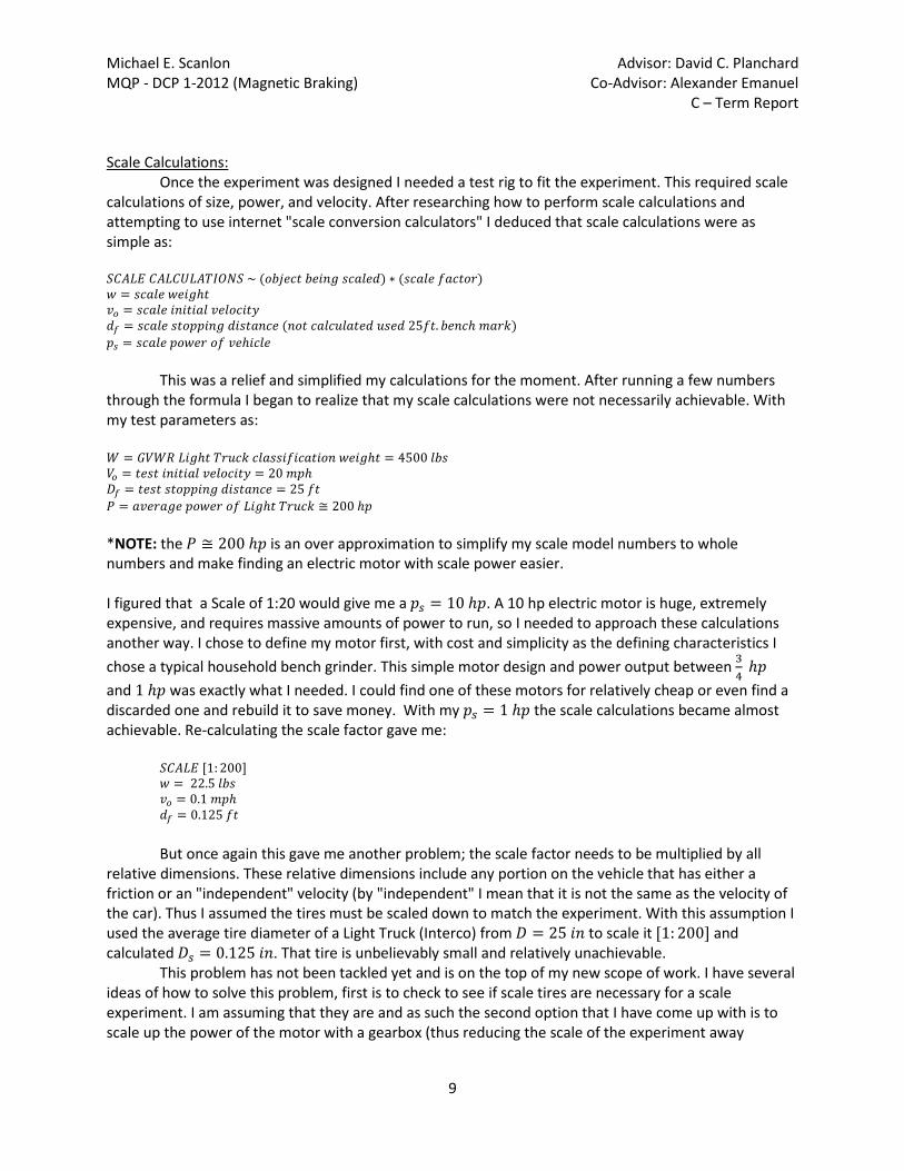
Figure 9: Image of my design concept sketch for the shaft. This sketch includes the collet that will be welded onto the shaft and some calculations for the dimensions of the shaft The shaft was the only piece to actually design; every other part was determined by the overall design of the test system. The next parts to determine was the right side support assembly. It only needs to be a bearing attached to mounts and set concentric to the axis of the shaft. The bearing was obtained from the WPI Washburn Shops; Toby Bergstrom (shop manager) allowed me to take one of the bearings in storage, this bearing has a 1/2 inch inner diameter and has Allen screws to hold the shaft in place. However the shaft was turned to 5/8 inches for ease of machining. Turning a 7/8 shaft down to 1/2 inch is a lengthy process and the output shaft for the motor is 5/8 inches (also turning an 11.5 inch shaft produces a lot of forces and a taper along the shaft – the closer the final O.D. is to original O.D. reduces this problem). To keep simplicity I purchased a 5/8 I.D. collet to attach the motor output to the shaft (I had originally decided to machine this collet to save money but the complexity of such a part would set me back a day or two so to save time purchasing the 20 dollar part became a precedent). The final parts to be determined were the stator mounts, motor mounts, and the base plate. The mounts are driven dimensions, which are simple to calculate but slightly complex to machine. The stator mounts will be machined to contour the stator (a 5 inch diameter profile along a 4 inch part by 1.9 inches thick) and will have specific bolt hole pattern dictated by the stator bolt hole pattern (Refer to Figure 10).
Michael E. Scanlon Advisor: David C. Planchard MQP - DCP 1-2012 (Magnetic Braking) Co-Advisor: Alexander Emanuel C – Term Report
25
Figure 10: Image of the Stator Mounts – bottom view rotated (used to depict most features)
The base plate was chosen to be aluminum because it was cheaper (literally half as expensive), easier to cut, and drill than steel. This specific part does not need to have specific properties but only a specific size. The piece that I purchased was ¼” thick x 5” wide x 3’ long (3 feet is longer than necessary but I can use the scrap for other parts). Feb. 12 – 18 (Week 14) I began week 14 on Saturday (2-11) in Washburn shops with the ambition of turning my shaft to the outer diameter on the HAAS TL-1 but due to factors such as time and student projects I was told that the machine was “out of round” by about 5 thousandths of an inch (0.005 in.). This could be problematic because an out of round machine can cause a tapered diameter from the chuck to the tailstock when turning a long part (the shaft is 11.5 inches long). This problem took me 3 days to address and after an initial measurement of the machine being out of round by 6 thousandths the final product got the machine back to 4 thousandths out of round. This was caused by buildup of deteriorated coolant and chips in the alignment plate inside the TL-1’s chuck.
After such disappointing results the only conclusion was that the chuck needs to be replaced. With that task accomplished I began turning the shaft on Wednesday 2-15. I decided to at least attempt the turning because I have 25 inches of steel from which to machine an 11.5 inch shaft and this means that I could turn two shafts from this material to determine if I needed a better machine.
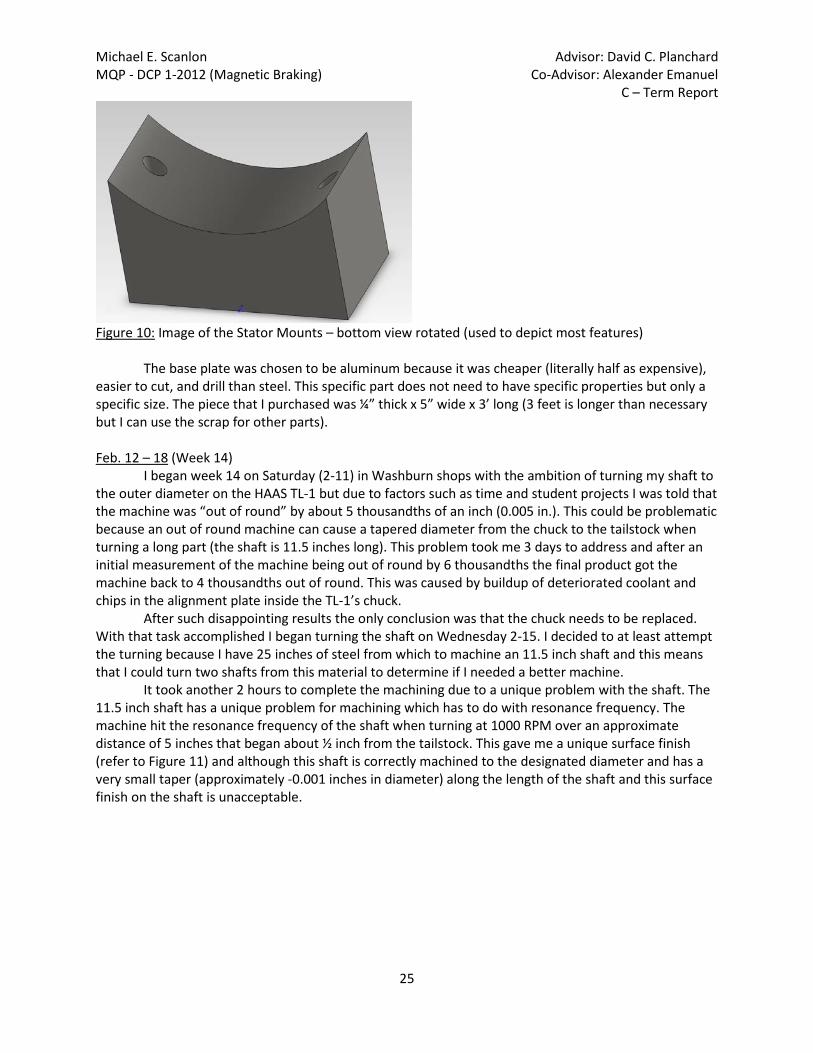
It took another 2 hours to complete the machining due to a unique problem with the shaft. The 11.5 inch shaft has a unique problem for machining which has to do with resonance frequency. The machine hit the resonance frequency of the shaft when turning at 1000 RPM over an approximate distance of 5 inches that began about ½ inch from the tailstock. This gave me a unique surface finish (refer to Figure 11) and although this shaft is correctly machined to the designated diameter and has a very small taper (approximately -0.001 inches in diameter) along the length of the shaft and this surface finish on the shaft is unacceptable.

Michael E. Scanlon Advisor: David C. Planchard MQP - DCP 1-2012 (Magnetic Braking) Co-Advisor: Alexander Emanuel C – Term Report
26
Figure 11: Image of the turned shaft with unique surface finish caused by the resonance frequency.
There were two solutions to this problem, first solution is to machine another shaft and the
second is to file down the current shaft. I decided to attempt the filing on Thursday and successfully minimalized the striations. The shaft was within tolerances and I decided to proceed with other machining. Feb 19 – 25 (Week 15) Week 15 consisted of turning the two collets (both the one labeled “Shaft Bolt Hole Alignment” and the one labeled “Shaft Bolt Plate” as SolidWorks files) on the Tl-1 lathe and fully machining and assembling the shaft assembly. I accomplished both the O.D. (Outer Diameter) turning and the I.D. (Inner Diameter) cutting. To turn the O.D. I set the lathe up with the O.D. turning tool (60 deg. Cutter) and turned the 2.25 inch diameter stock material that I had salvaged for this purpose down to the required 1.22 inch O.D. This was simple because the Tl-1 has pre-written programs to complete simple turning and facing operations, all the operator needs in basic feeds, speeds, and the dimensions of the parts. As well as knowledge of machine set up this process can take up to 45 minutes to cut the part (45 minutes is good time because the CNC machines cut down the machining time but setting up the machine still takes the same amount of time whether it’s a manual machine or a CNC machine because the same tools are used in both machines).
Once the O.D. was turned the I.D. needed to be accomplished. With this process I needed to talk it over with another person who understands the machining processes that I am attempting to duplicate. I spoke with James about how to cut my 5/8 inch I.D. simply and efficiently. We both came to the conclusion that the best way to cut the 5/8 I.D. is to drill it out. The drill was chosen because the boring bars need great concentricity to make a good I.D. and that and I.D. turning bars would not fit inside any bore smaller than 1 inch. To drill this 5/8 inch I.D. properly (Reminder: the machine is still 4 thousandths out of round) I needed to center drill and then step open the hole. The drill chuck for the Tl-1 needed to be aligned to the center of the axis of revolution of the machine. To do this I needed to set up a dowel pin in the chuck and set a magnetic dial indicator to the chuck of the TL-1, then spin the chuck (with the dial on it) and adjust the drill chuck until the dial reads zero on a complete revolution (this is the absolute center of revolution of the Tl-1 machine). The center drill is a small drill bit that cuts a small center divot (this makes the following drill bits align to that divot). Then I used a 3/8 inch drill bit to open the hole, a ½ inch drill bit to further open the hole, and finally a long 5/8 inch drill bit to give the part a the desired I.D. To specify why I used a long 5/8 drill bit, is that the longer bit has more flex than a short drill bit. With the machine being 4 thousandths out of round the hole itself is not perfectly round, so the larger the hole the further out of round it is. To correct this with the final drill bit the flex of a longer bit allows the drill bit to wander (or move and twist) to the center of the hole (or where the first drill bit cut). This does not eliminate the deviation of the hole but it does minimize it. This took me until about 6 p.m. to complete and at that time James decided to leave which made me end the machining session.

Michael E. Scanlon Advisor: David C. Planchard MQP - DCP 1-2012 (Magnetic Braking) Co-Advisor: Alexander Emanuel C – Term Report
27
On Monday (2-20) at around noon I returned to ask for assistance with my ESPRIT files. I had Mik Tan (a junior WPI Manufacturing Engineer whom I have worked with for years at the WPI Washburn Shops) create the files that I needed. He is excellent with ESPRIT and completed the three files that I asked him for in about 15 minutes. I asked him to create the files for the 3-Axis milling of the bolt patterns for the collets and the rotor. I had also asked him to make the files as simply as possible and base the bolt pattern off of one feature that was consistent for all the part with the bolt pattern. I had him base the bolt pattern off the I.D., this allowed me to base the bolt pattern off the center line of the TL-1 machine which created all the parts with said bolt pattern (this increases the consistency between all of the parts). Once he completed the files I proceeded to turn the rotors I.D. on the TL-1 using the same process that I used to accomplish the I.D. of the collets (the I.D. is the same for all three parts). I had to set the VF-4 3-axis machine up to complete these operations by adding a collet holder and a lathe chuck set up for 3-axis machining. The collet holder would be used to fixture the collets (they have the same O.D. which they would be fixture by) and the chuck would be used to fixture the rotor (the rotor has about a 5 inch diameter which is much too large for a collet holder). Once each part was fixtured properly I probed each part by the I.D. and set the proper tools in their respective tool positions I ran the set programs (Refer to Figures 12 and 13). Each part took about 40 minutes each, the “Shaft Bolt Plate” and the rotor used the same tools (a center drill and a #18 drill bit) to create the bolt pattern. Whereas the “Shaft Bolt Hole Alignment” used a #38 drill bit over a #18 because that part needed to be tapped with a 8-32 tap. However later research found that the #38 was the wrong drill bit, it needed to be a #28 (the hole was too small to tap). At the time I assumed that the parts were correct and I called it a night at 8:30p.m.
Figure 12: Image of the “Shaft Bolt Plate” collet with hole pattern (post-machining)

Michael E. Scanlon Advisor: David C. Planchard MQP - DCP 1-2012 (Magnetic Braking) Co-Advisor: Alexander Emanuel C – Term Report
28
Figure 13: Image of the rotor with the bolt hole pattern (post machining) I returned on Tuesday (2-21) at 1p.m. to tap the holes and deal with welding that particular collet (“Shaft Bolt Hole Alignment” collet) to the shaft. I then realized that the hole size was off and re-drilled the holes with the appropriate (#28) drill bit. I then proceeded to tap the holes and test said taps with available hardware. The taps came out proper and the part fit perfectly onto the shaft. I then realized that the available hardware was not long enough to grab all the threads. At which point I searched the campus (asked Higgins Shops, the Robotics groups in Higgins, and the ECE labs in Atwater Kent) to see if anyone had 8-32 bolts that were longer than 1 inch. No one carries them, at which point I assumed that the school buys the bolts as a bulk order and distributes them accordingly. I then spoke with Barbara of the ME department to order new bolts. We ordered 1 3/8 inch 8-32 bolts from McMaster-Carr and they came in on Wednesday afternoon. Once I had ordered the bolts I returned to the shops to attempt welding the collet to the shaft. I was planning on MIG welding the collet to the shaft against others recommendations (it was recommended that I TIG weld it). I chose to MIG over TIG weld because no one was available to TIG weld it and I had not experience TIG welding. I have had welding experience before and thought that I could practice and practically accomplish my goal (maybe not perfect but it would do the job) by the end of the day. I had Adam Sears (WPI Washburn Shops Assistant Manager) set up the MIG welding machine for me and I began practicing. After much toil I asked Greg Overton (a WPI senior who is a very confident welder) about how to better accomplish this. He recommended TIG welding and preceded to TIG weld the collet to the shaft then and there. It came out very good and will be more than strong enough for this application (Refer to Figure 14).
I waited for the shaft to cool and came back later in the evening to polish the welds and clean up the shaft. I set the shaft up in the TL-1 and Scotch Brite-ed the shaft to eliminate the welding discoloration.
Figure 14: Image of the Welds created by Greg Overton attaching the collet to the shaft
Once I attained the bolts on Wednesday (2-22) afternoon I found that the bolt heads needed to be ground down. This was due to my lack of foresight with the head clearance on the shaft (I should have checked the diameter of the heads of the bolts and accommodated for them). The heads of the bolts were rubbing on the shaft making them impossible to tighten. I proceeded to grind down the heads of the bolts to clearance the shaft (Refer to Figure 15).
With the bolts clearanced I assembled the shaft and set it up in the TL-1 and began the turning of the rotor. I began machining and realized that I was having a major problem with the machine. The shaft was pulling out of the tail stock on the machine. This allowed the shaft to wobble and improperly turn the rotor. I asked James Loiselle, who was the only shop worker there at the time, what to do to counteract this and he told me to wait and ask Adam Sears (who knows much more about the TL-1 than he does). The problem was not addressed until later in the next week.

Michael E. Scanlon Advisor: David C. Planchard MQP - DCP 1-2012 (Magnetic Braking) Co-Advisor: Alexander Emanuel C – Term Report
29
Figure 15: Image of the ground/ clearanced bolts
Figure 16: Image of the assembled shaft (the rotor has not been completely machined yet) Feb. 26 – Mar. 3 (Week 16) This week began on Saturday (2-25) with the I.D. turning of the stator. I spent 5 hours on Saturday machining the stator with Corey Stevens (a WPI graduate who has worked in the shops and for HAAS). He assisted me in the completion of the stators by setting up the Inner Diameter (I.D.) cutting operations in the SL-20 lathe. The SL-20 is not a machine that I am familiar with but it is the only machine that can properly machine a 5 inch diameter part. Also when using a 1.5 inch diameter boring bar the machine needs to be accurate (stress the boring bar part because the speeds and inertia of the part can cause a catastrophic breakage of a large tool – the breakage could be dangerous and potentially harmful). I had Corey assist me because he is very familiar with the machine and that specific tool (the 1.5 inch boring bar). After completing the 1.5 inch I.D. cut the next step was to I.D. turn the stator to required 2.5 inch diameter. That turning was the longest sequence because the machine cannot evacuate the chips it produces. The chips accumulate inside the cut and can cause scoring and an inaccurate I.D. To counter this the machine needs to be stopped after each pass and the chips need to be manually pulled out. This process of cutting the 2.5 inch I.D. takes about 2.5 hours per part.

Michael E. Scanlon Advisor: David C. Planchard MQP - DCP 1-2012 (Magnetic Braking) Co-Advisor: Alexander Emanuel C – Term Report
30
Figure 17: Image of the stator post machining, note volume of material removed during the I.D. turning. On Sunday (2-26) the machining was picked up again. I again had Corey assist me in completing the milling of the stators. We began the day at 1 p.m. by building the ESPRIT file for the stator. I attempted the file on my own and was unsuccessful in creating a proper file. I asked Corey for help and he helped me create a proper file. We then began the tedious tasks of setting up the machines. Each machine needs to be calibrated to the specific part and tools being used. The setup of the Mini Mills took about an hour (I set up two Mini Mills in an attempt to save machining time). I believed that running two machine simultaneously was the best approach because both machines would be running the same operations and they are within feet of each other so stopping a machine if it were to break something would be easier. This approach worked perfectly. Corey came back around 3:30 p.m. and assisted me in the programing of the machine (I am proficient at this process but Corey is much better than I and I decided to let him program the machines because I completely trust his experience). He approaches the machining process in a unique way which modifies the program as the machine cuts the parts. This maximizes the surface finish and accuracy of the parts. It took about 2 hours to cut each part but with the simultaneous method we were able to machine both stators in about 3 hours. However there has been an unexpected setback that could have been avoided, the stator was cut to almost all the proper dimensions.
There is one dimension that I previously overlooked which is the depth of the pockets I was machining. I cut the part to a depth of 1.024 inches, which is the required depth to accommodate the coils but that depth does not include the height of the brackets I have designed to hold the coils in place (the brackets are designed to be completely flush to the face of the stator – see Figure 18). The depth needed to be 1.274 inches because the bracket is 0.25 inches tall. This problem was not addressed when we made the ESPRIT file and as such was not accounted for when the part was cut. However the way we set up the machines we could not cut the part to the proper depth anyways. The tools we used were 0.5 inch diameter carbide end mill with 1 inch flute length. The tool with a 1 inch flute length cannot properly cut to a depth of over 1 inch so the problem could not be fixed during this machining process. I have acquired a 0.5 inch diameter end mill with 1.25 inch flute to cut the remaining 0.25 inches but I have not made the ESPRIT file to complete the cut, so the correction would not be made for some time. However this was not a critical feature at that time because the construction can be completed without the coils and the machining could wait until the coils are constructed.

Michael E. Scanlon Advisor: David C. Planchard MQP - DCP 1-2012 (Magnetic Braking) Co-Advisor: Alexander Emanuel C – Term Report
31
Figure 18: Image of the stator outlining the dimension relating to the previous paragraph.
On Monday (2-27) I returned to the shop to find it extremely crowded, at which point I decided to complete some simple projects. I calculated and cut the wood stock for the coil molds as well as creating a SolidWorks model and ESPRIT file for the part. This is as far as that project has gotten due to the unavailability of the machines and the amount of time required to setup the machines to cut wood. The machines can easily handle wood but their coolant systems cannot. The coolant systems of the milling machines are designed to separate out metal chips not wood ones. The machines could clog from the small wood chips and the wood would absorb the coolant it is surrounded by (lowering the coolant level of the machine). To set up a CNC mill to cut wood means to tape up and cover the machine in plastic so the wood falls into the plastic and doesn’t contaminate the coolant system. This is a long process and doesn’t allow anyone else to use that machine during the time that the machine is set up for wood. Torbjorn Bergstrom (the Washburn Shops manager) had instructed me to not tie down a machine during finals week because the ME 1800 classes are using the mills all week.
With that setback I moved on to constructing the bearing mount for the end of the shaft. This process is simple but time consuming. There needs to be two 5 inch steel plates welded to two precisely cut (2.25 inch) pieces of 1.125 inch diameter 0.0625 inch wall tube (see Figure 19). To accomplish this I needed to cut two pieces of 0.25 x 2.5 inch plate to 5 inches (these dimensions are not critical). Then cut the two tubes to roughly 2.3 inches to be able to sand down the parts to exactly 2.25 inches. I cut the part to this dimension because this allows me to accurately place the centerline of the bearing with the centerline of the shaft. I can accomplish this by shimming the bearing up to the required height. This is more practical because I can accurately control the dimensions of the shims and not the actual height of the mount after welding (the high heat will distort the part regardless of how much welding is done). These pieces then needed to be welded together which required me to practice my MIG welding. I spent about 1 hour practicing welding scrap tubes to scrap plates to get the hang of welding a thin walled tube to a thick plate. Welding these two pieces is tricky because the part requires a high voltage to weld the thick plate but a high voltage can “blow out” the thin walled tube (“blow out” means that the machine heats up the part too much and the force of the wire feeding into the weld pushes the material through the part opening a hole). A “blown out hole” is ugly, weak, and avoidable. After practicing I attempted welding the part, I successfully tack welded the part together (I chose to tack weld to avoid excessive heat distortion and a “blow out”). These tacks welds will be strong enough to withstand the forces exerted by the assembly because the forces are to be applied across the axis of rotation and not along it (the weld would break if a large bending force was applied to the shaft). The welding has been completed but the mounting holes have not been drilled yet because I have not figured out exactly where I am going to place the holes. However in the end this mount was not used. I recut other parts

Michael E. Scanlon Advisor: David C. Planchard MQP - DCP 1-2012 (Magnetic Braking) Co-Advisor: Alexander Emanuel C – Term Report
32
and could not shorten this part. I ended up milling a solid block of steel to fit the bearing mount requirements.
Figure 19: Image of the constructed bearing mount.

Michael E. Scanlon Advisor: David C. Planchard MQP - DCP 1-2012 (Magnetic Braking) Co-Advisor: Alexander Emanuel C – Term Report
33
D – Term: Mar. 11 – 17: (Week 17)
The work on the coils began Wednesday (3-14) with the creation of my coil cores (the wooden centers of the coil molds – Refer to Figures 20-21). This process was very tedious and I spent all night machining and cleaning the machine. I was in the shop from 3:30pm until 12:30am only taking a break to go to Lacrosse practice from 9-10:30. In order to create a safe working environment for both the machine and I, I had to tape off (using plastic garbage bags) one of the Mini-Mills in Washburn (this was to reduce the possibility of contaminating the coolant with wood dust). This also had to be done after-hours in the shop so as not to disturb the ME 1800 classes. The dust and chips created when milling wood can be hazardous to the coolant system of any large machine. They are not designed to separate out wood from coolant, only metal from coolant. The wood dust is much more fine and has the tendency to clog the coolant system. After spending about an hour and a half to tape off the machine I finally began to cut the wood cores. This process (including my “practice break”) took me up to around 11:45pm, and once all four cores had been cut I began the next tedious task of cleaning the wood out of the machine. This involved myself sweeping and vacuuming the wood out of the machine, as well as removing the plastic and tape.
Figure 20: Image of the base and cutting area used to create the coil mold cores.

Michael E. Scanlon Advisor: David C. Planchard MQP - DCP 1-2012 (Magnetic Braking) Co-Advisor: Alexander Emanuel C – Term Report
34
Figure 21: Image of the Coil Mold (fully constructed).
I returned on Thursday (3-15) with the intention of constructing a “coil center.” This device that I designed and created on Thursday afternoon was created for two purposes; first it was to assist me in holding and rotating the coil molds and second it was to act as a drying rack for the wet coils (Refer to Figure 22).
Figure 22: Image of “Coil Center” with labels. This “coil center” (created from scrap material) took about 4 hours to create and was my entire shop experience on Thursday and I did spent more time creating this stand than I wanted, but it came out better than I had hoped. Although I did have to change the design slightly after creating my first coil on Friday; I swapped out the rotating handle for a simple bolt because the handle was useless and kept hitting me when I was attempting to coil the first magnet. I figured out that coiling process takes about 3-4 hours to create one coil and in that time the handle was of no use. I spun the molds by hand (because the handle would have made me go too fast).

Michael E. Scanlon Advisor: David C. Planchard MQP - DCP 1-2012 (Magnetic Braking) Co-Advisor: Alexander Emanuel C – Term Report
35
On Friday (3-16) I returned to create my first coil (only one was created with the intention of optimizing the process in the future). The first coil came out horribly and needs to be replaced.
This coil was a failure due to the amount of hardener that I put in the epoxy mix. This mix was designed to be a 1:1 mix that hardens in 5 minutes. Now the process of winding one layer of coils takes approximately 30-40 minutes so that 1:1 mixture would not be appropriate. I had to attempt to mix the epoxy at about a 1:8 (1 part hardener to 8 parts resin) to keep the epoxy wet while I finished the row. This mistake has cost me several days’ worth of work and the epoxy has never hardened. I must have inadvertently mixed the epoxy with much less hardener (most likely 1:16, which will never harden) during this process. Mar. 18 -24: (Week 18) I returned to the shop briefly on Sunday (3-18) to check the hardening of my first coil. It had not hardened at all, so I decided that a better mixture of epoxy was appropriate (the next three coils were mixed about 1:4 – 1 part hardener to 4 parts resin) and they came out beautifully. I also switched the rotating handle out for the bolt at this time. However I had a cold this weekend and as such was not feeling well enough to sit and sniff epoxy for 12 hours, so I called it a day. I returned on Monday (3-19) to complete the final three coils. This was an all-day venture during which I needed to take breaks from (my hands were sore and cramped from winding each coil the required 180 times – I did not know how labor intensive this coil winding process was). With the proper mixture of hardener to resin the final three coils hardened overnight. I returned the next day (Tuesday 3-20) to un-pack the coils; this was also a labor intensive process. I had not thought ahead enough to devise a way to take the center mold out and once the epoxy had hardened it was a tough process. I eventually came up with the simple solution of cutting out a portion of the mold core to remove the rest in pieces. I used a wood chisel to cut out a rectangular portion of the center of the mold and then pushed the remaining two pieces out of the coils. This worked like a charm and the entire process took about 20 minutes per coil row. However, in order to address the first coil I created I needed to remove its core as well. I had a plan to bake the coil to harden the epoxy, but the wood core would pose a problem when heating. The wood would expand and cause the coil to also expand while the epoxy was hardening also the wood was saturated with resin and could catch fire in the oven; and as such needed to be removed. During the process of removing the core from the coil I discovered that I had wound that first coil very tight and it had pushed itself into grooves that I had created in the wood. This made the process of removing the core nearly impossible; and as such the coil came undone (without the hardened epoxy to hold its shape the other coils would have done the same) while I was attempting to remove the core. Thus the first coil I had made was ruined (Refer to Figure 23).

Michael E. Scanlon Advisor: David C. Planchard MQP - DCP 1-2012 (Magnetic Braking) Co-Advisor: Alexander Emanuel C – Term Report
36
Figure 23: Image of the first coil, the epoxy did not harden and as such was ruined when I attempted to remove the mold core. After running over to see Neil Whitehouse (the Higgins Shop Manager) and setting up a time where I could re-cut another core I returned to the shop to tape up the coils. Professor Emanuel has requested that I tape up the coils because it looks much more professional than the unfinished coils. (Refer to Figure 24).
Figure 24: Image of the unfinished coil (left) and the taped or “finished “ coil (right).
Machining on Friday (3-23) afternoon in the Higgins machine shop consisted of 3-Axis milling my fifth coil mold core. However due to several small differences between the mill in Higgins and the Mini-Mills in Washburn the setup I created for the Mini-Mills would not work the same in the Higgins mill. I made three attempts at milling the mold core and ruined all three parts. The mill base is slightly smaller and the wood base plate I used to fixture the stock was twisted more than it was inside the Mini-Mill. This caused the wooden base plates’ fixturing bolts to be inside the tool path. This is not acceptable and I attempted to correct this by adjusting my G54 work offset. This is not an easy concept to visualize but

Michael E. Scanlon Advisor: David C. Planchard MQP - DCP 1-2012 (Magnetic Braking) Co-Advisor: Alexander Emanuel C – Term Report
37
adjusting the work offset adjusts the entire tool path and cuts the stock entirely differently (it adjusts the point from which the entire program is based). The adjusting is simple, it’s getting it correct that’s tough and trial and error is the only proper process of correcting the work offset. I eventually ran out of time in the day, Neil Whitehouse (the Higgins Shop Manager) had to go home at 5pm, and had to begin cleaning up because in order to complete a fourth part I had to re-cut the stock required for the part. I returned on Monday to finish what I had started surrounding the coil mold. I was determined to properly cut the part on the first try, so I created a new wooden base plate (much larger than the first) so the tool path would not overlap the fixturing bolts. The creation of the mold core took approximately an hour and a half. I then returned on Tuesday to complete the coil. That was completed without a problem. Mar. 25 – 31: (Week 19)
Returning on Sunday (3-25), I was in the shop all afternoon creating my coil brackets and working on a couple incomplete SolidWorks files. The coil brackets needed to be created as ¼ inch plate that needed to be dimensioned to ½ inch wide by approximately 1.25 inches long. We did not have ¼ thick x ½ inch wide stock, so it needed to be created. I milled several pieces of 3/16 inch thick x 1 inch wide plate down to the required ½ inch. Then using the band saw and vertical belt sander I fit the pieces of stock into the profiles cut into the stator. This was a lengthy and painful process due to the small size of the parts and the heat created by the belt sander. This ended my day, the brackets are still incomplete because the brackets still need bolt holes and a clearance chamfer to seat the bolt heads flush to the bracket. Along with this the stator needs to be tap drilled and tapped (these two sets of holes need to be concentric). To create these concentric holes I have devised a plan to drill the two parts as one, by this I mean to drill the clearance hole in the coil bracket and just barely start the hole in the stator. This will allow me to remove the coil bracket and have a “dimple” where the drill was going to begin its cut. From here I can replace the drill bit with the tap drill and drill the pilot hole where the hole was to be continued (this is accomplished by replacing the drill in the “dimple”). This should line up the two holes and allow me to not have to write a program for both the stators and all eight coil brackets.
On Wednesday (3-28) afternoon, I returned to the shop to attempt milling the stator mounts. I would also like to state that this operation was not attempted earlier in the week due to break downs in Washburn. The shop compressor motor had been limping for a while (between Thursday 3-22 until Wednesday 3-28) and it finally went that week (on Monday). All the milling machines use compressed air to power the tool changes and the machines will not operate without air (an Alarm is posted on the machines interface and it does not allow the user to access the machine). The shop finally attained a rental compressor at around 3 pm on Wednesday and it took them about 2 hours to set it up.
My first attempt at milling the stator mount was a problematic experience because I have stock from which to cut the approximately 3.5 inch long x 2.35 inch tall x 1.9 inch wide part stock but we (everybody in the shop collectively) could not figure out what type of steel the stock was. On top of this the stock material that I have is huge and has been cut in the past (this meant that I needed to profile and square up the stock before milling it). The piece of stock that I have is approximately 8 inches wide x an available 1.68 inches tall (the available material was due to the previous cut in the material) x 2 feet long. The creation of the part stock took about 2 hours to create (for one part – the system requires two of these parts). Once the part stock was cut the matter of milling it was the next challenge to overcome. The piece of stock I had had been in the shop since before I arrived here at WPI (before my freshman year). We knew that it was steel and not stainless steel due to the rust that accumulated on it, but there was not much rust for over four years of sitting. So I attempted a conservative approach to milling the material, by using some specs from popular Chromalloy steel (a 4000 grade steel).

Michael E. Scanlon Advisor: David C. Planchard MQP - DCP 1-2012 (Magnetic Braking) Co-Advisor: Alexander Emanuel C – Term Report
38
NOTE: I chose to use a 4000 grade steel because from my experience in Materials Engineering steels containing chromium do not rust as fast as plain carbon steels and all 4000 grade steels contain chromium. But in the end it was determined to be 1018 plain carbon steel – Adam Sears recognized the particular scrap I asked him about. The reason for the tool breaking off inside the part was most likely that the operation I set up was incorrect to begin with and it work hardened the part.
This did not do the trick; I torched one drill bit using the specified feeds and speeds and after a few small adjustments to the program (slowing the pecking operation and slowing the Z-feed rate) I broke the second drill bit off inside the part. At this point I was determined to at least drill a hole inside the stock I had created. I asked both Corey Stevenson and James Loiselle for assistance, neither knew what to do or how to approach the problem. However after about 20 minutes of deliberation Corey had the idea to slightly increase the Z-feed and decrease the spindle RMP (from 1000 RPM to 900 RPM) as well as adding a pre-drill chamfer mill operation to start the hole. I do not know how (and neither does he) he got it to work but it cuts properly now and I have the speeds and feeds saved in the ESPRIT program. On Thursday (3-29) I created the stator mounts. To accomplish this I used a 3/8 inch carbide ball mill and an ESPRIT FreeForm feature. This FreeFrom feature allows the ESPRIT program to have complete control of how the surface is mapped. It was useful here because the stator mount has a unique 5 inch diameter cut on its top, this surface is difficult to program in any CAM program. The program ran without a hitch but each part took more than 30 minutes to cut, only due to the volume of material removed. However it was a simple operation to complete both parts because once one program runs properly all that needs to be done to cut the second is to probe the part and press cycle start. I returned to the Washburn Shops late on Friday (3-30) night to attempt a re-cut the stators for the new depth. However this proved to be a bad idea. In an attempt to be more accurate with my cuts I overlooked the simplest aspect of machining, to clamp the part tightly. This re-cut would prove to be very difficult because trying not to unnecessarily cut the part or destroy the machine would mean aligning the part in the machine to have several pre-cut faces parallel to the machine vice jaws. During the clamping of the part the part moves ever so slightly (it is very apparent when you have a highly calibrated 0.0001 inch dial giving you the exact position of a face). The part would shift about 1.5 thousandths of an inch each time the vice was tightened. In an attempt to be more accurate I decided to clamp the part lightly, figuring the weight of the part would partly keep the part in place. It did not. The part was thrown from the vice and the tool shattered seconds after beginning the cut. My night ended then and there, I cleaned up and decided it would be more productive to return another day. Apr. 1 – 7: (Week 20) After the shock over the thrown part on Friday I returned to the shop on Sunday (4-1) to again attempt to re-cut the stators. I took a more conservative approach to machining this time. I used the same method of locating the part that I used on Friday (3-30) but instead of being strict with my tolerances I allowed about 2 thousandths of deviation. This allowed me to properly clamp and machine the part. I also rewrote the ESPRIT program to also compensate for some things I overlooked on Friday (3-30). These changes allowed me to properly make the desired cuts. Although this programing took most of the day I had a program that would properly cut the part. Monday (4-2) I re-cut the second stator with the program that I had created the day before. This was completed without a setback. I continued on to shorten the stator mounts. The calculations that I had made back in January were “incorrect” in the aspect of my packing factor for the coils. I realized that the coil packing factor that I used to run my calculations was incorrect and caused the coils to be smaller

Michael E. Scanlon Advisor: David C. Planchard MQP - DCP 1-2012 (Magnetic Braking) Co-Advisor: Alexander Emanuel C – Term Report
39
than the cuts I had made in the stator. This is not a problem for the project because the only function of the stator is to hold the coils and conduct a magnetic field where neither of these properties was affected, although it is not aesthetically pleasing. I then decided that the stator mounts would be higher than necessary and the higher they were the more vibrations the system would experience. I proceeded to shorten the stator mounts in the Mini-Mill. However I had not considered the bearing mounts and how they could not be shortened. I cut the stator mounts on Monday (4-2) and then realized on Tuesday (4-3) that the bearing mounts would not work. My solution was to simply remake the bearing mount out of a solid block of steel (completed later). After the debacle over the bearing mounts I spent Tuesday (4-3) re-measuring all my parts and clearances to create ESPRIT and SolidWorks files with the new measurements. On Wednesday (4-4) I created my first baseplate from the stock that I had purchased. The machining went well. When I took the part out of the machine and decided to line everything up to get a picture of how it was all going to actually fit together, I realized that I had made a grave mistake back in the end of January. I had ordered a piece of aluminum that was 5 inches wide because the stator was 5 inches wide. But of course you cannot assume that a baseplate can be determined by only one parameter, I had not considered the width of the mounting plate on the electric motor (it is 7 inches wide). On top of this I had not completed my own personal step of creating a part; I always try to lay out all parts to get a clear view of what the measurement should be (my own way of double checking measurements). There were other bolt holes that had improper dimensions; I attribute this mistake to me rushing myself to get this project completed on time. So the part was scrapped, and I began looking for new stock. Luckily James Loiselle had set aside a piece of aluminum that would work. It was only 4 inches wide but I figured that I could create a new set of brackets to accommodate the motor mount plate. Thursday (4-5) I re-cut my base plate with the new piece of stock. I re-measured each piece of the assembly and triple checked my measurements, because I could not afford to be remaking this part again. The machining continued without a hitch. Friday (4-6) I planned on attempting to drill and tap my coil brackets and stator. This proved to be difficult and costly. I had planned to use the pieces of stock that I had already dimensioned earlier in the term and drill each part by hand, but those parts were to inconsistent. I made a judgment call and decided to scrap the parts. I opted to re-cut the stock and create a machine operation that would make each part consistent to each other. I spent Friday (4-6) creating the necessary stock and ESPRIT programs to cut the parts. Apr. 7 – 14: (Week 21)
On Sunday (4-8) I returned to the shop to complete the machining operations I had created on Friday. I spent about 4 hours on Saturday running the ESPRIT operation I had created for 8 parts (there are 8 coil brackets in the entire assembly). After creating the parts shown in Figure 25 I stopped due to the time constraints of working on a Sunday; the shop closes when the second to last person leaves due to school policy around machining – there needs to be two people in the shop when the machines are operating.

Michael E. Scanlon Advisor: David C. Planchard MQP - DCP 1-2012 (Magnetic Braking) Co-Advisor: Alexander Emanuel C – Term Report
40
Figure 25: Image of a completed coil bracket, eight were made.
The drilling and tapping operation that I designed in ESPRIT would take over 4 hours to complete and the necessary time caused me to return on Monday (4-9). This operation called for the stator to be realigned in the machine again (this process takes about an hour per part). This operation only takes 3 minutes to run but it is critical to the assembly. Using larger tolerances I had an easier time aligning the part in the machine, I used a large clearance drill in the coil brackets to give myself a large tolerance for the stator holes. This idea worked exactly as planned.
On Tuesday (4-10) I chose to tackle the bearing mount. This would be a simple but time consuming endeavor because the stock for the part had been previously cut and was not the proper size. I spent approximately 4 hours cutting and straightening the steel stock that I had used to create other parts such as the stator mounts and the stator shims (constructed later). The stock was cut for multiple purposes, as mentioned in the previous sentence the assembly now called for shims to go under the stator mounts. The stock I had was large enough to make these parts so I cut it to be able to have these three parts created from it.
Figure 26: Image of the completed motor mount with DC motor tachometer already attached.

Michael E. Scanlon Advisor: David C. Planchard MQP - DCP 1-2012 (Magnetic Braking) Co-Advisor: Alexander Emanuel C – Term Report
41
Wednesday (4-11) I set up a meeting with Professor Emanuel to obtain the control systems for the experiment. He would not let me take the Variac at the time but he did give me a great device to create. He informed me that the Tachometer that I was planning on using would not me adequate for my testing procedure. He then told me to obtain a small DC motor, the informed me that if the DC motor was mechanically attached to the shaft it would output a voltage as the shaft spun. This voltage would be directly proportional to the RPM of the shaft. After this meeting I designed the mounting system for the motor.
I did not return to the shop on Wednesday or Thursday (4-11 and 4-12 respectively) because in the upcoming week was project presentation and the poster file was due Thursday (4-12) in order to have it printed out by the Mechanical Engineering Department.
I went to the Higgins shops on Friday (4-13) to accomplish a small machining operation. This operation was to drill a small hole in the end of my shaft and press a dowel pin into the hole. This would be the connection point to the DC motor. I will attach the small DC motor to the shaft using this dowel pin and a heat shrink tube (the heat shrink will constrict around both shafts and allow the free spinning DC motor to generate voltage). The reason for completing this operation at Higgins is my personal opinion of the machines in Washburn; they have been beaten for years and are not within tight tolerances. This dowel pin would need to be as concentric to the shaft as humanly possible because the further it is off center the more vibrations and electrical noise would cause the test results to be very inaccurate. The machines in Higgins are highly maintained and are very accurate. I had Neil Whitehouse set me up and I made the cuts on the manual lathe. This process took about 2 hours to complete.
Figure 27: Enlarged Image of the end of the shaft, used to depict the dowel pins placement.
I finally returned to Washburn on Saturday (4-14) to cut the parts that I had created stock for the on Tuesday. I cut the bearing mount to be 5 inches wide by 1 inch thick by about 2 inches tall. I needed to drill and tap mounting holes inside the mount. The machine drilled and I tapped the part. I then moved on to the stator shims; these parts are simple their height is controlled while the only other feature is the clearance holes that are concentric to the holes in the stator mounts. This operation was simple because I simply reprogramed the stator mount ESPRIT file to only drill the holes. This saved me time and hassle because the holes would perfectly line up.

Michael E. Scanlon Advisor: David C. Planchard MQP - DCP 1-2012 (Magnetic Braking) Co-Advisor: Alexander Emanuel C – Term Report
42
Figure 28: Image of one of the stator shims. Apr. 15 -21: (Week 22) On Sunday (4-15) I spent time in the shop creating two small critical parts and writing parts of my presentation (to be presented on Thursday 4-19). The two small parts that I created were the motor mounts, remember the base plate is 4 inches wide and the motor mounts are approximately 6 inches wide so brackets would need to be made to compensate for this difference. The parts were simple, four holes aligned with the holes in the base plate and the motors base plate. These holes were tapped and ¾ inch long 3/8 inch diameter bolts were used to fixture the motor. Over the course of the next two days I clearanced many of the parts in my assembly to ensure a good fit inside the assembly. I spent the rest of my time preparing for presentation day, creating a power point presentation and rehearsing the presentation. On Wednesday (4-18) I spent the time to wire the motor. I had assistance from an Electrical Engineering student, Mike Flaherty. He helped me decipher the motor wiring harness and wire a new plug/ switch box combination to control the motor. This harness called for a three phase switch which the WPI ECE department does not carry. To counter this we decided to use three single phase switches. In order to operate this switch system the switches would need to be thrown simultaneously. This wiring took about 4 hours to complete but the process was not over. The switches and plug were wired but they had exposed wiring. I had to create a switchbox for the set of switches to be able to throw all three switches at once. I constructed an acrylic box, cemented it together with left over epoxy, and painted it black (for aesthetic reasons) with acrylic paint. I then wired and placed the switches inside the box.

Michael E. Scanlon Advisor: David C. Planchard MQP - DCP 1-2012 (Magnetic Braking) Co-Advisor: Alexander Emanuel C – Term Report
43
Figure 29: Image of the completed wiring harness with the 208 volt 3 phase adapter plug as well as the completed switch box.
Figure 30: Enlarged image of the painted acrylic switch box. After presentation day I had to continue to pick up the pace in an attempt to accomplish my designed tests. I returned to the shop on Saturday (4-21) to create the DC motor mount out of acrylic. This process took about 6 hours and carried over into Sunday because I had to wait for the epoxy to dry. The design of this small mount was as simple as possible, there are two rods aligning the top half of the movable mount and the movement is driven by a set screw. The entire small assembly was epoxied to the bearing mount.

Michael E. Scanlon Advisor: David C. Planchard MQP - DCP 1-2012 (Magnetic Braking) Co-Advisor: Alexander Emanuel C – Term Report
44
Figure 31: Image of the DC motor mount created out of acrylic.

Michael E. Scanlon Advisor: David C. Planchard MQP - DCP 1-2012 (Magnetic Braking) Co-Advisor: Alexander Emanuel C – Term Report
45
Design Descriptions: Prototype #1 (as of 12-12-2011) The original prototype was designed as a rolling cart that would contain scale sizes and power. This design allowed me to use one gear reduced motor and a stator design with two rotors and sets of coils. The design was meant to be a simple scale test of my proposed eddy current brake. Design Description (Prototype #1): I revised my application to apply to only electric vehicles. This meant combining the entire drive train and braking system into one. I came up with an electric motor – eddy current brake system that would eliminate my velocity problem. By combining the two systems I can use the eddy current brakes to slow the vehicle until they can no longer (or until a specified point defined by my later experiments) and then apply the electric motor in reverse to bring the vehicle to a complete stop. My proposed assembly concept sketch:
Figure 2: Proposed eddy current brake design (Prototype #1 – cut away view) (repeated). How the system will work: The proposed system will work by using sophisticated hardware and software that is currently available in the automotive market (although the hardware and software will not be addressed in this project) to slow the vehicle with the electromagnetic brakes until it can no longer provide a braking force. Once a velocity monitoring sensor relays a low velocity (resulting in a low force) the voltage to the motor will be reversed (thus reversing the motor) continually slowing the vehicle until its velocity is zero (the deceleration rate can be controlled by the same system applying a voltage to the motor). The instances at which the system will switch from the electromagnetic brakes to the electric motor can be instantaneously calculated by the software with the collection of velocity data. Similar software is currently in use to control Anti-Lock Brake (ABS) and Stability Control systems, and can be modified to suit this setup. Once the "stopping" problem was addressed the "stationary" problem needed to be addressed. The "stationary" problem, as I call it, of this system is that once the vehicle has stopped the motor and brakes can provide no force because a force will result in movement of the vehicle (which may not be desired). Also with no force holding the vehicle in place is could roll backwards or forwards (eg: if vehicle

Michael E. Scanlon Advisor: David C. Planchard MQP - DCP 1-2012 (Magnetic Braking) Co-Advisor: Alexander Emanuel C – Term Report
46
is on a hill). One solution to this problem is to use a 3-Phase motor to hold the shaft in place while the vehicle is stopped. This can happen because a 3-Phase motor has much smaller magnets than other motors (but has many more magnets than others) thus the force between the magnets has a greater controllability and can hold the shaft in place. Although this is a solution to the problem it is not a practical one because this means that while the car is stopped it is using electricity; is the owner going to want to be spending money by using electricity while the car is parked, most likely not. So one final addition must be made to compensate for this inadequacy, a small mechanical brake to hold the shaft in place while the vehicle is not moving. With the industry standards and the proper understanding of my new magnetic braking system I had enough information to design a testing procedure that would allow me to calculate the braking force and deceleration of my proposed electromagnetic brake. I designed a simple test that would allow me to visually capture the brake in action and measure the distance and time it takes to stop a scale model. To do this I have proposed a scale model experiment that uses a high speed camera to capture the entire experiment, this will allow me to see the exact moments of brake initiation and full stop. From the frames that this happens in the time it takes to stop, distance it takes to stop, deceleration, braking force, and braking torque can be calculated and/or measured.
Figure 3: Proposed testing design for prototype #1 (repeated). For this experiment I will use a measuring device (a board with precision lines on it) and a high speed camera (available at Academic Technology Center at WPI) to capture both the stopping distance and time. To further simplify the experiment I will put a mechanical switchbox at the beginning of the measuring device to act as the analogue of a driver applying the brakes. This eliminates errors in the measuring of the stopping distance and controls my budget by eliminating the need for a control system. This switchbox is a simple on/off switch that solely turns on the electromagnetic brakes at the beginning of the measuring board and can be switched by the motion of the model (refer to picture). This will save me time and money by eliminating the control system from my experiment. Results (Prototype #1): The proposed Prototype #1 was deemed to be unsafe and much too costly. This became apparent after discussing Professor Emanuel’s dislike of my corded system during the Thursday January 5 meeting. He believed it was dangerous and impractical. He explained to me that if we got these

Michael E. Scanlon Advisor: David C. Planchard MQP - DCP 1-2012 (Magnetic Braking) Co-Advisor: Alexander Emanuel C – Term Report
47
calculations wrong we would have a very large cart with a lot of momentum barreling towards a wall, with a large cord opposing this momentum; this scenario is not safe in anyway, the model could snap the cord, damage the wall, injure bystanders, and so on. Along with this designs safety issues it brings with it much more necessary material and thus cost much more than the Prototype #2 design. Eliminating the cart, the gear box, tires, a copper rotor, a set of coils and using only half the necessary stator material saves a large chunk of my budget. As a result this design was scrapped and the flywheel design was adopted. Prototype #2 (as of 1-14-2012) The next prototype design was the flywheel type design. This was chosen due to its ease of assembly, lower cost of production, safety, and simplicity. It is designed as a shop experiment and not as a scale test (although it is a scale test it is not designed specifically for one application). This design can be modified to suit different types of future experiments and allows the person conducting the experiment to be able to monitor all aspects of the equipment from one stationary area. Design Description (Prototype #2): The design will be composed of the 1hp electric motor I have, a single rotor/ coil set, and a flywheel (to simulate the load that would be applied to one wheel in an automobile brake application).
Figure 5: Final proposed design of electric motor and eddy current brake assembly (cut away view) (repeated).
This setup will be mounted to a stand and will be supported by the motor on one end and a ball
bearing on the other with the stator mounted to the stand in between the motor and the flywheel (the bearing is added to take the bending load off the shaft).
The mechanical brake proposed in Prototype #1 would still be used in this application but due to time and budget constraints I cannot address this aspect of the proposed design. It would take far too long to machine and in the end it would only provide the experiment with a means of holding the shaft in place (it is not essential to the function of the eddy current brake unit).

Michael E. Scanlon Advisor: David C. Planchard MQP - DCP 1-2012 (Magnetic Braking) Co-Advisor: Alexander Emanuel C – Term Report
48
Figure 6: The complete assembly of the test rig (repeated).
The way the test will be conducted is there will be markings on “Face A” (refer to Figure 2). The
markings will be equidistant as to be able to record how long it takes to stop the motion. There will be a high speed camera (available at Academic Technology Center at WPI) pointed at “Face A” to accurately record the initiation of the brake and when it has come to a complete stop. The time can be calculated by the number of high speed frames it takes to stop. Results (Prototype #2): This design is very promising and allows me to focus primarily on the eddy current brake. It also allows me to record data and run the experiment close to each other while maintaining safety. I am a firm supporter of this design and am moving forward into the calculation stage. This stage is crucial to the outcome of the experiment not because the design may break during operation but due to the magnetic conductivity of the stator material. The stator material needs to be a certain thickness in order to conduct enough of a magnetic field to produce the necessary stopping force while only having as much material as needed to decrease machine work.

Michael E. Scanlon Advisor: David C. Planchard MQP - DCP 1-2012 (Magnetic Braking) Co-Advisor: Alexander Emanuel C – Term Report
49
Prototype #3 (as of 4-14-2012):
Figure 32: Image of the simplified design concept for Prototype #3 The next prototype is based off the second prototype design and will not be produced during this project but it was designed to show that I have seen some problems with the current design that I have found improvements for. Such improvements to the second design include a flow through design, aluminum stators, and electromagnets bolted in instead of being strapped in, and a flow through bearing (see Figure 32). The flow through design was used to assist in cooling the system. If you refer to the TKSolver files on page 21 you will see that ω is power loss in the rotor, this power loss is mostly due to heat and 284.6 W of power loss is a lot for such a small brake. This heat could be problematic for the long term performance of the system. The heat could cause the copper rotor to degrade faster and warp sooner. My flow through design incorporates a turbo fan blade design into the rotor. This is to push the air across the rotor and down the shaft as the rotor spins. The stators will also be designed with air flow channels to feed the cool air into the rotor area. Next the stators will be constructed out of aluminum because of aluminums magnetic properties. Aluminum is non-magnetic and it partially reflects magnetism. This has been used for decades to direct the magnetic field of rare earth magnets. If you cover all but one face of a magnet (and leave a small hole in the backside to properly conduct the circular magnetic field) with aluminum the magnetic field is severely reduced around the aluminum but highly increased across the face of the magnet. [*NOTE: The “small hole” will be represented by the bolting system used to fixture the electromagnets inside the stator. The steel will conduct the magnetic field and make it continuous.] This property does not increase the overall strength of the magnetic field, but it does make it directionally stronger. This would increase the efficiency of the brake. Alongside this aluminum has many other usable properties that affect the system for the better. Aluminum has an excellent heat dissipation property (meaning that it does not retain heat like steel does) as well as lightening the entire system. Another aspect that needs to be addressed is the electromagnets, they are to be steel inserts wrapped in copper magnet wire and the reciprocating plains steel inserts. This creates opposite poles on the wrapped steel and the unwrapped steel as well as the two parts are connected by a magnetic medium or just touching each other.

Michael E. Scanlon Advisor: David C. Planchard MQP - DCP 1-2012 (Magnetic Braking) Co-Advisor: Alexander Emanuel C – Term Report
50
The final aspect of the new design is the flow through bearing. This support bearing is put in to reduce stresses along the shaft and the flow through design is continuous with the blade design in the rotor. Results (Prototype #3): This is the best design yet and it covers as many problems as I have encountered so far. However without having completed testing I cannot say that I have seen all the possible problems yet. So once testing has been accomplished I can further revise this design to counter the problems I encounter. This design was also produced with manufacturing in mind; I have experience milling and turning all parts on the system. With this experience and other work experience I can determine how “easily” this system would be to mass produce. This new design would be relatively easy, the aluminum stators could be cast and finish machined by a 6 Sigma 3-Axis machine. The coils could have cast cores and the wiring machines would be complex to create but not impossible. The other parts are self-explanatory, to people that understand manufacturing engineering, or can be made by simple processes.

Michael E. Scanlon Advisor: David C. Planchard MQP - DCP 1-2012 (Magnetic Braking) Co-Advisor: Alexander Emanuel C – Term Report
51
Experiment Expectations: This experiment is designed to test an eddy current brake system and compare its efficiency to a standard hydraulic friction brake. The comparison parameter that I will be comparing the two systems is the FMV Standard No. 135 and its stopping parameter of bringing a 4500 lb GVWR vehicle to a stop from
20 mph to 0 mph in 25 ft. This correlates to a stopping deceleration of 9.8 𝑓𝑡𝑠𝑒𝑐2
(FMV Standard No. 135
Subpart – B). To measure this I will use a DC motor to gather data on the RPMs of my assembly’s shaft. The DC motor will output a small voltage when spun, the voltage data will be gathered with respect to time and it directly correlates to the RPM of the shaft. The assembly will be powered by a 208 volt 3 phase power source with the capability to reach 50 amps of current. These features can be seen in Figure 33.
Figure33: Image of the completed test assembly. The Test is designed to simulate the stopping force of this brake by having it bring a rotating load to a stop. This will be accomplished by a weighted flywheel that is sized to be a scale representation of a 1:50 scale vehicle weighing approximately 4500 lbs. The test will run as follows:
1. The assembly will be powered up – the motor will be turned on and allowed to spin to full RPM (approximately 3400 RPM)
2. The DC motor will produce an output voltage that will be read by a computer and recorded as a baseline reading
3. The power to the motor will be terminated – this is to not allow the power of the motor to interfere with the test results
4. The Variac (variable current supply device) will be set to a pre-determined amperage and the power will be sent to the coils
a. The pre-determined amperages will be run as separate tests and will be run at the following intervals: [1, 2, 3, 4, 5, 10, 15, and possibly 20 Amps] – *NOTE: 20 Amps is the upper limit of the tests because if too much current is sent to the coils they could burnout or meltdown
5. The period of time where the coils are powered up will and the shaft slows down will be recorded by the DC motor output

Michael E. Scanlon Advisor: David C. Planchard MQP - DCP 1-2012 (Magnetic Braking) Co-Advisor: Alexander Emanuel C – Term Report
52
6. Once the rotor has slowed down to a very low velocity the test will be terminated and the power will be shut off to all systems – this length of time will be determined by the operator during the tests because according to our velocity theory the rotor will decelerate quickly but never stop (force is directly proportional to velocity)
The DC motor output graph should be very similar to the proposed velocity graph. The output will start at the baseline voltage and decrease exponentially as the velocity of the rotor does and extend out towards the asymptote at zero. The sample velocity graph in Figure 1 on page 7 has a similar form to what the DC motor should output.
Figure 1: Sample velocity graph from page 7 of this report (repeated). There will be variances between the graphs of the different current tests. I can only speculate what they will look like. This is what I am expecting to see; I am expecting these velocity graphs pictures above but much steeper as the amperage increases. The velocity or the measured voltage should approach zero faster as the amperage is increased – until the coils burnout. Future Applications: The possible applications of a system such as this are limitless. This type of system is not constricted by size and does not need to become more complicated as the size increases. This system will appear the same if the rotor is 0.01 inches or 40 inches. The force provided by this system will allow for future applications in automobiles and large machines. The primary focus of this project, however, was automobiles. A future application that may not be too far off in the future could be the use of this system on large 18 wheel trucks. This system will convert a major source of carbon emissions in the United States (even the world) to an electric power source. This system will also save time in assembly of the truck and cost of assembly. This truck could be designed to have one of these systems at the end of each axle and controlling each wheel. This would provide an excellent source of traction for these trucks and would allow the use of smaller motors. This truck could have many different power saving and efficiency increasing devices attached to it, such as a regenerative braking system, a system of thermocouples that gather the heat lost during braking and recycles it as electrical energy, or possibly a “fuel” management system that turns off certain motors while driving at speed and turns them into generators feeding off the momentum of this large truck. The possibilities of large electric trucks are endless. The fuel can be produced or gathered in many ways, the entire vehicle could be managed by a laptop size computer, and the rest of the space reserved for the engine/ drivetrain could be filled with batteries. Another application that stems from this would be the commercial automotive industry. Once this technology is proven in large trucks the automobile industry may push for similar simple electric systems to power their vehicles.

Michael E. Scanlon Advisor: David C. Planchard MQP - DCP 1-2012 (Magnetic Braking) Co-Advisor: Alexander Emanuel C – Term Report
53
All it takes is a stepping stone to show the power of a simple system such as this. To show that electric vehicles can be fun as well as economical would be a huge push for public acceptance of electric vehicles. To put it simply these vehicles would be much faster (pound for pound) than gasoline vehicles if the batteries were not so heavy. They accelerate faster because the engine does not need to rev-up to produce torque; it’s like turning on a light switch – instantaneous torque. Once we push battery technology to its limits electric vehicles are going to be the future. There are just too many ways to harness electricity and it has too many useful applications for it to not be used as a primary source of transportation.

Michael E. Scanlon Advisor: David C. Planchard MQP - DCP 1-2012 (Magnetic Braking) Co-Advisor: Alexander Emanuel C – Term Report
54
Final Product: The final product of this Major Qualifying Project is a functional testing assembly for an eddy
current braking system. This is a major accomplishment, after all the toil and all the setbacks I have experienced I finally have a finished product. The final product has not been powered up yet due to the time restraints of it being a school project and as such the concept has not been proven yet. So at the end the project appears to not have accomplished anything, but it has. This project has taught me the importance of assistance and the value of teamwork. I have almost always had others around me to call me out if they believe something will not work or to have input on the direction the project is headed.
During the course of this project I have found how difficult it is to attempt such a large project on my own. I have learned time management skill that will assist me in future work; I have learned how to manage time spent machining versus time spend designing; I have learned that simpler is better. This may sound like a dramatic ending but it is the truth. During this experience my understanding of the production process from start to finish has been embellished. I have found that simple consideration of the placement of bolt holes can save machining and assembly time. I now understand that asking for a professional opinion (Alexander Emanuel) saves many hours of research time. I could continue on with dozens of examples.
If I have one thing I would change about this project it would be the date I began it. I began this project on October 25, 2011 (the beginning of B – Term at WPI) because I had not obtained an MQP during A – Term. I started late and could not get anyone else to join my project. If I had not spent A – Term looking to join another MQP and spent it starting my own, I would have had time to complete my tests during D – Term. The assembly is currently ready for testing and had I had the five extra weeks in the beginning of the school year, the data would be analyzed and I would be presenting my findings throughout this paper.

Michael E. Scanlon Advisor: David C. Planchard MQP - DCP 1-2012 (Magnetic Braking) Co-Advisor: Alexander Emanuel C – Term Report
55
Acknowledgements: The final product of this MQP is a functional eddy current brake. Although the system has not
been tested yet due to time constrictions it should function properly. The final assembly is a combination of hard work, rushed machining, and lack of knowledge. I have never undertaken a project such as this before and I was naïve to think I could accomplish this on my own. I have had assistance along the way from the employees of the WPI Washburn Shops, whom have assisted me in ways that they don’t even know. As a one man team I did not have the luxury of group brainstorming and peer editing. So as a replacement I bounced ideas off the employees around me. I would like to thank several people who have had the largest impact upon this project: Alexander E. Emanuel Torbjorn Bergstrom Adam Sears Neil Whitehouse Corey Stevens James Loiselle Alex Segala Mik Tan Mike Flaherty
These people have willingly assisted me throughout this project. They have given me ideas, insight, and most importantly help. Without having these individuals as sounding boards I would not have made it this far. I extend my sincerest thanks to these people.

Michael E. Scanlon Advisor: David C. Planchard MQP - DCP 1-2012 (Magnetic Braking) Co-Advisor: Alexander Emanuel C – Term Report
56
Citations: Patents Used to Obtain Ideas and Concepts: (All patents obtained using Google Patent Search) Apparatus Including Eddy Current Braking System - http://www.google.com/patents/about?id=KEwHAAAAEBAJ
Eddy Current Braking Apparatus - http://www.google.com/patents/about?id=4g0NAAAAEBAJ
Electromagnetic Brake Apparatus - http://www.google.com/patents/about?id=Og4eAAAAEBAJ&dq=eddy+current+braking+system
Electromagnetic Type Retarder - http://www.google.com/patents/about?id=fT_uAQAAEBAJ
Permanent magnet type eddy current braking system - http://www.google.com/patents/about?id=KBwBAAAAEBAJ&dq=magnetism/+vehicle+braking
Persons Contacted and reasons: Fred's Duxbury Fix It Shop Inc. 638 Summer Street, Duxbury MA. The owner was recommended to me via my grandparents and they thought maybe he could assist me in my search if he didn't have anything, he did not and he was not much help. Town of Cohasset Recycling Transfer Facility. 81 Cedar Street, Cohasset MA. My grandparents belong to this transfer facility so I took the opportunity to search there. Marshfield Recycling LLC. 130 Clay Pit Road, Marshfield MA. My parents have a sticker to get into the recycling center so I began my search there. Matt Gorham - ABC Equipment Co. Marshfield, MA. I chose to contact Matt because he has many years of experience in the industrial equipment field and has been a good friend to our neighbors in the past. He was the appropriate candidate to begin my tire search because ABC Equipment is a small shop that doesn't get a ton of business, this was chosen so I could talk with Matt directly and he would most likely be available when I arrived. Mulligan Appliance Repair. 864 Plain Street, Marshfield MA. The owner Michael Mulligan has been a good family friend for years and as such I approached him to ask for help. To see if he had anything or knew anyone that could help me. Scrap Yards Contacted in search of 2hp. electric motor: Atlantic Metal Recycling. 1282 Main Street, Hanson MA. Bridgewater Recycling Inc. 44 Water Street, Bridgewater MA. Center Repair and Machine. 101 Pembroke Street, Kingston MA. Conway Scrap Metals Inc. 36 Vincent Street, Whitman MA. Jeff's Removal and Recycling. 175 Winter Street, Hanover MA. Weymouth Salvage Co Inc. 307 Middle Street, East Weymouth MA.

Michael E. Scanlon Advisor: David C. Planchard MQP - DCP 1-2012 (Magnetic Braking) Co-Advisor: Alexander Emanuel C – Term Report
57
Citations of Resources Used:
"Contact Patch" Article. Wikipedia. http://en.wikipedia.org/wiki/Contact_patch "Eddy Current Approximation of Maxwell Equations [Free Book]." Obtained from:
http://www.veryebooks.org/eddy-current-approximation-of-maxwell-equations-theory-algorithms-and-applications-ms-a_149465.html
"Electromagnetic Field Theory [Free Book]." Obtained from:
http://www.plasma.uu.se/CED/Book/ Engineering Inspiration. Copy write 2012.
http://www.engineeringinspiration.co.uk/brakecalcs.html#bt
"Fact or fiction? Tire contact patch size is determined mostly by weight and tire pressure." Google Search for Contact Patch. http://www.performancesimulations.com/fact-or-fiction-tires-1.htm
Field Precision. “Saturation curves for soft magnetic materials.” Used Google search: “magnetic saturation curve of steels.” http://www.fieldp.com/magneticproperties.html - this website contained all the data I used for the Excel file “Selected Steels Magnetic Properties (Data from Website)” – I only determined which materials I wanted to use and calculated Bs averages
Interco Tire corporation. Interco Help - Tire Mounting and Balancing.
http://www.intercotire.com/help-article.php?article_id=4Subpart B - Federal Motor Vehicle Safety LaFerre, Steve. "How Tread Design Impacts Wear, Traction, and Noise." Brake and Front End.
Written June 1, 2005.Google Search for Contact Patch. http://www.brakeandfrontend.com/Article/38576/how_tread_design_impacts_wear_traction_and_noise.aspx#disqus_thread
McMaster-Carr. Products and services for machinists – used to obtain pricing for materials and
parts. http://www.mcmaster.com/ Standards; § 571.135 Standard No. 135; Light vehicle brake systems. http://www.fmcsa.dot.gov/rules-regulations/administration/fmcsr/fmcsrruletext.aspx?reg=571.135 Title 49 of the US Code of Regulations; Downloadable from: http://uscode.house.gov/download/title_49.shtml

Michael E. Scanlon Advisor: David C. Planchard MQP - DCP 1-2012 (Magnetic Braking) Co-Advisor: Alexander Emanuel C – Term Report
58
Notes Provided by Professor Alexander E. Emanuel: The notes Professor Emanuel has provided me with have been invaluable. He has guided me to a point where I understand the basic concepts of the material and just need more practice. If you would like to view the actual notes, please let me know and I will provide you with them. Notes taken on November 29, 2011:

Michael E. Scanlon Advisor: David C. Planchard MQP - DCP 1-2012 (Magnetic Braking) Co-Advisor: Alexander Emanuel C – Term Report
59
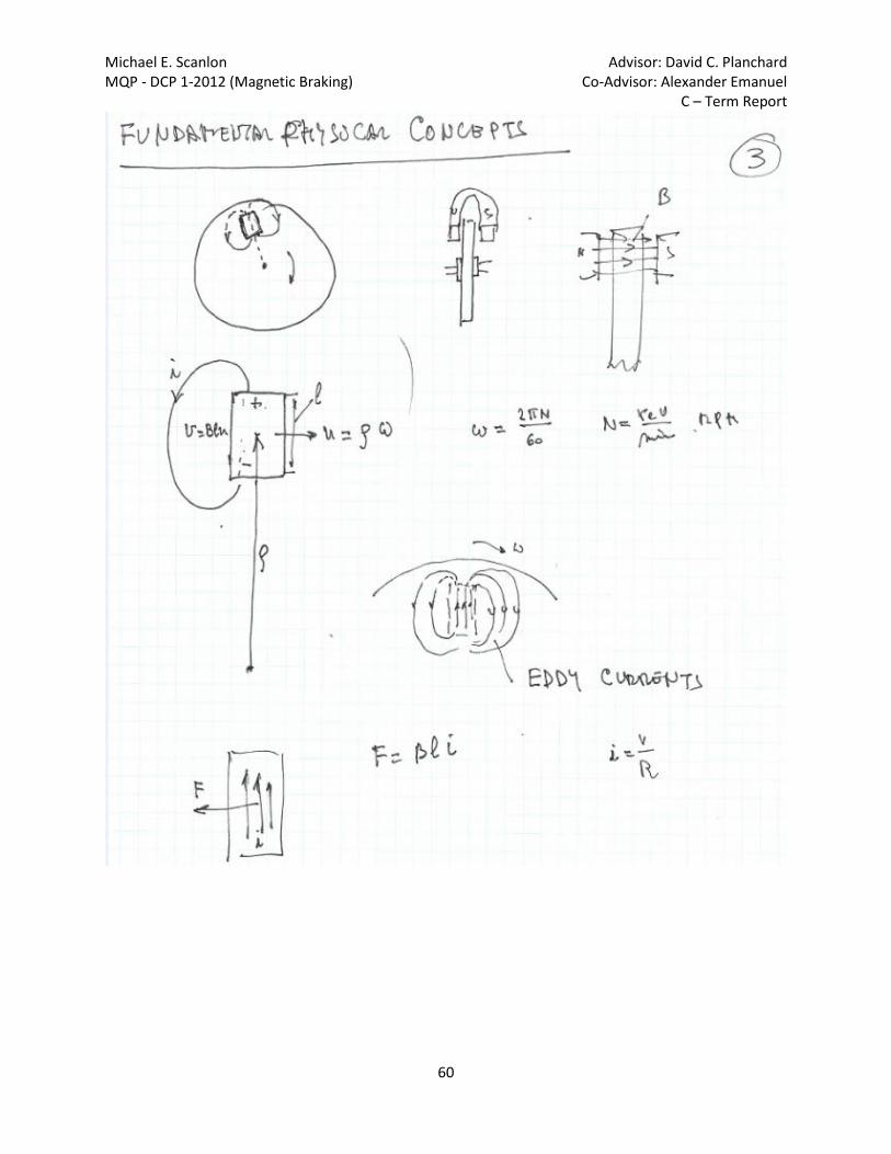
Michael E. Scanlon Advisor: David C. Planchard MQP - DCP 1-2012 (Magnetic Braking) Co-Advisor: Alexander Emanuel C – Term Report
60

Michael E. Scanlon Advisor: David C. Planchard MQP - DCP 1-2012 (Magnetic Braking) Co-Advisor: Alexander Emanuel C – Term Report
61
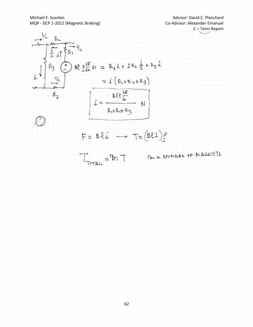
Michael E. Scanlon Advisor: David C. Planchard MQP - DCP 1-2012 (Magnetic Braking) Co-Advisor: Alexander Emanuel C – Term Report
62

Michael E. Scanlon Advisor: David C. Planchard MQP - DCP 1-2012 (Magnetic Braking) Co-Advisor: Alexander Emanuel C – Term Report
63
Notes from January 5, 2012:

Michael E. Scanlon Advisor: David C. Planchard MQP - DCP 1-2012 (Magnetic Braking) Co-Advisor: Alexander Emanuel C – Term Report
64

Michael E. Scanlon Advisor: David C. Planchard MQP - DCP 1-2012 (Magnetic Braking) Co-Advisor: Alexander Emanuel C – Term Report
65

Michael E. Scanlon Advisor: David C. Planchard MQP - DCP 1-2012 (Magnetic Braking) Co-Advisor: Alexander Emanuel C – Term Report
66

Michael E. Scanlon Advisor: David C. Planchard MQP - DCP 1-2012 (Magnetic Braking) Co-Advisor: Alexander Emanuel C – Term Report
67

Michael E. Scanlon Advisor: David C. Planchard MQP - DCP 1-2012 (Magnetic Braking) Co-Advisor: Alexander Emanuel C – Term Report
68
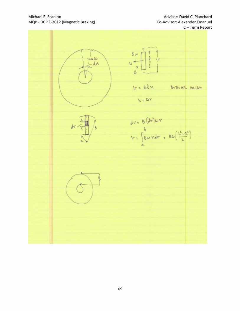
Michael E. Scanlon Advisor: David C. Planchard MQP - DCP 1-2012 (Magnetic Braking) Co-Advisor: Alexander Emanuel C – Term Report
69
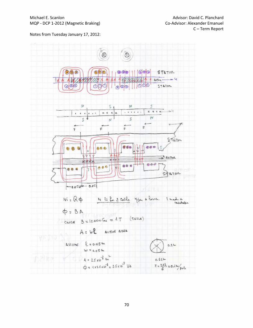
Michael E. Scanlon Advisor: David C. Planchard MQP - DCP 1-2012 (Magnetic Braking) Co-Advisor: Alexander Emanuel C – Term Report
70
Notes from Tuesday January 17, 2012:

Michael E. Scanlon Advisor: David C. Planchard MQP - DCP 1-2012 (Magnetic Braking) Co-Advisor: Alexander Emanuel C – Term Report
71
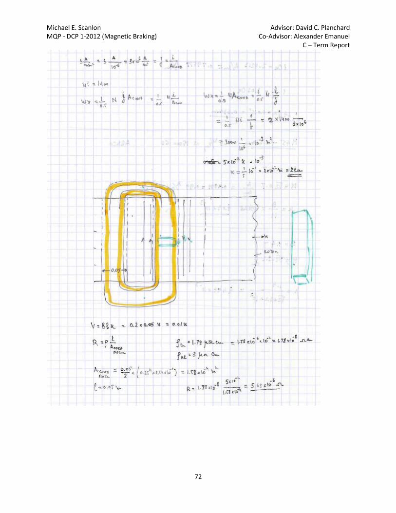
Michael E. Scanlon Advisor: David C. Planchard MQP - DCP 1-2012 (Magnetic Braking) Co-Advisor: Alexander Emanuel C – Term Report
72
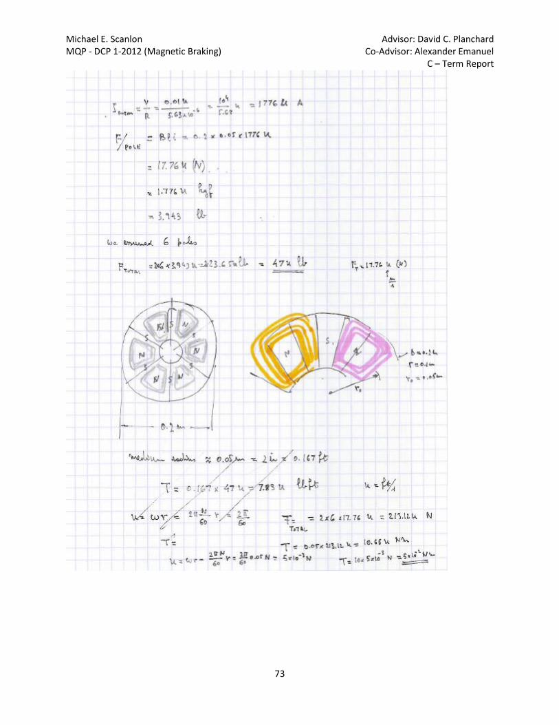
Michael E. Scanlon Advisor: David C. Planchard MQP - DCP 1-2012 (Magnetic Braking) Co-Advisor: Alexander Emanuel C – Term Report
73
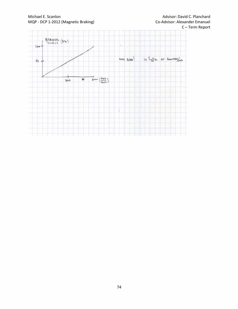
Michael E. Scanlon Advisor: David C. Planchard MQP - DCP 1-2012 (Magnetic Braking) Co-Advisor: Alexander Emanuel C – Term Report
74

Michael E. Scanlon Advisor: David C. Planchard MQP - DCP 1-2012 (Magnetic Braking) Co-Advisor: Alexander Emanuel C – Term Report
75
*These final two notes are important; they detail the specific formula’s used for calculations specific to the project.

Michael E. Scanlon Advisor: David C. Planchard MQP - DCP 1-2012 (Magnetic Braking) Co-Advisor: Alexander Emanuel C – Term Report
76