Embed Size (px)
Citation preview

R
2800 LAURA LANE • MIDDLETON, WI 53562 • (800) 288-9383 • FAX (608) 836-9044 • www.tcsbasys.com
1
SZ1041AMake Up Air Unit Thermostat
Product Manual
Description The SZ1041A is a microprocessor-based programmable thermostat designed to control air handling units and make up air units with modulating economizers and/or modulating heating or cooling. The SZ1041A has a 365-day time clock.
Features • Stand-alone or network operation• Outdoor air sensor input with heating & cooling lockout• Adjustable delay on power-up and start-up for
soft starts• P+I control option on digital stages• Smart Recovery• No battery backup required• Built-in HVAC equipment protection• 32 character LCD display• Six status LEDs for monitoring • Remote room sensing capability• User setpoint adjustment limits• Local and remote override capability • System and fan switching with access lockouts • Equipment monitoring inputs and indication• External time clock input • Access to programming or schedule may be locked
out or limited with the use of an access code• Fahrenheit or Celsius temperature display
Contents Description . . . . . . . . . . . . . . . . . . . . . . . . . . . . . . . . . . 1Features . . . . . . . . . . . . . . . . . . . . . . . . . . . . . . . . . . . . 1Mounting . . . . . . . . . . . . . . . . . . . . . . . . . . . . . . . . . . . 1Wiring . . . . . . . . . . . . . . . . . . . . . . . . . . . . . . . . . . . . . . 2Setup . . . . . . . . . . . . . . . . . . . . . . . . . . . . . . . . . . . . . . 3Programming . . . . . . . . . . . . . . . . . . . . . . . . . . . . . . . . 4Setting Clock & Schedule. . . . . . . . . . . . . . . . . . . . . . . 8Operation . . . . . . . . . . . . . . . . . . . . . . . . . . . . . . . . . . . 9Checkout & Troubleshooting . . . . . . . . . . . . . . . . . . . . 12LED Description . . . . . . . . . . . . . . . . . . . . . . . . . . . . . . 14Limiting Occupant Access . . . . . . . . . . . . . . . . . . . . . . 15User’s Guide. . . . . . . . . . . . . . . . . . . . . . . . . . . . . . . . . 15
Mounting The SZ1041A is designed for wall mounting using two #6 sheet metal screws, either over a horizontally installed 2" x 4" junction box, or directly to block or dry-wall.
For best results, the thermostat should be mounted on an interior wall which reflects normal room environment, at a height of approximately five feet from the floor. Avoid areas exposed to direct sunlight, unusual heat or cool sources, open doors and windows, unventilated locations and hot or cold air from diffusers.If using a remote room sensor, it should be mounted in the manner described above. The thermostat may then be mounted in an area which is accessible for adjusting its settings.
Caution: Remove power from thermostat prior to mounting.
Communicating Thermostats

AB
1
+ -67
1 For com m un ica tion w iring, use tw is ted, sh ie lded 18 A W G .M ust be run separa te ly.
2 D ry m om enta ry con tc t. M ust no t be pow ered.
3 24 V A C transfo rm er. S ee pow ering ins truc tions.
4
5 S ensor inpu t w iring 18 A W G , tw is ted, sh ie lded pa ir.
D ry con tac t. M ust no t be pow ered.
6 4 to 20 m A ou tpu t 600 ohm m ax. D o no t pow er ac tua to r w ith pow er from the the rm osta t. The the rm osta ts a re ha lf-w ave rec tified , w hereby the pow er g round is com m on w ith the s igna l g round.
34 44
5 5 5Remote
Zone/ReturnAir Temp
DischargeAir Temp
OutsideAir Temp2
U p to nom ina l 28 V A C from equ ipm ent transfo rm er.
R E F
heat, Cool, or economizer
R
2800 LAURA LANE • MIDDLETON, WI 53562 • (800) 288-9383 • FAX (608) 836-9044 • www.tcsbasys.com
2
Wiring The SZ1041A uses standard terminal designations for wiring. See diagram below.
Remote temPeRAtURe SenSoR WiRingUse 18 AWG shielded twisted-pair grounded at the sen-sor mounting location. Sensor wiring runs of up to 250 feet are attainable if properly shielded wire is used and the installation environment is free of electrical noise. Sensor wire should be kept at least five feet away from line voltage wiring.
The SZ1041A accepts three 2-wire remote temperature sensors. Consult the TS Series Temperature Sensor Submittal Data sheet for a complete listing of packaging and application styles. When using TCS Basys Controls three-wire sensors, use the black and red leads and either clip or twist off the white lead. Make sure that the dip switches are set for the sensors you are using.
PoWeRing the SZ1041A Superstats are powered from 24 VAC +/- 20%.
If wiring for communications, dedicated power must be used to power the Superstat. Several “S” Series ther-mostats may be powered from the same transformer, provided that the transformer has sufficient power. (Superstats require 8 VA @ 24 VAC.)
Caution: Do not connect to 120 VAC. When multiple TCS Basys Controls devices are using a single transformer, the polarity of the power wiring must be maintained because all TCS devices are half-wave rectified and have com-mon return paths.
When the Superstat is used as a stand-alone thermostat without communications, the unit transformer may be used to power it. To do this, install a jumper between the “R” and “+24” terminals. The “24-” terminal must then be connected to the common side of the unit trans-
Wiring for the SZ1041 A**Add 500Ω resistor (included in bag) to convert 0/4 to 20mA to, 0/2 to 10 VDC.
Y1 or W1 = HeatY2 or W2 = Cool
NOTE: Comm wires only needed with SZ line. Do not use with wireless line.
NOTE: The unit transformer may be used to power any wireless line product.

R
2800 LAURA LANE • MIDDLETON, WI 53562 • (800) 288-9383 • FAX (608) 836-9044 • www.tcsbasys.com
3
Setup note: If using remote sensor(s), the calibra-tion may need to be adjusted. See “Checkout and Troubleshooting” section.
temPeRAtURe SenSoR SeleCtionThe dipswitches in the cover (shown above) must be set when using remote room, discharge, and/or outdoor sensors.
Use the following guide to determine the dipswitch set-tings for your application.
Using built-in room sensor only. (this is the default setting.)
Using built-in room sensor with discharge air sensor only.
Using built-in room sensor with outdoor air sensor only.
Using built-in room sensor with both discharge and outdoor air sensors.
Using remote room sensor only.
Using remote room sensor with discharge air sensor only.
Using remote room sensor with outdoor air sensor only.
Using remote room sensor with both discharge and outdoor air sensors.
KeyPAd ACCeSSThe dipswitches in the cover (shown above connected with ribbon cable) must be set in order to lock the user out of programming and/or to set the clock and sched-ule. Use the guide below to set these dipswitches for your application. User access may also be limited with an access code set in programming. (The fan and sys-tem switches are enabled or disabled in programming only, and require no dipswitch placement.)
Keypad access to both program-ming and clock setup. (this is the default setting.)
no keypad access to programming or clock setup.
Keypad access to programming only.
Keypad access to clock setup only.
Once the dipswitches have been set and you have con-firmed that the sensors are reading correctly (and pro-gram and clock setup are finished, if locking out access with dipswitches), secure the cover to the base with the two set screws located at the top right and the left side to prevent tampering.
1 2 3 4 5
1 2 3 4 5
REF
A
B

R
2800 LAURA LANE • MIDDLETON, WI 53562 • (800) 288-9383 • FAX (608) 836-9044 • www.tcsbasys.com
4
Programming The SZ1041A may be programmed through the keypad on the face, or with a PC.
If programming with a PC, the following must be set through the face prior to programming:
• Address (step #2)• Baud rate (step #3)• Temperature scale (step #4) For more information on programming through the PC, consult your TCS software manual.
PRogRAmming thRoUgh the KeyPAdTo access the programming screens, press the program setup button. To make changes, use the warmer and cooler keys. Access may be locked out with dipswitches, or an access code may be required.
fan
Occupied
Heating
Cooling
Fan
Service
Program/
CooleR
WARmeRData
switch
systemswitch
programsetup
clocksetup
override
servicestatus
main monitoring Screen. Press the program setup button to access the following screens.
Access Code entry Screen. Will appear if access code is required for programming. Use 248 as the default. If the wrong code is entered, it will revert to the previous screen. Controller Address Screen. If using a PC to access the thermostat, set a unique address from 0 to 255, excluding 248.
Communication Baud Rate Screen. If using a PC to access the thermostat, all controllers on a network must be set to the same baud rate. Choose between 2.4K, 4.8K, 9.6K and 19.2K.
display type Screen. Choose between FAHRENHEIT and CELSIUS for tempera-ture indication.
System Access Screen. Choose whether or not to enable user’s access to the sys-tem switch to set the system mode.
System mode Screen. Choose from AUTO, HEAT, COOL, or OFF for system mode. In the OFF mode, all outputs are off. Fan Access Screen. Choose whether or not to enable the user’s access to the fan switch to set the occupied fan mode.
occupied Fan mode Screen. Choose between ON (continuous), COOL (gas heat or no heat), or AUTO for your fan run times during the occupied modes. Unoccupied Fan mode Screen. Choose between ON (continuous), COOL (gas heat or no heat), or AUTO for your fan run times during the unoccupied mode.
occupied heat Setpoint A Screen. Set the occupied heat setpoint A. occupied heat Setpoint B Screen. Set the occupied heat setpoint B.
occupied heat Setpoint C Screen. Set the occupied heat setpoint C.
occupied heat Setpoint d Screen. Set the occupied heat setpoint D.
Unoccupied heat Setpoint Screen. Set the unoccupied heat setpoint.
SET ADDRESS:
000
programsetup
programsetup
2.
ENTER ACCESS
CODE 000
programsetup
1.
MON 08-08-08
12:00 AM 72F
SET BAUD RATE:
9.6K
programsetup
3.
programsetup
TEMP SHOWN IN:
FAHRENHEIT
4.
programsetup
USER ACCESS TO
SYSTEM MODE? YES
5.
programsetup
OCCUPIED HEAT
SETPOINT B: 70F
11.
programsetup
OCCUPIED HEAT
SETPOINT A: 70F
10.
programsetup
SET UNOCCUPIED
FAN MODE? AUTO
9.
programsetup
SET OCCUPIED FAN
MODE: AUTO
8.
programsetup
USER ACCESS TO
FAN MODE? YES
7.
programsetup
OCCUPIED HEAT
SETPOINT C: 70F
12.
programsetup
SET SYSTEM
MODE: AUTO
6.
programsetup
OCCUPIED HEAT
SETPOINT D: 70F
13.
programsetup
UNOCCUPIED HEAT
SETPOINT: 60F
14.

R
2800 LAURA LANE • MIDDLETON, WI 53562 • (800) 288-9383 • FAX (608) 836-9044 • www.tcsbasys.com
5
occupied Cool Setpoint A Screen. Set the occupied cool setpoint A.
occupied Cool Setpoint B Screen. Set the occupied cool setpoint B. occupied Cool Setpoint C Screen. Set the occupied cool setpoint C. occupied Cool Setpoint d Screen. Set the occupied cool setpoint D. Unoccupied Cool Setpoint Screen. Set the unoccupied cool setpoint.
User Setpoint limit Screen. Enter the number of degrees you want the user to be allowed to change the preset occu-pied setpoints up or down.
override time Screen. Enter the num-ber of minutes (0 to 255) that the ther-mostat will maintain occupied setpoints when overridden.
Second Stage heat Screen. Indicate whether the thermostat will control a second stage of HEAT or use w2 as a time clock (TCLCK)output.
Second Stage heat Screen. Choose whether the thermostat will control a second stage of heating. (Select NO if not using a second stage of heating.) Second Stage Cool Screen. Choose whether the thermostat will control a second stage of cooling. (Select NO if not using a second stage of cooling.)
heat Stage 1 offset Screen. Enter an offset value for heat stage 1. First stage is normally 0 offset.
heat Stage 1 differential Screen. Enter a differential value for heat stage 1.
programsetup
OCCUPIED COOL
SETPOINT B: 75F
16.
programsetup
OCCUPIED COOL
SETPOINT A: 75F
15.
programsetup
OCCUPIED COOL
SETPOINT C: 75F
17.
programsetup
OCCUPIED COOL
SETPOINT D: 75F
18.
programsetup
SET OVERRIDE
TIME: 180 MINUTES
21.
programsetup
UNOCCUPIED COOL
SETPOINT: 80F
19
programsetup
LIMIT SETPOINT
ADJUST +/-: 05F
20.
programsetup
STAGE 2 HEAT
USED FOR HEAT
22.
programsetup
ENABLE SECOND
STAGE COOL? YES
24.
programsetup
HEAT STAGE 1
DIFF: 01F
26.
programsetup
HEAT STAGE 1
OFFSET: 00F
25.
heat Stage 2 offset Screen. Enter an offset value for heat stage 2. This screen only appears if heat stage 2 is enabled as heat.
heat Stage 2 differential Screen. Enter a differential value for heat stage 2. This screen only appears if heat stage 2 is enabled.
Cool Stage 1 offset Screen. Enter an offset value for cool stage 1. First stage is normally 0 offset.
Cool Stage 1 differential Screen. Enter a differential value for cool stage 1.
Cool Stage 2 offset Screen. Enter an offset value for cool stage 2. This screen only appears if cool stage 2 is enabled.
Cool Stage 2 differential Screen. Enter a differential value for cool stage 2. This screen only appears if cool stage 2 is enabled.
Cool Stage 3 offset Screen. Enter an offset value for cool stage 3. This screen only appears if cool stage 3 is enabled.
Cool Stage 3 differential Screen. Enter a differential value for cool stage 3. This screen only appears if cool stage 3 is enabled.
Control mode Screen. Enter whether you want to control by temperature only (P) or add a time factor (P+I). This applies to the stage outputs only. time Clock output Screen. Choose whether the auxiliary output will be OPEN during occupied periods (and closed during unoccupied periods) or CLOSED during occupied periods (and open during unoccupied periods).
outdoor Air Sensor Function Screen. Choose whether or not you are using an outdoor air sensor function. To monitor only, select NO. See setup instructions for dipswitch settings which must also be set.
Cooling lockout Screen. Enter an outdoor air cooling lockout temperature. This screen will not appear if the outdoor air sensor function is disabled.
programsetup
COOL STAGE 1
DIFF: 01F
30.
programsetup
COOL STAGE 2
OFFSET: 01F
31.
programsetup
COOL STAGE 1
OFFSET: 00F
29.
programsetup
HEAT STAGE 2
DIFF: 01F
28.
programsetup
SET CONTROL
MODE: P
35
programsetup
COOL STAGE 2
DIFF: 01F
32.
programsetup
ENABLE OUTDOOR
AIR FUNCT.? YES
37.
programsetup
COOLING LOCKOUT
TEMP: 065F
38.
programsetup
ENABLE SECOND STAGE HEAT? YES
23.
HEAT STAGE 2
OFFSET: 01F
27.
programsetup
programsetup
TIME CLOCK
OCCUPIED: OPEN
36.
programsetup
COOL STAGE 3
OFFSET: 01F
33.
programsetup
COOL STAGE 3
DIFF: 01F
34.

R
2800 LAURA LANE • MIDDLETON, WI 53562 • (800) 288-9383 • FAX (608) 836-9044 • www.tcsbasys.com
6
AO1 MODE AS: HEAT
41.
programsetup
programsetup
DSCHARGE AIR
PROP BAND: 010F
45.
programsetup
OUTDOOR DAMPER
MIN POSITION: 10%
46.
programsetup
DSCHARGE AIR
LOW LIMIT 040F
44.
programsetup
DSCHARGE AIR
SETPOINT: 055F
43.
programsetup
OUTDOOR AIR ECON
SETPOINT: 068F
42.
programsetup
AO1 OUTPUT
RANGE: 4-20 MA
47.
heating lockout Screen. Enter an outdoor air heating lockout temperature. This screen will not appear if the outdoor air sensor functi-ion is disabled.
discharge Air Sensor Function Screen. Choose whether or not you are using a dis-charge air sensor function. To monitor only, select NO. See setup instructions for dip-switch settings which must also be set.
Ao1 mode Selection Screen: Choose if AO1 is HEAT, COOL or ECON.
outdoor Air economizer Setpoint Screen. Set the outdoor air setpoint. This screen will not appear if the discharge air sensor function is disabled.
discharge Air Setpoint Screen. Set the discharge air setpoint. This screen will not appear if the discharge air sensor function is disabled.
discharge Air low limit Screen. Enter a discharge air low limit value. This screen will not appear if the discharge air sensor function is disabled.
discharge Air Proportional Band Screen. Set the discharge air proportional band or throttling range. This screen will not appear if the discharge air sensor function is disabled.
outdoor damper min. Position Screen. Set the minimum damper position. This screen will not appear if the discharge air sensor function is disabled.
Ao1 output Screen. Choose whether the modulating output range will be 0-20 mA or 4-20 mA. This screen will not appear if the discharge air sensor function is disabled.
modulating output 1 Control Screen. Choose whether to control based on DISCHARGE air reset of SPACE tempera-ture. enable heating low limit Screen. Choose whether to enable Heating Low temperature limit. Only appears if AO1 mode is HEAT.
discharge Air Setpoint Screen. Set the discharge air setpoint. This screen will not appear if the discharge air sensor function is disabled.
AO CONTROL BASED
ON: SPACE
48.
programsetup
ENABLE HEATING
LOW LIMIT: YES
49.
programsetup
ENABLE MOD OUT 1
MIN/MAX POS: YES
54.
programsetup
MOD OUT 1
MIN POS: 10%
55.
programsetup
MOD OUT 1
MAX POS: 99%
56.
programsetup
Reset Ratio Factor Screen. Enter a reset ratio factor. This is the number of degrees that the discharge air setpoint is raised when the space tempetature falls by 1 degree for heating, or the number of degrees that the discharge air setpoint is lowered when the space temperature rised by 1 degree for cool-ing. modulating output Proportional Band Screen. Enter the number of degrees away from the setpoint that the valves or damper will be fully open. Analog output Setpoint offset Screen. Enter a setpoint offset. This is a value below the heating setpoint or above the cooling setpoint where the analog output begins modulate. enable min/max PoS Screen. Choose whether to enable min/max mod out 1 control.
min Position Screen. Set the minimum posi-tion for analog output 1.
max Position Screen. Set the maximum position for analog output 1. modulating output 1 Action Screen. Choose whether the output will be direct reverse acting. Ao1 output Range Screen. Choose whether the modulating output range will be 0-20 mA or 4-20 mA. di1 Choice Screen. Choose DI1 as FAN PROVING, LOW TEMP ALARM or a MONITOR point. Select MONITOR if unused. di2 Choice Screen. Choose DI2 as ECON, FILTER SERVICE or MONITOR. Select MONITOR if unused.
di2 Shift Screen. Enter the setpoint shift value. This screen will only appear if DI2 is set to MONITOR
di3 Choice Screen. Choose FILTER SERVICE, EXTernal OVERRIDE, or EXTernal TIME CLOCK. Select EXTernal OVERRIDE if unused.
AO 1 CONTROL
ACTION: DIRECT
57.
programsetup
AO1 OUTPUT RANGE
RANGE: 4-20 MA
58.
programsetup
programsetup
DI1 USED FOR
MONITOR
59.
programsetup
DI2 USED FOR
MONITOR
60.
programsetup
DI3 USED FOR:
FILTER SERVICE
62.
programsetup
SET DI2 SETPOINT
SHIFT: 00F
61.
Not
e: O
nly
appe
ar if
AO
1 m
ode
is E
CON
.
MOD OUT 1 SET P.
OFFSET: 00F
53.
programsetup
DISCHARGE AIR
SETPOINT: 55F
50.
programsetup
Not
e: O
nly
appe
ar if
AO
1 m
ode
is H
eat o
f Coo
l.programsetup
ENABLE DISCHARGE
AIR FUNCT.? YES
40.
programsetup
HEATING LOCKOUT
TEMP: 070F
39. RESET RATIO
FACTOR: 2F
51.
programsetup
MOD OUT 1
BAND: 05F
52.
programsetup
Not
e: O
nly
appe
ar if
AO
1 m
ode
is H
eat o
f Coo
l.

R
2800 LAURA LANE • MIDDLETON, WI 53562 • (800) 288-9383 • FAX (608) 836-9044 • www.tcsbasys.com
7
programsetup
REQUIRE CODE FOR
CLOCK / SCHED? YES
66.
programsetup
SET ACCESS
CODE: 248
67.
MON. 08-08-08
12:00 AM 72F
delay on Powerup Screen. Enter a value in seconds, such that when the unit is pow-ered up, control is delayed for this amount of time.
Smart Recovery Screen. Choose whether or not smart recovery will be used. Note: Smart Recovery is not available when DI3 is used as EXTernal TIME CLOCK.
Programming Access Screen. Choose whether or not a code will be required to enter programming setup. A dipswitch option to lock out access altogether is also avail-able.
Clock and Schedule Access Screen. Choose whether or not a code will be required to enter clock and schedule setup. A dipswitch option to lock out access alto-gether is also available.
Access Code Screen. Enter an access (0 to 255) code that will be used to enter the pro-gramming and/or clock and schedule setups if access code has been required in the last two steps. The default is 248.
main monitoring Screen.
programsetup
REQUIRE CODE FOR
PROGRAMMING? YES
65.
programsetup
ENABLE SMART
RECOVERY? NO
64.
programsetup
DELAY ON POWERUP
010 SECONDS
63.

R
2800 LAURA LANE • MIDDLETON, WI 53562 • (800) 288-9383 • FAX (608) 836-9044 • www.tcsbasys.com
8
Setting Clock & Schedule The SZ1041A clock and schedule may be set through the keypad and display, or with a PC. For more informa-tion on programming through the PC, consult your TCS software manual.
Setting CloCK & SChedUle thRoUgh the KeyPAdTo access the clock and schedule screens, press the clock setup button. To make changes, use the warmer and cooler keys. For screens that have more than one field to set, use the override key to move to the next field. Access may be locked out with dipswitches, or an access code may be required.
main monitoring Screen. Press the clock setup button to access the following screens.
Access Code entry Screen. May appear if access code is required for set-ting clock and schedules. Use 248 as the default. If the wrong code is entered, it will revert to the previous screen.
time and day Screen. Set the hour, minutes, AM or PM, and day of the week.
date Screen. Set the month, date, and year.
Schedule Announcement Screen. Announces the next screen.
occupied times Screen. Set hours and minutes of start and end times for up to two occupied periods.
occupied times Screen. Set hours and minutes of start and end times for up to two occupied periods.
Schedule Announcement Screen. Announces the next screen.
Copy Schedule Screen. Choose to use the same schedule that was used for the previous day. If so, the next screen does not appear.
occupied times Screen. Set hours or minutes of start and end times for up to two occupied periods.
occupied times Screen. Set hours or minutes of start and end times for up to two occupied periods.
holiday Announcement Screen. Announces the next screen.
holidays #1 Screen. Set holiday peri-ods 1 through 12, month, date, and dura-tion for the periods that will follow the holiday #1 schedule.
holiday Announcement Screen. Announces the next screen.
holidays #2 Screen. Set holiday peri-ods 1 through 12, month, date, and dura-tion for the periods that will follow the holiday #2 schedule.
daylight Savings Screen. Choose to have automatic daylight savings adjust-ments made to your time.
main monitoring Screen.
c loc ks etup
COPY MON FOR
TUE? YES
clocksetup
SET OCCUPIED
TIMES TUESDAY:
clocksetup
A:08:00 TO 17:00
B:00:00 TO 00:00
clocksetup
7.
8.
9. override
ENTER DATES FOR
HOLIDAY #1
C:00:00 TO 00:00
D:00:00 TO 00:00
10. override
clocksetup
clocksetup
11.
clocksetup
SET TIME & DAY:
12:00 AM MON
2.override
SET OCCUPIED
TIMES MONDAY:
SET DATE:
08-08-08
clocksetup
3.
4.
MON 08-08-08
12:00AM 72F
clocksetup
ENTER ACCESS
CODE 000
1.
A:08:00 TO 17:00
B:00:00 TO 00:00
clocksetup
5. override
clocksetup
C:00:00 TO 00:00
D:00:00 TO 00:00
clocksetup
6.
clocksetup
override
override
clocksetup
clocksetup
ENTER DATES FOR
HOLIDAY #2
HOL1 01=01-01
DURATION=00 DAYS
12. override
clocksetup
13.
clocksetup
DAYLITE
SAVINGS? YES
HOL2 01=01-01
DURATION=00 DAYS
14. override
clocksetup
15.
MON 08-08-08
12:00 AM 72F
clocksetup
The following screens are repeated for Wed., Thurs., Fri., Sat., and Sun., Holiday #1 and #2

R
2800 LAURA LANE • MIDDLETON, WI 53562 • (800) 288-9383 • FAX (608) 836-9044 • www.tcs-basys.com
9
Operation UnoCCUPied SetBACKThe SZ1041A operates in either an occupied or unoc-cupied mode. During the occupied mode, the occupied heating and cooling setpoints will be maintained, and the fan will operate according to its occupied setting. During the unoccupied mode, the unoccupied heating and cooling setpoints will be maintained, and the fan will operate according to its unoccupied setting. The occupied LED will be lit when the unit is operating in the occupied mode.
The occupied schedule may be set utilizing the internal time clock or DI3 may be used with an external time clock, whereas when DI3 is closed, the unit is in the occupied mode. The Smart Recovery function is dis-abled when DI3 is used for external time clock.
oveRRideA timed override is available using the button on the face of the thermostat or through momentary contacts wired into the OVR terminal. The amount of time the unit will be overridden is set from 0 to 255 minutes in the programming screen. This override behaves differ-ently depending on the mode the thermostat is operating in (occupied or unoccupied) and the options that have been enabled within the software. In standard mode, the override only activates in unoccupied mode and takes the thermostat into occupied mode. If "Override for Occupied Period" is enabled, the override also activates in occupied mode and takes the thermostat into unoccu-pied mode. In either case, you are able to view the time remaining in the override period both within the software and by using the service button to scroll through the sta-tus screens. If the occupant desires to return the ther-mostat to unoccupied or occupied operation (depending on how the override was used) before the time interval is up, they may press the override again. If "Continuous Occupied Override" or "Continuous Unoccupied Override" is enabled, then pressing the override once and then pressing and holding it for 5 seconds puts the thermostat into a "hold” mode (the override LED on the thermostat will flash quickly). In this mode, the over-ride setpoints are used until the next occupied period is reached, or until the thermostat is manually taken out of the "Continuous Override" mode by pressing the over-ride again.
Continuous override is available through the DI3 contact or the software. If DI3 is set to external override, the unit will be in the occupied mode whenever the DI3 contact is closed. When using this option, the timed override may still be activated.
The software allows you to override the thermostat by putting the override parameter into the remote mode, and thus disabling the timed override.
SetBACK And oveRRide APPliCAtionSIn most applications, it is desired to maintain a regular schedule, and allow timed override with the button on the face or with a remote momentary contact.
To allow a regular schedule, and also automatically override with the use of occupancy or light sensor, set DI3 to over-ride and set it up so that the contact is closed when you want the override.
For applications where a room might not be used on a regular schedule, such as conference rooms, set DI3 to external time clock and close the contact when you want the room occupied, such as with a switch or wind-up timer. If each occupancy period is about the same, (theaters, meetings) another option is to set the DI3 to external time clock, and use the timed override button to put the unit in occupied mode.
To make the unit always occupied, set DI3 to external time clock and short the DI3 terminal to ground.
diSChARge AiR temPeRAtURe SenSingThe SZSZ1041A accepts a remote discharge air sensor for monitoring purposes. (See setup instructions for dip-switch placement for this option.)
Choose YES in programming screen #40 only if you have a discharge air sensor installed and you want the SZ1041A to use its built-in economizer functions. If NO is chosen, the discharge air is still monitored. You must also have an outdoor air sensor installed for economizer operation. The discharge air span is 0 to 150°F (-17.8 to 65.6°C).
AnAlog oUtPUtS On the SZ1041A, analog output one is used to control an economizer. See Economizer Operation section for fur-ther programming options.
AnAlog oUtPUtS/diSChARge AiR ReSetThe analog output on the SZ1041A is used to control the heating or cooling in a space. The analog outputs on the SZ1041A are used to control the heating and cool-ing in a space. To use the discharge air reset function, a discharge air sensor must be installed. In programming step #40, the discharge air sensor must be enabled. In programming step #48 the control must be based on DISCHARGE air.
In programming screen #49, you are asked whether to enable heating low limit. This will provide heat to limit the minimum discharge air temperature.
In programming screen #50, you are asked to enter a discharge air setpoint. The discharge air temperature will be controlled to this setting by modulating the heating or cooling device.
In programming screen #51, you are asked to enter a

reset ratio factor. This is the number of degrees that the discharge air setpoint is raised when the room tem-perature falls below the heating setpoint by 1 degree if the analog output is set for heating, or the number of degrees that the discharge air setpoint is lowered when the room temperature rises above the cooling setpoint by 1 degree if the analog output is set for cooling.
oUtdooR AiR temPeRAtURe SenSingThe SZ1041A accepts a remote outdoor temperature sensor for monitoring purposes. (See setup instructions for dipswitch placement for this option.)
Choose YES in programming screen #37 only if you are using an outdoor air sensor and you want to enable the outdoor air heating and cooling lockout functions. If NO is chosen, the outdoor air is still monitored.
When the function is enabled, COOLING LOCKOUT TEMP and HEATING LOCKOUT TEMP are entered in steps #38 and #39. If the outdoor air temperature falls below the COOLING LOCKOUT TEMP, all cooling stages will be locked out and will remain locked out until the outdoor air temperature rises 2° above the lockout temperature. If the outdoor air temperature rises above the HEATING LOCKOUT TEMP, all heating stages will be locked out and will remain locked out until the outdoor air temperature falls 2° below the lockout temperature.
The outdoor air span is -40 to 160 °F (-40.0 to 71.1 °C).
FAn PRovingThe SZ1041A allows DI1 to be set for fan proving to pro-tect equipment on fan failure. To utilize this, a pressure or current switch is required, which indicates when the fan is running. If the thermostat turns on the FAN, and DI1 is not closed after thirty seconds, the system will go to OFF, disabling all outputs, the fan LED will turn off and the service LED will be lit until the system is manu-ally reset by switching the system to a mode other than OFF.
di2 SetPoint ShiFtThe SZ1041A allows DI2 to be set for set-point shift for energy demand setback. This is enabled by setting DI2 to the MONITOR mode. A digital contact that closes when set-back is needed should be wired into DI2. You may specify a number of degrees such that, when the thermostat is operating in the occu-pied mode, and DI2 is closed, the heating setpoint will be lowered this number of degrees, and the cooling set-point will be raised this number of degrees. The fan will continue to operate according to its occupied setting. If you are using DI2 as monitor for another purpose, make sure to set the setpoint shift value to zero.
R
2800 LAURA LANE • MIDDLETON, WI 53562 • (800) 288-9383 • FAX (608) 836-9044 • www.tcsbasys.com
10
StAge oUtPUt PARAmeteRSThe SZ1041A will control up to two stages of either heat-ing or cooling. The SZ1041A will control two stages of heating and two stages of cooling.
For each stage, you may specify an offset and a differ-ential value. The offset value is the amount away from the setpoint a stage will turn off. By assigning a stage a value other than zero, you “anticipate” that the residual heat or cooling in the duct or the other stages will bring the temperature back to setpoint. In most cases, the first stage is set to zero. The differential value is the difference between the on and off points.
Unlike most other multi-stage programmable thermostats, the Superstat allows independent adjustments of "offsets" and "differentials" for stages of heating and cooling. The offset settings can be viewed as setpoints for the second and third stages and are programmed in the Superstat in the number of degrees (i.e. 1,2,3…) beyond the heating and cooling setpoints (temperatures to be maintained).
The differential for each stage can be viewed as the "anticipator" function used in mechanical thermostats.
P+i oPtionThe SZ1041A also have a P+I option. Without enabling this option, stages turn on and off based on temperature vs. setpoint alone, as described above. By enabling this option, you add a time factor to anticipate heating and cooling.
AnAlog oUtPUt PARAmeteRSUse programming steps #48 through #58 to program the operating parameters for the analog output. Select wheth-er the analog output is set for heating, cooling or econo-mizer. Select direct or reverse action. Select whether you want the analog output to modulate from 4 to 20mA or 0 to 20mA. Select the unoccupied action ("20mA or 0 / 4mA" will hold the analog output device open or closed during unoccupied times. "Modulating" will modulate the analog output device to maintain the unoccupied heating or cooling setpoint.). Enter a proportional band (throttling range) in degrees. Enter a setpoint offset in degrees.
heatSetpoint
CoolSetpoint
on
on
on
on
oFF
oFF
oFF
oFF
differential
differential
offset
offset
differential
differential 4 20 4 20
4 20 4 20
4 20 4 20
P
Zone
Temp
O utput (m A)
P
O utput (m A)
diReCt ACting ReveRSe ACting
P P
O utput (m A)
O utput (m A)
Zone
Temp
P P
O utput (m A)
O utput (m A)
PP
Zone
Temp
CSP CSP
hSP hSP
CSP CSP
hSP hSP

R
2800 LAURA LANE • MIDDLETON, WI 53562 • (800) 288-9383 • FAX (608) 836-9044 • www.tcsbasys.com
11
(This is a value below the heating setpoint or above the cooling setpoint where the analog output begins to modulate.)
eConomiZeR oPeRAtionThe analog output on the SZ1041A can be used to con-trol an economizer. Both outdoor air and discharge air temperature sensors are needed to accomplish this.
note: The discharge air sensor may be installed in the discharge air section or in the mixed air section. This instruction as well as product literature refers to a dis-charge air sensor, regardless of where it is mounted.
During occupied time, the outside air dampers are held at a minimum position, entered in programming step #46, until economizer operation is enabled. During unoc-cupied time, the outside air dampers are closed.
In programming screen #42, you are asked to enter an outdoor air setpoint. The outdoor air temperature must fall below this setpoint before economizer operation will be enabled. A call for cooling is also required to enable economizer operation. A typical value is 65°F.
In programming screen #43b, you are asked to enter a discharge air setpoint. The discharge air temperature will be controlled to this setting by modulating the outdoor air dampers, when economizer operation is enabled. In programming screen #44, you are asked to enter a dis-charge air low limit setpoint. If the discharge air falls to this setpoint, the outside air dampers will close.
A proportional band (throttling range), whether you want the analog output to modulate from 4 to 20mA or 0 to 20mA, and direct or reverse action must also be pro-grammed.
SmARt ReCoveRy“Smart Recovery” may be enabled. It ramps the setpoint 4°F/hr. when going from the unoccupied mode to the occupied mode. At the beginning of the occupied mode, the occupied setpoint will be reached, many times with-out the need for the second stage to come on. This fea-ture is automatically disabled when DI3 is set to external time clock.
BUilt-in delAySThe SZ1041A has delays built into the programming sequences to protect equipment. The fan has a mini-
mum on and off time of 30 seconds. When the fan is in AUTO or COOL mode, it will come on 30 seconds before the heating or cooling devices are allowed to sequence on, and remain on for 2 minutes after the heating or cooling devices sequence off. Each stage has a minimum on and off time of two minutes. There is a minimum of 2 minutes between when one stage turns on until the next stage is allowed to turn on, as well as when one stage turns off until the next stage is allowed to turn off.
Delay on occupied, see delay on powerup.
delAy on PoWeRUPThe SZ1041A has an adjustable delay on powerup. When several thermostats are used at one location, and the power goes out, most thermostats turn all of the units back on at the same time on regain of power, cre-ating a peak. The thermostat allows you to set a value, in seconds, where no outputs are allowed to turn on for that length of time on powerup. Setting each unit to a different delay allows you to soft start your system, and thus prevent this peak. This delay can also be applied to the start of occupied time.
dAylight SAvingS timeBeginning in 2007, Daylight Saving Time (DST) in the U.S. will be extended by having an earlier change to DST in spring and a delay in switching back to standard time in fall. However, this change may only be temporary, as this "new" schedule is only in effect for a 2 year trial period. After that, the DST schedule may revert back, stay the same, or be something completely different. Products shipped starting in 2007 with firmware ver-sion 1.5 or higher accommodate the new DST schedule. Products shipped starting in 2008 with firmware version 2.0 or higher accommodate the new DST schedule and have the ability to be programmed to accommodate any future schedules that may be used. Should the sched-ule change and you need to customer program the DST start and end dates, simply enable the "Daylight Savings Time" option within the software and enter the starting month + week and the ending month + week.
4 20 4 20
4 20 4 20
4 20 4 20
P
Zone
Temp
O utput (m A)
P
O utput (m A)
diReCt ACting ReveRSe ACting
P P
O utput (m A)
O utput (m A)
Zone
Temp
P P
O utput (m A)
O utput (m A)
PP
Zone
Temp
CSP CSP
hSP hSP
CSP CSP
hSP hSP
R
2800 LAURA LANE • MIDDLETON, WI 53562 • (800) 288-9383 • FAX (608) 836-9044 • www.tcsbasys.com
12
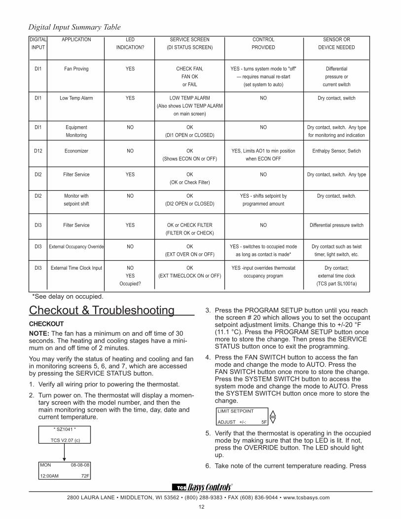
Checkout & Troubleshooting CheCKoUtnote: The fan has a minimum on and off time of 30 seconds. The heating and cooling stages have a mini-mum on and off time of 2 minutes.
You may verify the status of heating and cooling and fan in monitoring screens 5, 6, and 7, which are accessed by pressing the SERVICE STATUS button.
1. Verify all wiring prior to powering the thermostat.
2. Turn power on. The thermostat will display a momen-tary screen with the model number, and then the main monitoring screen with the time, day, date and current temperature.
3. Press the PROGRAM SETUP button until you reach the screen # 20 which allows you to set the occupant setpoint adjustment limits. Change this to +/-20 °F (11.1 °C). Press the PROGRAM SETUP button once more to store the change. Then press the SERVICE STATUS button once to exit the programming.
4. Press the FAN SWITCH button to access the fan mode and change the mode to AUTO. Press the FAN SWITCH button once more to store the change. Press the SYSTEM SWITCH button to access the system mode and change the mode to AUTO. Press the SYSTEM SWITCH button once more to store the change.
5. Verify that the thermostat is operating in the occupied mode by making sure that the top LED is lit. If not, press the OVERRIDE button. The LED should light up.
6. Take note of the current temperature reading. Press
DIGITAL APPLICATION LED SERVICE SCREEN CONTROL SENSOR OR INPUT INDICATION? (DI STATUS SCREEN) PROVIDED DEVICE NEEDED
DI1 Fan Proving YES CHECK FAN, YES - turns system mode to "off" Differential FAN OK — requires manual re-start pressure or or FAIL (set system to auto) current switch
DI1 Low Temp Alarm YES LOW TEMP ALARM NO Dry contact, switch (Also shows LOW TEMP ALARM on main screen)
DI1 Equipment NO OK NO Dry contact, switch. Any type Monitoring (DI1 OPEN or CLOSED) for monitoring and indication D12 Economizer NO OK YES, Limits AO1 to min position Enthalpy Sensor, Swtich (Shows ECON ON or OFF) when ECON OFF DI2 Filter Service YES OK NO Dry contact, switch. Any type (OK or Check Filter)
DI2 Monitor with NO OK YES - shifts setpoint by Dry contact, switch. setpoint shift (DI2 OPEN or CLOSED) programmed amount
DI3 Filter Service YES OK or CHECK FILTER NO Differential pressure switch (FILTER OK or CHECK)
DI3 External Occupancy Override NO OK YES - switches to occupied mode Dry contact such as twist (EXT OVER ON or OFF) as long as contact is made* timer, light switch, etc.
DI3 External Time Clock Input NO OK YES -input overrides thermostat Dry contact; YES (EXT TIMECLOCK ON or OFF) occupancy program external time clock Occupied? (TCS part SL1001a)
Digital Input Summary Table
*See delay on occupied.
LIMIT SETPOINT
ADJUST +/-: 5F
MON 08-08-08
12:00AM 72F
* SZ1041 *
TCS V2.07 (c)

R
2800 LAURA LANE • MIDDLETON, WI 53562 • (800) 288-9383 • FAX (608) 836-9044 • www.tcsbasys.com
13
Fan does not Come onThe fan is on whenever the fan LED is on. If the fan should be on, but the fan LED is off, check the fan and system switch modes, and the unoccupied fan mode in programming. If the fan is off but the fan LED is on, check wiring. Short terminals “R” to “G” and see if the fan comes on. This is a check for a mechanical relay failure.
heating or Cooling does not Come onAt least one stage of heating is on whenever the heat-ing LED is on, and at least one stage of cooling is on whenever the cooling LED is on. If heating or cooling should be on but the heating or cooling LED is off, check the fan and system switch modes. Also, check the heat-ing and cooling setpoints, offsets and differentials, and the room temperature to be sure heating or cooling should be on. If using outdoor air heating and cooling lockouts, or discharge air high and low limits, check their values to be sure heating or cooling is allowed. If heating or cooling is off, but the corresponding LED is on, check the wiring. Short terminals “R” to “Y/W1” or “Y/W2” and see if the heating or cooling comes on. This is a check for a mechanical relay failure.
Wrong temperature displayIf any of the temperatures are reading slightly high or low, there are three adjustment pots located in the cover to adjust them. “T1” is for the room temperature, “T2” is for the discharge air temperature, and “T3” is for the outdoor air temperature. If the temperature is at a minimum or maxi-mum reading, check the sensor dipswitch positions. (See setup instructions.) Check for wiring problems (opens or shorts). A remote 1000 Ω sensor should read 108 to 109 Ω at room temperature.
T1
T2T3
1 2
1 2 3 4 5
adjust display contrast
Service led is onIf the service LED is on, it may be for monitoring purpos-es or it may indicate a critical problem. The first monitor-ing screen accessed by pressing the service status but-ton will display why the light is on.
outputs Will not Shut offFirst check the room temperature and the setpoints and determine whether the output should be on. There are delays and minimum on and off times for the fan and heating and cooling stages. Also, check the service status menus to verify that the outputs are on. Turning the system to “off” will instantly turn all outputs off. The thermostat can be reset by pressing the system switch button and the service status button simultaneously.
the WARMER (up) button. The setpoint adjustment screen should now be showing. Press the WARMER button until the heating setpoint is greater than the current temperature by at least five degrees. The fan will come on. The heating stage(s) will sequence on after 30 seconds.
7. Press the cooler (down) button until the heating set-point is one degree less than the current tempera-ture. The heating stage(s) will sequence off. The fan will turn off 2 minutes after the last heating stage.
8. Press the cooler button until the cooling setpoint is less than the current temperature by at least five degrees. The fan will come on. The cooling stage(s) will sequence on after 2 minutes.
9. Press the warmer button until the cooling setpoint is greater than the current temperature by one degree. The cooling stage(s) will sequence off. The fan will turn off 2 minutes after the last cooling stage.
10. For a heating or cooling analog output: Take note of the room (and discharge) air temperatures. If the analog output is set for Cooling, press the Cooler but-ton until the cooling setpoint is less than the current room temperature by at least 5°. The cooling device should start operating. If the analog output is set for Heating, press the Warmer button until the heating setpoint is greater than the current room temperature by at least 5°. The heating device should start operat-ing.
11. For an economizer analog output: Take note of the discharge and outdoor air temperatures. Go to pro-gramming step #42 and set the outdoor air setpoint 5° greater than the outdoor air temperature. Go to programming step #43 and set the discharge air setpoint 10° less than the discharge air temperature. Press the Cooler button until the cooling setpoint is less than the current room temperature by at least 5°. The damper should now be fully open. Raising the discharge air setpoint, will modulate the damper closed. Raising the cooling setpoint above the room temperature or lowering the outdoor air setpoint below the outdoor air temperature will shut the damp-er to minimum position.
12. Go back to programming step #20 and set the set-point adjust limit back to the desired value. Make any other changes in programming, clock, and schedule. Set the fan and system modes to their desired set-tings.
13. If using remote sensor(s), verify that the reading is correct. If not, see Wrong Temperature Display in troubleshooting section.
tRoUBleShootingno displayCheck for 24 VAC on terminals “+24” and “-24”. Check the cable connecting the cover to the base for a good connection.

R
2800 LAURA LANE • MIDDLETON, WI 53562 • (800) 288-9383 • FAX (608) 836-9044 • www.tcsbasys.com
14
Analog output not Working ProperlyCheck wiring. A separate transformer should be used for the SZ1041A and a separate transformer should be used for the motor(s). Check to make sure that the ana-log output is programmed correctly.
Check the Service Menu. The Mod Out Screen will tell you what the SZ1041A is trying to put out. Compare this with the actual position on the heating or cooling device.
There are two conditions that must be met before the economizer analog output will modulate. First, there must be a call for cooling. Second, the outdoor air tem-perature must be less than the setting set in program-ming step #38.
Put the SZ1041A into occupied mode. You should be able to adjust the output by going to programming step #46 or 55 (depending on AO1 mode in step 41) and varying the minimum position setting. You need to exit programming before the change will take effect.
SeRviCe SCReenSContinually pressing the service status button allows more extensive monitoring. The screens are shown on the following page.
LED Description Six LEDs on the face allow the occupant to view the cur-rent operating status of the thermostat.
oCCUPiedThis LED will be lit whenever the unit is operating in the occupied mode.
heAtingThis LED will be lit when any heat output is operating.
CoolingThis LED will be lit when any cooling output is operating.
FAnThis LED will be lit when the fan output is closed.
SeRviCeThis LED will be lit when the high or low discharge air limit has been reached, when the fan interlock has indi-cated failure, or when the filter service or service input are closed.
PRogRAm/dAtAThis LED will be lit when the thermostat is within the programming or clock setup menus. It will blink when the unit is being accessed by a PC.
Additional monitoring is available by continually pressing the service key.
main monitoring Screen. Press the service button to access the following screens.
Service Screen. This message may be followed by any or all of the follow-ing: CHECK FILTER, CHECK FAN, DISCHARGE HIGH, DISCHARGE LOW, or CHECK DI2.
discharge Air temperature Screen. Shows discharge air temperature if sen-sor is used.
outdoor Air temperature Screen. Shows outdoor air temperature if sensor is used.
override Status Screen. Shows wheth-er the override is active and if so, how many minutes remaining. heat or Cool Stages Status Screen. Shows the status of the first and second stages of heating or cooling.
heat or Cool Stages Status Screen. Shows the status of the first and second stages of heating or cooling.
servicestatus
MOD OUT 25%
DI1 OPEN
7.
servicestatus
HEAT STAGE 1 OFF
HEAT STAGE 2 ON
5.
servicestatus
OVERRIDE ON
178 MINUTES
4.
servicestatus
OUTDOOR AIR
TEMP 75F
3.
servicestatus
DISCHARGE AIR TEMP 55F
2.
servicestatus
SERVICE STATUS
OK
1.
servicestatus
MON 11-19-01
12:00 AM 72F
modulating output 1 and di1 Status Screen. Shows the percent-age of modulating output 1 and sta-tus for DI1. di2 and di3 Status Screen.Shows DI2 status and filter status or DI3 status.
main monitoring Screen. (Date not shown on SZ1017a & SZ1017aW.)
servicestatus
DI2 SERVICE OFF
FILTER OK
8.
servicestatus
COOL STAGE 1 ON
COOL STAGE 2 OFF
6.
MON 08-08-08
12:00AM 72F
Occupied
Heating
C ooling
Fan
S ervice
Program/Data

R
2800 LAURA LANE • MIDDLETON, WI 53562 • (800) 288-9383 • FAX (608) 836-9044 • www.tcsbasys.com
15
Limiting Occupant Access SetPoint AdjUStmentThe occupant may temporarily change the occupied heating and cooling setpoints +/- 5°F by factory default. This setpoint change will remain until the end of the cur-rent occupied period, at which time the program reverts to the setpoints defined in programming. To change the range of adjustment allowed, see programming step #20.
oveRRideThe occupant has the ability to put the unit into occupied mode by pressing the override button on the front. By factory default, the unit will remain in the occupied mode for 180 minutes. This value may be changed from 0 to 255 minutes in programming step #21.
FAn SWitChingThe option to allow the occupant to change the occu-pied fan mode is allowed by factory default. To lock out access to fan switching, see programming step #7.
SyStem SWitChingThe option to allow the occupant to change the system mode is allowed by factory default. To lock out access to system switching, see programming step #5.
Setting CloCK & SChedUleThe ability to set the clock and schedule is allowed by factory default. An access code may be required as set in programming step # 64, or access may be denied altogether using dipswitches described in the setup sec-tion.
PRogRAmmingThe ability to program control parameters is allowed by factory default. An access code may be required as set in programming step # 63, or access may be denied altogether using dipswitches described in the setup sec-tion.
User’s Guide Inside the hinged door of the thermostat is the SuperstatTM User’s Guide. This guide is designed to assist the installer in explaining to the end user how to operate their new thermostat, as well as serve as a handy future reference for the end user.
We recommend that the installer fill out the appropriate pages and explain to the user how the thermostat oper-ates, what settings may be changed, and how the time clock schedules are used.
S U P E R S T A TTM
www.tcsbasys.com
C3782 Rev_0210


![SERVICE MANUAL 12VDC WALL THERMOSTAT AIR …1].pdf · 2006-06-16 · Page -5-THERMOSTAT LOCATION Thermostats are very sensitive instruments. For accurate temperature control and comfort](https://img.pdfslide.net/doc/110x75/5e3843dcbe5c8d470f3f409f/service-manual-12vdc-wall-thermostat-air-1pdf-2006-06-16-page-5-thermostat.jpg)