Embed Size (px)
Citation preview

GSC400 Calibration Utility Manual
Revision 1.0 Full Version File: MAN-0086R1.0, GSC400 Calibration Utility Manual.doc, September, 2010
2 of 18
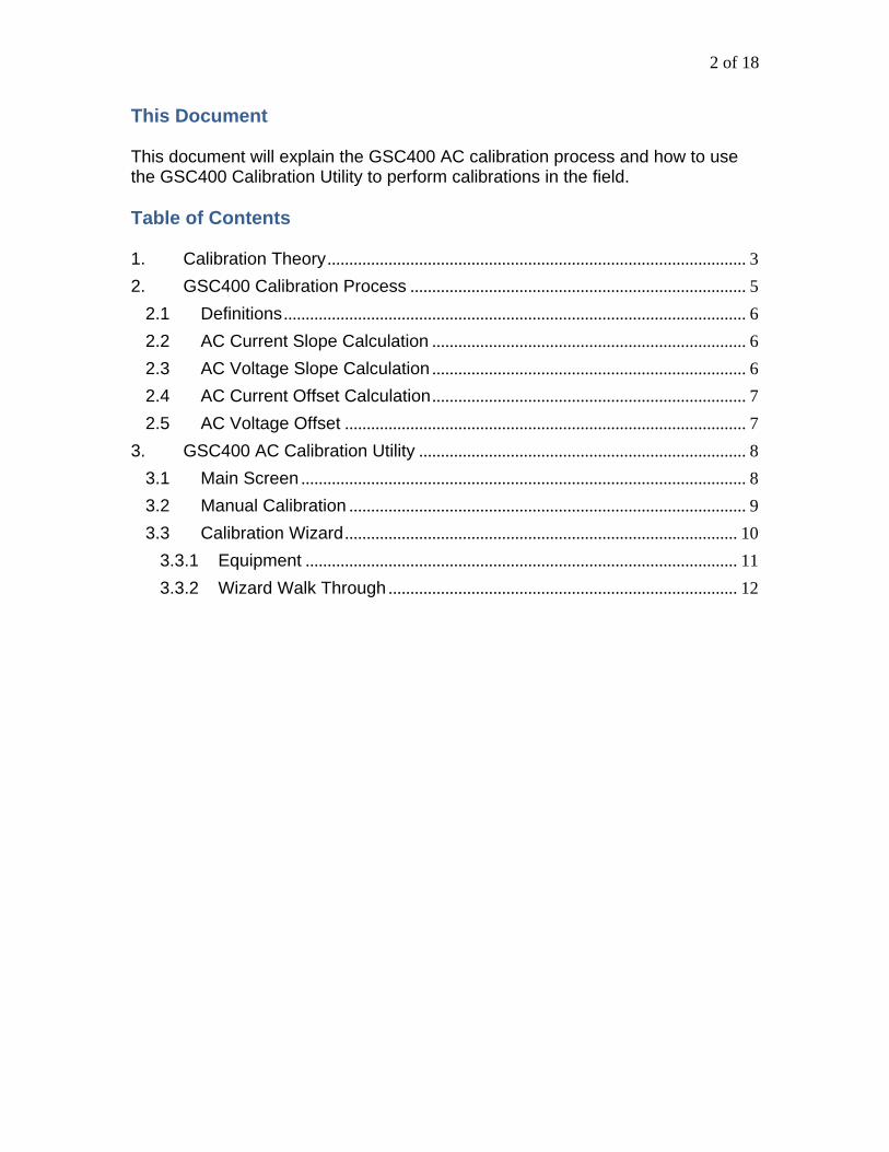
This Document This document will explain the GSC400 AC calibration process and how to use the GSC400 Calibration Utility to perform calibrations in the field. Table of Contents 1. Calibration Theory ................................................................................................ 3 2. GSC400 Calibration Process ............................................................................. 5
2.1 Definitions .......................................................................................................... 6 2.2 AC Current Slope Calculation ........................................................................ 6 2.3 AC Voltage Slope Calculation ........................................................................ 6 2.4 AC Current Offset Calculation ........................................................................ 7 2.5 AC Voltage Offset ............................................................................................ 7
3. GSC400 AC Calibration Utility ........................................................................... 8 3.1 Main Screen ...................................................................................................... 8 3.2 Manual Calibration ........................................................................................... 9 3.3 Calibration Wizard .......................................................................................... 10
3.3.1 Equipment ................................................................................................... 11 3.3.2 Wizard Walk Through ................................................................................ 12

3 of 18
1. Calibration Theory In an ideal world the output from the AC sensing circuit would be proportional to the AC current and voltage at its input for all voltage and current levels (within a certain random accuracy). In practice, the un-calibrated accuracy can vary as a function of the voltage or current level (this is called a slope error) and/or be offset by a fixed amount (offset error). This is shown in Figure 1 to Figure 3 below. The point of calibration is to make the measured current and voltage equal to the input voltage and current within a certain random error tolerance.
Ideal Curve
Pre-calibrated curve
Measured Voltage/Current
Inpu
t Vol
tage
/Cur
rent
Error varies with voltage/current level.
Pivot Point
Figure 1 – Pure slope error.
Ideal Curve
Pre-calibrated curve
Measured Voltage/Current
Inpu
t Vol
tage
/Cur
rent
Constant error
Figure 2 – Purse offset error.

4 of 18
Ideal Curve
Pre-calibrated curve
Measured Voltage/Current
Inpu
t Vol
tage
/Cur
rent Pivot Point
Figure 3 – Offset and slope errors.
5 of 18
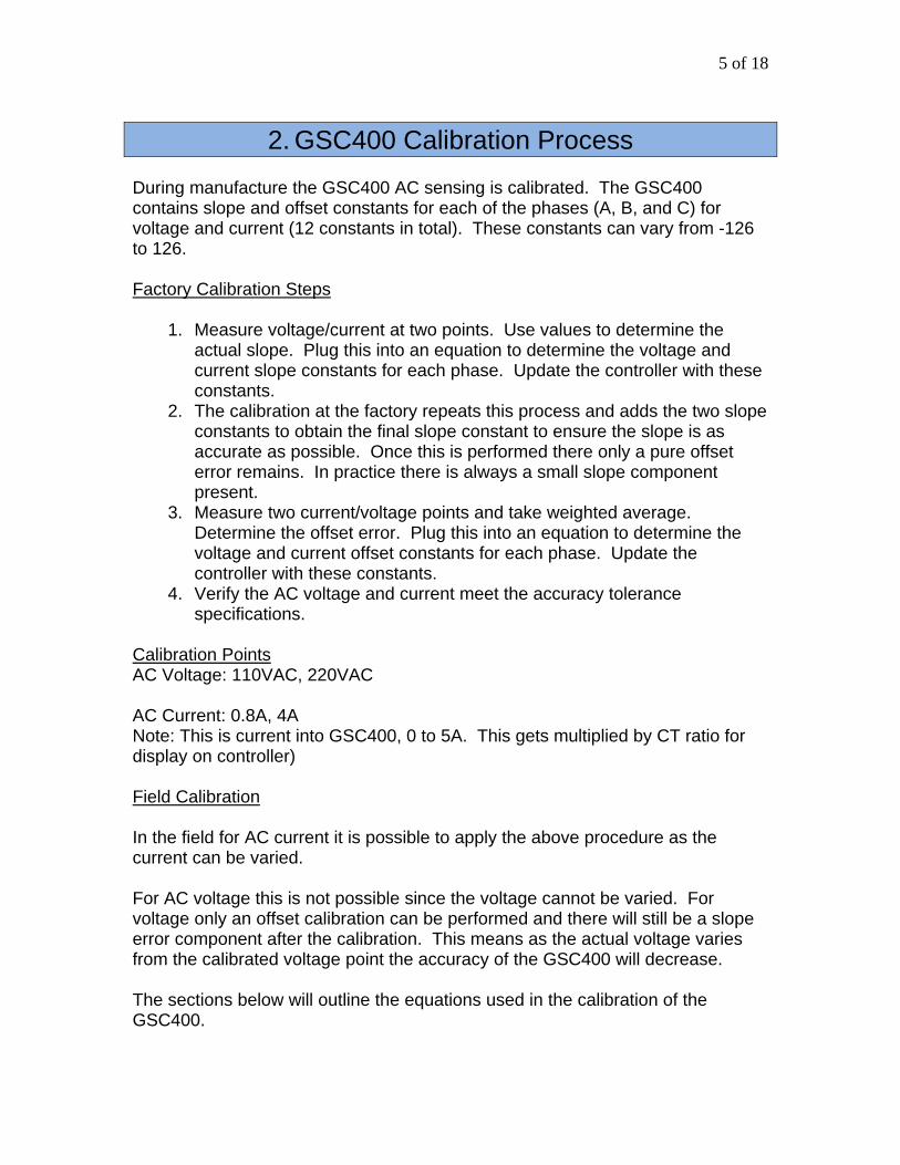
2. GSC400 Calibration Process During manufacture the GSC400 AC sensing is calibrated. The GSC400 contains slope and offset constants for each of the phases (A, B, and C) for voltage and current (12 constants in total). These constants can vary from -126 to 126. Factory Calibration Steps
1. Measure voltage/current at two points. Use values to determine the actual slope. Plug this into an equation to determine the voltage and current slope constants for each phase. Update the controller with these constants.
2. The calibration at the factory repeats this process and adds the two slope constants to obtain the final slope constant to ensure the slope is as accurate as possible. Once this is performed there only a pure offset error remains. In practice there is always a small slope component present.
3. Measure two current/voltage points and take weighted average. Determine the offset error. Plug this into an equation to determine the voltage and current offset constants for each phase. Update the controller with these constants.
4. Verify the AC voltage and current meet the accuracy tolerance specifications.
Calibration Points AC Voltage: 110VAC, 220VAC AC Current: 0.8A, 4A Note: This is current into GSC400, 0 to 5A. This gets multiplied by CT ratio for display on controller) Field Calibration In the field for AC current it is possible to apply the above procedure as the current can be varied. For AC voltage this is not possible since the voltage cannot be varied. For voltage only an offset calibration can be performed and there will still be a slope error component after the calibration. This means as the actual voltage varies from the calibrated voltage point the accuracy of the GSC400 will decrease. The sections below will outline the equations used in the calibration of the GSC400.

6 of 18
2.1 Definitions ACC_MH – AC Current Measured High ACC_ML – AC Current Measured Low ACV_MH – AC Voltage Measured High ACV_ML – AC Voltage Measured Low ACC_RH – AC Current Reference High ACC_RL – AC Current Reference Low ACV_RH – AC Voltage Reference High ACV_RL – AC Voltage Reference Low LOW_CUR_WEIGHTED_AVG – 5 LOW_VOL_WEIGHTED_AVG – 2 ACC_S – AC Current Slope ACV_S – AC Voltage Slope ACC_O – AC Current Offset ACV_O – AC Voltage Offset
2.2 AC Current Slope Calculation slope = (ACC_MH – ACC_ML) / (ACC_RH – ACC_RL) If slope < 0.78 Then
ACC_S = -126 Else If slope > 1.4 Then
ACC_S = 126 Else
ACC_S = (1 - (1 / slope) * 440 End If 2.3 AC Voltage Slope Calculation slope = (ACV_MH – ACV_ML) / (ACV_RH – ACV_HL) If slope < 0.929 Then
ACV_S = -126 Else If slope > 1.083 Then
ACV_S = 126 Else
ACV_S = (1 - (1 / slope)) * 1651 End If

7 of 18
2.4 AC Current Offset Calculation offset = -((ACC_ML – ACC_RL) * LOW_CUR_WEIGHTED_AVG + (ACC_MH – ACC_RH)) / (LOW_CUR_WEIGHTED_AVG + 1) If offset < -0.252 Then
ACC_O = -126 Else If offset > 0.252 Then
ACC_O = 126 Else
ACC_O = offset / 0.002 End If 2.5 AC Voltage Offset offset = -((ACV_ML – ACV_RL) * LOW_VOL_WEIGHTED_AVG + (ACV_MH) – ACV_RH)) / (LOW_VOL_WEIGHTED_AVG + 1) If offset < -12.6 Then
ACV_O = -126 Else If offset> 12.6 Then
ACV_O = 126 Else
ACV_O = offset / 0.1 ' comment: 1 unit = 0.1V End If

8 of 18
3. GSC400 AC Calibration Utility 3.1 Main Screen When you open the GSC400 AC Calibration Utility the window in Figure 4 will appear. This window allows you to read or modify the 12 AC Sensing calibration constants on the GSC400. Each value can range from -126 to 126.
It is highly recommended that you read and record the calibration constants (click the Read Calibration button shown in the figure below)
before making any changes. Once you make a change it is non reversible.
Figure 4 – Calibration Utility Main Window
To read the calibrations click the large “Read Calibration” button. To change a calibration constant enter the desired values in the boxes and click the “Set” buttons beside each phase. Make sure that you have the correct COM port selected under “Communication” menu at the top.
9 of 18
3.2 Manual Calibration AC Voltage CalibrationIf the voltage only varies a little from the system voltage a simple offset adjustment is sufficient. When the voltage offset calibration constant is decremented by 1 the actual voltage reading is decremented by 0.1VAC. The calibration constants range from -126 to 126. If adjusting the voltage offset is not enough the voltage slope calibration constants can also be adjusted. Increasing the value of the slope constants decreases the value of the voltage reading. AC Current Calibration It is recommended to use the wizard to calibrate the current. See below.

10 of 18
3.3 Calibration Wizard Under the “Tools” menu there is a “Calibration Wizard” option that you can use to automatically calibrate the current. Only perform a calibration if absolutely necessary.
Figure 5 – Calibration Wizard Main Window
Click on the Advanced Settings button and check which calibration you wish to perform (refer to Figure 6 below). Once you are done click on the “X” in the top right corner to close the window.
1. Voltage and Current – Performs a slope and offset calibration of current using two reference AC currents that you supply and an offset calibration of AC voltage. Do not use if AC voltage tolerance is adequate.
The old calibration constants stored in the GSC400 are used as a starting point. If voltage and/or current sensing are significantly off you should perform a manual AC voltage calibration and then use the wizard to calibrate the AC current (set all AC current calibration constants to 0 and select the “Current Only” option before beginning). If you only have a problem with the AC voltage sensing it is better to perform a manual calibration. See section 3.2 for instruction on performing a manual calibration of voltage.

11 of 18
2. Current Only – Does not modify the AC Voltage calibration constants.
Figure 6 – Advanced Settings Window
3.3.1 Equipment If you are doing an AC current calibration you will need the following:
1. An accurate instrument (e.g. ammeter or multimeter set to AC current) to measure current from the generator. Measure as close to the CTs as possible.
2. A load source to generate two different currents for the calibration preferably at 25% and 75% of normal maximum load.
3. Knowledge of the number of phases the GSC400 is measuring (A, B, C). To determine this look at the AC Voltage connections on the back of the GSC400.
If you are doing an AC voltage calibration you will need the following:
1. A voltmeter to measure the voltage at the GSC400 terminals.
12 of 18
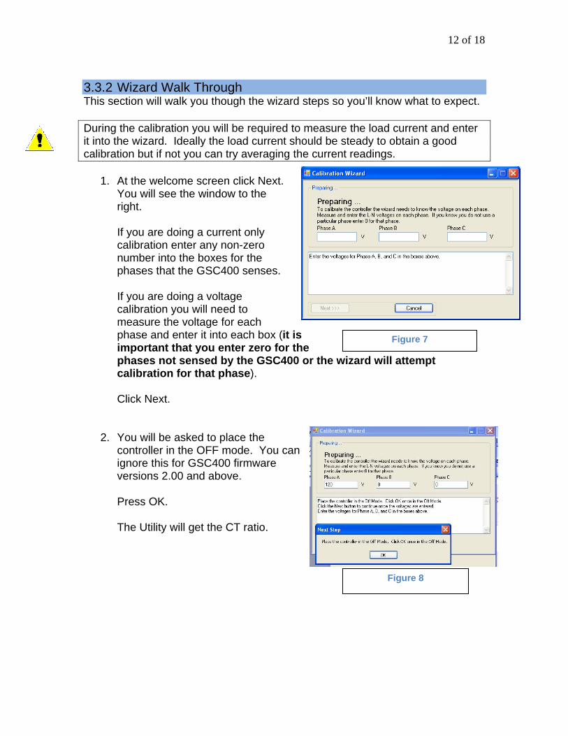
3.3.2 Wizard Walk Through This section will walk you though the wizard steps so you’ll know what to expect. During the calibration you will be required to measure the load current and enter it into the wizard. Ideally the load current should be steady to obtain a good calibration but if not you can try averaging the current readings.
1. At the welcome screen click Next. You will see the window to the right.
If you are doing a current only calibration enter any non-zero number into the boxes for the phases that the GSC400 senses. If you are doing a voltage calibration you will need to measure the voltage for each phase and enter it into each box (it is important that you enter zero for the phases not sensed by the GSC400 or the wizard wicalibration for that phase).
Click Next.
2. You will be asked to place the controller in the OFF mode. You can ignore this for GSC400 firmware versions 2.00 and above.
Press OK. The Utility will get the CT ratio.
Figure 7
ll attempt
Figure 8
13 of 18
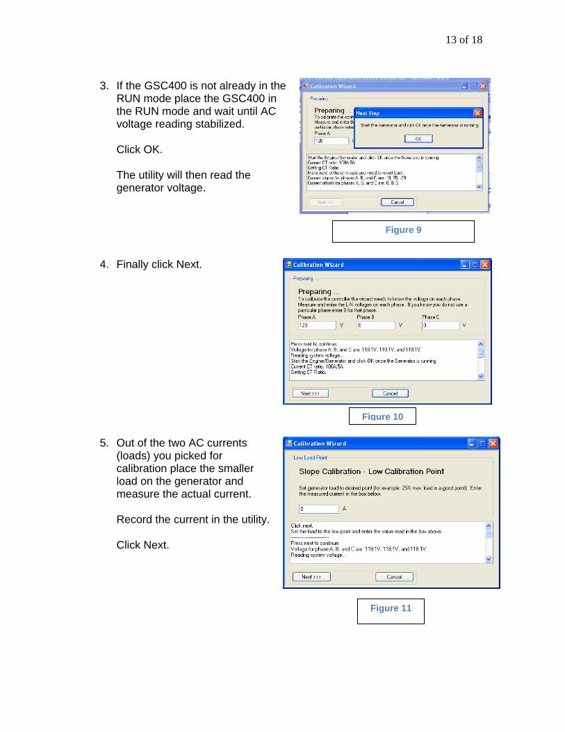
3. If the GSC400 is not already in the
RUN mode place the GSC400 in the RUN mode and wait until AC voltage reading stabilized.
Click OK.
The utility will then read the generator voltage.
4. Finally click Next.
5. Out of the two AC currents (loads) you picked for calibration place the smaller load on the generator and measure the actual current.
Record the current in the utility. Click Next.
Figure 9
Figure 10
Figure 11
14 of 18
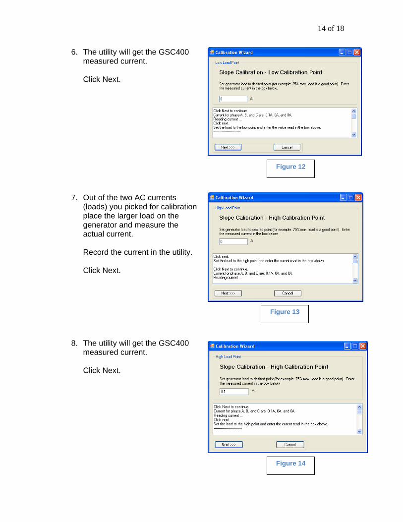
6. The utility will get the GSC400 measured current.
Click Next.
Figure 12
7. Out of the two AC currents (loads) you picked for calibration place the larger load on the generator and measure the actual current.
Record the current in the utility. Click Next.
Figure 13
8. The utility will get the GSC400 measured current.
Click Next.
Figure 14

15 of 18
9. The utility will calculate the calibration slope constants and save them to the GSC400.
Click Next.
Figure 15
10. Out of the two AC currents (loads) you picked for calibration place the smaller load on the generator and measure the actual current.
Record the current in the utility. Click Next.
Figure 16
11. The utility will get the GSC400 measured current.
Click Next.
Figure 17
16 of 18
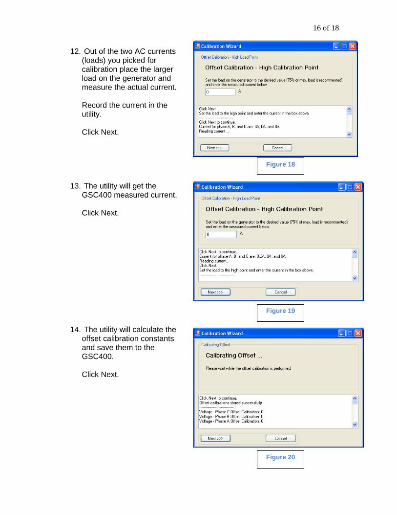
12. Out of the two AC currents (loads) you picked for calibration place the larger load on the generator and measure the actual current.
Record the current in the utility. Click Next.
Figure 18
13. The utility will get the GSC400 measured current.
Click Next.
Figure 19
14. The utility will calculate the offset calibration constants and save them to the GSC400.
Click Next.
Figure 20

17 of 18
15. Calibration is finished.
You can select and copy the text in the box if you want a copy of the calibration information. Click Finish.
Figure 21
Below is an example of the calibration status box text. Calibration is finished. Click the Finish button to exit. Click Next to continue. Offset calibrations stored successfully. -------------------------------- Voltage - Phase C Offset Calibration: 0 Voltage - Phase B Offset Calibration: 0 Voltage - Phase A Offset Calibration: 0 Current - Phase C Offset Calibration: 0 Current - Phase B Offset Calibration: 0 Current - Phase A Offset Calibration: -1 -------------------------- Click Next to continue. Current for phase A, B, and C are: 0A, 0A, and 0A. Reading current... Click Next. Set the load to the high point and enter the current in the box above. --------------------------------- Click Next to continue. Current for phase A, B, and C are: 0.1A, 0A, and 0A. Reading current ... Click Next. Set the load to the low point and enter the curent in the box above. -------------------------- Click Next to continue. Slope calibrations stored successfully. Current - Phase C Slope Calibration: -29 Current - Phase C Delta Slope Calibration: 0 Current - Phase B Slope Calibration: 55

18 of 18
Current - Phase B Delta Slope Calibration: 0 Current - Phase A Slope Calibration: -126 Current - Phase A Delta Slope Calibration: -3960 -------------------------------- Click Next to continue. Current for phase A, B, and C are: 0.1A, 0A, and 0A. Reading current ... Click next. Set the load to the high point and enter the curent read in the box above. ---------------------------- Click Next to continue. Current for phase A, B, and C are: 0.1A, 0A, and 0A. Reading current ... Click next. Set the load to the low point and enter the value read in the box above. ---------------------------- Press next to continue. Voltage for phase A, B, and C are: 116.2V, 116V, and 115.7V. Reading system voltage... Start the Engine/Generator and click OK once the Generator is running. Current CT ratio: 100A:5A Getting CT Ratio. Make note of these in case you need to revert back. Current slopes for phases A, B, and C are: -126, 55, -29. Current offsets for phases A, B, and C are: 0, 0, 0. Voltage slopes for phases A, B, and C are: 18, 18, 25. Voltage offsets for phases A, B, and C are: 0, 0, 0. Getting calibration coefficients.. Place the controller in the Off Mode. Click OK once in the Off Mode. Click the Next button to continue once the voltages are entered. Enter the voltages for Phase A, B, and C in the boxes above.