Embed Size (px)
Citation preview
Received 04/11/2020 Review began 04/16/2020 Review ended 04/16/2020 Published 04/23/2020
© Copyright 2020Sivakumar. This is an open access articledistributed under the terms of theCreative Commons Attribution LicenseCC-BY 4.0., which permits unrestricteduse, distribution, and reproduction in anymedium, provided the original author andsource are credited.
Management of Partial Edentulism UsingNonrigid Connectors as a Treatment Modality: ACase ReportSheela Sivakumar
1. Prosthodontics, Dr. M.G.R. Educational and Research Institute, Chennai, IND
Corresponding author: Sheela Sivakumar, [email protected]
AbstractThe most frequently encountered clinical situation, either in the maxillary or mandibular arch, is of amissing first premolar and first molar, where the canine and the second molar are known as terminalabutments and second premolar is a pier abutment. This clinical situation poses challenge to prosthodontistin rehabilitation phase. It has been postulated that terminal abutment has a rocking movement when infunction, whereas pier abutment acts as a fulcrum. This will lead to debonding of the less retentive terminalretainer. In order to overcome this, utilization of nonrigid connectors has been advised. This paper presentsa clinical case report which describes incorporation of nonrigid connector to rehabilitate pier abutmentcase.
Categories: DentistryKeywords: pier abutment, key and keyway, non rigid connectors
IntroductionThere are some important variables that are responsible for the longevity of a fixed partial denture (FPD)and its abutments such as proper occlusion, span length, bone loss surrounding the abutment, and thequality of the periodontium [1]. Excessive flexing of the long-span FPD will lead to material failure orunfavorable prosthesis failure. The occlusal forces are transmitted to the supporting structures through thepontic, connectors, and retainers in FPD prosthesis [2].
A FPD with the pontic rigidly fixed to the retainer provides adequate strength and stability to the prosthesisand also minimizes the stresses associated with the restoration. But if an edentulous space occurs on bothsides of a tooth, creating a pier abutment then physiologic tooth movement, arch position of the abutment,and a difference in the retentive capacity of the retainers can make a five-unit FPD a less than ideal for thetreatment [2].
Biomechanical factors such as overload, leverage, torque, and flexing induce abnormal stress concentrationin a FPD [3]. Stress concentration is found in the connectors of the prosthesis and in the cervical dentin areanear the edentulous ridge. This factor further plays an important role in the failure of the long-span FPD.Connectors are that portion of the FPDs that unite the retainers and the pontics. They are of two types, rigidconnectors and nonrigid connectors [3].
Rigid connectors are made by different procedures such as casting, soldering, and welding. The castconnectors are to be properly shaped in wax patterns. The connector that permits limited movementbetween the otherwise, independent members of the FPDs is the nonrigid connector. The nonrigid connectorcould be made by incorporation of prefabricated inserts, by use of a custom-milling machine, or by use of theprefabricated plastic patterns [4]. The purpose of this article is to summarize the treatment approaches incases of pier abutment to minimize the effect of forces in long-span bridges. The treatment options in caseof pier abutment are implant in edentulous spaces or FPD with nonrigid connectors, using precision andsemi-precision attachments.
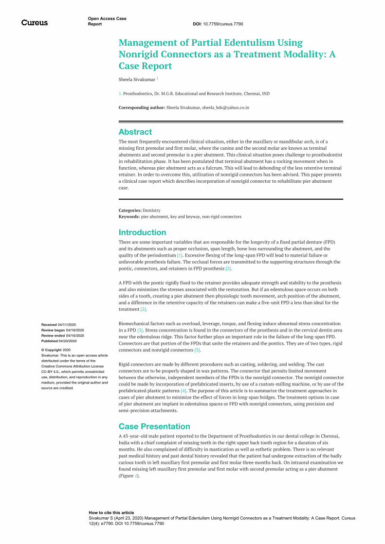
Case PresentationA 43-year-old male patient reported to the Department of Prosthodontics in our dental college in Chennai,India with a chief complaint of missing teeth in the right upper back tooth region for a duration of sixmonths. He also complained of difficulty in mastication as well as esthetic problem. There is no relevantpast medical history and past dental history revealed that the patient had undergone extraction of the badlycarious tooth in left maxillary first premolar and first molar three months back. On intraoral examination wefound missing left maxillary first premolar and first molar with second premolar acting as a pier abutment(Figure 1).
1
Open Access CaseReport DOI: 10.7759/cureus.7790
How to cite this articleSivakumar S (April 23, 2020) Management of Partial Edentulism Using Nonrigid Connectors as a Treatment Modality: A Case Report. Cureus12(4): e7790. DOI 10.7759/cureus.7790
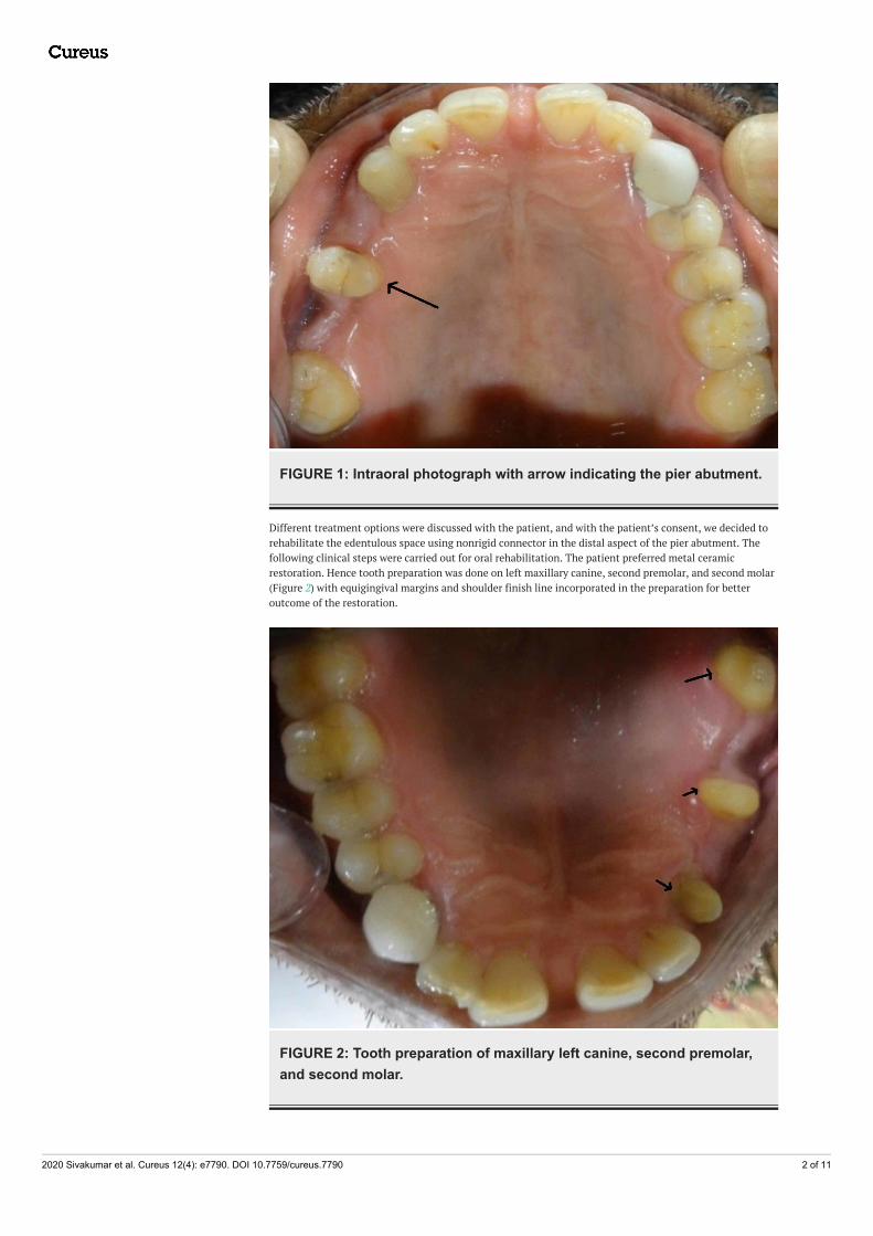
FIGURE 1: Intraoral photograph with arrow indicating the pier abutment.
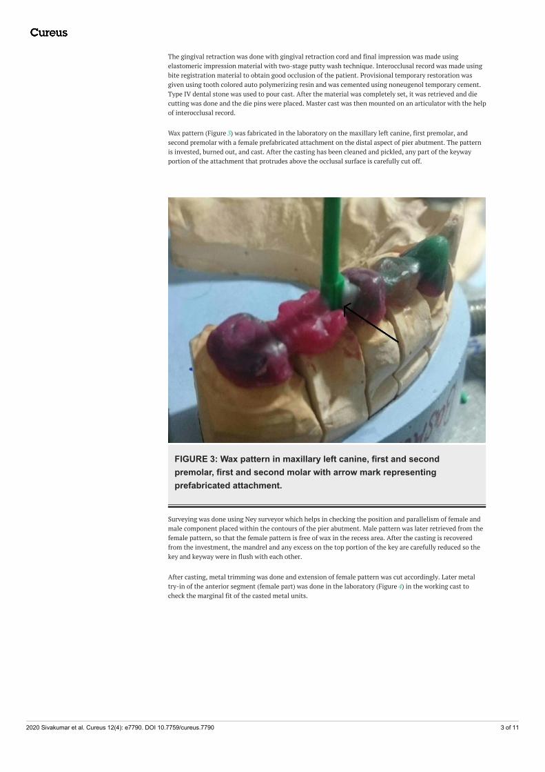
Different treatment options were discussed with the patient, and with the patient’s consent, we decided torehabilitate the edentulous space using nonrigid connector in the distal aspect of the pier abutment. Thefollowing clinical steps were carried out for oral rehabilitation. The patient preferred metal ceramicrestoration. Hence tooth preparation was done on left maxillary canine, second premolar, and second molar(Figure 2) with equigingival margins and shoulder finish line incorporated in the preparation for betteroutcome of the restoration.
FIGURE 2: Tooth preparation of maxillary left canine, second premolar,and second molar.
2020 Sivakumar et al. Cureus 12(4): e7790. DOI 10.7759/cureus.7790 2 of 11
The gingival retraction was done with gingival retraction cord and final impression was made usingelastomeric impression material with two-stage putty wash technique. Interocclusal record was made usingbite registration material to obtain good occlusion of the patient. Provisional temporary restoration wasgiven using tooth colored auto polymerizing resin and was cemented using noneugenol temporary cement.Type IV dental stone was used to pour cast. After the material was completely set, it was retrieved and diecutting was done and the die pins were placed. Master cast was then mounted on an articulator with the helpof interocclusal record.
Wax pattern (Figure 3) was fabricated in the laboratory on the maxillary left canine, first premolar, andsecond premolar with a female prefabricated attachment on the distal aspect of pier abutment. The patternis invested, burned out, and cast. After the casting has been cleaned and pickled, any part of the keywayportion of the attachment that protrudes above the occlusal surface is carefully cut off.
FIGURE 3: Wax pattern in maxillary left canine, first and secondpremolar, first and second molar with arrow mark representingprefabricated attachment.
Surveying was done using Ney surveyor which helps in checking the position and parallelism of female andmale component placed within the contours of the pier abutment. Male pattern was later retrieved from thefemale pattern, so that the female pattern is free of wax in the recess area. After the casting is recoveredfrom the investment, the mandrel and any excess on the top portion of the key are carefully reduced so thekey and keyway were in flush with each other.
After casting, metal trimming was done and extension of female pattern was cut accordingly. Later metaltry-in of the anterior segment (female part) was done in the laboratory (Figure 4) in the working cast tocheck the marginal fit of the casted metal units.
2020 Sivakumar et al. Cureus 12(4): e7790. DOI 10.7759/cureus.7790 3 of 11
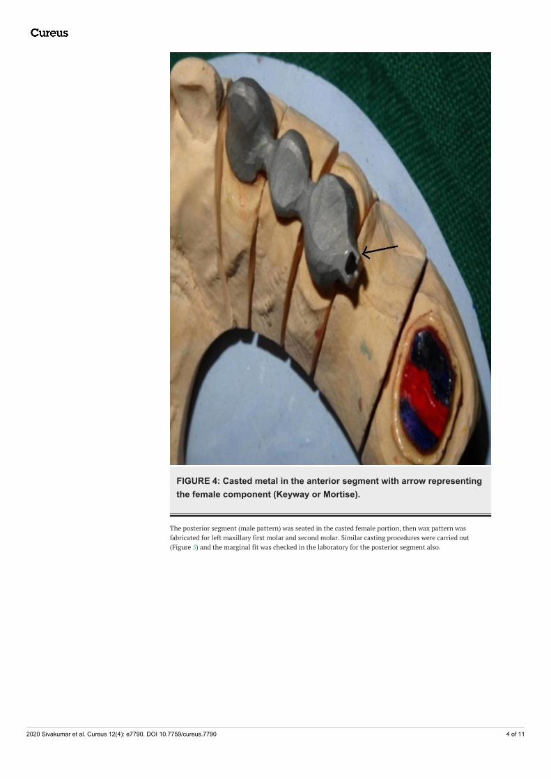
FIGURE 4: Casted metal in the anterior segment with arrow representingthe female component (Keyway or Mortise).
The posterior segment (male pattern) was seated in the casted female portion, then wax pattern wasfabricated for left maxillary first molar and second molar. Similar casting procedures were carried out(Figure 5) and the marginal fit was checked in the laboratory for the posterior segment also.
2020 Sivakumar et al. Cureus 12(4): e7790. DOI 10.7759/cureus.7790 4 of 11
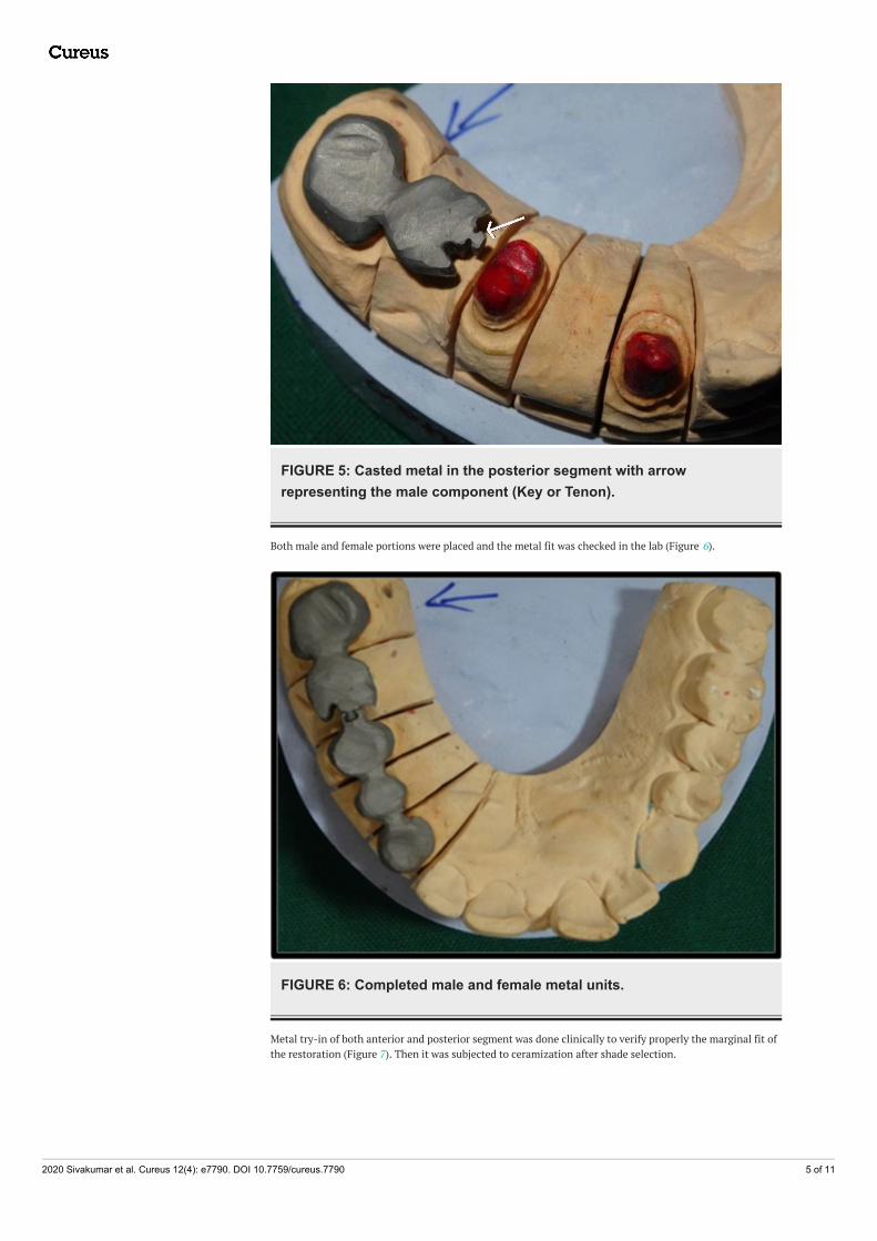
FIGURE 5: Casted metal in the posterior segment with arrowrepresenting the male component (Key or Tenon).
Both male and female portions were placed and the metal fit was checked in the lab (Figure 6).
FIGURE 6: Completed male and female metal units.
Metal try-in of both anterior and posterior segment was done clinically to verify properly the marginal fit ofthe restoration (Figure 7). Then it was subjected to ceramization after shade selection.
2020 Sivakumar et al. Cureus 12(4): e7790. DOI 10.7759/cureus.7790 5 of 11
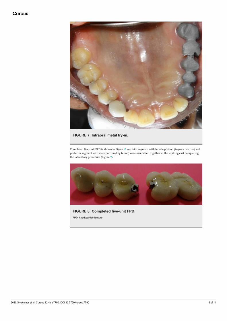
FIGURE 7: Intraoral metal try-in.
Completed five-unit FPD is shown in Figure 8. Anterior segment with female portion (keyway mortise) andposterior segment with male portion (key tenon) were assembled together in the working cast completingthe laboratory procedure (Figure 9).
FIGURE 8: Completed five-unit FPD.FPD, fixed partial denture
2020 Sivakumar et al. Cureus 12(4): e7790. DOI 10.7759/cureus.7790 6 of 11
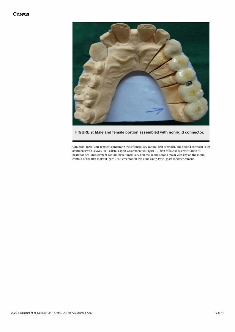
FIGURE 9: Male and female portion assembled with nonrigid connector.
Clinically, three-unit segment containing the left maxillary canine, first premolar, and second premolar (pierabutment) with keyway on its distal aspect was cemented (Figure 10) first followed by cementation ofposterior two-unit segment containing left maxillary first molar and second molar with key on the mesialcontour of the first molar (Figure 11). Cementation was done using Type I glass ionomer cement.
2020 Sivakumar et al. Cureus 12(4): e7790. DOI 10.7759/cureus.7790 7 of 11
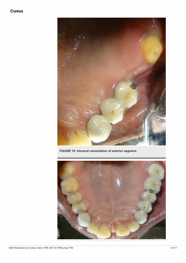
FIGURE 10: Intraoral cementation of anterior segment.
2020 Sivakumar et al. Cureus 12(4): e7790. DOI 10.7759/cureus.7790 8 of 11
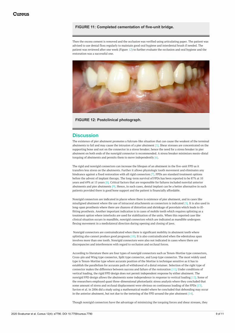
FIGURE 11: Completed cementation of five-unit bridge.
Then the excess cement is removed and the occlusion was verified using articulating paper. The patient wasadvised to use dental floss regularly to maintain good oral hygiene and interdental brush if needed. Thepatient was reviewed after one week (Figure 12) to further evaluate the occlusion and oral hygiene and therestoration was a successful one.
FIGURE 12: Postclinical photograph.
DiscussionThe existence of pier abutment promotes a fulcrum-like situation that can cause the weakest of the terminalabutments to fail and may cause the intrusion of a pier abutment [5]. Shear stresses are concentrated on thesupporting bone and not on the connector in a stress breaker; hence the need for a stress breaker in pierabutment on both ends of the nonrigid connector is recommended. A stress breaker minimizes mesio-distaltorquing of abutments and permits them to move independently [6].
The rigid and nonrigid connectors can increase the lifespan of an abutment in the five-unit FPD as ittransfers less stress on the abutments. Further it allows physiologic tooth movement and eliminates anyhindrance against a fixed restoration with all rigid connectors [7]. FPDs are standard treatment optionsbefore the advent of implant therapy. The long-term survival of FPDs has been reported to be 87% at 10years and 69% at 15 years [8]. Critical factors that are responsible for failures included nonvital anteriorabutments and pier abutments [9]. Hence, in such cases, dental implant can be a better alternative in suchpatients provided there is good bone support and the patient is financially affordable.
Nonrigid connectors are indicated in places where there is existence of pier abutment, and in cases likemisaligned abutment where the use of intracoral attachments as connectors is indicated [5]. It is also used inlong-span prosthesis where there are chances of distortion and shrinkage of porcelain which leads to ill-fitting prosthesis. Another important indication is in cases of mobile teeth which requires splinting as atreatment option where interlocks are used for stabilization of the units. When this reported case likeclinical situation occurs in mandible, nonrigid connectors which are indicated as mandible undergoesflexing movement in a mediolateral direction during opening and closing of jaws.
Nonrigid connectors are contraindicated when there is significant mobility in abutment teeth wheresplinting also cannot produce good prognosis [10]. It is also contraindicated when the edentulous spaninvolves more than one tooth. Nonrigid connectors were also not indicated in cases where there arediscrepancies and interferences with regard to occlusion and occlusal forces.
According to literature there are four types of nonrigid connectors such as Tenon-Mortise type connectors,Cross-pin and Wing type connector, Split type connector, and Loop type connector. The most widely usedtype is Tenon-Mortise type where accurate position of the Mortise is technique sensitive as it has toestablish the parallelism for accurate path of withdrawal of a distal retainer. Selection of the right type ofconnector makes the difference between success and failure of the restoration [11]. Under conditions ofvertical loading, the rigid FPD design does not permit independent response by either abutment. Thenonrigid FPD design allows the abutments some independence in response to vertical loading [12]. Some ofthe researchers employed quasi three-dimensional photoelastic stress analysis where they concluded thatsome amount of stress and occlusal displacement were obvious on continuous loading of the FPDs [13].Savion et al. in 2006 did a study using a mathematical model where he concluded that debonding may occurin the anterior abutment, but not due to the teetering of the FPD around the pier abutment [14].
Though nonrigid connectors have the advantage of minimizing the torquing forces and shear stresses, they
2020 Sivakumar et al. Cureus 12(4): e7790. DOI 10.7759/cureus.7790 9 of 11
have a disadvantage also. They involve more tooth reduction clinically in order to facilitate engagement ofmale and female components. It is more technique sensitive and requires precision in work. When there isno occlusal stability, lifting of key from key is also reported.
Shillinburg and Fischer in 1973 suggested that patrix should be prepared within the contours of the retainerand matrix attached to the distal of pontic. The pier abutment should have the keyway of the connector inthe distal and the key should be placed on the mesial of the distal most pontic. If the keyway of theconnector is placed on the distal side of the pier abutment, mesial movements seats the key into thekeyway [15]. Oruc et al. in 2008 attempted a study using finite element method and observed that the distalarea of pier abutment has minimum stress concentration which supported the placement of nonrigidconnectors at the distal region of premolar [16]. Markley suggested that the stress of the movement of onetooth prying against the others was eliminated much as a broken-stress joint frees a fixed bridge fromdestructive strain [17].
Gill in 1952 suggested that each tooth must function both as an individual and as a part of a collective unitwhich makes each tooth an important factor in the function of the entire mouth [18]. Adams in 1956suggested placing one nonrigid connector at the distal side of pier and also at the distal of the anteriorretainer if needed depending on the clinical situation [19]. Nimushara et al. in 1999 studied the stresstransfer patterns with variable implant support and simulated natural teeth through rigid and nonrigidconnection under simulated functional loads and concluded that the rigid connector in particular situationcaused only slightly higher stresses in the supporting structure and demonstrated more widespread stresstransfer. Misch suggested that bone and soft tissue consideration is important when planning for a long-span bridge. For a natural pier abutment two implants can be one of the treatment option where stressbreaker is not indicated [20]. By such treatment option, we are completely avoiding the load and fulcrum-like situation associated with the pier abutment. However, implants can only be placed after completemedical, clinical, and radiological evaluation. In cases where implants cannot be placed due to compromisedconditions, the nonrigid connectors are advocated. Hence precision and semi-precision attachments provideroom for slight movements which prevent loading of the pier abutment created due to the fulcrum-likesituation and increase the lifespan of five-unit FPD.
ConclusionsThus the factors such as physiologic tooth movement, arch position of the abutments, and retentive capacityof retainers make the rigid connectors a less ideal plan of treatment in cases involving pier abutmentsparticularly five-unit bridges. Broken-stress measures serve as “safety valves” against the tremendousleverage forces created by the rigid attachment to two or more teeth. The size, shape, and type of connectorsalso play a key role in future success of a FPD. The employment of nonrigid connector increases the life ofthe restoration as it minimizes the stresses on the abutments. The stress distributions and values of a FPDand a pier abutment are affected by the location of nonrigid connector. Apart from the advantages ofnonrigid connectors, the increased laboratory time and expense should be ignored while considering theaugmented life of the restoration.
Additional InformationDisclosuresHuman subjects: Consent was obtained by all participants in this study. Conflicts of interest: Incompliance with the ICMJE uniform disclosure form, all authors declare the following: Payment/servicesinfo: All authors have declared that no financial support was received from any organization for thesubmitted work. Financial relationships: All authors have declared that they have no financialrelationships at present or within the previous three years with any organizations that might have aninterest in the submitted work. Other relationships: All authors have declared that there are no otherrelationships or activities that could appear to have influenced the submitted work.
References1. Contemporary Fixed Prosthodontics-E-Book, 3rd Edn. Rosenstiel SF, Land MF (ed): Elsevier Health
Sciences, Amsterdam; 2002.2. Yaqoob A, Rasheed N, Ashraf J, Yaqub G: Non-rigid semi precision connectors for FPD. Dent Med Res. 2014,
2:17-21.3. Mattoo K, Brar A, Goswami R: Elucidating the problem of pier abutment through the use of a fixed movable
prosthesis - a clinical case report. Int J Dent Sci Res. 2014, 2:154-157. 10.12691/ijdsr-2-6-84. Sherring-Lucas M, Martin P: Attachments for Prosthetic Dentistry. Introduction and Application.
Quintessence, London; 1994.5. Badwaik PV, Pakhan AJ: Non-rigid connectors in fixed prosthodontics: current concepts with a case report . J
Indian Prosthodont Soc. 2005, 5:99-102.6. Sudhir N, Taruna M, Suchita T, Bharat M: Indigenously fabricated non-rigid connector for a pier abutment .
Indian J Dent Advance. 2011, Oct:770-774.7. Banerjee S, Khongshei A, Gupta T, Banerjee A: Non-rigid connector: the wand to allay the stresses on
abutment. Contemp Clin Dent. 2011, 2:351-354. 10.4103/0976-237X.918028. Walton TR: An up to 15-year longitudinal study of 515 metal-ceramic FPDs: part 1. Outcome . Int J
2020 Sivakumar et al. Cureus 12(4): e7790. DOI 10.7759/cureus.7790 10 of 11
Prosthodont. 2002, 15:439-445.9. Jivraj S, Chee W: Rationale for dental implants. Br Dent J. 2006, 200:661-665. 10.1038/sj.bdj.4813718
10. Shillingburg HT, Sather DA, Wilson EL, Cain JR, Mitchell DL, Blanco LJ: Fundamentals of FixedProsthodontics. Quintessence Publishing Co, Chicago; 2012.
11. Malone WF, Tylman SD, Koth DL: Tylman's Theory and Practice of Fixed Prosthodontics . IshiyakuEuroAmerica, Inc., St. Louis, MO; 1989.
12. Sutherland JK, Holland GA, Sluder TB, White JT: A photoelastic analysis of the stress distribution in bonesupporting fixed partial dentures of rigid and nonrigid design. J Prosth Dent. 1980, 44:616-623.
13. Standlee JP, Caputo AA: Load transfer by fixed partial dentures with three abutments . Quintessence Int.1988, 19:403.
14. Savion I, Saucier CL, Rues S, Sadan A, Blatz M: The pier abutment: a review of the literature and a suggestedmathematical model. Quintessence Int. 2006, 37:345-352.
15. Akulwar RS, Kodgi A: Non-rigid connector for managing pier abutment in FPD: a case report . J Clin DiagnRes. 2014, 8:12-14. 10.7860/JCDR/2014/9710.4572
16. Oruc S, Eraslan O, Tukay HA, Atay A: Stress analysis of effects of nonrigid connectors on fixed partialdentures with pier abutments. J Prosth Dent. 2008, 99:185-192.
17. Markley MR: Broken-stress principle and design in fixed bridge prosthesis . J Prosth Dent. 1951, 1:416-423.18. Gill JR: Treatment planning for mouth rehabilitation. J Prosth Dent. 1952, 2:230-245.19. Adams JD: Planning posterior bridges. J Am Dent Assoc. 1956, 53:647-654.20. Misch CE: Contemporary Implant Dentistry, 3rd edition . Mosby Elsevier, St. Louis, MO; 2008.
2020 Sivakumar et al. Cureus 12(4): e7790. DOI 10.7759/cureus.7790 11 of 11