Embed Size (px)
Citation preview

Management Software for Uninterruptible Power Supply Systems
1
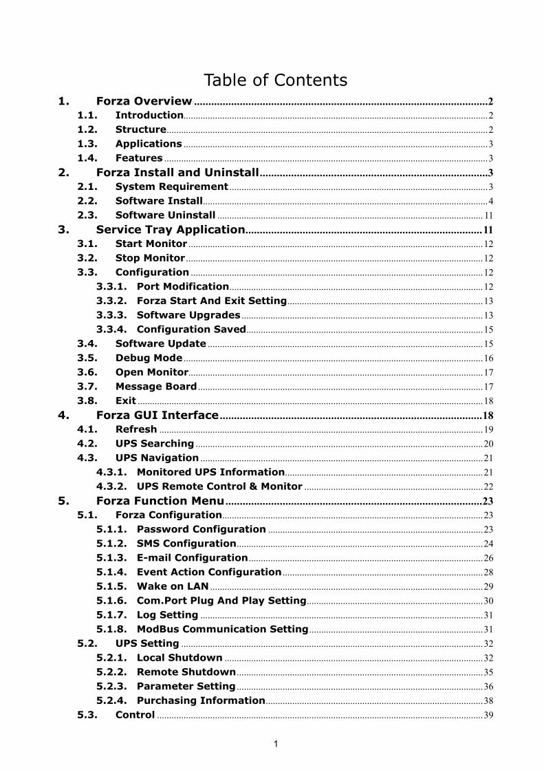
Table of Contents 1. Forza Overview .......................................................................................................2
1.1. Introduction..............................................................................................................................2 1.2. Structure.....................................................................................................................................2 1.3. Applications ..............................................................................................................................3 1.4. Features ......................................................................................................................................3
2. Forza Install and Uninstall................................................................................3 2.1. System Requirement ...........................................................................................................3 2.2. Software Install......................................................................................................................4 2.3. Software Uninstall .............................................................................................................. 11
3. Service Tray Application...................................................................................11 3.1. Start Monitor ..........................................................................................................................12 3.2. Stop Monitor ...........................................................................................................................12 3.3. Configuration .........................................................................................................................12
3.3.1. Port Modification.........................................................................................................12 3.3.2. Forza Start And Exit Setting.................................................................................13 3.3.3. Software Upgrades ....................................................................................................13 3.3.4. Configuration Saved..................................................................................................15
3.4. Software Update ..................................................................................................................15 3.5. Debug Mode ............................................................................................................................16 3.6. Open Monitor..........................................................................................................................17 3.7. Message Board ......................................................................................................................17 3.8. Exit ...............................................................................................................................................18
4. Forza GUI Interface ............................................................................................18 4.1. Refresh ......................................................................................................................................19 4.2. UPS Searching .......................................................................................................................20 4.3. UPS Navigation .....................................................................................................................21
4.3.1. Monitored UPS Information..................................................................................21 4.3.2. UPS Remote Control & Monitor ..........................................................................22
5. Forza Function Menu ..........................................................................................23 5.1. Forza Configuration............................................................................................................23
5.1.1. Password Configuration .........................................................................................23 5.1.2. SMS Configuration......................................................................................................24 5.1.3. Email Configuration.................................................................................................26 5.1.4. Event Action Configuration ...................................................................................28 5.1.5. Wake on LAN .................................................................................................................29 5.1.6. Com.Port Plug And Play Setting.........................................................................30 5.1.7. Log Setting .....................................................................................................................31 5.1.8. ModBus Communication Setting........................................................................31
5.2. UPS Setting .............................................................................................................................32 5.2.1. Local Shutdown ...........................................................................................................32 5.2.2. Remote Shutdown......................................................................................................35 5.2.3. Parameter Setting ......................................................................................................36 5.2.4. Purchasing Information..........................................................................................38
5.3. Control .......................................................................................................................................39
2
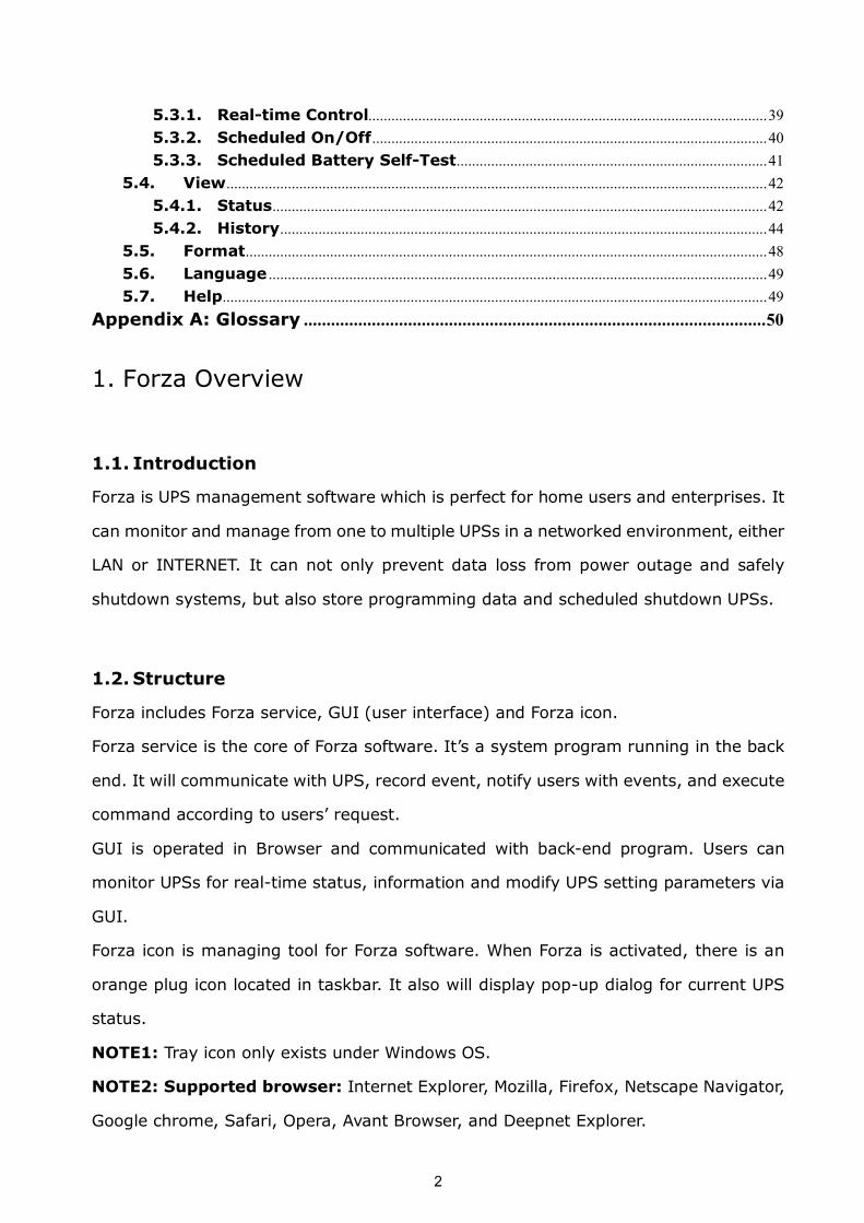
5.3.1. Realtime Control........................................................................................................39 5.3.2. Scheduled On/Off.......................................................................................................40 5.3.3. Scheduled Battery SelfTest.................................................................................41
5.4. View.............................................................................................................................................42 5.4.1. Status.................................................................................................................................42 5.4.2. History...............................................................................................................................44
5.5. Format........................................................................................................................................48 5.6. Language ..................................................................................................................................49 5.7. Help..............................................................................................................................................49
Appendix A: Glossary ......................................................................................................50
1. Forza Overview
1.1. Introduction
Forza is UPS management software which is perfect for home users and enterprises. It
can monitor and manage from one to multiple UPSs in a networked environment, either
LAN or INTERNET. It can not only prevent data loss from power outage and safely
shutdown systems, but also store programming data and scheduled shutdown UPSs.
1.2. Structure
Forza includes Forza service, GUI (user interface) and Forza icon.
Forza service is the core of Forza software. It’s a system program running in the back
end. It will communicate with UPS, record event, notify users with events, and execute
command according to users’ request.
GUI is operated in Browser and communicated with backend program. Users can
monitor UPSs for realtime status, information and modify UPS setting parameters via
GUI.
Forza icon is managing tool for Forza software. When Forza is activated, there is an
orange plug icon located in taskbar. It also will display popup dialog for current UPS
status.
NOTE1: Tray icon only exists under Windows OS.
NOTE2: Supported browser: Internet Explorer, Mozilla, Firefox, Netscape Navigator,
Google chrome, Safari, Opera, Avant Browser, and Deepnet Explorer.
3
1.3. Applications
l Monitor and manage the local UPS connected to local computer
l Monitor and manage other UPSs (with software installed) in LAN
l Remote monitor and manage other UPSs via INTERNET from remote PC (with
software installed)
1.4. Features
l Allows control and monitoring of multiple UPSs via LAN and INTERNET
l Realtime dynamic graphs of UPS data (voltage, frequency, load level, battery
capacity)
l Safely OS shutdown and protection from data loss during power failure
l Warning notifications via audible alarm, popup screen, broadcast, mobile
messenger, and email
l Scheduled UPS on/off, battery test, programmable outlet control, and audible
alarm control
l Password security protection and remote access management
2. Forza Install and Uninstall
2.1. System Requirement
l 512 MB physical memory at least (1 GB is recommended)
l 1 GB hard disk space at least
l Administrator authority is required
l More than 16bit colors and 800 x 600 or above resolution display is
recommended
l TCP/IP protocol must be installed for network management
l An available communication port (RS232 serial port or USB port) is needed
l Platforms supported by software are listed below:
Ø Windows 2000
Ø Windows XP/2003/Vista/2008/2012 (32bit & x64bit)
4
Ø Windows 7 / 8 (32bit & x64bit)
Ø Windows SBS 2011
Ø Linux RedHat 8, 9
Ø Linux RedHat Enterprise AS3, AS5, AS6 (32bit)
Ø Linux RedHat Enterprise AS6 (64bit)
Ø Linux RedHat Enterprise 5.2 (32bit & 64bit)
Ø Linux SUSE 10 (32bit & 64bit)
Ø Linux Cent OS 5.4 (32bit)
Ø Linux Ubuntu 8.X, 9.X, 10.X (32bit)
Ø Linux Ubuntu 10.X (64bit)
Ø Linux Ubuntu 12.04 (32bit & 64bit)
Ø Linux Fedora 5
Ø Linux OpenSUSE 11.2 (32bit & 64bit)
Ø Linux Debian 5.x, 6.x (32bit)
Ø Linux Debian 6.x (64bit)
Ø Mac OS 10.6 (x64bit)
Ø Mac OS 10.7 (x64bit)
Ø Solaris 10 for x86
2.2. Software Install
Step 1 Insert the Forza CD into CD ROM. Forza will display the installation menu,
or you can run autorun.exe to start the installation in CD directory. Refer
to the diagram 21.
Diagram 21
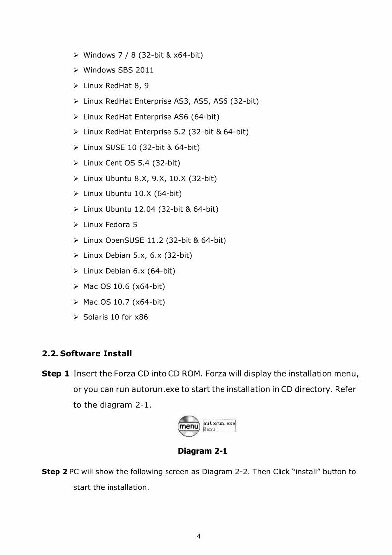
Step 2 PC will show the following screen as Diagram 22. Then Click “install” button to
start the installation.
5
Diagram 22
Step 1 After clicking install, it will display the installation in process. Refer to the
diagram 23.
Diagram 23
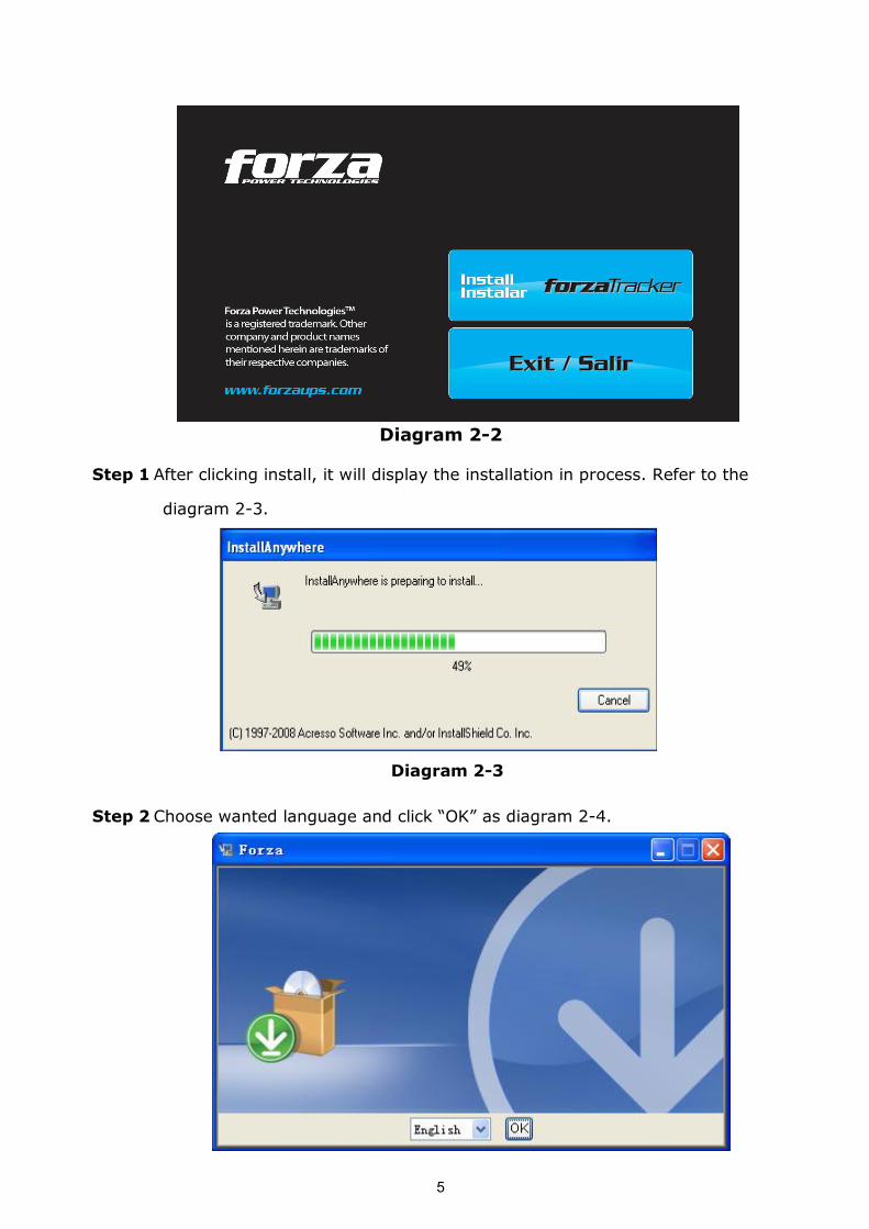
Step 2 Choose wanted language and click “OK” as diagram 24.
6
Diagram 24
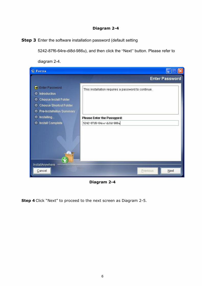
Step 3 Enter the software installation password (default setting
5242-87f6-64re-di8d-986u), and then click the “Next” button. Please refer to
diagram 2-4.
Diagram 24
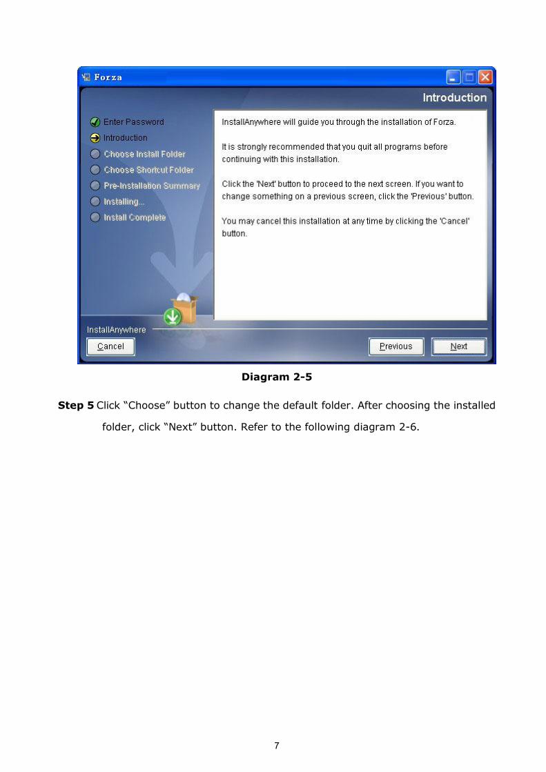
Step 4 Click “Next” to proceed to the next screen as Diagram 25.
7
Diagram 25
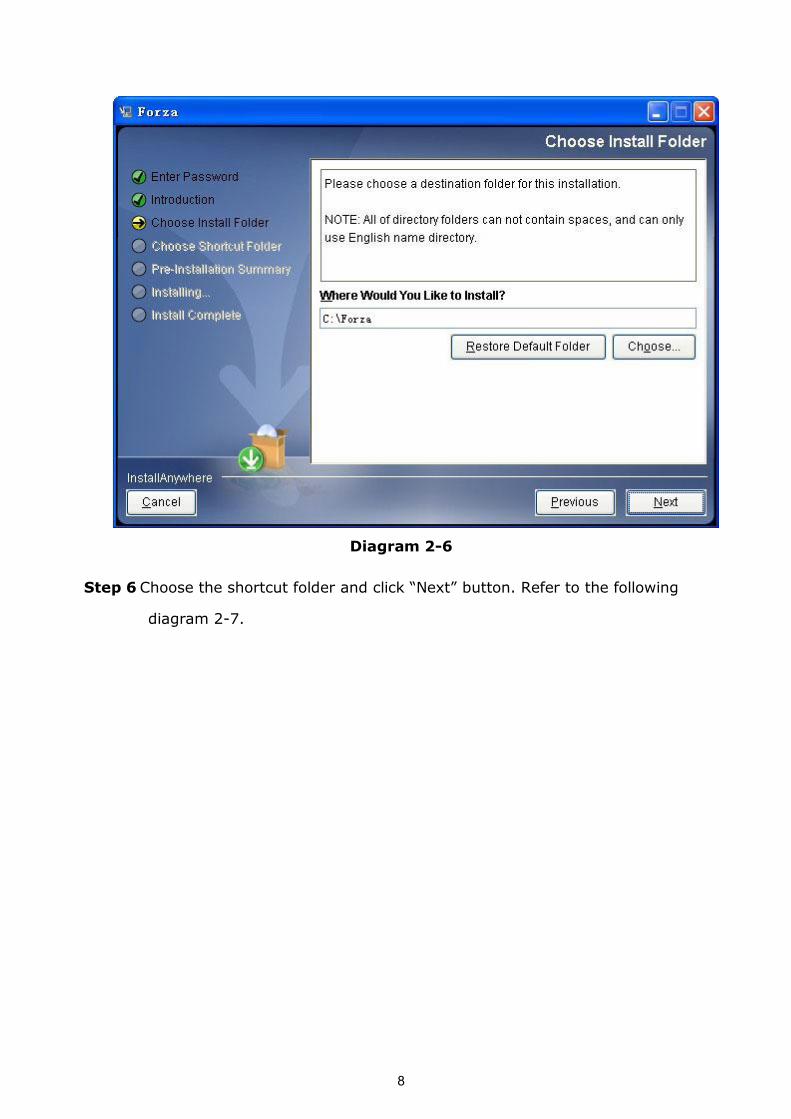
Step 5 Click “Choose” button to change the default folder. After choosing the installed
folder, click “Next” button. Refer to the following diagram 26.
8
Diagram 26
Step 6 Choose the shortcut folder and click “Next” button. Refer to the following
diagram 27.

9
Diagram 27
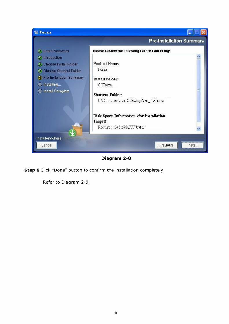
Step 7 It will display the software summary before installation. Click “Install” button to
start the installation and refer to Diagram 28.
10
Diagram 28
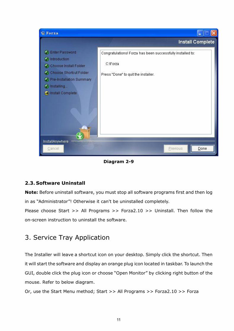
Step 8 Click “Done” button to confirm the installation completely.
Refer to Diagram 29.
11
Diagram 29
2.3. Software Uninstall
Note: Before uninstall software, you must stop all software programs first and then log
in as “Administrator”! Otherwise it can't be uninstalled completely.
Please choose Start >> All Programs >> Forza2.10 >> Uninstall. Then follow the
onscreen instruction to uninstall the software.
3. Service Tray Application
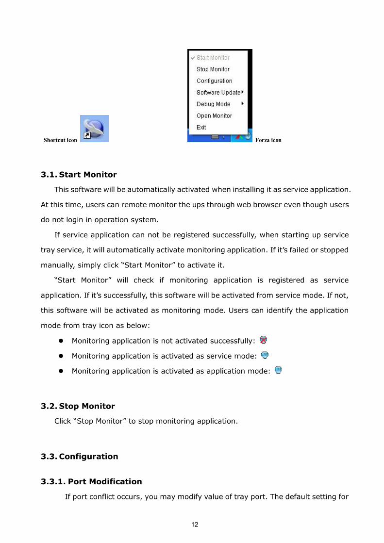
The Installer will leave a shortcut icon on your desktop. Simply click the shortcut. Then
it will start the software and display an orange plug icon located in taskbar. To launch the
GUI, double click the plug icon or choose “Open Monitor” by clicking right button of the
mouse. Refer to below diagram.
Or, use the Start Menu method; Start >> All Programs >> Forza2.10 >> Forza
12
Shortcut icon Forza icon
3.1. Start Monitor
This software will be automatically activated when installing it as service application.
At this time, users can remote monitor the ups through web browser even though users
do not login in operation system.
If service application can not be registered successfully, when starting up service
tray service, it will automatically activate monitoring application. If it’s failed or stopped
manually, simply click “Start Monitor” to activate it.
“Start Monitor” will check if monitoring application is registered as service
application. If it’s successfully, this software will be activated from service mode. If not,
this software will be activated as monitoring mode. Users can identify the application
mode from tray icon as below:
l Monitoring application is not activated successfully:
l Monitoring application is activated as service mode:
l Monitoring application is activated as application mode:
3.2. Stop Monitor
Click “Stop Monitor” to stop monitoring application.
3.3. Configuration
3.3.1. Port Modification
If port conflict occurs, you may modify value of tray port. The default setting for
13
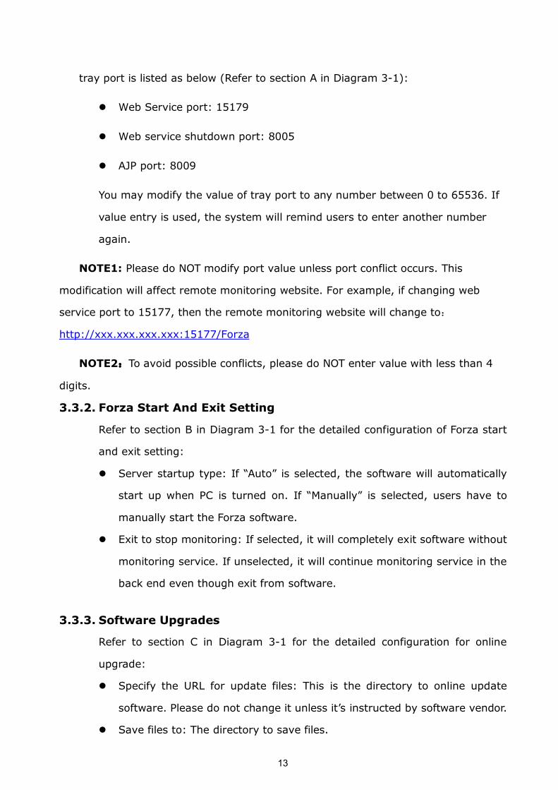
tray port is listed as below (Refer to section A in Diagram 31):
l Web Service port: 15179
l Web service shutdown port: 8005
l AJP port: 8009
You may modify the value of tray port to any number between 0 to 65536. If
value entry is used, the system will remind users to enter another number
again.
NOTE1: Please do NOT modify port value unless port conflict occurs. This
modification will affect remote monitoring website. For example, if changing web
service port to 15177, then the remote monitoring website will change to:
http://xxx.xxx.xxx.xxx:15177/Forza
NOTE2:To avoid possible conflicts, please do NOT enter value with less than 4
digits.
3.3.2. Forza Start And Exit Setting
Refer to section B in Diagram 31 for the detailed configuration of Forza start
and exit setting:
l Server startup type: If “Auto” is selected, the software will automatically
start up when PC is turned on. If “Manually” is selected, users have to
manually start the Forza software.
l Exit to stop monitoring: If selected, it will completely exit software without
monitoring service. If unselected, it will continue monitoring service in the
back end even though exit from software.
3.3.3. Software Upgrades
Refer to section C in Diagram 31 for the detailed configuration for online
upgrade:
l Specify the URL for update files: This is the directory to online update
software. Please do not change it unless it’s instructed by software vendor.
l Save files to: The directory to save files.
14
l Online autoupdate: If selected, it will automatically check if there is any
new version launched online every 1 hour.
l If applying online upgrade, please follow below for configuration:
1. Select “Apply the proxy configuration”;
2. Enter IP address and port of server;
3. If ID identification is requested, select “Enable authentication” and enter
User Name and Password.
l Connection test: Click this button to test if all configurations are set up well.
Diagram 31
15
3.3.4. Configuration Saved
Click “Apply” button to save all changes in Configuration page. Click “Cancel” to
stop the change.
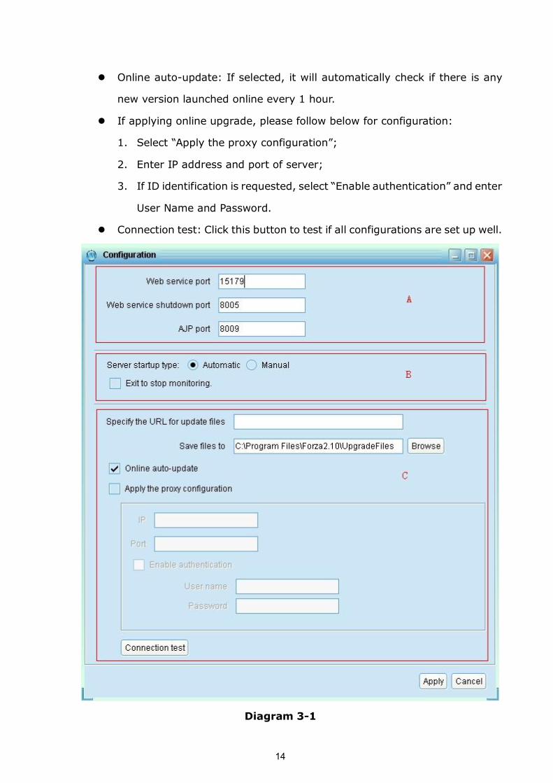
3.4. Software Update
Software update includes online update and manually update:
l Online Update:
Click “Online Update” to search the latest software version. If there is new
version, it will automatically download and update. Refer to Diagram 32:
Diagram 32
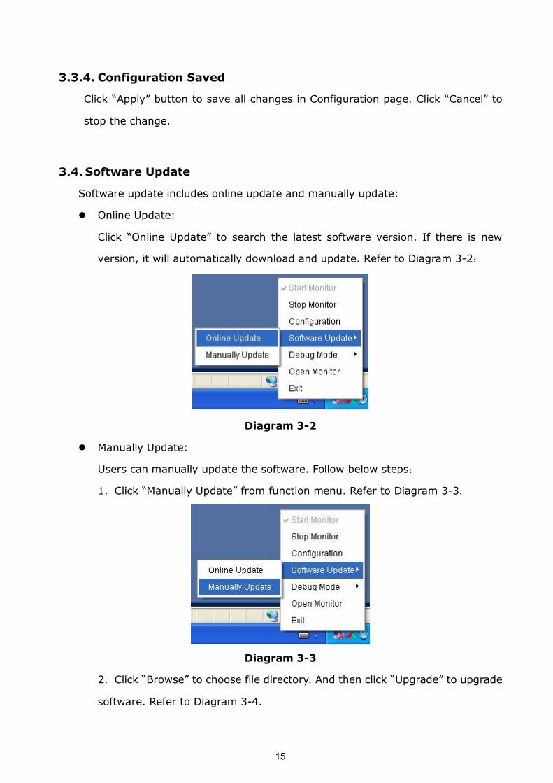
l Manually Update:
Users can manually update the software. Follow below steps:
1.Click “Manually Update” from function menu. Refer to Diagram 33.
Diagram 33
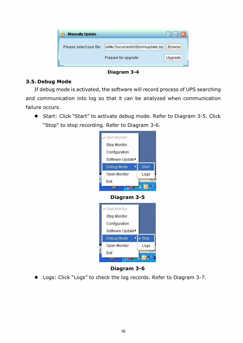
2.Click “Browse” to choose file directory. And then click “Upgrade” to upgrade
software. Refer to Diagram 34.
16
Diagram 34
3.5. Debug Mode
If debug mode is activated, the software will record process of UPS searching
and communication into log so that it can be analyzed when communication
failure occurs.
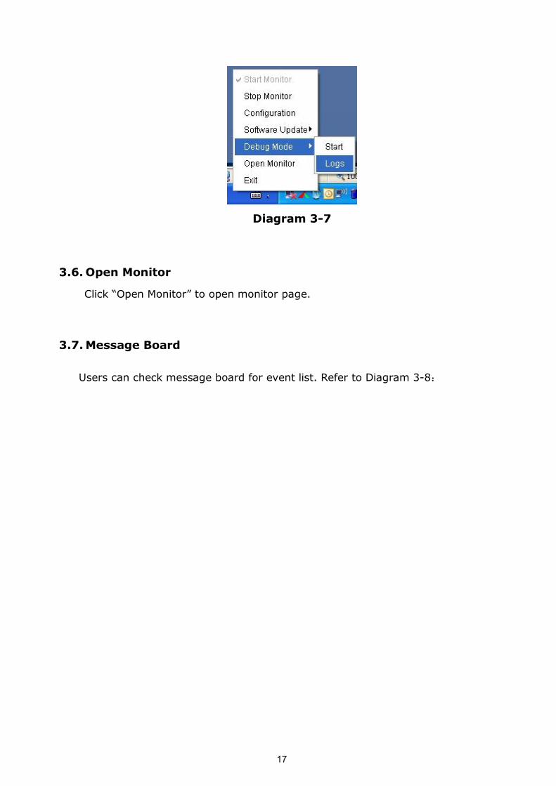
l Start: Click “Start” to activate debug mode. Refer to Diagram 35. Click
“Stop” to stop recording. Refer to Diagram 36.
Diagram 35
Diagram 36
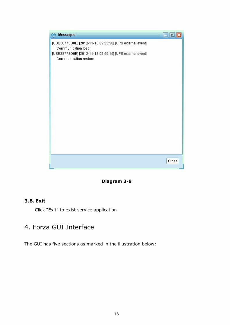
l Logs: Click “Logs” to check the log records. Refer to Diagram 37.
17
Diagram 37
3.6.Open Monitor
Click “Open Monitor” to open monitor page.
3.7.Message Board
Users can check message board for event list. Refer to Diagram 38:
18
Diagram 38
3.8. Exit
Click “Exit” to exist service application
4. Forza GUI Interface
The GUI has five sections as marked in the illustration below:
19
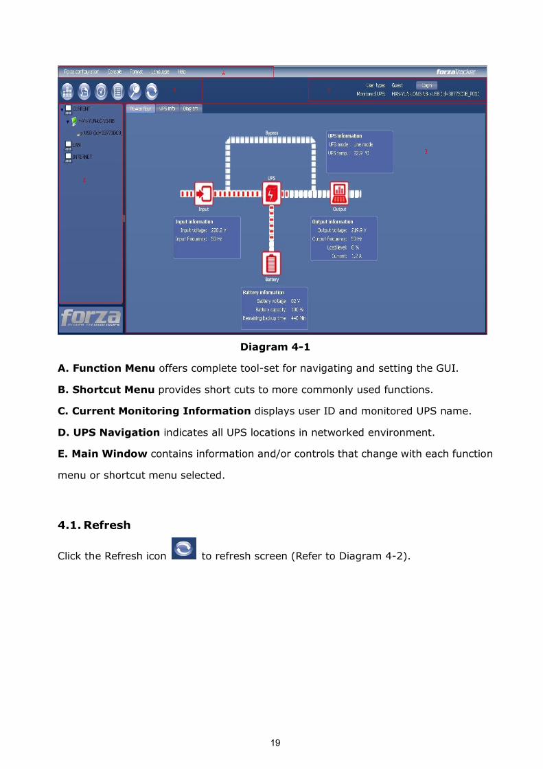
Diagram 41
A. Function Menu offers complete toolset for navigating and setting the GUI.
B. Shortcut Menu provides short cuts to more commonly used functions.
C. Current Monitoring Information displays user ID and monitored UPS name.
D. UPS Navigation indicates all UPS locations in networked environment.
E. Main Window contains information and/or controls that change with each function
menu or shortcut menu selected.
4.1. Refresh
Click the Refresh icon to refresh screen (Refer to Diagram 42).
20
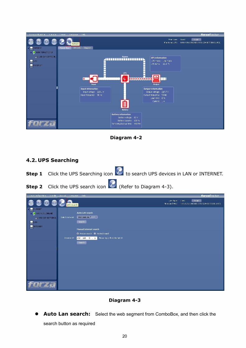
Diagram 42
4.2. UPS Searching
Step 1 Click the UPS Searching icon to search UPS devices in LAN or INTERNET.
Step 2 Click the UPS search icon (Refer to Diagram 43).
Diagram 43
l Auto Lan search: Select the web segment from ComboBox, and then click the
search button as required
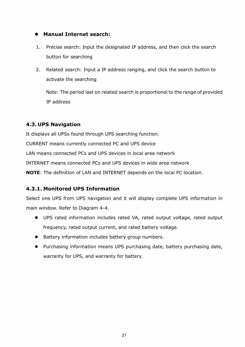
21
l Manual Internet search:
1. Precise search: Input the designated IP address, and then click the search
button for searching
2. Related search: Input a IP address ranging, and click the search button to
activate the searching
Note: The period last on related search is proportional to the range of provided
IP address
4.3. UPS Navigation
It displays all UPSs found through UPS searching function.
CURRENT means currently connected PC and UPS device
LAN means connected PCs and UPS devices in local area network
INTERNET means connected PCs and UPS devices in wide area network
NOTE: The definition of LAN and INTERNET depends on the local PC location.
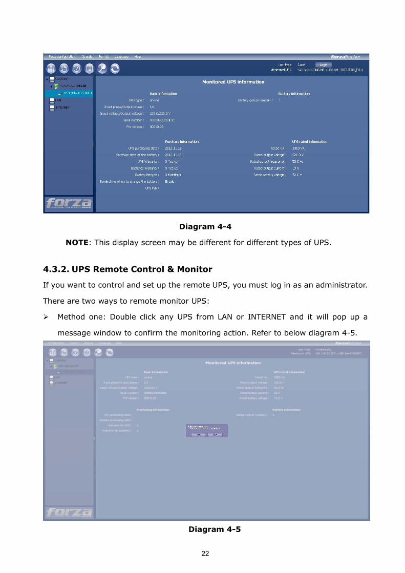
4.3.1. Monitored UPS Information
Select one UPS from UPS navigation and it will display complete UPS information in
main window. Refer to Diagram 44.
l UPS rated information includes rated VA, rated output voltage, rated output
frequency, rated output current, and rated battery voltage.
l Battery information includes battery group numbers.
l Purchasing information means UPS purchasing date, battery purchasing date,
warranty for UPS, and warranty for battery.
22
Diagram 44
NOTE: This display screen may be different for different types of UPS.
4.3.2. UPS Remote Control & Monitor
If you want to control and set up the remote UPS, you must log in as an administrator.
There are two ways to remote monitor UPS:
Ø Method one: Double click any UPS from LAN or INTERNET and it will pop up a
message window to confirm the monitoring action. Refer to below diagram 45.
Diagram 45
23
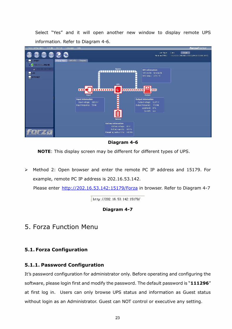
Select “Yes” and it will open another new window to display remote UPS
information. Refer to Diagram 46.
Diagram 46
NOTE: This display screen may be different for different types of UPS.
Ø Method 2: Open browser and enter the remote PC IP address and 15179. For
example, remote PC IP address is 202.16.53.142.
Please enter http://202.16.53.142:15179/Forza in browser. Refer to Diagram 47
Diagram 47
5. Forza Function Menu
5.1. Forza Configuration
5.1.1. Password Configuration
It’s password configuration for administrator only. Before operating and configuring the
software, please login first and modify the password. The default password is “111296”
at first log in. Users can only browse UPS status and information as Guest status
without login as an Administrator. Guest can NOT control or executive any setting.
24
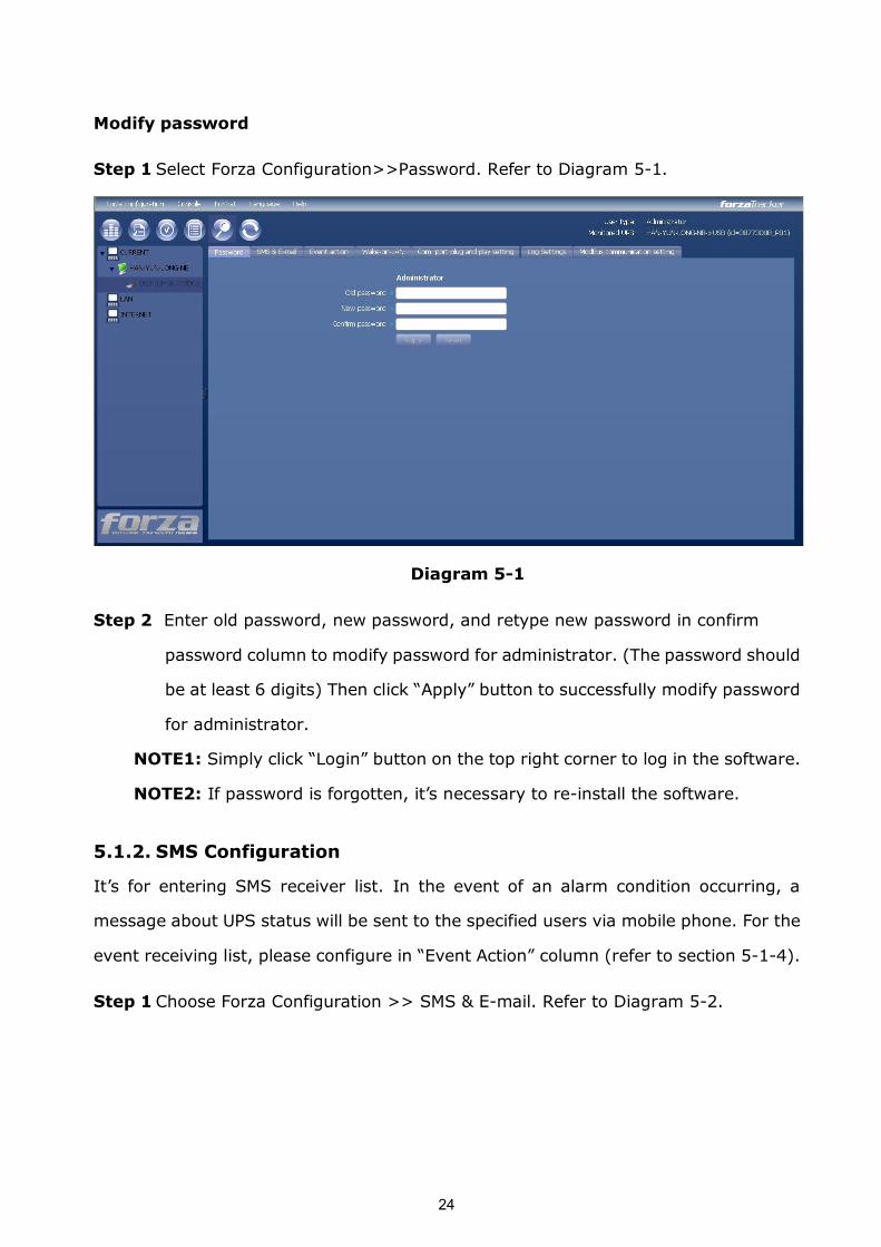
Modify password
Step 1 Select Forza Configuration>>Password. Refer to Diagram 51.
Diagram 51
Step 2 Enter old password, new password, and retype new password in confirm
password column to modify password for administrator. (The password should
be at least 6 digits) Then click “Apply” button to successfully modify password
for administrator.
NOTE1: Simply click “Login” button on the top right corner to log in the software.
NOTE2: If password is forgotten, it’s necessary to reinstall the software.
5.1.2. SMS Configuration
It’s for entering SMS receiver list. In the event of an alarm condition occurring, a
message about UPS status will be sent to the specified users via mobile phone. For the
event receiving list, please configure in “Event Action” column (refer to section 514).
Step 1 Choose Forza Configuration >> SMS & Email. Refer to Diagram 52.
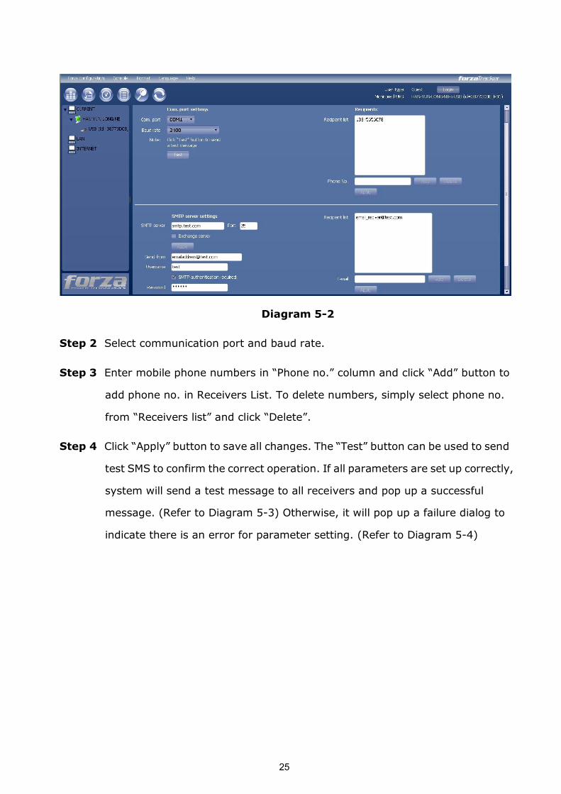
25
Diagram 52
Step 2 Select communication port and baud rate.
Step 3 Enter mobile phone numbers in “Phone no.” column and click “Add” button to
add phone no. in Receivers List. To delete numbers, simply select phone no.
from “Receivers list” and click “Delete”.
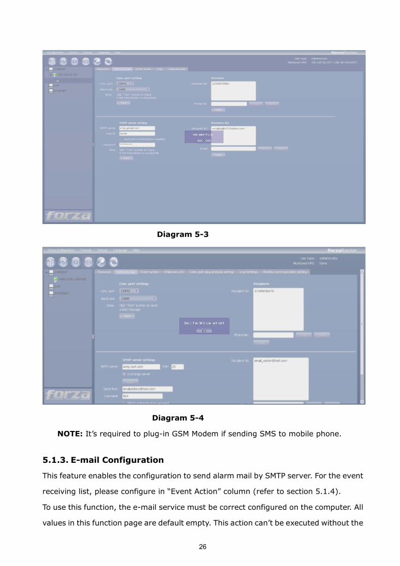
Step 4 Click “Apply” button to save all changes. The “Test” button can be used to send
test SMS to confirm the correct operation. If all parameters are set up correctly,
system will send a test message to all receivers and pop up a successful
message. (Refer to Diagram 53) Otherwise, it will pop up a failure dialog to
indicate there is an error for parameter setting. (Refer to Diagram 54)
26
Diagram 53
Diagram 54
NOTE: It’s required to plugin GSM Modem if sending SMS to mobile phone.
5.1.3. Email Configuration
This feature enables the configuration to send alarm mail by SMTP server. For the event
receiving list, please configure in “Event Action” column (refer to section 5.1.4).
To use this function, the email service must be correct configured on the computer. All
values in this function page are default empty. This action can’t be executed without the
27
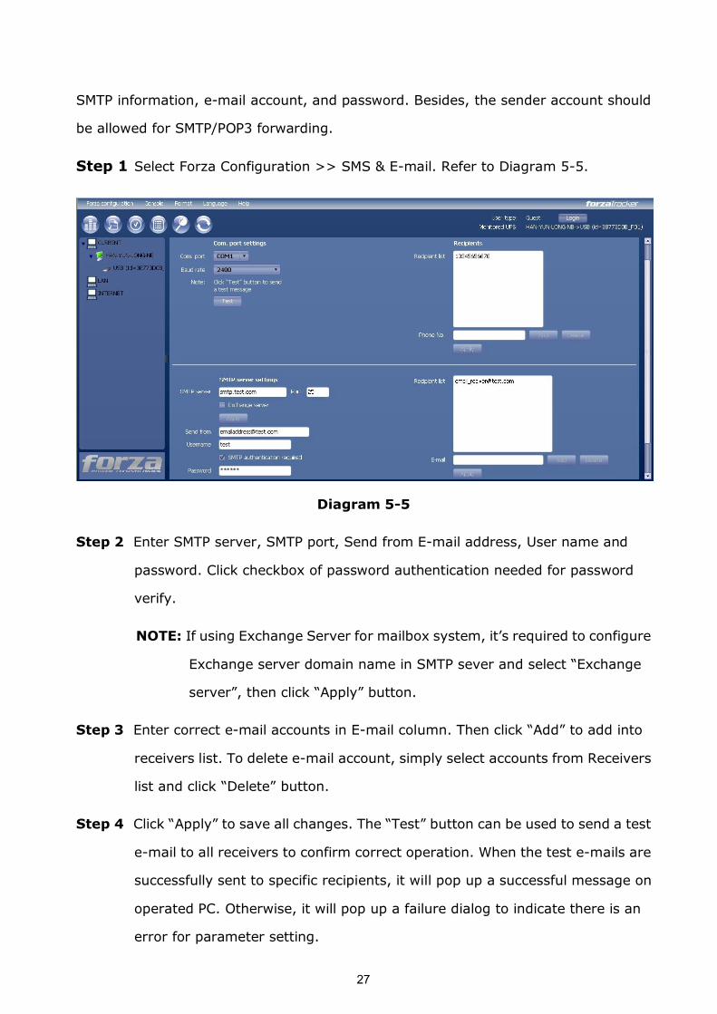
SMTP information, email account, and password. Besides, the sender account should
be allowed for SMTP/POP3 forwarding.
Step 1 Select Forza Configuration >> SMS & Email. Refer to Diagram 55.
Diagram 55
Step 2 Enter SMTP server, SMTP port, Send from Email address, User name and
password. Click checkbox of password authentication needed for password
verify.
NOTE: If using Exchange Server for mailbox system, it’s required to configure
Exchange server domain name in SMTP sever and select “Exchange
server”, then click “Apply” button.
Step 3 Enter correct email accounts in Email column. Then click “Add” to add into
receivers list. To delete email account, simply select accounts from Receivers
list and click “Delete” button.
Step 4 Click “Apply” to save all changes. The “Test” button can be used to send a test
email to all receivers to confirm correct operation. When the test emails are
successfully sent to specific recipients, it will pop up a successful message on
operated PC. Otherwise, it will pop up a failure dialog to indicate there is an
error for parameter setting.
28
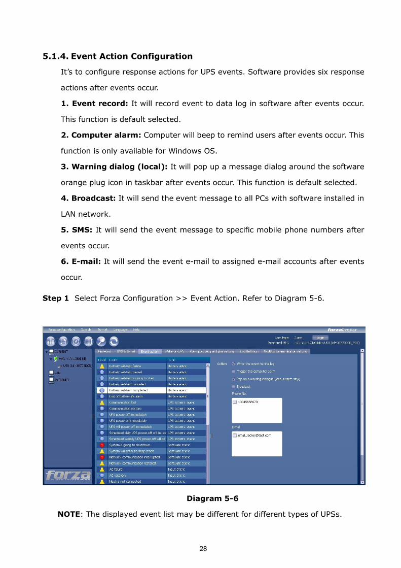
5.1.4. Event Action Configuration
It’s to configure response actions for UPS events. Software provides six response
actions after events occur.
1. Event record: It will record event to data log in software after events occur.
This function is default selected.
2. Computer alarm: Computer will beep to remind users after events occur. This
function is only available for Windows OS.
3. Warning dialog (local): It will pop up a message dialog around the software
orange plug icon in taskbar after events occur. This function is default selected.
4. Broadcast: It will send the event message to all PCs with software installed in
LAN network.
5. SMS: It will send the event message to specific mobile phone numbers after
events occur.
6. Email: It will send the event email to assigned email accounts after events
occur.
Step 1 Select Forza Configuration >> Event Action. Refer to Diagram 56.
Diagram 56
NOTE: The displayed event list may be different for different types of UPSs.
29
Step 2 Select a specific event from “Event List” and then action method page will be
active on the righthand column.
Step 3 Select desired action methods by clicking checkbox.
Step 4 Click “Apply” button to save all configurations.
NOTE1: When editing receiver list in SMS or email columns, it’s necessary to
refresh the event action page to reload the updated receiver list.
NOTE2: It is requested to have following conditions for successful broadcast.
1. All receiving PCs must have installed software.
2. Only send the message to the PCs in LAN found in UPS Navigation.
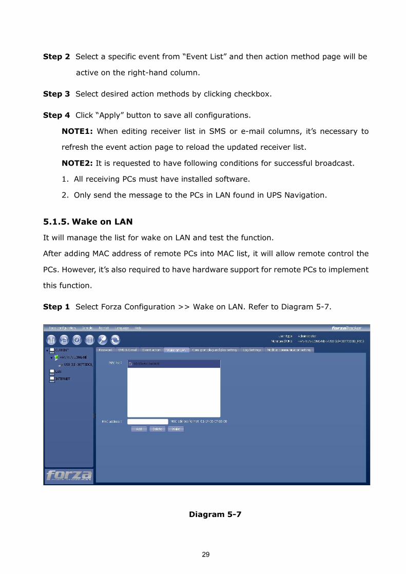
5.1.5. Wake on LAN
It will manage the list for wake on LAN and test the function.
After adding MAC address of remote PCs into MAC list, it will allow remote control the
PCs. However, it’s also required to have hardware support for remote PCs to implement
this function.
Step 1 Select Forza Configuration >> Wake on LAN. Refer to Diagram 57.
Diagram 57
30
Step 2 Add: Enter MAC address and click “Add” button to add in MAC List. Delete:
Select one from list and click “Delete” button. Test: Select one from list and
click “Test” button. Then it will execute WakeonLAN test.
NOTE: The MAC address format example: 011FC6C7E008.
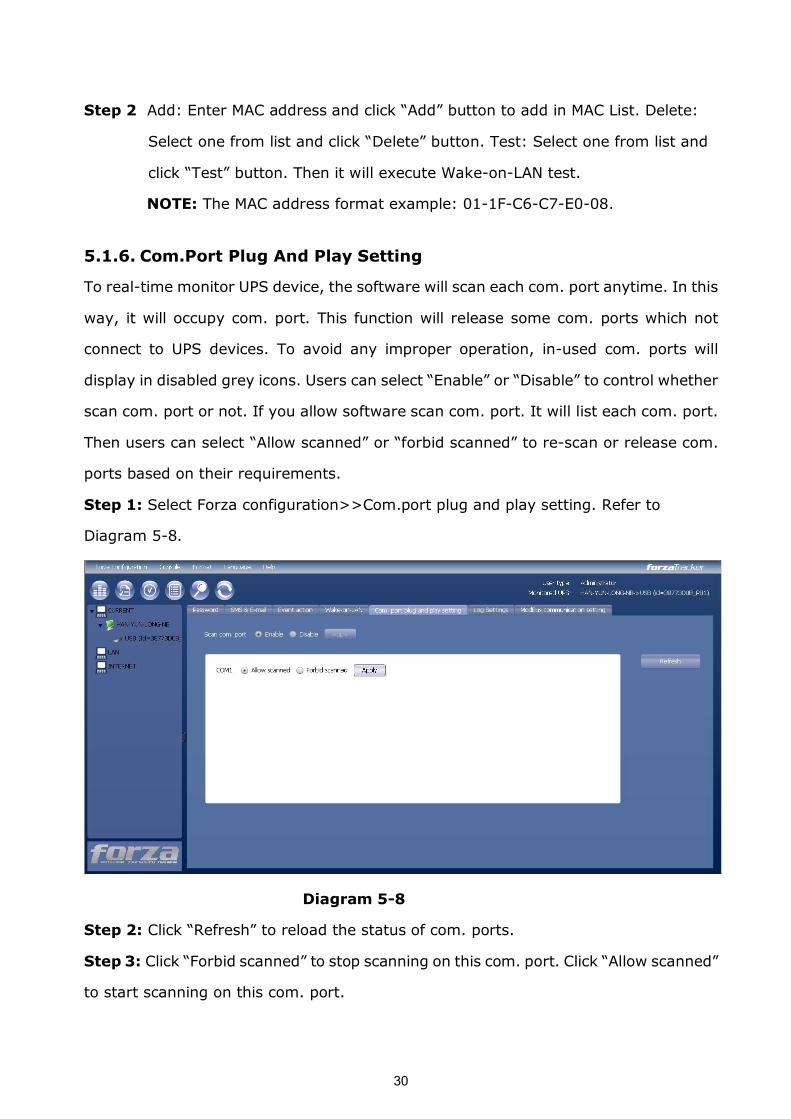
5.1.6. Com.Port Plug And Play Setting
To realtime monitor UPS device, the software will scan each com. port anytime. In this
way, it will occupy com. port. This function will release some com. ports which not
connect to UPS devices. To avoid any improper operation, inused com. ports will
display in disabled grey icons. Users can select “Enable” or “Disable” to control whether
scan com. port or not. If you allow software scan com. port. It will list each com. port.
Then users can select “Allow scanned” or “forbid scanned” to rescan or release com.
ports based on their requirements.
Step 1: Select Forza configuration>>Com.port plug and play setting. Refer to
Diagram 58.
Diagram 58
Step 2: Click “Refresh” to reload the status of com. ports.
Step 3: Click “Forbid scanned” to stop scanning on this com. port. Click “Allow scanned”
to start scanning on this com. port.
31
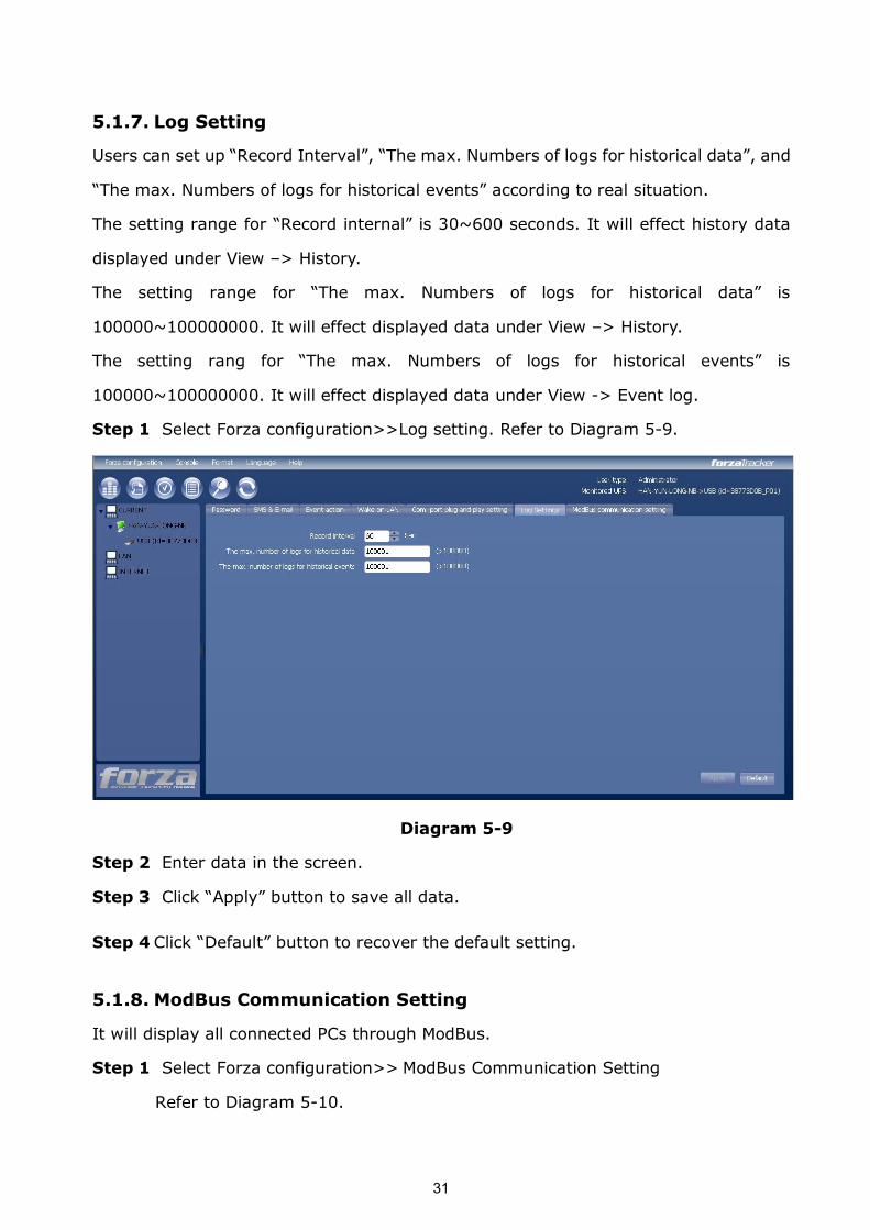
5.1.7. Log Setting
Users can set up “Record Interval”, “The max. Numbers of logs for historical data”, and
“The max. Numbers of logs for historical events” according to real situation.
The setting range for “Record internal” is 30~600 seconds. It will effect history data
displayed under View –> History.
The setting range for “The max. Numbers of logs for historical data” is
100000~100000000. It will effect displayed data under View –> History.
The setting rang for “The max. Numbers of logs for historical events” is
100000~100000000. It will effect displayed data under View > Event log.
Step 1 Select Forza configuration>>Log setting. Refer to Diagram 59.
Diagram 59
Step 2 Enter data in the screen.
Step 3 Click “Apply” button to save all data.
Step 4 Click “Default” button to recover the default setting.
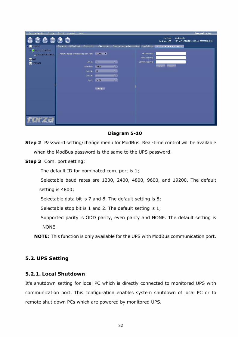
5.1.8. ModBus Communication Setting
It will display all connected PCs through ModBus.
Step 1 Select Forza configuration>> ModBus Communication Setting
Refer to Diagram 510.
32
Diagram 510
Step 2 Password setting/change menu for ModBus. Realtime control will be available
when the ModBus password is the same to the UPS password.
Step 3 Com. port setting:
The default ID for nominated com. port is 1;
Selectable baud rates are 1200, 2400, 4800, 9600, and 19200. The default
setting is 4800;
Selectable data bit is 7 and 8. The default setting is 8;
Selectable stop bit is 1 and 2. The default setting is 1;
Supported parity is ODD parity, even parity and NONE. The default setting is
NONE.
NOTE: This function is only available for the UPS with ModBus communication port.
5.2. UPS Setting
5.2.1. Local Shutdown
It’s shutdown setting for local PC which is directly connected to monitored UPS with
communication port. This configuration enables system shutdown of local PC or to
remote shut down PCs which are powered by monitored UPS.
33
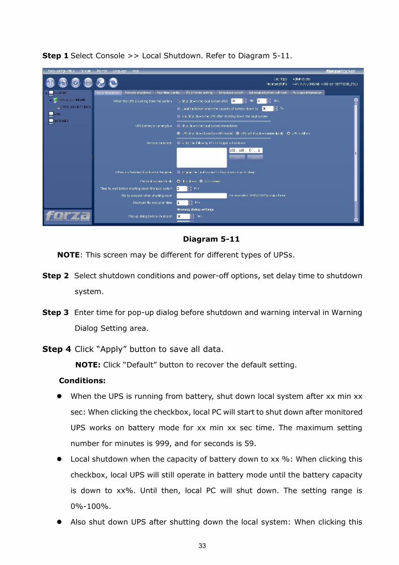
Step 1 Select Console >> Local Shutdown. Refer to Diagram 511.
Diagram 511
NOTE: This screen may be different for different types of UPSs.
Step 2 Select shutdown conditions and poweroff options, set delay time to shutdown
system.
Step 3 Enter time for popup dialog before shutdown and warning interval in Warning
Dialog Setting area.
Step 4 Click “Apply” button to save all data.
NOTE: Click “Default” button to recover the default setting.
Conditions:
l When the UPS is running from battery, shut down local system after xx min xx
sec: When clicking the checkbox, local PC will start to shut down after monitored
UPS works on battery mode for xx min xx sec time. The maximum setting
number for minutes is 999, and for seconds is 59.
l Local shutdown when the capacity of battery down to xx %: When clicking this
checkbox, local UPS will still operate in battery mode until the battery capacity
is down to xx%. Until then, local PC will shut down. The setting range is
0%100%.
l Also shut down UPS after shutting down the local system: When clicking this
34
checkbox, monitored UPS will shut down after local system shuts down. The UPS
shutdown time will be later than system complete shutdown time. The default
setting is clicked. But users can choose to shut down the system without
shutting down the monitored UPS by unclicking this checkbox.
l When UPS battery is running low, shut down the local system immediately:
When clicking this checkbox, local PC will shut down when monitored UPS
battery is running low.
1. UPS shut down based on UPSmodel: Only >3KVA standard UPS model will
automatically shut down. However, longrun models and UPSs with above
5KVA will remain on.
2. UPS will shutdown immediately: UPS will shutdown immediately no
matter what kind of UPSs.
3. UPS is still on: UPS will remain on until battery is running out.
l Accept shutdown command from remote system: When clicking the checkbox, it
accepts shutdown command from specific remote PCs. Please enter IP address
of remote systems in blank column and click “Add” button to add into list.
l Allows local system shutdown when UPS is scheduled off: When clicking this
checkbox, the local system will shut down before monitored UPS is scheduled to
power off. The default setting is clicked.
Poweroff option: Selecting poweroff method for above shutdown system.
l Shutdown: When clicking the checkbox, the selected system will shut down. The
default setting is clicked.
l Sleep mode: When clicking the checkbox, selected system will suspend the
system instead of a normal shutdown. But this function is only supported by
Windows 2000 or higher on supported hardware.
Delay time to shutdown system: Enter the delay time to shut down the
operating system. The value range is from 1 to 99 minutes.
On shutdown execute file: Enter the path of execute file.
Warning Dialog Setting:
l Popup dialog before shutdown: Timer setting for popup warning dialog
35
displayed in local PC. Local PC will pop up a warning dialog before system
starts to shut down. The range is from 1 to 999 seconds.
l Warning dialog interval: Reminding dialog interval setting. This setting also
applies for UPS shutdown because of power failure. The range is from 1 to 999
seconds.
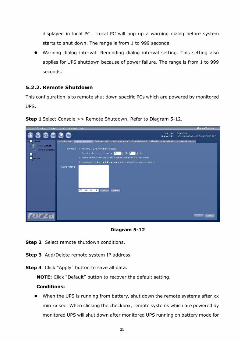
5.2.2. Remote Shutdown
This configuration is to remote shut down specific PCs which are powered by monitored
UPS.
Step 1 Select Console >> Remote Shutdown. Refer to Diagram 512.
Diagram 512
Step 2 Select remote shutdown conditions.
Step 3 Add/Delete remote system IP address.
Step 4 Click “Apply” button to save all data.
NOTE: Click “Default” button to recover the default setting.
Conditions:
l When the UPS is running from battery, shut down the remote systems after xx
min xx sec: When clicking the checkbox, remote systems which are powered by
monitored UPS will shut down after monitored UPS running on battery mode for
36
xx min xx sec. The maximum setting number for minutes is 999, and for
seconds is 59.
l Remote shutdown when the capacity of battery down to xx % (Battery mode):
When clicking this checkbox, local UPS will still operate until the battery capacity
is down to xx%. Until then, it will remotely shut down PCs.
l Immediately shut down the following remote systems when the battery is
running low: When clicking the checkbox, remote systems which are powered
by monitored UPS will shut down when monitored UPS is at low battery level.
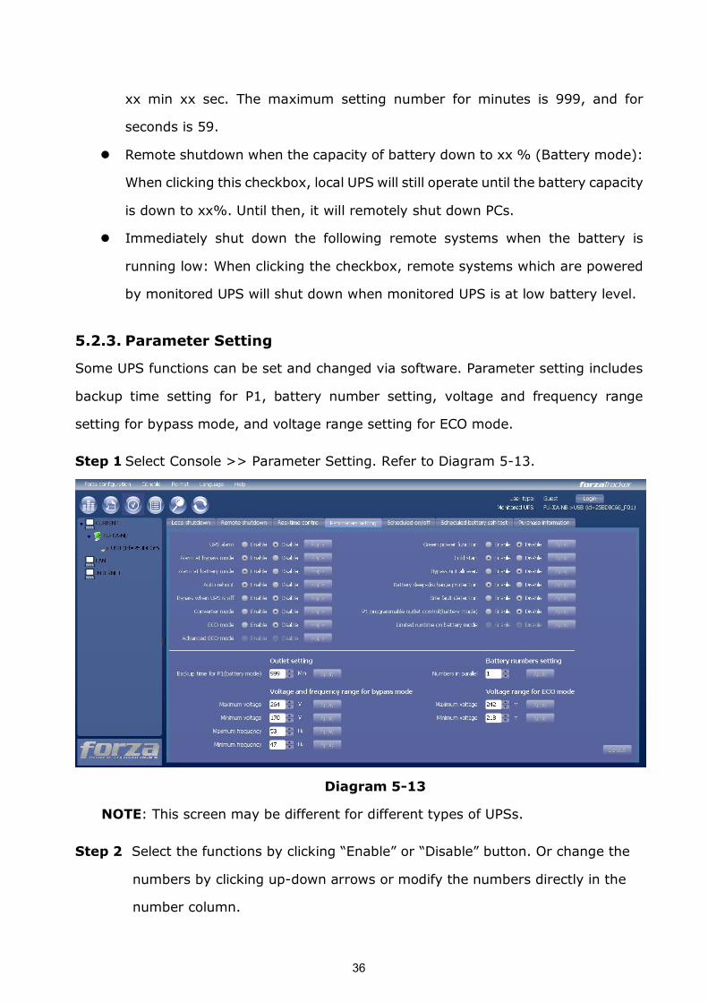
5.2.3. Parameter Setting
Some UPS functions can be set and changed via software. Parameter setting includes
backup time setting for P1, battery number setting, voltage and frequency range
setting for bypass mode, and voltage range setting for ECO mode.
Step 1 Select Console >> Parameter Setting. Refer to Diagram 513.
Diagram 513
NOTE: This screen may be different for different types of UPSs.
Step 2 Select the functions by clicking “Enable” or “Disable” button. Or change the
numbers by clicking updown arrows or modify the numbers directly in the
number column.
37
Step 3 Click “Apply” button to save the settings. Each function setting is saved by
clicking each “Apply” button.
NOTE1: Any functions which are not supported by UPS will not be able to access.
NOTE2: Click “Default” button to recover the default setting.
l UPS alarm: If enabled, UPS alarm will be activated. Vice versa.
l Alarm at bypass mode: If enabled, UPS alarms when it’s working at bypass
mode. Vice versa.
l Alarm at battery mode: If disabled, UPS will not alarm when it’s working at
battery mode. Vice versa.
l Auto reboot: If enabled, UPS will auto recover when AC is recovering. Vice
versa.
l Bypass when UPS is off: If enabled, AC will directly provide power to connected
devices when UPS is off. Vice versa.
l Converter mode: If enabled, the UPS will operate in converter mode. Vice versa.
l ECO mode: If enabled, the UPS will operate in ECO mode when input voltage is
within acceptable range. Vice versa.
l Battery open status check: If enabled, the monitored UPS will check if the
battery connection ok or not when UPS is turned on.
l Cold start: If disabled, the UPS can be turned on only when AC is normally
connected to UPS. Vice versa.
l Bypass not allowed: If enabled, the UPS will not transfer to bypass mode under
any conditions. If disabled, the UPS will be allowed to transfer to bypass mode
according to UPS internal setting.
l Battery deepdischarge protection: If enabled, the monitored UPS shutdown in
accordance with the condition of battery and load on battery mode to protect
battery. Vice versa.
l Site fault detection: If enabled, the monitored UPS will beep when the input
neutral and hot wires are reversed. Vice versa.
l P1 Programmable outlet control (battery mode): If enabled, when UPS is
running at battery mode, it will cut off P1 outlets after backup setting time arrive.
38
If disabled, UPS will provide continuous power to P1 outlets until the battery is
running out.
l Outlet setting: Users can set limited backup time for P1 outlets when UPS is on
battery mode.
l Battery numbers setting:
Ø Numbers in parallel: set battery numbers in parallel.
l Voltage and frequency range for bypass mode: Set acceptable voltage and
frequency range in bypass mode.
Ø Maximum and minimum voltage: When UPS is on bypass mode and input
voltage is out of setting range, UPS will enter battery mode.
Ø Maximum and minimum frequency: When UPS is on bypass mode and
input frequency is out of setting range, UPS will enter battery mode.
l Voltage range for ECO mode: Set acceptable voltage range for ECO mode.
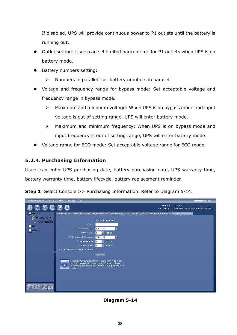
5.2.4. Purchasing Information
Users can enter UPS purchasing date, battery purchasing date, UPS warranty time,
battery warranty time, battery lifecycle, battery replacement reminder.
Step 1 Select Console >> Purchasing Information. Refer to Diagram 514.
Diagram 514
39
Step 2 Please fill out purchasing information.
Step 3 Click “Apply” button to save all data.
5.3. Control
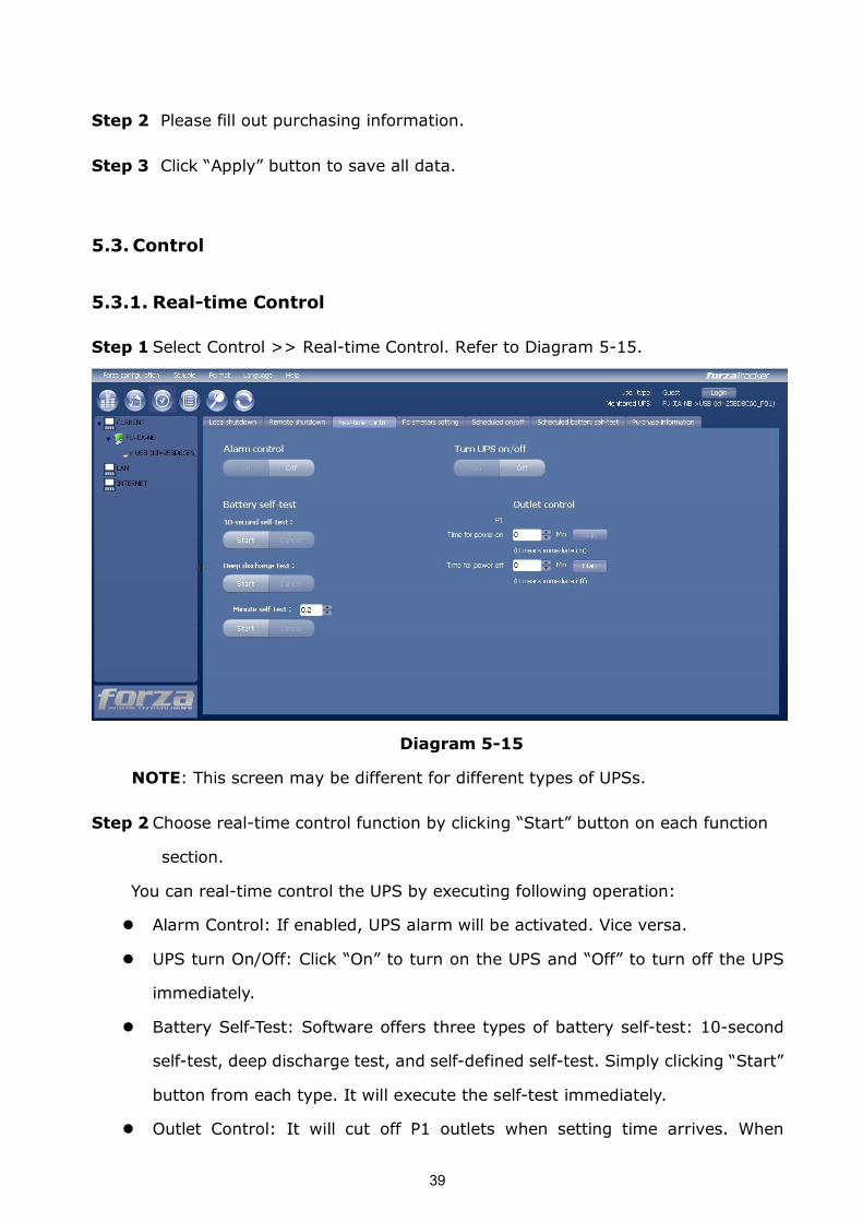
5.3.1. Realtime Control
Step 1 Select Control >> Realtime Control. Refer to Diagram 515.
Diagram 515
NOTE: This screen may be different for different types of UPSs.
Step 2 Choose realtime control function by clicking “Start” button on each function
section.
You can realtime control the UPS by executing following operation:
l Alarm Control: If enabled, UPS alarm will be activated. Vice versa.
l UPS turn On/Off: Click “On” to turn on the UPS and “Off” to turn off the UPS
immediately.
l Battery SelfTest: Software offers three types of battery selftest: 10second
selftest, deep discharge test, and selfdefined selftest. Simply clicking “Start”
button from each type. It will execute the selftest immediately.
l Outlet Control: It will cut off P1 outlets when setting time arrives. When
40
entering 0 in timer column and click “Start” button, it will cut off outlets
immediately when UPS works in battery mode.
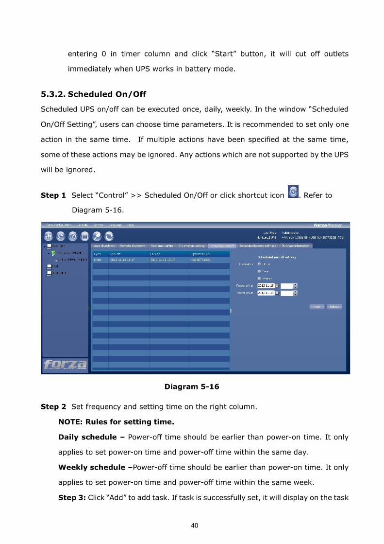
5.3.2. Scheduled On/Off
Scheduled UPS on/off can be executed once, daily, weekly. In the window “Scheduled
On/Off Setting”, users can choose time parameters. It is recommended to set only one
action in the same time. If multiple actions have been specified at the same time,
some of these actions may be ignored. Any actions which are not supported by the UPS
will be ignored.
Step 1 Select “Control” >> Scheduled On/Off or click shortcut icon . Refer to
Diagram 516.
Diagram 516
Step 2 Set frequency and setting time on the right column.
NOTE: Rules for setting time.
Daily schedule – Poweroff time should be earlier than poweron time. It only
applies to set poweron time and poweroff time within the same day.
Weekly schedule –Poweroff time should be earlier than poweron time. It only
applies to set poweron time and poweroff time within the same week.
Step 3: Click “Add” to add task. If task is successfully set, it will display on the task
41
table on the lefthand side. Select specific task and click “Delete” button to delete
the task.
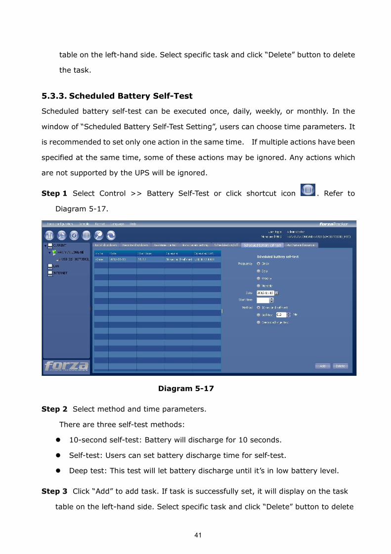
5.3.3. Scheduled Battery SelfTest
Scheduled battery selftest can be executed once, daily, weekly, or monthly. In the
window of “Scheduled Battery SelfTest Setting”, users can choose time parameters. It
is recommended to set only one action in the same time. If multiple actions have been
specified at the same time, some of these actions may be ignored. Any actions which
are not supported by the UPS will be ignored.
Step 1 Select Control >> Battery SelfTest or click shortcut icon . Refer to
Diagram 517.
Diagram 517
Step 2 Select method and time parameters.
There are three selftest methods:
l 10second selftest: Battery will discharge for 10 seconds.
l Selftest: Users can set battery discharge time for selftest.
l Deep test: This test will let battery discharge until it’s in low battery level.
Step 3 Click “Add” to add task. If task is successfully set, it will display on the task
table on the lefthand side. Select specific task and click “Delete” button to delete
42
the task.
5.4. View
5.4.1. Status
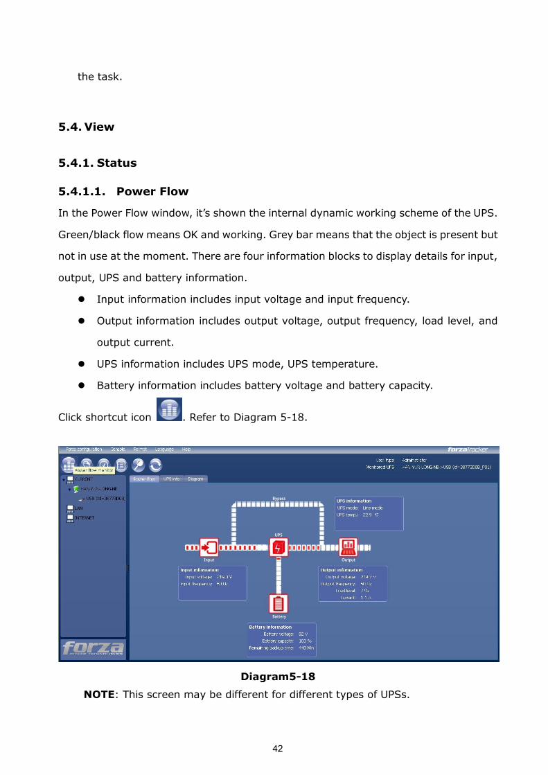
5.4.1.1. Power Flow
In the Power Flow window, it’s shown the internal dynamic working scheme of the UPS.
Green/black flow means OK and working. Grey bar means that the object is present but
not in use at the moment. There are four information blocks to display details for input,
output, UPS and battery information.
l Input information includes input voltage and input frequency.
l Output information includes output voltage, output frequency, load level, and
output current.
l UPS information includes UPS mode, UPS temperature.
l Battery information includes battery voltage and battery capacity.
Click shortcut icon . Refer to Diagram 518.
Diagram518
NOTE: This screen may be different for different types of UPSs.
43
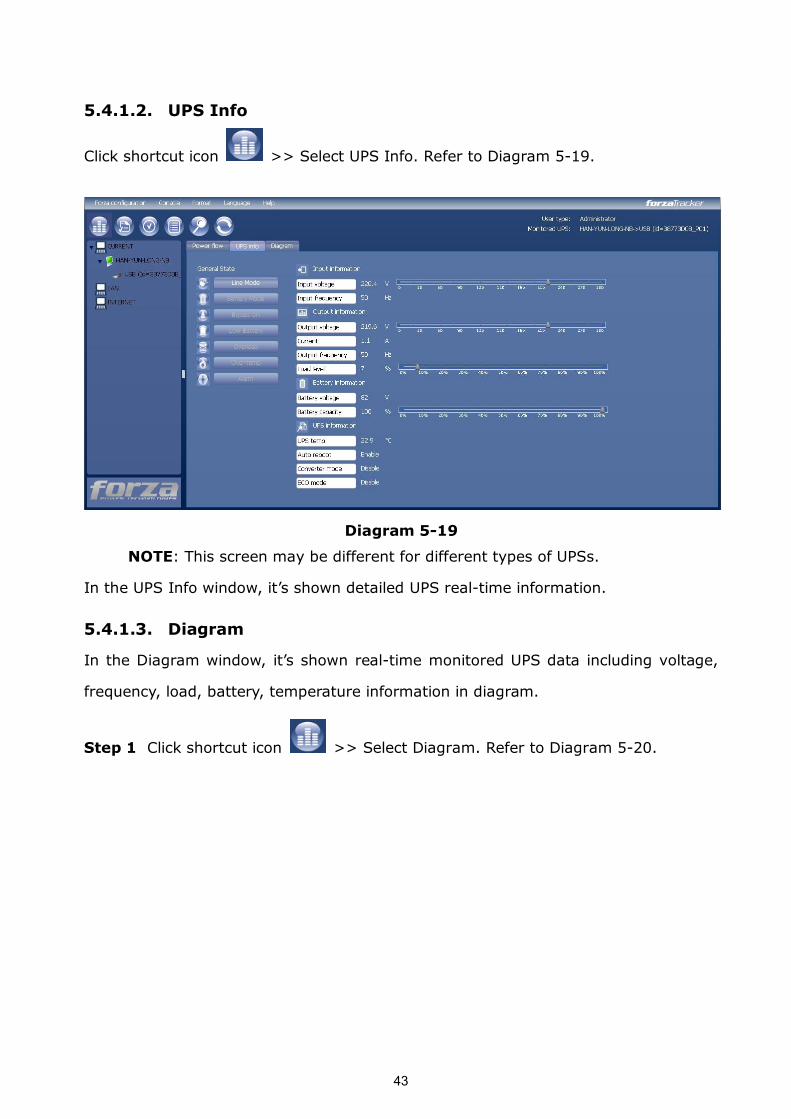
5.4.1.2. UPS Info
Click shortcut icon >> Select UPS Info. Refer to Diagram 519.
Diagram 519
NOTE: This screen may be different for different types of UPSs.
In the UPS Info window, it’s shown detailed UPS realtime information.
5.4.1.3. Diagram
In the Diagram window, it’s shown realtime monitored UPS data including voltage,
frequency, load, battery, temperature information in diagram.
Step 1 Click shortcut icon >> Select Diagram. Refer to Diagram 520.
44
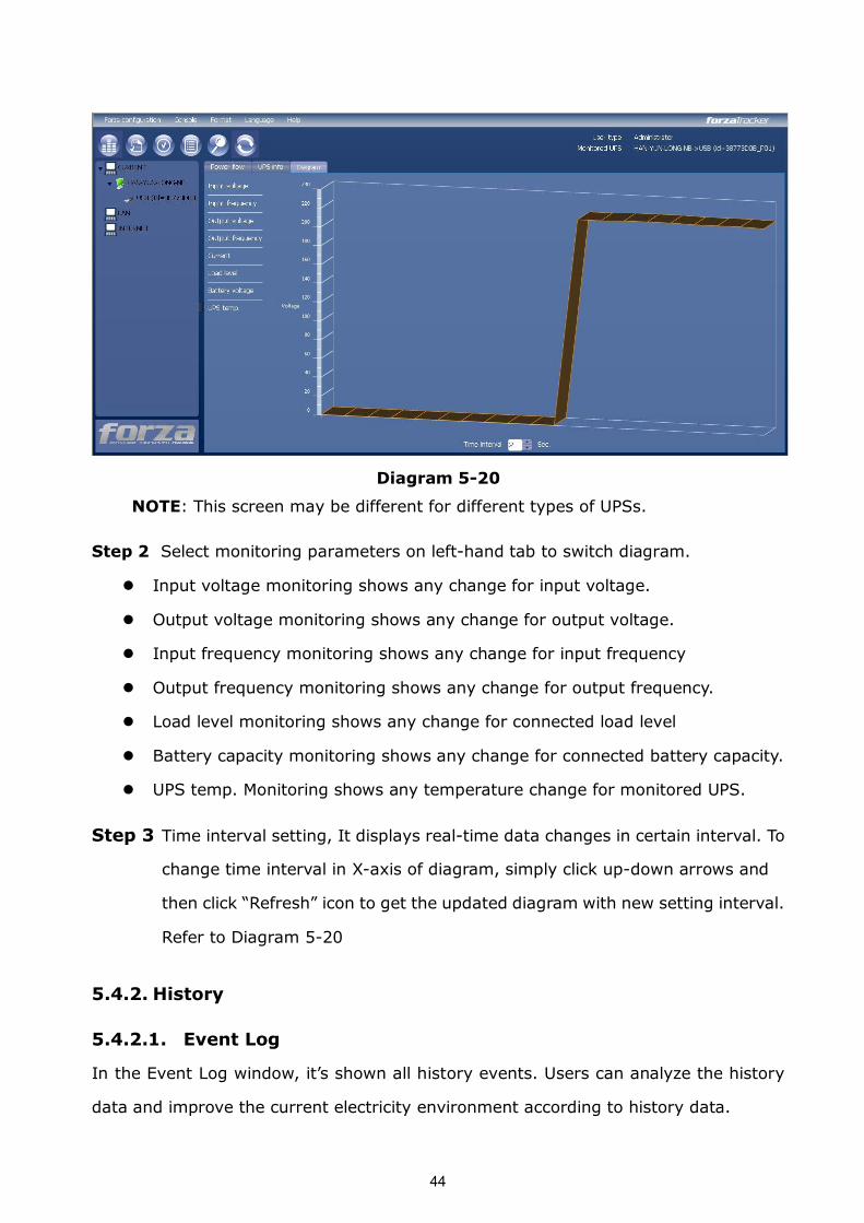
Diagram 520
NOTE: This screen may be different for different types of UPSs.
Step 2 Select monitoring parameters on lefthand tab to switch diagram.
l Input voltage monitoring shows any change for input voltage.
l Output voltage monitoring shows any change for output voltage.
l Input frequency monitoring shows any change for input frequency
l Output frequency monitoring shows any change for output frequency.
l Load level monitoring shows any change for connected load level
l Battery capacity monitoring shows any change for connected battery capacity.
l UPS temp. Monitoring shows any temperature change for monitored UPS.
Step 3 Time interval setting, It displays realtime data changes in certain interval. To
change time interval in Xaxis of diagram, simply click updown arrows and
then click “Refresh” icon to get the updated diagram with new setting interval.
Refer to Diagram 520
5.4.2. History
5.4.2.1. Event Log
In the Event Log window, it’s shown all history events. Users can analyze the history
data and improve the current electricity environment according to history data.
45
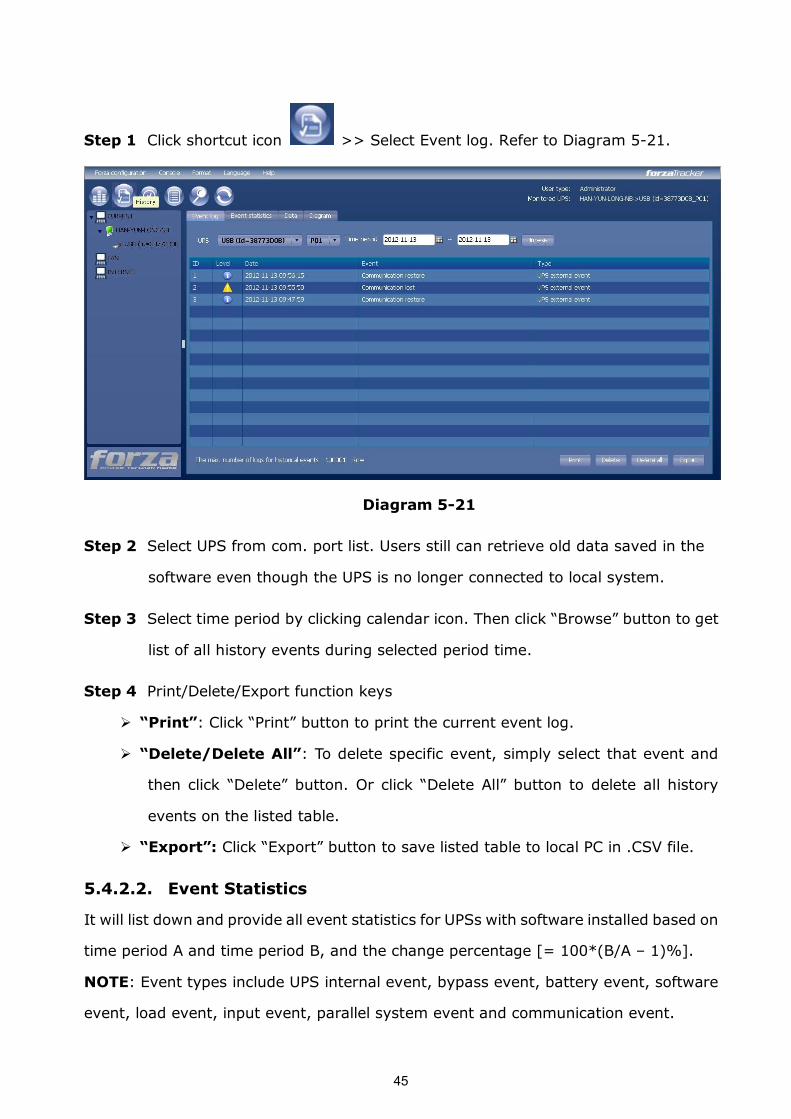
Step 1 Click shortcut icon >> Select Event log. Refer to Diagram 521.
Diagram 521
Step 2 Select UPS from com. port list. Users still can retrieve old data saved in the
software even though the UPS is no longer connected to local system.
Step 3 Select time period by clicking calendar icon. Then click “Browse” button to get
list of all history events during selected period time.
Step 4 Print/Delete/Export function keys
Ø “Print”: Click “Print” button to print the current event log.
Ø “Delete/Delete All”: To delete specific event, simply select that event and
then click “Delete” button. Or click “Delete All” button to delete all history
events on the listed table.
Ø “Export”: Click “Export” button to save listed table to local PC in .CSV file.
5.4.2.2. Event Statistics
It will list down and provide all event statistics for UPSs with software installed based on
time period A and time period B, and the change percentage [= 100*(B/A – 1)%].
NOTE: Event types include UPS internal event, bypass event, battery event, software
event, load event, input event, parallel system event and communication event.
46
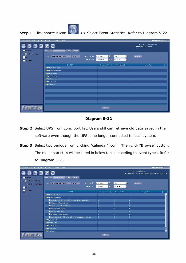
Step 1 Click shortcut icon >> Select Event Statistics. Refer to Diagram 522.
Diagram 522
Step 2 Select UPS from com. port list. Users still can retrieve old data saved in the
software even though the UPS is no longer connected to local system.
Step 3 Select two periods from clicking “calendar” icon. Then click “Browse” button.
The result statistics will be listed in below table according to event types. Refer
to Diagram 523.
47
Diagram 523
Step 4 Click “Print” button to print event statistics.
5.4.2.3. Data
In the window of Data, it shows UPS power data in figures during selected period time.
Software also offers print, save as, and delete functions.
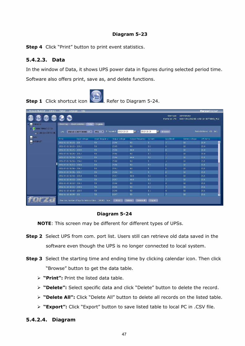
Step 1 Click shortcut icon . Refer to Diagram 524.
Diagram 524
NOTE: This screen may be different for different types of UPSs.
Step 2 Select UPS from com. port list. Users still can retrieve old data saved in the
software even though the UPS is no longer connected to local system.
Step 3 Select the starting time and ending time by clicking calendar icon. Then click
“Browse” button to get the data table.
Ø “Print”: Print the listed data table.
Ø “Delete”: Select specific data and click “Delete” button to delete the record.
Ø “Delete All”: Click “Delete All” button to delete all records on the listed table.
Ø “Export”: Click “Export” button to save listed table to local PC in .CSV file.
5.4.2.4. Diagram
48
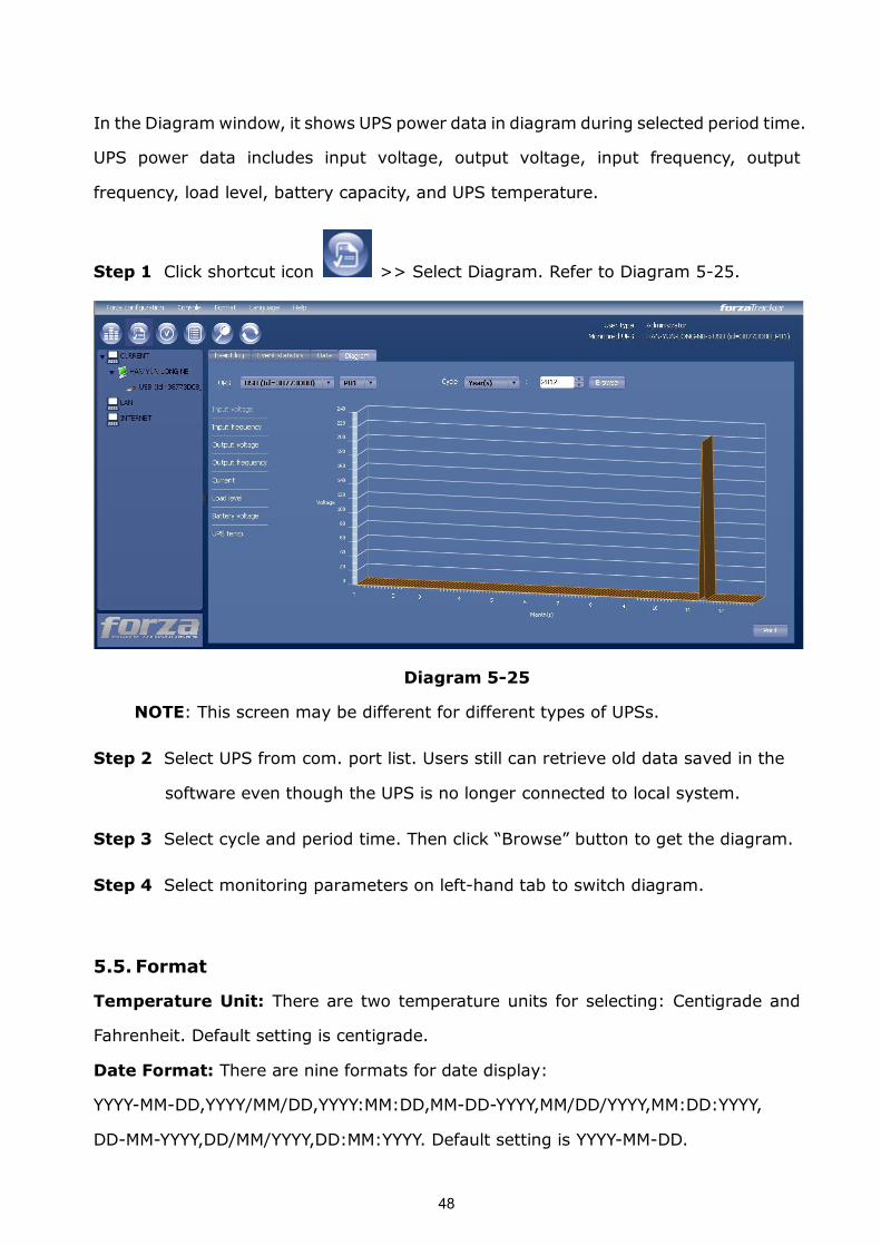
In the Diagram window, it shows UPS power data in diagram during selected period time.
UPS power data includes input voltage, output voltage, input frequency, output
frequency, load level, battery capacity, and UPS temperature.
Step 1 Click shortcut icon >> Select Diagram. Refer to Diagram 525.
Diagram 525
NOTE: This screen may be different for different types of UPSs.
Step 2 Select UPS from com. port list. Users still can retrieve old data saved in the
software even though the UPS is no longer connected to local system.
Step 3 Select cycle and period time. Then click “Browse” button to get the diagram.
Step 4 Select monitoring parameters on lefthand tab to switch diagram.
5.5. Format
Temperature Unit: There are two temperature units for selecting: Centigrade and
Fahrenheit. Default setting is centigrade.
Date Format: There are nine formats for date display:
YYYYMMDD,YYYY/MM/DD,YYYY:MM:DD,MMDDYYYY,MM/DD/YYYY,MM:DD:YYYY,
DDMMYYYY,DD/MM/YYYY,DD:MM:YYYY. Default setting is YYYYMMDD.
49
5.6. Language
Currently, software offers thirteen languages for selection:
√ Chinese(Simplified)
√ Chinese(Traditional)
√ English
√ German
√ Italian
√ Polish
√ Portuguese
√ Russian
√ Spanish
√ Ukrainian
√ French
√ Turkish
√ Czech
5.7.Help
l About: Click “Help” menu and select “About” item. It represents the copyright
information about software
l Help: Click “Help” menu and select “Online help” item. It will open the help
manual. Before operating software, please read manual carefully.

50
Appendix A: Glossary
l Local PC (system): The local PC (system) is physically connected to UPS with
communication port.
l Remote PCs (systems): The remote PCs (systems) are physically powered by
UPS without communication port connection.


![Windows 版GAMESS インストールマニュアル...Windows版GAMESSインストールマニュアル 2020/10/28 [64bit Windows の場合] [32bit Windows の場合] [64bit Windows](https://img.pdfslide.net/doc/110x75/607a0facf2b70c37922575be/windows-cgamess-ffffffff-windowscgamessffffffff.jpg)