Embed Size (px)
Citation preview
00
IDA PAPER P-2154N
MANAGING ENGINEERING DESIGN INFORMATION
R. E. Fulton, Georgia nstitute of TechnologyChou Pin-Yeh, Georgia Isitue of Technology
Karen J. Richter, IDA
DTICELECTEAPR 30 1990 October 1989SDED
Prepared forOffice of the Under Secretary of Defense for Acquisition
* (Research and Advanced Technology)
Supported byAir Force Human Resources Laboratory
Wright-Patterson AFB, Ohio
DISTht3U'!O? STATEME4 AkApprved foi pubL-ic releasel
Diam:.i=uo Unlimited
INSTITUTE FOR DEFENSE ANALYSES1801 N. Bemuegad Street, Alexmdria, Virginia 22311-1772
q0~ 04 27 01',odigo
DEFINrTIOSCSA publis he Urs foloin douet to sou th Ursultsb of t w&*
Itpa omI rutaiinuewi most cmaluIly considmaid produacts IDA publmaThe, iofly eodi moiult of major pajoctPs which (a) hae a direc' boin andeciion. aPocPH major paums (b) addos issue of sipifcant cocr to UthsEincutivs Umiche rn Co.ss andfo te public, or (c) adtheas Msust ti hoe sipidIcadonomi hn1Isplicaisns. IDA Repot m a l oed by outside paulo of espeni toaw ir No Tqat and misisto Uth ebl studied and UOW w e dby Ii.PlontI atIDA
GroupRoot PHr,-eoUn flmdlnp and .islts of IDA eaaNdo wouldag poWm a-me comosed of eior Individua aIwo*a' major hoous which -thoul* would
boeaftubect ofan IfAR p m & IDA GroupR hptemrolwad by Urs enior indivduals;oponobl for Uhe pr~c and gdom a selected by IDA to eamm 's thk lo quait
am imc I t liegbo. stdie d am eloed by UherI wrm of IDA.
Papoisn a ulm lafm e aid caduly cm pdroductsdu of IDA, add iss kdotm- s towi scope um lhoe PAd inipoe. IDA Paprswo Wusu to snot
that Off Met Udo hihsn~ apoctod of rIr popois hIn pIhooaljw
IDA Decainmatseantoed for lie ownlnsft rs sponseuso Un ayte (aStreeusubsonive work done In quick mafnstudio,(im)b toe pocen of ContWmm aid mo. v(in) to Mams emlable proanan and 1.m atlsisulin ofailos(Oltsacoviddds eoinfrnscowmofmn Imul m~n or~omomw I Imlotog In oaarnffl mmreyeidm tumldd. Ths aiw of IDA Documentos iled
The wouk rpoe I. intis documonowascooducied undercokc UA 903 89 C 00031far then DIpbrnnoI of Defense Ths puilian of tis IDA Paper dom adt IAdI
.enmfaa by the Depabmdn of Deftne, nor shoul is ctIt be coetidasN O hoc ~i of 0l 1oo-f0 of diW APnq.-
I Thi Pap ho bon reviewd by IDA t asmm. O It nmft the high ~lw of
Ap- for public raame, dkblibtihon unkanisd.
REPOT DOUMETATIN PAE jForm ApprovedREPORT ~~ ~ OUETTINPG MB No. 0704-0188
Publinith burden for"i collection of Wwinfo ion ie eatimed to aver. I howr per response. Incudktg the tim fat wevlowing Inotuctiono. sewcdItng w"~n dat soumne. gatheringadmaintaining ft da neede. en corrW&Vetkt and fiwigt collection of Infamln. Send onwsnt regering thes burdeekw e a~t a o hr & spect of thes collectioni oftfftoliIn.kniding suggeto fat edudngv t burden, to Ws"Vgon Heaftqiwits Seovices. Ofrectaae fat iroomalon Operations and Repoft, 1215 Jeflferson Davis HI~im. Suke 1204. ArlntonVA 22202-430. and to the Office di Manemro and BudgeL~ Paperwork Reduction Project (070"-188M. Washfit, DC 2DM0.
1. AGENCY USE ONLY (Leave blank) 2. REPORT DATE 3. REPORT TYPE AND DATES COVERED
I October 1989 Final 1/88 to 9/88
4. TITLE AND SUBTITLE 5. FUNDING NUMBERS
Managing Engineering Design Information C- MDA 903 89 C 0003
TA- T-DS-5536. AUTHOR(S)
Dr. Robert E. Fulton, Dr. Chou-pin Yeh, Dr. Karen J. Richter
7. PERFORMING ORGANIZATION NAME(S) AND ADDRESS(ES) S. PERFORMING ORGANIZATION
Institute for Defense Analyses REPORT NUMBER1801 N. Beauregard Street IDA Paper P-2154Alexandria, VA 22311
9. SPONSORING/MONITORING AGENCY NAME(S) AND ADDRESS(ES) 10. SPONSORINGMONrTORINGOUSD(A), R&AT AGENCY REPORT NUMBERRm. 301 089, PentagonWashington DC 20301 -3080
11. SUPPLEMENTARY NOTES
12a. DISTRIBUT1ONIAVAILABIUITY STATEMENT 12b. DISTRIBUTION CODE
Approved for public release, distribution unlimited.j
13. ABSTRACT (MaXIMum 200 words)
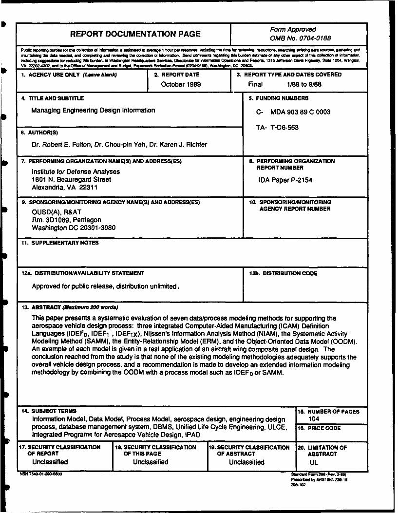
This paper presents a systematic evaluation of seven data/process modeling methods for supporting theaerospace vehicle design process: three integrated Computer-Aided Manufacturing (ICAM) DefinitionLanguages (IDEFo, IDEF 1 , IDEFIX), Nijssen's Information Analysis Method (NIAM), the Systematic ActivityModeling Method (SAMM), the Entity-Relationship Model (ERM), and the Object-Oriented Data Model (00DM).An example of each model is given in a test application of an aircraft wing composite panel design. Theconclusion reached from the study is that none of the existing modeling methodologies adequately supports theoverall vehicle design process, and a recommendation is made to develop an extended information modelingmethodology by combining the 00DM with a process model such as IDEF0 or SAMM.
14. SUBJECT TERMS 15. NUMBER OF PAGESInformation Model, Data Model, Process Model, aerospace design, engineering design 104process, database management system, DBMS, Unified Life Cycle Engineering, ULCE, 16. PRICE CODEIntegrated Programs for Aerosapce Vehicle Design, IPAD
17. SECURITY CLASSIFICATION I6L SECURITY CL ASSIFICATION 19. SECURITY CLASSIFICATION 20. LIMITATION OFOF REPORT IOF THIS PAGE OF ABSTRACT A13STRACT
Unclassified Unclassified Unclassified ULNSN 754001t280456W0Sedr Form 298 (Rev. 2-89)
Presabed by ANSI Sid. Z30- 18
IDA PAPER P-2154
MANAGING ENGINEERING DESIGN INFORMATION
R. E. Fulton, Georgia Institute of TechnologyChou Pin-Yeh, Georgia Institute of Technology
Karen J. Richter, IDA
October 1989 AcceL.,. For
NTIS c.z &UiTIC 1.4 F3
Ud j;h c,, ... L
ByDistr ibutio;By....
Avdailhb.ty Codes
a ISpcaAvi . dfo
IDAINSTiTUTE FOR DEFENSE ANALYSES
Contract MDA 903 89 C 0003Task T-D6-553
PREFACE
This report was prepared by the Institute for Defense Analyses (IDA) for the Office
of Engineering Technology, Deputy Under Secretary of Defense (Research and Advanced
Technology), and the Air Force Human Resources Laboratory, Logistics and HumanFactors Division, under Contract Number MDA 903 89 C 0003, Task Order T-D6-553.
"Applications of Systems Engineering Techniques to Development of a Unified Life Cycle
Engineering Environment."
The issuance of this report meets the specific tasks of surveying "techniques which
have been used in past studies of design processes," evaluating techniques, such as
"Object-Oriented Programming Techniques," and selecting "a design problem to be used as
a case study in examining the applicability of the techniques."
This paper was reviewed by Drs. Jeffrey H. Grotte and Frederick R. Riddell of
IDA.
iiiH
CONTENTS
PREFACE ............................................................................................ m
GLOSSARY ......................................................................................... ix
EXECUTIVE SUMMARY ..................................................................... ES-1
A. Introduction ......................................................................... ES-1
B. Overview ............................................................................ ES-2
C. Conclusions and Recommendations ............................................. ES-2
I. INTRODUCTION ..................................................................... 1
A. Background .......................................................................... 1
B. Overview .............................................................................. 2
II. AEROSPACE VEHICLE DESIGN PROCESS ......................................... 5A. Characteristics of Aerospace Vehicle Design Process .......................... 7B. Design Process Automation ........................................................ 9
C. Design Process Integration ........................................................ 10
1. Interface/Translation Approach ............................................. 112. Directory Data Base Approach ............................................... 133. Common Data Base Approach ............................................... 134. Executive-Centered Approach ............................................... 155. Case Studies ................................................................... 16
III. DATA BASE MANAGEMENT ISSUES IN THE DESIGN PROCESS .......... 23A. Conventional Data Base Management Systems .................................... 23
1. Hierarchical Data Model ..................................................... 232. Network Data Model ............................................................. 253. Relational Data Model ........................................................ 264. Model Comparison ............................................................... 27
B. Deficiencies of Conventional Data Base Models ............................... 28
1. Lack of Semantic Expressiveness .......................................... 302. Inability to Handle Engineering Heterogeneous Data Types ............. 30
v
3. Inability to Implement Dynamic Schema ....................................... 304. Limitations of Evolvability ................................................... 31
C. Design Data Base Management Systems ....................................... 32
IV. DESCRIPTION OF DATA/PROCESS MODELING METHODOLOGIES ....... 35
A. Illustration of Methodologies with Aerospace Design Application .............. 36
B. IDEF Methodologies ............................................................... 44
1. IDEF0 - Function Model ...................................................... 452. IDEF1/IDEFIx (Extended) - Information Model .......................... 463. IDEF2 -Dynamic Model ...................................................... 46
C. Systematic Activity Modeling Method ........................................... 47
D. Nijssen's Information Analysis Method ......................................... 48
E. Entity-Relationship Model ........................................................ 48
F. Object-Oriented Data Model ...................................................... 49
V. EVALUATION OF DATA/PROCESS MODELING TECHNOLOGIES .......... 51
A. Functional Requirements ............................................................. 51
B. Evaluation Matrices ............................................................... 52
C. Additional Evaluations ............................................................. 61
1. Assumptions ................................................................... 612. Skills Required for Use ...................................................... 613. Scope ............................................................................ 624. Graphical Representation and Software Support .......................... 62
VI. CONCLUSIONS AND RECOMMENDATIONS .................................. 63
REFERENCES ................................................................................. 65
DISTRIBUTION LIST ...................................................................... DL-1
vi
LIST OF FIGURES
1. Evolution of Aerospace Vehicle Design Process ..................................... 62. Design Network Example (PAD Project) ............................................. 8
O 3. Interface/Translation Approach for Design Process Integration ................... 12
4. Translator Interface Between Application Tools ....................................... 12
5. Example of Directory Data Base Approach ......................................... 14
6. Design Process Integ;ation--Common Data Base Approach ...................... 15
• 7. Design Process Integration--Executive-Centered Approach ....................... 16
8. Integrated Programs for Aerospace Vehicle Design Concepts .................... 17
9. Integrated Programs for Aerospace Vehicle Design Data BaseManagement Concept ................................................................... 19
10. Integrated Design Support System Components .................................... 20
11. System Architecture for Integrated Design Support ................................ 21
12. Examples of Conventional Data Base Management Systems ......................... 24
13. Solutions to Current Data Base Management System Deficiencies ............... 33
14. IDEFO Model for Aircraft Wing Composite Panel Design ......................... 37
15. IDEFlx Model for Aircraft Wing Composite Panel Design ....................... 38
16. IDEF2 Model for Aircraft Wing Composite Design Panel ......................... 39
17. Systematic Activity Modeling Method for Aircraft Wing CompositePanel D esign ............................................................................. 40
18. Nijssen's Information Analysis Method Model for AircraftWing Composite Panel Design ........................................................ 41
19. Entity-Relationship Model for Aircraft Wing Composite Panel Design ............. 42
20. Object-Oriented Data Model for Aircraft Wing Composite Panel Design .......... 43
* 21. IDEF M ethodologies ...................................................................... 4422. IDEFO Function Representation ...................................................... 45
vii
0mn m nnmmnnn lnl m n ~ l l lm l~ i a mm
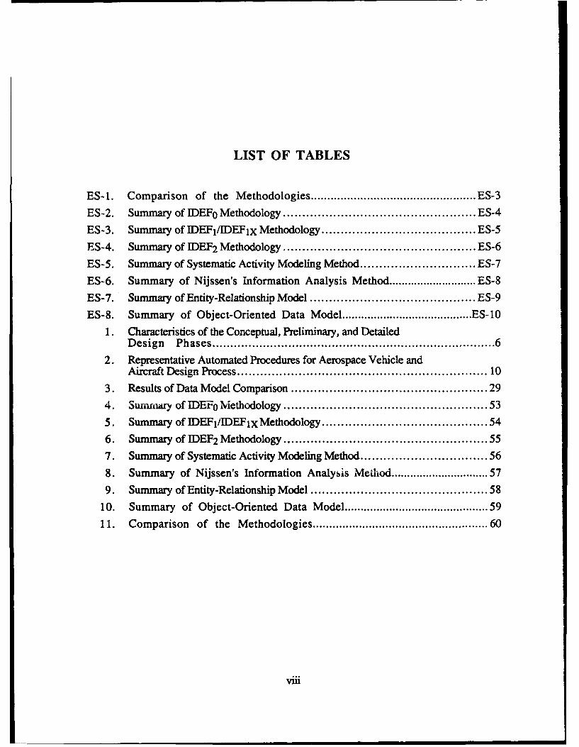
LIST OF TABLES
ES-1. Comparison of the Methodologies .................................................. ES-3
ES-2. Summary of IDEF0 Methodology .................................................. ES-4
ES-3. Summary of IDEF1/IDEF1x Methodology ........................................ ES-5
ES-4. Summary of IDEF2 Methodology .................................................. ES-6
ES-5. Summary of Systematic Activity Modeling Method .............................. ES-7
ES-6. Summary of Nijssen's Information Analysis Method ............................ ES-8
ES-7. Summary of Entity-Relationship Model ........................................... ES-9
ES-8. Summary of Object-Oriented Data Model ......................................... ES- 10
1. Characteristics of the Conceptual, Preliminary, and DetailedDesign Phases ......................................................................... 6
2. Representative Automated Procedures for Aerospace Vehicle andAircraft Design Process ............................................................. 10
3. Results of Data Model Comparison ................................................ 29
4. Summary of IDEF0 Methodology .................................................. 53
5. Summary of IDEF1/IDEF1x Methodology ........................................ 54
6. Summary of IDEF2 Methodology .................................................. 55
7. Summary of Systematic Activity Modeling Method .............................. 56
8. Summary of Nijssen's Information Analysis Method ........................... 579. Summary of Entity-Relationship Model ........................................... 58
10. Summary of Object-Oriented Data Model ......................................... 59
11. Comparison of the Methodologies ................................................ 60
viii
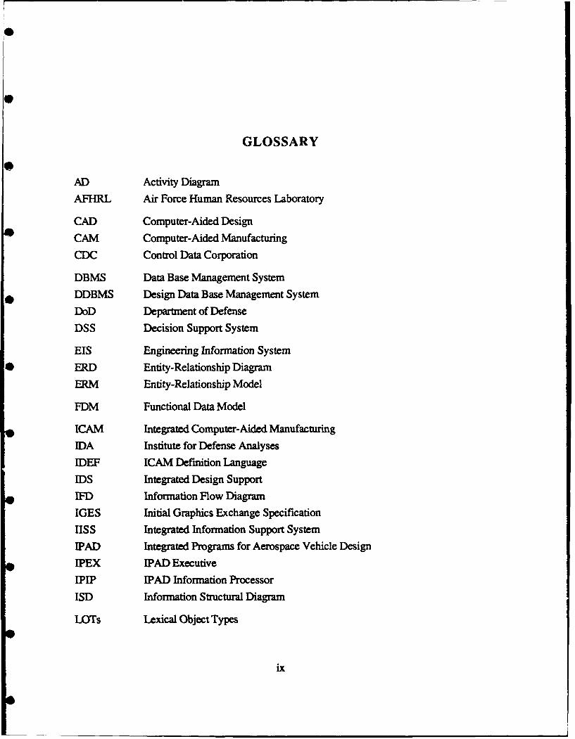
GLOSSARY
AD Activity Diagram
AFHRL Air Force Human Resources Laboratory
CAD Computer-Aided Design
CAM Computer-Aided Manufacturing
CDC Control Data Corporation
DBMS Data Base Management System
DDBMS Design Data Base Management System
DoD Department of Defense
DSS Decision Support System
EIS Engineering Information System
ERD Entity-Relationship Diagram
ERM Entity-Relationship Model
FDM Functional Data Model
ICAM Integrated Computer-Aided Manufacturing
IDA Institute for Defense Analyses
IDEF ICAM Definition Language
IDS Integrated Design Support
IFD Information Flow Diagram
IGES Initial Graphics Exchange Specification
IISS Integrated Information Support System
IPAD Integrated Programs for Aerospace Vehicle Design
IPEX IPAD Executive
IPIP IPAD Information Processor
ISD Information Structural Diagram
LOTs Lexical Object Types
ix
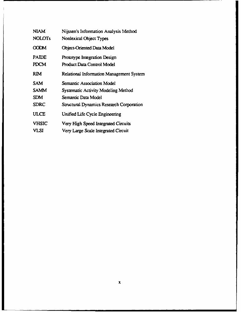
NIAM Nijssen's Information Analysis MethodNOLOTs Nonlexical Object Types
OODM Object-Oriented Data Model
PAIDE Prototype Integration DesignPDCM Product Data Control Model
RIM Relational Information Management System
SAM Semantic Association Model
SAMM Systematic Activity Modeling Method
SDM Semantic Data Model
SDRC Structural Dynamics Research Corporation
ULCE Unified Life Cycle Engineering
VHSIC Very High Speed Integrated Circuits
VLSI Very Large Scale Integrated Circuit
x
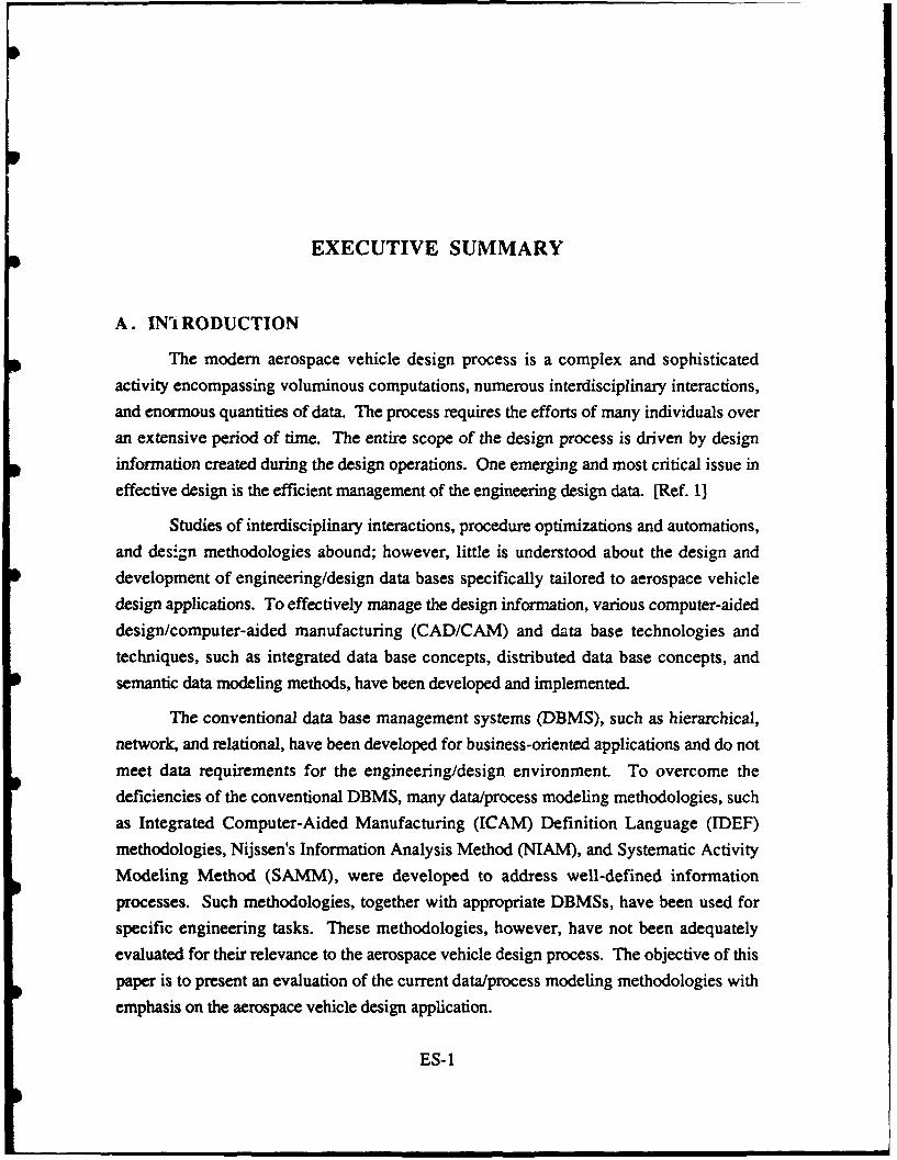
EXECUTIVE SUMMARY
A. IN't RODUCTION
The modern aerospace vehicle design process is a complex and sophisticated
activity encompassing voluminous computations, numerous interdisciplinary interactions,
and enormous quantities of data. The process requires the efforts of many individuals over
an extensive period of time. The entire scope of the design process is driven by design
information created during the design operations. One emerging and most critical issue in
effective design is the efficient management of the engineering design data. [Ref. 1]
Studies of interdisciplinary interactions, procedure optimizations and automations,and design methodologies abound; however, little is understood about the design and
development of engineering/design data bases specifically tailored to aerospace vehicle
design applications. To effectively manage the design information, various computer-aided
design/computer-aided manufacturing (CAD/CAM) and data base technologies and
techniques, such as integrated data base concepts, distributed data base concepts, andsemantic data modeling methods, have been developed and implemented.
The conventional data base management systems (DBMS), such as hierarchical,
network, and relational, have been developed for business-oriented applications and do not
meet data requirements for the engineering/design environment. To overcome the
deficiencies of the conventional DBMS, many data/process modeling methodologies, such
as Integrated Computer-Aided Manufacturing (ICAM) Definition Language (IDEF)
methodologies, Nijssen's Information Analysis Method (NIAM), and Systematic Activity
Modeling Method (SAMM), were developed to address well-defined information
processes. Such methodologies, together with appropriate DBMSs, have been used for
specific engineering tasks. These methodologies, however, have not been adequately
evaluated for their relevance to the aerospace vehicle design process. The objective of this
paper is to present an evaluation of the current data/process modeling methodologies with
emphasis on the aerospace vehicle design application.
ES-I
B. OVERVIEW
This paper presents a systematic evaluation of data/process modeling methods forsupporting the aerospace vehicle design process. One of the key issues for ensuring theeffective management of engineering information is the use of a DBMS specifically tailoredto engineering applications. Conventional DBMSs, developed for business- andadministrative-oriented environments, have been determined incapable of fulfiiling thefunctional requirements of engineering applications. Because of the deficiencies ofconventional DBMSs, many data/process modeling methodologies have been advocatedand implemented for engineering applications. Such methodologies were developed toserve the needs of particular engineering tasks and, prior to this study, had not beensufficiently evaluated for relevance to aerospace vehicle design. The IDA study coveredseven data/process modeling methodologies, which were evaluated by conducting a testapplication to an aircraft wing composite panel design. The following methodologies were
evaluated with the test application:
* Three Integrated Computer-Aided Manufacturing (ICAM) DefinitionLanguages (IDEF0, IDEFI1IDEFIx, IDEF2)
* SAMM
* NIAM
• Entity-Relationship Model (ERM)
* Object-Oriented Data Model (0ODM).
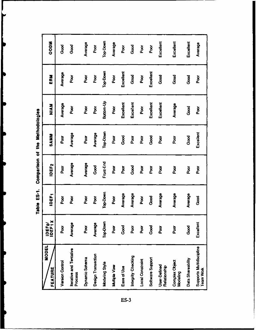
Table ES-1 is an evaluation matrix that presents the ratings of the various featuresof these methodologies. Summaries of the features, assets, and liabilities of eachprocess/data methodology are provided in Tables ES-2 through ES-8.
C. CONCLUSIONS AND RECOMMENDATIONS
The results of this evaluation indicate that none of the existing modelingmethodologies can adequately support the overall aerospace vehicle design process. TheOODM seems to possess many features required for the ideal design decision supportsystem for modeling the aerospace vehicle design process. Some of the features that theOODM does not possess are embodied in other methodologies. An extended informationmodeling methodology, formed by combining the OODM data model with a process model(such as IDEF0 or SAMM), may provide an ideal design decision support environment.
ES-2
0 0 . CL CL CL 0x x
a. . a. a0.00.a a* 0
z LCL C W W
.CC
0 0L CL CL
.C 4c )C X
0
o 2 0 0L 8
0-
. U. 08~> 0 C 0 .~0 O . 0 .
cha.C 0 0L 0 0 a
C C C C0 i
em- C
U. CL Cj w)mc o
ES-
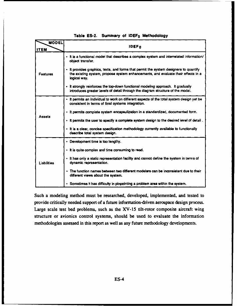
Table ES-2. Summary of IDEF0 Methodology
~IDEFo
" It is a functional model that describes a complex system and interrelated information/object transfer.
" It provides graphics, texts, and forms that permit the system designers to quantifyFeatures the existing system, propose system enhancements, and evaluate their effects in a
logical way.
" It strongly reinforces the top-down functional modeling approach. It graduallyintroduces greater levels of detail through the diagram structure of the model.
" It permits an individual to work on different aspects of the total system design yet beconsistent in terms of final systems integration.
" It permits complete system encapsulization in a standardized, documented form.Assets
" It permits the user to specify a complete system design to the desired level of detail.
" It is a clear, concise specification methodology currently available to functionallydescribe total system design.
" Development time is too lengthy.
" It is quite complex and time consuming to read.
" It has only a static representation facility and cannot define the system in terms ofLiabilities dynamic representation.
• The function names between two different modelers can be inconsistent due to theirdifferent views about the system.
I Sometimes it has difficulty in pinpointing a problem area within the system.
Such a modeling method must be researched, developed, implemented, and tested to
provide critically needed support of a future information-driven aerospace design process.
Large scale test bed problems, such as the XV-15 tilt-rotor composite aircraft wing
structure or avionics control systems, should be used to evaluate the information
methodologies assessed in this report as well as any future methodology developments.
ES-4
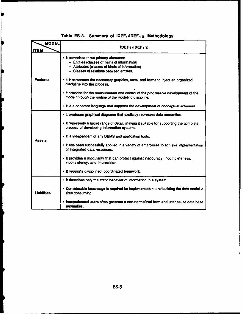
Table ES-3. Summary of IDEF 1/IDEF1 X MethodologyMOEL
IDEF 1 /IDEF1 XITEM__ _ _ _ _ _ _ _ _ _ _ _ _ _ _ _ _ _ _ _ _ _ _ _ _ _ _
- It comprises three primary elements:- Entities (classes of items of information)- Attributes (classes of kinds of information)- Classes of relations between entities.
Features - It incorporates the necessary graphics, texts, and forms to inject an organizeddiscipline into the process.
- It provides for the measurement and control of the progressive development of the
model through the routine of the modeling discipline.
- It is a coherent language that supports the development of conceptual schemas.
- It produces graphical diagrams that explicitly represent data semantics.
- It represents a broad range of detail, making it suitable for supporting the completeprocess of developing information systems.
- t is independent of any DBMS and application tools.Assets
- It has been successfully applied in a variety of enterprises to achieve implementationof integrated data resources.
- It provides a modularity that can protect against inaccuracy, incompleteness,inconsistency, and imprecision.
- It supports disciplined, coordinated teamwork.
- It describes only the static behavior of information in a system.
- Considerable knowledge is required for implementation, and building the data model isLiabilities time consuming.
- Inexperienced users often generate a non-normalized form and later cause data baseanomalies.
ES-5
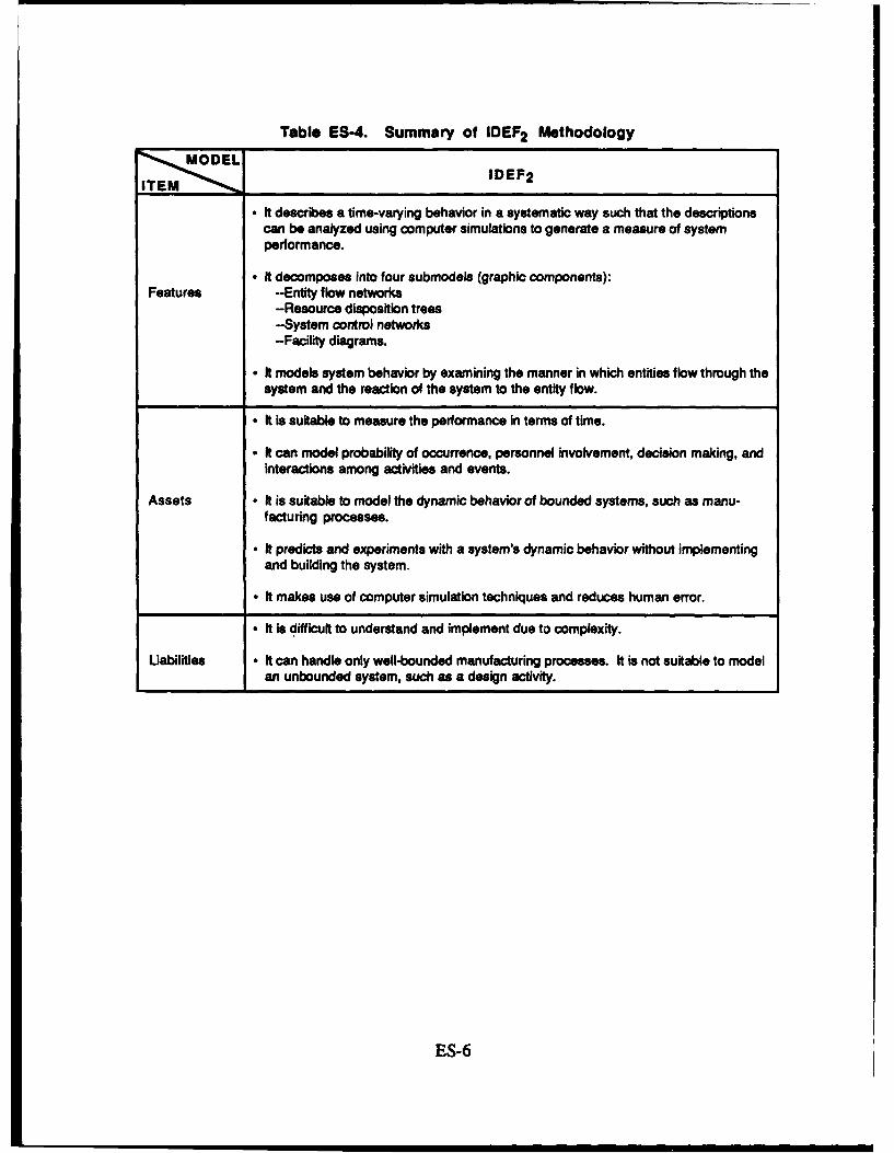
Table ES-4. Summary of IDEF 2 Methodology
MODELiTEM ' IDEF2
- It describes a time-varying behavior in a systematic way such that the descriptionscan be analyzed using computer simulations to generate a measure of systemperformance.
- It decomposes into four submodels (graphic components):Features --Entity flow networks
-Resource disposition trees-System control networks-Facility diagrams.
* It models system behavior by examining the manner in which entities flow through thesystem and the reaction of the system to the entity flow.
- It is suitable to measure the performance In terms of time.
- It can model probability of occurrence, personnel involvement, decision making, andinteractions among activities and events.
Assets - It is suitable to model the dynamic behavior of bounded systems, such as manu-facturing processes.
- It predicts and experiments with a system's dynamic behavior without implementing
and building the system.
- It makes use of computer simulation techniques and reduces human error.
• It is difficult to understand and implement due to complexity.
Uabilities • It can handle only well-bounded manufacturing processes. It is not suitable to modelan unbounded system, such as a design activity.
ES-6
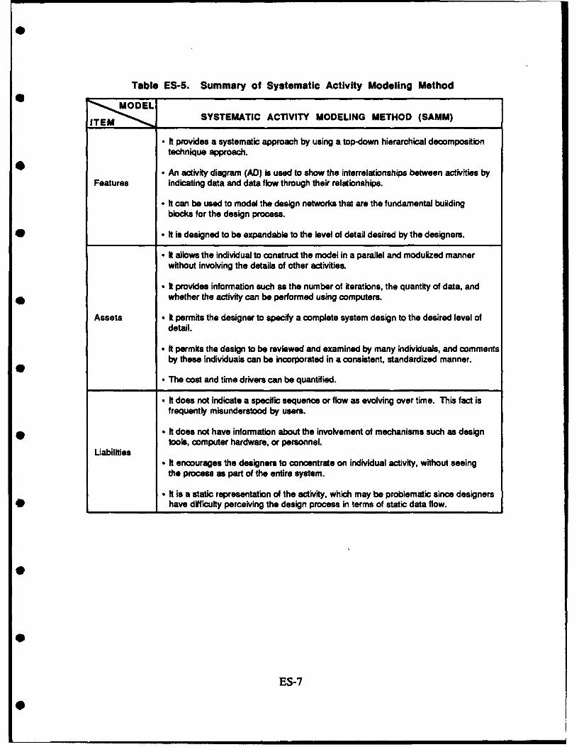
Table ES-5. Summary of Systematic Activity Modeling Method
MOEL;
TSYSTEMATIC ACTIVITY MODELING METHOD (SAMM)
- It provides a systematic approach by using a top-down hierarchical decompositiontechnique approach.
- An activity diagram (AD) is used to show the interrelationships between activities byFeatures indicating data and data flow through their relationships.
- It can be used to model the design networks that are the fundamental buildingblocks for the design process.
* • It is designed to be expandable to the level of detail desired by the designers.
- It allows the individual to construct the model in a parallel and modulized mannerwithout involving the details of other activities.
- It provides information such as the number of iterations, the quantity of data, andwhether the activity can be performed using computers.
Assets • It permits the designer to specify a complete system design to the desired level ofdetail.
* It permits the design to be reviewed and examined by many individuals, and commentsby these individuals can be incorporated in a consistent, standardized manner.
- The cost and time drivers can be quantified.
• It does not indicate a specific sequence or flow as evolving over time. This fact isfrequently misunderstood by users.
* • It does not have information about the involvement of mechanisms such as designtools, computer hardware, or personnel.
Liabilities* It encourages the designers to concentrate on individual activity, without seeing
the process as part of the entire system.
- It is a static representation of the activity, which may be problematic since designers* have difficulty perceiving the design process in terms of static data flow.
ES-7

Table ES-6. Summary of Niljssen's Information Analysis Method
TNIJSSEN'S INFORMATION ANALYSIS METHOD (NIAM)
* It is a binary-relationship conceptual data model.
- It is a means of capturing information requirements in user-understandable terms,modeling and analyzing the requirements in a formal information model, and trans-lating conceptual information requirements into implementable specifications.
Features- Relationships between object types are derived through entity-joins rather than
symbol-joins.
* It is a rule-based modeling technique that can be easily mapped into the data baseschema and data specifications up to the third normalized form using functionaldecomposition and an information structural diagram (ISD).
- It is easy for non-technical people to use because schemata defined in terms of themodel can be read almost like a natural language.
• It supports a variety of constraints that are not available in the conventional datamodels.
Assets • Users have complete freedom to override the form suggested by NIAM and dilutethe high level of normality.
- It uses a semantic binary association between objects in generalized object classes;therefore, it is capable of modeling any environment.
- Information can be easily automated by the computer algorithms to transform theconceptual schema into a logical data base schema.
- It is not considered a *realr data model since it does not provide a nice and well-defined set of data manipulation operations.
Liabilities • It does not provide capacities for view definition.
- It is inefficient even with simple queries, requiring a greater numbet of joint operationsthan conventional data models.
ES-8
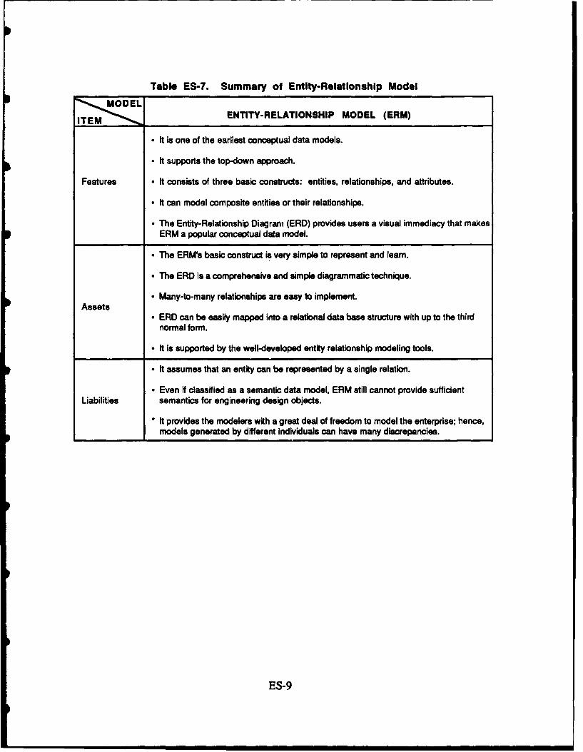
Table ES-7. Summary of Entity-Relationship Model
TENTITY-RELATIONSHIP MODEL (ERM)
- It is one of the earliest conceptual data models.
- It supports the top-down approach.
Features - It consists of three basic constructs: entities, relationships, and attributes.
- It can model composite entities or their relationships.
- The Entity-Relationship Diagram (ERD) provides users a visual immediacy that makesERM a popular conceptual data model.
- The ERM's basic construct is very simple to represent and learn.
* The ERD is a comprehensive and simple diagrammatic technique.
A Many-to-many relationships are easy to implement.Assets
- ERD can be easily mapped into a relational data base structure with up to the thirdnormal form.
- It is supported by the well-developed entity relationship modeling tools.
* ft assumes that an entity can be represented by a single relation.
• Even if classified as a semantic data model, ERM still cannot provide sufficientLiabilities semantics for engineering design objects.
* It provides the modelers with a great deal of freedom to model the enterprise; hence,models generated by different individuals can have many discrepancies.
ES-9
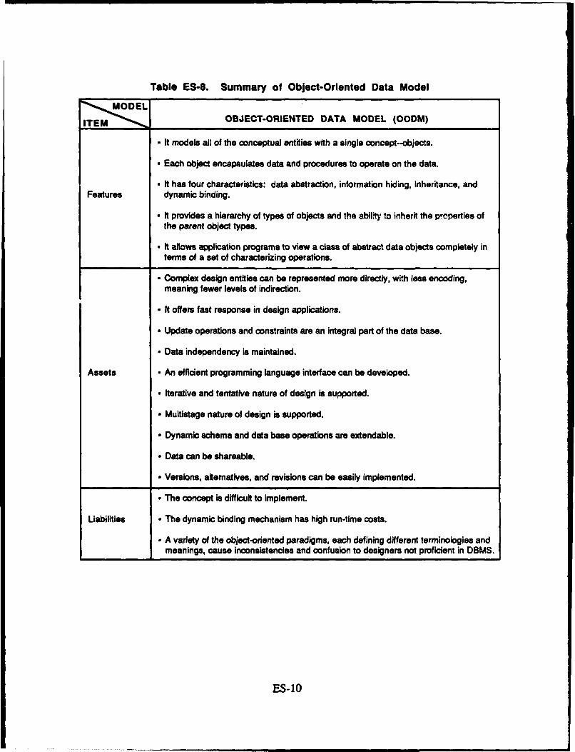
Table ES-8. Summary of Object-Oriented Data ModelODEL
ITEM "OBJECT-ORIENTED DATA MODEL (OODM)
" It models all of the conceptual entities with a single concept--objects.
" Each object encapsulates data and procedures to operate on the data.
* It has four characteristics: data abstraction, information hiding, inheritance, andFeatures dynamic binding.
" It provides a hierarchy of types of objects and the abilit, to inherit the properties ofthe parent object types.
" It allows application programs to view a class of abstract data objects completely interms of a set of characterizing operations.
* Complex design entities can be represented more directly, with less encoding,meaning fewer levels of indirection.
- It offers fast response in design applications.
* Update operations and constraints are an integral part of the data base.
* Data independency is maintained.
Assets - An efficient programming language interface can be developed.
- Iterative and tentative nature of design is supported.
- Multistage nature of design is supported.
* Dynamic schema and data base operations are extendable.
• Data can be shareable.
- Versions, alternatives, and revisions can be easily implemented.
- The concept is difficult to implement
Liabilities - The dynamic binding mechanism has high run-time costs.
- A variety of the object-oriented paradigms, each defining different terminologies andmeanings, cause inconsistencies and confusion to designers not proficient in DBMS.
ES-1O
I. INTRODUCTION
The modem aerospace vehicle design process is a complex and sophisticatedactivity encompassing voluminous computations, a lengthy time span, numerous
interdisciplinary interactions, and enormous quantities of data. An emerging and mostcritical issue in effective design is the efficient management of design data. [Ref. 1]
Studies of interdisciplinary interactions, procedure optimizations and automations,and design methodologies abound; however, little is understood about the design and
development of engineering/design data bases tailored to aerospace vehicle design
applications. The conventional data base management systems (DBMS), such as
hierarchical, network, and relational, were developed with business-oriented applications in
mind and do not meet data requirements for the engineering/design environment. Toovercome the deficiencies of the conventional DBMS, many data/process modeling
methodologies, such as Integrated Computer-Aided Manufacturing (ICAM) Definition
Language (IDEF) methodologies, Nijssen's Information Analysis Method (NIAM), and
Systematic Activity Modeling Method (SAMM), were developed to address well-defined
information processes. Such methodologies, together with appropriate DBMSs, have be-n
used for specific engineering tasks. These methodologies, however, have not been
adequately evaluated for their relevance to the aerospace vehicle design process. The
objective of this paper is to present a systematic and complete evaluation of the currentdata/process modeling methodologies, with an emphasis on an aerospace vehicle design
application.
A. BACKGROUND
In FY1987, the Institute for Defense Analyses (IDA) conducted two studies for theAir Force's Unified Life Cycle Engineering (ULCE) program. These studies were
supported by the Air Force Human Resources Laboratory (AFHRL), Logistics and Human
Factors Division, Wright-Patterson Air Force Base in Ohio. One study was aninvestigation of the decision support requirements for an ULCE environment. To identify
research priorities for decision support in ULCE, a working group composed of members
of academia, industry, and government was convened. The group identified the following
actions as necessary for implementation of a decision support system (DSS) in ULCE:
Engineering needs for data base design must be expected to differ fromthose that spring from DSS structure. It is important to identify thoseaspects of DSS data base design that lead to competition with, contradictionof, or require extension to data bases that are engineering dictated. Theadvantages and disadvantages of advanced data base technology, such asobject-oriented data bases versus the relational data base structure morecommonly used in business DSS, must be examined. [Ref. 2]
The second IDA study focused on the architecture and iuegration requirements for
an ULCE design environment. A recommendation resulting from this study was that"research should be conducted in the areas of data base management systems, data
modeling, and applications of object-oriented techniques to design systems." In particular,
An extensible representation of design engineering data, which incorporatesfeatures of the network, hierarchical, relational, and object-oriented datamodel types, is needed for ULCE. This data model will provide afoundation for the integration of the ULCE design tools and theknowledge/data base management systems. (Ref. 3]
To address some of the problems posed in these studies, the AFIRL, Logistics and
Human Factors Division, funded additional IDA research during FY1988. IDA enlisted the
expertise of Dr. Robert Fulton, Professor of Mechanical Engineering at Georgia Institute of
Technology, and his graduate student, Chou-pin Yeh. Dr. Fulton was Program Manager
of the Integrated Programs for Aerospace Vehicle Design (IPAD) at NASA-Langley
Research Center from 1972 to 1984. IPAD was one of the most extensive investigations of
the aerospace design process and resulted in comprehensive models of that process. Chou-
pin Yeh also has design experience and is working with Dr. Fulton to identify the relevance
of information modeling methods to engineering design tasks. This report is the result of
their work, performed for IDA, in identifying and evaluating the data and process modeling
methods for aerospace design.
B. OVERVIEW
This paper begins with a description of the aerospace vehicle design process. The
characteristics of the design process are identified in Section II-A. The automation and
integration of the design process are addressed in H-B and 11-C, respectively. Chapter IIIcontains a description of the conventional data base models, their defects, and why a design
2

data base management system is needed to effectively manage design information. The* current data/process modeling methodologies are described in Chapter IV and evaluated in
Chapter V. Conclusions and recommendations for further research are provided inChapter VI, including ideas for an extended data/process modeling methodology that meetsthe functional requirements for an aerospace vehicle design environment.
0
3
3
0
I. AEROSPACE VEHICLE DESIGN PROCESS
Design is the synthesis of related activities, including the design of products,
processes, manufacturing systems, software, and organizations [Ref. 4]. Engineering
design is the result of rational decision making and has been defined as a mapping processthrough which needs are translated into functional requirements and then into a product.
Engineering design can be viewed as a process of decomposing and refining interrelated
representations of functions, structures, and behaviors of the end product and its
components. The design process describes the gathering, handling, and creative
organizing of information relevant to the design practices [Ref. 5].
The modern aerospace vehicle is a complex integration of sophisticated technical
systems manufactured to the exact standards required for safety, economy, and mission
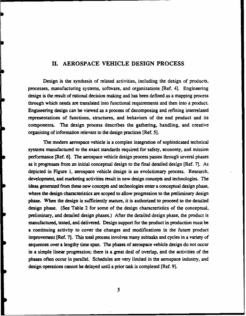
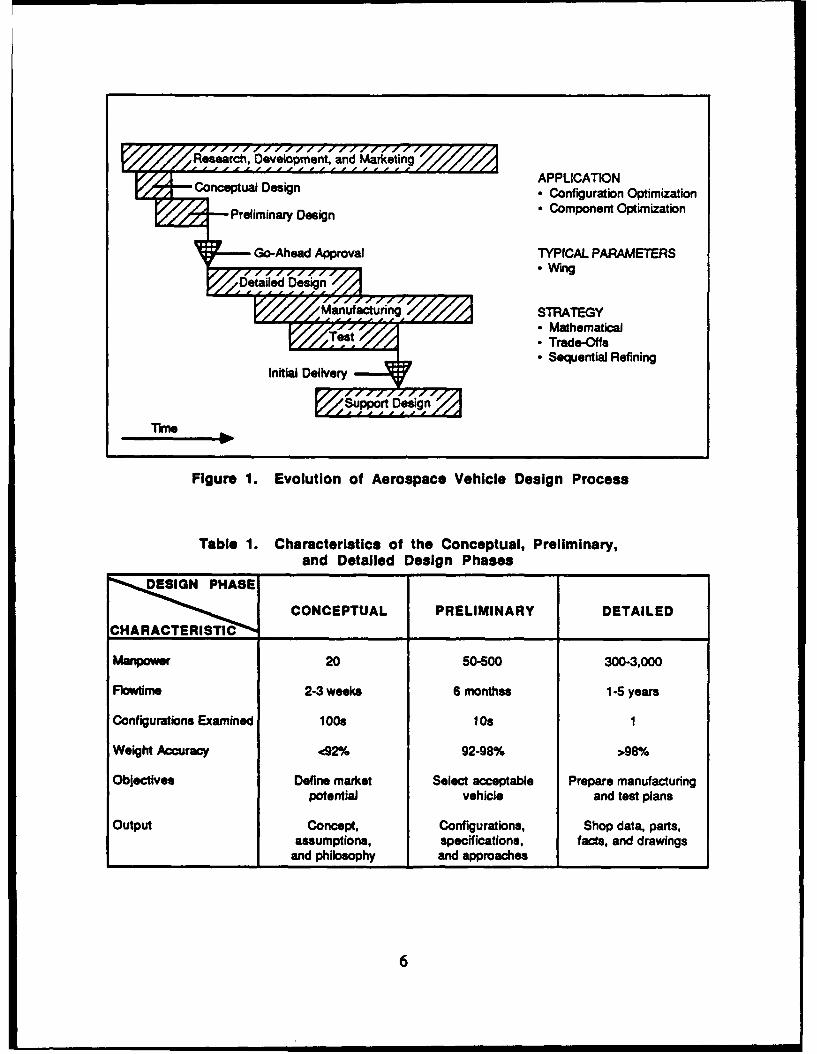
performance [Ref. 6]. The aerospace vehicle design process passes through several phases
as it progresses from an initial conceptual design to the final detailed design [Ref. 7]. As
depicted in Figure 1, aerospace vehicle design is an evolutionary process. Research,
development, and marketing activities result in new design concepts and technologies. The
ideas generated from these new concepts and technologies enter a conceptual design phase,
where the design characteristics are scoped to allow progression to the preliminary design
phase. When the design is sufficiently mature, it is authorized to proceed to the detailed
design phase. (See Table 2 for some of the design characteristics of the conceptual,
preliminary, and detailed design phases.) After the detailed design phase, the product is
manufactured, tested, and delivered. Design support for the product in production must be
a continuing activity to cover the changes and modifications in the future productimprovement [Ref. 7]. This total process involves many subtasks and cycles in a variety of
sequences over a lengthy time span. The phases of aerospace vehicle design do not occur
in a simple linear progression; there is a great deal of overlap, and the activities of the
phases often occur in parallel. Schedules are very limited in the aerospace industry, and
design operations cannot be delayed until a prior task is completed [Ref. 9].
5
ReacDevelopment, and 'Marketin~g
nceptal DsignAPPLICATION
Con eptu a y Design* Confguton Optimization
Priinni :eig Co mpgu tonen Optimization
Go-Ahead Approval TYPICAL PARAMETERS
V~l ZZf aWing
V,,//Manufacturing STRATEGY*Mathematical*Trade-Offs*Sequential Refining
Tme
Figure 1. Evolution of Aerospace Vehicle Design Process
Table 1. Characteristics of the Conceptual, Preliminary,and Detailed Design Phases
CONCEPTUAL PRELIMINARY DETAILED
Mapwr20 so-500 300-3,000
Flowtime 2-3 weeks 6 monthss 1 -5 years
Configurations Examined 1008 10s 1
Weight Accuracy <92% 92-98% >98%/
Objectives Define market Select acceptable Prepare manufacturingpotential vehicle and test plans
output Concept, Configurations, Shop data, parts,assumptions, specifications, facts, and drawings
and philosophy and approaches ________
6

Basically, design is an exploratory process during which abstraction is employed to
simplify the design process. The process of abstraction results in a design hierarchy. In
aerospace vehicle design, a design network is a useful representation of the design
hierarchy, to identify and describe the logical information flow for any level of the design
process [Ref. 9] (see Figure 2).
A. CHARACTERISTICS OF AEROSPACE VEHICLE DESIGN PROCESS
Aerospace vehicle design is an unusual system process because it has special
features not found in other complex processes. By carefully examining and studying the
design process, the characteristics of aerospace vehicle design can be identified as follows:
Complex and Sophisticated. The modern aerospace vehicle is an integration ofcomplex geometry, advanced technology, intricate manufacturing processes,and sophisticated business strategies. The structure of an aerospace vehiclecontains a vast number of parts and details. For instance, the airframe of awide-body jet transport contains more than one million parts [Ref. 7].
0 Time Conswning and Expensive. Aerospace vehicle design involves hundredsof individuals, and completing the entire design process can take several years.As a result, the cost of design can be enormous [Refs. 7, 9].
* Requiring Many Supporting Design Tools. It requires numerous design toolsand aids, such as analysis, optimization, and geometrical modeling packages tosupport and facilitate the design process.
Creating Large Quantities of Data. Due to the considerable size and complexityof an aerospace vehicle, its design creates large quantities of data. The datainclude design information (such as functional or graphical descriptions ofdesign objects), information to validate designs (test cases and simulationresults), and information that documents the design process [Ref. 10].
* Dynaimc. Aerospace vehicle design is a highly creative, newly developed, andinformal technology rather than a stereotyped, standardized, and well-established process. Hence, the design definition often changes to rectifydesign difficulties, accommodate new technology, and incorporate modifieddesign criteria, making the aerospace vehicle design process a very dynamicenvironment.Iterative. The design process is not a logically progressive path. Instead ofiterating the same algorithm time and time again, any one solution may requirea number of iterations at various stages of the process until the design criteriaand specifications are met [Ref. 11]. Resizing the configuration of an aircraft
7

Shwgsucjr StzsS an
CabAiaw wing boy Imng
mid kwtitbiuon
-PW SIWC Lafif(Fonmusm t
sine Gricuam for
F~~gure 2. Des ~ ~1gn Neto W Exampe PDPoet
8*
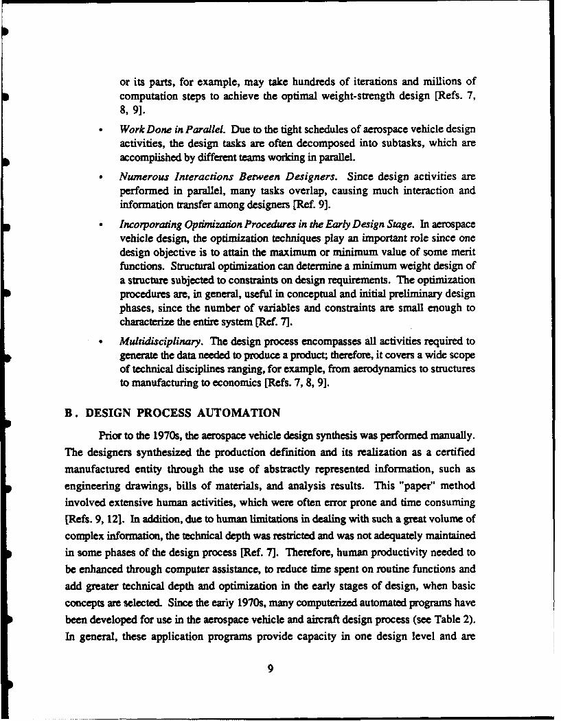
or its parts, for example, may take hundreds of iterations and millions ofcomputation steps to achieve the optimal weight-strength design [Refs. 7,8, 9].
Work Done in Parallel. Due to the tight schedules of aerospace vehicle designactivities, the design tasks are often decomposed into subtasks, which areaccomplished by different teams working in parallel.
* Numerous Interactions Between Designers. Since design activities areperformed in parallel, many tasks overlap, causing much interaction andinformation transfer among designers [Ref. 9].
* Incorporating Optimization Procedures in the Early Design Stage. In aerospacevehicle design, the optimization techniques play an important role since onedesign objective is to attain the maximum or minimum value of some meritfunctions. Structural optimization can determine a minimum weight design ofa structure subjected to constraints on design requirements. The optimizationprocedures are, in general, useful in conceptual and initial preliminary designphases, since the number of variables and constraints are small enough tocharacterize the entire system [Ref. 7].
* Multidisciplinary. The design process encompasses all activities required togenerate the data needed to produce a product; therefore, it covers a wide scopeof technical disciplines ranging, for example, from aerodynamics to structuresto manufacturing to economics [Refs. 7, 8, 9].
B. DESIGN PROCESS AUTOMATION
Prior to the 1970s, the aerospace vehicle design synthesis was performed manually.
The designers synthesized the production definition and its realization as a certified
manufactured entity through the use of abstractly represented information, such as
engineering drawings, bills of materials, and analysis results. This "paper" method
involved extensive human activities, which were often error prone and time consuming
[Refs. 9, 12]. In addition, due to human limitations in dealing with such a great volume of
complex information, the technical depth was restricted and was not adequately maintainedin some phases of the design process [Ref. 7]. Therefore, human productivity needed to
be enhanced through computer assistance, to reduce time spent on routine functions and
add greater technical depth and optimization in the early stages of design, when basicconcepts are selected. Since the eariy 1970s, many computerized automated programs have
been developed for use in the aerospace vehicle and aircraft design process (see Table 2).In general, these application programs provide capacity in one design level and are
9
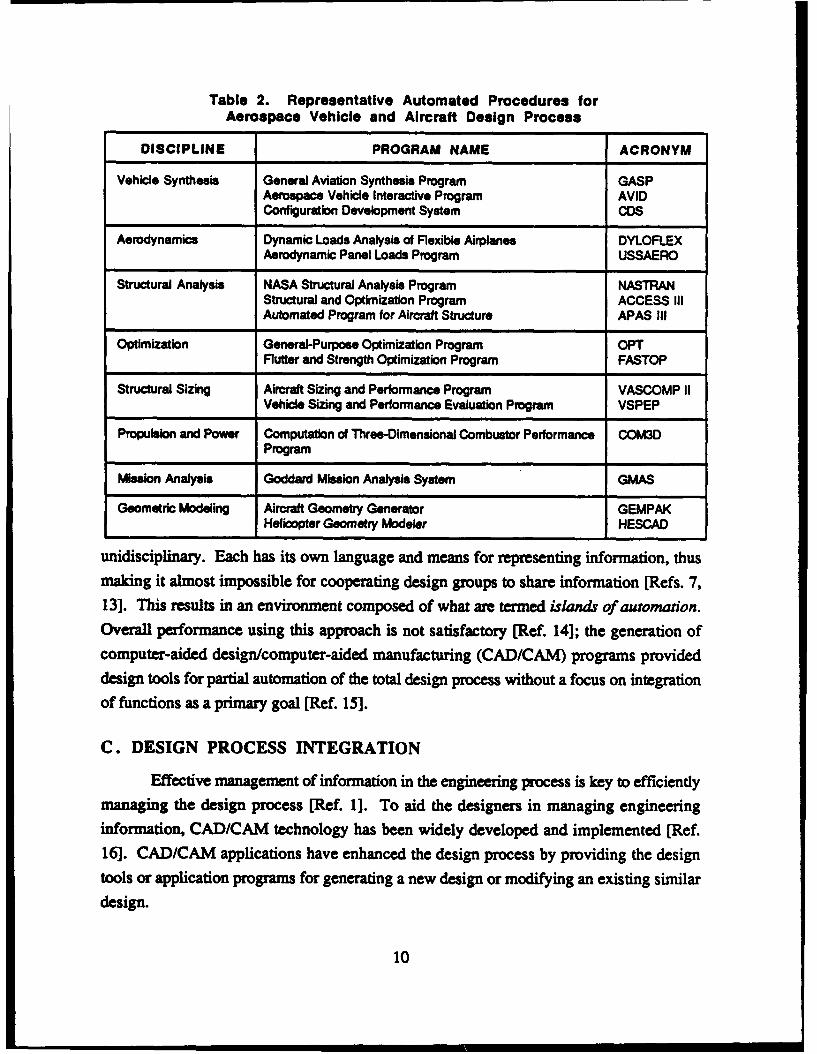
Table 2. Representative Automated Procedures for
Aerospace Vehicle and Aircraft Design Process
DISCIPLINE PROGRAM NAME ACRONYM
Vehicle Synthesis General Aviation Synthesis Program GASPAerospace Vehicle Interactive Program AVIDConfiguration Development System COS
Aerodynamics Dynamic Loads Analysis of Flexible Airplanes DYLOFLEXAerodynamic Panel Loads Program USSAERO
Structural Analysis NASA Structural Analysis Program NASTRANStructural and Optimization Program ACCESS IIIAutomated Program for Aircraft Structure APAS III
Optimization General-Purpose Optimization Program OPTFlutter and Strength Optimization Program FASTOP
Structural Sizing Aircraft Sizing and Performance Program VASCOMP IIVehicle Sizing and Performance Evaluation Program VSPEP
Propulsion and Power Computation of Three-Dimensional Combustor Performance COM3DProgram
Mission Analysis Goddard Mission Analysis System GMAS
Geometric Modeling Aircraft Geometry Generator GEMPAKHelicopter Geometry Modeler HESCAD
unidisciplinary. Each has its own language and means for representing information, thusmaking it almost impossible for cooperating design groups to share information [Refs. 7,13]. This results in an environment composed of what are termed islands of automaton.Overall performance using this approach is not satisfactory [Ref. 14]; the generation ofcomputer-aided design/computer-aided manufacturing (CAD/CAM) programs provideddesign tools for partial automation of the total design process without a focus on integrationof functions as a primary goal [Ref. 15].
C. DESIGN PROCESS INTEGRATION
Effective management of information in the engineering process is key to efficientlymanaging the design process [Ref. 1]. To aid the designers in managing engineeringinformation, CAD/CAM technology has been widely developed and implemented [Ref.16]. CAD/CAM applications have enhanced the design process by providing the designtools or application programs for generating a new design or modifying an existing similar
design.
10
When CAD/CAM systems were first introduced, each operated independently, and
design data were prepared manually as input to the individual application programs
containing their own local data bases. Due to these islands of automation, enormous
overhead costs were incurred in managing design data [Ref. 13]. To consistently managedesign and analysis of engineering objects, data in engineering applications must be
processed in an integrated manner. An integrated CAD/CAM system provides for the
greatest interaction and flexibility in program utilization and the highest potential for
automation without losing insight and innovation. In addition, an integrated system canprovide for an intelligent dialogue between the designer and the computer so that they may
augment and complement each other in managing and accomplishing the design task.
There are four basic approaches for integrating CAD/CAM systems, which are
discussed in the following sections.
1. Interface/Translation Approach
The first approach consists of constructing an interfacing network among variousCAD/CAM systems so that the output of the upstream program automatically becomes the
input of the downstream program (Ref. 16] (Figure 3). This approach, however, creates
several problems:
It requires many translators, one between every two CAD/CAM systems, tohandle the translations (input/output data conversion) and the communicationtasks. If there are N different CAD/CAM systems, then N*(N-1)/2 translatorsare required (Figure 4) [Refs. 13, 17].
If one system or tool changes its status, all other translators related to thissystem must adjust their status accordingly. This makes the entire integratedCAD/CAM system very rigid and difficult to modify and maintain, especiallywhen there are many systems [Ref. 18].
Translators operate in one direction only and do not provide the degree ofinteactivity required for normal decision making.
0 Translations and interfaces are simply too time-consuming and costly toexecute and maintain for these purposes.
To streamline the translation and interface, several data exchange standards such as theInitial Graphics Fxchange Specification (IGES) have been developed and do somewhat
improve this approach; however, difficulties in flexibility and interactivity still exist.
11

TOOL TOOL TOL
FILEFILEFILE
Figure 3. Interface/Translation Approach for Design Process Integration
Figure 4. Translator Interface Between Application Tools
12
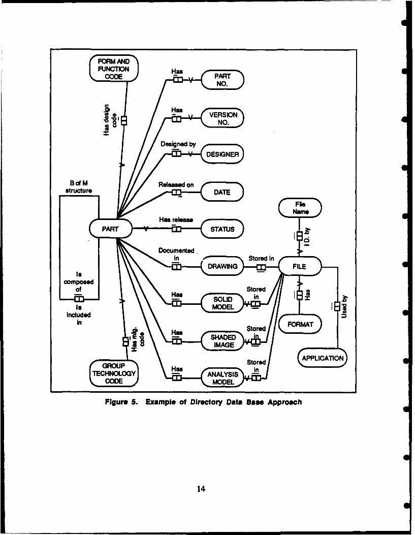
2. Directory Data Base Approach
The directory approach uses a data base with the traditional librarian functions to
track design and manufacturing information, in computer files or on paper [Ref. 17](Figure 5). The data base structure maps engineering document names into file names and
locations and allows the design engineers to ask for design documents without having to
recall file names. This approach is easy to implement because neither the file formats nor
the applications are changed from their original form. In addition, by providing the
necessary support procedures, most functions are transparent to the users. However, this
approach does have its drawbacks:
* It provides minimal assistance to the designers since they must still specify thedocument type and the part desired.
" The computer is used to manage engineering data files rather than individualfields and records as it usually does in data base management systems. Fileaccess is sequential, whereas records are randomly accessed--data is accessedmore quickly by the latter method.
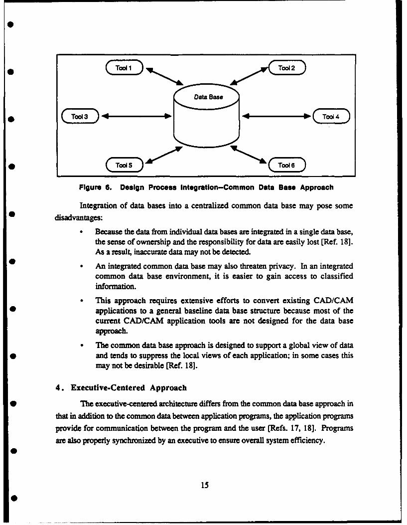
3. Common Data Base Approach
The third approach to integrating CAD/CAM systems eliminates the limitations ofthe first two, by achieving integration at the data base level--by connecting all systems to acommon data base. From the user's view, the communication or interface between anytwo systems always occurs through the common data base [Refs. 13, 17, 19] (Figure 6);however, the common data base can be centralized or distributed among various locationsthroughout the systems. The common data base approach best provides the full benefits of
data base management technology. The common data base managed by a powerful
commercial DBMS provides the enterprise with a flexible design/manufacturingenvironment because the data base is easily extended to support additional applicationswhen needed. These commercial DBMSs, called conventional DBMSs, embody manycustomized features for easier application development, simplified application maintenance,improved data shareability, and redundancy.
13
FORMFFU
Has PARTNO.
HasVEROIDONfNO.
Designed by.....................
4
8dM Released onstructure DATE
FileName
Has releasePART STATUS
Documentedin Stored n
DRAWING FILEIs
composedOf Has Stored
L--ff3--j LID In
Is ELincluded
In H Stored FORMAT
SHADED inIMAGE
GROUP Stored APPLICAITnll N
TECHNOLOGY Has ANALYSIS in
CODE MODEL
Figure 5. Example of Directory Data Base Approach
4
14
41
Data Bass
0 * q4 ED
Figure 6. Design Process Integration-Common Data Base Approach
Integration of data bases into a centralized common data base may pose some
0 disadvantages:
Because the data from individual data bases are integrated in a single data base,the sense of ownership and the responsibility for data are easily lost [Ref. 18].As a result, inaccurate data may not be detected.
* An integrated common data base may also threaten privacy. In an integratedcommon data base environment, it is easier to gain access to classifiedinformation.
This approach requires extensive efforts to convert existing CAD/CAM* applications to a general baseline data base structure because most of the
current CAD/CAM application tools are not designed for the data baseapproach.
The common data base approach is designed to support a global view of data* and tends to suppress the local views of each application; in some cases this
may not be desirable [Ref. 18].
4. Executive-Centered Approach
* The executive-centered architecture differs from the common data base approach in
that in addition to the common data between application programs, the application programs
provide for communication between the program and the user [Refs. 17, 18]. Programs
are also properly synchronized by an executive to ensure overall system efficiency.
15
0
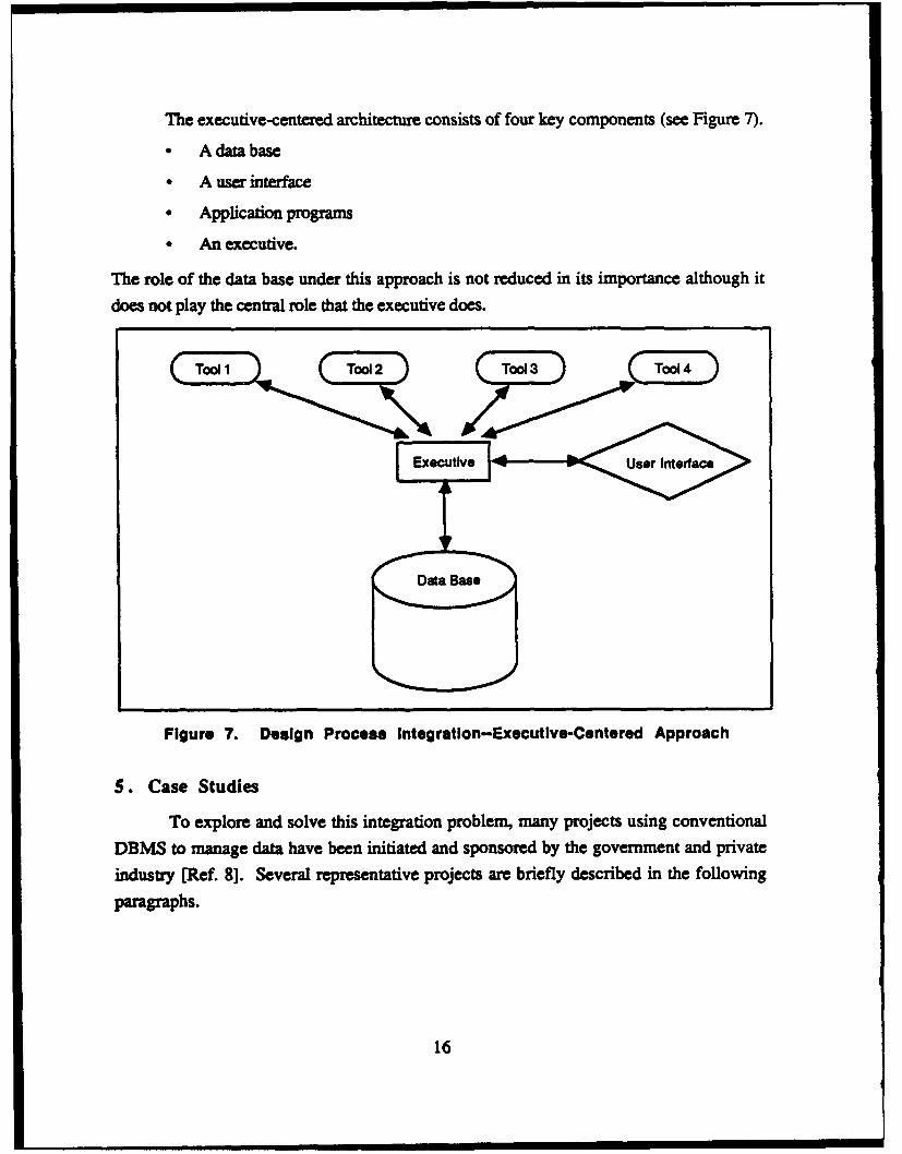
The executive-centered architecture consists of four key components (see Figure 7).
* A data base
* A user interface
* Application programs
* An executive.
The role of the data base under this approach is not reduced in its importance although it
does not play the central role that the executive does.
utiver nterface
Figure 7. Design Process Integration-Executive-Centered Approach
S. Case Studies
To explore and solve this integration problem, many projects using conventional
DBMS to manage data have been initiated and sponsored by the government and private
industry [Ref. 8]. Several representative projects are briefly described in the following
paragraphs.
16
.,. ., .m , , m,,= .mm mm mlmli • mi~lll MOM"II
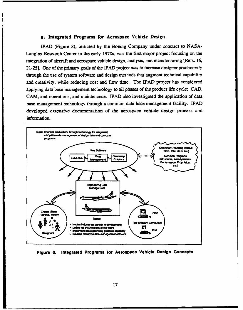
a. Integrated Programs for Aerospace Vehicle Design
IPAD (Figure 8), initiated by the Boeing Company under contract to NASA-
Langley Research Center in the early 1970s, was the first major project focusing on the
integration of aircraft and aerospace vehicle design, analysis, and manufacturing [Refs. 16,
21-25]. One of the primary goals of the IPAD project was to increase designer productivity
through the use of system software and design methods that augment technical capability
and creativity, while reducing cost and flow time. The [PAD project has considered
applying data base management technology to all phases of the product life cycle: CAD,
CAM, and operations, and maintenance. [PAD also investigated the application of data
base management technology through a common data base management facility. [PAD
developed extensive documentation of the aerospace vehicle design process andinformation.
Gooi: kns poduc* UvougtaUdoogy for MOgrAIdcamrpw~de mutqemet of dm=gn da WW wnpu
re I a PmmAh Ceoyncsmww"1m G'pl
I
W
08*0d U FAD elpso of t~o kUsu
,m c eo pop s dai ffawt n w afo t : Iw
Figure S. Integrated Programs for Aerospace Vehicle Design Concepts
17
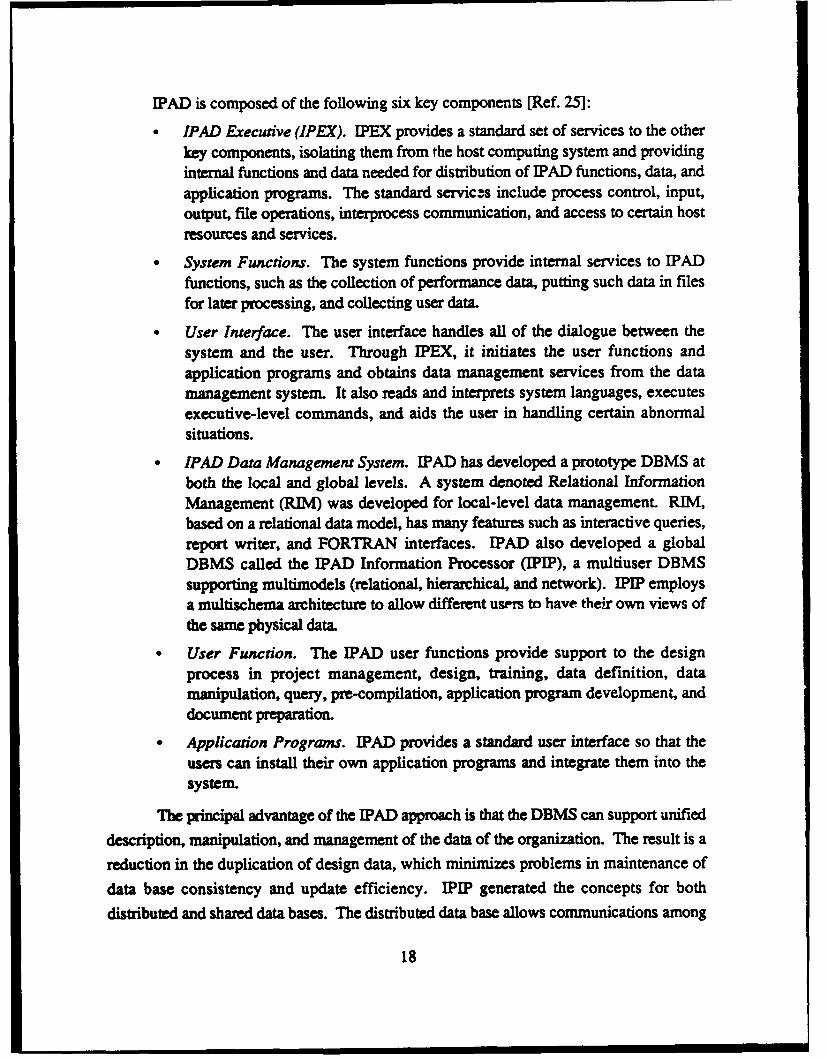
IPAD is composed of the following six key components [Ref. 25]:
" IPAD Executive (IPEX). IPEX provides a standard set of services to the otherkey components, isolating them from the host computing system and providinginternal functions and data needed for distribution of IPAD functions, data, andapplication programs. The standard services include process control, input,output, file operations, interprocess communication, and access to certain hostresources and services.
* System Functions. The system functions provide internal services to IPADfunctions, such as the collection of performance data, putting such data in filesfor later processing, and collecting user data.
User Interface. The user interface handles all of the dialogue between thesystem and the user. Through PEX, it initiates the user functions andapplication programs and obtains data management services from the datamanagement system. It also reads and interprets system languages, executes
executive-level commands, and aids the user in handling certain abnormalsituations.
* IPAD Data Management System. EPAD has developed a prototype DBMS atboth the local and global levels. A system denoted Relational InformationManagement (RIM) was developed for local-level data management. RIM,based on a relational data model, has many features such as interactive queries,report writer, and FORTRAN interfaces. IPAD also developed a globalDBMS called the EPAD Information Processor (PIP), a multiuser DBMSsupporting multimodels (relational, hierarchical, and network). PIP employsa multischema architecture to allow different users to have their own views ofthe same physical data.
* User Function. The PAD user functions provide support to the designprocess in project management, design, training, data definition, datamanipulation, query, pre-compilation, application program development, anddocument preparation.
Application Programs. PAD provides a standard user interface so that the
users can install their own application programs and integrate them into thesystem.
The principal advantage of the PAD approach is that the DBMS can support unified
description, manipulation, and management of the data of the organization. The result is a
reduction in the duplication of design data, which minimizes problems in maintenance of
data base consistency and update efficiency. IPIP generated the concepts for both
distributed and shared data bases. The distributed data base allows communications among
18

the existing softwares to be dispersed geographically in heterogeneous computer hardwares
* (Figure 9). The concept of shared data base provides a common interface, which aids the
integration of various design activities and computer-based support systems. While
performing its information storage and retrieval functions, the system can also maintain
data base integrity and enforce organization security rules [Ref. 26].
Multischema/View Data Base
Numerous MultipleExternal Arbitrary Single ComputerViews Enterprise Views
View*Geometry Translators Translators
Tasks Integrated
Engineering" ' ,-4----Data
Management Fu..h tureI(-199 Words) F
Future
CDC 1981IBM 1982
Computer Independent 1P w6. Computer Dependent
Figure 9. Integrated Program for Aerospace Vehicle DesignData Base Management Concept
To illustrate the IPAD concept and to aid instruction on integration concepts, the
Prototype Integration Design (PRIDE) system was built. The system primarily focuses on
structural analysis but can be readily expanded to accommodate other capacities.
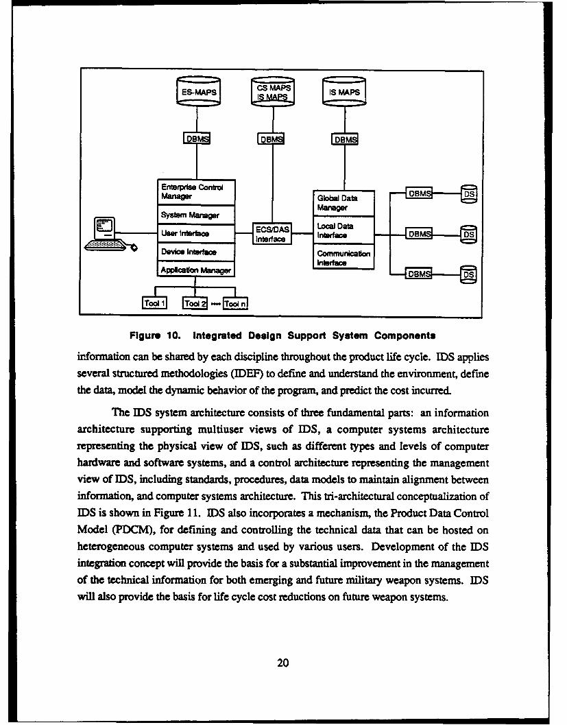
b. Integrated Design Support System
The Air Force's Integrated Design Support (IDS) System is an integrated
technology program that captures the critical technical engineering information necessary to
* perform the functions of maintenance, modification, repair, and reprocurement of the
weapon systems [Refs. 19, 27] (Figure 10). IDS uses an integrated data base so that
19
ES-MAPS CS MAPS IS MAPS
Enterprise ControlManager Global Data DB DS:Manager
System ManagerUser~ nt acEC /AS Loal Data
ntUserrf Interface
Device Interface Communication
Figure 10. Integrated Design Support System Components
information can be shared by each discipline throughout the product life cycle. IDS appliesseveral structured methodologies (IDEF) to define and understand the environment, define
the data, model the dynamic behavior of the program, and predict the cost incurred.
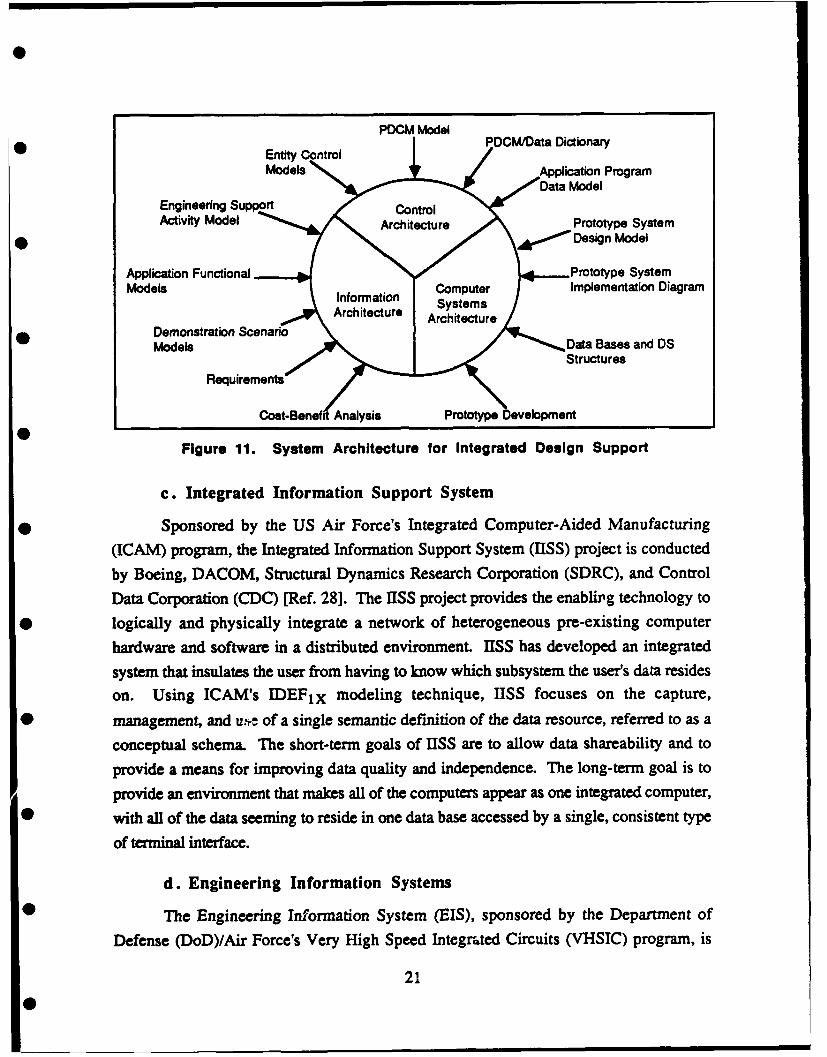
The IDS system architecture consists of three fundamental parts: an information
architecture supporting multiuser views of IDS, a computer systems architecture
representing the physical view of IDS, such as different types and levels of computer
hardware and software systems, and a control architecture representing the management
view of IDS, including standards, procedures, data models to maintain alignment between
information, and computer systems architecture. This tri-architectural conceptualization of
IDS is shown in Figure 11. IDS also incorporates a mechanism, the Product Data Control
Model (PDCM), for defining and controlling the technical data that can be hosted on
heterogeneous computer systems and used by various users. Development of the IDS
integration concept will provide the basis for a substantial improvement in the management
of the technical information for both emerging and future military weapon systems. IDS
will also provide the basis for life cycle cost reductions on future weapon systems.
20
Entity ConlPDCM/Data Dictionary
Models Application Program
Engineering Support ControlActivity Model Architecture Prototype System
* ' Design Model
Application Functional Prototype SystemInformation mputerImplementation DiagramMoelIArhitctur Systems
1 Archtecture ArchitectureDemonstration Scenario
Models Data Bases and DSR,, irem~t,'StructuresRequirements
Cost-Benef Analysis Prototype Development
Figure 11. System Architecture for Integrated Design Support
c. Integrated Information Support System
* Sponsored by the US Air Force's Integrated Computer-Aided Manufacturing
(ICAM) program, the Integrated Information Support System (IISS) project is conducted
by Boeing, DACOM, Structural Dynamics Research Corporation (SDRC), and Control
Data Corporation (CDC) [Ref. 28]. The ISS project provides the enablirg technology to
* logically and physically integrate a network of heterogeneous pre-existing computer
hardware and software in a distributed environment. IISS has developed an integrated
system that insulates the user from having to know which subsystem the user's data resides
on. Using ICAM's IDEF1x modeling technique, IISS focuses on the capture,
* management, and us of a single semantic definition of the data resource, referred to as a
conceptual schema. The short-term goals of IISS are to allow data shareability and to
provide a means for improving data quality and independence. The long-term goal is to
provide an environment that makes all of the computers appear as one integrated computer,
* with all of the data seeming to reside in one data base accessed by a single, consistent type
of terminal interface.
d. Engineering Information Systems
The Engineering Information System (EIS), sponsored by the Department of
Defense (DoD)/Air Force's Very High Speed Integrated Circuits (VHSIC) program, is
21
being developed using an object-oriented approach [Refs. 13, 29, 30]. Using this method,
the user can define new global or local object classes, such as three-dimensional parts with
operations such as display, rotate, and calculate volume. These capabilities exceed those ofcurrent DBMSs. EIS is focused on the information processing needs of engineers,
managers, and administrators in the organizations involved in integrated circuit design andin the development of the tools that support the design process. EIS supports theEngineering Information Model, which provides a graphical representation of the semanticsof the information in the engineering environment in which EIS operates.
22
I. DATA BASE MANAGEMENT ISSUES INTHE DESIGN PROCESS
The aerospace vehicle design process creates large quantities of data. A DBMS, a
set of software that defines, retrieves, and modifies data stored in a data base, can be used
to store and effectively manage the information, thereby increasing the productivity of the
aerospace vehicle design operations.
The first DBMSs were developed for business and administrative applications.These record-based DBMSs are usually classified as conventional DBMSs. Although
conventional DBMSs work well for business and administrative applications, they do not
meet the requirements for engineering applications, and they lack semantic expressiveness.
This section identifies and discusses conventional data base models and their deficiencieswith respect to the engineering/design environment. The design data base management
system (DDBMS) tailored to meet the functional requirements of the design process is also
introduced.
A. CONVENTIONAL DATA BASE MANAGEMENT SYSTEMS
A data model defines the overall logical structure of a data base. It provides the
structural framework into which the data are placed. The conventional data base models,
which dominate the data base systems commonly used today, include the hierarchical,
network, and relational models [Refs. 18, 31, 32] (Figure 12). Although the specific
modeling constructs of these models vary considerably, each presents the user-level view
of a schema in terms of record structures.
1. Hierarchical Data Model
The hierarchical model is tree structured. It is composed of nodes connected by
links. The nodes may be grouped into horizontal layers called levels. A hierarchy is a
multilevel data model. The tree structure of the hierarchical model implies that each node
may be linked to more than one node below itself but to only one node above.
23
[ I O Hierarchical DBMS
J. Anderon 2-15-1922 ngmsman D.C.
J. Carter 10-1-1924 ariner Georgia Relational DBMSJ. Ctr 10-1-1924 governor GeorgiaJ. Carter 10-1-1924 preIdent D.C.
R:.Reagan 24-1911 actor California.Regn 2--1911 goenr California
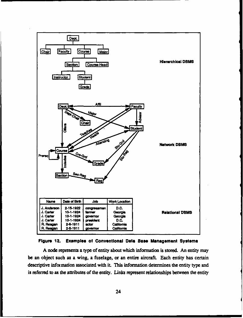
Figure 12. Examples of Conventonal Data Base Management Systems
A node represents a type of entity about which information is stored. An entity maybe an object such as a wing, a fuselage, or an entire aircraft. Each entity has certain
descriptive infonmation associated with it This information determines the entity type and
is referred to as the attibutes of the entity. Links represent relationships between the entity
24
J. Cate 10112 oer eri
types. The links indicate a relationship of one-to-many as they are followed down through
the hierarchy.
a. Advantages of Hierarchical Data Model
The major advantage of the hierarchical data model is that it has been successfully
used as the basic structure in data base management systems that use the hierarchical data
model as the basic structure. The hierarchical data model is also relatively simple and easy
to use. Data processing users are very familiar with the hierarchical form. In addition, the
hierarchical data model reduces data dependence, and performance prediction is simplified
through pre-defined relationships.
b. Disadvantages of Hierarchical Data Model
The disadvantages of the hierarchical data model include difficulties in
implementing the many-to-many relationship, which may cause redundancy in stored data.
(Although redundancy at the logical level is not necessarily undesirable, since it promotes
simplicity, redundancy at the physical level is undesirable.) As a result of the model's strict
hierarchical ordering, the operations of insertion and deletion become unduly complex, and
hierarchical commands tend to be procedural. Another disadvantage of the model is that
deletion of a parent results in the deletion of the children. As a result, users have to becareful when performing a delete operation. Also, child nodes are accessible only throughparent nodes because the dominate node type is the root.
2. Network Data Model
The network data model interconnects the entities of an enterprise in a network. In
the network data model, the data structures include records and sets. The network data
model represents the different types of objects and relationships in the real world. Each
type of object is represented as a record type, with the attributes of the object being data
fields in the record. A directed arrow connects two or more record types and is used to
represent a set type. The record type located at the tail of the arrow functions as the owner
record type, and the record type located at the head of the arrow as the member record type.
The arrow from owner to member is called a set type. A set type shows a logical one-to-
many relationship between an owner and a member.
25

A network is a directed graph. The network model is a multilevel data model in
which each node may be linked to more than one other node in both upward and downward
directions-this feature distinguishes the hierarchical model from the network. The network
model allows relationships to be established horizontally within levels between different
entity types as well as vertically between levels.
a. Advantages of Network Data Model
The major advantage of the network data model is that, like the hierarchical data
model, successful data base management systems use the network data model for their
basic structures. In addition, the many-to-many relationship, which occurs quite frequently
in real life, can be implemented easily. The network data model also provides very good
performance and data integrity checking.
b. Disadvantages of Network Data Model
The main disadvantage of the network model is its complexity. The application
programmer must be familiar with the logic structure of the data base. The network model
also tends to force a single view of data, hence the data are arranged in a rigid, inflexible
structure; fixed structural interconnections among data items are not easily molded into a
variety of semantic interpretations.
3. Relational Data Model
A relational model is a single-level model consisting of a collection of relations
represented in two-dimensional tabular form [Refs. 26,58]. Associated with the relations
is a set of operators that allow for the insertion, deletion, modification, and retrieval of
data. A figure for the relational model would simply contain a collection of nodes without
any links between them. There are no predefined hierarchies or networks in the relational
model. Links needed between nodes are automatically created by the relational DBMS
upon demand, and an access path is established to any node.
The rows of a relation are called tuples and its columns are called attributes. All
attribute values are drawn from the same domain--they are of the same data type. Each
tuple represents an entity and contains a value for each attribute. All tuples are distinct;
duplicates are not permitted. Tuples and domains have no order, they may be arbitrarily
interchanged without changing the data content and meaning of the relation. Tuples are
26
accessed by means of a key, a single attribute, or a combination of attributes that uniquely0 identifies a tuple.
a. Advantages of Relational Data Model
The relational data model is easy to understand and use because it is based on thesimple concept of a table with rows and columns of data. Users do not face a complicatedphysical implementation of the model. The relational data model removes the details of
storage structure and access strategy from the user interface. The model provides a0 relatively higher degree of data independence than the hierarchical or network data models.
To take advantage of the data independence feature of the relational data model, however,the design of the relations must be complete and accurate.
The relational data model is based on the well-developed mathematical theory of• relations. The rigorous method of designing a data base (using normalization I) gives this
model a solid foundation that does not exist for the other data models. Another advantageof this model is that an unlimited number of relationships can be represented, and thus theextensions that can be made to the set of supportive applications are unlimited. The types
* of relationships or collections of relationships that can be represented are also unlimited.
b. Disadvantages of Relational Data Model
A major drawback of this model is that the uniformity of structure and the• fragmentation into normalized relations compels the user to use queries that are long,
repetitive, and tedious, resulting in insufficient performance. Because the relational datamodel is fundamentally record-oriented, it uses an overly simple data structure to model anapplication environment. In consequence, the application of a relational model inevitably
0 involves the loss of information and semantics.
4. Model Comparison
While the similarities between the multilevel hierarchical and network models areevident, the network model is more flexible, allowing non-hierarchical or multihierarchicalrelations to be defined. This added flexibility results in greater representational power,
although it still does not afford the representational capabilities of the relational model.
Normalizadon is the process of removing dependencies and redundancies from among the attributes ofrelations.
270
Relationships among entities and constraints among attributes impose critical
requirements on a data base, and all user queries and updates generally cannot be
anticipated rior to the establishment of the data base structure. To satisfy diverse access
needs, links may be required between any of the components of the data base; however, the
hierarchical and network models have precisely defined links between the nodes. This
composition results in fixed data base structures that cannot be easily changed.
The hierarchical model presents difficulties in representing many-to-many
relationships. An additional disadvantage, that also occurs in the network model, is that
loops are not permitted (relationships cannot be established between a record type and
itself). These data models could be particularly limiting when used in an engineering/
design environment, where such relationships are common (for example, ribs connected to
adjacent spars or rivets to adjacent panels).
Neither of these disadvantages is found within the relational model. Its use requires
knowledge of only one data construct, and its underlying access mechanisms are hidden
from the user. The user needs to be concerned with only the content of individual
relations. The hierarchical and network models, however, do allow for efficientimplementations. Because hierarchy and network links are implemented as pointers, nodetraversal is direct and fast. A primary disadvantage of the relational model is that it offers
less efficient accessing.
An additional advantage of the relational model is its ability to avoid common
anomalies through nonalization. The concept of normalized relations is an integral part of
the relational model, and it promotes the achievement of well-structured data while
providing a degree of automatic integrity and consistency checking [Refs. 18, 31, 32].
The results of the data model comparisons are presented in Table 3.
B. DEFICIENCIES OF CONVENTIONAL DATA BASE MODELS
Applying conventional data base models to modeling design and engineering can beproblematic. The deficiencies of conventional data base models when used in design and
engineering applications are detailed in the following paragraphs [Refs.13, 33-37].
28
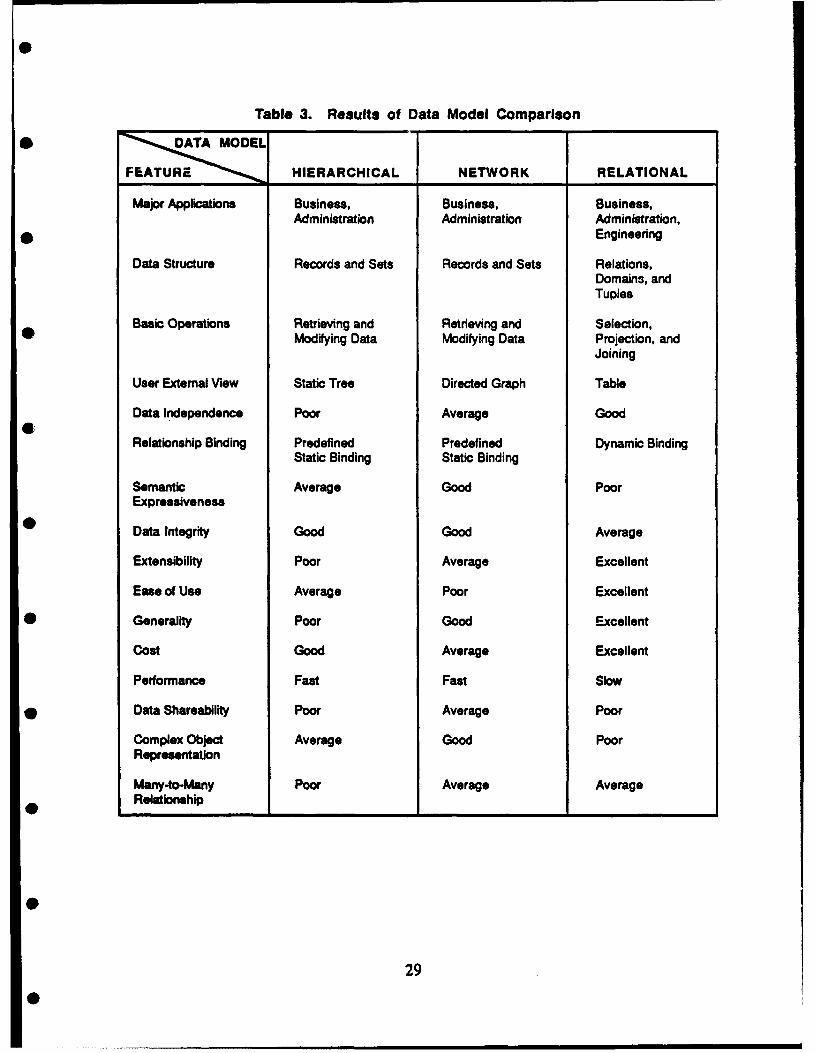
Table 3. Results of Data Model Comparison* DATAMODEL
HIERARCHICAL NETWORK RELATIONAL
Major Applications Business, Business, Business,Administration Administration Administration,
* Engineering
Data Structure Records and Sets Records and Sets Relations,Domains, andTuples
Basic Operations Retrieving and Retrieving and Selection,Modifying Data Modifying Data Projection, and
Joining
User External View Static Tree Directed Graph Table
Data Independence Poor Average Good
Relationship Binding Predefined Predefined Dynamic BindingStatic Binding Static Binding
Semantic Average Good Poor
Expressiveness
Data Integrity Good Good Average
Extensibility Poor Average Excellent
Ease of Use Average Poor Excellent
* Generality Poor Good Excellent
Cost Good Average Excellent
Performance Fast Fast Slow
* Data Shareability Poor Average Poor
Complex Object Average Good PoorRepresentation
Many-to-Many Poor Average AverageRelationship
29
1. Lack of Semantic Expressiveness
A fundamental problem of the hierarchical, network, and relational data basemodels is their limited semantic expressiveness. As noted in the preceding paragraphs, theconventional data base models are all fundamentally record oriented. These low-level,record-oriented models use overly simple data structures to model applicationenvironments, which results in substantial modeling limitations. The record-based modelsfail to distinguish the various generic relationships among applications. The relationships,such as is-inside of, is-part-of, on-top-of, commonly used in engineering-orientedapplications are difficult to represent with conventional data base models. Consequently,the application of a conventional model inevitably involves the loss of information and onlya limited portion of a data base designer's knowledge of the application environment can beexpressed.
2. Inability to Handle Engineering Heterogeneous Data Types
Conventional data base models were specifically designed to store and access onlyformatted alphanumeric data in the form of record files. However, design/engineering datacontains a variety of data types--graphical (two-dimensional), geometrical (three-dimensional), mathematical (numerical), procedural, and manufacturing, in addition toalphanumeric. These other data must be extracted with formatted records stored in a database. In a conventional data base model, such manual processing is arduous andsusceptible to errors and delays.
3. Inability to Implement Dynamic Schema
Since schema definition and generation are expensive off-line tasks, conventionaldata base models only support static schema definition. However, dynamic schemacapacities are fundamental for achieving an essential representation of design objects. Inconventional data bases, application objects are represented as record structures and arerelated indirectly through common identifiers, which are character strings that serve as (notnecessarily unique) keys to individual records. Thur, in a conventional data base, asubscriber and his claim would typically be associated through an identifier representing aclaim number. The subscriber record and the claim record would each contain a copy of
the identifier.
30

Allowing objects to represent themselves instead of using some identifier to
0 represent them makes it possible to directly reference an object from a related one. Inrecord-oriented data base models, it is necessary to explicitly cross-reference between
related objects by means of their identifiers; this causes data manipulation to be intricate and
semantically confusing. While it is, of course, necessary to eventually represent abstract* objects with symbols inside a computer, users (and application programs) should be able to
reference and manipulate abstractions as well as symbols; internal representations to
facilitate computer processing should be hidden.
0 4. Limitations of Evolvability
Record-oriented models are also limited in their ability to allow the structure of a
data base to support alternative ways of looking at the same information. (The capability of
expressing such alternate views may be termed relativism.) To accommodate multiple) perspecdves on the same data and to enable the evolution of new views of existing data, a
data base model must support schemas that capture the relationships and similarities
between multiple views of the same information.
The primary motivation for relativism is that slightly different viewc of the same
information should be conceptualized as a semantic unit (all of the previous definitions may
coexist in the same user view). In conventional models, imposing a single structuralorganization on the data is generally necessary; this single structure inevitably carries a
* particular interpretation of the data's meaning. This meaning may not be appropriate for all
users of the data base and may eventually become obsolete.
Conventional schemas are also, in a sense, structurally intricate, which affects the
evolution of both data base statics and dynamics. Statics expressed in record-based• structures are difficult to understand and are therefore so intimately tied to the specifics of
the statics that evolutionary changes in the statics are liable to upset the workings of the
record-based structures. For example, splitting a relation into two, due to a change in a
dependency, is likely to destroy the algebraic operation of any transaction using the original• relation. Also, changes in processing requirements, when mapped into record-based
languages, often require significant reprogramming efforts.
0
31
0
C. DESIGN DATA BASE MANAGEMENT SYSTEMS
Integrating the eagineering design process with computer technology and usingsophisticated computer-aided modeling and design systems is an important research area.Data base management technology plays a central role in the integration of CAD/CAMsystems. Data bases for CAD systems, so-called design data bases or engineering databases [Refs. 41, 35-38], have characteristics that differ significantly from those of thebusiness and administrative data bases, which are adequately managed by conventionalDBMS. Characteristics of design data bases are identified as follows [Refs. 37-41]:
Iterative. At any stage of the design, incremental changes arise in response todesign rule checks, new ideas, or alternative strategies. As a result, iterationsfor a particular segment of the design process or the entire design must beinitiated to reflect these changes.
* Tentative. During the design process, all design alternatives must bemaintained in the data base, pending final evaluation of the alternatives.
* Mztistaged. The design is usually separated into various levels or stages, andthe designers perform the design on a stage-by-stage basis. The processbegins with a product definition, and the design objects are typically designedin several stages, each of which represents a refinement and elaboration of theprevious stage. Hence, the earlier stages of design must be available to thedesigners working on the later stages.
" Incomplete. A design data base initially contains only the data determined byinitial design decisions. Application programs (design tools) generate moredata for future uses, and data continue to be derived until the design iscomplete. Therefore, the engineering design process is an evolution of arepresentation. Only when the process is finished is a complete data baseachieved.
* Dynamic. The design process is a dynamic operation. As the designprogresses, design objects and the relationships among them are added,deleted, and modified. In addition, many changes are made based on theresults of analysis or the designer's creativity.
* Extensive Transactions. A design transaction is defined as a segment of thedesign process between two states of consistency. In the design environment,reaching a new consistent state is time consuming and may take days or evenweeks.
32
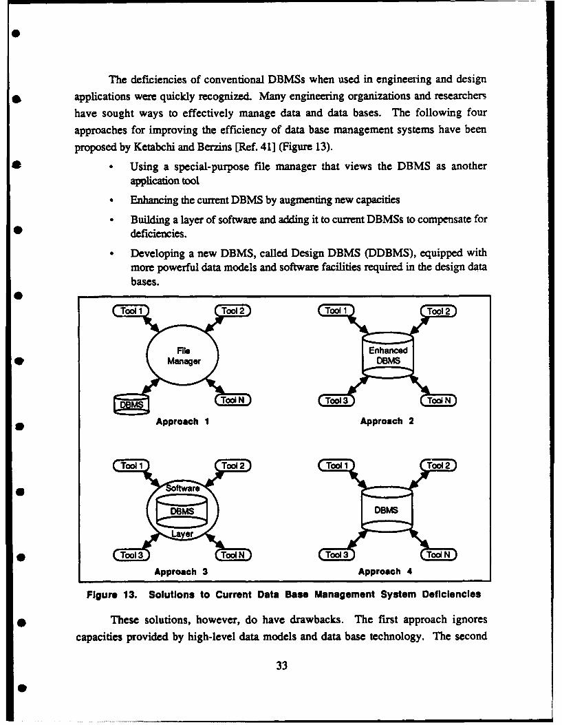
The deficiencies of conventional DBMSs when used in engineefing and design
* applications were quickly recognized. Many engineering organizations and researchers
have sought ways to effectively manage data and data bases. The following four
approaches for improving the efficiency of data base management systems have been
proposed by Ketabchi and Berzins [Ref. 41] (Figure 13).
* • Using a special-purpose file manager that views the DBMS as anotherapplication tool
* Enhancing the current DBMS by augmenting new capacities
• Building a layer of software and adding it to current DBMSs to compensate for* deficiencies.
Developing a new DBMS, called Design DBMS (DDBMS), equipped withmore powerful data models and software facilities required in the design databases.
S
SManaer DBMS
Approach 3 Approach 4
Figure 13. Solutions to Current Data Base Management System Deficiencies
* These solutions, however, do have drawbacks. The first approach ignores
capacities provided by high-level data models and data base technology. The second
33
approach requires extensive enhancements to the current DBMS and does not provide
optimal performance requirements. The third solution 5oes ao: offer the flexibility and
efficiency desired in the CAD environment. The fourth approach, although it requires
considerable development effort and advanced software technology, provides designers
with a better solution than the three other options.
To develop and implement a DDBMS to manage the engineering and design data,various data/process modeling methodologies have been promoted as a means of providing
the informational framework of the DDBMS. Methodologies, such as IDEF, SAMM,NIAM, and semantic data models, together with the improved DBMSs, have been widely
used in very large scale integrated (VLSI) circuit design, and mechanical design projects.
However, very few have addressed the use of DDBMS in aerospace vehicle design
applications.
34
34
0
S
IV. DESCRIPTION OF DATA/PROCESS MODELING* METHODOLOGIES
Because of the deficiencies of the conventional data base model, the three-schema* approach to data base design was proposed by ANSIIX3/SPARC Data Base Task Group in
1975 [Refs. 32, 42]. The architecture of this approach includes three levels:
* External schema
• Internal schema
0 * Conceptual schema.
The external schema supports user views and provides the user interface to theDBMS. One or more external schemas may be provided, each supporting a distinct user
0 view designed for a specific application. The internal schema supports the DBMS and thehardware itself--how the datz are physically stored and accessed inside a computer. The
conceptual schema serves as an informational model of the entrprise that the data base is toserve and as a control point for additional data base development.
* Two advantages are given for the three-schema approach. The first is that the
conceptual schema augments the data model with real-world semantics, which are easy tounderstand and use. The second advantage is the enhancement of data independence,
which means that modifying or extending the conceptual schema to capture information0 need not affect any application program. Based on the three-schema approach, many
conceptual data models, such as the Entity-Relationship Model (ERM), the SemanticAssociation Model (SAM), the Semantic Data Model (SDM) [Ref. 43], the Functional DataModel (FDM) [Ref. 44], and the Object-Oriented Data Model (OODM), have been defined
0 and implemented. They all provide high-level data structuring features to improve the
semantic expressiveness of data base conceptual schema and to increase data baseaccessibility by the end users. In addition to these conceptual data models, a number ofmodeling methodologies abound to address well-defined information processes. Thesemethodologies, along with the appropriate DBMS, have been applied to different
35
engineering applications. The IDEF methodologies, ERM, SAMM, NIAM, and 00DMare described in this section and illustrated with a specific aerospace design example.
.A. ILLUSTRATION OF METHODOLOGIES WITH AEROSPACE DESIGNAPPLICATION
The test problem adopted in this study covers the early design stages of an aircraftwing composite panel (conceptual and early preliminary design). The composite panelconsists of a skin and a certain number of stiffeners, all made with various numbers of ply.With the wide variety of types and fabrics available, many combinations of ply or fabric
directions can be used to efficiently sustain the applied load (Figure 14) [Refs. 45, 46].The ply orientation makes design with composite materials unique because the structure andthe material are being designed at the same time. All material properties and strengthallowables will vary depending on the ply orientation, and the orientation relies heavily ontest data. The stiffness properties alone for a multilayer laminate design can be as many as21, while metal material design has only 2. In the composite design process, four issuesmust be addressed.
• Material selectioa
" Fabrication methods
* Structural integrity
* Environmental effects and protections.
To simplify the test problem, only structural integrity has been considered. Since theelastic modulus (E) of the elements differs because of the various ply orientations, it isnecessary to determine E for each element and then determine a transformed area. Once
this transformed area is found, the section properties and the average E can be determinedand checked for compliance with the allowable compressive stress and limit strain.
Because of the anisotropic properties of the multilayer orientations, considerablymore information is needed to perform composite panel design than metal panel design.The following sections describe the various process/data models used for modeling thedesign of a composite panel subjected to a compressive load. Figures accompany eachdescription to demonstrate the form of the model.
The design of a wing composite panel is considered a well-bounded problem that issufficiently detailed for purposes of this study, yet not too complicated to implement. The
36
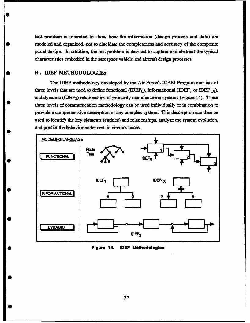
test problem is intended to show how the information (design process and data) are
* modeled and organized, not to elucidate the completeness and accuracy of the composite
panel design. In addition, the test problem is devised to capture and abstract the typical
characteristics embodied in the aerospace vehicle and aircraft design processes.
* B. IDEF METHODOLOGIES
The IDEF methodology developed by the Air Force's ICAM Program consists of
three levels that are used to define functional (IDEF0 ), informational (IDEFI or IDEF1x),
and dynamic (IDEF2) relationships of primarily manufacturing systems (Figure 14). These
three levels of communication methodology can be used individually or in combination toprovide a comprehensive description of any complex system. This description can then be
used to identify the key elements (entities) and relationships, analyze the system evolution,and predict the behavior under certain circumstances.
Ut~lFIIP IAWt I(+LFUNCTIONALj TreeEEF
IDEF1 E I IDEFIX
INFORMTNA
DYNAMICo
0 Figure 14. IDEF Methodologies
37

1. IDEFo - Function Model
The IDEF0 method employs a diagrammatic technique to hierarchically decompose
the entire system into its simplest levels, in terms of their functions in a systematic andlogical manner [Refs. 45-49]. The rules that apply to the IDEF0 are illustrated in Figure 15as follows:
* The box represents an activity that modifies input to produce output.
• Three to six activities are, in general, used for any level of a system
* Each activity may be subsequently and hierarchically decomposed, refined, andidentified.
Each side of the activity box is used as a location for functional details asfollows (see Figure 15):
Left - inputs to the activityTop - controls on the activityRight - outputs from the activityBottom - mechanisms required to effect the activity.
Control
Inu-Function sooutputMoco4is
Figure 15. IDEFo Function Representation
Figure 16 is an IDEF0 representation of the aircraft wing composite panel designapplication. The connecting lines between activity boxes are identified by nearby labels andmay be joined or split to indicate the merging or dividing of information flows. The IDEFomodel is a process model indicating the functional relationships of the various systems, thedata flow, and text/glossary sections. Individuals involved in various functions (such asinput, output, and controls) are interviewed, and the information resulting from these
38
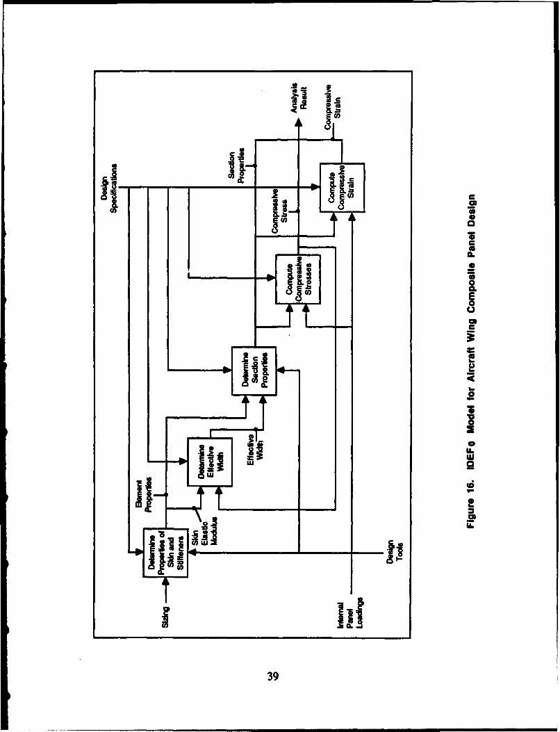
a-c
ICL
0
LUUui.
I_____ ii39
interviews is analyzed to define the resources required in each function, while the behavior
of the entire system is also considered.
Functions are related through inputs, outputs, mechanisms, and controls. A
function will be activated in the systems by receiving inputs to create outputs through
guidance of controls, where the activation is performed by mechanisms. IDEFO can beused to provide a starting point for system improvements or analysis of existing system
shortcomings. The IDEFo methodology enforces a top-down functional modeling
approach, an approach that is often found lacking in unsuccessful system designs.
2. IDEF1/IDEF1x (Extended) - Information Model
IDEF 1 is a comprehensive method for describing and analyzing the information of a
complex system through a set of rules and procedures for creating information models
(Refs. 47, 52-54]. IDEF 1 produces graphical diagrams that explicitly represent data
semantics in terms of entities (objects), relationships, and attributes (properties).
An entity is an item or an object to which information relates. IDEF1 represents
entities by rectangular boxes, and the entity's name is recorded above the box. (Individual
entity instances are not represented in the data modeL) Characteristics of an entity areknown attributes. Each entity instance has a value for each of its attributes. The attributevalues are the facts known about the entity instances. Entity attributes are represented in an
JIDEF 1 diagram by names within the entity's box. Relationships, associations betweenentities, are represented by lines between entity boxes. Each line is labeled with therelationship's name, which is a verb or verb phrase.
With IDEF1 , a data model is developed by a top-down analysis of entities and
relationships, which is suitable for supporting the full process of developing informationsystems. IDEF 1 is being successfully applied in a variety of enterprises to achieve
implementation of the integrated data resources. An IDEFIX representation of the aircraft
wing composite panel design application is shown in Figure 17.
3. IDEF2 - Dynamic Model
IDEF2 is a methodology that has been developed to describe the time-varying
behavior of manufacturing systems so that computer simulation can be used to generate
measures of system performance [Refs. 47, 55, 56].
40
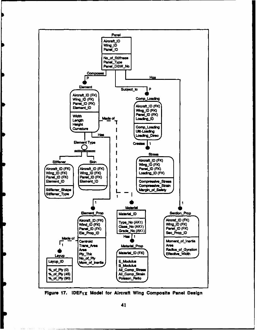
Panel
Alruaft-JDWhngjDPanek-ID
No...oL.StfftnssPanel-Type
Pa&GWNo,
Alaatj F) A iraafjD) (FK) r
PanelD(FK) PaID (K)
AircrafD (FK)afjI (F) irrKi (g~iWi_11) (FK)M
W idI D (FK)D am (K F ani (
Mde of Madeeof LpfdnefIa
Cenfraed
A,,.~~kVI (F) F lelieWi"AmnfLD F rly...Th MSIWI&JD JD FK
PaomofjFK P nerLa jFouhiflytl (0wkl)AIL Copres "_
I%..ofly(5)IML ~ Cnp..S ra wMSr~
alan.ral
Figre 7. DEF Pr oe foMicaft~j WnCopse wPanl esg
IDD(F) 4=LD41K
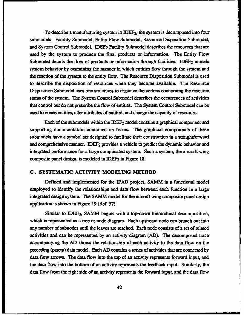
To describe a manufacturing system in IDEF2, the system is decomposed into four
submodels: Facility Submodel, Entity Flow Submodel, Resource Disposition Submodel,
and System Control Submodel IDEF2 Facility Submodel describes the resources that are
used by the system to produce the final products or information. The Entity Flow
Submodel details the flow of products or information through facilities. IDEF2 models
system behavior by examining the manner in which entities flow through the system and
the reaction of the system to the entity flow. The Resource Disposition Submodel is used
to describe the disposition of resources when they become available. The Resource
Disposition Submodel uses tree structures to organize the actions concerning the resource
status of the system. The System Control Submodel describes the occurrences of activities
that control but do not prescribe the flow of entities. The System Control Submodel can be
used to create entities, alter attributes of entities, and change the capacity of resources.
Each of the submodels within the IDEF2 model contains a graphical component and
supporting documentation contained on forms. The graphical components of these
submodels have a symbol set designed to facilitate their construction in a straightforward
and comprehensive manner. IDEF2 provides a vehicle to predict the dynamic behavior and
integrated performance for a large complicated system. Such a system, the aircraft wing
composite panel design, is modeled in IDEF2 in Figure 18.
C. SYSTEMATIC ACTIVITY MODELING METHOD
Defined and implemented for the IPAD project, SAMM is a functional model
employed to identify the relationships and data flow between each function in a large
integrated design system. The SAMM model for the aircraft wing composite panel design
application is shown in Figure 19 [Ref. 57].
Similar to IDEFO, SAMM begins with a top-down hierarchical decomposition,
which is represented as a tree or node diagram. Each upstream node can branch out into
any number of subnodes until the leaves are reached. Each node consists of a set of related
activities and can be represented by an activity diagram (AD). The decomposed trace
accompanying the AD shows the relationship of each activity to the data flow on the
preceding (parent) data model. Each AD contains a series of activities that are connected by
data flow arrows. The data flow into the top of an activity represents forward input, and
the data flow into the bottom of an activity represents the feedback input. Similarly, the
data flow from the right side of an activity represents the forward input, and the data flow
42
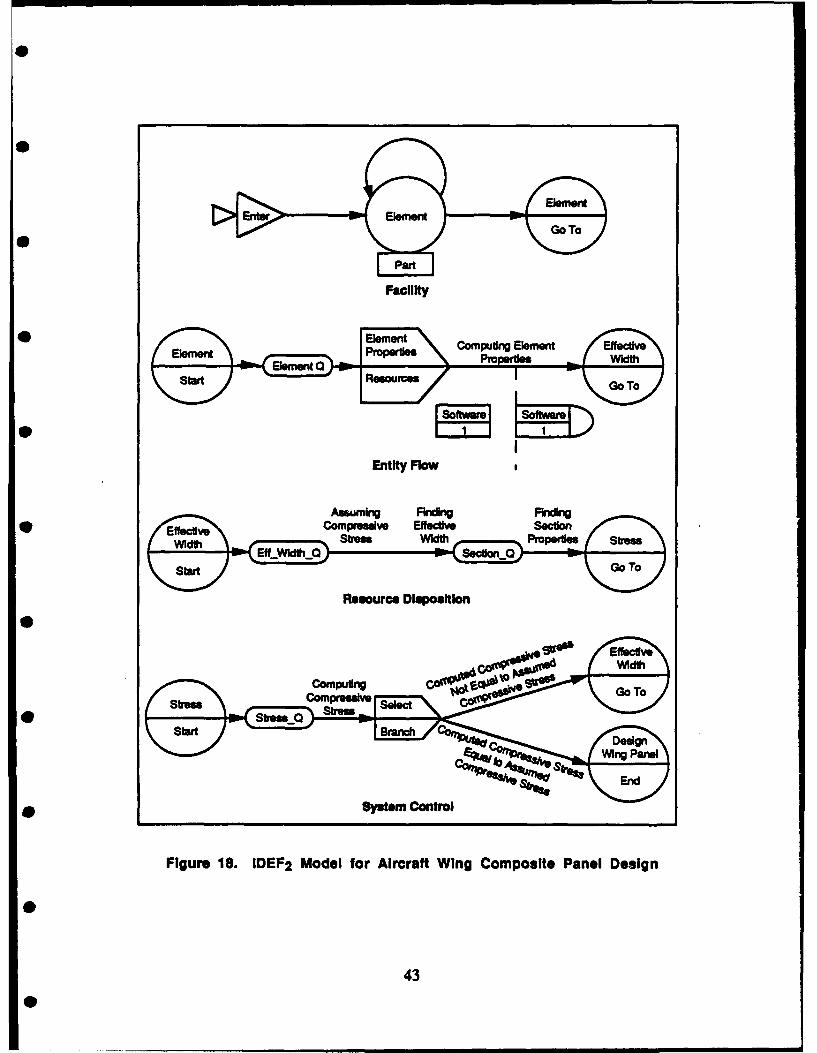
0
0
0
Entiity o
Resu Dipoito
Entity Flo
Compstem ControlSetio
rFfegurde 1.iE 2 MdlfrAcrfWigCmotPane Deig
Ste0it tv
Wid43
Str e o r e i p sto
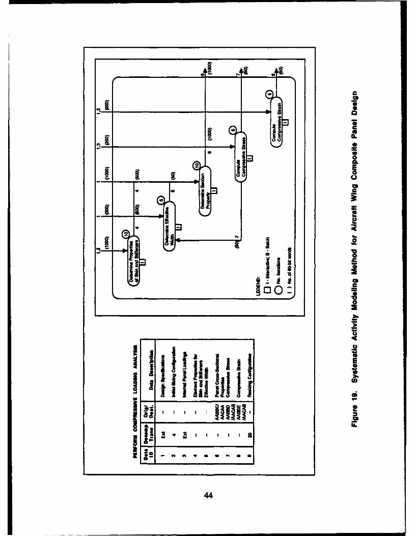
I______ U.-
ma C2
A ____________ ____ I Sa S
CA ma
___ _____________________ Sgo S
CC 4 a.- Ea
I. I U
ma II*
S. SUh.
4 U -
a 'F4! N,
S 02 I
- 0
II Iii -C~OU.- -I
4.U
Ij UES
Ii 4.I p111111 11111N- UCA* ______________________Ii; a
I ~cc~c~
ir
I I' ~ I I I I I~- Cd 91 4 * * N U U
a
44
from the left side represents feedback output. The data flow volume is identified by a0 number enclosed in parentheses located adjacent to the data identifier number. This number
represents the number of 60-bit words transferred on a computer. In addition, the number
of iterations of each activity is enclosed in a circle and is estimated for an entire
development program cycle. The type of computing support is identified as predominantlyinteractive or batch.
SAMM is expandable to any level of detail with the hierarchical structure, providing
an extremely comprehensive document specifying the activities, their relationships, and
*0 functionalities in modeling the design process.
D. NIJSSEN'S INFORMATION ANALYSIS METHOD
NIAM is based on a binary-relationship model using objects and associations
0 (relationships) as two fundamental building blocks to represent the real world
[Refs. 58-61]. It provides both information modelers and users with diagrammatic
representation, the information structural diagram (ISD).
The objects and associations are represented as circles and edges in the graphical
form. Object types are either Nonlexical Object types (NOLOTs) or Lexical Object types
(LOTs). Occurrences of NOLOTs cannot be shown; while occurrences of LOTs can be
shown. Associations are of two types, bridges and ideas. A bridge type associates a
NOLOT and a LOT. An idea type associates two NOLOTs. Further, both bridge and idea
types are composed of a pair of roles. The roles describe the nature and semantics of the
association between connected objects. With NIAM's ISD, a number of constraints on the
associations can also be graphically depicted. The description of constraints allows for
* devising an algorithm that would pinpoint the state of the lowest possible coupling. With
an emphasis on achieving binary semantics associations, coupled with a thorough
description of associative constraints, NIAM is able to expose the lowest possible object
coupling and functional dependency. This characteristic is commonly known as the third
normal form in relational terminology. A NIAM example for the aircraft wing composite
panel design application is shown in Figure 20.
0
45
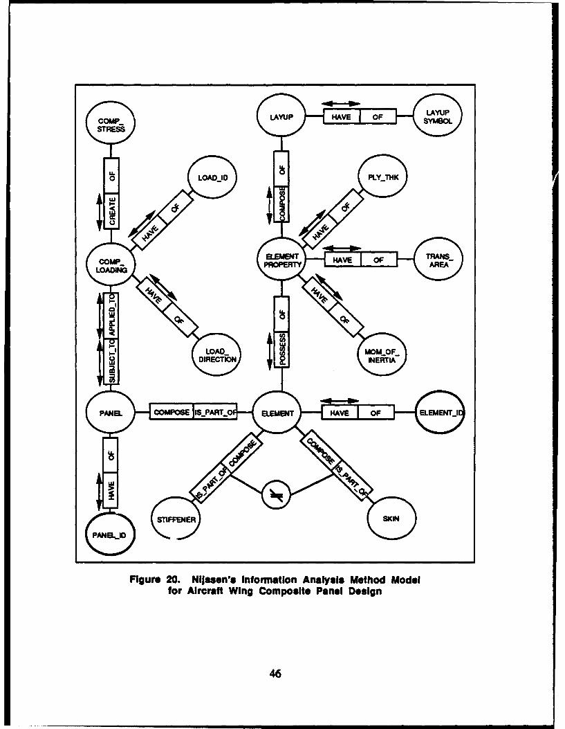
COMP..SYBOSTRESS
0L LOADJD
0
LOADINCI
0
Fiue2.Njsnsifrato nlssMto oe
LOor Air0af WigCmostFaelDsg
DIRECT4O
E. ENTITY-RELATIONSHIP MODEL
ERM was one of the first models to display/represent the correspondence betweenthe semantics of the user's world and the constructs of the relational model [Refs. 62, 63].ERM contains three primitive conceptual elements--entities, relationships, and attributes
(properties)--as representations of the real world. ERM can be implemented using adiagrammatic technique (Entity-Relationship Diagram or ERD) to translate therepresentation into a logical data base schema in a straightforward manner. The ERDtechnique represents entities with box symbols and relationships with diamond symbols.In addition, one-to-one, one-to-many, and many-to-many association types are
distinguished, and entities and relationships are labeled with meaningful English terms.The ERM for the aircraft wing composite panel design application is shown in Figure 2 1.
The ERM can adequately, although informally, describe the real world, which isdifficult to represent using a conventional data model. One attractive feature of ERD is thatit is very easy to map the ERM into the relational data base model with third normal form.
In addition, ERM allows the user to have a basic understanding of the underlying logical
organization used in the modeL
F. OBJECT-ORIENTED DATA MODEL
An OODM [Refs. 64-70], evolved from SMALLTALK-80 (an object-orientedprogranmmiii language), models all conceptual entities with a single concept--objects. Anobject may be a primitive object, such as an integer, or a complex assembly of parts, suchas an aircraft The object-oriented data model of the aircraft wing composite panel designapplication is shown in Figure 22. An object consists of a number of instance variables
and/or methods that define the behavior of the object. An instance variable contains the
status and the state of that object. The methods are simply procedures that are invoked bymessages that are sent by other objects.
A data base may contain a large collection of objects. If every object carries its owninstance variable and methods, the amount of information specified and stored can beunmanageably large. In an object-oriented approach, similar objects are grouped into aclass, and all objects belonging to the same class have the same instance variables and
methods.
47
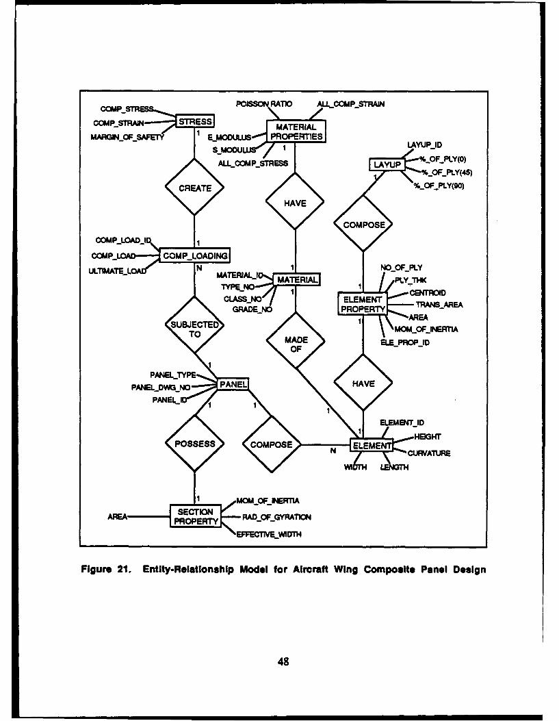
CCMP..STR POISSON RATIO ACMPSAIN
CCMFPSTRAN STRESS MAEIL
MARGFOF _AFE1 EMOCLUSr PROPERTIES LYP1
NL._COMP..STRESS LAVUP %..OF.YPLY(O)
_0F-PLY(45)CREATE %...F...LY(90)
HAVE
COMPOSE
COMP...LOA.IJ 1
COM_ LOADIANGNLTNATEJ.OLd' N 1 J00PLY
MAERALI MATE RIAL PLY THK1 CBETROID
CLAS4_NO ELEMENT TA-RAGRADELNJO PROPERTY
SUBJECTE 1RETO MOMOFjNER1A
TOMADE ELELPROP-DOF
PANELrYPEPANELDkqO PANEL HAVE
PANEL I
POSSESS COMPOSEN LM CUVTR
PROPERTY
Figure 21. Entity-Relationship Model for Aircraft Wing Composite Panel Design
48
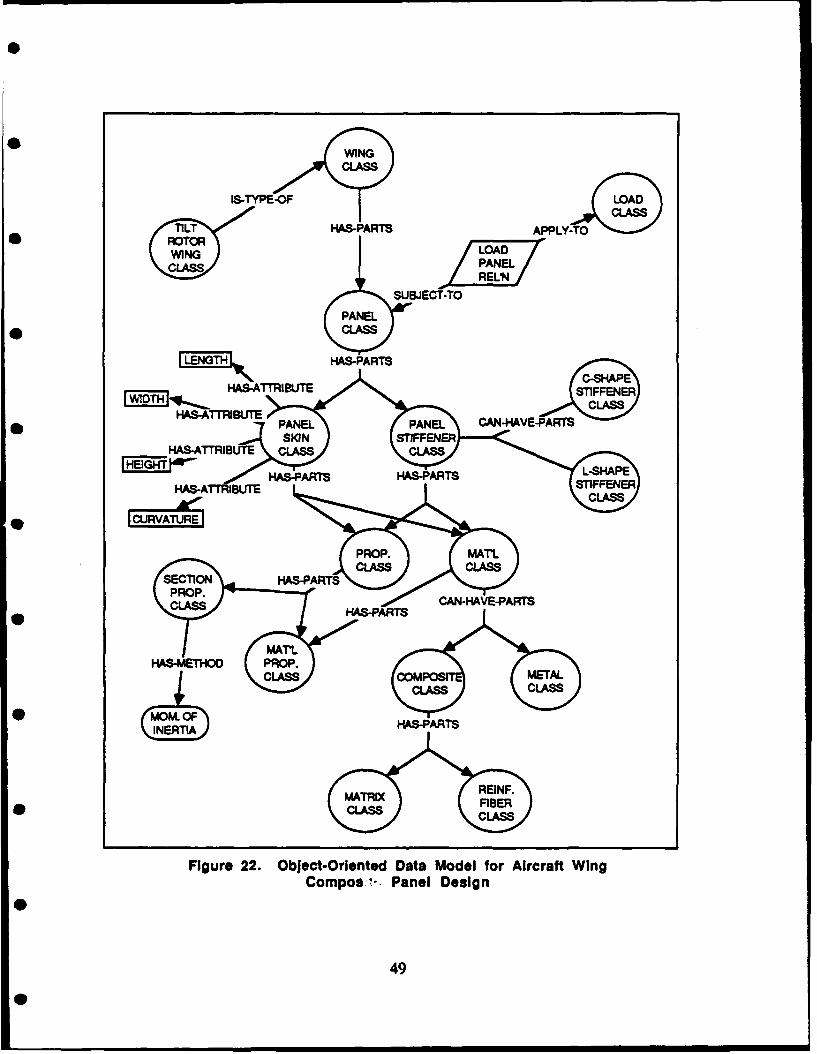
WINGCLASS
&T-YPE-OF LA~WLCLASS]
TILT RAS-PARTS APPLYTO'-.'
iN /PANEL/
SUBJECT-TO
PANEL* CLASS
CLS
HA-TRBT
PAE0AE ANHV-AT
S0NSIFEE
0A-TRB CLS LS
FigureJ~r 22.ASc-PARTS e DAAT MoelfoSArcafPWnCompos STPaneFDesig
AO0' LS
r ATUR49
PRP Mr
Four characteristics of the OODM are data abstraction, information hiding,
inheritance, and dynamic binding. Data abstraction and information binding are important
in representing complex engineering design information; dynamic binding is important in
developing computer-aided engineering systems that use representations.
Data abstraction is the process of selecting the important properties of a system and
representing these properties in a manner understood by the computer. Objects allow verygeneral data abstraction because they represent behavior of an entity independent of the
data.
Information hiding is the concept that each object should isolate information from
all other objects, with access to the information provided through well-defined interfaces.Objects naturally hide information because the objects include private variables and the
procedures (or methods) to operate on the variables. The information presented by the
variables and methods can only be accessed by an interface (called a protocol) that is part of
the object.
Inheritance allows objects to be organized according to common behavior. For
example, an object can be a specialization of a more general object. The specialized objectinherits the behavior of the general object and usually adds to or modifies that behavior. Inthis way, inheritance is used to organize information and simplify the structure of the
specialized object using the inherited information.
The final characteristic of the object-oriented data model is the binding of operators
with a type of operand at execution.
The advantages of using OODM include
* Ability to manage data from a variety of independent application programsunder the same interface (such as adding or changing programs)
" Ability to improve the representation of information, such as spatial data,which are handled with conventional data models
" Ability to manage part hierarchies and recursive data, which are not supportedby conventional data models
" Ability to develop software programs, such as modelers, without beingconcerned with data base management techniques
* Ability to support different views of the same application, which is essential inintegrating and managing design data bases.
50
V. EVALUATION OF DATA/PROCESS MODELINGTECHNOLOGIES
While much has been written about applying the modeling methodologies described
in the preceding section to design processes, such as VLSI design, literature focusing on
the aerospace engineering application is limited. This chapter contains an evaluation of
these methodologies for use in modeling aerospace vehicle design.
The functional requirements needed to provide designers an optimal design
environment in which to carry out the aerospace vehicle design process are first identified.
These functional requirements or specifications serve as the skeleton for development of an
ideal methodology. The test problem is then used to evaluate these methodologies by
pinpointing their features, assets, and liabilities and rating their capacities against the
identified functional requirements.
A. FUNCTIONAL REQUIREMENTS
The functional requirements [Refs. 20, 38, 68, 73] for an ideal process/data
modeling methodology embody features that provide designers an optimal design
environment, by addressing the special features of the complex aerospace vehicle design
process (described in Section 1-A). These features are
Dynamic Schema. A data schema defines the framework or representation ofthe design object and the associated relationships. Since the design process ishighly iterative and dynamic, the data model must support the evolving natureof the data schema--the schema must be flexible enough to supportmodification and extension.
" Versions, Alternatives, and Revisions. Throughout the design process,artifacts can often have several versions, alternatives, and revisions, whichhave different descriptions and definitions. The process/data model mustprovide a mechanism for storing and managing multiple versions, alternatives,and revisions so that designers can retrieve information about early designs,test new design ideas, and compare design options.
51
Complex Object Representation. The design object is usually an assembly ofmany part objects that may contain subpart objects or may contain lower-levelpart objects. The design data base model should support the hierarchicalrelationship between object types and the inheritance of certain characteristicsand properties.
Design Transactions. The various transactions of different designers must becoordinated so that the entire system operates smoothly. In conventional database models, a transaction has an all-or-nothing interpretation and is notsuitable to some of the design transactions that require extensive transactiontimes. The design data base model must be able to handle the latter kind oftransaction as well.
* Multiple Views. Different designers are interested in different portions of thesystem. Consequently, different views of the entire system must be availablefor different designers/teams. (Informally, a view can be thought of as aportion of the window into a portion of the data base.) The model should beflexible enough to allow the dynamic definition and movement of a view,instead of forcing the predefinition of possible views.
* Heterogeneous Daia Types. The design process involves the use of many datatypes, such as graphical data, textual data, procedural data, mathematical data,
and manufacturing data, which differ greatly in their representations andstructures. The process/data model should support all data types.
* Data Independence. The ability of application programs to have a constantlogical view of the data base structure, independent of the data base'srealization on a physical storage medium is termed physical data independence.Data models should exhibit this property as welL
B. EVALUATION MATRICES
To evaluate the effectiveness of the methodologies in aerospace engineering
applications, each methodology was used to model the wing composite panel subjected to a
compression load. The features, assets, and liabilities identified through the evaluation are
listed in Tables 4-10.
The comparison of the evaluations for the process/data modeling methodologies is
shown in the evaluation matrix (Table 11). The first column lists all of the characteristics
and functional requirements (identified in Section II-A and Section N-A, respectively).
Each methodology is rated in terms of its capability to model these characteristics and
requirements. These subjective ratings are based on how the methodologies performed in
52
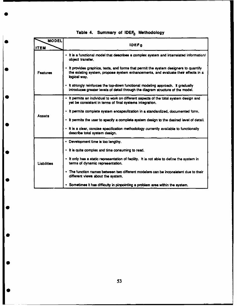
Table 4. Summary of IDEF0 Methodology* MO DEL
IDEFO
• It is a functional model that describes a complex system and interrelated information/object transfer.
* * It provides graphics, texts, and forms that permit the system designers to quantifyFeatures the existing system, propose system enhancements, and evaluate their effects in a
logical way.
- It strongly reinforces the top-down functional modeling approach. It graduallyintroduces greater levels of detail through the diagram structure of the model.
• • It permits an individual to work on different aspects of the total system design andyet be consistent in terms of final systems integration.
- It permits complete system encapsulization in a standardized, documented form.Assets
- It permits the user to specify a complete system design to the desired level of detail.
- It is a clear, concise specification methodology currently available to functionally
describe total system design.
* Development time is too lengthy.
* It is quite complex and time consuming to read.
- ft only has a static representation of facility. ft is not able to define the system inLiabilities terms of dynamic representation.
* The function names between two different modelers can be inconsistent due to theirdifferent views about the system.
• Sometimes it has difficulty in pinpointing a problem area within the system.
0
53
0

Table 5. Summary of IDEF1 /IDEF1 x Methodology
MOEL
IDEF 1 IDEF1 X
* It comprises three primary elements:- Entities (classes of things of information)- Attribue (classe of kinds of information)- Classes of relations between entities.
Features - It incorporates the necessary graphics, texts, and forms to inject an organizeddiscipline into the process.
" It provides for the measurement and control of the progressive development of themodel through the routine of the modeling discipline.
• It is a coherent language that supports the development of conceptual schemas.
" It produces graphical diagrams that explicitly represent data semantics.
* It represents a broad range of detail, making it suitable for supporting the completeprocess of developing information systems.
* t is independent of any DBMS and application tools.Assets
* t has been successfully applied in a variety of enterprises to achieve implementationof integrated data resources.
" It provides a modularity that can protect against inaccuracy, incompleteness,
Inconsistency, and imprecision.
" It supports disciplined, coordinated teamwork.
" It describes only the static behavior of information In a system.
" Considerable knowledge is required for implementation, and building the data model isUabilites time consuming.
* Inexperienced users often generate a non-normalized form and later cause data baseanomalies.
54
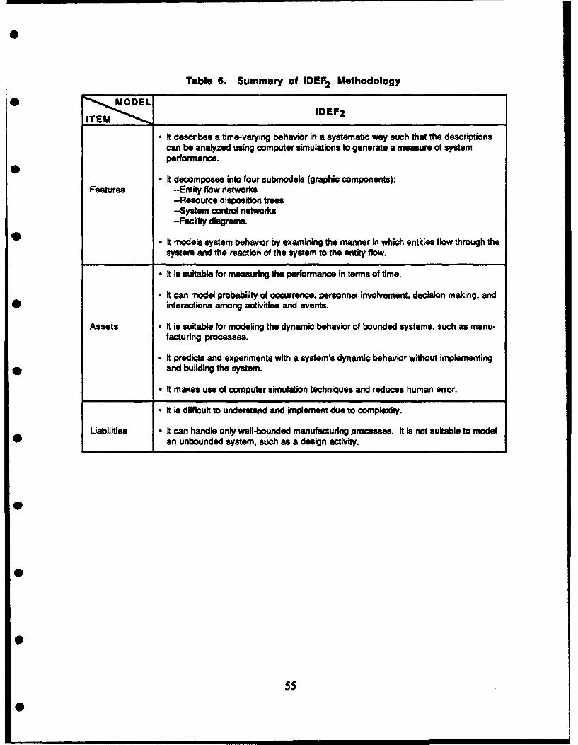
Table 6. Summary of IDEF2 Methodology* M , OEL
ITEM IDEF2
* It describes a time-varying behavior in a systematic way such that the descriptionscan be analyzed using computer simulations to generate a measure of systemperformance.
- It decomposes into four submodels (graphic components):Features --Entity flow networks
-Resource disposition trees-System control networks-Facility diagrams.
• It models system behavior by examining the manner in which entities flow through thesystem and the reaction of the system to the entity flow.
- It is suitable for measuring the performance in terms of time.
* It can model probability of occurrence, personnel involvement, decision making, and* interactions among activities and events.
Assets • It is suitable for modeling the dynamic behavior of bounded systems, such as manu-facturing processes.
* It predicts and experiments with a system's dynamic behavior without implementing* and building the system.
* It makes use of computer simulation techniques and reduces human error.
* It is difficult to understand and implement due to complexity.
Uabilities • It can handle only well-bounded manufacturing processes. It is not suitable to model* an unbounded system, such as a design activity.
0
55
0
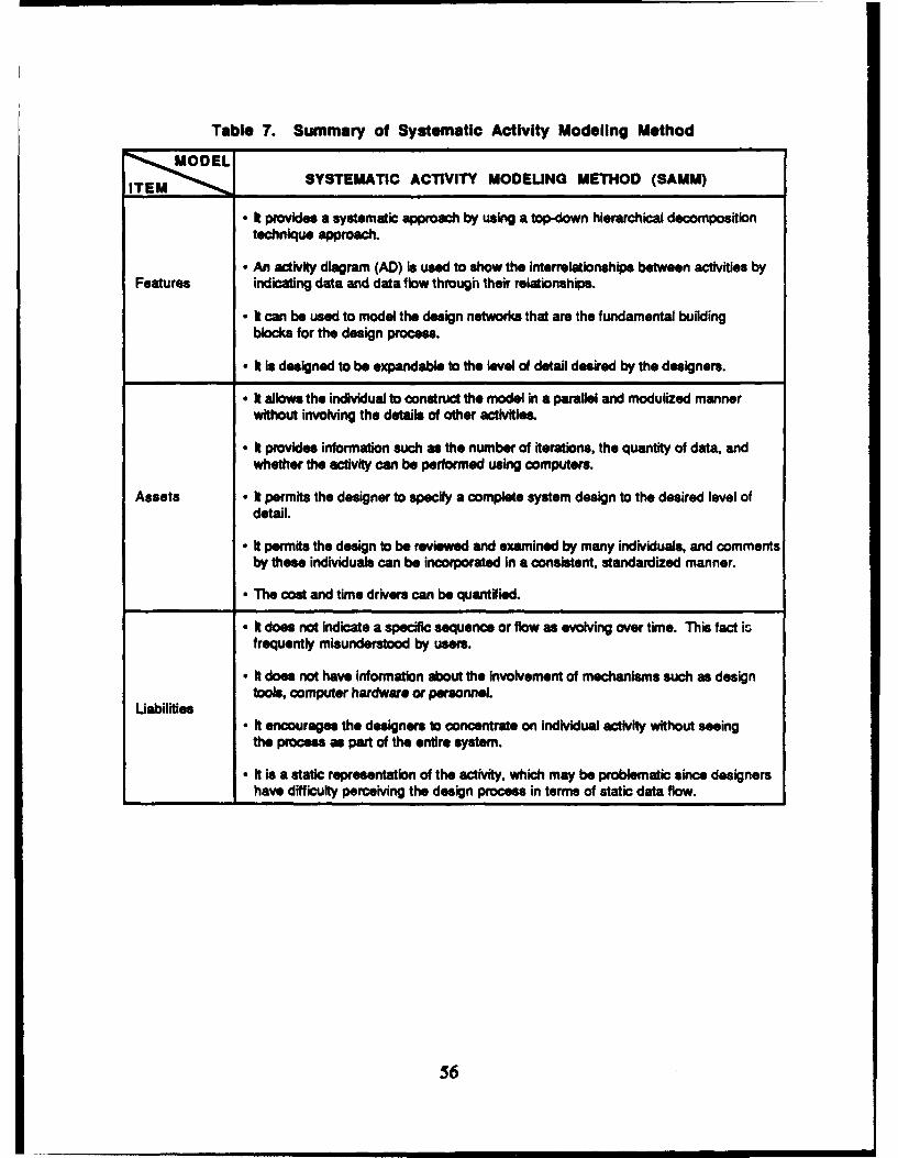
Table 7. Summary of Systematic Activity Modeling Method
~SYSTEMATIC ACTIVITY MODEUNG METHOD (SAMM)
" It prXovides a systematic approach by using a Uop-down hierarchical decompositiontechnique approach.
" An activity diagram (AD) is used to show the interrelationships between activities byFeatures indicating data and data flow through their relationships.
* It can be used to model the design networks that are the fundamental building
blocks for the design process.
" It is designed to be expandable to the level of detail desired by the designers.
" It allows the individual to construct the model in a parallel and modulized mannerwithout involving the details of other activities.
" It provides information such as the number of terations, the quantity of data, andwhether the activity can be performed using computers.
Assets - It permits the designer to specify a complete system design to the desired level ofdetail.
" It permits the design to be reviewed and examined by many individuals, and commentsby these individuals can be incorporated in a consistent, standardized manner.
" The cost and time drivers can be quantified.
* It does not indicate a specific sequence or flow as evolving over time. This fact isfrequently misunderstood by users.
" It does not have information about the involvement of mechanisms such as designtools, computer hardware or personnel.
Uabilities* It encourages the designers to concentrate on individual activity without seeing
the process as part of the entire system.
" it is a static representation of the activity, which may be problematic since designershave difficulty perceiving the design process in terms of static data flow.
56
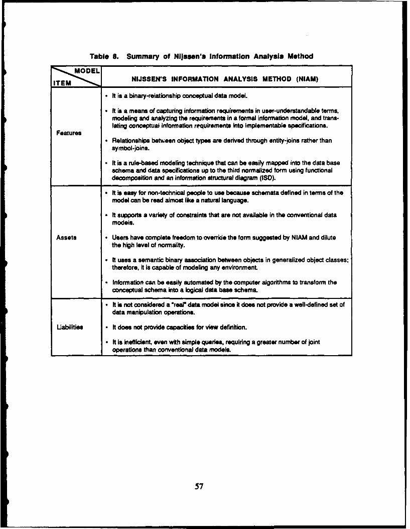
Table 8. Summary of Nijssen's Information Analysis MethodMD EL
ITEM NIJSSEN'S INFORMATION ANALYSIS METHOD (NIAM)
• It is a binary-relationship conceptual data model.
- It is a means of capturing information requirements in user-understandable terms,modeling and analyzing the requirements in a formal information model, and trans-lating conceptual information requirements into implementable specifications.
Features• Relationships between object types are derived through entity-joins rather than
symbol-joins.
- It is a rule-based modeling technique that can be easily mapped into the data baseschema and data specifications up to the third normalized form using functionaldecomposition and an information structural diagram (ISD).
- It is easy for non-technical people to use because schemata defined in terms of themodel can be read almost like a natural language.
• It supports a variety of constraints that are not available in the conventional datamodels.
Assets • Users have complete freedom to override the form suggested by NIAM and dilutethe high level of normality.
- It uses a semantic binary association between objects in generalized object classes;therefore, it is capable of modeling any environment.
- Information can be easily automated by the computer algorithms to transform theconceptual schema into a logical data base schema.
- It is not considered a "rear data model since it does not provide a well-defined set ofdata manipulation operations.
Uabilities - It does not provide capacities for view definition.
- It is inefficient, even with simple queries, requiring a greater number of jointoperations than conventional data models.
57

Table 9. Summary of Entity-Relationship Model
MODELITEM -ENTITY-RELATIONSHIP MODEL (ERM)
It is one of the earliest conceptual data models.
I ft supports the top-down approach.
Features - It consists of three basic constructs: entities, relationships, and attributes.
" It can model composite entities or their relationships.
" The Entity-Relationship Diagram (ERD) provides users a visual immediacy that makesERM a popular conceptual data model.
" The ERP's basic construct is very simple to represent and loam.
" The ERD is a comprehensive and simple diagrammatic technique.
" Many-to-many relationships are easy to implementAssets
" ERD can be easily mapped into a relational data base structure with up to the thirdnormal form.
* It is supported by the well-developed entity-relationship modeling tools.
" It assumes that an entity can be represented by a single relation.
" Even if classified as a semantic data model, ERM still cannot provide sufficientUabilities semantics for engineering design objects.
" It provides the modelers with a great deal of freedom to model the enterprise; hence,the models generated by different individuals can have many discrepancies.
58
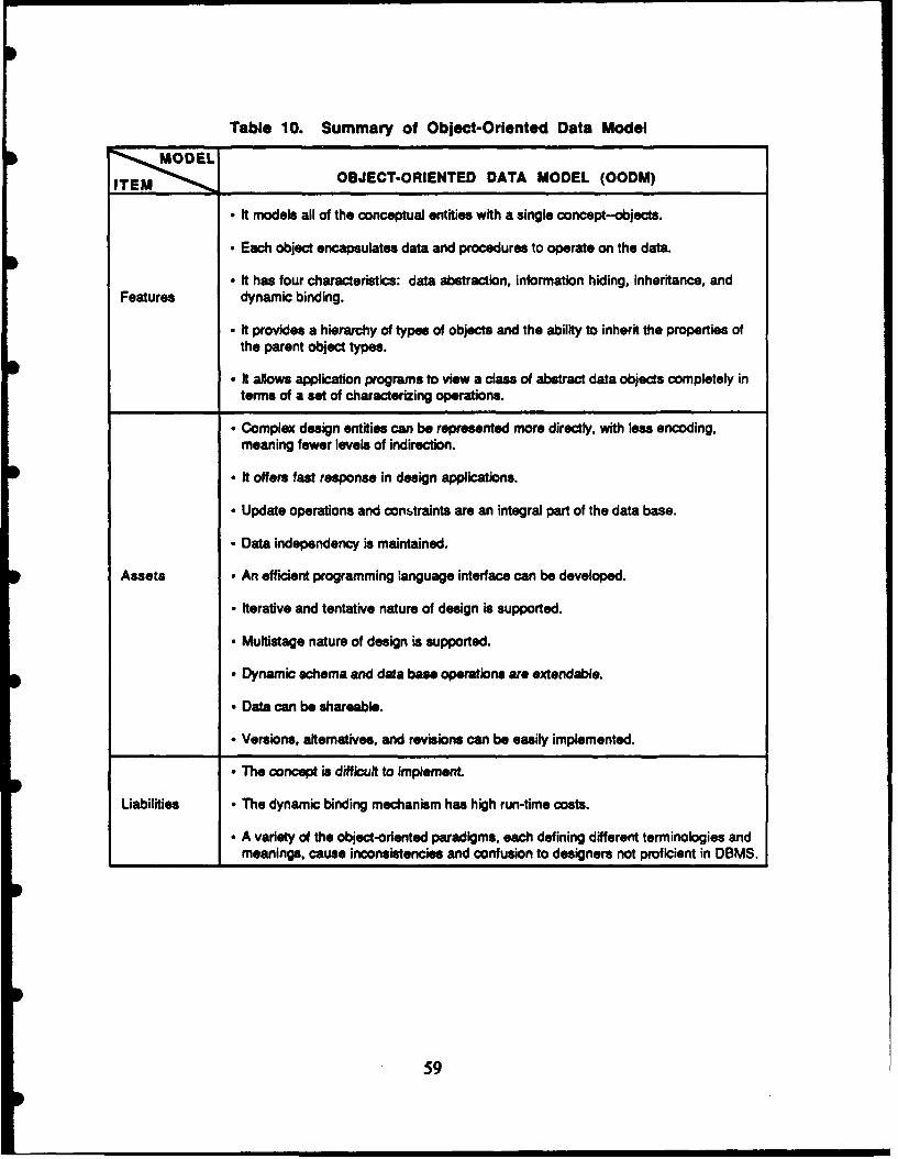
Table 10. Summary of Object-Oriented Data Model
TOBJECT-ORIENTED DATA MODEL (OODM)
- It models all of the conceptual entities with a single concept-objects.
• Each object encapsulates data and procedures to operate on the data.
* It has four characteristics: data abstraction, information hiding, inheritance, andFeatures dynamic binding.
- It provides a hierarchy of types of objects and the ability to inherit the properties ofthe parent object types.
- It allows application programs to view a class of abstract data objects completely interms of a set of characterizing operations.
- Complex design entities can be represented more directly, with less encoding,meaning fewer levels of indirection.
* It offers fast response in design applications.
* Update operations and onstraints are an integral part of the data base.
• Data independency is maintained.
Assets - An efficient programming language interface can be developed.
- Iterative and tentative nature of design is supported.
- Multistage nature of design is supported.
• Dynamic schema and data base operations are extendable.
- Data can be shareable.
- Versions, alternatives, and revisions can be easily implemented.
- The concept is difficult to implement
Liabilities • The dynamic binding mechanism has high run-time costs.
• A variety of the object-oriented paradigms, each defining different terminologies andmeanings, cause inconsistencies and confusion to designers not proficient in DBMS.
59
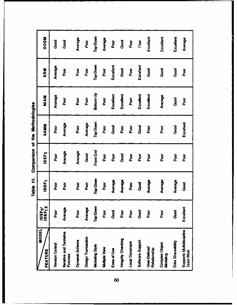
6c <
ui .5
S CL
~o. ~omw 4 u8
a. - -
0
ac
* UU
CL
o cmU. ~ 0. 0. 0
CL L Co.
. -. 8
LU C.0
0-0
the test problem. The results indicate that none of the methodologies meets all of thespecified functional requirements and characteristics of the design process, although the
object-oriented data model was found to be the best data modeling method for modeling the
aerospace vehicle design process. Combining two methodologies (one data model and one
process model) seems to be the best strategy for covering the requirements of modeling the
aerospace vehicle design process; however, the effort and time required to do so may be
prohibitive.
C. ADDITIONAL EVALUATIONS
In addition to identifying the predominant features, assets, and liabilities of these
methodologies, which is essential to fully evaluate them, other intangible features, such as
the assumptions the methodologies are based on and the skills required for use, are alsoimportant. The application of these methodologies requires not only a knowledge of the
steps and techniques involved, but also a comprehension of the underlying concepts,
philosophy, and scope.
1. Assumptions
All methodologies are based on certain assumptions, although they are not always
explicitly stated in the documentation of the model. Most methods are based on thecommon assumption that information can be modeled and that the models used in each
methodology are adequate for this purpose. More importantly, the mapping of these
models to implementation or physical models is assumed to be a simple task. NIAM usesobject types and associations; IDEFIx uses entities, attributes, and relationships; ERM usesentities and relationships; and OODM uses only objects as the basic constructs.
Other important assumptions are concerned with the decomposition of the systemsand the sequencing of the tasks. SAMM, IDEF, and ERM are based on the assumption
that a system can be hierarchically decomposed and partitioned using a top-down approach.NIAM is based on the assumption that the integration of information systems in a bottom-
up fashion can be applied to produce logical data models.
2. Skills Required for Use
The skills needed by the designers to use these methodologies differ substantially.
For some, no particular data processing skills are necessary; NIAM and ERM have been
61
successfully used by novices, while others, such as OODM and IDEF, require extensive
experience. These methodologies can be used individually or in combination to provide a
comprehensive description of any complex system, such as modeling of the aerospacevehicle design process. Although the skill levels necessary to use the methodologies vary
significantly, the complete knowledge and understanding of the system modeled is
required.
3. Scope
The scope of the methodologies also varies among the application areas. The
maximum benefits of each methodology can be obtained only by using the method in the
specific application area for which it was developed. For example, IDEF methodologies
were established for modeling the function, information, and dynamics of manufacturing
systems. SAMM is best suited for modeling design activities in the system development
phases. ERM and NIAM were designed to be the modeling methods for the entire scope of
an information system. OODM, however, is suitable for modeling engineering design
objects.
4. Graphical Representation and Software Support
All methodologies support graphical representation and techniques to facilitate and
simplify the modeling process. IDEFo and SAMM use rectangular boxes to representactivities and arrow lines to relate them. The ERD technique employs boxes (entities) and
diamonds (relationships). IDEFI and IDEFIX apply rectangles and lines to represent the
entities and relationships. OODM and IDEF2 have many graphical constructs with different
representations that can be difficult for novice designers to grasp. Almost all of the
modeling methods can be automated and aided by commercially available software. IDEF
methods are supported by ECLIPSE developed by DACOM. NLAM is supported by IAST
and RIDL, developed by CDC. OODM is supported by VBASE developed by Ontologic.
62

VI. CONCLUSIONS AND RECOMMENDATIONS
The aerospace vehicle design process is a complex activity that often requires the
effort of many individuals over an extensive period of time. The entire scope of the design
process is driven by design information created during the design operations. To
effectively manage the design information, various CAD/CAM and data base technologies
and techniques, such as integrated data base concepts, distributed data base concepts, and
semantic data modeling methods, have been developed and implemented. One of the key
issues for ensuring the effective management of engineering information is the use of a
DBMS specifically tailored to engineering applications. Conventional DBMSs, developed
for business- and administration-oriented environments, cannot fulfill the functional
requirements for engineering applications. In light of the deficiencies of conventional
DBMSs, many data/process modeling methodologies have been advocated and
implemented. Such methodologies were developed to serve the needs of particular
engineering tasks and previously were not sufficiently evaluated in terms of their relevance
to aerospace vehicle design. The IDA study covered seven data/process modeling
methodologies (IDEF0, IDEFlx, IDEF2 , NIAM, SAMMvf, ERM, and 00DM), which were
evaluated by testing their application to aircraft wing composite panel design. The results
of this evaluation are summarized in this paper.
The study indicated that none of the existing modeling methodologies is adequate
for supporting the overall aerospace vehicle design process. The OODM seems to possess
many of the features required for the ideal design decision support system for modeling the
aerospace vehicle design process. Some of the features that the OODM lacks are embodied
in other methodologies. It is felt that research toward ;n extended information modeling
methodology, formed by combining the OODM data model with a process model (such as
DEFo or SAMM), may provide the optimal design decision support environment. Such a
modeling method must be developed, implemented, and tested to provide critically needed
support of future information-driven aerospace design processes. Large-scale test bed
problems, such as the XV- 15 tilt-rotor composite aircraft wing structure or avionics control
63
systems, should be used to evaluate the information methodologies assessed in this report,as well as any future methodology developments.
64
REFERENCES
1. Fulton, R.E., "A Framework for Innovation," Computers in MechanicalEngineering, March 1987, pp. 26-40.
2. "Decision Support Requirements in a Unified Life Cycle Engineering (ULCE)Environment, Volume I: An Evaluation of Potential Research Directions," ULCEDSS Working Group, IDA Paper P-2064, May 1988.
3. Brei, ML, W.E. Cralley, D. Dierolf, D.J. Owen, K.J. Richter, and E. Rogan,"Architecture and Integration Requirements for an ULCE Design Environment,"IDA Paper P-2063, April 1988.
4. Alsina, J., J.P. Fielding, and A. J. Morris, "Progress Towards an Aircraft DesignSystem," Computer Applications in Aircraft Design and Operations,T. K. Smurthy, Ed., 1987, pp. 229-247.
5. Kinoglu, F., D. Riley, and M. Donath, "Expert System Model of Design Process,"IEEE/ACM 1983 Design Automation Conference, 1983, pp. 7-14 to 7-27.
6. Meyer, D.D., "Development of Integrated Programs for Aerospace-Vehicle Design(IPAD) - Reference Design Process," NASA Contract NASA-14700, NASAContract Report CR-2981, Boeing Commercial Airplane Company, March 1979.
7. Heldenfels, R.R., "Integrated Computer-Aided Design of Aircraft," NA TOAGARD Conference Proceedings in Aircraft Design Integration and Optimization,AGARD-CP-147, October 1973, pp. 16-1 to 16-12.
8. Barnes, R., "Technology for the Product & Process Data Base," Proceedings of aNational Symposium for IPAD Il--Advances in Distributed Data Base Managementfor CAD/CAM, Denver, CO, April 17-19, 1984, NASA Conference PublicationNo. 2301, NASA, Washington, DC, April 1984, pp. 35-41.
9. McKenna, E.G., ")esign Verse Manufacturing Data Base ManagementRequirements," Proceedings of National Symposium for IPAD Il--Advances inDistributed Data Base Management for CAD/CAM, Denver, CO, April 17-19,1984, NASA Conference Publication No. 2301, NASA, Washington, DC, April1984, pp. 51-79.
10. Dittrich, K.R., A.M. Kotz, and J.A. Mulle, "A Multilevel Approach to DesignDatabase Systems and its Basic Mechanisms," Proceedings of IEEE 1985Compint - Computer Aided Technologies, 1985, pp. 313-320.
65
i1. Peterson, J.G., G. Nadler, and M. Chignell, "Perspectives on Design, Problems,Processes and Purposes," Proceedings of the 1987 International Conference onMachines, Man, and Cybernetics, 1987, pp. 980-985.
12. Madison, D.E., T.J. Wilbur, Jr., and C.T. Wu, "Data-Driven CIM," Computers inMechanical Engineering, March/April 1987, pp. 38-45.
13. Ebel, J.L., and A.J. Gadient, "The VHSIC Engineering Information SystemProgram," Proceedings of IEEE 1986 National Aerospace and ElectronicsConference, NAECON '86, Vol. I, May 1986.
14. Ralston, D., and T. Munton, "Computer Integrated Manufacturing," Computer-Aided Engineering Journal, August 1987, pp. 167-174.
15. Hsu, C., and C. Skevington, "Integration of Data and Knowledge inManufacturing Enterprises: A Conceptual Framework," Journal of ManufacturingSystems, Vol. 6, No. 4, pp. 421-428 and 277-285.
16. Dittrich, K.R., A.M. Kotz, and J.A. Mulle, "A Multilevel Approach to DesignDatabase Systems and its Basic Mechanisms," Proceedings of IEEE 1985Compint - Computer Aided Technologies, 1985, pp. 313-320.
17. Bray, O.H., "Computer-Integrated Manufacturing: The Data ManagementStrategy," Digital Press, Bedford, MA, 1988.
18. Atre, S., "Data Base: Structured Techniques for Design, Performance, andManagement," published by John Wiley & Sons, Inc., 1980.
19. Hatchell, B.K., G. Benatar, R.E. Fulton, and C.L. Blackburn, "An Aid forInstruction on Integrated Engineering Design and Support," Managing EngineeringData: The Competitive Edge, The 1987 ASME International Computers inEngineering Conference and Exhibition, New York, NY, August 1987, pp. 87-95.
20. Staley, S.M., and D.C. Anderson, "Functional Specification for CAD Databases,"Computer-A ided Design Journal, Vol. 18, No. 3, April 1986.
21. "[PAD 11--Advances in Distributed Database Management for CAD/CAM,"Proceedings of a National Symposium for IPAD IL--Advances in Distributed DataBase Management for CAD/CAM, Denver, CO., April 17-19, 1984, NASAConference Publication No. 2301, NASA, Washington, DC, 1984.
22. Garrocq, C.A., J.J. Hosek, et al., "Feasibility Study of an Integrated Program forAerospace-Vehicle Design (PAD) System," NASA Contract NAS1- 11431,Contract Report CR-132403, General Dynamics Corporation, August 1973.
23. Southall, J.W., "Development of Integrated Programs for Aerospace-VehicleDesign (IPAD) - Information Processing Requirements," NASA Contract NAS1-14700, NASA Contract Report CR-2981, Boeing Commercial Airplane Company,June 1977.
66
24. Fulton, R.E., "Overview of Integrated Programs of Aerospace Vehicle Design(IPAD)," NASA Technical Memorandum TM-81874, 1980.
25. Diggins, R.M., "Preliminary Design of a Future Integrated Design System,"Proceedings of National Symposium for IPAD, Denver, CO, NASA ConferencePublication 2143, 1980, pp. 75-94.
26. Johnson, H.R., D.L. Comfort, and D.D. Shull, "An Engineering DataManagement System for IPAD," Proceedings of National Symposium for IPAD,Denver, CO, NASA Conference Publication 2143, 1980, pp. 145-178.
27. Bernstein, T.N., "Integrated Design Support System," Managing Engineering Data:The Competitive Edge, The 1987 ASME International Computers in EngineeringConference and Exhibition, New York, NY, August 1987, pp. 41-47.
28. "Information Support System (IISS) Information Modeling Manual - Extended(IDEFIx)," D. Appleton Company, Inc., Manhattan Beach, CA, 1985.
29. Gloudeman, J.F., and R.R. Brown, "Managing Engineering Analysis Data,"Computers in Mechanical Engineering, March 1987, pp. 42-44.
30. Rouse, N.E., "Managing Engineering Databases," Machine Design Magazine,September 10, 1987, pp. 108-112.
31. Fenves, S.J., and W.J. Rasdorf, "Role of Data Management Systems in StructuralEngineering," Proceedings of the IABSE Colloquium on Informatics in StructuralEngineering, International Association of Bridge and Structural Engineers, October1982, pp. 229-242.
32. Clemons, E.K., "Data Models and ANSI/SPARC Architecture," Principles ofDatabase Design, Vol. 1, S. B. Yao, Ed., Prentice-Hall, Inc., 1985, pp. 66-114.
33. Benayoune, M., and P. E. Preece, "Methodology for the Design of Databases forEngineering Applications," Journal of Computer-Aided Design, Vol. 18, No. 5,June 1986, pp. 257-262.
34. Du, H.C., and S. Ghanta, "A Framework for Efficient IC/VLSI CAD Databases,"Proceedings of IEEE 1987 Third International Conference on Data Engineering,pp. 619-625.
35. Cammarata, S.J., and M.A. Melkanoff, "An Information Dictionary for ManagingCAD/CAM Databases," Data Programming and Design, Vol. 1, No. 3, March1988.
36. Rice, L., "Managing CAD/CAM/CAE and Design Processes in MechanicalEngineering," Proceedings in Computers in Mechanical Engineering, pp. 421-428.
37. Mindlin, L, and S.H. Smith, "Database System Considerations in EngineeringDesign," Managing Engineering Data: The Competitive Edge, The 1987 ASMEInternational Computers in Engineering Conference and Exhibition, New York,NY, August 1987, pp. 9-15.
67
38. Bray, O.H., "Engineering Database Management Requirements: The NextGeneration," Managing Engineering Data: The Competitive Edge, The 1987 ASMEInternational Computers in Engineering Conference and Exhibition, New York,NY, August 1987, pp. 41-47.
39. Rasdorf, W.J., "Extending DBMS's for Engineering Applications," Computers inMechanical Engineering, March 1987, pp. 62-69.
40. Rasdorf, W.J., "Engineering Database Management Needs," ManagementEngineering Data: The Competitive Edge, The 1987 ASME InternationalComputers in Engineering Conference and Exhibition, New York, NY, August1987, pp. 41-47.
41. Ketabchi, M.A., and V. Berzins, "Modeling and Managing CAD Databases,"Computer, February 1987, pp. 93-102.
42. ANSI/X3/SPARC, "Interim Report from the Study Group on Data BaseManagement Systems," 75-02-08, FDT (Bulletin of the ACM SIGMOD), Vol. 7,No. 2, 1975.
43. Hammer, M., and D. McLeod, "Database Description with SDM: A SemanticDatabase Model," ACM Transactions on Database Systems, Vol. 6, No. 3,September 1981, pp. 351-386.
44. Buneman, P., and R.E. Franke, "FQL--A Functional Query Language,"Proceedings of ACM SIGMOD International Conference on the Management ofData, Boston, May 30-June 1, 1979.
45. Tsai, W., "Composite Design," Third Edition, Think Composite Company,Dayton, OH, 1985.
46. Mallick, P.K., "Fiber-Reinforced Composite," Marge Dekker PublishingCompany, 1988.
47. Parks, C.H., "Tutorial: Reading and Reviewing the Common Schema forElectrical Design and Analysis," Proceedings of 24th ACM/IEEE DesignAutomation Conference, 1987, pp. 479-483.
48. Shunk, D., B. Sullivan, and J. Cahill, "Making the Most of IDEF Modeling - TheTriple-Diagonal Concept," CIM Review, The Journal of Computer-IntegratedManufacturing Management, Vol. 3, No. 1, Fall 1986, pp. 12-17.
49. "Integrated Computer-Aided Manufacturing (ICAM) Architecture, Part II, Vol.IV - Functional Modeling Manual (IDEF0)," Softech, Inc., Waltham, MA, 1981.
50. Mackulak, G.T., "High Level Planning and Control: an IDEFo Analysis forAirframe Manufacture," Journal of Manufacturing Systems, Vol. 3, No. 2,pp. 121-133.
51. Mackulak, G.T., "An Examination of the IDEF0 Approach Used as a PotentialIndustrial Standard for Production Control System Design," Automated
68
Manufacturing, ASTM STP862, L. B. Gargner, Ed., Philadelphia, 1985,pp. 136-149.
52. "Integrated Computer-Aided Manufacturing (ICAM) Architecture, Part Ill, Vol.V - Information Modeling Manual (IDEF 1)," Softech, Inc., Waltham, MA, 1981.
53. Loomis, M.E.S., "Modeling - The IDEFIx Technique," IEEE 1986 PhoenixConference on Computers and Communications, pp. 146-151.
54. Bravoco, R.R., and S.B. Yadav, "A Methodology to Model the InformationStructure of an Organization," The Journal of Systems and Software, Vol. 5, 1985,pp. 59-71.
55. Bravoco, R.R., and S.B. Yadav, "A Methodology to Model the Dynamic Structureof an Organization," Information Systems, Vol. 10, No. 3, 1985, pp. 299-317.
56. "Integrated Computer-Aided Manufacturing (ICAM) Architecture, Part M, Vol.VI - Dynamics Modeling Manual (IDEF2)," Softech, Inc., Waltham, MA, 198 1.
57. Southall, J.W., "Development of Integrated Programs for Aerospace-VehicleDesign (IPAD) - Information Processing Requirements," NASA Contract NAS1-14700, NASA Contract Report CR-2981, Boeing Commercial Airplane Company,June 1977.
58. Nijssen, G.M., "Databases of the Future: Design and Methodology," DatabaseJournal (GB), Vol. 12, No. 1, January 1982, pp. 2-9.
59. Flynn, D.J., and A.H.F. Laender, "Mapping from a Conceptual Schema to aTarget Internal Schema," The Computer Journal (UK), Vol. 28, No. 5, 1985,pp. 508-516.
60. Gadre, S.H., "Building an Enterprise and Information Model," DatabaseProgramming and Design, Premier Issue 1987, San Francisco, CA, 1987,pp. 48-58.
61. Shoval, P., "Essential Information Structure Diagrams and Database SchemaDesign," Information Systems, Vol. 10, No. 4, 1985, pp. 417-423.
62. Chen, P.S., "Database Design Based on Entity and Relationship," Principles ofDatabase Design, Vol. I, edited by S. B. Yao, 1985, pp. 174-210.
63. Chen, P.S., "The Entity-Relationship Model: Toward a Unified View of Data,"ACM Transactions on Database Systems, Vol. 1, No. 1, March 1976, pp. 9-36.
64. Atwc.od, T.M., "An Object-Oriented DBMS for Design Support Applications,"Proceedings of IEEE Compint - Computer Aided Technologies, 1985,pp. 299-307.
65. Dittrich, K.R., and R.A. Lorie, "Object-Oriented Database Concepts forEngineering Applications," Proceedings of IEEE Compint - Computer AidedTechnologies, 1985, pp. 321-325.
69
66. Landis, G.S., "Design Evolution and History in an Object-Oriented CAD/CAMDatabase," IEEE Computer Society Compcon, Spring '86, March 1986,pp. 297-303.
67. Spooner, D.L., Michael and D.B. Faatz, "Modeling Mechanical CAD DataAbstraction and Object-Oriented Techniques," Proceedings: IEEE 1986International Conference on Data Engineering, 1986, pp. 416-424.
68. McLeod, D., K. Narayanaswamy, and K.V. Bapa Rao, "An Approach toInformation Management of CAD/VLSI Applications," Proceedings of 1983 ACMSIGMODIIEEE: Engineering Design Applications, 1983, pp. 39-49.
69. Stonebraker, M., B. Rubenstein, and A. Guttman, "Application of Abstract DataTypes and Abstract Indices to CAD Databases," Proceedings of Annual Meeting:Database Week, IEEE Computer Soc. Press, 1983, pp. 107-113.
70. Derret, N.P., D.H. Fishman, W. Kent, P. Lyngback, and T.A. Ryan, "An Object-Oriented Approach to Data Management," IEEE Computer Society Compcon,Spring '86, March 1986, pp. 330-335.
71. Pascoe, G.A., "Elements of Object-Oriented Programming," Byte, August 1986,pp. 139-144.
72. Fenves, G.L., "Object Representations for Structural Analysis and Design,"Proceedings of Computers in Civil Engineering, 1988, pp. 502-511.
73. LeJacq, J.P., "Functional Requirements for CAD Database Using a GeneralModeling Abstraction of Physical Systems," Conference on Data and KnowledgeSystems for Many4acturing and Engineering, October 1987, pp. 111-114.
70
DISTRIBUTION
IDA PAPER P-2154
MANAGING ENGINEERING DESIGN INFORMATION
133 Copies
Number of
Defartment of Defense
* OUSD (R&ATVETRm. 3D1089, PentagonWashington, DC 20301-3080
ATTN: Mr. Raymond Siewert 1Dr. Leo Young 1
Assistant Deputy, Systems, OASD/P&LDepartment of DefenseRoom 2B322, PentagonWashington, DC 20301-8000
'ATN: Mr. Russell R. Shorey
OASD CP&LS WSRm. 2B322, The PentagonWashington, DC 20301-8000
ATrN: Mr. Don Hall
Office of the Secretary of Defense (P&L)Director, CALSRm. 2B322, PentagonWashington, DC 20301
ATrN: Michael McGrath 1
OASD (P&L), SystemsDirector, Weapon Support Improvement GroupRm. 2B322, PentagonWashington, DC 20301
ATTN: Martin Meth 1
Dr. William E. Isler 1Program Manager, ISTODefense Advanced Research Projects Agency1400 Wilson Boulevard, 7th FloorArlington, VA 22209-2308
DL-1
Dr. Jacob SchwartzDirector, Information Science and Technology OfficeDefense Advanced Research Projects Agency1400 Wilson Boulevard, 7th FloorArlington, VA 22209-2308
Dr. Stephen L. SquiresInformation Science and Technology OfficeDefense Advanced Research Projects Agency1400 Wilson Boulevard, 7th FloorArlington, VA 22209-2308
Defense Technical Information Center 2Cameron StationAlexandria, VA 22304-6145
Miscellaneous. U.S. Government
Dr. Jaroslaw SobieskiDeputy Head, Interdisciplinary Research OfficeNASA Langley Research CenterStructures DirectorateHampton, VA 23665
Dr. John Zuk 1Chief, Advanced Plans and Programs OfficeNASA Ames Research CenterMoffett Field, CA 94035
National Science FoundationDirectorate for EngineeringDivision of Design and Manufacturing Systems1800 G Street, NWWashington, DC 20550
A[TN: Dr. Marvin DeVriesDr. Branimir F. von Turkovich
D ent of the Army
Mr. Sid MarkowitzUS Army AMCCOMATN: AMSMC-QAHPPicatinny Arsenal, Bldg. 62Dover, NJ 07806-5000
DL-2
Mr. Geza Papp IChief of TechnologyUS Army AMCCOMPicatinny Arsenal, Bldg. 62Dov--r, NJ 07806-5000
Mr. Charles ReadingChief, Logisu.s Management DivisionCdr USAAVSCOMAMCPM-LHX-L4300 Goodfellow BoulevardSt. Louis, MO 63120-1798
partment of the NM
Mr. W. J. WilloughbyDirector for Reliability, Maintainability
and QualityOffice of the Assistant Secretary of the Navy
(Shipbuilding and Logistics)Washington, DC 20360-5000
Department of the NavyAssistant Secretary of the NavyResearch, Engineering, and SystemsRm. 4E732, PentagonWashington, DC 20350-1000
Mr. Albert KnightNaval Ocean Systems CenterComputer Integrated Engineering, Code 936San Diego, CA 92152-5000
Detomaet of the Air Force
Hon. John J. WelchAssistant Secretary of the Air Force (Acquisition)HQ, US Air ForceRi. 4E964, PentagonWashington, DC 20330-1000
Brig. Gen. W. E. CollinsSpecial Assistant for Reliability and MaintainabilityHQ, USAF/LE-RDRm. 4E259, PentagonWashington, DC 20330
DL-3
Col. James Hanington 1HQ USAF/LE-RDRm. 4E259, PentagonWashington, DC 20330
Dr. John Dimmock 1Technical DirectorAir Force Office of Scientific ResearchBoiling AFB, Bldg. 410Washington, DC 20332
Capt. Maureen Harrington 1AFC SA/SAGRWashington, DC 20330-5420
AFHRLA.RLWright-Patterson AFB, OH 45433 9
ATIN: Capt. Raymond Hill 5Capt. Mike Hanuschik 1Capt. Rick Berry 1Capt. Don Loose 1Ms. Wendy Campbell 1
Dr. Gary Denman 1Deputy Dir=ctorWright Research and Development CenterArea B, Bldg. 45, Rm. 207Wright-Patterson AFB, OH 45433
Mr. Alan E. Herner 1Operations Research AnalystWRDC/MTCWright-Patterson AFB, OH 45433 S
Mr. Raymond L Johnson 1Technical DirectorAeronautical Systems DivisionUSAF, ASD/ENSDirectorate of Systems EngineeringWright-Patterson AFB, OH 45433-6503
Dr. Squire BrownDirector, Technology Assessment OfficeAFWAL/FIAWright-Patterson AFB, OH 45433
S
DL-4
I I I

.
Dr. Alice M. AgoginoAssociate Professor of Mechanical EngineeringMechanical Engineering DepartmentUniversity of California at Berkeley5136 Etcheverry HallBerkeley, CA 94720
Dr. Erik K. AntonnsonAssistant Professor of Mechanical EngineeringEngineering Design Research LaboratoryCalifornia Institute of TechnoogyMail Code 104-44Pasadena, CA 91125
Dr. Richard J. BallingCivil Engineering Department, 368 CBBrigham Young UniversityProvo, Utah 84602
Dr. Ben BlanchardAssistant Dean of Engineering for ExtensionVirginia Polytechnic and State UniversityCollege of Engineering341 Norris HallBlacksburg, VA 24061
Dr. Dale E. CalkinsResearch Associate ProfessorOcean Engineering ProgramDepartment of Mechanical EngineeringUniversity of WashingtonSeattle, WA 98195
Dr. Alexander N. ChristakisDefense Systems Management CollegeFort Belvoir, VA 22060-5426
Dr. Don ClausingLaboratory for Manufacturing and ProductivityMassachusetts Institute of TechnologyBldg. 35, Room 23877 Massachusetts AvenueCambridge, MA 02139
DL-5
Dr. John R. DixonProfessor of Mechanical EngineeringUniversity of MassachusettsDepartment of Mechanical EngineeringEngineering Laboratory BuildingAmherst, MA 01003
Dr. Walter J. FabryckyProfessor of Industrial Engineering and
Operations ResearchVirginia Polytechnic and State UniversityBlacksburg, VA 24061
Dr. Susan FingerCarnegie-Mellon UniversityThe Robotics InstitutePittsburgh, PA 15213
Dr. Mark Fox 1Director, Intelligent Systems LaboratoryCarnegie-Mellon UniversityThe Robotics InstitutePittsburgh, PA 15213
Dr. Robert E. FultonProfessor, Department of MEGeorgia Institute of TechnologyMechanical Engineering DepartmentAtlanta, GA 30332
Dr. M. HardwickRensselaer Polytechnic InstituteTroy, NY 12180-3590
Dr. Michel A. MelkanoffUniversity of California at Los Angeles3532 Boelter HallLos Angeles, CA 90024-1597
Dr. Farrokh MistreeProfessor of Mechanical EngineeringMechanical Engineering DepartmentUniversity of HoustonHouston, TX 77004
Mr. Thomas J. MurrinDistinguished Service Professor of TechnoiogyCarnegie Mellon University4630 Wean HallPittsburgh, PA 15213-3890
DL-6
,,..,,m ,,,..,l, ol llim m il ll IIIM M"I "
Dr. Gerald NadlerChairman, Department of Industrial and Systems
EngineeringIndustrial and Systems EngineeringUniversity of Southern CaliforniaUniversity ParkLos Angeles, CA 99089-1452
Dr. Michael PechtAssociate Professor of Mechanical EngineeringMechanical Engineering DepartmentUniversity of MarylandCollege Park, MD 20742
Dr. Robin J. PopplestoneDirector, Laboratory for Perceptual RoboticsDepartment of Computer and Information ScienceUniversity of MassachusettsLederly Graduate Research CenterAmherst, MA 01003
Dr. Ramana ReddyProfessor of Computer Science, Dir., AI LaboratoryDepartment of Statistics and Computer ScienceWest Virginia UniversityKnapp HallMorgantown, WV 26506
Mr. Edward RogaaSchool of Aerospace EngineeringGeorgia Institute of TechnologyAtlanta, GA 30332-0150
Dr. Bela I. SandorProfessor of Engineering MechanicsUniversity of Wisconsin - Madison2359 Engineering BuildingMadison, WI 53706
Dr. Daniel SchrageProfessor, School of Aerospace EngineeringSchool of Aerospace EngineeringGeorgia Institute of TechnologyAtlanta, GA 30332
Dr. D. L. SpoonerRensselaer Polytechnic InstituteTroy, NY 12180-3590
DL-7
Dr. Stanley Y.W. SuData Base Systems Research andDevelopment Center, 470 CSE
University of FloridaGainesville, FL 32611
Dr. Edison T.S. TseDirector, Decision Systems LaboratoryDepartment of Engineering-Economic SystemsStanford UniversityStanford, CT 94305
Dr. Manjula B. WaldronProfessor, Department of Biomedical EngineeringThe Ohio State University2070 Neil AvenueColumbus, OH 43210
Dr. John N. WarfieldDirector, Institute for Advanced Study in the IntegrativeGeorge Mason University4400 University Drive, 219 Thompson HallFairfax, VA 22030-4444
Dr. Raymond WillemAssociate Professor, Mechanical EngineeringNew Mexico State UniversityBox 345DLas Cruces, New Mexico 88003
Dr. Michael J. WoznyRensselaer Design Research CenterRensselaer Polytechnic InstituteCII, Rm. 7015Troy, NY 12180-3590
Dr. Chou-pin YehMechanical Engineering DepartmentGeorgia Institute of TechnologyAtlanta, GA 30332
Industrial Organizations
Mr. Michael G. AdamiChief, CAD/CAM MethodologyResearch and Enginering DepartmentUnited Technologies Sikorsky Aircraft6900 Main Street, MS S308AStratford, CT 06601-1381
DL-8
Mr. William G. BeazleyEditor and Publisher, CALS ReportKnowledge Base, International13939 Northwest Freeway, Suite 270Houston, TX 77040
Mr. George Beiser3001 N. Florida StreetArlington, VA 22207
Mr. Timothy V. BogardManager, Design Automation and Engineering ServicesTexas Instruments8505 Forrest Lane, P.O. Box 660246Dallas, TX 75266
Ms. ML Brei 18509 Kayburn RoadBethesda, MD 20817
Mr. E. Perley EatonPrincipal Engineer, Federal SystemsTRW Defense SystemsCommand Support Division1 Federal Systems Park12900 Fair Lakes ParkwayFairfax, VA 22033
Mr. Mark ErdrichLaboratory HeadAdv. CAD/CAM/CAEEastman Kodak Company7/23 Kodak ParkRochester, NY 14650
Dr. Iman ForoutanChief, Computer Integrated ManufacturingMicroelectronic Circuits DivisionIndustrial Electronics GroupHughes Aircraft CompanyP. O. Box H, 500 Superior AvenueNewport Beach, CA 92658-8903
Mr. David A. GatenbySupervisor, CAE/D and DFX PlanningAT&TOne Oak Way, Rm. 3EC126Berkeley Heights, NJ 07922
DL-9
Mr. Siegfried GoldsteinSiegfried Enterprises, Inc.P. 0. Box 2308North Babylon, NY 11703
Ms. Maria W. HuangData Asset Manager, Information ResourcesFMC CorporationGround Systems Division881 Martin Avenue, Box 58123Santa Clara, CA 95052
Dr. Reid June 1Manager, Stuctures TechnologyBoeing Commercial Airplane CompanyP.O. Box 3707, MS 4A-06Seattle, WA 98124
Dr. Clinton KellyCorporate Vice President for Advanced
Technology ProgramsSAIC, Inc.1710 Goodridge Drive, Rm. 1408McLean, VA 22102
Mr. Anthony KimManager, Aircraft Performance MethodsGeneral ElectricAircraft EngineOne Neumann WayCincinnati, OH 45215-6301
Mr. C. T. KitzmillerAdvanced Technology CenterBoeing Computer ServicesP.O. Box 24346, MS 7L-64Seattle, WA 98124-0346
Mrs. Mary KiementEngineering SpecialistGeneral DynamicsP.O. Box 85357, MS P1-2610San Diego, CA 92138
Dr. Janusz KowalikEngineening Technology ApplicationsBoeing Computer ServicesP.O. Box 24346Belleview, WA 98124-0346
DL-10
Dr. Manuel LoresDirector, Aircraft TechnologyLockheed Aeronautical Systems CompanyDepartment 01-35, Bldg. 63-2Plant A-1, P.O. Box 551Burbank, CA 91520-0135
Mr. Stephen A. MagnusEditorial Assistant, CAD/CAM AlertManagement Roundtable, Inc.824 Boylston StreetChestnut Hill MA 02167
Mr. Stephen MeyerMcDonnell Douglas Helicopter Company5000 E. McDowell Rd., Bldg. 530/B220Mesa, AZ 82505-9797
Dr. Alan MitchellDirector, Preliminary Design Tool DevelopmentResearch and Engineering DivisionBoeing Aerospace CompanyP. 0. Box 3999, MS 82-23Seattle, WA 98124-5214
Mr. James L. NevinsDivision LeaderThe Charles Stark Draper Laboratory, Inc.Robotics and Assembly Systems Division555 Technology SquareCambridge, MA 02139
Mr. Guy B. OlneyBoeing Computer ServicesP.O. Box 24346, M/S 7L-62Seattle, WA 98124
Mr. David OwenNTL, Inc.P. 0. Box 597Nortbport, NY 11768
Mr. Joseph PiteoUnited TechnologiesSikorsky AircraftMS S308A6900 Main StreetStratford, CT 06601-1381
DL-11
Mr. Charles R. RunyanAssistant Manager, Engineering DivisionHughes Aircraft CompanyRadar Systems GroupP. 0. Box 92426, Bldg. R1Los Angeles, CA 90009
Dr. Kamar J. SinghProject Manager, DARPA DICEGeneral Electric CompanyOne Neumann Way, MD H85Cincinnati, OH 45215-6301
Mr. David F. ZarnowAssistant Manager, Hybrid Engineering Dept.Hughes Aircraft Co., Solid State Products Div.Microelectronic Circuits Division, MS A2202500 Superior Avenue, Bldg. 700Newport Beach, CA 92658-8903
Institute for Defense Analyses1801 N. Beauregard StreetAlexandria, VA 22311 35
Gen. William Y. Smith 1Mr. Philip L. Major 1Dr. Robert E. Roberts 1Dr. William J. Schultis 1Dr. Robert I. Winner 1Mr. William E. Cralley 5Mr. David A. Dierolf 1Mr. G. Watts Hill 1Dr. James Pennell 1Dr. Karen J. Richter 10Dr. Frederick R. Riddell 1Dr. Edwin S. Townsley 1Control and Distribution 10
DL-12