Embed Size (px)
Citation preview

SYMPOSIUM SERIES NO. 156 Hazards XXII # 2011 IChemE
MANAGING REACTIVE CHEMICAL HAZARDS IN GAS SCRUBBER SYSTEMS
David Royle, Robert Fitch and Paul Gillespie, AstraZeneca, Macclesfield, Cheshire, UK
Vent gas scrubbers are routinely used to abate various substances from batch chemical processing
using a range of scrubber fluids. However it is not just the particular pollutant which can end up in
the scrubber, any other materials in use, particularly process solvents may be carried over into the
scrubber. This may give rise to unanticipated chemical reaction hazards within the abatement
system. A new risk based approach has been developed for use in process risk assessment meetings
to cover a wide range of likely interactions within a scrubber system used in batch manufacturing
process. This helps the process operator, accommodation manager, process engineer and process
chemist to quickly understand the potential for interactions and impact. A case study will be pre-
sented where an incident arose from a scrubbing operation during manufacturing. Following an
investigation into an exothermic decomposition within a scrubber system a compatibility matrix
has been produced. This screening tool, as part of the risk based approach, is designed to identify
when there is a possible interaction between process materials and scrubber solutions. The most
appropriate scrubber liquor can then be selected to minimize the risk of unwanted chemical inter-
actions taking place.
INTRODUCTIONDevelopment pharmaceuticals are generally manufacturedin multipurpose batch processing pilot plants. Due to thehighly variable demands of new processes a high degreeof flexibility is required from these manufacturing units.This need for flexibility extends to include abatementsystems for vent gasses. Multipurpose plants routinely useoff gas scrubbers to abate any various substances to withinpermitted limits and minimize the environmental impactof the manufacturing process. A range of scrubbing fluidscan be used depending on the specific scrubbing require-ments; a typical line diagram of a scrubbing system isshown in Figure 1.
Prior to operating processes in the pilot plant anindividual Process Risk Assessment (PRA) is carried out.This risk assessment considers a wide range of potentialhazards including chemical and operational hazards ofthe proposed process. It reviews the process against thepre-defined basis of safety for the pilot plant and also con-siders interactions with other activities in the area. If any-thing potentially falls outside of the basis of safety thensuitable alternative procedures/modifications may need tobe implemented.
Normal operation of the scrubber includes chargingthe scrubber with fresh liquor at the beginning of a cam-paign and confirming it is performing correctly by monitor-ing the liquor flow and column pressures. The scrubber iskept running throughout the whole manufacturing campaignwhere there is a scrubbing duty present. Sampling andanalysis of the scrubber liquors between manufacturingbatches is used to determine if the active component hasbeen depleted and need replenishing. Finally at the end ofthe campaign, or when there was no longer a duty, the scrub-ber liquor is drained and the scrubber flushed with water torinse the system.
246
DESCRIPTION OF INCIDENTPrior to beginning a manufacturing campaign for a develop-ment compound, a solvent trial is undertaken to confirmthe plant configuration is as expected and to check theintegrity of pipework and equipment following any engin-eering work. In this particular case, the scrubber hadbeen charged with dilute sodium hypochlorite solution(‘bleach’) ready for the solvent trial, as per the abatementrequirements of the process to be run. The scrubber heatexchanger in the liquor recirculation loop was not con-nected at this time, as it had been removed for cleaningand replaced by a temporary line. The unit was removedunder the site change control procedure and was due tobe refitted before the first batch was manufactured,however the decision had been taken to proceed with thesolvent trial without the heat exchanger due to there beingno scrubbing duty and thus no anticipated cooling orprocess duty.
The solvent trial operations included heating, cooling,trickle purging and transferring material using nitrogenpressure, conducted with venting via the scrubber. The com-puter sequences that control the plant routinely select thescrubber vent route, even with processes that do notrequire a scrubber for an abatement duty. During processingthe scrubber liquor low flow alarms were received andaccepted following confirmation that the operating par-ameters, including flow, remained within the typicalranges specified by the operating procedure. The alarmswere therefore assumed to be spurious. A number of hourslater, the scrubber high temperature alarm activated, indicat-ing that the scrubber liquors had reached 508C. An initialcheck confirmed that the other scrubber operating par-ameters were still within their expected ranges. The hightemperature alarm was thought to be connected to the factthat the heat exchanger was not in place and not related to

SYMPOSIUM SERIES NO. 156 Hazards XXII # 2011 IChemE
Figure 1. Typical gas scrubber line diagram
the ongoing activities in the plant. The temperature of thescrubber liquors was monitored and a peak temperature of728C was observed before the liquors began to cool. Thiscan be seen from the temperature measurements taken inthe scrubber during the solvent trial (see Figure 2). Theissue was communicated to the incoming shift whoobserved the temperature of the scrubber liquor to havecooled to 628C. Upon activation of a subsequent ‘low differ-ential pressure’ alarm, the operational team found scrubberliquors leaking out of the scrubber fan housing and gassampling point on the vent pipework, presumably due tofoaming of the liquors. The scrubber pump and fan wereimmediately switched off and the solvent trial halted await-ing investigation into the issue. Samples of the scrubberliquor indicated that it was now �pH 7 (ie. neutral), com-pared to strongly basic on charging.
The initial investigation focused on exploring thecause of the exothermic activity in the scrubber liquorscausing the large temperature rise (the details of the actualinvestigation work undertaken is given in the followingsection). Meanwhile, the scrubber liquors were discharged
247
and a strong smell of organic solvent was noticed; thiswas later confirmed to be tetrahydrofuran (THF). Thissolvent had been used in the solvent trials and an inventorycheck following the completion of the trials showed a deficitof greater than 60kg. Some solvent carryover is expectedduring normal processing; however the subsequent investi-gation into how this significant quantity of materialentered the scrubber system identified opportunities toreview the plant control philosophy and changes to the com-puter control sequences have since been implemented tominimise the routes of carryover. On inspection of thescrubber, a small quantity of residual solids was found tobe contaminating the internals of the equipment, howevertests ruled out reaction or degradation of this solid asbeing a cause of the exotherm. A major concern was thepotential impact of recirculating hot bleach on the mechan-ical integrity of the scrubber system. A thorough visualinspection, coupled with lab materials of construction com-patibility tests with coupons of the scrubber liner gave con-fidence that there had been no significant damage to theequipment.

SYMPOSIUM SERIES NO. 156 Hazards XXII # 2011 IChemE
Figure 2. Temperature exotherm in scrubber tank
CHEMICAL HAZARD INVESTIGATION WORKThe initial investigation work focused on identifying thesource of the temperature rise and the most obvious poten-tial cause was from chemical reaction involving the scrub-ber liquor, especially as no external heat source wasavailable. It is known that sodium hypochlorite is a strongoxidising agent and is inherently unstable, with the rate ofdecomposition related to factors including hypochloriteconcentration, pH, temperature, impurities/contaminants,exposure to light and ionic strength of the solution. Thereare two main decomposition mechanisms (highlighted inmany suppliers information/handling guides1):
3NaOCI �! NaCIO3 þ 3NaCI (1)
(1) is the predominant mechanism and generatessodium chlorate, the rate increasing with increasing temp-erature.
2NaOCI �! O2 þ 2NaCI (2)
Mechanism (2) is catalysed by the presence of tracemetals, such as Ni, Cu and Co and also light. This is aslow side reaction at ambient temperature to which over-pressurisation of storage containers have been attributed2.
pH of aqueous sodium hypochlorite has a pronouncedeffect on its stability, the most stable having a pH in therange of 11.0 to 13.0. Sodium hydroxide (0.5 – 1.0%excess) is added to commercially produced bleach to maxi-mise stability to temperature and light exposure. At pH . 9
248
OCl2 is the only component present, at pH 4 to 6 HOCl isthe dominant species and at pH , 2 chlorine is the maincomponent in solution.
The bleach charged to the scrubber was 14–15%available chlorine which was then diluted with an equalvolume of water (total volume �3000 Litres). Thethermal stability of this solution itself was investigated ina Carius tube experiment (used for searching for exothermicactivity and gas generation), with the results shown inFigure 3.
In this test no significant exotherm was observed ondiluting the bleach solution with water, however a slow exo-therm was observed on heating from 1118C, which could beseen from as low as 518C in bulk, i.e. in a low heat loss scen-ario. The scale factor applied is based on a series of assump-tions regarding reaction kinetics, the sensitivity of processsafety tests and the natural cooling rates of plant vesselscompared to lab scale, which all lead to a potential loweringof the onset temperature of thermal events on a larger scale.Appendix 1 gives more detail on the rationale behindthe application of safety factors for small scale thermal stab-ility tests used within AstraZeneca. The experimental testwas carried out in the presence of mild steel and rust toaddress any impact they could have as potential impuri-ties/contaminants. As stated earlier, all sources of externalheating to the scrubber was ruled out by route cause analy-sis. Therefore it was concluded that the significant selfheating of the hypochlorite solution from ambient tempera-ture, in the presence of some destabilising agent(s), was themost likely cause.

SYMPOSIUM SERIES NO. 156 Hazards XXII # 2011 IChemE
Figure 3. Carius tube test on diluted bleach
Account of the incident revealed that the scrubberliquors had a strong smell of THF and 66 kg of thesolvent from the trial remained unaccounted for. Thisvolume of THF relates to �2.5% of the volume of thediluted bleach in the scrubber. The results of a subsequentCarius tube test on a sample of scrubber liquors with
249
�5 vol% THF added showed a large rapid exotherm from708C (Figure 4), and this could potentially occur from aslow as 108C under low heat loss conditions. Ingress ofTHF into the scrubber at ambient temperature could there-fore explain the observed temperature excursion duringthe solvent trial. Un-stabilised THF was used in the Carius
Figure 4. Carius tube test on diluted bleach þ5 vol% unstabilised THF

SYMPOSIUM SERIES NO. 156 Hazards XXII # 2011 IChemE
tube experiments as this is likely to have been the caseduring ingress into the scrubber i.e. distilled and condensedTHF would have entered the scrubber leaving the stabiliserin the source vessel. The Carius tube test indicated inFigure 4 was carried out in the presence of mild steel andrust as there was a likelihood the mixture would contactthese materials. A test was repeated in the absence ofthese materials and showed no significant difference to theoriginal test showing that the ingress of (unstabilised)THF alone was capable of producing the observed tempera-ture excursion.
Testing of the scrubber liquors immediately after theincident showed them to be pH neutral. Therefore, an acidicmaterial must have been present before or during the inci-dent to neutralise the strongly basic bleach. The investi-gation found an amount of white solid in the scrubber buthis had not been identified at the time of writing thispaper. Interestingly a sample of this material was sub-sequently shown to be capable of neutralising the bleachliquors, i.e. it could be acidic. The results of a Carius tubetest on a sample of diluted bleach, unstabilised THF and asmall amount (20 mg) of the solid showed a very similartrace to the test in the absence of the solid but with a slightlylower (�8 K) onset temperature (see Figure 5). It is there-fore feasible that the white solid contaminant in the scrubbercould have brought about the neutralisation of the bleachsolution noted in this incident. The change in pH of thescrubber liquor would also in turn increase the rate ofdecomposition of the bleach at ambient temperature.However, subsequent investigation revealed literatureevidence4,5 that oxidising agents can generate a variety of
250
ring opened products with cyclic ethers, equation (3).
O O O COOHHOOC+NaBrO3 / KHSO4 (aq)
(3)
It was therefore postulated that the reaction betweenbleach and THF could produce succinic acid in a similarway either via NaOCl itself and/or with NaClO3 – a decom-position product of NaOCl. In which case no additionalacidic material would necessarily be needed to explain theobserved neutralisation of the very basic scrubber liquor.
To corroborate this a Carius tube experiment on asample of 14% bleach solution diluted with an equalvolume of water and unstabilised THF (5 vol%). The pH ofthe mixture was measured before and after the THF additionand after heating to 1208C. A small increase from pH 13.5 to13.8 was observed after adding the THF. After heating to1208C (to complete the reaction exotherm) the pH hadfallen to 5.0. Hence this supports the postulation that anacidic species is generated during the interaction of hypo-chlorite and THF that is capable of neutralising the bleachsolution. Further work would be required to confirm thatthis was succinic acid or other breakdown products.
The leakage of scrubber liquor from the fan housingand gas sampling point mentioned in the account of the inci-dent raised concern that chlorine gas may have been gener-ated. However a pH of �4 would have been necessary forthis to occur. This is supported by the observation that nosmell of chlorine was observed in the vicinity at the time.The likely mechanism for the decomposition is therefore
Figure 5. Carius tube test on diluted bleach þ5 vol% unstabilised THFþ scrubber solid

SYMPOSIUM SERIES NO. 156 Hazards XXII # 2011 IChemE
via equation (1) and (3) above. THF boils at �658C and theobserved leakage was probably due to liquid boiling andfrothing as the temperature rose.
Realistically, the solvent trial should have been morerigorously assessed and the potential interaction of THF andsodium hypochlorite would have been acknowledged andconsidered in more detail. Simple replacement of the scrub-ber liquor with water would have been the inherently safeoption. One of the conclusions of the investigation thereforefocussed on how to address these potential interactions in amore rigorous and effective manner.
DEVELOPMENT AND USE OF COMPATIBILITY
MATRIXIn order to minimise the risk of a re-occurrence of thisincident, the accommodation team required an effectivemechanism to review potential interactions in the scrubbersystem, ideally without introducing the requirement for
251
an experimental chemical compatibility screen for everyprocess. The intention was to provide a clear and conciseresource to primarily be used as a screening tool to identifylikely interactions. A suitable solution was identified byusing literature data to compile a matrix of known compat-ibility issues between a variety of solvent types and the mostfrequently used scrubbing fluids. This led to the constructionof the compatibility matrix shown in Figure 6. The matrix isconstructed from a number of literature sources which areillustrated in Figure 7.
If evidence of an unfavourable interaction was ident-ified from multiple sources, the box is coloured red and theuser is advised to seek guidance from a chemical hazardassessor. If indirect or conflicting evidence of interactionswas found, the box is coloured amber and the user isadvised to check the specific sources of information foradditional details. If no interactions are known, the box iscoloured green and no further action is required. In thevast majority of cases the literature information relates to
Scrubber Liquor chemical compatibility chart
Solvent Type
RED Known ineractions possible: Seek advice
AMBER Some evidence of interactions possible: Seek advice
GREEN No anticipated issues
Caustic (inc Proklenz one) Citric Acid Hypochlorite Dil. HCl (≤6% w/w) Water
Alcohols
Aldehydes
Alkanes
Amides
Amines (aliphatic)
Aromatics (hydrocarbons)
Carboxylic Acids
Ketones
Nitriles
Sulfoxides
Diols
Esters
Ethers
Furans, Pyrans
Halogenated (hydrocarbons)
Heterocycles
Figure 6. The chemical compatibility matrix

SYMPOSIUM SERIES NO. 156 Hazards XXII # 2011 IChemE
Material Compatibilities Search Table
Solvent Type
2121212143433432121212143434343212121214343434321212121
212162121
4343343212172121
43434343212121214343434321216212143434343212121214343434321212121434343432121521214343434321212121
434343431111
2121212143434343512162151
3434336666
1 = CHEMWATCH Chemical Compatability Chart www.chemwatch.net2 = CRC Chemical Compatibility Chart3 = EPA-600/2-80-076. Chemical Compatibility Chart. April 19804 = Vanderbilt Chemical Compatibility Chart5 = CHA ZZ05047 or other CHA evidence6 = Bretherick’s Handbook of Reactive Chemical Hazards7 = Brookhaven National Laboratory - Chemical Storage and Compatibility Table
Nitriles
Sulfoxides
Esters
Ethers
Furans, Pyrans
Halogenated (hydrocarbons)
Heterocycles
Ketones
Amides
Amines (aliphatic)
Aromatics (hydrocarbons)
Carboxylic Acids
Diols
Alcohols
Aldehydes
Caustic Citric Acid
Alkanes
Hypochlorite Dil. HCl Water Proklenz (KOH)
Figure 7. The chemical compatibility matrix citing literature
the concentrated reagents, whereas the chosen scrubberliquor is most likely to be used diluted with water. Hencein the situation where an unfavourable interaction is ident-ified, either through a more detailed review of the literaturedata or experimental testing, any risks can be assessed andmanaged appropriately. If the incompatibility cannot besafely managed, the matrix can be referred to for selectingan alternative scrubbing liquor.
The compatibility matrix now forms part of the stan-dard pre-accommodation assessment conducted by aprocess engineer familiar with the process and equipment.Once the process solvents have been defined by the develop-ment chemist and the scrubbing requirements have beenidentified from emissions calculations, the matrix is con-sulted to check for potential interactions. References tothe matrix within the PRA meetings has prompted bothqueries from the accommodation team to the processsafety assessors with regards to clarification and testing ofidentified intreactions, as well as challenge to decisionsregarding the choice of scrubber liquor.
252
CONCLUSIONExothermic decomposition of sodium hypochlorite solutionin the presence of unstabilised tetrahydrofuran has beenidentified as the most probable cause of the unexpectedtemperature rise in the gas scrubber system. The THF hadentered the scrubber system from the process vessels viasolvent carryover mechanisms. This incident led to athorough review of potential contamination routes for bothsolids and liquids and corrective measures to plant operationand control philosophies have been implemented.
Additionally, the incident identified a gap in thechemical reaction hazard assessment process that iscarried out prior to manufacturing all development products,i.e. potential interactions between the process solventand the scrubber liquor. This has been addressed throughthe introduction of a compatibility matrix to allow theaccommodation team to identify potentially unfavourablecombinations of solvents and scrubber liquors. This allowsany risks to be either managed or designed out. The screen-ing tool has been successfully integrated into the PRA and
SYMPOSIUM SERIES NO. 156 Hazards XXII # 2011 IChemE
minimises the risk of undesirable chemical interactions inthe scrubber system.
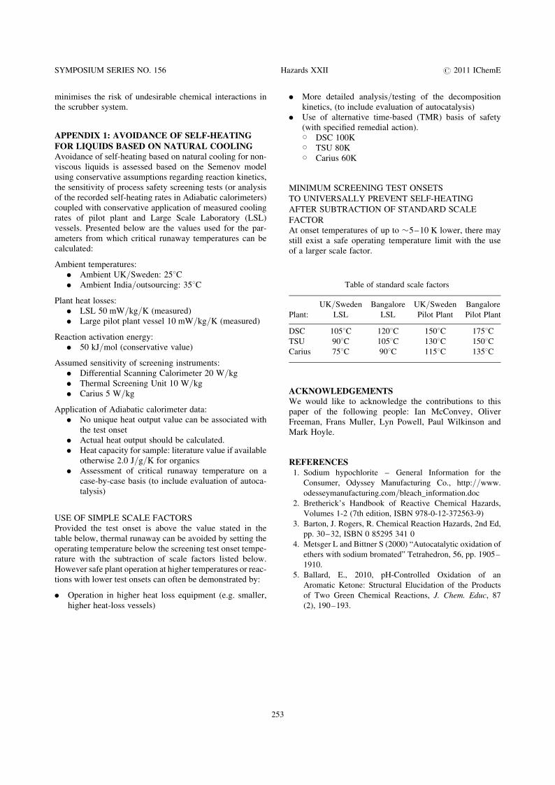
APPENDIX 1: AVOIDANCE OF SELF-HEATING
FOR LIQUIDS BASED ON NATURAL COOLINGAvoidance of self-heating based on natural cooling for non-viscous liquids is assessed based on the Semenov modelusing conservative assumptions regarding reaction kinetics,the sensitivity of process safety screening tests (or analysisof the recorded self-heating rates in Adiabatic calorimeters)coupled with conservative application of measured coolingrates of pilot plant and Large Scale Laboratory (LSL)vessels. Presented below are the values used for the par-ameters from which critical runaway temperatures can becalculated:
Ambient temperatures:. Ambient UK/Sweden: 258C. Ambient India/outsourcing: 358C
Plant heat losses:. LSL 50 mW/kg/K (measured). Large pilot plant vessel 10 mW/kg/K (measured)
Reaction activation energy:. 50 kJ/mol (conservative value)
Assumed sensitivity of screening instruments:. Differential Scanning Calorimeter 20 W/kg. Thermal Screening Unit 10 W/kg. Carius 5 W/kg
Application of Adiabatic calorimeter data:. No unique heat output value can be associated with
the test onset. Actual heat output should be calculated.. Heat capacity for sample: literature value if available
otherwise 2.0 J/g/K for organics. Assessment of critical runaway temperature on a
case-by-case basis (to include evaluation of autoca-talysis)
USE OF SIMPLE SCALE FACTORSProvided the test onset is above the value stated in thetable below, thermal runaway can be avoided by setting theoperating temperature below the screening test onset tempe-rature with the subtraction of scale factors listed below.However safe plant operation at higher temperatures or reac-tions with lower test onsets can often be demonstrated by:
. Operation in higher heat loss equipment (e.g. smaller,higher heat-loss vessels)
253
. More detailed analysis/testing of the decompositionkinetics, (to include evaluation of autocatalysis)
. Use of alternative time-based (TMR) basis of safety(with specified remedial action).W DSC 100KW TSU 80KW Carius 60K
MINIMUM SCREENING TEST ONSETS
TO UNIVERSALLY PREVENT SELF-HEATING
AFTER SUBTRACTION OF STANDARD SCALE
FACTORAt onset temperatures of up to �5–10 K lower, there maystill exist a safe operating temperature limit with the useof a larger scale factor.
ACKNOWLEDGEMENTSWe would like to acknowledge the contributions to thispaper of the following people: Ian McConvey, OliverFreeman, Frans Muller, Lyn Powell, Paul Wilkinson andMark Hoyle.
REFERENCES1. Sodium hypochlorite – General Information for the
Consumer, Odyssey Manufacturing Co., http://www.
odesseymanufacturing.com/bleach_information.doc
2. Bretherick’s Handbook of Reactive Chemical Hazards,
Volumes 1-2 (7th edition, ISBN 978-0-12-372563-9)
3. Barton, J. Rogers, R. Chemical Reaction Hazards, 2nd Ed,
pp. 30–32, ISBN 0 85295 341 0
4. Metsger L and Bittner S (2000) “Autocatalytic oxidation of
ethers with sodium bromated” Tetrahedron, 56, pp. 1905–
1910.
5. Ballard, E., 2010, pH-Controlled Oxidation of an
Aromatic Ketone: Structural Elucidation of the Products
of Two Green Chemical Reactions, J. Chem. Educ, 87
(2), 190–193.
Table of standard scale factors
Plant:
UK/Sweden
LSL
Bangalore
LSL
UK/Sweden
Pilot Plant
Bangalore
Pilot Plant
DSC 1058C 1208C 1508C 1758CTSU 908C 1058C 1308C 1508CCarius 758C 908C 1158C 1358C