Embed Size (px)
Citation preview
MANAGING URBAN STORMWATER
Soils and Const r uct ion
Volume 2D Main road construction
MANAGING URBAN STORMWATERSoils and Const r uct ion
Volume 2D Main road construction

Disclaimer: The Department of Environment and Climate Change NSW has prepared this publication in good faith exercising all due care and attention, but no representation or warranty, express or implied, is made as to the relevance, accuracy, completeness or fi tness for purpose of this publication in respect of any particular user’s circumstances. Users of this publication should satisfy themselves concerning its application to, and where necessary seek expert advice in respect of, their situation.
© Copyright State of NSW and Department of Environment and Climate Change 2008.
This material may be reproduced for non-commercial purposes in whole or in part, provided the meaning is unchanged and the source is acknowledged.
Published by the Department of Environment and Climate Change NSW in association with the Sydney Metropolitan Catchment Management Authority.
Department of Environment and Climate Change NSW59–61 Goulburn StreetPO Box A290Sydney South 1232Phone: (02) 9995 5000 (switchboard)Phone: 131 555 (environment information and publications requests)Phone: 1300 361 967 (national parks information and publications requests)Fax: (02) 9995 5999TTY: (02) 9211 4723Email: [email protected]: www.environment.nsw.gov.au
Sydney Metropolitan Catchment Management AuthorityGround Floor, 10 Valentine Avenue PO Box 3720Parramatta NSW 2124 Tel: 9895 7898 Fax: 9895 7330 Email: [email protected] Website: www.sydney.cma.nsw.gov.au
Cover photo: Northern Hume Highway projectChris Blake/RTA
ISBN: 978 1 74122 815 1DECC 2008/ 207June 2008
Printed on environmentally sustainable paper
Contents
iii
Acknowledgments iv
1 Introduction 1
2 Statutory requirements 5
3 Erosion and sediment control strategy 9
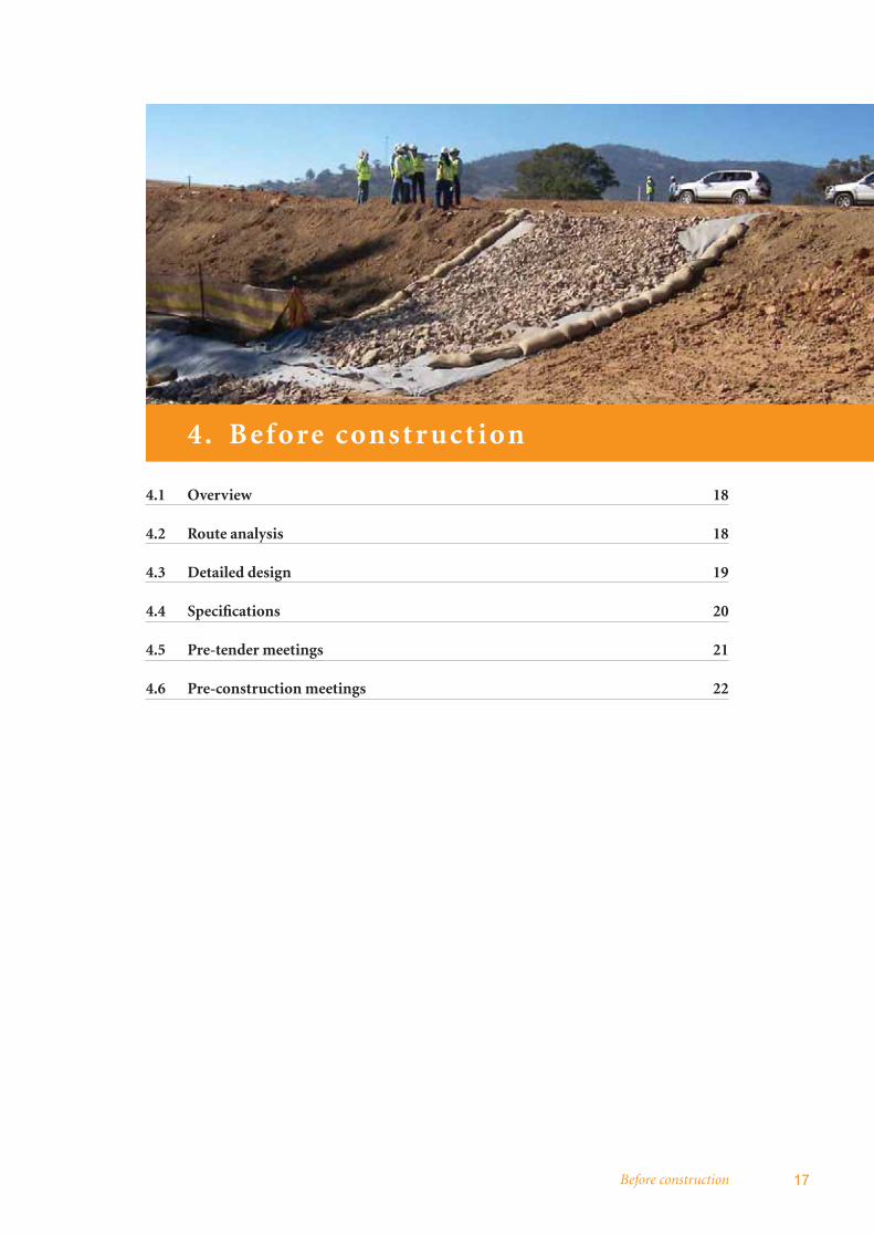
4 Before construction 17
5 Operational considerations 23
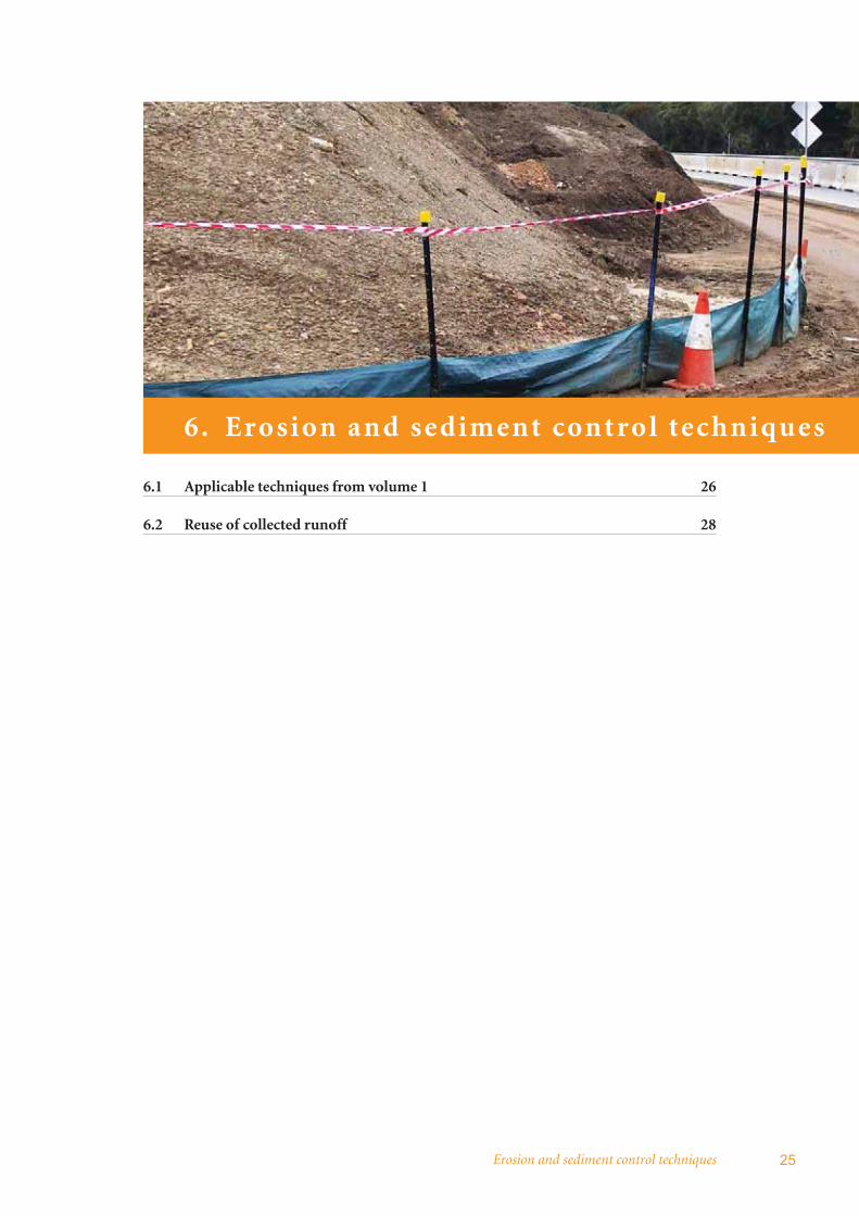
6 Erosion and sediment control techniques 25
Bibliography 30
Appendices 31
Appendix A: Erosion and sediment control planning 32
Appendix B: Sample erosion and sediment control plan 38
Appendix C: Typical arrangements diagrams 55
Appendix D: Selection of control measures 62

AcknowledgmentsThis publication includes material prepared for the Department of Environment and Climate Change by the Roads and Traffic Authority and their sub-consultant Toepfers Rehabilitation, Environmental & Ecological Services Pty Ltd.
Photography credits:
Contents opener F3 Freeway project DECC
Section 1 opener Northern Hume Highway projectChris Blake/RTA
Section 2 opener Alfords Point Bridge duplicationDECC
Section 3 opener Northern Hume Highway projectChris Blake/RTA
Section 4 opener Northern Hume Highway projectChris Blake/RTA
Section 5 opener Alfords Point Bridge duplicationDECC
Section 6 opener F3 Freeway projectDECC
Appendices opener Alfords Point Bridge duplicationDECC
iv

Introduction 1
1. Int ro duct ion
1.1 Main road construction 2
1.2 Purpose and scope 2
1.3 The nature of road construction and maintenance projects 3
1.4 Potential impacts on the water environment 4
1.5 Structure of this publication 4
Managing urban stormwater: soils and construction – main road construction2
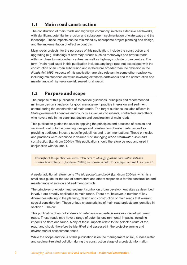
1.1 Main road constructionThe construction of main roads and highways commonly involves extensive earthworks, with signifi cant potential for erosion and subsequent sedimentation of waterways and the landscape. These impacts can be minimised by appropriate project planning and design, and the implementation of effective controls.
Main roads projects, for the purposes of this publication, include the construction and upgrading (e.g. widening) of new major roads such as motorways and arterial roads within or close to major urban centres, as well as highways outside urban centres. The term, ‘main road’ used in this publication includes any large road not associated with the construction of an urban subdivision and is therefore broader than the defi nition in the Roads Act 1993. Aspects of this publication are also relevant to some other roadworks, including maintenance activities involving extensive earthworks and the construction and maintenance of high-erosion-risk sealed rural roads.
1.2 Purpose and scopeThe purpose of this publication is to provide guidelines, principles and recommended minimum design standards for good management practice in erosion and sediment control during the construction of main roads. The target audience includes offi cers in State government agencies and councils as well as consultants, contractors and others who have a role in the planning, design and construction of main roads.
This publication guides the user in applying the principles and practices of erosion and sediment control to the planning, design and construction of main roads, as well as providing additional industry-specifi c guidelines and recommendations. These principles and practices were described in volume 1 of Managing urban stormwater: soils and construction (Landcom 2004b). This publication should therefore be read and used in conjunction with volume 1.
Throughout this publication, cross-references to Managing urban stormwater: soils and construction, volume 1 (Landcom 2004b) are shown in bold: for example, see vol. 1: section 5.3.
A useful additional reference is The hip pocket handbook (Landcom 2004a), which is a small fi eld guide for the use of contractors and others responsible for the construction and maintenance of erosion and sediment controls.
The principles of erosion and sediment control on urban development sites as described in vol. 1 are broadly applicable to main roads. There are, however, a number of key differences relating to the planning, design and construction of main roads that warrant special consideration. These unique characteristics of main road projects are identifi ed in section 1.3 below.
This publication does not address broader environmental issues associated with main roads. These roads may have a range of potential environmental impacts, including impacts on fl ora and fauna. Many of these impacts relate to the selected route of the road, and should therefore be identifi ed and assessed in the project-planning and environmental-assessment phase.
While the scope and focus of this publication is on the management of soil, surface water and sediment-related pollution during the construction stage of a project, information

Introduction 3
is also provided on both the pre-construction and operational stages. This is because effective erosion and sediment control during construction effectively begins during the project-planning stage.
Stormwater-quality management during the operational phase of the project should also be considered and addressed during pre-construction. It is not, however, addressed in this publication. Offi cers of the Roads and Traffi c Authority (RTA) are referred to the internal guidelines addressing stormwater management from roadways, entitled Procedure for selecting treatment strategies to control road runoff (RTA 2003). Technical guidance on the design and construction of a range of stormwater treatment measures suitable for the treatment of road runoff is provided in Austroads (2003) and IPWEA (2008).
1.3 The nature of road construction and maintenance projects
Main road construction often comprises large-scale earthworks and other activities involving:
• freeways and dual-carriageway highways with wide and straight pavements, elimination of steep grades, and extensive areas of cut and fi ll
• arterial roads to shorten distances and delays (e.g. to divert traffi c from shopping areas)
• improvements to existing roads (e.g. duplication, widening, provision of climbing, acceleration, de-acceleration and turning lanes)
• bridges or culverts
• road tunnels
• quarries and borrow areas involving production of materials
• batch plant sites (e.g. manufacture of concrete)
• side tracks for temporary traffi c diversions from works areas
• road maintenance works (e.g. patching, shoulder grading, drain and culvert cleaning).
Accordingly, issues relating to the management of soil and water during road construction may include:
• great variations in the linear size of projects, from small localised works (e.g. culverts, bridges) up to long stretches of new roads on greenfi eld sites (e.g. freeways)
• limited width of corridors, which may result in steep batter slopes, and restrictions on the number, type and size of control measures that may be successfully implemented
• large volumes of cut and fi ll, and, from a soil-and-water management perspective, a rapidly changing work site
• works across multiple catchments, with numerous discharge points and water diversion considerations
• works in and around watercourses, wetlands, fl ood-prone areas, acid-sulfate soils etc.
• public access onto and through construction sites (e.g. works under traffi c, traffi c management and safety considerations, provision of access for residents and businesses).

Managing urban stormwater: soils and construction – main road construction4
1.4 Potential impacts on the water environmentLarge-scale disturbance associated with main road construction can signifi cantly impact on the surrounding environment, including:
• sedimentation of waterways, affecting river health
• impacts on vegetation, potentially including threatened species.
Erosion, sedimentation and other forms of land degradation should therefore be controlled to minimise any impacts.
1.5 Structure of this publicationSection 2 summarises statutory requirements applicable to the erosion and sediment control aspects of the planning, design and construction of main roads
Section 3 outlines the approach that can be taken in developing an erosion and sediment control strategy for main road construction
Section 4 summarises considerations in the design of main roads that are relevant to operational erosion and sediment control
Section 5 provides information on relevant main road operational considerations
Section 6 provides guidance on applicable erosion and sediment control techniques for main roads
The appendices contain guidance on erosion and sediment control plans (ESCPs) and other supporting information.
Statutory requirements 5
2. Statutor y requirements
2.1 Overview 6
2.2 Relevant legislation 6
Managing urban stormwater: soils and construction – main road construction6
2.1 OverviewA number of State and local regulatory authorities may need to be consulted during the planning process to ensure activities associated with main roads are undertaken in accordance with all necessary statutory requirements relating to erosion and sediment control. These agencies may also need to be consulted during the preparation of various plans such as erosion and sediment control plans (ESCPs).
Several pieces of legislation may need to be considered in the planning and design stages of a road project. For example, the development assessment framework and provisions of the Environmental Planning and Assessment Act 1979 apply to the construction or upgrading of main roads.
This section, however, focuses on the main pieces of legislation that relate specifi cally to the aspects of erosion and sediment control of main road projects which may also have broader applicability to the project. These are:
• Protection of the Environment Operations Act 1997 (POEO Act)
• Roads Act 1993
• Fisheries Management Act 1984.
Other Acts which may need to be considered in the project-planning phase, and may indirectly infl uence aspects of erosion and sediment control (e.g. through route selection) are listed below, but not discussed in any detail in this publication:
• Water Management Act 2000
• Native Vegetation Act 2003
• Threatened Species Conservation Act 1995
• National Parks and Wildlife Act 1974
• Soil Conservation Act 1938.
For a more detailed description of these Acts, see vol. 1: appendix K.
The information below was current at the date of publication. However, statutory requirements and the roles of government agencies can change over time – proponents should check that this information is current during the planning stage of their project.
2.2 Relevant legislation
2.2.1 Protection of the Environment Operations Act 1997The POEO Act is the primary piece of NSW pollution control legislation. The Act defi nes activities that require environment protection licences (schedule 1) and the roles and responsibilities of appropriate regulatory authorities. The Act also prohibits the pollution of waters, except in accordance with an environment protection licence (section 120).
Environment protection licences are issued by the Environment Protection Authority (EPA), part of the Department of Environment and Climate Change (DECC). The EPA is normally the appropriate regulatory authority for:
• activities listed in schedule 1 of the POEO Act for which licences are issued
• activities carried on by a State or public authority (e.g. a council operating a small solid-waste landfi ll)
• other activities in relation to which a licence regulating water pollution is issued.

Statutory requirements 7
Local councils are normally the appropriate regulatory authority for other activities (e.g. operations by small to medium businesses and subdivision construction by private developers). Local councils have notice and enforcement powers under the POEO Act for these activities.
Certain freeway and tollway construction activities are prescribed in schedule 1 of the Act, for which an environment protection licence is issued by the EPA. The current schedule 1 defi nition is:
Freeway or tollway construction, being the construction of new, re-routed or additional carriageways, that as a result will have:
(1) physically separated carriageways for traffi c moving in different directions, and
(2) at least 4 lanes (other than lanes used for entry or exit), and
(3) no access for traffi c between interchanges,
for at least 1 kilometre of their length in the Metropolitan area or for at least 5 kilometres of their length in any other area.
The Metropolitan area is the area of Sydney, Newcastle, Central Coast and Wollongong bounded by and including the local government areas of Newcastle, Lake Macquarie, Wyong, Gosford, Hawkesbury, Blue Mountains, Penrith, Liverpool, Camden, Campbelltown, Wollongong and Shellharbour.
This item does not include maintenance of any such freeway or tollway.
At the time of publication, DECC was reviewing this defi nition and road proponents should therefore check the current version of schedule 1 to determine the need for an environment protection licence.
The impact on the environment of any pollution likely to be caused by the activity will be considered when determining an application for an environment protection licence. Where an environment protection licence is granted, conditions may include soil and water management requirements to avoid or minimise any potential impacts.
2.2.2 Roads Act 1993The Roads Act, among other things, establishes the authorities responsible for roads, provides for the classifi cation of roads and sets out procedures for the opening and closing of roads. Authorities responsible for roads in NSW include:
• the Roads and Traffi c Authority (RTA) – for all freeways and tollways, land held by the RTA and roads in the unincorporated area of western NSW
• local councils – for all public roads within their areas, except for any Crown public road or any public road declared under the control of some other road authority
• Department of Lands, as the roads authority for all Crown public roads
• specifi ed public authorities (e.g. the Lake Illawarra Authority) responsible for all public roads in a declared area.
2.2.3 Fisheries Management Act 1994The NSW Department of Primary Industries (DPI) is responsible for the administration of this piece of legislation. The Act provides a comprehensive framework for the sustainable management of living aquatic resources. The former NSW Fisheries has been incorporated into the DPI.

Managing urban stormwater: soils and construction – main road construction8
Under the Act, a permit is required for any activity associated with main roads that involves dredging or reclamation works, or that has the potential to:
• block the passage of fi sh (e.g. road crossings)
• harm marine vegetation.
Further details can be obtained from Policy and guidelines – aquatic habitat management and fi sh conservation (NSW Fisheries 1999).

Erosion and sediment control strategy 9
3. Erosion and sediment cont rol st r ate g y
3.1 Management objectives 10
3.2 Management principles 10
3.3 Strategic approach 10
3.4 Documenting the adopted strategy 15
3.5 Responsibility for strategy implementation 15
3.6 Strategy implementation by contractors 15
Managing urban stormwater: soils and construction – main road construction10
3.1 Management objectivesThe goal for erosion and sediment control for main road construction is to ensure that there is no pollution of surface or ground waters. Current best-practice erosion and sediment control techniques are, however, unlikely to achieve this goal, due to the limited effectiveness of most of these techniques. An appropriate management objective is therefore to take all reasonable measures (i.e. implement best-practice) to minimise water-quality impacts from erosion and sedimentation.
Given the limited effectiveness of techniques for retaining eroded sediment, a strong emphasis should be placed on pollution prevention through erosion control, rather than relying on treatment techniques to capture these sediments.
3.2 Management principles The primary principles for erosion and sediment control are fi rstly to minimise erosion and then to capture sediment from disturbed areas. This approach emphasises pollution prevention rather than pollution control.
Vol. 1: section 1.6 identifi es seven general principles of effective soil and water management for land disturbance associated with urban development. This approach focuses on appropriate site planning, and the installation of appropriate erosion-control and sediment-control measures.
These principles also broadly apply to main road construction. They can be paraphrased as follows:
• assess the soil and water implications of a project at the planning stage
• plan for erosion and sediment control during the project’s design and before any earthworks begin, including assessment of site constraints
• minimise the area of soil disturbed and exposed to erosion
• conserve topsoil for later site rehabilitation or regeneration (in a stabilised stockpile)
• control water fl ow from the top of and through the project area by diverting up-slope ‘clean’ water away from disturbed areas and ensuring concentrated fl ows are below erosive levels and sediment is retained from disturbed areas
• rehabilitate disturbed lands quickly
• maintain erosion and control measures appropriately.
These principles provide a framework for the development of an erosion and sediment control strategy for main road construction.
3.3 Strategic approach
3.3.1 OverviewEffective erosion and sediment control for a main roads project requires appropriate activities to be carried out over the life of the road, including:
• planning and design
• construction
• operations.

Erosion and sediment control strategy 11
The principles noted in section 3.2 can be used to guide the development of an erosion and sediment control strategy for a main road. The specifi c strategy adopted for a main road project will vary depending on the nature and scope of the project, type and sensitivity of receiving environments and other factors such as site rainfall characteristics, soils and topography. It is important that any erosion and sediment control strategy is consistent with, and meets any requirements of, any applicable environment protection licence, development consent or approval conditions.
The long period of disturbance associated with main road construction relative to subdivision construction, and the resulting longer operational life of many erosion and sediment controls, requires a stronger emphasis on some management principles, particularly:
• erosion control as a pollution prevention strategy
• runoff separation by diverting ‘clean’ stormwater runoff around the site or away from operational areas
• management and maintenance of long-term controls.
3.3.2 Planning and design considerationsThe effectiveness of erosion and sediment controls during the construction and operational stages can be optimised through effective main road planning and design. The effectiveness of construction phase erosion and sediment controls can be enhanced by considering potential construction-phase strategies during planning and design, while acknowledging that detailed strategies and plans will be developed during the construction period. Suitable strategies for these stages of a project include:
• designing any permanent drainage systems so that they do not cause erosion. This may involve scour protection of open drains and energy dissipaters located at drain outlets
• diverting up-slope runoff around large cut batters, where possible, to minimise external runoff fl owing over batters.
These strategies should be documented on the project drawings and in the contract specifi cations. Section 4 contains approaches that can be used in the pre-construction phase to enhance erosion and sediment control effectiveness.
3.3.3 Construction phase strategiesThe magnitude of erosion problems (and therefore the effort required to control erosion) at main road construction sites is proportional to the area of soil exposed to the erosive elements and the duration of that exposure. Main road construction often involves land disturbance for up to three years. Because of this long period, the management focus should principally be on scheduling land disturbance and rehabilitation to minimise erosion occurring, rather than relying on temporary works to control erosion and sedimentation.
It is recognised that activities will vary throughout the life of a main road construction project, with erosion and sediment control measures and activities expected to evolve over time. Erosion control strategies at main road construction sites should normally comprise the following:
• minimising forward clearing, particularly areas around fl ow lines, drainage lines and watercourses which, in particular, should remain in their natural state until the installation of drainage works (e.g. culverts) commences

Managing urban stormwater: soils and construction – main road construction12
• staging construction activities where practicable so that land disturbance is confi ned to the minimum possible area
• completing work and stabilising disturbed areas quickly and progressively. Temporary stabilisation measures should be used if permanent stabilisation is delayed by construction activities, by scheduling problems with third-party service installation, or by unsuitable site conditions
• minimising erosion from drainage lines which can be very vulnerable to the erosive effects of concentrated fl ow. This particularly applies to catch, table and diversion drains, where temporary erosion protection is likely to be required.
To reduce the runoff volumes requiring treatment and to maximise the effi ciency of sediment control, strategies should aim to:
• intercept, divert and safely dispose of ‘clean’ run-on water from undisturbed areas so that it does not fl ow onto the works
• pass ‘clean’ water through the site without mixing it with ‘dirty’ sediment-contaminated runoff from the works. This may require temporary solutions, such as temporary fl exible pipes to convey water across a working site
• break up slope lengths and minimise catchment areas within the work area, to reduce runoff volume and velocities to manageable levels.
Where possible, permanent erosion control measures (see section 4.3) should be integrated with temporary measures during the construction phase. For example:
• catch drains located above a cut batter to minimise long-term fl ows over the batter should be installed before earthworks commence, to divert runoff around the earthworks area
• down drains on a fi ll batter designed to convey road runoff should be installed immediately after completion of the earthworks, to convey the runoff from the pavement area down the batter while the batter is being stabilised
• energy dissipaters should be installed on pipe and culvert outlets before the drainage system or culvert becomes operational.
Erosion and sediment control measures should be inspected daily (with maintenance and modifi cation as necessary), together with more intense inspection and maintenance regimes during wet weather and wet-weather clean up (see vol. 1: chapter 8). Arrangements also need to be made for inspection and maintenance during industry shutdowns for weekends and holidays (e.g. Christmas and Easter), particularly if rainfall is predicted or there is predictable seasonal rainfall.
Due to the large scale of many road construction projects, a priority system for repairs and maintenance following large storms should be developed. This should focus on initially restoring controls in areas with high erosion risk which may impact on sensitive receiving environments, followed by restoration of controls in other areas.
Due to the longer operational life of many erosion and sediment controls relative to urban subdivision construction (outlined in vol. 1), additional maintenance effort is often required for long-term controls. For example:
• erosion and sediment control measures should be maintained in a functioning condition until individual areas have been revegetated
• structures for diverting and conveying runoff should be inspected after signifi cant storms so that sediment can be removed and damaged works promptly repaired and/or replaced

Erosion and sediment control strategy 13
• infl ow points and outfl ow structures (e.g. riser pipes and spillways) to sediment basins should be inspected after major storms and repaired as necessary.
Stormwater reuse should be considered as a management option for main road construction to reduce discharge of polluted water, as there are commonly a range of non-potable water uses such as dust suppression and irrigation of revegetation areas. This may be more cost-effective than treatment of polluted runoff and will also reduce consumption from other water sources.
Services such as water mains are often installed as part of a main road construction. Detailed guidance on erosion and sediment control for service installation is provided in Managing urban stormwater: soils and construction, volume 2A: installation of services(DECC 2008a).
Access tracks are often used on main road construction projects. Erosion of the tracks is a safety issue as well as a potential water-quality issue. Detailed guidance on erosion and sediment control for access tracks is provided in Managing urban stormwater: soils and construction, volume 2C: unsealed roads (DECC 2008b).
The strategies described above should be applied in all areas associated with the road construction. These areas include, but are not limited to:
• the principal work site
• side tracks, access tracks and haul roads
• borrow pits and spoil disposal areas
• temporary stockpiles, and laydown and storage areas
• compounds, site offi ces and batch plants.
Section 6 contains information on potentially suitable erosion and sediment control techniques for a main road construction.
Constrained sitesEffective erosion and sediment control can be more diffi cult in narrow road corridors or in areas of high-conservation-value vegetation (e.g. endangered ecological communities). These constraints can impact on the ability to install conventional sediment basins designed for a fi ve-day management period. In these circumstances, options include:
• installing smaller basin(s) designed for a two-day management period (see table 6.1 for the applicable volume reductions). This will require more intense on-site management or alternate approaches such as pumping water to a ‘turkeys nest’ dam for treatment prior to either reuse or discharge
• greater investment in erosion control. This particularly applies where sediment basins cannot be installed – see vol. 1: section 6.3.4(g) for a description of suitable approaches
• off-site sediment control – in some cases, land for sediment control may need to found downstream of the site and appropriate arrangements made with the landowner
• use of non-standard sediment control techniques where enhanced erosion controls cannot be implemented and insuffi cient space is available for standard sediment controls such as basins. Sectors such as the stormwater and wastewater treatment industries use non-standard approaches (e.g. gross pollutant traps or vortex separators) to remove sediment from water and it is possible that some of these techniques can be applied to diffi cult or constrained sites.
14 Managing urban stormwater: soils and construction – main road construction
These techniques are likely to achieve signifi cant coarse sediment removal, although reductions in turbidity may be low. In a constrained site, removal of coarse sediment only is better than no sediment controls at all. Note, however, that these techniques may have higher capital and operating costs, which should be considered during project planning.
Sensitive and high-erosion-risk sitesSome roads are constructed adjacent to sensitive receiving environments (e.g. national parks). In this situation, a greater degree of erosion and sediment control is warranted – section 6.1 outlines the larger sediment basin sizes applicable in these circumstances.
Some main roads are constructed in areas of high erosion risk with either narrow road corridors or other constraints to installing sediment basins (e.g. vegetation of high conservation value). In these circumstances, particular attention needs to be paid to erosion control as a pollution prevention strategy, given the limited opportunities for pollution control through sediment basin installation. Vol. 1: sections 6.3.4 (g) and 4.4.2 provide guidance on potential strategies.
In such sensitive sites, the implementation of enhanced controls should be independently audited at least fortnightly. The auditor should be a soil conservationist or an accredited erosion control specialist.
A more dynamic approach to erosion control is also recommended under these circumstances. This would involve the use of Bureau of Meteorology forecasts and rainfall radar images to assess the likelihood and severity of rainfall for the site. Where the forecast and/or radar images indicate the likelihood of moderate to heavy rainfall, additional short-term erosion controls should be used. These should focus particularly on unprotected drainage lines which will be more susceptible to erosion from concentrated fl ows than the susceptibility of unprotected batters to rill erosion. Standard approaches for preparing the site in the lead-up to forecast rain should be developed and included in the erosion and sediment control strategy.
Bridge and culvert constructionThe construction of bridges and culverts over watercourses and the installation of any associated approach embankments can present a high risk of water pollution, given the proximity of the works to the watercourse and the potential limitations of certain techniques.
Managing urban stormwater: soils and construction, volume 2C: unsealed roads (DECC 2008b) contains guidance on erosion and sediment control strategies for culvert and bridge construction.
3.3.4 Operational phase strategiesThe primary aim of soil and water management in the operational (i.e. post-construction) phase of a main road project is to minimise long-term erosion by ensuring that effective vegetation is maintained on areas disturbed during construction (e.g. batter slopes) and by addressing any erosion problems in the drainage system (e.g. scouring of unlined drains). Revegetated areas should be carefully managed for a number of years after the initial rehabilitation works, with intensive management over the fi rst few months. This is to promote rapid vegetation growth and development, and address any problems arising with vegetation establishment.
Guidance on operational considerations is provided in section 5.

Erosion and sediment control strategy
3.4 Documenting the adopted strategyIt is important that the strategy for erosion and sediment control is documented so that operational staff and regulatory authorities are aware of the approach adopted to minimising water pollution. The strategy should be documented before the start of land disturbance activities where erosion and sediment controls are needed. The strategy could be documented in an:
• environmental management plan, or
• erosion and sediment control plan.
There is generally no DECC requirement for a specifi c erosion and sediment control plan to be prepared for main road construction, although this is common practice. DECC does, however, expect there to be a document that is current at all times during the operational life of the project which details the current erosion and sediment control practices being implemented. In addition, staff or contractor responsibilities for implementing aspects of the strategy should also be documented to ensure clear accountability.
It is recommended that operators consider the scale and nature of their operations and any requirements to provide other plans relating to environmental management when deciding on how to document their erosion and sediment control strategy. For example, a small project may include erosion and sediment control in an environmental management plan required as a development consent condition, whereas a large project may warrant an erosion and sediment control plan as a sub-plan of the environmental management plan. Appendices B to D provide information on erosion and sediment control plans.
It is important that whatever format is adopted allows for the plan to be revised, if required, to account for monitoring results and to address any implementation problems that may arise.
3.5 Responsibility for strategy implementationThe project principal should ensure that staff or contractor responsibilities for implementing the erosion and sediment control strategy are clearly established and documented. It is recommended that a single person have overall responsibility for supervising the implementation of the strategy, while delegating particular responsibilities. The principal should ensure that all operational staff are aware of the need for effective erosion and sediment controls.
The inspection and maintenance responsibilities for erosion and sediment controls should be devolved across all persons working on the project site including managers, engineers, supervisors, overseers and gangers, as well as any environment offi cers. This avoids the situation where sediment control responsibility is assigned to a single employee or employee category (e.g. environment offi cer), resulting in other workers (including supervisors) taking little or no interest or responsibility.
3.6 Strategy implementation by contractors Main road construction is commonly carried out by contractors on behalf of a project principal or client. Both the project principal and the contractor have responsibilities for implementing an effective erosion and sediment control strategy.
15

16 Managing urban stormwater: soils and construction – main road construction
The POEO Act (parts 3.4 and 8.5) considers licence holders and occupiers of unlicensed premises to be liable for any breach of a licence condition or pollution caused by any associated person. The occupier of premises means the person (or organisation) who has the management or control of the premises. A person associated with the licence holder or occupier of the premises is taken to include an employee, agent, contractor or subcontractor.
Effectively this means that project principals cannot transfer their obligations under the POEO Act to a contractor. The EPA prosecution guidelines (DEC 2004) contain further information on the EPA’s approach to selecting an appropriate defendant for a pollution offence and the EPA’s views on the responsibility of principals and contractors.
These provisions do not, however, prevent proceedings being taken under the Act against the person who actually caused the pollution (e.g. a contractor who, in the opinion of the appropriate regulatory authority, has been clearly negligent).
The licence holder for a licensed main road construction project or the occupier of the project site for an unlicensed project (normally the project principal) therefore needs to take appropriate steps to ensure that any contractor or subcontractor does not contravene any licence condition or cause unauthorised water pollution. Potential approaches include:
• including details of the contractor’s obligations in the contract, along with appropriate contract provisions enabling the principal to direct the contractor or subcontractor to address any potential licence contravention or polluting activities
• providing guidance to the contractor on the procedures to be followed to prevent any licence contravention or polluting activities
• ongoing monitoring of a contractor’s activities to identify any potential licence contravention or polluting activities, with prompt directions issued to the contractor to address the inappropriate activities and a follow-up review to see that the actions have been addressed.
Before construction 17
4. Before const r uct ion
4.1 Overview 18
4.2 Route analysis 18
4.3 Detailed design 19
4.4 Specifi cations 20
4.5 Pre-tender meetings 21
4.6 Pre-construction meetings 22

18 Managing urban stormwater: soils and construction – main road construction
4.1 OverviewThe guidance provided in the following sections is focused on large main road projects, particularly those where there is a signifi cant risk of erosion and sedimentation of sensitive environments. Where the scale of the project is relatively small (e.g. installing an extra lane on a main road for a relatively short distance) and/or the risk of environmental impacts is low, the approach described below can be modifi ed to suit the nature of the project.
4.2 Route analysisErosion and sediment control planning should commence in the concept phase with a preliminary erosion-hazard evaluation of the area through which the road is to pass (refer to vol. 1: section 4.4.1). The erosion-hazard advantages or disadvantages of a particular route can then be weighed against all other engineering, social, economic and environmental considerations.
The erosion hazard and the expected sedimentation potential of an area will rarely necessitate the abandonment or a major shift of a proposed route. However, an advance study will identify problem areas that may warrant additional attention during later detailed design and construction phases, and for any additional costs to be considered during project budgeting.
Erosion hazard is the susceptibility of a parcel of land to the prevailing agents of erosion. It is dependent on:
• topography
• drainage
• soil erodibility
• vegetation cover
• climate
• land use.
Erosion hazard is categorised qualitatively as low, moderate, high, very high or extreme. Having determined the category of erosion hazard, the following points should be considered if the category is to be lowered and potential soil loss minimised:
• identifi cation of high-risk areas (e.g. steep and rugged terrain, erodible soils)
• avoidance of mid-slope locations on long, steep and unstable slopes
• location of roads on well-drained soil formations, avoiding poorly drained areas
• location of roads at a suffi cient distance from streams to provide fi lter strips to trap sediment down-slope of the alignment
• resumption of suffi cient land to enable construction of effective erosion and sediment control measures including catch drains and sediment basins.
These aspects of most road and highway construction projects, together with many of the issues discussed in vol. 1: section 3, should be further assessed as part of the project’s environmental impact assessment.

Before construction 19
4.3 Detailed designThe drainage drawings are the most relevant component of a project’s design plans for soil and water management purposes, with temporary erosion and sediment control during construction heavily infl uenced by the drainage design. Drainage drawings usually include all permanent stormwater management, erosion and sediment control measures (e.g. lined catch drains, batter chutes, culverts, outlet dissipaters and sediment basins).
Because the selection and location of temporary control measures such as sediment fences, straw bale sediment traps and temporary diversion banks are usually the responsibility of the construction contractor, designers should not attempt to pre-empt the location of these measures in design plans issued for tender. Locations are likely to be changed regularly during construction and both location and management will be specifi cally addressed by the contractor in their ESCPs.
In preparing design plans, road designers should be especially aware of the principles of erosion and sediment control as they relate to surface stormwater management. Provision should be made to conduct all fl ows along or through the route corridors by stable and permanent measures such as catch drains, lined channels and batter chutes. This applies all the way from the upper limits of the corridor catchments (e.g. top of cut batter and upstream boundary on fl ow line) down to the fi nal points of discharge.
In doing this, the following issues should be addressed as appropriate:
• identifi cation of catchment areas to determine fl ow paths and calculate relevant runoff data
• separation of ‘clean’ upper catchment run-on water from potentially contaminated road runoff during both the construction and operational stages of the project
• inclusion of catch drains and berm drains to protect cut batters, and to safely divert ‘clean’ run-on water through or away from the disturbed area
• location of culverts to permit a temporary stable bypass to be provided for ‘clean’ cross-drainage during construction (e.g. culvert slightly off-set from fl ow line)
• location of other drains to maximise the diversion of ‘dirty’ runoff into sediment traps and basins (construction phase) or stormwater treatment measures (operational phase)
• design and location of sediment basins to treat ‘dirty’ runoff during construction and then potentially to act as permanent water-quality protection measures during the operational stage. Operational controls should be particularly considered when stormwater may affect an area of high conservation value or a water supply catchment
• culvert inlet and outlet protection (e.g. energy dissipaters)
• batter grades and batter stabilisation treatments (refer to vol. 1: section 4.4.2 for constructed slope length and gradient requirements on sites of high-erosion hazard)
• kerbs, gutters or dykes discharging into batter drains to protect fi ll batters
• suitable drain and channel linings determined from catchment areas, grades and predicted velocities of fl ows
• bridges with piers and abutments not signifi cantly impacting on fl ow lines
• other applicable techniques (e.g. fl umes, rock mattress and gabion structures).
Road designers are particularly encouraged to seek specialist advice relating to erosion and sediment control on high-risk projects. The opportunity to infl uence results is greater in the early life of a project, and poor decisions are often diffi cult and/or costly to rectify later.
20 Managing urban stormwater: soils and construction – main road construction
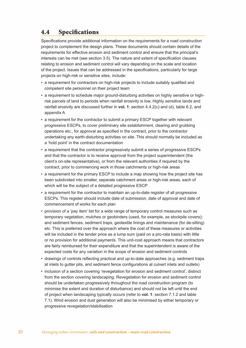
4.4 Specifi cationsSpecifi cations provide additional information on the requirements for a road construction project to complement the design plans. These documents should contain details of the requirements for effective erosion and sediment control and ensure that the principal’s interests can be met (see section 3.5). The nature and extent of specifi cation clauses relating to erosion and sediment control will vary depending on the scale and location of the project. Issues that can be addressed in the specifi cations, particularly for large projects on high-risk or sensitive sites, include:
• a requirement for contractors on high-risk projects to include suitably qualifi ed and competent site personnel on their project team
• a requirement to schedule major ground-disturbing activities on highly sensitive or high-risk parcels of land to periods when rainfall erosivity is low. Highly sensitive lands and rainfall erosivity are discussed further in vol. 1: section 4.4.2(c) and (d), table 6.2, and appendix A
• a requirement for the contractor to submit a primary ESCP together with relevant progressive ESCPs, to cover preliminary site establishment, clearing and grubbing operations etc., for approval as specifi ed in the contract, prior to the contractor undertaking any earth-disturbing activities on site. This should normally be included as a ‘hold point’ in the contract documentation
• a requirement that the contractor progressively submit a series of progressive ESCPs and that the contractor is to receive approval from the project superintendent (the client’s on-site representative), or from the relevant authorities if required by the contract, prior to commencing work in those catchments or high-risk areas
• a requirement for the primary ESCP to include a map showing how the project site has been subdivided into smaller, separate catchment areas or high-risk areas, each of which will be the subject of a detailed progressive ESCP
• a requirement for the contractor to maintain an up-to-date register of all progressive ESCPs. This register should include date of submission, date of approval and date of commencement of works for each plan
• provision of a ‘pay item’ list for a wide range of temporary control measures such as temporary vegetation, mulches or geobinders (used, for example, as stockpile covers); and sediment fences, sediment traps, geotextile linings and maintenance (for de-silting) etc. This is preferred over the approach where the cost of these measures or activities will be included in the tender price as a lump sum (paid on a pro-rata basis) with little or no provision for additional payments. This unit-cost approach means that contractors are fairly reimbursed for their expenditure and that the superintendent is aware of the expected costs for any variation in the scope of erosion and sediment controls
• drawings of controls refl ecting practical and up-to-date approaches (e.g. sediment traps at inlets to gutter pits, and sediment fence confi gurations at culvert inlets and outlets)
• inclusion of a section covering ‘revegetation for erosion and sediment control’, distinct from the section covering landscaping. Revegetation for erosion and sediment control should be undertaken progressively throughout the road construction program (to minimise the extent and duration of disturbance) and should not be left until the end of project when landscaping typically occurs (refer to vol. 1: section 7.1.2 and table 7.1). Wind erosion and dust generation will also be minimised by either temporary or progressive revegetation/stabilisation

Before construction 21
• landscaping details, typically focusing on the provision of a suitable landscape with visual and ecological considerations along the road corridor at the end of the project
• a separate pay item to cover revegetation contractors and/or specialist equipment. This will reduce the likelihood of progressive revegetation not occurring
• detail on specifi c seed mixtures and fertilisers to be used, as these will vary according to location, climate and time of sowing
• appropriate cross-referencing throughout the specifi cations to tie in erosion and sediment control requirements with all other aspects of construction (e.g. clearing, stripping and stockpiling of topsoil, bulk earthworks, culvert construction, bridge construction, borrow areas, side tracks and batch plants).
Specifi cations require careful wording, and the development of a clear, accurate and workable document is essential. Suffi cient fl exibility should also be retained to allow the contractor to propose (and get paid for) any customised or one-off control measures.
4.5 Pre-tender meetingsPre-tender meetings can be held for the benefi t of contracting companies interested in submitting tenders for proposed road construction projects, particularly for large projects. The aim of these meetings is to provide design engineers, construction engineers, geotechnical engineers, environmental personnel and contractors with an opportunity to discuss various aspects of the proposed construction, including erosion and sediment control, where a briefi ng can be provided on issues such as:
• the importance of erosion and sediment control and other water-quality issues
• high-hazard and sensitive areas both within and outside the corridor (e.g. watercourses, nature reserves, wetlands, oyster leases and water supply catchments)
• any specifi c conditions of approval placed on the project by the relevant authorities
• the requirement for ESCPs and their timing
• the necessity, where applicable, for:
- early construction of permanent drainage works (e.g. culverts, catch drains) as a signifi cant part of management of ‘clean’ or upper catchment run-on and ‘dirty’ construction runoff
- a continual or progressive approach to erosion and sediment control (e.g. temporary controls, revegetation)
- stream and drainage-line protection
- maintenance of erosion and sediment controls
• the development and implementation of an operating system involving the preparation of ESCPs, work procedures, training, inspections, reporting, checklists etc.
The briefi ng can also highlight the economic advantages relevant to the contractor’s own activities including:
• greatly reduced repair and maintenance resulting from on-site erosion damage, including the expensive process of de-silting stormwater drainage pipes
• a marked decrease in construction downtime following wet weather due to good surface-water management.
22 Managing urban stormwater: soils and construction – main road construction
4.6 Pre-construction meetingsA pre-construction meeting should be held with the successful contractor prior to works commencing on-site. This is important as the personnel undertaking the actual construction will often be different from those who attended the pre-tender meetings. The principal’s representative can use this opportunity to emphasise the main issues raised at the pre-tender meeting (section 4.5) and confi rm any requirements for licences, permits and/or approvals.
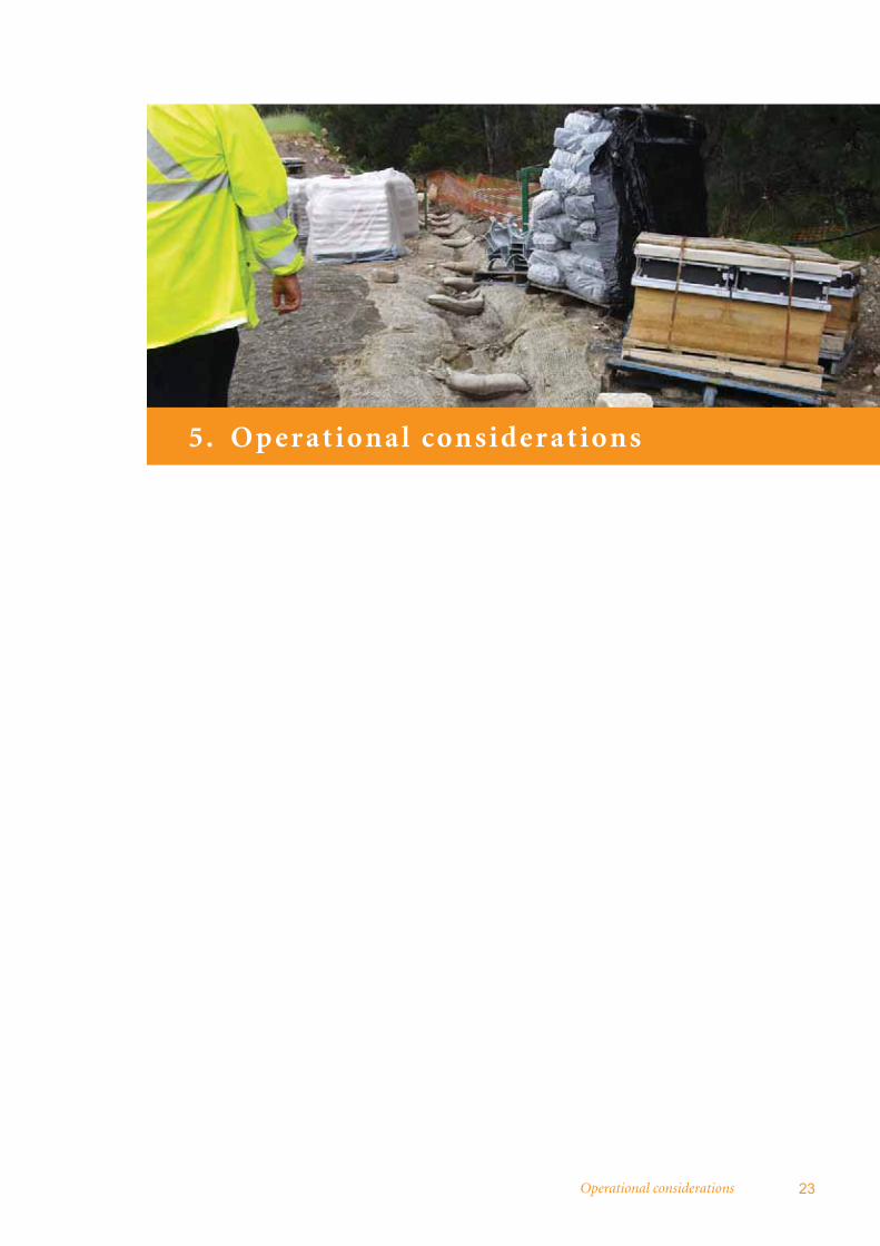
Operational considerations 23
5. O p er at ional consider at ions

24 Managing urban stormwater: soils and construction – main road construction
Erosion hazard and the risk of sedimentation generally diminishes following the conclusion of road construction activity. Surfaces which were disturbed and bare become less prone to erosion following the installation of surface water controls, paved surfaces and revegetated batters and verges.
However, regular maintenance inspections by roads authorities should be conducted with appropriate recording to identify and rectify general problems, including:
• areas of erosion and/or sediment deposition
• poor vegetative cover
• breached diversion banks
• blocked drains
• slumped batters
• sediment basins or other stormwater treatment measures requiring maintenance or repair.
Other more specifi c matters that may need to be addressed include:
• the management of sediment basins until formerly bare and disturbed surfaces achieve a C-factor (see vol. 1: appendix A) of 0.05 – approximately 70 per cent ground cover. This may require basin management for a period of three to 12 months into the operational period to ensure sediment pollution issues are not prematurely disregarded following the completion of construction (refer to vol. 1: section 7.1.2)
• ensuring that certain erosion and sediment control measures are suitably decommissioned or removed. In some cases leaving temporary controls in place, without maintenance, can cause erosion and sediment pollution
• the effective conversion of sediment basins to ‘spill’ basins or other permanent stormwater treatment measures, and their subsequent maintenance.
Erosion and sediment control techniques 25
6. Erosion and sediment cont rol te chniques
6.1 Applicable techniques from volume 1 26
6.2 Reuse of collected runoff 28

26 Managing urban stormwater: soils and construction – main road construction
6.1 Applicable techniques from volume 1Most of the erosion and sediment control techniques described in vol. 1 are applicable to erosion and sediment control for main road construction. Appendix D provides a summary of these techniques and guidance on their selection.
The main variation to the techniques described in vol. 1 relates to the sizing of diversion drains and sediment basins, to account for the longer duration of main road construction relative to urban subdivision construction.
Due to the longer operational life of sediment control measures at main road construction sites relative to urban development site construction, higher standards of design and construction should be adopted for water conveyance and storage structures on main road construction sites, particularly those that will remain after the operational life of the site.
The recommended minimum design criteria for sediment control measures for main road construction are presented in table 6.1. More stringent criteria may be adopted, particularly if considered warranted by a site-specifi c environmental impact assessment. Table 6.2, overleaf, presents the indicative average annual sediment basin overfl ow (or spill) frequency for various fi ve-day design storms presented in table 6.1 when treating runoff from type F or D soils.
Table 6.1 notes that the minimum basin design criteria can be reduced when enhanced erosion controls are used. Enhanced erosion controls would normally be used on a main road project where site constraints preclude the installation of basins designed to the conventional criteria. These constraints may include existing development, topography or endangered ecological communities. However, implementing enhanced controls may be challenging for large main road construction projects. If enhanced controls are implemented, an independent audit of their implementation should occur at least fortnightly for these sensitive sites. The auditor should be a soil conservationist or an accredited erosion-control specialist (this is similar to the approach outlined in section 3.3.3).
It should be noted that vol. 1: section 6.3.2 recommends a sediment retention basin be constructed in all situations where the estimated annual soil loss exceeds 150 cubic metres per year.
The operation of basins for type F and D soils is described in vol. 1: section 6.3.4. This section notes that the basin should be drained or pumped out within the adopted management period (commonly fi ve days) following rainfall. For the purposes of basin management, this requirement refers to rainfall of suffi cient depth to result in runoff entering the basin. This rainfall depth will vary depending on the site conditions at the time of the event, particularly the extent of any impervious surfaces (e.g. road pavement) and the extent of any preceding rainfall. For sites at the bulk earthworks stage where there has not been signifi cant preceding rainfall, rainfall depth of at least 5–10 mm may be needed before runoff commences.
This approach avoids the situation where the basin management period is extended for a further fi ve days following negligible rainfall (e.g. 1 mm). This would result in the basin containing runoff for a longer period, reducing its ability to capture runoff from subsequent storm events and hence increasing the spill frequency.

Erosion and sediment control techniques 27
Tabl
e 6.
1 R
ecom
men
ded
min
imum
des
ign
crite
ria fo
r tem
pora
ry e
rosi
on a
nd s
edim
ent c
ontr
ol m
easu
res
at w
aste
land
fi ll s
ites
Min
imum
ave
rage
recu
rren
ce in
terv
al (A
RI)
of d
esig
n st
orm
eve
nt
(unl
ess
othe
rwis
e in
dica
ted)
Dur
atio
n of
dis
turb
ance
< 6
mon
ths
6–12
mon
ths
1–3
year
s>
3 ye
ars
Sens
itivi
ty o
f rec
eivi
ng e
nviro
nmen
t (‘s
tand
ard’
or ‘
sens
itive
’)1st
anda
rdse
nsiti
vest
anda
rdse
nsiti
vest
anda
rdse
nsiti
vest
anda
rdse
nsiti
ve
Tem
pora
ry d
rain
age
(ero
sion
) con
trol
s2
– de
sign
ed to
hav
e a
non-
eros
ive
hydr
aulic
cap
acity
to c
onve
y2
yrs
5 yr
s5
yrs
10 y
rs10
yrs
20 y
rs20
yrs
20 y
rs
Tem
pora
ry s
edim
ent c
ontr
ol m
easu
res3
– sh
ould
be
cons
truct
ed to
rem
ain
stru
ctur
ally
sou
nd in
:2
yrs
5 yr
s5
yrs
10 y
rs10
yrs
20 y
rs20
yrs
20 y
rs
Type
C s
edim
ent r
eten
tion
basi
n
– de
sign
ed to
ach
ieve
requ
ired
wat
er q
ualit
y fo
r fl o
ws
up to
:
– em
bank
men
t and
spi
llway
des
igne
d to
be
stru
ctur
ally
sou
nd in
4 :
0.5
x 1
yr1
yr
1 yr
2 yr
s1
yr2
yrs
1 yr
2 yr
s
10 y
rs20
yrs
20 y
rs50
yrs
50 y
rs10
0 yr
s50
yrs
100
yrs
Type
F o
r D S
edim
ent r
eten
tion
basi
n
– de
sign
ed to
ach
ieve
requ
ired
wat
er q
ualit
y fo
r sto
rms
up to
no
min
ated
fi ve
-day
dur
atio
n pe
rcen
tile
even
t:5
– de
sign
ed to
ach
ieve
requ
ired
wat
er q
ualit
y fo
r sto
rms
up to
no
min
ated
fi ve
-day
dur
atio
n pe
rcen
tile
even
t with
enh
ance
d
eros
ion
cont
rols
6 :
– em
bank
men
t and
spi
llway
des
igne
d to
be
stru
ctur
ally
sou
nd in
4 :
75th
80th
80th
85th
80th
85th
90th
95th
75th
75th
75th
80th
75th
80th
90th
95th
10 y
rs20
yrs
20 y
rs50
yrs
50 y
rs10
0 yr
s50
yrs
100
yrs
1A
‘sen
sitiv
e’ re
ceiv
ing
envi
ronm
ent i
s on
e th
at h
as a
hig
h co
nser
vatio
n va
lue,
or s
uppo
rts h
uman
use
s of
wat
er th
at a
re p
artic
ular
ly s
ensi
tive
to d
egra
ded
wat
er q
ualit
y.2
e.g.
div
ersi
on b
anks
, per
imet
er b
anks
, cat
ch d
rain
s, le
vel s
prea
ders
, che
ck d
ams,
bat
ter d
rain
s an
d ch
utes
.3
e.g.
sed
imen
t fen
ces,
sta
cked
rock
sed
imen
t tra
ps e
tc. o
n sm
all c
atch
men
ts w
here
use
d as
a ‘l
ast l
ine
of d
efen
ce’ (
i.e. w
ithou
t a d
own-
slop
e se
dim
ent b
asin
).4
This
is in
dica
tive
only
– c
onsi
der t
he ri
sks
of b
asin
failu
re fo
r eac
h ba
sin
to d
eter
min
e ap
prop
riate
spi
llway
des
ign
fl ow
.5
For a
fi ve
-day
man
agem
ent p
erio
d. A
djus
tmen
t fac
tors
to th
e fi v
e-da
y vo
lum
es fo
r alte
rnat
e m
anag
emen
t per
iods
are
85%
for t
wo-
days
, 125
% fo
r 10
days
and
170
% fo
r 20
days
.6
Enh
ance
d er
osio
n co
ntro
ls a
re d
escr
ibed
on
vol.1
sec
tion
6.3.
4(g)
.

28 Managing urban stormwater: soils and construction – main road construction
Road constructors are encouraged to record rainfall data at large-scale road construction sites in the form of either daily rainfall measurement or, if necessary, rainfall intensity and duration data (to accurately determine the magnitude of individual storm events). This should be done using appropriate measuring facilities (e.g. tipping bucket rain gauge with data logger or pluviograph) in a secure on-site location.
Appendix B presents typical arrangement diagrams illustrating how common erosion and sediment control measures and techniques described in vol. 1 may be applied in a road construction context.
For the design of erosion and sediment control facilities, the following default soil characteristics (as described in vol. 1) can be adopted in the absence of site specifi c data:
• classifi cation as type D (i.e. dispersive) soil based on texture and dispersibility characteristics
• soil hydrologic group D for purposes of assessing runoff characteristics
• assumed erodibility (K-factor) of 0.05.
Sediment basins should also be designed on the basis of a volumetric runoff coeffi cient of 0.9 for any impervious areas within the basin’s catchment.
6.2 Reuse of collected runoffType F and D sedimentation basins should be drawn down to a required level within a specifi ed period following a storm so that the basin can subsequently retain runoff from the next storm (as noted in vol. 1). A simple and often cost-effective means of achieving this drawdown is to reuse the water within the site. Depending on the rate at which the collected stormwater can be used within the site, or directed to an additional holding dam, there is likely to be a need, at least on occasions, to discharge the treated stormwater from the site.
On a typical main road construction project, runoff water quality following basic treatment (e.g. sedimentation) is generally adequate for uses such as dust suppression, compaction of earthworks and irrigation of rehabilitated areas. For irrigation of captured runoff, the application rate will be limited by the hydraulic loading considerations of the irrigation area and evapo-transpiration needs of its vegetation. In addition, reuse water quality needs to be considered against the requirements of the proposed use (e.g. salinity levels should be considered when irrigating rehabilitation vegetation).
Table 6.2 Indicative average annual sediment basin overfl ow frequency
Design storm event Average annual overfl ow frequency
75th percentile 8–11 spills/year
80th percentile 6–8 spills/year
85th percentile 4–6 spills/year
90th percentile 2–4 spills/year
95th percentile 1–2 spills/year
Adapted from Evans and Peck (2007)

Erosion and sediment control techniques 29
Where a sediment basin also functions as a water storage for runoff prior to reuse, the capacity of a basin designed for type D or F soils should normally be the sum of the:
• required settling volume, based on the adopted design storm volume and management period, where infl ows will be treated and discharged
• sediment storage volume
• the capacity required for water reuse.
This ensures that suffi cient volume is available in the basin to capture runoff from storms up to the design event without overtopping. Such storages should be operated so that the storage is drawn down to the storage zone level within the adopted management period after the end of a storm, such that the basin can subsequently retain runoff from the next rainfall event.
For basins providing storage for reuse, runoff treatment and discharge will not be required where the runoff reused over the adopted basin management period (e.g. fi ve days) is greater than the settling volume. In this situation, the basin’s settling volume will be emptied within the basin management period through reuse rather than discharge. The basin will need to be designed with a reuse volume greater than or equal to the settling volume.
The requirements of the Dam Safety Act 1978 may apply to large water storage dams.
Managing urban stormwater: harvesting and reuse (DEC 2006a) provides guidance on stormwater reuse.

30 Managing urban stormwater: soils and construction – main road construction
Bibliography
Austroads Inc. 2003. Guidelines for treatment of stormwater runoff from the road infrastructure, Sydney.
Department of Environment and Climate Change NSW (DECC) 2008a. Managing urban stormwater: soils and construction, volume 2A: installation of services, Sydney.
Department of Environment and Climate Change NSW (DECC) 2008b. Managing urban stormwater: soils and construction, volume 2C: unsealed roads, Sydney.
Department of Environment and Conservation NSW (DEC) 2004. EPA prosecution guidelines, Sydney.
Department of Environment and Conservation NSW (DEC) 2006a. Managing urban stormwater: harvesting and reuse, Sydney.
Department of Environment and Conservation NSW (DEC) 2006b. A resource guide for local councils: erosion and sediment control, Sydney.
Department of Land and Water Conservation NSW (DLWC) 2000. Technical Report No. 34 Soil and landscape issues in environmental impact assessment, Sydney.
Department of Main Roads, Queensland 2002. Road drainage design manual, Brisbane.
Evans and Peck 2007. Sediment basin performance, fi nal report to Roads and Traffi c Authority, NSW.
Institute of Public Works Engineering Australia (IPWEA) 2008. Design guidelines for stormwater management measures, Sydney.
Landcom 2004a. The hip pocket handbook, Sydney.
Landcom 2004b. Managing urban stormwater: soils and construction, volume 1, 4th edition, Sydney.
NSW Fisheries 1999. Policy and guidelines – aquatic habitat management and fi sh conservation.
Roads and Traffi c Authority, NSW 2000. Road design manual, Sydney.
Roads and Traffi c Authority, NSW 2003. Procedure for selecting treatment strategies to control road runoff, Sydney.
Roads and Traffi c Authority, NSW 2004. Erosion and sedimentation risk assessment procedure, Sydney.

Appendices 31
App endices
Appendix A: Erosion and sediment control planning 32
Appendix B: Sample erosion and sediment control plan 38
Appendix C: Typical arrangements diagrams 55
Appendix D: Selection of control measures 62
32 Managing urban stormwater: soils and construction – main road construction
Appendix A: Erosion and sediment control planning
A.1 BackgroundThe methodology used to develop and present soil and water-related plans for road construction and maintenance projects differs slightly from the process described in vol. 1: section 2. This is due largely to the linear nature of main road projects.
The guidance provided in the following sections is focused on large main road projects, particularly those where there is a signifi cant risk of erosion and sedimentation of sensitive environments. Where the scale of the project is relatively small (e.g. installing an extra lane on a main road for a relatively short distance) and/or the risk of environmental impacts is low, the approach described below can be modifi ed to suit the nature of the project.
A.2 Environmental management plansConstruction and maintenance contractors on main road and highway projects are commonly required by the project’s principal or client to prepare and operate a site-specifi c or project-specifi c construction/contractor’s environmental management plan (CEMP). This plan should be developed by the contractor before any work physically starts on the site.
A CEMP commonly addresses:
• all limitations, constraints and/or opportunities as previously identifi ed by the project’s environmental impact assessment (e.g. review of environmental factors or environmental impact statement). DLWC 2000 provides guidance on the consideration of soil and landscape issues in environmental impact assessment. For RTA projects, these issues are addressed in the decision report and, where required, incorporated into design and contract documentation (e.g. drawings and specifi cations)
• general contract conditions
• statutory requirements and other specifi c conditions of approval as may be required by relevant government agencies
• the contractor’s proposed construction activities or operations, particularly in relation to high-risk areas and activities
• current accepted standards of industry best practice.
The CEMP addresses a comprehensive range of environmental issues, including soil and water, fl ora and fauna, noise and air, and management of hydrocarbons, chemicals, waste, other pollutants and contaminants.
An integral component of a CEMP is usually an erosion and sediment control plan (ESCP), which focuses on specifi c erosion and sediment control issues during construction and maintenance-related activities.
It should be noted that this combination of CEMP and ESCP, when used on road and highway construction projects, achieves the intent and includes the content of a soil and water management plan (SWMP) for urban development projects. Vol. 1 defi nes a requirement for the preparation of an ESCP for small urban development projects where an area between 250 and 2500 square metres will be disturbed, and a more broadly focused and detailed SWMP for projects with disturbed areas larger than 2500 square metres.

Appendix A: Erosion and sediment control planning 33
This precise application of this area-based approach is not considered suitable for the road construction industry. It is recommended that an ESCP be prepared to address erosion and sediment control for all road construction or modifi cation projects, with the level of detail presented in that plan refl ecting the nature and scale of the project, and the site and the surrounding environment as described in the following sections.
The actual format used to present the CEMP and ESCP will vary according to specifi c requirements of the contract and/or the contractor’s own quality or environmental management systems. Nonetheless, most CEMPs will generally include the ESCP as a stand-alone plan of management for ease of implementation and external agency review.
The format for a typical ‘global’ CEMP is outlined in fi gure A.1, while a suggested format for ESCPs is presented above in section 3.3.
Site and project-specific plans of management
(i.e. drawings, environmental safeguard tables, work procedures, method statements).
For example:
Water quality (hydrocarbons, chemicals, other pollutants and contaminants)
Erosion and sediment
control plan
Noise and vibration Air quality
Vegetation Fauna
Indigenous heritageNon-indigenous
heritage
Acid-sulfate soilsWaste avoidance and management
TYPICAL CONTRACTOR’S ENVIRONMENTAL MANAGEMENT PLAN
General project information and documentation• Document control information• Contractor’s environmental policy• Project description• Reference to relevant specifications, conditions of consent, etc.• Staff responsibilities and communication• Existing environmental conditions and issues• Limitations, constraints and opportunities• Risk assessment• Emergency planning and incident response• Induction, training and competence• Inspection, monitoring and reporting• Audits and system review• Non-conformances, corrective action etc.• Attachments such as: - licences, permits and approvals - standard procedures and/or guidelines - standard environmental system forms, registers etc.
34 Managing urban stormwater: soils and construction – main road construction
A.3 Erosion and sediment control plansDue to the unique nature of road construction projects (together with many of the particular issues listed below and in section 1.3), contractors have generally found that use of a multi-part ESCP allows a signifi cant degree of operational fl exibility for medium to large projects.
The primary ESCP contains detailed background information, risk assessment and discussion, while a series of subordinate progressive ESCPs provide up-to-date detail regarding location and installation of control measures.
Progressive ESCPs are typically developed as the project proceeds, as site conditions evolve and as fl ow paths are changed. Over the construction and/or maintenance phase of a project, a series of progressive ESCPs will be prepared to address all stages of the work and to provide the necessary levels of fl exibility.
Accordingly, it is important that a register of these progressive ESCPs be maintained on site, to ensure that there is no confusion about which ESCP is current at any particular time, and to ensure that appropriate processes are followed in the planning, implementation and decommissioning of erosion and sediment controls during the life of the project.
A map or drawing should also be developed showing how the project site has been subdivided into smaller, separate sub-catchments or high-risk areas, each of which should be the subject of a detailed progressive ESCP.
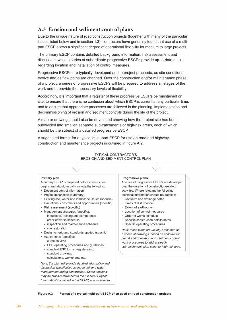
A suggested format for a typical multi-part ESCP for use on road and highway construction and maintenance projects is outlined in fi gure A.2.
Figure A.2 Format of a typical multi-part ESCP often used on road construction projects
TYPICAL CONTRACTOR’S EROSION AND SEDIMENT CONTROL PLAN
Primary planA primary ESCP is prepared before construction begins and should usually include the following:• Document control information• Project description (summary)• Existing soil, water and landscape issues (specific)• Limitations, constraints and opportunities (specific)• Risk assessment (specific)• Management strategies (specific): - inductions, training and competence - order of works schedule - inspection and maintenance schedule - site restoration• Design criteria and standards applied (specific)• Attachments (specific): - curricula vitae - ESC operating procedures and guidelines - standard ESC forms, registers etc. - standard drawings - calculations, worksheets etc.
Note: this plan will provide detailed information and discussion specifically relating to soil and water management during construction. Some sections may be cross-referrenced to the 'General Project Information' contained in the CEMP, and vice-versa.
Progressive plansA series of progressive ESCPs are developed over the duration of construction-related activities. Where relevant the following technical information should be detailed:• Contours and drainage paths• Limits of disturbance• Extent of earthworks• Location of control measures• Order of works schedule• Specific construction details/notes• Specific operating procedures
Note: these plans are usually presented as a series of drawings (based on construction plans) and/or erosion and sediment control work procedures to address each sub-catchment, plan sheet or high-risk area.

Appendix A: Erosion and sediment control planning 35
A.4 Contractor’s operating and management systemsMain roads contractors should have an internal operational quality-management and/or environmental-management system whereby their general day-to-day construction activities are fully linked to their ESCP and CEMP, and vice versa.
Accordingly, the planning, implementation and maintenance of erosion and sediment controls should be fully recorded within this system to ensure documented evidence is available at all times. As illustrated in the sample ESCP in appendix B, this system documentation for a medium-to-large project typically includes:
• an ESCP (i.e. both primary and progressive)
• a map or drawing of the project showing how the site has been subdivided for the purposes of preparing progressive ESCPs
• a register of progressive ESCPs
• work procedures, work-method statements, activity statements etc.
• inspection reports by the specialist soil conservationist (i.e. with action and close-out sections)
• routine inspection checklists used by construction personnel (i.e. with action and close-out sections)
• auditing programs
• a training and induction register
• site notes distributed internally about the project (e.g. instructions, alerts)
• formal correspondence (e.g. to and from RTA, councils, government authorities, designers, contractors)
• meeting minutes
• procedures for water-quality management in sediment basins
• water-quality monitoring results
• a fl ow chart of responsibilities.
The above documentation and recorded details will vary according to the nature of the project, the requirements of the contractor’s environmental-management system, the contractor’s quality-management system and/or the specifi c requirements of the contract.
Not only will a robust system be a defi nite advantage to a project during normal operations, but it will be particularly useful during any audit or regulatory investigation. A well-documented system will assist the contractor to demonstrate ‘due diligence’.
A.5 Progressive erosion and sediment control plansWhile primary ESCPs are prepared prior to any construction on a project, a series of progressive ESCPs are continually prepared prior to the start of each stage (e.g initial clearing, stripping and stockpiling topsoil, and bulk earthworks) or prior to commencement of a specifi c type of high-risk activity (e.g. culvert or bridge construction).
Primary and progressive ESCPs are discussed in section A.3 above, and a sample ESCP is presented in appendix B. Particular aspects of the sample ESCP that should be noted include:
• clear defi nition of the role and function of progressive ESCPs – see appendix B, section 3.
• format for a register of progressive plans – see appendix B, attachment 1
• samples of progressive ESCPs – see appendix B, attachment 2.

36 Managing urban stormwater: soils and construction – main road construction
The sample progressive ESCP on bridge construction demonstrates the integration with other fi eld-planning documents such as work procedures, work-method statements or activity statements, where a detailed level of planning is required at a sensitive site. Other situations where these detailed planning documents may be required include culvert construction, realignment and stabilisation of fl ow lines, and access through or around wetlands.
A.6 Preparation of erosion and sediment control plansAs previously indicated in section 4.4, specifi cations should contain a clause requiring the contractor to submit ESCPs for approval prior to commencement of works. On high-risk projects these plans should be developed and implemented as a cooperative effort between the contractor and a soil conservationist.
On projects with a lower risk, contractors may develop and present their own plans. However, it is recommended that a soil conservationist review these prior to submission to the superintendent. Periodic review of plan implementation by the soil conservationists (where they are part of the project team) will also provide benefi cial feedback to the contractor.
In this way a series of workable and practical ESCPs can be developed and implemented. These plans will result in structured forward planning, and an ordered approach to erosion and sediment control during construction, with an emphasis on being proactive and adaptive rather than being reactive.
While the use of a multi-part ESCP has been proposed and discussed in section 3.4, all plans should refl ect the specifi c requirements of the contractor, the client organisation (e.g. RTA, local council) and any other relevant consent authorities. Accordingly, plans may be prepared in many different formats, all with the prime requisite of achieving the desired project outcomes in the fi eld during construction.
As illustrated in section 3.4, the primary ESCP may be prepared as either a stand-alone document or included as a section of a more encompassing environmental document such as an EMP or an integrated project plan.
A.7 TrainingA successful erosion and sediment control program will depend on competent project personnel, including site managers, engineers, superintendents, foremen, leading hands, plant operators and labourers.
In this context, training is important and may be conducted, depending on the size and nature of the project, by one or more of the methods listed below. For example, large projects could include all methods of training, whereas smaller projects may only include site inductions and ‘toolbox’ meetings. To complement initial training, follow-up reviews of staff implementing these controls is also important to ensure that the training is being effectively implemented.
A.7.1 Site inductionsAll personnel should attend a project-specifi c site induction prior to commencing any work on the site. General erosion and sediment control and water quality matters should be highlighted, together with responsibilities under various pieces of legislation (e.g. POEO Act).
Appendix A: Erosion and sediment control planning 37
A.7.2 Toolbox meetingsThese informal on-the-job sessions should be conducted regularly (i.e. at least weekly) to address numerous issues related to operations, safety, the environment etc. Issues relevant to the stage of construction are usually highlighted (e.g. de-watering, mud tracking onto local roads, and care and maintenance of control measures).
A.7.3 Formal training sessionsIn situations where more intensive formal training sessions have not already occurred as part of a contractor’s environmental management system (EMS) and/or environmental policy, they can be conducted early in the project. This training may include:
• awareness training, which generally covers all soil and water-related issues and should be delivered to all personnel (see the training program outline at attachment 4 of appendix B)
• advanced training which addresses site-specifi c and project-specifi c issues and is directed to relevant personnel (e.g. preparation of progressive ESCPs and sediment basin management).
38 Managing urban stormwater: soils and construction – main road construction
Appendix B: Sample erosion and sediment control plan
B.1 IntroductionLand that has been disturbed or cleared of vegetation is potentially subject to erosion as a result of stormwater runoff. Soil particles that are eroded in such a way are transported down-slope, usually settling in watercourses, wetlands and lakes.
Erosion and sedimentation may result in many adverse environmental impacts including:
• reduction in water quality, increased turbidity and nutrient enrichment of water bodies
• damage to vegetation communities
• disturbance to aquatic fl ora and fauna
• increased potential for fl ooding
• restrictions to navigation
• reduction in recreational values
• reduction in aesthetic values
• increased maintenance costs
• promotion of weed growth
• reduced agricultural, forestry and biomass production.
This plan will form the initial ‘link in the chain’ to minimise on-site erosion and off-site sedimentation and therefore reduce adverse environmental impacts.
B.2 Project descriptionDescription will vary according to the nature of the project and should be:
• included in this section if the plan is a stand-alone document
• cross referenced to the relevant section if the plan forms part of a more encompassing environmental document such as an environmental management plan or integrated project plan.
B.3 Scope of this planThe purpose of this document is to serve as a broad based erosion and sediment control plan (ESCP) to outline the intentions and fundamental principles that will be followed in the planning and implementation of erosion and sediment control measures for the entire project.
This primary (or generic) ESCP will be supplemented by numerous progressive ESCPs detailing individual control measures. The progressive plans will be:
• prepared by the specialist soil conservationist in association with construction personnel to formulate practical documents for fi eld reference. Additionally, this process will provide a sense of ownership of the proposals to all parties
• prepared on relevant copies of drainage drawings for:
- different stages of construction (e.g. initial clearing, grubbing, topsoil stripping and stockpiling with revision for bulk earthworks)
- areas of high erosion hazard (e.g. culvert construction, bridge abutments). These plans will be revised as required
- specifi c areas that may occur outside the road alignment (e.g. compound, batch plant, stockpile sites and access roads). These plans will be revised when required by changing circumstances
Appendix B: Sample erosion and sediment control plan 39
• integrated with work procedures, work method statements, activity statements and their scheduling especially in relation to culvert and bridge construction
• site-specifi c and will not generally repeat the information contained in this primary ESCP and/or the contractor’s EMP
• given a sequential number and recorded in the register for progressive ESCPs (see attachment 1).
• controlled and distributed in accordance with the contractor’s quality system procedure for document control.
Samples of progressive plans are included at attachment 2.
B.4 Existing environment4.1 Landuse
4.2 Topography
4.3 Sensitive areas
4.4 Soil types
4.5 Rainfall
The above points will vary according to the location in New South Wales. They will also depend on the extent of project information included in this section if this plan is a stand-alone document, or cross-referenced to the relevant sections if this plan forms part of a more encompassing environmental document such as an environmental management plan or integrated project plan.
The points should be drawn together to emphasis matters relating to erosion hazard (e.g. best season for construction).
B.5 Specifi cations and supporting documentationProvide a list of specifi cations relevant to the project which are designed to minimise the potential for soil erosion and to contain sediment within the construction site. Specifi cations will vary from project to project.
Additionally, list any documents which are consistent with the specifi cations and provide guidelines on implementation of controls.
B.6 Key management strategiesThe following list outlines principles and control measures that should be considered for inclusion in this section of the plan (i.e. only include those points relevant to the project):
General• consider engaging a specialist soil conservationist with experience in road construction
(CV included in attachment 3)
• wherever possible make specialist input into detailed design including:
- design and location of sediment basins
- siting sediment basins to maximise capture of runoff from construction areas
- siting sediment basins to also contain road spillages during road operation
- location and stabilisation of open drains (e.g. catch and berm drains)

40 Managing urban stormwater: soils and construction – main road construction
- batter treatments
- culvert design with consideration for a stable fl ow path during construction
- bridge design in sympathy with maintaining the integrity of drainage lines
- dissipation of high-velocity fl ows
• form a specialist labour team to construct temporary controls, including sediment fences, batter drains on fi ll batters, and fl occulate sediment basins etc.
• ensure erosion and sediment controls are installed at all sites associated with construction activities, including:
- access roads and tracks
- offi ce and compound sites
- workshop areas
- concrete batching plants
- crushing and screening plants
- extraction sites
• liaise with the relevant government authorities in relation to control measures in watercourses and creeks (e.g. Department of Water and Energy, and Department of Primary Industries)
• develop relevant documentation and systems for recording erosion and sediment control activities via:
- progressive ESCPs as detailed in section 3 of this plan
- inspection reports completed by the specialist soil conservationist. A copy of the format for this report appears in attachment 6 and includes sections for location, control, recommendations/comment, action and ‘close-out’
- ESCP maintenance checklists completed by nominated construction personnel approximately every fortnight. A copy of the format appears in attachment 7. The checklist consists of a double-sided sheet where issues are identifi ed on the front page and a general list of items or ‘memory jogger’ is provided on the reverse side. As with soil conservationist inspection reports, there is provision for ‘close-out’ on the actual list
- site notes distributed internally between environmental and construction personnel
- meeting minutes
- formal correspondence (e.g. RTA, council, DECC, Department of Primary Industries)
- water-quality monitoring results (e.g. sediment basins, upstream and downstream).
Training• highlight the importance of soil conservation issues during site induction
• schedule half-day awareness seminars early in the project for all personnel involved in construction. The program will cover:
- environmental impacts
- relevant legislation
- principles of erosion and sediment control
- techniques of erosion and sediment control
More detail on the program appears in attachment 4.

Appendix B: Sample erosion and sediment control plan 41
• conduct advanced soil conservation seminars for personnel with special responsibilities. This may include training in fl occulation and water-quality management of sediment basins for the specialist labour team
• continually address relevant matters at regular ‘toolbox’ meetings during the course of the project.
Minimise extent and duration of disturbance• initially clear and grubb to leave the soil surface in a reasonably rough condition with
some surface vegetative cover
• minimise disturbance of vegetation along the road corridor with special emphasis on management of construction activities adjacent to watercourses
• leave watercourses undisturbed until culvert/bridge construction has commenced; use the cut-stump method where possible instead of stump removal to further maintain stream bank stability.
Control stormwater fl ows onto, through and from the site• separate ‘clean’ run-on water from ‘dirty’ (e.g. turbid) construction area runoff
• construct permanent drainage structures early in the project including:
- sediment basins and traps
- catch drains
- culverts and associated inlet and outlet protection (e.g. dissipaters)
• maximise the diversion of turbid construction runoff into sediment basins
• control runoff during the construction of embankments (e.g. fi ll shaping and the construction of temporary dykes and batter drains)
• divert formation runoff into pits and the stormwater drainage system as soon as practical to reduce surface fl ow lengths.
Use erosion control measures to prevent on-site damage• site stockpiles of soil material in low-hazard areas clear of watercourses. Additional
protection to be afforded with temporary vegetation, diversion banks and sediment control measures, if required
• construct a range of erosion controls within the various road sub-catchments to complement and increase the effectiveness and effi ciency of sediment controls in the lower areas
• use geotextile linings to provide temporary surface protection in areas of concentrated fl ows (e.g. batter drains, culvert construction).
Use sediment control measures to prevent off-site damage• construct control measures as close to the potential source of sediment as possible
• ensure sediment basin management of turbid water immediately after rain as required with one or a combination of:
- fl occulation with gypsum (or approved alternative fl occulant)
- pump-out for construction purposes or dust control

42 Managing urban stormwater: soils and construction – main road construction
• water not to be released from sediment basins prior to achieving acceptable water-quality standards. Attachment 5 contains a procedure for water-quality management in sediment basins
• manage water quality during de-watering activities (e.g. fi ltering techniques and fl occulation with gypsum)
• control the deposition of mud and soil material onto local roads
• initiate a water-quality monitoring program in the adjacent watercourses with results analysed to determine the effi ciency and effectiveness of implemented controls.
Stabilise disturbed areas quickly• ensure the success of the later revegetation program by utilising a good topsoil
management program
• progressively revegetate disturbed areas utilising appropriate species
• control dust through progressive revegetation techniques, water tankers etc.
Inspect and maintain control measures• ensure the progressive and continual implementation and maintenance of temporary
erosion and sediment controls (e.g. sediment fences, diversion banks, diversion drains, sediment traps)
• initiate a program to ensure regular maintenance of all erosion and sediment control measures. Sediment cleaned from structures, including sediment basins, to be deposited in a secure location where further pollution will not occur
• arrange regular inspections by a project soil conservationist or other key personnel to review and update control measures. Additional inspections will be conducted during and/or immediately following signifi cant rainfall events to monitor the functioning of controls.
The above points collectively fulfi l the principles of sound soil conservation practice as detailed in the various documents listed in section 5 of this plan. This will ensure a proactive and preventative philosophy is adopted, rather that a remedial approach to the control of erosion and sedimentation.
B.7 ConclusionThe strategies presented in this plan are considered to appropriately address all issues relevant to erosion and sediment control and to minimise potential impact.
Forward planning, adherence to a system of documentation and training will be key elements to ensure good performance in the fi eld.
B.8 AcknowledgmentsProvide a list of references etc. used in the compilation of this plan.

Appendix B: Sample erosion and sediment control plan 43
B.9 Attachments to this planAttachment 1: Register of progressive erosion and sediment control plans
Attachment 2: Sample progressive erosion and sediment control plans
Attachment 3: Curricula vitae of specialist soil conservationist
Attachment 4: Program for erosion and sediment control awareness seminars
Attachment 5: Procedure for water-quality management in sediment basins
Attachment 6: Inspection report for project soil conservationist
Attachment 7: Checklist for nominated construction personnel

44 Managing urban stormwater: soils and construction – main road construction
Pla
n no
.C
hain
age/
desc
ript
ion
Per
sonn
el in
volv
edin
pre
para
tion
Dat
e of
prep
arat
ion
Soil
cons
erva
tion
ist
init
ials
& d
ate
Env
iron
men
tal m
anag
erin
itia
ls &
dat
eSu
pers
eded
by
plan
no.
/co
mm
ent
ESC
P A
ttac
hm
ent 1
R
egis
ter
of p
rogr
essi
ve e
rosi
on a
nd
sed
imen
t con
trol
pla
ns
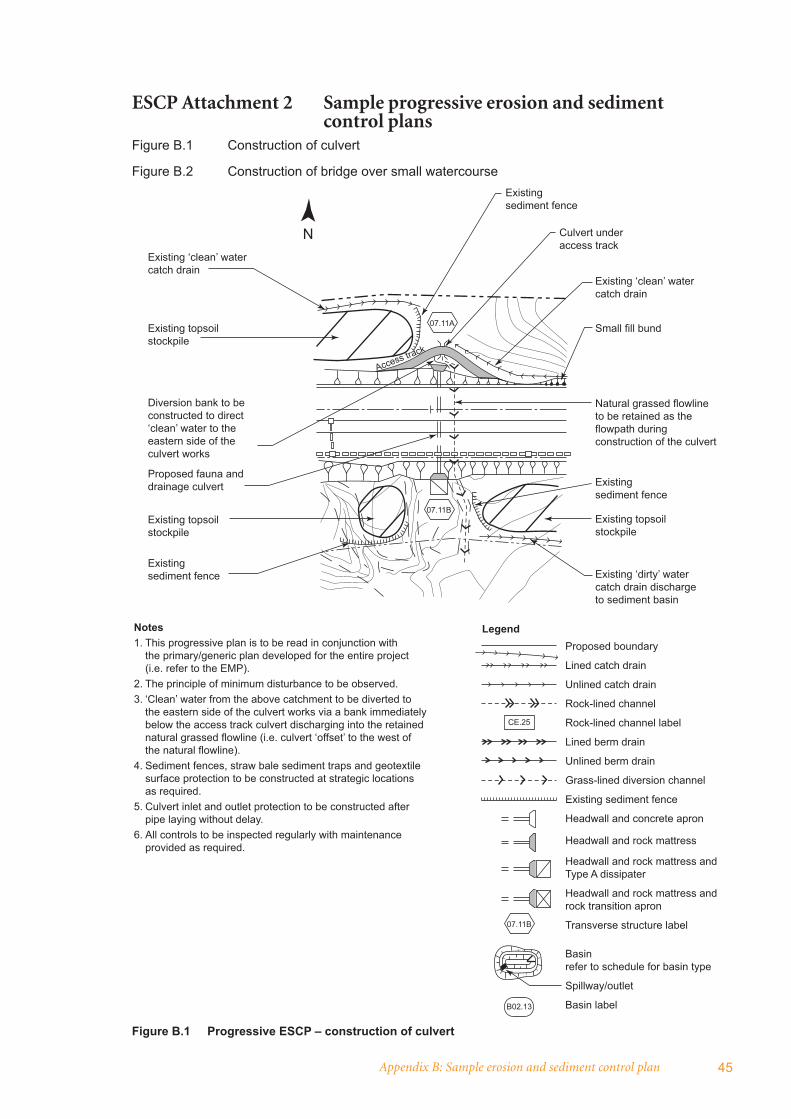
Appendix B: Sample erosion and sediment control plan 45
ESCP Attachment 2 Sample progressive erosion and sediment control plansFigure B.1 Construction of culvert
Figure B.2 Construction of bridge over small watercourse
Figure B.1 Progressive ESCP – construction of culvert
Existing ‘clean’ water catch drain
Existing topsoil stockpile
07.11A
Diversion bank to be constructed to direct ‘clean’ water to the eastern side of the culvert works
Proposed fauna and drainage culvert
Existing topsoil stockpile
Existing sediment fence
Culvert under access track
Existing ‘clean’ water catch drain
Small fill bund
Natural grassed flowline to be retained as the flowpath during construction of the culvert
Existing sediment fence
Existing topsoil stockpile
Existing ‘dirty’ water catch drain discharge to sediment basin
Notes1. This progressive plan is to be read in conjunction with the primary/generic plan developed for the entire project (i.e. refer to the EMP).2. The principle of minimum disturbance to be observed.3. ‘Clean’ water from the above catchment to be diverted to the eastern side of the culvert works via a bank immediately below the access track culvert discharging into the retained natural grassed flowline (i.e. culvert ‘offset’ to the west of the natural flowline).4. Sediment fences, straw bale sediment traps and geotextile surface protection to be constructed at strategic locations as required.5. Culvert inlet and outlet protection to be constructed after pipe laying without delay.6. All controls to be inspected regularly with maintenance provided as required.
Proposed boundary
Lined catch drain
Unlined catch drain
Rock-lined channel
Rock-lined channel label
Lined berm drain
Unlined berm drain
Grass-lined diversion channel
Existing sediment fence
Headwall and concrete apron
Headwall and rock mattress
Headwall and rock mattress and Type A dissipater
Headwall and rock mattress and rock transition apron
Transverse structure label
Basin refer to schedule for basin type
Spillway/outlet
Basin label
N
Existing sediment fence
07.11B
07.11B
B02.13
CE.25
Access track
Legend

46 Managing urban stormwater: soils and construction – main road construction
Figure B.2 Progressive ESCP – construction of bridge over small watercourse
LARGE EVENT
ELEVATION PLAN
Line of piling
Line of piling
Abutment A
Line of piling
Possible location of sediment fences
Flowpath over top of rock
Primary flowpath (i.e. 300 mm pipe)
Primary flowpath (i.e. 300 mm pipe)
Secondary flowpath (i.e. channel in clean rock platform)
Secondary flowpath (i.e. channel in clean rock platform)
Clean rock platform
Stream banks to be lined with geotextile in event of rain
Stream banks to be lined with geotextile in event of rain
Stream banks to be lined with geotextile in event of rain
Abutment B
Abutment B
Abutment A
Rock dissipater
CLEAN
ROCK
PLATFORM
Bund lined with geotextile to divert stream flows to pipe
Bund lined with geotextile to divert stream flows to pipe
DIRECTION OF FLOW

Appendix B: Sample erosion and sediment control plan 47
This progressive plan should be read in conjunction with the generic plan developed for the entire project.
The following methodology will be implemented to minimise erosion and sedimentation:
1 The creek banks to be partially cleared of vegetation for survey. This initial disturbance to be minimal via ‘trampling’ with any bare areas to be protected with sediment fence.
2 Existing small creek fl ow to be pumped around the site from the upstream side of the existing crossing to beneath the existing highway bridge.
3 The creek bed and banks to be fully cleared of vegetation.
4 The creek bed and banks to be excavated to foundation level.
5 All excavated unsuitable material to be stockpiled well clear of the creek in a protected locality (i.e. so as not to cause pollution).
6 The following cross-section and elevation plans illustrate:
(i) proposed creek water diversion measures, and
(ii) temporary erosion and sediment controls to be used during piling and laying of rock mattresses on the bed and banks.
7 The time to implement points 2, 3, 4, 5 and 6 is estimated to be 2 days. Weather forecasts to be perused prior to construction to reduce risk. In the event of rain, bare and disturbed areas of the stream bed and banks to be lined with geotextile as an interim protective measure.
8 Displaced water from the piling operation to be pumped directly into a water cart or adjacent sediment basin.
9 Immediately piling operations are completed, the platform and pipe to be removed from the creek bed and fi nal shaping and trimming to be completed.
10 The disturbed/bare creek bed and banks to be immediately covered with geotextile which will provide interim protection until installation of rock mattressing is completed.
11 Sediment fence and/or straw bale sediment traps to be constructed at strategic locations if required.
12 Interim protection of bare areas with geotextile lining to be used as required.
13 At completion of works, any bare or disturbed areas are to be seeded and fertilised.
14 All erosion and sedimentation controls to be inspected regularly and maintained when necessary (e.g. geotextile linings, sediment fences).
15 Creek stabilisation works should be completed over an 8–10 week period. All creek works to be completed prior to laying of bridge beams.
Figure B.2 (cont’d)

48 Managing urban stormwater: soils and construction – main road construction
ESCP Attachment 3 CV of specialist soil conservationist
Include relevant CV here.
Appendix B: Sample erosion and sediment control plan 49
ESCP Attachment 4 Program for erosion and sediment control awareness seminars – half day
1 Introduction
2 Environmental impacts This session focuses upon the on-site and off-site environmental impacts of erosion and sedimentation (e.g. water quality, fauna, fl ora). It concludes with an exercise listing all impacts.
3 Environmental legislationThis session examines:
• relevant legislation (e.g. POEO Act)
• practical application in the fi eld.
4 Principles of erosion and sediment control This session covers the following nine principles:
• investigation of site features
• planning
• minimum disturbance
• topsoil
• control of runoff
• minimisation of erosion
• trapping sediment
• progressive rehabilitation
• maintenance.
5 Techniques of erosion and sediment control This session includes the most common techniques including:
• clearing
• topsoil management
• drainage and installation of permanent structures (culverts, catch drains etc.)
• diversions banks
• drains and channels
• batter protection
• revegetation
• sediment basins and management
• sediment traps
• sand bags and their application
• maintenance
• miscellaneous matters (mud on local roads, de-watering, dust etc.)
6 Field inspectionsThis session examines techniques constructed in the fi eld together with associated discussions on impact, legislation and principles.
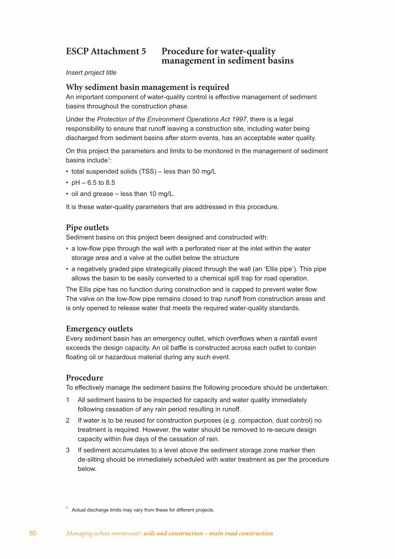
50 Managing urban stormwater: soils and construction – main road construction
ESCP Attachment 5 Procedure for water-quality management in sediment basins
Insert project title
Why sediment basin management is requiredAn important component of water-quality control is effective management of sediment basins throughout the construction phase.
Under the Protection of the Environment Operations Act 1997, there is a legal responsibility to ensure that runoff leaving a construction site, including water being discharged from sediment basins after storm events, has an acceptable water quality.
On this project the parameters and limits to be monitored in the management of sediment basins include1:
• total suspended solids (TSS) – less than 50 mg/L
• pH – 6.5 to 8.5
• oil and grease – less than 10 mg/L.
It is these water-quality parameters that are addressed in this procedure.
Pipe outletsSediment basins on this project been designed and constructed with:
• a low-fl ow pipe through the wall with a perforated riser at the inlet within the water storage area and a valve at the outlet below the structure
• a negatively graded pipe strategically placed through the wall (an ‘Ellis pipe’). This pipe allows the basin to be easily converted to a chemical spill trap for road operation.
The Ellis pipe has no function during construction and is capped to prevent water fl ow. The valve on the low-fl ow pipe remains closed to trap runoff from construction areas and is only opened to release water that meets the required water-quality standards.
Emergency outletsEvery sediment basin has an emergency outlet, which overfl ows when a rainfall event exceeds the design capacity. An oil baffl e is constructed across each outlet to contain fl oating oil or hazardous material during any such event.
ProcedureTo effectively manage the sediment basins the following procedure should be undertaken:
1 All sediment basins to be inspected for capacity and water quality immediately following cessation of any rain period resulting in runoff.
2 If water is to be reused for construction purposes (e.g. compaction, dust control) no treatment is required. However, the water should be removed to re-secure design capacity within fi ve days of the cessation of rain.
3 If sediment accumulates to a level above the sediment storage zone marker then de-silting should be immediately scheduled with water treatment as per the procedure below.
1 Actual discharge limits may vary from these for different projects.

Appendix B: Sample erosion and sediment control plan 51
4 If the water level has risen above the level of the sediment storage zone marker, then the parameters of pH, TSS and oil and grease to be tested and addressed are as follows:
i) pH • test basin water with a pH meter • no action if pH reading between 6.5 and 8.5 • lime (or suitable alternative) to be added if pH below 6.5 • hydrochloric acid (32% Muriatic) (or suitable alternative) to be added if pH
above 8.5 • determine volume of water in basin • determine percentage of lime or acid required by taking a 10-litre sample of basin
water and adding a known amount of lime or acid (initially 0.004%). If the pH is still not acceptable, vary the amount of lime or acid until within the limits
• once the required percentage has been determined, calculate the actual amount of lime or acid to be added by multiplying the volume of water in the basin by the determined percentage
• add the required amount of lime or acid to the basin • mix the water in the sediment basin well • treat for pH prior to TSS.
ii) TSS • test basin water by comparing with water samples contained in jars with
representative readings up to 100 mg/L created through laboratory testing. This will enable a relatively accurate comparison which will be verifi ed by laboratory testing approximately every six rainfall events
• no action if TSS reading less than 50 mg/L • if basins require fl occulation (e.g. TSS greater than 50 mg/L), bulk gypsum as
a fl occulant to be immediately applied evenly across the top of the water at an acceptable rate (i.e. trial and error as different for each basin). Methods of application to include:
a) broadcast by hand or shovel on small basins (i.e. less than 200 m3) b) mixing in a drum with water and pumping through a hose on large basins (i.e.
greater than 200 m3) (See vol. 1: appendix E.1 for further guidance on this technique).
iii) oil and grease • examine surface of water for evidence (e.g. sheen, discolouration) • no action if no visual contamination
• oil-absorbent material to be spread if there is contamination.
5 Leave basins to compensate for 24 to 48 hours.6 After re-testing, and once the above fi eld tests indicate the water quality is
acceptable, the stop valve should be opened by two or three notches (i.e. approximately 10%) for discharge to enable emptying within a 24-to-36-hour period to prevent sediment being stirred up by fast release of water and erosion at the outlet.
7 Steps 4, 5 and 6 may need to be repeated if acceptable water quality is not achieved initially.
8 Once water in the basins has been released the stop valve should be closed for the next rainfall event.
9 Records to be kept of the rainfall events, inspections undertaken, fi eld tests undertaken, dosage rates, timing of basin-water release etc. (see Figure B.3 overleaf).
10 The whole process of water-quality management in sediment basins should be completed within fi ve days of cessation of any rain period resulting in runoff entering the basin.

52 Managing urban stormwater: soils and construction – main road construction
Pro
ject
tit
le:
__________________________________
SE
DIM
EN
T B
AS
IN M
AN
AG
EM
EN
T C
HE
CK
LIS
T
Rai
nfal
l eve
ntm
m:
Allo
wab
le li
mits
:T
SS<
50 m
g/L
D
ays:
pH6.
5 to
8.5
Oil
and
grea
sem
ax. 1
0 m
g/L
(by
obs
erva
tion)
De-
silti
ng if
sed
imen
t acc
umul
ates
abo
ve m
arke
r
Bas
inno
.D
esig
nca
paci
tym
3
Is w
ater
to
beus
ed f
orco
nstr
ucti
on?
Wat
er q
ualit
y be
fore
trea
tmen
tR
ate
of lime
adde
d
Rat
eof ac
idad
ded
Rat
e of
gyps
umad
ded
Oil
abso
rbm
ent
adde
d
Wat
er q
ualit
y af
ter
trea
tmen
tD
ate
valv
eop
ened
Dat
eva
lve
clos
ed
De-
silt
ing
requ
ired
Dat
ede
-silt
edC
omm
ents
TSS
pHO
il &
grea
seT
SSpH
Oil
&gr
ease
________________________________________________
__________________
In
spec
ted b
y /
posi
tion
Dat
e
Figu
re B
.3
Sedi
men
t bas
in m
anag
emen
t che
cklis
t
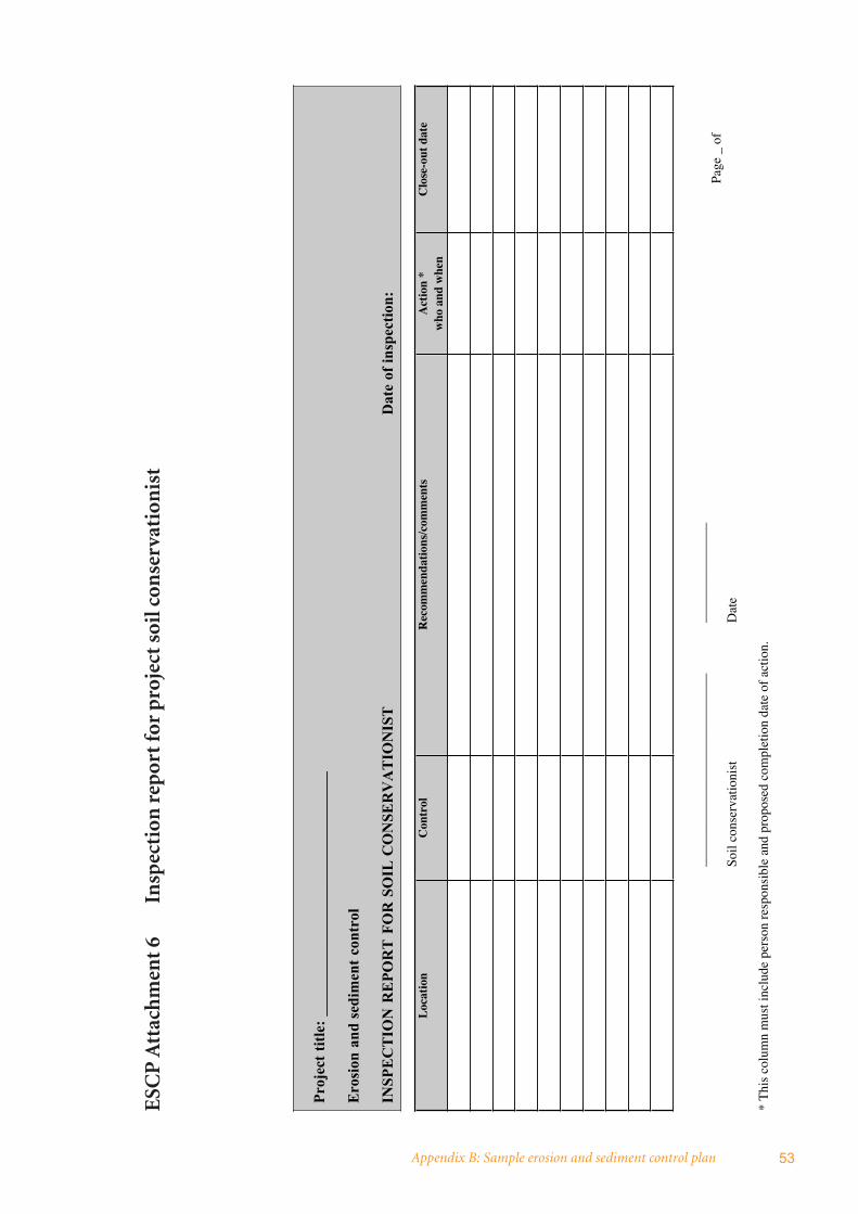
Appendix B: Sample erosion and sediment control plan 53
ESC
P A
ttac
hm
ent 6
In
spec
tion
rep
ort f
or p
roje
ct s
oil c
onse
rvat
ion
ist
Pro
ject
tit
le:
__
__
__
__
__
__
__
__
__
__
__
__
__
__
__
__
Ero
sio
n a
nd
sed
imen
t co
ntr
ol
INS
PE
CT
ION
RE
PO
RT
FO
R S
OIL
CO
NS
ER
VA
TIO
NIS
T
Da
te o
f in
spec
tio
n:
Loc
atio
nC
ontr
olR
ecom
men
dati
ons/
com
men
tsA
ctio
n *
who
and
whe
nC
lose
-out
dat
e
____
____
____
____
____
____
____
___
____
____
____
_Pa
ge _
of
Soil
cons
erva
tioni
stD
ate
* T
his
colu
mn
mus
t inc
lude
per
son
resp
onsi
ble
and
prop
osed
com
plet
ion
date
of
actio
n.
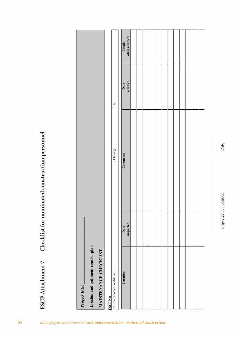
54 Managing urban stormwater: soils and construction – main road construction
ESC
P A
ttac
hm
ent 7
C
hec
klis
t for
nom
inat
ed c
onst
ruct
ion
per
son
nel
Pro
ject
tit
le:
________________________________
Ero
sion
an
d s
edim
ent
con
trol
pla
n
MA
INT
EN
AN
CE
CH
EC
KL
IST
ESC
P N
o:C
urr
ent
wea
ther
co
nd
itio
ns:
Ch
ain
age:
To
Loc
atio
nD
ate
insp
ecte
dC
omm
ents
Dat
ere
ctif
ied
Inti
als
whe
n re
ctif
ied
_
________________________________
________
I
nsp
ecte
d b
y /
posi
tion
Dat
e
Appendix C: Typical arrangements diagrams 55
Appendix C: Typical arrangements diagramsThis appendix presents the following ‘typical arrangement’ diagrams illustrating how common erosion and sediment control measures and techniques may be applied in a road construction context.
Figure C.1: Temporary diversion banks – typical arrangement
Figure C.2: Temporary batter drains – typical arrangement
Figure C.3: Check dams in drains and gullies – typical arrangement
Figure C.4: Temporary median banks – typical arrangement
Figure C.5: Sediment traps at drop inlets – typical arrangement
Figure C.6: Sediment fence – typical arrangement
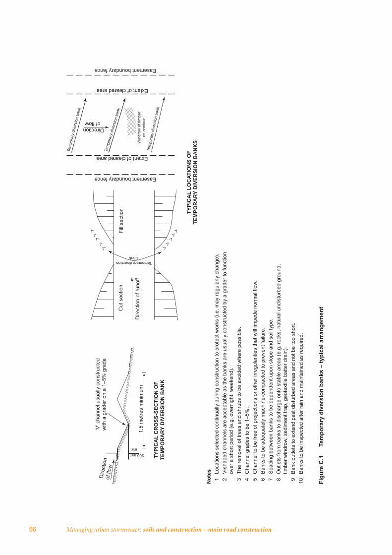
56 Managing urban stormwater: soils and construction – main road construction
Figu
re C
.1
Tem
pora
ry d
iver
sion
ban
ks –
typi
cal a
rran
gem
ent
‘V’ c
hann
el u
sual
ly c
onst
ruct
ed
with
a g
rade
r on
a 1–
5% g
rade
1.5
met
res
min
imum
Dire
ctio
nof
flow
300 mmmin.
TYPI
CA
L C
RO
SS-S
ECTI
ON
OF
TEM
POR
ARY
DIV
ERSI
ON
BA
NK
Cut
sec
tion
Dire
ctio
n of
runo
ff
Fill
sect
ion
Easement boundary fence
Temporary diversion bank
TYPI
CA
L LO
CAT
ION
S O
F TE
MPO
RA
RY D
IVER
SIO
N B
AN
KS
Extent of cleared area
Tem
pora
ry d
iver
sion
ban
k
Tem
pora
ry d
iver
sion
ban
k
Tem
pora
ry d
iver
sion
ban
k
Win
drow
of t
imbe
r on
con
tour
Directionof flow
Extent of cleared area
Easement boundary fence
Not
es 1
Lo
catio
ns s
elec
ted
cont
inua
lly d
urin
g co
nstru
ctio
n to
pro
tect
wor
ks (i
.e. m
ay re
gula
rly c
hang
e).
2
V-sh
aped
cha
nnel
s ar
e ac
cept
able
as
the
bank
s ar
e us
ually
con
stru
cted
by
a gr
ader
to fu
nctio
n
over
a s
hort
perio
d (e
.g. o
vern
ight
, wee
kend
). 3
Th
e re
mov
al o
f tre
es a
nd s
hrub
s to
be
avoi
ded
whe
re p
ossi
ble.
4
Cha
nnel
gra
des
to b
e 1–
5%.
5
Cha
nnel
to b
e fre
e of
pro
ject
ions
or o
ther
irre
gula
ritie
s th
at w
ill im
pede
nor
mal
flow
. 6
B
anks
to b
e ad
equa
tely
mac
hine
-com
pact
ed to
pre
vent
failu
re.
7
Spa
cing
bet
wee
n ba
nks
to b
e de
pend
ent u
pon
slop
e an
d so
il ty
pe.
8
Out
lets
from
ban
ks to
dis
char
ge o
nto
stab
le a
reas
(e.g
. roc
ks, n
atur
al u
ndis
turb
ed g
roun
d,
timbe
r win
drow
, sed
imen
t tra
p, g
eote
xtile
bat
ter d
rain
). 9
B
ank
outle
ts to
ext
end
past
dis
turb
ed a
reas
and
not
be
too
shor
t.10
B
anks
to b
e in
spec
ted
afte
r rai
n an
d m
aint
aine
d as
requ
ired.
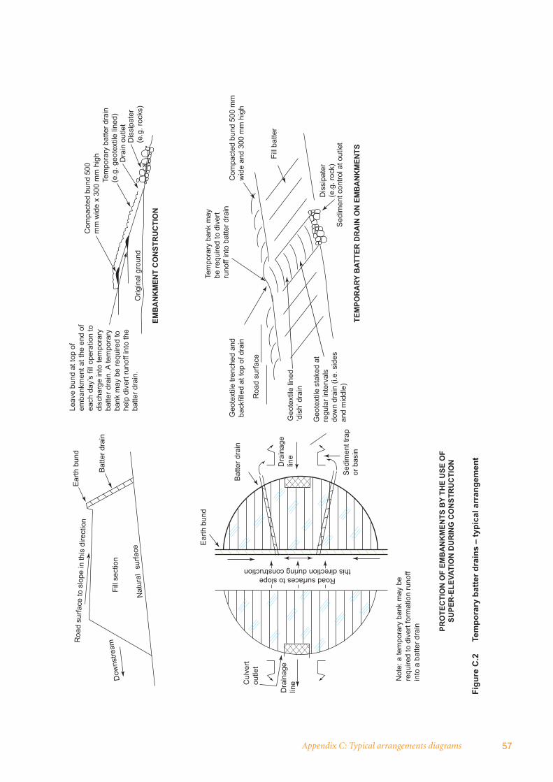
Appendix C: Typical arrangements diagrams 57
Figu
re C
.2
Tem
pora
ry b
atte
r dra
ins
– ty
pica
l arr
ange
men
t
Roa
d su
rface
to s
lope
in th
is d
irect
ion
Ear
th b
und
Dow
nstre
amFi
ll se
ctio
n
Bat
ter d
rain
Nat
ural
surfa
ce
Leav
e bu
nd a
t top
of
emba
nkm
ent a
t the
end
of
each
day
’s fi
ll op
erat
ion
to
disc
harg
e in
to te
mpo
rary
ba
tter d
rain
. A te
mpo
rary
ba
nk m
ay b
e re
quire
d to
he
lp d
iver
t run
off i
nto
the
batte
r dra
in.
Com
pact
ed b
und
500
mm
wid
e x
300
mm
hig
hTe
mpo
rary
bat
ter d
rain
(e
.g. g
eote
xtile
line
d)D
rain
out
let
Dis
sipa
ter
(e.g
. roc
ks)
EMB
AN
KM
ENT
CO
NST
RU
CTI
ON
Orig
inal
gro
und
Ear
th b
und
Bat
ter d
rain
Dra
inag
e lin
e
Sed
imen
t tra
p or
bas
in
Not
e: a
tem
pora
ry b
ank
may
be
requ
ired
to d
iver
t for
mat
ion
runo
ff in
to a
bat
ter d
rain PR
OTE
CTI
ON
OF
EMB
AN
KM
ENTS
BY
THE
USE
OF
SUPE
R-E
LEVA
TIO
N D
UR
ING
CO
NST
RU
CTI
ON
Geo
text
ile tr
ench
ed a
nd
back
fille
d at
top
of d
rain
Roa
d su
rface
Tem
pora
ry b
ank
may
be
requ
ired
to d
iver
t ru
noff
into
bat
ter d
rain
Com
pact
ed b
und
500
mm
w
ide
and
300
mm
hig
h
Geo
text
ile li
ned
‘dis
h’ d
rain
Fill
batte
r
Geo
text
ile s
take
d at
re
gula
r int
erva
ls
dow
n dr
ain
(i.e.
sid
es
and
mid
dle)
Dis
sipa
ter
(e.g
. roc
k)S
edim
ent c
ontro
l at o
utle
t
TEM
POR
ARY
BAT
TER
DR
AIN
ON
EM
BA
NK
MEN
TS
Cul
vert
outle
t
Dra
inag
e lin
e
Road surfaces to slopethis direction during construction

58 Managing urban stormwater: soils and construction – main road construction
Figu
re C
.3
Che
ck d
ams
in d
rain
s an
d gu
llies
– ty
pica
l arr
ange
men
t
End
of s
truct
ure
high
er th
an s
pillw
ay
Bal
es s
take
d w
ith tw
o st
akes
pe
r bal
eS
pillw
ay o
ver
top
of b
ale
Stra
w b
ales
Gro
und
leve
l G
roun
d le
vel
End
of s
truct
ure
high
er th
an s
pillw
ay
End
of
stru
ctur
ehi
gher
than
sp
illway
Stra
w b
ales
tren
ched
20
0 m
m in
to g
roun
dD
issi
pate
r bel
ow
spill
way
(e.g
. roc
k)D
issi
pate
r bel
ow
spill
way
(e.g
. roc
k)
CR
OSS
-SEC
TIO
N O
F ST
RAW
BA
LE C
HEC
K D
AM
Sta
r pic
ket o
r w
oode
n st
ake
Wire
may
be
secu
red
alon
g to
p of
fenc
e fo
r mor
e st
reng
th spillw
ay
Spi
llway
cre
ated
by:
(i) s
ecur
ing
horiz
onta
l sta
ke to
ver
tical
stak
es (2
) at a
hei
ght o
f ½ to
²⁄ 3 o
f
the
heig
ht o
f the
sed
imen
t fen
ce(ii
) cut
ting
the
sedi
men
t fen
ce a
nd
se
curin
g ov
er th
e ho
rizon
tal s
take
to c
reat
e a
‘win
dow
’
Sed
imen
t fen
ce
Sed
imen
t fen
ce
trenc
hed
200
mm
in
to g
roun
d
CR
OSS
-SEC
TIO
N O
F SE
DIM
ENT
FEN
CE
CH
ECK
DA
M
End
of s
truct
ure
high
er th
an
spillw
ay
End
of s
truct
ure
high
er th
an s
pillw
ay
Spi
lling
abo
ve d
rain
inve
rt w
ith ro
ck o
r su
itabl
e al
tern
ativ
e pl
aced
dow
nstre
am to
fu
nctio
n as
a d
issi
pate
r and
pre
vent
sco
urin
gE
nd o
f stru
ctur
e hi
gher
than
spi
llway
Roc
k or
alte
rnat
ive
(e.g
. filt
er m
ater
ial)
for d
issi
patio
nS
andb
ag o
r ag
greg
ate
bag
TYPI
CA
L M
EDIA
N/T
AB
LE D
RA
IN A
PPLI
CAT
ION
Not
es1
Che
ck d
ams
may
be
cons
truct
ed o
f a v
arie
ty o
f mat
eria
ls (e
.g.
st
raw
bal
es, s
edim
ent f
ence
, roc
k an
d ge
otex
tile,
she
et p
iling
).2
Che
ck d
ams
to b
e tre
nche
d 20
0 m
m in
to g
roun
d su
rface
on
base
an
d si
des
and
secu
rely
bac
kfill
ed.
3 S
pillw
ay to
be
over
inve
rt of
dra
in w
ith d
isch
arge
not
per
mitt
ed to
flow
aro
und
ends
.
4 S
pillw
ay to
be
less
than
1 m
abo
ve in
vert
of d
rain
.5
Som
e fo
rm o
f dis
sipa
tion
may
be
requ
ired
belo
w s
pillw
ays
of c
heck
dam
s
(e.g
. roc
k, s
andb
ags)
.6
Che
ck d
ams
to b
e sp
aced
so
the
toe
of th
e up
stre
am c
heck
is le
vel w
ith th
e
sp
illw
ay o
f the
nex
t dow
nstre
am c
heck
.7
Che
ck d
ams
to b
e in
spec
ted
afte
r rai
n an
d m
aint
aine
d as
requ
ired.

Appendix C: Typical arrangements diagrams 59
Figu
re C
.4
Tem
pora
ry m
edia
n ba
nks
– ty
pica
l arr
ange
men
t
Roc
k or
alte
rnat
ive
for d
issi
patio
nS
edim
ent d
epos
ition
Flow
dire
ctio
n
ELEV
ATIO
N
200 mmmin
TYPI
CA
L PL
AN
VIE
W
Med
ian
pit
Med
ian
pit
Ban
k
Carriage way
Flow direction Ban
k
Carriage way
Bat
ter
Bat
ter
Med
ian
bank
Med
ian
bank
EMB
AN
KM
ENT
SEC
TIO
N
Not
eP
rovi
ding
the
abov
e pr
inci
ples
of c
onst
ruct
ion
are
impl
emen
ted,
san
dbag
s m
ay
be s
ubst
itute
d w
ith o
ther
mat
eria
ls (e
.g. r
ock
wra
pped
in g
eote
xtile
, stra
w b
ales
)
CU
TTIN
G S
ECTI
ON
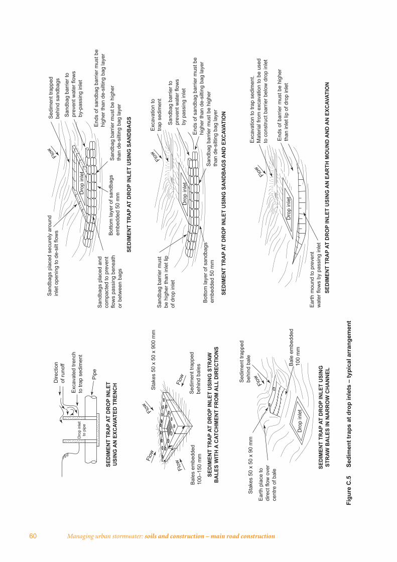
60 Managing urban stormwater: soils and construction – main road construction
Figu
re C
.5
Sedi
men
t tra
ps a
t dro
p in
lets
– ty
pica
l arr
ange
men
t
Dire
ctio
nof
runo
ff
Exc
avat
ed tr
ench
to
trap
sed
imen
tD
rop
inle
t to
pip
e
Pip
e
SED
IMEN
T TR
AP
AT D
RO
P IN
LET
USI
NG
AN
EXC
AVAT
ED T
REN
CH
San
dbag
s pl
aced
sec
urel
y ar
ound
in
let o
peni
ng to
de-
silt
flow
sFlo
w
Flow
Flow Flow
Flow
Flow
Flow
Dro
p in
let
Sed
imen
t tra
pped
be
hind
san
dbag
s
San
dbag
bar
rier t
o pr
even
t wat
er fl
ows
by-p
assi
ng in
let
San
dbag
bar
rier t
o pr
even
t wat
er fl
ows
by p
assi
ng in
let
End
s of
san
dbag
bar
rier m
ust b
e hi
gher
than
de-
silti
ng b
ag la
yer
End
s of
san
dbag
bar
rier m
ust b
e hi
gher
than
de-
silti
ng b
ag la
yer
San
dbag
bar
rier m
ust b
e hi
gher
th
an d
e-si
lting
bag
laye
r
San
dbag
bar
rier m
ust b
e hi
gher
th
an d
e-si
lting
bag
laye
r
Bot
tom
laye
r of s
andb
ags
embe
dded
50
mm
Bot
tom
laye
r of s
andb
ags
embe
dded
50
mm
San
dbag
s pl
aced
and
co
mpa
cted
to p
reve
nt
flow
s pa
ssin
g be
neat
h or
bet
wee
n ba
gs
SED
IMEN
T TR
AP
AT D
RO
P IN
LET
USI
NG
SA
ND
BA
GS
Dro
p in
let
Flow
Dro
p in
let
San
dbag
bar
rier m
ust
be h
ighe
r tha
n in
let l
ip
of d
rop
inle
t
SED
IMEN
T TR
AP
AT D
RO
P IN
LET
USI
NG
SA
ND
BA
GS
AN
D E
XCAV
ATIO
N
Exc
avat
ion
to
trap
sedi
men
t
Ear
th m
ound
to p
reve
nt
wat
er fl
ows
by p
assi
ng in
let
Exc
avat
ion
to tr
ap s
edim
ent.
Mat
eria
l fro
m e
xcav
atio
n to
be
used
to
con
stru
ct b
arrie
r bel
ow d
rop
inle
t
End
s of
bar
rier m
ust b
e hi
gher
th
an in
let l
ip o
f dro
p in
let
SED
IMEN
T TR
AP
AT D
RO
P IN
LET
USI
NG
AN
EA
RTH
MO
UN
D A
ND
AN
EXC
AVAT
ION
SED
IMEN
T TR
AP
AT D
RO
P IN
LET
USI
NG
STR
AW
BA
LES
WIT
H A
CAT
CH
MEN
T FR
OM
ALL
DIR
ECTI
ON
S
Sed
imen
t tra
pped
be
hind
bal
es
Sta
kes
50 x
50
x 90
0 m
m
Bal
es e
mbe
dded
10
0–15
0 m
m
SED
IMEN
T TR
AP
AT D
RO
P IN
LET
USI
NG
ST
RAW
BA
LES
IN N
AR
RO
W C
HA
NN
EL
Sta
kes
50 x
50
x 90
mm
Sed
imen
t tra
pped
be
hind
bal
e
Dro
p in
let
Bal
e em
bedd
ed
100
mm
Ear
th p
lace
to
dire
ct fl
ow o
ver
cent
re o
f bal
e
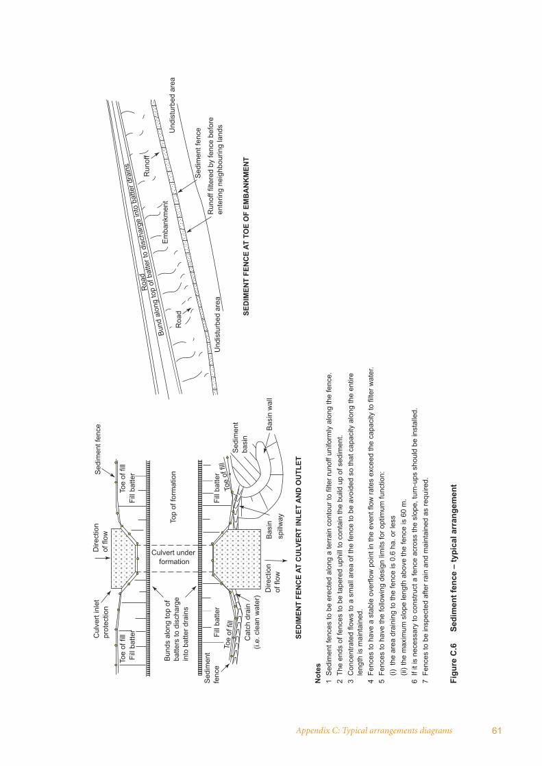
Appendix C: Typical arrangements diagrams 61
Figu
re C
.6
Sedi
men
t fen
ce –
typi
cal a
rran
gem
ent
Cul
vert
inle
t pr
otec
tion
Toe
of fi
llFi
ll ba
tter
Toe
of fi
llFi
ll ba
tter
Fill
batte
rFi
ll ba
tter
Dire
ctio
nof
flow
Sed
imen
t fen
ce
Sed
imen
tfe
nce
Bun
ds a
long
top
of
batte
rs to
dis
char
ge
into
bat
ter d
rain
s
Culvert under formation
Top
of fo
rmat
ion
Cat
ch d
rain
(i.
e. c
lean
wat
er)
Dire
ctio
nof
flow
Bas
insp
illway
Sed
imen
tba
sin
Bas
in w
all
SED
IMEN
T FE
NC
E AT
CU
LVER
T IN
LET
AN
D O
UTL
ET
Toe
of fi
llTo
e of
fill
Roa
d
Roa
d
Em
bank
men
t
Run
off
Und
istu
rbed
are
a
Run
off f
ilter
ed b
y fe
nce
befo
re
ente
ring
neig
hbou
ring
land
s
Bund
alo
ng to
p of
bat
ter t
o di
scha
rge
into
bat
ter d
rain
s
Und
istu
rbed
are
a
SED
IMEN
T FE
NC
E AT
TO
E O
F EM
BA
NK
MEN
T
Sed
imen
t fen
ce
Not
es1
Sed
imen
t fen
ces
to b
e er
ecte
d al
ong
a te
rrai
n co
ntou
r to
filte
r run
off u
nifo
rmly
alo
ng th
e fe
nce.
2 Th
e en
ds o
f fen
ces
to b
e ta
pere
d up
hill
to c
onta
in th
e bu
ild u
p of
sed
imen
t.3
Con
cent
rate
d flo
ws
to a
sm
all a
rea
of th
e fe
nce
to b
e av
oide
d so
that
cap
acity
alo
ng th
e en
tire
leng
th is
mai
ntai
ned.
4 Fe
nces
to h
ave
a st
able
ove
rflow
poi
nt in
the
even
t flo
w ra
tes
exce
ed th
e ca
paci
ty to
filte
r wat
er.
5 Fe
nces
to h
ave
the
follo
win
g de
sign
lim
its fo
r opt
imum
func
tion:
(i)
the
are
a dr
aini
ng to
the
fenc
e is
0.6
ha.
or l
ess
(ii
) the
max
imum
slo
pe le
ngth
abo
ve th
e fe
nce
is 6
0 m
.6
If it
is n
eces
sary
to c
onst
ruct
a fe
nce
acro
ss th
e sl
ope,
turn
-ups
sho
uld
be in
stal
led.
7 Fe
nces
to b
e in
spec
ted
afte
r rai
n an
d m
aint
aine
d as
requ
ired.
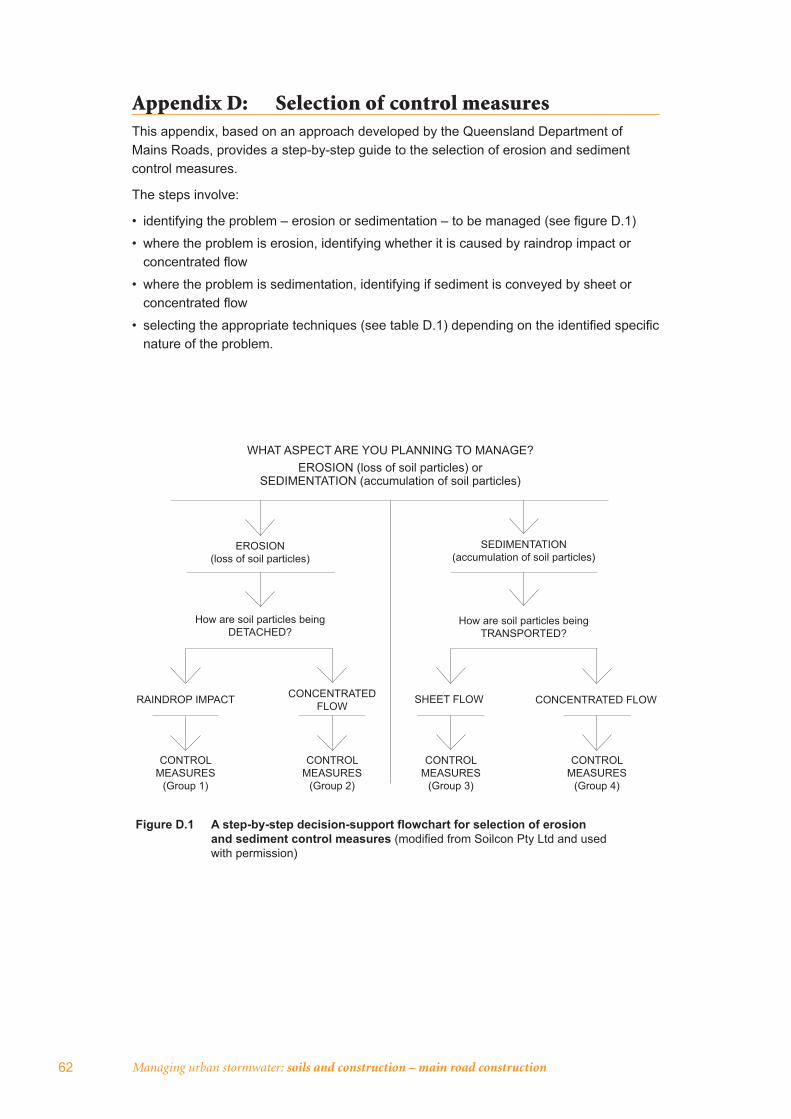
Managing urban stormwater: soils and construction – main road construction62
Appendix D: Selection of control measuresThis appendix, based on an approach developed by the Queensland Department of Mains Roads, provides a step-by-step guide to the selection of erosion and sediment control measures.
The steps involve:
• identifying the problem – erosion or sedimentation – to be managed (see fi gure D.1)
• where the problem is erosion, identifying whether it is caused by raindrop impact or concentrated fl ow
• where the problem is sedimentation, identifying if sediment is conveyed by sheet or concentrated fl ow
• selecting the appropriate techniques (see table D.1) depending on the identifi ed specifi c nature of the problem.
Figure D.1 A step-by-step decision-support flowchart for selection of erosion and sediment control measures (modified from Soilcon Pty Ltd and used with permission)
WHAT ASPECT ARE YOU PLANNING TO MANAGE?EROSION (loss of soil particles) or
SEDIMENTATION (accumulation of soil particles)
EROSION (loss of soil particles)
How are soil particles beingDETACHED?
RAINDROP IMPACT CONCENTRATED FLOW
CONTROL MEASURES
(Group 1)
CONTROL MEASURES
(Group 2)
CONTROL MEASURES
(Group 3)
CONTROL MEASURES
(Group 4)
SEDIMENTATION (accumulation of soil particles)
How are soil particles being TRANSPORTED?
SHEET FLOW CONCENTRATED FLOW

Appendix D: Selection of control measures 63
Table D.1 Group 1 – Erosion control RAINDROP IMPACT
Vegetation • temporary vegetation (cover crop only)• permanent vegetation – introduced (exotic) pasture
species or native (endemic) species• refer to vol. 1: sections 4.3.2, 7.1 and 7.2;
appendices A6 and G
Batter blankets• vegetation promotion blankets• vegetation suppression blankets• needle-punched geotextile membrane• builder’s plastic membrane• refer to vol. 1: section 5.4.2; SD5-2; appendices A6
and D
Soil surface mulching• hydromulch or hydraulic bonded-fi bre matrix• blown straw, hay, crop residue, with bitumen tack• tub-ground or chipped organic mulch• brush-matting• rock or gravel mulch• refer to vol. 1: section 7.4; fi gure 7.3; appendices
A6 and D
Geocellular containment systems• Non-woven geotextile type material• Polypropylene material (perforated and non-
perforated)• refer to vol. 1: section 5.4.2; SD5-3; appendix D
Surface roughening• roughening parallel to contour• contour ripping or scarifying• ‘track walking’• refer to vol. 1: section 4.3.2; fi gures 4.3(a) and (b)
Geobinders• organic tackifi ers• co-polymer emulsions• bitumen emulsion• cementitious products• refer to vol. 1: section 7.1.2; appendices A6 and D
© T
ony
Kin
g©
Ton
y K
ing
© T
ony
Kin
g©
Pre
sto
Pro
duct
Co.
US
A©
Ton
y K
ing
© T
ony
Kin
g

64 Managing urban stormwater: soils and construction – main road construction
Table D.1 Group 2 – Erosion control CONCENTRATED WATER FLOW
Up-slope diversions • excavated channel-type bank• backpush-type bank or windrow• catch drains• shoulder dyke• refer to vol. 1: section 5.4.4; SD5-5 and SD5-6
Mid-slope diversions• berms and benches• temporary diversions (at cut/fi ll line)• cross banks• refer to vol. 1: section 4.3.1; fi gure 4.2;
appendix A4
Soft armour channels• trapezoidal or parabolic shape• consider channel grade and maximum
permissible velocity• establish vegetative ground cover• standard (un-reinforced) or re-inforced turf• biodegradable erosion control mat (temporary)
or synthetic erosion control mat (permanent)• refer to vol. 1: sections 5.4.3, 7.3; SD5-7;
appendix D
Hard armour channels• loose rock• rock-fi lled wire mattresses• articulating concrete block systems• grouted rock• cast in-situ concrete• builder’s plastic lining or geotextile lining• refer to vol. 1: section 5.4.4; table 5.2;
fi gure 5.4; appendix D
In-stream diversions• temporary coffer dams• water-fi lled structures • temporary lined channel (stream diversion)• refer to vol. 1: section 5.3.5; appendix I
© T
ony
Kin
g©
Ton
y K
ing
© T
ony
Kin
g©
Ric
k M
orse
©
Por
tada
m
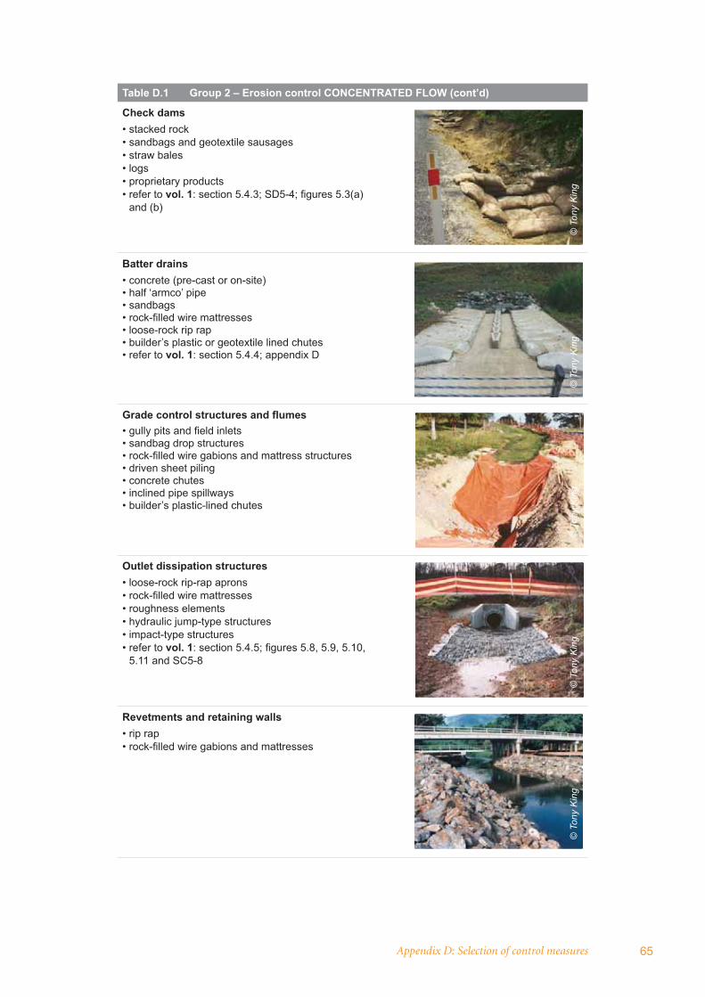
Appendix D: Selection of control measures 65
Table D.1 Group 2 – Erosion control CONCENTRATED FLOW (cont’d)
Check dams• stacked rock• sandbags and geotextile sausages• straw bales• logs• proprietary products• refer to vol. 1: section 5.4.3; SD5-4; fi gures 5.3(a)
and (b)
Batter drains• concrete (pre-cast or on-site)• half ‘armco’ pipe• sandbags• rock-fi lled wire mattresses• loose-rock rip rap• builder’s plastic or geotextile lined chutes• refer to vol. 1: section 5.4.4; appendix D
Grade control structures and fl umes• gully pits and fi eld inlets• sandbag drop structures• rock-fi lled wire gabions and mattress structures• driven sheet piling• concrete chutes• inclined pipe spillways• builder’s plastic-lined chutes
Outlet dissipation structures• loose-rock rip-rap aprons• rock-fi lled wire mattresses• roughness elements• hydraulic jump-type structures• impact-type structures• refer to vol. 1: section 5.4.5; fi gures 5.8, 5.9, 5.10,
5.11 and SC5-8
Revetments and retaining walls• rip rap• rock-fi lled wire gabions and mattresses
© T
ony
Kin
g©
Ton
y K
ing
© T
ony
Kin
g©
Ton
y K
ing
© T
ony
Kin
g
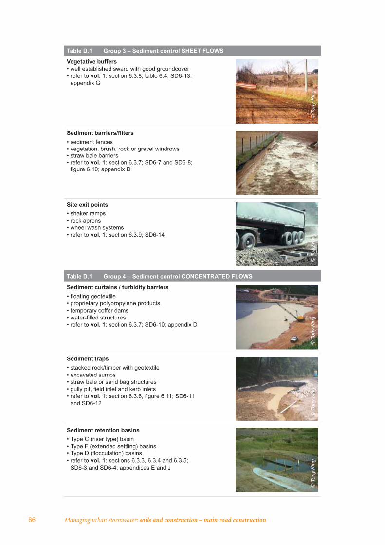
66 Managing urban stormwater: soils and construction – main road construction
Table D.1 Group 3 – Sediment control SHEET FLOWS
Vegetative buffers• well established sward with good groundcover• refer to vol. 1: section 6.3.8; table 6.4; SD6-13;
appendix G
Sediment barriers/fi lters• sediment fences• vegetation, brush, rock or gravel windrows• straw bale barriers• refer to vol. 1: section 6.3.7; SD6-7 and SD6-8;
fi gure 6.10; appendix D
Site exit points• shaker ramps• rock aprons• wheel wash systems• refer to vol. 1: section 6.3.9; SD6-14
Table D.1 Group 4 – Sediment control CONCENTRATED FLOWS
Sediment curtains / turbidity barriers• fl oating geotextile• proprietary polypropylene products• temporary coffer dams• water-fi lled structures• refer to vol. 1: section 6.3.7; SD6-10; appendix D
Sediment traps • stacked rock/timber with geotextile• excavated sumps• straw bale or sand bag structures• gully pit, fi eld inlet and kerb inlets • refer to vol. 1: section 6.3.6, fi gure 6.11; SD6-11
and SD6-12
Sediment retention basins• Type C (riser type) basin• Type F (extended settling) basins• Type D (fl occulation) basins• refer to vol. 1: sections 6.3.3, 6.3.4 and 6.3.5;
SD6-3 and SD6-4; appendices E and J
© T
ony
Kin
g©
Ton
y K
ing
© T
ony
Kin
g©
Ton
y K
ing
© T
ony
Kin
g©
Ton
y K
ing


www.environment.nsw.gov.au