Embed Size (px)
Citation preview
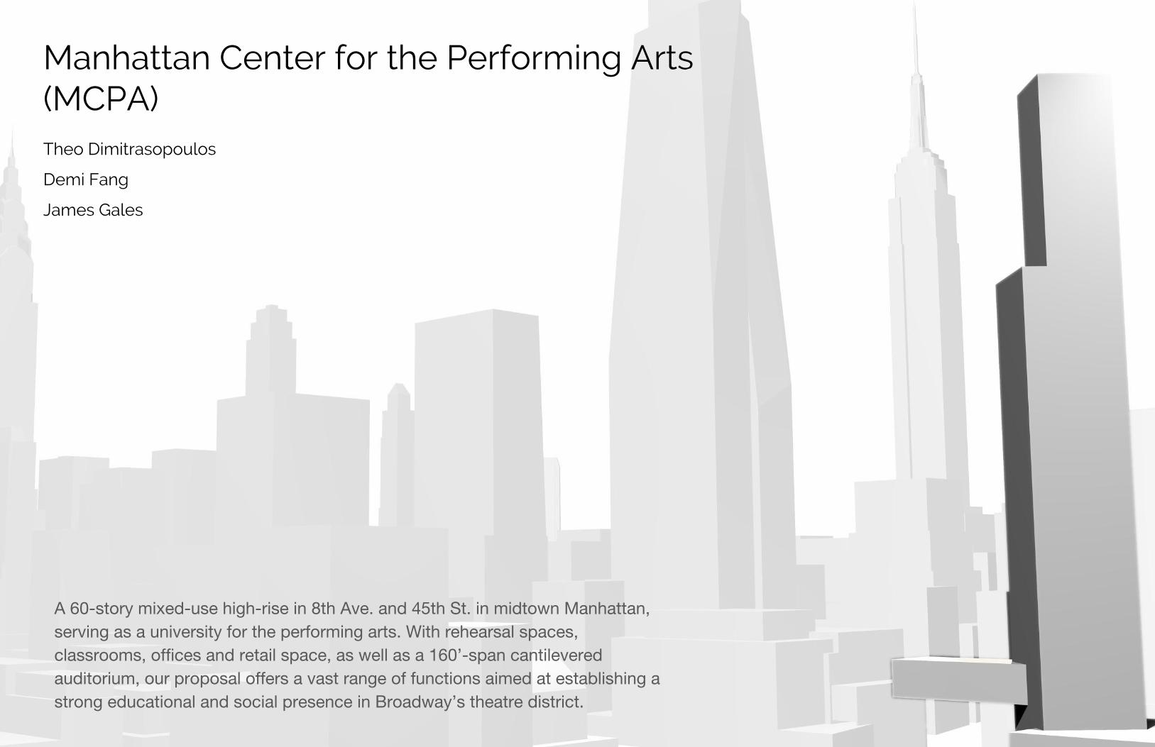
Manhattan Center for the Performing Arts(MCPA)Theo Dimitrasopoulos
Demi Fang
James Gales
A 60-story mixed-use high-rise in 8th Ave. and 45th St. in midtown Manhattan, serving as a university for the performing arts. With rehearsal spaces, classrooms, offices and retail space, as well as a 160’-span cantilevered auditorium, our proposal offers a vast range of functions aimed at establishing a strong educational and social presence in Broadway’s theatre district.
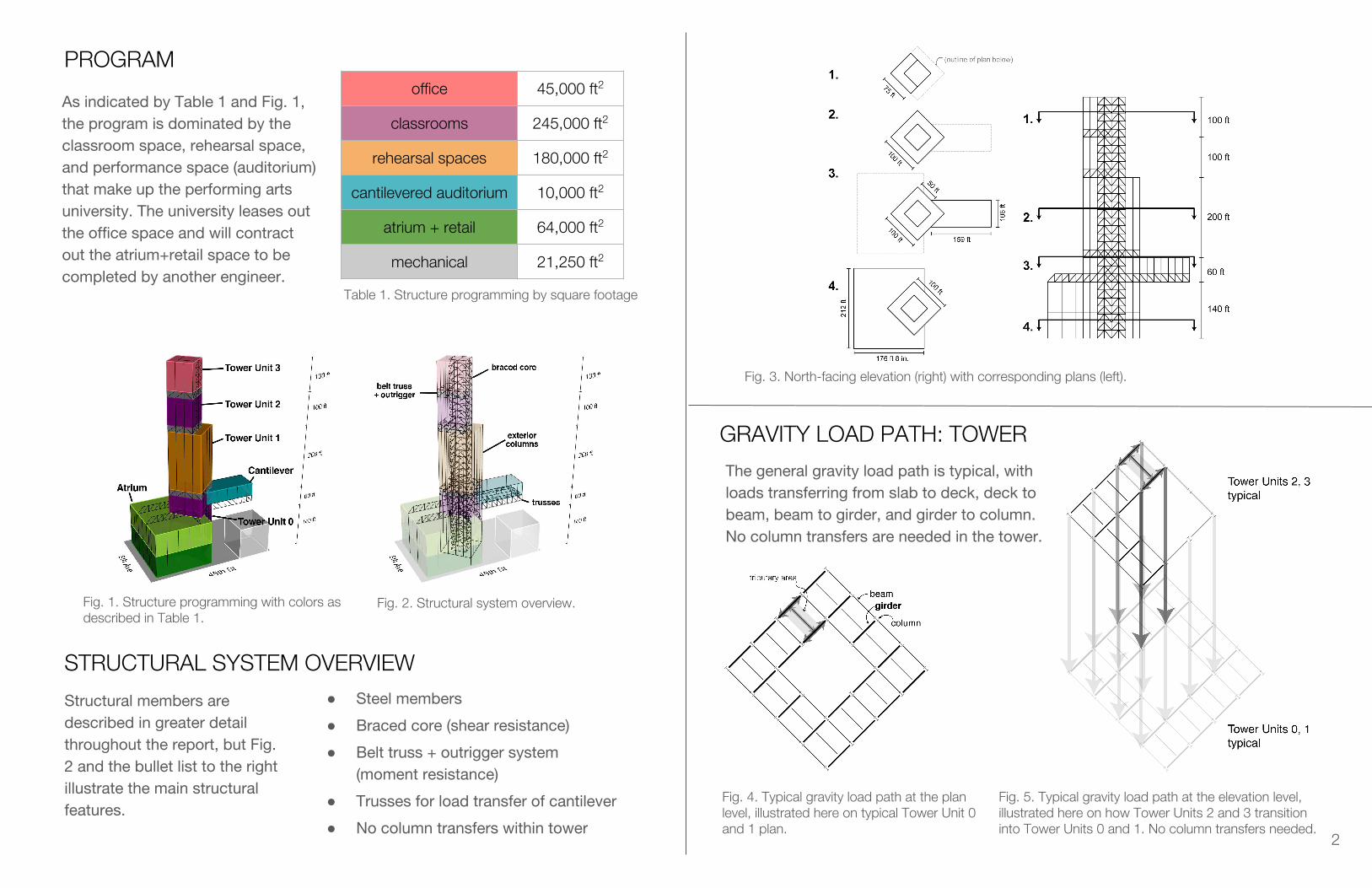
office 45,000 ft2
classrooms 245,000 ft2
rehearsal spaces 180,000 ft2
cantilevered auditorium 10,000 ft2
atrium + retail 64,000 ft2
mechanical 21,250 ft2
PROGRAM
STRUCTURAL SYSTEM OVERVIEW● Steel members
● Braced core (shear resistance)
● Belt truss + outrigger system (moment resistance)
● Trusses for load transfer of cantilever
● No column transfers within tower
GRAVITY LOAD PATH: TOWER
The general gravity load path is typical, with loads transferring from slab to deck, deck to beam, beam to girder, and girder to column. No column transfers are needed in the tower.
As indicated by Table 1 and Fig. 1, the program is dominated by the classroom space, rehearsal space, and performance space (auditorium) that make up the performing arts university. The university leases out the office space and will contract out the atrium+retail space to be completed by another engineer.
Table 1. Structure programming by square footage
Fig. 1. Structure programming with colors as described in Table 1.
Fig. 2. Structural system overview.
Structural members are described in greater detail throughout the report, but Fig. 2 and the bullet list to the right illustrate the main structural features.
Fig. 3. North-facing elevation (right) with corresponding plans (left).
Fig. 4. Typical gravity load path at the plan level, illustrated here on typical Tower Unit 0 and 1 plan.
Fig. 5. Typical gravity load path at the elevation level, illustrated here on how Tower Units 2 and 3 transition into Tower Units 0 and 1. No column transfers needed.
2
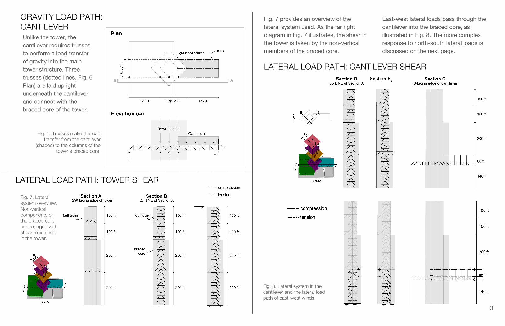
GRAVITY LOAD PATH: CANTILEVER
LATERAL LOAD PATH: TOWER SHEAR
Unlike the tower, the cantilever requires trusses to perform a load transfer of gravity into the main tower structure. Three trusses (dotted lines, Fig. 6 Plan) are laid upright underneath the cantilever and connect with the braced core of the tower.
Fig. 6. Trusses make the load transfer from the cantilever
(shaded) to the columns of the tower’s braced core.
LATERAL LOAD PATH: CANTILEVER SHEAR
Fig. 7. Lateral system overview. Non-vertical components of the braced core are engaged with shear resistance in the tower.
Fig. 7 provides an overview of the lateral system used. As the far right diagram in Fig. 7 illustrates, the shear in the tower is taken by the non-vertical members of the braced core.
East-west lateral loads pass through the cantilever into the braced core, as illustrated in Fig. 8. The more complex response to north-south lateral loads is discussed on the next page.
Fig. 8. Lateral system in the cantilever and the lateral load path of east-west winds.
3
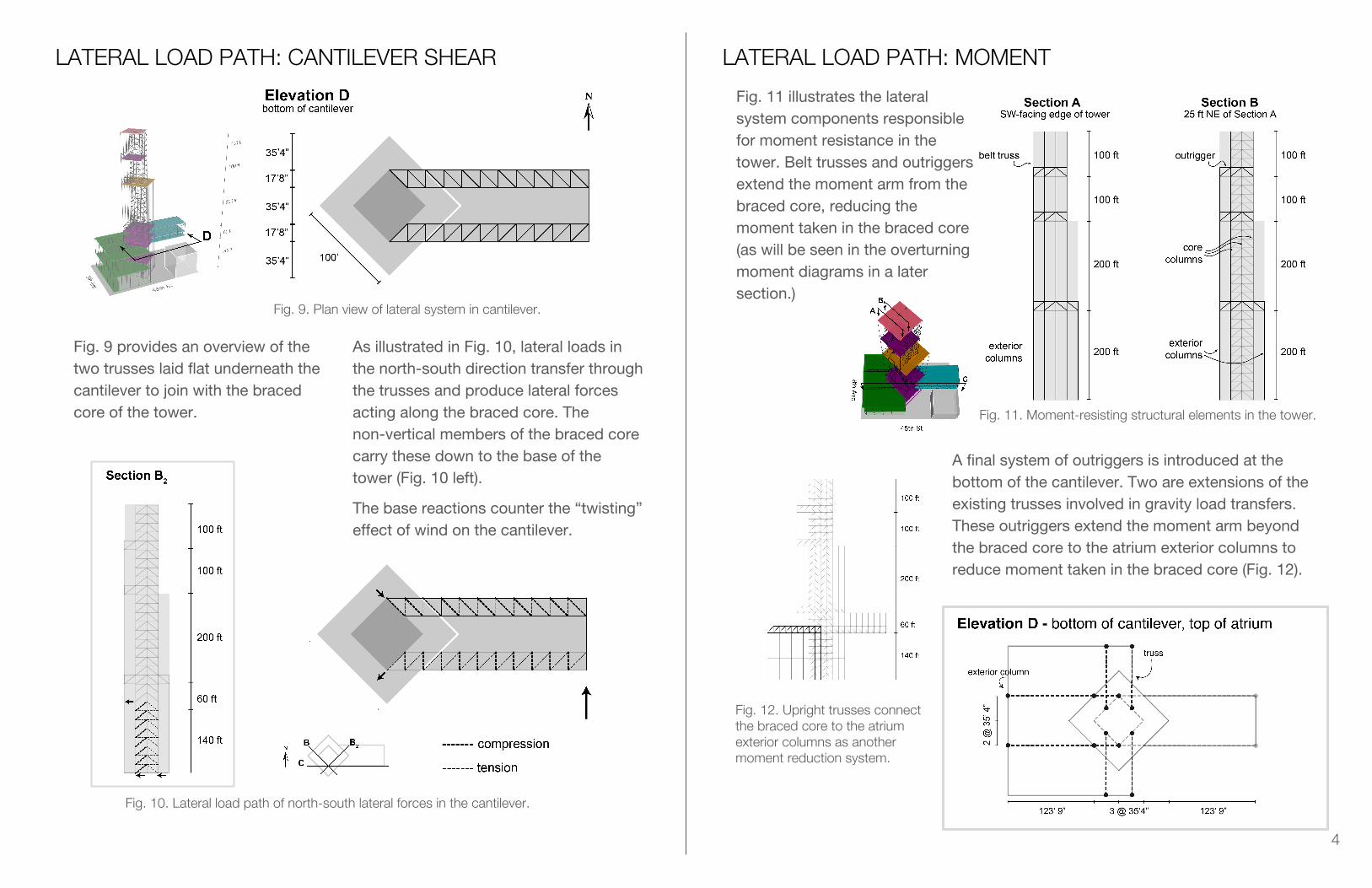
LATERAL LOAD PATH: CANTILEVER SHEAR
Fig. 9. Plan view of lateral system in cantilever.
Fig. 10. Lateral load path of north-south lateral forces in the cantilever.
Fig. 9 provides an overview of the two trusses laid flat underneath the cantilever to join with the braced core of the tower.
As illustrated in Fig. 10, lateral loads in the north-south direction transfer through the trusses and produce lateral forces acting along the braced core. The non-vertical members of the braced core carry these down to the base of the tower (Fig. 10 left).
The base reactions counter the “twisting” effect of wind on the cantilever.
LATERAL LOAD PATH: MOMENT
Fig. 11 illustrates the lateral system components responsible for moment resistance in the tower. Belt trusses and outriggers extend the moment arm from the braced core, reducing the moment taken in the braced core (as will be seen in the overturning moment diagrams in a later section.)
Fig. 11. Moment-resisting structural elements in the tower.
Fig. 12. Upright trusses connect the braced core to the atrium exterior columns as another moment reduction system.
A final system of outriggers is introduced at the bottom of the cantilever. Two are extensions of the existing trusses involved in gravity load transfers. These outriggers extend the moment arm beyond the braced core to the atrium exterior columns to reduce moment taken in the braced core (Fig. 12).
4
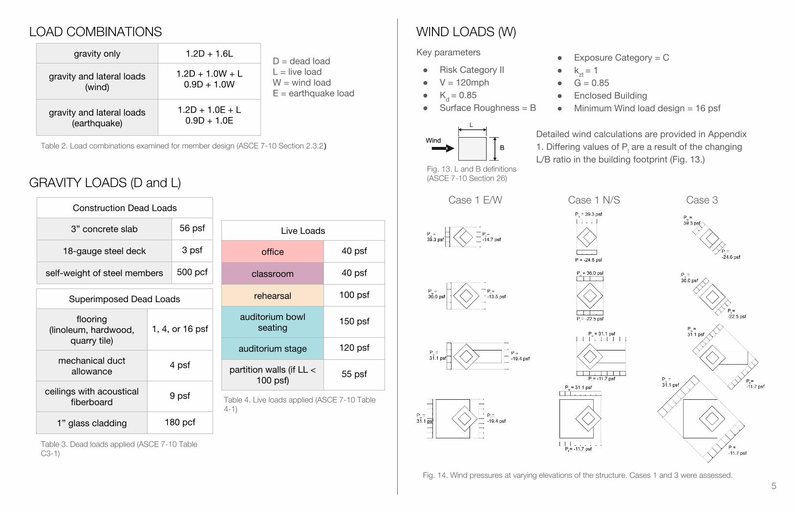
Case 1 E/W Case 1 N/S Case 3
LOAD COMBINATIONS
gravity only 1.2D + 1.6L
gravity and lateral loads (wind)
1.2D + 1.0W + L0.9D + 1.0W
gravity and lateral loads (earthquake)
1.2D + 1.0E + L0.9D + 1.0E
D = dead loadL = live loadW = wind loadE = earthquake load
GRAVITY LOADS (D and L)
Construction Dead Loads
3” concrete slab 56 psf
18-gauge steel deck 3 psf
self-weight of steel members 500 pcf
Superimposed Dead Loads
flooring(linoleum, hardwood,
quarry tile)1, 4, or 16 psf
mechanical duct allowance
4 psf
ceilings with acoustical fiberboard
9 psf
1” glass cladding 180 pcf
Live Loads
office 40 psf
classroom 40 psf
rehearsal 100 psf
auditorium bowl seating
150 psf
auditorium stage 120 psf
partition walls (if LL < 100 psf)
55 psf
5
WIND LOADS (W)Key parameters
● Risk Category II● V = 120mph● Kd = 0.85● Surface Roughness = B
● Exposure Category = C● kzt = 1● G = 0.85● Enclosed Building● Minimum Wind load design = 16 psf
Table 2. Load combinations examined for member design (ASCE 7-10 Section 2.3.2)
Table 3. Dead loads applied (ASCE 7-10 Table C3-1)
Table 4. Live loads applied (ASCE 7-10 Table 4-1)
Detailed wind calculations are provided in Appendix 1. Differing values of Pl are a result of the changing L/B ratio in the building footprint (Fig. 13.)
Fig. 13. L and B definitions (ASCE 7-10 Section 26)
Fig. 14. Wind pressures at varying elevations of the structure. Cases 1 and 3 were assessed.
Key parameters
● Risk Category II● Occupancy Category III● R = 8.00 (torsional irregularities due
to the cantilever)
6
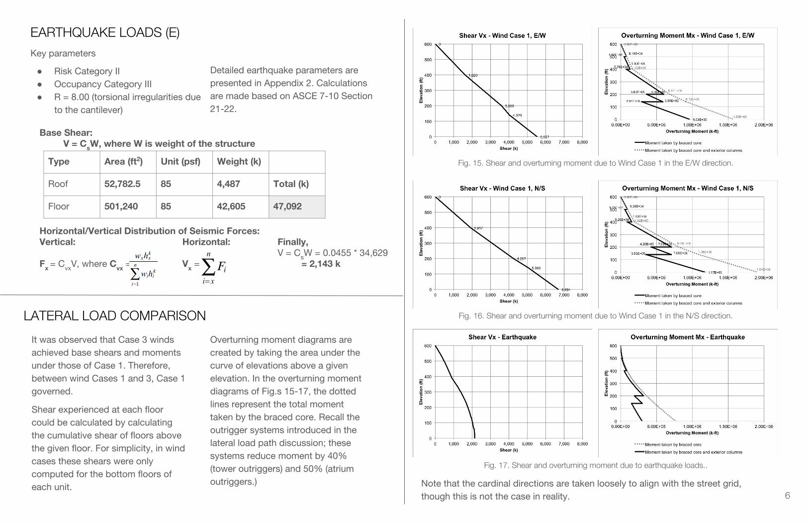
It was observed that Case 3 winds achieved base shears and moments under those of Case 1. Therefore, between wind Cases 1 and 3, Case 1 governed.
EARTHQUAKE LOADS (E)
Detailed earthquake parameters are presented in Appendix 2. Calculations are made based on ASCE 7-10 Section 21-22.
Base Shear:V = CsW, where W is weight of the structure
Horizontal/Vertical Distribution of Seismic Forces:Vertical: Horizontal: Finally,
V = CsW = 0.0455 * 34,629Fx = CvxV, where Cvx = Vx = = 2,143 k
Type Area (ft2) Unit (psf) Weight (k)
Roof 52,782.5 85 4,487 Total (k)
Floor 501,240 85 42,605 47,092
LATERAL LOAD COMPARISON
Shear experienced at each floor could be calculated by calculating the cumulative shear of floors above the given floor. For simplicity, in wind cases these shears were only computed for the bottom floors of each unit.
Overturning moment diagrams are created by taking the area under the curve of elevations above a given elevation. In the overturning moment diagrams of Fig.s 15-17, the dotted lines represent the total moment taken by the braced core. Recall the outrigger systems introduced in the lateral load path discussion; these systems reduce moment by 40% (tower outriggers) and 50% (atrium outriggers.)
Fig. 15. Shear and overturning moment due to Wind Case 1 in the E/W direction.
Fig. 16. Shear and overturning moment due to Wind Case 1 in the N/S direction.
Fig. 17. Shear and overturning moment due to earthquake loads..
Note that the cardinal directions are taken loosely to align with the street grid, though this is not the case in reality.
MEMBER DESIGNSUnderstanding the load paths and design loads on the structure informs the design of structural members.
Because the beams and girders are only involved in the gravity load path (as opposed to lateral), beams and girders throughout the structure were designed based on the gravity load combination 1.2D+1.6L.
Columns were considered under all load combinations and designed for their worst case induced axial load (which sometimes required tension.)
Trusses (braced core, outriggers, cantilever trusses) were also considered under all load combinations and designed for their worst case loads.
7
LATERAL LOAD COMPARISON (continued)
Comparing shear and overturning moment at the base and at all elevations in Fig.s 15-17, it is clear that wind loads dominate over earthquake loads. The earthquake load combinations may be neglected.
Both axes of wind Case 1 should be considered in design because they engage different members.
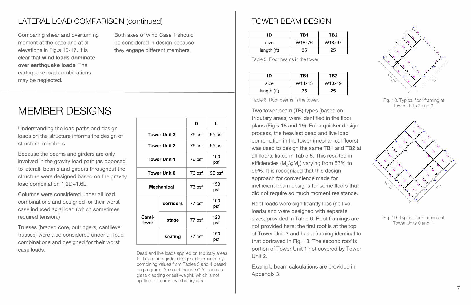
ID TB1 TB2size W18x76 W18x97
length (ft) 25 25
TOWER BEAM DESIGN
Two tower beam (TB) types (based on tributary areas) were identified in the floor plans (Fig.s 18 and 19). For a quicker design process, the heaviest dead and live load combination in the tower (mechanical floors) was used to design the same TB1 and TB2 at all floors, listed in Table 5. This resulted in efficiencies (Mu/ Mn) varying from 53% to 99%. It is recognized that this design approach for convenience made for inefficient beam designs for some floors that did not require so much moment resistance.
Roof loads were significantly less (no live loads) and were designed with separate sizes, provided in Table 6. Roof framings are not provided here; the first roof is at the top of Tower Unit 3 and has a framing identical to that portrayed in Fig. 18. The second roof is portion of Tower Unit 1 not covered by Tower Unit 2.
Example beam calculations are provided in Appendix 3.
Fig. 18. Typical floor framing at Tower Units 2 and 3.
Fig. 19. Typical floor framing at Tower Units 0 and 1.
Table 5. Floor beams in the tower.
ID TB1 TB2size W14x43 W10x49
length (ft) 25 25
Table 6. Roof beams in the tower.
D L
Tower Unit 3 76 psf 95 psf
Tower Unit 2 76 psf 95 psf
Tower Unit 1 76 psf 100 psf
Tower Unit 0 76 psf 95 psf
Mechanical 73 psf 150 psf
Canti-lever
corridors 77 psf 100 psf
stage 77 psf 120 psf
seating 77 psf 150 psf
Dead and live loads applied on tributary areas for beam and girder designs, determined by combining values from Tables 3 and 4 based on program. Does not include CDL such as glass cladding or self-weight, which is not applied to beams by tributary area

8
TOWER GIRDER DESIGN
Two tower girder (TG) types were identified using floor framing (Fig. 18 and 19). The load combinations experienced at non-mechanical floors were approximated to be the same; girders on non-mechanical floors were designed based on the heaviest non-mechanical program load combination in the tower and are tabulated in Table 7.
Example girder calculations are provided in Appendix 4.
ID TG1 TG2size W18x55 W21x55
length (ft) 25 25
Table 7. Floor girders for non-mechanical floors.
ID M-TG1 M-TG2size W21x62 W21x62
length (ft) 25 25
Table 8. Floor girders for mechanical floors.
ID TG1 TG2size W14x30 W16x40
length (ft) 25 25
Table 9. Roof girders.
CANTILEVER BEAM DESIGN
Six cantilever beam (CB) types were identified from the floor framing of the cantilever (Fig. 20).
It is recognized that some beam lengths are longer than usual; deflection checks are key in these situations.
Fig. 20. Floor framing of the cantilever (just below auditorium level. The dotted lines represent trusses. For the roof framing,
the dotted lines would represent girders.
ID CB1 CB2 CB3 CB4 CB5 CB6size W8x67 W12x72 W12x72 W10x45 W8x10 W8x10
length (ft) 35.33 35.33 35.33 26.50 8.83 4.42
Table 11. Roof beams for cantilever
ID CB1 CB2 CB3 CB4 CB5 CB6size W14x90 W18x143 W18x143 W14x90 W8x18 W8x10
length (ft) 35.33 35.33 35.33 26.50 8.83 4.42
Table 10. Floor beams for cantilever
CANTILEVER GIRDER DESIGN
ID CG1 CG2 CG3 CG4 CG5 CG6 CG7 CG8size W8x21 W21x48 W21x48 W14x34 W12x26 W36x160 W21x68 W14x34
length(ft) 17.67 35.33 35.33 35.33 17.67 70.67 35.33 35.33efficiency 86.37% 93.58% 93.58% 92.77% 91.97% 98.13% 90.37% 92.77%
Eight cantilever girder (CG) types were identified from the floor framing of the cantilever (Fig. 20). Roof girder sizes are provided in Table 12.
The auditorium level beams are supported directly by the cantilever trusses (dotted, Fig. 20).
Table 12. Roof girders for cantilever
9
TOWER COLUMN DESIGNFor a more efficient design process, columns are designed at the base of each unit. The axial effect of load combinations of gravity and wind, as outlined in Table 2, are tabulated, and the member is designed for the worst case axial load.
As an example, column TC8 of Tower Unit 3 is designed below. With D = 76 psf and L = 95 psf, column TC8 experiences the following axial loads:
1.2D+1.6L 1.2D+L 0.9D
1154 k 1069 k 370 k
Table 13. Axial loads experienced by column TC8 at the base of Tower Unit 3 (see also Fig.18.) Positive is compression in this table.
The moment experienced by the columns at the base of Tower Unit 3 (elevation = 500 ft) due to wind can be read off the overturning moment chart of the relevant wind case and direction.
From Fig. 16, the moment at elevation = 500 ft from N/S winds is 95,900 k-ft at the braced core (TC8 is a braced core column).
From Fig. 15, the moment at elevation = 500 ft from E/W winds is 81,000 k-ft at the braced core.
In order to determine the axial loads induced in the columns due to these moments, the quantity and length of moment arms for each wind case must be determined.
Fig. 21 illustrates these moment arms. In both wind direction cases, TC8 is one of 3 column couples in the braced core (thicker dotted lines, with squares representing columns in the braced core) that resist wind.
Each couple in the N/S direction resists 95,900 k-ft / 3 = 31,967 k-ft of moment. TC8 is in a couple distanced 35 ft apart; the axial load induced in TC8 from N/S wind is thus 31,967 k-ft / 35 ft = 913 k.
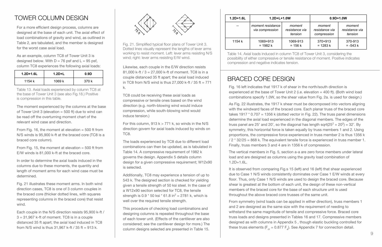
Fig. 21. Simplified typical floor plans of Tower Unit 3. Dotted lines visually represent the lengths of lever arms working to resist moment. Left: lever arms resisting N/S wind; right: lever arms resisting E/W wind.
Likewise, each couple in the E/W direction resists 81,000 k-ft / 3 = 27,000 k-ft of moment. TC8 is in a couple distanced 35 ft apart; the axial load induced in TC8 from N/S wind is thus 27,000 k-ft / 35 ft = 771 k.
TC8 could be receiving these axial loads as compressive or tensile ones based on the wind direction (e.g. north-blowing wind would induce compression, while south-blowing wind would induce tension.)
For this column, 913 k > 771 k, so winds in the N/S direction govern for axial loads induced by winds on TC8.
The loads experienced by TC8 due to different load combinations can then be updated, as is tabulated in Table 14. A compressive requirement of 1982 k governs the design. Appendix 5 details column design for a given compressive requirement; W12x90 is selected.
Additionally, TC8 may experience a tension of up to 543 k. The designed section is checked for yielding given a tensile strength of 50 ksi steel. In the case of a W12x90 section selected for TC8, the tensile strength is 0.9 * 50 ksi * 61.8 in2 = 2781 k, which is well over the required tensile strength.
This procedure of checking load combinations and designing columns is repeated throughout the base of each tower unit. (Effects of the cantilever are also considered; see the cantilever design for more.) The column designs selected are presented in Table 15.
1.2D+1.6L 1.2D+L+1.0W 0.9D+1.0W
-- moment resistance via compression
moment resistance via
tension
moment resistance via compression
moment resistance via
tension
1154 k 1069+913= 1982 k
1069-913= 156 k
370+913= 1283 k
370-913= -543 k
Table 14. Axial loads induced in column TC8 of Tower Unit 3, considering the possibility of either compressive or tensile resistance of moment. Positive indicates compression and negative indicates tension.
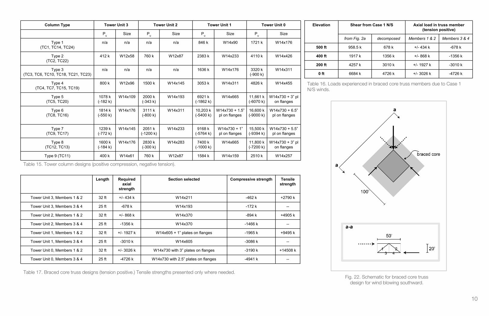
BRACED CORE DESIGNFig. 16 left indicates that 1917 k of shear in the north/south direction is experienced at the base of Tower Unit 2 (i.e. elevation = 400 ft). (Both wind load combinations specify 1.0W, so the shear value from Fig. 2a. is used for design.)
As Fig. 22 illustrates, the 1917 k shear must be decomposed into vectors aligning with the windward faces of the braced core. Each planar truss of the braced core takes 1917 * 0.707 = 1356 k (dotted vector in Fig. 22). The truss panel dimensions determine the axial load experienced in the diagonal members. The edges of the truss panel are 25’ and 20’, so the diagonal has length sqrt(252 + 202) = 32’. By symmetry, this horizontal force is taken equally by truss members 1 and 2. Using proportions, the compressive force experienced in truss member 2 is thus 1356 k / 2 * 32/25 = 868 k. The equivalent tensile force is experienced in truss member 1. Finally, truss members 3 and 4 are in 1356 k of compression.
The vertical members in Fig. 5, section a-a are zero force members under lateral load and are designed as columns using the gravity load combination of 1.2D+1.6L.
It is observed from comparing Fig.s 15 (left) and 16 (left) that shear experienced due to Case 1 N/S winds consistently dominates over Case 1 E/W winds at every floor. Thus, only Case 1 N/S winds are used to design the braced core. Because shear is greatest at the bottom of each unit, the design of these non-vertical members of the braced core for the base of each structure unit is used throughout the above braced core trusses of the same unit.
From symmetry (wind loads can be applied in either direction), truss members 1 and 2 are designed as the same size with the requirement of needing to withstand the same magnitude of tensile and compressive force. Braced core truss loads and designs presented in Tables 16 and 17. Compressive members designed as with columns in Appendix 5 , though elastic buckling controlled for these truss elements (Fcr = 0.877 Fe). See Appendix 7 for connection detail.
10
Column Type Tower Unit 3 Tower Unit 2 Tower Unit 1 Tower Unit 0
Pu Size Pu Size Pu Size Pu Size
Type 1(TC1, TC14, TC24)
n/a n/a n/a n/a 846 k W14x90 1721 k W14x176
Type 2(TC2, TC22)
412 k W12x58 760 k W12x87 2383 k W14x233 4110 k W14x426
Type 3(TC3, TC6, TC10, TC18, TC21, TC23)
n/a n/a n/a n/a 1636 k W14x176 3320 k(-900 k)
W14x311
Type 4(TC4, TC7, TC15, TC19)
800 k W12x96 1500 k W14x145 3053 k W14x311 4826 k W14x455
Type 5(TC5, TC20)
1078 k(-182 k)
W14x109 2000 k(-343 k)
W14x193 6921 k(-1862 k)
W14x665 11,661 k(-6070 k)
W14x730 + 3” pl on flanges
Type 6(TC8, TC16)
1814 k(-550 k)
W14x176 3111 k(-800 k)
W14x311 10,203 k(-5400 k)
W14x730 + 1.5” pl on flanges
16,600 k(-9000 k)
W14x730 + 6.5” pl on flanges
Type 7(TC9, TC17)
1239 k(-772 k)
W14x145 2051 k(-1200 k)
W14x233 9168 k(-5764 k)
W14x730 + 1” pl on flanges
15,500 k(-9394 k)
W14x730 + 5.5” pl on flanges
Type 8(TC12, TC13)
1600 k(-184 k)
W14x176 2830 k(-300 k)
W14x283 7400 k(-1000 k)
W14x665 11,800 k(-7200 k)
W14x730 + 3” pl on flanges
Type 9 (TC11) 400 k W14x61 760 k W12x87 1584 k W14x159 2510 k W14x257
Table 15. Tower column designs (positive compression, negative tension).
Fig. 22. Schematic for braced core truss design for wind blowing southward.
Elevation Shear from Case 1 N/S Axial load in truss member (tension positive)
from Fig. 2a decomposed Members 1 & 2 Members 3 & 4
500 ft 958.5 k 678 k +/- 434 k -678 k
400 ft 1917 k 1356 k +/- 868 k -1356 k
200 ft 4257 k 3010 k +/- 1927 k -3010 k
0 ft 6684 k 4726 k +/- 3026 k -4726 k
Table 16. Loads experienced in braced core truss members due to Case 1 N/S winds.
Length Required axial
strength
Section selected Compressive strength Tensile strength
Tower Unit 3, Members 1 & 2 32 ft +/- 434 k W14x211 -462 k +2790 k
Tower Unit 3, Members 3 & 4 25 ft -678 k W14x193 -172 k --
Tower Unit 2, Members 1 & 2 32 ft +/- 868 k W14x370 -894 k +4905 k
Tower Unit 2, Members 3 & 4 25 ft -1356 k W14x370 -1466 k --
Tower Unit 1, Members 1 & 2 32 ft +/- 1927 k W14x605 + 1” plates on flanges -1965 k +9495 k
Tower Unit 1, Members 3 & 4 25 ft -3010 k W14x605 -3086 k --
Tower Unit 0, Members 1 & 2 32 ft +/- 3026 k W14x730 with 3” plates on flanges -3190 k +14508 k
Tower Unit 0, Members 3 & 4 25 ft -4726 k W14x730 with 2.5” plates on flanges -4941 k --
Table 17. Braced core truss designs (tension positive.) Tensile strengths presented only where needed.
11
FOUNDATION DESIGNDesigning for 4 columns ranging from 1259-16000 k. Three column categories are being considered based on the service load range:
● Category I: TC1,3,6,10,11,18,21,23,24 | 2400k design load● Category II: TC2,4,7,15,19,22 | 3500k design load● Category III: TC5,8,9,12,13,14,16,17,20 | 16050k design load
Col. size Foot. size
qu (k/ft^2)
d (in) Vu1 (k) Vu2(k) φVc (k) M_u (k-ft)
I 17”x17” 5’x5’ 96 29” 989 560 1012 1.5e6
II 20”x20” 6’x6’ 97 35” 1454 825 1461 2.6e6
III 30”x30” 14’x14’ 82 89” 8008 4688 8038 2.4e7
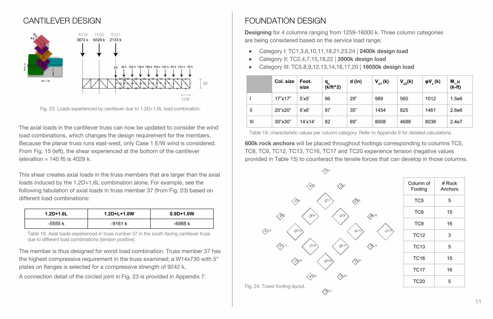
CANTILEVER DESIGN
600k rock anchors will be placed throughout footings corresponding to columns TC5, TC8, TC9, TC12, TC13, TC16, TC17 and TC20 experience tension (negative values provided in Table 15) to counteract the tensile forces that can develop in those columns.
Fig. 23. Loads experienced by cantilever due to 1.2D+1.6L load combination.
Table 19: characteristic values per column category. Refer to Appendix 8 for detailed calculations.
1.2D+1.6L 1.2D+L+1.0W 0.9D+1.0W
-5555 k -9161 k -6988 k
The axial loads in the cantilever truss can now be updated to consider the wind load combinations, which changes the design requirement for the members. Because the planar truss runs east-west, only Case 1 E/W wind is considered. From Fig. 15 (left), the shear experienced at the bottom of the cantilever (elevation = 140 ft) is 4029 k.
This shear creates axial loads in the truss members that are larger than the axial loads induced by the 1.2D+1.6L combination alone. For example, see the following tabulation of axial loads in truss member 37 (from Fig. 23) based on different load combinations:
The member is thus designed for worst load combination. Truss member 37 has the highest compressive requirement in the truss examined; a W14x730 with 5” plates on flanges is selected for a compressive strength of 9242 k.
A connection detail of the circled joint in Fig. 23 is provided in Appendix 7.
Table 18. Axial loads experienced in truss number 37 in the south-facing cantilever truss due to different load combinations (tension positive).
Fig. 24. Tower footing layout.
Column of Footing
# Rock Anchors
TC5 5
TC8 15
TC9 16
TC12 3
TC13 5
TC16 15
TC17 16
TC20 5
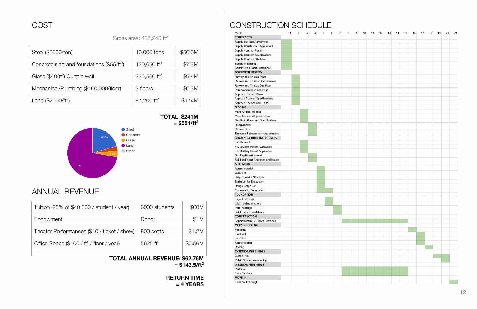
COST
Gross area: 437,240 ft2
Steel ($5000/ton) 10,000 tons $50.0M
Concrete slab and foundations ($56/ft3) 130,650 ft3 $7.3M
Glass ($40/ft2) Curtain wall 235,560 ft2 $9.4M
Mechanical/Plumbing ($100,000/floor) 3 floors $0.3M
Land ($2000/ft2) 87,200 ft2 $174M
TOTAL: $241M= $551/ft2
Tuition (25% of $40,000 / student / year) 6000 students $60M
Endowment Donor $1M
Theater Performances ($10 / ticket / show) 800 seats $1.2M
Office Space ($100 / ft2 / floor / year) 5625 ft2 $0.56M
TOTAL ANNUAL REVENUE: $62.76M= $143.5/ft2
RETURN TIME = 4 YEARS
ANNUAL REVENUE
CONSTRUCTION SCHEDULE
12
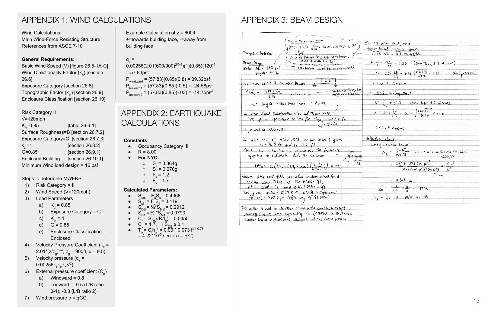
Wind CalculationsMain Wind-Force Resisting StructureReferences from ASCE 7-10
General Requirements:Basic Wind Speed (V) [figure 26.5-1A-C]Wind Directionality Factor (kd) [section 26.6]Exposure Category [section 26.8]Topographic Factor (kzt) [section 26.9]Enclosure Classification [section 26.10]
Risk Category IIV=120mphKd=0.85 [table 26.6-1]Surface Roughness=B [section 26.7.2]Exposure Category=C [section 26.7.3]kzt=1 [section 26.8.2]G=0.85 [section 26.9.1]Enclosed Building [section 26.10.1]Minimum Wind load design = 16 psf
Steps to determine MWFRS1) Risk Category = II2) Wind Speed (V=120mph)3) Load Parameters
a) Kd = 0.85b) Exposure Category = Cc) Kzt = 1d) G = 0.85e) Enclosure Classification =
Enclosed4) Velocity Pressure Coefficient (kz =
2.01*(z/zg)2/α, zg = 900ft, α = 9.5)
5) Velocity pressure (qz = 0.00256kzkztkdV
2)6) External pressure coefficient (Cp)
a) Windward = 0.8b) Leeward = -0.5 (L/B ratio
0-1), -0.3 (L/B ratio 2)7) Wind pressure p = qGCp
APPENDIX 1: WIND CALCULATIONS
13
Example Calculation at z = 600ft+=towards building face, -=away from building face
qz = 0.00256(2.01(600/900)2/9.5)(1)(0.85)(120)2 = 57.83psfPwindward = (57.83)(0.85)(0.8) = 39.32psfPleeward1 = (57.83)(0.85)(-0.5) = -24.58psfPleeward2 = (57.83)(0.85)(-.03) = -14.75psf
APPENDIX 2: EARTHQUAKE CALCULATIONS
Constants:● Occupancy Category III● R = 8.00● For NYC:
○ Ss = 0.364g○ S1 = 0.070g○ Fa = 1.2○ Fv = 1.7
Calculated Parameters:● SMS = FaSs = 0.4368● SM1 = FvS1 = 0.119● SDS = ⅔*SMS = 0.2912● SD1 = ⅔ *SM1 = 0.0793● Cs = SDS/(R/Ie) = 0.0455● Cu = 1.7, � SDS ≤ 0.1● Ta = Cthn
x = 0.03 * 0.0731a * 0.75
= 4.22*10-3 sec. ( a = R/2)
APPENDIX 3: BEAM DESIGN
14
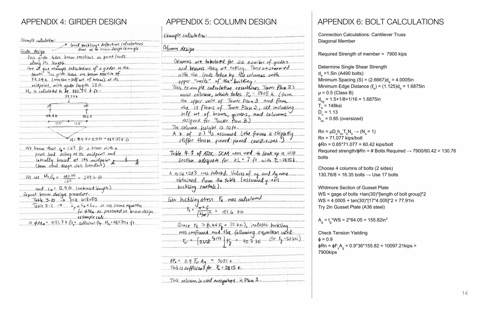
APPENDIX 4: GIRDER DESIGN APPENDIX 5: COLUMN DESIGNConnection Calculations: Cantilever TrussDiagonal Member
Required Strength of member = 7900 kips
Determine Single Shear Strengthdb =1.5in (A490 bolts)Minimum Spacing (S) = (2.6667)db = 4.0005inMinimum Edge Distance (ℓe) = (1.125)db = 1.6875inμ = 0.5 (Class B)dhg = 1.5+1/8+1/16 = 1.6875inTb = 148ksiDu = 1.13hsc = 0.85 (oversized)
Rn = μDuhscTbNs → (Ns = 1)Rn = 71.077 kips/boltϕRn = 0.85*71.077 = 60.42 kips/boltRequired strength/ϕRn = # Bolts Required → 7900/60.42 = 130.76 bolts
APPENDIX 6: BOLT CALCULATIONS
Choose 4 columns of bolts (2 sides)130.76/8 = 16.35 bolts → Use 17 bolts
Whitmore Section of Gusset PlateWS = gage of bolts +tan(30)*[length of bolt group]*2WS = 4.0005 + tan(30)*[17*4.005]*2 = 77.91inTry 2in Gusset Plate (A36 steel)
Ag = tg*WS = 2*64.05 = 155.82in2
Check Tension Yieldingɸ = 0.9ɸRn = ɸFyAg = 0.9*36*155.82 = 10097.21kips > 7900kips
15
Bolt bearing on plate
Based on spacing (S)ɸrn = 157*2 = 314 kips > 60.42 kips/bolt O.K.
Based on edge distance (ℓe)ɸrn = 57.1*2 = 114.2 kips > 60.42 kips/bolt O.K.
Bolt bearing on Flange
Based on spacing (S)ɸrn = 157*2 = 314 kips > 60.42 kips/bolt O.K.
Based on edge distance (ℓe)ɸrn = 64*2 = 128 kips > 60.42 kips/bolt O.K.
APPENDIX 8: FOUNDATION DESIGN CALCULATIONS
b = spreading width
1
2
3
APPENDIX 7: CONNECTION DETAILS
4
5
6
7
8
9
10
a = column width
c = distance to edge, d in. from col. abs.
iterate through d values.
g = distance to edge,0 in. from col. abs.
Check Block Shear Rupture in Plateɸ = 0.75Uniform tensile stress → Ubs = 1tg = 2inAgv = tg*4*[(#bolts - 1)S + ℓe] = 525.56in2
Anv = Agv - tg*4*[(#bolts - 0.5)*dhg] = 302.81in2
Ant = tg*(S - dhg) = 4.63in2
ɸRn = ɸ(0.6FuAnv + UbsFuAnt) ≤ ɸ(0.6FyAgv + UbsFuAnt)UbsFuAnt = 268.31kips0.6FyAgv = 11352.18kips0.6FuAnv = 10537.93kipsɸRn = 0.75(10537.93 + 268.3) ≤ 0.75(11352.18 + 268.3)= 8715.37kips ≤ 8104.68kips O.K.
APPENDIX 6: BOLT CALCULATIONS (continued)
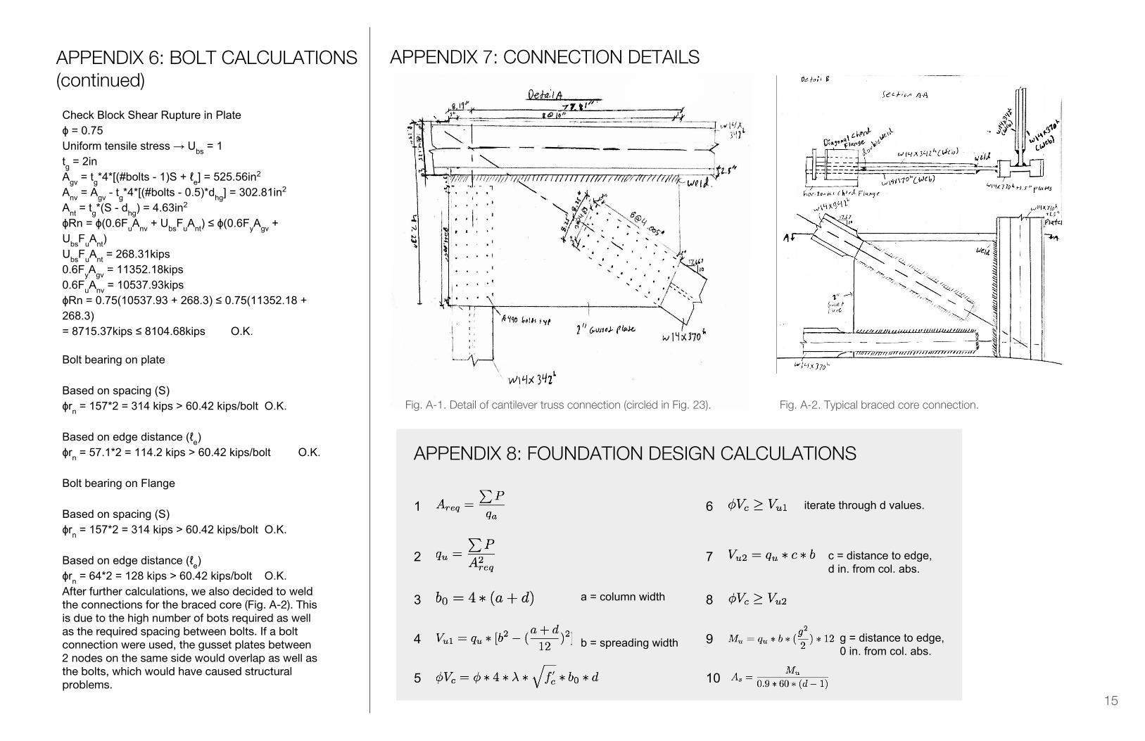
Fig. A-1. Detail of cantilever truss connection (circled in Fig. 23). Fig. A-2. Typical braced core connection.
After further calculations, we also decided to weld the connections for the braced core (Fig. A-2). This is due to the high number of bots required as well as the required spacing between bolts. If a bolt connection were used, the gusset plates between 2 nodes on the same side would overlap as well as the bolts, which would have caused structural problems.

16