Embed Size (px)
DESCRIPTION
Manual de funcionamiento.
Citation preview

Motor Drive
MANUFACTURER DATA SHEET
Eurotherm
620 Series
Manufacturer:
Model Number:
PDF File: Doc_000070_Cover.pdf
Covers: Doc_000072_Covers.mdb


All rights strictly reserved. No part of this document may be stored in a retrieval system, or transmitted in any form orby any means to persons not employed by a Eurotherm group company without written permission from EurothermDrives Ltd.
Although every effort has been taken to ensure the accuracy of this document it may be necessary, without notice, tomake amendments or correct omissions. Eurotherm Drives cannot accept responsibility for damage, injury, or expensesresulting therefrom.
!

This manual is to be made available to all persons who are required to configure, install or service the equipmentdescribed herein or any other associated operation.
" ## $%&
Eurotherm Drives warrants the goods against defects in design, materials and workmanshipfor the period of 12 months from the date of delivery on the terms
detailed in Eurotherm Drives Standard Conditions of Sale IA058393C.
Eurotherm Drives reserves the right to change the content and product specification without notice.

Only qualified personnel who thoroughly understand the operation of this equipment and anyassociated machinery should install, start-up or attempt maintenance of this equipment. Non-
compliance with this warning may result in personal injury and/or equipment damage.
Never work on any control equipment without first isolating all power supplies from the equipment.
The drive motor must be connected to an appropriate safety earth. Failure to do so presents anelectrical shock hazard.
This equipment contains high value capacitors. Allow five minutes for capacitors to discharge prior toremoving equipment covers. Failure to do so presents an electric shock hazard.
This equipment was tested before it left our factory. However, before installation and start-up, inspectall equipment for transit damage, loose parts, packing materials etc.
This product conforms to IP20 protection. Due consideration should be given to environmentalconditions of installation for safe and reliable operation.
Never perform high voltage resistance checks on the wiring without first disconnecting the productfrom the circuit being tested.
This equipment contains electrostatic discharge (ESD) sensitive parts. Observe static controlprecautions when handling, installing and servicing this product.
THESE WARNINGS AND INSTRUCTIONS ARE INCLUDED TO ENABLE THE USER TO OBTAINTHE MAXIMUM EFFECTIVENESS AND TO ALERT THE USER TO SAFETY ISSUES
APPLICATION AREA: Industrial (non consumer) "Motor speed control utilising AC induction or synchronousmotors"
PRODUCT MANUAL: This manual is intended to provide a description of how the product works. It is notintended to describe the apparatus into which the product is installed.
This manual is to be made available to all persons who are required to design an application, install, service or comeinto direct contact with the product.
APPLICATIONS ADVICE: Applications advice and training is available from Eurotherm Drives Ltd.

INSTALLATION: Ensure that mechanically secure fixings are used as recommended.
Ensure that cooling and air flow around the product are as recommended.
Ensure that cables and wire terminations are as recommended and clamped to required torque.
Ensure that the installation and commissioning of this product are carried out by a competent person.
Ensure that the product rating is not exceeded.
CAUTION: When power is removed from the product it must not be re-applied for a period of 30 seconds to
allow the inrush limit circuit to operate correctly.
APPLICATION RISK: The integration of this product into other apparatus or system is not theresponsibility of Eurotherm Drives Ltd as to its applicability, effectiveness or safety of operation or of otherapparatus or systems.
Where appropriate the user should consider some aspects of the following risk assessment.
RISK ASSESSMENT: Under fault conditions or conditions not intended.
1. The motor speed may be incorrect.
2. The motor speed may be excessive.
3. The direction of rotation may be incorrect.
4. The motor may be energised (unless the installation specifically prevents unexpected or unsequencedenergisation of the motor).
In all situations the user should provide sufficient guarding to prevent risk of injury and/or additionalredundant monitoring and safety systems.
NOTE: During power loss the product will not operate as specified.
MAINTENANCE: Maintenance and repair should only be performed by competent persons using only therecommended spares (or return to factory for repair). Use of unapproved parts may create a hazard and risk ofinjury.
WHEN REPLACING A PRODUCT IT IS ESSENTIAL THAT ALL USER DEFINED PARAMETERSTHAT DEFINE THE PRODUCT'S OPERATION ARE CORRECTLY INSTALLED BEFORERETURNING TO USE. FAILURE TO DO SO MAY CREATE A HAZARD AND RISK OF INJURY.
PACKAGING: The packaging is combustible and if disposed of in this manner incorrectly may lead to thegeneration of toxic fumes which are lethal.
WEIGHT: Consideration should be given to the weight of the product when handling.
REPAIRS: Repair reports can only be given if sufficient and accurate defect reporting is made by the user.
Remember, the product without the required precautions can represent an electrical hazard and risk of injury, andthat rotating machinery is a mechanical hazard and risk of injury.
1. All exposed metal insulation is protected by basic insulation and bonding to earth i.e. Class 1.
2. NOTE: Earth bonding is the responsibility of the installer.
3. All signal terminals are SELV, i.e., protected by double insulation (Class 2). The purpose of this protection is toallow safe connection to other low voltage equipment and is not designed to allow these terminals to beconnected to any unisolated potential. Ensure all wiring rated for highest system voltage.
NOTE: Thermal sensors contained within the motor are to be double insulate.
WALL MOUNTING: To maintain compliance with the European Low Voltage Directive standards VDE 0160(1994)/EN50178(1998) only units supplied and fitted with the NEMA 1 top cover are to be mounted on the wall.
RCDs: Compatible with Type B RCDs only.

!This manual provides information to support the installation and operation of the 620 Vector Drive. A description ofeach of the chapters is given here to assist in locating and using the information contained within the manual.
"
This chapter contains a brief description of the drive including a technical specification of the equipment. Thepurpose of this chapter is to familiarise the reader with the purpose and scope of the equipment.
#
This chapter contains a functional description of the equipment, wiring information and a description of the signalson the input/output terminals. The purpose of this chapter is to allow the user to understand the function of theequipment and to assist in designing a particular installation configuration.
This chapter contains information regarding the physical mounting arrangements, cable and fuse selection as well asinformation regarding EMC installation. The purpose of this chapter is to provide guidelines for the safe andefficient installation of the equipment. The theory of, and requirement for, dynamic braking is also explained withinthis chapter.
##
A description of the user adjustments and switch settings to configure the drive for a particular application. Thepurpose of this chapter is to guide the user through pre- and post-power on checks and provide running performanceadjustment procedures. Information is also provided on the function and set-up of operational parameters using theMan-Machine Interface (MMI).
$%&
This section provides reference information for the more advanced programming capabilities of the 620 Vectorseries controllers.
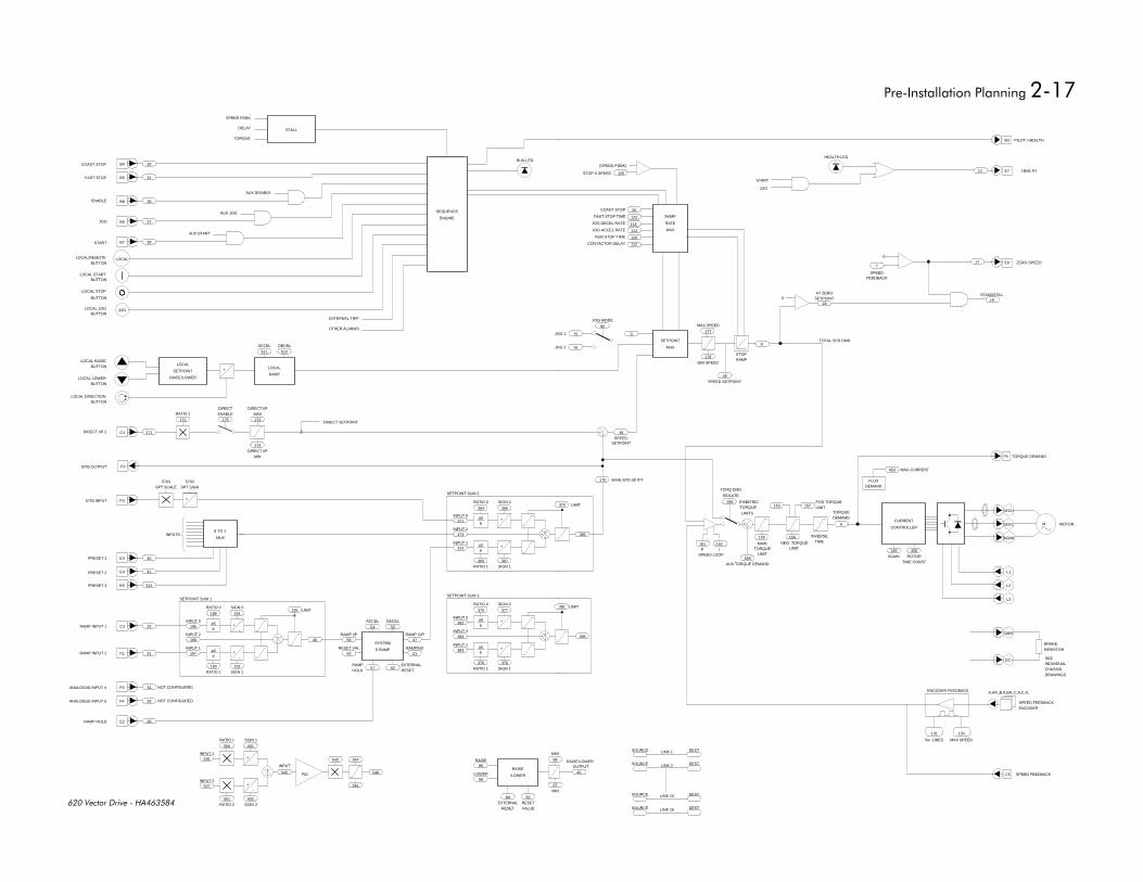
Each section describes a particular functional area and the associated menu options which are used to alter theparameters. Where appropriate, a functional block diagram illustrates the how the function blocks operate.Reference to the Functional Description and Microprocessor Block Diagram in Chapter 2 may be of assistance inunderstanding the relationship between these functional diagrams.
#$$#
A description of the procedures to diagnose and trace faults on the equipment. The purpose of this chapter is toguide the user through the on-board diagnosis and fault finding facilities, using the MMI diagnostic and alarmdisplay.
'(&
This chapter sets out Eurotherm Drives Limited responsibilities to the recent European ‘EMC, low voltage andmachinery’ Directives, and explains how Eurotherm are assisting their customers in achieving conformance. Thenorth American requirements are also discussed.
#
This chapter provides the routine maintenance and repair procedures. The purpose of this chapter is to assistreturning the controller to service following a fault condition.
Appendix A contains advanced tuning notes.
Appendix B contains MMI Listing
Appendix C contains Tags by Number and Text String

)"
$%#'(%'$
!!
)$# #%'$
#'(%# $)
'*
''$$%$%+ %'$
%$ + %'$
)
'
#
#
'
'
'
'
!
%&
%&
%&
%&
$' (#
!
)'"#
+#*
(
#*
)#
$%#'(%'$
+($%'$ '#"
!
,-
,
$ % %'$"#$) )#
+
!!
%#$ #%'$
,%
%
%
%
% ,--!,--!,--!,--!
%
%#$ %'$
)
$%#'(%'$
$ % %'$# (%'$
$ $ % %'$
%# $ % %'$
"
%%
%%
"
&$ ,# .$)
,-#
,-# !
!!,-
%,-(#
,-# +
$-
##
$ % %'$)($
+#$
"!
!
#
"
""
'
)##
$%#'(%'$
& #%'$
$ $$%#+
!!
+.
.
!.
$ ) %$)%$( %#(%(#
!
-
%%$)(#'(#
,!&
% !'!%
%
'
#
#%+!
- /
)$%&
%( # %#
#
'
'
# *
0
##
%
#
%*
#!
,-
#
'
# $.
+%!
!,
)+'# %
('#%
"'#
# % %(
$(
# %#
& % '+%" #$+'
'+%" #
& % # %$% %
& % '$+)(# '
$ ')($(%
$ ')('(%(%
$(%
)% '(%(%
'$+)(#
,'. )#
$%#$ $.
)#$$#
$%#'(%'$
+-
+
#
)'(&
#%
#
!
+
+
!!
#!
$(+ %(## (# $ % #
)
!!!
!
!!! !
)#
#'(%$ $%$ $
# #
#%(#$ %#
(#'%## ' $
'# ' $
)
$1
,-
(-
(-
('
)
%
$1, %$)
$1% )
% ) $
% ) %


'
) *++
This manual provides the necessary information to plan, install and commission the 620 Vector series drives.
Motors used must be suitable for inverter duty.
+
This manual comprises eight chapters, plus appendices.
• Chapter 1 summarises the 620 Vector drive's electrical and mechanical specifications.
• Chapter 2 covers the planning required prior to installing a 620 Vector drive.
• Chapter 3 describes the mechanical and electrical procedures for installing a 620 Vector drive.
• Chapter 4 shows how to commission an installation and how to adapt the 620 Vector drive to themotor/application.
• Chapter 5 describes the function blocks.
• Chapter 6 lists the diagnostic facilities built into the drive.
• Chapter 7 EMC and the ‘CE’ mark, explains how Eurotherm are assisting their customers in achievingEuropean conformance.
• Chapter 8 contains routine maintenance and repair information.
• Chapter 9 Appendices.
This manual contains the information required to set up a motor drive system which automatically tunes itself tothe motor and provides control of speed, ramp up and down times and similar functions. The 620 Vector seriesprovides a further host of sophisticated programming options as standard.
#
The 620 Vector drive allows high performance speed control of AC asynchronous induction motors fitted with anencoder. It is available with a range of power ratings in three variants:
620STD STANDARD for use in systems incorporating analogue setpoints and logic control systems.
620COM As above with the addition of a Serial port for use in Eurotherm Drives serial protocols and a referenceencoder input for phase control applications.
620L As above with the addition of a Link co-processor, LINK fibre optic ports for use in Eurotherm DrivesLINK fibre-optic based networks. This drive is programmed using ConfigEd Release 4.0+ availableand documented separately.
This manual only covers the 620Std and the hardware / software differences for the 620. For more information onthe 620L refer to Link documentation.
#
The 620 is available in four chassis types as follows:
"+! "+!
%& -" -"
%& -" -"
%& -" -"
%& -" -"
%& -"
%& -"
%& -"
%
The 620 models are housed in chassis of similar appearance with a 32 character Man-Machine Interface (MMI) -an alphanumeric display utilising multi-level menus to present all parameters, diagnostics and alarms (refer to
* Documented separately in HA463284 584s/620 Type 8,9,10 Manual Addendum
'
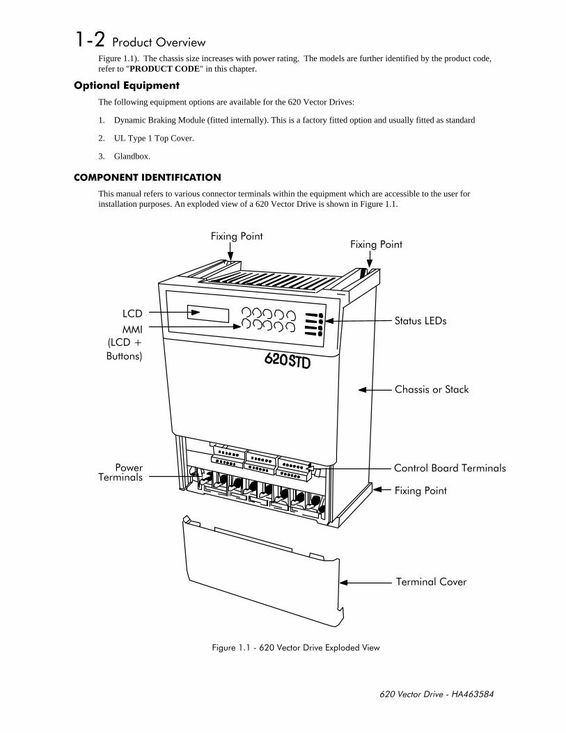
Figure 1.1). The chassis size increases with power rating. The models are further identified by the product code,refer to "PRODUCT CODE" in this chapter.
) !, )
The following equipment options are available for the 620 Vector Drives:
1. Dynamic Braking Module (fitted internally). This is a factory fitted option and usually fitted as standard
2. UL Type 1 Top Cover.
3. Glandbox.
$
This manual refers to various connector terminals within the equipment which are accessible to the user forinstallation purposes. An exploded view of a 620 Vector Drive is shown in Figure 1.1.
%
,
++
-
,%
+
%
+

'
$
The following paragraphs provide technical information regarding the features and performance characteristics ofthe 620 Vector Drives.
# !
The MMI display menus provides full access to all the drive's parameters.
Output Frequency 0-240Hz (for higher frequencies contact Eurotherm Drives Technical Support).
Switching Frequency 5 or 3kHz depending on type
Preset Speeds 8
Overload rating 150% for 60s
Speed control range 0-8 x base speed, 1000:1 of max. speed
Speed control precision ± 0.01% steady state of max. setpoint (digital setpoint)± 0.1% steady state of max. setpoint (analogue setpoint).
Speed ref. resolution ± 0.01% digital± 0.025% analogue (12 bit)
Stopping Modes Ramp, Fast stop, Coast
The 620 Vector series drives will trip under the following conditions:
• Short circuit line - line
• Short circuit line - earth
• Earth fault
• Overcurrent >220%
• Overvoltage
• Undervoltage
• Stall
• Overspeed
• 5703 repeater error
• External trip
• Heatsink overtemperature
• Motor thermistor overtemperature
Full diagnostics/monitoring is provided by the MMI display and status LEDs.
''''
The following range of inputs and outputs are provided:
• 5 Analogue Inputs (4 programmable)
• 2 Analogue Outputs (both programmable)
• Digital Inputs (24V DC) for Run, Fast Stop, Coast Stop, Jog, Enable, Ramp Hold, Preset 1, 2, and 3 (thelast 4 inputs are programmable.
• Three programmable digital outputs are provided (24V DC).
• A 24V DC supply is available for interfacing external digital inputs.
• A +10V and -10V DC supply is available for interfacing external analogue inputs.
• 2 or 4 wire RS-485 serial communications.
'
!** ! -*
) ! -*./
0 0 0 0
-"
'
!
+ ,-
"
+*
-/ -/
) ! -./
0 0 0 0
-"
'
!
+ ,-
"
+*
-/ -/
0 0 0 0
'
'' !
'+* /
'
%#
2
2!-"
(% 2
-
3 #*
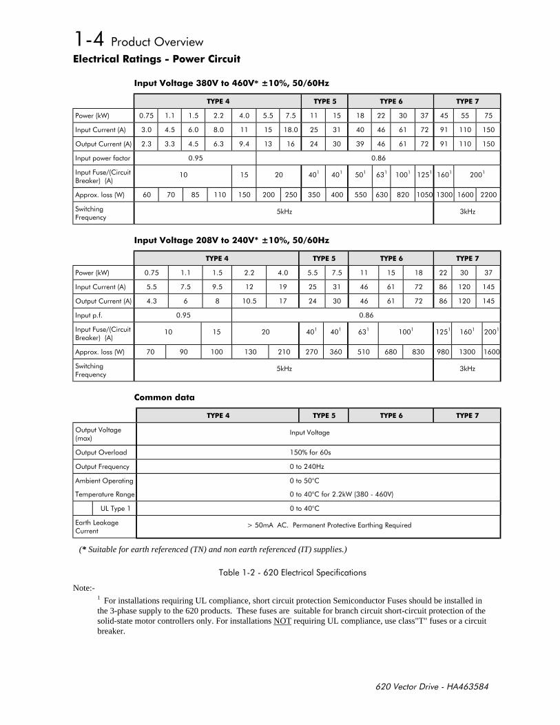
(* Suitable for earth referenced (TN) and non earth referenced (IT) supplies.)
% !
Note:-1 For installations requiring UL compliance, short circuit protection Semiconductor Fuses should be installed inthe 3-phase supply to the 620 products. These fuses are suitable for branch circuit short-circuit protection of thesolid-state motor controllers only. For installations NOT requiring UL compliance, use class"T" fuses or a circuitbreaker.
'
!** ! -!*
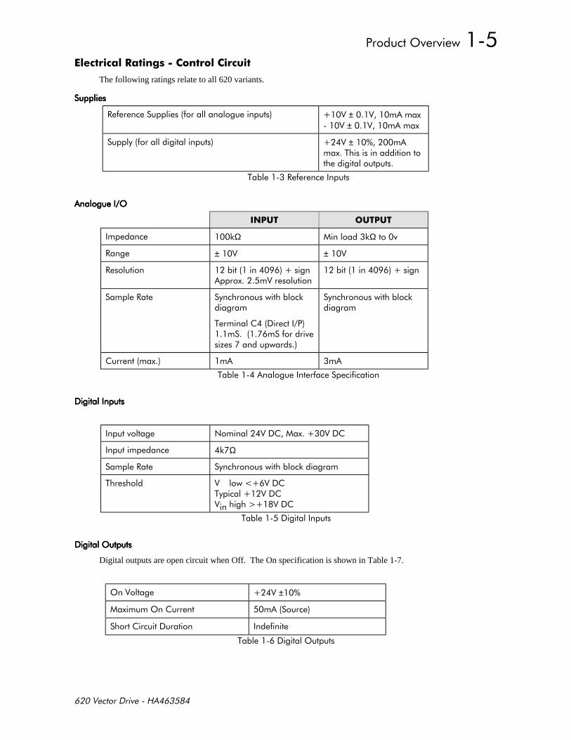
The following ratings relate to all 620 variants.
#! ! ± ±
! ± %
%#!
' ' ' '
-Ω -Ω
# ± ±
#
# -
% !/
-
% ! !
$
-Ω
# -
% %3
%
''''
Digital outputs are open circuit when Off. The On specification is shown in Table 1-7.
' ±
'
!
%'

'
''''
Pilot output is an open collector output that is off while the drive is healthy. The specification is shown in Table1-7.
' -
%'
!!
% ±±!!
±
+* -/! ,
MaxFreqMaxSpeedRPM
NoOfLines=60
*
%% !
' ' ' '
'
±#%'4 5
#
!
% ' !
! ! ! !
#
! 3Ω
#
% ' !

'
* * ! !
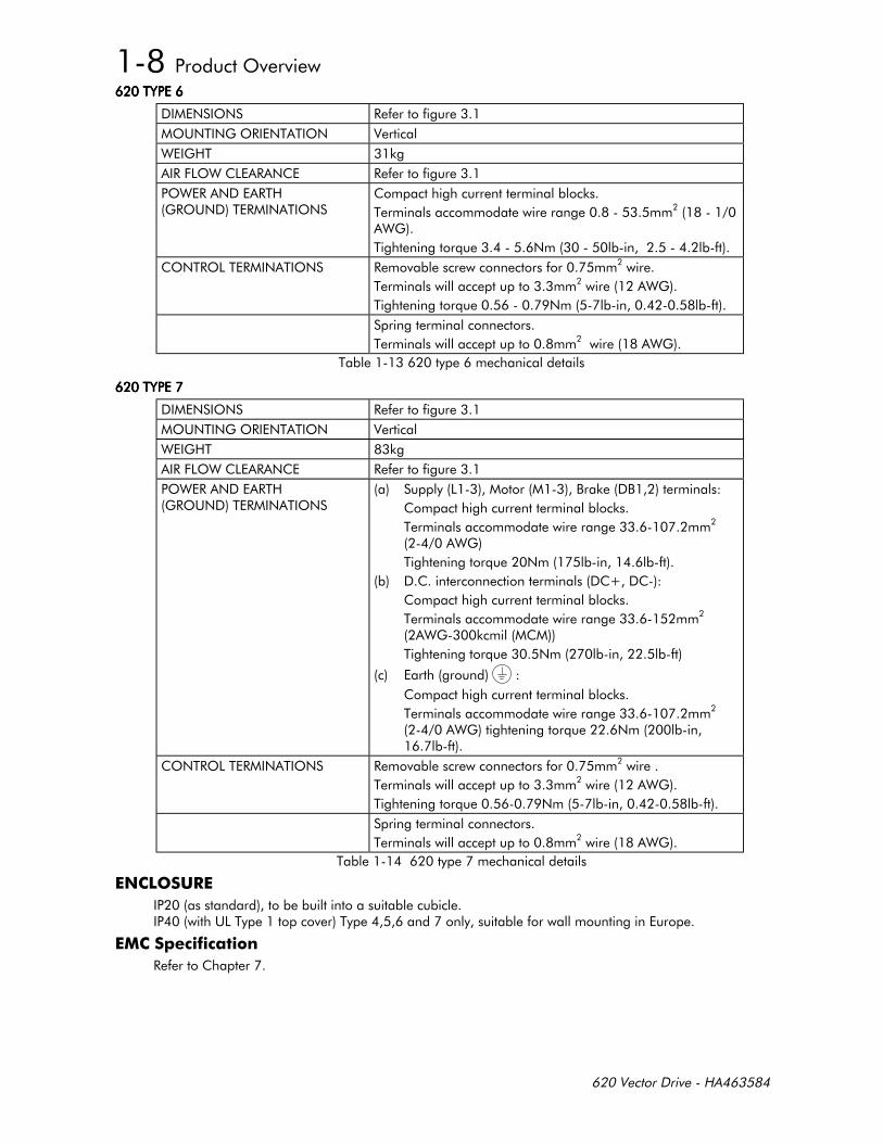
The mechanical details of all the 620 vector series controllers are shown in Tables 1-11 to 1-14. The generallayout of the cases is shown in Chapter 3.
%&%&%&%&
$ '$ #!!
'($%$)'#$% %'$
")% -
#+'" # $ #!!
'"#%#$ %'$
%*$!
#%)#'($%#$ %'$
)!)!)!)!*$!*$!
)!)!)!)!*$!*$!
'$%#'%#$ %'$ #!
% ")
%*$!
% ")
%
%&%&%&%&
$ '$ #!!
'($%$)'#$% %'$
")% -
#+'" # $ #!!
'"#%#$ %'$
%*$!
#%)#'($%#$ %'$
)!)!)!)!*$!
)!)!)!)!*$!
'$%#'%#$ %'$ #!
% ")
%*$!
% ")
%
'
%&%&%&%&
$ '$ #!!
'($%$)'#$% %'$
")% -
#+'" # $ #!!
'"# $ #%)#'($%#$ %'$
-
%
")
%*$!
'$%#'%#$ %'$ #!
% ")
%*$!
% ")
%
%&%&%&%&
$ '$ #!!
'($%$)'#$% %'$
")% -
#+'" # $ #!!
'"# $ #%)#'($%#$ %'$
,-,
-
%
")
%*$!
-
%
")-
%*$!
-
%
")*$!
'$%#'%#$ %'$ #!
% ")
%*$!
% ")
%
(%%!
)**
#!
'
#")
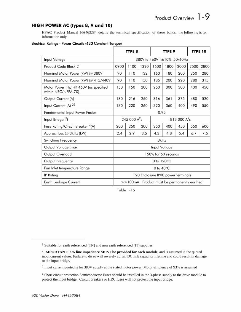
HPAC Product Manual HA463284 details the technical specification of these builds, the following is forinformation only.
####%*%*%*%*
0 0 0
6 /
,-
$-"7
$-"7
7!$ $+
'
++
,
+# ,-
7-/-"
+* -/
'
'' !
'+* /
+# °
#
- 33
%
1 Suitable for earth referenced (TN) and non earth referenced (IT) supplies
2 IMPORTANT: 3% line impedance MUST be provided for each module, and is assumed in the quotedinput current values. Failure to do so will severely curtail DC link capacitor lifetime and could result in damageto the input bridge.
3 Input current quoted is for 380V supply at the stated motor power. Motor efficiency of 93% is assumed
4 Short circuit protection Semiconductor Fuses should be installed in the 3-phase supply to the drive module toprotect the input bridge. Circuit breakers or HRC fuses will not protect the input bridge.
'
)* ! $ !! , -)! *
Motor Overload Protection
An external motor overload protective device must be provided by the installer.
Motor overload protection is provided in the controller by means of the thermal device in the motor winding.This protection cannot be evaluated by UL hence it is the responsibility of the installer and/or the local inspectorto determine whether the overload protection is in compliance with the National Electrical Code or Local Coderequirements.
Branch Circuit/Short Circuit Protection Requirements
Model 620 Type 4 Series
UL Listed (JDDZ) non-renewable cartridge fuses or UL Listed (JDRX) renewable cartridge fuses, rated 300Vacor 600Vac as appropriate (depending on the rated input voltage of the drive), must be installed upstream of thedrive. For fuse current ratings, see Chapter 1 “Electrical Ratings - Power Circuit”.
Model 620 Type 5 and 6 Series
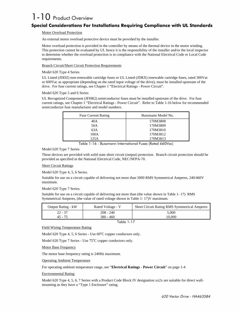
UL Recognized Component (JFHR2) semiconductor fuses must be installed upstream of the drive. For fusecurrent ratings, see Chapter 1 “Electrical Ratings - Power Circuit”. Refer to Table 1-16 below for recommendedsemiconductor fuse manufacturer and model numbers.
Fuse Current Rating Bussmann Model No.
40A50A63A
100A125A
170M3808170M3809170M3810170M3812170M3813
%,+#
Model 620 Type 7 Series
These devices are provided with solid state short circuit (output) protection. Branch circuit protection should beprovided as specified in the National Electrical Code, NEC/NFPA-70.
Short Circuit Ratings
Model 620 Type 4, 5, 6 Series.
Suitable for use on a circuit capable of delivering not more than 5000 RMS Symmetrical Amperes, 240/460Vmaximum.
Model 620 Type 7 Series.
Suitable for use on a circuit capable of delivering not more than (the value shown in Table 1- 17) RMSSymmetrical Amperes, (the value of rated voltage shown in Table 1- 17)V maximum.
Output Rating - kW Rated Voltage - V Short Circuit Rating RMS Symmetrical Amperes
22 - 3745 - 75
208 - 240380 - 460
5,00010,000
%
Field Wiring Temperature Rating
Model 620 Type 4, 5, 6 Series - Use 60oC copper conductors only.
Model 620 Type 7 Series - Use 75oC copper conductors only.
Motor Base Frequency
The motor base frequency rating is 240Hz maximum.
Operating Ambient Temperature
For operating ambient temperature range, see “Electrical Ratings - Power Circuit” on page 1-4
Environmental Rating
Model 620 Type 4, 5, 6, 7 Series with a Product Code Block IV designation xx2x are suitable for direct wall-mounting as they have a “Type 1 Enclosure” rating.
'
In order to preserve this enclosure rating, it is important to maintain the environmental integrity of the enclosure.The installer must provide correct Type 1 closures for all unused clearance/knockout holes within the driveglandbox.
Additionally, in order to preserve the “Type 1 Enclosure” rating for 620 Type 7 models, the installer must ensurethat the blanking plates are fitted to the ventilation apertures provided within the glandbox.
+ !,
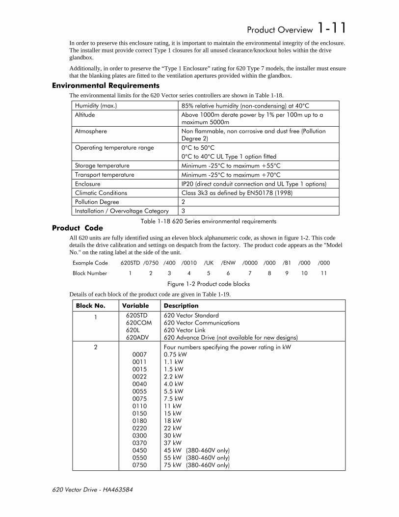
The environmental limits for the 620 Vector series controllers are shown in Table 1-18.
°
$!!
' °°°°(%!
°°% °° (%
-!$
'
% * *
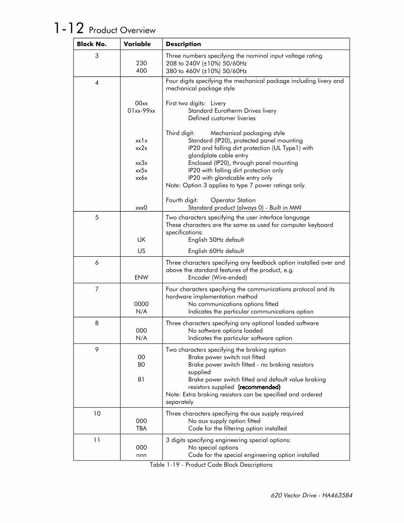
All 620 units are fully identified using an eleven block alphanumeric code, as shown in figure 1-2. This codedetails the drive calibration and settings on despatch from the factory. The product code appears as the "ModelNo." on the rating label at the side of the unit.
% (. $" ,
,-$
+-
Details of each block of the product code are given in Table 1-19.
%!* 1! *)
%'
- !
+!-"-"-"-"-"-"-"-"-"-"-"-"-"-"-" -" -"
'
%!* 1! *)
%!± /± /
+!--
+ !
% - !(%!
$'
+ ' ,
(.
(
%!!%!-!
/!
/!
$"
%!!-!!
"
$
+!
$!
$
%!!$!!
,
,
%!-,-!,-!-,-!!-
$-!
%,
%!*$!!!
!$!
%,-

'
620STD/0750/400/0010/UK/ENW/0000/000/B1/000/000
This code indicates a drive, which is:
• a 620 Standard product
• 75kW power rating
• 380-460v input supply
• Eurotherm Drives livery
• Enclosed mechanical package (IP20)
• No additional optional operator station
• UK language
• Wire-ended 15V encoder option
• No optional communications
• No optional loaded software
• Brake switch fitted with default value resistors supplied
• No aux supply option fitted
• No special options.

'
) !! ! -
This chapter contains a functional description of the 620 Vector Drive to enable a sound understanding of thesystem, and notes for consideration prior to installation.
$"
The 620 Vector enables very high performance control of 3-phase AC induction motors fitted with a compatibleencoder. It offers the user great system flexibility, allowing easy integration into various control schemes. The plainlanguage Man-Machine Interface (MMI) greatly simplifies setting up and commissioning the 620 Vector.
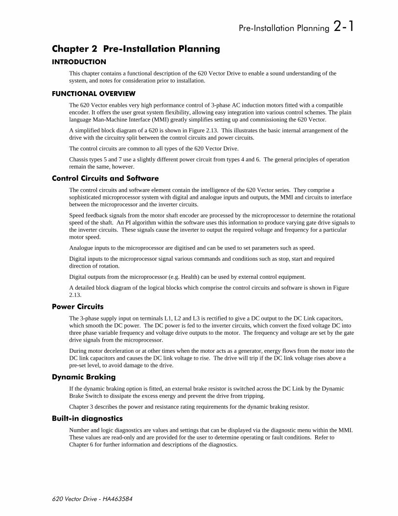
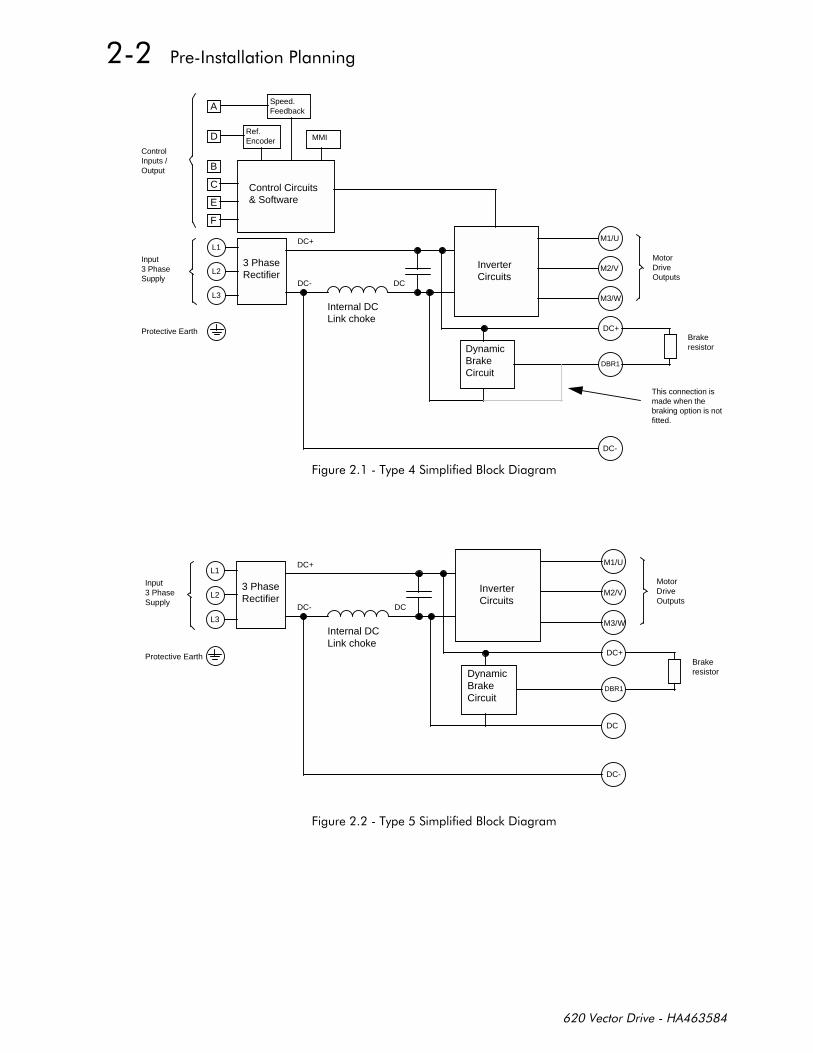
A simplified block diagram of a 620 is shown in Figure 2.13. This illustrates the basic internal arrangement of thedrive with the circuitry split between the control circuits and power circuits.
The control circuits are common to all types of the 620 Vector Drive.
Chassis types 5 and 7 use a slightly different power circuit from types 4 and 6. The general principles of operationremain the same, however.
!*
The control circuits and software element contain the intelligence of the 620 Vector series. They comprise asophisticated microprocessor system with digital and analogue inputs and outputs, the MMI and circuits to interfacebetween the microprocessor and the inverter circuits.
Speed feedback signals from the motor shaft encoder are processed by the microprocessor to determine the rotationalspeed of the shaft. An PI algorithm within the software uses this information to produce varying gate drive signals tothe inverter circuits. These signals cause the inverter to output the required voltage and frequency for a particularmotor speed.
Analogue inputs to the microprocessor are digitised and can be used to set parameters such as speed.
Digital inputs to the microprocessor signal various commands and conditions such as stop, start and requireddirection of rotation.
Digital outputs from the microprocessor (e.g. Health) can be used by external control equipment.
A detailed block diagram of the logical blocks which comprise the control circuits and software is shown in Figure2.13.
*
The 3-phase supply input on terminals L1, L2 and L3 is rectified to give a DC output to the DC Link capacitors,which smooth the DC power. The DC power is fed to the inverter circuits, which convert the fixed voltage DC intothree phase variable frequency and voltage drive outputs to the motor. The frequency and voltage are set by the gatedrive signals from the microprocessor.
During motor deceleration or at other times when the motor acts as a generator, energy flows from the motor into theDC link capacitors and causes the DC link voltage to rise. The drive will trip if the DC link voltage rises above apre-set level, to avoid damage to the drive.
*% -
If the dynamic braking option is fitted, an external brake resistor is switched across the DC Link by the DynamicBrake Switch to dissipate the excess energy and prevent the drive from tripping.
Chapter 3 describes the power and resistance rating requirements for the dynamic braking resistor.
% ! -*
Number and logic diagnostics are values and settings that can be displayed via the diagnostic menu within the MMI.These values are read-only and are provided for the user to determine operating or fault conditions. Refer toChapter 6 for further information and descriptions of the diagnostics.
Control Circuits& Software
Ref.Encoder MMI
3 PhaseRectifier
A
D
B
C
E
F
L1
L2
L3
InverterCircuits
DC-
M1/U
DC+
DynamicBrakeCircuit
Input3 PhaseSupply
ControlInputs / Output
Speed.Feedback
DBR1
This connection ismade when thebraking option is notfitted.
Brakeresistor
DC+
DC- DC
Internal DCLink choke
MotorDriveOutputs
Protective Earth
M2/V
M3/W
+% !,-
3 PhaseRectifier
L1
L2
L3
InverterCircuits
DC-
DC+
DynamicBrakeCircuit
Input3 PhaseSupply
DBR1
Brakeresistor
DC+
DC- DC
Internal DCLink choke
MotorDriveOutputs
DC
Protective Earth
M1/U
M2/V
M3/W
+% !,-
3 PhaseRectifier
L1
L2
L3
InverterCircuits
DC-
DC+
DynamicBrakeCircuit
Input3 PhaseSupply
DBR1
This connection ismade when thebraking option is notfitted.
Brakeresistor
DC+
DC- DC
Internal DCLink choke
MotorDriveOutputs
Protective Earth
M1/U
M2/V
M3/W
+% !,-
3 PhaseRectifier
L1
L2
L3
InverterCircuits
DC-
DC+
DynamicBrakeCircuit
Input3 PhaseSupply
DBR1
Brakeresistor
DC+
DC- DC
Internal DCLink choke
MotorDriveOutputs
DC
DBR2
Protective Earth
M1/U
M2/V
M3/W
+% !,-
"##
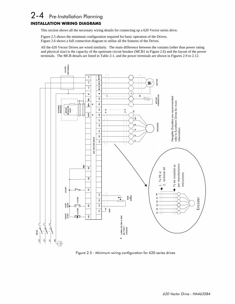
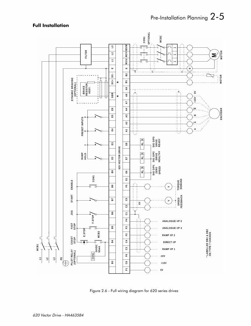
This section shows all the necessary wiring details for connecting up a 620 Vector series drive.
Figure 2.5 shows the minimum configuration required for basic operation of the Drives.Figure 2.6 shows a full connection diagram to utilise all the features of the Drives.
All the 620 Vector Drives are wired similarly. The main difference between the variants (other than power ratingand physical size) is the capacity of the upstream circuit breaker (MCB1 in Figure 2.6) and the layout of the powerterminals. The MCB details are listed in Table 2-1, and the power terminals are shown in Figures 2.9 to 2.12.
L3
L1
MC
B1
MO
TO
R
M
L1
L2
FIL
TE
R
(OP
TIO
NA
L)
M2/
VM
1/U
M3/
W
LA
BE
LL
ED
DB
1 &
DB
2O
N T
YP
E 7
CH
AS
SIS
*
RA
MP
SP
EE
D
L3 PE
L2
F.S
TO
P
GN
D
C2
C1
B4
B5
E.S
TO
P
C6
C3
B7
ST
OP
CO
AS
TS
TO
PF
AS
TS
TA
RT
AA
EN
CO
DE
RM
OT
OR
TH
ER
MIS
TO
R
B15
V0V
B
E
620
VE
CT
OR
DR
IVE
B8
B924
V24
V
A1
A2
AS
SY
.
A4
A3
*
A7
A8
DB
R
* B1
A9
EEB
2
DC
+D
C-
ED
C+
DC
-E
DY
NA
MIC
BR
AK
ING
RE
SIS
TO
RB
RA
KE
+
A1
A2
A4
A3
A7
A8
1.
To
PE
or
2.
term
inal
A9
Enc
oder
To
be in
stal
led
as
per
man
ufac
ture
rs
inst
ruct
ions
.
!!
!
+!!
$ !! !!
MC
B1
MC
B2
L1
OP
TIO
NA
L
CO
N1
I
M3/
W
L3
CO
N1
MO
TO
R
M
II
M1/
UM
2/V
L1
L2
FIL
TE
R
* L
AB
EL
LE
D D
B1
& D
B2
O
N T
YP
E 7
CH
AS
SIS
0V
RAMP I/P 1
DIRECT I/P
+10V
-10V
FE
ED
BA
CK
DE
MA
ND
ANALOGUE I/P 4
ANALOGUE I/P 5
RAMP I/P 2
VV
SP
EE
DT
OR
QU
E
0V
C4
B4
CO
AS
TS
TO
P
B3
F1
F6
C6
C3
50m
A24
VD
CC
ON
1
PIL
OT
RE
LA
Y(O
PT
ION
AL
)
PE
L2 L3
B5
B6
C1
F3
F4
F2
MC
B2
F.S
TO
P
B7
B8
C2
C5
F5
E.S
TO
PFA
ST
ST
OP
JOG
ST
AR
TE
NA
BL
E
AA
SP
EE
DH
EA
LT
HY
DIG
O/P
1Z
ER
OD
IG O
/P2
DR
IVE
RL
SR
LS
RE
AD
Y
DIG
O/P
3D
RIV
E
RL
S
EN
CO
DE
R
BB
+15V
0V
MO
TO
R
E
B9
E2
620
VE
CT
OR
DR
IVE
E1
E6
E7
E3
E4
E8
A1
A2
HO
LD
RA
MP
12
PR
ES
ET
IN
PU
TS
BR
AK
ER
ES
IST
OR
E9
E5
DB
R
A4
A3
*A
7A
8
DC
+D
C-
E
* B1
A9
B2
E
AS
SY
.
DY
NA
MIC
BR
AK
ING
(OP
TIO
NA
L)
3
++!
*1+
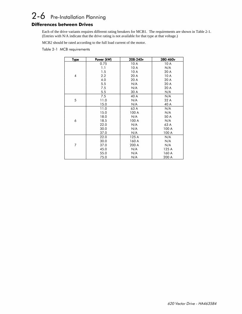
Each of the drive variants requires different rating breakers for MCB1. The requirements are shown in Table 2-1.(Entries with N/A indicate that the drive rating is not available for that type at that voltage.)
MCB2 should be rated according to the full load current of the motor.
%,*
%%%% -"-"-"-"
$
$ $ $
$ $
$
$ $ $
$ $ $ $
$ $
$ $ $ $
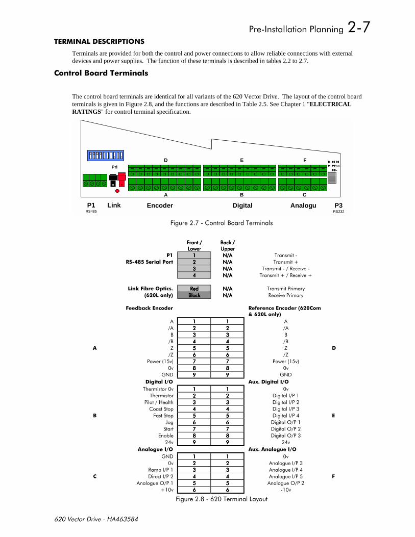
Terminals are provided for both the control and power connections to allow reliable connections with externaldevices and power supplies. The function of these terminals is described in tables 2.2 to 2.7.
!% !
The control board terminals are identical for all variants of the 620 Vector Drive. The layout of the control boardterminals is given in Figure 2.8, and the functions are described in Table 2.5. See Chapter 1 "ELECTRICALRATINGS" for control terminal specification.
Link Encoder Digital Analogu P3RS232
A B C
D E FPri
0v
Peek
P1RS485
+,%
+%
+ + + +
,- ,- ,- ,- ((((
$ $ $ $ %
! $ $ $ $ %
$ $ $ $ % #
$ $ $ $ % #
$1)* #### $ $ $ $ %
! ,-,-,-,- $ $ $ $ #
$1 ** **!
, ,
, ,
8 8
8 8
)$ )$
- ! 2- !
%
%
% +
0 '
'
'
!- 2 !-
)$
#
$
' '
%,%
! 1
!*)$1 **
, ,
,
8 8
8
!
!
)$
$'% $'% $'% $'% • +!
• ! , 8!
• • +!
! 1
!*)- ! !*-
,,,, % %,,-!%!
,,,, % !!%Ω!° Ω,, !,,-Ω±Ω%-Ω±Ω
! 1
!*)- ! !*-
,,,, ' -%!%!!!' % %',!
,,,, " " %
,,,, + "+ *"+ !!+
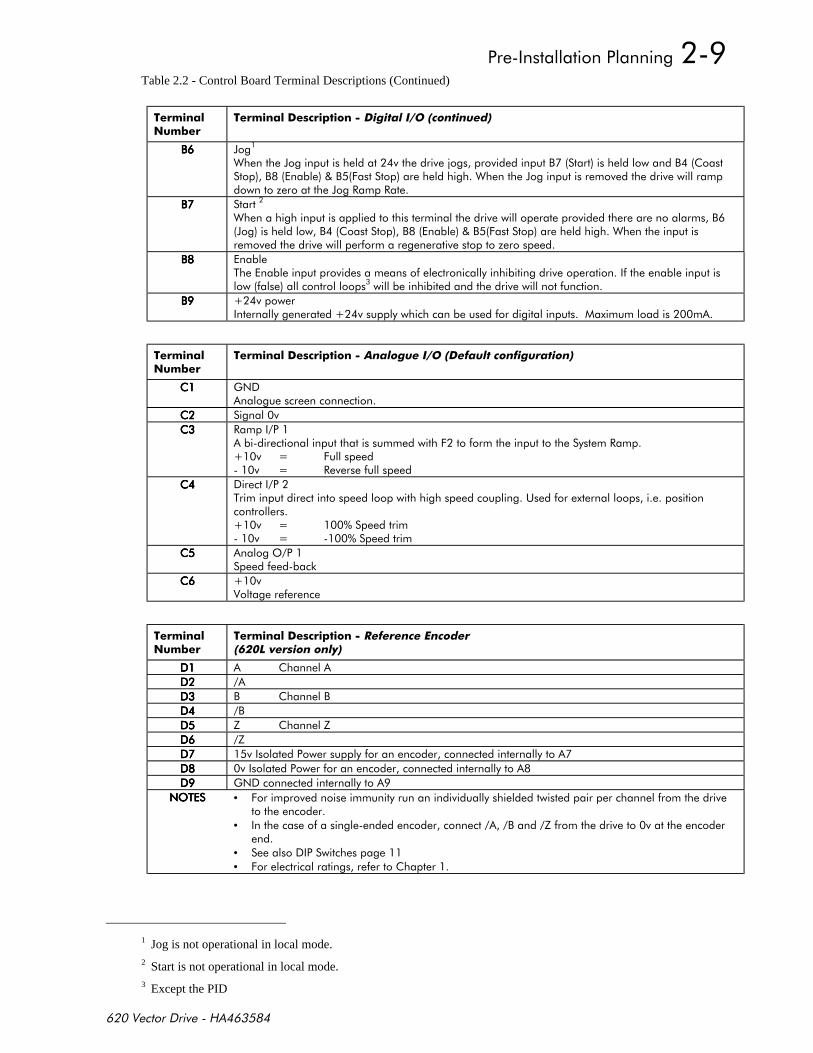
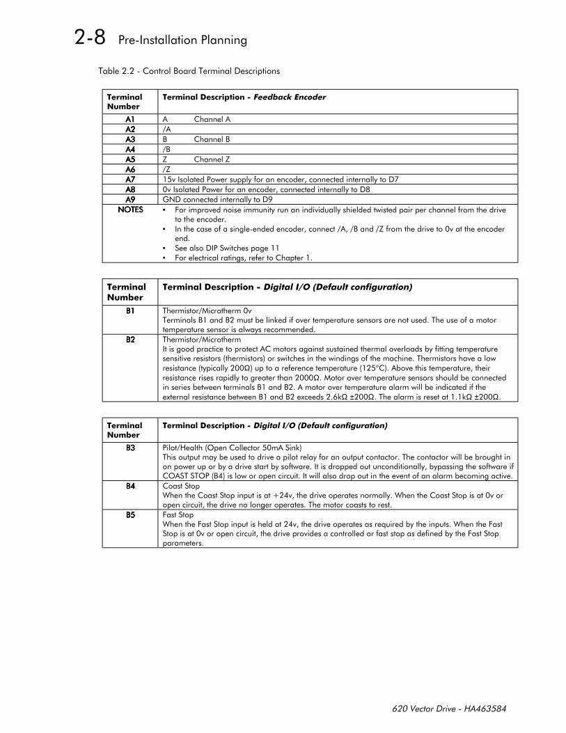
Table 2.2 - Control Board Terminal Descriptions (Continued)
! 1
!*)- !*
,,,, 0
"09, , ,,+ "0/0##
,,,,
",0, ,,+ "!/
,,,, %!!!
!
,,,, !
! 1
!*) !- !*-
)$
# +! # : + : #!
%(! : :
' !-
!
! 1
!*)**+!
, ,
,
8 8
8
!
!
)$
$'% $'% $'% $'% • +!
• ! , 8!
• • +!
1 Jog is not operational in local mode.
2 Start is not operational in local mode.
3 Except the PID
%,%
! 1
!*) 2- ! !-
!
# '! #!/!# "! #!# ####
# % %%!
% PRESET 1 PRESET 2 PRESET 3 PRESET 4 PRESET 8
%,!!
' 8#' !! 8
' !! % #% 0')
' #!! !-!
,
! 1
!*) 2 !-
++++
++++ !!#! # : + : #!
++++ $!!
++++ $!!
++++ ' !!%* : !* : *
++++ !
! 1
!*) !)! ))
)))) %+
)))) %+
)))) #+
)))) #+
*
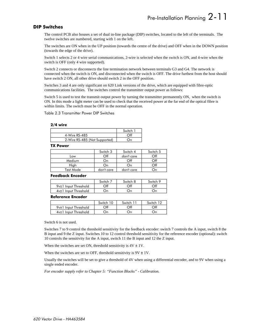
The control PCB also houses a set of dual in-line package (DIP) switches, located to the left of the terminals. Thetwelve switches are numbered, starting with 1 on the left.
The switches are ON when in the UP position (towards the centre of the drive) and OFF when in the DOWN position(towards the edge of the drive).
Switch 1 selects 2 or 4 wire serial communications, 2-wire is selected when the switch is ON, and 4-wire when theswitch is OFF (only 4 wire supported).
Switch 2 connects or disconnects the line termination network between terminals G3 and G4. The network isconnected when the switch is ON, and disconnected when the switch is OFF. The drive furthest from the host shouldhave switch 2 ON, all other drive should switch 2 in the OFF position.
Switches 3 and 4 are only significant on 620 Link versions of the drive, which are equipped with fibre-opticcommunications facilities. The switches control the transmitter output power as follows:
Switch 5 is used to test the transmit output power by turning the transmitter permanently ON, when the switch isON. In this mode a light meter can be used to check that the received power at the far end of the optical fibre iswithin limits. The switch must be OFF in the normal operation.
%%
"# '!!
"# $ '
3
'!! '!!
' '!! '!!
' ' '!!
% '
$1 **
±% '!! '!! '!!
±% ' ' '
**
±% '!! '!! '!!
±% ' ' '
Switch 6 is not used.
Switches 7 to 9 control the threshold sensitivity for the feedback encoder: switch 7 controls the A input, switch 8 theB input and 9 the Z input. Switches 10 to 12 control threshold sensitivity for the reference encoder (optional): switch10 controls the sensitivity for the A input, switch 11 the B input and 12 the Z input.
When the switches are set ON, threshold sensitivity is 4V ± 1V.
When the switches are set to OFF, threshold sensitivity is 9V ± 1V.
Usually the switches will be set to give a threshold of 4V when using a differential encoder, and to 9V when using asingle ended encoder.
For encoder supply refer to Chapter 5: “Function Blocks” - Calibration.
!
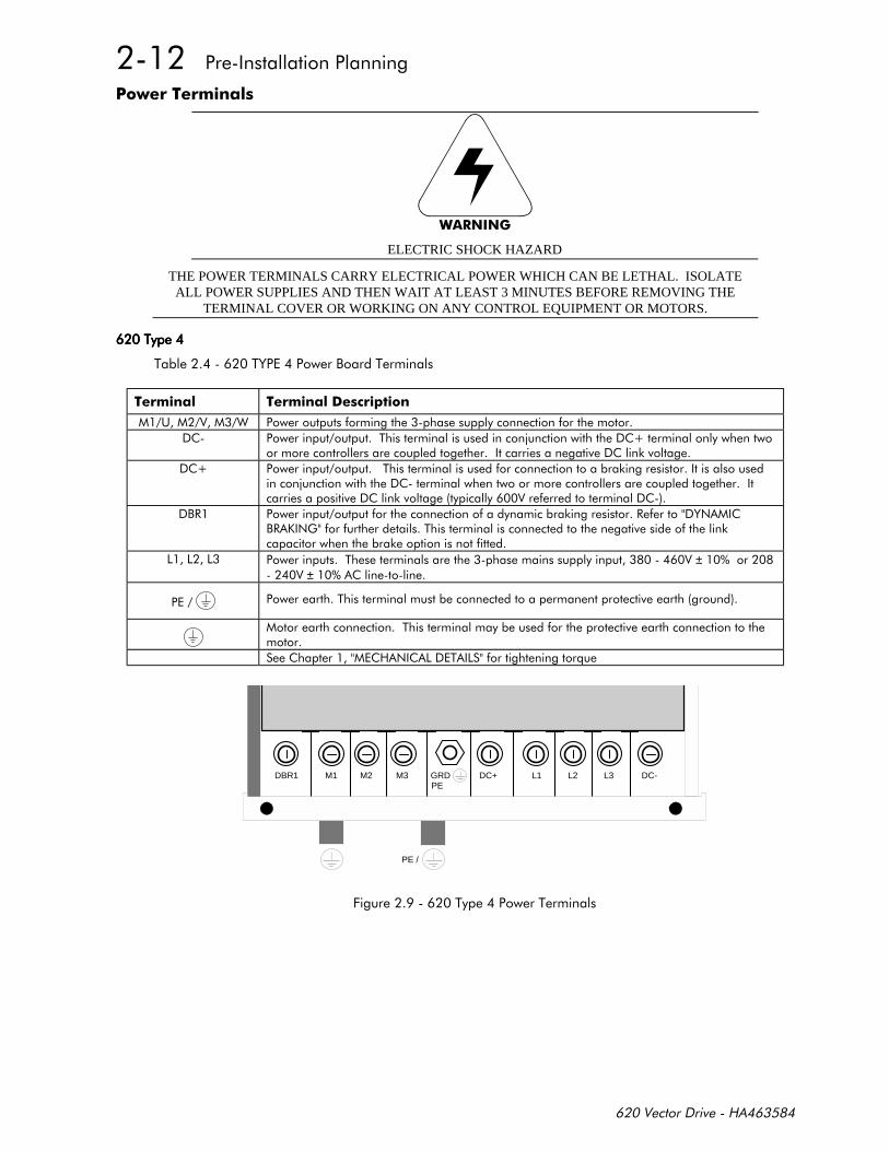
"#
ELECTRIC SHOCK HAZARD
THE POWER TERMINALS CARRY ELECTRICAL POWER WHICH CAN BE LETHAL. ISOLATEALL POWER SUPPLIES AND THEN WAIT AT LEAST 3 MINUTES BEFORE REMOVING THE
TERMINAL COVER OR WORKING ON ANY CONTROL EQUIPMENT OR MOTORS.
%%%%
%%&,%
! !*)
( " !!
%9-
%!-9-!
,# !!-#!&$ ,# .$)!!%!--!
%±±
%
%!
$ % !*
M1 M2 M3 DC+ L1 L2 L3 DC-DBR1 GRDPE
PE /
+%%
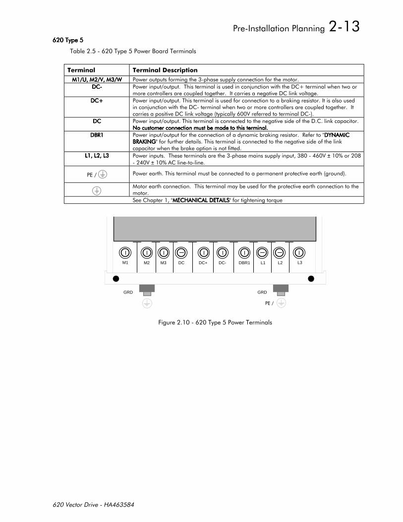
%%%%
%%,%
! !*)
( " ( " ( " ( " !!
%9-
%!-9-!
%!-$$$$
,#,#,#,# !!-#!&$ &$ &$ &$ ,# .$),# .$),# .$),# .$)!!%!--!
%±±
%
%!
$ % $ % $ % $ % !*
M2 M3 DC-DC DBR1 L1 L2 L3M1
GRD
DC+
GRD
+%%
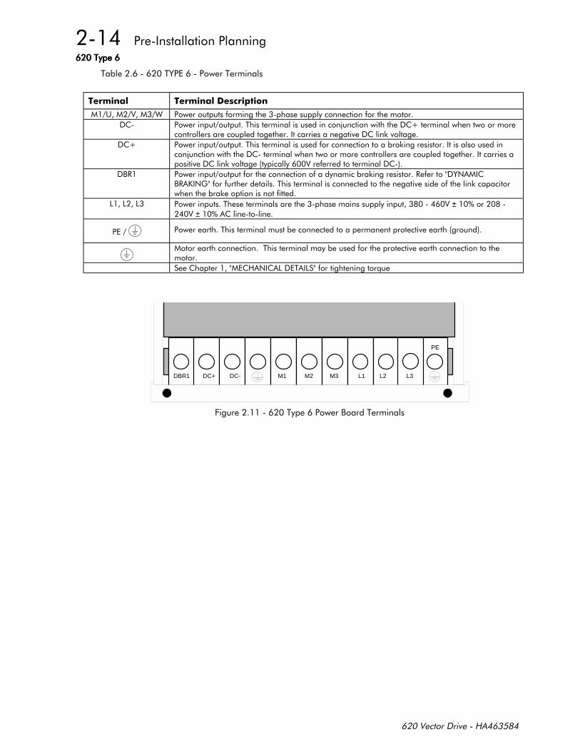
%%%%
%%&%
! !*)
( " !!
%9-
%!-9-!
,# !!-#!&$ ,# .$)!!%!--!
%±±
%
%!
$ % !*
M1 M2 M3 L1 L2DBR1 DC+ DC- L3
PE
+%,%
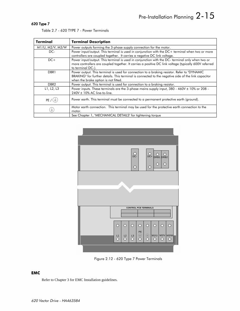
%%%%
%%&%
! !*)
( " !!
%9-
%9-!
,# %!-#!&$ ,# .$)!!%!--!
,# %!-
%±±
%
%!
$ % !*
M3/WM2/VM1/UL3L2L1
CONTROL PCB TERMINALS
DRB1DC+ DRB2DC-
PE
+%%
Refer to Chapter 3 for EMC Installation guidelines.

UL Compression Lug Kit is available for the drives which provide a set of lugs suitable for the following ratings.These lugs must be applied with the correct tooling as described in the Installation Instructions provided with eachLug Kit.
The following terminal kit is available for the connection of Power Cabling.
* ))!! -
,
4 *,
& -/ )
-" ")
-"
-"
-"
C4
B3
B4
B5
B7
B8
B6
26
22
38
38
37
075
76
80
JOG 1
JOG 2
JOG MODE
E7
E6
12
HEALTH LEDRUN LED
177
178
MAX SPEED
MIN SPEED
STOPRAMP
6
171
172 175
174
173
RATIO 1DIRECTENABLE
P3 +-
C3 29 +-
189 191
196
197 +-
192190
F2 31
46
5703SPT SCALE
+
+58 47
57
39E2
E3 40
E4 41
E5 521
SPT SIGN5703
++
SPEEDSETPOINT
+
-
198
21RAMPING
RAMP O/P
INPUT 0
INPUT 2
INPUT 1
RATIO 0 SIGN 0
RATIO 1 SIGN 1
54 55
ACCEL DECEL
62
63
EXTERNALRESET
RAMPHOLD
RAMP I/P
RESET VAL
7
1918
STANDSTILL
SPEEDFEEDBACK
AT ZEROSETPOINT
0
0
TOTAL SPD DMD
SETPOINT SUM 1
SETPOINT SUM 2
32F3
33F4
546
551 602
INPUT 2537
550
INPUT 1536
-+
++
601
-+
PID
MIN
MAX
87
88
85
86
89 82
45
EXTERNALRESET
RESETVALUE
LOWER
RAISE RAISE/LOWEROUTPUT
M2/V
M3/W
L2
L3
A,AA,,B,A,BA,,C,A,C,A,
159 158
MAIN
LIMIT
NEG. TORQUELIMIT
157153
9
TORQUEDEMAMD
POS TORQUELIMIT
SYMETRICTORQUE
COAST STOP
FAST STOP
ENABLE
JOG
START
INPUTS
NOT CONFIGURED
NOT CONFIGURED
PILOT / HEALTH
HEALTH
ZERO SPEED
TORQUE DEMAND
MOTOR
BRAKE
RESISTOR
SPEED FEEDBACKENCODER
ENCODER FEEDBACK
LOCAL
SETPOINT
RAISE/LOWER
8 TO 1
MUX
SYSTEM
S RAMP
RAISE
/LOWER
SETPOINT
MUX
RAMP
RATE
MUX
SEQUENCE
ENGINE
CURRENT
CONTROLLER
START
JOG
AUX START
AUX JOG
AUX DISABLE
EXTERNAL TRIP
OTHER ALARMS
STALL
SPEED FDBK
DELAY
TORQUE
|SPEED FDBK|
126STOP 0 SPEED
SIGN 1RATIO 1
++
SIGN 0RATIO 0
372INPUT 1
INPUT 0
INPUT 2+
-+
+-
385
370 LIMIT
195 LIMIT
386
RATIO 1 SIGN 1
RATIO 0
384
383INPUT 1
376
INPUT 0
INPUT 2
382
375
SETPOINT SUM 3
381SIGN 0
378
-+
+-
377
+++
LIMIT
aXb
aXb
aXb
aXb
aXb
aXb
DIRECT I/PMAX
DIRECT I/PMIN
DIRECT SETPOINT
LOCAL
RAMP
511 512
ACCEL DECEL
SPEED LOOP
161 162P I
INVERSETIME
453 MAG CURRENT
149 458
I/GAIN ROTORTIME CONST
131 130
No. LINES MAX SPEED
SEEINDIVIDUALCHASSISDRAWINGS
545
INPUT
543 547
LINK 1SOURCE DEST
LINK 2SOURCE DEST
LINK 15SOURCE DEST
LINK 16SOURCE DEST
176 MAIN SPD SETPT
542
48
SPEED SETPOINT
AUX TORQUE DEMAND
559
TORQ.DMD.
596
LOCAL/REMOTE
LOCAL START
LOCAL STOP
LOCAL JOG
BUTTON
BUTTON
BUTTON
BUTTON
LOCAL
JOG
C5 SPEED FEEDBACK
L1
M
373
371
364 366
365 367
RATIO 1 SIGN 1
RATIO 2 SIGN 2
RAMP INPUT 1
RAMP INPUT 2
ANALOGUE INPUT 4
ANALOGUE INPUT 5
RAMP HOLD
LOCAL RAISE
PRESET 2
PRESET 3
LOCAL LOWER
LOCAL DIRECTION
DIRECT I/P 2
5703 INPUT
5703 OUTPUT
PRESET 1
BUTTON
BUTTON
BUTTON
P3
48
COAST STOP
FAST STOP TIME
JOG DECEL RATE
JOG ACCEL RATE
RUN STOP TIME
CONTACTOR DELAY
26
123
114
113
120
112
17
ISOLATE
LIMITS
++
TORQUE
FLUXDEMAND
F5
M1/U
DC+
DBR


) !! *
This chapter contains the procedures required to install a 620 Vector Drive.
This product conforms to IP20 protection. Due consideration should be given to environmentalconditions of installation for safe and reliable operation.
When installing the 620 Vector Drive, the following points must be considered.
1) Mechanically secure fixings must be used, as recommended in "MOUNTING".
2) The enclosure into which this product is mounted must be suitable for the working environment.
3) The cooling and airflow around this product must be as recommended in "VENTILATION".
4) The cables and wire terminations must be as recommended and securely clamped.
5) The installation and commissioning of this equipment must only be carried out by competent personnel inaccordance with safe working practices.
-
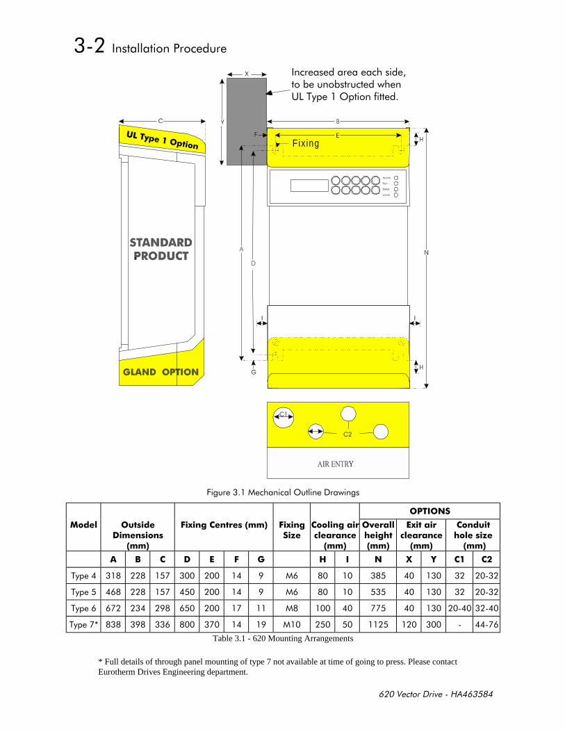
Mounting dimensions and suitable fixing bolts are shown in Figure 3.1.
The 620 Vector Drive must be mounted vertically on a cool, solid, flat vertical surface. It must be fixed using 4bolts or screws of the correct size through the fixing points provided at each corner at the rear of the unit. Thefixing points are in the form of keyholes and slots to simplify fastening or removal.
!
In normal operation the drive dissipates heat and must be mounted to allow the free flow of air vertically throughthe unit. Care must be taken to ensure that the mounting surface is cool and that any heat generated by adjacentequipment is not transmitted to the 620 Vector Drive. Similarly, ensure that the heat generated by the drive willnot adversely affect any other equipment or cabling.
For adequate ventilation of the drive, minimum clearance as defined in Figure 3.1 Mechanical Outline Drawingsmust be maintained. Side-by-side mounting of two or more drives is permissible providing the ambient operatingtemperature is not exceeded.
(%'!
Fix ing))
+'
!
$2- $2-/
!- *! *
+ !!-
2 *! *
!/
% $ # 3 0
%
%
%
%
Table 3.1 - 620 Mounting Arrangements
* Full details of through panel mounting of type 7 not available at time of going to press. Please contactEurotherm Drives Engineering department.

The following instructions describe the wiring requirements for operation of the 620 as basic speed controller.The variety of specific drive applications precludes the inclusion of diagrams showing all wiring options.
"-
Never perform high voltage resistance checks on the wiring without first disconnecting the drivefrom the circuit being tested.
Observe all national standards and local electricity supply company regulations while installing the 620 Vectordrive.
The following considerations apply to all installations.
1) Power cables must be rated at a minimum of 110% of the expected supply current.
2) Power cables (particularly 3-phase motor cables) must be routed well away from cables carrying setpointsor feedback signals, screened motor feedback cables, and cables from other electronic equipment in thesame plant.
3) The motor supply cables should be screened to avoid causing undue interference to other equipment in thearea.
4) The mains power supply must be 3-phase and within the voltage tolerances specified in "ELECTRICALRATINGS - Power Circuit" in Chapter 1 of this manual. The supply must be connected to power boardterminals L1, L2 and L3 of the 620 Vector drive.
1! ))!*
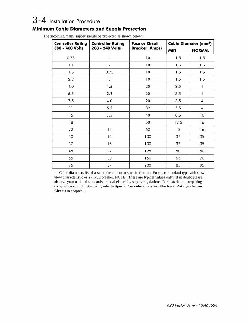
The incoming mains supply should be protected as shown below:
!! -!
!! -!
$ * % )
1!
* - Cable diameters listed assume the conductors are in free air. Fuses are standard type with slow-blow characteristic or a circuit breaker. NOTE: These are typical values only. If in doubt pleaseobserve your national standards or local electricity supply regulations. For installations requiringcompliance with UL standards, refer to Special Considerations and Electrical Ratings - PowerCircuit in chapter 1.
-
"#
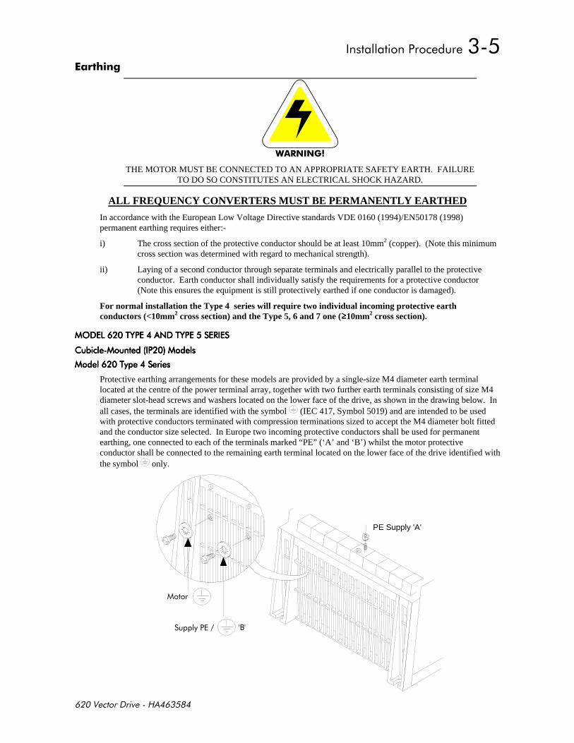
THE MOTOR MUST BE CONNECTED TO AN APPROPRIATE SAFETY EARTH. FAILURETO DO SO CONSTITUTES AN ELECTRICAL SHOCK HAZARD.
ALL FREQUENCY CONVERTERS MUST BE PERMANENTLY EARTHED
In accordance with the European Low Voltage Directive standards VDE 0160 (1994)/EN50178 (1998)permanent earthing requires either:-
i) The cross section of the protective conductor should be at least 10mm2 (copper). (Note this minimumcross section was determined with regard to mechanical strength).
ii) Laying of a second conductor through separate terminals and electrically parallel to the protectiveconductor. Earth conductor shall individually satisfy the requirements for a protective conductor(Note this ensures the equipment is still protectively earthed if one conductor is damaged).
For normal installation the Type 4 series will require two individual incoming protective earthconductors (<10mm2 cross section) and the Type 5, 6 and 7 one (10mm2 cross section).
'%& $%& # '%& $%& # '%& $%& # '%& $%& #
% % % %
Protective earthing arrangements for these models are provided by a single-size M4 diameter earth terminallocated at the centre of the power terminal array, together with two further earth terminals consisting of size M4diameter slot-head screws and washers located on the lower face of the drive, as shown in the drawing below. Inall cases, the terminals are identified with the symbol (IEC 417, Symbol 5019) and are intended to be usedwith protective conductors terminated with compression terminations sized to accept the M4 diameter bolt fittedand the conductor size selected. In Europe two incoming protective conductors shall be used for permanentearthing, one connected to each of the terminals marked “PE” (‘A’ and ‘B’) whilst the motor protectiveconductor shall be connected to the remaining earth terminal located on the lower face of the drive identified withthe symbol only.
PE Supply 'A'
,
% % % %
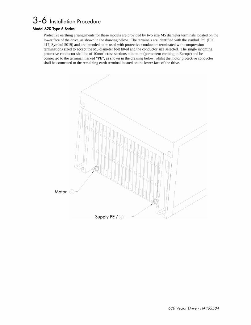
Protective earthing arrangements for these models are provided by two size M5 diameter terminals located on thelower face of the drive, as shown in the drawing below. The terminals are identified with the symbol (IEC417, Symbol 5019) and are intended to be used with protective conductors terminated with compressionterminations sized to accept the M5 diameter bolt fitted and the conductor size selected. The single incomingprotective conductor shall be of 10mm2 cross sections minimum (permanent earthing in Europe) and beconnected to the terminal marked “PE”, as shown in the drawing below, whilst the motor protective conductorshall be connected to the remaining earth terminal located on the lower face of the drive.
""""
%% %% %% %%
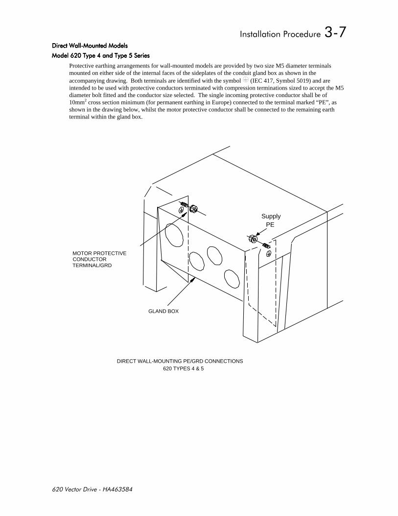
Protective earthing arrangements for wall-mounted models are provided by two size M5 diameter terminalsmounted on either side of the internal faces of the sideplates of the conduit gland box as shown in theaccompanying drawing. Both terminals are identified with the symbol (IEC 417, Symbol 5019) and areintended to be used with protective conductors terminated with compression terminations sized to accept the M5diameter bolt fitted and the conductor size selected. The single incoming protective conductor shall be of10mm2 cross section minimum (for permanent earthing in Europe) connected to the terminal marked “PE”, asshown in the drawing below, whilst the motor protective conductor shall be connected to the remaining earthterminal within the gland box.
PE
DIRECT WALL-MOUNTING PE/GRD CONNECTIONS620 TYPES 4 & 5
GLAND BOX
MOTOR PROTECTIVECONDUCTORTERMINAL/GRD
Supply
'%& $%& # '%& $%& # '%& $%& # '%& $%& #
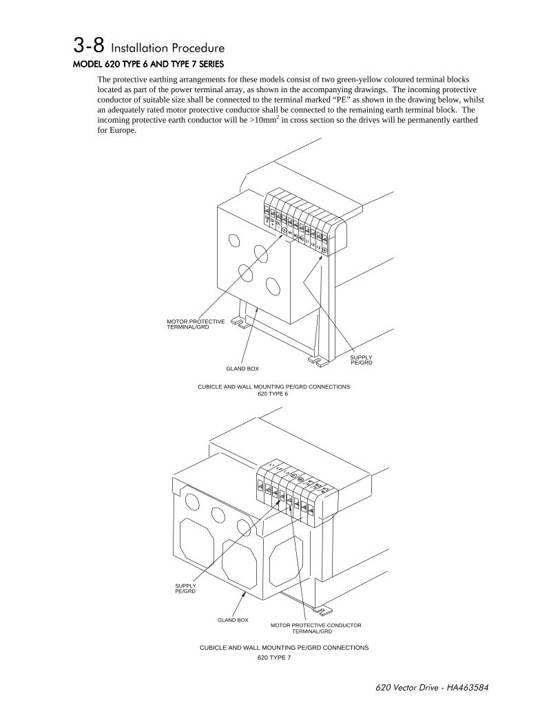
The protective earthing arrangements for these models consist of two green-yellow coloured terminal blockslocated as part of the power terminal array, as shown in the accompanying drawings. The incoming protectiveconductor of suitable size shall be connected to the terminal marked “PE” as shown in the drawing below, whilstan adequately rated motor protective conductor shall be connected to the remaining earth terminal block. Theincoming protective earth conductor will be >10mm2 in cross section so the drives will be permanently earthedfor Europe.
MOTOR PROTECTIVETERMINAL/GRD
GLAND BOX
SUPPLYPE/GRD
CUBICLE AND WALL MOUNTING PE/GRD CONNECTIONS620 TYPE 6
CUBICLE AND WALL MOUNTING PE/GRD CONNECTIONS
620 TYPE 7
SUPPLYPE/GRD
GLAND BOXMOTOR PROTECTIVE CONDUCTOR
TERMINAL/GRD
!"-
General wiring diagrams for the 620 are provided in Chapter 2.
Control cables should be 0.75mm2 (18AWG) minimum. It is recommended that screened cable is used, with thescreen connected at the drive end only. Control wiring should be kept separate from power and motor wiring.
For normal speed control operation, the speed demand signals are connected to the speed inputs (control boardterminals C3, C4 and F2) as required. Terminal C2 or F1 may be used for the 0V connection associated with theSPEED SETPOINT and DIRECT INPUT signals. The maximum speed, and other associated parameters, are setfrom the MMI.
The START signal to the 620 Vector drive is provided by connecting a single holding contact between control boardterminal B7 (START) and terminal B9 (+24V). When the contact is open, the motor stops. When the contact isclosed and both COAST STOP and FAST STOP are at +24V, the motor will run.
A digital output indicating that the drive is healthy is provided on terminals E7 of the 620 Vector drive. Any alarmwhich causes the drive healthy output to de-activate is internally latched by the drive until both START and JOG golow (0V or open circuit). The cause of the alarm is displayed by the MMI. Once latched, such an alarm can becleared only by removing and re-applying the START or JOG signal.
0%&#
*
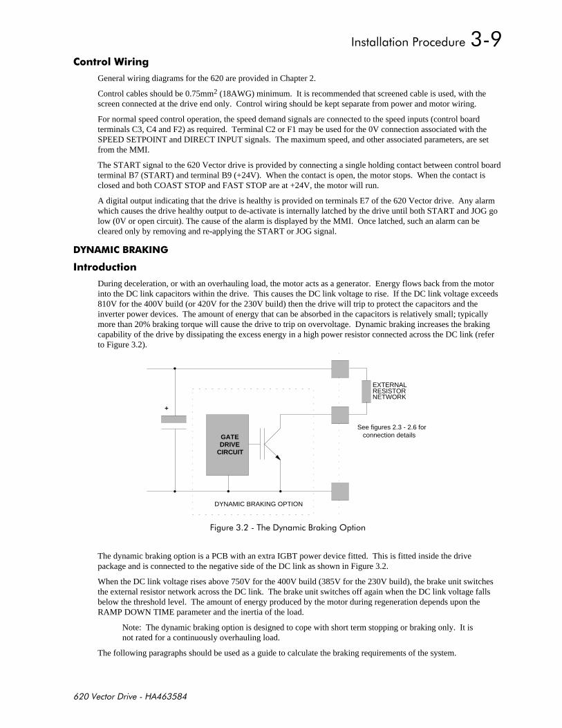
During deceleration, or with an overhauling load, the motor acts as a generator. Energy flows back from the motorinto the DC link capacitors within the drive. This causes the DC link voltage to rise. If the DC link voltage exceeds810V for the 400V build (or 420V for the 230V build) then the drive will trip to protect the capacitors and theinverter power devices. The amount of energy that can be absorbed in the capacitors is relatively small; typicallymore than 20% braking torque will cause the drive to trip on overvoltage. Dynamic braking increases the brakingcapability of the drive by dissipating the excess energy in a high power resistor connected across the DC link (referto Figure 3.2).
DYNAMIC BRAKING OPTION
GATEDRIVE
CIRCUIT
+
EXTERNALRESISTORNETWORK
See figures 2.3 - 2.6 for connection details
+%,-'
The dynamic braking option is a PCB with an extra IGBT power device fitted. This is fitted inside the drivepackage and is connected to the negative side of the DC link as shown in Figure 3.2.
When the DC link voltage rises above 750V for the 400V build (385V for the 230V build), the brake unit switchesthe external resistor network across the DC link. The brake unit switches off again when the DC link voltage fallsbelow the threshold level. The amount of energy produced by the motor during regeneration depends upon theRAMP DOWN TIME parameter and the inertia of the load.
Note: The dynamic braking option is designed to cope with short term stopping or braking only. It isnot rated for a continuously overhauling load.
The following paragraphs should be used as a guide to calculate the braking requirements of the system.
"#
Connecting a brake resistor to a drive not fitted with brake option ( see product code ) will result indamage to this unit. In the case when an internal brake option is not present the DBR terminal may be
used to connect an external braking unit
% !*
Brake resistor assemblies must be rated to absorb both peak braking power during deceleration and the averagepower over the complete cycle.
Peak braking power0 0055J n n
tW1
22
2
b=
× −. ( )( )
J - total inertia (kgm2)
n1 - initial speed (rpm)
Average braking power PP
tavpk
c= x tb n2 - final speed (rpm)
tb - braking time (s)
tc - cycle time (s)
Information on the peak power rating and the average power rating of the resistors must be obtained from theresistor manufacturer. Alternatively if this information is not available then a large safety margin must beincorporated to ensure that the resistors are not overloaded. Eurotherm Drives can supply suitable brake resistorassemblies as detailed over.
By connecting these resistors in series and in parallel the braking capacity can be selected for the application.
The minimum resistance of the combination should not be less than that specified in Table 3.2.
The resistor(s) must be specified to the maximum DC link voltage (810V for the 400V build, 420V for the 230Vbuild).
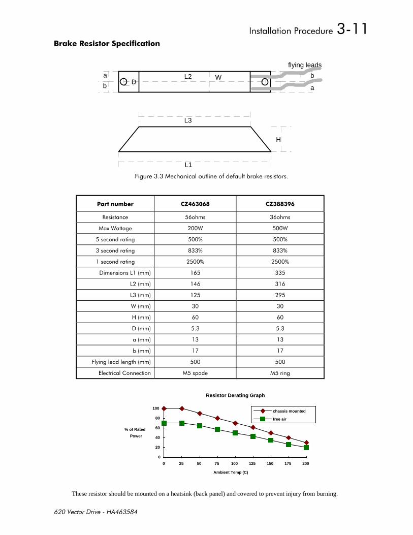
% )**
L1
H
flying leads
L2
L3
Wa
b a
bD
+!!-
1 5 5
#
" " "
"
+
Resistor Derating Graph
Ambient Temp (C)
% of Rated
Power
0
20
40
60
80
100
0 25 50 75 100 125 150 175 200
chassis mounted
free air
These resistor should be mounted on a heatsink (back panel) and covered to prevent injury from burning.
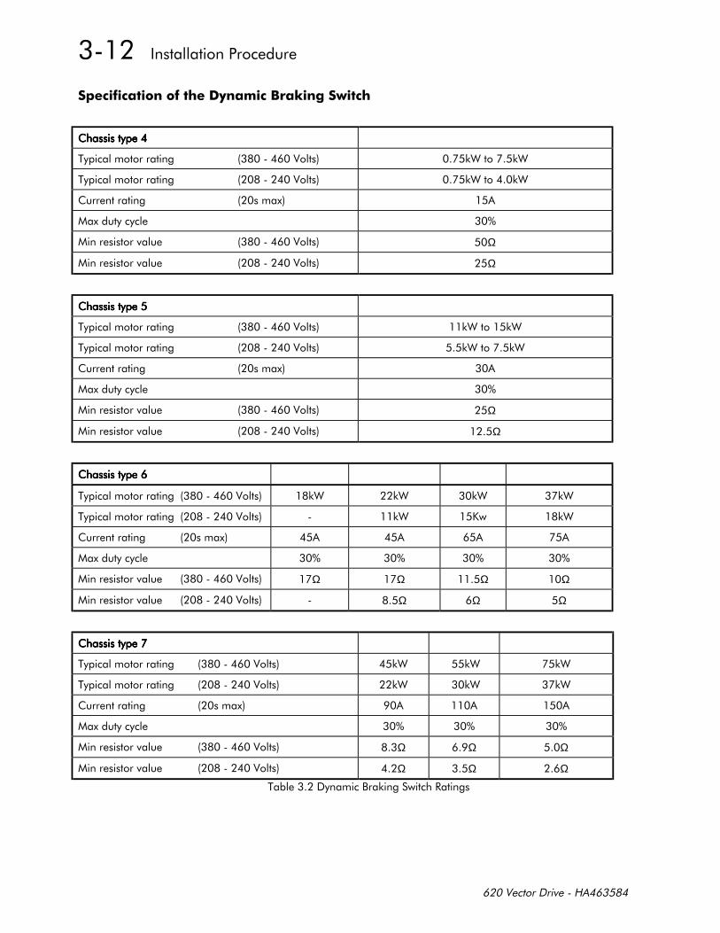
)** *% -*
% -"-"
% -"-"
Ω
Ω
% -"-"
% -"-"
Ω
Ω
% -" -" -" -"
% -" . -"
Ω Ω Ω Ω
Ω Ω Ω
% -" -" -"
% -" -" -"
Ω Ω Ω
Ω Ω Ω
%,- #
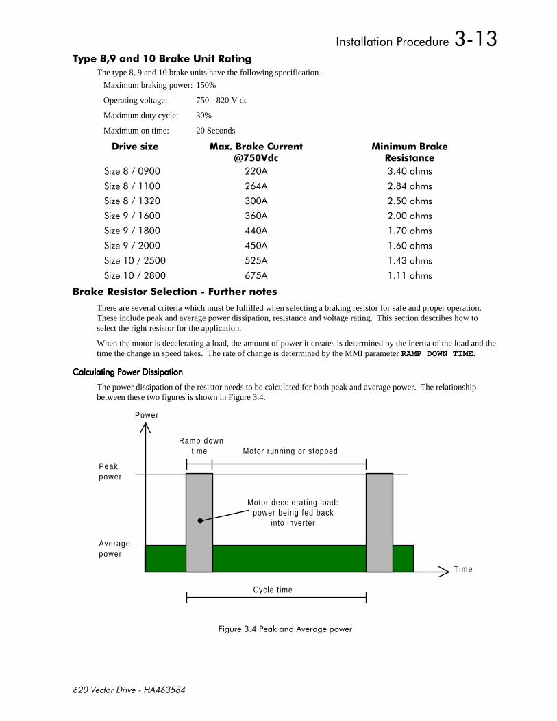
) % -
The type 8, 9 and 10 brake units have the following specification -
Maximum braking power: 150%
Operating voltage: 750 - 820 V dc
Maximum duty cycle: 30%
Maximum on time: 20 Seconds
+/ 2% 6*
% *
/
/
/
/
/
/
/
/
% !*$
There are several criteria which must be fulfilled when selecting a braking resistor for safe and proper operation.These include peak and average power dissipation, resistance and voltage rating. This section describes how toselect the right resistor for the application.
When the motor is decelerating a load, the amount of power it creates is determined by the inertia of the load and thetime the change in speed takes. The rate of change is determined by the MMI parameter RAMP DOWN TIME.
The power dissipation of the resistor needs to be calculated for both peak and average power. The relationshipbetween these two figures is shown in Figure 3.4.
Power
T ime
Ramp downt ime Motor running or stopped
Cycle t ime
Peakpower
Averagepower
Motor decelerating load:power being fed back
into inverter
+-
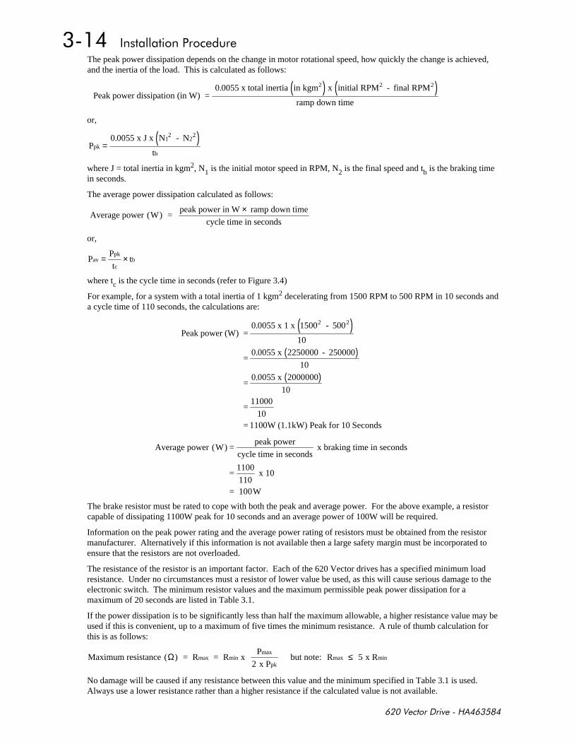
The peak power dissipation depends on the change in motor rotational speed, how quickly the change is achieved,and the inertia of the load. This is calculated as follows:
( ) ( )
Peak power dissipation (in W) = 0 0055 x total inertia in kgm x initial RPM - final RPM
ramp down time
2 2 2.
or,
( )P
0 0055 x J x N - N
tpk
12
22
b=
.
where J = total inertia in kgm2, N1 is the initial motor speed in RPM, N2 is the final speed and tb is the braking timein seconds.
The average power dissipation calculated as follows:
Average power (W) = peak power in W ramp down time
cycle time in seconds
×
or,
PP
ttav
pk
cb= ×
where tc is the cycle time in seconds (refer to Figure 3.4)
For example, for a system with a total inertia of 1 kgm2 decelerating from 1500 RPM to 500 RPM in 10 seconds anda cycle time of 110 seconds, the calculations are:
( )
( )
( )
Peak power (W) =0 0055 x 1 x 1500 - 500
10
=0 0055 x 2250000 - 250000
10
=0 0055 x 2000000
10
=11000
10= 1100W (1.1kW) Peak for 10 Seconds
2 2.
.
.
Average power (W) =peak power
cycle time in seconds x braking time in seconds
=1100
110 x 10
= 100W
The brake resistor must be rated to cope with both the peak and average power. For the above example, a resistorcapable of dissipating 1100W peak for 10 seconds and an average power of 100W will be required.
Information on the peak power rating and the average power rating of resistors must be obtained from the resistormanufacturer. Alternatively if this information is not available then a large safety margin must be incorporated toensure that the resistors are not overloaded.
The resistance of the resistor is an important factor. Each of the 620 Vector drives has a specified minimum loadresistance. Under no circumstances must a resistor of lower value be used, as this will cause serious damage to theelectronic switch. The minimum resistor values and the maximum permissible peak power dissipation for amaximum of 20 seconds are listed in Table 3.1.
If the power dissipation is to be significantly less than half the maximum allowable, a higher resistance value may beused if this is convenient, up to a maximum of five times the minimum resistance. A rule of thumb calculation forthis is as follows:
Maximum resistance ( ) = R = R x P
2 x P but note: R 5 x Rmax min
max
pkmax minΩ ≤
No damage will be caused if any resistance between this value and the minimum specified in Table 3.1 is used.Always use a lower resistance rather than a higher resistance if the calculated value is not available.
$- $- $- $-
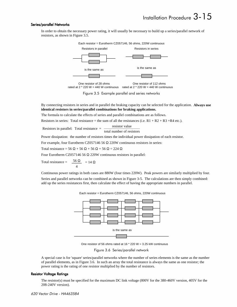
In order to obtain the necessary power rating, it will usually be necessary to build up a series/parallel network ofresistors, as shown in Figure 3.5.
Each resistor = Eurotherm CZ057146, 56 ohms, 220W continuous
is the same as
One resistor of 28 ohms
Resistors in parallel
rated at 2 * 220 W = 440 W continuousOne resistor of 112 ohms
rated at 2 * 220 W = 440 W continuous
Resistors in series
is the same as
+-
By connecting resistors in series and in parallel the braking capacity can be selected for the application. Always useidentical resistors in series/parallel combinations for braking applications.
The formula to calculate the effects of series and parallel combinations are as follows.
Resistors in series: Total resistance = the sum of all the resistances (i.e. R1 + R2 + R3 +R4 etc.).
Resistors in parallel: Total resistance = resistor value
total number of resistors
Power dissipation: the number of resistors times the individual power dissipation of each resistor.
For example, four Eurotherm CZ057146 56 Ω 220W continuous resistors in series:
Total resistance = 56 Ω + 56 Ω + 56 Ω + 56 Ω = 224 Ω
Four Eurotherm CZ057146 56 Ω 220W continuous resistors in parallel:
Total resistance = 56 Ω = 14 Ω4
Continuous power ratings in both cases are 880W (four times 220W). Peak powers are similarly multiplied by four.
Series and parallel networks can be combined as shown in Figure 3-5. The calculations are then simply combined:add up the series resistances first, then calculate the effect of having the appropriate numbers in parallel.
Each resistor = Eurotherm CZ057146, 56 ohms, 220W continuous
is the same as
One resistor of 56 ohms rated at 16 * 220 W = 3.25 kW continuous
+ -
A special case is for 'square' series/parallel networks where the number of series elements is the same as the numberof parallel elements, as in Figure 3.6. In such an array the total resistance is always the same as one resistor; thepower rating is the rating of one resistor multiplied by the number of resistors.
########
The resistor(s) must be specified for the maximum DC link voltage (800V for the 380-460V version, 405V for the208-240V version).
#
*
This section provides installation guidelines for drive modules and systems to maximise their 'Electro MagneticCompatibility' (EMC) in their intended operating environment. All installers must read this section and apply theadvice which is relevant to their application. Pass on this information to others as is appropriate.
All power drive systems have the potential to produce electrical emissions, both radiated and conducted back intothe AC supply. This is due to the inherent operation of all drives by switching large voltages and currents rapidlyin order to control the motor. Because the drives internal control electronics operates continuously in very closeproximity to the electrically noisy power switching elements, drives are inherently immune to any additionalexternal electrical noise.
Great care has been taken in the design and selection of suitable EMC filters to provide the correct level ofinterface suppression, ease of installation and to ensure that electrical safety is not compromised. The EMCperformance can only be guaranteed to be within the limits specified when the 620 drive modules are installedtogether with the recommended EMC filters in accordance with the following instructions.
The subject of EMC is explored in more detail in a separate Eurotherm Application Manual entitled "EMCInstallation Guidelines for modules and systems’, part number HA388879, available from your local Eurothermoffice.
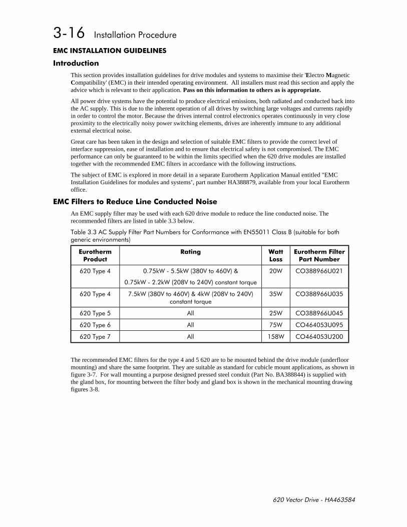
$! * *
An EMC supply filter may be used with each 620 drive module to reduce the line conducted noise. Therecommended filters are listed in table 3.3 below.
% +$!!$,!
*
- "
$! 1
% -"-"
-"-"*
" '(
% -"-"*
" '(
% " '(
% " '(
% " '(
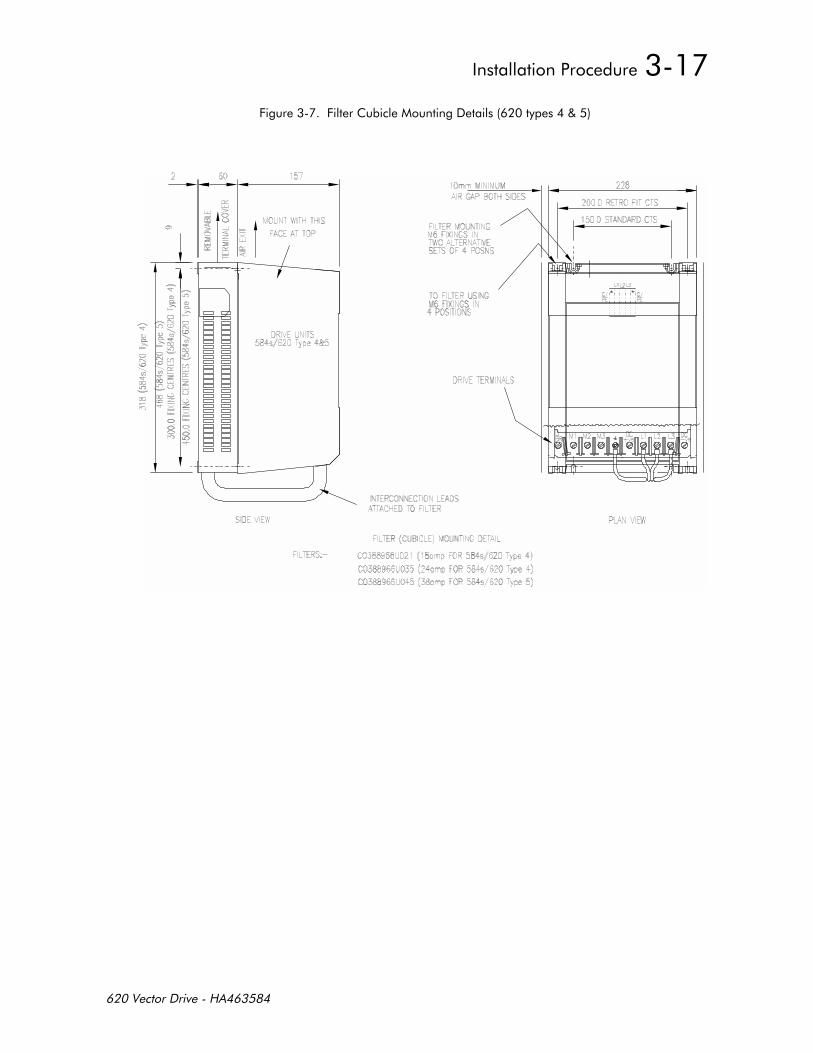
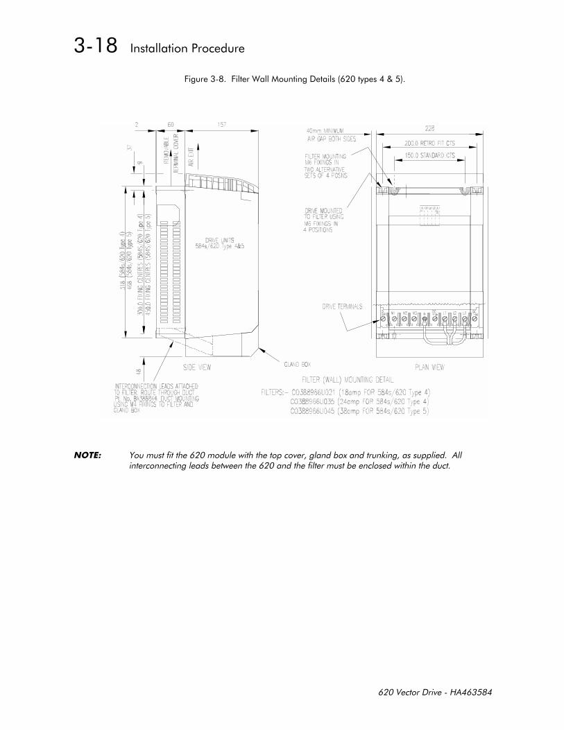
The recommended EMC filters for the type 4 and 5 620 are to be mounted behind the drive module (underfloormounting) and share the same footprint. They are suitable as standard for cubicle mount applications, as shown infigure 3-7. For wall mounting a purpose designed pressed steel conduit (Part No. BA388844) is supplied withthe gland box, for mounting between the filter body and gland box is shown in the mechanical mounting drawingfigures 3-8.
++
++"
&!- !
++%
++%

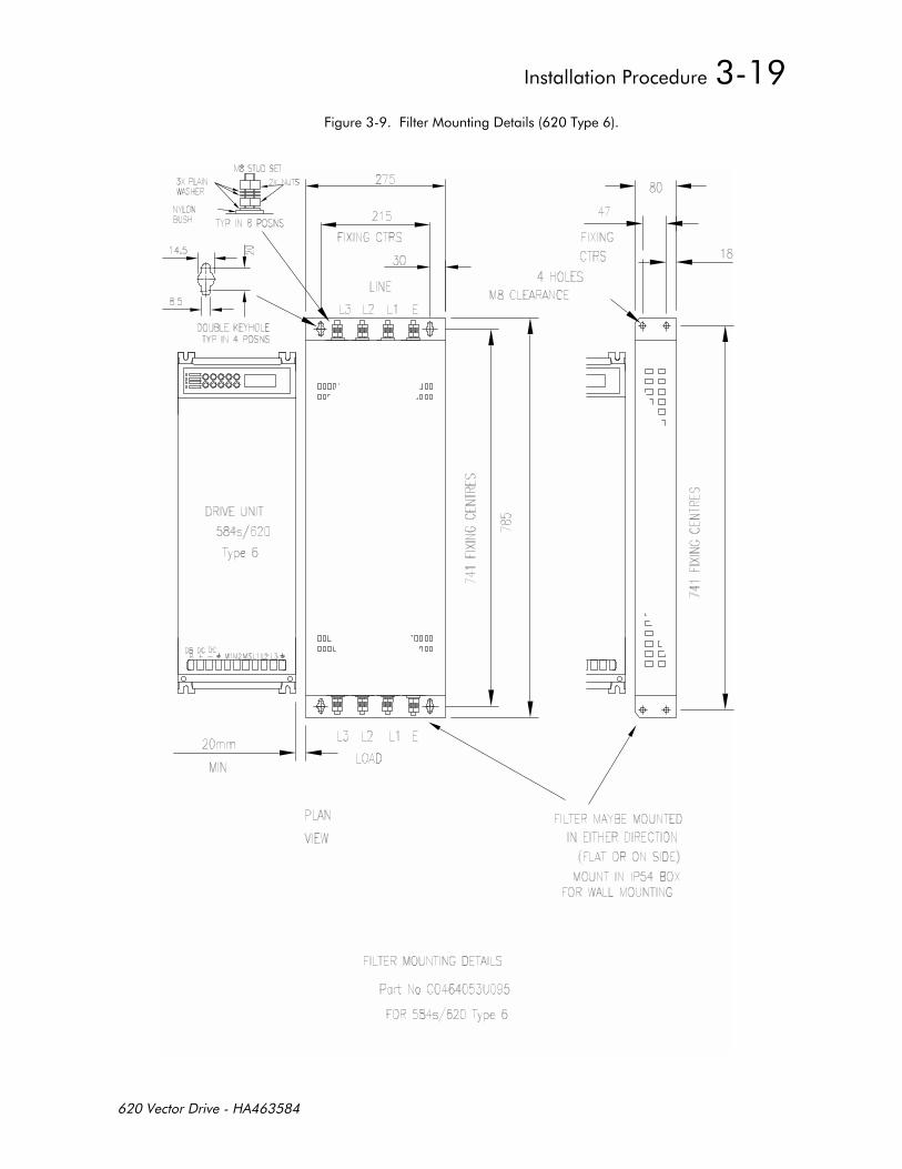
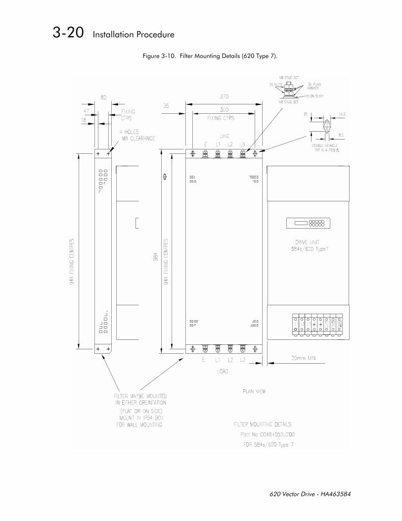
The type 6 and 7 620 filters are not of the footprint mounting design. These filters may be mounted to the left,right, above, below or spaced behind the product, but can be mounted in two orientations i) flat against the wallor ii) projecting over from the wall, mounting arrangements are shown in figures 3-9 and 3-10. Wallmountapplications require the EMC filter to be mounted in a separate suitable enclosure, and the gland box to be fittedto the 620.
The EMC filter should be mounted as close to the 620 drive module as possible. The connection between the 620and filter must always be as short as possible taking care not to obstruct any ventilation spacing and besegregated from all other cables. If this cable/busbar exceeds 0.3m in length then it must be replaced with ascreened/armoured cable, with the screen/armour earthed at both the filter and inverter ends with large-areacontact surfaces, preferably with metal cable glands. The connection between the 620 drive module and themotor must be installed away from all other cables or wires. Ideally the filter will be mounted onto the samemetallic panel as the drive. The RF connection between the inverter, filter and panel should be enhanced asfollows:
- Remove any paint/insulation between the mounting points of the EMC filter, 620 drive module andpanel.
- Liberally apply petroleum jelly over the mounting points and securing threads to prevent corrosion.Alternatively conducting paint could be used on mounting panels.
- If the proceeding is not possible, then the RF earth bond between the filter and 620 drive module isusefully improved by making an additional RF earth connection using wire braid of at least 10 mm2
cross sectional area (due to skin effect).
- For wall mount application, ensure that the cable between the EMC filter and the 620 drive modulecable is passed through conduit mounted between the filter and the Gland Box. This cable must be asshort as possible and segregated from all other cables. The conduit must be electrically connected tothe filter and drive module gland box.
NOTE: Metal surfaces such as eloxized or yellow chromed e.g. with cable mounting or 35 mm DIN rails,screws and bolts have a high RF impedance which can be very detrimental for EMC performance.
Care should be taken to ensure that the protective earth (PE) conductor exiting from the filter is connected to theprotective earth connection of the 620 drive module. Any additional RF earth such as a cable screen is not aprotective earth. The EMC filter must be permanently earthed to prevent the risk of electric shock underabnormal operating instances (such as the loss of one phase of the AC supply). Permanent earthing can beachieved by either:
- Using a copper protective earth conductor of at least 10 mm2 or
- Installing a second conductor in parallel connection with the protective conductor to a separate protectiveearth terminal.
Each conductor shall on its own meet the requirements for a protective earth conductor. On all recommendedunderfloor EMC filters two protective earth connections are provided for permanent earthing.
The recommended EMC filters are designed to operate from normal three-phases supplies which are balancedwith respect to earth (earth referenced supplies). This minimises the earth leakage current due to the filtercapacitors between phase and earth. On some specific customer sites the supply may not be balanced with respectto earth (non-earth referenced supplies). The earth leakage currents would increase and interfere with theoperation of any earth-fault monitoring equipment. In addition the EMC performance of the filter will bedegraded. Eurotherm Drives do not recommend the use of AC supply filters on non earth-referenced supplies.
As with all power electronic drives the conducted emissions increase with motor cable length. EMCconformance to the stringent limits is only guaranteed up to a cable length of 50 m (types 4, 5, 6 and 7).This length can be increased. Refer to section entitled Motor Cable-length Limitations in this chapter.
If one EMC filter is to be used in an enclosure, then this filter should be mounted as close to the incoming ACsupply to the enclosure as possible.
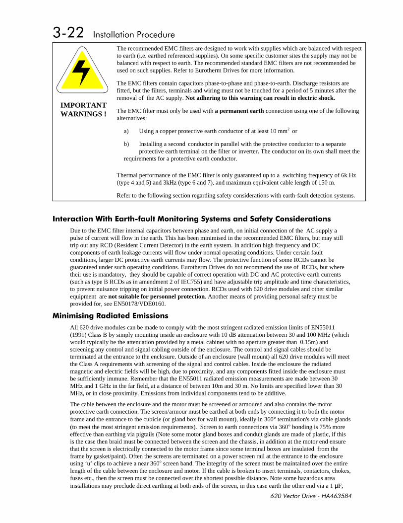
IMPORTANTWARNINGS !
The recommended EMC filters are designed to work with supplies which are balanced with respectto earth (i.e. earthed referenced supplies). On some specific customer sites the supply may not bebalanced with respect to earth. The recommended standard EMC filters are not recommended beused on such supplies. Refer to Eurotherm Drives for more information.
The EMC filters contain capacitors phase-to-phase and phase-to-earth. Discharge resistors arefitted, but the filters, terminals and wiring must not be touched for a period of 5 minutes after theremoval of the AC supply. Not adhering to this warning can result in electric shock.
The EMC filter must only be used with a permanent earth connection using one of the followingalternatives:
a) Using a copper protective earth conductor of at least 10 mm2 or
b) Installing a second conductor in parallel with the protective conductor to a separate protective earth terminal on the filter or inverter. The conductor on its own shall meet the
requirements for a protective earth conductor.
Thermal performance of the EMC filter is only guaranteed up to a switching frequency of 6k Hz(type 4 and 5) and 3kHz (type 6 and 7), and maximum equivalent cable length of 150 m.
Refer to the following section regarding safety considerations with earth-fault detection systems.
*" !-
Due to the EMC filter internal capacitors between phase and earth, on initial connection of the AC supply apulse of current will flow in the earth. This has been minimised in the recommended EMC filters, but may stilltrip out any RCD (Resident Current Detector) in the earth system. In addition high frequency and DCcomponents of earth leakage currents will flow under normal operating conditions. Under certain faultconditions, larger DC protective earth currents may flow. The protective function of some RCDs cannot beguaranteed under such operating conditions. Eurotherm Drives do not recommend the use of RCDs, but wheretheir use is mandatory, they should be capable of correct operation with DC and AC protective earth currents(such as type B RCDs as in amendment 2 of IEC755) and have adjustable trip amplitude and time characteristics,to prevent nuisance tripping on initial power connection. RCDs used with 620 drive modules and other similarequipment are not suitable for personnel protection. Another means of providing personal safety must beprovided for, see EN50178/VDE0160.
-
All 620 drive modules can be made to comply with the most stringent radiated emission limits of EN55011(1991) Class B by simply mounting inside an enclosure with 10 dB attenuation between 30 and 100 MHz (whichwould typically be the attenuation provided by a metal cabinet with no aperture greater than 0.15m) andscreening any control and signal cabling outside of the enclosure. The control and signal cables should beterminated at the entrance to the enclosure. Outside of an enclosure (wall mount) all 620 drive modules will meetthe Class A requirements with screening of the signal and control cables. Inside the enclosure the radiatedmagnetic and electric fields will be high, due to proximity, and any components fitted inside the enclosure mustbe sufficiently immune. Remember that the EN55011 radiated emission measurements are made between 30MHz and 1 GHz in the far field, at a distance of between 10m and 30 m. No limits are specified lower than 30MHz, or in close proximity. Emissions from individual components tend to be additive.
The cable between the enclosure and the motor must be screened or armoured and also contains the motorprotective earth connection. The screen/armour must be earthed at both ends by connecting it to both the motorframe and the entrance to the cubicle (or gland box for wall mount), ideally in 360° termination's via cable glands(to meet the most stringent emission requirements). Screen to earth connections via 360° bonding is 75% moreeffective than earthing via pigtails (Note some motor gland boxes and conduit glands are made of plastic, if thisis the case then braid must be connected between the screen and the chassis, in addition at the motor end ensurethat the screen is electrically connected to the motor frame since some terminal boxes are insulated from theframe by gasket/paint). Often the screens are terminated on a power screen rail at the entrance to the enclosureusing ‘u’ clips to achieve a near 360o screen band. The integrity of the screen must be maintained over the entirelength of the cable between the enclosure and motor. If the cable is broken to insert terminals, contactors, chokes,fuses etc., then the screen must be connected over the shortest possible distance. Note some hazardous areainstallations may preclude direct earthing at both ends of the screen, in this case earth the other end via a 1 µF,
50VAC capacitor. The motor protective earth should be connected to the drive module motor protective earthconnection.
If a shielded cable is not available, lay unshielded motor cables in a metal conduit which will act as a shield. Theconduit must be continuous with a direct electrical contact to the drive module and motor housing. If links arenecessary, use braid with a minimum cross sectional area of 10 mm2 .
Safety earthing always takes precedence over EMC earthing.
The use of screened cable without an EMC filter is not recommended, as line-conducted interference willincrease substantially and the capacitive coupling of the output cable to earth will result in high earth-leakagecurrents.
To ensure the correct operation of the 620 drive module, some control and signal cables (encoder, all analogueinputs and communications) have to be screened back to the inverter terminals. The screen integrity must becontinuous right back to the drive if not connected to the cubicle. Always minimise the length of screen strippedback to make this connection. The screen should only be connected at the drive end. If high frequency noise isstill a problem, earth at the non drive end via a 0.1 µF capacitor.
*- -" *!
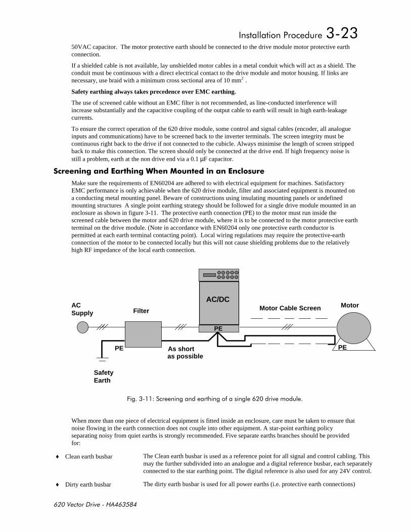
Make sure the requirements of EN60204 are adhered to with electrical equipment for machines. SatisfactoryEMC performance is only achievable when the 620 drive module, filter and associated equipment is mounted ona conducting metal mounting panel. Beware of constructions using insulating mounting panels or undefinedmounting structures A single point earthing strategy should be followed for a single drive module mounted in anenclosure as shown in figure 3-11. The protective earth connection (PE) to the motor must run inside thescreened cable between the motor and 620 drive module, where it is to be connected to the motor protective earthterminal on the drive module. (Note in accordance with EN60204 only one protective earth conductor ispermitted at each earth terminal contacting point). Local wiring regulations may require the protective-earthconnection of the motor to be connected locally but this will not cause shielding problems due to the relativelyhigh RF impedance of the local earth connection.
AC Supply Filter Motor Cable Screen Motor
SafetyEarth
PE
PE
PE
AC/DC
PE
As shortas possible
+ !
When more than one piece of electrical equipment is fitted inside an enclosure, care must be taken to ensure thatnoise flowing in the earth connection does not couple into other equipment. A star-point earthing policyseparating noisy from quiet earths is strongly recommended. Five separate earths branches should be providedfor:
♦ Clean earth busbar The Clean earth busbar is used as a reference point for all signal and control cabling. Thismay the further subdivided into an analogue and a digital reference busbar, each separatelyconnected to the star earthing point. The digital reference is also used for any 24V control.
♦ Dirty earth busbar The dirty earth busbar is used for all power earths (i.e. protective earth connections)
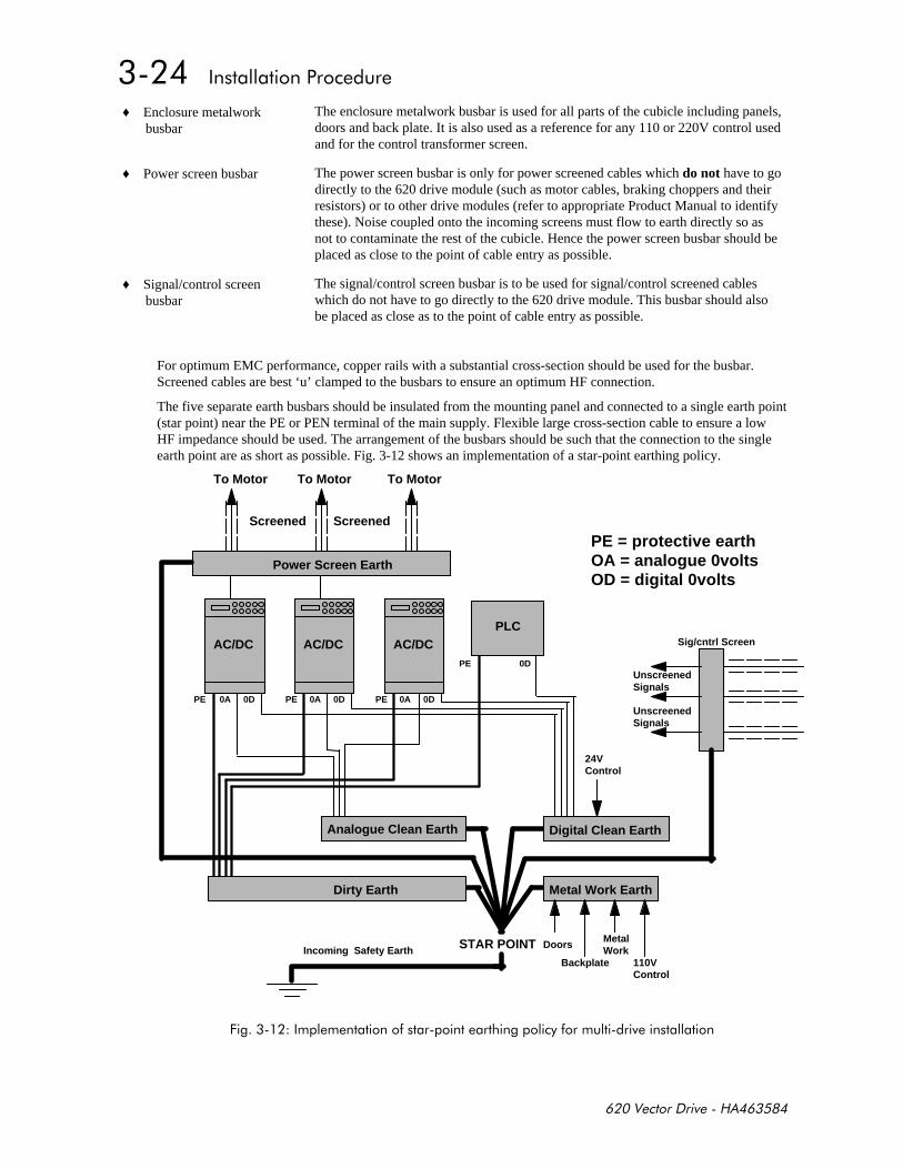
♦ Enclosure metalworkbusbar
The enclosure metalwork busbar is used for all parts of the cubicle including panels,doors and back plate. It is also used as a reference for any 110 or 220V control usedand for the control transformer screen.
♦ Power screen busbar The power screen busbar is only for power screened cables which do not have to godirectly to the 620 drive module (such as motor cables, braking choppers and theirresistors) or to other drive modules (refer to appropriate Product Manual to identifythese). Noise coupled onto the incoming screens must flow to earth directly so asnot to contaminate the rest of the cubicle. Hence the power screen busbar should beplaced as close to the point of cable entry as possible.
♦ Signal/control screenbusbar
The signal/control screen busbar is to be used for signal/control screened cableswhich do not have to go directly to the 620 drive module. This busbar should alsobe placed as close as to the point of cable entry as possible.
For optimum EMC performance, copper rails with a substantial cross-section should be used for the busbar.Screened cables are best ‘u’ clamped to the busbars to ensure an optimum HF connection.
The five separate earth busbars should be insulated from the mounting panel and connected to a single earth point(star point) near the PE or PEN terminal of the main supply. Flexible large cross-section cable to ensure a lowHF impedance should be used. The arrangement of the busbars should be such that the connection to the singleearth point are as short as possible. Fig. 3-12 shows an implementation of a star-point earthing policy.
Analogue Clean Earth
Dirty Earth
Digital Clean Earth
Metal Work Earth
AC/DC AC/DC AC/DCPLC
PE PE
PE
0D 0D 0D
0D
0A 0A 0A
Doors
Backplate
Metal Work
110VControl
24VControl
UnscreenedSignals
UnscreenedSignals
STAR POINTIncoming Safety Earth
To Motor To Motor To Motor
Screened Screened
PE = protective earthOA = analogue 0voltsOD = digital 0volts
PE
Sig/cntrl Screen
Power Screen Earth
+!!

Screening and Earthing When Wall MountedTo provide for good EMC performance the recommended EMC filter must be fitted and the cables between thewall-mount 620 drive module and the motor screened or armoured. Also screening of control and signal cablesmay be required. Refer to the previous instructions on minimising radiated emission (page 3-22). In addition anyconnections to the DC link must also be screened/armoured, with the screen connected at both ends (e.g. to theprotective earth of the dynamic brake resistor).
All 620 drive modules comply with the radiated emission limits of EN55011 (1991) Class A when wall mountedto these instructions, using the recommended EMC filter and screened motor control and signal cabling. Productswhich meet the limits of Class A can be made to meet the more stringent limits of Class B by mounting inside anenclosure with 10 dB attenuation between 30 and 100 MHz (which would typically be the attenuation providedby a metal cabinet with no aperture at a dimension greater than 0.15m) and screening any control and signalcabling outside of the cubicle. Minimise the length of unshielded cable inside the cubicle to prevent increasedradiated emission.
A single-point earthing policy as shown in Fig. 3-11 is required.
The protective earth connection (PE) to the motor must run inside the screened cable between the motor and 620drive module where it is to be connected to the protective earth terminal in the gland box or on the drive module(note, in accordance with EN60204 only one protective earth conductor is permitted at each earth terminalcontacting point) . Local wiring regulations may require the protective-earth connection of the motor to beconnected locally but this will not cause shielding problems due to relatively high RF impedance of the localearth connection.
The EMC filter must be permanently earthed in accordance with recommendations and warnings in the section“EMC Filters to Reduce Line Conducted Noise”, page 3-16.
Encoder Connections and RecommendationsRefer to figure 2.5 page 2-4 Minimum Wiring Configuration for 620 Series Drives. For EMC purposes usescreened cable. Always terminate the screen at the drive. Normally the screen is terminated within the encoderhousing, follow the encoder manufacturers instructions.
Motor Cable-length LimitationsScreened/armoured cable has significant capacitance between the conductors and the screen which increaseslinearly with cable length. Typically this is 200 pF per metre but this will vary with cable type and current rating.Long cable lengths may have the following undesirable effects:
- Tripping on 'over current' as the cable capacitance is charged and discharged at the switching frequency,
- Producing increased conducted emissions which degrade the performance of the EMC filter due tosaturation. EMC compliance is only guaranteed up to a maximum cable length of 50m (type 4, 5, 6 and7).
- Causes RCDs (Residential Current Detection) to trip out due to increased high frequency earth current.
- Produces increased heating inside the EMC AC supply filter from the increased conducted emissions.Eurotherm Drives only guarantee the thermal performance of the filters up to a specified cable length of150m with screened cable.
These effects can be overcome by adding chokes at the output of the 620 drive module. In applications wheremultiple motors are connected to a single drive, minimise the length of screened/armoured cable connected to thedrive by using a single length of cable to a star junction point, from where all the other motor cables are attached.Maintain the integrity of the shield. If the cable is interrupted to insert contactors or other components, the screenmust be connected over the shortest possible route. Table A1 in the appendix gives information on therecommended output chokes for use with long cables, cables connected in parallel, or when EMC output filtersare used with cables greater than that specified for EMC compliance.
Output filters can also be used to achieve EMC and filter thermal conformance with longer cable lengths thanthat specified. These output filters also ensure a long motor life by reducing the high dV/dt and over voltagestresses applied to the motor windings by inverters. These filters should be mounted as close to the 620 drivemodule as possible. Refer to Eurotherm Drives for the selection of suitable filters.
Other Layout ConsiderationsThe proximity between the source and victim circuit has a large effect on radiated coupling. The electromagneticfields produced by drive modules falls off rapidly with distance from the cabling/enclosure. It should beremembered that the radiated fields from EMC compliant drive systems are measured at least 10m from theequipment over the frequency band 30 to 1000 MHz (as required by EN55011, referenced by the generics andthe drive product specific standard). Any equipment placed closer to the drive system than this will see largermagnitude fields, particularly very close to the drive. No magnetic/electric field sensitive equipment should beplaced within 0.25m of the following parts of a drive system:
- 620 Drive module
- EMC output filters
- Input or output chokes/transformers
- Cable between 620 Frequency Inverter and Motor (even when screened/armoured)
- Connections to external braking chopper and resistor (even when screened/armoured)
- AC/DC brushed motors (due to commutation)
- DC link connections (even when screened/armoured)
- Relays and contactors (even if they are suppressed)
Often the coupling between electrically 'noisy' and 'sensitive' cables is a problem. This can be minimised byseparating parallel runs by at least 0.25m, and minimising the length of parallel runs. For long parallel runs (>10m) the separation should be increased proportionally. For example if the parallel runs were 50 m then theseparation would be (50/10) × 0.25 m = 1.25 m.
In addition the coupling between two cables which must cross is minimised if they cross over at 90°. Hencesensitive cables should cross the cables to the motor, DC link and braking chopper circuit at 90°, and shouldnever be run close to them or in parallel for any great length.
Never run supply, DC link or motor cables in the same bundle as the signal/control and feedback cables, even ifthey are screened.
From experience the following equipment is defined as particularly sensitive and care must be taken in theinstallation:
- Any transducers which produce low level analogue outputs (<1 volt) e.g. load cells, strain gauges,thermocouples, piezoelectric transducers, anometers, LVDT's
- A.M. radios (long and medium wave only)
- Video cameras and closed circuit TV
- Office personal computers
- Capacitive devices such as proximity sensors and level transducers
- Mains borne communication systems
- Equipment not suitable for operation in the intended EMC environment i.e. with insufficient immunity tonew EMC standards
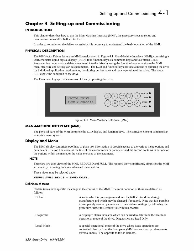
)- ) -
This chapter describes how to use the Man-Machine Interface (MMI), the necessary steps to set up andcommission an installed 620 Vector Drive.
In order to commission the drive successfully it is necessary to understand the basic operation of the MMI.
0
The 620 Vector Drives feature an MMI panel, shown in Figure 4.1 Man-Machine Interface (MMI), comprising a2x16 character liquid crystal display (LCD), four function keys six command keys and four status LEDs.Programming commands and data are entered into the drive by using the function keys to navigate the MMImenu structure and setting various parameters. The LCD and function keys provide a means of tailoring the drivefor individual application requirements, monitoring performance and basic operation of the drive. The statusLEDs show the condition of the drive.
The Command keys provide a means of locally operating the drive.
VECTOR DRIVEE
M
I
oJOG
RUN
LOCAL
PROG
LOCAL
BRAKE
HEATLH
TYPE X CHASSIS
+!
$
The physical parts of the MMI comprise the LCD display and function keys. The software element comprises anextensive menu system.
)!
The MMI display comprises two lines of plain text information to provide access to the various menu options andparameters. The top line contains the title of the current menu or parameter and the second contains either one ofthe options within the menu, or the value or status of the parameter.
$'%$'%$'%$'%
There are two user views of the MMI, REDUCED and FULL. The reduced view significantly simplifies the MMIstructure by removing the more advanced menu entries.
These views may be selected under
MENUS::FULL MENUS = TRUE/FALSE.
!!!!!!!!
Certain terms have specific meanings in the context of the MMI. The most common of these are defined asfollows.
Default A value which is pre-programmed into the 620 Vector drive duringmanufacture and which may be changed if required. Note that it is possibleto completely reset all parameters to their default settings by following theprocedure "Reset to Defaults" later in this chapter.
Diagnostic A displayed status indicator which can be used to determine the health oroperational mode of the drive. Diagnostics are Read Only.
Local Mode A special operational mode of the drive where basic operations arecontrolled directly from the front panel (MMI) rather than by reference toexternal inputs. The opposite to this is Remote.
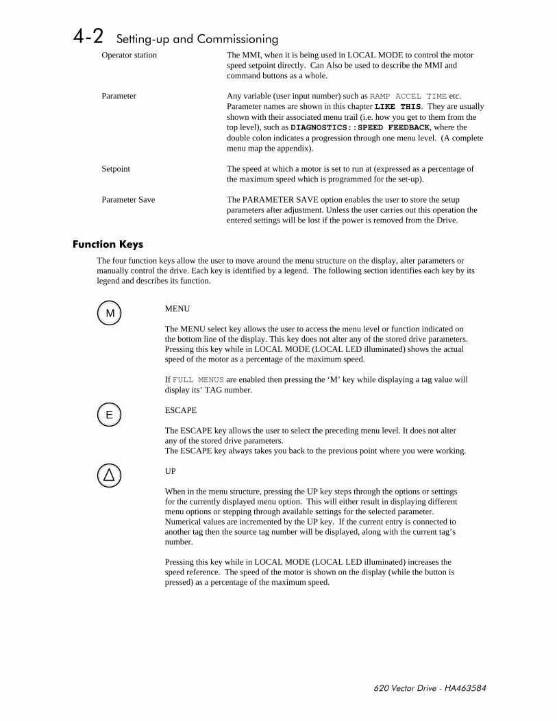
Operator station The MMI, when it is being used in LOCAL MODE to control the motorspeed setpoint directly. Can Also be used to describe the MMI andcommand buttons as a whole.
Parameter Any variable (user input number) such as RAMP ACCEL TIME etc.Parameter names are shown in this chapter LIKE THIS. They are usuallyshown with their associated menu trail (i.e. how you get to them from thetop level), such as DIAGNOSTICS::SPEED FEEDBACK, where thedouble colon indicates a progression through one menu level. (A completemenu map the appendix).
Setpoint The speed at which a motor is set to run at (expressed as a percentage ofthe maximum speed which is programmed for the set-up).
Parameter Save The PARAMETER SAVE option enables the user to store the setupparameters after adjustment. Unless the user carries out this operation theentered settings will be lost if the power is removed from the Drive.
$ *&
The four function keys allow the user to move around the menu structure on the display, alter parameters ormanually control the drive. Each key is identified by a legend. The following section identifies each key by itslegend and describes its function.
M MENU
The MENU select key allows the user to access the menu level or function indicated onthe bottom line of the display. This key does not alter any of the stored drive parameters.Pressing this key while in LOCAL MODE (LOCAL LED illuminated) shows the actualspeed of the motor as a percentage of the maximum speed.
If FULL MENUS are enabled then pressing the ‘M’ key while displaying a tag value willdisplay its’ TAG number.
E ESCAPE
The ESCAPE key allows the user to select the preceding menu level. It does not alterany of the stored drive parameters.The ESCAPE key always takes you back to the previous point where you were working.
UP
When in the menu structure, pressing the UP key steps through the options or settingsfor the currently displayed menu option. This will either result in displaying differentmenu options or stepping through available settings for the selected parameter.Numerical values are incremented by the UP key. If the current entry is connected toanother tag then the source tag number will be displayed, along with the current tag’snumber.
Pressing this key while in LOCAL MODE (LOCAL LED illuminated) increases thespeed reference. The speed of the motor is shown on the display (while the button ispressed) as a percentage of the maximum speed.
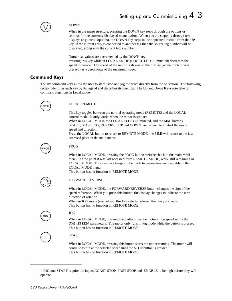
DOWN
When in the menu structure, pressing the DOWN key steps through the options orsettings for the currently displayed menu option. When you are stepping through textdisplays (e.g. menu options), the DOWN key steps in the opposite direction from the UPkey. If the current entry is connected to another tag then the source tag number will bedisplayed, along with the current tag’s number.
Numerical values are decremented by the DOWN key.Pressing this key while in LOCAL MODE (LOCAL LED illuminated) decreases thespeed reference. The speed of the motor is shown on the display (while the button ispressed) as a percentage of the maximum speed.
&
The six command keys allow the user to start / stop and jog the drive directly from the op station. The followingsection identifies each key by its legend and describes its function. The Up and Down Keys also take oncommand functions in Local mode.
LOCALLOCAL/REMOTE
This key toggles between the normal operating mode (REMOTE) and the LOCALcontrol mode. It only works when the motor is stopped.When in LOCAL MODE the LOCAL LED is illuminated, and the MMI buttonsSTART, STOP, JOG, REVERSE, UP and DOWN can be used to control the motorspeed and direction.Press the LOCAL button to return to REMOTE MODE, the MMI will return to the lastaccessed place in the main menu.
PROGPROG
When in LOCAL MODE, pressing the PROG button switches back to the main MMImenu. At the point it was last accessed from REMOTE MODE, while still remaining inLOCAL MODE. This enables changes to be made to parameters not available in theLOCAL MODE menu.This button has no function in REMOTE MODE.
FORWARD/REVERSE
When in LOCAL MODE, the FORWARD/REVERSE button changes the sign of thespeed reference. When you press this button, the display changes to indicate the newdirection of rotation.When in JOG mode (see below), this key selects between the two jog speeds.This button has no function in REMOTE MODE.
JOGJOG
When in LOCAL MODE, pressing this button runs the motor at the speed set by theJOG SPEED1 parameters. The motor only runs in jog mode while the button is pressed.This button has no function in REMOTE MODE.
I START
When in LOCAL MODE, pressing this button starts the motor running1The motor willcontinue to run at the selected speed until the STOP button is pressed .This button has no function in REMOTE MODE.
1 JOG and START require the inputs COAST STOP, FAST STOP and ENABLE to be high before they willoperate.
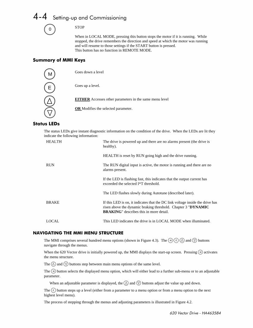
0 STOP
When in LOCAL MODE, pressing this button stops the motor if it is running. Whilestopped, the drive remembers the direction and speed at which the motor was runningand will resume to those settings if the START button is pressed.This button has no function in REMOTE MODE.
&
M Goes down a level
E Goes up a level.
EITHER Accesses other parameters in the same menu level
OR Modifies the selected parameter.
The status LEDs give instant diagnostic information on the condition of the drive. When the LEDs are lit theyindicate the following information:
HEALTH The drive is powered up and there are no alarms present (the drive ishealthy).
HEALTH is reset by RUN going high and the drive running.
RUN The RUN digital input is active, the motor is running and there are noalarms present.
If the LED is flashing fast, this indicates that the output current hasexceeded the selected I*T threshold.
The LED flashes slowly during Autotune (described later).
BRAKE If this LED is on, it indicates that the DC link voltage inside the drive hasrisen above the dynamic braking threshold. Chapter 3 "DYNAMICBRAKING" describes this in more detail.
LOCAL This LED indicates the drive is in LOCAL MODE when illuminated.
##
The MMI comprises several hundred menu options (shown in Figure 4.3). The M E and buttonsnavigate through the menus.
When the 620 Vector drive is initially powered up, the MMI displays the start-up screen. Pressing M activatesthe menu structure.
The and buttons step between main menu options of the same level.
The M button selects the displayed menu option, which will either lead to a further sub-menu or to an adjustableparameter.
When an adjustable parameter is displayed, the and buttons adjust the value up and down.
The E button steps up a level (either from a parameter to a menu option or from a menu option to the nexthighest level menu).
The process of stepping through the menus and adjusting parameters is illustrated in Figure 4.2.
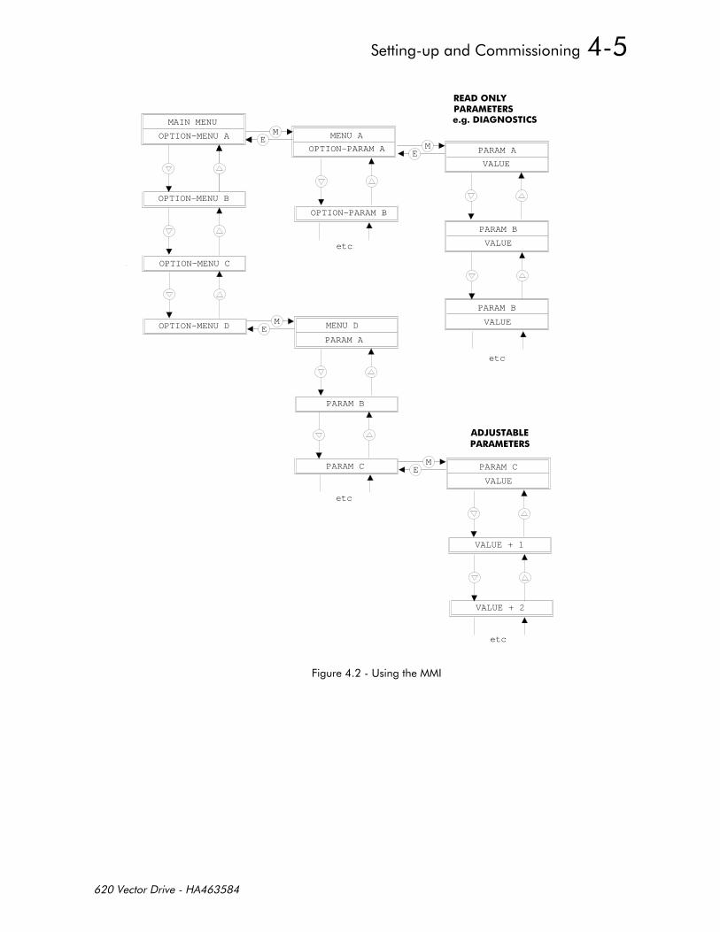
MAIN MENU
OPTION-MENU A
OPTION-MENU B
OPTION-MENU C
OPTION-MENU D
ME
ME
ME
ME
MENU A
OPTION-PARAM A PARAM A
VALUE
PARAM B
VALUE
PARAM B
VALUEMENU D
PARAM A
PARAM C
VALUE
OPTION-PARAM B
PARAM B
PARAM C
VALUE + 1
VALUE + 2
etc
etc
7%
etc
etc
0-#
+(
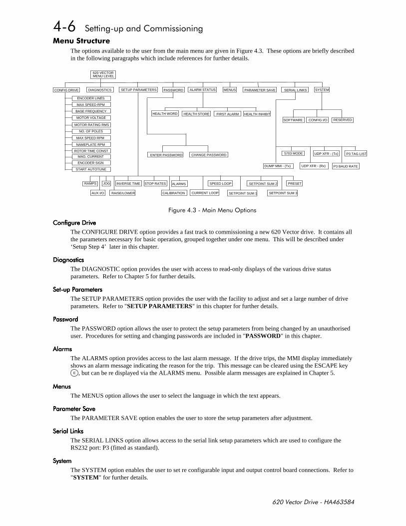
*
The options available to the user from the main menu are given in Figure 4.3. These options are briefly describedin the following paragraphs which include references for further details.
620 VECTORMENU LEVEL
DIAGNOSTICS SETUP PARAMETERS SERIAL LINKS SYSTEM
HEALTH WORD HEALTH STORE FIRST ALARM
CHANGE PASSWORD
SOFTWARE CONFIG I/O
5703 MODE
DUMP MMI - (Tx)
RAMPS
AUX I/O
PASSWORD ALARM STATUS MENUS PARAMETER SAVE
ENTER PASSWORD UDP XFR - (Tx) P3 TAG LIST
UDP XFR - (Rx) P3 BAUD RATE
JOG INVERSE TIME STOP RATES ALARMS SPEED LOOP SETPOINT SUM 2 PRESET
RAISE/LOWER CALIBRATION CURRENT LOOP SETPOINT SUM 1 SETPOINT SUM 3
RESERVED
CONFIG DRIVE
HEALTH INHIBITBASE FREQUENCY
ENCODER LINES
MAX SPEED RPM
MOTOR VOLTAGE
MOTOR RATING RMS
NO. OF POLES
MAX SPEED RPM
MAG. CURRENT
ENCODER SIGN
START AUTOTUNE
NAMEPLATE RPM
ROTOR TIME CONST
+'
!!!!
The CONFIGURE DRIVE option provides a fast track to commissioning a new 620 Vector drive. It contains allthe parameters necessary for basic operation, grouped together under one menu. This will be described under‘Setup Step 4’ later in this chapter.
The DIAGNOSTIC option provides the user with access to read-only displays of the various drive statusparameters. Refer to Chapter 5 for further details.
The SETUP PARAMETERS option provides the user with the facility to adjust and set a large number of driveparameters. Refer to "SETUP PARAMETERS" in this chapter for further details.
The PASSWORD option allows the user to protect the setup parameters from being changed by an unauthoriseduser. Procedures for setting and changing passwords are included in "PASSWORD" in this chapter.
The ALARMS option provides access to the last alarm message. If the drive trips, the MMI display immediatelyshows an alarm message indicating the reason for the trip. This message can be cleared using the ESCAPE key
E , but can be re displayed via the ALARMS menu. Possible alarm messages are explained in Chapter 5.
The MENUS option allows the user to select the language in which the text appears.
The PARAMETER SAVE option enables the user to store the setup parameters after adjustment.
- - - -
The SERIAL LINKS option allows access to the serial link setup parameters which are used to configure theRS232 port: P3 (fitted as standard).
The SYSTEM option enables the user to set re configurable input and output control board connections. Refer to"SYSTEM" for further details.

#
ELECTRIC SHOCK HAZARD
WAIT 3 MINUTES AFTER POWER IS DISCONNECTED BEFORE WORKING ON ANYPART OF THE SYSTEM OR REMOVING THE TERMINAL COVER FROM THE DRIVE
))%0
1. Before power is applied to the system the following items should be checked:
2. Mains power supply voltage is correct for the drive type.
3. Motor is of correct voltage rating and is connected in either star or delta as appropriate.
4. An encoder of the correct type is fitted to the motor properly with no plug. A, Ä, and B, B, are connected tothe drive. See Table 2.2.
5. All external wiring circuits such as Power connections, Control connections, Motor connections, Earthconnections are properly connected and secure.
6. Check for damage to equipment. Do not attempt to operate the equipment if damage is found.
7. Check for loose ends, clippings, drilling swarf, etc., lodged in the drive or ancillary equipment. Do notattempt to operate the equipment until any such foreign objects have been completely removed.
8. If possible check that the motor can be turned freely and that the motor cooling fan is intact and free ofobstructions.
)) )!
Next ensure the safety of the complete system when the drive is energised. In particular ensure:
1. That no personnel are at risk of injury or inconvenience when the drive system is energised.
2. That rotation of the motor in either direction will not cause damage.
3. That other equipment will not be adversely affected by powering up.
Before carrying out any high voltage insulation resistance checks with a Megger or similar deviceor performing point to point checking with a buzzer it is essential to completely disconnect the 620
Vector drive. Failure to comply may result in equipment damage and/or misleading results.
))) -
Prepare to energise the drive and system as follows:
1. Prevent application of the main power supply by removal of the supply fuses or isolate via supply circuitbreaker.
2. Disconnect the load from the motor shaft, if possible.
3. If any of the drive control terminals are not being used then refer to Chapter 2, Table 2.5 to check whetherthese unused terminals need to be tied high or low.
4. Check the external run contacts are open.
5. Check the external speed setpoint controls are all set to zero.
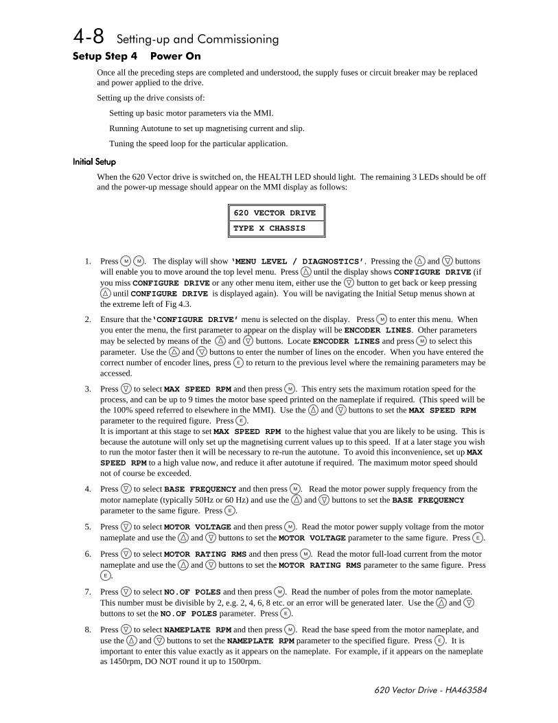
))
Once all the preceding steps are completed and understood, the supply fuses or circuit breaker may be replacedand power applied to the drive.
Setting up the drive consists of:
Setting up basic motor parameters via the MMI.
Running Autotune to set up magnetising current and slip.
Tuning the speed loop for the particular application.
When the 620 Vector drive is switched on, the HEALTH LED should light. The remaining 3 LEDs should be offand the power-up message should appear on the MMI display as follows:
1. Press M M . The display will show ‘MENU LEVEL / DIAGNOSTICS’. Pressing the and buttonswill enable you to move around the top level menu. Press until the display shows CONFIGURE DRIVE (ifyou miss CONFIGURE DRIVE or any other menu item, either use the button to get back or keep pressing
until CONFIGURE DRIVE is displayed again). You will be navigating the Initial Setup menus shown atthe extreme left of Fig 4.3.
2. Ensure that the‘CONFIGURE DRIVE’ menu is selected on the display. Press M to enter this menu. Whenyou enter the menu, the first parameter to appear on the display will be ENCODER LINES. Other parametersmay be selected by means of the and buttons. Locate ENCODER LINES and press M to select thisparameter. Use the and buttons to enter the number of lines on the encoder. When you have entered thecorrect number of encoder lines, press E to return to the previous level where the remaining parameters may beaccessed.
3. Press to select MAX SPEED RPM and then press M . This entry sets the maximum rotation speed for theprocess, and can be up to 9 times the motor base speed printed on the nameplate if required. (This speed will bethe 100% speed referred to elsewhere in the MMI). Use the and buttons to set the MAX SPEED RPMparameter to the required figure. Press E .It is important at this stage to set MAX SPEED RPM to the highest value that you are likely to be using. This isbecause the autotune will only set up the magnetising current values up to this speed. If at a later stage you wishto run the motor faster then it will be necessary to re-run the autotune. To avoid this inconvenience, set up MAXSPEED RPM to a high value now, and reduce it after autotune if required. The maximum motor speed shouldnot of course be exceeded.
4. Press to select BASE FREQUENCY and then press M . Read the motor power supply frequency from themotor nameplate (typically 50Hz or 60 Hz) and use the and buttons to set the BASE FREQUENCYparameter to the same figure. Press E .
5. Press to select MOTOR VOLTAGE and then press M . Read the motor power supply voltage from the motornameplate and use the and buttons to set the MOTOR VOLTAGE parameter to the same figure. Press E .
6. Press to select MOTOR RATING RMS and then press M . Read the motor full-load current from the motornameplate and use the and buttons to set the MOTOR RATING RMS parameter to the same figure. Press
E .
7. Press to select NO.OF POLES and then press M . Read the number of poles from the motor nameplate.This number must be divisible by 2, e.g. 2, 4, 6, 8 etc. or an error will be generated later. Use the and buttons to set the NO.OF POLES parameter. Press E .
8. Press to select NAMEPLATE RPM and then press M . Read the base speed from the motor nameplate, anduse the and buttons to set the NAMEPLATE RPM parameter to the specified figure. Press E . It isimportant to enter this value exactly as it appears on the nameplate. For example, if it appears on the nameplateas 1450rpm, DO NOT round it up to 1500rpm.
620 VECTOR DRIVE
TYPE X CHASSIS
9. Press to select MAG CURRENT % and then press M . Read the “no load current” from the motor nameplate,and use the and buttons to set the MAG CURRENT % parameter to the specified figure ((No LoadCurrent / Motor Rating RMS) * 100%). Press E .If the “no load current” is not available, set the MAG CURRENT % to 30-40% for motors less than 30kw and20-30% for motors > 30kw.
10. Press to select ROTOR TIME CONST and then press M . This parameter sets up an initial estimate of therotor time constant which Autotune will later optimise. For motors up to 2.2kW use 100.0ms, between 2.2kWand 7.5kW use 200.0ms, between 7.5kw and 22kW use 400.0ms and for larger motors use 800.0ms. Use the and buttons to set the ROTOR TIME CONST parameter to the required figure. Press E .
11. At this point almost all of the required basic parameters have been entered and further parameters can only bedetermined by running the drive. All the parameters should now be saved. To save the parameters, press E
M which will select SAVE PARAMETERS option, and then press M . Press to save the parameters.The display will say FINISHED after a second or so when the process is complete. Press E M to returnto the Configure Drive menu.
When power is removed from the product it must not be re-applied for a period of 30 seconds toallow the inrush limit circuit to operate correctly.
)) +
The next step is to run the drive.
• UNPREDICTABLE MOTION, ESPECIALLY IF MOTOR PARAMETERS ARE INCORRECT.• ENSURE NO PERSONNEL ARE IN THE VICINITY OF THE MOTOR OR ANY CONNECTED MACHINERY.• ENSURE THAT THE EMERGENCY STOP CIRCUITS FUNCTION CORRECTLY BEFORE RUNNING THE
MOTOR FOR THE FIRST TIME.• WHEN THE DRIVE IS RUN FOR THE FIRST TIME ROTATION WILL BE OF UNKNOWN DIRECTION,
MAY BE JERKY AND SPEED CONTROL MAY NOT OPERATE CORRECTLY.• ENSURE THAT NO MACHINERY CONNECTED TO THE MOTOR WILL BE DAMAGED BY
UNPREDICTABLE MOTION.
1. Press LOCAL to put the drive into LOCAL MODE. The LOCAL LED should light.
2. Use the and buttons to set a speed demand of between 5% and 10% of full speed (the actual value is notcritical).
3. Press I to start the motor. The RUN LED should illuminate. (If any error messages occur on the MMI, referto Chapter 6, "Diagnostics").
4. Listen to and look at the motion of the motor. If the encoder sign is correct the motor will rotate smoothly andrespond to changes in speed demand or direction. To check this, use the and buttons to increase thespeed to about double the first figure, and then use the button to change the direction of rotation. If itaccelerates and changes direction smoothly, this confirms that the encoder sign is set correctly.
5. If the ENCODER SIGN is incorrect, the motor will rotate in a jerky and/or noisy manner. Alternatively, it mayrotate smoothly at a very low speed but not respond to changes in speed demand or direction. In either case theencoder sign must be changed. Paragraph 7 describes how to change the encoder sign.
6. If the motor rotates in the wrong direction, press 0 to stop the motor then power down the entire driveassembly, wait 3 minutes for the DC Link capacitors to discharge then swap motor drive cables M1 and M2.Re-start the Initial Setup procedure from step 1. The encoder sign will have been changed by the change inmotor direction as described in step 4.
7. Press 0 to stop the motor, then press LOCAL to put the drive back into REMOTE MODE.
8. If the ENCODER SIGN needs changing, go into the ‘CONFIGURE DRIVE’ menu and select ENCODERSIGN , then press M . Use the and buttons to set the ENCODER SIGN parameter to the other setting.Press E .
9. This completes the initial part of the setting up phase. At this point the motor is running under control, but it isnot optimised for smooth, efficient running. The next step is to Autotune the drive to automatically set up theremaining basic parameters.
)) -+
The purpose of the Autotune function is to set up the magnetising current and rotor time constant for this motor.
This is a two-stage process. The first stage runs the drive up to various speeds to tune the magnetisation current.The second stage calculates the rotor time constant from the MAG CURRENT and motor nameplate details whichyou entered.
When the Autotune is carried out, the motor will run at base speed for several minutes.
It is essential that no load is applied to the output shaft for the Autotune to functioncorrectly. A gearbox may be permissible provided it does not significantly load the motor, but it
should be disconnected where possible.
Ensure that you are in the ‘CONFIGURE DRIVE’ menu. Scroll around the menu with the or buttons
until you locate AUTOTUNE. Press M . Press to set the AUTOTUNE flag TRUE. Then restart the drive.
The drive will now accelerate first to base speed, and then to a number of other speeds, up to the value set inMAX SPEED RPM. At each speed it will set up the magnetising current for this motor. When it has finished, itwill then calculate the rotor time constant. If any error messages occur on the MMI, refer to Chapter 6,"Alarms".
If the autotune fails to run, but no error message appears on the MMI, this may be due to a wrong configurationin the autotune menu. This menu contains 2 flags which control the autotune action. 'Mag I Autotune' must beset true to ensure that the mag current autotune is carried out, and 'Set Tr < Rtd Spd' must be true for the rotortime constant calculation to be done. Go into the autotune menu, under 'Setup Parameters (see 'Menu Structure'on page4-6) and ensure these flags are set to be true.
When Autotune has finished, the 620 Vector drive is set up with all the information required for basic operationas a speed controller. It is now necessary to save this information in non volatile memory, so that it will beretained when power is removed. This is done via the PARAMETER SAVE menu. See 'Parameter Save' under'Menu Structure' on page 4-6.
At the end of the autotune process, the drive will calculate a new value of rotor time constant. If it issignificantly different from the old value, it may be advisable to run the autotune again. The values ofmagnetising current obtained on the second pass will then be slightly more accurate, as the drive will now beusing a more accurate value of rotor time constant.
$ * !
Disconnect the power to the drive.
Hold down the and buttons while re-applying power and keep both buttons depressed for at least two
seconds after power-up
Note: The start input must also be low [B7].

The MMI display will read
Press E .
The drive is now safely configured to the factory defaults. On the 620L and 620Adv these factory defaults aresaved automatically, on the 620Std the factory defaults must be saved using “Parameter Save” if wished.
- */
This is only be necessary if you are installing a new control board on an existing stack.
SELECTING A DIFFERENT STACK SIZE FROM THAT INDICATED ON THE STACKRATING LABEL WILL DAMAGE THE STACK AND OR MOTOR
Disconnect the power to the drive.
Hold down the , and (prog)buttons while re-applying power and keep both buttons depressed for atleast two seconds after power-up.
Note: The start input must also be low [B7].
The MMI display will read
DRIVE RATING
75 kW 380-460v
At this stage the 620 Vector drive thinks that it is a 75kW model. It is vitally important that it is configuredfor the correct power rating or irreparable damage may occur to the drive when it attempts to run the
motor. Press the and buttons to step through the range of power ratings until the displayed value is thesame as the rating on the identification label on the side of the drive.
Press the E . to select rating.
Select whether you wish 50Hz defaults (False) or 60Hz defaults (True).
Press the E . to exit. This saves the new settings in EEprom (non volatile memory).
Note: The drives setup parameters are unchanged.
Note: The 620L / 620Adv need to have the power cycled to reinitialise the co-processor after this procedure.
Should it ever be necessary to reset all the parameters to their factory defaults (e.g. when swapping out a drive),use the following procedure.
SELF TEST
EEPROM NOT READ

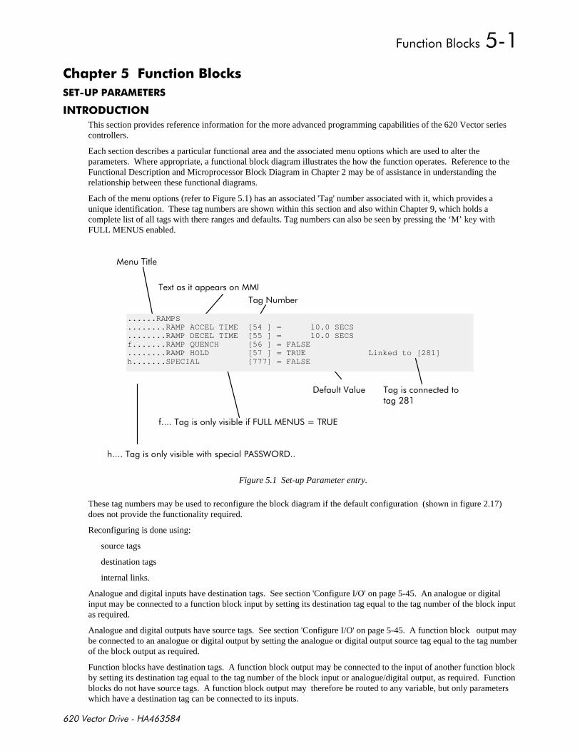
+,-
)$ *%!*
This section provides reference information for the more advanced programming capabilities of the 620 Vector seriescontrollers.
Each section describes a particular functional area and the associated menu options which are used to alter theparameters. Where appropriate, a functional block diagram illustrates the how the function operates. Reference to theFunctional Description and Microprocessor Block Diagram in Chapter 2 may be of assistance in understanding therelationship between these functional diagrams.
Each of the menu options (refer to Figure 5.1) has an associated 'Tag' number associated with it, which provides aunique identification. These tag numbers are shown within this section and also within Chapter 9, which holds acomplete list of all tags with there ranges and defaults. Tag numbers can also be seen by pressing the ‘M’ key withFULL MENUS enabled.
%
%$
!%!+($( :%#(
%
!
% "'#
......RAMPS
........RAMP ACCEL TIME [54 ] = 10.0 SECS
........RAMP DECEL TIME [55 ] = 10.0 SECSf.......RAMP QUENCH [56 ] = FALSE........RAMP HOLD [57 ] = TRUE Linked to [281]h.......SPECIAL [777] = FALSE
%
Figure 5.1 Set-up Parameter entry.
These tag numbers may be used to reconfigure the block diagram if the default configuration (shown in figure 2.17)does not provide the functionality required.
Reconfiguring is done using:
source tags
destination tags
internal links.
Analogue and digital inputs have destination tags. See section 'Configure I/O' on page 5-45. An analogue or digitalinput may be connected to a function block input by setting its destination tag equal to the tag number of the block inputas required.
Analogue and digital outputs have source tags. See section 'Configure I/O' on page 5-45. A function block output maybe connected to an analogue or digital output by setting the analogue or digital output source tag equal to the tag numberof the block output as required.
Function blocks have destination tags. A function block output may be connected to the input of another function blockby setting its destination tag equal to the tag number of the block input or analogue/digital output, as required. Functionblocks do not have source tags. A function block output may therefore be routed to any variable, but only parameterswhich have a destination tag can be connected to its inputs.

+,-
Internal links are used to route variables which do not have source tags or destination tags associated with them.
Source and destination tags are found in the menu 'Configure I/O' under 'System'. See 'Menu Structure' in chapter 4.This menu contains sub menus 'Analogue Inputs', 'Digital Inputs', 'Analogue Outputs', 'Digital Outputs', 'Block Diagram',and 'Internal Links'. Destination tags for analogue and digital inputs may be found under 'Analogue Inputs' and 'DigitalInputs'. Source tags for analogue and digital outputs may be found under 'Analogue Outputs' and 'Digital Outputs'.Destination tags for function blocks may be found in 'Block Diagram'. A full description of the source and destinationtags available is given in section 'Configure I/O' on page 5-45.
The menu also contains the flag 'Configure Enable' which must be set to true before any re-configuring can be done. Seesection 'Configure I/O' on page 5-45.
1
Re-route digital input 1 (terminal E2) to the 'System Ramp' 'External Reset' (It is normally connected to 'ramp hold' bydefault). See 'System Ramp' diagram on page 5-3. This will cause the system ramp output to return to its reset valuewhenever a '1' is applied to digital input 1.
1. Go into 'System' menu, then into 'Configure I/O'.
2. Select 'Configure Enable' and set this flag to true.
3. Find 'Digital Inputs' menu and select 'DIGIN 1 (E2)'.
4. Go into this menu and find 'Destination Tag'. Set this to the 'External Reset' tag number 62, which may be found insection 'System Ramp' or in the tag number list in the appendix, chapter 9.
5. Return to 'Configure Enable' flag and set this to false.
1
Bring Current Feedback to analogue output 2 (torque demand is normally connected to this output by default).
1. Go into 'System' menu, then into 'Configure I/O'.
2. Select 'Configure Enable' and set this flag to true.
3. Find 'Digital Inputs' menu and select 'ANOUT 2 (F5)'.
4. Go into this menu and find 'Source Tag'. Set this to the 'Current Feedback' tag number 78, which may be found inthe MMI list in the appendix, chapter 9, under diagnostics.
5. Return to 'Configure Enable' flag and set this to false.
1
Connect Speed Feedback to System Ramp Reset Value. This would allow the drive to start a spinning motor in asmooth manner. System Ramp Reset Value is a parameter which does not have a source tag associated with it, as it isnormally a fixed value set via the MMI. Speed Feedback does not have a destination tag. So the only way to do this isvia an internal link.
1. Go into 'System' menu, then into 'Configure I/O'.
2. Select 'Configure Enable' and set this flag to true.
3. Set Link 1 Source to 11 (i.e. tag number of speed feedback).
4. Set Link 1 Destination to 63 (i.e. tag number of Reset Value).
5. Return to 'Configure Enable' flag and set this to false.
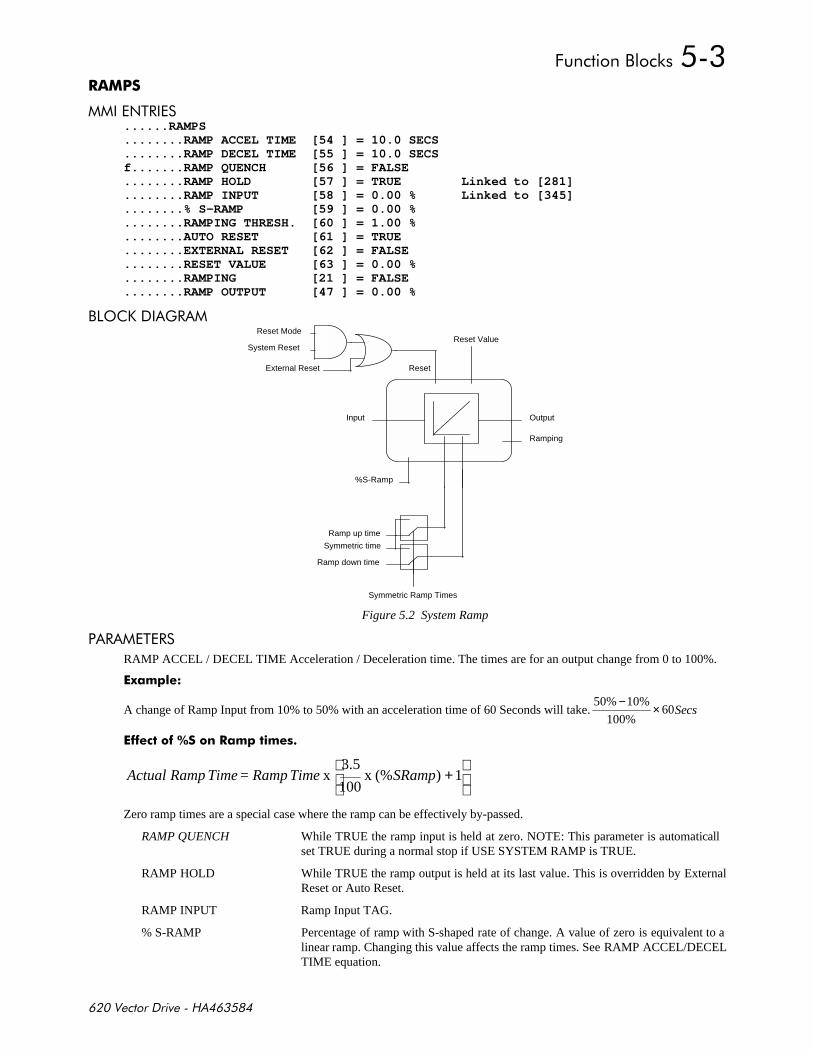
+,-
$%# ......RAMPS........RAMP ACCEL TIME [54 ] = 10.0 SECS........RAMP DECEL TIME [55 ] = 10.0 SECSf.......RAMP QUENCH [56 ] = FALSE........RAMP HOLD [57 ] = TRUE Linked to [281]........RAMP INPUT [58 ] = 0.00 % Linked to [345]........% S-RAMP [59 ] = 0.00 %........RAMPING THRESH. [60 ] = 1.00 %........AUTO RESET [61 ] = TRUE........EXTERNAL RESET [62 ] = FALSE........RESET VALUE [63 ] = 0.00 %........RAMPING [21 ] = FALSE........RAMP OUTPUT [47 ] = 0.00 %
,'. )#
Ramp up time
Ramp down time
Symmetric Ramp Times
Reset Mode
Reset
System Reset
External Reset
%S-Ramp
Input
Reset Value
Ramping
Output
Symmetric time
Figure 5.2 System Ramp
# %#
RAMP ACCEL / DECEL TIME Acceleration / Deceleration time. The times are for an output change from 0 to 100%.
2 )!
A change of Ramp Input from 10% to 50% with an acceleration time of 60 Seconds will take.50% 10%
100%60
− × Secs
* )
+1)(% x
100
3.5x SRamp Time Ramp = Time Ramp Actual
Zero ramp times are a special case where the ramp can be effectively by-passed.
RAMP QUENCH While TRUE the ramp input is held at zero. NOTE: This parameter is automaticallset TRUE during a normal stop if USE SYSTEM RAMP is TRUE.
RAMP HOLD While TRUE the ramp output is held at its last value. This is overridden by ExternalReset or Auto Reset.
RAMP INPUT Ramp Input TAG.
% S-RAMP Percentage of ramp with S-shaped rate of change. A value of zero is equivalent to alinear ramp. Changing this value affects the ramp times. See RAMP ACCEL/DECELTIME equation.
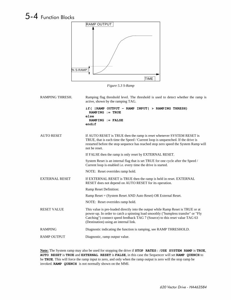
+,-
RAMP OUTPUT
TIME
% S-RAMP
Figure 5.3 S-Ramp
RAMPING THRESH. Ramping flag threshold level. The threshold is used to detect whether the ramp isactive, shown by the ramping TAG.
if( |RAMP OUTPUT - RAMP INPUT| > RAMPING THRESH)RAMPING := TRUE
elseRAMPING := FALSE
endif
AUTO RESET If AUTO RESET is TRUE then the ramp is reset whenever SYSTEM RESET isTRUE, that is each time the Speed / Current loop is unquenched. If the drive isrestarted before the stop sequence has reached stop zero speed the System Ramp willnot be reset.
If FALSE then the ramp is only reset by EXTERNAL RESET.
System Reset is an internal flag that is set TRUE for one cycle after the Speed /Current loop is enabled i.e. every time the drive is started.
NOTE: Reset overrides ramp hold.
EXTERNAL RESET If EXTERNAL RESET is TRUE then the ramp is held in reset. EXTERNALRESET does not depend on AUTO RESET for its operation.
Ramp Reset Definition:
Ramp Reset = (System Reset AND Auto Reset) OR External Reset.
NOTE: Reset overrides ramp hold.
RESET VALUE This value is pre-loaded directly into the output while Ramp Reset is TRUE or atpower-up. In order to catch a spinning load smoothly ("bumpless transfer" or "FlyCatching") connect speed feedback TAG 7 (Source) to this reset value TAG 63(Destination) using an internal link.
RAMPING Diagnostic indicating the function is ramping, see RAMP THRESHOLD.
RAMP OUTPUT Diagnostic, ramp output value.
Note: The System ramp may also be used for stopping the drive if STOP RATES::USE SYSTEM RAMP is TRUE,AUTO RESET is TRUE and EXTERNAL RESET is FALSE, in this case the Sequencer will set RAMP QUENCH tobe TRUE. This will force the ramp input to zero, and only when the ramp output is zero will the stop ramp beinvoked. RAMP QUENCH is not normally shown on the MMI.
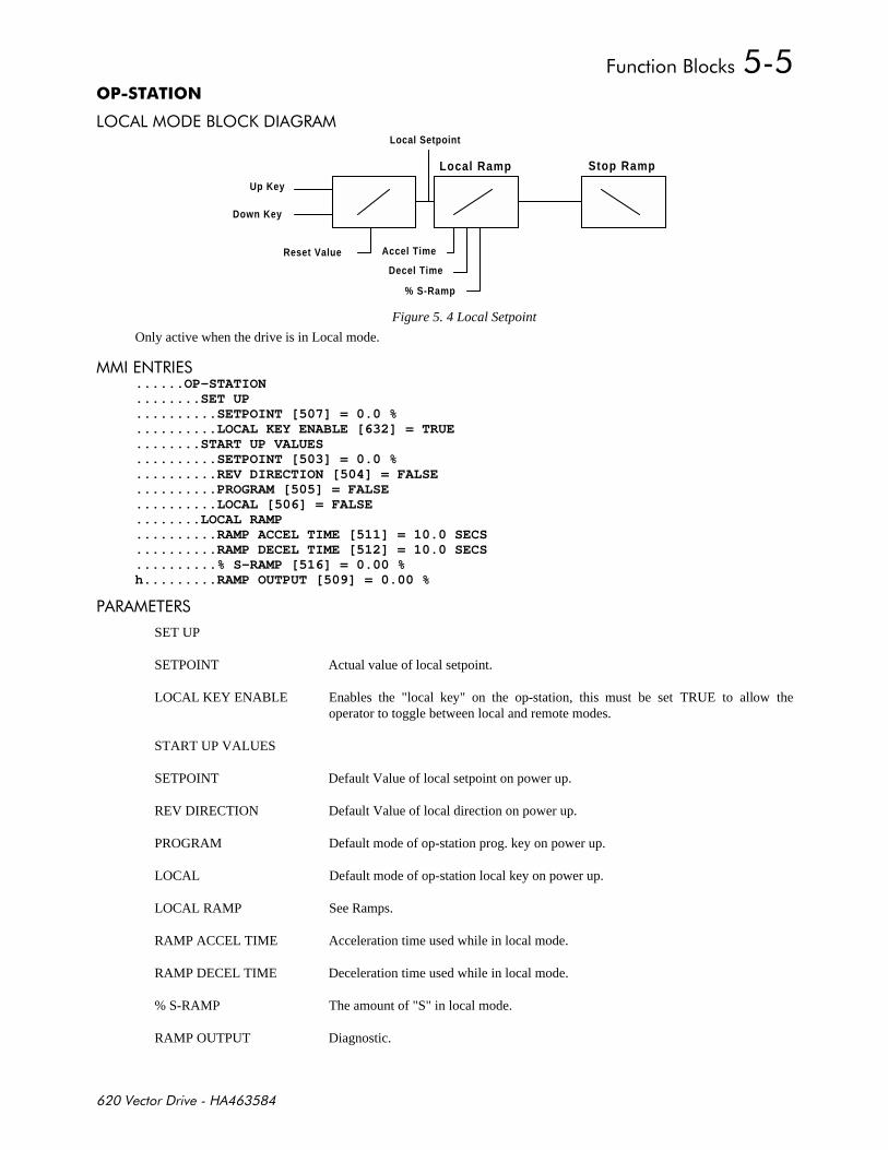
+,-
' ','. )#
Local Ramp
Accel Time
Decel Time
% S-Ramp
Up Key
Down Key
Reset Value
Local Setpoint
Stop Ramp
Figure 5. 4 Local Setpoint
Only active when the drive is in Local mode.
$%# ......OP-STATION........SET UP..........SETPOINT [507] = 0.0 %..........LOCAL KEY ENABLE [632] = TRUE........START UP VALUES..........SETPOINT [503] = 0.0 %..........REV DIRECTION [504] = FALSE..........PROGRAM [505] = FALSE..........LOCAL [506] = FALSE........LOCAL RAMP..........RAMP ACCEL TIME [511] = 10.0 SECS..........RAMP DECEL TIME [512] = 10.0 SECS..........% S-RAMP [516] = 0.00 %h.........RAMP OUTPUT [509] = 0.00 %
# %#
SET UP
SETPOINT Actual value of local setpoint.
LOCAL KEY ENABLE Enables the "local key" on the op-station, this must be set TRUE to allow theoperator to toggle between local and remote modes.
START UP VALUES
SETPOINT Default Value of local setpoint on power up.
REV DIRECTION Default Value of local direction on power up.
PROGRAM Default mode of op-station prog. key on power up.
LOCAL Default mode of op-station local key on power up.
LOCAL RAMP See Ramps.
RAMP ACCEL TIME Acceleration time used while in local mode.
RAMP DECEL TIME Deceleration time used while in local mode.
% S-RAMP The amount of "S" in local mode.
RAMP OUTPUT Diagnostic.
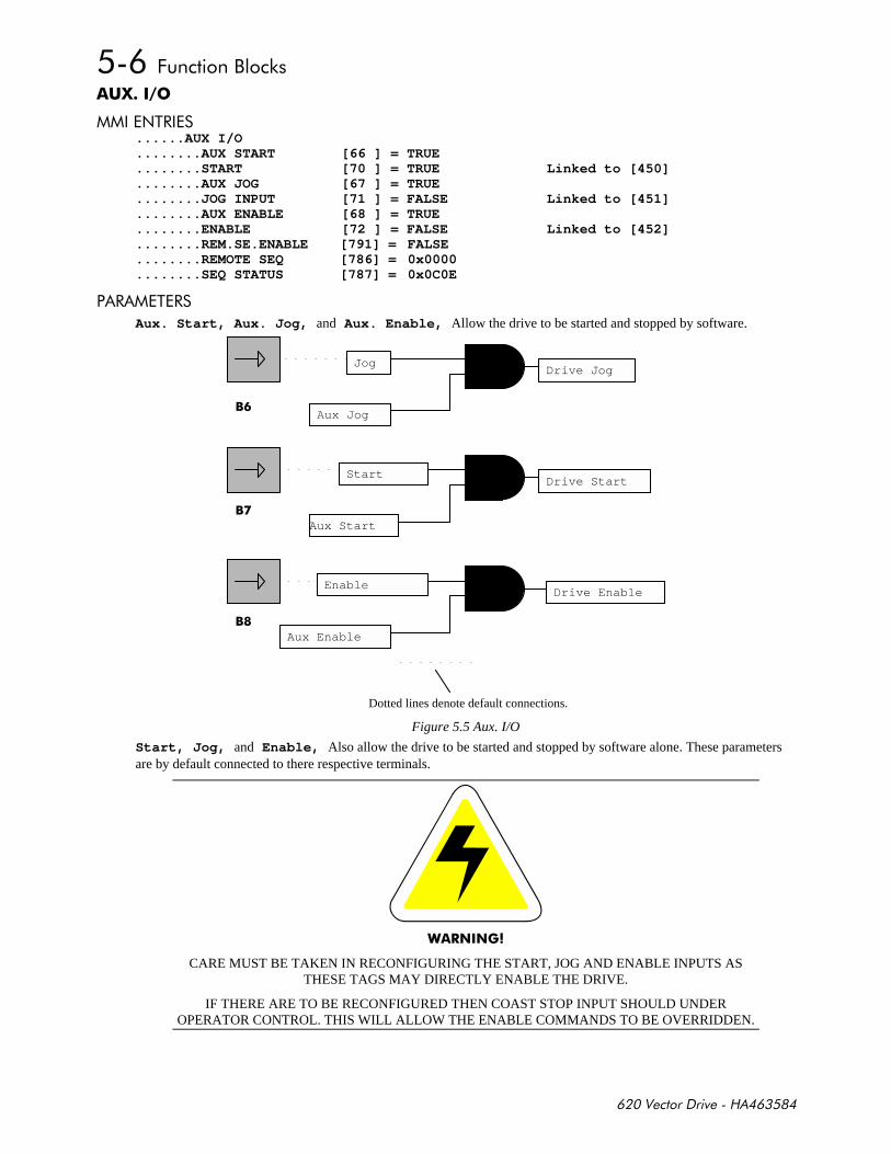
+,-
3
$%# ......AUX I/O........AUX START [66 ] = TRUE........START [70 ] = TRUE Linked to [450]........AUX JOG [67 ] = TRUE........JOG INPUT [71 ] = FALSE Linked to [451]........AUX ENABLE [68 ] = TRUE........ENABLE [72 ] = FALSE Linked to [452]........REM.SE.ENABLE [791] = FALSE........REMOTE SEQ [786] = 0x0000........SEQ STATUS [787] = 0x0C0E
# %#
Aux. Start, Aux. Jog, and Aux. Enable, Allow the drive to be started and stopped by software.
Dotted lines denote default connections.
Start
Aux Jog
Jog
Aux Enable
Enable
Aux Start
Drive Enable
Drive Start
Drive Jog
%
%
%
Figure 5.5 Aux. I/O
Start, Jog, and Enable, Also allow the drive to be started and stopped by software alone. These parametersare by default connected to there respective terminals.
"#
CARE MUST BE TAKEN IN RECONFIGURING THE START, JOG AND ENABLE INPUTS ASTHESE TAGS MAY DIRECTLY ENABLE THE DRIVE.
IF THERE ARE TO BE RECONFIGURED THEN COAST STOP INPUT SHOULD UNDEROPERATOR CONTROL. THIS WILL ALLOW THE ENABLE COMMANDS TO BE OVERRIDDEN.
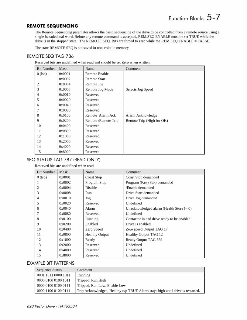
+,-
4#
The Remote Sequencing parameter allows the basic sequencing of the drive to be controlled from a remote source using asingle hexadecimal word. Before any remote command is accepted, REM.SEQ.ENABLE must be set TRUE while thedrive is in the stopped state. The REMOTE SEQ. Bits are forced to zero while the REM.SEQ.ENABLE = FALSE.
The state REMOTE SEQ is not saved in non-volatile memory.
#'% ;% )
Reserved bits are undefined when read and should be set Zero when written.
Bit Number Mask Name Comment0 (lsb) 0x0001 Remote Enable1 0x0002 Remote Start2 0x0004 Remote Jog3 0x0008 Remote Jog Mode Selects Jog Speed4 0x0010 Reserved5 0x0020 Reserved6 0x0040 Reserved7 0x0080 Reserved8 0x0100 Remote Alarm Ack Alarm Acknowledge9 0x0200 Remote /Remote Trip Remote Trip (High for OK)10 0x0400 Reserved11 0x0800 Reserved12 0x1000 Reserved13 0x2000 Reserved14 0x4000 Reserved15 0x8000 Reserved
; % %( % )# '$&
Reserved bits are undefined when read.
Bit Number Mask Name Comment0 (lsb) 0x0001 Coast Stop Coast Stop demanded1 0x0002 Program Stop Program (Fast) Stop demanded2 0x0004 Disable /Enable demanded3 0x0008 Run Drive Start demanded4 0x0010 Jog Drive Jog demanded5 0x0020 Reserved Undefined6 0x0040 Alarm Unacknowledged alarm (Health Store != 0)7 0x0080 Reserved Undefined8 0x0100 Running Contactor in and drive ready to be enabled9 0x0200 Enabled Drive is enabled.10 0x0400 Zero Speed Zero speed Output TAG 1711 0x0800 Healthy Output Healthy Output TAG 1212 0x1000 Ready Ready Output TAG 55913 0x2000 Reserved Undefined14 0x4000 Reserved Undefined15 0x8000 Reserved Undefined
1 ,% %%#$
Sequence Status Comment0001 1011 0000 1011 Running0000 0100 0100 1011 Tripped, Run High0000 0100 0100 0111 Tripped, Run Low, Enable Low0000 1100 0100 0111 Trip Acknowledged, Healthy o/p TRUE Alarm stays high until drive is restarted.
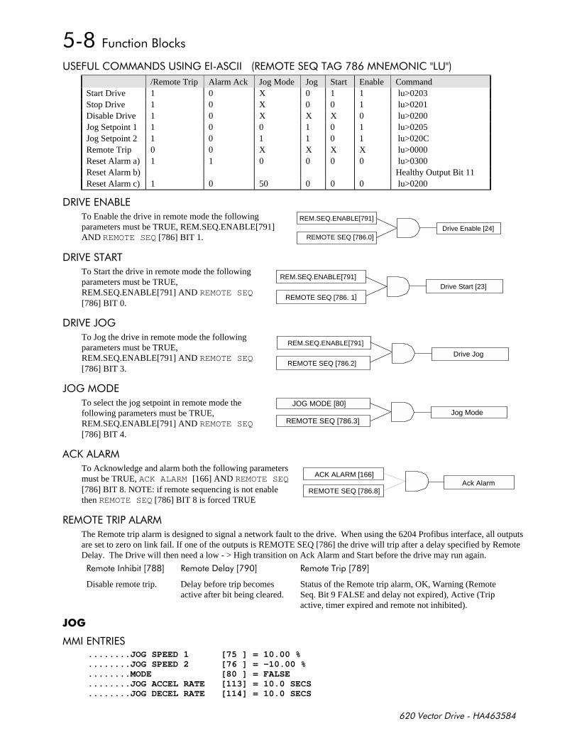
+,-
( +(' $ ( $) #'% ;% )$'$(
/Remote Trip Alarm Ack Jog Mode Jog Start Enable CommandStart Drive 1 0 X 0 1 1 lu>0203Stop Drive 1 0 X 0 0 1 lu>0201Disable Drive 1 0 X X X 0 lu>0200Jog Setpoint 1 1 0 0 1 0 1 lu>0205Jog Setpoint 2 1 0 1 1 0 1 lu>020CRemote Trip 0 0 X X X X lu>0000Reset Alarm a) 1 1 0 0 0 0 lu>0300Reset Alarm b) Healthy Output Bit 11Reset Alarm c) 1 0 50 0 0 0 lu>0200
#$ ,
To Enable the drive in remote mode the followingparameters must be TRUE, REM.SEQ.ENABLE[791]AND REMOTE SEQ [786] BIT 1.
# % #%
To Start the drive in remote mode the followingparameters must be TRUE,REM.SEQ.ENABLE[791] AND REMOTE SEQ[786] BIT 0.
#0')
To Jog the drive in remote mode the followingparameters must be TRUE,REM.SEQ.ENABLE[791] AND REMOTE SEQ[786] BIT 3.
0')'
To select the jog setpoint in remote mode thefollowing parameters must be TRUE,REM.SEQ.ENABLE[791] AND REMOTE SEQ[786] BIT 4.
. #
To Acknowledge and alarm both the following parametersmust be TRUE, ACK ALARM [166] AND REMOTE SEQ[786] BIT 8. NOTE: if remote sequencing is not enablethen REMOTE SEQ [786] BIT 8 is forced TRUE
#'%%# #
The Remote trip alarm is designed to signal a network fault to the drive. When using the 6204 Profibus interface, all outputsare set to zero on link fail. If one of the outputs is REMOTE SEQ [786] the drive will trip after a delay specified by RemoteDelay. The Drive will then need a low - > High transition on Ack Alarm and Start before the drive may run again.
#<= #<= #%<=
Disable remote trip. Delay before trip becomesactive after bit being cleared.
Status of the Remote trip alarm, OK, Warning (RemoteSeq. Bit 9 FALSE and delay not expired), Active (Tripactive, timer expired and remote not inhibited).
7#
$%# ........JOG SPEED 1 [75 ] = 10.00 %........JOG SPEED 2 [76 ] = -10.00 %........MODE [80 ] = FALSE........JOG ACCEL RATE [113] = 10.0 SECS........JOG DECEL RATE [114] = 10.0 SECS
Drive Enable [24]REMOTE SEQ [786.0]
REM.SEQ.ENABLE[791]
REMOTE SEQ [786. 1]
Drive Start [23]REM.SEQ.ENABLE[791]
Drive JogREMOTE SEQ [786.2]
REM.SEQ.ENABLE[791]
JOG MODE [80]
REMOTE SEQ [786.3]Jog Mode
ACK ALARM [166]
REMOTE SEQ [786.8]Ack Alarm
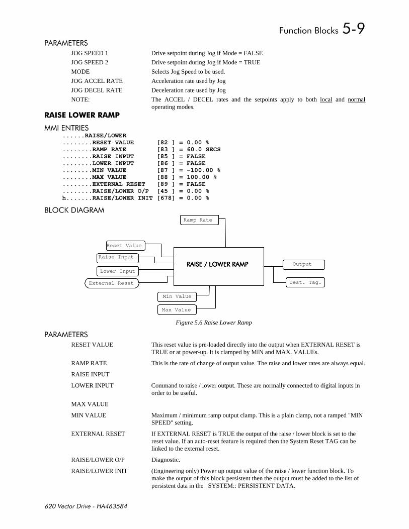
+,-
# %#
JOG SPEED 1 Drive setpoint during Jog if Mode = FALSE
JOG SPEED 2 Drive setpoint during Jog if Mode = TRUE
MODE Selects Jog Speed to be used.
JOG ACCEL RATE Acceleration rate used by Jog
JOG DECEL RATE Deceleration rate used by Jog
NOTE: The ACCEL / DECEL rates and the setpoints apply to both local and normaloperating modes.
"
$%# ......RAISE/LOWER........RESET VALUE [82 ] = 0.00 %........RAMP RATE [83 ] = 60.0 SECS........RAISE INPUT [85 ] = FALSE........LOWER INPUT [86 ] = FALSE........MIN VALUE [87 ] = -100.00 %........MAX VALUE [88 ] = 100.00 %........EXTERNAL RESET [89 ] = FALSE........RAISE/LOWER O/P [45 ] = 0.00 %h.......RAISE/LOWER INIT [678] = 0.00 %
,'. )#
Reset Value
Raise Input
Min Value
Ramp Rate
Lower Input
Max Value
External Reset
# '"## # '"## # '"## # '"##
Dest. Tag.
Output
Figure 5.6 Raise Lower Ramp
# %#
RESET VALUE This reset value is pre-loaded directly into the output when EXTERNAL RESET isTRUE or at power-up. It is clamped by MIN and MAX. VALUEs.
RAMP RATE This is the rate of change of output value. The raise and lower rates are always equal.
RAISE INPUT
LOWER INPUT Command to raise / lower output. These are normally connected to digital inputs inorder to be useful.
MAX VALUE
MIN VALUE Maximum / minimum ramp output clamp. This is a plain clamp, not a ramped "MINSPEED" setting.
EXTERNAL RESET If EXTERNAL RESET is TRUE the output of the raise / lower block is set to thereset value. If an auto-reset feature is required then the System Reset TAG can belinked to the external reset.
RAISE/LOWER O/P Diagnostic.
RAISE/LOWER INIT (Engineering only) Power up output value of the raise / lower function block. Tomake the output of this block persistent then the output must be added to the list ofpersistent data in the SYSTEM:: PERSISTENT DATA.
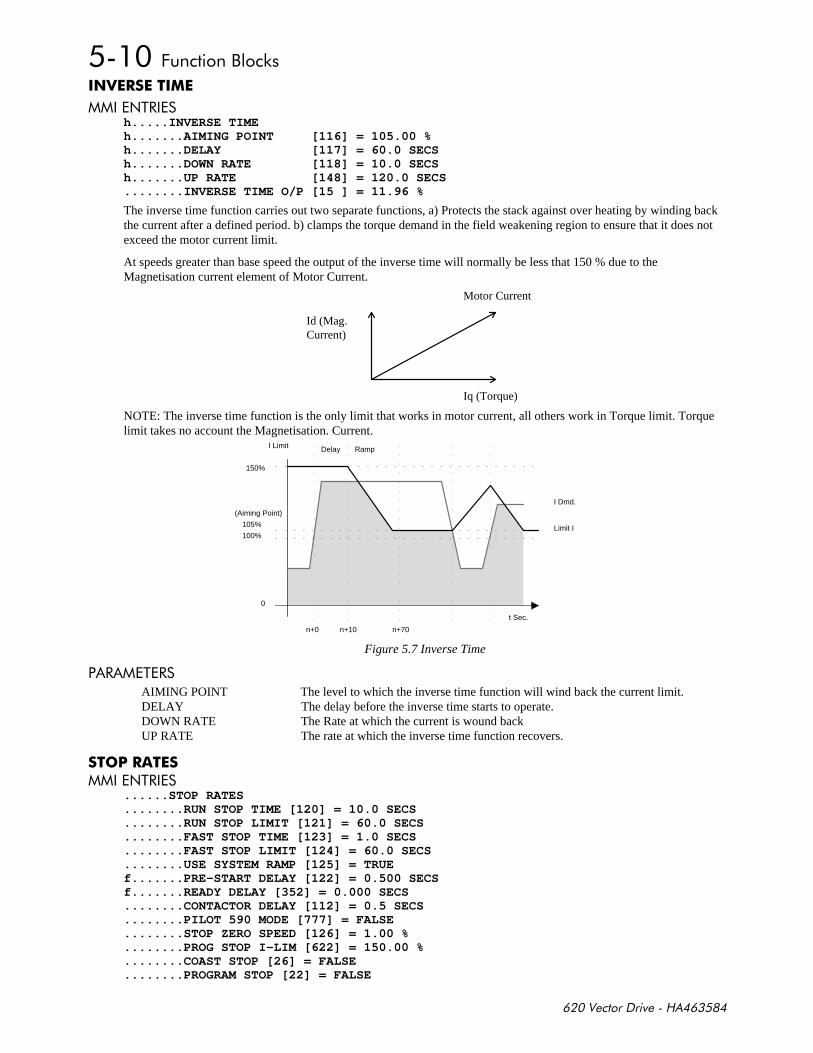
+,-
$%# h.....INVERSE TIMEh.......AIMING POINT [116] = 105.00 %h.......DELAY [117] = 60.0 SECSh.......DOWN RATE [118] = 10.0 SECSh.......UP RATE [148] = 120.0 SECS........INVERSE TIME O/P [15 ] = 11.96 %
The inverse time function carries out two separate functions, a) Protects the stack against over heating by winding backthe current after a defined period. b) clamps the torque demand in the field weakening region to ensure that it does notexceed the motor current limit.
At speeds greater than base speed the output of the inverse time will normally be less that 150 % due to theMagnetisation current element of Motor Current.
Iq (Torque)
Id (Mag.Current)
Motor Current
NOTE: The inverse time function is the only limit that works in motor current, all others work in Torque limit. Torquelimit takes no account the Magnetisation. Current.
150%
105%
I Dmd.
t Sec.
100%
Delay
(Aiming Point)
Ramp
Limit I
0
n+0 n+10 n+70
I Limit
Figure 5.7 Inverse Time
# %# AIMING POINT The level to which the inverse time function will wind back the current limit.DELAY The delay before the inverse time starts to operate.DOWN RATE The Rate at which the current is wound backUP RATE The rate at which the inverse time function recovers.
$%#
......STOP RATES
........RUN STOP TIME [120] = 10.0 SECS
........RUN STOP LIMIT [121] = 60.0 SECS
........FAST STOP TIME [123] = 1.0 SECS
........FAST STOP LIMIT [124] = 60.0 SECS
........USE SYSTEM RAMP [125] = TRUEf.......PRE-START DELAY [122] = 0.500 SECSf.......READY DELAY [352] = 0.000 SECS........CONTACTOR DELAY [112] = 0.5 SECS........PILOT 590 MODE [777] = FALSE........STOP ZERO SPEED [126] = 1.00 %........PROG STOP I-LIM [622] = 150.00 %........COAST STOP [26] = FALSE........PROGRAM STOP [22] = FALSE
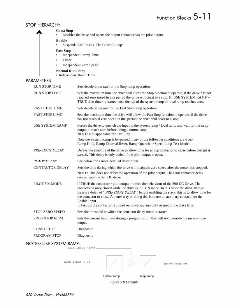
+,-
%'# #&Coast Stop• Disables the drive and opens the output contactor via the pilot output.
Enable• Suspends And Resets The Control Loops
Fast Stop• Independent Ramp Time
• Timer
• Independent Zero Speed.
Normal Run / Stop• Independent Ramp Time
# %#
RUN STOP TIME Sets deceleration rate for the Stop ramp operation.
RUN STOP LIMIT Sets the maximum time the drive will allow the Stop function to operate, if the drive has notreached zero speed in this period the drive will coast to a stop. If USE SYSTEM RAMP =TRUE then timer is started once the o/p of the system ramp of local ramp reaches zero.
FAST STOP TIME Sets deceleration rate for the Fast Stop ramp operation.
FAST STOP LIMIT Sets the maximum time the drive will allow the Fast Stop function to operate, if the drivehas not reached zero speed in this period the drive will coast to a stop.
USE SYSTEM RAMP Forces the drive to quench the input to the system ramp / local ramp and wait for the rampoutput to reach zero before doing a normal stop.NOTE: Not applicable for Fast Stop.
Note the System Ramp is by-passed if any of the following conditions are true:-Ramp Hold, Ramp External Reset, Ramp Quench or Speed Loop Test Mode.
PRE-START DELAY Delays the enabling of the drive to allow time for an o/p contactor to close before current ispassed. This delay is only added if the pilot output is open.
READY DELAY See below for a more detailed description.
CONTACTOR DELAY Sets the time during which the drive will maintain zero speed after the motor has stopped.
NOTE: This does not effect the operation of the pilot output. The term contactor delaycomes from the 590 DC drive.
PILOT 590 MODE If TRUE the contactor / pilot output mimics the behaviour of the 590 DC Drive. Thecontactor is only closed while the drive is in RUN mode. In this mode the drive alwaysinserts a delay of " PRE-START DELAY " before enabling the stack, this is to allow time forthe contactor to close. A better way of doing this is to use an auxiliary contact into theEnable Input.If FALSE the contactor is closed on power-up and only opened if the drive trips.
STOP ZERO SPEED Sets the threshold at which the contactor delay timer is started.
PROG STOP I-LIM Sets the current limit used during a program stop. This will not override the inverse timeoutput.
COAST STOP Diagnostic
PROGRAM STOP Diagnostic
$'% ( & %# Trim Input (10%)
Ramp Input (70%)
# #
Speed Setpoint
Figure 5.8 Example
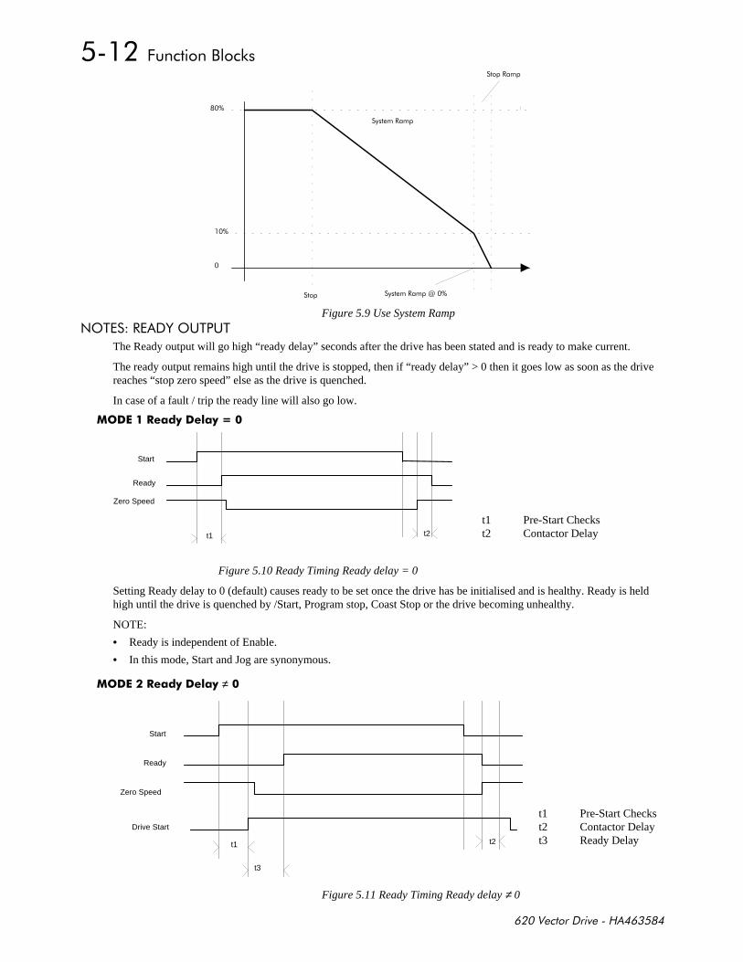
+,-
#
#
#7
Figure 5.9 Use System Ramp
$'% # &'(%(%
The Ready output will go high “ready delay” seconds after the drive has been stated and is ready to make current.
The ready output remains high until the drive is stopped, then if “ready delay” > 0 then it goes low as soon as the drivereaches “stop zero speed” else as the drive is quenched.
In case of a fault / trip the ready line will also go low.
! 8
Figure 5.10 Ready Timing Ready delay = 0
Setting Ready delay to 0 (default) causes ready to be set once the drive has be initialised and is healthy. Ready is heldhigh until the drive is quenched by /Start, Program stop, Coast Stop or the drive becoming unhealthy.
NOTE:
• Ready is independent of Enable.
• In this mode, Start and Jog are synonymous.
! ≠
Figure 5.11 Ready Timing Ready delay ≠ 0
Start
Zero Speed
Ready
t1 t2
t1 Pre-Start Checkst2 Contactor Delay
Start
Zero Speed
Ready
t1 t2
t3
Drive Start
t1 Pre-Start Checks t2 Contactor Delayt3 Ready Delay

+,-
Setting Ready delay to none zero causes ready to be set a fixed delay after the drive becoming ready. Ready is held highuntil the drive is stooped by /Start, Program stop, Coast Stop or the drive becoming unhealthy. In the case of a /Startcommand Ready will be low during the contactor delay period.
• Ready is independent of Enable.• The delay is only inserted for Start and not for JOG
$%#
......ALARMS / SEQ
........EXTERNAL TRIP [144] = FALSE
........MOTR.TMP.INHIBIT [146] = FALSEf.......ACK ALARM [166] = TRUE........STALL INHIBIT [143] = FALSE........STALL TORQUE [136] = 95.00 %........STALL SPEED [138] = 4.00 %........STALL DELAY [137] = 10.00........STALL TRIP [20] = OK........OVER SPD INHIBIT [145] = FALSE........OVER SPEED LEVEL [139] = 120.00 %h.......UNDER V LEVEL [685] = 440 VOLTSh......./UNDER VOLTS [686] = TRUE........5703 RCV.INHIBIT [142] = FALSEf.......SPD.FBK.DELAY [687] = 10.000 SECSf.......SPD.FBK.THRESHD [688] = 10.00 %........SPD.FBK.INHIBIT [689] = FALSEh.......HEALTH INHIBIT [219] = 0x0000f.......OPERATING MODE [25] = STOPPEDf.......DRIVE START [23] = FALSEf.......DRIVE ENABLE [24] = FALSEf.......READY [559] = FALSEf.......RUN [28] = FALSEf.......HEALTH STORE [203] = 0x0000f.......HEALTH WORD [217] = 0x0000f.......FIRST ALARM [218] = 0x0000f.......HEALTHY [27] = TRUEf.......HEALTH OUTPUT [12] = TRUE
#
EXTERNAL TRIP If set generates a user alarm / trip.
MOTOR.TMP.INHIBIT Disables operation of the Motor Thermistor alarm
ACK ALARM Must be TRUE to allow the automatic acknowledging of alarms by a start commandbeing reapplied.By connecting this to a normally open digital i/p, the drive will wait for a LOW-HIGH signal before restarting after a drive trip.
NOTE: 620L configurations from release 2.x set the value of ACK ALARM toFALSE, requiring a low → high → low transition to acknowledge an active alarm.
% STALL INHIBIT Disables the stall alarm.
STALL TORQUE The threshold at which torque must reach to be deemed as stalled.
STALL SPEED The threshold for speed feedback below, which the stall condition is looked for.Note the speed demand must also be above this threshold.
STALL DELAY Time stall has to be present before if generates an alarm.
!!!-
IF ((|SPEED_DEMAND| > STALL_SPEED) AND (|SPEED_FEEDBACK| < STALL_SPEED) AND |TORQUE_DEMAND| > STALL_TORQUE)) THEN Start Stall Timer
($#'% )
UNDER V LEVEL (Engineering only) sets the level above which /.UNDER VOLTS is TRUE.
/UNDER VOLTS (Engineering only) Under voltage signal, used to trigger saving of persistent data.

+,-
'#
OVER SPD INHIBIT Disables the overspeed alarm.
OVER SPEED LEVEL Threshold above which an overspeed alarm is generated.
###'#
5703 RCV.INHIBI Disables the 5703 alarm. This only applies for 5703 slaves, if enabled the drive willtrip if it stops receiving valid 5703 messages from its master.
+, .
SPD.FBK.DELAY Delay before the speed feedback alarm is triggered.
SPD.FBK.THRESHD The value of speed error below which the alarm is automatically inhibited.
SPD.FBK.INHIBI Disables the speed feedback trip. This is necessary if the drive is to operate in a modewhere there is a speed error, for example a drive operating in torque control.
)$' % OPERATING MODE Diagnostic.DRIVE START Diagnostic.DRIVE ENABLE Diagnostic.READY Diagnostic.RUN Diagnostic.HEALTH STORE Diagnostic.HEALTH WORD Diagnostic.FIRST ALARM Diagnostic.HEALTHY Diagnostic.HEALTH OUTPUT Diagnostic.
%
$%# ........ENCODER LINES [131] = 2048........ENCODER SUPPLY [774] = 50 %........MAX SPEED RPM [130] = 1500 RPM........BASE FREQUENCY [448] = 50.0 Hz........MOTOR VOLTS [486] = 415 VOLTS........MOTOR RATING RMS [134] = 1.0 AMPS........NO.OF POLES [399] = 4........NAMEPLATE RPM [135] = 1440 RPM
# %#
ENCODER LINES The exact number of lines on the encoder. Failure to enter this value correctly willcause loss of torque and incorrect results from the Autotune.
ENCODER SUPPLY Sets the encode supply voltage, the actual value should read with a Multi-meter. Thevoltage range is approximately 10 to 20volts with 50% being 10v.
MAX SPEED RPM Motor top speed setting, equates to 100% setpoint. This may be adjusted to suit yourprocess.
BASE FREQUENCY Base speed of the motor usually 50 or 60Hz.
MOTOR VOLTS Actual motor volts from motor nameplate, or motor data sheet.
MOTOR RATING RMS The motor rating current in amps from the motor nameplate. For the bestperformance, this value should be at least 50% of the drive rating.
If you are derating your motor for “Inverter” use then you should use the non-deratedvalue of current.
NO OF POLES Number of poles in the motor; must be divisible by two, e.g. 2,4,6,8.
NAMEPLATE RPM Motor speed, taking slip into account. This value will be provided by the motormanufacturer, usually on the motor nameplate.
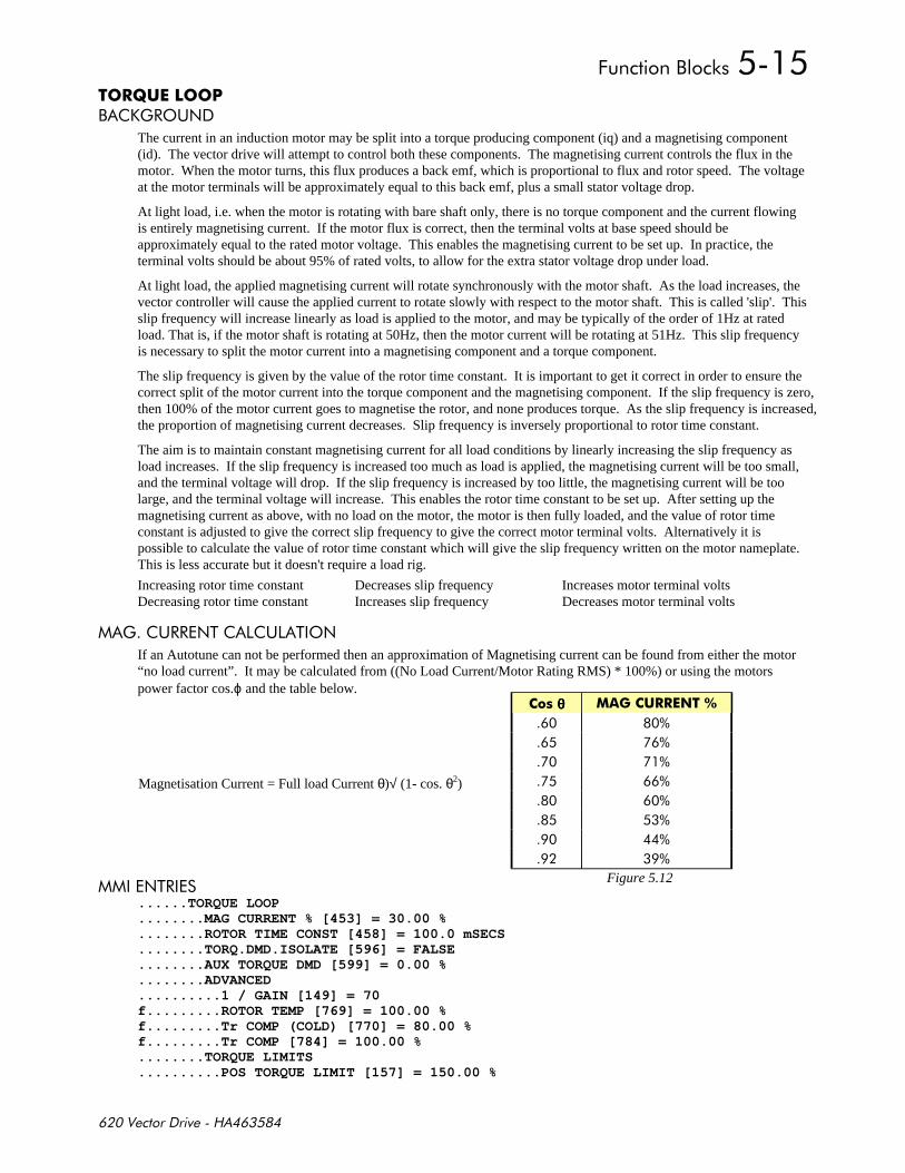
+,-
4, .)#'($
The current in an induction motor may be split into a torque producing component (iq) and a magnetising component(id). The vector drive will attempt to control both these components. The magnetising current controls the flux in themotor. When the motor turns, this flux produces a back emf, which is proportional to flux and rotor speed. The voltageat the motor terminals will be approximately equal to this back emf, plus a small stator voltage drop.
At light load, i.e. when the motor is rotating with bare shaft only, there is no torque component and the current flowingis entirely magnetising current. If the motor flux is correct, then the terminal volts at base speed should beapproximately equal to the rated motor voltage. This enables the magnetising current to be set up. In practice, theterminal volts should be about 95% of rated volts, to allow for the extra stator voltage drop under load.
At light load, the applied magnetising current will rotate synchronously with the motor shaft. As the load increases, thevector controller will cause the applied current to rotate slowly with respect to the motor shaft. This is called 'slip'. Thisslip frequency will increase linearly as load is applied to the motor, and may be typically of the order of 1Hz at ratedload. That is, if the motor shaft is rotating at 50Hz, then the motor current will be rotating at 51Hz. This slip frequencyis necessary to split the motor current into a magnetising component and a torque component.
The slip frequency is given by the value of the rotor time constant. It is important to get it correct in order to ensure thecorrect split of the motor current into the torque component and the magnetising component. If the slip frequency is zero,then 100% of the motor current goes to magnetise the rotor, and none produces torque. As the slip frequency is increased,the proportion of magnetising current decreases. Slip frequency is inversely proportional to rotor time constant.
The aim is to maintain constant magnetising current for all load conditions by linearly increasing the slip frequency asload increases. If the slip frequency is increased too much as load is applied, the magnetising current will be too small,and the terminal voltage will drop. If the slip frequency is increased by too little, the magnetising current will be toolarge, and the terminal voltage will increase. This enables the rotor time constant to be set up. After setting up themagnetising current as above, with no load on the motor, the motor is then fully loaded, and the value of rotor timeconstant is adjusted to give the correct slip frequency to give the correct motor terminal volts. Alternatively it ispossible to calculate the value of rotor time constant which will give the slip frequency written on the motor nameplate.This is less accurate but it doesn't require a load rig.
Increasing rotor time constant Decreases slip frequency Increases motor terminal voltsDecreasing rotor time constant Increases slip frequency Decreases motor terminal volts
)(##$% ( %'$
If an Autotune can not be performed then an approximation of Magnetising current can be found from either the motor“no load current”. It may be calculated from ((No Load Current/Motor Rating RMS) * 100%) or using the motorspower factor cos.ϕ and the table below.
$%# ......TORQUE LOOP........MAG CURRENT % [453] = 30.00 %........ROTOR TIME CONST [458] = 100.0 mSECS........TORQ.DMD.ISOLATE [596] = FALSE........AUX TORQUE DMD [599] = 0.00 %........ADVANCED..........1 / GAIN [149] = 70f.........ROTOR TEMP [769] = 100.00 %f.........Tr COMP (COLD) [770] = 80.00 %f.........Tr COMP [784] = 100.00 %........TORQUE LIMITS..........POS TORQUE LIMIT [157] = 150.00 %
θθθθ #
Figure 5.12
Magnetisation Current = Full load Current θ)√ (1- cos. θ2)
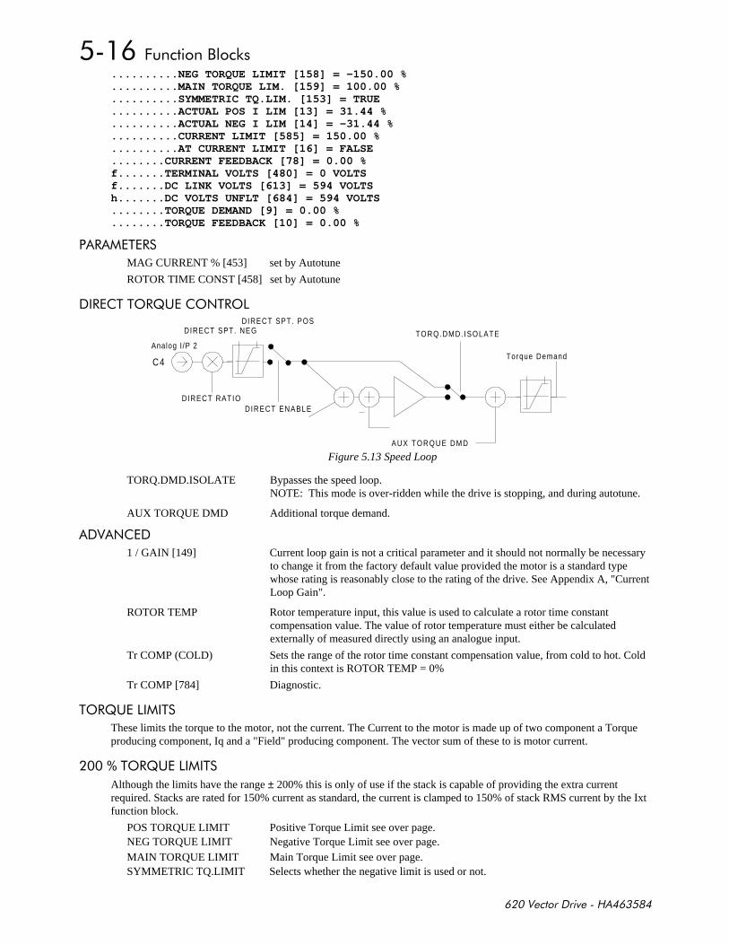
+,-
..........NEG TORQUE LIMIT [158] = -150.00 %
..........MAIN TORQUE LIM. [159] = 100.00 %
..........SYMMETRIC TQ.LIM. [153] = TRUE
..........ACTUAL POS I LIM [13] = 31.44 %
..........ACTUAL NEG I LIM [14] = -31.44 %
..........CURRENT LIMIT [585] = 150.00 %
..........AT CURRENT LIMIT [16] = FALSE
........CURRENT FEEDBACK [78] = 0.00 %f.......TERMINAL VOLTS [480] = 0 VOLTSf.......DC LINK VOLTS [613] = 594 VOLTSh.......DC VOLTS UNFLT [684] = 594 VOLTS........TORQUE DEMAND [9] = 0.00 %........TORQUE FEEDBACK [10] = 0.00 %
# %#
MAG CURRENT % [453] set by Autotune
ROTOR TIME CONST [458] set by Autotune
#%%'#;('$%#'
Torque Demand
AUX TORQUE DMD
TORQ.DMD. ISOLATE
DIRECT RATIO
DIRECT SPT. POSDIRECT SPT. NEG
C4
Analog I /P 2
DIRECT ENABLE
Figure 5.13 Speed Loop
TORQ.DMD.ISOLATE Bypasses the speed loop.NOTE: This mode is over-ridden while the drive is stopping, and during autotune.
AUX TORQUE DMD Additional torque demand.
$
1 / GAIN [149] Current loop gain is not a critical parameter and it should not normally be necessaryto change it from the factory default value provided the motor is a standard typewhose rating is reasonably close to the rating of the drive. See Appendix A, "CurrentLoop Gain".
ROTOR TEMP Rotor temperature input, this value is used to calculate a rotor time constantcompensation value. The value of rotor temperature must either be calculatedexternally of measured directly using an analogue input.
Tr COMP (COLD) Sets the range of the rotor time constant compensation value, from cold to hot. Coldin this context is ROTOR TEMP = 0%
Tr COMP [784] Diagnostic.
%'#;(%
These limits the torque to the motor, not the current. The Current to the motor is made up of two component a Torqueproducing component, Iq and a "Field" producing component. The vector sum of these to is motor current.
%'#;(%
Although the limits have the range ± 200% this is only of use if the stack is capable of providing the extra currentrequired. Stacks are rated for 150% current as standard, the current is clamped to 150% of stack RMS current by the Ixtfunction block.
POS TORQUE LIMIT Positive Torque Limit see over page.NEG TORQUE LIMIT Negative Torque Limit see over page.MAIN TORQUE LIMIT Main Torque Limit see over page.SYMMETRIC TQ.LIMIT Selects whether the negative limit is used or not.
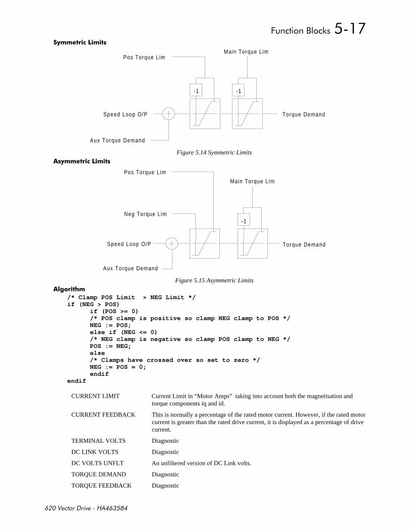
+,-
*
Pos Torque L im
-1
Speed Loop O/P Torque Demand
-1
Main Torque L im
Aux Torque Demand
Figure 5.14 Symmetric Limits
*
Pos Torque L im
Torque Demand
Neg Torque L im-1
Main Torque L im
Speed Loop O/P
Aux Torque Demand
Figure 5.15 Asymmetric Limits
!-
/* Clamp POS Limit > NEG Limit */if (NEG > POS)
if (POS >= 0)/* POS clamp is positive so clamp NEG clamp to POS */NEG := POS;else if (NEG <= 0)/* NEG clamp is negative so clamp POS clamp to NEG */POS := NEG;else/* Clamps have crossed over so set to zero */NEG := POS = 0;endif
endif
CURRENT LIMIT Current Limit in “Motor Amps” taking into account both the magnetisation andtorque components iq and id.
CURRENT FEEDBACK This is normally a percentage of the rated motor current. However, if the rated motorcurrent is greater than the rated drive current, it is displayed as a percentage of drivecurrent.
TERMINAL VOLTS Diagnostic
DC LINK VOLTS Diagnostic
DC VOLTS UNFLT An unfiltered version of DC Link volts.
TORQUE DEMAND Diagnostic
TORQUE FEEDBACK Diagnostic

+,-
$%#
......SPEED LOOP
........SPD. PROP. GAIN [161] = 10.00
........SPD. INT. TIME [162] = 100 mSECSf.......INT. DEFEAT [163] = FALSE........ENCODER SIGN [164] = NEGf.......ADVANCEDf.........SPEED FBK FILTER [673] = 0.500f.........SPEED DMD FILTER [662] = 0.750f.........ADAPTIVE THRESH [674] = 0.50 %f.........ADAPTIVE P-GAIN [675] = 10.00f.........PWR LOSS CNTRLf...........ENABLE [639] = FALSEf...........TRIP THRESHOLD [640] = 0 VOLTSf...........CONTROL BAND [657] = 20 VOLTSf...........DECEL RATE [641] = 2.50 %f...........ACCEL RATE [644] = 0.50 %f...........TIME LIMIT [643] = 30.000 SECSf...........PWR LOSS ACTIVE [766] = FALSE........SPEED SETPOINTS..........DIRECT SPT1 [171] = 0.00 %..........DIRECT RATIO [172] = 0.1000..........DIRECT SPT. MAX [173] = 100.00 %..........DIRECT SPT. MIN [174] = -100.00 %..........DIRECT ENABLE [175] = FALSE..........MAIN SPD.SPT. [176] = 0.00 % <- [346]..........MAX SPEED [177] = 100.00 %..........MIN SPEED [178] = -100.00 %h.........SEQ RUN INPUT [49] = 0.00 %h.........SEQ OUTPUT [50] = 0.00 %f.......ZERO SPEED..........ZERO SPD HYST [132] = 0.10 %..........ZERO SPEED LEVEL [252] = 0.50 %..........AT ZERO SPEED [17] = TRUE..........AT ZERO SETPOINT [18] = TRUE..........AT STANDSTILL [19] = TRUEf.......TEST MODEf.........ENABLE [647] = FALSEf.........SPEED SETPOINT 1 [648] = 5.00 %f.........SPEED SETPOINT 2 [649] = 10.00 %f.........PERIOD [650] = 1000 mSECS........TOTAL SPD.DMD. [6] = 0.00 %h.......SPEED FB UNFIL [7] = 0.00 %........SPEED FEEDBACK [11] = 0.00 %........SPEED ERROR [8] = 0.00 %........ENCODER [51] = 0 RPM........SPEED SETPOINT [48] = 0.00 %
''%($$)
SPD PROP GAIN Speed loop PI proportional gain adjustment. A gain value of 1.00 is unity.
SPD INT.TIME. Speed loop PI integral gain adjustment.
INT. DEFEAT Turn speed loop in to a P only controller.
The PI is designed as a saturating loop, i.e. it is normal for the output to reach saturation. In order to preventintegral wind up during saturation the integral term is held constant while the output is saturated.
Saturation is deemed to be when the output is ≥ to the prevailing torque limit.

+,-
ENCODER SIGN If the Encoder sign is incorrect the motor will not operate smoothly.The sign of the encoder can be changed either in hardware by swapping the Aand B channels or by toggling this parameter.A third way of matching encoder sign to motor direction is to swap any twomotor output phases.
+, .
The 620 requires an encoder feedback device tightly coupled to the motor shaft to achieve its high level ofperformance. This is because accurate real time measurement of shaft position is used in the vectorcalculations. The number of encoder lines is also important to achieve high performance, the higher the numberof lines the greater the speed loop gain. Also as a result of more lines the high frequency ripple in the torque isalso reduced, reducing audible noise.
The number of lines on the encoder is set in the SETUP PARAMETERS::CALIBRATION menu. An incorrectnumber of lines will prevent the drive from operating smoothly and in some circumstances may cause the driveto operate in an uncontrolled manner.
$
SPEED FBK FILTER A simple filter function that is applied to speed feedback to reduce ripplecaused by low line count encoders. A value of 0 disables the filter actionand 1.00 is the maximum value. A typical value would be between 0.5 and0.75, previous releases had a default of 0.5.NOTE: INCREASING THE FILTER VALUE MAY MAKE THE SPEEDLOOP UNSTABLE.
SPEED DMD FILTER A simple filter function applied to speed demand to reduce ripple. A valueof 0 disables the filter action and 1.00 is the maximum value.
ADAPTIVE THRESHOLD Level below which the ADAPTIVE P-GAIN is selected
ADAPTIVE P-GAIN P-Gain used when speed error is less than the adaptive threshold, this maybe used to lessen motor noise in the steady state.
$'% $'% $'% $'%
The filter time constant τ in milli-seconds can be calculated from the following equation .
=
α
τ1
1.1
eLog
Where α is the value of SPD FBK FILTER or SPD DMD FILTER. A value of 0.5 equates to a filter time of1,6mS, 0.8 to 4.9mS and 0.9 to 10.4mS.
'"#' '$%#'
$'% $'% $'% $'%
The power loss control on the 620 works if enabled, by continually comparing the actual value of DC-Linkvolts to a threshold. If the actual value of the DC-Link falls below this TRIP THRESHOLD then the driveattempts to pump-up the DC-Link by decelerating the load, thus recovering its stored kinetic energy. Once thedrive reaches zero speed or a time out occurs then a POWER LOSS alarm is triggered. If the power supply isresumed before the load has reached zero speed then the load is ramped back up to the actual demanded speed.If there is not enough kinetic energy in the load or the deceleration rate is set too long then an under voltage tripwill be trigged. Over Voltages may also occur if the deceleration rate is too fast and there is insufficientdynamic braking fitted.
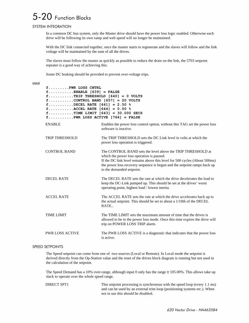
+,-
& %$%)# %'$
In a common DC bus system, only the Master drive should have the power loss logic enabled. Otherwise eachdrive will be following its own ramp and web speed will no longer be maintained.
With the DC link connected together, once the master starts to regenerate and the slaves will follow and the linkvoltage will be maintained by the sum of all the drives.
The slaves must follow the master as quickly as possible to reduce the drain on the link, the 5703 setpointrepeater is a good way of achieving this.
Some DC braking should be provided to prevent over-voltage trips.
f.........PWR LOSS CNTRLf...........ENABLE [639] = FALSEf...........TRIP THRESHOLD [640] = 0 VOLTSf...........CONTROL BAND [657] = 20 VOLTSf...........DECEL RATE [641] = 2.50 %f...........ACCEL RATE [644] = 0.50 %f...........TIME LIMIT [643] = 30.000 SECSf...........PWR LOSS ACTIVE [766] = FALSE
ENABLE Enables the power loss control option, without this TAG set the power losssoftware is inactive.
TRIP THRESHOLD The TRIP THRESHOLD sets the DC Link level in volts at which thepower loss operation is triggered.
CONTROL BAND The CONTROL BAND sets the level above the TRIP THRESHOLD atwhich the power loss operation is paused.If the DC link level remains above this level for 500 cycles (About 500ms)the power loss recovery sequence is begun and the setpoint ramps back upto the demanded setpoint.
DECEL RATE The DECEL RATE sets the rate at which the drive decelerates the load tokeep the DC-Link pumped up. This should be set at the drives’ worstoperating point, highest load / lowest inertia.
ACCEL RATE The ACCEL RATE sets the rate at which the drive accelerates back up tothe actual setpoint. This should be set to about a 1/10th of the DECELRATE..
TIME LIMIT The TIME LIMIT sets the maximum amount of time that the drives isallowed to be in the power loss mode. Once this time expires the drive willtrip on POWER LOSS TRIP alarm.
PWR LOSS ACTIVE The PWR LOSS ACTIVE is a diagnostic that indicates that the power lossis active.
%'$%
The Speed setpoint can come from one of two sources (Local or Remote). In Local mode the setpoint isderived directly from the Op-Station value and the reset of the drives block diagram is running but not used inthe calculation of the setpoint.
The Speed Demand has a 10% over-range, although input 0 only has the range ± 105.00%. This allows take upslack to operate over the whole speed range.
DIRECT SPT1 This setpoint processing is synchronous with the speed loop (every 1.1 ms)and can be used by an external trim loop (positioning systems etc.). Whennot in use this should be disabled.

+,-
DIRECT SPT. MAX
DIRECT SPT. MIN Limits the range of the scaled Direct input.
DIRECT ENABLE Disables the processing of analogue input C4, this must be enabled to makeuse of this feature. The Direct setpoint is automatically disabled while thestop ramps are active and in Local mode.
MAIN SPD.SPT. This is the main setpoint from the block diagram.
MAX SPEED
MIN SPEED These are intended to prevent the speed setpoint from going negative andnot to create an offset. Offsets may be generated elsewhere, probablybefore the system ramp.
8#'
ZERO SPD HYST Hysterises level for zero speed detection.
ZERO SPEED LEVEL Zero speed threshold.
AT ZERO SPEED Diagnostic
AT ZERO SETPOINT Diagnostic
AT STANDSTILL Diagnostic
% %'
ENABLE If enabled the speed loop setpoint is defeated and the setpoint is obtainedalternately from SPEED SETPOINT 1 and SPEED SETPOINT 2 at a ratedetermined by PERIOD. The test mode may be used to commission the PIfor the speed loop.
SPEED SETPOINT 1 Speed test mode setpoint 1.
SPEED SETPOINT 2 Speed test mode setpoint 2.
PERIOD Rate at which the test cycle operates at.
)$' %
TOTAL SPD.DMD. Diagnostic
SPEED FEEDBACK Diagnostic
SPEED ERROR Diagnostic
ENCODER Diagnostic
SPEED SETPOINT Diagnostic
$%#
......AUTOTUNE
........AUTOTUNE FLAG [482] = FALSE
........MAG I AUTOTUNE [483] = TRUE
........SET Tr < RTD SPD [484] = TRUE
........AUTOCAL MAX RPM [629] = 30000 RPM
# %#
AUTOTUNE FLAG If set the drive will begin its Autotune routine next time the drive is started.
MAG I AUTOTUNE Enables the tuning of the Magnetisation Current phase of the Autotune, thisrequires the motor to rotate at base speed.
SET TR < RTD SPD Enables the Rotor Time Constant calculation phase of Autotune.
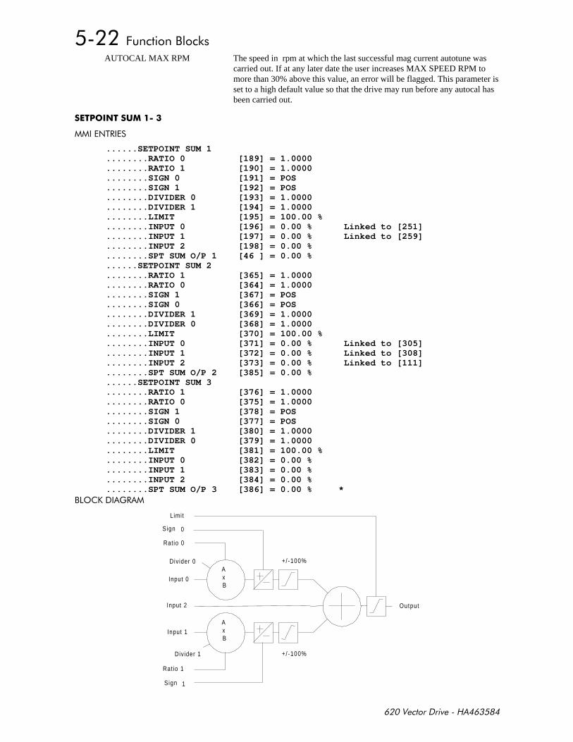
+,-
AUTOCAL MAX RPM The speed in rpm at which the last successful mag current autotune wascarried out. If at any later date the user increases MAX SPEED RPM tomore than 30% above this value, an error will be flagged. This parameter isset to a high default value so that the drive may run before any autocal hasbeen carried out.
$%#
......SETPOINT SUM 1
........RATIO 0 [189] = 1.0000
........RATIO 1 [190] = 1.0000
........SIGN 0 [191] = POS
........SIGN 1 [192] = POS
........DIVIDER 0 [193] = 1.0000
........DIVIDER 1 [194] = 1.0000
........LIMIT [195] = 100.00 %
........INPUT 0 [196] = 0.00 % Linked to [251]
........INPUT 1 [197] = 0.00 % Linked to [259]
........INPUT 2 [198] = 0.00 %
........SPT SUM O/P 1 [46 ] = 0.00 %
......SETPOINT SUM 2
........RATIO 1 [365] = 1.0000
........RATIO 0 [364] = 1.0000
........SIGN 1 [367] = POS
........SIGN 0 [366] = POS
........DIVIDER 1 [369] = 1.0000
........DIVIDER 0 [368] = 1.0000
........LIMIT [370] = 100.00 %
........INPUT 0 [371] = 0.00 % Linked to [305]
........INPUT 1 [372] = 0.00 % Linked to [308]
........INPUT 2 [373] = 0.00 % Linked to [111]
........SPT SUM O/P 2 [385] = 0.00 %
......SETPOINT SUM 3
........RATIO 1 [376] = 1.0000
........RATIO 0 [375] = 1.0000
........SIGN 1 [378] = POS
........SIGN 0 [377] = POS
........DIVIDER 1 [380] = 1.0000
........DIVIDER 0 [379] = 1.0000
........LIMIT [381] = 100.00 %
........INPUT 0 [382] = 0.00 %
........INPUT 1 [383] = 0.00 %
........INPUT 2 [384] = 0.00 %
........SPT SUM O/P 3 [386] = 0.00 % *,'. )#
+/ -100%
+/-100%
AxB
AxB
Limit
Sign 0
Input 1
Sign 1
Input 0
Ratio 0
Ratio 1
Divider 0
Divider 1
Input 2 Output
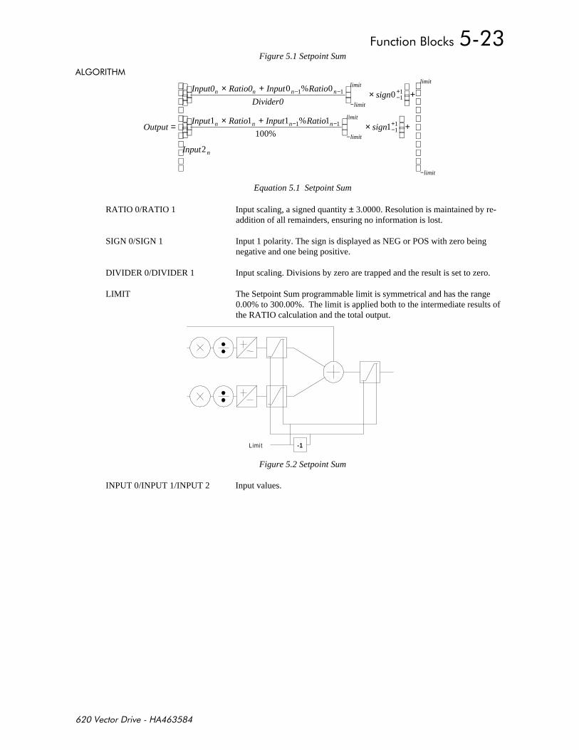
+,-
Figure 5.1 Setpoint Sum
)'#%
Output
Input0 Ratio0 Input Ratio
Divider0sign
Input Ratio Input Ratiosign
Input
n n n n
limit
limit
n n n n
limit
limit
n
limit
limit
=
× +
×
+
× +
×
+
− −
−−+
− −
−−+
−
0 00
1 1 1 1
100%1
2
1 111
1 111
%
%
Equation 5.1 Setpoint Sum
RATIO 0/RATIO 1 Input scaling, a signed quantity ± 3.0000. Resolution is maintained by re-addition of all remainders, ensuring no information is lost.
SIGN 0/SIGN 1 Input 1 polarity. The sign is displayed as NEG or POS with zero beingnegative and one being positive.
DIVIDER 0/DIVIDER 1 Input scaling. Divisions by zero are trapped and the result is set to zero.
LIMIT The Setpoint Sum programmable limit is symmetrical and has the range0.00% to 300.00%. The limit is applied both to the intermediate results ofthe RATIO calculation and the total output.
-1Limit
Figure 5.2 Setpoint Sum
INPUT 0/INPUT 1/INPUT 2 Input values.

+,-
$
$%#
f.....REF ENCODERf.......PHASEf.........RESET [600] = FALSEf.........POS CALC ENABLE [337] = FALSEf.........OFFSET MENUf...........OFFSET [447] = 0f...........OFFSET SCALE [609] = 1f...........OFFSET TRIM [670] = 0f.........TEST MODEf...........ENABLE [652] = FALSEf...........OFFSET 1 [653] = 500f...........OFFSET 2 [654] = 1000f...........PERIOD [655] = 1000 mSECSf.........MAX POSITION ERR [342] = 100.00f.........SATURATED [610] = FALSEf.........OVERFLOW [611] = FALSEf.........POSITION ERROR [338] = 0f.......INPUT SCALINGf.........FBK.SCALE A [498] = 10000f.........FBK.SCALE B [499] = 10000f.........REF SCALE A [343] = 10000f.........REF SCALE B [344] = 10000h.........REF ENCODER CNT [359] = 0h.........FBK ENCODER CNT [77] = 0f.......LENGTH MENUf.........LENGTH [765] = 0f.........LENGTH SCALE [762] = 1f.........LENGTH RATE [764] = 100.0f.........SUBTRACT LENGTH [763] = FALSEf.......INCH MENUf.........INCH ADVANCE [604] = FALSEf.........INCH RETARD [605] = FALSEf.........INCH RATE [606] = 10.0f.......CALC.REF.POSTIONf.........ENABLE [659] = FALSEf.........INPUT [660] = 0.00 %f.........OUTPUT [661] = 0f.......REF.SPEEDf.........MAX SPEED RPM [353] = 1500 RPMf.........ENCODER LINES [356] = 2048f.........SCALE REF.SPEED [783] = TRUEf.........REFSPEED [357] = 0.00 %f.........FILTER TC [767] = 1.00 SECSf.........FILTERED REF.SPD [768] = 0.00 %
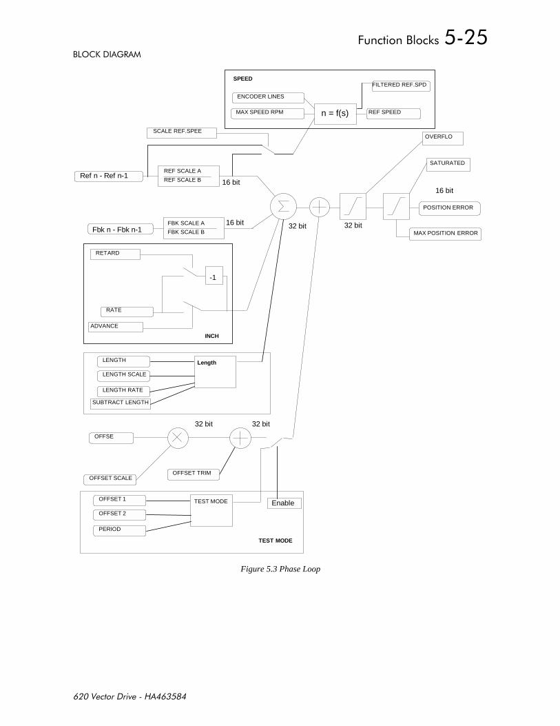
+,-
,'. )#
LENGTH
LENGTH SCALE
LENGTH RATE
Ref n - Ref n-1
Fbk n - Fbk n-1
REF SCALE A
REF SCALE B
RATE
POSITION ERROR
32 bit
16 bit16 bit
SATURATED
OVERFLO
MAX POSITION ERROR
-1
RETARD
ADVANCE
32 bitFBK SCALE A
FBK SCALE B
16 bit
REF SPEED
ENCODER LINES
MAX SPEED RPM n = f(s)
OFFSET SCALE
OFFSET 1
OFFSET 2
PERIOD
OFFSE
32 bit
OFFSET TRIM
32 bit
Enable
TEST MODE
TEST MODE
SPEED
INCH
SCALE REF.SPEE
FILTERED REF.SPD
Length
SUBTRACT LENGTH
Figure 5.3 Phase Loop

+,-
RESET Sets and holds the position error at zero.
POS CALC ENABLE Enable the computation of position error, disabling this also zeros theposition error.
POSITION ERROR Clamped Error output. This is the primary output of the phase loopfunction block. Position error is not usually used directly but insteadconnected to the PID input (first disconnecting the PID error calculator).The PID is then used either directly or more commonly as a speedcorrection.
SATURATED Position Error output has been clamped. Error information is still validuntil the OVERFLOW flag is set. It is not uncommon for this flag to be setduring rapid accelerations where torque limit is reached. For optimaloperation torque limit must never reached.
OVERFLOW Position Error has overflowed and phase information has been lost. This isbecause the error has exceeded ± 1,000,000,000 counts, about 120,000revolutions with a 2048 line encoder.
MAX POSITION ERR Limit clamp for position error.
'++ %$('++ %$('++ %$('++ %$(
OFFSET Fixed offset scaled by OFFSET SCALE and added to position error, inencoder counts1.
OFFSET SCALE Scalar for offset to allow greater range.
OFFSET TRIM Trim offset added into position error.Note: The total offset is a 32 bit quantity made up of the sum of offset andoffset trim. Total Offset = (Offset * Offset Scale) + Offset Trim
% %'% %'% %'% %'
ENABLE If enabled the phase loop offset is defeated and the offset is obtainedalternately from OFFSET 1 and OFFSET 2 at a rate determined by PERIOD.The test mode may be used to commission the PID for the phase loop.
OFFSET 1 Phase test mode offset 1.
OFFSET 2 Phase test mode offset 2.
PERIOD Rate at which the test cycle operates.
$(% $)$(% $)$(% $)$(% $)
REF SCALE A Multiplicand for reference encoder.
REF SCALE B Divisor for reference encoder.
Example: Reference encoder has 1000 line and Master has 2048 lines thenfor 1:1 phase locking Ref. Scale A and B should be set to 2048 and 1000respectively.
FBK SCALE A Multiplicand for feedback encoder.
FBK SCALE B Divisor for feedback encoder.
1 Note: Encoder counts are equal to four times the number of lines on the encoder.

+,-
$)%$)%$)%$)%
$%#'(%'$$%#'(%'$$%#'(%'$$%#'(%'$
The length function block adds the ability to subtract a length from position error on a signal to facilitate simplecut to length and indexing applications.
)'#% )'#% )'#% )'#%
The carriage is position locked to the product, the movement is limited to the track length by clamping the"position error" at the extreme ends of the track.
Once the cut point passes the carriage the error will be positive causing the carriage to accelerate up to linespeed. A synchronisation signal is calculated from position error and used to fire the knife.
After the “cut” a number of counts equivalent to the length to be cut is subtracted from the position error. Thishas the effect of re-synchronising the knife drive with the next cut position. External logic must be used toensure that the timing is appropriate and position the knife for the next cut
BA C
• Limit A is the Home End of travel limit.
• Between Limit A and B The position Error must be clamped to >= 0, this has the effect that the carriage isbrought to rest at the home point.
• Limit B is the final End of travel stop
$'% $'% $'% $'%
• The “cut” signal is edge triggered.
• The new position is applied through a linear ramp to reduce mechanical stresses to the machine.
• A new “cut” signal can be triggered at any point, two edges will cause 2 length to be subtracted.
LENGTH Is the number of counts to add or subtract from the position error on apositive transition of SUBTRACT LENGTH.
LENGTH SCALE A scale for LENGTH to allow for large indexes.
LENGTH RATE The rate at which length is subtracted from position error.
SUBTRACT LENGTH Each positive transition of SUBTRACT LENGTH causes Length to besubtracted from position error.
$$$$
INCH ADVANCE Boolean flag that when TRUE will trickle INCH RATE counts into theposition Error each millisecond. This can be used to align the master motorto the reference motor.
INCH RETARD As above in the other sense.
INCH RATE The number of counts to be trickled into the Position error accumulatorevery millisecond.
#+' %'$ #+' %'$ #+' %'$ #+' %'$
ENABLE If enabled the reference encoder position is synthesised from INPUT, it isassumed INPUT is demand velocity. The position error may then be usedwith the PID to provide a speed correction and added to demandedvelocity. The primary purpose of this block is to improve the accuracy ofopen loop position moves.
INPUT Velocity input for position calculator,
OUTPUT Output diagnostic.
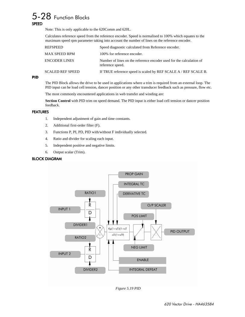
+,-
Note: This is only applicable to the 620Comm and 620L.
Calculates reference speed from the reference encoder. Speed is normalised to 100% which equates to themaximum speed rpm parameter taking into account the number of lines on the reference encoder.
REFSPEED Speed diagnostic calculated from Reference encoder.
MAX SPEED RPM 100% for reference encoder.
ENCODER LINES Number of lines on the reference encoder used for the calculation ofreference speed.
SCALED REF SPEED If TRUE reference speed is scaled by REF SCALE A / REF SCALE B.
The PID Block allows the drive to be used in applications where a trim is required from an external loop. ThePID input can be load cell tension, dancer position or any other transducer feedback such as pressure, flow etc.
The most commonly encountered applications in web transfer and winding are:
Section Control with PID trim on speed demand. The PID input is either load cell tension or dancer positionfeedback.
+ %(# + %(# + %(# + %(#
1. Independent adjustment of gain and time constants.
2. Additional first-order filter (F).
3. Functions P, PI, PD, PID with/without F individually selected.
4. Ratio and divider for scaling each input.
5. Independent positive and negative limits.
6. Output scalar (Trim).
,'. )# ,'. )# ,'. )# ,'. )#
$ ,
$%)# + %
$(%#
# %'
#
#
# %'
#
+
-
$(%
' %
$)%
' #
'(%(%.%%
%%!
#') $
$%)# %
# %%
Figure 5.19 PID
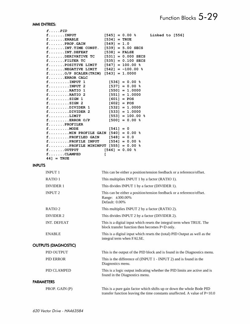
+,-
$%# $%# $%# $%#
f.....PIDf.......INPUT [545] = 0.00 % Linked to [556]f.......ENABLE [534] = TRUEf.......PROP.GAIN [549] = 1.0f.......INT.TIME CONST. [539] = 5.00 SECSf.......INT.DEFEAT [538] = FALSEf.......DERIVATIVE TC [531] = 0.000 SECSf.......FILTER TC [535] = 0.100 SECSf.......POSITIVE LIMIT [547] = 100.00 %f.......NEGATIVE LIMIT [542] = -100.00 %f.......O/P SCALER(TRIM) [543] = 1.0000f.......ERROR CALCf.........INPUT 1 [536] = 0.00 %f.........INPUT 2 [537] = 0.00 %f.........RATIO 1 [550] = 1.0000f.........RATIO 2 [551] = 1.0000f.........SIGN 1 [601] = POSf.........SIGN 2 [602] = POSf.........DIVIDER 1 [532] = 1.0000f.........DIVIDER 2 [533] = 1.0000f.........LIMIT [553] = 100.00 %f.........ERROR O/P [500] = 0.00 %f.......PROFILERf.........MODE [541] = 0f.........MIN PROFILE GAIN [540] = 0.00 %f.........PROFILED GAIN [548] = 0.0f.........PROFILE INPUT [554] = 0.00 %f.........PROFILE MININPUT [555] = 0.00 %f.......OUTPUT [546] = 0.00 %f.......CLAMPED [44] = TRUE
$(% $(% $(% $(%
INPUT 1 This can be either a position/tension feedback or a reference/offset.
RATIO 1 This multiplies INPUT 1 by a factor (RATIO 1).
DIVIDER 1 This divides INPUT 1 by a factor (DIVIDER 1).
INPUT 2 This can be either a position/tension feedback or a reference/offset.Range: ±300.00%Default: 0.00%
RATIO 2 This multiplies INPUT 2 by a factor (RATIO 2).
DIVIDER 2 This divides INPUT 2 by a factor (DIVIDER 2).
INT. DEFEAT This is a digital input which resets the integral term when TRUE. Theblock transfer function then becomes P+D only.
ENABLE This is a digital input which resets the (total) PID Output as well as theintegral term when FALSE.
'(%(% )$' %'(%(% )$' %'(%(% )$' %'(%(% )$' %
PID OUTPUT This is the output of the PID block and is found in the Diagnostics menu.
PID ERROR This is the difference of (INPUT 1 - INPUT 2) and is found in theDiagnostics menu.
PID CLAMPED This is a logic output indicating whether the PID limits are active and isfound in the Diagnostics menu.
# %# # %# # %# # %#
PROP. GAIN (P) This is a pure gain factor which shifts up or down the whole Bode PIDtransfer function leaving the time constants unaffected. A value of P=10.0

+,-
means that, for an error of 5%, the proportional part (initial step) of thePID output will be:
10 * [ 1 + (Td/Ti) ] * 5 % ,.e. approx. 50% for Td << Ti.
INT. TIME CONST. (Ti) This is the integrator time constant.
DERIVATIVE (Td) This is the differentiation time constant. When Td = 0 the transfer functionof the block becomes a P+I.
FILTER TC (Tf) In order to attenuate high-frequency noise a first order filter is added inconjunction with the differentiation. The ratio k of the Derivative TimeConstant (Td) over the Filter Time Constant (Tf) (typically 4 or 5)determines the high-frequency lift of the transfer function. For Tf = 0 thisfilter is eliminated.
POSITIVE LIMIT This is the upper limit of the PID algorithm.
NEGATIVE LIMIT This is the lower limit of the PID algorithm.
O/P SCALAR (TRIM) This is the ratio which the limited PID output is multiplied by in order togive the final PID Output. Normally this ratio would be between 0 and 1.
( #$%#+ ( #$%#+ ( #$%#+ ( #$%#+
'$+)(#$)%+($%'$'$+)(#$)%+($%'$'$+)(#$)%+($%'$'$+)(#$)%+($%'$
$(%'$$%'$ $(%'$$%'$ $(%'$$%'$ $(%'$$%'$
The two PID inputs (Input 1 & Input 2) by default are not connected to any signals and are only adjustable viathe MMI up/down arrow keys.
If the application requires setpoint and/or feedback coming from other sources, then these signals should beconfigured to point to Inputs 1 and Input 2 respectively.
'(%(%'$$%'$'(%(%'$$%'$'(%(%'$$%'$'(%(%'$$%'$
The default destination for the PID Output is 0 which means that the block will not be operating unless itsoutput is redirected to some other destination, typically a speed setpoint. This can be implemented by using theBlock Diagram section of the CONFIGURE I/O menu.
$%#$ %+($%'$ $%#$ %+($%'$ $%#$ %+($%'$ $%#$ %+($%'$
##'###'###'###'#
The PID Error is internally clamped to ±105.00%.
$%)# %#$%)# %#$%)# %#$%)# %#
The Integral Term is internally clamped to the prevailing values of "Positive Limit" and "Negative Limit"respectively as per PID Output.
It is also held while the PID Output is being clamped.
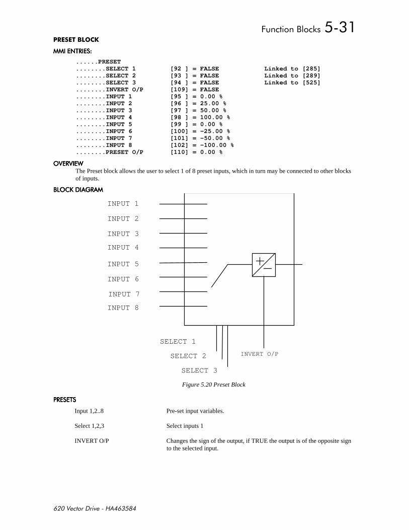
+,-
%&
$%# $%# $%# $%#
......PRESET
........SELECT 1 [92 ] = FALSE Linked to [285]
........SELECT 2 [93 ] = FALSE Linked to [289]
........SELECT 3 [94 ] = FALSE Linked to [525]
........INVERT O/P [109] = FALSE
........INPUT 1 [95 ] = 0.00 %
........INPUT 2 [96 ] = 25.00 %
........INPUT 3 [97 ] = 50.00 %
........INPUT 4 [98 ] = 100.00 %
........INPUT 5 [99 ] = 0.00 %
........INPUT 6 [100] = -25.00 %
........INPUT 7 [101] = -50.00 %
........INPUT 8 [102] = -100.00 %
........PRESET O/P [110] = 0.00 %
'#"'#"'#"'#"The Preset block allows the user to select 1 of 8 preset inputs, which in turn may be connected to other blocksof inputs.
,'. )# ,'. )# ,'. )# ,'. )#
INPUT 1
INPUT 2
INPUT 4
SELECT 1
SELECT 2
SELECT 3
INVERT O/P
INPUT 5
INPUT 6
INPUT 7
INPUT 8
INPUT 3
Figure 5.20 Preset Block
# % # % # % # %
Input 1,2..8 Pre-set input variables.
Select 1,2,3 Select inputs 1
INVERT O/P Changes the sign of the output, if TRUE the output is of the opposite signto the selected input.
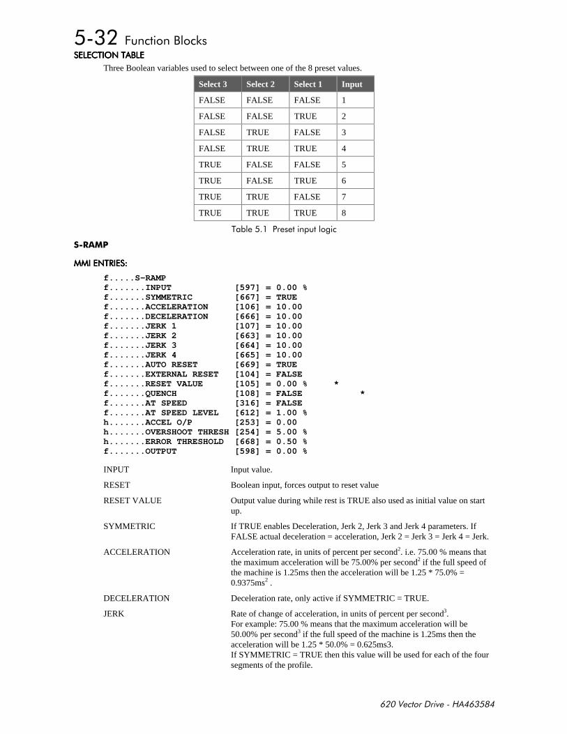
+,-
%'$% , %'$% , %'$% , %'$% ,
Three Boolean variables used to select between one of the 8 preset values.
Select 3 Select 2 Select 1 Input
FALSE FALSE FALSE 1
FALSE FALSE TRUE 2
FALSE TRUE FALSE 3
FALSE TRUE TRUE 4
TRUE FALSE FALSE 5
TRUE FALSE TRUE 6
TRUE TRUE FALSE 7
TRUE TRUE TRUE 8
%
$%# $%# $%# $%#
f.....S-RAMPf.......INPUT [597] = 0.00 %f.......SYMMETRIC [667] = TRUEf.......ACCELERATION [106] = 10.00f.......DECELERATION [666] = 10.00f.......JERK 1 [107] = 10.00f.......JERK 2 [663] = 10.00f.......JERK 3 [664] = 10.00f.......JERK 4 [665] = 10.00f.......AUTO RESET [669] = TRUEf.......EXTERNAL RESET [104] = FALSEf.......RESET VALUE [105] = 0.00 % *f.......QUENCH [108] = FALSE *f.......AT SPEED [316] = FALSEf.......AT SPEED LEVEL [612] = 1.00 %h.......ACCEL O/P [253] = 0.00h.......OVERSHOOT THRESH [254] = 5.00 %h.......ERROR THRESHOLD [668] = 0.50 %f.......OUTPUT [598] = 0.00 %
INPUT Input value.
RESET Boolean input, forces output to reset value
RESET VALUE Output value during while rest is TRUE also used as initial value on startup.
SYMMETRIC If TRUE enables Deceleration, Jerk 2, Jerk 3 and Jerk 4 parameters. IfFALSE actual deceleration = acceleration, Jerk 2 = Jerk 3 = Jerk 4 = Jerk.
ACCELERATION Acceleration rate, in units of percent per second2. i.e. 75.00 % means thatthe maximum acceleration will be 75.00% per second2 if the full speed ofthe machine is 1.25ms then the acceleration will be 1.25 * 75.0% =0.9375ms2 .
DECELERATION Deceleration rate, only active if SYMMETRIC = TRUE.
JERK Rate of change of acceleration, in units of percent per second3.For example: 75.00 % means that the maximum acceleration will be50.00% per second3 if the full speed of the machine is 1.25ms then theacceleration will be 1.25 * 50.0% = 0.625ms3.If SYMMETRIC = TRUE then this value will be used for each of the foursegments of the profile.
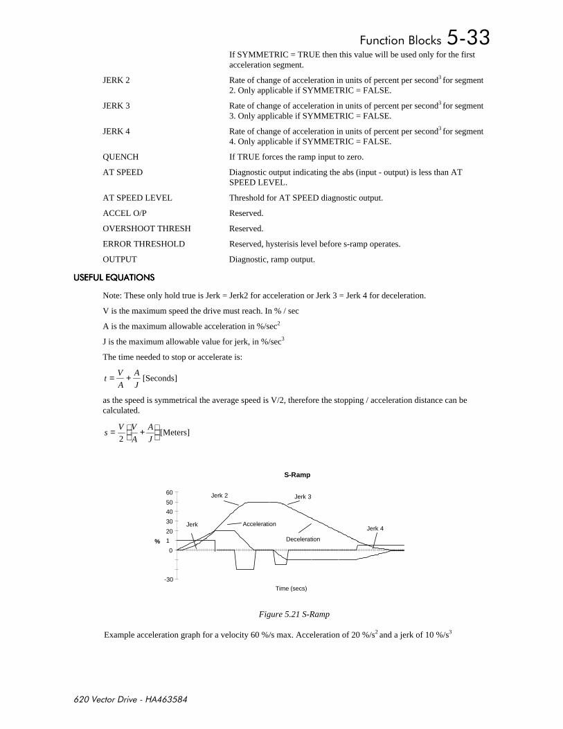
+,-
If SYMMETRIC = TRUE then this value will be used only for the firstacceleration segment.
JERK 2 Rate of change of acceleration in units of percent per second3 for segment2. Only applicable if SYMMETRIC = FALSE.
JERK 3 Rate of change of acceleration in units of percent per second3 for segment3. Only applicable if SYMMETRIC = FALSE.
JERK 4 Rate of change of acceleration in units of percent per second3 for segment4. Only applicable if SYMMETRIC = FALSE.
QUENCH If TRUE forces the ramp input to zero.
AT SPEED Diagnostic output indicating the abs (input - output) is less than ATSPEED LEVEL.
AT SPEED LEVEL Threshold for AT SPEED diagnostic output.
ACCEL O/P Reserved.
OVERSHOOT THRESH Reserved.
ERROR THRESHOLD Reserved, hysterisis level before s-ramp operates.
OUTPUT Diagnostic, ramp output.
( +(;( %'$ ( +(;( %'$ ( +(;( %'$ ( +(;( %'$
Note: These only hold true is Jerk = Jerk2 for acceleration or Jerk 3 = Jerk 4 for deceleration.
V is the maximum speed the drive must reach. In % / sec
A is the maximum allowable acceleration in %/sec2
J is the maximum allowable value for jerk, in %/sec3
The time needed to stop or accelerate is:
tV
A
A
J= + [Seconds]
as the speed is symmetrical the average speed is V/2, therefore the stopping / acceleration distance can becalculated.
sV V
A
A
J= +
2
[Meters]
S-Ramp
-30
0
1
20
30
40
50
60
Time (secs)
%
Jerk 3
Jerk 4
Jerk 2
Jerk Acceleration
Deceleration
Figure 5.21 S-Ramp
Example acceleration graph for a velocity 60 %/s max. Acceleration of 20 %/s2 and a jerk of 10 %/s3
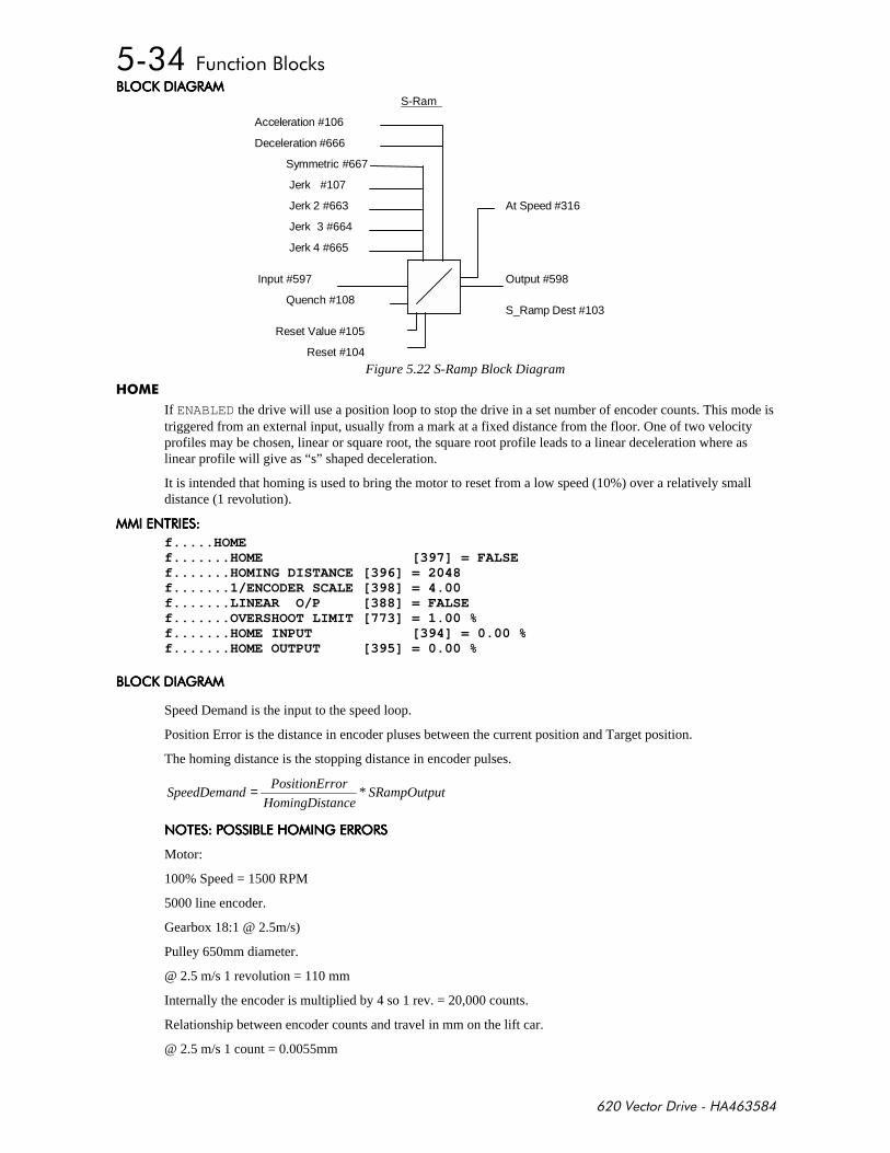
+,-
,'. )# ,'. )# ,'. )# ,'. )# S-Ram
At Speed #316
Acceleration #106
Jerk 2 #663
Reset Value #105
Reset #104
Quench #108
Input #597 Output #598
S_Ramp Dest #103
Jerk 3 #664
Jerk 4 #665
Jerk #107
Deceleration #666
Symmetric #667
Figure 5.22 S-Ramp Block Diagram
If ENABLED the drive will use a position loop to stop the drive in a set number of encoder counts. This mode istriggered from an external input, usually from a mark at a fixed distance from the floor. One of two velocityprofiles may be chosen, linear or square root, the square root profile leads to a linear deceleration where aslinear profile will give as “s” shaped deceleration.
It is intended that homing is used to bring the motor to reset from a low speed (10%) over a relatively smalldistance (1 revolution).
$%# $%# $%# $%#
f.....HOMEf.......HOME [397] = FALSEf.......HOMING DISTANCE [396] = 2048f.......1/ENCODER SCALE [398] = 4.00f.......LINEAR O/P [388] = FALSEf.......OVERSHOOT LIMIT [773] = 1.00 %f.......HOME INPUT [394] = 0.00 %f.......HOME OUTPUT [395] = 0.00 %
,'. )# ,'. )# ,'. )# ,'. )#
Speed Demand is the input to the speed loop.
Position Error is the distance in encoder pluses between the current position and Target position.
The homing distance is the stopping distance in encoder pulses.
SpeedDemandPositionError
HomingDistanceSRampOutput= *
$'% ' ,'$)##'# $'% ' ,'$)##'# $'% ' ,'$)##'# $'% ' ,'$)##'#
Motor:
100% Speed = 1500 RPM
5000 line encoder.
Gearbox 18:1 @ 2.5m/s)
Pulley 650mm diameter.
@ 2.5 m/s 1 revolution = 110 mm
Internally the encoder is multiplied by 4 so 1 rev. = 20,000 counts.
Relationship between encoder counts and travel in mm on the lift car.
@ 2.5 m/s 1 count = 0.0055mm
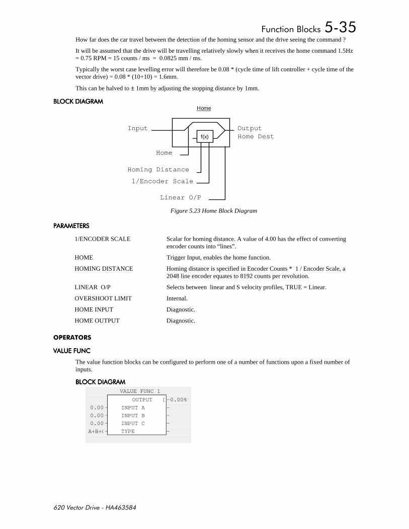
+,-
How far does the car travel between the detection of the homing sensor and the drive seeing the command ?
It will be assumed that the drive will be travelling relatively slowly when it receives the home command 1.5Hz= 0.75 RPM = 15 counts / ms = 0.0825 mm / ms.
Typically the worst case levelling error will therefore be 0.08 * (cycle time of lift controller + cycle time of thevector drive) = 0.08 * (10+10) = 1.6mm.
This can be halved to ± 1mm by adjusting the stopping distance by 1mm.
,'. )# ,'. )# ,'. )# ,'. )# Home
Home
f(x)
Homing Distance
1/Encoder Scale
Linear O/P
OutputInputHome Dest
Figure 5.23 Home Block Diagram
# %# # %# # %# # %#
1/ENCODER SCALE Scalar for homing distance. A value of 4.00 has the effect of convertingencoder counts into “lines”.
HOME Trigger Input, enables the home function.
HOMING DISTANCE Homing distance is specified in Encoder Counts * 1 / Encoder Scale, a2048 line encoder equates to 8192 counts per revolution.
LINEAR O/P Selects between linear and S velocity profiles, TRUE = Linear.
OVERSHOOT LIMIT Internal.
HOME INPUT Diagnostic.
HOME OUTPUT Diagnostic.
(+($ (+($ (+($ (+($
The value function blocks can be configured to perform one of a number of functions upon a fixed number ofinputs.
,'. )# ,'. )# ,'. )# ,'. )#
VALUE FUNC 1
OUTPUT []–0.00%
0.00%– INPUT A –
0.00%– INPUT B –
0.00%– INPUT C –
A+B+C– TYPE –
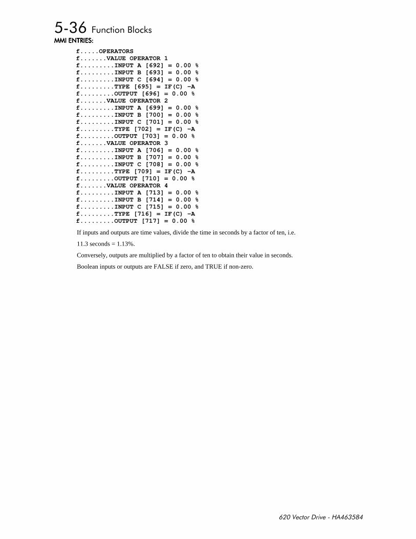
+,-
$%# $%# $%# $%#
f.....OPERATORSf.......VALUE OPERATOR 1f.........INPUT A [692] = 0.00 %f.........INPUT B [693] = 0.00 %f.........INPUT C [694] = 0.00 %f.........TYPE [695] = IF(C) -Af.........OUTPUT [696] = 0.00 %f.......VALUE OPERATOR 2f.........INPUT A [699] = 0.00 %f.........INPUT B [700] = 0.00 %f.........INPUT C [701] = 0.00 %f.........TYPE [702] = IF(C) -Af.........OUTPUT [703] = 0.00 %f.......VALUE OPERATOR 3f.........INPUT A [706] = 0.00 %f.........INPUT B [707] = 0.00 %f.........INPUT C [708] = 0.00 %f.........TYPE [709] = IF(C) -Af.........OUTPUT [710] = 0.00 %f.......VALUE OPERATOR 4f.........INPUT A [713] = 0.00 %f.........INPUT B [714] = 0.00 %f.........INPUT C [715] = 0.00 %f.........TYPE [716] = IF(C) -Af.........OUTPUT [717] = 0.00 %
If inputs and outputs are time values, divide the time in seconds by a factor of ten, i.e.
11.3 seconds = 1.13%.
Conversely, outputs are multiplied by a factor of ten to obtain their value in seconds.
Boolean inputs or outputs are FALSE if zero, and TRUE if non-zero.

+,-
# %# #%'$ # %# #%'$ # %# #%'$ # %# #%'$
INPUT A General purpose input.
INPUT B General purpose input.
INPUT C General purpose input.
TYPE The operation to be performed on the three inputs to produce the output value.
! )
0 IF(C) -A
1 ABS (A+B+C)
2 SWITCH (A,B)
3 (A*B)/C
4 A+B+C
5 A-B-C
6 B <= A <=C
7 A>B+/-C
8 A>=B
9 ABS (A) >B+/-C
10 ABS (A) >=B
11 A(1+B)
12 IF (C) HOLD (A)
13 BINARY DECODE
14 ON DELAY
15 OFF DELAY
16 TIMER
17 MINIMUM PULSE
18 PULSE TRAIN
19 WINDOW
20 UP/DWN COUNTER
OUTPUT Range: XXX.XX %
The result of performing the selected operation on the inputs.
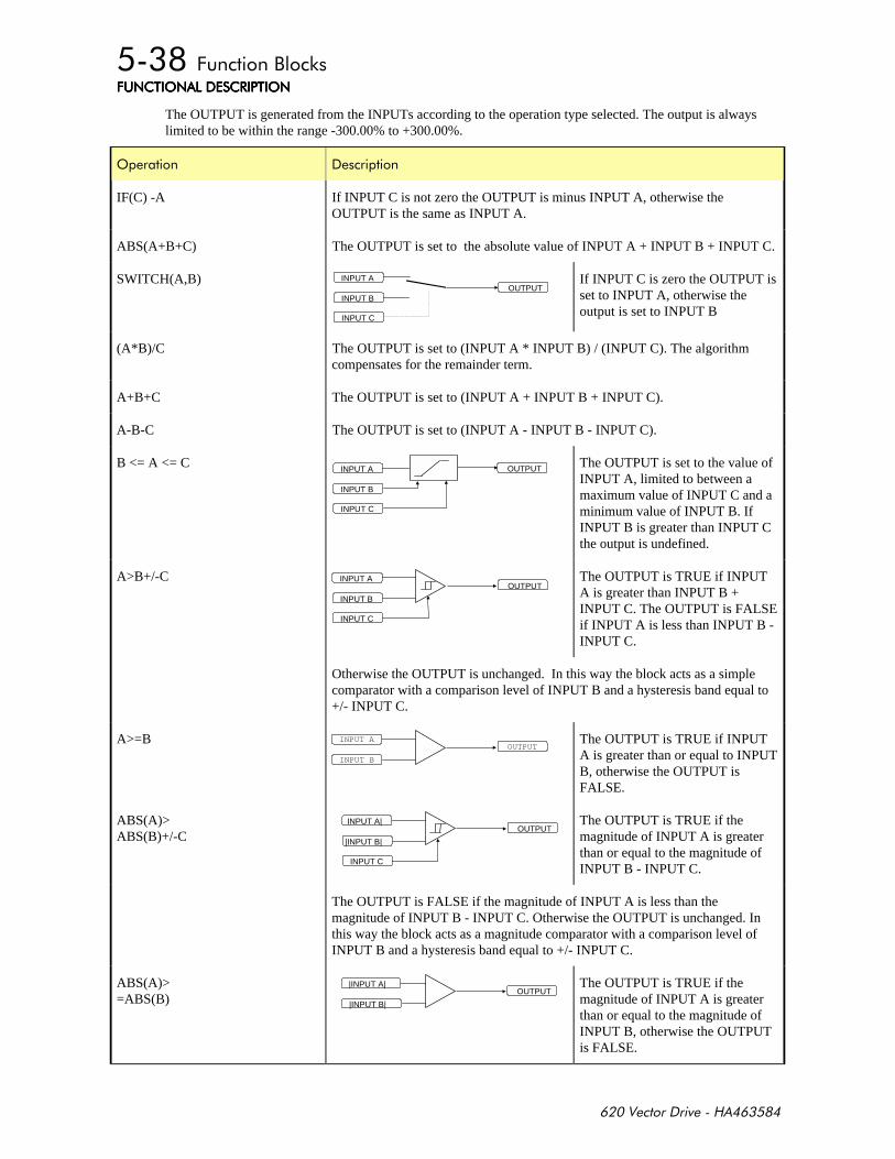
+,-
+($%'$ #%'$+($%'$ #%'$+($%'$ #%'$+($%'$ #%'$
The OUTPUT is generated from the INPUTs according to the operation type selected. The output is alwayslimited to be within the range -300.00% to +300.00%.
'
IF(C) -A If INPUT C is not zero the OUTPUT is minus INPUT A, otherwise theOUTPUT is the same as INPUT A.
ABS(A+B+C) The OUTPUT is set to the absolute value of INPUT A + INPUT B + INPUT C.
SWITCH(A,B)OUTPUT
INPUT A
INPUT B
INPUT C
If INPUT C is zero the OUTPUT isset to INPUT A, otherwise theoutput is set to INPUT B
(A*B)/C The OUTPUT is set to (INPUT A * INPUT B) / (INPUT C). The algorithmcompensates for the remainder term.
A+B+C The OUTPUT is set to (INPUT A + INPUT B + INPUT C).
A-B-C The OUTPUT is set to (INPUT A - INPUT B - INPUT C).
B <= A <= C OUTPUTINPUT A
INPUT B
INPUT C
The OUTPUT is set to the value ofINPUT A, limited to between amaximum value of INPUT C and aminimum value of INPUT B. IfINPUT B is greater than INPUT Cthe output is undefined.
A>B+/-COUTPUT
INPUT A
INPUT B
INPUT C
The OUTPUT is TRUE if INPUTA is greater than INPUT B +INPUT C. The OUTPUT is FALSEif INPUT A is less than INPUT B -INPUT C.
Otherwise the OUTPUT is unchanged. In this way the block acts as a simplecomparator with a comparison level of INPUT B and a hysteresis band equal to+/- INPUT C.
A>=BOUTPUT
INPUT A
INPUT B
The OUTPUT is TRUE if INPUTA is greater than or equal to INPUTB, otherwise the OUTPUT isFALSE.
ABS(A)>ABS(B)+/-C
OUTPUTINPUT A|
|INPUT B|
INPUT C
The OUTPUT is TRUE if themagnitude of INPUT A is greaterthan or equal to the magnitude ofINPUT B - INPUT C.
The OUTPUT is FALSE if the magnitude of INPUT A is less than themagnitude of INPUT B - INPUT C. Otherwise the OUTPUT is unchanged. Inthis way the block acts as a magnitude comparator with a comparison level ofINPUT B and a hysteresis band equal to +/- INPUT C.
ABS(A)>=ABS(B)
OUTPUT|INPUT A|
|INPUT B|
The OUTPUT is TRUE if themagnitude of INPUT A is greaterthan or equal to the magnitude ofINPUT B, otherwise the OUTPUTis FALSE.
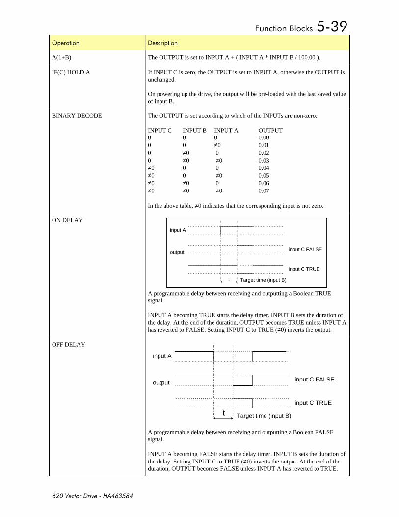
+,-
'
A(1+B) The OUTPUT is set to INPUT A + ( INPUT A * INPUT B / 100.00 ).
IF(C) HOLD A If INPUT C is zero, the OUTPUT is set to INPUT A, otherwise the OUTPUT isunchanged.
On powering up the drive, the output will be pre-loaded with the last saved valueof input B.
BINARY DECODE The OUTPUT is set according to which of the INPUTs are non-zero.
INPUT C INPUT B INPUT A OUTPUT0 0 0 0.000 0 ≠0 0.010 ≠0 0 0.020 ≠0 ≠0 0.03≠0 0 0 0.04≠0 0 ≠0 0.05≠0 ≠0 0 0.06≠0 ≠0 ≠0 0.07
In the above table, ≠0 indicates that the corresponding input is not zero.
ON DELAY
A programmable delay between receiving and outputting a Boolean TRUEsignal.
INPUT A becoming TRUE starts the delay timer. INPUT B sets the duration ofthe delay. At the end of the duration, OUTPUT becomes TRUE unless INPUT Ahas reverted to FALSE. Setting INPUT C to TRUE (≠0) inverts the output.
OFF DELAY
A programmable delay between receiving and outputting a Boolean FALSEsignal.
INPUT A becoming FALSE starts the delay timer. INPUT B sets the duration ofthe delay. Setting INPUT C to TRUE (≠0) inverts the output. At the end of theduration, OUTPUT becomes FALSE unless INPUT A has reverted to TRUE.
input A
output input C FALSE
input C TRUE
Target time (input B)t
input A
output input C FALSE
input C TRUE
Target time (input B)t
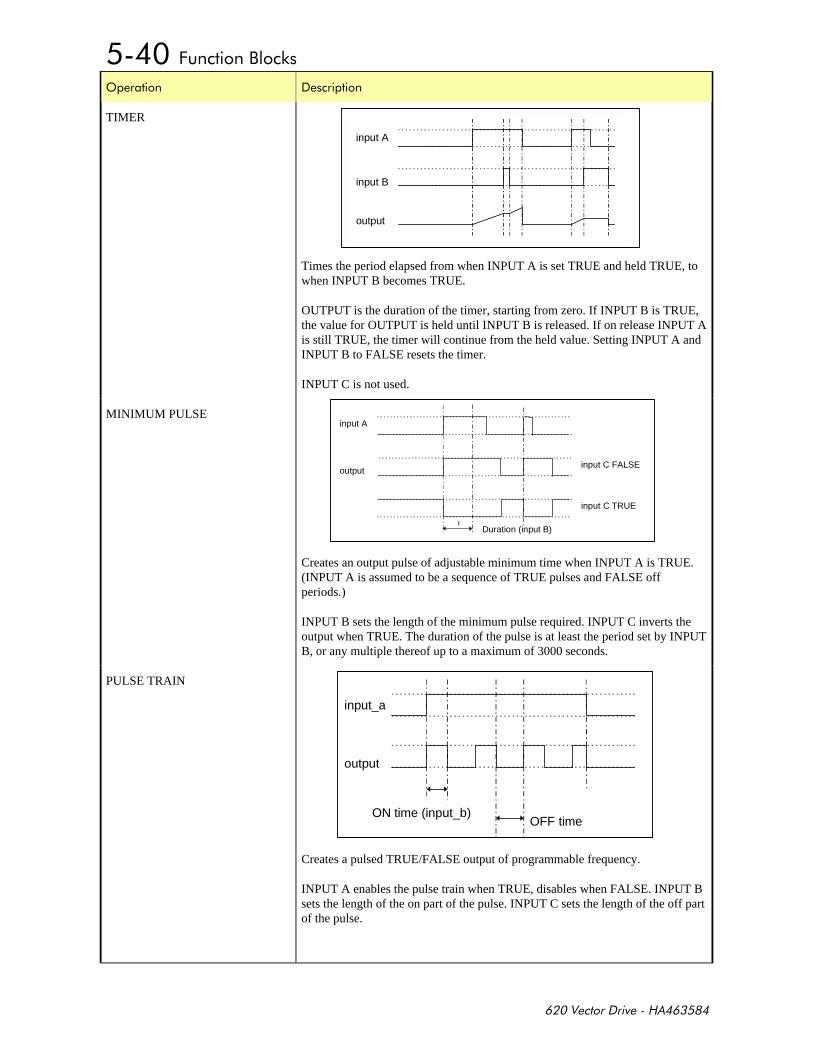
+,-
'
TIMER
Times the period elapsed from when INPUT A is set TRUE and held TRUE, towhen INPUT B becomes TRUE.
OUTPUT is the duration of the timer, starting from zero. If INPUT B is TRUE,the value for OUTPUT is held until INPUT B is released. If on release INPUT Ais still TRUE, the timer will continue from the held value. Setting INPUT A andINPUT B to FALSE resets the timer.
INPUT C is not used.
MINIMUM PULSE
Creates an output pulse of adjustable minimum time when INPUT A is TRUE.(INPUT A is assumed to be a sequence of TRUE pulses and FALSE offperiods.)
INPUT B sets the length of the minimum pulse required. INPUT C inverts theoutput when TRUE. The duration of the pulse is at least the period set by INPUTB, or any multiple thereof up to a maximum of 3000 seconds.
PULSE TRAIN
Creates a pulsed TRUE/FALSE output of programmable frequency.
INPUT A enables the pulse train when TRUE, disables when FALSE. INPUT Bsets the length of the on part of the pulse. INPUT C sets the length of the off partof the pulse.
input A
input B
output
input A
outputinput C FALSE
input C TRUE
Duration (input B)t
input_a
output
ON time (input_b)OFF time
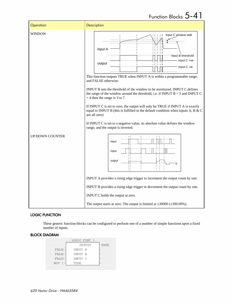
+,-
'
WINDOW
This function outputs TRUE when INPUT A is within a programmable range,and FALSE otherwise.
INPUT B sets the threshold of the window to be monitored. INPUT C definesthe range of the window around the threshold, i.e. if INPUT B = 5 and INPUT C= 4 then the range is 3 to 7.
If INPUT C is set to zero, the output will only be TRUE if INPUT A is exactlyequal to INPUT B (this is fulfilled in the default condition when inputs A, B & Care all zero)
If INPUT C is set to a negative value, its absolute value defines the windowrange, and the output is inverted.
UP/DOWN COUNTER
input
input
output0
INPUT A provides a rising edge trigger to increment the output count by one.
INPUT B provides a rising edge trigger to decrement the output count by one.
INPUT C holds the output at zero.
The output starts at zero. The output is limited at ±30000 (±300.00%).
')+($%'$')+($%'$')+($%'$')+($%'$
These generic function blocks can be configured to perform one of a number of simple functions upon a fixednumber of inputs.
,'. )# ,'. )# ,'. )# ,'. )#
LOGIC FUNC 1
OUTPUT –TRUE
FALSE– INPUT A –
FALSE– INPUT B –
FALSE– INPUT C –
NOT [ – TYPE –
input A
output
input B threshold
input C window widt
input C +ve
input C -ve

+,-
$%# $%# $%# $%#
f.......LOGIC OPERATOR 1f.........INPUT A [720] = FALSEf.........INPUT B [721] = FALSEf.........INPUT C [722] = FALSEf.........TYPE [723] = NOT(A)f.........OUTPUT [724] = TRUEf.......LOGIC OPERATOR 2f.........INPUT A [727] = FALSEf.........INPUT B [728] = FALSEf.........INPUT C [729] = FALSEf.........TYPE [730] = NOT(A)f.........OUTPUT [731] = TRUEf.......LOGIC OPERATOR 3f.........INPUT A [734] = FALSEf.........INPUT B [735] = FALSEf.........INPUT C [736] = FALSEf.........TYPE [737] = NOT(A)f.........OUTPUT [738] = TRUEf.......LOGIC OPERATOR 4f.........INPUT A [741] = FALSEf.........INPUT B [742] = FALSEf.........INPUT C [743] = FALSEf.........TYPE [744] = NOT(A)f.........OUTPUT [745] = TRUE
# %# #%'$ # %# #%'$ # %# #%'$ # %# #%'$
INPUT A General-purpose logic input.
INPUT B General-purpose logic input.
INPUT C General-purpose logic input.
TYPE see below
The operation to be performed on the three inputs to produce the output value. Theoperations that can be selected are:
Enumerated Value Type
0 NOT (A)
1 AND (A,B,C)
2 NAND (A,B,C)
3 OR (A,B,C)
4 NOR (A,B,C)
5 XOR (A,B)
6 0-1 EDGE (A)
7 1-0 EDGE (A)
8 AND (A,B,!C)
9 OR (A,B,!C)
10 FLIP-FLOP
OUTPUT The result of performing the selected operation on the inputs.
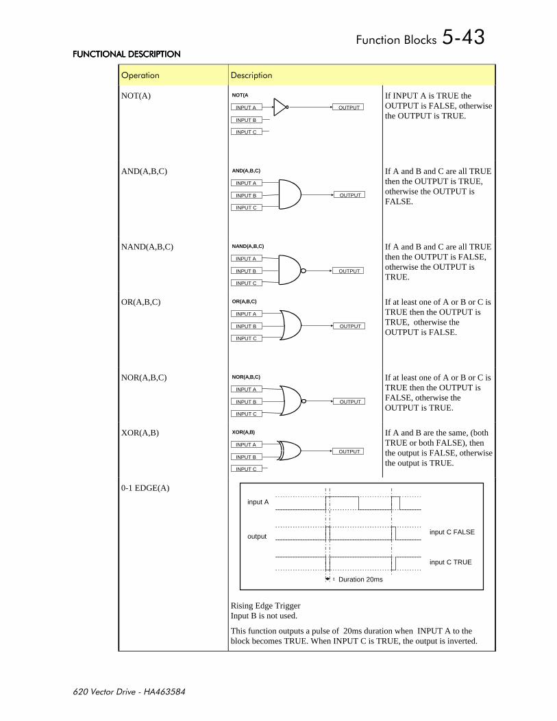
+,-
+($%'$ #%'$+($%'$ #%'$+($%'$ #%'$+($%'$ #%'$
'
NOT(A)OUTPUTINPUT A
INPUT B
INPUT C
NOT(A If INPUT A is TRUE theOUTPUT is FALSE, otherwisethe OUTPUT is TRUE.
AND(A,B,C)
OUTPUT
INPUT A
INPUT B
INPUT C
AND(A,B,C) If A and B and C are all TRUEthen the OUTPUT is TRUE,otherwise the OUTPUT isFALSE.
NAND(A,B,C)
OUTPUT
INPUT A
INPUT B
INPUT C
NAND(A,B,C) If A and B and C are all TRUEthen the OUTPUT is FALSE,otherwise the OUTPUT isTRUE.
OR(A,B,C)
OUTPUT
INPUT A
INPUT B
INPUT C
OR(A,B,C) If at least one of A or B or C isTRUE then the OUTPUT isTRUE, otherwise theOUTPUT is FALSE.
NOR(A,B,C)
OUTPUT
INPUT A
INPUT B
INPUT C
NOR(A,B,C) If at least one of A or B or C isTRUE then the OUTPUT isFALSE, otherwise theOUTPUT is TRUE.
XOR(A,B)
OUTPUTINPUT A
INPUT B
INPUT C
XOR(A,B) If A and B are the same, (bothTRUE or both FALSE), thenthe output is FALSE, otherwisethe output is TRUE.
0-1 EDGE(A)
input A
outputinput C FALSE
input C TRUE
Duration 20mst
Rising Edge TriggerInput B is not used.
This function outputs a pulse of 20ms duration when INPUT A to theblock becomes TRUE. When INPUT C is TRUE, the output is inverted.
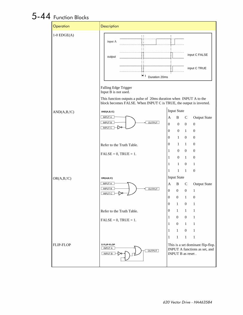
+,-
'
1-0 EDGE(A)
input A
outputinput C FALSE
input C TRUE
Duration 20mst
Falling Edge TriggerInput B is not used.
This function outputs a pulse of 20ms duration when INPUT A to theblock becomes FALSE. When INPUT C is TRUE, the output is inverted.
AND(A,B,!C)
OUTPUT
INPUT A
INPUT B
INPUT C
AND(A,B,!C)
Refer to the Truth Table.
FALSE = 0, TRUE = 1.
Input State
A B C Output State
0 0 0 0
0 0 1 0
0 1 0 0
0 1 1 0
1 0 0 0
1 0 1 0
1 1 0 1
1 1 1 0
OR(A,B,!C)
OUTPUT
INPUT A
INPUT B
INPUT C
OR(A,B,!C)
Refer to the Truth Table.
FALSE = 0, TRUE = 1.
Input State
A B C Output State
0 0 0 1
0 0 1 0
0 1 0 1
0 1 1 1
1 0 0 1
1 0 1 1
1 1 0 1
1 1 1 1
FLIP-FLOP
OUTPUTINPUT A
S FLIP-FLOP
INPUT B
This is a set dominant flip-flop.INPUT A functions as set, andINPUT B as reset .
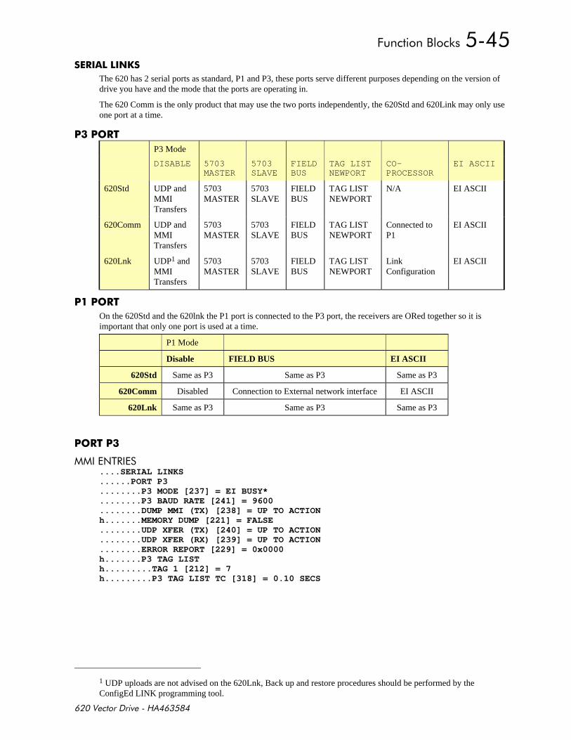
+,-
&
The 620 has 2 serial ports as standard, P1 and P3, these ports serve different purposes depending on the version ofdrive you have and the mode that the ports are operating in.
The 620 Comm is the only product that may use the two ports independently, the 620Std and 620Link may only useone port at a time.
P3 Mode
DISABLE 5703MASTER
5703SLAVE
FIELDBUS
TAG LISTNEWPORT
CO-PROCESSOR
EI ASCII
620Std UDP andMMITransfers
5703MASTER
5703SLAVE
FIELDBUS
TAG LISTNEWPORT
N/A EI ASCII
620Comm UDP andMMITransfers
5703MASTER
5703SLAVE
FIELDBUS
TAG LISTNEWPORT
Connected toP1
EI ASCII
620Lnk UDP1 andMMITransfers
5703MASTER
5703SLAVE
FIELDBUS
TAG LISTNEWPORT
LinkConfiguration
EI ASCII
On the 620Std and the 620lnk the P1 port is connected to the P3 port, the receivers are ORed together so it isimportant that only one port is used at a time.
P1 Mode
Disable FIELD BUS EI ASCII
620Std Same as P3 Same as P3 Same as P3
620Comm Disabled Connection to External network interface EI ASCII
620Lnk Same as P3 Same as P3 Same as P3
$%# ....SERIAL LINKS......PORT P3........P3 MODE [237] = EI BUSY*........P3 BAUD RATE [241] = 9600........DUMP MMI (TX) [238] = UP TO ACTIONh.......MEMORY DUMP [221] = FALSE........UDP XFER (TX) [240] = UP TO ACTION........UDP XFER (RX) [239] = UP TO ACTION........ERROR REPORT [229] = 0x0000h.......P3 TAG LISTh.........TAG 1 [212] = 7h.........P3 TAG LIST TC [318] = 0.10 SECS
1 UDP uploads are not advised on the 620Lnk, Back up and restore procedures should be performed by theConfigEd LINK programming tool.
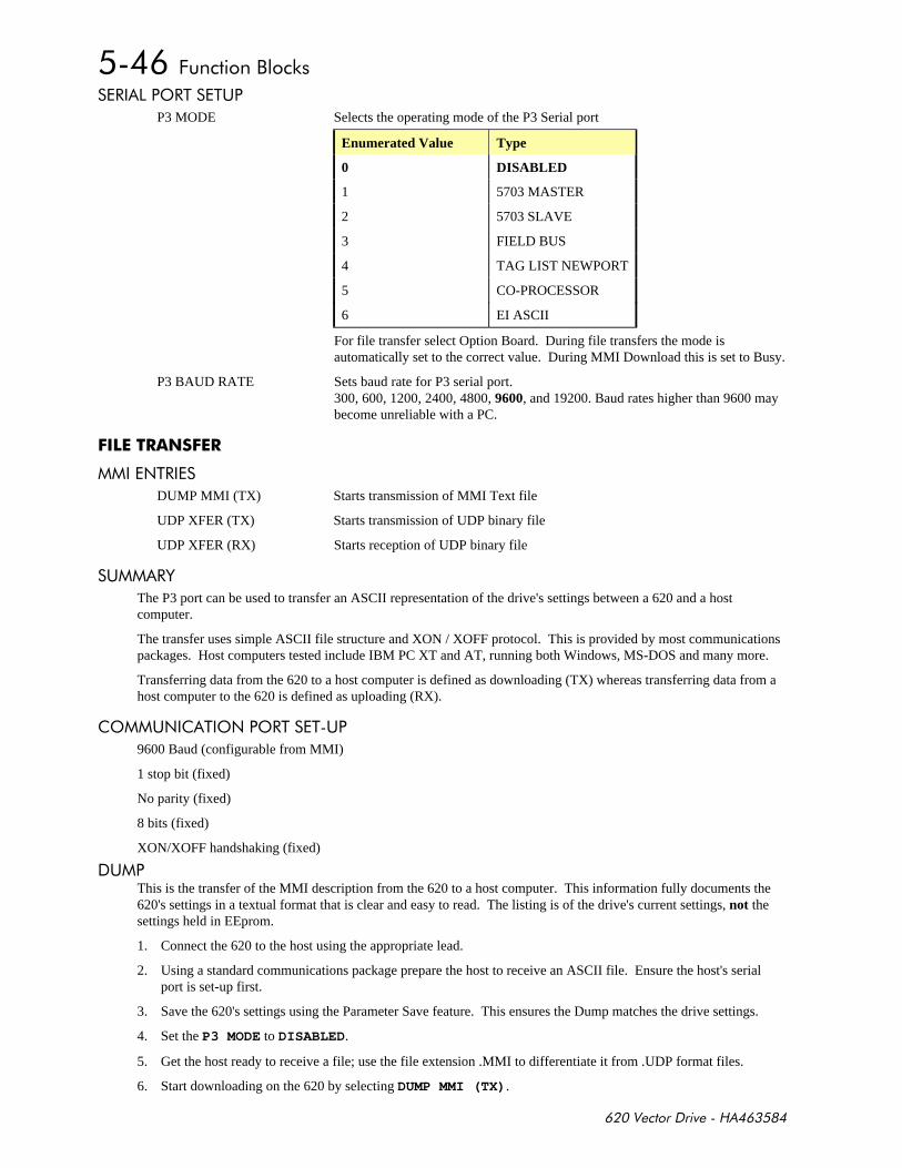
+,-
# '#% %(
P3 MODE Selects the operating mode of the P3 Serial port
Enumerated Value Type
0 DISABLED
1 5703 MASTER
2 5703 SLAVE
3 FIELD BUS
4 TAG LIST NEWPORT
5 CO-PROCESSOR
6 EI ASCII
For file transfer select Option Board. During file transfers the mode isautomatically set to the correct value. During MMI Download this is set to Busy.
P3 BAUD RATE Sets baud rate for P3 serial port.300, 600, 1200, 2400, 4800, 9600, and 19200. Baud rates higher than 9600 maybecome unreliable with a PC.
$$
$%#
DUMP MMI (TX) Starts transmission of MMI Text file
UDP XFER (TX) Starts transmission of UDP binary file
UDP XFER (RX) Starts reception of UDP binary file
( #&
The P3 port can be used to transfer an ASCII representation of the drive's settings between a 620 and a hostcomputer.
The transfer uses simple ASCII file structure and XON / XOFF protocol. This is provided by most communicationspackages. Host computers tested include IBM PC XT and AT, running both Windows, MS-DOS and many more.
Transferring data from the 620 to a host computer is defined as downloading (TX) whereas transferring data from ahost computer to the 620 is defined as uploading (RX).
'($ %'$'#% %(
9600 Baud (configurable from MMI)
1 stop bit (fixed)
No parity (fixed)
8 bits (fixed)
XON/XOFF handshaking (fixed)
(This is the transfer of the MMI description from the 620 to a host computer. This information fully documents the620's settings in a textual format that is clear and easy to read. The listing is of the drive's current settings, not thesettings held in EEprom.
1. Connect the 620 to the host using the appropriate lead.
2. Using a standard communications package prepare the host to receive an ASCII file. Ensure the host's serialport is set-up first.
3. Save the 620's settings using the Parameter Save feature. This ensures the Dump matches the drive settings.
4. Set the P3 MODE to DISABLED.
5. Get the host ready to receive a file; use the file extension .MMI to differentiate it from .UDP format files.
6. Start downloading on the 620 by selecting DUMP MMI (TX).

+,-
7. The file ends in a ctrl-z; some packages this automatically closes the file. If this is not the case, when the 620says it has finished and the host has stopped scrolling text, close the file by hand.
8. The file can now be treated like any normal file.
('"$' (1+#%1
This is the transfer of parameters from the 620 to a host computer. This information fully describes the 620's settingsin a binary format. The listing is of the drive's settings currently held in EEprom, i.e. those that have been saved.
1. Connect the 620 to the host using the appropriate lead.
2. Using a standard communications package prepare the host to receive an ASCII file. Ensure the host's serialport is set-up first.
3. Save the 620's settings using the Parameter Save feature. This ensures the UDP file matches the drive settings.
4. Set the P3 MODE to DISABLED.
5. Get the host ready to receive a file; use the file extension .UDP to differentiate it from .MMI format files.
6. Start downloading on the 620 by selecting UDP XFER (TX).
7. The file ends in a ctrl-z; some packages this automatically closes the file. If this is not the case, when the 620says it has finished and the host has stopped scrolling text, close the file by hand. The last line should read:00000001FF
8. The file can now be treated like any normal file.
((' (1+##1
The 620 UDP files are not compatible with any other EUROTHERM Product.Uploading a corrupted UDP file cause loss of data.
This is the transfer of parameters from the host computer to the 620. This information is written directly to EEprom,so all the drive's current settings will be overwritten.
1. Connect the 620 to the host using the appropriate lead.
2. Using a standard communications package prepare the host to transfer an ASCII file. Ensure the host's serialport is set-up first.
3. Set the P3 MODE to DISABLE.
4. Start uploading on the 620 by selecting UDP XFER (RX).
5. When the 620 says "RECEIVING", begin the file transmission.
6. The file ends in a ctrl-z which the 620 uses to close the file.
7. Pressing the ‘E’ key must now resets the 620, as the message on the MMI indicates.
##'##'#%
ERROR REPORT See EE ERROR CODES.NOTE: Writing to this parameter has the effect of resetting it.

+,-
All these parameters are common between the P3 port and the P1 port.
$%# ....SERIAL LINKS......PORT P3......EI ASCII........GROUP ID (GID) [223] = 0........UNIT ID (UID) [224] = 0f.......OPTION ADDRESS [230] = 0f.......OPTION VERSION [672] = 0.00
$%#
GROUP ID (GID) The GID and UID together form the logical address of the drive. This address isthe same on both the P3 port and the P1 port (620COM only).The drive will always reply to a message addressed to GID, UID = 0,0 This hasthe effect of making address 00 a broadcast address and should not be selected ina Multi-drop network.If the drive is connected to a host via the P3 port, It is preferable that the drive isaddressed as 00, so as not to conflict with the P1 address.
UNIT ID (UID) Unit address, see GID.
OPTION ADDRESS The address used by an external network interface card, for example the 6204Profibus interface. This address is only read when the external interfaceinitialises its self, so the power must be cycled after this parameter has beenmodified.
OPTION VERSION The software version number of the external network interface card. This will benon-zero if the card has initialised correctly.
Note 1: OPTION ADDRESS and OPTION VERSION are only applicable if the port mode is field bus.
Note 2: Only one external network interface card may be attached to the 620 at a time.
0$%0
The EI-Bisync communications protocol may be used to connect to a PC running suitable software. By default, theports operates at 9.6K Baud using the EI-Bisync ASCII protocol with Group ID = 0 and Unit Id = 0.
7 Data Bits1 Stop BitEven Parity
Note 1: Before EUROTHERM ASCII communications may be used with the P3 port the “P3 MODE” must be set toASCII.
'($ %'$ # %#
There are two classes of parameters. These are:
• EI-Bisync prime set
• Command / Status
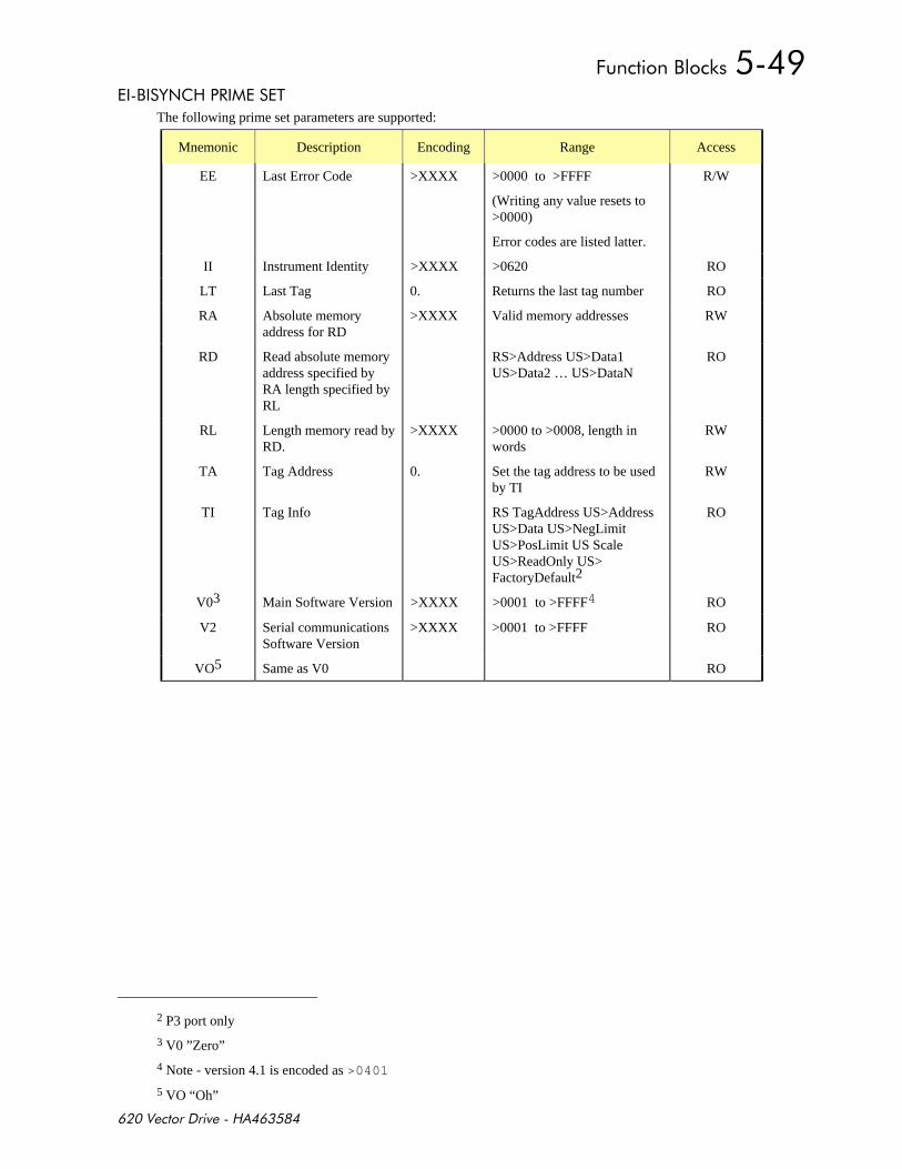
+,-
, &$# %
The following prime set parameters are supported:
Mnemonic Description Encoding Range Access
EE Last Error Code >XXXX >0000 to >FFFF
(Writing any value resets to>0000)
Error codes are listed latter.
R/W
II Instrument Identity >XXXX >0620 RO
LT Last Tag 0. Returns the last tag number RO
RA Absolute memoryaddress for RD
>XXXX Valid memory addresses RW
RD Read absolute memoryaddress specified byRA length specified byRL
RS>Address US>Data1US>Data2 … US>DataN
RO
RL Length memory read byRD.
>XXXX >0000 to >0008, length inwords
RW
TA Tag Address 0. Set the tag address to be usedby TI
RW
TI Tag Info RS TagAddress US>AddressUS>Data US>NegLimitUS>PosLimit US ScaleUS>ReadOnly US>FactoryDefault2
RO
V03 Main Software Version >XXXX >0001 to >FFFF4 RO
V2 Serial communicationsSoftware Version
>XXXX >0001 to >FFFF RO
VO5 Same as V0 RO
2 P3 port only
3 V0 ”Zero”
4 Note - version 4.1 is encoded as >0401
5 VO “Oh”
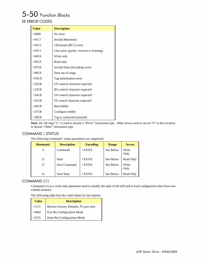
+,-
##'#'
Value Description
>0000 No error
>01C7 Invalid Mnemonic
>02C2 Checksum (BCC) error
>03C1 Line error, (parity, overrun or framing).
>04C8 Write only
>05C8 Read only
>07C8 Invalid Data (Encoding error)
>08C8 Data out of range
>0AC8 Tag initialisation error
>22CB US control character expected
>23CB RS control character expected
>24CB GS control character expected
>25CB FS control character expected
>26CB Run Inhibit
>27CB Configure Inhibit
>28CB Tag is connected (unused)
Note: the 3dr digit “C” is used to denote a “Drive” instrument type. Older drives used to use an “F” in this locationto denote “Other” instrument type.
' $ % %(
The following command / status parameters are supported:
Mnemonic Description Encoding Range Access
!1 Command >XXXX See Below WriteOnly
!2 State >XXXX See Below Read Only
!3 Save Command >XXXX See Below WriteOnly
!4 Save State >XXXX See Below Read Only
' $
Command (!1) is a write only parameter used to modify the state of the 620 and to load configuration data from non-volatile memory.
The following table lists the valid values for the request:
Value Description
>1111 Restore Factory Defaults, P3 port only
>4444 Exit Re-Configuration Mode
>5555 Enter Re-Configuration Mode

+,-
State (!2) is a read only parameter used to determine the major state of the 620.
The following table lists the valid values for the response:
Value Description
>0004 Re-Configuring Mode
>0005 Normal Operation Mode
Save Command (!3) is a write only parameter used to save the configuration and product code in non-volatilememory.
The following table lists the valid values for the request:
Value Description
>0000 Reset Command. Acknowledges (clears) any previous save error.
>0001 Saves Configuration to drive’s non-volatile memory.
Save State (!4) is a read only parameter used to determine the progress of a non-volatile saving operation.
The following table lists the valid values for the response:
Value Description
>0000 Idle
>0001 Saving
>0002 Failed
% )
All user parameters are accessible using a communications mnemonic derived from the tag number.
# %# $)
The algorithm to convert between tag number and 2-character mnemonics is as follows:m = int(TagNo / 36)n = TagNo - (m * 36)if m > 9 thenchar_1 = ‘a’ + (m - 10)
elsechar_1 = ‘0’ + m
end_ifif n > 9 thenchar_2 = ‘a’ + (n - 10)
elsechar_2 = ‘0’ + n
end_if
The algorithm generates mnemonics containing only the characters ‘0’ to ‘9’ and ‘a’ to ‘z’.
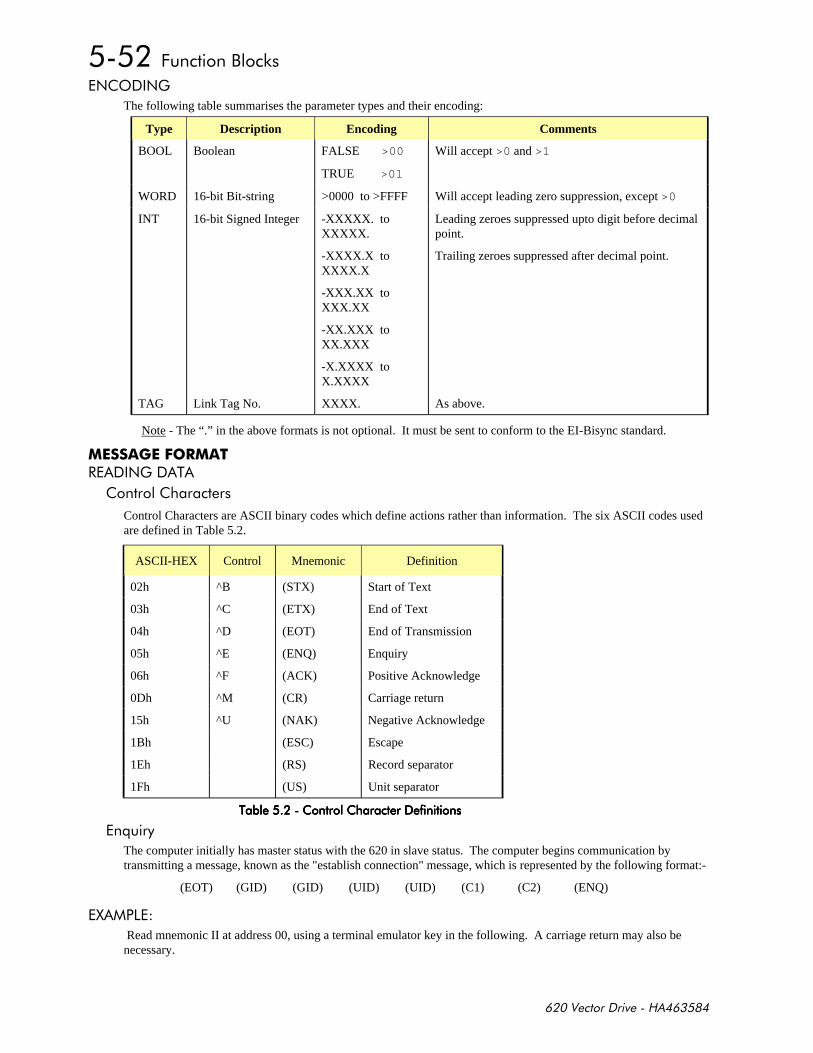
+,-
$'$)
The following table summarises the parameter types and their encoding:
Type Description Encoding Comments
BOOL Boolean FALSE >00
TRUE >01
Will accept >0 and >1
WORD 16-bit Bit-string >0000 to >FFFF Will accept leading zero suppression, except >0
INT 16-bit Signed Integer -XXXXX. toXXXXX.
-XXXX.X toXXXX.X
-XXX.XX toXXX.XX
-XX.XXX toXX.XXX
-X.XXXX toX.XXXX
Leading zeroes suppressed upto digit before decimalpoint.
Trailing zeroes suppressed after decimal point.
TAG Link Tag No. XXXX. As above.
Note - The “.” in the above formats is not optional. It must be sent to conform to the EI-Bisync standard.
#$# $) %
Control Characters are ASCII binary codes which define actions rather than information. The six ASCII codes usedare defined in Table 5.2.
ASCII-HEX Control Mnemonic Definition
02h ^B (STX) Start of Text
03h ^C (ETX) End of Text
04h ^D (EOT) End of Transmission
05h ^E (ENQ) Enquiry
06h ^F (ACK) Positive Acknowledge
0Dh ^M (CR) Carriage return
15h ^U (NAK) Negative Acknowledge
1Bh (ESC) Escape
1Eh (RS) Record separator
1Fh (US) Unit separator
%!%!%!%!
*
The computer initially has master status with the 620 in slave status. The computer begins communication bytransmitting a message, known as the "establish connection" message, which is represented by the following format:-
(EOT) (GID) (GID) (UID) (UID) (C1) (C2) (ENQ)
1
Read mnemonic II at address 00, using a terminal emulator key in the following. A carriage return may also benecessary.
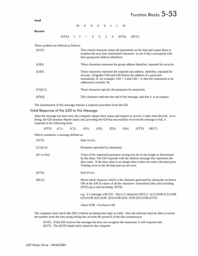
+,-
Send
^D 0 0 0 0 I I ^E
Receive
(STX) I I > 0 6 2 0 (ETX) (BCC)
These symbols are defined as follows:
(EOT) This control character resets all instruments on the link and causes them toexamine the next four transmitted characters to see if they correspond withtheir group/unit address identifiers.
(GID) These characters represent the group address identifier, repeated for security.
(UID) These characters represent the required unit address identifier, repeated forsecurity. (Together GID and UID define the address of a particularinstrument). If, for example, GID = 3 and UID = 4, then the instrument to beaddressed is number 34.
(CI)(C2) These characters specify the parameter by mnemonic.
(ENQ) This character indicates the end of the message, and that it is an enquiry.
The transmission of this message initiates a response procedure from the 620.
#!
After the message has been sent, the computer adopts slave status and expects to receive a reply from the 620. In sodoing, the 620 assumes Master status and, providing the 620 has successfully received the message in full, itresponds in the following form:
(STX) (C1) (C2) (D1) (D2) (D3) (Dn) (ETX) (BCC)
Which constitutes a message defined as:
(STX) Start of text.
(C1)(C2) Parameter specified by mnemonic.
(D1 to Dn) Value of the requested parameter (string may be of any length as determinedby the data). The 620 responds with the shortest message that represents thedata value. If the data value is an integer then it does not send a decimal point.Trailing zeros in the decimal part are not sent.
(ETX) End of text.
(BCC) Block check character which is the character generated by taking the exclusiveOR of the ASCII values of all the characters transmitted after and excluding(STX) up to and including (ETX).
e.g. if a message with (D1 - Dn) is 5 characters (BCC) = (C1) EOR (C2) EOR(D1) EOR (D2) EOR (D3) EOR (D4) EOR (D5) EOR (ETX)
where EOR = Exclusive OR
The computer must check this (BCC) before accepting this reply as valid. Also the software must be able to extractthe number from the data string taking into account the protocol of the data transmission.
NOTE: If the 620 receives the message but does not recognise the mnemonic it will respond with(EOT). The (EOT) hands back control to the computer.
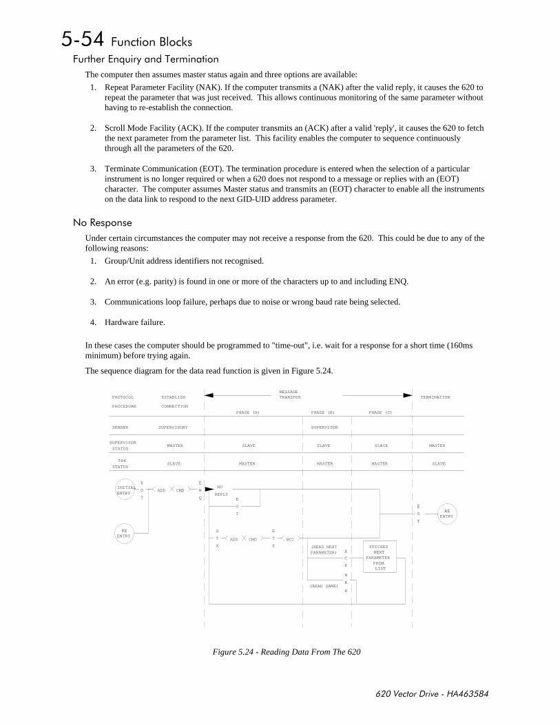
+,-
+*%
The computer then assumes master status again and three options are available:
1. Repeat Parameter Facility (NAK). If the computer transmits a (NAK) after the valid reply, it causes the 620 torepeat the parameter that was just received. This allows continuous monitoring of the same parameter withouthaving to re-establish the connection.
2. Scroll Mode Facility (ACK). If the computer transmits an (ACK) after a valid 'reply', it causes the 620 to fetchthe next parameter from the parameter list. This facility enables the computer to sequence continuouslythrough all the parameters of the 620.
3. Terminate Communication (EOT). The termination procedure is entered when the selection of a particularinstrument is no longer required or when a 620 does not respond to a message or replies with an (EOT)character. The computer assumes Master status and transmits an (EOT) character to enable all the instrumentson the data link to respond to the next GID-UID address parameter.
$#
Under certain circumstances the computer may not receive a response from the 620. This could be due to any of thefollowing reasons:
1. Group/Unit address identifiers not recognised.
2. An error (e.g. parity) is found in one or more of the characters up to and including ENQ.
3. Communications loop failure, perhaps due to noise or wrong baud rate being selected.
4. Hardware failure.
In these cases the computer should be programmed to "time-out", i.e. wait for a response for a short time (160msminimum) before trying again.
The sequence diagram for the data read function is given in Figure 5.24.
INITIALENTRY
E
O
T
ADD CMD
E
N
Q
REENTRY
NO
REPLYE
O
T
S
T
X
ADD CMD
E
T
X
BCC
(READ SAME)
(READ NEXTPARAMETER)
N
A
K
A
C
K
FETCHESNEXT
PARAMETERFROMLIST
E
O
T
REENTRY
PHASE (A) PHASE (B) PHASE (C)
MESSAGETRANSFER TERMINATIONESTABLISH
CONNECTION
PROTOCOL
PROCEDURE
SENDER
SUPERVISOR
STATUS
STATUSSLAVE
MASTER
SUPERVISORY
SLAVE SLAVE SLAVE
SLAVEMASTER MASTER MASTER
MASTER
SUPERVISOR
584
Figure 5.24 - Reading Data From The 620

+,-
$$) %
Connection is established with a particular 620 by sending:
(EOT) (GID) (GID) (UID) (UID)
Followed immediately by the data transfer:
(STX) (C1) (C2) (D1) (D2) (D3) (DN) (ETX) (BCC)
(Note that the data transfer message is identical to that transmitted by a 620 when giving a "valid reply").
The symbols of this message are defined as follows:
(STX) start of text character
(C1)(C2) parameter specified by mnemonic
(D1 to DN) parameter value
(ETX) end of text character
(BCC) Block Check Character (verification check digit which is again the exclusiveOR of (C1) to (ETX) inclusive and must be calculated by the computer beforetransmission)
#
After transmission of the whole message, the 620 responds to it by sending (ACK), (NAK) or by giving no reply.
1. Positive acknowledgement (ACK)
When the 620 has received the message, it performs the following tasks:
a) Checks for any parity errors in the message.
b) Verifies that the (BCC) character corresponds to the data pattern received.
c) Verifies that the (C1), (C2) command characters are a valid mnemonic that may be written to.
d) Verifies that the data (D1 to DN) is valid and not out-of-range6.
e) Updates the selected parameter with the new value contained in the message.
Only when all these tasks have been successfully completed does the 620 send the (ACK) response tothe computer. This signifies that the message was correctly received and implemented.
2. Negative acknowledgement (NAK)
If the message fails any of the above checks, the 620 sends (NAK) response to the computer. This signifiesthat the message received by the 620 contained an error and accordingly it has not updated the selectedparameter. One possible reason is the incorrect calculation of (BCC). At this point, the selected commandmay be repeated by sending the data transfer string without re-establishing connection, until the computerreceives the (ACK) response.
3. No Reply
Under certain circumstances, the computer may not receive a response from the 620. This could be due to anyof the following reasons:
6 Data out-of-range returns NAK and is discarded
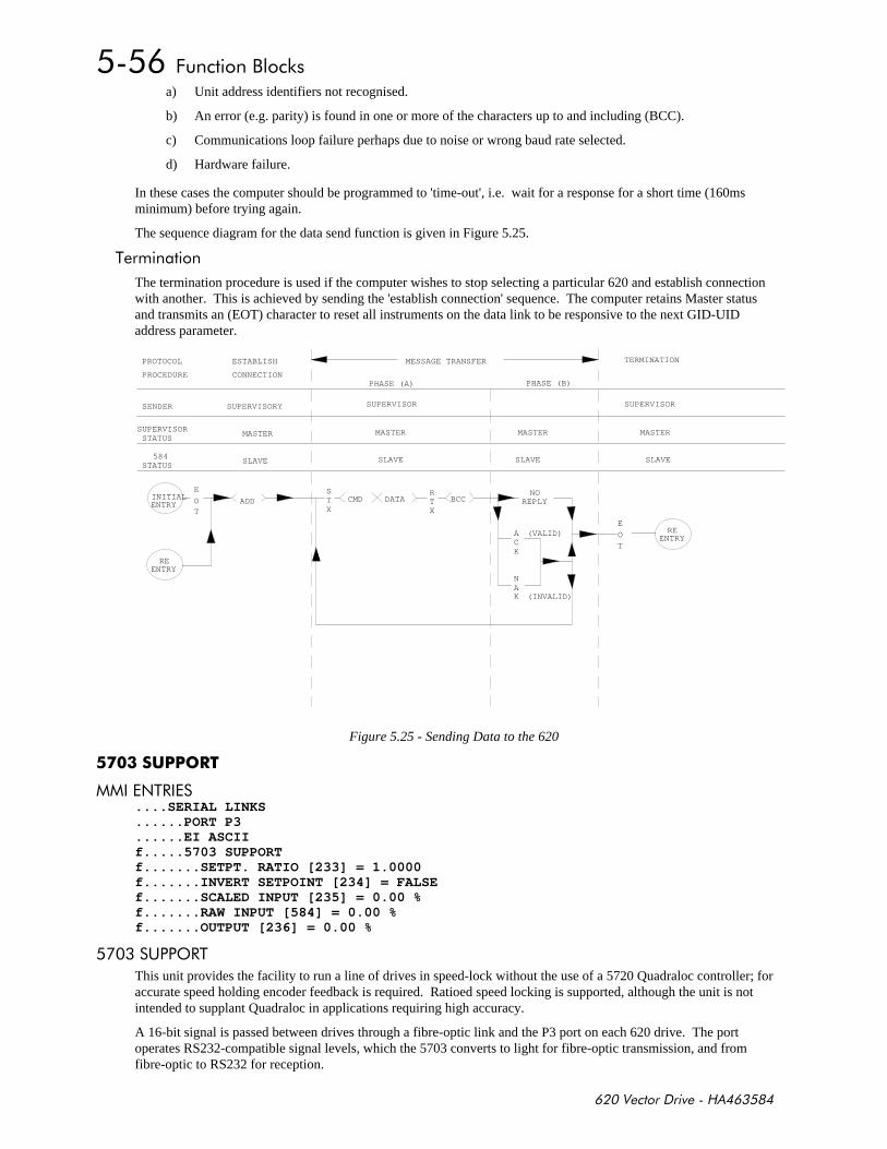
+,-
a) Unit address identifiers not recognised.
b) An error (e.g. parity) is found in one or more of the characters up to and including (BCC).
c) Communications loop failure perhaps due to noise or wrong baud rate selected.
d) Hardware failure.
In these cases the computer should be programmed to 'time-out', i.e. wait for a response for a short time (160msminimum) before trying again.
The sequence diagram for the data send function is given in Figure 5.25.
%
The termination procedure is used if the computer wishes to stop selecting a particular 620 and establish connectionwith another. This is achieved by sending the 'establish connection' sequence. The computer retains Master statusand transmits an (EOT) character to reset all instruments on the data link to be responsive to the next GID-UIDaddress parameter.
INITIALENTRY
E
OT
ADD
REENTRY
E
OT
REENTRY
PHASE (A) PHASE (B)
MESSAGE TRANSFER TERMINATIONESTABLISH
CONNECTION
PROTOCOL
PROCEDURE
SENDER
SUPERVISORSTATUS
STATUSSLAVE
MASTER
SUPERVISORY
SLAVE SLAVE SLAVE
MASTER MASTER MASTER
SUPERVISOR
584
STX
CMD DATA BCCRTX
NOREPLY
ACK
NAK
(VALID)
(INVALID)
SUPERVISOR
Figure 5.25 - Sending Data to the 620
$%# ....SERIAL LINKS......PORT P3......EI ASCIIf.....5703 SUPPORTf.......SETPT. RATIO [233] = 1.0000f.......INVERT SETPOINT [234] = FALSEf.......SCALED INPUT [235] = 0.00 %f.......RAW INPUT [584] = 0.00 %f.......OUTPUT [236] = 0.00 %
('#%
This unit provides the facility to run a line of drives in speed-lock without the use of a 5720 Quadraloc controller; foraccurate speed holding encoder feedback is required. Ratioed speed locking is supported, although the unit is notintended to supplant Quadraloc in applications requiring high accuracy.
A 16-bit signal is passed between drives through a fibre-optic link and the P3 port on each 620 drive. The portoperates RS232-compatible signal levels, which the 5703 converts to light for fibre-optic transmission, and fromfibre-optic to RS232 for reception.
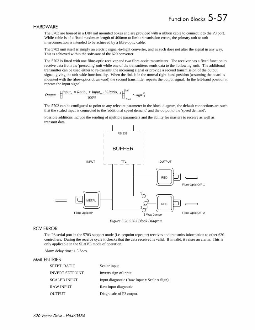
+,-
#" #
The 5703 are housed in a DIN rail mounted boxes and are provided with a ribbon cable to connect it to the P3 port.While cable is of a fixed maximum length of 400mm to limit transmission errors, the primary unit to unitinterconnection is intended to be achieved by a fibre-optic cable.
The 5703 unit itself is simply an electric signal-to-light converter, and as such does not alter the signal in any way.This is achieved within the software of the 620 converter.
The 5703 is fitted with one fibre-optic receiver and two fibre-optic transmitters. The receiver has a fixed function toreceive data from the 'preceding' unit while one of the transmitters sends data to the 'following' unit. The additionaltransmitter can be used either to re-transmit the incoming signal or provide a second transmission of the outputsignal, giving the unit wide functionality. When the link is in the normal right-hand position (assuming the board ismounted with the fibre-optics downward) the second transmitter repeats the output signal. In the left-hand position itrepeats the input signal.
OutputInput Ratio Input Ratio
signn n n n
limit
limit
=× +
×− −
−−+1 111
100%
%
The 5703 can be configured to point to any relevant parameter in the block diagram, the default connections are suchthat the scaled input is connected to the 'additional speed demand' and the output to the 'speed demand'.
Possible additions include the sending of multiple parameters and the ability for masters to receive as well astransmit data.
1
3
2
3 Way JumperFibre-Optic I/P
INPUT OUTPUT
Fibre-Optic O/P 1
Fibre-Optic O/P 2
RS 232
TTL
BUFFER
METAL
RED
RED
Figure 5.26 5703 Block Diagram
###'#
The P3 serial port in the 5703-support mode (i.e. setpoint repeater) receives and transmits information to other 620controllers. During the receive cycle it checks that the data received is valid. If invalid, it raises an alarm. This isonly applicable in the SLAVE mode of operation.
Alarm delay time: 1.5 Secs.
$%#
SETPT. RATIO Scalar input
INVERT SETPOINT Inverts sign of input.
SCALED INPUT Input diagnostic (Raw Input x Scale x Sign)
RAW INPUT Raw input diagnostic
OUTPUT Diagnostic of P3 output.
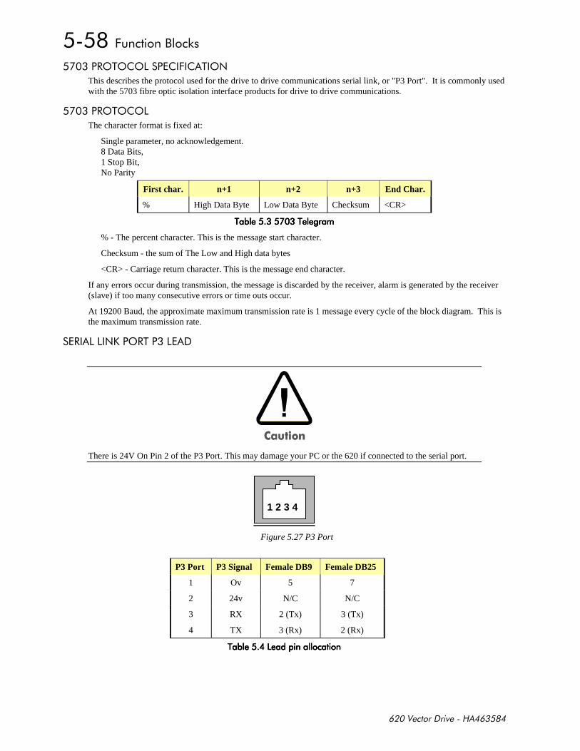
+,-
#'%'' + %'$
This describes the protocol used for the drive to drive communications serial link, or "P3 Port". It is commonly usedwith the 5703 fibre optic isolation interface products for drive to drive communications.
#'%''
The character format is fixed at:
Single parameter, no acknowledgement.8 Data Bits,1 Stop Bit,No Parity
First char. n+1 n+2 n+3 End Char.
% High Data Byte Low Data Byte Checksum <CR>
%%%%%%%%
% - The percent character. This is the message start character.
Checksum - the sum of The Low and High data bytes
<CR> - Carriage return character. This is the message end character.
If any errors occur during transmission, the message is discarded by the receiver, alarm is generated by the receiver(slave) if too many consecutive errors or time outs occur.
At 19200 Baud, the approximate maximum transmission rate is 1 message every cycle of the block diagram. This isthe maximum transmission rate.
# $.'#%
There is 24V On Pin 2 of the P3 Port. This may damage your PC or the 620 if connected to the serial port.
1 2 3 4
Figure 5.27 P3 Port
P3 Port P3 Signal Female DB9 Female DB25
1 Ov 5 7
2 24v N/C N/C
3 RX 2 (Tx) 3 (Tx)
4 TX 3 (Rx) 2 (Rx)
%%%%
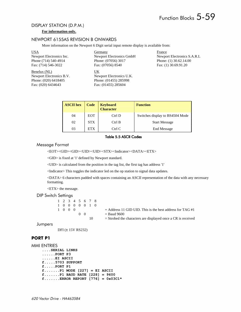
+,-
& % %'$
For information only.
$"'#% # '$,'$" #
More information on the Newport 6 Digit serial input remote display is available from:
USANewport Electronics Inc.Phone (714) 540-4914Fax: (714) 546-3022
GermanyNewport Electronics GmbHPhone: (07056) 3017Fax: (07056) 8540
FranceNewport Electronics S.A.R.LPhone: (1) 30.62.14.00Fax: (1) 30.69.91.20
Benelux (NL)Newport Electronics B.V.Phone: (020) 6418405Fax: (020) 6434643
UKNewport Electronics U.K.Phone: (01455) 285998Fax: (01455) 285604
ASCII hex Code KeyboardCharacter
Function
04 EOT Ctrl D Switches display to BS4504 Mode
02 STX Ctrl B Start Message
03 ETX Ctrl C End Message
% % % %
+
<EOT><GID><GID><UID><UID><STX><Indicator><DATA><ETX>
<GID> is fixed at '1' defined by Newport standard.
<UID> is calculated from the position in the tag list, the first tag has address '1'
<Indicator> This toggles the indicator led on the op station to signal data updates.
<DATA> 6 characters padded with spaces containing an ASCII representation of the data with any necessaryformatting.
<ETX> the message.
1 2 3 4 5 6 7 81 0 0 0 0 0 1 01 0 0 0 = Address 11 GID UID. This is the best address for TAG #1
0 0 = Baud 960010 = Strobed the characters are displayed once a CR is received
0DFI (± 15V RS232)
$%# ....SERIAL LINKS......PORT P3......EI ASCIIf.....5703 SUPPORTf.....PORT P1f.......P1 MODE [227] = EI ASCIIf.......P1 BAUD RATE [228] = 9600f.......ERROR REPORT [776] = 0x03C1*
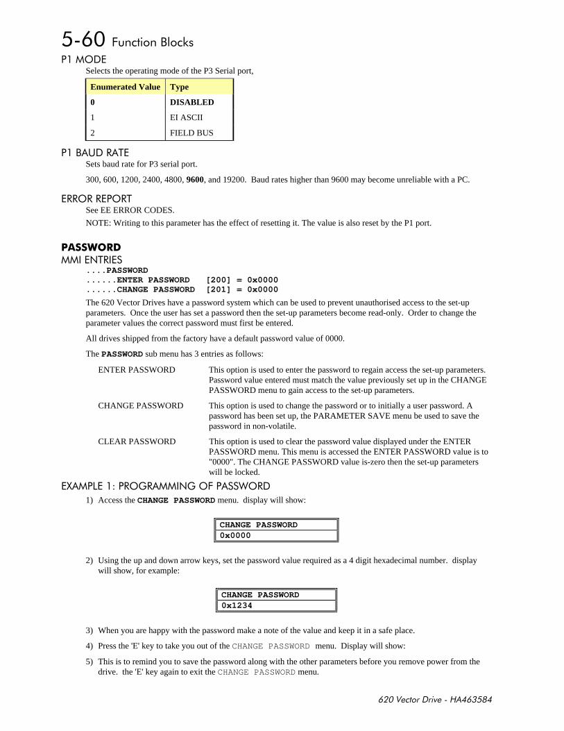
+,-
'Selects the operating mode of the P3 Serial port,
Enumerated Value Type
0 DISABLED
1 EI ASCII
2 FIELD BUS
, (# %Sets baud rate for P3 serial port.
300, 600, 1200, 2400, 4800, 9600, and 19200. Baud rates higher than 9600 may become unreliable with a PC.
##'##'#%See EE ERROR CODES.
NOTE: Writing to this parameter has the effect of resetting it. The value is also reset by the P1 port.
"$%#
....PASSWORD
......ENTER PASSWORD [200] = 0x0000
......CHANGE PASSWORD [201] = 0x0000
The 620 Vector Drives have a password system which can be used to prevent unauthorised access to the set-upparameters. Once the user has set a password then the set-up parameters become read-only. Order to change theparameter values the correct password must first be entered.
All drives shipped from the factory have a default password value of 0000.
The PASSWORD sub menu has 3 entries as follows:
ENTER PASSWORD This option is used to enter the password to regain access the set-up parameters.Password value entered must match the value previously set up in the CHANGEPASSWORD menu to gain access to the set-up parameters.
CHANGE PASSWORD This option is used to change the password or to initially a user password. Apassword has been set up, the PARAMETER SAVE menu be used to save thepassword in non-volatile.
CLEAR PASSWORD This option is used to clear the password value displayed under the ENTERPASSWORD menu. This menu is accessed the ENTER PASSWORD value is to"0000". The CHANGE PASSWORD value is-zero then the set-up parameterswill be locked.
1 #')# $)'+ "'#
1) Access the CHANGE PASSWORD menu. display will show:
CHANGE PASSWORD0x0000
2) Using the up and down arrow keys, set the password value required as a 4 digit hexadecimal number. displaywill show, for example:
CHANGE PASSWORD0x1234
3) When you are happy with the password make a note of the value and keep it in a safe place.
4) Press the 'E' key to take you out of the CHANGE PASSWORD menu. Display will show:
5) This is to remind you to save the password along with the other parameters before you remove power from thedrive. the 'E' key again to exit the CHANGE PASSWORD menu.
+,-
6) Access the CLEAR PASSWORD menu and press the 'M' key. Display will show:
CLEAR PASSWORDPASSWORD CLEARED
7) This indicates that the password value entered above has been locked into the system. CLEAR PASSWORD setsthe value in the ENTER PASSWORD menu to 0x0000, otherwise the password would still be displayed.
8) The set-up parameters are now locked. to use PARAMETER SAVE put the password value in non-volatilememory. you now go back to the CHANGE PASSWORD menu the password value is hidden and the display willshow:
CHANGE PASSWORD****
1 %( # %# "$% "'# %
1) Access the ENTER PASSWORD menu. display will show:
ENTER PASSWORD0x0000
2) Use the up and down arrow keys to select your password.
3) Press the 'E' key to exit the ENTER PASSWORD menu.
4) Access the SETUP PARAMETERS menu to make any necessary changes.
5) When all parameter changes have been made come back to the CLEAR PASSWORD menu to hide the passwordvalue and lock the set-up parameters again.
1 #'( & % "'#
1) Access the ENTER PASSWORD menu.
2) Use the up and down arrow keys to enter the existing password value.
3) Leave the ENTER PASSWORD menu and access the CHANGE PASSWORD menu.
4) Use the up and down arrow keys to select a new password value.
5) Leave the CHANGE PASSWORD menu and access the CLEAR PASSWORD menu.
6) Press the 'M' key to clear the password value and lock the set-up parameters.
7) Remember to use SAVE PARAMETERS to save the new password value in non-volatile memory.
$%# ....ALARM STATUS......HEALTH STORE [203] = 0x0000......HEALTH word [217] = 0x0010......FIRST ALARM [218] = 0x0010h.....HEALTH INHIBIT [219] = 0x0000
$%# ....MENUS......FULL MENUS [205] = FALSEf.....MENU DELAY [206] = 0f.....DATA DELAY [207] = 50
# %#
Full Menus If False, the MMI will not display tags marked as ‘f’ or ‘h’.
This menu is used to save all of the drive parameters in the non-volatile memory. The UP arrow as instructed on thesecond line of the MMI display (UP TO ACTION) to save the drive parameters.
+,-
0$"$
Diagnostic information about the current software and hardware build of the drive.......SOFTWARE INFO........620 VERSION [782] = 4.1f.......P1 VERSION [226] = 1.1f.......CO-PRO PRESENT [150] = TRUEf.......CO-PRO TYPE [781] = 1f.......DRIVE RATING RMS [133] = 9.4 AMPSf.......MID VOLTS [151] = TRUEf.......CHASSIS TYPE [152] = 4
$"
This shows the software release number. The 620 UDP parameter files are compatible between releases w.x and y.zwhere z > 1.
0
$%#
....SYSTEMh.....PERSISTENT DATAh......./WRITE [682] = FALSEh.......TAG No 1 [679] = 0h.......TAG No 2 [680] = 0h.......COUNT [681] = 0
%'$$'% $)# '"#'(%(%'$'"#'
The TAG No 1 and TAG NO 2 are saved to EEprom on the falling edged of /WRITE.
%
Configure the persistent data function to point to the tags that you wish to saved on power down, in this case TAG678 the raise lower initialisation value.....SYSTEMh...PERSISTENT DATAh...../WRITE [682] = FALSEh.....TAG No 1 [679] = 678h.....TAG No 2 [680] = 0h.....COUNT [681] = 0
%
Set up the under voltage trip level this needs to be high that the hardware trip level set a 415v DC on a 400v drivebut lower enough not to cause too many writes. A value of 440v is a good default value...ALARMS / SEQh..UNDER V LEVEL [685] = 440 VOLTSh../UNDER VOLTS [686] = TRUE
%
Link the under voltage trip flag to the /Write input of the persistent block....INTERNAL LINKSf....LINK 1 SOURCE [180] = 686f....LINK 1 DEST [181] = 682
%
Link the under voltage trip flag to Aux. Enable. This will quench the drive giving us the maximum chance of beingable to save the data....INTERNAL LINKSf....LINK 2 SOURCE [182] = 686f....LINK 2 DEST [183] = 68

+,-
$'%
The Value of PERSISTENT DATA::COUNT should be monitored to check that it is approximately equal to thenumber of power downs. The Eeprom is only rated for 10000 writes.
The Persistent data is not saved in the same area as the parameter data, any error in the data’s integrity will beflagged at power up. Pressing the ‘E’ key acknowledges the fault.
If this happens the drive reverts to the last saved value on the tags.
If the tag numbers of the persistent data area are different the data is also lost. This may happen if you change the taglist.
0$#
'$+)(#$ ,
During the process of reconfiguration there is a danger that Tag numbers will be connected to wrong parameters. Toavoid this possibility all configuration links must be temporarily "disconnected" during the configuration process andthe flag set to "enabled" to allow the activity. Failure to reset the flag to "disabled" after reconfiguration will causean alarm to be generated, "Configure Enabled", which will prevent drive operation.
#
$%# f.......ANALOG INPUTSf.........ANIN 1 (C3)f...........CALIBRATION [248] = 100.00 %f...........OFFSET [358] = 0.00 %f...........MAX VALUE [249] = 100.00 %f...........MIN VALUE [250] = -100.00 %f...........DESTINATION TAG [251] = 196f...........SCALED INPUT [390] = 0.00 %f...........ANIN 1 (C3) [29] = 0.000 VOLTSf.........ANIN 3 (F2)f...........CALIBRATION [256] = 100.00 %f...........OFFSET [360] = 0.00 %f...........MAX VALUE [257] = 100.00 %f...........MIN VALUE [258] = -100.00 %f...........DESTINATION TAG [259] = 197f...........SCALED INPUT [391] = 0.00 %f...........ANIN 3 (F2) [31] = 0.000 VOLTSf.........ANIN 4 (F3)f...........CALIBRATION [261] = 100.00 %f...........OFFSET [361] = 0.00 %f...........MAX VALUE [262] = 100.00 %f...........MIN VALUE [263] = -100.00 %f...........DESTINATION TAG [264] = 0f...........SCALED INPUT [392] = 0.00 %f...........ANIN 4 (F3) [32] = 0.000 VOLTSf.........ANIN 5 (F4)f...........CALIBRATION [266] = 100.00 %f...........OFFSET [362] = 0.00 %f...........MAX VALUE [267] = 100.00 %f...........MIN VALUE [268] = -100.00 %f...........DESTINATION TAG [269] = 0f...........SCALED INPUT [393] = 0.00 %f...........ANIN 5 (F4) [33] = 0.000 VOLTSh.........ANIN FILTER [671] = 0.800
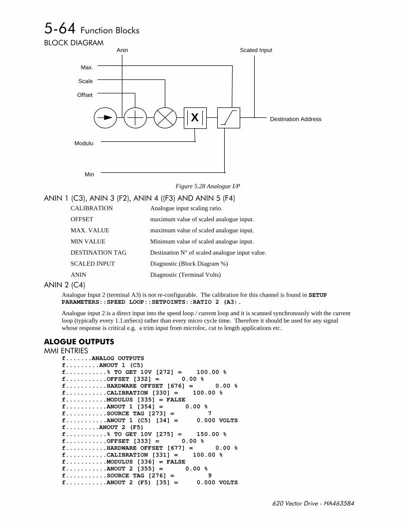
+,-
,'. )#
Destination Address
Max.
Scale
Offset
Min
Scaled Input
X
Modulu
Anin
Figure 5.28 Analogue I/P
$$ $$+ $$+ $ $$+
CALIBRATION Analogue input scaling ratio.
OFFSET maximum value of scaled analogue input.
MAX. VALUE maximum value of scaled analogue input.
MIN VALUE Minimum value of scaled analogue input.
DESTINATION TAG Destination N° of scaled analogue input value.
SCALED INPUT Diagnostic (Block Diagram %)
ANIN Diagnostic (Terminal Volts)
$$
Analogue Input 2 (terminal A3) is not re-configurable. The calibration for this channel is found in SETUPPARAMETERS::SPEED LOOP::SETPOINTS::RATIO 2 (A3).
Analogue input 2 is a direct input into the speed loop / current loop and it is scanned synchronously with the currentloop (typically every 1.1.mSecs) rather than every micro cycle time. Therefore it should be used for any signalwhose response is critical e.g. a trim input from microloc, cut to length applications etc.
#$%#
f.......ANALOG OUTPUTSf.........ANOUT 1 (C5)f...........% TO GET 10V [272] = 100.00 %f...........OFFSET [332] = 0.00 %f...........HARDWARE OFFSET [676] = 0.00 %f...........CALIBRATION [330] = 100.00 %f...........MODULUS [335] = FALSEf...........ANOUT 1 [354] = 0.00 %f...........SOURCE TAG [273] = 7f...........ANOUT 1 (C5) [34] = 0.000 VOLTSf.........ANOUT 2 (F5)f...........% TO GET 10V [275] = 150.00 %f...........OFFSET [333] = 0.00 %f...........HARDWARE OFFSET [677] = 0.00 %f...........CALIBRATION [331] = 100.00 %f...........MODULUS [336] = FALSEf...........ANOUT 2 [355] = 0.00 %f...........SOURCE TAG [276] = 9f...........ANOUT 2 (F5) [35] = 0.000 VOLTS
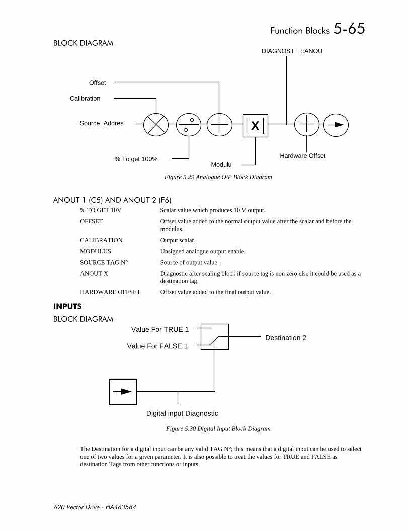
+,-
,'. )#
Source Addres
Offset
Calibration
Modulu
DIAGNOST ::ANOU
X
% To get 100% Hardware Offset
Figure 5.29 Analogue O/P Block Diagram
$'(% $ $'(%+
% TO GET 10V Scalar value which produces 10 V output.
OFFSET Offset value added to the normal output value after the scalar and before themodulus.
CALIBRATION Output scalar.
MODULUS Unsigned analogue output enable.
SOURCE TAG N° Source of output value.
ANOUT X Diagnostic after scaling block if source tag is non zero else it could be used as adestination tag.
HARDWARE OFFSET Offset value added to the final output value.
,'. )#
Digital input Diagnostic
Value For TRUE 1
Value For FALSE 1Destination 2
Figure 5.30 Digital Input Block Diagram
The Destination for a digital input can be any valid TAG N°; this means that a digital input can be used to selectone of two values for a given parameter. It is also possible to treat the values for TRUE and FALSE asdestination Tags from other functions or inputs.
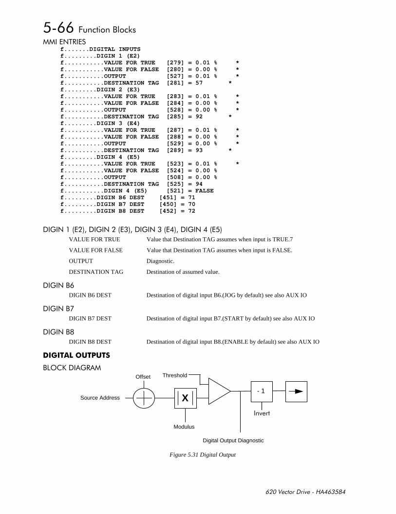
+,-
$%# f.......DIGITAL INPUTSf.........DIGIN 1 (E2)f...........VALUE FOR TRUE [279] = 0.01 % *f...........VALUE FOR FALSE [280] = 0.00 % *f...........OUTPUT [527] = 0.01 % *f...........DESTINATION TAG [281] = 57 *f.........DIGIN 2 (E3)f...........VALUE FOR TRUE [283] = 0.01 % *f...........VALUE FOR FALSE [284] = 0.00 % *f...........OUTPUT [528] = 0.00 % *f...........DESTINATION TAG [285] = 92 *f.........DIGIN 3 (E4)f...........VALUE FOR TRUE [287] = 0.01 % *f...........VALUE FOR FALSE [288] = 0.00 % *f...........OUTPUT [529] = 0.00 % *f...........DESTINATION TAG [289] = 93 *f.........DIGIN 4 (E5)f...........VALUE FOR TRUE [523] = 0.01 % *f...........VALUE FOR FALSE [524] = 0.00 %f...........OUTPUT [508] = 0.00 %f...........DESTINATION TAG [525] = 94f...........DIGIN 4 (E5) [521] = FALSEf.........DIGIN B6 DEST [451] = 71f.........DIGIN B7 DEST [450] = 70f.........DIGIN B8 DEST [452] = 72
)$)$)$)$
VALUE FOR TRUE Value that Destination TAG assumes when input is TRUE.7
VALUE FOR FALSE Value that Destination TAG assumes when input is FALSE.
OUTPUT Diagnostic.
DESTINATION TAG Destination of assumed value.
)$,
DIGIN B6 DEST Destination of digital input B6.(JOG by default) see also AUX IO
)$,
DIGIN B7 DEST Destination of digital input B7.(START by default) see also AUX IO
)$,
DIGIN B8 DEST Destination of digital input B8.(ENABLE by default) see also AUX IO
#
,'. )#
Modulus
Offset
Digital Output Diagnostic
Source Address
Threshold
X- 1
Figure 5.31 Digital Output
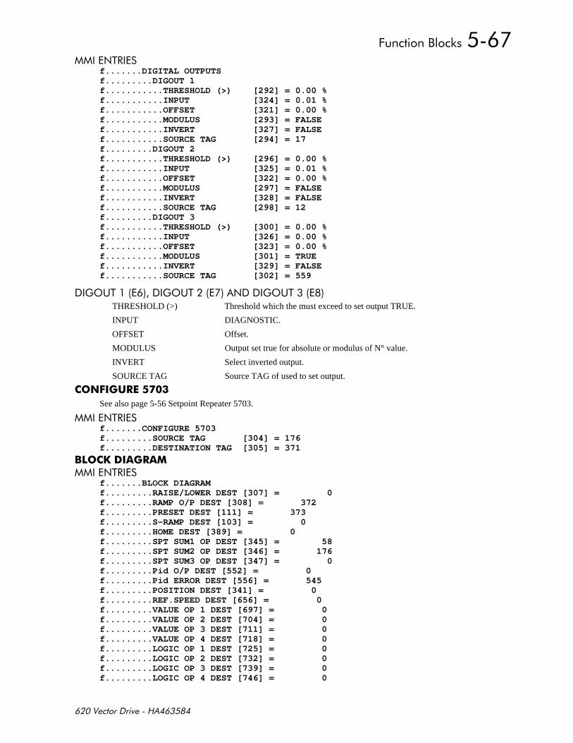
+,-
$%# f.......DIGITAL OUTPUTSf.........DIGOUT 1f...........THRESHOLD (>) [292] = 0.00 %f...........INPUT [324] = 0.01 %f...........OFFSET [321] = 0.00 %f...........MODULUS [293] = FALSEf...........INVERT [327] = FALSEf...........SOURCE TAG [294] = 17f.........DIGOUT 2f...........THRESHOLD (>) [296] = 0.00 %f...........INPUT [325] = 0.01 %f...........OFFSET [322] = 0.00 %f...........MODULUS [297] = FALSEf...........INVERT [328] = FALSEf...........SOURCE TAG [298] = 12f.........DIGOUT 3f...........THRESHOLD (>) [300] = 0.00 %f...........INPUT [326] = 0.00 %f...........OFFSET [323] = 0.00 %f...........MODULUS [301] = TRUEf...........INVERT [329] = FALSEf...........SOURCE TAG [302] = 559
)'(%)'(% $)'(%THRESHOLD (>) Threshold which the must exceed to set output TRUE.
INPUT DIAGNOSTIC.
OFFSET Offset.
MODULUS Output set true for absolute or modulus of N° value.
INVERT Select inverted output.
SOURCE TAG Source TAG of used to set output.
$#
See also page 5-56 Setpoint Repeater 5703.
$%# f.......CONFIGURE 5703f.........SOURCE TAG [304] = 176f.........DESTINATION TAG [305] = 371
%&#$%#
f.......BLOCK DIAGRAMf.........RAISE/LOWER DEST [307] = 0f.........RAMP O/P DEST [308] = 372f.........PRESET DEST [111] = 373f.........S-RAMP DEST [103] = 0f.........HOME DEST [389] = 0f.........SPT SUM1 OP DEST [345] = 58f.........SPT SUM2 OP DEST [346] = 176f.........SPT SUM3 OP DEST [347] = 0f.........Pid O/P DEST [552] = 0f.........Pid ERROR DEST [556] = 545f.........POSITION DEST [341] = 0f.........REF.SPEED DEST [656] = 0f.........VALUE OP 1 DEST [697] = 0f.........VALUE OP 2 DEST [704] = 0f.........VALUE OP 3 DEST [711] = 0f.........VALUE OP 4 DEST [718] = 0f.........LOGIC OP 1 DEST [725] = 0f.........LOGIC OP 2 DEST [732] = 0f.........LOGIC OP 3 DEST [739] = 0f.........LOGIC OP 4 DEST [746] = 0
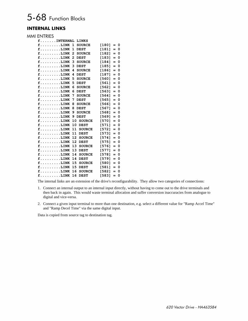
+,-
&
$%# f.......INTERNAL LINKSf.........LINK 1 SOURCE [180] = 0f.........LINK 1 DEST [181] = 0f.........LINK 2 SOURCE [182] = 0f.........LINK 2 DEST [183] = 0f.........LINK 3 SOURCE [184] = 0f.........LINK 3 DEST [185] = 0f.........LINK 4 SOURCE [186] = 0f.........LINK 4 DEST [187] = 0f.........LINK 5 SOURCE [560] = 0f.........LINK 5 DEST [561] = 0f.........LINK 6 SOURCE [562] = 0f.........LINK 6 DEST [563] = 0f.........LINK 7 SOURCE [564] = 0f.........LINK 7 DEST [565] = 0f.........LINK 8 SOURCE [566] = 0f.........LINK 8 DEST [567] = 0f.........LINK 9 SOURCE [568] = 0f.........LINK 9 DEST [569] = 0f.........LINK 10 SOURCE [570] = 0f.........LINK 10 DEST [571] = 0f.........LINK 11 SOURCE [572] = 0f.........LINK 11 DEST [573] = 0f.........LINK 12 SOURCE [574] = 0f.........LINK 12 DEST [575] = 0f.........LINK 13 SOURCE [576] = 0f.........LINK 13 DEST [577] = 0f.........LINK 14 SOURCE [578] = 0f.........LINK 14 DEST [579] = 0f.........LINK 15 SOURCE [580] = 0f.........LINK 15 DEST [581] = 0f.........LINK 16 SOURCE [582] = 0f.........LINK 16 DEST [583] = 0
The internal links are an extension of the drive's reconfigurability. They allow two categories of connections:
1. Connect an internal output to an internal input directly, without having to come out to the drive terminals andthen back in again. This would waste terminal allocation and suffer conversion inaccuracies from analogue todigital and vice-versa.
2. Connect a given input terminal to more than one destination, e.g. select a different value for "Ramp Accel Time"and "Ramp Decel Time" via the same digital input.
Data is copied from source tag to destination tag.
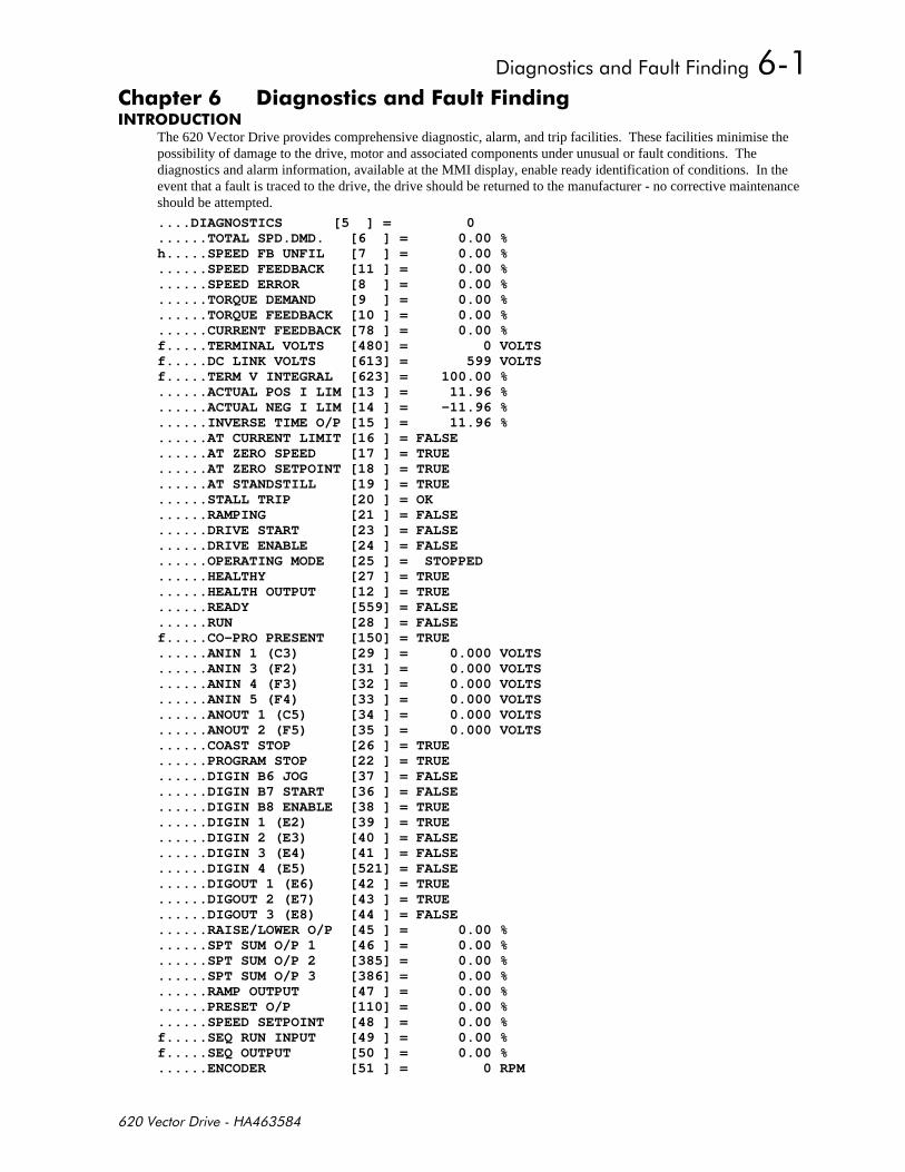
++
) -* $ !$-
The 620 Vector Drive provides comprehensive diagnostic, alarm, and trip facilities. These facilities minimise thepossibility of damage to the drive, motor and associated components under unusual or fault conditions. Thediagnostics and alarm information, available at the MMI display, enable ready identification of conditions. In theevent that a fault is traced to the drive, the drive should be returned to the manufacturer - no corrective maintenanceshould be attempted.
....DIAGNOSTICS [5 ] = 0
......TOTAL SPD.DMD. [6 ] = 0.00 %h.....SPEED FB UNFIL [7 ] = 0.00 %......SPEED FEEDBACK [11 ] = 0.00 %......SPEED ERROR [8 ] = 0.00 %......TORQUE DEMAND [9 ] = 0.00 %......TORQUE FEEDBACK [10 ] = 0.00 %......CURRENT FEEDBACK [78 ] = 0.00 %f.....TERMINAL VOLTS [480] = 0 VOLTSf.....DC LINK VOLTS [613] = 599 VOLTSf.....TERM V INTEGRAL [623] = 100.00 %......ACTUAL POS I LIM [13 ] = 11.96 %......ACTUAL NEG I LIM [14 ] = -11.96 %......INVERSE TIME O/P [15 ] = 11.96 %......AT CURRENT LIMIT [16 ] = FALSE......AT ZERO SPEED [17 ] = TRUE......AT ZERO SETPOINT [18 ] = TRUE......AT STANDSTILL [19 ] = TRUE......STALL TRIP [20 ] = OK......RAMPING [21 ] = FALSE......DRIVE START [23 ] = FALSE......DRIVE ENABLE [24 ] = FALSE......OPERATING MODE [25 ] = STOPPED......HEALTHY [27 ] = TRUE......HEALTH OUTPUT [12 ] = TRUE......READY [559] = FALSE......RUN [28 ] = FALSEf.....CO-PRO PRESENT [150] = TRUE......ANIN 1 (C3) [29 ] = 0.000 VOLTS......ANIN 3 (F2) [31 ] = 0.000 VOLTS......ANIN 4 (F3) [32 ] = 0.000 VOLTS......ANIN 5 (F4) [33 ] = 0.000 VOLTS......ANOUT 1 (C5) [34 ] = 0.000 VOLTS......ANOUT 2 (F5) [35 ] = 0.000 VOLTS......COAST STOP [26 ] = TRUE......PROGRAM STOP [22 ] = TRUE......DIGIN B6 JOG [37 ] = FALSE......DIGIN B7 START [36 ] = FALSE......DIGIN B8 ENABLE [38 ] = TRUE......DIGIN 1 (E2) [39 ] = TRUE......DIGIN 2 (E3) [40 ] = FALSE......DIGIN 3 (E4) [41 ] = FALSE......DIGIN 4 (E5) [521] = FALSE......DIGOUT 1 (E6) [42 ] = TRUE......DIGOUT 2 (E7) [43 ] = TRUE......DIGOUT 3 (E8) [44 ] = FALSE......RAISE/LOWER O/P [45 ] = 0.00 %......SPT SUM O/P 1 [46 ] = 0.00 %......SPT SUM O/P 2 [385] = 0.00 %......SPT SUM O/P 3 [386] = 0.00 %......RAMP OUTPUT [47 ] = 0.00 %......PRESET O/P [110] = 0.00 %......SPEED SETPOINT [48 ] = 0.00 %f.....SEQ RUN INPUT [49 ] = 0.00 %f.....SEQ OUTPUT [50 ] = 0.00 %......ENCODER [51 ] = 0 RPM

++
The Diagnostics menu allows the user to monitor the operation of the drive. Diagnostics that can be monitored aredescribed in the following paragraphs. These diagnostics are read-only.
TOTAL SPD.DMD. Speed loop total setpoint after the ramp-to-zero block.
SPEED FB UNFIL Raw speed feedback, usually used for analogue outputs.
SPEED FEEDBACK Speed loop feedback.
SPEED ERROR Speed loop error.
TORQUE DEMAND Current loop demand (speed error PI output or external current demandclamped by all the current limits).
TORQUE FEEDBACK Scaled and filtered torque.
CURRENT FEEDBACK Scaled and filtered current.
TERMINAL VOLTS Scaled motor output volts.
DC LINK VOLTS DC link volts.
TERM V INTEGRAL Output out motor volts compensation loop..
ACTUAL POS I LIM Overall positive current limit value.
ACTUAL NEG I LIM Overall negative current limit value.
INVERSE TIME O/P Inverse time clamp output level.
AT CURRENT LIMIT Current demand is being restrained by the overall current limit.
AT ZERO SPEED At zero speed feedback.
AT ZERO SETPOINT At zero speed demand.
AT STANDSTILL "AT ZERO SPEED" and "AT ZERO SETPOINT".
STALL TRIP Armature current is above "STALL THRESHOLD" and "AT ZERO SPEED"but not "AT ZERO SETPOINT".
RAMPING If the difference between the ramp input and the ramp output is greater than the"RAMP THRESHOLD", then "RAMPING" is TRUE.
DRIVE START Controller start / run command.
DRIVE ENABLE Drive speed and current loop are enabled / quenched.
OPERATING MODE Indicates whether the drive is in RUN, JOG 1....STOP etc.
HEALTHY
HEALTH OUTPUT
READY
RUN
CO-PRO PRESENT Indicates that there is a co-processor fitted and working normally, onlyapplicable to the 620L and 620Adv.

++
ANIN 1 (C3) Diagnostic displaying the current state of the analogue input 1 (C3), by defaultthis is connected to Speed setpoint no. 1.*
ANIN 2 (C4) Diagnostic displaying the current state of the analogue input 2 (C4), by defaultthis is connected to Direct speed setpoint no. 2 / current demand.
ANIN 3 (F2) Diagnostic displaying the current state of the analogue input 3 (F2), by defaultthis is connected to Speed setpoint no. 3 (ramped).*
ANIN 4 (F3) Diagnostic displaying the current state of the analogue input 4 (F3), by defaultthis is unconnected.
ANIN 5 (F4) Diagnostic displaying the current state of the analogue input 5 (F4), by defaultthis is unconnected.
ANOUT 1 (C5) Diagnostic displaying the current state of the analogue output 1 (C5), bydefault this is connected to Speed feedback.*
ANOUT 2 (F5) Diagnostic displaying the current state of the analogue output 2 (F5), bydefault this is connected to Torque demand. *
COAST STOP
PROGRAM STOP State of program stop (terminal B8).When B8 is at 24V then "PROGRAM STOP" is FALSE
START (B7) Diagnostic displaying the current state of the start input 2 (B7), by default thisis connected to Start terminal.
JOG INPUT (B6) Diagnostic displaying the current state of the Jog input 2 (B6), by default thisis connected to Jog Input terminal.
ENABLE (B8) Diagnostic displaying the current state of the Enable input (B8), by default thisis connected an Electronic Enable (ON = Enabled).
DIGIN 1 (E2) Diagnostic displaying the current state of the digital input 1 (E2), by defaultthis is connected to Ramp hold input (ON = Hold).*
DIGIN 2 (E3) Diagnostic displaying the current state of the digital input 2 (E3), by defaultthis is connected to Preset Select input 1. *
DIGIN 3 (E4) Diagnostic displaying the current state of the digital input 3 (E4), by defaultthis is connected to Preset Select input 2. *
DIGIN 4 (E5) Diagnostic displaying the current state of the digital input 4 (E5), by defaultthis is connected to Preset Select input 3. *
DIGOUT 1 (E6) Diagnostic displaying the current state of the digital output 1 (E6), by defaultthis is connected to At zero speed.
DIGOUT 2 (E7) Diagnostic displaying the current state of the digital output 2 (E7), by defaultthis is connected to Drive HEALTH. and is always ON when the start is low.This differs from Health as displayed on a front panel l.e.d. which remains ofuntil health is reset by the drive being restarted.
DIGOUT 3 (E8) Diagnostic displaying the current state of the digital output 3 (E8), by defaultthis is connected to drive READY
RAISE/LOWER O/P Value of the raise / lower ramp function.
PRESET O/P Output of Preset function block.
SPT SUM O/P 1 Output of Setpoint Sum 1 function block.

++
SPT SUM O/P 2 Output of Setpoint Sum 2 function block.
SPT SUM O/P 3 Output of Setpoint Sum 3 function block.
RAMP OUTPUT Output of Ramp function block.
SPEED SETPOINT Speed loop total setpoint including the ramp output before the ramp-to-zerofunction. The ramp-to-zero function block is only used while during thestopping states, Normal Stop, Program Stop and Coast Stop.
ENCODER Encoder speed feedback diagnostic in RPM.
)$1 *
There are two speed feedback diagnostics available in the DIAGNOSTICS menu:
ENCODER This displays the speed setpoint in RPM.
SPEED FEEDBACK This displays the speed setpoint as a percentage.
! $! ! ! ! !
First Alarm, Health Store and Health Word are displayed as 16bit hexadecimal status words where every bit hasunique meaning described in the table below. These parameters are in the Alarms section of the MMI.
In Health Store and First Alarm only one bit is set at any one time, All active bits are set in Health Wordimmediately the alarm condition is detected.
2 +)
% #
% #
% % $. +%
%'%'#% %
%'#'% '
%($#'% (
% +, . %!!-
%'"#' %' %!
% % .%# )''
% (%'%($
%#
% % %# %
%'#(##$% '%
%1%#$ %# %
%'%# '
Most Alarms may be disabled (inhibited) by setting the appropriate flags in the SET-UP PARAMETERS::ALARMS
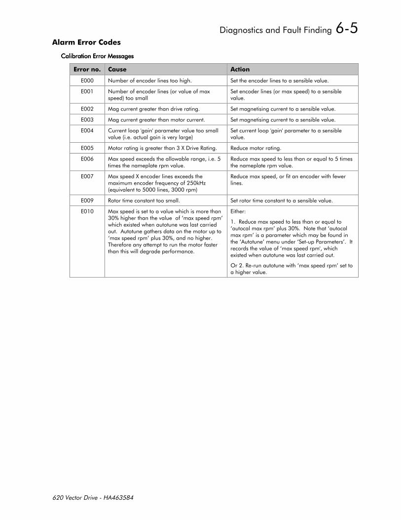
++
!
*
$!
$!!
1# #
#*
1!*!-/*
#!!
#
!>? >?%!!!
#*>?$>?!> ?> ?!>
'#>?
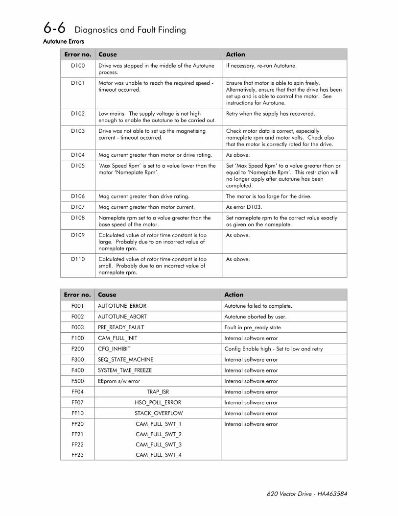
++
*
!
!
*
! !
%
#
--!
> #?>$#?
> #?*>$#?%!
%!
$!
!!
!!
*
+ (%'%($@##'# !
+ (%'%($@ ,'#%
+ #@# &@+ (% +@
+ @+(@$% !
+ +)@$,% !
+ ;@ % %@ $ !
+ & %@%@+#8 !
+ !
++ %# @ # !
++ '@'@##'# !
++ % .@'#+'" !
++
++
++
++
@+(@ "%@
@+(@ "%@
@+(@ "%@
@+(@ "%@
!

++
If the drive trips then the display immediately shows a message indicating the reason for the trip. Removing and re-applying RUN resets alarm conditions. The alarm message can be cleared from the display by pressing the "E" key.Using the FIRST ALARM menu can redisplay it.
The possible alarm messages are:
LINK UNDERVOLTS The DC link voltage is too low. Possible reasons for this alarm message are:(a) The mains voltage is too low;(b) The mains supply has been lost;(c) One of the three phases of the supply is missing.
LINK OVERVOLTAGE The DC link voltage is too high. Possible reasons for this alarm message are:(a) The mains voltage is too high;(b) Trying to decelerate a large inertia load too quickly.
LINK OVERCURRENT The output current is too high. Possible reasons for this alarm message are:(a) Short circuit between motor phases;(b) Short circuit between motor phase and earth;(c) Too long output cables or too many parallel motors;
HEATSINK TEMP The drive heat-sink temperature is too high. Possible reasons for this alarmmessage are:(a) The ambient air temperature is too high;(b) A drive cooling fan has failed.;(c) Poor ventilation.
MOTOR TEMP The motor temperature is too high. Possible reasons for this alarm messageare:(a) Prolonged operation of the motor at low speed without forced
cooling;(b) Excessive load;(c) Motor voltage rating incorrect; / Magnetising Current set too high.
MOTOR STALLED The motor has stalled. Possible reasons for this alarm message are:(a) Motor loading too great;(b) TORQUE LIMIT parameter set too low;(c) STALL TRIP TIME parameter too low;
EXTERNAL TRIP A Tag that can optionally be connected to a digital input. The drive will trip ifthis is set high.
CONFIG ENABLE The "Enable Configuration" flag has been left in the enable state. This needs tobe disabled in order to run the drive.
CHECKSUM FAILED Hardware error.
EE VERSION ERROR Hardware error.
SPD.FBK.TRIP The speed error is greater than the allowable threshold, this may be deliberate(the speed loop is saturated) in which case the alarm should be inhibited in theSET-UP PARAMETERS:ALARMS menu.
EEPROM ERROR Hardware error. Or 620L or 620Adv has been reset to factory defaults.

++

%-
) ) *+
Until recently each European drives manufacturer and importer has been interpreting the EMC directive and ‘CE’marking requirements differently. This has led to considerable confusion and frustration in the market place. Toprovide a unified approach, the European machines and drives manufactures, via their national trade associationshave formed the ‘European Committee of Manufacturers of Electrical Machines and Power Electronics’,termed CEMEP. This committee has produced a document entitled “Recommendations for Application of PowerDrive Systems (PDS), European Council Directives - CE Marking and Technical Standardisation”, which will befollowed by all major European Drives manufacturer. A copy is available from your local trade association or fromyour local Eurotherm Drives office.
)1!
The subject of CE marking and EMC is explored in more detail in a separate Eurotherm Application manual entitled‘EMC Installation Guidelines for modules and systems’, part number HA388879, available from your localEurotherm Drives office. The following sections are the minimum necessary for basic understanding.
Eurotherm Drives are adhering to the CEMEP recommendations on ‘CE’ marking for EMC. According to SI No.2372, implementing the EMC directive into UK law, the requirement to CE mark for EMC, applies only to ‘relevantapparatus’ that has ‘intrinsic function’ to the ‘end user’ and which is placed on the market (supplied). Themajority of drive modules/systems sold by Eurotherm Drives will be incorporated into a higher system/apparatus ormachine which includes (at least) the motor, cable and a driven load before providing ‘intrinsic function’ to the‘end user’. As such the majority of Eurotherm Drives products are categorised as ‘components’ (CEMEP validityfield 2) and it would be incorrect for Eurotherm Drives to apply the CE mark or produce an EC Declaration ofConformity in respect of EMC. It is the manufacturer/supplier/installer of the relevant apparatus (with the ‘intrinsicfunction’ to the ‘end user’) who must demonstrate conformance to the EMC directive
However, in a minority of cases, single drives may have ‘intrinsic function’ to the ‘end user’. An example is that of‘add on’ ‘intrinsic function’, where an existing fixed speed motor application (such as a fan or a pump) isconverted to variable speed with an ‘add on’ drive module (CEMEP validity field 1). In this application EurothermDrives CE mark its drive module and issue an EC declaration of conformity. Because the validity of the ‘CE’ markfor EMC is not known when the product is manufactured, the ‘CE’ mark will be applied via the product manual, andwill not be on the product label. From 1997, when the ‘CE’ mark for the Low Voltage Directive becomes mandatory,the CE mark will appear on the product label, but its validity for EMC can only be identified from the productmanual.
The validity of the ‘CE’ mark can be identified from the flowchart in figure 7.1, refer to SI No. 2372 for clarificationof relevant apparatus.
To assist manufacturers/suppliers/installers of relevant apparatus, Eurotherms 620 Vector drive modules are EMCcompliant to EN50081-1 (1992), EN50082-1 (1992), EN50081-2 (1994) and prEN50082-2 (1992), when fitted withthe specified filter and installed according to these instructions, (as confirmed by the Manufacturers EMC declarationto be found at the end of this chapter).
Manufacturers/suppliers/installers of relevant apparatus (CEMEP validity fields 3 & 4) may use this compliance andmanufacturers EMC declaration as a basis for their own justification of overall compliance with the EMC Directive.
It must be clearly understood by the customer before installation commences who is legally responsible forconformance with the EMC Directive. Misappropriation of the CE mark is a criminal offence.
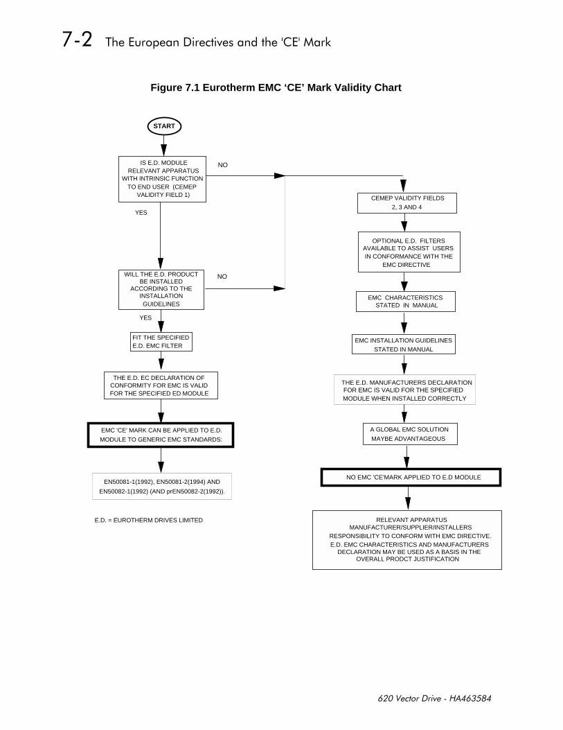
%-
Figure 7.1 Eurotherm EMC ‘CE’ Mark Validity Chart
THE E.D. EC DECLARATION OF CONFORMITY FOR EMC IS VALID FOR THE SPECIFIED ED MODULE
START
IS E.D. MODULE RELEVANT APPARATUS
WITH INTRINSIC FUNCTION TO END USER (CEMEP
VALIDITY FIELD 1)
NO
YES
FIT THE SPECIFIED E.D. EMC FILTER
WILL THE E.D. PRODUCT BE INSTALLED
ACCORDING TO THE INSTALLATIONGUIDELINES
NO
YES
E.D. = EUROTHERM DRIVES LIMITED
EMC 'CE' MARK CAN BE APPLIED TO E.D.
MODULE TO GENERIC EMC STANDARDS:
EN50081-1(1992), EN50081-2(1994) AND
EN50082-1(1992) (AND prEN50082-2(1992)).
EMC INSTALLATION GUIDELINES
STATED IN MANUAL
EMC CHARACTERISTICS STATED IN MANUAL
OPTIONAL E.D. FILTERS AVAILABLE TO ASSIST USERSIN CONFORMANCE WITH THE
EMC DIRECTIVE
A GLOBAL EMC SOLUTION
MAYBE ADVANTAGEOUS
CEMEP VALIDITY FIELDS
2, 3 AND 4
THE E.D. MANUFACTURERS DECLARATIONFOR EMC IS VALID FOR THE SPECIFIEDMODULE WHEN INSTALLED CORRECTLY
NO EMC 'CE'MARK APPLIED TO E.D MODULE
MANUFACTURER/SUPPLIER/INSTALLERSRESPONSIBILITY TO CONFORM WITH EMC DIRECTIVE.E.D. EMC CHARACTERISTICS AND MANUFACTURERS
DECLARATION MAY BE USED AS A BASIS IN THE
RELEVANT APPARATUS
OVERALL PRODCT JUSTIFICATION
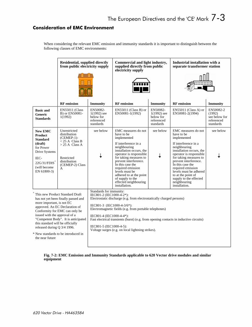
%-
+
When considering the relevant EMC emission and immunity standards it is important to distinguish between thefollowing classes of EMC environments:
Residential, supplied directlyfrom public electricity supply
Commercial and light industry,supplied directly from publicelectricity supply
Industrial installation with aseparate transformer station
RF emission Immunity RF emission Immunity RF emission Immunity
Basic andGenericStandards
EN55011 (ClassB) or EN50081-1(1992)
EN50082-1(1992) seebelow forreferencedstandards
EN55011 (Class B) orEN50081-1(1992)
EN50082-1(1992) seebelow forreferencedstandards
EN55011 (Class A) orEN50081-2(1994)
EN50082-2(1992)see below forreferencedstandards
New EMCProductStandard(draft)for PowerDrive Systems
IEC-22G/31/FDIS
+
(will becomeEN 61800-3)
Unrestricteddistribution(CEMEP-1):< 25 A Class B> 25 A Class A
Restricteddistribution(CEMEP-2) ClassA
see below EMC measures do nothave to beimplemented
If interference in aneighbouringinstallation occurs, theoperator is responsiblefor taking measures toprevent interference.In this case therequired emissionlevels must beadhered to at the pointof supply to theeffected neighbouringinstallation.
see below EMC measures do nothave to beimplemented
If interference in aneighbouringinstallation occurs, theoperator is responsiblefor taking measures toprevent interference.In this case therequired emissionlevels must be adheredto at the point ofsupply to the effectedneighbouringinstallation.
see below
+ This new Product Standard Drafthas not yet been finally passed andmore important, is not ECapproved. An EC Declaration ofConformity for EMC can only beissued with the approval of a"Competent Body". It is anticipatedthis standard will be officiallyreleased during Q 3/4 1996.
* New standards to be introduced inthe near future
Standards for immunity:IEC801-2 (IEC1000-4-2*):Electrostatic discharge (e.g. from electrostatically charged persons)
IEC801-3 (IEC1000-4-3/6*):Electromagnetic fields (e.g. from portable telephones)
IEC801-4 (IEC1000-4-4*):Fast electrical transients (burst) (e.g. from opening contacts in inductive circuits)
IEC801-5 (IEC1000-4-5):Voltage surges (e.g. on local lightning strikes).
Fig. 7-2: EMC Emission and Immunity Standards applicable to 620 Vector drive modules and similarequipment
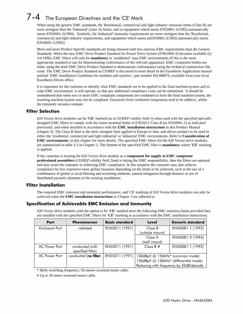
%-
When using the generic EMC standards, the 'Residential, commercial and light industry' emission limits (Class B) aremore stringent than the 'Industrial' (class A) limits, and so equipment which meets EN50081-1(1992) automaticallymeets EN50081-2(1994). Similarly, the 'Industrial' immunity requirements are more stringent than the 'Residential,commercial and light industry' requirements, and equipment which meets prEN50082-2(1992) automatically meetsEN50082-1(1992).
More and more Product Specific standards are being released with less onerous EMC requirements than the GenericStandards. When the new EMC Drive Product Standard for Power Drive System (EN61800-3) becomes available (Q3/4 1996), EMC filters will only be mandatory in ‘residential’ type EMC environments (if this is the mostappropriate standard to use for demonstrating conformance of the relevant apparatus). EMC competent bodies aretoday using the draft EMC Drive Product Standard to demonstrate conformance using the technical construction fileroute. The EMC Drive Product Standard as CEMEP is discussed in more detail in the Eurotherm Application manualentitled ‘EMC Installation Guidelines for modules and systems’, part number HA388879, available from your localEurotherm Drives office.
It is important for the customer to identify what EMC standards are to be applied to the final machine/system and inwhat EMC environment it will operate, so that any additional compliance costs can be minimised. It should beremembered that when two or more EMC compliant components are combined to form the final machine/system, theresulting machine/system may not be compliant. Emissions from combined components tend to be additive, whilstthe immunity remains constant.
$!!*
620 Vector drive modules can be 'CE' marked (as in CEMEP validity field 1) when used with the specified speciallydesigned EMC filters to comply with the mains terminal limits of EN55011 Class B (or EN50081-1) as indicatedpreviously, and when installed in accordance with the EMC installation instructions in this Product Manual(chapter 3). The Class B limit is the most stringent limit applied in Europe to date, and allows product to be used ineither the 'residential, commercial and light industrial' or 'industrial' EMC environments. Refer to Consideration ofEMC environments, in this chapter for more details. The specified EMC filters for the 620 Vector drive modulesare summarised in table 3-3 in Chapter 3. The fitment of the specified EMC filter is mandatory where 'CE' markingis applied.
If the customer is treating the 620 Vector drive module as a component for supply to EMC competentprofessional assemblers (CEMEP validity field 2)and is taking the EMC responsibility, then the filters are optionaland may assist the customer in achieving EMC compliance. In this situation the customer may also achievecompliance by less expensive more global measures depending on the limits to be achieved, such as the use of acombination of global or local filtering and screening methods, natural mitigation through distance or use ofdistributed parasitic elements of the existing installation.
$! !!
The required EMC emission and immunity performance, and 'CE' marking of 620 Vector drive modules can only beachieved when the EMC installation instructions in Chapter 3 are adhered to.
)** *+ 1!
620 Vector drive modules with the option to be 'CE' marked meet the following EMC emission limits provided theyare installed with the specified EMC filters for 'CE' marking in accordance with the EMC installation instructions.
% * +! #*
$ ,
$
$
!!
$ , $
!!!! $ ,µ7-/
,µ7-/!!
#!*,
* 6kHz switching frequency, 50 metres screened motor cable.
# Up to 50 meter screened motor cable.
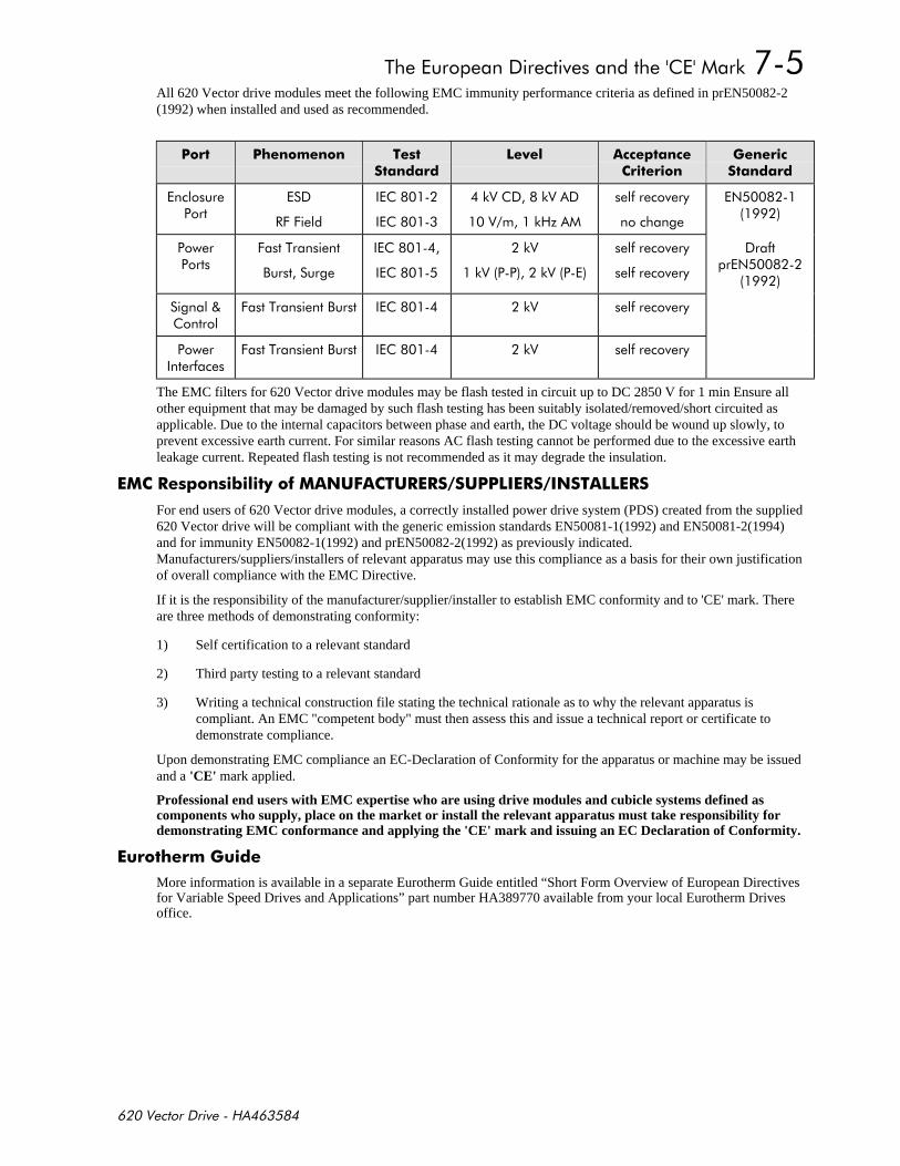
%-
All 620 Vector drive modules meet the following EMC immunity performance criteria as defined in prEN50082-2(1992) when installed and used as recommended.
+! **) *
#*
#++
--
-/
!
$
+%
,
-
--
!
!
!$
+%, - !
!
+%, - !
The EMC filters for 620 Vector drive modules may be flash tested in circuit up to DC 2850 V for 1 min Ensure allother equipment that may be damaged by such flash testing has been suitably isolated/removed/short circuited asapplicable. Due to the internal capacitors between phase and earth, the DC voltage should be wound up slowly, toprevent excessive earth current. For similar reasons AC flash testing cannot be performed due to the excessive earthleakage current. Repeated flash testing is not recommended as it may degrade the insulation.
)1!$
For end users of 620 Vector drive modules, a correctly installed power drive system (PDS) created from the supplied620 Vector drive will be compliant with the generic emission standards EN50081-1(1992) and EN50081-2(1994)and for immunity EN50082-1(1992) and prEN50082-2(1992) as previously indicated.Manufacturers/suppliers/installers of relevant apparatus may use this compliance as a basis for their own justificationof overall compliance with the EMC Directive.
If it is the responsibility of the manufacturer/supplier/installer to establish EMC conformity and to 'CE' mark. Thereare three methods of demonstrating conformity:
1) Self certification to a relevant standard
2) Third party testing to a relevant standard
3) Writing a technical construction file stating the technical rationale as to why the relevant apparatus iscompliant. An EMC "competent body" must then assess this and issue a technical report or certificate todemonstrate compliance.
Upon demonstrating EMC compliance an EC-Declaration of Conformity for the apparatus or machine may be issuedand a 'CE' mark applied.
Professional end users with EMC expertise who are using drive modules and cubicle systems defined ascomponents who supply, place on the market or install the relevant apparatus must take responsibility fordemonstrating EMC conformance and applying the 'CE' mark and issuing an EC Declaration of Conformity.
#
More information is available in a separate Eurotherm Guide entitled “Short Form Overview of European Directivesfor Variable Speed Drives and Applications” part number HA389770 available from your local Eurotherm Drivesoffice.

%-
$
$$0-!
Issued for *+ ! -*+ The drive is CEcompliancewith the EMCDirective whenthe unit is usedas relevantapparatus.
In accordance with the EEC Directive89/336/EEC and amended by 92/31/EEC and93/68/EEC, Article 10 and Annex 1, (EMC
DIRECTIVE)We Eurotherm Drives Limited, address as
below, declare under our sole responsibilitythat the above Electronic Products when
installed and operated with reference to theinstructions in the Product Manual (providedwith each piece of equipment) and using the
specified EMC filters is in accordance with therelevant clauses from the following standards:-BSEN50081-1(1992), BSEN50081-2 (1994),
BSEN50082-1# (1992)and draft prEN50082-2#* (1992)
In accordance with the EEC Directive73/23/EEC and amended by 93/68/EEC,
Article 13 and Annex III, (LOW VOLTAGEDIRECTIVE)
We Eurotherm Drives Limited, address asbelow, declare under our sole responsibility
that the above Electronic Products wheninstalled and operated with reference to the
instructions in the Product Manual(provided with each piece of equipment), is in
accordance with the following standard :-EN50178 (1998)
marked inaccordance withthe low voltagedirective forelectricalequipment andappliances in thevoltage rangewhen installedcorrectly.
$
This is *! **+ Since theprovided to aidyourjustification forEMCcompliancewhen the unitis used as acomponent.
We Eurotherm Drives Limited, address asbelow, declare under our sole responsibility
that the above Electronic Products wheninstalled and operated with reference to the
instructions in the Product Manual (providedwith each piece of equipment) and using the
specified EMC filters is in accordance with therelevant clauses from the following standards:-BSEN50081-1 (1992), BSEN50081-2 (1994),BSEN50082-1# (1992) and draft prEN50082-
2#* (1992)
The above Electronic Productsare components to be incorporated into
machinery and may not be operated alone.The complete machinery or installation usingthis equipment may only be put into service
when the safety considerations of the Directive89/392/EEC are fully adhered to.
Particular reference should be made toEN60204-1 (Safety of Machinery - Electrical
Equipment of Machines).All instructions, warnings and safety
information of the Product Manual must beadhered to.
potential hazardsare mainlyelectrical ratherthan mechanical,the drive does notfall under themachinerydirective.However, we dosupply amanufacturer'sdeclaration for
when the drive isused(as acomponent) inmachinery.
Dr Martin Payn (Conformance Officer)
or information only. # Compliant with these immunity standards without specified EMC filters.
$"'(#%". $%% %'$" % ( 1,$#8%'$+ 1#$#'!! """ ,$$$
+$AA +%&A#'(% AAA#'+A. B(#'%## %
% #$ . # "$)$(,#.
%%!!
%'+
%

) +*-
Routine maintenance of the 620 Vector Drives comprises a periodic inspection to check for a build-up of dust orother obstructions that may affect the ventilation of the unit. Obstructions should be removed and any dust mustbe cleared using dry air.
The 620 Vector Drives must not be repaired by the user. If repair is necessary return the unit to EurothermDrives.
"#
BEFORE DISCONNECTING THIS UNIT, ENSURE ISOLATION OF THE MAIN SUPPLY TOTERMINALS M1, M2 AND M3.
WAIT FOR AT LEAST 3 MINUTES FOR THE DC LINK TERMINALS (DC+ & DC-) TODISCHARGE TO SAFE VOLTAGE LEVELS (<50V), FAILURE TO DO SO CONSTITUTES
AN ELECTRICAL SHOCK HAZARD.
The following procedures are recommended in the unlikely event of a fault which necessitates return of acontroller (or part) to Eurotherm Drives.
a) Contact your nearest Eurotherm Drives service centre to arrange return of the controller, if necessary.(Refer to the list of Eurotherm Drives service centres at the end of this Chapter). Eurotherm Drives willrequest the model number and serial number of the controller, please have this information to hand prior tomaking contact.
b) On contacting your local Eurotherm Drives service centre, a Returned Material Authorisation (RMA) codewill be issued, if necessary, which must be used as a reference on paperwork returned with the controller.
c) Package and despatch the controller.
NOTE: In the unlikely event that a 620 is to be returned to Eurotherm Drives, it must be suitablypackaged. If Styrofilä chips, or equivalent, are being used as a packing material then the controllermust first be sealed in a polythene bag or similar, to prevent ingress of the packing material.
) !
This product contains materials which are consignable waste under the Special Waste Regulations1996 which complies with the EC Hazardous Waste Directive - Directive 91/689/EEC.
We recommend you dispose of the appropriate materials in accordance with the validenvironmental control laws. The following table shows which materials can be recycled and whichhave to be disposed of in a special way.
Material Recycle Disposal
metal yes no
plastics material yes no
printed circuit board no yes

The printed circuit board should be disposed of in one of two ways:
1. High temperature incineration (minimum temperature 1200oC) by an incinerator authorisedunder parts A or B of the Environmental Protection Act
2. Disposal in an engineered land fill site that is licensed to take aluminium electrolytic capacitors.Do not dispose of in a land fill site set aside for domestic waste.
----
During transport our products are protected by suitable packaging. This is entirely environmentallycompatible and should be taken for central disposal as secondary raw material.
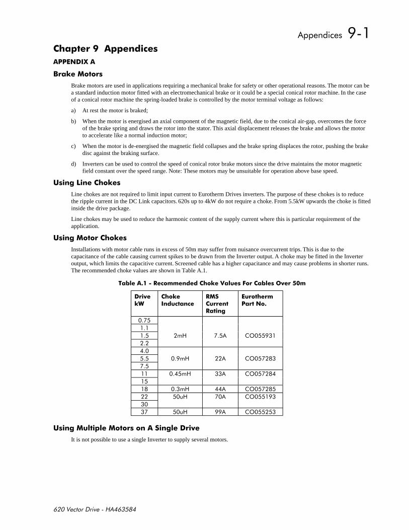
) ))*
3
%
Brake motors are used in applications requiring a mechanical brake for safety or other operational reasons. The motor can bea standard induction motor fitted with an electromechanical brake or it could be a special conical rotor machine. In the caseof a conical rotor machine the spring-loaded brake is controlled by the motor terminal voltage as follows:
a) At rest the motor is braked;
b) When the motor is energised an axial component of the magnetic field, due to the conical air-gap, overcomes the forceof the brake spring and draws the rotor into the stator. This axial displacement releases the brake and allows the motorto accelerate like a normal induction motor;
c) When the motor is de-energised the magnetic field collapses and the brake spring displaces the rotor, pushing the brakedisc against the braking surface.
d) Inverters can be used to control the speed of conical rotor brake motors since the drive maintains the motor magneticfield constant over the speed range. Note: These motors may be unsuitable for operation above base speed.
-
Line chokes are not required to limit input current to Eurotherm Drives inverters. The purpose of these chokes is to reducethe ripple current in the DC Link capacitors. 620s up to 4kW do not require a choke. From 5.5kW upwards the choke is fittedinside the drive package.
Line chokes may be used to reduce the harmonic content of the supply current where this is particular requirement of theapplication.
-
Installations with motor cable runs in excess of 50m may suffer from nuisance overcurrent trips. This is due to thecapacitance of the cable causing current spikes to be drawn from the Inverter output. A choke may be fitted in the Inverteroutput, which limits the capacitive current. Screened cable has a higher capacitance and may cause problems in shorter runs.The recommended choke values are shown in Table A.1.
1!* ! $ 1!+
+"
* *
-
'
'
'
'
'
'
- !)!-!+
It is not possible to use a single Inverter to supply several motors.

)#
Motors that are designed for high-speed operation at several times base speed will tend to have lower impedance. It may thenbe necessary to reduce the current loop gain.
In this case it is necessary to go into the 'test functions' menu. This is found under 'system/reserved'. Select test function 2.This will cause the software to generate a square wave current demand. The amplitude, period, and offset may be set by theparameters 'current amplitude', 'current period', and 'current offset' respectively. It is convenient best to set these numbers to200, 40, and zero respectively.
Return to the 'current loop' menu under 'set-up parameters'. Select 'gain'. This is a number which may vary between 0 and255. This number will typically be around 70 for most motors, but for higher speed motors it may need to be increased. Notethat to increase the gain, the number in 'GAIN' needs to be decreased.
Turn on the drive and observe the actual current with an oscilloscope on the diagnostic test pin. See diagram 9.1 for thelocation of the two current feedback signals.
If the current loop gain is correct, or too low, the current feedback should follow the square wave current demand in asmooth controlled manner with no overshoot. When it has reached the new level it should settle down to a smooth waveformwith a small amount of ripple.
As the gain is increased (i.e. the number in 'gain' is decreased) the current will follow the demand with less delay. As thegain is increased further (i.e. the number in 'gain' is decreased further) the point will be reached where the ripple (in thesteady state when it has reached its new level) will suddenly increase. When this happens, the gain should be reduced untilthe ripple drops back to the low level.
The aim is to get the current to follow the demand with minimum delay, while ensuring the steady state ripple remains at aminimum.

-*
I1 Fbk.
I3 Fbk.
I1 Dmd.
0v
I3 Dmd.
Peek Diag.
+
Diagnostic test point scaling.
Feedback: 100% = 1.59v peekDemand: 220% = 5v peek (Centred on -5v)
Diagnostic test points:
These are of two types:
• Analogue current control diagnostics
• Peek memory location diagnostic
Current control diagnostics:
The current control loop has two channels, here called 1 and 3 (for historical reasons).
Each channel has a current feedback, a current demand, and a resulting current error. The current error is taken to acomparator, and a sawtooth waveform is taken to the other input of the comparator to produce the PWM waveform.
The current feedback is centred on zero, and scaled such that rated drive current gives 1.6v peak.
The current demand is centred on 5v, and is scaled such that rated drive current is 2.04v peak, i.e. 5v + or - 2.04v.
Peek memory location diagnostic (Peek Diag.):
This displays the 'peeked' value as an analogue output.
A Tag may be displayed by setting PEEK TAG to the desired Tag number. The default is speed feedback. The valuecan be scaled using PEEK SCALE.
An absolute memory location may be displayed by setting PEEK TAG to zero and selecting the memory location withPEEK DATA This function requires the supper password.

3%#
VECTOR DRIVE
RELEASE 4.8
4.0 kW 380-460v
..MENU LEVEL
....DIAGNOSTICS
......TOTAL SPD.DMD. [6] = 0.00 %
h.....SPEED FB UNFIL [7] = 0.00 %
......SPEED FEEDBACK [11] = 0.00 %
......SPEED ERROR [8] = 0.00 %
......TORQUE DEMAND [9] = 0.00 %
......TORQUE FEEDBACK [10] = 0.00 %
......CURRENT FEEDBACK [78] = 0.00 %
f.....TERMINAL VOLTS [480] = 0 VOLTS
f.....DC LINK VOLTS [613] = 608 VOLTS
h.....DC VOLTS UNFLT [684] = 608 VOLTS
f.....TERM V INTEGRAL [623] = 100.00 %
......ACTUAL POS I LIM [13] = 100.00 %
......ACTUAL NEG I LIM [14] = -100.00 %
......INVERSE TIME O/P [15] = 100.00 %
......AT CURRENT LIMIT [16] = FALSE
......AT ZERO SPEED [17] = TRUE
......AT ZERO SETPOINT [18] = TRUE
......AT STANDSTILL [19] = TRUE
......STALL TRIP [20] = OK
......RAMPING [21] = FALSE
......DRIVE START [23] = FALSE
......DRIVE ENABLE [24] = FALSE
......OPERATING MODE [25] = STOPPED
......HEALTHY [27] = TRUE
......HEALTH OUTPUT [12] = TRUE
......READY [559] = FALSE
......RUN [28] = FALSE
......ANIN 1 (C3) [29] = 0.000 VOLTS
......ANIN 3 (F2) [31] = 0.000 VOLTS
......ANIN 4 (F3) [32] = 0.000 VOLTS
......ANIN 5 (F4) [33] = 0.000 VOLTS
......ANOUT 1 (C5) [34] = 0.000 VOLTS
......ANOUT 2 (F5) [35] = 0.000 VOLTS
......COAST STOP [26] = FALSE
......PROGRAM STOP [22] = FALSE
......DIGIN B6 JOG [37] = FALSE
......DIGIN B7 START [36] = FALSE
......DIGIN B8 ENABLE [38] = FALSE
......DIGIN 1 (E2) [39] = FALSE
......DIGIN 2 (E3) [40] = FALSE
......DIGIN 3 (E4) [41] = FALSE
......DIGIN 4 (E5) [521] = FALSE
......DIGOUT 1 (E6) [42] = TRUE
......DIGOUT 2 (E7) [43] = TRUE
......DIGOUT 3 (E8) [44] = FALSE
......RAISE/LOWER O/P [45] = 0.00 %
......SPT SUM O/P 1 [46] = 0.00 %
......SPT SUM O/P 2 [385] = 0.00 %
......SPT SUM O/P 3 [386] = 0.00 %
......RAMP OUTPUT [47] = 0.00 %
......PRESET O/P [110] = 0.00 %
......SPEED SETPOINT [48] = 0.00 %
f.....SEQ RUN INPUT [49] = 0.00 %
f.....SEQ OUTPUT [50] = 0.00 %
......ENCODER [51] = 0 RPM
....SETUP PARAMETERS
......RAMPS
........RAMP ACCEL TIME [54] = 10.0 SECS
........RAMP DECEL TIME [55] = 10.0 SECS
f.......RAMP QUENCH [56] = FALSE
........RAMP HOLD [57] = FALSE <- [281]
........RAMP INPUT [58] = 0.00 % <- [345]
........% S-RAMP [59] = 0.00 %
........RAMPING THRESH. [60] = 1.00 %
........AUTO RESET [61] = TRUE
........EXTERNAL RESET [62] = FALSE
........RESET VALUE [63] = 0.00 %
........RAMPING [21] = FALSE
........RAMP OUTPUT [47] = 0.00 %
......OP-STATION
........SET UP
..........SETPOINT [507] = 0.0 %
..........LOCAL KEY ENABLE [632] = TRUE
........START UP VALUES
..........SETPOINT [503] = 0.0 %
..........REV DIRECTION [504] = FALSE
..........PROGRAM [505] = FALSE
..........LOCAL [506] = FALSE
........LOCAL RAMP
..........RAMP ACCEL TIME [511] = 10.0 SECS
..........RAMP DECEL TIME [512] = 10.0 SECS
..........% S-RAMP [516] = 0.00 %
h.........RAMP OUTPUT [509] = 0.00 %
......AUX I/O
........AUX START [66] = TRUE
........START [70] = FALSE <- [450]
........AUX JOG [67] = TRUE
........JOG INPUT [71] = FALSE <- [451]
........AUX ENABLE [68] = TRUE
........ENABLE [72] = FALSE <- [452]
f.......REM.SEQ.ENABLE [791] = FALSE
f.......REMOTE SEQ [786] = 0x0000
f.......SEQ STATUS [787] = 0x0C04
......JOG
........JOG SPEED 1 [75] = 10.00 %
........JOG SPEED 2 [76] = -10.00 %
........MODE [80] = FALSE
........JOG ACCEL RATE [113] = 10.0 SECS
........JOG DECEL RATE [114] = 10.0 SECS
......RAISE/LOWER
........RESET VALUE [82] = 0.00 %
........RAMP RATE [83] = 60.0 SECS
........RAISE INPUT [85] = FALSE
........LOWER INPUT [86] = FALSE
........MIN VALUE [87] = -100.00 %
........MAX VALUE [88] = 100.00 %
........EXTERNAL RESET [89] = FALSE
........RAISE/LOWER O/P [45] = 0.00 %
h.......RAISE/LOWER INIT [678] = 0.00 %
h.....INVERSE TIME
h.......AIMING POINT [116] = 105.00 %
h.......DELAY [117] = 60.0 SECS
h.......DOWN RATE [118] = 10.0 SECS
h.......UP RATE [148] = 120.0 SECS
h.......INVERSE TIME O/P [15] = 31.44 %
......STOP RATES
........RUN STOP TIME [120] = 10.0 SECS
........RUN STOP LIMIT [121] = 60.0 SECS
........FAST STOP TIME [123] = 1.0 SECS
........FAST STOP LIMIT [124] = 60.0 SECS
........USE SYSTEM RAMP [125] = TRUE
f.......PRE-START DELAY [122] = 0.500 SECS
f.......READY DELAY [352] = 0.000 SECS
........CONTACTOR DELAY [112] = 0.5 SECS
........PILOT 590 MODE [777] = FALSE
........STOP ZERO SPEED [126] = 1.00 %
........PROG STOP I-LIM [622] = 150.00 %
........COAST STOP [26] = FALSE
........PROGRAM STOP [22] = FALSE
......ALARMS / SEQ
........EXTERNAL TRIP [144] = FALSE
f.......REMOTE INHIBIT [788] = FALSE
f.......REMOTE DELAY [790] = 1.00
........REMOTE TRIP [789] = OK
h.......MOTOR TMP.TRIP [128] = 75.00 %
h.......MOTOR TMP.RST. [309] = 50.00 %
........MOTR.TMP.INHIBIT [146] = FALSE
h.......HEATSINK LEVEL [129] = 17.00 %
f.......ACK ALARM [166] = TRUE
........STALL INHIBIT [143] = FALSE
........STALL TORQUE [136] = 95.00 %
........STALL SPEED [138] = 4.00 %
........STALL DELAY [137] = 10.00
........STALL TRIP [20] = OK
........OVER SPD INHIBIT [145] = FALSE
........OVER SPEED LEVEL [139] = 120.00 %
h.......UNDER V LEVEL [685] = 440 VOLTS
h......./UNDER VOLTS [686] = TRUE
........5703 RCV.INHIBIT [142] = FALSE
f.......SPD.FBK.DELAY [687] = 10.000 SECS
f.......SPD.FBK.THRESHD [688] = 10.00 %
........SPD.FBK.INHIBIT [689] = FALSE
h.......HEALTH INHIBIT [219] = 0x0000
f.......OPERATING MODE [25] = STOPPED
f.......DRIVE START [23] = FALSE
f.......DRIVE ENABLE [24] = FALSE
f.......READY [559] = FALSE
f.......RUN [28] = FALSE
f.......HEALTH STORE [203] = 0x0000
f.......HEALTH WORD [217] = 0x0010
f.......FIRST ALARM [218] = 0x0010
f.......HEALTHY [27] = TRUE
f.......HEALTH OUTPUT [12] = TRUE
......CALIBRATION
........ENCODER LINES [131] = 2048
........ENCODER SUPPLY [774] = 50 %
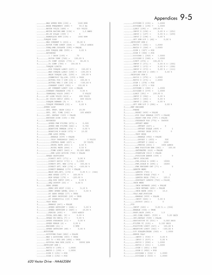
........MAX SPEED RPM [130] = 1500 RPM
........BASE FREQUENCY [448] = 50.0 Hz
........MOTOR VOLTS [486] = 415 VOLTS
........MOTOR RATING RMS [134] = 1.0 AMPS
........NO.OF POLES [399] = 4
........NAMEPLATE RPM [135] = 1440 RPM
......TORQUE LOOP
........MAG CURRENT % [453] = 30.00 %
........ROTOR TIME CONST [458] = 100.0 mSECS
........TORQ.DMD.ISOLATE [596] = FALSE
........AUX TORQUE DMD [599] = 0.00 %
........ADVANCED
..........1 / GAIN [149] = 70
f.........ROTOR TEMP [769] = 100.00 %
f.........Tr COMP (COLD) [770] = 80.00 %
f.........Tr COMP [784] = 100.00 %
........TORQUE LIMITS
..........POS TORQUE LIMIT [157] = 150.00 %
..........NEG TORQUE LIMIT [158] = -150.00 %
..........MAIN TORQUE LIM. [159] = 100.00 %
..........SYMMETRIC TQ.LIM. [153] = TRUE
..........ACTUAL POS I LIM [13] = 100.00 %
..........ACTUAL NEG I LIM [14] = -100.00 %
..........CURRENT LIMIT [585] = 150.00 %
..........AT CURRENT LIMIT [16] = FALSE
........CURRENT FEEDBACK [78] = 0.00 %
f.......TERMINAL VOLTS [480] = 0 VOLTS
f.......DC LINK VOLTS [613] = 608 VOLTS
h.......DC VOLTS UNFLT [684] = 608 VOLTS
........TORQUE DEMAND [9] = 0.00 %
........TORQUE FEEDBACK [10] = 0.00 %
......SPEED LOOP
........SPD. PROP. GAIN [161] = 10.00
........SPD. INT. TIME [162] = 100 mSECS
f.......INT. DEFEAT [163] = FALSE
........ENCODER SIGN [164] = POS
f.......ADVANCED
f.........SPEED FBK FILTER [673] = 0.500
f.........SPEED DMD FILTER [662] = 0.750
f.........ADAPTIVE THRESH [674] = 0.00 %
f.........ADAPTIVE P-GAIN [675] = 10.00
f.........PWR LOSS CNTRL
f...........ENABLE [639] = FALSE
f...........TRIP THRESHOLD [640] = 0 VOLTS
f...........CONTROL BAND [657] = 20 VOLTS
f...........DECEL RATE [641] = 2.50 %
f...........ACCEL RATE [644] = 0.50 %
f...........TIME LIMIT [643] = 30.000 SECS
f...........PWR LOSS ACTIVE [766] = FALSE
........SPEED SETPOINTS
..........DIRECT SPT1 [171] = 0.00 %
..........DIRECT RATIO [172] = 0.1000
..........DIRECT SPT. MAX [173] = 100.00 %
..........DIRECT SPT. MIN [174] = -100.00 %
..........DIRECT ENABLE [175] = FALSE
..........MAIN SPD.SPT. [176] = 0.00 % <- [346]
..........MAX SPEED [177] = 100.00 %
..........MIN SPEED [178] = -100.00 %
h.........SEQ RUN INPUT [49] = 0.00 %
h.........SEQ OUTPUT [50] = 0.00 %
f.......ZERO SPEED
..........ZERO SPD HYST [132] = 0.10 %
..........ZERO SPEED LEVEL [252] = 0.50 %
..........AT ZERO SPEED [17] = TRUE
..........AT ZERO SETPOINT [18] = TRUE
..........AT STANDSTILL [19] = TRUE
f.......TEST MODE
f.........ENABLE [647] = FALSE
f.........SPEED SETPOINT 1 [648] = 5.00 %
f.........SPEED SETPOINT 2 [649] = 10.00 %
f.........PERIOD [650] = 1000 mSECS
........TOTAL SPD.DMD. [6] = 0.00 %
h.......SPEED FB UNFIL [7] = 0.00 %
........SPEED FEEDBACK [11] = 0.00 %
........SPEED ERROR [8] = 0.00 %
........ENCODER [51] = 0 RPM
........SPEED SETPOINT [48] = 0.00 %
......AUTOTUNE
........AUTOTUNE FLAG [482] = FALSE
........MAG I AUTOTUNE [483] = TRUE
........SET Tr < RTD SPD [484] = TRUE
........AUTOCAL MAX RPM [629] = 30000 RPM
......SETPOINT SUM 1
........RATIO 0 [189] = 1.0000
........RATIO 1 [190] = 1.0000
........SIGN 0 [191] = POS
........SIGN 1 [192] = POS
........DIVIDER 0 [193] = 1.0000
........DIVIDER 1 [194] = 1.0000
........LIMIT [195] = 100.00 %
........INPUT 0 [196] = 0.00 % <- [251]
........INPUT 1 [197] = 0.00 % <- [259]
........INPUT 2 [198] = 0.00 %
........SPT SUM O/P 1 [46] = 0.00 %
......SETPOINT SUM 2
........RATIO 1 [365] = 1.0000
........RATIO 0 [364] = 1.0000
........SIGN 1 [367] = POS
........SIGN 0 [366] = POS
........DIVIDER 1 [369] = 1.0000
........DIVIDER 0 [368] = 1.0000
........LIMIT [370] = 100.00 %
........INPUT 0 [371] = 0.00 % <- [305]
........INPUT 1 [372] = 0.00 % <- [308]
........INPUT 2 [373] = 0.00 % <- [111]
........SPT SUM O/P 2 [385] = 0.00 %
......SETPOINT SUM 3
........RATIO 1 [376] = 1.0000
........RATIO 0 [375] = 1.0000
........SIGN 1 [378] = POS
........SIGN 0 [377] = POS
........DIVIDER 1 [380] = 1.0000
........DIVIDER 0 [379] = 1.0000
........LIMIT [381] = 100.00 %
........INPUT 0 [382] = 0.00 %
........INPUT 1 [383] = 0.00 %
........INPUT 2 [384] = 0.00 %
........SPT SUM O/P 3 [386] = 0.00 %
f.....REF ENCODER
f.......PHASE
f.........RESET [600] = FALSE
f.........POS CALC ENABLE [337] = FALSE
h.........RESET FBK POS [797] = FALSE
h.........FEEDBACK POS [775] = 0x0000
f.........OFFSET MENU
f...........OFFSET [447] = 0
f...........OFFSET SCALE [609] = 1
f...........OFFSET TRIM [670] = 0
f.........TEST MODE
f...........ENABLE [652] = FALSE
f...........OFFSET 1 [653] = 500
f...........OFFSET 2 [654] = 1000
f...........PERIOD [655] = 1000 mSECS
f.........MAX POSITION ERR [342] = 100.00
f.........SATURATED [610] = FALSE
f.........OVERFLOW [611] = FALSE
f.........POSITION ERROR [338] = 0
f.......INPUT SCALING
f.........FBK.SCALE A [498] = 10000
f.........FBK.SCALE B [499] = 10000
h.........FBK ENCODER CNT [77] = 0
f.......LENGTH MENU
f.........LENGTH [765] = 0
f.........LENGTH SCALE [762] = 1
f.........LENGTH RATE [764] = 100.0
f.........SUBTRACT LENGTH [763] = FALSE
f.......INCH MENU
f.........INCH ADVANCE [604] = FALSE
f.........INCH RETARD [605] = FALSE
f.........INCH RATE [606] = 10.0
f.......CALC.REF.POSTION
f.........ENABLE [659] = FALSE
f.........INPUT [660] = 0.00 %
f.........OUTPUT [661] = 0
f.....PID
f.......INPUT [545] = 0.00 % <- [556]
f.......ENABLE [534] = TRUE
f.......PROP.GAIN [549] = 1.0
f.......INT.TIME CONST. [539] = 5.00 SECS
f.......INT.DEFEAT [538] = FALSE
f.......DERIVATIVE TC [531] = 0.000 SECS
f.......FILTER TC [535] = 0.100 SECS
f.......POSITIVE LIMIT [547] = 100.00 %
f.......NEGATIVE LIMIT [542] = -100.00 %
f.......O/P SCALER(TRIM) [543] = 1.0000
f.......ERROR CALC
f.........INPUT 1 [536] = 0.00 %
f.........INPUT 2 [537] = 0.00 %
f.........RATIO 1 [550] = 1.0000
f.........RATIO 2 [551] = 1.0000
f.........SIGN 1 [601] = POS
f.........SIGN 2 [602] = POS
f.........DIVIDER 1 [532] = 1.0000
f.........DIVIDER 2 [533] = 1.0000
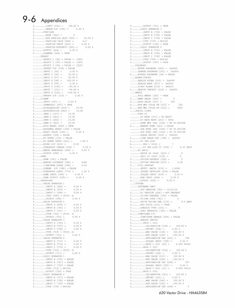
f.........LIMIT [553] = 100.00 %
f.........ERROR O/P [500] = 0.00 %
f.......PROFILER
f.........MODE [541] = 0
f.........MIN PROFILE GAIN [540] = 20.00 %
f.........PROFILED GAIN [548] = 0.0
f.........PROFILE INPUT [554] = 0.00 %
f.........PROFILE MININPUT [555] = 0.00 %
f.......OUTPUT [546] = 0.00 %
f.......CLAMPED [544] = TRUE
......PRESET
........SELECT 1 [92] = FALSE <- [285]
........SELECT 2 [93] = FALSE <- [289]
........SELECT 3 [94] = FALSE <- [525]
........INVERT O/P [109] = FALSE
........INPUT 1 [95] = 0.00 %
........INPUT 2 [96] = 25.00 %
........INPUT 3 [97] = 50.00 %
........INPUT 4 [98] = 100.00 %
........INPUT 5 [99] = 0.00 %
........INPUT 6 [100] = -25.00 %
........INPUT 7 [101] = -50.00 %
........INPUT 8 [102] = -100.00 %
........PRESET O/P [110] = 0.00 %
f.....S-RAMP
f.......INPUT [597] = 0.00 %
f.......SYMMETRIC [667] = TRUE
f.......ACCELERATION [106] = 10.00
f.......DECELERATION [666] = 10.00
f.......JERK 1 [107] = 10.00
f.......JERK 2 [663] = 10.00
f.......JERK 3 [664] = 10.00
f.......JERK 4 [665] = 10.00
f.......AUTO RESET [669] = TRUE
f.......EXTERNAL RESET [104] = FALSE
f.......RESET VALUE [105] = 0.00 %
f.......QUENCH [108] = FALSE
f.......AT SPEED [316] = FALSE
f.......AT SPEED LEVEL [612] = 1.00 %
h.......ACCEL O/P [253] = 0.00
h.......OVERSHOOT THRESH [254] = 5.00 %
h.......ERROR THRESHOLD [668] = 0.50 %
f.......OUTPUT [598] = 0.00 %
f.....HOME
f.......HOME [397] = FALSE
f.......HOMING DISTANCE [396] = 2048
f.......1/ENCODER SCALE [398] = 4.00
f.......LINEAR O/P [388] = FALSE
f.......OVERSHOOT LIMIT [773] = 1.00 %
f.......HOME INPUT [394] = 0.00 %
f.......HOME OUTPUT [395] = 0.00 %
f.....OPERATORS
f.......VALUE OPERATOR 1
f.........INPUT A [692] = 0.00 %
f.........INPUT B [693] = 0.00 %
f.........INPUT C [694] = 0.00 %
f.........TYPE [695] = IF(C) -A
f.........OUTPUT [696] = 0.00 %
f.......VALUE OPERATOR 2
f.........INPUT A [699] = 0.00 %
f.........INPUT B [700] = 0.00 %
f.........INPUT C [701] = 0.00 %
f.........TYPE [702] = IF(C) -A
f.........OUTPUT [703] = 0.00 %
f.......VALUE OPERATOR 3
f.........INPUT A [706] = 0.00 %
f.........INPUT B [707] = 0.00 %
f.........INPUT C [708] = 0.00 %
f.........TYPE [709] = IF(C) -A
f.........OUTPUT [710] = 0.00 %
f.......VALUE OPERATOR 4
f.........INPUT A [713] = 0.00 %
f.........INPUT B [714] = 0.00 %
f.........INPUT C [715] = 0.00 %
f.........TYPE [716] = IF(C) -A
f.........OUTPUT [717] = 0.00 %
f.......LOGIC OPERATOR 1
f.........INPUT A [720] = FALSE
f.........INPUT B [721] = FALSE
f.........INPUT C [722] = FALSE
f.........TYPE [723] = NOT(A)
f.........OUTPUT [724] = TRUE
f.......LOGIC OPERATOR 2
f.........INPUT A [727] = FALSE
f.........INPUT B [728] = FALSE
f.........INPUT C [729] = FALSE
f.........TYPE [730] = NOT(A)
f.........OUTPUT [731] = TRUE
f.......LOGIC OPERATOR 3
f.........INPUT A [734] = FALSE
f.........INPUT B [735] = FALSE
f.........INPUT C [736] = FALSE
f.........TYPE [737] = NOT(A)
f.........OUTPUT [738] = TRUE
f.......LOGIC OPERATOR 4
f.........INPUT A [741] = FALSE
f.........INPUT B [742] = FALSE
f.........INPUT C [743] = FALSE
f.........TYPE [744] = NOT(A)
f.........OUTPUT [745] = TRUE
....PASSWORD
......ENTER PASSWORD [200] = 0x0000
......CHANGE PASSWORD [201] = 0x0000
h.....BYPASS PASSWORD [69] = FALSE
....ALARM STATUS
......HEALTH STORE [203] = 0x0000
......HEALTH WORD [217] = 0x0010
......FIRST ALARM [218] = 0x0010
h.....HEALTH INHIBIT [219] = 0x0000
....MENUS
......FULL MENUS [205] = TRUE
f.....MENU DELAY [206] = 0
f.....DATA DELAY [207] = 100
h.....MIN MMI CYCLE TM [313] = 200
h.....MAX MMI CYCLE TM [314] = 4000
....SERIAL LINKS
......PORT P3
........P3 MODE [237] = EI BUSY*
........P3 BAUD RATE [241] = 9600
........DUMP MMI (TX) [238] = UP TO ACTION
h.......MEMORY DUMP [221] = FALSE
........UDP XFER (TX) [240] = UP TO ACTION
........UDP XFER (RX) [239] = UP TO ACTION
........ERROR REPORT [229] = 0x0000
h.......LINE ERROR CNT [798] = 0x0000
h.......P3 TAG LIST
h.........TAG 1 [212] = 7
h.........P3 TAG LIST TC [318] = 0.10 SECS
......EI ASCII
........GROUP ID (GID) [223] = 0
........UNIT ID (UID) [224] = 0
f.......OPTION ADDRESS [230] = 0
f.......OPTION VERSION [672] = 0.00
f.....5703 SUPPORT
f.......SETPT. RATIO [233] = 1.0000
f.......INVERT SETPOINT [234] = FALSE
f.......SCALED INPUT [235] = 0.00 %
f.......RAW INPUT [584] = 0.00 %
f.......OUTPUT [236] = 0.00 %
....SYSTEM
......SOFTWARE INFO
........620 VERSION [782] = 12:21:39
f.......P1 VERSION [226] = NOT PRESENT
f.......CO-PRO PRESENT [150] = FALSE
f.......CO-PRO TYPE [781] = 0
f.......DRIVE RATING RMS [133] = 9.4 AMPS
f.......MID VOLTS [151] = TRUE
f.......CHASSIS TYPE [152] = 4
f.......60Hz DEFAULTS [785] = FALSE
f.....CONFIGURE I/O
f.......CONFIGURE ENABLE [245] = FALSE
f.......ANALOG INPUTS
f.........ANIN 1 (C3)
f...........CALIBRATION [248] = 100.00 %
f...........OFFSET [358] = 0.00 %
f...........MAX VALUE [249] = 100.00 %
f...........MIN VALUE [250] = -100.00 %
f...........DESTINATION TAG [251] = 196
f...........SCALED INPUT [390] = 0.00 %
f...........ANIN 1 (C3) [29] = 0.000 VOLTS
f.........ANIN 3 (F2)
f...........CALIBRATION [256] = 100.00 %
f...........OFFSET [360] = 0.00 %
f...........MAX VALUE [257] = 100.00 %
f...........MIN VALUE [258] = -100.00 %
f...........DESTINATION TAG [259] = 197
f...........SCALED INPUT [391] = 0.00 %
f...........ANIN 3 (F2) [31] = 0.000 VOLTS
f.........ANIN 4 (F3)
f...........CALIBRATION [261] = 100.00 %
f...........OFFSET [361] = 0.00 %
f...........MAX VALUE [262] = 100.00 %
f...........MIN VALUE [263] = -100.00 %
f...........DESTINATION TAG [264] = 0
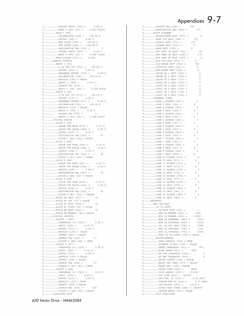
f...........SCALED INPUT [392] = 0.00 %
f...........ANIN 4 (F3) [32] = 0.000 VOLTS
f.........ANIN 5 (F4)
f...........CALIBRATION [266] = 100.00 %
f...........OFFSET [362] = 0.00 %
f...........MAX VALUE [267] = 100.00 %
f...........MIN VALUE [268] = -100.00 %
f...........DESTINATION TAG [269] = 0
f...........SCALED INPUT [393] = 0.00 %
f...........ANIN 5 (F4) [33] = 0.000 VOLTS
h.........ANIN FILTER [671] = 0.800
f.......ANALOG OUTPUTS
f.........ANOUT 1 (C5)
f...........% TO GET 10V [272] = 100.00 %
f...........OFFSET [332] = 0.00 %
f...........HARDWARE OFFSET [676] = 0.00 %
f...........CALIBRATION [330] = 100.00 %
f...........MODULUS [335] = FALSE
f...........ANOUT 1 [354] = 0.00 %
f...........SOURCE TAG [273] = 7
f...........ANOUT 1 (C5) [34] = 0.000 VOLTS
f.........ANOUT 2 (F5)
f...........% TO GET 10V [275] = 150.00 %
f...........OFFSET [333] = 0.00 %
f...........HARDWARE OFFSET [677] = 0.00 %
f...........CALIBRATION [331] = 100.00 %
f...........MODULUS [336] = FALSE
f...........ANOUT 2 [355] = 0.00 %
f...........SOURCE TAG [276] = 9
f...........ANOUT 2 (F5) [35] = 0.000 VOLTS
f.......DIGITAL INPUTS
f.........DIGIN 1 (E2)
f...........VALUE FOR TRUE [279] = 0.01 %
f...........VALUE FOR FALSE [280] = 0.00 %
f...........OUTPUT [527] = 0.00 %
f...........DESTINATION TAG [281] = 57
f...........DIGIN 1 (E2) [39] = FALSE
f.........DIGIN 2 (E3)
f...........VALUE FOR TRUE [283] = 0.01 %
f...........VALUE FOR FALSE [284] = 0.00 %
f...........OUTPUT [528] = 0.00 %
f...........DESTINATION TAG [285] = 92
f...........DIGIN 2 (E3) [40] = FALSE
f.........DIGIN 3 (E4)
f...........VALUE FOR TRUE [287] = 0.01 %
f...........VALUE FOR FALSE [288] = 0.00 %
f...........OUTPUT [529] = 0.00 %
f...........DESTINATION TAG [289] = 93
f...........DIGIN 3 (E4) [41] = FALSE
f.........DIGIN 4 (E5)
f...........VALUE FOR TRUE [523] = 0.01 %
f...........VALUE FOR FALSE [524] = 0.00 %
f...........OUTPUT [508] = 0.00 %
f...........DESTINATION TAG [525] = 94
f...........DIGIN 4 (E5) [521] = FALSE
f.........DIGIN B6 DEST [451] = 71
f.........DIGIN B6 JOG [37] = FALSE
f.........DIGIN B7 DEST [450] = 70
f.........DIGIN B7 START [36] = FALSE
f.........DIGIN B8 DEST [452] = 72
f.........DIGIN B8 ENABLE [38] = FALSE
f.......DIGITAL OUTPUTS
f.........DIGOUT 1 (E6)
f...........THRESHOLD (>) [292] = 0.00 %
f...........INPUT [324] = 0.01 %*
f...........OFFSET [321] = 0.00 %
f...........MODULUS [293] = FALSE
f...........INVERT [327] = FALSE
f...........SOURCE TAG [294] = 17
f...........DIGOUT 1 (E6) [42] = TRUE
f.........DIGOUT 2 (E7)
f...........THRESHOLD (>) [296] = 0.00 %
f...........INPUT [325] = 0.01 %*
f...........OFFSET [322] = 0.00 %
f...........MODULUS [297] = FALSE
f...........INVERT [328] = FALSE
f...........SOURCE TAG [298] = 12
f...........DIGOUT 2 (E7) [43] = TRUE
f.........DIGOUT 3 (E8)
f...........THRESHOLD (>) [300] = 0.00 %
f...........INPUT [326] = 0.00 %
f...........OFFSET [323] = 0.00 %
f...........MODULUS [301] = TRUE
f...........INVERT [329] = FALSE
f...........SOURCE TAG [302] = 559
f...........DIGOUT 3 (E8) [44] = FALSE
f.......CONFIGURE 5703
f.........SOURCE TAG [304] = 176
f.........DESTINATION TAG [305] = 371
f.......BLOCK DIAGRAM
f.........RAISE/LOWER DEST [307] = 0
f.........RAMP O/P DEST [308] = 372
f.........PRESET DEST [111] = 373
f.........S-RAMP DEST [103] = 0
f.........HOME DEST [389] = 0
f.........SPT SUM1 OP DEST [345] = 58
f.........SPT SUM2 OP DEST [346] = 176
f.........SPT SUM3 OP DEST [347] = 0
f.........Pid O/P DEST [552] = 0
f.........Pid ERROR DEST [556] = 545
f.........POSITION DEST [341] = 0
f.........REF.SPEED DEST [656] = 0
f.........VALUE OP 1 DEST [697] = 0
f.........VALUE OP 2 DEST [704] = 0
f.........VALUE OP 3 DEST [711] = 0
f.........VALUE OP 4 DEST [718] = 0
f.........LOGIC OP 1 DEST [725] = 0
f.........LOGIC OP 2 DEST [732] = 0
f.........LOGIC OP 3 DEST [739] = 0
f.........LOGIC OP 4 DEST [746] = 0
f.......INTERNAL LINKS
f.........LINK 1 SOURCE [180] = 0
f.........LINK 1 DEST [181] = 0
f.........LINK 2 SOURCE [182] = 0
f.........LINK 2 DEST [183] = 0
f.........LINK 3 SOURCE [184] = 0
f.........LINK 3 DEST [185] = 0
f.........LINK 4 SOURCE [186] = 0
f.........LINK 4 DEST [187] = 0
f.........LINK 5 SOURCE [560] = 0
f.........LINK 5 DEST [561] = 0
f.........LINK 6 SOURCE [562] = 0
f.........LINK 6 DEST [563] = 0
f.........LINK 7 SOURCE [564] = 0
f.........LINK 7 DEST [565] = 0
f.........LINK 8 SOURCE [566] = 0
f.........LINK 8 DEST [567] = 0
f.........LINK 9 SOURCE [568] = 0
f.........LINK 9 DEST [569] = 0
f.........LINK 10 SOURCE [570] = 0
f.........LINK 10 DEST [571] = 0
f.........LINK 11 SOURCE [572] = 0
f.........LINK 11 DEST [573] = 0
f.........LINK 12 SOURCE [574] = 0
f.........LINK 12 DEST [575] = 0
f.........LINK 13 SOURCE [576] = 0
f.........LINK 13 DEST [577] = 0
f.........LINK 14 SOURCE [578] = 0
f.........LINK 14 DEST [579] = 0
f.........LINK 15 SOURCE [580] = 0
f.........LINK 15 DEST [581] = 0
f.........LINK 16 SOURCE [582] = 0
f.........LINK 16 DEST [583] = 0
h.....RESERVED
h.......ENG USE ONLY
h.........Id Iq LOOPS
h...........Id PROP GAIN [401] = 2
h...........MAX Id DEMAND [403] = 7500
h...........MIN Id DEMAND [404] = -2000
h...........MAX Id INTEGRAL [405] = 5000
h...........MIN Id INTEGRAL [406] = -5000
h...........Id, Iq INT GAIN [794] = 2500
h...........MAX Iq INTEGRAL [795] = 1250
h...........MIN Iq INTEGRAL [796] = -1250
h...........FAST ID IQ LOOPS [792] = FALSE
h.........MISCELLANEOUS
h...........584S CHASSIS [169] = TRUE
h...........DISABLE CO-PRO [154] = FALSE
h...........BRAKE THRESHOLD [411] = 936
h...........MODN INDEX [412] = 7500
h...........AD POS THRESHOLD [413] = 6
h...........AD NEG THRESHOLD [414] = 6
h...........DRIVE STATUS [168] = FALSE
h...........RESET VEC VARS [167] = FALSE*
h...........RESET EAT [155] = FALSE
h...........CYCLE TIME [315] = 8000
h...........TICK LENGTH [497] = 15.452
h...........SYS TIME [351] = 0xC352
h...........SPD.FBK. TC [319] = 0.10 SECS
h...........TORQUE.FBK.TC [320] = 0.10 SECS
h...........IFB ADJUST [495] = 115.0 %
h...........TOTAL TRIP COUNT [624] = 0x0000
h...........SYSTEM RESET [64] = FALSE
h.........TEST FUNCTIONS
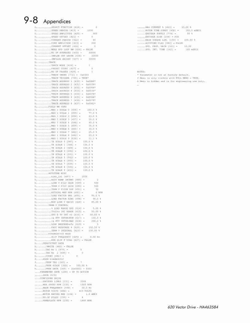
h...........SELECT FUNCTION [418] = 0
h...........SPEED PERIOD [419] = 1000
h...........SPEED AMPLITUDE [420] = 500
h...........SPEED OFFSET [421] = 0
h...........CURRENT PERIOD [422] = 40
h...........CURR AMPLITUDE [423] = 200
h...........CURRENT OFFSET [424] = 0
h...........MEAS SPD LOOP BW [634] = FALSE
h...........NO OF AVERAGES [635] = 30000
h...........IMPLSE CNT LNGTH [636] = 30000
h...........IMPULSE HEIGHT [637] = 30000
h.........TRACE
h...........TRACE MODE [426] = 1
h...........PRESET COUNT [427] = 0
h...........NO OF PASSES [428] = 1
h...........TRACE INDEX [772] = 0xC000
h...........TRACE TRIGGER [793] = TRUE*
h...........TRACE ADDRESS 1 [430] = 0xD0B6*
h...........TRACE ADDRESS 2 [431] = 0x0038*
h...........TRACE ADDRESS 3 [432] = 0x0068*
h...........TRACE ADDRESS 4 [433] = 0x0036*
h...........TRACE ADDRESS 5 [434] = 0x007A*
h...........TRACE ADDRESS 6 [435] = 0x006A*
h...........TRACE ADDRESS 7 [436] = 0x0078*
h...........TRACE ADDRESS 8 [437] = 0x0082*
h.........FIELD WK VARS
h...........MAG I SCALE 0 [454] = 100.0 %
h...........MAG I SCALE 1 [455] = 77.0 %
h...........MAG I SCALE 2 [456] = 63.0 %
h...........MAG I SCALE 3 [457] = 50.0 %
h...........MAG I SCALE 4 [586] = 40.0 %
h...........MAG I SCALE 5 [459] = 35.0 %
h...........MAG I SCALE 6 [460] = 30.0 %
h...........MAG I SCALE 7 [461] = 25.0 %
h...........MAG I SCALE 8 [462] = 20.0 %
h...........MAG I SCALE 9 [630] = 11.1 %
h...........TR SCALE 0 [587] = 100.0 %
h...........TR SCALE 1 [588] = 100.0 %
h...........TR SCALE 2 [589] = 100.0 %
h...........TR SCALE 3 [590] = 100.0 %
h...........TR SCALE 4 [591] = 100.0 %
h...........TR SCALE 5 [592] = 100.0 %
h...........TR SCALE 6 [593] = 100.0 %
h...........TR SCALE 7 [594] = 100.0 %
h...........TR SCALE 8 [595] = 100.0 %
h...........TR SCALE 9 [631] = 100.0 %
h.........AUTOTUNE MISC
h...........kimr_int [487] = 1000
h...........AUTO RAMP INCRMT [488] = 2
h...........LINK V FILT GAIN [489] = 500
h...........TERM V FILT GAIN [490] = 500
h...........TERM V FLTGN DSP [491] = 50
h...........AUTOCAL MAX RPM [492] = 0 RPM
h...........LOAD FACTOR @BS [493] = 95.0 %
h...........LOAD FACTOR @2BS [494] = 90.0 %
h...........MIN LINK V RATIO [628] = 85.00 %
h.........TERM V CONTROL
h...........% LOAD @BASE SPD [614] = 5.00 %
h...........TVolts INT RANGE [615] = 50.00 %
h...........SPD @ TV INT =0 [616] = 50.00 %
h...........iq @TV INTGN=MIN [617] = 100.0 %
h...........iq @TV INTGN=MAX [618] = 200.0 %
h...........LOOP RESPNSE=nTr [619] = 5
h...........FAST RESPONSE % [620] = 102.50 %
h...........TERM V INTEGRAL [623] = 100.00 %
h.........DIAGNOSTICS RESD
h...........SLIP FREQUENCY [625] = 0.00 Hz
h...........RUN SLIP F DIAG [627] = FALSE
h.....PERSISTENT DATA
h......./WRITE [682] = FALSE
h.......TAG No 1 [679] = 0
h.......TAG No 2 [680] = 0
h.......COUNT [681] = 0
f.....PEEK DIAGNOSTIC
f.......PEEK TAG [340] = 7
f.......PEEK SCALE [350] = 100.00 %
h.......PEEK DATA [349] = [0xC000] = 0000
....PARAMETER SAVE [208] = UP TO ACTION
......SAVE (U/D)
....CONFIGURE DRIVE
......ENCODER LINES [131] = 2048
......MAX SPEED RPM [130] = 1500 RPM
......BASE FREQUENCY [448] = 50.0 Hz
......MOTOR VOLTS [486] = 415 VOLTS
......MOTOR RATING RMS [134] = 1.0 AMPS
......NO.OF POLES [399] = 4
......NAMEPLATE RPM [135] = 1440 RPM
......MAG CURRENT % [453] = 30.00 %
......ROTOR TIME CONST [458] = 100.0 mSECS
......ENCODER SUPPLY [774] = 50 %
......ENCODER SIGN [164] = POS
......MAIN TORQUE LIM. [159] = 100.00 %
......AUTOTUNE FLAG [482] = FALSE
......SPD. PROP. GAIN [161] = 10.00
......SPD. INT. TIME [162] = 100 mSECS
NOTES:
* Parameter is not at factory default.
f Menu is only visible with FULL MENU = TRUE.
h Menu is hidden and is for engineering use only.
_
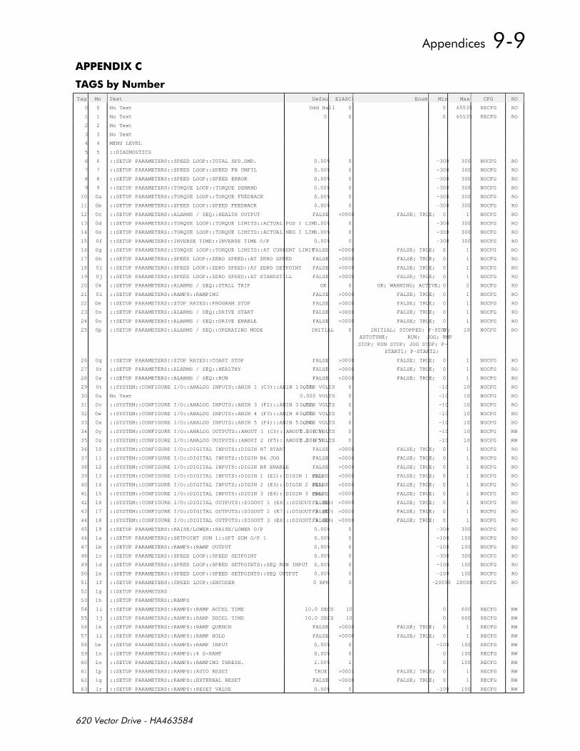
3
#1 1Tag Mn Text DefaultEIASCII Enum Min Max CFG RO
0 0 No Text Odd Ball 0 0 65535 RECFG RO
1 1 No Text 0 0 0 65535 RECFG RO
2 2 No Text
3 3 No Text
4 4 MENU LEVEL
5 5 ::DIAGNOSTICS
6 6 ::SETUP PARAMETERS::SPEED LOOP::TOTAL SPD.DMD. 0.00% 0 -300 300 NOCFG RO
7 7 ::SETUP PARAMETERS::SPEED LOOP::SPEED FB UNFIL 0.00% 0 -300 300 NOCFG RO
8 8 ::SETUP PARAMETERS::SPEED LOOP::SPEED ERROR 0.00% 0 -300 300 NOCFG RO
9 9 ::SETUP PARAMETERS::TORQUE LOOP::TORQUE DEMAND 0.00% 0 -300 300 NOCFG RO
10 0a ::SETUP PARAMETERS::TORQUE LOOP::TORQUE FEEDBACK 0.00% 0 -300 300 NOCFG RO
11 0b ::SETUP PARAMETERS::SPEED LOOP::SPEED FEEDBACK 0.00% 0 -300 300 NOCFG RO
12 0c ::SETUP PARAMETERS::ALARMS / SEQ::HEALTH OUTPUT FALSE >0000 FALSE; TRUE; 0 1 NOCFG RO
13 0d ::SETUP PARAMETERS::TORQUE LOOP::TORQUE LIMITS::ACTUAL POS I LIM0.00% 0 -300 300 NOCFG RO
14 0e ::SETUP PARAMETERS::TORQUE LOOP::TORQUE LIMITS::ACTUAL NEG I LIM0.00% 0 -300 300 NOCFG RO
15 0f ::SETUP PARAMETERS::INVERSE TIME::INVERSE TIME O/P 0.00% 0 -300 300 NOCFG RO
16 0g ::SETUP PARAMETERS::TORQUE LOOP::TORQUE LIMITS::AT CURRENT LIMITFALSE >0000 FALSE; TRUE; 0 1 NOCFG RO
17 0h ::SETUP PARAMETERS::SPEED LOOP::ZERO SPEED::AT ZERO SPEED FALSE >0000 FALSE; TRUE; 0 1 NOCFG RO
18 0i ::SETUP PARAMETERS::SPEED LOOP::ZERO SPEED::AT ZERO SETPOINT FALSE >0000 FALSE; TRUE; 0 1 NOCFG RO
19 0j ::SETUP PARAMETERS::SPEED LOOP::ZERO SPEED::AT STANDSTILL FALSE >0000 FALSE; TRUE; 0 1 NOCFG RO
20 0k ::SETUP PARAMETERS::ALARMS / SEQ::STALL TRIP OK 0 OK; WARNING; ACTIVE; 0 2 NOCFG RO
21 0l ::SETUP PARAMETERS::RAMPS::RAMPING FALSE >0000 FALSE; TRUE; 0 1 NOCFG RO
22 0m ::SETUP PARAMETERS::STOP RATES::PROGRAM STOP FALSE >0000 FALSE; TRUE; 0 1 NOCFG RO
23 0n ::SETUP PARAMETERS::ALARMS / SEQ::DRIVE START FALSE >0000 FALSE; TRUE; 0 1 NOCFG RO
24 0o ::SETUP PARAMETERS::ALARMS / SEQ::DRIVE ENABLE FALSE >0000 FALSE; TRUE; 0 1 NOCFG RO
25 0p ::SETUP PARAMETERS::ALARMS / SEQ::OPERATING MODE INITIAL 0 INITIAL; STOPPED; F-STOP;
AUTOTUNE; RUN; JOG; RMP
STOP; RUN STOP; JOG STOP; P-
START1; P-START2;
0 10 NOCFG RO
26 0q ::SETUP PARAMETERS::STOP RATES::COAST STOP FALSE >0000 FALSE; TRUE; 0 1 NOCFG RO
27 0r ::SETUP PARAMETERS::ALARMS / SEQ::HEALTHY FALSE >0000 FALSE; TRUE; 0 1 NOCFG RO
28 0s ::SETUP PARAMETERS::ALARMS / SEQ::RUN FALSE >0000 FALSE; TRUE; 0 1 NOCFG RO
29 0t ::SYSTEM::CONFIGURE I/O::ANALOG INPUTS::ANIN 1 (C3)::ANIN 1 (C3)0.000 VOLTS 0 -10 10 NOCFG RO
30 0u No Text 0.000 VOLTS 0 -10 10 NOCFG RO
31 0v ::SYSTEM::CONFIGURE I/O::ANALOG INPUTS::ANIN 3 (F2)::ANIN 3 (F2)0.000 VOLTS 0 -10 10 NOCFG RO
32 0w ::SYSTEM::CONFIGURE I/O::ANALOG INPUTS::ANIN 4 (F3)::ANIN 4 (F3)0.000 VOLTS 0 -10 10 NOCFG RO
33 0x ::SYSTEM::CONFIGURE I/O::ANALOG INPUTS::ANIN 5 (F4)::ANIN 5 (F4)0.000 VOLTS 0 -10 10 NOCFG RO
34 0y ::SYSTEM::CONFIGURE I/O::ANALOG OUTPUTS::ANOUT 1 (C5)::ANOUT 1 (C5)0.000 VOLTS 0 -10 10 NOCFG RW
35 0z ::SYSTEM::CONFIGURE I/O::ANALOG OUTPUTS::ANOUT 2 (F5)::ANOUT 2 (F5)0.000 VOLTS 0 -10 10 NOCFG RW
36 10 ::SYSTEM::CONFIGURE I/O::DIGITAL INPUTS::DIGIN B7 START FALSE >0000 FALSE; TRUE; 0 1 NOCFG RO
37 11 ::SYSTEM::CONFIGURE I/O::DIGITAL INPUTS::DIGIN B6 JOG FALSE >0000 FALSE; TRUE; 0 1 NOCFG RO
38 12 ::SYSTEM::CONFIGURE I/O::DIGITAL INPUTS::DIGIN B8 ENABLE FALSE >0000 FALSE; TRUE; 0 1 NOCFG RO
39 13 ::SYSTEM::CONFIGURE I/O::DIGITAL INPUTS::DIGIN 1 (E2)::DIGIN 1 (E2)FALSE >0000 FALSE; TRUE; 0 1 NOCFG RO
40 14 ::SYSTEM::CONFIGURE I/O::DIGITAL INPUTS::DIGIN 2 (E3)::DIGIN 2 (E3)FALSE >0000 FALSE; TRUE; 0 1 NOCFG RO
41 15 ::SYSTEM::CONFIGURE I/O::DIGITAL INPUTS::DIGIN 3 (E4)::DIGIN 3 (E4)FALSE >0000 FALSE; TRUE; 0 1 NOCFG RO
42 16 ::SYSTEM::CONFIGURE I/O::DIGITAL OUTPUTS::DIGOUT 1 (E6)::DIGOUT 1 (E6)FALSE >0000 FALSE; TRUE; 0 1 NOCFG RO
43 17 ::SYSTEM::CONFIGURE I/O::DIGITAL OUTPUTS::DIGOUT 2 (E7)::DIGOUT 2 (E7)FALSE >0000 FALSE; TRUE; 0 1 NOCFG RO
44 18 ::SYSTEM::CONFIGURE I/O::DIGITAL OUTPUTS::DIGOUT 3 (E8)::DIGOUT 3 (E8)FALSE >0000 FALSE; TRUE; 0 1 NOCFG RO
45 19 ::SETUP PARAMETERS::RAISE/LOWER::RAISE/LOWER O/P 0.00% 0 -300 300 NOCFG RO
46 1a ::SETUP PARAMETERS::SETPOINT SUM 1::SPT SUM O/P 1 0.00% 0 -100 100 NOCFG RO
47 1b ::SETUP PARAMETERS::RAMPS::RAMP OUTPUT 0.00% 0 -100 100 NOCFG RO
48 1c ::SETUP PARAMETERS::SPEED LOOP::SPEED SETPOINT 0.00% 0 -300 300 NOCFG RO
49 1d ::SETUP PARAMETERS::SPEED LOOP::SPEED SETPOINTS::SEQ RUN INPUT 0.00% 0 -100 100 NOCFG RO
50 1e ::SETUP PARAMETERS::SPEED LOOP::SPEED SETPOINTS::SEQ OUTPUT 0.00% 0 -100 100 NOCFG RO
51 1f ::SETUP PARAMETERS::SPEED LOOP::ENCODER 0 RPM 0 -20000 20000 NOCFG RO
52 1g ::SETUP PARAMETERS
53 1h ::SETUP PARAMETERS::RAMPS
54 1i ::SETUP PARAMETERS::RAMPS::RAMP ACCEL TIME 10.0 SECS 10 0 600 RECFG RW
55 1j ::SETUP PARAMETERS::RAMPS::RAMP DECEL TIME 10.0 SECS 10 0 600 RECFG RW
56 1k ::SETUP PARAMETERS::RAMPS::RAMP QUENCH FALSE >0000 FALSE; TRUE; 0 1 RECFG RW
57 1l ::SETUP PARAMETERS::RAMPS::RAMP HOLD FALSE >0000 FALSE; TRUE; 0 1 RECFG RW
58 1m ::SETUP PARAMETERS::RAMPS::RAMP INPUT 0.00% 0 -100 100 RECFG RW
59 1n ::SETUP PARAMETERS::RAMPS::% S-RAMP 0.00% 0 0 100 RECFG RW
60 1o ::SETUP PARAMETERS::RAMPS::RAMPING THRESH. 1.00% 1 0 100 RECFG RW
61 1p ::SETUP PARAMETERS::RAMPS::AUTO RESET TRUE >0001 FALSE; TRUE; 0 1 RECFG RW
62 1q ::SETUP PARAMETERS::RAMPS::EXTERNAL RESET FALSE >0000 FALSE; TRUE; 0 1 RECFG RW
63 1r ::SETUP PARAMETERS::RAMPS::RESET VALUE 0.00% 0 -100 100 RECFG RW
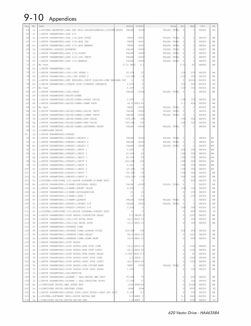
Tag Mn Text DefaultEIASCII Enum Min Max CFG RO
64 1s ::SYSTEM::RESERVED::ENG USE ONLY::MISCELLANEOUS::SYSTEM RESET FALSE >0000 FALSE; TRUE; 0 1 NOCFG RO
65 1t ::SETUP PARAMETERS::AUX I/O
66 1u ::SETUP PARAMETERS::AUX I/O::AUX START TRUE >0001 FALSE; TRUE; 0 1 RECFG RW
67 1v ::SETUP PARAMETERS::AUX I/O::AUX JOG TRUE >0001 FALSE; TRUE; 0 1 RECFG RW
68 1w ::SETUP PARAMETERS::AUX I/O::AUX ENABLE TRUE >0001 FALSE; TRUE; 0 1 RECFG RW
69 1x ::PASSWORD::BYPASS PASSWORD FALSE >0000 FALSE; TRUE; 0 1 RECFG RW
70 1y ::SETUP PARAMETERS::AUX I/O::START FALSE >0000 FALSE; TRUE; 0 1 RECFG RW
71 1z ::SETUP PARAMETERS::AUX I/O::JOG INPUT FALSE >0000 FALSE; TRUE; 0 1 RECFG RW
72 20 ::SETUP PARAMETERS::AUX I/O::ENABLE FALSE >0000 FALSE; TRUE; 0 1 RECFG RW
73 21 No Text 0.10 SECS 0.1 0.01 60 RECFG RW
74 22 ::SETUP PARAMETERS::JOG
75 23 ::SETUP PARAMETERS::JOG::JOG SPEED 1 10.00% 10 -100 100 RECFG RW
76 24 ::SETUP PARAMETERS::JOG::JOG SPEED 2 -10.00% -10 -100 100 RECFG RW
77 25 ::SETUP PARAMETERS::REF ENCODER::INPUT SCALING::FBK ENCODER CNT 0 0 0 65535 NOCFG RO
78 26 ::SETUP PARAMETERS::TORQUE LOOP::CURRENT FEEDBACK 0.00% 0 -300 300 NOCFG RO
79 27 No Text 0.00% 0 -100 100 RECFG RW
80 28 ::SETUP PARAMETERS::JOG::MODE FALSE >0000 FALSE; TRUE; 0 1 RECFG RW
81 29 ::SETUP PARAMETERS::RAISE/LOWER
82 2a ::SETUP PARAMETERS::RAISE/LOWER::RESET VALUE 0.00% 0 -100 100 RECFG RW
83 2b ::SETUP PARAMETERS::RAISE/LOWER::RAMP RATE 60.0 SECS 60 0.1 600 RECFG RW
84 2c No Text TRUE >0001 FALSE; TRUE; 0 1 NOCFG RW
85 2d ::SETUP PARAMETERS::RAISE/LOWER::RAISE INPUT FALSE >0000 FALSE; TRUE; 0 1 RECFG RW
86 2e ::SETUP PARAMETERS::RAISE/LOWER::LOWER INPUT FALSE >0000 FALSE; TRUE; 0 1 RECFG RW
87 2f ::SETUP PARAMETERS::RAISE/LOWER::MIN VALUE -100.00% -100 -300 300 RECFG RW
88 2g ::SETUP PARAMETERS::RAISE/LOWER::MAX VALUE 100.00% 100 -300 300 RECFG RW
89 2h ::SETUP PARAMETERS::RAISE/LOWER::EXTERNAL RESET FALSE >0000 FALSE; TRUE; 0 1 RECFG RW
90 2i ::CONFIGURE DRIVE
91 2j ::SETUP PARAMETERS::PRESET
92 2k ::SETUP PARAMETERS::PRESET::SELECT 1 FALSE >0000 FALSE; TRUE; 0 1 RECFG RW
93 2l ::SETUP PARAMETERS::PRESET::SELECT 2 FALSE >0000 FALSE; TRUE; 0 1 RECFG RW
94 2m ::SETUP PARAMETERS::PRESET::SELECT 3 FALSE >0000 FALSE; TRUE; 0 1 RECFG RW
95 2n ::SETUP PARAMETERS::PRESET::INPUT 1 0.00% 0 -300 300 RECFG RW
96 2o ::SETUP PARAMETERS::PRESET::INPUT 2 25.00% 25 -300 300 RECFG RW
97 2p ::SETUP PARAMETERS::PRESET::INPUT 3 50.00% 50 -300 300 RECFG RW
98 2q ::SETUP PARAMETERS::PRESET::INPUT 4 100.00% 100 -300 300 RECFG RW
99 2r ::SETUP PARAMETERS::PRESET::INPUT 5 0.00% 0 -300 300 RECFG RW
100 2s ::SETUP PARAMETERS::PRESET::INPUT 6 -25.00% -25 -300 300 RECFG RW
101 2t ::SETUP PARAMETERS::PRESET::INPUT 7 -50.00% -50 -300 300 RECFG RW
102 2u ::SETUP PARAMETERS::PRESET::INPUT 8 -100.00% -100 -300 300 RECFG RW
103 2v ::SYSTEM::CONFIGURE I/O::BLOCK DIAGRAM::S-RAMP DEST 0 0 0 800 RECFG RI
104 2w ::SETUP PARAMETERS::S-RAMP::EXTERNAL RESET FALSE >0000 FALSE; TRUE; 0 1 RECFG RW
105 2x ::SETUP PARAMETERS::S-RAMP::RESET VALUE 0.00% 0 -100 100 RECFG RW
106 2y ::SETUP PARAMETERS::S-RAMP::ACCELERATION 10 10 0 150 RECFG RW
107 2z ::SETUP PARAMETERS::S-RAMP::JERK 1 10 10 0 150 RECFG RW
108 30 ::SETUP PARAMETERS::S-RAMP::QUENCH FALSE >0000 FALSE; TRUE; 0 1 RECFG RW
109 31 ::SETUP PARAMETERS::PRESET::INVERT O/P FALSE >0000 FALSE; TRUE; 0 1 RECFG RW
110 32 ::SETUP PARAMETERS::PRESET::PRESET O/P 0.00% 0 -300 300 NOCFG RO
111 33 ::SYSTEM::CONFIGURE I/O::BLOCK DIAGRAM::PRESET DEST 0 0 0 800 RECFG RI
112 34 ::SETUP PARAMETERS::STOP RATES::CONTACTOR DELAY 0.5 SECS0.5 0 1000 RECFG RW
113 35 ::SETUP PARAMETERS::JOG::JOG ACCEL RATE 10.0 SECS 10 0 100 RECFG RW
114 36 ::SETUP PARAMETERS::JOG::JOG DECEL RATE 10.0 SECS 10 0 100 RECFG RW
115 37 ::SETUP PARAMETERS::INVERSE TIME
116 38 ::SETUP PARAMETERS::INVERSE TIME::AIMING POINT 105.00% 105 100 200 RECFG RW
117 39 ::SETUP PARAMETERS::INVERSE TIME::DELAY 60.0 SECS 60 0 1000 RECFG RW
118 3a ::SETUP PARAMETERS::INVERSE TIME::DOWN RATE 10.0 SECS 10 0 600 RECFG RW
119 3b ::SETUP PARAMETERS::STOP RATES
120 3c ::SETUP PARAMETERS::STOP RATES::RUN STOP TIME 10.0 SECS 10 0 1000 RECFG RW
121 3d ::SETUP PARAMETERS::STOP RATES::RUN STOP LIMIT 60.0 SECS 60 0 1000 RECFG RW
122 3e ::SETUP PARAMETERS::STOP RATES::PRE-START DELAY 0.500 SECS 0.5 0 30 RECFG RW
123 3f ::SETUP PARAMETERS::STOP RATES::FAST STOP TIME 1.0 SECS 1 0 1000 RECFG RW
124 3g ::SETUP PARAMETERS::STOP RATES::FAST STOP LIMIT 60.0 SECS 60 0 1000 RECFG RW
125 3h ::SETUP PARAMETERS::STOP RATES::USE SYSTEM RAMP TRUE >0001 FALSE; TRUE; 0 1 RECFG RW
126 3i ::SETUP PARAMETERS::STOP RATES::STOP ZERO SPEED 1.00% 1 0 100 RECFG RW
127 3j ::SETUP PARAMETERS::CALIBRATION
128 3k ::SETUP PARAMETERS::ALARMS / SEQ::MOTOR TMP.TRIP 75.00% 75 0 200 RECFG RW
129 3l ::SETUP PARAMETERS::ALARMS / SEQ::HEATSINK LEVEL 17.00% 17 0 200 RECFG RW
130 3m ::CONFIGURE DRIVE::MAX SPEED RPM 1500 RPM1500 0 32000 RECFG RW
131 3n ::CONFIGURE DRIVE::ENCODER LINES 2048 2048 0 8000 NOCFG RI
132 3o ::SETUP PARAMETERS::SPEED LOOP::ZERO SPEED::ZERO SPD HYST 0.10% 0.1 0 100 RECFG RW
133 3p ::SYSTEM::SOFTWARE INFO::DRIVE RATING RMS 0.0 AMPS 0 0.1 3000 NOCFG RO
134 3q ::CONFIGURE DRIVE::MOTOR RATING RMS 1.0 AMPS 1 0.1 3000 RECFG RI
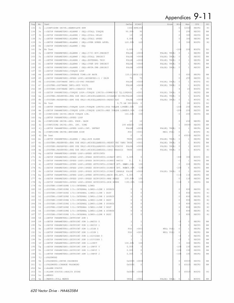
Tag Mn Text DefaultEIASCII Enum Min Max CFG RO
135 3r ::CONFIGURE DRIVE::NAMEPLATE RPM 1440 RPM1440 0 32000 RECFG RI
136 3s ::SETUP PARAMETERS::ALARMS / SEQ::STALL TORQUE 95.00% 95 0 200 RECFG RW
137 3t ::SETUP PARAMETERS::ALARMS / SEQ::STALL DELAY 10 10 0 300 RECFG RW
138 3u ::SETUP PARAMETERS::ALARMS / SEQ::STALL SPEED 4.00% 4 0 300 RECFG RW
139 3v ::SETUP PARAMETERS::ALARMS / SEQ::OVER SPEED LEVEL 120.00% 120 0 300 NOCFG RI
140 3w ::SETUP PARAMETERS::ALARMS / SEQ
141 3x No Text 0.00% 0 -200 200 NOCFG RO
142 3y ::SETUP PARAMETERS::ALARMS / SEQ::5703 RCV.INHIBIT FALSE >0000 FALSE; TRUE; 0 1 RECFG RW
143 3z ::SETUP PARAMETERS::ALARMS / SEQ::STALL INHIBIT FALSE >0000 FALSE; TRUE; 0 1 RECFG RW
144 40 ::SETUP PARAMETERS::ALARMS / SEQ::EXTERNAL TRIP FALSE >0000 FALSE; TRUE; 0 1 RECFG RW
145 41 ::SETUP PARAMETERS::ALARMS / SEQ::OVER SPD INHIBIT FALSE >0000 FALSE; TRUE; 0 1 RECFG RW
146 42 ::SETUP PARAMETERS::ALARMS / SEQ::MOTR.TMP.INHIBIT FALSE >0000 FALSE; TRUE; 0 1 RECFG RW
147 43 ::SETUP PARAMETERS::TORQUE LOOP
148 44 ::SETUP PARAMETERS::INVERSE TIME::UP RATE 120.0 SECS 120 0 600 RECFG RW
149 45 ::SETUP PARAMETERS::SPEED LOOP::ADVANCED::1 / GAIN 70 70 0 255 RECFG RI
150 46 ::SYSTEM::SOFTWARE INFO::CO-PRO PRESENT FALSE >0000 FALSE; TRUE; 0 1 NOCFG RO
151 47 ::SYSTEM::SOFTWARE INFO::MID VOLTS FALSE >0000 FALSE; TRUE; 0 1 NOCFG RO
152 48 ::SYSTEM::SOFTWARE INFO::CHASSIS TYPE 0 0 4 10 NOCFG RO
153 49 ::SETUP PARAMETERS::TORQUE LOOP::TORQUE LIMITS::SYMMETRIC TQ.LIM.TRUE >0001 FALSE; TRUE; 0 1 RECFG RW
154 4a ::SYSTEM::RESERVED::ENG USE ONLY::MISCELLANEOUS::DISABLE CO-PRO FALSE >0000 FALSE; TRUE; 0 1 NOCFG RW
155 4b ::SYSTEM::RESERVED::ENG USE ONLY::MISCELLANEOUS::RESET EAT FALSE >0000 FALSE; TRUE; 0 1 NOCFG RI
156 4c No Text 0.75 kW 380-460v 0 0 28 NOCFG RO
157 4d ::SETUP PARAMETERS::TORQUE LOOP::TORQUE LIMITS::POS TORQUE LIMIT150.00% 150 -200 200 RECFG RW
158 4e ::SETUP PARAMETERS::TORQUE LOOP::TORQUE LIMITS::NEG TORQUE LIMIT-150.00% -150 -200 200 RECFG RW
159 4f ::CONFIGURE DRIVE::MAIN TORQUE LIM. 100.00% 100 0 200 RECFG RW
160 4g ::SETUP PARAMETERS::SPEED LOOP
161 4h ::CONFIGURE DRIVE::SPD. PROP. GAIN 10 10 0 250 RECFG RW
162 4i ::CONFIGURE DRIVE::SPD. INT. TIME 100 mSECS 100 1 30000 RECFG RW
163 4j ::SETUP PARAMETERS::SPEED LOOP::INT. DEFEAT FALSE >0000 FALSE; TRUE; 0 1 RECFG RW
164 4k ::CONFIGURE DRIVE::ENCODER SIGN POS >0001 NEG; POS; 0 1 NOCFG RI
165 4l No Text 0 0 0 65535 RECFG RO
166 4m ::SETUP PARAMETERS::ALARMS / SEQ::ACK ALARM TRUE >0001 FALSE; TRUE; 0 1 RECFG RW
167 4n ::SYSTEM::RESERVED::ENG USE ONLY::MISCELLANEOUS::RESET VEC VARS TRUE >0001 FALSE; TRUE; 0 1 NOCFG RW
168 4o ::SYSTEM::RESERVED::ENG USE ONLY::MISCELLANEOUS::DRIVE STATUS FALSE >0000 FALSE; TRUE; 0 1 NOCFG RO
169 4p ::SYSTEM::RESERVED::ENG USE ONLY::MISCELLANEOUS::584S CHASSIS TRUE >0001 FALSE; TRUE; 0 1 NOCFG RI
170 4q ::SETUP PARAMETERS::SPEED LOOP::SPEED SETPOINTS
171 4r ::SETUP PARAMETERS::SPEED LOOP::SPEED SETPOINTS::DIRECT SPT1 0.00% 0 -300 300 NOCFG RO
172 4s ::SETUP PARAMETERS::SPEED LOOP::SPEED SETPOINTS::DIRECT RATIO 0.1 0.1 -1 1 RECFG RW
173 4t ::SETUP PARAMETERS::SPEED LOOP::SPEED SETPOINTS::DIRECT SPT. MAX100.00% 100 0 100 RECFG RW
174 4u ::SETUP PARAMETERS::SPEED LOOP::SPEED SETPOINTS::DIRECT SPT. MIN-100.00% -100 -100 0 RECFG RW
175 4v ::SETUP PARAMETERS::SPEED LOOP::SPEED SETPOINTS::DIRECT ENABLE FALSE >0000 FALSE; TRUE; 0 1 RECFG RW
176 4w ::SETUP PARAMETERS::SPEED LOOP::SPEED SETPOINTS::MAIN SPD.SPT. 0.00% 0 -110 110 RECFG RW
177 4x ::SETUP PARAMETERS::SPEED LOOP::SPEED SETPOINTS::MAX SPEED 100.00% 100 0 110 RECFG RW
178 4y ::SETUP PARAMETERS::SPEED LOOP::SPEED SETPOINTS::MIN SPEED -100.00% -100 -110 0 RECFG RW
179 4z ::SYSTEM::CONFIGURE I/O::INTERNAL LINKS
180 50 ::SYSTEM::CONFIGURE I/O::INTERNAL LINKS::LINK 1 SOURCE 0 0 0 800 RECFG RI
181 51 ::SYSTEM::CONFIGURE I/O::INTERNAL LINKS::LINK 1 DEST 0 0 0 800 RECFG RI
182 52 ::SYSTEM::CONFIGURE I/O::INTERNAL LINKS::LINK 2 SOURCE 0 0 0 800 RECFG RI
183 53 ::SYSTEM::CONFIGURE I/O::INTERNAL LINKS::LINK 2 DEST 0 0 0 800 RECFG RI
184 54 ::SYSTEM::CONFIGURE I/O::INTERNAL LINKS::LINK 3 SOURCE 0 0 0 800 RECFG RI
185 55 ::SYSTEM::CONFIGURE I/O::INTERNAL LINKS::LINK 3 DEST 0 0 0 800 RECFG RI
186 56 ::SYSTEM::CONFIGURE I/O::INTERNAL LINKS::LINK 4 SOURCE 0 0 0 800 RECFG RI
187 57 ::SYSTEM::CONFIGURE I/O::INTERNAL LINKS::LINK 4 DEST 0 0 0 800 RECFG RI
188 58 ::SETUP PARAMETERS::SETPOINT SUM 1
189 59 ::SETUP PARAMETERS::SETPOINT SUM 1::RATIO 0 1 1 -3 3 RECFG RW
190 5a ::SETUP PARAMETERS::SETPOINT SUM 1::RATIO 1 1 1 -3 3 RECFG RW
191 5b ::SETUP PARAMETERS::SETPOINT SUM 1::SIGN 0 POS >0001 NEG; POS; 0 1 RECFG RW
192 5c ::SETUP PARAMETERS::SETPOINT SUM 1::SIGN 1 POS >0001 NEG; POS; 0 1 RECFG RW
193 5d ::SETUP PARAMETERS::SETPOINT SUM 1::DIVIDER 0 1 1 -3 3 RECFG RW
194 5e ::SETUP PARAMETERS::SETPOINT SUM 1::DIVIDER 1 1 1 -3 3 RECFG RW
195 5f ::SETUP PARAMETERS::SETPOINT SUM 1::LIMIT 100.00% 100 0 300 RECFG RW
196 5g ::SETUP PARAMETERS::SETPOINT SUM 1::INPUT 0 0.00% 0 -100 100 RECFG RW
197 5h ::SETUP PARAMETERS::SETPOINT SUM 1::INPUT 1 0.00% 0 -100 100 RECFG RW
198 5i ::SETUP PARAMETERS::SETPOINT SUM 1::INPUT 2 0.00% 0 -100 100 RECFG RW
199 5j ::PASSWORD
200 5k ::PASSWORD::ENTER PASSWORD 0x0000 >0000 0 65535 RECFG RW
201 5l ::PASSWORD::CHANGE PASSWORD 0x0000 0 0 65535 RECFG RW
202 5m ::ALARM STATUS
203 5n ::ALARM STATUS::HEALTH STORE 0x0000 >0000 0 65535 NOCFG RO
204 5o ::MENUS
205 5p ::MENUS::FULL MENUS TRUE >0001 FALSE; TRUE; 0 1 NOCFG RW
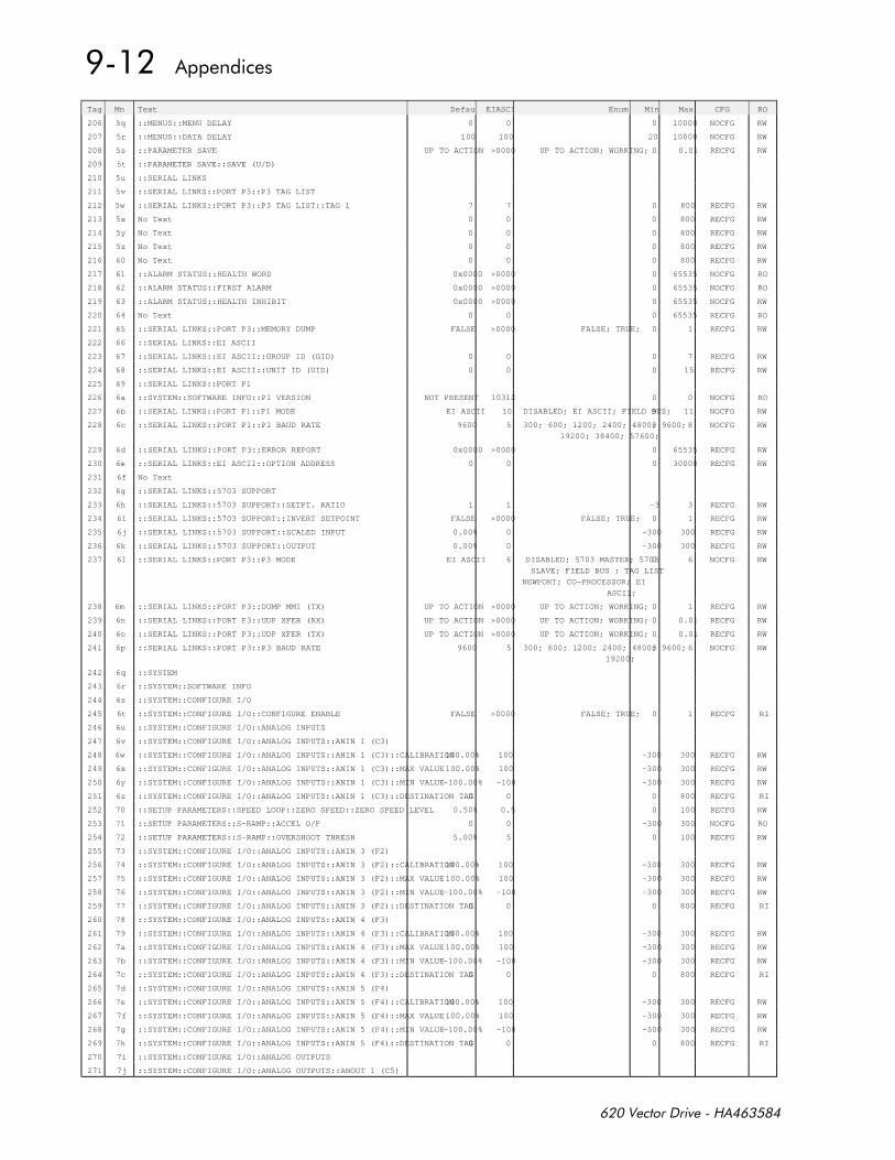
Tag Mn Text DefaultEIASCII Enum Min Max CFG RO
206 5q ::MENUS::MENU DELAY 0 0 0 10000 NOCFG RW
207 5r ::MENUS::DATA DELAY 100 100 20 10000 NOCFG RW
208 5s ::PARAMETER SAVE UP TO ACTION >0000 UP TO ACTION; WORKING; 0 0.01 RECFG RW
209 5t ::PARAMETER SAVE::SAVE (U/D)
210 5u ::SERIAL LINKS
211 5v ::SERIAL LINKS::PORT P3::P3 TAG LIST
212 5w ::SERIAL LINKS::PORT P3::P3 TAG LIST::TAG 1 7 7 0 800 RECFG RW
213 5x No Text 0 0 0 800 RECFG RW
214 5y No Text 0 0 0 800 RECFG RW
215 5z No Text 0 0 0 800 RECFG RW
216 60 No Text 0 0 0 800 RECFG RW
217 61 ::ALARM STATUS::HEALTH WORD 0x0000 >0000 0 65535 NOCFG RO
218 62 ::ALARM STATUS::FIRST ALARM 0x0000 >0000 0 65535 NOCFG RO
219 63 ::ALARM STATUS::HEALTH INHIBIT 0x0000 >0000 0 65535 NOCFG RW
220 64 No Text 0 0 0 65535 RECFG RO
221 65 ::SERIAL LINKS::PORT P3::MEMORY DUMP FALSE >0000 FALSE; TRUE; 0 1 RECFG RW
222 66 ::SERIAL LINKS::EI ASCII
223 67 ::SERIAL LINKS::EI ASCII::GROUP ID (GID) 0 0 0 7 RECFG RW
224 68 ::SERIAL LINKS::EI ASCII::UNIT ID (UID) 0 0 0 15 RECFG RW
225 69 ::SERIAL LINKS::PORT P1
226 6a ::SYSTEM::SOFTWARE INFO::P1 VERSION NOT PRESENT 10312 0 0 NOCFG RO
227 6b ::SERIAL LINKS::PORT P1::P1 MODE EI ASCII 10 DISABLED; EI ASCII; FIELD BUS;9 11 NOCFG RW
228 6c ::SERIAL LINKS::PORT P1::P1 BAUD RATE 9600 5 300; 600; 1200; 2400; 4800; 9600;
19200; 38400; 57600;
0 8 NOCFG RW
229 6d ::SERIAL LINKS::PORT P3::ERROR REPORT 0x0000 >0000 0 65535 RECFG RW
230 6e ::SERIAL LINKS::EI ASCII::OPTION ADDRESS 0 0 0 30000 RECFG RW
231 6f No Text
232 6g ::SERIAL LINKS::5703 SUPPORT
233 6h ::SERIAL LINKS::5703 SUPPORT::SETPT. RATIO 1 1 -3 3 RECFG RW
234 6i ::SERIAL LINKS::5703 SUPPORT::INVERT SETPOINT FALSE >0000 FALSE; TRUE; 0 1 RECFG RW
235 6j ::SERIAL LINKS::5703 SUPPORT::SCALED INPUT 0.00% 0 -300 300 RECFG RW
236 6k ::SERIAL LINKS::5703 SUPPORT::OUTPUT 0.00% 0 -300 300 RECFG RW
237 6l ::SERIAL LINKS::PORT P3::P3 MODE EI ASCII 6 DISABLED; 5703 MASTER; 5703
SLAVE; FIELD BUS ; TAG LIST
NEWPORT; CO-PROCESSOR; EI
ASCII;
0 6 NOCFG RW
238 6m ::SERIAL LINKS::PORT P3::DUMP MMI (TX) UP TO ACTION >0000 UP TO ACTION; WORKING; 0 1 RECFG RW
239 6n ::SERIAL LINKS::PORT P3::UDP XFER (RX) UP TO ACTION >0000 UP TO ACTION; WORKING; 0 0.01 RECFG RW
240 6o ::SERIAL LINKS::PORT P3::UDP XFER (TX) UP TO ACTION >0000 UP TO ACTION; WORKING; 0 0.01 RECFG RW
241 6p ::SERIAL LINKS::PORT P3::P3 BAUD RATE 9600 5 300; 600; 1200; 2400; 4800; 9600;
19200;
0 6 NOCFG RW
242 6q ::SYSTEM
243 6r ::SYSTEM::SOFTWARE INFO
244 6s ::SYSTEM::CONFIGURE I/O
245 6t ::SYSTEM::CONFIGURE I/O::CONFIGURE ENABLE FALSE >0000 FALSE; TRUE; 0 1 RECFG RI
246 6u ::SYSTEM::CONFIGURE I/O::ANALOG INPUTS
247 6v ::SYSTEM::CONFIGURE I/O::ANALOG INPUTS::ANIN 1 (C3)
248 6w ::SYSTEM::CONFIGURE I/O::ANALOG INPUTS::ANIN 1 (C3)::CALIBRATION100.00% 100 -300 300 RECFG RW
249 6x ::SYSTEM::CONFIGURE I/O::ANALOG INPUTS::ANIN 1 (C3)::MAX VALUE100.00% 100 -300 300 RECFG RW
250 6y ::SYSTEM::CONFIGURE I/O::ANALOG INPUTS::ANIN 1 (C3)::MIN VALUE-100.00% -100 -300 300 RECFG RW
251 6z ::SYSTEM::CONFIGURE I/O::ANALOG INPUTS::ANIN 1 (C3)::DESTINATION TAG0 0 0 800 RECFG RI
252 70 ::SETUP PARAMETERS::SPEED LOOP::ZERO SPEED::ZERO SPEED LEVEL 0.50% 0.5 0 100 RECFG RW
253 71 ::SETUP PARAMETERS::S-RAMP::ACCEL O/P 0 0 -300 300 NOCFG RO
254 72 ::SETUP PARAMETERS::S-RAMP::OVERSHOOT THRESH 5.00% 5 0 100 RECFG RW
255 73 ::SYSTEM::CONFIGURE I/O::ANALOG INPUTS::ANIN 3 (F2)
256 74 ::SYSTEM::CONFIGURE I/O::ANALOG INPUTS::ANIN 3 (F2)::CALIBRATION100.00% 100 -300 300 RECFG RW
257 75 ::SYSTEM::CONFIGURE I/O::ANALOG INPUTS::ANIN 3 (F2)::MAX VALUE100.00% 100 -300 300 RECFG RW
258 76 ::SYSTEM::CONFIGURE I/O::ANALOG INPUTS::ANIN 3 (F2)::MIN VALUE-100.00% -100 -300 300 RECFG RW
259 77 ::SYSTEM::CONFIGURE I/O::ANALOG INPUTS::ANIN 3 (F2)::DESTINATION TAG0 0 0 800 RECFG RI
260 78 ::SYSTEM::CONFIGURE I/O::ANALOG INPUTS::ANIN 4 (F3)
261 79 ::SYSTEM::CONFIGURE I/O::ANALOG INPUTS::ANIN 4 (F3)::CALIBRATION100.00% 100 -300 300 RECFG RW
262 7a ::SYSTEM::CONFIGURE I/O::ANALOG INPUTS::ANIN 4 (F3)::MAX VALUE100.00% 100 -300 300 RECFG RW
263 7b ::SYSTEM::CONFIGURE I/O::ANALOG INPUTS::ANIN 4 (F3)::MIN VALUE-100.00% -100 -300 300 RECFG RW
264 7c ::SYSTEM::CONFIGURE I/O::ANALOG INPUTS::ANIN 4 (F3)::DESTINATION TAG0 0 0 800 RECFG RI
265 7d ::SYSTEM::CONFIGURE I/O::ANALOG INPUTS::ANIN 5 (F4)
266 7e ::SYSTEM::CONFIGURE I/O::ANALOG INPUTS::ANIN 5 (F4)::CALIBRATION100.00% 100 -300 300 RECFG RW
267 7f ::SYSTEM::CONFIGURE I/O::ANALOG INPUTS::ANIN 5 (F4)::MAX VALUE100.00% 100 -300 300 RECFG RW
268 7g ::SYSTEM::CONFIGURE I/O::ANALOG INPUTS::ANIN 5 (F4)::MIN VALUE-100.00% -100 -300 300 RECFG RW
269 7h ::SYSTEM::CONFIGURE I/O::ANALOG INPUTS::ANIN 5 (F4)::DESTINATION TAG0 0 0 800 RECFG RI
270 7i ::SYSTEM::CONFIGURE I/O::ANALOG OUTPUTS
271 7j ::SYSTEM::CONFIGURE I/O::ANALOG OUTPUTS::ANOUT 1 (C5)
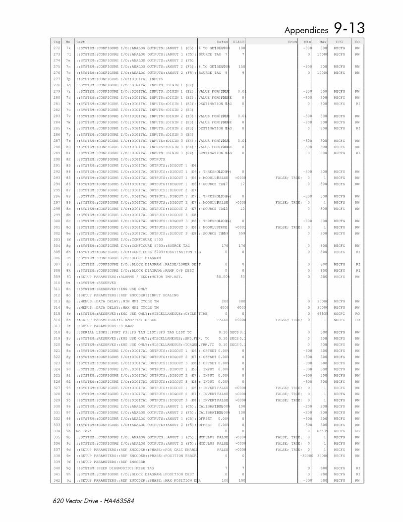
Tag Mn Text DefaultEIASCII Enum Min Max CFG RO
272 7k ::SYSTEM::CONFIGURE I/O::ANALOG OUTPUTS::ANOUT 1 (C5)::% TO GET 10V100.00% 100 -300 300 RECFG RW
273 7l ::SYSTEM::CONFIGURE I/O::ANALOG OUTPUTS::ANOUT 1 (C5)::SOURCE TAG 7 7 0 10000 RECFG RW
274 7m ::SYSTEM::CONFIGURE I/O::ANALOG OUTPUTS::ANOUT 2 (F5)
275 7n ::SYSTEM::CONFIGURE I/O::ANALOG OUTPUTS::ANOUT 2 (F5)::% TO GET 10V150.00% 150 -300 300 RECFG RW
276 7o ::SYSTEM::CONFIGURE I/O::ANALOG OUTPUTS::ANOUT 2 (F5)::SOURCE TAG 9 9 0 10000 RECFG RW
277 7p ::SYSTEM::CONFIGURE I/O::DIGITAL INPUTS
278 7q ::SYSTEM::CONFIGURE I/O::DIGITAL INPUTS::DIGIN 1 (E2)
279 7r ::SYSTEM::CONFIGURE I/O::DIGITAL INPUTS::DIGIN 1 (E2)::VALUE FOR TRUE0.01% 0.01 -300 300 RECFG RW
280 7s ::SYSTEM::CONFIGURE I/O::DIGITAL INPUTS::DIGIN 1 (E2)::VALUE FOR FALSE0.00% 0 -300 300 RECFG RW
281 7t ::SYSTEM::CONFIGURE I/O::DIGITAL INPUTS::DIGIN 1 (E2)::DESTINATION TAG0 0 0 800 RECFG RI
282 7u ::SYSTEM::CONFIGURE I/O::DIGITAL INPUTS::DIGIN 2 (E3)
283 7v ::SYSTEM::CONFIGURE I/O::DIGITAL INPUTS::DIGIN 2 (E3)::VALUE FOR TRUE0.01% 0.01 -300 300 RECFG RW
284 7w ::SYSTEM::CONFIGURE I/O::DIGITAL INPUTS::DIGIN 2 (E3)::VALUE FOR FALSE0.00% 0 -300 300 RECFG RW
285 7x ::SYSTEM::CONFIGURE I/O::DIGITAL INPUTS::DIGIN 2 (E3)::DESTINATION TAG0 0 0 800 RECFG RI
286 7y ::SYSTEM::CONFIGURE I/O::DIGITAL INPUTS::DIGIN 3 (E4)
287 7z ::SYSTEM::CONFIGURE I/O::DIGITAL INPUTS::DIGIN 3 (E4)::VALUE FOR TRUE0.01% 0.01 -300 300 RECFG RW
288 80 ::SYSTEM::CONFIGURE I/O::DIGITAL INPUTS::DIGIN 3 (E4)::VALUE FOR FALSE0.00% 0 -300 300 RECFG RW
289 81 ::SYSTEM::CONFIGURE I/O::DIGITAL INPUTS::DIGIN 3 (E4)::DESTINATION TAG0 0 0 800 RECFG RI
290 82 ::SYSTEM::CONFIGURE I/O::DIGITAL OUTPUTS
291 83 ::SYSTEM::CONFIGURE I/O::DIGITAL OUTPUTS::DIGOUT 1 (E6)
292 84 ::SYSTEM::CONFIGURE I/O::DIGITAL OUTPUTS::DIGOUT 1 (E6)::THRESHOLD (>)0.00% 0 -300 300 RECFG RW
293 85 ::SYSTEM::CONFIGURE I/O::DIGITAL OUTPUTS::DIGOUT 1 (E6)::MODULUSFALSE >0000 FALSE; TRUE; 0 1 RECFG RW
294 86 ::SYSTEM::CONFIGURE I/O::DIGITAL OUTPUTS::DIGOUT 1 (E6)::SOURCE TAG17 17 0 800 RECFG RW
295 87 ::SYSTEM::CONFIGURE I/O::DIGITAL OUTPUTS::DIGOUT 2 (E7)
296 88 ::SYSTEM::CONFIGURE I/O::DIGITAL OUTPUTS::DIGOUT 2 (E7)::THRESHOLD (>)0.00% 0 -300 300 RECFG RW
297 89 ::SYSTEM::CONFIGURE I/O::DIGITAL OUTPUTS::DIGOUT 2 (E7)::MODULUSFALSE >0000 FALSE; TRUE; 0 1 RECFG RW
298 8a ::SYSTEM::CONFIGURE I/O::DIGITAL OUTPUTS::DIGOUT 2 (E7)::SOURCE TAG12 12 0 800 RECFG RW
299 8b ::SYSTEM::CONFIGURE I/O::DIGITAL OUTPUTS::DIGOUT 3 (E8)
300 8c ::SYSTEM::CONFIGURE I/O::DIGITAL OUTPUTS::DIGOUT 3 (E8)::THRESHOLD (>)0.00% 0 -300 300 RECFG RW
301 8d ::SYSTEM::CONFIGURE I/O::DIGITAL OUTPUTS::DIGOUT 3 (E8)::MODULUSTRUE >0001 FALSE; TRUE; 0 1 RECFG RW
302 8e ::SYSTEM::CONFIGURE I/O::DIGITAL OUTPUTS::DIGOUT 3 (E8)::SOURCE TAG559 559 0 800 RECFG RW
303 8f ::SYSTEM::CONFIGURE I/O::CONFIGURE 5703
304 8g ::SYSTEM::CONFIGURE I/O::CONFIGURE 5703::SOURCE TAG 176 176 0 800 RECFG RW
305 8h ::SYSTEM::CONFIGURE I/O::CONFIGURE 5703::DESTINATION TAG 0 0 0 800 RECFG RI
306 8i ::SYSTEM::CONFIGURE I/O::BLOCK DIAGRAM
307 8j ::SYSTEM::CONFIGURE I/O::BLOCK DIAGRAM::RAISE/LOWER DEST 0 0 0 800 RECFG RI
308 8k ::SYSTEM::CONFIGURE I/O::BLOCK DIAGRAM::RAMP O/P DEST 0 0 0 800 RECFG RI
309 8l ::SETUP PARAMETERS::ALARMS / SEQ::MOTOR TMP.RST. 50.00% 50 0 200 RECFG RW
310 8m ::SYSTEM::RESERVED
311 8n ::SYSTEM::RESERVED::ENG USE ONLY
312 8o ::SETUP PARAMETERS::REF ENCODER::INPUT SCALING
313 8p ::MENUS::DATA DELAY::MIN MMI CYCLE TM 200 200 0 30000 RECFG RW
314 8q ::MENUS::DATA DELAY::MAX MMI CYCLE TM 4000 4000 0 30000 RECFG RW
315 8r ::SYSTEM::RESERVED::ENG USE ONLY::MISCELLANEOUS::CYCLE TIME 0 0 0 65535 NOCFG RO
316 8s ::SETUP PARAMETERS::S-RAMP::AT SPEED FALSE >0000 FALSE; TRUE; 0 1 NOCFG RO
317 8t ::SETUP PARAMETERS::S-RAMP
318 8u ::SERIAL LINKS::PORT P3::P3 TAG LIST::P3 TAG LIST TC 0.10 SECS 0.1 0 300 RECFG RW
319 8v ::SYSTEM::RESERVED::ENG USE ONLY::MISCELLANEOUS::SPD.FBK. TC 0.10 SECS 0.1 0 300 RECFG RW
320 8w ::SYSTEM::RESERVED::ENG USE ONLY::MISCELLANEOUS::TORQUE.FBK.TC 0.10 SECS 0.1 0 300 RECFG RW
321 8x ::SYSTEM::CONFIGURE I/O::DIGITAL OUTPUTS::DIGOUT 1 (E6)::OFFSET 0.00% 0 -300 300 RECFG RW
322 8y ::SYSTEM::CONFIGURE I/O::DIGITAL OUTPUTS::DIGOUT 2 (E7)::OFFSET 0.00% 0 -300 300 RECFG RW
323 8z ::SYSTEM::CONFIGURE I/O::DIGITAL OUTPUTS::DIGOUT 3 (E8)::OFFSET 0.00% 0 -300 300 RECFG RW
324 90 ::SYSTEM::CONFIGURE I/O::DIGITAL OUTPUTS::DIGOUT 1 (E6)::INPUT 0.00% 0 -300 300 RECFG RW
325 91 ::SYSTEM::CONFIGURE I/O::DIGITAL OUTPUTS::DIGOUT 2 (E7)::INPUT 0.00% 0 -300 300 RECFG RW
326 92 ::SYSTEM::CONFIGURE I/O::DIGITAL OUTPUTS::DIGOUT 3 (E8)::INPUT 0.00% 0 -300 300 RECFG RW
327 93 ::SYSTEM::CONFIGURE I/O::DIGITAL OUTPUTS::DIGOUT 1 (E6)::INVERT FALSE >0000 FALSE; TRUE; 0 1 RECFG RW
328 94 ::SYSTEM::CONFIGURE I/O::DIGITAL OUTPUTS::DIGOUT 2 (E7)::INVERT FALSE >0000 FALSE; TRUE; 0 1 RECFG RW
329 95 ::SYSTEM::CONFIGURE I/O::DIGITAL OUTPUTS::DIGOUT 3 (E8)::INVERT FALSE >0000 FALSE; TRUE; 0 1 RECFG RW
330 96 ::SYSTEM::CONFIGURE I/O::ANALOG OUTPUTS::ANOUT 1 (C5)::CALIBRATION100.00% 100 -200 200 RECFG RW
331 97 ::SYSTEM::CONFIGURE I/O::ANALOG OUTPUTS::ANOUT 2 (F5)::CALIBRATION100.00% 100 -200 200 RECFG RW
332 98 ::SYSTEM::CONFIGURE I/O::ANALOG OUTPUTS::ANOUT 1 (C5)::OFFSET 0.00% 0 -300 300 RECFG RW
333 99 ::SYSTEM::CONFIGURE I/O::ANALOG OUTPUTS::ANOUT 2 (F5)::OFFSET 0.00% 0 -300 300 RECFG RW
334 9a No Text 0 0 0 65535 RECFG RO
335 9b ::SYSTEM::CONFIGURE I/O::ANALOG OUTPUTS::ANOUT 1 (C5)::MODULUS FALSE >0000 FALSE; TRUE; 0 1 RECFG RW
336 9c ::SYSTEM::CONFIGURE I/O::ANALOG OUTPUTS::ANOUT 2 (F5)::MODULUS FALSE >0000 FALSE; TRUE; 0 1 RECFG RW
337 9d ::SETUP PARAMETERS::REF ENCODER::PHASE::POS CALC ENABLE FALSE >0000 FALSE; TRUE; 0 1 RECFG RW
338 9e ::SETUP PARAMETERS::REF ENCODER::PHASE::POSITION ERROR 0 0 -30000 30000 RECFG RW
339 9f ::SETUP PARAMETERS::REF ENCODER
340 9g ::SYSTEM::PEEK DIAGNOSTIC::PEEK TAG 7 7 0 800 RECFG RI
341 9h ::SYSTEM::CONFIGURE I/O::BLOCK DIAGRAM::POSITION DEST 0 0 0 800 RECFG RI
342 9i ::SETUP PARAMETERS::REF ENCODER::PHASE::MAX POSITION ERR 100 100 -300 300 RECFG RW
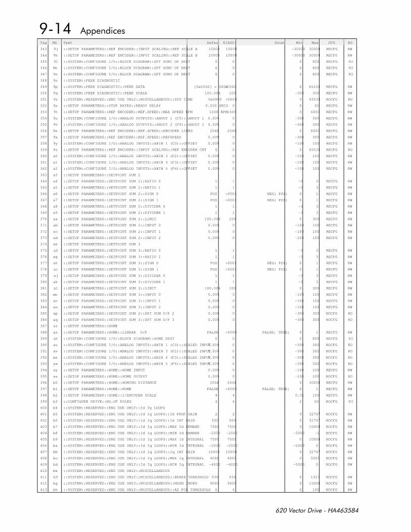
Tag Mn Text DefaultEIASCII Enum Min Max CFG RO
343 9j ::SETUP PARAMETERS::REF ENCODER::INPUT SCALING::REF SCALE A 10000 10000 -30000 30000 RECFG RW
344 9k ::SETUP PARAMETERS::REF ENCODER::INPUT SCALING::REF SCALE B 10000 10000 -30000 30000 RECFG RW
345 9l ::SYSTEM::CONFIGURE I/O::BLOCK DIAGRAM::SPT SUM1 OP DEST 0 0 0 800 RECFG RI
346 9m ::SYSTEM::CONFIGURE I/O::BLOCK DIAGRAM::SPT SUM2 OP DEST 0 0 0 800 RECFG RI
347 9n ::SYSTEM::CONFIGURE I/O::BLOCK DIAGRAM::SPT SUM3 OP DEST 0 0 0 800 RECFG RI
348 9o ::SYSTEM::PEEK DIAGNOSTIC
349 9p ::SYSTEM::PEEK DIAGNOSTIC::PEEK DATA [0xC000] = 0000>C000 0 65535 RECFG RW
350 9q ::SYSTEM::PEEK DIAGNOSTIC::PEEK SCALE 100.00% 100 -300 300 RECFG RW
351 9r ::SYSTEM::RESERVED::ENG USE ONLY::MISCELLANEOUS::SYS TIME 0x0000 >0000 0 65535 NOCFG RO
352 9s ::SETUP PARAMETERS::STOP RATES::READY DELAY 0.000 SECS 0 0 30 RECFG RW
353 9t ::SETUP PARAMETERS::REF ENCODER::REF.SPEED::MAX SPEED RPM 1500 RPM1500 0 6000 RECFG RW
354 9u ::SYSTEM::CONFIGURE I/O::ANALOG OUTPUTS::ANOUT 1 (C5)::ANOUT 1 0.00% 0 -300 300 RECFG RW
355 9v ::SYSTEM::CONFIGURE I/O::ANALOG OUTPUTS::ANOUT 2 (F5)::ANOUT 2 0.00% 0 -300 300 RECFG RW
356 9w ::SETUP PARAMETERS::REF ENCODER::REF.SPEED::ENCODER LINES 2048 2048 0 8000 RECFG RW
357 9x ::SETUP PARAMETERS::REF ENCODER::REF.SPEED::REFSPEED 0.00% 0 -300 300 RECFG RW
358 9y ::SYSTEM::CONFIGURE I/O::ANALOG INPUTS::ANIN 1 (C3)::OFFSET 0.00% 0 -100 100 RECFG RW
359 9z ::SETUP PARAMETERS::REF ENCODER::INPUT SCALING::REF ENCODER CNT 0 0 0 65535 RECFG RO
360 a0 ::SYSTEM::CONFIGURE I/O::ANALOG INPUTS::ANIN 3 (F2)::OFFSET 0.00% 0 -100 100 RECFG RW
361 a1 ::SYSTEM::CONFIGURE I/O::ANALOG INPUTS::ANIN 4 (F3)::OFFSET 0.00% 0 -100 100 RECFG RW
362 a2 ::SYSTEM::CONFIGURE I/O::ANALOG INPUTS::ANIN 5 (F4)::OFFSET 0.00% 0 -100 100 RECFG RW
363 a3 ::SETUP PARAMETERS::SETPOINT SUM 2
364 a4 ::SETUP PARAMETERS::SETPOINT SUM 2::RATIO 0 1 1 -3 3 RECFG RW
365 a5 ::SETUP PARAMETERS::SETPOINT SUM 2::RATIO 1 1 1 -3 3 RECFG RW
366 a6 ::SETUP PARAMETERS::SETPOINT SUM 2::SIGN 0 POS >0001 NEG; POS; 0 1 RECFG RW
367 a7 ::SETUP PARAMETERS::SETPOINT SUM 2::SIGN 1 POS >0001 NEG; POS; 0 1 RECFG RW
368 a8 ::SETUP PARAMETERS::SETPOINT SUM 2::DIVIDER 0 1 1 -3 3 RECFG RW
369 a9 ::SETUP PARAMETERS::SETPOINT SUM 2::DIVIDER 1 1 1 -3 3 RECFG RW
370 aa ::SETUP PARAMETERS::SETPOINT SUM 2::LIMIT 100.00% 100 0 300 RECFG RW
371 ab ::SETUP PARAMETERS::SETPOINT SUM 2::INPUT 0 0.00% 0 -100 100 RECFG RW
372 ac ::SETUP PARAMETERS::SETPOINT SUM 2::INPUT 1 0.00% 0 -100 100 RECFG RW
373 ad ::SETUP PARAMETERS::SETPOINT SUM 2::INPUT 2 0.00% 0 -100 100 RECFG RW
374 ae ::SETUP PARAMETERS::SETPOINT SUM 3
375 af ::SETUP PARAMETERS::SETPOINT SUM 3::RATIO 0 1 1 -3 3 RECFG RW
376 ag ::SETUP PARAMETERS::SETPOINT SUM 3::RATIO 1 1 1 -3 3 RECFG RW
377 ah ::SETUP PARAMETERS::SETPOINT SUM 3::SIGN 0 POS >0001 NEG; POS; 0 1 RECFG RW
378 ai ::SETUP PARAMETERS::SETPOINT SUM 3::SIGN 1 POS >0001 NEG; POS; 0 1 RECFG RW
379 aj ::SETUP PARAMETERS::SETPOINT SUM 3::DIVIDER 0 1 1 -3 3 RECFG RW
380 ak ::SETUP PARAMETERS::SETPOINT SUM 3::DIVIDER 1 1 1 -3 3 RECFG RW
381 al ::SETUP PARAMETERS::SETPOINT SUM 3::LIMIT 100.00% 100 0 300 RECFG RW
382 am ::SETUP PARAMETERS::SETPOINT SUM 3::INPUT 0 0.00% 0 -100 100 RECFG RW
383 an ::SETUP PARAMETERS::SETPOINT SUM 3::INPUT 1 0.00% 0 -100 100 RECFG RW
384 ao ::SETUP PARAMETERS::SETPOINT SUM 3::INPUT 2 0.00% 0 -100 100 RECFG RW
385 ap ::SETUP PARAMETERS::SETPOINT SUM 2::SPT SUM O/P 2 0.00% 0 -300 300 NOCFG RO
386 aq ::SETUP PARAMETERS::SETPOINT SUM 3::SPT SUM O/P 3 0.00% 0 -300 300 NOCFG RO
387 ar ::SETUP PARAMETERS::HOME
388 as ::SETUP PARAMETERS::HOME::LINEAR O/P FALSE >0000 FALSE; TRUE; 0 1 RECFG RW
389 at ::SYSTEM::CONFIGURE I/O::BLOCK DIAGRAM::HOME DEST 0 0 0 800 RECFG RI
390 au ::SYSTEM::CONFIGURE I/O::ANALOG INPUTS::ANIN 1 (C3)::SCALED INPUT0.00% 0 -300 300 NOCFG RO
391 av ::SYSTEM::CONFIGURE I/O::ANALOG INPUTS::ANIN 3 (F2)::SCALED INPUT0.00% 0 -300 300 NOCFG RO
392 aw ::SYSTEM::CONFIGURE I/O::ANALOG INPUTS::ANIN 4 (F3)::SCALED INPUT0.00% 0 -300 300 NOCFG RO
393 ax ::SYSTEM::CONFIGURE I/O::ANALOG INPUTS::ANIN 5 (F4)::SCALED INPUT0.00% 0 -300 300 NOCFG RO
394 ay ::SETUP PARAMETERS::HOME::HOME INPUT 0.00% 0 -100 100 RECFG RW
395 az ::SETUP PARAMETERS::HOME::HOME OUTPUT 0.00% 0 -100 100 NOCFG RO
396 b0 ::SETUP PARAMETERS::HOME::HOMING DISTANCE 2048 2048 0 30000 RECFG RW
397 b1 ::SETUP PARAMETERS::HOME::HOME FALSE >0000 FALSE; TRUE; 0 1 RECFG RW
398 b2 ::SETUP PARAMETERS::HOME::1/ENCODER SCALE 4 4 0.01 100 RECFG RW
399 b3 ::CONFIGURE DRIVE::NO.OF POLES 4 4 2 50 NOCFG RI
400 b4 ::SYSTEM::RESERVED::ENG USE ONLY::Id Iq LOOPS
401 b5 ::SYSTEM::RESERVED::ENG USE ONLY::Id Iq LOOPS::Id PROP GAIN 2 2 0 32767 NOCFG RW
402 b6 ::SYSTEM::RESERVED::ENG USE ONLY::Id Iq LOOPS::Id INT GAIN 500 500 0 32767 NOCFG RW
403 b7 ::SYSTEM::RESERVED::ENG USE ONLY::Id Iq LOOPS::MAX Id DEMAND 7500 7500 0 10000 NOCFG RW
404 b8 ::SYSTEM::RESERVED::ENG USE ONLY::Id Iq LOOPS::MIN Id DEMAND -2000 -2000 -5000 -1 NOCFG RW
405 b9 ::SYSTEM::RESERVED::ENG USE ONLY::Id Iq LOOPS::MAX Id INTEGRAL 7500 7500 0 10000 NOCFG RW
406 ba ::SYSTEM::RESERVED::ENG USE ONLY::Id Iq LOOPS::MIN Id INTEGRAL -2000 -2000 -5000 0 NOCFG RW
407 bb ::SYSTEM::RESERVED::ENG USE ONLY::Id Iq LOOPS::Iq INT GAIN 10000 10000 0 32767 NOCFG RW
408 bc ::SYSTEM::RESERVED::ENG USE ONLY::Id Iq LOOPS::MAX Iq INTEGRAL 4000 4000 0 5000 NOCFG RW
409 bd ::SYSTEM::RESERVED::ENG USE ONLY::Id Iq LOOPS::MIN Iq INTEGRAL -4000 -4000 -5000 0 NOCFG RW
410 be ::SYSTEM::RESERVED::ENG USE ONLY::MISCELLANEOUS
411 bf ::SYSTEM::RESERVED::ENG USE ONLY::MISCELLANEOUS::BRAKE THRESHOLD 936 936 0 1023 NOCFG RW
412 bg ::SYSTEM::RESERVED::ENG USE ONLY::MISCELLANEOUS::MODN INDEX 9000 9000 0 12000 NOCFG RW
413 bh ::SYSTEM::RESERVED::ENG USE ONLY::MISCELLANEOUS::AD POS THRESHOLD 6 6 0 100 NOCFG RW
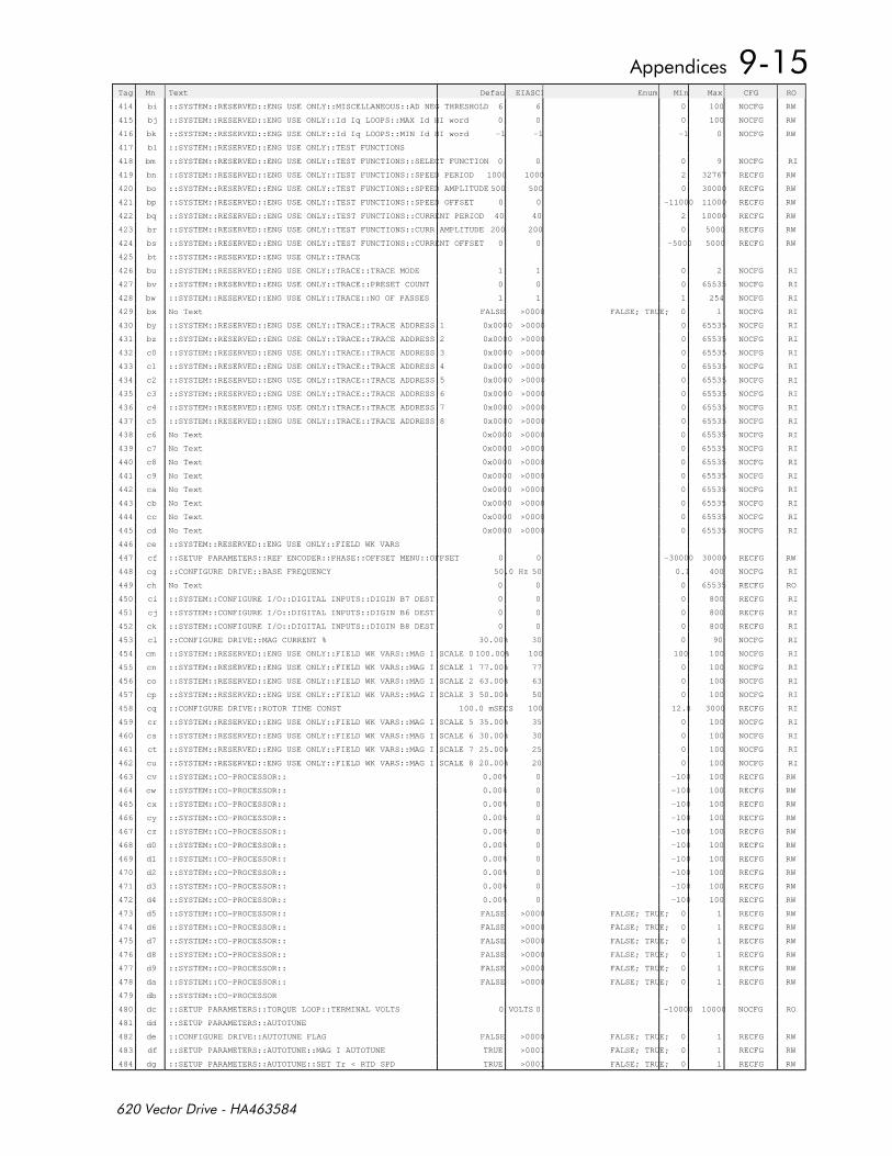
Tag Mn Text DefaultEIASCII Enum Min Max CFG RO
414 bi ::SYSTEM::RESERVED::ENG USE ONLY::MISCELLANEOUS::AD NEG THRESHOLD 6 6 0 100 NOCFG RW
415 bj ::SYSTEM::RESERVED::ENG USE ONLY::Id Iq LOOPS::MAX Id HI word 0 0 0 100 NOCFG RW
416 bk ::SYSTEM::RESERVED::ENG USE ONLY::Id Iq LOOPS::MIN Id HI word -1 -1 -1 0 NOCFG RW
417 bl ::SYSTEM::RESERVED::ENG USE ONLY::TEST FUNCTIONS
418 bm ::SYSTEM::RESERVED::ENG USE ONLY::TEST FUNCTIONS::SELECT FUNCTION 0 0 0 9 NOCFG RI
419 bn ::SYSTEM::RESERVED::ENG USE ONLY::TEST FUNCTIONS::SPEED PERIOD 1000 1000 2 32767 RECFG RW
420 bo ::SYSTEM::RESERVED::ENG USE ONLY::TEST FUNCTIONS::SPEED AMPLITUDE 500 500 0 30000 RECFG RW
421 bp ::SYSTEM::RESERVED::ENG USE ONLY::TEST FUNCTIONS::SPEED OFFSET 0 0 -11000 11000 RECFG RW
422 bq ::SYSTEM::RESERVED::ENG USE ONLY::TEST FUNCTIONS::CURRENT PERIOD 40 40 2 10000 RECFG RW
423 br ::SYSTEM::RESERVED::ENG USE ONLY::TEST FUNCTIONS::CURR AMPLITUDE 200 200 0 5000 RECFG RW
424 bs ::SYSTEM::RESERVED::ENG USE ONLY::TEST FUNCTIONS::CURRENT OFFSET 0 0 -5000 5000 RECFG RW
425 bt ::SYSTEM::RESERVED::ENG USE ONLY::TRACE
426 bu ::SYSTEM::RESERVED::ENG USE ONLY::TRACE::TRACE MODE 1 1 0 2 NOCFG RI
427 bv ::SYSTEM::RESERVED::ENG USE ONLY::TRACE::PRESET COUNT 0 0 0 65535 NOCFG RI
428 bw ::SYSTEM::RESERVED::ENG USE ONLY::TRACE::NO OF PASSES 1 1 1 254 NOCFG RI
429 bx No Text FALSE >0000 FALSE; TRUE; 0 1 NOCFG RI
430 by ::SYSTEM::RESERVED::ENG USE ONLY::TRACE::TRACE ADDRESS 1 0x0000 >0000 0 65535 NOCFG RI
431 bz ::SYSTEM::RESERVED::ENG USE ONLY::TRACE::TRACE ADDRESS 2 0x0000 >0000 0 65535 NOCFG RI
432 c0 ::SYSTEM::RESERVED::ENG USE ONLY::TRACE::TRACE ADDRESS 3 0x0000 >0000 0 65535 NOCFG RI
433 c1 ::SYSTEM::RESERVED::ENG USE ONLY::TRACE::TRACE ADDRESS 4 0x0000 >0000 0 65535 NOCFG RI
434 c2 ::SYSTEM::RESERVED::ENG USE ONLY::TRACE::TRACE ADDRESS 5 0x0000 >0000 0 65535 NOCFG RI
435 c3 ::SYSTEM::RESERVED::ENG USE ONLY::TRACE::TRACE ADDRESS 6 0x0000 >0000 0 65535 NOCFG RI
436 c4 ::SYSTEM::RESERVED::ENG USE ONLY::TRACE::TRACE ADDRESS 7 0x0000 >0000 0 65535 NOCFG RI
437 c5 ::SYSTEM::RESERVED::ENG USE ONLY::TRACE::TRACE ADDRESS 8 0x0000 >0000 0 65535 NOCFG RI
438 c6 No Text 0x0000 >0000 0 65535 NOCFG RI
439 c7 No Text 0x0000 >0000 0 65535 NOCFG RI
440 c8 No Text 0x0000 >0000 0 65535 NOCFG RI
441 c9 No Text 0x0000 >0000 0 65535 NOCFG RI
442 ca No Text 0x0000 >0000 0 65535 NOCFG RI
443 cb No Text 0x0000 >0000 0 65535 NOCFG RI
444 cc No Text 0x0000 >0000 0 65535 NOCFG RI
445 cd No Text 0x0000 >0000 0 65535 NOCFG RI
446 ce ::SYSTEM::RESERVED::ENG USE ONLY::FIELD WK VARS
447 cf ::SETUP PARAMETERS::REF ENCODER::PHASE::OFFSET MENU::OFFSET 0 0 -30000 30000 RECFG RW
448 cg ::CONFIGURE DRIVE::BASE FREQUENCY 50.0 Hz 50 0.1 400 NOCFG RI
449 ch No Text 0 0 0 65535 RECFG RO
450 ci ::SYSTEM::CONFIGURE I/O::DIGITAL INPUTS::DIGIN B7 DEST 0 0 0 800 RECFG RI
451 cj ::SYSTEM::CONFIGURE I/O::DIGITAL INPUTS::DIGIN B6 DEST 0 0 0 800 RECFG RI
452 ck ::SYSTEM::CONFIGURE I/O::DIGITAL INPUTS::DIGIN B8 DEST 0 0 0 800 RECFG RI
453 cl ::CONFIGURE DRIVE::MAG CURRENT % 30.00% 30 0 90 NOCFG RI
454 cm ::SYSTEM::RESERVED::ENG USE ONLY::FIELD WK VARS::MAG I SCALE 0 100.00% 100 100 100 NOCFG RI
455 cn ::SYSTEM::RESERVED::ENG USE ONLY::FIELD WK VARS::MAG I SCALE 1 77.00% 77 0 100 NOCFG RI
456 co ::SYSTEM::RESERVED::ENG USE ONLY::FIELD WK VARS::MAG I SCALE 2 63.00% 63 0 100 NOCFG RI
457 cp ::SYSTEM::RESERVED::ENG USE ONLY::FIELD WK VARS::MAG I SCALE 3 50.00% 50 0 100 NOCFG RI
458 cq ::CONFIGURE DRIVE::ROTOR TIME CONST 100.0 mSECS 100 12.8 3000 RECFG RI
459 cr ::SYSTEM::RESERVED::ENG USE ONLY::FIELD WK VARS::MAG I SCALE 5 35.00% 35 0 100 NOCFG RI
460 cs ::SYSTEM::RESERVED::ENG USE ONLY::FIELD WK VARS::MAG I SCALE 6 30.00% 30 0 100 NOCFG RI
461 ct ::SYSTEM::RESERVED::ENG USE ONLY::FIELD WK VARS::MAG I SCALE 7 25.00% 25 0 100 NOCFG RI
462 cu ::SYSTEM::RESERVED::ENG USE ONLY::FIELD WK VARS::MAG I SCALE 8 20.00% 20 0 100 NOCFG RI
463 cv ::SYSTEM::CO-PROCESSOR:: 0.00% 0 -100 100 RECFG RW
464 cw ::SYSTEM::CO-PROCESSOR:: 0.00% 0 -100 100 RECFG RW
465 cx ::SYSTEM::CO-PROCESSOR:: 0.00% 0 -100 100 RECFG RW
466 cy ::SYSTEM::CO-PROCESSOR:: 0.00% 0 -100 100 RECFG RW
467 cz ::SYSTEM::CO-PROCESSOR:: 0.00% 0 -100 100 RECFG RW
468 d0 ::SYSTEM::CO-PROCESSOR:: 0.00% 0 -100 100 RECFG RW
469 d1 ::SYSTEM::CO-PROCESSOR:: 0.00% 0 -100 100 RECFG RW
470 d2 ::SYSTEM::CO-PROCESSOR:: 0.00% 0 -100 100 RECFG RW
471 d3 ::SYSTEM::CO-PROCESSOR:: 0.00% 0 -100 100 RECFG RW
472 d4 ::SYSTEM::CO-PROCESSOR:: 0.00% 0 -100 100 RECFG RW
473 d5 ::SYSTEM::CO-PROCESSOR:: FALSE >0000 FALSE; TRUE; 0 1 RECFG RW
474 d6 ::SYSTEM::CO-PROCESSOR:: FALSE >0000 FALSE; TRUE; 0 1 RECFG RW
475 d7 ::SYSTEM::CO-PROCESSOR:: FALSE >0000 FALSE; TRUE; 0 1 RECFG RW
476 d8 ::SYSTEM::CO-PROCESSOR:: FALSE >0000 FALSE; TRUE; 0 1 RECFG RW
477 d9 ::SYSTEM::CO-PROCESSOR:: FALSE >0000 FALSE; TRUE; 0 1 RECFG RW
478 da ::SYSTEM::CO-PROCESSOR:: FALSE >0000 FALSE; TRUE; 0 1 RECFG RW
479 db ::SYSTEM::CO-PROCESSOR
480 dc ::SETUP PARAMETERS::TORQUE LOOP::TERMINAL VOLTS 0 VOLTS 0 -10000 10000 NOCFG RO
481 dd ::SETUP PARAMETERS::AUTOTUNE
482 de ::CONFIGURE DRIVE::AUTOTUNE FLAG FALSE >0000 FALSE; TRUE; 0 1 RECFG RW
483 df ::SETUP PARAMETERS::AUTOTUNE::MAG I AUTOTUNE TRUE >0001 FALSE; TRUE; 0 1 RECFG RW
484 dg ::SETUP PARAMETERS::AUTOTUNE::SET Tr < RTD SPD TRUE >0001 FALSE; TRUE; 0 1 RECFG RW
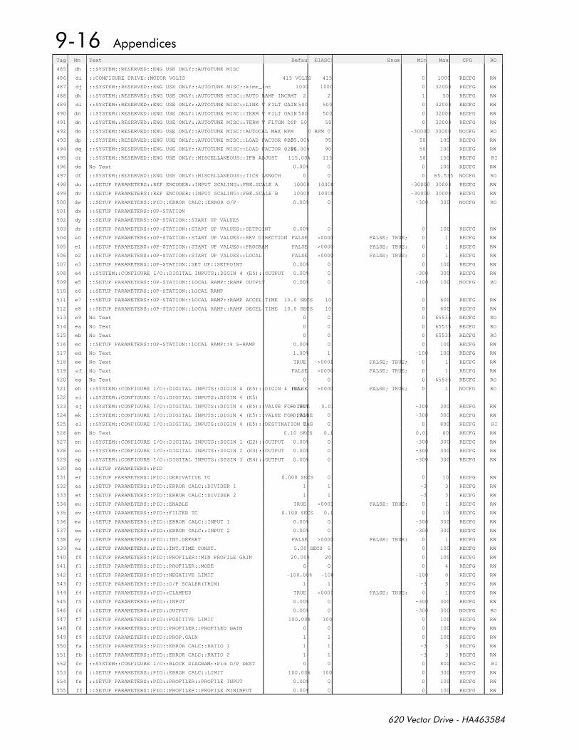
Tag Mn Text DefaultEIASCII Enum Min Max CFG RO
485 dh ::SYSTEM::RESERVED::ENG USE ONLY::AUTOTUNE MISC
486 di ::CONFIGURE DRIVE::MOTOR VOLTS 415 VOLTS 415 0 1000 RECFG RW
487 dj ::SYSTEM::RESERVED::ENG USE ONLY::AUTOTUNE MISC::kimr_int 1000 1000 0 32000 RECFG RW
488 dk ::SYSTEM::RESERVED::ENG USE ONLY::AUTOTUNE MISC::AUTO RAMP INCRMT 2 2 1 50 RECFG RW
489 dl ::SYSTEM::RESERVED::ENG USE ONLY::AUTOTUNE MISC::LINK V FILT GAIN 500 500 0 32000 RECFG RW
490 dm ::SYSTEM::RESERVED::ENG USE ONLY::AUTOTUNE MISC::TERM V FILT GAIN 500 500 0 32000 RECFG RW
491 dn ::SYSTEM::RESERVED::ENG USE ONLY::AUTOTUNE MISC::TERM V FLTGN DSP 50 50 0 32000 RECFG RW
492 do ::SYSTEM::RESERVED::ENG USE ONLY::AUTOTUNE MISC::AUTOCAL MAX RPM 0 RPM 0 -30000 30000 NOCFG RO
493 dp ::SYSTEM::RESERVED::ENG USE ONLY::AUTOTUNE MISC::LOAD FACTOR @BS95.00% 95 50 100 RECFG RW
494 dq ::SYSTEM::RESERVED::ENG USE ONLY::AUTOTUNE MISC::LOAD FACTOR @2BS90.00% 90 50 100 RECFG RW
495 dr ::SYSTEM::RESERVED::ENG USE ONLY::MISCELLANEOUS::IFB ADJUST 115.00% 115 50 150 RECFG RI
496 ds No Text 0.00% 0 0 100 RECFG RW
497 dt ::SYSTEM::RESERVED::ENG USE ONLY::MISCELLANEOUS::TICK LENGTH 0 0 0 65.535 NOCFG RO
498 du ::SETUP PARAMETERS::REF ENCODER::INPUT SCALING::FBK.SCALE A 10000 10000 -30000 30000 RECFG RW
499 dv ::SETUP PARAMETERS::REF ENCODER::INPUT SCALING::FBK.SCALE B 10000 10000 -30000 30000 RECFG RW
500 dw ::SETUP PARAMETERS::PID::ERROR CALC::ERROR O/P 0.00% 0 -300 300 NOCFG RO
501 dx ::SETUP PARAMETERS::OP-STATION
502 dy ::SETUP PARAMETERS::OP-STATION::START UP VALUES
503 dz ::SETUP PARAMETERS::OP-STATION::START UP VALUES::SETPOINT 0.00% 0 0 100 RECFG RW
504 e0 ::SETUP PARAMETERS::OP-STATION::START UP VALUES::REV DIRECTION FALSE >0000 FALSE; TRUE; 0 1 RECFG RW
505 e1 ::SETUP PARAMETERS::OP-STATION::START UP VALUES::PROGRAM FALSE >0000 FALSE; TRUE; 0 1 RECFG RW
506 e2 ::SETUP PARAMETERS::OP-STATION::START UP VALUES::LOCAL FALSE >0000 FALSE; TRUE; 0 1 RECFG RW
507 e3 ::SETUP PARAMETERS::OP-STATION::SET UP::SETPOINT 0.00% 0 0 100 RECFG RW
508 e4 ::SYSTEM::CONFIGURE I/O::DIGITAL INPUTS::DIGIN 4 (E5)::OUTPUT 0.00% 0 -300 300 RECFG RW
509 e5 ::SETUP PARAMETERS::OP-STATION::LOCAL RAMP::RAMP OUTPUT 0.00% 0 -100 100 NOCFG RO
510 e6 ::SETUP PARAMETERS::OP-STATION::LOCAL RAMP
511 e7 ::SETUP PARAMETERS::OP-STATION::LOCAL RAMP::RAMP ACCEL TIME 10.0 SECS 10 0 600 RECFG RW
512 e8 ::SETUP PARAMETERS::OP-STATION::LOCAL RAMP::RAMP DECEL TIME 10.0 SECS 10 0 600 RECFG RW
513 e9 No Text 0 0 0 65535 RECFG RO
514 ea No Text 0 0 0 65535 RECFG RO
515 eb No Text 0 0 0 65535 RECFG RO
516 ec ::SETUP PARAMETERS::OP-STATION::LOCAL RAMP::% S-RAMP 0.00% 0 0 100 RECFG RW
517 ed No Text 1.00% 1 -100 100 RECFG RW
518 ee No Text TRUE >0001 FALSE; TRUE; 0 1 RECFG RW
519 ef No Text FALSE >0000 FALSE; TRUE; 0 1 RECFG RW
520 eg No Text 0 0 0 65535 RECFG RO
521 eh ::SYSTEM::CONFIGURE I/O::DIGITAL INPUTS::DIGIN 4 (E5)::DIGIN 4 (E5)FALSE >0000 FALSE; TRUE; 0 1 NOCFG RO
522 ei ::SYSTEM::CONFIGURE I/O::DIGITAL INPUTS::DIGIN 4 (E5)
523 ej ::SYSTEM::CONFIGURE I/O::DIGITAL INPUTS::DIGIN 4 (E5)::VALUE FOR TRUE0.01% 0.01 -300 300 RECFG RW
524 ek ::SYSTEM::CONFIGURE I/O::DIGITAL INPUTS::DIGIN 4 (E5)::VALUE FOR FALSE0.00% 0 -300 300 RECFG RW
525 el ::SYSTEM::CONFIGURE I/O::DIGITAL INPUTS::DIGIN 4 (E5)::DESTINATION TAG0 0 0 800 RECFG RI
526 em No Text 0.10 SECS 0.1 0.01 60 RECFG RW
527 en ::SYSTEM::CONFIGURE I/O::DIGITAL INPUTS::DIGIN 1 (E2)::OUTPUT 0.00% 0 -300 300 RECFG RW
528 eo ::SYSTEM::CONFIGURE I/O::DIGITAL INPUTS::DIGIN 2 (E3)::OUTPUT 0.00% 0 -300 300 RECFG RW
529 ep ::SYSTEM::CONFIGURE I/O::DIGITAL INPUTS::DIGIN 3 (E4)::OUTPUT 0.00% 0 -300 300 RECFG RW
530 eq ::SETUP PARAMETERS::PID
531 er ::SETUP PARAMETERS::PID::DERIVATIVE TC 0.000 SECS 0 0 10 RECFG RW
532 es ::SETUP PARAMETERS::PID::ERROR CALC::DIVIDER 1 1 1 -3 3 RECFG RW
533 et ::SETUP PARAMETERS::PID::ERROR CALC::DIVIDER 2 1 1 -3 3 RECFG RW
534 eu ::SETUP PARAMETERS::PID::ENABLE TRUE >0001 FALSE; TRUE; 0 1 RECFG RW
535 ev ::SETUP PARAMETERS::PID::FILTER TC 0.100 SECS 0.1 0 10 RECFG RW
536 ew ::SETUP PARAMETERS::PID::ERROR CALC::INPUT 1 0.00% 0 -300 300 RECFG RW
537 ex ::SETUP PARAMETERS::PID::ERROR CALC::INPUT 2 0.00% 0 -300 300 RECFG RW
538 ey ::SETUP PARAMETERS::PID::INT.DEFEAT FALSE >0000 FALSE; TRUE; 0 1 RECFG RW
539 ez ::SETUP PARAMETERS::PID::INT.TIME CONST. 5.00 SECS 5 0 100 RECFG RW
540 f0 ::SETUP PARAMETERS::PID::PROFILER::MIN PROFILE GAIN 20.00% 20 0 100 RECFG RW
541 f1 ::SETUP PARAMETERS::PID::PROFILER::MODE 0 0 0 4 RECFG RW
542 f2 ::SETUP PARAMETERS::PID::NEGATIVE LIMIT -100.00% -100 -100 0 RECFG RW
543 f3 ::SETUP PARAMETERS::PID::O/P SCALER(TRIM) 1 1 -3 3 RECFG RW
544 f4 ::SETUP PARAMETERS::PID::CLAMPED TRUE >0001 FALSE; TRUE; 0 1 RECFG RW
545 f5 ::SETUP PARAMETERS::PID::INPUT 0.00% 0 -300 300 RECFG RW
546 f6 ::SETUP PARAMETERS::PID::OUTPUT 0.00% 0 -300 300 NOCFG RO
547 f7 ::SETUP PARAMETERS::PID::POSITIVE LIMIT 100.00% 100 0 100 RECFG RW
548 f8 ::SETUP PARAMETERS::PID::PROFILER::PROFILED GAIN 0 0 0 100 RECFG RW
549 f9 ::SETUP PARAMETERS::PID::PROP.GAIN 1 1 0 100 RECFG RW
550 fa ::SETUP PARAMETERS::PID::ERROR CALC::RATIO 1 1 1 -3 3 RECFG RW
551 fb ::SETUP PARAMETERS::PID::ERROR CALC::RATIO 2 1 1 -3 3 RECFG RW
552 fc ::SYSTEM::CONFIGURE I/O::BLOCK DIAGRAM::Pid O/P DEST 0 0 0 800 RECFG RI
553 fd ::SETUP PARAMETERS::PID::ERROR CALC::LIMIT 100.00% 100 0 300 RECFG RW
554 fe ::SETUP PARAMETERS::PID::PROFILER::PROFILE INPUT 0.00% 0 0 100 RECFG RW
555 ff ::SETUP PARAMETERS::PID::PROFILER::PROFILE MININPUT 0.00% 0 0 100 RECFG RW
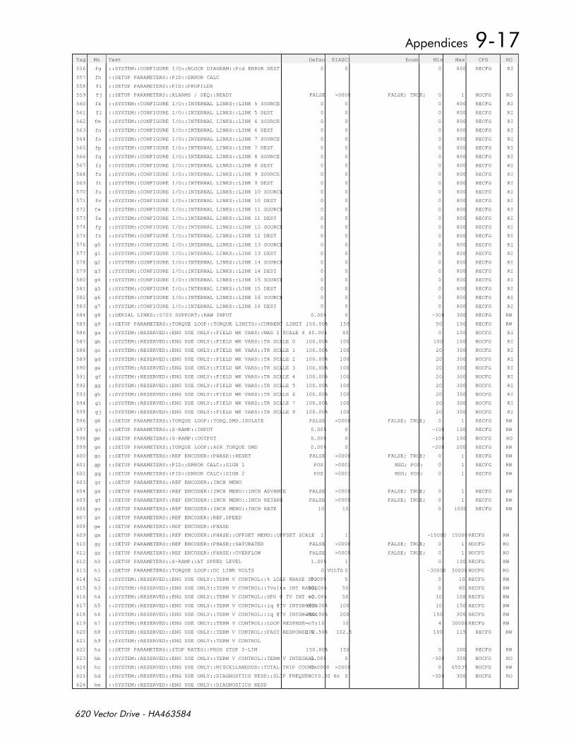
Tag Mn Text DefaultEIASCII Enum Min Max CFG RO
556 fg ::SYSTEM::CONFIGURE I/O::BLOCK DIAGRAM::Pid ERROR DEST 0 0 0 800 RECFG RI
557 fh ::SETUP PARAMETERS::PID::ERROR CALC
558 fi ::SETUP PARAMETERS::PID::PROFILER
559 fj ::SETUP PARAMETERS::ALARMS / SEQ::READY FALSE >0000 FALSE; TRUE; 0 1 NOCFG RO
560 fk ::SYSTEM::CONFIGURE I/O::INTERNAL LINKS::LINK 5 SOURCE 0 0 0 800 RECFG RI
561 fl ::SYSTEM::CONFIGURE I/O::INTERNAL LINKS::LINK 5 DEST 0 0 0 800 RECFG RI
562 fm ::SYSTEM::CONFIGURE I/O::INTERNAL LINKS::LINK 6 SOURCE 0 0 0 800 RECFG RI
563 fn ::SYSTEM::CONFIGURE I/O::INTERNAL LINKS::LINK 6 DEST 0 0 0 800 RECFG RI
564 fo ::SYSTEM::CONFIGURE I/O::INTERNAL LINKS::LINK 7 SOURCE 0 0 0 800 RECFG RI
565 fp ::SYSTEM::CONFIGURE I/O::INTERNAL LINKS::LINK 7 DEST 0 0 0 800 RECFG RI
566 fq ::SYSTEM::CONFIGURE I/O::INTERNAL LINKS::LINK 8 SOURCE 0 0 0 800 RECFG RI
567 fr ::SYSTEM::CONFIGURE I/O::INTERNAL LINKS::LINK 8 DEST 0 0 0 800 RECFG RI
568 fs ::SYSTEM::CONFIGURE I/O::INTERNAL LINKS::LINK 9 SOURCE 0 0 0 800 RECFG RI
569 ft ::SYSTEM::CONFIGURE I/O::INTERNAL LINKS::LINK 9 DEST 0 0 0 800 RECFG RI
570 fu ::SYSTEM::CONFIGURE I/O::INTERNAL LINKS::LINK 10 SOURCE 0 0 0 800 RECFG RI
571 fv ::SYSTEM::CONFIGURE I/O::INTERNAL LINKS::LINK 10 DEST 0 0 0 800 RECFG RI
572 fw ::SYSTEM::CONFIGURE I/O::INTERNAL LINKS::LINK 11 SOURCE 0 0 0 800 RECFG RI
573 fx ::SYSTEM::CONFIGURE I/O::INTERNAL LINKS::LINK 11 DEST 0 0 0 800 RECFG RI
574 fy ::SYSTEM::CONFIGURE I/O::INTERNAL LINKS::LINK 12 SOURCE 0 0 0 800 RECFG RI
575 fz ::SYSTEM::CONFIGURE I/O::INTERNAL LINKS::LINK 12 DEST 0 0 0 800 RECFG RI
576 g0 ::SYSTEM::CONFIGURE I/O::INTERNAL LINKS::LINK 13 SOURCE 0 0 0 800 RECFG RI
577 g1 ::SYSTEM::CONFIGURE I/O::INTERNAL LINKS::LINK 13 DEST 0 0 0 800 RECFG RI
578 g2 ::SYSTEM::CONFIGURE I/O::INTERNAL LINKS::LINK 14 SOURCE 0 0 0 800 RECFG RI
579 g3 ::SYSTEM::CONFIGURE I/O::INTERNAL LINKS::LINK 14 DEST 0 0 0 800 RECFG RI
580 g4 ::SYSTEM::CONFIGURE I/O::INTERNAL LINKS::LINK 15 SOURCE 0 0 0 800 RECFG RI
581 g5 ::SYSTEM::CONFIGURE I/O::INTERNAL LINKS::LINK 15 DEST 0 0 0 800 RECFG RI
582 g6 ::SYSTEM::CONFIGURE I/O::INTERNAL LINKS::LINK 16 SOURCE 0 0 0 800 RECFG RI
583 g7 ::SYSTEM::CONFIGURE I/O::INTERNAL LINKS::LINK 16 DEST 0 0 0 800 RECFG RI
584 g8 ::SERIAL LINKS::5703 SUPPORT::RAW INPUT 0.00% 0 -300 300 RECFG RW
585 g9 ::SETUP PARAMETERS::TORQUE LOOP::TORQUE LIMITS::CURRENT LIMIT 150.00% 150 50 150 RECFG RW
586 ga ::SYSTEM::RESERVED::ENG USE ONLY::FIELD WK VARS::MAG I SCALE 4 40.00% 40 0 100 NOCFG RI
587 gb ::SYSTEM::RESERVED::ENG USE ONLY::FIELD WK VARS::TR SCALE 0 100.00% 100 100 100 NOCFG RI
588 gc ::SYSTEM::RESERVED::ENG USE ONLY::FIELD WK VARS::TR SCALE 1 100.00% 100 20 300 NOCFG RI
589 gd ::SYSTEM::RESERVED::ENG USE ONLY::FIELD WK VARS::TR SCALE 2 100.00% 100 20 300 NOCFG RI
590 ge ::SYSTEM::RESERVED::ENG USE ONLY::FIELD WK VARS::TR SCALE 3 100.00% 100 20 300 NOCFG RI
591 gf ::SYSTEM::RESERVED::ENG USE ONLY::FIELD WK VARS::TR SCALE 4 100.00% 100 20 300 NOCFG RI
592 gg ::SYSTEM::RESERVED::ENG USE ONLY::FIELD WK VARS::TR SCALE 5 100.00% 100 20 300 NOCFG RI
593 gh ::SYSTEM::RESERVED::ENG USE ONLY::FIELD WK VARS::TR SCALE 6 100.00% 100 20 300 NOCFG RI
594 gi ::SYSTEM::RESERVED::ENG USE ONLY::FIELD WK VARS::TR SCALE 7 100.00% 100 20 300 NOCFG RI
595 gj ::SYSTEM::RESERVED::ENG USE ONLY::FIELD WK VARS::TR SCALE 8 100.00% 100 20 300 NOCFG RI
596 gk ::SETUP PARAMETERS::TORQUE LOOP::TORQ.DMD.ISOLATE FALSE >0000 FALSE; TRUE; 0 1 RECFG RW
597 gl ::SETUP PARAMETERS::S-RAMP::INPUT 0.00% 0 -100 100 RECFG RW
598 gm ::SETUP PARAMETERS::S-RAMP::OUTPUT 0.00% 0 -100 100 NOCFG RO
599 gn ::SETUP PARAMETERS::TORQUE LOOP::AUX TORQUE DMD 0.00% 0 -200 200 RECFG RW
600 go ::SETUP PARAMETERS::REF ENCODER::PHASE::RESET FALSE >0000 FALSE; TRUE; 0 1 RECFG RW
601 gp ::SETUP PARAMETERS::PID::ERROR CALC::SIGN 1 POS >0001 NEG; POS; 0 1 RECFG RW
602 gq ::SETUP PARAMETERS::PID::ERROR CALC::SIGN 2 POS >0001 NEG; POS; 0 1 RECFG RW
603 gr ::SETUP PARAMETERS::REF ENCODER::INCH MENU
604 gs ::SETUP PARAMETERS::REF ENCODER::INCH MENU::INCH ADVANCE FALSE >0000 FALSE; TRUE; 0 1 RECFG RW
605 gt ::SETUP PARAMETERS::REF ENCODER::INCH MENU::INCH RETARD FALSE >0000 FALSE; TRUE; 0 1 RECFG RW
606 gu ::SETUP PARAMETERS::REF ENCODER::INCH MENU::INCH RATE 10 10 0 1000 RECFG RW
607 gv ::SETUP PARAMETERS::REF ENCODER::REF.SPEED
608 gw ::SETUP PARAMETERS::REF ENCODER::PHASE
609 gx ::SETUP PARAMETERS::REF ENCODER::PHASE::OFFSET MENU::OFFSET SCALE 1 1 -15000 15000 RECFG RW
610 gy ::SETUP PARAMETERS::REF ENCODER::PHASE::SATURATED FALSE >0000 FALSE; TRUE; 0 1 NOCFG RO
611 gz ::SETUP PARAMETERS::REF ENCODER::PHASE::OVERFLOW FALSE >0000 FALSE; TRUE; 0 1 NOCFG RO
612 h0 ::SETUP PARAMETERS::S-RAMP::AT SPEED LEVEL 1.00% 1 0 100 RECFG RW
613 h1 ::SETUP PARAMETERS::TORQUE LOOP::DC LINK VOLTS 0 VOLTS 0 -30000 30000 NOCFG RO
614 h2 ::SYSTEM::RESERVED::ENG USE ONLY::TERM V CONTROL::% LOAD @BASE SPD5.00% 5 0 10 RECFG RW
615 h3 ::SYSTEM::RESERVED::ENG USE ONLY::TERM V CONTROL::TVolts INT RANGE50.00% 50 0 80 RECFG RW
616 h4 ::SYSTEM::RESERVED::ENG USE ONLY::TERM V CONTROL::SPD @ TV INT =050.00% 50 10 100 RECFG RW
617 h5 ::SYSTEM::RESERVED::ENG USE ONLY::TERM V CONTROL::iq @TV INTGN=MIN100.00% 100 10 150 RECFG RW
618 h6 ::SYSTEM::RESERVED::ENG USE ONLY::TERM V CONTROL::iq @TV INTGN=MAX200.00% 200 150 300 RECFG RW
619 h7 ::SYSTEM::RESERVED::ENG USE ONLY::TERM V CONTROL::LOOP RESPNSE=nTr10 10 4 30000 RECFG RW
620 h8 ::SYSTEM::RESERVED::ENG USE ONLY::TERM V CONTROL::FAST RESPONSE %102.50% 102.5 100 115 RECFG RW
621 h9 ::SYSTEM::RESERVED::ENG USE ONLY::TERM V CONTROL
622 ha ::SETUP PARAMETERS::STOP RATES::PROG STOP I-LIM 150.00% 150 0 200 RECFG RW
623 hb ::SYSTEM::RESERVED::ENG USE ONLY::TERM V CONTROL::TERM V INTEGRAL0.00% 0 -300 300 NOCFG RO
624 hc ::SYSTEM::RESERVED::ENG USE ONLY::MISCELLANEOUS::TOTAL TRIP COUNT 0x0000 >0000 0 65535 NOCFG RW
625 hd ::SYSTEM::RESERVED::ENG USE ONLY::DIAGNOSTICS RESD::SLIP FREQUENCY 0.00 Hz 0 -300 300 NOCFG RO
626 he ::SYSTEM::RESERVED::ENG USE ONLY::DIAGNOSTICS RESD
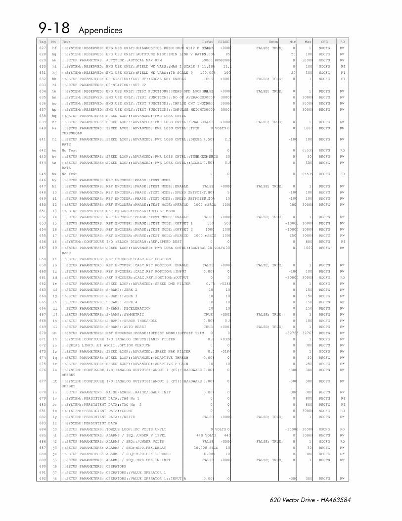
Tag Mn Text DefaultEIASCII Enum Min Max CFG RO
627 hf ::SYSTEM::RESERVED::ENG USE ONLY::DIAGNOSTICS RESD::RUN SLIP F DIAGFALSE >0000 FALSE; TRUE; 0 1 NOCFG RW
628 hg ::SYSTEM::RESERVED::ENG USE ONLY::AUTOTUNE MISC::MIN LINK V RATIO85.00% 85 50 100 RECFG RW
629 hh ::SETUP PARAMETERS::AUTOTUNE::AUTOCAL MAX RPM 30000 RPM30000 0 30000 RECFG RW
630 hi ::SYSTEM::RESERVED::ENG USE ONLY::FIELD WK VARS::MAG I SCALE 9 11.10% 11.1 0 100 NOCFG RI
631 hj ::SYSTEM::RESERVED::ENG USE ONLY::FIELD WK VARS::TR SCALE 9 100.00% 100 20 300 NOCFG RI
632 hk ::SETUP PARAMETERS::OP-STATION::SET UP::LOCAL KEY ENABLE TRUE >0001 FALSE; TRUE; 0 1 NOCFG RI
633 hl ::SETUP PARAMETERS::OP-STATION::SET UP
634 hm ::SYSTEM::RESERVED::ENG USE ONLY::TEST FUNCTIONS::MEAS SPD LOOP BWFALSE >0000 FALSE; TRUE; 0 1 RECFG RW
635 hn ::SYSTEM::RESERVED::ENG USE ONLY::TEST FUNCTIONS::NO OF AVERAGES30000 30000 0 30000 RECFG RW
636 ho ::SYSTEM::RESERVED::ENG USE ONLY::TEST FUNCTIONS::IMPLSE CNT LNGTH30000 30000 0 30000 RECFG RW
637 hp ::SYSTEM::RESERVED::ENG USE ONLY::TEST FUNCTIONS::IMPULSE HEIGHT30000 30000 0 30000 RECFG RW
638 hq ::SETUP PARAMETERS::SPEED LOOP::ADVANCED::PWR LOSS CNTRL
639 hr ::SETUP PARAMETERS::SPEED LOOP::ADVANCED::PWR LOSS CNTRL::ENABLEFALSE >0000 FALSE; TRUE; 0 1 RECFG RW
640 hs ::SETUP PARAMETERS::SPEED LOOP::ADVANCED::PWR LOSS CNTRL::TRIP
THRESHOLD
0 VOLTS 0 0 1000 RECFG RW
641 ht ::SETUP PARAMETERS::SPEED LOOP::ADVANCED::PWR LOSS CNTRL::DECEL
RATE
2.50% 2.5 -100 100 RECFG RW
642 hu No Text 0 0 0 65535 RECFG RO
643 hv ::SETUP PARAMETERS::SPEED LOOP::ADVANCED::PWR LOSS CNTRL::TIME LIMIT30.000 SECS 30 0 30 RECFG RW
644 hw ::SETUP PARAMETERS::SPEED LOOP::ADVANCED::PWR LOSS CNTRL::ACCEL
RATE
0.50% 0.5 0 300 RECFG RW
645 hx No Text 0 0 0 65535 RECFG RO
646 hy ::SETUP PARAMETERS::REF ENCODER::PHASE::TEST MODE
647 hz ::SETUP PARAMETERS::REF ENCODER::PHASE::TEST MODE::ENABLE FALSE >0000 FALSE; TRUE; 0 1 RECFG RW
648 i0 ::SETUP PARAMETERS::REF ENCODER::PHASE::TEST MODE::SPEED SETPOINT 15.00% 5 -100 100 RECFG RW
649 i1 ::SETUP PARAMETERS::REF ENCODER::PHASE::TEST MODE::SPEED SETPOINT 210.00% 10 -100 100 RECFG RW
650 i2 ::SETUP PARAMETERS::REF ENCODER::PHASE::TEST MODE::PERIOD 1000 mSECS 1000 250 30000 RECFG RW
651 i3 ::SETUP PARAMETERS::REF ENCODER::PHASE::OFFSET MENU
652 i4 ::SETUP PARAMETERS::REF ENCODER::PHASE::TEST MODE::ENABLE FALSE >0000 FALSE; TRUE; 0 1 RECFG RW
653 i5 ::SETUP PARAMETERS::REF ENCODER::PHASE::TEST MODE::OFFSET 1 500 500 -10000 10000 RECFG RW
654 i6 ::SETUP PARAMETERS::REF ENCODER::PHASE::TEST MODE::OFFSET 2 1000 1000 -10000 10000 RECFG RW
655 i7 ::SETUP PARAMETERS::REF ENCODER::PHASE::TEST MODE::PERIOD 1000 mSECS 1000 250 30000 RECFG RW
656 i8 ::SYSTEM::CONFIGURE I/O::BLOCK DIAGRAM::REF.SPEED DEST 0 0 0 800 RECFG RI
657 i9 ::SETUP PARAMETERS::SPEED LOOP::ADVANCED::PWR LOSS CNTRL::CONTROL
BAND
20 VOLTS20 0 1000 RECFG RW
658 ia ::SETUP PARAMETERS::REF ENCODER::CALC.REF.POSTION
659 ib ::SETUP PARAMETERS::REF ENCODER::CALC.REF.POSTION::ENABLE FALSE >0000 FALSE; TRUE; 0 1 RECFG RW
660 ic ::SETUP PARAMETERS::REF ENCODER::CALC.REF.POSTION::INPUT 0.00% 0 -100 100 RECFG RW
661 id ::SETUP PARAMETERS::REF ENCODER::CALC.REF.POSTION::OUTPUT 0 0 -30000 30000 NOCFG RO
662 ie ::SETUP PARAMETERS::SPEED LOOP::ADVANCED::SPEED DMD FILTER 0.75 >02EE 0 1 NOCFG RW
663 if ::SETUP PARAMETERS::S-RAMP::JERK 2 10 10 0 150 RECFG RW
664 ig ::SETUP PARAMETERS::S-RAMP::JERK 3 10 10 0 150 RECFG RW
665 ih ::SETUP PARAMETERS::S-RAMP::JERK 4 10 10 0 150 RECFG RW
666 ii ::SETUP PARAMETERS::S-RAMP::DECELERATION 10 10 0 150 RECFG RW
667 ij ::SETUP PARAMETERS::S-RAMP::SYMMETRIC TRUE >0001 FALSE; TRUE; 0 1 RECFG RW
668 ik ::SETUP PARAMETERS::S-RAMP::ERROR THRESHOLD 0.50% 0.5 0 100 RECFG RW
669 il ::SETUP PARAMETERS::S-RAMP::AUTO RESET TRUE >0001 FALSE; TRUE; 0 1 RECFG RW
670 im ::SETUP PARAMETERS::REF ENCODER::PHASE::OFFSET MENU::OFFSET TRIM 0 0 -32768 32767 RECFG RW
671 in ::SYSTEM::CONFIGURE I/O::ANALOG INPUTS::ANIN FILTER 0.8 >0320 0 1 NOCFG RW
672 io ::SERIAL LINKS::EI ASCII::OPTION VERSION 0 0 0 300 RECFG RW
673 ip ::SETUP PARAMETERS::SPEED LOOP::ADVANCED::SPEED FBK FILTER 0.5 >01F4 0 1 NOCFG RW
674 iq ::SETUP PARAMETERS::SPEED LOOP::ADVANCED::ADAPTIVE THRESH 0.00% 0 0 10 RECFG RW
675 ir ::SETUP PARAMETERS::SPEED LOOP::ADVANCED::ADAPTIVE P-GAIN 10 10 0 250 RECFG RW
676 is ::SYSTEM::CONFIGURE I/O::ANALOG OUTPUTS::ANOUT 1 (C5)::HARDWARE
OFFSET
0.00% 0 -300 300 RECFG RW
677 it ::SYSTEM::CONFIGURE I/O::ANALOG OUTPUTS::ANOUT 2 (F5)::HARDWARE
OFFSET
0.00% 0 -300 300 RECFG RW
678 iu ::SETUP PARAMETERS::RAISE/LOWER::RAISE/LOWER INIT 0.00% 0 -300 300 RECFG RW
679 iv ::SYSTEM::PERSISTENT DATA::TAG No 1 0 0 0 800 RECFG RI
680 iw ::SYSTEM::PERSISTENT DATA::TAG No 2 0 0 0 800 RECFG RI
681 ix ::SYSTEM::PERSISTENT DATA::COUNT 0 0 0 30000 NOCFG RO
682 iy ::SYSTEM::PERSISTENT DATA::/WRITE FALSE >0000 FALSE; TRUE; 0 1 RECFG RW
683 iz ::SYSTEM::PERSISTENT DATA
684 j0 ::SETUP PARAMETERS::TORQUE LOOP::DC VOLTS UNFLT 0 VOLTS 0 -30000 30000 NOCFG RO
685 j1 ::SETUP PARAMETERS::ALARMS / SEQ::UNDER V LEVEL 440 VOLTS 440 0 30000 RECFG RW
686 j2 ::SETUP PARAMETERS::ALARMS / SEQ::/UNDER VOLTS FALSE >0000 FALSE; TRUE; 0 1 NOCFG RO
687 j3 ::SETUP PARAMETERS::ALARMS / SEQ::SPD.FBK.DELAY 10.000 SECS 10 0 30 RECFG RW
688 j4 ::SETUP PARAMETERS::ALARMS / SEQ::SPD.FBK.THRESHD 10.00% 10 0 300 RECFG RW
689 j5 ::SETUP PARAMETERS::ALARMS / SEQ::SPD.FBK.INHIBIT FALSE >0000 FALSE; TRUE; 0 1 RECFG RW
690 j6 ::SETUP PARAMETERS::OPERATORS
691 j7 ::SETUP PARAMETERS::OPERATORS::VALUE OPERATOR 1
692 j8 ::SETUP PARAMETERS::OPERATORS::VALUE OPERATOR 1::INPUT A 0.00% 0 -300 300 RECFG RW
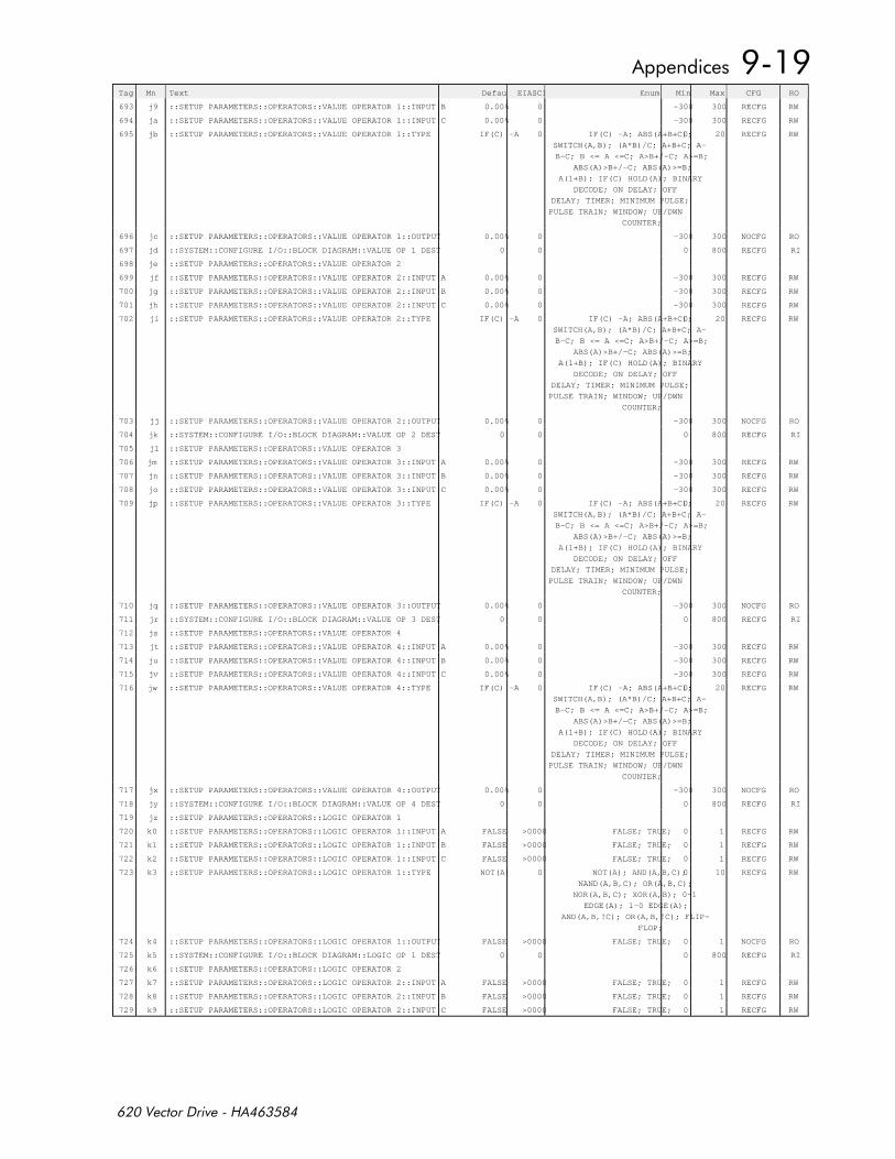
Tag Mn Text DefaultEIASCII Enum Min Max CFG RO
693 j9 ::SETUP PARAMETERS::OPERATORS::VALUE OPERATOR 1::INPUT B 0.00% 0 -300 300 RECFG RW
694 ja ::SETUP PARAMETERS::OPERATORS::VALUE OPERATOR 1::INPUT C 0.00% 0 -300 300 RECFG RW
695 jb ::SETUP PARAMETERS::OPERATORS::VALUE OPERATOR 1::TYPE IF(C) -A 0 IF(C) -A; ABS(A+B+C);
SWITCH(A,B); (A*B)/C; A+B+C; A-
B-C; B <= A <=C; A>B+/-C; A>=B;
ABS(A)>B+/-C; ABS(A)>=B;
A(1+B); IF(C) HOLD(A); BINARY
DECODE; ON DELAY; OFF
DELAY; TIMER; MINIMUM PULSE;
PULSE TRAIN; WINDOW; UP/DWN
COUNTER;
0 20 RECFG RW
696 jc ::SETUP PARAMETERS::OPERATORS::VALUE OPERATOR 1::OUTPUT 0.00% 0 -300 300 NOCFG RO
697 jd ::SYSTEM::CONFIGURE I/O::BLOCK DIAGRAM::VALUE OP 1 DEST 0 0 0 800 RECFG RI
698 je ::SETUP PARAMETERS::OPERATORS::VALUE OPERATOR 2
699 jf ::SETUP PARAMETERS::OPERATORS::VALUE OPERATOR 2::INPUT A 0.00% 0 -300 300 RECFG RW
700 jg ::SETUP PARAMETERS::OPERATORS::VALUE OPERATOR 2::INPUT B 0.00% 0 -300 300 RECFG RW
701 jh ::SETUP PARAMETERS::OPERATORS::VALUE OPERATOR 2::INPUT C 0.00% 0 -300 300 RECFG RW
702 ji ::SETUP PARAMETERS::OPERATORS::VALUE OPERATOR 2::TYPE IF(C) -A 0 IF(C) -A; ABS(A+B+C);
SWITCH(A,B); (A*B)/C; A+B+C; A-
B-C; B <= A <=C; A>B+/-C; A>=B;
ABS(A)>B+/-C; ABS(A)>=B;
A(1+B); IF(C) HOLD(A); BINARY
DECODE; ON DELAY; OFF
DELAY; TIMER; MINIMUM PULSE;
PULSE TRAIN; WINDOW; UP/DWN
COUNTER;
0 20 RECFG RW
703 jj ::SETUP PARAMETERS::OPERATORS::VALUE OPERATOR 2::OUTPUT 0.00% 0 -300 300 NOCFG RO
704 jk ::SYSTEM::CONFIGURE I/O::BLOCK DIAGRAM::VALUE OP 2 DEST 0 0 0 800 RECFG RI
705 jl ::SETUP PARAMETERS::OPERATORS::VALUE OPERATOR 3
706 jm ::SETUP PARAMETERS::OPERATORS::VALUE OPERATOR 3::INPUT A 0.00% 0 -300 300 RECFG RW
707 jn ::SETUP PARAMETERS::OPERATORS::VALUE OPERATOR 3::INPUT B 0.00% 0 -300 300 RECFG RW
708 jo ::SETUP PARAMETERS::OPERATORS::VALUE OPERATOR 3::INPUT C 0.00% 0 -300 300 RECFG RW
709 jp ::SETUP PARAMETERS::OPERATORS::VALUE OPERATOR 3::TYPE IF(C) -A 0 IF(C) -A; ABS(A+B+C);
SWITCH(A,B); (A*B)/C; A+B+C; A-
B-C; B <= A <=C; A>B+/-C; A>=B;
ABS(A)>B+/-C; ABS(A)>=B;
A(1+B); IF(C) HOLD(A); BINARY
DECODE; ON DELAY; OFF
DELAY; TIMER; MINIMUM PULSE;
PULSE TRAIN; WINDOW; UP/DWN
COUNTER;
0 20 RECFG RW
710 jq ::SETUP PARAMETERS::OPERATORS::VALUE OPERATOR 3::OUTPUT 0.00% 0 -300 300 NOCFG RO
711 jr ::SYSTEM::CONFIGURE I/O::BLOCK DIAGRAM::VALUE OP 3 DEST 0 0 0 800 RECFG RI
712 js ::SETUP PARAMETERS::OPERATORS::VALUE OPERATOR 4
713 jt ::SETUP PARAMETERS::OPERATORS::VALUE OPERATOR 4::INPUT A 0.00% 0 -300 300 RECFG RW
714 ju ::SETUP PARAMETERS::OPERATORS::VALUE OPERATOR 4::INPUT B 0.00% 0 -300 300 RECFG RW
715 jv ::SETUP PARAMETERS::OPERATORS::VALUE OPERATOR 4::INPUT C 0.00% 0 -300 300 RECFG RW
716 jw ::SETUP PARAMETERS::OPERATORS::VALUE OPERATOR 4::TYPE IF(C) -A 0 IF(C) -A; ABS(A+B+C);
SWITCH(A,B); (A*B)/C; A+B+C; A-
B-C; B <= A <=C; A>B+/-C; A>=B;
ABS(A)>B+/-C; ABS(A)>=B;
A(1+B); IF(C) HOLD(A); BINARY
DECODE; ON DELAY; OFF
DELAY; TIMER; MINIMUM PULSE;
PULSE TRAIN; WINDOW; UP/DWN
COUNTER;
0 20 RECFG RW
717 jx ::SETUP PARAMETERS::OPERATORS::VALUE OPERATOR 4::OUTPUT 0.00% 0 -300 300 NOCFG RO
718 jy ::SYSTEM::CONFIGURE I/O::BLOCK DIAGRAM::VALUE OP 4 DEST 0 0 0 800 RECFG RI
719 jz ::SETUP PARAMETERS::OPERATORS::LOGIC OPERATOR 1
720 k0 ::SETUP PARAMETERS::OPERATORS::LOGIC OPERATOR 1::INPUT A FALSE >0000 FALSE; TRUE; 0 1 RECFG RW
721 k1 ::SETUP PARAMETERS::OPERATORS::LOGIC OPERATOR 1::INPUT B FALSE >0000 FALSE; TRUE; 0 1 RECFG RW
722 k2 ::SETUP PARAMETERS::OPERATORS::LOGIC OPERATOR 1::INPUT C FALSE >0000 FALSE; TRUE; 0 1 RECFG RW
723 k3 ::SETUP PARAMETERS::OPERATORS::LOGIC OPERATOR 1::TYPE NOT(A) 0 NOT(A); AND(A,B,C);
NAND(A,B,C); OR(A,B,C);
NOR(A,B,C); XOR(A,B); 0-1
EDGE(A); 1-0 EDGE(A);
AND(A,B,!C); OR(A,B,!C); FLIP-
FLOP;
0 10 RECFG RW
724 k4 ::SETUP PARAMETERS::OPERATORS::LOGIC OPERATOR 1::OUTPUT FALSE >0000 FALSE; TRUE; 0 1 NOCFG RO
725 k5 ::SYSTEM::CONFIGURE I/O::BLOCK DIAGRAM::LOGIC OP 1 DEST 0 0 0 800 RECFG RI
726 k6 ::SETUP PARAMETERS::OPERATORS::LOGIC OPERATOR 2
727 k7 ::SETUP PARAMETERS::OPERATORS::LOGIC OPERATOR 2::INPUT A FALSE >0000 FALSE; TRUE; 0 1 RECFG RW
728 k8 ::SETUP PARAMETERS::OPERATORS::LOGIC OPERATOR 2::INPUT B FALSE >0000 FALSE; TRUE; 0 1 RECFG RW
729 k9 ::SETUP PARAMETERS::OPERATORS::LOGIC OPERATOR 2::INPUT C FALSE >0000 FALSE; TRUE; 0 1 RECFG RW
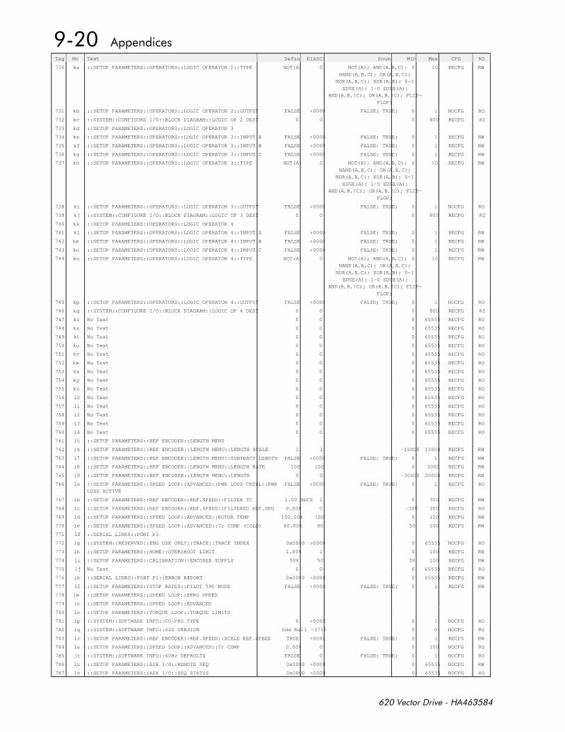
Tag Mn Text DefaultEIASCII Enum Min Max CFG RO
730 ka ::SETUP PARAMETERS::OPERATORS::LOGIC OPERATOR 2::TYPE NOT(A) 0 NOT(A); AND(A,B,C);
NAND(A,B,C); OR(A,B,C);
NOR(A,B,C); XOR(A,B); 0-1
EDGE(A); 1-0 EDGE(A);
AND(A,B,!C); OR(A,B,!C); FLIP-
FLOP;
0 10 RECFG RW
731 kb ::SETUP PARAMETERS::OPERATORS::LOGIC OPERATOR 2::OUTPUT FALSE >0000 FALSE; TRUE; 0 1 NOCFG RO
732 kc ::SYSTEM::CONFIGURE I/O::BLOCK DIAGRAM::LOGIC OP 2 DEST 0 0 0 800 RECFG RI
733 kd ::SETUP PARAMETERS::OPERATORS::LOGIC OPERATOR 3
734 ke ::SETUP PARAMETERS::OPERATORS::LOGIC OPERATOR 3::INPUT A FALSE >0000 FALSE; TRUE; 0 1 RECFG RW
735 kf ::SETUP PARAMETERS::OPERATORS::LOGIC OPERATOR 3::INPUT B FALSE >0000 FALSE; TRUE; 0 1 RECFG RW
736 kg ::SETUP PARAMETERS::OPERATORS::LOGIC OPERATOR 3::INPUT C FALSE >0000 FALSE; TRUE; 0 1 RECFG RW
737 kh ::SETUP PARAMETERS::OPERATORS::LOGIC OPERATOR 3::TYPE NOT(A) 0 NOT(A); AND(A,B,C);
NAND(A,B,C); OR(A,B,C);
NOR(A,B,C); XOR(A,B); 0-1
EDGE(A); 1-0 EDGE(A);
AND(A,B,!C); OR(A,B,!C); FLIP-
FLOP;
0 10 RECFG RW
738 ki ::SETUP PARAMETERS::OPERATORS::LOGIC OPERATOR 3::OUTPUT FALSE >0000 FALSE; TRUE; 0 1 NOCFG RO
739 kj ::SYSTEM::CONFIGURE I/O::BLOCK DIAGRAM::LOGIC OP 3 DEST 0 0 0 800 RECFG RI
740 kk ::SETUP PARAMETERS::OPERATORS::LOGIC OPERATOR 4
741 kl ::SETUP PARAMETERS::OPERATORS::LOGIC OPERATOR 4::INPUT A FALSE >0000 FALSE; TRUE; 0 1 RECFG RW
742 km ::SETUP PARAMETERS::OPERATORS::LOGIC OPERATOR 4::INPUT B FALSE >0000 FALSE; TRUE; 0 1 RECFG RW
743 kn ::SETUP PARAMETERS::OPERATORS::LOGIC OPERATOR 4::INPUT C FALSE >0000 FALSE; TRUE; 0 1 RECFG RW
744 ko ::SETUP PARAMETERS::OPERATORS::LOGIC OPERATOR 4::TYPE NOT(A) 0 NOT(A); AND(A,B,C);
NAND(A,B,C); OR(A,B,C);
NOR(A,B,C); XOR(A,B); 0-1
EDGE(A); 1-0 EDGE(A);
AND(A,B,!C); OR(A,B,!C); FLIP-
FLOP;
0 10 RECFG RW
745 kp ::SETUP PARAMETERS::OPERATORS::LOGIC OPERATOR 4::OUTPUT FALSE >0000 FALSE; TRUE; 0 1 NOCFG RO
746 kq ::SYSTEM::CONFIGURE I/O::BLOCK DIAGRAM::LOGIC OP 4 DEST 0 0 0 800 RECFG RI
747 kr No Text 0 0 0 65535 RECFG RO
748 ks No Text 0 0 0 65535 RECFG RO
749 kt No Text 0 0 0 65535 RECFG RO
750 ku No Text 0 0 0 65535 RECFG RO
751 kv No Text 0 0 0 65535 RECFG RO
752 kw No Text 0 0 0 65535 RECFG RO
753 kx No Text 0 0 0 65535 RECFG RO
754 ky No Text 0 0 0 65535 RECFG RO
755 kz No Text 0 0 0 65535 RECFG RO
756 l0 No Text 0 0 0 65535 RECFG RO
757 l1 No Text 0 0 0 65535 RECFG RO
758 l2 No Text 0 0 0 65535 RECFG RO
759 l3 No Text 0 0 0 65535 RECFG RO
760 l4 No Text 0 0 0 65535 RECFG RO
761 l5 ::SETUP PARAMETERS::REF ENCODER::LENGTH MENU
762 l6 ::SETUP PARAMETERS::REF ENCODER::LENGTH MENU::LENGTH SCALE 1 1 -15000 15000 RECFG RW
763 l7 ::SETUP PARAMETERS::REF ENCODER::LENGTH MENU::SUBTRACT LENGTH FALSE >0000 FALSE; TRUE; 0 1 RECFG RW
764 l8 ::SETUP PARAMETERS::REF ENCODER::LENGTH MENU::LENGTH RATE 100 100 0 3000 RECFG RW
765 l9 ::SETUP PARAMETERS::REF ENCODER::LENGTH MENU::LENGTH 0 0 -30000 30000 RECFG RW
766 la ::SETUP PARAMETERS::SPEED LOOP::ADVANCED::PWR LOSS CNTRL::PWR
LOSS ACTIVE
FALSE >0000 FALSE; TRUE; 0 1 RECFG RO
767 lb ::SETUP PARAMETERS::REF ENCODER::REF.SPEED::FILTER TC 1.00 SECS 1 0 300 RECFG RW
768 lc ::SETUP PARAMETERS::REF ENCODER::REF.SPEED::FILTERED REF.SPD 0.00% 0 -300 300 RECFG RO
769 ld ::SETUP PARAMETERS::SPEED LOOP::ADVANCED::ROTOR TEMP 100.00% 100 0 100 RECFG RW
770 le ::SETUP PARAMETERS::SPEED LOOP::ADVANCED::Tr COMP (COLD) 80.00% 80 50 100 RECFG RW
771 lf ::SERIAL LINKS::PORT P3
772 lg ::SYSTEM::RESERVED::ENG USE ONLY::TRACE::TRACE INDEX 0x0000 >0000 0 65535 NOCFG RO
773 lh ::SETUP PARAMETERS::HOME::OVERSHOOT LIMIT 1.00% 1 0 100 RECFG RW
774 li ::SETUP PARAMETERS::CALIBRATION::ENCODER SUPPLY 50% 50 50 100 RECFG RW
775 lj No Text 0 0 0 65535 RECFG RO
776 lk ::SERIAL LINKS::PORT P1::ERROR REPORT 0x0000 >0000 0 65535 RECFG RW
777 ll ::SETUP PARAMETERS::STOP RATES::PILOT 590 MODE FALSE >0000 FALSE; TRUE; 0 1 RECFG RW
778 lm ::SETUP PARAMETERS::SPEED LOOP::ZERO SPEED
779 ln ::SETUP PARAMETERS::SPEED LOOP::ADVANCED
780 lo ::SETUP PARAMETERS::TORQUE LOOP::TORQUE LIMITS
781 lp ::SYSTEM::SOFTWARE INFO::CO-PRO TYPE 0 >0000 0 1 NOCFG RO
782 lq ::SYSTEM::SOFTWARE INFO::620 VERSION Odd Ball -3712 0 0 NOCFG RO
783 lr ::SETUP PARAMETERS::REF ENCODER::REF.SPEED::SCALE REF.SPEED TRUE >0001 FALSE; TRUE; 0 1 RECFG RW
784 ls ::SETUP PARAMETERS::SPEED LOOP::ADVANCED::Tr COMP 0.00% 0 0 100 NOCFG RO
785 lt ::SYSTEM::SOFTWARE INFO::60Hz DEFAULTS FALSE 0 FALSE; TRUE; 0 1 NOCFG RO
786 lu ::SETUP PARAMETERS::AUX I/O::REMOTE SEQ 0x0000 >0000 0 65535 NOCFG RW
787 lv ::SETUP PARAMETERS::AUX I/O::SEQ STATUS 0x0000 >0000 0 65535 NOCFG RO

Tag Mn Text DefaultEIASCII Enum Min Max CFG RO
788 lw ::SETUP PARAMETERS::ALARMS / SEQ::REMOTE INHIBIT FALSE >0000 FALSE; TRUE; 0 1 RECFG RW
789 lx ::SETUP PARAMETERS::ALARMS / SEQ::REMOTE TRIP OK 0 OK; WARNING; ACTIVE; 0 2 NOCFG RO
790 ly ::SETUP PARAMETERS::ALARMS / SEQ::REMOTE DELAY 1 1 0 300 RECFG RW
791 lz ::SETUP PARAMETERS::AUX I/O::REM.SEQ.ENABLE FALSE >0000 FALSE; TRUE; 0 1 RECFG RI
792 m0 No Text 0 0 0 65535 RECFG RO
793 m1 No Text 0 0 0 65535 RECFG RO
794 m2 No Text 0 0 0 65535 RECFG RO
795 m3 No Text 0 0 0 65535 RECFG RO
796 m4 No Text 0 0 0 65535 RECFG RO
797 m5 No Text 0 0 0 65535 RECFG RO
798 m6 No Text 0 0 0 65535 RECFG RO
799 m7 No Text 0 0 0 65535 RECFG RO
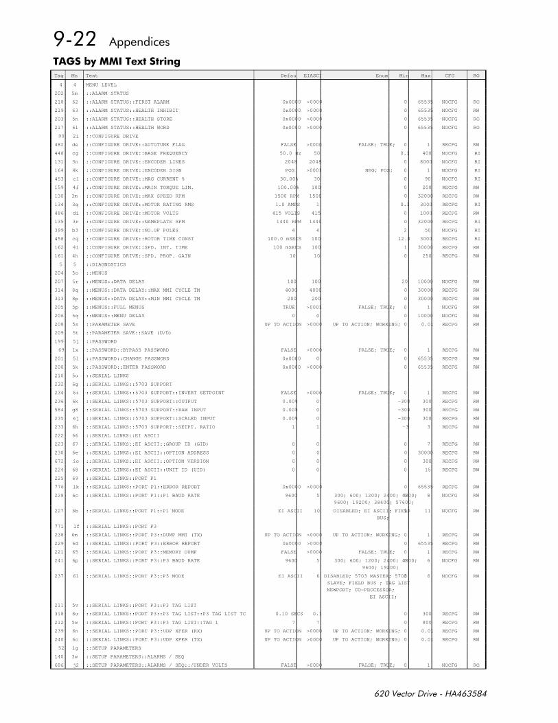
#12-Tag Mn Text Default EIASCII Enum Min Max CFG RO
4 4 MENU LEVEL
202 5m ::ALARM STATUS
218 62 ::ALARM STATUS::FIRST ALARM 0x0000 >0000 0 65535 NOCFG RO
219 63 ::ALARM STATUS::HEALTH INHIBIT 0x0000 >0000 0 65535 NOCFG RW
203 5n ::ALARM STATUS::HEALTH STORE 0x0000 >0000 0 65535 NOCFG RO
217 61 ::ALARM STATUS::HEALTH WORD 0x0000 >0000 0 65535 NOCFG RO
90 2i ::CONFIGURE DRIVE
482 de ::CONFIGURE DRIVE::AUTOTUNE FLAG FALSE >0000 FALSE; TRUE; 0 1 RECFG RW
448 cg ::CONFIGURE DRIVE::BASE FREQUENCY 50.0 Hz 50 0.1 400 NOCFG RI
131 3n ::CONFIGURE DRIVE::ENCODER LINES 2048 2048 0 8000 NOCFG RI
164 4k ::CONFIGURE DRIVE::ENCODER SIGN POS >0001 NEG; POS; 0 1 NOCFG RI
453 cl ::CONFIGURE DRIVE::MAG CURRENT % 30.00% 30 0 90 NOCFG RI
159 4f ::CONFIGURE DRIVE::MAIN TORQUE LIM. 100.00% 100 0 200 RECFG RW
130 3m ::CONFIGURE DRIVE::MAX SPEED RPM 1500 RPM 1500 0 32000 RECFG RW
134 3q ::CONFIGURE DRIVE::MOTOR RATING RMS 1.0 AMPS 1 0.1 3000 RECFG RI
486 di ::CONFIGURE DRIVE::MOTOR VOLTS 415 VOLTS 415 0 1000 RECFG RW
135 3r ::CONFIGURE DRIVE::NAMEPLATE RPM 1440 RPM 1440 0 32000 RECFG RI
399 b3 ::CONFIGURE DRIVE::NO.OF POLES 4 4 2 50 NOCFG RI
458 cq ::CONFIGURE DRIVE::ROTOR TIME CONST 100.0 mSECS 100 12.8 3000 RECFG RI
162 4i ::CONFIGURE DRIVE::SPD. INT. TIME 100 mSECS 100 1 30000 RECFG RW
161 4h ::CONFIGURE DRIVE::SPD. PROP. GAIN 10 10 0 250 RECFG RW
5 5 ::DIAGNOSTICS
204 5o ::MENUS
207 5r ::MENUS::DATA DELAY 100 100 20 10000 NOCFG RW
314 8q ::MENUS::DATA DELAY::MAX MMI CYCLE TM 4000 4000 0 30000 RECFG RW
313 8p ::MENUS::DATA DELAY::MIN MMI CYCLE TM 200 200 0 30000 RECFG RW
205 5p ::MENUS::FULL MENUS TRUE >0001 FALSE; TRUE; 0 1 NOCFG RW
206 5q ::MENUS::MENU DELAY 0 0 0 10000 NOCFG RW
208 5s ::PARAMETER SAVE UP TO ACTION >0000 UP TO ACTION; WORKING; 0 0.01 RECFG RW
209 5t ::PARAMETER SAVE::SAVE (U/D)
199 5j ::PASSWORD
69 1x ::PASSWORD::BYPASS PASSWORD FALSE >0000 FALSE; TRUE; 0 1 RECFG RW
201 5l ::PASSWORD::CHANGE PASSWORD 0x0000 0 0 65535 RECFG RW
200 5k ::PASSWORD::ENTER PASSWORD 0x0000 >0000 0 65535 RECFG RW
210 5u ::SERIAL LINKS
232 6g ::SERIAL LINKS::5703 SUPPORT
234 6i ::SERIAL LINKS::5703 SUPPORT::INVERT SETPOINT FALSE >0000 FALSE; TRUE; 0 1 RECFG RW
236 6k ::SERIAL LINKS::5703 SUPPORT::OUTPUT 0.00% 0 -300 300 RECFG RW
584 g8 ::SERIAL LINKS::5703 SUPPORT::RAW INPUT 0.00% 0 -300 300 RECFG RW
235 6j ::SERIAL LINKS::5703 SUPPORT::SCALED INPUT 0.00% 0 -300 300 RECFG RW
233 6h ::SERIAL LINKS::5703 SUPPORT::SETPT. RATIO 1 1 -3 3 RECFG RW
222 66 ::SERIAL LINKS::EI ASCII
223 67 ::SERIAL LINKS::EI ASCII::GROUP ID (GID) 0 0 0 7 RECFG RW
230 6e ::SERIAL LINKS::EI ASCII::OPTION ADDRESS 0 0 0 30000 RECFG RW
672 io ::SERIAL LINKS::EI ASCII::OPTION VERSION 0 0 0 300 RECFG RW
224 68 ::SERIAL LINKS::EI ASCII::UNIT ID (UID) 0 0 0 15 RECFG RW
225 69 ::SERIAL LINKS::PORT P1
776 lk ::SERIAL LINKS::PORT P1::ERROR REPORT 0x0000 >0000 0 65535 RECFG RW
228 6c ::SERIAL LINKS::PORT P1::P1 BAUD RATE 9600 5 300; 600; 1200; 2400; 4800;
9600; 19200; 38400; 57600;
0 8 NOCFG RW
227 6b ::SERIAL LINKS::PORT P1::P1 MODE EI ASCII 10 DISABLED; EI ASCII; FIELD
BUS;
9 11 NOCFG RW
771 lf ::SERIAL LINKS::PORT P3
238 6m ::SERIAL LINKS::PORT P3::DUMP MMI (TX) UP TO ACTION >0000 UP TO ACTION; WORKING; 0 1 RECFG RW
229 6d ::SERIAL LINKS::PORT P3::ERROR REPORT 0x0000 >0000 0 65535 RECFG RW
221 65 ::SERIAL LINKS::PORT P3::MEMORY DUMP FALSE >0000 FALSE; TRUE; 0 1 RECFG RW
241 6p ::SERIAL LINKS::PORT P3::P3 BAUD RATE 9600 5 300; 600; 1200; 2400; 4800;
9600; 19200;
0 6 NOCFG RW
237 6l ::SERIAL LINKS::PORT P3::P3 MODE EI ASCII 6 DISABLED; 5703 MASTER; 5703
SLAVE; FIELD BUS ; TAG LIST
NEWPORT; CO-PROCESSOR;
EI ASCII;
0 6 NOCFG RW
211 5v ::SERIAL LINKS::PORT P3::P3 TAG LIST
318 8u ::SERIAL LINKS::PORT P3::P3 TAG LIST::P3 TAG LIST TC 0.10 SECS 0.1 0 300 RECFG RW
212 5w ::SERIAL LINKS::PORT P3::P3 TAG LIST::TAG 1 7 7 0 800 RECFG RW
239 6n ::SERIAL LINKS::PORT P3::UDP XFER (RX) UP TO ACTION >0000 UP TO ACTION; WORKING; 0 0.01 RECFG RW
240 6o ::SERIAL LINKS::PORT P3::UDP XFER (TX) UP TO ACTION >0000 UP TO ACTION; WORKING; 0 0.01 RECFG RW
52 1g ::SETUP PARAMETERS
140 3w ::SETUP PARAMETERS::ALARMS / SEQ
686 j2 ::SETUP PARAMETERS::ALARMS / SEQ::/UNDER VOLTS FALSE >0000 FALSE; TRUE; 0 1 NOCFG RO
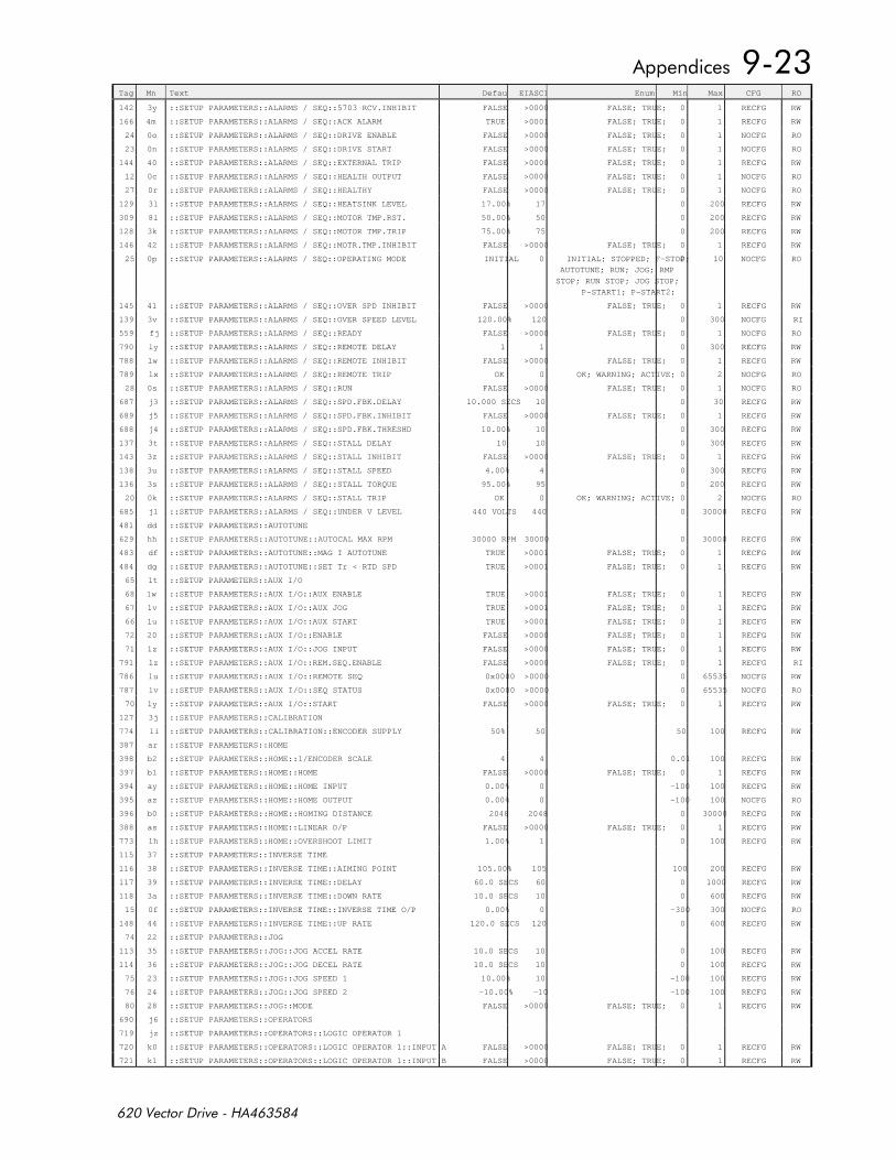
Tag Mn Text Default EIASCII Enum Min Max CFG RO
142 3y ::SETUP PARAMETERS::ALARMS / SEQ::5703 RCV.INHIBIT FALSE >0000 FALSE; TRUE; 0 1 RECFG RW
166 4m ::SETUP PARAMETERS::ALARMS / SEQ::ACK ALARM TRUE >0001 FALSE; TRUE; 0 1 RECFG RW
24 0o ::SETUP PARAMETERS::ALARMS / SEQ::DRIVE ENABLE FALSE >0000 FALSE; TRUE; 0 1 NOCFG RO
23 0n ::SETUP PARAMETERS::ALARMS / SEQ::DRIVE START FALSE >0000 FALSE; TRUE; 0 1 NOCFG RO
144 40 ::SETUP PARAMETERS::ALARMS / SEQ::EXTERNAL TRIP FALSE >0000 FALSE; TRUE; 0 1 RECFG RW
12 0c ::SETUP PARAMETERS::ALARMS / SEQ::HEALTH OUTPUT FALSE >0000 FALSE; TRUE; 0 1 NOCFG RO
27 0r ::SETUP PARAMETERS::ALARMS / SEQ::HEALTHY FALSE >0000 FALSE; TRUE; 0 1 NOCFG RO
129 3l ::SETUP PARAMETERS::ALARMS / SEQ::HEATSINK LEVEL 17.00% 17 0 200 RECFG RW
309 8l ::SETUP PARAMETERS::ALARMS / SEQ::MOTOR TMP.RST. 50.00% 50 0 200 RECFG RW
128 3k ::SETUP PARAMETERS::ALARMS / SEQ::MOTOR TMP.TRIP 75.00% 75 0 200 RECFG RW
146 42 ::SETUP PARAMETERS::ALARMS / SEQ::MOTR.TMP.INHIBIT FALSE >0000 FALSE; TRUE; 0 1 RECFG RW
25 0p ::SETUP PARAMETERS::ALARMS / SEQ::OPERATING MODE INITIAL 0 INITIAL; STOPPED; F-STOP;
AUTOTUNE; RUN; JOG; RMP
STOP; RUN STOP; JOG STOP;
P-START1; P-START2;
0 10 NOCFG RO
145 41 ::SETUP PARAMETERS::ALARMS / SEQ::OVER SPD INHIBIT FALSE >0000 FALSE; TRUE; 0 1 RECFG RW
139 3v ::SETUP PARAMETERS::ALARMS / SEQ::OVER SPEED LEVEL 120.00% 120 0 300 NOCFG RI
559 fj ::SETUP PARAMETERS::ALARMS / SEQ::READY FALSE >0000 FALSE; TRUE; 0 1 NOCFG RO
790 ly ::SETUP PARAMETERS::ALARMS / SEQ::REMOTE DELAY 1 1 0 300 RECFG RW
788 lw ::SETUP PARAMETERS::ALARMS / SEQ::REMOTE INHIBIT FALSE >0000 FALSE; TRUE; 0 1 RECFG RW
789 lx ::SETUP PARAMETERS::ALARMS / SEQ::REMOTE TRIP OK 0 OK; WARNING; ACTIVE; 0 2 NOCFG RO
28 0s ::SETUP PARAMETERS::ALARMS / SEQ::RUN FALSE >0000 FALSE; TRUE; 0 1 NOCFG RO
687 j3 ::SETUP PARAMETERS::ALARMS / SEQ::SPD.FBK.DELAY 10.000 SECS 10 0 30 RECFG RW
689 j5 ::SETUP PARAMETERS::ALARMS / SEQ::SPD.FBK.INHIBIT FALSE >0000 FALSE; TRUE; 0 1 RECFG RW
688 j4 ::SETUP PARAMETERS::ALARMS / SEQ::SPD.FBK.THRESHD 10.00% 10 0 300 RECFG RW
137 3t ::SETUP PARAMETERS::ALARMS / SEQ::STALL DELAY 10 10 0 300 RECFG RW
143 3z ::SETUP PARAMETERS::ALARMS / SEQ::STALL INHIBIT FALSE >0000 FALSE; TRUE; 0 1 RECFG RW
138 3u ::SETUP PARAMETERS::ALARMS / SEQ::STALL SPEED 4.00% 4 0 300 RECFG RW
136 3s ::SETUP PARAMETERS::ALARMS / SEQ::STALL TORQUE 95.00% 95 0 200 RECFG RW
20 0k ::SETUP PARAMETERS::ALARMS / SEQ::STALL TRIP OK 0 OK; WARNING; ACTIVE; 0 2 NOCFG RO
685 j1 ::SETUP PARAMETERS::ALARMS / SEQ::UNDER V LEVEL 440 VOLTS 440 0 30000 RECFG RW
481 dd ::SETUP PARAMETERS::AUTOTUNE
629 hh ::SETUP PARAMETERS::AUTOTUNE::AUTOCAL MAX RPM 30000 RPM 30000 0 30000 RECFG RW
483 df ::SETUP PARAMETERS::AUTOTUNE::MAG I AUTOTUNE TRUE >0001 FALSE; TRUE; 0 1 RECFG RW
484 dg ::SETUP PARAMETERS::AUTOTUNE::SET Tr < RTD SPD TRUE >0001 FALSE; TRUE; 0 1 RECFG RW
65 1t ::SETUP PARAMETERS::AUX I/O
68 1w ::SETUP PARAMETERS::AUX I/O::AUX ENABLE TRUE >0001 FALSE; TRUE; 0 1 RECFG RW
67 1v ::SETUP PARAMETERS::AUX I/O::AUX JOG TRUE >0001 FALSE; TRUE; 0 1 RECFG RW
66 1u ::SETUP PARAMETERS::AUX I/O::AUX START TRUE >0001 FALSE; TRUE; 0 1 RECFG RW
72 20 ::SETUP PARAMETERS::AUX I/O::ENABLE FALSE >0000 FALSE; TRUE; 0 1 RECFG RW
71 1z ::SETUP PARAMETERS::AUX I/O::JOG INPUT FALSE >0000 FALSE; TRUE; 0 1 RECFG RW
791 lz ::SETUP PARAMETERS::AUX I/O::REM.SEQ.ENABLE FALSE >0000 FALSE; TRUE; 0 1 RECFG RI
786 lu ::SETUP PARAMETERS::AUX I/O::REMOTE SEQ 0x0000 >0000 0 65535 NOCFG RW
787 lv ::SETUP PARAMETERS::AUX I/O::SEQ STATUS 0x0000 >0000 0 65535 NOCFG RO
70 1y ::SETUP PARAMETERS::AUX I/O::START FALSE >0000 FALSE; TRUE; 0 1 RECFG RW
127 3j ::SETUP PARAMETERS::CALIBRATION
774 li ::SETUP PARAMETERS::CALIBRATION::ENCODER SUPPLY 50% 50 50 100 RECFG RW
387 ar ::SETUP PARAMETERS::HOME
398 b2 ::SETUP PARAMETERS::HOME::1/ENCODER SCALE 4 4 0.01 100 RECFG RW
397 b1 ::SETUP PARAMETERS::HOME::HOME FALSE >0000 FALSE; TRUE; 0 1 RECFG RW
394 ay ::SETUP PARAMETERS::HOME::HOME INPUT 0.00% 0 -100 100 RECFG RW
395 az ::SETUP PARAMETERS::HOME::HOME OUTPUT 0.00% 0 -100 100 NOCFG RO
396 b0 ::SETUP PARAMETERS::HOME::HOMING DISTANCE 2048 2048 0 30000 RECFG RW
388 as ::SETUP PARAMETERS::HOME::LINEAR O/P FALSE >0000 FALSE; TRUE; 0 1 RECFG RW
773 lh ::SETUP PARAMETERS::HOME::OVERSHOOT LIMIT 1.00% 1 0 100 RECFG RW
115 37 ::SETUP PARAMETERS::INVERSE TIME
116 38 ::SETUP PARAMETERS::INVERSE TIME::AIMING POINT 105.00% 105 100 200 RECFG RW
117 39 ::SETUP PARAMETERS::INVERSE TIME::DELAY 60.0 SECS 60 0 1000 RECFG RW
118 3a ::SETUP PARAMETERS::INVERSE TIME::DOWN RATE 10.0 SECS 10 0 600 RECFG RW
15 0f ::SETUP PARAMETERS::INVERSE TIME::INVERSE TIME O/P 0.00% 0 -300 300 NOCFG RO
148 44 ::SETUP PARAMETERS::INVERSE TIME::UP RATE 120.0 SECS 120 0 600 RECFG RW
74 22 ::SETUP PARAMETERS::JOG
113 35 ::SETUP PARAMETERS::JOG::JOG ACCEL RATE 10.0 SECS 10 0 100 RECFG RW
114 36 ::SETUP PARAMETERS::JOG::JOG DECEL RATE 10.0 SECS 10 0 100 RECFG RW
75 23 ::SETUP PARAMETERS::JOG::JOG SPEED 1 10.00% 10 -100 100 RECFG RW
76 24 ::SETUP PARAMETERS::JOG::JOG SPEED 2 -10.00% -10 -100 100 RECFG RW
80 28 ::SETUP PARAMETERS::JOG::MODE FALSE >0000 FALSE; TRUE; 0 1 RECFG RW
690 j6 ::SETUP PARAMETERS::OPERATORS
719 jz ::SETUP PARAMETERS::OPERATORS::LOGIC OPERATOR 1
720 k0 ::SETUP PARAMETERS::OPERATORS::LOGIC OPERATOR 1::INPUT A FALSE >0000 FALSE; TRUE; 0 1 RECFG RW
721 k1 ::SETUP PARAMETERS::OPERATORS::LOGIC OPERATOR 1::INPUT B FALSE >0000 FALSE; TRUE; 0 1 RECFG RW
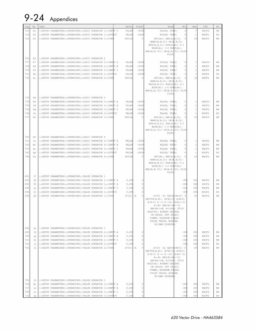
Tag Mn Text Default EIASCII Enum Min Max CFG RO
722 k2 ::SETUP PARAMETERS::OPERATORS::LOGIC OPERATOR 1::INPUT C FALSE >0000 FALSE; TRUE; 0 1 RECFG RW
724 k4 ::SETUP PARAMETERS::OPERATORS::LOGIC OPERATOR 1::OUTPUT FALSE >0000 FALSE; TRUE; 0 1 NOCFG RO
723 k3 ::SETUP PARAMETERS::OPERATORS::LOGIC OPERATOR 1::TYPE NOT(A) 0 NOT(A); AND(A,B,C);
NAND(A,B,C); OR(A,B,C);
NOR(A,B,C); XOR(A,B); 0-1
EDGE(A); 1-0 EDGE(A);
AND(A,B,!C); OR(A,B,!C); FLIP-
FLOP;
0 10 RECFG RW
726 k6 ::SETUP PARAMETERS::OPERATORS::LOGIC OPERATOR 2
727 k7 ::SETUP PARAMETERS::OPERATORS::LOGIC OPERATOR 2::INPUT A FALSE >0000 FALSE; TRUE; 0 1 RECFG RW
728 k8 ::SETUP PARAMETERS::OPERATORS::LOGIC OPERATOR 2::INPUT B FALSE >0000 FALSE; TRUE; 0 1 RECFG RW
729 k9 ::SETUP PARAMETERS::OPERATORS::LOGIC OPERATOR 2::INPUT C FALSE >0000 FALSE; TRUE; 0 1 RECFG RW
731 kb ::SETUP PARAMETERS::OPERATORS::LOGIC OPERATOR 2::OUTPUT FALSE >0000 FALSE; TRUE; 0 1 NOCFG RO
730 ka ::SETUP PARAMETERS::OPERATORS::LOGIC OPERATOR 2::TYPE NOT(A) 0 NOT(A); AND(A,B,C);
NAND(A,B,C); OR(A,B,C);
NOR(A,B,C); XOR(A,B); 0-1
EDGE(A); 1-0 EDGE(A);
AND(A,B,!C); OR(A,B,!C); FLIP-
FLOP;
0 10 RECFG RW
733 kd ::SETUP PARAMETERS::OPERATORS::LOGIC OPERATOR 3
734 ke ::SETUP PARAMETERS::OPERATORS::LOGIC OPERATOR 3::INPUT A FALSE >0000 FALSE; TRUE; 0 1 RECFG RW
735 kf ::SETUP PARAMETERS::OPERATORS::LOGIC OPERATOR 3::INPUT B FALSE >0000 FALSE; TRUE; 0 1 RECFG RW
736 kg ::SETUP PARAMETERS::OPERATORS::LOGIC OPERATOR 3::INPUT C FALSE >0000 FALSE; TRUE; 0 1 RECFG RW
738 ki ::SETUP PARAMETERS::OPERATORS::LOGIC OPERATOR 3::OUTPUT FALSE >0000 FALSE; TRUE; 0 1 NOCFG RO
737 kh ::SETUP PARAMETERS::OPERATORS::LOGIC OPERATOR 3::TYPE NOT(A) 0 NOT(A); AND(A,B,C);
NAND(A,B,C); OR(A,B,C);
NOR(A,B,C); XOR(A,B); 0-1
EDGE(A); 1-0 EDGE(A);
AND(A,B,!C); OR(A,B,!C); FLIP-
FLOP;
0 10 RECFG RW
740 kk ::SETUP PARAMETERS::OPERATORS::LOGIC OPERATOR 4
741 kl ::SETUP PARAMETERS::OPERATORS::LOGIC OPERATOR 4::INPUT A FALSE >0000 FALSE; TRUE; 0 1 RECFG RW
742 km ::SETUP PARAMETERS::OPERATORS::LOGIC OPERATOR 4::INPUT B FALSE >0000 FALSE; TRUE; 0 1 RECFG RW
743 kn ::SETUP PARAMETERS::OPERATORS::LOGIC OPERATOR 4::INPUT C FALSE >0000 FALSE; TRUE; 0 1 RECFG RW
745 kp ::SETUP PARAMETERS::OPERATORS::LOGIC OPERATOR 4::OUTPUT FALSE >0000 FALSE; TRUE; 0 1 NOCFG RO
744 ko ::SETUP PARAMETERS::OPERATORS::LOGIC OPERATOR 4::TYPE NOT(A) 0 NOT(A); AND(A,B,C);
NAND(A,B,C); OR(A,B,C);
NOR(A,B,C); XOR(A,B); 0-1
EDGE(A); 1-0 EDGE(A);
AND(A,B,!C); OR(A,B,!C); FLIP-
FLOP;
0 10 RECFG RW
691 j7 ::SETUP PARAMETERS::OPERATORS::VALUE OPERATOR 1
692 j8 ::SETUP PARAMETERS::OPERATORS::VALUE OPERATOR 1::INPUT A 0.00% 0 -300 300 RECFG RW
693 j9 ::SETUP PARAMETERS::OPERATORS::VALUE OPERATOR 1::INPUT B 0.00% 0 -300 300 RECFG RW
694 ja ::SETUP PARAMETERS::OPERATORS::VALUE OPERATOR 1::INPUT C 0.00% 0 -300 300 RECFG RW
696 jc ::SETUP PARAMETERS::OPERATORS::VALUE OPERATOR 1::OUTPUT 0.00% 0 -300 300 NOCFG RO
695 jb ::SETUP PARAMETERS::OPERATORS::VALUE OPERATOR 1::TYPE IF(C) -A 0 IF(C) -A; ABS(A+B+C);
SWITCH(A,B); (A*B)/C; A+B+C;
A-B-C; B <= A <=C; A>B+/-C;
A>=B; ABS(A)>B+/-C;
ABS(A)>=B; A(1+B); IF(C)
HOLD(A); BINARY DECODE;
ON DELAY; OFF DELAY;
TIMER; MINIMUM PULSE;
PULSE TRAIN; WINDOW;
UP/DWN COUNTER;
0 20 RECFG RW
698 je ::SETUP PARAMETERS::OPERATORS::VALUE OPERATOR 2
699 jf ::SETUP PARAMETERS::OPERATORS::VALUE OPERATOR 2::INPUT A 0.00% 0 -300 300 RECFG RW
700 jg ::SETUP PARAMETERS::OPERATORS::VALUE OPERATOR 2::INPUT B 0.00% 0 -300 300 RECFG RW
701 jh ::SETUP PARAMETERS::OPERATORS::VALUE OPERATOR 2::INPUT C 0.00% 0 -300 300 RECFG RW
703 jj ::SETUP PARAMETERS::OPERATORS::VALUE OPERATOR 2::OUTPUT 0.00% 0 -300 300 NOCFG RO
702 ji ::SETUP PARAMETERS::OPERATORS::VALUE OPERATOR 2::TYPE IF(C) -A 0 IF(C) -A; ABS(A+B+C);
SWITCH(A,B); (A*B)/C; A+B+C;
A-B-C; B <= A <=C; A>B+/-C;
A>=B; ABS(A)>B+/-C;
ABS(A)>=B; A(1+B); IF(C)
HOLD(A); BINARY DECODE;
ON DELAY; OFF DELAY;
TIMER; MINIMUM PULSE;
PULSE TRAIN; WINDOW;
UP/DWN COUNTER;
0 20 RECFG RW
705 jl ::SETUP PARAMETERS::OPERATORS::VALUE OPERATOR 3
706 jm ::SETUP PARAMETERS::OPERATORS::VALUE OPERATOR 3::INPUT A 0.00% 0 -300 300 RECFG RW
707 jn ::SETUP PARAMETERS::OPERATORS::VALUE OPERATOR 3::INPUT B 0.00% 0 -300 300 RECFG RW
708 jo ::SETUP PARAMETERS::OPERATORS::VALUE OPERATOR 3::INPUT C 0.00% 0 -300 300 RECFG RW
710 jq ::SETUP PARAMETERS::OPERATORS::VALUE OPERATOR 3::OUTPUT 0.00% 0 -300 300 NOCFG RO
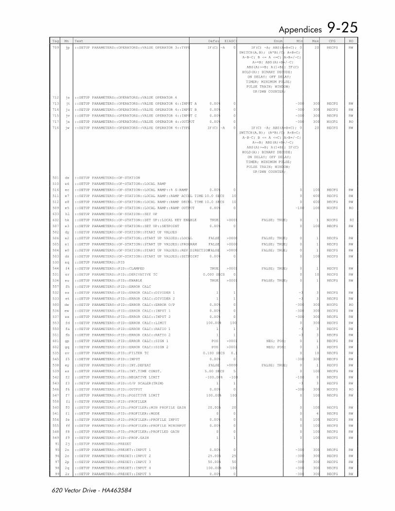
Tag Mn Text Default EIASCII Enum Min Max CFG RO
709 jp ::SETUP PARAMETERS::OPERATORS::VALUE OPERATOR 3::TYPE IF(C) -A 0 IF(C) -A; ABS(A+B+C);
SWITCH(A,B); (A*B)/C; A+B+C;
A-B-C; B <= A <=C; A>B+/-C;
A>=B; ABS(A)>B+/-C;
ABS(A)>=B; A(1+B); IF(C)
HOLD(A); BINARY DECODE;
ON DELAY; OFF DELAY;
TIMER; MINIMUM PULSE;
PULSE TRAIN; WINDOW;
UP/DWN COUNTER;
0 20 RECFG RW
712 js ::SETUP PARAMETERS::OPERATORS::VALUE OPERATOR 4
713 jt ::SETUP PARAMETERS::OPERATORS::VALUE OPERATOR 4::INPUT A 0.00% 0 -300 300 RECFG RW
714 ju ::SETUP PARAMETERS::OPERATORS::VALUE OPERATOR 4::INPUT B 0.00% 0 -300 300 RECFG RW
715 jv ::SETUP PARAMETERS::OPERATORS::VALUE OPERATOR 4::INPUT C 0.00% 0 -300 300 RECFG RW
717 jx ::SETUP PARAMETERS::OPERATORS::VALUE OPERATOR 4::OUTPUT 0.00% 0 -300 300 NOCFG RO
716 jw ::SETUP PARAMETERS::OPERATORS::VALUE OPERATOR 4::TYPE IF(C) -A 0 IF(C) -A; ABS(A+B+C);
SWITCH(A,B); (A*B)/C; A+B+C;
A-B-C; B <= A <=C; A>B+/-C;
A>=B; ABS(A)>B+/-C;
ABS(A)>=B; A(1+B); IF(C)
HOLD(A); BINARY DECODE;
ON DELAY; OFF DELAY;
TIMER; MINIMUM PULSE;
PULSE TRAIN; WINDOW;
UP/DWN COUNTER;
0 20 RECFG RW
501 dx ::SETUP PARAMETERS::OP-STATION
510 e6 ::SETUP PARAMETERS::OP-STATION::LOCAL RAMP
516 ec ::SETUP PARAMETERS::OP-STATION::LOCAL RAMP::% S-RAMP 0.00% 0 0 100 RECFG RW
511 e7 ::SETUP PARAMETERS::OP-STATION::LOCAL RAMP::RAMP ACCEL TIME 10.0 SECS 10 0 600 RECFG RW
512 e8 ::SETUP PARAMETERS::OP-STATION::LOCAL RAMP::RAMP DECEL TIME 10.0 SECS 10 0 600 RECFG RW
509 e5 ::SETUP PARAMETERS::OP-STATION::LOCAL RAMP::RAMP OUTPUT 0.00% 0 -100 100 NOCFG RO
633 hl ::SETUP PARAMETERS::OP-STATION::SET UP
632 hk ::SETUP PARAMETERS::OP-STATION::SET UP::LOCAL KEY ENABLE TRUE >0001 FALSE; TRUE; 0 1 NOCFG RI
507 e3 ::SETUP PARAMETERS::OP-STATION::SET UP::SETPOINT 0.00% 0 0 100 RECFG RW
502 dy ::SETUP PARAMETERS::OP-STATION::START UP VALUES
506 e2 ::SETUP PARAMETERS::OP-STATION::START UP VALUES::LOCAL FALSE >0000 FALSE; TRUE; 0 1 RECFG RW
505 e1 ::SETUP PARAMETERS::OP-STATION::START UP VALUES::PROGRAM FALSE >0000 FALSE; TRUE; 0 1 RECFG RW
504 e0 ::SETUP PARAMETERS::OP-STATION::START UP VALUES::REV DIRECTIONFALSE >0000 FALSE; TRUE; 0 1 RECFG RW
503 dz ::SETUP PARAMETERS::OP-STATION::START UP VALUES::SETPOINT 0.00% 0 0 100 RECFG RW
530 eq ::SETUP PARAMETERS::PID
544 f4 ::SETUP PARAMETERS::PID::CLAMPED TRUE >0001 FALSE; TRUE; 0 1 RECFG RW
531 er ::SETUP PARAMETERS::PID::DERIVATIVE TC 0.000 SECS 0 0 10 RECFG RW
534 eu ::SETUP PARAMETERS::PID::ENABLE TRUE >0001 FALSE; TRUE; 0 1 RECFG RW
557 fh ::SETUP PARAMETERS::PID::ERROR CALC
532 es ::SETUP PARAMETERS::PID::ERROR CALC::DIVIDER 1 1 1 -3 3 RECFG RW
533 et ::SETUP PARAMETERS::PID::ERROR CALC::DIVIDER 2 1 1 -3 3 RECFG RW
500 dw ::SETUP PARAMETERS::PID::ERROR CALC::ERROR O/P 0.00% 0 -300 300 NOCFG RO
536 ew ::SETUP PARAMETERS::PID::ERROR CALC::INPUT 1 0.00% 0 -300 300 RECFG RW
537 ex ::SETUP PARAMETERS::PID::ERROR CALC::INPUT 2 0.00% 0 -300 300 RECFG RW
553 fd ::SETUP PARAMETERS::PID::ERROR CALC::LIMIT 100.00% 100 0 300 RECFG RW
550 fa ::SETUP PARAMETERS::PID::ERROR CALC::RATIO 1 1 1 -3 3 RECFG RW
551 fb ::SETUP PARAMETERS::PID::ERROR CALC::RATIO 2 1 1 -3 3 RECFG RW
601 gp ::SETUP PARAMETERS::PID::ERROR CALC::SIGN 1 POS >0001 NEG; POS; 0 1 RECFG RW
602 gq ::SETUP PARAMETERS::PID::ERROR CALC::SIGN 2 POS >0001 NEG; POS; 0 1 RECFG RW
535 ev ::SETUP PARAMETERS::PID::FILTER TC 0.100 SECS 0.1 0 10 RECFG RW
545 f5 ::SETUP PARAMETERS::PID::INPUT 0.00% 0 -300 300 RECFG RW
538 ey ::SETUP PARAMETERS::PID::INT.DEFEAT FALSE >0000 FALSE; TRUE; 0 1 RECFG RW
539 ez ::SETUP PARAMETERS::PID::INT.TIME CONST. 5.00 SECS 5 0 100 RECFG RW
542 f2 ::SETUP PARAMETERS::PID::NEGATIVE LIMIT -100.00% -100 -100 0 RECFG RW
543 f3 ::SETUP PARAMETERS::PID::O/P SCALER(TRIM) 1 1 -3 3 RECFG RW
546 f6 ::SETUP PARAMETERS::PID::OUTPUT 0.00% 0 -300 300 NOCFG RO
547 f7 ::SETUP PARAMETERS::PID::POSITIVE LIMIT 100.00% 100 0 100 RECFG RW
558 fi ::SETUP PARAMETERS::PID::PROFILER
540 f0 ::SETUP PARAMETERS::PID::PROFILER::MIN PROFILE GAIN 20.00% 20 0 100 RECFG RW
541 f1 ::SETUP PARAMETERS::PID::PROFILER::MODE 0 0 0 4 RECFG RW
554 fe ::SETUP PARAMETERS::PID::PROFILER::PROFILE INPUT 0.00% 0 0 100 RECFG RW
555 ff ::SETUP PARAMETERS::PID::PROFILER::PROFILE MININPUT 0.00% 0 0 100 RECFG RW
548 f8 ::SETUP PARAMETERS::PID::PROFILER::PROFILED GAIN 0 0 0 100 RECFG RW
549 f9 ::SETUP PARAMETERS::PID::PROP.GAIN 1 1 0 100 RECFG RW
91 2j ::SETUP PARAMETERS::PRESET
95 2n ::SETUP PARAMETERS::PRESET::INPUT 1 0.00% 0 -300 300 RECFG RW
96 2o ::SETUP PARAMETERS::PRESET::INPUT 2 25.00% 25 -300 300 RECFG RW
97 2p ::SETUP PARAMETERS::PRESET::INPUT 3 50.00% 50 -300 300 RECFG RW
98 2q ::SETUP PARAMETERS::PRESET::INPUT 4 100.00% 100 -300 300 RECFG RW
99 2r ::SETUP PARAMETERS::PRESET::INPUT 5 0.00% 0 -300 300 RECFG RW
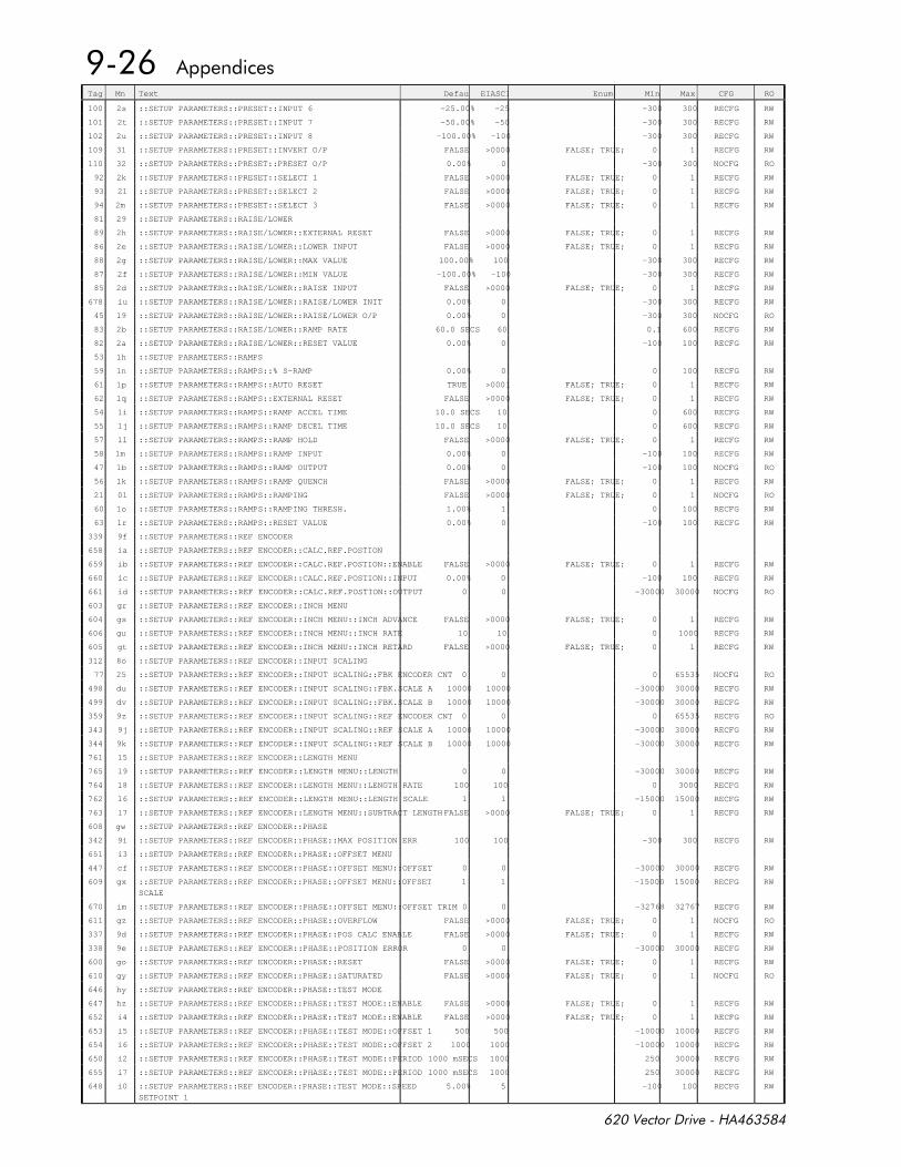
Tag Mn Text Default EIASCII Enum Min Max CFG RO
100 2s ::SETUP PARAMETERS::PRESET::INPUT 6 -25.00% -25 -300 300 RECFG RW
101 2t ::SETUP PARAMETERS::PRESET::INPUT 7 -50.00% -50 -300 300 RECFG RW
102 2u ::SETUP PARAMETERS::PRESET::INPUT 8 -100.00% -100 -300 300 RECFG RW
109 31 ::SETUP PARAMETERS::PRESET::INVERT O/P FALSE >0000 FALSE; TRUE; 0 1 RECFG RW
110 32 ::SETUP PARAMETERS::PRESET::PRESET O/P 0.00% 0 -300 300 NOCFG RO
92 2k ::SETUP PARAMETERS::PRESET::SELECT 1 FALSE >0000 FALSE; TRUE; 0 1 RECFG RW
93 2l ::SETUP PARAMETERS::PRESET::SELECT 2 FALSE >0000 FALSE; TRUE; 0 1 RECFG RW
94 2m ::SETUP PARAMETERS::PRESET::SELECT 3 FALSE >0000 FALSE; TRUE; 0 1 RECFG RW
81 29 ::SETUP PARAMETERS::RAISE/LOWER
89 2h ::SETUP PARAMETERS::RAISE/LOWER::EXTERNAL RESET FALSE >0000 FALSE; TRUE; 0 1 RECFG RW
86 2e ::SETUP PARAMETERS::RAISE/LOWER::LOWER INPUT FALSE >0000 FALSE; TRUE; 0 1 RECFG RW
88 2g ::SETUP PARAMETERS::RAISE/LOWER::MAX VALUE 100.00% 100 -300 300 RECFG RW
87 2f ::SETUP PARAMETERS::RAISE/LOWER::MIN VALUE -100.00% -100 -300 300 RECFG RW
85 2d ::SETUP PARAMETERS::RAISE/LOWER::RAISE INPUT FALSE >0000 FALSE; TRUE; 0 1 RECFG RW
678 iu ::SETUP PARAMETERS::RAISE/LOWER::RAISE/LOWER INIT 0.00% 0 -300 300 RECFG RW
45 19 ::SETUP PARAMETERS::RAISE/LOWER::RAISE/LOWER O/P 0.00% 0 -300 300 NOCFG RO
83 2b ::SETUP PARAMETERS::RAISE/LOWER::RAMP RATE 60.0 SECS 60 0.1 600 RECFG RW
82 2a ::SETUP PARAMETERS::RAISE/LOWER::RESET VALUE 0.00% 0 -100 100 RECFG RW
53 1h ::SETUP PARAMETERS::RAMPS
59 1n ::SETUP PARAMETERS::RAMPS::% S-RAMP 0.00% 0 0 100 RECFG RW
61 1p ::SETUP PARAMETERS::RAMPS::AUTO RESET TRUE >0001 FALSE; TRUE; 0 1 RECFG RW
62 1q ::SETUP PARAMETERS::RAMPS::EXTERNAL RESET FALSE >0000 FALSE; TRUE; 0 1 RECFG RW
54 1i ::SETUP PARAMETERS::RAMPS::RAMP ACCEL TIME 10.0 SECS 10 0 600 RECFG RW
55 1j ::SETUP PARAMETERS::RAMPS::RAMP DECEL TIME 10.0 SECS 10 0 600 RECFG RW
57 1l ::SETUP PARAMETERS::RAMPS::RAMP HOLD FALSE >0000 FALSE; TRUE; 0 1 RECFG RW
58 1m ::SETUP PARAMETERS::RAMPS::RAMP INPUT 0.00% 0 -100 100 RECFG RW
47 1b ::SETUP PARAMETERS::RAMPS::RAMP OUTPUT 0.00% 0 -100 100 NOCFG RO
56 1k ::SETUP PARAMETERS::RAMPS::RAMP QUENCH FALSE >0000 FALSE; TRUE; 0 1 RECFG RW
21 0l ::SETUP PARAMETERS::RAMPS::RAMPING FALSE >0000 FALSE; TRUE; 0 1 NOCFG RO
60 1o ::SETUP PARAMETERS::RAMPS::RAMPING THRESH. 1.00% 1 0 100 RECFG RW
63 1r ::SETUP PARAMETERS::RAMPS::RESET VALUE 0.00% 0 -100 100 RECFG RW
339 9f ::SETUP PARAMETERS::REF ENCODER
658 ia ::SETUP PARAMETERS::REF ENCODER::CALC.REF.POSTION
659 ib ::SETUP PARAMETERS::REF ENCODER::CALC.REF.POSTION::ENABLE FALSE >0000 FALSE; TRUE; 0 1 RECFG RW
660 ic ::SETUP PARAMETERS::REF ENCODER::CALC.REF.POSTION::INPUT 0.00% 0 -100 100 RECFG RW
661 id ::SETUP PARAMETERS::REF ENCODER::CALC.REF.POSTION::OUTPUT 0 0 -30000 30000 NOCFG RO
603 gr ::SETUP PARAMETERS::REF ENCODER::INCH MENU
604 gs ::SETUP PARAMETERS::REF ENCODER::INCH MENU::INCH ADVANCE FALSE >0000 FALSE; TRUE; 0 1 RECFG RW
606 gu ::SETUP PARAMETERS::REF ENCODER::INCH MENU::INCH RATE 10 10 0 1000 RECFG RW
605 gt ::SETUP PARAMETERS::REF ENCODER::INCH MENU::INCH RETARD FALSE >0000 FALSE; TRUE; 0 1 RECFG RW
312 8o ::SETUP PARAMETERS::REF ENCODER::INPUT SCALING
77 25 ::SETUP PARAMETERS::REF ENCODER::INPUT SCALING::FBK ENCODER CNT 0 0 0 65535 NOCFG RO
498 du ::SETUP PARAMETERS::REF ENCODER::INPUT SCALING::FBK.SCALE A 10000 10000 -30000 30000 RECFG RW
499 dv ::SETUP PARAMETERS::REF ENCODER::INPUT SCALING::FBK.SCALE B 10000 10000 -30000 30000 RECFG RW
359 9z ::SETUP PARAMETERS::REF ENCODER::INPUT SCALING::REF ENCODER CNT 0 0 0 65535 RECFG RO
343 9j ::SETUP PARAMETERS::REF ENCODER::INPUT SCALING::REF SCALE A 10000 10000 -30000 30000 RECFG RW
344 9k ::SETUP PARAMETERS::REF ENCODER::INPUT SCALING::REF SCALE B 10000 10000 -30000 30000 RECFG RW
761 l5 ::SETUP PARAMETERS::REF ENCODER::LENGTH MENU
765 l9 ::SETUP PARAMETERS::REF ENCODER::LENGTH MENU::LENGTH 0 0 -30000 30000 RECFG RW
764 l8 ::SETUP PARAMETERS::REF ENCODER::LENGTH MENU::LENGTH RATE 100 100 0 3000 RECFG RW
762 l6 ::SETUP PARAMETERS::REF ENCODER::LENGTH MENU::LENGTH SCALE 1 1 -15000 15000 RECFG RW
763 l7 ::SETUP PARAMETERS::REF ENCODER::LENGTH MENU::SUBTRACT LENGTH FALSE >0000 FALSE; TRUE; 0 1 RECFG RW
608 gw ::SETUP PARAMETERS::REF ENCODER::PHASE
342 9i ::SETUP PARAMETERS::REF ENCODER::PHASE::MAX POSITION ERR 100 100 -300 300 RECFG RW
651 i3 ::SETUP PARAMETERS::REF ENCODER::PHASE::OFFSET MENU
447 cf ::SETUP PARAMETERS::REF ENCODER::PHASE::OFFSET MENU::OFFSET 0 0 -30000 30000 RECFG RW
609 gx ::SETUP PARAMETERS::REF ENCODER::PHASE::OFFSET MENU::OFFSET
SCALE
1 1 -15000 15000 RECFG RW
670 im ::SETUP PARAMETERS::REF ENCODER::PHASE::OFFSET MENU::OFFSET TRIM 0 0 -32768 32767 RECFG RW
611 gz ::SETUP PARAMETERS::REF ENCODER::PHASE::OVERFLOW FALSE >0000 FALSE; TRUE; 0 1 NOCFG RO
337 9d ::SETUP PARAMETERS::REF ENCODER::PHASE::POS CALC ENABLE FALSE >0000 FALSE; TRUE; 0 1 RECFG RW
338 9e ::SETUP PARAMETERS::REF ENCODER::PHASE::POSITION ERROR 0 0 -30000 30000 RECFG RW
600 go ::SETUP PARAMETERS::REF ENCODER::PHASE::RESET FALSE >0000 FALSE; TRUE; 0 1 RECFG RW
610 gy ::SETUP PARAMETERS::REF ENCODER::PHASE::SATURATED FALSE >0000 FALSE; TRUE; 0 1 NOCFG RO
646 hy ::SETUP PARAMETERS::REF ENCODER::PHASE::TEST MODE
647 hz ::SETUP PARAMETERS::REF ENCODER::PHASE::TEST MODE::ENABLE FALSE >0000 FALSE; TRUE; 0 1 RECFG RW
652 i4 ::SETUP PARAMETERS::REF ENCODER::PHASE::TEST MODE::ENABLE FALSE >0000 FALSE; TRUE; 0 1 RECFG RW
653 i5 ::SETUP PARAMETERS::REF ENCODER::PHASE::TEST MODE::OFFSET 1 500 500 -10000 10000 RECFG RW
654 i6 ::SETUP PARAMETERS::REF ENCODER::PHASE::TEST MODE::OFFSET 2 1000 1000 -10000 10000 RECFG RW
650 i2 ::SETUP PARAMETERS::REF ENCODER::PHASE::TEST MODE::PERIOD 1000 mSECS 1000 250 30000 RECFG RW
655 i7 ::SETUP PARAMETERS::REF ENCODER::PHASE::TEST MODE::PERIOD 1000 mSECS 1000 250 30000 RECFG RW
648 i0 ::SETUP PARAMETERS::REF ENCODER::PHASE::TEST MODE::SPEED
SETPOINT 1
5.00% 5 -100 100 RECFG RW
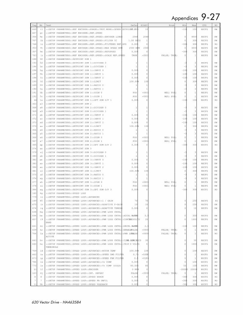
Tag Mn Text Default EIASCII Enum Min Max CFG RO
649 i1 ::SETUP PARAMETERS::REF ENCODER::PHASE::TEST MODE::SPEED SETPOINT 210.00% 10 -100 100 RECFG RW
607 gv ::SETUP PARAMETERS::REF ENCODER::REF.SPEED
356 9w ::SETUP PARAMETERS::REF ENCODER::REF.SPEED::ENCODER LINES 2048 2048 0 8000 RECFG RW
767 lb ::SETUP PARAMETERS::REF ENCODER::REF.SPEED::FILTER TC 1.00 SECS 1 0 300 RECFG RW
768 lc ::SETUP PARAMETERS::REF ENCODER::REF.SPEED::FILTERED REF.SPD 0.00% 0 -300 300 RECFG RO
353 9t ::SETUP PARAMETERS::REF ENCODER::REF.SPEED::MAX SPEED RPM 1500 RPM 1500 0 6000 RECFG RW
357 9x ::SETUP PARAMETERS::REF ENCODER::REF.SPEED::REFSPEED 0.00% 0 -300 300 RECFG RW
783 lr ::SETUP PARAMETERS::REF ENCODER::REF.SPEED::SCALE REF.SPEED TRUE >0001 FALSE; TRUE; 0 1 RECFG RW
188 58 ::SETUP PARAMETERS::SETPOINT SUM 1
193 5d ::SETUP PARAMETERS::SETPOINT SUM 1::DIVIDER 0 1 1 -3 3 RECFG RW
194 5e ::SETUP PARAMETERS::SETPOINT SUM 1::DIVIDER 1 1 1 -3 3 RECFG RW
196 5g ::SETUP PARAMETERS::SETPOINT SUM 1::INPUT 0 0.00% 0 -100 100 RECFG RW
197 5h ::SETUP PARAMETERS::SETPOINT SUM 1::INPUT 1 0.00% 0 -100 100 RECFG RW
198 5i ::SETUP PARAMETERS::SETPOINT SUM 1::INPUT 2 0.00% 0 -100 100 RECFG RW
195 5f ::SETUP PARAMETERS::SETPOINT SUM 1::LIMIT 100.00% 100 0 300 RECFG RW
189 59 ::SETUP PARAMETERS::SETPOINT SUM 1::RATIO 0 1 1 -3 3 RECFG RW
190 5a ::SETUP PARAMETERS::SETPOINT SUM 1::RATIO 1 1 1 -3 3 RECFG RW
191 5b ::SETUP PARAMETERS::SETPOINT SUM 1::SIGN 0 POS >0001 NEG; POS; 0 1 RECFG RW
192 5c ::SETUP PARAMETERS::SETPOINT SUM 1::SIGN 1 POS >0001 NEG; POS; 0 1 RECFG RW
46 1a ::SETUP PARAMETERS::SETPOINT SUM 1::SPT SUM O/P 1 0.00% 0 -100 100 NOCFG RO
363 a3 ::SETUP PARAMETERS::SETPOINT SUM 2
368 a8 ::SETUP PARAMETERS::SETPOINT SUM 2::DIVIDER 0 1 1 -3 3 RECFG RW
369 a9 ::SETUP PARAMETERS::SETPOINT SUM 2::DIVIDER 1 1 1 -3 3 RECFG RW
371 ab ::SETUP PARAMETERS::SETPOINT SUM 2::INPUT 0 0.00% 0 -100 100 RECFG RW
372 ac ::SETUP PARAMETERS::SETPOINT SUM 2::INPUT 1 0.00% 0 -100 100 RECFG RW
373 ad ::SETUP PARAMETERS::SETPOINT SUM 2::INPUT 2 0.00% 0 -100 100 RECFG RW
370 aa ::SETUP PARAMETERS::SETPOINT SUM 2::LIMIT 100.00% 100 0 300 RECFG RW
364 a4 ::SETUP PARAMETERS::SETPOINT SUM 2::RATIO 0 1 1 -3 3 RECFG RW
365 a5 ::SETUP PARAMETERS::SETPOINT SUM 2::RATIO 1 1 1 -3 3 RECFG RW
366 a6 ::SETUP PARAMETERS::SETPOINT SUM 2::SIGN 0 POS >0001 NEG; POS; 0 1 RECFG RW
367 a7 ::SETUP PARAMETERS::SETPOINT SUM 2::SIGN 1 POS >0001 NEG; POS; 0 1 RECFG RW
385 ap ::SETUP PARAMETERS::SETPOINT SUM 2::SPT SUM O/P 2 0.00% 0 -300 300 NOCFG RO
374 ae ::SETUP PARAMETERS::SETPOINT SUM 3
379 aj ::SETUP PARAMETERS::SETPOINT SUM 3::DIVIDER 0 1 1 -3 3 RECFG RW
380 ak ::SETUP PARAMETERS::SETPOINT SUM 3::DIVIDER 1 1 1 -3 3 RECFG RW
382 am ::SETUP PARAMETERS::SETPOINT SUM 3::INPUT 0 0.00% 0 -100 100 RECFG RW
383 an ::SETUP PARAMETERS::SETPOINT SUM 3::INPUT 1 0.00% 0 -100 100 RECFG RW
384 ao ::SETUP PARAMETERS::SETPOINT SUM 3::INPUT 2 0.00% 0 -100 100 RECFG RW
381 al ::SETUP PARAMETERS::SETPOINT SUM 3::LIMIT 100.00% 100 0 300 RECFG RW
375 af ::SETUP PARAMETERS::SETPOINT SUM 3::RATIO 0 1 1 -3 3 RECFG RW
376 ag ::SETUP PARAMETERS::SETPOINT SUM 3::RATIO 1 1 1 -3 3 RECFG RW
377 ah ::SETUP PARAMETERS::SETPOINT SUM 3::SIGN 0 POS >0001 NEG; POS; 0 1 RECFG RW
378 ai ::SETUP PARAMETERS::SETPOINT SUM 3::SIGN 1 POS >0001 NEG; POS; 0 1 RECFG RW
386 aq ::SETUP PARAMETERS::SETPOINT SUM 3::SPT SUM O/P 3 0.00% 0 -300 300 NOCFG RO
160 4g ::SETUP PARAMETERS::SPEED LOOP
779 ln ::SETUP PARAMETERS::SPEED LOOP::ADVANCED
149 45 ::SETUP PARAMETERS::SPEED LOOP::ADVANCED::1 / GAIN 70 70 0 255 RECFG RI
675 ir ::SETUP PARAMETERS::SPEED LOOP::ADVANCED::ADAPTIVE P-GAIN 10 10 0 250 RECFG RW
674 iq ::SETUP PARAMETERS::SPEED LOOP::ADVANCED::ADAPTIVE THRESH 0.00% 0 0 10 RECFG RW
638 hq ::SETUP PARAMETERS::SPEED LOOP::ADVANCED::PWR LOSS CNTRL
644 hw ::SETUP PARAMETERS::SPEED LOOP::ADVANCED::PWR LOSS CNTRL::ACCEL RATE0.50% 0.5 0 300 RECFG RW
657 i9 ::SETUP PARAMETERS::SPEED LOOP::ADVANCED::PWR LOSS CNTRL::CONTROL
BAND
20 VOLTS 20 0 1000 RECFG RW
641 ht ::SETUP PARAMETERS::SPEED LOOP::ADVANCED::PWR LOSS CNTRL::DECEL RATE2.50% 2.5 -100 100 RECFG RW
639 hr ::SETUP PARAMETERS::SPEED LOOP::ADVANCED::PWR LOSS CNTRL::ENABLEFALSE >0000 FALSE; TRUE; 0 1 RECFG RW
766 la ::SETUP PARAMETERS::SPEED LOOP::ADVANCED::PWR LOSS CNTRL::PWR LOSS
ACTIVE
FALSE >0000 FALSE; TRUE; 0 1 RECFG RO
643 hv ::SETUP PARAMETERS::SPEED LOOP::ADVANCED::PWR LOSS CNTRL::TIME LIMIT 30.000 SECS 30 0 30 RECFG RW
640 hs ::SETUP PARAMETERS::SPEED LOOP::ADVANCED::PWR LOSS CNTRL::TRIP
THRESHOLD
0 VOLTS 0 0 1000 RECFG RW
769 ld ::SETUP PARAMETERS::SPEED LOOP::ADVANCED::ROTOR TEMP 100.00% 100 0 100 RECFG RW
662 ie ::SETUP PARAMETERS::SPEED LOOP::ADVANCED::SPEED DMD FILTER 0.75 >02EE 0 1 NOCFG RW
673 ip ::SETUP PARAMETERS::SPEED LOOP::ADVANCED::SPEED FBK FILTER 0.5 >01F4 0 1 NOCFG RW
784 ls ::SETUP PARAMETERS::SPEED LOOP::ADVANCED::Tr COMP 0.00% 0 0 100 NOCFG RO
770 le ::SETUP PARAMETERS::SPEED LOOP::ADVANCED::Tr COMP (COLD) 80.00% 80 50 100 RECFG RW
51 1f ::SETUP PARAMETERS::SPEED LOOP::ENCODER 0 RPM 0 -20000 20000 NOCFG RO
163 4j ::SETUP PARAMETERS::SPEED LOOP::INT. DEFEAT FALSE >0000 FALSE; TRUE; 0 1 RECFG RW
8 8 ::SETUP PARAMETERS::SPEED LOOP::SPEED ERROR 0.00% 0 -300 300 NOCFG RO
7 7 ::SETUP PARAMETERS::SPEED LOOP::SPEED FB UNFIL 0.00% 0 -300 300 NOCFG RO
11 0b ::SETUP PARAMETERS::SPEED LOOP::SPEED FEEDBACK 0.00% 0 -300 300 NOCFG RO
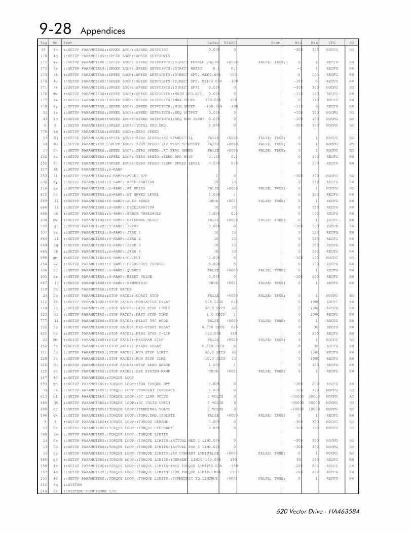
Tag Mn Text Default EIASCII Enum Min Max CFG RO
48 1c ::SETUP PARAMETERS::SPEED LOOP::SPEED SETPOINT 0.00% 0 -300 300 NOCFG RO
170 4q ::SETUP PARAMETERS::SPEED LOOP::SPEED SETPOINTS
175 4v ::SETUP PARAMETERS::SPEED LOOP::SPEED SETPOINTS::DIRECT ENABLE FALSE >0000 FALSE; TRUE; 0 1 RECFG RW
172 4s ::SETUP PARAMETERS::SPEED LOOP::SPEED SETPOINTS::DIRECT RATIO 0.1 0.1 -1 1 RECFG RW
173 4t ::SETUP PARAMETERS::SPEED LOOP::SPEED SETPOINTS::DIRECT SPT. MAX100.00% 100 0 100 RECFG RW
174 4u ::SETUP PARAMETERS::SPEED LOOP::SPEED SETPOINTS::DIRECT SPT. MIN-100.00% -100 -100 0 RECFG RW
171 4r ::SETUP PARAMETERS::SPEED LOOP::SPEED SETPOINTS::DIRECT SPT1 0.00% 0 -300 300 NOCFG RO
176 4w ::SETUP PARAMETERS::SPEED LOOP::SPEED SETPOINTS::MAIN SPD.SPT. 0.00% 0 -110 110 RECFG RW
177 4x ::SETUP PARAMETERS::SPEED LOOP::SPEED SETPOINTS::MAX SPEED 100.00% 100 0 110 RECFG RW
178 4y ::SETUP PARAMETERS::SPEED LOOP::SPEED SETPOINTS::MIN SPEED -100.00% -100 -110 0 RECFG RW
50 1e ::SETUP PARAMETERS::SPEED LOOP::SPEED SETPOINTS::SEQ OUTPUT 0.00% 0 -100 100 NOCFG RO
49 1d ::SETUP PARAMETERS::SPEED LOOP::SPEED SETPOINTS::SEQ RUN INPUT 0.00% 0 -100 100 NOCFG RO
6 6 ::SETUP PARAMETERS::SPEED LOOP::TOTAL SPD.DMD. 0.00% 0 -300 300 NOCFG RO
778 lm ::SETUP PARAMETERS::SPEED LOOP::ZERO SPEED
19 0j ::SETUP PARAMETERS::SPEED LOOP::ZERO SPEED::AT STANDSTILL FALSE >0000 FALSE; TRUE; 0 1 NOCFG RO
18 0i ::SETUP PARAMETERS::SPEED LOOP::ZERO SPEED::AT ZERO SETPOINT FALSE >0000 FALSE; TRUE; 0 1 NOCFG RO
17 0h ::SETUP PARAMETERS::SPEED LOOP::ZERO SPEED::AT ZERO SPEED FALSE >0000 FALSE; TRUE; 0 1 NOCFG RO
132 3o ::SETUP PARAMETERS::SPEED LOOP::ZERO SPEED::ZERO SPD HYST 0.10% 0.1 0 100 RECFG RW
252 70 ::SETUP PARAMETERS::SPEED LOOP::ZERO SPEED::ZERO SPEED LEVEL 0.50% 0.5 0 100 RECFG RW
317 8t ::SETUP PARAMETERS::S-RAMP
253 71 ::SETUP PARAMETERS::S-RAMP::ACCEL O/P 0 0 -300 300 NOCFG RO
106 2y ::SETUP PARAMETERS::S-RAMP::ACCELERATION 10 10 0 150 RECFG RW
316 8s ::SETUP PARAMETERS::S-RAMP::AT SPEED FALSE >0000 FALSE; TRUE; 0 1 NOCFG RO
612 h0 ::SETUP PARAMETERS::S-RAMP::AT SPEED LEVEL 1.00% 1 0 100 RECFG RW
669 il ::SETUP PARAMETERS::S-RAMP::AUTO RESET TRUE >0001 FALSE; TRUE; 0 1 RECFG RW
666 ii ::SETUP PARAMETERS::S-RAMP::DECELERATION 10 10 0 150 RECFG RW
668 ik ::SETUP PARAMETERS::S-RAMP::ERROR THRESHOLD 0.50% 0.5 0 100 RECFG RW
104 2w ::SETUP PARAMETERS::S-RAMP::EXTERNAL RESET FALSE >0000 FALSE; TRUE; 0 1 RECFG RW
597 gl ::SETUP PARAMETERS::S-RAMP::INPUT 0.00% 0 -100 100 RECFG RW
107 2z ::SETUP PARAMETERS::S-RAMP::JERK 1 10 10 0 150 RECFG RW
663 if ::SETUP PARAMETERS::S-RAMP::JERK 2 10 10 0 150 RECFG RW
664 ig ::SETUP PARAMETERS::S-RAMP::JERK 3 10 10 0 150 RECFG RW
665 ih ::SETUP PARAMETERS::S-RAMP::JERK 4 10 10 0 150 RECFG RW
598 gm ::SETUP PARAMETERS::S-RAMP::OUTPUT 0.00% 0 -100 100 NOCFG RO
254 72 ::SETUP PARAMETERS::S-RAMP::OVERSHOOT THRESH 5.00% 5 0 100 RECFG RW
108 30 ::SETUP PARAMETERS::S-RAMP::QUENCH FALSE >0000 FALSE; TRUE; 0 1 RECFG RW
105 2x ::SETUP PARAMETERS::S-RAMP::RESET VALUE 0.00% 0 -100 100 RECFG RW
667 ij ::SETUP PARAMETERS::S-RAMP::SYMMETRIC TRUE >0001 FALSE; TRUE; 0 1 RECFG RW
119 3b ::SETUP PARAMETERS::STOP RATES
26 0q ::SETUP PARAMETERS::STOP RATES::COAST STOP FALSE >0000 FALSE; TRUE; 0 1 NOCFG RO
112 34 ::SETUP PARAMETERS::STOP RATES::CONTACTOR DELAY 0.5 SECS 0.5 0 1000 RECFG RW
124 3g ::SETUP PARAMETERS::STOP RATES::FAST STOP LIMIT 60.0 SECS 60 0 1000 RECFG RW
123 3f ::SETUP PARAMETERS::STOP RATES::FAST STOP TIME 1.0 SECS 1 0 1000 RECFG RW
777 ll ::SETUP PARAMETERS::STOP RATES::PILOT 590 MODE FALSE >0000 FALSE; TRUE; 0 1 RECFG RW
122 3e ::SETUP PARAMETERS::STOP RATES::PRE-START DELAY 0.500 SECS 0.5 0 30 RECFG RW
622 ha ::SETUP PARAMETERS::STOP RATES::PROG STOP I-LIM 150.00% 150 0 200 RECFG RW
22 0m ::SETUP PARAMETERS::STOP RATES::PROGRAM STOP FALSE >0000 FALSE; TRUE; 0 1 NOCFG RO
352 9s ::SETUP PARAMETERS::STOP RATES::READY DELAY 0.000 SECS 0 0 30 RECFG RW
121 3d ::SETUP PARAMETERS::STOP RATES::RUN STOP LIMIT 60.0 SECS 60 0 1000 RECFG RW
120 3c ::SETUP PARAMETERS::STOP RATES::RUN STOP TIME 10.0 SECS 10 0 1000 RECFG RW
126 3i ::SETUP PARAMETERS::STOP RATES::STOP ZERO SPEED 1.00% 1 0 100 RECFG RW
125 3h ::SETUP PARAMETERS::STOP RATES::USE SYSTEM RAMP TRUE >0001 FALSE; TRUE; 0 1 RECFG RW
147 43 ::SETUP PARAMETERS::TORQUE LOOP
599 gn ::SETUP PARAMETERS::TORQUE LOOP::AUX TORQUE DMD 0.00% 0 -200 200 RECFG RW
78 26 ::SETUP PARAMETERS::TORQUE LOOP::CURRENT FEEDBACK 0.00% 0 -300 300 NOCFG RO
613 h1 ::SETUP PARAMETERS::TORQUE LOOP::DC LINK VOLTS 0 VOLTS 0 -30000 30000 NOCFG RO
684 j0 ::SETUP PARAMETERS::TORQUE LOOP::DC VOLTS UNFLT 0 VOLTS 0 -30000 30000 NOCFG RO
480 dc ::SETUP PARAMETERS::TORQUE LOOP::TERMINAL VOLTS 0 VOLTS 0 -10000 10000 NOCFG RO
596 gk ::SETUP PARAMETERS::TORQUE LOOP::TORQ.DMD.ISOLATE FALSE >0000 FALSE; TRUE; 0 1 RECFG RW
9 9 ::SETUP PARAMETERS::TORQUE LOOP::TORQUE DEMAND 0.00% 0 -300 300 NOCFG RO
10 0a ::SETUP PARAMETERS::TORQUE LOOP::TORQUE FEEDBACK 0.00% 0 -300 300 NOCFG RO
780 lo ::SETUP PARAMETERS::TORQUE LOOP::TORQUE LIMITS
14 0e ::SETUP PARAMETERS::TORQUE LOOP::TORQUE LIMITS::ACTUAL NEG I LIM0.00% 0 -300 300 NOCFG RO
13 0d ::SETUP PARAMETERS::TORQUE LOOP::TORQUE LIMITS::ACTUAL POS I LIM0.00% 0 -300 300 NOCFG RO
16 0g ::SETUP PARAMETERS::TORQUE LOOP::TORQUE LIMITS::AT CURRENT LIMITFALSE >0000 FALSE; TRUE; 0 1 NOCFG RO
585 g9 ::SETUP PARAMETERS::TORQUE LOOP::TORQUE LIMITS::CURRENT LIMIT 150.00% 150 50 150 RECFG RW
158 4e ::SETUP PARAMETERS::TORQUE LOOP::TORQUE LIMITS::NEG TORQUE LIMIT-150.00% -150 -200 200 RECFG RW
157 4d ::SETUP PARAMETERS::TORQUE LOOP::TORQUE LIMITS::POS TORQUE LIMIT150.00% 150 -200 200 RECFG RW
153 49 ::SETUP PARAMETERS::TORQUE LOOP::TORQUE LIMITS::SYMMETRIC TQ.LIM.TRUE >0001 FALSE; TRUE; 0 1 RECFG RW
242 6q ::SYSTEM
244 6s ::SYSTEM::CONFIGURE I/O
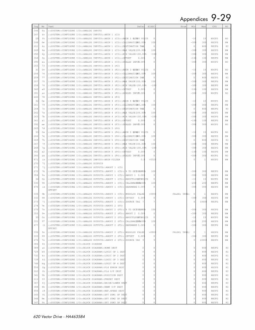
Tag Mn Text Default EIASCII Enum Min Max CFG RO
246 6u ::SYSTEM::CONFIGURE I/O::ANALOG INPUTS
247 6v ::SYSTEM::CONFIGURE I/O::ANALOG INPUTS::ANIN 1 (C3)
29 0t ::SYSTEM::CONFIGURE I/O::ANALOG INPUTS::ANIN 1 (C3)::ANIN 1 (C3) 0.000 VOLTS 0 -10 10 NOCFG RO
248 6w ::SYSTEM::CONFIGURE I/O::ANALOG INPUTS::ANIN 1 (C3)::CALIBRATION100.00% 100 -300 300 RECFG RW
251 6z ::SYSTEM::CONFIGURE I/O::ANALOG INPUTS::ANIN 1 (C3)::DESTINATION TAG0 0 0 800 RECFG RI
249 6x ::SYSTEM::CONFIGURE I/O::ANALOG INPUTS::ANIN 1 (C3)::MAX VALUE100.00% 100 -300 300 RECFG RW
250 6y ::SYSTEM::CONFIGURE I/O::ANALOG INPUTS::ANIN 1 (C3)::MIN VALUE-100.00% -100 -300 300 RECFG RW
358 9y ::SYSTEM::CONFIGURE I/O::ANALOG INPUTS::ANIN 1 (C3)::OFFSET 0.00% 0 -100 100 RECFG RW
390 au ::SYSTEM::CONFIGURE I/O::ANALOG INPUTS::ANIN 1 (C3)::SCALED INPUT0.00% 0 -300 300 NOCFG RO
255 73 ::SYSTEM::CONFIGURE I/O::ANALOG INPUTS::ANIN 3 (F2)
31 0v ::SYSTEM::CONFIGURE I/O::ANALOG INPUTS::ANIN 3 (F2)::ANIN 3 (F2) 0.000 VOLTS 0 -10 10 NOCFG RO
256 74 ::SYSTEM::CONFIGURE I/O::ANALOG INPUTS::ANIN 3 (F2)::CALIBRATION100.00% 100 -300 300 RECFG RW
259 77 ::SYSTEM::CONFIGURE I/O::ANALOG INPUTS::ANIN 3 (F2)::DESTINATION TAG0 0 0 800 RECFG RI
257 75 ::SYSTEM::CONFIGURE I/O::ANALOG INPUTS::ANIN 3 (F2)::MAX VALUE100.00% 100 -300 300 RECFG RW
258 76 ::SYSTEM::CONFIGURE I/O::ANALOG INPUTS::ANIN 3 (F2)::MIN VALUE-100.00% -100 -300 300 RECFG RW
360 a0 ::SYSTEM::CONFIGURE I/O::ANALOG INPUTS::ANIN 3 (F2)::OFFSET 0.00% 0 -100 100 RECFG RW
391 av ::SYSTEM::CONFIGURE I/O::ANALOG INPUTS::ANIN 3 (F2)::SCALED INPUT0.00% 0 -300 300 NOCFG RO
260 78 ::SYSTEM::CONFIGURE I/O::ANALOG INPUTS::ANIN 4 (F3)
32 0w ::SYSTEM::CONFIGURE I/O::ANALOG INPUTS::ANIN 4 (F3)::ANIN 4 (F3) 0.000 VOLTS 0 -10 10 NOCFG RO
261 79 ::SYSTEM::CONFIGURE I/O::ANALOG INPUTS::ANIN 4 (F3)::CALIBRATION100.00% 100 -300 300 RECFG RW
264 7c ::SYSTEM::CONFIGURE I/O::ANALOG INPUTS::ANIN 4 (F3)::DESTINATION TAG0 0 0 800 RECFG RI
262 7a ::SYSTEM::CONFIGURE I/O::ANALOG INPUTS::ANIN 4 (F3)::MAX VALUE100.00% 100 -300 300 RECFG RW
263 7b ::SYSTEM::CONFIGURE I/O::ANALOG INPUTS::ANIN 4 (F3)::MIN VALUE-100.00% -100 -300 300 RECFG RW
361 a1 ::SYSTEM::CONFIGURE I/O::ANALOG INPUTS::ANIN 4 (F3)::OFFSET 0.00% 0 -100 100 RECFG RW
392 aw ::SYSTEM::CONFIGURE I/O::ANALOG INPUTS::ANIN 4 (F3)::SCALED INPUT0.00% 0 -300 300 NOCFG RO
265 7d ::SYSTEM::CONFIGURE I/O::ANALOG INPUTS::ANIN 5 (F4)
33 0x ::SYSTEM::CONFIGURE I/O::ANALOG INPUTS::ANIN 5 (F4)::ANIN 5 (F4) 0.000 VOLTS 0 -10 10 NOCFG RO
266 7e ::SYSTEM::CONFIGURE I/O::ANALOG INPUTS::ANIN 5 (F4)::CALIBRATION100.00% 100 -300 300 RECFG RW
269 7h ::SYSTEM::CONFIGURE I/O::ANALOG INPUTS::ANIN 5 (F4)::DESTINATION TAG0 0 0 800 RECFG RI
267 7f ::SYSTEM::CONFIGURE I/O::ANALOG INPUTS::ANIN 5 (F4)::MAX VALUE100.00% 100 -300 300 RECFG RW
268 7g ::SYSTEM::CONFIGURE I/O::ANALOG INPUTS::ANIN 5 (F4)::MIN VALUE-100.00% -100 -300 300 RECFG RW
362 a2 ::SYSTEM::CONFIGURE I/O::ANALOG INPUTS::ANIN 5 (F4)::OFFSET 0.00% 0 -100 100 RECFG RW
393 ax ::SYSTEM::CONFIGURE I/O::ANALOG INPUTS::ANIN 5 (F4)::SCALED INPUT0.00% 0 -300 300 NOCFG RO
671 in ::SYSTEM::CONFIGURE I/O::ANALOG INPUTS::ANIN FILTER 0.8 >0320 0 1 NOCFG RW
270 7i ::SYSTEM::CONFIGURE I/O::ANALOG OUTPUTS
271 7j ::SYSTEM::CONFIGURE I/O::ANALOG OUTPUTS::ANOUT 1 (C5)
272 7k ::SYSTEM::CONFIGURE I/O::ANALOG OUTPUTS::ANOUT 1 (C5)::% TO GET 10V100.00% 100 -300 300 RECFG RW
354 9u ::SYSTEM::CONFIGURE I/O::ANALOG OUTPUTS::ANOUT 1 (C5)::ANOUT 1 0.00% 0 -300 300 RECFG RW
34 0y ::SYSTEM::CONFIGURE I/O::ANALOG OUTPUTS::ANOUT 1 (C5)::ANOUT 1 (C5) 0.000 VOLTS 0 -10 10 NOCFG RW
330 96 ::SYSTEM::CONFIGURE I/O::ANALOG OUTPUTS::ANOUT 1 (C5)::CALIBRATION100.00% 100 -200 200 RECFG RW
676 is ::SYSTEM::CONFIGURE I/O::ANALOG OUTPUTS::ANOUT 1 (C5)::HARDWARE
OFFSET
0.00% 0 -300 300 RECFG RW
335 9b ::SYSTEM::CONFIGURE I/O::ANALOG OUTPUTS::ANOUT 1 (C5)::MODULUS FALSE >0000 FALSE; TRUE; 0 1 RECFG RW
332 98 ::SYSTEM::CONFIGURE I/O::ANALOG OUTPUTS::ANOUT 1 (C5)::OFFSET 0.00% 0 -300 300 RECFG RW
273 7l ::SYSTEM::CONFIGURE I/O::ANALOG OUTPUTS::ANOUT 1 (C5)::SOURCE TAG 7 7 0 10000 RECFG RW
274 7m ::SYSTEM::CONFIGURE I/O::ANALOG OUTPUTS::ANOUT 2 (F5)
275 7n ::SYSTEM::CONFIGURE I/O::ANALOG OUTPUTS::ANOUT 2 (F5)::% TO GET 10V150.00% 150 -300 300 RECFG RW
355 9v ::SYSTEM::CONFIGURE I/O::ANALOG OUTPUTS::ANOUT 2 (F5)::ANOUT 2 0.00% 0 -300 300 RECFG RW
35 0z ::SYSTEM::CONFIGURE I/O::ANALOG OUTPUTS::ANOUT 2 (F5)::ANOUT 2 (F5) 0.000 VOLTS 0 -10 10 NOCFG RW
331 97 ::SYSTEM::CONFIGURE I/O::ANALOG OUTPUTS::ANOUT 2 (F5)::CALIBRATION100.00% 100 -200 200 RECFG RW
677 it ::SYSTEM::CONFIGURE I/O::ANALOG OUTPUTS::ANOUT 2 (F5)::HARDWARE
OFFSET
0.00% 0 -300 300 RECFG RW
336 9c ::SYSTEM::CONFIGURE I/O::ANALOG OUTPUTS::ANOUT 2 (F5)::MODULUS FALSE >0000 FALSE; TRUE; 0 1 RECFG RW
333 99 ::SYSTEM::CONFIGURE I/O::ANALOG OUTPUTS::ANOUT 2 (F5)::OFFSET 0.00% 0 -300 300 RECFG RW
276 7o ::SYSTEM::CONFIGURE I/O::ANALOG OUTPUTS::ANOUT 2 (F5)::SOURCE TAG 9 9 0 10000 RECFG RW
306 8i ::SYSTEM::CONFIGURE I/O::BLOCK DIAGRAM
389 at ::SYSTEM::CONFIGURE I/O::BLOCK DIAGRAM::HOME DEST 0 0 0 800 RECFG RI
725 k5 ::SYSTEM::CONFIGURE I/O::BLOCK DIAGRAM::LOGIC OP 1 DEST 0 0 0 800 RECFG RI
732 kc ::SYSTEM::CONFIGURE I/O::BLOCK DIAGRAM::LOGIC OP 2 DEST 0 0 0 800 RECFG RI
739 kj ::SYSTEM::CONFIGURE I/O::BLOCK DIAGRAM::LOGIC OP 3 DEST 0 0 0 800 RECFG RI
746 kq ::SYSTEM::CONFIGURE I/O::BLOCK DIAGRAM::LOGIC OP 4 DEST 0 0 0 800 RECFG RI
556 fg ::SYSTEM::CONFIGURE I/O::BLOCK DIAGRAM::Pid ERROR DEST 0 0 0 800 RECFG RI
552 fc ::SYSTEM::CONFIGURE I/O::BLOCK DIAGRAM::Pid O/P DEST 0 0 0 800 RECFG RI
341 9h ::SYSTEM::CONFIGURE I/O::BLOCK DIAGRAM::POSITION DEST 0 0 0 800 RECFG RI
111 33 ::SYSTEM::CONFIGURE I/O::BLOCK DIAGRAM::PRESET DEST 0 0 0 800 RECFG RI
307 8j ::SYSTEM::CONFIGURE I/O::BLOCK DIAGRAM::RAISE/LOWER DEST 0 0 0 800 RECFG RI
308 8k ::SYSTEM::CONFIGURE I/O::BLOCK DIAGRAM::RAMP O/P DEST 0 0 0 800 RECFG RI
656 i8 ::SYSTEM::CONFIGURE I/O::BLOCK DIAGRAM::REF.SPEED DEST 0 0 0 800 RECFG RI
345 9l ::SYSTEM::CONFIGURE I/O::BLOCK DIAGRAM::SPT SUM1 OP DEST 0 0 0 800 RECFG RI
346 9m ::SYSTEM::CONFIGURE I/O::BLOCK DIAGRAM::SPT SUM2 OP DEST 0 0 0 800 RECFG RI
347 9n ::SYSTEM::CONFIGURE I/O::BLOCK DIAGRAM::SPT SUM3 OP DEST 0 0 0 800 RECFG RI
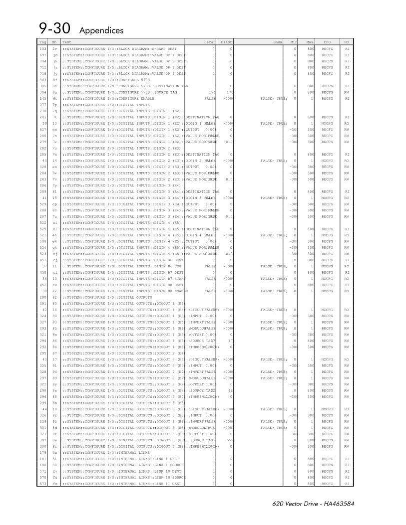
Tag Mn Text Default EIASCII Enum Min Max CFG RO
103 2v ::SYSTEM::CONFIGURE I/O::BLOCK DIAGRAM::S-RAMP DEST 0 0 0 800 RECFG RI
697 jd ::SYSTEM::CONFIGURE I/O::BLOCK DIAGRAM::VALUE OP 1 DEST 0 0 0 800 RECFG RI
704 jk ::SYSTEM::CONFIGURE I/O::BLOCK DIAGRAM::VALUE OP 2 DEST 0 0 0 800 RECFG RI
711 jr ::SYSTEM::CONFIGURE I/O::BLOCK DIAGRAM::VALUE OP 3 DEST 0 0 0 800 RECFG RI
718 jy ::SYSTEM::CONFIGURE I/O::BLOCK DIAGRAM::VALUE OP 4 DEST 0 0 0 800 RECFG RI
303 8f ::SYSTEM::CONFIGURE I/O::CONFIGURE 5703
305 8h ::SYSTEM::CONFIGURE I/O::CONFIGURE 5703::DESTINATION TAG 0 0 0 800 RECFG RI
304 8g ::SYSTEM::CONFIGURE I/O::CONFIGURE 5703::SOURCE TAG 176 176 0 800 RECFG RW
245 6t ::SYSTEM::CONFIGURE I/O::CONFIGURE ENABLE FALSE >0000 FALSE; TRUE; 0 1 RECFG RI
277 7p ::SYSTEM::CONFIGURE I/O::DIGITAL INPUTS
278 7q ::SYSTEM::CONFIGURE I/O::DIGITAL INPUTS::DIGIN 1 (E2)
281 7t ::SYSTEM::CONFIGURE I/O::DIGITAL INPUTS::DIGIN 1 (E2)::DESTINATION TAG0 0 0 800 RECFG RI
39 13 ::SYSTEM::CONFIGURE I/O::DIGITAL INPUTS::DIGIN 1 (E2)::DIGIN 1 (E2)FALSE >0000 FALSE; TRUE; 0 1 NOCFG RO
527 en ::SYSTEM::CONFIGURE I/O::DIGITAL INPUTS::DIGIN 1 (E2)::OUTPUT 0.00% 0 -300 300 RECFG RW
280 7s ::SYSTEM::CONFIGURE I/O::DIGITAL INPUTS::DIGIN 1 (E2)::VALUE FOR FALSE0.00% 0 -300 300 RECFG RW
279 7r ::SYSTEM::CONFIGURE I/O::DIGITAL INPUTS::DIGIN 1 (E2)::VALUE FOR TRUE0.01% 0.01 -300 300 RECFG RW
282 7u ::SYSTEM::CONFIGURE I/O::DIGITAL INPUTS::DIGIN 2 (E3)
285 7x ::SYSTEM::CONFIGURE I/O::DIGITAL INPUTS::DIGIN 2 (E3)::DESTINATION TAG0 0 0 800 RECFG RI
40 14 ::SYSTEM::CONFIGURE I/O::DIGITAL INPUTS::DIGIN 2 (E3)::DIGIN 2 (E3)FALSE >0000 FALSE; TRUE; 0 1 NOCFG RO
528 eo ::SYSTEM::CONFIGURE I/O::DIGITAL INPUTS::DIGIN 2 (E3)::OUTPUT 0.00% 0 -300 300 RECFG RW
284 7w ::SYSTEM::CONFIGURE I/O::DIGITAL INPUTS::DIGIN 2 (E3)::VALUE FOR FALSE0.00% 0 -300 300 RECFG RW
283 7v ::SYSTEM::CONFIGURE I/O::DIGITAL INPUTS::DIGIN 2 (E3)::VALUE FOR TRUE0.01% 0.01 -300 300 RECFG RW
286 7y ::SYSTEM::CONFIGURE I/O::DIGITAL INPUTS::DIGIN 3 (E4)
289 81 ::SYSTEM::CONFIGURE I/O::DIGITAL INPUTS::DIGIN 3 (E4)::DESTINATION TAG0 0 0 800 RECFG RI
41 15 ::SYSTEM::CONFIGURE I/O::DIGITAL INPUTS::DIGIN 3 (E4)::DIGIN 3 (E4)FALSE >0000 FALSE; TRUE; 0 1 NOCFG RO
529 ep ::SYSTEM::CONFIGURE I/O::DIGITAL INPUTS::DIGIN 3 (E4)::OUTPUT 0.00% 0 -300 300 RECFG RW
288 80 ::SYSTEM::CONFIGURE I/O::DIGITAL INPUTS::DIGIN 3 (E4)::VALUE FOR FALSE0.00% 0 -300 300 RECFG RW
287 7z ::SYSTEM::CONFIGURE I/O::DIGITAL INPUTS::DIGIN 3 (E4)::VALUE FOR TRUE0.01% 0.01 -300 300 RECFG RW
522 ei ::SYSTEM::CONFIGURE I/O::DIGITAL INPUTS::DIGIN 4 (E5)
525 el ::SYSTEM::CONFIGURE I/O::DIGITAL INPUTS::DIGIN 4 (E5)::DESTINATION TAG0 0 0 800 RECFG RI
521 eh ::SYSTEM::CONFIGURE I/O::DIGITAL INPUTS::DIGIN 4 (E5)::DIGIN 4 (E5)FALSE >0000 FALSE; TRUE; 0 1 NOCFG RO
508 e4 ::SYSTEM::CONFIGURE I/O::DIGITAL INPUTS::DIGIN 4 (E5)::OUTPUT 0.00% 0 -300 300 RECFG RW
524 ek ::SYSTEM::CONFIGURE I/O::DIGITAL INPUTS::DIGIN 4 (E5)::VALUE FOR FALSE0.00% 0 -300 300 RECFG RW
523 ej ::SYSTEM::CONFIGURE I/O::DIGITAL INPUTS::DIGIN 4 (E5)::VALUE FOR TRUE0.01% 0.01 -300 300 RECFG RW
451 cj ::SYSTEM::CONFIGURE I/O::DIGITAL INPUTS::DIGIN B6 DEST 0 0 0 800 RECFG RI
37 11 ::SYSTEM::CONFIGURE I/O::DIGITAL INPUTS::DIGIN B6 JOG FALSE >0000 FALSE; TRUE; 0 1 NOCFG RO
450 ci ::SYSTEM::CONFIGURE I/O::DIGITAL INPUTS::DIGIN B7 DEST 0 0 0 800 RECFG RI
36 10 ::SYSTEM::CONFIGURE I/O::DIGITAL INPUTS::DIGIN B7 START FALSE >0000 FALSE; TRUE; 0 1 NOCFG RO
452 ck ::SYSTEM::CONFIGURE I/O::DIGITAL INPUTS::DIGIN B8 DEST 0 0 0 800 RECFG RI
38 12 ::SYSTEM::CONFIGURE I/O::DIGITAL INPUTS::DIGIN B8 ENABLE FALSE >0000 FALSE; TRUE; 0 1 NOCFG RO
290 82 ::SYSTEM::CONFIGURE I/O::DIGITAL OUTPUTS
291 83 ::SYSTEM::CONFIGURE I/O::DIGITAL OUTPUTS::DIGOUT 1 (E6)
42 16 ::SYSTEM::CONFIGURE I/O::DIGITAL OUTPUTS::DIGOUT 1 (E6)::DIGOUT 1 (E6)FALSE >0000 FALSE; TRUE; 0 1 NOCFG RO
324 90 ::SYSTEM::CONFIGURE I/O::DIGITAL OUTPUTS::DIGOUT 1 (E6)::INPUT 0.00% 0 -300 300 RECFG RW
327 93 ::SYSTEM::CONFIGURE I/O::DIGITAL OUTPUTS::DIGOUT 1 (E6)::INVERT FALSE >0000 FALSE; TRUE; 0 1 RECFG RW
293 85 ::SYSTEM::CONFIGURE I/O::DIGITAL OUTPUTS::DIGOUT 1 (E6)::MODULUSFALSE >0000 FALSE; TRUE; 0 1 RECFG RW
321 8x ::SYSTEM::CONFIGURE I/O::DIGITAL OUTPUTS::DIGOUT 1 (E6)::OFFSET 0.00% 0 -300 300 RECFG RW
294 86 ::SYSTEM::CONFIGURE I/O::DIGITAL OUTPUTS::DIGOUT 1 (E6)::SOURCE TAG17 17 0 800 RECFG RW
292 84 ::SYSTEM::CONFIGURE I/O::DIGITAL OUTPUTS::DIGOUT 1 (E6)::THRESHOLD (>)0.00% 0 -300 300 RECFG RW
295 87 ::SYSTEM::CONFIGURE I/O::DIGITAL OUTPUTS::DIGOUT 2 (E7)
43 17 ::SYSTEM::CONFIGURE I/O::DIGITAL OUTPUTS::DIGOUT 2 (E7)::DIGOUT 2 (E7)FALSE >0000 FALSE; TRUE; 0 1 NOCFG RO
325 91 ::SYSTEM::CONFIGURE I/O::DIGITAL OUTPUTS::DIGOUT 2 (E7)::INPUT 0.00% 0 -300 300 RECFG RW
328 94 ::SYSTEM::CONFIGURE I/O::DIGITAL OUTPUTS::DIGOUT 2 (E7)::INVERT FALSE >0000 FALSE; TRUE; 0 1 RECFG RW
297 89 ::SYSTEM::CONFIGURE I/O::DIGITAL OUTPUTS::DIGOUT 2 (E7)::MODULUSFALSE >0000 FALSE; TRUE; 0 1 RECFG RW
322 8y ::SYSTEM::CONFIGURE I/O::DIGITAL OUTPUTS::DIGOUT 2 (E7)::OFFSET 0.00% 0 -300 300 RECFG RW
298 8a ::SYSTEM::CONFIGURE I/O::DIGITAL OUTPUTS::DIGOUT 2 (E7)::SOURCE TAG12 12 0 800 RECFG RW
296 88 ::SYSTEM::CONFIGURE I/O::DIGITAL OUTPUTS::DIGOUT 2 (E7)::THRESHOLD (>)0.00% 0 -300 300 RECFG RW
299 8b ::SYSTEM::CONFIGURE I/O::DIGITAL OUTPUTS::DIGOUT 3 (E8)
44 18 ::SYSTEM::CONFIGURE I/O::DIGITAL OUTPUTS::DIGOUT 3 (E8)::DIGOUT 3 (E8)FALSE >0000 FALSE; TRUE; 0 1 NOCFG RO
326 92 ::SYSTEM::CONFIGURE I/O::DIGITAL OUTPUTS::DIGOUT 3 (E8)::INPUT 0.00% 0 -300 300 RECFG RW
329 95 ::SYSTEM::CONFIGURE I/O::DIGITAL OUTPUTS::DIGOUT 3 (E8)::INVERT FALSE >0000 FALSE; TRUE; 0 1 RECFG RW
301 8d ::SYSTEM::CONFIGURE I/O::DIGITAL OUTPUTS::DIGOUT 3 (E8)::MODULUSTRUE >0001 FALSE; TRUE; 0 1 RECFG RW
323 8z ::SYSTEM::CONFIGURE I/O::DIGITAL OUTPUTS::DIGOUT 3 (E8)::OFFSET 0.00% 0 -300 300 RECFG RW
302 8e ::SYSTEM::CONFIGURE I/O::DIGITAL OUTPUTS::DIGOUT 3 (E8)::SOURCE TAG559 559 0 800 RECFG RW
300 8c ::SYSTEM::CONFIGURE I/O::DIGITAL OUTPUTS::DIGOUT 3 (E8)::THRESHOLD (>)0.00% 0 -300 300 RECFG RW
179 4z ::SYSTEM::CONFIGURE I/O::INTERNAL LINKS
181 51 ::SYSTEM::CONFIGURE I/O::INTERNAL LINKS::LINK 1 DEST 0 0 0 800 RECFG RI
180 50 ::SYSTEM::CONFIGURE I/O::INTERNAL LINKS::LINK 1 SOURCE 0 0 0 800 RECFG RI
571 fv ::SYSTEM::CONFIGURE I/O::INTERNAL LINKS::LINK 10 DEST 0 0 0 800 RECFG RI
570 fu ::SYSTEM::CONFIGURE I/O::INTERNAL LINKS::LINK 10 SOURCE 0 0 0 800 RECFG RI
573 fx ::SYSTEM::CONFIGURE I/O::INTERNAL LINKS::LINK 11 DEST 0 0 0 800 RECFG RI
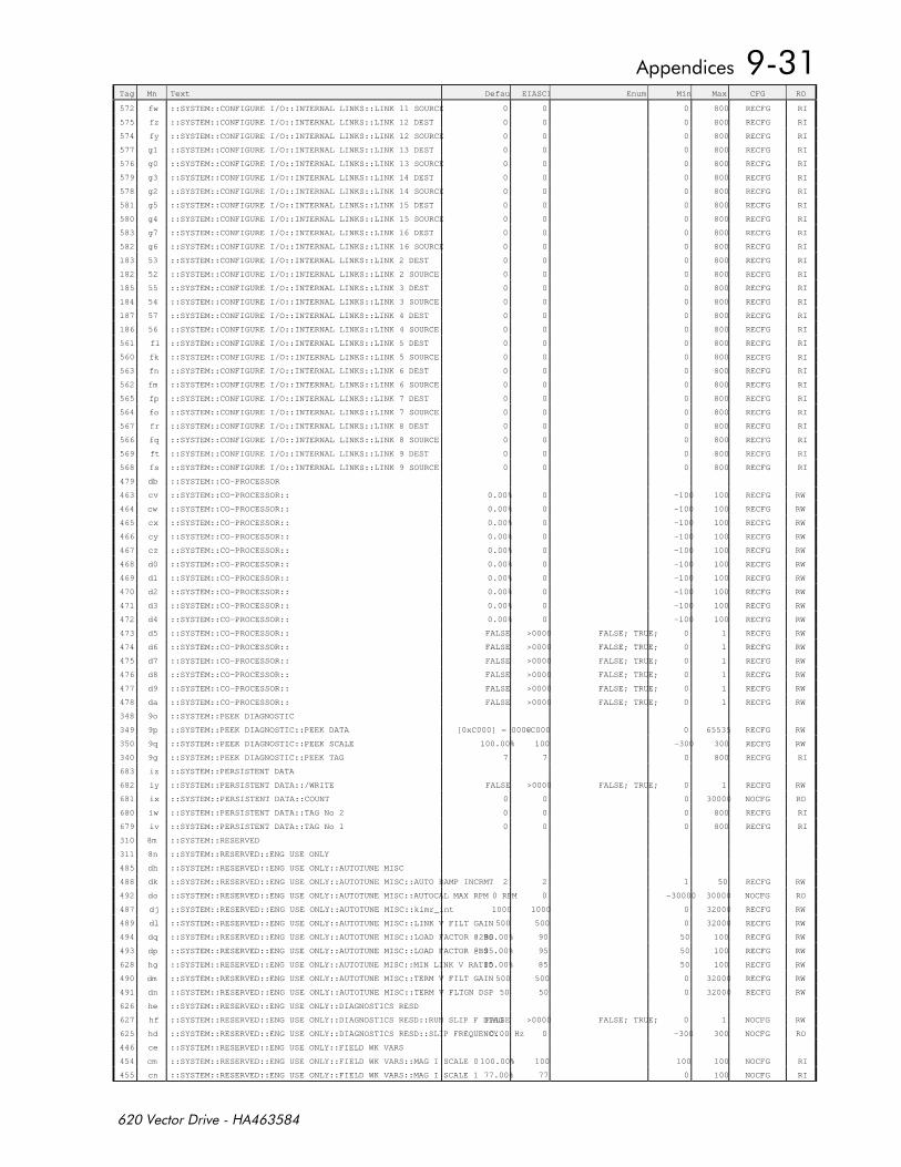
Tag Mn Text Default EIASCII Enum Min Max CFG RO
572 fw ::SYSTEM::CONFIGURE I/O::INTERNAL LINKS::LINK 11 SOURCE 0 0 0 800 RECFG RI
575 fz ::SYSTEM::CONFIGURE I/O::INTERNAL LINKS::LINK 12 DEST 0 0 0 800 RECFG RI
574 fy ::SYSTEM::CONFIGURE I/O::INTERNAL LINKS::LINK 12 SOURCE 0 0 0 800 RECFG RI
577 g1 ::SYSTEM::CONFIGURE I/O::INTERNAL LINKS::LINK 13 DEST 0 0 0 800 RECFG RI
576 g0 ::SYSTEM::CONFIGURE I/O::INTERNAL LINKS::LINK 13 SOURCE 0 0 0 800 RECFG RI
579 g3 ::SYSTEM::CONFIGURE I/O::INTERNAL LINKS::LINK 14 DEST 0 0 0 800 RECFG RI
578 g2 ::SYSTEM::CONFIGURE I/O::INTERNAL LINKS::LINK 14 SOURCE 0 0 0 800 RECFG RI
581 g5 ::SYSTEM::CONFIGURE I/O::INTERNAL LINKS::LINK 15 DEST 0 0 0 800 RECFG RI
580 g4 ::SYSTEM::CONFIGURE I/O::INTERNAL LINKS::LINK 15 SOURCE 0 0 0 800 RECFG RI
583 g7 ::SYSTEM::CONFIGURE I/O::INTERNAL LINKS::LINK 16 DEST 0 0 0 800 RECFG RI
582 g6 ::SYSTEM::CONFIGURE I/O::INTERNAL LINKS::LINK 16 SOURCE 0 0 0 800 RECFG RI
183 53 ::SYSTEM::CONFIGURE I/O::INTERNAL LINKS::LINK 2 DEST 0 0 0 800 RECFG RI
182 52 ::SYSTEM::CONFIGURE I/O::INTERNAL LINKS::LINK 2 SOURCE 0 0 0 800 RECFG RI
185 55 ::SYSTEM::CONFIGURE I/O::INTERNAL LINKS::LINK 3 DEST 0 0 0 800 RECFG RI
184 54 ::SYSTEM::CONFIGURE I/O::INTERNAL LINKS::LINK 3 SOURCE 0 0 0 800 RECFG RI
187 57 ::SYSTEM::CONFIGURE I/O::INTERNAL LINKS::LINK 4 DEST 0 0 0 800 RECFG RI
186 56 ::SYSTEM::CONFIGURE I/O::INTERNAL LINKS::LINK 4 SOURCE 0 0 0 800 RECFG RI
561 fl ::SYSTEM::CONFIGURE I/O::INTERNAL LINKS::LINK 5 DEST 0 0 0 800 RECFG RI
560 fk ::SYSTEM::CONFIGURE I/O::INTERNAL LINKS::LINK 5 SOURCE 0 0 0 800 RECFG RI
563 fn ::SYSTEM::CONFIGURE I/O::INTERNAL LINKS::LINK 6 DEST 0 0 0 800 RECFG RI
562 fm ::SYSTEM::CONFIGURE I/O::INTERNAL LINKS::LINK 6 SOURCE 0 0 0 800 RECFG RI
565 fp ::SYSTEM::CONFIGURE I/O::INTERNAL LINKS::LINK 7 DEST 0 0 0 800 RECFG RI
564 fo ::SYSTEM::CONFIGURE I/O::INTERNAL LINKS::LINK 7 SOURCE 0 0 0 800 RECFG RI
567 fr ::SYSTEM::CONFIGURE I/O::INTERNAL LINKS::LINK 8 DEST 0 0 0 800 RECFG RI
566 fq ::SYSTEM::CONFIGURE I/O::INTERNAL LINKS::LINK 8 SOURCE 0 0 0 800 RECFG RI
569 ft ::SYSTEM::CONFIGURE I/O::INTERNAL LINKS::LINK 9 DEST 0 0 0 800 RECFG RI
568 fs ::SYSTEM::CONFIGURE I/O::INTERNAL LINKS::LINK 9 SOURCE 0 0 0 800 RECFG RI
479 db ::SYSTEM::CO-PROCESSOR
463 cv ::SYSTEM::CO-PROCESSOR:: 0.00% 0 -100 100 RECFG RW
464 cw ::SYSTEM::CO-PROCESSOR:: 0.00% 0 -100 100 RECFG RW
465 cx ::SYSTEM::CO-PROCESSOR:: 0.00% 0 -100 100 RECFG RW
466 cy ::SYSTEM::CO-PROCESSOR:: 0.00% 0 -100 100 RECFG RW
467 cz ::SYSTEM::CO-PROCESSOR:: 0.00% 0 -100 100 RECFG RW
468 d0 ::SYSTEM::CO-PROCESSOR:: 0.00% 0 -100 100 RECFG RW
469 d1 ::SYSTEM::CO-PROCESSOR:: 0.00% 0 -100 100 RECFG RW
470 d2 ::SYSTEM::CO-PROCESSOR:: 0.00% 0 -100 100 RECFG RW
471 d3 ::SYSTEM::CO-PROCESSOR:: 0.00% 0 -100 100 RECFG RW
472 d4 ::SYSTEM::CO-PROCESSOR:: 0.00% 0 -100 100 RECFG RW
473 d5 ::SYSTEM::CO-PROCESSOR:: FALSE >0000 FALSE; TRUE; 0 1 RECFG RW
474 d6 ::SYSTEM::CO-PROCESSOR:: FALSE >0000 FALSE; TRUE; 0 1 RECFG RW
475 d7 ::SYSTEM::CO-PROCESSOR:: FALSE >0000 FALSE; TRUE; 0 1 RECFG RW
476 d8 ::SYSTEM::CO-PROCESSOR:: FALSE >0000 FALSE; TRUE; 0 1 RECFG RW
477 d9 ::SYSTEM::CO-PROCESSOR:: FALSE >0000 FALSE; TRUE; 0 1 RECFG RW
478 da ::SYSTEM::CO-PROCESSOR:: FALSE >0000 FALSE; TRUE; 0 1 RECFG RW
348 9o ::SYSTEM::PEEK DIAGNOSTIC
349 9p ::SYSTEM::PEEK DIAGNOSTIC::PEEK DATA [0xC000] = 0000>C000 0 65535 RECFG RW
350 9q ::SYSTEM::PEEK DIAGNOSTIC::PEEK SCALE 100.00% 100 -300 300 RECFG RW
340 9g ::SYSTEM::PEEK DIAGNOSTIC::PEEK TAG 7 7 0 800 RECFG RI
683 iz ::SYSTEM::PERSISTENT DATA
682 iy ::SYSTEM::PERSISTENT DATA::/WRITE FALSE >0000 FALSE; TRUE; 0 1 RECFG RW
681 ix ::SYSTEM::PERSISTENT DATA::COUNT 0 0 0 30000 NOCFG RO
680 iw ::SYSTEM::PERSISTENT DATA::TAG No 2 0 0 0 800 RECFG RI
679 iv ::SYSTEM::PERSISTENT DATA::TAG No 1 0 0 0 800 RECFG RI
310 8m ::SYSTEM::RESERVED
311 8n ::SYSTEM::RESERVED::ENG USE ONLY
485 dh ::SYSTEM::RESERVED::ENG USE ONLY::AUTOTUNE MISC
488 dk ::SYSTEM::RESERVED::ENG USE ONLY::AUTOTUNE MISC::AUTO RAMP INCRMT 2 2 1 50 RECFG RW
492 do ::SYSTEM::RESERVED::ENG USE ONLY::AUTOTUNE MISC::AUTOCAL MAX RPM 0 RPM 0 -30000 30000 NOCFG RO
487 dj ::SYSTEM::RESERVED::ENG USE ONLY::AUTOTUNE MISC::kimr_int 1000 1000 0 32000 RECFG RW
489 dl ::SYSTEM::RESERVED::ENG USE ONLY::AUTOTUNE MISC::LINK V FILT GAIN 500 500 0 32000 RECFG RW
494 dq ::SYSTEM::RESERVED::ENG USE ONLY::AUTOTUNE MISC::LOAD FACTOR @2BS90.00% 90 50 100 RECFG RW
493 dp ::SYSTEM::RESERVED::ENG USE ONLY::AUTOTUNE MISC::LOAD FACTOR @BS95.00% 95 50 100 RECFG RW
628 hg ::SYSTEM::RESERVED::ENG USE ONLY::AUTOTUNE MISC::MIN LINK V RATIO85.00% 85 50 100 RECFG RW
490 dm ::SYSTEM::RESERVED::ENG USE ONLY::AUTOTUNE MISC::TERM V FILT GAIN 500 500 0 32000 RECFG RW
491 dn ::SYSTEM::RESERVED::ENG USE ONLY::AUTOTUNE MISC::TERM V FLTGN DSP 50 50 0 32000 RECFG RW
626 he ::SYSTEM::RESERVED::ENG USE ONLY::DIAGNOSTICS RESD
627 hf ::SYSTEM::RESERVED::ENG USE ONLY::DIAGNOSTICS RESD::RUN SLIP F DIAGFALSE >0000 FALSE; TRUE; 0 1 NOCFG RW
625 hd ::SYSTEM::RESERVED::ENG USE ONLY::DIAGNOSTICS RESD::SLIP FREQUENCY 0.00 Hz 0 -300 300 NOCFG RO
446 ce ::SYSTEM::RESERVED::ENG USE ONLY::FIELD WK VARS
454 cm ::SYSTEM::RESERVED::ENG USE ONLY::FIELD WK VARS::MAG I SCALE 0 100.00% 100 100 100 NOCFG RI
455 cn ::SYSTEM::RESERVED::ENG USE ONLY::FIELD WK VARS::MAG I SCALE 1 77.00% 77 0 100 NOCFG RI
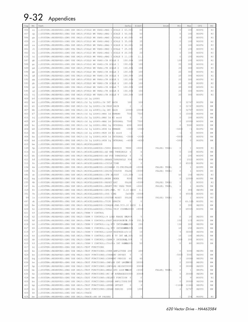
Tag Mn Text Default EIASCII Enum Min Max CFG RO
456 co ::SYSTEM::RESERVED::ENG USE ONLY::FIELD WK VARS::MAG I SCALE 2 63.00% 63 0 100 NOCFG RI
457 cp ::SYSTEM::RESERVED::ENG USE ONLY::FIELD WK VARS::MAG I SCALE 3 50.00% 50 0 100 NOCFG RI
586 ga ::SYSTEM::RESERVED::ENG USE ONLY::FIELD WK VARS::MAG I SCALE 4 40.00% 40 0 100 NOCFG RI
459 cr ::SYSTEM::RESERVED::ENG USE ONLY::FIELD WK VARS::MAG I SCALE 5 35.00% 35 0 100 NOCFG RI
460 cs ::SYSTEM::RESERVED::ENG USE ONLY::FIELD WK VARS::MAG I SCALE 6 30.00% 30 0 100 NOCFG RI
461 ct ::SYSTEM::RESERVED::ENG USE ONLY::FIELD WK VARS::MAG I SCALE 7 25.00% 25 0 100 NOCFG RI
462 cu ::SYSTEM::RESERVED::ENG USE ONLY::FIELD WK VARS::MAG I SCALE 8 20.00% 20 0 100 NOCFG RI
630 hi ::SYSTEM::RESERVED::ENG USE ONLY::FIELD WK VARS::MAG I SCALE 9 11.10% 11.1 0 100 NOCFG RI
587 gb ::SYSTEM::RESERVED::ENG USE ONLY::FIELD WK VARS::TR SCALE 0 100.00% 100 100 100 NOCFG RI
588 gc ::SYSTEM::RESERVED::ENG USE ONLY::FIELD WK VARS::TR SCALE 1 100.00% 100 20 300 NOCFG RI
589 gd ::SYSTEM::RESERVED::ENG USE ONLY::FIELD WK VARS::TR SCALE 2 100.00% 100 20 300 NOCFG RI
590 ge ::SYSTEM::RESERVED::ENG USE ONLY::FIELD WK VARS::TR SCALE 3 100.00% 100 20 300 NOCFG RI
591 gf ::SYSTEM::RESERVED::ENG USE ONLY::FIELD WK VARS::TR SCALE 4 100.00% 100 20 300 NOCFG RI
592 gg ::SYSTEM::RESERVED::ENG USE ONLY::FIELD WK VARS::TR SCALE 5 100.00% 100 20 300 NOCFG RI
593 gh ::SYSTEM::RESERVED::ENG USE ONLY::FIELD WK VARS::TR SCALE 6 100.00% 100 20 300 NOCFG RI
594 gi ::SYSTEM::RESERVED::ENG USE ONLY::FIELD WK VARS::TR SCALE 7 100.00% 100 20 300 NOCFG RI
595 gj ::SYSTEM::RESERVED::ENG USE ONLY::FIELD WK VARS::TR SCALE 8 100.00% 100 20 300 NOCFG RI
631 hj ::SYSTEM::RESERVED::ENG USE ONLY::FIELD WK VARS::TR SCALE 9 100.00% 100 20 300 NOCFG RI
400 b4 ::SYSTEM::RESERVED::ENG USE ONLY::Id Iq LOOPS
402 b6 ::SYSTEM::RESERVED::ENG USE ONLY::Id Iq LOOPS::Id INT GAIN 500 500 0 32767 NOCFG RW
401 b5 ::SYSTEM::RESERVED::ENG USE ONLY::Id Iq LOOPS::Id PROP GAIN 2 2 0 32767 NOCFG RW
407 bb ::SYSTEM::RESERVED::ENG USE ONLY::Id Iq LOOPS::Iq INT GAIN 10000 10000 0 32767 NOCFG RW
403 b7 ::SYSTEM::RESERVED::ENG USE ONLY::Id Iq LOOPS::MAX Id DEMAND 7500 7500 0 10000 NOCFG RW
415 bj ::SYSTEM::RESERVED::ENG USE ONLY::Id Iq LOOPS::MAX Id HI word 0 0 0 100 NOCFG RW
405 b9 ::SYSTEM::RESERVED::ENG USE ONLY::Id Iq LOOPS::MAX Id INTEGRAL 7500 7500 0 10000 NOCFG RW
408 bc ::SYSTEM::RESERVED::ENG USE ONLY::Id Iq LOOPS::MAX Iq INTEGRAL 4000 4000 0 5000 NOCFG RW
404 b8 ::SYSTEM::RESERVED::ENG USE ONLY::Id Iq LOOPS::MIN Id DEMAND -2000 -2000 -5000 -1 NOCFG RW
416 bk ::SYSTEM::RESERVED::ENG USE ONLY::Id Iq LOOPS::MIN Id HI word -1 -1 -1 0 NOCFG RW
406 ba ::SYSTEM::RESERVED::ENG USE ONLY::Id Iq LOOPS::MIN Id INTEGRAL -2000 -2000 -5000 0 NOCFG RW
409 bd ::SYSTEM::RESERVED::ENG USE ONLY::Id Iq LOOPS::MIN Iq INTEGRAL -4000 -4000 -5000 0 NOCFG RW
410 be ::SYSTEM::RESERVED::ENG USE ONLY::MISCELLANEOUS
169 4p ::SYSTEM::RESERVED::ENG USE ONLY::MISCELLANEOUS::584S CHASSIS TRUE >0001 FALSE; TRUE; 0 1 NOCFG RI
414 bi ::SYSTEM::RESERVED::ENG USE ONLY::MISCELLANEOUS::AD NEG THRESHOLD 6 6 0 100 NOCFG RW
413 bh ::SYSTEM::RESERVED::ENG USE ONLY::MISCELLANEOUS::AD POS THRESHOLD 6 6 0 100 NOCFG RW
411 bf ::SYSTEM::RESERVED::ENG USE ONLY::MISCELLANEOUS::BRAKE THRESHOLD 936 936 0 1023 NOCFG RW
315 8r ::SYSTEM::RESERVED::ENG USE ONLY::MISCELLANEOUS::CYCLE TIME 0 0 0 65535 NOCFG RO
154 4a ::SYSTEM::RESERVED::ENG USE ONLY::MISCELLANEOUS::DISABLE CO-PRO FALSE >0000 FALSE; TRUE; 0 1 NOCFG RW
168 4o ::SYSTEM::RESERVED::ENG USE ONLY::MISCELLANEOUS::DRIVE STATUS FALSE >0000 FALSE; TRUE; 0 1 NOCFG RO
495 dr ::SYSTEM::RESERVED::ENG USE ONLY::MISCELLANEOUS::IFB ADJUST 115.00% 115 50 150 RECFG RI
412 bg ::SYSTEM::RESERVED::ENG USE ONLY::MISCELLANEOUS::MODN INDEX 9000 9000 0 12000 NOCFG RW
155 4b ::SYSTEM::RESERVED::ENG USE ONLY::MISCELLANEOUS::RESET EAT FALSE >0000 FALSE; TRUE; 0 1 NOCFG RI
167 4n ::SYSTEM::RESERVED::ENG USE ONLY::MISCELLANEOUS::RESET VEC VARS TRUE >0001 FALSE; TRUE; 0 1 NOCFG RW
319 8v ::SYSTEM::RESERVED::ENG USE ONLY::MISCELLANEOUS::SPD.FBK. TC 0.10 SECS 0.1 0 300 RECFG RW
351 9r ::SYSTEM::RESERVED::ENG USE ONLY::MISCELLANEOUS::SYS TIME 0x0000 >0000 0 65535 NOCFG RO
64 1s ::SYSTEM::RESERVED::ENG USE ONLY::MISCELLANEOUS::SYSTEM RESET FALSE >0000 FALSE; TRUE; 0 1 NOCFG RO
497 dt ::SYSTEM::RESERVED::ENG USE ONLY::MISCELLANEOUS::TICK LENGTH 0 0 0 65.535 NOCFG RO
320 8w ::SYSTEM::RESERVED::ENG USE ONLY::MISCELLANEOUS::TORQUE.FBK.TC 0.10 SECS 0.1 0 300 RECFG RW
624 hc ::SYSTEM::RESERVED::ENG USE ONLY::MISCELLANEOUS::TOTAL TRIP COUNT 0x0000 >0000 0 65535 NOCFG RW
621 h9 ::SYSTEM::RESERVED::ENG USE ONLY::TERM V CONTROL
614 h2 ::SYSTEM::RESERVED::ENG USE ONLY::TERM V CONTROL::% LOAD @BASE SPD5.00% 5 0 10 RECFG RW
620 h8 ::SYSTEM::RESERVED::ENG USE ONLY::TERM V CONTROL::FAST RESPONSE %102.50% 102.5 100 115 RECFG RW
618 h6 ::SYSTEM::RESERVED::ENG USE ONLY::TERM V CONTROL::iq @TV INTGN=MAX200.00% 200 150 300 RECFG RW
617 h5 ::SYSTEM::RESERVED::ENG USE ONLY::TERM V CONTROL::iq @TV INTGN=MIN100.00% 100 10 150 RECFG RW
619 h7 ::SYSTEM::RESERVED::ENG USE ONLY::TERM V CONTROL::LOOP RESPNSE=nTr10 10 4 30000 RECFG RW
616 h4 ::SYSTEM::RESERVED::ENG USE ONLY::TERM V CONTROL::SPD @ TV INT =050.00% 50 10 100 RECFG RW
623 hb ::SYSTEM::RESERVED::ENG USE ONLY::TERM V CONTROL::TERM V INTEGRAL0.00% 0 -300 300 NOCFG RO
615 h3 ::SYSTEM::RESERVED::ENG USE ONLY::TERM V CONTROL::TVolts INT RANGE50.00% 50 0 80 RECFG RW
417 bl ::SYSTEM::RESERVED::ENG USE ONLY::TEST FUNCTIONS
423 br ::SYSTEM::RESERVED::ENG USE ONLY::TEST FUNCTIONS::CURR AMPLITUDE 200 200 0 5000 RECFG RW
424 bs ::SYSTEM::RESERVED::ENG USE ONLY::TEST FUNCTIONS::CURRENT OFFSET 0 0 -5000 5000 RECFG RW
422 bq ::SYSTEM::RESERVED::ENG USE ONLY::TEST FUNCTIONS::CURRENT PERIOD 40 40 2 10000 RECFG RW
636 ho ::SYSTEM::RESERVED::ENG USE ONLY::TEST FUNCTIONS::IMPLSE CNT LNGTH30000 30000 0 30000 RECFG RW
637 hp ::SYSTEM::RESERVED::ENG USE ONLY::TEST FUNCTIONS::IMPULSE HEIGHT30000 30000 0 30000 RECFG RW
634 hm ::SYSTEM::RESERVED::ENG USE ONLY::TEST FUNCTIONS::MEAS SPD LOOP BWFALSE >0000 FALSE; TRUE; 0 1 RECFG RW
635 hn ::SYSTEM::RESERVED::ENG USE ONLY::TEST FUNCTIONS::NO OF AVERAGES30000 30000 0 30000 RECFG RW
418 bm ::SYSTEM::RESERVED::ENG USE ONLY::TEST FUNCTIONS::SELECT FUNCTION 0 0 0 9 NOCFG RI
420 bo ::SYSTEM::RESERVED::ENG USE ONLY::TEST FUNCTIONS::SPEED AMPLITUDE 500 500 0 30000 RECFG RW
421 bp ::SYSTEM::RESERVED::ENG USE ONLY::TEST FUNCTIONS::SPEED OFFSET 0 0 -11000 11000 RECFG RW
419 bn ::SYSTEM::RESERVED::ENG USE ONLY::TEST FUNCTIONS::SPEED PERIOD 1000 1000 2 32767 RECFG RW
425 bt ::SYSTEM::RESERVED::ENG USE ONLY::TRACE
428 bw ::SYSTEM::RESERVED::ENG USE ONLY::TRACE::NO OF PASSES 1 1 1 254 NOCFG RI
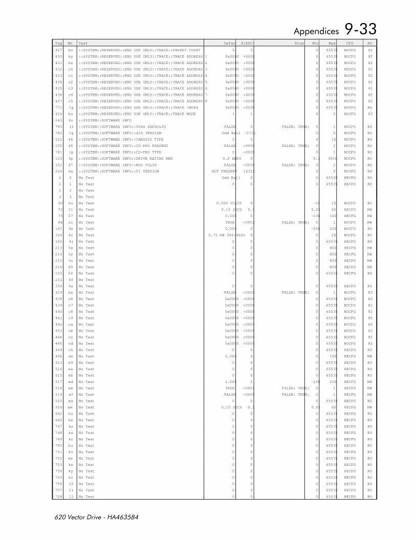
Tag Mn Text Default EIASCII Enum Min Max CFG RO
427 bv ::SYSTEM::RESERVED::ENG USE ONLY::TRACE::PRESET COUNT 0 0 0 65535 NOCFG RI
430 by ::SYSTEM::RESERVED::ENG USE ONLY::TRACE::TRACE ADDRESS 1 0x0000 >0000 0 65535 NOCFG RI
431 bz ::SYSTEM::RESERVED::ENG USE ONLY::TRACE::TRACE ADDRESS 2 0x0000 >0000 0 65535 NOCFG RI
432 c0 ::SYSTEM::RESERVED::ENG USE ONLY::TRACE::TRACE ADDRESS 3 0x0000 >0000 0 65535 NOCFG RI
433 c1 ::SYSTEM::RESERVED::ENG USE ONLY::TRACE::TRACE ADDRESS 4 0x0000 >0000 0 65535 NOCFG RI
434 c2 ::SYSTEM::RESERVED::ENG USE ONLY::TRACE::TRACE ADDRESS 5 0x0000 >0000 0 65535 NOCFG RI
435 c3 ::SYSTEM::RESERVED::ENG USE ONLY::TRACE::TRACE ADDRESS 6 0x0000 >0000 0 65535 NOCFG RI
436 c4 ::SYSTEM::RESERVED::ENG USE ONLY::TRACE::TRACE ADDRESS 7 0x0000 >0000 0 65535 NOCFG RI
437 c5 ::SYSTEM::RESERVED::ENG USE ONLY::TRACE::TRACE ADDRESS 8 0x0000 >0000 0 65535 NOCFG RI
772 lg ::SYSTEM::RESERVED::ENG USE ONLY::TRACE::TRACE INDEX 0x0000 >0000 0 65535 NOCFG RO
426 bu ::SYSTEM::RESERVED::ENG USE ONLY::TRACE::TRACE MODE 1 1 0 2 NOCFG RI
243 6r ::SYSTEM::SOFTWARE INFO
785 lt ::SYSTEM::SOFTWARE INFO::60Hz DEFAULTS FALSE 0 FALSE; TRUE; 0 1 NOCFG RO
782 lq ::SYSTEM::SOFTWARE INFO::620 VERSION Odd Ball -3712 0 0 NOCFG RO
152 48 ::SYSTEM::SOFTWARE INFO::CHASSIS TYPE 0 0 4 10 NOCFG RO
150 46 ::SYSTEM::SOFTWARE INFO::CO-PRO PRESENT FALSE >0000 FALSE; TRUE; 0 1 NOCFG RO
781 lp ::SYSTEM::SOFTWARE INFO::CO-PRO TYPE 0 >0000 0 1 NOCFG RO
133 3p ::SYSTEM::SOFTWARE INFO::DRIVE RATING RMS 0.0 AMPS 0 0.1 3000 NOCFG RO
151 47 ::SYSTEM::SOFTWARE INFO::MID VOLTS FALSE >0000 FALSE; TRUE; 0 1 NOCFG RO
226 6a ::SYSTEM::SOFTWARE INFO::P1 VERSION NOT PRESENT 10312 0 0 NOCFG RO
0 0 No Text Odd Ball 0 0 65535 RECFG RO
1 1 No Text 0 0 0 65535 RECFG RO
2 2 No Text
3 3 No Text
30 0u No Text 0.000 VOLTS 0 -10 10 NOCFG RO
73 21 No Text 0.10 SECS 0.1 0.01 60 RECFG RW
79 27 No Text 0.00% 0 -100 100 RECFG RW
84 2c No Text TRUE >0001 FALSE; TRUE; 0 1 NOCFG RW
141 3x No Text 0.00% 0 -200 200 NOCFG RO
156 4c No Text 0.75 kW 380-460v 0 0 28 NOCFG RO
165 4l No Text 0 0 0 65535 RECFG RO
213 5x No Text 0 0 0 800 RECFG RW
214 5y No Text 0 0 0 800 RECFG RW
215 5z No Text 0 0 0 800 RECFG RW
216 60 No Text 0 0 0 800 RECFG RW
220 64 No Text 0 0 0 65535 RECFG RO
231 6f No Text
334 9a No Text 0 0 0 65535 RECFG RO
429 bx No Text FALSE >0000 FALSE; TRUE; 0 1 NOCFG RI
438 c6 No Text 0x0000 >0000 0 65535 NOCFG RI
439 c7 No Text 0x0000 >0000 0 65535 NOCFG RI
440 c8 No Text 0x0000 >0000 0 65535 NOCFG RI
441 c9 No Text 0x0000 >0000 0 65535 NOCFG RI
442 ca No Text 0x0000 >0000 0 65535 NOCFG RI
443 cb No Text 0x0000 >0000 0 65535 NOCFG RI
444 cc No Text 0x0000 >0000 0 65535 NOCFG RI
445 cd No Text 0x0000 >0000 0 65535 NOCFG RI
449 ch No Text 0 0 0 65535 RECFG RO
496 ds No Text 0.00% 0 0 100 RECFG RW
513 e9 No Text 0 0 0 65535 RECFG RO
514 ea No Text 0 0 0 65535 RECFG RO
515 eb No Text 0 0 0 65535 RECFG RO
517 ed No Text 1.00% 1 -100 100 RECFG RW
518 ee No Text TRUE >0001 FALSE; TRUE; 0 1 RECFG RW
519 ef No Text FALSE >0000 FALSE; TRUE; 0 1 RECFG RW
520 eg No Text 0 0 0 65535 RECFG RO
526 em No Text 0.10 SECS 0.1 0.01 60 RECFG RW
642 hu No Text 0 0 0 65535 RECFG RO
645 hx No Text 0 0 0 65535 RECFG RO
747 kr No Text 0 0 0 65535 RECFG RO
748 ks No Text 0 0 0 65535 RECFG RO
749 kt No Text 0 0 0 65535 RECFG RO
750 ku No Text 0 0 0 65535 RECFG RO
751 kv No Text 0 0 0 65535 RECFG RO
752 kw No Text 0 0 0 65535 RECFG RO
753 kx No Text 0 0 0 65535 RECFG RO
754 ky No Text 0 0 0 65535 RECFG RO
755 kz No Text 0 0 0 65535 RECFG RO
756 l0 No Text 0 0 0 65535 RECFG RO
757 l1 No Text 0 0 0 65535 RECFG RO
758 l2 No Text 0 0 0 65535 RECFG RO

Tag Mn Text Default EIASCII Enum Min Max CFG RO
759 l3 No Text 0 0 0 65535 RECFG RO
760 l4 No Text 0 0 0 65535 RECFG RO
775 lj No Text 0 0 0 65535 RECFG RO
792 m0 No Text 0 0 0 65535 RECFG RO
793 m1 No Text 0 0 0 65535 RECFG RO
794 m2 No Text 0 0 0 65535 RECFG RO
795 m3 No Text 0 0 0 65535 RECFG RO
796 m4 No Text 0 0 0 65535 RECFG RO
797 m5 No Text 0 0 0 65535 RECFG RO
798 m6 No Text 0 0 0 65535 RECFG RO
799 m7 No Text 0 0 0 65535 RECFG RO
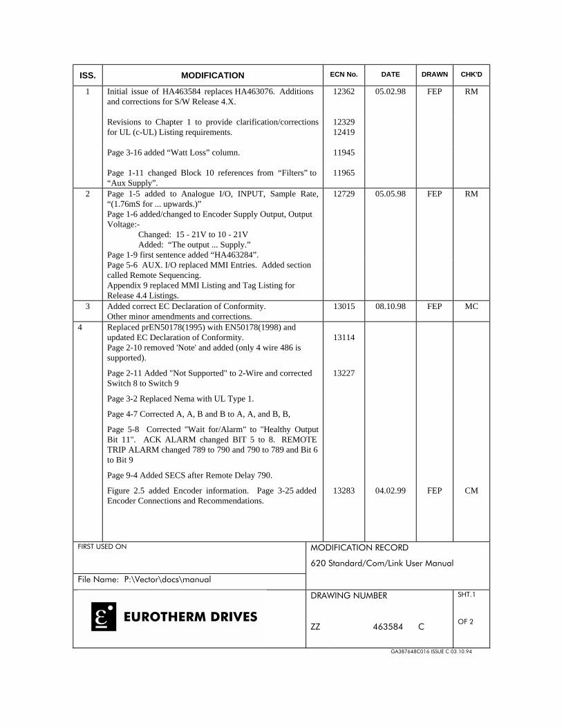
ISS. MODIFICATION ECN No. DATE DRAWN CHK'D
1 Initial issue of HA463584 replaces HA463076. Additionsand corrections for S/W Release 4.X.
12362 05.02.98 FEP RM
Revisions to Chapter 1 to provide clarification/correctionsfor UL (c-UL) Listing requirements.
1232912419
Page 3-16 added “Watt Loss” column. 11945
Page 1-11 changed Block 10 references from “Filters” to“Aux Supply”.
11965
2 Page 1-5 added to Analogue I/O, INPUT, Sample Rate,“(1.76mS for ... upwards.)”
12729 05.05.98 FEP RM
Page 1-6 added/changed to Encoder Supply Output, OutputVoltage:-
Changed: 15 - 21V to 10 - 21VAdded: “The output ... Supply.”
Page 1-9 first sentence added “HA463284”.Page 5-6 AUX. I/O replaced MMI Entries. Added sectioncalled Remote Sequencing.Appendix 9 replaced MMI Listing and Tag Listing forRelease 4.4 Listings.
3 Added correct EC Declaration of Conformity. 13015 08.10.98 FEP MCOther minor amendments and corrections.
4 Replaced prEN50178(1995) with EN50178(1998) andupdated EC Declaration of Conformity. 13114Page 2-10 removed 'Note' and added (only 4 wire 486 issupported).
Page 2-11 Added "Not Supported" to 2-Wire and correctedSwitch 8 to Switch 9
13227
Page 3-2 Replaced Nema with UL Type 1.
Page 4-7 Corrected A, A, B and B to A, A, and B, B,
Page 5-8 Corrected "Wait for/Alarm" to "Healthy OutputBit 11". ACK ALARM changed BIT 5 to 8. REMOTETRIP ALARM changed 789 to 790 and 790 to 789 and Bit 6to Bit 9
Page 9-4 Added SECS after Remote Delay 790.
Figure 2.5 added Encoder information. Page 3-25 addedEncoder Connections and Recommendations.
13283 04.02.99 FEP CM
+# %( '$ '+ %'$#'#
-(
+$AAA
# "$)$(,#
88
%
'+
) (

ISS. MODIFICATION ECN No. DATE DRAWN CHK'D
5 Page 1-1 added "Important: Motors used must be suitablefor inverter duty".
Page 1-2 re-drawn figure 1, so will be visible when pdf filesare generated.
Page 1-3 corrected output frequency from 400 to 240 andadded (for higher frequencies contact ... support).
Page 1-12 Block 9 replaced (standard) with (recommended).
13715
13996
13.12.1999 FEP RM
Page 2-7 Replaced 620Adv with 620 Com.Page 3-9 Removed "All 620 units are supplied withoutbraking resistors by default".Page 3-18 added "Note: You must fit the 620 .... the duct". 13591Removed pages 5-69 to 5-80 Profibus information andadded to Profibus manual HA389815.
13907
Page 7-6, 7, 8 and 9 Replaced Certificates and correctedfooter information.
13908
Page 8-1 added information on Disposal and Packaging.Replaced prEN50178(1995) with EN50178(1988)Page 9-1 reworded sentence from "Recommended chokevalues for cables up to 500m" to "Recommended chokevalues for cables over 50m". 13779Pages 9-4 to 9-8 Replaced MMI Listing release 4.4 with 4.8.
+# %( '$ '+ %'$#'#
-(
+$AAA
# "$)$(,#
88
%
'+
) (

This page is intentionally left blank