Embed Size (px)
Citation preview
1/3420178 - 933 - ENGRev. 2005.12.09.
Service manual - SMC/TSMC 100 Mk4
01 in
trod
uctio
n.fm
Manual for SMC and TSMC Mk4, S-L-EThe SMC/TSMC reciprocating compressor can be fitted with a range of equipment, depending on the function and requirements it is expected to meet.
Some of these variants are discussed in this man-ual, even if they are not featured on your particu-lar unit.
The variants featured on the unit are marked with an 'x' in the following diagram, with the compres-sor number stated below.
Compressor type SMC ❑ TSMC ❏ S ❏ L ❏ E ❏
104 ❑ 106 ❏ 108 ❏ 112 ❏ 116 ❏
Compressor no
Refrigerant R717 ❑ R22 ❑ R134a ❑ R404A ❑R507 ❑ Other _________ ❏
Control UNISAB II control- and regulating system
Analog control system
Compressor cooling
Thermopump
Water cooled top and side covers
Air cooled top and side covers
Oil cooling (water-cooled side covers)
Oil cooling OOSI/OOKH
Drive type Coupling
V-belts
Explosion-proof electrical design
Equipment for parallel operation
SABROE OVUR oil separator
1. Introduction
2/342 0178 - 933 - ENGRev. 2005.12.09.
Service manual - SMC/TSMC 100 Mk4
1. IntroductionThe purpose of this manual is to provide the oper-ating personnel with a thorough knowledge of the compressor as well as information about:
• The function and maintenance of eachcomponent.
• Service schedules.
This manual describes the compressor and its component parts as well as safety instruc-tions/regulations. Moreover, the manual explains the different settings that can be of assistance to those who are responsible for the daily operation and maintenance of the equipment.
To prevent any accidents, assembly and disas-sembly of components should only be carried out by authorized personnel.
It is essential that the operating personnel famil-iarize themselves with the contents of this manual in order to ensure a proper and efficient operation. Sabroe Refrigeration (YORK Denmark ApS) - hereafter referred to as Sabroe Refrigeration - is not liable for damage occurring during the warran-
ty period where this is attributable to incorrect op-eration.
Sabroe Refrigeration's manual concept covers six standard manuals: Engineering, Operating, Serv-ice, Installation and Commissioning, Transport and Spare Parts. Therefore, references may be made to chapters which are not part of this manu-al.
This manual was produced by:
Sabroe Refrigeration (YORK Denmark ApS)Chr. X’s Vej 201, P.O. Box 18108270 Højbjerg, DenmarkPhone +45 87 36 70 00Fax +45 87 36 70 05www.sabroe.comReg. No 19 05 61 71
Copyright © 2004 Sabroe Refrigeration
This manual must not be copied without the writ-ten permission of Sabroe Refrigeration and the contents must not be imparted to a third party nor be used for any unauthorised purpose. Contravention will be prosecuted.
In the space below you may enter the name and address of your local Sabroe Representative
3/3420178 - 933 - ENG
Rev. 2005.12.09.
Service manual - SMC/TSMC 100 Mk4
0178
-933
-EN
GT
OC
.fm
Table of Contents
Manual for SMC and TSMC Mk4, S-L-E . . . . . . . . . . . . . . . . . . . . . . . . . . . . . . . . . . . . . . . . . . . 1
Introduction . . . . . . . . . . . . . . . . . . . . . . . . . . . . . . . . . . . . . . . . . . . . . . . . . . . . . . . . . . . . . . . . . 2
Signs and Warnings . . . . . . . . . . . . . . . . . . . . . . . . . . . . . . . . . . . . . . . . . . . . . . . . . . . . . . . . . . . 9Identification of Sabroe Refrigeration Equipment . . . . . . . . . . . . . . . . . . . . . . . . . . . . . . . . 10Unit pipe system name plate . . . . . . . . . . . . . . . . . . . . . . . . . . . . . . . . . . . . . . . . . . . . . . . 11Compressor name plate . . . . . . . . . . . . . . . . . . . . . . . . . . . . . . . . . . . . . . . . . . . . . . . . . . . 12Vessel name plate . . . . . . . . . . . . . . . . . . . . . . . . . . . . . . . . . . . . . . . . . . . . . . . . . . . . . . . 13Signs in instructions . . . . . . . . . . . . . . . . . . . . . . . . . . . . . . . . . . . . . . . . . . . . . . . . . . . . . . 14The sign: CAUTION . . . . . . . . . . . . . . . . . . . . . . . . . . . . . . . . . . . . . . . . . . . . . . . . . . . . . . 14The sign: HIGH VOLTAGE . . . . . . . . . . . . . . . . . . . . . . . . . . . . . . . . . . . . . . . . . . . . . . . . . 14The sign: The temperature of tangible surfaces . . . . . . . . . . . . . . . . . . . . . . . . . . . . . . . . . 15The sign: Internal protection . . . . . . . . . . . . . . . . . . . . . . . . . . . . . . . . . . . . . . . . . . . . . . . . 15Other warning signs . . . . . . . . . . . . . . . . . . . . . . . . . . . . . . . . . . . . . . . . . . . . . . . . . . . . . . 15Emergency Stop . . . . . . . . . . . . . . . . . . . . . . . . . . . . . . . . . . . . . . . . . . . . . . . . . . . . . . . . . 16Safety during Service . . . . . . . . . . . . . . . . . . . . . . . . . . . . . . . . . . . . . . . . . . . . . . . . . . . . . 16Warnings in Instructions . . . . . . . . . . . . . . . . . . . . . . . . . . . . . . . . . . . . . . . . . . . . . . . . . . . 17Texts Marked with Danger! . . . . . . . . . . . . . . . . . . . . . . . . . . . . . . . . . . . . . . . . . . . . . . . . . 17Texts Marked with Warning! . . . . . . . . . . . . . . . . . . . . . . . . . . . . . . . . . . . . . . . . . . . . . . . . 17Texts Marked with Caution! . . . . . . . . . . . . . . . . . . . . . . . . . . . . . . . . . . . . . . . . . . . . . . . . 17
Safety Precautions . . . . . . . . . . . . . . . . . . . . . . . . . . . . . . . . . . . . . . . . . . . . . . . . . . . . . . . . . . . . 19General Safety Instructions and Considerations . . . . . . . . . . . . . . . . . . . . . . . . . . . . . . . . 19Personal Safety . . . . . . . . . . . . . . . . . . . . . . . . . . . . . . . . . . . . . . . . . . . . . . . . . . . . . . . . . 19Work Area Safety . . . . . . . . . . . . . . . . . . . . . . . . . . . . . . . . . . . . . . . . . . . . . . . . . . . . . . . . 19Tool Safety . . . . . . . . . . . . . . . . . . . . . . . . . . . . . . . . . . . . . . . . . . . . . . . . . . . . . . . . . . . . . 20Transmission safety . . . . . . . . . . . . . . . . . . . . . . . . . . . . . . . . . . . . . . . . . . . . . . . . . . . . . . 20Coupling . . . . . . . . . . . . . . . . . . . . . . . . . . . . . . . . . . . . . . . . . . . . . . . . . . . . . . . . . . . . . . . 20Belt drive . . . . . . . . . . . . . . . . . . . . . . . . . . . . . . . . . . . . . . . . . . . . . . . . . . . . . . . . . . . . . . . 20Lifting and Carrying Safety . . . . . . . . . . . . . . . . . . . . . . . . . . . . . . . . . . . . . . . . . . . . . . . . . 20Installation and Relocation Safety . . . . . . . . . . . . . . . . . . . . . . . . . . . . . . . . . . . . . . . . . . . 21Set-Up and Operation Safety . . . . . . . . . . . . . . . . . . . . . . . . . . . . . . . . . . . . . . . . . . . . . . . 21Maintenance Safety . . . . . . . . . . . . . . . . . . . . . . . . . . . . . . . . . . . . . . . . . . . . . . . . . . . . . . 22Materials Used with this Product . . . . . . . . . . . . . . . . . . . . . . . . . . . . . . . . . . . . . . . . . . . . 23First aid for accidents with ammonia . . . . . . . . . . . . . . . . . . . . . . . . . . . . . . . . . . . . . . . . . 24General . . . . . . . . . . . . . . . . . . . . . . . . . . . . . . . . . . . . . . . . . . . . . . . . . . . . . . . . . . . . . . . . 24Basic rules for first aid . . . . . . . . . . . . . . . . . . . . . . . . . . . . . . . . . . . . . . . . . . . . . . . . . . . . 24First aid measures . . . . . . . . . . . . . . . . . . . . . . . . . . . . . . . . . . . . . . . . . . . . . . . . . . . . . . . 24First aid for accidents with HFC/HCFC . . . . . . . . . . . . . . . . . . . . . . . . . . . . . . . . . . . . . . . . 25General . . . . . . . . . . . . . . . . . . . . . . . . . . . . . . . . . . . . . . . . . . . . . . . . . . . . . . . . . . . . . . . . 25Basic rules for first aid . . . . . . . . . . . . . . . . . . . . . . . . . . . . . . . . . . . . . . . . . . . . . . . . . . . . 25Protecting the operator as well as the environment . . . . . . . . . . . . . . . . . . . . . . . . . . . . . . 26Furthermore, it can be said about refrigerants: . . . . . . . . . . . . . . . . . . . . . . . . . . . . . . . . . . 27Purging a refrigeration plant . . . . . . . . . . . . . . . . . . . . . . . . . . . . . . . . . . . . . . . . . . . . . . . . 28Cooling media . . . . . . . . . . . . . . . . . . . . . . . . . . . . . . . . . . . . . . . . . . . . . . . . . . . . . . . . . . . 29Lubricating oils . . . . . . . . . . . . . . . . . . . . . . . . . . . . . . . . . . . . . . . . . . . . . . . . . . . . . . . . . . 29
4/342 0178 - 933 - ENGRev. 2005.12.09.
Service manual - SMC/TSMC 100 Mk4
Cooling water systems . . . . . . . . . . . . . . . . . . . . . . . . . . . . . . . . . . . . . . . . . . . . . . . . . . . . . 29
Technical Description . . . . . . . . . . . . . . . . . . . . . . . . . . . . . . . . . . . . . . . . . . . . . . . . . . . . . . . . . . 31Areas of Application of the Reciprocating Compressor Unit . . . . . . . . . . . . . . . . . . . . . . . . 31Marine application . . . . . . . . . . . . . . . . . . . . . . . . . . . . . . . . . . . . . . . . . . . . . . . . . . . . . . . . 33Description of the Compressors Compressor Types . . . . . . . . . . . . . . . . . . . . . . . . . . . . . . 34Compressor Description . . . . . . . . . . . . . . . . . . . . . . . . . . . . . . . . . . . . . . . . . . . . . . . . . . . 36Single-stage Compressors . . . . . . . . . . . . . . . . . . . . . . . . . . . . . . . . . . . . . . . . . . . . . . . . . . 36Two-stage Compressors Type TSMC 100 . . . . . . . . . . . . . . . . . . . . . . . . . . . . . . . . . . . . . . 47Compressor Block . . . . . . . . . . . . . . . . . . . . . . . . . . . . . . . . . . . . . . . . . . . . . . . . . . . . . . . . 47Piston Pin Bearing . . . . . . . . . . . . . . . . . . . . . . . . . . . . . . . . . . . . . . . . . . . . . . . . . . . . . . . . 48Suction Filters . . . . . . . . . . . . . . . . . . . . . . . . . . . . . . . . . . . . . . . . . . . . . . . . . . . . . . . . . . . 49Conversion of TSMC Compressors from Two-stage to Single-stage . . . . . . . . . . . . . . . . . 50Oil Separator Type OVUR . . . . . . . . . . . . . . . . . . . . . . . . . . . . . . . . . . . . . . . . . . . . . . . . . . 51Mode of Operation . . . . . . . . . . . . . . . . . . . . . . . . . . . . . . . . . . . . . . . . . . . . . . . . . . . . . . . . 51Selecting an Oil Separator . . . . . . . . . . . . . . . . . . . . . . . . . . . . . . . . . . . . . . . . . . . . . . . . . . 51Oil Return to the Compressor . . . . . . . . . . . . . . . . . . . . . . . . . . . . . . . . . . . . . . . . . . . . . . . 52Thermodynamic Liquid Trap (TLT) . . . . . . . . . . . . . . . . . . . . . . . . . . . . . . . . . . . . . . . . . . . 54Oil Return in Connection with Parallel Operation . . . . . . . . . . . . . . . . . . . . . . . . . . . . . . . . . 56System A . . . . . . . . . . . . . . . . . . . . . . . . . . . . . . . . . . . . . . . . . . . . . . . . . . . . . . . . . . . . . . . 57System B . . . . . . . . . . . . . . . . . . . . . . . . . . . . . . . . . . . . . . . . . . . . . . . . . . . . . . . . . . . . . . . 60System C . . . . . . . . . . . . . . . . . . . . . . . . . . . . . . . . . . . . . . . . . . . . . . . . . . . . . . . . . . . . . . . 62Capacity Regulation of Compressor . . . . . . . . . . . . . . . . . . . . . . . . . . . . . . . . . . . . . . . . . . 63Capacity Regulation and Unloading of Compressor . . . . . . . . . . . . . . . . . . . . . . . . . . . . . . 63Start Unloading . . . . . . . . . . . . . . . . . . . . . . . . . . . . . . . . . . . . . . . . . . . . . . . . . . . . . . . . . . 65Regulating Sequence . . . . . . . . . . . . . . . . . . . . . . . . . . . . . . . . . . . . . . . . . . . . . . . . . . . . . . 66Variable speed drive (VSD) . . . . . . . . . . . . . . . . . . . . . . . . . . . . . . . . . . . . . . . . . . . . . . . . . 75Compressor Units . . . . . . . . . . . . . . . . . . . . . . . . . . . . . . . . . . . . . . . . . . . . . . . . . . . . . . . . 76Instrumentation . . . . . . . . . . . . . . . . . . . . . . . . . . . . . . . . . . . . . . . . . . . . . . . . . . . . . . . . . . 77Manometers . . . . . . . . . . . . . . . . . . . . . . . . . . . . . . . . . . . . . . . . . . . . . . . . . . . . . . . . . . . . . 79Cooling of the Intermediate Discharge Gas on TSMC Compressors . . . . . . . . . . . . . . . . . 82Automatic Regulation of Intermediate Pressure IP . . . . . . . . . . . . . . . . . . . . . . . . . . . . . . . 84Determining the Intermediate Pressure IP . . . . . . . . . . . . . . . . . . . . . . . . . . . . . . . . . . . . . . 84Cooling Systems for Compressors . . . . . . . . . . . . . . . . . . . . . . . . . . . . . . . . . . . . . . . . . . . 86Standard Cooling Systems for Compressors . . . . . . . . . . . . . . . . . . . . . . . . . . . . . . . . . . . . 86Description . . . . . . . . . . . . . . . . . . . . . . . . . . . . . . . . . . . . . . . . . . . . . . . . . . . . . . . . . . . . . . 86Mounting of Cooling Water Hoses . . . . . . . . . . . . . . . . . . . . . . . . . . . . . . . . . . . . . . . . . . . . 88Pressure Loss in the Cooling System in SMC/TSMC Compressors . . . . . . . . . . . . . . . . . . 93Description of the Pumping Cycle . . . . . . . . . . . . . . . . . . . . . . . . . . . . . . . . . . . . . . . . . . . . 97Ensuring Liquid to the Thermo Pump . . . . . . . . . . . . . . . . . . . . . . . . . . . . . . . . . . . . . . . . . 99Power Connection . . . . . . . . . . . . . . . . . . . . . . . . . . . . . . . . . . . . . . . . . . . . . . . . . . . . . . . . 100Compressor Accessories . . . . . . . . . . . . . . . . . . . . . . . . . . . . . . . . . . . . . . . . . . . . . . . . . . . 102Types of Spare Parts Set: . . . . . . . . . . . . . . . . . . . . . . . . . . . . . . . . . . . . . . . . . . . . . . . . . . 103
Technical Data . . . . . . . . . . . . . . . . . . . . . . . . . . . . . . . . . . . . . . . . . . . . . . . . . . . . . . . . . . . . . . . 105Technical Data for the SMC 100 Series . . . . . . . . . . . . . . . . . . . . . . . . . . . . . . . . . . . . . . . . 106Compressor Capacity . . . . . . . . . . . . . . . . . . . . . . . . . . . . . . . . . . . . . . . . . . . . . . . . . . . . . 109Dimension Sketches of Compressor Block . . . . . . . . . . . . . . . . . . . . . . . . . . . . . . . . . . . . . 109Planning the Machine Room . . . . . . . . . . . . . . . . . . . . . . . . . . . . . . . . . . . . . . . . . . . . . . . . 113
5/3420178 - 933 - ENG
Rev. 2005.12.09.
Service manual - SMC/TSMC 100 Mk4
0178
-933
-EN
GT
OC
.fm
Operating Limits Diagrams . . . . . . . . . . . . . . . . . . . . . . . . . . . . . . . . . . . . . . . . . . . . . . . . . 114Direction of Rotation of the Compressor . . . . . . . . . . . . . . . . . . . . . . . . . . . . . . . . . . . . . . . 129Choice of Electric Motor . . . . . . . . . . . . . . . . . . . . . . . . . . . . . . . . . . . . . . . . . . . . . . . . . . . 130Motor Dimension . . . . . . . . . . . . . . . . . . . . . . . . . . . . . . . . . . . . . . . . . . . . . . . . . . . . . . . . . 130Starting torque of the compressor . . . . . . . . . . . . . . . . . . . . . . . . . . . . . . . . . . . . . . . . . . . 132Moment of Inertia . . . . . . . . . . . . . . . . . . . . . . . . . . . . . . . . . . . . . . . . . . . . . . . . . . . . . . . . 135Direction of Rotation of Electric Motor . . . . . . . . . . . . . . . . . . . . . . . . . . . . . . . . . . . . . . . . 136Handling of Compressor and Unit . . . . . . . . . . . . . . . . . . . . . . . . . . . . . . . . . . . . . . . . . . . . 137Compressor Shaft . . . . . . . . . . . . . . . . . . . . . . . . . . . . . . . . . . . . . . . . . . . . . . . . . . . . . . . . 138Coupling . . . . . . . . . . . . . . . . . . . . . . . . . . . . . . . . . . . . . . . . . . . . . . . . . . . . . . . . . . . . . . . 140V-belt drive for SMC/TSMC 100 . . . . . . . . . . . . . . . . . . . . . . . . . . . . . . . . . . . . . . . . . . . . . 142Transmission Ratio . . . . . . . . . . . . . . . . . . . . . . . . . . . . . . . . . . . . . . . . . . . . . . . . . . . . . . . 142Power Transmission . . . . . . . . . . . . . . . . . . . . . . . . . . . . . . . . . . . . . . . . . . . . . . . . . . . . . . 144Construction of V-Belt Drive . . . . . . . . . . . . . . . . . . . . . . . . . . . . . . . . . . . . . . . . . . . . . . . . 146Service . . . . . . . . . . . . . . . . . . . . . . . . . . . . . . . . . . . . . . . . . . . . . . . . . . . . . . . . . . . . . . . . 147Noise from Compressors and Units . . . . . . . . . . . . . . . . . . . . . . . . . . . . . . . . . . . . . . . . . . 148Noise Data for Reciprocating Compressors . . . . . . . . . . . . . . . . . . . . . . . . . . . . . . . . . . . . 152Reverberation Time . . . . . . . . . . . . . . . . . . . . . . . . . . . . . . . . . . . . . . . . . . . . . . . . . . . . . . 153Vibration Data for Compressors - All Compressor Types . . . . . . . . . . . . . . . . . . . . . . . . . . 155Specification of Compressor Materials . . . . . . . . . . . . . . . . . . . . . . . . . . . . . . . . . . . . . . . . 156Pressure Levels for Standard Compressors and Components . . . . . . . . . . . . . . . . . . . . . 157Charging the Compressor with Oil . . . . . . . . . . . . . . . . . . . . . . . . . . . . . . . . . . . . . . . . . . . 159Oil Consumption . . . . . . . . . . . . . . . . . . . . . . . . . . . . . . . . . . . . . . . . . . . . . . . . . . . . . . . . . 161Selecting Oil Separator . . . . . . . . . . . . . . . . . . . . . . . . . . . . . . . . . . . . . . . . . . . . . . . . . . . . 161Selecting Lubricating Oil for SABROE Reciprocating Compressors . . . . . . . . . . . . . . . . . 162Data Sheet for Listed Sabroe Oils . . . . . . . . . . . . . . . . . . . . . . . . . . . . . . . . . . . . . . . . . . . 168List of Part Numbers for Available Sabroe Oils . . . . . . . . . . . . . . . . . . . . . . . . . . . . . . . . . 169List of Major Oil Companies . . . . . . . . . . . . . . . . . . . . . . . . . . . . . . . . . . . . . . . . . . . . . . . . 173Selecting Lubricating Oil for SABROE Reciprocating Compressors . . . . . . . . . . . . . . . . . 174Oil Changing Intervals . . . . . . . . . . . . . . . . . . . . . . . . . . . . . . . . . . . . . . . . . . . . . . . . . . . . 179Data Sheet for Listed Sabroe Oils . . . . . . . . . . . . . . . . . . . . . . . . . . . . . . . . . . . . . . . . . . . 180List of Part Numbers for Available Sabroe Oils . . . . . . . . . . . . . . . . . . . . . . . . . . . . . . . . . 181List of Major Oil Companies . . . . . . . . . . . . . . . . . . . . . . . . . . . . . . . . . . . . . . . . . . . . . . . . 194
Settings . . . . . . . . . . . . . . . . . . . . . . . . . . . . . . . . . . . . . . . . . . . . . . . . . . . . . . . . . . . . . . . . . . . . 195Safety Precautions . . . . . . . . . . . . . . . . . . . . . . . . . . . . . . . . . . . . . . . . . . . . . . . . . . . . . . . 195Qualification Requirements . . . . . . . . . . . . . . . . . . . . . . . . . . . . . . . . . . . . . . . . . . . . . . . . . 195Compressor control systems . . . . . . . . . . . . . . . . . . . . . . . . . . . . . . . . . . . . . . . . . . . . . . . 195
Operating instructions . . . . . . . . . . . . . . . . . . . . . . . . . . . . . . . . . . . . . . . . . . . . . . . . . . . . . . . . . 199
Maintenance Instructions . . . . . . . . . . . . . . . . . . . . . . . . . . . . . . . . . . . . . . . . . . . . . . . . . . . . . . . 201Safety Precautions . . . . . . . . . . . . . . . . . . . . . . . . . . . . . . . . . . . . . . . . . . . . . . . . . . . . . . . 201Safety Measures . . . . . . . . . . . . . . . . . . . . . . . . . . . . . . . . . . . . . . . . . . . . . . . . . . . . . . . . . 201Maintenance of the Compressor Unit . . . . . . . . . . . . . . . . . . . . . . . . . . . . . . . . . . . . . . . . . 202General . . . . . . . . . . . . . . . . . . . . . . . . . . . . . . . . . . . . . . . . . . . . . . . . . . . . . . . . . . . . . . . . 202Service intervals . . . . . . . . . . . . . . . . . . . . . . . . . . . . . . . . . . . . . . . . . . . . . . . . . . . . . . . . . 203Measures to be taken . . . . . . . . . . . . . . . . . . . . . . . . . . . . . . . . . . . . . . . . . . . . . . . . . . . . . 205Visual Inspection . . . . . . . . . . . . . . . . . . . . . . . . . . . . . . . . . . . . . . . . . . . . . . . . . . . . . . . . . 206
6/342 0178 - 933 - ENGRev. 2005.12.09.
Service manual - SMC/TSMC 100 Mk4
General Rules for Use of Lubricating Oil in Refrigeration Compressors . . . . . . . . . . . . . . . 207Assessing the Oil . . . . . . . . . . . . . . . . . . . . . . . . . . . . . . . . . . . . . . . . . . . . . . . . . . . . . . . . . 208Analytical Evaluation . . . . . . . . . . . . . . . . . . . . . . . . . . . . . . . . . . . . . . . . . . . . . . . . . . . . . . 208Procedure . . . . . . . . . . . . . . . . . . . . . . . . . . . . . . . . . . . . . . . . . . . . . . . . . . . . . . . . . . . . . . 208Analysing the Oil . . . . . . . . . . . . . . . . . . . . . . . . . . . . . . . . . . . . . . . . . . . . . . . . . . . . . . . . . 208Limiting Values . . . . . . . . . . . . . . . . . . . . . . . . . . . . . . . . . . . . . . . . . . . . . . . . . . . . . . . . . . . 209Charging Compressor with Lubricating Oil . . . . . . . . . . . . . . . . . . . . . . . . . . . . . . . . . . . . . 210Searching for Leaks . . . . . . . . . . . . . . . . . . . . . . . . . . . . . . . . . . . . . . . . . . . . . . . . . . . . . . . 211Method of Searching for Leaks . . . . . . . . . . . . . . . . . . . . . . . . . . . . . . . . . . . . . . . . . . . . . . 211Motor Lubrication . . . . . . . . . . . . . . . . . . . . . . . . . . . . . . . . . . . . . . . . . . . . . . . . . . . . . . . . . 211
Fault-finding Instructions . . . . . . . . . . . . . . . . . . . . . . . . . . . . . . . . . . . . . . . . . . . . . . . . . . . . . . . . 213Safety Precautions . . . . . . . . . . . . . . . . . . . . . . . . . . . . . . . . . . . . . . . . . . . . . . . . . . . . . . . . 213Qualification Requirements . . . . . . . . . . . . . . . . . . . . . . . . . . . . . . . . . . . . . . . . . . . . . . . . . 213How to Carry Out Fault-finding . . . . . . . . . . . . . . . . . . . . . . . . . . . . . . . . . . . . . . . . . . . . . . 214Reciprocating Compressor Unit as Part of the Overall System . . . . . . . . . . . . . . . . . . . . . . 214Systematic Fault-finding . . . . . . . . . . . . . . . . . . . . . . . . . . . . . . . . . . . . . . . . . . . . . . . . . . . . 214Operating Condition . . . . . . . . . . . . . . . . . . . . . . . . . . . . . . . . . . . . . . . . . . . . . . . . . . . . . . . 214Using the Troubleshooting Chart . . . . . . . . . . . . . . . . . . . . . . . . . . . . . . . . . . . . . . . . . . . . . 214Remedying Malfunctions . . . . . . . . . . . . . . . . . . . . . . . . . . . . . . . . . . . . . . . . . . . . . . . . . . . 217
Service Instructions . . . . . . . . . . . . . . . . . . . . . . . . . . . . . . . . . . . . . . . . . . . . . . . . . . . . . . . . . . . . 227Safety Measures . . . . . . . . . . . . . . . . . . . . . . . . . . . . . . . . . . . . . . . . . . . . . . . . . . . . . . . . . 227General Preparations before Service . . . . . . . . . . . . . . . . . . . . . . . . . . . . . . . . . . . . . . . . . . 228Ventilation . . . . . . . . . . . . . . . . . . . . . . . . . . . . . . . . . . . . . . . . . . . . . . . . . . . . . . . . . . . . . . 228Pressure . . . . . . . . . . . . . . . . . . . . . . . . . . . . . . . . . . . . . . . . . . . . . . . . . . . . . . . . . . . . . . . . 228Hot and Cold Surfaces . . . . . . . . . . . . . . . . . . . . . . . . . . . . . . . . . . . . . . . . . . . . . . . . . . . . . 228Qualification Requirements . . . . . . . . . . . . . . . . . . . . . . . . . . . . . . . . . . . . . . . . . . . . . . . . . 228Main Power Supply . . . . . . . . . . . . . . . . . . . . . . . . . . . . . . . . . . . . . . . . . . . . . . . . . . . . . . . 228Tools and Accessories . . . . . . . . . . . . . . . . . . . . . . . . . . . . . . . . . . . . . . . . . . . . . . . . . . . . . 228Servicing the piston compressor . . . . . . . . . . . . . . . . . . . . . . . . . . . . . . . . . . . . . . . . . . . . . 229Pressure drop test: . . . . . . . . . . . . . . . . . . . . . . . . . . . . . . . . . . . . . . . . . . . . . . . . . . . . . . . . 229Removing refrigerant from compressor . . . . . . . . . . . . . . . . . . . . . . . . . . . . . . . . . . . . . . . . 230Servicing the refrigeration plant . . . . . . . . . . . . . . . . . . . . . . . . . . . . . . . . . . . . . . . . . . . . . . 231Maintenance of reciprocating compressor . . . . . . . . . . . . . . . . . . . . . . . . . . . . . . . . . . . . . . 233General . . . . . . . . . . . . . . . . . . . . . . . . . . . . . . . . . . . . . . . . . . . . . . . . . . . . . . . . . . . . . . . . 233Preparation for maintenance . . . . . . . . . . . . . . . . . . . . . . . . . . . . . . . . . . . . . . . . . . . . . . . . 233Pump-down . . . . . . . . . . . . . . . . . . . . . . . . . . . . . . . . . . . . . . . . . . . . . . . . . . . . . . . . . . . . . 2331. If the compressor is operational . . . . . . . . . . . . . . . . . . . . . . . . . . . . . . . . . . . . . . . . . . . . 2332. If the compressor is inoperative . . . . . . . . . . . . . . . . . . . . . . . . . . . . . . . . . . . . . . . . . . . . 233Dismantling and assembly . . . . . . . . . . . . . . . . . . . . . . . . . . . . . . . . . . . . . . . . . . . . . . . . . . 234Water covers . . . . . . . . . . . . . . . . . . . . . . . . . . . . . . . . . . . . . . . . . . . . . . . . . . . . . . . . . . . . 234Fitting water covers . . . . . . . . . . . . . . . . . . . . . . . . . . . . . . . . . . . . . . . . . . . . . . . . . . . . . . . 234Top covers . . . . . . . . . . . . . . . . . . . . . . . . . . . . . . . . . . . . . . . . . . . . . . . . . . . . . . . . . . . . . . 234Fitting top cover . . . . . . . . . . . . . . . . . . . . . . . . . . . . . . . . . . . . . . . . . . . . . . . . . . . . . . . . . . 235Mounting top and water covers . . . . . . . . . . . . . . . . . . . . . . . . . . . . . . . . . . . . . . . . . . . . . . 236Discharge valve . . . . . . . . . . . . . . . . . . . . . . . . . . . . . . . . . . . . . . . . . . . . . . . . . . . . . . . . . . 237Pos. 20 . . . . . . . . . . . . . . . . . . . . . . . . . . . . . . . . . . . . . . . . . . . . . . . . . . . . . . . . . . . . . . . . . 237Discharge valve types: . . . . . . . . . . . . . . . . . . . . . . . . . . . . . . . . . . . . . . . . . . . . . . . . . . . . . 238
7/3420178 - 933 - ENG
Rev. 2005.12.09.
Service manual - SMC/TSMC 100 Mk4
0178
-933
-EN
GT
OC
.fm
Dismantling . . . . . . . . . . . . . . . . . . . . . . . . . . . . . . . . . . . . . . . . . . . . . . . . . . . . . . . . . . . . . 239Assembly . . . . . . . . . . . . . . . . . . . . . . . . . . . . . . . . . . . . . . . . . . . . . . . . . . . . . . . . . . . . . . 239Tightness testing of discharge valve . . . . . . . . . . . . . . . . . . . . . . . . . . . . . . . . . . . . . . . . . . 239Service life of discharge and suction valves . . . . . . . . . . . . . . . . . . . . . . . . . . . . . . . . . . . . 239Cylinder lining with suction valve . . . . . . . . . . . . . . . . . . . . . . . . . . . . . . . . . . . . . . . . . . . . 240Extracting cylinder lining . . . . . . . . . . . . . . . . . . . . . . . . . . . . . . . . . . . . . . . . . . . . . . . . . . . 240Dismantling suction valve . . . . . . . . . . . . . . . . . . . . . . . . . . . . . . . . . . . . . . . . . . . . . . . . . . 240Mounting suction valve . . . . . . . . . . . . . . . . . . . . . . . . . . . . . . . . . . . . . . . . . . . . . . . . . . . . 240Inserting cylinder lining . . . . . . . . . . . . . . . . . . . . . . . . . . . . . . . . . . . . . . . . . . . . . . . . . . . . 240Connecting rod . . . . . . . . . . . . . . . . . . . . . . . . . . . . . . . . . . . . . . . . . . . . . . . . . . . . . . . . . . 241Procedure for removing piston and connecting rod . . . . . . . . . . . . . . . . . . . . . . . . . . . . . . 241Fitting bearings . . . . . . . . . . . . . . . . . . . . . . . . . . . . . . . . . . . . . . . . . . . . . . . . . . . . . . . . . . 242Fitting connecting rod . . . . . . . . . . . . . . . . . . . . . . . . . . . . . . . . . . . . . . . . . . . . . . . . . . . . . 242Piston . . . . . . . . . . . . . . . . . . . . . . . . . . . . . . . . . . . . . . . . . . . . . . . . . . . . . . . . . . . . . . . . . 243Fitting piston rings in piston . . . . . . . . . . . . . . . . . . . . . . . . . . . . . . . . . . . . . . . . . . . . . . . . 243Assembling and stripping down piston and connecting rod . . . . . . . . . . . . . . . . . . . . . . . . 243Shaft seal . . . . . . . . . . . . . . . . . . . . . . . . . . . . . . . . . . . . . . . . . . . . . . . . . . . . . . . . . . . . . . 244Assembling and mounting shaft seal . . . . . . . . . . . . . . . . . . . . . . . . . . . . . . . . . . . . . . . . . 247Crankshaft . . . . . . . . . . . . . . . . . . . . . . . . . . . . . . . . . . . . . . . . . . . . . . . . . . . . . . . . . . . . . 248Dismantling crankshaft . . . . . . . . . . . . . . . . . . . . . . . . . . . . . . . . . . . . . . . . . . . . . . . . . . . . 248Inspection . . . . . . . . . . . . . . . . . . . . . . . . . . . . . . . . . . . . . . . . . . . . . . . . . . . . . . . . . . . . . . 249Refitting crankshaft . . . . . . . . . . . . . . . . . . . . . . . . . . . . . . . . . . . . . . . . . . . . . . . . . . . . . . . 249Main bearings . . . . . . . . . . . . . . . . . . . . . . . . . . . . . . . . . . . . . . . . . . . . . . . . . . . . . . . . . . . 249Compressor lubricating system . . . . . . . . . . . . . . . . . . . . . . . . . . . . . . . . . . . . . . . . . . . . . 251Oil pump . . . . . . . . . . . . . . . . . . . . . . . . . . . . . . . . . . . . . . . . . . . . . . . . . . . . . . . . . . . . . . . 252Dismantling of oil pump . . . . . . . . . . . . . . . . . . . . . . . . . . . . . . . . . . . . . . . . . . . . . . . . . . . 252Oil pressure valve . . . . . . . . . . . . . . . . . . . . . . . . . . . . . . . . . . . . . . . . . . . . . . . . . . . . . . . . 253Adjustment . . . . . . . . . . . . . . . . . . . . . . . . . . . . . . . . . . . . . . . . . . . . . . . . . . . . . . . . . . . . . 253Service . . . . . . . . . . . . . . . . . . . . . . . . . . . . . . . . . . . . . . . . . . . . . . . . . . . . . . . . . . . . . . . . 253By-pass valve pos. 24 . . . . . . . . . . . . . . . . . . . . . . . . . . . . . . . . . . . . . . . . . . . . . . . . . . . . . 254Strainer . . . . . . . . . . . . . . . . . . . . . . . . . . . . . . . . . . . . . . . . . . . . . . . . . . . . . . . . . . . . . . . . 255Oil filter . . . . . . . . . . . . . . . . . . . . . . . . . . . . . . . . . . . . . . . . . . . . . . . . . . . . . . . . . . . . . . . . 255Suction filters . . . . . . . . . . . . . . . . . . . . . . . . . . . . . . . . . . . . . . . . . . . . . . . . . . . . . . . . . . . 257Monitoring cylinder lining insertion . . . . . . . . . . . . . . . . . . . . . . . . . . . . . . . . . . . . . . . . . . . 2581. Checking clearance volume . . . . . . . . . . . . . . . . . . . . . . . . . . . . . . . . . . . . . . . . . . . . . . 258Adjustment is carried out as follows: . . . . . . . . . . . . . . . . . . . . . . . . . . . . . . . . . . . . . . . . . 2582. Checking lifting reserve . . . . . . . . . . . . . . . . . . . . . . . . . . . . . . . . . . . . . . . . . . . . . . . . . 259Pressure gauges . . . . . . . . . . . . . . . . . . . . . . . . . . . . . . . . . . . . . . . . . . . . . . . . . . . . . . . . . 261Adjustment to other temperature ranges . . . . . . . . . . . . . . . . . . . . . . . . . . . . . . . . . . . . . . 261Cleaning and refilling glycerine-filled gauges . . . . . . . . . . . . . . . . . . . . . . . . . . . . . . . . . . . 262Fitting and alignment of coupling type AMR . . . . . . . . . . . . . . . . . . . . . . . . . . . . . . . . . . . 2634. Installation and alignment . . . . . . . . . . . . . . . . . . . . . . . . . . . . . . . . . . . . . . . . . . . . . . . . 263Preliminary installation . . . . . . . . . . . . . . . . . . . . . . . . . . . . . . . . . . . . . . . . . . . . . . . . . . . . 264Alignment . . . . . . . . . . . . . . . . . . . . . . . . . . . . . . . . . . . . . . . . . . . . . . . . . . . . . . . . . . . . . . 265Achieving correct centre height . . . . . . . . . . . . . . . . . . . . . . . . . . . . . . . . . . . . . . . . . . . . . 266Achieving parallel shafts in vertical plane . . . . . . . . . . . . . . . . . . . . . . . . . . . . . . . . . . . . . . 266Final installation . . . . . . . . . . . . . . . . . . . . . . . . . . . . . . . . . . . . . . . . . . . . . . . . . . . . . . . . . 266Refrigeration plant maintenance . . . . . . . . . . . . . . . . . . . . . . . . . . . . . . . . . . . . . . . . . . . . . 267Operational reliability . . . . . . . . . . . . . . . . . . . . . . . . . . . . . . . . . . . . . . . . . . . . . . . . . . . . . 267
8/342 0178 - 933 - ENGRev. 2005.12.09.
Service manual - SMC/TSMC 100 Mk4
Pumping down the refrigeration plant . . . . . . . . . . . . . . . . . . . . . . . . . . . . . . . . . . . . . . . . . 267Dismantling plant . . . . . . . . . . . . . . . . . . . . . . . . . . . . . . . . . . . . . . . . . . . . . . . . . . . . . . . . . 267Tightness testing and pump-down of refrigeration plant . . . . . . . . . . . . . . . . . . . . . . . . . . . 268Torques etc. . . . . . . . . . . . . . . . . . . . . . . . . . . . . . . . . . . . . . . . . . . . . . . . . . . . . . . . . . . . . . 268Ordering spare parts . . . . . . . . . . . . . . . . . . . . . . . . . . . . . . . . . . . . . . . . . . . . . . . . . . . . . . 269
Part list . . . . . . . . . . . . . . . . . . . . . . . . . . . . . . . . . . . . . . . . . . . . . . . . . . . . . . . . . . . . . . . . . . . . . 271How to use the part list . . . . . . . . . . . . . . . . . . . . . . . . . . . . . . . . . . . . . . . . . . . . . . . . . . . . 271Parts list - 0662-022 . . . . . . . . . . . . . . . . . . . . . . . . . . . . . . . . . . . . . . . . . . . . . . . . . . . . . . . 272Tools for compressor . . . . . . . . . . . . . . . . . . . . . . . . . . . . . . . . . . . . . . . . . . . . . . . . . . . . . . 304Tools for compressor . . . . . . . . . . . . . . . . . . . . . . . . . . . . . . . . . . . . . . . . . . . . . . . . . . . . . . 305SMC 104-116 Mk3 & TSMC 108-116 Mk3 - Type S-L-E . . . . . . . . . . . . . . . . . . . . . . . . . . 305Supplementary tool set for SMC 100 Mk4 . . . . . . . . . . . . . . . . . . . . . . . . . . . . . . . . . . . . . . 307
Drawings . . . . . . . . . . . . . . . . . . . . . . . . . . . . . . . . . . . . . . . . . . . . . . . . . . . . . . . . . . . . . . . . . . . . 309SMC 104-106-108 . . . . . . . . . . . . . . . . . . . . . . . . . . . . . . . . . . . . . . . . . . . . . . . . . . . . . . . . 309TSMC 108 . . . . . . . . . . . . . . . . . . . . . . . . . . . . . . . . . . . . . . . . . . . . . . . . . . . . . . . . . . . . . . 310SMC 112-116 . . . . . . . . . . . . . . . . . . . . . . . . . . . . . . . . . . . . . . . . . . . . . . . . . . . . . . . . . . . . 311TSMC 116 . . . . . . . . . . . . . . . . . . . . . . . . . . . . . . . . . . . . . . . . . . . . . . . . . . . . . . . . . . . . . . 312Piston, cylinder liner and connecting rod . . . . . . . . . . . . . . . . . . . . . . . . . . . . . . . . . . . . . . . 313Shaft seal . . . . . . . . . . . . . . . . . . . . . . . . . . . . . . . . . . . . . . . . . . . . . . . . . . . . . . . . . . . . . . . 314Covers . . . . . . . . . . . . . . . . . . . . . . . . . . . . . . . . . . . . . . . . . . . . . . . . . . . . . . . . . . . . . . . . . 315Crankshaft, bearings and coupling . . . . . . . . . . . . . . . . . . . . . . . . . . . . . . . . . . . . . . . . . . . 316Oil system . . . . . . . . . . . . . . . . . . . . . . . . . . . . . . . . . . . . . . . . . . . . . . . . . . . . . . . . . . . . . . 317Unloading frame/cylinder . . . . . . . . . . . . . . . . . . . . . . . . . . . . . . . . . . . . . . . . . . . . . . . . . . . 318By-pass and service valves . . . . . . . . . . . . . . . . . . . . . . . . . . . . . . . . . . . . . . . . . . . . . . . . . 319Stop valves . . . . . . . . . . . . . . . . . . . . . . . . . . . . . . . . . . . . . . . . . . . . . . . . . . . . . . . . . . . . . 320Suction filters . . . . . . . . . . . . . . . . . . . . . . . . . . . . . . . . . . . . . . . . . . . . . . . . . . . . . . . . . . . . 321Thermo pump cover . . . . . . . . . . . . . . . . . . . . . . . . . . . . . . . . . . . . . . . . . . . . . . . . . . . . . . . 322Analogue control and safety equipment . . . . . . . . . . . . . . . . . . . . . . . . . . . . . . . . . . . . . . . . 323
Final Disposal . . . . . . . . . . . . . . . . . . . . . . . . . . . . . . . . . . . . . . . . . . . . . . . . . . . . . . . . . . . . . . . . 325General . . . . . . . . . . . . . . . . . . . . . . . . . . . . . . . . . . . . . . . . . . . . . . . . . . . . . . . . . . . . . . . . 325Safety Precautions . . . . . . . . . . . . . . . . . . . . . . . . . . . . . . . . . . . . . . . . . . . . . . . . . . . . . . . . 325Disposal of Machine Parts . . . . . . . . . . . . . . . . . . . . . . . . . . . . . . . . . . . . . . . . . . . . . . . . . . 325Disposal of Oil and Refrigerant . . . . . . . . . . . . . . . . . . . . . . . . . . . . . . . . . . . . . . . . . . . . . . 325Disposal of Electrical Components . . . . . . . . . . . . . . . . . . . . . . . . . . . . . . . . . . . . . . . . . . . 326Disposal of Batteries . . . . . . . . . . . . . . . . . . . . . . . . . . . . . . . . . . . . . . . . . . . . . . . . . . . . . . 326
Appendices . . . . . . . . . . . . . . . . . . . . . . . . . . . . . . . . . . . . . . . . . . . . . . . . . . . . . . . . . . . . . . . . . . 327References to Instructions . . . . . . . . . . . . . . . . . . . . . . . . . . . . . . . . . . . . . . . . . . . . . . . . . . 327Appendix . . . . . . . . . . . . . . . . . . . . . . . . . . . . . . . . . . . . . . . . . . . . . . . . . . . . . . . . . . . . . . . 327Torque Moments for Screws and Bolts . . . . . . . . . . . . . . . . . . . . . . . . . . . . . . . . . . . . . . . . 328Coupling data . . . . . . . . . . . . . . . . . . . . . . . . . . . . . . . . . . . . . . . . . . . . . . . . . . . . . . . . . . . . 330Sundry Clearances and Check Dimensions . . . . . . . . . . . . . . . . . . . . . . . . . . . . . . . . . . . . 331
Index . . . . . . . . . . . . . . . . . . . . . . . . . . . . . . . . . . . . . . . . . . . . . . . . . . . . . . . . . . . . . . . . . . . . . . . 333
2. Signs and Warnings
9/3420178 - 933 - ENGRev. 2005.12.09.
Service manual - SMC/TSMC 100 Mk4
02 s
igns
and
war
ning
s.fm
2. Signs and WarningsThe purpose of this chapter is to describe:
• How Sabroe Refrigeration equipment can be identified.
• All warning signs used on equipment deliv-ered by Sabroe Refrigeration.
• How information important to the safety of personnel and equipment is presented in in-structions belonging to equipment delivered by Sabroe Refrigeration.
This chapter is intended for all user categories.
This chapter describes the importance of the indi-vidual signs which are attached to the Sabroe Refrigeration products.
Before a compressor/unit is put into operation it must be provided with the warning signs corre-sponding to the actual type of compressor/unit in accordance with the rules and regulations in force.
WDanger!
Risk of injury to personnel and damage to equip-ment! Always read the safety precautions be-longing to this equipment before starting the in-stallation process. Failure to comply with safety precautions may cause death or injury to person-nel. It may also cause damage to or destruction of the equipment.
2. Signs and Warnings
10/342 0178 - 933 - ENGRev. 2005.12.09.
Service manual - SMC/TSMC 100 Mk4
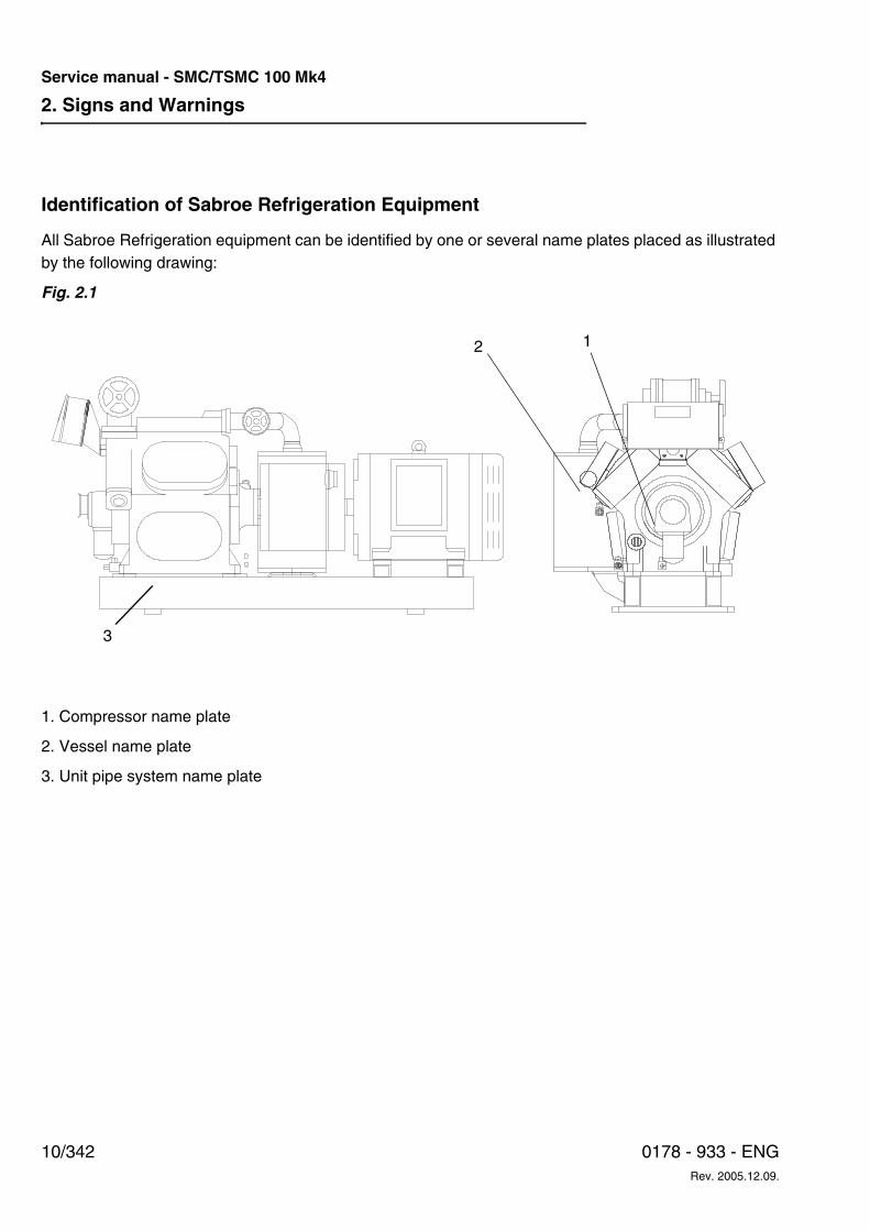
Identification of Sabroe Refrigeration Equipment
All Sabroe Refrigeration equipment can be identified by one or several name plates placed as illustrated by the following drawing:
Fig. 2.1
3
2 1
1. Compressor name plate
2. Vessel name plate
3. Unit pipe system name plate
2. Signs and Warnings
11/3420178 - 933 - ENGRev. 2005.12.09.
Service manual - SMC/TSMC 100 Mk4
02 s
igns
and
war
ning
s.fm
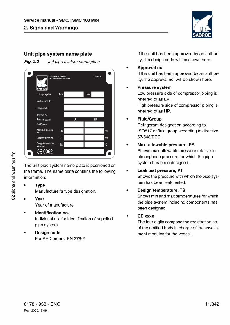
Unit pipe system name plateFig. 2.2 Unit pipe system name plate
The unit pipe system name plate is positioned on the frame. The name plate contains the following information:
• TypeManufacturer's type designation.
• YearYear of manufacture.
• Identification no.Individual no. for identification of supplied pipe system.
• Design codeFor PED orders: EN 378-2
If the unit has been approved by an author-ity, the design code will be shown here.
• Approval no.If the unit has been approved by an author-ity, the approval no. will be shown here.
• Pressure systemLow pressure side of compressor piping is referred to as LP. High pressure side of compressor piping is referred to as HP.
• Fluid/GroupRefrigerant designation according to ISO817 or fluid group according to directive 67/548/EEC.
• Max. allowable pressure, PSShows max allowable pressure relative to atmospheric pressure for which the pipe system has been designed.
• Leak test pressure, PTShows the pressure with which the pipe sys-tem has been leak tested.
• Design temperature, TSShows min and max temperatures for which the pipe system including components has been designed.
• CE xxxxThe four digits compose the registration no. of the notified body in charge of the assess-ment modules for the vessel.
2. Signs and Warnings
12/342 0178 - 933 - ENGRev. 2005.12.09.
Service manual - SMC/TSMC 100 Mk4
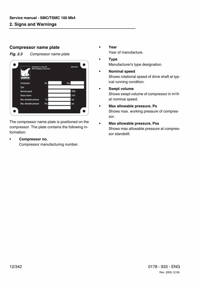
Compressor name plateFig. 2.3 Compressor name plate
The compressor name plate is positioned on the compressor. The plate contains the following in-formation:
• Compressor no.Compressor manufacturing number.
• YearYear of manufacture.
• TypeManufacturer's type designation.
• Nominal speedShows rotational speed of drive shaft at typ-ical running condition.
• Swept volumeShows swept volume of compressor in m3/h at nominal speed.
• Max allowable pressure, PsShows max. working pressure of compres-sor.
• Max allowable pressure, PssShows max allowable pressure at compres-sor standstill.
2. Signs and Warnings
13/3420178 - 933 - ENGRev. 2005.12.09.
Service manual - SMC/TSMC 100 Mk4
02 s
igns
and
war
ning
s.fm
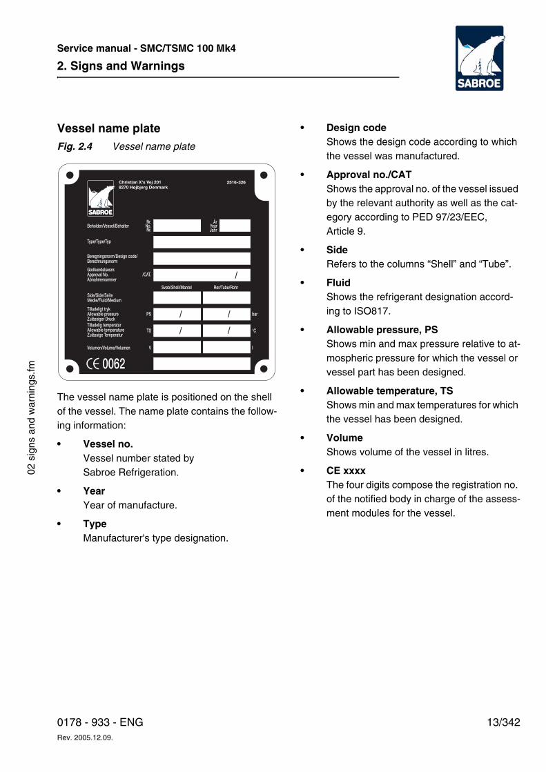
Vessel name plateFig. 2.4 Vessel name plate
The vessel name plate is positioned on the shell of the vessel. The name plate contains the follow-ing information:
• Vessel no.Vessel number stated by Sabroe Refrigeration.
• YearYear of manufacture.
• TypeManufacturer's type designation.
• Design codeShows the design code according to which the vessel was manufactured.
• Approval no./CATShows the approval no. of the vessel issued by the relevant authority as well as the cat-egory according to PED 97/23/EEC, Article 9.
• SideRefers to the columns “Shell” and “Tube”.
• FluidShows the refrigerant designation accord-ing to ISO817.
• Allowable pressure, PSShows min and max pressure relative to at-mospheric pressure for which the vessel or vessel part has been designed.
• Allowable temperature, TSShows min and max temperatures for which the vessel has been designed.
• VolumeShows volume of the vessel in litres.
• CE xxxxThe four digits compose the registration no. of the notified body in charge of the assess-ment modules for the vessel.
/ /
/ /
2. Signs and Warnings
14/342 0178 - 933 - ENGRev. 2005.12.09.
Service manual - SMC/TSMC 100 Mk4
In the following section, all signs which may be found on the equipment are described. The number of signs, however, may vary from product to product.
Signs in instructions
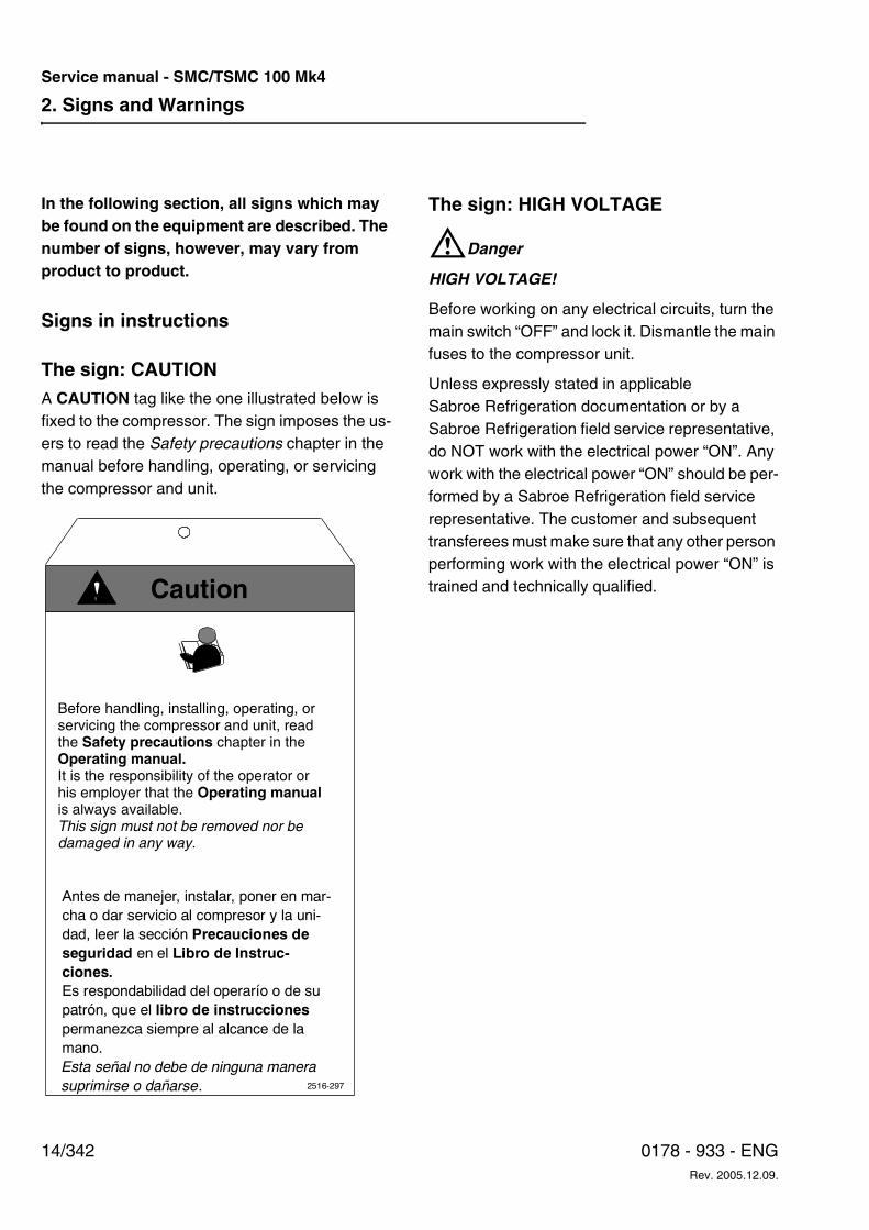
The sign: CAUTION A CAUTION tag like the one illustrated below is fixed to the compressor. The sign imposes the us-ers to read the Safety precautions chapter in the manual before handling, operating, or servicing the compressor and unit.
The sign: HIGH VOLTAGE
WDanger
HIGH VOLTAGE!
Before working on any electrical circuits, turn the main switch “OFF” and lock it. Dismantle the main fuses to the compressor unit.
Unless expressly stated in applicable Sabroe Refrigeration documentation or by a Sabroe Refrigeration field service representative, do NOT work with the electrical power “ON”. Any work with the electrical power “ON” should be per-formed by a Sabroe Refrigeration field service representative. The customer and subsequent transferees must make sure that any other person performing work with the electrical power “ON” is trained and technically qualified.
Antes de manejer, instalar, poner en mar-
cha o dar servicio al compresor y la uni-
dad, leer la sección Precauciones de
seguridad en el Libro de Instruc-
ciones.
Es respondabilidad del operarío o de su
patrón, que el libro de instrucciones
permanezca siempre al alcance de la
mano.
Esta señal no debe de ninguna manera
suprimirse o dañarse. 2516-297
Before handling, installing, operating, or servicing the compressor and unit, read the Safety precautions chapter in the Operating manual.It is the responsibility of the operator or his employer that the Operating manual is always available.This sign must not be removed nor be damaged in any way.
Caution
2. Signs and Warnings
15/3420178 - 933 - ENGRev. 2005.12.09.
Service manual - SMC/TSMC 100 Mk4
02 s
igns
and
war
ning
s.fm
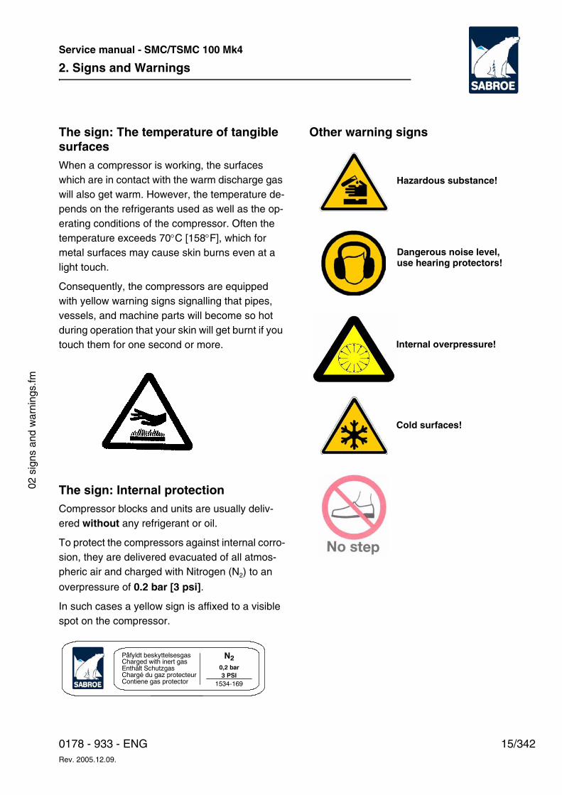
The sign: The temperature of tangible surfacesWhen a compressor is working, the surfaces which are in contact with the warm discharge gas will also get warm. However, the temperature de-pends on the refrigerants used as well as the op-erating conditions of the compressor. Often the temperature exceeds 70°C [158°F], which for metal surfaces may cause skin burns even at a light touch.
Consequently, the compressors are equipped with yellow warning signs signalling that pipes, vessels, and machine parts will become so hot during operation that your skin will get burnt if you touch them for one second or more.
The sign: Internal protectionCompressor blocks and units are usually deliv-ered without any refrigerant or oil.
To protect the compressors against internal corro-sion, they are delivered evacuated of all atmos-pheric air and charged with Nitrogen (N2) to an
overpressure of 0.2 bar [3 psi].
In such cases a yellow sign is affixed to a visible spot on the compressor.
Other warning signs
Påfyldt beskyttelsesgasCharged with inert gasEnthält SchutzgasChargé du gaz protecteurContiene gas protector
N20,2 bar
3 PSI
1534-169
Hazardous substance!
Dangerous noise level,use hearing protectors!
Internal overpressure!
Cold surfaces!
2. Signs and Warnings
16/342 0178 - 933 - ENGRev. 2005.12.09.
Service manual - SMC/TSMC 100 Mk4
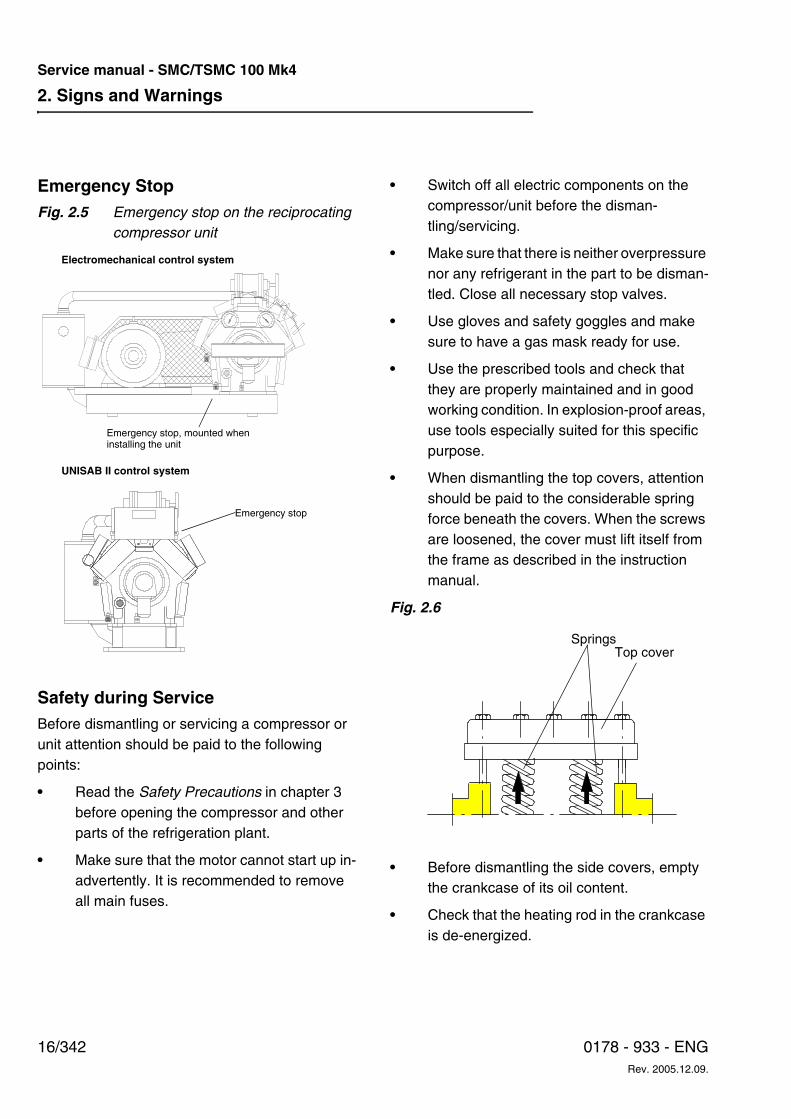
Emergency StopFig. 2.5 Emergency stop on the reciprocating
compressor unit
Safety during ServiceBefore dismantling or servicing a compressor or unit attention should be paid to the following points:
• Read the Safety Precautions in chapter 3 before opening the compressor and other parts of the refrigeration plant.
• Make sure that the motor cannot start up in-advertently. It is recommended to remove all main fuses.
• Switch off all electric components on the compressor/unit before the disman-tling/servicing.
• Make sure that there is neither overpressure nor any refrigerant in the part to be disman-tled. Close all necessary stop valves.
• Use gloves and safety goggles and make sure to have a gas mask ready for use.
• Use the prescribed tools and check that they are properly maintained and in good working condition. In explosion-proof areas, use tools especially suited for this specific purpose.
• When dismantling the top covers, attention should be paid to the considerable spring force beneath the covers. When the screws are loosened, the cover must lift itself from the frame as described in the instruction manual.
Fig. 2.6
• Before dismantling the side covers, empty the crankcase of its oil content.
• Check that the heating rod in the crankcase is de-energized.
UNISAB II control system
Emergency stop
Electromechanical control system
Emergency stop, mounted when installing the unit
Top coverSprings
2. Signs and Warnings
17/3420178 - 933 - ENGRev. 2005.12.09.
Service manual - SMC/TSMC 100 Mk4
02 s
igns
and
war
ning
s.fm
Warnings in InstructionsThis section describes warnings used in instruc-tions pertaining to Sabroe Refrigeration equip-ment.
Information of importance to the safety of person-nel or equipment is given at three levels.
• Danger!
• Warning!
• Caution!
There is an important distinction between these three levels. However, as shown below, the prin-ciple is the same at all three levels.
Note: Information is sometimes given in a Note. A Note is used to emphasise information but it is never used for information vital to the safety of personnel and equipment.
Texts Marked with Danger!The example below shows how information vital to the safety of involved personnel is presented.
WDanger!
Risk of electrical shock! Always turn off the main switch before servicing the unit! Contact with high voltage may cause death or serious injury.
Failure to observe information marked with Dan-ger! may cause death or serious injury to person-nel or even to a third party.
Texts Marked with Warning!The example below shows how information of im-portance to the safety of involved personnel or of major importance to the safety of equipment is presented.
WWarning!
Risk of damage to compressor! Always consult your supplier before using a compressor under operating conditions outside the specified working range.
Texts Marked with Caution!The example below shows how information of im-portance to the safety of equipment is presented.
WCaution!
Risk of incorrect viscosity! Always make sure that all oils used are mixable without causing chemical reactions. Chemical reactions might have serious effects on the viscosity.
Failure to observe information marked with Cau-tion! may cause damage to equipment.

2. Signs and Warnings
18/342 0178 - 933 - ENGRev. 2005.12.09.
Service manual - SMC/TSMC 100 Mk4
3. Safety Precautions
19/3420178 - 933 - ENGRev. 2005.12.09.
Service manual - SMC/TSMC 100 Mk4
03 s
afet
y pr
ecau
tions
.fm
3. Safety Precautions The purpose of this chapter is to provide general safety precautions for this equipment. Additional safety precautions relating to a specific task are given in the corresponding documents.
The safety precautions are intended for all user categories.
WDanger!
Risk of injury to personnel and damage to equip-ment! Always read the safety precautions belong-ing to this equipment before start. Failure to com-ply with safety precautions may cause death or in-jury to personnel. It may also cause damage to or destruction of the equipment.
WWarning!
Read related safety precautions before operating the compressor/unit. Failure to follow safety in-structions may result in serious personal injury or death.
Important!The safety precautions for this Sabroe Refrigeration compressor have been pre-pared to assist the operator, programmer and maintenance personnel in practicing good shop safety procedures.
Operator and maintenance personnel must read and understand these precautions completely be-fore operating, setting up, running or performing maintenance on the compressor/unit.
These precautions are to be used as a supple-ment to the safety precautions and warnings in-cluded in:
a. All other manuals pertaining to the compres-sor/unit.
b. Local, plant and shop safety rules and codes.
c. National safety rules, regulations and direc-tives.
General Safety Instructions and Considerations
Personal SafetyOwners, operators, set-up, maintenance and service personnel must be aware that constant day-to-day safety procedures are a vital part of their job. Accident prevention must be one of the principal objectives of the job, regardless of the activity involved.
Know and respect the compressor/unit. Read and carry out the prescribed safety and checking pro-cedures.
Make sure that everyone who works for, with or near you fully understands and - more importantly - complies with the following safety precautions and procedures when operating this compres-sor/unit.
Observe the safety warnings on the compres-sor/unit.
Use safety equipment. Wear approved eye or face protection as well as gloves when working with parts containing refrigerant and/or lubricating oil. Safety shoes with slip-proof soles can help you avoid injuries. Keep your safety equipment in good condition.
Never operate or service this equipment if affect-ed by alcohol, drugs or other substances or if in a condition which decreases alertness or judgment.
Work Area SafetyAlways keep your work area clean. Dirty work ar-eas with such hazards as oil, debris or water on the floor may cause someone to fall onto the floor,
3. Safety Precautions
20/342 0178 - 933 - ENGRev. 2005.12.09.
Service manual - SMC/TSMC 100 Mk4
into the machine or onto other objects resulting in serious personal injury.
Make sure your work area is free of hazardous ob-structions and be aware of protruding machine parts.
Always keep your work area tidy so that you can escape if a dangerous situation should arise.
Report unsafe working conditions to your supervi-sor or safety department.
Tool SafetyAlways make sure that the hand tools are in prop-er working condition.
Remove hand tools such as wrenches, measuring equipment, hammers, etc. from the compres-sor/unit immediately after use.
Transmission safety
CouplingThe coupling guard for directly driven compres-sors is not designed to resist unintended load. Therefore, do not step on it or load it in any way during operation. The guard is marked with a sign.
WWhen mounting the coupling guard make sure that it is not in contact with any rotating parts. For correct torque see the Service Instructions sec-tion. After 20 hours check to see if tightening-up is required. Check the coupling guard for correct tightening, cracks or other defects every 5000 hours.
WDo not start the compressor until the coupling guard or belt drive is mounted correctly. Before performing any kind of work on the coupling, make
sure that the compressor motor cannot start up unintended.
When performing service where the motor is dis-mantled from the base frame, follow the instruc-tions for coupling alignment in the Installations In-structions section.
Belt driveThe belt guard is not designed to resist unintend-ed load and is therefore marked with a warning sign - “No step”. When the belt guard is mounted it should be checked after 20 hours whether tight-ening-up is required. Check the belt guard for cor-rect tightening, cracks or other defects every 5000 hours.
Lifting and Carrying SafetyContact Sabroe Refrigeration if you have any questions or if you are not sure about the proper procedures for lifting and carrying.
Before lifting or carrying a compressor/unit or oth-er parts, determine the weight and size by means of e.g. tags, shipping data, labels, marked infor-mation or manuals.
Use power hoists or other mechanical lifting and carrying equipment for heavy, bulky or unwieldy objects. Use hook-up methods recommended by your safety department and familiarise yourself with the signals for safely directing a crane opera-tor.
Never place any part of your body under a sus-pended load or move a suspended load over any other persons. Before lifting, be certain that you have a safe spot for depositing the load. Never work on a component while it is hanging from a crane or any other lifting mechanism.
If in doubt as to the size or type of lifting equip-ment, the method and procedures to be used in connection with lifting, contact
3. Safety Precautions
21/3420178 - 933 - ENGRev. 2005.12.09.
Service manual - SMC/TSMC 100 Mk4
03 s
afet
y pr
ecau
tions
.fm
Sabroe Refrigeration before proceeding to lift the compressor, motor, unit or its components.
Always inspect slings, chains, hoists and other lift-ing devices prior to use. Do not use lifting devices which are defective or in a questionable condition.
Never exceed the lifting capacity of cranes, slings, eyebolts and other lifting equipment. Follow standards and instructions applicable to any lifting equipment used.
Before inserting an eyebolt, be certain that both the eyebolt and the hole have the same size and type of threads. To attain safe working loads, at least 90% of the threaded portion of a standard forged eyebolt must be engaged.
WWarning!
Failure to follow safety instructions on this page may result in serious personal injury or death.
Installation and Relocation SafetyBefore lifting the compressor, unit or other parts of the plant, consult the Engineering manual or Sabroe Refrigeration for proper methods and pro-cedures.
An electrician must read and understand the elec-trical diagrams prior to connecting the machine to the power source. After connecting the machine, test all aspects of the electrical system for proper functioning. Always make sure that the machine is grounded properly. Place all selector switches in their O or neutral (disengaged) position. The doors of the main electrical cabinet must be closed and the main disconnect switch must be in
the O position after the power source connec-tion is complete.
Before starting the compressor for the first time, make sure that all the motors rotate in the indicat-ed direction.
Set-Up and Operation SafetyRead and understand all the safety instructions before setting up, operating or servicing this com-pressor. Assign only qualified personnel instruct-ed in safety and all machine functions to operate or service this compressor.
Operators and maintenance personnel must care-fully read, understand and fully comply with all warnings and instruction plates mounted on the machine. Do not paint over, alter or deface these plates or remove them from the compressor/unit. Replace all plates which become illegible. Re-placement plates can be purchased from Sabroe Refrigeration.
Safety guards, shields, barriers, covers and pro-tective devices must not be removed while the compressor/unit is operating.
All safety features, disengagements and inter-locks must be in place and function correctly be-fore this equipment is put in operation. Never by-pass or wire around any safety device.
Keep all parts of your body off the compres-sor/motor/unit during operation. Never lean on or reach over the compressor.
During operation, pay attention to the compressor unit process. Excessive vibration, unusual sounds, etc. can indicate problems requiring your immediate attention.
3. Safety Precautions
22/342 0178 - 933 - ENGRev. 2005.12.09.
Service manual - SMC/TSMC 100 Mk4
Maintenance SafetyDo not attempt to perform maintenance on the compressor unit until you have read and under-stood all the safety instructions.
Assign only qualified service or maintenance per-sonnel trained by Sabroe Refrigeration to per-form maintenance and repair work on the unit. They should consult the service manual before at-tempting any service or repair work and contact Sabroe Refrigeration in case of questions. Use only Sabroe Refrigeration original spare parts; other parts may impair the safety of the compres-sor/unit.
Before removing or opening any electrical enclo-sure, cover, plate or door, be sure that the Main Disconnect Switch is in the O position and the main fuses are dismantled.
If any tool is required to remove a guard, cover, bracket or any basic part of this compressor, place the Main Disconnect Switch in the O position and lock it in the O position. If possible, post a sign at the disconnect switch indicating that main-tenance is being performed. Dismantle main fus-es to the unit.
When maintenance is to be performed in an area away from the disconnect, and the switch is not locked, tag all start button stations with a “DO NOT START” tag.
Adequate precautions such as warning notices or other equally effective means must be taken to prevent electrical equipment from being activated electrically when maintenance work is being per-formed.
When removing electrical equipment, place number or labelled tags on those wires not marked. If wiring is replaced, be sure it is of the same type, length, size and has the same current carrying capacity.
WDangerHIGH VOLTAGE!
Before working on any electrical circuits, place the Main Disconnect Device of the compres-sor/unit in the "OFF" position and lock it. Dis-mantle the main fuses to the compressor unit. Unless expressly stated in applicable Sabroe Refrigeration documentation or by ap-propriate Sabroe Refrigeration Field Service Representative, do NOT work with the electri-cal power "ON". If such express statement or advice exists, work with the electrical power "ON" should be performed by a Sabroe Refrigeration Field Service Represent-ative. The customer and subsequent transfer-ees must make sure that any other person per-forming work with the electrical power "ON" is trained and technically qualified.FAILURE TO FOLLOW THIS INSTRUCTION MAY RESULT IN DEATH OR SERIOUS PERSONAL SHOCK INJURY.
3. Safety Precautions
23/3420178 - 933 - ENGRev. 2005.12.09.
Service manual - SMC/TSMC 100 Mk4
03 s
afet
y pr
ecau
tions
.fm
Close and fasten all guards, shields, covers, plates or doors securely before power is recon-nected.
An electrician must analyse the electrical system to determine the possible use of power retaining devices such as capacitors. Such power retaining devices must be disconnected, discharged or made safe before maintenance is performed.
Working space around electrical equipment must be clear of obstructions.
Provide adequate illumination to allow for proper operation and maintenance.
Materials Used with this ProductAlways use Sabroe Refrigeration original spare parts.
Please note the type of refrigerant on which the compressor operates as well as the precautions that need to be taken as described in the following sections:
• First aid for accidents with ammonia.
• First aid for accidents with HFC/HCFC.
• First aid for accidents with HC.
• First aid for accidents with CO2
• Protecting the operator as well as the environment.
3. Safety Precautions
24/342 0178 - 933 - ENGRev. 2005.12.09.
Service manual - SMC/TSMC 100 Mk4
First aid for accidents with ammonia
(Chemical formula: NH3 - refrigerant no.: R717)
GeneralAmmonia is not a cumulative poison. It has a di-stinctive, pungent odour that even at very low, harmless concentrations is detectable by most persons.
Since ammonia is self-alarming, it serves as its own warning agent so that no person remains vol-untarily in hazardous concentrations. Since am-monia is lighter than air, adequate ventilation is the best means of preventing an accumulation.
Experience has shown that ammonia is extremely hard to ignite and under normal conditions a very stable compound. At extremely high, though limit-ed concentrations, ammonia can form ignitable mixtures with air and oxygen and should be treat-ed with respect.
Basic rules for first aidAlways call a doctor immediately.
Be prepared: Keep an irrigation bottle available containing a sterile isotonic (0.9%) NaCl-solution (salt water). A shower or a water tank should be available near all bulk installations with ammonia.
When applying first aid, the persons assisting must be duly protected to avoid further injuries.
First aid measuresInhalation: Immediately, move affected person-nel into fresh air and loosen clothing restricting breathing.
Call a doctor/ambulance with oxygen equipment.
Keep the patient still and warmly wrapped in blan-kets.
If mouth and throat are burnt (freeze or acid burn) and the patient is conscious, let him drink water in small mouthfuls.
If the patient is conscious and mouth and throat are not burnt, feed him sweetened tea or coffee (never feed an unconscious person).
Oxygen may be given to the patient, but only when authorised by a doctor. If the patient stops breathing, apply artificial respiration.
Eyes: In case of injuries from liquid splashes or concentrated vapour, immediately rinse with wa-ter (preferably using an eye rinser) and consult a doctor. Continue rinsing until otherwise stated by a doctor.
If the affected person wears contact lenses these must be removed before the rinsing.
Skin: In case of burns from liquid splashes or con-centrated vapour, immediately wash with large quantities of water until the pain stops.
Consult a doctor about actual burns.
After washing, apply wet compresses - wetted with a sterile isotonic (0.9%) NaCl-solution (salt water) - to affected areas until medical advice is available.
WWarning!
No plant can ever be said to be too safe - safety is a way of life.
3. Safety Precautions
25/3420178 - 933 - ENGRev. 2005.12.09.
Service manual - SMC/TSMC 100 Mk4
03 s
afet
y pr
ecau
tions
.fm
First aid for accidents with HFC/HCFC
GeneralHFC/HCFC form colourless and invisible gasses which are heavier than air and smell faintly of chloroform at high concentrations.
Characteristics:• non-toxic
• non-inflammable
• non-explosive
• non-corrosive
When heated to above approx. 300°C, they break down into toxic, acid gas components, which are strongly irritating and aggressive to nose, eyes and skin and generally corrosive.
Besides the obvious risk of unnoticeable, heavy gases displacing the atmospheric oxygen, inhala-tion of larger concentrations may have an accu-mulating, anaesthetic effect which may not be im-mediately apparent. 24 hours medical observation is therefore recommended.
Basic rules for first aidWhen affected persons are moved from low-lying or poorly ventilated rooms where high gas con-centrations are suspected, the rescuer must wear a lifeline and be under constant observation from an assistant outside the room.
Do not use adrenaline or similar heart stimuli.
Inhalation: Immediately move affected persons into fresh air. Keep them still and warm and loos-en clothing restricting breathing.
If the patient is unconscious, call a doctor/ambu-lance with oxygen equipment immediately.
Apply artificial respiration until a doctor authorizes other treatment.
Eyes: Immediately rinse with water (preferably using an eye rinser) and consult a doctor. Contin-ue rinsing until otherwise stated by a doctor.
If the affected person wears contact lenses these must be removed before the rinsing.
Skin: In case of frost-bite, immediately rinse with luke-warm water (max. 37°C) and remove all clothes impeding blood circulation.
Consult a doctor.
Avoid direct contact with contaminated oil/refriger-ant mixtures from electrically burnt-out hermetic compressors.
WWarning!
No plant can ever be said to be too safe- safety is a way of life.
3. Safety Precautions
26/342 0178 - 933 - ENGRev. 2005.12.09.
Service manual - SMC/TSMC 100 Mk4
Protecting the operator as well as the environment
Increasing industrialisation threatens our environ-ment. It is therefore absolutely imperative to pro-tect nature against pollution.
To this end, many countries have passed legisla-tion in an effort to reduce pollution and preserve the environment. This legislation applies to all fields of industry, including refrigeration, and must be complied with.
Pay extra attention to the following substances:
• refrigerants
• cooling media (brine, etc.)
• lubricating oils
Refrigerants usually have a natural boiling point considerably below 0°C. This means that liquid re-frigerants can be extremely harmful if they come into contact with skin or eyes.
High concentrations of refrigerant vapours can be suffocating when they displace air.
If high concentrations of refrigerant vapours are inhaled, they will attack the human nervous sys-tem.
When halogenated gasses come into contact with open flame or hot surfaces (over approx. 300°C), they will decompose to produce poisonous chem-icals. These have a very pungent odour and will thus warn personnel of their presence.
At high concentrations R717 causes respiratory problems. When the amount of ammonia vapour in air is between 15 and 28 vol. % the combination is explosive and can be ignited by an electric spark or open flame.
Oil vapour in the ammonia vapour increases this risk significantly as the point of ignition falls below that of the mixture ratio stated.
Usually the strong smell of ammonia will warn personnel before the concentration becomes dangerous.
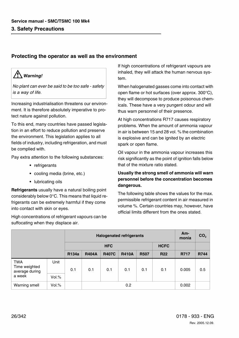
The following table shows the values for the max. permissible refrigerant content in air measured in volume %. Certain countries may, however, have official limits different from the ones stated.
WWarning!
No plant can ever be said to be too safe - safety is a way of life.
Halogenated refrigerants Am-monia
CO2
HFC HCFC
R134a R404A R407C R410A R507 R22 R717 R744
TWATime weighted average during a week
Unit
0.1 0.1 0.1 0.1 0.1 0.1 0.005 0.5
Vol.%
Warning smell Vol.% 0.2 0.002
3. Safety Precautions
27/3420178 - 933 - ENGRev. 2005.12.09.
Service manual - SMC/TSMC 100 Mk4
03 s
afet
y pr
ecau
tions
.fm
Furthermore, it can be said about refrigerants:
HFC/HCFC • If released into the atmosphere, halogenat-
ed refrigerants of the types CFC and HCFC (e.g. R22) will contribute to the depletion of the ozone layer in the stratosphere. The ozone layer protects the earth from the ul-traviolet rays of the sun. Refrigerants of the types CFC, HFC and HCFC are greenhouse gases which contribute to an intensification of the greenhouse effect. They must, there-fore, never be released into the atmos-phere. Use a separate compressor to draw the refrigerant into the plant condenser/re-ceiver or into separate refrigerant cylinders.
Ammonia
• Ammonia is easily absorbed by water:At 15°C 1 litre of water can absorb approx. 0.5 kg liquid ammonia (or approx. 700 litres ammonia vapour).
• Even small amounts of ammonia in water (2-5 mg per litre) are enough to wreak havoc with marine life if allowed to pollute water-ways and lakes.
• As ammonia is alkaline, it will damage plant life if released into the atmosphere in large quantities.
Hydro carbons (HC) • HC gasses are a group of B1 refrigerants
characterized as very flammable.
• Hydro carbons are odourless and non-toxic gasses. Specific mixtures of air and gas cre-ate danger of explosion. As the gasses are heavier than air, they will be concentrated at the lowest possible level in case of leaks.
Carbon dioxide (CO2)
• Carbon dioxide (CO2) is a greenhouse gas
with a GWP (Global Warming Potential) fac-tor of 1. It is found in the atmosphere in a concentration of 0.036 vol. % (360 parts per million, ppm). As CO2 is extracted from at-
mospheric air, it can safely be released into the atmosphere and does not contribute to enhancing the greenhouse effect.
• The boiling point for CO2 is -78.5°C
at 1.013 bar.
• CO2 is an odourless, non-toxic non-inflam-
mable gas. At concentrations higher than 5000 ppm the gas can be dangerous for hu-mans. The gas is heavier than air and will thus be concentrated on the lowest level of the room in case of a leak. In closed rooms the gas can displace oxygen and cause suf-focation.
Refrigerant evacuated from a refrigeration plant must be charged into refrigerant cylinders intend-ed for this specific refrigerant.
If the refrigerant is not to be reused, return it to the supplier or to an authorized incineration plant.
Halogenated refrigerants must never be mixed. Nor must R717 ever be mixed with halogenated refrigerants.
3. Safety Precautions
28/342 0178 - 933 - ENGRev. 2005.12.09.
Service manual - SMC/TSMC 100 Mk4
Purging a refrigeration plant
If it is necessary to purge air from a refrigeration plant, make sure to observe the following:
• Refrigerants must not be released into the atmosphere (exept CO2).
• When purging an R717 plant, use an ap-proved air purger. The purged air must pass through an open container of water for any remaining R717 to be absorbed. The water
mixture must be sent to an authorized incin-eration plant.
• Halogenated refrigerants cannot be ab-sorbed by water. An approved air purger must be fitted to the plant. This must be checked regularly by use of a leak detector.
Note: The occurrence of air is usually an indica-tion of poor maintenance or lack of thoroughness at installation.
3. Safety Precautions
29/3420178 - 933 - ENGRev. 2005.12.09.
Service manual - SMC/TSMC 100 Mk4
03 s
afet
y pr
ecau
tions
.fm
Cooling mediaSalt solutions (brines) of calcium chloride (CaCl2)
or sodium chloride (NaCl) are often used.
In recent years alcohol, glycol and halogenated compounds have been used in the production of brine.
In general, all brines must be considered harmful to nature and they must be used with caution. Be very careful when charging or purging a refrigera-tion plant.
Never empty brines down a sewer or into the environment. The brine must be collected in suitable containers clearly marked with the contents and sent to an approved incineration plant.
Lubricating oils
WWarning!
When charging oil, follow the safety instructions given by the oil supplier (MSDS: Material Safety Data Sheet). Always avoid direcst contact with the oil as this may cause skin allergies. Always use protective equipment - goggles and gloves - when charging oil.
Refrigeration compressors are lubricated by one of the following oil types depending on the refrig-erant plant type, and operating conditons.
– Mineral oil (M oil)
– Hydro treated mineral oil (H oil)
– Semi-synthetic oil (mix of M oil and syn-thetic oil)
– Alkyl benzene-based synthetic oil (A oil)
– Polyalphaolefine-based synthetic oil (PAO oil)
– Mixed A and PAO oil (AP-oil)
– Polyalkylen Glycol-based synthetic oil (PAG oil)
– Ester oil (E oil)
See the section Selecting lubricating oil for Sabroe Refrigeration compressors in chapter 6, Technical Data.
When changing the oil in the compressor or drain-ing oil from the vessel of the refrigeration plant, al-ways collect the used oil in containers marked “waste oil” and send them to an approved inciner-ation plant. It is not recommended to re-use oil.
Cooling water systems
WWarning!
The recirculation water system may contain chemicals or biological contaminants, including legionella, which can be harmful if inhaled or in-gested. Water systems should only be operated with an effective biological treatment programme.
Note:
These instructions only provide general information. The owner of the refrigeration plant is responsible for ensuring that all codes, regulations and industry standards are complied with.
3. Safety Precautions
30/342 0178 - 933 - ENGRev. 2005.12.09.
Service manual - SMC/TSMC 100 Mk4
4. Technical Description
31/3420178 - 933 - ENGRev. 2005.12.09.
Service manual - SMC/TSMC 100 Mk4
04 te
chni
cal d
escr
iptio
n.fm
4. Technical DescriptionThe purpose of this chapter is to describe the in-tended purpose, the physical characteristics and the functions of the unit.
This chapter is primarily intended for designers, service engineers, prospective customers, sales personnel and personnel undergoing training.
Areas of Application of the Reciprocating Compressor Unit
ApplicationIn view of preventing an unintended application of the compressor, which could cause injuries to the operating staff or lead to technical damage, the compressors may only be applied for the following purposes:
• As a refrigeration compressor with the number of revolutions pr. minute specified by Sabroe Refrigeration and the operating limits as stated in this manual or in a written agreement with Sabroe Refrigeration.
• Compressor types SMC 100 and TSMC 100 in an S or L execution can - as standard compressors - be used with the following re-frigerants: R717 - R22 - R134a - R407C - R404A - R507 - R600 - R600A - R290 - LPG. This manual only deals with the ones written in bold letters.
• Compressor types SMC 100 and TSMC 100 in an E execution are as standard compres-sors used with R717 only.
• The compressors can be used with other re-frigerants, but only following a written agree-ment with Sabroe Refrigeration.
• SMC 100 and TSMC 100 compressors in S, L or E executions may be used at a max dis-
charge design pressure of 25 bar. See Test Pressure Levels for Standard Compressors and Components in chapter 6.
• The compressors are approved for applica-tion in an explosion-prone environment, pro-vided they have been fitted with explo-sion-proof equipment. This can be seen from the Ex nameplates, Fig. 4.1, fixed on each unit.
Fig. 4.1
Please, note that specially made tools which can-not cause any sparks must be used in connection with maintenance work on the compressor.
WWarning!
The compressor must NOT be used:
• For evacuating the refrigeration plant of air and moisture,
• For putting the refrigeration plant under air pressure in view of a pressure test-ing,
• As an air compressor.
T2516273_0
4. Technical Description
32/342 0178 - 933 - ENGRev. 2005.12.09.
Service manual - SMC/TSMC 100 Mk4
WDanger!
Sabroe Refrigeration does not take any responsi-bility for injuries to personnel or damage to equip-ment resulting from using this equipment for other purposes than the ones stated above.
Application of Combustion EnginesIf combustion engines are installed in rooms con-taining refrigeration machinery or rooms where
there are pipes and components containing refrig-erant, make sure that in case of leakage the com-bustion air for the engine comes from an area in which there is no refrigerant gas.
Failure to do so will involve a risk of lubricating oil from the combustion engine mixing with refriger-ant; at worst this may lead to corrosion and dam-age of the engine.
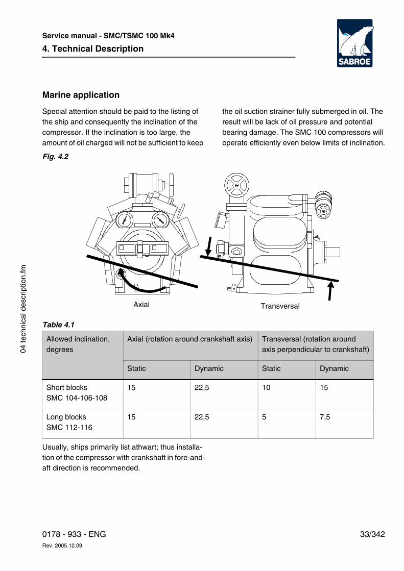
4. Technical Description
33/3420178 - 933 - ENGRev. 2005.12.09.
Service manual - SMC/TSMC 100 Mk4
04 te
chni
cal d
escr
iptio
n.fm
Marine application
Special attention should be paid to the listing of the ship and consequently the inclination of the compressor. If the inclination is too large, the amount of oil charged will not be sufficient to keep
the oil suction strainer fully submerged in oil. The result will be lack of oil pressure and potential bearing damage. The SMC 100 compressors will operate efficiently even below limits of inclination.
Fig. 4.2
Table 4.1
Usually, ships primarily list athwart; thus installa-tion of the compressor with crankshaft in fore-and-aft direction is recommended.
Allowed inclination, degrees
Axial (rotation around crankshaft axis) Transversal (rotation around axis perpendicular to crankshaft)
Static Dynamic Static Dynamic
Short blocksSMC 104-106-108
15 22,5 10 15
Long blocksSMC 112-116
15 22,5 5 7,5
Axial Transversal
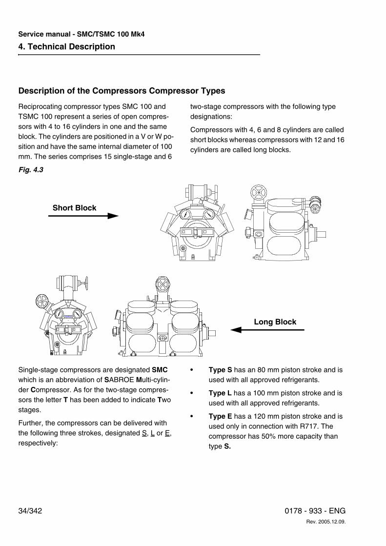
4. Technical Description
34/342 0178 - 933 - ENGRev. 2005.12.09.
Service manual - SMC/TSMC 100 Mk4
Description of the Compressors Compressor Types
Reciprocating compressor types SMC 100 and TSMC 100 represent a series of open compres-sors with 4 to 16 cylinders in one and the same block. The cylinders are positioned in a V or W po-sition and have the same internal diameter of 100 mm. The series comprises 15 single-stage and 6
two-stage compressors with the following type designations:
Compressors with 4, 6 and 8 cylinders are called short blocks whereas compressors with 12 and 16 cylinders are called long blocks.
Fig. 4.3
Single-stage compressors are designated SMC which is an abbreviation of SABROE Multi-cylin-der Compressor. As for the two-stage compres-sors the letter T has been added to indicate Two stages.
Further, the compressors can be delivered with the following three strokes, designated S, L or E, respectively:
• Type S has an 80 mm piston stroke and is used with all approved refrigerants.
• Type L has a 100 mm piston stroke and is used with all approved refrigerants.
• Type E has a 120 mm piston stroke and is used only in connection with R717. The compressor has 50% more capacity than type S.
Short Block
SABROE
Long Block
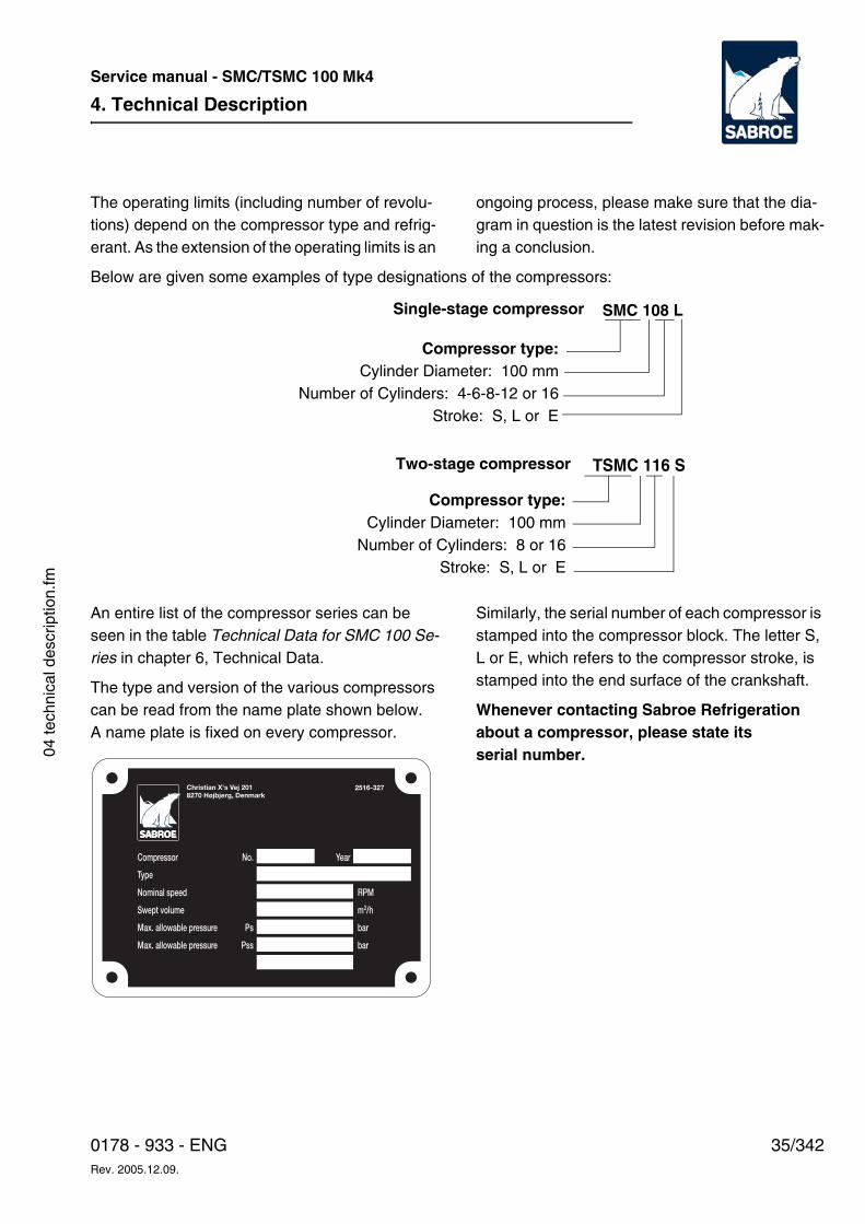
4. Technical Description
35/3420178 - 933 - ENGRev. 2005.12.09.
Service manual - SMC/TSMC 100 Mk4
04 te
chni
cal d
escr
iptio
n.fm
The operating limits (including number of revolu-tions) depend on the compressor type and refrig-erant. As the extension of the operating limits is an
ongoing process, please make sure that the dia-gram in question is the latest revision before mak-ing a conclusion.
Below are given some examples of type designations of the compressors:
An entire list of the compressor series can be seen in the table Technical Data for SMC 100 Se-ries in chapter 6, Technical Data.
The type and version of the various compressors can be read from the name plate shown below. A name plate is fixed on every compressor.
Similarly, the serial number of each compressor is stamped into the compressor block. The letter S, L or E, which refers to the compressor stroke, is stamped into the end surface of the crankshaft.
Whenever contacting Sabroe Refrigeration about a compressor, please state its serial number.
Compressor type:Cylinder Diameter: 100 mm
Number of Cylinders: 4-6-8-12 or 16Stroke: S, L or E
SMC 108 L
Compressor type:Cylinder Diameter: 100 mm
Number of Cylinders: 8 or 16Stroke: S, L or E
TSMC 116 S
Single-stage compressor
Two-stage compressor
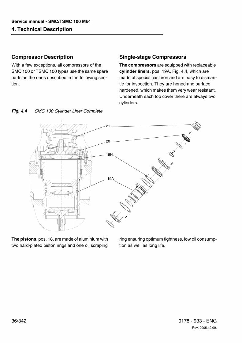
4. Technical Description
36/342 0178 - 933 - ENGRev. 2005.12.09.
Service manual - SMC/TSMC 100 Mk4
Compressor DescriptionWith a few exceptions, all compressors of the SMC 100 or TSMC 100 types use the same spare parts as the ones described in the following sec-tion.
Single-stage CompressorsThe compressors are equipped with replaceable cylinder liners, pos. 19A, Fig. 4.4, which are made of special cast iron and are easy to disman-tle for inspection. They are honed and surface hardened, which makes them very wear resistant. Underneath each top cover there are always two cylinders.
Fig. 4.4 SMC 100 Cylinder Liner Complete
The pistons, pos. 18, are made of aluminium with two hard-plated piston rings and one oil scraping
ring ensuring optimum tightness, low oil consump-tion as well as long life.
19A
21
19H
20
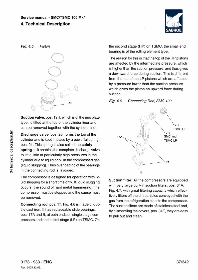
4. Technical Description
37/3420178 - 933 - ENGRev. 2005.12.09.
Service manual - SMC/TSMC 100 Mk4
04 te
chni
cal d
escr
iptio
n.fm
Fig. 4.5 Piston
Suction valve, pos. 19H, which is of the ring plate type, is fitted at the top of the cylinder liner and can be removed together with the cylinder liner.
Discharge valve, pos. 20, forms the top of the cylinder and is kept in place by a powerful spring, pos. 21. This spring is also called the safety spring as it enables the complete discharge valve to lift a little at particularly high pressures in the cylinder due to liquid or oil in the compressed gas (liquid slugging). Thus overloading of the bearings in the connecting rod is avoided.
The compressor is designed for operation with liq-uid slugging for a short time only. If liquid slugging occurs (the sound of hard metal hammering), the compressor must be stopped and the cause must be removed.
Connecting rod, pos. 17, Fig. 4.6 is made of duc-tile cast iron. It has replaceable slide bearings, pos. 17A and B, at both ends on single stage com-pressors and on the first stage (LP) on TSMC. On
the second stage (HP) on TSMC, the small end bearing is of the rolling element type.
The reason for this is that the top of the HP pistons are affected by the intermediate pressure, which is higher than the suction pressure, and thus gives a downward force during suction. This is different from the top of the LP pistons which are affected by a pressure lower than the suction pressure which gives the piston an upward force during suction.
Fig. 4.6 Connecting Rod, SMC 100
Suction filter: All the compressors are equipped with very large built-in suction filters, pos. 34A, Fig. 4.7, with great filtering capacity which effec-tively filters off the dirt particles conveyed with the gas from the refrigeration plant to the compressor. The suction filters are made of stainless steel and, by dismantling the covers, pos. 34E, they are easy to pull out and clean.
18
17A17B
17
SMC andTSMC LP
TSMC HP17B
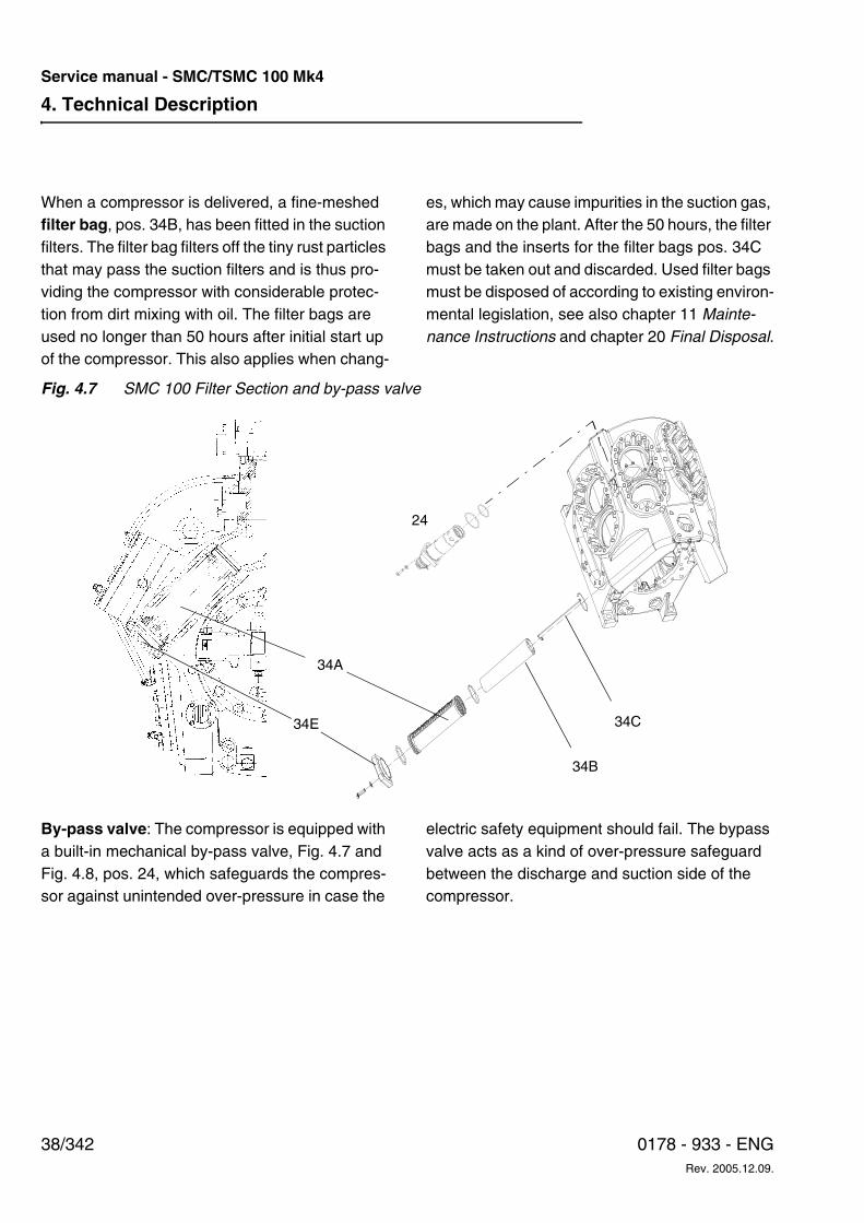
4. Technical Description
38/342 0178 - 933 - ENGRev. 2005.12.09.
Service manual - SMC/TSMC 100 Mk4
When a compressor is delivered, a fine-meshed filter bag, pos. 34B, has been fitted in the suction filters. The filter bag filters off the tiny rust particles that may pass the suction filters and is thus pro-viding the compressor with considerable protec-tion from dirt mixing with oil. The filter bags are used no longer than 50 hours after initial start up of the compressor. This also applies when chang-
es, which may cause impurities in the suction gas, are made on the plant. After the 50 hours, the filter bags and the inserts for the filter bags pos. 34C must be taken out and discarded. Used filter bags must be disposed of according to existing environ-mental legislation, see also chapter 11 Mainte-nance Instructions and chapter 20 Final Disposal.
Fig. 4.7 SMC 100 Filter Section and by-pass valve
By-pass valve: The compressor is equipped with a built-in mechanical by-pass valve, Fig. 4.7 and Fig. 4.8, pos. 24, which safeguards the compres-sor against unintended over-pressure in case the
electric safety equipment should fail. The bypass valve acts as a kind of over-pressure safeguard between the discharge and suction side of the compressor.
34A
34E
34B
34C
24
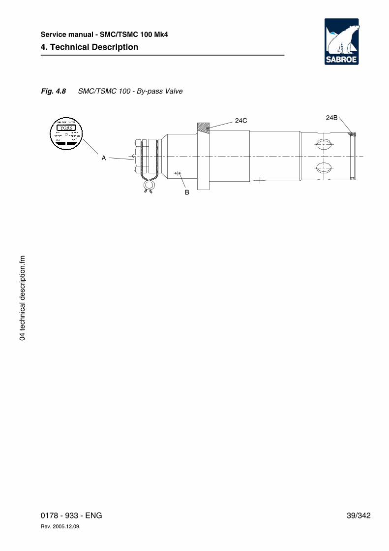
4. Technical Description
39/3420178 - 933 - ENGRev. 2005.12.09.
Service manual - SMC/TSMC 100 Mk4
04 te
chni
cal d
escr
iptio
n.fm
Fig. 4.8 SMC/TSMC 100 - By-pass Valve
24C
B
24B
A

4. Technical Description
40/342 0178 - 933 - ENGRev. 2005.12.09.
Service manual - SMC/TSMC 100 Mk4
The by-pass valve is delivered pre-set, sealed and adjusted to the following opening pressures:
– Standard for SMC and TSMC (HP stage) compressors: 24 bar [348 psi].
– Special for SMC - and TSMC (HP stage) compressors: 22 bar [319 psi]; this is only delivered following a specific order and applied in accordance with local rules and regulations concerning pres-sure vessels as e.g. oil separators. The current set pressure is stamped into the name plate pos. A.
– Standard for TSMC (LP stage) compres-sors: 12 bar [174 psi].
The by-pass valve is of the high-lifting type, which makes it robust and durable.
Moreover, the by-pass valve is independent of the pressure on the suction side of the compressor. Consequently, it opens only when the pressure on the discharge side exceeds the set pressure com-pared to that of the atmosphere.
Note: The by-pass valve should not be consid-ered a safety valve.
Fig. 4.9 SMC 104-108 Short Block
Fig. 4.10 TSMC 112-116 Long Block
The crankshaft, pos. 16, Fig. 4.9, rests in large slide main bearings pos. 5 and 6 which are able to absorb both radial and axial loads. Both the main bearings and the connecting rod bearings at the large end of the connecting rod are easy to re-place in connection with an overhaul of the com-pressor and need no additional finishing after re-mounting. The bearings are available in 0.5 mm undersize to be used for crankshafts that are ground to 0.5 mm undersize during a renovation. After having been ground to undersize, the crank-shaft needs no surface hardening or the like, but can be used directly as bearing surface. The crankshaft is dynamically balanced for a smooth and vibration free operation and need no further balancing after the above-mentioned machining to undersize. In the SMC 112-116 compressors the crankshaft is also supported by an intermedi-ate bearing, pos. 49A, Fig. 4.10.
16
6
5
49A
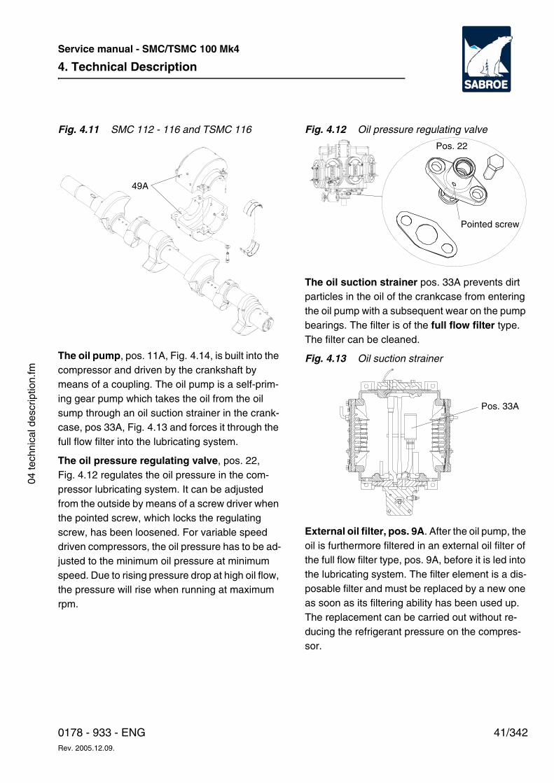
4. Technical Description
41/3420178 - 933 - ENGRev. 2005.12.09.
Service manual - SMC/TSMC 100 Mk4
04 te
chni
cal d
escr
iptio
n.fm
Fig. 4.11 SMC 112 - 116 and TSMC 116
The oil pump, pos. 11A, Fig. 4.14, is built into the compressor and driven by the crankshaft by means of a coupling. The oil pump is a self-prim-ing gear pump which takes the oil from the oil sump through an oil suction strainer in the crank-case, pos 33A, Fig. 4.13 and forces it through the full flow filter into the lubricating system.
The oil pressure regulating valve, pos. 22, Fig. 4.12 regulates the oil pressure in the com-pressor lubricating system. It can be adjusted from the outside by means of a screw driver when the pointed screw, which locks the regulating screw, has been loosened. For variable speed driven compressors, the oil pressure has to be ad-justed to the minimum oil pressure at minimum speed. Due to rising pressure drop at high oil flow, the pressure will rise when running at maximum rpm.
Fig. 4.12 Oil pressure regulating valve
The oil suction strainer pos. 33A prevents dirt particles in the oil of the crankcase from entering the oil pump with a subsequent wear on the pump bearings. The filter is of the full flow filter type. The filter can be cleaned.
Fig. 4.13 Oil suction strainer
External oil filter, pos. 9A. After the oil pump, the oil is furthermore filtered in an external oil filter of the full flow filter type, pos. 9A, before it is led into the lubricating system. The filter element is a dis-posable filter and must be replaced by a new one as soon as its filtering ability has been used up. The replacement can be carried out without re-ducing the refrigerant pressure on the compres-sor.
49A
Pos. 22
Pointed screw
Pos. 33A
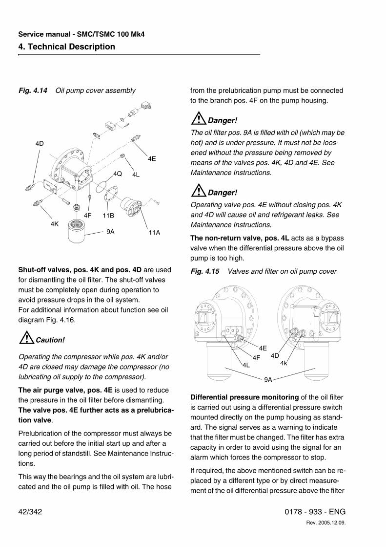
4. Technical Description
42/342 0178 - 933 - ENGRev. 2005.12.09.
Service manual - SMC/TSMC 100 Mk4
Fig. 4.14 Oil pump cover assembly
Shut-off valves, pos. 4K and pos. 4D are used for dismantling the oil filter. The shut-off valves must be completely open during operation to avoid pressure drops in the oil system. For additional information about function see oil diagram Fig. 4.16.
WCaution!
Operating the compressor while pos. 4K and/or 4D are closed may damage the compressor (no lubricating oil supply to the compressor).
The air purge valve, pos. 4E is used to reduce the pressure in the oil filter before dismantling. The valve pos. 4E further acts as a prelubrica-tion valve.
Prelubrication of the compressor must always be carried out before the initial start up and after a long period of standstill. See Maintenance Instruc-tions.
This way the bearings and the oil system are lubri-cated and the oil pump is filled with oil. The hose
from the prelubrication pump must be connected to the branch pos. 4F on the pump housing.
WDanger!
The oil filter pos. 9A is filled with oil (which may be hot) and is under pressure. It must not be loos-ened without the pressure being removed by means of the valves pos. 4K, 4D and 4E. See Maintenance Instructions.
WDanger!
Operating valve pos. 4E without closing pos. 4K and 4D will cause oil and refrigerant leaks. See Maintenance Instructions.
The non-return valve, pos. 4L acts as a bypass valve when the differential pressure above the oil pump is too high.
Fig. 4.15 Valves and filter on oil pump cover
Differential pressure monitoring of the oil filter is carried out using a differential pressure switch mounted directly on the pump housing as stand-ard. The signal serves as a warning to indicate that the filter must be changed. The filter has extra capacity in order to avoid using the signal for an alarm which forces the compressor to stop.
If required, the above mentioned switch can be re-placed by a different type or by direct measure-ment of the oil differential pressure above the filter
9A4K
4D
4E
4F
4L
11A
4Q
11B
9A
4D4E
4F4L 4k
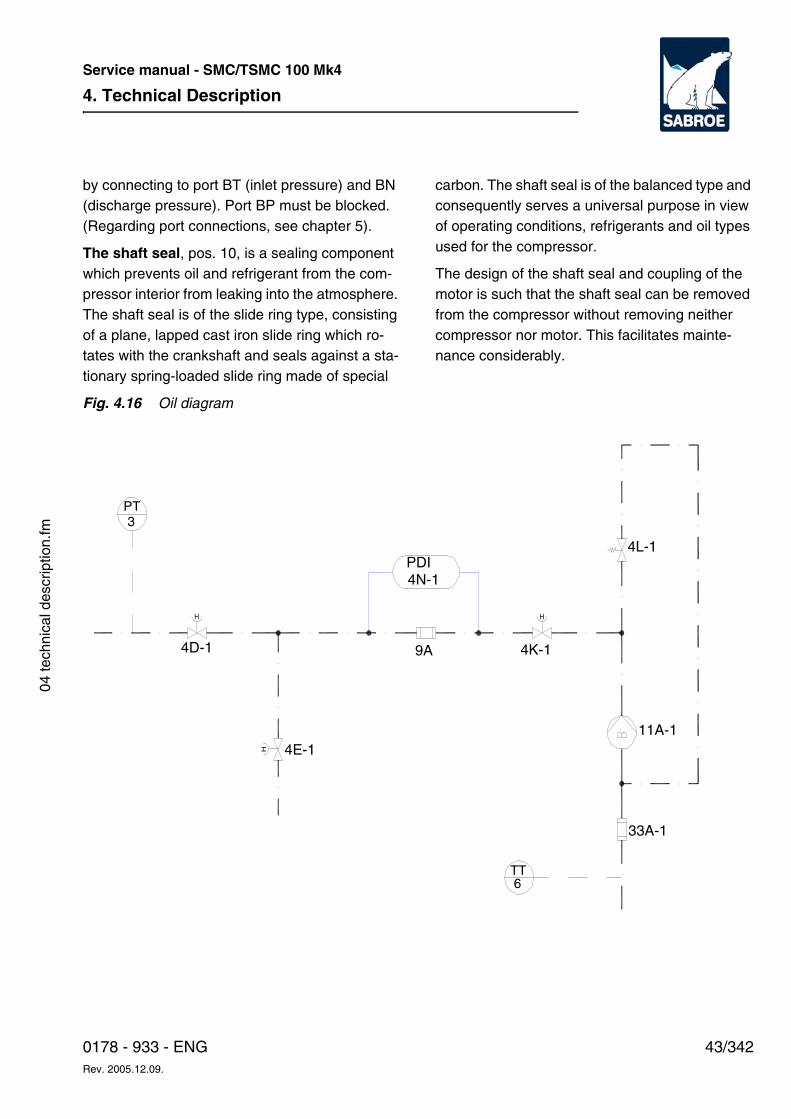
4. Technical Description
43/3420178 - 933 - ENGRev. 2005.12.09.
Service manual - SMC/TSMC 100 Mk4
04 te
chni
cal d
escr
iptio
n.fm
by connecting to port BT (inlet pressure) and BN (discharge pressure). Port BP must be blocked. (Regarding port connections, see chapter 5).
The shaft seal, pos. 10, is a sealing component which prevents oil and refrigerant from the com-pressor interior from leaking into the atmosphere. The shaft seal is of the slide ring type, consisting of a plane, lapped cast iron slide ring which ro-tates with the crankshaft and seals against a sta-tionary spring-loaded slide ring made of special
carbon. The shaft seal is of the balanced type and consequently serves a universal purpose in view of operating conditions, refrigerants and oil types used for the compressor.
The design of the shaft seal and coupling of the motor is such that the shaft seal can be removed from the compressor without removing neither compressor nor motor. This facilitates mainte-nance considerably.
Fig. 4.16 Oil diagram
H H
H
4D-1 9A
4N-1PDI
4E-1
4K-1
4L-1
11A-1
33A-1
6TT
3PT
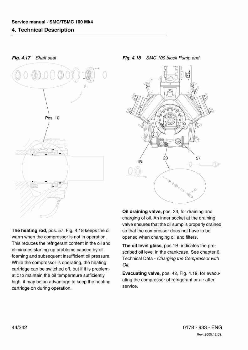
4. Technical Description
44/342 0178 - 933 - ENGRev. 2005.12.09.
Service manual - SMC/TSMC 100 Mk4
Fig. 4.17 Shaft seal
The heating rod, pos. 57, Fig. 4.18 keeps the oil warm when the compressor is not in operation. This reduces the refrigerant content in the oil and eliminates starting-up problems caused by oil foaming and subsequent insufficient oil pressure. While the compressor is operating, the heating cartridge can be switched off, but if it is problem-atic to maintain the oil temperature sufficiently high, it may be an advantage to keep the heating cartridge on during operation.
Fig. 4.18 SMC 100 block Pump end
Oil draining valve, pos. 23, for draining and charging of oil. An inner socket at the draining valve ensures that the oil sump is properly drained so that the compressor does not have to be opened when changing oil and filters.
The oil level glass, pos.1B, indicates the pre-scribed oil level in the crankcase. See chapter 6, Technical Data - Charging the Compressor with Oil.
Evacuating valve, pos. 42, Fig. 4.19, for evacu-ating the compressor of refrigerant or air after service.
Pos. 10
57231B
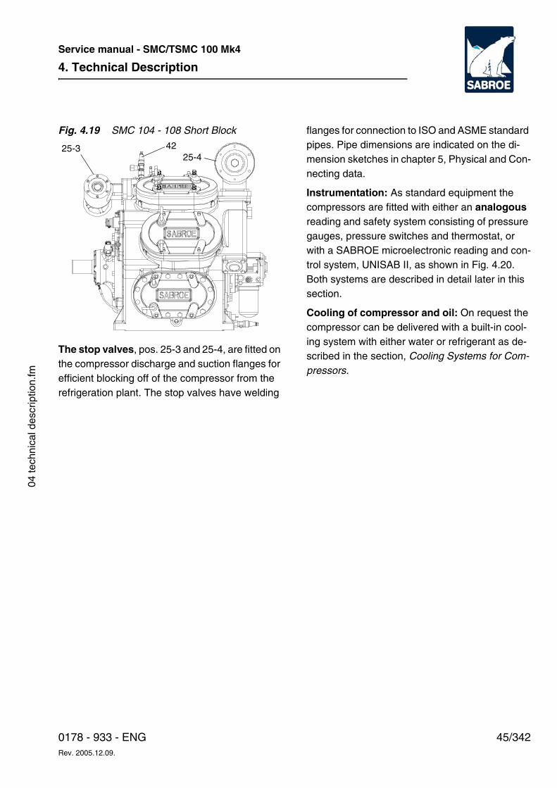
4. Technical Description
45/3420178 - 933 - ENGRev. 2005.12.09.
Service manual - SMC/TSMC 100 Mk4
04 te
chni
cal d
escr
iptio
n.fm
Fig. 4.19 SMC 104 - 108 Short Block
The stop valves, pos. 25-3 and 25-4, are fitted on the compressor discharge and suction flanges for efficient blocking off of the compressor from the refrigeration plant. The stop valves have welding
flanges for connection to ISO and ASME standard pipes. Pipe dimensions are indicated on the di-mension sketches in chapter 5, Physical and Con-necting data.
Instrumentation: As standard equipment the compressors are fitted with either an analogous reading and safety system consisting of pressure gauges, pressure switches and thermostat, or with a SABROE microelectronic reading and con-trol system, UNISAB II, as shown in Fig. 4.20. Both systems are described in detail later in this section.
Cooling of compressor and oil: On request the compressor can be delivered with a built-in cool-ing system with either water or refrigerant as de-scribed in the section, Cooling Systems for Com-pressors.
25-44225-3
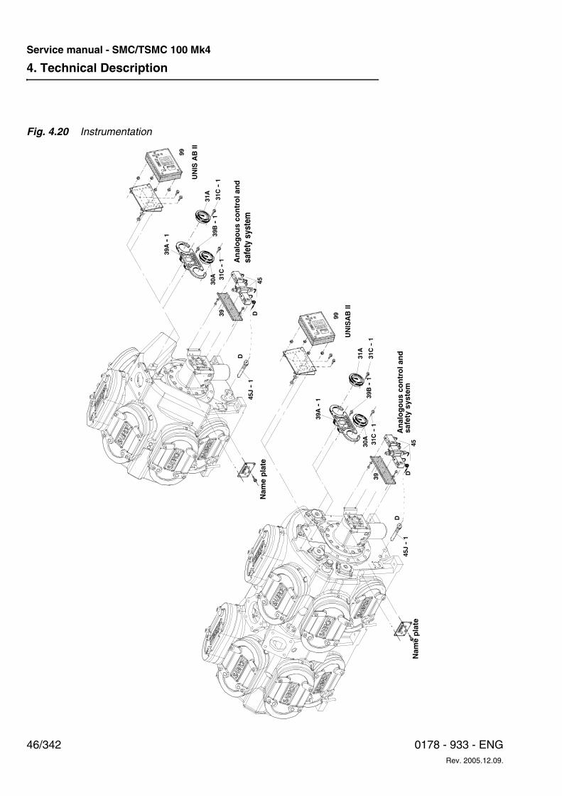
4. Technical Description
46/342 0178 - 933 - ENGRev. 2005.12.09.
Service manual - SMC/TSMC 100 Mk4
Fig. 4.20 Instrumentation
UN
ISA
B II
UN
ISA
B II
D
D
D45
J--
1
45J
--1
45
39
39
4530A
30A
31C
--1
31C
--1
39B
--1
39B
--1
31C
--1
31C
--1
31A
31A
99
99
39A
--1
39A
--1
DA
nal
og
ou
s co
ntr
ol a
nd
sa
fety
sys
tem
An
alo
go
us
con
tro
l an
d
safe
ty s
yste
m
Nam
e p
late
Nam
e p
late
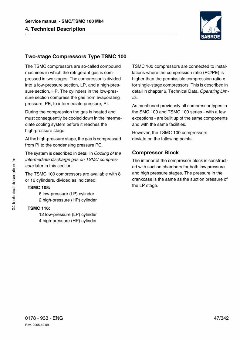
4. Technical Description
47/3420178 - 933 - ENGRev. 2005.12.09.
Service manual - SMC/TSMC 100 Mk4
04 te
chni
cal d
escr
iptio
n.fm
Two-stage Compressors Type TSMC 100
The TSMC compressors are so-called compound machines in which the refrigerant gas is com-pressed in two stages. The compressor is divided into a low-pressure section, LP, and a high-pres-sure section, HP. The cylinders in the low-pres-sure section compress the gas from evaporating pressure, PE, to intermediate pressure, PI.
During the compression the gas is heated and must consequently be cooled down in the interme-diate cooling system before it reaches the high-pressure stage.
At the high-pressure stage, the gas is compressed from PI to the condensing pressure PC.
The system is described in detail in Cooling of the intermediate discharge gas on TSMC compres-sors later in this section.
The TSMC 100 compressors are available with 8 or 16 cylinders, divided as indicated:
TSMC 100 compressors are connected to instal-lations where the compression ratio (PC/PE) is higher than the permissible compression ratio π for single-stage compressors. This is described in detail in chapter 6, Technical Data, Operating Lim-its.
As mentioned previously all compressor types in the SMC 100 and TSMC 100 series - with a few exceptions - are built up of the same components and with the same facilities.
However, the TSMC 100 compressors deviate on the following points:
Compressor BlockThe interior of the compressor block is construct-ed with suction chambers for both low pressure and high pressure stages. The pressure in the crankcase is the same as the suction pressure of the LP stage. TSMC 108:
6 low-pressure (LP) cylinder 2 high-pressure (HP) cylinder
TSMC 116:12 low-pressure (LP) cylinder4 high-pressure (HP) cylinder
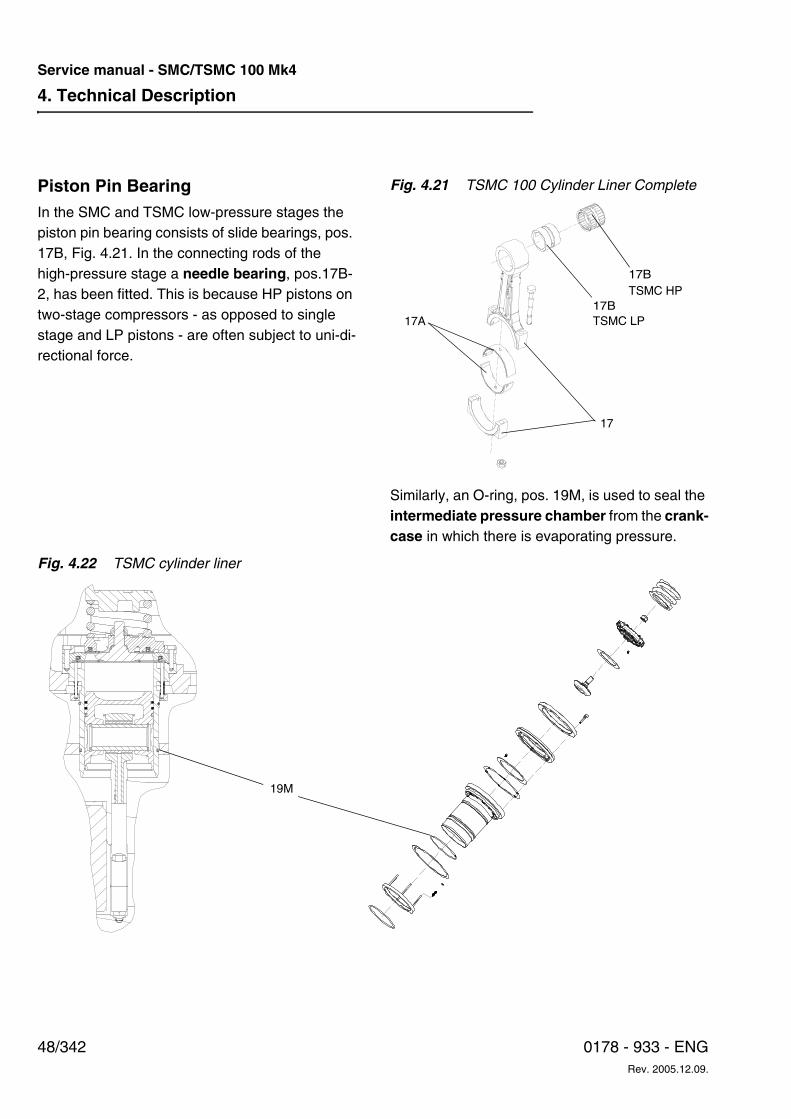
4. Technical Description
48/342 0178 - 933 - ENGRev. 2005.12.09.
Service manual - SMC/TSMC 100 Mk4
Piston Pin BearingIn the SMC and TSMC low-pressure stages the piston pin bearing consists of slide bearings, pos. 17B, Fig. 4.21. In the connecting rods of the high-pressure stage a needle bearing, pos.17B-2, has been fitted. This is because HP pistons on two-stage compressors - as opposed to single stage and LP pistons - are often subject to uni-di-rectional force.
Fig. 4.21 TSMC 100 Cylinder Liner Complete
Similarly, an O-ring, pos. 19M, is used to seal the intermediate pressure chamber from the crank-case in which there is evaporating pressure.
Fig. 4.22 TSMC cylinder liner
17A17B
17
TSMC LP
TSMC HP17B
19M
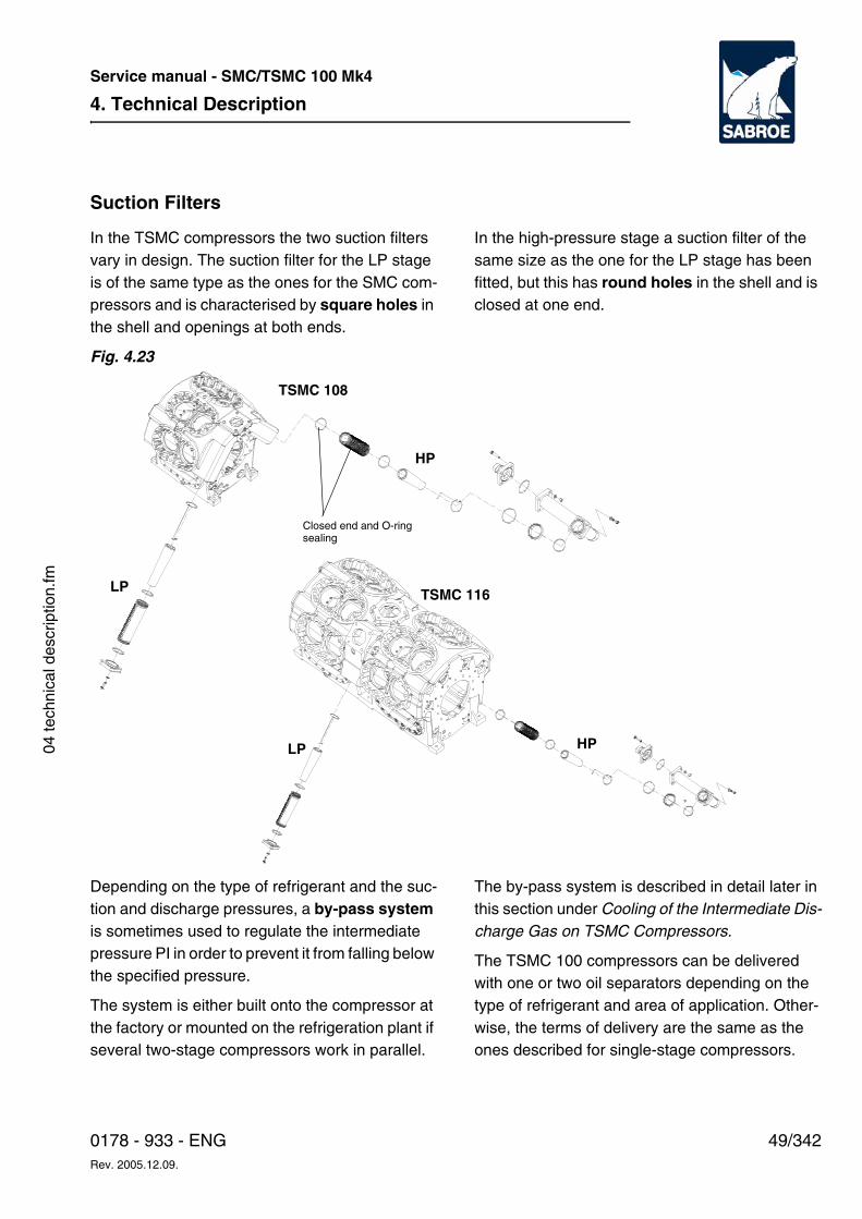
4. Technical Description
49/3420178 - 933 - ENGRev. 2005.12.09.
Service manual - SMC/TSMC 100 Mk4
04 te
chni
cal d
escr
iptio
n.fm
Suction Filters
In the TSMC compressors the two suction filters vary in design. The suction filter for the LP stage is of the same type as the ones for the SMC com-pressors and is characterised by square holes in the shell and openings at both ends.
In the high-pressure stage a suction filter of the same size as the one for the LP stage has been fitted, but this has round holes in the shell and is closed at one end.
Fig. 4.23
Depending on the type of refrigerant and the suc-tion and discharge pressures, a by-pass system is sometimes used to regulate the intermediate pressure PI in order to prevent it from falling below the specified pressure.
The system is either built onto the compressor at the factory or mounted on the refrigeration plant if several two-stage compressors work in parallel.
The by-pass system is described in detail later in this section under Cooling of the Intermediate Dis-charge Gas on TSMC Compressors.
The TSMC 100 compressors can be delivered with one or two oil separators depending on the type of refrigerant and area of application. Other-wise, the terms of delivery are the same as the ones described for single-stage compressors.
B
TSMC 108
LP
HP
HP
Closed end and O-ring sealing
LP
TSMC 116
4. Technical Description
50/342 0178 - 933 - ENGRev. 2005.12.09.
Service manual - SMC/TSMC 100 Mk4
Conversion of TSMC Compressors from Two-stage to Single-stage
If necessary, it is possible to convert a two-stage compressor into a single-stage compressor.
The following variations are possible:
a. Altering the compressor and using the same refrigerant
b. Altering the compressor and changing the re-frigerant from R717 to HFC/HCFC at the same time
c. Altering the compressor and changing the re-frigerant from HFC/HCFC to R717 at the same time
Generally, the conversion includes the following points:
1. Replacing the suction filter with a normal single-stage suction filter on the HP side.
2. Dismantling the pipe connection on the HP suction side and installing a standard cover, pos. 34 E.
3. Changing the pipe connections on the discharge side. As the built-in channel, which connects the top covers on a single-stage compressor, does not exist between the HP and LP top covers, this connection must be established externally.
4. Changing the HP stage connecting rods to the single stage type (journal bearing in small end). The piston pins must be changed.
5. Ensuring that the correct suction and dis-charge valves are fitted.
6. Installing the correct by-pass valves.
7. Adjusting the safety pressure controls.
Moreover, it is necessary to replace the compres-sor name plate and the name plates on the safety valves.
Please contact Sabroe Refrigeration’s After Mar-ket Sales Department for further information.
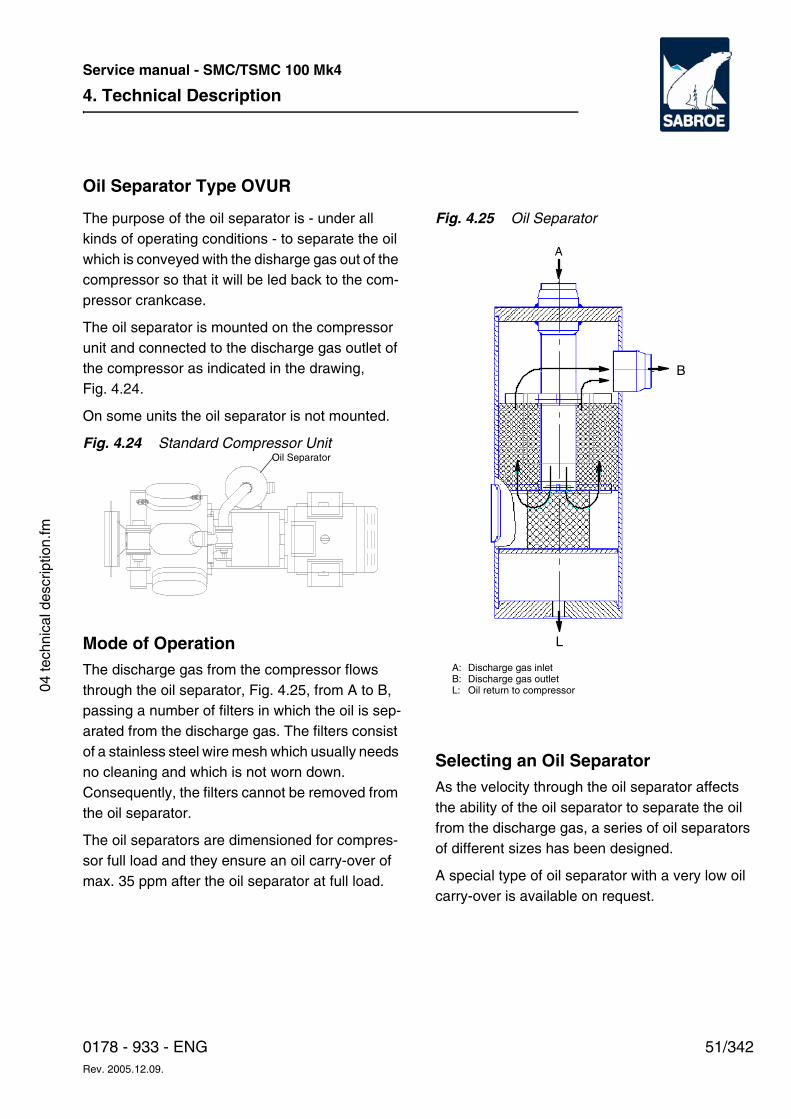
4. Technical Description
51/3420178 - 933 - ENGRev. 2005.12.09.
Service manual - SMC/TSMC 100 Mk4
04 te
chni
cal d
escr
iptio
n.fm
Oil Separator Type OVUR
The purpose of the oil separator is - under all kinds of operating conditions - to separate the oil which is conveyed with the disharge gas out of the compressor so that it will be led back to the com-pressor crankcase.
The oil separator is mounted on the compressor unit and connected to the discharge gas outlet of the compressor as indicated in the drawing, Fig. 4.24.
On some units the oil separator is not mounted.
Fig. 4.24 Standard Compressor Unit
Mode of OperationThe discharge gas from the compressor flows through the oil separator, Fig. 4.25, from A to B, passing a number of filters in which the oil is sep-arated from the discharge gas. The filters consist of a stainless steel wire mesh which usually needs no cleaning and which is not worn down. Consequently, the filters cannot be removed from the oil separator.
The oil separators are dimensioned for compres-sor full load and they ensure an oil carry-over of max. 35 ppm after the oil separator at full load.
Fig. 4.25 Oil Separator
Selecting an Oil SeparatorAs the velocity through the oil separator affects the ability of the oil separator to separate the oil from the discharge gas, a series of oil separators of different sizes has been designed.
A special type of oil separator with a very low oil carry-over is available on request.
Oil Separator
L
B
A
A:B:L:
Discharge gas inletDischarge gas outletOil return to compressor
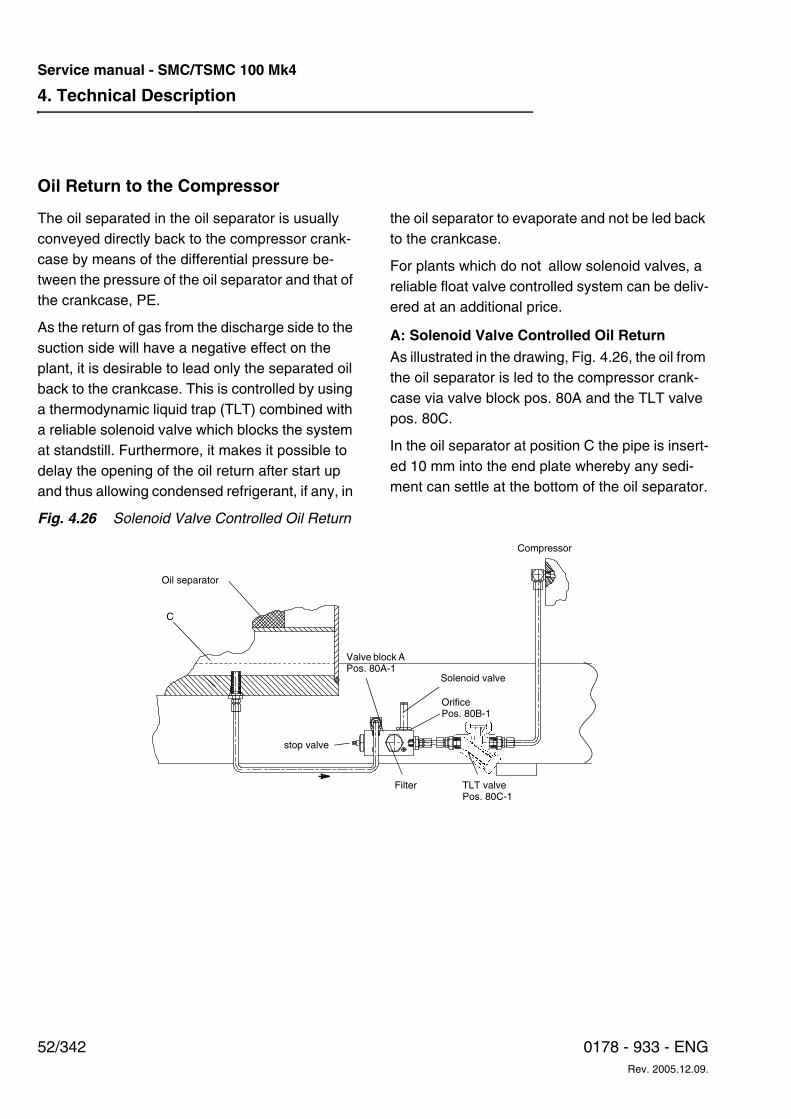
4. Technical Description
52/342 0178 - 933 - ENGRev. 2005.12.09.
Service manual - SMC/TSMC 100 Mk4
Oil Return to the Compressor
The oil separated in the oil separator is usually conveyed directly back to the compressor crank-case by means of the differential pressure be-tween the pressure of the oil separator and that of the crankcase, PE.
As the return of gas from the discharge side to the suction side will have a negative effect on the plant, it is desirable to lead only the separated oil back to the crankcase. This is controlled by using a thermodynamic liquid trap (TLT) combined with a reliable solenoid valve which blocks the system at standstill. Furthermore, it makes it possible to delay the opening of the oil return after start up and thus allowing condensed refrigerant, if any, in
the oil separator to evaporate and not be led back to the crankcase.
For plants which do not allow solenoid valves, a reliable float valve controlled system can be deliv-ered at an additional price.
A: Solenoid Valve Controlled Oil ReturnAs illustrated in the drawing, Fig. 4.26, the oil from the oil separator is led to the compressor crank-case via valve block pos. 80A and the TLT valve pos. 80C.
In the oil separator at position C the pipe is insert-ed 10 mm into the end plate whereby any sedi-ment can settle at the bottom of the oil separator.
Fig. 4.26 Solenoid Valve Controlled Oil Return
Oil separator
C
Compressor
Valve block A Pos. 80A-1
Solenoid valve
Filter TLT valve Pos. 80C-1
stop valve
OrificePos. 80B-1
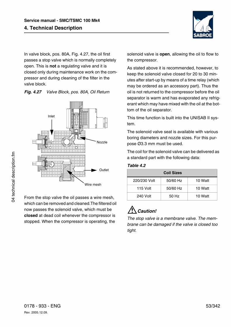
4. Technical Description
53/3420178 - 933 - ENGRev. 2005.12.09.
Service manual - SMC/TSMC 100 Mk4
04 te
chni
cal d
escr
iptio
n.fm
In valve block, pos. 80A, Fig. 4.27, the oil first passes a stop valve which is normally completely open. This is not a regulating valve and it is closed only during maintenance work on the com-pressor and during cleaning of the filter in the valve block.
Fig. 4.27 Valve Block, pos. 80A, Oil Return
From the stop valve the oil passes a wire mesh, which can be removed and cleaned.The filtered oil now passes the solenoid valve, which must be closed at dead coil whenever the compressor is stopped. When the compressor is operating, the
solenoid valve is open, allowing the oil to flow to the compressor.
As stated above it is recommended, however, to keep the solenoid valve closed for 20 to 30 min-utes after start-up by means of a time relay (which may be ordered as an accessory part). Thus the oil is not returned to the compressor before the oil separator is warm and has evaporated any refrig-erant which may have mixed with the oil at the bot-tom of the oil separator.
This time function is built into the UNISAB II sys-tem.
The solenoid valve seat is available with various boring diameters and nozzle sizes. For this pur-pose Ø3.3 mm must be used.
The coil for the solenoid valve can be delivered as a standard part with the following data:
Table 4.2
WCaution!
The stop valve is a membrane valve. The mem-brane can be damaged if the valve is closed too tight.
Wire mesh
Inlet
Outlet
Nozzle
Coil Sizes
220/230 Volt 50/60 Hz 10 Watt
115 Volt 50/60 Hz 10 Watt
240 Volt 50 Hz 10 Watt
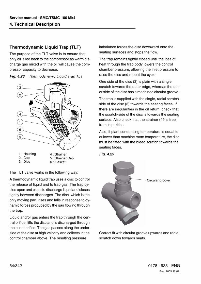
4. Technical Description
54/342 0178 - 933 - ENGRev. 2005.12.09.
Service manual - SMC/TSMC 100 Mk4
Thermodynamic Liquid Trap (TLT)The purpose of the TLT valve is to ensure that only oil is led back to the compressor as warm dis-charge gas mixed with the oil will cause the com-pressor capacity to decrease.
Fig. 4.28 Thermodynamic Liquid Trap TLT
The TLT valve works in the following way:
A thermodynamic liquid trap uses a disc to control the release of liquid and to trap gas. The trap cy-cles open and close to discharge liquid and closes tightly between discharges. The disc, which is the only moving part, rises and falls in response to dy-namic forces produced by the gas flowing through the trap.
Liquid and/or gas enters the trap through the cen-tral orifice, lifts the disc and is discharged through the outlet orifice. The gas passes along the under-side of the disc at high velocity and collects in the control chamber above. The resulting pressure
imbalance forces the disc downward onto the seating surfaces and stops the flow.
The trap remains tightly closed until the loss of heat through the trap body lowers the control chamber pressure, allowing the inlet pressure to raise the disc and repeat the cycle.
One side of the disc (3) is plain with a single scratch towards the outer edge, whereas the oth-er side of the disc has a machined circular groove.
The trap is supplied with the single, radial scratch-side of the disc (3) towards the seating faces. If there are iregularities in the oil return, check that the scratch-side of the disc is towards the seating surface. Also check that the strainer (49 is free from impurities.
Also, if plant condensing temperature is equal to or lower than machine room temperature, the disc must be fitted with the bleed scratch towards the seating faces.
Fig. 4.29
Correct fit with circular groove upwards and radial scratch down towards seats.
1 : Housing2 : Cap3 : Disc
6
3
2
4
1
5
4 : Strainer5 : Strainer Cap6 : Gasket
Circular groove
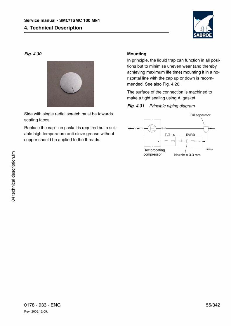
4. Technical Description
55/3420178 - 933 - ENGRev. 2005.12.09.
Service manual - SMC/TSMC 100 Mk4
04 te
chni
cal d
escr
iptio
n.fm
Fig. 4.30
Side with single radial scratch must be towards seating faces.
Replace the cap - no gasket is required but a suit-able high temperature anti-sieze grease without copper should be applied to the threads.
MountingIn principle, the liquid trap can function in all posi-tions but to minimise uneven wear (and thereby achieving maximum life time) mounting it in a ho-rizontal line with the cap up or down is recom-mended. See also Fig. 4.26.
The surface of the connection is machined to make a tight sealing using Al gasket.
Fig. 4.31 Principle piping diagram
TLT 15 EVRB
245893Reciprocating compressor Nozzle ø 3.3 mm
Oil separator
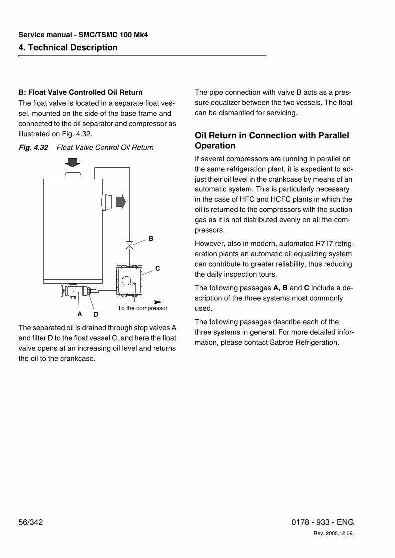
4. Technical Description
56/342 0178 - 933 - ENGRev. 2005.12.09.
Service manual - SMC/TSMC 100 Mk4
B: Float Valve Controlled Oil ReturnThe float valve is located in a separate float ves-sel, mounted on the side of the base frame and connected to the oil separator and compressor as illustrated on Fig. 4.32.
Fig. 4.32 Float Valve Control Oil Return
The separated oil is drained through stop valves A and filter D to the float vessel C, and here the float valve opens at an increasing oil level and returns the oil to the crankcase.
The pipe connection with valve B acts as a pres-sure equalizer between the two vessels. The float can be dismantled for servicing.
Oil Return in Connection with Parallel OperationIf several compressors are running in parallel on the same refrigeration plant, it is expedient to ad-just their oil level in the crankcase by means of an automatic system. This is particularly necessary in the case of HFC and HCFC plants in which the oil is returned to the compressors with the suction gas as it is not distributed evenly on all the com-pressors.
However, also in modern, automated R717 refrig-eration plants an automatic oil equalizing system can contribute to greater reliability, thus reducing the daily inspection tours.
The following passages A, B and C include a de-scription of the three systems most commonly used.
The following passages describe each of the three systems in general. For more detailed infor-mation, please contact Sabroe Refrigeration.
B
C
A DTo the compressor
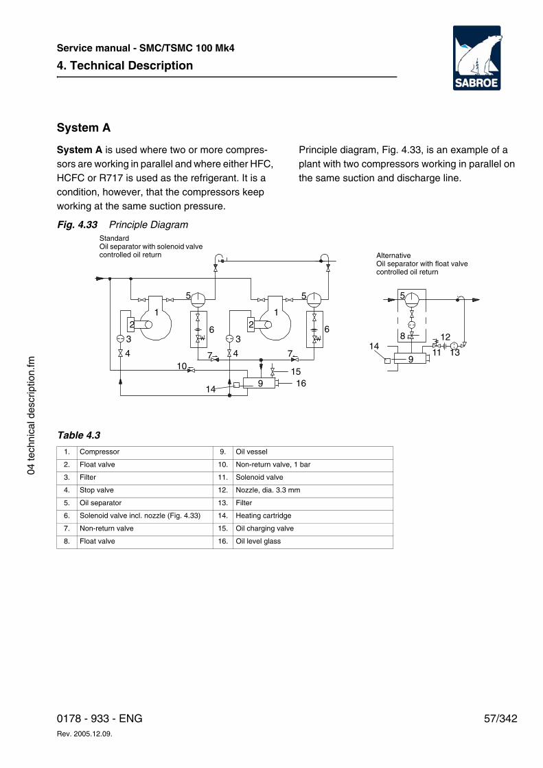
4. Technical Description
57/3420178 - 933 - ENGRev. 2005.12.09.
Service manual - SMC/TSMC 100 Mk4
04 te
chni
cal d
escr
iptio
n.fm
System A
System A is used where two or more compres-sors are working in parallel and where either HFC, HCFC or R717 is used as the refrigerant. It is a condition, however, that the compressors keep working at the same suction pressure.
Principle diagram, Fig. 4.33, is an example of a plant with two compressors working in parallel on the same suction and discharge line.
Fig. 4.33 Principle Diagram
Table 4.3
2
3
4
1 12
3
47
6
5
9
10
5
7
6
9
8
5
11
12
13
14
1516
14
AlternativeOil separator with float valvecontrolled oil return
StandardOil separator with solenoid valvecontrolled oil return
1. Compressor 9. Oil vessel
2. Float valve 10. Non-return valve, 1 bar
3. Filter 11. Solenoid valve
4. Stop valve 12. Nozzle, dia. 3.3 mm
5. Oil separator 13. Filter
6. Solenoid valve incl. nozzle (Fig. 4.33) 14. Heating cartridge
7. Non-return valve 15. Oil charging valve
8. Float valve 16. Oil level glass
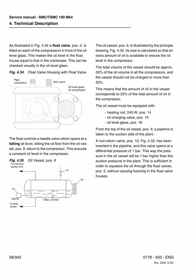
4. Technical Description
58/342 0178 - 933 - ENGRev. 2005.12.09.
Service manual - SMC/TSMC 100 Mk4
As illustrated in Fig. 4.34 a float valve, pos. 2, is fitted on each of the compressors in front of the oil level glass. This makes the oil level in the float house equal to that in the crankcase. This can be checked visually in the oil level glass.
Fig. 4.34 Float Valve Housing with Float Valve
The float controls a needle valve which opens at a falling oil level, letting the oil flow from the oil ves-sel, pos. 9, return to the compressor. This ensures a constant oil level in the compressor.
Fig. 4.35 Oil Vessel, pos. 9
The oil vessel, pos. 9, is illustrated by the principle drawing, Fig. 4.35. Its size is calculated so that an extra amount of oil is available to ensure the oil level in the compressor.
The total volume of the vessel should be approx. 50% of the oil volume in all the compressors, and the vessel should not be charged to more than 50%.
This means that the amount of oil in the vessel corresponds to 25% of the total amount of oil in the compressor.
The oil vessel must be equipped with:
- heating rod, 240 W, pos. 14- oil charging valve, pos. 15- oil level glass, pos. 16
From the top of the oil vessel, pos. 9, a pipeline is taken to the suction side of the plant.
A non-return valve, pos. 10, Fig. 4.33, has been inserted in the pipeline, and this valve opens at a differential pressure of 1 bar. This way the pres-sure in the oil vessel will be 1 bar higher than the suction pressure in the plant. This is sufficient in order to squeeze the oil through the float valves, pos. 2, without causing foaming in the float valve houses.
Pipe connection Vent valve
Oil level glasson compressor
16
To common suction line
240 W
To float valves
15
Max. oil level
14
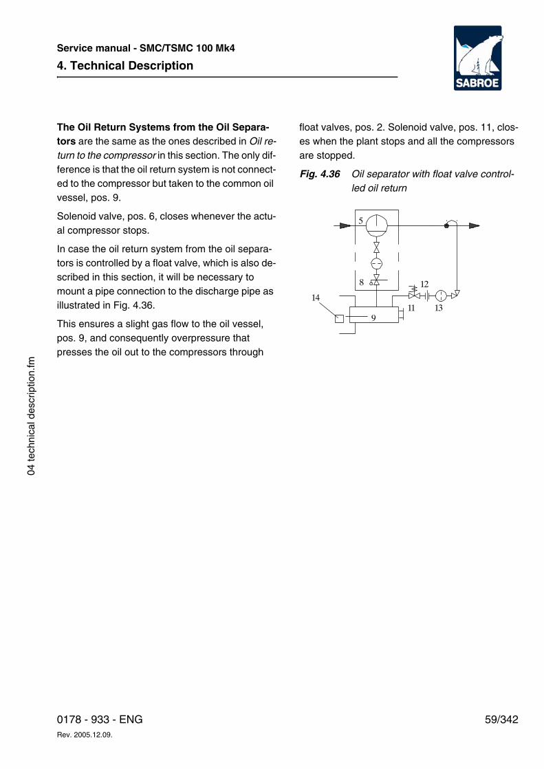
4. Technical Description
59/3420178 - 933 - ENGRev. 2005.12.09.
Service manual - SMC/TSMC 100 Mk4
04 te
chni
cal d
escr
iptio
n.fm
The Oil Return Systems from the Oil Separa-tors are the same as the ones described in Oil re-turn to the compressor in this section. The only dif-ference is that the oil return system is not connect-ed to the compressor but taken to the common oil vessel, pos. 9.
Solenoid valve, pos. 6, closes whenever the actu-al compressor stops.
In case the oil return system from the oil separa-tors is controlled by a float valve, which is also de-scribed in this section, it will be necessary to mount a pipe connection to the discharge pipe as illustrated in Fig. 4.36.
This ensures a slight gas flow to the oil vessel, pos. 9, and consequently overpressure that presses the oil out to the compressors through
float valves, pos. 2. Solenoid valve, pos. 11, clos-es when the plant stops and all the compressors are stopped.
Fig. 4.36 Oil separator with float valve control-led oil return
9
8
5
11
12
1314
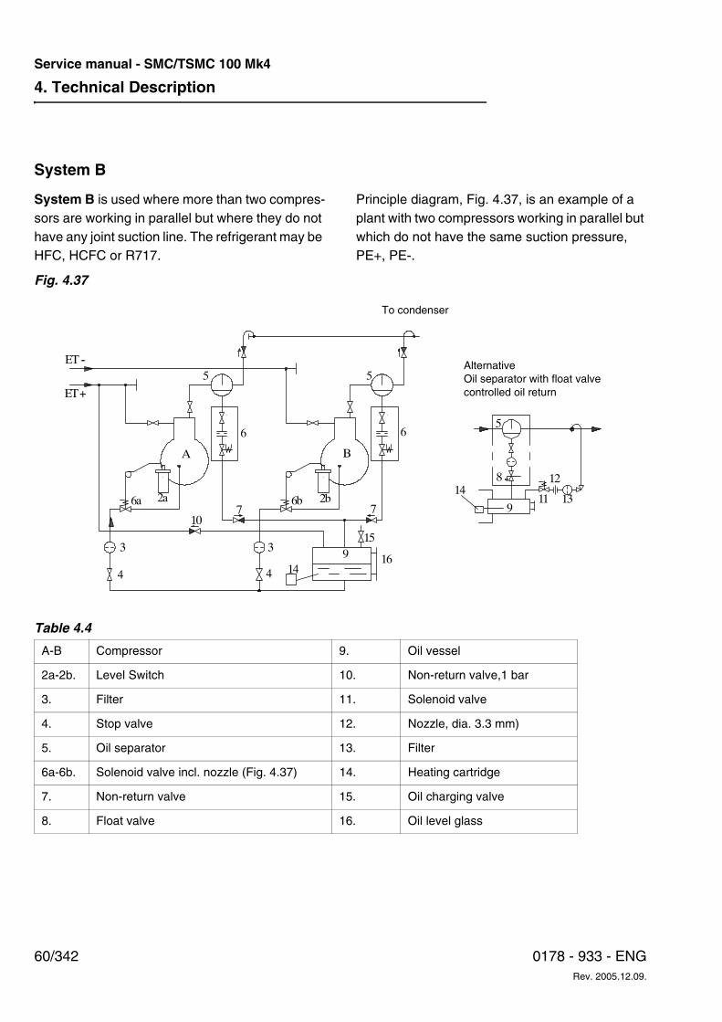
4. Technical Description
60/342 0178 - 933 - ENGRev. 2005.12.09.
Service manual - SMC/TSMC 100 Mk4
System B
System B is used where more than two compres-sors are working in parallel but where they do not have any joint suction line. The refrigerant may be HFC, HCFC or R717.
Principle diagram, Fig. 4.37, is an example of a plant with two compressors working in parallel but which do not have the same suction pressure, PE+, PE-.
Fig. 4.37
Table 4.4
A-B Compressor 9. Oil vessel
2a-2b. Level Switch 10. Non-return valve,1 bar
3. Filter 11. Solenoid valve
4. Stop valve 12. Nozzle, dia. 3.3 mm)
5. Oil separator 13. Filter
6a-6b. Solenoid valve incl. nozzle (Fig. 4.37) 14. Heating cartridge
7. Non-return valve 15. Oil charging valve
8. Float valve 16. Oil level glass
ET--
ET+
4
3
2a 2b6b6a
A B
5 5
7
6
7
6
3
4
9
9
8
5
11
12
1314
10
1416
15
To condenser
AlternativeOil separator with float valvecontrolled oil return
4. Technical Description
61/3420178 - 933 - ENGRev. 2005.12.09.
Service manual - SMC/TSMC 100 Mk4
04 te
chni
cal d
escr
iptio
n.fm
To be able to press the oil from the oil vessel, pos. 9, to the crankcase on the compressor, pos. A, which is working at the highest suction pressure PE+, the pipeline with the non-return valve (1 bar), pos. 10, is connected to the suction gas line for this compressor.
There is a risk, however, that the differential pres-sure between the oil vessel, pos. 9, and the crank-case on compressor B may become so great that the oil conveyed via the solenoid valve 6a starts foaming. Usually, this foaming does not cause any problems as the oil is supplied to the compressor
above oil level. Any foaming that may occur will soon be dissolved in the crankcase.
The system has one further advantage as the oil does not pass the level switch vessels 2a and 2b. Should foaming occur, this is not going to interfere with the working of the level switch.
In case the oil return system is regulated by means of a float valve as described under System A, the same system as the one shown in Fig. 4.38 should be used.
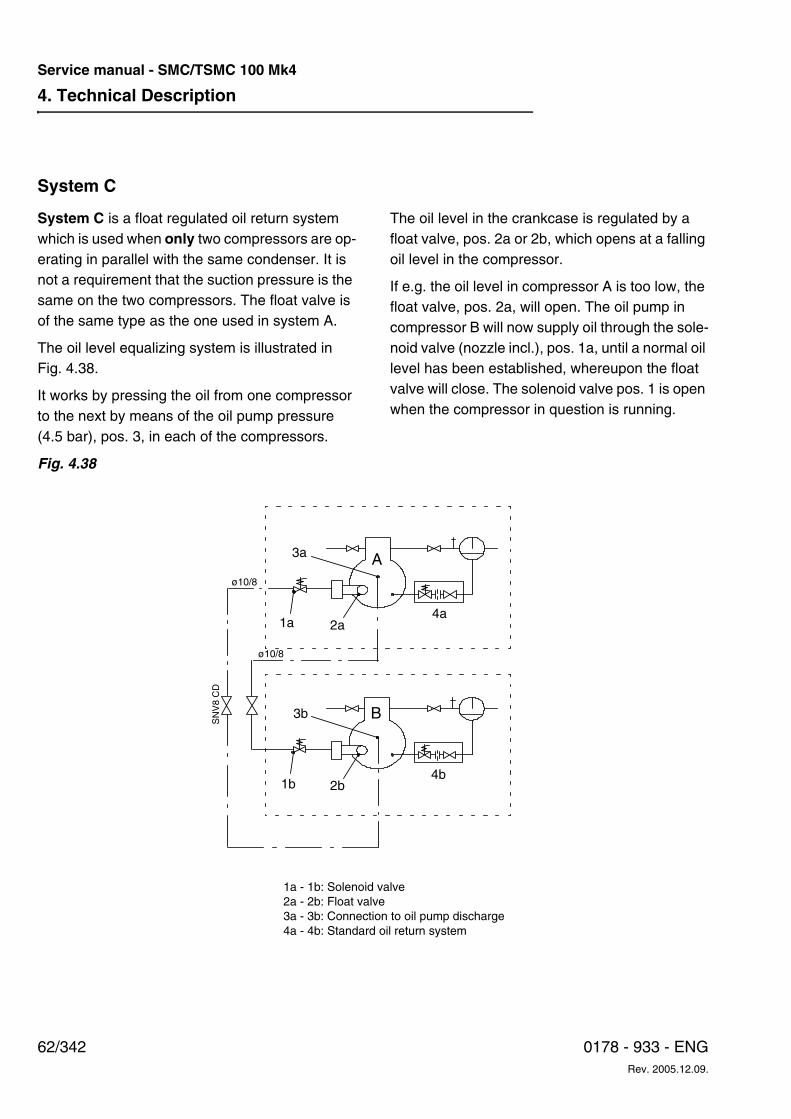
4. Technical Description
62/342 0178 - 933 - ENGRev. 2005.12.09.
Service manual - SMC/TSMC 100 Mk4
System C
System C is a float regulated oil return system which is used when only two compressors are op-erating in parallel with the same condenser. It is not a requirement that the suction pressure is the same on the two compressors. The float valve is of the same type as the one used in system A.
The oil level equalizing system is illustrated in Fig. 4.38.
It works by pressing the oil from one compressor to the next by means of the oil pump pressure (4.5 bar), pos. 3, in each of the compressors.
The oil level in the crankcase is regulated by a float valve, pos. 2a or 2b, which opens at a falling oil level in the compressor.
If e.g. the oil level in compressor A is too low, the float valve, pos. 2a, will open. The oil pump in compressor B will now supply oil through the sole-noid valve (nozzle incl.), pos. 1a, until a normal oil level has been established, whereupon the float valve will close. The solenoid valve pos. 1 is open when the compressor in question is running.
Fig. 4.38
1a - 1b: Solenoid valve2a - 2b: Float valve3a - 3b: Connection to oil pump discharge4a - 4b: Standard oil return system
A
B
4a
4b
3a
1a 2a
2b1b
SN
V8
CD
ø10/8
ø10/8
3b
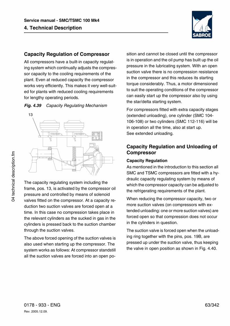
4. Technical Description
63/3420178 - 933 - ENGRev. 2005.12.09.
Service manual - SMC/TSMC 100 Mk4
04 te
chni
cal d
escr
iptio
n.fm
Capacity Regulation of CompressorAll compressors have a built-in capacity regulat-ing system which continually adjusts the compres-sor capacity to the cooling requirements of the plant. Even at reduced capacity the compressor works very efficiently. This makes it very well-suit-ed for plants with reduced cooling requirements for lengthy operating periods.
Fig. 4.39 Capacity Regulating Mechanism
The capacity regulating system including the frame, pos. 13, is activated by the compressor oil pressure and controlled by means of solenoid valves fitted on the compressor. At a capacity re-duction two suction valves are forced open at a time. In this case no compression takes place in the relevant cylinders as the sucked in gas in the cylinders is pressed back to the suction chamber through the suction valves.
The above forced opening of the suction valves is also used when starting up the compressor. The system works as follows: At compressor standstill all the suction valves are forced into an open po-
sition and cannot be closed until the compressor is in operation and the oil pump has built up the oil pressure in the lubricating system. With an open suction valve there is no compression resistance in the compressor and this reduces its starting torque considerably. Thus, a motor dimensioned to suit the operating conditions of the compressor can easily start up the compressor also by using the star/delta starting system.
For compressors fitted with extra capacity stages (extended unloading), one cylinder (SMC 104-106-108) or two cylinders (SMC 112-116) will be in operation all the time, also at start up. See extended unloading.
Capacity Regulation and Unloading of Compressor
Capacity RegulationAs mentioned in the introduction to this section all SMC and TSMC compressors are fitted with a hy-draulic capacity regulating system by means of which the compressor capacity can be adjusted to the refrigerating requirements of the plant.
When reducing the compressor capacity, two or more suction valves (on compressors with ex-tended unloading: one or more suction valves) are forced open so that compression does not occur in the cylinders in question.
The suction valve is forced open when the unload-ing ring together with the pins, pos. 19B, are pressed up under the suction valve, thus keeping the valve in open position as shown in Fig. 4.40.
13
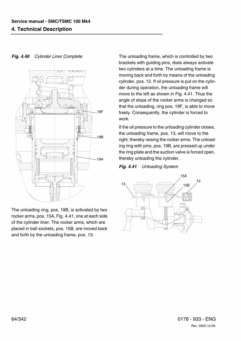
4. Technical Description
64/342 0178 - 933 - ENGRev. 2005.12.09.
Service manual - SMC/TSMC 100 Mk4
Fig. 4.40 Cylinder Liner Complete
The unloading ring, pos. 19B, is activated by two rocker arms, pos. 15A, Fig. 4.41, one at each side of the cylinder liner. The rocker arms, which are placed in ball sockets, pos. 15B, are moved back and forth by the unloading frame, pos. 13.
The unloading frame, which is controlled by two brackets with guiding pins, does always activate two cylinders at a time. The unloading frame is moving back and forth by means of the unloading cylinder, pos. 12. If oil pressure is put on the cylin-der during operation, the unloading frame will move to the left as shown in Fig. 4.41. Thus the angle of slope of the rocker arms is changed so that the unloading, ring pos. 19F, is able to move freely. Consequently, the cylinder is forced to work.
If the oil pressure to the unloading cylinder closes, the unloading frame, pos. 13, will move to the right, thereby raising the rocker arms. The unload-ing ring with pins, pos. 19B, are pressed up under the ring plate and the suction valve is forced open, thereby unloading the cylinder.
Fig. 4.41 Unloading System
19A
19B
19F
15B
15A
1312
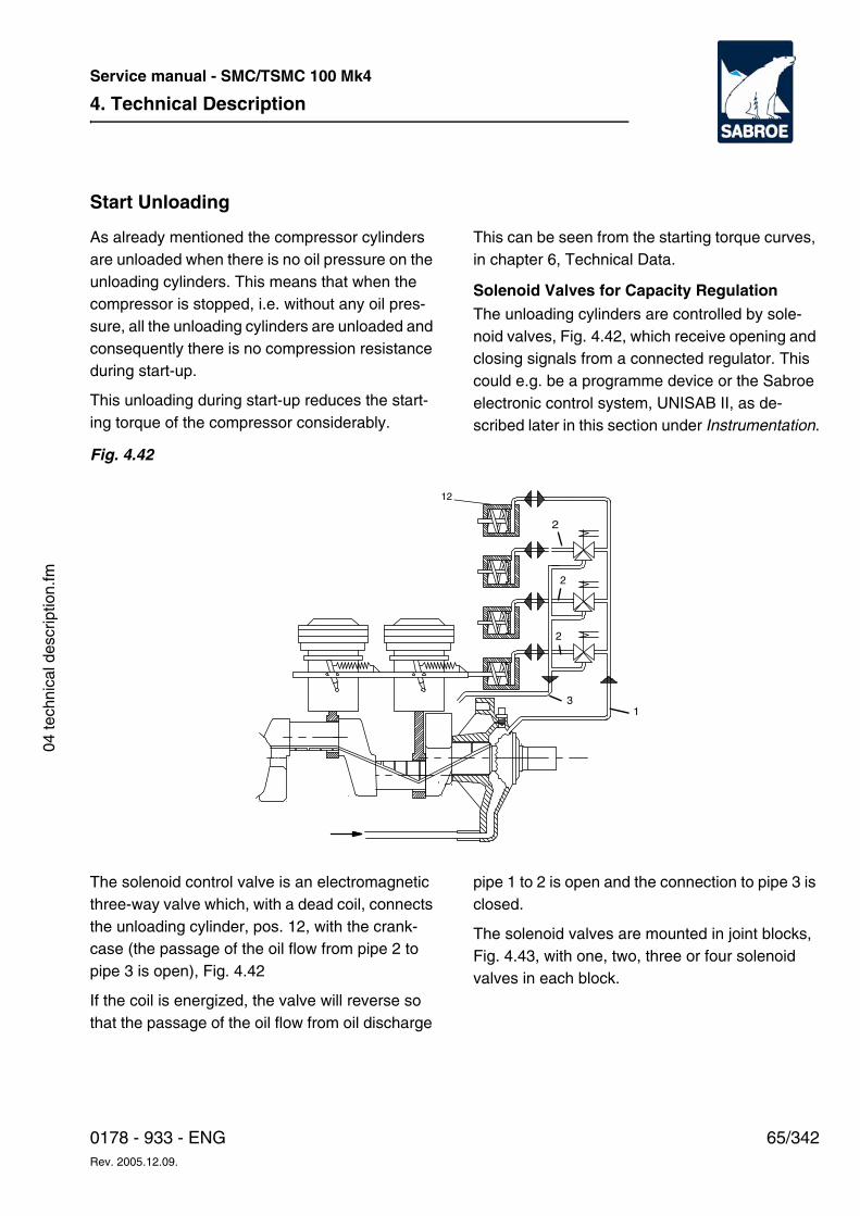
4. Technical Description
65/3420178 - 933 - ENGRev. 2005.12.09.
Service manual - SMC/TSMC 100 Mk4
04 te
chni
cal d
escr
iptio
n.fm
Start Unloading
As already mentioned the compressor cylinders are unloaded when there is no oil pressure on the unloading cylinders. This means that when the compressor is stopped, i.e. without any oil pres-sure, all the unloading cylinders are unloaded and consequently there is no compression resistance during start-up.
This unloading during start-up reduces the start-ing torque of the compressor considerably.
This can be seen from the starting torque curves, in chapter 6, Technical Data.
Solenoid Valves for Capacity RegulationThe unloading cylinders are controlled by sole-noid valves, Fig. 4.42, which receive opening and closing signals from a connected regulator. This could e.g. be a programme device or the Sabroe electronic control system, UNISAB II, as de-scribed later in this section under Instrumentation.
Fig. 4.42
The solenoid control valve is an electromagnetic three-way valve which, with a dead coil, connects the unloading cylinder, pos. 12, with the crank-case (the passage of the oil flow from pipe 2 to pipe 3 is open), Fig. 4.42
If the coil is energized, the valve will reverse so that the passage of the oil flow from oil discharge
pipe 1 to 2 is open and the connection to pipe 3 is closed.
The solenoid valves are mounted in joint blocks, Fig. 4.43, with one, two, three or four solenoid valves in each block.
3
2
2
2
1
12
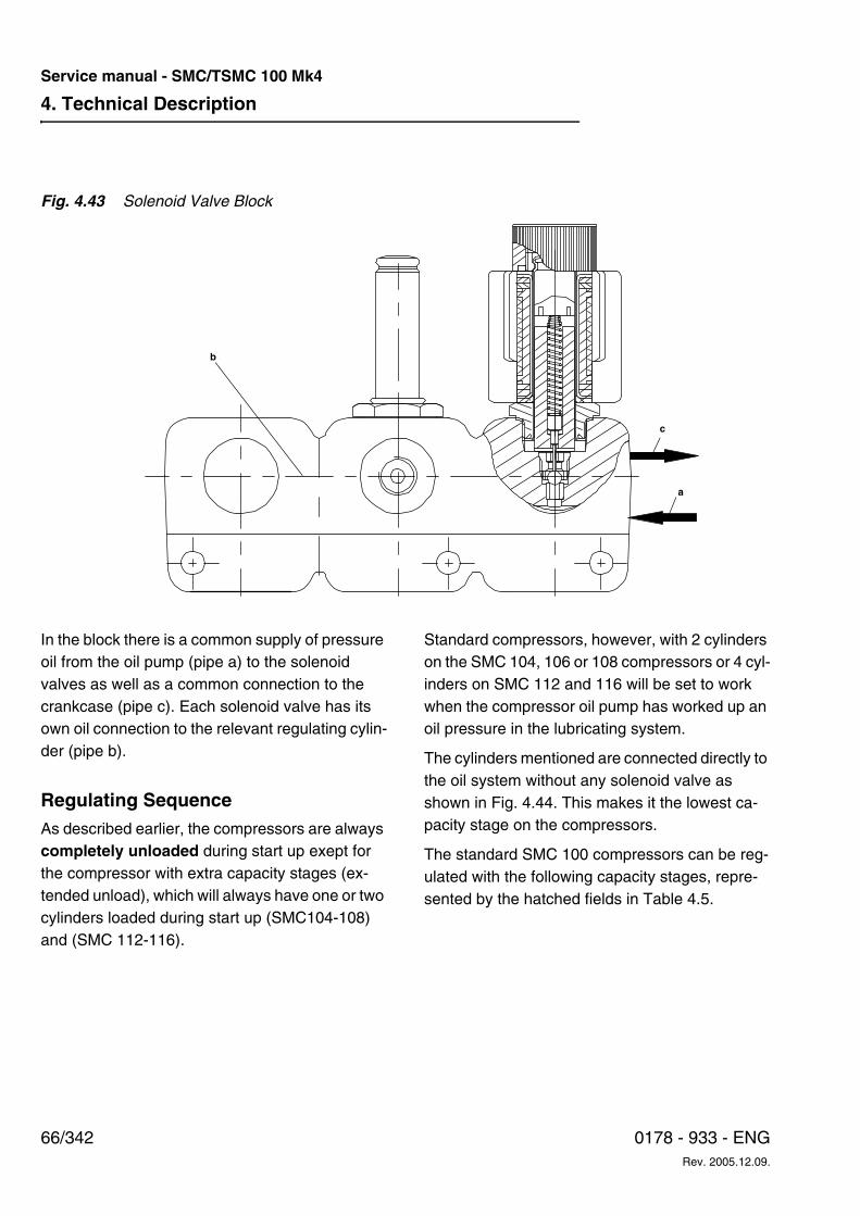
4. Technical Description
66/342 0178 - 933 - ENGRev. 2005.12.09.
Service manual - SMC/TSMC 100 Mk4
Fig. 4.43 Solenoid Valve Block
In the block there is a common supply of pressure oil from the oil pump (pipe a) to the solenoid valves as well as a common connection to the crankcase (pipe c). Each solenoid valve has its own oil connection to the relevant regulating cylin-der (pipe b).
Regulating SequenceAs described earlier, the compressors are always completely unloaded during start up exept for the compressor with extra capacity stages (ex-tended unload), which will always have one or two cylinders loaded during start up (SMC104-108) and (SMC 112-116).
Standard compressors, however, with 2 cylinders on the SMC 104, 106 or 108 compressors or 4 cyl-inders on SMC 112 and 116 will be set to work when the compressor oil pump has worked up an oil pressure in the lubricating system.
The cylinders mentioned are connected directly to the oil system without any solenoid valve as shown in Fig. 4.44. This makes it the lowest ca-pacity stage on the compressors.
The standard SMC 100 compressors can be reg-ulated with the following capacity stages, repre-sented by the hatched fields in Table 4.5.
b
c
a
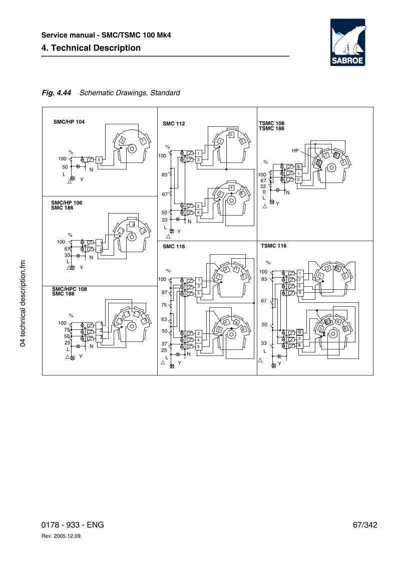
4. Technical Description
67/3420178 - 933 - ENGRev. 2005.12.09.
Service manual - SMC/TSMC 100 Mk4
04 te
chni
cal d
escr
iptio
n.fm
Fig. 4.44 Schematic Drawings, Standard
SMC/HP 104
%100
50
LY
1
N
2 1
SMC/HP 106
%100
YL
N
1
21
3
26733
SMC 186
SMC/HPC 108SMC 188
%
100
YL
N
1
2
3275
25 4
3
4
SMC 112 TSMC 108TSMC 188
SMC 116 TSMC 116
%
100
83
67
50
33
LY
N
1
3
5
2
4
6
%
1006733
LY
0
HP
1
2
S
S
%
Y
N
L
S
100
83
67
50
33
Y
NL
3
1
75
5
5
6
2
%
100
50 3
12
37
5
S87
63
2
6
1
3
5
S
4S
S
1
3 1
4
8
S
1
2
1
3
2
4
25
1
50
4
2
4. Technical Description
68/342 0178 - 933 - ENGRev. 2005.12.09.
Service manual - SMC/TSMC 100 Mk4
The electric regulating system should be made in such a way that, after start-up, addi-tional capacity cannot be loaded until the mo-tor has reached its full torque.
The recommended run up time is 10 sec. The min-imum speed according to the operating limit dia-gram is 5 sec (also applies to variable speed driv-en compressors).
Fig. 4.45 illustrates the regulating system in prin-ciple. The percentages indicate the compressor capacity at every stage. When unloading a compressor without extra ca-pacity stages, the solenoid valves are unloaded in numerical order: 1 -> 2 -> 3 -> 4. When loading, the order is: 4 -> 3 -> 2 -> 1.
Note: On TSMC 116 compressors the solenoid valves nos. 3 and 4 must always be loaded simul-taneously as they control both the LP and the HP cylinders.
Further, the TSMC compressors can, as standard equipment, be totally unloaded as described in the following.
Total UnloadingBesides the standard equipment as described in the previous passage the compressor can be fit-ted with a solenoid valve marked S (optional). Fig. 4.45.
The TSMC compressors, however, are always equipped with this S solenoid valve.
The S solenoid valve makes the total unloading of the compressor possible - i.e. the compressor idles at 0% capacity. The S solenoid valve must never, however, be part of a normal capacity reg-ulation as the compressor will heat up excessively during a lengthy operating period at 0% capacity. The S solenoid valve must therefore only be used as follows:
• When total unloading is required until the motor has reached its maximum torque.
• When a refrigeration plant has sudden brief operational stops for a short time and com-pressor stop is not required. In this case the compressor must not be allowed to run for more than 5 minutes at 0% capacity. If the compressor is equipped with a refrigerant cooled oil cooler type OOSI (R717) or OOKH (HFC/HFCF) and liquid refrigerants are available so that the cooling system can operate, idling is allowed for up to 30 min-utes.
The regulating sequence can be seen from the schematic drawings in Fig. 4.45.
Capacity Stages:The SMC 100 compressors can be regulated with the following capacity stages, represented by the hatched fields in Table 4.5.
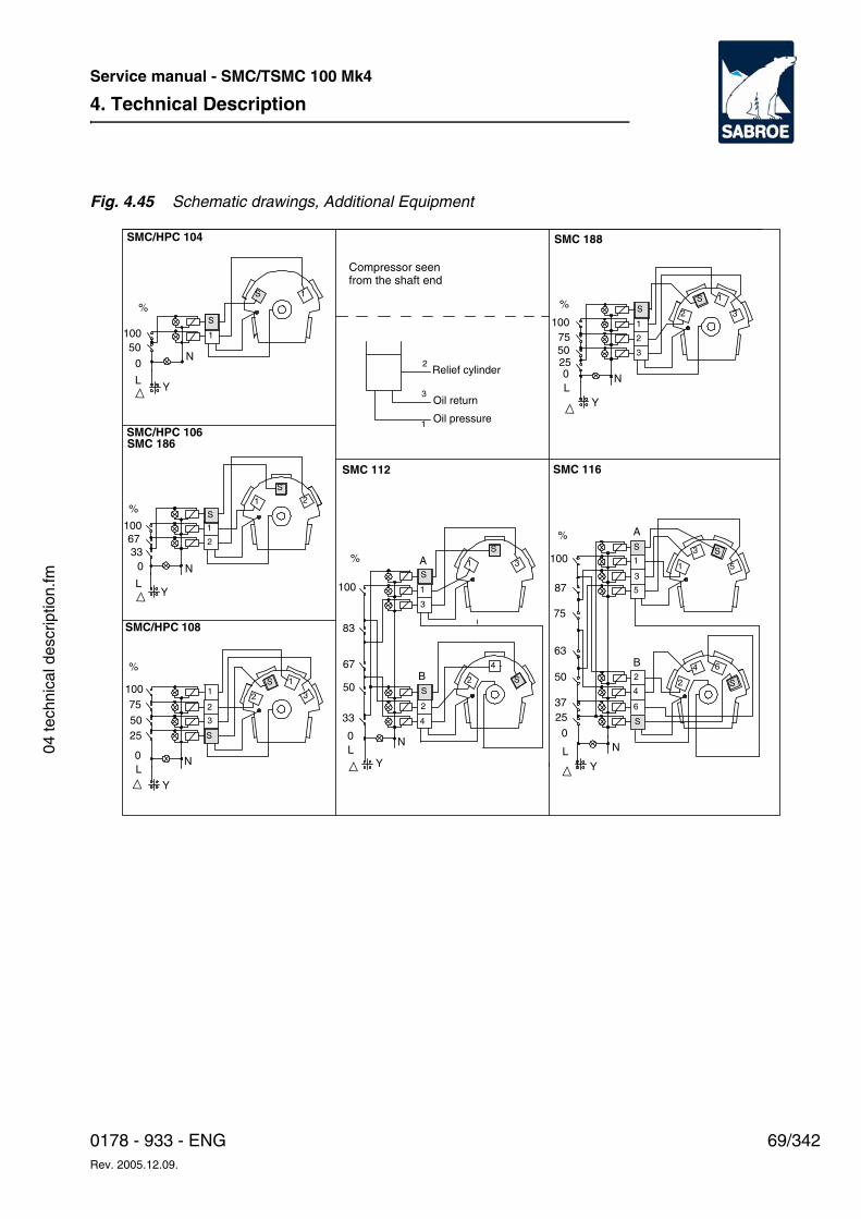
4. Technical Description
69/3420178 - 933 - ENGRev. 2005.12.09.
Service manual - SMC/TSMC 100 Mk4
04 te
chni
cal d
escr
iptio
n.fm
Fig. 4.45 Schematic drawings, Additional Equipment
%
100
67
%
SMC/HPC 104
33
10050
0
LY
N
S
1
1S
SMC/HPC 106
1
SMC 186
2
S
1
2
S
LN0
100
%
Y
SMC/HPC 108
1
25
100
0
75
L
50
N
Y
1
22
3
S
3
S
Compressor seen from the shaft end
1
Relief cylinder2
3Oil return
Oil pressure
SMC 112
S
83
67
50
33
0L
Y
N
%
2
4
1
S
3
2
4
S
S
1
3
SMC 188
SMC 116
%
%
75
1
1
7550
025
100
LY
N
2
S
3
2
S 1
3
100
87
63
50
3725
0
LY
N
3 S
5
2
4 6
S
1
3
5
2
4
6
S
S
A
BB
A
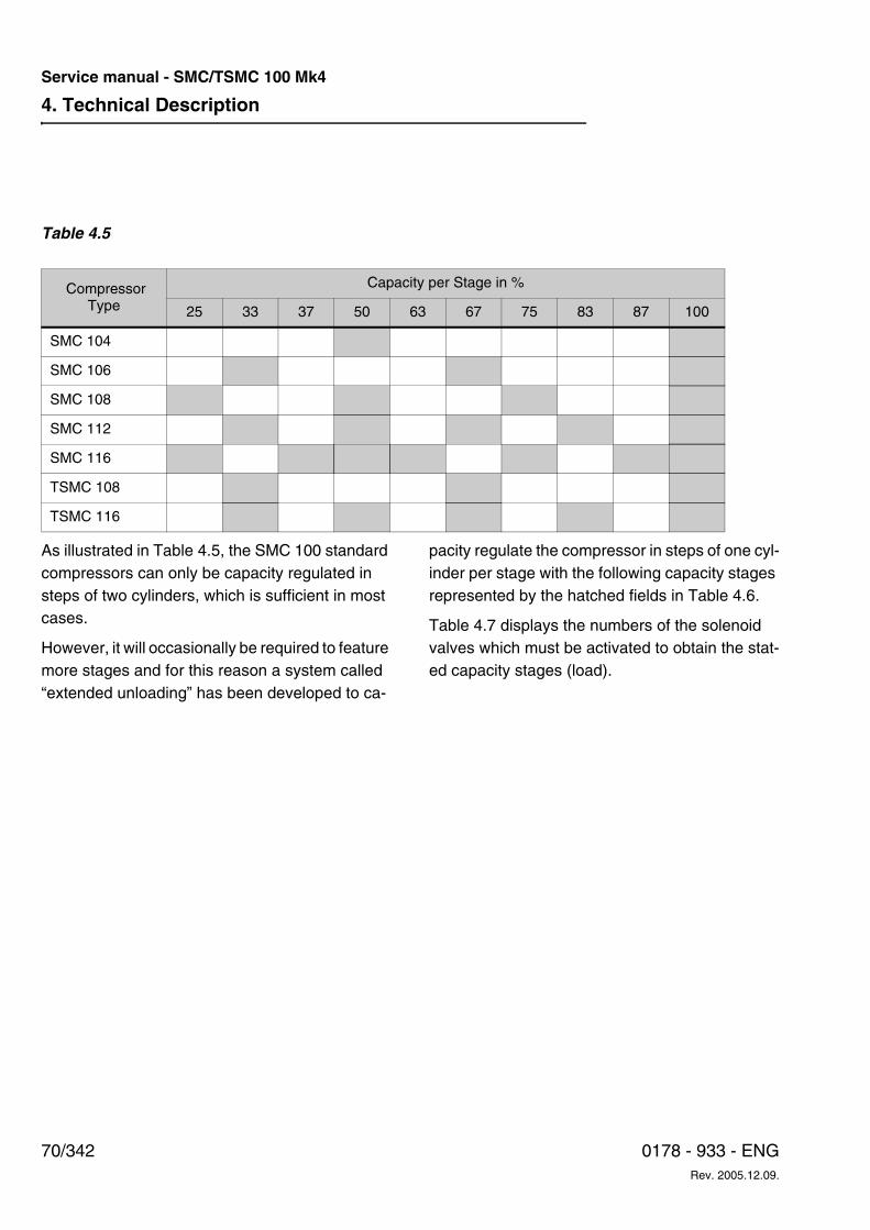
4. Technical Description
70/342 0178 - 933 - ENGRev. 2005.12.09.
Service manual - SMC/TSMC 100 Mk4
Table 4.5
As illustrated in Table 4.5, the SMC 100 standard compressors can only be capacity regulated in steps of two cylinders, which is sufficient in most cases.
However, it will occasionally be required to feature more stages and for this reason a system called “extended unloading” has been developed to ca-
pacity regulate the compressor in steps of one cyl-inder per stage with the following capacity stages represented by the hatched fields in Table 4.6.
Table 4.7 displays the numbers of the solenoid valves which must be activated to obtain the stat-ed capacity stages (load).
CompressorType
Capacity per Stage in %
25 33 37 50 63 67 75 83 87 100
SMC 104
SMC 106
SMC 108
SMC 112
SMC 116
TSMC 108
TSMC 116
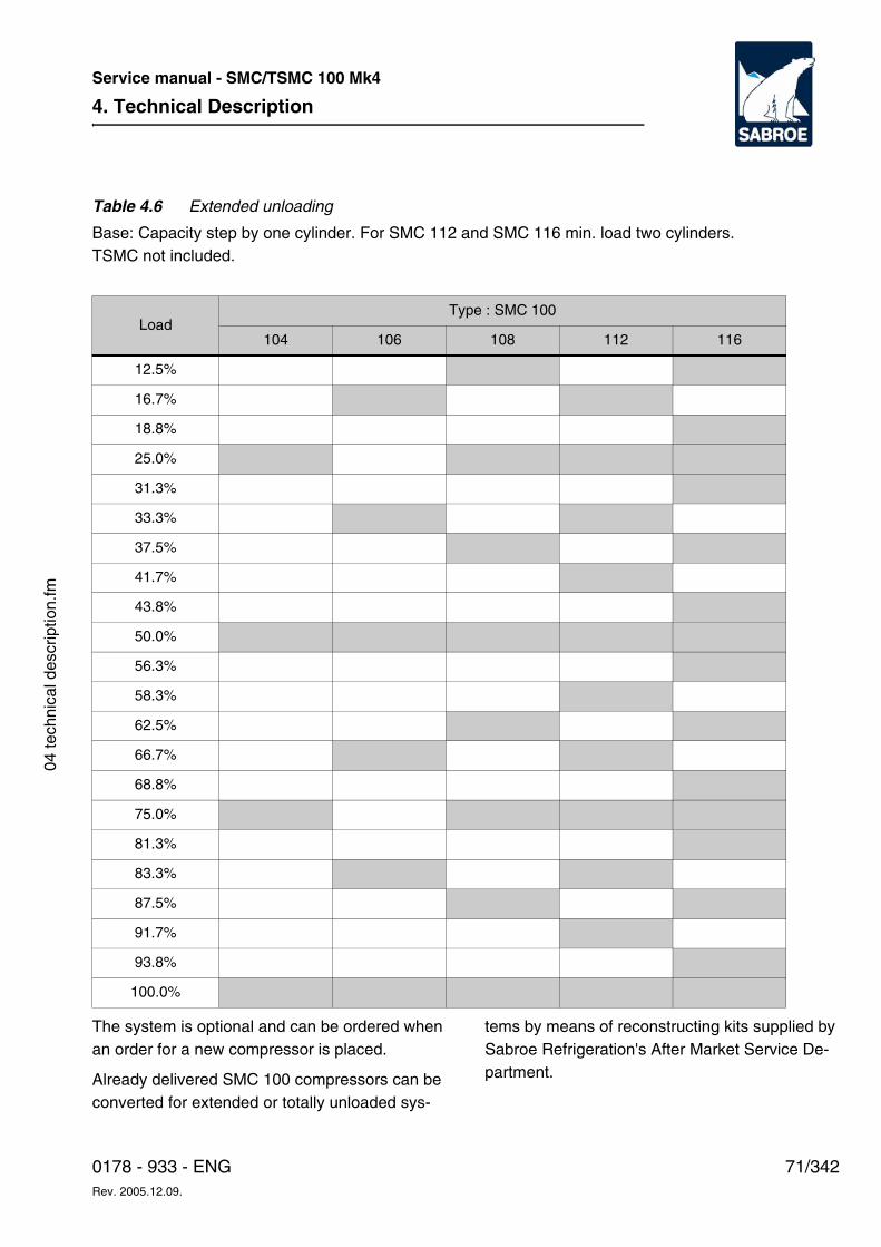
4. Technical Description
71/3420178 - 933 - ENGRev. 2005.12.09.
Service manual - SMC/TSMC 100 Mk4
04 te
chni
cal d
escr
iptio
n.fm
Table 4.6 Extended unloading
Base: Capacity step by one cylinder. For SMC 112 and SMC 116 min. load two cylinders.TSMC not included.
The system is optional and can be ordered when an order for a new compressor is placed.
Already delivered SMC 100 compressors can be converted for extended or totally unloaded sys-
tems by means of reconstructing kits supplied by Sabroe Refrigeration's After Market Service De-partment.
LoadType : SMC 100
104 106 108 112 116
12.5%
16.7%
18.8%
25.0%
31.3%
33.3%
37.5%
41.7%
43.8%
50.0%
56.3%
58.3%
62.5%
66.7%
68.8%
75.0%
81.3%
83.3%
87.5%
91.7%
93.8%
100.0%
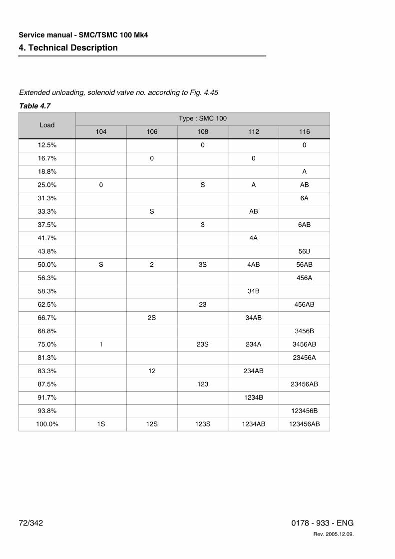
4. Technical Description
72/342 0178 - 933 - ENGRev. 2005.12.09.
Service manual - SMC/TSMC 100 Mk4
Extended unloading, solenoid valve no. according to Fig. 4.45
Table 4.7
LoadType : SMC 100
104 106 108 112 116
12.5% 0 0
16.7% 0 0
18.8% A
25.0% 0 S A AB
31.3% 6A
33.3% S AB
37.5% 3 6AB
41.7% 4A
43.8% 56B
50.0% S 2 3S 4AB 56AB
56.3% 456A
58.3% 34B
62.5% 23 456AB
66.7% 2S 34AB
68.8% 3456B
75.0% 1 23S 234A 3456AB
81.3% 23456A
83.3% 12 234AB
87.5% 123 23456AB
91.7% 1234B
93.8% 123456B
100.0% 1S 12S 123S 1234AB 123456AB
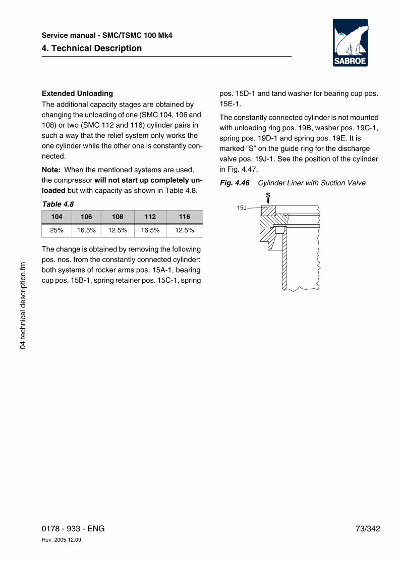
4. Technical Description
73/3420178 - 933 - ENGRev. 2005.12.09.
Service manual - SMC/TSMC 100 Mk4
04 te
chni
cal d
escr
iptio
n.fm
Extended UnloadingThe additional capacity stages are obtained by changing the unloading of one (SMC 104, 106 and 108) or two (SMC 112 and 116) cylinder pairs in such a way that the relief system only works the one cylinder while the other one is constantly con-nected.
Note: When the mentioned systems are used, the compressor will not start up completely un-loaded but with capacity as shown in Table 4.8.
Table 4.8
The change is obtained by removing the following pos. nos. from the constantly connected cylinder: both systems of rocker arms pos. 15A-1, bearing cup pos. 15B-1, spring retainer pos. 15C-1, spring
pos. 15D-1 and tand washer for bearing cup pos. 15E-1.
The constantly connected cylinder is not mounted with unloading ring pos. 19B, washer pos. 19C-1, spring pos. 19D-1 and spring pos. 19E. It is marked “S” on the guide ring for the discharge valve pos. 19J-1. See the position of the cylinder in Fig. 4.47.
Fig. 4.46 Cylinder Liner with Suction Valve
104 106 108 112 116
25% 16.5% 12.5% 16.5% 12.5%
S
19J
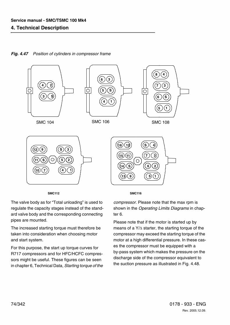
4. Technical Description
74/342 0178 - 933 - ENGRev. 2005.12.09.
Service manual - SMC/TSMC 100 Mk4
Fig. 4.47 Position of cylinders in compressor frame
The valve body as for “Total unloading” is used to regulate the capacity stages instead of the stand-ard valve body and the corresponding connecting pipes are mounted.
The increased starting torque must therefore be taken into consideration when choosing motor and start system.
For this purpose, the start up torque curves for R717 compressors and for HFC/HCFC compres-sors might be useful. These figures can be seen in chapter 6, Technical Data, Starting torque of the
compressor. Please note that the max rpm is shown in the Operating Limits Diagrams in chap-ter 6.
Please note that if the motor is started up by means of a Y/∆ starter, the starting torque of the compressor may exceed the starting torque of the motor at a high differential pressure. In these cas-es the compressor must be equipped with a by-pass system which makes the pressure on the discharge side of the compressor equivalent to the suction pressure as illustrated in Fig. 4.48.
4 2
3 S1
S
4
36
5
S
1
3
48
7
6
5
SMC112 SMC116
12
11
10
9
S
7
S 3
5 2
4 1
13
14
59 1
6S 2
15
16 12 S 4
7 311
SMC 104 SMC 106 SMC 108
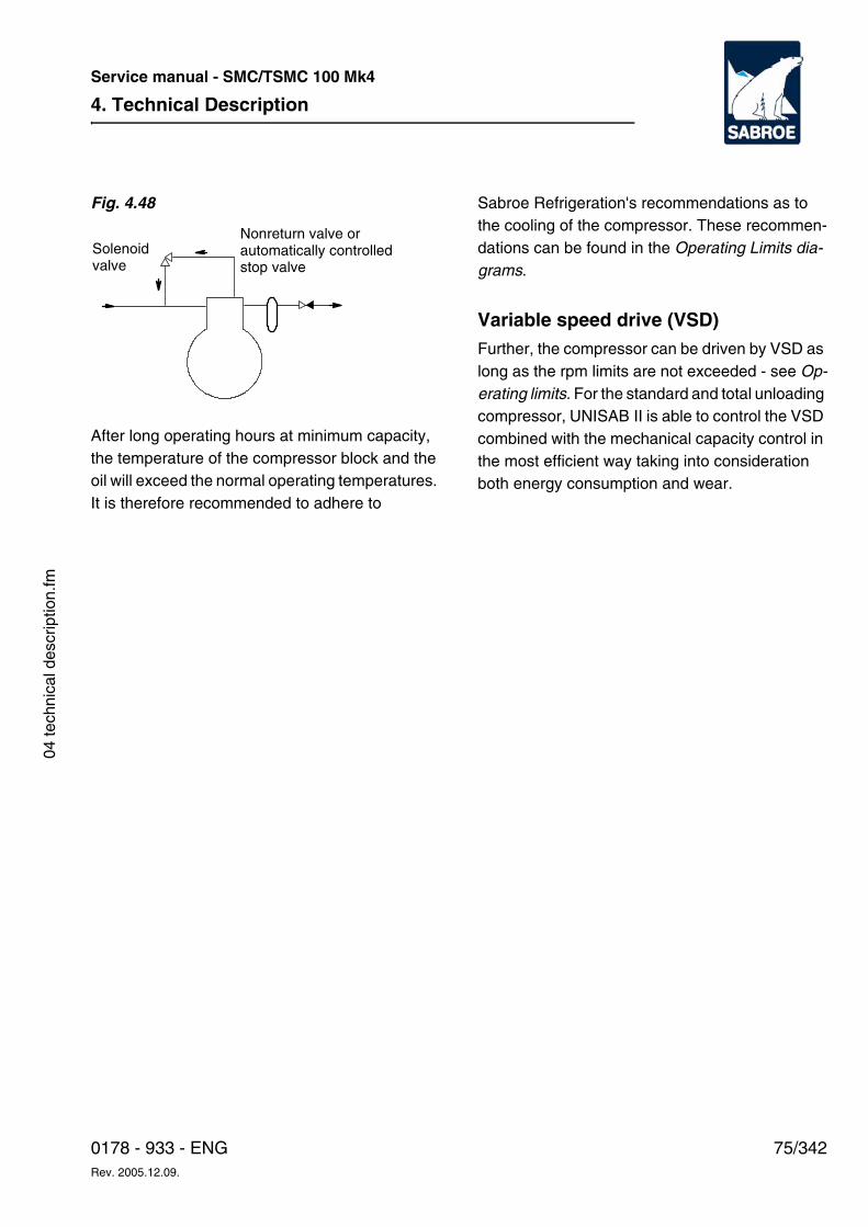
4. Technical Description
75/3420178 - 933 - ENGRev. 2005.12.09.
Service manual - SMC/TSMC 100 Mk4
04 te
chni
cal d
escr
iptio
n.fm
Fig. 4.48
After long operating hours at minimum capacity, the temperature of the compressor block and the oil will exceed the normal operating temperatures. It is therefore recommended to adhere to
Sabroe Refrigeration's recommendations as to the cooling of the compressor. These recommen-dations can be found in the Operating Limits dia-grams.
Variable speed drive (VSD)Further, the compressor can be driven by VSD as long as the rpm limits are not exceeded - see Op-erating limits. For the standard and total unloading compressor, UNISAB II is able to control the VSD combined with the mechanical capacity control in the most efficient way taking into consideration both energy consumption and wear.
Solenoidvalve
Nonreturn valve orautomatically controlledstop valve
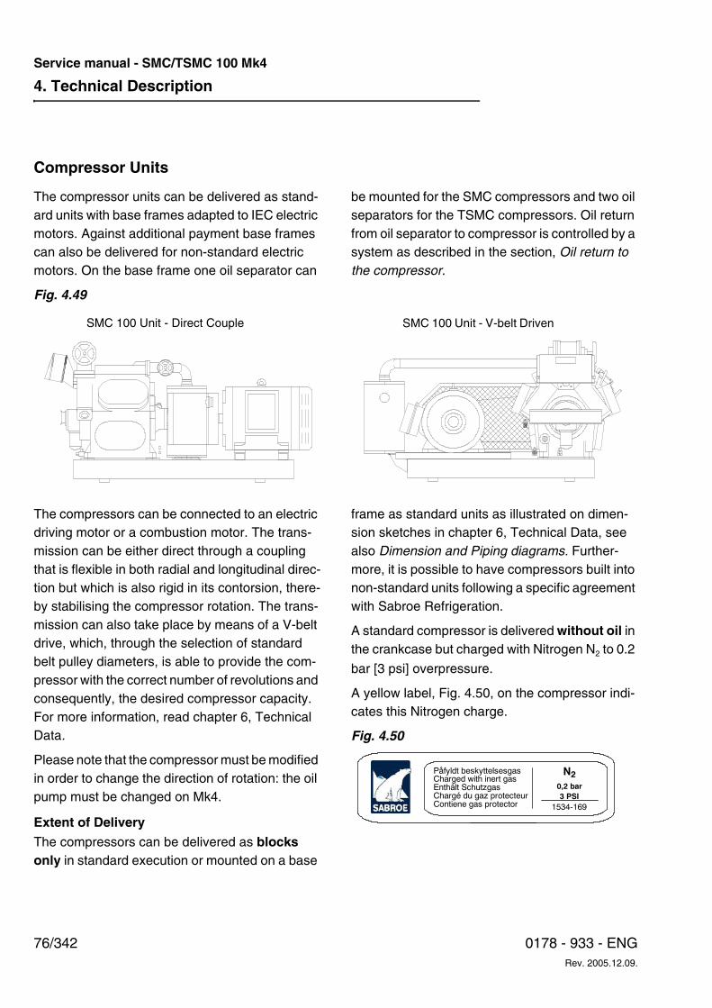
4. Technical Description
76/342 0178 - 933 - ENGRev. 2005.12.09.
Service manual - SMC/TSMC 100 Mk4
Compressor Units
The compressor units can be delivered as stand-ard units with base frames adapted to IEC electric motors. Against additional payment base frames can also be delivered for non-standard electric motors. On the base frame one oil separator can
be mounted for the SMC compressors and two oil separators for the TSMC compressors. Oil return from oil separator to compressor is controlled by a system as described in the section, Oil return to the compressor.
Fig. 4.49
The compressors can be connected to an electric driving motor or a combustion motor. The trans-mission can be either direct through a coupling that is flexible in both radial and longitudinal direc-tion but which is also rigid in its contorsion, there-by stabilising the compressor rotation. The trans-mission can also take place by means of a V-belt drive, which, through the selection of standard belt pulley diameters, is able to provide the com-pressor with the correct number of revolutions and consequently, the desired compressor capacity. For more information, read chapter 6, Technical Data.
Please note that the compressor must be modified in order to change the direction of rotation: the oil pump must be changed on Mk4.
Extent of Delivery The compressors can be delivered as blocks only in standard execution or mounted on a base
frame as standard units as illustrated on dimen-sion sketches in chapter 6, Technical Data, see also Dimension and Piping diagrams. Further-more, it is possible to have compressors built into non-standard units following a specific agreement with Sabroe Refrigeration.
A standard compressor is delivered without oil in the crankcase but charged with Nitrogen N2 to 0.2
bar [3 psi] overpressure.
A yellow label, Fig. 4.50, on the compressor indi-cates this Nitrogen charge.
Fig. 4.50
SMC 100 Unit - Direct Couple SMC 100 Unit - V-belt Driven
Påfyldt beskyttelsesgasCharged with inert gasEnthält SchutzgasChargé du gaz protecteurContiene gas protector
N20,2 bar
3 PSI
1534-169
4. Technical Description
77/3420178 - 933 - ENGRev. 2005.12.09.
Service manual - SMC/TSMC 100 Mk4
04 te
chni
cal d
escr
iptio
n.fm
Instrumentation
In the standard version the compressors are avail-able with one of the following two systems:
A: analogue reading and safety system
B: UNISAB II reading, safety and capacity regulating system
The compressors are designed so that either the analogue system or the UNISAB II system can be fitted without changing the compressor. They each have their own characteristics, however, as described in the following:
A: Analogue Reading and Safety SystemThe analogue system only has reading and safety functions and cannot control the com-pressor capacity.
Capacity control is handled by an external system built into the electrical switchboard and connected to the compressor on the mounting site. Some mounting costs must be expected.
The control system can be one of many types and makes. It must, however, be able to send out opening and closing signals to the solenoid valves of the compressor in the prescribed unloading and loading sequence as already described in this section, Capac-ity Regulation and Unloading of Compres-sor.
In special cases a manually operated switch system can be used instead of the automat-ic one. This makes it possible to regulate the compressor capacity by hand.
In its standard execution the analogue sys-tem consists of controls, built onto the com-pressor on delivery, but without electrical connections.
The controls are not factory adjusted and should therefore be adjusted before the ini-tial start-up of the compressor.
As may be seen from the drawing Fig. 4.51 some of the controls have a dual function, i.e. the type designation KP15 indicates that 1 is the low pressure and 5 the high pres-sure cut-out function. KP98 e.g. has two temperature systems incorporated.
The specific controls are mentioned in the following, with reference to the numbers in Fig. 4.51.
Fig. 4.51
6 5 4 3 2 1
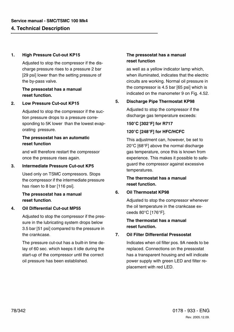
4. Technical Description
78/342 0178 - 933 - ENGRev. 2005.12.09.
Service manual - SMC/TSMC 100 Mk4
1. High Pressure Cut-out KP15
Adjusted to stop the compressor if the dis-charge pressure rises to a pressure 2 bar [29 psi] lower than the setting pressure of the by-pass valve.
The pressostat has a manual reset function.
2. Low Pressure Cut-out KP15
Adjusted to stop the compressor if the suc-tion pressure drops to a pressure corre-sponding to 5K lower than the lowest evap-orating pressure.
The pressostat has an automatic reset function
and will therefore restart the compressor once the pressure rises again.
3. Intermediate Pressure Cut-out KP5
Used only on TSMC compressors. Stops the compressor if the intermediate pressure has risen to 8 bar [116 psi].
The pressostat has a manualreset function.
4. Oil Differential Cut-out MP55
Adjusted to stop the compressor if the pres-sure in the lubricating system drops below 3.5 bar [51 psi] compared to the pressure in the crankcase.
The pressure cut-out has a built-in time de-lay of 60 sec. which keeps it idle during the start-up of the compressor until the correct oil pressure has been established.
The pressostat has a manual reset function
as well as a yellow indicator lamp which, when illuminated, indicates that the electric circuits are working. Normal oil pressure in the compressor is 4.5 bar [65 psi] which is indicated on the manometer 9 on Fig. 4.52.
5. Discharge Pipe Thermostat KP98
Adjusted to stop the compressor if the discharge gas temperature exceeds:
150°C [302°F] for R717
120°C [248°F] for HFC/HCFC
This adjustment can, however, be set to 20°C [68°F] above the normal discharge gas temperature, once this is known from experience. This makes it possible to safe-guard the compressor against excessive temperatures.
The thermostat has a manual reset function.
6. Oil Thermostat KP98
Adjusted to stop the compressor whenever the oil temperature in the crankcase ex-ceeds 80°C [176°F].
The thermostat has a manual reset function.
7. Oil Filter Differential Pressostat
Indicates when oil filter pos. 9A needs to be replaced. Connections on the pressostat has a transparent housing and will indicate power supply with green LED and filter re-placement with red LED.
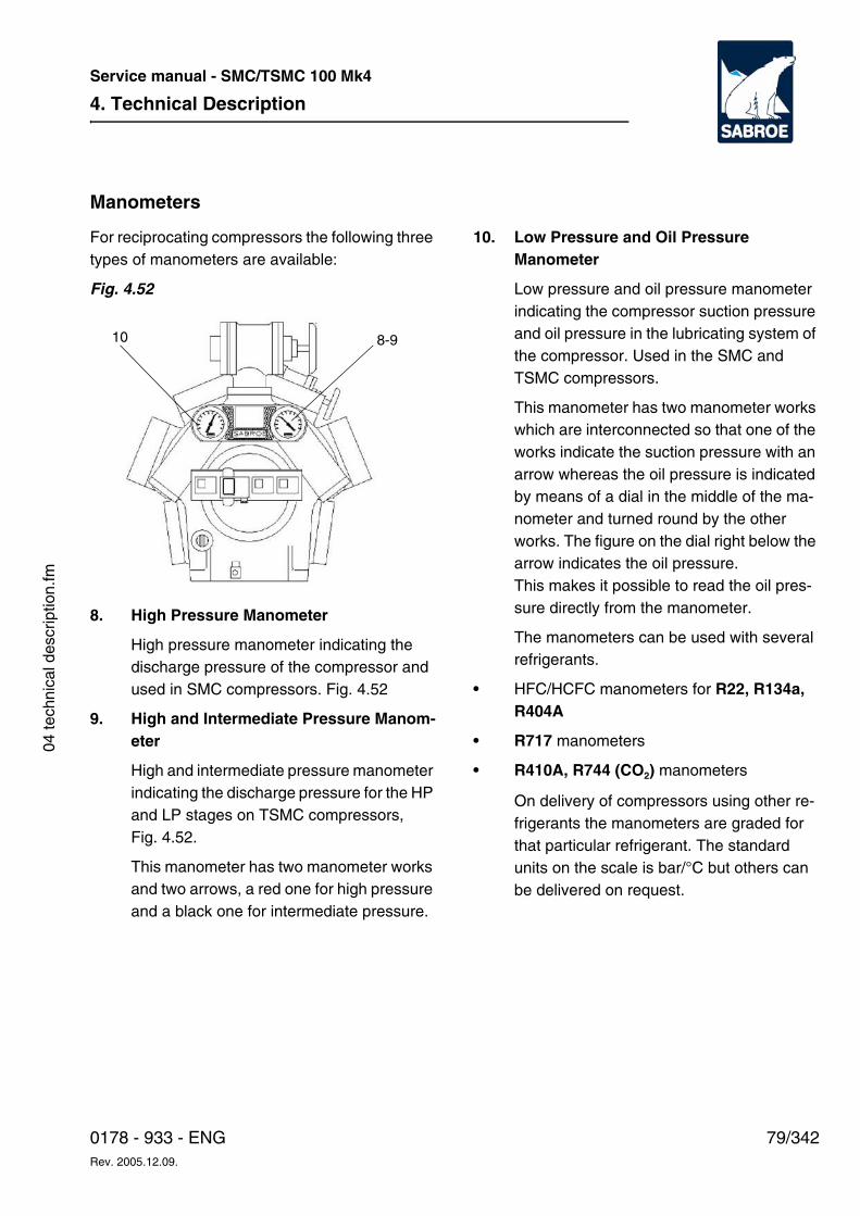
4. Technical Description
79/3420178 - 933 - ENGRev. 2005.12.09.
Service manual - SMC/TSMC 100 Mk4
04 te
chni
cal d
escr
iptio
n.fm
Manometers
For reciprocating compressors the following three types of manometers are available:
Fig. 4.52
8. High Pressure Manometer
High pressure manometer indicating the discharge pressure of the compressor and used in SMC compressors. Fig. 4.52
9. High and Intermediate Pressure Manom-eter
High and intermediate pressure manometer indicating the discharge pressure for the HP and LP stages on TSMC compressors, Fig. 4.52.
This manometer has two manometer works and two arrows, a red one for high pressure and a black one for intermediate pressure.
10. Low Pressure and Oil Pressure Manometer
Low pressure and oil pressure manometer indicating the compressor suction pressure and oil pressure in the lubricating system of the compressor. Used in the SMC and TSMC compressors.
This manometer has two manometer works which are interconnected so that one of the works indicate the suction pressure with an arrow whereas the oil pressure is indicated by means of a dial in the middle of the ma-nometer and turned round by the other works. The figure on the dial right below the arrow indicates the oil pressure. This makes it possible to read the oil pres-sure directly from the manometer.
The manometers can be used with several refrigerants.
• HFC/HCFC manometers for R22, R134a, R404A
• R717 manometers
• R410A, R744 (CO2) manometers
On delivery of compressors using other re-frigerants the manometers are graded for that particular refrigerant. The standard units on the scale is bar/°C but others can be delivered on request.
8-910
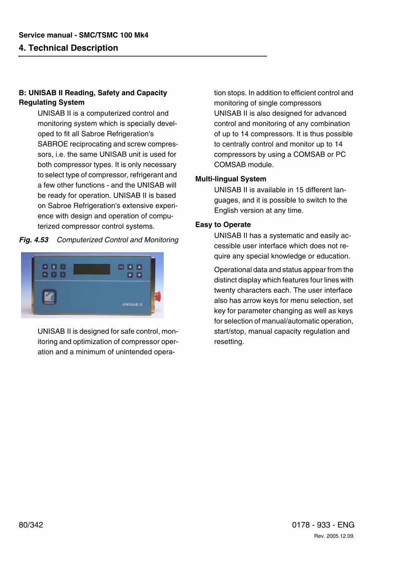
4. Technical Description
80/342 0178 - 933 - ENGRev. 2005.12.09.
Service manual - SMC/TSMC 100 Mk4
B: UNISAB II Reading, Safety and Capacity Regulating System
UNISAB II is a computerized control and monitoring system which is specially devel-oped to fit all Sabroe Refrigeration's SABROE reciprocating and screw compres-sors, i.e. the same UNISAB unit is used for both compressor types. It is only necessary to select type of compressor, refrigerant and a few other functions - and the UNISAB will be ready for operation. UNISAB II is based on Sabroe Refrigeration's extensive experi-ence with design and operation of compu-terized compressor control systems.
Fig. 4.53 Computerized Control and Monitoring
UNISAB II is designed for safe control, mon-itoring and optimization of compressor oper-ation and a minimum of unintended opera-
tion stops. In addition to efficient control and monitoring of single compressors UNISAB II is also designed for advanced control and monitoring of any combination of up to 14 compressors. It is thus possible to centrally control and monitor up to 14 compressors by using a COMSAB or PC COMSAB module.
Multi-lingual SystemUNISAB II is available in 15 different lan-guages, and it is possible to switch to the English version at any time.
Easy to Operate
UNISAB II has a systematic and easily ac-cessible user interface which does not re-quire any special knowledge or education.
Operational data and status appear from the distinct display which features four lines with twenty characters each. The user interface also has arrow keys for menu selection, set key for parameter changing as well as keys for selection of manual/automatic operation, start/stop, manual capacity regulation and resetting.
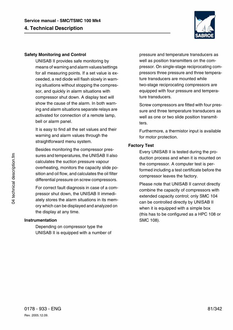
4. Technical Description
81/3420178 - 933 - ENGRev. 2005.12.09.
Service manual - SMC/TSMC 100 Mk4
04 te
chni
cal d
escr
iptio
n.fm
Safety Monitoring and ControlUNISAB II provides safe monitoring by means of warning and alarm values/settings for all measuring points. If a set value is ex-ceeded, a red diode will flash slowly in warn-ing situations without stopping the compres-sor, and quickly in alarm situations with compressor shut down. A display text will show the cause of the alarm. In both warn-ing and alarm situations separate relays are activated for connection of a remote lamp, bell or alarm panel.
It is easy to find all the set values and their warning and alarm values through the straightforward menu system.
Besides monitoring the compressor pres-sures and temperatures, the UNISAB II also calculates the suction pressure vapour overheating, monitors the capacity slide po-sition and oil flow, and calculates the oil filter differential pressure on screw compressors.
For correct fault diagnosis in case of a com-pressor shut down, the UNISAB II immedi-ately stores the alarm situations in its mem-ory which can be displayed and analyzed on the display at any time.
InstrumentationDepending on compressor type the UNISAB II is equipped with a number of
pressure and temperature transducers as well as position transmitters on the com-pressor. On single-stage reciprocating com-pressors three pressure and three tempera-ture transducers are mounted while two-stage reciprocating compressors are equipped with four pressure and tempera-ture transducers.
Screw compressors are fitted with four pres-sure and three temperature transducers as well as one or two slide position transmit-ters.
Furthermore, a thermistor input is available for motor protection.
Factory TestEvery UNISAB II is tested during the pro-duction process and when it is mounted on the compressor. A computer test is per-formed including a test certificate before the compressor leaves the factory.
Please note that UNISAB II cannot directly combine the capacity of compressors with extended capacity control; only SMC 104 can be controlled directly by UNISAB II when it is equipped with a simple box (this has to be configured as a HPC 108 or SMC 108).
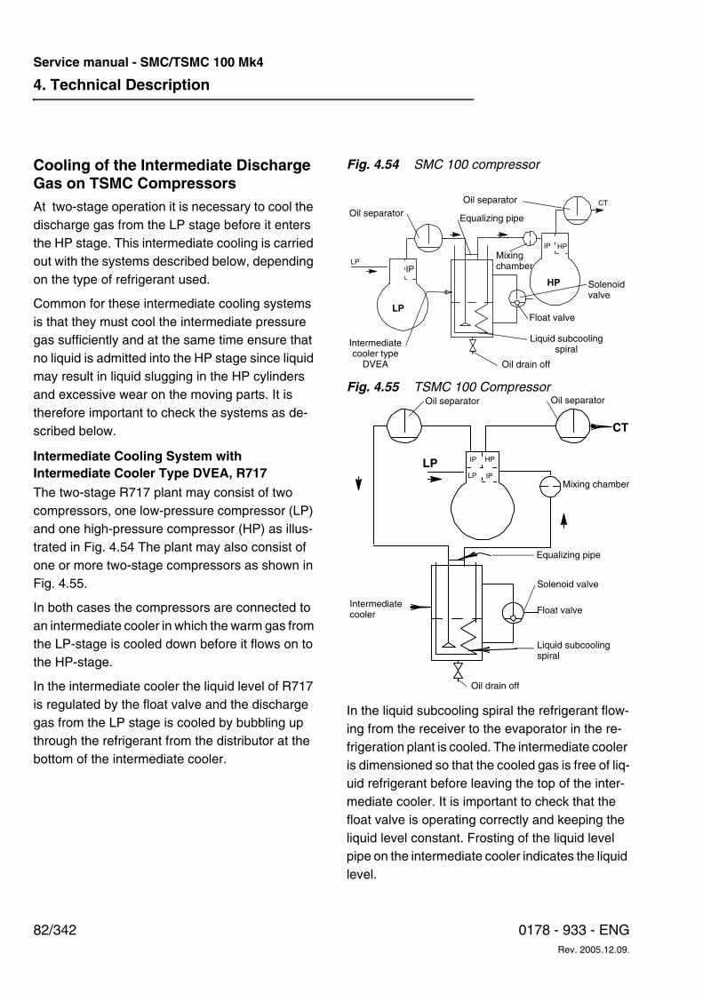
4. Technical Description
82/342 0178 - 933 - ENGRev. 2005.12.09.
Service manual - SMC/TSMC 100 Mk4
Cooling of the Intermediate Discharge Gas on TSMC CompressorsAt two-stage operation it is necessary to cool the discharge gas from the LP stage before it enters the HP stage. This intermediate cooling is carried out with the systems described below, depending on the type of refrigerant used.
Common for these intermediate cooling systems is that they must cool the intermediate pressure gas sufficiently and at the same time ensure that no liquid is admitted into the HP stage since liquid may result in liquid slugging in the HP cylinders and excessive wear on the moving parts. It is therefore important to check the systems as de-scribed below.
Intermediate Cooling System with Intermediate Cooler Type DVEA, R717The two-stage R717 plant may consist of two compressors, one low-pressure compressor (LP) and one high-pressure compressor (HP) as illus-trated in Fig. 4.54 The plant may also consist of one or more two-stage compressors as shown in Fig. 4.55.
In both cases the compressors are connected to an intermediate cooler in which the warm gas from the LP-stage is cooled down before it flows on to the HP-stage.
In the intermediate cooler the liquid level of R717 is regulated by the float valve and the discharge gas from the LP stage is cooled by bubbling up through the refrigerant from the distributor at the bottom of the intermediate cooler.
Fig. 4.54 SMC 100 compressor
Fig. 4.55 TSMC 100 Compressor
In the liquid subcooling spiral the refrigerant flow-ing from the receiver to the evaporator in the re-frigeration plant is cooled. The intermediate cooler is dimensioned so that the cooled gas is free of liq-uid refrigerant before leaving the top of the inter-mediate cooler. It is important to check that the float valve is operating correctly and keeping the liquid level constant. Frosting of the liquid level pipe on the intermediate cooler indicates the liquid level.
Oil separatorOil separator
Equalizing pipe
Mixingchamber
Solenoidvalve
Float valve
Liquid subcoolingspiral
Oil drain off
Intermediatecooler type
DVEA
HP
LP
CT
LP
IP HP
IP
Oil separator Oil separator
Mixing chamber
Equalizing pipe
Solenoid valve
Float valve
Liquid subcoolingspiral
Oil drain off
Intermediatecooler
CT
LP IP HP
LP IP
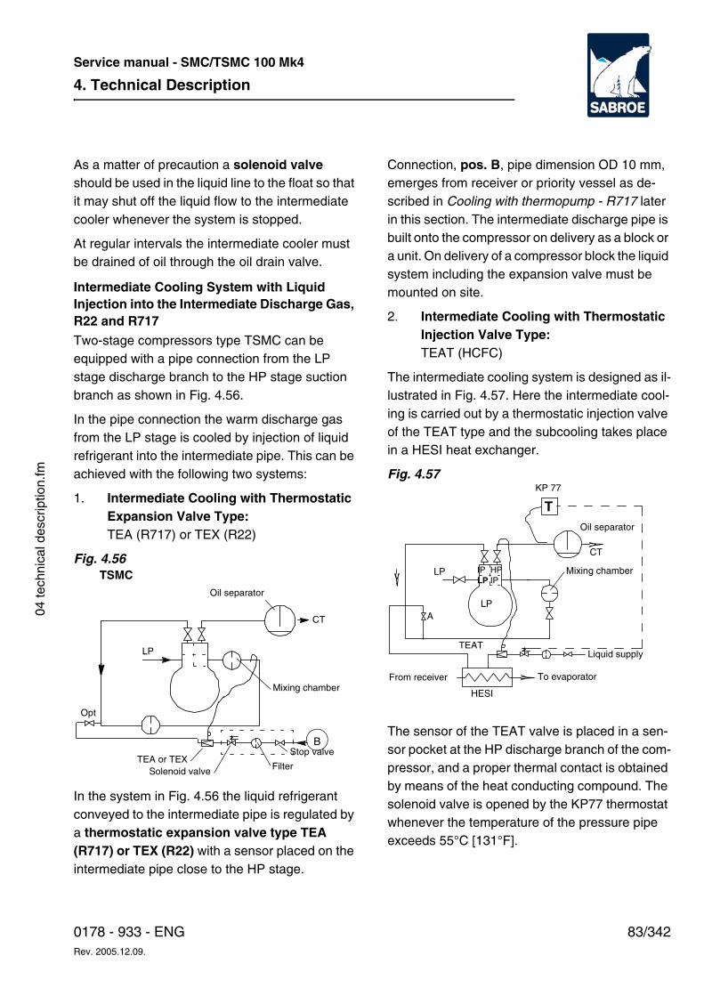
4. Technical Description
83/3420178 - 933 - ENGRev. 2005.12.09.
Service manual - SMC/TSMC 100 Mk4
04 te
chni
cal d
escr
iptio
n.fm
As a matter of precaution a solenoid valve should be used in the liquid line to the float so that it may shut off the liquid flow to the intermediate cooler whenever the system is stopped.
At regular intervals the intermediate cooler must be drained of oil through the oil drain valve.
Intermediate Cooling System with Liquid Injection into the Intermediate Discharge Gas, R22 and R717
Two-stage compressors type TSMC can be equipped with a pipe connection from the LP stage discharge branch to the HP stage suction branch as shown in Fig. 4.56.
In the pipe connection the warm discharge gas from the LP stage is cooled by injection of liquid refrigerant into the intermediate pipe. This can be achieved with the following two systems:
1. Intermediate Cooling with ThermostaticExpansion Valve Type: TEA (R717) or TEX (R22)
Fig. 4.56
In the system in Fig. 4.56 the liquid refrigerant conveyed to the intermediate pipe is regulated by a thermostatic expansion valve type TEA (R717) or TEX (R22) with a sensor placed on the intermediate pipe close to the HP stage.
Connection, pos. B, pipe dimension OD 10 mm, emerges from receiver or priority vessel as de-scribed in Cooling with thermopump - R717 later in this section. The intermediate discharge pipe is built onto the compressor on delivery as a block or a unit. On delivery of a compressor block the liquid system including the expansion valve must be mounted on site.
2. Intermediate Cooling with Thermostatic Injection Valve Type: TEAT (HCFC)
The intermediate cooling system is designed as il-lustrated in Fig. 4.57. Here the intermediate cool-ing is carried out by a thermostatic injection valve of the TEAT type and the subcooling takes place in a HESI heat exchanger.
Fig. 4.57
The sensor of the TEAT valve is placed in a sen-sor pocket at the HP discharge branch of the com-pressor, and a proper thermal contact is obtained by means of the heat conducting compound. The solenoid valve is opened by the KP77 thermostat whenever the temperature of the pressure pipe exceeds 55°C [131°F].
Oil separator
CT
Mixing chamber
Stop valve
FilterSolenoid valve
LP
Opt
TSMC
TEA or TEX
B
T
HPIPIPLP
Oil separator
Mixing chamber
CT
LP
Liquid supply
To evaporatorFrom receiver
LPA
TEAT
KP 77
HESI
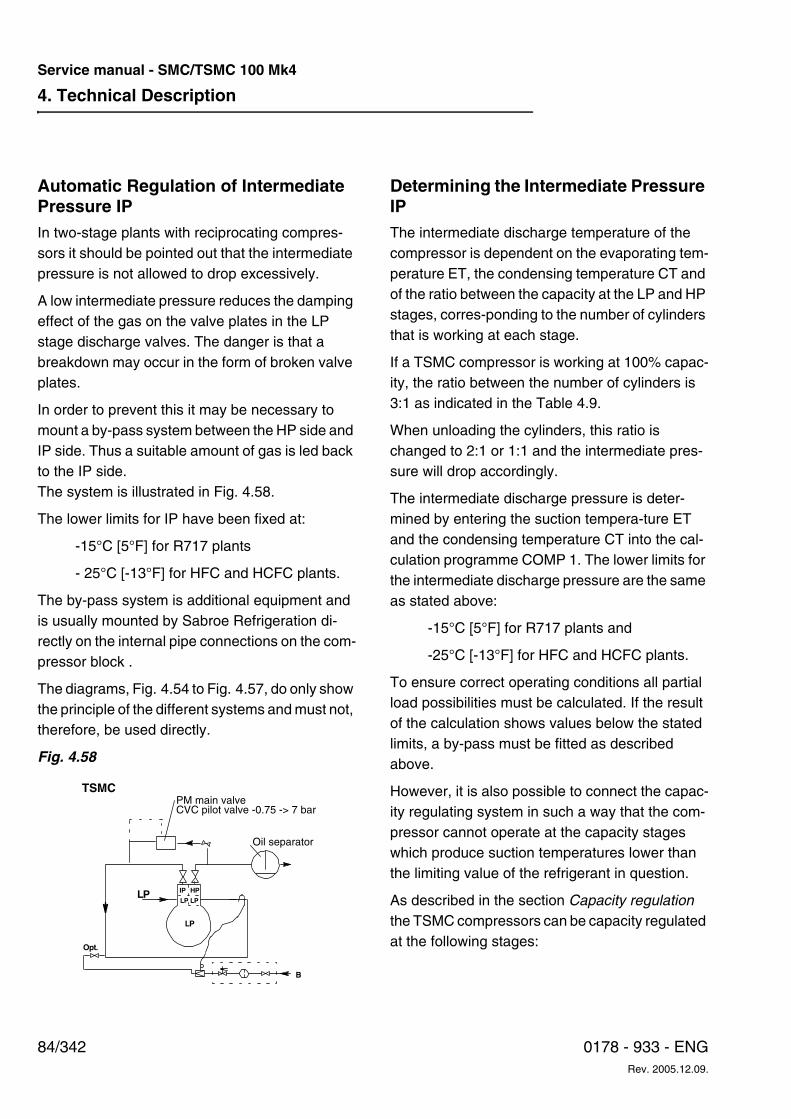
4. Technical Description
84/342 0178 - 933 - ENGRev. 2005.12.09.
Service manual - SMC/TSMC 100 Mk4
Automatic Regulation of Intermediate Pressure IPIn two-stage plants with reciprocating compres-sors it should be pointed out that the intermediate pressure is not allowed to drop excessively.
A low intermediate pressure reduces the damping effect of the gas on the valve plates in the LP stage discharge valves. The danger is that a breakdown may occur in the form of broken valve plates.
In order to prevent this it may be necessary to mount a by-pass system between the HP side and IP side. Thus a suitable amount of gas is led back to the IP side. The system is illustrated in Fig. 4.58.
The lower limits for IP have been fixed at:
-15°C [5°F] for R717 plants
- 25°C [-13°F] for HFC and HCFC plants.
The by-pass system is additional equipment and is usually mounted by Sabroe Refrigeration di-rectly on the internal pipe connections on the com-pressor block .
The diagrams, Fig. 4.54 to Fig. 4.57, do only show the principle of the different systems and must not, therefore, be used directly.
Fig. 4.58
Determining the Intermediate Pressure IPThe intermediate discharge temperature of the compressor is dependent on the evaporating tem-perature ET, the condensing temperature CT and of the ratio between the capacity at the LP and HP stages, corres-ponding to the number of cylinders that is working at each stage.
If a TSMC compressor is working at 100% capac-ity, the ratio between the number of cylinders is 3:1 as indicated in the Table 4.9.
When unloading the cylinders, this ratio is changed to 2:1 or 1:1 and the intermediate pres-sure will drop accordingly.
The intermediate discharge pressure is deter-mined by entering the suction tempera-ture ET and the condensing temperature CT into the cal-culation programme COMP 1. The lower limits for the intermediate discharge pressure are the same as stated above:
-15°C [5°F] for R717 plants and
-25°C [-13°F] for HFC and HCFC plants.
To ensure correct operating conditions all partial load possibilities must be calculated. If the result of the calculation shows values below the stated limits, a by-pass must be fitted as described above.
However, it is also possible to connect the capac-ity regulating system in such a way that the com-pressor cannot operate at the capacity stages which produce suction temperatures lower than the limiting value of the refrigerant in question.
As described in the section Capacity regulation the TSMC compressors can be capacity regulated at the following stages:
LPHPIP
LPLP
LP
Opt.
B
TSMCPM main valveCVC pilot valve -0.75 -> 7 bar
Oil separator
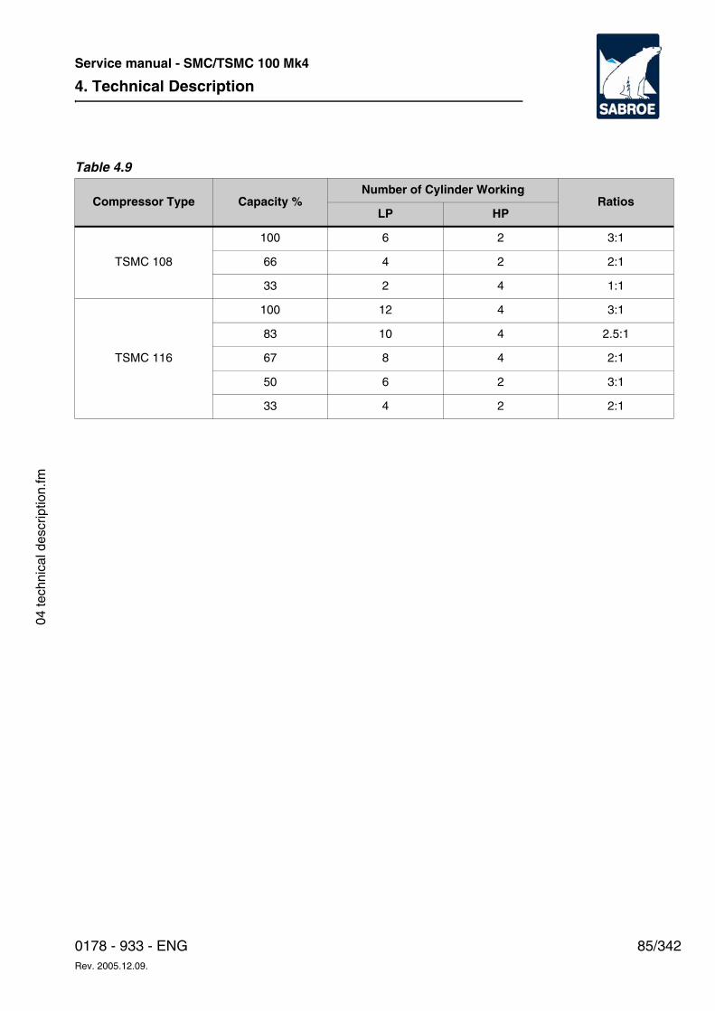
4. Technical Description
85/3420178 - 933 - ENGRev. 2005.12.09.
Service manual - SMC/TSMC 100 Mk4
04 te
chni
cal d
escr
iptio
n.fm
Table 4.9
Compressor Type Capacity %Number of Cylinder Working
RatiosLP HP
TSMC 108
100 6 2 3:1
66 4 2 2:1
33 2 4 1:1
TSMC 116
100 12 4 3:1
83 10 4 2.5:1
67 8 4 2:1
50 6 2 3:1
33 4 2 2:1
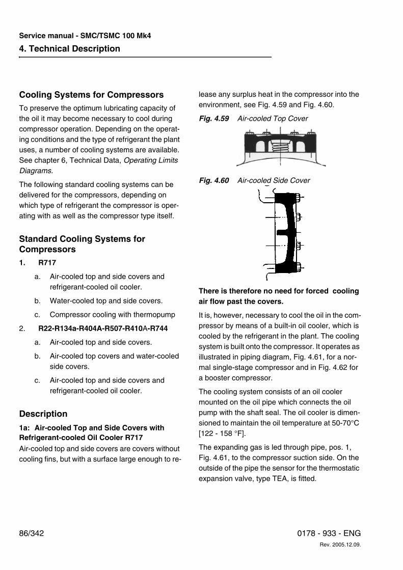
4. Technical Description
86/342 0178 - 933 - ENGRev. 2005.12.09.
Service manual - SMC/TSMC 100 Mk4
Cooling Systems for CompressorsTo preserve the optimum lubricating capacity of the oil it may become necessary to cool during compressor operation. Depending on the operat-ing conditions and the type of refrigerant the plant uses, a number of cooling systems are available. See chapter 6, Technical Data, Operating Limits Diagrams.
The following standard cooling systems can be delivered for the compressors, depending on which type of refrigerant the compressor is oper-ating with as well as the compressor type itself.
Standard Cooling Systems for Compressors1. R717
a. Air-cooled top and side covers and refrigerant-cooled oil cooler.
b. Water-cooled top and side covers.
c. Compressor cooling with thermopump
2. R22-R134a-R404A-R507-R410A-R744
a. Air-cooled top and side covers.
b. Air-cooled top covers and water-cooled side covers.
c. Air-cooled top and side covers and refrigerant-cooled oil cooler.
Description
1a: Air-cooled Top and Side Covers with Refrigerant-cooled Oil Cooler R717Air-cooled top and side covers are covers without cooling fins, but with a surface large enough to re-
lease any surplus heat in the compressor into the environment, see Fig. 4.59 and Fig. 4.60.
Fig. 4.59 Air-cooled Top Cover
Fig. 4.60 Air-cooled Side Cover
There is therefore no need for forced cooling air flow past the covers.
It is, however, necessary to cool the oil in the com-pressor by means of a built-in oil cooler, which is cooled by the refrigerant in the plant. The cooling system is built onto the compressor. It operates as illustrated in piping diagram, Fig. 4.61, for a nor-mal single-stage compressor and in Fig. 4.62 for a booster compressor.
The cooling system consists of an oil cooler mounted on the oil pipe which connects the oil pump with the shaft seal. The oil cooler is dimen-sioned to maintain the oil temperature at 50-70°C [122 - 158 °F].
The expanding gas is led through pipe, pos. 1, Fig. 4.61, to the compressor suction side. On the outside of the pipe the sensor for the thermostatic expansion valve, type TEA, is fitted.
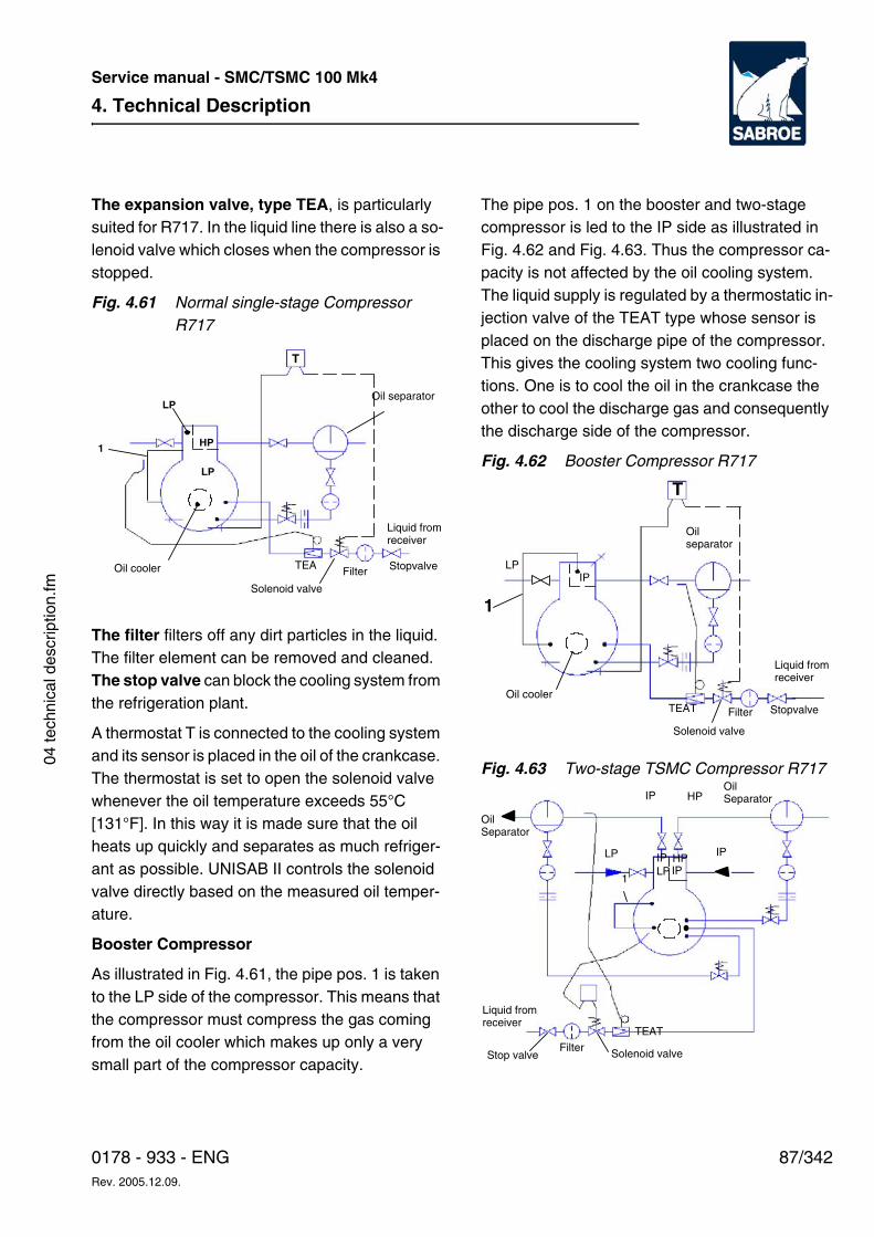
4. Technical Description
87/3420178 - 933 - ENGRev. 2005.12.09.
Service manual - SMC/TSMC 100 Mk4
04 te
chni
cal d
escr
iptio
n.fm
The expansion valve, type TEA, is particularly suited for R717. In the liquid line there is also a so-lenoid valve which closes when the compressor is stopped.
Fig. 4.61 Normal single-stage Compressor R717
The filter filters off any dirt particles in the liquid. The filter element can be removed and cleaned. The stop valve can block the cooling system from the refrigeration plant.
A thermostat T is connected to the cooling system and its sensor is placed in the oil of the crankcase. The thermostat is set to open the solenoid valve whenever the oil temperature exceeds 55°C [131°F]. In this way it is made sure that the oil heats up quickly and separates as much refriger-ant as possible. UNISAB II controls the solenoid valve directly based on the measured oil temper-ature.
Booster Compressor
As illustrated in Fig. 4.61, the pipe pos. 1 is taken to the LP side of the compressor. This means that the compressor must compress the gas coming from the oil cooler which makes up only a very small part of the compressor capacity.
The pipe pos. 1 on the booster and two-stage compressor is led to the IP side as illustrated in Fig. 4.62 and Fig. 4.63. Thus the compressor ca-pacity is not affected by the oil cooling system. The liquid supply is regulated by a thermostatic in-jection valve of the TEAT type whose sensor is placed on the discharge pipe of the compressor. This gives the cooling system two cooling func-tions. One is to cool the oil in the crankcase the other to cool the discharge gas and consequently the discharge side of the compressor.
Fig. 4.62 Booster Compressor R717
Fig. 4.63 Two-stage TSMC Compressor R717
HP
LP
1
LP
T
Oil cooler
Liquid fromreceiver
StopvalveFilter
Solenoid valve
TEA
Oil separator
1
T
Oilseparator
Oil coolerTEAT
Solenoid valve
Stopvalve
Liquid fromreceiver
Filter
LPIP
TEAT
Solenoid valveFilterStop valve
Liquid fromreceiver
IP HP
OilSeparator
OilSeparator
IPLP1
IPLP
HPIP
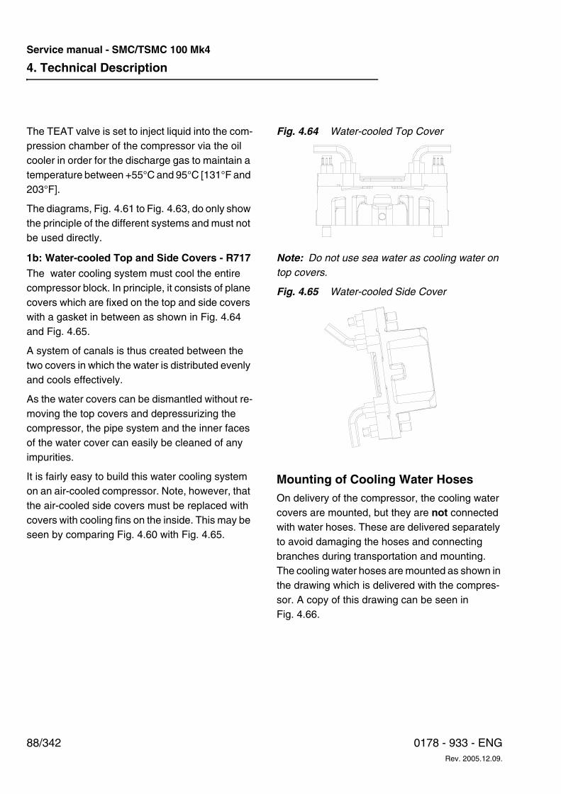
4. Technical Description
88/342 0178 - 933 - ENGRev. 2005.12.09.
Service manual - SMC/TSMC 100 Mk4
The TEAT valve is set to inject liquid into the com-pression chamber of the compressor via the oil cooler in order for the discharge gas to maintain a temperature between +55°C and 95°C [131°F and 203°F].
The diagrams, Fig. 4.61 to Fig. 4.63, do only show the principle of the different systems and must not be used directly.
1b: Water-cooled Top and Side Covers - R717
The water cooling system must cool the entire compressor block. In principle, it consists of plane covers which are fixed on the top and side covers with a gasket in between as shown in Fig. 4.64 and Fig. 4.65.
A system of canals is thus created between the two covers in which the water is distributed evenly and cools effectively.
As the water covers can be dismantled without re-moving the top covers and depressurizing the compressor, the pipe system and the inner faces of the water cover can easily be cleaned of any impurities.
It is fairly easy to build this water cooling system on an air-cooled compressor. Note, however, that the air-cooled side covers must be replaced with covers with cooling fins on the inside. This may be seen by comparing Fig. 4.60 with Fig. 4.65.
Fig. 4.64 Water-cooled Top Cover
Note: Do not use sea water as cooling water on top covers.
Fig. 4.65 Water-cooled Side Cover
Mounting of Cooling Water HosesOn delivery of the compressor, the cooling water covers are mounted, but they are not connected with water hoses. These are delivered separately to avoid damaging the hoses and connecting branches during transportation and mounting. The cooling water hoses are mounted as shown in the drawing which is delivered with the compres-sor. A copy of this drawing can be seen in Fig. 4.66.
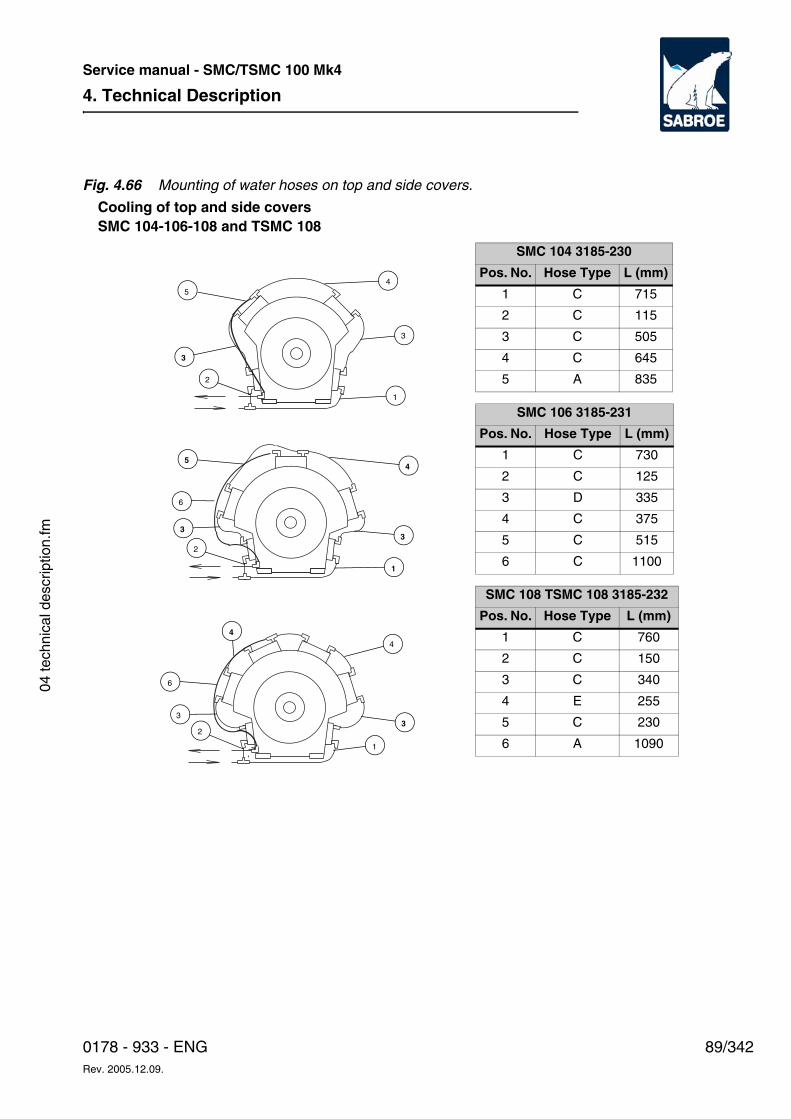
4. Technical Description
89/3420178 - 933 - ENGRev. 2005.12.09.
Service manual - SMC/TSMC 100 Mk4
04 te
chni
cal d
escr
iptio
n.fm
Fig. 4.66 Mounting of water hoses on top and side covers.
Cooling of top and side coversSMC 104-106-108 and TSMC 108
3
2
4
6
3
1
4
3
5
6
2
3
1
4
3
2
1
5
3
4
SMC 104 3185-230
Pos. No. Hose Type L (mm)
1 C 715
2 C 115
3 C 505
4 C 645
5 A 835
SMC 106 3185-231
Pos. No. Hose Type L (mm)
1 C 730
2 C 125
3 D 335
4 C 375
5 C 515
6 C 1100
SMC 108 TSMC 108 3185-232
Pos. No. Hose Type L (mm)
1 C 760
2 C 150
3 C 340
4 E 255
5 C 230
6 A 1090
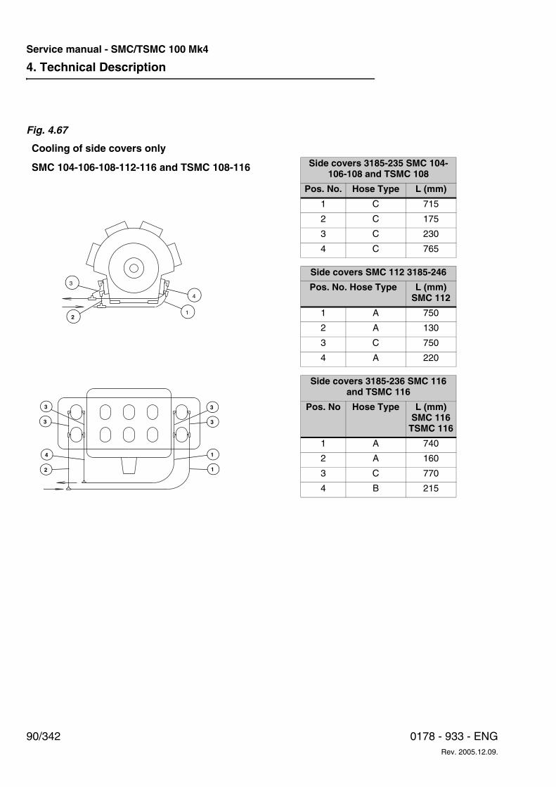
4. Technical Description
90/342 0178 - 933 - ENGRev. 2005.12.09.
Service manual - SMC/TSMC 100 Mk4
Fig. 4.67
3
4
2 1
1
3
3 3
2
3
1
4
Cooling of side covers only
SMC 104-106-108-112-116 and TSMC 108-116 Side covers 3185-235 SMC 104-106-108 and TSMC 108
Pos. No. Hose Type L (mm)
1 C 715
2 C 175
3 C 230
4 C 765
Side covers SMC 112 3185-246
Pos. No. Hose Type L (mm)SMC 112
1 A 750
2 A 130
3 C 750
4 A 220
Side covers 3185-236 SMC 116 and TSMC 116
Pos. No Hose Type L (mm)SMC 116
TSMC 116
1 A 740
2 A 160
3 C 770
4 B 215
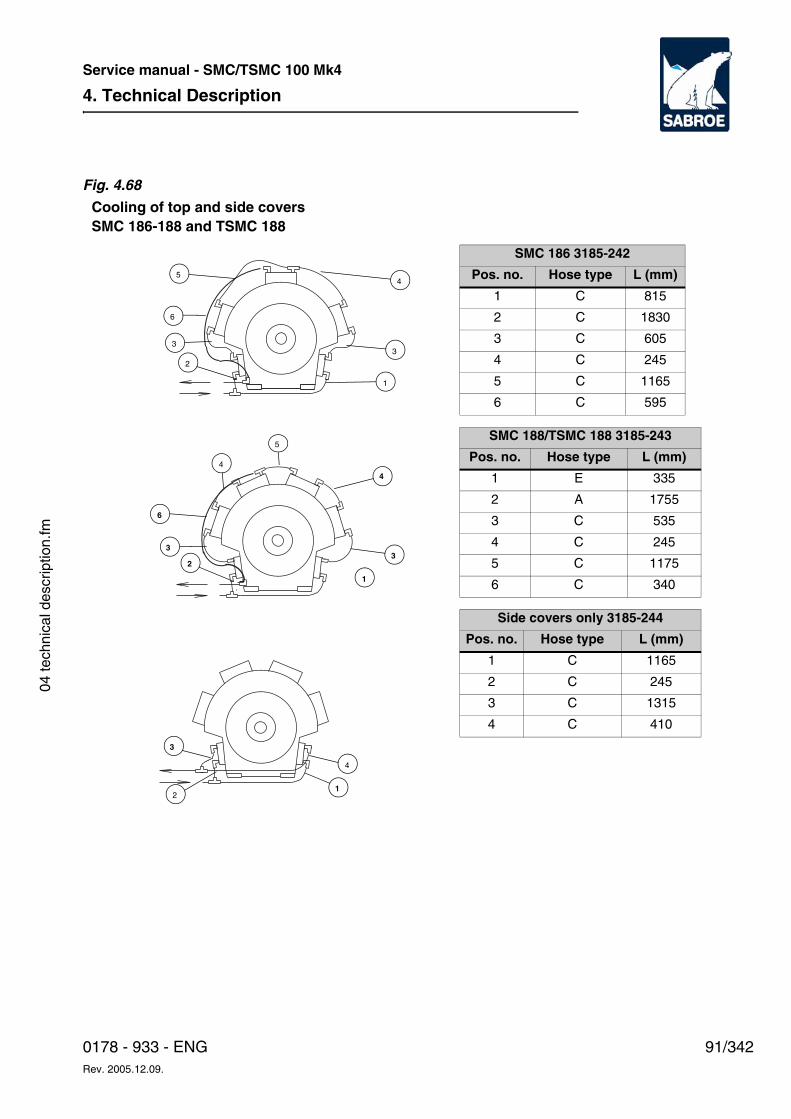
4. Technical Description
91/3420178 - 933 - ENGRev. 2005.12.09.
Service manual - SMC/TSMC 100 Mk4
04 te
chni
cal d
escr
iptio
n.fm
Fig. 4.68
Cooling of top and side coversSMC 186-188 and TSMC 188
3
2
4
6
3
1
4
5
3
5
6
2
3
1
4
2
3
1
4
SMC 186 3185-242
Pos. no. Hose type L (mm)
1 C 815
2 C 1830
3 C 605
4 C 245
5 C 1165
6 C 595
SMC 188/TSMC 188 3185-243
Pos. no. Hose type L (mm)
1 E 335
2 A 1755
3 C 535
4 C 245
5 C 1175
6 C 340
Side covers only 3185-244
Pos. no. Hose type L (mm)
1 C 1165
2 C 245
3 C 1315
4 C 410
4. Technical Description
92/342 0178 - 933 - ENGRev. 2005.12.09.
Service manual - SMC/TSMC 100 Mk4
Note:
• The direction of the water flow is indicated in Fig. 4.66.
• The hose sections have been shortened to the lengths indicated from factory.
• In the supply pipe to the water system a so-lenoid valve must be fitted which shuts off the water flow in the refrigerating system when the compressor is not in operation. It is recommended, however, to continue the water cooling for approx. 10 minutes after the compressor has been stopped to protect the cooling water hoses against excessive temperatures.
• Dimensions of the inlet and outlet pipes for the cooling water system are indicated in chapter 5, Physical and Connection Data - Table of Water Connection.
Necessary Water ConsumptionTo achieve satisfactory distribution of cooling wa-ter and hence proper compressor cooling, the fol-lowing limiting values should be followed.
Min. Water Flow
5.5 litres per hour per kW motor output. On water circulation plants greater water flow is recom-mended. See Fig. 4.69.
Max. permissible inlet temperature:+40°C [104°F]
Min. permissible inlet temperature:+10°C [50°F]
Max. permissible outlet temperature:+55°C [151°F]
Max. permissible temperature rise from inlet to outlet on compressor:
15°C [59°F]
Max. permissible cooling water pressure:
8 bar.
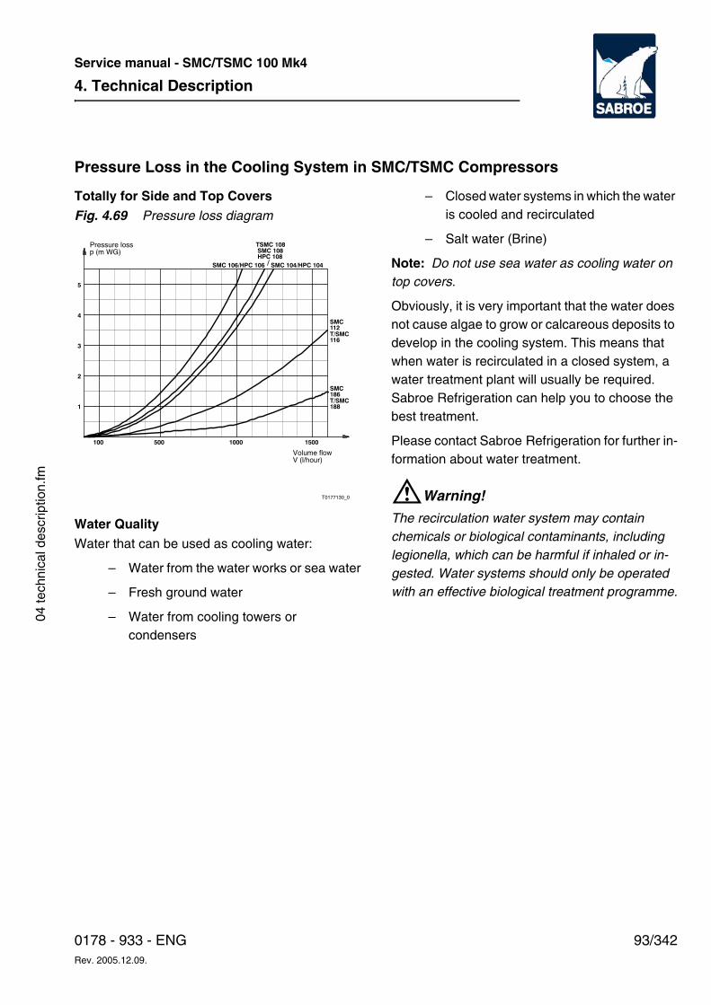
4. Technical Description
93/3420178 - 933 - ENGRev. 2005.12.09.
Service manual - SMC/TSMC 100 Mk4
04 te
chni
cal d
escr
iptio
n.fm
Pressure Loss in the Cooling System in SMC/TSMC Compressors
Totally for Side and Top Covers
Fig. 4.69 Pressure loss diagram
Water Quality
Water that can be used as cooling water:
– Water from the water works or sea water
– Fresh ground water
– Water from cooling towers or condensers
– Closed water systems in which the water is cooled and recirculated
– Salt water (Brine)
Note: Do not use sea water as cooling water on top covers.
Obviously, it is very important that the water does not cause algae to grow or calcareous deposits to develop in the cooling system. This means that when water is recirculated in a closed system, a water treatment plant will usually be required. Sabroe Refrigeration can help you to choose the best treatment.
Please contact Sabroe Refrigeration for further in-formation about water treatment.
WWarning!
The recirculation water system may contain chemicals or biological contaminants, including legionella, which can be harmful if inhaled or in-gested. Water systems should only be operated with an effective biological treatment programme.
1
2
100 500 1000 1500
T0177130_0
3
4
5
SMC 106/HPC 106 SMC 104/HPC 104
T/SMC
TSMC 108SMC 108
116
SMC112
HPC 108
T/SMC188
SMC186
Volume flowV (l/hour)
Pressure lossp (m WG)
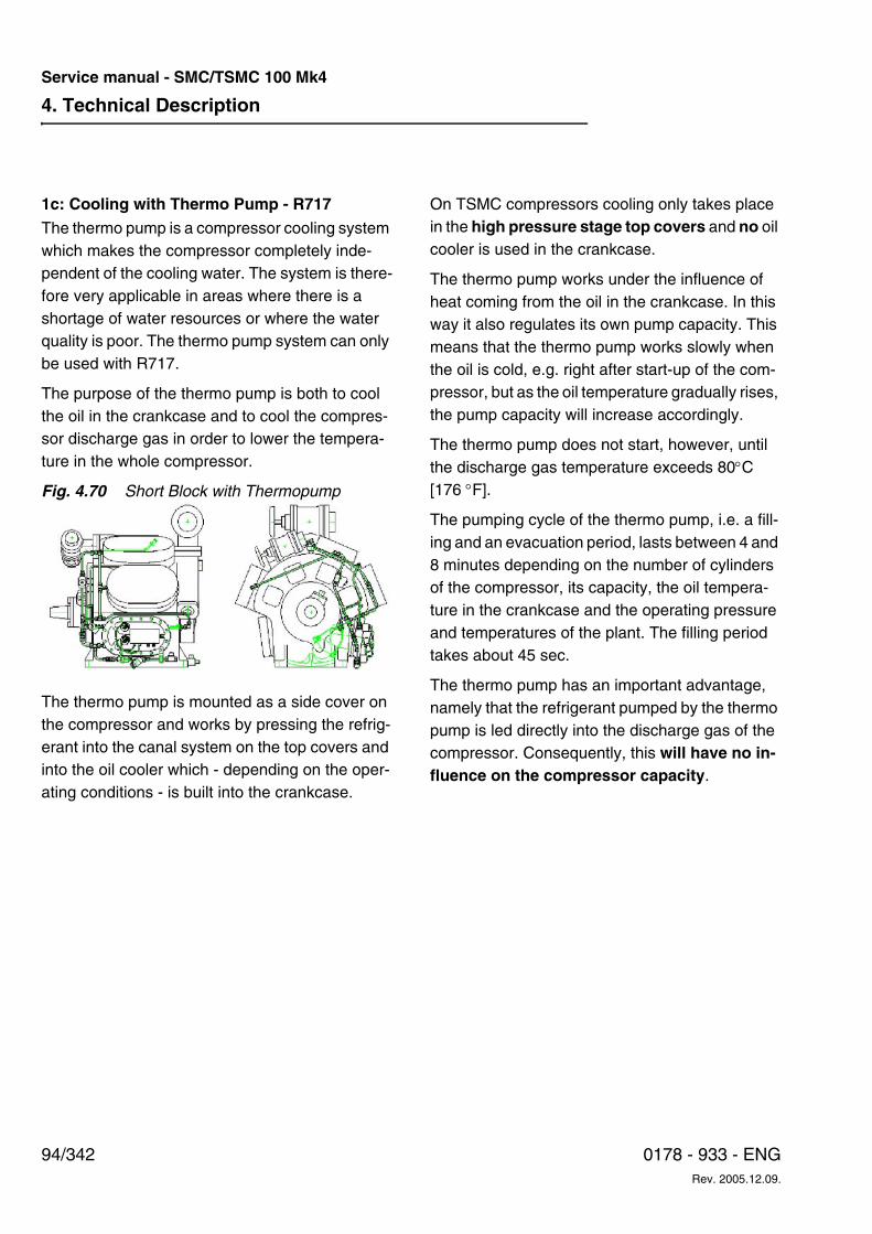
4. Technical Description
94/342 0178 - 933 - ENGRev. 2005.12.09.
Service manual - SMC/TSMC 100 Mk4
1c: Cooling with Thermo Pump - R717The thermo pump is a compressor cooling system which makes the compressor completely inde-pendent of the cooling water. The system is there-fore very applicable in areas where there is a shortage of water resources or where the water quality is poor. The thermo pump system can only be used with R717.
The purpose of the thermo pump is both to cool the oil in the crankcase and to cool the compres-sor discharge gas in order to lower the tempera-ture in the whole compressor.
Fig. 4.70 Short Block with Thermopump
The thermo pump is mounted as a side cover on the compressor and works by pressing the refrig-erant into the canal system on the top covers and into the oil cooler which - depending on the oper-ating conditions - is built into the crankcase.
On TSMC compressors cooling only takes place in the high pressure stage top covers and no oil cooler is used in the crankcase.
The thermo pump works under the influence of heat coming from the oil in the crankcase. In this way it also regulates its own pump capacity. This means that the thermo pump works slowly when the oil is cold, e.g. right after start-up of the com-pressor, but as the oil temperature gradually rises, the pump capacity will increase accordingly.
The thermo pump does not start, however, until the discharge gas temperature exceeds 80°C [176 °F].
The pumping cycle of the thermo pump, i.e. a fill-ing and an evacuation period, lasts between 4 and 8 minutes depending on the number of cylinders of the compressor, its capacity, the oil tempera-ture in the crankcase and the operating pressure and temperatures of the plant. The filling period takes about 45 sec.
The thermo pump has an important advantage, namely that the refrigerant pumped by the thermo pump is led directly into the discharge gas of the compressor. Consequently, this will have no in-fluence on the compressor capacity.
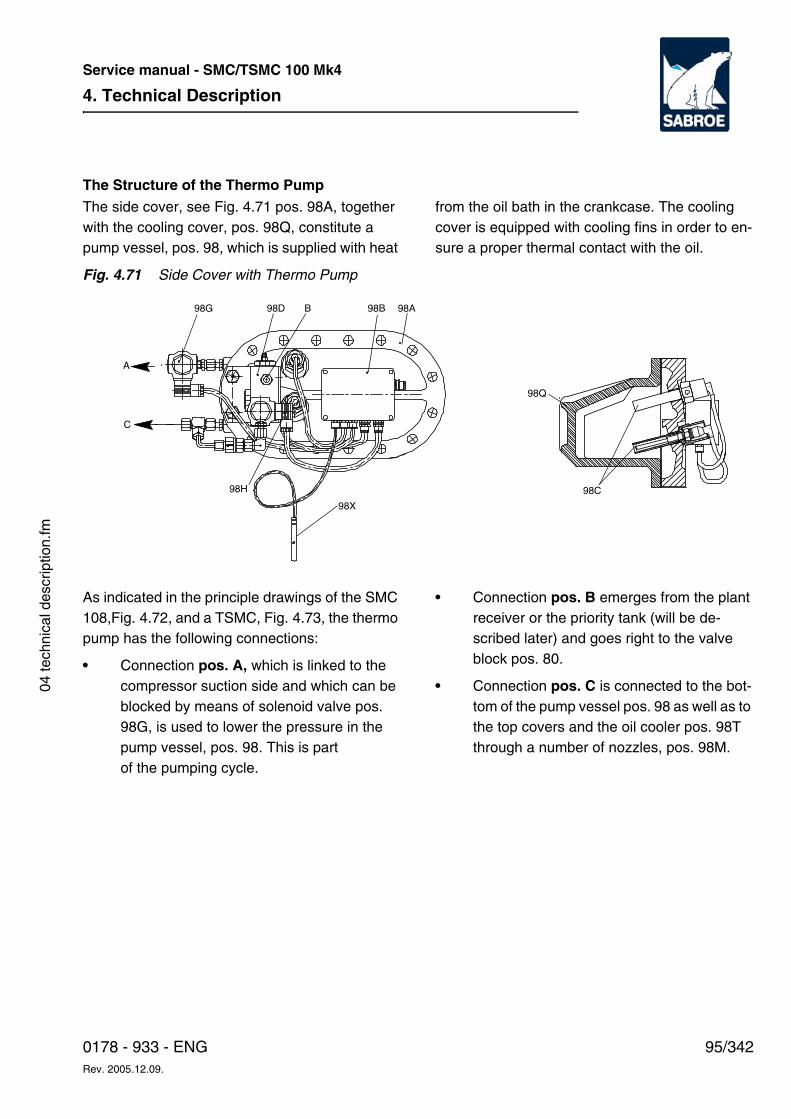
4. Technical Description
95/3420178 - 933 - ENGRev. 2005.12.09.
Service manual - SMC/TSMC 100 Mk4
04 te
chni
cal d
escr
iptio
n.fm
The Structure of the Thermo PumpThe side cover, see Fig. 4.71 pos. 98A, together with the cooling cover, pos. 98Q, constitute a pump vessel, pos. 98, which is supplied with heat
from the oil bath in the crankcase. The cooling cover is equipped with cooling fins in order to en-sure a proper thermal contact with the oil.
Fig. 4.71 Side Cover with Thermo Pump
As indicated in the principle drawings of the SMC 108,Fig. 4.72, and a TSMC, Fig. 4.73, the thermo pump has the following connections:
• Connection pos. A, which is linked to the compressor suction side and which can be blocked by means of solenoid valve pos. 98G, is used to lower the pressure in the pump vessel, pos. 98. This is partof the pumping cycle.
• Connection pos. B emerges from the plant receiver or the priority tank (will be de-scribed later) and goes right to the valve block pos. 80.
• Connection pos. C is connected to the bot-tom of the pump vessel pos. 98 as well as to the top covers and the oil cooler pos. 98T through a number of nozzles, pos. 98M.
98D B 98B 98A98G
98X
98H
C
A
98Q
98C
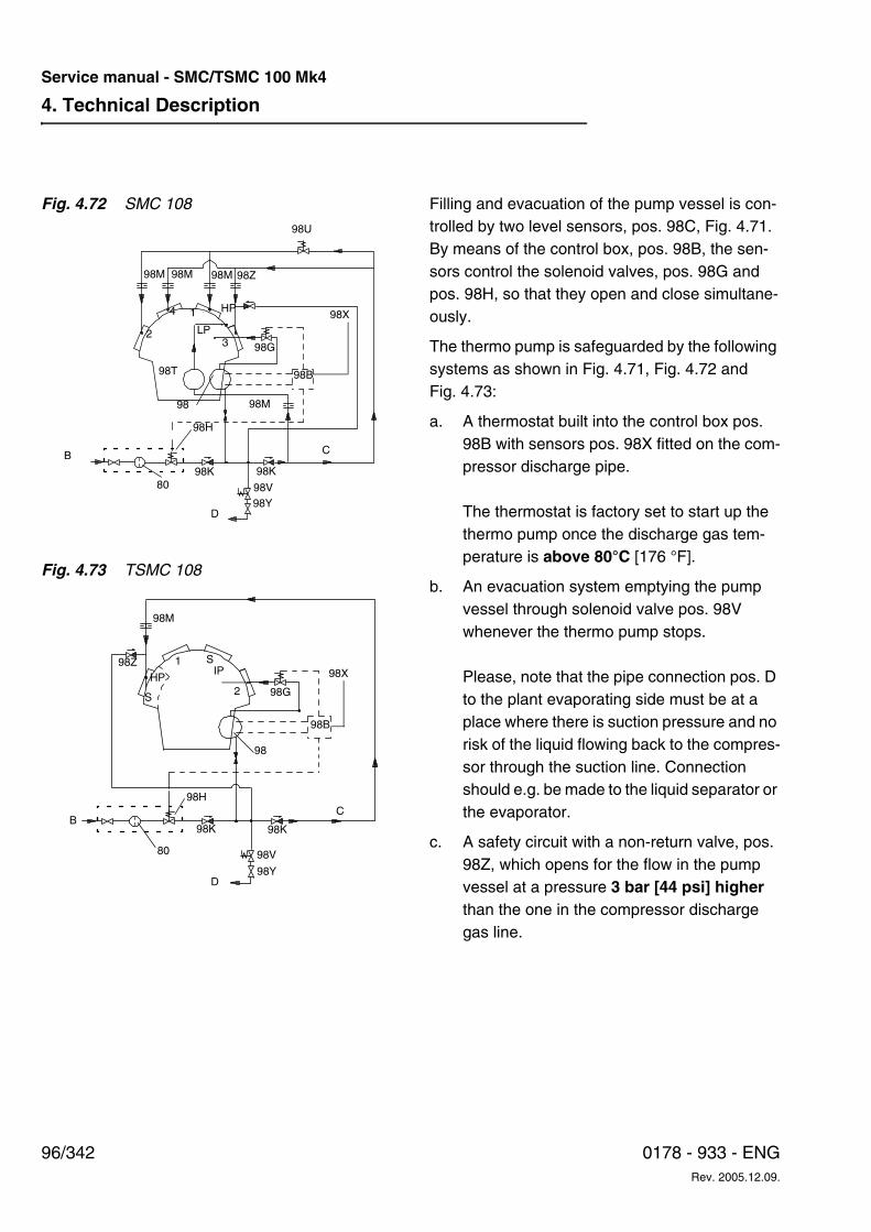
4. Technical Description
96/342 0178 - 933 - ENGRev. 2005.12.09.
Service manual - SMC/TSMC 100 Mk4
Fig. 4.72 SMC 108
Fig. 4.73 TSMC 108
Filling and evacuation of the pump vessel is con-trolled by two level sensors, pos. 98C, Fig. 4.71. By means of the control box, pos. 98B, the sen-sors control the solenoid valves, pos. 98G and pos. 98H, so that they open and close simultane-ously.
The thermo pump is safeguarded by the following systems as shown in Fig. 4.71, Fig. 4.72 and Fig. 4.73:
a. A thermostat built into the control box pos. 98B with sensors pos. 98X fitted on the com-pressor discharge pipe.
The thermostat is factory set to start up the thermo pump once the discharge gas tem-perature is above 80°C [176 °F].
b. An evacuation system emptying the pump vessel through solenoid valve pos. 98V whenever the thermo pump stops.
Please, note that the pipe connection pos. D to the plant evaporating side must be at a place where there is suction pressure and no risk of the liquid flowing back to the compres-sor through the suction line. Connection should e.g. be made to the liquid separator or the evaporator.
c. A safety circuit with a non-return valve, pos. 98Z, which opens for the flow in the pump vessel at a pressure 3 bar [44 psi] higher than the one in the compressor discharge gas line.
98K
98Y
80
B
D
C
98K
98V
98H
98T
98 98M
98B
98X
98U
4
98M 98M 98M 98Z
98G
HP
LP3
1
2
98M
98G
98Z
98K
98H
98
98Y
80
B
98B
C
D
98X
98K
2
IP
S
1
HP
S
98V
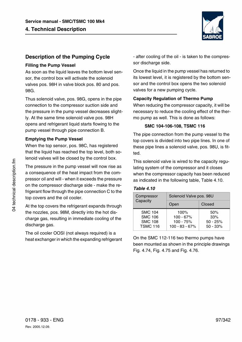
4. Technical Description
97/3420178 - 933 - ENGRev. 2005.12.09.
Service manual - SMC/TSMC 100 Mk4
04 te
chni
cal d
escr
iptio
n.fm
Description of the Pumping Cycle
Filling the Pump Vessel
As soon as the liquid leaves the bottom level sen-sor, the control box will activate the solenoid valves pos. 98H in valve block pos. 80 and pos. 98G.
Thus solenoid valve, pos. 98G, opens in the pipe connection to the compressor suction side and the pressure in the pump vessel decreases slight-ly. At the same time solenoid valve pos. 98H opens and refrigerant liquid starts flowing to the pump vessel through pipe connection B.
Emptying the Pump VesselWhen the top sensor, pos. 98C, has registered that the liquid has reached the top level, both so-lenoid valves will be closed by the control box.
The pressure in the pump vessel will now rise as a consequence of the heat impact from the com-pressor oil and will - when it exceeds the pressure on the compressor discharge side - make the re-frigerant flow through the pipe connection C to the top covers and the oil cooler.
At the top covers the refrigerant expands through the nozzles, pos. 98M, directly into the hot dis-charge gas, resulting in immediate cooling of the discharge gas.
The oil cooler OOSI (not always required) is a heat exchanger in which the expanding refrigerant
- after cooling of the oil - is taken to the compres-sor discharge side.
Once the liquid in the pump vessel has returned to its lowest level, it is registered by the bottom sen-sor and the control box opens the two solenoid valves for a new pumping cycle.
Capacity Regulation of Thermo PumpWhen reducing the compressor capacity, it will be necessary to reduce the cooling effect of the ther-mo pump as well. This is done as follows:
SMC 104-106-108, TSMC 116
The pipe connection from the pump vessel to the top covers is divided into two pipe lines. In one of these pipe lines a solenoid valve, pos. 98U, is fit-ted.
This solenoid valve is wired to the capacity regu-lating system of the compressor and it closes when the compressor capacity has been reduced as indicated in the following table, Table 4.10.
Table 4.10
On the SMC 112-116 two thermo pumps have been mounted as shown in the principle drawings Fig. 4.74, Fig. 4.75 and Fig. 4.76.
CompressorCapacity
Solenoid Valve pos. 98U
Open Closed
SMC 104SMC 106SMC 108
TSMC 116
100%100 - 67%100 - 75%
100 - 83 - 67%
50%33%
50 - 25%50 - 33%
4. Technical Description
98/342 0178 - 933 - ENGRev. 2005.12.09.
Service manual - SMC/TSMC 100 Mk4
Fig. 4.74 SMC 112 Fig. 4.75 SMC 116
Fig. 4.76 TSMC 116
2
4
6
98
98B
98B
98G
1
3
5
98H
80
98D
98H
98K
98K 98K98V98Y
98Z
98M98M98M
LP
LP
98M98M98M
A
B
B
C
98Y
D
X
98V
98K
98Z
98
A
7
B
2
4 6
8
98
98B
98B
98G
98G1
37
5
98H
80
98K
98K
98K 98V98Y
9898T
98Z
98M98M98M
98M
LP
LP
98M
98M98M98M98M
HP
A
B
B
C
D
D
X
98H
98D
98M
98Y98V
98
98B
98U
98K
98G
98K
98H
98M98M
3HP
S 4IP
S
1 5
CB
A
98T
98D
4. Technical Description
99/3420178 - 933 - ENGRev. 2005.12.09.
Service manual - SMC/TSMC 100 Mk4
04 te
chni
cal d
escr
iptio
n.fm
The total capacity of the thermo pumps is adapted to the compressor capacity by stopping and start-ing the thermo pump marked with an X on the principle drawing.
The stopping and starting is achieved through the wire connection of the thermo pump via terminals 5 and 6/7 or 8 to the capacity regulating system of the compressor. The supply voltage to the thermo pump must be switched off once the compressor capacity has been reduced to the values indicated in the Table 4.11.
Table 4.11
When the compressor is stopped, the current to the thermo pump is cut off, closing the solenoid valves pos. 98H and pos. 98G. At the same time solenoid valve pos. 98V opens and drains the liq-uid in the thermo pump back to the evaporating side of the plant. See the previously mentioned point b.
Ensuring Liquid to the Thermo PumpThe thermo pump must always be ensured liquid from the plant, irrespective of whether the plant lacks liquid or if some other factor prevails.
Thus, the thermo pump must also be ensured liq-uid during a possible pump down by means of the compressor.
In other words: During operation the compressor must never be short of cooling.
This safety is achieved either by taking the liquid directly from the receiver, pipe connection B, or by building a priority tank into the liquid line of the plant, Fig. 4.77. The liquid volume A of the priority vessel must be minimum 10 litres per thermo pump.
The liquid tube from the priority vessel to the ther-mo pump must be dimensioned to prevent the for-mation of flash gas along the way.
Compr.Capacity
Thermo Pump at CompressorShaft End
Working Not Working
SMC 112SMC 116
100 - 83 - 67%100-87-75-63%
50 - 33%50 - 37 - 25%
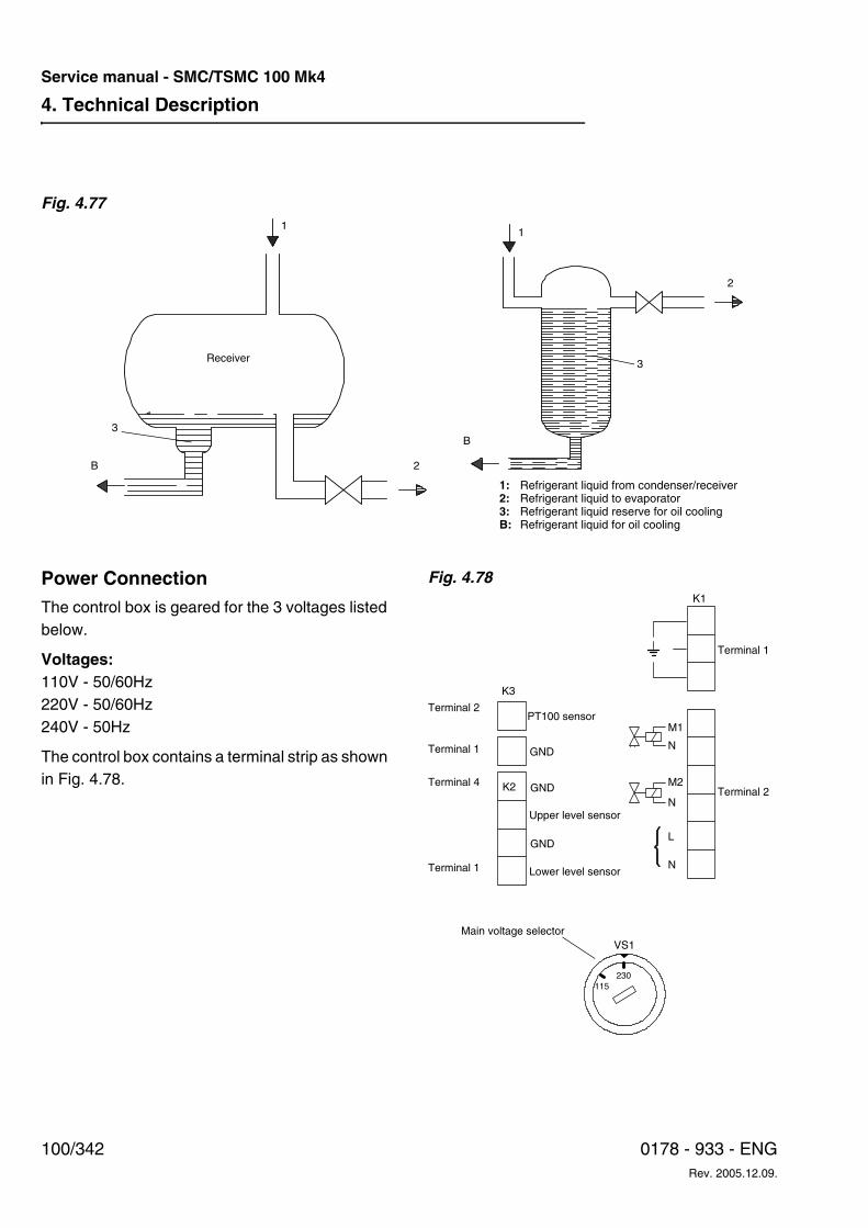
4. Technical Description
100/342 0178 - 933 - ENGRev. 2005.12.09.
Service manual - SMC/TSMC 100 Mk4
Fig. 4.77
Power ConnectionThe control box is geared for the 3 voltages listed below.
Voltages:110V - 50/60Hz220V - 50/60Hz240V - 50Hz
The control box contains a terminal strip as shown in Fig. 4.78.
Fig. 4.78
1: Refrigerant liquid from condenser/receiver2: Refrigerant liquid to evaporator3: Refrigerant liquid reserve for oil coolingB: Refrigerant liquid for oil cooling
1
3
2B
B
3
2
Receiver
1
K3
Terminal 2
GND
Main voltage selectorVS1
K1
Terminal 4
Terminal 1
Terminal 1
K2 GND
GND
PT100 sensor
Upper level sensor
Lower level sensor
115230
Terminal 1
Terminal 2
M1
N
N
M2
L
N
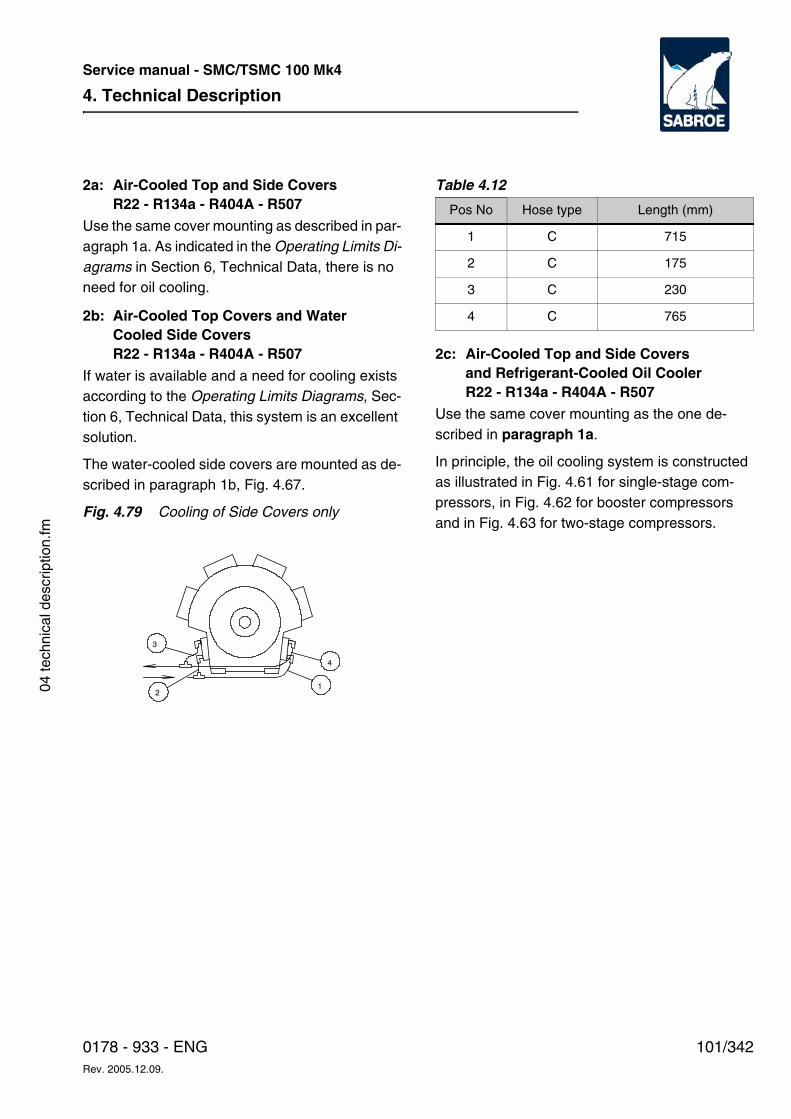
4. Technical Description
101/3420178 - 933 - ENGRev. 2005.12.09.
Service manual - SMC/TSMC 100 Mk4
04 te
chni
cal d
escr
iptio
n.fm
2a: Air-Cooled Top and Side Covers R22 - R134a - R404A - R507
Use the same cover mounting as described in par-agraph 1a. As indicated in the Operating Limits Di-agrams in Section 6, Technical Data, there is no need for oil cooling.
2b: Air-Cooled Top Covers and WaterCooled Side Covers R22 - R134a - R404A - R507
If water is available and a need for cooling exists according to the Operating Limits Diagrams, Sec-tion 6, Technical Data, this system is an excellent solution.
The water-cooled side covers are mounted as de-scribed in paragraph 1b, Fig. 4.67.
Fig. 4.79 Cooling of Side Covers only
Table 4.12
2c: Air-Cooled Top and Side Covers and Refrigerant-Cooled Oil CoolerR22 - R134a - R404A - R507
Use the same cover mounting as the one de-scribed in paragraph 1a.
In principle, the oil cooling system is constructed as illustrated in Fig. 4.61 for single-stage com-pressors, in Fig. 4.62 for booster compressors and in Fig. 4.63 for two-stage compressors.
2
3
1
4
Pos No Hose type Length (mm)
1 C 715
2 C 175
3 C 230
4 C 765
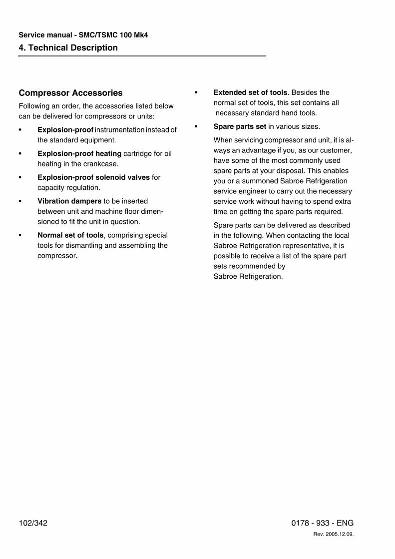
4. Technical Description
102/342 0178 - 933 - ENGRev. 2005.12.09.
Service manual - SMC/TSMC 100 Mk4
Compressor AccessoriesFollowing an order, the accessories listed below can be delivered for compressors or units:
• Explosion-proof instrumentation instead of the standard equipment.
• Explosion-proof heating cartridge for oil heating in the crankcase.
• Explosion-proof solenoid valves for capacity regulation.
• Vibration dampers to be inserted between unit and machine floor dimen-sioned to fit the unit in question.
• Normal set of tools, comprising special tools for dismantling and assembling the compressor.
• Extended set of tools. Besides the normal set of tools, this set contains all necessary standard hand tools.
• Spare parts set in various sizes.
When servicing compressor and unit, it is al-ways an advantage if you, as our customer, have some of the most commonly used spare parts at your disposal. This enables you or a summoned Sabroe Refrigeration service engineer to carry out the necessary service work without having to spend extra time on getting the spare parts required.
Spare parts can be delivered as described in the following. When contacting the local Sabroe Refrigeration representative, it is possible to receive a list of the spare part sets recommended by Sabroe Refrigeration.
4. Technical Description
103/3420178 - 933 - ENGRev. 2005.12.09.
Service manual - SMC/TSMC 100 Mk4
04 te
chni
cal d
escr
iptio
n.fm
Types of Spare Parts Set:
For the different compressor blocks:
• Standard spare parts set: Contains a suit-able selection of O-rings as well as valve ring plates and valve spring.
• Extended spare parts set: In addition to the parts included in the standard spare parts set, the set contains a cylinder liner and discharge valve as well as an extended number and types of gaskets and fittings.
• Certificate spare parts set: In addition to the parts from the extended spare parts set this set contains a major number of components and wearing parts selected by the classification societies.
• Special spare parts set: This is a more comprehensive set than the extended
spare parts set as almost all O-rings and gaskets are included and for the most wear-ing parts the number of parts have been ex-tended.
For the different compressor units:• Standard spare parts set: This is a set
consisting mainly of O-rings and gaskets for some of the components included in the unit.
• Certificate spare parts set: In addition to the parts from the standard spare parts set this set contains other components selected in accordance with the requirements of the classification societies.

4. Technical Description
104/342 0178 - 933 - ENGRev. 2005.12.09.
Service manual - SMC/TSMC 100 Mk4
6. Technical Data
105/3420178 - 933 - ENGRev. 2005.12.09.
Service manual - SMC/TSMC 100 Mk4
06 te
chni
cal d
ata.
fm
6. Technical DataThe purpose of this chapter is to provide the tech-nical data of the equipment. In this chapter technical data is defined as:
• Data for compressor
• Data for unit
• Working range
• Handling the compressor
• Area of application
• Noise level data
• Vibration data
• Test pressure for compressors
• Assessing the oil
• Selecting lubricating oil
This chapter is primarily intended for designers, service engineers, sales personnel and prospective customers.
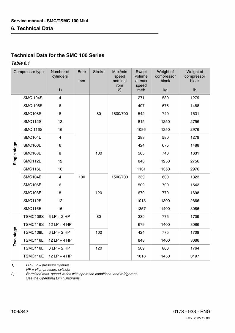
6. Technical Data
106/342 0178 - 933 - ENGRev. 2005.12.09.
Service manual - SMC/TSMC 100 Mk4
Technical Data for the SMC 100 SeriesTable 6.1
1) LP = Low pressure cylinder HP = High pressure cylinder2) Permitted max. speed varies with operation conditions- and refrigerant.
See the Operating Limit Diagrams
Compressor type Number of cylinders
1)
Bore
mm
Stroke Max/min speed
nominal rpm 2)
Swept volume at max speed m3/h
Weight of compressor
block
kg
Weight of compressor
block
lb
Sin
gle
sta
ge
SMC 104S 4 271 580 1279
SMC 106S 6 407 675 1488
SMC108S 8 80 1800/700 542 740 1631
SMC112S 12 815 1250 2756
SMC 116S 16 1086 1350 2976
SMC104L 4 283 580 1279
SMC106L 6 424 675 1488
SMC108L 8 100 565 740 1631
SMC112L 12 848 1250 2756
SMC116L 16 1131 1350 2976
SMC104E 4 100 1500/700 339 600 1323
SMC106E 6 509 700 1543
SMC108E 8 120 679 770 1698
SMC112E 12 1018 1300 2866
SMC116E 16 1357 1400 3086
Tw
o s
tag
e
TSMC108S 6 LP + 2 HP 80 339 775 1709
TSMC116S 12 LP + 4 HP 679 1400 3086
TSMC108L 6 LP + 2 HP 100 424 775 1709
TSMC116L 12 LP + 4 HP 848 1400 3086
TSMC116L 6 LP + 2 HP 120 509 800 1764
TSMC116E 12 LP + 4 HP 1018 1450 3197
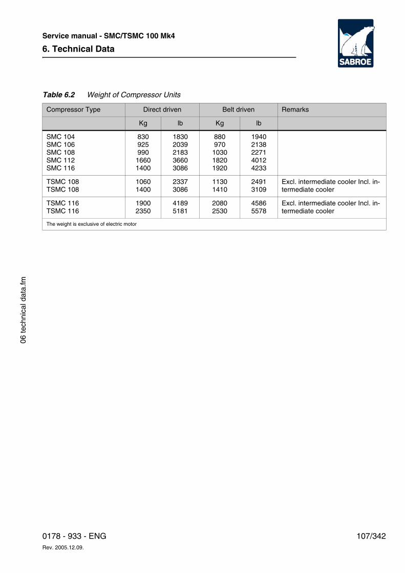
6. Technical Data
107/3420178 - 933 - ENGRev. 2005.12.09.
Service manual - SMC/TSMC 100 Mk4
06 te
chni
cal d
ata.
fm
Table 6.2 Weight of Compressor Units
Compressor Type Direct driven Belt driven Remarks
Kg lb Kg lb
SMC 104 SMC 106 SMC 108 SMC 112 SMC 116
83092599016601400
18302039218336603086
880970
103018201920
19402138227140124233
TSMC 108 TSMC 108
10601400
23373086
11301410
24913109
Excl. intermediate cooler Incl. in-termediate cooler
TSMC 116 TSMC 116
19002350
41895181
20802530
45865578
Excl. intermediate cooler Incl. in-termediate cooler
The weight is exclusive of electric motor
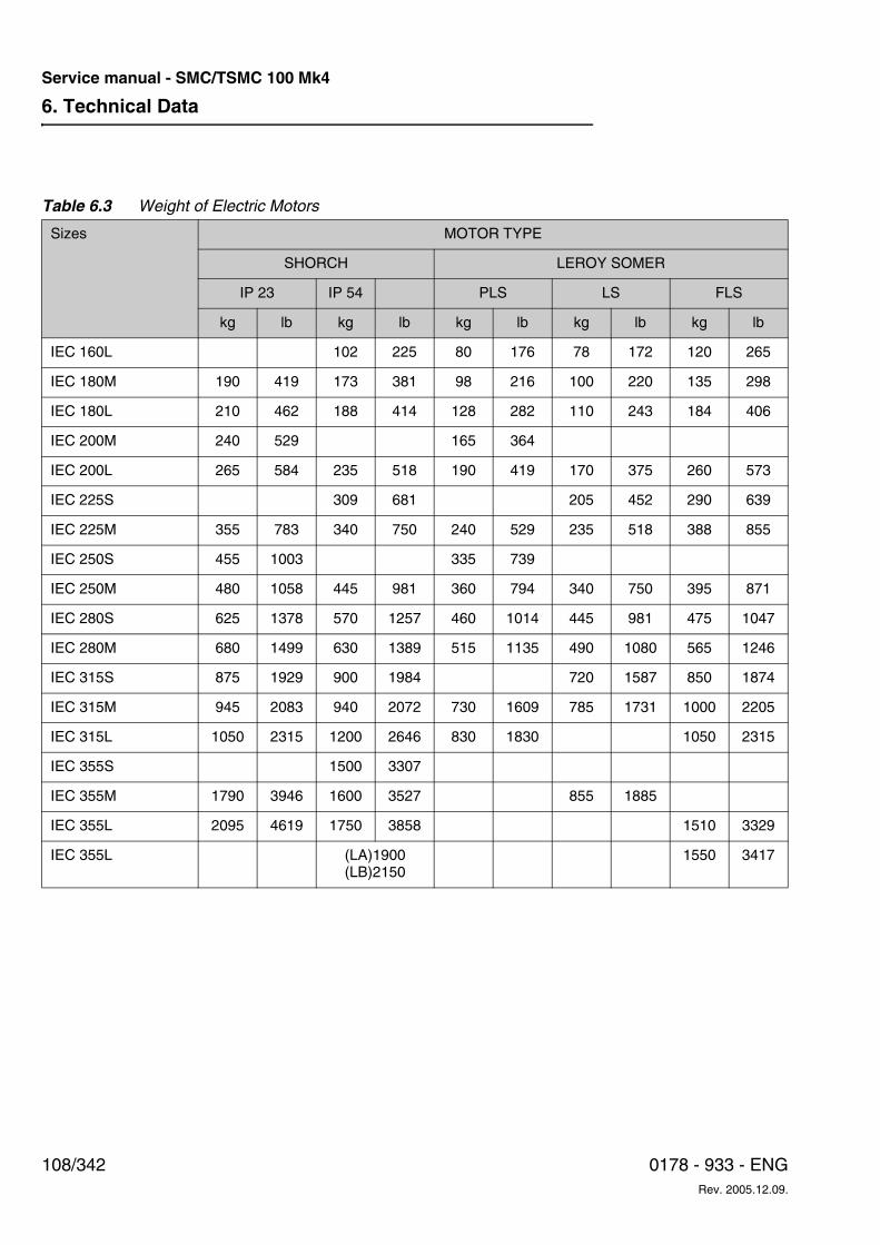
6. Technical Data
108/342 0178 - 933 - ENGRev. 2005.12.09.
Service manual - SMC/TSMC 100 Mk4
Table 6.3 Weight of Electric Motors
Sizes MOTOR TYPE
SHORCH LEROY SOMER
IP 23 IP 54 PLS LS FLS
kg lb kg lb kg lb kg lb kg lb
IEC 160L 102 225 80 176 78 172 120 265
IEC 180M 190 419 173 381 98 216 100 220 135 298
IEC 180L 210 462 188 414 128 282 110 243 184 406
IEC 200M 240 529 165 364
IEC 200L 265 584 235 518 190 419 170 375 260 573
IEC 225S 309 681 205 452 290 639
IEC 225M 355 783 340 750 240 529 235 518 388 855
IEC 250S 455 1003 335 739
IEC 250M 480 1058 445 981 360 794 340 750 395 871
IEC 280S 625 1378 570 1257 460 1014 445 981 475 1047
IEC 280M 680 1499 630 1389 515 1135 490 1080 565 1246
IEC 315S 875 1929 900 1984 720 1587 850 1874
IEC 315M 945 2083 940 2072 730 1609 785 1731 1000 2205
IEC 315L 1050 2315 1200 2646 830 1830 1050 2315
IEC 355S 1500 3307
IEC 355M 1790 3946 1600 3527 855 1885
IEC 355L 2095 4619 1750 3858 1510 3329
IEC 355L (LA)1900 (LB)2150
1550 3417
6. Technical Data
109/3420178 - 933 - ENGRev. 2005.12.09.
Service manual - SMC/TSMC 100 Mk4
06 te
chni
cal d
ata.
fm
Compressor Capacity
Compressor capacity is calculated by means of the COMP 1 program in the Sabroe Match Master suite of programs.
Alternatively, contact your local dealer who can help dimensioning the compressor.
Dimension Sketches of Compressor BlockAs standard execution the compressor block can be delivered with either an analog display and safety system, i.e. with pressure gauges, pres-sure sentive and thermostats, or with a UNISAB II
system with display and safety facilities as well as capacity regulation of the compressor.
To illustrate the structure of the dimension sketch-es, three examples have been included, Fig. 6.1, Fig. 6.2 and Fig. 6.3. Moreover, reference is made to Dimension and Piping Diagram, which in-cludes dimension sketches of all compressors and units.
However, during the final planning the latest di-mension sketches from Sabroe Refrigeration are required.
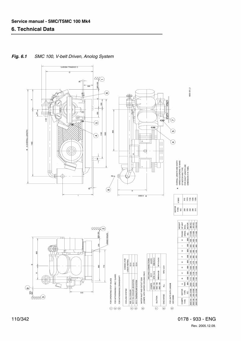
6. Technical Data
110/342 0178 - 933 - ENGRev. 2005.12.09.
Service manual - SMC/TSMC 100 Mk4
Fig. 6.1 SMC 100, V-belt Driven, Anolog System
4833--001_0
SABROE
K
HMAX
900
650
710
275
510
I
25
4XM22HOLES
MIN
250
1100
1500
80
200
G
205
D
C(OVERALLHEIGHT)
200
32
MIN
400
600
E
MIN
620
B
A(OVERALLLENGTH)
1455
F
141
SUCTION
DISCHARGE
FORUNITSWITHUNISAB
987
SMC108
ALL
SMC106
ADD80MM
M76.1x2.9
M88.9x4.85
M114.3x3.6
COMPR
TYPE
SMC104
SMC106
SMC108
200--315M
200--315M
200--315M
IEC
MOTOR
TYPE
MM
A
MM
MAX
B
MM
C
MMD
MM
E
2050
2010
2020
1095
1130
1125
1000
1035
1030
275
275
300
MMF
MM
G
440
395
405
350
395
405
1115
1090
1130
I MM
635
665
MM
635
620
635K
171438
171438
171438
OFUNIT
MOTOR
EXCL.
WEIGHT
315
1335
TYPE
MOTOR
IEC
250
280
200
225
915
1015
1135
1235
HMAX
645
FOUND.
DRWG.
NO.
OFMOTORANDTYPE
FOREXACTLENGTHUSE
VARIESACCORDINGTOMAKE
OVERALLLENGTHANDWIDTH
DIMENSIONHIN
TABEL
880KG
970KG
1030KG
2
FORWITHDRAWINGCRANKSHAFT
R717OILCOOLER(BOOSTER)
COOLINGSYSTEM
43
R22OILCOOLER
5
(COMPR.WITHWATERCOOLINGONLY)
6
SMC104
M76.1x4.5
M88.9x3.2
COMPR.
R717
WELDINGCONNECTIONS
CONNEC.FOR
R717THERMOPUMP.SYSTEM
(H)CFC
FORWITHDRAWINGV--BELT
GUARD
1FOROPERATINGSTOPVALVES
G1/4
G1/4
G1/4
WATERINLETANDOUTLETG3/8
LIQUID
REFRIG.
75
4
8
III
III
2
45
1
6
3
9
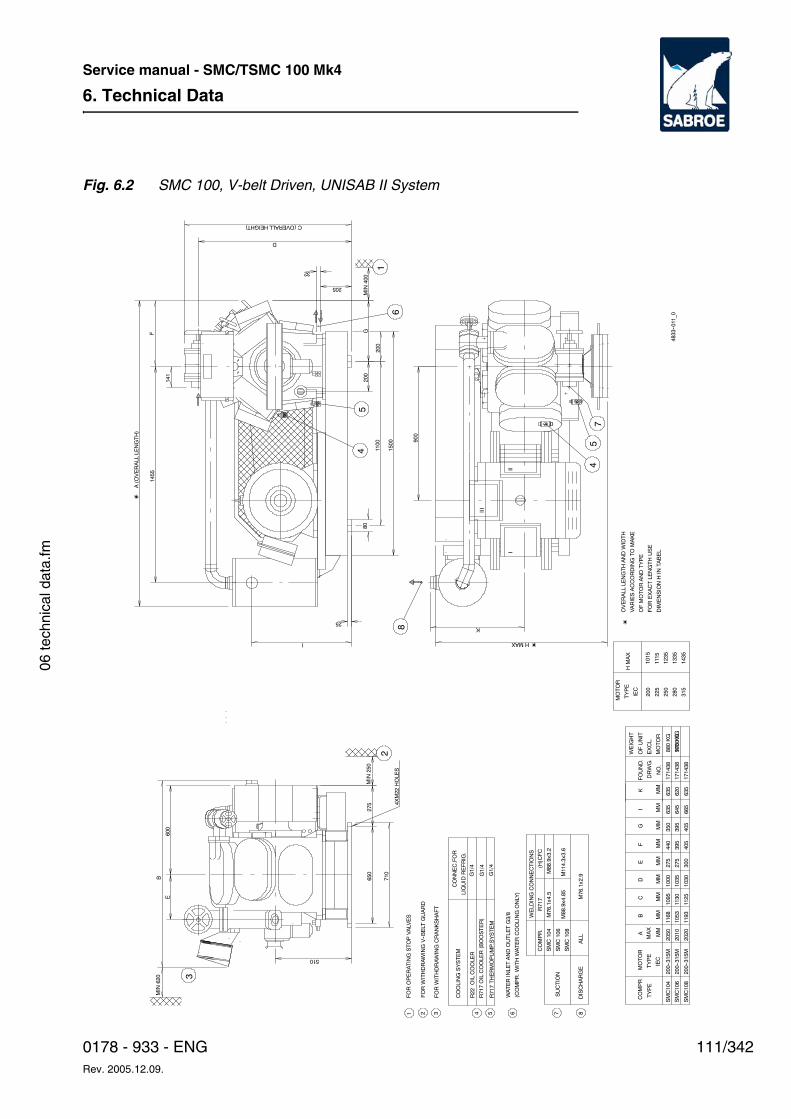
6. Technical Data
111/3420178 - 933 - ENGRev. 2005.12.09.
Service manual - SMC/TSMC 100 Mk4
06 te
chni
cal d
ata.
fm
Fig. 6.2 SMC 100, V-belt Driven, UNISAB II System
4833--011_0
HMAX
K
900
650
710
275
510
I
25
4XM22HOLES
MIN
250
1100
1500
80
200
G
205
D
C(OVERALLHEIGHT)
200
32
MIN
400
600
E
BMIN
620
A(OVERALLLENGTH)
1455
F
141
SUCTION
DISCHARGE
87
SMC108
ALL
SMC106
M76.1x2.9
M88.9x4.85
M114.3x3.6
COMPR
TYPE
SMC104
SMC106
SMC108
200--315M
200--315M
200--315M
IEC
MOTOR
TYPE
MM
A
MM
MAX
B
MM
C
MMD
MM
E
2050
2010
2020
1095
1130
1125
1000
1035
1030
275
275
300
MMF
MM
G
440
395
405
350
395
405
1053
1168
1193
I MM
635
665
MM
635
620
635K
171438
171438
171438
OFUNIT
MOTOR
EXCL.
WEIGHT
315
TYPE
MOTOR
IEC
250
280
200
225
HMAX
645
FOUND.
DRWG.
NO.
OFMOTORANDTYPE
FOREXACTLENGTHUSE
VARIESACCORDINGTOMAKE
OVERALLLENGTHANDWIDTH
DIMENSIONHIN
TABEL
1015
1115
1235
1335
1435
880KG
970KG
1030KG
2
FORWITHDRAWINGCRANKSHAFT
R717OILCOOLER(BOOSTER)
COOLINGSYSTEM
43
R22OILCOOLER
5
(COMPR.WITHWATERCOOLINGONLY)
6
SMC104
M76.1x4.5
M88.9x3.2
COMPR.
R717
WELDINGCONNECTIONS
CONNEC.FOR
R717THERMOPUMP.SYSTEM
(H)CFC
FORWITHDRAWINGV--BELT
GUARD
1FOROPERATINGSTOPVALVES
LIQUID
REFRIG.
WATERINLETANDOUTLETG3/8
G1/4
G1/4
G1/4
47
5
8
III
III
2
45
1
6
3
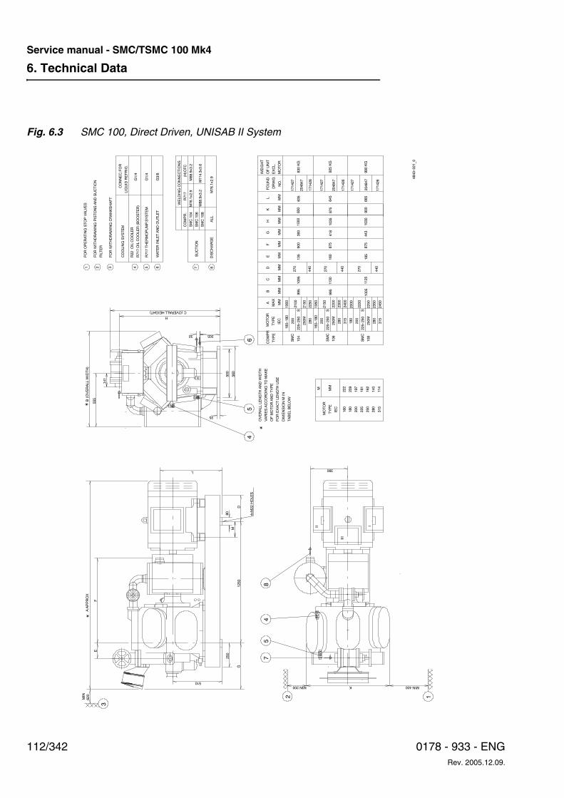
6. Technical Data
112/342 0178 - 933 - ENGRev. 2005.12.09.
Service manual - SMC/TSMC 100 Mk4
Fig. 6.3 SMC 100, Direct Driven, UNISAB II System
4843--021_0
MIN400KMIN200
390
OFMOTORANDTYPE
FOREXACTLENGTHUSE
DIMENSIONMIN
TABELBELOW
1250
250
G
510
D
M
L
80
4xM22HOLES
500
560
205
C(OVERALLHEIGHT)
VARIESACCORDINGTOMAKE
OVERALLLENGTHANDWIDTH
25
32
EF
AAPPROX
620
MIN
555
141
B(OVERALLWIDTH)
H
315
250M
280
108
225--250
SSMC
250
280
315
1005
162
140
114
2250
2350
2450
1125
185
1030
665
204847
171426
875
900
440
443
990KG
200
225--250
S
250M
280
315
180
200
IEC
160--180
225--250
S
250M
280
160--180
MOTOR
TYPE
COMPR
TYPE
MM
A
MM
200
SMC
104
SMC
106
MAX
200
225
180
TYPE
MOTOR
IEC
160
995
995
197
181
209
222M MM
1900
2100
2150
2250
1950
2150
2200
2300
2400
2000
2200
B
MM
1095
1130C
MMD
MM
E
MMF
MM
G
MMH
MM
K
875
1000
160
1035
135
900
MM
635
645
171426
204847
171427
171427
204847
171426
171427
OFUNIT
MOTOR
EXCL.
L
875
440
440
830
FOUND.
DRWG.
NO.
393
418
270
270
270
830KG
925KG
SUCTION
DISCHARGE
87
SMC108
ALL
SMC106
COMPR.
SMC104
R717
WELDINGCONNECTIONS
WEIGHT
M76.1x2.9
M88.9x3.2
M114.3x3.6
M88.9x3.2 M76.1x2.9
(H)CFC
5
R717OILCOOLER(BOOSTER)
COOLINGSYSTEM
4
CONNEC.FOR
R22OILCOOLER
WATERINLETANDOUTLET
6
FORWITHDRAWINGCRANKSHAFT
3
FILTER
FORWITHDRAWINGPISTONSANDSUCTION
21FOROPERATINGSTOPVALVES
R717THERMOPUMP.SYSTEM
LIQUID
REFRIG.
G1/4
G1/4
G3/8
1
I
48
75
2
II
III
45
6
3
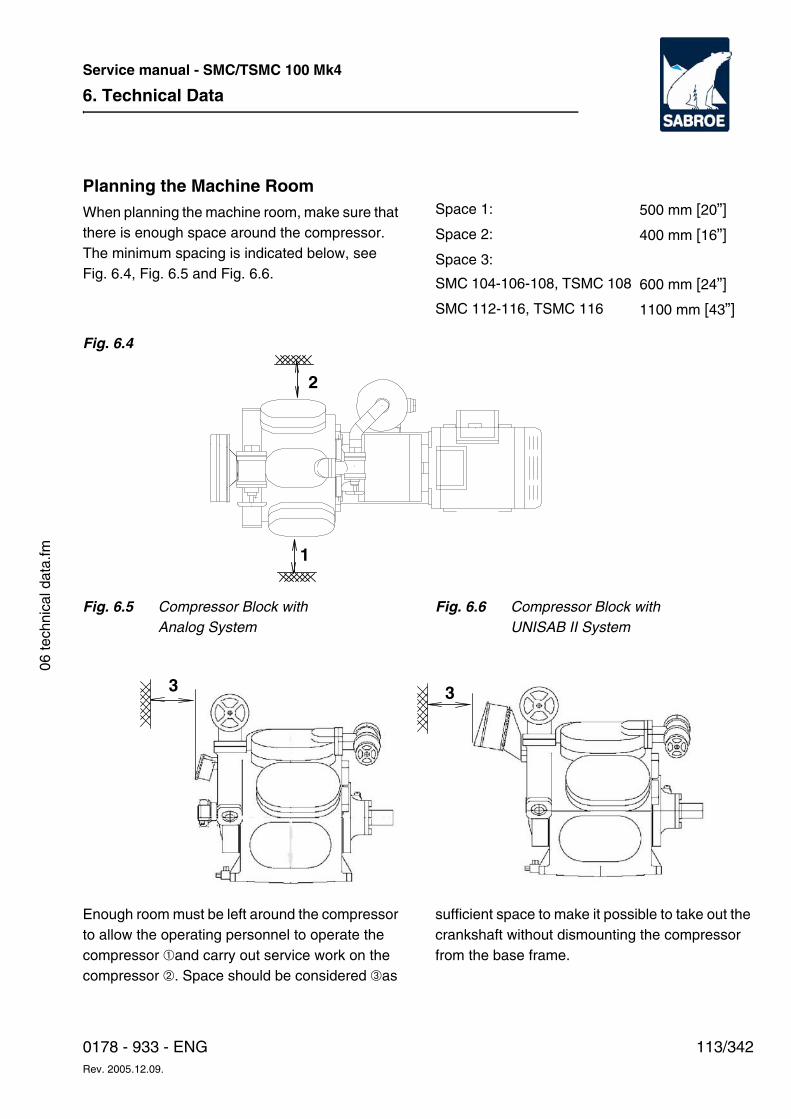
6. Technical Data
113/3420178 - 933 - ENGRev. 2005.12.09.
Service manual - SMC/TSMC 100 Mk4
06 te
chni
cal d
ata.
fm
Planning the Machine RoomWhen planning the machine room, make sure that there is enough space around the compressor. The minimum spacing is indicated below, see Fig. 6.4, Fig. 6.5 and Fig. 6.6.
Fig. 6.4
Fig. 6.5 Compressor Block with Analog System
Fig. 6.6 Compressor Block withUNISAB II System
Enough room must be left around the compressor to allow the operating personnel to operate the compressor ➀and carry out service work on the compressor ➁. Space should be considered ➂as
sufficient space to make it possible to take out the crankshaft without dismounting the compressor from the base frame.
Space 1: 500 mm [20”]
Space 2: 400 mm [16”]
Space 3:
SMC 104-106-108, TSMC 108 600 mm [24”]
SMC 112-116, TSMC 116 1100 mm [43”]
2
1
33
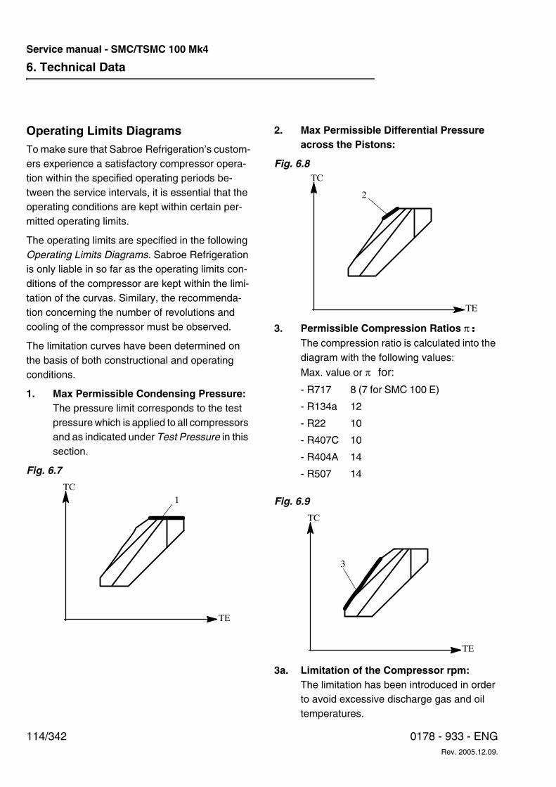
6. Technical Data
114/342 0178 - 933 - ENGRev. 2005.12.09.
Service manual - SMC/TSMC 100 Mk4
Operating Limits DiagramsTo make sure that Sabroe Refrigeration’s custom-ers experience a satisfactory compressor opera-tion within the specified operating periods be-tween the service intervals, it is essential that the operating conditions are kept within certain per-mitted operating limits.
The operating limits are specified in the following Operating Limits Diagrams. Sabroe Refrigerationis only liable in so far as the operating limits con-ditions of the compressor are kept within the limi-tation of the curvas. Similary, the recommenda-tion concerning the number of revolutions and cooling of the compressor must be observed.
The limitation curves have been determined on the basis of both constructional and operating conditions.
1. Max Permissible Condensing Pressure:The pressure limit corresponds to the test pressure which is applied to all compressors and as indicated under Test Pressure in this section.
Fig. 6.7
2. Max Permissible Differential Pressure across the Pistons:
Fig. 6.8
3. Permissible Compression Ratios π:The compression ratio is calculated into the diagram with the following values:
Max. value or π for:
Fig. 6.9
3a. Limitation of the Compressor rpm:The limitation has been introduced in order to avoid excessive discharge gas and oil temperatures.
TE
TC
1
- R717 8 (7 for SMC 100 E)
- R134a 12
- R22 10
- R407C 10
- R404A 14
- R507 14
TE
TC
2
TE
TC
3
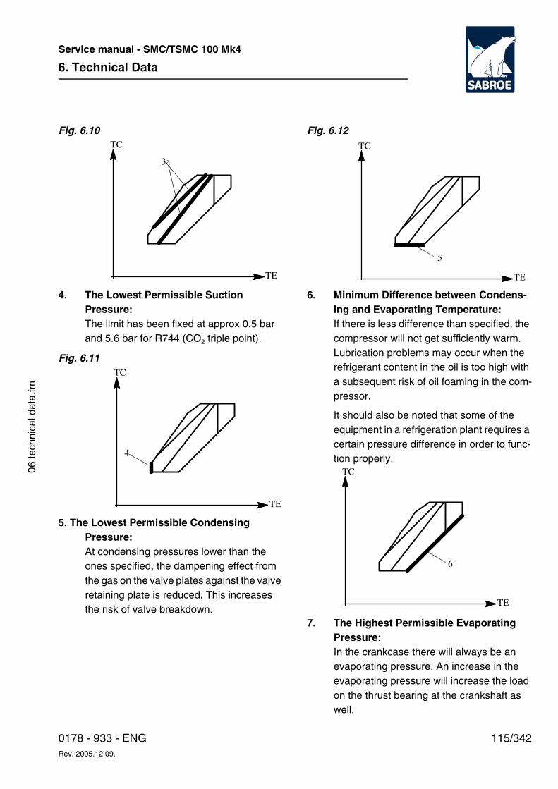
6. Technical Data
115/3420178 - 933 - ENGRev. 2005.12.09.
Service manual - SMC/TSMC 100 Mk4
06 te
chni
cal d
ata.
fm
Fig. 6.10
4. The Lowest Permissible Suction Pressure:The limit has been fixed at approx 0.5 bar and 5.6 bar for R744 (CO2 triple point).
Fig. 6.11
5. The Lowest Permissible Condensing Pressure:At condensing pressures lower than the ones specified, the dampening effect from the gas on the valve plates against the valve retaining plate is reduced. This increases the risk of valve breakdown.
Fig. 6.12
6. Minimum Difference between Condens-ing and Evaporating Temperature:If there is less difference than specified, the compressor will not get sufficiently warm. Lubrication problems may occur when the refrigerant content in the oil is too high with a subsequent risk of oil foaming in the com-pressor.
It should also be noted that some of the equipment in a refrigeration plant requires a certain pressure difference in order to func-tion properly.
7. The Highest Permissible Evaporating Pressure:In the crankcase there will always be an evaporating pressure. An increase in the evaporating pressure will increase the load on the thrust bearing at the crankshaft as well.
TE
TC
3a
TE
TC
4
TE
TC
5
TE
TC
6
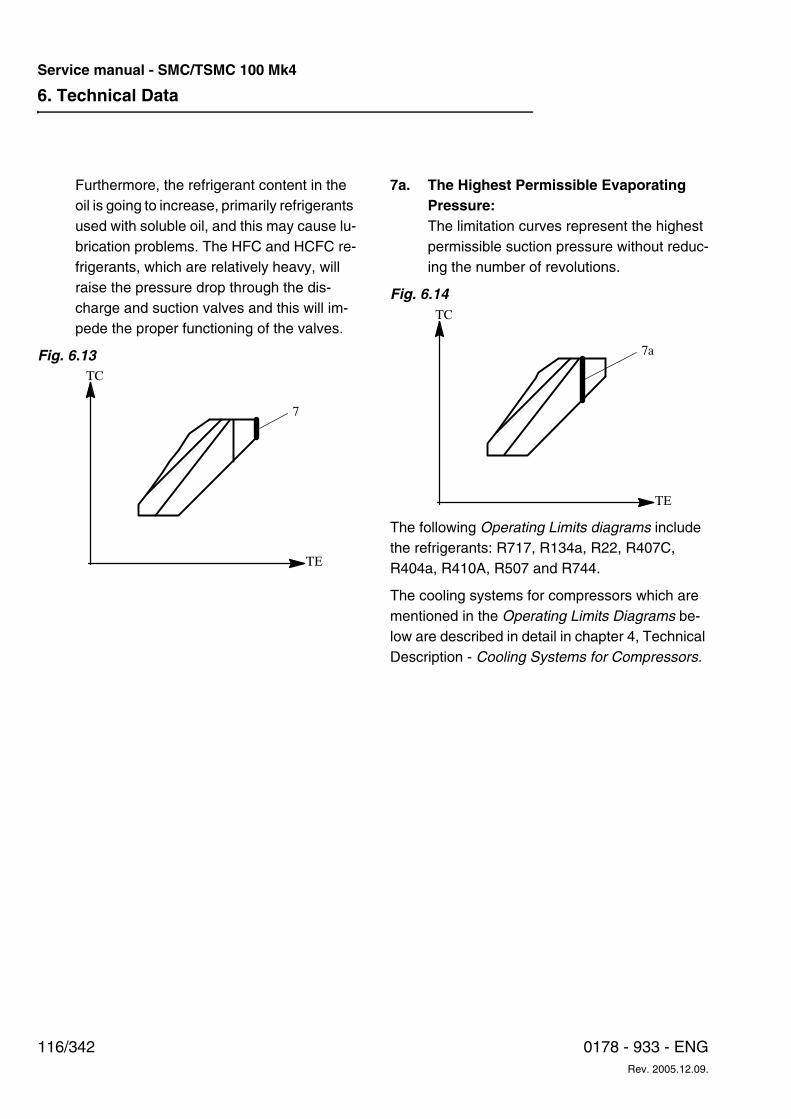
6. Technical Data
116/342 0178 - 933 - ENGRev. 2005.12.09.
Service manual - SMC/TSMC 100 Mk4
Furthermore, the refrigerant content in the oil is going to increase, primarily refrigerants used with soluble oil, and this may cause lu-brication problems. The HFC and HCFC re-frigerants, which are relatively heavy, will raise the pressure drop through the dis-charge and suction valves and this will im-pede the proper functioning of the valves.
Fig. 6.13
7a. The Highest Permissible EvaporatingPressure:The limitation curves represent the highest permissible suction pressure without reduc-ing the number of revolutions.
Fig. 6.14
The following Operating Limits diagrams include the refrigerants: R717, R134a, R22, R407C, R404a, R410A, R507 and R744.
The cooling systems for compressors which are mentioned in the Operating Limits Diagrams be-low are described in detail in chapter 4, Technical Description - Cooling Systems for Compressors.
TE
TC
7
TE
TC
7a
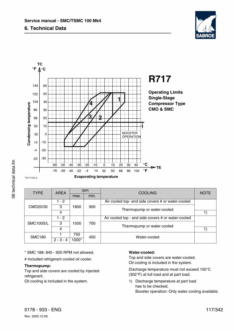
6. Technical Data
117/3420178 - 933 - ENGRev. 2005.12.09.
Service manual - SMC/TSMC 100 Mk4
06 te
chni
cal d
ata.
fm
-30
-20
0
10
20
-10
-60 -50
40
50
60
30
Co
nd
ensi
ng
tem
per
atu
re
-20-30
3
0
2
-10
4
-40
T0111123_6
3020 40
1
10
Evaporating temperature
°C
°C
TE°F-40 -22 -4 32 50 86 10468
TC°F
68
86
104
122
140
50
32
14
14
-4
-22
-58-76
R717Operating LimitsSingle-StageCompressor TypeCMO & SMC
BOOSTER OPERATION
TYPE AREArpm
COOLING NOTEmax. min.
CMO20/301 - 2
1800 900Air cooled top- and side covers # or water-cooled
3Thermopump or water-cooled
4 1)
SMC100S/L1 - 2
1500 700Air cooled top - and side covers # or water-cooled
3Thermopump or water cooled
4 1)
SMC1801 750
450 Water-cooled2 - 3 - 4 1000*
* SMC 188: 840 - 920 RPM not allowed.
# Included refrigerant cooled oil cooler.
Thermopump:Top and side covers are cooled by injected refrigerant.Oil cooling is included in the system.
Water-cooled:Top and side covers are water-cooled.Oil cooling is included in the system.
Discharge temperature must not exceed 150°C (302°F) at full load and at part load.
1) Discharge temperature at part load has to be checked.Booster operation: Only water cooling available.
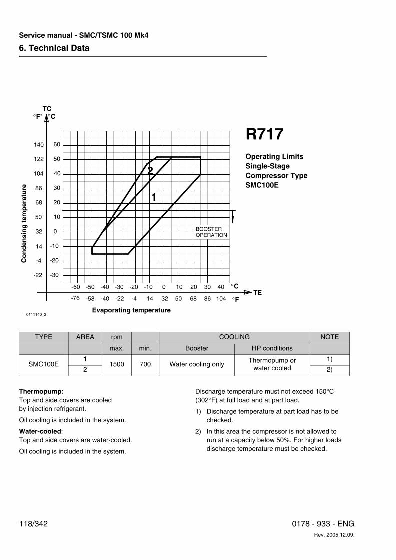
6. Technical Data
118/342 0178 - 933 - ENGRev. 2005.12.09.
Service manual - SMC/TSMC 100 Mk4
T0111140_2
0
10
20
30
-50-60
-30
-20
-10
40
50
60
Co
nd
ensi
ng
tem
per
atu
re
-30 0-10
1
-20
2
-40 3020 4010
Evaporating temperature
TE°F-40 -22 -4 14 32 50 86 10468
TC°F’
68
86
104
50
32
14
-4
-22
°C
°C
122
140
-58-76
R717Operating LimitsSingle-StageCompressor TypeSMC100E
BOOSTER OPERATION
TYPE AREA rpm COOLING NOTE
max. min. Booster HP conditions
SMC100E1
1500 700 Water cooling onlyThermopump or
water cooled1)
2 2)
Thermopump:Top and side covers are cooled by injection refrigerant.
Oil cooling is included in the system.
Water-cooled:Top and side covers are water-cooled.
Oil cooling is included in the system.
Discharge temperature must not exceed 150°C (302°F) at full load and at part load.
1) Discharge temperature at part load has to be checked.
2) In this area the compressor is not allowed to run at a capacity below 50%. For higher loads discharge temperature must be checked.
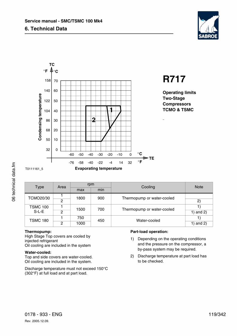
6. Technical Data
119/3420178 - 933 - ENGRev. 2005.12.09.
Service manual - SMC/TSMC 100 Mk4
06 te
chni
cal d
ata.
fm
Thermopump: High Stage Top covers are cooled by injected refrigerantOil cooling are included in the system
Water-cooled: Top and side covers are water-cooled.Oil cooling are included in the system.
Discharge temperature must not exceed 150°C (302°F) at full load and at part load.
Part-load operation:
Type Arearpm
Cooling Notemax min
TCMO20/30 1
1800 900 Thermopump or water-cooled2 2)
TSMC 100 S-L-E
11500 700 Thermopump or water-cooled
1)2 1) and 2)
TSMC 1801 750
450 Water-cooled1)
2 1000 1) and 2)
TE
TC
°C
-60 -50 -40 -30 -20 -10 0 0
10
20
30
40
50
60
70
Co
nd
ensi
ng
tem
per
atu
re
Evaporating temperature
°C
-76 -58 -40 -22 -4 14 32 °F
°F
32
50
68
86
104
122
140
158
1
2
R717Operating limitsTwo-Stage CompressorsTCMO & TSMC
T0111161_5
1) Depending on the operating conditions and the pressure on the compressor, a by-pass system may be required.
2) Discharge temperature at part load has to be checked.
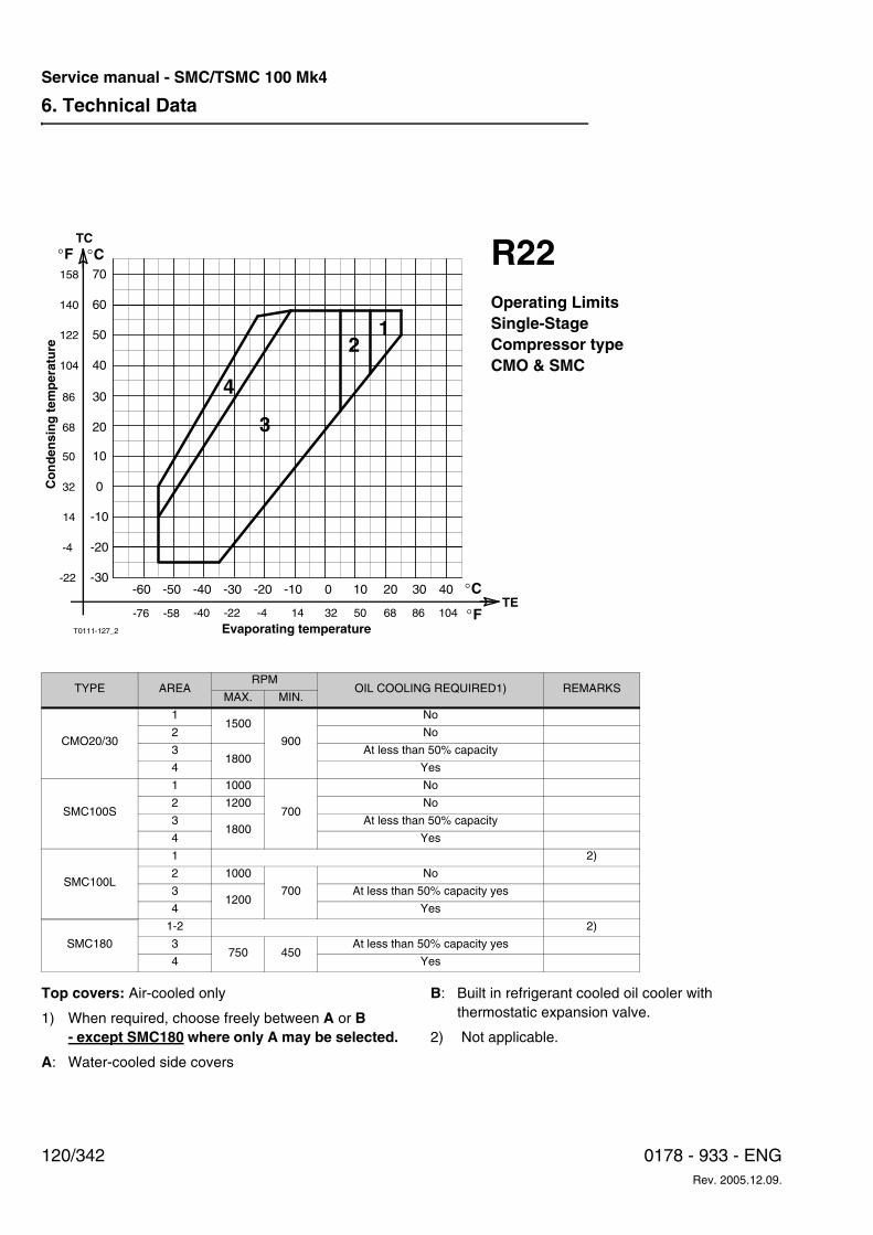
6. Technical Data
120/342 0178 - 933 - ENGRev. 2005.12.09.
Service manual - SMC/TSMC 100 Mk4
-30
-20
-10
0
10
-50 -40
T0111-127_2
-60
30
40
20
60
70
50
-20 0-10-30 20 30 4010TE
°F-40 -22 -4 14 32 50 86 10468
TC°F
68
86
104
50
32
14
-4
-22°C
°C
-58-76
122
140
158
Co
nd
ensi
ng
tem
per
atu
re
Evaporating temperature
4
3
21
R22Operating LimitsSingle-StageCompressor typeCMO & SMC
TYPE AREARPM
OIL COOLING REQUIRED1) REMARKSMAX. MIN.
CMO20/30
11500
900
No
2 No
31800
At less than 50% capacity
4 Yes
SMC100S
1 1000
700
No
2 1200 No
31800
At less than 50% capacity
4 Yes
SMC100L
1 2)
2 1000
700
No
31200
At less than 50% capacity yes
4 Yes
SMC180
1-2 2)
3750 450
At less than 50% capacity yes
4 Yes
Top covers: Air-cooled only
1) When required, choose freely between A or B- except SMC180 where only A may be selected.
A: Water-cooled side covers
B: Built in refrigerant cooled oil cooler with thermostatic expansion valve.
2) Not applicable.
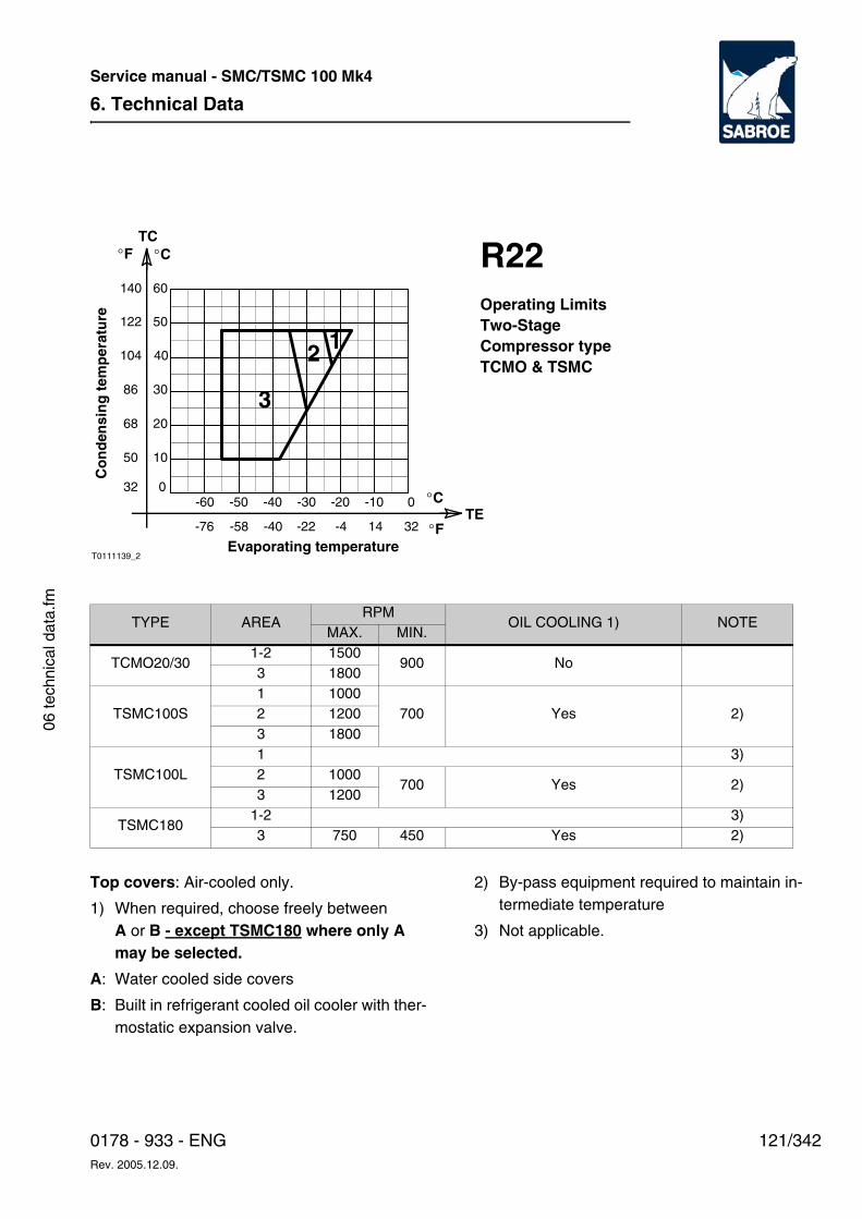
6. Technical Data
121/3420178 - 933 - ENGRev. 2005.12.09.
Service manual - SMC/TSMC 100 Mk4
06 te
chni
cal d
ata.
fm
TYPE AREARPM
OIL COOLING 1) NOTEMAX. MIN.
TCMO20/301-2 1500
900 No3 1800
TSMC100S1 1000
700 Yes 2)2 12003 1800
TSMC100L1 3)2 1000
700 Yes 2)3 1200
TSMC1801-2 3)3 750 450 Yes 2)
10
20
Evaporating temperature
Co
nd
ensi
ng
tem
per
atu
re
0-60
T0111139_2
-50 -40 -30 -20 -10 0
40
50
30
60
TE°F-40 -22 -4 14 32
°C
TC°F
68
86
104
122
140
50
°C
32
-58-76
12
3
R22Operating LimitsTwo-StageCompressor typeTCMO & TSMC
Top covers: Air-cooled only.
1) When required, choose freely between A or B - except TSMC180 where only A may be selected.
A: Water cooled side covers
B: Built in refrigerant cooled oil cooler with ther-mostatic expansion valve.
2) By-pass equipment required to maintain in-termediate temperature
3) Not applicable.
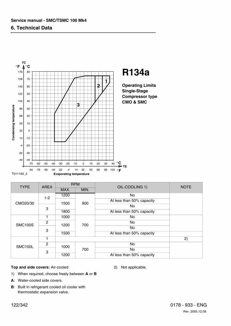
6. Technical Data
122/342 0178 - 933 - ENGRev. 2005.12.09.
Service manual - SMC/TSMC 100 Mk4
TYPE AREARPM
OIL-COOLING 1) NOTEMAX. MIN.
CMO20/30 1-2
1200
900
No
1500At less than 50% capacity
3No
1800 At less than 50% capacity
SMC100S
1 1000
700
No2
1200No
3No
1500 At less than 50% capacity
SMC100L
1 2)2
1000700
No
3No
1200 At less than 50% capacity
TE
TC°C
-30
-20
-10
-60 -50 -40 -30 -20 -10 0 10 20 30 40
0
10
20
30
40
50
60
70
Co
nd
ensi
ng
tem
per
atu
re
Evaporating temperature
°C-70-40
-76 -58 -40 -22 -4 14 32 50 68 86 104 °F-94
°F
-22
-4
14
32
50
68
86
104
122
140
158
-40
80 176
12
3
R134aOperating LimitsSingle-StageCompressor typeCMO & SMC
T011162_2
Top and side covers: Air-cooled
1) When required, choose freely between A or B
A: Water-cooled side covers
B: Built in refrigerant cooled oil cooler with thermostatic expansion valve.
2) Not applicable.
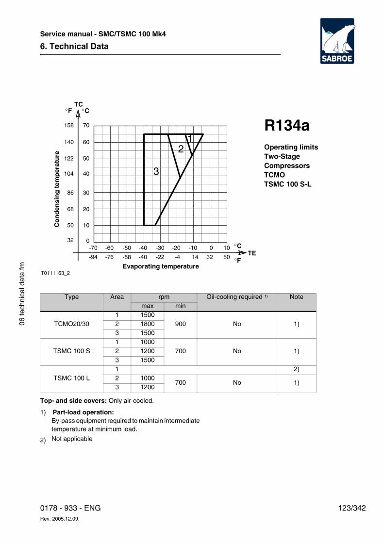
6. Technical Data
123/3420178 - 933 - ENGRev. 2005.12.09.
Service manual - SMC/TSMC 100 Mk4
06 te
chni
cal d
ata.
fm
Top- and side covers: Only air-cooled.
Type Area rpm Oil-cooling required 1) Notemax min
TCMO20/30 1 1500
900 No 1)2 18003 1500
TSMC 100 S 1 1000
700 No 1)2 12003 1500
TSMC 100 L 1 2)2 1000
700 No 1)3 1200
TE
TC°C
-50 -40 -30 -20 -10 0 10 0
10
20
30
40
50
60
70
Co
nd
ensi
ng
tem
per
atu
re
Evaporating temperature
°C
-58 -40 -22 -4 14 32 50 °F
°F
32
50
68
86
104
122
140
158
12
3
R134aOperating limitsTwo-StageCompressorsTCMOTSMC 100 S-L
-60
-76
-70
-94
T0111163_2
1) Part-load operation: By-pass equipment required to maintain intermediate temperature at minimum load.
2) Not applicable
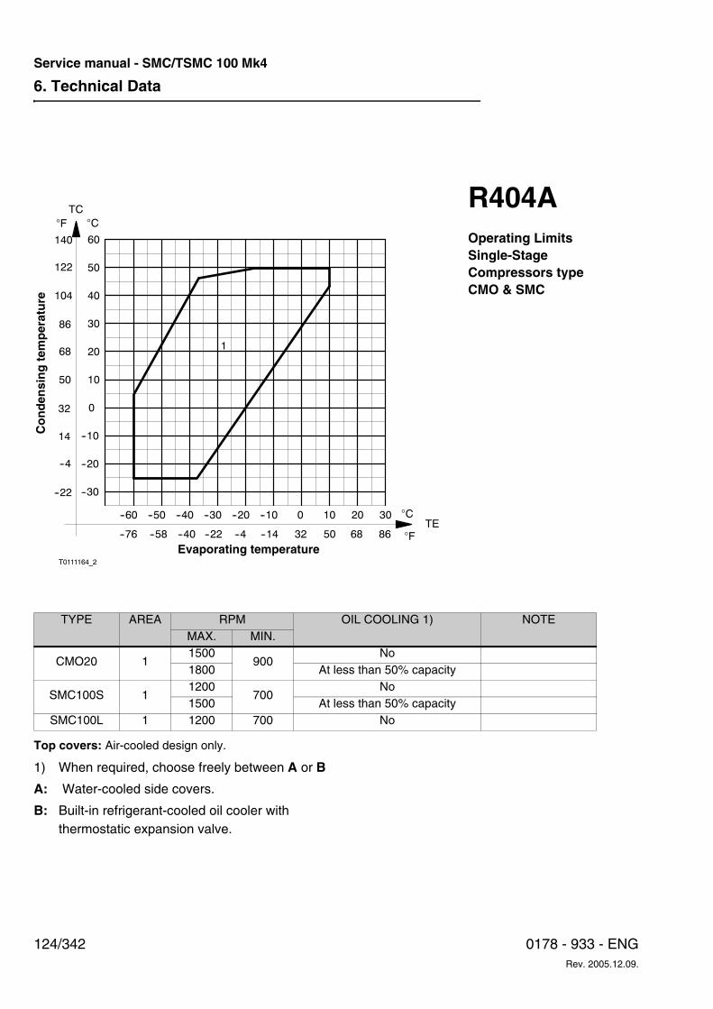
6. Technical Data
124/342 0178 - 933 - ENGRev. 2005.12.09.
Service manual - SMC/TSMC 100 Mk4
Top covers: Air-cooled design only.
--30
--20
--10
0
--60 --50
T0111164_2
--40 --30 --20 --10 0 10 20 30
10
20
30
60
40
50
1
�C�F
TC
122
140
104
86
68
50
32
14
--4
--22
--76 --58 --40 --22 --4 --14 32 50 68 86
�C
�FTE
Co
nd
ensi
ng
tem
per
atu
re
Evaporating temperature
R404AOperating LimitsSingle-StageCompressors typeCMO & SMC
TYPE AREA RPM OIL COOLING 1) NOTEMAX. MIN.
CMO20 11500
900No
1800 At less than 50% capacity
SMC100S 11200
700No
1500 At less than 50% capacitySMC100L 1 1200 700 No
1) When required, choose freely between A or B
A: Water-cooled side covers.
B: Built-in refrigerant-cooled oil cooler with thermostatic expansion valve.
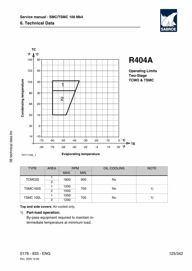
6. Technical Data
125/3420178 - 933 - ENGRev. 2005.12.09.
Service manual - SMC/TSMC 100 Mk4
06 te
chni
cal d
ata.
fm
Top and side covers: Air-cooled only.
TYPE AREA RPM OIL COOLING NOTEMAX. MIN.
TCMO20 1
1800 900 No2
TSMC100S 1 1200
700 No 1)2 1500
TSMC 100L 1 1000
700 No 1)2 1200
TE
TC°C
0
10
20
-60 -50 -40 -30 -20 -10 0
30
40
50
60
Co
nd
ensi
ng
tem
per
atu
re
Evaporating temperature
°C-70-10
-76 -58 -40 -22 -4 14 32 °F-94
°F
32
50
68
86
104
122
140
14
1
2
R404AOperating LimitsTwo-StageTCMO & TSMC
T0111165_1
1) Part-load operation: By-pass equipment required to maintain in-termediate temperature at minimum load.
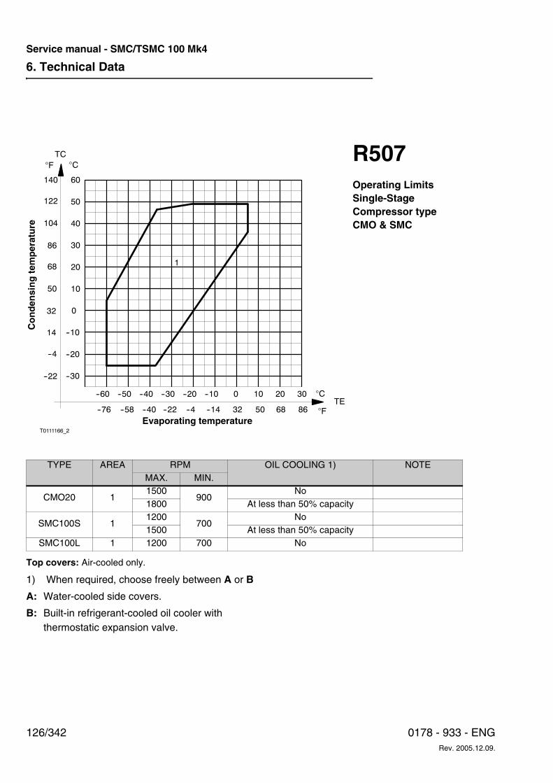
6. Technical Data
126/342 0178 - 933 - ENGRev. 2005.12.09.
Service manual - SMC/TSMC 100 Mk4
Top covers: Air-cooled only.
TYPE AREA RPM OIL COOLING 1) NOTEMAX. MIN.
CMO20 11500
900No
1800 At less than 50% capacity
SMC100S 11200
700No
1500 At less than 50% capacitySMC100L 1 1200 700 No
--30
--20
--10
0
--60 --50
T0111166_2
--40 --30 --20 --10 0 10 20 30
10
20
30
60
40
50
1
�C�F
TC
122
140
104
86
68
50
32
14
--4
--22
--76 --58 --40 --22 --4 --14 32 50 68 86
�C
�FTE
Co
nd
ensi
ng
tem
per
atu
re
Evaporating temperature
R507Operating LimitsSingle-StageCompressor typeCMO & SMC
1) When required, choose freely between A or B
A: Water-cooled side covers.
B: Built-in refrigerant-cooled oil cooler with thermostatic expansion valve.
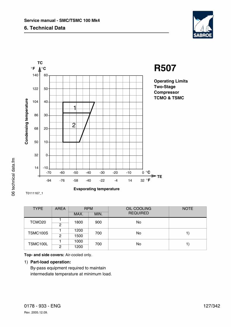
6. Technical Data
127/3420178 - 933 - ENGRev. 2005.12.09.
Service manual - SMC/TSMC 100 Mk4
06 te
chni
cal d
ata.
fm
Top- and side covers: Air-cooled only.
TYPE AREA RPM OIL COOLING REQUIRED
NOTEMAX. MIN.
TCMO20 1
1800 900 No2
TSMC100S 1 1200
700 No 1)2 1500
TSMC100L 1 1000
700 No 1)2 1200
TE
TC°C
0
10
20
-60 -50 -40 -30 -20 -10 0
30
40
50
60
Co
nd
ensi
ng
tem
per
atu
re
Evaporating temperature
°C-70-10
-76 -58 -40 -22 -4 14 32 °F-94
°F
32
50
68
86
104
122
140
14
1
2
R507Operating LimitsTwo-StageCompressorTCMO & TSMC
T0111167_1
1) Part-load operation: By-pass equipment required to maintain intermediate temperature at minimum load.
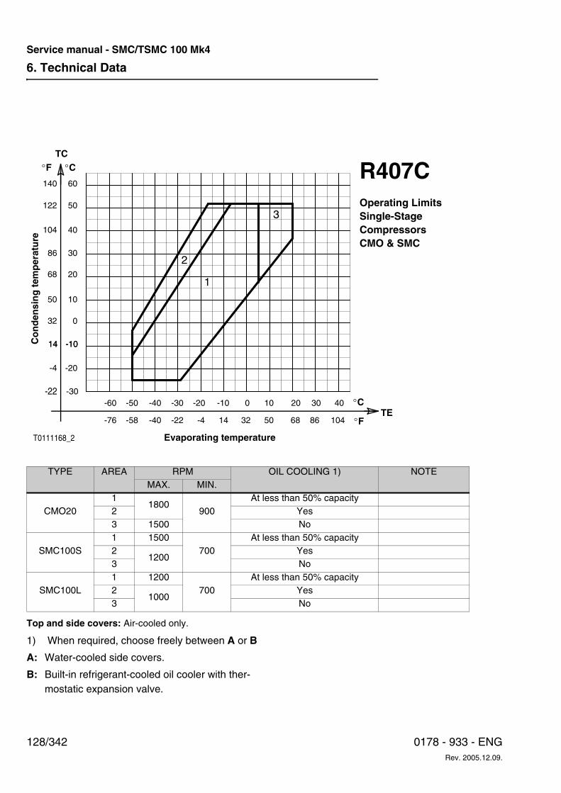
6. Technical Data
128/342 0178 - 933 - ENGRev. 2005.12.09.
Service manual - SMC/TSMC 100 Mk4
Top and side covers: Air-cooled only.
TYPE AREA RPM OIL COOLING 1) NOTEMAX. MIN.
CMO201
1800900
At less than 50% capacity2 Yes3 1500 No
SMC100S1 1500
700At less than 50% capacity
21200
Yes3 No
SMC100L1 1200
700At less than 50% capacity
21000
Yes3 No
1
2
3
Co
nd
ensi
ng
tem
per
atu
re
R407COperating LimitsSingle-StageCompressorsCMO & SMC
TE
TC°C
0
10
20
-60 -50 -40 -30 -20 -10 0
30
40
50
60
Evaporating temperature
°C
-10
-76 -58 -40 -22 -4 14 32 °F
°F
32
50
68
86
104
122
140
14 -1014
-20-4
-30-22 10
50
20
68
30
86
40
104
T0111168_2
1) When required, choose freely between A or B
A: Water-cooled side covers.
B: Built-in refrigerant-cooled oil cooler with ther-mostatic expansion valve.
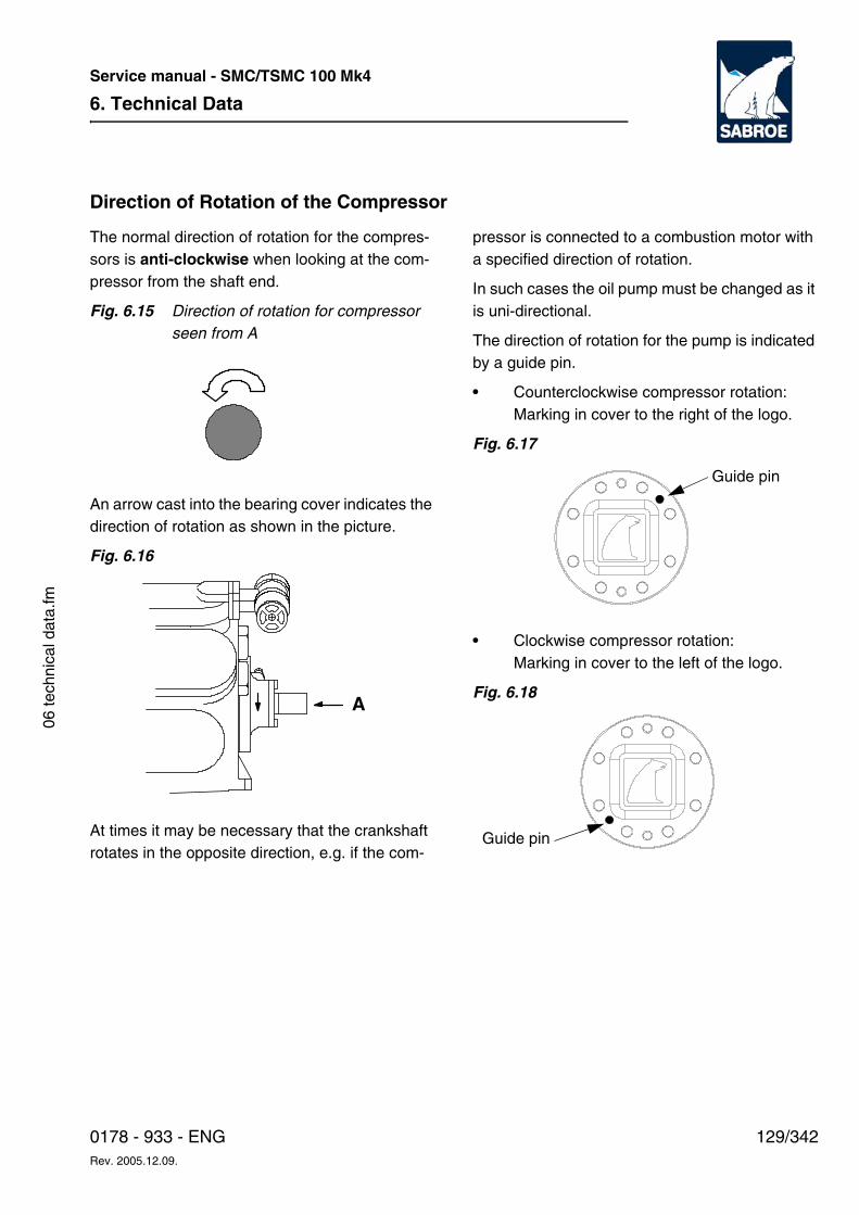
6. Technical Data
129/3420178 - 933 - ENGRev. 2005.12.09.
Service manual - SMC/TSMC 100 Mk4
06 te
chni
cal d
ata.
fm
Direction of Rotation of the Compressor
The normal direction of rotation for the compres-sors is anti-clockwise when looking at the com-pressor from the shaft end.
Fig. 6.15 Direction of rotation for compressor seen from A
An arrow cast into the bearing cover indicates the direction of rotation as shown in the picture.
Fig. 6.16
At times it may be necessary that the crankshaft rotates in the opposite direction, e.g. if the com-
pressor is connected to a combustion motor with a specified direction of rotation.
In such cases the oil pump must be changed as it is uni-directional.
The direction of rotation for the pump is indicated by a guide pin.
• Counterclockwise compressor rotation:Marking in cover to the right of the logo.
Fig. 6.17
• Clockwise compressor rotation:Marking in cover to the left of the logo.
Fig. 6.18A
Guide pin
Guide pin
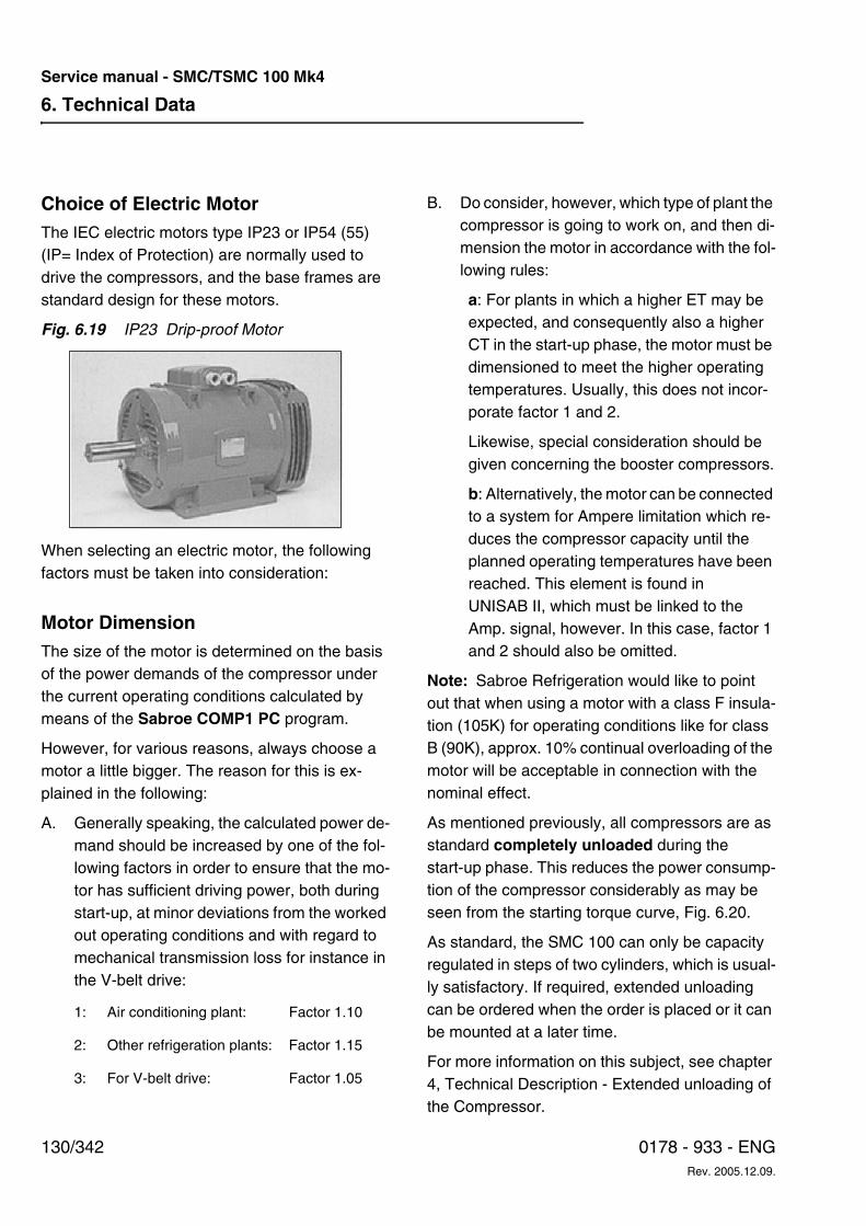
6. Technical Data
130/342 0178 - 933 - ENGRev. 2005.12.09.
Service manual - SMC/TSMC 100 Mk4
Choice of Electric MotorThe IEC electric motors type IP23 or IP54 (55) (IP= Index of Protection) are normally used to drive the compressors, and the base frames are standard design for these motors.
Fig. 6.19 IP23 Drip-proof Motor
When selecting an electric motor, the following factors must be taken into consideration:
Motor DimensionThe size of the motor is determined on the basis of the power demands of the compressor under the current operating conditions calculated by means of the Sabroe COMP1 PC program.
However, for various reasons, always choose a motor a little bigger. The reason for this is ex-plained in the following:
A. Generally speaking, the calculated power de-mand should be increased by one of the fol-lowing factors in order to ensure that the mo-tor has sufficient driving power, both during start-up, at minor deviations from the worked out operating conditions and with regard to mechanical transmission loss for instance in the V-belt drive:
B. Do consider, however, which type of plant the compressor is going to work on, and then di-mension the motor in accordance with the fol-lowing rules:
a: For plants in which a higher ET may be expected, and consequently also a higher CT in the start-up phase, the motor must be dimensioned to meet the higher operating temperatures. Usually, this does not incor-porate factor 1 and 2.
Likewise, special consideration should be given concerning the booster compressors.
b: Alternatively, the motor can be connected to a system for Ampere limitation which re-duces the compressor capacity until the planned operating temperatures have been reached. This element is found in UNISAB II, which must be linked to the Amp. signal, however. In this case, factor 1 and 2 should also be omitted.
Note: Sabroe Refrigeration would like to point out that when using a motor with a class F insula-tion (105K) for operating conditions like for class B (90K), approx. 10% continual overloading of the motor will be acceptable in connection with the nominal effect.
As mentioned previously, all compressors are as standard completely unloaded during the start-up phase. This reduces the power consump-tion of the compressor considerably as may be seen from the starting torque curve, Fig. 6.20.
As standard, the SMC 100 can only be capacity regulated in steps of two cylinders, which is usual-ly satisfactory. If required, extended unloading can be ordered when the order is placed or it can be mounted at a later time.
For more information on this subject, see chapter 4, Technical Description - Extended unloading of the Compressor.
1: Air conditioning plant: Factor 1.10
2: Other refrigeration plants: Factor 1.15
3: For V-belt drive: Factor 1.05
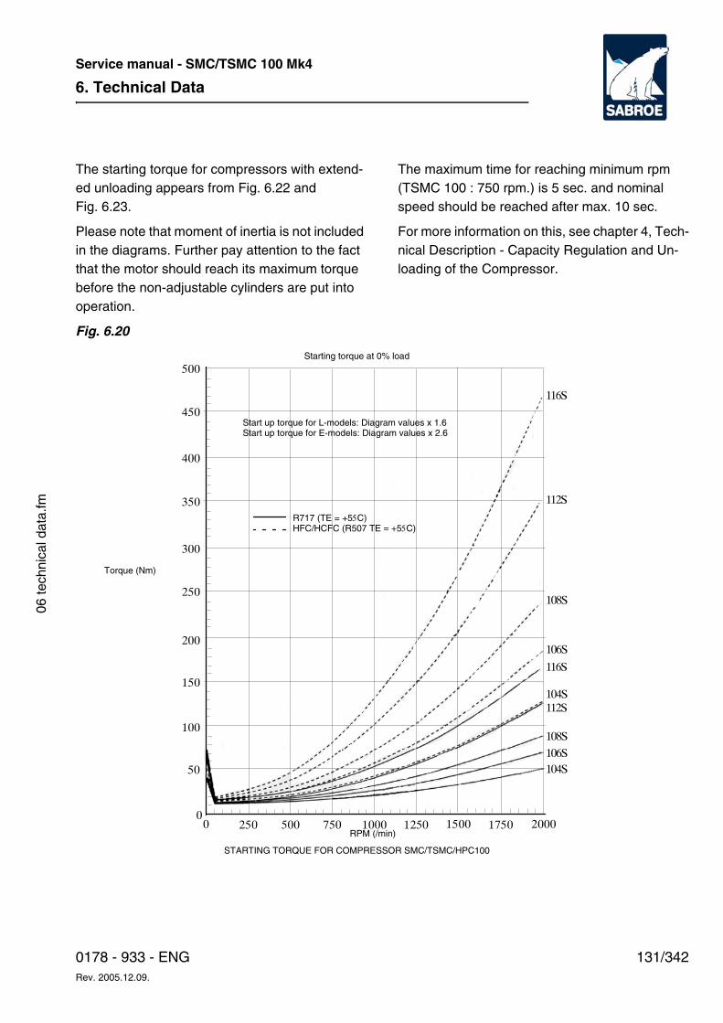
6. Technical Data
131/3420178 - 933 - ENGRev. 2005.12.09.
Service manual - SMC/TSMC 100 Mk4
06 te
chni
cal d
ata.
fm
The starting torque for compressors with extend-ed unloading appears from Fig. 6.22 and Fig. 6.23.
Please note that moment of inertia is not included in the diagrams. Further pay attention to the fact that the motor should reach its maximum torque before the non-adjustable cylinders are put into operation.
The maximum time for reaching minimum rpm (TSMC 100 : 750 rpm.) is 5 sec. and nominal speed should be reached after max. 10 sec.
For more information on this, see chapter 4, Tech-nical Description - Capacity Regulation and Un-loading of the Compressor.
Fig. 6.20
500
450
400
350
300
250
200
150
100
50
00 250 500 750 1000 1250 1500 1750 2000
104S
106S
108S
112S104S
116S
106S
108S
112S
116S
STARTING TORQUE FOR COMPRESSOR SMC/TSMC/HPC100
RPM (/min)
Torque (Nm)
Starting torque at 0% load
Start up torque for L-models: Diagram values x 1.6Start up torque for E-models: Diagram values x 2.6
R717 (TE = +55C)HFC/HCFC (R507 TE = +55C)
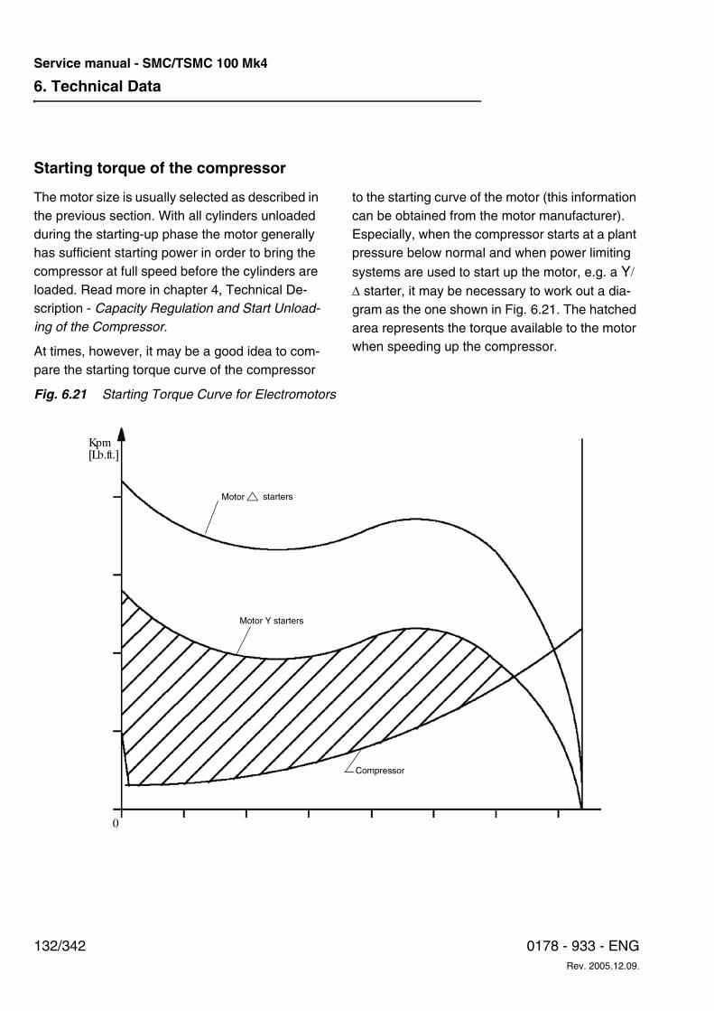
6. Technical Data
132/342 0178 - 933 - ENGRev. 2005.12.09.
Service manual - SMC/TSMC 100 Mk4
Starting torque of the compressor
The motor size is usually selected as described in the previous section. With all cylinders unloaded during the starting-up phase the motor generally has sufficient starting power in order to bring the compressor at full speed before the cylinders are loaded. Read more in chapter 4, Technical De-scription - Capacity Regulation and Start Unload-ing of the Compressor.
At times, however, it may be a good idea to com-pare the starting torque curve of the compressor
to the starting curve of the motor (this information can be obtained from the motor manufacturer). Especially, when the compressor starts at a plant pressure below normal and when power limiting
systems are used to start up the motor, e.g. a Y/ ∆ starter, it may be necessary to work out a dia-gram as the one shown in Fig. 6.21. The hatched area represents the torque available to the motor when speeding up the compressor.
Fig. 6.21 Starting Torque Curve for Electromotors
Kpm[Lb.ft.]
0
Compressor
Motor Y starters
Motor starters
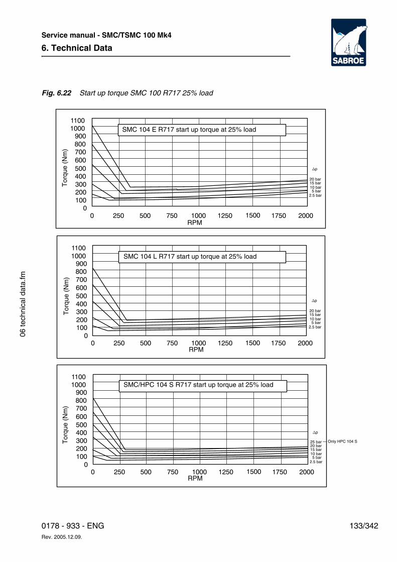
6. Technical Data
133/3420178 - 933 - ENGRev. 2005.12.09.
Service manual - SMC/TSMC 100 Mk4
06 te
chni
cal d
ata.
fm
Fig. 6.22 Start up torque SMC 100 R717 25% load
10 bar
2.5 bar5 bar
15 bar20 bar
np
2000175015001250100075050025000
100200300400500600700800900
10001100
10 bar
2.5 bar5 bar
15 bar20 bar
np
2000175015001250100075050025000
100200300400500600700800900
10001100
10 bar
2.5 bar5 bar
15 bar20 bar
np
2000175015001250100075050025000
100200300400500600700800900
10001100
25 bar
SMC 104 E R717 start up torque at 25% load
SMC 104 L R717 start up torque at 25% load
SMC/HPC 104 S R717 start up torque at 25% load
--- Only HPC 104 S
Tor
que
(Nm
)
RPM
Tor
que
(Nm
)
RPM
Tor
que
(Nm
)
RPM
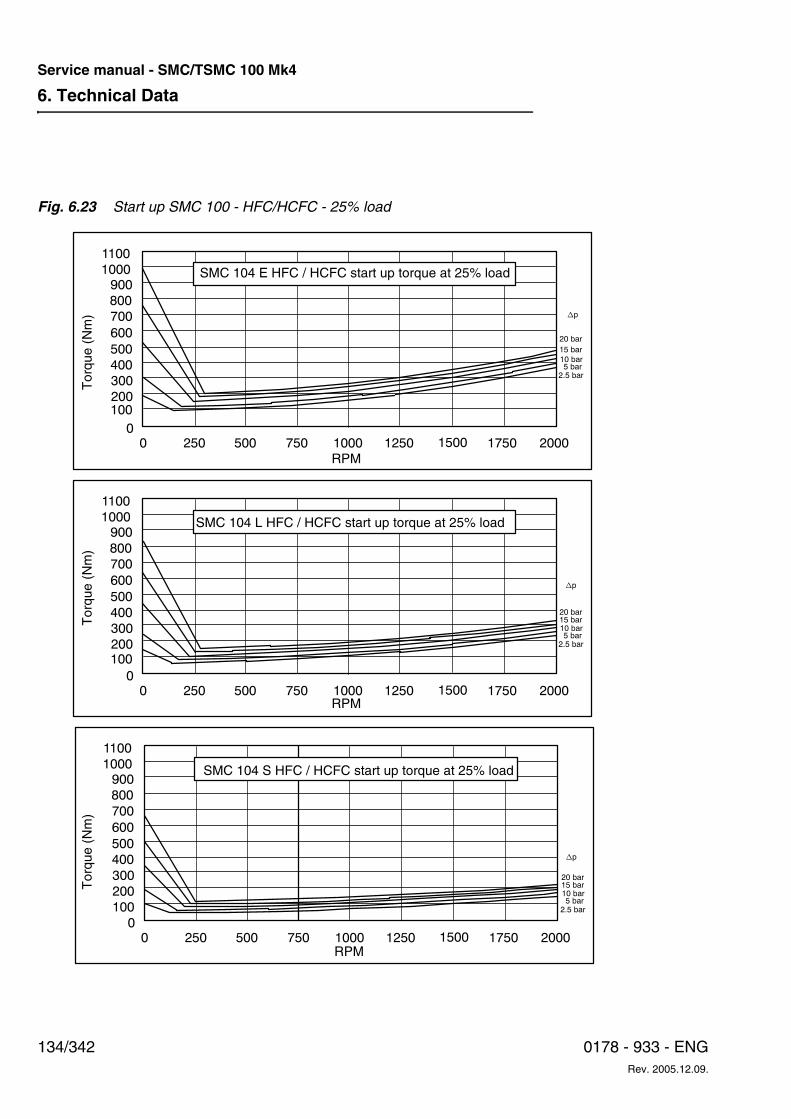
6. Technical Data
134/342 0178 - 933 - ENGRev. 2005.12.09.
Service manual - SMC/TSMC 100 Mk4
Fig. 6.23 Start up SMC 100 - HFC/HCFC - 25% load
10 bar
2.5 bar5 bar
15 bar20 bar
np
2000175015001250100075050025000
100200300400500600700800900
10001100
10 bar
2.5 bar5 bar
15 bar
20 bar
np
2000175015001250100075050025000
200300400500600700800900
10001100
10 bar
2.5 bar5 bar
15 bar20 bar
np
2000175015001250100075050025000
200300400500600700800900
10001100
100
100
SMC 104 E HFC / HCFC start up torque at 25% load
Tor
que
(Nm
)
RPM
SMC 104 L HFC / HCFC start up torque at 25% load
SMC 104 S HFC / HCFC start up torque at 25% load
Tor
que
(Nm
)T
orqu
e (N
m)
RPM
RPM

6. Technical Data
135/3420178 - 933 - ENGRev. 2005.12.09.
Service manual - SMC/TSMC 100 Mk4
06 te
chni
cal d
ata.
fm
Moment of Inertia
As to the moment of inertia, Table 6.4 and Table 6.5, the SMC/HPC/TSMC 100 compressors have the following values:
Table 6.4 Moment of Inertia (kgm2) for SMC/HPC/TSMC 100 Compressors
Table 6.5 Moment of Inertia (Ib.ft2) for SMC/HPC/TSMC 100 Compressors
Type SMC 100 S (80 mm stroke) SMC 100 L (100 mm stroke) SMC 100 E (120 mm stroke)
No of cylinders: SMC/TSMC 100
4 6 8 12 16 4 6 8 12 16 4 6 8 12 16
HPC 100 4 6 8
Compressor with free shaft end
0.154 0.189 0.218 0.376 0.427 0.196 0.234 0.269 0.464 0.579 0.254 0.321 0.340 0.593 0.705
V-belt driven compressor with shaft pulley
4 1.529 1.564 1.593 1.751 1.802 1.571 1.609 1.644 1.839 1.954 1.629 1.696 1.715 1.968 2.080
No of V-belts 6 1.404 1.439 1.468 1.626 1.677 1.446 1.484 1.519 1.714 1.829 1.504 1.571 1.590 1.843 1.955
Profil SPB 8 1.779 1.814 1.843 2.001 2.052 1.821 1.859 1.894 2.089 2.204 1.879 1.946 1.965 2.218 2.330
Direct driven com-pressor with com-plete AMR coupling
0.262 0.297 0.326 0.559 0.610 0.304 0.342 0.377 0.647 0.762 0.362 0.429 0.448 0.776 0.888
Type SMC 100 S (80 mm stroke) SMC 100 L (100 mm stroke) SMC 100 E (120 mm stroke)
No of cylinders: SMC/TSMC 100
4 6 8 12 16 4 6 8 12 16 4 6 8 12 16
HPC 100 4 6 8
Compressor with free shaft end
3.66 4.49 5.18 8.93 10.14 4.66 5.56 6.39 11.02 13.75 6.03 7.62 8.08 14.09 16.75
V-belt driven compressor with shaft pulley
4 36.31 37.15 37.84 41.59 42.80 37.32 38.22 39.05 43.68 46.41 38.69 40.29 40.74 46.75 49.41
No of V-belts 6 33.35 34.18 34.87 38.62 39.83 34.35 35.25 36.08 40.71 43.44 35.72 37.32 37.77 43.78 46.44
Profil SPB 8 42.26 43.09 43.75 47.53 48.74 43.25 44.16 44.99 49.62 52.35 44.63 46.22 46.67 52.68 55.34
Direct driven com-pressor with com-plete AMR coupling
6.22 7.05 7.74 13.28 14.49 7.22 8.12 8.95 15.37 18.10 8.60 10.19 10.64 18.43 21.09
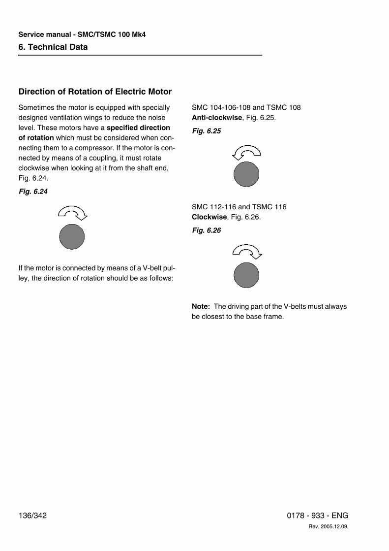
6. Technical Data
136/342 0178 - 933 - ENGRev. 2005.12.09.
Service manual - SMC/TSMC 100 Mk4
Direction of Rotation of Electric Motor
Sometimes the motor is equipped with specially designed ventilation wings to reduce the noise level. These motors have a specified direction of rotation which must be considered when con-necting them to a compressor. If the motor is con-nected by means of a coupling, it must rotate clockwise when looking at it from the shaft end, Fig. 6.24.
Fig. 6.24
If the motor is connected by means of a V-belt pul-ley, the direction of rotation should be as follows:
SMC 104-106-108 and TSMC 108Anti-clockwise, Fig. 6.25.
Fig. 6.25
SMC 112-116 and TSMC 116Clockwise, Fig. 6.26.
Fig. 6.26
Note: The driving part of the V-belts must always be closest to the base frame.
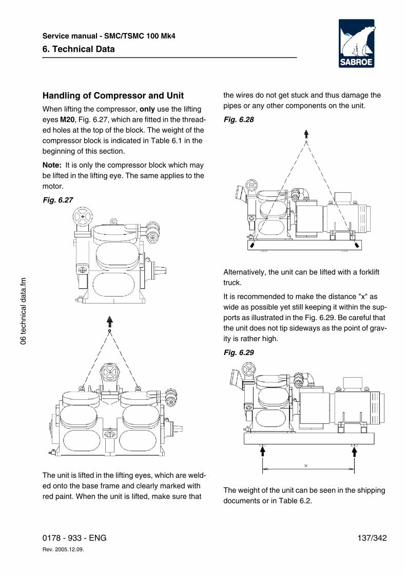
6. Technical Data
137/3420178 - 933 - ENGRev. 2005.12.09.
Service manual - SMC/TSMC 100 Mk4
06 te
chni
cal d
ata.
fm
Handling of Compressor and UnitWhen lifting the compressor, only use the lifting eyes M20, Fig. 6.27, which are fitted in the thread-ed holes at the top of the block. The weight of the compressor block is indicated in Table 6.1 in the beginning of this section.
Note: It is only the compressor block which may be lifted in the lifting eye. The same applies to the motor.
Fig. 6.27
The unit is lifted in the lifting eyes, which are weld-ed onto the base frame and clearly marked with red paint. When the unit is lifted, make sure that
the wires do not get stuck and thus damage the pipes or any other components on the unit.
Fig. 6.28
Alternatively, the unit can be lifted with a forklift truck.
It is recommended to make the distance "x" as wide as possible yet still keeping it within the sup-ports as illustrated in the Fig. 6.29. Be careful that the unit does not tip sideways as the point of grav-ity is rather high.
Fig. 6.29
The weight of the unit can be seen in the shipping documents or in Table 6.2.
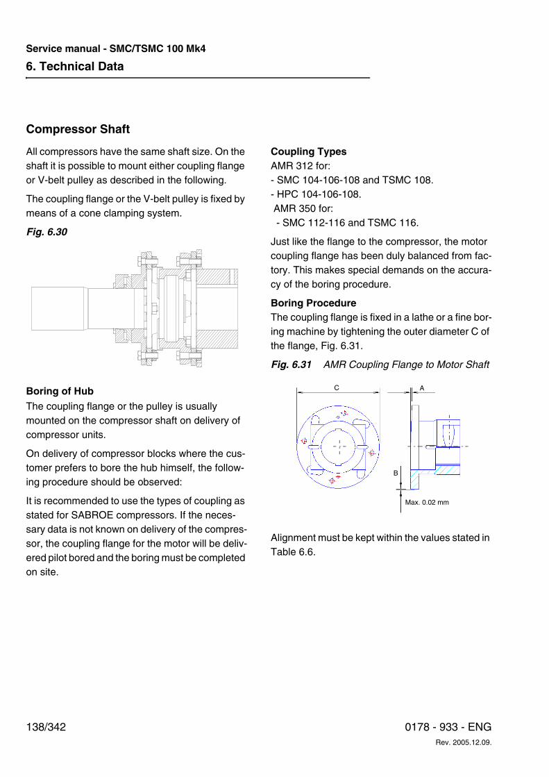
6. Technical Data
138/342 0178 - 933 - ENGRev. 2005.12.09.
Service manual - SMC/TSMC 100 Mk4
Compressor Shaft
All compressors have the same shaft size. On the shaft it is possible to mount either coupling flange or V-belt pulley as described in the following.
The coupling flange or the V-belt pulley is fixed by means of a cone clamping system.
Fig. 6.30
Boring of HubThe coupling flange or the pulley is usually mounted on the compressor shaft on delivery of compressor units.
On delivery of compressor blocks where the cus-tomer prefers to bore the hub himself, the follow-ing procedure should be observed:
It is recommended to use the types of coupling as stated for SABROE compressors. If the neces-sary data is not known on delivery of the compres-sor, the coupling flange for the motor will be deliv-ered pilot bored and the boring must be completed on site.
Coupling TypesAMR 312 for:- SMC 104-106-108 and TSMC 108. - HPC 104-106-108. AMR 350 for: - SMC 112-116 and TSMC 116.
Just like the flange to the compressor, the motor coupling flange has been duly balanced from fac-tory. This makes special demands on the accura-cy of the boring procedure.
Boring ProcedureThe coupling flange is fixed in a lathe or a fine bor-ing machine by tightening the outer diameter C of the flange, Fig. 6.31.
Fig. 6.31 AMR Coupling Flange to Motor Shaft
Alignment must be kept within the values stated in Table 6.6.
Max. 0.02 mm
C A
B
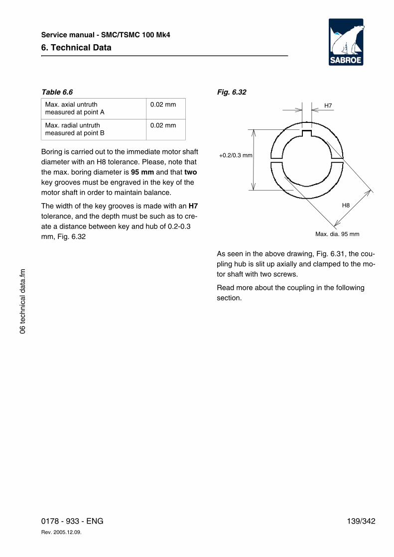
6. Technical Data
139/3420178 - 933 - ENGRev. 2005.12.09.
Service manual - SMC/TSMC 100 Mk4
06 te
chni
cal d
ata.
fm
Table 6.6
Boring is carried out to the immediate motor shaft diameter with an H8 tolerance. Please, note that the max. boring diameter is 95 mm and that two key grooves must be engraved in the key of the motor shaft in order to maintain balance.
The width of the key grooves is made with an H7 tolerance, and the depth must be such as to cre-ate a distance between key and hub of 0.2-0.3 mm, Fig. 6.32
Fig. 6.32
As seen in the above drawing, Fig. 6.31, the cou-pling hub is slit up axially and clamped to the mo-tor shaft with two screws.
Read more about the coupling in the following section.
Max. axial untruth measured at point A
0.02 mm
Max. radial untruth measured at point B
0.02 mm
H7
H8
+0.2/0.3 mm
Max. dia. 95 mm
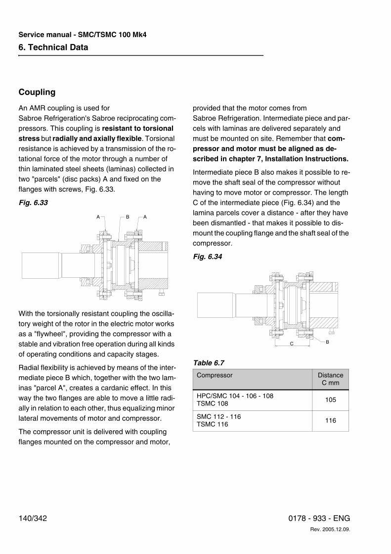
6. Technical Data
140/342 0178 - 933 - ENGRev. 2005.12.09.
Service manual - SMC/TSMC 100 Mk4
Coupling
An AMR coupling is used for Sabroe Refrigeration's Sabroe reciprocating com-pressors. This coupling is resistant to torsional stress but radially and axially flexible. Torsional resistance is achieved by a transmission of the ro-tational force of the motor through a number of thin laminated steel sheets (laminas) collected in two "parcels" (disc packs) A and fixed on the flanges with screws, Fig. 6.33.
Fig. 6.33
With the torsionally resistant coupling the oscilla-tory weight of the rotor in the electric motor works as a "flywheel", providing the compressor with a stable and vibration free operation during all kinds of operating conditions and capacity stages.
Radial flexibility is achieved by means of the inter-mediate piece B which, together with the two lam-inas "parcel A", creates a cardanic effect. In this way the two flanges are able to move a little radi-ally in relation to each other, thus equalizing minor lateral movements of motor and compressor.
The compressor unit is delivered with coupling flanges mounted on the compressor and motor,
provided that the motor comes from Sabroe Refrigeration. Intermediate piece and par-cels with laminas are delivered separately and must be mounted on site. Remember that com-pressor and motor must be aligned as de-scribed in chapter 7, Installation Instructions.
Intermediate piece B also makes it possible to re-move the shaft seal of the compressor without having to move motor or compressor. The length C of the intermediate piece (Fig. 6.34) and the lamina parcels cover a distance - after they have been dismantled - that makes it possible to dis-mount the coupling flange and the shaft seal of the compressor.
Fig. 6.34
Table 6.7
A B A
Compressor Distance C mm
HPC/SMC 104 - 106 - 108TSMC 108
105
SMC 112 - 116TSMC 116
116
C B
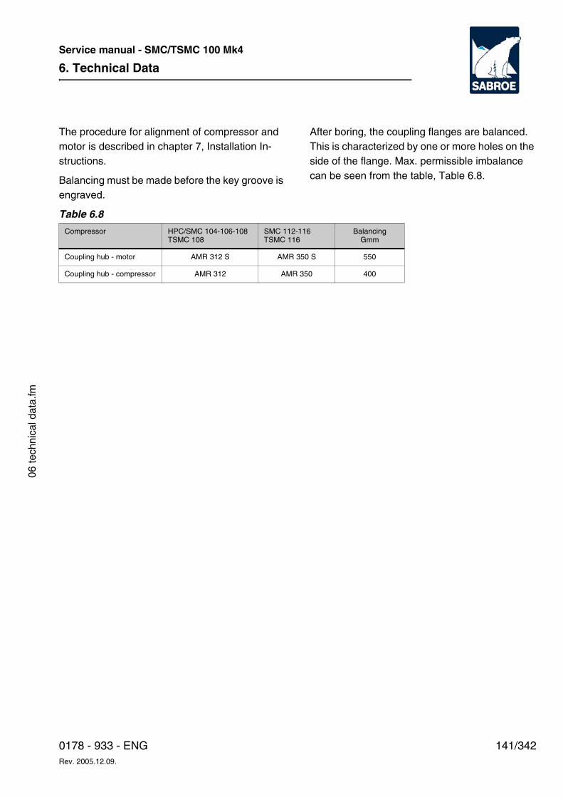
6. Technical Data
141/3420178 - 933 - ENGRev. 2005.12.09.
Service manual - SMC/TSMC 100 Mk4
06 te
chni
cal d
ata.
fm
The procedure for alignment of compressor and motor is described in chapter 7, Installation In-structions.
Balancing must be made before the key groove is engraved.
After boring, the coupling flanges are balanced. This is characterized by one or more holes on the side of the flange. Max. permissible imbalance can be seen from the table, Table 6.8.
Table 6.8
Compressor HPC/SMC 104-106-108 TSMC 108
SMC 112-116 TSMC 116
Balancing Gmm
Coupling hub - motor AMR 312 S AMR 350 S 550
Coupling hub - compressor AMR 312 AMR 350 400
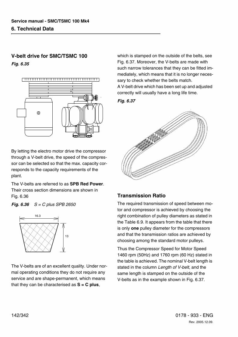
6. Technical Data
142/342 0178 - 933 - ENGRev. 2005.12.09.
Service manual - SMC/TSMC 100 Mk4
V-belt drive for SMC/TSMC 100Fig. 6.35
By letting the electro motor drive the compressor through a V-belt drive, the speed of the compres-sor can be selected so that the max. capacity cor-responds to the capacity requirements of the plant.
The V-belts are referred to as SPB Red Power. Their cross section dimensions are shown in Fig. 6.36
Fig. 6.36 S = C plus SPB 2650
The V-belts are of an excellent quality. Under nor-mal operating conditions they do not require any service and are shape-permanent, which means that they can be characterised as S = C plus,
which is stamped on the outside of the belts, see Fig. 6.37. Moreover, the V-belts are made with such narrow tolerances that they can be fitted im-mediately, which means that it is no longer neces-sary to check whether the belts match. A V-belt drive which has been set up and adjusted correctly will usually have a long life time.
Fig. 6.37
Transmission RatioThe required transmission of speed between mo-tor and compressor is achieved by choosing the right combination of pulley diameters as stated in the Table 6.9. It appears from the table that there is only one pulley diameter for the compressors and that the transmission ratios are achieved by choosing among the standard motor pulleys.
Thus the Compressor Speed for Motor Speed 1460 rpm (50Hz) and 1760 rpm (60 Hz) stated in the table is achieved. The nominal V-belt length is stated in the column Length of V-belt, and the same length is stamped on the outside of the V-belts as in the example shown in Fig. 6.37.
16.3
13
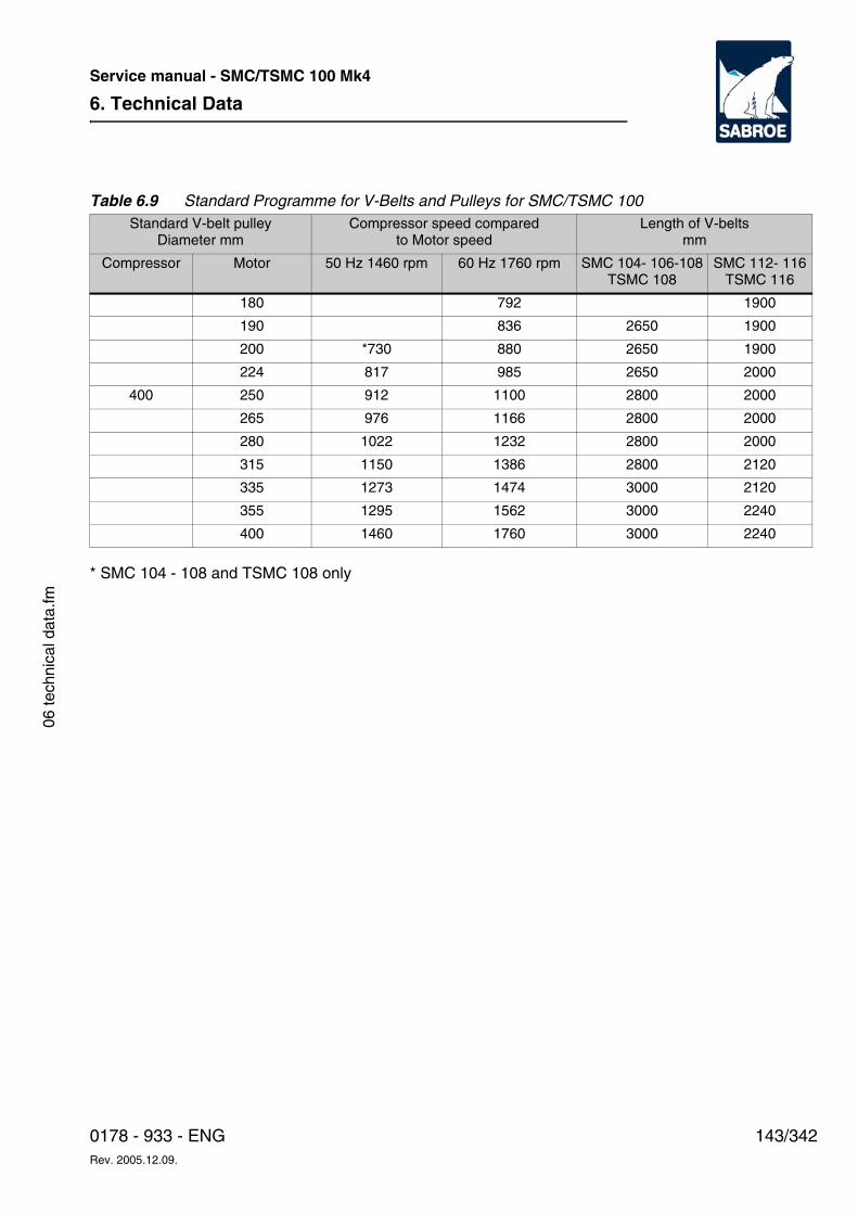
6. Technical Data
143/3420178 - 933 - ENGRev. 2005.12.09.
Service manual - SMC/TSMC 100 Mk4
06 te
chni
cal d
ata.
fm
Table 6.9 Standard Programme for V-Belts and Pulleys for SMC/TSMC 100
* SMC 104 - 108 and TSMC 108 only
Standard V-belt pulley Diameter mm
Compressor speed comparedto Motor speed
Length of V-beltsmm
Compressor Motor 50 Hz 1460 rpm 60 Hz 1760 rpm SMC 104- 106-108TSMC 108
SMC 112- 116TSMC 116
180 792 1900
190 836 2650 1900
200 *730 880 2650 1900
224 817 985 2650 2000
400 250 912 1100 2800 2000
265 976 1166 2800 2000
280 1022 1232 2800 2000
315 1150 1386 2800 2120
335 1273 1474 3000 2120
355 1295 1562 3000 2240
400 1460 1760 3000 2240
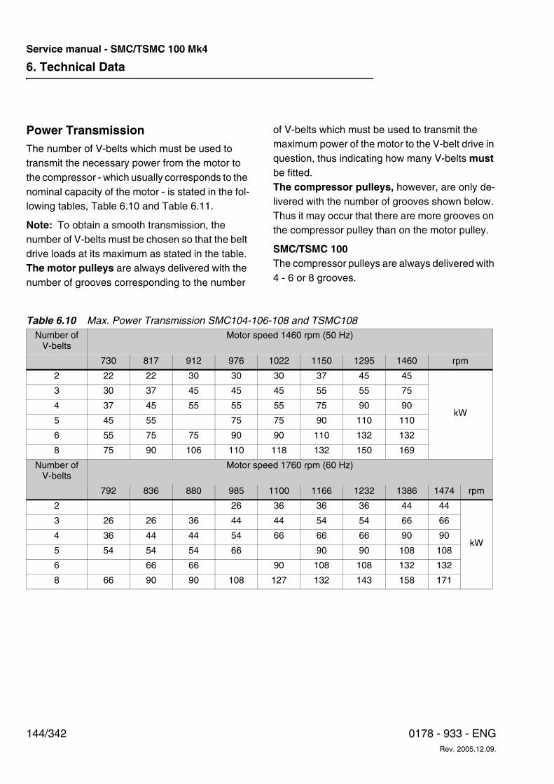
6. Technical Data
144/342 0178 - 933 - ENGRev. 2005.12.09.
Service manual - SMC/TSMC 100 Mk4
Power TransmissionThe number of V-belts which must be used to transmit the necessary power from the motor to the compressor - which usually corresponds to the nominal capacity of the motor - is stated in the fol-lowing tables, Table 6.10 and Table 6.11.
Note: To obtain a smooth transmission, the number of V-belts must be chosen so that the belt drive loads at its maximum as stated in the table. The motor pulleys are always delivered with the number of grooves corresponding to the number
of V-belts which must be used to transmit the maximum power of the motor to the V-belt drive in question, thus indicating how many V-belts must be fitted.The compressor pulleys, however, are only de-livered with the number of grooves shown below. Thus it may occur that there are more grooves on the compressor pulley than on the motor pulley.
SMC/TSMC 100 The compressor pulleys are always delivered with 4 - 6 or 8 grooves.
Table 6.10 Max. Power Transmission SMC104-106-108 and TSMC108Number of
V-beltsMotor speed 1460 rpm (50 Hz)
730 817 912 976 1022 1150 1295 1460 rpm
2 22 22 30 30 30 37 45 45
kW
3 30 37 45 45 45 55 55 75
4 37 45 55 55 55 75 90 90
5 45 55 75 75 90 110 110
6 55 75 75 90 90 110 132 132
8 75 90 106 110 118 132 150 169
Number of V-belts
Motor speed 1760 rpm (60 Hz)
792 836 880 985 1100 1166 1232 1386 1474 rpm
2 26 36 36 36 44 44
kW
3 26 26 36 44 44 54 54 66 66
4 36 44 44 54 66 66 66 90 90
5 54 54 54 66 90 90 108 108
6 66 66 90 108 108 132 132
8 66 90 90 108 127 132 143 158 171
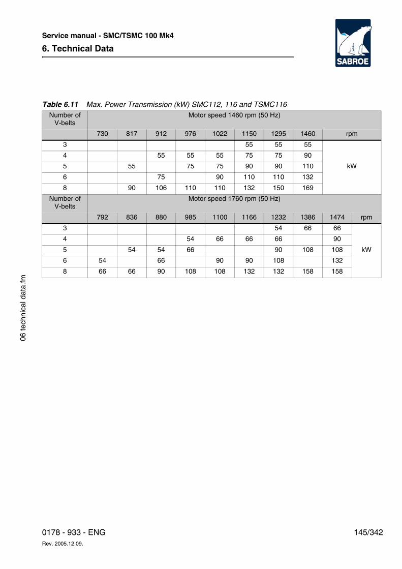
6. Technical Data
145/3420178 - 933 - ENGRev. 2005.12.09.
Service manual - SMC/TSMC 100 Mk4
06 te
chni
cal d
ata.
fm
Table 6.11 Max. Power Transmission (kW) SMC112, 116 and TSMC116Number of
V-beltsMotor speed 1460 rpm (50 Hz)
730 817 912 976 1022 1150 1295 1460 rpm
3 55 55 55
kW
4 55 55 55 75 75 90
5 55 75 75 90 90 110
6 75 90 110 110 132
8 90 106 110 110 132 150 169
Number of V-belts
Motor speed 1760 rpm (50 Hz)
792 836 880 985 1100 1166 1232 1386 1474 rpm
3 54 66 66
kW
4 54 66 66 66 90
5 54 54 66 90 108 108
6 54 66 90 90 108 132
8 66 66 90 108 108 132 132 158 158
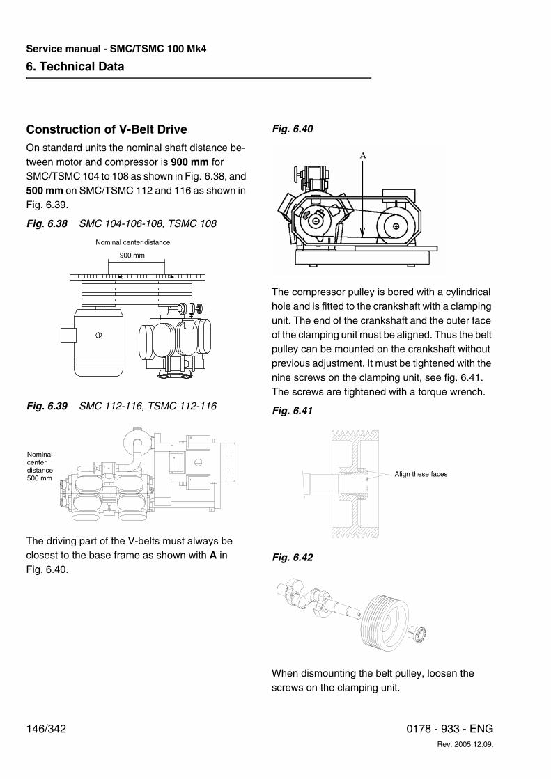
6. Technical Data
146/342 0178 - 933 - ENGRev. 2005.12.09.
Service manual - SMC/TSMC 100 Mk4
Construction of V-Belt DriveOn standard units the nominal shaft distance be-tween motor and compressor is 900 mm for SMC/TSMC 104 to 108 as shown in Fig. 6.38, and 500 mm on SMC/TSMC 112 and 116 as shown in Fig. 6.39.
Fig. 6.38 SMC 104-106-108, TSMC 108
Fig. 6.39 SMC 112-116, TSMC 112-116
The driving part of the V-belts must always be closest to the base frame as shown with A in Fig. 6.40.
Fig. 6.40
The compressor pulley is bored with a cylindrical hole and is fitted to the crankshaft with a clamping unit. The end of the crankshaft and the outer face of the clamping unit must be aligned. Thus the belt pulley can be mounted on the crankshaft without previous adjustment. It must be tightened with the nine screws on the clamping unit, see fig. 6.41. The screws are tightened with a torque wrench.
Fig. 6.41
Fig. 6.42
When dismounting the belt pulley, loosen the screws on the clamping unit.
900 mm
Nominal center distance
II
III
I
Nominalcenterdistance500 mm
A
Align these faces
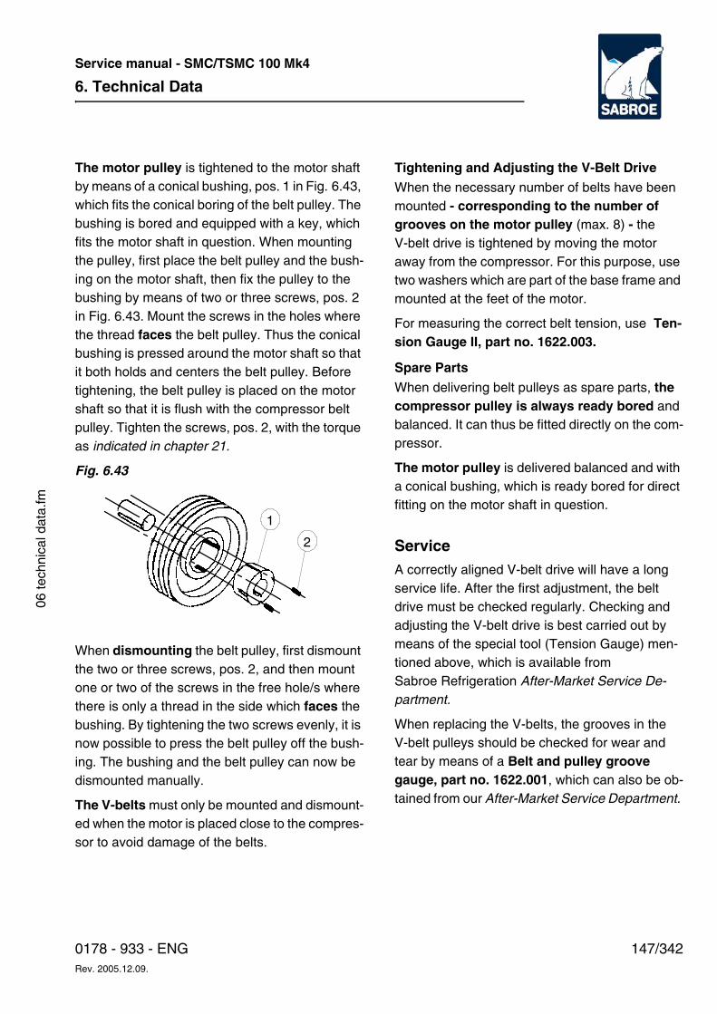
6. Technical Data
147/3420178 - 933 - ENGRev. 2005.12.09.
Service manual - SMC/TSMC 100 Mk4
06 te
chni
cal d
ata.
fm
The motor pulley is tightened to the motor shaft by means of a conical bushing, pos. 1 in Fig. 6.43, which fits the conical boring of the belt pulley. The bushing is bored and equipped with a key, which fits the motor shaft in question. When mounting the pulley, first place the belt pulley and the bush-ing on the motor shaft, then fix the pulley to the bushing by means of two or three screws, pos. 2 in Fig. 6.43. Mount the screws in the holes where the thread faces the belt pulley. Thus the conical bushing is pressed around the motor shaft so that it both holds and centers the belt pulley. Before tightening, the belt pulley is placed on the motor shaft so that it is flush with the compressor belt pulley. Tighten the screws, pos. 2, with the torque as indicated in chapter 21.
Fig. 6.43
When dismounting the belt pulley, first dismount the two or three screws, pos. 2, and then mount one or two of the screws in the free hole/s where there is only a thread in the side which faces the bushing. By tightening the two screws evenly, it is now possible to press the belt pulley off the bush-ing. The bushing and the belt pulley can now be dismounted manually.
The V-belts must only be mounted and dismount-ed when the motor is placed close to the compres-sor to avoid damage of the belts.
Tightening and Adjusting the V-Belt DriveWhen the necessary number of belts have been mounted - corresponding to the number of grooves on the motor pulley (max. 8) - the V-belt drive is tightened by moving the motor away from the compressor. For this purpose, use two washers which are part of the base frame and mounted at the feet of the motor.
For measuring the correct belt tension, use Ten-sion Gauge II, part no. 1622.003.
Spare Parts
When delivering belt pulleys as spare parts, the compressor pulley is always ready bored and balanced. It can thus be fitted directly on the com-pressor.
The motor pulley is delivered balanced and with a conical bushing, which is ready bored for direct fitting on the motor shaft in question.
ServiceA correctly aligned V-belt drive will have a long service life. After the first adjustment, the belt drive must be checked regularly. Checking and adjusting the V-belt drive is best carried out by means of the special tool (Tension Gauge) men-tioned above, which is available from Sabroe Refrigeration After-Market Service De-partment.
When replacing the V-belts, the grooves in the V-belt pulleys should be checked for wear and tear by means of a Belt and pulley groove gauge, part no. 1622.001, which can also be ob-tained from our After-Market Service Department.
1
2
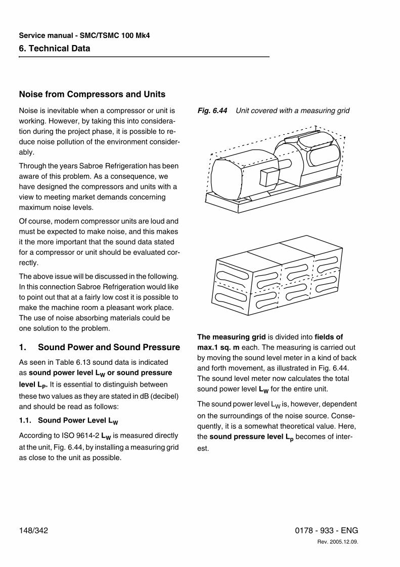
6. Technical Data
148/342 0178 - 933 - ENGRev. 2005.12.09.
Service manual - SMC/TSMC 100 Mk4
Noise from Compressors and Units
Noise is inevitable when a compressor or unit is working. However, by taking this into considera-tion during the project phase, it is possible to re-duce noise pollution of the environment consider-ably.
Through the years Sabroe Refrigeration has been aware of this problem. As a consequence, we have designed the compressors and units with a view to meeting market demands concerning maximum noise levels.
Of course, modern compressor units are loud and must be expected to make noise, and this makes it the more important that the sound data stated for a compressor or unit should be evaluated cor-rectly.
The above issue will be discussed in the following. In this connection Sabroe Refrigeration would like to point out that at a fairly low cost it is possible to make the machine room a pleasant work place. The use of noise absorbing materials could be one solution to the problem.
1. Sound Power and Sound Pressure
As seen in Table 6.13 sound data is indicated as sound power level LW or sound pressure
level LP. It is essential to distinguish between
these two values as they are stated in dB (decibel) and should be read as follows:
1.1. Sound Power Level LW
According to ISO 9614-2 LW is measured directly
at the unit, Fig. 6.44, by installing a measuring grid as close to the unit as possible.
Fig. 6.44 Unit covered with a measuring grid
The measuring grid is divided into fields of max.1 sq. m each. The measuring is carried out by moving the sound level meter in a kind of back and forth movement, as illustrated in Fig. 6.44. The sound level meter now calculates the total sound power level LW for the entire unit.
The sound power level LW is, however, dependent
on the surroundings of the noise source. Conse-quently, it is a somewhat theoretical value. Here, the sound pressure level Lp becomes of inter-
est.
6. Technical Data
149/3420178 - 933 - ENGRev. 2005.12.09.
Service manual - SMC/TSMC 100 Mk4
06 te
chni
cal d
ata.
fm
1.2. Sound Pressure Level Lp
It is actually the sound pressure level Lp that is measured by the sound meter. In the sound meter this is then automatically converted to the sound power level LW by means of its built-in calculation
programs.
The sound pressure measuring is, however, de-pendent on the room in which the measuring is carried out. As a consequence, this may yield dif-ferent results from one room to another.
The arrangement of the room as well as building materials have a considerable influence on the re-sults of the measuring.
This is why the measured values of the manufac-turers for sound pressures are based on standard measures according to ISO 3989 which refers sound pressure level LP to a free field above a
reflecting plane at a distance of 1 meter from the measuring grid, as described in pt. 1.1.
Above facts should be taken into consideration during a check measuring on the plant in question as mentioned in points 2.1 and 2.3.
1.3. Frequency
Sound is fundamentally a pressure wave in the air at a given wave length (frequency).
From a compressor unit sound waves are emitted at many different frequencies due to the different movable parts.
The human ear can normally perceive frequen-cies in areas ranging from 20 Hz to 20 k Hz, but it does not perceive all frequencies equally well. Consequently, a sound meter must measure the sound pressure at various frequencies and then filter the measuring corresponding to the percep-tual capacity of the ear (the A-weighting).
To this must be added the purely subjective per-ception of sound as most human beings feel con-siderable unease on hearing the so-called "pure" notes. If a frequency is followed by a sound pres-sure of 3-6 dB above the other frequencies, this feels annoying. In case of screw compressors, it is a fact that 300 and 600 Hz is normally felt to be an-noying whereas reciprocating machines issue a more low-frequency (pleasant) sound.
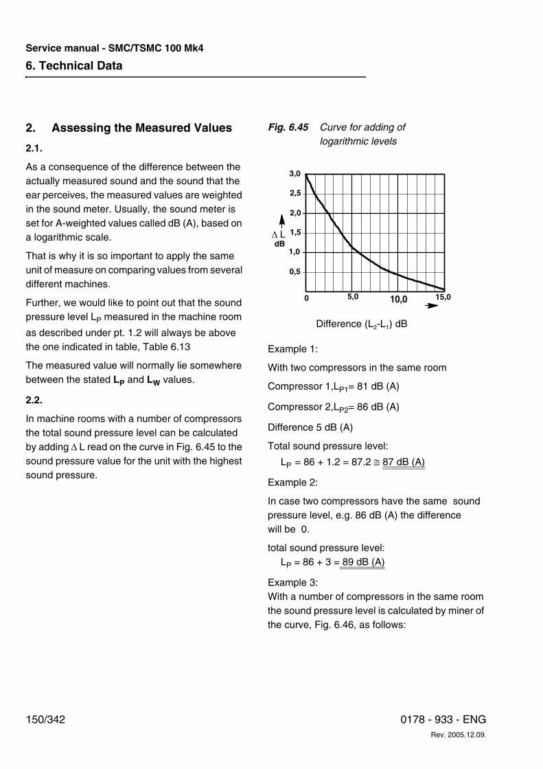
6. Technical Data
150/342 0178 - 933 - ENGRev. 2005.12.09.
Service manual - SMC/TSMC 100 Mk4
2. Assessing the Measured Values
2.1.
As a consequence of the difference between the actually measured sound and the sound that the ear perceives, the measured values are weighted in the sound meter. Usually, the sound meter is set for A-weighted values called dB (A), based on a logarithmic scale.
That is why it is so important to apply the same unit of measure on comparing values from several different machines.
Further, we would like to point out that the sound pressure level LP measured in the machine room
as described under pt. 1.2 will always be above the one indicated in table, Table 6.13
The measured value will normally lie somewhere between the stated LP and LW values.
2.2.
In machine rooms with a number of compressors the total sound pressure level can be calculated by adding ∆ L read on the curve in Fig. 6.45 to the sound pressure value for the unit with the highest sound pressure.
Fig. 6.45 Curve for adding of logarithmic levels
Example 1:
With two compressors in the same room
Compressor 1,LP1= 81 dB (A)
Compressor 2,LP2= 86 dB (A)
Difference 5 dB (A)
Total sound pressure level:
LP = 86 + 1.2 = 87.2 ≅ 87 dB (A)
Example 2:
In case two compressors have the same sound pressure level, e.g. 86 dB (A) the difference will be 0.
total sound pressure level:LP = 86 + 3 = 89 dB (A)
Example 3:With a number of compressors in the same room the sound pressure level is calculated by miner of the curve, Fig. 6.46, as follows:
Difference (L2-L1) dB
3,0
2,5
2,0
1,5
1,0
0,5
0 5,0 10,0 15,0
dB∆ L
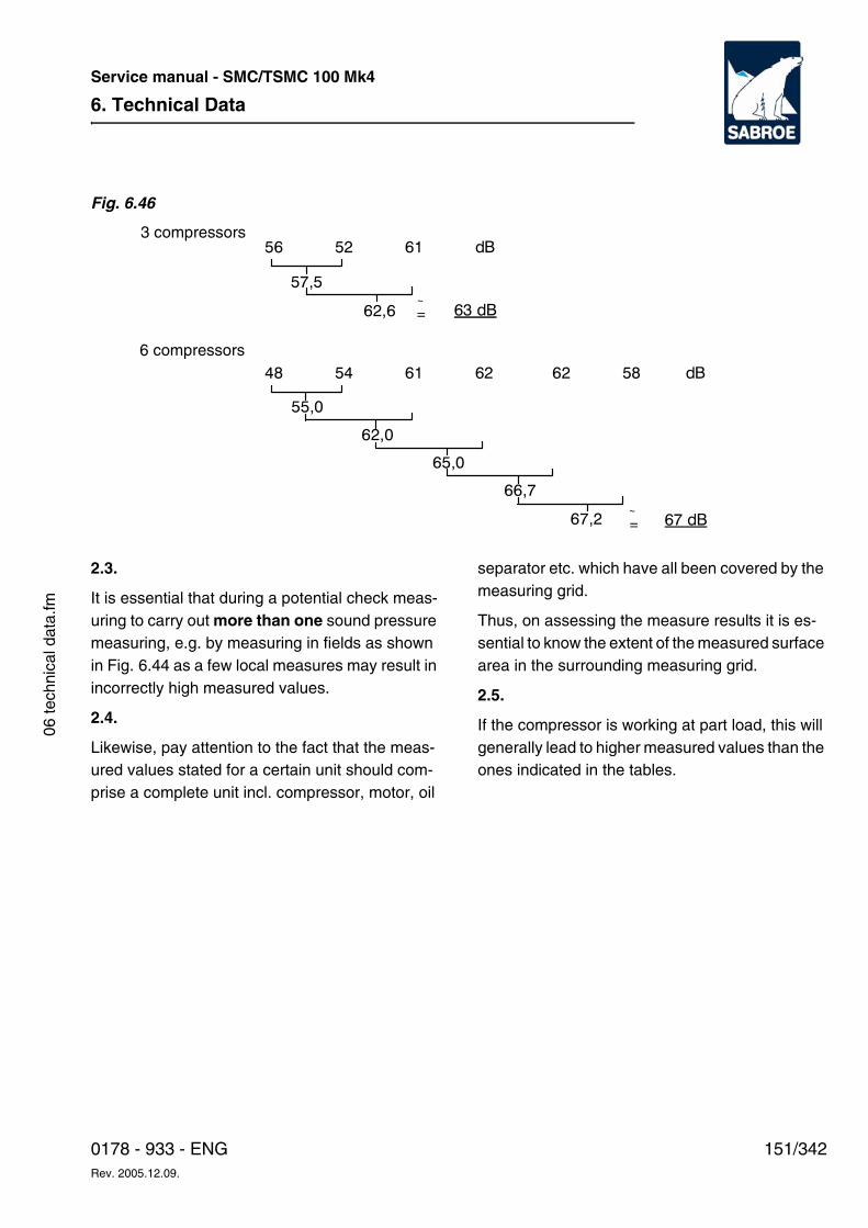
6. Technical Data
151/3420178 - 933 - ENGRev. 2005.12.09.
Service manual - SMC/TSMC 100 Mk4
06 te
chni
cal d
ata.
fm
Fig. 6.46
2.3.
It is essential that during a potential check meas-uring to carry out more than one sound pressure measuring, e.g. by measuring in fields as shown in Fig. 6.44 as a few local measures may result in incorrectly high measured values.
2.4.
Likewise, pay attention to the fact that the meas-ured values stated for a certain unit should com-prise a complete unit incl. compressor, motor, oil
separator etc. which have all been covered by the measuring grid.
Thus, on assessing the measure results it is es-sential to know the extent of the measured surface area in the surrounding measuring grid.
2.5.
If the compressor is working at part load, this will generally lead to higher measured values than the ones indicated in the tables.
56 52 61 dB
62,6
48 54 61 62
63 dB
62 58 dB
67,2 67 dB
55,0
57,5
62,0
65,0
66,7
6 compressors
=~
~=
3 compressors
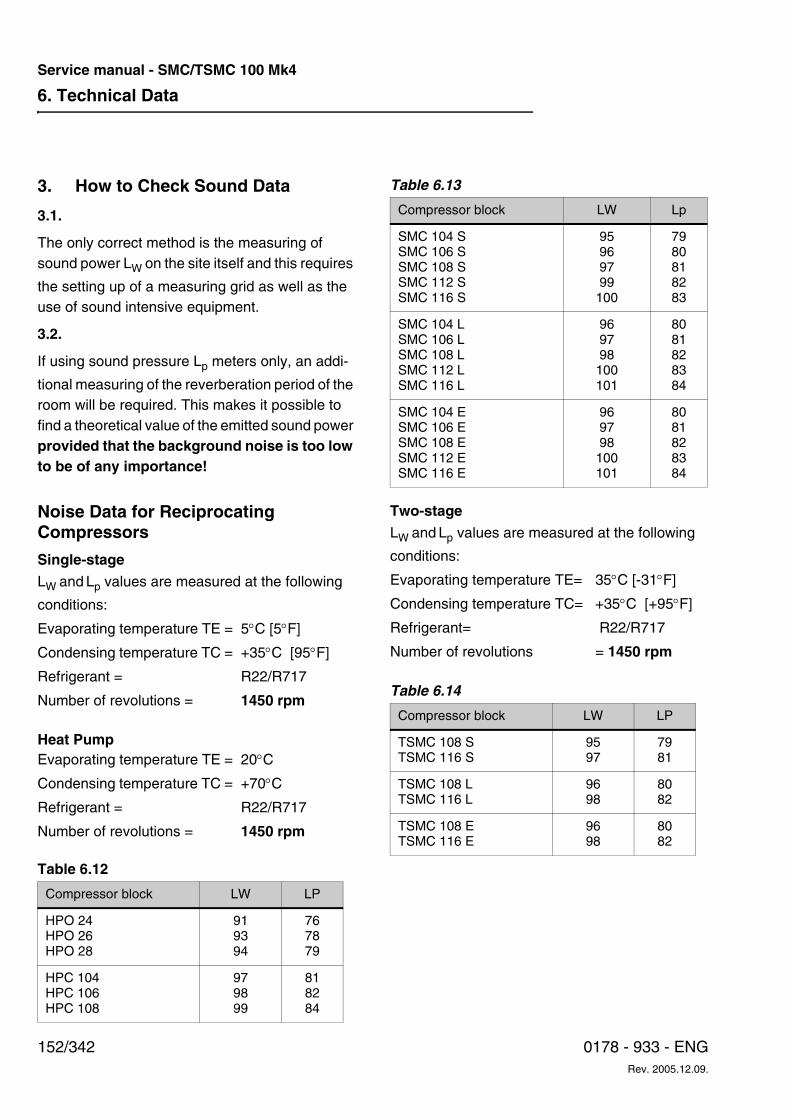
6. Technical Data
152/342 0178 - 933 - ENGRev. 2005.12.09.
Service manual - SMC/TSMC 100 Mk4
3. How to Check Sound Data
3.1.
The only correct method is the measuring of sound power LW on the site itself and this requires
the setting up of a measuring grid as well as the use of sound intensive equipment.
3.2.
If using sound pressure Lp meters only, an addi-
tional measuring of the reverberation period of the room will be required. This makes it possible to find a theoretical value of the emitted sound power provided that the background noise is too low to be of any importance!
Noise Data for Reciprocating Compressors
Single-stage
LW and Lp values are measured at the following
conditions:
Heat Pump
Table 6.12
Table 6.13
Two-stage
LW and Lp values are measured at the following
conditions:
Table 6.14
Evaporating temperature TE = 5°C [5°F]
Condensing temperature TC = +35°C [95°F]
Refrigerant = R22/R717
Number of revolutions = 1450 rpm
Evaporating temperature TE = 20°C
Condensing temperature TC = +70°C
Refrigerant = R22/R717
Number of revolutions = 1450 rpm
Compressor block LW LP
HPO 24HPO 26HPO 28
919394
767879
HPC 104HPC 106HPC 108
979899
818284
Compressor block LW Lp
SMC 104 SSMC 106 SSMC 108 SSMC 112 SSMC 116 S
95969799100
7980818283
SMC 104 LSMC 106 LSMC 108 LSMC 112 LSMC 116 L
969798100101
8081828384
SMC 104 ESMC 106 ESMC 108 ESMC 112 ESMC 116 E
969798100101
8081828384
Evaporating temperature TE= 35°C [-31°F]
Condensing temperature TC= +35°C [+95°F]
Refrigerant= R22/R717
Number of revolutions = 1450 rpm
Compressor block LW LP
TSMC 108 S TSMC 116 S
9597
7981
TSMC 108 LTSMC 116 L
9698
8082
TSMC 108 ETSMC 116 E
9698
8082
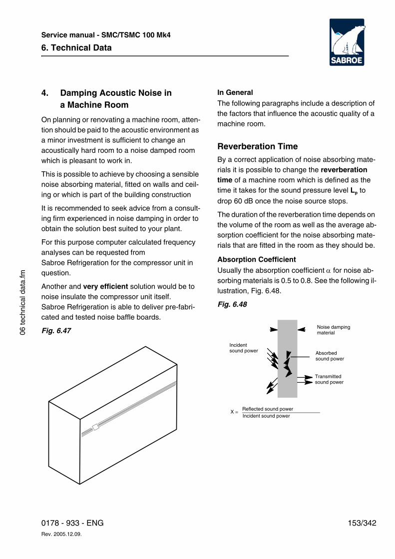
6. Technical Data
153/3420178 - 933 - ENGRev. 2005.12.09.
Service manual - SMC/TSMC 100 Mk4
06 te
chni
cal d
ata.
fm
4. Damping Acoustic Noise in a Machine Room
On planning or renovating a machine room, atten-tion should be paid to the acoustic environment as a minor investment is sufficient to change an acoustically hard room to a noise damped room which is pleasant to work in.
This is possible to achieve by choosing a sensible noise absorbing material, fitted on walls and ceil-ing or which is part of the building construction
It is recommended to seek advice from a consult-ing firm experienced in noise damping in order to obtain the solution best suited to your plant.
For this purpose computer calculated frequency analyses can be requested from Sabroe Refrigeration for the compressor unit in question.
Another and very efficient solution would be to noise insulate the compressor unit itself. Sabroe Refrigeration is able to deliver pre-fabri-cated and tested noise baffle boards.
Fig. 6.47
In GeneralThe following paragraphs include a description of the factors that influence the acoustic quality of a machine room.
Reverberation TimeBy a correct application of noise absorbing mate-rials it is possible to change the reverberation time of a machine room which is defined as the time it takes for the sound pressure level Lp to
drop 60 dB once the noise source stops.
The duration of the reverberation time depends on the volume of the room as well as the average ab-sorption coefficient for the noise absorbing mate-rials that are fitted in the room as they should be.
Absorption CoefficientUsually the absorption coefficient α for noise ab-sorbing materials is 0.5 to 0.8. See the following il-lustration, Fig. 6.48.
Fig. 6.48
Incidentsound power
X =
Transmitted sound power
Noise damping material
Absorbedsound power
Reflected sound powerIncident sound power
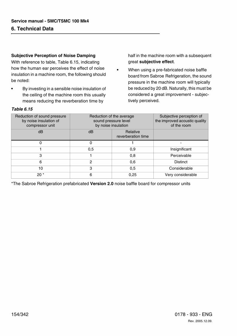
6. Technical Data
154/342 0178 - 933 - ENGRev. 2005.12.09.
Service manual - SMC/TSMC 100 Mk4
Subjective Perception of Noise DampingWith reference to table, Table 6.15, indicating how the human ear perceives the effect of noise insulation in a machine room, the following should be noted:
• By investing in a sensible noise insulation of the ceiling of the machine room this usually means reducing the reverberation time by
half in the machine room with a subsequent great subjective effect.
• When using a pre-fabricated noise baffle board from Sabroe Refrigeration, the sound pressure in the machine room will typically be reduced by 20 dB. Naturally, this must be considered a great improvement - subjec-tively perceived.
*The Sabroe Refrigeration prefabricated Version 2.0 noise baffle board for compressor units
Table 6.15
Reduction of sound pressure by noise insulation of
compressor unit
Reduction of the average sound pressure level by noise insulation
Subjective perception of the improved acoustic quality
of the room
dB dB Relative reverberation time
0 0 1 -
1 0,5 0,9 Insignificant
3 1 0,8 Perceivable
6 2 0,6 Distinct
10 3 0,5 Considerable
20 * 6 0,25 Very considerable
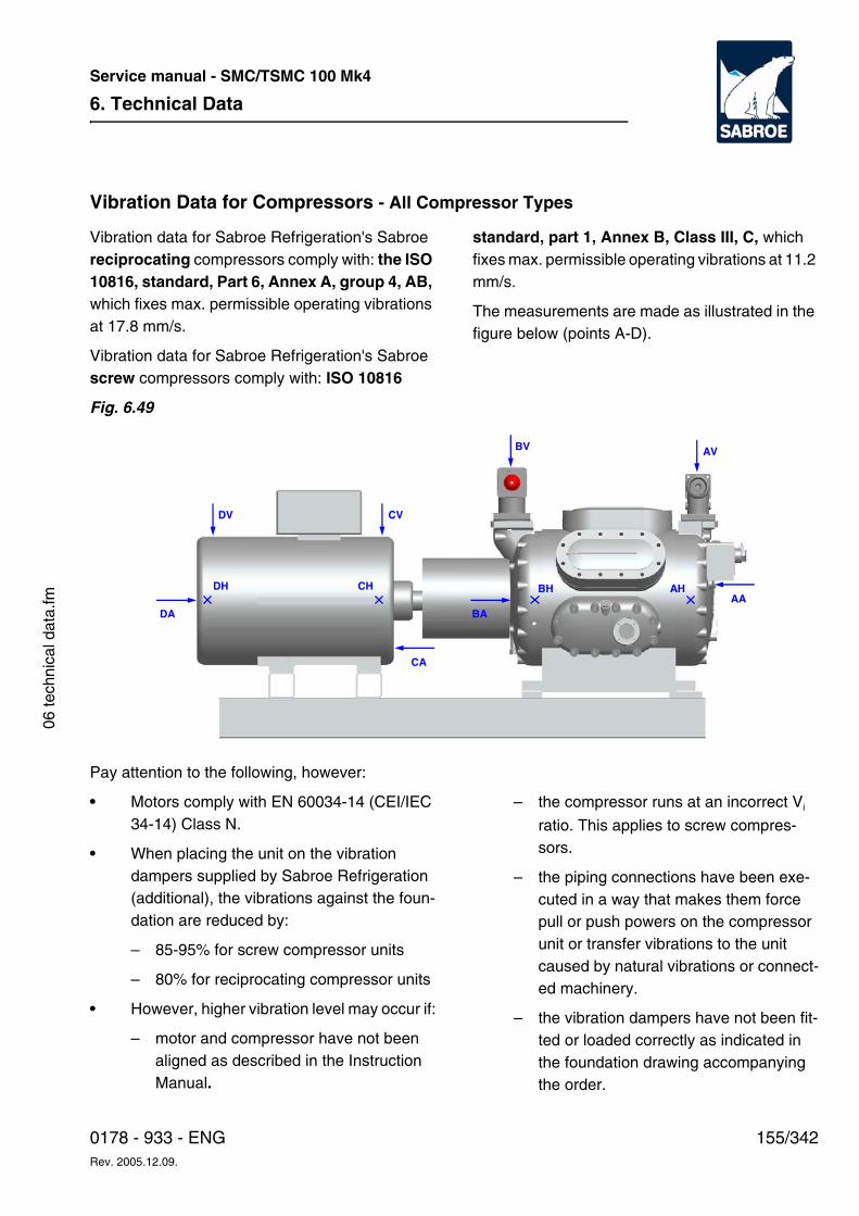
6. Technical Data
155/3420178 - 933 - ENGRev. 2005.12.09.
Service manual - SMC/TSMC 100 Mk4
06 te
chni
cal d
ata.
fm
Vibration Data for Compressors - All Compressor Types
Vibration data for Sabroe Refrigeration's Sabroe reciprocating compressors comply with: the ISO 10816, standard, Part 6, Annex A, group 4, AB, which fixes max. permissible operating vibrations at 17.8 mm/s.
Vibration data for Sabroe Refrigeration's Sabroe screw compressors comply with: ISO 10816
standard, part 1, Annex B, Class III, C, which fixes max. permissible operating vibrations at 11.2 mm/s.
The measurements are made as illustrated in the figure below (points A-D).
Fig. 6.49
Pay attention to the following, however:
• Motors comply with EN 60034-14 (CEI/IEC 34-14) Class N.
• When placing the unit on the vibration dampers supplied by Sabroe Refrigeration (additional), the vibrations against the foun-dation are reduced by:
– 85-95% for screw compressor units
– 80% for reciprocating compressor units
• However, higher vibration level may occur if:
– motor and compressor have not been aligned as described in the Instruction Manual.
– the compressor runs at an incorrect Vi
ratio. This applies to screw compres-sors.
– the piping connections have been exe-cuted in a way that makes them force pull or push powers on the compressor unit or transfer vibrations to the unit caused by natural vibrations or connect-ed machinery.
– the vibration dampers have not been fit-ted or loaded correctly as indicated in the foundation drawing accompanying the order.
AA
AV
AH
BA
BV
BH
CA
CV
CH
DA
DV
DH
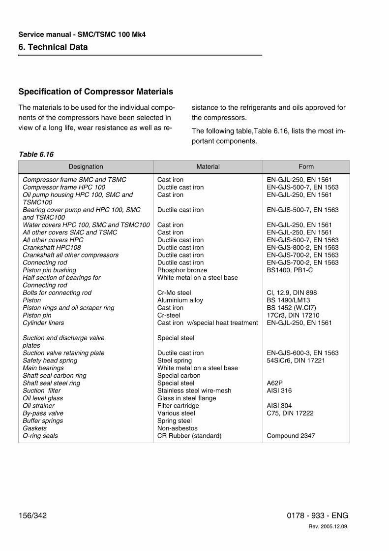
6. Technical Data
156/342 0178 - 933 - ENGRev. 2005.12.09.
Service manual - SMC/TSMC 100 Mk4
Specification of Compressor Materials
The materials to be used for the individual compo-nents of the compressors have been selected in view of a long life, wear resistance as well as re-
sistance to the refrigerants and oils approved for the compressors.
The following table,Table 6.16, lists the most im-portant components.
Table 6.16
Designation Material Form
Compressor frame SMC and TSMC Compressor frame HPC 100Oil pump housing HPC 100, SMC and TSMC100Bearing cover pump end HPC 100, SMC and TSMC100Water covers HPC 100, SMC and TSMC100All other covers SMC and TSMC All other covers HPCCrankshaft HPC108Crankshaft all other compressorsConnecting rodPiston pin bushingHalf section of bearings for Connecting rodBolts for connecting rodPistonPiston rings and oil scraper ringPiston pinCylinder liners
Suction and discharge valve platesSuction valve retaining plateSafety head springMain bearingsShaft seal carbon ringShaft seal steel ringSuction filterOil level glassOil strainerBy-pass valveBuffer springsGasketsO-ring seals
Cast ironDuctile cast ironCast iron
Ductile cast iron
Cast ironCast ironDuctile cast ironDuctile cast ironDuctile cast ironDuctile cast ironPhosphor bronzeWhite metal on a steel base
Cr-Mo steelAluminium alloyCast ironCr-steelCast iron w/special heat treatment
Special steel
Ductile cast ironSteel springWhite metal on a steel baseSpecial carbonSpecial steelStainless steel wire-meshGlass in steel flangeFilter cartridgeVarious steelSpring steelNon-asbestosCR Rubber (standard)
EN-GJL-250, EN 1561EN-GJS-500-7, EN 1563EN-GJL-250, EN 1561
EN-GJS-500-7, EN 1563
EN-GJL-250, EN 1561EN-GJL-250, EN 1561EN-GJS-500-7, EN 1563EN-GJS-800-2, EN 1563EN-GJS-700-2, EN 1563EN-GJS-700-2, EN 1563BS1400, PB1-C
Cl, 12.9, DIN 898BS 1490/LM13BS 1452 (W.CI7)17Cr3, DIN 17210EN-GJL-250, EN 1561
EN-GJS-600-3, EN 156354SiCr6, DIN 17221
A62PAISI 316
AISI 304C75, DIN 17222
Compound 2347
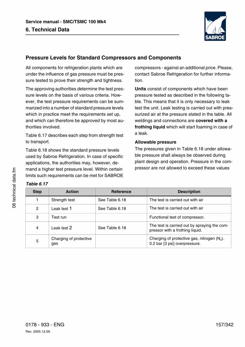
6. Technical Data
157/3420178 - 933 - ENGRev. 2005.12.09.
Service manual - SMC/TSMC 100 Mk4
06 te
chni
cal d
ata.
fm
Pressure Levels for Standard Compressors and Components
All components for refrigeration plants which are under the influence of gas pressure must be pres-sure tested to prove their strength and tightness.
The approving authorities determine the test pres-sure levels on the basis of various criteria. How-ever, the test pressure requirements can be sum-marized into a number of standard pressure levels which in practice meet the requirements set up, and which can therefore be approved by most au-thorities involved.
Table 6.17 describes each step from strength test to transport.
Table 6.18 shows the standard pressure levels used by Sabroe Refrigeration. In case of specific applications, the authorities may, however, de-mand a higher test pressure level. Within certain limits such requirements can be met for SABROE
compressors - against an additional price. Please, contact Sabroe Refrigeration for further informa-tion.
Units consist of components which have been pressure tested as described in the following ta-ble. This means that it is only necessary to leak test the unit. Leak testing is carried out with pres-surized air at the pressure stated in the table. All weldings and connections are covered with a frothing liquid which will start foaming in case of a leak.
Allowable pressureThe pressures given in Table 6.18 under allowa-ble pressure shall always be observed during plant design and operation. Pressure in the com-pressor are not allowed to exceed these values
Table 6.17
Step Action Reference Description
1 Strength test See Table 6.18 The test is carried out with air
2 Leak test 1 See Table 6.18 The test is carried out with air
3 Test run Functional test of compressor.
4 Leak test 2 See Table 6.18The test is carried out by spraying the com-pressor with a frothing liquid.
5Charging of protective gas
Charging of protective gas, nitrogen (N2). 0.2 bar [3 psi] overpressure.
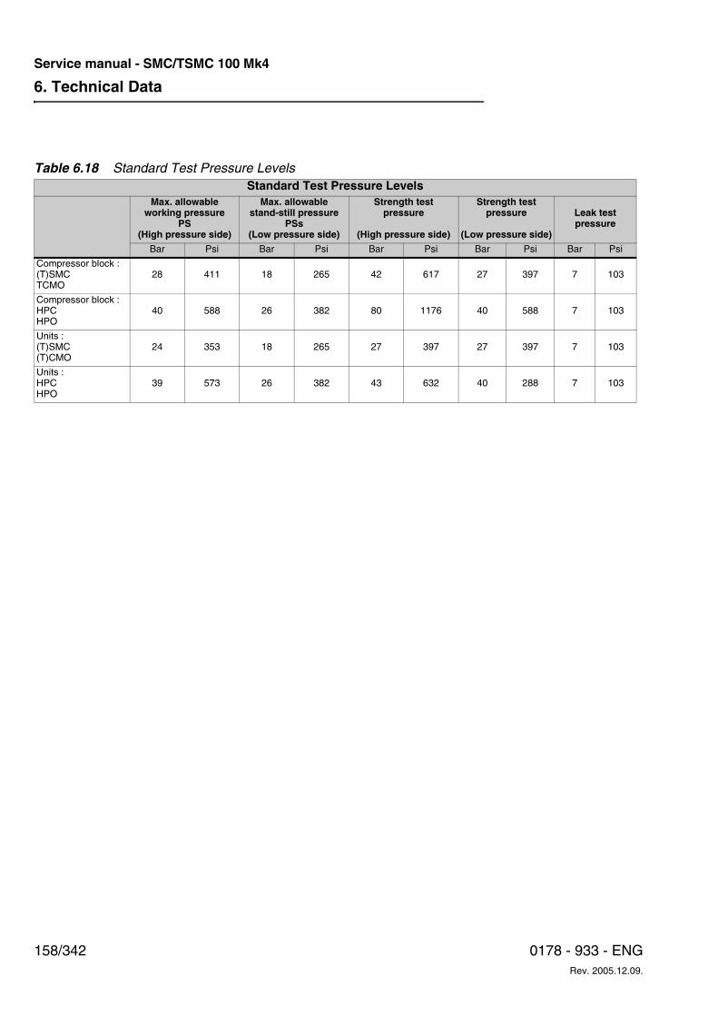
6. Technical Data
158/342 0178 - 933 - ENGRev. 2005.12.09.
Service manual - SMC/TSMC 100 Mk4
Table 6.18 Standard Test Pressure LevelsStandard Test Pressure Levels
Max. allowableworking pressure
PS(High pressure side)
Max. allowablestand-still pressure
PSs(Low pressure side)
Strength testpressure
(High pressure side)
Strength testpressure
(Low pressure side)
Leak testpressure
Bar Psi Bar Psi Bar Psi Bar Psi Bar Psi
Compressor block :(T)SMCTCMO
28 411 18 265 42 617 27 397 7 103
Compressor block :HPCHPO
40 588 26 382 80 1176 40 588 7 103
Units :(T)SMC(T)CMO
24 353 18 265 27 397 27 397 7 103
Units :HPCHPO
39 573 26 382 43 632 40 288 7 103
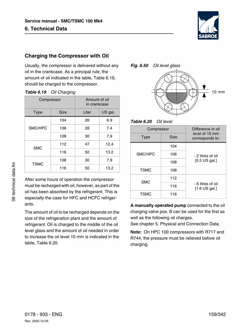
6. Technical Data
159/3420178 - 933 - ENGRev. 2005.12.09.
Service manual - SMC/TSMC 100 Mk4
06 te
chni
cal d
ata.
fm
Charging the Compressor with Oil
Usually, the compressor is delivered without any oil in the crankcase. As a principal rule, the amount of oil indicated in the table, Table 6.19, should be charged to the compressor.
Table 6.19 Oil Charging
After some hours of operation the compressor must be recharged with oil, however, as part of the oil has been absorbed by the refrigerant. This is especially the case for HFC and HCFC refriger-ants.
The amount of oil to be recharged depends on the size of the refrigeration plant and the amount of refrigerant. Oil is charged to the middle of the oil level glass and the amount of oil needed in order to increase the oil level 10 mm is indicated in the table, Table 6.20.
Fig. 6.50 Oil level glass
Table 6.20 Oil level
A manually operated pump connected to the oil charging valve pos. B can be used for the first as well as the following oil charges. See chapter 5, Physical and Connection Data.
Note: On HPC 100 compressors with R717 and R744, the pressure must be relieved before oil charging.
Compressor Amount of oil in crankcase
Type Size Liter US gal.
SMC/HPC
104 26 6.9
106 28 7.4
108 30 7.9
SMC112 47 12.4
116 50 13.2
TSMC108 30 7.9
116 50 13.2
Compressor Difference in oil level of 10 mm corresponds to:Type Size
SMC/HPC
104
- 2 litres of oil[0.5 US gal.]
106
108
TSMC 108
SMC112
- 6 litres of oil[1.6 US gal.]
116
TSMC 116
T0177162_0
10 mm
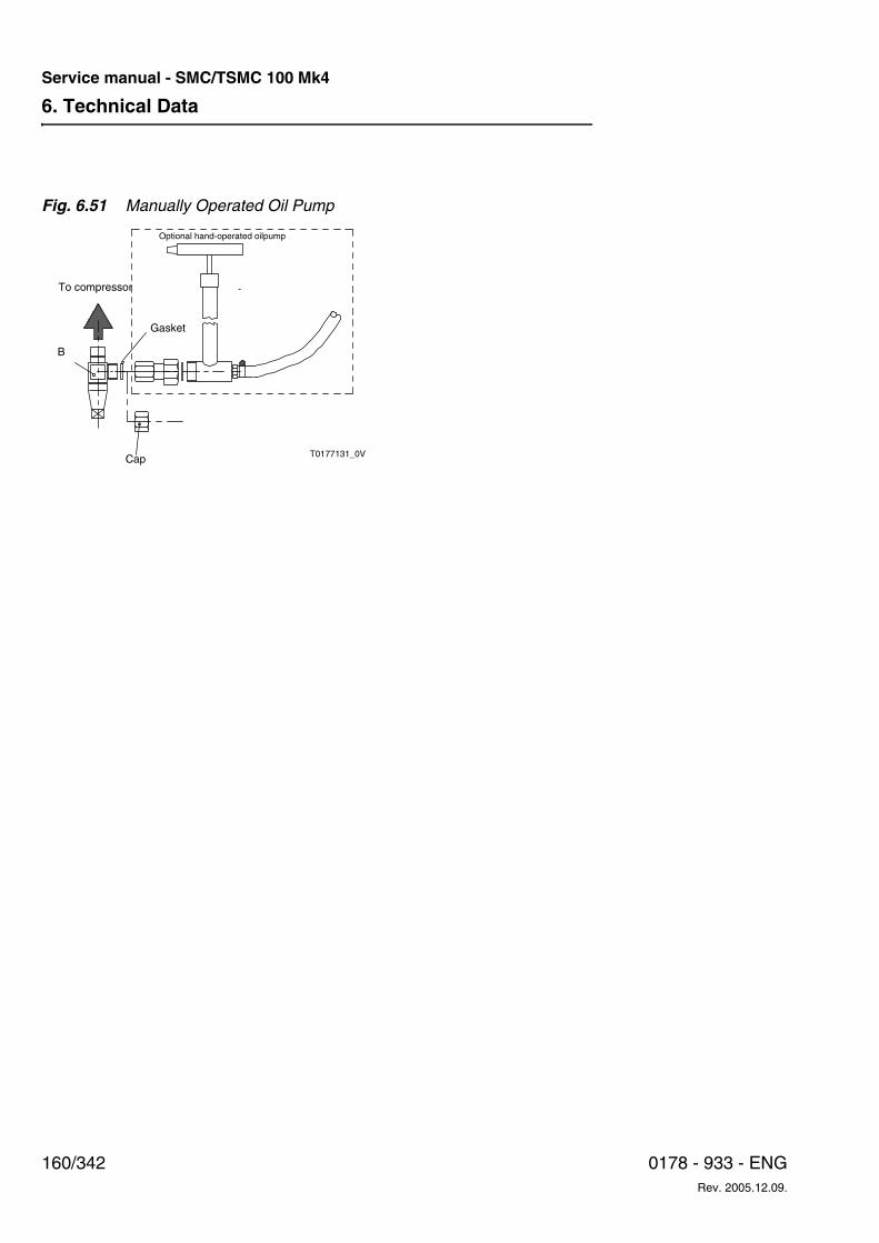
6. Technical Data
160/342 0178 - 933 - ENGRev. 2005.12.09.
Service manual - SMC/TSMC 100 Mk4
Fig. 6.51 Manually Operated Oil Pump
-
B
To compressor
Gasket
Optional hand-operated oilpump
Cap T0177131_0V
6. Technical Data
161/3420178 - 933 - ENGRev. 2005.12.09.
Service manual - SMC/TSMC 100 Mk4
06 te
chni
cal d
ata.
fm
Oil Consumption
In refrigeration compressors there will always be a minor oil consumption, which means that a little oil is bound to follow the warm discharge gas out of the compressor.
In order to separate this oil, an oil separator is nor-mally used. The separator is built into the dis-charge pipe, right next to the compressor. The separated oil is returned to the compressor as de-scribed in chapter 4, Technical Description - Oil Separator.
A minor part of the oil, however, present in the dis-charge gas as vapour, cannot be separated and
will consequently continue into the plant, in which it is condensed in the condenser.
In R744, HFC and HCFC as well as in compact R717 refrigeration plants this oil will return to the compressor together with the suction gas.
In return, the oil in larger and ramified R717 refrig-eration plants should be drained off and never re-used in the compressor. This amount of oil repre-sents the so-called oil consumption measured in ppm (parts per million) and is calculated by using the following formula:
The normal oil consumption is between 20 and 30 ppm for an SMC/HPC 100 compressor.
Selecting Oil SeparatorAs the velocity through the oil separator affects the ability of the oil separator to separate the oil from the discharge gas, an oil separator size has been designed for each compressor.
The maximum oil consumption for this oil separa-tor is 35 ppm. Depending on the choice of lubricat-ing oil, the oil consumption is normally much low-er.
Oil consumption kg/h = Circulated amount of refrigerant Q (kg/h) x Oil consumption (ppm)
106
6. Technical Data
162/342 0178 - 933 - ENGRev. 2005.12.09.
Service manual - SMC/TSMC 100 Mk4
Selecting Lubricating Oil for SABROE Reciprocating Compressors
Refrigerant: R717
In a period from 1990 to 1995 Sabroe Refrigeration experienced a rising number of problems with the use of mineral oils, especially in R717 plants. The problems can be divided into two groups:
c. The oil changes viscosity within a few operat-ing hours.
d. The oil dissolves (becomes very black).
The problems have been observed in connection with several different types of mineral oil and often occur within only a few operating hours. The con-sequences have been severe for both compres-sors and plants.
On the basis of the thorough investigation subse-quently carried out by Sabroe Refrigeration, it was decided to introduce a series of synthetic oils complying with the requirements of modern refrig-eration plants.
Mineral oils can, however, still be used in refriger-ation plants, provided the lubricating quality is carefully monitored. For modern high-capacity re-frigeration plants where a long service life for both lubricant and moving parts is expected, Sabroe Refrigeration recommends the use of syn-thetic oils.
Areas of application and specifications for the syn-thetic oils mentioned are described in the follow-ing pages. Supervisors and/or users of plants are at liberty to choose between Sabroe Refrigeration's own oil brands and alter-native oil brands, provided they comply with the specifications required.
General
This recommendation will only deal with the lubri-cation of the compressor. The performance of the
lubricant in the plant (receiver, evaporator, etc.) must, however, also be considered.
Lubricating oils with relatively high viscosity must be used to ensure a satisfactory lubrication of re-frigeration compressors.
To achieve the best lubrication, the oil must:
• possess the correct viscosity under all operating conditions.
• possess acceptable viscosity at start-up.
• possess sufficient oxidation stability (the oil must be free of moisture when charged to the system).
• possess sufficient chemical stability when used together with R717.
Moreover, the extent to which different refriger-ants dissolve in the oil must be determined so that the oil return system, etc. can be designed to per-form at its optimum.
Stratification
Note that the oil in some plants is layered in refrig-erant receivers and evaporators under certain op-erating conditions and at certain oil concentra-tions.
Plants with Several Different Compressor Types/Makes
In plants where several different compressor types/makes are connected, it is strongly recom-mended to use the same type of oil in all the com-pressors. This is very important where automatic oil return systems are used.
If you consider changing the type of oil, please read the section Oil Changing on SABROE Com-pressors carefully.
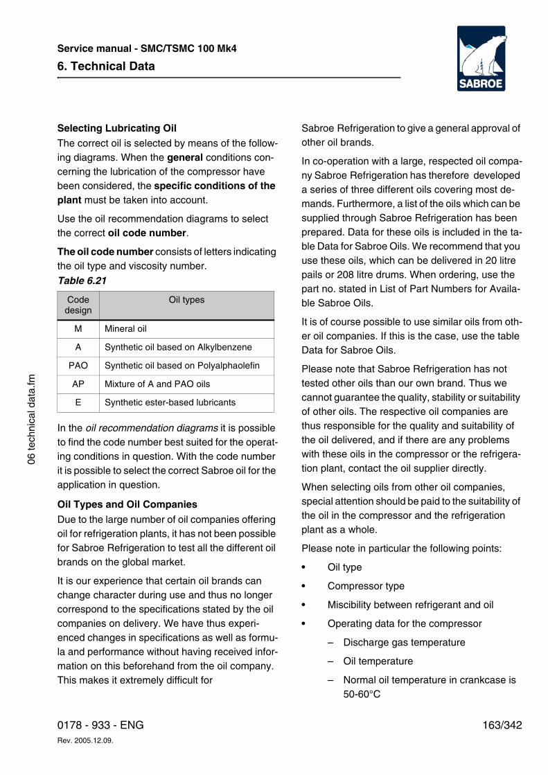
6. Technical Data
163/3420178 - 933 - ENGRev. 2005.12.09.
Service manual - SMC/TSMC 100 Mk4
06 te
chni
cal d
ata.
fm
Selecting Lubricating OilThe correct oil is selected by means of the follow-ing diagrams. When the general conditions con-cerning the lubrication of the compressor have been considered, the specific conditions of the plant must be taken into account.
Use the oil recommendation diagrams to select the correct oil code number.
The oil code number consists of letters indicating the oil type and viscosity number.
In the oil recommendation diagrams it is possible to find the code number best suited for the operat-ing conditions in question. With the code number it is possible to select the correct Sabroe oil for the application in question.
Oil Types and Oil Companies
Due to the large number of oil companies offering oil for refrigeration plants, it has not been possible for Sabroe Refrigeration to test all the different oil brands on the global market.
It is our experience that certain oil brands can change character during use and thus no longer correspond to the specifications stated by the oil companies on delivery. We have thus experi-enced changes in specifications as well as formu-la and performance without having received infor-mation on this beforehand from the oil company. This makes it extremely difficult for
Sabroe Refrigeration to give a general approval of other oil brands.
In co-operation with a large, respected oil compa-ny Sabroe Refrigeration has therefore developed a series of three different oils covering most de-mands. Furthermore, a list of the oils which can be supplied through Sabroe Refrigeration has been prepared. Data for these oils is included in the ta-ble Data for Sabroe Oils. We recommend that you use these oils, which can be delivered in 20 litre pails or 208 litre drums. When ordering, use the part no. stated in List of Part Numbers for Availa-ble Sabroe Oils.
It is of course possible to use similar oils from oth-er oil companies. If this is the case, use the table Data for Sabroe Oils.
Please note that Sabroe Refrigeration has not tested other oils than our own brand. Thus we cannot guarantee the quality, stability or suitability of other oils. The respective oil companies are thus responsible for the quality and suitability of the oil delivered, and if there are any problems with these oils in the compressor or the refrigera-tion plant, contact the oil supplier directly.
When selecting oils from other oil companies, special attention should be paid to the suitability of the oil in the compressor and the refrigeration plant as a whole.
Please note in particular the following points:
• Oil type
• Compressor type
• Miscibility between refrigerant and oil
• Operating data for the compressor
– Discharge gas temperature
– Oil temperature
– Normal oil temperature in crankcase is 50-60°C
Table 6.21
Code design
Oil types
M Mineral oil
A Synthetic oil based on Alkylbenzene
PAO Synthetic oil based on Polyalphaolefin
AP Mixture of A and PAO oils
E Synthetic ester-based lubricants
6. Technical Data
164/342 0178 - 933 - ENGRev. 2005.12.09.
Service manual - SMC/TSMC 100 Mk4
– Max. permitted oil temperature = set point for alarm
– Min. permitted oil temperature = set point for alarm - if there is any
• The viscosity of the oil in the compressor during operation:
– Type of refrigerant and solubility of re-frigerant in the oil
– Operating temperatures
– Vapour pressure in the oil reservoir
– Suction pressure and oil temperature in the crankcase
– Compatibility with neoprene O-rings: The aniline point indicates how the O-ring material reacts to the oil.
– At an aniline point less than approx. 100°C the material has a tendency to swell, and at an aniline point higher than approx. 120°C it has a tendency to shrink
– Thus it cannot be recommended to change the oil type from M to PAO with-out changing the O-rings at the same time as a leak may otherwise easily oc-cur in the compressor or the plant. Sabroe Refrigeration recommends therefore the use of the Sabroe AP68 oil since this type of oil in this case reduces considerably the risk of leaks. Sabroe Refrigeration can supply a list of operat-ing data on request.
• Please note the viscosity limits during oper-ation:
• Optimum viscosity limits = 20 to 50 cSt
• Max. permitted viscosity = 100 cSt
• Min. permitted viscosity = 10 cSt
• Max. permitted viscosity during start-up of the compressor = 500 cSt
• Max. refrigerant concentration in the oil during operation: 25% - also in case the viscosity requirements have been met.
Use of Mineral OilAs described in the introduction, mineral oil in par-ticular causes serious problems especially in R717 plants.
When using mineral oil, it is important to monitor the plant closely. The condition/colour of the oil must therefore be checked on a weekly basis and for each 1,000 to 2,000 operating hours oil sam-ples must be taken for further analysis.
Sabroe Refrigeration recommends therefore only to use M oil under moderate operating conditions - see the following oil recommen-dation diagrams.
Sabroe Refrigeration is aware that several cus-tomers have used mineral oils for many years without any problems. The customers who wish to continue using mineral oil in existing as well as new compressors can do so, provided that the compressor type and the operating conditions are similar to the existing ones.
Sabroe Refrigeration has thus decided to market one brand of mineral oil which has been tested and found suitable for most of the general refriger-ation purposes.
In case another brand of mineral oil is used, follow the specifications on the data pages in this recom-mendation as a guideline.
Mineral oil can be used in refrigeration plants, pro-vided the lubricating quality is carefully monitored. Sabroe Refrigeration recommends, however, that you use synthetic oils for modern high-capacity
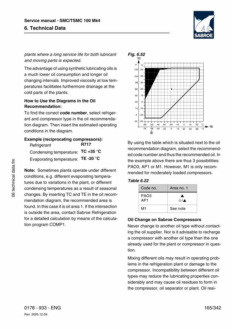
6. Technical Data
165/3420178 - 933 - ENGRev. 2005.12.09.
Service manual - SMC/TSMC 100 Mk4
06 te
chni
cal d
ata.
fm
plants where a long service life for both lubricant and moving parts is expected.
The advantage of using synthetic lubricating oils is a much lower oil consumption and longer oil changing intervals. Improved viscosity at low tem-peratures facilitates furthermore drainage at the cold parts of the plants.
How to Use the Diagrams in the Oil Recommendation:To find the correct code number, select refriger-ant and compressor type in the oil recommenda-tion diagram. Then insert the estimated operating conditions in the diagram.
Example (reciprocating compressors):
Note: Sometimes plants operate under different conditions, e.g. different evaporating tempera-tures due to variations in the plant, or different condensing temperatures as a result of seasonal changes. By inserting TC and TE in the oil recom-mendation diagram, the recommended area is found. In this case it is oil area 1. If the intersection is outside the area, contact Sabroe Refrigeration for a detailed calculation by means of the calcula-tion program COMP1.
Fig. 6.52
By using the table which is situated next to the oil recommendation diagram, select the recommend-ed code number and thus the recommended oil. In the example above there are thus 3 possibilities: PAO3, AP1 or M1. However, M1 is only recom-mended for moderately loaded compressors.
Table 6.22
Oil Change on Sabroe CompressorsNever change to another oil type without contact-ing the oil supplier. Nor is it advisable to recharge a compressor with another oil type than the one already used for the plant or compressor in ques-tion.
Mixing different oils may result in operating prob-lems in the refrigeration plant or damage to the compressor. Incompatibility between different oil types may reduce the lubricating properties con-siderably and may cause oil residues to form in the compressor, oil separator or plant. Oil resi-
Refrigerant R717
Condensing temperature: TC +35 °C
Evaporating temperature: TE -20 °C
Code no. Area no. 1
PAO3AP1
▲
✩/▲
M1 See note
-60 -50 -40 -30
-30
-20
-10
0
10
-20 -10 0 10 20
20
30
40
50
C�
C�
1
F
122
104
86
68
50
32
14
-4
-22
�
TC
F�68503214-4-22-40-58-76TE
C
6. Technical Data
166/342 0178 - 933 - ENGRev. 2005.12.09.
Service manual - SMC/TSMC 100 Mk4
dues may block filters and damage the moving parts of the compressor.
Changing the oil type or brand should only be done following a thorough procedure involving drainage and evacuation of the refrigeration plant. Information on a suitable procedure can be ob-tained from Sabroe Refrigeration as well as a number of oil companies.
It is extremely important that the new unused oil is taken directly from its original container and that both the brand and the type correspond to the specifications of the plant.
Make sure that the original oil container is sealed properly during storage so that moisture from the air is not absorbed by the oil. Many oils, particular-ly polyolester oils, are extremely hygroscopic. It is therefore recommended only to buy the oil in con-tainers whose size correspond to the amount to be used.
In case all of the oil is not used, make sure that the rest of the oil is sealed in the original container and stored in a warm, dry place. It is recommend-ed to charge nitrogen to keep the water content below 50 ppm.
Ideally, oil containers should be equipped with a barrel tap to ensure an effective, airtight seal.
6. Technical Data
167/3420178 - 933 - ENGRev. 2005.12.09.
Service manual - SMC/TSMC 100 Mk4
06 te
chni
cal d
ata.
fm
Oil Changing IntervalsA list of the recommended oil changing intervals is included in the instruction manuals of the com-pressors. This list is for guidance only. The actual oil changing intervals are often determined by a number of operating parameters in the plant.
It is strongly recommended to monitor the quality of the oil by performing oil analyses on a regular basis. This will also give an indication of the con-dition of the plant. This service can be supplied by
Sabroe Refrigeration or the oil supplier.
Oil recommendation diagram symbols:
▲ In case of a new plant. Very suitable.
✩ In case you wish to change from mineral oil
a Max oil concentration in liquid phase at: TE: 2% W
b Max oil concentration in liquid phase: contact Sabroe Refrigeration
c Min. suction temperature -50°C. At TE< -50°C superheating must be introduced.
*Dry expansion systems only. Flooded systems to be considered individually: contact Sabroe Refrigeration
SH Suction gas superheat, K (Kelvin)
L Zone in which both oils are useable
M Calculation must be performed using COMP1
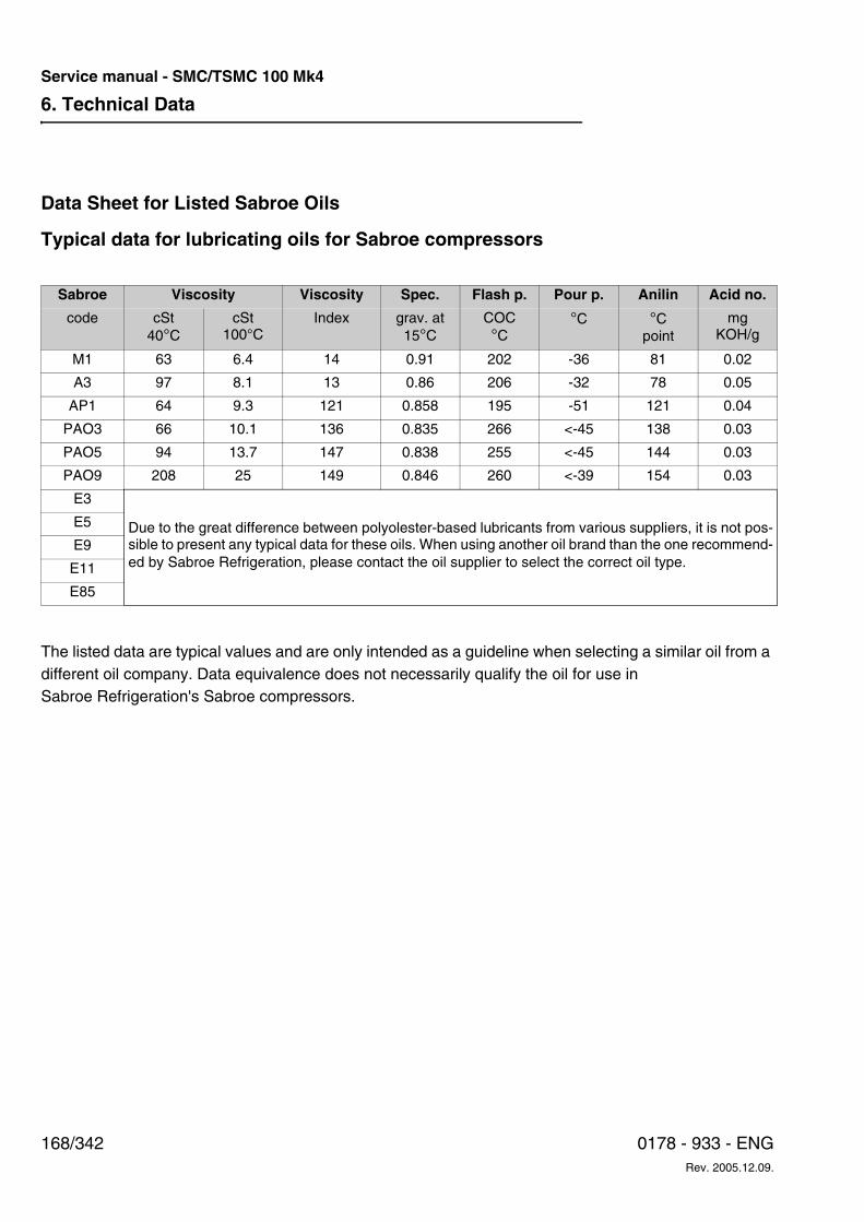
6. Technical Data
168/342 0178 - 933 - ENGRev. 2005.12.09.
Service manual - SMC/TSMC 100 Mk4
Data Sheet for Listed Sabroe Oils
Typical data for lubricating oils for Sabroe compressors
The listed data are typical values and are only intended as a guideline when selecting a similar oil from a different oil company. Data equivalence does not necessarily qualify the oil for use in Sabroe Refrigeration's Sabroe compressors.
Sabroe Viscosity Viscosity Spec. Flash p. Pour p. Anilin Acid no.
code cSt40°C
cSt100°C
Index grav. at15°C
COC°C
°C °Cpoint
mgKOH/g
M1 63 6.4 14 0.91 202 -36 81 0.02
A3 97 8.1 13 0.86 206 -32 78 0.05
AP1 64 9.3 121 0.858 195 -51 121 0.04
PAO3 66 10.1 136 0.835 266 <-45 138 0.03
PAO5 94 13.7 147 0.838 255 <-45 144 0.03
PAO9 208 25 149 0.846 260 <-39 154 0.03
E3
Due to the great difference between polyolester-based lubricants from various suppliers, it is not pos-sible to present any typical data for these oils. When using another oil brand than the one recommend-ed by Sabroe Refrigeration, please contact the oil supplier to select the correct oil type.
E5
E9
E11
E85
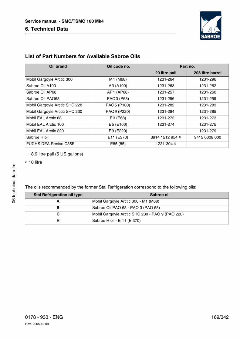
6. Technical Data
169/3420178 - 933 - ENGRev. 2005.12.09.
Service manual - SMC/TSMC 100 Mk4
06 te
chni
cal d
ata.
fm
List of Part Numbers for Available Sabroe Oils
1) 18.9 litre pail (5 US gallons)
2) 10 litre
The oils recommended by the former Stal Refrigeration correspond to the following oils:
Oil brand Oil code no. Part no.
20 litre pail 208 litre barrel
Mobil Gargoyle Arctic 300 M1 (M68) 1231-264 1231-296
Sabroe Oil A100 A3 (A100) 1231-263 1231-262
Sabroe Oil AP68 AP1 (AP68) 1231-257 1231-260
Sabroe Oil PAO68 PAO3 (P68) 1231-256 1231-259
Mobil Gargoyle Arctic SHC 228 PAO5 (P100) 1231-282 1231-283
Mobil Gargoyle Arctic SHC 230 PAO9 (P220) 1231-284 1231-285
Mobil EAL Arctic 68 E3 (E68) 1231-272 1231-273
Mobil EAL Arctic 100 E5 (E100) 1231-274 1231-275
Mobil EAL Arctic 220 E9 (E220) 1231-279
Sabroe H oil E11 (E370) 3914 1512 954 1) 9415 0008 000
FUCHS DEA Reniso C85E E85 (85) 1231-304 2)
Stal Refrigeration oil type Sabroe oil
A Mobil Gargoyle Arctic 300 - M1 (M68)
B Sabroe Oil PAO 68 - PAO 3 (PAO 68)
C Mobil Gargoyle Arctic SHC 230 - PAO 9 (PAO 220)
H Sabroe H oil - E 11 (E 370)
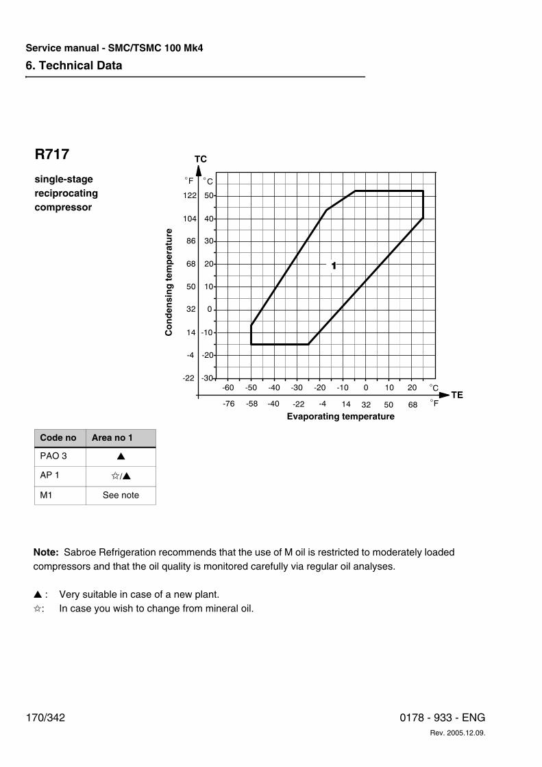
6. Technical Data
170/342 0178 - 933 - ENGRev. 2005.12.09.
Service manual - SMC/TSMC 100 Mk4
R717
single-stagereciprocatingcompressor
Note: Sabroe Refrigeration recommends that the use of M oil is restricted to moderately loaded compressors and that the oil quality is monitored carefully via regular oil analyses.
▲ : Very suitable in case of a new plant. ✩: In case you wish to change from mineral oil.
Evaporating temperature
Code no Area no 1
PAO 3 ▲
AP 1 ✩/▲
M1 See note
Co
nd
ensi
ng
tem
per
atu
re
-30
-20
-10
0
-60 -50 -40 -30 -20 -10 0 10 20
10
20
30
40
50
C�
C
1
F
122
104
86
68
50
32
14
-4
-22
� �
F�68503214-4-22-40-58-76TE
TC
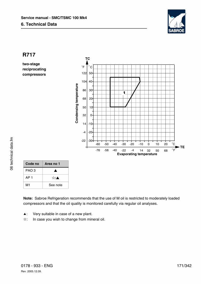
6. Technical Data
171/3420178 - 933 - ENGRev. 2005.12.09.
Service manual - SMC/TSMC 100 Mk4
06 te
chni
cal d
ata.
fm
R717
two-stagereciprocatingcompressors
-30
-20
-10
0
-60 -50 -40 -30 -20 -10 0 10 20
10
20
30
40
50
C�
C�
1
F
122
104
86
68
50
32
14
-4
-22
F�68503214-4-22-40-58-76TE
TC
�
Evaporating temperature
Code no Area no 1
PAO 3 ▲
AP 1 ✩/▲
M1 See note
Note: Sabroe Refrigeration recommends that the use of M oil is restricted to moderately loaded compressors and that the oil quality is monitored carefully via regular oil analyses.
j: Very suitable in case of a new plant.
✩: In case you wish to change from mineral oil.
Co
nd
ensi
ng
tem
per
atu
re
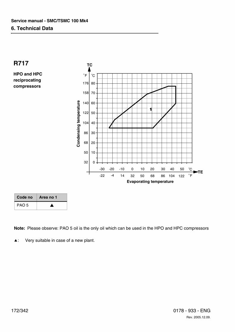
6. Technical Data
172/342 0178 - 933 - ENGRev. 2005.12.09.
Service manual - SMC/TSMC 100 Mk4
0
10
20
30
-30 -20 -10 0 10 20 30 40 50
40
50
60
70
80
C
C�
1
F
140
122
104
86
68
50
32
�
158
F�8668503214-4-22TE
104 122
�
176
TCR717
HPO and HPCreciprocatingcompressors
Note: Please observe: PAO 5 oil is the only oil which can be used in the HPO and HPC compressors
j: Very suitable in case of a new plant.
Code no Area no 1
PAO 5 ▲
Evaporating temperature
Co
nd
ensi
ng
tem
per
atu
re
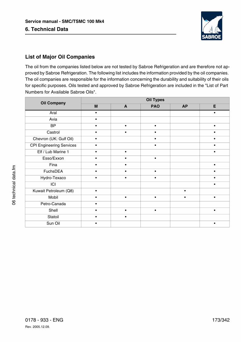
6. Technical Data
173/3420178 - 933 - ENGRev. 2005.12.09.
Service manual - SMC/TSMC 100 Mk4
06 te
chni
cal d
ata.
fm
List of Major Oil Companies
The oil from the companies listed below are not tested by Sabroe Refrigeration and are therefore not ap-proved by Sabroe Refrigeration. The following list includes the information provided by the oil companies. The oil companies are responsible for the information concerning the durability and suitability of their oils for specific purposes. Oils tested and approved by Sabroe Refrigeration are included in the "List of Part
Numbers for Available Sabroe Oils".
Oil CompanyOil Types
M A PAO AP E
Aral • •
Avia •
BP • • • •
Castrol • • • •
Chevron (UK: Gulf Oil) • • •
CPI Engineering Services • • •
Elf / Lub Marine 1 • • •
Esso/Exxon • • •
Fina • • •
FuchsDEA • • • •
Hydro-Texaco • • • •
ICI •
Kuwait Petroleum (Q8) • •
Mobil • • • • •
Petro-Canada •
Shell • • • •
Statoil • •
Sun Oil • •
6. Technical Data
174/342 0178 - 933 - ENGRev. 2005.12.09.
Service manual - SMC/TSMC 100 Mk4
Selecting Lubricating Oil for SABROE Reciprocating Compressors
Refrigerant: HFC/HCFC/R744
In a period from 1990 to 1995 Sabroe Refrigeration experienced a rising number of problems with the use of mineral oils, especially in R717 plants. The problems can be divided into two groups:
e. The oil changes viscosity within a few operat-ing hours.
f. The oil dissolves becomes very black).
The problems have been observed in connection with several different types of mineral oil and often occur within only a few operating hours. The con-sequences have been severe for both compres-sors and plants.
On the basis of the thorough investigation subse-quently carried out by Sabroe Refrigeration, it was decided to introduce a series of synthetic oils complying with the requirements of modern refrig-eration plants.
Mineral oils can, however, still be used in refriger-ation plants, provided the lubricating quality is carefully monitored. For modern high-capacity re-frigeration plants where a long service life for both lubricant and moving parts is expected, Sabroe Refrigeration recommends the use of synthetic oils.
Areas of application and specifications for the syn-thetic oils mentioned are described in the follow-ing pages. Supervisors and/or users of plants are at liberty to choose between Sabroe Refrigera-tion's own oil brands and alternative oil brands, provided they comply with the specifications re-quired.
General
This recommendation will only deal with the lubri-cation of the compressor. The performance of the
lubricant in the plant (receiver, evaporator, etc.) must, however, also be considered.
Lubricating oils with relatively high viscosity must be used to ensure a satisfactory lubrication of re-frigeration compressors.
To achieve the best lubrication, the oil must:
• possess the correct viscosity under all oper-ating conditions.
• possess acceptable viscosity at start-up.
• possess sufficient oxidation stability (the oil must be free of moisture when charged to the system).
• possess sufficient chemical stability when used together with HFC/HCFC.
Moreover, the extent to which different refriger-ants dissolve in the oil must be determined so that the oil return system, etc. can be designed to per-form at its optimum.
Stratification
Note that the oil in some plants is layered in refrig-erant receivers and evaporators under certain op-erating conditions and at certain oil concentra-tions. This applies in particular to HFC/HCFC plants.
The oil recommendation diagrams for SABROE compressors with HFC and HCFC refrigerants in-dicate the limits for Sabroe oils where stratification occurs. The oil concentrations stated in these dia-grams must not be exceeded. This makes it pos-sible to adjust the oil rectification/return systems to the oil consumption of the compressor so that the maximum concentration is not exceeded. For area A in the diagrams, the oil concentration in the liquid phase must not exceed 2%. For the other
6. Technical Data
175/3420178 - 933 - ENGRev. 2005.12.09.
Service manual - SMC/TSMC 100 Mk4
06 te
chni
cal d
ata.
fm
areas, the oil concentration must not exceed 5%. For area B, please contact Sabroe Refrigeration.
Plants with Several Different Compressor Types/Makes
In plants where several different compressor types/makes are connected, it is strongly recom-mended to use the same type of oil in all the com-pressors. This is very important where automatic oil return systems are used.
If you consider changing the type of oil, please read the section Oil Changing on SABROE Com-pressors carefully.
Selecting Lubricating Oil
The correct oil is selected by means of the follow-ing diagrams. When the general conditions con-cerning the lubrication of the compressor have been considered, the specific conditions of the plant must be taken into account.
Use the oil recommendation diagrams to select the correct oil code number.
The oil code number consists of letters indicating the oil type and viscosity number..
In the oil recommendation diagrams it is possible to find the code number best suited for the operat-ing conditions in question. With the code number it is possible to select the correct Sabroe oil for the application in question.
Oil Types and Oil CompaniesDue to the large number of oil companies offering oil for refrigeration plants, it has not been possible for Sabroe Refrigeration to test all the different oil brands on the global market.
It is our experience that certain oil brands can change character during use and thus no longer correspond to the specifications stated by the oil companies on delivery. We have thus experi-enced changes in specifications as well as formu-la and performance without having received infor-mation on this beforehand from the oil company. This makes it extremely difficult for Sabroe Refrigeration to give a general approval of other oil brands.
In co-operation with a large, respected oil compa-ny Sabroe Refrigeration has therefore developed a series of three different oils covering most de-mands. Furthermore, a list of the oils which can be supplied through Sabroe Refrigeration has been prepared. Data for these oils is included in the ta-ble Data for Sabroe Oils. We recommend that you use these oils, which can be delivered in 20 litre pails or 208 litre drums. When ordering, use the part no. stated in List of Part Numbers for Availa-ble Sabroe Oils.
It is of course possible to use similar oils from oth-er oil companies. If this is the case, use the table Data for Sabroe Oils.
Please note that Sabroe Refrigeration has not tested other oils than our own brand. Thus we cannot guarantee the quality, stability or suitability of other oils. The respective oil companies are thus responsible for the quality and suitability of the oil delivered, and if there are any problems with these oils in the compressor or the refrigera-tion plant, contact the oil supplier directly.
When selecting oils from other oil companies, special attention should be paid to the suitability of
Table 6.23
Code design
Oil types
M Mineral oil
A Synthetic oil based on Alkylbenzene
PAO Synthetic oil based on Polyalphaolefin
AP Mixture of A and PAO oils
E Synthetic ester-based lubricants
6. Technical Data
176/342 0178 - 933 - ENGRev. 2005.12.09.
Service manual - SMC/TSMC 100 Mk4
the oil in the compressor and the refrigeration plant as a whole.
Please note in particular the following points:
• Oil type
• Refrigerant type
• Compressor type
• Miscibility between refrigerant and oil
• Operating data for the compressor
– Discharge gas temperature
– Oil temperature
– Normal temperature in the crank case is 50-60°C
– Max. permitted oil temperature = set point for alarm.
– Min. permitted oil temperature = set point for alarm - if there is any
• The viscosity of the oil in the compressor during operation and under the influence of:
– Type of refrigerant and solubility of re-frigerant in the oil
– Operating temperatures
– Vapour pressure in the oil reservoir
– Suction pressure and oil temperature in the crankcase
– Compatibility with neoprene O-rings: The aniline point indicates how the O-ring material reacts to the oil.
At an aniline point less than approx. 100°C the material has a tendency to swell, and at an aniline point higher than approx. 120°C it has a tendency to shrink.
Thus it cannot be recommended to change the oil type from M to PAO without changing the O-rings at the same time as a leak may otherwise easily occur in the compressor or
the plant. Sabroe Refrigeration recom-mends therefore the use of the Sabroe AP68 oil since this type of oil in this case re-duces considerably the risk of leaks.
Sabroe Refrigeration can supply a list of op-erating data on request.
• Please note the viscosity limits during oper-ation:
• Optimum viscosity limits = 20 to 50 cSt
• Max. permitted viscosity = 100 cSt
• Min. permitted viscosity = 10 cSt
• Max. permitted viscosity during start-up of the compressor = 500 cSt
• Max. refrigerant concentration in the oil during operation: 25% - also in case the viscosity requirements have been met.
Use of Mineral Oil
As described in the introduction, mineral oil in par-ticular causes serious problems especially in R717 plants.
When using mineral oil, it is important to monitor the plant closely. The condition/colour of the oil must therefore be checked on a weekly basis and for each 1,000 to 2,000 operating hours oil sam-ples must be taken for further analysis.
Sabroe Refrigeration recommends therefore only to use M oil under moderate operating conditions - see the following oil recommendation diagrams.Sabroe Refrigeration is aware that several cus-tomers have used mineral oils for many years without any problems. The customers who wish to continue using mineral oil in existing as well as new compressors can do so, provided that the compressor type and the operating conditions are similar to the existing ones.
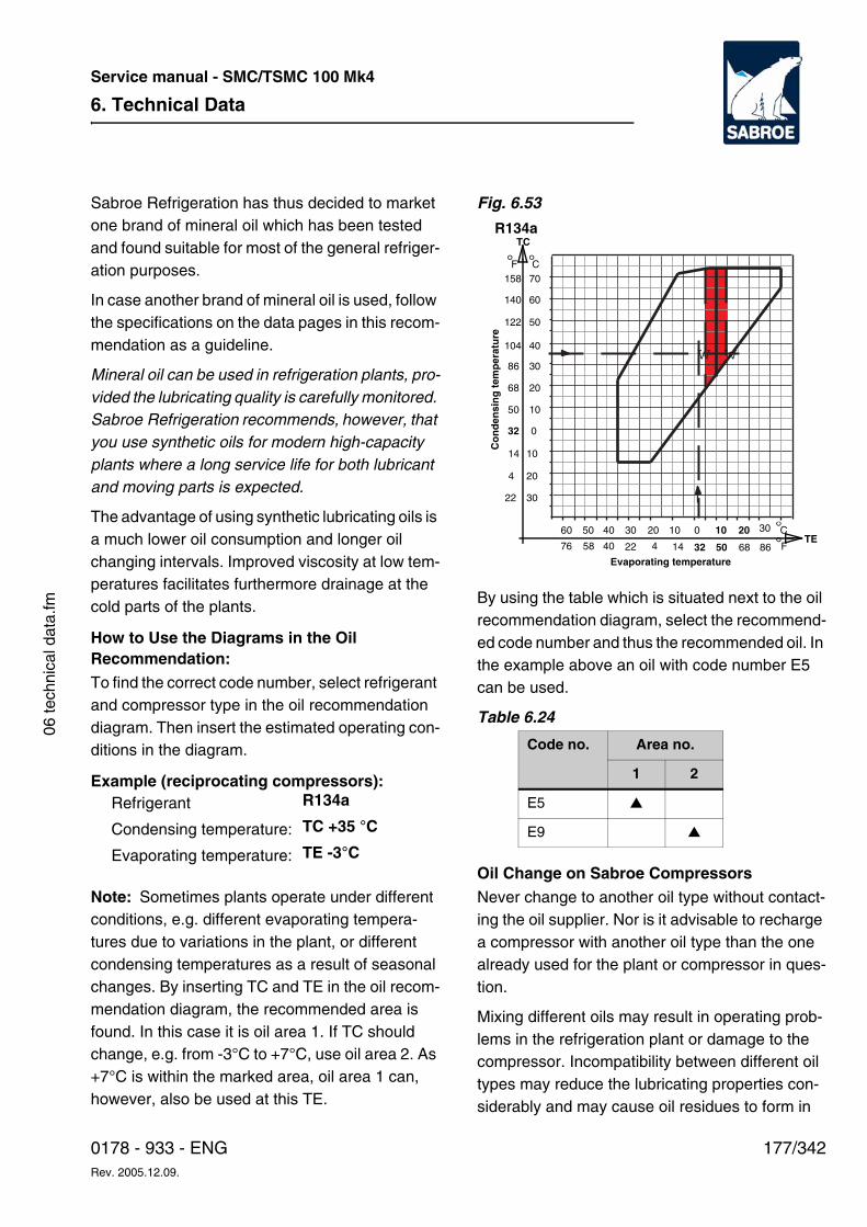
6. Technical Data
177/3420178 - 933 - ENGRev. 2005.12.09.
Service manual - SMC/TSMC 100 Mk4
06 te
chni
cal d
ata.
fm
Sabroe Refrigeration has thus decided to market one brand of mineral oil which has been tested and found suitable for most of the general refriger-ation purposes.
In case another brand of mineral oil is used, follow the specifications on the data pages in this recom-mendation as a guideline.
Mineral oil can be used in refrigeration plants, pro-vided the lubricating quality is carefully monitored. Sabroe Refrigeration recommends, however, that you use synthetic oils for modern high-capacity plants where a long service life for both lubricant and moving parts is expected.
The advantage of using synthetic lubricating oils is a much lower oil consumption and longer oil changing intervals. Improved viscosity at low tem-peratures facilitates furthermore drainage at the cold parts of the plants.
How to Use the Diagrams in the Oil Recommendation:To find the correct code number, select refrigerant and compressor type in the oil recommendation diagram. Then insert the estimated operating con-ditions in the diagram.
Example (reciprocating compressors):
Note: Sometimes plants operate under different conditions, e.g. different evaporating tempera-tures due to variations in the plant, or different condensing temperatures as a result of seasonal changes. By inserting TC and TE in the oil recom-mendation diagram, the recommended area is found. In this case it is oil area 1. If TC should change, e.g. from -3°C to +7°C, use oil area 2. As +7°C is within the marked area, oil area 1 can, however, also be used at this TE.
Fig. 6.53
By using the table which is situated next to the oil recommendation diagram, select the recommend-ed code number and thus the recommended oil. In the example above an oil with code number E5 can be used.
Table 6.24
Oil Change on Sabroe CompressorsNever change to another oil type without contact-ing the oil supplier. Nor is it advisable to recharge a compressor with another oil type than the one already used for the plant or compressor in ques-tion.
Mixing different oils may result in operating prob-lems in the refrigeration plant or damage to the compressor. Incompatibility between different oil types may reduce the lubricating properties con-siderably and may cause oil residues to form in
Refrigerant R134a
Condensing temperature: TC +35 °C
Evaporating temperature: TE -3°C
Code no. Area no.
1 2
E5 ▲
E9 ▲
Evaporating temperature
Co
nd
ensi
ng
tem
per
atu
re
30
20
10
60 50 40 30 20 10 0 10 20 30
0
10
20
30
40
50
60
70F
140
122
104
86
68
50
32
°158
TC
14
4
22
C°
F°8668503214422405876TE
C°
R134a
w w
6. Technical Data
178/342 0178 - 933 - ENGRev. 2005.12.09.
Service manual - SMC/TSMC 100 Mk4
the compressor, oil separator or plant. Oil resi-dues may block filters and damage the moving parts of the compressor.
Changing the oil type or brand should only be done following a thorough procedure involving drainage and evacuation of the refrigeration plant. Information on a suitable procedure can be ob-tained from Sabroe Refrigeration as well as a number of oil companies.
It is extremely important that the new unused oil is taken directly from its original container and that both the brand and the type correspond to the specifications of the plant.
Make sure that the original oil container is sealed properly during storage so that moisture from the air is not absorbed by the oil. Many oils, particular-ly polyester oils, are extremely hygroscopic. It is therefore recommended only to buy the oil in con-tainers whose size correspond to the amount to be used.
In case all of the oil is not used, make sure that the rest of the oil is sealed in the original container and stored in a warm, dry place. It is recommend-ed to charge nitrogen to keep the water content below 50 ppm.
Ideally, oil containers should be equipped with a barrel tap to ensure an effective, airtight seal.
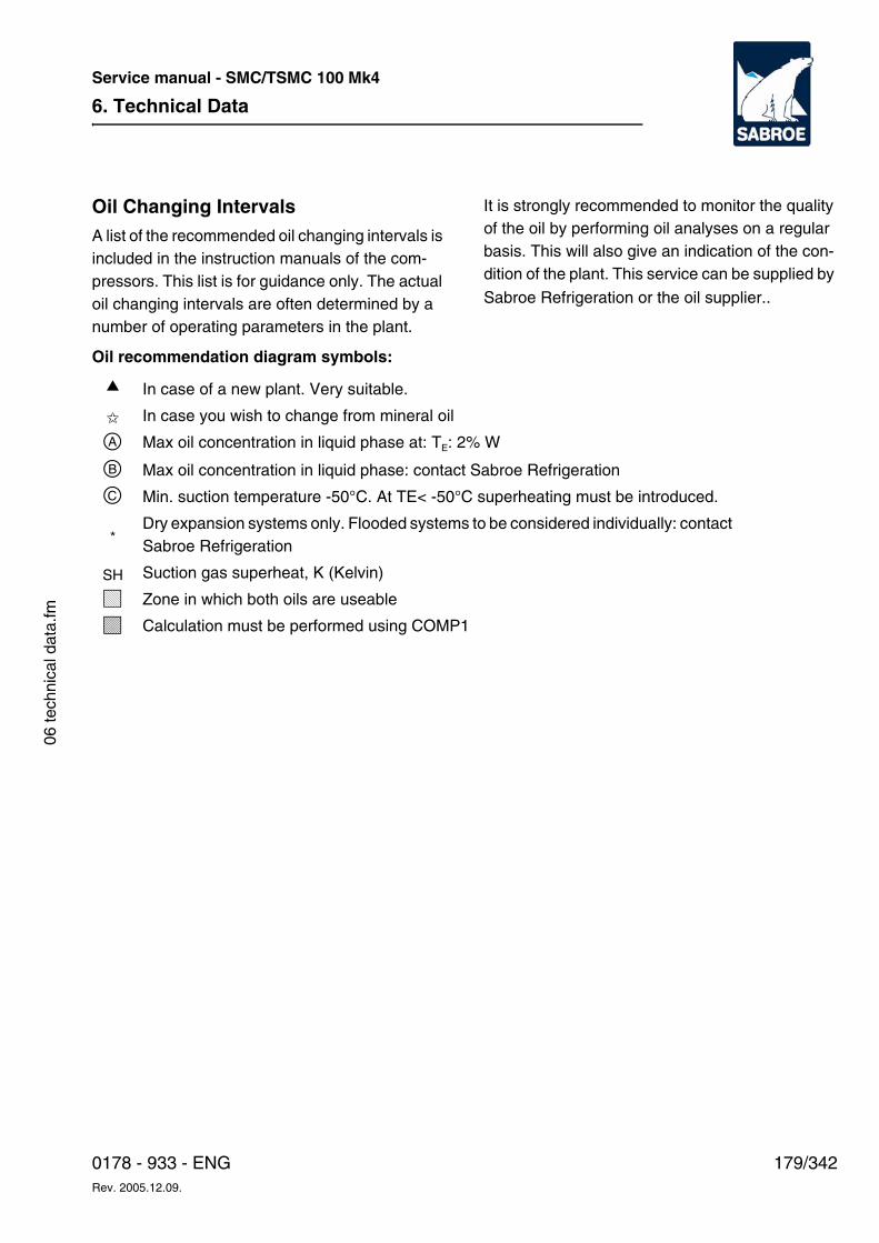
6. Technical Data
179/3420178 - 933 - ENGRev. 2005.12.09.
Service manual - SMC/TSMC 100 Mk4
06 te
chni
cal d
ata.
fm
Oil Changing IntervalsA list of the recommended oil changing intervals is included in the instruction manuals of the com-pressors. This list is for guidance only. The actual oil changing intervals are often determined by a number of operating parameters in the plant.
It is strongly recommended to monitor the quality of the oil by performing oil analyses on a regular basis. This will also give an indication of the con-dition of the plant. This service can be supplied by
Sabroe Refrigeration or the oil supplier..
Oil recommendation diagram symbols:
▲ In case of a new plant. Very suitable.
✩ In case you wish to change from mineral oil
a Max oil concentration in liquid phase at: TE: 2% W
b Max oil concentration in liquid phase: contact Sabroe Refrigeration
c Min. suction temperature -50°C. At TE< -50°C superheating must be introduced.
*Dry expansion systems only. Flooded systems to be considered individually: contact Sabroe Refrigeration
SH Suction gas superheat, K (Kelvin)
L Zone in which both oils are useable
M Calculation must be performed using COMP1
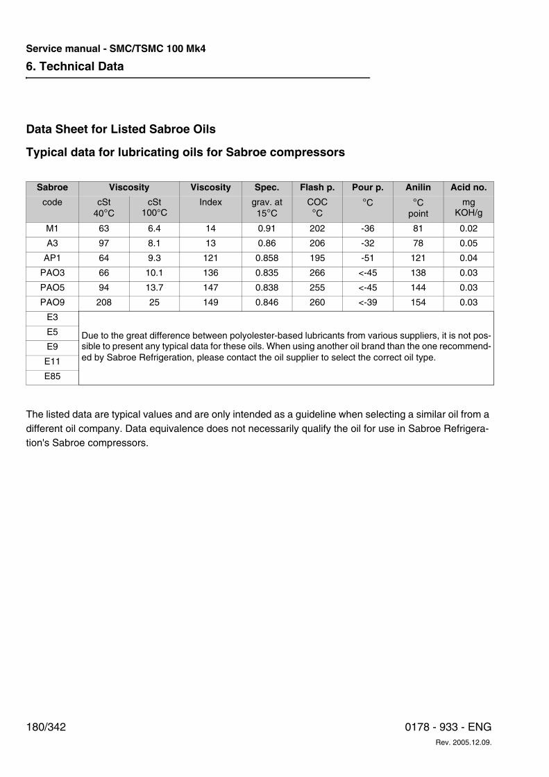
6. Technical Data
180/342 0178 - 933 - ENGRev. 2005.12.09.
Service manual - SMC/TSMC 100 Mk4
Data Sheet for Listed Sabroe Oils
Typical data for lubricating oils for Sabroe compressors
The listed data are typical values and are only intended as a guideline when selecting a similar oil from a different oil company. Data equivalence does not necessarily qualify the oil for use in Sabroe Refrigera-tion's Sabroe compressors.
Sabroe Viscosity Viscosity Spec. Flash p. Pour p. Anilin Acid no.
code cSt40°C
cSt100°C
Index grav. at15°C
COC°C
°C °Cpoint
mgKOH/g
M1 63 6.4 14 0.91 202 -36 81 0.02
A3 97 8.1 13 0.86 206 -32 78 0.05
AP1 64 9.3 121 0.858 195 -51 121 0.04
PAO3 66 10.1 136 0.835 266 <-45 138 0.03
PAO5 94 13.7 147 0.838 255 <-45 144 0.03
PAO9 208 25 149 0.846 260 <-39 154 0.03
E3
Due to the great difference between polyolester-based lubricants from various suppliers, it is not pos-sible to present any typical data for these oils. When using another oil brand than the one recommend-ed by Sabroe Refrigeration, please contact the oil supplier to select the correct oil type.
E5
E9
E11
E85

6. Technical Data
181/3420178 - 933 - ENGRev. 2005.12.09.
Service manual - SMC/TSMC 100 Mk4
06 te
chni
cal d
ata.
fm
List of Part Numbers for Available Sabroe Oils
1) 18.9 litre pail (5 US gallons)
2) 10 litre
The oils recommended by the former Stal Refrigeration correspond to the following oils:
Oil brand Oil code no. Part no.
20 litre pail 208 litre barrel
Mobil Gargoyle Arctic 300 M1 (M68) 1231-264 1231-296
Sabroe Oil A100 A3 (A100) 1231-263 1231-262
Sabroe Oil AP68 AP1 (AP68) 1231-257 1231-260
Sabroe Oil PAO68 PAO3 (P68) 1231-256 1231-259
Mobil Gargoyle Arctic SHC 228 PAO5 (P100) 1231-282 1231-283
Mobil Gargoyle Arctic SHC 230 PAO9 (P220) 1231-284 1231-285
Mobil EAL Arctic 68 E3 (E68) 1231-272 1231-273
Mobil EAL Arctic 100 E5 (E100) 1231-274 1231-275
Mobil EAL Arctic 220 E9 (E220) 1231-279
Sabroe H oil E11 (E370) 3914 1512 954 1) 9415 0008 000
FUCHS DEA Reniso C85E E85 (85) 1231-304 2)
Stal Refrigeration oil type Sabroe oil
A Mobil Gargoyle Arctic 300 - M1 (M68)
B Sabroe Oil PAO 68 - PAO 3 (PAO 68)
C Mobil Gargoyle Arctic SHC 230 - PAO 9 (PAO 220)
H Sabroe H oil - E 11 (E 370)
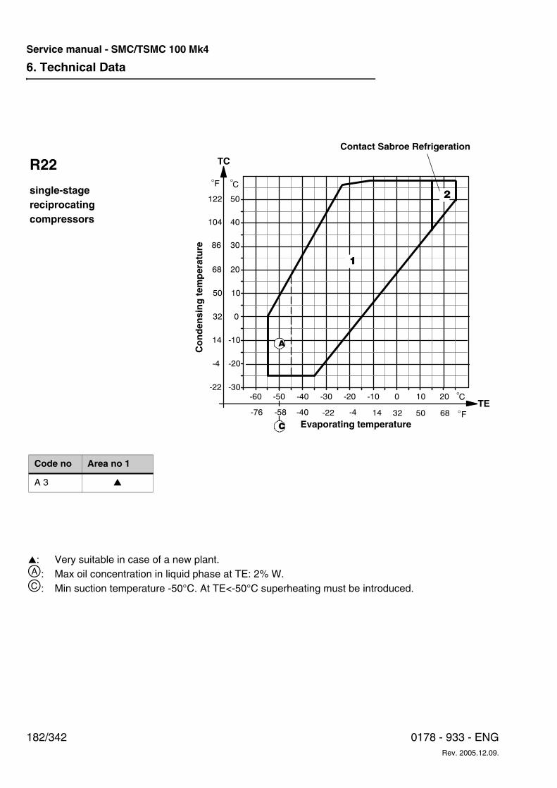
6. Technical Data
182/342 0178 - 933 - ENGRev. 2005.12.09.
Service manual - SMC/TSMC 100 Mk4
-30
-20
-10
0
-60 -50 -40 -30 -20 -10 0 10 20
10
20
30
40
50
C�
1
C�F
122
104
86
68
50
32
14
-4
-22
TC
�
F�68503214-4-22-40-58-76TE
A
C
2
R22
single-stagereciprocatingcompressors
Co
nd
ensi
ng
tem
per
atu
re
Evaporating temperature
Code no Area no 1
A 3 ▲
▲: Very suitable in case of a new plant. a: Max oil concentration in liquid phase at TE: 2% W.c: Min suction temperature -50°C. At TE<-50°C superheating must be introduced.
Contact Sabroe Refrigeration
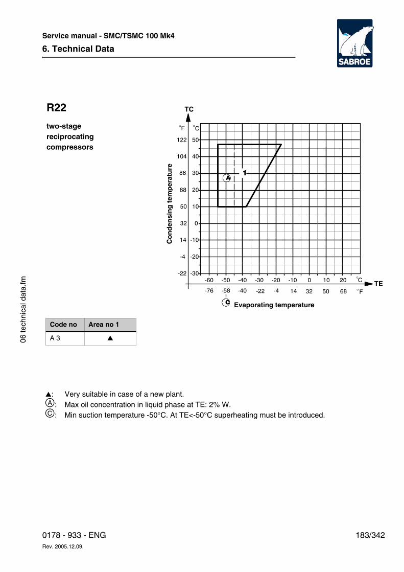
6. Technical Data
183/3420178 - 933 - ENGRev. 2005.12.09.
Service manual - SMC/TSMC 100 Mk4
06 te
chni
cal d
ata.
fm
-30
-20
-10
0
-60 -50 -40 -30 -20 -10 0 10 20
10
20
30
40
50
C�
C�
1
F
122
104
86
68
50
32
14
-4
-22
TC
�
F�68503214-4-22-40-58-76TE
A
C
R22
two-stagereciprocatingcompressors
Co
nd
ensi
ng
tem
per
atu
re
Evaporating temperature
Code no Area no 1
A 3 ▲
▲: Very suitable in case of a new plant. a: Max oil concentration in liquid phase at TE: 2% W.c: Min suction temperature -50°C. At TE<-50°C superheating must be introduced.
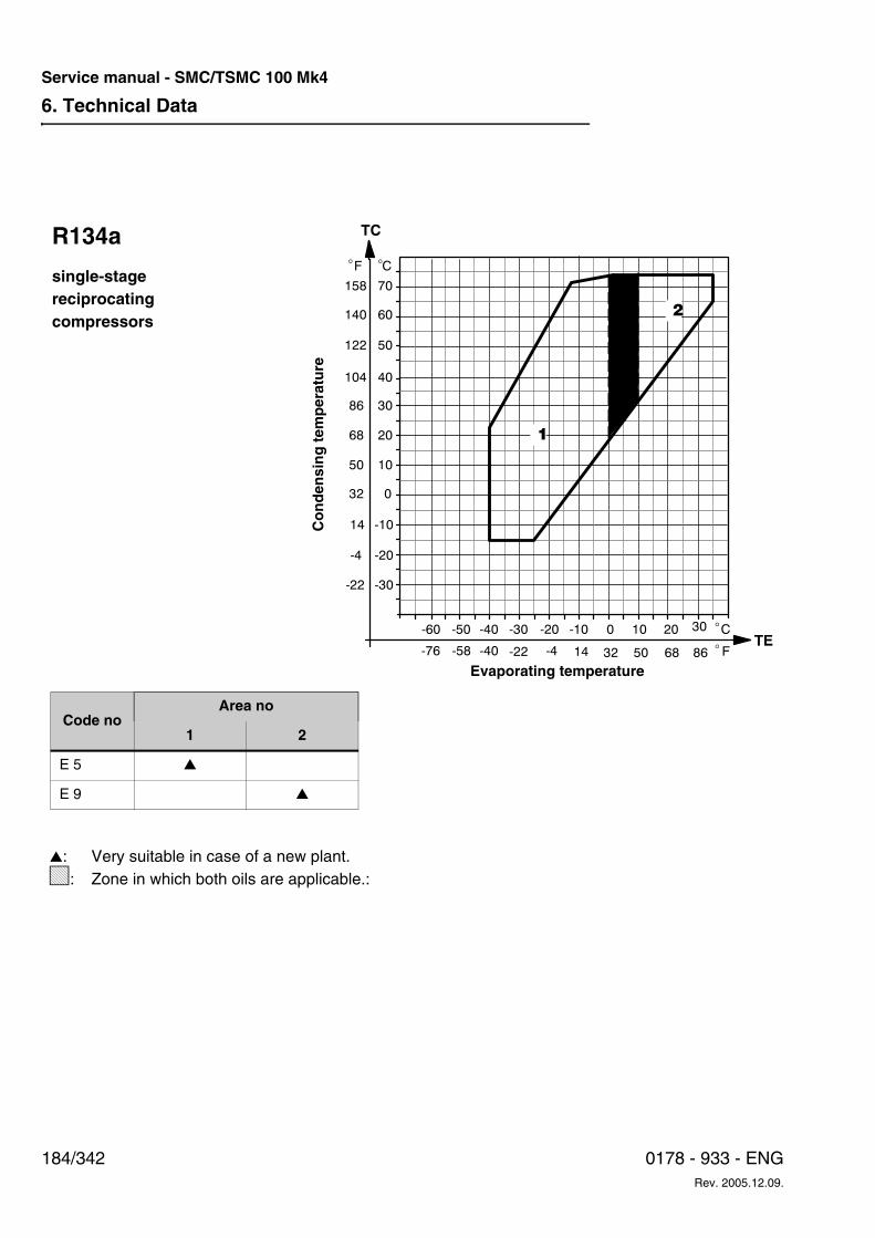
6. Technical Data
184/342 0178 - 933 - ENGRev. 2005.12.09.
Service manual - SMC/TSMC 100 Mk4
-30
-20
-10
-60 -50 -40 -30 -20 -10 0 10 20 30
0
10
20
30
40
50
60
70
1
2
F
140
122
104
86
68
50
32
�
158
TC
14
-4
-22
C�
F�8668503214-4-22-40-58-76TE
C�
R134a
single-stagereciprocatingcompressors
Co
nd
ensi
ng
tem
per
atu
re
Evaporating temperature
Code noArea no
1 2
E 5 ▲
E 9 ▲
▲: Very suitable in case of a new plant. L: Zone in which both oils are applicable.:
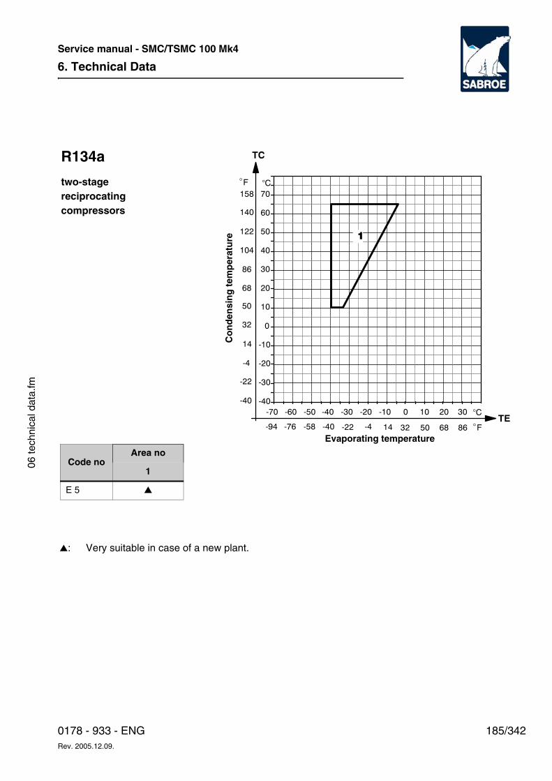
6. Technical Data
185/3420178 - 933 - ENGRev. 2005.12.09.
Service manual - SMC/TSMC 100 Mk4
06 te
chni
cal d
ata.
fm
�
-30
-20
-10
-60 -50 -40 -30 -20 -10 0 10 20 30
0
10
20
30
40
50
60
70
1
C
-40
F
86
68
50
32
�
14
-4
-22
-40
140
122
104
158
-70
F�8668503214-4-22-40-58-76TE
-94
�C
TCR134a
two-stagereciprocatingcompressors
Co
nd
ensi
ng
tem
per
atu
re
Evaporating temperature
Code noArea no
1
E 5 ▲
▲: Very suitable in case of a new plant.
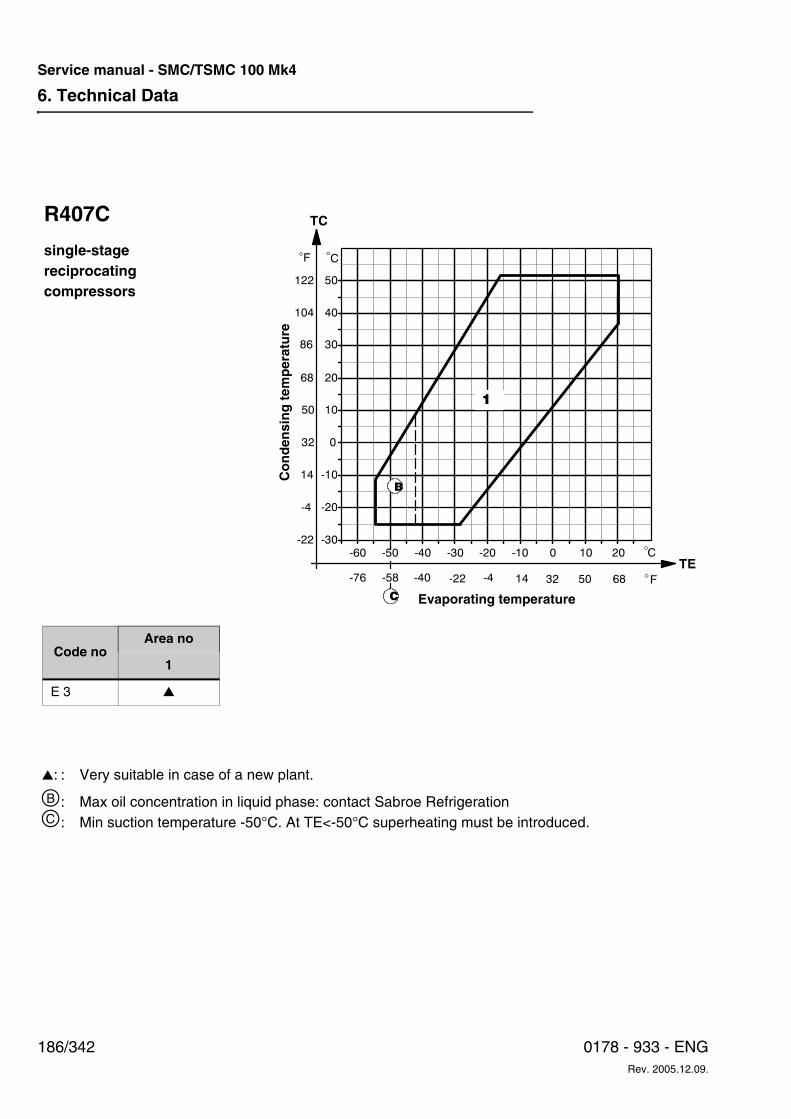
6. Technical Data
186/342 0178 - 933 - ENGRev. 2005.12.09.
Service manual - SMC/TSMC 100 Mk4
-30
-20
-10
0
-60 -50 -40 -30 -20 -10 0 10 20
10
20
30
40
50
C�
C�F
122
104
86
68
50
32
14
-4
-22
TC
�
F�68503214-4-22-40-58-76TE
1
B
C
R407C
single-stagereciprocatingcompressors
Co
nd
ensi
ng
tem
per
atu
re
Evaporating temperature
Code noArea no
1
E 3 ▲
▲: : Very suitable in case of a new plant.
b: Max oil concentration in liquid phase: contact Sabroe Refrigerationc: Min suction temperature -50°C. At TE<-50°C superheating must be introduced.
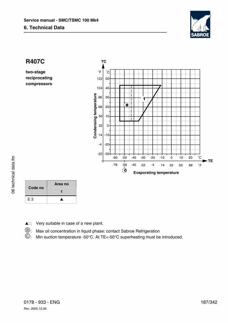
6. Technical Data
187/3420178 - 933 - ENGRev. 2005.12.09.
Service manual - SMC/TSMC 100 Mk4
06 te
chni
cal d
ata.
fm
-30
-20
-10
0
-60 -50 -40 -30 -20 -10 0 10 20
10
20
30
40
50
C�
C�F
122
104
86
68
50
32
14
-4
-22
TC
�
F�68503214-4-22-40-58-76TE
1
B
C
R407C
two-stagereciprocatingcompressors
Co
nd
ensi
ng
tem
per
atu
re
Evaporating temperature
Code noArea no
1
E 3 ▲
▲: : Very suitable in case of a new plant.
b: Max oil concentration in liquid phase: contact Sabroe Refrigerationc: Min suction temperature -50°C. At TE<-50°C superheating must be introduced.
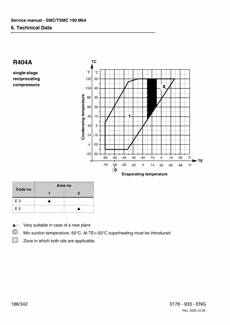
6. Technical Data
188/342 0178 - 933 - ENGRev. 2005.12.09.
Service manual - SMC/TSMC 100 Mk4
-30
-20
-10
0
-60 -50 -40 -30 -20 -10 0 10 20
10
20
30
40
50
C�
C�F
122
104
86
68
50
32
14
-4
-22
TC
�
F�68503214-4-22-40-58-76TE
1
2
C
R404A
single-stagereciprocatingcompressors
Co
nd
ensi
ng
tem
per
atu
re
Evaporating temperature
Code noArea no
1 2
E 3 ▲
E 5 ▲
▲: : Very suitable in case of a new plant.
c: Min suction temperature -50°C. At TE<-50°C superheating must be introduced
L: Zone in which both oils are applicable.
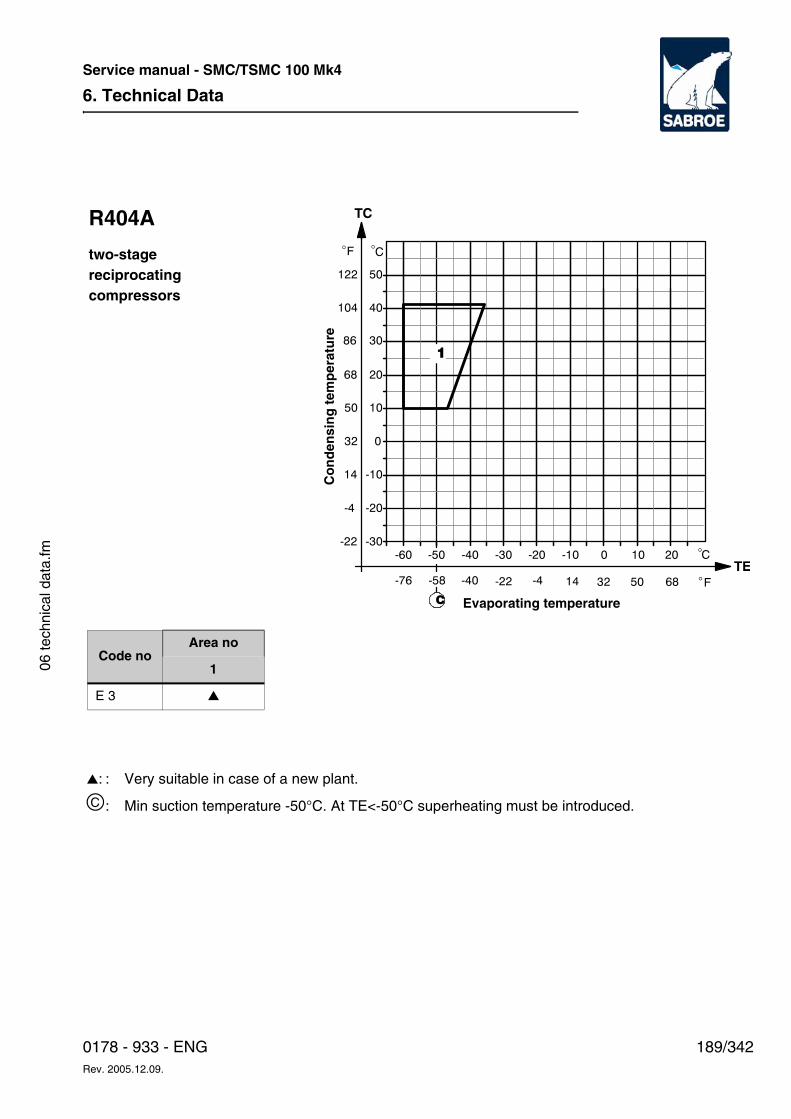
6. Technical Data
189/3420178 - 933 - ENGRev. 2005.12.09.
Service manual - SMC/TSMC 100 Mk4
06 te
chni
cal d
ata.
fm
-30
-20
-10
0
-60 -50 -40 -30 -20 -10 0 10 20
10
20
30
40
50
C�
C�F
122
104
86
68
50
32
14
-4
-22
TC
�
F�68503214-4-22-40-58-76TE
1
C
R404A
two-stagereciprocatingcompressors
Co
nd
ensi
ng
tem
per
atu
re
Evaporating temperature
Code noArea no
1
E 3 ▲
▲: : Very suitable in case of a new plant.
c: Min suction temperature -50°C. At TE<-50°C superheating must be introduced.
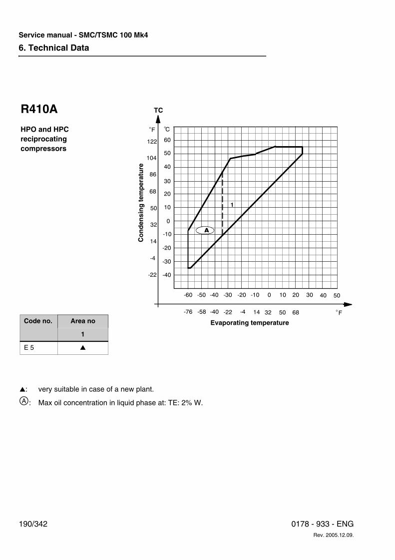
6. Technical Data
190/342 0178 - 933 - ENGRev. 2005.12.09.
Service manual - SMC/TSMC 100 Mk4
F
122
104
86
68
50
32
14
-4
-22
TC
�
F�68503214-4-22-40-58-76
-40
-30
-20
-60 -50 -40 -30 -20 -10
0
10
20
30
40
50
60
C�
0 10 20 30 40 50
1
A-10
R410A
HPO and HPCreciprocatingcompressors
Co
nd
ensi
ng
tem
per
atu
re
Evaporating temperatureCode no. Area no
1
E 5 ▲
▲: very suitable in case of a new plant.
a: Max oil concentration in liquid phase at: TE: 2% W.
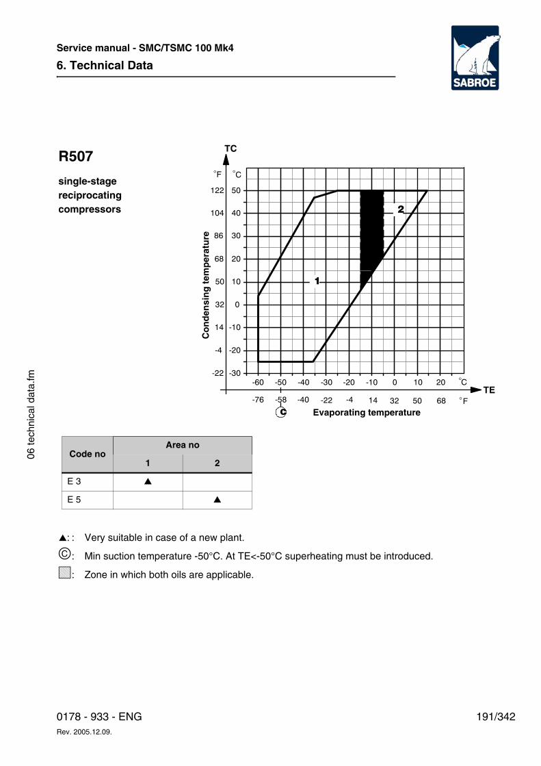
6. Technical Data
191/3420178 - 933 - ENGRev. 2005.12.09.
Service manual - SMC/TSMC 100 Mk4
06 te
chni
cal d
ata.
fm -30
-20
-10
0
-60 -50 -40 -30 -20 -10 0 10 20
10
20
30
40
50
C�
C�F
122
104
86
68
50
32
14
-4
-22
TC
�
F�68503214-4-22-40-58-76TE
1
2
C
R507
single-stagereciprocatingcompressors
Co
nd
ensi
ng
tem
per
atu
re
Evaporating temperature
▲: : Very suitable in case of a new plant.
c: Min suction temperature -50°C. At TE<-50°C superheating must be introduced.
L: Zone in which both oils are applicable.
Code noArea no
1 2
E 3 ▲
E 5 ▲
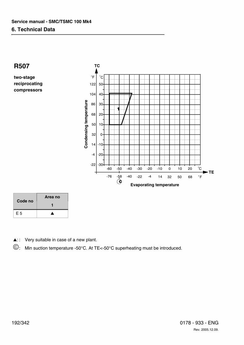
6. Technical Data
192/342 0178 - 933 - ENGRev. 2005.12.09.
Service manual - SMC/TSMC 100 Mk4
-30
-20
-10
0
-60 -50 -40 -30 -20 -10 0 10 20
10
20
30
40
50
C�
C�F
122
104
86
68
50
32
14
-4
-22
TC
�
F�68503214-4-22-40-58-76TE
1
C
R507
two-stagereciprocatingcompressors
Co
nd
ensi
ng
tem
per
atu
re
Evaporating temperature
Code noArea no
1
E 5 ▲
▲: : Very suitable in case of a new plant.
c: Min suction temperature -50°C. At TE<-50°C superheating must be introduced.
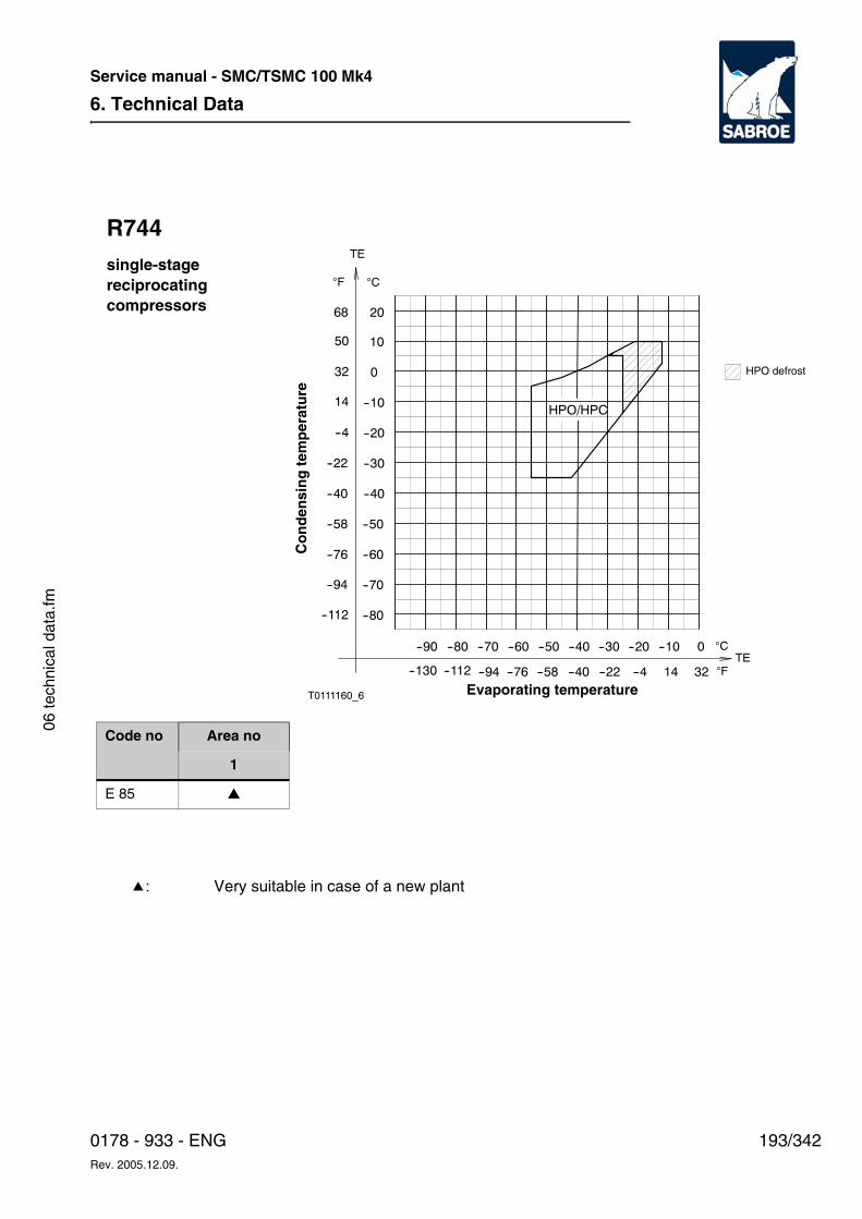
6. Technical Data
193/3420178 - 933 - ENGRev. 2005.12.09.
Service manual - SMC/TSMC 100 Mk4
06 te
chni
cal d
ata.
fm
T0111160_6
--80
--90 --80 --70 --60 --50 --40 --30 --20 --10 0
--70
--60
--50
--40
--30
--20
--10HPO/HPC
0
10
20
14--4--94 32--58 --40--76 --22--112--130
68
50
32
14
--4
--22
--40
--58
--76
--94
--112
TE
TE
CF
C
F
R744single-stagereciprocatingcompressors
j: Very suitable in case of a new plant
Evaporating temperature
Co
nd
ensi
ng
tem
per
atu
re
Code no Area no
1
E 85 ▲
HPO defrost
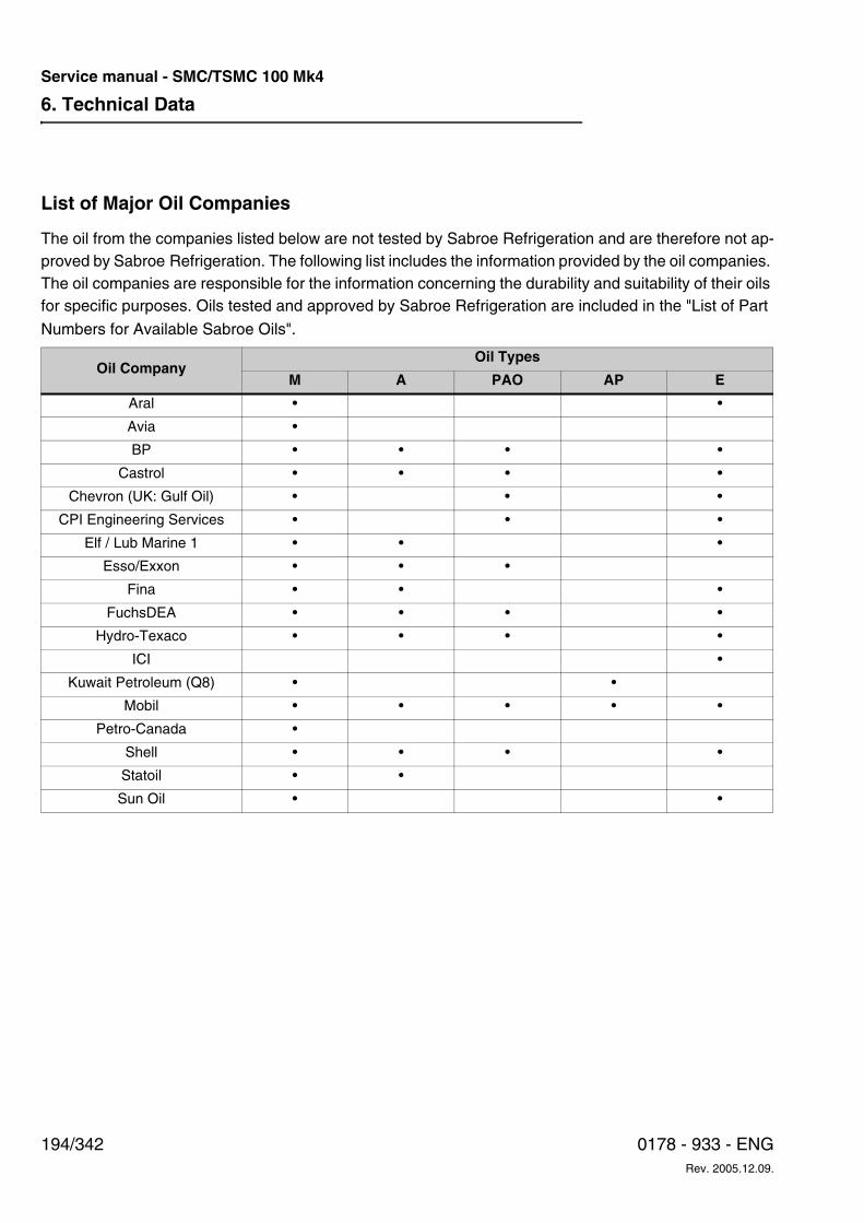
6. Technical Data
194/342 0178 - 933 - ENGRev. 2005.12.09.
Service manual - SMC/TSMC 100 Mk4
List of Major Oil Companies
The oil from the companies listed below are not tested by Sabroe Refrigeration and are therefore not ap-proved by Sabroe Refrigeration. The following list includes the information provided by the oil companies. The oil companies are responsible for the information concerning the durability and suitability of their oils for specific purposes. Oils tested and approved by Sabroe Refrigeration are included in the "List of Part
Numbers for Available Sabroe Oils".
Oil CompanyOil Types
M A PAO AP E
Aral • •
Avia •
BP • • • •
Castrol • • • •
Chevron (UK: Gulf Oil) • • •
CPI Engineering Services • • •
Elf / Lub Marine 1 • • •
Esso/Exxon • • •
Fina • • •
FuchsDEA • • • •
Hydro-Texaco • • • •
ICI •
Kuwait Petroleum (Q8) • •
Mobil • • • • •
Petro-Canada •
Shell • • • •
Statoil • •
Sun Oil • •
9. Settings
195/3420178 - 933 - ENGRev. 2005.12.09.
Service manual - SMC/TSMC 100 Mk4
09 s
ettin
gs.fm
9. SettingsThe purpose of this chapter is to provide informa-tion about the factory settings of the safety and control equipment, how to change the settings and the effect of a change.
This chapter is primarily intended for installation and service engineers.
Safety Precautions
WDanger!
Risk of injury to personnel and damage to equip-ment! In addition to the safety precautions in this chapter, always read the safety precautions be-longing to this equipment before changing the set-tings. Failure to comply with safety precautions may cause death or injury to personnel. It may also cause damage to or destruction of the equip-ment.
Qualification RequirementsChanges in the factory settings must only be car-ried out by an authorised refrigeration company.
Moreover, it is required that the personnel is able to follow a detailed description in English.
Factory settings for analogous control and safety system appear from Table 9.1. In connection with fault-finding in case of irregularities in the opera-tion, the table should include own settings to make it easier for the supervisor to identify the error in question. The same applies to UNISAB II control.
Compressor control systemsCompressors are delivered with an analogue con-trol and safety system or the UNISAB II reading, safety and capacity regulating system.
With regard to compressors delivered with the UNISAB II system, the system is described in the Operating Manual located in the UNISAB II cabi-net.
Furthermore, a UNISAB II Engineering Manual (version 2.04) is available. This manual describes the control system in more detail. Consequently, setting of set points etc. is not described in this section.
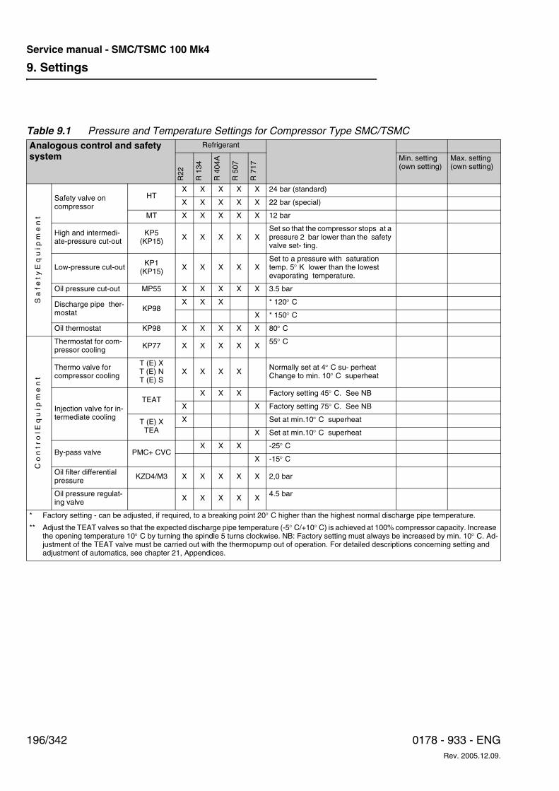
9. Settings
196/342 0178 - 933 - ENGRev. 2005.12.09.
Service manual - SMC/TSMC 100 Mk4
Table 9.1 Pressure and Temperature Settings for Compressor Type SMC/TSMCAnalogous control and safety system
Refrigerant
R22
R 1
34
R 4
04A
R 5
07
R 7
17
Min. setting (own setting)
Max. setting (own setting)
S a
f e
t y E
q u
i p
m e
n t
Safety valve on compressor
HTX X X X X 24 bar (standard)
X X X X X 22 bar (special)
MT X X X X X 12 bar
High and intermedi- ate-pressure cut-out
KP5 (KP15) X X X X X
Set so that the compressor stops at a pressure 2 bar lower than the safety valve set- ting.
Low-pressure cut-out KP1(KP15) X X X X X
Set to a pressure with saturation temp. 5° K lower than the lowest evaporating temperature.
Oil pressure cut-out MP55 X X X X X 3.5 bar
Discharge pipe ther-mostat KP98
X X X * 120° C
X * 150° C
Oil thermostat KP98 X X X X X 80° C
C o
n t
r o
l E q
u i
p m
e n
t
Thermostat for com-pressor cooling KP77 X X X X X 55° C
Thermo valve for compressor cooling
T (E) XT (E) NT (E) S
X X X X Normally set at 4° C su- perheatChange to min. 10° C superheat
Injection valve for in-termediate cooling
TEATX X X Factory setting 45° C. See NB
X X Factory setting 75° C. See NB
T (E) XTEA
X Set at min.10° C superheat
X Set at min.10° C superheat
By-pass valve PMC+ CVCX X X -25° C
X -15° C
Oil filter differential pressure KZD4/M3 X X X X X 2,0 bar
Oil pressure regulat-ing valve X X X X X 4.5 bar
* Factory setting - can be adjusted, if required, to a breaking point 20° C higher than the highest normal discharge pipe temperature.
** Adjust the TEAT valves so that the expected discharge pipe temperature (-5° C/+10° C) is achieved at 100% compressor capacity. Increase the opening temperature 10° C by turning the spindle 5 turns clockwise. NB: Factory setting must always be increased by min. 10° C. Ad-justment of the TEAT valve must be carried out with the thermopump out of operation. For detailed descriptions concerning setting and adjustment of automatics, see chapter 21, Appendices.
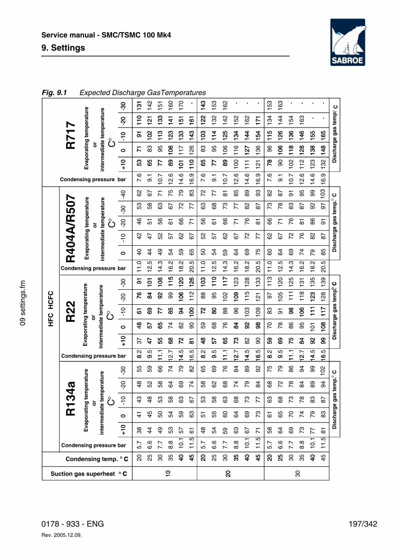
9. Settings
197/3420178 - 933 - ENGRev. 2005.12.09.
Service manual - SMC/TSMC 100 Mk4
09 s
ettin
gs.fm
Fig. 9.1 Expected Discharge GasTemperatures
Suction gas superheat ° C
Condensing temp. ° C
HF
C H
CF
C
bar
bar
bar
10 20 30
20 25 30 35 40 45
8.8
10.1
11.5
5.7
6.6
7.7
8.8
10.1
11.5
5.7
6.6
7.7
8.8
10.1
11.5
20 25 30 35 40 45 20 25 30 35 40 45
38 44 49 53 57 61 48 54 63 67 71 58 64 69 73 81
41 45 50 54 59 63 51 55 60 64 69 73 61 65 70 74 79 83
43 48 53 58 63 67 53 58 63 68 73 77 63 68 73 78 83 87
48 52 58 64 69 74 58 62 68 74 79 84 68 72 78 84 89 94
55 59 66 74 79 82 65 69 76 84 89 92 75 79 86 94 99
8.2
9.5
11.1
14.5
16.5
8.2
9.5
11.1
12.7
14.5
16.5
8.2
9.5
11.1
12.7
14.5
16.5
37 47 55 68 72 81 48 57 65 73 82 90 59 69 75 84 92 99
48 57 65 74 82 90 59 68 76 84 92 98 70 78 86 95 101
108
61 69 77 85 94 100
72 80 88 96 103
109
83 91 98 106
111
117
76 84 92 99 106
112
88 95 102
109
115
121
97 105
111
118
123
128
91 101
108
115
120
126
103
110
117
123
128
133
113
120
125
131
135
139
5371
9111
013
1
10.7
12.6
14.6
16.9
10.7
12.6
14.6
16.9
10.7
12.6
14.6
16.9
65 77 89 101
110 65 77 89 100
111
121 78 90 102
112
123
132
83 95 106
117
126 83 95 106
116
127
136 96 106
118
128
138
148
102
113
123
133
143
103
114
125
134
144
154
115
126
136
146
155
165
121
133
141
151
161
122
132
142
152
162
171
134
144
154
163 -
-
142
151
160
170 -
143
153
162 -
-
-
153
163 -
-
-
-
+10
0-1
0-2
0+
100
-1
0-2
0-3
00
-1
0-2
0-3
0-4
0+
100
10
2030
°CD
isch
arg
e g
as t
emp
.°C
Dis
char
ge
gas
tem
p.
° C
° C
Condensing pressure
10 20
40 45
5.7
6.6
7.7
20 35 40 45 20 25 40
8 9 11.
12.7
14 8 9 11 12 14 16 8 9 11 12 14 16
47 55 68 72 81 48 57 65 73 59 69 75 84 92 99
48 57 65 84 92 98 108
61 69 77 85 94 100
72 80 98 106
111
117
76 84 92 106
109
123
91 101
108
115
120
126
103
110
117
7.6
5371
9111
013
1
9.1
7.6
9.1
7.6
9.1
65 77 89 101
110 65 77 89 78
106
127
106
118
128
138
148
102
113
123
133
143
103
114
125
134
144
154
115
126
136
146
155
165
121
133
141
151
161
122
171
-
143
-
+10
0+
100
0
+
100
-1
0-2
0-3
0
R13
4aR
22R
404A
/R50
7R
717
°C
°Co
rin
term
edia
te t
emp
erat
ure
°Co
rin
term
edia
te t
emp
erat
ure
Eva
po
rati
ng
tem
per
atu
re
7759
102
16.2
18.2
20.5
11.0
12.5
14.3
16.2
18.2
20.5
11.0
12.5
14.3
16.2
18.2
20.5
40 44 49 54 59 65 50 54 64 69 75 60 64 69 74 85
42 47 52 57 62 67 52 57 62 67 72 77 62 67 72 76 82 87
46 51 56 61 66 71 56 61 66 71 76 81 66 71 76 81 86 91
53 58 63 67 72 77 63 68 73 77 82 87 73 78 83 87 92 97
62 67 71 75 79 83 72 77 81 85 89 93 82 87 91 95 99
11.0
12.5
14.3
7959
103
Condensing pressure
Condensing pressure
Eva
po
rati
ng
tem
per
atu
re
barCondensing pressure
°Co
r
Eva
po
rati
ng
tem
per
atu
re
inte
rmed
iate
tem
per
atu
re
°Co
r
Eva
po
rati
ng
tem
per
atu
re
inte
rmed
iate
tem
per
atu
re
Dis
char
ge
gas
tem
p.°
CD
isch
arg
e g
as t
emp
. °C
-30
9. Settings
198/342 0178 - 933 - ENGRev. 2005.12.09.
Service manual - SMC/TSMC 100 Mk4
10. Operating instructions
199/3420178 - 933 - ENGRev. 2005.12.09.
Service manual - SMC/TSMC 100 Mk4
10 o
pera
ting
inst
ruct
ions
.fm
10. Operating instructionsThis chapter is included in the separate manual ‘Operating instructions’; please consult this manu-al if you need information about operating the compressor.
10. Operating instructions
200/342 0178 - 933 - ENGRev. 2005.12.09.
Service manual - SMC/TSMC 100 Mk4
11. Maintenance Instructions
201/3420178 - 933 - ENGRev. 2005.12.09.
Service manual - SMC/TSMC 100 Mk4
11 m
aint
enan
ce in
stru
ctio
ns.fm
11. Maintenance InstructionsThe purpose of this chapter is to describe:
• Dangers resulting from failure to comply with safety precautions when performing maintenance tasks.
• Scheduled maintenance tasks for this equipment and how to carry them out safely.
• When these scheduled maintenance tasks should be performed.
This chapter is primarily intended for operators and service engineers.
WDanger!
Risk of injury to personnel and damage to equip-ment! Always read the safety precautions belong-ing to this equipment before start. Failure to com-ply with safety precautions may cause death or in-jury to personnel. It may also cause damage to or destruction of the equipment.
Safety Precautions
WDanger!
Risk of injury to personnel and damage to equip-ment! In addition to the safety precautions in this chapter, always read the safety precautions be-longing to this equipment before start. Failure to comply with safety precautions may cause death or injury to personnel. It may also cause damage to or destruction of the equipment.
Safety Measures
WDanger!
The paragraphs that follow present some impor-tant safety considerations for this type of com-pressor unit. Before starting maintenance work, study carefully the general safety instructions/reg-ulations that apply to this series of compressor units. Failure to follow these instructions/regula-tions can lead to personal injury and even death. Moreover, the equipment can be damaged or de-stroyed.
11. Maintenance Instructions
202/342 0178 - 933 - ENGRev. 2005.12.09.
Service manual - SMC/TSMC 100 Mk4
Maintenance of the Compressor Unit
GeneralTo make certain that the compressor unit oper-ates without problems throughout a long service life, follow the system of maintenance presented in the following instructions.
Maintenance can be divided into three groups:
1. Daily MaintenanceThis consists of visual inspections. When fa-miliar with the normal noise and vibration of the unit, compare each day's performance with previous observations. Make compari-sons with the available diagrams etc. to make certain that the operating data lie with-in the permissible ranges.
• Inspect the compressor unit and check that both noise and vibration are normal.
• Enter the observed operating data into the operations log, see Table for Moni-toring Operation in chapter 10, Operat-ing Instructions. Check that all operating values are within the permissible rang-es. Compare them with previous values to detect trends. If necessary, submit a report so that a closer check can be made.
• Check the oil level in the oil separator (Screw compressor unit).
• Check the oil level in the compressor (Reciprocating compressor unit).
• Check oil pressure.
• Check the refrigerant charge.
• Search for leaks if there is even the slightest suspicion that there may be a leak. Conducting a manual check right at the compressor unit itself is always the best way to check for:a) leakage of oil and/or refrigerant,b) leakage of cooling water or brine,c) abnormal vibrations.
• Do not wait for the monitoring equipment to issue an alarm. Searching for leaks is explained in greater detail later in this chapter.
WWarning!
Daily maintenance is normally conducted by oper-ating personnel. Other maintenance and service tasks which require the refrigeration system to be opened must only be conducted by authorized personnel.
2. Periodic maintenanceMotor lubrication and other routine mainte-nance tasks are usually based on running time. Note, however, that these can be con-ducted more frequently if necessary.
3. Major overhaulFor major maintenance tasks such as com-pressor overhauls, the usual procedure is to call in the supplier's service personnel.
The different parts of the compressor unit that re-quire regular periodical maintenance are indicat-ed below.
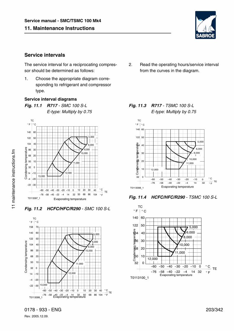
11. Maintenance Instructions
203/3420178 - 933 - ENGRev. 2005.12.09.
Service manual - SMC/TSMC 100 Mk4
11 m
aint
enan
ce in
stru
ctio
ns.fm
Service intervals
The service interval for a reciprocating compres-sor should be determined as follows:
1. Choose the appropriate diagram corre-sponding to refrigerant and compressor type.
2. Read the operating hours/service interval from the curves in the diagram.
Service interval diagrams Fig. 11.1 R717 - SMC 100 S-L
E-type: Multiply by 0.75
Fig. 11.2 HCFC/HFC/R290 - SMC 100 S-L
Fig. 11.3 R717 - TSMC 100 S-LE-type: Multiply by 0.75
Fig. 11.4 HCFC/HFC/R290 - TSMC 100 S-L--76 --58
T0113097_1
--40 --22 --4 14 32 50 68 86 104
--60 --50
--30
--20
--10
10
20
0
--22
--4
14
32
50
68
13,000
--40 --30 --20 --10 0 10 20 30 40
10,000
11,000
12,000
TE
30
40
50
60
86
104
122
140
TC
5,000
6,000
8,000
C
CF
F
Evaporating temperature
Con
dens
ing
tem
pera
ture
T0113099_1--40 --22 --4 14 32 50 68 86 104
--60 --50
--30
--20
--10
0
10
20
--22
--4
14
50
68
32
--76 --58
13,000
--40 --30 --20 --10 0
11,000
12,000
10 20 30 40TE
30
40
50
60
70
86
104
122
140
158
TC
5,000
6,000
8,000
10,000
C
F
CF
Con
dens
ing
tem
pera
ture
Evaporating temperature
T0113098_1
--600
10
20
30
40
50
60
32
50
68
86
104
122
140
--76
--50 --40 --30 --20
--40--58 --22 --4
--10
14
0
32TE
TC
12,000
10,000
11,000
8,000
6,000
5,000
CF
C
F
Con
dens
ing
tem
pera
ture
Evaporating temperature
10
20
0--60
--76
50
68
32
T0113100_1
--50 --40 --30 --20
--58 --22--40 --4
12,000
11,000
--10
14
0
32TE
40
50
30
60
86
104
122
140
TC
10,000
8,000
6,000
5,000
CF
C
FEvaporating temperature
Con
dens
ing
tem
pera
ture
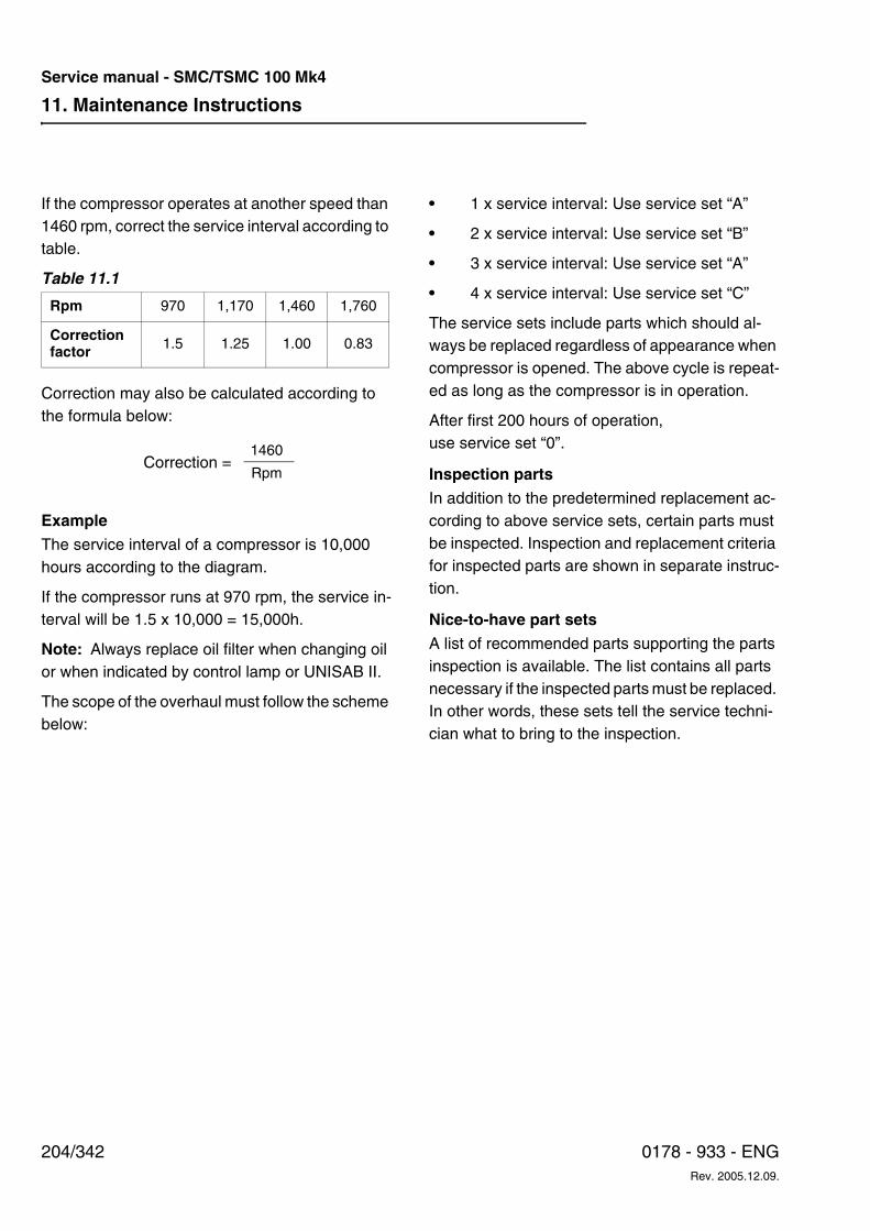
11. Maintenance Instructions
204/342 0178 - 933 - ENGRev. 2005.12.09.
Service manual - SMC/TSMC 100 Mk4
If the compressor operates at another speed than 1460 rpm, correct the service interval according to table.
Table 11.1
Correction may also be calculated according to the formula below:
ExampleThe service interval of a compressor is 10,000 hours according to the diagram.
If the compressor runs at 970 rpm, the service in-terval will be 1.5 x 10,000 = 15,000h.
Note: Always replace oil filter when changing oil or when indicated by control lamp or UNISAB II.
The scope of the overhaul must follow the scheme below:
• 1 x service interval: Use service set “A”
• 2 x service interval: Use service set “B”
• 3 x service interval: Use service set “A”
• 4 x service interval: Use service set “C”
The service sets include parts which should al-ways be replaced regardless of appearance when compressor is opened. The above cycle is repeat-ed as long as the compressor is in operation.
After first 200 hours of operation, use service set “0”.
Inspection partsIn addition to the predetermined replacement ac-cording to above service sets, certain parts must be inspected. Inspection and replacement criteria for inspected parts are shown in separate instruc-tion.
Nice-to-have part sets A list of recommended parts supporting the parts inspection is available. The list contains all parts necessary if the inspected parts must be replaced. In other words, these sets tell the service techni-cian what to bring to the inspection.
Rpm 970 1,170 1,460 1,760
Correction factor 1.5 1.25 1.00 0.83
1460
RpmCorrection =
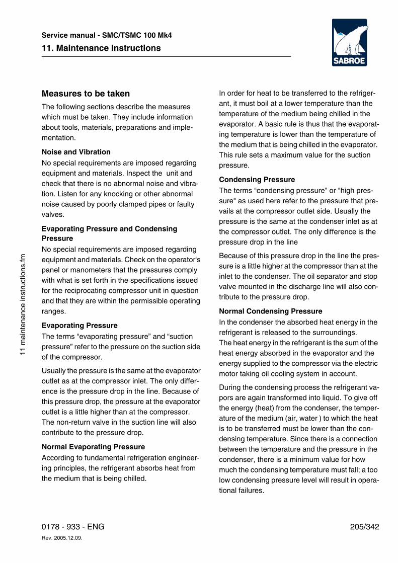
11. Maintenance Instructions
205/3420178 - 933 - ENGRev. 2005.12.09.
Service manual - SMC/TSMC 100 Mk4
11 m
aint
enan
ce in
stru
ctio
ns.fm
Measures to be takenThe following sections describe the measures which must be taken. They include information about tools, materials, preparations and imple-mentation.
Noise and Vibration
No special requirements are imposed regarding equipment and materials. Inspect the unit and check that there is no abnormal noise and vibra-tion. Listen for any knocking or other abnormal noise caused by poorly clamped pipes or faulty valves.
Evaporating Pressure and Condensing PressureNo special requirements are imposed regarding equipment and materials. Check on the operator's panel or manometers that the pressures comply with what is set forth in the specifications issued for the reciprocating compressor unit in question and that they are within the permissible operating ranges.
Evaporating Pressure
The terms “evaporating pressure” and “suction pressure” refer to the pressure on the suction side of the compressor.
Usually the pressure is the same at the evaporator outlet as at the compressor inlet. The only differ-ence is the pressure drop in the line. Because of this pressure drop, the pressure at the evaporator outlet is a little higher than at the compressor. The non-return valve in the suction line will also contribute to the pressure drop.
Normal Evaporating PressureAccording to fundamental refrigeration engineer-ing principles, the refrigerant absorbs heat from the medium that is being chilled.
In order for heat to be transferred to the refriger-ant, it must boil at a lower temperature than the temperature of the medium being chilled in the evaporator. A basic rule is thus that the evaporat-ing temperature is lower than the temperature of the medium that is being chilled in the evaporator. This rule sets a maximum value for the suction pressure.
Condensing PressureThe terms “condensing pressure” or "high pres-sure" as used here refer to the pressure that pre-vails at the compressor outlet side. Usually the pressure is the same at the condenser inlet as at the compressor outlet. The only difference is the pressure drop in the line
Because of this pressure drop in the line the pres-sure is a little higher at the compressor than at the inlet to the condenser. The oil separator and stop valve mounted in the discharge line will also con-tribute to the pressure drop.
Normal Condensing Pressure
In the condenser the absorbed heat energy in the refrigerant is released to the surroundings. The heat energy in the refrigerant is the sum of the heat energy absorbed in the evaporator and the energy supplied to the compressor via the electric motor taking oil cooling system in account.
During the condensing process the refrigerant va-pors are again transformed into liquid. To give off the energy (heat) from the condenser, the temper-ature of the medium (air, water ) to which the heat is to be transferred must be lower than the con-densing temperature. Since there is a connection between the temperature and the pressure in the condenser, there is a minimum value for how much the condensing temperature must fall; a too low condensing pressure level will result in opera-tional failures.
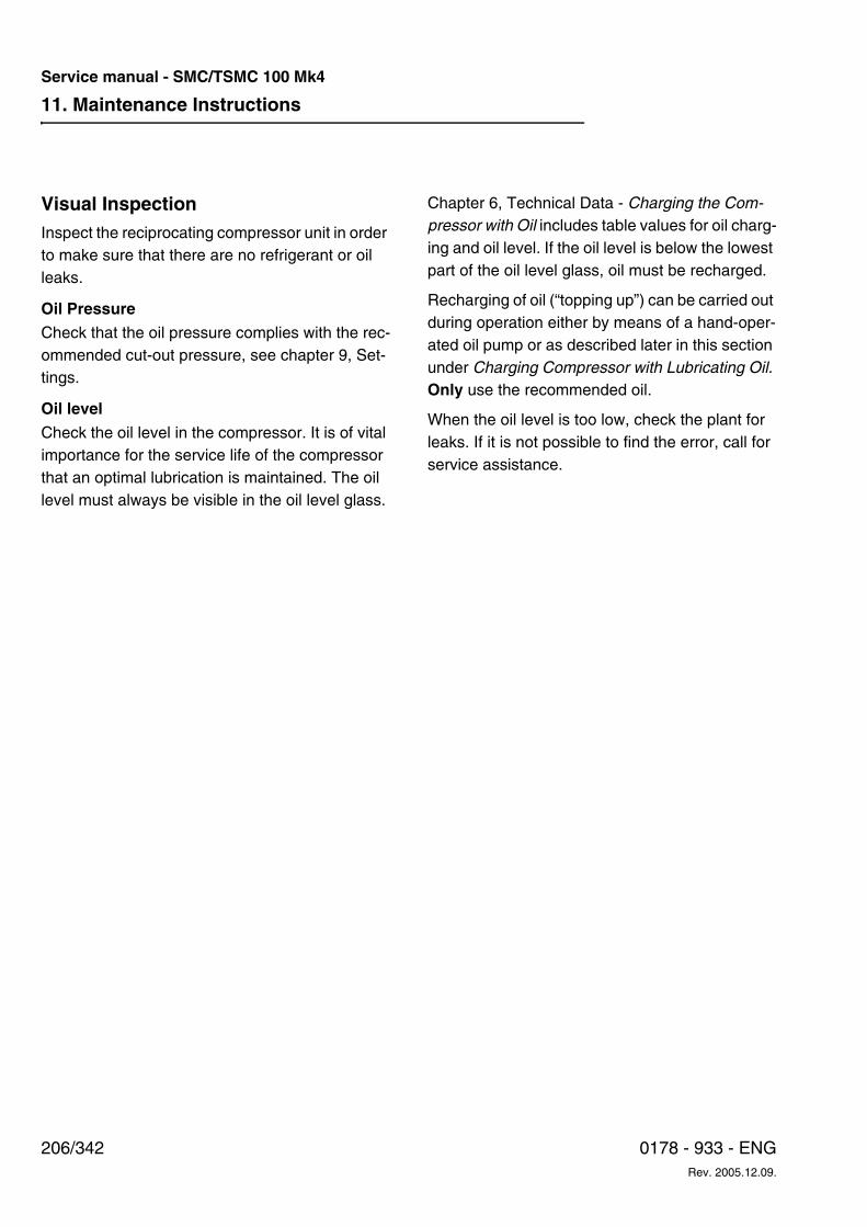
11. Maintenance Instructions
206/342 0178 - 933 - ENGRev. 2005.12.09.
Service manual - SMC/TSMC 100 Mk4
Visual InspectionInspect the reciprocating compressor unit in order to make sure that there are no refrigerant or oil leaks.
Oil PressureCheck that the oil pressure complies with the rec-ommended cut-out pressure, see chapter 9, Set-tings.
Oil level
Check the oil level in the compressor. It is of vital importance for the service life of the compressor that an optimal lubrication is maintained. The oil level must always be visible in the oil level glass.
Chapter 6, Technical Data - Charging the Com-pressor with Oil includes table values for oil charg-ing and oil level. If the oil level is below the lowest part of the oil level glass, oil must be recharged.
Recharging of oil (“topping up”) can be carried out during operation either by means of a hand-oper-ated oil pump or as described later in this section under Charging Compressor with Lubricating Oil. Only use the recommended oil.
When the oil level is too low, check the plant for leaks. If it is not possible to find the error, call for service assistance.
11. Maintenance Instructions
207/3420178 - 933 - ENGRev. 2005.12.09.
Service manual - SMC/TSMC 100 Mk4
11 m
aint
enan
ce in
stru
ctio
ns.fm
General Rules for Use of Lubricating Oil in Refrigeration Compressors• Only fresh, clean refrigeration machine oil
may be charged. Oil tapped from the evaporator system in an ammonia plant must not be reused in the compressor.
• Use grade of oil originally prescribed for compressor.
• As far as possible, avoid mixing different types of oil. Mixed oil is generally inferior to the two original oils. Mixing various types of oil may give rise to formation of sludge, which will lodge in valves and filters.
• If it is necessary to switch to another brand of oil, please contact the supplier of the new oil for instructions. Note that some of the old oil may be left in the piping system.
• The refrigeration oil must be free of mois-ture, which may give rise to operating mal-functions and attacks of corrosion.
The oil should, therefore, be purchased in con-tainers corresponding to the quantity to be used for a single, or at most, two top-ups. The oil con-
tainers must be kept carefully sealed. If all the oil in a container is not used in one go, the container should be tightly sealed and stored in a warm place to prevent the absorption of moisture.
Note:It is inadvisable to reuse oil which has been drawn from a compressor or plant. This oil will have ab-sorbed moisture from the air and may cause oper-ating problems. Always switch off the power to the heating rod be-fore drawing off the oil.
Chapter 6, Technical Data - Charging the Com-pressor with Oil includes a detailed description of lubricating oils as well as directions for selecting the correct oil.
WCaution!
Never add oil until the reason for the drop in the oil level has been found and remedied.
WWarning!
Corrosive oil is a hazardous substance. It can cause irritation and other injuries.
11. Maintenance Instructions
208/342 0178 - 933 - ENGRev. 2005.12.09.
Service manual - SMC/TSMC 100 Mk4
Assessing the OilRefrigeration machine oil is a vital part of the com-pressor as it not only lubricates and cools the movable parts of the compressor, but also pre-vents abrasive particles from entering the bear-ings.
An analysis of the oil can give important informa-tion on how the compressor is running. We would, therefore, advise that the oil analyses be carried out at the intervals prescribed.
An oil sample must be drawn off while the com-pressor is in operation, which gives a represent-ative sample. Before taking the sample, clean the drain valve and drain off some oil. This is done to prevent any impurities which may have accumu-lated in the valve or the piping from mixing with the oil sample.
Analytical EvaluationNaturally, the oil sample can be analysed by the oil company which supplies the oil. As a special offer to our customers Sabroe Refrigeration has developed an analytical concept, in cooperation with Mobil Oil, which is able to analyse all oil makes. This will mean a uni-form reporting of the results.
The analysis allows the following to be deter-mined:
• Whether or not the oil is still usable, if nec-essary after filtering.
• Whether solid particles possibly present in the oil originate from the bearings or other components exposed to wear and tear in
which case the compressor must be in-spected.
• Each report will include the corresponding measuring results from the previous 3 oil analyses. In this way it is possible to follow up on the state of both the oil and the com-pressor from one analysis to the next.
Procedure• A form set with a plastic sampling bottle and
a dispatching envelope can be requested from the local Sabroe Refrigeration repre-sentative.
• The oil sample must be drained from the cleaned oil drain valve into the sample bot-tle. Screw the lid loosely on and let the bottle stand for a few hours to enable refrigerant contained in the oil sample to evaporate be-fore sending it to the laboratory.
• Please follow the Sampling and Shipping In-structions enclosed in the form set in which the addresses of the laboratory in Holland are also mentioned.
Analysing the OilThe following table states some average values that can be applied in practice. However, be on the alert whenever the results of the analy-ses approach these values. In some cases the water content of 100 ppm in HCFC plants may be too much and thus lead to Cu-plating in the shaft seal.
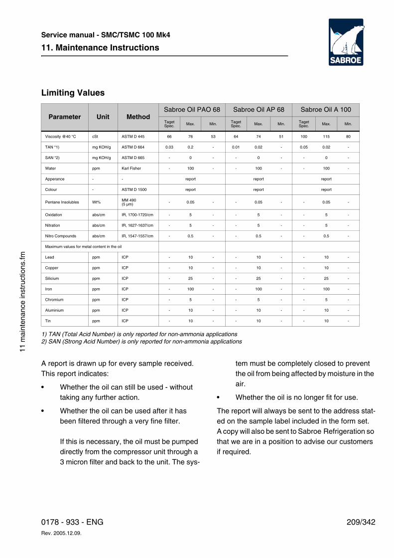
11. Maintenance Instructions
209/3420178 - 933 - ENGRev. 2005.12.09.
Service manual - SMC/TSMC 100 Mk4
11 m
aint
enan
ce in
stru
ctio
ns.fm
Limiting Values
1) TAN (Total Acid Number) is only reported for non-ammonia applications2) SAN (Strong Acid Number) is only reported for non-ammonia applications
A report is drawn up for every sample received. This report indicates:
• Whether the oil can still be used - without taking any further action.
• Whether the oil can be used after it has been filtered through a very fine filter.
If this is necessary, the oil must be pumped directly from the compressor unit through a 3 micron filter and back to the unit. The sys-
tem must be completely closed to prevent the oil from being affected by moisture in the air.
• Whether the oil is no longer fit for use.
The report will always be sent to the address stat-ed on the sample label included in the form set. A copy will also be sent to Sabroe Refrigeration so that we are in a position to advise our customers if required.
Parameter Unit MethodSabroe Oil PAO 68 Sabroe Oil AP 68 Sabroe Oil A 100
TagetSpec. Max. Min. Taget
Spec. Max. Min. TagetSpec. Max. Min.
Viscosity @40 °C cSt ASTM D 445 66 76 53 64 74 51 100 115 80
TAN *1) mg KOH/g ASTM D 664 0.03 0.2 - 0.01 0.02 - 0.05 0.02 -
SAN *2) mg KOH/g ASTM D 665 - 0 - - 0 - - 0 -
Water ppm Karl Fisher - 100 - - 100 - - 100 -
Apperance - - report report report
Colour - ASTM D 1500 report report report
Pentane Insolubles Wt% MM 490(5 µm) - 0.05 - - 0.05 - - 0.05 -
Oxidation abs/cm IR, 1700-1720/cm - 5 - - 5 - - 5 -
Nitration abs/cm IR, 1627-1637/cm - 5 - - 5 - - 5 -
Nitro Compounds abs/cm IR, 1547-1557/cm - 0.5 - - 0.5 - - 0.5 -
Maximum values for metal content in the oil
Lead ppm ICP - 10 - - 10 - - 10 -
Copper ppm ICP - 10 - - 10 - - 10 -
Silicium ppm ICP - 25 - - 25 - - 25 -
Iron ppm ICP - 100 - - 100 - - 100 -
Chromium ppm ICP - 5 - - 5 - - 5 -
Aluminium ppm ICP - 10 - - 10 - - 10 -
Tin ppm ICP - 10 - - 10 - - 10 -
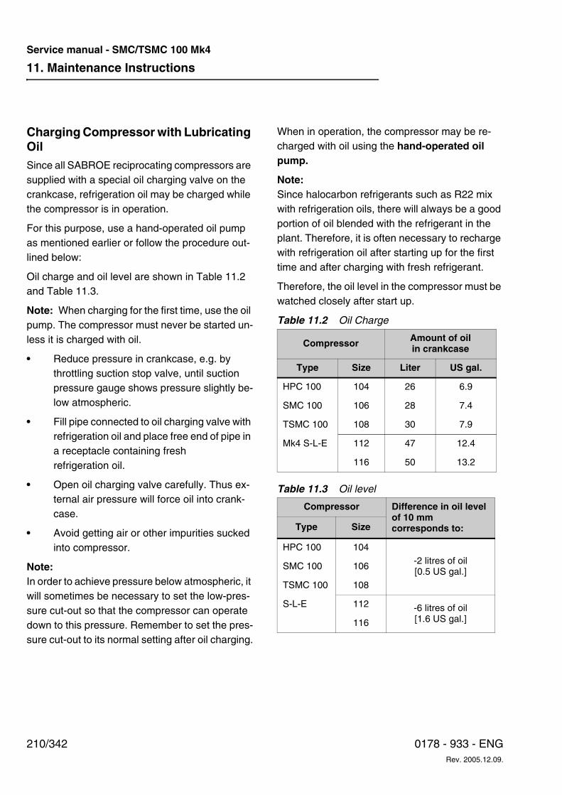
11. Maintenance Instructions
210/342 0178 - 933 - ENGRev. 2005.12.09.
Service manual - SMC/TSMC 100 Mk4
Charging Compressor with Lubricating Oil Since all SABROE reciprocating compressors are supplied with a special oil charging valve on the crankcase, refrigeration oil may be charged while the compressor is in operation.
For this purpose, use a hand-operated oil pump as mentioned earlier or follow the procedure out-lined below:
Oil charge and oil level are shown in Table 11.2 and Table 11.3.
Note: When charging for the first time, use the oil pump. The compressor must never be started un-less it is charged with oil.
• Reduce pressure in crankcase, e.g. by throttling suction stop valve, until suction pressure gauge shows pressure slightly be-low atmospheric.
• Fill pipe connected to oil charging valve with refrigeration oil and place free end of pipe in a receptacle containing fresh refrigeration oil.
• Open oil charging valve carefully. Thus ex-ternal air pressure will force oil into crank-case.
• Avoid getting air or other impurities sucked into compressor.
Note:In order to achieve pressure below atmospheric, it will sometimes be necessary to set the low-pres-sure cut-out so that the compressor can operate down to this pressure. Remember to set the pres-sure cut-out to its normal setting after oil charging.
When in operation, the compressor may be re-charged with oil using the hand-operated oil pump.
Note:Since halocarbon refrigerants such as R22 mix with refrigeration oils, there will always be a good portion of oil blended with the refrigerant in the plant. Therefore, it is often necessary to recharge with refrigeration oil after starting up for the first time and after charging with fresh refrigerant.
Therefore, the oil level in the compressor must be watched closely after start up.
Table 11.2 Oil Charge
Table 11.3 Oil level
Compressor Amount of oil in crankcase
Type Size Liter US gal.
HPC 100 104 26 6.9
SMC 100 106 28 7.4
TSMC 100 108 30 7.9
Mk4 S-L-E 112 47 12.4
116 50 13.2
Compressor Difference in oil level of 10 mm corresponds to:Type Size
HPC 100 104-2 litres of oil[0.5 US gal.]
SMC 100 106
TSMC 100 108
S-L-E 112 -6 litres of oil[1.6 US gal.]116
11. Maintenance Instructions
211/3420178 - 933 - ENGRev. 2005.12.09.
Service manual - SMC/TSMC 100 Mk4
11 m
aint
enan
ce in
stru
ctio
ns.fm
Searching for LeaksSearching for leaks can be carried out in many ways. The most frequently used method is to use a leak detector. After finding a leak, a good way to find its exact location is to apply soapy water.
In case of large leaks, divide the system into sec-tions by closing the valve to prevent needless amounts of refrigerant from leaking out.
Proceed as follows to search for leaks:
• Ascertain whether there is a shortage of re-frigerant by checking the level of the refrig-erant in the condenser or the receiver.
• Also check that the measuring equipment is functioning properly and do not give false readings.
• Search for drops of oil at couplings, flanged joints, valve spindles, shaft seals, safety valves, oil filter and the like.
• Ventilate in advance to remove any gase-ous refrigerant from the searching area.
• Check that the required refrigerant pressure is present in the part of the system in ques-tion.
• Conduct the search systematically to make certain that all possible sources of leaks are checked.
Do not forget any of the following:
• Threaded joints and flanged joints
• Valve spindles
• Shaft seals
• Relief equipment
• Expansion valves
• Pressure transducers and pressure gauges
• Safety valves
Method of Searching for Leaks
HFC/HCFC
Move the leak-detection probe slowly along the places where leaks are possible and move all the way around couplings and the like.
Continue searching for leaks even after finding one (the system may be leaking at other places).
Before proceeding, wipe away any oil that is present after fixing a leak. Write all observations into a log book (searching, fixing, topping up the refrigerant etc.).
After concluding maintenance or repairing tasks, check that the reciprocating compressor unit is tight. The air that remains must be removed with a vacuum pump before putting the unit back in op-eration.
Ammonia
Leak detection with ammonia is carried out in the same way as with HFC/HCFC, using sulphur sticks instead of the leak-detection probe.
Motor LubricationFor electric motors it is absolutely essential to lu-bricate the bearings in the right way and use the correct type of grease.
For correct service, please follow the instructions of the motor manufacturer.
Replacing Motor Bearings
Contact Sabroe Refrigeration's service organization.
Major Overhaul of the Compressor
Contact Sabroe Refrigeration's service organization.
11. Maintenance Instructions
212/342 0178 - 933 - ENGRev. 2005.12.09.
Service manual - SMC/TSMC 100 Mk4
12. Fault-finding Instructions
213/3420178 - 933 - ENGRev. 2005.12.09.
Service manual - SMC/TSMC 100 Mk4
12 fa
ult-
findi
ng in
stru
ctio
ns.fm
12. Fault-finding Instructions The purpose of this chapter is to:
• Describe the dangers resulting from failure to comply with instructions and safety pre-cautions during the fault-finding process.
• Provide a list of common problems.
• For each problem, suggest cause(s) and recommend actions to solve the problem.
This chapter is primarily intended for service engi-neers.
WDanger!
Risk of injury to personnel and damage to equip-ment! Always read the safety precautions belong-ing to this equipment before start. Failure to com-ply with safety precautions may cause death or in-jury to personnel. It may also cause damage to or destruction of the equipment.
Safety Precautions
WDanger!
Risk of injury to personnel and damage to equip-ment! In addition to the safety precautions in this chapter, always read the general safety precau-tions belonging to this equipment before starting the fault-finding process. Failure to comply with safety precautions may cause death or injury to personnel. It may also cause damage to or de-struction of the equipment.
Qualification RequirementsFault-finding requires highly skilled, qualified per-sonnel with extensive knowledge of the system in question. The formal requirements include a knowledge of refrigeration engineering and famili-arity with the system in question.
12. Fault-finding Instructions
214/342 0178 - 933 - ENGRev. 2005.12.09.
Service manual - SMC/TSMC 100 Mk4
How to Carry Out Fault-findingFault-finding is necessary in three general situa-tions:
• When acute problems ariseTo find out what caused the reciprocating compressor unit to malfunction.
• MaintenanceDuring scheduled maintenance to detect operational deficiencies that can lead to fu-ture disturbances or uneconomical operation.
• Starting up after repairsAfter a damaged component has been re-placed (for example) to find external rea-sons why the component failed.
Reciprocating Compressor Unit as Part of the Overall SystemThe functions performed by a reciprocating com-pressor unit — and thus the errors that may occur — are often linked to the overall system (plant) in which it is operating.
On the low pressure side, the reciprocating com-pressor unit is connected to an evaporator as well as to a system used for distributing the chilled me-dium.
On the high pressure side, it is connected to a condenser as well as to a system used for the coolant.
A control system performs monitoring, control and regulation. Most of the errors which occur are in-dicated by the control system.
Personnel who carry out fault-finding must take into account all of the above mentioned system parts to obtain a clear picture of what is happen-ing.
Systematic Fault-findingFault-finding should be carried out systematically. The personnel will often know what the problem is, and find the error immediately. If the personnel has a thorough knowledge of the unit in question, they will often know the cause of the problem.
If this is not the case, consider the situation quiet-ly. Do not change any settings immediately. Spend some time working out a systematic ap-proach.
Operating ConditionExperience shows that pressure and temperature variations in a refrigeration system can provide in-formation about the refrigeration plant operating conditions.
In particular, the suction and condensing pressure as well as the temperatures of suction and dis-charge gases may provide important information as to the operating conditions of the plant.
Considerable changes in the operating conditions can often be produced by only very small changes in the variable pressure and temperatures.
Using the following troubleshooting chart, it is pos-sible to ascertain the cause of and remedy for any operating disturbance.
Using the Troubleshooting ChartIn the following chart each individual error possi-bility is indicated by a code number in the left hand column, with the error briefly described in the sec-ond column. The third column states code num-bers for the possible causes of the error.
The code numbers refer to the subsequent chart. The section entitled Remedying Malfunctions states how to remedy the observed error. See the following example for the correct procedure.
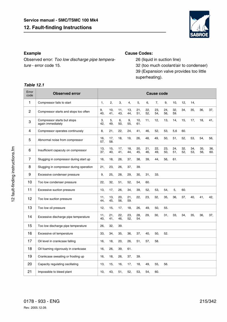
12. Fault-finding Instructions
215/3420178 - 933 - ENGRev. 2005.12.09.
Service manual - SMC/TSMC 100 Mk4
12 fa
ult-
findi
ng in
stru
ctio
ns.fm
ExampleObserved error: Too low discharge pipe tempera-ture - error code 15.
Cause Codes: 26 (liquid in suction line)32 (too much coolant/air to condenser)39 (Expansion valve provides too little superheating).
Table 12.1
Errorcode Observed error Cause code
1 Compressor fails to start 1, 2, 3, 4, 5, 6, 7, 9, 10, 12, 14,
2 Compressor starts and stops too often 9,40,
10,41,
11,43,
13,44,
21,51,
22,52,
23,54,
24,56,
32,59.
34, 35, 36, 37,
3 Compressor starts but stops again immediately
3,42,
5,49,
6,50,
9,55,
10,61.
11, 12, 13, 14, 15, 17, 18, 41,
4 Compressor operates continuosly 8, 21, 22, 24, 41, 46, 52, 53, 5,6 60.
5 Abnormal noise from compressor 16,57,
17,58.
18, 19, 26, 48, 49, 50, 51, 52, 53, 54, 56,
6 Insufficient capacuty on compressor 13,37,
15,40,
17,41,
18,44,
20,45,
21,46,
22,49,
23,50,
24,51,
32,52,
34,53,
35,56,
36,60.
7 Slugging in compressor during start up 16, 18, 26, 37, 38, 39, 44, 56, 61.
8 Slugging in compressor during operation 21, 23, 26, 37, 39.
9 Excessive condenser pressure 9, 25, 28, 29, 30, 31, 33.
10 Too low condenser pressure 22, 32, 51, 52, 54, 60.
11 Excessive suction pressure 13, 17, 26, 34, 39, 52, 53, 54, 5, 60.
12 Too low suction pressure 11,44,
13,45,
20,56,
21,59.
22, 23, 32, 35, 36, 37, 40, 41, 42,
13 Too low oil pressure 12, 15, 17, 18, 26, 49, 50, 55.
14 Excessive discharge pipe temperature 11,40,
21,41,
22,46,
23,52,
28,54.
29, 30, 31, 33, 34, 35, 36, 37,
15 Too low discharge pipe temperature 26, 32, 39.
16 Excessive oil temperature 33, 34, 35, 36, 37, 40, 50, 52.
17 Oil level in crankcase falling 16, 18, 20, 26, 51, 57, 58.
18 Oil foaming vigorously in crankcase 16, 26, 39, 61.
19 Crankcase sweating or frosting up 16, 18, 26, 37, 39.
20 Capacity regulating oscillating 13, 15, 16, 17, 18, 49, 55, 56.
21 Impossible to bleed plant 10, 43, 51, 52, 53, 54, 60.
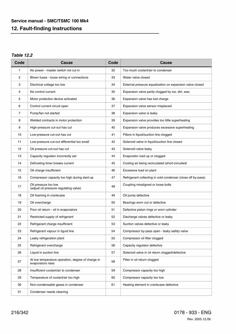
12. Fault-finding Instructions
216/342 0178 - 933 - ENGRev. 2005.12.09.
Service manual - SMC/TSMC 100 Mk4
Table 12.2
Code Cause Code Cause
1 No power - master switch not cut in 32 Too much coolant/air to condenser
2 Blown fuses - loose wiring or connections 33 Water valve closed
3 Electrical voltage too low 34 External pressure equalization on expansion valve closed
4 No control current 35 Expansion valve partly clogged by ice, dirt, wax.
5 Motor protection device activated 36 Expansion valve has lost charge
6 Control current circuit open 37 Expansion valve sensor misplaced
7 Pump/fan not started 38 Expansion valve is leaky
8 Welded contracts in motor protection 39 Expansion valve provides too little superheating
9 High-pressure cut-out has cut 40 Expansion valve produces excessive superheating
10 Low-pressure cut-out has cut 41 Filters in liquid/suction line clogged
11 Low-pressure cut-out differential too small 42 Solenoid valve in liquid/suction line closed
12 Oil pressure cut-out has cut 43 Solenoid valve leaky
13 Capacity regulator incorrectly set 44 Evaporator iced up or clogged
14 Defrosting timer breaks current 45 Cooling air being recirculated (short-circuited)
15 Oil charge insufficient 46 Excessive load on plant
16 Compressor capacity too high during start-up 47 Refrigerant collecting in cold condenser (close off by-pass)
17 Oil pressure too low (adjust oil pressure regulating valve) 48 Coupling misaligned or loose bolts
18 Oil foaming in crankcase 49 Oil pump defective
19 Oil overcharge 50 Bearings worn out or defective
20 Poor oil return - oil in evaporators 51 Defective piston rings or worn cylinder
21 Restricted supply of refrigerant 52 Discharge valves defective or leaky
22 Refrigerant charge insufficient 53 Suction valves defective or leaky
23 Refrigerant vapour in liguid line 54 Compressor by-pass open - leaky safety valve
24 Leaky refrigeration plant 55 Compressor oil filter clogged
25 Refrigerant overcharge 56 Capacity regulator defective
26 Liquid in suction line 57 Solenoid valve in oil return clogged/defective
27 At low temperature operation, degree of charge in evaporators rises 58 Filter in oil return clogged
28 Insufficient coolant/air to condenser 59 Compressor capacity too high
29 Temperature of coolant/air too high 60 Compressor capacity too low
30 Non-condensable gases in condenser 61 Heating element in crankcase defective
31 Condenser needs cleaning
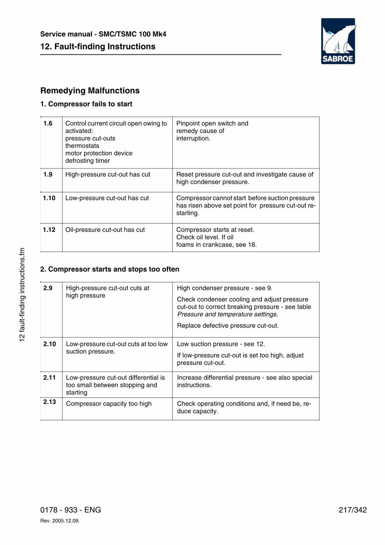
12. Fault-finding Instructions
217/3420178 - 933 - ENGRev. 2005.12.09.
Service manual - SMC/TSMC 100 Mk4
12 fa
ult-
findi
ng in
stru
ctio
ns.fm
Remedying Malfunctions
1. Compressor fails to start
2. Compressor starts and stops too often
1.6 Control current circuit open owing to activated: pressure cut-outsthermostats motor protection device defrosting timer
Pinpoint open switch andremedy cause of interruption.
1.9 High-pressure cut-out has cut Reset pressure cut-out and investigate cause of high condenser pressure.
1.10 Low-pressure cut-out has cut Compressor cannot start before suction pressure has risen above set point for pressure cut-out re-starting.
Oil-pressure cut-out has cut Compressor starts at reset. Check oil level. If oil foams in crankcase, see 18.
1.12
Low-pressure cut-out cuts at too low suction pressure.
High-pressure cut-out cuts at high pressure
High condenser pressure - see 9.
Check condenser cooling and adjust pressure cut-out to correct breaking pressure - see table Pressure and temperature settings.
Replace defective pressure cut-out.
2.9
Low suction pressure - see 12.
If low-pressure cut-out is set too high, adjust pressure cut-out.
2.10
Low-pressure cut-out differential is too small between stopping and starting
Increase differential pressure - see also special instructions.
2.11
Compressor capacity too high Check operating conditions and, if need be, re-duce capacity.
2.13
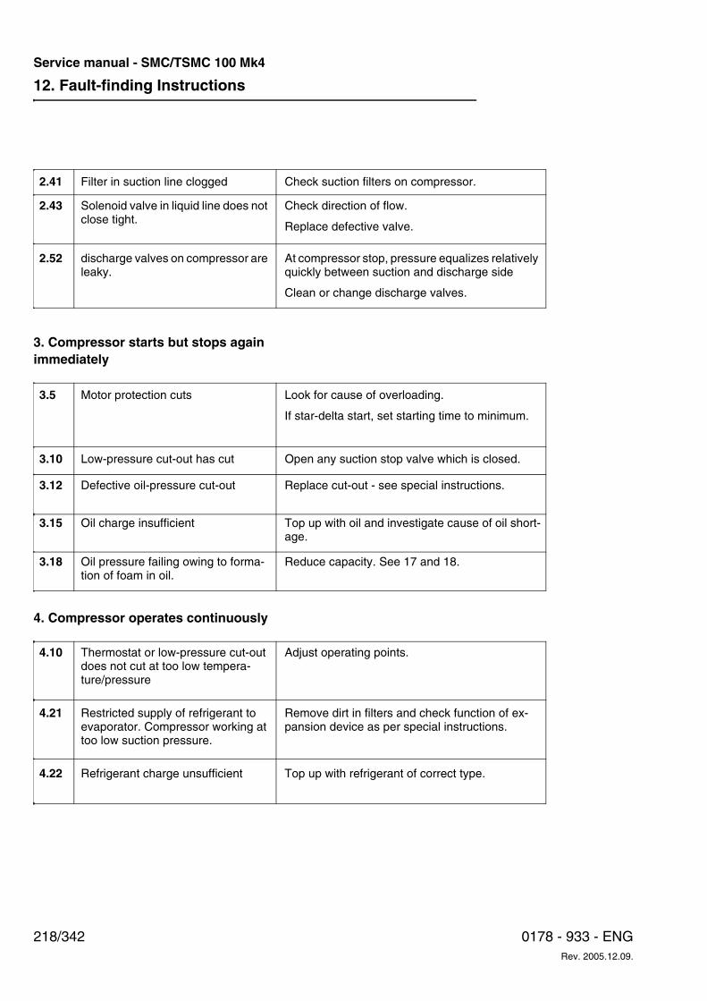
12. Fault-finding Instructions
218/342 0178 - 933 - ENGRev. 2005.12.09.
Service manual - SMC/TSMC 100 Mk4
3. Compressor starts but stops again immediately
4. Compressor operates continuously
discharge valves on compressor are leaky.
At compressor stop, pressure equalizes relatively quickly between suction and discharge side
Clean or change discharge valves.
2.52
Filter in suction line clogged Check suction filters on compressor.2.41
Solenoid valve in liquid line does not close tight.
Check direction of flow.
Replace defective valve.
2.43
Oil charge insufficient Top up with oil and investigate cause of oil short-age.
3.15
Low-pressure cut-out has cut Open any suction stop valve which is closed.3.10
Oil pressure failing owing to forma-tion of foam in oil.
Reduce capacity. See 17 and 18.3.18
Defective oil-pressure cut-out Replace cut-out - see special instructions.3.12
Motor protection cuts Look for cause of overloading.
If star-delta start, set starting time to minimum.
3.5
Thermostat or low-pressure cut-out does not cut at too low tempera-ture/pressure
Adjust operating points. 4.10
Refrigerant charge unsufficient Top up with refrigerant of correct type.4.22
Restricted supply of refrigerant to evaporator. Compressor working at too low suction pressure.
Remove dirt in filters and check function of ex-pansion device as per special instructions.
4.21
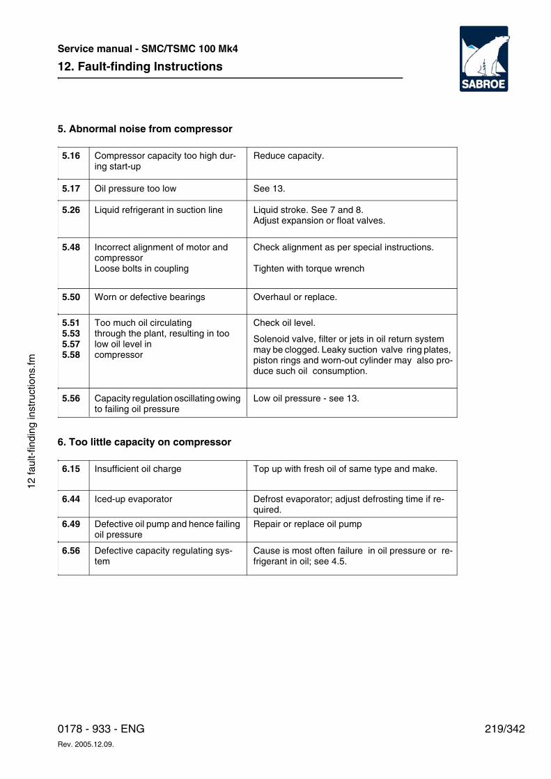
12. Fault-finding Instructions
219/3420178 - 933 - ENGRev. 2005.12.09.
Service manual - SMC/TSMC 100 Mk4
12 fa
ult-
findi
ng in
stru
ctio
ns.fm
5. Abnormal noise from compressor
6. Too little capacity on compressor
Compressor capacity too high dur-ing start-up
Reduce capacity. 5.16
Capacity regulation oscillating owing to failing oil pressure
Low oil pressure - see 13. 5.56
Oil pressure too low See 13.5.17
Liquid refrigerant in suction line Liquid stroke. See 7 and 8. Adjust expansion or float valves.
5.26
Incorrect alignment of motor and compressor Loose bolts in coupling
Check alignment as per special instructions.
Tighten with torque wrench
5.48
Worn or defective bearings Overhaul or replace.5.50
Too much oil circulatingthrough the plant, resulting in too low oil level in compressor
Check oil level.
Solenoid valve, filter or jets in oil return system may be clogged. Leaky suction valve ring plates, piston rings and worn-out cylinder may also pro-duce such oil consumption.
5.515.535.575.58
Insufficient oil charge Top up with fresh oil of same type and make.6.15
Iced-up evaporator Defrost evaporator; adjust defrosting time if re-quired.
6.44
Defective oil pump and hence failing oil pressure
Repair or replace oil pump6.49
Defective capacity regulating sys-tem
Cause is most often failure in oil pressure or re-frigerant in oil; see 4.5.
6.56
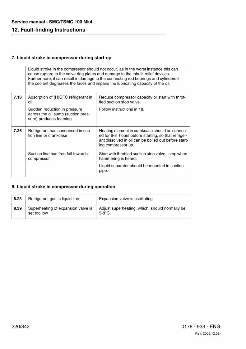
12. Fault-finding Instructions
220/342 0178 - 933 - ENGRev. 2005.12.09.
Service manual - SMC/TSMC 100 Mk4
7. Liquid stroke in compressor during start-up
8. Liquid stroke in compressor during operation
Refrigerant has condensed in suc-tion line or crankcase
Heating element in crankcase should be connect-ed for 6-8 hours before starting, so that refriger-ant dissolved in oil can be boiled out before start-ing compressor up.
7.26
Liquid stroke in the compressor should not occur, as in the worst instance this can cause rupture to the valve ring plates and damage to the inbuilt relief devices. Furthermore, it can result in damage to the connecting rod bearings and cylinders if the coolant degreases the faces and impairs the lubricating capacity of the oil.
Adsorption of (H)CFC refrigerant in oil
Sudden reduction in pressure across the oil sump (suction pres-sure) produces foaming
Reduce compressor capacity or start with throt-tled suction stop valve.
Follow instructions in 18.
7.18
Suction line has free fall towards compressor
Start with throttled suction stop valve - stop when hammering is heard.
Liquid separator should be mounted in suction pipe.
Refrigerant gas in liquid line Expansion valve is oscillating.8.23
Superheating of expansion valve is set too low
Adjust superheating, which should normally be 5-8°C.
8.39
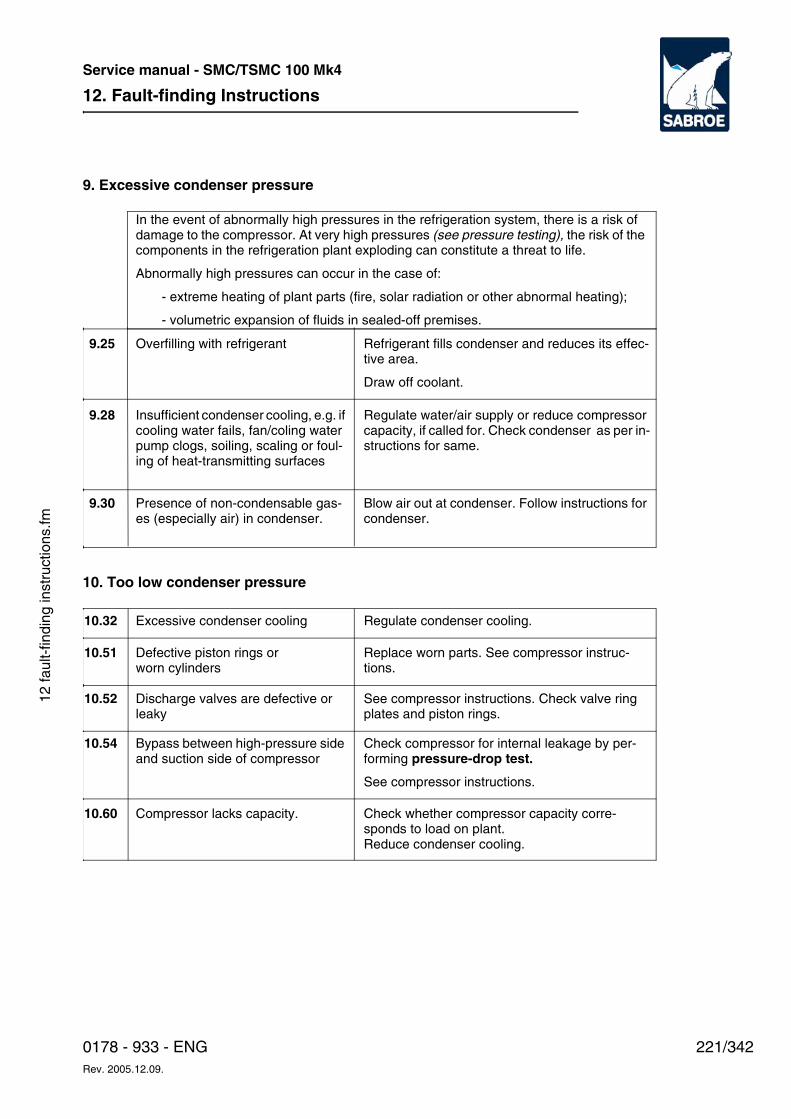
12. Fault-finding Instructions
221/3420178 - 933 - ENGRev. 2005.12.09.
Service manual - SMC/TSMC 100 Mk4
12 fa
ult-
findi
ng in
stru
ctio
ns.fm
9. Excessive condenser pressure
10. Too low condenser pressure
Overfilling with refrigerant Refrigerant fills condenser and reduces its effec-tive area.
Draw off coolant.
9.25
Presence of non-condensable gas-es (especially air) in condenser.
Blow air out at condenser. Follow instructions for condenser.
9.30
In the event of abnormally high pressures in the refrigeration system, there is a risk of damage to the compressor. At very high pressures (see pressure testing), the risk of the components in the refrigeration plant exploding can constitute a threat to life.
Abnormally high pressures can occur in the case of:
- extreme heating of plant parts (fire, solar radiation or other abnormal heating);
- volumetric expansion of fluids in sealed-off premises.
Insufficient condenser cooling, e.g. if cooling water fails, fan/coling water pump clogs, soiling, scaling or foul-ing of heat-transmitting surfaces
Regulate water/air supply or reduce compressor capacity, if called for. Check condenser as per in-structions for same.
9.28
Excessive condenser cooling Regulate condenser cooling.10.32
Compressor lacks capacity. Check whether compressor capacity corre-sponds to load on plant. Reduce condenser cooling.
10.60
Defective piston rings or worn cylinders
Replace worn parts. See compressor instruc-tions.
10.51
Discharge valves are defective or leaky
See compressor instructions. Check valve ring plates and piston rings.
10.52
Bypass between high-pressure side and suction side of compressor
Check compressor for internal leakage by per-forming pressure-drop test.
See compressor instructions.
10.54
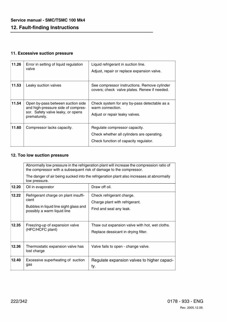
12. Fault-finding Instructions
222/342 0178 - 933 - ENGRev. 2005.12.09.
Service manual - SMC/TSMC 100 Mk4
11. Excessive suction pressure
12. Too low suction pressure
Error in setting of liquid regulation valve
Liquid refrigerant in suction line.
Adjust, repair or replace expansion valve.
11.26
Compressor lacks capacity. Regulate compressor capacity.
Check whether all cylinders are operating.
Check function of capacity regulator.
11.60
Leaky suction valves See compressor instructions. Remove cylinder covers; check valve plates. Renew if needed.
11.53
Open by-pass between suction side and high-pressure side of compres-sor. Safety valve leaky, or opens prematurely.
Check system for any by-pass detectable as a warm connection.
Adjust or repair leaky valves.
11.54
Oil in evaporator Draw off oil.12.20
Abnormally low pressure in the refrigeration plant will increase the compression ratio of the compressor with a subsequent risk of damage to the compressor.
The danger of air being sucked into the refrigeration plant also increases at abnormally low pressure.
Refrigerant charge on plant insuffi-cient
Bubbles in liquid line sight glass and possibly a warm liquid line
Check refrigerant charge.
Charge plant with refrigerant.
Find and seal any leak.
12.22
Freezing-up of expansion valve (HFC/HCFC plant)
Thaw out expansion valve with hot, wet cloths.
Replace dessicant in drying filter.
12.35
Thermostatic expansion valve has lost charge
Valve fails to open - change valve.12.36
Excessive superheating of suction gas
Regulate expansion valves to higher capaci-ty.
12.40
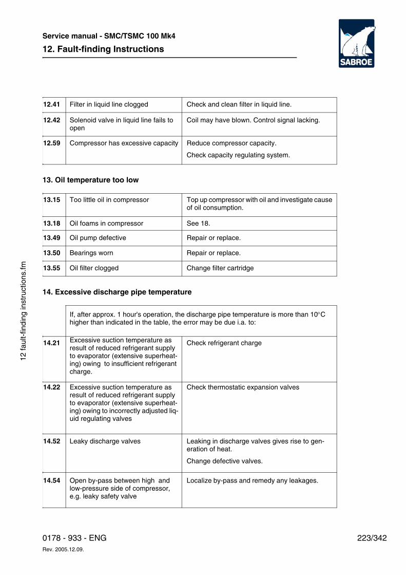
12. Fault-finding Instructions
223/3420178 - 933 - ENGRev. 2005.12.09.
Service manual - SMC/TSMC 100 Mk4
12 fa
ult-
findi
ng in
stru
ctio
ns.fm
13. Oil temperature too low
14. Excessive discharge pipe temperature
Compressor has excessive capacity Reduce compressor capacity.
Check capacity regulating system.
12.59
Filter in liquid line clogged Check and clean filter in liquid line.12.41
Solenoid valve in liquid line fails to open
Coil may have blown. Control signal lacking.12.42
Too little oil in compressor Top up compressor with oil and investigate cause of oil consumption.
13.15
Oil filter clogged Change filter cartridge13.55
Oil foams in compressor See 18.13.18
Oil pump defective Repair or replace.13.49
Bearings worn Repair or replace.13.50
If, after approx. 1 hour's operation, the discharge pipe temperature is more than 10°C higher than indicated in the table, the error may be due i.a. to:
Open by-pass between high and low-pressure side of compressor, e.g. leaky safety valve
Localize by-pass and remedy any leakages. 14.54
Excessive suction temperature as result of reduced refrigerant supply to evaporator (extensive superheat-ing) owing to insufficient refrigerant charge.
Check refrigerant charge 14.21
Excessive suction temperature as result of reduced refrigerant supply to evaporator (extensive superheat-ing) owing to incorrectly adjusted liq-uid regulating valves
Check thermostatic expansion valves14.22
Leaky discharge valves Leaking in discharge valves gives rise to gen-eration of heat.
Change defective valves.
14.52
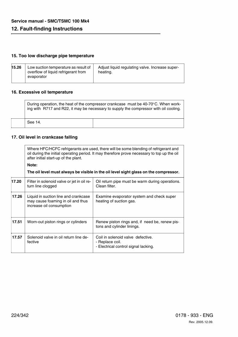
12. Fault-finding Instructions
224/342 0178 - 933 - ENGRev. 2005.12.09.
Service manual - SMC/TSMC 100 Mk4
15. Too low discharge pipe temperature
16. Excessive oil temperature
17. Oil level in crankcase falling
Low suction temperature as result of overflow of liquid refrigerant from evaporator
Adjust liquid regulating valve. Increase super-heating.
15.26
During operation, the heat of the compressor crankcase must be 40-70°C. When work-ing with R717 and R22, it may be necessary to supply the compressor with oil cooling.
See 14.
Where HFC/HCFC refrigerants are used, there will be some blending of refrigerant and oil during the initial operating period. It may therefore prove necessary to top up the oil after initial start-up of the plant.
Note:
The oil level must always be visible in the oil level sight glass on the compressor.
Filter in solenoid valve or jet in oil re-turn line clogged
Oil return pipe must be warm during operations. Clean filter.
17.20
Liquid in suction line and crankcase may cause foaming in oil and thus increase oil consumption
Examine evaporator system and check super heating of suction gas.
17.26
Worn-out piston rings or cylinders Renew piston rings and, if need be, renew pis-tons and cylinder linings.
17.51
Solenoid valve in oil return line de-fective
Coil in solenoid valve defective. - Replace coil. - Electrical control signal lacking.
17.57
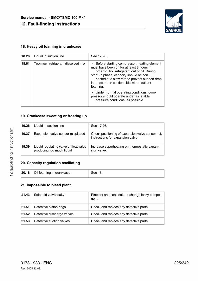
12. Fault-finding Instructions
225/3420178 - 933 - ENGRev. 2005.12.09.
Service manual - SMC/TSMC 100 Mk4
12 fa
ult-
findi
ng in
stru
ctio
ns.fm
18. Heavy oil foaming in crankcase
19. Crankcase sweating or frosting up
20. Capacity regulation oscillating
21. Impossible to bleed plant
Liquid in suction line See 17.26.18.26
Too much refrigerant dissolved in oil - Before starting compressor, heating element must have been on for at least 8 hours in
order to boil refrigerant out of oil. During start-up phase, capacity should be con-
nected at a slow rate to prevent sudden drop in pressure on suction side with resultant foaming.
- Under normal operating conditions, com-pressor should operate under as stable
pressure conditions as possible.
18.61
Liquid in suction line See 17.26.19.26
Expansion valve sensor misplaced Check positioning of expansion valve sensor - cf. instructions for expansion valve.
19.37
Liquid regulating valve or float valve producing too much liquid
Increase superheating on thermostatic expan-sion valve.
19.39
Oil foaming in crankcase See 18.20.18
Solenoid valve leaky Pinpoint and seal leak, or change leaky compo-nent.
21.43
Defective piston rings Check and replace any defective parts.21.51
Defective discharge valves Check and replace any defective parts.21.52
Defective suction valves Check and replace any defective parts. 21.53
12. Fault-finding Instructions
226/342 0178 - 933 - ENGRev. 2005.12.09.
Service manual - SMC/TSMC 100 Mk4
13. Service Instructions
227/3420178 - 933 - ENGRev. 2005.12.09.
Service manual - SMC/TSMC 100 Mk4
13 s
ervi
ce in
stru
ctio
ns.fm
13. Service InstructionsThe purpose of this chapter is to describe:
• Dangers resulting from failure to comply with safety precautions when performing maintenance tasks.
• Scheduled maintenance tasks for this equipment and how to carry them out safely.
This chapter is primarily intended for service engi-neers.
WDanger!
Risk of injury to personnel and damage to equip-ment! Always read the safety precautions belong-ing to this equipment before start. Failure to com-ply with safety precautions may cause death or in-jury to personnel. It may also cause damage to or destruction of equipment.
WDanger!
Risk of injury to personnel and damage to equip-ment! In addition to the safety precautions in this
chapter, always read the safety precautions be-longing to the equipment before changing the set-tings. Failure to comply with safety precautions may cause death or injury to personnel. It may also cause damage to or destruction of the equip-ment.
Safety Measures
WDanger!
The paragraphs that follow present some impor-tant safety considerations for this type of com-pressor unit. Before starting service work, study carefully the general safety instructions/regula-tions that apply to this series of reciprocating com-pressor units. Failure to follow these instruc-tions/regulations can lead to personal injury or even death. Moreover, the equipment can be damaged or destroyed.
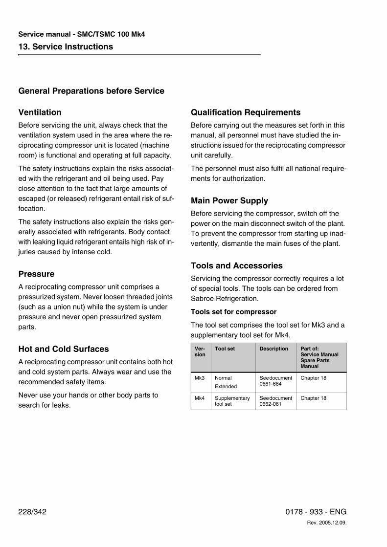
13. Service Instructions
228/342 0178 - 933 - ENGRev. 2005.12.09.
Service manual - SMC/TSMC 100 Mk4
General Preparations before Service
VentilationBefore servicing the unit, always check that the ventilation system used in the area where the re-ciprocating compressor unit is located (machine room) is functional and operating at full capacity.
The safety instructions explain the risks associat-ed with the refrigerant and oil being used. Pay close attention to the fact that large amounts of escaped (or released) refrigerant entail risk of suf-focation.
The safety instructions also explain the risks gen-erally associated with refrigerants. Body contact with leaking liquid refrigerant entails high risk of in-juries caused by intense cold.
PressureA reciprocating compressor unit comprises a pressurized system. Never loosen threaded joints (such as a union nut) while the system is under pressure and never open pressurized system parts.
Hot and Cold SurfacesA reciprocating compressor unit contains both hot and cold system parts. Always wear and use the recommended safety items.
Never use your hands or other body parts to search for leaks.
Qualification RequirementsBefore carrying out the measures set forth in this manual, all personnel must have studied the in-structions issued for the reciprocating compressor unit carefully.
The personnel must also fulfil all national require-ments for authorization.
Main Power SupplyBefore servicing the compressor, switch off the power on the main disconnect switch of the plant. To prevent the compressor from starting up inad-vertently, dismantle the main fuses of the plant.
Tools and AccessoriesServicing the compressor correctly requires a lot of special tools. The tools can be ordered from Sabroe Refrigeration.
Tools set for compressor
The tool set comprises the tool set for Mk3 and a supplementary tool set for Mk4.
Ver-sion
Tool set Description Part of:Service ManualSpare Parts Manual
Mk3 Normal
Extended
See document 0661-684
Chapter 18
Mk4 Supplementary tool set
See document 0662-061
Chapter 18
13. Service Instructions
229/3420178 - 933 - ENGRev. 2005.12.09.
Service manual - SMC/TSMC 100 Mk4
13 s
ervi
ce in
stru
ctio
ns.fm
Servicing the piston compressor
Good and careful servicing of compressor and unit is of great importance for their proper func-tioning and service life.
It is therefore recommended that these service in-structions be followed. Based on the number of operating hours, they indicate the service tasks to be carried out.
The servicing schedules also depend on the speed of the compressor. If the compressor is run-ning at less than 1200 rpm, Sabroe Refrigeration permits extended service intervals. However, the compressor must always operate within the speed recommended by Sabroe Refrigeration.See chapter 4, Description of compressor. Providing the compressor operates within the specified pressures and temperatures and the prescribed periodic services are performed, the compressor will have a long and efficient service life.
Consequently, operating conditions must be checked on a daily basis and registered in an op-erating log.
Pressure drop test:Using the pressure drop test, it is possible to check the internal tightness of the compressor from discharge to suction side. The pressure drop test is performed with the compressor at standstill, as described below:
• Immediately after stopping the compressor, read the pressure on discharge and suction side of compressor.
• Close the discharge stop valve quickly and, from the moment of closure, time how long it takes for the pressure to drop on the high pressure side of the compressor. Normally, the pressure drop should not be more than 3 bar over a period of approx. 5 minutes.
• If the pressure drops more quickly, this is due to internal leakage, which may occur:
• where the pressure valve ring plates are in bad contact with their seats (Pos. 20C against Pos. 20A and 19H);
• with defective seal Pos. 19T;
• with defective seal Pos. 19K;
• because cylinder lining and top cover have been tightened without a long mount-ing stopper being fitted. Cylinder lining is thus resting on rocker arms, Pos. 15A;
• on the by-pass valve, because the valve cone does not fit tightly against the seat, or outer O-ring Pos. 24B or inner O-ring Pos. 24C is defective.
During pressure drop testing, pay attention to any piping connections to the discharge side of the compressor, which may influence the test result.
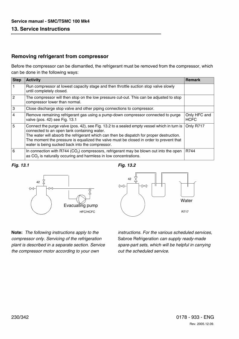
13. Service Instructions
230/342 0178 - 933 - ENGRev. 2005.12.09.
Service manual - SMC/TSMC 100 Mk4
Removing refrigerant from compressor
Before the compressor can be dismantled, the refrigerant must be removed from the compressor, which can be done in the following ways:
Fig. 13.1 Fig. 13.2
Note: The following instructions apply to the compressor only. Servicing of the refrigeration plant is described in a separate section. Service the compressor motor according to your own
instructions. For the various scheduled services, Sabroe Refrigeration can supply ready-made spare-part sets, which will be helpful in carrying out the scheduled service.
Step Activity Remark
1 Run compressor at lowest capacity stage and then throttle suction stop valve slowly until completely closed.
2 The compressor will then stop on the low pressure cut-out. This can be adjusted to stop compressor lower than normal.
3 Close discharge stop valve and other piping connections to compressor.
4 Remove remaining refrigerant gas using a pump-down compressor connected to purge valve (pos. 42) see Fig. 13.1
Only HFC and HCFC
5 Connect the purge valve (pos. 42), see Fig. 13.2 to a sealed empty vessel which in turn is connected to an open tank containing water.The water will absorb the refrigerant which can then be dispatch for proper destruction. The moment the pressure is equalized the valve must be closed in order to prevent that water is being sucked back into the compressor.
Only R717
6 In connection with R744 (CO2) compresosrs, refrigerant may be blown out into the open as CO2 is naturally occuring and harmless in low concentrations.
R744
HFC/HCFC
42
Evacuating pump
42
Water
R717
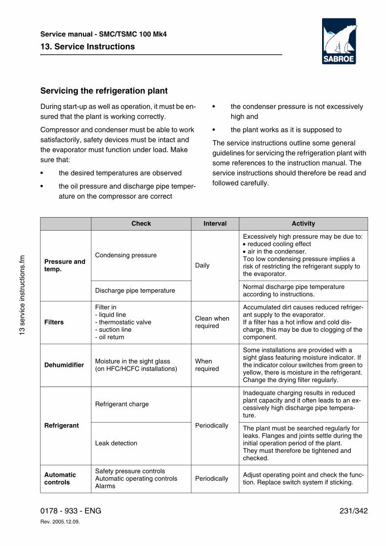
13. Service Instructions
231/3420178 - 933 - ENGRev. 2005.12.09.
Service manual - SMC/TSMC 100 Mk4
13 s
ervi
ce in
stru
ctio
ns.fm
Servicing the refrigeration plant
During start-up as well as operation, it must be en-sured that the plant is working correctly.
Compressor and condenser must be able to work satisfactorily, safety devices must be intact and the evaporator must function under load. Make sure that:
• the desired temperatures are observed
• the oil pressure and discharge pipe temper-ature on the compressor are correct
• the condenser pressure is not excessively high and
• the plant works as it is supposed to
The service instructions outline some general guidelines for servicing the refrigeration plant with some references to the instruction manual. The service instructions should therefore be read and followed carefully.
Check Interval Activity
Pressure and temp.
Condensing pressure
Daily
Excessively high pressure may be due to:• reduced cooling effect• air in the condenser.Too low condensing pressure implies a risk of restricting the refrigerant supply to the evaporator.
Discharge pipe temperatureNormal discharge pipe temperature according to instructions.
Filters
Filter in- liquid line- thermostatic valve- suction line- oil return
Clean when required
Accumulated dirt causes reduced refriger-ant supply to the evaporator. If a filter has a hot inflow and cold dis-charge, this may be due to clogging of the component.
Dehumidifier Moisture in the sight glass (on HFC/HCFC installations)
When required
Some installations are provided with a sight glass featuring moisture indicator. If the indicator colour switches from green to yellow, there is moisture in the refrigerant. Change the drying filter regularly.
Refrigerant
Refrigerant charge
Periodically
Inadequate charging results in reduced plant capacity and it often leads to an ex-cessively high discharge pipe tempera-ture.
Leak detection
The plant must be searched regularly for leaks. Flanges and joints settle during the initial operation period of the plant. They must therefore be tightened and checked.
Automatic controls
Safety pressure controls Automatic operating controlsAlarms
Periodically Adjust operating point and check the func-tion. Replace switch system if sticking.
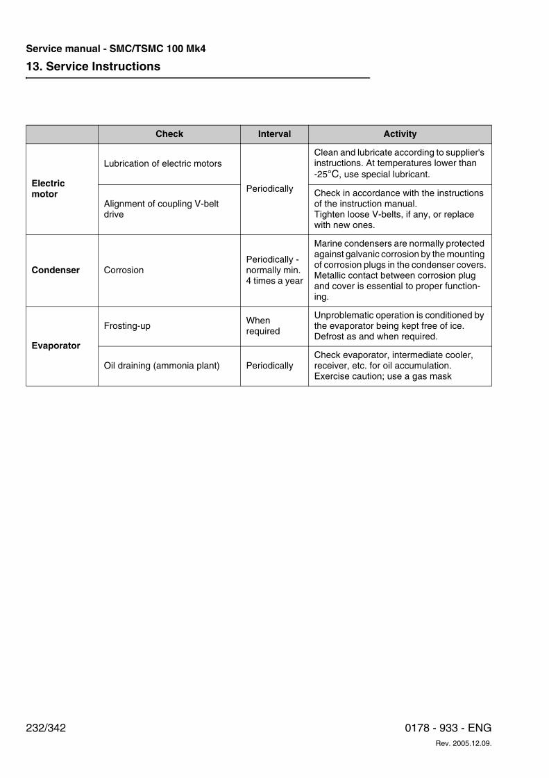
13. Service Instructions
232/342 0178 - 933 - ENGRev. 2005.12.09.
Service manual - SMC/TSMC 100 Mk4
Electric motor
Lubrication of electric motors
Periodically
Clean and lubricate according to supplier's instructions. At temperatures lower than -25°C, use special lubricant.
Alignment of coupling V-belt drive
Check in accordance with the instructions of the instruction manual. Tighten loose V-belts, if any, or replace with new ones.
Condenser CorrosionPeriodically - normally min. 4 times a year
Marine condensers are normally protected against galvanic corrosion by the mounting of corrosion plugs in the condenser covers.Metallic contact between corrosion plug and cover is essential to proper function-ing.
Evaporator
Frosting-upWhen required
Unproblematic operation is conditioned by the evaporator being kept free of ice. Defrost as and when required.
Oil draining (ammonia plant) PeriodicallyCheck evaporator, intermediate cooler, receiver, etc. for oil accumulation. Exercise caution; use a gas mask
Check Interval Activity
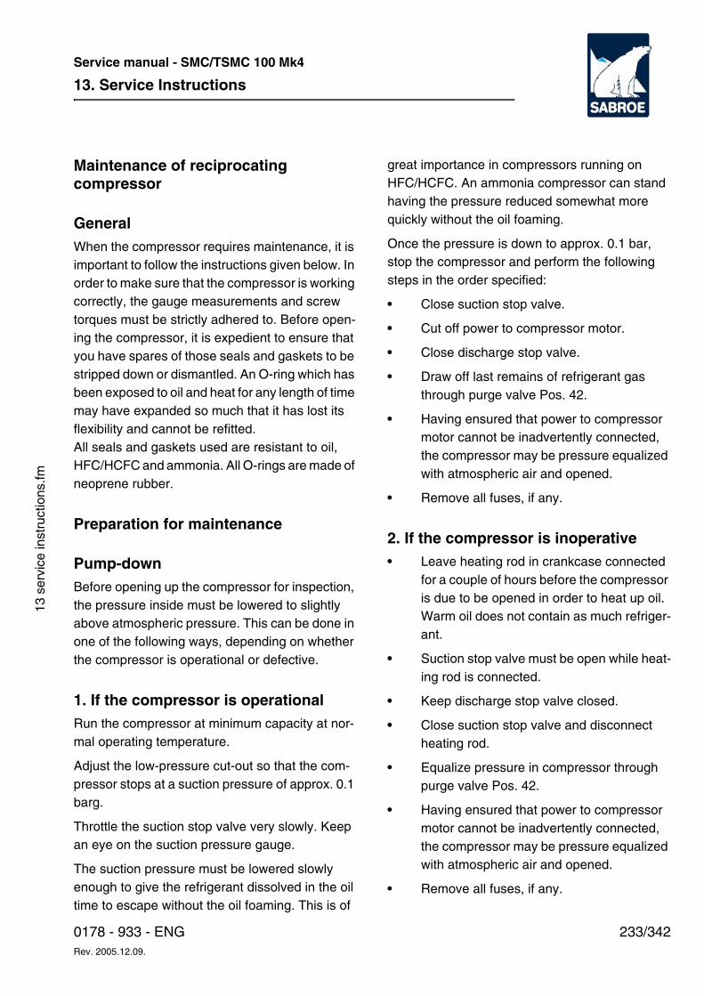
13. Service Instructions
233/3420178 - 933 - ENGRev. 2005.12.09.
Service manual - SMC/TSMC 100 Mk4
13 s
ervi
ce in
stru
ctio
ns.fm
Maintenance of reciprocating compressor
GeneralWhen the compressor requires maintenance, it is important to follow the instructions given below. In order to make sure that the compressor is working correctly, the gauge measurements and screw torques must be strictly adhered to. Before open-ing the compressor, it is expedient to ensure that you have spares of those seals and gaskets to be stripped down or dismantled. An O-ring which has been exposed to oil and heat for any length of time may have expanded so much that it has lost its flexibility and cannot be refitted.All seals and gaskets used are resistant to oil, HFC/HCFC and ammonia. All O-rings are made of neoprene rubber.
Preparation for maintenance
Pump-downBefore opening up the compressor for inspection, the pressure inside must be lowered to slightly above atmospheric pressure. This can be done in one of the following ways, depending on whether the compressor is operational or defective.
1. If the compressor is operationalRun the compressor at minimum capacity at nor-mal operating temperature.
Adjust the low-pressure cut-out so that the com-pressor stops at a suction pressure of approx. 0.1 barg.
Throttle the suction stop valve very slowly. Keep an eye on the suction pressure gauge.
The suction pressure must be lowered slowly enough to give the refrigerant dissolved in the oil time to escape without the oil foaming. This is of
great importance in compressors running on HFC/HCFC. An ammonia compressor can stand having the pressure reduced somewhat more quickly without the oil foaming.
Once the pressure is down to approx. 0.1 bar, stop the compressor and perform the following steps in the order specified:
• Close suction stop valve.
• Cut off power to compressor motor.
• Close discharge stop valve.
• Draw off last remains of refrigerant gas through purge valve Pos. 42.
• Having ensured that power to compressor motor cannot be inadvertently connected, the compressor may be pressure equalized with atmospheric air and opened.
• Remove all fuses, if any.
2. If the compressor is inoperative • Leave heating rod in crankcase connected
for a couple of hours before the compressor is due to be opened in order to heat up oil. Warm oil does not contain as much refriger-ant.
• Suction stop valve must be open while heat-ing rod is connected.
• Keep discharge stop valve closed.
• Close suction stop valve and disconnect heating rod.
• Equalize pressure in compressor through purge valve Pos. 42.
• Having ensured that power to compressor motor cannot be inadvertently connected, the compressor may be pressure equalized with atmospheric air and opened.
• Remove all fuses, if any.
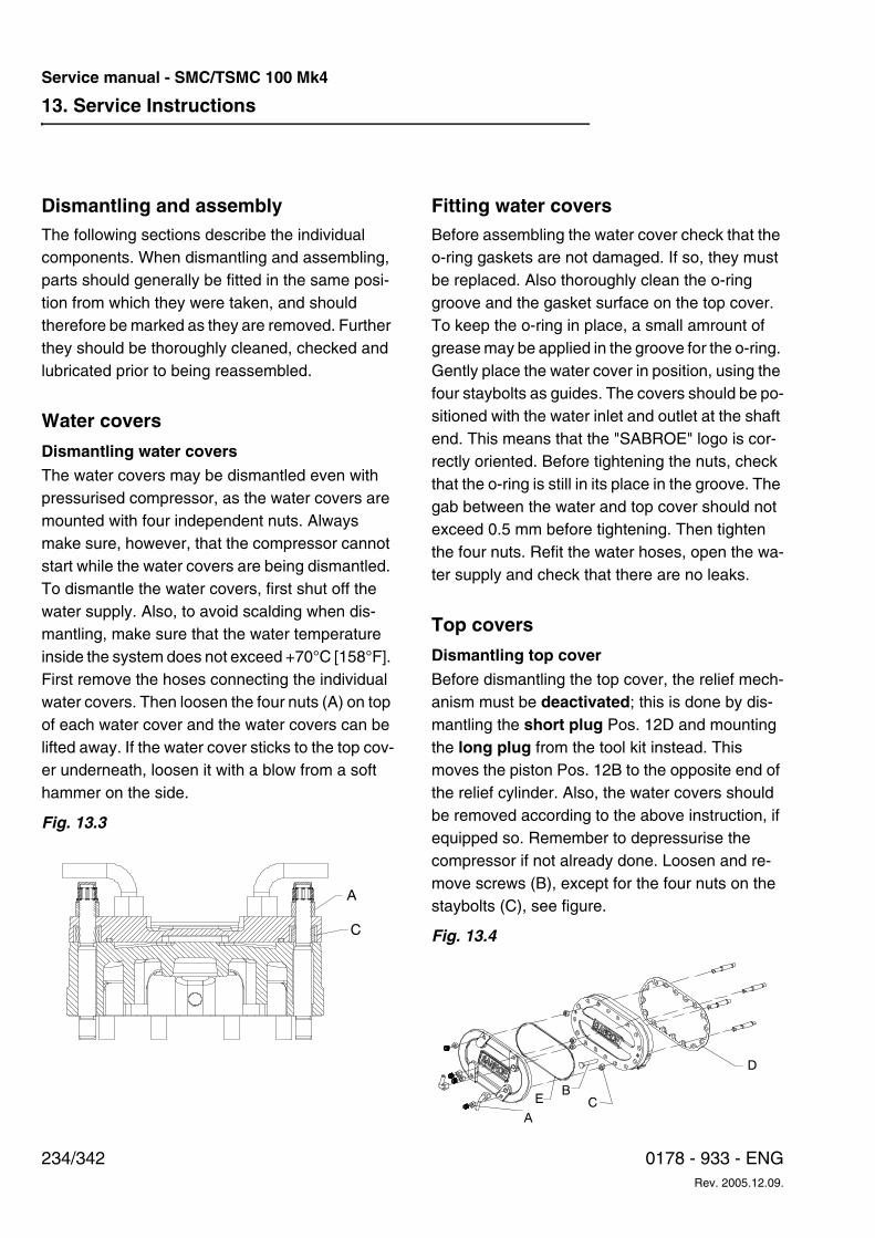
13. Service Instructions
234/342 0178 - 933 - ENGRev. 2005.12.09.
Service manual - SMC/TSMC 100 Mk4
Dismantling and assembly The following sections describe the individual components. When dismantling and assembling, parts should generally be fitted in the same posi-tion from which they were taken, and should therefore be marked as they are removed. Further they should be thoroughly cleaned, checked and lubricated prior to being reassembled.
Water covers
Dismantling water coversThe water covers may be dismantled even with pressurised compressor, as the water covers are mounted with four independent nuts. Always make sure, however, that the compressor cannot start while the water covers are being dismantled. To dismantle the water covers, first shut off the water supply. Also, to avoid scalding when dis-mantling, make sure that the water temperature inside the system does not exceed +70°C [158°F]. First remove the hoses connecting the individual water covers. Then loosen the four nuts (A) on top of each water cover and the water covers can be lifted away. If the water cover sticks to the top cov-er underneath, loosen it with a blow from a soft hammer on the side.
Fig. 13.3
Fitting water coversBefore assembling the water cover check that the o-ring gaskets are not damaged. If so, they must be replaced. Also thoroughly clean the o-ring groove and the gasket surface on the top cover. To keep the o-ring in place, a small amrount of grease may be applied in the groove for the o-ring. Gently place the water cover in position, using the four staybolts as guides. The covers should be po-sitioned with the water inlet and outlet at the shaft end. This means that the "SABROE" logo is cor-rectly oriented. Before tightening the nuts, check that the o-ring is still in its place in the groove. The gab between the water and top cover should not exceed 0.5 mm before tightening. Then tighten the four nuts. Refit the water hoses, open the wa-ter supply and check that there are no leaks.
Top covers
Dismantling top cover
Before dismantling the top cover, the relief mech-anism must be deactivated; this is done by dis-mantling the short plug Pos. 12D and mounting the long plug from the tool kit instead. This moves the piston Pos. 12B to the opposite end of the relief cylinder. Also, the water covers should be removed according to the above instruction, if equipped so. Remember to depressurise the compressor if not already done. Loosen and re-move screws (B), except for the four nuts on the staybolts (C), see figure.
Fig. 13.4
A
C
BC
A
D
E
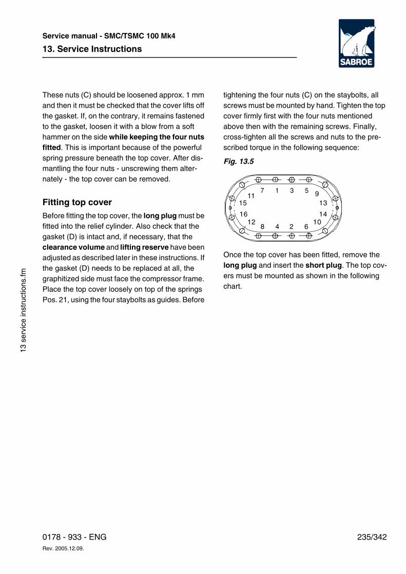
13. Service Instructions
235/3420178 - 933 - ENGRev. 2005.12.09.
Service manual - SMC/TSMC 100 Mk4
13 s
ervi
ce in
stru
ctio
ns.fm
These nuts (C) should be loosened approx. 1 mm and then it must be checked that the cover lifts off the gasket. If, on the contrary, it remains fastened to the gasket, loosen it with a blow from a soft hammer on the side while keeping the four nuts fitted. This is important because of the powerful spring pressure beneath the top cover. After dis-mantling the four nuts - unscrewing them alter-nately - the top cover can be removed.
Fitting top coverBefore fitting the top cover, the long plug must be fitted into the relief cylinder. Also check that the gasket (D) is intact and, if necessary, that the clearance volume and lifting reserve have been adjusted as described later in these instructions. If the gasket (D) needs to be replaced at all, the graphitized side must face the compressor frame. Place the top cover loosely on top of the springs Pos. 21, using the four staybolts as guides. Before
tightening the four nuts (C) on the staybolts, all screws must be mounted by hand. Tighten the top cover firmly first with the four nuts mentioned above then with the remaining screws. Finally, cross-tighten all the screws and nuts to the pre-scribed torque in the following sequence:
Fig. 13.5
Once the top cover has been fitted, remove the long plug and insert the short plug. The top cov-ers must be mounted as shown in the following chart.
7 1 3 5
8 4 2 610
9
14
13
16
15
12
11
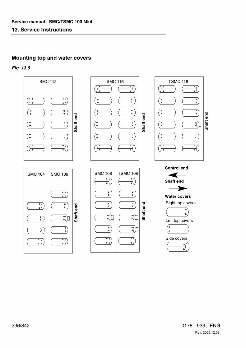
13. Service Instructions
236/342 0178 - 933 - ENGRev. 2005.12.09.
Service manual - SMC/TSMC 100 Mk4
Mounting top and water covers
Fig. 13.6
SMC 112 SMC 116 TSMC 116
SMC 104 SMC 106 SMC 108 TSMC 108
Sh
aft
end
Sh
aft
end
Sh
aft
end
Sh
aft
end
Sh
aft
end
Right top covers
Left top covers
Side covers
Water covers
Control end
Shaft end
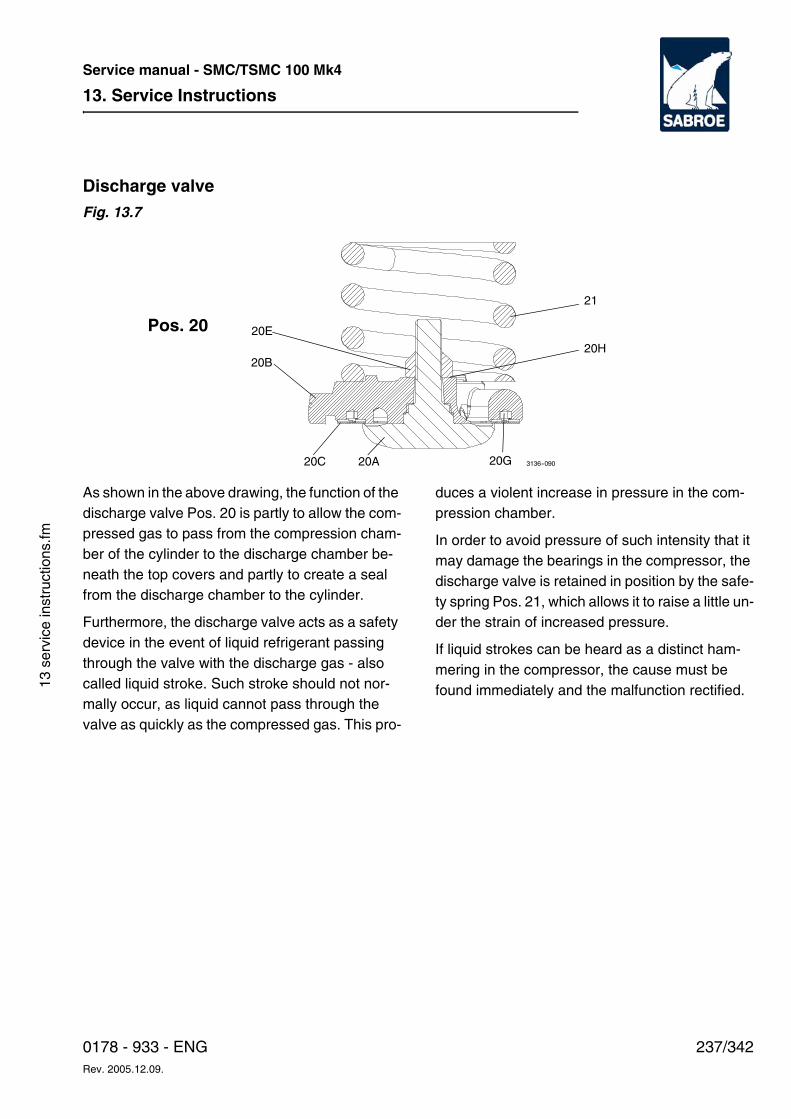
13. Service Instructions
237/3420178 - 933 - ENGRev. 2005.12.09.
Service manual - SMC/TSMC 100 Mk4
13 s
ervi
ce in
stru
ctio
ns.fm
Discharge valve Fig. 13.7
As shown in the above drawing, the function of the discharge valve Pos. 20 is partly to allow the com-pressed gas to pass from the compression cham-ber of the cylinder to the discharge chamber be-neath the top covers and partly to create a seal from the discharge chamber to the cylinder.
Furthermore, the discharge valve acts as a safety device in the event of liquid refrigerant passing through the valve with the discharge gas - also called liquid stroke. Such stroke should not nor-mally occur, as liquid cannot pass through the valve as quickly as the compressed gas. This pro-
duces a violent increase in pressure in the com-pression chamber.
In order to avoid pressure of such intensity that it may damage the bearings in the compressor, the discharge valve is retained in position by the safe-ty spring Pos. 21, which allows it to raise a little un-der the strain of increased pressure.
If liquid strokes can be heard as a distinct ham-mering in the compressor, the cause must be found immediately and the malfunction rectified.
3136--090
Pos. 20
21
20B
20E
20A20C 20G
20H
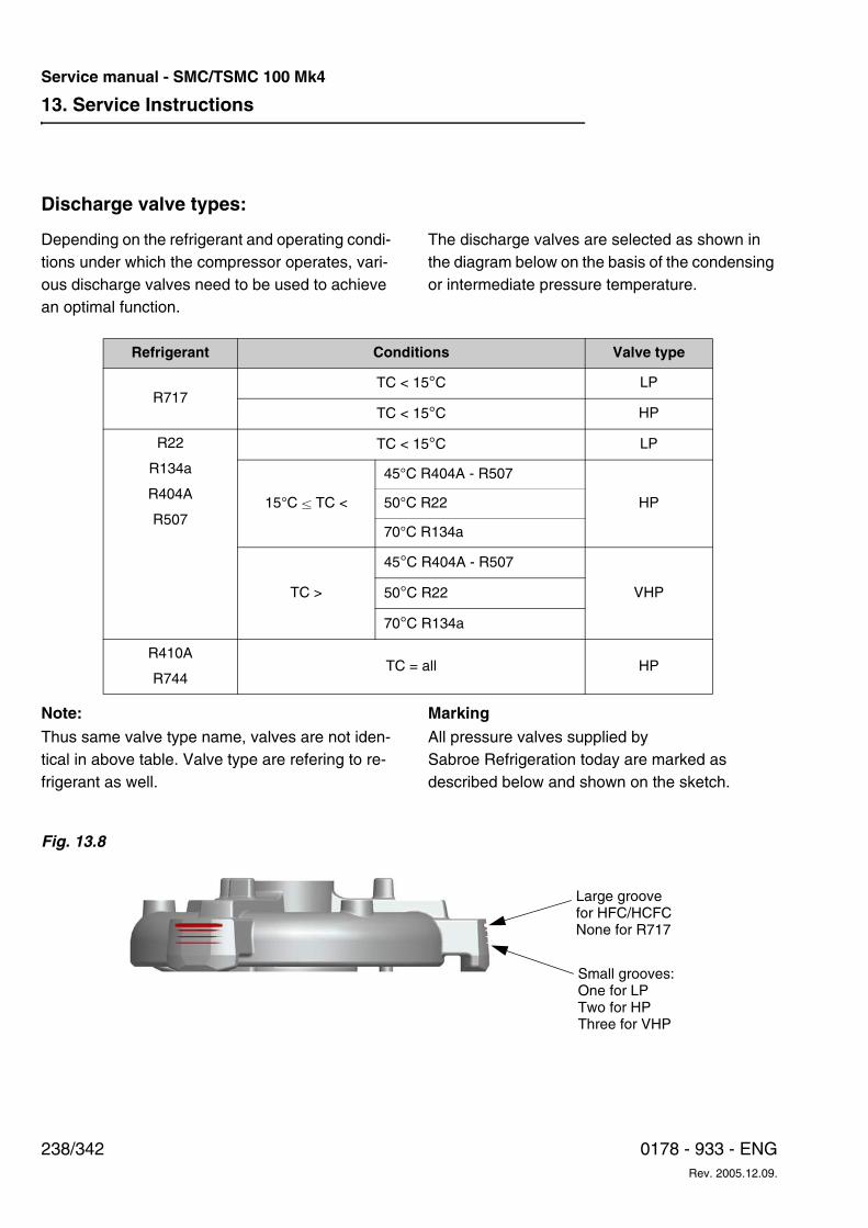
13. Service Instructions
238/342 0178 - 933 - ENGRev. 2005.12.09.
Service manual - SMC/TSMC 100 Mk4
Discharge valve types:
Depending on the refrigerant and operating condi-tions under which the compressor operates, vari-ous discharge valves need to be used to achieve an optimal function.
The discharge valves are selected as shown in the diagram below on the basis of the condensing or intermediate pressure temperature.
Note:Thus same valve type name, valves are not iden-tical in above table. Valve type are refering to re-frigerant as well.
Marking All pressure valves supplied by Sabroe Refrigeration today are marked as described below and shown on the sketch.
Fig. 13.8
Refrigerant Conditions Valve type
R717TC < 15°C LP
TC < 15°C HP
R22
R134a
R404A
R507
TC < 15°C LP
15°C ± TC <
45°C R404A - R507
HP50°C R22
70°C R134a
TC >
45°C R404A - R507
VHP50°C R22
70°C R134a
R410A
R744TC = all HP
Large groovefor HFC/HCFCNone for R717
Small grooves:One for LPTwo for HPThree for VHP
13. Service Instructions
239/3420178 - 933 - ENGRev. 2005.12.09.
Service manual - SMC/TSMC 100 Mk4
13 s
ervi
ce in
stru
ctio
ns.fm
Refrigerants HFC/HCFC All discharge valves are marked with a large groove near the upper edge of the valve feet.
Refrigerant R717 There is no large groove at the upper edge of the valve feet.
Conditions
The valve type is marked with one, two or three small grooves below the large groove (if any).
One small groove: LP
Two small grooves: HP
Three small grooves: VHP
Dismantling • When the top cover has been removed,
spring Pos. 21A and discharge valve Pos. 20B can be lifted out by hand. See disman-tling of top cover.
• Tighten discharge valve in a soft-jawed vice, then dismantle the nut Pos. 20E, and re-move the lock washer Pos. 20H.
• Valve seat Pos. 20A, discharge valve Pos. 20B and ring plate Pos. 20C can now be disassembled by hand.
• Remove valve springs Pos. 20G by hand.
Assembly Before assembling the discharge valve, make sure that the valve springs Pos. 20G are in good condition and fixed firmly in their apertures.
Assemble the discharge valve in reverse order of the one described above. Note the following, how-ever:
• Tighten nut Pos. 20E See Torque for screws and bolts in Chapter 21
Tightness testing of discharge valve This is done by means of the pressure drop test as described later in this manual.
Service life of discharge and suction valvesIn order to ensure that the compressor always works perfectly, it is advisable - at suitable inter-vals - to replace the suction and discharge valve ring plates.
It is difficult to give altogether precise times for such replacements, as the durability of the valve ring plates depends on the following factors:
• If the compressor is exposed to liquid stroke or moist refrigerant gas, the service life is re-duced.
• Speed of the compressor: At 900 rpm, the service life of the valve ring plates is considerably longer than at 1500 rpm.
• The compressor ratio at which the compres-sor operates:At high compression ratios, the load on valve ring plates and springs is considerably larger than at low compression ratios. When the valve ring plates are changed, the valve springs should also be replaced.
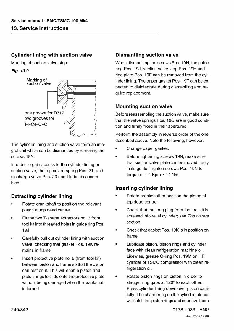
13. Service Instructions
240/342 0178 - 933 - ENGRev. 2005.12.09.
Service manual - SMC/TSMC 100 Mk4
Cylinder lining with suction valve Marking of suction valve stop:
Fig. 13.9
The cylinder lining and suction valve form an inte-gral unit which can be dismantled by removing the screws 19N.
In order to gain access to the cylinder lining or suction valve, the top cover, spring Pos. 21, and discharge valve Pos. 20 need to be disassem-bled.
Extracting cylinder lining• Rotate crankshaft to position the relevant
piston at top dead centre.
• Fit the two T-shape extractors no. 3 from tool kit into threaded holes in guide ring Pos. 19J.
• Carefully pull out cylinder lining with suction valve, checking that gasket Pos. 19K re-mains in frame.
• Insert protective plate no. 5 (from tool kit) between piston and frame so that the piston can rest on it. This will enable piston and piston rings to slide onto the protective plate without being damaged when the crankshaft is turned.
Dismantling suction valve When dismantling the screws Pos. 19N, the guide ring Pos. 19J, suction valve stop Pos. 19H and ring plate Pos. 19F can be removed from the cyl-inder lining. The paper gasket Pos. 19T can be ex-pected to disintegrate during dismantling and re-quire replacement.
Mounting suction valve Before reassembling the suction valve, make sure that the valve springs Pos. 19G are in good condi-tion and firmly fixed in their apertures.
Perform the assembly in reverse order of the one described above. Note the following, however:
• Change paper gasket.
• Before tightening screws 19N, make sure that suction valve plate can be moved freely in its guide. Tighten screws Pos. 19N to torque of 1.4 Kpm ≅ 14 Nm.
Inserting cylinder lining • Rotate crankshaft to position the piston at
top dead centre.
• Check that the long plug from the tool kit is screwed into relief cylinder; see Top covers section.
• Check that gasket Pos. 19K is in position on frame.
• Lubricate piston, piston rings and cylinder face with clean refrigeration machine oil. Likewise, grease O-ring Pos. 19M on HP cylinder of TSMC compressor with clean re-frigeration oil.
• Rotate piston rings on piston in order to stagger ring gaps at 120° to each other. Press cylinder lining down over piston care-fully. The chamfering on the cylinder interior will catch the piston rings and squeeze them
one groove for R717two grooves for
Marking ofsuction valve
HFC/HCFC
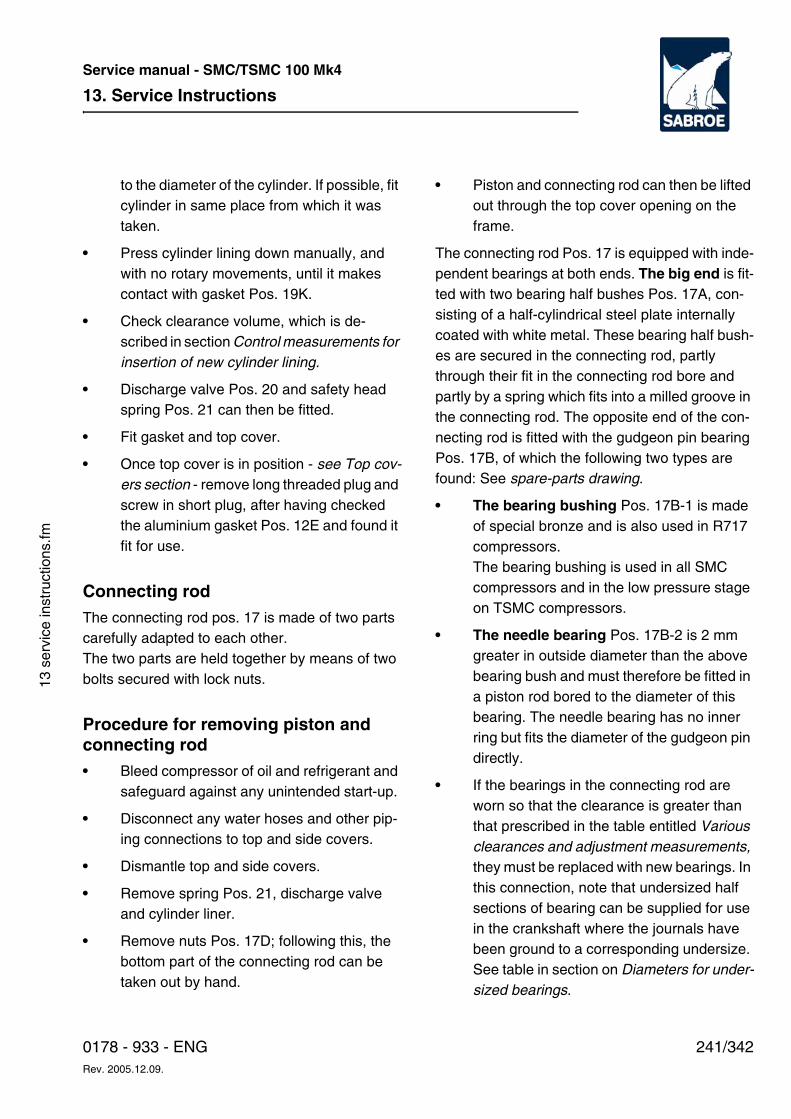
13. Service Instructions
241/3420178 - 933 - ENGRev. 2005.12.09.
Service manual - SMC/TSMC 100 Mk4
13 s
ervi
ce in
stru
ctio
ns.fm
to the diameter of the cylinder. If possible, fit cylinder in same place from which it was taken.
• Press cylinder lining down manually, and with no rotary movements, until it makes contact with gasket Pos. 19K.
• Check clearance volume, which is de-scribed in section Control measurements for insertion of new cylinder lining.
• Discharge valve Pos. 20 and safety head spring Pos. 21 can then be fitted.
• Fit gasket and top cover.
• Once top cover is in position - see Top cov-ers section - remove long threaded plug and screw in short plug, after having checked the aluminium gasket Pos. 12E and found it fit for use.
Connecting rod The connecting rod pos. 17 is made of two parts carefully adapted to each other.The two parts are held together by means of two bolts secured with lock nuts.
Procedure for removing piston and connecting rod • Bleed compressor of oil and refrigerant and
safeguard against any unintended start-up.
• Disconnect any water hoses and other pip-ing connections to top and side covers.
• Dismantle top and side covers.
• Remove spring Pos. 21, discharge valve and cylinder liner.
• Remove nuts Pos. 17D; following this, the bottom part of the connecting rod can be taken out by hand.
• Piston and connecting rod can then be lifted out through the top cover opening on the frame.
The connecting rod Pos. 17 is equipped with inde-pendent bearings at both ends. The big end is fit-ted with two bearing half bushes Pos. 17A, con-sisting of a half-cylindrical steel plate internally coated with white metal. These bearing half bush-es are secured in the connecting rod, partly through their fit in the connecting rod bore and partly by a spring which fits into a milled groove in the connecting rod. The opposite end of the con-necting rod is fitted with the gudgeon pin bearing Pos. 17B, of which the following two types are found: See spare-parts drawing.
• The bearing bushing Pos. 17B-1 is made of special bronze and is also used in R717 compressors. The bearing bushing is used in all SMC compressors and in the low pressure stage on TSMC compressors.
• The needle bearing Pos. 17B-2 is 2 mm greater in outside diameter than the above bearing bush and must therefore be fitted in a piston rod bored to the diameter of this bearing. The needle bearing has no inner ring but fits the diameter of the gudgeon pin directly.
• If the bearings in the connecting rod are worn so that the clearance is greater than that prescribed in the table entitled Various clearances and adjustment measurements, they must be replaced with new bearings. In this connection, note that undersized half sections of bearing can be supplied for use in the crankshaft where the journals have been ground to a corresponding undersize. See table in section on Diameters for under-sized bearings.
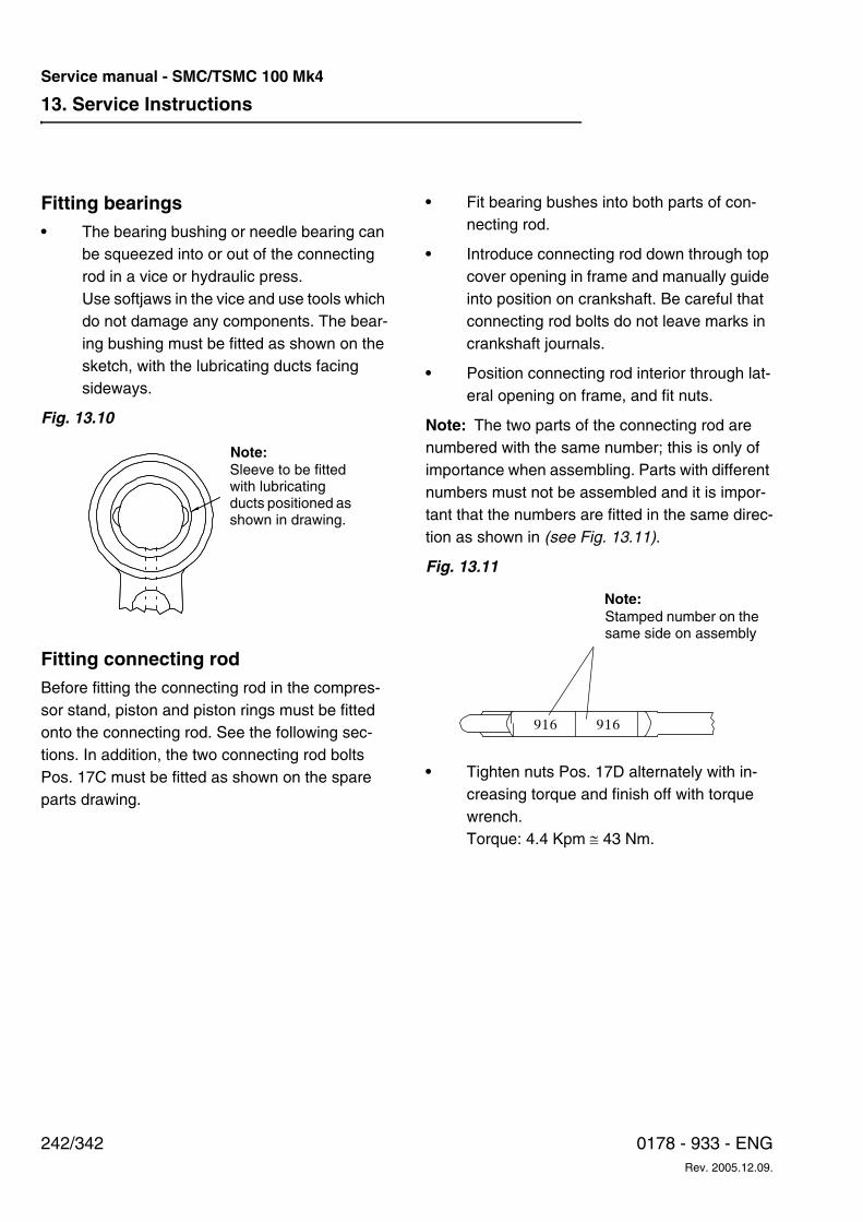
13. Service Instructions
242/342 0178 - 933 - ENGRev. 2005.12.09.
Service manual - SMC/TSMC 100 Mk4
Fitting bearings• The bearing bushing or needle bearing can
be squeezed into or out of the connecting rod in a vice or hydraulic press.Use softjaws in the vice and use tools which do not damage any components. The bear-ing bushing must be fitted as shown on the sketch, with the lubricating ducts facing sideways.
Fig. 13.10
Fitting connecting rod Before fitting the connecting rod in the compres-sor stand, piston and piston rings must be fitted onto the connecting rod. See the following sec-tions. In addition, the two connecting rod bolts Pos. 17C must be fitted as shown on the spare parts drawing.
• Fit bearing bushes into both parts of con-necting rod.
• Introduce connecting rod down through top cover opening in frame and manually guide into position on crankshaft. Be careful that connecting rod bolts do not leave marks in crankshaft journals.
• Position connecting rod interior through lat-eral opening on frame, and fit nuts.
Note: The two parts of the connecting rod are numbered with the same number; this is only of importance when assembling. Parts with different numbers must not be assembled and it is impor-tant that the numbers are fitted in the same direc-tion as shown in (see Fig. 13.11).
Fig. 13.11
• Tighten nuts Pos. 17D alternately with in-creasing torque and finish off with torque wrench. Torque: 4.4 Kpm ≅ 43 Nm.
Sleeve to be fitted with lubricating ducts positioned as shown in drawing.
Note:
916 916
Note:Stamped number on the same side on assembly
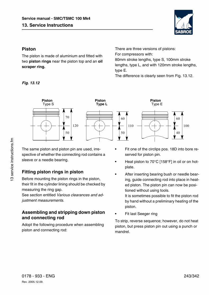
13. Service Instructions
243/3420178 - 933 - ENGRev. 2005.12.09.
Service manual - SMC/TSMC 100 Mk4
13 s
ervi
ce in
stru
ctio
ns.fm
Piston The piston is made of aluminium and fitted with two piston rings near the piston top and an oil scraper ring.
There are three versions of pistons: For compressors with:80mm stroke lengths, type S, 100mm stroke lengths, type L, and with 120mm stroke lengths, type E. The difference is clearly seen from Fig. 13.12.
Fig. 13.12
The same piston and piston pin are used, irre-spective of whether the connecting rod contains a sleeve or a needle bearing.
Fitting piston rings in piston Before mounting the piston rings in the piston, their fit in the cylinder lining should be checked by measuring the ring gap. See section entitled Various clearances and ad-justment measurements.
Assembling and stripping down piston and connecting rodAdopt the following procedure when assembling piston and connecting rod:
• Fit one of the circlips pos. 18D into bore re-served for piston pin.
• Heat piston to 70°C [158°F] in oil or on hot-plate.
• After inserting bearing bush or needle bear-ing, guide connecting rod into place in heat-ed piston. The piston pin can now be posi-tioned without using tools.It is sometimes possible to fit the piston rod by hand without a preliminary heating of the piston.
• Fit last Seeger ring
To strip, reverse sequence; however, do not heat piston, but press piston pin out using a punch or mandrel.
60
50
110
70
50
120
60
40
100
PistonType L
PistonType S
PistonType E
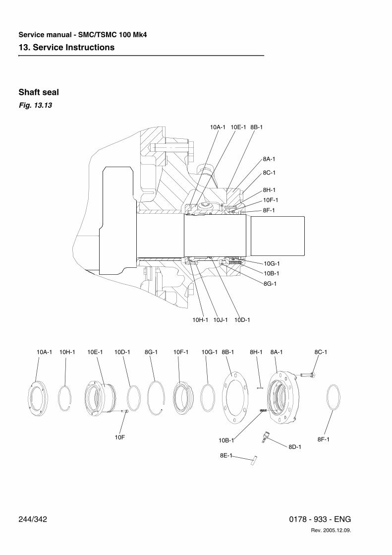
13. Service Instructions
244/342 0178 - 933 - ENGRev. 2005.12.09.
Service manual - SMC/TSMC 100 Mk4
Shaft sealFig. 13.13
10J-110H-1
10A-1
10D-1
8G-110H-1 10E-1 10D-1 10G-1 8H-1 8A-1
8F-1
8C-1
8D-1
10F-1 8B-1
10F 10B-1
8E-1
10B-1
8B-1
8C-1
8A-1
8H-1
10F-1
10E-110A-1
8F-1
10G-1
8G-1
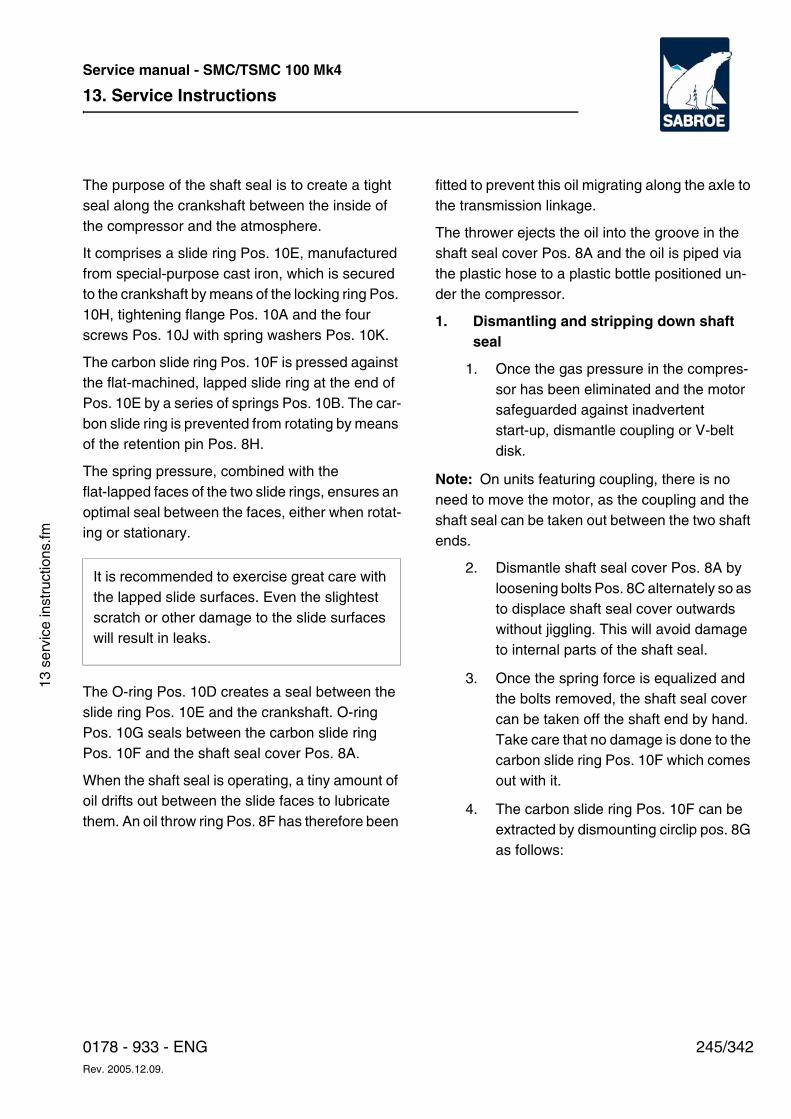
13. Service Instructions
245/3420178 - 933 - ENGRev. 2005.12.09.
Service manual - SMC/TSMC 100 Mk4
13 s
ervi
ce in
stru
ctio
ns.fm
The purpose of the shaft seal is to create a tight seal along the crankshaft between the inside of the compressor and the atmosphere.
It comprises a slide ring Pos. 10E, manufactured from special-purpose cast iron, which is secured to the crankshaft by means of the locking ring Pos. 10H, tightening flange Pos. 10A and the four screws Pos. 10J with spring washers Pos. 10K.
The carbon slide ring Pos. 10F is pressed against the flat-machined, lapped slide ring at the end of Pos. 10E by a series of springs Pos. 10B. The car-bon slide ring is prevented from rotating by means of the retention pin Pos. 8H.
The spring pressure, combined with the flat-lapped faces of the two slide rings, ensures an optimal seal between the faces, either when rotat-ing or stationary.
The O-ring Pos. 10D creates a seal between the slide ring Pos. 10E and the crankshaft. O-ring Pos. 10G seals between the carbon slide ring Pos. 10F and the shaft seal cover Pos. 8A.
When the shaft seal is operating, a tiny amount of oil drifts out between the slide faces to lubricate them. An oil throw ring Pos. 8F has therefore been
fitted to prevent this oil migrating along the axle to the transmission linkage.
The thrower ejects the oil into the groove in the shaft seal cover Pos. 8A and the oil is piped via the plastic hose to a plastic bottle positioned un-der the compressor.
1. Dismantling and stripping down shaft seal
1. Once the gas pressure in the compres-sor has been eliminated and the motor safeguarded against inadvertent start-up, dismantle coupling or V-belt disk.
Note: On units featuring coupling, there is no need to move the motor, as the coupling and the shaft seal can be taken out between the two shaft ends.
2. Dismantle shaft seal cover Pos. 8A by loosening bolts Pos. 8C alternately so as to displace shaft seal cover outwards without jiggling. This will avoid damage to internal parts of the shaft seal.
3. Once the spring force is equalized and the bolts removed, the shaft seal cover can be taken off the shaft end by hand. Take care that no damage is done to the carbon slide ring Pos. 10F which comes out with it.
4. The carbon slide ring Pos. 10F can be extracted by dismounting circlip pos. 8G as follows:
It is recommended to exercise great care with the lapped slide surfaces. Even the slightest scratch or other damage to the slide surfaces will result in leaks.
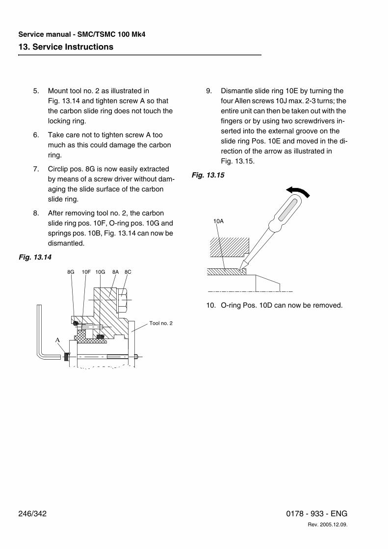
13. Service Instructions
246/342 0178 - 933 - ENGRev. 2005.12.09.
Service manual - SMC/TSMC 100 Mk4
5. Mount tool no. 2 as illustrated in Fig. 13.14 and tighten screw A so that the carbon slide ring does not touch the locking ring.
6. Take care not to tighten screw A too much as this could damage the carbon ring.
7. Circlip pos. 8G is now easily extracted by means of a screw driver without dam-aging the slide surface of the carbon slide ring.
8. After removing tool no. 2, the carbon slide ring pos. 10F, O-ring pos. 10G and springs pos. 10B, Fig. 13.14 can now be dismantled.
Fig. 13.14
9. Dismantle slide ring 10E by turning the four Allen screws 10J max. 2-3 turns; the entire unit can then be taken out with the fingers or by using two screwdrivers in-serted into the external groove on the slide ring Pos. 10E and moved in the di-rection of the arrow as illustrated in Fig. 13.15.
Fig. 13.15
10. O-ring Pos. 10D can now be removed.
w
A
w
w
10G 8A8G 10F 8C
Tool no. 2
10A
13. Service Instructions
247/3420178 - 933 - ENGRev. 2005.12.09.
Service manual - SMC/TSMC 100 Mk4
13 s
ervi
ce in
stru
ctio
ns.fm
Assembling and mounting shaft seal After thoroughly cleaning the crankshaft, check that its sealing faces are smooth and free of scratches, blows and wear marks. Then oil the crankshaft and the shaft seal components thor-oughly with the same type of oil as used in the compressor.
1. Unit with slide ring, Pos. 10E
1. Before fitting slide ring Pos. 10E, tighten screws Pos. 10J until there is approx. 2 mm spacing and parallelism between the two flanges. Check also that locking ring Pos. 10H is mounted as shown in the drawing and that O-ring Pos. 10D is in its correct position.
2. Position slide ring Pos. 10E on shaft and make sure that tightening flange makes contact with shaft shoulder.
3. Crosswise, tighten screws Pos. 10J al-ternately with Allen wrench from tool kit. The torque is specified in the instruction manual.
4. Check axial position of shaft seal by measuring distance from frame sealing face to slide face on Pos. 10E. This must measure approx. 5.5 mm, as shown in the drawing.
2. Unit with shaft seal cover Pos. 8A
1. Mount O-ring Pos. 10G and the ten spi-ral springs 10B in shaft seal cover Pos. 8A, then position carbon slide ring Pos. 10F carefully. Rotate carbon slide ring
so that slot fits in over the retention pin Pos. 8H.
2. With tool no. 2 fitted as shown (see Fig. 13.14) press carbon slide ring pos. 10F against spring pos. 10B. Locking ring Pos. 8G can now be fitted. Observe closely that the carbon slide ring is not overloaded by misbalanced pressure and that its slide face is not damaged.
3. Give complete shaft seal cover an extra oiling on slide face of carbon slide ring and guide it in over shaft together with gasket Pos. 8B.
4. By gently pressing shaft seal cover and carbon ring in against slide ring Pos. 10E without compressing springs Pos. 10B, measure distance from gasket Pos. 8B to sealing face of shaft seal cover. This distance must be about 3 mm. Make sure the hose branch Pos. 8D fac-es down.
5. Mount screws Pos. 8C and tighten even-ly, crosswise. This will avoid damaging the carbon slide ring. Tighten screws Pos. 8C to prescribed torque according to table in instruction manual.
6. Mount oil throw ring, as shown in drawing.
7. After mounting coupling half or V-belt disk, it must be possible to turn the crankshaft easily by hand.
13. Service Instructions
248/342 0178 - 933 - ENGRev. 2005.12.09.
Service manual - SMC/TSMC 100 Mk4
Crankshaft The crankshaft is made of heat-treated SG cast iron with fine strength and glide properties. The bearing journals are superfinished and oil chan-nels are bored for all lubricating points.
At the centre and end of the crankshaft, the oil channels are blanked off with 3 blind plugs on the SMC 104 - 106 - 108, and 6 plugs on the SMC 112 and 116.
When fitting the crankshaft, it should be checked that the plugs are mounted and tightened. By way of bores in the counterweights, the crankshaft is dynamically balanced with regard to 1st and 2nd order forces.
The crankshaft is available in three versions: an S type for compressors with short strokes (80mm), an L type for longer strokes (100mm) and an E type for the longest strokes (120mm). The crank-shafts have an S, L or E stamped into the connect-ing end.
Dismantling crankshaftDismantle the crankshaft through the pump end of the frame in the following way:
• Bleed compressor of oil and refrigerant and safeguard against inadvertent start-up.
• Dismantle top and side covers.
• Dismantle all cylinder linings.
• Extract all pistons and connecting rods.
• Pull off V-belt pulley or coupling half.
• Dismantle shaft seal cover and shaft seal.
• Dismantle cut-outs and pipes to manome-ters or piping connections to UNISAB.
• Dismantle end cover, Pos. 4A.
• Dismantle oil filter.
• Dismantle oil pump drive and oil pump.
• On SMC/TSMC 112-116 loosen the middle bearing by dismantling the plugs pos. 49H as well as gasket pos. 49J in both sides of the compressor.Next, dismantle screws pos. 49F and lock-ing plates pos. 49G.
• Rotate crankshaft to place connecting rod journals on horizontal level.
• Dismantle bearing cover at pump end and support the crankshaft by means of a board inserted through the side openings.
• After this the crankshaft can be drawn out of the frame. The crankshaft must still be sup-ported.
• The middle bearing on SMC/TSMC 112-116 can be dismantled by removing screws pos. 49B and shims pos. 49C as well as guide pins pos. 49D.
13. Service Instructions
249/3420178 - 933 - ENGRev. 2005.12.09.
Service manual - SMC/TSMC 100 Mk4
13 s
ervi
ce in
stru
ctio
ns.fm
Inspection Check bearing journals on connecting rods for wear and tear and, if necessary, measure diame-ter of journals. The maximum wear on the bear-ings is shown in the section Various clearances and adjustment measurements. In most instances, the permissible play in the bearing can be obtained by replacing the bearing half bushes. The bearing journals on the main bearings are normally subject to very little wear, but should be check measured during main over-hauls. If wear and tear exceeds the play stated, the crankshaft can normally be ground to 0.5 mm undersize. For the ground crankshaft, main bear-ings and connecting rod bearings with an under-size of 0.5 mm can be supplied as stated in the part list.
The drawing for grinding the crankshaft to under-size is found in this instruction manual.
Note: After grinding the crankshaft, all lubricating channels must be thoroughly cleaned with an ap-proved cleansing fluid and blasted with com-pressed air. Remember to refit the blind plugs.
• Check sealing face for O-ring seal, Pos. 10D, on shaft seal. The surface must be bright and free of scratches and marks.
Refitting crankshaft Refit the crankshaft in the reverse order of that for dismantling. Note the following, however:
• After the crankshaft has been inserted into the housing, mount main bearing cover Pos. 5A using gasket Pos. 5D as a shim.
• Check end play on crankshaft by pressing shaft up against pressure bearing Pos. 6C and measure clearance in the other bearing, using a feeler gauge.
• The permissible end play is indicated in the section Various clearances and adjustment measurements.
• End play adjustment is achieved by means of the gasket Pos. 5D.
• The gasket can be supplied in the following thicknesses, see the spare parts list: 0.3mm, 0.5mm, 0.75mm, 1.0mm, 1.3mm, 1.5mm, 1.75mm, 2.0mm
Main bearings The main bearings pos. 5C and 6C are mounted on the main bearing covers and their purpose is to guide the crankshaft both radially and axially.
They consist of a steel bushing with collar. The collar and the inside of the bushing are provided with a thin white metal coating.
The bushing can be pressed out and replaced by new ones and needs no further machining after mounting.
On mounting the bushings it is recommended to secure them with Loctite 601.
When a new bearing bushing pos. 6C at the shaft seal end is put into place in cover pos. 6A the in- and outlets of the lubricating channels must be positioned in a four o'clock position as illus-trated in fig. 1 below. The bearing bushing pos. 5C is positioned with in- and outlets in a 12 o'clock position.
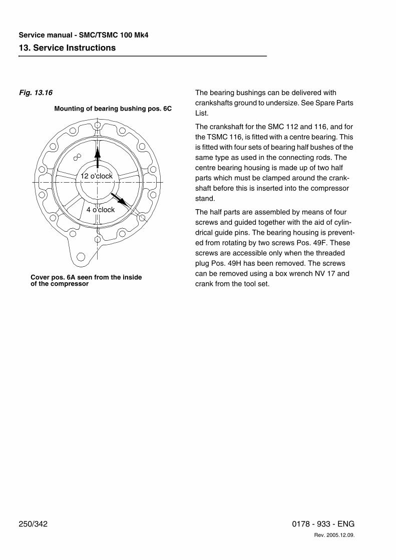
13. Service Instructions
250/342 0178 - 933 - ENGRev. 2005.12.09.
Service manual - SMC/TSMC 100 Mk4
Fig. 13.16 The bearing bushings can be delivered with crankshafts ground to undersize. See Spare Parts List.
The crankshaft for the SMC 112 and 116, and for the TSMC 116, is fitted with a centre bearing. This is fitted with four sets of bearing half bushes of the same type as used in the connecting rods. The centre bearing housing is made up of two half parts which must be clamped around the crank-shaft before this is inserted into the compressor stand.
The half parts are assembled by means of four screws and guided together with the aid of cylin-drical guide pins. The bearing housing is prevent-ed from rotating by two screws Pos. 49F. These screws are accessible only when the threaded plug Pos. 49H has been removed. The screws can be removed using a box wrench NV 17 and crank from the tool set.
12 o'clock
4 o'clock
Mounting of bearing bushing pos. 6C
Cover pos. 6A seen from the insideof the compressor
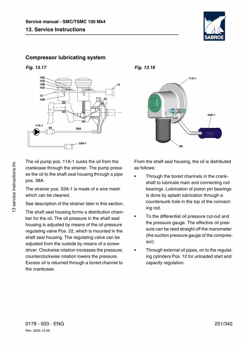
13. Service Instructions
251/3420178 - 933 - ENGRev. 2005.12.09.
Service manual - SMC/TSMC 100 Mk4
13 s
ervi
ce in
stru
ctio
ns.fm
Compressor lubricating system
Fig. 13.17 Fig. 13.18
The oil pump pos. 11A-1 sucks the oil from the crankcase through the strainer. The pump press-es the oil to the shaft seal housing through a pipe pos. 38A.
The strainer pos. 33A-1 is made of a wire mesh which can be cleaned.
See description of the strainer later in this section.
The shaft seal housing forms a distribution cham-ber for the oil. The oil pressure in the shaft seal housing is adjusted by means of the oil pressure regulating valve Pos. 22, which is mounted in the shaft seal housing. The regulating valve can be adjusted from the outside by means of a screw-driver. Clockwise rotation increases the pressure; counterclockwise rotation lowers the pressure. Excess oil is returned through a bored channel to the crankcase.
From the shaft seal housing, the oil is distributed as follows:
• Through the bored channels in the crank-shaft to lubricate main and connecting rod bearings. Lubrication of piston pin bearings is done by splash lubrication through a countersunk hole in the top of the connect-ing rod.
• To the differential oil pressure cut-out and the pressure gauge. The effective oil pres-sure can be read straight off the manometer (the suction pressure gauge of the compres-sor).
• Through external oil pipes, on to the regulat-ing cylinders Pos. 12 for unloaded start and capacity regulation.
33A-1
38A11A-1
19D
22
15D19B
15B13
15A12
9A
33A-1
11A-1
9A
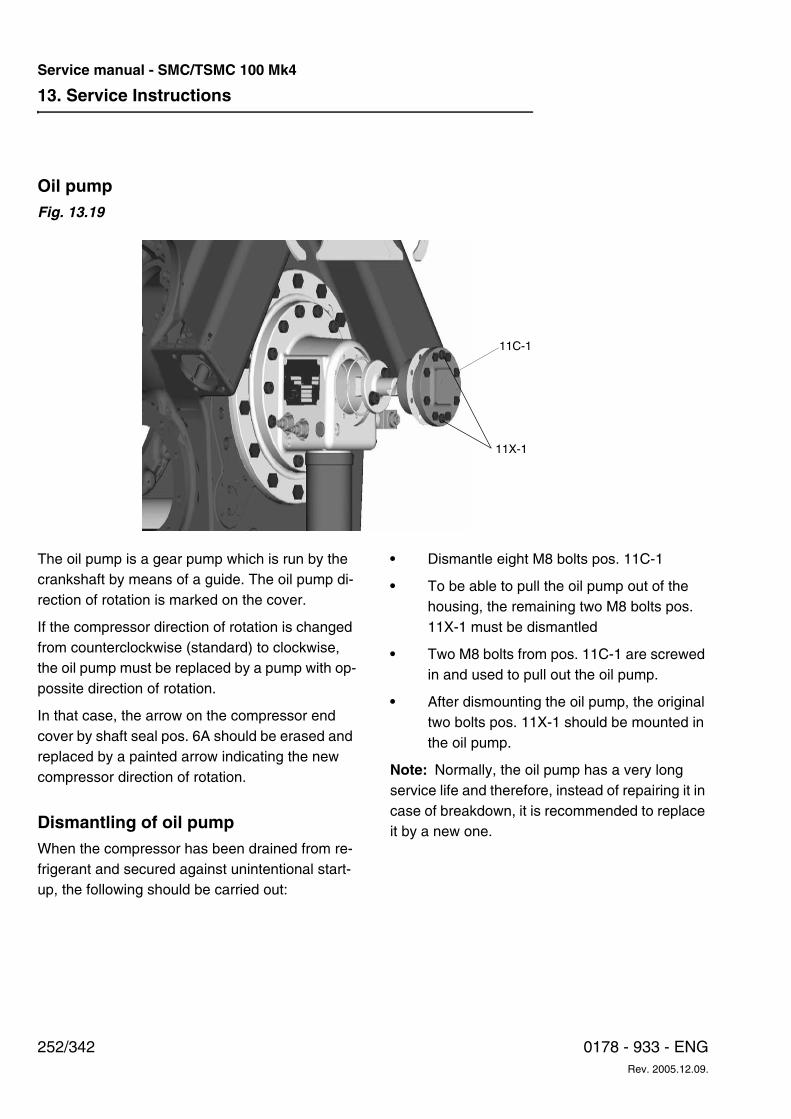
13. Service Instructions
252/342 0178 - 933 - ENGRev. 2005.12.09.
Service manual - SMC/TSMC 100 Mk4
Oil pump Fig. 13.19
The oil pump is a gear pump which is run by the crankshaft by means of a guide. The oil pump di-rection of rotation is marked on the cover.
If the compressor direction of rotation is changed from counterclockwise (standard) to clockwise, the oil pump must be replaced by a pump with op-possite direction of rotation.
In that case, the arrow on the compressor end cover by shaft seal pos. 6A should be erased and replaced by a painted arrow indicating the new compressor direction of rotation.
Dismantling of oil pumpWhen the compressor has been drained from re-frigerant and secured against unintentional start-up, the following should be carried out:
• Dismantle eight M8 bolts pos. 11C-1
• To be able to pull the oil pump out of the housing, the remaining two M8 bolts pos. 11X-1 must be dismantled
• Two M8 bolts from pos. 11C-1 are screwed in and used to pull out the oil pump.
• After dismounting the oil pump, the original two bolts pos. 11X-1 should be mounted in the oil pump.
Note: Normally, the oil pump has a very long service life and therefore, instead of repairing it in case of breakdown, it is recommended to replace it by a new one.
11C-1
11X-1
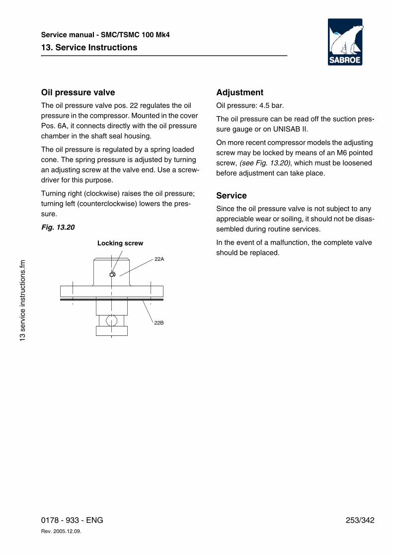
13. Service Instructions
253/3420178 - 933 - ENGRev. 2005.12.09.
Service manual - SMC/TSMC 100 Mk4
13 s
ervi
ce in
stru
ctio
ns.fm
Oil pressure valve The oil pressure valve pos. 22 regulates the oil pressure in the compressor. Mounted in the cover Pos. 6A, it connects directly with the oil pressure chamber in the shaft seal housing.
The oil pressure is regulated by a spring loaded cone. The spring pressure is adjusted by turning an adjusting screw at the valve end. Use a screw-driver for this purpose.
Turning right (clockwise) raises the oil pressure; turning left (counterclockwise) lowers the pres-sure.
Fig. 13.20
Adjustment Oil pressure: 4.5 bar.
The oil pressure can be read off the suction pres-sure gauge or on UNISAB II.
On more recent compressor models the adjusting screw may be locked by means of an M6 pointed screw, (see Fig. 13.20), which must be loosened before adjustment can take place.
Service Since the oil pressure valve is not subject to any appreciable wear or soiling, it should not be disas-sembled during routine services.
In the event of a malfunction, the complete valve should be replaced.
22A
Locking screw
22B
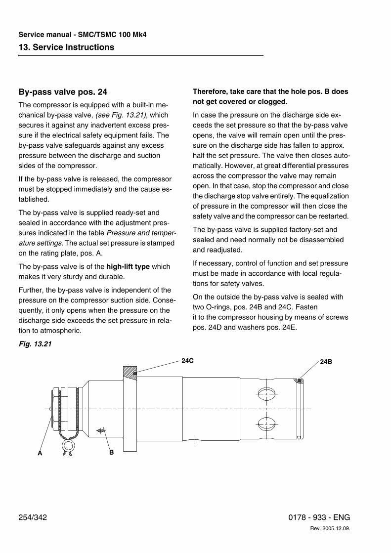
13. Service Instructions
254/342 0178 - 933 - ENGRev. 2005.12.09.
Service manual - SMC/TSMC 100 Mk4
By-pass valve pos. 24 The compressor is equipped with a built-in me-chanical by-pass valve, (see Fig. 13.21), which secures it against any inadvertent excess pres-sure if the electrical safety equipment fails. The by-pass valve safeguards against any excess pressure between the discharge and suction sides of the compressor.
If the by-pass valve is released, the compressor must be stopped immediately and the cause es-tablished.
The by-pass valve is supplied ready-set and sealed in accordance with the adjustment pres-sures indicated in the table Pressure and temper-ature settings. The actual set pressure is stamped on the rating plate, pos. A.
The by-pass valve is of the high-lift type which makes it very sturdy and durable.
Further, the by-pass valve is independent of the pressure on the compressor suction side. Conse-quently, it only opens when the pressure on the discharge side exceeds the set pressure in rela-tion to atmospheric.
Therefore, take care that the hole pos. B does not get covered or clogged.
In case the pressure on the discharge side ex-ceeds the set pressure so that the by-pass valve opens, the valve will remain open until the pres-sure on the discharge side has fallen to approx. half the set pressure. The valve then closes auto-matically. However, at great differential pressures across the compressor the valve may remain open. In that case, stop the compressor and close the discharge stop valve entirely. The equalization of pressure in the compressor will then close the safety valve and the compressor can be restarted.
The by-pass valve is supplied factory-set and sealed and need normally not be disassembled and readjusted.
If necessary, control of function and set pressure must be made in accordance with local regula-tions for safety valves.
On the outside the by-pass valve is sealed with two O-rings, pos. 24B and 24C. Fasten it to the compressor housing by means of screws pos. 24D and washers pos. 24E.
Fig. 13.21
24C 24B
BA
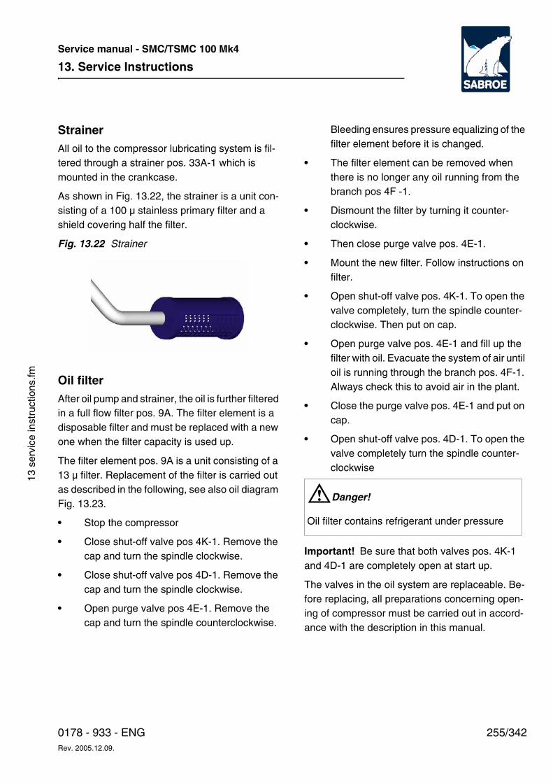
13. Service Instructions
255/3420178 - 933 - ENGRev. 2005.12.09.
Service manual - SMC/TSMC 100 Mk4
13 s
ervi
ce in
stru
ctio
ns.fm
StrainerAll oil to the compressor lubricating system is fil-tered through a strainer pos. 33A-1 which is mounted in the crankcase.
As shown in Fig. 13.22, the strainer is a unit con-sisting of a 100 µ stainless primary filter and a shield covering half the filter.
Fig. 13.22 Strainer
Oil filterAfter oil pump and strainer, the oil is further filtered in a full flow filter pos. 9A. The filter element is a disposable filter and must be replaced with a new one when the filter capacity is used up.
The filter element pos. 9A is a unit consisting of a 13 µ filter. Replacement of the filter is carried out as described in the following, see also oil diagram Fig. 13.23.
• Stop the compressor
• Close shut-off valve pos 4K-1. Remove the cap and turn the spindle clockwise.
• Close shut-off valve pos 4D-1. Remove the cap and turn the spindle clockwise.
• Open purge valve pos 4E-1. Remove the cap and turn the spindle counterclockwise.
Bleeding ensures pressure equalizing of the filter element before it is changed.
• The filter element can be removed when there is no longer any oil running from the branch pos 4F -1.
• Dismount the filter by turning it counter-clockwise.
• Then close purge valve pos. 4E-1.
• Mount the new filter. Follow instructions on filter.
• Open shut-off valve pos. 4K-1. To open the valve completely, turn the spindle counter-clockwise. Then put on cap.
• Open purge valve pos. 4E-1 and fill up the filter with oil. Evacuate the system of air until oil is running through the branch pos. 4F-1. Always check this to avoid air in the plant.
• Close the purge valve pos. 4E-1 and put on cap.
• Open shut-off valve pos. 4D-1. To open the valve completely turn the spindle counter-clockwise
Important! Be sure that both valves pos. 4K-1 and 4D-1 are completely open at start up.
The valves in the oil system are replaceable. Be-fore replacing, all preparations concerning open-ing of compressor must be carried out in accord-ance with the description in this manual.
WDanger!
Oil filter contains refrigerant under pressure
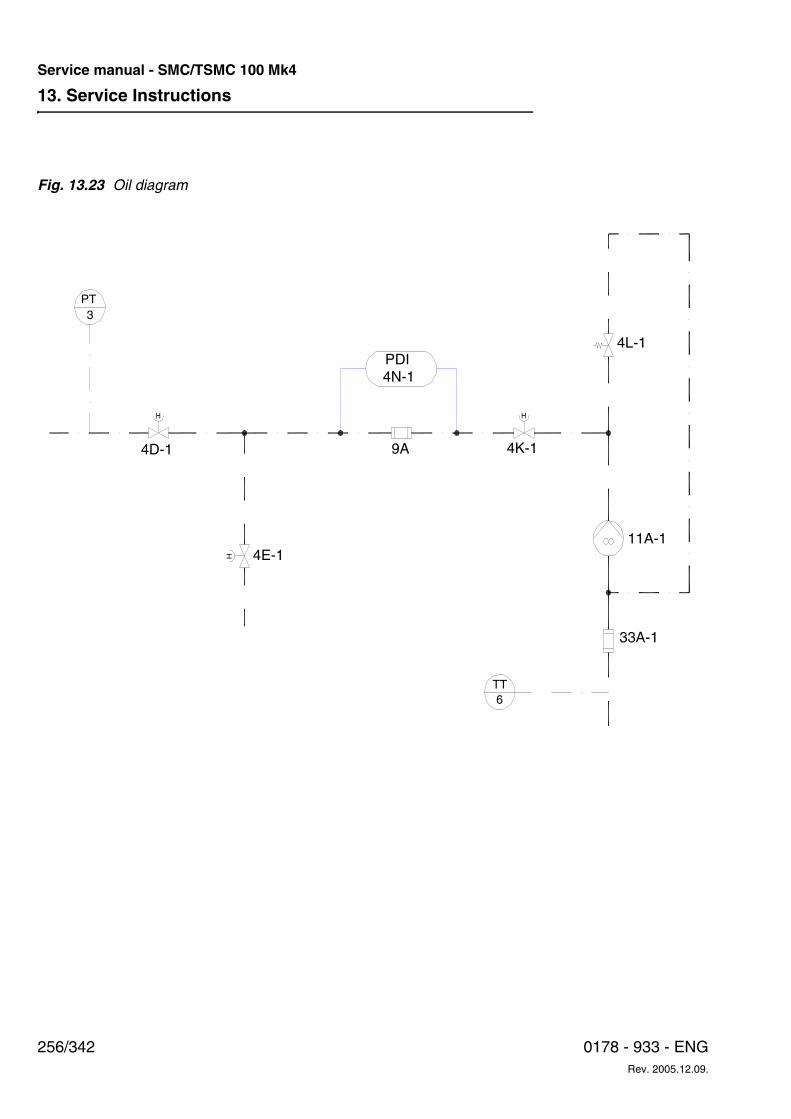
13. Service Instructions
256/342 0178 - 933 - ENGRev. 2005.12.09.
Service manual - SMC/TSMC 100 Mk4
Fig. 13.23 Oil diagram
H H
H
4D-1 9A
4N-1PDI
4E-1
4K-1
4L-1
11A-1
33A-1
6TT
3PT
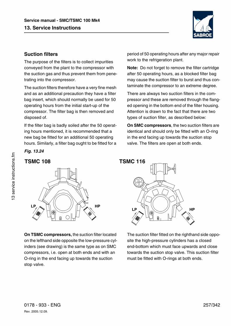
13. Service Instructions
257/3420178 - 933 - ENGRev. 2005.12.09.
Service manual - SMC/TSMC 100 Mk4
13 s
ervi
ce in
stru
ctio
ns.fm
Suction filters The purpose of the filters is to collect impurities conveyed from the plant to the compressor with the suction gas and thus prevent them from pene-trating into the compressor.
The suction filters therefore have a very fine mesh and as an additional precaution they have a filter bag insert, which should normally be used for 50 operating hours from the initial start-up of the compressor. The filter bag is then removed and disposed of.
If the filter bag is badly soiled after the 50 operat-ing hours mentioned, it is recommended that a new bag be fitted for an additional 50 operating hours. Similarly, a filter bag ought to be fitted for a
period of 50 operating hours after any major repair work to the refrigeration plant.
Note: Do not forget to remove the filter cartridge after 50 operating hours, as a blocked filter bag may cause the suction filter to burst and thus con-taminate the compressor to an extreme degree.
There are always two suction filters in the com-pressor and these are removed through the flang-ed opening in the bottom end of the filter housing. Attention is drawn to the fact that there are two types of suction filter, as described below:
On SMC compressors, the two suction filters are identical and should only be fitted with an O-ring in the end facing up towards the suction stop valve. The filters are open at both ends.
Fig. 13.24
On TSMC compressors, the suction filter located on the lefthand side opposite the low-pressure cyl-inders (see drawing) is the same type as on SMC compressors, i.e. open at both ends and with an O-ring in the end facing up towards the suction stop valve.
The suction filter fitted on the righthand side oppo-site the high-pressure cylinders has a closed end-bottom which must face upwards and close towards the suction stop valve. This suction filter must be fitted with O-rings at both ends.
TSMC 108
LP HP
TSMC 116
LP HP
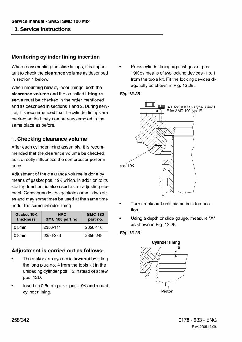
13. Service Instructions
258/342 0178 - 933 - ENGRev. 2005.12.09.
Service manual - SMC/TSMC 100 Mk4
Monitoring cylinder lining insertion
When reassembling the slide linings, it is impor-tant to check the clearance volume as described in section 1 below.
When mounting new cylinder linings, both the clearance volume and the so called lifting re-serve must be checked in the order mentioned and as described in sections 1 and 2. During serv-ice, it is recommended that the cylinder linings are marked so that they can be reassembled in the same place as before.
1. Checking clearance volume After each cylinder lining assembly, it is recom-mended that the clearance volume be checked, as it directly influences the compressor perform-ance.
Adjustment of the clearance volume is done by means of gasket pos. 19K which, in addition to its sealing function, is also used as an adjusting ele-ment. Consequently, the gaskets come in two siz-es and may sometimes be used at the same time
under the same cylinder lining.
Adjustment is carried out as follows: • The rocker arm system is lowered by fitting
the long plug no. 4 from the tools kit in the unloading cylinder pos. 12 instead of screw pos. 12D.
• Insert an 0.5mm gasket pos. 19K and mount cylinder lining.
• Press cylinder lining against gasket pos. 19K by means of two locking devices - no. 1 from the tools kit. Fit the locking devices di-agonally as shown in Fig. 13.25.
Fig. 13.25
• Turn crankshaft until piston is in top posi-tion.
• Using a depth or slide gauge, measure "X" as shown in Fig. 13.26.
Fig. 13.26
Gasket 19Kthickness
HPCSMC 100 part no.
SMC 180part no.
0.5mm 2356-111 2356-116
0.8mm 2356-233 2356-249
w
w
pos. 19K
S- L for SMC 100 type S and LE for SMC 100 type E
Piston
Cylinder liningX
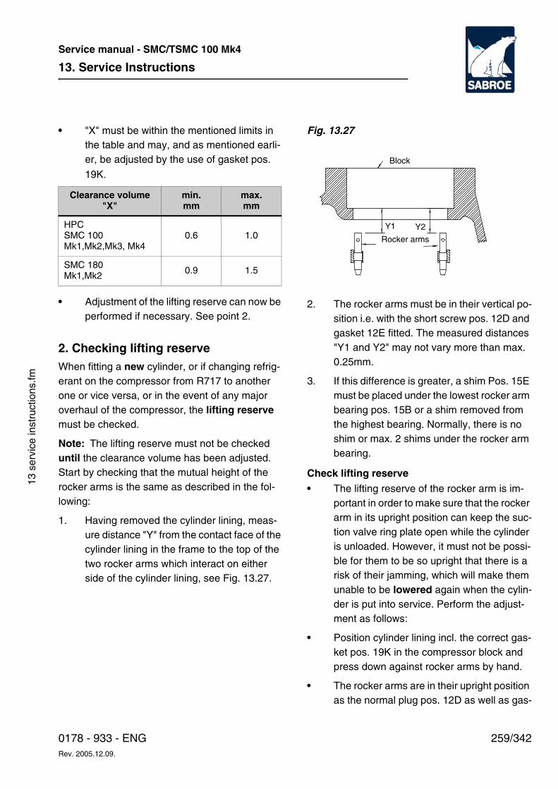
13. Service Instructions
259/3420178 - 933 - ENGRev. 2005.12.09.
Service manual - SMC/TSMC 100 Mk4
13 s
ervi
ce in
stru
ctio
ns.fm
• "X" must be within the mentioned limits in the table and may, and as mentioned earli-er, be adjusted by the use of gasket pos.
19K.
• Adjustment of the lifting reserve can now be performed if necessary. See point 2.
2. Checking lifting reserve When fitting a new cylinder, or if changing refrig-erant on the compressor from R717 to another one or vice versa, or in the event of any major overhaul of the compressor, the lifting reserve must be checked.
Note: The lifting reserve must not be checked until the clearance volume has been adjusted. Start by checking that the mutual height of the rocker arms is the same as described in the fol-lowing:
1. Having removed the cylinder lining, meas-ure distance "Y" from the contact face of the cylinder lining in the frame to the top of the two rocker arms which interact on either side of the cylinder lining, see Fig. 13.27.
Fig. 13.27
2. The rocker arms must be in their vertical po-sition i.e. with the short screw pos. 12D and gasket 12E fitted. The measured distances "Y1 and Y2" may not vary more than max. 0.25mm.
3. If this difference is greater, a shim Pos. 15E must be placed under the lowest rocker arm bearing pos. 15B or a shim removed from the highest bearing. Normally, there is no shim or max. 2 shims under the rocker arm bearing.
Check lifting reserve • The lifting reserve of the rocker arm is im-
portant in order to make sure that the rocker arm in its upright position can keep the suc-tion valve ring plate open while the cylinder is unloaded. However, it must not be possi-ble for them to be so upright that there is a risk of their jamming, which will make them unable to be lowered again when the cylin-der is put into service. Perform the adjust-ment as follows:
• Position cylinder lining incl. the correct gas-ket pos. 19K in the compressor block and press down against rocker arms by hand.
• The rocker arms are in their upright position as the normal plug pos. 12D as well as gas-
Clearance volume "X"
min.mm
max.mm
HPCSMC 100Mk1,Mk2,Mk3, Mk4
0.6 1.0
SMC 180Mk1,Mk2
0.9 1.5
Y1
Rocker arms
Y2
Block
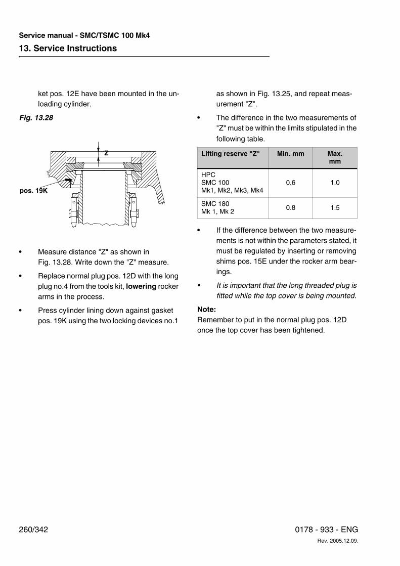
13. Service Instructions
260/342 0178 - 933 - ENGRev. 2005.12.09.
Service manual - SMC/TSMC 100 Mk4
ket pos. 12E have been mounted in the un-loading cylinder.
Fig. 13.28
• Measure distance "Z" as shown in Fig. 13.28. Write down the "Z" measure.
• Replace normal plug pos. 12D with the long plug no.4 from the tools kit, lowering rocker arms in the process.
• Press cylinder lining down against gasket pos. 19K using the two locking devices no.1
as shown in Fig. 13.25, and repeat meas-urement "Z".
• The difference in the two measurements of "Z" must be within the limits stipulated in the
following table.
• If the difference between the two measure-ments is not within the parameters stated, it must be regulated by inserting or removing shims pos. 15E under the rocker arm bear-ings.
• It is important that the long threaded plug is fitted while the top cover is being mounted.
Note:Remember to put in the normal plug pos. 12D once the top cover has been tightened.
w
Z
pos. 19K
Lifting reserve "Z" Min. mm Max.mm
HPC SMC 100Mk1, Mk2, Mk3, Mk4
0.6 1.0
SMC 180Mk 1, Mk 2
0.8 1.5
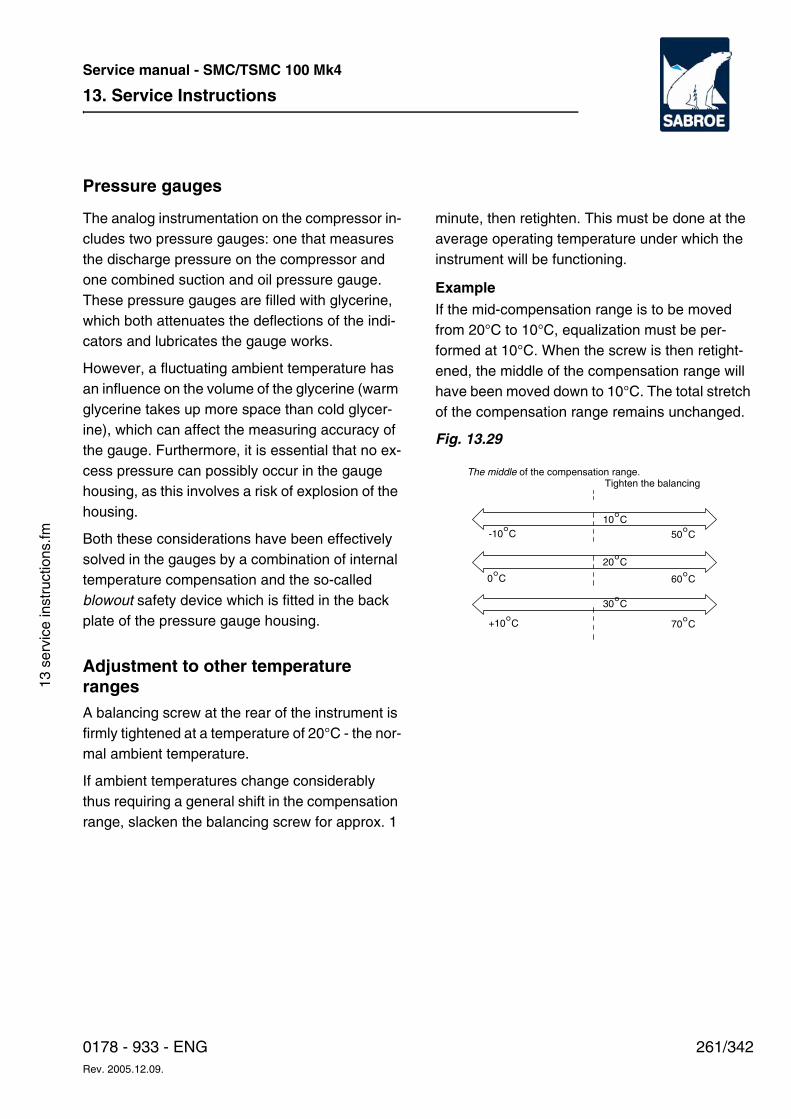
13. Service Instructions
261/3420178 - 933 - ENGRev. 2005.12.09.
Service manual - SMC/TSMC 100 Mk4
13 s
ervi
ce in
stru
ctio
ns.fm
Pressure gauges
The analog instrumentation on the compressor in-cludes two pressure gauges: one that measures the discharge pressure on the compressor and one combined suction and oil pressure gauge. These pressure gauges are filled with glycerine, which both attenuates the deflections of the indi-cators and lubricates the gauge works.
However, a fluctuating ambient temperature has an influence on the volume of the glycerine (warm glycerine takes up more space than cold glycer-ine), which can affect the measuring accuracy of the gauge. Furthermore, it is essential that no ex-cess pressure can possibly occur in the gauge housing, as this involves a risk of explosion of the housing.
Both these considerations have been effectively solved in the gauges by a combination of internal temperature compensation and the so-called blowout safety device which is fitted in the back plate of the pressure gauge housing.
Adjustment to other temperature ranges A balancing screw at the rear of the instrument is firmly tightened at a temperature of 20°C - the nor-mal ambient temperature.
If ambient temperatures change considerably thus requiring a general shift in the compensation range, slacken the balancing screw for approx. 1
minute, then retighten. This must be done at the average operating temperature under which the instrument will be functioning.
Example
If the mid-compensation range is to be moved from 20°C to 10°C, equalization must be per-formed at 10°C. When the screw is then retight-ened, the middle of the compensation range will have been moved down to 10°C. The total stretch of the compensation range remains unchanged.
Fig. 13.29
50°C
60°C
70°C
-10°C
0°C
+10°C
10°C
20°C
30°C
The middle of the compensation range.Tighten the balancing
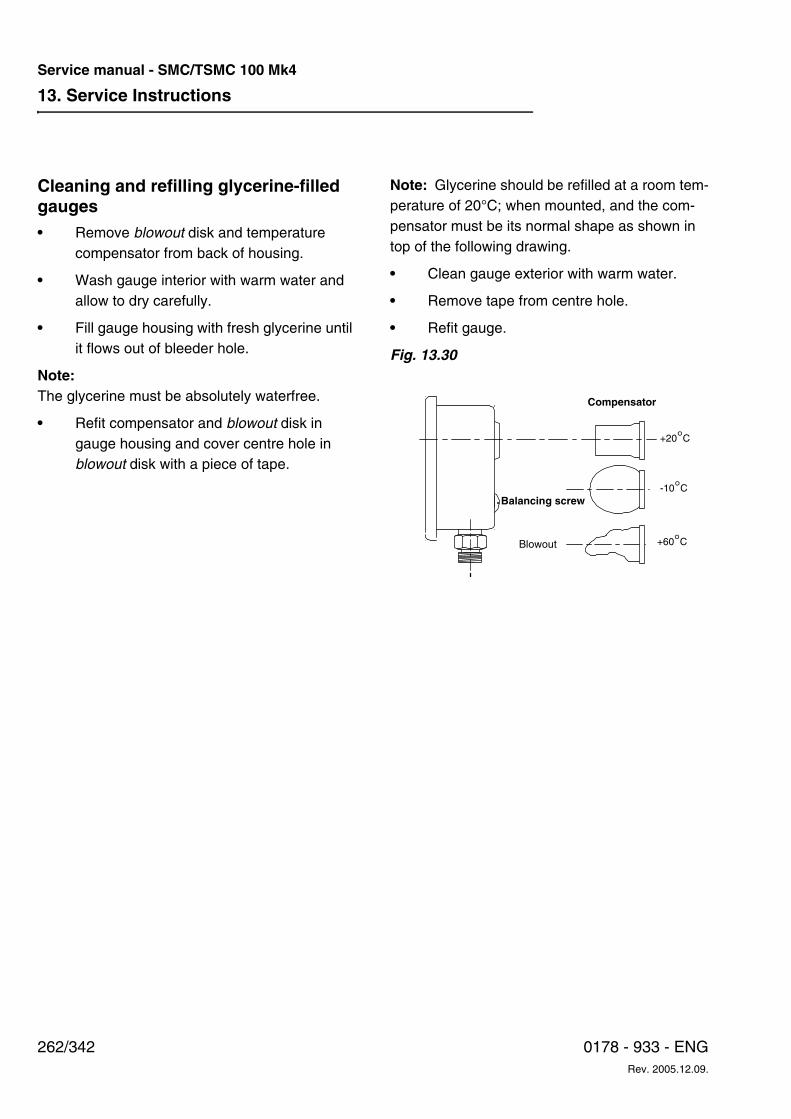
13. Service Instructions
262/342 0178 - 933 - ENGRev. 2005.12.09.
Service manual - SMC/TSMC 100 Mk4
Cleaning and refilling glycerine-filled gauges• Remove blowout disk and temperature
compensator from back of housing.
• Wash gauge interior with warm water and allow to dry carefully.
• Fill gauge housing with fresh glycerine until it flows out of bleeder hole.
Note:The glycerine must be absolutely waterfree.
• Refit compensator and blowout disk in gauge housing and cover centre hole in blowout disk with a piece of tape.
Note: Glycerine should be refilled at a room tem-perature of 20°C; when mounted, and the com-pensator must be its normal shape as shown in top of the following drawing.
• Clean gauge exterior with warm water.
• Remove tape from centre hole.
• Refit gauge.
Fig. 13.30
Balancing screw
Compensator
+20°C
-10°C
+60°CBlowout
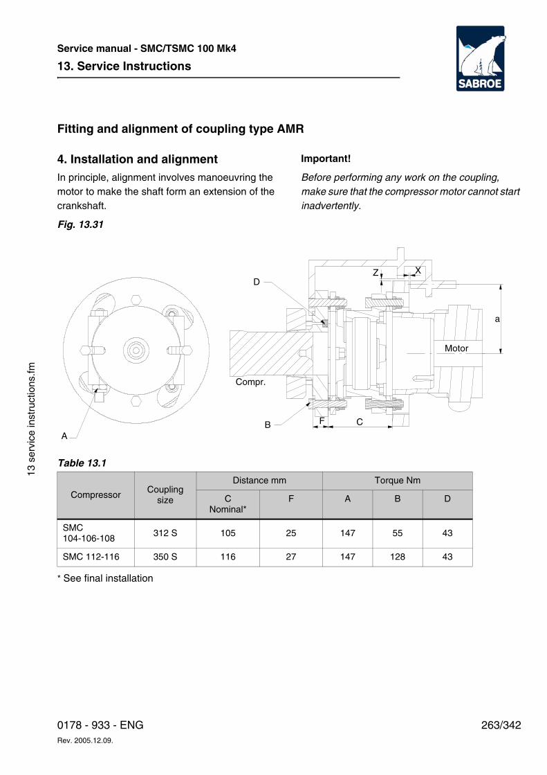
13. Service Instructions
263/3420178 - 933 - ENGRev. 2005.12.09.
Service manual - SMC/TSMC 100 Mk4
13 s
ervi
ce in
stru
ctio
ns.fm
Fitting and alignment of coupling type AMR
4. Installation and alignmentIn principle, alignment involves manoeuvring the motor to make the shaft form an extension of the crankshaft.
Important!
Before performing any work on the coupling, make sure that the compressor motor cannot start inadvertently.
Fig. 13.31
Table 13.1
* See final installation
CompressorCoupling
size
Distance mm Torque Nm
CNominal*
F A B D
SMC 104-106-108
312 S 105 25 147 55 43
SMC 112-116 350 S 116 27 147 128 43
B
DZ X
a
A
Compr.
Motor
CF
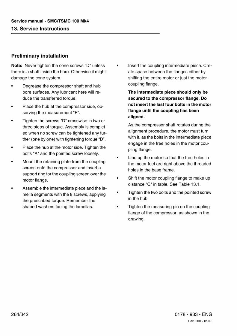
13. Service Instructions
264/342 0178 - 933 - ENGRev. 2005.12.09.
Service manual - SMC/TSMC 100 Mk4
Preliminary installation
Note: Never tighten the cone screws "D" unless there is a shaft inside the bore. Otherwise it might damage the cone system.
• Degrease the compressor shaft and hub bore surfaces. Any lubricant here will re-duce the transferred torque.
• Place the hub at the compressor side, ob-serving the measurement "F".
• Tighten the screws "D" crosswise in two or three steps of torque. Assembly is complet-ed when no screw can be tightened any fur-ther (one by one) with tightening torque “D”.
• Place the hub at the motor side. Tighten the bolts "A" and the pointed screw loosely.
• Mount the retaining plate from the coupling screen onto the compressor and insert a support ring for the coupling screen over the motor flange.
• Assemble the intermediate piece and the la-mella segments with the 8 screws, applying the prescribed torque. Remember the shaped washers facing the lamellas.
• Insert the coupling intermediate piece. Cre-ate space between the flanges either by shifting the entire motor or just the motor coupling flange.
The intermediate piece should only be secured to the compressor flange. Do not insert the last four bolts in the motor flange until the coupling has been aligned.
As the compressor shaft rotates during the alignment procedure, the motor must turn with it, as the bolts in the intermediate piece engage in the free holes in the motor cou-pling flange.
• Line up the motor so that the free holes in the motor feet are right above the threaded holes in the base frame.
• Shift the motor coupling flange to make up distance "C" in table. See Table 13.1.
• Tighten the two bolts and the pointed screw in the hub.
• Tighten the measuring pin on the coupling flange of the compressor, as shown in the drawing.
13. Service Instructions
265/3420178 - 933 - ENGRev. 2005.12.09.
Service manual - SMC/TSMC 100 Mk4
13 s
ervi
ce in
stru
ctio
ns.fm
Alignment
Check that the motor with loose bolts is positioned with all four feet on the base frame. Insert any liner plates needed where there is an air gap beneath the feet. Tighten the bolts loosely.
Achieving parallel shafts in horizontal plane
• Turn the coupling so that the alignment gauge is in upper position.
• Guide the measuring pin (pos. 2) towards the coupling flange, using a 1.0 mm feeler gauge, and fix the pin. Remove the feeler gauge.
• Rotate the coupling 180° and measure the change in distance from the measuring pin to the flange, using feeler gauges. This change is called "x".
• Measure the distance “b” between the motor feet as shown in Fig. 13.32. Measure the distance “a” from the centre of the pin pos. 2 to the centre of the motor as illustrated in Fig. 13.31
• Insert shims of thickness "y" either under both front feet or both rear feet, thereby tilt-ing the motor in the direction required.
• Shim thickness "y" is calculated by using the following formula (see also Fig. 13.32):
Fig. 13.32
• After tightening the motor bolts, repeat the measurement and compare the result with the values in the table below:
Table 13.2
y = Xb
2 x a•
y
b
Compressor Coupling size
Maximum variation (mm) measured with feeler gauge at a 180° turning of the coupling
Pos 1 Pos 2
max.
mm
Horizontal
max. mm
Vertical
min./max. mm
SMC 104-106-108 312 S 0.2 0.1/0.3 0.2
SMC 112-116 350 S 0.2 0.1/0.3 0.2
13. Service Instructions
266/342 0178 - 933 - ENGRev. 2005.12.09.
Service manual - SMC/TSMC 100 Mk4
Achieving correct centre height
• Turn the coupling so that the alignment gauge faces vertically down.
• Guide the measuring pin (pos. 1) towards the coupling flange, using a 1.0 mm feeler gauge, and fix the pin. Remove the feeler gauge.
• Rotate the coupling 180° and measure the increase in distance "z" from one millimetre using feeler gauges.
• Then lift the motor by placing shims of a thickness equal to half value of "z" under all four feet.
• After securing the motor, repeat the meas-urement and compare the result with the ta-ble values in pos. 1 vertical. Remember that the centreline of the motor shaft must be at least 0.05 mm higher than the centreline of the compressor, corresponding to a mini-mum of 0.1 mm distance less at the top po-sition of the alignment gauge.
Achieving parallel shafts in vertical plane• The motor is now positioned at its correct
height. What remains is to push and turn the motor at the level on which it is already lined up.
• Turn the coupling so that the alignment gauge faces out to one side horizontally.
• Guide both measuring pins towards the cou-pling with a 1.0 mm feeler gauge in be-tween.
• Turn the coupling 180° and by using feeler gauges measure deviations from one milli-metre at both pins.
• Move and turn the motor and repeat this measurement, align the motor in accord-ance with pos. 1 horizontal and pos. 2 in the table. Remember that the motor must be firmly secured during any measurements.
Final installation• Tighten the foundation bolts on the motor
(see torque table).
• Fit four bolts into the motor coupling flange so that thin shims are placed between the flange and the lamellae, with the rounded side facing lamella.
• Tighten the bolts to torque specified in the table.
• Readjust the flange distance "C" so that the lamellae are aligned, by moving the motor flange on the shaft and fastening the motor flange.
• Check the alignment of the coupling in hori-zontal and vertical planes for pos. 1 and pos. 2.
• Dismantle the measuring pin and tighten the screw to the prescribed torque.
• Fit the coupling guard.
• Once normal operating temperature has been achieved, double-check the coupling alignment.
13. Service Instructions
267/3420178 - 933 - ENGRev. 2005.12.09.
Service manual - SMC/TSMC 100 Mk4
13 s
ervi
ce in
stru
ctio
ns.fm
Refrigeration plant maintenance
Operational reliabilityThe prime causes of operating malfunctions to the plant are:
1. Incorrect control of liquid supply to the evap-orator.
2. Moisture in the plant.
3. Air in the plant.
4. Antifreeze liquid is missing.
5. Congestion due to metal shavings and dirt.
6. Congestion due to iron oxides.
7. Congestion due to copper oxides.
8. Inadequate refrigerant charge.
Below, information is given about ways of keeping contaminants out of the refrigerating system and at the same time facilitating day-to-day supervi-sion of the refrigeration plant.
Pumping down the refrigeration plantBefore dismounting any parts of the refrigeration plant for inspection or repair, pump-down must be carried out.
1. Open suction and discharge stop valves on compressor.
2. Close liquid stop valve after condenser or receiver so that liquid refrigerant can be col-lected in the tank. Any solenoid valves in the liquid line should be opened by force, ad-justing the thermostat to its lowest position so that the liquid line can be bled of refriger-ant. Adjust any constant pressure valves to bring evaporator pressure down to atmos-pheric pressure.
3. Start up the compressor. Adjust regulating system to lower suction pressure.
4. Keep a close eye on the suction pressure gauge! When the suction pressure is equal to at-mospheric, stop the compressor and quickly shut off the discharge stop valve. Shut off any stop valve in the oil return line.
5. If the receiver has an extra stop valve in the feed line, this can be closed; practically the entire refrigerant charge will then remain shut off in the receiver.
Note: The receiver must not be overfilled! There should be a minimum gas volume of 5%.
6. A slight overpressure should normally re-main in the piping system - this safeguards the system against the penetration of air and moisture.
7. Before dismantling parts, the operator should put a gas mask on.
Dismantling plantIn order to prevent moisture penetrating into the refrigeration plant during repair work, it is advisa-ble to follow the rules below:
1. No component should be opened unneces-sarily.
2. When dismantling the system, the pressure in the system should be a little higher than atmospheric.
Note: If the piping system is colder than the sur-roundings, there is a considerable risk of damp precipitation (condensation) on cold plant parts. Plant components to be dismantled must be warmer than the ambient temperature.
3. No two points in the system should be opened at the same time.
13. Service Instructions
268/342 0178 - 933 - ENGRev. 2005.12.09.
Service manual - SMC/TSMC 100 Mk4
4. Plug, close or at least cover opening with oiled paper or suchlike.
5. Be aware that filters may be very moist.
Tightness testing and pump-down of refrigeration plantBefore charging refrigerant into that part of the re-frigeration plant which has been opened, this should be pressure tested as described in the sec-tion entitled Pressure testing.
Afterwards, pump down in order to eliminate air and moisture. In this regard, consult the section on Evacuation. Otherwise, follow the instructions
given in the separate instruction manual on plant components.
Note: If the oil in the crankcase of the reciprocat-ing compressor or the oil separator of the screw compressor has been in contact with the atmos-pheric air for any length of time, it must be re-placed with fresh oil of the same grade and make.
Torques etc.All relevant data and tables regarding torques, coupling data etc. are specified in chapter 21, Ap-pendices.
13. Service Instructions
269/3420178 - 933 - ENGRev. 2005.12.09.
Service manual - SMC/TSMC 100 Mk4
13 s
ervi
ce in
stru
ctio
ns.fm
Ordering spare parts
When ordering spare parts, please state the fol-lowing:
1. Compressor no.All compressors are fitted with an identification plate, which states the type and compressor no. of the compressor and indicates which refrigerant to use.
2. Part no.Spare part drawings and part lists inserted in an instruction manual identify spare parts with the fol-lowing:
a. Spare part no. - a reference number which makes it easy to find a part in a drawing and cross-reference in the part list or vice versa.
b. Designation of the part.
c. Part no. - a 7-digit number which refers to Sabroe Refrigeration´s stocks.
When ordering spare parts, please always state at least the designation and part number. If in doubt, state the spare part no. as well.
3. Forwarding instructionsWhen ordering spare parts, please state the for-warding address and the address where the in-voice should be sent. If appropriate, please state the name of your local bank, how you wish the goods to be transported and a delivery date.
4. Classification certificateIf requiring a certificate from a classification au-thority, please mark the order appropriately, as the inspection and issuing procedures take extra time and incur extra expenses.
5. Quotation no.If you have received a quotation no. in earlier cor-respondence, please refer to this when placing your order - it will help us identify and execute your order quickly.

13. Service Instructions
270/342 0178 - 933 - ENGRev. 2005.12.09.
Service manual - SMC/TSMC 100 Mk4
18. Part list
271/3420178 - 933 - ENGRev. 2005.12.09.
Service manual - SMC/TSMC 100 Mk4
18 s
pare
par
ts li
st _
tool
list
.fm
18. Part list
How to use the part listThe key to identify a spare part is the pos. no. of the spare part.
By means of the pos. no., the position of the spare part can be found on the spare parts drawings.
Usually the spare part no. is stated next to the pos. no. If no spare part no. is stated, it may be be-cause the part is not considered a spare part or because the part is not sold as a spare part.
Parts which are not sold individually are contained in spare parts kits.
The spare parts list contains single parts and com-ponents, complete main parts, e.g. cylinder liner with suction valve, kit assemblies which is a col-lection of spare parts, service kits and gasket kits.
Spare parts which are not available as single parts will be contained in complete main parts as sub parts, kit assemblies, service kits and gasket kits.
Example
The part list is divided into sections with the main components of the compressor as headlines.
For each main part, e.g. cylinder liner complete, the part no. of the main part is stated first and then the pos. nos. of all single parts contained in the main part.
Then all kits related to the main part - including the pos. nos. of all sub parts contained in these kits - are indicated.
In some cases a kit will be related to several main parts which is why the kit is not indicated until after the relevant main parts.
Example
A ring plate kit contains a discharge valve ring plate pos. 20C, a suction valve ring plate pos. 19F and valve springs. Therefore, the ring plate kit will be indicated after the discharge valve ring plate pos. 20.
Component: Pos 19-1, part number 3112.085, designation: Cylinder liner with suction valve S&L.
Kit assembly: Part number 3184.350, designation: Kit assembly oil pump housing
Service kit: Part number 3188.027, designation: Service kit ring plates
Gasket kit: Part number 3188.009, designation: Gasket kit unloading cylinder
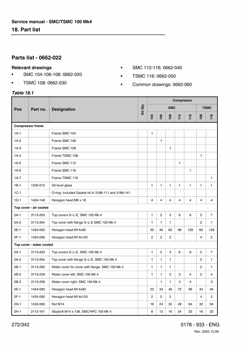
18. Part list
272/342 0178 - 933 - ENGRev. 2005.12.09.
Service manual - SMC/TSMC 100 Mk4
Parts list - 0662-022
Relevant drawings
• SMC 104-106-108: 0662-020
• TSMC 108: 0662-030
• SMC 112-116: 0662-040
• TSMC 116: 0662-050
• Common drawings: 0662-060
Table 18.1
Pos Part no. Designation
Kit
Qty
Compressor
SMC TSMC
104
106
108
112
116
108
116
Compressor frame
1A-1 Frame SMC 104 1
1A-2 Frame SMC 106 1
1A-3 Frame SMC 108 1
1A-4 Frame TSMC 108 1
1A-5 Frame SMC 112 1
1A-6 Frame SMC 116 1
1A-7 Frame TSMC 116 1
1B-1 1226-015 Oil level glass 1 1 1 1 1 1 1
1C-1 O-ring: Included Gasket kit in 3188-111 and 3188-141
1D-1 1424-148 Hexagon head M6 x 18 4 4 4 4 4 4 4
Top cover - air cooled
2A-1 3113-263 Top covers S–L-E, SMC 100 Mk 4 1 2 3 6 8 2 7
2A-2 3113-264 Top cover with flange S–L-E SMC 100 Mk 4 1 1 1 2 1
2E-1 1424-083 Hexagon head M14x90 30 46 62 96 128 60 128
2F-1 1424-090 Hexagon head M14x120 2 2 2 4 2
Top cover - water cooled
2A-1 3113-263 Top covers S–L-E, SMC 100 Mk 4 1 2 3 6 8 2 7
2A-2 3113-264 Top cover with flange S–L-E, SMC 100 Mk 4 1 1 1 2 1
2B-1 3113-260 Water cover for cover with flange, SMC 100 Mk 4 1 1 1 2 1
2B-2 3113-259 Water cover left, SMC 100 Mk 4 1 1 2 3 4 2 4
2B-3 3113-258 Water cover right, SMC 100 Mk 4 1 1 3 4 3
2E-1 1424-083 Hexagon head M14x90 22 34 46 72 96 44 94
2F-1 1424-090 Hexagon head M14x120 2 2 2 4 2
2G-1 1432-066 Nut M14 16 24 32 48 64 32 64
2H-1 2112-161 Staybolt M14 x 138, SMC/HPC 100 Mk 4 8 12 16 24 32 16 32
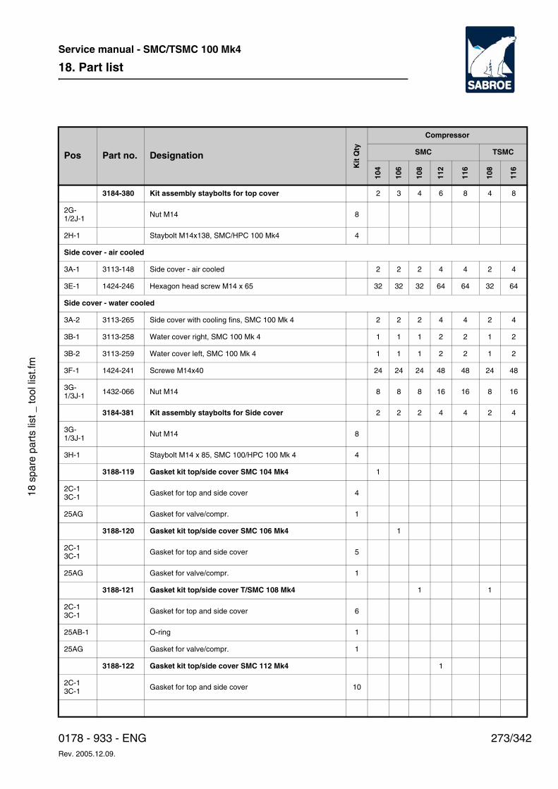
18. Part list
273/3420178 - 933 - ENGRev. 2005.12.09.
Service manual - SMC/TSMC 100 Mk4
18 s
pare
par
ts li
st _
tool
list
.fm
3184-380 Kit assembly staybolts for top cover 2 3 4 6 8 4 8
2G-1/2J-1 Nut M14 8
2H-1 Staybolt M14x138, SMC/HPC 100 Mk4 4
Side cover - air cooled
3A-1 3113-148 Side cover - air cooled 2 2 2 4 4 2 4
3E-1 1424-246 Hexagon head screw M14 x 65 32 32 32 64 64 32 64
Side cover - water cooled
3A-2 3113-265 Side cover with cooling fins, SMC 100 Mk 4 2 2 2 4 4 2 4
3B-1 3113-258 Water cover right, SMC 100 Mk 4 1 1 1 2 2 1 2
3B-2 3113-259 Water cover left, SMC 100 Mk 4 1 1 1 2 2 1 2
3F-1 1424-241 Screwe M14x40 24 24 24 48 48 24 48
3G-1/3J-1 1432-066 Nut M14 8 8 8 16 16 8 16
3184-381 Kit assembly staybolts for Side cover 2 2 2 4 4 2 4
3G-1/3J-1 Nut M14 8
3H-1 Staybolt M14 x 85, SMC 100/HPC 100 Mk 4 4
3188-119 Gasket kit top/side cover SMC 104 Mk4 1
2C-13C-1 Gasket for top and side cover 4
25AG Gasket for valve/compr. 1
3188-120 Gasket kit top/side cover SMC 106 Mk4 1
2C-13C-1 Gasket for top and side cover 5
25AG Gasket for valve/compr. 1
3188-121 Gasket kit top/side cover T/SMC 108 Mk4 1 1
2C-13C-1 Gasket for top and side cover 6
25AB-1 O-ring 1
25AG Gasket for valve/compr. 1
3188-122 Gasket kit top/side cover SMC 112 Mk4 1
2C-13C-1 Gasket for top and side cover 10
Pos Part no. Designation
Kit
Qty
Compressor
SMC TSMC
104
106
108
112
116
108
116
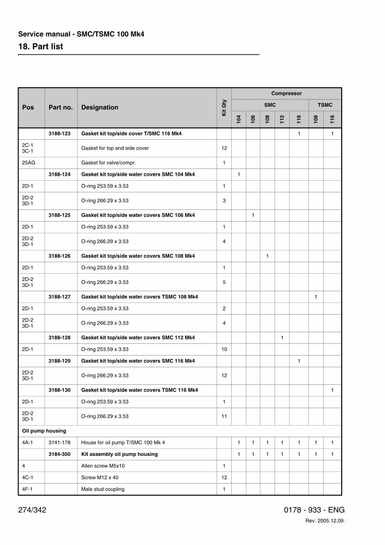
18. Part list
274/342 0178 - 933 - ENGRev. 2005.12.09.
Service manual - SMC/TSMC 100 Mk4
3188-123 Gasket kit top/side cover T/SMC 116 Mk4 1 1
2C-13C-1 Gasket for top and side cover 12
25AG Gasket for valve/compr. 1
3188-124 Gasket kit top/side water covers SMC 104 Mk4 1
2D-1 O-ring 253.59 x 3.53 1
2D-23D-1 O-ring 266.29 x 3.53 3
3188-125 Gasket kit top/side water covers SMC 106 Mk4 1
2D-1 O-ring 253.59 x 3.53 1
2D-23D-1 O-ring 266.29 x 3.53 4
3188-126 Gasket kit top/side water covers SMC 108 Mk4 1
2D-1 O-ring 253.59 x 3.53 1
2D-23D-1 O-ring 266.29 x 3.53 5
3188-127 Gasket kit top/side water covers TSMC 108 Mk4 1
2D-1 O-ring 253.59 x 3.53 2
2D-23D-1 O-ring 266.29 x 3.53 4
3188-128 Gasket kit top/side water covers SMC 112 Mk4 1
2D-1 O-ring 253.59 x 3.53 10
3188-129 Gasket kit top/side water covers SMC 116 Mk4 1
2D-23D-1 O-ring 266.29 x 3.53 12
3188-130 Gasket kit top/side water covers TSMC 116 Mk4 1
2D-1 O-ring 253.59 x 3.53 1
2D-23D-1 O-ring 266.29 x 3.53 11
Oil pump housing
4A-1 3141-178 House for oil pump T/SMC 100 Mk 4 1 1 1 1 1 1 1
3184-350 Kit assembly oil pump housing 1 1 1 1 1 1 1
4 Allen screw M5x10 1
4C-1 Screw M12 x 40 12
4F-1 Male stud coupling 1
Pos Part no. Designation
Kit
Qty
Compressor
SMC TSMC
104
106
108
112
116
108
116
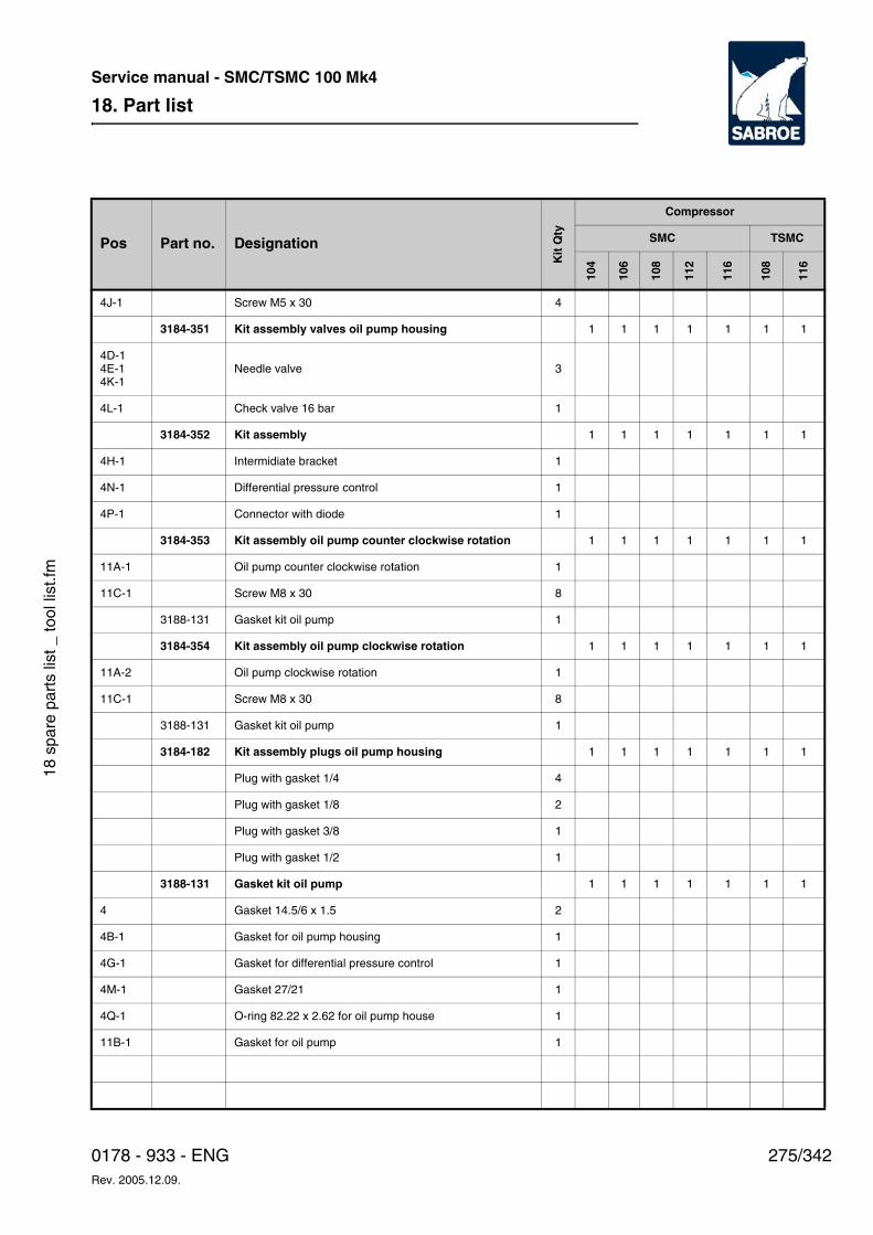
18. Part list
275/3420178 - 933 - ENGRev. 2005.12.09.
Service manual - SMC/TSMC 100 Mk4
18 s
pare
par
ts li
st _
tool
list
.fm
4J-1 Screw M5 x 30 4
3184-351 Kit assembly valves oil pump housing 1 1 1 1 1 1 1
4D-14E-14K-1
Needle valve 3
4L-1 Check valve 16 bar 1
3184-352 Kit assembly 1 1 1 1 1 1 1
4H-1 Intermidiate bracket 1
4N-1 Differential pressure control 1
4P-1 Connector with diode 1
3184-353 Kit assembly oil pump counter clockwise rotation 1 1 1 1 1 1 1
11A-1 Oil pump counter clockwise rotation 1
11C-1 Screw M8 x 30 8
3188-131 Gasket kit oil pump 1
3184-354 Kit assembly oil pump clockwise rotation 1 1 1 1 1 1 1
11A-2 Oil pump clockwise rotation 1
11C-1 Screw M8 x 30 8
3188-131 Gasket kit oil pump 1
3184-182 Kit assembly plugs oil pump housing 1 1 1 1 1 1 1
Plug with gasket 1/4 4
Plug with gasket 1/8 2
Plug with gasket 3/8 1
Plug with gasket 1/2 1
3188-131 Gasket kit oil pump 1 1 1 1 1 1 1
4 Gasket 14.5/6 x 1.5 2
4B-1 Gasket for oil pump housing 1
4G-1 Gasket for differential pressure control 1
4M-1 Gasket 27/21 1
4Q-1 O-ring 82.22 x 2.62 for oil pump house 1
11B-1 Gasket for oil pump 1
Pos Part no. Designation
Kit
Qty
Compressor
SMC TSMC
104
106
108
112
116
108
116
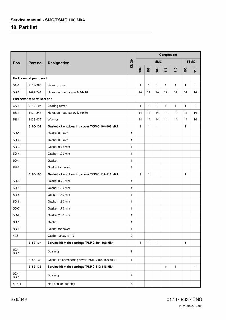
18. Part list
276/342 0178 - 933 - ENGRev. 2005.12.09.
Service manual - SMC/TSMC 100 Mk4
End cover at pump end
5A-1 3113-266 Bearing cover 1 1 1 1 1 1 1
5B-1 1424-241 Hexagon head screw M14x40 14 14 14 14 14 14 14
End cover at shaft seal end
6A-1 3113-124 Bearing cover 1 1 1 1 1 1 1
6B-1 1424-245 Hexagon head screw M14x60 14 14 14 14 14 14 14
6E-1 1436-037 Washer 14 14 14 14 14 14 14
3188-132 Gasket kit end/bearing cover T/SMC 104-108 Mk4 1 1 1 1
5D-1 Gasket 0.3 mm 1
5D-2 Gasket 0.5 mm 1
5D-3 Gasket 0.75 mm 1
5D-4 Gasket 1.00 mm 1
6D-1 Gasket 1
8B-1 Gasket for cover 1
3188-133 Gasket kit end/bearing cover T/SMC 112-116 Mk4 1 1 1 1
5D-3 Gasket 0.75 mm 1
5D-4 Gasket 1.00 mm 1
5D-5 Gasket 1.30 mm 1
5D-6 Gasket 1.50 mm 1
5D-7 Gasket 1.75 mm 1
5D-8 Gasket 2.00 mm 1
6D-1 Gasket 1
8B-1 Gasket for cover 1
49J Gasket 34/27 x 1.5 2
3188-134 Service kit main bearings T/SMC 104-108 Mk4 1 1 1 1
5C-16C-1 Bushing 2
3188-132 Gasket kit end/bearing cover T/SMC 104-108 Mk4 1
3188-135 Service kit main bearings T/SMC 112-116 Mk4 1 1 1
5C-16C-1 Bushing 2
49E-1 Half section bearing 8
Pos Part no. Designation
Kit
Qty
Compressor
SMC TSMC
104
106
108
112
116
108
116
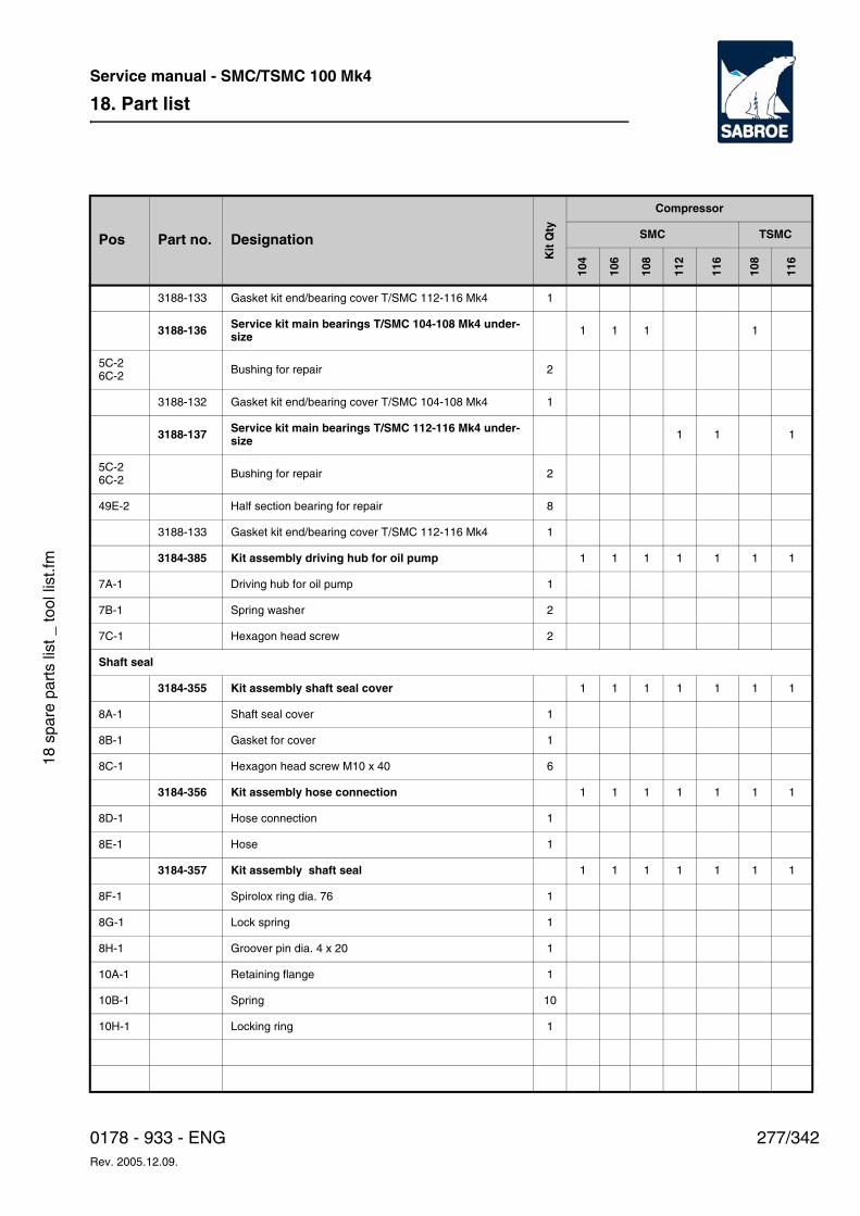
18. Part list
277/3420178 - 933 - ENGRev. 2005.12.09.
Service manual - SMC/TSMC 100 Mk4
18 s
pare
par
ts li
st _
tool
list
.fm
3188-133 Gasket kit end/bearing cover T/SMC 112-116 Mk4 1
3188-136 Service kit main bearings T/SMC 104-108 Mk4 under-size 1 1 1 1
5C-26C-2 Bushing for repair 2
3188-132 Gasket kit end/bearing cover T/SMC 104-108 Mk4 1
3188-137 Service kit main bearings T/SMC 112-116 Mk4 under-size 1 1 1
5C-26C-2 Bushing for repair 2
49E-2 Half section bearing for repair 8
3188-133 Gasket kit end/bearing cover T/SMC 112-116 Mk4 1
3184-385 Kit assembly driving hub for oil pump 1 1 1 1 1 1 1
7A-1 Driving hub for oil pump 1
7B-1 Spring washer 2
7C-1 Hexagon head screw 2
Shaft seal
3184-355 Kit assembly shaft seal cover 1 1 1 1 1 1 1
8A-1 Shaft seal cover 1
8B-1 Gasket for cover 1
8C-1 Hexagon head screw M10 x 40 6
3184-356 Kit assembly hose connection 1 1 1 1 1 1 1
8D-1 Hose connection 1
8E-1 Hose 1
3184-357 Kit assembly shaft seal 1 1 1 1 1 1 1
8F-1 Spirolox ring dia. 76 1
8G-1 Lock spring 1
8H-1 Groover pin dia. 4 x 20 1
10A-1 Retaining flange 1
10B-1 Spring 10
10H-1 Locking ring 1
Pos Part no. Designation
Kit
Qty
Compressor
SMC TSMC
104
106
108
112
116
108
116
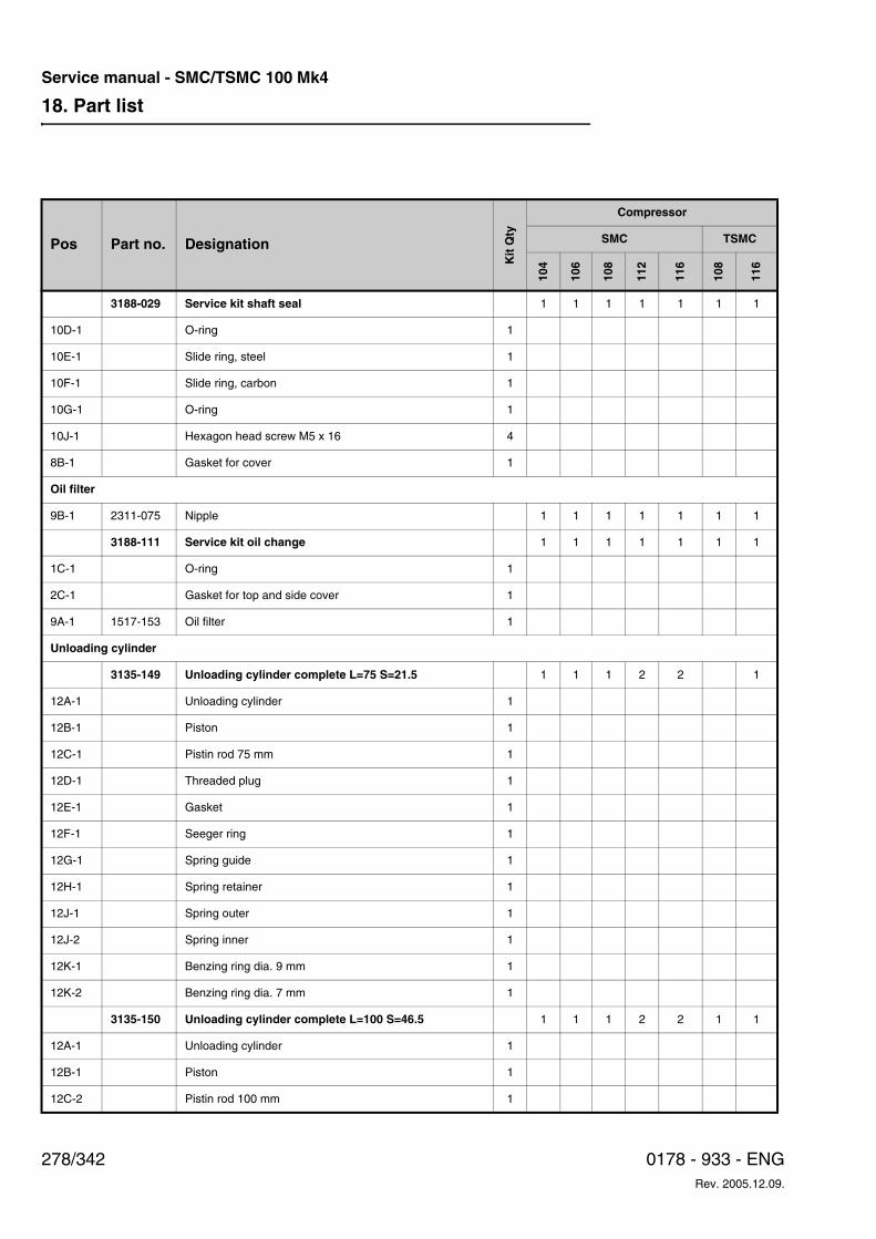
18. Part list
278/342 0178 - 933 - ENGRev. 2005.12.09.
Service manual - SMC/TSMC 100 Mk4
3188-029 Service kit shaft seal 1 1 1 1 1 1 1
10D-1 O-ring 1
10E-1 Slide ring, steel 1
10F-1 Slide ring, carbon 1
10G-1 O-ring 1
10J-1 Hexagon head screw M5 x 16 4
8B-1 Gasket for cover 1
Oil filter
9B-1 2311-075 Nipple 1 1 1 1 1 1 1
3188-111 Service kit oil change 1 1 1 1 1 1 1
1C-1 O-ring 1
2C-1 Gasket for top and side cover 1
9A-1 1517-153 Oil filter 1
Unloading cylinder
3135-149 Unloading cylinder complete L=75 S=21.5 1 1 1 2 2 1
12A-1 Unloading cylinder 1
12B-1 Piston 1
12C-1 Pistin rod 75 mm 1
12D-1 Threaded plug 1
12E-1 Gasket 1
12F-1 Seeger ring 1
12G-1 Spring guide 1
12H-1 Spring retainer 1
12J-1 Spring outer 1
12J-2 Spring inner 1
12K-1 Benzing ring dia. 9 mm 1
12K-2 Benzing ring dia. 7 mm 1
3135-150 Unloading cylinder complete L=100 S=46.5 1 1 1 2 2 1 1
12A-1 Unloading cylinder 1
12B-1 Piston 1
12C-2 Pistin rod 100 mm 1
Pos Part no. Designation
Kit
Qty
Compressor
SMC TSMC
104
106
108
112
116
108
116
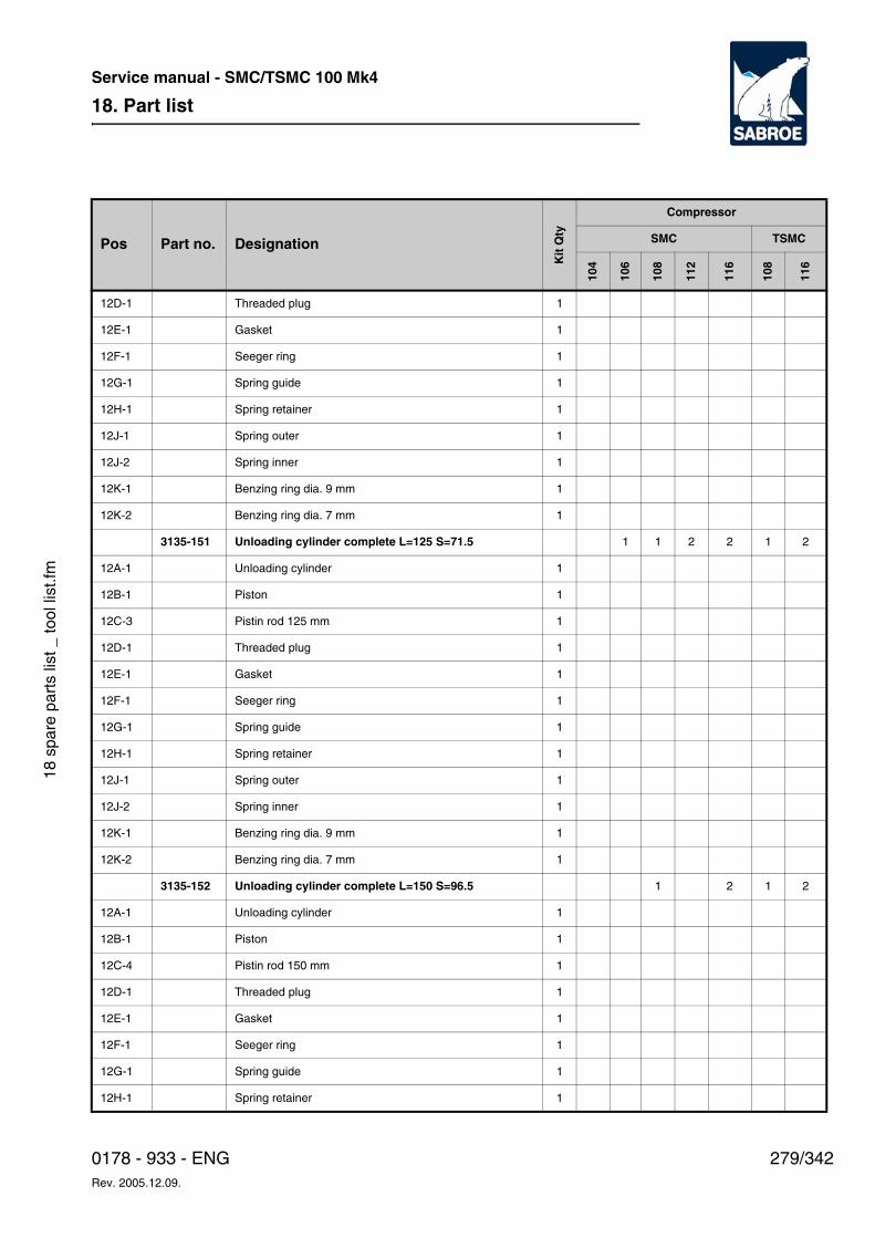
18. Part list
279/3420178 - 933 - ENGRev. 2005.12.09.
Service manual - SMC/TSMC 100 Mk4
18 s
pare
par
ts li
st _
tool
list
.fm
12D-1 Threaded plug 1
12E-1 Gasket 1
12F-1 Seeger ring 1
12G-1 Spring guide 1
12H-1 Spring retainer 1
12J-1 Spring outer 1
12J-2 Spring inner 1
12K-1 Benzing ring dia. 9 mm 1
12K-2 Benzing ring dia. 7 mm 1
3135-151 Unloading cylinder complete L=125 S=71.5 1 1 2 2 1 2
12A-1 Unloading cylinder 1
12B-1 Piston 1
12C-3 Pistin rod 125 mm 1
12D-1 Threaded plug 1
12E-1 Gasket 1
12F-1 Seeger ring 1
12G-1 Spring guide 1
12H-1 Spring retainer 1
12J-1 Spring outer 1
12J-2 Spring inner 1
12K-1 Benzing ring dia. 9 mm 1
12K-2 Benzing ring dia. 7 mm 1
3135-152 Unloading cylinder complete L=150 S=96.5 1 2 1 2
12A-1 Unloading cylinder 1
12B-1 Piston 1
12C-4 Pistin rod 150 mm 1
12D-1 Threaded plug 1
12E-1 Gasket 1
12F-1 Seeger ring 1
12G-1 Spring guide 1
12H-1 Spring retainer 1
Pos Part no. Designation
Kit
Qty
Compressor
SMC TSMC
104
106
108
112
116
108
116
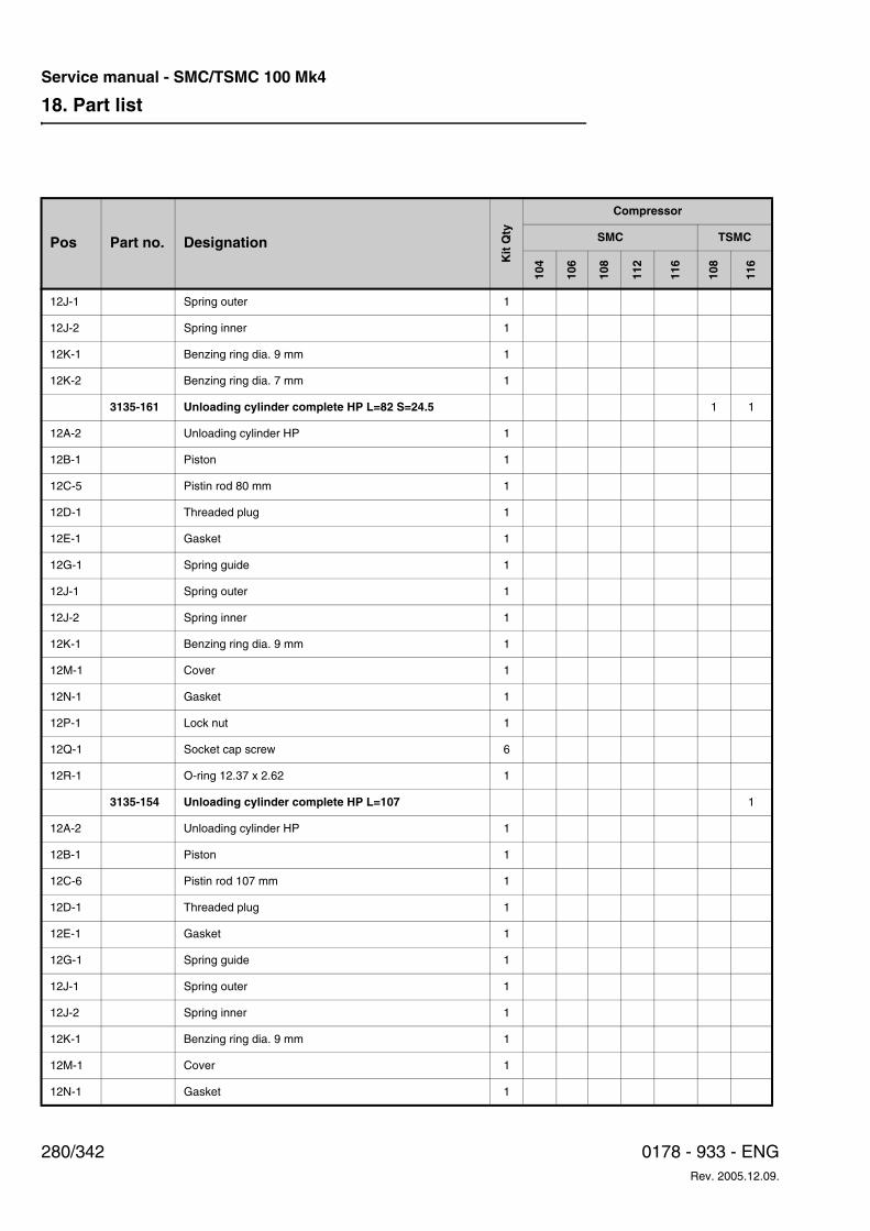
18. Part list
280/342 0178 - 933 - ENGRev. 2005.12.09.
Service manual - SMC/TSMC 100 Mk4
12J-1 Spring outer 1
12J-2 Spring inner 1
12K-1 Benzing ring dia. 9 mm 1
12K-2 Benzing ring dia. 7 mm 1
3135-161 Unloading cylinder complete HP L=82 S=24.5 1 1
12A-2 Unloading cylinder HP 1
12B-1 Piston 1
12C-5 Pistin rod 80 mm 1
12D-1 Threaded plug 1
12E-1 Gasket 1
12G-1 Spring guide 1
12J-1 Spring outer 1
12J-2 Spring inner 1
12K-1 Benzing ring dia. 9 mm 1
12M-1 Cover 1
12N-1 Gasket 1
12P-1 Lock nut 1
12Q-1 Socket cap screw 6
12R-1 O-ring 12.37 x 2.62 1
3135-154 Unloading cylinder complete HP L=107 1
12A-2 Unloading cylinder HP 1
12B-1 Piston 1
12C-6 Pistin rod 107 mm 1
12D-1 Threaded plug 1
12E-1 Gasket 1
12G-1 Spring guide 1
12J-1 Spring outer 1
12J-2 Spring inner 1
12K-1 Benzing ring dia. 9 mm 1
12M-1 Cover 1
12N-1 Gasket 1
Pos Part no. Designation
Kit
Qty
Compressor
SMC TSMC
104
106
108
112
116
108
116
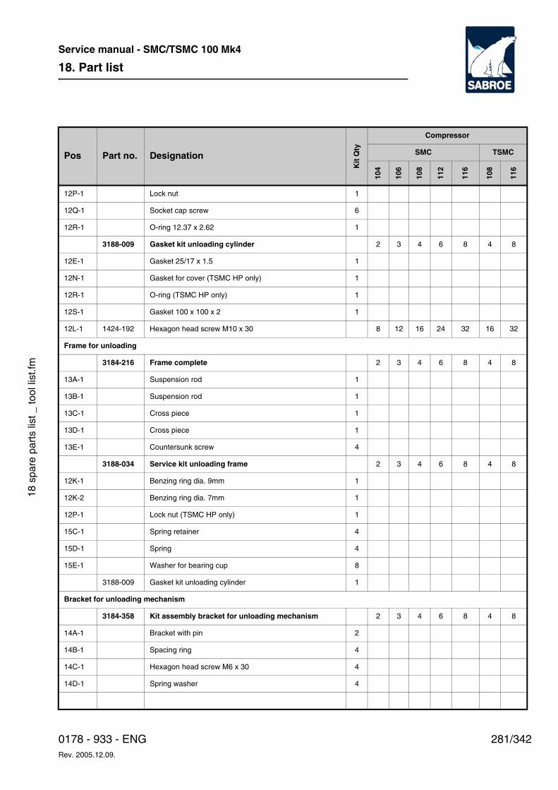
18. Part list
281/3420178 - 933 - ENGRev. 2005.12.09.
Service manual - SMC/TSMC 100 Mk4
18 s
pare
par
ts li
st _
tool
list
.fm
12P-1 Lock nut 1
12Q-1 Socket cap screw 6
12R-1 O-ring 12.37 x 2.62 1
3188-009 Gasket kit unloading cylinder 2 3 4 6 8 4 8
12E-1 Gasket 25/17 x 1.5 1
12N-1 Gasket for cover (TSMC HP only) 1
12R-1 O-ring (TSMC HP only) 1
12S-1 Gasket 100 x 100 x 2 1
12L-1 1424-192 Hexagon head screw M10 x 30 8 12 16 24 32 16 32
Frame for unloading
3184-216 Frame complete 2 3 4 6 8 4 8
13A-1 Suspension rod 1
13B-1 Suspension rod 1
13C-1 Cross piece 1
13D-1 Cross piece 1
13E-1 Countersunk screw 4
3188-034 Service kit unloading frame 2 3 4 6 8 4 8
12K-1 Benzing ring dia. 9mm 1
12K-2 Benzing ring dia. 7mm 1
12P-1 Lock nut (TSMC HP only) 1
15C-1 Spring retainer 4
15D-1 Spring 4
15E-1 Washer for bearing cup 8
3188-009 Gasket kit unloading cylinder 1
Bracket for unloading mechanism
3184-358 Kit assembly bracket for unloading mechanism 2 3 4 6 8 4 8
14A-1 Bracket with pin 2
14B-1 Spacing ring 4
14C-1 Hexagon head screw M6 x 30 4
14D-1 Spring washer 4
Pos Part no. Designation
Kit
Qty
Compressor
SMC TSMC
104
106
108
112
116
108
116
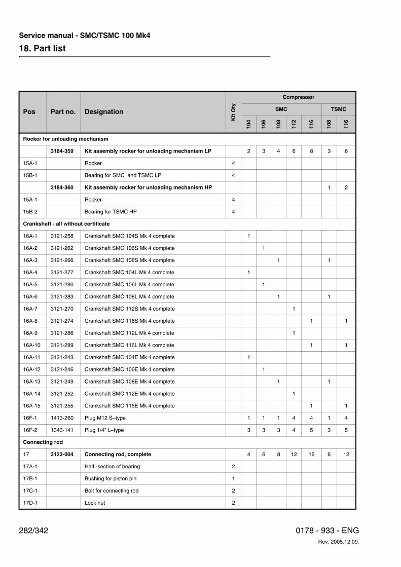
18. Part list
282/342 0178 - 933 - ENGRev. 2005.12.09.
Service manual - SMC/TSMC 100 Mk4
Rocker for unloading mechanism
3184-359 Kit assembly rocker for unloading mechanism LP 2 3 4 6 8 3 6
15A-1 Rocker 4
15B-1 Bearing for SMC and TSMC LP 4
3184-360 Kit assembly rocker for unloading mechanism HP 1 2
15A-1 Rocker 4
15B-2 Bearing for TSMC HP 4
Crankshaft - all without certificate
16A-1 3121-258 Crankshaft SMC 104S Mk 4 complete 1
16A-2 3121-262 Crankshaft SMC 106S Mk 4 complete 1
16A-3 3121-266 Crankshaft SMC 108S Mk 4 complete 1 1
16A-4 3121-277 Crankshaft SMC 104L Mk 4 complete 1
16A-5 3121-280 Crankshaft SMC 106L Mk 4 complete 1
16A-6 3121-283 Crankshaft SMC 108L Mk 4 complete 1 1
16A-7 3121-270 Crankshaft SMC 112S Mk 4 complete 1
16A-8 3121-274 Crankshaft SMC 116S Mk 4 complete 1 1
16A-9 3121-286 Crankshaft SMC 112L Mk 4 complete 1
16A-10 3121-289 Crankshaft SMC 116L Mk 4 complete 1 1
16A-11 3121-243 Crankshaft SMC 104E Mk 4 complete 1
16A-12 3121-246 Crankshaft SMC 106E Mk 4 complete 1
16A-13 3121-249 Crankshaft SMC 108E Mk 4 complete 1 1
16A-14 3121-252 Crankshaft SMC 112E Mk 4 complete 1
16A-15 3121-255 Crankshaft SMC 116E Mk 4 complete 1 1
16F-1 1413-260 Plug M12 S–type 1 1 1 4 4 1 4
16F-2 1343-141 Plug 1/4” L–type 3 3 3 4 5 3 5
Connecting rod
17 3123-004 Connecting rod, complete 4 6 8 12 16 6 12
17A-1 Half -section of bearing 2
17B-1 Bushing for piston pin 1
17C-1 Bolt for connecting rod 2
17D-1 Lock nut 2
Pos Part no. Designation
Kit
Qty
Compressor
SMC TSMC
104
106
108
112
116
108
116
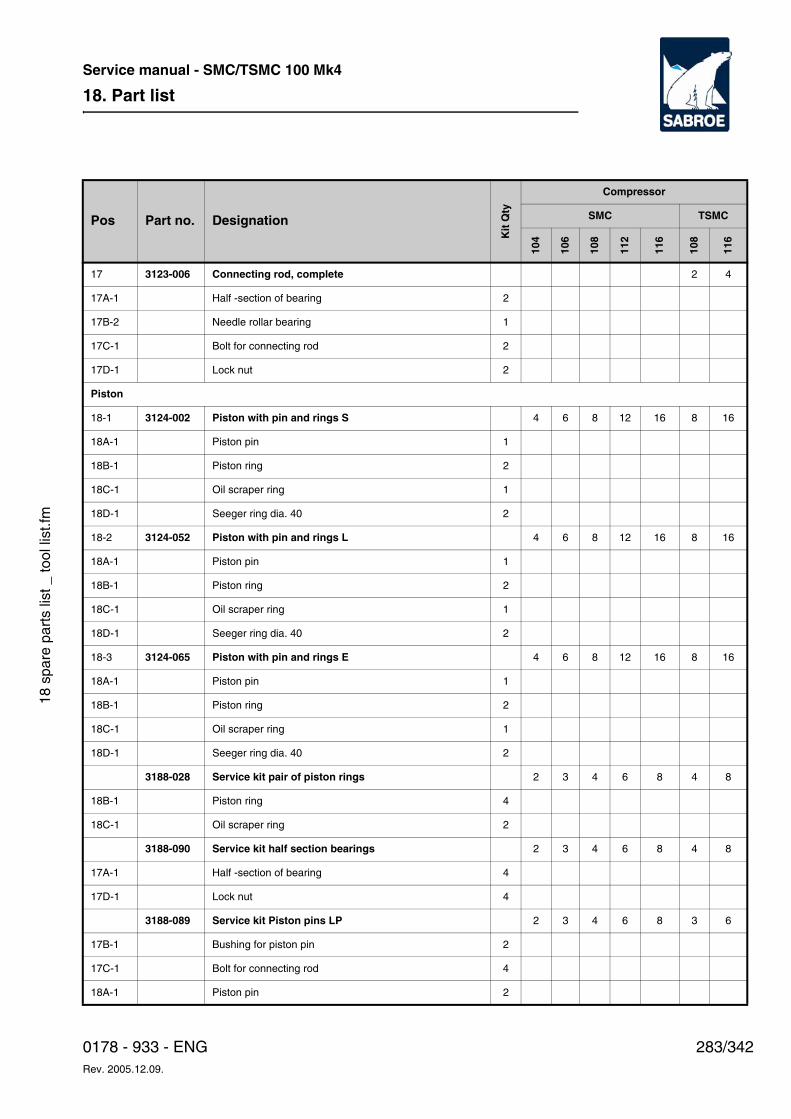
18. Part list
283/3420178 - 933 - ENGRev. 2005.12.09.
Service manual - SMC/TSMC 100 Mk4
18 s
pare
par
ts li
st _
tool
list
.fm
17 3123-006 Connecting rod, complete 2 4
17A-1 Half -section of bearing 2
17B-2 Needle rollar bearing 1
17C-1 Bolt for connecting rod 2
17D-1 Lock nut 2
Piston
18-1 3124-002 Piston with pin and rings S 4 6 8 12 16 8 16
18A-1 Piston pin 1
18B-1 Piston ring 2
18C-1 Oil scraper ring 1
18D-1 Seeger ring dia. 40 2
18-2 3124-052 Piston with pin and rings L 4 6 8 12 16 8 16
18A-1 Piston pin 1
18B-1 Piston ring 2
18C-1 Oil scraper ring 1
18D-1 Seeger ring dia. 40 2
18-3 3124-065 Piston with pin and rings E 4 6 8 12 16 8 16
18A-1 Piston pin 1
18B-1 Piston ring 2
18C-1 Oil scraper ring 1
18D-1 Seeger ring dia. 40 2
3188-028 Service kit pair of piston rings 2 3 4 6 8 4 8
18B-1 Piston ring 4
18C-1 Oil scraper ring 2
3188-090 Service kit half section bearings 2 3 4 6 8 4 8
17A-1 Half -section of bearing 4
17D-1 Lock nut 4
3188-089 Service kit Piston pins LP 2 3 4 6 8 3 6
17B-1 Bushing for piston pin 2
17C-1 Bolt for connecting rod 4
18A-1 Piston pin 2
Pos Part no. Designation
Kit
Qty
Compressor
SMC TSMC
104
106
108
112
116
108
116
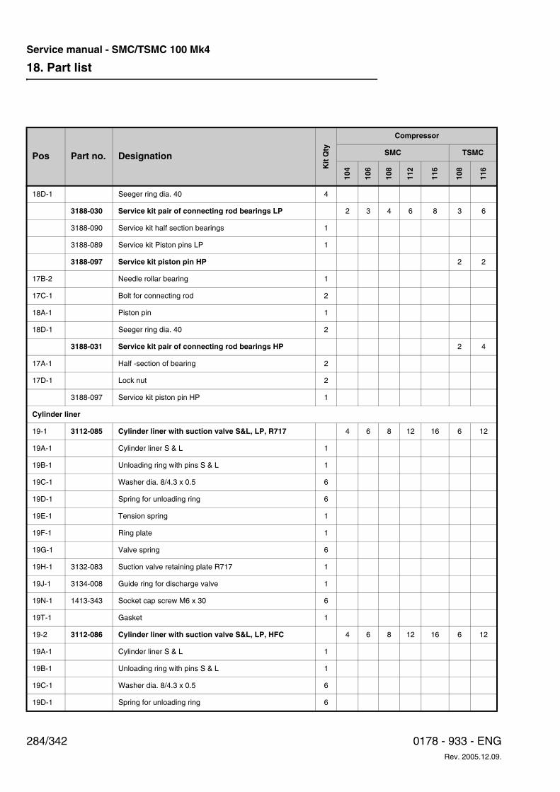
18. Part list
284/342 0178 - 933 - ENGRev. 2005.12.09.
Service manual - SMC/TSMC 100 Mk4
18D-1 Seeger ring dia. 40 4
3188-030 Service kit pair of connecting rod bearings LP 2 3 4 6 8 3 6
3188-090 Service kit half section bearings 1
3188-089 Service kit Piston pins LP 1
3188-097 Service kit piston pin HP 2 2
17B-2 Needle rollar bearing 1
17C-1 Bolt for connecting rod 2
18A-1 Piston pin 1
18D-1 Seeger ring dia. 40 2
3188-031 Service kit pair of connecting rod bearings HP 2 4
17A-1 Half -section of bearing 2
17D-1 Lock nut 2
3188-097 Service kit piston pin HP 1
Cylinder liner
19-1 3112-085 Cylinder liner with suction valve S&L, LP, R717 4 6 8 12 16 6 12
19A-1 Cylinder liner S & L 1
19B-1 Unloading ring with pins S & L 1
19C-1 Washer dia. 8/4.3 x 0.5 6
19D-1 Spring for unloading ring 6
19E-1 Tension spring 1
19F-1 Ring plate 1
19G-1 Valve spring 6
19H-1 3132-083 Suction valve retaining plate R717 1
19J-1 3134-008 Guide ring for discharge valve 1
19N-1 1413-343 Socket cap screw M6 x 30 6
19T-1 Gasket 1
19-2 3112-086 Cylinder liner with suction valve S&L, LP, HFC 4 6 8 12 16 6 12
19A-1 Cylinder liner S & L 1
19B-1 Unloading ring with pins S & L 1
19C-1 Washer dia. 8/4.3 x 0.5 6
19D-1 Spring for unloading ring 6
Pos Part no. Designation
Kit
Qty
Compressor
SMC TSMC
104
106
108
112
116
108
116
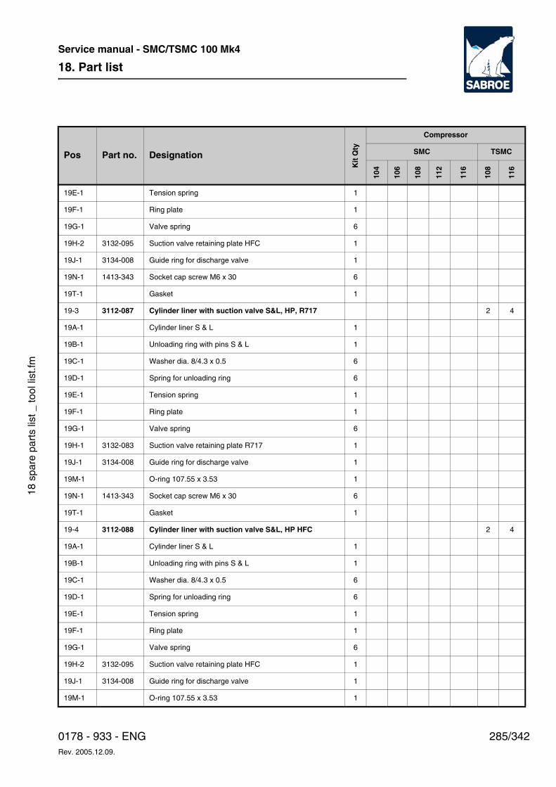
18. Part list
285/3420178 - 933 - ENGRev. 2005.12.09.
Service manual - SMC/TSMC 100 Mk4
18 s
pare
par
ts li
st _
tool
list
.fm
19E-1 Tension spring 1
19F-1 Ring plate 1
19G-1 Valve spring 6
19H-2 3132-095 Suction valve retaining plate HFC 1
19J-1 3134-008 Guide ring for discharge valve 1
19N-1 1413-343 Socket cap screw M6 x 30 6
19T-1 Gasket 1
19-3 3112-087 Cylinder liner with suction valve S&L, HP, R717 2 4
19A-1 Cylinder liner S & L 1
19B-1 Unloading ring with pins S & L 1
19C-1 Washer dia. 8/4.3 x 0.5 6
19D-1 Spring for unloading ring 6
19E-1 Tension spring 1
19F-1 Ring plate 1
19G-1 Valve spring 6
19H-1 3132-083 Suction valve retaining plate R717 1
19J-1 3134-008 Guide ring for discharge valve 1
19M-1 O-ring 107.55 x 3.53 1
19N-1 1413-343 Socket cap screw M6 x 30 6
19T-1 Gasket 1
19-4 3112-088 Cylinder liner with suction valve S&L, HP HFC 2 4
19A-1 Cylinder liner S & L 1
19B-1 Unloading ring with pins S & L 1
19C-1 Washer dia. 8/4.3 x 0.5 6
19D-1 Spring for unloading ring 6
19E-1 Tension spring 1
19F-1 Ring plate 1
19G-1 Valve spring 6
19H-2 3132-095 Suction valve retaining plate HFC 1
19J-1 3134-008 Guide ring for discharge valve 1
19M-1 O-ring 107.55 x 3.53 1
Pos Part no. Designation
Kit
Qty
Compressor
SMC TSMC
104
106
108
112
116
108
116
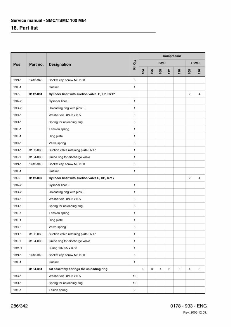
18. Part list
286/342 0178 - 933 - ENGRev. 2005.12.09.
Service manual - SMC/TSMC 100 Mk4
19N-1 1413-343 Socket cap screw M6 x 30 6
19T-1 Gasket 1
19-5 3112-081 Cylinder liner with suction valve E, LP, R717 2 4
19A-2 Cylinder liner E 1
19B-2 Unloading ring with pins E 1
19C-1 Washer dia. 8/4.3 x 0.5 6
19D-1 Spring for unloading ring 6
19E-1 Tension spring 1
19F-1 Ring plate 1
19G-1 Valve spring 6
19H-1 3132-083 Suction valve retaining plate R717 1
19J-1 3134-008 Guide ring for discharge valve 1
19N-1 1413-343 Socket cap screw M6 x 30 6
19T-1 Gasket 1
19-6 3112-097 Cylinder liner with suction valve E, HP, R717 2 4
19A-2 Cylinder liner E 1
19B-2 Unloading ring with pins E 1
19C-1 Washer dia. 8/4.3 x 0.5 6
19D-1 Spring for unloading ring 6
19E-1 Tension spring 1
19F-1 Ring plate 1
19G-1 Valve spring 6
19H-1 3132-083 Suction valve retaining plate R717 1
19J-1 3134-008 Guide ring for discharge valve 1
19M-1 O-ring 107.55 x 3.53 1
19N-1 1413-343 Socket cap screw M6 x 30 6
19T-1 Gasket 1
3184-361 Kit assembly springs for unloading ring 2 3 4 6 8 4 8
19C-1 Washer dia. 8/4.3 x 0.5 12
19D-1 Spring for unloading ring 12
19E-1 Tesion spring 2
Pos Part no. Designation
Kit
Qty
Compressor
SMC TSMC
104
106
108
112
116
108
116
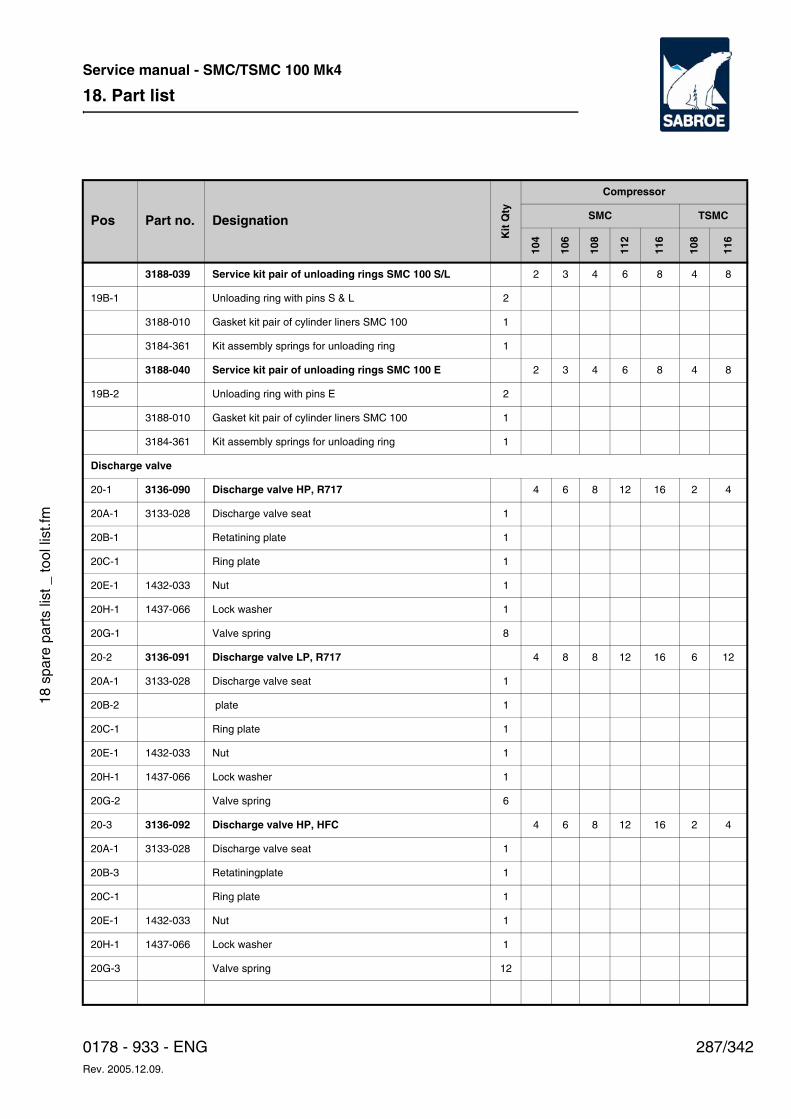
18. Part list
287/3420178 - 933 - ENGRev. 2005.12.09.
Service manual - SMC/TSMC 100 Mk4
18 s
pare
par
ts li
st _
tool
list
.fm
3188-039 Service kit pair of unloading rings SMC 100 S/L 2 3 4 6 8 4 8
19B-1 Unloading ring with pins S & L 2
3188-010 Gasket kit pair of cylinder liners SMC 100 1
3184-361 Kit assembly springs for unloading ring 1
3188-040 Service kit pair of unloading rings SMC 100 E 2 3 4 6 8 4 8
19B-2 Unloading ring with pins E 2
3188-010 Gasket kit pair of cylinder liners SMC 100 1
3184-361 Kit assembly springs for unloading ring 1
Discharge valve
20-1 3136-090 Discharge valve HP, R717 4 6 8 12 16 2 4
20A-1 3133-028 Discharge valve seat 1
20B-1 Retatining plate 1
20C-1 Ring plate 1
20E-1 1432-033 Nut 1
20H-1 1437-066 Lock washer 1
20G-1 Valve spring 8
20-2 3136-091 Discharge valve LP, R717 4 8 8 12 16 6 12
20A-1 3133-028 Discharge valve seat 1
20B-2 plate 1
20C-1 Ring plate 1
20E-1 1432-033 Nut 1
20H-1 1437-066 Lock washer 1
20G-2 Valve spring 6
20-3 3136-092 Discharge valve HP, HFC 4 6 8 12 16 2 4
20A-1 3133-028 Discharge valve seat 1
20B-3 Retatiningplate 1
20C-1 Ring plate 1
20E-1 1432-033 Nut 1
20H-1 1437-066 Lock washer 1
20G-3 Valve spring 12
Pos Part no. Designation
Kit
Qty
Compressor
SMC TSMC
104
106
108
112
116
108
116
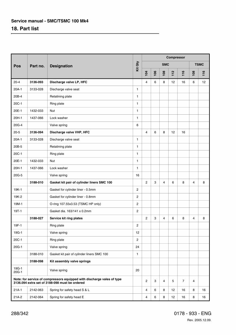
18. Part list
288/342 0178 - 933 - ENGRev. 2005.12.09.
Service manual - SMC/TSMC 100 Mk4
20-4 3136-093 Discharge valve LP, HFC 4 6 8 12 16 6 12
20A-1 3133-028 Discharge valve seat 1
20B-4 Retatining plate 1
20C-1 Ring plate 1
20E-1 1432-033 Nut 1
20H-1 1437-066 Lock washer 1
20G-4 Valve spring 6
20-5 3136-094 Discharge valve VHP, HFC 4 6 8 12 16
20A-1 3133-028 Discharge valve seat 1
20B-5 Retatining plate 1
20C-1 Ring plate 1
20E-1 1432-033 Nut 1
20H-1 1437-066 Lock washer 1
20G-5 Valve spring 16
3188-010 Gasket kit pair of cylinder liners SMC 100 2 3 4 6 8 4 8
19K-1 Gasket for cylinder liner - 0.5mm 2
19K-2 Gasket for cylinder liner - 0.8mm 2
19M-1 O-ring 107.55x3.53 (TSMC HP only) 2
19T-1 Gasket dia. 163/141 x 0.2mm 2
3188-027 Service kit ring plates 2 3 4 6 8 4 8
19F-1 Ring plate 2
19G-1 Valve spring 12
20C-1 Ring plate 2
20G-1 Valve spring 24
3188-010 Gasket kit pair of cylinder liners SMC 100 1
3188-098 Kit assembly valve springs
19G-120G-1 Valve spring 20
Note: for service of compressors equipped with discharge vales of type 3136.094 extra set of 3188-098 must be ordered 2 3 4 5 7 4
21A-1 2142-063 Spring for safety head S & L 4 6 8 12 16 8 16
21A-2 2142-064 Spring for safety head E 4 6 8 12 16 8 16
Pos Part no. Designation
Kit
Qty
Compressor
SMC TSMC
104
106
108
112
116
108
116
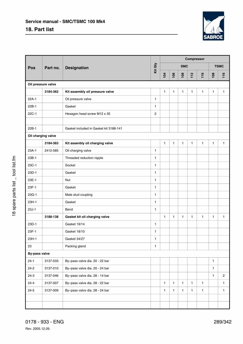
18. Part list
289/3420178 - 933 - ENGRev. 2005.12.09.
Service manual - SMC/TSMC 100 Mk4
18 s
pare
par
ts li
st _
tool
list
.fm
Oil pressure valve
3184-362 Kit assembly oil pressure valve 1 1 1 1 1 1 1
22A-1 Oil pressure valve 1
22B-1 Gasket 1
22C-1 Hexagon head screw M12 x 35 2
22B-1 Gasket included in Gasket kit 3188-141
Oil charging valve
3184-363 Kit assenbly oil charging valve 1 1 1 1 1 1 1
23A-1 2412-585 Oil charging valve 1
23B-1 Threaded reduction nipple 1
23C-1 Socket 1
23D-1 Gasket 1
23E-1 Nut 1
23F-1 Gasket 1
23G-1 Male stud coupling 1
23H-1 Gasket 1
23J-1 Bend 1
3188-138 Gasket kit oil charging valve 1 1 1 1 1 1 1
23D-1 Gasket 19/14 1
23F-1 Gasket 18/10 1
23H-1 Gasket 34/27 1
23 Packing gland 1
By-pass valve
24-1 3137-033 By–pass valve dia. 20 - 22 bar 1
24-2 3137-010 By–pass valve dia. 20 - 24 bar 1
24-3 3137-046 By–pass valve dia. 28 - 14 bar 1 2
24-4 3137-007 By–pass valve dia. 28 - 22 bar 1 1 1 1 1 1
24-5 3137-009 By–pass valve dia. 28 - 24 bar 1 1 1 1 1 1
Pos Part no. Designation
Kit
Qty
Compressor
SMC TSMC
104
106
108
112
116
108
116
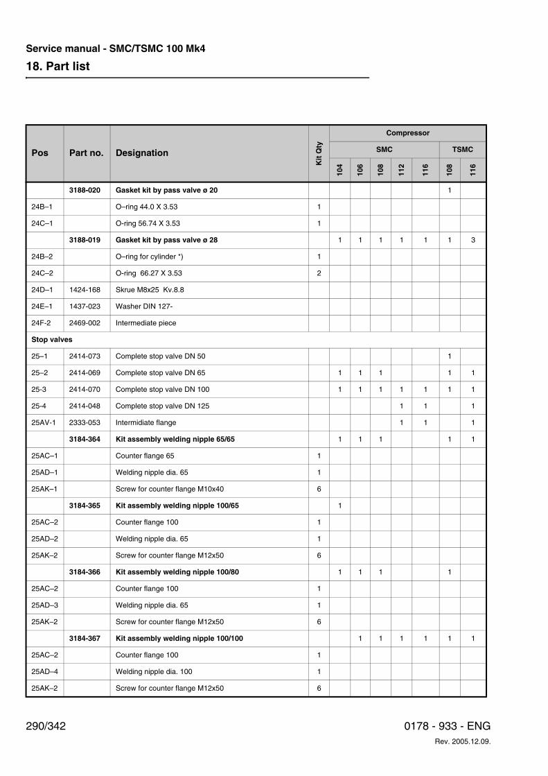
18. Part list
290/342 0178 - 933 - ENGRev. 2005.12.09.
Service manual - SMC/TSMC 100 Mk4
3188-020 Gasket kit by pass valve ø 20 1
24B–1 O–ring 44.0 X 3.53 1
24C–1 O-ring 56.74 X 3.53 1
3188-019 Gasket kit by pass valve ø 28 1 1 1 1 1 1 3
24B–2 O–ring for cylinder *) 1
24C–2 O-ring 66.27 X 3.53 2
24D–1 1424-168 Skrue M8x25 Kv.8.8
24E–1 1437-023 Washer DIN 127-
24F-2 2469-002 Intermediate piece
Stop valves
25–1 2414-073 Complete stop valve DN 50 1
25–2 2414-069 Complete stop valve DN 65 1 1 1 1 1
25-3 2414-070 Complete stop valve DN 100 1 1 1 1 1 1 1
25-4 2414-048 Complete stop valve DN 125 1 1 1
25AV-1 2333-053 Intermidiate flange 1 1 1
3184-364 Kit assembly welding nipple 65/65 1 1 1 1 1
25AC–1 Counter flange 65 1
25AD–1 Welding nipple dia. 65 1
25AK–1 Screw for counter flange M10x40 6
3184-365 Kit assembly welding nipple 100/65 1
25AC–2 Counter flange 100 1
25AD–2 Welding nipple dia. 65 1
25AK–2 Screw for counter flange M12x50 6
3184-366 Kit assembly welding nipple 100/80 1 1 1 1
25AC–2 Counter flange 100 1
25AD–3 Welding nipple dia. 65 1
25AK–2 Screw for counter flange M12x50 6
3184-367 Kit assembly welding nipple 100/100 1 1 1 1 1 1
25AC–2 Counter flange 100 1
25AD–4 Welding nipple dia. 100 1
25AK–2 Screw for counter flange M12x50 6
Pos Part no. Designation
Kit
Qty
Compressor
SMC TSMC
104
106
108
112
116
108
116
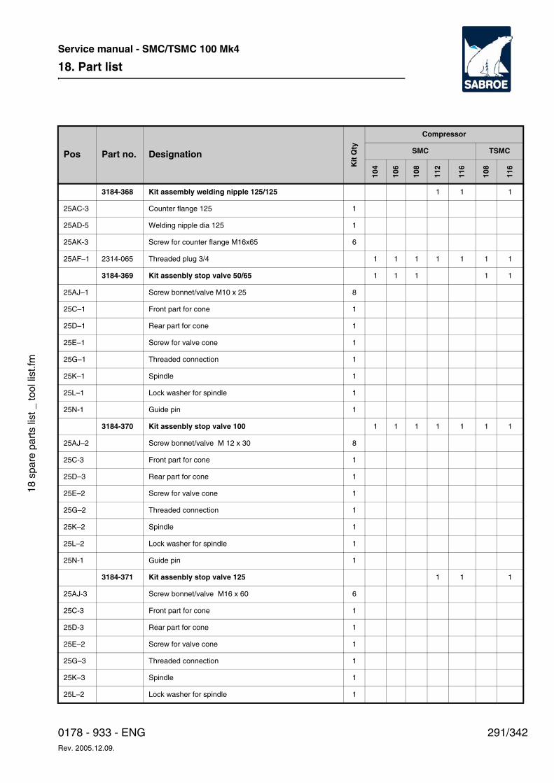
18. Part list
291/3420178 - 933 - ENGRev. 2005.12.09.
Service manual - SMC/TSMC 100 Mk4
18 s
pare
par
ts li
st _
tool
list
.fm
3184-368 Kit assembly welding nipple 125/125 1 1 1
25AC-3 Counter flange 125 1
25AD-5 Welding nipple dia 125 1
25AK-3 Screw for counter flange M16x65 6
25AF–1 2314-065 Threaded plug 3/4 1 1 1 1 1 1 1
3184-369 Kit assenbly stop valve 50/65 1 1 1 1 1
25AJ–1 Screw bonnet/valve M10 x 25 8
25C–1 Front part for cone 1
25D–1 Rear part for cone 1
25E–1 Screw for valve cone 1
25G–1 Threaded connection 1
25K–1 Spindle 1
25L–1 Lock washer for spindle 1
25N-1 Guide pin 1
3184-370 Kit assenbly stop valve 100 1 1 1 1 1 1 1
25AJ–2 Screw bonnet/valve M 12 x 30 8
25C-3 Front part for cone 1
25D–3 Rear part for cone 1
25E–2 Screw for valve cone 1
25G–2 Threaded connection 1
25K–2 Spindle 1
25L–2 Lock washer for spindle 1
25N-1 Guide pin 1
3184-371 Kit assenbly stop valve 125 1 1 1
25AJ-3 Screw bonnet/valve M16 x 60 6
25C-3 Front part for cone 1
25D-3 Rear part for cone 1
25E–2 Screw for valve cone 1
25G–3 Threaded connection 1
25K–3 Spindle 1
25L–2 Lock washer for spindle 1
Pos Part no. Designation
Kit
Qty
Compressor
SMC TSMC
104
106
108
112
116
108
116
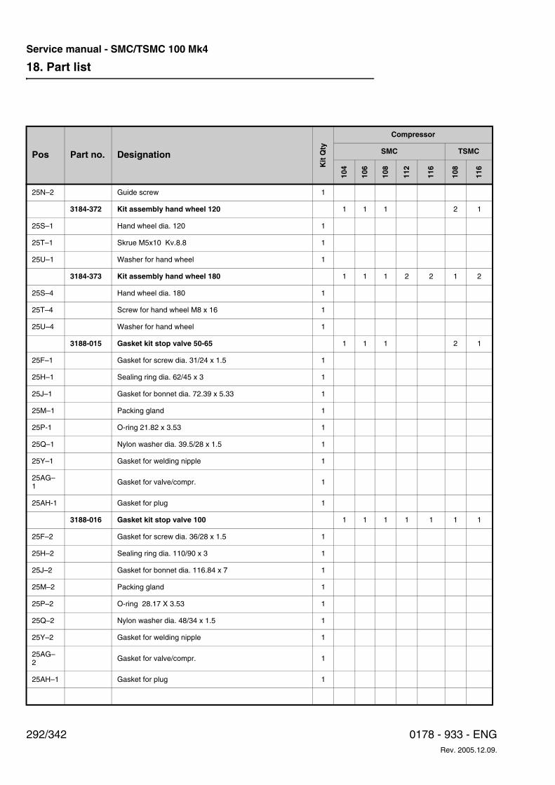
18. Part list
292/342 0178 - 933 - ENGRev. 2005.12.09.
Service manual - SMC/TSMC 100 Mk4
25N–2 Guide screw 1
3184-372 Kit assembly hand wheel 120 1 1 1 2 1
25S–1 Hand wheel dia. 120 1
25T–1 Skrue M5x10 Kv.8.8 1
25U–1 Washer for hand wheel 1
3184-373 Kit assembly hand wheel 180 1 1 1 2 2 1 2
25S–4 Hand wheel dia. 180 1
25T–4 Screw for hand wheel M8 x 16 1
25U–4 Washer for hand wheel 1
3188-015 Gasket kit stop valve 50-65 1 1 1 2 1
25F–1 Gasket for screw dia. 31/24 x 1.5 1
25H–1 Sealing ring dia. 62/45 x 3 1
25J–1 Gasket for bonnet dia. 72.39 x 5.33 1
25M–1 Packing gland 1
25P-1 O-ring 21.82 x 3.53 1
25Q–1 Nylon washer dia. 39.5/28 x 1.5 1
25Y–1 Gasket for welding nipple 1
25AG–1 Gasket for valve/compr. 1
25AH-1 Gasket for plug 1
3188-016 Gasket kit stop valve 100 1 1 1 1 1 1 1
25F–2 Gasket for screw dia. 36/28 x 1.5 1
25H–2 Sealing ring dia. 110/90 x 3 1
25J–2 Gasket for bonnet dia. 116.84 x 7 1
25M–2 Packing gland 1
25P–2 O-ring 28.17 X 3.53 1
25Q–2 Nylon washer dia. 48/34 x 1.5 1
25Y–2 Gasket for welding nipple 1
25AG–2 Gasket for valve/compr. 1
25AH–1 Gasket for plug 1
Pos Part no. Designation
Kit
Qty
Compressor
SMC TSMC
104
106
108
112
116
108
116
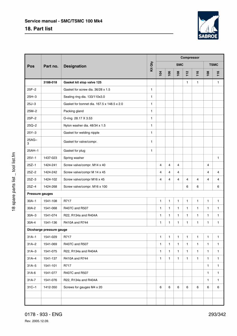
18. Part list
293/3420178 - 933 - ENGRev. 2005.12.09.
Service manual - SMC/TSMC 100 Mk4
18 s
pare
par
ts li
st _
tool
list
.fm
3188-018 Gasket kit stop valve 125 1 1 1
25F–2 Gasket for screw dia. 36/28 x 1.5 1
25H–3 Sealing ring dia. 133/110x3.0 1
25J–3 Gasket for bonnet dia. 167.5 x 148.5 x 2.0 1
25M–2 Packing gland 1
25P–2 O-ring 28.17 X 3.53 1
25Q–2 Nylon washer dia. 48/34 x 1.5 1
25Y–3 Gasket for welding nipple 1
25AG–3 Gasket for valve/compr. 1
25AH–1 Gasket for plug 1
25V–1 1437-023 Spring washer 1
25Z–1 1424-241 Screw valve/compr. M14 x 40 4 4 4 4
25Z–2 1424-242 Screw valve/compr M 14 x 45 4 4 4 4 4
25Z–3 1424-102 Screw valve/compr M16 x 45 4 4 4 4 4 4 4
25Z–4 1424-268 Screw valve/compr. M16 x 100 6 6 6
Pressure gauges
30A–1 1541-108 R717 1 1 1 1 1 1 1
30A-2 1541-068 R407C and R507 1 1 1 1 1 1 1
30A–3 1541-074 R22, R134a and R404A 1 1 1 1 1 1 1
30A-4 1541-136 R410A and R744 1 1 1 1 1 1 1
Dicsharge pressure gauge
31A–1 1541-029 R717 1 1 1 1 1 1 1
31A–2 1541-069 R407C and R507 1 1 1 1 1 1 1
31A–3 1541-075 R22, R134a and R404A 1 1 1 1 1 1 1
31A–4 1541-137 R410A and R744 1 1 1 1 1 1 1
31A–5 1541-101 R717 1 1
31A-6 1541-077 R407C and R507 1 1
31A-7 1541-076 R22, R134a and R404A 1 1
31C–1 1412-350 Screws for gauges M4 x 20 6 6 6 6 6 6 6
Pos Part no. Designation
Kit
Qty
Compressor
SMC TSMC
104
106
108
112
116
108
116
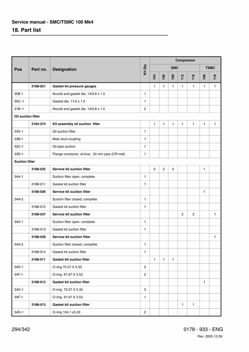
18. Part list
294/342 0178 - 933 - ENGRev. 2005.12.09.
Service manual - SMC/TSMC 100 Mk4
3188-021 Gasket kit pressure gauges 1 1 1 1 1 1 1
30B-1 Nozzle and gasket dia. 14/0.8 x 1.5 1
30C–1 Gasket dia. 11/4 x 1.5 1
31B–1 Nozzle and gasket dia. 14/0.8 x 1.5 2
Oil suction filter
3184-374 Kit assembly oil suction filter 1 1 1 1 1 1 1
33A-1 Oil suction filter 1
33B-1 Male stud coupling 1
33C-1 Oil pipe suction 1
33D-1 Flange connector, el-bow, 22 mm pipe (CR-mat) 1
Suction filter
3188-035 Service kit suction filter 2 2 2 1
34A-1 Suction filter open, complete 1
3188-011 Gasket kit suction filter 1
3188-036 Service kit suction filter 1
34A-2 Suction filter closed, complete 1
3188-012 Gasket kit suction filter 1
3188-037 Service kit suction filter 2 2 1
34A-1 Suction filter open, complete 1
3188-013 Gasket kit suction filter 1
3188-038 Service kit suction filter 1
34A-2 Suction filter closed, complete 1
3188-014 Gasket kit suction filter 1
3188-011 Gasket kit suction filter 1 1 1
34D-1 O-ring 75.57 X 5.33 2
34F-1 O-ring 91.67 X 3.53 2
3188-012 Gasket kit suction filter 1
34D-1 O-ring 75.57 X 5.33 3
34F-1 O-ring 91.67 X 3.53 1
3188-013 Gasket kit suction filter 1 1
34D-1 O-ring 104.1 x5,33 2
Pos Part no. Designation
Kit
Qty
Compressor
SMC TSMC
104
106
108
112
116
108
116
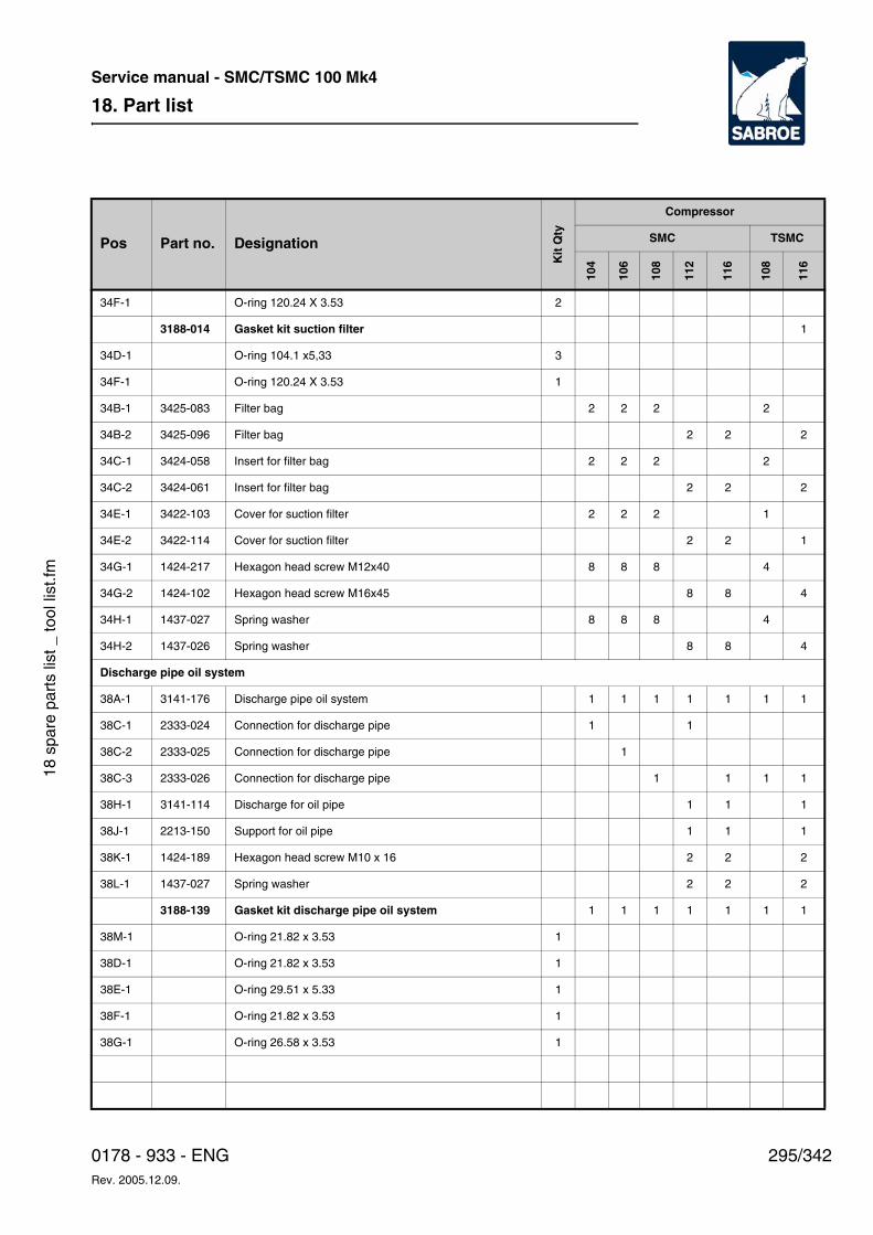
18. Part list
295/3420178 - 933 - ENGRev. 2005.12.09.
Service manual - SMC/TSMC 100 Mk4
18 s
pare
par
ts li
st _
tool
list
.fm
34F-1 O-ring 120.24 X 3.53 2
3188-014 Gasket kit suction filter 1
34D-1 O-ring 104.1 x5,33 3
34F-1 O-ring 120.24 X 3.53 1
34B-1 3425-083 Filter bag 2 2 2 2
34B-2 3425-096 Filter bag 2 2 2
34C-1 3424-058 Insert for filter bag 2 2 2 2
34C-2 3424-061 Insert for filter bag 2 2 2
34E-1 3422-103 Cover for suction filter 2 2 2 1
34E-2 3422-114 Cover for suction filter 2 2 1
34G-1 1424-217 Hexagon head screw M12x40 8 8 8 4
34G-2 1424-102 Hexagon head screw M16x45 8 8 4
34H-1 1437-027 Spring washer 8 8 8 4
34H-2 1437-026 Spring washer 8 8 4
Discharge pipe oil system
38A-1 3141-176 Discharge pipe oil system 1 1 1 1 1 1 1
38C-1 2333-024 Connection for discharge pipe 1 1
38C-2 2333-025 Connection for discharge pipe 1
38C-3 2333-026 Connection for discharge pipe 1 1 1 1
38H-1 3141-114 Discharge for oil pipe 1 1 1
38J-1 2213-150 Support for oil pipe 1 1 1
38K-1 1424-189 Hexagon head screw M10 x 16 2 2 2
38L-1 1437-027 Spring washer 2 2 2
3188-139 Gasket kit discharge pipe oil system 1 1 1 1 1 1 1
38M-1 O-ring 21.82 x 3.53 1
38D-1 O-ring 21.82 x 3.53 1
38E-1 O-ring 29.51 x 5.33 1
38F-1 O-ring 21.82 x 3.53 1
38G-1 O-ring 26.58 x 3.53 1
Pos Part no. Designation
Kit
Qty
Compressor
SMC TSMC
104
106
108
112
116
108
116
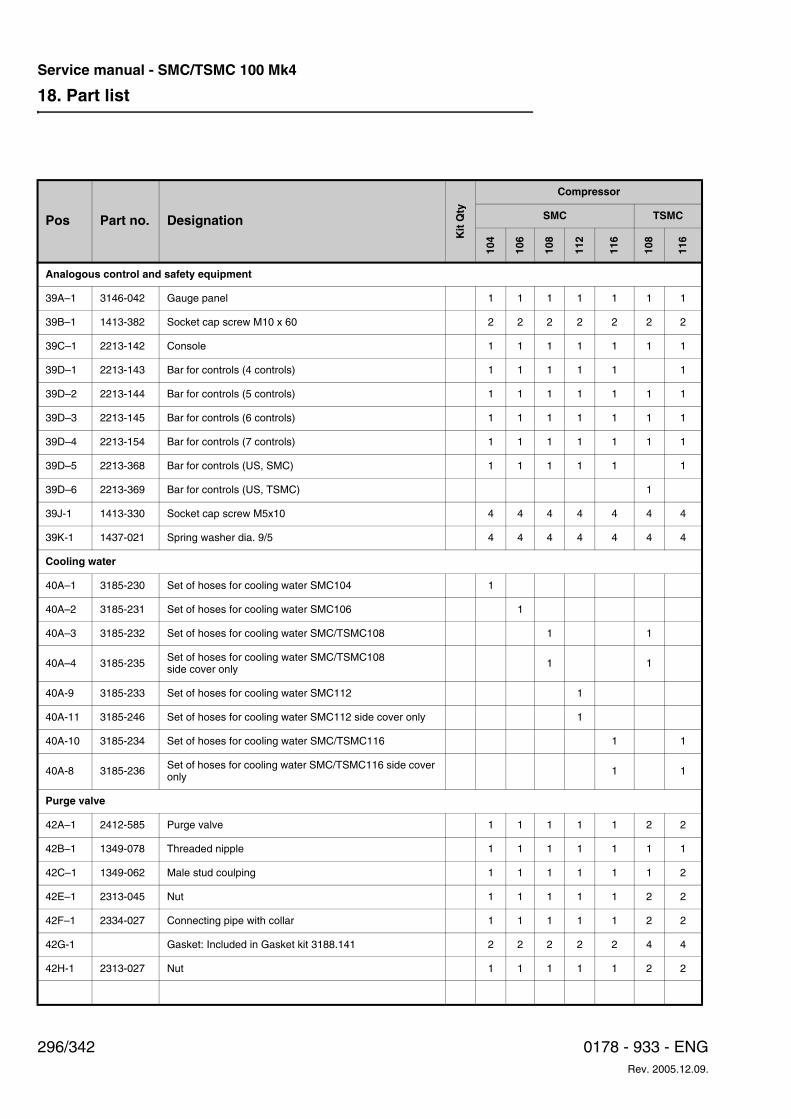
18. Part list
296/342 0178 - 933 - ENGRev. 2005.12.09.
Service manual - SMC/TSMC 100 Mk4
Analogous control and safety equipment
39A–1 3146-042 Gauge panel 1 1 1 1 1 1 1
39B–1 1413-382 Socket cap screw M10 x 60 2 2 2 2 2 2 2
39C–1 2213-142 Console 1 1 1 1 1 1 1
39D–1 2213-143 Bar for controls (4 controls) 1 1 1 1 1 1
39D–2 2213-144 Bar for controls (5 controls) 1 1 1 1 1 1 1
39D–3 2213-145 Bar for controls (6 controls) 1 1 1 1 1 1 1
39D–4 2213-154 Bar for controls (7 controls) 1 1 1 1 1 1 1
39D–5 2213-368 Bar for controls (US, SMC) 1 1 1 1 1 1
39D–6 2213-369 Bar for controls (US, TSMC) 1
39J-1 1413-330 Socket cap screw M5x10 4 4 4 4 4 4 4
39K-1 1437-021 Spring washer dia. 9/5 4 4 4 4 4 4 4
Cooling water
40A–1 3185-230 Set of hoses for cooling water SMC104 1
40A–2 3185-231 Set of hoses for cooling water SMC106 1
40A–3 3185-232 Set of hoses for cooling water SMC/TSMC108 1 1
40A–4 3185-235 Set of hoses for cooling water SMC/TSMC108side cover only 1 1
40A-9 3185-233 Set of hoses for cooling water SMC112 1
40A-11 3185-246 Set of hoses for cooling water SMC112 side cover only 1
40A-10 3185-234 Set of hoses for cooling water SMC/TSMC116 1 1
40A-8 3185-236 Set of hoses for cooling water SMC/TSMC116 side cover only 1 1
Purge valve
42A–1 2412-585 Purge valve 1 1 1 1 1 2 2
42B–1 1349-078 Threaded nipple 1 1 1 1 1 1 1
42C–1 1349-062 Male stud coulping 1 1 1 1 1 1 2
42E–1 2313-045 Nut 1 1 1 1 1 2 2
42F–1 2334-027 Connecting pipe with collar 1 1 1 1 1 2 2
42G-1 Gasket: Included in Gasket kit 3188.141 2 2 2 2 2 4 4
42H-1 2313-027 Nut 1 1 1 1 1 2 2
Pos Part no. Designation
Kit
Qty
Compressor
SMC TSMC
104
106
108
112
116
108
116
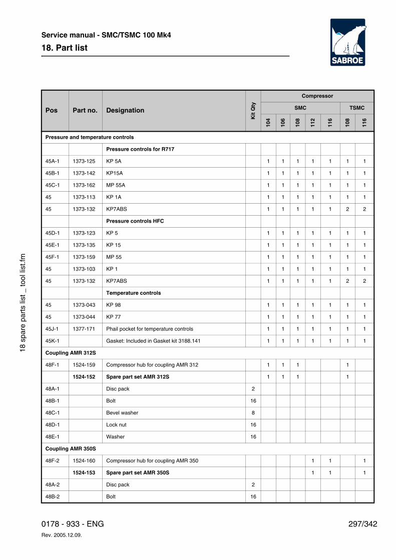
18. Part list
297/3420178 - 933 - ENGRev. 2005.12.09.
Service manual - SMC/TSMC 100 Mk4
18 s
pare
par
ts li
st _
tool
list
.fm
Pressure and temperature controls
Pressure controls for R717
45A-1 1373-125 KP 5A 1 1 1 1 1 1 1
45B-1 1373-142 KP15A 1 1 1 1 1 1 1
45C-1 1373-162 MP 55A 1 1 1 1 1 1 1
45 1373-113 KP 1A 1 1 1 1 1 1 1
45 1373-132 KP7ABS 1 1 1 1 1 2 2
Pressure controls HFC
45D-1 1373-123 KP 5 1 1 1 1 1 1 1
45E-1 1373-135 KP 15 1 1 1 1 1 1 1
45F-1 1373-159 MP 55 1 1 1 1 1 1 1
45 1373-103 KP 1 1 1 1 1 1 1 1
45 1373-132 KP7ABS 1 1 1 1 1 2 2
Temperature controls
45 1373-043 KP 98 1 1 1 1 1 1 1
45 1373-044 KP 77 1 1 1 1 1 1 1
45J-1 1377-171 Phail pocket for temperature controls 1 1 1 1 1 1 1
45K-1 Gasket: Included in Gasket kit 3188.141 1 1 1 1 1 1 1
Coupling AMR 312S
48F-1 1524-159 Compressor hub for coupling AMR 312 1 1 1 1
1524-152 Spare part set AMR 312S 1 1 1 1
48A-1 Disc pack 2
48B-1 Bolt 16
48C-1 Bevel washer 8
48D-1 Lock nut 16
48E-1 Washer 16
Coupling AMR 350S
48F-2 1524-160 Compressor hub for coupling AMR 350 1 1 1
1524-153 Spare part set AMR 350S 1 1 1
48A-2 Disc pack 2
48B-2 Bolt 16
Pos Part no. Designation
Kit
Qty
Compressor
SMC TSMC
104
106
108
112
116
108
116
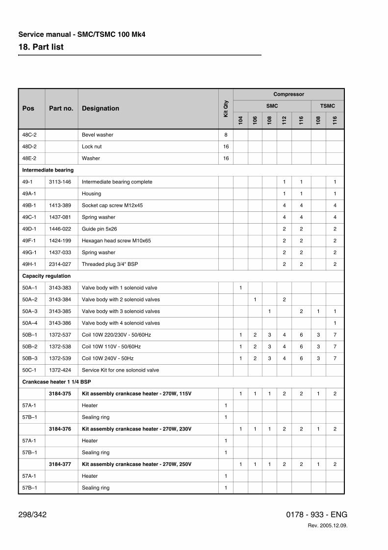
18. Part list
298/342 0178 - 933 - ENGRev. 2005.12.09.
Service manual - SMC/TSMC 100 Mk4
48C-2 Bevel washer 8
48D-2 Lock nut 16
48E-2 Washer 16
Intermediate bearing
49-1 3113-146 Intermediate bearing complete 1 1 1
49A-1 Housing 1 1 1
49B-1 1413-389 Socket cap screw M12x45 4 4 4
49C-1 1437-081 Spring washer 4 4 4
49D-1 1446-022 Guide pin 5x26 2 2 2
49F-1 1424-199 Hexagan head screw M10x65 2 2 2
49G-1 1437-033 Spring washer 2 2 2
49H-1 2314-027 Threaded plug 3/4" BSP 2 2 2
Capacity regulation
50A–1 3143-383 Valve body with 1 solenoid valve 1
50A–2 3143-384 Valve body with 2 solenoid valves 1 2
50A–3 3143-385 Valve body with 3 solenoid valves 1 2 1 1
50A–4 3143-386 Valve body with 4 solenoid valves 1
50B–1 1372-537 Coil 10W 220/230V - 50/60Hz 1 2 3 4 6 3 7
50B–2 1372-538 Coil 10W 110V - 50/60Hz 1 2 3 4 6 3 7
50B–3 1372-539 Coil 10W 240V - 50Hz 1 2 3 4 6 3 7
50C-1 1372-424 Service Kit for one solonoid valve
Crankcase heater 1 1/4 BSP
3184-375 Kit assembly crankcase heater - 270W, 115V 1 1 1 2 2 1 2
57A-1 Heater 1
57B–1 Sealing ring 1
3184-376 Kit assembly crankcase heater - 270W, 230V 1 1 1 2 2 1 2
57A-1 Heater 1
57B–1 Sealing ring 1
3184-377 Kit assembly crankcase heater - 270W, 250V 1 1 1 2 2 1 2
57A-1 Heater 1
57B–1 Sealing ring 1
Pos Part no. Designation
Kit
Qty
Compressor
SMC TSMC
104
106
108
112
116
108
116
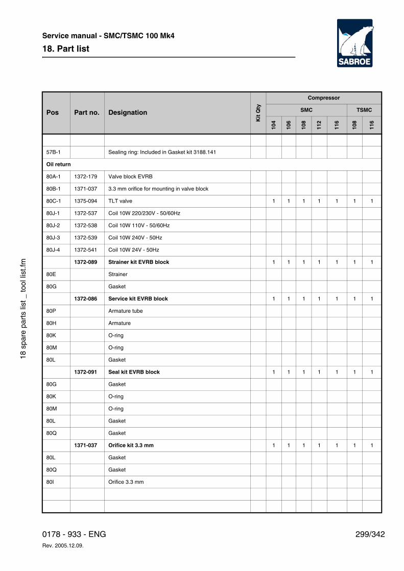
18. Part list
299/3420178 - 933 - ENGRev. 2005.12.09.
Service manual - SMC/TSMC 100 Mk4
18 s
pare
par
ts li
st _
tool
list
.fm
57B-1 Sealing ring: Included in Gasket kit 3188.141
Oil return
80A-1 1372-179 Valve block EVRB
80B-1 1371-037 3.3 mm orifice for mounting in valve block
80C-1 1375-094 TLT valve 1 1 1 1 1 1 1
80J-1 1372-537 Coil 10W 220/230V - 50/60Hz
80J-2 1372-538 Coil 10W 110V - 50/60Hz
80J-3 1372-539 Coil 10W 240V - 50Hz
80J-4 1372-541 Coil 10W 24V - 50Hz
1372-089 Strainer kit EVRB block 1 1 1 1 1 1 1
80E Strainer
80G Gasket
1372-086 Service kit EVRB block 1 1 1 1 1 1 1
80P Armature tube
80H Armature
80K O-ring
80M O-ring
80L Gasket
1372-091 Seal kit EVRB block 1 1 1 1 1 1 1
80G Gasket
80K O-ring
80M O-ring
80L Gasket
80Q Gasket
1371-037 Orifice kit 3.3 mm 1 1 1 1 1 1 1
80L Gasket
80Q Gasket
80I Orifice 3.3 mm
Pos Part no. Designation
Kit
Qty
Compressor
SMC TSMC
104
106
108
112
116
108
116
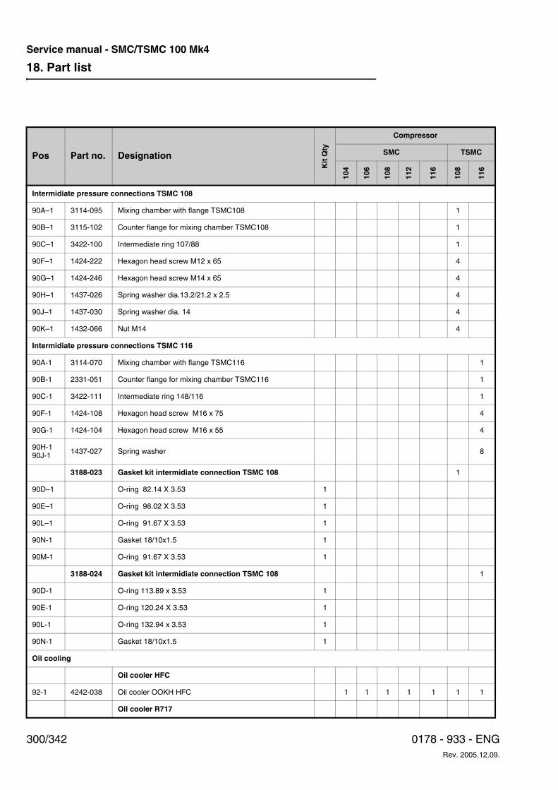
18. Part list
300/342 0178 - 933 - ENGRev. 2005.12.09.
Service manual - SMC/TSMC 100 Mk4
Intermidiate pressure connections TSMC 108
90A–1 3114-095 Mixing chamber with flange TSMC108 1
90B–1 3115-102 Counter flange for mixing chamber TSMC108 1
90C–1 3422-100 Intermediate ring 107/88 1
90F–1 1424-222 Hexagon head screw M12 x 65 4
90G–1 1424-246 Hexagon head screw M14 x 65 4
90H–1 1437-026 Spring washer dia.13.2/21.2 x 2.5 4
90J–1 1437-030 Spring washer dia. 14 4
90K–1 1432-066 Nut M14 4
Intermidiate pressure connections TSMC 116
90A-1 3114-070 Mixing chamber with flange TSMC116 1
90B-1 2331-051 Counter flange for mixing chamber TSMC116 1
90C-1 3422-111 Intermediate ring 148/116 1
90F-1 1424-108 Hexagon head screw M16 x 75 4
90G-1 1424-104 Hexagon head screw M16 x 55 4
90H-190J-1 1437-027 Spring washer 8
3188-023 Gasket kit intermidiate connection TSMC 108 1
90D–1 O-ring 82.14 X 3.53 1
90E–1 O-ring 98.02 X 3.53 1
90L–1 O-ring 91.67 X 3.53 1
90N-1 Gasket 18/10x1.5 1
90M-1 O-ring 91.67 X 3.53 1
3188-024 Gasket kit intermidiate connection TSMC 108 1
90D-1 O-ring 113.89 x 3.53 1
90E-1 O-ring 120.24 X 3.53 1
90L-1 O-ring 132.94 x 3.53 1
90N-1 Gasket 18/10x1.5 1
Oil cooling
Oil cooler HFC
92-1 4242-038 Oil cooler OOKH HFC 1 1 1 1 1 1 1
Oil cooler R717
Pos Part no. Designation
Kit
Qty
Compressor
SMC TSMC
104
106
108
112
116
108
116
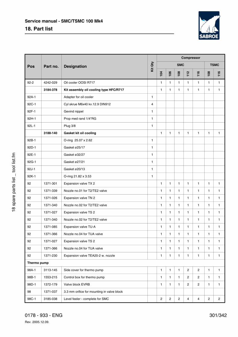
18. Part list
301/3420178 - 933 - ENGRev. 2005.12.09.
Service manual - SMC/TSMC 100 Mk4
18 s
pare
par
ts li
st _
tool
list
.fm
92-2 4242-029 Oil cooler OOSI R717 1 1 1 1 1 1 1
3184-378 Kit assembly oil cooling type HFC/R717 1 1 1 1 1 1 1
92A-1 Adapter for oil cooler 1
92C-1 Cyl skrue M6x40 kv.12.9 DIN912 4
92F-1 Gevind nippel 1
92H-1 Prop med rand 1/4"RG 1
92L-1 Plug 3/8 1
3188-140 Gasket kit oil cooling 1 1 1 1 1 1 1
92B-1 O-ring 25.07 x 2.62 1
92D-1 Gasket ø25/17 1
92E-1 Gasket ø32/27 1
92G-1 Gasket ø27/21 1
92J-1 Gasket ø20/13 1
92K-1 O-ring 21.82 x 3.53 1
92 1371-301 Expansion valve TX 2 1 1 1 1 1 1 1
92 1371-339 Nozzle no.01 for T2/TE2 valve 1 1 1 1 1 1 1
92 1371-026 Expansion valve TN 2 1 1 1 1 1 1 1
92 1371-340 Nozzle no.02 for T2/TE2 valve 1 1 1 1 1 1 1
92 1371-027 Expansion valve TS 2 1 1 1 1 1 1 1
92 1371-340 Nozzle no.02 for T2/TE2 valve 1 1 1 1 1 1 1
92 1371-085 Expansion valve TU-A 1 1 1 1 1 1 1
92 1371-366 Nozzle no.04 for TUA valve 1 1 1 1 1 1 1
92 1371-027 Expansion valve TS 2 1 1 1 1 1 1 1
92 1371-366 Nozzle no.04 for TUA valve 1 1 1 1 1 1 1
92 1371-230 Expansion valve TEA20-2 w. nozzle 1 1 1 1 1 1 1
Thermo pump
98A-1 3113-145 Side cover for thermo pump 1 1 1 2 2 1 1
98B-1 1553-215 Control box for thermo pump 1 1 1 2 2 1 1
98D-1 1372-179 Valve block EVRB 1 1 1 2 2 1 1
98 1371-037 3.3 mm orifice for mounting in valve block
98C-1 3185-038 Level feeler - complete for SMC 2 2 2 4 4 2 2
Pos Part no. Designation
Kit
Qty
Compressor
SMC TSMC
104
106
108
112
116
108
116
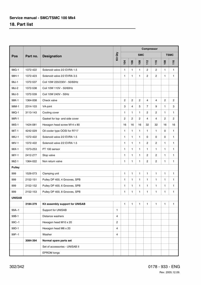
18. Part list
302/342 0178 - 933 - ENGRev. 2005.12.09.
Service manual - SMC/TSMC 100 Mk4
98G-1 1372-422 Solenoid valve 2/2 EVRA 1.5 1 1 1 2 2 1 1
98H-1 1372-423 Solenoid valve 2/2 EVRA 3.5 1 1 1 2 2 1 1
98J-1 1372-537 Coil 10W 220/230V - 50/60Hz
98J-2 1372-538 Coil 10W 110V - 50/60Hz
98J-3 1372-539 Coil 10W 240V - 50Hz
98K-1 1364-008 Check valve 2 2 2 4 4 2 2
98M-1 2314-103 VA-joint 3 4 5 7 9 1 3
98Q-1 3113-143 Cooling cover 1 1 1 2 2 1 1
98R-1 Gasket for top- and side cover 2 2 2 4 4 2 2
98S-1 1424-081 Hexagon head screw M14 x 80 16 16 16 32 32 16 16
98T-1 4242-029 Oil cooler type OOSI for R717 1 1 1 1 1 0 1
98U-1 1372-422 Solenoid valve 2/2 EVRA 1.5 1 1 1 0 0 0 1
98V-1 1372-422 Solenoid valve 2/2 EVRA 1.5 1 1 1 2 2 1 1
98X-1 1373-253 PT 100 sensor 1 1 1 1 1 1 1
98Y-1 2412-277 Stop valve 1 1 1 2 2 1 1
98Z-1 1364-022 Non return valve 1 1 1 2 2 1 1
Pulley
999 1526-073 Clamping unit 1 1 1 1 1 1 1
999 2152-151 Pulley DP 400, 4 Grooves, SPB 1 1 1 1 1 1 1
999 2152-152 Pulley DP 400, 6 Grooves, SPB 1 1 1 1 1 1 1
999 2152-153 Pulley DP 400, 8 Grooves, SPB 1 1 1 1 1 1 1
UNISAB
3184-379 Kit assembly support for UNISAB 1 1 1 1 1 1 1
99A–1 Support for UNISAB 1
99B-1 Distance washers 4
99C–1 Hexagon head M10 x 20 2
99D-1 Hexagon head M6 x 20 4
99F–1 Washer 4
3084-394 Normal spare parts set
Set of accessories - UNISAB II
EPROM tongs
Pos Part no. Designation
Kit
Qty
Compressor
SMC TSMC
104
106
108
112
116
108
116
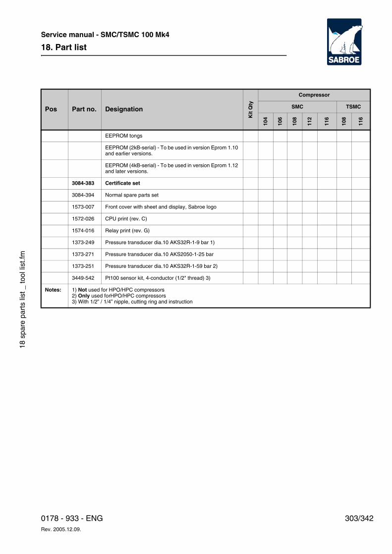
18. Part list
303/3420178 - 933 - ENGRev. 2005.12.09.
Service manual - SMC/TSMC 100 Mk4
18 s
pare
par
ts li
st _
tool
list
.fm
EEPROM tongs
EEPROM (2kB-serial) - To be used in version Eprom 1.10 and earlier versions.
EEPROM (4kB-serial) - To be used in version Eprom 1.12 and later versions.
3084-383 Certificate set
3084-394 Normal spare parts set
1573-007 Front cover with sheet and display, Sabroe logo
1572-026 CPU print (rev. C)
1574-016 Relay print (rev. G)
1373-249 Pressure transducer dia.10 AKS32R-1-9 bar 1)
1373-271 Pressure transducer dia.10 AKS2050-1-25 bar
1373-251 Pressure transducer dia.10 AKS32R-1-59 bar 2)
3449-542 Pt100 sensor kit, 4-conductor (1/2" thread) 3)
Notes: 1) Not used for HPO/HPC compressors2) Only used forHPO/HPC compressors3) With 1/2” / 1/4” nipple, cutting ring and instruction
Pos Part no. Designation
Kit
Qty
Compressor
SMC TSMC
104
106
108
112
116
108
116
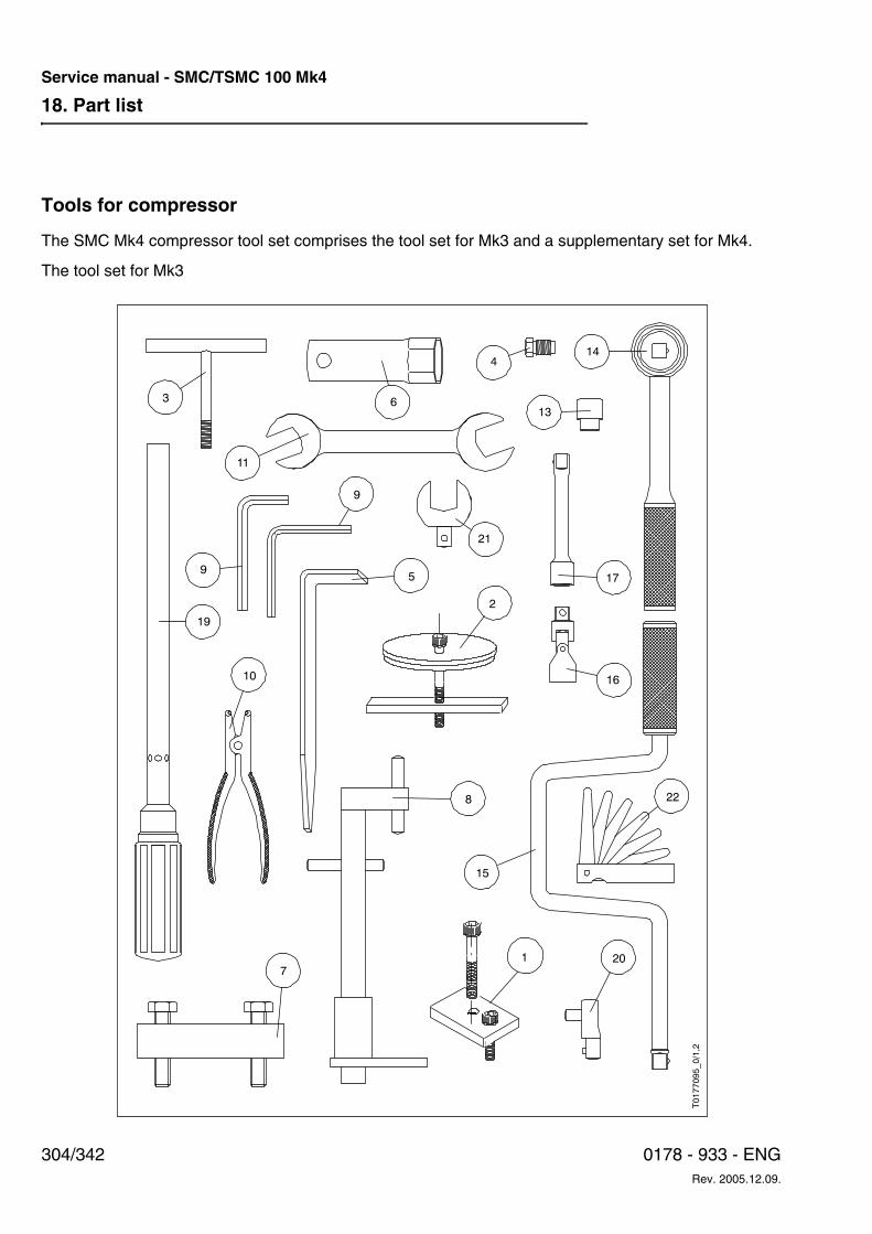
18. Part list
304/342 0178 - 933 - ENGRev. 2005.12.09.
Service manual - SMC/TSMC 100 Mk4
Tools for compressor
The SMC Mk4 compressor tool set comprises the tool set for Mk3 and a supplementary set for Mk4.
The tool set for Mk3
5
19
8
17
15
7
22
11
9
9
21
20
10 16
313
144
T0177095_0/1,2
6
2
1
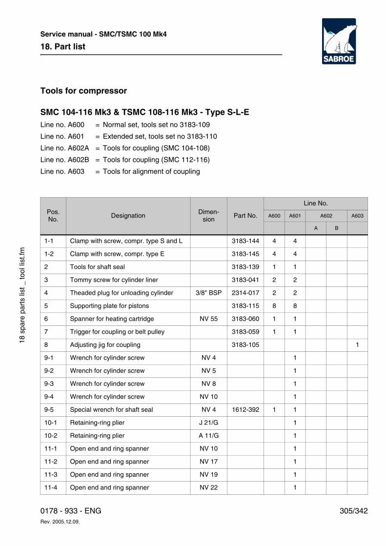
18. Part list
305/3420178 - 933 - ENGRev. 2005.12.09.
Service manual - SMC/TSMC 100 Mk4
18 s
pare
par
ts li
st _
tool
list
.fm
Tools for compressor
SMC 104-116 Mk3 & TSMC 108-116 Mk3 - Type S-L-E Line no. A600 = Normal set, tools set no 3183-109
Line no. A601 = Extended set, tools set no 3183-110
Line no. A602A = Tools for coupling (SMC 104-108)
Line no. A602B = Tools for coupling (SMC 112-116)
Line no. A603 = Tools for alignment of coupling
Pos. No.
DesignationDimen-
sionPart No.
Line No.
A600 A601 A602 A603
A B
1-1 Clamp with screw, compr. type S and L 3183-144 4 4
1-2 Clamp with screw, compr. type E 3183-145 4 4
2 Tools for shaft seal 3183-139 1 1
3 Tommy screw for cylinder liner 3183-041 2 2
4 Theaded plug for unloading cylinder 3/8" BSP 2314-017 2 2
5 Supporting plate for pistons 3183-115 8 8
6 Spanner for heating cartridge NV 55 3183-060 1 1
7 Trigger for coupling or belt pulley 3183-059 1 1
8 Adjusting jig for coupling 3183-105 1
9-1 Wrench for cylinder screw NV 4 1
9-2 Wrench for cylinder screw NV 5 1
9-3 Wrench for cylinder screw NV 8 1
9-4 Wrench for cylinder screw NV 10 1
9-5 Special wrench for shaft seal NV 4 1612-392 1 1
10-1 Retaining-ring plier J 21/G 1
10-2 Retaining-ring plier A 11/G 1
11-1 Open end and ring spanner NV 10 1
11-2 Open end and ring spanner NV 17 1
11-3 Open end and ring spanner NV 19 1
11-4 Open end and ring spanner NV 22 1
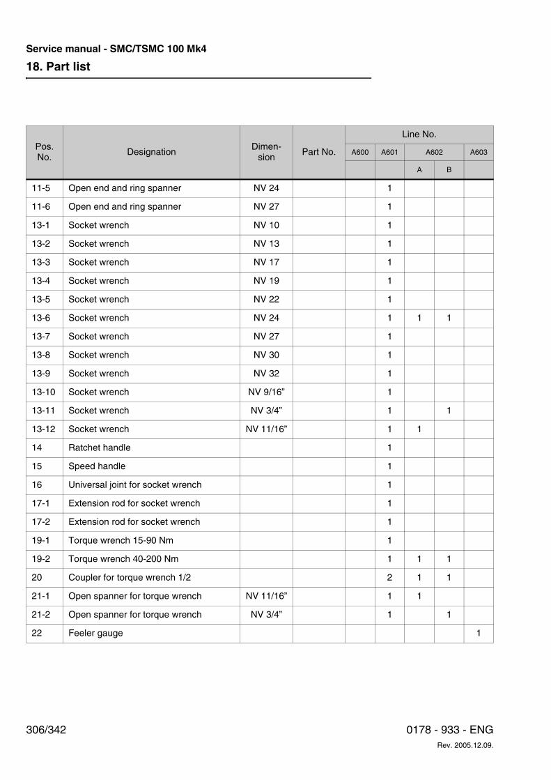
18. Part list
306/342 0178 - 933 - ENGRev. 2005.12.09.
Service manual - SMC/TSMC 100 Mk4
11-5 Open end and ring spanner NV 24 1
11-6 Open end and ring spanner NV 27 1
13-1 Socket wrench NV 10 1
13-2 Socket wrench NV 13 1
13-3 Socket wrench NV 17 1
13-4 Socket wrench NV 19 1
13-5 Socket wrench NV 22 1
13-6 Socket wrench NV 24 1 1 1
13-7 Socket wrench NV 27 1
13-8 Socket wrench NV 30 1
13-9 Socket wrench NV 32 1
13-10 Socket wrench NV 9/16” 1
13-11 Socket wrench NV 3/4” 1 1
13-12 Socket wrench NV 11/16” 1 1
14 Ratchet handle 1
15 Speed handle 1
16 Universal joint for socket wrench 1
17-1 Extension rod for socket wrench 1
17-2 Extension rod for socket wrench 1
19-1 Torque wrench 15-90 Nm 1
19-2 Torque wrench 40-200 Nm 1 1 1
20 Coupler for torque wrench 1/2 2 1 1
21-1 Open spanner for torque wrench NV 11/16” 1 1
21-2 Open spanner for torque wrench NV 3/4” 1 1
22 Feeler gauge 1
Pos. No.
DesignationDimen-
sionPart No.
Line No.
A600 A601 A602 A603
A B
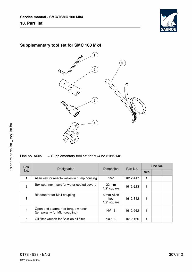
18. Part list
307/3420178 - 933 - ENGRev. 2005.12.09.
Service manual - SMC/TSMC 100 Mk4
18 s
pare
par
ts li
st _
tool
list
.fm
Supplementary tool set for SMC 100 Mk4
Line no. A605 = Supplementary tool set for Mk4 no 3183-148
Pos. No.
Designation Dimension Part No.Line No.
A605
1 Allen key for needle valves in pump housing 1/4” 1612-417 1
2Box spanner insert for water-cooled covers 22 mm
1/2” square1612-323 1
3Bit adapter for Mk4 coupling 6 mm Allen
key1/2” square
1612-342 1
4 Open end spanner for torque wrench(temporarily for Mk4 coupling)
NV 13 1612-262 1
5 Oil filter wrench for Spin-on oil filter dia.100 1612-166 1
1
2
3
4
5

18. Part list
308/342 0178 - 933 - ENGRev. 2005.12.09.
Service manual - SMC/TSMC 100 Mk4
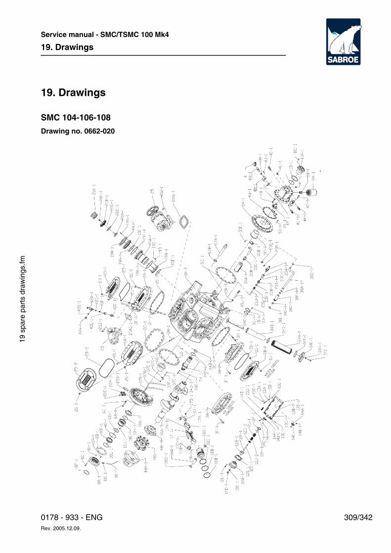
19. Drawings
309/3420178 - 933 - ENGRev. 2005.12.09.
Service manual - SMC/TSMC 100 Mk4
19 s
pare
par
ts d
raw
ings
.fm
19. Drawings
SMC 104-106-108
Drawing no. 0662-020
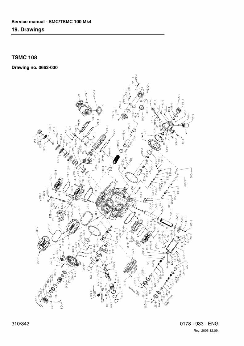
19. Drawings
310/342 0178 - 933 - ENGRev. 2005.12.09.
Service manual - SMC/TSMC 100 Mk4
TSMC 108
Drawing no. 0662-030
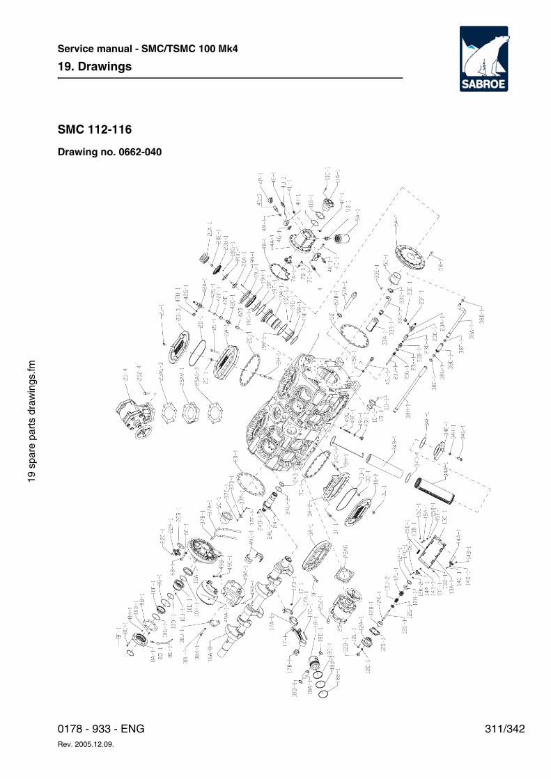
19. Drawings
311/3420178 - 933 - ENGRev. 2005.12.09.
Service manual - SMC/TSMC 100 Mk4
19 s
pare
par
ts d
raw
ings
.fm
SMC 112-116
Drawing no. 0662-040

19. Drawings
312/342 0178 - 933 - ENGRev. 2005.12.09.
Service manual - SMC/TSMC 100 Mk4
TSMC 116
Drawing no. 0662-050
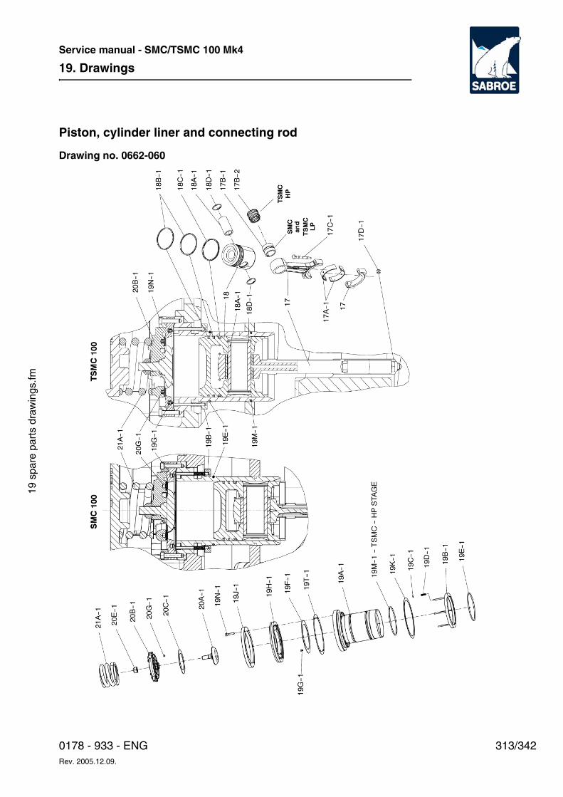
19. Drawings
313/3420178 - 933 - ENGRev. 2005.12.09.
Service manual - SMC/TSMC 100 Mk4
19 s
pare
par
ts d
raw
ings
.fm
Piston, cylinder liner and connecting rod
Drawing no. 0662-060
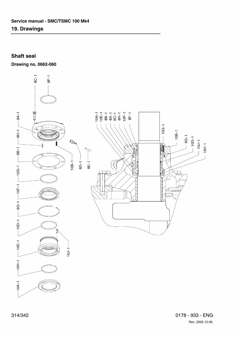
19. Drawings
314/342 0178 - 933 - ENGRev. 2005.12.09.
Service manual - SMC/TSMC 100 Mk4
Shaft seal
Drawing no. 0662-060
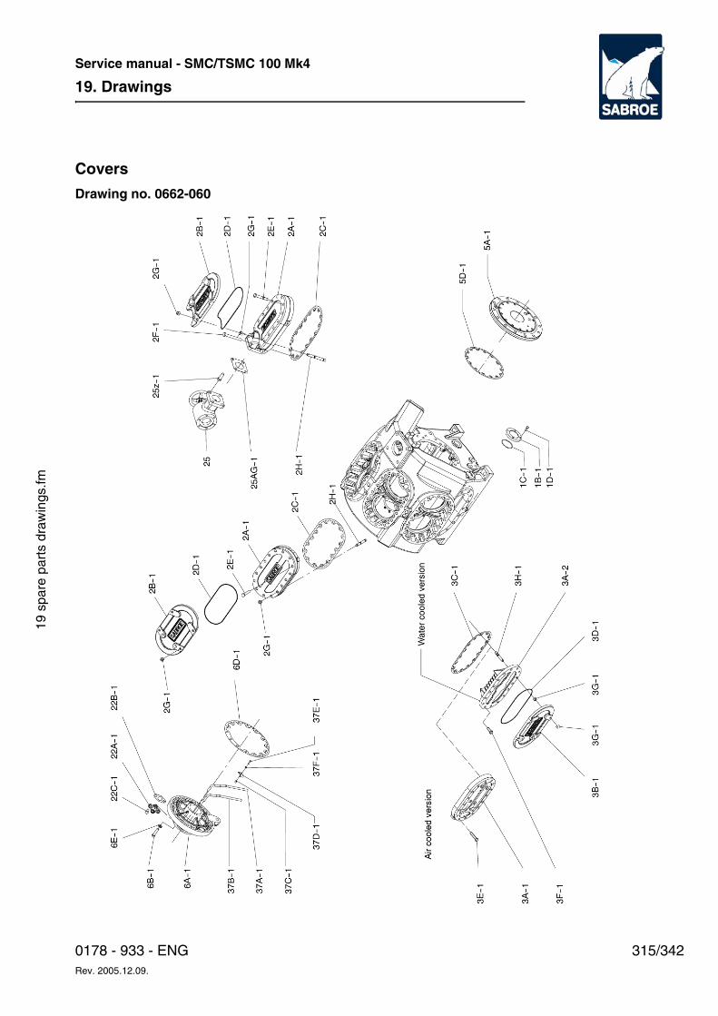
19. Drawings
315/3420178 - 933 - ENGRev. 2005.12.09.
Service manual - SMC/TSMC 100 Mk4
19 s
pare
par
ts d
raw
ings
.fm
Covers
Drawing no. 0662-060
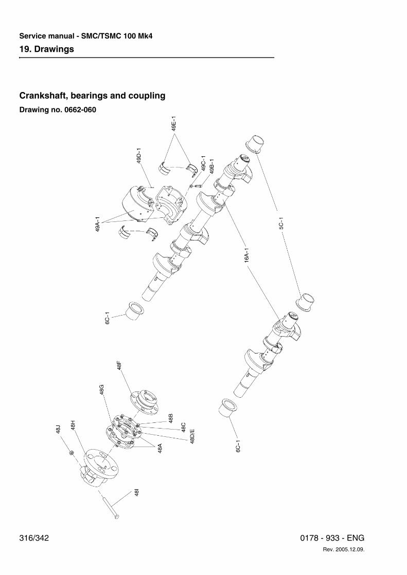
19. Drawings
316/342 0178 - 933 - ENGRev. 2005.12.09.
Service manual - SMC/TSMC 100 Mk4
Crankshaft, bearings and coupling
Drawing no. 0662-060
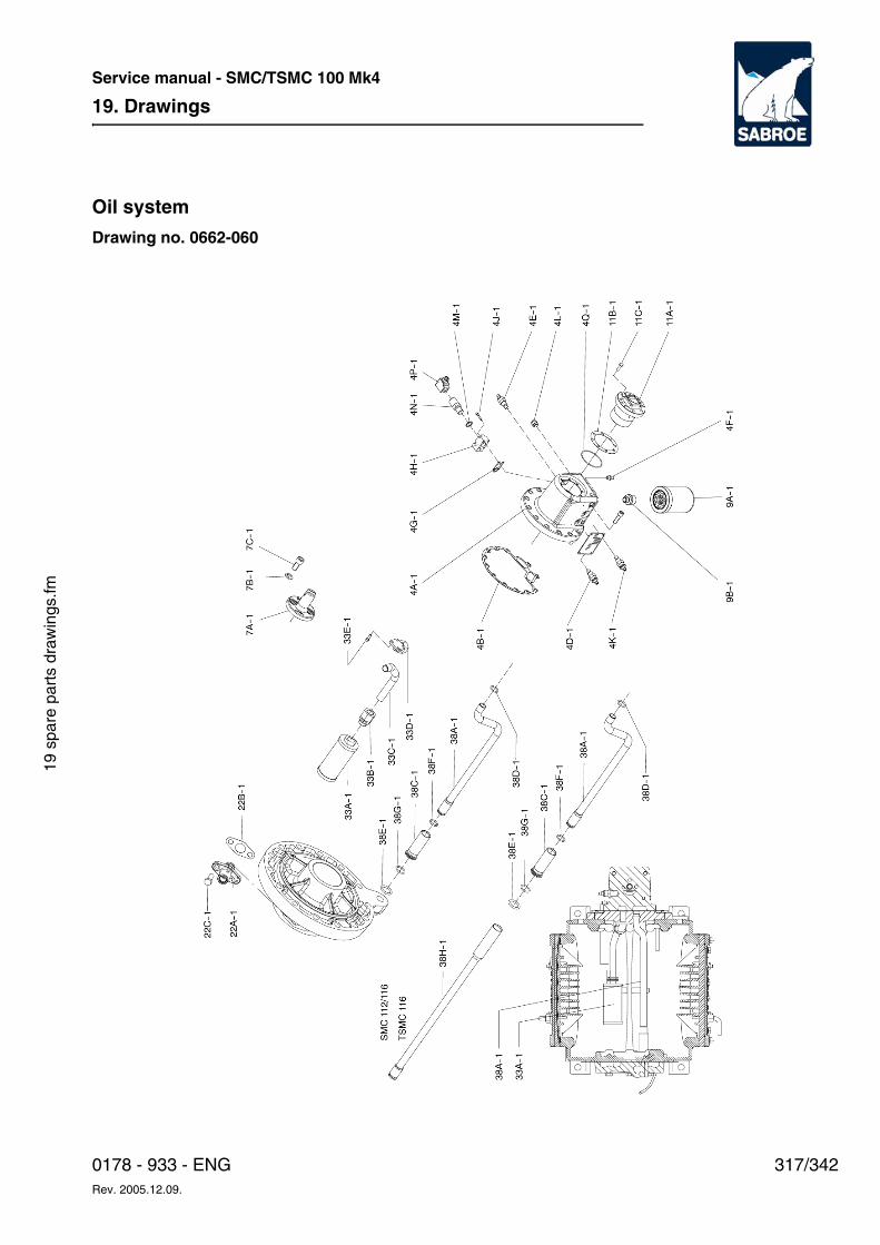
19. Drawings
317/3420178 - 933 - ENGRev. 2005.12.09.
Service manual - SMC/TSMC 100 Mk4
19 s
pare
par
ts d
raw
ings
.fm
Oil system
Drawing no. 0662-060
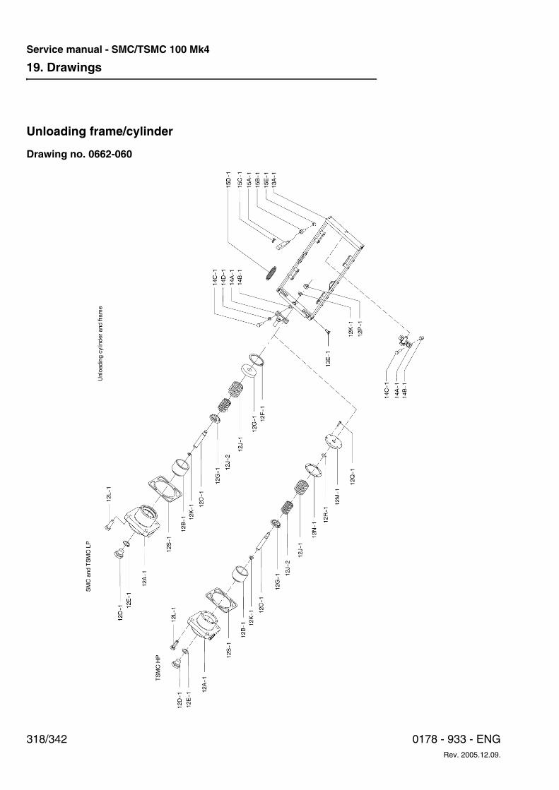
19. Drawings
318/342 0178 - 933 - ENGRev. 2005.12.09.
Service manual - SMC/TSMC 100 Mk4
Unloading frame/cylinder
Drawing no. 0662-060
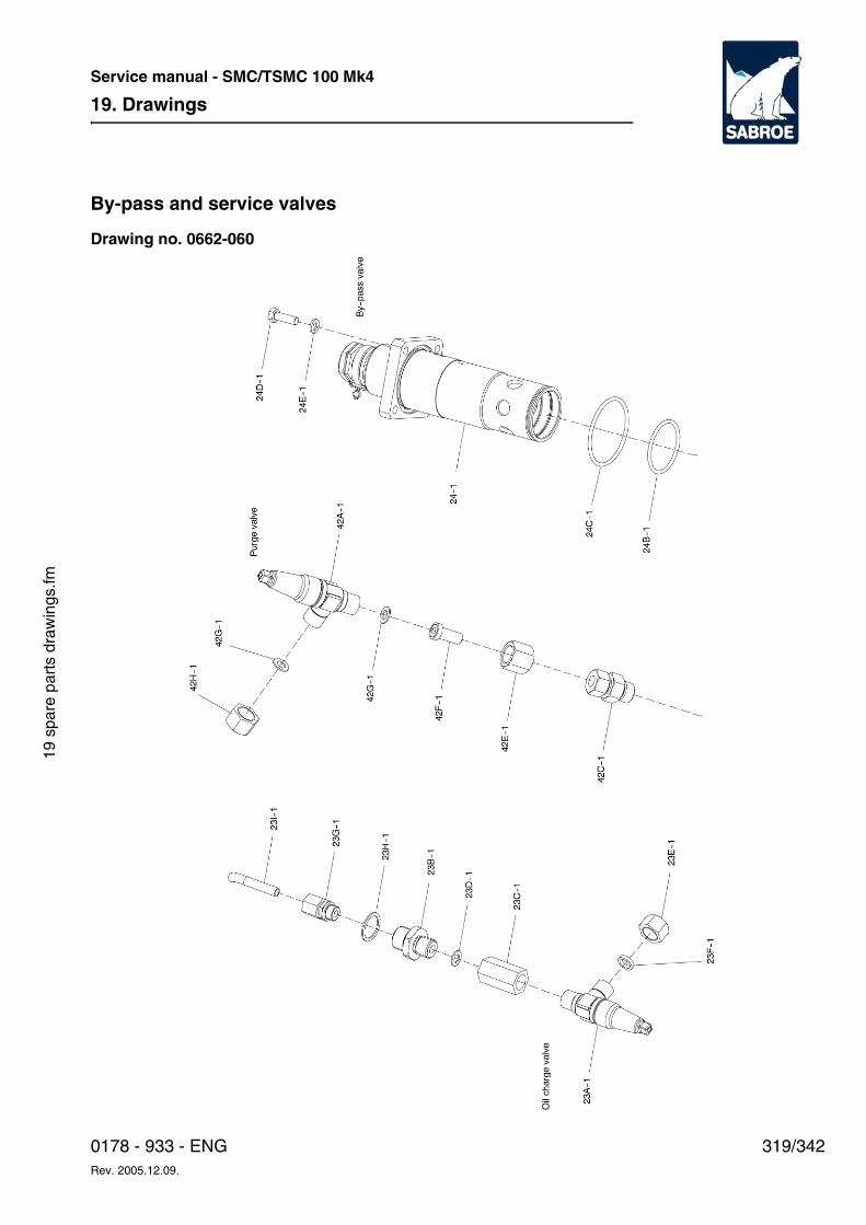
19. Drawings
319/3420178 - 933 - ENGRev. 2005.12.09.
Service manual - SMC/TSMC 100 Mk4
19 s
pare
par
ts d
raw
ings
.fm
By-pass and service valves
Drawing no. 0662-060
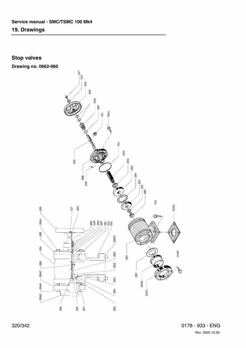
19. Drawings
320/342 0178 - 933 - ENGRev. 2005.12.09.
Service manual - SMC/TSMC 100 Mk4
Stop valves
Drawing no. 0662-060
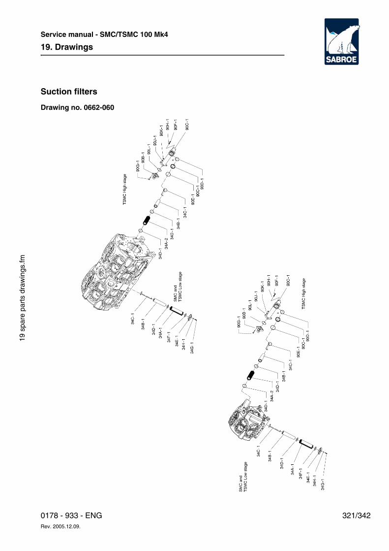
19. Drawings
321/3420178 - 933 - ENGRev. 2005.12.09.
Service manual - SMC/TSMC 100 Mk4
19 s
pare
par
ts d
raw
ings
.fm
Suction filters
Drawing no. 0662-060
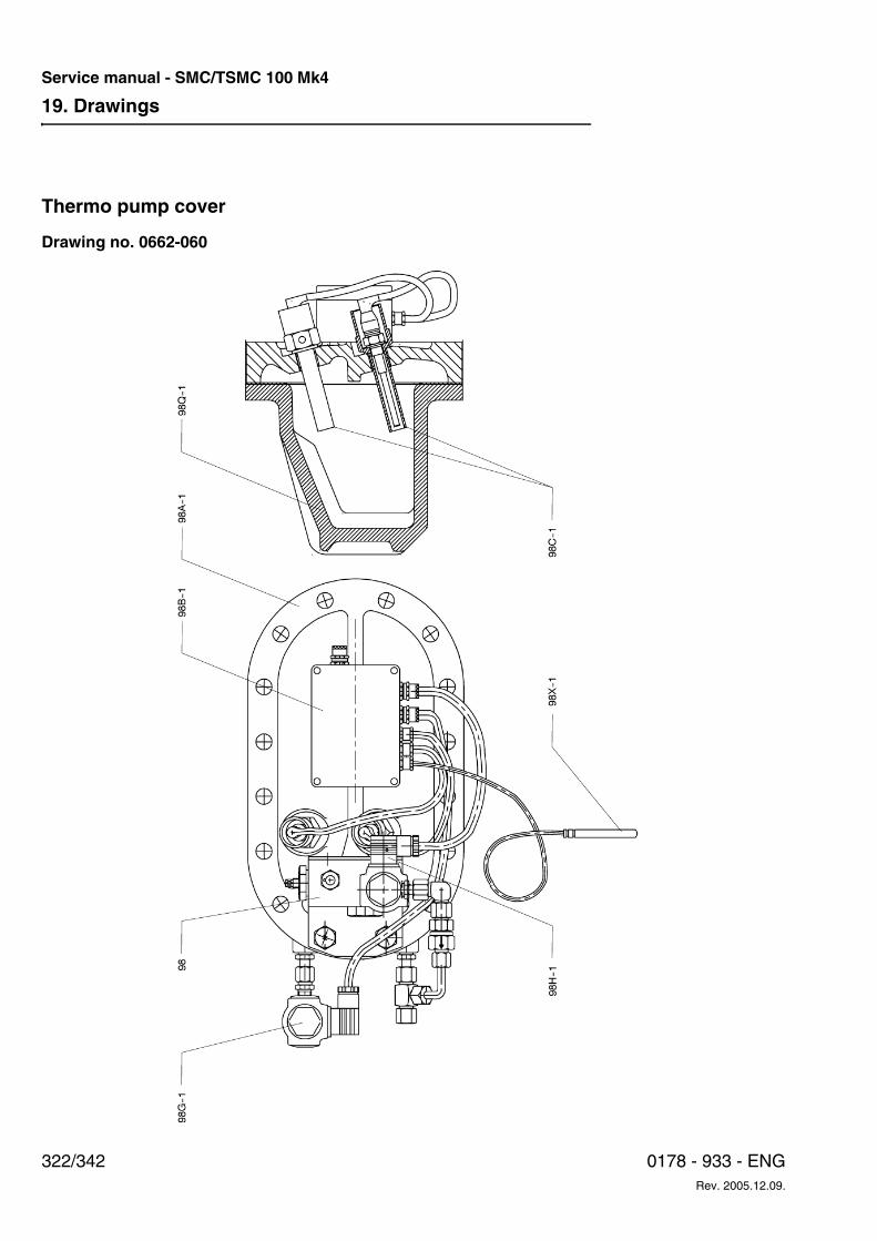
19. Drawings
322/342 0178 - 933 - ENGRev. 2005.12.09.
Service manual - SMC/TSMC 100 Mk4
Thermo pump cover
Drawing no. 0662-060
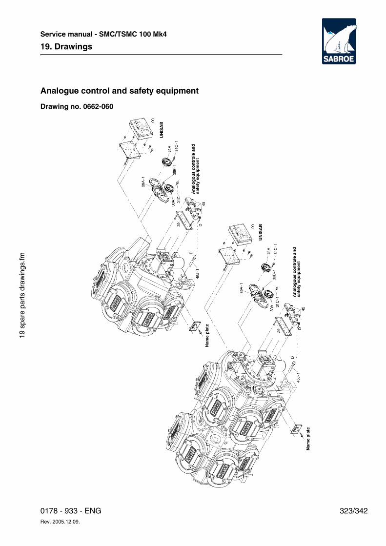
19. Drawings
323/3420178 - 933 - ENGRev. 2005.12.09.
Service manual - SMC/TSMC 100 Mk4
19 s
pare
par
ts d
raw
ings
.fm
Analogue control and safety equipment
Drawing no. 0662-060
19. Drawings
324/342 0178 - 933 - ENGRev. 2005.12.09.
Service manual - SMC/TSMC 100 Mk4
20. Final Disposal
325/3420178 - 933 - ENGRev. 2005.12.09.
Service manual - SMC/TSMC 100 Mk4
20 fi
nal d
ispo
sal.f
m
20. Final DisposalThe purpose of this chapter is to describe how to safely dispose of this equipment or part of it.
This chapter is primarily intended for the de-com-missioning engineers and authorities.
General
Safety Precautions
WDanger!
Before dismantling the plant, read chapter 3, Safety Precautions carefully. Failure to do so may result in personal injury or even death.
Dismantling of a cooling unit which is to be scrapped must be carried out in a safe way.
Authorized refrigeration personnel must partici-pate in the first part of the dismantling process as fundamental knowledge of refrigerating systems and the risks involved is required.
Before dismantling the plant, refrigerant and oil must be drained into containers intended for the purpose. Disconnect all electrical connections to the unit. Remove fuses in the main switchboard.
During the dismantling process, the individual ma-chine parts and components must be sorted so that disposal can take place in an efficient way.
WDanger!
Take great care if using cutting tools, e.g. angle grinder or flame cutter, during the dismantling process as pipes or the like will contain oil residue which may ignite. Refrigerant residue does also involve a great risk as HFC and HCFC refrigerants will develop toxic gasses when heated. Make sure that there are no air traps as heating will result in a pressure rise.
Disposal of Machine PartsWhen dismantling the plant, it is important to sort the parts to be disposed of. Compressor, frame, containers, etc. belonging to the category of iron and metal scrap must be delivered to an approved scrap dealer complying with the prevailing rules and regulations of the individual country.
Disposal of Oil and RefrigerantOil and refrigerant must be delivered for destruc-tion or regeneration at a receiving station for haz-ardous waste, including used oil filters. The re-ceiving station must comply with the prevailing rules and regulations of the individual country.
20. Final Disposal
326/342 0178 - 933 - ENGRev. 2005.12.09.
Service manual - SMC/TSMC 100 Mk4
Disposal of Electrical ComponentsElectrical and electronic products, e.g. wiring, panels, hardware, etc., must be delivered to a re-ceiving station approved to handle electronic waste. The receiving station must comply with the prevailing rules and regulations of the individual country.
Disposal of BatteriesUsed batteries from e.g. the backup of the compu-ter control must be delivered for destruction at a receiving station. The receiving station must com-ply with the prevailing rules and regulations of the individual country.
21. Appendices
327/3420178 - 933 - ENGRev. 2005.12.09.
Service manual - SMC/TSMC 100 Mk4
21 a
ppen
dice
s.fm
21. AppendicesThe purpose of this chapter is:
• to collect all relevant data and tables regard-ing torques, coupling data etc.
• to collect all relevant instructions of products supplied by sub-suppliers and used in the Sabroe product in question.
References to InstructionsThe instructions from the sub-suppliers must as far as possible be copied from the original instruc-tions, firstly, to avoid any errors and secondly, to avoid losing the right to claim damages.
AppendixThis chapter includes data sheets and instructions concerning the components and the tables of torques.
1. List of torques
2. Coupling data
3. Sundry Clearences and Check Dimensions
4. Instructions from sub-suppliers, valves, sensors, automatic etc.
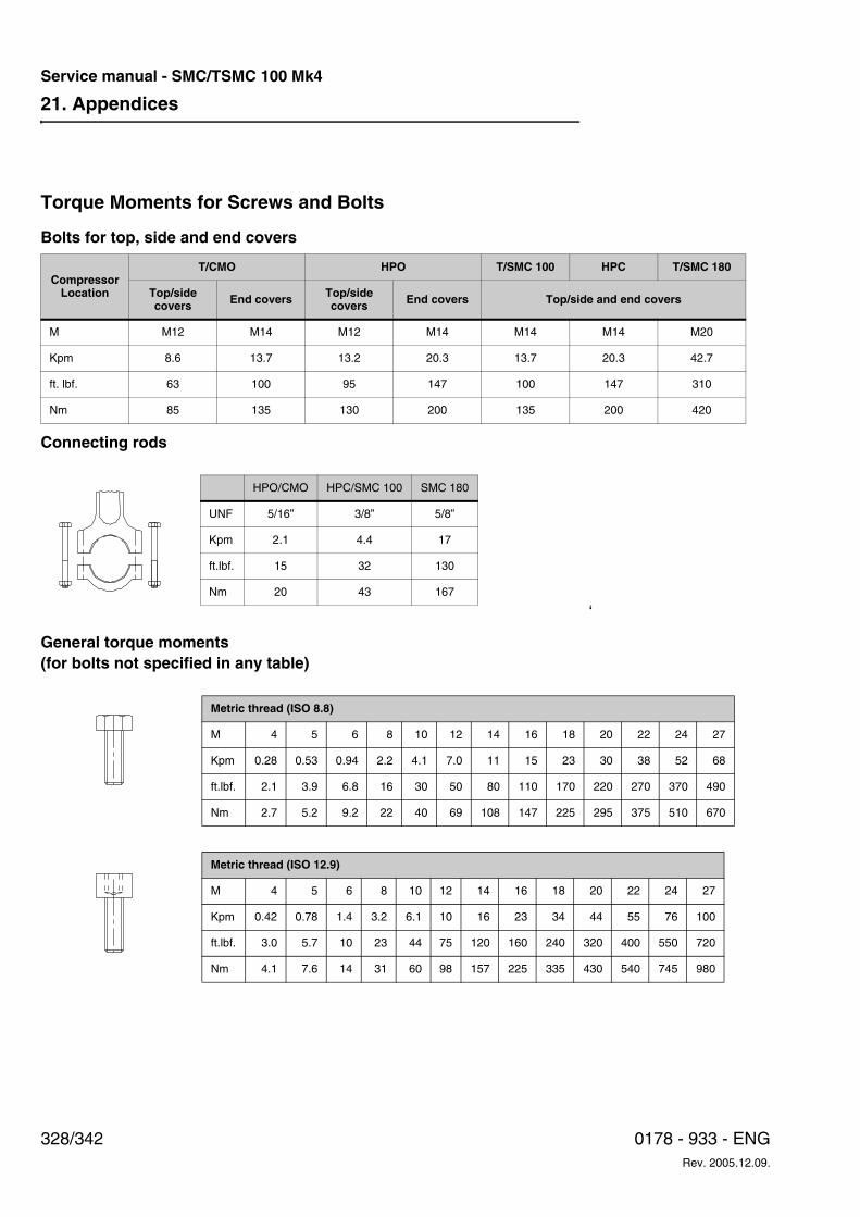
21. Appendices
328/342 0178 - 933 - ENGRev. 2005.12.09.
Service manual - SMC/TSMC 100 Mk4
Torque Moments for Screws and Bolts
Bolts for top, side and end covers
Connecting rods
‘
General torque moments (for bolts not specified in any table)
Compressor Location
T/CMO HPO T/SMC 100 HPC T/SMC 180
Top/side covers End covers Top/side
covers End covers Top/side and end covers
M M12 M14 M12 M14 M14 M14 M20
Kpm 8.6 13.7 13.2 20.3 13.7 20.3 42.7
ft. lbf. 63 100 95 147 100 147 310
Nm 85 135 130 200 135 200 420
HPO/CMO HPC/SMC 100 SMC 180
UNF 5/16” 3/8” 5/8”
Kpm 2.1 4.4 17
ft.lbf. 15 32 130
Nm 20 43 167
Metric thread (ISO 8.8)
M 4 5 6 8 10 12 14 16 18 20 22 24 27
Kpm 0.28 0.53 0.94 2.2 4.1 7.0 11 15 23 30 38 52 68
ft.lbf. 2.1 3.9 6.8 16 30 50 80 110 170 220 270 370 490
Nm 2.7 5.2 9.2 22 40 69 108 147 225 295 375 510 670
Metric thread (ISO 12.9)
M 4 5 6 8 10 12 14 16 18 20 22 24 27
Kpm 0.42 0.78 1.4 3.2 6.1 10 16 23 34 44 55 76 100
ft.lbf. 3.0 5.7 10 23 44 75 120 160 240 320 400 550 720
Nm 4.1 7.6 14 31 60 98 157 225 335 430 540 745 980
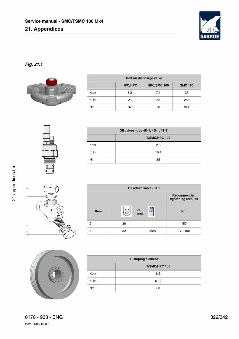
21. Appendices
329/3420178 - 933 - ENGRev. 2005.12.09.
Service manual - SMC/TSMC 100 Mk4
21 a
ppen
dice
s.fm
Fig. 21.1
Bolt on discharge valve
HPO/HPC HPC/SMC 100 SMC 180
Kpm 3.2 7.1 35
ft. lbf. 23 52 255
Nm 32 70 344
Oil valves (pos 4K-1, 4D-1, 4E-1)
T/SMC/HPC 100
Kpm 2.5
ft. lbf. 18.4
Nm 25
Oil return valve - TLT
Recommended tightening torques
Item
Nm
2 36 150
5 32 M28 170-190
Clamping element
T/SMC/HPC 100
Kpm 8.5
ft. lbf. 61.2
Nm 83
ormm
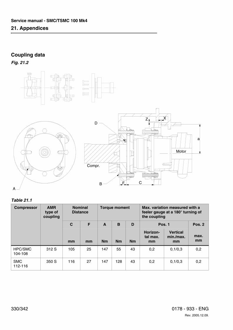
21. Appendices
330/342 0178 - 933 - ENGRev. 2005.12.09.
Service manual - SMC/TSMC 100 Mk4
Coupling dataFig. 21.2
Table 21.1
Compressor AMR type of
coupling
NominalDistance
Torque moment Max. variation measured with a feeler gauge at a 180° turning of the coupling
C F A B D Pos. 1 Pos. 2
max. mmmm mm Nm Nm Nm
Horizon-tal max.
mm
Vertical min./max.
mm
HPC/SMC104-108
312 S 105 25 147 55 43 0,2 0,1/0,3 0,2
SMC112-116
350 S 116 27 147 128 43 0,2 0,1/0,3 0,2
B
DZ X
a
A
Compr.
Motor
F C
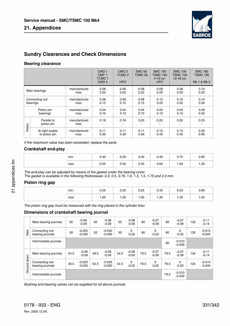
21. Appendices
331/3420178 - 933 - ENGRev. 2005.12.09.
Service manual - SMC/TSMC 100 Mk4
21 a
ppen
dice
s.fm
Sundry Clearances and Check Dimensions
Bearing clearance
If the maximum value has been exceeded, replace the parts.
Crankshaft end-play
The end-play can be adjusted by means of the gasket under the bearing cover.The gasket is available in the following thicknesses: 0.3, 0.5, 0.75, 1.0, 1.3, 1.5, 1.75 and 2.0 mm.
Piston ring gap
The piston ring gap must be measured with the ring placed in the cylinder liner.
Dimensions of crankshaft bearing journal
Bushing and bearing valves can be supplied for all above journals.
CMO 1CMP 1
TCMO 1CMO 4
CMO 2TCMO 2
HPO
SMC 65TSMC 65
SMC 100TSMC 1004-10 cyl.
HPC
SMC 100TSMC 10012-16 cyl.
SMC 180TSMC 180
Mk 1 & Mk 2
Main bearings manufacturedmax.
0.080.20
0.080.20
0.080.20
0.080.20
0.080.20
0.140.35
Connecting rodbearings
manufacturedmax.
0.080.15
0.080.15
0.080.15
0.100.20
0.100.20
0.140.30
Piston pinbearings
manufacturedmax.
0.040.10
0.040.10
0.040.10
0.040.10
0.040.10
0.090.20
Pis
ton
Parallel topiston pin
manufacturedmax.
0.18-
0.18-
0.20-
0.20-
0.20-
0.25-
Al right anglesto piston pin
manufacturedmax.
0.110.30
0.110.30
0.110.30
0.150.40
0.150.40
0.350.90
min. 0.30 0.30 0.40 0.40 0.75 0.95
max. 0.55 0.55 0.55 0.64 1.00 1.20
min. 0.25 0.25 0.25 0.33 0.33 0.66
max. 1.00 1.00 1.00 1.30 1.30 1.50
New
Main bearing journals 55 -0.06-0.09 60 -0.06
-0.09 55 -0.06-0.09 80 -0.07
-0.09 80 -0.07-0.09 135 -0.11
-0.14
Connecting rodbearing journals 50 -0.025
-0.040 55 -0.040-0.059 55 0
-0.02 80 0-0.02 80 0
-0.02 135 -0.015-0.040
Intermediate journals 80 -0.010-0.029
Gro
und
dow
n
Main bearing journals 54.5 -0.06-0.09 59.5 -0.06
-0.09 54.5 -0.06-0.09 79.5 -0.07
-0.09 79.5 -0.07-0.09 134 -0.11
-0.14
Connecting rod bearing journals 49.5 -0.025
-0.040 54.5 -0.035-0.050 54.5 0
-0.02 79.5 0-0.02 79.5 0
-0.02 134 -0.015-0.040
Intermediate journals 79.5 -0.010-0.029
21. Appendices
332/342 0178 - 933 - ENGRev. 2005.12.09.
Service manual - SMC/TSMC 100 Mk4
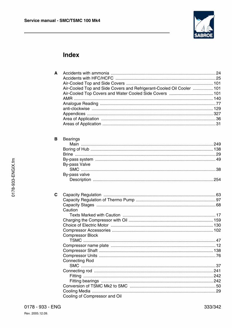
Service manual - SMC/TSMC 100 Mk4
0178
-933
-EN
GIX
.fm
333/3420178 - 933 - ENGRev. 2005.12.09.
Index
A Accidents with ammonia ........................................................................................24Accidents with HFC/HCFC .................................................................................... 25Air-Cooled Top and Side Covers .........................................................................101Air-Cooled Top and Side Covers and Refrigerant-Cooled Oil Cooler .................101Air-Cooled Top Covers and Water Cooled Side Covers .....................................101AMR .....................................................................................................................140Analogue Reading .................................................................................................77anti-clockwise ......................................................................................................129Appendices ..........................................................................................................327Area of Application ................................................................................................36Areas of Application ...............................................................................................31
B BearingsMain ...............................................................................................................249
Boring of Hub ....................................................................................................... 138Brine ......................................................................................................................29By-pass system .....................................................................................................49By-pass Valve
SMC .................................................................................................................38By-pass valve
Description .....................................................................................................254
C Capacity Regulation .............................................................................................. 63Capacity Regulation of Thermo Pump ...................................................................97Capacity Stages ....................................................................................................68Caution
Texts Marked with Caution ..............................................................................17Charging the Compressor with Oil ....................................................................... 159Choice of Electric Motor ......................................................................................130Compressor Accessories .....................................................................................102Compressor Block
TSMC ...............................................................................................................47Compressor name plate ........................................................................................12Compressor Shaft ................................................................................................138Compressor Units ..................................................................................................76Connecting Rod
SMC .................................................................................................................37Connecting rod ....................................................................................................241
Fitting .............................................................................................................242Fitting bearings ..............................................................................................242
Conversion of TSMC Mk2 to SMC ........................................................................50Cooling Media ........................................................................................................29Cooling of Compressor and Oil
Service manual - SMC/TSMC 100 Mk4
334/342 0178 - 933 - ENGRev. 2005.12.09.
SMC .................................................................................................................45Cooling system
Booster Compressor ........................................................................................87Pressure Loss ..................................................................................................93R22 ..................................................................................................................86R717 ................................................................................................................86Thermo pump .............................................................................................94, 95Water flow ........................................................................................................92Water pressure ................................................................................................92Water temp. .....................................................................................................92
Cooling Systems ....................................................................................................86Cooling with Thermo Pump ...................................................................................94Coupling
AMR ...............................................................................................................140Coupling Types ....................................................................................................138Crankshaft
Description .....................................................................................................248Dismantling ....................................................................................................248Inspection .......................................................................................................249Refitting ..........................................................................................................249SMC .................................................................................................................40
Cylinder liningAdjustment .....................................................................................................258Checking clearance .......................................................................................258Lifting reserve ................................................................................................259Monitoring ......................................................................................................258with suction valve ...........................................................................................240
D DangerTexts Marked with Danger ...............................................................................17
Description .............................................................................................................83Additional unloading .........................................................................................69Analogue Reading ...........................................................................................77By-pass system ................................................................................................49Capacity Regulation .........................................................................................63
Solenoid Valves ..........................................................................................65Capacity Stages ...............................................................................................68Conversion of TSMC Mk2 to SMC ...................................................................50Cooling of the Intermediate Gas ......................................................................49Cooling system
R22 .............................................................................................................86R717 ...........................................................................................................86
Determining the Intermediate Pressure IP .......................................................84Discharge Pipe Thermostat KP98 ....................................................................78DVEA ...............................................................................................................82High Pressure Cut-out KP15 ............................................................................78Intermediate Cooling
TEAT ..........................................................................................................83
Service manual - SMC/TSMC 100 Mk4
0178
-933
-EN
GIX
.fm
335/3420178 - 933 - ENGRev. 2005.12.09.
TEA-TEX ....................................................................................................83Intermediate Gas .............................................................................................82Intermediate Pressure Cut-out KP5 .................................................................78Low Pressure Cut-out KP15 ............................................................................78Oil Differential Cut-out MP55 ...........................................................................78Oil Thermostat KP98 ........................................................................................78Regulation of Intermediate Pressure IP ...........................................................84SMC
By-pass Valve ............................................................................................38Connecting Rod ..........................................................................................37Cooling of Compressor and Oil ..................................................................45Crankshaft ..................................................................................................40Cylinder liners .............................................................................................36Discharge Valve .........................................................................................37Draining valve .............................................................................................44Evacuating Valve ........................................................................................44Filter bag ....................................................................................................38Heating Rod ...............................................................................................44Instrumentation ...........................................................................................45Oil Filter ......................................................................................................41Oil Level Glass ...........................................................................................44Oil Pressure Regulating Valve ...................................................................41Oil Pump .....................................................................................................41Pistons ........................................................................................................36Safety spring .............................................................................................. 37Shaft Seal ...................................................................................................43Stop Valves ................................................................................................45Suction Filter .............................................................................................. 37Suction Valve .............................................................................................37
Special unloading 104 ......................................................................................70Standard unloading ..........................................................................................67Start Unloading ................................................................................................65Suction Filters ..................................................................................................49TEA ..................................................................................................................83TEAT ................................................................................................................83Total Unloading ................................................................................................68TSMC
Compressor Block ......................................................................................47Intermediate pressure ................................................................................48Needle bearing ...........................................................................................48Piston Pin Bearing ......................................................................................48
Water Quality ...................................................................................................93Description of Compressor Types ......................................................................... 34Description of Pumping Cycle ...............................................................................97Determining the Intermediate Pressure IP ............................................................84Dimension Sketches ............................................................................................ 109Direction of Rotation ............................................................................................ 129
Electric Motor .................................................................................................136Direction of Rotation of Electric Motor .................................................................136
Service manual - SMC/TSMC 100 Mk4
336/342 0178 - 933 - ENGRev. 2005.12.09.
Discharge GasTemperatures ..............................................................................197Discharge Pipe Thermostat KP98 .........................................................................78Discharge Valve ....................................................................................................37Discharge valve ...................................................................................................237
Refrigerants ...................................................................................................239Types .............................................................................................................238
Dismantling plant .................................................................................................267DVEA .....................................................................................................................82
E Electric Motor .......................................................................................................130Direction of Rotation ......................................................................................136
Emergency Stop ....................................................................................................16Ensuring Liquid to the Thermo Pump ....................................................................99Evacuating Valve
SMC .................................................................................................................44Explosion-proof ....................................................................................................102Explosion-proof heating .......................................................................................102Explosion-proof solenoid valves ..........................................................................102Extended set of tools ...........................................................................................102
F Fault-findingHow to carry out fault-finding .........................................................................214
Filter bagSMC .................................................................................................................38
Final Disposal ......................................................................................................325First aid
Accidents with ammonia ..................................................................................24Accidents with HFC/HCFC ...............................................................................25
H Handling of Compressor and Unit .......................................................................137Heating Rod
SMC .................................................................................................................44High voltage ...........................................................................................................22Hub
Boring of Hub .................................................................................................138
I Installation and Relocation Safety .........................................................................21Instrumentation ......................................................................................................77
SMC .................................................................................................................45
Service manual - SMC/TSMC 100 Mk4
0178
-933
-EN
GIX
.fm
337/3420178 - 933 - ENGRev. 2005.12.09.
Intermediate Cooler Type DVEA ...........................................................................82Intermediate Cooling
Liquid Injection .................................................................................................83TEAT ................................................................................................................83TEA-TEX ..........................................................................................................83
Intermediate Gas .............................................................................................49, 82Intermediate pressure
TSMC ...............................................................................................................48Intermediate Pressure Cut-out KP5 .......................................................................78
K KP15 ......................................................................................................................78KP5 ........................................................................................................................78KP98 ......................................................................................................................78
L Lifting and Carrying Safety .................................................................................... 20Lifting the compressor Block ...............................................................................137Lifting the compressor Unit .................................................................................. 137Liquid Injection .......................................................................................................83Long block .............................................................................................................34Lubricating system ...............................................................................................251
M Machine RoomPlanning .........................................................................................................113
Main bearings ......................................................................................................249Maintenance ........................................................................................................233Maintenance Instructions .....................................................................................201Maintenance Safety ...............................................................................................22Manometers
DescriptionManometers ...............................................................................................79
Max. Power Transmission ...................................................................................144Moment of Inertia .................................................................................................135Motor Dimension .................................................................................................130Motor weight ........................................................................................................108MP55 .....................................................................................................................78
N Needle bearingTSMC ...............................................................................................................48
Nitrogen charge .....................................................................................................76Noise ...................................................................................................................148
Damping Acoustic Noise ................................................................................153Reverberation Time .......................................................................................153
Normal set of tools ...............................................................................................102Nozzle size ............................................................................................................53
Service manual - SMC/TSMC 100 Mk4
338/342 0178 - 933 - ENGRev. 2005.12.09.
O Oil Charging .........................................................................................................159Oil Consumption ..................................................................................................161Oil Differential Cut-out MP55 .................................................................................78Oil Draining Valve
SMC .................................................................................................................44Oil Filter
SMC .................................................................................................................41Oil Level Glass
SMC .................................................................................................................44Oil Pressure Regulating Valve
SMC .................................................................................................................41Oil pressure valve
Adjustment .....................................................................................................253Description .....................................................................................................253Service ...........................................................................................................253
Oil PumpSMC .................................................................................................................41
Oil pumpDescription .....................................................................................................252
Oil Return ..............................................................................................................52Coil for the solenoid valve ................................................................................53Float Valve Controlled ......................................................................................56Parallel Operation ............................................................................................56
Different Et ..................................................................................................60Float valve ..................................................................................................58Same Ct ......................................................................................................62Same Et ......................................................................................................57
Oil returnNozzle size .......................................................................................................53Solenoid Valve Controlled ................................................................................52
Oil Thermostat KP98 .............................................................................................78Operating Limits Diagrams ..................................................................................114Operational reliability ...........................................................................................267Ordering Spare Parts ...........................................................................................269
P Parallel Operation ..................................................................................................56Personal Safety .....................................................................................................19Piston
Fitting piston rings ..........................................................................................243Types .............................................................................................................243
Piston Pin BearingTSMC ...............................................................................................................48
PistonsSMC .................................................................................................................36
Planning the Machine Room ...............................................................................113Plant Maintenance ...............................................................................................267Power Transmission ............................................................................................144Prelubrication .........................................................................................................42
Service manual - SMC/TSMC 100 Mk4
0178
-933
-EN
GIX
.fm
339/3420178 - 933 - ENGRev. 2005.12.09.
Prelubrication valve ...............................................................................................42Preparations before Service ................................................................................228Pressure and Temperature Setting .....................................................................196Pressure drop test ...............................................................................................229Pressure gauges .................................................................................................261Pressure Levels ...................................................................................................157Pressure levels ....................................................................................................157Pressure Loss ........................................................................................................93Pump-down .........................................................................................................233Pumping down .....................................................................................................267Purging a refrigeration plant ..................................................................................28
R Refrigerants .....................................................................................................28, 29Discharge valve .............................................................................................239
Regulation of Intermediate Pressure IP .................................................................84Removing refrigerant from compressor ...............................................................230
S Safety at Servicing .................................................................................................16Safety Instructions
High voltage .....................................................................................................22Installation and Relocation ...............................................................................21Lifting and Carrying Safety ...............................................................................20Maintenance Safety .........................................................................................22Personal Safety ................................................................................................19Set-Up and Operation ......................................................................................21Tool Safety .......................................................................................................20Work Area Safety .............................................................................................19
Safety Precautions ................................................................................................19Service
Discharge valve .............................................................................................237Refrigeration Plant .........................................................................................231Top covers .....................................................................................................234
Service Instructions .............................................................................................227Servicing the Plant ...............................................................................................231Settings ................................................................................................................195Set-Up and Operation Safety ................................................................................21Shaft Seal
SMC .................................................................................................................43Shaft seal
Assembling ....................................................................................................247Description .....................................................................................................244Dismantling ....................................................................................................245
Short blocks ...........................................................................................................34Sign
CAUTION ......................................................................................................... 14Cold surfaces ...................................................................................................15Dangerous noise level .....................................................................................15
Service manual - SMC/TSMC 100 Mk4
340/342 0178 - 933 - ENGRev. 2005.12.09.
Hazardous substance ......................................................................................15HIGH VOLTAGE ..............................................................................................14Internal overpressure .......................................................................................15Internal protection ............................................................................................15Temperature of tangible surfaces ....................................................................15
Signs and Warnings ................................................................................................9Signs in instructions ...............................................................................................14Single-stage ...........................................................................................................35SMC
Cylinder liners ..................................................................................................36Designation ......................................................................................................34Safety spring ....................................................................................................37Type E ..............................................................................................................34Type L ..............................................................................................................34Type S ..............................................................................................................34
SMC/HPC 104 Special Unloading .........................................................................70Sound Data
How to check .................................................................................................152Spare parts set ....................................................................................................102Special unloading 104 ...........................................................................................70Specification of Materials .....................................................................................156Start Unloading ......................................................................................................65Start up
SMC/HPC 100 - HFC/HCFC - 25% load ........................................................134Start up torque SMC/HPC 100 R717 25% load ...................................................133Starting Torque ....................................................................................................132Stop Valves
SMC .................................................................................................................45Structure of the Thermo Pump ..............................................................................95Suction Filter
SMC .................................................................................................................37Suction filter
Description .....................................................................................................257SMC ...............................................................................................................257TSMC .............................................................................................................257
Suction Filters ........................................................................................................49Round holes .....................................................................................................49Square holes ....................................................................................................49
Suction ValveSMC .................................................................................................................37
T TEA ........................................................................................................................83Technical Data .....................................................................................................106Technical Description ............................................................................................31Test Pressure Levels ...........................................................................................157TEX ........................................................................................................................83The compressor must NOT be used .....................................................................31Thermo Pump
Service manual - SMC/TSMC 100 Mk4
0178
-933
-EN
GIX
.fm
341/3420178 - 933 - ENGRev. 2005.12.09.
Capacity Regulation .........................................................................................97Thermo pump ........................................................................................................94
Description of the Pumping Cycle ....................................................................97Ensuring Liquid ................................................................................................99Power Connection ..........................................................................................100Structure ..........................................................................................................95
Thermodynamic Liquid Trap ..................................................................................54Tightness testing .................................................................................................268TLT Thermodynamic Liquid Trap ..........................................................................54Tool Safety ............................................................................................................20Top Covers
Mounting top and water covers ......................................................................236Top covers
Service .....................................................................................................234Total Unloading .....................................................................................................68TWA-Time weighted average ................................................................................26Two-stage ..............................................................................................................35Two-stage Compressors
TSMC ...............................................................................................................47Type
E .......................................................................................................................34L .......................................................................................................................34S .......................................................................................................................34
Types of Spare Parts Set ....................................................................................103
U Unisab II ................................................................................................................80Unit pipe system name plate .................................................................................11
V V-Belt Drive .........................................................................................................142Construction ...................................................................................................146Motor pulley ...................................................................................................147
V-Belts and Pulleys .............................................................................................143Vessel name plate .................................................................................................13Vibration dampers ...............................................................................................102Vibration Data ......................................................................................................155
W WarningTexts Marked with Warning .............................................................................17
Warnings in Instructions ........................................................................................17Water flow ..............................................................................................................92Water pressure ......................................................................................................92Water Quality ......................................................................................................... 93Water temp. ...........................................................................................................92Weight of Electric Motors .....................................................................................108Work Area Safety ..................................................................................................19
Service manual - SMC/TSMC 100 Mk4
342/342 0178 - 933 - ENGRev. 2005.12.09.