Embed Size (px)
Citation preview

7/15/2019 Manual Intecont Tersus
http://slidepdf.com/reader/full/manual-intecont-tersus 1/176
INTECONT ® Tersus WeighfeederInstruction Manual
BV-H2463 GB

7/15/2019 Manual Intecont Tersus
http://slidepdf.com/reader/full/manual-intecont-tersus 2/176
PASS - Service you can rely onFast, comprehensive, anywhere in the world
Quality and reliability are the cornerstones of our company’sphilosophy. That is why we consider a comprehensive serviceconcept simply par for the course, from strict quality control,installation and commissioning through to seamless supportacross the entire product life cycle.With over 30 service stations and over 180 service specialists,
you can count on us to be there whenever – and wherever – you need us.It doesn’t matter where you are, our specialists are there toadvise and assist with the best in worldwide, personal, com-prehensive service.
During office hours, service specialists from all divisions areon hand to analyze problems and failures. Look atwww.schenckprocess.com for your nearestSchenck Process Location.
Customized to meet your requirements, our comprehensiveProcess Advanced Service System provides you with the bestservice. Are you looking for individual, perfect-fit service solu-
tions?Then our service system PASS is the ticket. It covers the en-tire service spectrum, from simple inspections through to fullservice. Interested?Then find out more about the individual components atwww.schenckprocess.com/en/service.
© by Schenck Process GmbHPallaswiesenstraße 100, 64293 Darmstadt, GermanyPhone: +49 6151 1531-0www.schenckprocess.com
All rights reserved. Any reproduction of this documentation,
regardless of method, without prior permission bySchenck Process GmbH in writing, even by excerpt, is prohi-bited.Subject to change without prior notice.
Note: Translation of the original German Instruction

7/15/2019 Manual Intecont Tersus
http://slidepdf.com/reader/full/manual-intecont-tersus 3/176
Table of Contents
INTECONT® Tersus Weighfeeder, Instruction ManualSchenck Process Group
BV-H2463GB, 1149- i -
Table of ContentsTable of ContentsTable of ContentsTable of Contents
1111 About This ManualAbout This ManualAbout This ManualAbout This Manual .................................................................................................................................................................................................................................................................................................................................................................................................................................................................................................................................... 1111
2222 Safety notesSafety notesSafety notesSafety notes............................................................................................................................................................................................................................................................................................................................................................................................................................................................................................................................................................................ 3333
2.1 Signal Words .......................................................................................................................................... 5
2.1.1 Signal Words for Safety Warnings ................................................................................................. 5
2.1.2 Signal Words for Application Notes ............................................................................................... 5
2.2 Five Safety Rules of Electrical Engineering ........................................................................................... 6
2.3 Damaged / Defective Electrical Components ......................................................................................... 6
3333 General DiagramGeneral DiagramGeneral DiagramGeneral Diagram ............................................................................................................................................................................................................................................................................................................................................................................................................................................................................................................................................ 7777
3.1 An overview of the INTECONT Tersus .................................................................................................. 7
3.2 The basic diagram of the weighfeeder ................................................................................................... 8
3.3 Method of Function ................................................................................................................................. 9
3.4 Characteristics ...................................................................................................................................... 10
4444 OperationOperationOperationOperation .................................................................................................................................................................................................................................................................................................................................................................................................................................................................................................................................................................................... 15151515
4.1 Quick guide ........................................................................................................................................... 15
4.2 Function block....................................................................................................................................... 17
4.3 Operating in Normal Operation............................................................................................................. 18
5555 Service FunctionsService FunctionsService FunctionsService Functions ................................................................................................................................................................................................................................................................................................................................................................................................................................................................................................................................ 212121215.1 Display Test and Version Number ........................................................................................................ 21
6666 Counter functionsCounter functionsCounter functionsCounter functions .................................................................................................................................................................................................................................................................................................................................................................................................................................................................................................................................... 23232323
7777 Mode functionsMode functionsMode functionsMode functions ................................................................................................................................................................................................................................................................................................................................................................................................................................................................................................................................................ 25252525
7.1 Types of operation ................................................................................................................................ 25
7.2 Keyboard operation ON/OFF ................................................................................................................ 26
7.3 Prefeeder .............................................................................................................................................. 26
7.4 Simulation ............................................................................................................................................. 27
8888 CalibratiCalibratiCalibratiCalibration functionson functionson functionson functions ................................................................................................................................................................................................................................................................................................................................................................................................................................................................................................................ 29292929
8.1 Starting the calibration functions .......................................................................................................... 29
8.2 Pulse/Belt circuit LB ............................................................................................................................. 30
8.3 Tare TW ................................................................................................................................................ 31
8.4 Weight Check CW ................................................................................................................................ 33
8.5 Setting the Time ................................................................................................................................... 35
9999 Parameter functionsParameter functionsParameter functionsParameter functions .................................................................................................................................................................................................................................................................................................................................................................................................................................................................................................................... 37373737
9.1 Read Parameters ................................................................................................................................ 37
10101010 Printer functionsPrinter functionsPrinter functionsPrinter functions ............................................................................................................................................................................................................................................................................................................................................................................................................................................................................................................................................ 39393939
10.1 Status Report ........................................................................................................................................ 40
11111111 Batching functionsBatching functionsBatching functionsBatching functions ............................................................................................................................................................................................................................................................................................................................................................................................................................................................................................................................ 41414141
11.1 Batching mode ...................................................................................................................................... 4111.2 Record the batch .................................................................................................................................. 43

7/15/2019 Manual Intecont Tersus
http://slidepdf.com/reader/full/manual-intecont-tersus 4/176
Table of Contents
BV-H2463GB, 1149- ii -
INTECONT® Tersus Weighfeeder, Instruction ManualSchenck Process Group
12121212 Startup operationStartup operationStartup operationStartup operation .................................................................................................................................................................................................................................................................................................................................................................................................................................................................................................................................... 45454545
12.1 Weighing Platforms .............................................................................................................................. 45
12.1.1 Effective Weighing Platform Length ............................................................................................ 45
12.1.2 Calibration Weight ........................................................................................................................ 47
12.1.3 Belt inclination ............................................................................................................................. 49
12.2 Parameter Input .................................................................................................................................... 49
12.3 Function Check ..................................................................................................................................... 51
12.4 Test With Calibration Weight ................................................................................................................ 51
12.5 Belt Velocity Check ............................................................................................................................... 52
12.6 Test with Material ................................................................................................................................. 52
13131313 ParametersParametersParametersParameters ........................................................................................................................................................................................................................................................................................................................................................................................................................................................................................................................................................................ 53535353
13.1 Abbreviations ........................................................................................................................................ 54
13.2 Configuring Event Messages ................................................................................................................ 55
13.3 Parameter Listing ................................................................................................................................ 55
13.3.1 Parameter Overview .................................................................................................................... 55
13.3.2 Parameter Details ........................................................................................................................ 65
13.3.2.1 Parameter Block 01 - Dialog Behaviour ....................................................................................... 65
13.3.2.2 Parameter Block 02 - Rated Data ................................................................................................ 69
13.3.2.3 Parameter Block 03 - Calibration Data ........................................................................................ 73
13.3.2.4 Parameter Block 04 - Calibrat. Results ........................................................................................ 74
13.3.2.5 Parameter Block 05 - Analog Outputs ......................................................................................... 74
13.3.2.6 Parameter Block 06 - Limit Values ............................................................................................... 77
13.3.2.7 Parameter Block 07 - Filters......................................................................................................... 80
13.3.2.8 Parameter Block 08 - Additional device ....................................................................................... 81
13.3.2.9 Parameter Block 09 - Batch Mode ............................................................................................... 8213.3.2.1
Parameter Block 10 - Printer Setting ........................................................................................... 83
13.3.2.1
Parameter Block 11 - Maintenance interval ................................................................................. 84
13.3.2.1
Parameter Block 12 - Belt Monitoring .......................................................................................... 85
13.3.2.1
Parameter Block 13 - Events ....................................................................................................... 88
13.3.2.1
Parameter Block 14 - Rate controller ........................................................................................... 91
13.3.2.1
Parameter Block 15 - Linearization .............................................................................................. 97
13.3.2.1
Parameter Block 16 - Digital Inputs ............................................................................................. 99
13.3.2.1
Parameter Block 17 - Digital Outputs ......................................................................................... 100
13.3.2.1
Parameter Block 18 - Communication EasyServe ..................................................................... 103
13.3.2.1
Parameter Block 19 - Communication Fieldbus......................................................................... 104
13.3.2.2
Parameter Block 20 - Fixed mode configuration ........................................................................ 109
13.3.2.2
Parameter Block 21 - Ethernet ................................................................................................... 11113.3.2.2
Parameter Block 22 - Data Logging ........................................................................................... 111
13.3.2.2
Parameter Block 23 - Configuration HMI Values ....................................................................... 114
13.3.2.2
Parameter Block 24 - Second Display ....................................................................................... 116
14141414 Event messagesEvent messagesEvent messagesEvent messages ................................................................................................................................................................................................................................................................................................................................................................................................................................................................................................................................ 119119119119

7/15/2019 Manual Intecont Tersus
http://slidepdf.com/reader/full/manual-intecont-tersus 5/176
Table of Contents
INTECONT® Tersus Weighfeeder, Instruction ManualSchenck Process Group
BV-H2463GB, 1149- iii -
15151515 EventsEventsEventsEvents ............................................................................................................................................................................................................................................................................................................................................................................................................................................................................................................................................................................................ 121121121121
15.1 Events Details ..................................................................................................................................... 12115.1.1 Event Group: Calibration ............................................................................................................ 121
15.1.2 Event Group: Controller ............................................................................................................. 121
15.1.3 Event Group: Electrical System ................................................................................................. 122
15.1.4 Event Group: Interlock ............................................................................................................... 122
15.1.5 Event Group: Material Flow........................................................................................................ 122
15.1.6 Event Group: MAX ..................................................................................................................... 123
15.1.7 Event Group: Mechanic .............................................................................................................. 124
15.1.8 Event Group: MIN ...................................................................................................................... 124
15.1.9 Event Group: Sequence Monitoring ........................................................................................... 125
15.1.10 Event Group: System Message ................................................................................................. 126
16161616 Hardware and technical dataHardware and technical dataHardware and technical dataHardware and technical data ........................................................................................................................................................................................................................................................................................................................................................................................................................................................ 12912912912916.1 Technical Data and Replacement Parts ............................................................................................. 129
16.2 Connection Diagrams ......................................................................................................................... 131
16.3 Replacing INTECONT PLUS with INTECONT Tersus ....................................................................... 133
16.4 PROFIBUS module (VPB8020) .......................................................................................................... 136
16.5 DeviceNet Module (VCB8020) .......................................................................................................... 138
16.6 Modbus Interface VSS8020 ................................................................................................................ 140
16.7 LED diagnosis..................................................................................................................................... 141
17171717 Web server functionsWeb server functionsWeb server functionsWeb server functions .................................................................................................................................................................................................................................................................................................................................................................................................................................................................................................... 143143143143
17.1 Web Server ......................................................................................................................................... 143
17.2 System Information ............................................................................................................................. 143
18181818 AppendixAppendixAppendixAppendix ............................................................................................................................................................................................................................................................................................................................................................................................................................................................................................................................................................................ 111145454545
18.1 Service Values .................................................................................................................................... 145
18.2 Set option ............................................................................................................................................ 146
18.3 Function Check ................................................................................................................................... 147
18.4 Test Connector ................................................................................................................................... 148
18.5 Sources of Setpoints and Switch Signals ........................................................................................... 149
18.6 Regulation .......................................................................................................................................... 151
18.7 Measuring at the Discharge Point VAP .............................................................................................. 153
18.8 Belt Monitoring .................................................................................................................................... 154
18.9 BIC belt impact compensation ............................................................................................................ 154
18.10 Linearization ....................................................................................................................................... 155
IndexIndexIndexIndex .................................................................................................................................................................................................................................................................................................................................................................................................................................................................................................................................................................................................... 156156156156

7/15/2019 Manual Intecont Tersus
http://slidepdf.com/reader/full/manual-intecont-tersus 6/176

7/15/2019 Manual Intecont Tersus
http://slidepdf.com/reader/full/manual-intecont-tersus 7/176
About This Manual
INTECONT® Tersus Weighfeeder, Instruction ManualSchenck Process Group
BV-H2463GB, 1149- 1 -
1111 About This ManualAbout This ManualAbout This ManualAbout This Manual
The operating manual for weighfeeders is intended for the service technician. It describes the functionali-ty of the VWF 20650-xxx software.
This manual is available in different forms: A printed version An electronic document in the platform-independent ADOBE format (file ending: *.PDF) As online help in the Microsoft Windows HTMLHelp format (file ending: *.CHM)

7/15/2019 Manual Intecont Tersus
http://slidepdf.com/reader/full/manual-intecont-tersus 8/176

7/15/2019 Manual Intecont Tersus
http://slidepdf.com/reader/full/manual-intecont-tersus 9/176
Safety notes
INTECONT® Tersus Weighfeeder, Instruction ManualSchenck Process Group
BV-H2463GB, 1149- 3 -
2222 Safety notesSafety notesSafety notesSafety notes
To avoid personal injury and equipment damage, follow the safety regulations stated below.Additionally, you should observe: Safety hints given in order-specific documentation Safety hints relating to mechanical components Instructions and safety tips for parts manufactured by sub-suppliers or that are not part of
Schenck Process's scope of delivery.
When performing installation, commissioning and service work, observe all applicable local regulations.
Intended ApplicationIntended ApplicationIntended ApplicationIntended Application
The measuring system and its connected mechanical components are exclusively designed for weighing andcontrolling tasks. Any use other than originally intended is considered inappropriate.
Sources of RiskSources of RiskSources of RiskSources of Risk
If the measuring system has been correctly installed and commissioned, it does not pose any danger duringweigh operations.
Hazards may arise when the system is used for control operations or for transporting weighed goods. Poten-tial hazards may then arise from e.g. additional devices through which the weighed goods are passed ormetered. Minor risks may arise in these situations if the measuring system is used or operated by untrainedpersonnel.
The measuring system can be part of a more complex plant. The system operating company is fully respon-sible for the operating safety of the system.
PersonnelPersonnelPersonnelPersonnel
Preparation, assembly, commissioning, operation, maintenance and servicing may only be carried out byqualified personnel.
All persons working on the system are required to observe the safety hints and know the parts of the tech-nical documentation relevant to their work.
The operating company is responsible for instructing his operators to observe all regulations and instructionsgiven.
Changing ParametersChanging ParametersChanging ParametersChanging Parameters
The measuring system's functionality is determined by parameters. Only personnel familiar with the device'smode of operation may alter these parameters (e.g. after training by Schenck Process). Incorrectly set para-meters may cause injury or material damage. Furthermore they may also cause considerable disruption toweigh operations.
PasswordPasswordPasswordPassword
Passwords safeguard the parameters against unauthorized alteration. The measuring system operatingcompany must ensure that the password is handled safely.

7/15/2019 Manual Intecont Tersus
http://slidepdf.com/reader/full/manual-intecont-tersus 10/176
Safety notes
BV-H2463GB, 1149- 4 -
INTECONT® Tersus Weighfeeder, Instruction ManualSchenck Process Group
Acknowledging Event MessagesAcknowledging Event MessagesAcknowledging Event MessagesAcknowledging Event Messages
Error messages may be acknowledged only after cause of fault has been remedied.Ensure that any connected peripheral devices are functioning correctly before acknowledging an event. Anyconnected control systems in particular must be in safe state.
Service and MaintenanceService and MaintenanceService and MaintenanceService and Maintenance
All warning and instruction signs on the scales must be observed. The measuring system must be shut down before work is performed on mechanical equipment or peri-
pheral devices (control systems in particular). Take appropriate action to ensure that the measuring sys-tem cannot be inadvertently restarted.
Before performing work on the electrical equipment, disconnect the power supply. The devices may be operated only in the provided housings. There is danger of contacting live parts.
Moisture and HumidityMoisture and HumidityMoisture and HumidityMoisture and Humidity
All scales parts, electrical components in particular, must be protected from moisture and humidity when thehousing is opened for e.g. maintenance and service. In other respects the protection classes of the housingmust be observed.
Design ModificationsDesign ModificationsDesign ModificationsDesign Modifications
Unauthorized modifications to the system and/or use of replacement parts not supplied by Schenck Processvoids Schenck Process's liability for any resulting damages. This especially applies to alterations which couldaffect the operating safety of the system.
Replacing ComponentsReplacing ComponentsReplacing ComponentsReplacing Components
Spare parts must meet the technical specifications indicated by Schenck Process. To ensure this require-ment is met, only genuine Schenck Process spare parts should be used. When using other spare parts, thewarranty will be void.

7/15/2019 Manual Intecont Tersus
http://slidepdf.com/reader/full/manual-intecont-tersus 11/176
Safety notes
INTECONT® Tersus Weighfeeder, Instruction ManualSchenck Process Group
BV-H2463GB, 1149- 5 -
2.12.12.12.1 Signal WordsSignal WordsSignal WordsSignal Words
2.1.12.1.12.1.12.1.1 Signal Words for Safety WSignal Words for Safety WSignal Words for Safety WSignal Words for Safety Warningsarningsarningsarnings
Potential dangers will always exist when working with technical devices. Dangers will arise if the machine was incorrectly installed was incorrectly commissioned is operated by untrained personnel is repaired by not qualified personnel
The following signal words throughout this manual indicate dangers that may arise when handling this ma-chine.
DANGER
This signal word indicates a danger that can immediately cause themost severe injuries up to and including death.
Follow all instructions to prevent this from occurring.
WARNING
This signal word indicates a danger that can cause serious injuries upto and including death.
Follow all instructions to prevent this from occurring.
CAUTION
This signal word indicates a danger that can cause slight or mediuminjuries.
Follow all instructions to prevent this from occurring.
2.1.22.1.22.1.22.1.2 Signal Words for Application NotesSignal Words for Application NotesSignal Words for Application NotesSignal Words for Application Notes
Signal words for information on material damages and on the optimal use of the machine
STRICTLY OBSERVE
Signal word used to identify situations in which material or environ-mental damage could occur.
Follow all instructions to prevent this from occurring.

7/15/2019 Manual Intecont Tersus
http://slidepdf.com/reader/full/manual-intecont-tersus 12/176
Safety notes
BV-H2463GB, 1149- 6 -
INTECONT® Tersus Weighfeeder, Instruction ManualSchenck Process Group
HINTSignal word used to identify information on using the product eco-nomically and at an optimal level of efficiency.
2.22.22.22.2 Five Safety Rules of Electrical EngFive Safety Rules of Electrical EngFive Safety Rules of Electrical EngFive Safety Rules of Electrical Engineeringineeringineeringineering
These fives safety rules must be followed in the order shown before commencing work on electrical systems.Once the work is finished, they are to be applied in reverse order.
DANGER
Electric shock from live components
Danger of life from electric shocks – Take all possible precautions to ensure safety before commencing work
on live components. Observe, among other things, the following.
1. Disconnect the components.
2. Secure them against inadvertent restart.
3. Ensure that the components have been de-energized.
4. Above 1 KV: Earth the cables and bypass them.
5. Cover or shield adjacent, live components.
2.32.32.32.3 Damaged / Defective Electrical ComponentsDamaged / Defective Electrical ComponentsDamaged / Defective Electrical ComponentsDamaged / Defective Electrical Components
DANGER
Electrified damaged or defective components
There is a danger of life from an electric shock. – Always have qualified personnel ensure that the components are neither
damaged nor defective.
1. Damaged or defective electrical components must immediately be re-placed or, if possible, repaired by qualified personnel.

7/15/2019 Manual Intecont Tersus
http://slidepdf.com/reader/full/manual-intecont-tersus 13/176
General Diagram
INTECONT® Tersus Weighfeeder, Instruction ManualSchenck Process Group
BV-H2463GB, 1149- 7 -
3333 General DiagramGeneral DiagramGeneral DiagramGeneral Diagram
3.13.13.13.1 An overview of the INTECONT TersusAn overview of the INTECONT TersusAn overview of the INTECONT TersusAn overview of the INTECONT Tersus
INTECONT Tersus is an extension of and improvement on the INTECONT system that has proven its worthfor years and has been used in more than 50,000 scales all over the world.
INTECONT Tersus is a measuring and measurement processing system of continuous weighing and feedingequipment for weighfeeders conveyor belt scales differential feeding scales
Coriolis mass flow equipment and solids flow equipment.
The basic hardware equipment is aligned to the needs of the application.
The following can be installed as optional equipment: fieldbus modules 230 VAC power supply module with additional analog outputs and analog inputs

7/15/2019 Manual Intecont Tersus
http://slidepdf.com/reader/full/manual-intecont-tersus 14/176
General Diagram
BV-H2463GB, 1149- 8 -
INTECONT® Tersus Weighfeeder, Instruction ManualSchenck Process Group
3.23.23.23.2 The basic diagram of the weighfeeder The basic diagram of the weighfeeder The basic diagram of the weighfeeder The basic diagram of the weighfeeder
Fig. 1: The basic diagram of the ITE inputs and outputs
1 COUNTER Pulse output for connecting an external totalizing counter
2 ANALOG Analog output
3 SERIAL Serial interfaces for the printer or second display
4 24 V Supply voltage (VEG: 24 V; VKG: 85 - 230 V)
5 MOTOR Control output for belt drive
6 PREFEEDER Control output for a prefeeder
7 FULL "full feed“ relay output for batching
8 DRIBBLE "Dribble feed" relay output
9 MAX Relay output for maximum monitoring
10 MIN Relay output for minimum monitoring
11 FAULT Relay output for alarms
12 ON/OFF Switch-on/off of the scales and the totalizing
13 RELEASE Release signal for recording the total
LC Load cell for ascertaining the belt load
Belt speed Speed pick-up (tachometer)
Belt sensor Sensor for belt drift

7/15/2019 Manual Intecont Tersus
http://slidepdf.com/reader/full/manual-intecont-tersus 15/176
General Diagram
INTECONT® Tersus Weighfeeder, Instruction ManualSchenck Process Group
BV-H2463GB, 1149- 9 -
3.33.33.33.3 Method of FunctionMethod of FunctionMethod of FunctionMethod of Function
A belt weigher or weighfeeder continuously weighs the quantity of material transported by a conveyor belt.The feed rate is regulated on a weighfeeder according to a setpoint. A belt weigher only measures and itcannot influence the feed rate.
DefinitionsDefinitionsDefinitionsDefinitions
Q Belt load The weight of the material on a meter belt
V Speed The speed of the conveyor belt
I Feed rate The quantity of material transported by the conveyor belt per unit of time
Z Total Amount of material transported = Feed rate x feed time
Belt load Q and speed v are continuously measured and factored together. The result is the feed rate I, fromwhich the flow rate is determined.
Fig. 2: The belt load of the weighbridge is not legal for trade
The material is transported over a weighing platform located beneath the belt, limited by 2 carrying idlers.The load on the platform exerts a force on the load cell LC through one or more weighing idlers. The mea-suring displacement is approximately 0.2 mm. The measuring rolls are linked with the frame construction viaparallel plate springs. The load cell output voltage is proportional to the platform load. It is recorded with a
suitable measuring amplifier.
The load distribution on a single-roll weighbridge is shown by the white triangle. Only half of the force fromthe weight of the material is passed into the measuring idler. The following conversion formula applies to theeffective bridge length with single-roll weighbridges:
Leff = Lg / 2 Leff = effective weighing platform length
Lg = total weighing platform length
Weighing platforms with more than one weighing idler will have a different factor than 1/2.
Therefore the belt load in kg/m totals:
QB = total load on the weighbridge.

7/15/2019 Manual Intecont Tersus
http://slidepdf.com/reader/full/manual-intecont-tersus 16/176
General Diagram
BV-H2463GB, 1149- 10 -
INTECONT® Tersus Weighfeeder, Instruction ManualSchenck Process Group
Belt speedBelt speedBelt speedBelt speed
The belt speed is recorded using velocity sensor D and converted into a corresponding pulse frequency.
Feed rateFeed rateFeed rateFeed rate
The readings Q and v are standardized in the unit to the physical quantities kg/m and m/s and multiplied withone another. The product is feed rate I.
I in kg/s
Q in kg/m
v in m/s
QB in kg
Leff in m
I in kg/h
3.43.43.43.4 CharacteristicsCharacteristicsCharacteristicsCharacteristics
Readouts
The display of INTECONT Tersus consists of 4 parts:
1. You can give the technical name at the installation location in the header. A rotating symbol on the leftedge shows whether the weighfeeder is on or off.
2. The second line of the display is reserved for event information.3. The following two lines show readings that can be selected with the cursor buttons. These lines cor-
respond to the lines of the INTECONT PLUS display.4. The lower half of the display is used for various visualizations: the large-scale display of an individual
reading, the display of 4 readings in line font size or the display of as many as 9 readings that can be ad- justed in the parameters block Configuration HMI Values . They adapt their font size over 3 levels.

7/15/2019 Manual Intecont Tersus
http://slidepdf.com/reader/full/manual-intecont-tersus 17/176
General Diagram
INTECONT® Tersus Weighfeeder, Instruction ManualSchenck Process Group
BV-H2463GB, 1149- 11 -
Event messages Events and malfunctions are shown by an alphanumerical shorthand symbol and title. The appropriate "uncoded text" for all subsequent events can be called up via the operating keyboard. It distinguishes alarms (red) and warnings that either have to be acknowledged (orange) or do not have
to be acknowledged (yellow). Alarms will shut down the scales, warnings will not. All alarms are also sig-naled through a relay output.
Fig. 3: Display warning 2
Fig. 4: Display warning 1

7/15/2019 Manual Intecont Tersus
http://slidepdf.com/reader/full/manual-intecont-tersus 18/176
General Diagram
BV-H2463GB, 1149- 12 -
INTECONT® Tersus Weighfeeder, Instruction ManualSchenck Process Group
Fig. 5: Display alarm
Operating philosophy Operator guidance through menus on several levels. Important configuration and calibration functions
are secured via a password.
Dialog language for fault messages, operation and service programs DEUTSCH , ENGLISH , FR-FRANCAIS , ES-ESPANOL, IT-ITALIANO , CN-CHINESE , JP-JAPANESE ,
RU-RUSSIAN , HU-HUNGARIAN , NL-NETHERLAND at your choice or a loadable language (OTHER / XX-NEW ).
Dimensions SI units (Metric ): kg, kg/h, t, t/h, m and cm NON SI units (English ): lb, lb/h, t, t/h, f and inches
Turning recording the total or setpoint specification on or off This can be selected with the P02.06Feeder Start and P02.07Feedrate Setpoint parameters.
Monitoring for minimum and maximum limit values for feed rate, belt load and belt speed The limit values, relay outputs and event classes are separately
definable for all 6 possibilities.
Mains power failure Scales data, calibration data, counter readings and quantity pulses not yet issued remain saved for unli-
mited time after a mains power failure, and the time for approx. 5 days.
Belt speed The belt speed is recorded with a speed pick-up.
Zero setting The zero point fault of the belt weigher comes from soiling that adheres permanently or from other con-
stant factors. The zero setting records the zero point fault on an empty belt over one or several whole-number belt circuits. This corrects the regular measurement in normal operation.
Zero setting takes place with an empty belt conveyor with a program which runs automatically. Zero setting should be started manually at regular intervals if automatic operation is not preselected. The maximum permitted zero setting correction is monitored.
Zero drop out Suppression of the totalizing for measurements around zero, so that the counter remains constant during
no-load operation of the belt. The function can be turned off.

7/15/2019 Manual Intecont Tersus
http://slidepdf.com/reader/full/manual-intecont-tersus 19/176
General Diagram
INTECONT® Tersus Weighfeeder, Instruction ManualSchenck Process Group
BV-H2463GB, 1149- 13 -
Tare Taring is a calibration procedure in which the influence of the empty belt on the measuring signal, the
basic tare, is determined. After taring, the total remains unchanged over one belt circuit with the emptybelt. The call-up is protected by a password.
Measuring at dispatch: VAP For reasons of design, the weighing platform is not located directly at the material dispatch point. This
means that if the belt load changes, the measurement result for the feed rate will not accord preciselywith the current feed rate at the dispatch point. Measurement is relocated to the material dispatch pointusing a special velocity-dependent delay element. No special measuring sensors are required to do this.
Batching mode Batch mode conveys a preset amount of material. The conveying process ends once the batch setpoint
has been reached. The batching process can be controlled via the belt conveyor drive or via the binfeeder.
The turn-off point and the utilization of "dribble feed" can be automatically adapted.
BIC belt influence compensation and belt drift This function makes it possible for the belt to record and compensate for dynamic zero point influence
with an additional belt circuit sensor and a metallic marking flag in the belt. This increases the scale'sshort-term accuracy.
Display filters For feed rate, belt load and belt speed
Maintenance guidelines through the appearance of an event in the display
For the voltage supply's operating time, for the scale's operating time and for the next zero setting.
Calibration Calibration of the pick-up input is not necessary. Certain design data on the load cells, velocity sensor,
inclination of the conveyor belt, etc. must be entered. From this data, the device calculates all requiredstandardizations for the displays. The control or readjustment can take place using two different me-thods.
Control with material: the result of a material inspection is entered into the device and serves to correctthe measurement result.
Control with calibration weight: the standardization is controlled or, if the technical data (lever ratio, beltconveyor inclination etc.) is not precisely known, it can be corrected.In due course, the program also becomes suitable for the verification of mechanical changes, for exam-
ple twisting of the weighing platform due to movement of the foundations.

7/15/2019 Manual Intecont Tersus
http://slidepdf.com/reader/full/manual-intecont-tersus 20/176

7/15/2019 Manual Intecont Tersus
http://slidepdf.com/reader/full/manual-intecont-tersus 21/176
Operation
INTECONT® Tersus Weighfeeder, Instruction ManualSchenck Process Group
BV-H2463GB, 1149- 15 -
4444 OperationOperationOperationOperation
4.14.14.14.1 Quick guideQuick guideQuick guideQuick guide
Elements of the graphic display:
line 1: header rotating cross as a progress indicator. The scales are switched on; feed rate and flowrate are being recorded. It only measures the belt load and belt speed when off (thecross is stationary).
Ɖ : with activated batching mode
local designation of the feeder. This can be changed with EasyServe via parametersP01.05.
line 2: event line event information with a code and plain text
upper display zone two lines of the actual value displays These lines correspond to the two lines ofINTECONT PLUS.
lower display zone Actual value displays that can be selected with buttons 0 - 9. The functions of buttons4 - 7 depend on the application software and parameterization.
--- Totalizer 1 reading as per the parameter block
Configuration HMI Values
Batch Actual Value Large
with bars
Setpoint Large
with bars
---
Feedrate Large
with bars
Belt Load Large
with bars
Belt Speed Large
with bars
reduce the brightness 4 readings with a bar display increase the brightness

7/15/2019 Manual Intecont Tersus
http://slidepdf.com/reader/full/manual-intecont-tersus 22/176
Operation
BV-H2463GB, 1149- 16 -
INTECONT® Tersus Weighfeeder, Instruction ManualSchenck Process Group
operating elements:
SCROLL Preselect the data display of the upper line Select a group of parameters or one parameter
Preselect the data display of the lower line Change to the right or left with number inputs
…
Numerical keys, signs and decimal points for entering parameters
Number buttons in basic position for selecting the actual value displays
DELETE Acknowledge event messages, delete inputs
START/STOP Switch-on/off are preselected
DATA Prepare the input, for instance changing the parame-ters and inserting the setpoint
FUNCTION Call up the function block, then select the desiredfunction using the SCROLL keys
If an event is pending, the function "display Events"has been preselected.

7/15/2019 Manual Intecont Tersus
http://slidepdf.com/reader/full/manual-intecont-tersus 23/176
Operation
INTECONT® Tersus Weighfeeder, Instruction ManualSchenck Process Group
BV-H2463GB, 1149- 17 -
ESCAPE Cancel a function or input and return to the actualvalue displays.
ENTER Activate a function or confirm an input
4.24.24.24.2 Function blockFunction blockFunction blockFunction block
The function block is the point of entry for everything to be performed on the device. All functions and dialogscan be called up through it. The function block is two-staged.
Call up the function block
The previously selected function will be displayed if no event is pending.
Select the desired function of the first level. This space has a yellowbackground.
Change to the second level. The selected space of the first level has anorange background.
Select the desired function of the second level. This space has a yellowbackground.
Select function. It only shows the functions that can be called up now.
Return to the normal display, or abort a function.
Change back to the first level.

7/15/2019 Manual Intecont Tersus
http://slidepdf.com/reader/full/manual-intecont-tersus 24/176
Operation
BV-H2463GB, 1149- 18 -
INTECONT® Tersus Weighfeeder, Instruction ManualSchenck Process Group
The functions of the 1st stage of the function block:
Setup
Totals Mode
Calibration
Parameter
Printer Set- ting
Batch
Configuration and parameter functions are only accessible via password. The password is queried once thefunction has been called up.
Access to some functions can be configured in the Dialog Behaviour block. Entries might be missing de-pending upon this setting.
The appearance on the unit:
Fig. 6: display – function block
4.34.34.34.3 Operating in Normal OperationOperating in Normal OperationOperating in Normal OperationOperating in Normal Operation
Turn on of the total measurement
Specified condition:
The external clearance signal has to be pending (selectable), P02.06 Feeder Start has to be on OP or the keyboard mode has to be activated.
Turn off of total measurement
The feeder drive can be switched on and off with the keys in this field if the mode of operation and the para-meterization permit it.

7/15/2019 Manual Intecont Tersus
http://slidepdf.com/reader/full/manual-intecont-tersus 25/176
Operation
INTECONT® Tersus Weighfeeder, Instruction ManualSchenck Process Group
BV-H2463GB, 1149- 19 -
WARNING
A start signal will actuate the motors.
There is the danger of injury if persons are in the area of the drives. Bulksolids can be transported and cover the following equipment.The turn-off command is not an emergency-off. Instead, it is provided foroperational shutdown.
Reset the totalizing counter
The function has to be activated with the P01.13 or P01.14 parameters.
Totals Reset Totalizer 1 or
Reset Totalizer 2
Call up the function block
Select the function
Note: Totalizer 3 cannot be deleted.
Call up the zero setting program
Calibration
>0< Zero Set
Call up the function block
Acknowledge event information
Call up other functions such as showing event information, configuration and return from the functionblock

7/15/2019 Manual Intecont Tersus
http://slidepdf.com/reader/full/manual-intecont-tersus 26/176
Operation
BV-H2463GB, 1149- 20 -
INTECONT® Tersus Weighfeeder, Instruction ManualSchenck Process Group
Key in the setpoint
……
Key in the numerical value.
Acknowledge input.
This deletes the last symbol.
This interrupts the input.

7/15/2019 Manual Intecont Tersus
http://slidepdf.com/reader/full/manual-intecont-tersus 27/176
Service Functions
INTECONT® Tersus Weighfeeder, Instruction ManualSchenck Process Group
BV-H2463GB, 1149- 21 -
5555 Service FunctionsService FunctionsService FunctionsService Functions
Display Events Setup
Display Check
Service Values /
Standard Values
Start Data Logging /
Stop Data Logging
Clear Data Log File
Service functions help get an overview of the status of the unit and the weighing system.
Display Events leads to a list of current upcoming events.
Service Values activates the display of other internal status information in the lower line of the display. Thisline has a grey background. The return from this display takes place from Standard Values .
The other functions operate the routines set in the parameter block Data Logging .
5.15.15.15.1 Display Test and Version Number Display Test and Version Number Display Test and Version Number Display Test and Version Number
This function performs a self-test on the display and the signal lamps.
Setup
Display Check
Select function display check
Overlay the software version number
Overlay the Schenck Process Logo
The test ends automatically

7/15/2019 Manual Intecont Tersus
http://slidepdf.com/reader/full/manual-intecont-tersus 28/176

7/15/2019 Manual Intecont Tersus
http://slidepdf.com/reader/full/manual-intecont-tersus 29/176
Counter functions
INTECONT® Tersus Weighfeeder, Instruction ManualSchenck Process Group
BV-H2463GB, 1149- 23 -
6666 Counter functionsCounter functionsCounter functionsCounter functions
Reset Totalizer 1
Reset Totalizer 2 Totals
Totalizer Record
Counter 1 and counter 2 can be reset with these functions.
Counter 3 cannot be reset because it documents the total of materials conveyed.
The Totalizer Record function starts the counter print-out on a connected printer.

7/15/2019 Manual Intecont Tersus
http://slidepdf.com/reader/full/manual-intecont-tersus 30/176

7/15/2019 Manual Intecont Tersus
http://slidepdf.com/reader/full/manual-intecont-tersus 31/176
Mode functions
INTECONT® Tersus Weighfeeder, Instruction ManualSchenck Process Group
BV-H2463GB, 1149- 25 -
7777 Mode functionsMode functionsMode functionsMode functions
There are functions brought together in the Mode menu for switching over into various operating modes.
Functions: Mode
Volumetric Mode
Volumetric Synchronous
Start Keyboard Mode /
Stop Keyboard Mode
Mode
Stop Prefeeder /
Particip. Prefeeder
Start Simulation /
Stop Simulation
Gravimetric
7.17.17.17.1 Types of operationTypes of operationTypes of operationTypes of operation
You can change between these types of operation with the GravimetricVolumetric Mode and Volumetric
Synchronous functions.
Display:
V is shown in the header and status line and VOL is shown in the service values in volumetric operation. V isshown in the header and status line and VOL-S is shown in the service values in volumetric synchronousoperation.
There is no separate status display in gravimetric operation, i.e. normal operation.
Characteristics:
All operation functions can be executed.
All control inputs and outputs work as set.
Gravimetric Operation:
The actual value for the feed rate is regulated to the specified setpoint.
The maximum possible setpoint equals the nominal feed rate. There is the message SC01 Event: Setpoint Limited with larger inputs.

7/15/2019 Manual Intecont Tersus
http://slidepdf.com/reader/full/manual-intecont-tersus 32/176
Mode functions
BV-H2463GB, 1149- 26 -
INTECONT® Tersus Weighfeeder, Instruction ManualSchenck Process Group
Volumetric Operation:
The drive motor for the conveyor belt or material prefeeder is regulated proportional to the setpoint. The beltload does not have any impact.
The feed rate approximately equals the specified setpoint under rated conditions. The setpoint is limited tothree times the nominal feed rate.
The calibration functions >0< Zero Set , TW: Tare , CW: Span Calibration and LB: Pulses/Belt can only becalled up in volumetric operation.
Volumetric synchronous operation:
In contrast to volumetric operation, it is not the rated belt load that is used for calculating the current targetbelt speed. Instead, it is the current belt load before changing over. That means that changing over is jerk-free.
7.27.27.27.2 Keyboard operation ON/OFFKeyboard operation ON/OFFKeyboard operation ON/OFFKeyboard operation ON/OFF
The Start Keyboard Mode function can be used to put the preselected operating sources on the keyboard ofINTECONT for turning on/off and specifying the setpoint and target batching values.
Deselecting with Stop Keyboard Mode makes the old sources function again.
When changing from an external source (such as serial) to the keyboard, the on-off status and
the setpoints are retained. The external signals act in the opposite direction. It is still possible to see a prese-lected external setpoint.
Display: Keyboard operation is indicated by OP in the status line.
7.37.37.37.3 Prefeeder Prefeeder Prefeeder Prefeeder
The Particip. Prefeeder or Stop Prefeeder functions determine the impact of INTECONT on the prefeeder.
This function is activated in normal operation and INTECONT takes on controlling the prefeeder. The materi-al flow is interrupted when it is off and the scale can be tared, etc.

7/15/2019 Manual Intecont Tersus
http://slidepdf.com/reader/full/manual-intecont-tersus 33/176
Mode functions
INTECONT® Tersus Weighfeeder, Instruction ManualSchenck Process Group
BV-H2463GB, 1149- 27 -
7.47.47.47.4 SimulationSimulationSimulationSimulation
In simulation mode, all functions of the scales without material can be tested during start-up. The scales arenot suited to normal operation during simulation.
Display:
SY14 Event: Simulation active event information
SIM is shown in the status line and service values.
This function can be turned off again with Stop Simulation in the same fashion.
Characteristics: 1. All operating functions can be carried out
2. The actual value for the feed rate is set to the setpoint adjusted.
3. The belt load and velocity measurement are active.
4. All control inputs and outputs work as adjusted.

7/15/2019 Manual Intecont Tersus
http://slidepdf.com/reader/full/manual-intecont-tersus 34/176

7/15/2019 Manual Intecont Tersus
http://slidepdf.com/reader/full/manual-intecont-tersus 35/176
Calibration functions
INTECONT® Tersus Weighfeeder, Instruction ManualSchenck Process Group
BV-H2463GB, 1149- 29 -
8888 Calibration functionsCalibration functionsCalibration functionsCalibration functions
Functions: Calibration
>0< Zero Set
LB: Pulses/Belt
TW: Tare
CW: Span Calibration Calibration
Set Time
8.18.18.18.1 Starting the calibration functionsStarting the calibration functionsStarting the calibration functionsStarting the calibration functions
The 3 adjustment programs that provide basic and secondary calibration are available in this menu alongwith the >0< Zero Set and Set Time functions.
The procedure is the same for all programs.
They have to be used in basic calibration in the order of LB, TW and CW.
All of them are protected from unintentional operation with a password. A total is not recorded during therunning term of a program until acknowledgement. Instead, analog outputs are set to the amount of lift andevent information is not shown.
Calibration
Call up the function block
Select the desired adjustment program LB, TW or CW
…
Key in password 7353
Afterwards it shows the dialog of the selected adjustment program.

7/15/2019 Manual Intecont Tersus
http://slidepdf.com/reader/full/manual-intecont-tersus 36/176
Calibration functions
BV-H2463GB, 1149- 30 -
INTECONT® Tersus Weighfeeder, Instruction ManualSchenck Process Group
8.28.28.28.2 Pulse/Belt circuit LBPulse/Belt circuit LBPulse/Belt circuit LBPulse/Belt circuit LB
The LB: Pulses/Belt adjustment program only has to be called up. At initial calibration when a new belt is mounted or the belt tension was substantially changed when one of the P02.04 Pulses per length or P02.05 Nominal Speed parameters was changed on scales
with or without speed measurement
The amount of impulses given by the velocity sensor for one belt circuit is calculated. Afterwards, the numberof impulses acts as a belt circuit identifier for the TW: Tare , CW: Span Calibration programs and zero setting.
This program should be called up at initial calibration as the first of all adjustment programs. This also ap-plies to scales with no speed measurement.
Preconditions: 1. Measure the time for a belt circuit as precisely as possible and key in as theP03.02 Belt Circuit Time
parameters before calling up2. The conveyor belt has to run3. Volumetric4. Switch off batch mode
Note: Belt conveyor drive and prefeeder are not controlled by the set-up program. The setup program will beinterrupted with a corresponding message if one of the preconditions is not met.
Sequence:
Calibration
LB: Pulses/Belt
Call up the function block
Abort possible at any time
While the program is running, the remaining seconds of the program running time and the impulses of thevelocity sensor added up are shown in the display.
LB: Calibration active is shown in the header.

7/15/2019 Manual Intecont Tersus
http://slidepdf.com/reader/full/manual-intecont-tersus 37/176
Calibration functions
INTECONT® Tersus Weighfeeder, Instruction ManualSchenck Process Group
BV-H2463GB, 1149- 31 -
After ending the program, the mean of the belt speed is shown in the display over the entire running termalong with the final result of impulses/belt circuit.
There is the request LB: wait for Confirmation in the header.
The results are accepted and filed in P04.06 Belt Circuit No. parameters.
The result is not taken over. Aborted ! is shown in the header.
The procedure is identical for models without velocity measurement.
Specific Messages:
Start ! when the belt is not running,Volumetric ! when it is gravimetrically active
Note:
The program routine is slightly different if there is a P12.03 Belt Sensor Active belt sensor:
The new reading is shown for impulses/belt circuit after every belt circuit.
If the sensor is not correctly identified, it gives the Error Sensor message and the adjustment program iscancelled.
8.38.38.38.3 Tare TWTare TWTare TWTare TW
The taring program uses one or several whole-number belt circuits to record the zero point fault of the weigh-feeders. This value is used to correct the ongoing measuring results in normal operation. Taring and zerosetting must be differentiated.
Tare: Recording of the base tares (weight of mechanics, belt conveyor etc.) during com-missioning, service and maintenance
Zero: Recording the operational zero deviation such as soiling
The maximum correction stroke of the zero setting program is limited; that of the tare program is not.After taring, the zeroing program bases the permissible correction deviation on the new reference
value.
Preconditions : 1. Under no circumstances may there be any material on the belt. The prefeeder can be controlled with
Feeder ON/OFF function.2. The mechanical equipment within the scales area must be cleaned. Deposits may remain that develop
again immediately in normal operation.3. Switch off batch mode4. The belt conveyor must be running. Notice is given automatically.

7/15/2019 Manual Intecont Tersus
http://slidepdf.com/reader/full/manual-intecont-tersus 38/176
Calibration functions
BV-H2463GB, 1149- 32 -
INTECONT® Tersus Weighfeeder, Instruction ManualSchenck Process Group
Sequence:
Calibration
TW: Tare
Call up the function block
Abort possible at any time
While the program is running, it shows the remaining running period in % of the entire running period andthe continually meaned tare in % of the rated belt load in the display.
TW: Calibration active is shown in the header
After ending the program, it shows how much tare departs from prior taring in % of the rated belt load andthe mean of the entire tare in % of the rated belt load in the display.
Dev = + : tare has increased
Dev = + : tare has decreased
The message TW: wait for Confirmation in the header reports the end of the program and requests userinput.
The result is accepted and stored in parameters P04.04 Basic Tare . At the sametime, P04.05 Tare Correction is set to zero.
The result is not adopted, the scales will not be tared.
Specific Messages:
Start ! when the belt is not running,
Volumetric ! when it is gravimetrically active

7/15/2019 Manual Intecont Tersus
http://slidepdf.com/reader/full/manual-intecont-tersus 39/176
Calibration functions
INTECONT® Tersus Weighfeeder, Instruction ManualSchenck Process Group
BV-H2463GB, 1149- 33 -
NOTE
The tare may exceed 100 % by using the rated belt load as reference.
CAUTION
If the deviation 'Dev' is significant (>20 %), this may indicate a me-chanical fault.
The weighing platform must then be checked for jammed material particles.
If BIC is active (P12.05 BIC Active = YES ), the tare vectors of BIC are initialized with the taring program.
8.48.48.48.4 Weight Check CWWeight Check CWWeight Check CWWeight Check CW
Using this program, the turndown of the device can be controlled. This is done by loading the weighing plat-form with a known calibration weight and automatically calculating the average platform load over one orseveral whole belt circuits. The result is compared to a predetermined reference value and then displayed.
No automatic correction is performed.
Suitable calibration weights are available as accessories.
Preconditions: 1. Tare or zero
2. Key in the calibration weight in P03.08 parameters. The calibration weight should be between 30 % and100 % of the rated bridge load Qo.
Qo = qo * Leff qo = Nominal Belt Load , parameters P04.01
Leff = Effective Platform Length , parameters P03.05
1. Attach the calibration weight at the place provided.2. Switch off batch mode3. The scale has to run in volumetric operation. Notice is given automatically.

7/15/2019 Manual Intecont Tersus
http://slidepdf.com/reader/full/manual-intecont-tersus 40/176
Calibration functions
BV-H2463GB, 1149- 34 -
INTECONT® Tersus Weighfeeder, Instruction ManualSchenck Process Group
Sequence:
Function block
Calibration
CW: Span Calibration
Abort possible at any time
While program is running, the remaining running period is shown in the display in % of the total running
period along with the continual measuring result Set/Act .CW: Calibration active is shown in the header.
After ending the program, the fictitiously conveyed quantity of material is shown in the display over therunning period along with the mean of KOR of the Set/Act over the entire running period.
The message TW: wait for Confirmation in the header reports the end of the program and requests userinput.
Exiting the program. Either button may be used AS THE RESULT IS NOT TAKENOVER AUTOMATICALLY.
Specific Messages:
Start ! when the belt is not running,
Volumetric ! when it is gravimetrically active
Aborted !

7/15/2019 Manual Intecont Tersus
http://slidepdf.com/reader/full/manual-intecont-tersus 41/176
Calibration functions
INTECONT® Tersus Weighfeeder, Instruction ManualSchenck Process Group
BV-H2463GB, 1149- 35 -
NOTE
If no calibration weight is mounted, the zero point of the scales can be checked with this program.
Evaluating the resultsError < 1 % KOR = 0.99 ... 1.01
The scales condition is fine, no further measures are necessary.
Error < 5 % KOR = 0.95 ... 1.05
Enter the value KOR into parameters D 02. Of course, this is only effective if theresult of a material control has not yet been allowed for in the parameters.
Error > 5 % KOR < 0.95 or KOR > 1.05
Deviations of several percent indicate incorrectly entered technical data (e.g. un-known exact belt incline, levers, etc.) or mechanical errors (alignment, tension).
The current value of the P04.02 Range Correction parameter is not taken into account in the check.
This is why the control program will show the same KOR fault quotients after correcting with the value input inP04.02.
8.58.58.58.5 Setting the TimeSetting the TimeSetting the TimeSetting the Time
The date and time are among the Service Values status information for the scale and
they can be changed at any time.
Call up the function block
Calibration
Set Time
Abort possible at any time
…
Enter the year, month, day, hour, minute and second.
Confirm each entry.
After the seconds have been entered and confirmed, the new time will beaccepted.
Then it shows the new setting for a couple of seconds as Current Time .
The internal clock will run for a further approx. 5 days in case of a mains failure.

7/15/2019 Manual Intecont Tersus
http://slidepdf.com/reader/full/manual-intecont-tersus 42/176

7/15/2019 Manual Intecont Tersus
http://slidepdf.com/reader/full/manual-intecont-tersus 43/176
Parameter functions
INTECONT® Tersus Weighfeeder, Instruction ManualSchenck Process Group
BV-H2463GB, 1149- 37 -
9999 Parameter functionsParameter functionsParameter functionsParameter functions
Functions: Parameter
Read Parameters
Enter Parameters
Print Parameters
Load Factory Defaults
Load Custom Defaults Parameter
Option activate
9.19.19.19.1 Read ParametersRead ParametersRead ParametersRead Parameters
Parameter are changeable characteristics or data with which the device can be adapted to its special weigh-ing task.
You can find the meaning of the parameters in the detailed parameter description.
The input of parameters is protected by a password. They can inspected without any hazard with the Read Parameters function. The parameters are broken down into functional blocks and numbered within a block.
Parameters are composed as follows:
Pxx.yy <Text>, where: xx: block number
yy: Number of the parameters in the block
<Text> Explanatory name of the parameters (language-dependent)
Depending on the situation, individual parameters or groups of parameters may be fadedout to highlight the parameters important to an application. Hidden parameters can only beshown with the EasyServe service software and they can also be cleared there for the dis-play on the unit wherever necessary. Fading out may result in breaks in the numbering.
Some parameters can be write protected. The write protection can also be configured usingEasyServe.

7/15/2019 Manual Intecont Tersus
http://slidepdf.com/reader/full/manual-intecont-tersus 44/176
Parameter functions
BV-H2463GB, 1149- 38 -
INTECONT® Tersus Weighfeeder, Instruction ManualSchenck Process Group
Reading parameters:
Call up the function block
Parameter
Read Parameters
Scrolling through parameter blocks 1, 2, …
and select the required block.
Scrolling through the parameters within a block
Return to the blocks
Return to normal display

7/15/2019 Manual Intecont Tersus
http://slidepdf.com/reader/full/manual-intecont-tersus 45/176
Printer functions
INTECONT® Tersus Weighfeeder, Instruction ManualSchenck Process Group
BV-H2463GB, 1149- 39 -
10101010 Printer functionsPrinter functionsPrinter functionsPrinter functions
Functions: Printer Setting
Totalizer Record
Print Parameters
Print Status Report
Batch Record
Printer Set- ting
When printing with the Batch Record function, the Totalizer Record function adds the batch setpoint andactual batch value to the print-out and Totalizer Printout is printed out as the heading.
The batch protocol can only be printed after completing the batch. The counter protocol is available at anytime.
The complete parameter list is printed out with the current readings using the Print Parameters function. Allinputs departing from the default readings are marked with an *. The list of all possible event messages andthe current hardware allocation is printed out as an appendix.
The printing procedure can be cancelled at any time.

7/15/2019 Manual Intecont Tersus
http://slidepdf.com/reader/full/manual-intecont-tersus 46/176
Printer functions
BV-H2463GB, 1149- 40 -
INTECONT® Tersus Weighfeeder, Instruction ManualSchenck Process Group
10.110.110.110.1 Status ReportStatus ReportStatus ReportStatus Report
The Print Status Report can be printed out at any time. It provides information on the events and configura-tion results that have occurred to date, etc. The Service Values chapter explains the specific data in detail.
The printing procedure can be cancelled at any time.
Software version
Own Address EasyServe address information
IP Address Ethernet address information
OP Mode
Simulation Mode
Feeder On
Volumetric Mode
Summary Alarm
Status information
Maintenance Electric Overall duty cycle of mains voltage.
Maintenance Feeder Run Overall duty cycle of the belt conveyor and the device.
Totalizer 1
Totalizer 2
Totalizer 3
The readings of the total counter
The events since Power ON The number and type of events from Power ON or since the last print-out ofPrint
Status Report .

7/15/2019 Manual Intecont Tersus
http://slidepdf.com/reader/full/manual-intecont-tersus 47/176
Batching functions
INTECONT® Tersus Weighfeeder, Instruction ManualSchenck Process Group
BV-H2463GB, 1149- 41 -
11111111 Batching functionsBatching functionsBatching functionsBatching functions
Functions: Batch
Select Batch / Deselect Batch
Batch Record
Abort Batch
Batch
11.111.111.111.1 BatchingBatchingBatchingBatching modemodemodemode
A preselected quantity of material is dispatched in batching mode. When it reaches the batch setpoint, theconveyor belt and material prefeeder are turned off and the feeding process is ended.
Display :
If Batch Mode is selected, the summation symbolƉ
appears in the header.Relevant data in the middle and lower display zone: Batch Setpoint , Batch Actual Value and Batch Residual Amount .
Before starting a batch, Batch Actual Value and Batch Residual Amount show the amounts reached by theprevious batch. Deselecting Batch Mode means that the displays are no longer accessible, although theyappear again with the new preselection.
The display format corresponds to Counter 1 Unit .
Preselection batching mode
Preselecting the batching mode makes batching possible, although it does not initiate a batch.
The condition: scale OFF and the function is activated.
Batch
Select Batch
Call up the function block

7/15/2019 Manual Intecont Tersus
http://slidepdf.com/reader/full/manual-intecont-tersus 48/176
Batching functions
BV-H2463GB, 1149- 42 -
INTECONT® Tersus Weighfeeder, Instruction ManualSchenck Process Group
Input the Batch Setpoint
The Batch Setpoint is queried automatically with preselection or it can be manually initiated after finishing abatch (scale OFF).
No entry can be made if batch mode is deselected or if a batch is in process.
No input is possible if the Batch Setpoint is specified with the fieldbus (Batch Setpoint Source P09.07 = FB ).
If Feedrate Setpoint P02.07 is on OP or keyboard mode is active, it first queries according to the
Setpoint of the Feedrate .
Skip the input.
The old Setpoint of the Feedrate is maintained. Then it automatically asksfor the Batch Setpoint Source .
…
Input the value
Acknowledge input.
Interrupt entry, continue with previous setpoint
Delete symbols incorrectly keyed in
Starting and interrupting
Start the batch and the conveying process begins
Interrupting a batch
The batch is continued with the next start command.
Deselect Batch
This function deselects batching mode, i.e. it is taken out of the active
scope of functions. The summation symbol disappears from the header and the batching values can nolonger be called up again. However, they will not be cleared.
Conditions: the batch is ended or cancelled via Abort Batch function (scale OFF).

7/15/2019 Manual Intecont Tersus
http://slidepdf.com/reader/full/manual-intecont-tersus 49/176
Batching functions
INTECONT® Tersus Weighfeeder, Instruction ManualSchenck Process Group
BV-H2463GB, 1149- 43 -
Batch
Deselect Batch
Call up the function block
Batching mode can be re-activated with the Select Batch function and you can inspect the old batching val-ues again.
Abort Batch
This function cancels a current batch and the conveying process is ended immediately.
Operation remains in batch mode
The next start command will begin a new batch; the previous batch will not be resumed.
Batch
Abort Batch
Call up the function block
11.211.211.211.2 Record the batchRecord the batchRecord the batchRecord the batch
Issuing the batching results on a printer.
The batch has to be ended or cancelled. This function is only available in batching mode.
It can be printed out with the Batch Record function or automatically after every finished batch (P09.06 Batch Automatic Record = YES ).
The printing procedure can be cancelled at any time.

7/15/2019 Manual Intecont Tersus
http://slidepdf.com/reader/full/manual-intecont-tersus 50/176

7/15/2019 Manual Intecont Tersus
http://slidepdf.com/reader/full/manual-intecont-tersus 51/176
Startup operation
INTECONT® Tersus Weighfeeder, Instruction ManualSchenck Process Group
BV-H2463GB, 1149- 45 -
12121212 Startup operationStartup operationStartup operationStartup operation
12.112.112.112.1 Weighing PlatformsWeighing PlatformsWeighing PlatformsWeighing Platforms
12.1.112.1.112.1.112.1.1 Effective Weighing Platform LengthEffective Weighing Platform LengthEffective Weighing Platform LengthEffective Weighing Platform Length
The effective weighing platform length "L" is an important value for calibration. It is determined by the designof the weighing platform and can usually be found in the technical data sheets. However, it is always expe-dient to measure the length manually and to enter the exact value as a parameter. The hatched area showsthe load distribution on the weighing platform.
Single-Idler Platform
The load on the weighing platform is conducted via a weighing idler into the load cell. This can be done bymeans of a lever system or without levers by means of a parallel leaf-spring system.
In this case, L is computed as:
Multiple-Idler Platform
Several weighing idlers are combined into one mechanical unit, the measuring bridge.

7/15/2019 Manual Intecont Tersus
http://slidepdf.com/reader/full/manual-intecont-tersus 52/176
Startup operation
BV-H2463GB, 1149- 46 -
INTECONT® Tersus Weighfeeder, Instruction ManualSchenck Process Group
Buckled Platform
The weighing platform consists of two parts. The force is conducted centrally into the load cell. A split mea-suring table can also be used in place of the weighing idlers.
Mounting for entire belt on one side only
Lg = Distance to the center of the material cone

7/15/2019 Manual Intecont Tersus
http://slidepdf.com/reader/full/manual-intecont-tersus 53/176
Startup operation
INTECONT® Tersus Weighfeeder, Instruction ManualSchenck Process Group
BV-H2463GB, 1149- 47 -
12.1.212.1.212.1.212.1.2 Calibration WeightCalibration WeightCalibration WeightCalibration Weight
The calibration weight simulates a certain belt load and serves to control the weighing system. It can have adirect effect on the weighing platform or via a lever system. In parameters C 08, not the actual weight but theweight affecting the weighing platform must be entered. The effective calibration weight QPRF is the weigh-ing platform load in kg simulated by the calibration weight.
SingleSingleSingleSingle----Idler PlatformIdler PlatformIdler PlatformIdler Platform
Parallel leaf-spring bearing
The calibration weight can theoretically be mounted at any point on the weighing plat-form mechanical equipment. The effective load is always the applied weight QP.
QPRF = QP
Pivot joint bearing (e.g. crossed flexure strip)
tan(a)» 0.018 * a
Angle a = 0 : K = 0
Angle a = neg : K = neg

7/15/2019 Manual Intecont Tersus
http://slidepdf.com/reader/full/manual-intecont-tersus 54/176
Startup operation
BV-H2463GB, 1149- 48 -
INTECONT® Tersus Weighfeeder, Instruction ManualSchenck Process Group
MultipleMultipleMultipleMultiple----Idler PlatformIdler PlatformIdler PlatformIdler Platform
Entire platform supported on load cells
QPRF = QP
Pivot joint bearing
See Single-idler platform
Buckled PlatformBuckled PlatformBuckled PlatformBuckled Platform
The calibration weight usually has an effect in the center.
QPRF = QP
If the entire belt issupported on one side, the following applies
If the belts are inclined, the extension or shortening of the calibration lever corresponding to the single-idlerplatform must be taken into account.
Chain Calibration Weights:Chain Calibration Weights:Chain Calibration Weights:Chain Calibration Weights:
If a chain curtain is placed over the weighing platform area, the effective calibration weight then becomes thetotal weight of the chain in the weighing area.
QPRF = n * Lg * s
n = Number of chains
Lg = Overall weighing platform length in m
s = Weight of chain per m in kg/m

7/15/2019 Manual Intecont Tersus
http://slidepdf.com/reader/full/manual-intecont-tersus 55/176
Startup operation
INTECONT® Tersus Weighfeeder, Instruction ManualSchenck Process Group
BV-H2463GB, 1149- 49 -
12.1.312.1.312.1.312.1.3 Belt inclinationBelt inclinationBelt inclinationBelt inclination
In certain cases, the belt inclination must be entered as a parameter. The mounting orientation of the loadcell is the decisive factor.
At right angles to the belt conveyor At right angles to the belt conveyor At right angles to the belt conveyor At right angles to the belt conveyor
The angle a must be entered as the parameters. The load acting on the load cell is N = Q - cos a.
VeVeVeVertical to the belt conveyor rtical to the belt conveyor rtical to the belt conveyor rtical to the belt conveyor
0° must be entered as angle a. The full force Q acts on the load cells.
12.212.212.212.2 Parameter InputParameter InputParameter InputParameter Input
A technical data sheet is part of the scope of delivery. It contains all important nominal and calibration dataacc. specification. We will therefore list only a few important pieces of information and some recommenda-tions at this point. It makes sense to go through all of the parameters and consider the value entered.
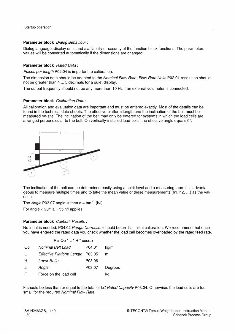
7/15/2019 Manual Intecont Tersus
http://slidepdf.com/reader/full/manual-intecont-tersus 56/176
Startup operation
BV-H2463GB, 1149- 50 -
INTECONT® Tersus Weighfeeder, Instruction ManualSchenck Process Group
Parameter block Dialog Behaviour :
Dialog language, display units and availability or security of the function block functions. The parametersvalues will be converted automatically if the dimensions are changed.
Parameter block Rated Data :
Pulses per length P02.04 is important to calibration.
The dimension data should be adapted to the Nominal Flow Rate . Flow Rate Units P02.01 resolution shouldnot be greater than 4 ... 5 decimals for a quiet display.
The output frequency should not be any more than 10 Hz if an external volumeter is connected.
Parameter block Calibration Data :
All calibration and evaluation data are important and must be entered exactly. Most of the details can befound in the technical data sheets. The effective platform length and the inclination of the belt must be
measured on-site. The inclination of the belt may only be entered for systems in which the load cells arearranged perpendicular to the belt. On vertically-installed load cells, the effective angle equals 0°.
The inclination of the belt can be determined easily using a spirit level and a measuring tape. It is advanta-geous to measure multiple times and to take the mean value of these measurements (h1, h2, …) as the val-ue 'h'.
The Angle P03.07 angle is then a = tan-1
(h/l)
For angle < 20°, a = 55 h/l applies
Parameter block Calibrat. Results :
No input is needed. P04.02 Range Correction should be on 1 at initial calibration. We recommend that once
you have entered the rated data you check whether the load cell becomes overloaded by the rated feed rate.
F = Qo * L * H * cos(a)
Qo Nominal Belt Load P04.01 kg/m
L Effective Platform Length P03.05 m
H Lever Ratio P03.06
a Angle P03.07 Degrees
F Force on the load cell kg
F should be less than or equal to the total of LC Rated Capacity P03.04. Otherwise, the load cells are too
small for the required Nominal Flow Rate .

7/15/2019 Manual Intecont Tersus
http://slidepdf.com/reader/full/manual-intecont-tersus 57/176
Startup operation
INTECONT® Tersus Weighfeeder, Instruction ManualSchenck Process Group
BV-H2463GB, 1149- 51 -
12.312.312.312.3 Function CheckFunction CheckFunction CheckFunction Check
1. Switch on the belt conveyor and scales. The switch-on process depends on the preselected Feeder Start P02.06 source.2. A rotating cross appears in the header as a progress indicator. If not, there is no clearance or the ON
button was not pressed.3. Take any event messages which appear into account and remove the error.4. Check the following:
Tachometer: The output frequency of the tachometer generator has to be less than 3,000 Hz with acti-vated measurement. The value must approximately correspond to the information in the data sheet.Load cell: The non-standardized initial value for the load cell amplifier may not be larger than 2.85 mV/Veven at nominal load of the weighing platform. It must change if the weighing platform is placed underload (e.g. the calibration weight). If the value is too large, the load cell is overloaded. If the value is nega-tive, the load cell may be wrongly connected.The load cell load in percent, sourced from the sum of the load cell nominal capacities, should not be
larger than 100 % with nominal belt load.
12.412.412.412.4 Test With Calibration WeightTest With Calibration WeightTest With Calibration WeightTest With Calibration Weight
The test with a calibration weight makes sense because1. mechanical or electrical faults are possible2. calibration data can be unreliable (for instance, the leverage is not precisely known) and it is difficult to
measure the belt inclination3. data may be incorrectly entered
The calibration weight should be between 30 % ... 100 % of the platform nominal load and be accurate.1. Enter Calibration Weight P03.08.
On beltweighers with parallel leaf-spring guides, the effective calibration weight is the same as the actualvalue. In other cases, the effective calibration weight can be taken from the data sheet, or can be calcu-lated according to the chapter details/data flow images. The inclination of the conveyor belt has no effecton the effective calibration weight.
2. Call up the CW: Span Calibration program.
Some Possible Causes of Fault:
Warping of the weighing platform, improper alignment, interferences in the load cell cable.
If you suspect any of these faults, repeat the check with a different weight.
Non-linearity is an indication of such faults, linear faults are more likely to be cause by incorrect data.

7/15/2019 Manual Intecont Tersus
http://slidepdf.com/reader/full/manual-intecont-tersus 58/176
Startup operation
BV-H2463GB, 1149- 52 -
INTECONT® Tersus Weighfeeder, Instruction ManualSchenck Process Group
12.512.512.512.5 Belt Velocity CheckBelt Velocity CheckBelt Velocity CheckBelt Velocity Check
The velocity sensor frequency generator can be actuated in a number of different ways.1. with a frictional wheel on the lower carrying run of the belt or2. with the shaft of the drive motor
In the first case, the value Pulses per length P02.04 depends on the exact diameter of the frictional wheel; inthe second case, it depends on the gear and looping factor of the belt. So the velocity measurement accura-cy should be checked.1. Establish the velocity of the conveyor belt using a stopwatch and a tape measure. Make several mea-
surements to be sure and then calculate the mean.2. Read the speed display over the same period of time wherever feasible.3. Compare these readings with one another and correct P02.04 wherever necessary. (new value = prior
value * speed measured/speed read)
This procedure can also be used to determine unknown characteristic values.
Check the space between the recording sensor and crown gear and reduce wherever necessary if there is aknown Pulses per length and large deviations.
12.612.612.612.6 Test with MaterialTest with MaterialTest with MaterialTest with Material
Each test or calibration with calibration weights can only approximate the actual operating conditions. Scales
with highly accurate measurement can only be achieved by several measurements made using material anda subsequent correction. It is corrected with Range Correction P04.02.
The following items must be observed:1. The route from the weighing platform to the collecting point for the material must be clean2. Any available diverters must not divert material.3. If there are any feed screws or air slides between the weighing platform and the collection point, material
must be conveyed for approx. 1/2 hour before any inspection measurements are made. This will allowthe usual material build-ups to form on the conveying elements.
4. Dedusting must be set to a minimum5. The containers or vehicles in which the material is transported onto a legal-for-trade scales must be
cleaned and re-weighed (tared) before each filling.
For example:Old value of P04.02 = 1
A material quantity of 4.9 t is conveyed over a time period of 15 minutes. The count read on the unit is 5.0 t.
P04.02 (new) = 1 * 4.9/5.0 = 0.98
The calculated value should be keyed into P04.02.

7/15/2019 Manual Intecont Tersus
http://slidepdf.com/reader/full/manual-intecont-tersus 59/176
Parameters
INTECONT® Tersus Weighfeeder, Instruction ManualSchenck Process Group
BV-H2463GB, 1149- 53 -
13131313 ParametersParametersParametersParameters
The INTECONT Tersus is adapted to each application by means of parameters. No special programingknowledge is therefore necessary.
Fig. 7: Parameter sets
Parameter set Purpose Activation Preparation and Alteration
Active parameters set A summary of the effec-tive parameters Always active via EasyServe or on the unit
Factory settings Complete parameters set
Non-alterable basic set-ting
Use EasyServe or the unit tocopy into the active parame-ter set
Cannot be changed
Backup set Pre-setting for a group ofapplications or a settingstored during commission-ing
Use EasyServe or the unit tocopy into the active parame-ter set
Only using EasyServe inexpert mode
Tab. 1 : Using parameter sets
Note: Parameters not required for an application can be faded out or declared 'read only' using EasyServe inexpert mode. EasyServe compiles a list of visible parameters that form an integral part of the system docu-mentation. They, together with this manual, make up the relevant documentation of the control system for anapplication. The parameter list in the operating manual contains all of the parameters, regardless of theiractual use in an application.
In addition to the parameter set stored in the scales, we recommend that after commissioning you keep acopy of the parameter set in a mass storage medium using EasyServe.
The parameters are sorted into blocks for purposes of clarity. The parameter can be explicitly identified bymeans of its block and the number in the block in the corresponding version of the scales software:
P01.03: Parameter block 1, 3rd parameter

7/15/2019 Manual Intecont Tersus
http://slidepdf.com/reader/full/manual-intecont-tersus 60/176
Parameters
BV-H2463GB, 1149- 54 -
INTECONT® Tersus Weighfeeder, Instruction ManualSchenck Process Group
Note: Each parameter also has a unique number (ID) with which it can be addressed over the serial inter-face. This number can be seen as a Tooltip in EasyServe when passing over the parameter and can be out-put in the parameter printout.
Gaps can appear between block numbers and parameters within the blocks.In rare cases, the number of a parameter may change.
13.113.113.113.1 AbbreviationsAbbreviationsAbbreviationsAbbreviations
Source Description
FB Fieldbus
OP Operating panel
DI Digital Input
DO Digital Output
AI Analog Inputs
AO Analog Outputs
Event Event The reaction to an event can be configured.
W1 Warning 1 (requires acknowledgement)
W2 Warning 2 (does not require acknowledgement)
ALARM Alarm
IGNORE Ignore: do not show any event message but switch the corresponding contact outputs
LC Load cell
I Feed rate
v Belt speed
VCU VCU 20100 system unit of DISOCONT Tersus
VHM The operator panel of DISOCONT Tersus
IT INTECONT Tersus
Tab. 2 : List of commonly used parameters-related abbreviations

7/15/2019 Manual Intecont Tersus
http://slidepdf.com/reader/full/manual-intecont-tersus 61/176
Parameters
INTECONT® Tersus Weighfeeder, Instruction ManualSchenck Process Group
BV-H2463GB, 1149- 55 -
13.213.213.213.2 Configuring Event MessagesConfiguring Event MessagesConfiguring Event MessagesConfiguring Event Messages
The system monitors a range of both of its own operation and the peripherals. The reaction to a recognizeddeviation, that is to say an event, is set by parameters. The parameters are used to assign to each event aclass that will determine this reaction.
Event class Description Impact onfeeding
Acknowledgementrequired
Color
Alarm ALARM Stop feeding, scales are switchedoff
Cannot be switched on
Yes Red
Warning 1 W1 Feeder will continue to run Yes Orange
Warning 2 W2 Feeder will continue to run No
Only display as long asthe event is active
Yellow
Ignore IG Feeder will continue to run - -
Tab. 3 : Event classes
Note: An external binary output channel that may have been assigned to an event is set, independent of theevent class.
A newly pending alarm or warning 1-class event will be shown on the operating panel blinking and in color.The blinking stops when acknowledged. Acknowledged event messages are cleared from the display forcurrently pending events when the event is no longer pending. Each event is stored with a time-stamp in theinternal memory for later analysis.
13.313.313.313.3 Parameter ListingParameter ListingParameter ListingParameter Listing
13.3.113.3.113.3.113.3.1 Parameter OverviewParameter OverviewParameter OverviewParameter Overview
VWF20650-002 2491
01 - Dialog Behaviour
Number: Name Default Customer Sys ID
P01.01 [ 65] Language DEUTSCH 4224
P01.02 [ 65] Userdefined Text XX-NEW 5816
P01.03 [ 65] Font UMing 30 6244
P01.04 [ 65] Units Metric 4225
P01.05 [ 65] Scale Name INTECONT Tersus VWF 6238
P01.06 [ 65] Password 10000 4292
P01.07 [ 65] 2. Password 14389 4321
P01.08 [ 65] Feeder ON/OFF active 4280
P01.09 [ 65] Switch Grav./Vol. command active 4595

7/15/2019 Manual Intecont Tersus
http://slidepdf.com/reader/full/manual-intecont-tersus 62/176
Parameters
BV-H2463GB, 1149- 56 -
INTECONT® Tersus Weighfeeder, Instruction ManualSchenck Process Group
P01.10 [ 65] Switch Keyboard-/Normal Mode active 4282
P01.11 [ 65] Batch control active 4283
P01.12 [ 65] >0: Zero ON/OFF active 4284
P01.13 [ 65] Reset Counter 1 active 4286
P01.14 [ 65] Reset Counter 2 active 4287
P01.15 [ 65] Data Log ON/OFF not active 4309
02 - Rated Data
Number: Name Default Customer Sys ID
P02.01 [ 69] Flow Rate Units ------ kg/h 4229
P02.02 [ 69] Nominal Flow Rate 10 t/h 4226
P02.03 [ 69] Speed Measurement DI 6144
P02.04 [ 69] Pulses per length 10000 I/m 4256
P02.05 [ 69] Nominal Speed 0.1 m/s 4227
P02.06 [ 69] Feeder Start OP 4241
P02.07 [ 69] Feedrate Setpoint OP 4242
P02.08 [ 69] Relative Setpoint NO 4247
P02.09 [ 69] WZ Active YES 6158
P02.10 [ 69] Counter 1 Unit ------- kg 4230
P02.11 [ 69] Pulse Length Total 0 ms 4231
P02.12 [ 69] Counter 2 Unit ------- t 4232
P02.13 [ 69] Counter 3 Unit ------- t 4233
P02.14 [ 69] DO: Pulse Counter n/a 4239
P02.15 [ 69] Totalizer Increment 10 kg 4254
P02.16 [ 69] Z1-Numberstep Automatic 4255
03 - Calibration Data
Number: Name Default Customer Sys ID
P03.01 [ 73] Belt Circuit No. 1 6145
P03.02 [ 73] Belt Circuit Time 30 s 4353
P03.03 [ 73] LC Characteristic Value 2 mV/V 4257
P03.04 [ 73] LC Rated Capacity 60 kg 4258
P03.05 [ 73] Effective Platform Length 0.5 m 4259

7/15/2019 Manual Intecont Tersus
http://slidepdf.com/reader/full/manual-intecont-tersus 63/176
Parameters
INTECONT® Tersus Weighfeeder, Instruction ManualSchenck Process Group
BV-H2463GB, 1149- 57 -
P03.06 [ 73] Lever Ratio 1 4260
P03.07 [ 73] Angle 0 Grad 4261
P03.08 [ 73] Calibration Weight 10 kg 4354
04 - Calibrat. Results
Number: Name Default Customer Sys ID
P04.01 [ 74] Nominal Belt Load 27.78 kg/m 6146
P04.02 [ 74] Range Correction 1 4352
P04.03 [ 74] Total Tare 0 kg/m 6147
P04.04 [ 74] Basic Tare 0 kg/m 4355
P04.05 [ 74] Tare Correction 0 kg/m 4356
P04.06 [ 74] Belt Circuit No. 1000000 I/B 4357
05 - Analog Outputs
Number: Name Default Customer Sys ID
P05.01 [ 74] AO: Setpoint n/a 4385
P05.02 [ 74] Setpoint Offset 4 mA 4386
P05.03 [ 74] Setpoint Range 20 mA 4387
P05.04 [ 74] AO: Actual Flow Rate n/a 4388
P05.05 [ 74] Flow Rate Offset 4 mA 4389
P05.06 [ 74] Flow Rate Range 20 mA 4390
P05.07 [ 74] AO: Belt Load n/a 4391
P05.08 [ 74] Belt Load Offset 4 mA 4392
P05.09 [ 74] Belt Load Range 20 mA 4393
P05.10 [ 74] AO: Speed n/a 4394
P05.11 [ 74] Speed Offset 4 mA 4395
P05.12 [ 74] Speed Range 20 mA 4396
P05.13 [ 74] AO: Deviation n/a 4397
P05.14 [ 74] Deviation Offset 4 mA 4398
P05.15 [ 74] Deviation Range 20 mA 4399
P05.16 [ 74] AO: Motor Speed Control AO 4400
06 - Limit Values
Number: Name Default Customer Sys ID
P06.01 [
77]Limit: Actual Flow Rate MIN 5 % Io 4337
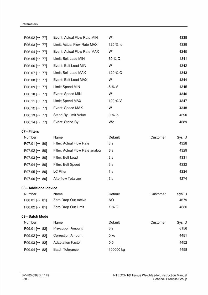
7/15/2019 Manual Intecont Tersus
http://slidepdf.com/reader/full/manual-intecont-tersus 64/176
Parameters
BV-H2463GB, 1149- 58 -
INTECONT® Tersus Weighfeeder, Instruction ManualSchenck Process Group
P06.02 [ 77] Event: Actual Flow Rate MIN W1 4338
P06.03 [ 77] Limit: Actual Flow Rate MAX 120 % Io 4339
P06.04 [ 77] Event: Actual Flow Rate MAX W1 4340
P06.05 [ 77] Limit: Belt Load MIN 60 % Q 4341
P06.06 [ 77] Event: Belt Load MIN W1 4342
P06.07 [ 77] Limit: Belt Load MAX 120 % Q 4343
P06.08 [ 77] Event: Belt Load MAX W1 4344
P06.09 [ 77] Limit: Speed MIN 5 % V 4345
P06.10 [ 77] Event: Speed MIN W1 4346
P06.11 [ 77] Limit: Speed MAX 120 % V 4347
P06.12 [ 77] Event: Speed MAX W1 4348
P06.13 [ 77] Stand-By Limit Value 0 % Io 4290
P06.14 [ 77] Event: Stand-By W2 4289
07 - Filters
Number: Name Default Customer Sys ID
P07.01 [ 80] Filter: Actual Flow Rate 3 s 4328
P07.02 [ 80] Filter: Actual Flow Rate analog 3 s 4329
P07.03 [ 80] Filter: Belt Load 3 s 4331
P07.04 [ 80] Filter: Belt Speed 3 s 4332
P07.05 [ 80] LC Filter 1 s 4334
P07.06 [ 80] Afterflow Totalizer 3 s 4274
08 - Additional device
Number: Name Default Customer Sys ID
P08.01 [ 81] Zero Drop-Out Active NO 4679
P08.02 [ 81] Zero Drop-Out Limit 1 % Q 4680
09 - Batch Mode
Number: Name Default Customer Sys ID
P09.01 [ 82] Pre-cut-off Amount 3 s 6156
P09.02 [ 82] Correction Amount 0 kg 4451
P09.03 [ 82] Adaptation Factor 0.5 4452
P09.04 [ 82] Batch Tolerance 100000 kg 4458

7/15/2019 Manual Intecont Tersus
http://slidepdf.com/reader/full/manual-intecont-tersus 65/176
Parameters
INTECONT® Tersus Weighfeeder, Instruction ManualSchenck Process Group
BV-H2463GB, 1149- 59 -
P09.05 [ 82] Event: Out of Tolerance W1 4459
P09.06 [ 82] Batch Automatic Record NO 4453
P09.07 [ 82] Batch Setpoint Source OP 4449
10 - Printer Setting
Number: Name Default Customer Sys ID
P10.01 [ 83] Baud rate 9600 4512
P10.02 [ 83] Print Event YES 6164
P10.03 [ 83] Print Page Length 72 4513
11 - Maintenance interval
Number: Name Default Customer Sys IDP11.01 [ 84] Maintenance Electric 3000 h 4465
P11.02 [ 84] Event: Maint. Electric W1 4466
P11.03 [ 84] Maintenance Feeder Run 3000 h 4467
P11.04 [ 84] Event: Maint.Feeder Run W1 4468
12 - Belt Monitoring
Number: Name Default Customer Sys ID
P12.01 [ 85] VAP Active NO 4480
P12.02 [ 85] Platform Dis.Length 0 % LB 4482
P12.03 [ 85] Belt Sensor Active NO 4496
P12.04 [ 85] DI: Source Belt Sensor DI 4497
P12.05 [ 85] BIC Active NO 4498
P12.06 [ 85] Sensor Length 8.2 cm 4500
P12.07 [ 85] Sensor Width 12 cm 4501
P12.08 [ 85] Sensor Offset 0 cm 4502
P12.09 [ 85] Belt Drift 3 cm 4503
P12.10 [ 85] Event: Belt Drift W1 4504
P12.11 [ 85] Belt Skew 4 cm 4505
P12.12 [ 85] Event: Belt Skew A 4506
P12.13 [ 85] Slip Value 2 % LB 4507
P12.14 [ 85] Event: Slip W1 4508
P12.15 [ 85] DO: Belt Drift n/a 4509

7/15/2019 Manual Intecont Tersus
http://slidepdf.com/reader/full/manual-intecont-tersus 66/176
Parameters
BV-H2463GB, 1149- 60 -
INTECONT® Tersus Weighfeeder, Instruction ManualSchenck Process Group
P12.16 [ 85] DO: Belt Skew n/a 4510
P12.17 [ 85] DO: Belt Slip n/a 4511
P12.18 [ 85] DI: BIC freeze n/a 4499
13 - Events
Number: Name Default Customer Sys ID
P13.01 [ 88] Event: Power Failure A 4297
P13.02 [ 88] Event: Memory A 4302
P13.03 [ 88] Event: Tachometer Input A 4291
P13.04 [ 88] Event: Namur Error Tacho A 6199
P13.05 [ 88] Event: Namur Error Belt W1 6200
P13.06 [ 88] Event: Error LC Input A 4293
P13.07 [ 88] Event: Run Disabled W1 4246
P13.08 [ 88] Event: LC Input > MAX A 4295
P13.09 [ 88] Event: LC Input < MIN A 4294
P13.10 [ 88] Event: Simulation active W2 6202
P13.11 [ 88] Event: Setpoint Limited W1 4296
P13.12 [ 88] Event: External Event 1 A 4417
P13.13 [ 88] Event: External Event 2 A 4430
P13.14 [ 88] Event: License Violation A 4303
14 - Rate controller
Number: Name Default Customer Sys ID
P14.01 [ 91] Optimize Controller STANDARD 4368
P14.02 [ 91] P-Component KP 0.04 mA/% 4369
P14.03 [ 91] I-Component TN 1 s 4370
P14.04 [ 91] Filter: Deviation 3 s 4333
P14.05 [ 91] Time Deviation 20 s 4298
P14.06 [ 91] Threshold Deviation 5 % 4299
P14.07 [ 91] Factor Deviation 1 4320
P14.08 [ 91] Deviation abs. max. 100 % 6255
P14.09 [ 91] Event: Deviation W1 4300
P14.10 [ 91] Event: Controller Limited W1 4301
P14.11 [ 91] Lower Limit 0 mA 4371

7/15/2019 Manual Intecont Tersus
http://slidepdf.com/reader/full/manual-intecont-tersus 67/176
Parameters
INTECONT® Tersus Weighfeeder, Instruction ManualSchenck Process Group
BV-H2463GB, 1149- 61 -
P14.12 [ 91] Upper Limit 20 mA 4372
P14.13 [ 91] Controller Magnitude Offset 0 mA 4373
P14.14 [ 91] Position at STOP 0 4374
P14.15 [ 91] Volumetric Start-Up 0 Circuits 4272
P14.16 [ 91] Volumetric Clearance 0 Circuits 4273
P14.17 [ 91] Setpoint Offset 0 mA 4244
P14.18 [ 91] Setpoint Range 20 mA 4243
P14.19 [ 91] Store NO 4376
P14.20 [ 91] Volumetric Mode Qconst 4377
P14.21 [ 91] Bypass 0 mA 4375
P14.22 [ 91] Setpoint Filter 1st Ord 0 s 4378
P14.23 [ 91] Setpoint Filter 2nd Ord 0 s 4379
P14.24 [ 91] Set/Act Sources I 4381
P14.25 [ 91] Adaptation 1 NO 4382
15 - Linearization
Number: Name Default Customer Sys ID
P15.01 [ 97] Linearization ON NO 4577
P15.02 [ 97] Linearization S1 25 % Q 4681
P15.03 [ 97] Linearization I1 25 % Q 4579
P15.04 [ 97] Linearization S2 50 % Q 4682
P15.05 [ 97] Linearization I2 50 % Q 4581
P15.06 [ 97] Linearization S3 75 % Q 4683
P15.07 [ 97] Linearization I3 75 % Q 4583
P15.08 [ 97] Linearization S4 100 % Q 4684
P15.09 [ 97] Linearization I4 100 % Q 4585
P15.10 [ 97] Event: Linearization Error W2 4586
16 - Digital Inputs
Number: Name Default Customer Sys ID
P16.01 [ 99] Source Run Enable DI 4245
P16.02 [ 99] DI: Batch Terminate n/a 4454
P16.03 [ 99] DI: Acknowledge Events DI 4419
P16.04 [ 99] DI: Volumetric Mode n/a 4421

7/15/2019 Manual Intecont Tersus
http://slidepdf.com/reader/full/manual-intecont-tersus 68/176
Parameters
BV-H2463GB, 1149- 62 -
INTECONT® Tersus Weighfeeder, Instruction ManualSchenck Process Group
P16.05 [ 99] DI: Volumetric synchron n/a 4941
P16.06 [ 99] DI: Start n/a 6207
P16.07 [ 99] DI: External Event 1 n/a 4418
P16.08 [ 99] DI: External Event 2 n/a 4431
17 - Digital Outputs
Number: Name Default Customer Sys ID
P17.01 [ 100] DO: ALARM DO 4436
P17.02 [ 100] DO: Start Prefeeder DO 4435
P17.03 [ 100] DO: Scale Start DO 4433
P17.04 [ 100] DO: Actual Flow Rate MIN DO 4438
P17.05 [ 100] DO: Actual Flow Rate MAX DO 4439
P17.06 [ 100] DO: Belt load MIN n/a 4440
P17.07 [ 100] DO: Belt Load MAX n/a 4441
P17.08 [ 100] DO: Speed MIN n/a 4442
P17.09 [ 100] DO: Speed MAX n/a 4443
P17.10 [ 100] DO: Batch Running n/a 4455
P17.11 [ 100] DO: Full Feed n/a 4457
P17.12 [ 100] DO: Dribble Feed n/a 4456
P17.13 [ 100] DO: Feeder Started DO 4434
P17.14 [ 100] DO: Deviation DO 4437
P17.15 [ 100] DO: Volumetric Mode n/a 4444
P17.16 [ 100] DO: Keyboard Mode n/a 4462
18 - Communication EasyServe
Number: Name Default Customer Sys ID
P18.01 [ 103] Own Address 1 4520
P18.02 [ 103] Baud Rate 38400 4521
P18.03 [ 103] Format Data 8-N-1 6189
19 - Communication Fieldbus
Number: Name Default Customer Sys ID
P19.01 [ 104] Protocol Type NO 4528
P19.02 [ 104] Timeout Host 5 s 4529
P19.03 [
104]Event: Cyclic Communication A 4530

7/15/2019 Manual Intecont Tersus
http://slidepdf.com/reader/full/manual-intecont-tersus 69/176
Parameters
INTECONT® Tersus Weighfeeder, Instruction ManualSchenck Process Group
BV-H2463GB, 1149- 63 -
P19.04 [ 104] Event: Acyclic Communication A 5680
P19.05 [ 104] Check in Keyboard Mode YES 6234
P19.06 [ 104] Compatibility DISOCONT Master NO 6287
P19.07 [ 104] Word Sequence I:std/L:std 6246
P19.08 [ 104] Byte Sequence High - Low 6245
P19.09 [ 104] Configuration FIXED_8_8 4661
P19.10 [ 104] Address 1 4531
P19.11 [ 104] Resolution 4096 4533
P19.12 [ 104] Baud rate 19200 4535
P19.13 [ 104] Data Format 8-O-1 4656
P19.14 [ 104] Physics RS232 6186
P19.15 [ 104] Address 16 4539
P19.16 [ 104] FLOAT-Format IEEE 4540
P19.17 [ 104] Compatiblity INTECONT NO 4788
P19.18 [ 104] Identifier format BYTE 6190
P19.19 [ 104] PA32 compatible NO 4660
P19.20 [ 104] Address 63 4541
P19.21 [ 104] Baud rate 125K 4542
P19.22 [ 104] Access Rights Limitation FB NO 4786
P19.23 [ 104] Remote IP Address FB 192.168.240.250 4787
20 - Fixed mode configuration
Number: Name Default Customer Sys ID
P20.01 [ 109] ID Preset Value 1 320 6247
P20.02 [ 109] ID Preset Value 2 352 6248
P20.03 [ 109] ID Preset Value 3 384 6249
P20.04 [ 109] ID Preset Value 4 592 6250
P20.05 [ 109] ID Preset Value 5 594 6251
P20.06 [ 109] ID Preset Value 6 0 6252
P20.07 [ 109] ID Preset Value 7 0 6253
P20.08 [ 109] ID Preset Value 8 0 6254
P20.09 [ 109] ID Read Value 1 752 6256
P20.10 [ 109] ID Read Value 2 784 6257

7/15/2019 Manual Intecont Tersus
http://slidepdf.com/reader/full/manual-intecont-tersus 70/176
Parameters
BV-H2463GB, 1149- 64 -
INTECONT® Tersus Weighfeeder, Instruction ManualSchenck Process Group
P20.11 [ 109] ID Read Value 3 1552 6258
P20.12 [ 109] ID Read Value 4 1872 6259
P20.13 [ 109] ID Read Value 5 1874 6260
P20.14 [ 109] ID Read Value 6 1880 6261
P20.15 [ 109] ID Read Value 7 1884 6262
P20.16 [ 109] ID Read Value 8 1894 6263
21 - Ethernet
Number: Name Default Customer Sys ID
P21.01 [ 111] IP Address 192.168.240.1 6235
P21.02 [ 111] Net Mask 255.255.255.0 6236
P21.03 [ 111] Gateway 0.0.0.0 6237
22 - Data Logging
Number: Name Default Customer Sys ID
P22.01 [ 111] Hourly Total Time 0 min 5743
P22.02 [ 111] Daily Total Time 0 min 5744
P22.03 [ 111] Logger cycle time 1 min 6288
P22.04 [ 111] Data Log Value 1 752 6289
P22.05 [ 111] Data Log Value 2 755 6290
P22.06 [ 111] Data Log Value 3 1872 6291
P22.07 [ 111] Data Log Value 4 1874 6292
P22.08 [ 111] Data Log Value 5 1876 6293
P22.09 [ 111] Data Log Value 6 1880 6294
P22.10 [ 111] Data Log Value 7 1884 6295
P22.11 [ 111] Data Log Value 8 1894 6296
P22.12 [ 111] Data Log Value 9 0 6297
P22.13 [ 111] Data Log Value 10 0 6298
23 - Configuration HMI Values
Number: Name Default Customer Sys ID
P23.01 [ 114] HMI Value 01 1996 6299
P23.02 [ 114] HMI Value 02 1944 6300
P23.03 [ 114] HMI Value 03 1942 6301
P23.04 [
114]HMI Value 04 1950 6302

7/15/2019 Manual Intecont Tersus
http://slidepdf.com/reader/full/manual-intecont-tersus 71/176
Parameters
INTECONT® Tersus Weighfeeder, Instruction ManualSchenck Process Group
BV-H2463GB, 1149- 65 -
P23.05 [ 114] HMI Value 05 0 6303
P23.06 [ 114] HMI Value 06 0 6304
P23.07 [ 114] HMI Value 07 0 6305
P23.08 [ 114] HMI Value 08 0 6306
P23.09 [ 114] HMI Value 09 0 6307
P23.10 [ 114] HMI Value 10 0 6308
24 - Second Display
Number: Name Default Customer Sys ID
P24.01 [ 116] Second Display active NO 4525
P24.02 [ 116] Baud rate 9600 4526
P24.03 [ 116] Data Format 8-N-1 4527
P24.04 [ 116] Physics RS232 4783
13.3.213.3.213.3.213.3.2 Parameter DetailsParameter DetailsParameter DetailsParameter Details
13.3.2.113.3.2.113.3.2.113.3.2.1 Parameter BlockParameter BlockParameter BlockParameter Block 01010101 ---- Dialog Behaviour Dialog Behaviour Dialog Behaviour Dialog Behaviour
The parameters of this group define system behavior towards the operator and set access authorization.
P01.01 Language Default: DEUTSCH
Alternative: DEUTSCHENGLISHOTHER
Device dialog language. User-defined texts can be used if OTHER is selected. Texts canbe written and loaded using EasyServe.
P01.02 Userdefined Text Default: XX-NEW
Alternative: FR-FRANCAIS
ES-ESPANOLIT-ITALIANOCN-CHINESEJP-JAPANESERU-RUSSIANHU-HUNGARIANNL-NETHERLANDXX-NEW
Direct switching between several built-in languages.

7/15/2019 Manual Intecont Tersus
http://slidepdf.com/reader/full/manual-intecont-tersus 72/176
Parameters
BV-H2463GB, 1149- 66 -
INTECONT® Tersus Weighfeeder, Instruction ManualSchenck Process Group
P01.03 Font Default: UMing 30
Alternative: UMing 30SAZ 30
Adjustable character representation. The current selection offers the versions of UMing30for Chinese and SAZ30 for Japanese symbols.
P01.04 Units Default: Metric
Alternative: MetricEnglish
Switches display and parameter entry units from metric (SI units) to non-metric systems(English). All values entered will be converted automatically.
P01.05 Scale Name Default: INTECONT Tersus VWF
Letters and characters can be used. The name appears in the upper row of the operatingconsole and when searching through networks for controllers.
Remark: The characters ";" and "=" are not accepted. During the saving procedure thesecharacters will automatically be deleted.
P01.06 Password Default: 10000
Min: 1000 Max: 9999Password 1 for access protection of certain functions on the operator panel as per the fol-lowing parameters. Usually the 1st password is used for the service personnel and the 2ndpassword for operating personnel with particular privileges. The password keyed in isshown encoded for protection. The password can be reset using EasyServe if it should beforgotten.The password set at the factory: 7353
P01.07 2. Password Default: 14389
Min: 1000 Max: 9999
Password 2 for access protection for certain functions on the operator panel as per thefollowing parameters. Usually the 1st password is used for the service personnel and the2nd password for operating personnel with particular privileges. The password entered isshown encoded on the screen. The password can be reset using EasyServe if it should beforgotten.The password set at the factory: 2889

7/15/2019 Manual Intecont Tersus
http://slidepdf.com/reader/full/manual-intecont-tersus 73/176
Parameters
INTECONT® Tersus Weighfeeder, Instruction ManualSchenck Process Group
BV-H2463GB, 1149- 67 -
P01.08 Feeder ON/OFF Default: active
Alternative: activenot active
Password2.PasswordConfirm
Defines the access protection for using the operating console.
Using this parameters, access to the basic function prefeeder ON/OFF can be controlled.The following options are available:active: Access is always permitted.not active: Access is never allowed. This function is not visible in the block.Password: Access is available with the standard password.2nd password: Access is available with the 2nd password.Confirm: The access must be confirmed for security reasons.
Note: The prefeeder also has to be activated via parameters.
P01.09 Switch Grav./Vol. command Default: active
Alternative: activenot activePassword2.PasswordConfirm
Defines the access protection for using the operating console.
P01.10 Switch Keyboard-/Normal Mode Default: active
Alternative: activenot activePassword2.PasswordConfirm
Defines the access protection for using the operating console.
P01.11 Batch control Default: active
Alternative: activenot activePassword2.PasswordConfirm
Defines the access protection for using the operating console.

7/15/2019 Manual Intecont Tersus
http://slidepdf.com/reader/full/manual-intecont-tersus 74/176
Parameters
BV-H2463GB, 1149- 68 -
INTECONT® Tersus Weighfeeder, Instruction ManualSchenck Process Group
P01.12 >0: Zero ON/OFF Default: active
Alternative: activenot active
Password2.PasswordConfirm
Defines the access protection for the function at the operating console.Definition des Zugriffsschutzes für die Funktion am Bedienteil.
P01.13 Reset Counter 1 Default: active
Alternative: activenot activePassword
2.PasswordConfirm
Defines the access protection for using the operating console.
P01.14 Reset Counter 2 Default: active
Alternative: activenot activePassword2.PasswordConfirm
Defines the access protection for using the operating console.
P01.15 Data Log ON/OFF Default: not active
Alternative: activenot activePassword2.PasswordConfirm
Defines the access protection for using the operating console.
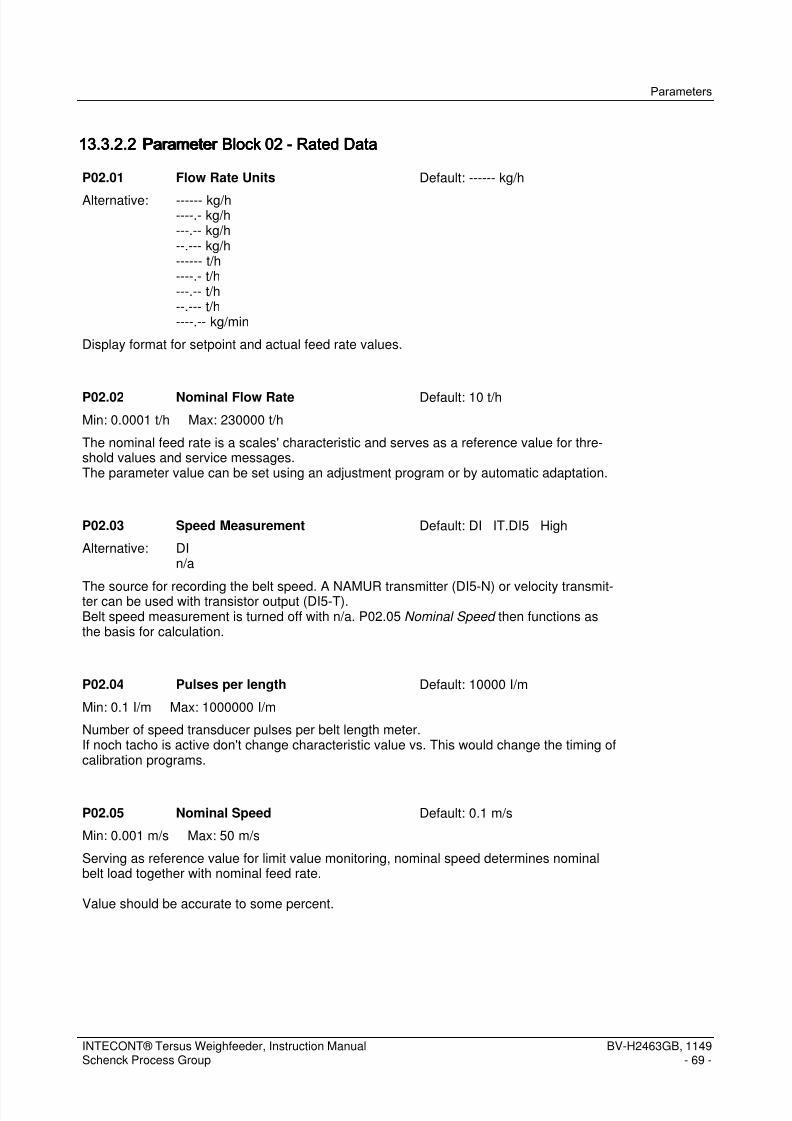
7/15/2019 Manual Intecont Tersus
http://slidepdf.com/reader/full/manual-intecont-tersus 75/176
Parameters
INTECONT® Tersus Weighfeeder, Instruction ManualSchenck Process Group
BV-H2463GB, 1149- 69 -
13.3.2.213.3.2.213.3.2.213.3.2.2 Parameter BlockParameter BlockParameter BlockParameter Block 02020202 ---- Rated DataRated DataRated DataRated Data
P02.01 Flow Rate Units Default: ------ kg/h
Alternative: ------ kg/h----.- kg/h---.-- kg/h--.--- kg/h------ t/h----.- t/h---.-- t/h--.--- t/h----.-- kg/min
Display format for setpoint and actual feed rate values.
P02.02 Nominal Flow Rate Default: 10 t/h
Min: 0.0001 t/h Max: 230000 t/h
The nominal feed rate is a scales' characteristic and serves as a reference value for thre-shold values and service messages.The parameter value can be set using an adjustment program or by automatic adaptation.
P02.03 Speed Measurement Default: DI IT.DI5 High
Alternative: DIn/a
The source for recording the belt speed. A NAMUR transmitter (DI5-N) or velocity transmit-ter can be used with transistor output (DI5-T).Belt speed measurement is turned off with n/a. P02.05 Nominal Speed then functions asthe basis for calculation.
P02.04 Pulses per length Default: 10000 I/m
Min: 0.1 I/m Max: 1000000 I/m
Number of speed transducer pulses per belt length meter.If noch tacho is active don't change characteristic value vs. This would change the timing ofcalibration programs.
P02.05 Nominal Speed Default: 0.1 m/s
Min: 0.001 m/s Max: 50 m/s
Serving as reference value for limit value monitoring, nominal speed determines nominalbelt load together with nominal feed rate.
Value should be accurate to some percent.

7/15/2019 Manual Intecont Tersus
http://slidepdf.com/reader/full/manual-intecont-tersus 76/176
Parameters
BV-H2463GB, 1149- 70 -
INTECONT® Tersus Weighfeeder, Instruction ManualSchenck Process Group
P02.06 Feeder Start Default: OP
Alternative: OPFB
DI
Specifies the device that will turn on the scales.
OP: from the keyboard of INTECONTFB: through the fieldbus interfaceDI: through a digital input
The digital input is flank-controlled, i.e. the ON signal must be removed and then reappliedif the scales becomes inoperative because of e.g. an alarm.
P02.07 Feedrate Setpoint Default: OP
Alternative: OPFBAI
Determining the signal input that specifies the feed rate setpoint.
OP: from the keyboard of INTECONTFB: through the fieldbus interfaceAI: through an analog input
P02.08 Relative Setpoint Default: NO
Alternative: NOYES
YES: The external absolute setpoints of the fieldbus (FB) or analog output (AI) can be eva-luated relatively with the keyboard.
The value for the plant can be adapted through P14.17 Setpoint Offset as the starting valueand P14.18 Setpoint Range as the final value.
P02.09 WZ Active Default: YES
Alternative: NO
YESNO: Belt load measurement is turned off. The Nominal Belt Load calculated from the ratedvalues functions internally.

7/15/2019 Manual Intecont Tersus
http://slidepdf.com/reader/full/manual-intecont-tersus 77/176
Parameters
INTECONT® Tersus Weighfeeder, Instruction ManualSchenck Process Group
BV-H2463GB, 1149- 71 -
P02.10 Counter 1 Unit Default: ------- kg
Alternative: ------- kg-----.- kg
----.-- kg---.--- kg------- t-----.- t----.-- t---.--- t
Display format for counter 1.
P02.11 Pulse Length Total Default: 0 ms
Min: 0 ms Max: 10000 ms
Duration of an external totalizing counter output impulse.
The weighting of an impulse is defined by P02.15 Totalizer Increment
If the impulse duration is shorter than 10 ms the impulse output is disabled. All impulses notissued yet are cleared.
At nominal feed rate the output frequency f is:f [Hz] = Pnom / 3600 * Zmin
Pnom = Nominal feed rate in kg/h or t/h (see P02.02 Nominal Flow Rate )Zmin = Smallest display unit of counter 1 in kg or t (see P02.10 Counter 1 Unit )
The output frequency must be ≤ 10 Hz if an external counter is connected.Refer also to chapter 'Appendices' → 'Impulse Output for External Totalizing Counter'.
P02.12 Counter 2 Unit Default: ------- t
Alternative: ------- kg-----.- kg----.-- kg---.--- kg------- t-----.- t----.-- t
---.--- t
Display format for counter 2

7/15/2019 Manual Intecont Tersus
http://slidepdf.com/reader/full/manual-intecont-tersus 78/176
Parameters
BV-H2463GB, 1149- 72 -
INTECONT® Tersus Weighfeeder, Instruction ManualSchenck Process Group
P02.13 Counter 3 Unit Default: ------- t
Alternative: ------- kg-----.- kg
----.-- kg---.--- kg------- t-----.- t----.-- t---.--- t
Display format for counter 3.
P02.14 DO: Pulse Counter Default: n/a
Alternative: n/a
DODO: Selecting the physical output for triggering an external pulse counter for the measuredquantity Bear in mind the limitations on speed and life cycle when selecting a relay outputand set the weight equivalent for an impulse in P02.15 Totalizer Increment . The duration ofthe impulse is set by P02.11 Pulse Length Total .
n/a: It is output through contact X3-1.2 where the output frequency may not be in excess of10 Hz.
P02.15 Totalizer Increment Default: 10 kg
Min: 0 kg Max: 100000 kg
Weight equivalent of an impulse at the output for the external counter as per P02.14 DO: Pulse Counter .The DO: Pulse Counter is blocked when setting the valence 0.
P02.16 Z1-Numberstep Default: Automatic
Alternative: Automatic2 kg5 kg20 kg50 kg
200 kg500 kg0.02 t0.05 t0.2 t0.5 t
Determines the increment value für counter 1 and all batch values. Parameter P02.10Counter 1 Unit applies for "Automatic".The increment value only applies to the local display and for printouts.

7/15/2019 Manual Intecont Tersus
http://slidepdf.com/reader/full/manual-intecont-tersus 79/176
Parameters
INTECONT® Tersus Weighfeeder, Instruction ManualSchenck Process Group
BV-H2463GB, 1149- 73 -
13.3.2.313.3.2.313.3.2.313.3.2.3 Parameter BlockParameter BlockParameter BlockParameter Block 03030303 ---- Calibration DataCalibration DataCalibration DataCalibration Data
P03.01 Belt Circuit No. Default: 1
Min: 1 Max: 100
Sets the runtime of the programs zero, tare and weight check. Does not apply for the auto-matic zero setting device.
P03.02 Belt Circuit Time Default: 30 s
Min: 1 s Max: 9999 s
Determines the measurement period for the impulse/belt circuit calibration program.Usually, the time chosen is the time required for one belt circuit.
P03.03 LC Characteristic Value Default: 2 mV/V
Min: 0.01 mV/V Max: 9.9999 mV/V
Characteristic value (transmission factor) of the load cell.
P03.04 LC Rated Capacity Default: 60 kg
Min: 0.5 kg Max: 220000 kg
The total of the load cell rated loads for recording the weight of the continuous scale.
P03.05 Effective Platform Length Default: 0.5 m
Min: 0.1 m Max: 50 m
Effective weigh bridge length.
P03.06 Lever Ratio Default: 1
Min: 0.01 Max: 2
Lever ratio between force transducing weigh idler and load cell.Using weighing modules with leaf spring parallel guidance, lever ratio is always 1.
P03.07 Angle Default: 0 Grad
Min: 0 Grad Max: 60 Grad
The inclination of the longitudinal axis of the scale when the load cell is installed vertical tothe belt.

7/15/2019 Manual Intecont Tersus
http://slidepdf.com/reader/full/manual-intecont-tersus 80/176
Parameters
BV-H2463GB, 1149- 74 -
INTECONT® Tersus Weighfeeder, Instruction ManualSchenck Process Group
P03.08 Calibration Weight Default: 10 kg
Min: 0.001 kg Max: 22000 kg
Required for the calibration program CW: Span Calibration .
Also refer to: P04.02 Range Correction
13.3.2.413.3.2.413.3.2.413.3.2.4 Parameter BlockParameter BlockParameter BlockParameter Block 04040404 ---- Calibrat. ResultsCalibrat. ResultsCalibrat. ResultsCalibrat. Results
P04.01 Nominal Belt Load Default: 27.78 kg/m
Min: 0.06 kg/m Max: 10000 kg/m
Reference for limit values and zeroing program.This is calculated from Nominal Flow Rate P02.02 and Nominal Speed P02.05.
P04.02 Range Correction Default: 1
Min: 0.5 Max: 2
The parameter affects the belt-load measurement F proportionally.Q(corrected) = Q(measured) * P04.02
P04.03 Total Tare Default: 0 kg/m
Min: 0 kg/m Max: 10000 kg/m
Total Tare = Basic Tare + Tare Correction
P04.04 Basic Tare Default: 0 kg/m
Min: 0 kg/m Max: 10000 kg/m
Results of the taring adjustment program.
P04.05 Tare Correction Default: 0 kg/m
Min: -1000 kg/m Max: 1000 kg/m
Results of the >0< Zero Set adjustment program or automatic zero setting.
P04.06 Belt Circuit No. Default: 1000000 I/B
Min: 0 I/B Max: 9000000 I/B
Result of program LB: Pulses/Belt . Defines the cycle of the calibration programs.Divided by P02.04 Pulses per length results the belt length in m.
13.3.2.513.3.2.513.3.2.513.3.2.5 Parameter BlockParameter BlockParameter BlockParameter Block 05050505 ---- Analog OutputsAnalog OutputsAnalog OutputsAnalog Outputs
The parameters in this group select the control source for the analog output channels. On the VCU 20104controller only one analog channel is available and it is set to feedrate feedback by default.

7/15/2019 Manual Intecont Tersus
http://slidepdf.com/reader/full/manual-intecont-tersus 81/176
Parameters
INTECONT® Tersus Weighfeeder, Instruction ManualSchenck Process Group
BV-H2463GB, 1149- 75 -
P05.01 AO: Setpoint Default: n/a
Alternative: n/aAO
Analog output channel for the setpoint feed rate.
Also refer to: P05.02 Setpoint Offset , P05.03 Setpoint Range
P05.02 Setpoint Offset Default: 4 mA
Min: -200 mA Max: 200 mA
Output current for a feed rate setpoint value of 0 %.
Reference: P02.02 Nominal Flow Rate
See also: P05.01 AO: Setpoint
P05.03 Setpoint Range Default: 20 mA
Min: 0 mA Max: 1000 mA
Output current for a feed rate setpoint value of 100%.
Reference: P02.02 Nominal Flow Rate
Also refer to: P05.01 AO: Setpoint
P05.04 AO: Actual Flow Rate Default: n/a
Alternative: n/aAO
Analog output channel for the actual feed rate.
Also refer to: P05.05 Flow Rate Offset , P05.06 Flow Rate Range
P05.05 Flow Rate Offset Default: 4 mA
Min: -200 mA Max: 200 mA
Output current for an actual feed rate value of 0%.
Reference: P02.02 Nominal Flow Rate
Also refer to: P05.04 AO: Actual Flow Rate

7/15/2019 Manual Intecont Tersus
http://slidepdf.com/reader/full/manual-intecont-tersus 82/176
Parameters
BV-H2463GB, 1149- 76 -
INTECONT® Tersus Weighfeeder, Instruction ManualSchenck Process Group
P05.06 Flow Rate Range Default: 20 mA
Min: 0 mA Max: 1000 mA
Output current for the value of an actual feed rate of 100%.
Reference: P02.02 Nominal Flow Rate
Also refer to: P05.04 AO: Actual Flow Rate
P05.07 AO: Belt Load Default: n/a
Alternative: n/aAO
Analog output source for the belt load.
P05.08 Belt Load Offset Default: 4 mA
Min: -200 mA Max: 200 mA
The output flow for the value of the belt load of 0 %
Reference: P04.01 Nominal Belt Load
Also refer to: P05.07 AO: Belt Load
P05.09 Belt Load Range Default: 20 mA
Min: 0 mA Max: 1000 mA
The output flow for the value of the belt load of 100 %.
Reference: P04.01 Nominal Belt Load
Also refer to: P05.07 AO: Belt Load
P05.10 AO: Speed Default: n/a
Alternative: n/aAO
The analog output source for belt speed.
P05.11 Speed Offset Default: 4 mA
Min: -200 mA Max: 200 mA
The output flow for the value of the belt speed of 0 %.
Reference: P02.05 Nominal Speed
Also refer to: P05.10 AO: Speed

7/15/2019 Manual Intecont Tersus
http://slidepdf.com/reader/full/manual-intecont-tersus 83/176
Parameters
INTECONT® Tersus Weighfeeder, Instruction ManualSchenck Process Group
BV-H2463GB, 1149- 77 -
P05.12 Speed Range Default: 20 mA
Min: 0 mA Max: 1000 mA
The output flow for the value of the belt speed of 100 %.
Reference: P02.05 Nominal Speed
Also refer to: P05.10 AO: Speed
P05.13 AO: Deviation Default: n/a
Alternative: n/aAO
Analog output channel for the control deviation.
See also: P05.14 Deviation Offset , P05.15 Deviation Range
P05.14 Deviation Offset Default: 4 mA
Min: -200 mA Max: 200 mA
The value of the control deviation 'zero' lies between the offset and 20 mA.
Also refer to: P05.13 AO: Deviation
P05.15 Deviation Range Default: 20 mA
Min: 0 mA Max: 1000 mA
The output current is calculated according to the following formula:
Current = 10 mA + (P05.14)/2 + (P05.15 - P05.14) × control deviation / 100 %
Reference value: P02.02 Nominal Flow Rate
P05.16 AO: Motor Speed Control Default: AO IT.AO1
Alternative: AOn/a
Analog output for the actuating variable Y of the feed rate regulator.
Also refer to:- the parameters in the 'regulator' block- the regulator diagram in the appendices
13.3.2.613.3.2.613.3.2.613.3.2.6 Parameter BlockParameter BlockParameter BlockParameter Block 06060606 ---- Limit ValuesLimit ValuesLimit ValuesLimit Values
The parameters of this group define the limits for process values and specify the event classes of the asso-ciated events.
Events that can only occur with regular feed operation are only monitored 10 s after beginning feed opera-tion.

7/15/2019 Manual Intecont Tersus
http://slidepdf.com/reader/full/manual-intecont-tersus 84/176
Parameters
BV-H2463GB, 1149- 78 -
INTECONT® Tersus Weighfeeder, Instruction ManualSchenck Process Group
P06.01 Limit: Actual Flow Rate MIN Default: 5 % Io
Min: -10 % Io Max: 200 % Io
Lower threshold for the actual feed rate.
Reference : P02.02 Nominal Flow Rate
P06.02 Event: Actual Flow Rate MIN Default: W1
Event Group: LO Number: 02
Actual feed rate lower than the minimum value set in Limit: Actual Flow Rate MIN
Possible causes:
- no bulk material- disturbance forces from force shunts or pressures acting on the weighing equipment- feed rate setpoint too low
P06.03 Limit: Actual Flow Rate MAX Default: 120 % Io
Min: -10 % Io Max: 200 % Io
Upper threshold for the actual feed rate.
Reference : P02.02 Nominal Flow Rate
P06.04 Event: Actual Flow Rate MAX Default: W1
Event Group: HI Number: 02
Actual feed rate greater than the maximum value set in P06.03 Limit: Actual Flow Rate MAX
Possible causes:- bulk material shooting out of the discharge chute- disturbance forces from force shunts or pressures acting on the weighing equipment- feed rate setpoint too large
P06.05 Limit: Belt Load MIN Default: 60 % Q
Min: -10 % Q Max: 200 % Q
Lower limit for belt load.
Reference: P04.01 Nominal Belt Load

7/15/2019 Manual Intecont Tersus
http://slidepdf.com/reader/full/manual-intecont-tersus 85/176
Parameters
INTECONT® Tersus Weighfeeder, Instruction ManualSchenck Process Group
BV-H2463GB, 1149- 79 -
P06.06 Event: Belt Load MIN Default: W1
Event Group: LO Number: 03
The belt load is less than the minimum value set in Limit: Belt Load MIN
Possible causes:- no bulk material- disturbance forces from force shunts or pressures acting on the weighing equipment
P06.07 Limit: Belt Load MAX Default: 120 % Q
Min: -10 % Q Max: 200 % Q
Upper limit for the belt load
Reference: P04.01 Nominal Belt Load
P06.08 Event: Belt Load MAX Default: W1
Event Group: HI Number: 03
The belt load is greater than the maximum value set in P06.07 Limit: Belt Load MAX
Possible causes:- bulk material shooting out of the discharge chute
- disturbance forces from force shunts or pressures acting on the weighing equipment
P06.09 Limit: Speed MIN Default: 5 % V
Min: -10 % V Max: 200 % V
Lower limit for belt speed.
Reference: P02.05 Nominal Speed
P06.10 Event: Speed MIN Default: W1
Event Group: LO Number: 04
The belt speed is less than the minimum value set in Limit: Speed MIN
P06.11 Limit: Speed MAX Default: 120 % V
Min: -10 % V Max: 200 % V
Upper limit for belt speed.
Reference: P02.05 Nominal Speed

7/15/2019 Manual Intecont Tersus
http://slidepdf.com/reader/full/manual-intecont-tersus 86/176
Parameters
BV-H2463GB, 1149- 80 -
INTECONT® Tersus Weighfeeder, Instruction ManualSchenck Process Group
P06.12 Event: Speed MAX Default: W1
Event Group: HI Number: 04
The belt speed is greater than the maximum value set in Limit: Speed MAX
P06.13 Stand-By Limit Value Default: 0 % Io
Min: 0 % Io Max: 100 % Io
The feeder drive is switched off if the setpoints are lower than the threshold value to protectthe motor from overheating.
Also refer to: P06.14 Event: Stand-By
P06.14 Event: Stand-By Default: W2
Event Group: SC Number: 02
The scale is in stand-by operation. That means that the setpoint is less than the limit set inP06.13 Stand-By Limit Value . The feeder drive is switched off. The 'running' state will stillbe displayed.
This function protects the motor from overheating at very low speeds or when idling.
Steps to take:
Key in the larger setpoint and check P06.13 Stand-By Limit Value .
13.3.2.713.3.2.713.3.2.713.3.2.7 Parameter BlockParameter BlockParameter BlockParameter Block 07070707 ---- FiltersFiltersFiltersFilters
The parameters of this group define the time constants of the filters for measurement and display.All of the filters are 1st order (exponentially). That means that approximately 2/3 of the final value is reachedafter the time set with a volatile change in the signal.Long times result in a smooth but slowly-updating display.
P07.01 Filter: Actual Flow Rate Default: 3 s
Min: 0 s Max: 600 s
Filter time constant for the display and for outputs of the actual feed rate at the operatingconsole, EasyServe and all fieldbuses. Has no effect on the feeder regulation.
P07.02 Filter: Actual Flow Rate analog Default: 3 s
Min: 0 s Max: 600 s
Filter time constant for the actual feed rate analog output.

7/15/2019 Manual Intecont Tersus
http://slidepdf.com/reader/full/manual-intecont-tersus 87/176
Parameters
INTECONT® Tersus Weighfeeder, Instruction ManualSchenck Process Group
BV-H2463GB, 1149- 81 -
P07.03 Filter: Belt Load Default: 3 s
Min: 0 s Max: 600 s
Belt load display
P07.04 Filter: Belt Speed Default: 3 s
Min: 0 s Max: 600 s
Belt speed display
P07.05 LC Filter Default: 1 s
Min: 0 s Max: 600 s
The load cell filters affects all load cell related measuring values. In general this valueshould be left at the factory setting.
Note: filtering the load cell signal also effects the regulating action.
P07.06 Afterflow Totalizer Default: 3 s
Min: 0 s Max: 2000 s
Once shut off the scales continue to measure for this duration of time the trickle of materialstill flowing.
13.3.2.813.3.2.813.3.2.813.3.2.8 PPPParameter Blockarameter Blockarameter Blockarameter Block 08080808 ---- Additional deviceAdditional deviceAdditional deviceAdditional device
P08.01 Zero Drop-Out Active Default: NO
Alternative: NOYES
YES: Activating the zero drop-out equipment.
P08.02 Zero Drop-Out Limit Default: 1 % Q
Min: 0 % Q Max: 10 % Q
Recording the total is suppressed with measurements within this limit around the zero pointto ensure that the counter remains constant when the belt is idle.No feature appears on the display.Reference: P04.01 Nominal Belt Load

7/15/2019 Manual Intecont Tersus
http://slidepdf.com/reader/full/manual-intecont-tersus 88/176
Parameters
BV-H2463GB, 1149- 82 -
INTECONT® Tersus Weighfeeder, Instruction ManualSchenck Process Group
13.3.2.913.3.2.913.3.2.913.3.2.9 ParameteParameteParameteParameter Blockr Blockr Blockr Block 09090909 ---- Batch ModeBatch ModeBatch ModeBatch Mode
The parameters of this group define and optimize behavior in batching mode.
P09.01 Pre-cut-off Amount Default: 3 s
Min: 0 s Max: 3600 s
When Batch Actual Value is reached, the Setpoint is changed to 0 with a ramp functionregardless of the source of the setpoint.
Batch Actual Value = Batch Setpoint - Setpoint /2 * P09.01 - P09.02
P09.02 Correction Amount Default: 0 kg
Min: -1000000 kg Max: 1000000 kg
This can be used for correcting the disconnection in the next batch.The correction quantity should be set to 0 on commissioning.
P09.03 Adaptation Factor Default: 0.5
Min: 0 Max: 1
The application point of the switch-off function is adapted automatically so that the systemis better adapted to the actual conditions for the next batch.
Adaptation Factor = 0 : no adaptation
Adaptation Factor = 1 : full adaptation
Interim values result in filtered adjustment; this should be used in particular for systems withpoor reproducibility.The result of the event is stored in P09.02 Correction Amount .
P09.02 NEW = P09.02 OLD - Batch Residual Amount * P09.03
P09.04 Batch Tolerance Default: 100000 kg
Min: 0 kg Max: 2200000 kg
If the batch lies outside of the tolerance range, the maximum alteration ofthe correction quantity at adaptation is the entered tolerance value. Also, an event is identi-fied.
Also refer to: P09.05 Event: Out of Tolerance

7/15/2019 Manual Intecont Tersus
http://slidepdf.com/reader/full/manual-intecont-tersus 89/176
Parameters
INTECONT® Tersus Weighfeeder, Instruction ManualSchenck Process Group
BV-H2463GB, 1149- 83 -
P09.05 Event: Out of Tolerance Default: W1
Event Group: MF Number: 06
The batch result is outside the tolerance range.
Possible causes:- highly erratic material flow- altered feeder discharge behavior- error in weight calculation due to disturbance forces
P09.06 Batch Automatic Record Default: NO
Alternative: NOYES
YES: automatic print after each completed batch.NO: Printout of the batch can only be made via menu.
The printout can be made only after a batch has ended automatically or manually. Theprintout is stored to a file that can be read using the Web-Server.INTECONT Tersus additionaly may use a printer.
P09.07 Batch Setpoint Source Default: OP
Alternative: OPFB
Establish the source that will determine the batch.
13.3.2.1013.3.2.1013.3.2.1013.3.2.10 Parameter BlockParameter BlockParameter BlockParameter Block 10101010 ---- Printer SettingPrinter SettingPrinter SettingPrinter Setting
P10.01 Baud rate Default: 9600
Alternative: 120024004800960019200
38400
P10.02 Print Event Default: YES
Alternative: NOYES
This Parameter lets you determine whether available event messages are printed or not.

7/15/2019 Manual Intecont Tersus
http://slidepdf.com/reader/full/manual-intecont-tersus 90/176
Parameters
BV-H2463GB, 1149- 84 -
INTECONT® Tersus Weighfeeder, Instruction ManualSchenck Process Group
P10.03 Print Page Length Default: 72
Min: 9 Max: 127
The page length must be larger than the number of print data by at least 4. TheThe line spacing is always 1/6 inch.
Form feed is not issued at value 128 at the end of the sheet.
13.3.2.1113.3.2.1113.3.2.1113.3.2.11 Parameter BlockParameter BlockParameter BlockParameter Block 11111111 ---- Maintenance intervalMaintenance intervalMaintenance intervalMaintenance interval
The parameters of this group define maintenance intervals and the internal accuracy analysis function.
P11.01 Maintenance Electric Default: 3000 h
Min: 1 h Max: 10000 h
Indication of maintenance work that may need to be performed, dependent on the dutycycle of the power supply. This parameter defines the interval between maintenance work.
Also refer to: P11.02 Event: Maint. Electric
P11.02 Event: Maint. Electric Default: W1
Event Group: SC Number: 04
The sum of the times during which the mains voltage is on is greater than the time 'voltageON'.
A message occurs after each expired time interval. The message may indicate service workrequired.
See also: P11.01 Maintenance Electric
P11.03 Maintenance Feeder Run Default: 3000 h
Min: 1 h Max: 10000 h
Indication of maintenance work that may need to be performed, dependent on the dutycycle of the scales (scales ON). This parameter defines the interval between maintenance
work.
Also refer to: P11.04 Event: Maint.Feeder Run

7/15/2019 Manual Intecont Tersus
http://slidepdf.com/reader/full/manual-intecont-tersus 91/176
Parameters
INTECONT® Tersus Weighfeeder, Instruction ManualSchenck Process Group
BV-H2463GB, 1149- 85 -
P11.04 Event: Maint.Feeder Run Default: W1
Event Group: SC Number: 03
The sum of the runtimes of the conveying elements is greater than the time 'Scales ON'(P11.03 Maintenance Feeder Run ).
A message occurs after each expired time interval. The message may indicate service workrequired.
13.3.2.1213.3.2.1213.3.2.1213.3.2.12 Parameter BlockParameter BlockParameter BlockParameter Block 12121212 ---- Belt MonitoringBelt MonitoringBelt MonitoringBelt Monitoring
P12.01 VAP Active Default: NO
Alternative: NOYES
If measurement is made at the discharge point VAP, the weighing platform measuring pointis repositioned to the material discharge point by a delay element. The totalized amount ofmaterial discharged is directly recorded.
Note: If VAP is active, we recommend turning onautomatic belt influence compensation (BIC).
The conditions: The length ratio from the middle of the weighbridge to material discharge tothe entire length of the conveyor belt is known.
P12.02 Platform Dis.Length Default: 0 % LB
Min: 0 % LB Max: 50 % LB
The space from the middle of the weighbridge to the material discharge in % of the entirebelt length (refer to P04.06 Belt Circuit No.)
P12.03 Belt Sensor Active Default: NO
Alternative: NOYES
The belt sensor and sensor surface in the conveyor belt are used for identifying Belt Drift
and Slip Value and synchronizing adaptive belt influence compensation (BIC).
P12.04 DI: Source Belt Sensor Default: DI IT.DI4 High
Alternative: DIn/a
The digital input for the belt sensor. This function can be checked with the correspondingservice value.
DI: Only DI4 can be used with INTECONT Tersus.n/a: BIC and the belt monitoring functions are inactive.

7/15/2019 Manual Intecont Tersus
http://slidepdf.com/reader/full/manual-intecont-tersus 92/176
Parameters
BV-H2463GB, 1149- 86 -
INTECONT® Tersus Weighfeeder, Instruction ManualSchenck Process Group
P12.05 BIC Active Default: NO
Alternative: NOYES
Automatic belt influence compensation (BIC) monitors and corrects the belt influence. Itneeds a sensor and sensor surface just like belt monitoring.
Note:It is started up for the first time without activating BIC.
Characteristics:After activating belt influence compensation, the influence that the conveyor belt has on themeasurement is compensated after approximately ten belt circuits.
P12.06 Sensor Length Default: 8.2 cm
Min: 0.01 cm Max: 400 cm
Lenght of the conductive mark included in the belt measured in travel direction.
P12.07 Sensor Width Default: 12 cm
Min: 0.01 cm Max: 400 cm
width of the conductive mark included in the belt measured in 90 degrees to the belt traveldirection..
P12.08 Sensor Offset Default: 0 cm
Min: -400 cm Max: 400 cm
The zero point of recording the belt drift can be corrected with the offset. Unfortunately, thisrestricts the maximum display zone. This is why greater differences should be calibrated bymechanically shifting the sensor.The new display = the old display - the offset
P12.09 Belt Drift Default: 3 cm
Min: 0.01 cm Max: 400 cm
Threshold of the belt drift for detection of event Event: Belt Drift .

7/15/2019 Manual Intecont Tersus
http://slidepdf.com/reader/full/manual-intecont-tersus 93/176
Parameters
INTECONT® Tersus Weighfeeder, Instruction ManualSchenck Process Group
BV-H2463GB, 1149- 87 -
P12.10 Event: Belt Drift Default: W1
Event Group: WM Number: 04
Belt out of tolerance.Action:1. Clean tail and drive pulleys.2. Align belt.Monitoring can be faulty. Watch belt circuit sensor service value; if need be, remedyfault.Related threshold: Belt Drift
P12.11 Belt Skew Default: 4 cm
Min: 0.01 cm Max: 400 cm
Threshold of the belt drift for detection of event Event: Belt Skew .
P12.12 Event: Belt Skew Default: A
Event Group: WM Number: 03
Belt has run off-center. Feeder is no longer operable.Action: See Event: Belt Drift Related threshold: Belt Skew
P12.13 Slip Value Default: 2 % LB
Min: 0 % LB Max: 10 % LB
The permitted change in length of the conveyor belt in % of the total belt length.
There is a Event: Slip event message if it exceeds the limitand the P12.17 DO: Belt Slip digital output is set.
P12.14 Event: Slip Default: W1
Event Group: WM Number: 02
P12.15 DO: Belt Drift Default: n/a
Alternative: n/aDO
The digital output to show the event of drift.Also refer to: P12.09 Belt Drift and P12.10 Event: Belt Drift

7/15/2019 Manual Intecont Tersus
http://slidepdf.com/reader/full/manual-intecont-tersus 94/176
Parameters
BV-H2463GB, 1149- 88 -
INTECONT® Tersus Weighfeeder, Instruction ManualSchenck Process Group
P12.16 DO: Belt Skew Default: n/a
Alternative: n/aDO
Digital output reporting Belt Skew event.See also: P12.11 Belt Skew and P12.12 Event: Belt Skew
P12.17 DO: Belt Slip Default: n/a
Alternative: n/aDO
The digital output to show Event: Slip .Also refer to P12.13 Slip Value .
P12.18 DI: BIC freeze Default: n/a
Alternative: n/aDIFB
The BIC values currently running in are frozen when this digital input is set.This prevents the values already ascertained from being falsified on belt loads that fluctuategreatly.
13.3.2.1313.3.2.1313.3.2.1313.3.2.13 Parameter BlockParameter BlockParameter BlockParameter Block 13131313 ---- EventsEventsEventsEvents
P13.01 Event: Power Failure Default: A
Event Group: WE Number: 01
This event is identified once the power supply is restored.
The scales will not switch on automatically, regardless of the event class. The event mustfirst be acknowledged and the command to start given again before the scales will restart.
P13.02 Event: Memory Default: A
Event Group: SY Number: 01
The program and parameters memory are checked cyclically. An error has occurred duringthat. The scales will no longer function correctly.
Steps to take:- load the factory settings- Normally the hardware has to be replaced.

7/15/2019 Manual Intecont Tersus
http://slidepdf.com/reader/full/manual-intecont-tersus 95/176
Parameters
INTECONT® Tersus Weighfeeder, Instruction ManualSchenck Process Group
BV-H2463GB, 1149- 89 -
P13.03 Event: Tachometer Input Default: A
Event Group: CA Number: 02
The input frequency is greater than 3,000 Hz.
P13.04 Event: Namur Error Tacho Default: A
Event Group: WE Number: 09
A short-circuit or break in the cable to the velocity sensor.
The internal velocity value is set to 0 if a Namur error occurs.The frequency display (service value) is still active.
The event message has to be on IG when connecting up other equipment (not Namur).External Namur adapters and resistance wiring, etc. are not needed.
P13.05 Event: Namur Error Belt Default: W1
Event Group: WE Number: 10
A short-circuit or break in the cable of the belt circuit sensor (BIC).
P13.06 Event: Error LC Input Default: A
Event Group: CA Number: 01
The load cell cable is improperly connected, not connected or has been interrupted. Theload cell may be faulty.
Steps to take:- check the cabling and the load cell- check the load cell
Note:
The power supply must be switched off and on again if the scales still cannot be switchedon even after the error has been rectified.
P13.07 Event: Run Disabled Default: W1
Event Group: IL Number: 01
No release signal from the source determined by P16.01.
If this event is pending then the downstream transport equipment is most likely not switchedon.

7/15/2019 Manual Intecont Tersus
http://slidepdf.com/reader/full/manual-intecont-tersus 96/176
Parameters
BV-H2463GB, 1149- 90 -
INTECONT® Tersus Weighfeeder, Instruction ManualSchenck Process Group
P13.08 Event: LC Input > MAX Default: A
Event Group: HI Number: 01
The load acting on the load cell is greater than 110 % of the sum of the nominal loads ofthe load cells.
Measuring range end:125 % for load cells with 2.85 mV/V175 % for load cells with 2 mV/V
Possible causes:- Shunt forces or compression ratios bring about incorrect load cell loading- incorrect cabling- faulty load cell
P13.09 Event: LC Input < MIN Default: A
Event Group: LO Number: 01
The load cell load is less than 3 % of the sum of the load cell nominal loads.
Possible reasons:- force shunts or pressure ratios can reduce significantly the load on the load cell- incorrect cabling- faulty load cell
P13.10 Event: Simulation active Default: W2
Event Group: SY Number: 14
Simulation operation is on.
P13.11 Event: Setpoint Limited Default: W1
Event Group: SC Number: 01
Cause of the event:Depending on the respective mode of operation:a) The setpoint is limited to the nominal feed rate (P02.02 Nominal Flow Rate ) in gravime-tric operation.b) The setpoint is limited to three times the value of the nominal feed rate (P02.02 Nominal Flow Rate ) in volumetric operation.

7/15/2019 Manual Intecont Tersus
http://slidepdf.com/reader/full/manual-intecont-tersus 97/176
Parameters
INTECONT® Tersus Weighfeeder, Instruction ManualSchenck Process Group
BV-H2463GB, 1149- 91 -
P13.12 Event: External Event 1 Default: A
Event Group: SC Number: 05
External interference signal at fault input 1.
Possible cause: depends on the external cabling. Usually: an error in the main drive
P13.13 Event: External Event 2 Default: A
Event Group: SC Number: 06
External interference signal at fault input 2.
Possible cause: depends on the external cabling.
P13.14 Event: License Violation Default: A
Event Group: SY Number: 09
The option selected in the P19.01 Protocol Type parameter is not activated.It has to be cleared. Refer to the Option activate function
13.3.2.1413.3.2.1413.3.2.1413.3.2.14 Parameter BlockParameter BlockParameter BlockParameter Block 14141414 ---- Rate controller Rate controller Rate controller Rate controller
P14.01 Optimize Controller Default: STANDARD
Alternative: STANDARDUNIVERS
STANDARD: standard controller adjustment for weighfeeder application.UNIVERS: User-defined controller adjustment for special cases (refer to appendix).
The appendix contains a detailed wiring diagram and applications for special cases.
Caution The parameters from P10.08 are written on the default values again when chang-ing from UNIVERS to STANDARD.
P14.02 P-Component KP Default: 0.04 mA/%
Min: 0 mA/% Max: 1000 mA/%
Proportional component of the feed rate regulator.
Special case: KP = 0 results in an I-regulator

7/15/2019 Manual Intecont Tersus
http://slidepdf.com/reader/full/manual-intecont-tersus 98/176
Parameters
BV-H2463GB, 1149- 92 -
INTECONT® Tersus Weighfeeder, Instruction ManualSchenck Process Group
P14.03 I-Component TN Default: 1 s
Min: 0 s Max: 60000 s
Reset time (integral component) for the feed rate regulator.
The reset time TN is the time in which the change to the actuating variable produced by theI-component is the same as that produced by the P-component (P14.02).Special cases:a) KP = 0 : I-regulatorTN is the reciprocal value of the integration constants KI, i.e. a larger value means a slowerregulator.KI = 1/TN TN in %/(mA/s)b) TN = 0 : P-regulatorThe I-component is cleared.C) KP = TN = 0 : Regulator output = increase in P14.13 Controller Magnitude Offset
P14.04 Filter: Deviation Default: 3 s
Min: 0 s Max: 600 s
Filter time constant for all displays and printouts of the control deviation.
P14.05 Time Deviation Default: 20 s
Min: 0 s Max: 600 s
Time for which a control deviation above the threshold in P14.06 Threshold Deviation willbe tolerated. The event 'control deviation' is recognized once the time has been exceeded.
Simultaneously, P14.05 Time Deviation functions as a time constant for the filter that con-tains the value of the control deviation. A 'control deviation' event is also recognized if thefiltered result exceeds the threshold value P14.08 Deviation abs. max..
See also:P14.06 Threshold Deviation P14.07 Factor Deviation P14.08 Deviation abs. max. P14.09 Event: Deviation
P14.06 Threshold Deviation Default: 5 %
Min: 0 % Max: 100 %
Maximum permissible control deviation.Reference: P02.02 Nominal Flow Rate .
Also refer to: P14.05 Time Deviation , P14.09 Event: Deviation

7/15/2019 Manual Intecont Tersus
http://slidepdf.com/reader/full/manual-intecont-tersus 99/176
Parameters
INTECONT® Tersus Weighfeeder, Instruction ManualSchenck Process Group
BV-H2463GB, 1149- 93 -
P14.07 Factor Deviation Default: 1
Min: 0 Max: 1
An event message as per P14.09 Event: Deviation will be identified if the absolute value ofthe control deviation for the duration P14.05 Time Deviation is greater than the thresholdP14.06 Threshold Deviation .With a setpoint of 100%, the effective threshold is always determined by the parameterP14.06 Threshold Deviation . For lower setpoints the threshold can be reduced with para-meter P14.07 Factor Deviation .Examples:P14.07 = 0 : Effective threshold = P14.06 × Setpoint / P02.02P14.07 = 1 : Effective threshold = P14.06
Also refer to chapter 'Appendices' → 'Feed Rate Regulation'
P14.08 Deviation abs. max. Default: 100 %
Min: 0.1 % Max: 1000 %
The amount of the control deviation will be filtered (filter time constant: P14.05 Time Devia- tion ). If the filter output exceeds the limit set here a 'control deviation' event will be identified(P14.09 Event: Deviation ). The filter is reset when the scales are switched off.
P14.09 Event: Deviation Default: W1
Event Group: HI Number: 05
Maximum control deviation exceeded. The actual feed rate has deviated to far from thesetpoint over too long a period of time.
Possible causes:- Fault in material handling: the bulk solids flow irregularly or cannot be discharged suffi-ciently well.
- the controller has at times come against its limits- error in the electronics- check the cable to the external output regulator and to the motor. Check the output regu-lator settings (current limiting, speed range)
- Calibration error: the controller was set at such a critical value during initial calibration that
minor changes in the overall properties of the system lead to unreliable operation.

7/15/2019 Manual Intecont Tersus
http://slidepdf.com/reader/full/manual-intecont-tersus 100/176
Parameters
BV-H2463GB, 1149- 94 -
INTECONT® Tersus Weighfeeder, Instruction ManualSchenck Process Group
P14.10 Event: Controller Limited Default: W1
Event Group: CO Number: 01
The actuating variable of the feed rate regulator has reached the upper response threshold.After a time the message HI-5 (control deviation) is also sent.1. No material is flowing or material flow is irregular.2. The external output regulator has been incorrectly set.
Steps to take: check the material discharge and the actuating variable (service value Y). Atthe nominal feed rate, Y should be between about 10...14 mA.
P14.11 Lower Limit Default: 0 mA
Min: 0 mA Max: 20 mA
Lower limit for the regulator actuating variable.
If transfer is made with currents of between 4-20 mA, the parameter must be set to 4 mA atleast. P14.13 Controller Magnitude Offset must be set to a value equal to or greater thanP14.11 Lower Limit .
Also refer to: P14.13 Controller Magnitude Offset
P14.12 Upper Limit Default: 20 mA
Min: 0 mA Max: 20 mA
Upper limit for the regulator actuating variable.
With inputs lower than 20 mA the limit depends on the size of the threshold value.
Also refer to:- description of the effect of the upper limit can be found in the appendices

7/15/2019 Manual Intecont Tersus
http://slidepdf.com/reader/full/manual-intecont-tersus 101/176
Parameters
INTECONT® Tersus Weighfeeder, Instruction ManualSchenck Process Group
BV-H2463GB, 1149- 95 -
P14.13 Controller Magnitude Offset Default: 0 mA
Min: 0 mA Max: 20 mA
Offset of the actuating variable by a constant value. The offset takes effect before the limi-tation of the actuating variable.
Generally the same values are chosen for P14.13 Controller Magnitude Offset as forP14.11 Lower Limit .Optimization:- fill the feeder hopper with bulk material- calculate the actuating variable Y1, the value at which the discharge unit begins to work- calculate the actuating variable Y2, the value at which reduction of the feed is suspended.For feeders that are operated with feed rate setpoints of 0:P14.13 Controller Magnitude Offset = Y2All other feeders:P14.13 Controller Magnitude Offset = Y1
Note: P14.13 Controller Magnitude Offset must be equal to or greater than P14.11 Lower Limit .
P14.14 Position at STOP Default: 0
Alternative: 0Lower Limit
If the scales are switched off the actuating variable can be set to 0 or to the offset value inthe 'lower limit' parameter.
0: the actuating variable is set to 0 when the scales are switched off.
Lower limit: the actuating variable is set to the lower limit.
P14.15 Volumetric Start-Up Default: 0 Circuits
Min: 0 Circuits Max: 2 Circuits
Length of time it takes to begin volumetric operation once the scales have been switchedon. If selected, feeding will switch to gravimetric operation once the startup time has past.
This function improves the startup with an empty feeder.The optional DISOCONT speed controller is also active during startup.
P14.16 Volumetric Clearance Default: 0 Circuits
Min: 0 Circuits Max: 2 Circuits
Duration of clearance mode. For clearance mode the flow gate is switched off before thefeeder discharge element. This allows the discharge element to be emptied.

7/15/2019 Manual Intecont Tersus
http://slidepdf.com/reader/full/manual-intecont-tersus 102/176
Parameters
BV-H2463GB, 1149- 96 -
INTECONT® Tersus Weighfeeder, Instruction ManualSchenck Process Group
P14.17 Setpoint Offset Default: 0 mA
Min: 0 mA Max: 200 mA
Input current offset for an analog setpoint of 0 % of the nominal feed rate.
This parameter takes effect only if P02.07 Feedrate Setpoint has been set to AI.
P14.18 Setpoint Range Default: 20 mA
Min: 0 mA Max: 200 mA
Input current for the analog setpoint of 100 % of the nominal feed rate.
The range and offset parameters take effect only if P02.07 Feedrate Setpoint has been setto AI.
P14.19 Store Default: NO
Alternative: NOYESYES-A
Saving the control value after turning off the scale. The next start will begin with this value.
NO: do not saveYES: saveYES-A: only save if the scale has not broken down due to an alarm
P14.20 Volumetric Mode Default: Qconst
Alternative: QconstYconst
Selects Volumetric mode
Qconst : V * Qconst acts as actual value. V is current belt speed and Qconst is the storedbeltload (nominal beltload, or last measurement)Scale operates speed-controlled.
Yconst : Controller cut off, only P14.21 Bypass is active.
P14.21 Bypass Default: 0 mA
Min: 0 mA Max: 20 mA
Constant for the feed rate setpoint pilot control.
One value is superimposed additively on the actuating variable, proportionally to the presetsetpoint. This parameter gives the bypass value for the nominal setpoint.

7/15/2019 Manual Intecont Tersus
http://slidepdf.com/reader/full/manual-intecont-tersus 103/176
Parameters
INTECONT® Tersus Weighfeeder, Instruction ManualSchenck Process Group
BV-H2463GB, 1149- 97 -
P14.22 Setpoint Filter 1st Ord Default: 0 s
Min: 0 s Max: 6000 s
1st-order filter in the setpoint branch. Does not function for the bypass.
P14.23 Setpoint Filter 2nd Ord Default: 0 s
Min: 0 s Max: 6000 s
2nd-order filter in the setpoint branch. Does not function for the bypass.
P14.24 Set/Act Sources Default: I
Alternative: IQ
Selecting the setpoint.
I: setpoint = target feed rateQ: setpoint = rated belt load Qo
P14.25 Adaptation 1 Default: NO
Alternative: NOW
Controlled adaption of the controller input
The adaption means that the controller can be adapted to variable route reinforcements ortheguidance behavior can be improved.
13.3.2.1513.3.2.1513.3.2.1513.3.2.15 Parameter BlockParameter BlockParameter BlockParameter Block 15151515 ---- LinearizationLinearizationLinearizationLinearization
The parameters of this group define the characteristic curve of a non-linear external structural component.
P15.01 Linearization ON Default: NO
Alternative: NOYES
Belt load measuring can be linearized with this parameters.The 4 linearization points can be determined by calibration with calibration weights or usingmaterial. Not required or not measured points must be laid either outside the measuringrange or must be interpolated. Detailed calibration instructions are in the appendix.
P15.02 Linearization S1 Default: 25 % Q
Min: 0.01 % Q Max: 1000 % Q
Linearization point 1:Actual belt load, e.g. determined using calibration weights or by material measurement.

7/15/2019 Manual Intecont Tersus
http://slidepdf.com/reader/full/manual-intecont-tersus 104/176
Parameters
BV-H2463GB, 1149- 98 -
INTECONT® Tersus Weighfeeder, Instruction ManualSchenck Process Group
P15.03 Linearization I1 Default: 25 % Q
Min: 0.01 % Q Max: 1000 % Q
Linearization point 1:Belt load measured by the weighing electronics.
P15.04 Linearization S2 Default: 50 % Q
Min: 0.01 % Q Max: 1000 % Q
Linearization point 2.Otherwise as P15.02 Linearization S1
P15.05 Linearization I2 Default: 50 % Q
Min: 0.01 % Q Max: 1000 % Q
Linearization point 2:Otherwise as P15.03 Linearization I1
P15.06 Linearization S3 Default: 75 % Q
Min: 0.01 % Q Max: 1000 % Q
Linearization point 3.Otherwise as P15.02 Linearization S1
P15.07 Linearization I3 Default: 75 % Q
Min: 0.01 % Q Max: 1000 % Q
Linearization point 3:Otherwise as P15.03 Linearization I1
P15.08 Linearization S4 Default: 100 % Q
Min: 0.01 % Q Max: 1000 % Q
Linearization point 4.Otherwise as P15.02 Linearization S1
P15.09 Linearization I4 Default: 100 % Q
Min: 0.01 % Q Max: 1000 % Q
Linearization point 4:Otherwise as P15.03 Linearization I1

7/15/2019 Manual Intecont Tersus
http://slidepdf.com/reader/full/manual-intecont-tersus 105/176
Parameters
INTECONT® Tersus Weighfeeder, Instruction ManualSchenck Process Group
BV-H2463GB, 1149- 99 -
P15.10 Event: Linearization Error Default: W2
Event Group: CA Number: 05
Not a monotonically increasing curve.
A monotonically increasing compensation curve is monitored:- when the linearization is switched on,- when the parameter is altered
13.3.2.1613.3.2.1613.3.2.1613.3.2.16 PaPaPaParameter Blockrameter Blockrameter Blockrameter Block 16161616 ---- Digital InputsDigital InputsDigital InputsDigital Inputs
The parameters in this group are used to associate various controller functions with specific digital inputchannels and to associate events with those functions. Most of the functions specified in this group are hard
wired on the controller and cannot be changed.
P16.01 Source Run Enable Default: DI IT.DI3 High
Alternative: DIFBn/a
Determines the signal input that gives the scales release signal. This input is generallyused for interlocking with downstream transport equipment.
The setting 'n/a' means that no release is required.
P16.02 DI: Batch Terminate Default: n/a
Alternative: n/aDI
Digital input signal for stopping a current batch.
P16.03 DI: Acknowledge Events Default: DI IT.DI1 High
Alternative: DIn/a
Digital input for acknowledging event messages.
Caution: the level is static and may not be on permanently (otherwise continuous acknowl-edgement).
P16.04 DI: Volumetric Mode Default: n/a
Alternative: n/aDI
Digital input for switching the scales to volumetric, not with prehistory synchronized opera-tion.

7/15/2019 Manual Intecont Tersus
http://slidepdf.com/reader/full/manual-intecont-tersus 106/176
Parameters
BV-H2463GB, 1149- 100 -
INTECONT® Tersus Weighfeeder, Instruction ManualSchenck Process Group
P16.05 DI: Volumetric synchron Default: n/a
Alternative: n/aDI
Switches to volumetric operation while the actuating variable continues itself steadily. Theactuating variable is calculated as an average of the actuating variable obtained duringsteady operation. Alterations to the feed rate setpoint automatically adjusts the actuatingvariable.
P16.06 DI: Start Default: n/a
Alternative: n/aDI
If OP is selected as the turn-on source, the digital input that the scale can be started withusing a turn-on impulse can be configured here in parallel to the ON/OFF buttons on the
keyboard.The scale is turned off by an impulse on the digital input P16.01 Source Run Enable .
P16.07 DI: External Event 1 Default: n/a
Alternative: n/aDI
Input 1 for an external interference signal.
P16.08 DI: External Event 2 Default: n/a
Alternative: n/aDI
Input 2 for an external interference signal.
13.3.2.1713.3.2.1713.3.2.1713.3.2.17 Parameter BlockParameter BlockParameter BlockParameter Block 17171717 ---- Digital OutputsDigital OutputsDigital OutputsDigital Outputs
The parameters in this group are used to associate various controller functions with specific digital outputchannels. Most of the functions specified in this group are hard wired at assembly.
P17.01 DO: ALARM Default: DO IT.DO3 Low
Alternative: DOn/a
The output becomes active if any alarm is triggered (common alarm). The scales havefailed.
P17.02 DO: Start Prefeeder Default: DO IT.DO6 High
Alternative: DOn/a
The digital output for turning the prefeeder on or off.

7/15/2019 Manual Intecont Tersus
http://slidepdf.com/reader/full/manual-intecont-tersus 107/176
Parameters
INTECONT® Tersus Weighfeeder, Instruction ManualSchenck Process Group
BV-H2463GB, 1149- 101 -
P17.03 DO: Scale Start Default: DO IT.DO7 High
Alternative: DOn/a
Sends a start command to the feeder's main drive.
P17.04 DO: Actual Flow Rate MIN Default: DO IT.DO4 Low
Alternative: DOn/a
The output signal becomes active if the feed rate falls below the minimum feed rate (P06.01Limit: Actual Flow Rate MIN ).
The contact output is independent of the event class.
P17.05 DO: Actual Flow Rate MAX Default: DO IT.DO2 Low
Alternative: DOn/a
The output signal becomes active when the maximum feed rate (P06.03 Limit: Actual Flow Rate MAX ) is exceeded.
The contact output is independent of the event class.
P17.06 DO: Belt load MIN Default: n/a
Alternative: n/aDO
The output signal becomes active when it falls below the minimum belt load (P06.05 Limit: Belt Load MIN ).
The contact output is independent of the event class.
P17.07 DO: Belt Load MAX Default: n/a
Alternative: n/aDO
The output signal becomes active when it exceeds the maximum belt load (P06.07 Limit: Belt Load MAX ).
The contact output is independent of the event class.

7/15/2019 Manual Intecont Tersus
http://slidepdf.com/reader/full/manual-intecont-tersus 108/176
Parameters
BV-H2463GB, 1149- 102 -
INTECONT® Tersus Weighfeeder, Instruction ManualSchenck Process Group
P17.08 DO: Speed MIN Default: n/a
Alternative: n/aDO
The output signal becomes active when it falls below the minimum belt speed (P06.09 Lim- it: Speed MIN ).
The contact output is independent of the event class.
P17.09 DO: Speed MAX Default: n/a
Alternative: n/aDO
The output signal becomes active when it exceeds the maximum belt speed (P06.11 Limit: Speed MAX ).
The contact output is independent of the event class.
P17.10 DO: Batch Running Default: n/a
Alternative: n/aDO
The output becomes active if a batch is run.The signal is activated on the start of the batch and deactivated once the batch has beencompleted. It remains active if batch operation is continuous.
P17.11 DO: Full Feed Default: n/a
Alternative: n/aDO
The output becomes active in the full feed phase.
P17.12 DO: Dribble Feed Default: n/a
Alternative: n/aDO
The output becomes active in the dribble feed phase.
P17.13 DO: Feeder Started Default: DO IT.DO1 High
Alternative: DOn/a
Digital output signal used to display the ON or OFF scales states.

7/15/2019 Manual Intecont Tersus
http://slidepdf.com/reader/full/manual-intecont-tersus 109/176
Parameters
INTECONT® Tersus Weighfeeder, Instruction ManualSchenck Process Group
BV-H2463GB, 1149- 103 -
P17.14 DO: Deviation Default: DO IT.DO5 Low
Alternative: DOn/a
The output signal becomes active when the monitoring activates the control deviation(P14.09 Event: Deviation ).
This contact output is independent of the event class.
P17.15 DO: Volumetric Mode Default: n/a
Alternative: n/aDO
The output becomes active if the scales are switched to a volumetric mode.
P17.16 DO: Keyboard Mode Default: n/a
Alternative: n/aDO
The output becomes active when keyboard mode is preselected.
(The DISOCONT Tersus is operated using the operating console VHM).
13.3.2.1813.3.2.1813.3.2.1813.3.2.18 Parameter BlockParameter BlockParameter BlockParameter Block 18181818 ---- Communication EasyServeCommunication EasyServeCommunication EasyServeCommunication EasyServe
The parameters of this group define the parameters for serial communication with EasyServe via RS 232 orRS 485. These parameters have no function if EasyServe is connected via Ethernet.
P18.01 Own Address Default: 1
Min: 1 Max: 1
Relevant only for EasyServe connection via RS 232 or RS 485.
This parameter is used for information only. The address cannot be changed.
Also refer to: P18.02 Baud Rate , P18.03 Format Data
P18.02 Baud Rate Default: 38400
Alternative: 38400
Relevant only for EasyServe connection via RS232 or RS485.
Data transfer speed. This parameter is used for information only. The speed cannot bechanged.

7/15/2019 Manual Intecont Tersus
http://slidepdf.com/reader/full/manual-intecont-tersus 110/176
Parameters
BV-H2463GB, 1149- 104 -
INTECONT® Tersus Weighfeeder, Instruction ManualSchenck Process Group
P18.03 Format Data Default: 8-N-1
Alternative: 8-N-1
Relevant only for EasyServe connection via RS232 or RS485.
Formats the serial data.
13.3.2.1913.3.2.1913.3.2.1913.3.2.19 Parameter BlockParameter BlockParameter BlockParameter Block 19191919 ---- CommunicationCommunicationCommunicationCommunication FieldbusFieldbusFieldbusFieldbus
The parameters of this group define the communication procedure to be used to a higher-level plant controlsystem and configure the data link.
P19.01 Protocol Type Default: NO
Alternative: NO
Modbus-RTUPROFIBUS DPDeviceNetModbus-TCPEthernet/IP
Type of communication protocol. Some types of fieldbus need their respective fieldbuscard.The manual Data Communication BV-H2448 contains further details on the data structures.
NO: It is possible to read via Modbus-TCP, although writing access is not processed.
Modbus: Modbus-RTU protocol; RS232, RS422 or RS485 interface; the VSS 28020 field-bus interface card has to be installed.
PROFIBUS DP: Fieldbus interface card VPB 28020 must be installed.
DeviceNet: The VCB 28020 fieldbus interface card has to be installed.
Modbus-TCP: communication via Ethernet (RJ45 to X5).
Ethernet/IP: communication via Ethernet (RJ45 to X5). Can be cleared as an option.
P19.02 Timeout Host Default: 5 s
Min: 1 s Max: 600 s
Monitors the interface
A telegram from the host system will be expected within the time set if the timeout value isgreater than zero.

7/15/2019 Manual Intecont Tersus
http://slidepdf.com/reader/full/manual-intecont-tersus 111/176
Parameters
INTECONT® Tersus Weighfeeder, Instruction ManualSchenck Process Group
BV-H2463GB, 1149- 105 -
P19.03 Event: Cyclic Communication Default: A
Event Group: SY Number: 08
Cyclical serial communication with the higher-order plant control system has been inter-rupted for longer than the timeout-period.
To rectify: check cable connections.
P19.04 Event: Acyclic Communication Default: A
Event Group: SY Number: 10
Incorrect data in the noncyclical communication to host computer.
Possible cause: poor programming of the host computer
P19.05 Check in Keyboard Mode Default: YES
Alternative: NOYES
If the data link fails, this parameter can be used to deactivate fieldbus communication moni-toring in keyboard mode so that keyboard mode can beused for emergency operation without needing to sign off the fieldbus link.This allows the scales to be operated even if the fieldbus link fails.
P19.06 Compatibility DISOCONT Master Default: NO
Alternative: NOYES
Compatibility setting for the predecessor electronics systems DISOCONT or INTECONTPLUS.
NO: Not completely compatibleYES: compatible, but with restricted data link compatibility for new functions
P19.07 Word Sequence Default: I:std/L:std
Alternative: I:std/L:stdI:swp/L:stdI:std/L:swpI:swp/L:swp
The parameter determines the word sequence within a double word.
I denotes IEEE 754 values (floating-point values)L denotes LONG values (4 byte integer values)std will not swap the word orderswp will swap the word order

7/15/2019 Manual Intecont Tersus
http://slidepdf.com/reader/full/manual-intecont-tersus 112/176
Parameters
BV-H2463GB, 1149- 106 -
INTECONT® Tersus Weighfeeder, Instruction ManualSchenck Process Group
P19.08 Byte Sequence Default: High - Low
Alternative: High - LowLow - High
Determines the byte sequence in a data word.
P19.09 Configuration Default: FIXED_8_8
Alternative: NO_PARA_ID_3_6PARA_ID_2_4PARA_ID_3_6FIXED_8_8FIXED_4_4
Configuration of the data in the transfer protocol.
See the manual Data Communication (BV-H2220) for details.
'Variable' formats:NO_PARA_ID_3_6: parameters are not transferred, 3 control values, 6 query valuesPARA_ID_2_4: parameters are transferred, 2 control values, 4 query valuesPARA_ID_3_6: parameters are transferred, 3 control values, 6 query values
'Fixed' formats:FIXED_8_8: 8 control values, 8 query valuesFIXED_4_4 4 control values, 4 query values
P19.10 Address Default: 1
Min: 1 Max: 254
Address of the device as a slave at the modbus.Each address may be used at a bus once only.
P19.11 Resolution Default: 4096
Min: 1 Max: 32767
The maximum resolution in analog format or integer format of the measured value trans-ferred.
The resolution is related to the nominal value on the respective day.
P19.12 Baud rate Default: 19200
Alternative: 2400480096001920038400
Data transfer rate at Modbus-RTU.

7/15/2019 Manual Intecont Tersus
http://slidepdf.com/reader/full/manual-intecont-tersus 113/176
Parameters
INTECONT® Tersus Weighfeeder, Instruction ManualSchenck Process Group
BV-H2463GB, 1149- 107 -
P19.13 Data Format Default: 8-O-1
Alternative: 8-O-18-E-1
8-N-1
Modbus-RTU always uses an 11-bit character frame.
Example: 8-O-1 means:1 start bit, 8 data bit, odd parity, 1 stop bit
N = no parity, E = even parity)
P19.14 Physics Default: RS232
Alternative: RS485-2-wire
RS485-4-wireRS232
Selects the electrical interface type. (Modbus-RTU)
P19.15 Address Default: 16
Min: 0 Max: 126
The address of the slave at the Profibus
P19.16 FLOAT-Format Default: IEEE
Alternative: IEEESIEMENS-KG
Information on the formats for all setpoints, measuring values and floating point parame-ters.
P19.17 Compatiblity INTECONT Default: NO
Alternative: NOYES
Compatibility to earlier PROFIBUS-Versions of INTECONT PLUS.
Relevant for replacement by INTECONT Tersus.
YES: Ident-No. 0524 is valid and GSD-file of INTECONT PLUS has to be used.
NO: Ident-No. 0C9B is valid and GSD-file of INTECONT Tersus has to be used.

7/15/2019 Manual Intecont Tersus
http://slidepdf.com/reader/full/manual-intecont-tersus 114/176
Parameters
BV-H2463GB, 1149- 108 -
INTECONT® Tersus Weighfeeder, Instruction ManualSchenck Process Group
P19.18 Identifier format Default: BYTE
Alternative: BYTEWORD
The configuration bytes correspond to INTECONT PLUS if the parameter is on bytes. Oth-erwise, the data are written in words. Consistency always refers to a data word or doubledata word.
This parameter together with P19.19 PA32 compatible guarantees that there is no problemexchanging with PROFIBUS Master in an existing system without having to adapt Master.
P19.19 PA32 compatible Default: NO
Alternative: NO
YESYES: It is filled with ZERO bytes to 32 bytes with a defined data scope <32 bytes
P19.20 Address Default: 63
Min: 0 Max: 63
Address of the weighing electronics at the DeviceNet.
P19.21 Baud rate Default: 125K
Alternative: 125K250K500K
Data transfer rate of the DeviceNet.
P19.22 Access Rights Limitation FB Default: NO
Alternative: NOFIRST WRITEREMOTE IP
Determines for network protocol Modbus-TCP which master system may intervene as a
controller:
NO: No restrictions
FIRST WRITE: The subscriber that transmits the first write access gets the control rights.The other subscribers may read only.
REMOTE IP: Control commands from the subscriber with the IP address given in P19.23Remote IP Address FB only will be carried out.

7/15/2019 Manual Intecont Tersus
http://slidepdf.com/reader/full/manual-intecont-tersus 115/176
Parameters
INTECONT® Tersus Weighfeeder, Instruction ManualSchenck Process Group
BV-H2463GB, 1149- 109 -
P19.23 Remote IP Address FB Default: 192.168.240.250
IP address of the subscriber with control rights for Modbus-TCP.
Also refer to: P19.22 Access Rights Limitation FB
13.3.2.2013.3.2.2013.3.2.2013.3.2.20 Parameter BloParameter BloParameter BloParameter Blockckckck 20202020 ---- Fixed mode configurationFixed mode configurationFixed mode configurationFixed mode configuration
Configuration of the data in fieldbus communication 'FIXED' mode.
This is only relevant when P19.09 Configuration = FIXED_8_8
P20.01 ID Preset Value 1 Default: 320
Selecting the first control command with ID 320 (decimal) in the Fieldbus telegram.
The other values can be configured as per the ID list in the Data Communication manual.
P20.02 ID Preset Value 2 Default: 352
Corresponds to P20.01 ID Preset Value 1
P20.03 ID Preset Value 3 Default: 384
Corresponds to P20.01 ID Preset Value 1
P20.04 ID Preset Value 4 Default: 592
Corresponds to P20.01 ID Preset Value 1
P20.05 ID Preset Value 5 Default: 594
Corresponds to P20.01 ID Preset Value 1
P20.06 ID Preset Value 6 Default: 0
Corresponds to P20.01 ID Preset Value 1

7/15/2019 Manual Intecont Tersus
http://slidepdf.com/reader/full/manual-intecont-tersus 116/176
Parameters
BV-H2463GB, 1149- 110 -
INTECONT® Tersus Weighfeeder, Instruction ManualSchenck Process Group
P20.07 ID Preset Value 7 Default: 0
Corresponds to P20.01 ID Preset Value 1
P20.08 ID Preset Value 8 Default: 0
Corresponds to P20.01 ID Preset Value 1
P20.09 ID Read Value 1 Default: 752
Selecting the first value to be read from weighing electronics in the fieldbus telegram. Thenumber of the value (ID) can be found in the BV-H2448 Data Communication manual.
P20.10 ID Read Value 2 Default: 784
As P20.09 ID Read Value 1
P20.11 ID Read Value 3 Default: 1552
As P20.09 ID Read Value 1
P20.12 ID Read Value 4 Default: 1872
As P20.09 ID Read Value 1
P20.13 ID Read Value 5 Default: 1874
As P20.09 ID Read Value 1
P20.14 ID Read Value 6 Default: 1880
As P20.09 ID Read Value 1

7/15/2019 Manual Intecont Tersus
http://slidepdf.com/reader/full/manual-intecont-tersus 117/176
Parameters
INTECONT® Tersus Weighfeeder, Instruction ManualSchenck Process Group
BV-H2463GB, 1149- 111 -
P20.15 ID Read Value 7 Default: 1884
As P20.09 ID Read Value 1
P20.16 ID Read Value 8 Default: 1894
As P20.09 ID Read Value 1
13.3.2.2113.3.2.2113.3.2.2113.3.2.21 PPPParameter Blockarameter Blockarameter Blockarameter Block 21212121 ---- EthernetEthernetEthernetEthernet
The parameters in this group control the Ethernet ports.
P21.01 IP Address Default: 192.168.240.1
IP address of the weighing electronics. If the control system is integrated into an Ethernetnetwork, the address must be chosen in agreement with the network administrator. In iso-lated networks we recommend the factory setting 192.168.240.x. "x" allows for selection ofthe system on the bus.
P21.02 Net Mask Default: 255.255.255.0
The net mask setting is based on the local network type.In general the following setting is used: 255.255.255.0
See also: P21.02 Net Mask , system manual BV-H2406
P21.03 Gateway Default: 0.0.0.0
Generally no input is required. Usual value: 0.0.0.0
13.3.2.2213.3.2.2213.3.2.2213.3.2.22 Parameter BlockParameter BlockParameter BlockParameter Block 22222222 ---- Data LoggingData LoggingData LoggingData Logging
The parameters in this group are used to specify the time that material total data logging occurs.
P22.01 Hourly Total Time Default: 0 min
Min: -1 min Max: 59 min
Moment at which the totalizing counter begins logging in minutes from the start of a fullhour.

7/15/2019 Manual Intecont Tersus
http://slidepdf.com/reader/full/manual-intecont-tersus 118/176
Parameters
BV-H2463GB, 1149- 112 -
INTECONT® Tersus Weighfeeder, Instruction ManualSchenck Process Group
P22.02 Daily Total Time Default: 0 min
Min: -1 min Max: 1439 min
Moment at which the totalizing counter begins logging in minutes from the start of a day.
P22.03 Logger cycle time Default: 1 min
Min: 1 min Max: 1439 min
Logging cycle time for the Data Log Values selected by P22.04 ... P22.13.
P22.04 Data Log Value 1 Default: 752
Selects the process value for logging. The identification number of the values can be foundin the Data Communication manual.
See also: P22.03 Logger cycle time
P22.05 Data Log Value 2 Default: 755
Selects the process value for logging. The identification number of the values can be foundin the Data Communication manual.
See also: P22.03 Logger cycle time
P22.06 Data Log Value 3 Default: 1872
Selects the process value for logging. The identification number of the values can be foundin the Data Communication manual.
See also: P22.03 Logger cycle time
P22.07 Data Log Value 4 Default: 1874
Selects the process value for logging. The identification number of the values can be foundin the Data Communication manual.
See also: P22.03 Logger cycle time

7/15/2019 Manual Intecont Tersus
http://slidepdf.com/reader/full/manual-intecont-tersus 119/176
Parameters
INTECONT® Tersus Weighfeeder, Instruction ManualSchenck Process Group
BV-H2463GB, 1149- 113 -
P22.08 Data Log Value 5 Default: 1876
Selects the process value for logging. The identification number of the values can be foundin the Data Communication manual.
See also: P22.03 Logger cycle time
P22.09 Data Log Value 6 Default: 1880
Selects the process value for logging. The identification number of the values can be foundin the Data Communication manual.
See also: P22.03 Logger cycle time
P22.10 Data Log Value 7 Default: 1884
Selects the process value for logging. The identification number of the values can be foundin the Data Communication manual.
See also: P22.03 Logger cycle time
P22.11 Data Log Value 8 Default: 1894
Selects the process value for logging. The identification number of the values can be foundin the Data Communication manual.
See also: P22.03 Logger cycle time
P22.12 Data Log Value 9 Default: 0
Selects the process value for logging. The identification number of the values can be foundin the Data Communication manual.
See also: P22.03 Logger cycle time
P22.13 Data Log Value 10 Default: 0
Selects the process value for logging. The identification number of the values can be foundin the Data Communication manual.
See also: P22.03 Logger cycle time

7/15/2019 Manual Intecont Tersus
http://slidepdf.com/reader/full/manual-intecont-tersus 120/176
Parameters
BV-H2463GB, 1149- 114 -
INTECONT® Tersus Weighfeeder, Instruction ManualSchenck Process Group
13.3.2.2313.3.2.2313.3.2.2313.3.2.23 Parameter BlockParameter BlockParameter BlockParameter Block 23232323 ---- Configuration HMI ValuesConfiguration HMI ValuesConfiguration HMI ValuesConfiguration HMI Values
The parameters in this group define the process variables to be displayed on the 'Values' page of the operat-ing panel of DISOCONT Tersus.
In INTECONT Tersus the display can be chosen by typing key "9".
EasyServe can be used for easy configuration or the settings can be made with the help of the allocationmap in the data description of the serial interface in the operating panel.
P23.01 HMI Value 01 Default: 1996
Identification number (ID) of the desired process variable.
P23.02 HMI Value 02 Default: 1944
Identification number (ID) of the desired process variable.
P23.03 HMI Value 03 Default: 1942
Identification number (ID) of the desired process variable.
P23.04 HMI Value 04 Default: 1950
Identification number (ID) of the desired process variable.
P23.05 HMI Value 05 Default: 0
Identification number (ID) of the desired process variable.
P23.06 HMI Value 06 Default: 0
Identification number (ID) of the desired process variable.
P23.07 HMI Value 07 Default: 0
Identification number (ID) of the desired process variable.

7/15/2019 Manual Intecont Tersus
http://slidepdf.com/reader/full/manual-intecont-tersus 121/176
Parameters
INTECONT® Tersus Weighfeeder, Instruction ManualSchenck Process Group
BV-H2463GB, 1149- 115 -
P23.08 HMI Value 08 Default: 0
Identification number (ID) of the desired process variable.
P23.09 HMI Value 09 Default: 0
Identification number (ID) of the desired process variable.
P23.10 HMI Value 10 Default: 0
Identification number (ID) of the desired process variable.

7/15/2019 Manual Intecont Tersus
http://slidepdf.com/reader/full/manual-intecont-tersus 122/176
Parameters
BV-H2463GB, 1149- 116 -
INTECONT® Tersus Weighfeeder, Instruction ManualSchenck Process Group
13.3.2.13.3.2.13.3.2.13.3.2.24242424 Parameter BlockParameter BlockParameter BlockParameter Block 24242424 ---- Second DisplaySecond DisplaySecond DisplaySecond Display
P24.01 Second Display active Default: NO
Alternative: NOYES
A DLZ055 or DLZ110 model large-scale display can be connected at interface X11.
The display shows the value selected in the upper line of INTECONT Tersus.
The symbols in the display and what they mean:I : Feedrate i : Relative Feedrate Q : Belt Load q : Relative Belt Load v : Belt Speed
1 : Totalizer 1 p : Perc. setpoint factor x : Deviation 2 : Totalizer 2 3 : Totalizer 3 b : Batch Setpoint d : Batch Residual Amount N : Batch No. C : Batch Actual Value B : Reload Setpoint D : Reload Amount P : Setpoint E : External Setpoint
The large-scale display can only show the dimensions kg or t.
If the letter space is illuminated as a full-surface block, this is an indication that the valueshown is invalid.Either it is not possible to show the desired format or the unit is in the operator dialog.Beyond this, the block is also shown to indicate that printing is active.
P24.02 Baud rate Default: 9600
Alternative: 12002400
480096001920038400

7/15/2019 Manual Intecont Tersus
http://slidepdf.com/reader/full/manual-intecont-tersus 123/176
Parameters
INTECONT® Tersus Weighfeeder, Instruction ManualSchenck Process Group
BV-H2463GB, 1149- 117 -
P24.03 Data Format Default: 8-N-1
Alternative: 7 Bit Even8-N-1
8-O-18-E-1
P24.04 Physics Default: RS232
Alternative: RS485-2-wireRS485-4-wireRS232

7/15/2019 Manual Intecont Tersus
http://slidepdf.com/reader/full/manual-intecont-tersus 124/176

7/15/2019 Manual Intecont Tersus
http://slidepdf.com/reader/full/manual-intecont-tersus 125/176
Event messages
INTECONT® Tersus Weighfeeder, Instruction ManualSchenck Process Group
BV-H2463GB, 1149- 119 -
14141414 Event messagesEvent messagesEvent messagesEvent messages
DANGER
Events register abnormal states, e.g. malfunctions or exceeded thre-shold values.
A running feeder can be a hazard to people or to property.
The cause of event messages must be corrected before events are ac-knowledged!
Event messages are grouped together.
Group Identifier Event Domain
SY Internally monitoring the control system
SC Irregularities in operator control or peripheral control
WE Fault in the external power electronics
MF Fault in the bulk material flow
IL Messages from interlocking with system control
CO Internal controller malfunction message
CA Adjustment fault
HI Threshold value exceeded upwards
LO Threshold value exceeded downwards
Tab. 4 : Event groups
Note: In the following list, parameters related to the indicated event are shown in parentheses.

7/15/2019 Manual Intecont Tersus
http://slidepdf.com/reader/full/manual-intecont-tersus 126/176

7/15/2019 Manual Intecont Tersus
http://slidepdf.com/reader/full/manual-intecont-tersus 127/176
Events
INTECONT® Tersus Weighfeeder, Instruction ManualSchenck Process Group
BV-H2463GB, 1149- 121 -
15151515 EventsEventsEventsEvents
15.115.115.115.1 Events DetailsEvents DetailsEvents DetailsEvents Details
15.1.115.1.115.1.115.1.1 Event Group:Event Group:Event Group:Event Group: CalibrationCalibrationCalibrationCalibration
CA01 Event: Error LC Input (P13.06)
The load cell cable is improperly connected, not connected or has been interrupted.The load cell may be faulty.
Steps to take:- check the cabling and the load cell- check the load cell
Note:The power supply must be switched off and on again if the scales still cannot beswitched on even after the error has been rectified.
CA02 Event: Tachometer Input (P13.03)
The input frequency is greater than 3,000 Hz.
CA05 Event: Linearization Error (P15.10)
Not a monotonically increasing curve.
A monotonically increasing compensation curve is monitored:- when the linearization is switched on,- when the parameter is altered
15.1.215.1.215.1.215.1.2 Event Group:Event Group:Event Group:Event Group: Controller Controller Controller Controller
CO01 Event: Controller Limited (P14.10)
The actuating variable of the feed rate regulator has reached the upper response
threshold. After a time the message HI-5 (control deviation) is also sent.1. No material is flowing or material flow is irregular.2. The external output regulator has been incorrectly set.
Steps to take: check the material discharge and the actuating variable (service valueY). At the nominal feed rate, Y should be between about 10...14 mA.

7/15/2019 Manual Intecont Tersus
http://slidepdf.com/reader/full/manual-intecont-tersus 128/176
Events
BV-H2463GB, 1149- 122 -
INTECONT® Tersus Weighfeeder, Instruction ManualSchenck Process Group
15.1.315.1.315.1.315.1.3 Event Group:Event Group:Event Group:Event Group: Electrical SystemElectrical SystemElectrical SystemElectrical System
WE01 Event: Power Failure (P13.01)
This event is identified once the power supply is restored.
The scales will not switch on automatically, regardless of the event class. The eventmust first be acknowledged and the command to start given again before the scaleswill restart.
WE09 Event: Namur Error Tacho (P13.04)
A short-circuit or break in the cable to the velocity sensor.
The internal velocity value is set to 0 if a Namur error occurs.The frequency display (service value) is still active.
The event message has to be on IG when connecting up other equipment (not Na-mur). External Namur adapters and resistance wiring, etc. are not needed.
WE10 Event: Namur Error Belt (P13.05)
A short-circuit or break in the cable of the belt circuit sensor (BIC).
15.1.415.1.415.1.415.1.4 Event Group:Event Group:Event Group:Event Group: InterlockInterlockInterlockInterlock
IL01 Event: Run Disabled (P13.07)
No release signal from the source determined by P16.01.
If this event is pending then the downstream transport equipment is most likely notswitched on.
15.1.515.1.515.1.515.1.5 Event Group:Event Group:Event Group:Event Group: Material FlowMaterial FlowMaterial FlowMaterial Flow
MF06 Event: Out of Tolerance (P09.05)
The batch result is outside the tolerance range.
Possible causes:- highly erratic material flow- altered feeder discharge behavior- error in weight calculation due to disturbance forces

7/15/2019 Manual Intecont Tersus
http://slidepdf.com/reader/full/manual-intecont-tersus 129/176
Events
INTECONT® Tersus Weighfeeder, Instruction ManualSchenck Process Group
BV-H2463GB, 1149- 123 -
15.1.615.1.615.1.615.1.6 Event Group:Event Group:Event Group:Event Group: MAXMAXMAXMAX
HI01 Event: LC Input > MAX (P13.08)
The load acting on the load cell is greater than 110 % of the sum of the nominalloads of the load cells.
Measuring range end:125 % for load cells with 2.85 mV/V175 % for load cells with 2 mV/V
Possible causes:- Shunt forces or compression ratios bring about incorrect load cell loading- incorrect cabling- faulty load cell
HI02 Event: Actual Flow Rate MAX (P06.04)
Actual feed rate greater than the maximum value set in P06.03 Limit: Actual Flow Rate MAX
Possible causes:- bulk material shooting out of the discharge chute- disturbance forces from force shunts or pressures acting on the weighing equip-ment- feed rate setpoint too large
HI03 Event: Belt Load MAX (P06.08)
The belt load is greater than the maximum value set in P06.07 Limit: Belt Load MAX
Possible causes:- bulk material shooting out of the discharge chute- disturbance forces from force shunts or pressures acting on the weighing equip-ment
HI04 Event: Speed MAX (P06.12)
The belt speed is greater than the maximum value set in Limit: Speed MAX

7/15/2019 Manual Intecont Tersus
http://slidepdf.com/reader/full/manual-intecont-tersus 130/176
Events
BV-H2463GB, 1149- 124 -
INTECONT® Tersus Weighfeeder, Instruction ManualSchenck Process Group
HI05 Event: Deviation (P14.09)
Maximum control deviation exceeded. The actual feed rate has deviated to far fromthe setpoint over too long a period of time.
Possible causes:- Fault in material handling: the bulk solids flow irregularly or cannot be dischargedsufficiently well.
- the controller has at times come against its limits- error in the electronics- check the cable to the external output regulator and to the motor. Check the outputregulator settings (current limiting, speed range)
- Calibration error: the controller was set at such a critical value during initial calibra-tion that minor changes in the overall properties of the system lead to unreliable op-eration.
15.1.715.1.715.1.715.1.7 EEEEvent Group:vent Group:vent Group:vent Group: MechanicMechanicMechanicMechanic
WM02 Event: Slip (P12.14)
WM03 Event: Belt Skew (P12.12)
Belt has run off-center. Feeder is no longer operable.
Action: See Event: Belt Drift Related threshold: Belt Skew
WM04 Event: Belt Drift (P12.10)
Belt out of tolerance.Action:1. Clean tail and drive pulleys.2. Align belt.Monitoring can be faulty. Watch belt circuit sensor service value; if need be, remedyfault.Related threshold: Belt Drift
15.1.815.1.815.1.815.1.8 Event Group:Event Group:Event Group:Event Group: MINMINMINMIN
LO01 Event: LC Input < MIN (P13.09)
The load cell load is less than 3 % of the sum of the load cell nominal loads.
Possible reasons:- force shunts or pressure ratios can reduce significantly the load on the load cell- incorrect cabling- faulty load cell

7/15/2019 Manual Intecont Tersus
http://slidepdf.com/reader/full/manual-intecont-tersus 131/176
Events
INTECONT® Tersus Weighfeeder, Instruction ManualSchenck Process Group
BV-H2463GB, 1149- 125 -
LO02 Event: Actual Flow Rate MIN (P06.02)
Actual feed rate lower than the minimum value set in Limit: Actual Flow Rate MIN
Possible causes:- no bulk material- disturbance forces from force shunts or pressures acting on the weighing equip-ment- feed rate setpoint too low
LO03 Event: Belt Load MIN (P06.06)
The belt load is less than the minimum value set in Limit: Belt Load MIN
Possible causes:- no bulk material
- disturbance forces from force shunts or pressures acting on the weighing equip-ment
LO04 Event: Speed MIN (P06.10)
The belt speed is less than the minimum value set in Limit: Speed MIN
15.1.915.1.915.1.915.1.9 Event Group:Event Group:Event Group:Event Group: Sequence MonitoringSequence MonitoringSequence MonitoringSequence Monitoring
SC01 Event: Setpoint Limited (P13.11)
Cause of the event:Depending on the respective mode of operation:a) The setpoint is limited to the nominal feed rate (P02.02 Nominal Flow Rate ) ingravimetric operation.b) The setpoint is limited to three times the value of the nominal feed rate (P02.02Nominal Flow Rate ) in volumetric operation.
SC02 Event: Stand-By (P06.14)
The scale is in stand-by operation. That means that the setpoint is less than the limitset in P06.13 Stand-By Limit Value . The feeder drive is switched off. The 'running'
state will still be displayed.
This function protects the motor from overheating at very low speeds or when idling.
Steps to take:Key in the larger setpoint and check P06.13 Stand-By Limit Value .

7/15/2019 Manual Intecont Tersus
http://slidepdf.com/reader/full/manual-intecont-tersus 132/176
Events
BV-H2463GB, 1149- 126 -
INTECONT® Tersus Weighfeeder, Instruction ManualSchenck Process Group
SC03 Event: Maint.Feeder Run (P11.04)
The sum of the runtimes of the conveying elements is greater than the time 'ScalesON' (P11.03 Maintenance Feeder Run ).
A message occurs after each expired time interval. The message may indicate ser-vice work required.
SC04 Event: Maint. Electric (P11.02)
The sum of the times during which the mains voltage is on is greater than the time'voltage ON'.
A message occurs after each expired time interval. The message may indicate ser-vice work required.
See also: P11.01 Maintenance Electric
SC05 Event: External Event 1 (P13.12)
External interference signal at fault input 1.
Possible cause: depends on the external cabling. Usually: an error in the main drive
SC06 Event: External Event 2 (P13.13)
External interference signal at fault input 2.
Possible cause: depends on the external cabling.
15.1.1015.1.1015.1.1015.1.10 Event Group:Event Group:Event Group:Event Group: System MessageSystem MessageSystem MessageSystem Message
SY01 Event: Memory (P13.02)
The program and parameters memory are checked cyclically. An error has occurredduring that. The scales will no longer function correctly.
Steps to take:
- load the factory settings- Normally the hardware has to be replaced.
SY08 Event: Cyclic Communication (P19.03)
Cyclical serial communication with the higher-order plant control system has beeninterrupted for longer than the timeout-period.
To rectify: check cable connections.

7/15/2019 Manual Intecont Tersus
http://slidepdf.com/reader/full/manual-intecont-tersus 133/176
Events
INTECONT® Tersus Weighfeeder, Instruction ManualSchenck Process Group
BV-H2463GB, 1149- 127 -
SY09 Event: License Violation (P13.14)
The option selected in the P19.01 Protocol Type parameter is not activated.It has to be cleared. Refer to the Option activate function
SY10 Event: Acyclic Communication (P19.04)
Incorrect data in the noncyclical communication to host computer.
Possible cause: poor programming of the host computer
SY14 Event: Simulation active (P13.10)
Simulation operation is on.

7/15/2019 Manual Intecont Tersus
http://slidepdf.com/reader/full/manual-intecont-tersus 134/176

7/15/2019 Manual Intecont Tersus
http://slidepdf.com/reader/full/manual-intecont-tersus 135/176
Hardware and technical data
INTECONT® Tersus Weighfeeder, Instruction ManualSchenck Process Group
BV-H2463GB, 1149- 129 -
16161616 Hardware and technical dataHardware and technical dataHardware and technical dataHardware and technical data
16.116.116.116.1 Technical Data aTechnical Data aTechnical Data aTechnical Data and Replacement Partsnd Replacement Partsnd Replacement Partsnd Replacement Parts
Display LCD graphic display with adjustable brightness
Keyboard 22 buttons
Supply voltage 24 VDC +50 % / -25 %, max. 20 VA
Temperature range Operating temperature: -40 °C to +60 °C
Bearing temperature: -40 °C to +80 °C
Legal for trade operation: -10 °C to +40 °C
Electromagnetic ambientconditions
E2 (OIML D11)
Scales connection Power supply: 6 V alternating voltage
Load cell impedance: R min 80 Ω
Length of cable: max. 1000 m
The housing Built-in IP54 control panel case with optional retainers for IP65
Binary inputs 5 optocouplers 18 - 36 VDC, model 5 mA
1 NAMUR, and 1 NAMUR/voltage 0.04 - 3,000 Hz
Binary outputs 8 relays, max. 230 V, 8 A ohm. / 1 A inductive
Pulse output 1 optocoupler for totalizing counter 24 V, 0.1 A, max. 10 Hz
Analog outputs 2 x 0(4)-20 mA, load max. 500 Ω, galvanically separated
Analog input Current 0(4)-20 mA or voltage 0 - 10 V, input impedance 100 Ω, galvanicallyseparated
Serial Interfaces: Interface 1: EasyServe
Interface 2: Printer
Interface 3: Large-scale display
VNT0650 power supply
Internal (optional)
85 – 264 VAC / 24 VDC, 1.1 A
fieldbus (optional) Can be selected from: Modbus, PROFIBUS DP, DeviceNet, Ethernet/IP
Analog signal card(optional) VEA 20451
2 analog outputs 0(4)-20 mA, load max. 500 Ω,galvanically separated, joint potential reference
2 analog inputs 0(4)-20 mA or voltage 0 - 10 V, input impedance 100 Ω,galvanically separated, joint potential reference

7/15/2019 Manual Intecont Tersus
http://slidepdf.com/reader/full/manual-intecont-tersus 136/176
Hardware and technical data
BV-H2463GB, 1149- 130 -
INTECONT® Tersus Weighfeeder, Instruction ManualSchenck Process Group
Wall-Mounted Housing IP65 wall-mounted housing, 380 mm x 300 mm x 236 mm
Power supply 85 - 264 VAC / 24 VDC, 2 A
Power supply, external, desk-top
model
85 – 264 VAC / 24 VDC, 1.25 A
Event printer Printer with serial RS232 interface and system cable
Large-scale displays Can be selected from: VLD 20100 (LED, 100 mm);
VLZ 20045 (LCD, 45 mm); VLZ 20100 (LCD, 100 mm)
Control cubicles andequipment frames
Control cubicles and equipment frames for severalINTECONT Tersus units with or without feed
Description Type Material Nummer
Front-of-panel unit with VWF 20650 software for the weighfeeder VEG 20650
Basic Equipment V082001.B01with Modbus option V082001.B02
with PROFIBUS option V082001.B03
with DeviceNet option V082001.B04
with Ethernet/IP option V082001.B05
Modbus VSS 28020 V081902.B01
PROFIBUS VPB 28020 V081901.B01
DeviceNet VCB 28020 V081903.B01
Ethernet/IP clearance VET 20700 V040035.B01
Further Options
Installed power supply and mounting set V082050.B01
Analog signal card with 2 analog inputs and 2 analog outputs VEA 20451 V054098.B01
IP65 protection type for front-side control panel installation V082039.B01
Software
EasyServe VPC 20150 E144541.01
Large-scale displays
Large-scale 5-digit display, LED, 100 mm digit height VLD 20100 V090252.B01
Large-scale 6-digit display, LCD, 45 mm digit height VLZ 20045 V067304.B01
Large-scale 5-digit display, LCD, 100 mm digit height VLZ 20100 V066611.B01

7/15/2019 Manual Intecont Tersus
http://slidepdf.com/reader/full/manual-intecont-tersus 137/176
Hardware and technical data
INTECONT® Tersus Weighfeeder, Instruction ManualSchenck Process Group
BV-H2463GB, 1149- 131 -
16.216.216.216.2 Connection DiagramsConnection DiagramsConnection DiagramsConnection Diagrams
Fig. 8: Connection diagram for voltage supply
Fig. 9: WZ connection diagram and tachometer
Fig. 10: Connection diagram for inputs and outputs 1
Fig. 11: Connection diagram for ITE inputs and outputs 2

7/15/2019 Manual Intecont Tersus
http://slidepdf.com/reader/full/manual-intecont-tersus 138/176
Hardware and technical data
BV-H2463GB, 1149- 132 -
INTECONT® Tersus Weighfeeder, Instruction ManualSchenck Process Group
Fig. 12: Serial interface connection diagram
Fig. 13: Modbus connection diagram
Fig. 14: ITE PROFIBUS connection diagram

7/15/2019 Manual Intecont Tersus
http://slidepdf.com/reader/full/manual-intecont-tersus 139/176
Hardware and technical data
INTECONT® Tersus Weighfeeder, Instruction ManualSchenck Process Group
BV-H2463GB, 1149- 133 -
Fig. 15: DeviceNet connection diagram
16.316.316.316.3 ReplReplReplReplacing INTECONT PLUS with INTECONT Tersusacing INTECONT PLUS with INTECONT Tersusacing INTECONT PLUS with INTECONT Tersusacing INTECONT PLUS with INTECONT Tersus
In the beginning, INTECONT PLUS equipment was produced as the FIP model and then as the VEG 206xxmodel starting in 2003.
INTECONT Tersus as the follow-up unit was also kept very similar to its predecessors in terms of its hard-ware connections.
The EasyServe adjustment program (VPC 20150) can be used for INTECONT Tersus from version 19 whichmakes it possible to conveniently change over from VEG to INTECONT Tersus.
The following tables show the connector pin assignment of FIP, VEG and INTECONT Tersus opposite oneanother for all physical signals.
Power Supply
Signal FIP andVEG andINTECONT Tersus
0 V
24 V in
0 V
24 V out
X2 1
X2 2
X2 3
X2 4
Load cell
Signal FIP VEG INTECONT Tersus
OUT1
REF1
IN2
IN1
REF2
OUT2
X5 3
X5 4
X5 5
X5 6
X5 7
X5 8
X7 3
X7 4
X7 6
X7 5
X7 7
X7 8
X10 3
X10 4
X10 6
X10 5
X10 7
X10 8

7/15/2019 Manual Intecont Tersus
http://slidepdf.com/reader/full/manual-intecont-tersus 140/176
Hardware and technical data
BV-H2463GB, 1149- 134 -
INTECONT® Tersus Weighfeeder, Instruction ManualSchenck Process Group
Digital Outputs, DO
Signal FIP VEG INTECONT Tersus
DO1
DO2
DO3
X1 1,2
X1 3,4
X1 5,6
DO4
DO5
DO6
DO7
DO8
X6 1,2
X6 3,4
X6 5,6
X6 7,8
X6 9,10
X8 1,2
X8 3,4
X8 5,6
X8 7,8
X8 9,10
X13 9,10
X13 7,8
X13 5,6
X13 3,4
X13 1,2
Digital Inputs, DI
Signal FIP VEG INTECONT Tersus
DI1
DI2
DI3
Namur sensor
Namur tachometer 1
Open collector tachometer1
Vol. Synchronous
X3 1,2
X9 1,2
X9 3,4
DI6 X3 5,6
DI7 X5 1,2
—-
X3 3,4
X3 1,2
X3 3,4
X6 6,7
DI4 X9 1,2
DI5 X9 3,4
DI6 X3 5,6
X7 1,2
—-
X4 1,2
X4 3,4
X4 5,6
DI4-N X9 1,2 Namur
DI5-N X10 1,2
DI5-T X9 3,4
DI6 X12 3,4
DI7 X12 1,2
Analog outputs AO
Signal FIP VEG INTECONT Tersus
A01
A02
AO3
AO4
X9 9,10
X9 11,12
—-
—-
X6 4,5
X9 5,6
—-
—-
X8 4,5
X12 8,9
Optional VEA X30
Optional VEA X30
Analog inputs AI
Signal FIP VEG INTECONT Tersus
AI1
AI2
AI3
X11 1,2,3
—-
—-
X6 1,2,3
—-
—-
X8 1,2,3
Optional VEA X30
Optional VEA X30

7/15/2019 Manual Intecont Tersus
http://slidepdf.com/reader/full/manual-intecont-tersus 141/176
Hardware and technical data
INTECONT® Tersus Weighfeeder, Instruction ManualSchenck Process Group
BV-H2463GB, 1149- 135 -
Printer
Signal FIP VEG INTECONT Tersus
ShieldTX
RX
X8 1X8 2
X8 3
X10 1X10 2
X10 3
X7 1X7 2
X7 3
Large-scale display
Signal FIP VEG INTECONT Tersus
Shield
TX
RX
—-
—-
—-
—-
—-
—-
X11
Pin assignmentafter RSxxx selec-tion
EasyServe
Signal FIP VEG INTECONTTersus
Shield
TX
RX
—-
—-
—-
X4 5 or X5 1
X4 2 or X5 2
X4 3 or X5 3
X6 1
X6 2
X6 3
Pulse output
Signal FIP VEG INTECONT Tersus
24 V
Open collector
Open Emitter
0 V
X9 5
X9 6
X9 7
X9 8
X6 8
X6 9
X6 10
X6 11
—-
X3 1
—-
X3 2
Fieldbus connection (Modbus, PROFIBUS and DeviceNet)
Signal FIP VEG INTECONT Tersus
Separate field-bus card
—- X20 X20
Modbus is connected to X7 with FIP

7/15/2019 Manual Intecont Tersus
http://slidepdf.com/reader/full/manual-intecont-tersus 142/176
Hardware and technical data
BV-H2463GB, 1149- 136 -
INTECONT® Tersus Weighfeeder, Instruction ManualSchenck Process Group
16.416.416.416.4 PROFIBUS module (VPB8020)PROFIBUS module (VPB8020)PROFIBUS module (VPB8020)PROFIBUS module (VPB8020)
The module may be attached to the base card of the device to make an interface with the PROFIBUS.
Features of the module:
Isolation: Optocoupler
Power supply: 5 VDC internal
Electricity supply: max. 310 mA
Bus connection plug XP1: 9-pin Sub-D femaleXP3: Phönix 5p MSTB 3.5; max. 1.5 mm²
Arrangement of the components:
Fig. 16: VPB8020 PROFIBUS module
Settings:
W100 Determining the power supply:The platform W100 always remains in position 2-3
W150 Bus termination:The bus termination resistances must be activated at the first and last station of the bus. This is doneby setting all three jumpers on the board (W150, W151, W152) to position 1-2. By default theresistances are not activated (position 2-3).
W151
W152
Bus address:The addresses are set using parameters.

7/15/2019 Manual Intecont Tersus
http://slidepdf.com/reader/full/manual-intecont-tersus 143/176
Hardware and technical data
INTECONT® Tersus Weighfeeder, Instruction ManualSchenck Process Group
BV-H2463GB, 1149- 137 -
PinXP1Signal
XP3Signal
1 - B-line, positive RS485 RxD/TxD*
2 - A-line, negative RS485 RxD/TxD**
3 B-line, positive RS485 RxD/TxD*
GND BUS
4 RTS (Request to Send) +5 V BUS
5 GND BUS Shielding
6 +5 V BUS -
7 - -
8 A-line, negative RS485 RxD/TxD ** -
9 - -
Housing Bus Cable Shield -
Tab. 5 : Bus connection plug
***
Wire color red.Wire color green.
LEDs H110, H120:
There is one identical-function double-LED (H110, H120) for each bus connection plug (XP1, XP3).
Example H110:
Fig. 17: LEDs - VPB8020 front view
Status Display
Off Not online/no power supply
Green Online, data transfer
Green, flashing Online, clear mode
Red, flashing (1 Hz) Parameterisation fault
Red, blinking (2 Hz) Configuration error
Tab. 6 : LED 'Operating Mode' (below)

7/15/2019 Manual Intecont Tersus
http://slidepdf.com/reader/full/manual-intecont-tersus 144/176
Hardware and technical data
BV-H2463GB, 1149- 138 -
INTECONT® Tersus Weighfeeder, Instruction ManualSchenck Process Group
Status Display
Off No power supply or not initialized
Green Initialized
Green, flashing Initialized, result of diagnostic test pending
red Exception error
Tab. 7 : LED 'Status' (above)
16.516.516.516.5 DeviceNet Module (VCB8020)DeviceNet Module (VCB8020)DeviceNet Module (VCB8020)DeviceNet Module (VCB8020)
The module can be attached to the mainboard to create an interface to the DeviceNet.
Features of the module:Isolation: Optocoupler
Power supply: 5 VDC internal
Electricity supply: max. 250 mA
Bus connection plug XC1:Phönix 5p MSTB 5; max. 2.5 mm²XC3: Phönix 5p MSTB 3.5; max. 1.5 mm²
Arrangement of the components:
Fig. 18: DeviceNet module VCB8020
Settings:
W100 Determining the power supply:
The platform W100 always remains in position 2-3
W160 Bus termination:The bus termination resistances must be activated at the first and last station of the bus. This is doneby applying the W160 jumper to the position 1-2.By default the resistances are not activated (position 2-3).
Bus address and Baud rate:Both values are set using parameters.

7/15/2019 Manual Intecont Tersus
http://slidepdf.com/reader/full/manual-intecont-tersus 145/176
Hardware and technical data
INTECONT® Tersus Weighfeeder, Instruction ManualSchenck Process Group
BV-H2463GB, 1149- 139 -
PinXC1Signal
XC3Signal
1 V-
Ditto:2 CAN_L
3 Shielding
4 CAN_H
5 V+
Tab. 8 : Bus connection plug
LEDs H110, H120:
There is one identical-function double-LED (H110, H120) for each bus connection plug (XC1, XC3).
Example H110:
Fig. 19: VCB8020:XC1 DeviceNet module front view
Network status Display
Off Not online/no power supply
Green Online, one or more connections established
Green, flashing Online, no connection
red Critical connection error
Red, flashing (1 Hz) One or more connections have been timed out
Alternating red-green Self-test
Tab. 9 : LED 'Network Status' (above)
Module status Display
Off No power supply
Green Exchange of user data
Green, flashing Incorrect configuration
red Non-repairable error
Red, flashing Repairable error
Alternating red-green Self-test
Tab. 10 : LED 'Module Status' (below)

7/15/2019 Manual Intecont Tersus
http://slidepdf.com/reader/full/manual-intecont-tersus 146/176
Hardware and technical data
BV-H2463GB, 1149- 140 -
INTECONT® Tersus Weighfeeder, Instruction ManualSchenck Process Group
16.616.616.616.6 Modbus Interface VSS8020Modbus Interface VSS8020Modbus Interface VSS8020Modbus Interface VSS8020
The interface card is an isolated, serial interface. The type of the interface is set using control unit parame-ters and using jumpers in the plug. Both plugs are electrically parallel.
Features of the module:
Isolation: Optocoupler
Power supply: 5 VDC internal
Current supply Max. 250 mA
Connector to bus
activation
XS2: Phoenix 7p max. 1.3 mm²
XS3: Phoenix 7p max. 1.3 mm²
Tab. 11 : Modbus module properties
Arrangement of the components:
Fig. 20: VSS8020 Modbus module layout drawing
Pin assignment serial interfaces:
Pin RS232 RS422 RS485
1 GND GND GND
2 TX Tx B RTx A
3 RX Rx B Jumper to pin 2
4 Rx A Jumper to pin 5
5 TX A RTx B
6 Jumper to pin 4 for bus termination
7 Jumper to pin 3 for bus termination
Tab. 12 : Pin assignment modbus serial interface

7/15/2019 Manual Intecont Tersus
http://slidepdf.com/reader/full/manual-intecont-tersus 147/176
Hardware and technical data
INTECONT® Tersus Weighfeeder, Instruction ManualSchenck Process Group
BV-H2463GB, 1149- 141 -
16.716.716.716.7 LED diagnosisLED diagnosisLED diagnosisLED diagnosis
Status LED Color Function
LNK Green Ethernet is connected
FDX Yellow Full Duplex
100 Red 100 MBaud (otherwise 10 MBaud)
ADR Green Measuring hardware is active
IDL Yellow The processor's idling time, flashes during operation
DIA Red Unused
PWR Green Power OK
SYC Yellow System cycle, flashes during operation
ERR Red Fault display, set by the system software

7/15/2019 Manual Intecont Tersus
http://slidepdf.com/reader/full/manual-intecont-tersus 148/176

7/15/2019 Manual Intecont Tersus
http://slidepdf.com/reader/full/manual-intecont-tersus 149/176
Web server functions
INTECONT® Tersus Weighfeeder, Instruction ManualSchenck Process Group
BV-H2463GB, 1149- 143 -
17171717 Web server functiWeb server functiWeb server functiWeb server functionsonsonsons
17.117.117.117.1 Web Server Web Server Web Server Web Server
The unit is equipped with a web server that provides a homepage for the scale. This homepage is availablein English only.
Equipment needed: The PC has an Ethernet link to the equipment.
Establishing the connection: The IP address of the controller must be entered into the browser addressline.
Various data from the controller can be called up in the left-hand navigation bar.
Navigation entry Function
Events Most recent stored events (alarms, warnings, etc.)
Parameter changes Most recent parameter alterations
Command Log List of certain commands, e.g. start / stop
Totalizer hourly Table of hourly-saved totalizing integrators / counters.
The minute after the full hour at which the saving occurs can be set in P22.01.
Totalizer daily Table of daily-saved totalizing integrators / counters.
The time of saving from 00:00 h is set in P22.02.
Totalizer Table of totalizing integrators / counters saved on the command.
Data logger 1 / 2 Table of recorded measured values. The sampling interval can be set using P22.03.Up to 10 process variables can be selected to be recorded using P22.04 - P22.13. Itstarts recording by activating in the Mode operating zone.
Tab. 13 : Functions available on the controller web page
Memory depth is approx. 1,000 entries. All entries are recorded with the entry time. The table is refreshedonly when it is called up. These readings can be exported by selecting, copying and inserting them into a filein the PC for evaluating with standard programs.
17.217.217.217.2 System InformationSystem InformationSystem InformationSystem Information
The system data are provided here. You can find files such as the software version, hardware version,IP address. "Serial No." or "MAC-ID" are the names of the serial number on the CPU board.
Together with the 'mainboard' data, this data also supplies the user with the 'fieldbus' configurations andsettings. In particular the amount of bytes for the read and transmitted data.
This page is still undergoing development and may differ from the image shown here.

7/15/2019 Manual Intecont Tersus
http://slidepdf.com/reader/full/manual-intecont-tersus 150/176

7/15/2019 Manual Intecont Tersus
http://slidepdf.com/reader/full/manual-intecont-tersus 151/176
Appendix
INTECONT® Tersus Weighfeeder, Instruction ManualSchenck Process Group
BV-H2463GB, 1149- 145 -
18181818 AppendixAppendixAppendixAppendix
18.118.118.118.1 Service ValuesService ValuesService ValuesService Values
Detailed information on the system is contained in the service table. The call-up does not interfere with anyweigh functions.
Setup
Service Values
Call up the function block
Scroll through the service values
Setup
Standard Values
Exit the service values
Readouts:
Vxx 2065y-yyy Software version
2011-08-01 08:01:58 Date and time
VOL OP Operating mode when active
(VOL = volumetric, OP = keyboard mode)
DO = 1 1 1 0 0 0 0 0 Relay Outputs Switching State "1" = Contact closed
"0" = Contact open
DI = 1 1 1 1 - 0 1 Inputs Switching State "1" = Contact closed
"0" = Contact open
additional for Namur signals "+" Short circuit
"-" Cable breakage
"1" = Sensor covered
"0" = Sensor clear
Additional for legal for tradebelt weighers
"1" = Calibration switch active
"0" = Calibration switch inactive
Analog Output 1 4.15 mA Output current of the analog output 1
Time Voltage ON: 22 h Duty cycle of power supplyMonitoring: parameters P11.01

7/15/2019 Manual Intecont Tersus
http://slidepdf.com/reader/full/manual-intecont-tersus 152/176
Appendix
BV-H2463GB, 1149- 146 -
INTECONT® Tersus Weighfeeder, Instruction ManualSchenck Process Group
Time Feeder ON: 19 h Duty cycle of scales and belt conveyor.
Monitoring: parameters P11.03
Tachometer 1 96.655 Hz velocity sensor input frequency.
The frequency must be within the range 0.04 ... 3000 Hz.
Utilization LC 30.988 % Load on load cells sourced from the sum of the load cell nominal capac-ities.
The weigh cells are overloaded if the values exceed 100 %.
The message H4: LC Input > MAX occurs upwards of 110 %.
Loadcell 1 0.383257 mV/V Non-standardized output value of the weigh cell amplifier (gross).
The value is recorded before the belt influence compensation functionand before the delay at the dispatch point.
CSUM: Flash 1 Check sum of the scale software
CSUM: Flash calc. 1 Check sum of scales software. recalculated
Controller Magnitude 1.44 mA Controller output as specification for the driveActual Tare 27.000 kg/m Currently stored tare value
Temperature 22.5 °C Current temperature in the equipment
Deviation abs. 0.03 % Current value of the controller deviation
ETHERNET/IP : OK OK if ETHERNET/IP option is cleared; otherwise NO
The values listed are exemplary.
18.218.218.218.2 Set optionSet optionSet optionSet option
There is the option of clearing fieldbus coupling ETHERNET/IP by software. This unit issues an unambi-guous ID (the MAC address). An activation code is generated from this ID that is then keyed into the unit. Ifthe optional activation is required on devices which have already been delivered, the data is transferred tothe Schenck process, and the generated activation code is reported back.
The Option activate function is only accessible when the fieldbus protocol is on NO or ETHERNET/IP .
Parameter Option activate
Call up the function block
…
Key in password
Abort possible at any time

7/15/2019 Manual Intecont Tersus
http://slidepdf.com/reader/full/manual-intecont-tersus 153/176
Appendix
INTECONT® Tersus Weighfeeder, Instruction ManualSchenck Process Group
BV-H2463GB, 1149- 147 -
The MAC-ID (example: 00:15:84:01:03:ee) and selected option(example:ETHERNET/IP ) are shown.
If there is no clearance, memorize the value and report to Schenck Process.
Code: Key in the clearance code from Schenck Process
ETHERNET/IP Message after input of a valid activation code or error messageand abort
18.318.318.318.3 Function CheckFunction CheckFunction CheckFunction Check
Turn on the scale
The switch-on process depends on the preselected P02.06 Feeder Start source.
Analyze any event messages that may appear and rectify the fault.
Call up the function Setup - Service Values
a) tachometer
The output frequency of the tachometer generator has to be less than 3,000 Hz when the measurement isactivated. The value must approximately correspond to the information in the data sheet. If the frequencyfluctuates substantially at a constant belt speed, the Namur sensor of the tachometer generator is probablytoo far away.
b) wz
The non-standardized output value of the load cell amplifier may not be greater than 2.85 mV/V even at therated load of the weighbridge. It must change if the weighing platform is placed under load (e.g. the calibra-tion weight).
Value too large:
– load cell overloaded
– tare equalization weight incorrectly set (if available)
Negative Value:
– load cell connected incorrectly
– tare equalization weight incorrectly set
c) aw
Load of the load cell in percents with reference to the total of the rated loads of the load cell.
The value can be analyzed as per item b). aw should not be greater
than 100 % at the rated belt load.
If it is not possible to bring about a reasonable operational state in spite of all efforts, the test plug chaptermight help.

7/15/2019 Manual Intecont Tersus
http://slidepdf.com/reader/full/manual-intecont-tersus 154/176
Appendix
BV-H2463GB, 1149- 148 -
INTECONT® Tersus Weighfeeder, Instruction ManualSchenck Process Group
18.418.418.418.4 Test Connector Test Connector Test Connector Test Connector
A basic function control of the INTECONT can be carried out using a simple test connector. In this way anerror can be limited between the load cell with wiring and electrical equipment.1. Connect the connector as shown in the diagram2. Disconnect load cell connector X7 and plug in the test connector instead
The dimensioned resistances given result in the following service values:1. Load cell signal (lc) approx.1.1 mV/V2. Load cell usage factor (aw) approx. 55 % if C03 = 2 mV/V and approx. 39 % if C03 = 2.85 mV/V
If lc is in the listed areas, the pick-up input is free of errors.
Note:
With other resistances R1 and R2, the LC Raw is calculated to 500 * R2 / R1 [mV/V].
The test plug is available as an accessory.

7/15/2019 Manual Intecont Tersus
http://slidepdf.com/reader/full/manual-intecont-tersus 155/176
Appendix
INTECONT® Tersus Weighfeeder, Instruction ManualSchenck Process Group
BV-H2463GB, 1149- 149 -
18.518.518.518.5 Sources of Setpoints and Switch SignalsSources of Setpoints and Switch SignalsSources of Setpoints and Switch SignalsSources of Setpoints and Switch Signals
Setpoint can be set and feed on and off commands can come from different sources.
Fig. 21: Setpoint and switching-in source changeover VWF
The sources are preselected with parameters in the Control Sources group.You can use the Keyboard mode function to change over between the preselected sources and the key-board (Keyboard Mode ON/OFF).
Parameters Function Range
P02.06 Switch-on source Keyboard (OP)
Serial (FB)
Contact (DI)
P02.07 Setpoint source Keyboard (OP)
Serial (FB)Analog input (AI)
FALSE Setpoint with a percentage quantifi-er
Switched off (n/a)
Keyboard (OP)
Analog input (AI)
The effective setpoint is displayed on the operating panel. The setpoint entry field will only be active if theparameters permit entry with the operating panel.
A new window for entering the relative portion will open when the setpoint field is touched if the relative set-point qualifier was preselected using the operating panel.

7/15/2019 Manual Intecont Tersus
http://slidepdf.com/reader/full/manual-intecont-tersus 156/176
Appendix
BV-H2463GB, 1149- 150 -
INTECONT® Tersus Weighfeeder, Instruction ManualSchenck Process Group
Setpoint Synchronization:
The external setpoint will be taken if the source is switched from an external source to the keyboard (OP).The external source will take effect in the opposite direction.
On / Off Synchronization:
The on/off switch status is preserved if switching from an external source to the keyboard (OP). The externalsource will take effect in the opposite direction.
Mains Power OFF:
The keyboard setpoints are stored.
Fig. 22: VWF switch-on sequence
Time Condition
1 Feeding does not begin with the on command as the all-clear signal has not been given.
2 To start, the scales requires the increasing slope of a start command.
3 Feeding is started with the increasing slope.
4 Feed rate control will operate in volumetric mode during the startup time defined in P14.15 (also referto: Volumetric / (Volumetric Synchronous) / Gravimetric Modes of Regulator Operation).
5 Changing over to normal gravimetrically controlled feeding operation (assuming gravimetric mode wasselected before). Regulation stays in volumetric mode (assuming the operator selected this ahead oftime).
6 Feeding will be switched off if no all-clear signal is received (or if the switch on command was re-moved).
7 The feed rate will continue being calculated for the time set in P07.06 in order to capture the last trick-ling material. Calculation will then stop; the counter will retain the value previously reached even if thefill level in the hopper changes.
Tab. 14 : States and points in time in the flow chart

7/15/2019 Manual Intecont Tersus
http://slidepdf.com/reader/full/manual-intecont-tersus 157/176
Appendix
INTECONT® Tersus Weighfeeder, Instruction ManualSchenck Process Group
BV-H2463GB, 1149- 151 -
Parameters Function
P14.15 Duration of volumetric startup time
P07.06 Duration of continuing feed rate calculation once feeding has been switched off (stoppingtime counter)
P02.06 Source of on signal
P16.01 Source of all-clear signal
P17.13 Scales signal output switched on
Tab. 15 : Relevant parameters
Behavior if alarm Triggered:
The feeder drive is switched off immediately if an alarm is triggered. The feed rate will continue being calcu-lated for the time set in P07.06.
Measurement and display: The measuring load will always be calculated and displayed. The feed rate will only be calculated with thefeeder switched on and during the stopping time (P07.06).
18.618.618.618.6 RegulationRegulationRegulationRegulation
Weighfeeder
A weighfeeder draws material from a storage hopper. The set and actual feed rates are compared and the
difference conducted to the controller. This changes the speed of the conveyor belt until the actual value isequal to the setpoint.
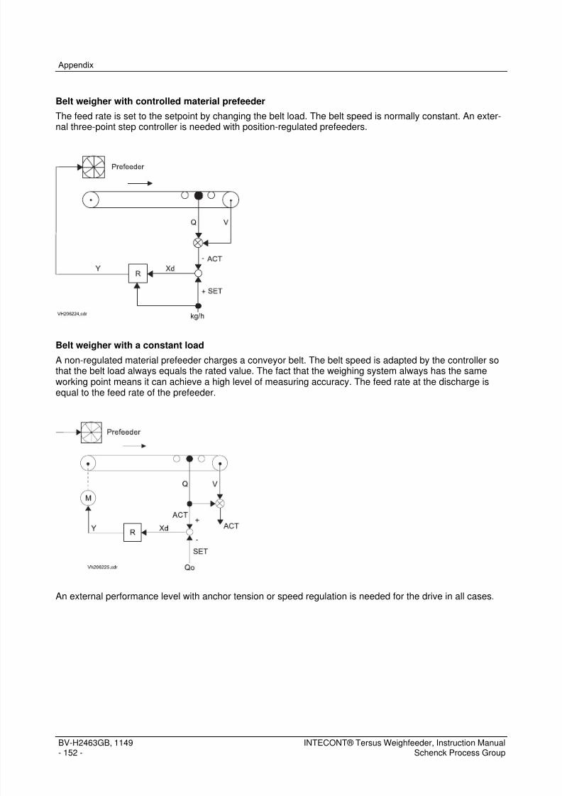
7/15/2019 Manual Intecont Tersus
http://slidepdf.com/reader/full/manual-intecont-tersus 158/176
Appendix
BV-H2463GB, 1149- 152 -
INTECONT® Tersus Weighfeeder, Instruction ManualSchenck Process Group
Belt weigher with controlled material prefeeder
The feed rate is set to the setpoint by changing the belt load. The belt speed is normally constant. An exter-nal three-point step controller is needed with position-regulated prefeeders.
Belt weigher with a constant load
A non-regulated material prefeeder charges a conveyor belt. The belt speed is adapted by the controller sothat the belt load always equals the rated value. The fact that the weighing system always has the sameworking point means it can achieve a high level of measuring accuracy. The feed rate at the discharge isequal to the feed rate of the prefeeder.
An external performance level with anchor tension or speed regulation is needed for the drive in all cases.

7/15/2019 Manual Intecont Tersus
http://slidepdf.com/reader/full/manual-intecont-tersus 159/176
Appendix
INTECONT® Tersus Weighfeeder, Instruction ManualSchenck Process Group
BV-H2463GB, 1149- 153 -
Modes:
Gravimetric
Controlled operation as described above
Volumetric
Uncontrolled operation, i.e. the belt speed or prefeeder is controlled proportional to the setpoint. The meas-ured feed rate or actual belt load value is not taken into consideration.
Volumetric Synchronous
In contrast to volumetric operation, it is not the rated belt load that is used for calculating the set belt speed.Instead, the measured belt load is used before changing over. That means that changing over is jerk-free.
The operating modes can be selected with a dialog function. Special start-up and empty running functionscan also be activated.
Operating sources:
Some operating functions can be triggered by various sources. For example, setpoint specification, turningon and off, resetting the counter and acknowledging events.
18.718.718.718.7 Measuring at the Discharge Point VAPMeasuring at the Discharge Point VAPMeasuring at the Discharge Point VAPMeasuring at the Discharge Point VAP
Measuring on the VAP discharge point shifts the measuring point of the weighbridge to the discharge point ofthe material by means of a time-lag device. The totalized amount of material dispatched is directly recorded.
Measuring at dispatch: VAP
Preconditions: The length ratio from the centerline of the weighing platform to the material dispatch to the overall belt
conveyor length is known. Key in the length ratio in percent in parameters Platform Dis.Length P12.02. Activate VAP via VAP Active P12.01 parameters.

7/15/2019 Manual Intecont Tersus
http://slidepdf.com/reader/full/manual-intecont-tersus 160/176
Appendix
BV-H2463GB, 1149- 154 -
INTECONT® Tersus Weighfeeder, Instruction ManualSchenck Process Group
18.818.818.818.8 Belt MonitoringBelt MonitoringBelt MonitoringBelt Monitoring
Drift and slippage monitoring is built into the functions. Monitoring is activated with the P12.03 Belt Sensor Active parameter.
The programs can only be used for belt monitoring if there is a belt circuit sensor (Namur transmitter) and atriangular metallic sensor surface in the conveyor belt. Otherwise, the aforementioned parameter andP12.05 BIC Active parameters have to be on NO .
Procedure for activating belt monitoring
1. Set the parameters P12.03 Belt Sensor Active to YES
2. Key in the sensor length in P12.06 Sensor Length parameters
3. Key in the sensor width in P12.07 Sensor Width parameters
4. Set P12.08 Sensor Offset parameters to 0
5. Call up the calibration function LB: Pulses/Belt
18.918.918.918.9 BIC belt impact compensationBIC belt impact compensationBIC belt impact compensationBIC belt impact compensation
Even excellent conveyor belts are never completely even and they become heavier and stiffer especially on
the seams. This is why it is normally only possible to guarantee a high level of accuracy over entire belt cir-cuits (i.e. over the mean).
An additional belt circuit sensor and metallic marking flag in the belt enable the unit to record this impact andconstantly correct it.
That substantially boosts the short-term accuracy of the scale.
Belt impact measurement is constant to take changes in regular operation into account. Compensationadapts itself whenever material is conveyed.
Relevant parameters P12.05 BIC Active , P12.03 Belt Sensor Active , P12.04 DI: Source Belt Sensor .

7/15/2019 Manual Intecont Tersus
http://slidepdf.com/reader/full/manual-intecont-tersus 161/176
Appendix
INTECONT® Tersus Weighfeeder, Instruction ManualSchenck Process Group
BV-H2463GB, 1149- 155 -
18.1018.1018.1018.10 LinearizationLinearizationLinearizationLinearization
The belt loading does not usually need to be linearized. It only makes sense with major belt load fluctuationsand simple weighing mechanisms.
Calibration with calibration weights:
Apply calibration weight Q1, start the scales and call up the zeroing program.
Key in the final result of zero setting program and key in later in Linearization I1 parameters.
Cancel the program and do not exceed the result.
Key in the result of the formula q1 = Q1 / L * 100 % / q0 in Linearization S1 parameters.Where
Q1: calibration weight in kg
L: P03.05 Effective Platform Length
q0: P04.01 Nominal Belt Load
Repeat work processes 1 - 3 with increasingly large calibration weights for the other linearization points.
Calibration using material:
Perform a material check with a belt load q1.
Read the mean of the belt load q1(a) on the equipment and key it into the Linearization I1 parameters.
Key in the result of the formula q1(s) = q1(a) * Ms / Ma into the Linearization S1 parameters.
Where
Ms: conveyed quantity of material in kg
Ma: quantity of material read on the equipment in kg
Repeat work processes 1 - 3 with increasingly large calibration weights for the other linearization points.

7/15/2019 Manual Intecont Tersus
http://slidepdf.com/reader/full/manual-intecont-tersus 162/176
Index
BV-H2463GB, 1149- 156 -
INTECONT® Tersus Weighfeeder, Instruction ManualSchenck Process Group
IndexIndexIndexIndex>0 Zero ON/OFF ........................................................ .......................................................... ............................................ 68
2. Password ...................................................................................................................................................................... 66Abbreviations .................................................................................................................................................................... 54About This Manual .............................................................................................................................................................. 1Access Rights Limitation FB ................................................. ........................................................... ................................ 108acknowledge event information ..................................................... ........................................................... ......................... 19Activation code ................................................... .......................................................... ................................................... 146Adaptation 1 ...................................................................................................................................................................... 97Adaptation Factor ........................................................ .......................................................... ............................................ 82Additional device ............................................................................................................................................................... 81Address ........................................................................................................................................................... 106, 107, 108Afterflow Totalizer ............................................................................................................................................................. 81An overview of the INTECONT Tersus................................................................................................................................ 7Analog Outputs ................................................................................................................................................................. 74Angle ................................................................................................................................................................................. 73AO Actual Flow Rate .................................................. .......................................................... ............................................ 75
AO Belt Load ..................................................... .......................................................... ..................................................... 76AO Deviation ..................................................... .......................................................... ..................................................... 77AO Motor Speed Control ..................................................... ........................................................... .................................. 77AO Setpoint ....................................................... .......................................................... ..................................................... 75AO Speed .......................................................... .......................................................... ..................................................... 76Appendix ......................................................................................................................................................................... 145Basic Tare ......................................................................................................................................................................... 74Batch Automatic Record.................................................................................................................................................... 83Batch control ..................................................................................................................................................................... 67Batch Mode ....................................................................................................................................................................... 82Batch Setpoint Source....................................................................................................................................................... 83Batch Tolerance ................................................................................................................................................................ 82Batching functions ....................................................... .......................................................... ............................................ 41Batching mode .................................................................................................................................................................. 41Baud rate .................................................. ........................................................... ...................................... 83, 106, 108, 116
Baud Rate ....................................................................................................................................................................... 103Belt Circuit No. ............................................................................................................................................................ 73, 74Belt Circuit Time ................................................. .......................................................... ..................................................... 73Belt Drift ............................................................................................................................................................................ 86Belt inclination ................................................................................................................................................................... 49belt load............................................................................................................................................................................... 9Belt Load Offset ................................................................................................................................................................ 76Belt Load Range ............................................................................................................................................................... 76Belt Monitoring ................................................................................................................................................................ 154Belt Monitoring ................................................................................................................................................ 85, 86, 87, 88Belt Sensor Active ....................................................... .......................................................... ............................................ 85Belt Skew .......................................................................................................................................................................... 87Belt Velocity Check ........................................................................................................................................................... 52BIC Active ......................................................................................................................................................................... 86BIC belt impact compensation ....................................................... ........................................................... ....................... 154Bypass .............................................................................................................................................................................. 96Byte Sequence ................................................... .......................................................... ................................................... 106CA01 Event Error LC Input ................................................. ........................................................... ................................ 121CA02 Event Tachometer Input .................................................... ........................................................... ....................... 121CA05 Event Linearization Error ................................................... ........................................................... ....................... 121Calibrat. Results ................................................. .......................................................... ..................................................... 74Calibration ....................................................................................................................................................................... 121Calibration Data .......................................................................................................................................................... 73, 74Calibration functions .................................................... .......................................................... ............................................ 29calibration switch ................................................ .......................................................... ................................................... 145Calibration Switch ........................................................................................................................................................... 145Calibration Weight ....................................................................................................................................................... 47, 74call up the zero setting program ........................................................................................................................................ 19Characteristics .................................................................................................................................................................. 10Check in Keyboard Mode ................................................................................................................................................ 105CO01 Event Controller Limited .................................................... ........................................................... ....................... 121Communication EasyServe ................................................... .......................................................... ................................ 103

7/15/2019 Manual Intecont Tersus
http://slidepdf.com/reader/full/manual-intecont-tersus 163/176
Index
INTECONT® Tersus Weighfeeder, Instruction ManualSchenck Process Group
BV-H2463GB, 1149- 157 -
Communication Fieldbus ...................................................... ........................................................... ................................ 104Compatibility DISOCONT Master ................................................... .......................................................... ....................... 105Compatiblity INTECONT ................................................................................................................................................. 107Configuration ...................................................... .......................................................... ................................................... 106Configuration HMI Values ............................................................................................................................................... 114Configuring Event Messages ............................................................................................................................................ 55Connection Diagrams .................................................. ........................................................... ......................................... 131Controller .................................................. ........................................................... .......................................................... .. 121Controller Magnitude Offset .............................................................................................................................................. 95Correction Amount ............................................................................................................................................................ 82Counter 1 Unit ................................................................................................................................................................... 71Counter 2 Unit ................................................................................................................................................................... 71Counter 3 Unit ................................................................................................................................................................... 72Counter functions .............................................................................................................................................................. 23Daily Total Time .............................................................................................................................................................. 112Damaged / Defective Electrical Components ................................................... ........................................................... ........ 6DATA................................................................................................................................................................................. 16Data Format ............................................................................................................................................................ 107, 117Data Log ON/OFF ....................................................... .......................................................... ............................................ 68
Data Log Value 1 ............................................................................................................................................................ 112Data Log Value 10 .......................................................................................................................................................... 113Data Log Value 2 ............................................................................................................................................................ 112Data Log Value 3 ............................................................................................................................................................ 112Data Log Value 4 ............................................................................................................................................................ 112Data Log Value 5 ............................................................................................................................................................ 113Data Log Value 6 ............................................................................................................................................................ 113Data Log Value 7 ............................................................................................................................................................ 113Data Log Value 8 ............................................................................................................................................................ 113Data Log Value 9 ............................................................................................................................................................ 113Data Logging ...................................................... .......................................................... ................................................... 111DELETE ............................................................................................................................................................................ 16Deviation abs. max. ..................................................... .......................................................... ............................................ 93Deviation Offset .................................................. .......................................................... ..................................................... 77Deviation Range ................................................. .......................................................... ..................................................... 77
DeviceNet Module (VCB8020) ............................................................................................... ......................................... 138DI Acknowledge Events ...................................................... ........................................................... .................................. 99DI Batch Terminate .................................................... .......................................................... ............................................ 99DI BIC freeze ..................................................... .......................................................... ..................................................... 88DI External Event 1 .................................................... .......................................................... .......................................... 100DI External Event 2 .................................................... .......................................................... .......................................... 100DI Source Belt Sensor ................................................ .......................................................... ............................................ 85DI Start .................................................... ........................................................... .......................................................... .. 100DI Volumetric Mode .................................................... .......................................................... ............................................ 99DI Volumetric synchron ....................................................... .......................................................... ................................. 100Dialog Behaviour ................................................ .......................................................... ..................................................... 65Digital Inputs ..................................................................................................................................................................... 99Digital Outputs .................................................... .......................................................... ................................................... 100Display Test and Version Number .................................................. .......................................................... ......................... 21DO Actual Flow Rate MAX .................................................. ........................................................... ................................ 101
DO Actual Flow Rate MIN ................................................... ........................................................... ................................ 101DO ALARM ....................................................... .......................................................... ................................................... 100DO Batch Running ..................................................... .......................................................... .......................................... 102DO Belt Drift ..................................................... ........................................................... ..................................................... 87DO Belt Load MAX ..................................................... .......................................................... .......................................... 101DO Belt load MIN ....................................................... .......................................................... .......................................... 101DO Belt Skew .................................................... .......................................................... ..................................................... 88DO Belt Slip ...................................................... ........................................................... ..................................................... 88DO Deviation ..................................................... .......................................................... ................................................... 103DO Dribble Feed ........................................................ .......................................................... .......................................... 102DO Feeder Started ..................................................... .......................................................... .......................................... 102DO Full Feed ..................................................... .......................................................... ................................................... 102DO Keyboard Mode ................................................... ........................................................... ......................................... 103DO Pulse Counter ...................................................... .......................................................... ............................................ 72DO Scale Start .................................................. .......................................................... ................................................... 101
DO Speed MAX ................................................. .......................................................... ................................................... 102DO Speed MIN .................................................. .......................................................... ................................................... 102

7/15/2019 Manual Intecont Tersus
http://slidepdf.com/reader/full/manual-intecont-tersus 164/176
Index
BV-H2463GB, 1149- 158 -
INTECONT® Tersus Weighfeeder, Instruction ManualSchenck Process Group
DO Start Prefeeder .................................................... .......................................................... .......................................... 100DO Volumetric Mode .................................................. ........................................................... ......................................... 103dribble feed ......................................................................................................................................................................... 8duty cycle ........................................................................................................................................................................ 145Effective Platform Length .................................................................................................................................................. 73Effective weighing platform length ................................................. ........................................................... ........................... 9Effective Weighing Platform Length .............................................................................. .................................................... 45Electrical System ......................................................... .......................................................... .......................................... 122ENTER .............................................................................................................................................................................. 17ESCAPE .................................................... .......................................................... ........................................................... ... 17Ethernet........................................................................................................................................................................... 111Ethernet/IP ...................................................................................................................................................................... 146Event Actual Flow Rate MAX ....................................................... ........................................................... ................. 78, 123Event Actual Flow Rate MIN ............................................... ........................................................... .......................... 78, 125Event Acyclic Communication ...................................................... ........................................................... ............... 105, 127Event Belt Drift .................................................. .......................................................... ............................................. 87, 124Event Belt Load MAX ................................................. ........................................................... ................................... 79, 123Event Belt Load MIN .................................................. .......................................................... .................................... 79, 125Event Belt Skew ......................................................... .......................................................... .................................... 87, 124
Event Controller Limited ...................................................... .......................................................... ........................... 94, 121Event Cyclic Communication ............................................... ........................................................... ........................ 105, 126Event Deviation ................................................. .......................................................... ............................................. 93, 124Event Error LC Input .................................................. .......................................................... .................................... 89, 121Event External Event 1 ........................................................ .......................................................... ........................... 91, 126Event External Event 2 ........................................................ .......................................................... ........................... 91, 126Event LC Input < MIN ................................................. .......................................................... .................................... 90, 124Event LC Input > MAX ......................................................... .......................................................... ........................... 90, 123Event License Violation ....................................................... .......................................................... ........................... 91, 127Event Linearization Error ..................................................... .......................................................... ........................... 99, 121Event Maint. Electric..................................................................... .......................................................... .................. 84, 126Event Maint.Feeder Run ..................................................... ........................................................... .......................... 85, 126Event Memory ................................................... .......................................................... ............................................. 88, 126Event Namur Error Belt ....................................................... .......................................................... ........................... 89, 122Event Namur Error Tacho ................................................... ........................................................... .......................... 89, 122
Event Out of Tolerance ....................................................... .......................................................... ........................... 83, 122Event Power Failure ................................................... .......................................................... .................................... 88, 122Event Run Disabled ................................................... .......................................................... .................................... 89, 122Event Setpoint Limited ........................................................ .......................................................... ........................... 90, 125Event Simulation active ....................................................... .......................................................... ........................... 90, 127Event Slip ......................................................... ........................................................... ............................................. 87, 124Event Speed MAX ...................................................... .......................................................... .................................... 80, 123Event Speed MIN ....................................................... .......................................................... .................................... 79, 125Event Stand-By ................................................. .......................................................... ............................................. 80, 125Event Tachometer Input ...................................................... ........................................................... .......................... 89, 121Event Group: Calibration ...................................................... .......................................................... ................................. 121Event Group: Controller................................................................................................................................................... 121Event Group: Electrical System ..................................................... ........................................................... ....................... 122Event Group: Interlock..................................................................................................................................................... 122Event Group: Material Flow .................................................. ........................................................... ................................ 122
Event Group: MAX .......................................................................................................................................................... 123Event Group: Mechanic ........................................................ ........................................................... ................................ 124Event Group: MIN ........................................................................................................................................................... 124Event Group: Sequence Monitoring ................................................................................................................................ 125Event Group: System Message ...................................................... .......................................................... ....................... 126Event messages ................................................. .......................................................... ................................................... 119Events ............................................................................................................................................................................. 121Events ............................................................................................................................................................. 88, 89, 90, 91Events Details ................................................................................................................................................................. 121Factor Deviation ................................................................................................................................................................ 93feed rate .............................................................................................................................................................................. 9Feeder ON/OFF ................................................................................................................................................................ 67Feeder Start ...................................................................................................................................................................... 70Feedrate Setpoint ........................................................ .......................................................... ............................................ 70Fig. 1: The basic diagram of the ITE inputs and outputs ......................................................... ............................................ 8
Fig. 10: Connection diagram for inputs and outputs 1 ............................................... ...................................................... 131Fig. 11: Connection diagram for ITE inputs and outputs 2 ................................................................................. ............. 131

7/15/2019 Manual Intecont Tersus
http://slidepdf.com/reader/full/manual-intecont-tersus 165/176
Index
INTECONT® Tersus Weighfeeder, Instruction ManualSchenck Process Group
BV-H2463GB, 1149- 159 -
Fig. 12: Serial interface connection diagram ................................................................................... ................................ 132Fig. 13: Modbus connection diagram ............................................................... ............................................................... 132Fig. 14: ITE PROFIBUS connection diagram ............................................................................................ ...................... 132Fig. 15: DeviceNet connection diagram........................................................................................................................... 133Fig. 16: VPB8020 PROFIBUS module ........................................................................... ................................................. 136Fig. 17: LEDs - VPB8020 front view ............................................... .......................................................... ....................... 137Fig. 18: DeviceNet module VCB8020 ...................................................... .......................................................... .............. 138Fig. 19: VCB8020:XC1 DeviceNet module front view ..................................................................................................... 139Fig. 2: The belt load of the weighbridge is not legal for trade .................................................. ............................................ 9Fig. 20: VSS8020 Modbus module layout drawing .................................................... ...................................................... 140Fig. 21: Setpoint and switching-in source changeover VWF .................................................... ....................................... 149Fig. 22: VWF switch-on sequence .................................................. .......................................................... ....................... 150Fig. 3: Display warning 2 ...................................................... .......................................................... ................................... 11Fig. 4: Display warning 1 ...................................................... .......................................................... ................................... 11Fig. 5: Display alarm ......................................................................................................................................................... 12Fig. 6: display – function block .......................................................................................................................................... 18Fig. 7: Parameter sets ................................................. .......................................................... ............................................ 53Fig. 8: Connection diagram for voltage supply ............................................................... ................................................. 131Fig. 9: WZ connection diagram and tachometer ............................................... ........................................................... .... 131
Filter Actual Flow Rate ........................................................ .......................................................... ................................... 80Filter Actual Flow Rate analog ..................................................... ........................................................... ......................... 80Filter Belt Load .................................................. .......................................................... ..................................................... 81Filter Belt Speed ......................................................... .......................................................... ............................................ 81Filter Deviation .................................................. .......................................................... ..................................................... 92Filters ................................................................................................................................................................................ 80Five Safety Rules of Electrical Engineering......................................................................................................................... 6Fixed mode configuration ..................................................... ........................................................... ................................ 109FLOAT-Format ................................................... .......................................................... ................................................... 107Flow Rate Offset ............................................................................................................................................................... 75Flow Rate Range .............................................................................................................................................................. 76Flow Rate Units .................................................. .......................................................... ..................................................... 69Font ................................................................................................................................................................................... 66Format Data .................................................................................................................................................................... 104full feed................................................................................................................................................................................ 8
FUNCTION ......................................................... .......................................................... ..................................................... 16function block .................................................................................................................................................................... 19Function block ................................................................................................................................................................... 17Function Check ......................................................................................................................................................... 51, 147Gateway .......................................................................................................................................................................... 111General Diagram ................................................ .......................................................... ....................................................... 7Hardware and technical data ................................................ ........................................................... ................................ 129HI01 Event LC Input > MAX ........................................................ ........................................................... ....................... 123HI02 Event Actual Flow Rate MAX ............................................... .......................................................... ....................... 123HI03 Event Belt Load MAX ................................................. ........................................................... ................................ 123HI04 Event Speed MAX ..................................................... ........................................................... ................................ 123HI05 Event Deviation................................................................... .......................................................... ........................ 124HMI Value 01 .................................................................................................................................................................. 114HMI Value 02 .................................................................................................................................................................. 114HMI Value 03 .................................................................................................................................................................. 114
HMI Value 04 .................................................................................................................................................................. 114HMI Value 05 .................................................................................................................................................................. 114HMI Value 06 .................................................................................................................................................................. 114HMI Value 07 .................................................................................................................................................................. 114HMI Value 08 .................................................................................................................................................................. 115HMI Value 09 .................................................................................................................................................................. 115HMI Value 10 .................................................................................................................................................................. 115Hourly Total Time ........................................................ .......................................................... .......................................... 111I-Component TN ................................................. .......................................................... ..................................................... 92ID Preset Value 1 ............................................................................................................................................................ 109ID Preset Value 2 ............................................................................................................................................................ 109ID Preset Value 3 ............................................................................................................................................................ 109ID Preset Value 4 ............................................................................................................................................................ 109ID Preset Value 5 ............................................................................................................................................................ 109ID Preset Value 6 ............................................................................................................................................................ 109
ID Preset Value 7 ............................................................................................................................................................ 110ID Preset Value 8 ............................................................................................................................................................ 110

7/15/2019 Manual Intecont Tersus
http://slidepdf.com/reader/full/manual-intecont-tersus 166/176
Index
BV-H2463GB, 1149- 160 -
INTECONT® Tersus Weighfeeder, Instruction ManualSchenck Process Group
ID Read Value 1 .............................................................................................................................................................. 110ID Read Value 2 .............................................................................................................................................................. 110ID Read Value 3 .............................................................................................................................................................. 110ID Read Value 4 .............................................................................................................................................................. 110ID Read Value 5 .............................................................................................................................................................. 110ID Read Value 6 .............................................................................................................................................................. 110ID Read Value 7 .............................................................................................................................................................. 111ID Read Value 8 .............................................................................................................................................................. 111Identifier format ............................................................................................................................................................... 108IL01 Event Run Disabled .................................................... ........................................................... ................................ 122Interlock .................................................... ........................................................... .......................................................... .. 122IP Address ......................................................... ........................................................... ................................................... 111key in the setpoint ............................................................................................................................................................. 20Keyboard operation ON/OFF ............................................................................................................................................ 26Language .......................................................................................................................................................................... 65LC Characteristic Value..................................................................................................................................................... 73LC Filter .................................................... ........................................................... .......................................................... .... 81LC Rated Capacity ............................................................................................................................................................ 73LED diagnosis ................................................................................................................................................................. 141
Lever Ratio ........................................................ ........................................................... ..................................................... 73Limit Actual Flow Rate MAX ................................................ ........................................................... .................................. 78Limit Actual Flow Rate MIN ................................................. ........................................................... .................................. 78Limit Belt Load MAX ................................................... .......................................................... ............................................ 79Limit Belt Load MIN .................................................... .......................................................... ............................................ 78Limit Speed MAX ....................................................... .......................................................... ............................................ 79Limit Speed MIN ......................................................... .......................................................... ............................................ 79Limit Values ....................................................... ........................................................... ..................................................... 77Linearization ...................................................... ........................................................... ................................................... 155Linearization ...................................................... ........................................................... ..................................................... 97Linearization I1 ................................................... .......................................................... ..................................................... 98Linearization I2 ................................................... .......................................................... ..................................................... 98Linearization I3 ................................................... .......................................................... ..................................................... 98Linearization I4 ................................................... .......................................................... ..................................................... 98Linearization ON ............................................................................................................................................................... 97
Linearization S1 ................................................................................................................................................................ 97Linearization S2 ................................................................................................................................................................ 98Linearization S3 ................................................................................................................................................................ 98Linearization S4 ................................................................................................................................................................ 98LO01 Event LC Input < MIN ........................................................ ........................................................... ....................... 124LO02 Event Actual Flow Rate MIN ............................................... .......................................................... ....................... 125LO03 Event Belt Load MIN ................................................. ........................................................... ................................ 125LO04 Event Speed MIN ..................................................... ........................................................... ................................ 125Logger cycle time ............................................................................................................................................................ 112Lower Limit ........................................................ ........................................................... ..................................................... 94Maintenance Electric ................................................... .......................................................... ............................................ 84Maintenance Feeder Run ..................................................... ........................................................... .................................. 84Maintenance interval ......................................................................................................................................................... 84Material Flow ...................................................... .......................................................... ................................................... 122MAX ................................................................................................................................................................................ 123
Measuring at the Discharge Point VAP ........................................................................................................................... 153Mechanic ................................................... .......................................................... .......................................................... .. 124Method of Function ............................................................................................................................................................. 9MF06 Event Out of Tolerance ..................................................... ........................................................... ....................... 122MIN.................................................................................................................................................................................. 124Modbus Interface VSS8020 ............................................................................................................................................ 140Mode functions ................................................... .......................................................... ..................................................... 25Net Mask ......................................................................................................................................................................... 111Nominal Belt Load ....................................................... .......................................................... ............................................ 74Nominal Flow Rate ............................................................................................................................................................ 69Nominal Speed ................................................... .......................................................... ..................................................... 69Operating in Normal Operation ......................................................................................................................................... 18operating sources ........................................................ .......................................................... ............................................ 26Operation .......................................................................................................................................................................... 15Optimize Controller ........................................................................................................................................................... 91
Output current ................................................................................................................................................................. 145Own Address ...................................................... .......................................................... ................................................... 103

7/15/2019 Manual Intecont Tersus
http://slidepdf.com/reader/full/manual-intecont-tersus 167/176
Index
INTECONT® Tersus Weighfeeder, Instruction ManualSchenck Process Group
BV-H2463GB, 1149- 161 -
P01 - Dialog Behaviour ..................................................................................................................................................... 65P01.01 - Language ...................................................... .......................................................... ............................................ 65P01.02 - Userdefined Text ................................................................................................................................................ 65P01.03 - Font .................................................................................................................................................................... 66P01.04 - Units ................................................................................................................................................................... 66P01.05 - Scale Name ........................................................................................................................................................ 66P01.06 - Password ...................................................... .......................................................... ............................................ 66P01.07 - 2. Password .................................................. .......................................................... ............................................ 66P01.08 - Feeder ON/OFF ..................................................... ........................................................... .................................. 67P01.09 - Switch Grav./Vol. command ............................................................................................................................... 67P01.10 - Switch Keyboard-/Normal Mode ......................................................................................................................... 67P01.11 - Batch control ................................................. .......................................................... ............................................ 67P01.12 - >0 Zero ON/OFF ................................................... ........................................................... .................................. 68P01.13 - Reset Counter 1.................................................................................................................................................. 68P01.14 - Reset Counter 2.................................................................................................................................................. 68P01.15 - Data Log ON/OFF .................................................. ........................................................... .................................. 68P02 - Rated Data ............................................................................................................................................ 69, 70, 71, 72P02.01 - Flow Rate Units .................................................................................................................................................. 69P02.02 - Nominal Flow Rate ............................................................................................................................................. 69
P02.03 - Speed Measurement .......................................................................................................................................... 69P02.04 - Pulses per length ................................................................................................................................................ 69P02.05 - Nominal Speed ................................................................................................................................................... 69P02.06 - Feeder Start .................................................. .......................................................... ............................................ 70P02.07 - Feedrate Setpoint ............................................................................................................................................... 70P02.08 - Relative Setpoint .................................................... .......................................................... ................................... 70P02.09 - WZ Active ........................................................................................................................................................... 70P02.10 - Counter 1 Unit..................................................................................................................................................... 71P02.11 - Pulse Length Total ................................................. ........................................................... .................................. 71P02.12 - Counter 2 Unit..................................................................................................................................................... 71P02.13 - Counter 3 Unit..................................................................................................................................................... 72P02.14 - DO Pulse Counter ................................................. ........................................................... .................................. 72P02.15 - Totalizer Increment .................................................................................................. ........................................... 72P02.16 - Z1-Numberstep ...................................................... ........................................................... .................................. 72P03 - Calibration Data ................................................................................................................................................. 73, 74
P03.01 - Belt Circuit No. ....................................................... .......................................................... ................................... 73P03.02 - Belt Circuit Time ................................................................................................................................................. 73P03.03 - LC Characteristic Value ...................................................................................................................................... 73P03.04 - LC Rated Capacity ................................................. ........................................................... .................................. 73P03.05 - Effective Platform Length ................................................ ........................................................... ......................... 73P03.06 - Lever Ratio ......................................................................................................................................................... 73P03.07 - Angle .................................................................................................................................................................. 73P03.08 - Calibration Weight .............................................................................................................................................. 74P04 - Calibrat. Results ...................................................................................................................................................... 74P04.01 - Nominal Belt Load .............................................................................................................................................. 74P04.02 - Range Correction ................................................... ........................................................... .................................. 74P04.03 - Total Tare ........................................................................................................................................................... 74P04.04 - Basic Tare .......................................................................................................................................................... 74P04.05 - Tare Correction ...................................................... .......................................................... ................................... 74P04.06 - Belt Circuit No. ....................................................... .......................................................... ................................... 74
P05 - Analog Outputs .................................................. .......................................................... ............................................ 74P05.01 - AO Setpoint ................................................. .......................................................... ............................................ 75P05.02 - Setpoint Offset ........................................................................................................ ............................................ 75P05.03 - Setpoint Range ........................................................................................................ ........................................... 75P05.04 - AO Actual Flow Rate ..................................................... ........................................................... ......................... 75P05.05 - Flow Rate Offset ................................................................................................................................................. 75P05.06 - Flow Rate Range ................................................................................................................................................ 76P05.07 - AO Belt Load ........................................................ .......................................................... ................................... 76P05.08 - Belt Load Offset .................................................................................................................................................. 76P05.09 - Belt Load Range ................................................................................................................................................. 76P05.10 - AO Speed .................................................... .......................................................... ............................................ 76P05.11 - Speed Offset ................................................. .......................................................... ............................................ 76P05.12 - Speed Range ................................................ ........................................................... ........................................... 77P05.13 - AO Deviation......................................................... .......................................................... ................................... 77P05.14 - Deviation Offset .................................................................................................................................................. 77
P05.15 - Deviation Range ................................................................................................................................................. 77P05.16 - AO Motor Speed Control ........................................................................................ ........................................... 77

7/15/2019 Manual Intecont Tersus
http://slidepdf.com/reader/full/manual-intecont-tersus 168/176
Index
BV-H2463GB, 1149- 162 -
INTECONT® Tersus Weighfeeder, Instruction ManualSchenck Process Group
P06 - Limit Values ............................................................................................................................................................. 77P06.01 - Limit Actual Flow Rate MIN .................................................................................... ........................................... 78P06.02 - Event Actual Flow Rate MIN .................................................... .......................................................... ................ 78P06.03 - Limit Actual Flow Rate MAX .................................................... .......................................................... ................ 78P06.04 - Event Actual Flow Rate MAX ................................................... .......................................................... ................ 78P06.05 - Limit Belt Load MIN ....................................................... ........................................................... ......................... 78P06.06 - Event Belt Load MIN ...................................................... ........................................................... ......................... 79P06.07 - Limit Belt Load MAX ...................................................... ........................................................... ......................... 79P06.08 - Event Belt Load MAX ..................................................... ........................................................... ......................... 79P06.09 - Limit Speed MIN ................................................... ........................................................... .................................. 79P06.10 - Event Speed MIN .................................................. ........................................................... .................................. 79P06.11 - Limit Speed MAX .................................................. ........................................................... .................................. 79P06.12 - Event Speed MAX ................................................. .......................................................... .................................. 80P06.13 - Stand-By Limit Value .......................................................................................................................................... 80P06.14 - Event Stand-By ..................................................... ........................................................... .................................. 80P07 - Filters ....................................................... ........................................................... ..................................................... 80P07.01 - Filter Actual Flow Rate ................................................... ........................................................... ......................... 80P07.02 - Filter Actual Flow Rate analog ................................................. .......................................................... ................ 80P07.03 - Filter Belt Load....................................................................................................... ............................................ 81
P07.04 - Filter Belt Speed ................................................... .......................................................... ................................... 81P07.05 - LC Filter .............................................................................................................................................................. 81P07.06 - Afterflow Totalizer .................................................................................................... ........................................... 81P08 - Additional device...................................................................................................................................................... 81P08.01 - Zero Drop-Out Active ...................................................... ........................................................... ......................... 81P08.02 - Zero Drop-Out Limit ............................................................................................................................................ 81P09 - Batch Mode ............................................................................................................................................................. 82P09.01 - Pre-cut-off Amount ................................................. ........................................................... .................................. 82P09.02 - Correction Amount ................................................. ........................................................... .................................. 82P09.03 - Adaptation Factor ............................................................................................................................................... 82P09.04 - Batch Tolerance.................................................................................................................................................. 82P09.05 - Event Out of Tolerance .................................................. ........................................................... ......................... 83P09.06 - Batch Automatic Record ..................................................................................................................................... 83P09.07 - Batch Setpoint Source .................................................... ........................................................... ......................... 83P10 - Printer Setting .................................................... .......................................................... ...................................... 83, 84
P10.01 - Baud rate ............................................................................................................................................................ 83P10.02 - Print Event .......................................................................................................................................................... 83P10.03 - Print Page Length .................................................. ........................................................... .................................. 84P11 - Maintenance interval ................................................... ........................................................... .................................. 84P11.01 - Maintenance Electric .......................................................................................................................................... 84P11.02 - Event Maint. Electric ...................................................... ........................................................... ......................... 84P11.03 - Maintenance Feeder Run ................................................................................................................................... 84P11.04 - Event Maint.Feeder Run ................................................. .......................................................... ......................... 85P12 - Belt Monitoring ................................................... .......................................................... .......................... 85, 86, 87, 88P12.01 - VAP Active .................................................... .......................................................... ............................................ 85P12.02 - Platform Dis.Length ............................................................................................................................................ 85P12.03 - Belt Sensor Active .............................................................................................................................................. 85P12.04 - DI Source Belt Sensor ................................................... ........................................................... ......................... 85P12.05 - BIC Active ..................................................... .......................................................... ............................................ 86P12.06 - Sensor Length .................................................................................................................................................... 86
P12.07 - Sensor Width ...................................................................................................................................................... 86P12.08 - Sensor Offset ................................................ .......................................................... ............................................ 86P12.09 - Belt Drift ........................................................ .......................................................... ............................................ 86P12.10 - Event Belt Drift ...................................................... .......................................................... ................................... 87P12.11 - Belt Skew ...................................................... .......................................................... ............................................ 87P12.12 - Event Belt Skew .................................................... ........................................................... .................................. 87P12.13 - Slip Value ........................................................................................................................................................... 87P12.14 - Event Slip .................................................... .......................................................... ............................................ 87P12.15 - DO Belt Drift................................................. .......................................................... ............................................ 87P12.16 - DO Belt Skew ....................................................... ........................................................... .................................. 88P12.17 - DO Belt Slip ................................................. .......................................................... ............................................ 88P12.18 - DI BIC freeze ........................................................ .......................................................... ................................... 88P13 - Events ....................................................... .......................................................... ................................... 88, 89, 90, 91P13.01 - Event Power Failure ...................................................... ........................................................... ......................... 88P13.02 - Event Memory................................................................ ........................................................... ......................... 88
P13.03 - Event Tachometer Input ......................................................................................... ........................................... 89P13.04 - Event Namur Error Tacho ............................................... .......................................................... ......................... 89

7/15/2019 Manual Intecont Tersus
http://slidepdf.com/reader/full/manual-intecont-tersus 169/176
Index
INTECONT® Tersus Weighfeeder, Instruction ManualSchenck Process Group
BV-H2463GB, 1149- 163 -
P13.05 - Event Namur Error Belt .................................................. ........................................................... ......................... 89P13.06 - Event Error LC Input ...................................................... ........................................................... ......................... 89P13.07 - Event Run Disabled ....................................................... ........................................................... ......................... 89P13.08 - Event LC Input > MAX ................................................... ........................................................... ......................... 90P13.09 - Event LC Input < MIN .................................................... ........................................................... ......................... 90P13.10 - Event Simulation active ................................................. ........................................................... ......................... 90P13.11 - Event Setpoint Limited ................................................... ........................................................... ......................... 90P13.12 - Event External Event 1 .................................................. ........................................................... ......................... 91P13.13 - Event External Event 2 .................................................. ........................................................... ......................... 91P13.14 - Event License Violation ................................................. ........................................................... ......................... 91P14 - Rate controller ..................................................................................................................... 91, 92, 93, 94, 95, 96, 97P14.01 - Optimize Controller ................................................ ........................................................... .................................. 91P14.02 - P-Component KP ................................................... ........................................................... .................................. 91P14.03 - I-Component TN ................................................................................................................................................. 92P14.04 - Filter Deviation ...................................................... .......................................................... ................................... 92P14.05 - Time Deviation ....................................................... .......................................................... ................................... 92P14.06 - Threshold Deviation ............................................... ........................................................... .................................. 92P14.07 - Factor Deviation ..................................................... .......................................................... ................................... 93P14.08 - Deviation abs. max. ............................................................................................................................................ 93
P14.09 - Event Deviation..................................................... ........................................................... .................................. 93P14.10 - Event Controller Limited ................................................ ........................................................... ......................... 94P14.11 - Lower Limit ......................................................................................................................................................... 94P14.12 - Upper Limit ......................................................................................................................................................... 94P14.13 - Controller Magnitude Offset ..................................................... ........................................................... ................ 95P14.14 - Position at STOP ................................................................................................................................................ 95P14.15 - Volumetric Start-Up ............................................................................................................................................ 95P14.16 - Volumetric Clearance ......................................................................................................................................... 95P14.17 - Setpoint Offset ........................................................................................................ ............................................ 96P14.18 - Setpoint Range ........................................................................................................ ........................................... 96P14.19 - Store ................................................................................................................................................................... 96P14.20 - Volumetric Mode .................................................... ........................................................... .................................. 96P14.21 - Bypass ................................................. .......................................................... ..................................................... 96P14.22 - Setpoint Filter 1st Ord ..................................................... ........................................................... ......................... 97P14.23 - Setpoint Filter 2nd Ord .................................................... ........................................................... ......................... 97
P14.24 - Set/Act Sources ..................................................... ........................................................... .................................. 97P14.25 - Adaptation 1 ....................................................................................................................................................... 97P15 - Linearization ............................................................................................................................................................ 97P15.01 - Linearization ON ................................................................................................................................................. 97P15.02 - Linearization S1 ..................................................... .......................................................... ................................... 97P15.03 - Linearization I1 ................................................................................................................................................... 98P15.04 - Linearization S2 ..................................................... .......................................................... ................................... 98P15.05 - Linearization I2 ................................................................................................................................................... 98P15.06 - Linearization S3 ..................................................... .......................................................... ................................... 98P15.07 - Linearization I3 ................................................................................................................................................... 98P15.08 - Linearization S4 ..................................................... .......................................................... ................................... 98P15.09 - Linearization I4 ................................................................................................................................................... 98P15.10 - Event Linearization Error ............................................... ........................................................... ......................... 99P16 - Digital Inputs ............................................................................................................................................................ 99P16.01 - Source Run Enable ................................................ ........................................................... .................................. 99
P16.02 - DI Batch Terminate ............................................... ........................................................... .................................. 99P16.03 - DI Acknowledge Events .................................................. .......................................................... ......................... 99P16.04 - DI Volumetric Mode ....................................................... ........................................................... ......................... 99P16.05 - DI Volumetric synchron .................................................. ........................................................... ....................... 100P16.06 - DI Start ........................................................ .......................................................... .......................................... 100P16.07 - DI External Event 1 ............................................... ........................................................... ................................ 100P16.08 - DI External Event 2 ............................................... ........................................................... ................................ 100P17 - Digital Outputs ....................................................................................................................................................... 100P17.01 - DO ALARM .................................................. ........................................................... ......................................... 100P17.02 - DO Start Prefeeder ............................................... ........................................................... ................................ 100P17.03 - DO Scale Start ...................................................... .......................................................... ................................. 101P17.04 - DO Actual Flow Rate MIN ............................................... .......................................................... ....................... 101P17.05 - DO Actual Flow Rate MAX .............................................................................................. ................................ 101P17.06 - DO Belt load MIN .................................................. ........................................................... ................................ 101P17.07 - DO Belt Load MAX ................................................ .......................................................... ................................ 101
P17.08 - DO Speed MIN ..................................................... ........................................................... ................................ 102P17.09 - DO Speed MAX .................................................... ........................................................... ................................ 102

7/15/2019 Manual Intecont Tersus
http://slidepdf.com/reader/full/manual-intecont-tersus 170/176
Index
BV-H2463GB, 1149- 164 -
INTECONT® Tersus Weighfeeder, Instruction ManualSchenck Process Group
P17.10 - DO Batch Running ................................................ ........................................................... ................................ 102P17.11 - DO Full Feed ........................................................ .......................................................... ................................. 102P17.12 - DO Dribble Feed ................................................... ........................................................... ................................ 102P17.13 - DO Feeder Started ............................................... ........................................................... ................................ 102P17.14 - DO Deviation ........................................................ .......................................................... ................................. 103P17.15 - DO Volumetric Mode ..................................................... ........................................................... ....................... 103P17.16 - DO Keyboard Mode ....................................................... ........................................................... ....................... 103P18 - Communication EasyServe ................................................................................................................................... 103P18.01 - Own Address .................................................................................................................................................... 103P18.02 - Baud Rate ..................................................... .......................................................... .......................................... 103P18.03 - Format Data .................................................. .......................................................... .......................................... 104P19 - Communication Fieldbus ..................................................................................... .................................................. 104P19.01 - Protocol Type.................................................................................................................................................... 104P19.02 - Timeout Host .................................................................................................................................................... 104P19.03 - Event Cyclic Communication ................................................... .......................................................... .............. 105P19.04 - Event Acyclic Communication................................................................................................... ....................... 105P19.05 - Check in Keyboard Mode ................................................................................................................................. 105P19.06 - Compatibility DISOCONT Master ..................................................................................................................... 105P19.07 - Word Sequence ....................................................................................................... ......................................... 105
P19.08 - Byte Sequence ................................................................................................................................................. 106P19.09 - Configuration .................................................................................................................................................... 106P19.10 - Address ............................................................................................................................................................ 106P19.11 - Resolution ..................................................... .......................................................... .......................................... 106P19.12 - Baud rate .......................................................................................................................................................... 106P19.13 - Data Format .................................................. .......................................................... .......................................... 107P19.14 - Physics ............................................................................................................................................................. 107P19.15 - Address ............................................................................................................................................................ 107P19.16 - FLOAT-Format.................................................................................................................................................. 107P19.17 - Compatiblity INTECONT .................................................. .......................................................... ....................... 107P19.18 - Identifier format ...................................................... .......................................................... ................................. 108P19.19 - PA32 compatible .................................................... ........................................................... ................................ 108P19.20 - Address ............................................................................................................................................................ 108P19.21 - Baud rate .......................................................................................................................................................... 108P19.22 - Access Rights Limitation FB ............................................................................................................................. 108
P19.23 - Remote IP Address FB .................................................... .......................................................... ....................... 109P20 - Fixed mode configuration ...................................................................................................................................... 109P20.01 - ID Preset Value 1 ................................................... ........................................................... ................................ 109P20.02 - ID Preset Value 2 ................................................... ........................................................... ................................ 109P20.03 - ID Preset Value 3 ................................................... ........................................................... ................................ 109P20.04 - ID Preset Value 4 ................................................... ........................................................... ................................ 109P20.05 - ID Preset Value 5 ................................................... ........................................................... ................................ 109P20.06 - ID Preset Value 6 ................................................... ........................................................... ................................ 109P20.07 - ID Preset Value 7 ................................................... ........................................................... ................................ 110P20.08 - ID Preset Value 8 ................................................... ........................................................... ................................ 110P20.09 - ID Read Value 1 ............................................................................................................................................... 110P20.10 - ID Read Value 2 ............................................................................................................................................... 110P20.11 - ID Read Value 3 ............................................................................................................................................... 110P20.12 - ID Read Value 4 ............................................................................................................................................... 110P20.13 - ID Read Value 5 ............................................................................................................................................... 110
P20.14 - ID Read Value 6 ............................................................................................................................................... 110P20.15 - ID Read Value 7 ............................................................................................................................................... 111P20.16 - ID Read Value 8 ............................................................................................................................................... 111P21 - Ethernet ................................................................................................................................................................. 111P21.01 - IP Address ........................................................................................................................................................ 111P21.02 - Net Mask .......................................................................................................................................................... 111P21.03 - Gateway ........................................................................................................................................................... 111P22 - Data Logging ......................................................................................................................................................... 111P22.01 - Hourly Total Time ............................................................................................................................................. 111P22.02 - Daily Total Time ..................................................... .......................................................... ................................. 112P22.03 - Logger cycle time ................................................... ........................................................... ................................ 112P22.04 - Data Log Value 1 ................................................... ........................................................... ................................ 112P22.05 - Data Log Value 2 ................................................... ........................................................... ................................ 112P22.06 - Data Log Value 3 ................................................... ........................................................... ................................ 112P22.07 - Data Log Value 4 ................................................... ........................................................... ................................ 112
P22.08 - Data Log Value 5 ................................................... ........................................................... ................................ 113P22.09 - Data Log Value 6 ................................................... ........................................................... ................................ 113

7/15/2019 Manual Intecont Tersus
http://slidepdf.com/reader/full/manual-intecont-tersus 171/176
Index
INTECONT® Tersus Weighfeeder, Instruction ManualSchenck Process Group
BV-H2463GB, 1149- 165 -
P22.10 - Data Log Value 7 ................................................... ........................................................... ................................ 113P22.11 - Data Log Value 8 ................................................... ........................................................... ................................ 113P22.12 - Data Log Value 9 ................................................... ........................................................... ................................ 113P22.13 - Data Log Value 10 ................................................. ........................................................... ................................ 113P23 - Configuration HMI Values .................................................... ........................................................... ....................... 114P23.01 - HMI Value 01 .................................................................................................................................................... 114P23.02 - HMI Value 02 .................................................................................................................................................... 114P23.03 - HMI Value 03 .................................................................................................................................................... 114P23.04 - HMI Value 04 .................................................................................................................................................... 114P23.05 - HMI Value 05 .................................................................................................................................................... 114P23.06 - HMI Value 06 .................................................................................................................................................... 114P23.07 - HMI Value 07 .................................................................................................................................................... 114P23.08 - HMI Value 08 .................................................................................................................................................... 115P23.09 - HMI Value 09 .................................................................................................................................................... 115P23.10 - HMI Value 10 .................................................................................................................................................... 115P24 - Second Display .................................................. .......................................................... .................................. 116, 117P24.01 - Second Display active ...................................................................................................................................... 116P24.02 - Baud rate .......................................................................................................................................................... 116P24.03 - Data Format .................................................. .......................................................... .......................................... 117
P24.04 - Physics ............................................................................................................................................................. 117PA32 compatible ............................................................................................................................................................. 108Parameter Block 01 - Dialog Behaviour ............................................................................................................................ 65Parameter Block 02 - Rated Data ..................................................................................................................................... 69Parameter Block 03 - Calibration Data .................................................... .......................................................... ................ 73Parameter Block 04 - Calibrat. Results ............................................................................................................................. 74Parameter Block 05 - Analog Outputs ..................................................... .......................................................... ................ 74Parameter Block 06 - Limit Values .................................................................................................................................... 77Parameter Block 07 - Filters ................................................. ........................................................... .................................. 80Parameter Block 08 - Additional device............................................................................................................................. 81Parameter Block 09 - Batch Mode .................................................................................................................................... 82Parameter Block 10 - Printer Setting ...................................................... ........................................................... ................ 83Parameter Block 11 - Maintenance interval....................................................................................................................... 84Parameter Block 12 - Belt Monitoring ..................................................... ........................................................... ................ 85Parameter Block 13 - Events ................................................ ........................................................... .................................. 88
Parameter Block 14 - Rate controller ................................................................................................................................ 91Parameter Block 15 - Linearization ................................................................................................................................... 97Parameter Block 16 - Digital Inputs ............................................... ........................................................... ......................... 99Parameter Block 17 - Digital Outputs .............................................................................................................................. 100Parameter Block 18 - Communication EasyServe .......................................................................................................... 103Parameter Block 19 - Communication Fieldbus .............................................................................................................. 104Parameter Block 20 - Fixed mode configuration ..................................... ........................................................... ............. 109Parameter Block 21 - Ethernet ...................................................... ........................................................... ....................... 111Parameter Block 22 - Data Logging ................................................................................................................................ 111Parameter Block 23 - Configuration HMI Values .............................................. ........................................................... .... 114Parameter Block 24 - Second Display ..................................................... .......................................................... .............. 116Parameter Details ............................................................................................................................................................. 65Parameter functions .......................................................................................................................................................... 37Parameter Input ................................................................................................................................................................ 49Parameter Listing .............................................................................................................................................................. 55
Parameter Overview ......................................................................................................................................................... 55Parameters ......................................................... .......................................................... ..................................................... 53Password .......................................................................................................................................................................... 66P-Component KP .............................................................................................................................................................. 91Physics ..................................................... ........................................................... .................................................... 107, 117Platform Dis.Length ..................................................... .......................................................... ............................................ 85Position at STOP ......................................................... .......................................................... ............................................ 95Pre-cut-off Amount ............................................................................................................................................................ 82Prefeeder .......................................................................................................................................................................... 26Print Event ......................................................... ........................................................... ..................................................... 83Print Page Length ............................................................................................................................................................. 84Printer functions ................................................................................................................................................................ 39Printer Setting ............................................................................................................................................................. 83, 84PROFIBUS module (VPB8020) ...................................................... .......................................................... ....................... 136Protocol Type .................................................................................................................................................................. 104
Pulse Length Total ............................................................................................................................................................ 71Pulse/Belt circuit LB .......................................................................................................................................................... 30

7/15/2019 Manual Intecont Tersus
http://slidepdf.com/reader/full/manual-intecont-tersus 172/176
Index
BV-H2463GB, 1149- 166 -
INTECONT® Tersus Weighfeeder, Instruction ManualSchenck Process Group
Pulses per length .............................................................................................................................................................. 69Quick guide ....................................................................................................................................................................... 15Range Correction .............................................................................................................................................................. 74Rate controller .................................................... .......................................................... ................. 91, 92, 93, 94, 95, 96, 97Rated Data ...................................................................................................................................................... 69, 70, 71, 72Read Parameters .............................................................................................................................................................. 37Record the batch ......................................................... .......................................................... ............................................ 43Regulation ....................................................................................................................................................................... 151Relative Setpoint ............................................................................................................................................................... 70Remote IP Address FB.................................................................................................................................................... 109Replacing INTECONT PLUS with INTECONT Tersus ........................................................................................ ............ 133Reset Counter 1 ................................................................................................................................................................ 68Reset Counter 2 ................................................................................................................................................................ 68reset the totalizing counter ................................................................................................................................................ 19Resolution ....................................................................................................................................................................... 106Safety notes ........................................................................................................................................................................ 3SC01 Event Setpoint Limited ...................................................... ........................................................... ....................... 125SC02 Event Stand-By ........................................................ ........................................................... ................................ 125SC03 Event Maint.Feeder Run .................................................... .......................................................... ....................... 126
SC04 Event Maint. Electric ................................................. ........................................................... ................................ 126SC05 Event External Event 1 ...................................................... ........................................................... ....................... 126SC06 Event External Event 2 ...................................................... ........................................................... ....................... 126Scale Name ........................................................ .......................................................... ..................................................... 66SCROLL .................................................... .......................................................... ........................................................... ... 16Second Display ....................................................................................................................................................... 116, 117Second Display active ..................................................................................................................................................... 116Sensor Length .................................................... .......................................................... ..................................................... 86Sensor Offset .................................................................................................................................................................... 86Sensor Width ...................................................... .......................................................... ..................................................... 86Sequence Monitoring ...................................................................................................................................................... 125Serial number of the CPU board ..................................................................... ................................................................ 143Service Functions ........................................................ .......................................................... ............................................ 21Service Values ................................................................................................................................................................ 145Set option ........................................................................................................................................................................ 146
Set/Act Sources ................................................................................................................................................................ 97Setpoint Filter 1st Ord ....................................................................................................................................................... 97Setpoint Filter 2nd Ord ...................................................................................................................................................... 97Setpoint Offset ............................................................................................................................................................ 75, 96Setpoint Range ........................................................................................................................................................... 75, 96Setting the Time ................................................................................................................................................................ 35Signal Words ...................................................... .......................................................... ....................................................... 5Signal Words for Application Notes ............................................... ........................................................... ........................... 5Signal Words for Safety Warnings ...................................................................................................................................... 5Simulation ......................................................................................................................................................................... 27Slip Value ................................................. ........................................................... .......................................................... .... 87software identification .................................................. .......................................................... .......................................... 145Software version ..................................................................................................................................................... 143, 145Source Run Enable ........................................................................................................................................................... 99Sources of Setpoints and Switch Signals ................................................ .......................................................... .............. 149
speed .................................................................................................................................................................................. 9Speed Measurement ................................................... ........................................................... ........................................... 69Speed Offset ..................................................................................................................................................................... 76Speed Range .................................................................................................................................................................... 77Stand-By Limit Value ................................................... .......................................................... ............................................ 80START/STOP ..................................................... .......................................................... ..................................................... 16Starting the calibration functions ....................................................................................................................................... 29Startup operation ......................................................... .......................................................... ............................................ 45Status Report .................................................................................................................................................................... 40Store.................................................................................................................................................................................. 96Switch Grav./Vol. command ................................................. ........................................................... .................................. 67Switch Keyboard-/Normal Mode ..................................................... .......................................................... ......................... 67SY01 Event Memory ................................................. ........................................................... ......................................... 126SY08 Event Cyclic Communication ....................................................... .......................................................... .............. 126SY09 Event License Violation ..................................................... ........................................................... ....................... 127
SY10 Event Acyclic Communication ..................................................... .......................................................... .............. 127SY14 Event Simulation active ..................................................... ........................................................... ....................... 127

7/15/2019 Manual Intecont Tersus
http://slidepdf.com/reader/full/manual-intecont-tersus 173/176
Index
INTECONT® Tersus Weighfeeder, Instruction ManualSchenck Process Group
BV-H2463GB, 1149- 167 -
System Information ......................................................................................................................................................... 143System Message ......................................................... .......................................................... .......................................... 126Tab.1: Using parameter sets ............................................................................................................................................. 53Tab.10: LED 'Module Status' (below) .............................................................................................................................. 139Tab.11: Modbus module properties ................................................ .......................................................... ....................... 140Tab.12: Pin assignment modbus serial interface .............................................. ........................................................... .... 140Tab.13: Functions available on the controller web page ............................................................................................. .... 143Tab.14: States and points in time in the flow chart ......................................................... ................................................. 150Tab.15: Relevant parameters ............................................... ........................................................... ................................ 151Tab.2: List of commonly used parameters-related abbreviations ...................................................................................... 54Tab.3: Event classes ................................................... .......................................................... ............................................ 55Tab.4: Event groups .................................................... .......................................................... .......................................... 119Tab.5: Bus connection plug .................................................. ........................................................... ................................ 137Tab.6: LED 'Operating Mode' (below) .............................................................. ............................................................... 137Tab.7: LED 'Status' (above) ............................................................................................................................................ 138Tab.8: Bus connection plug .................................................. ........................................................... ................................ 139Tab.9: LED 'Network Status' (above) .............................................................. ................................................................ 139Tare Correction ................................................................................................................................................................. 74Tare TW ............................................................................................................................................................................ 31
Technical Data and Replacement Parts .................................................. .......................................................... .............. 129Test Connector ................................................... .......................................................... ................................................... 148Test With Calibration Weight ................................................ ........................................................... .................................. 51Test with Material .............................................................................................................................................................. 52The basic diagram of the weighfeeder ................................................................................................................................ 8Threshold Deviation .......................................................................................................................................................... 92Time Deviation .................................................................................................................................................................. 92Timeout Host ...................................................... .......................................................... ................................................... 104total ..................................................................................................................................................................................... 9Total Tare ................................................. ........................................................... .......................................................... .... 74Totalizer Increment ........................................................................................................................................................... 72Turn off ..................................................... ........................................................... .......................................................... .... 18turn on ............................................................................................................................................................................... 18Types of operation ............................................................................................................................................................ 25Units .................................................................................................................................................................................. 66
Upper Limit ........................................................ ........................................................... ..................................................... 94Userdefined Text ......................................................... .......................................................... ............................................ 65VAP Active ........................................................................................................................................................................ 85Volumetric Clearance .................................................. .......................................................... ............................................ 95Volumetric Mode ............................................................................................................................................................... 96Volumetric Start-Up ..................................................... .......................................................... ............................................ 95WE01 Event Power Failure ................................................ ........................................................... ................................ 122WE09 Event Namur Error Tacho .................................................. .......................................................... ....................... 122WE10 Event Namur Error Belt .................................................... ........................................................... ....................... 122Web Server ..................................................................................................................................................................... 143Web server functions....................................................................................................................................................... 143Weighing Platforms ........................................................................................................................................................... 45Weight Check CW ....................................................... .......................................................... ............................................ 33WM02 Event Slip ....................................................... .......................................................... .......................................... 124WM03 Event Belt Skew ...................................................... ........................................................... ................................ 124
WM04 Event Belt Drift ........................................................ .......................................................... ................................. 124Word Sequence .............................................................................................................................................................. 105WZ Active .................................................. .......................................................... .......................................................... .... 70Z1-Numberstep ................................................................................................................................................................. 72Zero Drop-Out Active ........................................................................................................................................................ 81Zero Drop-Out Limit .......................................................................................................................................................... 81

7/15/2019 Manual Intecont Tersus
http://slidepdf.com/reader/full/manual-intecont-tersus 174/176

7/15/2019 Manual Intecont Tersus
http://slidepdf.com/reader/full/manual-intecont-tersus 175/176

7/15/2019 Manual Intecont Tersus
http://slidepdf.com/reader/full/manual-intecont-tersus 176/176