Embed Size (px)
Citation preview

Manual Supplement
Agilent Technologies
For8753ET/ES Network Analyzers
Documentation Set (08753-90470)and
8753ES Option 011Documentation Set (08753-90477)
Updates for Network Analyzers with Firmware Revision 7.66
Updates for Network Analyzers with Firmware Revision 7.68
Manufacturing Part Number: 08753-90534Printed in USA
February 2001Supersedes July 2000
© Copyright 2000 −2001 Agilent Technologies

NoticeThe information contained in this document is subject to change without notice.
Agilent Technologies makes no warranty of any kind with regard to this material,including but not limited to, the implied warranties of merchantability and fitness for aparticular purpose. Agilent Technologies shall not be liable for errors contained herein orfor incidental or consequential damages in connection with the furnishing, performance, oruse of this material.
CertificationAgilent Technologies certifies that this product met its published specifications at the timeof shipment from the factory. Agilent Technologies further certifies that its calibrationmeasurements are traceable to the United States National Institute of Standards andTechnology, to the extent allowed by the Institute's calibration facility, and to thecalibration facilities of other International Standards Organization members.
Regulatory and Warranty Information
The regulatory and warranty information is located in Chapter 8, “Safety and RegulatoryInformation” of your 8753ET or 8753ES network analyzer user’s guide.
AssistanceProduct maintenance agreements and other customer assistance agreements are availablefor Agilent Technologies products. For any assistance, contact your nearest AgilentTechnologies sales or service office. See Table 8-1 of your 8753ET or 8753ES networkanalyzer user’s guide for the nearest office.
ii

Manuals that This Document SupplementsThis manual supplement provides documentation updates for all 8753ET and 8753ESnetwork analyzers with firmware revision of 7.66, 7.68 and documentation printed prior toFebruary 2001.
• In the 8753ET/ES Network Analyzers Documentation Set (part number 08753-90470),this document supplements the following manuals:
— 8753ET and 8753ES Network Analyzers User’s Guide (part number 08753-90472)
— 8753ET and 8753ES Network Analyzers Reference Guide (part number08753-90473)
— 8719ET/ES, 8720ET/ES, 8722ET/ES, and 8753ET/ES Network AnalyzersProgrammer’s Guide (part number 08753-90475)
— 8753ET/ES Network Analyzers Installation and Quick Start Guide (part number08753-90471) - firmware revision 7.68 only
• In the 8753ES Option 011 Network Analyzer Documentation Set (part number08753-90477), this document supplements the following manuals:
— 8753ES Option 011 Network Analyzer User’s Guide (part number 08753-90479)
— 8753ES Option 011 Network Analyzer Reference Guide (part number 08753-90480)
— 8719ET/ES, 8720ET/ES, 8722ET/ES, and 8753ET/ES Network AnalyzersProgrammer’s Guide (part number 08753-90475)
— 8753ES Option 011 Network Analyzer Installation and Quick Start Guide (partnumber 08753-90478) - firmware revision 7.68 only
The information within this manual supplement has been included in manuals printedduring or after February 2001.
How to Use This GuideThis guide uses the following conventions:
This represents a key physically located on theinstrument.
This represents a “softkey,” a key whose label isdetermined by the instrument’s firmware.
Screen Text This represents text displayed on the instrument’s screen.
Front-Panel Key
SOFTKEY
iii

Documentation Map
The Installation and Quick Start Guide provides procedures forinstalling, configuring, and verifying the operation of the analyzer. Italso will help you familiarize yourself with the basic operation of theanalyzer.
The User’s Guide shows how to make measurements, explainscommonly-used features, and tells you how to get the mostperformance from your analyzer.
The Reference Guide provides reference information, such asspecifications, menu maps, and key definitions.
The Programmer’s Guide provides general GPIB programminginformation, a command reference, and example programs. TheProgrammer’s Guide contains a CD-ROM with example programs.
The CD-ROM provides the Installation and Quick Start Guide, theUser’s Guide, the Reference Guide, and the Programmer’s Guide inPDF format for viewing or printing from a PC. This supplement is notincluded on the CD-ROM.
The Service Guide provides information on calibrating,troubleshooting, and servicing your analyzer. The Service Guide is notpart of a standard shipment and is available only as Option 0BW, orby ordering part number 08753-90484 (8753ES without Option 011and 8753ET) or by ordering part number 08753-90485 (8753ES withOption 011). A CD-ROM with the Service Guide in PDF format isincluded for viewing or printing from a PC.
iv

Contents
1. Supplement for the User’s Guide (Firmware Version 7.66)Using This Chapter . . . . . . . . . . . . . . . . . . . . . . . . . . . . . . . . . . . . . . . . . . . . . . . . . . . . . . . . . .1-2Using Limit Lines to Test a Device . . . . . . . . . . . . . . . . . . . . . . . . . . . . . . . . . . . . . . . . . . . . . .1-3
Creating Flat Limit Lines . . . . . . . . . . . . . . . . . . . . . . . . . . . . . . . . . . . . . . . . . . . . . . . . . . .1-3Creating a Sloping Limit Line . . . . . . . . . . . . . . . . . . . . . . . . . . . . . . . . . . . . . . . . . . . . . . . .1-3Creating Single Point Limits . . . . . . . . . . . . . . . . . . . . . . . . . . . . . . . . . . . . . . . . . . . . . . . . .1-3Editing Limit Segments . . . . . . . . . . . . . . . . . . . . . . . . . . . . . . . . . . . . . . . . . . . . . . . . . . . . .1-3Running a Limit Test . . . . . . . . . . . . . . . . . . . . . . . . . . . . . . . . . . . . . . . . . . . . . . . . . . . . . . .1-4Offsetting Limit Lines . . . . . . . . . . . . . . . . . . . . . . . . . . . . . . . . . . . . . . . . . . . . . . . . . . . . . .1-4
Using Test Sequencing to Test a Device . . . . . . . . . . . . . . . . . . . . . . . . . . . . . . . . . . . . . . . . . .1-5Limit Test Example Sequence . . . . . . . . . . . . . . . . . . . . . . . . . . . . . . . . . . . . . . . . . . . . . . . .1-5
Using Ripple Limits to Test a Device . . . . . . . . . . . . . . . . . . . . . . . . . . . . . . . . . . . . . . . . . . . .1-7Setting Up the List of Ripple Limits to Test . . . . . . . . . . . . . . . . . . . . . . . . . . . . . . . . . . . . .1-7Editing Ripple Test Limits . . . . . . . . . . . . . . . . . . . . . . . . . . . . . . . . . . . . . . . . . . . . . . . . . .1-10Running the Ripple Test . . . . . . . . . . . . . . . . . . . . . . . . . . . . . . . . . . . . . . . . . . . . . . . . . . . .1-12
Using Bandwidth Limits to Test a Bandpass Filter. . . . . . . . . . . . . . . . . . . . . . . . . . . . . . . .1-17Setting Up Bandwidth Limits . . . . . . . . . . . . . . . . . . . . . . . . . . . . . . . . . . . . . . . . . . . . . . .1-17Running a Bandwidth Test. . . . . . . . . . . . . . . . . . . . . . . . . . . . . . . . . . . . . . . . . . . . . . . . . .1-19
Conversion Loss Using the Frequency Offset Mode . . . . . . . . . . . . . . . . . . . . . . . . . . . . . . .1-23Setting Measurement Parameters for the IF Range. . . . . . . . . . . . . . . . . . . . . . . . . . . . . .1-25Performing a Power Meter (Source) Calibration Over the IF Range . . . . . . . . . . . . . . . . .1-25Setting the Analyzer to the RF Frequency Range. . . . . . . . . . . . . . . . . . . . . . . . . . . . . . . .1-26Performing a Power Meter Calibration Over the RF Range. . . . . . . . . . . . . . . . . . . . . . . .1-28Performing the R-Channel Measurement . . . . . . . . . . . . . . . . . . . . . . . . . . . . . . . . . . . . . .1-29
To View Plot Files on a PC . . . . . . . . . . . . . . . . . . . . . . . . . . . . . . . . . . . . . . . . . . . . . . . . . . .1-31Saving Measurement Results . . . . . . . . . . . . . . . . . . . . . . . . . . . . . . . . . . . . . . . . . . . . . . . . .1-33
Saving in Textual (CSV) Form . . . . . . . . . . . . . . . . . . . . . . . . . . . . . . . . . . . . . . . . . . . . . . .1-33Saving in Graphical (JPEG) Form . . . . . . . . . . . . . . . . . . . . . . . . . . . . . . . . . . . . . . . . . . . .1-34
Calibrating for Non-Coaxial Devices (ES Analyzers Only) . . . . . . . . . . . . . . . . . . . . . . . . . .1-35TRL Error Correction . . . . . . . . . . . . . . . . . . . . . . . . . . . . . . . . . . . . . . . . . . . . . . . . . . . . . .1-35
LRM Error Correction . . . . . . . . . . . . . . . . . . . . . . . . . . . . . . . . . . . . . . . . . . . . . . . . . . . . . . .1-36Create a User-Defined LRM Calibration Kit . . . . . . . . . . . . . . . . . . . . . . . . . . . . . . . . . . . .1-36
Modifying Calibration Kits . . . . . . . . . . . . . . . . . . . . . . . . . . . . . . . . . . . . . . . . . . . . . . . . . . .1-37Saving Modified Calibration Kits to a Disk. . . . . . . . . . . . . . . . . . . . . . . . . . . . . . . . . . . . .1-37
2. Supplement for the Reference Guide (Firmware Revision 7.66)In This Chapter . . . . . . . . . . . . . . . . . . . . . . . . . . . . . . . . . . . . . . . . . . . . . . . . . . . . . . . . . . . . .2-2Menu Maps . . . . . . . . . . . . . . . . . . . . . . . . . . . . . . . . . . . . . . . . . . . . . . . . . . . . . . . . . . . . . . . . .2-3Hardkey/Softkey Reference . . . . . . . . . . . . . . . . . . . . . . . . . . . . . . . . . . . . . . . . . . . . . . . . . . . .2-9
Analyzer Functions . . . . . . . . . . . . . . . . . . . . . . . . . . . . . . . . . . . . . . . . . . . . . . . . . . . . . . . .2-9Error Messages. . . . . . . . . . . . . . . . . . . . . . . . . . . . . . . . . . . . . . . . . . . . . . . . . . . . . . . . . . . . .2-15
Error Messages in Alphabetical Order . . . . . . . . . . . . . . . . . . . . . . . . . . . . . . . . . . . . . . . .2-15Error Messages in Numerical Order . . . . . . . . . . . . . . . . . . . . . . . . . . . . . . . . . . . . . . . . . .2-15
Options and Accessories. . . . . . . . . . . . . . . . . . . . . . . . . . . . . . . . . . . . . . . . . . . . . . . . . . . . . .2-16Accessories Available . . . . . . . . . . . . . . . . . . . . . . . . . . . . . . . . . . . . . . . . . . . . . . . . . . . . . .2-16
Preset State and Memory Allocation. . . . . . . . . . . . . . . . . . . . . . . . . . . . . . . . . . . . . . . . . . . .2-17Preset State . . . . . . . . . . . . . . . . . . . . . . . . . . . . . . . . . . . . . . . . . . . . . . . . . . . . . . . . . . . . .2-17
Contents-v
Contents
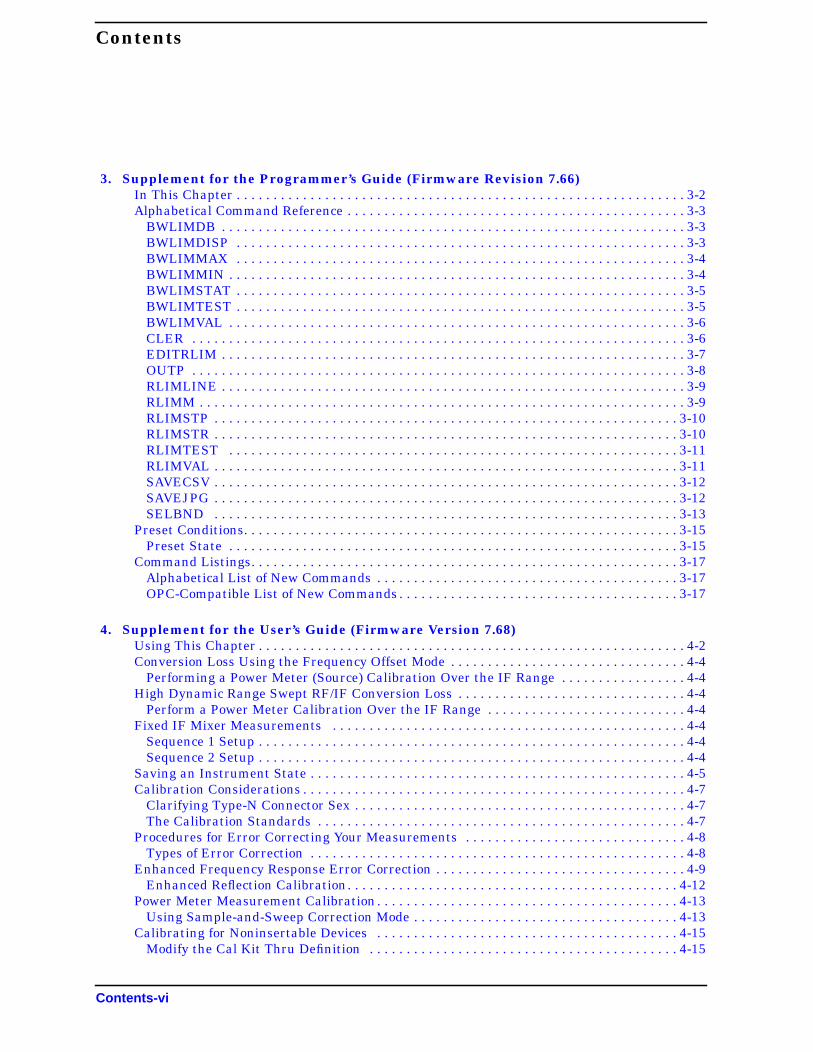
3. Supplement for the Programmer’s Guide (Firmware Revision 7.66)In This Chapter . . . . . . . . . . . . . . . . . . . . . . . . . . . . . . . . . . . . . . . . . . . . . . . . . . . . . . . . . . . . . 3-2Alphabetical Command Reference . . . . . . . . . . . . . . . . . . . . . . . . . . . . . . . . . . . . . . . . . . . . . . 3-3
BWLIMDB . . . . . . . . . . . . . . . . . . . . . . . . . . . . . . . . . . . . . . . . . . . . . . . . . . . . . . . . . . . . . . . 3-3BWLIMDISP . . . . . . . . . . . . . . . . . . . . . . . . . . . . . . . . . . . . . . . . . . . . . . . . . . . . . . . . . . . . . 3-3BWLIMMAX . . . . . . . . . . . . . . . . . . . . . . . . . . . . . . . . . . . . . . . . . . . . . . . . . . . . . . . . . . . . . 3-4BWLIMMIN . . . . . . . . . . . . . . . . . . . . . . . . . . . . . . . . . . . . . . . . . . . . . . . . . . . . . . . . . . . . . . 3-4BWLIMSTAT . . . . . . . . . . . . . . . . . . . . . . . . . . . . . . . . . . . . . . . . . . . . . . . . . . . . . . . . . . . . . 3-5BWLIMTEST . . . . . . . . . . . . . . . . . . . . . . . . . . . . . . . . . . . . . . . . . . . . . . . . . . . . . . . . . . . . . 3-5BWLIMVAL . . . . . . . . . . . . . . . . . . . . . . . . . . . . . . . . . . . . . . . . . . . . . . . . . . . . . . . . . . . . . . 3-6CLER . . . . . . . . . . . . . . . . . . . . . . . . . . . . . . . . . . . . . . . . . . . . . . . . . . . . . . . . . . . . . . . . . . . 3-6EDITRLIM . . . . . . . . . . . . . . . . . . . . . . . . . . . . . . . . . . . . . . . . . . . . . . . . . . . . . . . . . . . . . . . 3-7OUTP . . . . . . . . . . . . . . . . . . . . . . . . . . . . . . . . . . . . . . . . . . . . . . . . . . . . . . . . . . . . . . . . . . . 3-8RLIMLINE . . . . . . . . . . . . . . . . . . . . . . . . . . . . . . . . . . . . . . . . . . . . . . . . . . . . . . . . . . . . . . . 3-9RLIMM . . . . . . . . . . . . . . . . . . . . . . . . . . . . . . . . . . . . . . . . . . . . . . . . . . . . . . . . . . . . . . . . . . 3-9RLIMSTP . . . . . . . . . . . . . . . . . . . . . . . . . . . . . . . . . . . . . . . . . . . . . . . . . . . . . . . . . . . . . . . 3-10RLIMSTR . . . . . . . . . . . . . . . . . . . . . . . . . . . . . . . . . . . . . . . . . . . . . . . . . . . . . . . . . . . . . . . 3-10RLIMTEST . . . . . . . . . . . . . . . . . . . . . . . . . . . . . . . . . . . . . . . . . . . . . . . . . . . . . . . . . . . . . 3-11RLIMVAL . . . . . . . . . . . . . . . . . . . . . . . . . . . . . . . . . . . . . . . . . . . . . . . . . . . . . . . . . . . . . . . 3-11SAVECSV . . . . . . . . . . . . . . . . . . . . . . . . . . . . . . . . . . . . . . . . . . . . . . . . . . . . . . . . . . . . . . . 3-12SAVEJPG . . . . . . . . . . . . . . . . . . . . . . . . . . . . . . . . . . . . . . . . . . . . . . . . . . . . . . . . . . . . . . . 3-12SELBND . . . . . . . . . . . . . . . . . . . . . . . . . . . . . . . . . . . . . . . . . . . . . . . . . . . . . . . . . . . . . . . 3-13
Preset Conditions. . . . . . . . . . . . . . . . . . . . . . . . . . . . . . . . . . . . . . . . . . . . . . . . . . . . . . . . . . . 3-15Preset State . . . . . . . . . . . . . . . . . . . . . . . . . . . . . . . . . . . . . . . . . . . . . . . . . . . . . . . . . . . . . 3-15
Command Listings. . . . . . . . . . . . . . . . . . . . . . . . . . . . . . . . . . . . . . . . . . . . . . . . . . . . . . . . . . 3-17Alphabetical List of New Commands . . . . . . . . . . . . . . . . . . . . . . . . . . . . . . . . . . . . . . . . . 3-17OPC-Compatible List of New Commands . . . . . . . . . . . . . . . . . . . . . . . . . . . . . . . . . . . . . . 3-17
4. Supplement for the User’s Guide (Firmware Version 7.68)Using This Chapter . . . . . . . . . . . . . . . . . . . . . . . . . . . . . . . . . . . . . . . . . . . . . . . . . . . . . . . . . . 4-2Conversion Loss Using the Frequency Offset Mode . . . . . . . . . . . . . . . . . . . . . . . . . . . . . . . . 4-4
Performing a Power Meter (Source) Calibration Over the IF Range . . . . . . . . . . . . . . . . . 4-4High Dynamic Range Swept RF/IF Conversion Loss . . . . . . . . . . . . . . . . . . . . . . . . . . . . . . . 4-4
Perform a Power Meter Calibration Over the IF Range . . . . . . . . . . . . . . . . . . . . . . . . . . . 4-4Fixed IF Mixer Measurements . . . . . . . . . . . . . . . . . . . . . . . . . . . . . . . . . . . . . . . . . . . . . . . . 4-4
Sequence 1 Setup . . . . . . . . . . . . . . . . . . . . . . . . . . . . . . . . . . . . . . . . . . . . . . . . . . . . . . . . . . 4-4Sequence 2 Setup . . . . . . . . . . . . . . . . . . . . . . . . . . . . . . . . . . . . . . . . . . . . . . . . . . . . . . . . . . 4-4
Saving an Instrument State . . . . . . . . . . . . . . . . . . . . . . . . . . . . . . . . . . . . . . . . . . . . . . . . . . . 4-5Calibration Considerations . . . . . . . . . . . . . . . . . . . . . . . . . . . . . . . . . . . . . . . . . . . . . . . . . . . . 4-7
Clarifying Type-N Connector Sex . . . . . . . . . . . . . . . . . . . . . . . . . . . . . . . . . . . . . . . . . . . . . 4-7The Calibration Standards . . . . . . . . . . . . . . . . . . . . . . . . . . . . . . . . . . . . . . . . . . . . . . . . . . 4-7
Procedures for Error Correcting Your Measurements . . . . . . . . . . . . . . . . . . . . . . . . . . . . . . 4-8Types of Error Correction . . . . . . . . . . . . . . . . . . . . . . . . . . . . . . . . . . . . . . . . . . . . . . . . . . . 4-8
Enhanced Frequency Response Error Correction . . . . . . . . . . . . . . . . . . . . . . . . . . . . . . . . . . 4-9Enhanced Reflection Calibration. . . . . . . . . . . . . . . . . . . . . . . . . . . . . . . . . . . . . . . . . . . . . 4-12
Power Meter Measurement Calibration. . . . . . . . . . . . . . . . . . . . . . . . . . . . . . . . . . . . . . . . . 4-13Using Sample-and-Sweep Correction Mode . . . . . . . . . . . . . . . . . . . . . . . . . . . . . . . . . . . . 4-13
Calibrating for Noninsertable Devices . . . . . . . . . . . . . . . . . . . . . . . . . . . . . . . . . . . . . . . . . 4-15Modify the Cal Kit Thru Definition . . . . . . . . . . . . . . . . . . . . . . . . . . . . . . . . . . . . . . . . . . 4-15
Contents-vi

Contents
Calibrating Using Electronic Calibration (ECal) . . . . . . . . . . . . . . . . . . . . . . . . . . . . . . . . . .4-17Set Up the Measurement . . . . . . . . . . . . . . . . . . . . . . . . . . . . . . . . . . . . . . . . . . . . . . . . . . .4-17Connect the ECal Equipment. . . . . . . . . . . . . . . . . . . . . . . . . . . . . . . . . . . . . . . . . . . . . . . .4-18Select the ECal Options . . . . . . . . . . . . . . . . . . . . . . . . . . . . . . . . . . . . . . . . . . . . . . . . . . . .4-20Perform the Calibration . . . . . . . . . . . . . . . . . . . . . . . . . . . . . . . . . . . . . . . . . . . . . . . . . . . .4-21Display the Module Information . . . . . . . . . . . . . . . . . . . . . . . . . . . . . . . . . . . . . . . . . . . . .4-24Perform the Confidence Check . . . . . . . . . . . . . . . . . . . . . . . . . . . . . . . . . . . . . . . . . . . . . . .4-24Investigating the Calibration Results Using the ECal Service Menu . . . . . . . . . . . . . . . .4-27
Adapter Removal Using ECal (ES Analyzers Only). . . . . . . . . . . . . . . . . . . . . . . . . . . . . . . .4-29Perform the 2-Port Error Corrections . . . . . . . . . . . . . . . . . . . . . . . . . . . . . . . . . . . . . . . . .4-31Determine the Electrical Delay . . . . . . . . . . . . . . . . . . . . . . . . . . . . . . . . . . . . . . . . . . . . . .4-33Remove the Adapter . . . . . . . . . . . . . . . . . . . . . . . . . . . . . . . . . . . . . . . . . . . . . . . . . . . . . . .4-34Verify the Results . . . . . . . . . . . . . . . . . . . . . . . . . . . . . . . . . . . . . . . . . . . . . . . . . . . . . . . . .4-36
Calibration Routines . . . . . . . . . . . . . . . . . . . . . . . . . . . . . . . . . . . . . . . . . . . . . . . . . . . . . . . .4-37Enhanced Response Calibration . . . . . . . . . . . . . . . . . . . . . . . . . . . . . . . . . . . . . . . . . . . . .4-37ECal . . . . . . . . . . . . . . . . . . . . . . . . . . . . . . . . . . . . . . . . . . . . . . . . . . . . . . . . . . . . . . . . . . .4-37
Safety Considerations . . . . . . . . . . . . . . . . . . . . . . . . . . . . . . . . . . . . . . . . . . . . . . . . . . . . . . .4-39Servicing . . . . . . . . . . . . . . . . . . . . . . . . . . . . . . . . . . . . . . . . . . . . . . . . . . . . . . . . . . . . . . . .4-39
5. Supplement for the Reference Guide (Firmware Revision 7.68)In This Chapter . . . . . . . . . . . . . . . . . . . . . . . . . . . . . . . . . . . . . . . . . . . . . . . . . . . . . . . . . . . . .5-2Menu Maps . . . . . . . . . . . . . . . . . . . . . . . . . . . . . . . . . . . . . . . . . . . . . . . . . . . . . . . . . . . . . . . . .5-3Hardkey/Softkey Reference . . . . . . . . . . . . . . . . . . . . . . . . . . . . . . . . . . . . . . . . . . . . . . . . . . .5-17
Changes to Existing Softkeys . . . . . . . . . . . . . . . . . . . . . . . . . . . . . . . . . . . . . . . . . . . . . . . .5-17New Softkeys . . . . . . . . . . . . . . . . . . . . . . . . . . . . . . . . . . . . . . . . . . . . . . . . . . . . . . . . . . . . .5-18
Error Messages. . . . . . . . . . . . . . . . . . . . . . . . . . . . . . . . . . . . . . . . . . . . . . . . . . . . . . . . . . . . .5-21Error Messages in Alphabetical Order . . . . . . . . . . . . . . . . . . . . . . . . . . . . . . . . . . . . . . . .5-21Error Messages in Numerical Order . . . . . . . . . . . . . . . . . . . . . . . . . . . . . . . . . . . . . . . . . .5-25
Options and Accessories. . . . . . . . . . . . . . . . . . . . . . . . . . . . . . . . . . . . . . . . . . . . . . . . . . . . . .5-27Accessories Available . . . . . . . . . . . . . . . . . . . . . . . . . . . . . . . . . . . . . . . . . . . . . . . . . . . . . .5-27
Preset State and Memory Allocation . . . . . . . . . . . . . . . . . . . . . . . . . . . . . . . . . . . . . . . . . . .5-29Preset State . . . . . . . . . . . . . . . . . . . . . . . . . . . . . . . . . . . . . . . . . . . . . . . . . . . . . . . . . . . . .5-29
6. Supplement for the Programmer’s Guide (Firmware Revision 7.68)In This Chapter . . . . . . . . . . . . . . . . . . . . . . . . . . . . . . . . . . . . . . . . . . . . . . . . . . . . . . . . . . . . .6-2Alphabetical Command Reference . . . . . . . . . . . . . . . . . . . . . . . . . . . . . . . . . . . . . . . . . . . . . .6-3
CALI . . . . . . . . . . . . . . . . . . . . . . . . . . . . . . . . . . . . . . . . . . . . . . . . . . . . . . . . . . . . . . . . . . . .6-3CALK . . . . . . . . . . . . . . . . . . . . . . . . . . . . . . . . . . . . . . . . . . . . . . . . . . . . . . . . . . . . . . . . . . .6-3ECALAB?. . . . . . . . . . . . . . . . . . . . . . . . . . . . . . . . . . . . . . . . . . . . . . . . . . . . . . . . . . . . . . . . .6-5ECALCONT. . . . . . . . . . . . . . . . . . . . . . . . . . . . . . . . . . . . . . . . . . . . . . . . . . . . . . . . . . . . . . .6-5ECALDONE . . . . . . . . . . . . . . . . . . . . . . . . . . . . . . . . . . . . . . . . . . . . . . . . . . . . . . . . . . . . . .6-6ECALERC . . . . . . . . . . . . . . . . . . . . . . . . . . . . . . . . . . . . . . . . . . . . . . . . . . . . . . . . . . . . . . . .6-6ECALFREQS. . . . . . . . . . . . . . . . . . . . . . . . . . . . . . . . . . . . . . . . . . . . . . . . . . . . . . . . . . . . . .6-7ECALFUL2 . . . . . . . . . . . . . . . . . . . . . . . . . . . . . . . . . . . . . . . . . . . . . . . . . . . . . . . . . . . . . . .6-7ECALISOAVG . . . . . . . . . . . . . . . . . . . . . . . . . . . . . . . . . . . . . . . . . . . . . . . . . . . . . . . . . . . . .6-8ECALMANTHRU . . . . . . . . . . . . . . . . . . . . . . . . . . . . . . . . . . . . . . . . . . . . . . . . . . . . . . . . . .6-8ECALMODID . . . . . . . . . . . . . . . . . . . . . . . . . . . . . . . . . . . . . . . . . . . . . . . . . . . . . . . . . . . . .6-9ECALMODINF . . . . . . . . . . . . . . . . . . . . . . . . . . . . . . . . . . . . . . . . . . . . . . . . . . . . . . . . . . .6-10
Contents-vii

Contents
ECALMODSELA . . . . . . . . . . . . . . . . . . . . . . . . . . . . . . . . . . . . . . . . . . . . . . . . . . . . . . . . . 6-11ECALMODSELB . . . . . . . . . . . . . . . . . . . . . . . . . . . . . . . . . . . . . . . . . . . . . . . . . . . . . . . . . 6-11ECALNFREQS . . . . . . . . . . . . . . . . . . . . . . . . . . . . . . . . . . . . . . . . . . . . . . . . . . . . . . . . . . . 6-12ECALOMII . . . . . . . . . . . . . . . . . . . . . . . . . . . . . . . . . . . . . . . . . . . . . . . . . . . . . . . . . . . . . . 6-12ECALPAUSED . . . . . . . . . . . . . . . . . . . . . . . . . . . . . . . . . . . . . . . . . . . . . . . . . . . . . . . . . . . 6-13ECALRERC . . . . . . . . . . . . . . . . . . . . . . . . . . . . . . . . . . . . . . . . . . . . . . . . . . . . . . . . . . . . . 6-13ECALS11. . . . . . . . . . . . . . . . . . . . . . . . . . . . . . . . . . . . . . . . . . . . . . . . . . . . . . . . . . . . . . . . 6-14ECALS22. . . . . . . . . . . . . . . . . . . . . . . . . . . . . . . . . . . . . . . . . . . . . . . . . . . . . . . . . . . . . . . . 6-14
Preset Conditions. . . . . . . . . . . . . . . . . . . . . . . . . . . . . . . . . . . . . . . . . . . . . . . . . . . . . . . . . . . 6-15Command Listings. . . . . . . . . . . . . . . . . . . . . . . . . . . . . . . . . . . . . . . . . . . . . . . . . . . . . . . . . . 6-17
Alphabetical List of Commands. . . . . . . . . . . . . . . . . . . . . . . . . . . . . . . . . . . . . . . . . . . . . . 6-17OPC-Compatible List of Commands . . . . . . . . . . . . . . . . . . . . . . . . . . . . . . . . . . . . . . . . . . 6-17
7. Supplement for the Installation and Quick Start Guide (Firmware Version 7.68)Using This Chapter . . . . . . . . . . . . . . . . . . . . . . . . . . . . . . . . . . . . . . . . . . . . . . . . . . . . . . . . . . 7-2General Safety Considerations . . . . . . . . . . . . . . . . . . . . . . . . . . . . . . . . . . . . . . . . . . . . . . . . 7-3If You Encounter a Problem . . . . . . . . . . . . . . . . . . . . . . . . . . . . . . . . . . . . . . . . . . . . . . . . . . . 7-4
Power-Up Problems . . . . . . . . . . . . . . . . . . . . . . . . . . . . . . . . . . . . . . . . . . . . . . . . . . . . . . . . 7-4
Contents-viii
1 Supplement for the User’s Guide(Firmware Version 7.66)
1-1

Supplement for the User’s Guide (Firmware Version 7.66)Using This Chapter
Using This ChapterThis chapter contains the supplemental information changes to the user’s guides thatcoincide with the release of firmware revision 7.66. These changes pertain to the followinguser’s guides.
• 8753ET and 8753ES Network Analyzers User’s Guide (part number 08753-90472)
• 8753ES Option 011 Network Analyzer User’s Guide (part number 08753-90479)
The following list describes the changes to 8753ET and 8753ES user’s guides printed priorto July 2000. Each of the changes are described in detail in the remainder of this chapter.The page references in this list refer to page numbers in this supplement.
• Making Measurements Chapter
— Add the softkey after the softkey in all existinglocations.
— Add the softkey between the key and thesoftkey in the section titled “Limit Test Example Sequence”
in “Using Test Sequencing to Test a Device” on page 1-5.
— Add “Using Ripple Limits to Test a Device” on page 1-7 to the chapter.
— Add “Using Bandwidth Limits to Test a Bandpass Filter” on page 1-17 to the chapter.
• Making Mixer Measurements Chapter
— Replace the section titled “Conversion Loss Using the Frequency Offset Mode” onpage 1-23.
• Printing, Plotting, and Saving Measurement Results Chapter
— Add a note referencing the new “Saving in Graphical (JPEG) Form” section after thedisplayed paragraph in “To View Plot Files on a PC.”
— Add the new sections “Saving in Textual (CSV) Form” on page 1-33 and “Saving inGraphical (JPEG) Form” on page 1-34 to the “Saving Measurement Results” section.
• Calibrating for Increased Measurement Accuracy Chapter
— Add a paragraph explaining the frequency entry to step 5 of “Calibrating forNon-Coaxial Devices (ES Analyzers Only).”
— Append a note referencing the new “Saving Modified Calibration Kits to a Disk”section to step 19 of the “Calibrating for Non-Coaxial Devices (ES Analyzers Only)”section.
— Append a note referencing the new “Saving Modified Calibration Kits to a Disk”section to step 19 of the “LRM Error Correction” section.
• Operating Concepts Chapter
— Append “Saving Modified Calibration Kits to a Disk” on page 1-37 to the end of thesection titled “Modifying Calibration Kits.”
LIMIT LINE LIMIT MENU
RECALL KEYS Save/Recall RECALLKEYS MENU
1-2

Supplement for the User’s Guide (Firmware Version 7.66)Using Limit Lines to Test a Device
Using Limit Lines to Test a Device
Creating Flat Limit Lines
In step 1, replace the following line:
with
Creating a Sloping Limit Line
In step 1, replace the following line:
with
Creating Single Point Limits
In step 1, replace the following line:
with
Editing Limit Segments
In step 1, replace the following line:
with
System LIMIT MENU LIMIT LINE ON EDIT LIMIT LINE CLEAR LIST YES
System LIMIT MENU LIMIT LINE LIMIT LINE ON EDIT LIMIT LINE CLEAR LIST YES
System LIMIT MENU LIMIT LINE ON EDIT LIMIT LINE CLEAR LIST YES
System LIMIT MENU LIMIT LINE LIMIT LINE ON EDIT LIMIT LINE CLEAR LIST YES
System LIMIT MENU LIMIT LINE ON EDIT LIMIT LINE CLEAR LIST YES
System LIMIT MENU LIMIT LINE LIMIT LINE ON EDIT LIMIT LINE CLEAR LIST YES
System LIMIT MENU LIMIT LINE ON EDIT LIMIT LINE
System LIMIT MENU LIMIT LINE LIMIT LINE ON EDIT LIMIT LINE
1-3

Supplement for the User’s Guide (Firmware Version 7.66)Using Limit Lines to Test a Device
Deleting Limit Segments
In step 1, replace the following line:
with
Running a Limit Test
In step 1, replace the following line:
with
Activating the Limit Test
In this section, replace the following line:
with
Offsetting Limit Lines
In step 1, replace the following line:
with
System LIMIT MENU LIMIT LINE ON EDIT LIMIT LINE
System LIMIT MENU LIMIT LINE LIMIT LINE ON EDIT LIMIT LINE
System LIMIT MENU LIMIT LINE ON EDIT LIMIT LINE
System LIMIT MENU LIMIT LINE LIMIT LINE ON EDIT LIMIT LINE
System LIMIT MENU LIMIT TEST ON BEEP FAIL ON
System LIMIT MENU LIMIT LINE LIMIT TEST ON BEEP FAIL ON
System LIMIT MENU LIMIT LINE OFFSETS STIMULUS OFFSET 3 M/µ
System LIMIT MENU LIMIT LINE LIMIT LINE OFFSETS STIMULUS OFFSET3 M/µ
1-4

Supplement for the User’s Guide (Firmware Version 7.66)Using Test Sequencing to Test a Device
Using Test Sequencing to Test a Device
Limit Test Example Sequence
In step 1, replace the following line:
with:
Save/Recall RECALLKEYS MENU RECALL REG1
Save/Recall RECALL KEYS RECALLKEYS MENU RECALL REG1
1-5

Supplement for the User’s Guide (Firmware Version 7.66)Using Test Sequencing to Test a Device
This page intentionally left blank.
1-6

Supplement for the User’s Guide (Firmware Version 7.66)Using Ripple Limits to Test a Device
Using Ripple Limits to Test a Device
Setting Up the List of Ripple Limits to Test
Two tasks are involved in preparing for ripple testing:
• First, set up the analyzer settings to view the frequency of interest.
• Second, set up the analyzer to test over the appropriate frequencies against yourspecific limits.
This example will show you how to set up the analyzer to test ripple limits. In thisexample, we will be testing the pass band of a bandpass filter where the center frequencyof the filter is approximately 1.8 GHz and has a bandwidth of approximately 2.9 GHz.Refer to Figure 1-1.
Figure 1-1 Bandpass Filter Being Ripple Tested
1-7

Supplement for the User’s Guide (Firmware Version 7.66)Using Ripple Limits to Test a Device
Setting Up the Analyzer to Perform the Ripple Test
This section sets up the analyzer so that a bandpass filter can be easily viewed on theanalyzer display.
1. Connect your filter as shown in Figure 1-2.
Figure 1-2 Connections for an Example Ripple Test Measurement
2. Press and choose the measurement settings. For this example, themeasurement settings are as follows:
• or on ET models:
•
•
•
You may also want to select settings for the number of data points, power, averaging,and IF bandwidth.
3. Substitute a thru for the device and perform a response calibration by pressing:
4. Reconnect your test device.
5. To better view the measurement trace, press . Refer toFigure 1-3.
Preset
Meas Trans: FWD S21 (B/R) TRANSMISSN
Center 1.8 G/n
Span 3.4 G/n
Scale Ref AUTO SCALE
Cal CALIBRATE MENU RESPONSE THRU
Scale Ref AUTO SCALE
1-8

Supplement for the User’s Guide (Firmware Version 7.66)Using Ripple Limits to Test a Device
Figure 1-3 Filter Pass Band Before Ripple Test
Setting Up Limits for Ripple Testing
This section instructs you on setting up the ripple tests parameters. You must set up theanalyzer to check the DUT at the correct frequencies and compare the measured valuesagainst the maximum allowable ripple value for each frequency band. To do this, you setup individual frequency bands. You define the stop and start frequency and the maximumallowable ripple value of each frequency band. You may set up as many as 12 frequencybands for testing ripple. The frequency bands are combined in a list that is displayed whilethe ripple frequency bands are being edited.
In this example, we will create one ripple limit (or frequency band) that spans the entirepass band from 500 MHz to 3.2 GHz. We will also create two additional frequency bandsthat when merged, will span the pass band with tighter limits. Using the Ripple EditMenu, we will create a ripple limits list on the analyzer that is similar to the followingtable.
Notice that Frequency Band 1 overlaps in frequency the remaining frequency bands.Whereas, Frequency Bands 2 and 3 are separate bands that cover the same span offrequency. This can be done to put tighter limits over narrower frequency spans within thebandpass or to customize the ripple test to meet your specific requirements.
Table 1-1 Ripple Limits for Ripple Test Example
Frequency Band Minimum Frequency Maximum Frequency Maximum Ripple
1 500 MHz 3.2 GHz 2.0 dB
2 500 MHz 1.85 GHz 1.3 dB
3 1.85 GHz 3.2 GHz 1.3 dB
1-9

Supplement for the User’s Guide (Firmware Version 7.66)Using Ripple Limits to Test a Device
1. To access the ripple test menu, press:
2. To access the ripple test edit menu, press .
3. Add the first frequency band (Frequency Band 1) to be tested by pressing .
4. Set the lower frequency value of Frequency Band 1 by pressing:
5. Set the upper frequency value of Frequency Band 1 by pressing:
6. Set the maximum allowable ripple amplitude value of Frequency Band 1 by pressing:
7. Repeat steps 3 through 6 for the two remaining frequency bands to be tested formaximum ripple.
The network analyzer allows you to enter up to 12 frequency bands to be tested formaximum ripple.
8. After you have entered all of the ripple test frequency band parameters, return to theripple test menu by pressing .
Editing Ripple Test Limits
Once the frequency band limits for ripple testing has been created, the limits may bechanged using the same menu that was used to create them. Using the edit ripple testmenu, you may:
• change existing frequency band limits
• add more frequency band limits
• delete individual frequency band limits
• clear all frequency band limits
Changing Existing Frequency Band Limits
Existing frequency band limits may be changed for testing the ripple. This procedureguides you through changing the existing frequency band limits.
1. To access the ripple test edit menu from the ripple test menu, press:
2. Enter the frequency band whose limits you want to change by pressing:
a.
b. The numeric key indicating the frequency band number that you are changing.
The frequency band number is located in the left column of the list of frequencybands.
System LIMIT MENU RIPPLE LIMIT
EDIT RIPL LIMIT
ADD
MINIMUM FREQUENCY 500 M/µ
MAXIMUM FREQUENCY 3.2 G/n
MAXIMUM RIPPLE 2.0 x1
DONE
EDIT RIPL LIMIT
FREQUENCY BAND
1-10

Supplement for the User’s Guide (Firmware Version 7.66)Using Ripple Limits to Test a Device
3. Make the changes to the selected band by pressing:
a. and the new value to change the lower frequency of thefrequency band.
b. and the new value to change the upper frequency of thefrequency band.
c. and the new decibel value to change the maximum allowableripple of the frequency band. Terminate the new decibel value with the key.
4. Repeat steps 2 and 3 for additional frequency bands to be changed to test the ripple.
5. After you have entered the necessary changes to the ripple test frequency bandparameters, return to the ripple test menu by pressing .
Adding Additional Frequency Bands
More frequency band limits may be added for testing the ripple. This procedure guides youthrough adding the more frequency band limits.
The network analyzer allows you to enter up to 12 frequency bands for maximum rippletesting.
1. To access the ripple test edit menu, press .
2. Create a new frequency band by pressing .
3. Set the lower frequency value of the frequency band by pressing:
a.
b. the numeric keys indicating the minimum frequency value of the frequency band
c. the appropriate frequency key (either , , or )
4. Set the upper frequency value of the frequency band by pressing:
a.
b. the numeric keys indicating the maximum frequency value of the frequency band
c. the appropriate frequency key (either , , or )
5. Set the maximum allowable ripple amplitude value of the frequency band by pressing:
a.
b. the decibel value of the frequency band’s maximum allowable ripple
c.
6. Repeat steps 2 through 5 for additional frequency bands to be tested for maximumripple.
7. After you have added all of the new frequency bands, return to the ripple test menu bypressing .
MINIMUM FREQUENCY
MAXIMUM FREQUENCY
MAXIMUM RIPPLEx1
DONE
EDIT RIPL LIMIT
ADD
MINIMUM FREQUENCY
G/n M/µ k/m
MAXIMUM FREQUENCY
G/n M/µ k/m
MAXIMUM RIPPLE
x1
DONE
1-11

Supplement for the User’s Guide (Firmware Version 7.66)Using Ripple Limits to Test a Device
Deleting Existing Frequency Bands
Frequency band limits may be deleted for testing the ripple. This procedure guides youthrough deleting existing frequency band limits. You may delete individual frequencybands or delete all of the frequency bands from the list.
1. To access the ripple test edit menu, press:
2. Select the first frequency band (as an example, Frequency Band 3) to be deleted bypressing:
3. Repeat step 2 until you have deleted the required frequency bands from the list.
4. If you need to delete all of the frequency bands, you can delete them all by pressing:
When this softkey is pressed, you will be asked to confirm that you want to delete all ofthe frequency bands from the list.
5. After you have finished deleting the frequency bands, you can return to the ripple testmenu by pressing .
Running the Ripple Test
Once the list of ripple limits has been set up, you are ready to run the ripple test. From theRipple Test Menu, you can:
• start and stop the ripple test
• display and hide the ripple test limit lines
• select a frequency band and display its ripple measurement in two ways:
the absolute measured ripple value
the margin which the measured ripple passes or fails the user-defined maximumripple value
Starting and Stopping the Ripple Test
Once the list of ripple limits have been set up, start the ripple test by pressing from the Ripple Test Menu until ON is displayed on the softkey.
Pressing this softkey toggles the analyzer between ripple test on and ripple test off status.Figure 1-4 shows the filter pass band (with the scale changed to 1 dB/division) being rippletested. Note that the filter fails the ripple test. The portions of the pass band trace whichdo not meet the test requirements are displayed in red.
EDIT RIPL LIMIT
FREQUENCY BAND 3 x1 DELETE
CLEAR LIST
DONE
RIPL TEST on OFF
1-12

Supplement for the User’s Guide (Firmware Version 7.66)Using Ripple Limits to Test a Device
Figure 1-4 Filter Passband with Ripple Test Activated
As the analyzer measures the ripple, a message is displayed indicating whether themeasurement passes or fails:
• If the ripple test passes, a RIPLn PASS message (where n = the channel number) isdisplayed in the color assigned to Channel 1 Memory. The ripple test must pass in allfrequency bands before the pass message is displayed.
• If the ripple test fails, a RIPLn FAIL message (where n = the channel number) isdisplayed in red. The portion of the trace that exceeds the user-specified maximumripple value is also displayed in red.
Displaying the Ripple Limits
After the list of ripple limits has been set up, display the ripple test limits by pressingfrom the Ripple Test Menu until ON is displayed on the softkey.
Pressing this softkey toggles the analyzer ripple limits display on and off. If the ripplelimits are displayed and the ripple test is off, the ripple limits are displayed near the top ofthe graticule and are not compared with the displayed trace. However, once the ripple testis started, the ripple limits are displayed with respect to the measured trace in thefollowing manner:
• If the ripple test passes, the ripple limits are drawn on the display for each frequencyband. Within each frequency band, an upper and lower ripple limit is drawn such thatthey are equidistant above the upper point of the measured trace and below the lowerpoint of the measured trace.
• If the ripple test fails, the ripple limits are drawn on the display for each frequencyband. Within each frequency band, the lower ripple limit is drawn at the lowest point onthe measured trace and the upper ripple limit is drawn at the user-specified maximum
RIPL LIMIT on OFF
1-13

Supplement for the User’s Guide (Firmware Version 7.66)Using Ripple Limits to Test a Device
ripple value above the lower ripple limit. The ripple that exceeds the maximum ripplevalue extends above the upper limit. This measured trace that extends above the upperlimit is displayed in red.
Figure 1-5 shows the filter pass band tested with the ripple limits activated. Notice thatthere are three sets of ripple limits shown. Also notice that the measured trace exceeds theupper ripple limit only in Frequency Band 3.
Figure 1-5 Filter Pass Band with Ripple Test and Ripple Limits Activated
Changing the Ripple Limits Line Color. The color of the lines that represent theripple limits can be changed by:
1. pressing the key
2. pressing
3. pressing and turning the analyzer front panel knob untilthe desired color appears (You may also use the step keys or the numeric keypadinstead of the front panel knob to change the color.)
Checking the Ripple Value
Once the ripple test has been started and is running, you may display the ripple value ofeach frequency band in one of two formats, the absolute format or the margin format. Bothformats are described in this section.
To display the ripple value, press . Pressing this softkey togglesbetween , , and
. from the Ripple Test Menu until ON isdisplayed on the softkey. Pressing this softkey toggles the analyzer between ripple test on
Display
MORE ADJUST DISPLAY MODIFY COLORS MORE
RIPPLE LIM LINES TINT
RIPL VALUE [ ] RIPL VALUE [OFF ] RIPL VALUE [ABSOLUTE ]
RIPL VALUE [MARGIN ] RIPL TEST on OFF
1-14

Supplement for the User’s Guide (Firmware Version 7.66)Using Ripple Limits to Test a Device
and ripple test off status.
When the Absolute and Margin choices are selected, the frequency band and measurementvalue are displayed to the right side of the pass/fail message described previously. Thisdisplay is displayed in the same color as the pass/fail message.
The frequency band of the displayed value is displayed as Bn (where n = the frequencyband number). The frequency band may be changed to display the value of each band. Tochange the displayed frequency band value, from the Ripple Test Menu, press
and then use the and keys (or the numerical keypad) toselect the desired frequency band.
Viewing the Ripple Value in Absolute Format
When is selected, the absolute ripple value of the selectedfrequency band is displayed. The absolute ripple value is the measured maximum levelminus the measured minimum level within the frequency band. This value is displayed indB.
Figure 1-6 shows the ripple test with absolute ripple value displayed for FrequencyBand 1. The B1 indicates that the ripple value displayed is for Frequency Band 1. Noticethat Frequency Band 1 passes the ripple test. It has an absolute ripple value of 1.675 dBwhile the maximum ripple value entered for Frequency Band 1 was 2.0 dB. Thus, eventhough the ripple test fails because of Frequency Band 3, the ripple passes in FrequencyBand 1.
Figure 1-6 Filter Pass Band with Absolute Ripple Value for Band 1 Activated
RIPL VALUE BAND
RIPL VALUE [ABSOLUTE ]
1-15
Supplement for the User’s Guide (Firmware Version 7.66)Using Ripple Limits to Test a Device
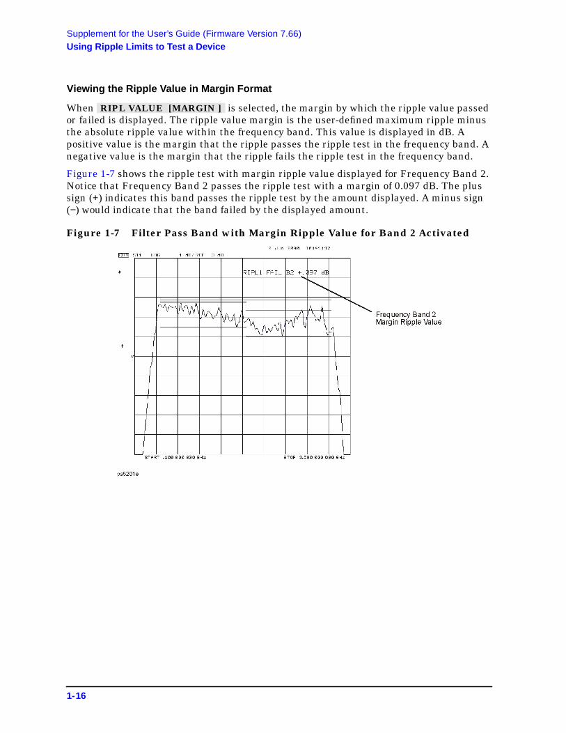
Viewing the Ripple Value in Margin Format
When is selected, the margin by which the ripple value passedor failed is displayed. The ripple value margin is the user-defined maximum ripple minusthe absolute ripple value within the frequency band. This value is displayed in dB. Apositive value is the margin that the ripple passes the ripple test in the frequency band. Anegative value is the margin that the ripple fails the ripple test in the frequency band.
Figure 1-7 shows the ripple test with margin ripple value displayed for Frequency Band 2.Notice that Frequency Band 2 passes the ripple test with a margin of 0.097 dB. The plussign (+) indicates this band passes the ripple test by the amount displayed. A minus sign(−) would indicate that the band failed by the displayed amount.
Figure 1-7 Filter Pass Band with Margin Ripple Value for Band 2 Activated
RIPL VALUE [MARGIN ]
1-16

Supplement for the User’s Guide (Firmware Version 7.66)Using Bandwidth Limits to Test a Bandpass Filter
Using Bandwidth Limits to Test a Bandpass FilterThe bandwidth testing mode can be used to test the bandwidth of a bandpass filter. Thebandwidth test finds the peak of a signal in the passband and locates a point on each sideof the passband at an amplitude below the peak (that you specify during the test setup).The frequency between these two points is the bandwidth of the filter. This bandwidth iscompared to minimum and maximum allowable bandwidths that you specify during thetest setup.
This example shows you how to test the bandwidth of a bandpass filter. In this example,we will be testing the pass band of a bandpass filter where the center frequency of the filteris approximately 321 MHz. Refer to Figure 1-8.
Figure 1-8 Bandpass Filter Being Bandwidth Tested
Setting Up Bandwidth Limits
When you set up the bandwidth limits to test the bandpass filter, you will first set up theanalyzer to perform the bandwidth test and then you will set up bandwidth limits of thebandwidth test.
Setting Up the Analyzer to Perform the Bandwidth Test
This section sets up the analyzer so that a bandpass filter can be easily viewed on theanalyzer display.
1. Connect your filter as shown in Figure 1-9.
1-17

Supplement for the User’s Guide (Firmware Version 7.66)Using Bandwidth Limits to Test a Bandpass Filter
Figure 1-9 Connections for a Bandpass Filter Example Measurement
2. Press and choose the measurement settings. For this example, themeasurement settings are as follows:
a. or on ET models:
b.
c.
d.
You may also want to select settings for the number of data points, power, averaging,and IF bandwidth.
Figure 1-10 Filter Pass Band Before Bandwidth Test
Preset
Meas Trans: FWD S21 (B/R) TRANSMISSN
Center 321 M/µ
Span 200 M/µ
Scale Ref AUTO SCALE
1-18

Supplement for the User’s Guide (Firmware Version 7.66)Using Bandwidth Limits to Test a Bandpass Filter
3. Substitute a thru for the device and perform a response calibration by pressing:
4. Reconnect your test device.
Refer to Figure 1-10.
Setting Up the Bandwidth Limits
When you set up the bandwidth limits to test the bandpass filter, you will set
• the amplitude below the peak that is used to measure the filter’s bandwidth. Thissetting is called N dB Points.
• the Maximum Bandwidth value. If the measured bandwidth is greater than this value,the test will fail.
• the Minimum Bandwidth value. If the measured bandwidth is less than this value, thetest will fail.
1. To access the bandwidth menu, press:
2. To set the amplitude below the peak passband amplitude that you want to measure thebandwidth. In this case, we are setting the bandwidth that will be measured 40 dBbelow the peak amplitude of the bandpass filter by pressing:
3. To set the minimum bandwidth for the bandwidth test, press:
4. To set the maximum bandwidth for the bandwidth test, press:
Running a Bandwidth Test
After setting up the bandwidth limits, you are ready to run the bandwidth test and checkthe test results. For this example, we will:
• Start the test.
• Display the bandwidth markers.
• Review the test results.
Activating the Bandwidth Test
1. Start the bandwidth test by pressing the softkey until ON isdisplayed.
The bandwidth test continues to run until the softkey is returned to the OFF position.
The test displays a message in the upper left corner of the graticule showing that thebandwidth test is being performed and the channel on which the test is being
Cal CALIBRATE MENU RESPONSE THRU
System LIMIT MENU BANDWIDTH LIMIT
N DB POINTS 40 x1
MINIMUM BANDWIDTH 100 M/µ
MAXIMUM BANDWIDTH 150 M/µ
BW TEST on OFF
1-19

Supplement for the User’s Guide (Firmware Version 7.66)Using Bandwidth Limits to Test a Bandpass Filter
performed. For example, BW1: indicates that the bandwidth test is being run onchannel 1. See Figure 1-11.
The test also displays a message indicating whether the filter passes or fails thebandwidth test. When the filter is passing the test, the message indicates Pass. Whenthe filter is failing the test, the failure message indicates either Wide (when the passband is wider than the maximum bandwidth input) or Narrow (when the pass band isnarrower than the minimum bandwidth input).
When the filter passes the bandwidth test, the color of the bandwidth test Pass messageis green. When the filter fails the bandwidth test, the color of the bandwidth testWide/Narrow message is red.
Figure 1-11 Filter Pass Band with Bandwidth Test Activated
Displaying the Bandwidth Markers
1. Display the bandwidth markers by pressing the softkey untilON is displayed on the softkey.
When the bandwidth markers are displayed, a marker is placed on each side of the peakamplitude at a position equal to the N dB Points value below the peak. The markers areplaced at the 40 dB points on the signal in Figure 1-12. The bandwidth markersresemble the following symbol: T
BW MARKER on OFF
1-20

Supplement for the User’s Guide (Firmware Version 7.66)Using Bandwidth Limits to Test a Bandpass Filter
Figure 1-12 Bandwidth Markers Placed 40 dB Below the Bandpass Peak
Displaying the Bandwidth Value
1. Display the bandwidth value by pressing the softkey until ONis displayed on the softkey.
When this softkey is set to the ON position, the measured bandwidth value is displayedin the upper left corner of the display, to the right of the bandwidth Pass/Wide/Narrowmessage. This value changes as the analyzer continues measuring the bandwidth. Thebandwidth value is displayed in Figure 1-13.
If the filter is failing the bandwidth test, the color of the bandwidth value is red, thesame color as the failure (Wide) message of Figure 1-11. If the filter is passing thebandwidth test, the displayed bandwidth value is green (the same color as thebandwidth test Pass message).
BW DISPLAY on OFF
1-21

Supplement for the User’s Guide (Firmware Version 7.66)Using Bandwidth Limits to Test a Bandpass Filter
Figure 1-13 Filter Pass Band with Bandwidth Value Displayed
1-22

Supplement for the User’s Guide (Firmware Version 7.66)Conversion Loss Using the Frequency Offset Mode
Conversion Loss Using the Frequency Offset ModeConversion loss is the measure of efficiency of a mixer. It is the ratio of side-band IF powerto RF signal power, and is usually expressed in dB. The mixer translates the incomingsignal, (RF), to a replica, (IF), displaced in frequency by the local oscillator, (LO).Frequency translation is characterized by a loss in signal amplitude and the generation ofadditional sidebands. For a given translation, two equal output signals are expected, alower sideband and an upper sideband.
Figure 1-14 An Example Spectrum of RF, LO, and IF Signals Present in aConversion Loss Measurement
The following procedure describes the R channel swept IF frequency conversion lossmeasurement of a broadband component mixer with power meter calibration. For thisexample, we will use an LO frequency of 1 GHz (1000 MHz), an IF start frequency of100 MHz, and an IF stop frequency of 350 MHz.
1. Set the LO source to the desired CW frequency of 1000 MHz and power level to 13 dBm.
2. Connect the measurement equipment as shown in Step 1 of Figure 1-15 (or Step 1 ofFigure 1-16).
3. Set the desired analyzer RF power to the value which will provide −10 dBm or less tothe R channel input.
For 8753ET/ES, press .
For 8753ES with Option 011, press .
CAUTION To prevent connector damage, use an adapter (part number 1250-1462) as aconnector saver for R CHANNEL IN.
Power PWR RANGE MAN 0 x1
Power 0 x1
1-23

Supplement for the User’s Guide (Firmware Version 7.66)Conversion Loss Using the Frequency Offset Mode
Figure 1-15 8753ET/ES Connections for R Channel andSource Calibration (IF Range)
Figure 1-16 8753ES Option 011 Connections for R Channel andSource Calibration (IF Range)
1-24

Supplement for the User’s Guide (Firmware Version 7.66)Conversion Loss Using the Frequency Offset Mode
Setting Measurement Parameters for the IF Range
1. From the front panel of the analyzer, set the desired receiver (IF) frequency and sourceoutput power by pressing:
If the LO frequency is not set to 0 Hz, press:
2. Select the measurement trace.
• For 8753ET/ES, press .
• For 8753ES with Option 011, press .
The measurement trace is shown on the display.
3. To select the analyzer as the system controller by pressing.
Performing a Power Meter (Source) Calibration Over the IF Range
1. Calibrate and zero the power meter.
2. Set the power meter's address:
(where aa is the GPIB address of the power meter)
3. Select the appropriate power meter by pressing until the correctmodel number is displayed (Agilent 436A or Agilent 438A/437).
NOTE The Agilent E4418B and Agilent E4419B power meters have a “437emulation” mode. This allows these power meters, with an Agilent848X-series power sensor, to be used with the network analyzer. In this step,when selecting a power meter, choose the 438A/437 selection.
4. Press andenter the correction factors as listed on the power sensor. Press
(where fff is the frequency of the calibration factor in MHz) (where nnn is the calibration factor number) for each correction
factor. When finished, press .
System INSTRUMENT MODE FREQ OFFS MENU
Start 100 M/µ Stop 350 M/µ
LO MENU FREQUENCY: CW 0 x1
Meas INPUT PORTS R
Meas R
Local SYSTEM CONTROLLER
SET ADDRESSES
ADDRESS: P MTR/GPIB aa
x1
POWER MTR [ ]
Cal PWRMTR CAL LOSS/SENSR LISTS CAL FACTOR SENSOR A ADD FREQUENCY
fff M/µ CAL FACTORnnn x1 DONE
DONE
1-25
Supplement for the User’s Guide (Firmware Version 7.66)Conversion Loss Using the Frequency Offset Mode
5. To perform a one sweep power meter calibration over the IF frequency range at 0 dBm,press:
NOTE Because power meter calibration requires a longer sweep time, you may wantto reduce the number of points before pressing . Afterthe power meter calibration is finished, return the number of points to itsoriginal value and the analyzer will automatically interpolate thiscalibration.
6. To calibrate the R channel over the IF range, connect the equipment as shown in Step 2of Figure 1-15 (or Figure 1-16) and press:
The low pass filter is required to limit the range of frequencies passed into the Rchannel input port. The filter is selected to pass the IF frequencies for themeasurement but prevent the LO feedthrough and unwanted mixer products fromconfusing the phase-lock loop operation.
A pad is used to isolate the filter and improve the IF port match for the mixer.
Once completed, the display should read 0 dBm.
Setting the Analyzer to the RF Frequency Range
1. While the analyzer is still set to the IF frequency range, set the frequency offset modeLO frequency from the analyzer by pressing:
The LO menu is used to set only the LO CW frequency. All other settings apply whenusing the HP/Agilent 8625A external source.
2. To select the converter type and a high-side LO measurement configuration, press:
3. Turn on frequency offset operation by pressing:
Notice in this high-side LO, down conversion configuration, the analyzer's source isactually sweeping backwards, as shown in Figure 1-17.
The measurement setup diagram is shown in Figure 1-18 and Figure 1-19. Note the RFfrequency values are shown in this illustration.
Cal PWRMTR CAL ONE SWEEP
0 x1 TAKE CAL SWEEP
TAKE CAL SWEEP
Cal CALIBRATE MENU RECEIVER CAL 0 x1 TAKE RCVR CAL SWEEP
System INSTRUMENT MODE FREQ OFFS MENU
LO MENU FREQUENCY:CW
1000 M/µ
RETURN DOWN CONVERTER RF < LO
FREQS OFFS ON
1-26

Supplement for the User’s Guide (Firmware Version 7.66)Conversion Loss Using the Frequency Offset Mode
Figure 1-17 Diagram of Measurement Frequencies
Figure 1-18 8753ET/ES Measurement Setup from Display
Figure 1-19 8753ES Option 011 Measurement Setup from Display
1-27
Supplement for the User’s Guide (Firmware Version 7.66)Conversion Loss Using the Frequency Offset Mode
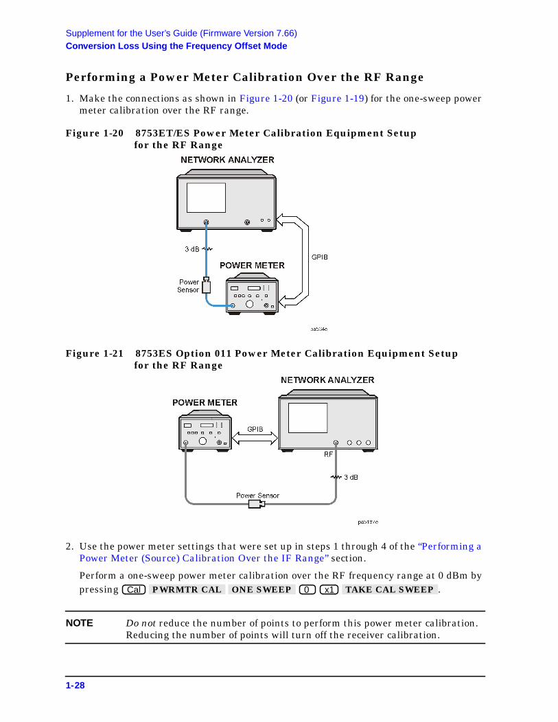
Performing a Power Meter Calibration Over the RF Range
1. Make the connections as shown in Figure 1-20 (or Figure 1-19) for the one-sweep powermeter calibration over the RF range.
Figure 1-20 8753ET/ES Power Meter Calibration Equipment Setupfor the RF Range
Figure 1-21 8753ES Option 011 Power Meter Calibration Equipment Setupfor the RF Range
2. Use the power meter settings that were set up in steps 1 through 4 of the “Performing aPower Meter (Source) Calibration Over the IF Range” section.
Perform a one-sweep power meter calibration over the RF frequency range at 0 dBm bypressing .
NOTE Do not reduce the number of points to perform this power meter calibration.Reducing the number of points will turn off the receiver calibration.
Cal PWRMTR CAL ONE SWEEP 0 x1 TAKE CAL SWEEP
1-28

Supplement for the User’s Guide (Firmware Version 7.66)Conversion Loss Using the Frequency Offset Mode
Performing the R-Channel Measurement
1. Connect the equipment as shown in Figure 1-22 (or Figure 1-23).
Figure 1-22 8753ET/ES R-Channel Mixer Measurement Equipment Setup
Figure 1-23 8753ES Option 011 R-Channel Mixer Measurement Equipment Setup
The analyzer is now displaying the conversion loss of the mixer calibrated with powermeter accuracy.
1-29
Supplement for the User’s Guide (Firmware Version 7.66)Conversion Loss Using the Frequency Offset Mode
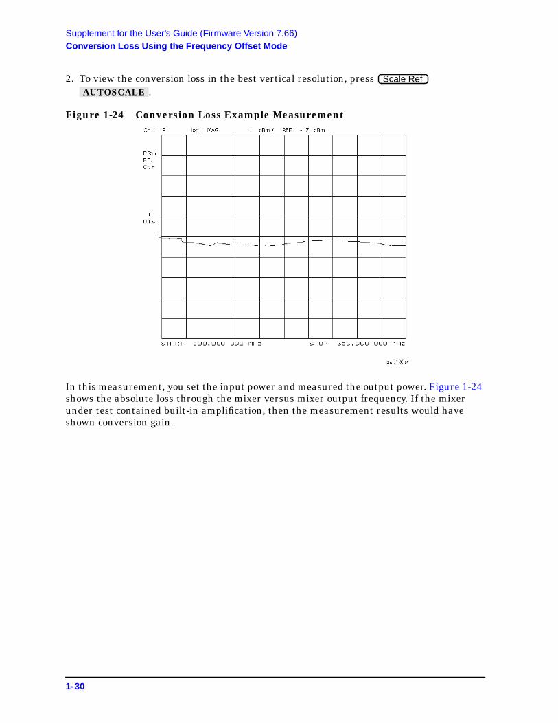
2. To view the conversion loss in the best vertical resolution, press.
Figure 1-24 Conversion Loss Example Measurement
In this measurement, you set the input power and measured the output power. Figure 1-24shows the absolute loss through the mixer versus mixer output frequency. If the mixerunder test contained built-in amplification, then the measurement results would haveshown conversion gain.
Scale Ref AUTOSCALE
1-30

Supplement for the User’s Guide (Firmware Version 7.66)To View Plot Files on a PC
To View Plot Files on a PCTo modify the color or font size, consult the documentation for the particular applicationbeing used.
NOTE Plot files may also be saved to a floppy disk as a JPEG file and used on apersonal computer. Refer to “Saving in Graphical (JPEG) Form” on page 1-34.
1-31

Supplement for the User’s Guide (Firmware Version 7.66)To View Plot Files on a PC
This page intentionally left blank.
1-32

Supplement for the User’s Guide (Firmware Version 7.66)Saving Measurement Results
Saving Measurement Results
Saving in Textual (CSV) Form
Textual measurement results can be saved in a comma-separated value (CSV) format andimported into a spreadsheet application. Additional information is also saved as apreamble to the measurement results. The saved information includes:
• network analyzer model number and firmware version
• date the file was saved
• type of measurement being done
• start and stop frequencies
• sweep time
• port power
• IF bandwidth
• channel number
• number of points
• format
• the frequency (or time) and the real and imaginary measurement values for each ofpoints measured
1. Press .
2. Make sure that is displayed.
3. Make sure that is underlined. If it is not underlined, press thesoftkey so that TEXT is underlined.
4. Insert a 3.5-inch floppy disk in the network analyzer’s disk drive.
5. Press to save the display information as text in the CSV format.
The text file may be retrieved from the floppy disk on personal computer and can beimported into an application that accepts text in the comma-separated value format,such as a spreadsheet.
Save/Recall SAVE FILE FORMATS
TEXT FMT [CSV]
FILETYPE: TEXT
SAVE FILE
1-33

Supplement for the User’s Guide (Firmware Version 7.66)Saving Measurement Results
How the Analyzer Names These Files Sequentially
When text files are saved, the analyzer generates the file names automatically in thefollowing format:
Saving in Graphical (JPEG) Form
Graphical measurement results can be saved in JPEG format and used as an illustrationin a text editor or desktop publishing application.1
1. Press .
2. Make sure that is displayed.
3. Make sure that is underlined. If it is not underlined, press thesoftkey so that GRAPHIC is underlined.
4. Insert a 3.5-inch floppy disk in the network analyzer’s disk drive.
5. Press to save the display as a graphic in the JPEG format.
The graphic file may be retrieved from the floppy disk on personal computer and can beimported into an application that accepts graphics in the JPEG format.
txtcss.csv
where: txt is a constant that indicates that this is a text file,
c is the indicator of the channel (1−4) on which the measurement data wastaken (channel-file index number).
ss is a 2-digit, sequential indicator of the measurement (file index number). Thefile index number may be numbered from 00−31. As the next measurement istaken, the file index number is incremented.
If all four channels are making measurements and a save is performed, therewill be four channel numbers that share the same file index number. Forexample, the files would be named txt100.csv, txt200.csv, txt300.csv, andtxt400.csv. If a measurement does not include all four channels, unusedchannel-file index numbers will not be used by the next measurement.However, if all of the files that share a file index number are erased, that fileindex number will be re-used.
csv is the file format, comma-separated value in this case.
1. The network analyzer firmware is based in part on the work of the Independent JPEG Group.
Save/Recall SAVE FILE FORMATS
GRAPH FMT [JPG]
FILETYPE: GRAPHIC
SAVE FILE
1-34

Supplement for the User’s Guide (Firmware Version 7.66)Calibrating for Non-Coaxial Devices (ES Analyzers Only)
Calibrating for Non-Coaxial Devices (ES Analyzers Only)
TRL Error Correction
Modify the Standard Definitions
5. To define the LINE/MATCH standard, press:
Enter a frequency greater than the maximum frequency range of the analyzer. Forexample, press . Then, press .
Label the Calibration Kit
19. To save the newly defined kit into nonvolatile memory, press:
NOTE Refer to “Saving Modified Calibration Kits to a Disk” in the “OperatingConcepts” chapter for information about saving modified calibration kits,along with calibration data and instrument states, to a disk.
DEFINE STANDARD 6 x1 DELAY/THRU MODIFY STD DEFINITION SPECIFY OFFSET OFFSET DELAY .08 G/n MAXIMUM FREQUENCY
10 G/n STD OFFSET DONE
KIT DONE (MODIFIED) SAVE USER KIT
1-35

Supplement for the User’s Guide (Firmware Version 7.66)LRM Error Correction
LRM Error Correction
Create a User-Defined LRM Calibration Kit
19. To save the newly defined kit into nonvolatile memory, press:
NOTE Refer to “Saving Modified Calibration Kits to a Disk” in the “OperatingConcepts” chapter for information about saving modified calibration kits,along with calibration data and instrument states, to a disk.
KIT DONE (MODIFIED) SAVE USER KIT
1-36

Supplement for the User’s Guide (Firmware Version 7.66)Modifying Calibration Kits
Modifying Calibration Kits
Saving Modified Calibration Kits to a Disk
The calibration kit, along with any calibration data and other instrument stateinformation, can be saved to an ISTATE file on a floppy disk. To save a modified calibrationkit with an instrument state, press:
Cal CAL KIT SELECT CAL KIT USER KIT
Save/Recall SAVE STATE
1-37

2 Supplement for the Reference Guide(Firmware Revision 7.66)
2-1

Supplement for the Reference Guide (Firmware Revision 7.66)In This Chapter
In This ChapterThis chapter contains the supplemental information changes to the reference guides thatcoincide with the release of firmware revision 7.66. These changes pertain to the followingreference guides.
• 8753ET and 8753ES Network Analyzers Reference Guide (part number 08753-90473)
• 8753ES Option 011 Network Analyzer Reference Guide (part number 08753-90480)
The following list describes the changes to 8753ET and 8753ES reference guides printedprior to July 2000. Each of the changes are described in detail in the remainder of thischapter. The page references in this list refer to page numbers in this supplement.
• Menu Maps Chapter
— Replace the Display menu map using Figure 2-1 on page 2-3.
— Replace the Save/Recall menu map using Figure 2-2 on page 2-4.
— Replace the System menu map for the 8753ET using Figure 2-3.
— Replace the System menu map for the 8753ES using Figure 2-4.
• Hardkey/Softkey Reference Chapter
— Replace the description for five existing softkeys. See “Existing Softkeys” onpage 2-9.
— Add 24 new softkeys and their descriptions. See “New Softkeys” on page 2-10.
• Error Messages Chapter
— Add four new error messages. See to “Error Messages” on page 2-15.
• Options and Accessories Chapter
— Update the Agilent Technologies Internet URL. See “Accessories Available” onpage 2-16.
• Preset State and Memory Allocation Chapter
— Add the Limit Menu preset conditions for Ripple Limits and Bandwidth Limit to thePreset Conditions table. See “Preset Conditions” on page 2-17.
2-2

Supplement for the Reference Guide (Firmware Revision 7.66)Menu Maps
Menu Maps
Figure 2-1 Menu Map for Display
2-3

Supplement for the Reference Guide (Firmware Revision 7.66)Menu Maps
Figure 2-2 Menu Map for Save/Recall
2-4

LIMIT LINEon OFF
LIMIT TESTon OFF
BEEP FAILon OFF
EDITLIMIT LINE
LIMIT LINEOFFSETS
RETURN
LimitsMenu
BandwidthTest Menu
SEGMENT
EDIT
DELETE
ADD
CLEARLIST
LIMITTYPE
DONE
Edit LimitsMenu
SEGMENT
EDIT
DELETE
ADD
CLEARLIST
DONE
Edit ListMenu
STIMULUSVALUE
MARKERSTIMULUS
UPPERLIMIT
LOWERLIMIT
DELTALIMITS
MIDDLEVALUE
MARKERMIDDLE
DONE
Edit SegmentMenu
Edit RippleLimits Menu
FREQUENCY
CALFACTOR
DONE
Edit SensorMenu
****
ESTS
TESTIONS
SELFOSIS
VICEDES
BUS OFF
EEK /OKE
ARESION
URN
ceu
CONTINUETEST
REPEATon OFF
RECORDon OFF
LIMITS[ NORM ]
PWR LOSSon OFF
LOSS / SENSRLISTS
DUMP GRAPHon OFF
RETURN
Test OptionsMenu
FRACN TUNEon OFF
SRC ADJUSTMENU
SOURCE PLLON off
PLL AUTOON off
PLL DIAGon OFF
PLL PAUSE[ CONT ]
MORE
RETURN
Service ModesMenu
USE SENSORA / B
CAL FACTORSENSOR A
CAL FACTORSENSOR B
POWERLOSS
RETURN
EXECUTETEST
INTERNALTESTS
EXTERNALTESTS
SYS VERTESTS
ADJUSTMENTTESTS
DISPLAYTESTS
RETURN
TestsMenu
SRC TUNEon OFF
SRC TUNEFREQ
ALCON off
PWR DACon OFF
SLOPEDAC
SRC ADJUSTDACS
HB FLTR SWon OFF
RETURN
GATE SHAPE
MAXIMUM
WIDE
NORMAL
MINIMUM
RETURN
WINDOW:
MAXIMUM
NORMAL
MINIMUM
E MEMORY
on OFF
DEMOD:
OFF
MPLITUDE
PHASE
RETURN
SLOPINGLINE
FLATLINE
SINGLEPOINT
RETURN
PEEK / POKEADDRESS
PEEK
POKE
RESETMEMORY
RETURN
Peek / PokeMenu
SLOPEOFFSET DAC
SQUARE LAWLINEAR DAC
DETECTOROFFSET DAC
LOGOFFSET DAC
WRITEEEPROM
RETURN
SAMPLE CORON off
IF GAINAUTO
IF GAINON
IF GAINOFF
SPUR TESTon OFF
STORE EEPRon OFF
SPUR AVOIDON off
RETURN
Serve ModeMore Menu
Offset TableMenu
SourceAdjust Menu
Gate ShapeMenu
WindowMenu
Limit TypeMenu
Adjust DACSMenu
Only appears on instruments equipped with Option 010.
Only appears on instruments equipped with Option 002.
Service menu key descriptions are located in the 8753D Option 011 Network Analyzer Service Guide.
Loss appears thru the power loss path.
*
**
***
****
.
BW TESTon OFF
BW DISPLAYon OFF
BW MARKERon OFF
N DBPOINTS
MINIMUMBANDWIDTH
MAXIMUMBANDWIDTH
RETURN
FREQUENCYBAND
MINIMUMFREQUENCY
MAXIMUMFREQUENCY
MAXIMUMRIPPLE
DELETE
ADD
CLEARLIST
DONE
TIME STAMPON off
ROUNDSECONDS
SETMINUTES
SETHOUR
SETDAY
SETMONTH
SETYEAR
RETURN
Set ClockMenu
PRESETSETTINGS
K36 MODEon OFF
K39 MODEon OFF
User SettingsMenu
CAL INTERPON off
Preset SettingsMenu
Select LimitsMenu
LIMIT LINE
RIPPLELIMIT
BANDWIDTHLIMIT
RETURN
RIPL LIMITon OFF
RIPL TESTon OFF
RIPL VALUE[ ]OFF
RIPL VALUEBAND
EDITRIPL LIMIT
RETURN
RippleTest Menu
System
NETWORKANALYZER
EXT SOURCEAUTO
EXT SOURCEMANUAL
TUNEDRECEIVER
FREQ OFFSMENU
RETURN
Instrument Mode Menu
T
OPT
DIAGN
SERMO
ANALOGon
PP
FIRMWREVI
RET
ServiMen
HARMONICOFF
SECOND
THIRD
RETURN
HarmonicMode Menu
RAW OFFSETON off
SPUR AVOIDON off
USERSETTINGS
RETURN
ConfigureMenu
FREQ OFFSon OFF
LOMENU
DOWNCONVERTER
UPCONVERTER
RF > LO
RF < LO
VIEWMEASURE
RETURN
Frequency Offset Menu
FREQUENCY :CW
SWEEP
POWER :FIXED
SWEEP
LO CONTROLon OFF
LO SOURCEADDRESS
VIEWMEASURE
RETURN
LOMenu
US
A
GATE
on OFF
GATE:
START
STOP
CENTER
SPAN
GATE
SHAPE
RETURN
TRANSFORMon OFF
SET FREQLOW PASS
LOW PASSIMPULSE
LOW PASSSTEP
BANDPASS
WINDOW
SPECIFYGATE
RETURN
STIMULUSOFFSET
AMPLITUDEOFFSET
MARKERAMP. OFS.
RETURN
SET CLOCK
CONFIGUREMENU
LIMITMENU
TRANSFORMMENU
HARMONICMEAS
INSTRUMENTMODE
SERVICEMENU
SystemMenu
*
**
***
Specify GateMenu
TransformMenu
Offset LimitsMenu
Menu Map for System (8753ET only)ka538e

LIMIT LINEon OFF
LIMIT TESTon OFF
BEEP FAILon OFF
EDITLIMIT LINE
LIMIT LINEOFFSETS
RETURN
LimitsMenu
BandwidthTest Menu
SEGMENT
EDIT
DELETE
ADD
CLEARLIST
LIMITTYPE
DONE
Edit LimitsMenu
SEGMENT
EDIT
DELETE
ADD
CLEARLIST
DONE
Edit ListMenu
STIMULUSVALUE
MARKERSTIMULUS
UPPERLIMIT
LOWERLIMIT
DELTALIMITS
MIDDLEVALUE
MARKERMIDDLE
DONE
.
BW TESTon OFF
BW DISPLAYon OFF
BW MARKERon OFF
N DBPOINTS
MINIMUMBANDWIDTH
MAXIMUMBANDWIDTH
RETURN
FREQUENCYBAND
MINIMUMFREQUENCY
MAXIMUMFREQUENCY
MAXIMUMRIPPLE
DELETE
ADD
CLEARLIST
DONE
Edit SegmentMenu
Edit RippleLimits Menu
FREQUENCY
CALFACTOR
DONE
Edit SensorMenu
****
ESTS
TESTIONS
SELFOSIS
VICEDES
BUS OFF
EEK /OKE
ARESION
URN
ceu
CONTINUETEST
REPEATon OFF
RECORDon OFF
LIMITS[ NORM ]
PWR LOSSon OFF
LOSS / SENSRLISTS
DUMP GRAPHon OFF
RETURN
Test OptionsMenu
FRACN TUNEon OFF
SRC ADJUSTMENU
SOURCE PLLON off
PLL AUTOON off
PLL DIAGon OFF
PLL PAUSE[ CONT ]
MORE
RETURN
Service ModesMenu
USE SENSORA / B
CAL FACTORSENSOR A
CAL FACTORSENSOR B
POWERLOSS
RETURN
EXECUTETEST
INTERNALTESTS
EXTERNALTESTS
SYS VERTESTS
ADJUSTMENTTESTS
DISPLAYTESTS
RETURN
TestsMenu
SRC TUNEon OFF
SRC TUNEFREQ
ALCON off
PWR DACon OFF
SLOPEDAC
SRC ADJUSTDACS
HB FLTR SWon OFF
RETURN
GATE SHAPE
MAXIMUM
WIDE
NORMAL
MINIMUM
RETURN
WINDOW:
MAXIMUM
NORMAL
MINIMUM
E MEMORY
on OFF
DEMOD:
OFF
MPLITUDE
PHASE
RETURN
SLOPINGLINE
FLATLINE
SINGLEPOINT
RETURN
PEEK / POKEADDRESS
PEEK
POKE
RESETMEMORY
RETURN
Peek / PokeMenu
SLOPEOFFSET DAC
SQUARE LAWLINEAR DAC
DETECTOROFFSET DAC
LOGOFFSET DAC
WRITEEEPROM
RETURN
SAMPLE CORON off
IF GAINAUTO
IF GAINON
IF GAINOFF
SPUR TESTon OFF
STORE EEPRon OFF
SPUR AVOIDON off
RETURN
Serve ModeMore Menu
Offset TableMenu
SourceAdjust Menu
Gate ShapeMenu
WindowMenu
Limit TypeMenu
Adjust DACSMenu
Only appears on instruments equipped with Option 010.
Only appears on instruments equipped with Option 002.
Service menu key descriptions are located in the 8753D Option 011 Network Analyzer Service Guide.
Loss appears thru the power loss path.
Only appears on instruments equipped with Option K36.
Only appears on instruments equipped with Option K39.
*
**
***
*********
******
this is in the correct position on the page for a 1" gutter and 1/2" margin on the right. It prints out correctly for dummies. Please don't move it!! Thanks
TIME STAMPON off
ROUNDSECONDS
SETMINUTES
SETHOUR
SETDAY
SETMONTH
SETYEAR
RETURN
Set ClockMenu
PRESETSETTINGS
K36 MODEon OFF
K39 MODEon OFF
User SettingsMenu
CAL INTERPON off
Preset SettingsMenu
Select LimitsMenu
LIMIT LINE
RIPPLELIMIT
BANDWIDTHLIMIT
RETURN
RIPL LIMITon OFF
RIPL TESTon OFF
RIPL VALUE[ ]OFF
RIPL VALUEBAND
EDITRIPL LIMIT
RETURN
RippleTest Menu
System
NETWORKANALYZER
EXT SOURCEAUTO
EXT SOURCEMANUAL
TUNEDRECEIVER
FREQ OFFSMENU
RETURN
Instrument Mode Menu
T
OPT
DIAGN
SERMO
ANALOGon
PP
FIRMWREVI
RET
ServiMen
HARMONICOFF
SECOND
THIRD
RETURN
HarmonicMode Menu
TESTSET SWCONTINUOUS
RAW OFFSETON off
SPUR AVOIDON off
USERSETTINGS
RETURN
ConfigureMenu
FREQ OFFSon OFF
LOMENU
DOWNCONVERTER
UPCONVERTER
RF > LO
RF < LO
VIEWMEASURE
RETURN
Frequency Offset Menu
FREQUENCY :CW
SWEEP
POWER :FIXED
SWEEP
LO CONTROLon OFF
LO SOURCEADDRESS
VIEWMEASURE
RETURN
LOMenu
US
A
GATE
on OFF
GATE:
START
STOP
CENTER
SPAN
GATE
SHAPE
RETURN
TRANSFORMon OFF
SET FREQLOW PASS
LOW PASSIMPULSE
LOW PASSSTEP
BANDPASS
WINDOW
SPECIFYGATE
RETURN
STIMULUSOFFSET
AMPLITUDEOFFSET
MARKERAMP. OFS.
RETURN
SET CLOCK
CONFIGUREMENU
LIMITMENU
TRANSFORMMENU
HARMONICMEAS
INSTRUMENTMODE
SERVICEMENU
SystemMenu
*
**
***
Specify GateMenu
TransformMenu
Offset LimitsMenu
******
*****
Menu Map for System (8753ES only)ka537e

Supplement for the Reference Guide (Firmware Revision 7.66)Hardkey/Softkey Reference
Hardkey/Softkey Reference
Analyzer Functions
Existing Softkeys
The description of these softkeys changed for reference guides printed prior to July 2000:
1) displays the edit segment menu and adds a newsegment to the end of the list. The new segment is initiallya duplicate of the segment indicated by the pointer > andselected with the softkey.2) adds a new frequency band to the Ripple Limit listwhich is indicated by the pointer >. The new frequencyband is a duplicate of the most recently selected frequencyband.
deletes all segments or bands in the list.
deletes the segment or the frequency band indicated bythe > pointer.
is used to:1) define the highest frequency at which a calibration kitstandard can be used during measurement calibration. Inwaveguide, this is normally the upper cutoff frequency ofthe standard.or2) set the maximum frequency of the selected frequencyband when setting up ripple test parameters.
is used to:1) define the lowest frequency at which a calibration kitstandard can be used during measurement calibration. Inwaveguide, this must be the lower cutoff frequency of thestandard, so that the analyzer can calculate dispersiveeffects correctly (see ).or2) set the minimum frequency of the selected frequencyband when setting up ripple test parameters.
ADD
SEGMENT
CLEAR LIST
DELETE
MAXIMUM FREQUENCY
MINIMUM FREQUENCY
OFFSET DELAY
2-9

Supplement for the Reference Guide (Firmware Revision 7.66)Hardkey/Softkey Reference
New Softkeys
These are new softkeys and do not appear in reference guides printed prior to July 2000:
selects the bandwidth limit line choice. This selectionleads to the menu used to define and test bandwidth limitsof a bandpass filter. Refer to the “Using Bandwidth Limitsto Test a Bandpass Filter” section in the “MakingMeasurements” chapter of the user’s guide.
displays the measured bandwidth value to the right of thepass/fail message.
displays the cutoff frequencies of the bandwidth usingmarkers on the data trace.
turns bandpass filter bandwidth testing on or off. Whenbandwidth testing is on, the analyzer locates themaximum point of the data trace and uses it as thereference from which to measure the filter’s bandwidth.Then, the analyzer determines the two cutoff frequenciesof the bandpass filter. The cutoff frequencies are the twopoints on the data trace at a user-specified amplitudebelow the reference point. The cutoff frequencies are alsoreferred to as the N dB Points where “N” is defined as thenumber of decibels below the peak of the bandpass thatthe filter is specified. (The amplitude is specified using the
softkey.)
The bandwidth is the frequency difference between thetwo cutoff frequencies. The bandwidth is compared to theuser-specified minimum and maximum bandwidth limits(entered using the and
softkeys).
If the test passed, a message is displayed in green text inthe upper left portion of the LCD. An example of thismessage is: BW1: Pass, where the “1” indicates thechannel where the bandwidth test is performed. If thebandwidth test does not pass, a fail message indicatingwhether the bandpass was too wide or too narrow isdisplayed in red text. An example of this message is BW1:Wide.
selects the menu used to edit the ripple limits. The editripple limits menu allows you to add, change, or deleteripple limits for the ripple test.
BANDWIDTH LIMIT
BW DISPLAY on OFF
BW MARKER on OFF
BW TEST on OFF
N DB POINTS
MINIMUM BANDWIDTH
MAXIMUM BANDWIDTH
EDIT RIPL LIMIT
2-10
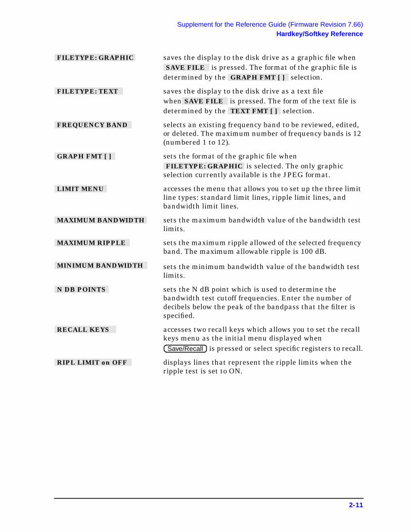
Supplement for the Reference Guide (Firmware Revision 7.66)Hardkey/Softkey Reference
saves the display to the disk drive as a graphic file when is pressed. The format of the graphic file is
determined by the selection.
saves the display to the disk drive as a text filewhen is pressed. The form of the text file isdetermined by the selection.
selects an existing frequency band to be reviewed, edited,or deleted. The maximum number of frequency bands is 12(numbered 1 to 12).
sets the format of the graphic file when is selected. The only graphic
selection currently available is the JPEG format.
accesses the menu that allows you to set up the three limitline types: standard limit lines, ripple limit lines, andbandwidth limit lines.
sets the maximum bandwidth value of the bandwidth testlimits.
sets the maximum ripple allowed of the selected frequencyband. The maximum allowable ripple is 100 dB.
sets the minimum bandwidth value of the bandwidth testlimits.
sets the N dB point which is used to determine thebandwidth test cutoff frequencies. Enter the number ofdecibels below the peak of the bandpass that the filter isspecified.
accesses two recall keys which allows you to set the recallkeys menu as the initial menu displayed when
is pressed or select specific registers to recall.
displays lines that represent the ripple limits when theripple test is set to ON.
FILETYPE: GRAPHIC SAVE FILE
GRAPH FMT [ ]
FILETYPE: TEXT SAVE FILE
TEXT FMT [ ]
FREQUENCY BAND
GRAPH FMT [ ] FILETYPE: GRAPHIC
LIMIT MENU
MAXIMUM BANDWIDTH
MAXIMUM RIPPLE
MINIMUM BANDWIDTH
N DB POINTS
RECALL KEYS
Save/Recall
RIPL LIMIT on OFF
2-11

Supplement for the Reference Guide (Firmware Revision 7.66)Hardkey/Softkey Reference
turns ripple testing on or off. When ripple testing is on, theanalyzer sets the lower ripple limit line at the lowestamplitude point within the frequency band and sets theupper limit line at the user-specified amplitude above. Ifthe trace data remains at or below the upper limit line,that portion of the ripple test passes. If the trace data risesabove the upper limit line within the frequency band, thetest fails. Data within each frequency band is comparedwith the defined ripple limit of the band. The ripple testchecks each frequency band using this method. Amaximum of 12 frequency bands can be tested on eachchannel. These bands may overlap in frequency. If all ofthe channel’s frequency bands pass the ripple test, theanalyzer displays a pass message.
If the test passed, a message is displayed in orange text inthe upper right portion of the LCD. An example of thismessage is: RIPL1 PASS, where the “1” indicates thechannel where the ripple test is performed. If the rippletest does not pass, a fail message is displayed in red text.An example of this message is RIPL1 FAIL.
displays the ripple value of the selected frequency band.The ripple value can be displayed in two ways or turnedoff. Selecting OFF removes the displayed ripple value fromthe display. Selecting ABSOLUTE or MARGIN displaysthe ripple value. The ripple value is preceded on thedisplay by an indicator of the selected band. For example,when the ripple value is preceded by “B2”, this indicatesthat the ripple value shown is for Band 2. The frequencyband indicator and ripple value are displayed in the samecolor as the pass/fail message for the overall ripple test.
When ABSOLUTE is selected, the display shows theabsolute ripple of the data trace within the frequencyband.
When MARGIN is selected, the display shows thedifference between the maximum allowable ripple and theabsolute ripple value within the frequency band. When themargin value is preceded by a plus sign (+), this indicatesthat the ripple within the selected frequency band ispassing by the value shown. When the margin value ispreceded by a negative sign (−), this indicates that theripple within the selected band is failing by the valueshown.
selects a frequency band to display the ripple value. Whenis set to the absolute or margin choices,
this softkey selects the ripple measurement for theselected frequency band.
RIPL TEST on OFF
RIPL VALUE [ ]
RIPL VALUE BAND RIPL VALUE [ ]
2-12

Supplement for the Reference Guide (Firmware Revision 7.66)Hardkey/Softkey Reference
selects ripple limit line trace on the display colormodification.
selects the ripple limit line choice. This selection leads tomenus used to define ripple limits or specifications withwhich to compare a test device. Refer to the “Using RippleLimits to Test a Device” section in the “MakingMeasurements” chapter of the user’s guide.
saves the display information to the disk drive. The type ofinformation saved is dependent on the FILETYPEselection. The FILETYPE selection can either be graphicor text.
accesses the save file menu which allows you to save thedisplay information to the disk drive as either graphic ortextual information.
sets the format of the text file when isselected. The only text selection currently available is thecomma separated values (CSV) format.
RIPPLE LIM LINES
RIPPLE LIMIT
SAVE FILE
SAVE FILE FORMATS
TEXT FMT [ ] FILETYPE: TEXT
2-13
Supplement for the Reference Guide (Firmware Revision 7.66)Hardkey/Softkey Reference
This page intentionally left blank.
2-14

Supplement for the Reference Guide (Firmware Revision 7.66)Error Messages
Error Messages
Error Messages in Alphabetical Order
Error Messages in Numerical Order
BANDWIDTH LIMIT INVALID: MIN BW > MAX BW
InformationMessage
The bandwidth test has a minimum bandwidth greater than the maximumbandwidth. Change the minimum bandwidth to a frequency less than thefrequency of the maximum bandwidth or change the maximum bandwidth to afrequency greater than the frequency of the minimum bandwidth.
CAUTION: FLOPPY DISK IS FULL
Error Number218
This message is displayed if you try to save files to the floppy disk that does nothave enough memory to perform the save task. Correct by inserting a new floppydisk in the front panel disk drive or by erasing files from the current floppy disk.
CAUTION: TOO MANY SEGMENTS OR POINTS
InformationMessage
This message is displayed if you try to insert too many segments or points usingyour current function.
RIPPLE LIMIT TABLE EMPTY
InformationMessage
The ripple limit table does not have any frequency bands defined. Add at leastone frequency band to the ripple limit table for ripple testing.
ErrorNumber
Error
218 CAUTION: FLOPPY DISK IS FULL
2-15

Supplement for the Reference Guide (Firmware Revision 7.66)Options and Accessories
Options and Accessories
Accessories Available
For accessories not listed in this section, refer to the configuration guide for your analyzeror refer to the following Internet site:
www.agilent.com/find/8753
2-16

Supplement for the Reference Guide (Firmware Revision 7.66)Preset State and Memory Allocation
Preset State and Memory Allocation
Preset StateTable 2-1 Preset Conditions
Preset Conditions Preset Value
Limit Menu
Limit Lines
Limit Lines Off
Limit Testing Off
Limit List Empty
Edit Mode Upper/Lower Limits
Stimulus Offset 0 Hz
Amplitude Offset 0 dB
Limit Type Sloping Line
Beep Fail Off
Ripple Limit
Ripple Limit Off
Ripple Test Off
Bandwidth Limit
Bandwidth Test Off
Bandwidth Display Off
Bandwidth Marker Off
2-17

3 Supplement for the Programmer’sGuide (Firmware Revision 7.66)
3-1
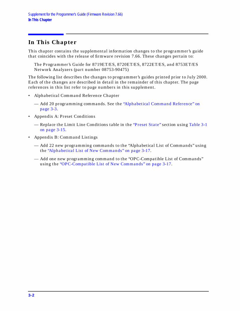
Supplement for the Programmer’s Guide (Firmware Revision 7.66)In This Chapter
In This ChapterThis chapter contains the supplemental information changes to the programmer’s guidethat coincides with the release of firmware revision 7.66. These changes pertain to:
The Programmer’s Guide for 8719ET/ES, 8720ET/ES, 8722ET/ES, and 8753ET/ESNetwork Analyzers (part number 08753-90475)
The following list describes the changes to programmer’s guides printed prior to July 2000.Each of the changes are described in detail in the remainder of this chapter. The pagereferences in this list refer to page numbers in this supplement.
• Alphabetical Command Reference Chapter
— Add 20 programming commands. See the “Alphabetical Command Reference” onpage 3-3.
• Appendix A: Preset Conditions
— Replace the Limit Line Conditions table in the “Preset State” section using Table 3-1on page 3-15.
• Appendix B: Command Listings
— Add 22 new programming commands to the “Alphabetical List of Commands” usingthe “Alphabetical List of New Commands” on page 3-17.
— Add one new programming command to the “OPC-Compatible List of Commands”using the “OPC-Compatible List of New Commands” on page 3-17.
3-2

Supplement for the Programmer’s Guide (Firmware Revision 7.66)Alphabetical Command Reference
Alphabetical Command Reference
BWLIMDB
Syntax
BWLIMDB<num>; or BWLIMDB?;
Description
Front Panel Equivalents
BWLIMDISP
Syntax
BWLIMDISP<ON|OFF>; or BWLIMDISP?;
Description
Front Panel Equivalents
Command Description Range Query Response
BWLIMDB Enters the N dB Point, the amplitudebelow the peak that is used to measure thefilter’s bandwidth.
0.001 to 300 dB <num><LF>
Command Hardkey Softkey
BWLIMDB
Command Description Range Query Response
BWLIMDISP Turns the measured bandwidth value inthe upper left corner of the display on andoff. The measured bandwidth value isdisplayed near the bandwidthPass/Wide/Narrow message.
N/A <0|1><LF>
Command Hardkey Softkey
BWLIMDISP
System N DB POINTS
System BW DISPLAY on OFF
3-3

Supplement for the Programmer’s Guide (Firmware Revision 7.66)Alphabetical Command Reference
BWLIMMAX
Syntax
BWLIMMAX<num>[HZ|KHZ|MHZ|GHZ]; or BWLIMMAX?;
Description
Front Panel Equivalents
BWLIMMIN
Syntax
BWLIMMIN<num>[HZ|KHZ|MHZ|GHZ]; or BWLIMMIN?;
Description
Front Panel Equivalents
Command Description Range Query Response
BWLIMMAX Enters the maximum bandwidth value. If themeasured bandwidth is greater than thisvalue, the filter fails the bandwidth test.
stimulus rangea
a. Refer to “Preset State and Memory Allocation” in your analyzer’s reference guide.
<num><LF>
Command Hardkey Softkey
BWLIMMAX
Command Description Range Query Response
BWLIMMIN Enters the minimum bandwidth value. Ifthe measured bandwidth is less than thisvalue, the filter fails the bandwidth test.
stimulus rangea
a. Refer to “Preset State and Memory Allocation” in your analyzer’s reference guide.
<num><LF>
Command Hardkey Softkey
BWLIMMIN
System MAXIMUM BANDWIDTH
System MINIMUM BANDWIDTH
3-4

Supplement for the Programmer’s Guide (Firmware Revision 7.66)Alphabetical Command Reference
BWLIMSTAT
Syntax
BWLIMSTAT;
Description
No Front Panel Equivalents
GPIB only: no front panel equivalent.
BWLIMTEST
Syntax
BWLIMTEST<ON|OFF>; or BWLIMTEST?;
Description
Front Panel Equivalents
Command Description Range Response
BWLIMSTAT Returns the results of the bandwidth test.A returned value of 0 indicates that thefilter passed the bandwidth test. Areturned value of −1 indicates that thefilter failed the bandwidth test because itis narrower than the bandwidth limit. Areturned value of 1 indicates that thefilter failed the bandwidth test because itis wider than the bandwidth limit.
N/A <−1|0|1><LF>
Command Description Range Query Response
BWLIMTEST Turns the bandwidth test on and off. N/A <0|1><LF>
Command Hardkey Softkey
BWLIMTEST System BW TEST on OFF
3-5

Supplement for the Programmer’s Guide (Firmware Revision 7.66)Alphabetical Command Reference
BWLIMVAL
Syntax
BWLIMVAL;
Description
Front Panel Equivalents
GPIB only: no front panel equivalent.
CLER
Syntax
CLER;
Description
Front Panel Equivalents
Command Description Range Response
BWLIMVAL Returns the measured bandwidth value. N/A <num><LF>
Command Description Range Query Response
CLER Clears (or deletes) all of the existing rippletest limits.
N/A N/A
Command Hardkey Softkey
CLER System CLEAR LIST
3-6

Supplement for the Programmer’s Guide (Firmware Revision 7.66)Alphabetical Command Reference
EDITRLIM
Syntax
EDITRLIM;
Description
Front Panel Equivalents
Command Description Range Query Response
EDITRLIM Begins the editing of the ripple limit list. N/A N/A
Command Hardkey Softkey
EDITRLIM System EDIT RIPL LIMIT
3-7

Supplement for the Programmer’s Guide (Firmware Revision 7.66)Alphabetical Command Reference
OUTP
NOTE Because this is an “Alphabetical Command Reference,” the output commandsare listed alphabetically, rather than by function, in both the “Syntax” sectionand the “Description” section.
Syntax
OUTPFARPLPT;
OUTPRPLBNDALL;
OUTPRPLBNDPF;
OUTPRPLBNDVAL;
Description
NOTE Most commands that output an array require that you set the format for datatransfers with the FORM command.
Front Panel Equivalents
GPIB only: no front panel equivalent.
Command Description Range Response
OUTPFARPLPT Outputs the onscreen failed ripple pointinformation in the following comma-separated value format: the number offailed points followed by pairs of numbersrepresenting the first failed frequency,first failure value, second failed frequency,second failure value, and so on.
N/A <num,array><LF>
OUTPRPLBNDALL Outputs the measured ripple values for allactive frequency bands in the followingcomma-separated value format: thenumber of bands followed by pairs ofnumbers representing the first bandnumber (1), ripple value of first band,second band number (2), ripple value ofsecond band, and so on.
N/A <num,array><LF>
OUTPRPLBNDPF Outputs the pass/fail status for selectedfrequency band (see “SELBND”) as “1”(band passes) or as “0” (band fails).
N/A <0|1><LF>
OUTPRPLBNDVAL Outputs the ripple value for selectedfrequency band (see “SELBND”).
N/A <num><LF>
3-8

Supplement for the Programmer’s Guide (Firmware Revision 7.66)Alphabetical Command Reference
RLIMLINE
Syntax
RLIMLINE<ON|OFF>; or RLIMLINE?;
Description
Front Panel Equivalents
RLIMM
Syntax
RLIMM<num>[DB]; or RLIMM?;
Description
Front Panel Equivalents
Command Description Range Query Response
RLIMLINE Turns the lines that represent the rippletest limits on and off.
N/A <0|1><LF>
Command Hardkey Softkey
RLIMLINE
Command Description Range Query Response
RLIMM Sets the value of the maximum allowableripple limit for current frequency band.
0.01 to 100 dB <num><LF>
Command Hardkey Softkey
RLIMM
System RIPL LIMIT on OFF
System MAXIMUM RIPPLE
3-9

Supplement for the Programmer’s Guide (Firmware Revision 7.66)Alphabetical Command Reference
RLIMSTP
Syntax
RLIMSTP<num>[HZ|KHZ|MHZ|GHZ]; or RLIMSTP?;
Description
Front Panel Equivalents
RLIMSTR
Syntax
RLIMSTR<num>[HZ|KHZ|MHZ|GHZ]; or RLIMSTR?;
Description
Front Panel Equivalents
Command Description Range Query Response
RLIMSTP Sets the stop frequency of the currentfrequency band.
stimulus rangea
a. Refer to “Preset State and Memory Allocation” in your analyzer’s reference guide.
<num><LF>
Command Hardkey Softkey
RLIMSTP
Command Description Range Query Response
RLIMSTR Sets the start frequency of the currentripple limit.
stimulus rangea
a. Refer to “Preset State and Memory Allocation” in your analyzer’s reference guide.
<num><LF>
Command Hardkey Softkey
RLIMSTR
System MAXIMUM FREQUENCY
System MINIMUM FREQUENCY
3-10

Supplement for the Programmer’s Guide (Firmware Revision 7.66)Alphabetical Command Reference
RLIMTEST
Syntax
RLIMTEST<ON|OFF>; or RLIMTEST?;
Description
Front Panel Equivalents
RLIMVAL
Syntax
RLIMVAL<OFF|ABS|MAR>;
Description
Front Panel Equivalents
Command Description Range Query Response
RLIMTEST Turns the ripple limit test on and off. N/A <0|1><LF>
Command Hardkey Softkey
RLIMTEST
Command Description Range Query Response
RLIMVAL Displays the ripple limit value of theselected band (see “SELBND”) in absoluteformat (ABS) or margin format (MAR).OFF turns the displayed ripple limit valueoff.
N/A N/A
Command Hardkey Softkey
RLIMVAL
System RIPL TEST on OFF
System RIPL VALUE [ ]
3-11

Supplement for the Programmer’s Guide (Firmware Revision 7.66)Alphabetical Command Reference
SAVECSV
Syntax
SAVECSV;
Description
Front Panel Equivalents
SAVEJPG
Syntax
SAVEJPG;
Description
Front Panel Equivalents
Command Description Range Query Response
SAVECSV Saves the current measurement to thedisk drive in the comma-separated value(CSV) format.
N/A N/A
Command Hardkey Softkey
SAVECSV when is set to CSV and
is selected.
Command Description Range Query Response
SAVEJPG Saves the current display to the disk drivein the JPG format. OPC-compatible.
N/A N/A
Command Hardkey Softkey
SAVEJPG when is set to JPG and
is selected.
Save/Recall SAVE FILE GRAPH FMT [ ] FILETYPE: GRAPHIC
Save/Recall SAVE FILE GRAPH FMT [ ] FILETYPE: GRAPHIC
3-12

Supplement for the Programmer’s Guide (Firmware Revision 7.66)Alphabetical Command Reference
SELBND
Syntax
SELBND<num>; or SELBND?;
Description
Front Panel Equivalents
Command Description Range Query Response
SELBND Selects the ripple frequency band for thefollowing commands: OUTPRPLBNDPF,OUTPRPLBNDVAL, and RLIMVAL.
integers 1−12 <num><LF>
Command Hardkey Softkey
SELBND System FREQUENCY BAND
3-13

Supplement for the Programmer’s Guide (Firmware Revision 7.66)Alphabetical Command Reference
This page intentionally left blank.
3-14

Supplement for the Programmer’s Guide (Firmware Revision 7.66)Preset Conditions
Preset Conditions
Preset StateTable 3-1 Limit Line Conditions
Preset Conditions Preset Value
Limit Lines
Limit Lines Off
Limit Testing Off
Limit List Empty
Edit Mode Upper/Lower Limits
Stimulus Offset 0 Hz
Amplitude Offset 0 dB
Limit Type Sloping Line
Beep Fail Off
Ripple Limit
Ripple Limit Off
Ripple Test Off
Bandwidth Limit
Bandwidth Test Off
Bandwidth Display Off
Bandwidth Marker Off
3-15

Supplement for the Programmer’s Guide (Firmware Revision 7.66)Preset Conditions
This page intentionally left blank.
3-16

Supplement for the Programmer’s Guide (Firmware Revision 7.66)Command Listings
Command Listings
Alphabetical List of New Commands
OPC-Compatible List of New Commands
BWLIMDB EDITRLIM RLIMSTR
BWLIMDISP OUTPFARPLPT RLIMTEST
BWLIMMAX OUTPRPLBNDALL RLIMVAL
BWLIMMIN OUTPRPLBNDPF SAVECSV
BWLIMSTAT OUTPRPLBNDVAL SAVEJPG
BWLIMTEST RLIMLINE SELBND
BWLIMVAL RLIMM
CLER RLIMSTP
SAVEJPG
3-17
4 Supplement for the User’s Guide(Firmware Version 7.68)
4-1

Supplement for the User’s Guide (Firmware Version 7.68)Using This Chapter
Using This ChapterThis chapter contains the supplemental information changes to the user’s guides thatcoincide with the release of firmware revision 7.68. These changes pertain to the followinguser’s guides.
• 8753ET and 8753ES Network Analyzers User’s Guide (part number 08753-90472)
• 8753ES Option 011 Network Analyzer User’s Guide (part number 08753-90479)
IMPORTANT If you are upgrading your firmware from a revision prior to revision 7.66, addthe information changes from Chapter 1 , “Supplement for the User’s Guide(Firmware Version 7.66),” before adding the changes from this chapter.
The following list describes the changes to 8753ET and 8753ES user’s guides printed priorto February 2001. Each of the changes are described in detail in the remainder of thischapter. The page references in this list refer to page numbers in this supplement.
• Making Mixer Measurements Chapter
— Change the softkey to and the softkey to . Refer to
“Conversion Loss Using the Frequency Offset Mode,” “High Dynamic Range SweptRF/IF Conversion Loss,” and “Fixed IF Mixer Measurements” on page 4-4.
• Printing, Plotting, and Saving Measurement Results Chapter
— Replace the section titled “Saving an Instrument State” with the revised section onpage 4-5.
• Calibrating for Increased Measurement Accuracy Chapter
— Append a note regarding the 85032F Calibration Kit after the displayed paragraphshown in “Clarifying Type-N Connector Sex” of the “Calibration Considerations”section. See page 4-7.
— Append a paragraph referencing ECal modules after the three paragraphs displayedin “The Calibration Standards” of the “Calibration Considerations” section. Seepage 4-7.
— Add information regarding the Enhanced Reflection feature to the EnhancedResponse row of the “Purpose and Use of Different Error Correction Procedures”table. See page 4-8.
— Replace the section titled “Enhanced Frequency Response Error Correction” with therevised section. See page 4-9.
— Change the softkey to . Refer to“Power Meter Measurement Calibration” on page 4-13.
— Replace the subsection titled “Modify the Cal Kit Thru Definition” (part of the“Calibrating for Noninsertable Devices” section) with the revised section. Seepage 4-15.
ADDRESS: P MTR/HPIB ADDRESS: P MTR/GPIB PERIPHERAL HPIB ADDRHIB ADDR
PERIPHERAL GPIB ADDRHIB ADDR
ADDRESS: P MTR/HPIB ADDRESS: P MTR/GPIB
4-2

Supplement for the User’s Guide (Firmware Version 7.68)Using This Chapter
— Add two new sections (“Calibrating Using Electronic Calibration (ECal)” starting onpage 4-17 and “Adapter Removal Using ECal (ES Analyzers Only)” starting onpage 4-29) to the end of the chapter.
• Operating Concepts Chapter
— Append the Enhanced Reflection Calibration information to the end of thesubsection titled “Enhanced Response Calibration” (part of the “CalibrationRoutines” section). See page 4-37.
— Append the subsection titled “ECal” to the end of the section titled “CalibrationRoutines.” See page 4-37.
• Safety and Regulatory Information Chapter
— Replace the warning describing the line fuse type and rating with a revised warningin the “Servicing” subsection of “Safety Considerations.” See page 4-39.
4-3

Supplement for the User’s Guide (Firmware Version 7.68)Conversion Loss Using the Frequency Offset Mode
Conversion Loss Using the Frequency Offset Mode
Performing a Power Meter (Source) Calibration Over the IF Range
In Step 2 of this section, change the softkey to.
High Dynamic Range Swept RF/IF Conversion Loss
Perform a Power Meter Calibration Over the IF Range
In Step 4 of this section, change the softkey to.
Fixed IF Mixer Measurements
Sequence 1 Setup
Performing a Response Calibration
Change the softkey to in twoplaces in this section.
Addressing and Configuring the Two Sources
Change the softkey to in threeplaces in this section.
Sequence 2 Setup
Incrementing the Source Frequencies
Change the softkey to in twoplaces in this section.
ADDRESS: P MTR/HPIB ADDRESS: P MTR/GPIB
ADDRESS: P MTR/HPIB ADDRESS: P MTR/GPIB
PERIPHERAL HPIB ADDRHIB ADDR
PERIPHERAL GPIB ADDRHIB ADDR
PERIPHERAL HPIB ADDRHIB ADDR
PERIPHERAL GPIB ADDRHIB ADDR
PERIPHERAL HPIB ADDRHIB ADDR
PERIPHERAL GPIB ADDRHIB ADDR
4-4

Supplement for the User’s Guide (Firmware Version 7.68)Saving an Instrument State
Saving an Instrument State
1. Press and select one of the storage devices:
connect an external disk drive to the analyzer’s GPIB connector,and configure as follows:
a. Connect an external disk drive to the analyzer's GPIB connector, and configure asfollows:
b. Press and enter the drive where your disk islocated, followed by .
c. If your storage disk is partitioned, press and enter thevolume number where you want to store the instrument state file.
d. Press .
e. Enter the GPIB address of the peripheral, if the default address is incorrect(default = 00). Follow the entry by pressing .
f. Press and select one of the following:
— allows the analyzer to control peripherals directly.
— allows the computer controller to be involved in allperipheral access operations.
— allows you to control the analyzer over GPIB and alsoallows the analyzer to take or pass control.
2. Press .
The analyzer saves the state in the next available register, if you are saving to internalmemory, or saves the state to disk. Although one file is shown to represent aninstrument state on the analyzer display, each instrument state is composed ofnumerous files (which can be viewed on a PC).
NOTE If you have saved enough files that you have used all the default names(FILE00 − FILE31 for disk files, or REG1 − REG31 for memory files), youmust do one of the following to save more states:
• use another disk
• rename an existing file to make a default name available
• re-save a file/register
• delete an existing file/register
Save/Recall SELECT DISK
INTERNAL MEMORY
INTERNAL DISK
EXTERNAL DISK
Local DISK UNIT NUMBERx1
VOLUME NUMBER
SET ADDRESSES ADDRESS: DISK
x1
Local
SYSTEM CONTROLLER
TALKER/LISTENER
USE PASS CONTROL
Save/Recall SAVE STATE
4-5

Supplement for the User’s Guide (Firmware Version 7.68)Saving an Instrument State
This page intentionally left blank.
4-6

Supplement for the User’s Guide (Firmware Version 7.68)Calibration Considerations
Calibration Considerations
Clarifying Type-N Connector Sex
When you are performing error correction for a system that has type-N port connectors,the softkey menus label the sex of the test port connector — not the calibration standardconnector. For example, the label, SHORT (F), refers to the short that will be connected tothe female test port. Since many devices have type-N (f) connectors, the calibrationstandard to select is the type-N (m). Be sure to use the port extension pin on the type-N(m) Open calibration standard.
NOTE Since the 85032F calibration kit offsets are equal for both male and femaleconnectors, the standard’s sex type is not requested during the calibration.
The Calibration Standards
During measurement calibration, the analyzer measures actual, well-defined standardsand mathematically compares the results with ideal "models" of those standards. Thedifferences are separated into error terms which are later removed during error correction.Most of the differences are due to systematic errors—repeatable errors introduced by theanalyzer, test set, and cables—which are correctable.
The standard devices required for system calibration are available in compatiblecalibration kits with different connector types. Each kit contains at least one short circuit,one open circuit, and an impedance-matched load. In kits that require adapters forinterface to the test set ports, the adapters are phase-matched for calibration prior tomeasurement of non-insertable and non-reversible devices. Other standard devices can beused by specifying their characteristics in a user-defined kit, as described in the“Modifying Calibration Kits” section of Chapter 7, “Operating Concepts.”
The accuracy improvement of the correction is limited by the quality of the standarddevices, and by the connection techniques used. For maximum accuracy, ensure that theconnectors are clean and use a torque wrench for final connections.
Electronic calibration (ECal) modules serve as the calibration standards for electroniccalibration procedures. ECal modules are electronic networks that simulate impedancestates that are similar to mechanical standards. The factory error correction for optimumperformance is embedded in the module’s memory.
4-7

Supplement for the User’s Guide (Firmware Version 7.68)Procedures for Error Correcting Your Measurements
Procedures for Error Correcting Your Measurements
Types of Error CorrectionPurpose and Use of Different Error Correction Procedures
Correction Procedure CorrespondingMeasurement
Errors Corrected Standard Devices
Enhanced Responseand EnhancedReflection
Transmission orreflectionmeasurement whenimproved accuracy isdesired. Not asaccurate as 2-portcalibration.
Directivity, sourcematch, and frequencyresponse forreflection. Frequencyresponse, sourcematch, and isolationfor transmission.Enhanced reflectioncorrects for loadmatch on bilateraldevices.
Short, open, load, andthru or ECal module.
4-8
Supplement for the User’s Guide (Firmware Version 7.68)Enhanced Frequency Response Error Correction
Enhanced Frequency Response Error CorrectionThe enhanced frequency response error correction removes the following errors in theforward direction in ET models or in both the forward and reverse directions in ES models:
• removes directivity errors of the test setup
• removes source match errors of the test setup
• removes isolation errors of the test setup (optional)
• removes frequency response of the test setup
The enhanced reflection error correction may be used to remove load match from the testsetup when measuring bilateral devices. Enhanced reflection terms are mathematicallyderived during all enhanced response calibrations but are not applied unless initiated bythe softkey. Enhanced reflection correction is applied after theenhanced frequency response error correction is finished.
IMPORTANT Use enhanced reflection error correction only on bilateral devices. A bilateraldevice has similar forward and reverse transmission characteristics.Examples of bilateral devices are passive devices (filters, attenuators, andswitches). Most active devices (amplifiers) and some passive devices(isolators and circulators) are not bilateral. If this error correction is used fora non-bilateral device, errors will occur in the resulting measurement.
1. Press .
2. Select the type of measurement you want to make.
If you want to make measurements in the forward direction (S21 S11), press:
or on ET models:
For ES analyzers, if you want to make measurements in the reverse direction (S12
S22), press .
3. Set any measurement parameters that you want for the device measurement: power,format, number of points, or IF bandwidth.
4. To access the measurement correction menus, press .
5. If your calibration kit is different than the kit specified under the softkey,press , then select your type of kit, and press .
If your type of calibration kit is not listed in the displayed menu, refer to the “ModifyingCalibration Kits” section in this chapter.
ENH. REFL. on OFF
Preset
Meas Trans: FWD S21 (B/R) TRANSMISSN
Meas Trans: REV S12 (A/R)
Cal
CAL KIT [ ] CAL KIT SELECT CAL KIT RETURN
4-9

Supplement for the User’s Guide (Firmware Version 7.68)Enhanced Frequency Response Error Correction
6. To select the correction type, pressand select the correction type.
If you want to make measurements in the forward direction, press:
or on ET models:
For ES analyzers, if you want to make measurements in the reverse direction, press:
7. Connect a shielded open circuit to PORT 1 (or PORT 2 for reverse measurements).
NOTE Include any adapters that you will have in the device measurement. That is,connect the standard to the particular connector where you will connect yourdevice under test.
Figure 4-1 8753ET/ES Standard Connections for Enhanced ResponseCalibration
Figure 4-2 8753ES Option 011 Standard Connections for Enhanced ResponseCalibration
CALIBRATE MENU ENHANCED RESPONSE
S11/S21 ENH. RESP. TRAN/REFL ENH. RESP.
S22/S12 ENH. RESP.
4-10

Supplement for the User’s Guide (Firmware Version 7.68)Enhanced Frequency Response Error Correction
8. To measure the standard, when the displayed trace has settled, press .
The analyzer displays WAIT - MEASURING CAL STANDARD during the standardmeasurement. The analyzer underlines the softkey after it measures thestandard.
9. Disconnect the open, and connect a short circuit to the test port.
10.To measure the device, when the displayed trace has settled, press .
The analyzer measures the short circuit and underlines the softkey.
11.Disconnect the short, and connect an impedance-matched load to the test port.
12.To measure the standard, when the displayed trace has settled, press , selectthe type of load you are using, and then press when the analyzer hasfinished measuring the load.
Notice that the softkey is now underlined.
13.To compute the reflection correction coefficients, press .
14.To start the transmission portion of the correction, press .
15.Make a "thru" connection between the points where you will connect your device undertest as shown in Figure 4-1 (or Figure 4-2).
NOTE Include any adapters or cables that you will have in the device measurement.That is, connect the standard device where you will connect your device undertest.
NOTE The thru in most calibration kits is defined with zero length. The correctionwill not work properly if a non-zero length thru is used, unless the calibrationkit is modified to change the defined thru to the length used. This isimportant for measurements of non-insertable devices (devices having portsthat are both male or both female). The modified calibration kit must besaved as the user calibration kit, and the softkey must beselected before the calibration is started.
16.To measure the standard, when the trace has settled, press:
or
The analyzer underlines the softkey label after it makes each measurement.
OPEN
OPEN
SHORT
SHORT
LOADS DONE: LOADS
LOADS
STANDARDS DONE
TRANSMISSION
USER KIT
FWD TRANS THRU REV TRANS THRU
STANDARDS DONE
4-11

Supplement for the User’s Guide (Firmware Version 7.68)Enhanced Frequency Response Error Correction
17.Press and select from the following two options:
If you will be measuring devices with a dynamic range less than 90 dB, press.
If you will be measuring devices with a dynamic range greater than 90 dB, followthese steps:
a. Connect impedance-matched loads to the test ports. Include the adapters that youwould include for your device measurement.
NOTE If you will be measuring highly reflective devices such as filters, use the testdevice, connected to the reference plane and terminated with a load, for theisolation standard.
b. Activate at least four times more averages than desired during the devicemeasurement.
c. Press.
d. Return the averaging to the original state of the measurement, and press.
18.To compute the error coefficients, press .
The analyzer displays the corrected measurement trace. The analyzer also shows thenotation Cor at the left of the screen, indicating that error correction is on.
Enhanced Reflection Calibration
19.If you are measuring a bilateral device and want to remove the load match error,activate the enhanced reflection calibration by pressing andthen pressing until ON is selected.
NOTE You can save or store the measurement correction to use for latermeasurements. Refer to Chapter 4, “Printing, Plotting, and SavingMeasurement Results” for procedures.
20.This completes the enhanced response correction procedure. You can connect andmeasure your device under test.
ISOLATION
OMIT ISOLATION
Cal RESUME CAL SEQUENCE ISOLATION FWD or REV ISOL'N STD DONE
Cal RESUME CAL SEQUENCE
DONE ENH RESP CAL
ENHANCED RESPONSE ENH. REFL. on OFF
4-12

Supplement for the User’s Guide (Firmware Version 7.68)Power Meter Measurement Calibration
Power Meter Measurement Calibration
Using Sample-and-Sweep Correction Mode
Change the softkey to in thefollowing location:
• Step 4 of “Using Sample-and-Sweep Correction Mode”
ADDRESS: P MTR/HPIB ADDRESS: P MTR/GPIB
4-13

Supplement for the User’s Guide (Firmware Version 7.68)Power Meter Measurement Calibration
This page intentionally left blank.
4-14

Supplement for the User’s Guide (Firmware Version 7.68)Calibrating for Noninsertable Devices
Calibrating for Noninsertable Devices
Modify the Cal Kit Thru Definition
With this method, it is only necessary to use a thru adapter. The calibration kit thrudefinition is modified to compensate for the adapter and then saved as a user kit. However,the electrical delay of the adapter must first be found. The adapter match will degrade theeffective load match terms on both ports as well as degrade the transmission frequencyresponse (tracking).
1. Refer to Figure 4-3 (or Figure 4-4) while performing the steps in this procedure. Alsorefer to the “Adapter Removal” subsection (part of the “Calibrating for NoninsertableDevices” section) for an explanation of A1, A2, and A3.
2. Perform a 1-port calibration at “Reference Port 1.” Refer to Step A of Figure 4-3 (orFigure 4-4).
Figure 4-3 8753ET/ES Determining the Electrical Delay Setup
Figure 4-4 8753ES Option 011 Determining the Electrical Delay Setup
4-15

Supplement for the User’s Guide (Firmware Version 7.68)Calibrating for Noninsertable Devices
3. Connect the A3 adapter to “Reference Port 1” as shown in Step B of Figure 4-3 (orFigure 4-4). Connect a short to the open end of the A3 adapter.
4. Measure the delay of the adapter by pressing .
5. Divide the resulting delay measurement by 2 to determine the delay of the thru and theshort in one direction.
6. Determine the offset delay of the calibration short by examining the define standardmenu (see the “Define Standard Menus” section in Chapter 7).
7. Subtract the offset delay of the short (determined in step 6) from the delay of the thruand the short in one direction (determined in step 5). The result is electrical delay of thethru. This value is used in the next step.
8. Modify the calibration kit thru definition by entering in the electrical delay of adapterA3. Save this as a user kit.
For example, if A3 has 100 ps of delay, press:
9. Perform the desired calibration with this new user kit.
10.Connect the test device as shown in the figure titled “Calibrated Measurement” (in the“Adapter Removal” subsection of the “Calibrating for Noninsertable Devices” section)and measure the device.
Format DELAY
Cal CAL KIT MODIFY DEFINE STANDARD 4 x1
MODIFY STD DEFINITION SPECIFY OFFSET OFFSET DELAY 0.100 G/n
STD DONE (DEFINED) RETURN KIT DONE (MODIFIED) SAVE USER KIT
4-16

Supplement for the User’s Guide (Firmware Version 7.68)Calibrating Using Electronic Calibration (ECal)
Calibrating Using Electronic Calibration (ECal)This section describes Electronic Calibration (ECal).
Use the following steps to perform the calibration.
1. Set up the measurement for which you are calibrating. Refer to “Set Up theMeasurement.”
2. Connect the ECal equipment. Refer to “Connect the ECal Equipment” on page 4-18.
3. Select the ECal options. Refer to “Select the ECal Options” on page 4-20.
4. Perform the calibration. Refer to “Perform the Calibration” on page 4-21.
5. Perform the confidence check. Refer to “Perform the Confidence Check” on page 4-24.
Set Up the Measurement
1. Press .
2. Select the type of measurement you want to make.
If you want to make a reflection measurement on PORT 1 (in the forward direction,S11), leave the instrument default setting or press:
or on ET models:
If you want to make a transmission measurement in the forward direction (S21),press:
or on ET models:
For ES analyzers, if you want to make a transmission measurement in the reversedirection (S12), press:
For ES analyzers, if you want to make a reflection measurement on PORT 2 (in thereverse direction, S22), press:
3. Set any other measurement parameters that you want for the device measurement:frequency, span, power, sweep type, number of points, or IF bandwidth.
Preset
Meas Refl: FWD S11 (A/R) REFLECTION
Meas Trans: FWD S21 (B/R) TRANSMISSN
Meas Trans: REV S12 (A/R)
Meas Refl: REV S22 (B/R)
4-17

Supplement for the User’s Guide (Firmware Version 7.68)Calibrating Using Electronic Calibration (ECal)
Connect the ECal Equipment
1. Connect the power supply to the PC interface unit. Refer to Figure 4-5 (or Figure 4-6).
Figure 4-5 8753ET/ES ECal Setup
Figure 4-6 8753ES Option 011 ECal Setup
2. Connect the power supply to the ac source.
3. Connect one end of a DB25 cable to the Parallel Port connector on the rear of thenetwork analyzer. Connect the other end of the DB25 cable to the connector on the PCinterface unit labeled "DB25 Interface to Parallel Interface on Personal Computer."
4-18
Supplement for the User’s Guide (Firmware Version 7.68)Calibrating Using Electronic Calibration (ECal)
CAUTION Only connect the DB25 cable to the Parallel Port connector of the networkanalyzer.
If the cable is connected to the Test Set - I/O Interconnect connector, damageto the PC interface unit could occur.
NOTE For steps 3 through 5, use the three DB25 cables (part number 8120-8710)shipped with the 85097A Electronic Calibration System. Other cables maynot give reliable results.
4. Connect one end of a DB25 cable to the connector on the PC interface unit labeled"DB25 Interface to ECal Module A." Connect the other end of the DB25 cable to theparallel cable connector on the ECal module.
5. If you need to calibrate with a second ECal module, connect one end of another DB25cable to the connector on the PC interface unit labeled "DB25 Interface to ECalModule B." Connect the other end of the DB25 cable to the parallel cable connector onthe ECal module.
NOTE Why Use a Second ECal Module?
If the frequency span of the measurement that you set up earlier exceeds thespan of a single ECal module, you need to use another ECal module whosefrequency range allows the rest of the measurement span to be calibrated.The frequency range of the ECal modules is listed in the “GeneralInformation” chapter of the 85097A Electronic Calibration System User'sGuide.
6. Using an RF cable (or a microwave cable, as appropriate), connect one port of the ECalmodule to test port 1 of the analyzer. Refer to Figure 4-5 (or Figure 4-6).
CAUTION RF ECal modules can be damaged if you apply excessive torque to theconnectors. Do not exceed the recommended torque indicated in theElectronic Calibration Module Reference Guide (part number 85091-90009).
NOTE It is not critical which ECal module port (Port A or Port B) is connected to thenetwork analyzer test ports. The network analyzer detects where each ECalmodule port is connected and uses the appropriate module data. If Port A isconnected to Port 1 of the analyzer, the calibration will be performed slightlyfaster.
7. Using an RF cable (or a microwave cable, as appropriate), connect the other port of theECal module to test port 2 of the analyzer.
4-19

Supplement for the User’s Guide (Firmware Version 7.68)Calibrating Using Electronic Calibration (ECal)
Select the ECal Options
In addition to the standard ECal method, there are two options that you may want to usewhen performing the electronic calibration. They are:
• ECal using a manual thru
Calibration using a manual thru is more accurate than calibrating using the thruinternal to the ECal module. (A zero-length thru is created by connecting the two testport cables together.) The improved loss of the manual thru compared to the ECalmodule's thru, increases the accuracy of other error terms in the correction. Theaccuracy of the overall calibration is improved. Manual thrus can only be used withECal modules having connectors of the opposite sex.
• ECal using isolation averaging
During the isolation measurement portion of ECal, you are actually measuringinstrument crosstalk. Typically, the data during this measurement is near the noisefloor. (See also the “Omitting Isolation Calibration” in Chapter 6, “Calibrating forIncreased Measurement Accuracy” in the user’s guide.)
When the crosstalk is near (or in) the noise floor, one way to reduce the noise is to turnon the isolation averaging. When the random noise of the instrument is averaged, itsmagnitude declines. As the energy of the trace is averaged, the displayed data becomessmoother. When the random noise is reduced, the network analyzer display shows thenon-random crosstalk data.
NOTE If you are performing an ECal using two modules, selecting either option setsup the option to be performed with both modules.
To Select the Manual Thru Calibration Option
1. To select the manual thru calibration option, press.
2. Press until ON is selected.
3. Press .
4. Continue with step 2 of “Perform the Calibration” on page 4-21.
To Select the Isolation Calibration Option
1. To select the isolation calibration option, press .
2. Press until OFF is selected.
The isolation measurement is normally off. Therefore, the default setting for the softkey is ON. When isolation is not omitted
( ), isolation standards are measured.
3. Press , enter the isolation averages numeric value on thefront panel keypad, and then press .
Cal ECal MENU CONFIGURE [ ]
MAN’L THRU on OFF
RETURN
Cal ECal MENU CONFIGURE [ ]
OMIT ISOLATION ON off
OMIT ISOLATION ON off OMIT ISOLATION on OFFISOLATION on OFF
ISOLATION AVERAGESAVERAGES x1
4-20

Supplement for the User’s Guide (Firmware Version 7.68)Calibrating Using Electronic Calibration (ECal)
NOTE The isolation averaging default is set to take 10 sweeps. This isolationaveraging value is less than the network analyzer default sweep averagingvalue of 16.
4. Press .
5. Continue with step 2 of “Perform the Calibration.”
Perform the Calibration
1. Press .
When ECal is first selected (or when you select module A or module B), there is a smallinitial delay so that the network analyzer can detect and download the calibrationinformation from the internal memory of the ECal module.
2. Press so that A is selected.
NOTE If you are calibrating with two modules, the overlapping frequency span willbe determined by the second module. Therefore, if you want to use thecalibration data of Module A in the overlapping frequency span, calibrateusing Module B first, and then calibrate using Module A.
3. Press the ECal calibration selection.
• The calibration choices for ES models are:
— performs a measurement calibration for reflection-only. Measuresof one-port devices or properly terminated two-port devices, at port 1 of anS-parameter test set.
— performs a measurement calibration for reflection-only. Measuresof one-port devices or properly terminated two-port devices, at port 2 of anS-parameter test set.
— performs a complete calibration for measurement of all fourS-parameters of a two-port device. This is the most accurate calibration formeasurements of two-port devices.
— performs an S11 and S21 enhanced response calibration(forward direction). Enhanced response generates a 1-port cal for S11 and animproved calibration over the response cal for S21.
— performs an S22 and S12 enhanced response calibration(reverse direction). Enhanced response generates a 1-port cal for S22 and animproved calibration over the response cal for S12.
• The calibration choices for ET models are:
— performs a reflection 1-port calibration.
RETURN
Cal ECal MENU
MODULE A b
S11 1-PORT
S22 1-PORT
FULL 2-PORT
S11/S21 ENH. RESP.
S22/S12 ENH. RESP.
REFLECTION 1-PORT
4-21

Supplement for the User’s Guide (Firmware Version 7.68)Calibrating Using Electronic Calibration (ECal)
— performs a transmission (same as S21) and reflection(same as S11) enhanced response calibration (forward direction). Enhancedresponse generates a 1-port cal for reflection and an improved calibration over theresponse cal for transmission.
Once the ECal calibration selection is made, the network analyzer performs thecalibration.
4. If you selected the manual thru calibration option, when the prompt is displayed,remove the ECal module from the setup and connect the manual thru (the two testports connected together) as shown in Figure 4-7 (or Figure 4-8).
Figure 4-7 8753ET/ES Manual Thru Setup
Figure 4-8 8753ES Option 011 Manual Thru Setup
TRANS/REFL ENH. RESP.
4-22

Supplement for the User’s Guide (Firmware Version 7.68)Calibrating Using Electronic Calibration (ECal)
5. After you connect the manual thru, press to complete the manualthru portion of the ECal.
6. If you are calibrating using two ECal modules, a prompt is displayed directing you toremove the first module and connect the second module. Follow this prompt as shown inFigure 4-9 (or Figure 4-10).
Figure 4-9 8753ET/ES Connect the Second ECal Module
Figure 4-10 8753ES Option 011 Connect the Second ECal Module
CONTINUE ECal
4-23
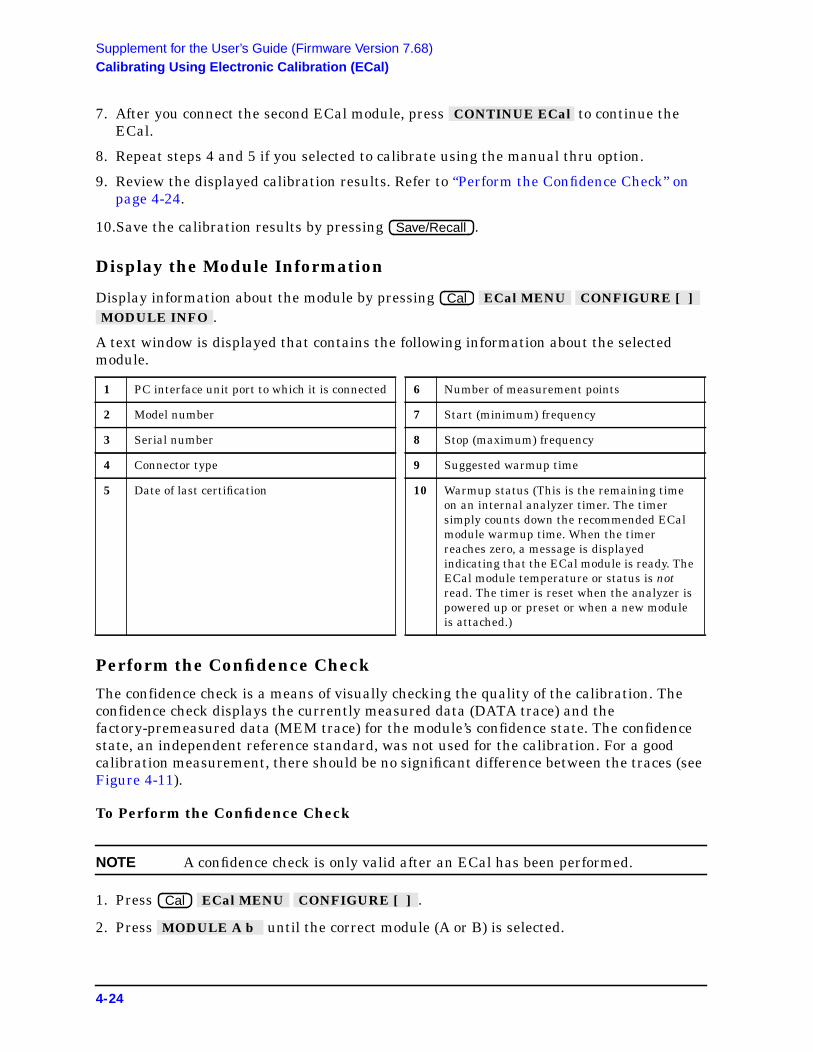
Supplement for the User’s Guide (Firmware Version 7.68)Calibrating Using Electronic Calibration (ECal)
7. After you connect the second ECal module, press to continue theECal.
8. Repeat steps 4 and 5 if you selected to calibrate using the manual thru option.
9. Review the displayed calibration results. Refer to “Perform the Confidence Check” onpage 4-24.
10.Save the calibration results by pressing .
Display the Module Information
Display information about the module by pressing.
A text window is displayed that contains the following information about the selectedmodule.
Perform the Confidence Check
The confidence check is a means of visually checking the quality of the calibration. Theconfidence check displays the currently measured data (DATA trace) and thefactory-premeasured data (MEM trace) for the module’s confidence state. The confidencestate, an independent reference standard, was not used for the calibration. For a goodcalibration measurement, there should be no significant difference between the traces (seeFigure 4-11).
To Perform the Confidence Check
NOTE A confidence check is only valid after an ECal has been performed.
1. Press .
2. Press until the correct module (A or B) is selected.
1 PC interface unit port to which it is connected 6 Number of measurement points
2 Model number 7 Start (minimum) frequency
3 Serial number 8 Stop (maximum) frequency
4 Connector type 9 Suggested warmup time
5 Date of last certification 10 Warmup status (This is the remaining timeon an internal analyzer timer. The timersimply counts down the recommended ECalmodule warmup time. When the timerreaches zero, a message is displayedindicating that the ECal module is ready. TheECal module temperature or status is notread. The timer is reset when the analyzer ispowered up or preset or when a new moduleis attached.)
CONTINUE ECal
Save/Recall
Cal ECal MENU CONFIGURE [ ] MODULE INFO
Cal ECal MENU CONFIGURE [ ]
MODULE A b
4-24
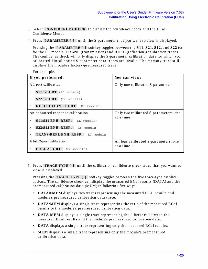
Supplement for the User’s Guide (Firmware Version 7.68)Calibrating Using Electronic Calibration (ECal)
3. Select to display the confidence check and the ECalConfidence Menu.
4. Press until the S-parameter that you want to view is displayed.
Pressing the softkey toggles between the S11, S21, S12, and S22 (orfor the ET models, TRANS (transmission) and REFL (reflection)) calibration traces.The confidence check will only display the S-parameter calibration data for which youcalibrated. Uncalibrated S-parameter data traces are invalid. The memory trace stilldisplays the module’s factory-premeasured trace.
For example,
5. Press until the calibration confidence check trace that you want toview is displayed.
Pressing the softkey toggles between the five trace-type displayoptions. The confidence check can display the measured ECal results (DATA) and thepremeasured calibration data (MEM) in following five ways.
• DATA&MEM displays two traces representing the measured ECal results andmodule's premeasured calibration data trace.
• DATA/MEM displays a single trace representing the ratio of the measured ECalresults to the module's premeasured calibration data.
• DATA-MEM displays a single trace representing the difference between themeasured ECal results and the module's premeasured calibration data.
• DATA displays a single trace representing only the measured ECal results.
• MEM displays a single trace representing only the module's premeasuredcalibration data.
If you performed: You can view:
A 1-port calibration
• (ES models)
• (ES models)
• (ET models)
Only one calibrated S-parameter
An enhanced response calibration
• (ES models)
• (ES models)
• (ET models)
Only two calibrated S-parameters, oneat a time
A full 2-port calibration
• (ES models)
All four calibrated S-parameters, oneat a time
CONFIDENCE CHECK
PARAMETER [ ]
PARAMETER [ ]
S11 1-PORT
S22 1-PORT
REFLECTION 1-PORT
S11/S21 ENH. RESP.
S22/S12 ENH. RESP.
TRANS/REFL ENH. RESP.
FULL 2-PORT
TRACE TYPE [ ]
TRACE TYPE [ ]
4-25

Supplement for the User’s Guide (Firmware Version 7.68)Calibrating Using Electronic Calibration (ECal)
6. If you want to change the scale of the display, press .
The softkey is located in this menu for convenience in viewing theconfidence check data. It acts the same as under the key.
7. Review the confidence check display.
Figure 4-11 Confidence Check Display showing DATA&MEM Trace Type
8. If you want to check other calibration S-parameters or trace types, repeat steps 4through 7.
9. When finished, select to complete the confidence check.
AUTO SCALE
AUTO SCALE AUTO SCALE Scale Ref
RETURN
4-26

Supplement for the User’s Guide (Firmware Version 7.68)Calibrating Using Electronic Calibration (ECal)
Investigating the Calibration Results Using the ECal Service Menu
CAUTION The confidence check described in the previous section displays the ECal dataof a single state. This confidence state is a calibrated standard not usedduring ECal. It is provided to give an independent assessment of the qualityof a calibration. In the Ecal Service menu, you may also display each of thecalibration standards which are used during an ECal calibration, along withthe analyzer’s measurement of those standards.
You may notice a difference in measurement results when comparing ECalconfidence state data and ECal standard state data. This result may berelated to certain measurement errors with the network analyzer system,which add uncertainty to measurement results. More detailed informationregarding measurement uncertainty is documented in the “DeterminingSystem Measurement Uncertainties” chapter of the network analyzer'sreference guide. Additional information on improving your measurementscan be found in Chapter 5, “Optimizing Measurement Results” in the user’sguide.
Using the ECal Service menu is not a standard part of the ECal procedure. It is a tool toallow you to identify problems in the calibration equipment, cables, connectors, orprocedures.
The Confidence Check menu supports the comparison of the measured data versus themodule's premeasured calibration data for the confidence state. The ECal Service menusupports the comparison of the measured data versus the module's premeasuredcalibration data for the remainder of the module states, in addition to the confidence state.
Access the ECal Service menu by pressing from the Confidence Checkmenu.
The ECal Service menu softkeys are:
Toggles the analyzer to show the data for the following calibrationstates:
• CONF (Confidence)
• THRU
• ISOL (Isolation)
• S11 REFL (S11 Reflection)
• S22 REFL (S22 Reflection)
Toggles between the available S11 and S22 reflection states listed inthe softkey described above.
• S11 REFL allows up to 13 reflection states.
• S22 REFL allows up to 13 reflection states.
ECal SERVICE
ECal STD [ ]
REFL STD [ ] ECal STD [ ]
4-27

Supplement for the User’s Guide (Firmware Version 7.68)Calibrating Using Electronic Calibration (ECal)
NOTE When returning to the Confidence Check menu from the ECal Service menu,press the softkey on the ECal Confidence Checkmenu. If this softkey is not pressed, the confidence check informationdisplayed may not be accurate.
NOTE When there is no premeasured calibration data for a given state andmeasurement parameter, a warning is displayed indicating that no moduledate is available.
Toggles the analyzer to show the data for the following S-parameters:
• S11 (ES models)
• S21 (ES models)
• S12 (ES models)
• S22 (ES models)
• RFL (ET models) - Reflection
• TRN (ET models) - Transmission
Toggles through the following trace types:
• DATA&MEM displays two traces representing the measured ECalresults and the module's premeasured calibration data trace.
• DATA/MEM displays a single trace representing a ratio of themeasured ECal results to the module's premeasured calibrationdata.
• DATA-MEM displays a single trace representing the differencebetween the measured ECal results and the module's premeasuredcalibration data.
• DATA displays a single trace representing only the measured ECalresults.
• MEM displays a single trace representing only the module'spremeasured calibration data.
Changes scale and reference values to bring the trace data in view onthe display. The analyzer determines the smallest possible scale factorthat will put all displayed data onto 80% of the vertical graticule. Thereference value is chosen to put the trace in center screen.
Returns to the ECal Confidence Check menu.
PARAMETER [ ]
TRACE TYPE [ ]
AUTO SCALE
RETURN
SET CONF STANDARD
4-28

Supplement for the User’s Guide (Firmware Version 7.68)Adapter Removal Using ECal (ES Analyzers Only)
Adapter Removal Using ECal (ES Analyzers Only)A device under test (DUT) whose connectors cannot be connected directly to a testconfiguration is considered to be a noninsertable device. See Figure 4-12 (or Figure 4-13).Noninsertable devices can be caused because the DUT has:
• input or output connectors with the same sex connector as the test configuration.
• input or output connectors of a different connector type than the test configuration.
Figure 4-12 8753ET/ES Noninsertable Device
Figure 4-13 8753ES Option 011 Noninsertable Device
The adapter removal calibration technique may be used with the ECal calibration toaccurately measure noninsertable devices. The following adapters (shown in Figure 4-14or Figure 4-15) are needed.
4-29

Supplement for the User’s Guide (Firmware Version 7.68)Adapter Removal Using ECal (ES Analyzers Only)
• Adapter A1, which mates with port 1 of the DUT, must be installed on Port 1 of theanalyzer.
• Adapter A2, which mates with port 2 of the DUT, must be installed on Port 2 of theanalyzer.
• Adapter A3 must match the connectors on the DUT. The effects of this adapter will becompletely removed with this calibration technique.
NOTE Adapters A1 and A2 become part of the test setup to allow connection to theDUT. Adapter A3 is used during the calibration only. Its effects will beremoved.
Figure 4-14 8753ET/ES Adapters Needed
Figure 4-15 8753ES Option 011 Adapters Needed
4-30

Supplement for the User’s Guide (Firmware Version 7.68)Adapter Removal Using ECal (ES Analyzers Only)
The following requirements must also be met:
• An ECal module for performing a 2-port error correction for each connector type mustbe available.
• Specified electrical length of adapter A3 within ± 1/4 wavelength for the measurementfrequency range.
For each port, a separate 2-port error correction needs to be performed to create twocalibration sets. The adapter removal algorithm uses the resultant data from the twocalibration sets and the nominal electrical length of the adapter to compute the adapter'sactual S-parameters. This data is then used to generate a separate third calibration set inwhich the forward and reverse match and tracking terms are as if port 1 and port 2 couldbe connected. This is possible because the actual S-parameters of the adapter aremeasured with great accuracy, thus allowing the effects of the adapter to be completelyremoved when the third calibration set is generated.
Perform the 2-Port Error Corrections
1. Connect adapter A3 to adapter A2 on port 2 as shown in Figure 4-16 (or Figure 4-17).
Figure 4-16 8753ET/ES Two-Port Cal Set 1
Figure 4-17 8753ES Option 011 Two-Port Cal Set 1
4-31

Supplement for the User’s Guide (Firmware Version 7.68)Adapter Removal Using ECal (ES Analyzers Only)
2. Connect the ECal module between adapter A1 and adapter A3.
3. Press .
4. Press to perform the first 2-port error correction using the ECalmodule.
NOTE When using adapter removal calibration, you must save calibration sets tothe internal disk, not to internal memory.
5. Save the results to disk. Name the file "PORT1."
6. Remove the ECal module and adapter A3 from the setup. Connect adapter A3 toadapter A1 on port 1 as shown in Figure 4-18 (or Figure 4-19).
Figure 4-18 8753ET/ES Two-Port Cal Set 2
Figure 4-19 8753ES Option 011 Two-Port Cal Set 2
7. Connect the ECal module between adapter A3 and adapter A2.
Cal ECal MENU MODULE A b
FULL 2-PORT
4-32

Supplement for the User’s Guide (Firmware Version 7.68)Adapter Removal Using ECal (ES Analyzers Only)
8. Press .
9. Press to perform the second 2-port error correction using the ECalmodule.
10.Save the results to disk. Name the file "PORT2."
11.Determine the electrical delay of adapter A3. If you have adapter specifications thatidentify the electrical delay, you may use that information and continue with “Removethe Adapter” on page 4-34. If you do not know the delay of adapter A3, perform the“Determine the Electrical Delay” procedure on page 4-33.
Determine the Electrical Delay
This procedure determines the electrical delay of adapter A3 using a short.
1. Refer to Figure 4-20 (or Figure 4-21) while performing the steps in this procedure.
2. Perform a 1-port calibration at “Reference Port 1.” Refer to Step A of Figure 4-20 (orFigure 4-21).
This 1-port calibration can either be a manual calibration or an ECal.
Figure 4-20 8753ET/ES Determining the Electrical Delay Setup
Figure 4-21 8753ES Option 011 Determining the Electrical Delay Setup
Cal ECal MENU
FULL 2-PORT
4-33

Supplement for the User’s Guide (Firmware Version 7.68)Adapter Removal Using ECal (ES Analyzers Only)
3. Connect the A3 adapter to “Reference Port 1” as shown in Step B of Figure 4-20 (orFigure 4-21). Connect a short to the open end of the A3 adapter.
4. Measure the delay of the adapter by pressing .
5. Divide the resulting delay measurement by 2 to determine the delay of the thru and theshort in one direction.
6. Determine the offset delay of the calibration short by examining the define standardmenu. (See the “Define Standard Menus” section in Chapter 7, “Operating Concepts” ofthe user’s guide.)
7. Subtract the offset delay of the short (determined in step 6) from the delay of the thruand the short in one direction (determined in step 5). The result is electrical delay of thethru. This value is used in the next procedure.
Remove the Adapter
When the two sets of error correction files have been created (now referred to as"calibration sets"), the A3 adapter may be removed.
1. Press to display the following menu:
2. Press to display and.
also displays the internal (or external if internal not used) diskfile directory.
NOTE In the following two steps, calibration data is recalled, not instrument states.
3. From the disk directory, choose the file associated with the port 1 error correction, thenpress .
4. When this is complete, choose the file for the port 2 error correction and press.
5. When complete, press .
6. Enter the value of adapter A3 electrical delay by pressing andentering the value.
7. Select the appropriate key: or .
(This Help softkey provides a quick reference guideto using the adapter removal technique.)
Format DELAY
Cal MORE ADAPTER REMOVAL
HELP ADAPT REMOVAL
RECALL CAL SETS
ADAPTER DELAY
ADAPTER COAX
ADAPTER WAVEGUIDE
REMOVE ADAPTER
RECALL CAL SETS RECALL CAL PORT 1 RECALL CAL PORT 2
RECALL CAL SETS
RECALL CAL PORT 1
RECALL CAL PORT 2
RETURN
ADAPTER DELAY
ADAPTER COAX ADAPTER WAVEGUIDE
4-34
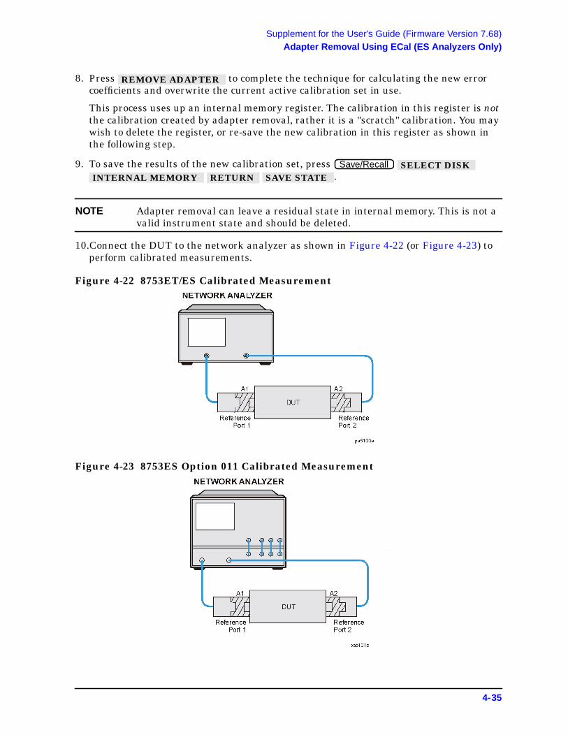
Supplement for the User’s Guide (Firmware Version 7.68)Adapter Removal Using ECal (ES Analyzers Only)
8. Press to complete the technique for calculating the new errorcoefficients and overwrite the current active calibration set in use.
This process uses up an internal memory register. The calibration in this register is notthe calibration created by adapter removal, rather it is a "scratch" calibration. You maywish to delete the register, or re-save the new calibration in this register as shown inthe following step.
9. To save the results of the new calibration set, press.
NOTE Adapter removal can leave a residual state in internal memory. This is not avalid instrument state and should be deleted.
10.Connect the DUT to the network analyzer as shown in Figure 4-22 (or Figure 4-23) toperform calibrated measurements.
Figure 4-22 8753ET/ES Calibrated Measurement
Figure 4-23 8753ES Option 011 Calibrated Measurement
REMOVE ADAPTER
Save/Recall SELECT DISK INTERNAL MEMORY RETURN SAVE STATE
4-35

Supplement for the User’s Guide (Firmware Version 7.68)Adapter Removal Using ECal (ES Analyzers Only)
Verify the Results
Since the effect of the adapter has been removed, it is easy to verify the accuracy of thetechnique by simply measuring the adapter itself. Because the adapter was used duringthe creation of the two calibration sets, and the technique removes its effects,measurement of the adapter itself should show the S-parameters.
If unexpected phase variations are observed, this indicates that the electrical delay of theadapter was not specified within a quarter wavelength over the frequency range ofinterest. To correct this, recall both cal sets; since the data was previously stored to disk,change the adapter delay, and press . REMOVE ADAPTER
4-36

Supplement for the User’s Guide (Firmware Version 7.68)Calibration Routines
Calibration Routines
Enhanced Response Calibration
The enhanced response calibration, activated by pressing thesoftkey within the calibrate menu, provides a one-port calibration to correct for directivity,source match, and frequency response for reflection measurements, and corrects for sourcematch as well as frequency response for transmission measurements.
For ES models, enhanced response calibration improves accuracy in transmissionmeasurements compared to a response calibration or a response and isolation calibration,but it is not as accurate as a full 2-port calibration. For ET models, this calibrationprovides the best accuracy for measurements with a T/R test set.
Enhanced Reflection Calibration
The enhanced reflection calibration is activated by selecting underthe menu.
The enhanced reflection calibration effectively removes load match error from theenhanced response calibration performed on a bilateral device. A bilateral device has anidentical forward (S21) and reverse transmission (S12) response. Most passive devices (suchas filters, attenuators, or switches) are bilateral. Some passive devices (circulators,isolators) and most active devices do not have identical forward and reverse transmissionresponses and enhanced reflection calibration will not work with these devices.
ECal
The ECal calibration menu is activated by pressing in the calibration menu.
The ECal (Electronic Calibration) system determines systemic errors of the analyzerthrough a one-time connection of an ECal module to the network analyzer ports. Therandom error of connector repeatability is reduced substantially through a one-timeconnection when compared to frequent connections and disconnections of the conventionalshort/open/load methods.
ENHANCED RESPONSE
ENH. REFL. ON off ENHANCED RESPONSE
ECal MENU
4-37

Supplement for the User’s Guide (Firmware Version 7.68)Calibration Routines
This page intentionally left blank.
4-38

Supplement for the User’s Guide (Firmware Version 7.68)Safety Considerations
Safety Considerations
Servicing
WARNING For continued protection against fire hazard replace line fuse onlywith same type and rating (115V operation: T 5A 125 V UL/CSA;230V operation: T 4A H 250V IEC). The use of other fuses or materialis prohibited.
4-39

5 Supplement for the Reference Guide(Firmware Revision 7.68)
5-1

Supplement for the Reference Guide (Firmware Revision 7.68)In This Chapter
In This ChapterThis chapter contains the supplemental information changes to the reference guides thatcoincide with the release of firmware revision 7.68. These changes pertain to the followingreference guides.
• 8753ET and 8753ES Network Analyzers Reference Guide (part number 08753-90473)
• 8753ES Option 011 Network Analyzer Reference Guide (part number 08753-90480)
IMPORTANT If you are upgrading your firmware from a revision prior to revision 7.66, addthe information changes from Chapter 2 , “Supplement for the ReferenceGuide (Firmware Revision 7.66),” before adding the changes from thischapter.
The following list describes the changes to 8753ET and 8753ES reference guides printedprior to February 2001. Each of the changes are described in detail in the remainder of thischapter. The page references in this list refer to page numbers in this supplement.
• Menu Maps Chapter
— Replace the Display menu map using Figure 5-1 on page 5-3.
— Replace the Save and Recall menu map using Figure 5-2 on page 5-5.
— Replace the Calibration menu map for the 8753ET using Figure 5-3.
— Replace the Calibration menu map for the 8753ES using Figure 5-4.
— Replace the Calibration menu map for the 8753ES Option 011 using Figure 5-5.
— Replace the System menu map for the 8753ET using Figure 5-6.
— Replace the System menu map for the 8753ES and 8753ES Option 011 using Figure5-7.
• Hardkey/Softkey Reference Chapter
— Adjust the description of four existing softkeys. See “Changes to Existing Softkeys”on page 5-17.
— Add 18 new softkeys and their descriptions. See “New Softkeys” on page 5-18.
• Error Messages Chapter
— Add 19 new error messages. See to “Error Messages” on page 5-21.
• Options and Accessories Chapter
— Add two calibration kits and update electronic calibration (ECal) options. See“Options and Accessories” on page 5-27.
• Preset State and Memory Allocation Chapter
— Add six new preset values. See “Preset State and Memory Allocation” on page 5-29.
5-2

Supplement for the Reference Guide (Firmware Revision 7.68)Menu Maps
Menu Maps
Figure 5-1 Menu Map for Display
5-3

Supplement for the Reference Guide (Firmware Revision 7.68)Menu Maps
This page intentionally left blank.
5-4

Supplement for the Reference Guide (Firmware Revision 7.68)Menu Maps
Figure 5-2 Menu Map for Save/Recall
5-5

Supplement for the Reference Guide (Firmware Revision 7.68)Menu Maps
This page intentionally left blank.
5-6

USE SENSOR
A / B
CAL FACTOR
SENSOR A
CAL FACTOR
SENSOR B
POWER
LOSS
RETURN
Pwr. Loss/Sens.Lists Menu
ENHANCEDRESPONSE
RESPONSE
RESPONSE& ISOL'N
REFLECTION1-PORT
RECEIVERCAL
CalibrateMenu
SHORT (M)
SHORT (F)
DONE:SHORTS
TAKE RCVRCAL SWEEP
RETURN
ShortsMenu
Rcvr CalMenu
SHORT (M)
SHORT (F)
OPEN (M)
OPEN (F)
THRU
ResponseMenu
OPEN ( M )
OPEN ( F )
DONE:OPENS
OpensMenu
TRAN / REFLENH. RESP.
ENH. REFL.on OFF
RETURN
EnhancedResponse Menu
REFLECT'N
TRANS-MISSION
ISOLATION
DONE FWDENH RESP
Enh. Resp.Cal. Menu
RESPONSE
ISOL 'N STD
DONE RESPISOL 'N CAL
Response & Isolation Menu
DO BOTHFWD THRUS
FWD TRANSTHRU
FWD MATCHTHRU
STANDARDSDONE
Enh. Resp.Trans. Menu
OMITISOLATION
FWD ISOL'N
ISOLATIONDONE
Enh. Resp.Isolation Menu
FORWARD:OPENS
SHORTS
LOAD
DONE1-PORT CAL
Reflection1-Port Menu
FORWARD:OPENS
SHORTS
LOAD
STANDARDSDONE
Enh. Resp.Refl. Menu
CLEAR LIST
YES
NO
Clear ListMenu
SEGMENT
EDIT
DELETE
ADD
CLEAR
LIST
DONE
SegmentModify Menu
PWRMTR CALOFF
EACH SWEEP
ONE SWEEP
TAKE CALSWEEP
NUMBER ofREADINGS
PWR LOSSon OFF
LOSS/SENSRLISTS
RETURN
Power MeterCal. Main Menu
FREQUENCY
CALFACTOR
DONE
Seg. Edit (CalFactor) Menu
FREQUENCY
LOSS
DONE
Seg. Edit (Pwr.Loss) Menu
DEFINESTANDARD
SPECIFYCLASS
LABELCLASS
LABELKIT
TRL/LRMOPTION
KIT DONE(MODIFIED)
Modify Cal Kit Menu
S11A
S11B
S11C
S22A
S22B
S22C
MORE
SPECIFY
CLASS DONE
Specify ClassMenu
FWD TRANS
REV TRANS
FWD MATCH
REV MATCH
RESPONSE
RESPONSE
& ISOL'N
MORE
SPECIFY
CLASS DONE
Specify Class More Menu
SPECIFY:
TRL THRU
TRL
REFLECT
TRL LINE
OR MATCH
SPECIFY
CLASS DONE
Specify Class More Menu
SELECTLETTER
SPACE
BACKSPACE
ERASETITLE
DONE
Label SelectMenu
ANS
ANS
TCH
TCH
NSE
NSE
L'N
RE
BEL
ONE
ssnu
LABEL:TRL THRU
TRLREFLECT
TRL LINEOR MATCH
LABELCLASS DONE
Label Class / KitMore Menu
SPECIFYOFFSET
LABELSTD
STD DONE(DEFINED)
Define Delay/Thru Menu
SPECIFYOFFSET
LABELSTD
STD DONE(DEFINED)
Define ShortMenu
C0
C1
C2
C3
SPECIFYOFFSET
LABELSTD
STD DONE(DEFINED)
Define OpenMenu
STD TYPE:OPEN
SHORT
LOAD
DELAY /THRU
ARBITRARYIMPEDANCE
MODIFY STDDEFINITION
RETURN
Define StandardMenu
TERMINAL
IMPEDANCE
FIXED
SLIDING
SPECIFY
OFFSET
LABEL
STD
STD DONE
(DEFINED)
Def. ArbitraryImped. Menu
FIXED
SLIDING
OFFSET
SPECIFYOFFSET
LABELSTD
STD DONE(DEFINED)
Define LoadMenu
OFFSETDELAY
OFFSETLOSS
OFFSETZ0
MINIMUMFREQUENCY
MAXIMUMFREQUENCY
COAX
WAVEGUIDE
STD OFFSETDONE
Specify OffsetMenu
SELECTLETTER
SPACE
BACKSPACE
ERASETITLE
DONE
Label StandardMenu
Calibration Factor Softkey Path
Power Loss Softkey Path
ECal ECalervice Menu
ECal STD[CONF]
REFL STD[ 0 ]
PARAMETER[RFL]
TRACE TYPE[DATA]
AUTO SCALE
RETURN
ECal
1. When two ECal modules are used in a measurement, the routine will pause to allow you to insert
CAL Z0:LINE Z0
SYSTEM Z0
SET REF:THRU
REFLECT
RETURN
TRL OptionMenu
Cal
SELECTCAL KIT
SAVEUSER KIT
MODIFY[ ]
RETURN
Cal KitMenu
EXTENSIONSon OFF
EXTENSIONINPUT A
EXTENSIONINPUT B
EXTENSIONREFL PORT
EXTENSIONTRANS PORT
RETURN
ReferencePlane Menu
PORTEXTENSIONS
VELOCITYFACTOR
SET Z
ALTERNATERFL/TRN
CHOPRFL/TRN
RETURN
Æ
CalibrateMore Menu
FWD TR
REV TR
FWD MA
REV MA
RESPO
RESPO
& ISO
MO
LA
CLASS D
Label ClaMore Me
S11A
S11B
S11C
S22A
S22B
S22C
MORE
LABEL
CLASS DONE
Label ClassMenu
7mm 85031
3.5mmD 85033D/E
N 50W 85032F
N 50W 85032B/E
N 75W 85036
USER KIT
MORE
RETURN
Select Cal KitMenu
2.4mm 85056
2.92* 85056K
2.9mmother kits
TRL 3.5mm 85052C
7-16 85038
3.5mmC 85033C
RETURN
Select Cal KitMore Menu
SET CONFSTANDARD
PARAMETER[RFL]
TRACE TYPE[DATA]
AUTO SCALE
ECalSERVICE
RETURN
Confidence SConfig Menu
MODULEA b
CONFIDENCECHECK
MODULEINFO
OMIT ISOLON off
ISOLATIONAVERAGES
MAN’L THRUon OFF
RETURN
CORRECTIONon OFF
INTERPOLON off
CALIBRATEMENU
RESUME CALSEQUENCE
ECalMENU
CAL KIT[ ]
PWRMTR CAL[OFF]
MORE
CorrectionMenu
MODULEA b
REFLECTION1-PORT
TRAN/REFLENH. RESP.
CONFIGURE[MODULE A]
RETURN
ECalMenu
CONTINUEECal
ABORTECal
ECalPause Menu
1, 2
1
kl508ets Menu Map For Cal (8753ET) only
the next module. A "CONTINUE ECal" and "ABORT ECal" menu will be displayed during the pause.
2. When "MAN'L THRU" is turned "ON", the calibration will pause and allow you to insert your own thru. A "CONTINUE ECal" and "ABORT ECal" menu will be displayed during the pause.

k
ENHANCEDRESPONSE
RESPONSE
RESPONSE& ISOL'N
S111-PORT
S221-PORT
FULL2-PORT
TRL*/LRM*2-PORT
RECEIVERCAL
CalibrateMenu
OPEN (M)
OPEN (F)
DONE:OPENS
OpensMenu
SHORT (M)
SHORT (F)
DONE:SHORTS
ShortsMenu
XTENSIONSon OFF
EXTENSIONINPUT A
EXTENSIONINPUT B
EXTENSIONPORT 1
EXTENSIONPORT 2
RETURN
Referencelane Menu
DEFINESTANDARD
SPECIFYCLASS
LABELCLASS
LABELKIT
TRL/LRMOPTION
KIT DONE(MODIFIED)
Modify Cal Kit Menu
S11A
S11B
S11C
S22A
S22B
S22C
MORE
SPECIFY
CLASS DONE
Specify ClassMenu
FWD TRANS
REV TRANS
FWD MATCH
REV MATCH
RESPONSE
RESPONSE
& ISOL'N
MORE
SPECIFY
CLASS DONE
Specify Class More Menu
SPECIFY:
TRL THRU
TRL
REFLECT
TRL LINE
OR MATCH
SPECIFY
CLASS DONE
Specify Class More Menu
SELECTLETTER
SPACE
BACKSPACE
ERASETITLE
DONE
Label SelectKit Menu
Calibration Factor Softkey Path
Power Loss Softkey Path
TAKE RCVRCAL SWEEP
RETURN
Rcvr CalMenu
OMITISOLATION
DO BOTHFWD + REV
FWD ISOL 'NISOL 'N STD
REV ISOL 'NISOL 'N STD
ISOLATIONDONE
2-Port IsolationMenu
DO BOTHFWD + REV
FWD TRANSTHRU
FWD MATCHTHRU
REV TRANSTHRU
REV MATCHTHRU
STANDARDSDONE
2-Port Trans.Menu
FORWARD:OPENS
SHORTS
LOAD
REVERSE:OPENS
SHORTS
LOAD
STANDARDSDONE
2-Port ReflectionMenu
REFLECTION
TRANS-MISSION
ISOLATION
DONE2-PORT CAL
Full 2-PortMenu
THRUTHRU
S11 REFLOPENS
S22 REFLOPENS
ISOLATION
LINE/MATCH
DONETRL/LRM
TRL/LRMCal Menu
OMITISOLATION
DO BOTHFWD + REV
FWD ISOL 'NISOL 'N STD
REV ISOL 'NISOL 'N STD
ISOLATIONDONE
TRL/LRMIsolation Menu
DO BOTHFWD + REV
LN/MATCH1LOAD
LN/MATCH2LOAD
DONELINE / MATCH
Line / MatchMenu
SHORT (M)
SHORT (F)
OPEN (M)
OPEN (F)
THRU
ResponseMenu
RESPONSE
ISOL 'N STD
DONE RESPISOL 'N CAL
Response & Isolation Menu
REVERSE:OPENS
SHORTS
LOAD
DONE1-PORT CAL
S22 1-PortMenu
FORWARD:OPENS
SHORTS
LOAD
DONE1-PORT CAL
S11 1-PortMenu
S11/S21ENH. RESP.
S22/S12ENH. RESP.
ENH. REFL.on OFF
RETURN
EnhancedResponseMenu
REFLECT'N
TRANS-MISSION
ISOLATION
DONE ***ENH RESP
Enh. Resp.Cal. Menu
DO BOTH THRUS***
TRANS***THRU
MATCH***THRU
STANDARDSDONE
Enh. Resp.Trans. Menu
OMITISOLATION
ISOL'N***
ISOLATIONDONE
Enh. Resp.Isolation Menu
:***OPENS
SHORTS
LOAD
STANDARDSDONE
Enh. Resp.Refl. Menu
1. When two ECal modules are used in a measurement, the routine will pause to allow you to insert the next module. A "CONTINUE ECal" and "ABORT ECal" menu will be displayed during the pause.
CLEAR LIST
YES
NO
Clear ListMenu
PWRMTR CALOFF
EACH SWEEP
ONE SWEEP
TAKE CALSWEEP
NUMBER ofREADINGS
PWR LOSSon OFF
LOSS/SENSRLISTS
RETURN
Power MeterCal. Main Menu
FREQUENCY
CALFACTOR
DONE
Seg. Edit (CalFactor) Menu
FREQUENCY
LOSS
DONE
Seg. Edit (Pwr.Loss) Menu
USE SENSOR
A / B
CAL FACTOR
SENSOR A
CAL FACTOR
SENSOR B
POWER
LOSS
RETURN
Pwr. Loss/Sens.Lists Menu
SEGMENT
EDIT
DELETE
ADD
CLEAR
LIST
DONE
SegmentModify Menu
SPECIFYOFFSET
LABELSTD
STD DONE(DEFINED)
Define Delay/Thru Menu
SPECIFYOFFSET
LABELSTD
STD DONE(DEFINED)
Define ShortMenu
C0
C1
C2
C3
SPECIFYOFFSET
LABELSTD
STD DONE(DEFINED)
Define OpenMenu
STD TYPE:OPEN
SHORT
LOAD
DELAY /THRU
ARBITRARYIMPEDANCE
MODIFY STDDEFINITION
RETURN
Define StandardMenu
TERMINAL
IMPEDANCE
FIXED
SLIDING
SPECIFY
OFFSET
LABEL
STD
STD DONE
(DEFINED)
Def. ArbitraryImped. Menu
FIXED
SLIDING
OFFSET
SPECIFYOFFSET
LABELSTD
STD DONE(DEFINED)
Define LoadMenu
OFFSETDELAY
OFFSETLOSS
OFFSETZ0
MINIMUMFREQUENCY
MAXIMUMFREQUENCY
COAX
WAVEGUIDE
STD OFFSETDONE
Specify OffsetMenu
SELECTLETTER
SPACE
BACKSPACE
ERASETITLE
DONE
Label StandardMenu
Cale Menu
Cal STD[CONF]
EFL STD[ 0 ]
AMETER[S11]
CE TYPE[DATA]
O SCALE
RETURN
CAL Z0:LINE Z0
SYSTEM Z0
SET REF:THRU
REFLECT
RETURN
TRL OptionMenu
SELECTCAL KIT
SAVEUSER KIT
MODIFY[ ]
RETURN
Cal KitMenu
E
P
PORTEXTENSIONS
VELOCITYFACTOR
SET Z
ADAPTERREMOVAL
TESTSET SWCONTINUOUS
ALTERNATEA and B
CHOPA and B
RETURN
Æ
CalibrateMore Menu
RECALLCAL PORT 1
RECALLCAL PORT 2
RETURN
Recall Cal SetsMenu
FWD TRANS
REV TRANS
FWD MATCH
REV MATCH
RESPONSE
RESPONSE
& ISOL'N
MORE
LABEL
CLASS DONE
Label ClassMore Menu
S11A
S11B
S11C
S22A
S22B
S22C
MORE
LABEL
CLASS DONE
Label ClassMenu
LABEL:TRL THRU
TRLREFLECT
TRL LINEOR MATCH
LABELCLASS DONE
Label ClassMore Menu
2.4mm 85056
2.92* 85056K
2.9mmother kits
TRL 3.5mm 85052C
7-16 85038
3.5mmC 85033C
RETURN
Select Cal KitMore Menu
7mm 85031
3.5mmD 85033D/E
N 50W 85032F
N 50W 85032B/E
N 75W 85036
USER KIT
MORE
RETURN
Select Cal KitMenu
HELP ADAPTREMOVAL
RECALL CALSTETS
ADAPTERDELAY
ADAPTER: COAX
WAVEGUIDE
REMOVEADAPTER
RETURN
AdapterRemoval Menu
ECalConfig Menu
MODULEA b
CONFIDENCECHECK
MODULEINFO
OMIT ISOLON off
ISOLATIONAVERAGES
MAN’L THRUon OFF
RETURN
SET CONFSTANDARD
PARAMETER[S11]
TRACE TYPE[DATA]
AUTO SCALE
ECalSERVICE
RETURN
ECalConfidence
EServic
E
R
PAR
TRA
AUT
Cal ECalMenu
MODULEA b
S111-PORT
S221-PORT
FULL2-PORT
S11/S21ENH. RESP.
S22/S12ENH. RESP.
CONFIGURE[MODULE A]
RETURN
CORRECTIONon OFF
INTERPOLon OFF
CALIBRATEMENU
RESUME CALSEQUENCE
ECalMENU
CAL KIT[ ]
PWRMTR CAL[OFF]
MORE
CorrectionMenu
CONTINUEECal
ABORTECal
ECalPause Menu
1, 2
1, 2
1, 2
1
1
l507ets Menu Map For Cal (8753ES only)
2. When "MAN'L THRU" is turned "ON", the calibration routine will pause and allow you to insert your own thru. A "CONTINUE ECal" and "ABORT ECal" menu will be displayed during the pause. *** Represents "FORWARD"/"FWD" when calibrating the forward path or "REVERSE"/ "REV" when calibrating the reverse path.
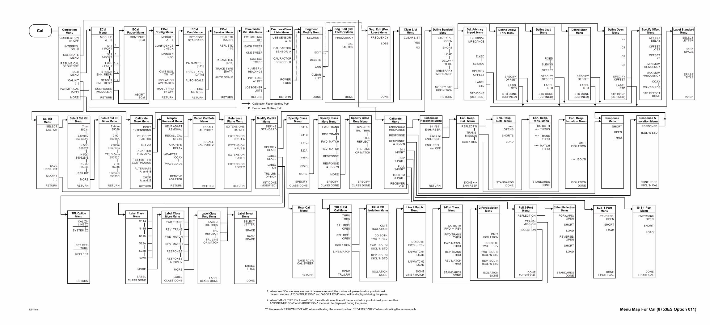
ENHANCEDRESPONSE
RESPONSE
RESPONSE& ISOL'N
S111-PORT
S221-PORT
FULL2-PORT
TRL/LRM2-PORT
RECEIVERCAL
CalibrateMenu
EXTENSIONSon OFF
EXTENSIONINPUT A
EXTENSIONINPUT B
EXTENSIONPORT 1
EXTENSIONPORT 2
RETURN
ReferencePlane Menu
DEFINESTANDARD
SPECIFYCLASS
LABELCLASS
LABELKIT
TRL/LRMOPTION
KIT DONE(MODIFIED)
Modify Cal Kit Menu
S11A
S11B
S11C
S22A
S22B
S22C
MORE
SPECIFY
CLASS DONE
Specify ClassMenu
FWD TRANS
REV TRANS
FWD MATCH
REV MATCH
RESPONSE
RESPONSE
& ISOL'N
MORE
SPECIFY
CLASS DONE
Specify Class More Menu
SPECIFY:
TRL THRU
TRL
REFLECT
TRL LINE
OR MATCH
SPECIFY
CLASS DONE
Specify Class More Menu
SELECTLETTER
SPACE
BACKSPACE
ERASETITLE
DONE
Label SelectMenu
TAKE RCVRCAL SWEEP
RETURN
Rcvr CalMenu
OMITISOLATION
DO BOTHFWD + REV
FWD ISOL 'NISOL 'N STD
REV ISOL 'NISOL 'N STD
ISOLATIONDONE
2-Port IsolationMenu
DO BOTHFWD + REV
FWD TRANSTHRU
FWD MATCHTHRU
REV TRANSTHRU
REV MATCHTHRU
STANDARDSDONE
2-Port Trans.Menu
FORWARD:OPEN
SHORT
LOAD
REVERSE:OPEN
SHORT
LOAD
STANDARDSDONE
2-Port ReflectionMenu
REFLECTION
TRANS-MISSION
ISOLATION
DONE2-PORT CAL
Full 2-PortMenu
THRUTHRU
S11 REFLOPEN
S22 REFLOPEN
ISOLATION
LINE/MATCH
DONETRL/LRM
TRL/LRMCal Menu
OMITISOLATION
DO BOTHFWD + REV
FWD ISOL 'NISOL 'N STD
REV ISOL 'NISOL 'N STD
ISOLATIONDONE
TRL/LRMIsolation Menu
DO BOTHFWD + REV
LN/MATCH1LOAD
LN/MATCH2LOAD
DONELINE / MATCH
Line / MatchMenu
SHORT
OPEN
THRU
ResponseMenu
RESPONSE
ISOL 'N STD
DONE RESPISOL 'N CAL
Response & Isolation Menu
REVERSE:OPEN
SHORT
LOAD
DONEI-PORT CAL
S22 1-PortMenu
FORWARD:OPEN
SHORT
LOAD
DONEI-PORT CAL
S11 1-PortMenu
S11/S21ENH. RESP.
S22/S12ENH. RESP.
ENH. REFL.on OFF
RETURN
EnhancedResponse Menu
REFLECT'N
TRANS-MISSION
ISOLATION
DONE ***ENH RESP
Enh. Resp.Cal. Menu
DO BOTH THRUS***
TRANS***THRU
MATCH***THRU
STANDARDSDONE
Enh. Resp.Trans. Menu
OMITISOLATION
ISOL'N***
ISOLATIONDONE
Enh. Resp.Isolation Menu
:***OPENS
SHORTS
LOAD
STANDARDSDONE
Enh. Resp.Refl. Menu
k
USE SENSOR
A / B
CAL FACTOR
SENSOR A
CAL FACTOR
SENSOR B
POWER
LOSS
RETURN
Pwr. Loss/Sens.Lists Menu
CLEAR LIST
YES
NO
Clear ListMenu
SEGMENT
EDIT
DELETE
ADD
CLEAR
LIST
DONE
SegmentModify Menu
PWRMTR CALOFF
EACH SWEEP
ONE SWEEP
TAKE CALSWEEP
NUMBER ofREADINGS
PWR LOSSon OFF
LOSS/SENSRLISTS
RETURN
Power MeterCal. Main Menu
FREQUENCY
CALFACTOR
DONE
Seg. Edit (CalFactor) Menu
FREQUENCY
LOSS
DONE
Seg. Edit (Pwr.Loss) Menu
Calibration Factor Softkey Path
Power Loss Softkey Path
STD TYPE:OPEN
SHORT
LOAD
DELAY /THRU
ARBITRARYIMPEDANCE
MODIFY STDDEFINITION
RETURN
Define StandardMenu
SPECIFYOFFSET
LABELSTD
STD DONE(DEFINED)
Define Delay/Thru Menu
SPECIFYOFFSET
LABELSTD
STD DONE(DEFINED)
Define ShortMenu
C0
C1
C2
C3
SPECIFYOFFSET
LABELSTD
STD DONE(DEFINED)
Define OpenMenu
TERMINAL
IMPEDANCE
FIXED
SLIDING
SPECIFY
OFFSET
LABEL
STD
STD DONE
(DEFINED)
Def. ArbitraryImped. Menu
FIXED
SLIDING
OFFSET
SPECIFYOFFSET
LABELSTD
STD DONE(DEFINED)
Define LoadMenu
OFFSETDELAY
OFFSETLOSS
OFFSETZ0
MINIMUMFREQUENCY
MAXIMUMFREQUENCY
COAX
WAVEGUIDE
STD OFFSETDONE
Specify OffsetMenu
SELECTLETTER
BACKSPACE
ERASETITLE
DONE
Label StandardMenu
lenu
l STDONF]
STD[ 0 ]
ETER[S11]
TYPEATA]
CALE
URN
1. When two ECal modules are used in a measurement, the routine will pause to allow you to insert the next module. A "CONTINUE ECal" and "ABORT ECal" menu will be displayed during the pause.
CAL Z0:LINE Z0
SYSTEM Z0
SET REF:THRU
REFLECT
RETURN
TRL OptionMenu
Cal
SELECTCAL KIT
SAVEUSER KIT
MODIFY[ ]
RETURN
Cal KitMenu
PORTEXTENSIONS
VELOCITYFACTOR
SET Z
ADAPTERREMOVAL
TESTSET SWCONTINUOUS
ALTERNATEA and B
CHOPA and B
RETURN
Æ
CalibrateMore Menu
RECALLCAL PORT 1
RECALLCAL PORT 2
RETURN
Recall Cal SetsMenu
FWD TRANS
REV TRANS
FWD MATCH
REV MATCH
RESPONSE
RESPONSE
& ISOL'N
MORE
LABEL
CLASS DONE
Label ClassMore Menu
S11A
S11B
S11C
S22A
S22B
S22C
MORE
LABEL
CLASS DONE
Label ClassMenu
LABEL:TRL THRU
TRLREFLECT
TRL LINEOR MATCH
LABELCLASS DONE
Label ClassMore Menu
2.4mm 85056
2.92* 85056K
2.9mmother kits
TRL 3.5mm 85052C
7-16 85038
3.5mmC 85033C
RETURN
Select Cal KitMore Menu
7mm 85031
3.5mmD 85033D/E
N 50 85032F
N 50 85032B/E
N 75 85036
USER KIT
MORE
RETURN
W
W
W
Select Cal KitMenu
HELP ADAPTREMOVAL
RECALL CALSTETS
ADAPTERDELAY
ADAPTER: COAX
WAVEGUIDE
REMOVEADAPTER
RETURN
AdapterRemoval Menu
MODULEA b
S111-PORT
S221-PORT
FULL2-PORT
S11/S21ENH. RESP.
S22/S12ENH. RESP.
CONFIGURE[MODULE A]
RETURN
ECalMenu
SET CONFSTANDARD
PARAMETER[S11]
TRACE TYPE[DATA]
AUTO SCALE
ECalSERVICE
RETURN
ECalConfidence
ECaService M
ECa[C
REFL
PARAM
TRACE [D
AUTO S
RET
ECalConfig Menu
MODULEA b
CONFIDENCECHECK
MODULEINFO
OMIT ISOLON off
ISOLATIONAVERAGES
MAN’L THRUon OFF
RETURN
CORRECTIONon OFF
INTERPOLON off
CALIBRATEMENU
RESUME CALSEQUENCE
ECalMENU
CAL KIT[ ]
PWRMTR CAL[OFF]
MORE
CorrectionMenu
CONTINUEECal
ABORTECal
ECalPause Menu
1, 2
1, 2
1, 2
1
1
l511ets Menu Map For Cal (8753ES Option 011)
2. When "MAN'L THRU" is turned "ON", the calibration routine will pause and allow you to insert your own thru. A "CONTINUE ECal" and "ABORT ECal" menu will be displayed during the pause. *** Represents "FORWARD"/"FWD" when calibrating the forward path or "REVERSE"/"REV" when calibrating the reverse path.

LIMIT LINEon OFF
LIMIT TESTon OFF
BEEP FAILon OFF
EDITLIMIT LINE
LIMIT LINEOFFSETS
RETURN
LimitsMenu
BandwidthTest Menu
SEGMENT
EDIT
DELETE
ADD
CLEARLIST
LIMITTYPE
DONE
Edit LimitsMenu
SEGMENT
EDIT
DELETE
ADD
CLEARLIST
DONE
Edit ListMenu
STIMULUSVALUE
MARKERSTIMULUS
UPPERLIMIT
LOWERLIMIT
DELTALIMITS
MIDDLEVALUE
MARKERMIDDLE
DONE
Edit SegmentMenu
Edit RippleLimits Menu
FREQUENCY
CALFACTOR
DONE
Edit SensorMenu
****
ESTS
TESTIONS
SELFOSIS
VICEDES
BUS OFF
EEK /OKE
ARESION
URN
ceu
CONTINUETEST
REPEATon OFF
RECORDon OFF
LIMITS[ NORM ]
PWR LOSSon OFF
LOSS / SENSRLISTS
DUMP GRAPHon OFF
RETURN
Test OptionsMenu
FRACN TUNEon OFF
SRC ADJUSTMENU
SOURCE PLLON off
PLL AUTOON off
PLL DIAGon OFF
PLL PAUSE[ CONT ]
MORE
RETURN
Service ModesMenu
USE SENSORA / B
CAL FACTORSENSOR A
CAL FACTORSENSOR B
POWERLOSS
RETURN
EXECUTETEST
INTERNALTESTS
EXTERNALTESTS
SYS VERTESTS
ADJUSTMENTTESTS
DISPLAYTESTS
RETURN
TestsMenu
SRC TUNEon OFF
SRC TUNEFREQ
ALCON off
PWR DACon OFF
SLOPEDAC
SRC ADJUSTDACS
HB FLTR SWon OFF
RETURN
GATE SHAPE
MAXIMUM
WIDE
NORMAL
MINIMUM
RETURN
WINDOW:
MAXIMUM
NORMAL
MINIMUM
E MEMORY
on OFF
DEMOD:
OFF
MPLITUDE
PHASE
RETURN
SLOPINGLINE
FLATLINE
SINGLEPOINT
RETURN
PEEK / POKEADDRESS
PEEK
POKE
RESETMEMORY
RETURN
Peek / PokeMenu
SLOPEOFFSET DAC
SQUARE LAWLINEAR DAC
DETECTOROFFSET DAC
LOGOFFSET DAC
WRITEEEPROM
RETURN
SAMPLE CORON off
IF GAINAUTO
IF GAINON
IF GAINOFF
SPUR TESTon OFF
STORE EEPRon OFF
SPUR AVOIDON off
RETURN
Serve ModeMore Menu
Offset TableMenu
SourceAdjust Menu
Gate ShapeMenu
WindowMenu
Limit TypeMenu
Adjust DACSMenu
Only appears on instruments equipped with Option 010.
Only appears on instruments equipped with Option 002.
Service menu key descriptions are located in this analyzer's service guide.
Loss appears thru the power loss path.
*
**
***
****
.
BW TESTon OFF
BW DISPLAYon OFF
BW MARKERon OFF
N DBPOINTS
MINIMUMBANDWIDTH
MAXIMUMBANDWIDTH
RETURN
FREQUENCYBAND
MINIMUMFREQUENCY
MAXIMUMFREQUENCY
MAXIMUMRIPPLE
DELETE
ADD
CLEARLIST
DONE
this is in the correct position on the page for a 1" gutter and 1/2" margin on the right. It prints out correctly for dummies. Please don't move it!! Thanks
TIME STAMPON off
ROUNDSECONDS
SETMINUTES
SETHOUR
SETDAY
SETMONTH
SETYEAR
RETURN
Set ClockMenu
PRESETSETTINGS
K36 MODEon OFF
K39 MODEon OFF
User SettingsMenu
CAL INTERPON off
Preset SettingsMenu
Select LimitsMenu
LIMIT LINE
RIPPLELIMIT
BANDWIDTHLIMIT
RETURN
RIPL LIMITon OFF
RIPL TESTon OFF
RIPL VALUE[ ]OFF
RIPL VALUEBAND
EDITRIPL LIMIT
RETURN
RippleTest Menu
System
NETWORKANALYZER
EXT SOURCEAUTO
EXT SOURCEMANUAL
TUNEDRECEIVER
FREQ OFFSMENU
RETURN
Instrument Mode Menu
T
OPT
DIAGN
SERMO
ANALOGon
PP
FIRMWREVI
RET
ServiMen
HARMONICOFF
SECOND
THIRD
RETURN
HarmonicMode Menu
RAW OFFSETON off
SPUR AVOIDON off
USERSETTINGS
RETURN
ConfigureMenu
FREQ OFFSon OFF
LOMENU
DOWNCONVERTER
UPCONVERTER
RF > LO
RF < LO
VIEWMEASURE
RETURN
Frequency Offset Menu
FREQUENCY :CW
SWEEP
POWER :FIXED
SWEEP
LO CONTROLon OFF
LO SOURCEADDRESS
VIEWMEASURE
RETURN
LOMenu
US
A
GATE
on OFF
GATE:
START
STOP
CENTER
SPAN
GATE
SHAPE
RETURN
TRANSFORMon OFF
SET FREQLOW PASS
LOW PASSIMPULSE
LOW PASSSTEP
BANDPASS
WINDOW
SPECIFYGATE
RETURN
STIMULUSOFFSET
AMPLITUDEOFFSET
MARKERAMP. OFS.
RETURN
SET CLOCK
CONFIGUREMENU
LIMITMENU
TRANSFORMMENU
HARMONICMEAS
INSTRUMENTMODE
SERVICEMENU
SystemMenu
*
**
***
Specify GateMenu
TransformMenu
Offset LimitsMenu
Menu Map for System (8753ET only)kl504ets

LIMIT LINEon OFF
LIMIT TESTon OFF
BEEP FAILon OFF
EDITLIMIT LINE
LIMIT LINEOFFSETS
RETURN
LimitsMenu
BandwidthTest Menu
SEGMENT
EDIT
DELETE
ADD
CLEARLIST
LIMITTYPE
DONE
Edit LimitsMenu
SEGMENT
EDIT
DELETE
ADD
CLEARLIST
DONE
Edit ListMenu
STIMULUSVALUE
MARKERSTIMULUS
UPPERLIMIT
LOWERLIMIT
DELTALIMITS
MIDDLEVALUE
MARKERMIDDLE
DONE
.
BW TESTon OFF
BW DISPLAYon OFF
BW MARKERon OFF
N DBPOINTS
MINIMUMBANDWIDTH
MAXIMUMBANDWIDTH
RETURN
FREQUENCYBAND
MINIMUMFREQUENCY
MAXIMUMFREQUENCY
MAXIMUMRIPPLE
DELETE
ADD
CLEARLIST
DONE
Edit SegmentMenu
Edit RippleLimits Menu
FREQUENCY
CALFACTOR
DONE
Edit SensorMenu
****
ESTS
TESTIONS
SELFOSIS
VICEDES
BUS OFF
EEK /OKE
ARESION
URN
ceu
CONTINUETEST
REPEATon OFF
RECORDon OFF
LIMITS[ NORM ]
PWR LOSSon OFF
LOSS / SENSRLISTS
DUMP GRAPHon OFF
RETURN
Test OptionsMenu
FRACN TUNEon OFF
SRC ADJUSTMENU
SOURCE PLLON off
PLL AUTOON off
PLL DIAGon OFF
PLL PAUSE[ CONT ]
MORE
RETURN
Service ModesMenu
USE SENSORA / B
CAL FACTORSENSOR A
CAL FACTORSENSOR B
POWERLOSS
RETURN
EXECUTETEST
INTERNALTESTS
EXTERNALTESTS
SYS VERTESTS
ADJUSTMENTTESTS
DISPLAYTESTS
RETURN
TestsMenu
SRC TUNEon OFF
SRC TUNEFREQ
ALCON off
PWR DACon OFF
SLOPEDAC
SRC ADJUSTDACS
HB FLTR SWon OFF
RETURN
GATE SHAPE
MAXIMUM
WIDE
NORMAL
MINIMUM
RETURN
WINDOW:
MAXIMUM
NORMAL
MINIMUM
E MEMORY
on OFF
DEMOD:
OFF
MPLITUDE
PHASE
RETURN
SLOPINGLINE
FLATLINE
SINGLEPOINT
RETURN
PEEK / POKEADDRESS
PEEK
POKE
RESETMEMORY
RETURN
Peek / PokeMenu
SLOPEOFFSET DAC
SQUARE LAWLINEAR DAC
DETECTOROFFSET DAC
LOGOFFSET DAC
WRITEEEPROM
RETURN
SAMPLE CORON off
IF GAINAUTO
IF GAINON
IF GAINOFF
SPUR TESTon OFF
STORE EEPRon OFF
SPUR AVOIDON off
RETURN
Serve ModeMore Menu
Offset TableMenu
SourceAdjust Menu
Gate ShapeMenu
WindowMenu
Limit TypeMenu
Adjust DACSMenu
Only appears on instruments equipped with Option 010.
Only appears on instruments equipped with Option 002.
Service menu key descriptions are located in this analyzer's service guide.
Loss appears thru the power loss path.
Only appears on instruments equipped with Option K36.
Only appears on instruments equipped with Option K39.
*
**
***
*********
******
this is in the correct position on the page for a 1" gutter and 1/2" margin on the right. It prints out correctly for dummies. Please don't move it!! Thanks
TIME STAMPON off
ROUNDSECONDS
SETMINUTES
SETHOUR
SETDAY
SETMONTH
SETYEAR
RETURN
Set ClockMenu
PRESETSETTINGS
K36 MODEon OFF
K39 MODEon OFF
User SettingsMenu
CAL INTERPON off
Preset SettingsMenu
Select LimitsMenu
LIMIT LINE
RIPPLELIMIT
BANDWIDTHLIMIT
RETURN
RIPL LIMITon OFF
RIPL TESTon OFF
RIPL VALUE[ ]OFF
RIPL VALUEBAND
EDITRIPL LIMIT
RETURN
RippleTest Menu
System
NETWORKANALYZER
EXT SOURCEAUTO
EXT SOURCEMANUAL
TUNEDRECEIVER
FREQ OFFSMENU
RETURN
Instrument Mode Menu
T
OPT
DIAGN
SERMO
ANALOGon
PP
FIRMWREVI
RET
ServiMen
HARMONICOFF
SECOND
THIRD
RETURN
HarmonicMode Menu
TESTSET SWCONTINUOUS
RAW OFFSETON off
SPUR AVOIDON off
USERSETTINGS
RETURN
ConfigureMenu
FREQ OFFSon OFF
LOMENU
DOWNCONVERTER
UPCONVERTER
RF > LO
RF < LO
VIEWMEASURE
RETURN
Frequency Offset Menu
FREQUENCY :CW
SWEEP
POWER :FIXED
SWEEP
LO CONTROLon OFF
LO SOURCEADDRESS
VIEWMEASURE
RETURN
LOMenu
US
A
GATE
on OFF
GATE:
START
STOP
CENTER
SPAN
GATE
SHAPE
RETURN
TRANSFORMon OFF
SET FREQLOW PASS
LOW PASSIMPULSE
LOW PASSSTEP
BANDPASS
WINDOW
SPECIFYGATE
RETURN
STIMULUSOFFSET
AMPLITUDEOFFSET
MARKERAMP. OFS.
RETURN
SET CLOCK
CONFIGUREMENU
LIMITMENU
TRANSFORMMENU
HARMONICMEAS
INSTRUMENTMODE
SERVICEMENU
SystemMenu
*
**
***
Specify GateMenu
TransformMenu
Offset LimitsMenu
******
*****
Menu Map for System (8753ES only)kl503ets

Supplement for the Reference Guide (Firmware Revision 7.68)Hardkey/Softkey Reference
Hardkey/Softkey Reference
Changes to Existing Softkeys
The description of these softkeys changed for the reference guides printed prior toFebruary 2001.
selects the 85033D or the 85033E cal kit.
indicates the currently selected cal kit and leads to theselect cal kit menu, which is used to select one of thedefault calibration kits available for different connectortypes. This, in turn, leads to additional menus used todefine calibration standards other than those in thedefault kits (refer to “Modifying Calibration Kits” in the“Operating Concepts” chapter of the user’s guide). When acalibration kit has been specified, its connector type isdisplayed in brackets in the softkey label. The cal kitsavailable are listed below, refer to the softkey descriptionsfor these softkeys for more information.
—
—
—
—
—
—
—
—
—
—
—
selects the 85032B/E cal kit.
selects the 85032F cal kit.
3.5mmD 85033D/E
CAL KIT [ ]
2.4mm 85056
2.92* 85056K
2.92mm other kits
3.5mmC 85033C
3.5mmD 85033D/E
7-16 85038
7mm 85031
N 50Ω 85032B/E
N 50Ω 85032F
N 75Ω 85036
TRL 3.5mm 85052C
N 50Ω 85032B/E
N 50Ω 85032F
5-17

Supplement for the Reference Guide (Firmware Revision 7.68)Hardkey/Softkey Reference
New Softkeys
Added new softkeys that refer to electronic calibration (ECal) and enhanced reflection.
is displayed during ECal dual module operation andduring manual thru operation as a pause in the process ofmeasurement. Press this softkey to stop the process andreturn to the main ECal menu.
provides access to the ECal confidence menu. This menucontains choices to compare current measurements of theselected ECal module against factory measurements.
provides access to the configure menu. This menu containssoftkeys to control raw offsets, spur avoidance, the test settransfer switch, and user preset settings.
provides access to the ECal module configure menu. Thismenu contains softkeys to check the operation of themodule, to get information about the module, and to setisolation parameters.
is displayed during ECal dual module operation andduring manual thru operation as a pause in the process ofmeasurement. After you have inserted the next module orconnected the thru, press this softkey to continue theprocess.
provides access to the calibration menu for ECal correctionroutines and other menu choices that pertain to ECaloperation.
provides access to the service menu for ECal. In this menuyou can check the operation of the ECal module.
is located in the ECal service menu. This softkey allowsyou to check ECal module parameters. The choices are:CONF (confidence state), THRU, ISOL, S11 REFL, andS22 REFL.
selects the enhanced reflection calibration. Thiscalibration improves the response of an enhanced responsecalibration.
NOTE Use enhanced reflection only on a bilateral device. A bilateral device hassimilar forward and reverse transmission characteristics. Examples ofbilateral devices are passive devices (filters, attenuators, and switches). Mostactive devices (amplifiers) and some passive devices (isolators andcirculators) are not bilateral. If this calibration is used for a non-bilateraldevice, errors may occur in the resulting measurement.
ABORT ECal
CONFIDENCE CHECK
CONFIGURE MENU
CONFIGURE [MODULE A]
CONTINUE ECal
ECal MENU
ECal SERVICE
ECal STD [CONF]
ENH. REFL. on OFF
5-18

Supplement for the Reference Guide (Firmware Revision 7.68)Hardkey/Softkey Reference
allows the number of isolation averages taken in the ECalcorrection to be set manually. Use the number keypad toset the number of averages. The number of averages canbe set from 1 to 999. The default number of averages is 10.
allows the insertion of a different thru during the ECalcorrection routine. When turned ON, the routine willpause for the insertion of the thru and display a menu thatcontains a continue and abort softkey.
selects the module to be used in the ECal operation. Selectthe module according to frequency range and connectortype of the DUT. In some cases the Module B selection willnot be used.
presents a text window that contains information aboutthe selected module.
is used to toggle the isolation portion of the calibration forthe ECal correction routine.
is located in the ECal confidence and ECal service menus.In ES models you can display the S11, S22, S21, or S12ECal module factory response and the actualmeasurement response. In ET models, you can display theTRN or RFL responses.
is located in the ECal service menu. This allows you toselect different reflection standards in the ECal module.The number of reflection standards varies with ECalmodule type.
sets the ECal module back the confidence state. Used afterexiting the ECal service menu to reset the Ecal moduleback to the confidence state.
is located in the ECal confidence menu and ECal servicemenu. This softkey allows you to display the ECal modulefactory response and measurement data in different forms.The choices include: DATA, DATA&MEM, DATA/MEM,DATA-MEM, and MEM.
ISOLATION AVERAGES
MAN’ L THRU on OFF
MODULE A b
MODULE INFO
OMIT ISOL ON off
PARAMETER [S11]
REFL STD [0]
SET CONF STANDARD
TRACE TYPE [DATA]
5-19

Supplement for the Reference Guide (Firmware Revision 7.68)Hardkey/Softkey Reference
This page intentionally left blank.
5-20

Supplement for the Reference Guide (Firmware Revision 7.68)Error Messages
Error Messages
Error Messages in Alphabetical Order
CANNOT DETERMINE ORIENTATION
InformationMessage
There is a problem with the ECal module in the RF path. Check RF connections,power connections, and interface connections to module.
ECal: CHECKING ORIENTATION
InformationMessage
This message is displayed while the network analyzer verifies that the ECalmodule is properly connected in the RF path.
ECal: CONFIDENCE STATE
InformationMessage
This message is displayed when the confidence state is initiated. The confidencestate response will be displayed.
ECal FAILED
Error Number224
This is a serious ECal failure. It may occur due to corrupt data in the ECalmodule or a problem with the network analyzer. If the error message continues,contact the service center. For a list of sales and service centers near you, referto Chapter 8, Safety and Regulatory Information in the user’s guide.
ECal: ISOLATION STATE
InformationMessage
This message is displayed when ECal module is set to the isolation state.
ECal: MODULE NOT IN RF PATH
Error Number219
The ECal module is not in the RF path. Check all connections to the ECalmodule.
ECal: MODULE NOT RESPONDING
Error Number222
The ECal module is not responding to the network analyzer. Check all the ECalmodule connections and the power supply connection.
ECal: MODULE NOT SUPPORTED
InformationMessage
The ECal module that is being used for calibration is not compatible with thenetwork analyzer. Refer to the Electronic Calibration Module Reference Guidefor information regarding compatibility.
5-21

Supplement for the Reference Guide (Firmware Revision 7.68)Error Messages
ECal: REFLECTION STATE
InformationMessage
This message is displayed when the ECal module is set to the reflection state.
ECal: SELECTING BEST REFECTION REFLECTION STATE
InformationMessage
The network analyzer is in the process of selecting the most accurate reflectionresponse.
ECal: SELECT OTHER MODULE
Error Number221
This error occurs when two ECal modules are connected. The selected ECalmodule may not be able to measure the selected frequency range. Check thefrequency range of the other module and connect in the RF path.
ECal: THRU STATE
InformationMessage
This message is displayed when the ECal module is set to the thru state.
ISOL AVERAGES < SWP AVERAGES
Error Number223
The isolation averages are less than the instrument sweep averages. Increasethe isolation averages to be equal to or greater than instrument sweep averages.This error can only occur when instrument averaging is turned on.
NO MODULE DATA FOR THIS PARAMETER
InformationMessage
This message is displayed in Ecal service when there is no parameter data inthe ECal module.
NO MODULE DATA FOR ISOLATION STD
InformationMessage
This message is displayed in ECal service when there is no isolation data in theECal module.
OK TO ALTER CORRECTION CONSTANTS?
Error Number186
This message is displayed as a prompt during operations when the correctionconstants will be changed. Correction constants may be change in theadjustment tests in the service menu.
SELECTED MODULE OUTSIDE START-STOP FREQ RANGE
Error Number220
The start and stop frequency range is outside the limits of the ECal module.Manually set the frequency limits to within the module range.
5-22
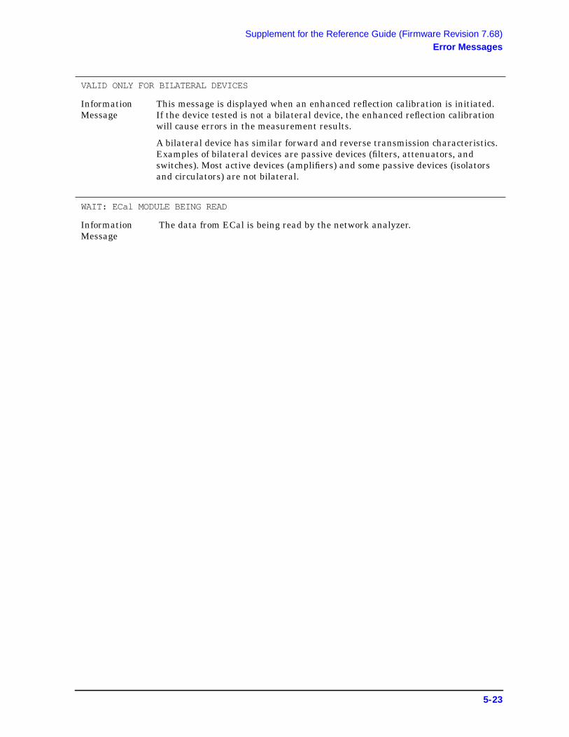
Supplement for the Reference Guide (Firmware Revision 7.68)Error Messages
VALID ONLY FOR BILATERAL DEVICES
InformationMessage
This message is displayed when an enhanced reflection calibration is initiated.If the device tested is not a bilateral device, the enhanced reflection calibrationwill cause errors in the measurement results.
A bilateral device has similar forward and reverse transmission characteristics.Examples of bilateral devices are passive devices (filters, attenuators, andswitches). Most active devices (amplifiers) and some passive devices (isolatorsand circulators) are not bilateral.
WAIT: ECal MODULE BEING READ
InformationMessage
The data from ECal is being read by the network analyzer.
5-23

Supplement for the Reference Guide (Firmware Revision 7.68)Error Messages
This page intentionally left blank.
5-24

Supplement for the Reference Guide (Firmware Revision 7.68)Error Messages
Error Messages in Numerical Order
ErrorNumber
Error
219 ECal MODULE NOT IN RF PATH
220 SELECTED MODULE OUTSIDE START-STOP FREQ RANGE
221 ECal SELECT OTHER MODULE
222 ECal MODULE NOT RESPONDING
223 ISOL AVGS < SWP AVGS
224 ECal FAILED
5-25

Supplement for the Reference Guide (Firmware Revision 7.68)Error Messages
This page intentionally left blank.
5-26

Supplement for the Reference Guide (Firmware Revision 7.68)Options and Accessories
Options and Accessories
Accessories Available
Added new calibration kits and updated Electronic calibration (ECal) section.
Calibration Kits
Choose a kit for each connector type to be used.
• 85032F 50 Ω type-N calibration kit (30 kHz to 9 GHz)Contains a female and male open and short, female and male load standard, and atorque wrench.
— Option 500Adds four type-N to 7-mm adapter.
• 85033E 50 Ω 3.5-mm calibration kit (30kHz to 9 GHz)Contains a female and male open and short, female and male load standard, and atorque wrench.
— Option 400Adds four 3.5 mm to Type-N adapters.
— Option 500Adds four 3.5 mm to 7-mm adapters.
RF electronic calibration (ECal) modules and PC software
This product family provides electronic calibration (ECal) capability. With ECal, the usualcalibration kit standards are replaced by one solid-state calibration module. A full two-portcalibration can be done with a single connection, with reduced errors and wear onconnectors. ECal requires the 85097A PC interface kit, an 85090-series calibration modulewith the appropriate connector type, and a network analyzer with firmware version 7.68and above.
NOTE For network analyzers with firmware versions between 7.60 and 7.68, a PCwith Windows1 95, 98, 2000 or NT 4.0 loaded with software from the85097A PC interface kit is used to perform the ECal calibration.
• 85097A ECal PC interface kit and software
— Contains PC interface module for connecting an ECal module to a PC or a networkanalyzer (with firmware version 7.68 and above) and PC ECal control software.
• 85091B RF ECal module (30 kHz to 9 GHz), 7-mm connectors
• 85092B RF ECal module (30 kHz to 9 GHz), 50 Ω type-N (m) to 50 Ω type-N (f)connectors
1. Windows is a U.S. registered trademark of Microsoft Corporation.
5-27

Supplement for the Reference Guide (Firmware Revision 7.68)Options and Accessories
— Option 00F substitutes type-N (f) to type-N (f) RF ECal module.
— Option 00M substitutes type-N (m) to type-N (m) RF ECal module.
— Option 00A adds:
— type-N (f) to type-N (f) adapter
— type-N (m) to type-N (m) adapter
• 85093B RF ECal module (30 kHz to 9 GHz), 3.5-mm (m) to 3.5-mm (f) connectors
— Option 00F substitutes 3.5-mm (f) to 3.5-mm (f) RF ECal module.
— Option 00M substitutes 3.5-mm (m) to 3.5-mm (m) RF ECal module.
— Option 00A adds:
— 3.5-mm (f) to 3.5-mm (f) adapter
— 3.5-mm (m) to 3.5-mm (m) adapter
• 85098B RF ECal module (30 kHz to 7.5 GHz), 7-16 (m) to 7-16 (f) connectors
— Option 00F substitutes 7-16 (f) to 7-16 (f) RF ECal module.
— Option 00M substitutes 7-16 (m) to 7-16 (m) RF ECal module.
— Option 00A adds:
— 7-16 (f) to 7-16 (f) adapter
— 7-16 (m) to 7-16 (m) adapter
• 85096B RF ECal module (30 kHz to 3 GHz), 75 Ω type-N (m) to 75 Ω type-N (f)connectors
— Option 00F substitutes module with two type-N female connectors.
— Option 00M substitutes module with two type-N male connectors.
— Option 00A adds:
— type-N (m) to type-N (m) adapter
— type-N (f) to type-N (f) adapter
• 85099B RF ECal module (30 kHz to 3 GHz), 75 Ω type-F (m) to type-F (f) connectors
— Option 00F substitutes module with two type-F female connectors.
— Option 00M substitutes module with two type-F male connectors.
— Option 00A adds:
— type-F (m) to type-F (m) adapter
— type-F (f) to type-F (f) adapter
5-28

Supplement for the Reference Guide (Firmware Revision 7.68)Preset State and Memory Allocation
Preset State and Memory AllocationAdded new preset value for enhanced reflection and ECal.
Preset StateTable 5-1. Preset Conditions
Preset Conditions Preset Value
Enhanced Reflection Calibration Off
Electronic Calibration (ECal)
Module A (information may not be loaded)
Omit Isolation On
Isolation Averages 10
Manual Thru Off
5-29

6 Supplement for the Programmer’sGuide (Firmware Revision 7.68)
6-1

Supplement for the Programmer’s Guide (Firmware Revision 7.68)In This Chapter
In This ChapterThis chapter contains the supplemental information changes to the programmer’s guidethat coincides with the release of firmware revision 7.68. These changes pertain to:
The Programmer’s Guide for 8719ET/ES, 8720ET/ES, 8722ET/ES, and 8753ET/ESNetwork Analyzers (part number 08753-90475)
IMPORTANT If you are upgrading your firmware from a revision prior to revision 7.66, addthe information changes from Chapter 3 , “Supplement for the Programmer’sGuide (Firmware Revision 7.66),” before adding the changes from thischapter.
The following list describes the changes to programmer’s guides printed prior toFebruary 2001. Each of the changes are described in detail in the remainder of thischapter. The page references in this list refer to page numbers in this supplement.
• Alphabetical Command Reference Chapter
— Add the new command options to the existing CALI and CALK commands of the“Alphabetical Command Reference” section. CALI has one new command option andCALK has two new command options. See page 6-3.
— Add the 18 new ECal programming commands (page 6-5 through page 6-14) to the“Alphabetical Command Reference” section.
• Appendix A: Preset Conditions
— Add enhanced reflection preset conditions from Table 6-1 to the existing “CalibrationConditions” table. See page 6-15.
— Add Table 6-2, “Electronic Calibration (ECal) Conditions,”to the existing “PresetConditions” section. See page 6-15.
• Appendix B: Command Listings
— Add 21 new programming commands to the “Alphabetical List of Commands”subsection of the “Command Listings” section. See page 6-17.
— Add 2 new programming commands to the “OPC-Compatible List of Commands”subsection of the “Command Listings” section. See page 6-17.
6-2

Supplement for the Programmer’s Guide (Firmware Revision 7.68)Alphabetical Command Reference
Alphabetical Command Reference
CALI
Syntax
CALI<EREFL>; or CALI<EREFL>?;
Description
Front Panel Equivalents
CALK
Syntax
CALK<32F|35ME>; or CALK<|32F|35ME>?;
Description
Front Panel Equivalents
Command Description Range Query Response
CALIEREFL Turns the enhanced reflectionresponse on or off.
N/A <0|1><LF>
Command Hardkey Softkey
CALIEREFL
Command Description Range Query Response
CALK32F Selects a 32F calibration kit (85032F)as the default cal kit.
N/A <0|1><LF>
CALK35ME Selects a 33D/E calibration kit(85033D/E) as the default cal kit forall analyzers.
N/A <0|1><LF>
Command Hardkey Softkey
CALK32F
CALK35ME
Cal ENH. REFL. on OFF
Cal N 50Ω 85032F
Cal 3.5mmD 85033D/E
6-3

Supplement for the Programmer’s Guide (Firmware Revision 7.68)Alphabetical Command Reference
This page intentionally left blank.
6-4
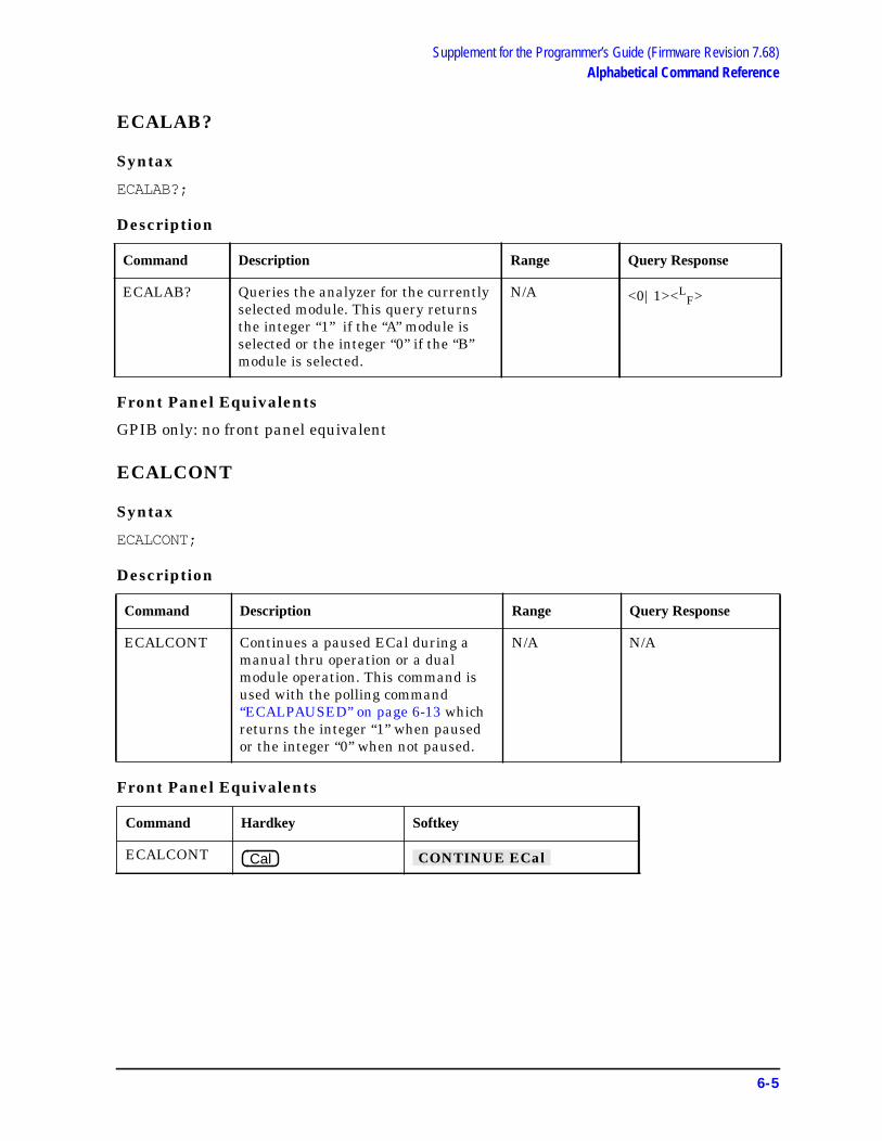
Supplement for the Programmer’s Guide (Firmware Revision 7.68)Alphabetical Command Reference
ECALAB?
Syntax
ECALAB?;
Description
Front Panel Equivalents
GPIB only: no front panel equivalent
ECALCONT
Syntax
ECALCONT;
Description
Front Panel Equivalents
Command Description Range Query Response
ECALAB? Queries the analyzer for the currentlyselected module. This query returnsthe integer “1” if the “A” module isselected or the integer “0” if the “B”module is selected.
N/A <0|1><LF>
Command Description Range Query Response
ECALCONT Continues a paused ECal during amanual thru operation or a dualmodule operation. This command isused with the polling command“ECALPAUSED” on page 6-13 whichreturns the integer “1” when pausedor the integer “0” when not paused.
N/A N/A
Command Hardkey Softkey
ECALCONT Cal CONTINUE ECal
6-5
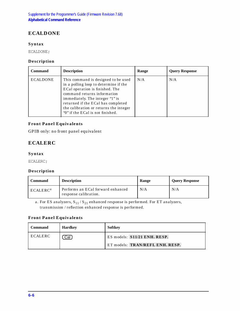
Supplement for the Programmer’s Guide (Firmware Revision 7.68)Alphabetical Command Reference
ECALDONE
Syntax
ECALDONE;
Description
Front Panel Equivalents
GPIB only: no front panel equivalent
ECALERC
Syntax
ECALERC;
Description
Front Panel Equivalents
Command Description Range Query Response
ECALDONE This command is designed to be usedin a polling loop to determine if theECal operation is finished. Thecommand returns informationimmediately. The integer “1” isreturned if the ECal has completedthe calibration or returns the integer“0” if the ECal is not finished.
N/A N/A
Command Description Range Query Response
ECALERCa
a. For ES analyzers, S11 / S21 enhanced response is performed. For ET analyzers,transmission / reflection enhanced response is performed.
Performs an ECal forward enhancedresponse calibration.
N/A N/A
Command Hardkey Softkey
ECALERC ES models:
ET models:
Cal S11/21 ENH. RESP.
TRAN/REFL ENH. RESP.
6-6

Supplement for the Programmer’s Guide (Firmware Revision 7.68)Alphabetical Command Reference
ECALFREQS
Syntax
ECALFREQS;
Description
Front Panel Equivalents
GPIB only: no front panel equivalent
ECALFUL2
Syntax
ECALFUL2;
Description
Front Panel Equivalents
Command Description Range Response
ECALFREQS Extracts an array of the factorycalibration frequency values that arestored in the ECal module. Beforeusing this command, use“ECALNFREQS” on page 6-12 todetermine the number of frequencypoints stored in the module. Use thisnumber to dimension the array fordata from the ECALFREQScommand. This is an ASCII transfer.
varies withECal module
<array><LF>
Command Description Range Query Response
ECALFUL2a
a. This command is not valid with ET analyzers.
Performs an ECal full two-portcalibration.
N/A N/A
Command Hardkey Softkey
ECALFUL2 Cal FULL 2-PORT
6-7

Supplement for the Programmer’s Guide (Firmware Revision 7.68)Alphabetical Command Reference
ECALISOAVG
Syntax
ECALISOAVG<NUM>; or ECALISOAVG?;
Description
Front Panel Equivalents
ECALMANTHRU
Syntax
ECALMANTHRU<ON|OFF>; or ECALMANTHRU?;
Description
Front Panel Equivalents
Command Description Range Query Response
ECALISOAVG Sets the number of averages in theECal isolation averages function.
1-999 <num><LF>
Command Hardkey Softkey
ECALISOAVG
Command Description Range Query Response
ECALMANTHRUON Sets manual thru to “on.” N/A <0|1><LF>
ECALMANTHRUOFF Sets manual thru to “off.” N/A <0|1><LF>
Command Hardkey Softkey
ECALMANTHRUON
ECALMANTHRUOFF
Cal ISOLATION AVERAGES
Cal MAN ’ L THRU ON off
Cal MAN ’ L THRU on OFF
6-8

Supplement for the Programmer’s Guide (Firmware Revision 7.68)Alphabetical Command Reference
ECALMODID
Syntax
ECALMODID;
Description
Front Panel Equivalents
GPIB only: no front panel equivalent
Command Description Range Response
ECALMODID This command returns the selectedECal module model number andserial number in string form.
Model number output:
MODEL NUMBER: XXXXX-XXXXX
Serial number output:
SERIAL NUMBER: XXXXX
N/A <$><LF>
6-9

Supplement for the Programmer’s Guide (Firmware Revision 7.68)Alphabetical Command Reference
ECALMODINF
Syntax
ECALMODINF;
Description
Front Panel Equivalents
Command Description Range Response
ECALMODINF This command returns string variables onthe following information on the selectedECal module.
Model Number: xxxxx-xxxxxSerial Number: xxxxxConnector Type: connector typeLast Certification: ddmmmyearModule Number of Points: xxx
Module Start Frequency: xxxxx a
Module Stop Frequency: xxxxxxxxxx a
Suggested Warmup Time: xxx SECONDS
Module Warmup Status: xxx b
For an example of the output data, refer tothe description on module information inthe user’s guide in the “Calibrating forIncreased Measurement Accuracy” chapter.
a. Output in hertz.b. Can be polled in a loop to return the latest warmup time. When warmup time is finished,
the string “READY” will be returned.
N/A <array><LF>
Command Hardkey Softkey
ECALMODINF Cal MODULE INFO
6-10

Supplement for the Programmer’s Guide (Firmware Revision 7.68)Alphabetical Command Reference
ECALMODSELA
Syntax
ECALMODSELA;
Description
Front Panel Equivalents
ECALMODSELB
Syntax
ECALMODSELB;
Description
Front Panel Equivalents
Command Description Range Query Response
ECALMODSELA Sets the active module to “A”. If no moduleis connected to “A”, error message 222“ECal MODULE NOT RESPONDING”will be set in the error buffer.
N/A N/A
Command Hardkey Softkey
ECALMODSELA
Command Description Range Query Response
ECALMODSELB Sets the active module to “B”. If no moduleis connected to “B”, error message 222“ECal MODULE NOT RESPONDING”will be set in the error buffer.
N/A N/A
Command Hardkey Softkey
ECALMODSELB
Cal MODULE A b
Cal MODULE a B
6-11
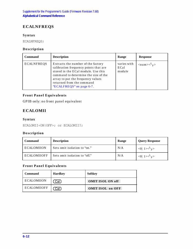
Supplement for the Programmer’s Guide (Firmware Revision 7.68)Alphabetical Command Reference
ECALNFREQS
Syntax
ECALNFREQS;
Description
Front Panel Equivalents
GPIB only: no front panel equivalent
ECALOMII
Syntax
ECALOMII<ON|OFF>; or ECALOMII?;
Description
Front Panel Equivalents
Command Description Range Response
ECALNFREQS Extracts the number of the factorycalibration frequency points that arestored in the ECal module. Use thiscommand to determine the size of thearray to put the frequency valuesreturned from the command“ECALFREQS” on page 6-7.
varies withECalmodule
<num><LF>
Command Description Range Query Response
ECALOMIION Sets omit isolation to “on.” N/A <0|1><LF>
ECALOMIIOFF Sets omit isolation to “off.” N/A <0|1><LF>
Command Hardkey Softkey
ECALOMIION
ECALOMIIOFF
Cal OMIT ISOL ON off
Cal OMIT ISOL on OFF
6-12

Supplement for the Programmer’s Guide (Firmware Revision 7.68)Alphabetical Command Reference
ECALPAUSED
Syntax
ECALPAUSED;
Description
Front Panel Equivalents
GPIB only: no front panel equivalent
ECALRERC
Syntax
ECALRERC;
Description
Front Panel Equivalents
Command Description Range Query Response
ECALPAUSED This command is designed to be used in apolling loop to determine if the ECaloperation is in the pause stage of a manualthru and a dual module calibration. Usedwith the command “ECALCONT” onpage 6-5. Returns the integer “1” if theECal is paused or returns the integer “0” ifthe ECal is not paused.
N/A N/A
Command Description Range Query Response
ECALRERCa
a. For ES analyzers, an S22 / S12 enhanced response is performed. This command is not validwith ET analyzers.
Starts an ECal reverse enhanced responsecalibration.
N/A N/A
Command Hardkey Softkey
ECALRERC Cal S22/12 ENH. RESP.
6-13
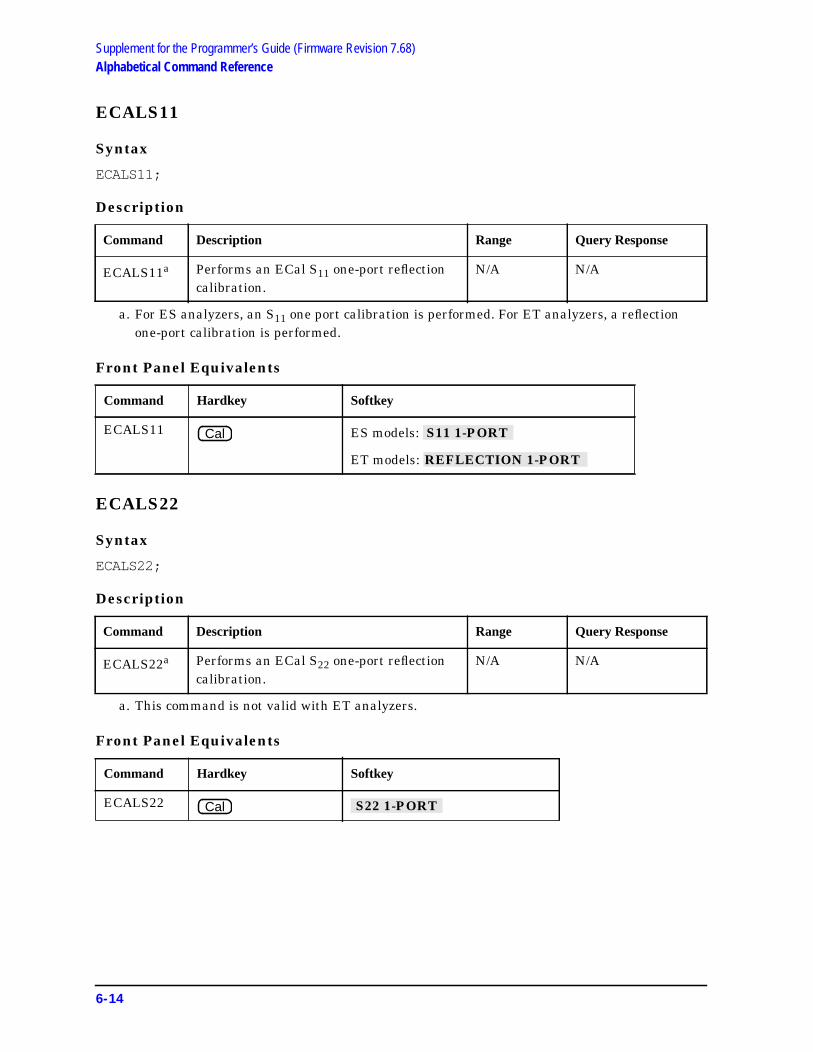
Supplement for the Programmer’s Guide (Firmware Revision 7.68)Alphabetical Command Reference
ECALS11
Syntax
ECALS11;
Description
Front Panel Equivalents
ECALS22
Syntax
ECALS22;
Description
Front Panel Equivalents
Command Description Range Query Response
ECALS11a
a. For ES analyzers, an S11 one port calibration is performed. For ET analyzers, a reflectionone-port calibration is performed.
Performs an ECal S11 one-port reflectioncalibration.
N/A N/A
Command Hardkey Softkey
ECALS11 ES models:
ET models:
Command Description Range Query Response
ECALS22a
a. This command is not valid with ET analyzers.
Performs an ECal S22 one-port reflectioncalibration.
N/A N/A
Command Hardkey Softkey
ECALS22
Cal S11 1-PORT
REFLECTION 1-PORT
Cal S22 1-PORT
6-14

Supplement for the Programmer’s Guide (Firmware Revision 7.68)Preset Conditions
Preset ConditionsTable 6-1 Calibration Conditions
Preset Conditions Preset Value
Enhanced Reflection Calibration Off
Table 6-2 Electronic Calibration (ECal) Conditions
Preset Conditions Preset Value
Module A (information may not be loaded)
Omit Isolation On
Isolation Averages 10
Manual Thru Off
6-15

Supplement for the Programmer’s Guide (Firmware Revision 7.68)Preset Conditions
This page intentionally left blank.
6-16

Supplement for the Programmer’s Guide (Firmware Revision 7.68)Command Listings
Command Listings
Alphabetical List of Commands
OPC-Compatible List of Commands
CALIEREFL ECALFREQS ECALMODSELB
CALK32F ECALFUL2 ECALNFREQS
CALK35ME ECALISOAVG ECALOMII
ECALAB? ECALMANTHRU ECALPAUSED
ECALCONT ECALMODID ECALRERC
ECALDONE ECALMODINF ECALS11
ECALERC ECALMODSELA ECALS22
ECALMODSELA ECALMODSELB
6-17

7 Supplement for theInstallation and Quick Start Guide(Firmware Version 7.68)
7-1

Supplement for the Installation and Quick Start Guide (Firmware Version 7.68)Using This Chapter
Using This ChapterThis chapter contains the supplemental information changes to the installation and quickstart guides that coincide with the release of firmware revision 7.68. These changespertain to the following installation and quick start guides.
• 8753ET and 8753ES Network Analyzers Installation and Quick Start Guide(part number 08753-90471)
• 8753ES Option 011 Network Analyzer Installation and Quick Start Guide(part number 08753-90478)
The following list describes the changes to 8753ET and 8753ES installation and quickstart guides printed prior to February 2001. Each of the changes are described in detail inthe remainder of this chapter. The page references in this list refer to page numbers in thissupplement.
• Front Matter
— Replace the warning describing the line fuse type and rating with a revised warningin “General Safety Considerations.” See page 7-3.
• Quick Start: Learning How to Make Measurements Chapter
— Replace the paragraph describing checking and replacing the fuse with the revisedparagraph in the “Power-Up Problems” subsection of “If You Encounter a Problem.”See page 7-4.
7-2

Supplement for the Installation and Quick Start Guide (Firmware Version 7.68)General Safety Considerations
General Safety Considerations
WARNING For continued protection against fire hazard replace line fuse onlywith same type and rating (115V operation: T 5A 125V UL/ 230Voperation: T 4A H 250V IEC). The use of other fuses or material isprohibited.
7-3

Supplement for the Installation and Quick Start Guide (Firmware Version 7.68)If You Encounter a Problem
If You Encounter a Problem
Power-Up Problems
Refer to Figure 2-17 to remove the fuse from the power module. You can use a continuitylight or an ohmmeter to check the fuse. An ohmmeter should read very close to zero ohmsif the fuse is good. For 115V operation, use Fuse, T 5A 125V, UL listed/CSA certified to 248standard (part number 2110-1059). For 230V operation, use Fuse, T 4A H 250V, built toIEC 127-2/5 standard (part number 2110-1036).
7-4

Index
Numerics2-port error corrections,
performing, 4-313.5mmD 85033D/E softkey, 6-3
Aabsolute
ripple test value, 1-14, 1-15absolute value, ripple test, 3-11accessories available, 5-27accessories URL, 2-16activating the bandwidth test,
1-19Agilent Technologies URL, 2-16analyzer functions, 2-9, 5-17,
5-18averaging
isolation, 4-20
Bband
adding a frequency, 1-11changing a frequency, 1-10deleting a frequency, 1-12frequency, 1-9
bandwidth, 1-19bandwidth limit
preset state, 2-17bandwidth markers
displaying, 1-20bandwidth test
activating, 1-19display of measurement status,
3-5display of measurement value,
3-3maximum width, 3-4minimum width, 3-4on/off control, 3-5returning measured value, 3-6running, 1-19–1-22setting dB point amplitude, 3-3setting up limits, 1-17–1-19
bandwidth testing, 1-17–1-22bandwidth value
displaying, 1-21bilateral device, 4-9, 4-12BWLIMDB, 3-3BWLIMDISP, 3-3BWLIMMAX, 3-4BWLIMMIN, 3-4BWLIMSTAT, 3-5BWLIMTEST, 3-5BWLIMVAL, 3-6
Ccal kits, 6-3CALI, 6-3calibrating for noninsertable
devicesmodifying the cal kit through
definition, 4-15calibration
ECal, 4-17–4-28, 6-5electronic calibration, 6-5electronic. See ECalenhanced reflection, 6-3enhanced response ECal, 6-6,
6-13one-port ECal, 6-14two-port ECal, 6-7
calibration considerationscalibration standards, 4-7clarifying type-N connector sex,
4-7calibration data, saving, 1-37calibration kit, saving a modified,
1-37calibration kits, 5-27calibration standards, 4-7CALIEREFL, 6-3CALK32F, 6-3CALK35ME, 6-3changing the ripple limits color,
1-14clarifying type-N connector sex,
4-7clear list, 3-6CLER, 3-6color
changing the ripple limits, 1-14ripple test message, 1-13
comma-separated values, saving,3-12
comma-separated values. SeeCSV format
confidence check, 4-24conversion loss using frequency
offset mode, 1-23CSV files, saving, 3-12CSV format, saving measurement
results in, 1-33
Ddelay, determining electrical, 4-33delete frequency band list, 3-6device, bilateral, 4-9, 4-12display
bandwidth test measurementstatus, 3-5
bandwidth test measurementvalue, 3-3
ripple test measured value, 3-11Display menu map, 2-3display ripple test limits, 1-13display ripple test values, 1-14displaying the bandwidth
markers, 1-20displaying the bandwidth value,
1-21
EECal, 4-17–4-36
calibration, 4-17–4-28check all module information,
6-10check module factory frequency
values, 6-7check module factory number of
frequency points, 6-12check module identification, 6-9confidence check, 4-24continue, 6-5do forward enhance calibration,
6-13do forward enhanced
calibration, 6-6do full 2-port calibration, 6-7do one-port s11, 6-14do one-port s22, 6-14equipment, 4-18is calibration done?, 6-6is calibration paused?, 6-13isolation calibration, 4-20manual thru, 4-20module information, 4-24module query, 6-5options, 4-20select module A, 6-11select module B, 6-11service menu, 4-27set number of isolation
averages, 6-8toggle isolation, 6-12toggle manual thru, 6-8
ECal calibration, 6-5ECALAB?, 6-5ECALCONT, 6-5ECALDONE, 6-6ECALERC, 6-6ECALFREQS, 6-7ECALFUL2, 6-7ECALISOAVG, 6-8ECALMANTHRU, 6-8ECALMODID, 6-9ECALMODINF, 6-10ECALMODSELA, 6-11ECALMODSELB, 6-11ECALNFREQS, 6-12
Index-1

Index
ECALOMII, 6-12ECALPAUSED, 6-13ECALRERC, 6-13ECALS11, 6-14ECALS22, 6-14edit
ripple test limit list, 3-7editing ripple limits, 1-10–1-12EDITRLIM, 3-7electrical delay, determining, 4-33electronic calibration, 6-5electronic calibration. See ECalenhanced frequency response
error correction, 4-9enhanced reflection calibration,
6-3enhanced reflection error
correction, 4-9, 4-12enhanced reflection softkey, 6-3error correction
enhanced frequency response,4-9
enhanced reflection, 4-9, 4-12error messages, 2-15error messages in alphabetical
order, 5-21error messages in numerical
order, 5-25existing softkeys, 2-9
Ffile
index numbers, 1-34sequential CSV naming of, 1-34
firmwarerevision, 2-2, 3-2, 5-2, 6-2
frequency bandclearing list, 3-6
frequency bandsadding, 1-11changing, 1-10deleting, 1-12selecting for ripple test, 3-13setting, 1-9
frequency offset mode, conversionloss, 1-23
functions, analyzer, 2-9
Ggraphic files
saving as JPG, 3-12saving measurement results as,
1-34
Hhardkey definitions, 5-17, 5-18
Iinstrument state
saving, 1-37, 4-5internet, 2-16isolation
averaging, 4-20calibrating using ECal, 4-20
Jjpeg files, saving results as, 1-34JPG files, saving, 3-12
Kkey definitions, 5-17, 5-18kits, calibration, 5-27
Llimit lines
preset state, 2-17limit list
editing for ripple test, 3-7limit menu
preset state, 2-17
Mmanual part number, 2-2, 3-2,
5-2, 6-2manual thru, 4-20margin
ripple test value, 1-14, 1-16margin value, ripple test, 3-11maximum
allowable ripple value, 3-9bandwidth value, 3-4
maximum and minimum, 1-19maximum bandwidth, 1-19measured value
for ripple test, output of, 3-8measurement
results, saving graphically, 1-34returning bandwidth test value,
3-6measurement accessories
calibration kits, 5-27RF ECal modules and PC
software, 5-27measurements
saving as graphic files, 3-12saving as text files, 3-12
menu mapDisplay, 2-3Save/Recall, 2-3System, 2-4, 2-7
menu maps, 5-3messages
error, 2-15minimum
bandwidth value, 3-4minimum bandwidth, 1-19mixer
measurement diagram, using,1-26
modifyingcal kit through definition, 4-15
modifying calibration kitssaving to a disk, 1-37
module information, 4-24
NN 50 ohm 85032F softkey, 6-3n dB
setting for bandwidth test, 3-3N dB Point, 1-19names for CSV files, 1-34new softkeys, 2-10
Oon/off control
bandwidth test, 3-5ripple test, 3-11
OUTPFARPLPT, 3-8OUTPRPLBNDALL, 3-8OUTPRPLBNDPF, 3-8OUTPRPLBNDVAL, 3-8output
failed ripple test points, 3-8ripple test measured value, 3-8ripple test measured values, 3-8ripple test pass/fail status, 3-8
Ppart number
reference guide, 2-2, 3-2, 5-2,6-2
pass/fail statusfor ripple test, output of, 3-8
PC interface unit, 4-18PC software, 5-27performing
2-port error corrections, 4-31preset state, 2-17, 5-29, 6-15problems, power-up
display does not light, 7-4
Rreference guide
changes, 2-2, 3-2, 5-2, 6-2part number, 2-2, 3-2, 5-2, 6-2
removing the effect of an adapter,4-34
RF ECal modules, 5-27
Index-2

Index
RF frequency rangeusing the mixer measurement
diagram, 1-26ripple limit
preset state, 2-17ripple limit testing, 1-7–1-16ripple limits
editing, 1-10–1-12running the test, 1-12–1-16setting, 1-7–1-10
ripple testabsolute value, 1-15band start frequency, 3-10band stop frequency, 3-10clear frequency band list, 3-6display measured value, 3-11displaying limits, 1-13displaying values, 1-14edit limit list, 3-7frequency bands, 1-9margin value, 1-16maximum ripple, 3-9message color, 1-13on/off control, 3-11output all band measured
values, 3-8output measured value, 3-8output pass/fail status, 3-8outputting failed points, 3-8selecting frequency bands, 3-13starting and stopping, 1-12
RLIMM, 3-9RLIMSTP, 3-10RLIMSTR, 3-10RLIMTEST, 3-11RLIMVAL, 3-11running a bandwidth test,
1-19–1-22running the ripple limits test,
1-12–1-16
Ssave
measurements as graphic files,3-12
measurements as text files, 3-12Save/Recall menu map, 2-3SAVECSV, 3-12SAVEJPG, 3-12saving
calibration data, 1-37instrument state, 1-37, 4-5measurement results
graphically, 1-34modified calibration kits, 1-37to a disk, 1-37
SELBAND, 3-13
service menu (ECal), 4-27setting ripple limits, 1-7–1-10setting up bandwidth test limits,
1-17–1-19softkey definitions, 5-17, 5-18softkeys
existing, 2-9new, 2-10
spreadsheet, saving test file for a,1-33
standards, calibration, 4-7start frequency
ripple test bands, 3-10starting the ripple test, 1-12stop frequency
ripple test bands, 3-10stopping the ripple test, 1-12System menu map, 2-4, 2-7
Ttest
bandwidth, 1-17–1-22ripple limit, 1-7–1-16
text file, saving measurements asa, 1-33
text filessaving as CSV, 3-12
thru, manual, 4-20TRL error correction
label the calibration kit, 1-35type-N connector sex
clarifying, 4-7
UURL
Agilent Technologies, 2-16for accessories, 2-16
Wworld wide web, 2-16
Index-3