Embed Size (px)
Citation preview
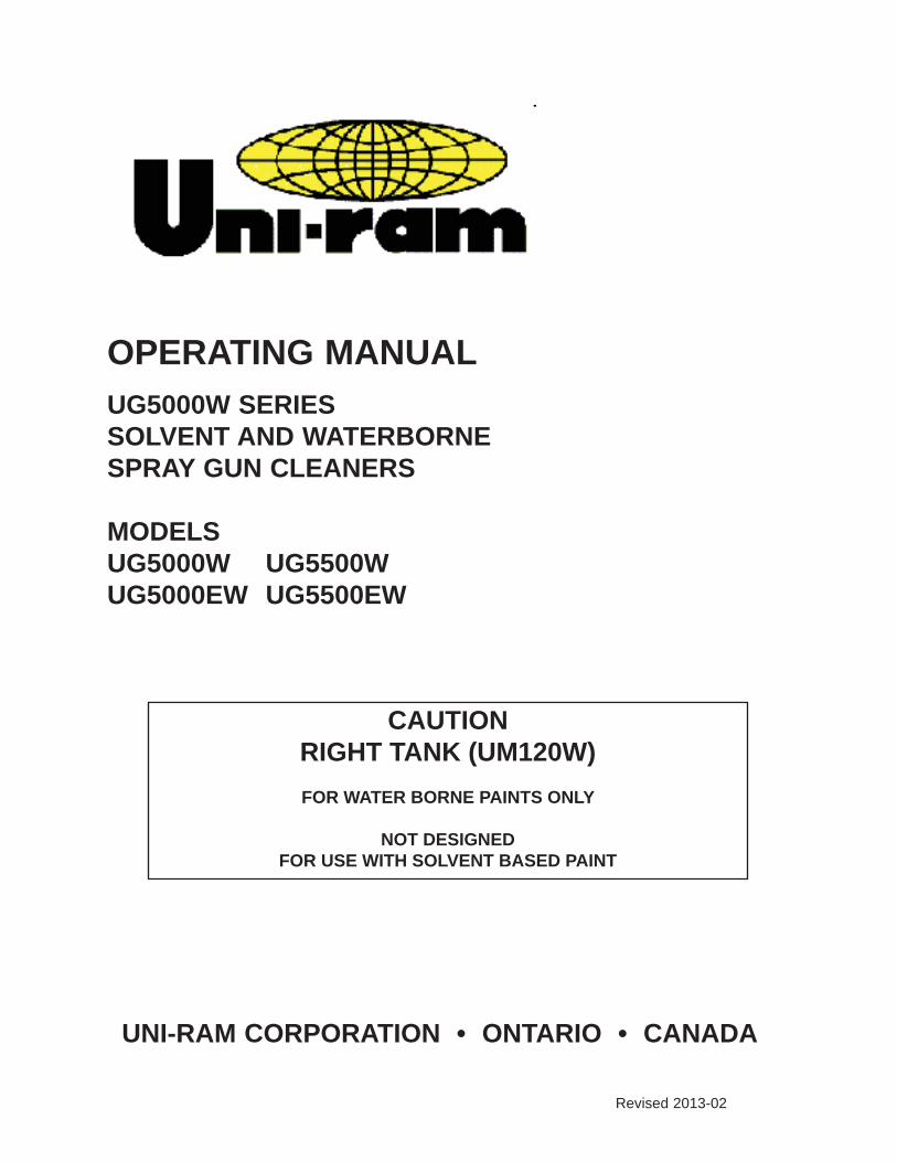
OPERATING MANUAL
UG5000W SERIESSOLVENT AND WATERBORNESPRAY GUN CLEANERS MODELSUG5000W UG5500WUG5000EW UG5500EW
UNI-RAM CORPORATION • ONTARIO • CANADA
Revised 2013-02
CAUTIONRIGHT TANK (UM120W)
FOR WATER BORNE PAINTS ONLY
NOT DESIGNED FOR USE WITH SOLVENT BASED PAINT
MANUAL - SPRAY GUN CLEANERS - UG5000 SERIES Revision 2013-02
2
CONTENTSINTRODUCTION . . . . . . . . . . . . . . . . . . . . . . . . . . . . . . . . . . . . . . . . . . . . . . . . . . . . . . . . . . . . . . 3
FEATURES . . . . . . . . . . . . . . . . . . . . . . . . . . . . . . . . . . . . . . . . . . . . . . . . . . . . . . . . . . . . . . . . . . 3
SETUPINSPECTION . . . . . . . . . . . . . . . . . . . . . . . . . . . . . . . . . . . . . . . . . . . . . . . . . . . . . . . . . . . . . . . . . 3INCLUDED PARTS . . . . . . . . . . . . . . . . . . . . . . . . . . . . . . . . . . . . . . . . . . . . . . . . . . . . . . . . . . . . 3STRUCTURE . . . . . . . . . . . . . . . . . . . . . . . . . . . . . . . . . . . . . . . . . . . . . . . . . . . . . . . . . . . . . . . . . 4LOCATION . . . . . . . . . . . . . . . . . . . . . . . . . . . . . . . . . . . . . . . . . . . . . . . . . . . . . . . . . . . . . . . . . . . 5LEVELING, VENT AND AIR SUPPLY . . . . . . . . . . . . . . . . . . . . . . . . . . . . . . . . . . . . . . . . . . . . . . 5INSTALL WASH GUN AND WHIP LINE COUPLER . . . . . . . . . . . . . . . . . . . . . . . . . . . . . . . . . . . 5SOLVENT SELECTION . . . . . . . . . . . . . . . . . . . . . . . . . . . . . . . . . . . . . . . . . . . . . . . . . . . . . . . . 5PAIL SETUP. . . . . . . . . . . . . . . . . . . . . . . . . . . . . . . . . . . . . . . . . . . . . . . . . . . . . . . . . . . . . . . . . . 5 OPERATION LEFT TANK (UG4000 or UG4500), SOLVENT. . . . . . . . . . . . . . . . . . . . . . . . . . . . . . . . . 6 PRE-CLEAN . . . . . . . . . . . . . . . . . . . . . . . . . . . . . . . . . . . . . . . . . . . . . . . . . . . . . . . . 6 CLEANING SPRAY GUNS AND CUPS . . . . . . . . . . . . . . . . . . . . . . . . . . . . . . . . . . . 6 USING THE FLOW-THROUGH BRUSH. . . . . . . . . . . . . . . . . . . . . . . . . . . . . . . . . . . 6 RIGHT TANK (UM120W), WATER . . . . . . . . . . . . . . . . . . . . . . . . . . . . . . . . . . . . . . . . . . 6 PRE-CLEAN WHEN USING A NON DISPOSABLE CUP SYSTEM. . . . . . . . . . . . . . 7 CLEAN SPRAY GUNS AND CUPS. . . . . . . . . . . . . . . . . . . . . . . . . . . . . . . . . . . . . . . 7 WATER TREATMENT . . . . . . . . . . . . . . . . . . . . . . . . . . . . . . . . . . . . . . . . . . . . . . . . . 8 HOSE CLEANING (UG5500W MODEL ONLY) . . . . . . . . . . . . . . . . . . . . . . . . . . . . . . .8-9
DAILY MAINTENANCE FILTER PADS AND SCREEN. . . . . . . . . . . . . . . . . . . . . . . . . . . . . . . . . . . . . . . . . . . . . . 9 REPLACING SOLVENT (UG4000 or UG4500) . . . . . . . . . . . . . . . . . . . . . . . . . . . . . . . . 9 TROUBLESHOOTING CHART . . . . . . . . . . . . . . . . . . . . . . . . . . . . . . . . . . . . . . . . . . . . . . . . 10-11
TROUBLESHOOTING PROCEDURES. . . . . . . . . . . . . . . . . . . . . . . . . . . . . . . . . . . . . . . . . . . . 12
FLOW DIAGRAM . . . . . . . . . . . . . . . . . . . . . . . . . . . . . . . . . . . . . . . . . . . . . . . . . . . . . . . . . . . . . 13
REPLACEMENT PARTS . . . . . . . . . . . . . . . . . . . . . . . . . . . . . . . . . . . . . . . . . . . . . . . . . . . . .14-15
WARRANTY . . . . . . . . . . . . . . . . . . . . . . . . . . . . . . . . . . . . . . . . . . . . . . . . . . . . . . . . . . . . . . . . . 16
3
MANUAL - SPRAY GUN CLEANERS - UG5000W SERIES Revision 2013-02
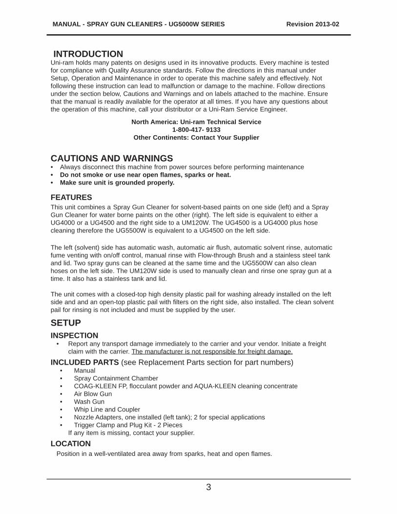
INTRODUCTIONUni-ram holds many patents on designs used in its innovative products. Every machine is tested for compliance with Quality Assurance standards. Follow the directions in this manual under Setup, Operation and Maintenance in order to operate this machine safely and effectively. Not following these instruction can lead to malfunction or damage to the machine. Follow directions under the section below, Cautions and Warnings and on labels attached to the machine. Ensure that the manual is readily available for the operator at all times. If you have any questions about the operation of this machine, call your distributor or a Uni-Ram Service Engineer.
CAUTIONS AND WARNINGS• Always disconnect this machine from power sources before performing maintenance• Do not smoke or use near open flames, sparks or heat.• Make sure unit is grounded properly.
FEATURES This unit combines a Spray Gun Cleaner for solvent-based paints on one side (left) and a Spray Gun Cleaner for water borne paints on the other (right). The left side is equivalent to either a UG4000 or a UG4500 and the right side to a UM120W. The UG4500 is a UG4000 plus hose cleaning therefore the UG5500W is equivalent to a UG4500 on the left side.
The left (solvent) side has automatic wash, automatic air flush, automatic solvent rinse, automatic fume venting with on/off control, manual rinse with Flow-through Brush and a stainless steel tank and lid. Two spray guns can be cleaned at the same time and the UG5500W can also clean hoses on the left side. The UM120W side is used to manually clean and rinse one spray gun at a time. It also has a stainless tank and lid.
The unit comes with a closed-top high density plastic pail for washing already installed on the left side and and an open-top plastic pail with filters on the right side, also installed. The clean solvent pail for rinsing is not included and must be supplied by the user.
SETUPINSPECTION
• Report any transport damage immediately to the carrier and your vendor. Initiate a freight claim with the carrier. The manufacturer is not responsible for freight damage.
INCLUDED PARTS (see Replacement Parts section for part numbers) • Manual • Spray Containment Chamber • COAG-KLEEN FP, flocculant powder and AQUA-KLEEN cleaning concentrate • Air Blow Gun • Wash Gun • Whip Line and Coupler • Nozzle Adapters, one installed (left tank); 2 for special applications • Trigger Clamp and Plug Kit - 2 Pieces
If any item is missing, contact your supplier.
LOCATIONPosition in a well-ventilated area away from sparks, heat and open flames.
North America: Uni-ram Technical Service1-800-417- 9133
Other Continents: Contact Your Supplier
MANUAL - SPRAY GUN CLEANERS - UG5000 SERIES Revision 2013-02
4
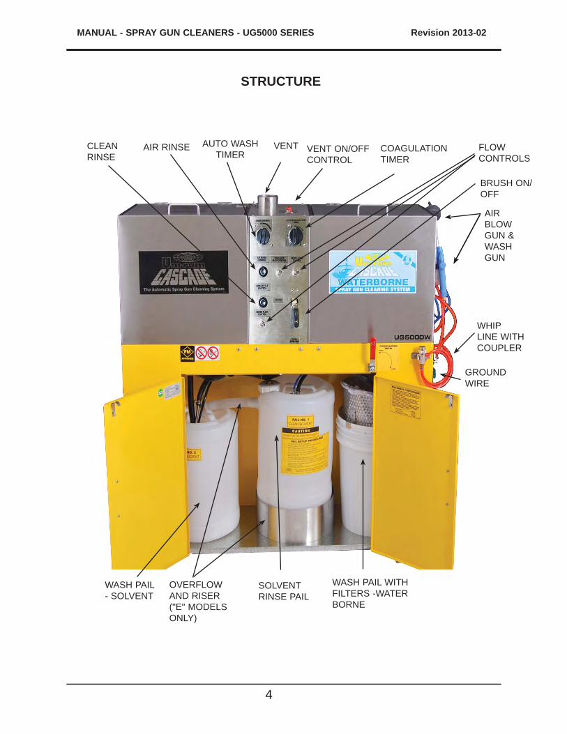
STRUCTURE
VENT AUTO WASH TIMER
AIR RINSECLEAN RINSE
WHIP LINE WITH COUPLER
COAGULATION TIMER
WASH PAIL WITH FILTERS -WATER BORNE
WASH PAIL - SOLVENT
VENT ON/OFF CONTROL
AIR BLOW GUN & WASH GUN
GROUND WIRE
SOLVENT RINSE PAIL
BRUSH ON/OFF
OVERFLOW AND RISER ("E" MODELS ONLY)
FLOW CONTROLS
5
MANUAL - SPRAY GUN CLEANERS - UG5000W SERIES Revision 2013-02
GROUND WIRESConnect the external ground wire (right side of cabinet) to an external grounded object.
LEVELING, VENT AND AIR SUPPLY• Level the machine using the adjustable legs.• Remove the cover on the "Air Input" (right side of machine) and attach an air supply adapter
(not supplied).• If necessary, replace the female quick connect on the Whip Air Line with a quick connect that
will fit the male quick connect of your spray gun.The air supply pressure must be at least 85 PSI and the air must be free from contaminants such as water, dust, rust, tar, grease etc. To prevent damage to the Diaphragm Pumps an internal Air Pressure Regulator has been installed to limit the air pressure to precisely 85 PSI. Do not install a second air pressure regu-lator or use a pressure set below 85 PSI.
INSTALL BLOW GUN, WASH GUN AND WHIP LINE COUPLERRemove the Blow Gun, Wash Gun and Whip LIne Coupler from the Acessory Kit bag (inside the tank) and install on the unit by inserting the appropriate air tubes into the tools and hanging them on the brackets (Blow Gun and Wash Gun on the right side and Coupler on the front). Use the labels below the tubes as a guide.
SOLVENT SELECTIONThe adhesion quality of automotive paint has dramatically improved in recent years. The choice of solvent is critical. Only use good quality solvent that is formulated for your paint and intended for use with automatic spray guns cleaners.
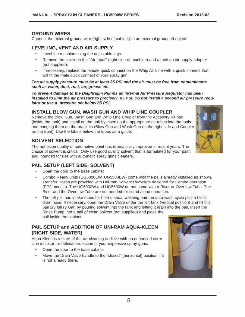
PAIL SETUP (LEFT SIDE, SOLVENT)• Open the door to the base cabinet • Combo Ready units (UG5000EW, UG5500EW) come with the pails already installed as shown.
Transfer Hoses are provided with Uni-ram Solvent Recyclers designed for Combo operation (EP2 models). The UG5000W and UG5500W do not come with a Riser or Overflow Tube. The Riser and the Overflow Tube are not needed for stand alone operation.
• The left pail has intake tubes for both manual washing and the auto wash cycle plus a black drain hose. If necessary, open the Drain Valve under the left tank (vertical position) and fill this pail 2/3 full (3 Gal) by pouring solvent into the tank and letting it drain into the pail. Insert the Rinse Pump into a pail of clean solvent (not supplied) and place the pail inside the cabinet.
PAIL SETUP and ADDITION OF UNI-RAM AQUA-KLEEN (RIGHT SIDE, WATER)Aqua-Kleen is a state-of-the-art cleaning additive with an enhanced corro-sion inhibitor for optimal protection of your expensive spray guns.
• Open the door to the base cabinet • Move the Drain Valve handle to the "closed" (horizontal) position if it
is not already there.
MANUAL - SPRAY GUN CLEANERS - UG5000 SERIES Revision 2013-02
6
• Move the pail outside the unit. Remove the two filters. Pour a full bottle of Uni-ram Aqua Kleen into the pail and add tap water until the combined liquid level reaches the bottom of the filter holder. Replace filter.
• Insert the manual wash suction tube into the pail between the Filter Holder and the wall of the pail. Move the pail into the cabinet.
OPERATIONLEFT TANK (UG4000, SOLVENT)PRE - CLEAN
• Disconnect the spray gun from the air hose. Pour paint from the cup (when present) into a 5 gallon pail (not supplied).
• Rinse cup with solvent and pour into the same 5 gallon pail for later disposal or recycling.
SELECTION OF NOZZLE EXTENSION
780-3530 INSTALLED. HOLES PROVIDE SOLVENT TO CEAN DISPOSABLE CUP ADAPTOR. CANNOT BE USED FOR CONVENTIONAL SYSTEMS.
110-430PPS HOLES PROVIDE SOLVENT TO CLEAN DISPOSABLE CUP ADAPTOR. MAY ALSO BE USED FOR CONVENTIONAL SYSTEMS WITH LARGER OPENINGS IN NECK OF CUP.
110-430 FOR CONVENTIONAL SYSTEMS ONLY WITH SMALLER OPENINGS IN NECK OF CUP.
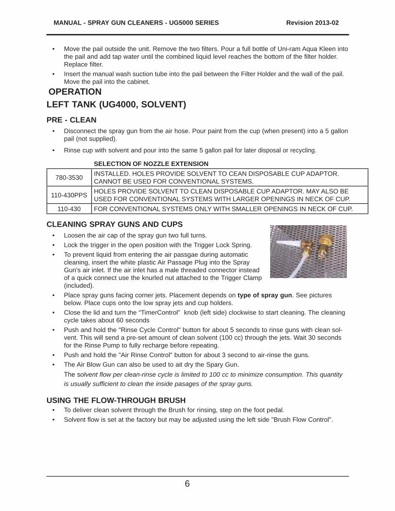
CLEANING SPRAY GUNS AND CUPS• Loosen the air cap of the spray gun two full turns.• Lock the trigger in the open position with the Trigger Lock Spring.• To prevent liquid from entering the air passgae during automatic
cleaning, insert the white plastic Air Passage Plug into the Spray Gun's air inlet. If the air inlet has a male threaded connector instead of a quick connect use the knurled nut attached to the Trigger Clamp (included).
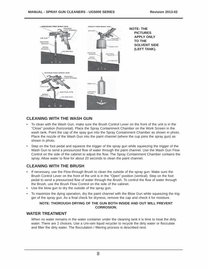
• Place spray guns facing corner jets. Placement depends on type of spray gun. See pictures below. Place cups onto the low spray jets and cup holders.
• Close the lid and turn the “TimerControl” knob (left side) clockwise to start cleaning. The cleaning cycle takes about 60 seconds
• Push and hold the "Rinse Cycle Control" button for about 5 seconds to rinse guns with clean sol-vent. This will send a pre-set amount of clean solvent (100 cc) through the jets. Wait 30 seconds for the Rinse Pump to fully recharge before repeating.
• Push and hold the "Air Rinse Control" button for about 3 second to air-rinse the guns.• The Air Blow Gun can also be used to ait dry the Spary Gun. The solvent flow per clean-rinse cycle is limited to 100 cc to minimize consumption. This quantity
is usually sufficient to clean the inside pasages of the spray guns.
USING THE FLOW-THROUGH BRUSH• To deliver clean solvent through the Brush for rinsing, step on the foot pedal.• Solvent flow is set at the factory but may be adjusted using the left side "Brush Flow Control".
7
MANUAL - SPRAY GUN CLEANERS - UG5000W SERIES Revision 2013-02
After cleaning guns, remove the guns and cups from the tank and wipe them dry. Do not store spray guns in the tank.
RIGHT TANK (UM120W, WATER)This tank is used to clean spray guns, cups and parts. There are two modes of operation - Manual Wash and Manual Rinse. NOTE: WATERBORNE PAINT DRIES QUICKLY! TO MINIMIZE HARDENING OF THE PAINT, BEGIN CLEANING AS SOON AS POSSIBLE AFTER COMPLETION OF THE PAINT JOB.
PRE - CLEAN WHEN USING A NON DISPOSABLE CUP SYSTEM Skip this step if you use a disposalble cup system. • Disconnect the spray gun from the air hose. Pour paint from the cup (when present) into a 5 gallon
pail (not supplied).
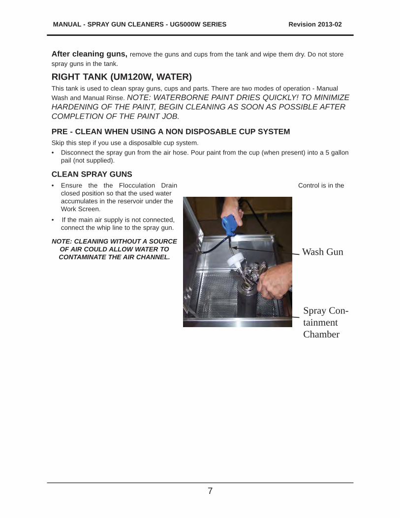
CLEAN SPRAY GUNS• Ensure the the Flocculation Drain Control is in the
closed position so that the used water accumulates in the reservoir under the Work Screen.
• If the main air supply is not connected, connect the whip line to the spray gun.
NOTE: CLEANING WITHOUT A SOURCE OF AIR COULD ALLOW WATER TO CONTAMINATE THE AIR CHANNEL. Wash Gun
Spray Con-tainment Chamber
MANUAL - SPRAY GUN CLEANERS - UG5000 SERIES Revision 2013-02
8
CLEANING WITH THE WASH GUN• To clean with the Wash Gun, make sure the Brush Control Lever on the front of the unit is in the
"Close" position (horizontal). Place the Spray Containment Chamber on the Work Screen in the wash tank. Point the cap of the spay gun into the Spray Containment Chamber as shown in photo. Place the nozzle of the Wash Gun into the paint channel (where the cup joins the spray gun) as shown in photo.
• Step on the foot pedal and squeeze the trigger of the spray gun while squeezing the trigger of the Wash Gun to send a pressurized flow of water through the paint channel. Use the Wash Gun Flow Control on the side of the cabinet to adjust the flow. The Spray Containment Chamber contains the spray. Allow water to flow for about 20 seconds to clean the paint channel.
CLEANING WITH THE BRUSH• If necessary, use the Flow-through Brush to clean the outside of the spray gun. Make sure the
Brush Control Lever on the front of the unit is in the "Open" position (vertical). Step on the foot pedal to send a pressurized flow of water through the Brush. To control the flow of water through the Brush, use the Brush Flow Control on the side of the cabinet.
• Use the blow gun to dry the outside of the spray gun.• To maximize the dying operation, dry the paint channel with the Blow Gun while squeezing the trig-
ger of the spray gun. As a final check for dryness, remove the cap and check it for moisture. NOTE: THOROUGH DRYING OF THE GUN BOTH INSIDE AND OUT WILL PREVENT
CORROSION.
WATER TREATMENT When no water remains in the water container under the cleaning tank it is time to treat the dirty
water. There are 2 choices. Use a Uni-ram liquid recycler to recycle the dirty water or flocculate and filter the dirty water. The flocculation / filtering process is described next.
NOTE: THE PICTURES APPLY ONLY TO THE SOLVENT SIDE (LEFT TANK).
9
MANUAL - SPRAY GUN CLEANERS - UG5000W SERIES Revision 2013-02
• Remove the Work Screen and the side rails. Sprinkle 2 full scoops* of the flocculant, COAG-KLEEN, evenly over the dirty water. Close the lid and turn the Flocculation Timer fully. When the Timer is finished wait 2 minutes and turn the timer a second time to the one minute mark.
• Open the Flocculation Drain Valve, using the Control on the front of the unit to drain and filter the dirty water. Note: As the flocculation proceeds, the water should become clear. The debris consisting of paint absorbed into the flocculant will collect in the filters. Clean the tank with the wash gun, wipe off the screen and rails, reinsert them and then close the drain valve. Ensure that the Air Agitator in the bottom of the tank lies flat.
• Remove the two filters containing the debris and set aside for about 20 minutes to dry. When the debris is dry, it should have an "oatmeal like" consistency. The debris should be disposed of according to local environmental regulations.
• If the filtered water is not clean, see the Troubleshooting section.• The treated water can be reused until it becomes "silky" to the touch and then it should be dis-
posed of according to local environmental regulations. When adding fresh water, refill until the water reaches the bottom of the filter holder.
• Reuse the filters and replace as required.
* Each scoop = 1 fl oz or 34g of flocculant; 2 kg = about 50-58 scoops.
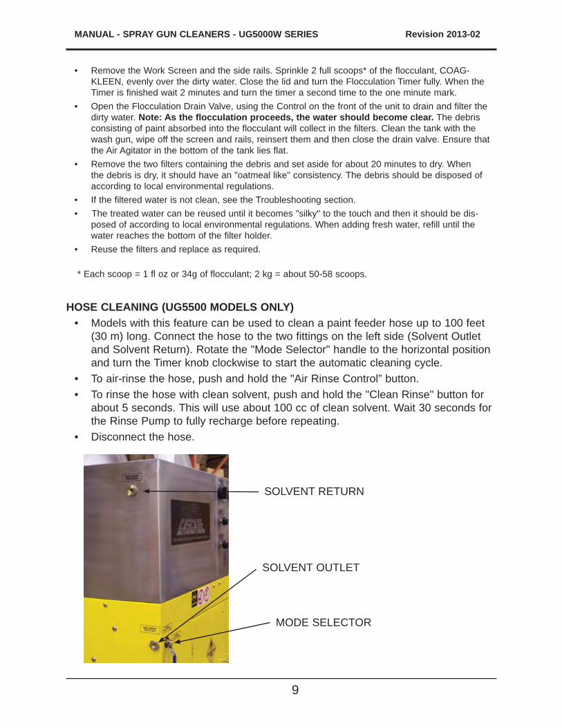
HOSE CLEANING (UG5500 MODELS ONLY)• Models with this feature can be used to clean a paint feeder hose up to 100 feet
(30 m) long. Connect the hose to the two fittings on the left side (Solvent Outlet and Solvent Return). Rotate the "Mode Selector" handle to the horizontal position and turn the Timer knob clockwise to start the automatic cleaning cycle.
• To air-rinse the hose, push and hold the "Air Rinse Control” button. • To rinse the hose with clean solvent, push and hold the "Clean Rinse" button for
about 5 seconds. This will use about 100 cc of clean solvent. Wait 30 seconds for the Rinse Pump to fully recharge before repeating.
• Disconnect the hose.
MODE SELECTOR
SOLVENT RETURN
SOLVENT OUTLET
MANUAL - SPRAY GUN CLEANERS - UG5000 SERIES Revision 2013-02
10
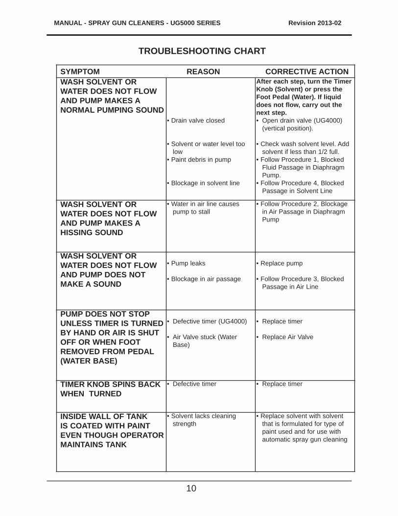
TROUBLESHOOTING CHART
SYMPTOM REASON CORRECTIVE ACTION WASH SOLVENT OR WATER DOES NOT FLOW AND PUMP MAKES A NORMAL PUMPING SOUND
• Drain valve closed
• Solvent or water level too low
• Paint debris in pump
• Blockage in solvent line
After each step, turn the Timer Knob (Solvent) or press the Foot Pedal (Water). If liquid does not flow, carry out the next step.• Open drain valve (UG4000)
(vertical position).
• Check wash solvent level. Add solvent if less than 1/2 full.
• Follow Procedure 1, Blocked Fluid Passage in Diaphragm Pump.
• Follow Procedure 4, Blocked Passage in Solvent Line
WASH SOLVENT OR WATER DOES NOT FLOW AND PUMP MAKES A HISSING SOUND
• Water in air line causes pump to stall
• Follow Procedure 2, Blockage in Air Passage in Diaphragm Pump
WASH SOLVENT OR WATER DOES NOT FLOW AND PUMP DOES NOT MAKE A SOUND
• Pump leaks
• Blockage in air passage
• Replace pump
• Follow Procedure 3, Blocked Passage in Air Line
PUMP DOES NOT STOP UNLESS TIMER IS TURNED BY HAND OR AIR IS SHUT OFF OR WHEN FOOT REMOVED FROM PEDAL (WATER BASE)
• Defective timer (UG4000)
• Air Valve stuck (Water Base)
• Replace timer
• Replace Air Valve
TIMER KNOB SPINS BACK WHEN TURNED
• Defective timer • Replace timer
INSIDE WALL OF TANK IS COATED WITH PAINT EVEN THOUGH OPERATOR MAINTAINS TANK
• Solvent lacks cleaning strength
• Replace solvent with solvent that is formulated for type of paint used and for use with automatic spray gun cleaning

11
MANUAL - SPRAY GUN CLEANERS - UG5000W SERIES Revision 2013-02
SYMPTOM REASON CORRECTIVE ACTION
CLEANING PROBLEMSGUNS NOT CLEAN, PUMP WORKING, SOLVENT OR WATER FLOW NORMAL
• Trigger not locked in open position
• Spray gun is not properly installed on to nozzle
• Incompatible solvent
• Water too dirty(UM120W)
• Low pressure in air supply
• Plugged jets
After Each Step Below, Turn Timer. If guns are not clean, carry out next step.
• Use Trigger Lock Spring
• Re-install with proper adapter
• Replace incompatible solvent with sol-vent formulated for type of paint used and for Automatic Spray Gun Cleaners.
• Increase air pressure to a minimum of 85 PSI
• Remove and clean by blowing air through the jets. If not successful, replace.
GUNS NOT CLEAN, WASH SOLVENT IS MILKY WHITE
• Wash solvent is con-taminated with water
• Replace or recycle wash solvent
CLEAN RINSE DOES NOT WORK
• Not enough solvent in clean rinse pail (right side)
• Rinse Pump is leak-ing from a crack caused by corrosion due to acidic or chlo-rine-contaminated solvent
• Clean Rinse Air Valve is defective
• See Section “REPLACING SOLVENT”
• Replace rinse pump
• Follow Procedure 3, “Blocked Passage in Air Line” for air rinse valve only.
CLEAN RINSE IS DIRTY • Faulty Combination Valve
• Replace Combination Valve.
TROUBLESHOOTING CHART
MANUAL - SPRAY GUN CLEANERS - UG5000 SERIES Revision 2013-02
12
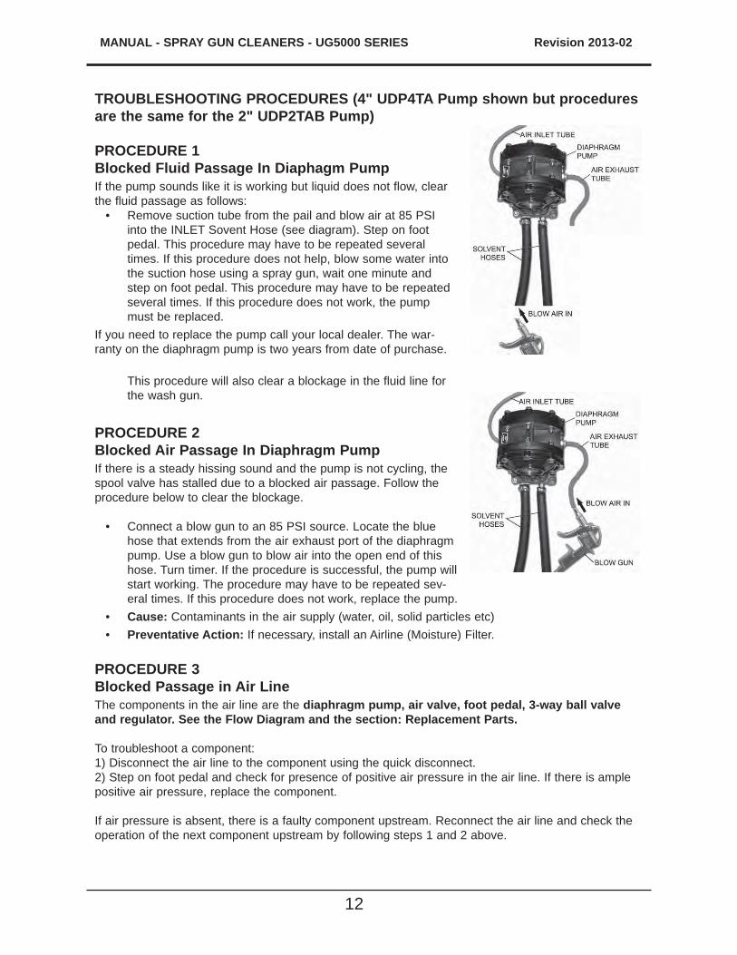
TROUBLESHOOTING PROCEDURES (4" UDP4TA Pump shown but procedures are the same for the 2" UDP2TAB Pump)
PROCEDURE 1Blocked Fluid Passage In Diaphagm PumpIf the pump sounds like it is working but liquid does not flow, clear the fluid passage as follows:
• Remove suction tube from the pail and blow air at 85 PSI into the INLET Sovent Hose (see diagram). Step on foot pedal. This procedure may have to be repeated several times. If this procedure does not help, blow some water into the suction hose using a spray gun, wait one minute and step on foot pedal. This procedure may have to be repeated several times. If this procedure does not work, the pump must be replaced.
If you need to replace the pump call your local dealer. The war-ranty on the diaphragm pump is two years from date of purchase.
This procedure will also clear a blockage in the fluid line for the wash gun.
PROCEDURE 2Blocked Air Passage In Diaphragm PumpIf there is a steady hissing sound and the pump is not cycling, the spool valve has stalled due to a blocked air passage. Follow the procedure below to clear the blockage.
• Connect a blow gun to an 85 PSI source. Locate the blue hose that extends from the air exhaust port of the diaphragm pump. Use a blow gun to blow air into the open end of this hose. Turn timer. If the procedure is successful, the pump will start working. The procedure may have to be repeated sev-eral times. If this procedure does not work, replace the pump.
• Cause: Contaminants in the air supply (water, oil, solid particles etc)• Preventative Action: If necessary, install an Airline (Moisture) Filter.
PROCEDURE 3Blocked Passage in Air LineThe components in the air line are the diaphragm pump, air valve, foot pedal, 3-way ball valve and regulator. See the Flow Diagram and the section: Replacement Parts.
To troubleshoot a component:1) Disconnect the air line to the component using the quick disconnect. 2) Step on foot pedal and check for presence of positive air pressure in the air line. If there is ample positive air pressure, replace the component.
If air pressure is absent, there is a faulty component upstream. Reconnect the air line and check the operation of the next component upstream by following steps 1 and 2 above.
13
MANUAL - SPRAY GUN CLEANERS - UG5000W SERIES Revision 2013-02
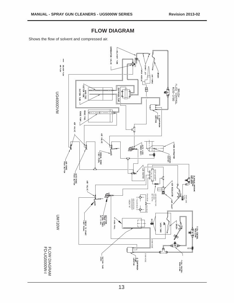
FLOW DIAGRAMShows the flow of solvent and compressed air.
MANUAL - SPRAY GUN CLEANERS - UG5000 SERIES Revision 2013-02
14
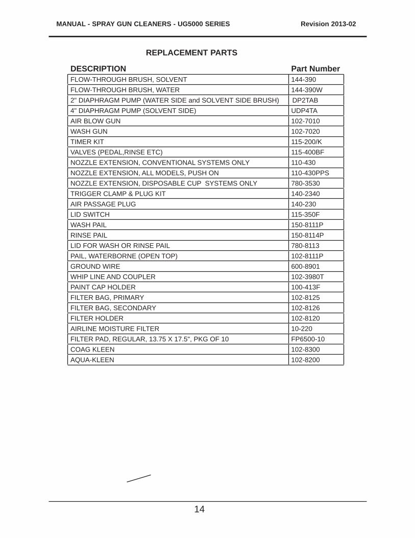
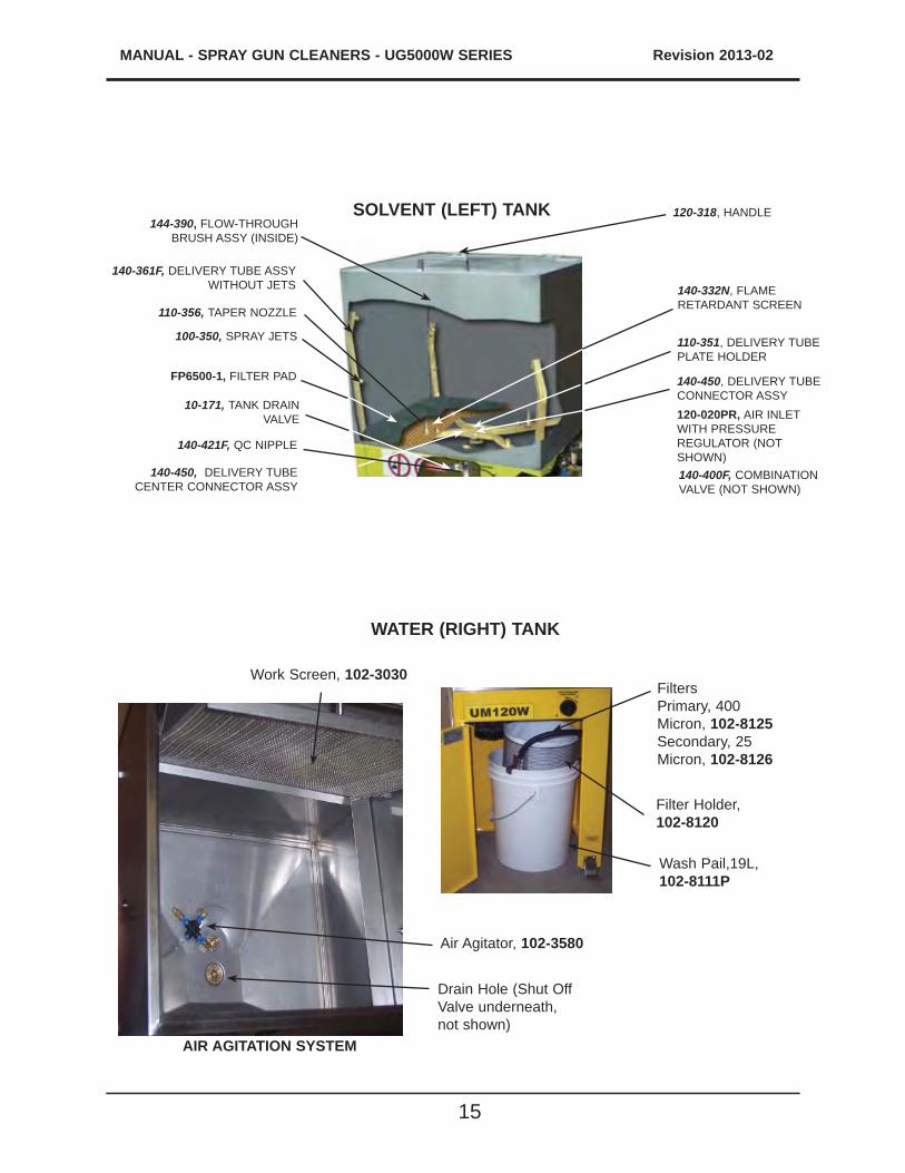
REPLACEMENT PARTS
DESCRIPTION Part NumberFLOW-THROUGH BRUSH, SOLVENT 144-390FLOW-THROUGH BRUSH, WATER 144-390W2" DIAPHRAGM PUMP (WATER SIDE and SOLVENT SIDE BRUSH) DP2TAB4" DIAPHRAGM PUMP (SOLVENT SIDE) UDP4TAAIR BLOW GUN 102-7010WASH GUN 102-7020TIMER KIT 115-200/KVALVES (PEDAL,RINSE ETC) 115-400BFNOZZLE EXTENSION, CONVENTIONAL SYSTEMS ONLY 110-430NOZZLE EXTENSION, ALL MODELS, PUSH ON 110-430PPSNOZZLE EXTENSION, DISPOSABLE CUP SYSTEMS ONLY 780-3530TRIGGER CLAMP & PLUG KIT 140-2340AIR PASSAGE PLUG 140-230LID SWITCH 115-350FWASH PAIL 150-8111PRINSE PAIL 150-8114PLID FOR WASH OR RINSE PAIL 780-8113PAIL, WATERBORNE (OPEN TOP) 102-8111PGROUND WIRE 600-8901WHIP LINE AND COUPLER 102-3980TPAINT CAP HOLDER 100-413FFILTER BAG, PRIMARY 102-8125FILTER BAG, SECONDARY 102-8126FILTER HOLDER 102-8120AIRLINE MOISTURE FILTER 10-220FILTER PAD, REGULAR, 13.75 X 17.5", PKG OF 10 FP6500-10COAG KLEEN 102-8300AQUA-KLEEN 102-8200
15
MANUAL - SPRAY GUN CLEANERS - UG5000W SERIES Revision 2013-02
140-421F, QC NIPPLE
FP6500-1, FILTER PAD
140-450, DELIVERY TUBE CENTER CONNECTOR ASSY
140-332N, FLAME RETARDANT SCREEN
140-400F, COMBINATION VALVE (NOT SHOWN)
120-020PR, AIR INLET WITH PRESSURE REGULATOR (NOT SHOWN)
10-171, TANK DRAIN VALVE
110-356, TAPER NOZZLE
100-350, SPRAY JETS
140-361F, DELIVERY TUBE ASSY WITHOUT JETS
120-318, HANDLE144-390, FLOW-THROUGH
BRUSH ASSY (INSIDE)
SOLVENT (LEFT) TANK
140-450, DELIVERY TUBECONNECTOR ASSY
110-351, DELIVERY TUBE PLATE HOLDER
FiltersPrimary, 400 Micron, 102-8125Secondary, 25 Micron, 102-8126
Filter Holder, 102-8120
Wash Pail,19L, 102-8111P
Work Screen, 102-3030
AIR AGITATION SYSTEM
Air Agitator, 102-3580
Drain Hole (Shut Off Valve underneath, not shown)
WATER (RIGHT) TANK
MANUAL - SPRAY GUN CLEANERS - UG5000 SERIES Revision 2013-02
16
Full Product Warranty
These Uni-ram products have been engineered and manufactured to high performance standards. Each unit has been subjected to detailed factory testing before shipment.
This product comes with a one-year full warranty from the date of purchase. Uni-ram Corporation reserves the right to repair or replace the unit, free of charge, to the original purchaser if a part is found to be defective in material or workmanship as determined by factory service personnel. The items listed below under "Conditions of Warranty" as consumables are not covered.
Uni-ram reserves the right to direct the customer to ship the unit collect to the Uni-ram factory or to an approved Service Center for repair using the Uni-ram Return Goods Procedure or to repair the unit on-site. To prevent damage in transport, the purchaser must ship the unit in the original pack-aging or use alternate adequate packaging. All units must be shipped clean and free of solvent.
Diaphragm Pump:We are pleased to advise that the warranty on the diaphragm pump, the heart of the spray gun cleaner, comes with a 2 year replacement warranty. If, in the unlikely event your diaphragm pump fails during the first two years of service, call Uni-ram Service at 1-800-417-9133. We will send you a new pump free of charge and arrange for the return of your original pump.
Conditions of Warranty:As Uni-ram Corporation has no control over the working conditions or circumstances under which the purchaser stores, handles or uses the product, Uni-ram makes no warranty or claim, either expressed or implied with respect to this product's fitness for any purpose or the result to be obtained from its use. This condition applies to the sale of all products and no representative or dis-tributor of Uni-ram Corporation has the authority to waive or change these conditions.
This warranty applies only to the original purchaser and does not apply if the unit has been mis-used, overloaded, neglected, altered or used for any purpose other than those specified in the operating and installation instructions. Deterioration due to normal wear is not covered by this warranty. Damage due to accident, transportation, fire, floods or acts of God is also not covered. Units whose serial numbers have been altered or removed are not covered. The warranty is invalid if unauthorized chemicals as noted in the manual or solvents with acid content are used in this unit. Unauthorized attempts at self-repair or alterations by the owner also invalidate this warranty. Interior or exterior finishes are not covered by this warranty.
Consumable Items are not covered by this warranty (eg: gaskets, screens, bags, filters, nozzles and air jets).
This warranty replaces all other warranties expressed or implied by statute or otherwise.
To make a claim, call Uni-ram Service at 1-800-417-9133 and quote the serial number of the unit.