Embed Size (px)
Citation preview
March 12, 2008 Fan's MS Defense 1
Soft Error Rate Determination for Soft Error Rate Determination for Nanometer CMOS VLSI CircuitsNanometer CMOS VLSI Circuits
Master’s DefenseMaster’s DefenseFan WangFan Wang
Department of Electrical and Computer EngineeringAuburn University, AL 36849 USA
Thesis Advisor: Dr. Vishwani D. Agrawal
Thesis Committee: Dr. Fa Foster Dai and Dr. Victor P. Nelson
March 12, 2008 Fan's MS Defense 2
Outline
Background
Problem Statement
Contributions
Proposed soft error model
Proposed soft error propagation through logic
Experimental resultsDiscussion of results
Conclusion
March 12, 2008 Fan's MS Defense 3
Motivation for This Work
With the continuous downscaling of CMOS technologies, the device reliability has become a major bottleneck.
The sensitivity of electronic systems can potentially become a major cause of soft (non-permanent) failures.
The determination of soft error rate in logic circuits is a complex problem. There is no existing analysis method that comprehensively considers all the factors that influence the soft error rate.
March 12, 2008 Fan's MS Defense 4
BackgroundCertain behaviors in the state of the art electronic
circuits caused by random factors.
Single event upset (SEU) is a non-permanent or transient error.
Definition from NASA Thesaurus: “Single Event Upset (SEU): Radiation-induced errors in
microelectronic circuits caused when charged particles [also, high energy particles] (usually from the radiation belts or from cosmic rays) lose energy by ionizing the medium through which they pass, leaving behind a wake of electron-hole pairs”.
March 12, 2008 Fan's MS Defense 5
What is Soft Error A “fault” is the cause of errors. Faults can be permanent
(hardware fault) or non-permanent. A non-permanent fault is a non-destructive fault and falls
into two categories: Transient faults caused by environmental conditions like
temperature, humidity, pressure, voltage, power supply, vibrations, fluctuations, electromagnetic interference, ground loops, cosmic rays and alpha particles.
Intermittent faults caused by non-environmental conditions like loose connections, aging components, critical timing, interconnect coupling, resistive or capacitive variations and noise in the system.
An error caused by a non-permanent fault is a “soft error”. With advances in manufacturing, soft errors caused by
cosmic rays and alpha particles remain the dominant causes of failures in electronic systems.
March 12, 2008 Fan's MS Defense 6
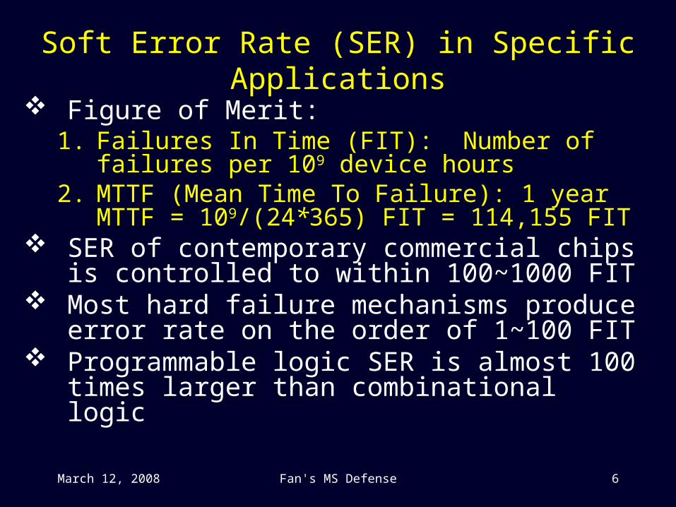
Soft Error Rate (SER) in Specific Applications
Figure of Merit:1. Failures In Time (FIT): Number of failures per 109
device hours2. MTTF (Mean Time To Failure): 1 year MTTF =
109/(24*365) FIT = 114,155 FIT SER of contemporary commercial chips is controlled
to within 100~1000 FIT Most hard failure mechanisms produce error rate on
the order of 1~100 FIT Programmable logic SER is almost 100 times larger
than combinational logic
March 12, 2008 Fan's MS Defense 7
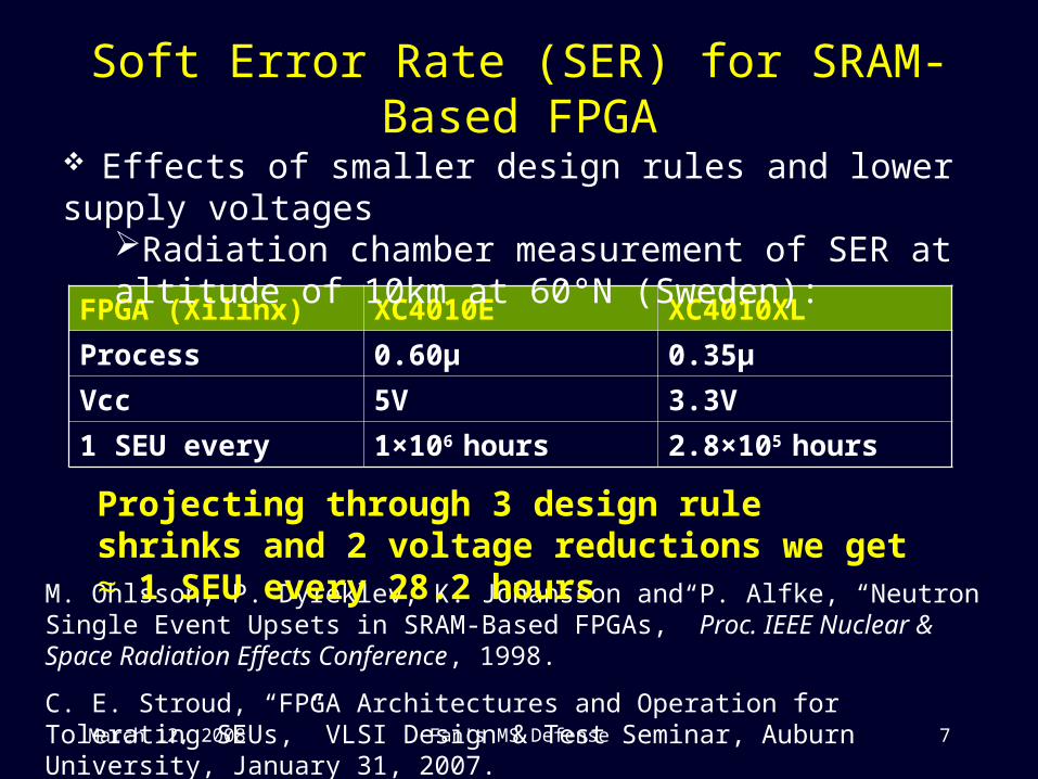
Soft Error Rate (SER) for SRAM-Based FPGA
FPGA (Xilinx) XC4010E XC4010XL
Process 0.60μ 0.35μ
Vcc 5V 3.3V
1 SEU every 1×10⁶ hours 2.8×10⁵ hours
M. Ohlsson, P. Dyreklev, K. Johansson and P. Alfke, “Neutron Single Event Upsets in SRAM-Based FPGAs,” Proc. IEEE Nuclear & Space Radiation Effects Conference, 1998.
C. E. Stroud, “FPGA Architectures and Operation for Tolerating SEUs,” VLSI Design & Test Seminar, Auburn University, January 31, 2007.
Effects of smaller design rules and lower supply voltagesRadiation chamber measurement of SER at altitude of 10km at 60°N (Sweden):
Projecting through 3 design rule shrinks and 2 voltage reductions we get ≈ 1 SEU every 28.2 hours
March 12, 2008 Fan's MS Defense 8
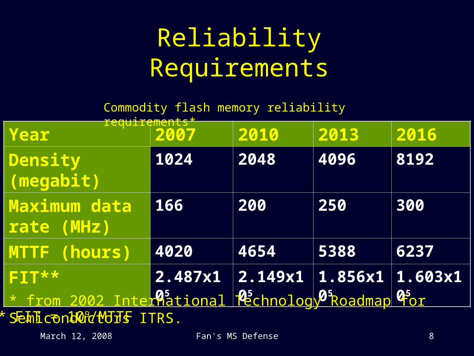
Reliability Requirements
Year 2007 2010 2013 2016
Density (megabit) 1024 2048 4096 8192
Maximum data rate (MHz)
166 200 250 300
MTTF (hours) 4020 4654 5388 6237
FIT** 2.487x10⁵ 2.149x10⁵ 1.856x10⁵ 1.603x10⁵
Commodity flash memory reliability requirements*
* from 2002 International Technology Roadmap for Semiconductors ITRS.** FIT = 109/MTTF
March 12, 2008 Fan's MS Defense 9
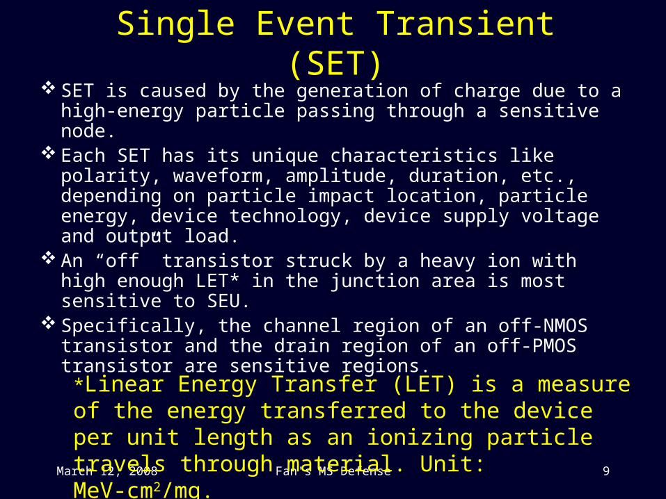
Single Event Transient (SET) SET is caused by the generation of charge due to a high-
energy particle passing through a sensitive node. Each SET has its unique characteristics like polarity,
waveform, amplitude, duration, etc., depending on particle impact location, particle energy, device technology, device supply voltage and output load.
An “off” transistor struck by a heavy ion with high enough LET* in the junction area is most sensitive to SEU.
Specifically, the channel region of an off-NMOS transistor and the drain region of an off-PMOS transistor are sensitive regions.
*Linear Energy Transfer (LET) is a measure of the energy transferred to the device per unit length as an ionizing particle travels through material. Unit: MeV-cm2/mg.
March 12, 2008 Fan's MS Defense 10
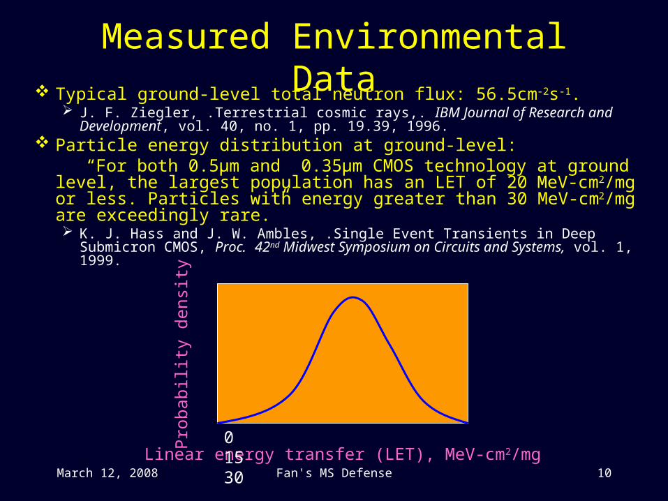
Measured Environmental Data Typical ground-level total neutron flux: 56.5cm-2s-1.
J. F. Ziegler, .Terrestrial cosmic rays,. IBM Journal of Research and Development, vol. 40, no. 1, pp. 19.39, 1996.
Particle energy distribution at ground-level: “For both 0.5μm and 0.35μm CMOS technology at ground level, the
largest population has an LET of 20 MeV-cm2/mg or less. Particles with energy greater than 30 MeV-cm2/mg are exceedingly rare.” K. J. Hass and J. W. Ambles, .Single Event Transients in Deep Submicron
CMOS, Proc. 42nd Midwest Symposium on Circuits and Systems, vol. 1, 1999.
Linear energy transfer (LET), MeV-cm2/mg
Pro
babi
lity
dens
ity
0 15 30
March 12, 2008 Fan's MS Defense 11
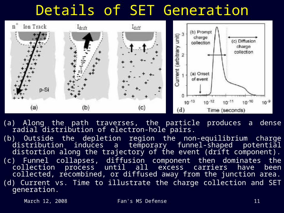
Details of SET Generation
(a) Along the path traverses, the particle produces a dense radial distribution of electron-hole pairs.
(b) Outside the depletion region the non-equilibrium charge distribution induces a temporary funnel-shaped potential distortion along the trajectory of the event (drift component).
(c) Funnel collapses, diffusion component then dominates the collection process until all excess carriers have been collected, recombined, or diffused away from the junction area.
(d) Current vs. Time to illustrate the charge collection and SET generation.
March 12, 2008 Fan's MS Defense 12
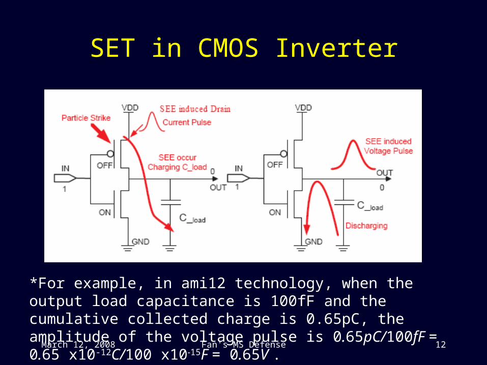
SET in CMOS Inverter
*For example, in ami12 technology, when the output load capacitance is 100fF and the cumulative collected charge is 0.65pC, the amplitude of the voltage pulse is 0.65pC/100fF = 0.65 x10⁻¹²C/100 x10-15F = 0.65V .
March 12, 2008 Fan's MS Defense 13
Original Contributions of This Research
March 12, 2008 Fan's MS Defense 14
Problem StatementGiven background environment data
Neutron fluxBackground LET distribution
*Those two factors are location dependent.
Given circuit characteristicsTechnologyCircuit netlistCircuit node sensitive region data
*Those three factors depend on the circuit.
Estimate neutron caused soft error rate in standard FIT units.
March 12, 2008 Fan's MS Defense 15
Proposed Soft Error Model
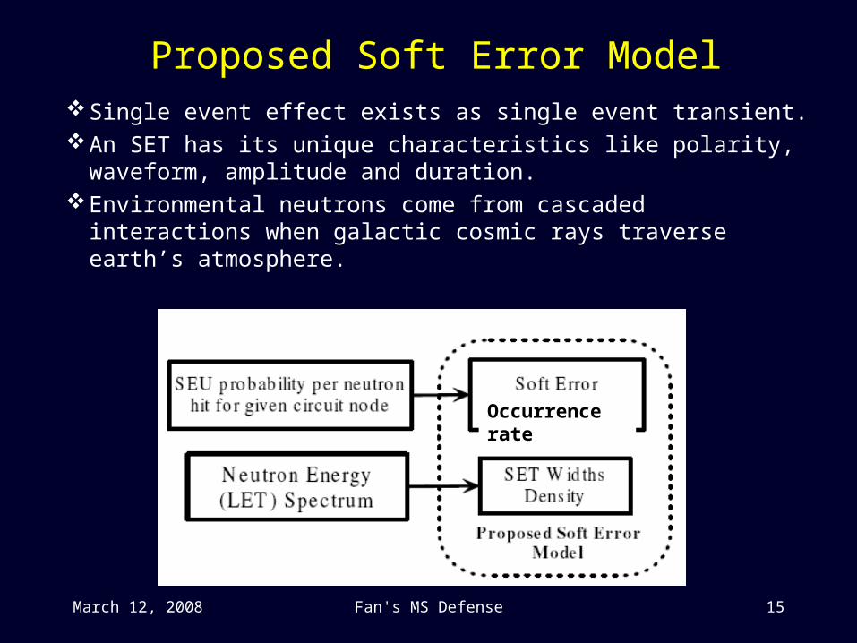
Single event effect exists as single event transient.An SET has its unique characteristics like polarity,
waveform, amplitude and duration.Environmental neutrons come from cascaded interactions
when galactic cosmic rays traverse earth’s atmosphere.
Occurrence rate
March 12, 2008 Fan's MS Defense 16
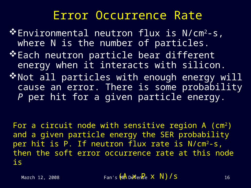
Error Occurrence RateEnvironmental neutron flux is N/cm2-s, where N is the
number of particles.Each neutron particle bear different energy when it
interacts with silicon.Not all particles with enough energy will cause an error.
There is some probability P per hit for a given particle energy.
For a circuit node with sensitive region A (cm2) and a given particle energy the SER probability per hit is P. If neutron flux rate is N/cm2-s, then the soft error occurrence rate at this node is
(A x P x N)/s
March 12, 2008 Fan's MS Defense 17
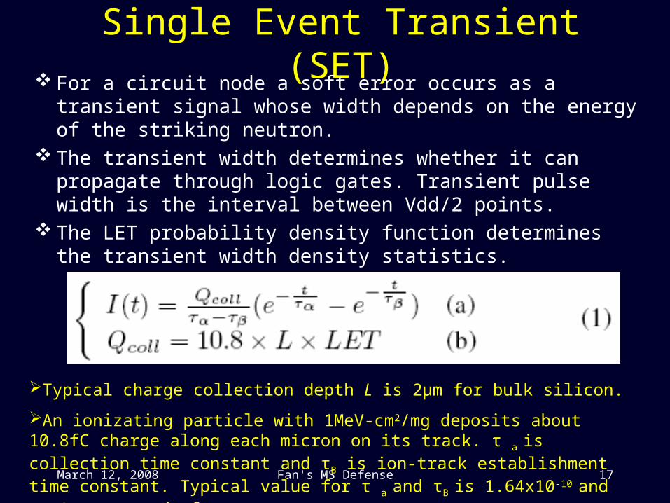
Single Event Transient (SET) For a circuit node a soft error occurs as a transient signal whose
width depends on the energy of the striking neutron. The transient width determines whether it can propagate through
logic gates. Transient pulse width is the interval between Vdd/2 points.
The LET probability density function determines the transient width density statistics.
Typical charge collection depth L is 2μm for bulk silicon.
An ionizating particle with 1MeV-cm2/mg deposits about 10.8fC charge along each micron on its track. τ a is collection time constant and τB is ion-track establishment time constant. Typical value for τ a and τB is 1.64x10⁻¹⁰ and 5x10-11 respectively.
March 12, 2008 Fan's MS Defense 18
SummarizingWe model the soft error with two parameters:
Occurrence rateSingle event transient width
Next, we propose a propagation algorithm for the modeled soft error transient pulses.
March 12, 2008 Fan's MS Defense 19
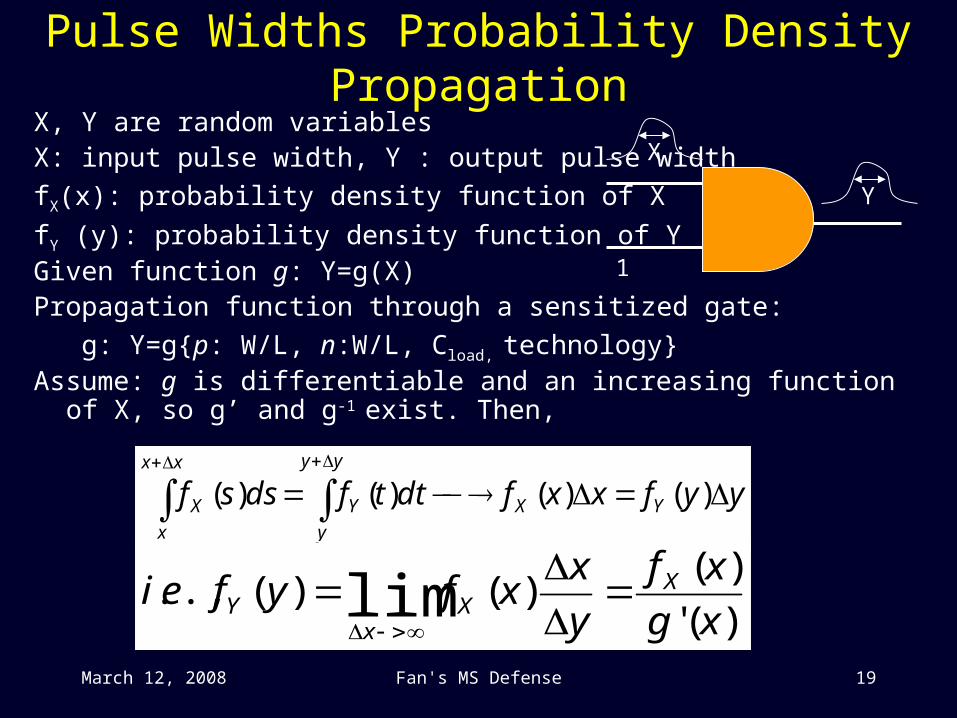
Pulse Widths Probability Density PropagationX, Y are random variablesX: input pulse width, Y : output pulse width
fX(x): probability density function of X
fY (y): probability density function of YGiven function g: Y=g(X)Propagation function through a sensitized gate:
g: Y=g{p: W/L, n:W/L, Cload, technology}Assume: g is differentiable and an increasing function of X, so g’ and g-1 exist.
Then,
yyfxxfdttfdssf YX
yy
y
Y
xx
x
X
)()()()(
)('
)()()(.,. lim xg
xf
y
xxfyfei X
Xx
Y
1
X
Y
March 12, 2008 Fan's MS Defense 20
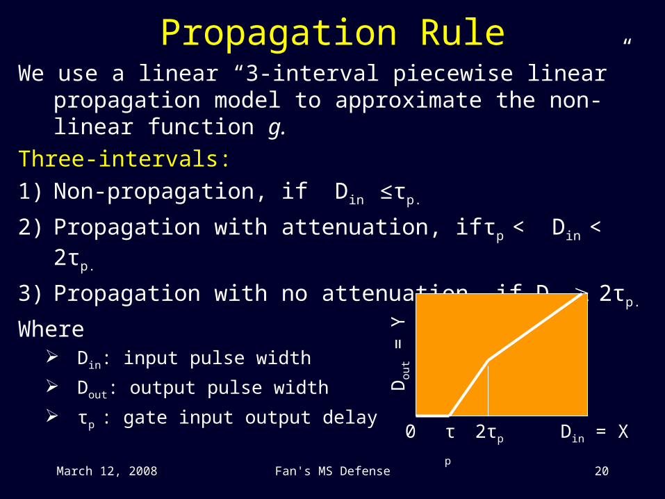
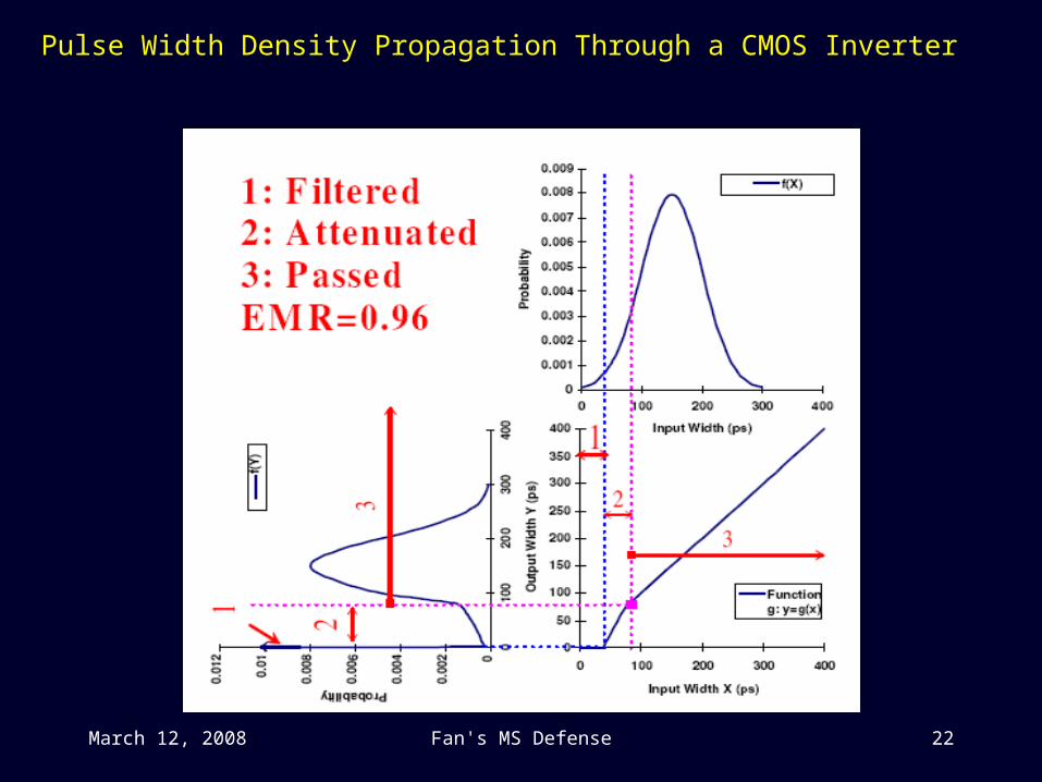
Propagation RuleWe use a linear “3-interval piecewise linear” propagation
model to approximate the non-linear function g.
Three-intervals:
1) Non-propagation, if Din ≤τp.
2) Propagation with attenuation, ifτp < Din < 2τp.
3) Propagation with no attenuation, if Din 2τp.
Where Din: input pulse width
Dout: output pulse width
τp : gate input output delay τp 2τp0 Din = X
Dou
t = Y
March 12, 2008 Fan's MS Defense 21
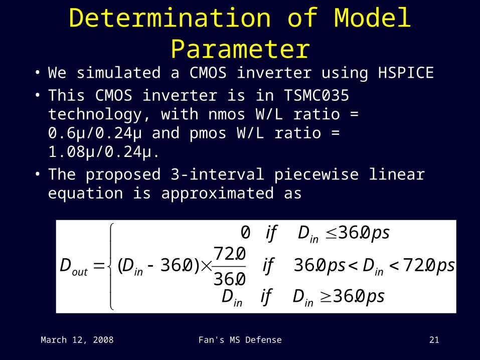
Determination of Model Parameter
• We simulated a CMOS inverter using HSPICE• This CMOS inverter is in TSMC035 technology, with
nmos W/L ratio = 0.6µ/0.24µ and pmos W/L ratio = 1.08µ/0.24µ.
• The proposed 3-interval piecewise linear equation is approximated as
psDifD
psDpsifD
psDif
D
inin
inin
in
out
0.36
0.720.360.36
0.72)0.36(
0.360
March 12, 2008 Fan's MS Defense 22
Pulse Width Density Propagation Through a CMOS Inverter
March 12, 2008 Fan's MS Defense 23
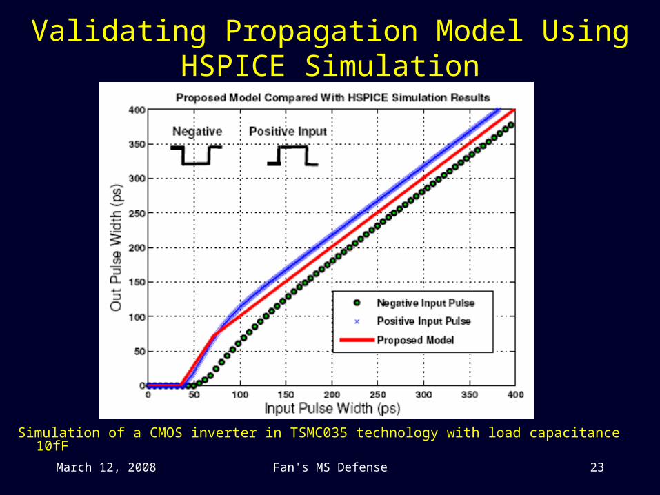
Validating Propagation Model Using HSPICE Simulation
Simulation of a CMOS inverter in TSMC035 technology with load capacitance 10fF
March 12, 2008 Fan's MS Defense 24
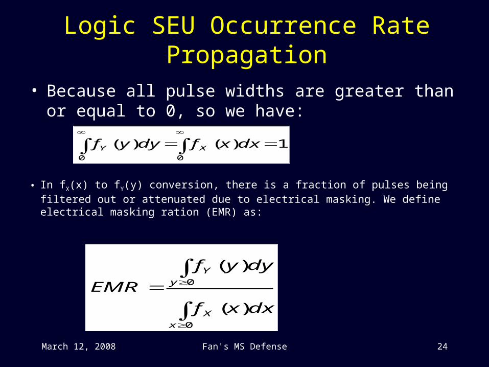
Logic SEU Occurrence Rate Propagation
• Because all pulse widths are greater than or equal to 0, so we have:
0
0
)(
)(
x
X
y
Y
dxxf
dyyf
EMR
1)()(00
dxxfdyyf XY
• In fX(x) to fY(y) conversion, there is a fraction of pulses being filtered out or attenuated due to electrical masking. We define electrical masking ration (EMR) as:
March 12, 2008 Fan's MS Defense 25
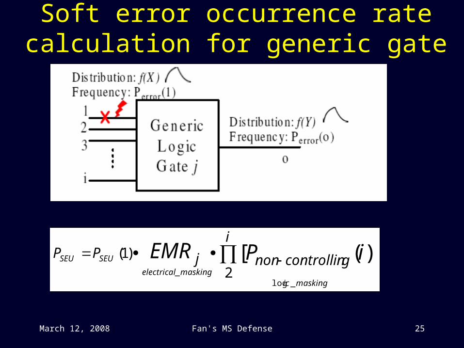
Soft error occurrence rate calculation for generic gate
i
gcontrollinnonjPP iPEMRmaskingic
maskingelectrical
SEUSEU
2
)1( )]([_log
_

March 12, 2008 Fan's MS Defense 26
Experimental Results for ISCAS85 Circuits
Assume probability of SEU per particle hit is 10-4.Assume the SET width density per circuit node follows normal distribution with mean µ = 150 and standard deviation σ = 50 for ground level environment.At ground level, total neutron flux is 56.5 m-2s-1.Circuit are in TSMC035 technology and sensitive region per node is 10 µm2.For a circuit with n primary outputs and m nodes, we calculate the SER as:
n
i
m
jjbycausediSER
mnSER
0 0___ )
1(
1

March 12, 2008 Fan's MS Defense 27
SER Results on Workstation Sun Fire 280R
Circuit #PIs #POs #Gates CPU sFIT/gate/
output
C17 5 2 6 0.01 0.3679
C432 36 7 160 0.04 1.0563
C499 41 32 202 0.14 0.2188
C880 60 26 383 0.08 0.3882
C1908 33 25 880 1.14 0.7427
C2670 233 140 1193 0.77 0.2882
C5315 178 123 2307 2.78 0.5572
C7552 207 108 3512 10.82 0.6652
March 12, 2008 Fan's MS Defense 28
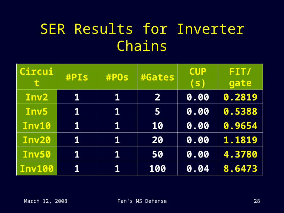
SER Results for Inverter Chains
Circuit #PIs #POs #Gates CUP (s) FIT/gate
Inv2 1 1 2 0.00 0.2819
Inv5 1 1 5 0.00 0.5388
Inv10 1 1 10 0.00 0.9654
Inv20 1 1 20 0.00 1.1819
Inv50 1 1 50 0.00 4.3780
Inv100 1 1 100 0.04 8.6473
March 12, 2008 Fan's MS Defense 29
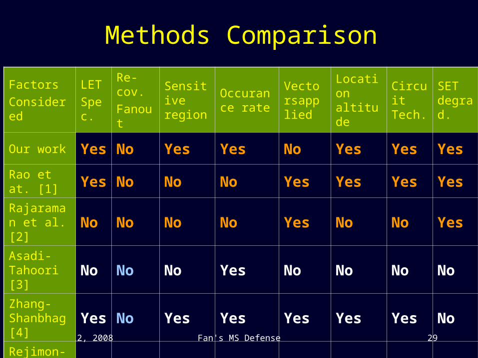
Methods Comparison
Factors
Considered
LET
Spec.
Re-cov.
FanoutSensitive region
Occurance rate
Vectorsapplied
Location altitude
Circuit Tech.
SET degrad.
Our work Yes No Yes Yes No Yes Yes Yes
Rao et at. [1] Yes No No No Yes Yes Yes Yes
Rajaraman et al. [2] No No No No Yes No No Yes
Asadi-Tahoori [3] No No No Yes No No No No
Zhang-Shanbhag[4] Yes No Yes Yes Yes Yes Yes No
Rejimon-Bhanja [5] No No No Yes Yes No No No
March 12, 2008 Fan's MS Defense 30
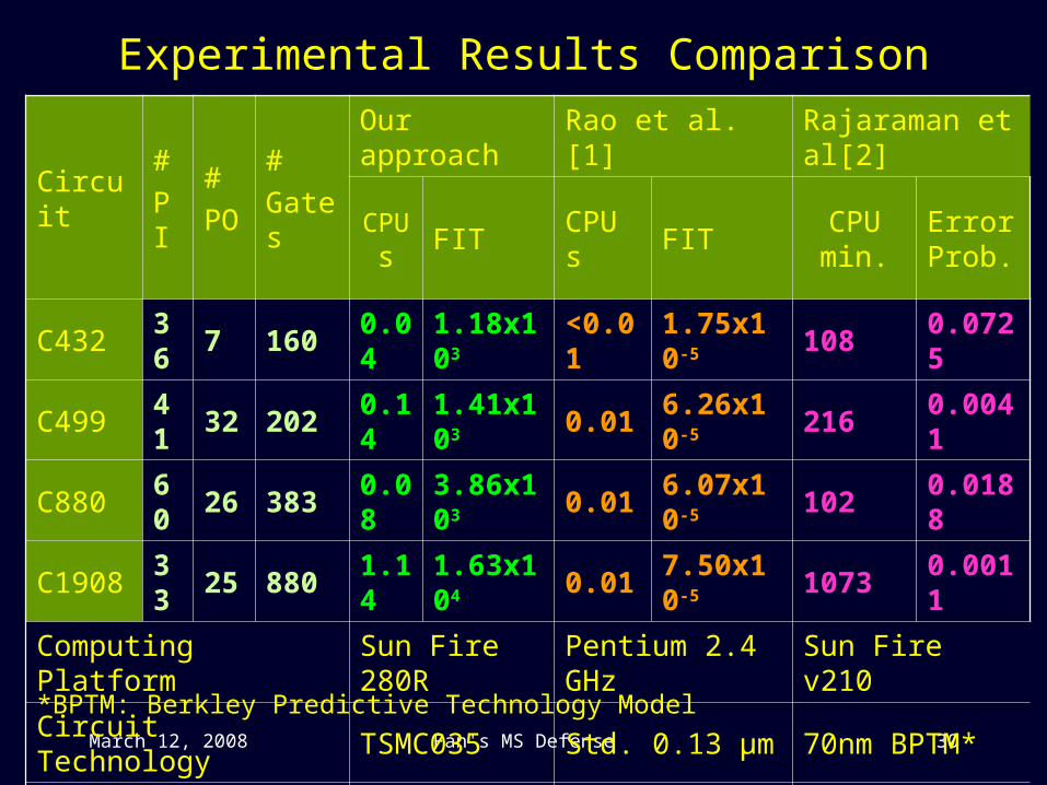
Experimental Results Comparison
Circuit#
PI
#
PO
#
Gates
Our approach Rao et al. [1] Rajaraman et al[2]
CPU s
FIT CPU s FITCPU min.
Error Prob.
C432 36 7 160 0.04 1.18x10³ <0.01 1.75x10⁻⁵ 108 0.0725
C499 41 32 202 0.14 1.41x10³ 0.01 6.26x10⁻⁵ 216 0.0041
C880 60 26 383 0.08 3.86x10³ 0.01 6.07x10⁻⁵ 102 0.0188
C1908 33 25 880 1.14 1.63x10⁴ 0.01 7.50x10⁻⁵ 1073 0.0011
Computing Platform Sun Fire 280R Pentium 2.4 GHz Sun Fire v210
Circuit Technology TSMC035 Std. 0.13 µm 70nm BPTM*
Altitude Ground Ground N/A
*BPTM: Berkley Predictive Technology Model
March 12, 2008 Fan's MS Defense 31
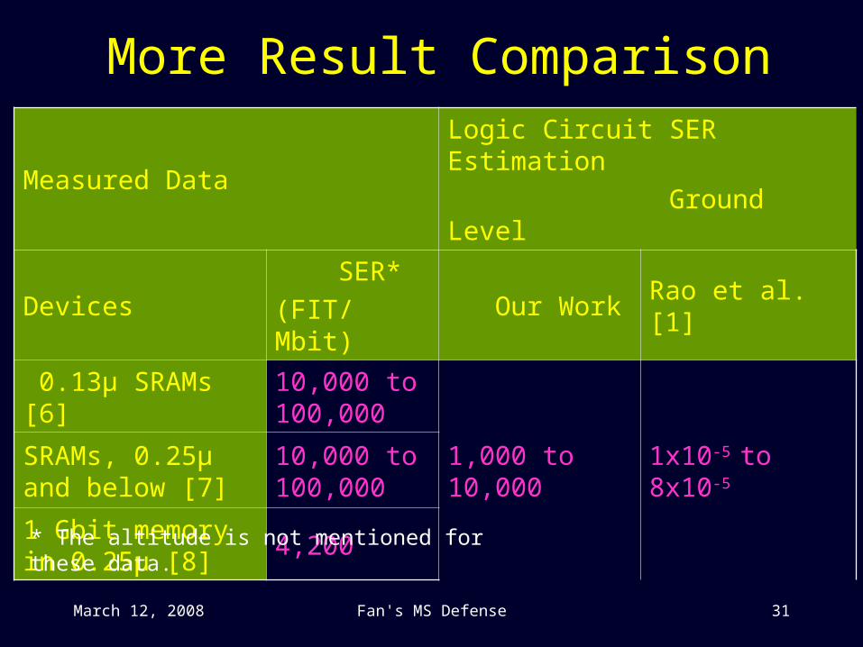
More Result Comparison
Measured DataLogic Circuit SER Estimation
Ground Level
Devices SER*
(FIT/Mbit) Our Work Rao et al. [1]
0.13µ SRAMs [6]10,000 to 100,000
1,000 to 10,000 1x10⁻⁵ to 8x10⁻⁵SRAMs, 0.25μ and below [7]
10,000 to 100,000
1 Gbit memory in 0.25µ [8]
4,200
* The altitude is not mentioned for these data.
March 12, 2008 Fan's MS Defense 32
Discussion We take the energy of neutron to be the key factor to induce
SEU. In real cases, there can also be secondary particles generated through interaction with neutrons.
Estimating sensitive regions in silicon is a hard task. Also, the polarity of SET should be taken into account.
Because on the earth surface, typical error rates are very small, their measurement is time consuming and can produce large discrepancy. This motivates the use of analytical methods.
For example, a circuit may experience 1 SEU in 6 months (4320 hours), equals 231,480 FIT. It is also likely that the circuit has 0 SEU in these 6 months, so the measured SER is 0 FIT.
March 12, 2008 Fan's MS Defense 33
Fan-out stems should be considered. Two situations can arise:
When an SET goes through a large fan-out, the large load capacitance can eliminate the SET, or
If it is not canceled by the fan-out node, it will go through multiple fan-out paths to increase the SER.
It is highly recommended to have more field tests for logic circuits.
None of these SER approaches consider the process variation effects on SER.
Discussion Continued
March 12, 2008 Fan's MS Defense 34
Conclusion SER in logic and memory chips will continue to
increase as devices become more sensitive to soft errors at sea level.
By modeling the soft errors by two parameters, the occurrence rate and single event transient pulse width density, we are able to effectively account for the electrical masking of circuit.
Our approach considers more factors and thus gives more realistic soft error rate estimation.
March 12, 2008 Fan's MS Defense 35
Publications related to this work• F. Wang and V. D. Agrawal, “Single Event Upset: An Embedded
Tutorial,” in Proc. 21st IEEE International Conference on VLSI Design, January 2008, pp. 429-434.
• F. Wang and V. D. Agrawal, “Soft Error Rate Determination for Nanometer CMOS VLSI Circuits,” in Proc. 40th IEEE Southeastern Symposium on System Theory, March 16-18, 2008, Paper TA1.
• F. Wang and V. D. Agrawal, “Probabilistic Soft Error Rate Estimation from Statistical SEU Parameters,” in Proc. 17th IEEE North Atlantic Test Workshop, May 2008.
Unpublished work:• F. Wang and V. D. Agrawal, “Soft Error Considerations for Computer
Web Servers”.
March 12, 2008 Fan's MS Defense 36
References[1] R. R. Rao, K. Chopra, D. Blaauw, and D. Sylvester, “An Efficient Static Algorithm for
Computing the Soft Error Rates of Combinational Circuits," Proceedings of the conference on Design automation and test in Europe: Proceedings, pp. 164-169, 2006.
[2] R. Rajaraman, J. S. Kim, N. Vijaykrishnan, Y. Xie, and M. J. Irwin, “SEAT-LA: A Soft Error Analysis Tool for Combinational Logic," VLSI Design, 2006 19th International Conference on, 2006, pp. 499-502.
[3] G. Asadi and M. B. Tahoori, “An Accurate SER Estimation Method Based on Propagation Probability,” Proc. Design Automation and Test in Europe Conf,2005, pp. 306-307.
[4] M. Zhang and N. R. Shanbhag, “A soft error rate analysis (SERA) methodology," in IEEE/ACM International Conference on Computer Aided Design, ICCAD-2004, 2004, pp. 111-118.
[5] T. Rejimon and S. Bhanja, “An Accurate Probabilistic Model for Error Detection," in 18th International Conference on VLSI Design, 2005, pp.717-722.
[6] J. Graham, “Soft errors a problem as SRAM geometries shrink,“http://www.ebnews.com/story/OEG20020128S0079, ebn, 28 Jan 2002.
[7] Wingyu Leung; Fu-Chieh Hsu; Jones, M. E., "The ideal SoC memory: 1T-SRAMTM," Proc.13th Annual IEEE International on ASIC/SOC Conference, vol., no., pp.32-36, 2000
[8] Report, “Soft Errors in Electronic Memory-A White Paper," Technical report, Tezzaron Semiconductor, 2004.
March 12, 2008 Fan's MS Defense 37
Thank You . . .