Embed Size (px)
Citation preview
March 2004
Communications Research LaboratorySlide 1
doc.: IEEE 802.15-04-0112-01-004a
Submission
Project: IEEE P802.15 Working Group for Wireless Personal Area Networks (WPANs)
Submission Title: [Spatio-Temporal UWB Propagation Channel Characterization]Date Submitted: [14 March, 2004]Source: [Katsuyuki Haneda (1), Jun-ichi Takada (1) and Takehiko Kobayashi (2)]Company [(1) Communications Research Laboratory UWB Technology Institute / Tokyo Institute of Technology,
(2) Communications Research Laboratory UWB Technology Institute / Tokyo Denki University]Address [3-4, Hikarino-oka, Yokosuka city, Kanagawa 239-0847 Japan]Voice []E-Mail: [(1) {haneda, takada}@ap.ide.titech.ac.jp, (2) [email protected] ]Re: [Status report of the 802.15.4a channel modeling subgroup]Abstract: [This contribution describes the results of spatio-temporal propagation channel measurements in a typical home environments in Japan. ]Purpose: [Reports on UWB channel measurement for IEEE802.15TG4a]Notice: This document has been prepared to assist the IEEE P802.15. It is offered as a basis for discussion and is not binding on the contributing individual(s) or organization(s). The material in this document is subject to change in form and content after further study. The contributor(s) reserve(s) the right to add, amend or withdraw material contained herein.Release: The contributor acknowledges and accepts that this contribution becomes the property of IEEE and may be made publicly available by P802.15.
March 2004
Communications Research LaboratorySlide 2
doc.: IEEE 802.15-04-0112-01-004a
Submission
Spatio-Temporal UWB Propagation Channel Characterization
Katsuyuki Haneda (1), Jun-ichi Takada (1)Takehiko Kobayashi (2)
Communications Research Laboratory(1) Tokyo Institute of Technology
(2) Tokyo Denki University
Presented by Honggang Zhang, Yuko RikutaCommunications Research Laboratory
March 2004
Communications Research LaboratorySlide 3
doc.: IEEE 802.15-04-0112-01-004a
Submission
Table of contents• Spatio-temporal channel measurement tech
nique
• Specifications of experiment
• Measurement site
• Path identification results
• Clusters in spatio-temporal domain and their relation to physical structure of the environment
• Diffuse scattering
March 2004
Communications Research LaboratorySlide 4
doc.: IEEE 802.15-04-0112-01-004a
Submission
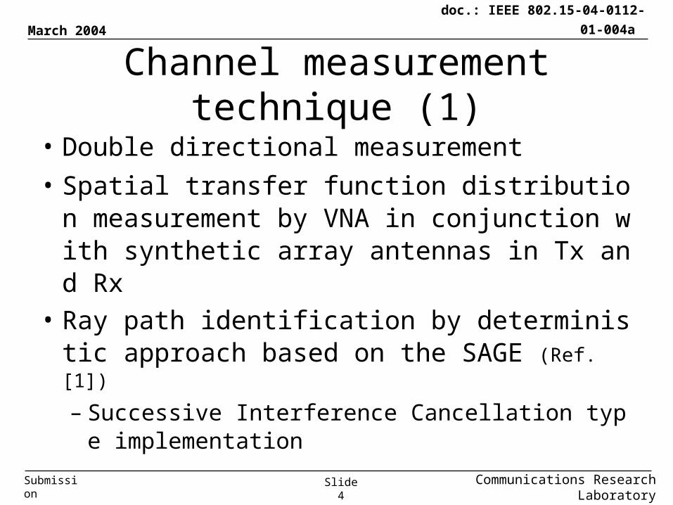
Channel measurement technique (1)
• Double directional measurement
• Spatial transfer function distribution measurement by VNA in conjunction with synthetic array antennas in Tx and Rx
• Ray path identification by deterministic approach based on the SAGE (Ref. [1])
– Successive Interference Cancellation type implementation
March 2004
Communications Research LaboratorySlide 5
doc.: IEEE 802.15-04-0112-01-004a
Submission
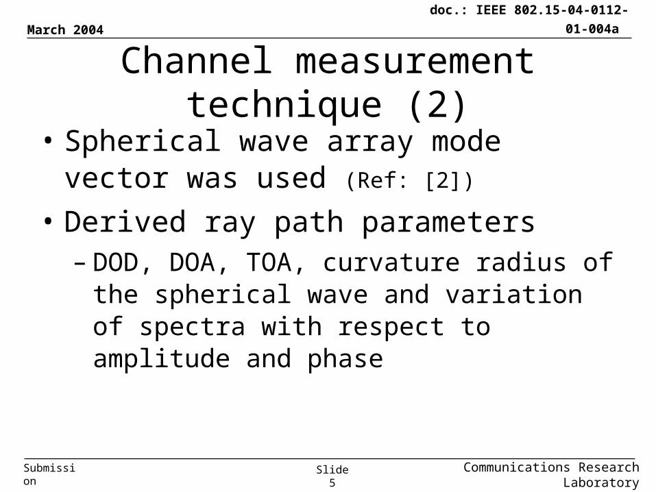
Channel measurement technique (2)
• Spherical wave array mode vector was used (Ref: [2])
• Derived ray path parameters– DOD, DOA, TOA, curvature radius of the
spherical wave and variation of spectra with respect to amplitude and phase
March 2004
Communications Research LaboratorySlide 6
doc.: IEEE 802.15-04-0112-01-004a
Submission
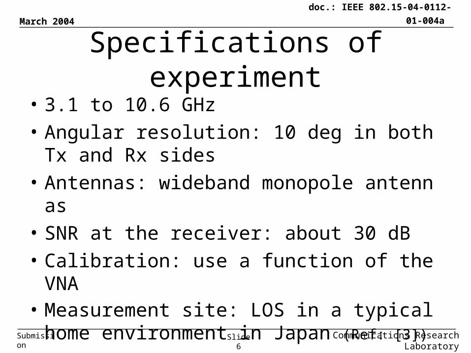
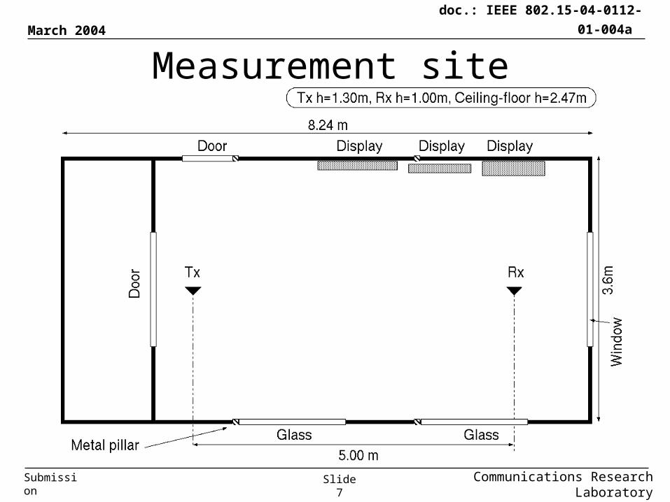
Specifications of experiment
• 3.1 to 10.6 GHz
• Angular resolution: 10 deg in both Tx and Rx sides
• Antennas: wideband monopole antennas
• SNR at the receiver: about 30 dB
• Calibration: use a function of the VNA• Measurement site: LOS in a typical home
environment in Japan (Ref: [3])
March 2004
Communications Research LaboratorySlide 7
doc.: IEEE 802.15-04-0112-01-004a
Submission
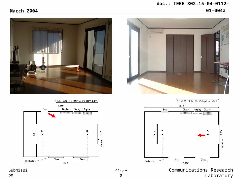
Measurement site
March 2004
Communications Research LaboratorySlide 8
doc.: IEEE 802.15-04-0112-01-004a
Submission
March 2004
Communications Research LaboratorySlide 9
doc.: IEEE 802.15-04-0112-01-004a
Submission
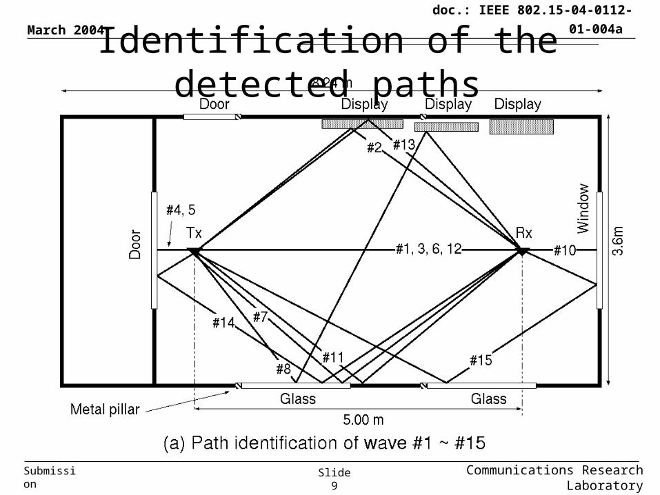
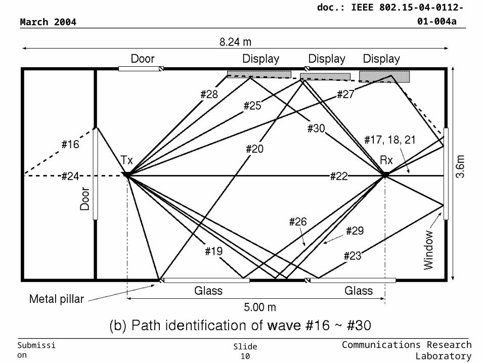
Identification of the detected paths
March 2004
Communications Research LaboratorySlide 10
doc.: IEEE 802.15-04-0112-01-004a
Submission
March 2004
Communications Research LaboratorySlide 11
doc.: IEEE 802.15-04-0112-01-004a
Submission
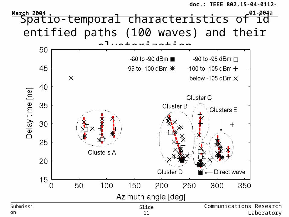
Spatio-temporal characteristics of identified paths (100 waves) and their clusterization
March 2004
Communications Research LaboratorySlide 12
doc.: IEEE 802.15-04-0112-01-004a
Submission
Clusterization procedure
• The whole paths were clusterized intuitivel
y by human recognition on the delay-angul
ar map.
• We can observe sub-clusters in clusters A
and E (expressed in red lines).
March 2004
Communications Research LaboratorySlide 13
doc.: IEEE 802.15-04-0112-01-004a
Submission
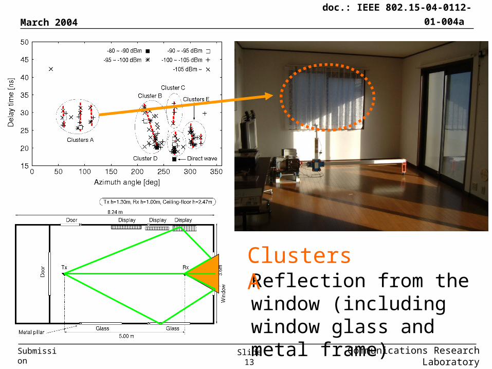
Reflection from the window (including window glass and metal frame)
Clusters A
March 2004
Communications Research LaboratorySlide 14
doc.: IEEE 802.15-04-0112-01-004a
Submission
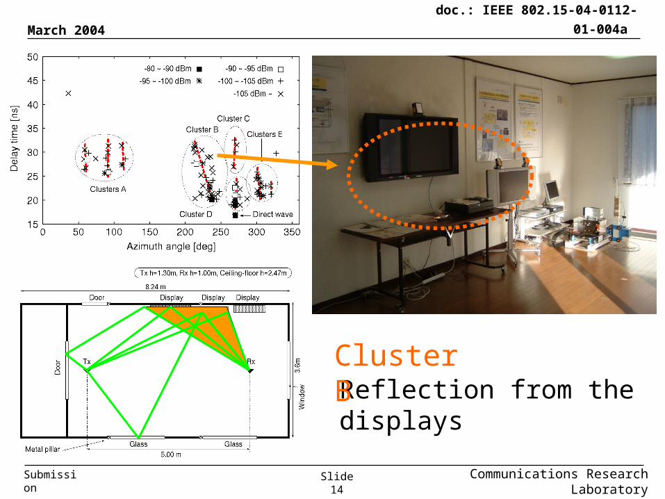
Reflection from the displays
Cluster B
March 2004
Communications Research LaboratorySlide 15
doc.: IEEE 802.15-04-0112-01-004a
Submission
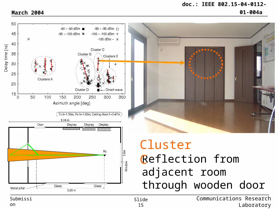
Reflection from adjacent room through wooden door
Cluster C
March 2004
Communications Research LaboratorySlide 16
doc.: IEEE 802.15-04-0112-01-004a
Submission
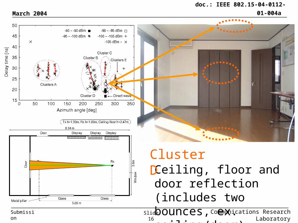
Ceiling, floor and door reflection (includes two bounces, ex. ceiling/door)
Cluster D
March 2004
Communications Research LaboratorySlide 17
doc.: IEEE 802.15-04-0112-01-004a
Submission
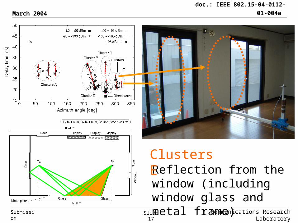
Reflection from the window (including window glass and metal frame)
Clusters E
March 2004
Communications Research LaboratorySlide 18
doc.: IEEE 802.15-04-0112-01-004a
Submission
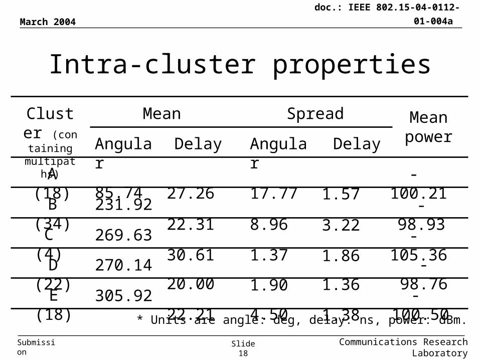
Intra-cluster properties
Cluster (containing multipaths)
A (18)
B (34)
C (4)
D (22)
E (18)
Mean
Angular Delay
Spread
Angular Delay
85.74
231.92
269.63
270.14
305.92
27.26
22.31
30.61
20.00
22.21
17.77
8.96
1.37
1.90
4.50
1.57
3.22
1.86
1.36
1.38
Mean power
-100.21
-98.93
-105.36
-98.76
-100.50
* Units are angle: deg, delay: ns, power: dBm.
March 2004
Communications Research LaboratorySlide 19
doc.: IEEE 802.15-04-0112-01-004a
Submission
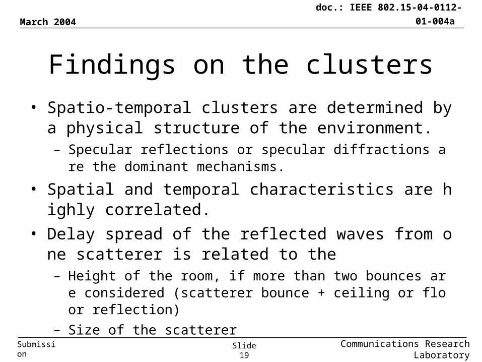
Findings on the clusters
• Spatio-temporal clusters are determined by a physical structure of the environment.– Specular reflections or specular diffractions are the dominant me
chanisms.
• Spatial and temporal characteristics are highly correlated.
• Delay spread of the reflected waves from one scatterer is related to the – Height of the room, if more than two bounces are considered (sc
atterer bounce + ceiling or floor reflection)
– Size of the scatterer
March 2004
Communications Research LaboratorySlide 20
doc.: IEEE 802.15-04-0112-01-004a
Submission
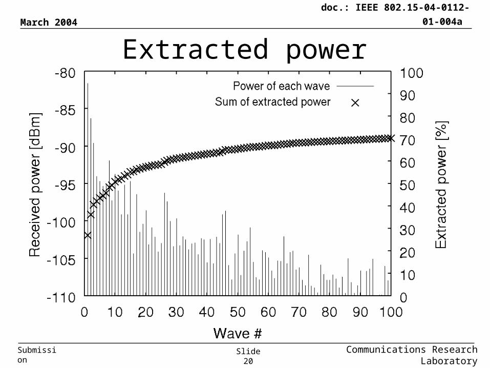
Extracted power
March 2004
Communications Research LaboratorySlide 21
doc.: IEEE 802.15-04-0112-01-004a
Submission
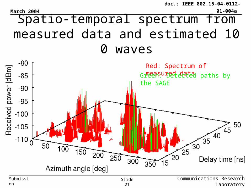
Spatio-temporal spectrum from measured data and estimated 100 waves
Red: Spectrum of measured data
Green: Detected paths by the SAGE
March 2004
Communications Research LaboratorySlide 22
doc.: IEEE 802.15-04-0112-01-004a
Submission
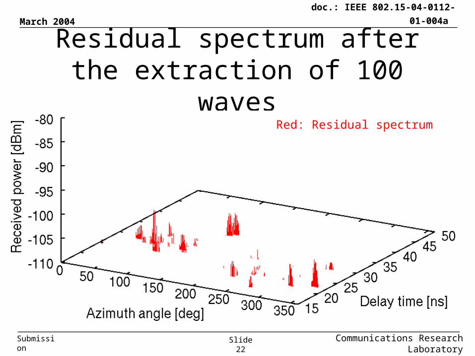
Residual spectrum after the extraction of 100 waves
Red: Residual spectrum

March 2004
Communications Research LaboratorySlide 23
doc.: IEEE 802.15-04-0112-01-004a
Submission
Spatio-temporal characteristics of identified paths (100 waves) and their clusterization
March 2004
Communications Research LaboratorySlide 24
doc.: IEEE 802.15-04-0112-01-004a
Submission
-115 dBm
-110 dBm
-120 dBm
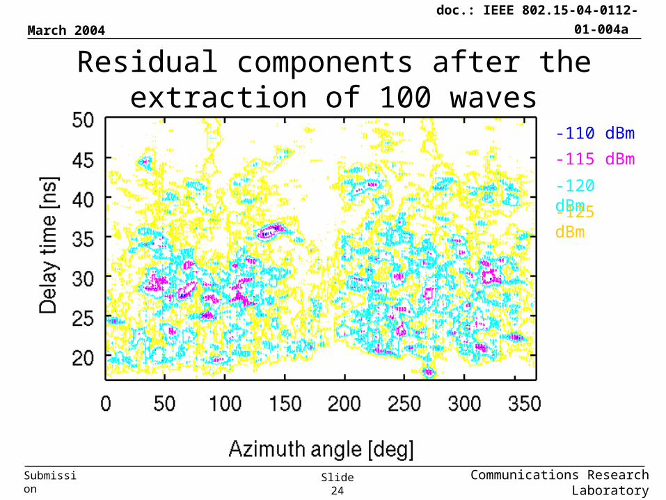
Residual components after the extraction of 100 waves
-125 dBm
March 2004
Communications Research LaboratorySlide 25
doc.: IEEE 802.15-04-0112-01-004a
Submission
Findings on the residual components
• About 30 % of the measured power still remains unextracted even if 100 waves were extracted by the SAGE.
• The residual component = diffuse scattering which is hard to characterize by our deterministic approach.
• Further investigations on the diffuse components should be continued.
March 2004
Communications Research LaboratorySlide 26
doc.: IEEE 802.15-04-0112-01-004a
Submission
Summary• Paths and clusters identification based on
the physical phenomena.
• Whole received power was divided into the deterministic components (70%) and the diffuse components (30%).
• Site-specific models are appropriate if the indoor UWB channels are simulated, i.e. ray tracing + diffuse scattering.
March 2004
Communications Research LaboratorySlide 27
doc.: IEEE 802.15-04-0112-01-004a
Submission
References
• Channel measurement system:[1] Haneda et. al., UWBST2003, Reston, VA, USA,
Nov. 2003.
[2] Haneda et. al., accepted for IWUWBS joint
with UWBST 2004, Kyoto, Japan, May 2004.
• Channel measurement result:[3] Haneda et. al., submitted to WPMC04, Padova, Italy,
Sept. 2004.