Embed Size (px)
Citation preview

March 23, 200 Bill Wisniewski 1
Intro to BaBar Detector and its subsystems
Identify the assets Look at reuse potential
Preserve the assets Minimal maintenance state
definition Progress to the MMS
D&D History Early plans Response to review
Inventory
BaBar Overview & MMS Status

March 23, 2009 Bill Wisniewski 2
BaBar Detector
Cerenkov Detector (DIRC)144 quartz bars
11000 PMTs
1.5 T Solenoid
Electromagnetic Calorimeter 6580 CsI(Tl) crystals
Drift Chamber40 stereo layers
Instrumented Flux ReturnIron & Brass/RPCs, LSTs (muon/neutral hadrons)
Silicon Vertex Tracker5 layers, double sided
strips
e+ (3.1 GeV)
e- (9 GeV)‘
‘Ideal’

March 23, 2009 Bill Wisniewski 3
BaBar Detector
Details can be found in NIM A479 (2002) 1-116.

March 23, 2009 Bill Wisniewski 4
BaBar Detector
‘Actual’Shield wall removed

March 23, 2009 Bill Wisniewski 5
BaBar Detector Assets
Subsystems: SVT, DCH, DIRC, EMC, IFR, magnet, Trig and Online
Identification of assets: Subsystem managers were involved in identifying detector
components with long term value. Assets with high value to preserve in the disassembly process,
if they have not already been spoken for: Quartz bars from the DIRC. CsI (Tl) crystals from the EMC. Superconducting magnet coil, cryostat and current leads
and cryo plant. Look at detector disassembly by subsystem from the IP.
Complication in the disposition of the disassembled detector components and services that have no clear reuse: Metals Suspension.

March 23, 2009 Bill Wisniewski 6
Silicon Vertex Tracker
SVT has 5 double-sided layers providing z and φ readout. There are 6,6,6,16 and 18 modules in each later. ~150K channels in 208 read-out sections.

March 23, 2009 Bill Wisniewski 7
Silicon Vertex Tracker
SVT located in the support tube that carries the beam line elements closest to IP.
Read-out: matching cards in the support tube, power supplies and next level of read-out atop the detector and on mezzanine (all in the accelerator housing). Final stage of readout (ROM) in Electronics Hut (EH).
Services: humidity controlled air; water cooling system (dual system fed from front and rear; includes pumps, chillers, and their backups); cables for power. Parts of each of the services are located in the accelerator housing.

March 23, 2009 Bill Wisniewski 8
Silicon Vertex Tracker
Radiation damage sufficient to limit usefulness. Damage especially severe in the accelerator mid-plane.
Expected disposition: tests initially to understand radiation damage effects on performance (to be folded into the design of a possible Super B factory; display, half in Italy, half in a US museum (site undetermined).

March 23, 2009 Bill Wisniewski 9
Drift Chamber
Drift Chamber: charged particle tracker consists of 7104 small drift cells arranged in 40 cylindrical layers which form ten superlayers, 4 axial, and 6 stereo.

March 23, 2009 Bill Wisniewski 10
Drift Chamber
Front end electronics packages are mounted at the aft end of the drift chamber. There is a single low voltage power supply located in the Electronics Hut (EH), along with high voltage supplies for the wires.

March 23, 2009 Bill Wisniewski 11
Drift Chamber
The DCH is mounted in the DIRC support tube, cantilevered into the center of the detector.
The DCH used an 80:20 helium:isobutane mix provided at slight overpressure by a gas mixing system that re-circulates and scrubs gas in the DCH. Nitrogen was flushed between the bulkheads and endplates to limit the spread of He to the DIRC phototubes. Gas system is an example of
‘recovery by collaborators’.

March 23, 2009 Bill Wisniewski 12
Drift Chamber
Planned disposition: display in a museum.

March 23, 2009 Bill Wisniewski 13
DIRC Particle identification system: ring imaging Cherenkov detector
that provides π/K identification from π threshold to 4.2GeV/c. Radiator is synthetic fused silica in the form of long, thin bars with
rectangular cross-section. Radiator acts as light pipe too (total internal reflection). The material was chosen for its resistance to radiation, long attenuation length, large index of refraction, excellent optical finishing properties. The 144 bars are collected together in groups of 12 in hermetically sealed bar boxes.
The bar boxes are cantilevered off the IFR barrel in a central support tube that is necessarily thin, and which is attached to the strong support tube (see figure later transparency).
The Cherenkov photons emerge from the bars into a water filled expansion region, the Stand-Off Box. The SOB is instrumented with ~11000 phototubes whose faces are exposed to ultra-pure water.
High voltage distribution and front end readout electronics are attached around the SOB. The final readout electronics and HV supplies are located in the EH.

March 23, 2009 Bill Wisniewski 14
DIRC
March 23, 2009 Bill Wisniewski 15
DIRC
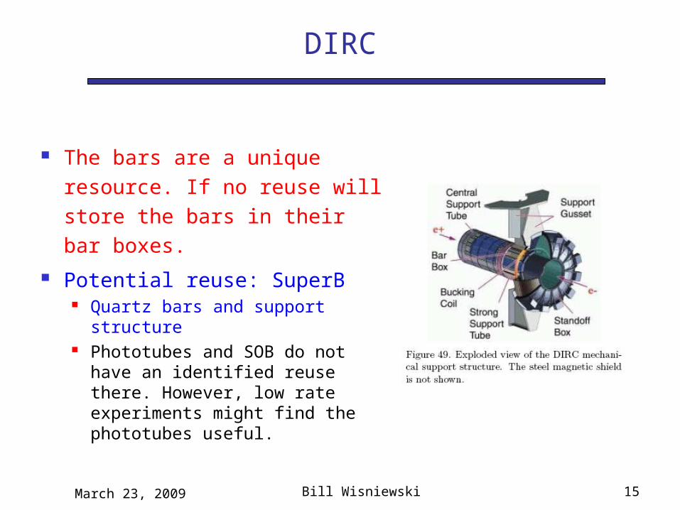
The bars are a unique resource. If no reuse will store the bars in their bar boxes.
Potential reuse: SuperB Quartz bars and support
structure Phototubes and SOB do not
have an identified reuse there. However, low rate experiments might find the phototubes useful.

March 23, 2009 Bill Wisniewski 16
Electromagnetic Calorimeter
Measures energy deposited by particles interacting in the device. Principal goal is to measure photon energies; aids in identification of charged particles (hadron-electron separation, muon ID); provides some neutral hadron ID.
Consists of 6580 ~4kg CsI(Tl) crystals read out with two photodiodes each. CsI(Tl) is mildly hygroscopic. Crystal/diode glue joint is secure over a limited thermal range. Crystals are suspended in carbon-fiber support structures mounted in the calorimeter support structures. ~$30M asset.
Calorimeter is in two parts: barrel portion (most of crystals) and forward endcap, suspended from the steel flux return.
Cooling for barrel power-hungry readout electronics is water cooling the support structure. Cooling for barrel preamps located at the back of each crystal is fluorinert. All endcap cooling is fluorinert. Fluorinert cooling maintains constant temperature for the diode-crystal glue joint. Extensive cooling plant. Nitrogen flush system to maintain dry environment.
Final read-out electronics in EH. Large contingent of ROMs and VME crates, and power supplies.
Calibration systems include radioactive source system (DT generator) and light pulsing system.

March 23, 2009 Bill Wisniewski 17
Electromagnetic Calorimeter

March 23, 2009 Bill Wisniewski 18
Electromagnetic Calorimeter

March 23, 2009 Bill Wisniewski 19
EMC: Glue Joint Fragility
Crystal-photodiode glue joints (127) were tested before calorimeter construction through 40 8-hour cycles of +/- 4C and 120 12 hour cycles of +/- 5C. No joints failed.
While the endcap calorimeter was being prepared for installation, assembly area cooling failed on a hot day. A temperature excursion of +10C was measured. Several glue joints failed in several modules, leading to the temperature maintenance requirement for the calorimeter.

March 23, 2009 Bill Wisniewski 20
Electromagnetic Calorimeter
Potential Barrel reuse: SuperB
Some endcap crystals may have a home in SuperB. Others would be stored if radiation damage has not degraded the response too much.
Will require dry room construction to store crystals that do not have an identified reuse.

March 23, 2009 Bill Wisniewski 21
Instrumented Flux Return
Instrumented Flux Return consists of two systems: Limited Streamer Tubes in the barrel, installed in 2004 and 2006, and Resistive Plate Chambers in the forward and backward endcaps.
LSTs: twelve layers of modules in 6 sextants. Six layers of brass installed in gaps formerly occupied by RPCs (increase interaction lengths). These detectors are expected to have minimal aging at the time of cessation of B-Factory operations. No re-use identified.
RPCs: Forward endcap: 16 layers of chambers (192 gaps), 4 in double modules, with 5 layers of brass; these chambers are being aged by backgrounds. Backward endcap: 18 layers of modules (216 gaps) from the initial construction of the detector; the majority of these chambers are in bad shape. Discard.
Gas mixing systems provide mixes for LSTs, RPCs, and avalanche mode RPCs. Has re-use potential, at least for device testing.

March 23, 2009 Bill Wisniewski 22
IFR: LSTs
LST Installation
Barrel Flux Return Steel

March 23, 2009 Bill Wisniewski 23
IFR: RPCs
Endcap Geometry
408

March 23, 2009 Bill Wisniewski 24
IFR: Gas System
Gas Shack
IFR gas mixing racks

March 23, 2009 Bill Wisniewski 25
BaBar Superconducting Coil & Steel
The magnet system is composed of:
Superconducting coil in its cryostat, with current leads. This is an asset with long term value. Power supply for the magnet. Cryogen system: pumps, liquifier, dewars and controls. Has long term value, though will be almost two decades old, half its expected service life. Flux return steel (IFR). Has scrap value (pending metals suspension resolution) Potential reuse: coil, cryogenic system, and perhaps steel, in SuperB

March 23, 2009 Bill Wisniewski 26
Cryo Plant
IR2 portion of the cryo plant.

March 23, 2009 Bill Wisniewski 27
Electronics Hut
Electronics hut and contents: Readout electronics: special purpose for
BaBar; single board computers are relatively aged, though may have some reuse.
Power supplies: some low voltage can be reused (‘off the shelf’). HV: supplies are older models, but may be useful to other experiments reaching the end of their lives (and spares) (eg, RHIC experiments); generally useful. Many are property to be recovered by collaborators.
Level 3 Trigger compute farm and event builder switches. Have good reuse since recently upgraded. Have been used as a Monte Carlo farm for BaBar in situ till this month.
EH was a candidate for disposal. BUT!
SCCS has power and cooling limitations Reuse compute farm in situ as MC farm
Done! Reuse racks and building in corner of
IR2; couple provide equivalent of more than a Sun BlackBox at substantially less cost. This is the most likely fate of the building.

March 23, 2009 Bill Wisniewski 28
The Minimal Maintenance State
The goal of the minimal maintenance state (MMS) is to safely preserve assets for reuse. This should be done at the lowest cost in preparation for, and during, detector disassembly
A stand-alone version of the monitoring system should be developed to track the state of the detector in the MMS. This is in lieu of using the detector’s full monitoring system in the data taking phase, which would require substantial computing professional effort.

March 23, 2009 Bill Wisniewski 29
Silicon Vertex Detector
During Transition to MMS: electronics to be turned off and locked out; humidification turned off; cooling system drained and dried out.
Originally intended that during MMS, dry air flow would be maintained. But secular changes due to weather do not interfere with intended disposition
No monitoring system checks.

March 23, 2009 Bill Wisniewski 30
Drift Chamber
Minimal maintenance state: Chamber gas: dry air. Bulkhead flush: dry air. Front end electronics: off. Power supplies: LV off, locked out. HV off, supply locked
off. Chiller and cooling water flow off, lines dried. Reduced monitoring system checks gas flow and
pressure.

March 23, 2009 Bill Wisniewski 31
DIRC
Minimal maintenance state: Electronics off. Low voltage off. High voltage off. Water chiller for electronics off and system drained. Nitrogen flow to bar boxes on to maintain dry
atmosphere needed for bar surface. SOB emptied, dried. Purification system off, removed. Reduced monitoring system checks bar box humidity.

March 23, 2009 Bill Wisniewski 32
EMC
Minimal maintenance state: Electronics off. Nitrogen flow on to maintain dry environment. Water flow off. System drained. Barrel cooling channels
dried out to prevent corrosion of structure. Source system fluorinert (fluid irrradiated by DT
generator for 6.1 MeV calibration photons) drained. Fluorinert cooling on, to maintain constant
temperature for the glue joint. Reduced monitoring system checks humidity, crystal
temperatures, fluorinert chiller operational status (temp out, temp in).

March 23, 2009 Bill Wisniewski 33
IFR
Minimal maintenance state: LSTs:
Electronics off. Gas changed to nitrogen. HV off. Cooling off.
RPCs: Electronics off. Gas off. HV off. Cooling off and
drained. No monitoring.

March 23, 2009 Bill Wisniewski 34
Magnet
Asset preservation in the MMS: Power supply off. Cryo plant drained and mothballed. Cold mass warmed to room temperature. Vacuum pumps off. Cryostat volume backfilled with
nitrogen Stand-alone monitoring system to keep track of
temperature and gauges (earthquake).

March 23, 2009 Bill Wisniewski 35
SystemFront-end electronics
Power supplies Gas Cooling Other utilities
SVT Off Off dry air off, drainedDCH Off Off dry nitrogen off
DRC Off Off dry nitrogen off, emptySOB drained, purification system off
EMC Off Off dry nitrogenfluorinert circulating
water system drained and dried; source system drained
IFR-RPC Off Off dry nitrogen off, drainedIFR-LST Off Off dry nitrogen off, drainedTrigger Off Off n/a n/aDAQ Off Off n/a n/aOnline farm Off Off n/a n/a
Safety systems/monitoring/UPS On On n/a
EH cooling on UPS maintained
Infrastructure n/a n/a n/aEH cooling on UPS maintained
Magnet On Off n/a n/a vacuum pumps onIR2 complex n/a On On On gas shack limited use
Minimal Maintenance State Table
2007: expectation 2009: evolution
Dry air
Off
Pumps off, Backfill N2
On till March: MonteCarlo farm
Decommission: remove hazards

March 23, 2009 Bill Wisniewski 36
Detector Transition
End run April 7, 2008 Collaboration decision to maintain the
detector in a ‘warm ready’ state for ~3 months.
Purpose: be able to take final calibrations; be able to take data if warranted by
results of analysis of Run 7 data
March 23, 2009 Bill Wisniewski 37
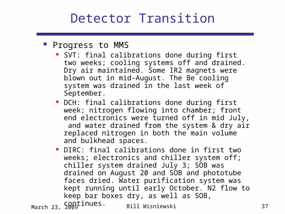
Detector Transition
Progress to MMS SVT: final calibrations done during first two
weeks; cooling systems off and drained. Dry air maintained. Some IR2 magnets were blown out in mid-August. The Be cooling system was drained in the last week of September.
DCH: final calibrations done during first week; nitrogen flowing into chamber; front end electronics were turned off in mid July, and water drained from the system & dry air replaced nitrogen in both the main volume and bulkhead spaces.
DIRC: final calibrations done in first two weeks; electronics and chiller system off; chiller system drained July 3; SOB was drained on August 20 and SOB and phototube faces dried. Water purification system was kept running until early October. N2 flow to keep bar boxes dry, as well as SOB, continues.

March 23, 2009 Bill Wisniewski 38
DIRC PMTs
Peek at the PMTs in SOB while the optical coupling is good. At first glance looks ok.
But: some tubes have a whitish ring near the light catcher something to investigate when the SOB is opened.

March 23, 2009 Bill Wisniewski 39
Detector Transition
Progress to MMS EMC: source calibrations continue until the
end of the warm ready state. The last calibration was done mid July. Water was drained from barrel cooling channels to avoid corrosion on Al structure in the last week of July. The patch where the aft water cooling circuit had developed a leak early in the running life of the experiment was OK. Fluorinert flow for barrel and endcap cooling continues till disassembly to keep stress off photodiode-crystal glue joint. N2 flow maintained to keep crystals dry.

March 23, 2009 Bill Wisniewski 40

March 23, 2009 Bill Wisniewski 41
Detector Transition
Progress to MMS IFR-RPC: final plateau runs taken in the week following
end of data taking; gas off for both avalanche and streamer mode chambers. Chambers open to air.
IFR-LST: final plateau runs taken in the week following end of data taking; nitrogen flowing through tubes.
Access control: Omnilocks (code for each user, entry recorded) installed on entries into IR2, including PEP South IR2 Adit; Omnilocks also installed on EH and Computing Alcove.
Level 3 Trigger farm adapted for Monte Carlo production.
Magnet and Cryo-sytems: magnet off; cooling for magnet off; liquifier/compressor system repaired/regenerated before most of cryogenics staff left – now mothballed.

March 23, 2009 Bill Wisniewski 42
Detector Transition
Progress to MMS: Monitoring System
Defined items to monitor at collaboration meeting early June
Progress on monitoring system:
* installed MMS application server - Dell 2950 purchased Sep 2007 - stand-alone RedHat 5 - non-taylored - update via RedHat subscription - minimum dependencies on SLAC core services - internal RAID with 500 GB for archive data + 80 GB for applications
* installed control software - EPICS version 3.14.7 (BaBar Production version) ported to RedHat5 - standard EPICS Channel Archiver - will provide access to live + archived data through "StripTool","DM" display manager and JAVA archiver viewer - no dependencies on BaBar releases or packages
* IOC - one installed - most recent hardware used by BaBar - mvme5500 running Linux - driver support for VSAM, SIAM and CANBUS - covers all sensors we want to monitor
* servers were shut down at IR2 on August 22
* put the MMS core infrastructure hardware in place * started to move sensors to the MMS in the last week of August.
Move completed second week of September. Includes fault warning.

March 23, 2009 Bill Wisniewski 43
Magnet MMS
Moving the magnet to its final MMS configuration was a very slow process:
June 30: 210K July 21: 228K Aug 27: 251K Sept 23: 263KOct 21: 271.6 Nov 21: 278.1 Dec 3: 280.1KDec 15: 281.4Dec 19: 281.6 Turn off one of the vacuum pumps Jan 5: 282.9K Jan 20: 283.9 Feb 2: 284.7 Back-fill with nitrogen Feb 3: 286.1K Feb 4: 287.1K MMS achieved.

March 23, 2009 Bill Wisniewski 44
D&D Planning History
First round of planning for D&D of the BaBar detector was prepared for review August ‘07.
Elements of the plan: FY09: BaBar transitions to the MMS in the quarter following the end of data
taking. FY10-FY14: keep the detector in the MMS to preserve equipment. Look to
possibility of reuse of components (for example: offshore SuperB Factory). About FY15: Dismantle and dispose of the detector if strategic reuse does
not materialize, subject to the DOE order dealing with Metals Suspension. Identify components with long term value. Schedule: 45 months to fully disassemble the detector (sequential process)
(some steps are crane limited). Requires the use of 2 IR halls. Preliminary cost estimate was $9.4M, no disposal costs. Next steps were seen as: identifying project team, refine the cost estimate,
preserving and documenting tooling, develop plan including disposal.

March 23, 2009 Bill Wisniewski 45
Digression
A word about Metals Suspension: Details will appear in the final talks tomorrow
morning. Details of how BaBar D&D will handle all materials will appear in a talk this afternoon.
The Metals Suspension restricts the distribution of metals that potentially may be activated in bulk because of their stay in the accelerator housing during beam operations. These materials become ‘hold materials’ that require careful handling and record keeping, and may not be free released as scrap metals.

March 23, 2009 Bill Wisniewski 46
D&D Planning History
Key recommendations from the review: Database of all equipment, future potential for reuse… Duration of the MMS, cost consequences, eliminate it…. Planning for demolition and disposal should begin in FY2008,
even if it would begin in 2015. Best if disassembly starts as soon as possible by the physicists
and engineers who have detailed knowledge of the detector before they are attracted to other projects.
Activities timeline and spending profile to be developed. Bottoms-up cost estimate. Detailed consideration of metals suspension, activated
equipment handling, materials disposal. Comment from the DOE annual program review (2008):
Give high priority to develop a process to deal with the metals suspension.

March 23, 2009 Bill Wisniewski 47
D&D Planning
Reactions to the recommendations: Database of all equipment, future potential for reuse…
Databases of electronics parts and cables exist. Most straightforward scheme followed after discussions with database experts which suggested a new database would be a long time in arriving. That most straight forward scheme is to use the existing equipment database, since it already has many of the items in it, and has sufficient flexibility to cover mechanical materials.
Philosophy: Electronics already captured; update locations as they come off the
detector/out of the EH, and are stored, or disposed of. Mechanical items, as they come off the detector will be bar-coded,
stenciled where appropriate. Smaller items will be combined into a bar-coded barrel, rather than recorded individually, with their source location included. Cable segments not reused will be stored in grey holding bins which will be bar coded and stenciled, and labeled as hold material. (Details of materials disposition in a later talk).
Some details of the database appear in the following slides.

48Hardware Database Home page.Hardware Database Home page.

49
Define LocationsDefine Locations
• Predetermine locations or add new ones as you progress• Searchable by locations and location types

50
Module TypesModule Types
• Again, predefine Module types or add as work is progressing• Searchable by Module types

51
InventoryInventory
• Can check current location of a particular Module• Individual Modules are identified by the barcode number• Can have many of a specific Module but only one instance of a
barcode number

52
Location History and NotesLocation History and Notes
• Location History is identified and tracked• “Notes” is simply a text field
– Hope to use this to identify the location of radiological surveys, photos, special disposition notes.
• Some level of institutional discipline will be required

53
Search FeatureSearch Feature
• Database is “searchable” by any field• Search can be sorted and prioritized by fields• Search can be bookmarked so that it can be repeated
without rebuilding the search

54
Mechanical disassembly input
form.

March 23, 2009 Bill Wisniewski 55
D&D Planning
Reactions to the recommendations:
Duration of the MMS, cost consequences, eliminate it…. MMS is, for the detector, a means of preserving the assets. Some
systems will continue in the MMS even as other systems around them are disassembled. However, the plan for D&D for the review has been advanced to an earlier start.
Planning for demolition and disposal should begin in FY2008, even if it would begin in 2015.
Begun. See Jim Krebs’ talk later today.

March 23, 2009 Bill Wisniewski 56
D&D Planning
Reactions to the recommendations: Best if disassembly starts as soon as possible by the physicists and
engineers who have detailed knowledge of the detector before they are attracted to other projects.
In 2007, before BaBar’s final data taking run was curtailed for budgetary reasons, key mechanical engineering personnel have been temporarily transferred to LCLS to meet pressing needs. With the completion of installation in early December, engineering personnel became available. Other personnel have focused on data-taking operations till early April. Nevertheless, planning effort has gone on to define the scope, develop a schedule, develop a budget, including the spread over the years of the disassembly.
Progress has been made in refurbishing tooling, documenting tooling and procedures, and load testing fixtures. Tooling has been located, and collected. Cleanup of unneeded equipment has taken place. Containers have been prepared for storage. A D&D Safety Plan, using experience from the IFR interventions in 2002, 2004, 2005, and 2006, has been developed.

March 23, 2009 Bill Wisniewski 57
D&D Planning
Reactions to the recommendations: Bottoms-up cost estimate.
Engineering effort in FY09 to refine the estimates further. The current cost estimate, $15.1M, incorporates ~27% contingency.
Estimate does not include materials disposal costs, in particular, effects of the metals suspension.
Jim Krebs will discuss this item later today. Detailed consideration of metals suspension, activated equipment
handling, materials disposal. In conjunction with ESH division personnel, have developed materials
disposal scheme. Radiation Physics (ESH), with BaBar participation, has developed a
plan for seeking an exemption from the metals suspension. It relies on simulation of expected dose, and measurement, including gamma spectroscopy, of materials removed from BaBar, to verify predicted activities. SSO is aware of progress here. The issue will be discussed in several talks tomorrow.

March 23, 2009 Bill Wisniewski 58
Summary
BaBar components have been discussed Long term assets have been identified: superconducting
magnet, DIRC bars, crystal calorimeter
BaBar Minimal Maintenance State described Transition to the MMS is complete
Reviewed BaBar’s response to the recommendations and comments of past reviews
Presented information on database for detector components