Embed Size (px)
Citation preview
MARINE RADAR
FR-8062/8122/8252

The paper used in this manualis elemental chlorine free.
FURUNO Authorized Distributor/DealerFURUNO Authorized Distributor/Dealer
9-52 Ashihara-cho,9-52 Ashihara-cho,Nishinomiya 662-8580, JAPANNishinomiya 662-8580, JAPAN
Telephone :Telephone : 0798-65-21110798-65-2111FaxFax 0798-65-42000798-65-4200::
FIRST EDITION :FIRST EDITION : SEP.SEP. 20052005Printed in JapanPrinted in JapanAll rights reserved.All rights reserved.BB :: JAN.JAN. 10, 200610, 2006
Pub. No.Pub. No. IME-35390-BIME-35390-B*00015331801**00015331801**00015331801**00015331801*(( TATATATA )) FR-8062/8122/8252FR-8062/8122/8252
* 0 0 0 1 5 3 3 1 8 0 1 ** 0 0 0 1 5 3 3 1 8 0 1 *
*IME35390B00**IME35390B00**IME35390B00**IME35390B00*
* I M E 3 5 3 9 0 B 0 0 ** I M E 3 5 3 9 0 B 0 0 *
i
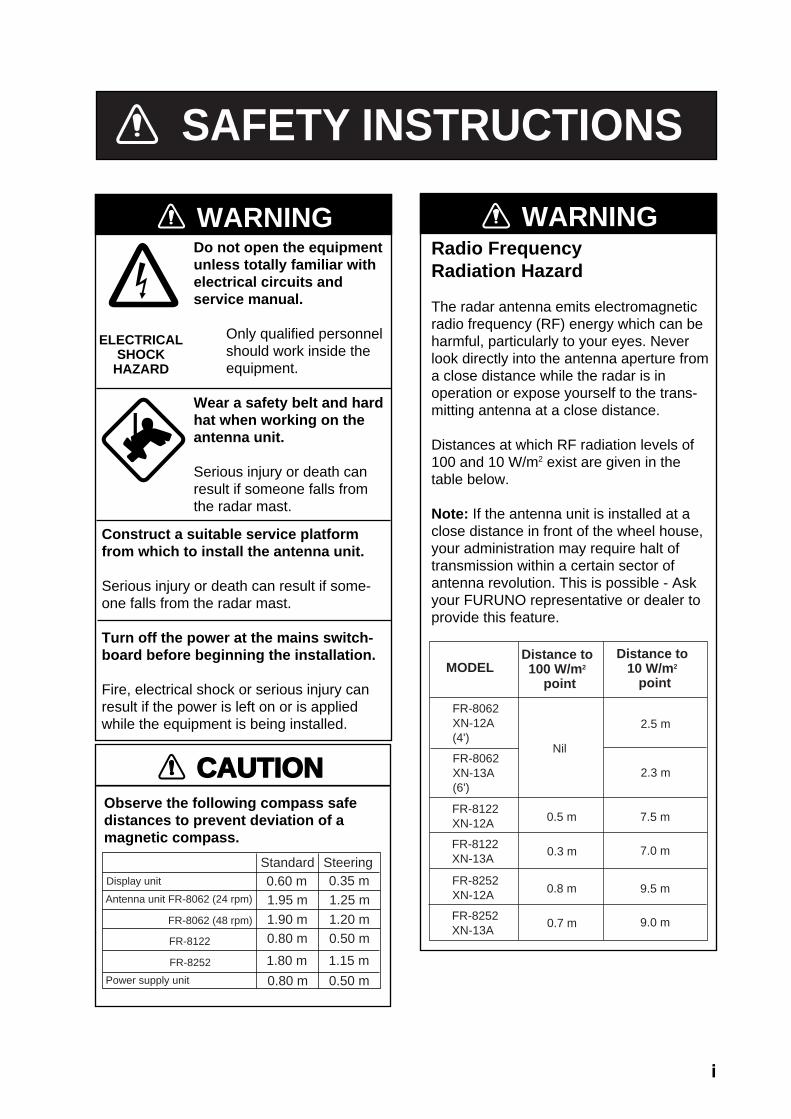
WARNINGRadio FrequencyRadiation Hazard
The radar antenna emits electromagneticradio frequency (RF) energy which can beharmful, particularly to your eyes. Neverlook directly into the antenna aperture froma close distance while the radar is inoperation or expose yourself to the trans-mitting antenna at a close distance.
Distances at which RF radiation levels of100 and 10 W/m2 exist are given in thetable below.
Note: If the antenna unit is installed at aclose distance in front of the wheel house,your administration may require halt oftransmission within a certain sector ofantenna revolution. This is possible - Askyour FURUNO representative or dealer toprovide this feature.
MODELDistance to100 W/m2
point
Distance to10 W/m2
point
Nil
2.3 m
SAFETY INSTRUCTIONS
Do not open the equipmentunless totally familiar withelectrical circuits andservice manual.
Only qualified personnel should work inside the equipment.
Wear a safety belt and hardhat when working on theantenna unit.
Serious injury or death canresult if someone falls fromthe radar mast.
WARNING
Construct a suitable service platformfrom which to install the antenna unit.
Serious injury or death can result if some-one falls from the radar mast.
Turn off the power at the mains switch-board before beginning the installation.
Fire, electrical shock or serious injury canresult if the power is left on or is appliedwhile the equipment is being installed.
ELECTRICALSHOCK
HAZARD
FR-8122XN-12A 7.5 m
Observe the following compass safedistances to prevent deviation of a magnetic compass.
Standard SteeringDisplay unit 0.60 m 0.35 m
0.80 m 0.50 m
CAUTION
Power supply unit
Antenna unit FR-8062 (24 rpm) 1.95 m 1.25 m
FR-8062XN-12A(4')
2.5 m
0.5 m
FR-8062XN-13A(6')
FR-8122XN-13A
0.3 m 7.0 m
FR-8252XN-12A 9.5 m0.8 m
FR-8252XN-13A
0.7 m 9.0 m1.90 m 1.20 m0.80 m 0.50 m
1.80 m 1.15 m
FR-8062 (48 rpm)
FR-8122
FR-8252
ii
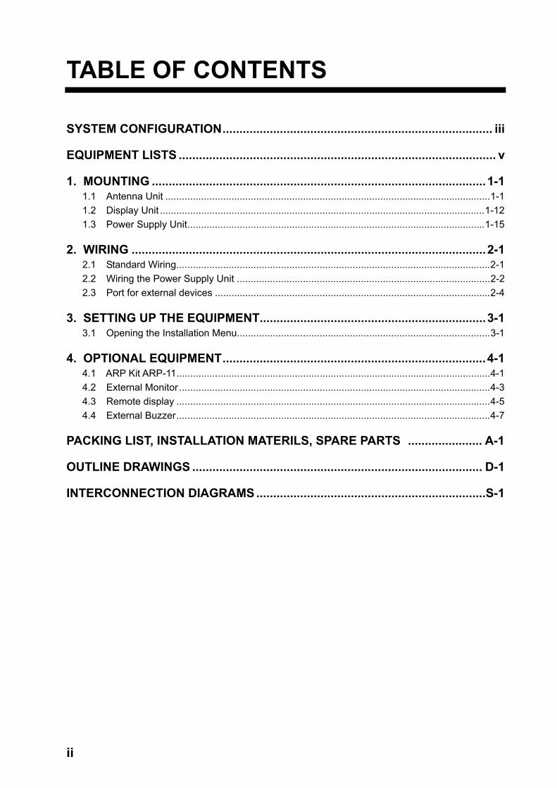
TABLE OF CONTENTS
SYSTEM CONFIGURATION................................................................................ iii
EQUIPMENT LISTS .............................................................................................. v
1. MOUNTING ...................................................................................................1-1 1.1 Antenna Unit ......................................................................................................................1-1 1.2 Display Unit ......................................................................................................................1-12 1.3 Power Supply Unit............................................................................................................1-15
2. WIRING .........................................................................................................2-1 2.1 Standard Wiring..................................................................................................................2-1 2.2 Wiring the Power Supply Unit ............................................................................................2-2 2.3 Port for external devices ....................................................................................................2-4
3. SETTING UP THE EQUIPMENT...................................................................3-1 3.1 Opening the Installation Menu............................................................................................3-1
4. OPTIONAL EQUIPMENT..............................................................................4-1 4.1 ARP Kit ARP-11..................................................................................................................4-1 4.2 External Monitor .................................................................................................................4-3 4.3 Remote display ..................................................................................................................4-5 4.4 External Buzzer..................................................................................................................4-7
PACKING LIST, INSTALLATION MATERILS, SPARE PARTS ...................... A-1
OUTLINE DRAWINGS ...................................................................................... D-1
INTERCONNECTION DIAGRAMS ....................................................................S-1
iii
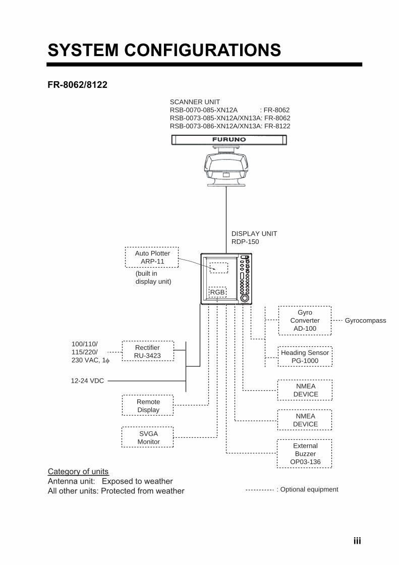
SYSTEM CONFIGURATIONS
FR-8062/8122
SCANNER UNITRSB-0070-085-XN12A : FR-8062RSB-0073-085-XN12A/XN13A: FR-8062RSB-0073-086-XN12A/XN13A: FR-8122
DISPLAY UNITRDP-150
Auto PlotterARP-11
(built indisplay unit)
RectifierRU-3423
100/110/115/220/230 VAC, 1φ
12-24 VDC
RemoteDisplay
SVGAMonitor
GyroConverterAD-100
Heading SensorPG-1000
NMEADEVICE
NMEADEVICE
ExternalBuzzer
OP03-136
: Optional equipment
Gyrocompass
Category of unitsAntenna unit: Exposed to weatherAll other units: Protected from weather
RGB
iv
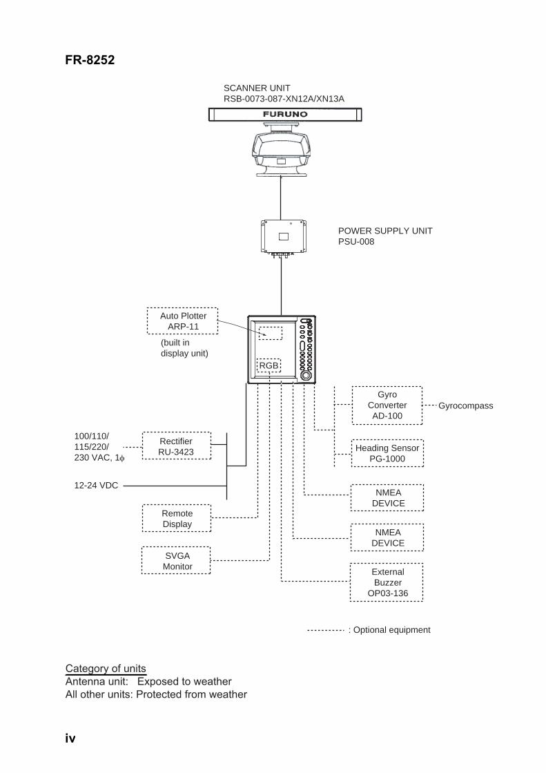
FR-8252
SCANNER UNITRSB-0073-087-XN12A/XN13A
POWER SUPPLY UNITPSU-008
Auto PlotterARP-11
(built indisplay unit)
RectifierRU-3423
12-24 VDC
RemoteDisplay
SVGAMonitor
GyroConverterAD-100
Heading SensorPG-1000
NMEADEVICE
NMEADEVICE
ExternalBuzzer
OP03-136
: Optional equipment
100/110/115/220/230 VAC, 1φ
Gyrocompass
Category of unitsAntenna unit: Exposed to weatherAll other units: Protected from weather
RGB
v
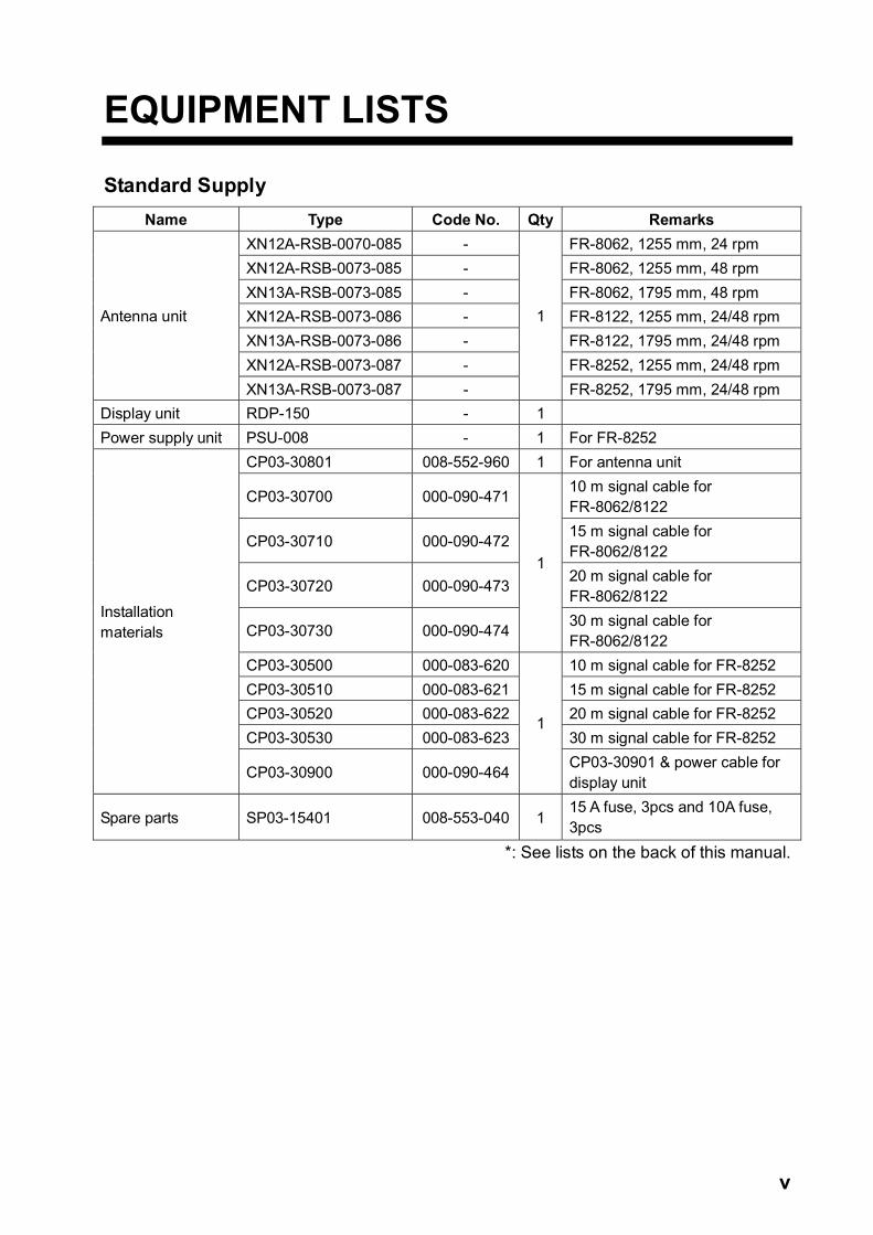
EQUIPMENT LISTS
Standard Supply Name Type Code No. Qty Remarks
XN12A-RSB-0070-085 - FR-8062, 1255 mm, 24 rpm XN12A-RSB-0073-085 - FR-8062, 1255 mm, 48 rpm XN13A-RSB-0073-085 - FR-8062, 1795 mm, 48 rpm XN12A-RSB-0073-086 - FR-8122, 1255 mm, 24/48 rpm XN13A-RSB-0073-086 - FR-8122, 1795 mm, 24/48 rpm XN12A-RSB-0073-087 - FR-8252, 1255 mm, 24/48 rpm
Antenna unit
XN13A-RSB-0073-087 -
1
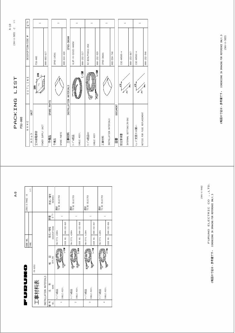
FR-8252, 1795 mm, 24/48 rpm Display unit RDP-150 - 1 Power supply unit PSU-008 - 1 For FR-8252
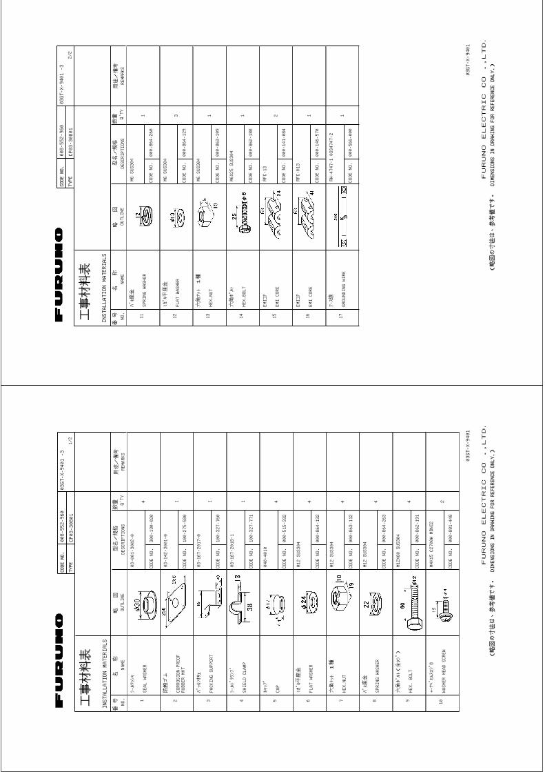
CP03-30801 008-552-960 1 For antenna unit
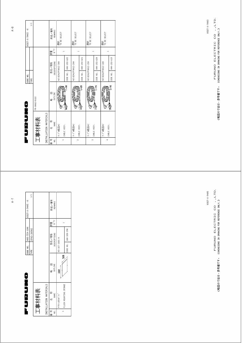
CP03-30700 000-090-471 10 m signal cable for FR-8062/8122
CP03-30710 000-090-472 15 m signal cable for FR-8062/8122
CP03-30720 000-090-473 20 m signal cable for FR-8062/8122
CP03-30730 000-090-474
1
30 m signal cable for FR-8062/8122
CP03-30500 000-083-620 10 m signal cable for FR-8252 CP03-30510 000-083-621 15 m signal cable for FR-8252 CP03-30520 000-083-622 20 m signal cable for FR-8252 CP03-30530 000-083-623 30 m signal cable for FR-8252
Installation materials
CP03-30900 000-090-464
1
CP03-30901 & power cable for display unit
Spare parts SP03-15401 008-553-040 1 15 A fuse, 3pcs and 10A fuse, 3pcs
*: See lists on the back of this manual.

vi
Optional Supply Name Type Code No. Remarks
External buzzer OP03-136 000-086-443 Rectifier RU-3423 000-030-443
MJ-A7SPF0007-050C 000-144-418-10 W/ 7P plug for one end, 5m MJ-A6SPF0003-050C 000-154-054-10 W/6P plug at one end, 5 m Cable assy. MJ-A6SPF0007-100 000-125-237 For compass, 10 m
Auto plotter ARP-11 008-523-050 EMI core CP03-31001 008-556-830 RFC-H13 1pc & plastic bands RGB kit OP03-195 008-553-110 RGB board assembly to
connect monitor.
1-1
1. MOUNTING
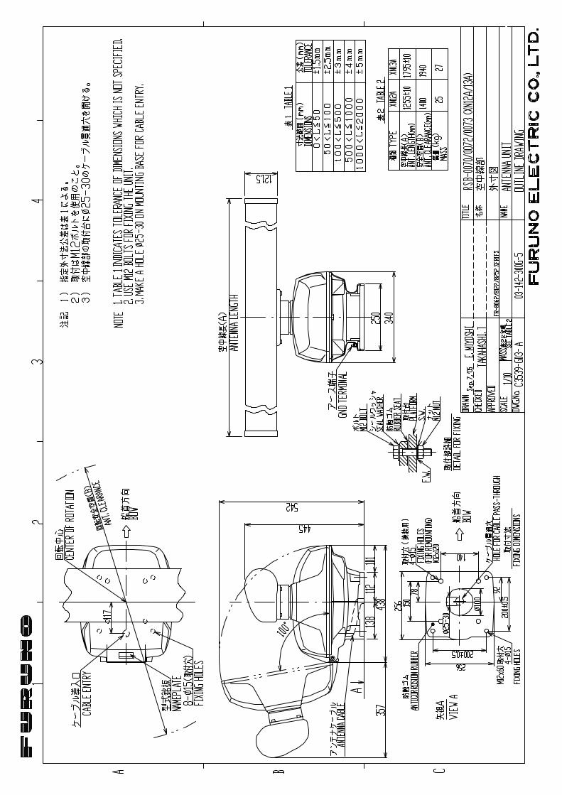
1.1 Antenna Unit Mounting considerations
• The antenna unit is generally installed either on top of the wheelhouse or on the radar mast on a suitable platform. Locate the antenna unit where there is a good all-round view. Any obstruction will cause shadow and blind sectors. A mast for instance, with a diameter considerably less than the horizontal beamwidth of the radiator, will cause only a small blind sector, but a horizontal spreader or crosstrees in the same horizontal plane as the antenna unit would be a much more serious obstruction; you would need to place the antenna unit well above or below it.
• It is rarely possible to place the antenna unit where a completely clear view in all directions is available. Thus, you should determine the angular width and relative bearing of any shadow sectors for their influence on the radar at the first opportunity after fitting.
• To lessen the chance of picking up electrical interference, avoid where possible routing the signal cable near other onboard electrical equipment. Also avoid running the cable in parallel with power cables.
• A magnetic compass will be affected if the antenna unit is placed too close to it. Observe the compass safe distances mentioned in the SAFETY INSTRUCTIONS to prevent interference to a magnetic compass.
• Do not paint the radiator aperture, to ensure proper emission of the radar waves.
• When this radar is to be installed on larger vessels, consider the following points:
• The signal cable run between the antenna and the display units comes in lengths of 10 m, 15 m, 20 m and 30 m.
• Deposits and fumes from a funnel or other exhaust vent can adversely affect the aerial performance and hot gases may distort the radiator portion. The antenna unit must not be mounted where the temperature is more than 70°C.
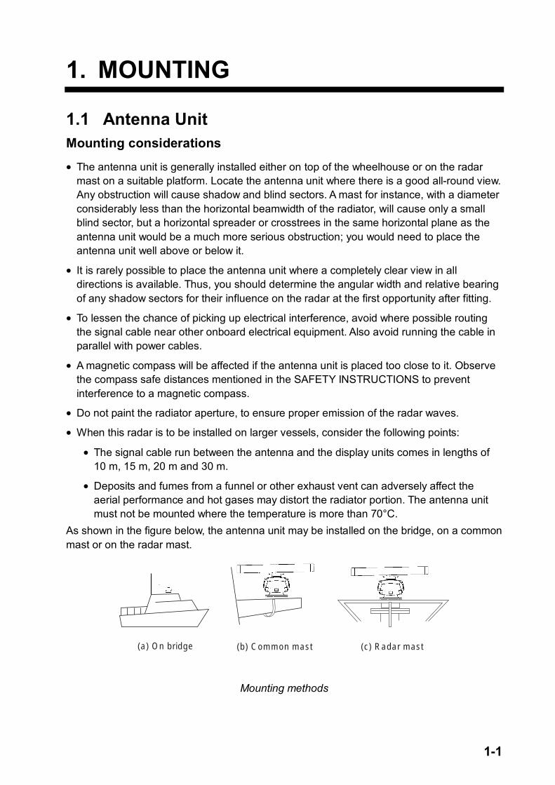
As shown in the figure below, the antenna unit may be installed on the bridge, on a common mast or on the radar mast.
(a) On bridge (b) Common mast (c) Radar mast
Mounting methods
1. MOUNTING
1-2
Mounting procedure Referring to the outline drawing at the back of this manual, drill five holes in the mounting platform: four holes of 15 mm diameter for fixing the antenna unit and one hole of 25-30 mm diameter for the signal cable. Fastening the radiator to the radiator bracket
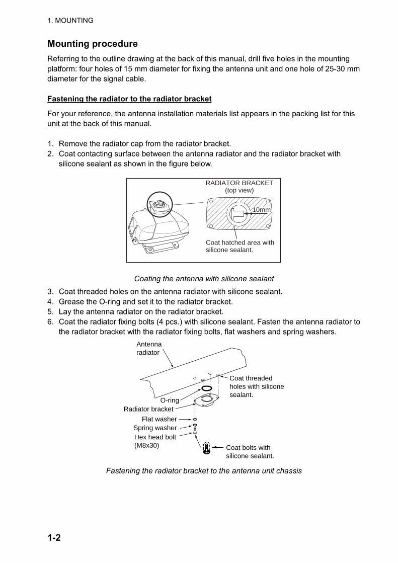
For your reference, the antenna installation materials list appears in the packing list for this unit at the back of this manual. 1. Remove the radiator cap from the radiator bracket. 2. Coat contacting surface between the antenna radiator and the radiator bracket with
silicone sealant as shown in the figure below.
RADIATOR BRACKET(top view)
Coat hatched area withsilicone sealant.
10mm
Coating the antenna with silicone sealant
3. Coat threaded holes on the antenna radiator with silicone sealant. 4. Grease the O-ring and set it to the radiator bracket. 5. Lay the antenna radiator on the radiator bracket. 6. Coat the radiator fixing bolts (4 pcs.) with silicone sealant. Fasten the antenna radiator to
the radiator bracket with the radiator fixing bolts, flat washers and spring washers.
Flat washerSpring washerHex head bolt(M8x30)
Radiator bracket
Coat bolts withsilicone sealant.
Antennaradiator
O-ring
Coat threadedholes with siliconesealant.
Fastening the radiator bracket to the antenna unit chassis
1. MOUNTING
1-3
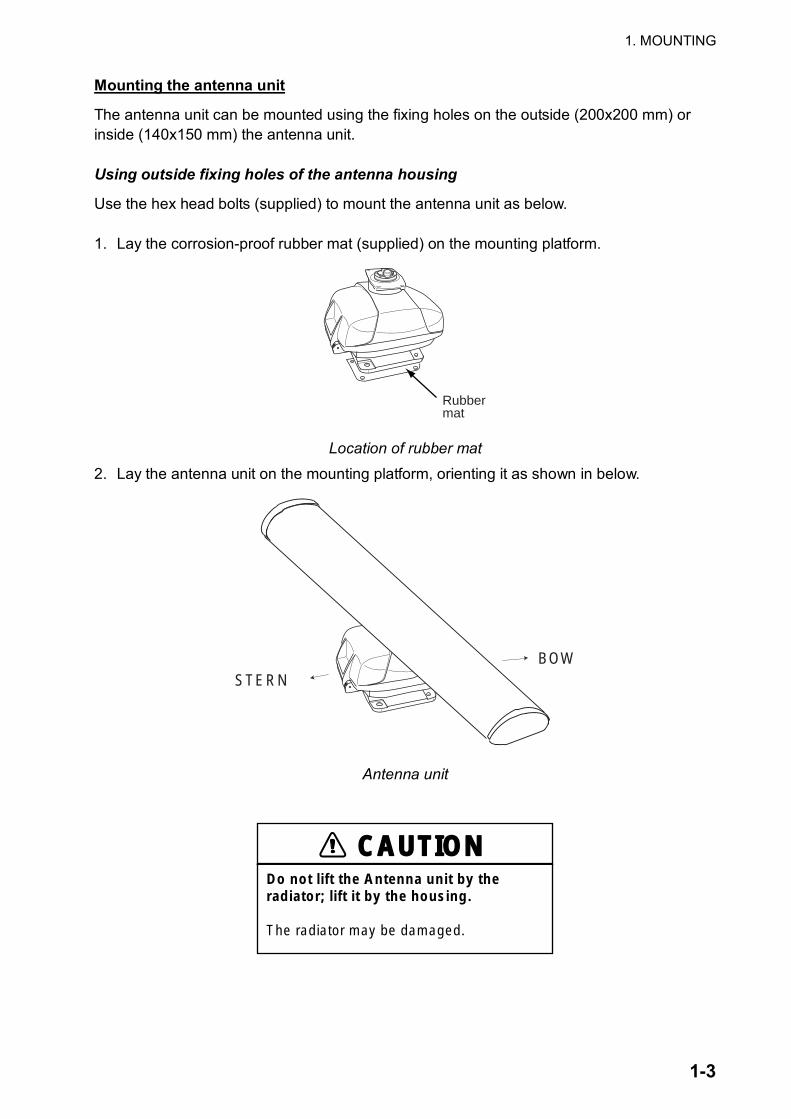
Mounting the antenna unit
The antenna unit can be mounted using the fixing holes on the outside (200x200 mm) or inside (140x150 mm) the antenna unit. Using outside fixing holes of the antenna housing
Use the hex head bolts (supplied) to mount the antenna unit as below. 1. Lay the corrosion-proof rubber mat (supplied) on the mounting platform.
Rubbermat
Location of rubber mat
2. Lay the antenna unit on the mounting platform, orienting it as shown in below.
STERNBOW
Antenna unit
CAUTIONDo not lift the Antenna unit by the radiator; lift it by the housing.
The radiator may be damaged.
1. MOUNTING
1-4
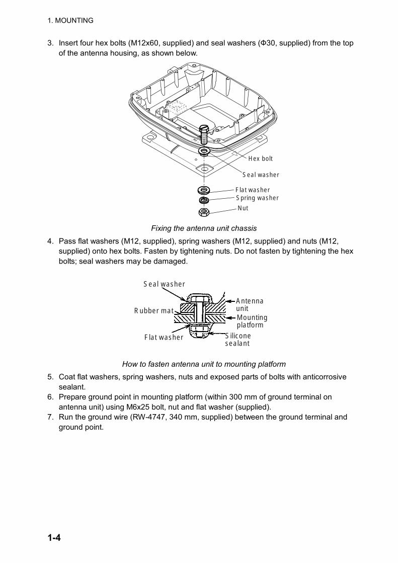
3. Insert four hex bolts (M12x60, supplied) and seal washers (Ф30, supplied) from the top of the antenna housing, as shown below.
Hex bolt
Seal washer
Flat washerSpring washer
Nut
Fixing the antenna unit chassis
4. Pass flat washers (M12, supplied), spring washers (M12, supplied) and nuts (M12, supplied) onto hex bolts. Fasten by tightening nuts. Do not fasten by tightening the hex bolts; seal washers may be damaged.
AntennaunitMountingplatform
Siliconesealant
Flat washer
Rubber mat
Seal washer
How to fasten antenna unit to mounting platform 5. Coat flat washers, spring washers, nuts and exposed parts of bolts with anticorrosive
sealant. 6. Prepare ground point in mounting platform (within 300 mm of ground terminal on
antenna unit) using M6x25 bolt, nut and flat washer (supplied). 7. Run the ground wire (RW-4747, 340 mm, supplied) between the ground terminal and
ground point.
1. MOUNTING
1-5
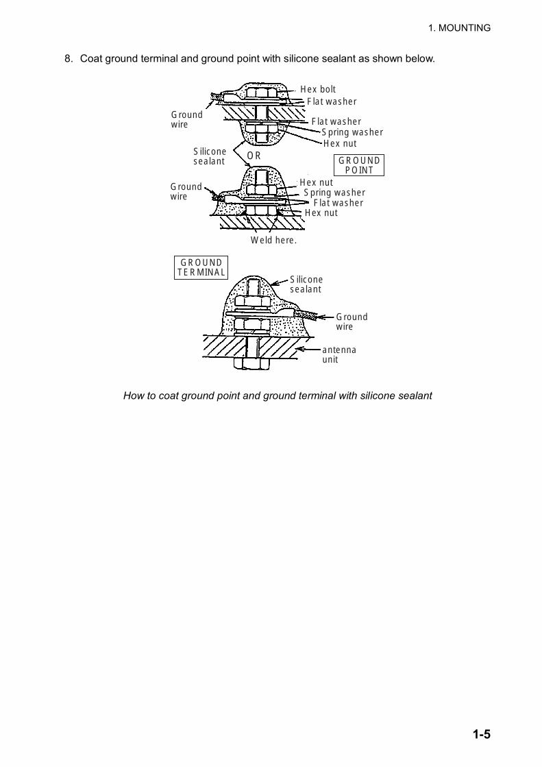
8. Coat ground terminal and ground point with silicone sealant as shown below.
Groundwire
Hex boltFlat washer
Spring washerFlat washer
Hex nutSiliconesealant
Hex nut
Weld here.
Siliconesealant
Groundwire
antennaunit
OR
Flat washerSpring washer
Groundwire
GROUNDTERMINAL
GROUNDPOINT
Hex nut
How to coat ground point and ground terminal with silicone sealant
1. MOUNTING
1-6
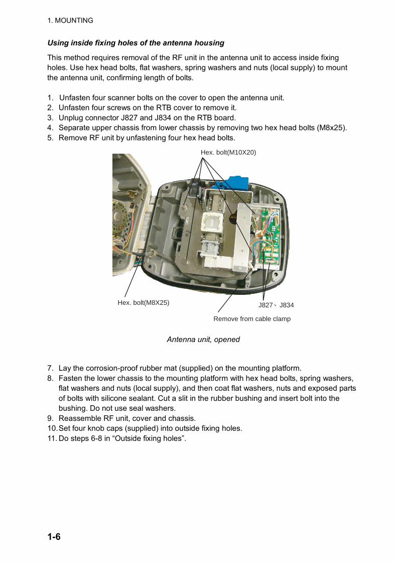
Using inside fixing holes of the antenna housing
This method requires removal of the RF unit in the antenna unit to access inside fixing holes. Use hex head bolts, flat washers, spring washers and nuts (local supply) to mount the antenna unit, confirming length of bolts. 1. Unfasten four scanner bolts on the cover to open the antenna unit. 2. Unfasten four screws on the RTB cover to remove it. 3. Unplug connector J827 and J834 on the RTB board. 4. Separate upper chassis from lower chassis by removing two hex head bolts (M8x25). 5. Remove RF unit by unfastening four hex head bolts.
Hex. bolt(M10X20)
Hex. bolt(M8X25) J827、J834
Remove from cable clamp
Antenna unit, opened
7. Lay the corrosion-proof rubber mat (supplied) on the mounting platform. 8. Fasten the lower chassis to the mounting platform with hex head bolts, spring washers,
flat washers and nuts (local supply), and then coat flat washers, nuts and exposed parts of bolts with silicone sealant. Cut a slit in the rubber bushing and insert bolt into the bushing. Do not use seal washers.
9. Reassemble RF unit, cover and chassis. 10. Set four knob caps (supplied) into outside fixing holes. 11. Do steps 6-8 in “Outside fixing holes”.
1. MOUNTING
1-7
Connecting the signal cable
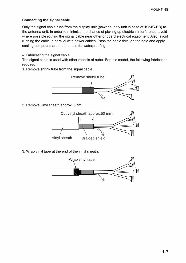
Only the signal cable runs from the display unit (power supply unit in case of 1954C-BB) to the antenna unit. In order to minimize the chance of picking up electrical interference, avoid where possible routing the signal cable near other onboard electrical equipment. Also, avoid running the cable in parallel with power cables. Pass the cable through the hole and apply sealing compound around the hole for waterproofing. • Fabricating the signal cable The signal cable is used with other models of radar. For this model, the following fabrication required. 1. Remove shrink tube from the signal cable.
Remove shrink tube.
2. Remove vinyl sheath approx. 5 cm.
Cut vinyl sheath approx.50 mm.
Braided shieldVinyl sheath
3. Wrap vinyl tape at the end of the vinyl sheath.
Wrap vinyl tape.
1. MOUNTING
1-8
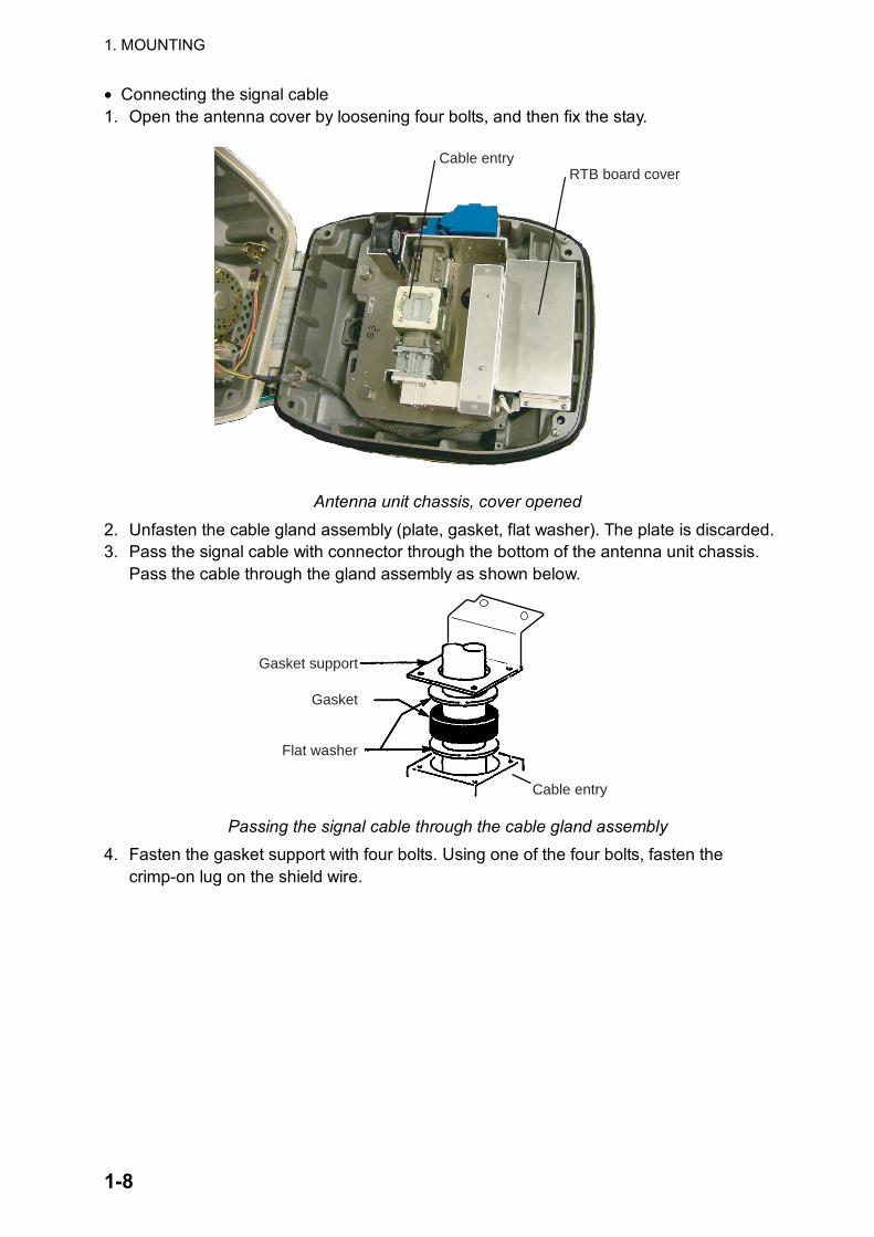
• Connecting the signal cable 1. Open the antenna cover by loosening four bolts, and then fix the stay.
Cable entryRTB board cover
Antenna unit chassis, cover opened
2. Unfasten the cable gland assembly (plate, gasket, flat washer). The plate is discarded. 3. Pass the signal cable with connector through the bottom of the antenna unit chassis.
Pass the cable through the gland assembly as shown below.
Gasket support
Gasket
Flat washer
Cable entry
Passing the signal cable through the cable gland assembly 4. Fasten the gasket support with four bolts. Using one of the four bolts, fasten the
crimp-on lug on the shield wire.
1. MOUNTING
1-9
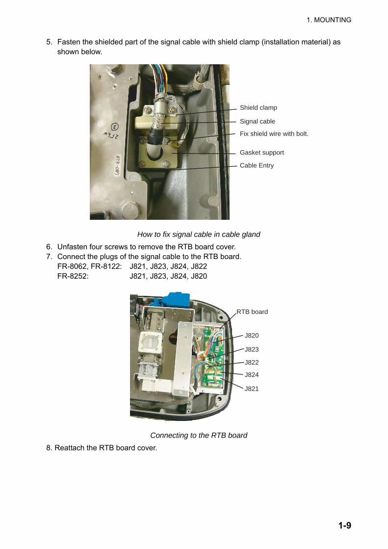
5. Fasten the shielded part of the signal cable with shield clamp (installation material) as shown below.
Shield clamp
Signal cable
Fix shield wire with bolt.
Gasket support
Cable Entry
How to fix signal cable in cable gland 6. Unfasten four screws to remove the RTB board cover. 7. Connect the plugs of the signal cable to the RTB board. FR-8062, FR-8122: J821, J823, J824, J822 FR-8252: J821, J823, J824, J820
RTB board
J820
J823
J822
J824
J821
Connecting to the RTB board 8. Reattach the RTB board cover.
1. MOUNTING
1-10
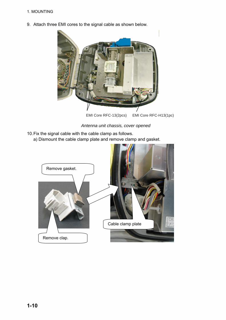
9. Attach three EMI cores to the signal cable as shown below.
EMI Core RFC-13(2pcs) EMI Core RFC-H13(1pc)
Antenna unit chassis, cover opened
10. Fix the signal cable with the cable clamp as follows. a) Dismount the cable clamp plate and remove clamp and gasket.
Remove gasket.
Remove clap.
Cable clamp plate
1. MOUNTING
1-11
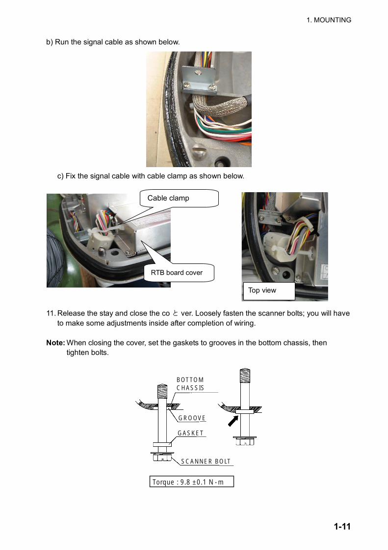
b) Run the signal cable as shown below.
c) Fix the signal cable with cable clamp as shown below.
11. Release the stay and close the coと ver. Loosely fasten the scanner bolts; you will have to make some adjustments inside after completion of wiring.
Note: When closing the cover, set the gaskets to grooves in the bottom chassis, then
tighten bolts.
BOTTOM CHASSIS
GASKET
GROOVE
SCANNER BOLT
Torque : 9.8 ±0.1 N m.
RTB board cover
Top view
Cable clamp
1. MOUNTING
1-12
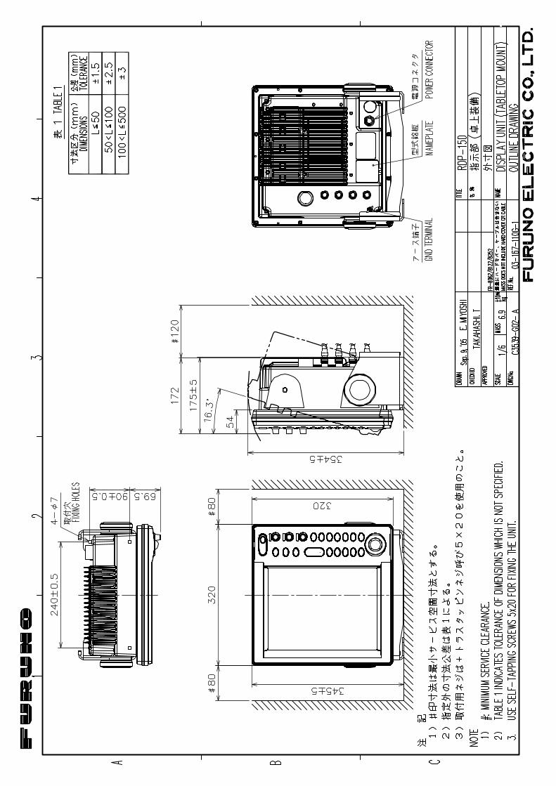
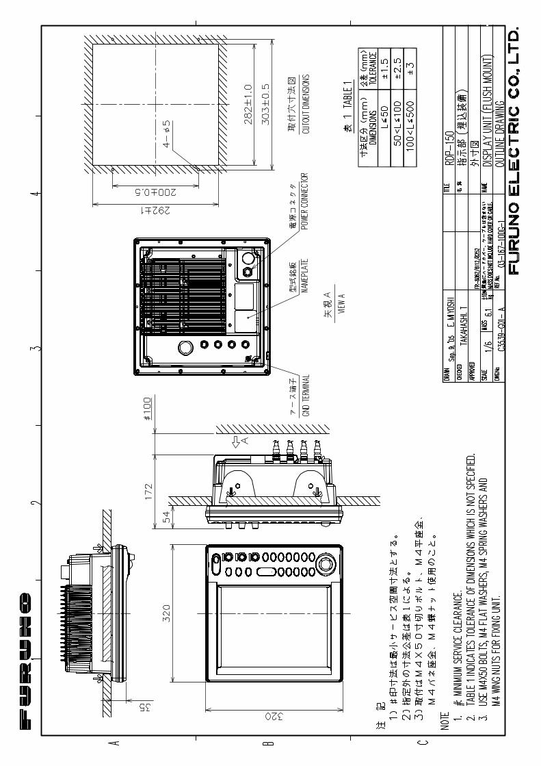
1.2 Display Unit The display unit can be mounted on a tabletop, on the overhead or flush mounted in a console or panel.
Mounting considerations When selecting a mounting location for the display unit, keep the following in mind: • Keep the display unit out of direct sunlight.
• The temperature and humidity at the mounting location should be moderate and stable.
• Locate the unit away from exhaust pipes and vents.
• The mounting location should be well ventilated.
• Mount the unit where shock and vibration are minimal.
• Keep the unit away from electromagnetic field generating equipment such as motors and generators.
• For maintenance and checking purposes, leave sufficient space at the sides and rear of the unit and leave slack in cables. Minimum recommended space is shown in the outline drawing for the display unit.
• A magnetic compass will be affected if the display unit is placed too close to it. Observe the compass safe distances shown in the SAFETY INSTRUCTIONS to prevent disturbance to the magnetic compass.
1. MOUNTING
1-13
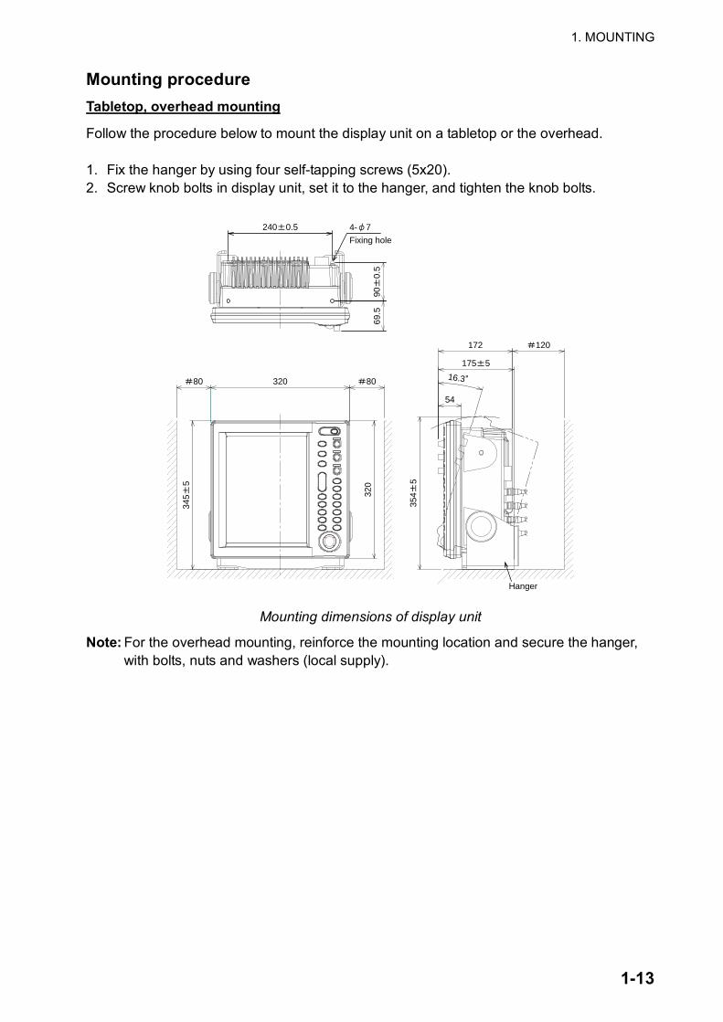
Mounting procedure Tabletop, overhead mounting
Follow the procedure below to mount the display unit on a tabletop or the overhead. 1. Fix the hanger by using four self-tapping screws (5x20). 2. Screw knob bolts in display unit, set it to the hanger, and tighten the knob bolts.
240 0.5
320 8080
345
5
320
4- 7
Fixing hole
172 120
175 5
54
354
5
16.369
.590
0.5
Hanger
Mounting dimensions of display unit
Note: For the overhead mounting, reinforce the mounting location and secure the hanger, with bolts, nuts and washers (local supply).
1. MOUNTING
1-14
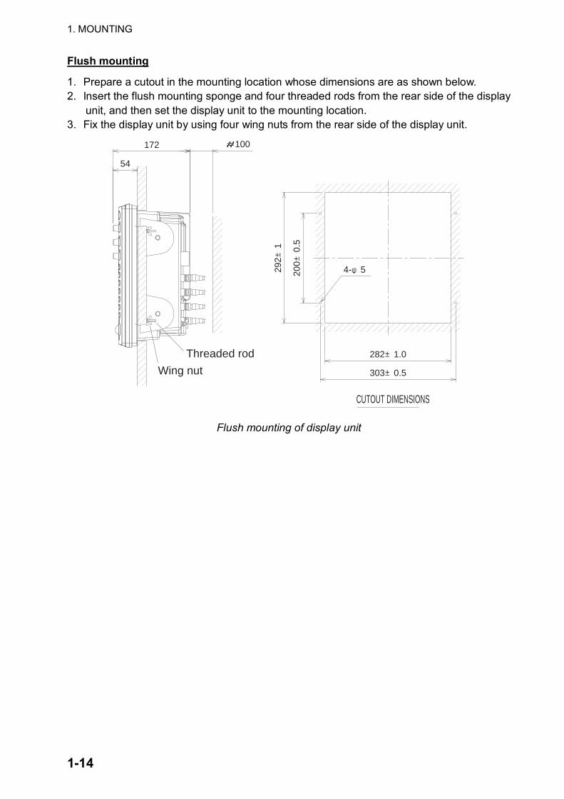
Flush mounting
1. Prepare a cutout in the mounting location whose dimensions are as shown below. 2. Insert the flush mounting sponge and four threaded rods from the rear side of the display
unit, and then set the display unit to the mounting location. 3. Fix the display unit by using four wing nuts from the rear side of the display unit.
292±
1
200±
0.5
282±1.0
303±0.5
54
172 #100
4-φ5
CUTOUT DIMENSIONS
Wing nut
Threaded rod
Flush mounting of display unit
1. MOUNTING
1-15
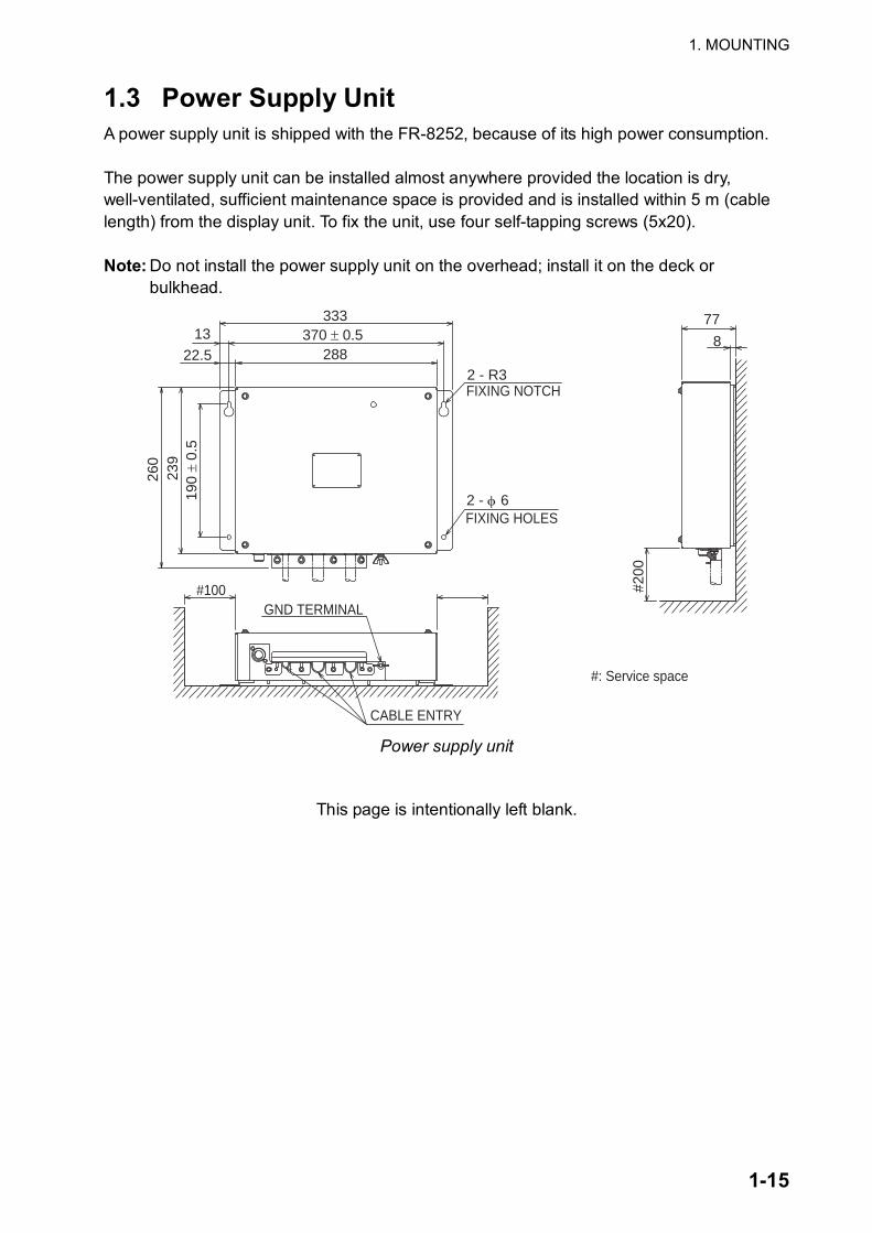
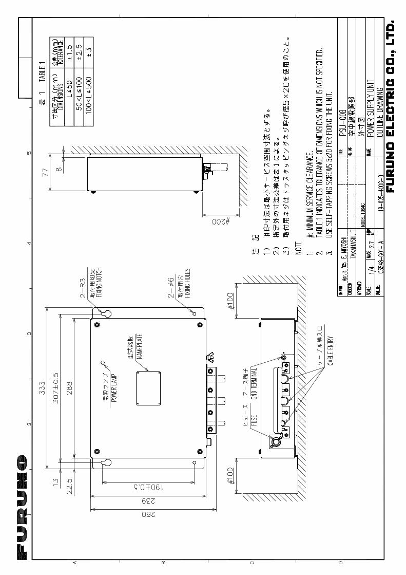
1.3 Power Supply Unit A power supply unit is shipped with the FR-8252, because of its high power consumption. The power supply unit can be installed almost anywhere provided the location is dry, well-ventilated, sufficient maintenance space is provided and is installed within 5 m (cable length) from the display unit. To fix the unit, use four self-tapping screws (5x20). Note: Do not install the power supply unit on the overhead; install it on the deck or
bulkhead.
#200
2 - φ 6
13
22.5
333370 ± 0.5
2882 - R3FIXING NOTCH
FIXING HOLES
190
± 0.
523
926
0
77
8
CABLE ENTRY
GND TERMINAL#100
#: Service space
Power supply unit
This page is intentionally left blank.

1. MOUNTING
1-16
2-1
2. WIRING
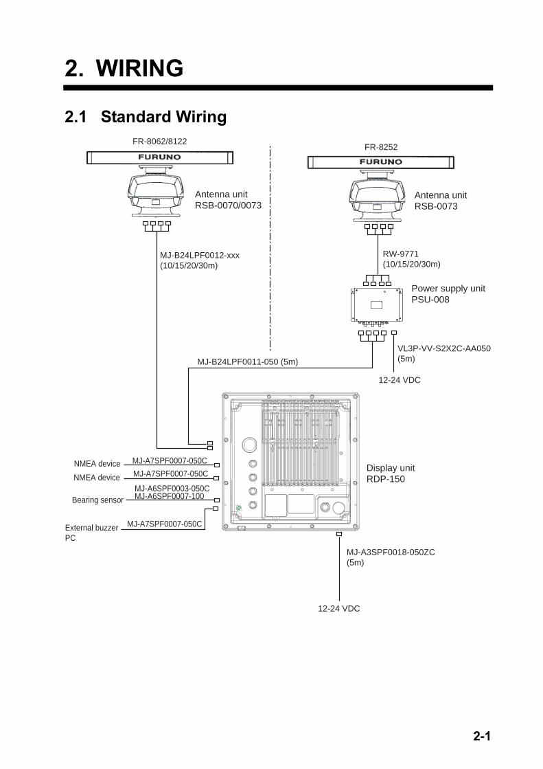
2.1 Standard Wiring FR-8252
Power supply unitPSU-008
FR-8062/8122
Display unitRDP-150
RW-9771(10/15/20/30m)
MJ-B24LPF0012-xxx(10/15/20/30m)
MJ-B24LPF0011-050 (5m)
MJ-A3SPF0018-050ZC(5m)
12-24 VDC
MJ-A7SPF0007-050C
MJ-A7SPF0007-050CNMEA device
NMEA device
Bearing sensorMJ-A6SPF0003-050CMJ-A6SPF0007-100
External buzzerPC
MJ-A7SPF0007-050C
VL3P-VV-S2X2C-AA050(5m)
12-24 VDC
Antenna unitRSB-0070/0073
Antenna unitRSB-0073
2. Wiring
2-2
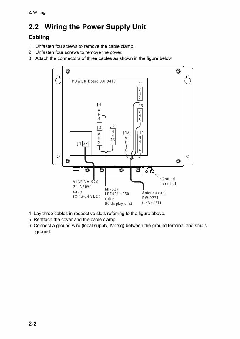
2.2 Wiring the Power Supply Unit Cabling 1. Unfasten fou screws to remove the cable clamp. 2. Unfasten four screws to remove the cover. 3. Attach the connectors of three cables as shown in the figure below.
POWER Board 03P9419
J1 3P
VL3P-VV-S2X2C-AA050cable(to 12-24 VDC)
MJ-B24 LPF0011-050cable(to display unit)
VH9
NH13
VH4
J3
J4
J5
Ground terminal
VH10
J12NH14
J14
VH5
J13
VH2
J11
Antenna cableRW-9771(03S9771)
4. Lay three cables in respective slots referring to the figure above. 5. Reattach the cover and the cable clamp. 6. Connect a ground wire (local supply, IV-2sq) between the ground terminal and ship’s
ground.
2. Wiring
2-3
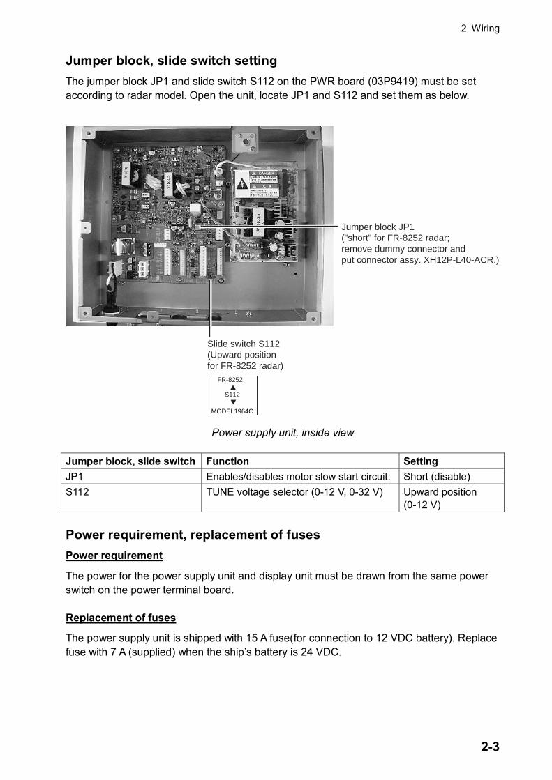
Jumper block, slide switch setting The jumper block JP1 and slide switch S112 on the PWR board (03P9419) must be set according to radar model. Open the unit, locate JP1 and S112 and set them as below.
FR-8252 S112 MODEL1964C
Jumper block JP1("short" for FR-8252 radar;remove dummy connector and put connector assy. XH12P-L40-ACR.)
Slide switch S112(Upward positionfor FR-8252 radar)
Power supply unit, inside view
Jumper block, slide switch Function Setting JP1 Enables/disables motor slow start circuit. Short (disable) S112 TUNE voltage selector (0-12 V, 0-32 V) Upward position
(0-12 V) Power requirement, replacement of fuses Power requirement
The power for the power supply unit and display unit must be drawn from the same power switch on the power terminal board. Replacement of fuses
The power supply unit is shipped with 15 A fuse(for connection to 12 VDC battery). Replace fuse with 7 A (supplied) when the ship’s battery is 24 VDC.
2. Wiring
2-4
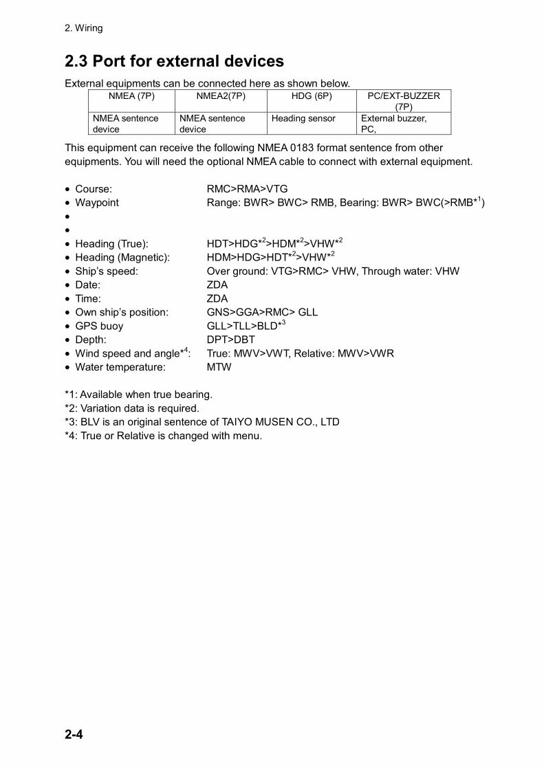
2.3 Port for external devices External equipments can be connected here as shown below.
NMEA (7P) NMEA2(7P) HDG (6P) PC/EXT-BUZZER (7P)
NMEA sentence device
NMEA sentence device
Heading sensor External buzzer, PC,
This equipment can receive the following NMEA 0183 format sentence from other equipments. You will need the optional NMEA cable to connect with external equipment. • Course: RMC>RMA>VTG • Waypoint Range: BWR> BWC> RMB, Bearing: BWR> BWC(>RMB*1) • • • Heading (True): HDT>HDG*2>HDM*2>VHW*2 • Heading (Magnetic): HDM>HDG>HDT*2>VHW*2 • Ship’s speed: Over ground: VTG>RMC> VHW, Through water: VHW • Date: ZDA • Time: ZDA • Own ship’s position: GNS>GGA>RMC> GLL • GPS buoy GLL>TLL>BLD*3 • Depth: DPT>DBT • Wind speed and angle*4: True: MWV>VWT, Relative: MWV>VWR • Water temperature: MTW *1: Available when true bearing. *2: Variation data is required. *3: BLV is an original sentence of TAIYO MUSEN CO., LTD *4: True or Relative is changed with menu.
3-1
3. SETTING UP THE EQUIPMENT
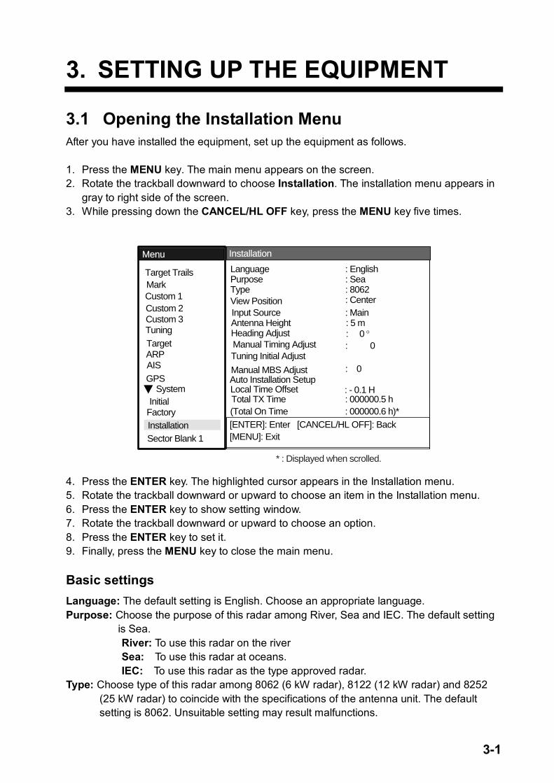
3.1 Opening the Installation Menu After you have installed the equipment, set up the equipment as follows. 1. Press the MENU key. The main menu appears on the screen. 2. Rotate the trackball downward to choose Installation. The installation menu appears in
gray to right side of the screen. 3. While pressing down the CANCEL/HL OFF key, press the MENU key five times.
[ENTER]: Enter [CANCEL/HL OFF]: Back[MENU]: Exit
SystemGPS
MarkTarget Trails
Custom 1
Custom 2Custom 3
TargetARPAIS
Tuning
Type View PositionInput Source
Language Purpose
Antenna HeightHeading Adjust
: Center: Main: 5 m: 0 °
: 8062
: English: Sea
Tuning Initial Adjust
Manual MBS AdjustAuto Installation Setup
Manual Timing Adjust
Local Time Offset
: 0
: - 0.1 H
: 0
Menu Installation
InitialFactory
Sector Blank 1Installation
Total TX Time : 000000.5 h(Total On Time : 000000.6 h)*
* : Displayed when scrolled.
4. Press the ENTER key. The highlighted cursor appears in the Installation menu. 5. Rotate the trackball downward or upward to choose an item in the Installation menu. 6. Press the ENTER key to show setting window. 7. Rotate the trackball downward or upward to choose an option. 8. Press the ENTER key to set it. 9. Finally, press the MENU key to close the main menu. Basic settings Language: The default setting is English. Choose an appropriate language. Purpose: Choose the purpose of this radar among River, Sea and IEC. The default setting
is Sea. River: To use this radar on the river Sea: To use this radar at oceans. IEC: To use this radar as the type approved radar. Type: Choose type of this radar among 8062 (6 kW radar), 8122 (12 kW radar) and 8252
(25 kW radar) to coincide with the specifications of the antenna unit. The default setting is 8062. Unsuitable setting may result malfunctions.
3. SETTING UP THE EQUIPMENT
3-2
View Position: Choose an operating position for this radar among Left, Left-Center, Center, Right-Center and Right to view the colors (echo, background, characters, etc.) correctly. The default setting is Center.
Left: When operating this radar at the left side. Left-Center: When operating this radar at the left-center side. Center: When operating this radar at center position. Right-Center: When operating this radar at the right-center side. Right: When operating this radar at the right side. Input Source: Choose the input source between Main and Sub. The default setting is Main. Main: When using this display unit as main radar. Sub: When using this display unit as sub display. Antenna Height: Choose a position of the antenna unit from the sea level among 5, 10, 15, 20, 30, 40 and 50 m. The default setting is 5 m. Local Time Offset: To display a local time on the screen, set the time difference from the UTC. Heading Adjustment You have mounted the antenna unit facing straight ahead in the direction of the bow. Therefore, a small but conspicuous target dead ahead visually should appear on the heading line (zero degrees). In practice, you will probably observe some small error on the display because of the difficulty in achieving accurate initial positioning of the antenna unit. The following adjustment will compensate for this error. 1. Set ship’s heading toward a suitable target (for example, ship or buoy) at a range
between 0.125 and 0.25 nautical mile. 2. Transmit the radar at 0.25 nm range and measure the bearing of that target relative to
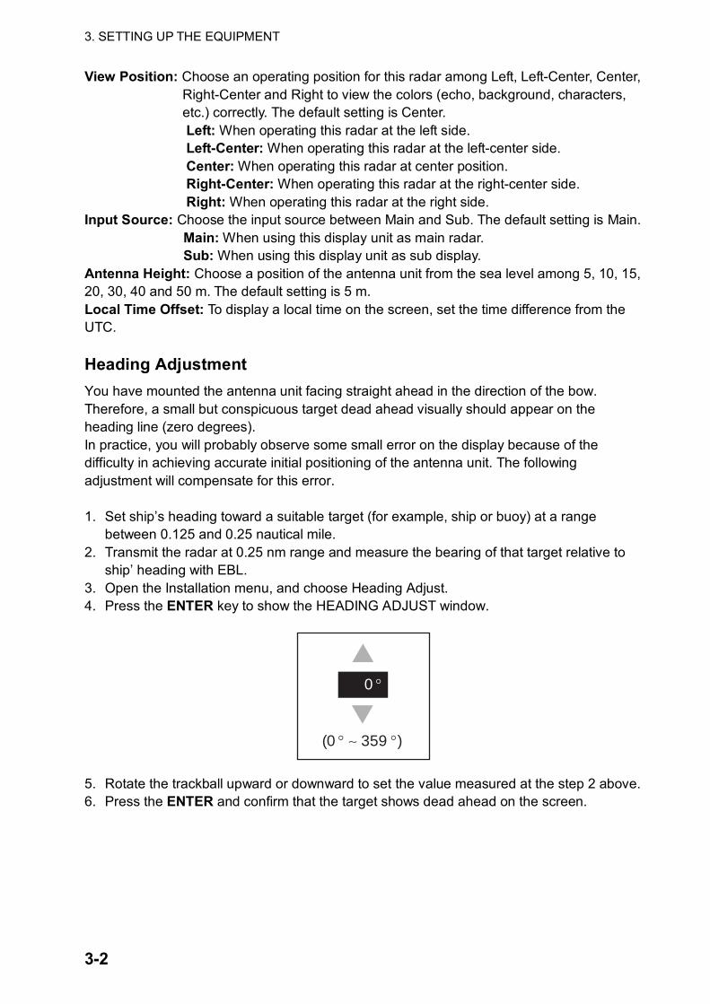
ship’ heading with EBL. 3. Open the Installation menu, and choose Heading Adjust. 4. Press the ENTER key to show the HEADING ADJUST window.
0 °
(0 ° ∼ 359 °)
5. Rotate the trackball upward or downward to set the value measured at the step 2 above. 6. Press the ENTER and confirm that the target shows dead ahead on the screen.
3-3
Auto Installation Setup When this item is executed, the tune adjustment, timing adjustment, video adjustment and MSB adjustment are automatically done. 1. Transmit the radar at 48 nm range. 2. Choose Auto Installation Setup at the installation menu and press the ENTER key. 3. Rotate the trackball to choose Yes, and then press the Enter key.
Automatically, the tune adjustment begins, indicating “Tuning adjusting….” Then, the timing adjustment, video adjustment and MSB adjustment are execute automatically, indicating “Timing adjustment…”, “Video adjustment…”, and “MSB adjustment…” in that order. After adjustment, the window disappears.
If you do not satisfy the result of the Auto Installation Setup, execute Manual Timing Adjust, Tuning Initial Adjust and Manual MSB Adjust as follows. Tuning Initial Adjust 1. Transmit the radar. 2. Open the Installation menu, and choose Tuning Initial Adjust. 3. Press the ENTER key to show the setting window. 4. Rotate the trackball to choose Yes, and then press the Enter key. The tune adjustment
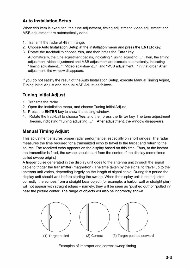
begins, indicating “Tuning adjusting….” After adjustment, the window disappears. Manual Timing Adjust This adjustment ensures proper radar performance, especially on short ranges. The radar measures the time required for a transmitted echo to travel to the target and return to the source. The received echo appears on the display based on this time. Thus, at the instant the transmitter is fired, the sweep should start from the center of the display (sometimes called sweep origin.) A trigger pulse generated in the display unit goes to the antenna unit through the signal cable to trigger the transmitter (magnetron). The time taken by the signal to travel up to the antenna unit varies, depending largely on the length of signal cable. During this period the display unit should wait before starting the sweep. When the display unit is not adjusted correctly, the echoes from a straight local object (for example, a harbor wall or straight pier) will not appear with straight edges – namely, they will be seen as “pushed out” or “pulled in” near the picture center. The range of objects will also be incorrectly shown.
(1) Target pulled (2) Correct (3) Target pushed outward
Examples of improper and correct sweep timing
3. SETTING UP THE EQUIPMENT
3-4
1. Transmit on the shortest range and confirm that gain and A/C SEA are properly adjusted.
2. Visually select a target which forms straight line (harbor wall, straight piers). 3. Open the Installation menu and choose Manual Timing Adjust. 4. Press the ENTER key to show the setting window. 5. Rotate the trackball to straighten the target selected at step 2, and then press the
ENTER key to finish. Manual MBS Adjust Main bang (black hole), which appears at the display center on short ranges, can be suppressed as follows. 1. Open the Installation menu and select b Manual MBS Adjust. 2. Press the ENTER key to show the setting window. 3. Rotate the trackball to suppress main bang (between 0 and 25). 4. Press the ENTER key to finish.
4-1
4. OPTIONAL EQUIPMENT
4.1 ARP Kit ARP-11 Necessary parts
Name: ARP kit Type: ARP-11 Code no.: 008-523-050
Contents of ARP kit
Name Type Code No. Qty ARP Board 18P9013 008-521-830 1 Pan head screw M3x6 C2700W 000-881-403 4
SQ9 000-801-850 1 Spacer* SQ15 000-801-779 3
Spring washer* M3 C5191W 000-864-204 3 *Not used
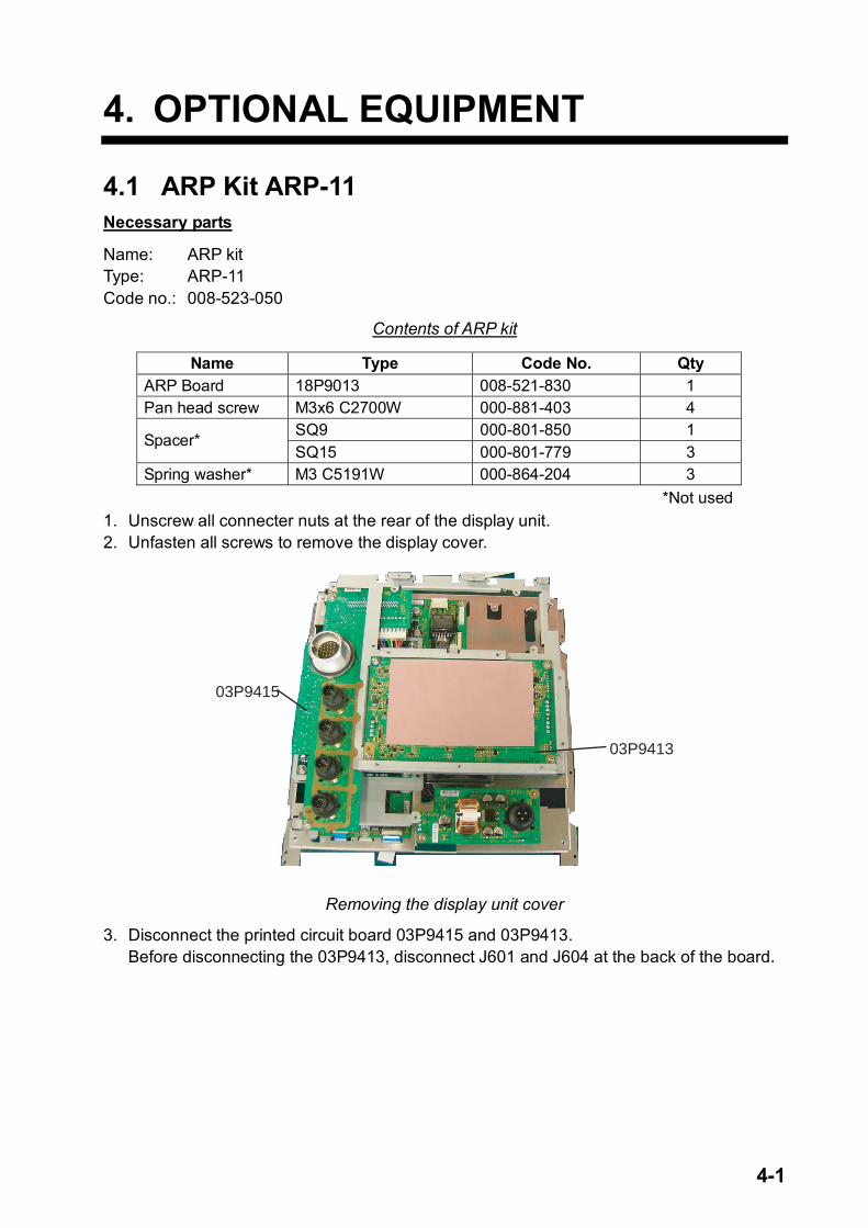
1. Unscrew all connecter nuts at the rear of the display unit. 2. Unfasten all screws to remove the display cover.
03P9413
03P9415
Removing the display unit cover
3. Disconnect the printed circuit board 03P9415 and 03P9413. Before disconnecting the 03P9413, disconnect J601 and J604 at the back of the board.
4. OPTIONAL EQUIPMENT
4-2
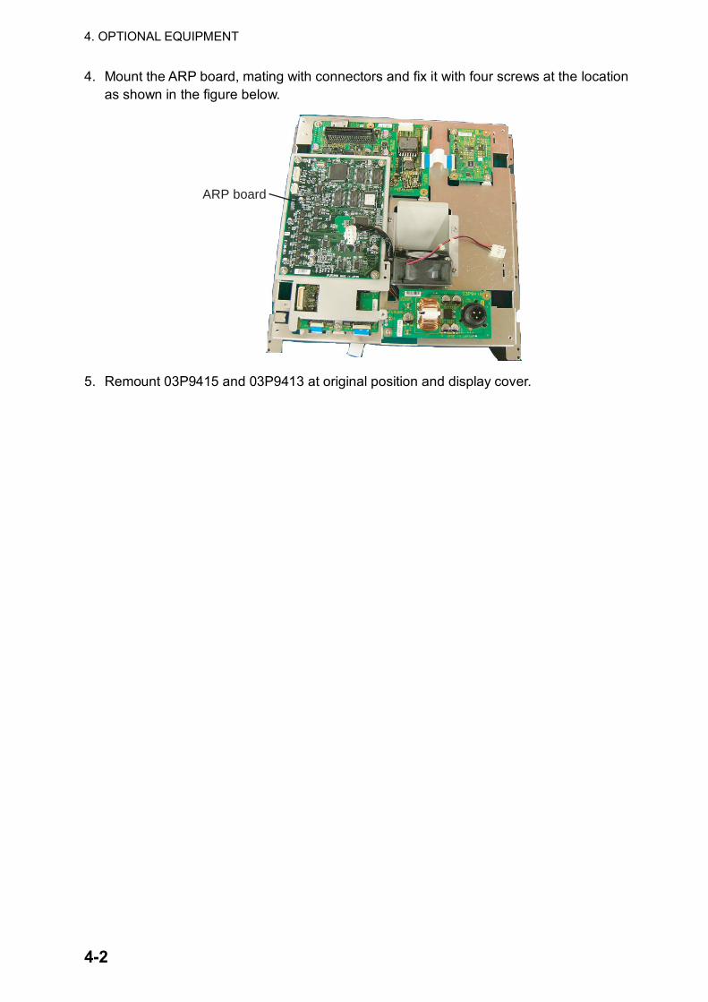
4. Mount the ARP board, mating with connectors and fix it with four screws at the location as shown in the figure below.
ARP board
5. Remount 03P9415 and 03P9413 at original position and display cover.
4. OPTIONAL EQUIPMENT
4-3
4.2 External Monitor You can display the radar screen on an external monitor which accepts industrial standard VGA input by using the optional RGB kit OP03-195. Supply monitor and interconnection cable (with HD-15P connectors of male, three rows of 15 pins) locally. Necessary parts for external monitor
Name: RGB kit Type: OP03-195 Code No.: 008-553-110
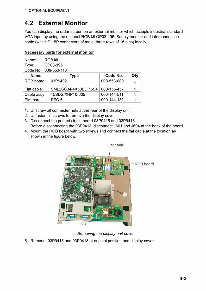
Name Type Code No. QtyRGB board 03P9492 008-553-680 1 Flat cable SML2SC34-4X50BDP.5S4 000-155-457 1 Cable assy 15SDS/XHP10-005 000-144-511 1 EMI core RFC-6 000-144-132 1 1. Unscrew all connecter nuts at the rear of the display unit. 2. Unfasten all screws to remove the display cover. 3. Disconnect the printed circuit board 03P9415 and 03P9413. Before disconnecting the 03P9413, disconnect J601 and J604 at the back of the board. 4. Mount the RGB board with two screws and connect the flat cable at the location as
shown in the figure below.
Flat cable
RGB board
Removing the display unit cover
5. Remount 03P9415 and 03P9413 at original position and display cover.
4. OPTIONAL EQUIPMENT
4-4
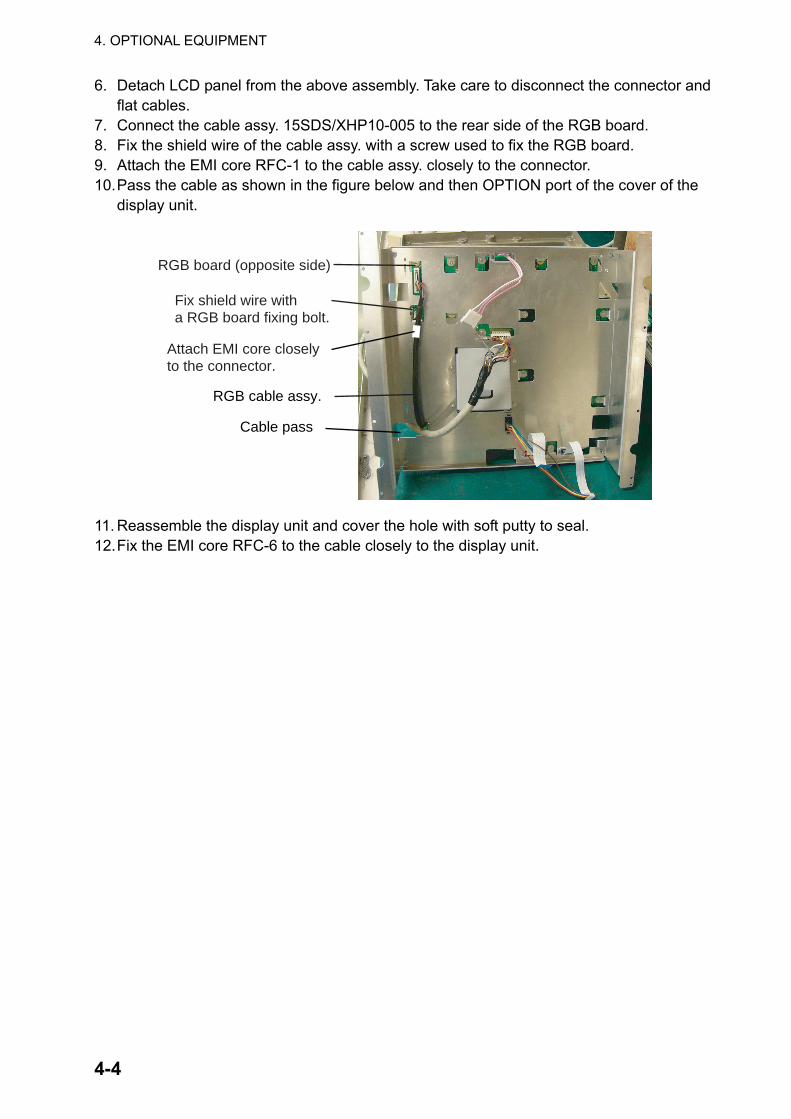
6. Detach LCD panel from the above assembly. Take care to disconnect the connector and flat cables.
7. Connect the cable assy. 15SDS/XHP10-005 to the rear side of the RGB board. 8. Fix the shield wire of the cable assy. with a screw used to fix the RGB board. 9. Attach the EMI core RFC-1 to the cable assy. closely to the connector. 10. Pass the cable as shown in the figure below and then OPTION port of the cover of the
display unit.
RGB board (opposite side)
Fix shield wire witha RGB board fixing bolt.
Attach EMI core closely to the connector.
RGB cable assy.
Cable pass
11. Reassemble the display unit and cover the hole with soft putty to seal. 12. Fix the EMI core RFC-6 to the cable closely to the display unit.
4. OPTIONAL EQUIPMENT
4-5
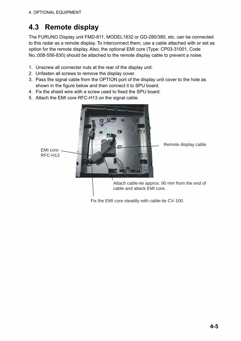
4.3 Remote display The FURUNO Display unit FMD-811, MODEL1832 or GD-280/380, etc. can be connected to this radar as a remote display. To interconnect them, use a cable attached with or set as option for the remote display. Also, the optional EMI core (Type: CP03-31001, Code No.:008-556-830) should be attached to the remote display cable to prevent a noise. 1. Unscrew all connecter nuts at the rear of the display unit. 2. Unfasten all screws to remove the display cover. 3. Pass the signal cable from the OPTION port of the display unit cover to the hole as
shown in the figure below and then connect it to SPU board. 4. Fix the shield wire with a screw used to fixed the SPU board. 5. Attach the EMI core RFC-H13 on the signal cable.
EMI coreRFC-H13
Attach cable-tie approx. 90 mm from the end ofcable and attack EMI core.
Remote display cable90mm
Fix the EMI core steadily with cable-tie CV-100.
4. OPTIONAL EQUIPMENT
4-6
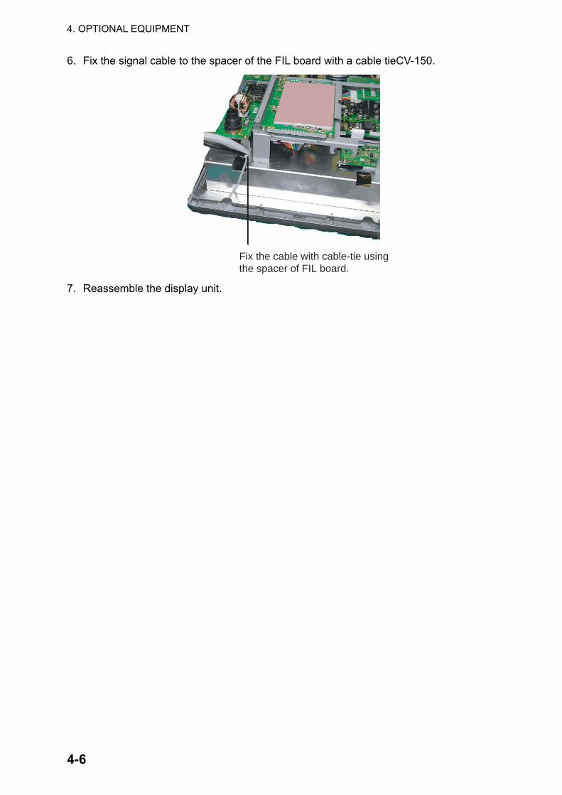
6. Fix the signal cable to the spacer of the FIL board with a cable tieCV-150.
Fix the cable with cable-tie usingthe spacer of FIL board.
7. Reassemble the display unit.
4. OPTIONAL EQUIPMENT
4-7
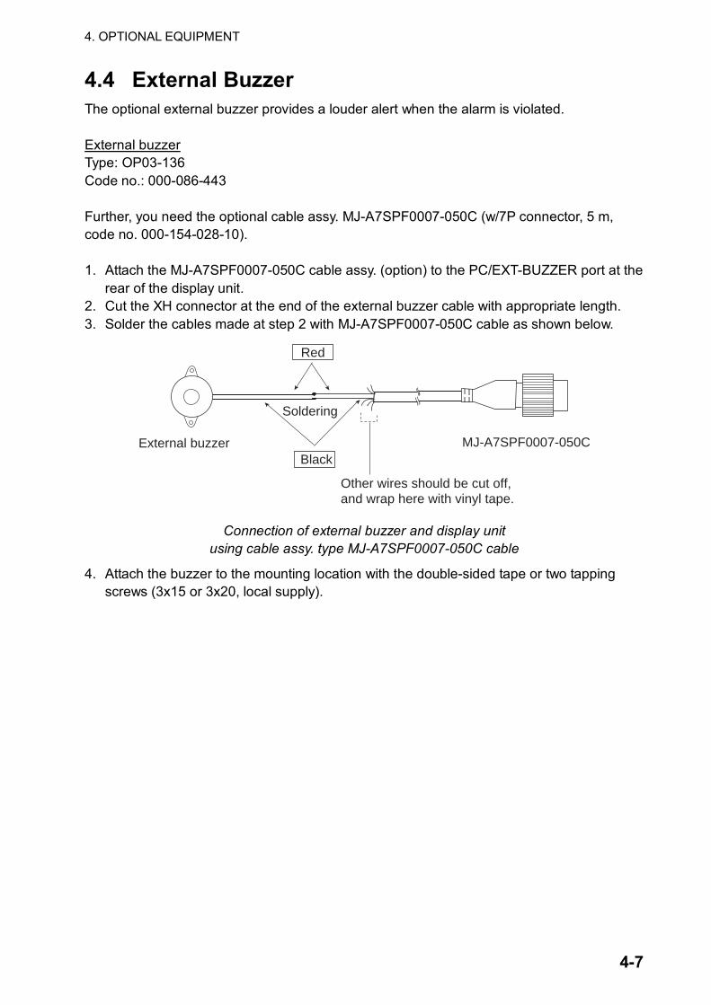
4.4 External Buzzer The optional external buzzer provides a louder alert when the alarm is violated. External buzzer Type: OP03-136 Code no.: 000-086-443 Further, you need the optional cable assy. MJ-A7SPF0007-050C (w/7P connector, 5 m, code no. 000-154-028-10). 1. Attach the MJ-A7SPF0007-050C cable assy. (option) to the PC/EXT-BUZZER port at the
rear of the display unit. 2. Cut the XH connector at the end of the external buzzer cable with appropriate length. 3. Solder the cables made at step 2 with MJ-A7SPF0007-050C cable as shown below.
Red
BlackExternal buzzer MJ-A7SPF0007-050C
Soldering
Other wires should be cut off, and wrap here with vinyl tape.
Connection of external buzzer and display unit using cable assy. type MJ-A7SPF0007-050C cable
4. Attach the buzzer to the mounting location with the double-sided tape or two tapping screws (3x15 or 3x20, local supply).
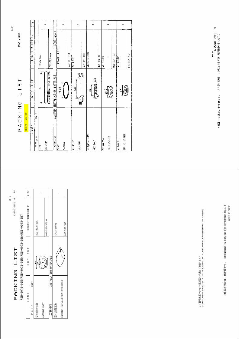
PACKING LIST
03GT-X-9852-0
RSB-0070-085/RSB-0073-085/RSB-0073-086/RSB-0073-087
N A M E
O U T L I N E
DESCRIPTION/CODE №
Q'TY1/1
ユニット
UNIT
空中線本体部
ANTENNA UNIT
RSB-0070-085
008-552-970
1
**
工事材料
INSTALLATION MATERIALS
空中線部工材
ANTENNA INSTALLATION MATERIALS
CP03-30801
008-552-960
1
コ-ト番゙号末尾の
[**]は、選択品の代表コートを゙表します。
CODE
NUM
BER
ENDI
NG W
ITH
"**"
INDI
CATE
S TH
E CO
DE N
UMBE
R O
F RE
PRES
ENTA
TIVE
MAT
ERIA
L.
(略図の寸法は、参考値です。 DIMENSIONS IN DRAWING FOR REFERENCE ONLY.)
03GT-X-9852
A-1
A-2
XN12A, XN13A
CODE NO.
008-552-960
TYPE
CP03-30801
略 図
OUTLINE
名 称
NAME
数量 Q'TY
用途/備考
REMARKS
番 号 NO.
型名/規格
DESCRIPTIONS
1/2
-3
INSTALLATION MATERIALS
工事材料表
03GT-X-9401
シールワッシャ
SEAL WASHER
03-001-3002-0
4
300-130-020
1
CODE NO.
防蝕ゴム
CORROSION-PROOF
RUBBER MAT
03-142-3001-0
1
100-275-580
2
CODE NO.
パッキンオサエ
PACKING SUPPORT
03-167-2017-0
1
100-327-760
3
CODE NO.
シールドクランプ
SHIELD CLAMP
03-167-2018-1
1
100-327-771
4
CODE NO.
キャップ
CAP
040-4010
4
000-515-332
5
CODE NO.
ミガキ平座金
FLAT WASHER
M12 SUS304
4
000-864-132
6
CODE NO.
六角ナット 1種
HEX.NUT
M12 SUS304
4
000-863-112
7
CODE NO.
バネ座金
SPRING WASHER
M12 SUS304
4
000-864-263
8
CODE NO.
六角ボルト(全ネジ)
HEX. BOLT
M12X60 SUS304
4
000-862-191
9
CODE NO.
+-ナベセムスネジB
WASHER HEAD SCREW
M4X15 C2700W MBNI2
2
000-881-448
10
CODE NO.
(略図の寸法は、参考値です。 DIMENSIONS IN DRAWING FOR REFERENCE ONLY.)
FURUNO ELECTRIC CO .,LTD.
03GT-X-9401
CODE NO.
008-552-960
TYPE
CP03-30801
略 図
OUTLINE
名 称
NAME
数量 Q'TY
用途/備考
REMARKS
番 号 NO.
型名/規格
DESCRIPTIONS
2/2
-3
INSTALLATION MATERIALS
工事材料表
03GT-X-9401
バネ座金
SPRING WASHER
M6 SUS304
1
000-864-260
11
CODE NO.
ミガキ平座金
FLAT WASHER
M6 SUS304
3
000-864-129
12
CODE NO.
六角ナット 1種
HEX.NUT
M6 SUS304
1
000-863-109
13
CODE NO.
六角ボルト
HEX.BOLT
M6X25 SUS304
1
000-862-180
14
CODE NO.
EMIコア
EMI CORE
RFC-13
2
000-141-084
15
CODE NO.
EMIコア
EMI CORE
RFC-H13
1
000-146-570
16
CODE NO.
アース線
GROUNDING WIRE
RW-4747-1 03S4747-2
1
000-566-000
17
CODE NO.
(略図の寸法は、参考値です。 DIMENSIONS IN DRAWING FOR REFERENCE ONLY.)
FURUNO ELECTRIC CO .,LTD.
03GT-X-9401
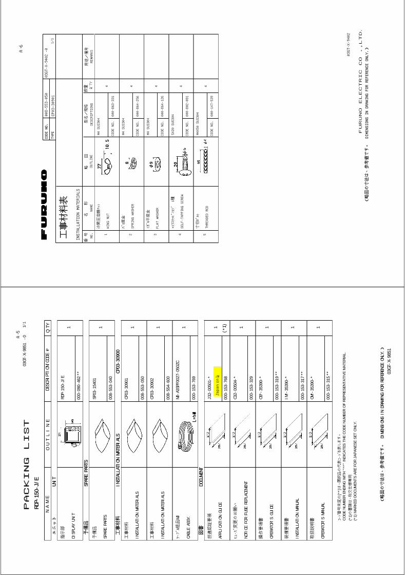
PACKING LIST
03GT
-X-9
851
-0
RDP-
150-
J/E
N A M
EO U T L I N E
DESCRIPTION/CODE №
Q'TY1/
1
ユニット
UNIT
指示部
DISP
LAY
UNIT
RDP-
150-
J/E
000-
090-
462
1
**
予備品
SPAR
E PA
RTS
予備品
SPAR
E PA
RTS
SP03
-154
01
008-
553-
040
1
工事材料
INST
ALLA
TION
MAT
ERIA
LSCP
03-3
0900
工事材料
INST
ALLA
TION
MAT
ERIA
LS
CP03
-309
01
008-
553-
050
1
工事材料
INST
ALLA
TION
MAT
ERIA
LS
CP03
-309
02
008-
554-
600
1
ケーブル組品
MJ
CABL
E AS
SY.
MJ-A
3SPF
0027
-050
ZC
000-
153-
769
1
図書
DOCU
MENT
技適認証要領
APPL
ICAT
ION
GUID
E
J32-
0050
1-*
000-
153-
768
1
(*1)
ヒューズ変更のお願い
NOTI
CE F
OR F
USE
REPL
ACEM
ENT
C32-
0050
4-*
000-
153-
329
1
操作要領書
OPER
ATOR
'S G
UIDE
OS*-
3539
0-*
000-
153-
319
1
**
装備要領書
INST
ALLA
TION
MAN
UAL
IM*-
3539
0-*
000-
153-
317
1
**
取扱説明書
OPER
ATOR
'S M
ANUA
L
OM*-
3539
0-*
000-
153-
315
1
**
コ-ト番゙号末尾の
[**]は、選択品の代表コートを゙表します。
CODE
NUM
BER
ENDI
NG W
ITH
"**"
INDI
CATE
S TH
E CO
DE N
UMBE
R O
F RE
PRES
ENTA
TIVE
MAT
ERIA
L.(*
1)の書類は、和文仕様専用
(*1)
MAR
KED
DOCU
MEN
TS A
RE F
OR
JAPA
NESE
SET
ONL
Y.
(略図の寸法は、参考値です。
DI
MENS
IONS
IN
DRAW
ING
FOR
REFE
RENC
E ON
LY.)
03GT-X-9851
Japan only
A-5
CODE NO.
008-553-050
TYPE
CP03-30901
略 図
OUTLINE
名 称
NAME
数量 Q'TY
用途/備考
REMARKS
番 号 NO.
型名/規格
DESCRIPTIONS
1/1
-0
INSTALLATION MATERIALS
工事材料表
03GT-X-9402
冷間圧造蝶ナット
WING NUT
M4 SUS304
4
000-863-331
1
CODE NO.
バネ座金
SPRING WASHER
M4 SUS304
4
000-864-256
2
CODE NO.
ミガキ平座金
FLAT WASHER
M4 SUS304
4
000-864-126
3
CODE NO.
+トラスタッピンネジ 1種
SELF-TAPPING SCREW
5X20 SUS304
4
000-802-081
4
CODE NO.
寸切ボルト
THREADED ROD
M4X50 SUS304
4
000-147-539
5
CODE NO.
(略図の寸法は、参考値です。 DIMENSIONS IN DRAWING FOR REFERENCE ONLY.)
FURUNO ELECTRIC CO .,LTD.
03GT-X-9402
A-6
CODE NO.
008-554-600
TYPE
CP03-30902
略 図
OUTLINE
名 称
NAME
数量 Q'TY
用途/備考
REMARKS
番 号 NO.
型名/規格
DESCRIPTIONS
1/1
-0
INSTALLATION MATERIALS
工事材料表
03GT-X-9405
Fマウントヨウスポンジ
FLUSH MOUNTING SPONGE
03-167-1601-0
1
100-328-390
1
CODE NO.
(略図の寸法は、参考値です。 DIMENSIONS IN DRAWING FOR REFERENCE ONLY.)
FURUNO ELECTRIC CO .,LTD.
03GT-X-9405
A-7
CODE NO.
TYPE
略 図
OUTLINE
名 称
NAME
数量 Q'TY
用途/備考
REMARKS
番 号 NO.
型名/規格
DESCRIPTIONS
1/1
-0
INSTALLATION MATERIALS
工事材料表
FR-8062/8122
03GT-X-9403
ケーブル組品MJ
CABLE ASSY.
MJ-B24LPF0012-300
1
選択
TO BE SELECT
000-153-622
1
CODE NO.
ケーブル組品MJ
CABLE ASSY.
MJ-B24LPF0012-200
1
選択
TO BE SELECT
000-153-621
2
CODE NO.
ケーブル組品MJ
CABLE ASSY.
MJ-B24LPF0012-150
1
選択
TO BE SELECT
000-153-620
3
CODE NO.
ケーブル組品MJ
CABLE ASSY.
MJ-B24LPF0012-100
1
選択
TO BE SELECT
000-153-619
4
CODE NO.
(略図の寸法は、参考値です。 DIMENSIONS IN DRAWING FOR REFERENCE ONLY.)
FURUNO ELECTRIC CO .,LTD.
03GT-X-9403
A-8
CODE NO.
TYPE
略 図
OUTLINE
名 称
NAME
数量 Q'TY
用途/備考
REMARKS
番 号 NO.
型名/規格
DESCRIPTIONS
1/1
-0
INSTALLATION MATERIALS
工事材料表
FR-8252
19AV-X-9402
ケーブル組品
CABLE ASSY.
RW-9771 *30M*
1
選択
TO BE SELECTED
000-152-869
1
CODE NO.
ケーブル組品
CABLE ASSY.
RW-9771 *20M*
1
選択
TO BE SELECTED
000-152-868
2
CODE NO.
ケーブル組品
CABLE ASSY.
RW-9771 *15M*
1
選択
TO BE SELECTED
000-152-867
3
CODE NO.
ケーブル組品
CABLE ASSY.
RW-9771 *10M*
1
選択
TO BE SELECTED
000-152-866
4
CODE NO.
(略図の寸法は、参考値です。 DIMENSIONS IN DRAWING FOR REFERENCE ONLY.)
FURUNO ELECTRIC CO .,LTD.
19AV-X-9402
A-9
PACKING LIST
19AV-X-9855-2
PSU-008
N A M E
O U T L I N E
DESCRIPTION/CODE №
Q'TY1/1
ユニット
UNIT
空中線電源部
POWER SUPPLY UNIT
PSU-008
000-083-617
1
予備品
SPARE PARTS
予備品
SPARE PARTS
SP03-14501
008-444-420
1
工事材料
INSTALLATION MATERIALS
CP03-30600
ケーブル組品
CABLE ASSY.
VL3P-VV-S2X2C-AA050
000-152-217
1
ケーブル組品MJ
CABLE ASSY
MJ-B24LPF0011-050
000-152-939
1
工事材料
INSTALLATION MATERIALS
CP03-30601
008-550-740
1
図書
DOCUMENT
設定要領書
INTERNAL SETTING(JR/EN)
C32-00505-*
000-153-867
1
ヒューズ変更のお願い
NOTICE FOR FUSE REPLACEMENT
C32-00502-*
000-152-940
1
(略図の寸法は、参考値です。 DIMENSIONS IN DRAWING FOR REFERENCE ONLY.)
19AV-X-9855
A-10
CODE NO.
008-550-740
TYPE
CP03-30601
略 図
OUTLINE
名 称
NAME
数量 Q'TY
用途/備考
REMARKS
番 号 NO.
型名/規格
DESCRIPTIONS
1/1
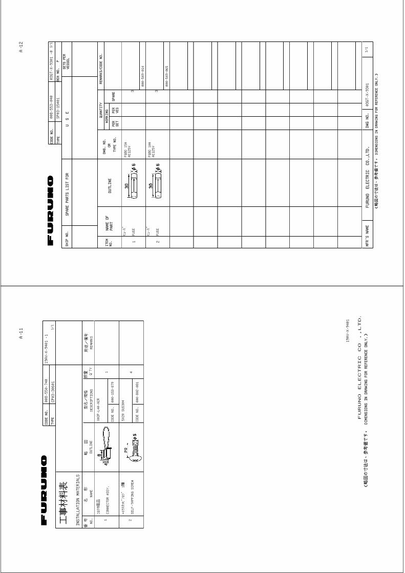
-1
INSTALLATION MATERIALS
工事材料表
19AV-X-9401
コネクタ組品
CONNECTOR ASSY.
XH2P-L40-ACR
1
000-153-879
1
CODE NO.
+トラスタッピンネジ 1種
SELF-TAPPING SCREW
5X20 SUS304
4
000-802-081
2
CODE NO.
(略図の寸法は、参考値です。 DIMENSIONS IN DRAWING FOR REFERENCE ONLY.)
FURUNO ELECTRIC CO .,LTD.
19AV-X-9401
A-11
CODE NO.
008-553-040
TYPE
SP03-15401
ITEM
NO.
NAME OF
PART
OUTLINE
DWG. NO.
OR
TYPE NO.
PER
SET
PER
VES
SPARE
WORKING
QUANTITY
REMARKS/CODE NO.
BOX NO. P
SHIP NO.
SPARE PARTS LIST FOR
U S E
SETS PER
VESSEL
-003GT-X-9301
1/1
ヒューズ
FGBO 15A
AC125V
3FUSE
000-549-014
1
ヒューズ
FGBO 10A
AC125V
3FUSE
000-549-065
2
1/1
MFR'S NAME
FURUNO ELECTRIC CO.,LTD.
DWG NO.
(略図の寸法は、参考値です。 DIMENSIONS IN DRAWING FOR REFERENCE ONLY.)
03GT-X-9301
A-12
CODE NO.
008-444-420
TYPE
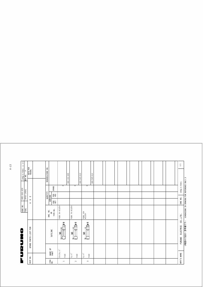
SP03-14501
ITEM
NO.
NAME OF
PART
OUTLINE
DWG. NO.
OR
TYPE NO.
PER
SET
PER
VES
SPARE
WORKING
QUANTITY
REMARKS/CODE NO.
BOX NO. P
SHIP NO.
SPARE PARTS LIST FOR
U S E
SETS PER
VESSEL
-1
19AQ-X-9301
1/1
カンイリヒューズ
FGBO 3A AC125V
3FUSE
000-131-845
1
ヒューズ
FGBO 7A AC125V
3FUSE
000-549-013
2
ヒューズ
FGBO 15A
AC125V
3FUSE
000-549-014
3
1/1
MFR'S NAME
FURUNO ELECTRIC CO.,LTD.
DWG NO.
(略図の寸法は、参考値です。 DIMENSIONS IN DRAWING FOR REFERENCE ONLY.)
19AQ-X-9301
A-13
A B C
12
34
kg
名称
NAME
TITLE
MASS
DWG.No.
SCALE
APPROVED
CHECKED
DRAWN
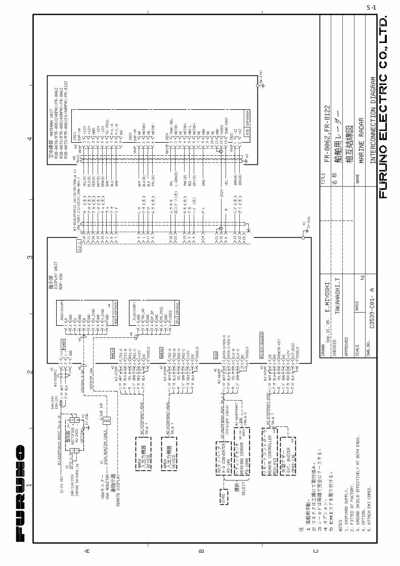
MARINERADAR
INTERCONNECTIONDIAGRAM
船舶用レーダー
相互結線図
FR-8062,FR-8122
指示部
DISPLAYUNIT
空中線部ANTENNAUNIT
RSB-0073/RTR-085(48RPM):FR-8062
RSB-0073/RTR-086(24/48RPM):FR-8122
RDP-150
RSB-0070/RTR-085(24RPM):FR-8062
VH9P
VH4P
NH13P
*3
VH2P
+12
-12
J822
VIDEO
GND
MBS-L
B4P-VH
J823
987654321
NCP/L-B
P/L-A
TX-TRIG.
-12V
-12VGND
+12V
J821
1 2 3 4 5 6 7 8 9 10 11 12 13 1 2
517197821514201110 43 121361621242218
2C2V
DJ-1
*2
MOTOR+
HD.
J824TUNE-IND.
MOTOR-
NC MOTOR+
MOTOR+
NC NC NC GND
TUNE-CONT
MJ-B24LPF0012,10/15/20/30m,φ11
*2(RW-9807,21C+2C2V,30mMAX.)
MOTOR-
B9P-VH +12V
BP
RW-4747
*1
321
GND
(-)
(+)
BLK
WHT
シロクロ
6521
-+
(OPTION)
RU-3423
整流器
RECTIFIER24V
DPYC-2.5
*1
*1
*2
IV-2SQ.
10A:24V
15A:12V
MJ-A3SPFZ
POWER
54321 6 7
+12V
SHIELD
*2
54321 6 7GND
8 9
GND
10*1
VGAMONITOR
VGAモニター
副指示器
D-SUB15P
TD1-B
REMOTEDISPLAY
SVGAMONITORCABLE
G B H_SYNC
V_SYNC
RGB03P9429
54321 6 7 8
GND
GND
GND
GND
TRU_HD
DP_BP
PR_TRIG
SPUJ110(XH8P)
19P4911
NMEA1
RD1-H
RD1-C
SG入出力機器
DEVICE
NMEA
シロ
ミド
WHT
GRN
アカRED
アオBLU
クロBLK
GND
GND
TD1-A
GND
RJ802(XH10P)
MJ-A7SPF
54321
*2
TD2-B
シロ
ミドキ
WHT
YELGRN
NMEA2
RD2-H
+12VSG
7SHIELD
RED
BLK
クロ
入出力機器
NMEA
アカ
TD2-A
761 2 3 4 5
*2
ミドキ
WHT
YELGRN
アカ
外部ブザー
アオBLU
クロ
431 5 6
CLK-C
*2
NCDATA-H/HDG-H
DATA-C/HDG-C
SHIELD
ミドキ
BLKYELGRN
選択
SELECT
AD-100
ADコンバータ
A-DCONVERTER
HEADINGSENSOR
PG-1000
NMEA
AD-10/
GYRO
10m,φ6
MJ-A6SPF
MJ-A7SPF
HDG
PC/EXT-BUZZER
SD RD REMOTE-KEY
NC
MJ-A6SPF0007
-100
OP03-136
2
BLK
シロ
シロクロWHT
RED
EXT.BUZZER
CLK-H
+12VEXT.BUZZ
SHIELD
RD2-C
6
19
4321
12-24VDC
ヘディングセンサ
DEVICE
3.GROUNDSHIELDEFFECTIVELYATBOTHENDS.
2.FITTEDATFACTORY.
1.SHIPYARDSUPPLY.
NOTES
3シールドは両端で完全にアースする。
2コネクタは工場にて取付済み。
1造船所手配。
注
MJ-A7SPF
VIDEO TAKAHASHI.T
E.MIYOSHI
C3539-C01-A
MJ-A3SPF0018-050ZC,5m,φ10
MJ-A7SPF0007-050C,
アオBLU
MJ-A6SPF0003-050C,5m,φ6
(Straightcable)
RCU-019
REMOTECONTROLLER
MJ-A7SPF0007-050C,
5m,φ7
03P9405A
5m,φ7
MJ-A7SPF0007-050C,
5m,φ7
リモートコントローラ
100/110/220/
230VAC50/60Hz,1φ
キYEL
19S1004,0.5m
03S9299,10m*5
*5
*4
4オプション。
5EMIコアを取り付ける。
4.OPTION.
5.ATTACHEMICORES.
*4
*5
IV-2sq.
RTB
3pcs*5
23
Sep.15,'05
キ
ムラ(太)
クロアオ(太)
シロ
ミド
アオ
チャ(太)
シロ(太)
アカ(太)
ダイ(太)
チャ
ミド(太)
クロ(太)
キ(太)
ダイ
モモ(太)
ムラサキ
アカ
ハイ(太)
YEL
GRN(B)
RED
PPL(B)
BLK
BLU(B)
WHT
L-GRN(B)
PNK(B)
ORG
ORG(B)
RED(B)
BRN
GRN
BLU
BRN(B)
WHT(B)
BLK(B)
YEL(B)
PPL
GRY(B)
淡ミドリ(太)
*4
FURUNO ELECTRIC CO., LTD.
1 2 4 5 63
B
A
D
C
54321
67
+12V
SHIELD
*2
54321
67GND
89
GND
GND
GND
GND10
*1
VGA MONITORVGAモニター
副指示器
TUNE_CONT
P/L AP/L B
+12V
GND
GND
GND-12V
+12V
-12VTX_TRIG
VIDEO
1011201415287
91175
MBS_L 3
18
24
1621
6
23
19
1213
1312111098765
87
432
65
1
9
1234
1234
*3
TUNE_IND.
TUNE_CONT
P/L AP/L B
+12V
GND
GND-12V
+12V
-12VTX_TRIG
VIDEO
(17C+2C2V,MAX.30m)
*3
キ(太) YEL[B]クロ(太) BLK[B]アカ(太) RED[B]シロ(太) WHT[B]チャ(太) BRN[B]
アオ BLUミドリ GRN
シロ WHT
クロ BLK
YEL
WHT/ORG
WHT/BRN
321 (+)
(-)
J3(VH9P)
J1(VL3P)
J4(VH4P)
J5(NH13P)
321J2(VL3P)15A:12V
電源部 POWER SUPPLY UNIT
GND
D-SUB 15P
03S9299,10m
22
4
TUNE_IND
*2
相互結線図
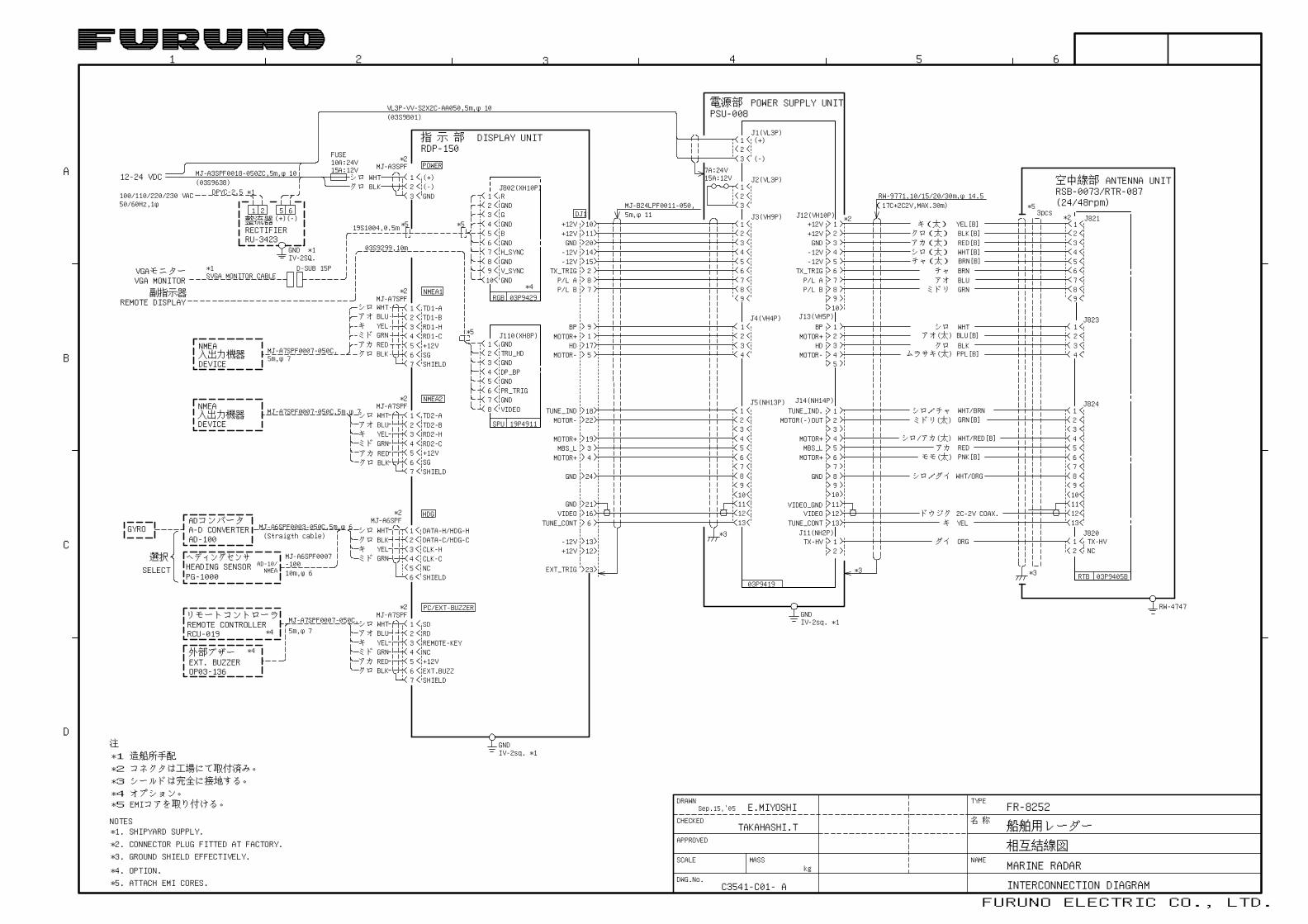
INTERCONNECTION DIAGRAM
船舶用レーダー
MARINE RADARNAME
TYPE
名 称
DRAWN
CHECKED
APPROVED
DWG.No.
SCALEkg
MASS
21
クロ BLKシロ WHT
3
*2
指 示 部 DISPLAY UNIT
(+)(-)GND
(+)(-)1 2 5 6整流器RECTIFIERRU-3423
(03S9638)
GNDIV-2SQ.
*1
TD1-ATD1-B
100/110/220/230 VAC
GND
REMOTE DISPLAY
EXT_TRIG
2C-2V COAX.
VL3P-VV-S2X2C-AA050,5m,φ10(03S9801)
MJ-A3SPF
MJ-A7SPF
PSU-008
03P9419
12345678910
12345
12 GRN[B]34
MOTOR(-)OUT
5MBS_L RED6 PNK[B]
WHT/RED[B]
78910111213
12
J13(VH5P)
J14(NH14P)
ORG
ミドリ(太)シロ/チャ
シロ/アカ(太)アカ
モモ(太)
シロ/ダイ
ドウジクキ
ダイ
アオ(太) BLU[B]
チャ BRN
ムラサキ(太) PPL[B]
RW-9771,10/15/20/30m,φ14.5
BPMOTOR+
HDMOTOR-
MOTOR+
MOTOR+
VIDEO_GND
TX-HV
FUSE10A:24V15A:12V
BPMOTOR+HD
MOTOR-
MOTOR-
MOTOR+
MOTOR+
-12V+12V
DPYC-2.5 *1
SVGA MONITOR CABLE
J802(XH10P)R
G
B
H_SYNC
V_SYNC
RGB 03P9429
54321
678
GND
GND
GND
GND
TRU_HD
DP_BP
PR_TRIG
SPU
J110(XH8P)
19P4911
NMEA1
RD1-HRD1-C
SG
EXT.BUZZ+12V
76
12345
*2
シロ
ミドキ
WHT
YELGRN
アカ RED外部ブザー
アオ BLU
BLKクロ
4321
56
CLK-HCLK-C
*2
NC
DATA-H/HDG-HDATA-C/HDG-C
SHIELD
シロクロ
ミドキ
WHTBLKYELGRN選択
SELECT
AD-100
ADコンバータA-D CONVERTER
HEADING SENSORPG-1000
ヘディングセンサNMEAAD-10/
GYRO
10m,φ6
MJ-A6SPF
MJ-A7SPF
HDG
PC/EXT-BUZZER
SDRDREMOTE-KEYNC
54321
6
*2
TD2-ATD2-B
シロ
ミドキ
WHT
YELGRN
NMEA2
RD2-HRD2-C+12VSG
7 SHIELD
アカ REDBLKクロ
SHIELD
MJ-A6SPF0007-100
入出力機器DEVICE
NMEA
入出力機器DEVICE
NMEA
シロ
ミドキ
WHT
YELGRN
アカ RED
アオ BLU
BLKクロ
FR-8252
5m,φ7
EXT. BUZZEROP03-136
MJ-A7SPF
DJ1
E.MIYOSHI
TAKAHASHI.T
C3541-C01- A
POWER
VIDEO
MJ-A3SPF0018-050ZC,5m,φ10
MJ-A7SPF0007-050C,
MJ-A7SPF0007-050C,5m,φ7
BLUアオ
MJ-A6SPF0003-050C,5m,φ6(Straigth cable)
リモートコントローラ
RCU-019REMOTE CONTROLLER MJ-A7SPF0007-050C,
5m,φ7
*2. CONNECTOR PLUG FITTED AT FACTORY.*1. SHIPYARD SUPPLY.NOTES
*4. OPTION.
RDP-150
MJ-B24LPF0011-050,5m,φ11 J12(VH10P)
J11(NH2P)
7A:24V12-24 VDC
50/60Hz,1φ
IV-2sq. *1
IV-2sq. *1*4
*4
注*1 造船所手配*2 コネクタは工場にて取付済み。
*4 オプション。*5 EMIコアを取り付ける。
*5. ATTACH EMI CORES.
*3. GROUND SHIELD EFFECTIVELY.
*3 シールドは完全に接地する。
19S1004,0.5m *5 *5
*4
*5
1312111098765
*2
87
432
65
1
9
1234
1234
1
空中線部 ANTENNA UNITRSB-0073/RTR-087(24/48rpm)
RW-4747
2
03P9405B
J820TX-HVNC
RTB
J824
J823
J821
*3
*53pcs
Sep.15,'05