Embed Size (px)
Citation preview
AN
DOCUMENT
Prepared by AIRLINES ELECTRONIC ENGINEERING COMMITTEE Published by AERONAUTICAL RADIO, INC. 2551 RIVA ROAD, ANNAPOLIS, MARYLAND 21401
MARK 33 DIGITAL INFORMATION TRANSFER SYSTEM (DITS)
PART 2 DISCRETE WORD DATA STANDARDS
ARINC SPECIFICATION 429 PART 2-16
PUBLISHED: December 17, 2004

This document is based on material submitted by various participants during the drafting process. Neither AEEC nor ARINC has made any determination whether these materials could be subject to valid claims of patent, copyright or other proprietary rights by third parties, and no representation or warranty, express or implied, is made in this regard. Any use of or reliance on this document shall constitute an acceptance thereof “as is” and be subject to this disclaimer.

©2004 BY AERONAUTICAL RADIO, INC.
2551 RIVA ROAD ANNAPOLIS, MARYLAND 21401-7465 USA
Prepared by the Airlines Electronic Engineering Committee
Specification 429 Adopted by the Airlines Electronic Engineering Committee July 21, 1977
Summary of Document Supplements
Supplement Adoption Date Published
Specification 429-1 April 11, 1978 June 1, 1978
Specification 429-2 December 6, 1978 March 1, 1979
Specification 429-3 August 31, 1979 November 1, 1979
Specification 429-4 June 17, 1980 August 1, 1980
Specification 429-5 March 12, 1981 April 4, 1981
Specification 429-6 December 9, 1981 January 22, 1982
Specification 429-7 November 4, 1982 January 3, 1983
Specification 429-8 November 4, 1983 December 3, 1984
Specification 429-9 October 11, 1984 April 30, 1985
Specification 429-10 November 7, 1985 November 17, 1986
Specification 429-11 June 15, 1988 July 22, 1988
Specification 429-12 October 25, 1989 July 1, 1990
Specification 429-13 October 8, 1991 December 30, 1991
Specification 429-14 November 4, 1992 January 4, 1993
Specification 429P2-15 April 18, 1995 March 6, 1996
Specification 429P2-16 October 27, 2004 December 17, 2004
A description of the changes introduced by this supplement is included on Goldenrod paper at the end of this document.
ARINC SPECIFICATION 429P2-16
MARK 33 DIGITAL INFORMATION TRANSFER SYSTEM (DITS) PART 2
DISCRETE WORD DATA STANDARDS
Published: December 17, 2004

ii
FOREWORD
Aeronautical Radio, Inc., the AEEC, and ARINC Standards
Aeronautical Radio, Inc. (ARINC) was incorporated in 1929 by four fledgling airlines in the United States as a privately-owned company dedicated to serving the communications needs of the air transport industry. Today, the major U.S. airlines remain the Company’s principal shareholders. Other shareholders include a number of non-U.S. airlines and other aircraft operators.
ARINC sponsors aviation industry committees and participates in related industry activities that benefit aviation at large by providing technical leadership and guidance and frequency management. These activities directly support airline goals: promote safety, efficiency, regularity, and cost-effectiveness in aircraft operations.
The Airlines Electronic Engineering Committee (AEEC) is an international body of airline technical professionals that leads the development of technical standards for airborne electronic equipment-including avionics and in-flight entertainment equipment-used in commercial, military, and business aviation. The AEEC establishes consensus-based, voluntary form, fit, function, and interface standards that are published by ARINC and are known as ARINC Standards. The use of ARINC Standards results in substantial benefits to airlines by allowing avionics interchangeability and commonality and reducing avionics cost by promoting competition.
There are three classes of ARINC Standards:
a) ARINC Characteristics – Define the form, fit, function, and interfaces of avionics and other airline electronic equipment. ARINC Characteristics indicate to prospective manufacturers of airline electronic equipment the considered and coordinated opinion of the airline technical community concerning the requisites of new equipment including standardized physical and electrical characteristics to foster interchangeability and competition.
b) ARINC Specifications – Are principally used to define either the physical packaging or mounting of avionics equipment, data communication standards, or a high-level computer language.
c) ARINC Reports – Provide guidelines or general information found by the airlines to be good practices, often related to avionics maintenance and support.
The release of an ARINC Standard does not obligate any airline or ARINC to purchase equipment so described, nor does it establish or indicate recognition or the existence of an operational requirement for such equipment, nor does it constitute endorsement of any manufacturer’s product designed or built to meet the ARINC Standard.
In order to facilitate the continuous product improvement of this ARINC Standard, two items are included in the back of this volume:
An Errata Report solicits any corrections to the text or diagrams in this ARINC Standard.
An ARINC IA Project Initiation/Modification (APIM) form solicits any recommendations for addition of substantive material to this volume which would be the subject of a new Supplement.

ARINC SPECIFICATION 429
TABLE OF CONTENTS
iii
1.0 INTRODUCTION......................................................................................................... 1 1.1 Purpose of ARINC Specification 429 ........................................................................... 1 1.1.1 Relationship to Other Documents ........................................................................... 1 1.2 Organization of ARINC Specification 429 .................................................................... 1 Table 1 List of Discrete Labels by Equipment Identifier ............................................................ 2 Table 2 List of Discrete Labels by Octal Number.................................................................... 11 DATA STANDARDS ........................................................................................................... 20 ARINC IA Project Initiation/Modification (APIM) Guidelines for Submittal ...............................End ARINC Standard – Errata Report............................................................................................End
ARINC SPECIFICATION 429 PART 2 – Page 1
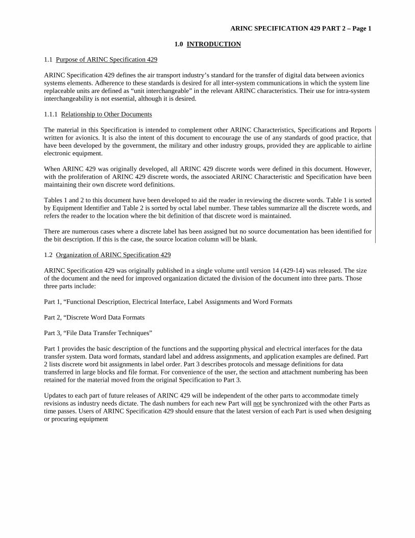
1.0 INTRODUCTION
1.1 Purpose of ARINC Specification 429 ARINC Specification 429 defines the air transport industry’s standard for the transfer of digital data between avionics systems elements. Adherence to these standards is desired for all inter-system communications in which the system line replaceable units are defined as “unit interchangeable” in the relevant ARINC characteristics. Their use for intra-system interchangeability is not essential, although it is desired. 1.1.1 Relationship to Other Documents The material in this Specification is intended to complement other ARINC Characteristics, Specifications and Reports written for avionics. It is also the intent of this document to encourage the use of any standards of good practice, that have been developed by the government, the military and other industry groups, provided they are applicable to airline electronic equipment. When ARINC 429 was originally developed, all ARINC 429 discrete words were defined in this document. However, with the proliferation of ARINC 429 discrete words, the associated ARINC Characteristic and Specification have been maintaining their own discrete word definitions. Tables 1 and 2 to this document have been developed to aid the reader in reviewing the discrete words. Table 1 is sorted by Equipment Identifier and Table 2 is sorted by octal label number. These tables summarize all the discrete words, and refers the reader to the location where the bit definition of that discrete word is maintained. There are numerous cases where a discrete label has been assigned but no source documentation has been identified for the bit description. If this is the case, the source location column will be blank. 1.2 Organization of ARINC Specification 429 ARINC Specification 429 was originally published in a single volume until version 14 (429-14) was released. The size of the document and the need for improved organization dictated the division of the document into three parts. Those three parts include: Part 1, “Functional Description, Electrical Interface, Label Assignments and Word Formats Part 2, “Discrete Word Data Formats Part 3, “File Data Transfer Techniques” Part 1 provides the basic description of the functions and the supporting physical and electrical interfaces for the data transfer system. Data word formats, standard label and address assignments, and application examples are defined. Part 2 lists discrete word bit assignments in label order. Part 3 describes protocols and message definitions for data transferred in large blocks and file format. For convenience of the user, the section and attachment numbering has been retained for the material moved from the original Specification to Part 3. Updates to each part of future releases of ARINC 429 will be independent of the other parts to accommodate timely revisions as industry needs dictate. The dash numbers for each new Part will not be synchronized with the other Parts as time passes. Users of ARINC Specification 429 should ensure that the latest version of each Part is used when designing or procuring equipment
ARINC SPECIFICATION 429 PART 2 – Page 2
DATA STANDARDS
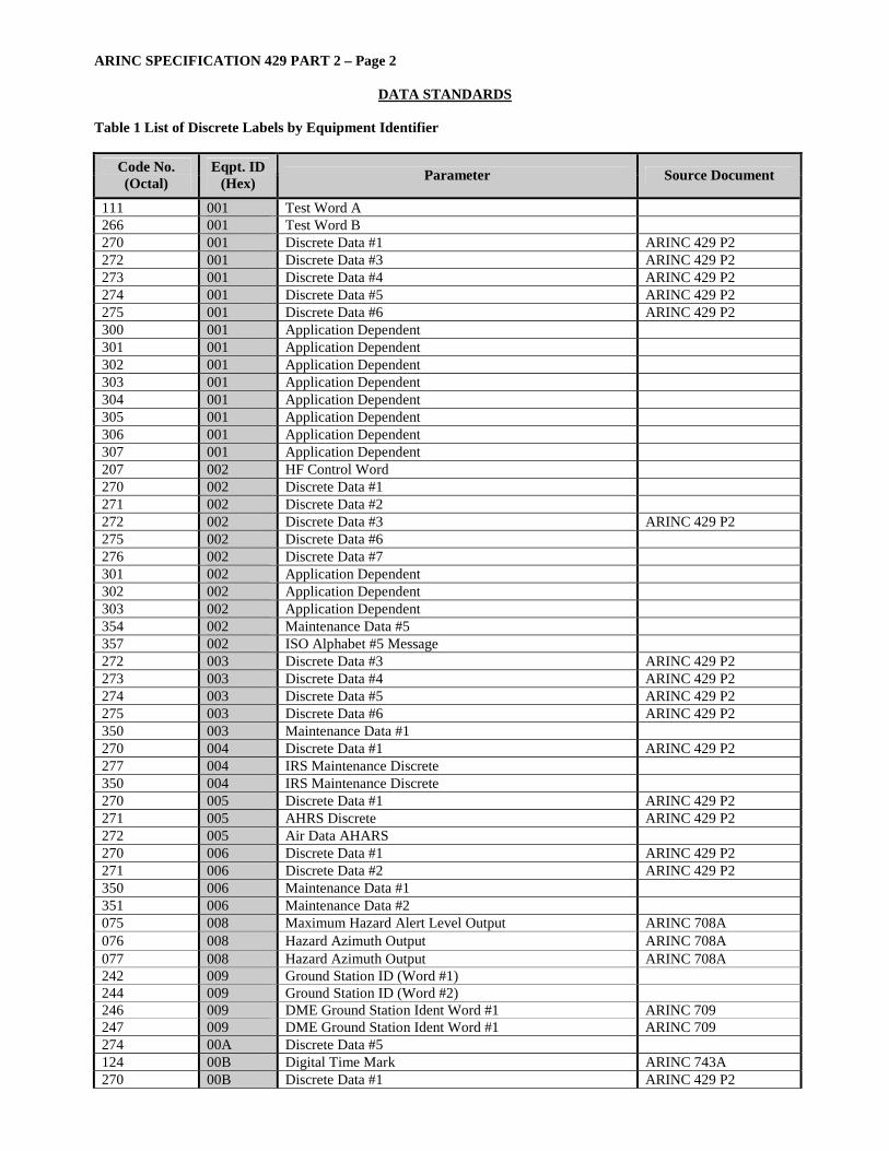
Table 1 List of Discrete Labels by Equipment Identifier
Code No. (Octal)
Eqpt. ID (Hex) Parameter Source Document
111 001 Test Word A 266 001 Test Word B 270 001 Discrete Data #1 ARINC 429 P2 272 001 Discrete Data #3 ARINC 429 P2 273 001 Discrete Data #4 ARINC 429 P2 274 001 Discrete Data #5 ARINC 429 P2 275 001 Discrete Data #6 ARINC 429 P2 300 001 Application Dependent 301 001 Application Dependent 302 001 Application Dependent 303 001 Application Dependent 304 001 Application Dependent 305 001 Application Dependent 306 001 Application Dependent 307 001 Application Dependent 207 002 HF Control Word 270 002 Discrete Data #1 271 002 Discrete Data #2 272 002 Discrete Data #3 ARINC 429 P2 275 002 Discrete Data #6 276 002 Discrete Data #7 301 002 Application Dependent 302 002 Application Dependent 303 002 Application Dependent 354 002 Maintenance Data #5 357 002 ISO Alphabet #5 Message 272 003 Discrete Data #3 ARINC 429 P2 273 003 Discrete Data #4 ARINC 429 P2 274 003 Discrete Data #5 ARINC 429 P2 275 003 Discrete Data #6 ARINC 429 P2 350 003 Maintenance Data #1 270 004 Discrete Data #1 ARINC 429 P2 277 004 IRS Maintenance Discrete 350 004 IRS Maintenance Discrete 270 005 Discrete Data #1 ARINC 429 P2 271 005 AHRS Discrete ARINC 429 P2 272 005 Air Data AHARS 270 006 Discrete Data #1 ARINC 429 P2 271 006 Discrete Data #2 ARINC 429 P2 350 006 Maintenance Data #1 351 006 Maintenance Data #2 075 008 Maximum Hazard Alert Level Output ARINC 708A 076 008 Hazard Azimuth Output ARINC 708A 077 008 Hazard Azimuth Output ARINC 708A 242 009 Ground Station ID (Word #1) 244 009 Ground Station ID (Word #2) 246 009 DME Ground Station Ident Word #1 ARINC 709 247 009 DME Ground Station Ident Word #1 ARINC 709 274 00A Discrete Data #5 124 00B Digital Time Mark ARINC 743A 270 00B Discrete Data #1 ARINC 429 P2

ARINC SPECIFICATION 429 PART 2 – Page 3
DATA STANDARDS
Code No. (Octal)
Eqpt. ID (Hex) Parameter Source Document
273 00B GNSS Sensor Status ARINC 743A 350 00B GPS Test Word (manufacturer specific) 351 00B SRU Test Word (manufacturer specific) 355 00B GNSS Fault Summary ARINC 743A 242 010 Ground Station ID (Word #1) 244 010 Ground Station ID (Word #2) 263 010 ILS Ground Station Ident Word #1 ARINC 710 264 010 ILS Ground Station Ident Word #2 ARINC 710 242 011 Ground Station ID (Word #1) ARINC 711 244 011 VOR Ground Station Ident Word #2 ARINC 711 244 012 Ground Station ID (Word #2) 254 012 ADF Ground Station Ident Word #1 ARINC 712 255 012 ADF Ground Station Ident Word #2 ARINC 712 357 017 ISO Alphabet #5 Message 271 018 Discrete Data #2 ARINC 429 P2 272 018 Discrete Data #3 ARINC 429 P2 273 018 Discrete Data #4 ARINC 429 P2 274 018 Discrete Data #5 ARINC 429 P2 275 018 Discrete Data #6 ARINC 429 P2 276 018 Discrete Data #7 ARINC 429 P2 277 018 Discrete Data #8 ARINC 429 P2 350 018 Maintenance Data #1 ARINC 429 P2 227 019 CFDS Bite Command Summary for HFDR ARINC 753 350 019 CFDS Bite Fault Summary Word for HFDR ARINC 753 270 01A Discrete Data #1 ARINC 429 P2 271 01A Discrete Data #2 ARINC 429 P2 272 01A Discrete Data #3 ARINC 429 P2 300 01A Application Dependent 301 01A Application Dependent 302 01A Application Dependent 303 01A Application Dependent 304 01A Application Dependent 305 01A Application Dependent 306 01A Application Dependent 307 01A Application Dependent 350 01A Maintenance Data #1 ARINC 429 P2 351 01A Maintenance Data #2 ARINC 429 P2 352 01A Maintenance Data #3 ARINC 429 P2 353 01A Maintenance Data #4 ARINC 429 P2 354 01A Maintenance Data #5 ARINC 429 P2 270 01B Discrete Data #1 155 01C Maintenance Data #6 156 01C Maintenance Data #7 160 01C Maintenance Data #9 161 01C Maintenance Data #10 270 01C Discrete Data #1 271 01C Discrete Data #2 272 01C Discrete Data #3 273 01C Discrete Data #4 274 01C Discrete Data #5 275 01C Discrete Data #6 276 01C Discrete Data #7 350 01C Maintenance Data #1
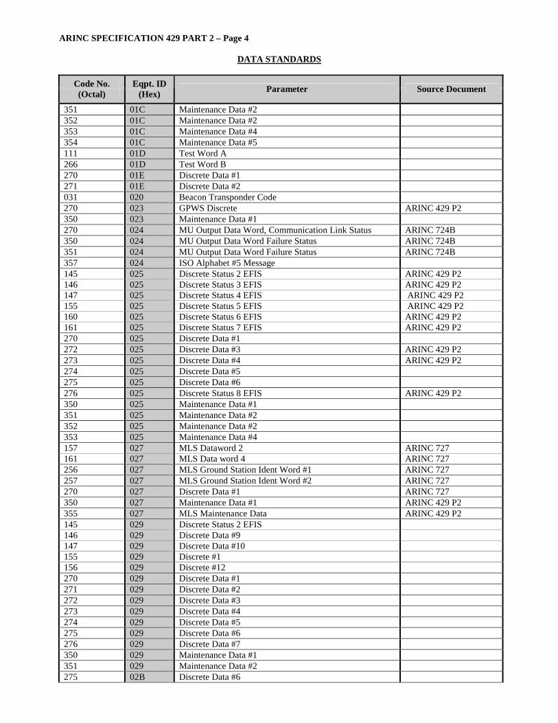
ARINC SPECIFICATION 429 PART 2 – Page 4
DATA STANDARDS
Code No. (Octal)
Eqpt. ID (Hex) Parameter Source Document
351 01C Maintenance Data #2 352 01C Maintenance Data #2 353 01C Maintenance Data #4 354 01C Maintenance Data #5 111 01D Test Word A 266 01D Test Word B 270 01E Discrete Data #1 271 01E Discrete Data #2 031 020 Beacon Transponder Code 270 023 GPWS Discrete ARINC 429 P2 350 023 Maintenance Data #1 270 024 MU Output Data Word, Communication Link Status ARINC 724B 350 024 MU Output Data Word Failure Status ARINC 724B 351 024 MU Output Data Word Failure Status ARINC 724B 357 024 ISO Alphabet #5 Message 145 025 Discrete Status 2 EFIS ARINC 429 P2 146 025 Discrete Status 3 EFIS ARINC 429 P2 147 025 Discrete Status 4 EFIS ARINC 429 P2 155 025 Discrete Status 5 EFIS ARINC 429 P2 160 025 Discrete Status 6 EFIS ARINC 429 P2 161 025 Discrete Status 7 EFIS ARINC 429 P2 270 025 Discrete Data #1 272 025 Discrete Data #3 ARINC 429 P2 273 025 Discrete Data #4 ARINC 429 P2 274 025 Discrete Data #5 275 025 Discrete Data #6 276 025 Discrete Status 8 EFIS ARINC 429 P2 350 025 Maintenance Data #1 351 025 Maintenance Data #2 352 025 Maintenance Data #2 353 025 Maintenance Data #4 157 027 MLS Dataword 2 ARINC 727 161 027 MLS Data word 4 ARINC 727 256 027 MLS Ground Station Ident Word #1 ARINC 727 257 027 MLS Ground Station Ident Word #2 ARINC 727 270 027 Discrete Data #1 ARINC 727 350 027 Maintenance Data #1 ARINC 429 P2 355 027 MLS Maintenance Data ARINC 429 P2 145 029 Discrete Status 2 EFIS 146 029 Discrete Data #9 147 029 Discrete Data #10 155 029 Discrete #1 156 029 Discrete #12 270 029 Discrete Data #1 271 029 Discrete Data #2 272 029 Discrete Data #3 273 029 Discrete Data #4 274 029 Discrete Data #5 275 029 Discrete Data #6 276 029 Discrete Data #7 350 029 Maintenance Data #1 351 029 Maintenance Data #2 275 02B Discrete Data #6
ARINC SPECIFICATION 429 PART 2 – Page 5
DATA STANDARDS
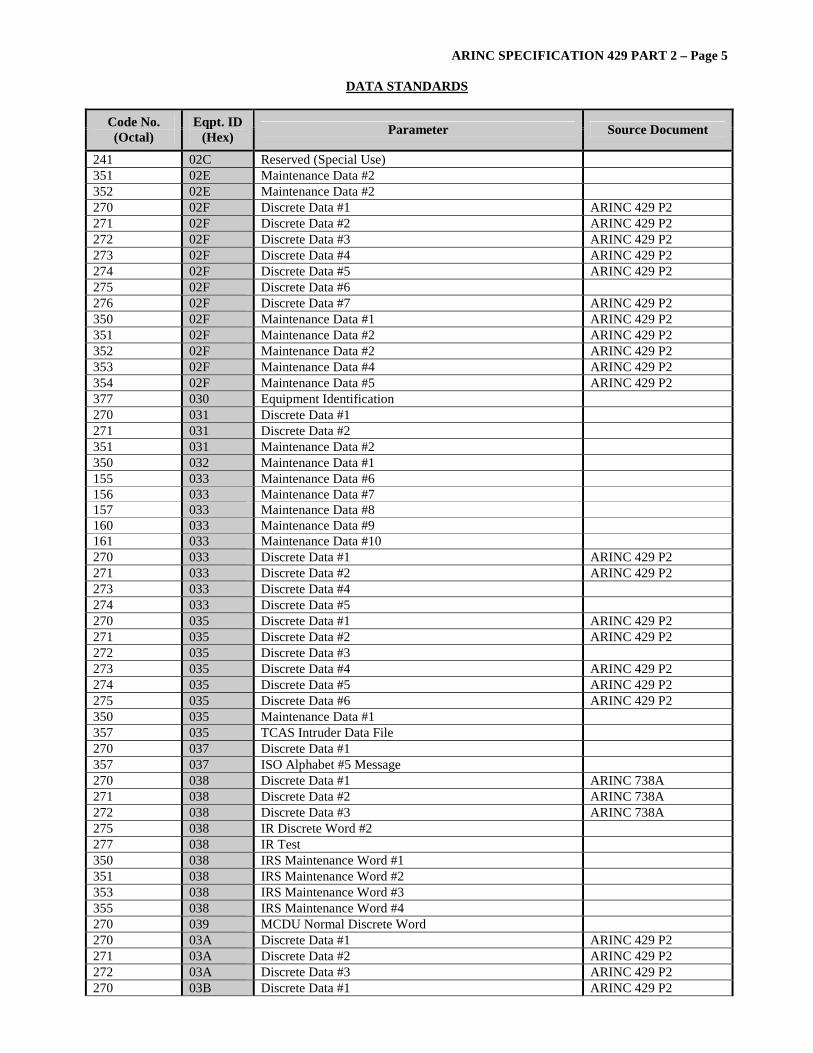
Code No. (Octal)
Eqpt. ID (Hex) Parameter Source Document
241 02C Reserved (Special Use) 351 02E Maintenance Data #2 352 02E Maintenance Data #2 270 02F Discrete Data #1 ARINC 429 P2 271 02F Discrete Data #2 ARINC 429 P2 272 02F Discrete Data #3 ARINC 429 P2 273 02F Discrete Data #4 ARINC 429 P2 274 02F Discrete Data #5 ARINC 429 P2 275 02F Discrete Data #6 276 02F Discrete Data #7 ARINC 429 P2 350 02F Maintenance Data #1 ARINC 429 P2 351 02F Maintenance Data #2 ARINC 429 P2 352 02F Maintenance Data #2 ARINC 429 P2 353 02F Maintenance Data #4 ARINC 429 P2 354 02F Maintenance Data #5 ARINC 429 P2 377 030 Equipment Identification 270 031 Discrete Data #1 271 031 Discrete Data #2 351 031 Maintenance Data #2 350 032 Maintenance Data #1 155 033 Maintenance Data #6 156 033 Maintenance Data #7 157 033 Maintenance Data #8 160 033 Maintenance Data #9 161 033 Maintenance Data #10 270 033 Discrete Data #1 ARINC 429 P2 271 033 Discrete Data #2 ARINC 429 P2 273 033 Discrete Data #4 274 033 Discrete Data #5 270 035 Discrete Data #1 ARINC 429 P2 271 035 Discrete Data #2 ARINC 429 P2 272 035 Discrete Data #3 273 035 Discrete Data #4 ARINC 429 P2 274 035 Discrete Data #5 ARINC 429 P2 275 035 Discrete Data #6 ARINC 429 P2 350 035 Maintenance Data #1 357 035 TCAS Intruder Data File 270 037 Discrete Data #1 357 037 ISO Alphabet #5 Message 270 038 Discrete Data #1 ARINC 738A 271 038 Discrete Data #2 ARINC 738A 272 038 Discrete Data #3 ARINC 738A 275 038 IR Discrete Word #2 277 038 IR Test 350 038 IRS Maintenance Word #1 351 038 IRS Maintenance Word #2 353 038 IRS Maintenance Word #3 355 038 IRS Maintenance Word #4 270 039 MCDU Normal Discrete Word 270 03A Discrete Data #1 ARINC 429 P2 271 03A Discrete Data #2 ARINC 429 P2 272 03A Discrete Data #3 ARINC 429 P2 270 03B Discrete Data #1 ARINC 429 P2
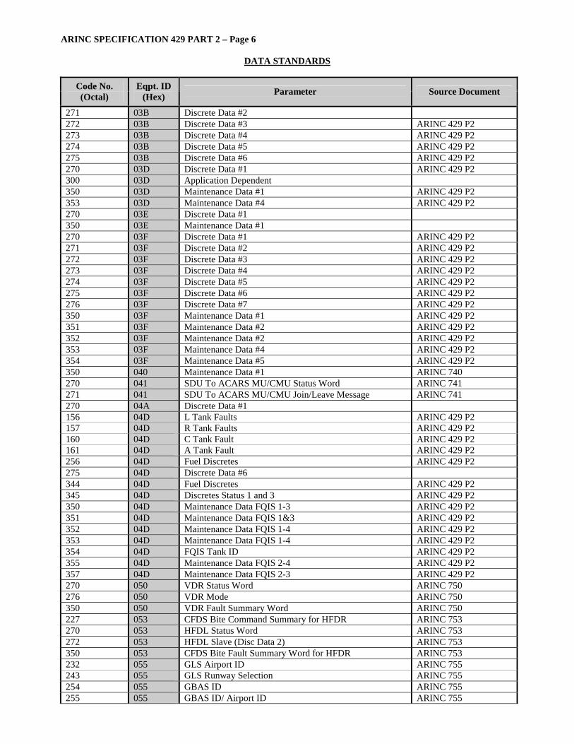
ARINC SPECIFICATION 429 PART 2 – Page 6
DATA STANDARDS
Code No. (Octal)
Eqpt. ID (Hex) Parameter Source Document
271 03B Discrete Data #2 272 03B Discrete Data #3 ARINC 429 P2 273 03B Discrete Data #4 ARINC 429 P2 274 03B Discrete Data #5 ARINC 429 P2 275 03B Discrete Data #6 ARINC 429 P2 270 03D Discrete Data #1 ARINC 429 P2 300 03D Application Dependent 350 03D Maintenance Data #1 ARINC 429 P2 353 03D Maintenance Data #4 ARINC 429 P2 270 03E Discrete Data #1 350 03E Maintenance Data #1 270 03F Discrete Data #1 ARINC 429 P2 271 03F Discrete Data #2 ARINC 429 P2 272 03F Discrete Data #3 ARINC 429 P2 273 03F Discrete Data #4 ARINC 429 P2 274 03F Discrete Data #5 ARINC 429 P2 275 03F Discrete Data #6 ARINC 429 P2 276 03F Discrete Data #7 ARINC 429 P2 350 03F Maintenance Data #1 ARINC 429 P2 351 03F Maintenance Data #2 ARINC 429 P2 352 03F Maintenance Data #2 ARINC 429 P2 353 03F Maintenance Data #4 ARINC 429 P2 354 03F Maintenance Data #5 ARINC 429 P2 350 040 Maintenance Data #1 ARINC 740 270 041 SDU To ACARS MU/CMU Status Word ARINC 741 271 041 SDU To ACARS MU/CMU Join/Leave Message ARINC 741 270 04A Discrete Data #1 156 04D L Tank Faults ARINC 429 P2 157 04D R Tank Faults ARINC 429 P2 160 04D C Tank Fault ARINC 429 P2 161 04D A Tank Fault ARINC 429 P2 256 04D Fuel Discretes ARINC 429 P2 275 04D Discrete Data #6 344 04D Fuel Discretes ARINC 429 P2 345 04D Discretes Status 1 and 3 ARINC 429 P2 350 04D Maintenance Data FQIS 1-3 ARINC 429 P2 351 04D Maintenance Data FQIS 1&3 ARINC 429 P2 352 04D Maintenance Data FQIS 1-4 ARINC 429 P2 353 04D Maintenance Data FQIS 1-4 ARINC 429 P2 354 04D FQIS Tank ID ARINC 429 P2 355 04D Maintenance Data FQIS 2-4 ARINC 429 P2 357 04D Maintenance Data FQIS 2-3 ARINC 429 P2 270 050 VDR Status Word ARINC 750 276 050 VDR Mode ARINC 750 350 050 VDR Fault Summary Word ARINC 750 227 053 CFDS Bite Command Summary for HFDR ARINC 753 270 053 HFDL Status Word ARINC 753 272 053 HFDL Slave (Disc Data 2) ARINC 753 350 053 CFDS Bite Fault Summary Word for HFDR ARINC 753 232 055 GLS Airport ID ARINC 755 243 055 GLS Runway Selection ARINC 755 254 055 GBAS ID ARINC 755 255 055 GBAS ID/ Airport ID ARINC 755

ARINC SPECIFICATION 429 PART 2 – Page 7
DATA STANDARDS
Code No. (Octal)
Eqpt. ID (Hex) Parameter Source Document
256 055 MLS Station ID #1 ARINC 755 263 055 Ground Station/Approach ARINC 755 264 055 Ground Station/Approach ARINC 755 270 055 MLS Discrete ARINC 755 271 055 MMR Discrete ARINC 755 273 055 GNSS Status ARINC 755 350 055 ILS Maintenance Word ARINC 755 351 055 MMR Maintenance Word ARINC 755 352 055 MLS Bite Status ARINC 755 270 056 Status Discretes ARINC 755 271 056 Discrete Data #2 272 056 Discrete Data #3 275 056 Discrete Data #6 276 056 Discrete Data #7 301 056 Application Dependent 302 056 Application Dependent 303 056 Application Dependent 354 056 Maintenance Data #5 357 056 ISO Alphabet #5 Message 270 027 Output Status Word #1 ARINC 758 276 024 Output Status Word #2 ARINC 758 350 024 Maintenance Word #1 ARINC 758 351 024 Maintenance Word #2 ARINC 758 352 024 Maintenance Word 151 05A LB/KG Control Word ARINC 429 P2 155 05A FQIC 270 05A Discrete Data #1 271 05A Fuel Density 272 05A FQS Fuel Density ARINC 429 P2 273 05A FQS Right Wing (A320) ARINC 429 P2 274 05A FQS (A320) ARINC 429 P2 275 05A FQS – Left Wing (A320) ARINC 429 P2 276 05A Discrete Data #7 357 05A Part Number (Manufacturer - Specific) 270 060 Intent Status 270 060 Status Discretes 270 060 Discrete Data #1 271 060 Discrete Data #2 272 060 Discrete Data #3 275 060 Discrete Data #6 276 060 Discrete Data #7 301 060 Application Dependent 302 060 Application Dependent 303 060 Application Dependent 354 060 Maintenance Data #5 020 06D Landing Gear Position Infor & System Status 021 06D Landing Gear Position Infor & System Status 022 06D Landing Gear Position Infor & System Status 023 06D Landing Gear Position Infor & System Status 024 06D Landing Gear Position Infor & System Status 145 0A1 AFS DFDR Discretes #1 ARINC 429 P2 146 0A1 AFS DFDR Discretes #2 ARINC 429 P2 147 0A1 AFS DFDR Discretes #3

ARINC SPECIFICATION 429 PART 2 – Page 8
DATA STANDARDS
Code No. (Octal)
Eqpt. ID (Hex) Parameter Source Document
270 0A2 Discrete Data #1 271 0A2 Discrete Data #2 270 0A8 Discrete Data #1 271 0A8 Discrete Data #2 270 0AD Discrete Data #1 271 0AD Discrete Data #2 272 0AD Discrete Data #3 013 0B8 Control Word for TCAS/Mode S ARINC 429 P2 016 0B8 Control Word for TCAS/Mode S ARINC 429 P2 031 0B8 Beacon Transponder Code 207 0B9 HF Control Word 155 0BB Maintenance Data #6 156 0BB Maintenance Data #7 157 0BB Maintenance Data #8 160 0BB Maintenance Data #9 276 0BB Discrete Data #7 354 0BB Maintenance Data #5 270 0C5 Discrete Data #1 271 0C5 Discrete Data #2 272 0C5 Discrete Data #3 273 0C5 Discrete Data #4 274 0C5 Discrete Data #5 ARINC 429 P2 005 0D0 Engine Discrete ARINC 429 P2 006 0D0 Engine Discrete ARINC 429 P2 155 10A Maintenance Data #6 156 10A Maintenance Data #7 157 10A Maintenance Data #8 160 10A Maintenance Data #9 161 10A Maintenance Data #10 ARINC 429 P2 270 10A Discrete Data #1 271 10A Discrete Data #2 272 10A Discrete Data #3 273 10A Discrete Data #4 274 10A Discrete Data #5 275 10A Discrete Data #6 350 10A Maintenance Data #1 351 10A Maintenance Data #2 352 10A Maintenance Data #2 353 10A Maintenance Data #4 354 10A Maintenance Data #5 155 10B Maintenance Data #6 156 10B Maintenance Data #7 157 10B Maintenance Data #8 160 10B Maintenance Data #9 161 10B Maintenance Data #10 ARINC 429 P2 270 10B Discrete Data #1 271 10B Discrete Data #2 272 10B Discrete Data #3 273 10B Discrete Data #4 274 10B Discrete Data #5 275 10B Discrete Data #6 350 10B Maintenance Data #1 351 10B Maintenance Data #2
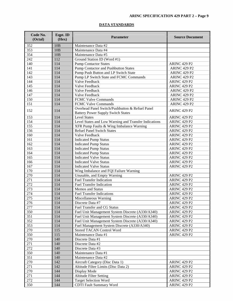
ARINC SPECIFICATION 429 PART 2 – Page 9
DATA STANDARDS
Code No. (Octal)
Eqpt. ID (Hex) Parameter Source Document
352 10B Maintenance Data #2 353 10B Maintenance Data #4 354 10B Maintenance Data #5 242 112 Ground Station ID (Word #1) 140 114 Pump Contactor States ARINC 429 P2 141 114 Pump Contactor and Pushbutton States ARINC 429 P2 142 114 Pump Push Button and LP Switch State ARINC 429 P2 143 114 Pump LP Switch State and FCMC Commands ARINC 429 P2 144 114 Valve Feedback ARINC 429 P2 145 114 Valve Feedback ARINC 429 P2 146 114 Valve Feedback ARINC 429 P2 147 114 Valve Feedback ARINC 429 P2 150 114 FCMC Valve Commands ARINC 429 P2 151 114 FCMC Valve Commands ARINC 429 P2
152 114 Overhead Panel Switch/Pushbutton & Refuel Panel Battery Power Supply Switch States ARINC 429 P2
153 114 Level States ARINC 429 P2 154 114 Level States and Low Warning and Transfer Indications ARINC 429 P2 155 114 XFR Pump Faults & Wing Imbalance Warning ARINC 429 P2 156 114 Refuel Panel Switch States ARINC 429 P2 160 114 Valve Feedback ARINC 429 P2 161 114 Indicated Pump Status ARINC 429 P2 162 114 Indicated Pump Status ARINC 429 P2 163 114 Indicated Pump Status ARINC 429 P2 164 114 Indicated Pump Status ARINC 429 P2 165 114 Indicated Valve Status ARINC 429 P2 166 114 Indicated Valve Status ARINC 429 P2 167 114 Indicated Valve Status ARINC 429 P2 170 114 Wing Imbalance and FQI Failure Warning 270 114 Unusable, and Empty Warning ARINC 429 P2 271 114 Fuel Transfer Indication ARINC 429 P2 272 114 Fuel Transfer Indication ARINC 429 P2 273 114 Memos and Status ARINC 429 P2 274 114 Fuel Transfer Indications ARINC 429 P2 275 114 Miscellaneous Warning ARINC 429 P2 276 114 Discrete Data #7 ARINC 429 P2 277 114 Fuel Transfer and CG Status ARINC 429 P2 350 114 Fuel Unit Management System Discrete (A330/A340) ARINC 429 P2 351 114 Fuel Unit Management System Discrete (A330/A340) ARINC 429 P2 352 114 Fuel Unit Management System Discrete (A330/A340) ARINC 429 P2 353 114 Fuel Management System Discrete (A330/A340) ARINC 429 P2 270 115 Stored TACAN Control Word ARINC 429 P2 350 115 Maintenance Data #1 ARINC 429 P2 270 140 Discrete Data #1 271 140 Discrete Data #2 272 140 Discrete Data #3 350 140 Maintenance Data #1 351 140 Maintenance Data #2 270 142 Aircraft Category (Disc Data 1) ARINC 429 P2 271 142 Altitude Filter Limits (Disc Data 2) ARINC 429 P2 270 144 Display Mode ARINC 429 P2 271 144 Altitude Filter Setting ARINC 429 P2 272 144 Target Selection Word ARINC 429 P2 350 144 CDTI Fault Summary Word ARINC 429 P2
ARINC SPECIFICATION 429 PART 2 – Page 10
DATA STANDARDS
Code No. (Octal)
Eqpt. ID (Hex) Parameter Source Document
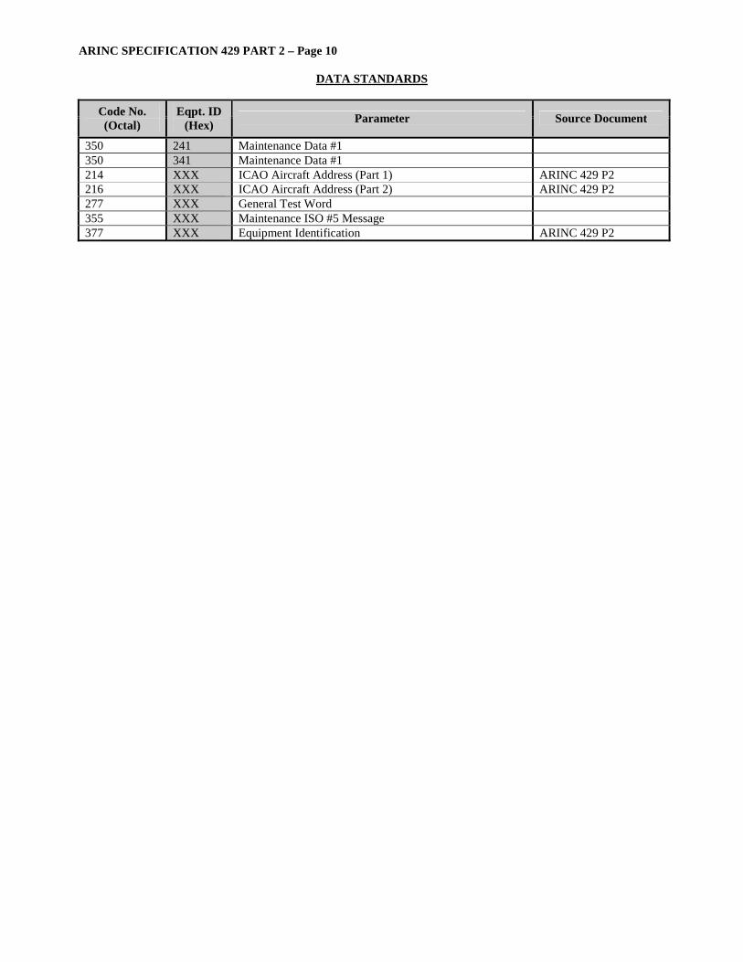
350 241 Maintenance Data #1 350 341 Maintenance Data #1 214 XXX ICAO Aircraft Address (Part 1) ARINC 429 P2 216 XXX ICAO Aircraft Address (Part 2) ARINC 429 P2 277 XXX General Test Word 355 XXX Maintenance ISO #5 Message 377 XXX Equipment Identification ARINC 429 P2
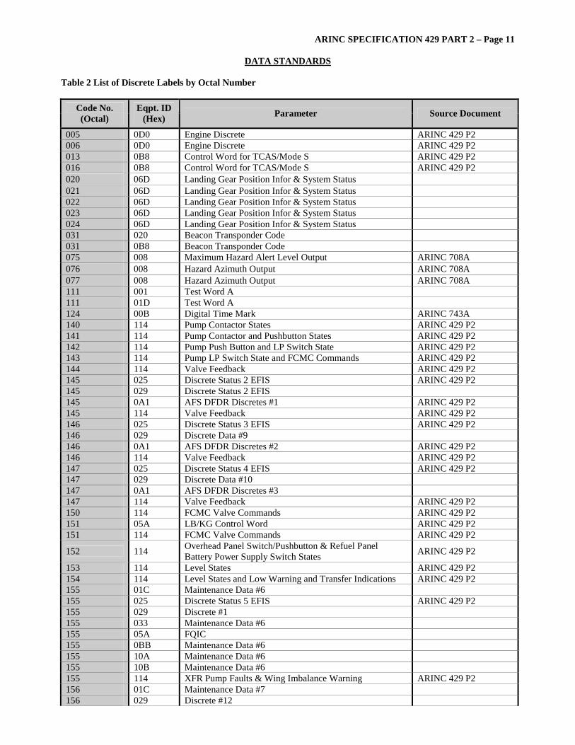
ARINC SPECIFICATION 429 PART 2 – Page 11
DATA STANDARDS
Table 2 List of Discrete Labels by Octal Number
Code No. (Octal)
Eqpt. ID (Hex) Parameter Source Document
005 0D0 Engine Discrete ARINC 429 P2 006 0D0 Engine Discrete ARINC 429 P2 013 0B8 Control Word for TCAS/Mode S ARINC 429 P2 016 0B8 Control Word for TCAS/Mode S ARINC 429 P2 020 06D Landing Gear Position Infor & System Status 021 06D Landing Gear Position Infor & System Status 022 06D Landing Gear Position Infor & System Status 023 06D Landing Gear Position Infor & System Status 024 06D Landing Gear Position Infor & System Status 031 020 Beacon Transponder Code 031 0B8 Beacon Transponder Code 075 008 Maximum Hazard Alert Level Output ARINC 708A 076 008 Hazard Azimuth Output ARINC 708A 077 008 Hazard Azimuth Output ARINC 708A 111 001 Test Word A 111 01D Test Word A 124 00B Digital Time Mark ARINC 743A 140 114 Pump Contactor States ARINC 429 P2 141 114 Pump Contactor and Pushbutton States ARINC 429 P2 142 114 Pump Push Button and LP Switch State ARINC 429 P2 143 114 Pump LP Switch State and FCMC Commands ARINC 429 P2 144 114 Valve Feedback ARINC 429 P2 145 025 Discrete Status 2 EFIS ARINC 429 P2 145 029 Discrete Status 2 EFIS 145 0A1 AFS DFDR Discretes #1 ARINC 429 P2 145 114 Valve Feedback ARINC 429 P2 146 025 Discrete Status 3 EFIS ARINC 429 P2 146 029 Discrete Data #9 146 0A1 AFS DFDR Discretes #2 ARINC 429 P2 146 114 Valve Feedback ARINC 429 P2 147 025 Discrete Status 4 EFIS ARINC 429 P2 147 029 Discrete Data #10 147 0A1 AFS DFDR Discretes #3 147 114 Valve Feedback ARINC 429 P2 150 114 FCMC Valve Commands ARINC 429 P2 151 05A LB/KG Control Word ARINC 429 P2 151 114 FCMC Valve Commands ARINC 429 P2
152 114 Overhead Panel Switch/Pushbutton & Refuel Panel Battery Power Supply Switch States ARINC 429 P2
153 114 Level States ARINC 429 P2 154 114 Level States and Low Warning and Transfer Indications ARINC 429 P2 155 01C Maintenance Data #6 155 025 Discrete Status 5 EFIS ARINC 429 P2 155 029 Discrete #1 155 033 Maintenance Data #6 155 05A FQIC 155 0BB Maintenance Data #6 155 10A Maintenance Data #6 155 10B Maintenance Data #6 155 114 XFR Pump Faults & Wing Imbalance Warning ARINC 429 P2 156 01C Maintenance Data #7 156 029 Discrete #12

ARINC SPECIFICATION 429 PART 2 – Page 12
DATA STANDARDS
Code No. (Octal)
Eqpt. ID (Hex) Parameter Source Document
156 033 Maintenance Data #7 156 04D L Tank Faults ARINC 429 P2 156 0BB Maintenance Data #7 156 10A Maintenance Data #7 156 10B Maintenance Data #7 156 114 Refuel Panel Switch States ARINC 429 P2 157 027 MLS Dataword 2 ARINC 727 157 033 Maintenance Data #8 157 04D R Tank Faults ARINC 429 P2 157 0BB Maintenance Data #8 157 10A Maintenance Data #8 157 10B Maintenance Data #8 160 01C Maintenance Data #9 160 025 Discrete Status 6 EFIS ARINC 429 P2 160 033 Maintenance Data #9 160 04D C Tank Fault ARINC 429 P2 160 0BB Maintenance Data #9 160 10A Maintenance Data #9 160 10B Maintenance Data #9 160 114 Valve Feedback ARINC 429 P2 161 01C Maintenance Data #10 161 025 Discrete Status 7 EFIS ARINC 429 P2 161 027 MLS Data word 4 ARINC 727 161 033 Maintenance Data #10 161 04D A Tank Fault ARINC 429 P2 161 10A Maintenance Data #10 ARINC 429 P2 161 10B Maintenance Data #10 ARINC 429 P2 161 114 Indicated Pump Status ARINC 429 P2 162 114 Indicated Pump Status ARINC 429 P2 163 114 Indicated Pump Status ARINC 429 P2 164 114 Indicated Pump Status ARINC 429 P2 165 114 Indicated Valve Status ARINC 429 P2 166 114 Indicated Valve Status ARINC 429 P2 167 114 Indicated Valve Status ARINC 429 P2 170 114 Wing Imbalance and FQI Failure Warning 207 002 HF Control Word 207 0B9 HF Control Word 214 XXX ICAO Aircraft Address (Part 1) ARINC 429 P2 216 XXX ICAO Aircraft Address (Part 2) ARINC 429 P2 227 019 CFDS Bite Command Summary for HFDR ARINC 753 227 053 CFDS Bite Command Summary for HFDR ARINC 753 232 055 GLS Airport ID ARINC 755 241 02C Reserved (Special Use) 242 009 Ground Station ID (Word #1) 242 010 Ground Station ID (Word #1) 242 011 Ground Station ID (Word #1) ARINC 711 242 112 Ground Station ID (Word #1) 243 055 GLS Runway Selection ARINC 755 244 009 Ground Station ID (Word #2) 244 010 Ground Station ID (Word #2) 244 011 VOR Ground Station Ident Word #2 ARINC 711 244 012 Ground Station ID (Word #2) 246 009 DME Ground Station Ident Word #1 ARINC 709 247 009 DME Ground Station Ident Word #1 ARINC 709
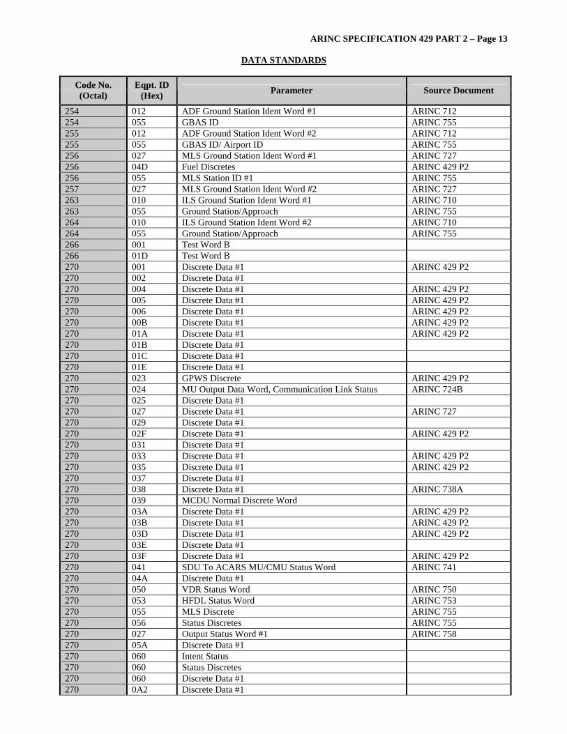
ARINC SPECIFICATION 429 PART 2 – Page 13
DATA STANDARDS
Code No. (Octal)
Eqpt. ID (Hex) Parameter Source Document
254 012 ADF Ground Station Ident Word #1 ARINC 712 254 055 GBAS ID ARINC 755 255 012 ADF Ground Station Ident Word #2 ARINC 712 255 055 GBAS ID/ Airport ID ARINC 755 256 027 MLS Ground Station Ident Word #1 ARINC 727 256 04D Fuel Discretes ARINC 429 P2 256 055 MLS Station ID #1 ARINC 755 257 027 MLS Ground Station Ident Word #2 ARINC 727 263 010 ILS Ground Station Ident Word #1 ARINC 710 263 055 Ground Station/Approach ARINC 755 264 010 ILS Ground Station Ident Word #2 ARINC 710 264 055 Ground Station/Approach ARINC 755 266 001 Test Word B 266 01D Test Word B 270 001 Discrete Data #1 ARINC 429 P2 270 002 Discrete Data #1 270 004 Discrete Data #1 ARINC 429 P2 270 005 Discrete Data #1 ARINC 429 P2 270 006 Discrete Data #1 ARINC 429 P2 270 00B Discrete Data #1 ARINC 429 P2 270 01A Discrete Data #1 ARINC 429 P2 270 01B Discrete Data #1 270 01C Discrete Data #1 270 01E Discrete Data #1 270 023 GPWS Discrete ARINC 429 P2 270 024 MU Output Data Word, Communication Link Status ARINC 724B 270 025 Discrete Data #1 270 027 Discrete Data #1 ARINC 727 270 029 Discrete Data #1 270 02F Discrete Data #1 ARINC 429 P2 270 031 Discrete Data #1 270 033 Discrete Data #1 ARINC 429 P2 270 035 Discrete Data #1 ARINC 429 P2 270 037 Discrete Data #1 270 038 Discrete Data #1 ARINC 738A 270 039 MCDU Normal Discrete Word 270 03A Discrete Data #1 ARINC 429 P2 270 03B Discrete Data #1 ARINC 429 P2 270 03D Discrete Data #1 ARINC 429 P2 270 03E Discrete Data #1 270 03F Discrete Data #1 ARINC 429 P2 270 041 SDU To ACARS MU/CMU Status Word ARINC 741 270 04A Discrete Data #1 270 050 VDR Status Word ARINC 750 270 053 HFDL Status Word ARINC 753 270 055 MLS Discrete ARINC 755 270 056 Status Discretes ARINC 755 270 027 Output Status Word #1 ARINC 758 270 05A Discrete Data #1 270 060 Intent Status 270 060 Status Discretes 270 060 Discrete Data #1 270 0A2 Discrete Data #1
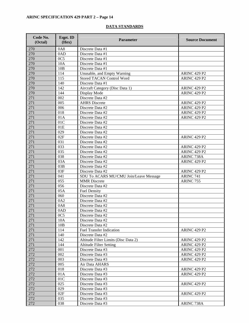
ARINC SPECIFICATION 429 PART 2 – Page 14
DATA STANDARDS
Code No. (Octal)
Eqpt. ID (Hex) Parameter Source Document
270 0A8 Discrete Data #1 270 0AD Discrete Data #1 270 0C5 Discrete Data #1 270 10A Discrete Data #1 270 10B Discrete Data #1 270 114 Unusable, and Empty Warning ARINC 429 P2 270 115 Stored TACAN Control Word ARINC 429 P2 270 140 Discrete Data #1 270 142 Aircraft Category (Disc Data 1) ARINC 429 P2 270 144 Display Mode ARINC 429 P2 271 002 Discrete Data #2 271 005 AHRS Discrete ARINC 429 P2 271 006 Discrete Data #2 ARINC 429 P2 271 018 Discrete Data #2 ARINC 429 P2 271 01A Discrete Data #2 ARINC 429 P2 271 01C Discrete Data #2 271 01E Discrete Data #2 271 029 Discrete Data #2 271 02F Discrete Data #2 ARINC 429 P2 271 031 Discrete Data #2 271 033 Discrete Data #2 ARINC 429 P2 271 035 Discrete Data #2 ARINC 429 P2 271 038 Discrete Data #2 ARINC 738A 271 03A Discrete Data #2 ARINC 429 P2 271 03B Discrete Data #2 271 03F Discrete Data #2 ARINC 429 P2 271 041 SDU To ACARS MU/CMU Join/Leave Message ARINC 741 271 055 MMR Discrete ARINC 755 271 056 Discrete Data #2 271 05A Fuel Density 271 060 Discrete Data #2 271 0A2 Discrete Data #2 271 0A8 Discrete Data #2 271 0AD Discrete Data #2 271 0C5 Discrete Data #2 271 10A Discrete Data #2 271 10B Discrete Data #2 271 114 Fuel Transfer Indication ARINC 429 P2 271 140 Discrete Data #2 271 142 Altitude Filter Limits (Disc Data 2) ARINC 429 P2 271 144 Altitude Filter Setting ARINC 429 P2 272 001 Discrete Data #3 ARINC 429 P2 272 002 Discrete Data #3 ARINC 429 P2 272 003 Discrete Data #3 ARINC 429 P2 272 005 Air Data AHARS 272 018 Discrete Data #3 ARINC 429 P2 272 01A Discrete Data #3 ARINC 429 P2 272 01C Discrete Data #3 272 025 Discrete Data #3 ARINC 429 P2 272 029 Discrete Data #3 272 02F Discrete Data #3 ARINC 429 P2 272 035 Discrete Data #3 272 038 Discrete Data #3 ARINC 738A
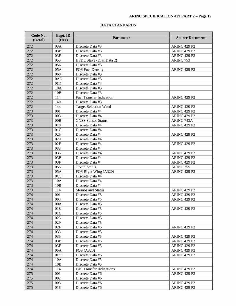
ARINC SPECIFICATION 429 PART 2 – Page 15
DATA STANDARDS
Code No. (Octal)
Eqpt. ID (Hex) Parameter Source Document
272 03A Discrete Data #3 ARINC 429 P2 272 03B Discrete Data #3 ARINC 429 P2 272 03F Discrete Data #3 ARINC 429 P2 272 053 HFDL Slave (Disc Data 2) ARINC 753 272 056 Discrete Data #3 272 05A FQS Fuel Density ARINC 429 P2 272 060 Discrete Data #3 272 0AD Discrete Data #3 272 0C5 Discrete Data #3 272 10A Discrete Data #3 272 10B Discrete Data #3 272 114 Fuel Transfer Indication ARINC 429 P2 272 140 Discrete Data #3 272 144 Target Selection Word ARINC 429 P2 273 001 Discrete Data #4 ARINC 429 P2 273 003 Discrete Data #4 ARINC 429 P2 273 00B GNSS Sensor Status ARINC 743A 273 018 Discrete Data #4 ARINC 429 P2 273 01C Discrete Data #4 273 025 Discrete Data #4 ARINC 429 P2 273 029 Discrete Data #4 273 02F Discrete Data #4 ARINC 429 P2 273 033 Discrete Data #4 273 035 Discrete Data #4 ARINC 429 P2 273 03B Discrete Data #4 ARINC 429 P2 273 03F Discrete Data #4 ARINC 429 P2 273 055 GNSS Status ARINC 755 273 05A FQS Right Wing (A320) ARINC 429 P2 273 0C5 Discrete Data #4 273 10A Discrete Data #4 273 10B Discrete Data #4 273 114 Memos and Status ARINC 429 P2 274 001 Discrete Data #5 ARINC 429 P2 274 003 Discrete Data #5 ARINC 429 P2 274 00A Discrete Data #5 274 018 Discrete Data #5 ARINC 429 P2 274 01C Discrete Data #5 274 025 Discrete Data #5 274 029 Discrete Data #5 274 02F Discrete Data #5 ARINC 429 P2 274 033 Discrete Data #5 274 035 Discrete Data #5 ARINC 429 P2 274 03B Discrete Data #5 ARINC 429 P2 274 03F Discrete Data #5 ARINC 429 P2 274 05A FQS (A320) ARINC 429 P2 274 0C5 Discrete Data #5 ARINC 429 P2 274 10A Discrete Data #5 274 10B Discrete Data #5 274 114 Fuel Transfer Indications ARINC 429 P2 275 001 Discrete Data #6 ARINC 429 P2 275 002 Discrete Data #6 275 003 Discrete Data #6 ARINC 429 P2 275 018 Discrete Data #6 ARINC 429 P2

ARINC SPECIFICATION 429 PART 2 – Page 16
DATA STANDARDS
Code No. (Octal)
Eqpt. ID (Hex) Parameter Source Document
275 01C Discrete Data #6 275 025 Discrete Data #6 275 029 Discrete Data #6 275 02B Discrete Data #6 275 02F Discrete Data #6 275 035 Discrete Data #6 ARINC 429 P2 275 038 IR Discrete Word #2 275 03B Discrete Data #6 ARINC 429 P2 275 03F Discrete Data #6 ARINC 429 P2 275 04D Discrete Data #6 275 056 Discrete Data #6 275 05A FQS – Left Wing (A320) ARINC 429 P2 275 060 Discrete Data #6 275 10A Discrete Data #6 275 10B Discrete Data #6 275 114 Miscellaneous Warning ARINC 429 P2 276 002 Discrete Data #7 276 018 Discrete Data #7 ARINC 429 P2 276 01C Discrete Data #7 276 025 Discrete Status 8 EFIS ARINC 429 P2 276 029 Discrete Data #7 276 02F Discrete Data #7 ARINC 429 P2 276 03F Discrete Data #7 ARINC 429 P2 276 050 VDR Mode ARINC 750 276 056 Discrete Data #7 276 024 Output Status Word #2 ARINC 758 276 05A Discrete Data #7 276 060 Discrete Data #7 276 0BB Discrete Data #7 276 114 Discrete Data #7 ARINC 429 P2 277 004 IRS Maintenance Discrete 277 018 Discrete Data #8 ARINC 429 P2 277 038 IR Test 277 114 Fuel Transfer and CG Status ARINC 429 P2 277 XXX General Test Word 300 001 Application Dependent 300 01A Application Dependent 300 03D Application Dependent 301 001 Application Dependent 301 002 Application Dependent 301 01A Application Dependent 301 056 Application Dependent 301 060 Application Dependent 302 001 Application Dependent 302 002 Application Dependent 302 01A Application Dependent 302 056 Application Dependent 302 060 Application Dependent 303 001 Application Dependent 303 002 Application Dependent 303 01A Application Dependent 303 056 Application Dependent 303 060 Application Dependent

ARINC SPECIFICATION 429 PART 2 – Page 17
DATA STANDARDS
Code No. (Octal)
Eqpt. ID (Hex) Parameter Source Document
304 001 Application Dependent 304 01A Application Dependent 305 001 Application Dependent 305 01A Application Dependent 306 001 Application Dependent 306 01A Application Dependent 307 001 Application Dependent 307 01A Application Dependent 344 04D Fuel Discretes ARINC 429 P2 345 04D Discretes Status 1 and 3 ARINC 429 P2 350 003 Maintenance Data #1 350 004 IRS Maintenance Discrete 350 006 Maintenance Data #1 350 00B GPS Test Word (manufacturer specific) 350 018 Maintenance Data #1 ARINC 429 P2 350 019 CFDS Bite Fault Summary Word for HFDR ARINC 753 350 01A Maintenance Data #1 ARINC 429 P2 350 01C Maintenance Data #1 350 023 Maintenance Data #1 350 024 MU Output Data Word Failure Status ARINC 724B 350 025 Maintenance Data #1 350 027 Maintenance Data #1 ARINC 429 P2 350 029 Maintenance Data #1 350 02F Maintenance Data #1 ARINC 429 P2 350 032 Maintenance Data #1 350 035 Maintenance Data #1 350 038 IRS Maintenance Word #1 350 03D Maintenance Data #1 ARINC 429 P2 350 03E Maintenance Data #1 350 03F Maintenance Data #1 ARINC 429 P2 350 040 Maintenance Data #1 ARINC 740 350 04D Maintenance Data FQIS 1-3 ARINC 429 P2 350 050 VDR Fault Summary Word ARINC 750 350 053 CFDS Bite Fault Summary Word for HFDR ARINC 753 350 055 ILS Maintenance Word ARINC 755 350 024 Maintenance Word #1 ARINC 758 350 10A Maintenance Data #1 350 10B Maintenance Data #1 350 114 Fuel Unit Management System Discrete (A330/A340) ARINC 429 P2 350 115 Maintenance Data #1 ARINC 429 P2 350 140 Maintenance Data #1 350 144 CDTI Fault Summary Word ARINC 429 P2 350 241 Maintenance Data #1 350 341 Maintenance Data #1 351 006 Maintenance Data #2 351 00B SRU Test Word (manufacturer specific) 351 01A Maintenance Data #2 ARINC 429 P2 351 01C Maintenance Data #2 351 024 MU Output Data Word Failure Status ARINC 724B 351 025 Maintenance Data #2 351 029 Maintenance Data #2 351 02E Maintenance Data #2 351 02F Maintenance Data #2 ARINC 429 P2
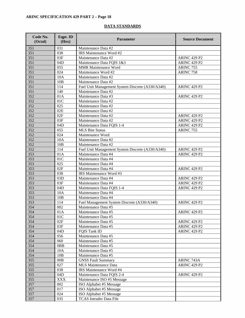
ARINC SPECIFICATION 429 PART 2 – Page 18
DATA STANDARDS
Code No. (Octal)
Eqpt. ID (Hex) Parameter Source Document
351 031 Maintenance Data #2 351 038 IRS Maintenance Word #2 351 03F Maintenance Data #2 ARINC 429 P2 351 04D Maintenance Data FQIS 1&3 ARINC 429 P2 351 055 MMR Maintenance Word ARINC 755 351 024 Maintenance Word #2 ARINC 758 351 10A Maintenance Data #2 351 10B Maintenance Data #2 351 114 Fuel Unit Management System Discrete (A330/A340) ARINC 429 P2 351 140 Maintenance Data #2 352 01A Maintenance Data #3 ARINC 429 P2 352 01C Maintenance Data #2 352 025 Maintenance Data #2 352 02E Maintenance Data #2 352 02F Maintenance Data #2 ARINC 429 P2 352 03F Maintenance Data #2 ARINC 429 P2 352 04D Maintenance Data FQIS 1-4 ARINC 429 P2 352 055 MLS Bite Status ARINC 755 352 024 Maintenance Word 352 10A Maintenance Data #2 352 10B Maintenance Data #2 352 114 Fuel Unit Management System Discrete (A330/A340) ARINC 429 P2 353 01A Maintenance Data #4 ARINC 429 P2 353 01C Maintenance Data #4 353 025 Maintenance Data #4 353 02F Maintenance Data #4 ARINC 429 P2 353 038 IRS Maintenance Word #3 353 03D Maintenance Data #4 ARINC 429 P2 353 03F Maintenance Data #4 ARINC 429 P2 353 04D Maintenance Data FQIS 1-4 ARINC 429 P2 353 10A Maintenance Data #4 353 10B Maintenance Data #4 353 114 Fuel Management System Discrete (A330/A340) ARINC 429 P2 354 002 Maintenance Data #5 354 01A Maintenance Data #5 ARINC 429 P2 354 01C Maintenance Data #5 354 02F Maintenance Data #5 ARINC 429 P2 354 03F Maintenance Data #5 ARINC 429 P2 354 04D FQIS Tank ID ARINC 429 P2 354 056 Maintenance Data #5 354 060 Maintenance Data #5 354 0BB Maintenance Data #5 354 10A Maintenance Data #5 354 10B Maintenance Data #5 355 00B GNSS Fault Summary ARINC 743A 355 027 MLS Maintenance Data ARINC 429 P2 355 038 IRS Maintenance Word #4 355 04D Maintenance Data FQIS 2-4 ARINC 429 P2 355 XXX Maintenance ISO #5 Message 357 002 ISO Alphabet #5 Message 357 017 ISO Alphabet #5 Message 357 024 ISO Alphabet #5 Message 357 035 TCAS Intruder Data File
ARINC SPECIFICATION 429 PART 2 – Page 19
DATA STANDARDS
Code No. (Octal)
Eqpt. ID (Hex) Parameter Source Document
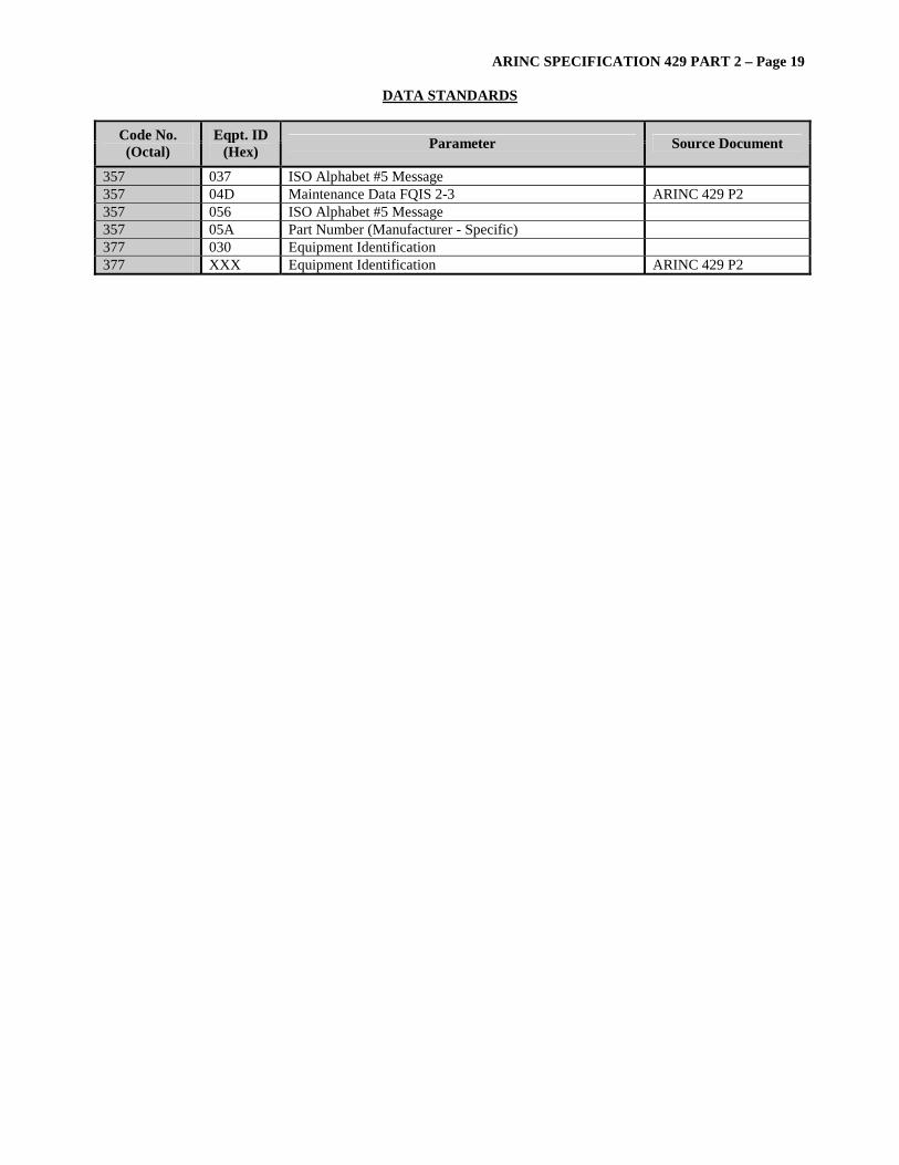
357 037 ISO Alphabet #5 Message 357 04D Maintenance Data FQIS 2-3 ARINC 429 P2 357 056 ISO Alphabet #5 Message 357 05A Part Number (Manufacturer - Specific) 377 030 Equipment Identification 377 XXX Equipment Identification ARINC 429 P2
ARINC SPECIFICATION 429 PART 2 – Page 20
DATA STANDARDS
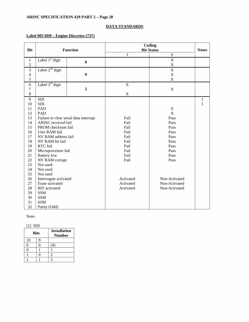
Label 005 0D0 – Engine Discretes (737)
Coding Bit Status Bit Function
1 0 Notes
1 Label 1st digit X 2 0 X 3 Label 2nd digit X 4 X 5
0 X
6 Label 3rd digit X 7 X 8
5 X
9 SDI 1 10 SDI 1 11 PAD X 12 PAD X 13 Failure to clear serial data interrupt Fail Pass 14 ARINC received fail Fail Pass 15 PROM checksum fail Fail Pass 16 User RAM fail Fail Pass 17 NV RAM address fail Fail Pass 18 NV RAM bit fail Fail Pass 19 RTC fail Fail Pass 20 Microprocessor fail Fail Pass 21 Battery low Fail Pass 22 NV RAM corrupt Fail Pass 23 Not used 24 Not used 25 Not used 26 Interrogate activated Activated Non-Activated 27 Erase activated Activated Non-Activated 28 BIT activated Activated Non-Activated 29 SSM 30 SSM 31 SSM 32 Parity (Odd)
Note: [1] SDI
Bits Installation Number
10 9 0 0 (4) 0 1 1 1 0 2 1 1 3
ARINC SPECIFICATION 429 PART 2 – Page 21
DATA STANDARDS
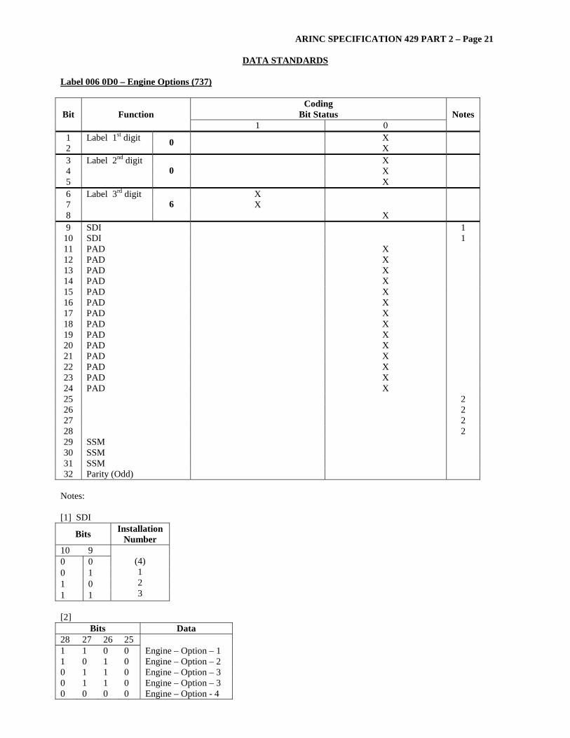
Label 006 0D0 – Engine Options (737)
Coding Bit Status Bit Function
1 0 Notes
1 Label 1st digit X 2 0 X 3 Label 2nd digit X 4 X 5
0 X
6 Label 3rd digit X 7 X 8
6 X
9 SDI 1 10 SDI 1 11 PAD X 12 PAD X 13 PAD X 14 PAD X 15 PAD X 16 PAD X 17 PAD X 18 PAD X 19 PAD X 20 PAD X 21 PAD X 22 PAD X 23 PAD X 24 PAD X 25 2 26 2 27 2 28 2 29 SSM 30 SSM 31 SSM 32 Parity (Odd)
Notes: [1] SDI
Bits Installation Number
10 9 0 0 0 1 1 0 1 1
(4) 1 2 3
[2]
Bits Data 28 27 26 25 1 1 0 0 Engine – Option – 1 1 0 1 0 Engine – Option – 2 0 1 1 0 Engine – Option – 3 0 1 1 0 Engine – Option – 3 0 0 0 0 Engine – Option - 4
ARINC SPECIFICATION 429 PART 2 – Page 22
DATA STANDARDS
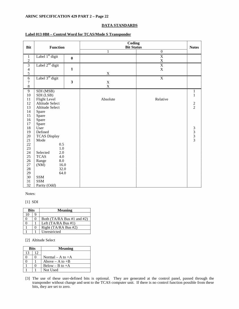
Label 013 0B8 – Control Word for TCAS/Mode S Transponder
Coding Bit Status Bit Function
1 0 Notes
1 Label 1st digit X 2 0 X 3 Label 2nd digit X 4 X 5
1 X
6 Label 3rd digit X 7 X 8
3 X
9 SDI (MSB) 1 10 SDI (LSB) 1 11 Flight Level Absolute Relative 12 Altitude Select 2 13 Altitude Select 2 14 Spare 15 Spare 16 Spare 17 Spare 18 User 3 19 Defined 3 20 TCAS Display 3 21 Mode 3 22 0.5 23 1.0 24 Selected 2.0 25 TCAS 4.0 26 Range 8.0 27 (NM) 16.0 28 32.0 29 64.0 30 SSM 31 SSM 32 Parity (Odd)
Notes: [1] SDI
Bits Meaning 10 9 0 0 Both (TA/RA Bus #1 and #2) 0 1 Left (TA/RA Bus #1) 1 0 Right (TA/RA Bus #2) 1 1 Unrestricted [2] Altitude Select
Bits Meaning 13 12 0 0 Normal – A to +A 0 1 Above – A to +B 1 0 Below – B to +A 1 1 Not Used [3] The use of these user-defined bits is optional. They are generated at the control panel, passed through the
transponder without change and sent to the TCAS computer unit. If there is no control function possible from these bits, they are set to zero.

ARINC SPECIFICATION 429 PART 2 – Page 23
DATA STANDARDS
Label 016 0B8 – Control Word for TCAS/Mode S Transponder
Coding Bit Status Bit Function
1 0 Notes
1 Label 1st digit X 2 0 X 3 Label 2nd digit X 4 X 5
1 X
6 Label 3rd digit X 7 X 8
6 X
9 SDI 10 SDI 11 Altitude Reporting OFF ON 12 SPI Indent ON Indent OFF 13 Display 1, 5 14 Control 1, 5 15 Sensitivity 16 Level 2 17 Control 2 18 D1 2 19 D2 20 D4 3 21 C1 3 22 C2 4096 3 23 C4 Indent 3 24 B1 Code 3 25 B2 3 26 B4 3 27 A1 3 28 A2 3 29 A4 3 30 SSM 31 SSM 32 Parity (Odd)
Notes: [1] Display Control
Bits Meaning 14 13 0 0 Primary and Traffic Advisory 0 1 Primary display functions only (no TCAS data) 1 0 TCAS Traffic Advisory Only 1 1 No control function possible [2] Manual Sensitivity Level Control
Bits Meaning 17 16 15 0 0 0 SL = 0 (AUTOMATIC) 0 0 1 SL = 1 (STBY) 0 1 0 SL = 2 (TA ONLY) 0 1 1 SL = 3 1 0 0 SL = 4 1 0 1 SL = 5 1 1 0 SL = 6 1 1 1 SL = 7 [3] See Attachment 5A of ARINC Characteristic 735 for Mode A reply codes. [4] The transfer time should not exceed 200 milliseconds.
COMMENTARY The delay from the time a command is activated at the control panel to the time of the equipment response should
be minimized. [5] Primary display functions are those functions for which a display may have need designed when that display is also
being used in a shared manner as a Traffic Advisory Display.
ARINC SPECIFICATION 429 PART 2 – Page 24
DATA STANDARDS
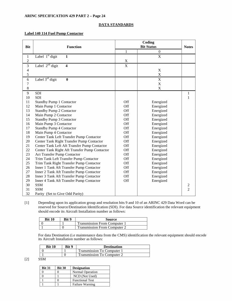
Label 140 114 Fuel Pump Contactor
Coding Bit Status Bit Function
1 0 Notes
1 Label 1st digit 1 X 2 X 3 Label 2nd digit 4 X 4 X 5 X 6 Label 3rd digit 0 X 7 X 8 X 9 SDI 1
10 SDI 1 11 Standby Pump 1 Contactor Off Energized 12 Main Pump 1 Contactor Off Energized 13 Standby Pump 2 Contactor Off Energized 14 Main Pump 2 Contactor Off Energized 15 Standby Pump 3 Contactor Off Energized 16 Main Pump 3 Contactor Off Energized 17 Standby Pump 4 Contactor Off Energized 18 Main Pump 4 Contactor Off Energized 19 Center Tank Left Transfer Pump Contactor Off Energized 20 Center Tank Right Transfer Pump Contactor Off Energized 21 Center Tank Left Aft Transfer Pump Contactor Off Energized 22 Center Tank Right Aft Transfer Pump Contactor Off Energized 23 Act Transfer Pump Contactor Off Energized 24 Trim Tank Left Transfer Pump Contactor Off Energized 25 Trim Tank Right Transfer Pump Contactor Off Energized 26 Inner 1 Tank Aft Transfer Pump Contactor Off Energized 27 Inner 2 Tank Aft Transfer Pump Contactor Off Energized 28 Inner 3 Tank Aft Transfer Pump Contactor Off Energized 29 Inner 4 Tank Aft Transfer Pump Contactor Off Energized 30 SSM 2 31 SSM 2 32 Parity (Set to Give Odd Parity)
[1] Depending upon its application group and resolution bits 9 and 10 of an ARINC 429 Data Word can be
reserved for Source/Destination Identification (SDI). For data Source identification the relevant equipment should encode its Aircraft Installation number as follows:
Bit 10 Bit 9 Source
0 1 Transmission From Computer 1 1 0 Transmission From Computer 2
For data Destination (i.e maintenance data from the CMS) identification the relevant equipment should encode its Aircraft Installation number as follows:
Bit 10 Bit 9 Destination
0 1 Transmission To Computer 1 1 0 Transmission To Computer 2
[2] SSM
Bit 31 Bit 30 Designation 0 0 Normal Operation 0 1 NCD (Not Used) 1 0 Functional Test 1 1 Failure Warning

ARINC SPECIFICATION 429 PART 2 – Page 25
DATA STANDARDS
Label 141 114 Pump Contactor And Pushbutton States
Coding Bit Status Bit Function
1 0 Notes
1 Label 1st digit 1 X 2 X 3 Label 2nd digit 4 X 4 X 5 X 6 Label 3rd digit 1 X 7 X 8 X 9 SDI 1
10 SDI 1 11 RCT Transfer Pump A (Front) Contactor Off Energized 12 RCT Transfer Pump B (Rear) Contactor Off Energized 13 APU Pump Contactor Off Energized 14 Main Pump 1 Pushbutton On Off 15 Standby Pump 1 Pushbutton On Off 16 Main Pump 2 Pushbutton On Off 17 Standby Pump 2 Pushbutton On Off 18 Main Pump 3 Pushbutton On Off 19 Standby Pump 3 Pushbutton On Off 20 Main Pump 4 Pushbutton On Off 21 Standby Pump 3 Pushbutton On Off 22 Center Tank Left Transfer Pump Pushbutton On Off 23 Center Tank Right Transfer Pump Pushbutton On Off 24 Center Tank Left Aft Transfer Pump PSHBTN On Off 25 Center Tank Right Aft Transfer Pump PSHBTN On Off 26 Trim Tank Left Transfer Pump Pushbutton On Off 27 Trim Tank Right Transfer Pump Pushbutton On Off 28 RCT Transfer Pump A (Front) Pushbutton On Off 29 RCT Transfer Pump B (Rear) Pushbutton On Off 30 SSM 2 31 SSM 2 32 Parity (Set to Odd Parity)
[1] Depending upon its application group and resolution bits 9 and 10 of an ARINC 429 Data Word can be
reserved for Source/Destination Identification (SDI). For data Source identification the relevant equipment should encode its Aircraft Installation number as follows:
Bit 10 Bit 9 Source
0 1 Transmission From Computer 1 1 0 Transmission From Computer 2
For data Destination (i.e maintenance data from the CMS) identification the relevant equipment should encode its Aircraft Installation number as follows:
Bit 10 Bit 9 Destination
0 1 Transmission To Computer 1 1 0 Transmission To Computer 2
[2] SSM
Bit 31 Bit 30 Designation 0 0 Normal Operation 0 1 NCD (Not Used) 1 0 Functional Test 1 1 Failure Warning
ARINC SPECIFICATION 429 PART 2 – Page 26
DATA STANDARDS
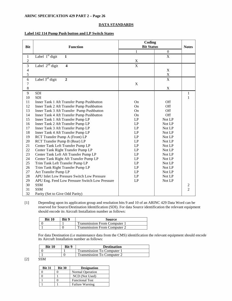
Label 142 114 Pump Push button and LP Switch States
Coding Bit Status Bit Function
1 0 Notes
1 Label 1st digit 1 X 2 X 3 Label 2nd digit 4 X 4 X 5 X 6 Label 3rd digit 2 X 7 X 8 X 9 SDI 1
10 SDI 1 11 Inner Tank 1 Aft Transfer Pump Pushbutton On Off 12 Inner Tank 2 Aft Transfer Pump Pushbutton On Off 13 Inner Tank 3 Aft Transfer Pump Pushbutton On Off 14 Inner Tank 4 Aft Transfer Pump Pushbutton On Off 15 Inner Tank 1 Aft Transfer Pump LP LP Not LP 16 Inner Tank 2 Aft Transfer Pump LP LP Not LP 17 Inner Tank 3 Aft Transfer Pump LP LP Not LP 18 Inner Tank 4 Aft Transfer Pump LP LP Not LP 19 RCT Transfer Pump A (Front) LP LP Not LP 20 RCT Transfer Pump B (Rear) LP LP Not LP 21 Center Tank Left Transfer Pump LP LP Not LP 22 Center Tank Right Transfer Pump LP LP Not LP 23 Center Tank Left Aft Transfer Pump LP LP Not LP 24 Center Tank Right Aft Transfer Pump LP LP Not LP 25 Trim Tank Left Transfer Pump LP LP Not LP 26 Trim Tank Right Transfer Pump LP LP Not LP 27 Act Transfer Pump LP LP Not LP 28 APU Inlet Low Pressure Switch Low Pressure LP Not LP 29 APU Eng. Feed Low Pressure Switch Low Pressure LP Not LP 30 SSM 2 31 SSM 2 32 Parity (Set to Give Odd Parity)
[1] Depending upon its application group and resolution bits 9 and 10 of an ARINC 429 Data Word can be
reserved for Source/Destination Identification (SDI). For data Source identification the relevant equipment should encode its Aircraft Installation number as follows:
Bit 10 Bit 9 Source
0 1 Transmission From Computer 1 1 0 Transmission From Computer 2
For data Destination (i.e maintenance data from the CMS) identification the relevant equipment should encode its Aircraft Installation number as follows:
Bit 10 Bit 9 Destination
0 1 Transmission To Computer 1 1 0 Transmission To Computer 2
[2] SSM
Bit 31 Bit 30 Designation 0 0 Normal Operation 0 1 NCD (Not Used) 1 0 Functional Test 1 1 Failure Warning

ARINC SPECIFICATION 429 PART 2 – Page 27
DATA STANDARDS
Label 143 114 Pump LP Switch State and FCMC Commands
Coding Bit Status Bit Function
1 0 Notes
1 Label 1st digit 1 X 2 X 3 Label 2nd digit 4 X 4 X 5 X 6 Label 3rd digit 3 X 7 X 8 X 9 SDI 1
10 SDI 1 11 Standby Pump 1 LP Low Not Low 12 Main Pump 1 LP Low Not Low 13 Standby Pump 2 LP Low Not Low 14 Main Pump 2 LP Low Not Low 15 Standby Pump 3 LP Low Not Low 16 Main Pump 3 LP Low Not Low 17 Standby Pump 4 LP Low Not Low 18 Main Pump 4 LP Low Not Low 19 Center Tank Left Transfer Pump Command On Off 20 Center Tank Right Transfer Pump Command On Off 21 Center Tank Left Aft Transfer Pump Command On Off 22 Center Tank Right Aft Transfer Pump Command On Off 23 Trim Tank Left Transfer Pump Command On Off 24 Trim Tank Right Transfer Pump Command On Off 25 Inner 1 Tank Aft Transfer Pump Command On Off 26 Inner 2 Tank Aft Transfer Pump Command On Off 27 Inner 3 Tank Aft Transfer Pump Command On Off 28 Inner 4 Tank Aft Transfer Pump Command On Off 29 Act Transfer Pump Command On Off 30 SSM 2 31 SSM 2 32 Parity ( Set to Give Odd Parity)
[1] Depending upon its application group and resolution bits 9 and 10 of an ARINC 429 Data Word can be
reserved for Source/Destination Identification (SDI). For data Source identification the relevant equipment should encode its Aircraft Installation number as follows:
Bit 10 Bit 9 Source
0 1 Transmission From Computer 1 1 0 Transmission From Computer 2
For data Destination (i.e maintenance data from the CMS) identification the relevant equipment should encode its Aircraft Installation number as follows:
Bit 10 Bit 9 Destination
0 1 Transmission To Computer 1 1 0 Transmission To Computer 2
[2] SSM
Bit 31 Bit 30 Designation 0 0 Normal Operation 0 1 NCD (Not Used) 1 0 Functional Test 1 1 Failure Warning

ARINC SPECIFICATION 429 PART 2 – Page 28
DATA STANDARDS
Label 144 114 Valve Feedbacks
Coding Bit Status Bit Function
1 0 Notes
1 Label 1st digit 1 X 2 X 3 Label 2nd digit 4 X 4 X 5 X 6 Label 3rd digit 4 X 7 X 8 X 9 SDI 1
10 SDI 1 11 LP Valve 1 Open (1) Open Not Open 12 LP Valve 1 Shut (1) Shut Not Shut 13 LP Valve 2 Open (2) Open Not Open 14 LP Valve 2 Shut (2) Shut Not Shut 15 LP Valve 3 Open (3) Open Not Open 16 LP Valve 3 Shut (3) Shut Not Shut 17 LP Valve 4 Open (4) Open Not Open 18 LP Valve 4 Shut (4) Shut Not Shut 19 Crossfeed Valve 1 (C) Open Not Open 20 Crossfeed Valve 1 (C) Shut Not Shut 21 Crossfeed Valve 2 (A) Open Not Open 22 Crossfeed Valve 2 (A) Shut Not Shut 23 Crossfeed Valve 3 (E) Open Not Open 24 Crossfeed Valve 3 (E) Shut Not Shut 25 Crossfeed Valve 4 (Z) Open Not Open 26 Crossfeed Valve 4 (Z) Shut Not Shut 27 Left Outer Tank Inlet Valve (M) Open Not Open 28 Left Outer Tank Inlet Valve (M) Shut Not Shut 29 Pad Bit 30 SSM 2 31 SSM 2 32 Parity (Set to Give Odd Parity)
[1] Depending upon its application group and resolution bits 9 and 10 of an ARINC 429 Data Word can be
reserved for Source/Destination Identification (SDI). For data Source identification the relevant equipment should encode its Aircraft Installation number as follows:
Bit 10 Bit 9 Source
0 1 Transmission From Computer 1 1 0 Transmission From Computer 2
For data Destination (i.e maintenance data from the CMS) identification the relevant equipment should encode its Aircraft Installation number as follows:
Bit 10 Bit 9 Destination
0 1 Transmission To Computer 1 1 0 Transmission To Computer 2
[2] SSM
Bit 31 Bit 30 Designation 0 0 Normal Operation 0 1 NCD (Not Used) 1 0 Functional Test 1 1 Failure Warning
ARINC SPECIFICATION 429 PART 2 – Page 29
DATA STANDARDS
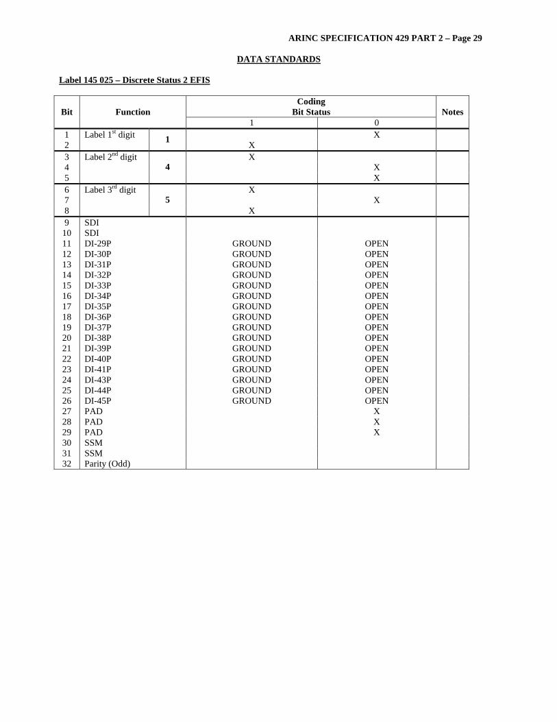
Label 145 025 – Discrete Status 2 EFIS
Coding Bit Status Bit Function
1 0 Notes
1 Label 1st digit X 2 1 X 3 Label 2nd digit X 4 X 5
4 X
6 Label 3rd digit X 7 X 8
5 X
9 SDI 10 SDI 11 DI-29P GROUND OPEN 12 DI-30P GROUND OPEN 13 DI-31P GROUND OPEN 14 DI-32P GROUND OPEN 15 DI-33P GROUND OPEN 16 DI-34P GROUND OPEN 17 DI-35P GROUND OPEN 18 DI-36P GROUND OPEN 19 DI-37P GROUND OPEN 20 DI-38P GROUND OPEN 21 DI-39P GROUND OPEN 22 DI-40P GROUND OPEN 23 DI-41P GROUND OPEN 24 DI-43P GROUND OPEN 25 DI-44P GROUND OPEN 26 DI-45P GROUND OPEN 27 PAD X 28 PAD X 29 PAD X 30 SSM 31 SSM 32 Parity (Odd)
ARINC SPECIFICATION 429 PART 2 – Page 30
DATA STANDARDS
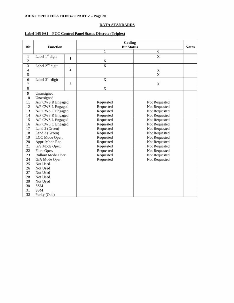
Label 145 0A1 – FCC Control Panel Status Discrete (Triplex)
Coding Bit Status Bit Function
1 0 Notes
1 Label 1st digit X 2 1 X 3 Label 2nd digit X 4 X 5
4 X
6 Label 3rd digit X 7 X 8
5 X
9 Unassigned 10 Unassigned 11 A/P CWS R Engaged Requested Not Requested 12 A/P CWS L Engaged Requested Not Requested 13 A/P CWS C Engaged Requested Not Requested 14 A/P CWS R Engaged Requested Not Requested 15 A/P CWS L Engaged Requested Not Requested 16 A/P CWS C Engaged Requested Not Requested 17 Land 2 (Green) Requested Not Requested 18 Land 3 (Green) Requested Not Requested 19 LOC Mode Oper. Requested Not Requested 20 Appr. Mode Req. Requested Not Requested 21 G/S Mode Oper. Requested Not Requested 22 Flare Oper. Requested Not Requested 23 Rollout Mode Oper. Requested Not Requested 24 G/A Mode Oper. Requested Not Requested 25 Not Used 26 Not Used 27 Not Used 28 Not Used 29 Not Used 30 SSM 31 SSM 32 Parity (Odd)

ARINC SPECIFICATION 429 PART 2 – Page 31
DATA STANDARDS
Label 145 114 Valve Feedbacks
Coding Bit Status Bit Function
1 0 Notes
1 Label 1st digit 1 2 3 Label 2nd digit 4 4 5 6 Label 3rd digit 5 7 8 9 SDI 1
10 SDI 1 11 Inner Tank 2 Transfer Control Valve (EC) Forward Not Forward 12 Inner Tank 2 Transfer Control Valve (EC) Open Not Open 13 Left Refuel Isolation Valve (R) Shut Not Shut 14 Inner Tank 1 Inlet (BA) Open Not Open 15 Inner Tank 1 Inlet (BA) Shut Not Shut 16 Inner Tank 2 Inlet (F) Open Not Open 17 Inner Tank 2 Inlet (F) Shut Not Shut 18 Inner Tank 3 Inlet (H) Open Not Open 19 Inner Tank 3 Inlet (H) Shut Not Shut 20 Inner Tank 4 Inlet (BB) Open Not Open 21 Inner Tank 4 Inlet (BB) Shut Not Shut 22 Left Intertank Transfer Valve (Q) Open Not Open 23 Left Intertank Transfer Valve (Q) Shut Not Shut 24 Left Jettison Valve (X) Open Not Open 25 Left Jettison Valve (X) Shut Not Shut 26 Center Tank Restrictor Valve (GG) Open Not Open 27 Center Tank Restrictor Valve (GG) Shut Not Shut 28 Center Tank Inlet Valve (G) Open Not Open 29 Center Tank Inlet Valve (G) Shut Not Shut 30 SSM 2 31 SSM 2 32 Parity (Set to Give Odd Parity)
[1] Depending upon its application group and resolution bits 9 and10 of an ARINC 429 Data Word can be
reserved for Source/Destination Identification (SDI). For data Source identification the relevant equipment should encode its Aircraft Installation number as follows:
Bit 10 Bit 9 Source
0 1 Transmission From Computer 1 1 0 Transmission From Computer 2
For data Destination (i.e maintenance data from the CMS) identification the relevant equipment should encode its Aircraft Installation number as follows:
Bit 10 Bit 9 Destination
0 1 Transmission To Computer 1 1 0 Transmission To Computer 2
[2] SSM
Bit 31 Bit 30 Designation 0 0 Normal Operation 0 1 NCD (Not Used) 1 0 Functional Test 1 1 Failure Warning

ARINC SPECIFICATION 429 PART 2 – Page 32
DATA STANDARDS
Label 146 025 – Discrete Status 3 EFIS
Coding Bit Status Bit Function
1 0 Notes
1 Label 1st digit X 2 1 X 3 Label 2nd digit X 4 X 5
4 X
6 Label 3rd digit X 7 X 8
6 X
9 SDI 10 SDI 11 DI-46P Ground Open 12 DI-47P Ground Open 13 DI-48P Ground Open 14 DI-49P Ground Open 15 DI-50P Ground Open 16 DI-51P Ground Open 17 DI-52P Ground Open 18 DI-53P Ground Open 19 DI-54P Ground Open 20 DI-55P Ground Open 21 DI-56P Ground Open 22 DI-58P Ground Open 23 DI-59P Ground Open 24 DI-60P Ground Open 25 DI-61P Ground Open 26 DI-62P Ground Open 27 PAD X 28 PAD X 29 PAD X 30 SSM 31 SSM 32 Parity (Odd)
ARINC SPECIFICATION 429 PART 2 – Page 33
DATA STANDARDS
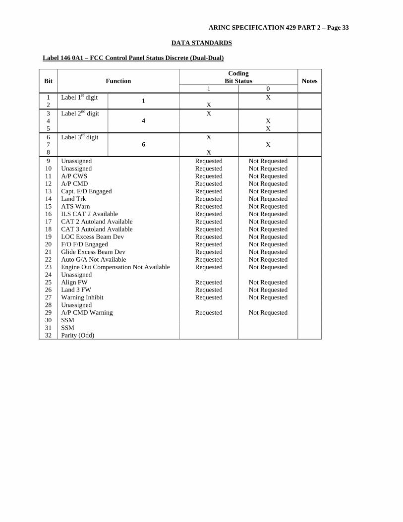
Label 146 0A1 – FCC Control Panel Status Discrete (Dual-Dual)
Coding Bit Status Bit Function
1 0 Notes
1 Label 1st digit X 2 1 X 3 Label 2nd digit X 4 X 5
4 X
6 Label 3rd digit X 7 X 8
6 X
9 Unassigned Requested Not Requested 10 Unassigned Requested Not Requested 11 A/P CWS Requested Not Requested 12 A/P CMD Requested Not Requested 13 Capt. F/D Engaged Requested Not Requested 14 Land Trk Requested Not Requested 15 ATS Warn Requested Not Requested 16 ILS CAT 2 Available Requested Not Requested 17 CAT 2 Autoland Available Requested Not Requested 18 CAT 3 Autoland Available Requested Not Requested 19 LOC Excess Beam Dev Requested Not Requested 20 F/O F/D Engaged Requested Not Requested 21 Glide Excess Beam Dev Requested Not Requested 22 Auto G/A Not Available Requested Not Requested 23 Engine Out Compensation Not Available Requested Not Requested 24 Unassigned 25 Align FW Requested Not Requested 26 Land 3 FW Requested Not Requested 27 Warning Inhibit Requested Not Requested 28 Unassigned 29 A/P CMD Warning Requested Not Requested 30 SSM 31 SSM 32 Parity (Odd)
ARINC SPECIFICATION 429 PART 2 – Page 34
DATA STANDARDS
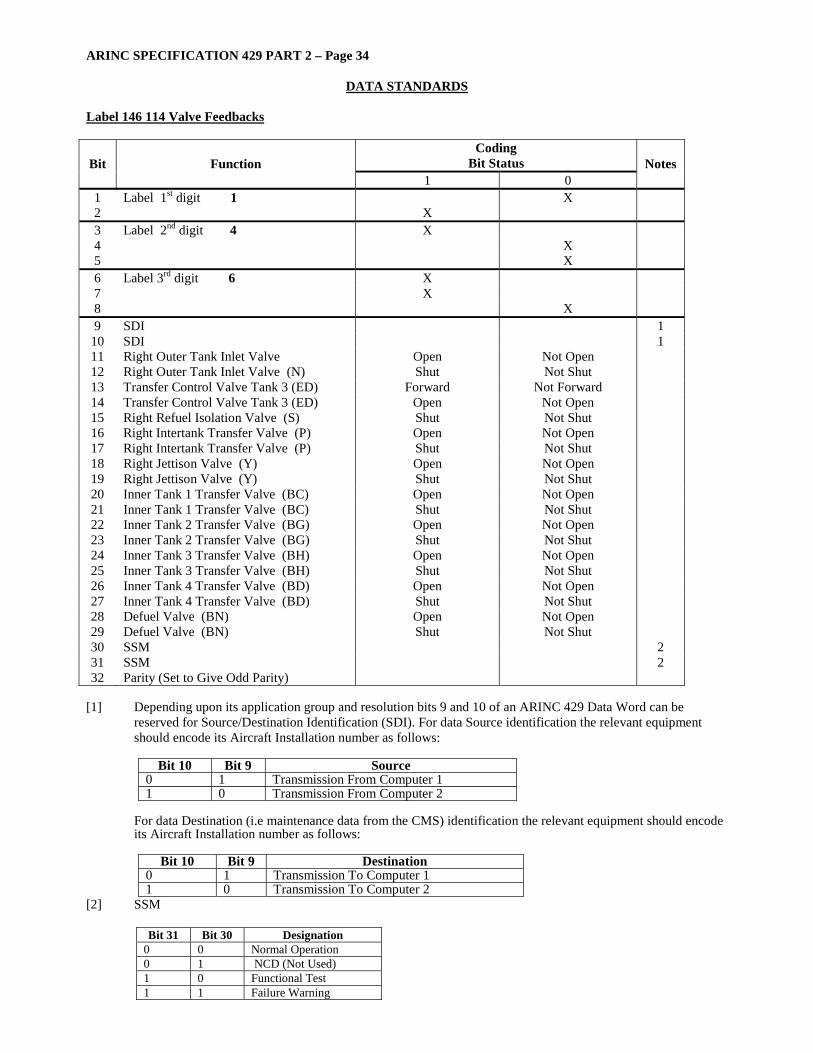
Label 146 114 Valve Feedbacks
Coding Bit Status Bit Function
1 0 Notes
1 Label 1st digit 1 X 2 X 3 Label 2nd digit 4 X 4 X 5 X 6 Label 3rd digit 6 X 7 X 8 X 9 SDI 1
10 SDI 1 11 Right Outer Tank Inlet Valve Open Not Open 12 Right Outer Tank Inlet Valve (N) Shut Not Shut 13 Transfer Control Valve Tank 3 (ED) Forward Not Forward 14 Transfer Control Valve Tank 3 (ED) Open Not Open 15 Right Refuel Isolation Valve (S) Shut Not Shut 16 Right Intertank Transfer Valve (P) Open Not Open 17 Right Intertank Transfer Valve (P) Shut Not Shut 18 Right Jettison Valve (Y) Open Not Open 19 Right Jettison Valve (Y) Shut Not Shut 20 Inner Tank 1 Transfer Valve (BC) Open Not Open 21 Inner Tank 1 Transfer Valve (BC) Shut Not Shut 22 Inner Tank 2 Transfer Valve (BG) Open Not Open 23 Inner Tank 2 Transfer Valve (BG) Shut Not Shut 24 Inner Tank 3 Transfer Valve (BH) Open Not Open 25 Inner Tank 3 Transfer Valve (BH) Shut Not Shut 26 Inner Tank 4 Transfer Valve (BD) Open Not Open 27 Inner Tank 4 Transfer Valve (BD) Shut Not Shut 28 Defuel Valve (BN) Open Not Open 29 Defuel Valve (BN) Shut Not Shut 30 SSM 2 31 SSM 2 32 Parity (Set to Give Odd Parity)
[1] Depending upon its application group and resolution bits 9 and 10 of an ARINC 429 Data Word can be
reserved for Source/Destination Identification (SDI). For data Source identification the relevant equipment should encode its Aircraft Installation number as follows:
Bit 10 Bit 9 Source
0 1 Transmission From Computer 1 1 0 Transmission From Computer 2
For data Destination (i.e maintenance data from the CMS) identification the relevant equipment should encode its Aircraft Installation number as follows:
Bit 10 Bit 9 Destination
0 1 Transmission To Computer 1 1 0 Transmission To Computer 2
[2] SSM
Bit 31 Bit 30 Designation 0 0 Normal Operation 0 1 NCD (Not Used) 1 0 Functional Test 1 1 Failure Warning

ARINC SPECIFICATION 429 PART 2 – Page 35
DATA STANDARDS
Label 147 025 – Discrete Status 4 EFIS
Coding Bit Status Bit Function
1 0 Notes
1 Label 1st digit X 2 1 X 3 Label 2nd digit X 4 X 5
4 X
6 Label 3rd digit X 7 X 8
7 X
9 SDI 10 SDI 11 DI-63P Ground Open 12 DI-64P Ground Open 13 DI-65P Ground Open 14 DI-66P Ground Open 15 DI-67P Ground Open 16 DI-68P Ground Open 17 DI-69P Ground Open 18 DI-93P Ground Open 19 DI-94P Ground Open 20 DI-95P Ground Open 21 DI-98P Ground Open 22 DI-99P Ground Open 23 DI-100P Ground Open 24 DI-101P Ground Open 25 DI-106P Ground Open 26 DI-107P Ground Open 27 PAD X 28 PAD X 29 PAD X 30 SSM 31 SSM 32 Parity (Odd)
ARINC SPECIFICATION 429 PART 2 – Page 36
DATA STANDARDS
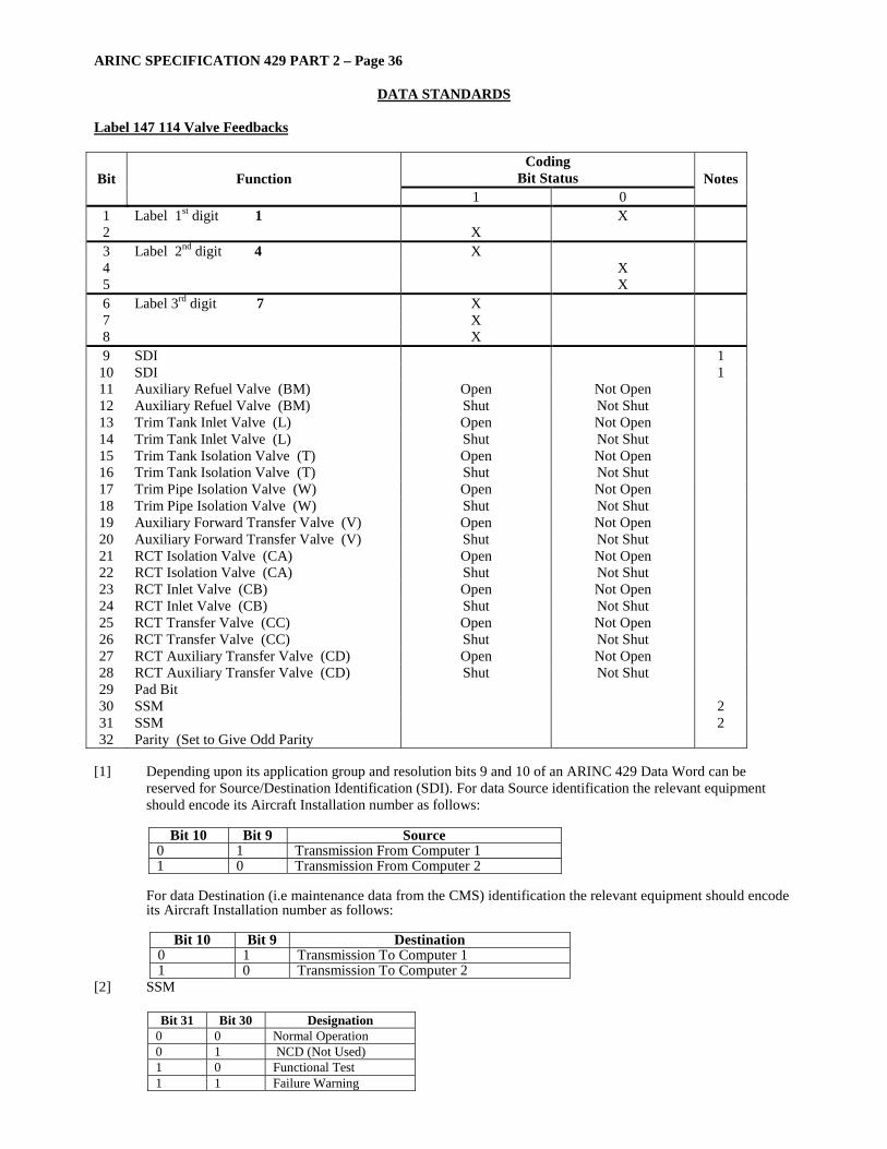
Label 147 114 Valve Feedbacks
Coding Bit Status Bit Function
1 0 Notes
1 Label 1st digit 1 X 2 X 3 Label 2nd digit 4 X 4 X 5 X 6 Label 3rd digit 7 X 7 X 8 X 9 SDI 1
10 SDI 1 11 Auxiliary Refuel Valve (BM) Open Not Open 12 Auxiliary Refuel Valve (BM) Shut Not Shut 13 Trim Tank Inlet Valve (L) Open Not Open 14 Trim Tank Inlet Valve (L) Shut Not Shut 15 Trim Tank Isolation Valve (T) Open Not Open 16 Trim Tank Isolation Valve (T) Shut Not Shut 17 Trim Pipe Isolation Valve (W) Open Not Open 18 Trim Pipe Isolation Valve (W) Shut Not Shut 19 Auxiliary Forward Transfer Valve (V) Open Not Open 20 Auxiliary Forward Transfer Valve (V) Shut Not Shut 21 RCT Isolation Valve (CA) Open Not Open 22 RCT Isolation Valve (CA) Shut Not Shut 23 RCT Inlet Valve (CB) Open Not Open 24 RCT Inlet Valve (CB) Shut Not Shut 25 RCT Transfer Valve (CC) Open Not Open 26 RCT Transfer Valve (CC) Shut Not Shut 27 RCT Auxiliary Transfer Valve (CD) Open Not Open 28 RCT Auxiliary Transfer Valve (CD) Shut Not Shut 29 Pad Bit 30 SSM 2 31 SSM 2 32 Parity (Set to Give Odd Parity
[1] Depending upon its application group and resolution bits 9 and 10 of an ARINC 429 Data Word can be
reserved for Source/Destination Identification (SDI). For data Source identification the relevant equipment should encode its Aircraft Installation number as follows:
Bit 10 Bit 9 Source
0 1 Transmission From Computer 1 1 0 Transmission From Computer 2
For data Destination (i.e maintenance data from the CMS) identification the relevant equipment should encode its Aircraft Installation number as follows:
Bit 10 Bit 9 Destination
0 1 Transmission To Computer 1 1 0 Transmission To Computer 2
[2] SSM
Bit 31 Bit 30 Designation 0 0 Normal Operation 0 1 NCD (Not Used) 1 0 Functional Test 1 1 Failure Warning
ARINC SPECIFICATION 429 PART 2 – Page 37
DATA STANDARDS
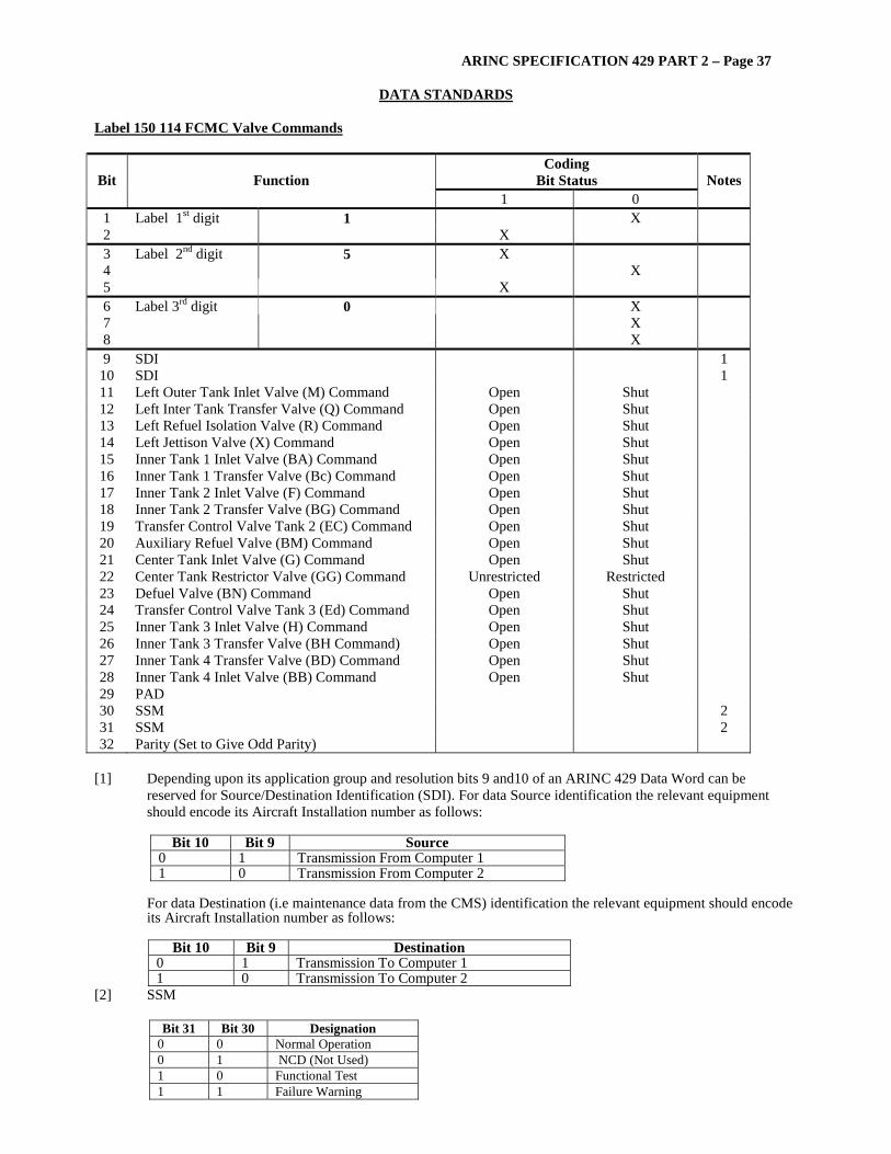
Label 150 114 FCMC Valve Commands
Coding Bit Status Bit Function
1 0 Notes
1 Label 1st digit 1 X 2 X 3 Label 2nd digit 5 X 4 X 5 X 6 Label 3rd digit 0 X 7 X 8 X 9 SDI 1
10 SDI 1 11 Left Outer Tank Inlet Valve (M) Command Open Shut 12 Left Inter Tank Transfer Valve (Q) Command Open Shut 13 Left Refuel Isolation Valve (R) Command Open Shut 14 Left Jettison Valve (X) Command Open Shut 15 Inner Tank 1 Inlet Valve (BA) Command Open Shut 16 Inner Tank 1 Transfer Valve (Bc) Command Open Shut 17 Inner Tank 2 Inlet Valve (F) Command Open Shut 18 Inner Tank 2 Transfer Valve (BG) Command Open Shut 19 Transfer Control Valve Tank 2 (EC) Command Open Shut 20 Auxiliary Refuel Valve (BM) Command Open Shut 21 Center Tank Inlet Valve (G) Command Open Shut 22 Center Tank Restrictor Valve (GG) Command Unrestricted Restricted 23 Defuel Valve (BN) Command Open Shut 24 Transfer Control Valve Tank 3 (Ed) Command Open Shut 25 Inner Tank 3 Inlet Valve (H) Command Open Shut 26 Inner Tank 3 Transfer Valve (BH Command) Open Shut 27 Inner Tank 4 Transfer Valve (BD) Command Open Shut 28 Inner Tank 4 Inlet Valve (BB) Command Open Shut 29 PAD 30 SSM 2 31 SSM 2 32 Parity (Set to Give Odd Parity)
[1] Depending upon its application group and resolution bits 9 and10 of an ARINC 429 Data Word can be
reserved for Source/Destination Identification (SDI). For data Source identification the relevant equipment should encode its Aircraft Installation number as follows:
Bit 10 Bit 9 Source
0 1 Transmission From Computer 1 1 0 Transmission From Computer 2
For data Destination (i.e maintenance data from the CMS) identification the relevant equipment should encode its Aircraft Installation number as follows:
Bit 10 Bit 9 Destination
0 1 Transmission To Computer 1 1 0 Transmission To Computer 2
[2] SSM
Bit 31 Bit 30 Designation 0 0 Normal Operation 0 1 NCD (Not Used) 1 0 Functional Test 1 1 Failure Warning
ARINC SPECIFICATION 429 PART 2 – Page 38
DATA STANDARDS
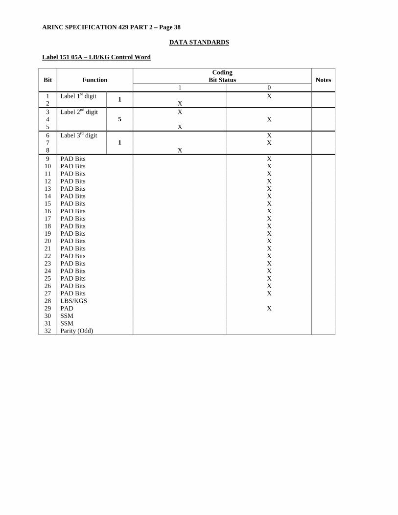
Label 151 05A – LB/KG Control Word
Coding Bit Status Bit Function
1 0 Notes
1 Label 1st digit X 2 1 X 3 Label 2nd digit X 4 X 5
5 X
6 Label 3rd digit X 7 X 8
1 X
9 PAD Bits X 10 PAD Bits X 11 PAD Bits X 12 PAD Bits X 13 PAD Bits X 14 PAD Bits X 15 PAD Bits X 16 PAD Bits X 17 PAD Bits X 18 PAD Bits X 19 PAD Bits X 20 PAD Bits X 21 PAD Bits X 22 PAD Bits X 23 PAD Bits X 24 PAD Bits X 25 PAD Bits X 26 PAD Bits X 27 PAD Bits X 28 LBS/KGS 29 PAD X 30 SSM 31 SSM 32 Parity (Odd)

ARINC SPECIFICATION 429 PART 2 – Page 39
DATA STANDARDS
Label 151 114 FCMC Valve Commands
Coding Bit Status Bit Function
1 0 Notes
1 Label 1st digit 1 X 2 X 3 Label 2nd digit 5 X 4 X 5 X 6 Label 3rd digit 1 X 7 X 8 X 9 SDI
10 SDI 11 Right Refuel Isolation Valve (S) Command Open Shut 12 Right Jettison Valve (Y) Command Open Shut 13 Right Inter Tank Transfer Valve (P) Command Open Shut 14 Right Outer Tank Inlet Valve (N) Command Open Shut 15 Auxiliary Fwd Transfer Valve (V) Command Open Shut 16 Trim Pipe Isolation Valve (W) Command Open Shut 17 Act Isolation Valve (AC) Command Open Shut 18 Act Transfer Valve ( AA) Command Open Shut 19 Act1 Inlet Valve (AG) Command Open Shut 20 Act2 Inlet Valve (Ah) Command Open Shut 21 Act Air Pressurization Command Pressurized Depressurized 22 RCT Isolation Valve (Ca) Command Open Shut 23 RCT Auxiliary Transfer Valve (CD) Command Open Shut 24 RCT Inlet Valve (CB) Command Open Shut 25 RCT Transfer Valve (CC) Command Open Shut 26 Trim Tank Inlet Valve (L) Command Open Shut 27 Trim Tank Isolation Valve (T) Command Open Shut 28 PAD 29 PAD 30 SSM 2 31 SSM 2 32 Parity (Set to Give Odd Parity)
[1] Depending upon its application group and resolution bits 9 and 10 of an ARINC 429 Data Word can be
reserved for Source/Destination Identification (SDI). For data Source identification the relevant equipment should encode its Aircraft Installation number as follows:
Bit 10 Bit 9 Source
0 1 Transmission From Computer 1 1 0 Transmission From Computer 2
For data Destination (i.e maintenance data from the CMS) identification the relevant equipment should encode its Aircraft Installation number as follows:
Bit 10 Bit 9 Destination
0 1 Transmission To Computer 1 1 0 Transmission To Computer 2
[2] SSM
Bit 31 Bit 30 Designation 0 0 Normal Operation 0 1 NCD (Not Used) 1 0 Functional Test 1 1 Failure Warning

ARINC SPECIFICATION 429 PART 2 – Page 40
DATA STANDARDS
Label 152 114 Overhead/Refuel Panel Switch & Pushbutton States
Coding Bit Status Bit Function
1 0 Notes
1 Label 1st digit 1 X 2 X 3 Label 2nd digit 5 X 4 X 5 X 6 Label 3rd digit 2 X 7 X 8 X 9 SDI 1
10 SDI 1 11 Act Transfer Override Pushbutton Override Not Override 12 Act Selector Switch ACT 2 Not ACT 2 13 Trim Tank Auto Forward XFR O/Ride P/B Auto Not Auto 14 Trim Line Isolation Switch Isolation Not Isolation 15 Trim Line Isolation Switch Open Not Open 16 RCT Transfer Override P/B Override Not Override 17 Crossfeed 1 Switch Shut Open 18 Crossfeed 2 Switch Shut Open 19 Crossfeed 3 Switch Shut Open 20 Crossfeed 4 Switch Shut Open 21 Jettison Pushbuttons Shut Open 22 Outer Transfer Override P/B Override Not Override 23 Center Transfer Override P/B Override Not Override 24 Refuel Panel Mode Select Switch Auto Refuel Not Auto Refuel 25 Refuel Panel Mode Select Switch Off Not Off 26 Refuel Panel Mode Select Switch Man Refuel Not Man Refuel 27 Refuel Panel Mode Select Switch Defuel Not Defuel 28 Refuel Panel Mode Select Switch Ground XFR Not Ground XFR 29 PAD 30 SSM 31 SSM 32 Parity (Set to Give Odd Parity)
[1] Depending upon its application group and resolution bits 9 and 10 of an ARINC 429 Data Word can be
reserved for Source/Destination Identification (SDI). For data Source identification the relevant equipment should encode its Aircraft Installation number as follows:
Bit 10 Bit 9 Source
0 1 Transmission From Computer 1 1 0 Transmission From Computer 2
For data Destination (i.e maintenance data from the CMS) identification the relevant equipment should encode its Aircraft Installation number as follows:
Bit 10 Bit 9 Destination
0 1 Transmission To Computer 1 1 0 Transmission To Computer 2
[2] SSM
Bit 31 Bit 30 Designation 0 0 Normal Operation 0 1 NCD (Not Used) 1 0 Functional Test 1 1 Failure Warning
ARINC SPECIFICATION 429 PART 2 – Page 41
DATA STANDARDS
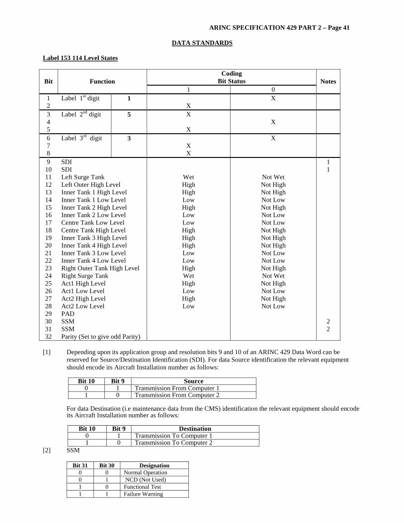
Label 153 114 Level States
Coding Bit Status Bit Function
1 0 Notes
1 Label 1st digit 1 X 2 X 3 Label 2nd digit 5 X 4 X 5 X 6 Label 3rd digit 3 X 7 X 8 X 9 SDI 1
10 SDI 1 11 Left Surge Tank Wet Not Wet 12 Left Outer High Level High Not High 13 Inner Tank 1 High Level High Not High 14 Inner Tank 1 Low Level Low Not Low 15 Inner Tank 2 High Level High Not High 16 Inner Tank 2 Low Level Low Not Low 17 Centre Tank Low Level Low Not Low 18 Centre Tank High Level High Not High 19 Inner Tank 3 High Level High Not High 20 Inner Tank 4 High Level High Not High 21 Inner Tank 3 Low Level Low Not Low 22 Inner Tank 4 Low Level Low Not Low 23 Right Outer Tank High Level High Not High 24 Right Surge Tank Wet Not Wet 25 Act1 High Level High Not High 26 Act1 Low Level Low Not Low 27 Act2 High Level High Not High 28 Act2 Low Level Low Not Low 29 PAD 30 SSM 2 31 SSM 2 32 Parity (Set to give odd Parity)
[1] Depending upon its application group and resolution bits 9 and 10 of an ARINC 429 Data Word can be
reserved for Source/Destination Identification (SDI). For data Source identification the relevant equipment should encode its Aircraft Installation number as follows:
Bit 10 Bit 9 Source
0 1 Transmission From Computer 1 1 0 Transmission From Computer 2
For data Destination (i.e maintenance data from the CMS) identification the relevant equipment should encode its Aircraft Installation number as follows:
Bit 10 Bit 9 Destination
0 1 Transmission To Computer 1 1 0 Transmission To Computer 2
[2] SSM
Bit 31 Bit 30 Designation 0 0 Normal Operation 0 1 NCD (Not Used) 1 0 Functional Test 1 1 Failure Warning
ARINC SPECIFICATION 429 PART 2 – Page 42
DATA STANDARDS
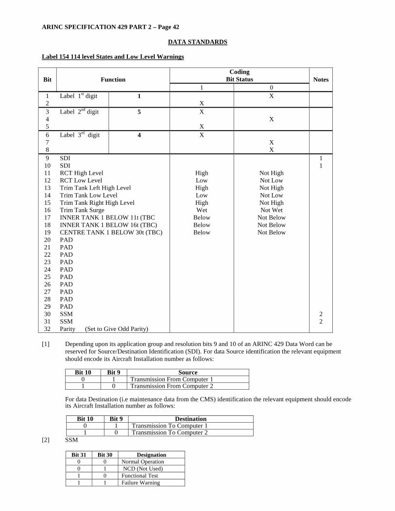
Label 154 114 level States and Low Level Warnings
Coding Bit Status Bit Function
1 0 Notes
1 Label 1st digit 1 X 2 X 3 Label 2nd digit 5 X 4 X 5 X 6 Label 3rd digit 4 X 7 X 8 X 9 SDI 1
10 SDI 1 11 RCT High Level High Not High 12 RCT Low Level Low Not Low 13 Trim Tank Left High Level High Not High 14 Trim Tank Low Level Low Not Low 15 Trim Tank Right High Level High Not High 16 Trim Tank Surge Wet Not Wet 17 INNER TANK 1 BELOW 11t (TBC Below Not Below 18 INNER TANK 1 BELOW 16t (TBC) Below Not Below 19 CENTRE TANK 1 BELOW 30t (TBC) Below Not Below 20 PAD 21 PAD 22 PAD 23 PAD 24 PAD 25 PAD 26 PAD 27 PAD 28 PAD 29 PAD 30 SSM 2 31 SSM 2 32 Parity (Set to Give Odd Parity)
[1] Depending upon its application group and resolution bits 9 and 10 of an ARINC 429 Data Word can be
reserved for Source/Destination Identification (SDI). For data Source identification the relevant equipment should encode its Aircraft Installation number as follows:
Bit 10 Bit 9 Source
0 1 Transmission From Computer 1 1 0 Transmission From Computer 2
For data Destination (i.e maintenance data from the CMS) identification the relevant equipment should encode its Aircraft Installation number as follows:
Bit 10 Bit 9 Destination
0 1 Transmission To Computer 1 1 0 Transmission To Computer 2
[2] SSM
Bit 31 Bit 30 Designation 0 0 Normal Operation 0 1 NCD (Not Used) 1 0 Functional Test 1 1 Failure Warning

ARINC SPECIFICATION 429 PART 2 – Page 43
DATA STANDARDS
Label 155 025 – Discrete Status 5 EFIS
Coding Bit Status Bit Function
1 0 Notes
1 Label 1st digit X 2 1 X 3 Label 2nd digit X 4 X 5
5 X
6 Label 3rd digit X 7 X 8
5 X
9 SDI 10 SDI 11 DI-108P Ground Open 12 DI-110P Ground Open 13 DI-111P Ground Open 14 DI-112P Ground Open 15 DI-115P Ground Open 16 DI-116P Ground Open 17 DI-117P Ground Open 18 DI-118P Ground Open 19 DI-119P Ground Open 20 DI-120P Ground Open 21 DI-121P Ground Open 22 DI-122P Ground Open 23 DI-123P Ground Open 24 DI-125P Ground Open 25 DI-126P Ground Open 26 DI-127P Ground Open 27 PAD X 28 PAD X 29 PAD X 30 SSM 31 SSM 32 Parity (Odd)
ARINC SPECIFICATION 429 PART 2 – Page 44
DATA STANDARDS
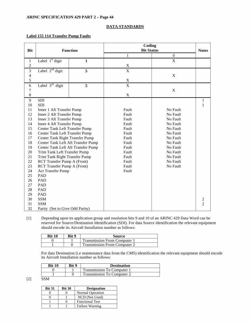
Label 155 114 Transfer Pump Faults
Coding Bit Status Bit Function
1 0 Notes
1 Label 1st digit 1 X 2 X 3 Label 2nd digit 5 X 4 X 5 X 6 Label 3rd digit 5 X 7 X 8 X 9 SDI 1
10 SDI 1 11 Inner 1 Aft Transfer Pump Fault No Fault 12 Inner 2 Aft Transfer Pump Fault No Fault 13 Inner 3 Aft Transfer Pump Fault No Fault 14 Inner 4 Aft Transfer Pump Fault No Fault 15 Center Tank Left Transfer Pump Fault No Fault 16 Center Tank Left Transfer Pump Fault No Fault 17 Center Tank Right Transfer Pump Fault No Fault 18 Center Tank Left Aft Transfer Pump Fault No Fault 19 Center Tank Left Aft Transfer Pump Fault No Fault 20 Trim Tank Left Transfer Pump Fault No Fault 21 Trim Tank Right Transfer Pump Fault No Fault 22 RCT Transfer Pump A (Front) Fault No Fault 23 RCT Transfer Pump A (Front) Fault No Fault 24 Act Transfer Pump Fault 25 PAD 26 PAD 27 PAD 28 PAD 29 PAD 30 SSM 2 31 SSM 2 32 Parity (Set to Give Odd Parity)
[1] Depending upon its application group and resolution bits 9 and 10 of an ARINC 429 Data Word can be
reserved for Source/Destination Identification (SDI). For data Source identification the relevant equipment should encode its Aircraft Installation number as follows:
Bit 10 Bit 9 Source
0 1 Transmission From Computer 1 1 0 Transmission From Computer 2
For data Destination (i.e maintenance data from the CMS) identification the relevant equipment should encode its Aircraft Installation number as follows:
Bit 10 Bit 9 Destination
0 1 Transmission To Computer 1 1 0 Transmission To Computer 2
[2] SSM
Bit 31 Bit 30 Designation 0 0 Normal Operation 0 1 NCD (Not Used) 1 0 Functional Test 1 1 Failure Warning
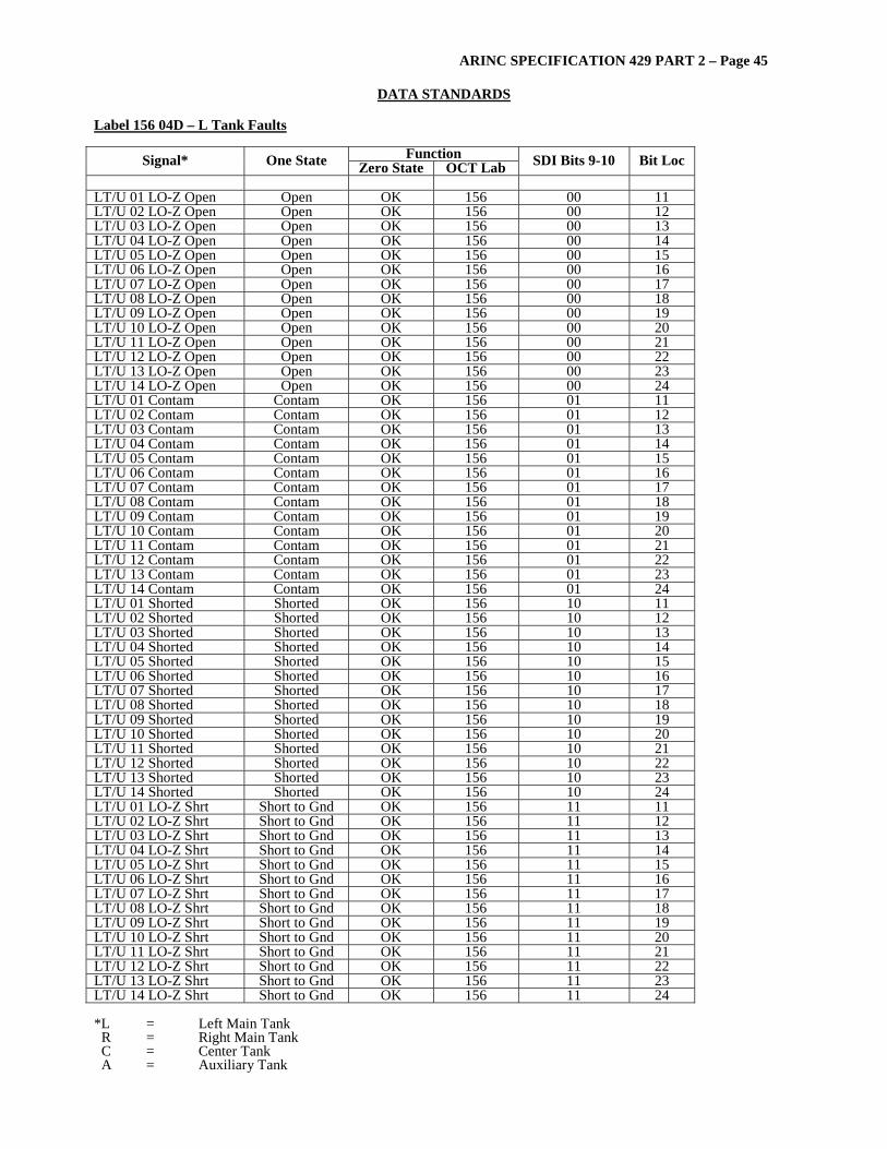
ARINC SPECIFICATION 429 PART 2 – Page 45
DATA STANDARDS
Label 156 04D – L Tank Faults
Function Signal* One State Zero State OCT Lab SDI Bits 9-10 Bit Loc LT/U 01 LO-Z Open Open OK 156 00 11 LT/U 02 LO-Z Open Open OK 156 00 12 LT/U 03 LO-Z Open Open OK 156 00 13 LT/U 04 LO-Z Open Open OK 156 00 14 LT/U 05 LO-Z Open Open OK 156 00 15 LT/U 06 LO-Z Open Open OK 156 00 16 LT/U 07 LO-Z Open Open OK 156 00 17 LT/U 08 LO-Z Open Open OK 156 00 18 LT/U 09 LO-Z Open Open OK 156 00 19 LT/U 10 LO-Z Open Open OK 156 00 20 LT/U 11 LO-Z Open Open OK 156 00 21 LT/U 12 LO-Z Open Open OK 156 00 22 LT/U 13 LO-Z Open Open OK 156 00 23 LT/U 14 LO-Z Open Open OK 156 00 24 LT/U 01 Contam Contam OK 156 01 11 LT/U 02 Contam Contam OK 156 01 12 LT/U 03 Contam Contam OK 156 01 13 LT/U 04 Contam Contam OK 156 01 14 LT/U 05 Contam Contam OK 156 01 15 LT/U 06 Contam Contam OK 156 01 16 LT/U 07 Contam Contam OK 156 01 17 LT/U 08 Contam Contam OK 156 01 18 LT/U 09 Contam Contam OK 156 01 19 LT/U 10 Contam Contam OK 156 01 20 LT/U 11 Contam Contam OK 156 01 21 LT/U 12 Contam Contam OK 156 01 22 LT/U 13 Contam Contam OK 156 01 23 LT/U 14 Contam Contam OK 156 01 24 LT/U 01 Shorted Shorted OK 156 10 11 LT/U 02 Shorted Shorted OK 156 10 12 LT/U 03 Shorted Shorted OK 156 10 13 LT/U 04 Shorted Shorted OK 156 10 14 LT/U 05 Shorted Shorted OK 156 10 15 LT/U 06 Shorted Shorted OK 156 10 16 LT/U 07 Shorted Shorted OK 156 10 17 LT/U 08 Shorted Shorted OK 156 10 18 LT/U 09 Shorted Shorted OK 156 10 19 LT/U 10 Shorted Shorted OK 156 10 20 LT/U 11 Shorted Shorted OK 156 10 21 LT/U 12 Shorted Shorted OK 156 10 22 LT/U 13 Shorted Shorted OK 156 10 23 LT/U 14 Shorted Shorted OK 156 10 24 LT/U 01 LO-Z Shrt Short to Gnd OK 156 11 11 LT/U 02 LO-Z Shrt Short to Gnd OK 156 11 12 LT/U 03 LO-Z Shrt Short to Gnd OK 156 11 13 LT/U 04 LO-Z Shrt Short to Gnd OK 156 11 14 LT/U 05 LO-Z Shrt Short to Gnd OK 156 11 15 LT/U 06 LO-Z Shrt Short to Gnd OK 156 11 16 LT/U 07 LO-Z Shrt Short to Gnd OK 156 11 17 LT/U 08 LO-Z Shrt Short to Gnd OK 156 11 18 LT/U 09 LO-Z Shrt Short to Gnd OK 156 11 19 LT/U 10 LO-Z Shrt Short to Gnd OK 156 11 20 LT/U 11 LO-Z Shrt Short to Gnd OK 156 11 21 LT/U 12 LO-Z Shrt Short to Gnd OK 156 11 22 LT/U 13 LO-Z Shrt Short to Gnd OK 156 11 23 LT/U 14 LO-Z Shrt Short to Gnd OK 156 11 24 *L = Left Main Tank R = Right Main Tank C = Center Tank A = Auxiliary Tank
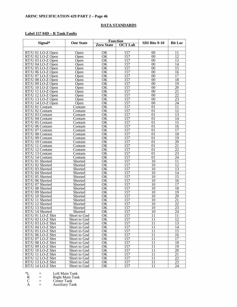
ARINC SPECIFICATION 429 PART 2 – Page 46
DATA STANDARDS
Label 157 04D – R Tank Faults
Function Signal* One State Zero State OCT Lab SDI Bits 9-10 Bit Loc RT/U 01 LO-Z Open Open OK 157 00 11 RT/U 02 LO-Z Open Open OK 157 00 12 RT/U 03 LO-Z Open Open OK 157 00 13 RT/U 04 LO-Z Open Open OK 157 00 14 RT/U 05 LO-Z Open Open OK 157 00 15 RT/U 06 LO-Z Open Open OK 157 00 16 RT/U 07 LO-Z Open Open OK 157 00 17 RT/U 08 LO-Z Open Open OK 157 00 18 RT/U 09 LO-Z Open Open OK 157 00 19 RT/U 10 LO-Z Open Open OK 157 00 20 RT/U 11 LO-Z Open Open OK 157 00 21 RT/U 12 LO-Z Open Open OK 157 00 22 RT/U 13 LO-Z Open Open OK 157 00 23 RT/U 14 LO-Z Open Open OK 157 00 24 RT/U 01 Contam Contam OK 157 01 11 RT/U 02 Contam Contam OK 157 01 12 RT/U 03 Contam Contam OK 157 01 13 RT/U 04 Contam Contam OK 157 01 14 RT/U 05 Contam Contam OK 157 01 15 RT/U 06 Contam Contam OK 157 01 16 RT/U 07 Contam Contam OK 157 01 17 RT/U 08 Contam Contam OK 157 01 18 RT/U 09 Contam Contam OK 157 01 19 RT/U 10 Contam Contam OK 157 01 20 RT/U 11 Contam Contam OK 157 01 21 RT/U 12 Contam Contam OK 157 01 22 RT/U 13 Contam Contam OK 157 01 23 RT/U 14 Contam Contam OK 157 01 24 RT/U 01 Shorted Shorted OK 157 10 11 RT/U 02 Shorted Shorted OK 157 10 12 RT/U 03 Shorted Shorted OK 157 10 13 RT/U 04 Shorted Shorted OK 157 10 14 RT/U 05 Shorted Shorted OK 157 10 15 RT/U 06 Shorted Shorted OK 157 10 16 RT/U 07 Shorted Shorted OK 157 10 17 RT/U 08 Shorted Shorted OK 157 10 18 RT/U 09 Shorted Shorted OK 157 10 19 RT/U 10 Shorted Shorted OK 157 10 20 RT/U 11 Shorted Shorted OK 157 10 21 RT/U 12 Shorted Shorted OK 157 10 22 RT/U 13 Shorted Shorted OK 157 10 23 RT/U 14 Shorted Shorted OK 157 10 24 RT/U 01 LO-Z Shrt Short to Gnd OK 157 11 11 RT/U 02 LO-Z Shrt Short to Gnd OK 157 11 12 RT/U 03 LO-Z Shrt Short to Gnd OK 157 11 13 RT/U 04 LO-Z Shrt Short to Gnd OK 157 11 14 RT/U 05 LO-Z Shrt Short to Gnd OK 157 11 15 RT/U 06 LO-Z Shrt Short to Gnd OK 157 11 16 RT/U 07 LO-Z Shrt Short to Gnd OK 157 11 17 RT/U 08 LO-Z Shrt Short to Gnd OK 157 11 18 RT/U 09 LO-Z Shrt Short to Gnd OK 157 11 19 RT/U 10 LO-Z Shrt Short to Gnd OK 157 11 20 RT/U 11 LO-Z Shrt Short to Gnd OK 157 11 21 RT/U 12 LO-Z Shrt Short to Gnd OK 157 11 22 RT/U 13 LO-Z Shrt Short to Gnd OK 157 11 23 RT/U 14 LO-Z Shrt Short to Gnd OK 157 11 24 *L = Left Main Tank R = Right Main Tank C = Center Tank A = Auxiliary Tank

ARINC SPECIFICATION 429 PART 2 – Page 47
DATA STANDARDS
Label 160 025 – Discrete Status 6 EFIS
Coding Bit Status Bit Function
1 0 Notes
1 Label 1st digit X 2 1 X 3 Label 2nd digit X 4 X 5
6 X
6 Label 3rd digit X 7 X 8
0 X
9 SDI Ground Open 10 SDI Ground Open 11 DI-128P Ground Open 12 DI-129P Ground Open 13 DI-130P Ground Open 14 DI-139P Ground Open 15 DI-140P Ground Open 16 DI-142P Ground Open 17 DI-143P Ground Open 18 DI-144P Ground Open 19 Reserved 20 Reserved 21 Reserved 22 Reserved 23 Reserved 24 Reserved 25 Reserved 26 Reserved 27 PAD X 28 PAD X 29 PAD X 30 SSM 31 SSM 32 Parity (Odd)

ARINC SPECIFICATION 429 PART 2 – Page 48
DATA STANDARDS
Label 160 04D – C Tank Faults
Function Signal* One State Zero State OCT Lab SDI Bits 9-10 Bit Loc CT/U 01 LO-Z Open Open OK 160 00 11 CT/U 02 LO-Z Open Open OK 160 00 12 CT/U 03 LO-Z Open Open OK 160 00 13 CT/U 04 LO-Z Open Open OK 160 00 14 CT/U 05 LO-Z Open Open OK 160 00 15 CT/U 06 LO-Z Open Open OK 160 00 16 CT/U 07 LO-Z Open Open OK 160 00 17 CT/U 08 LO-Z Open Open OK 160 00 18 CT/U 09 LO-Z Open Open OK 160 00 19 CT/U 01 Contam Contam OK 160 01 11 CT/U 02 Contam Contam OK 160 01 12 CT/U 03 Contam Contam OK 160 01 13 CT/U 04 Contam Contam OK 160 01 14 CT/U 05 Contam Contam OK 160 01 15 CT/U 06 Contam Contam OK 160 01 16 CT/U 07 Contam Contam OK 160 01 17 CT/U 08 Contam Contam OK 160 01 18 CT/U 09 Contam Contam OK 160 01 19 CT/U 01 Shorted Shorted OK 160 10 11 CT/U 02 Shorted Shorted OK 160 10 12 CT/U 03 Shorted Shorted OK 160 10 13 CT/U 04 Shorted Shorted OK 160 10 14 CT/U 05 Shorted Shorted OK 160 10 15 CT/U 06 Shorted Shorted OK 160 10 16 CT/U 07 Shorted Shorted OK 160 10 17 CT/U 08 Shorted Shorted OK 160 10 18 CT/U 09 Shorted Shorted OK 160 10 19 CT/U 01 LO-Z Shrt Short to Gnd OK 160 11 11 CT/U 02 LO-Z Shrt Short to Gnd OK 160 11 12 CT/U 03 LO-Z Shrt Short to Gnd OK 160 11 13 CT/U 04 LO-Z Shrt Short to Gnd OK 160 11 14 CT/U 05 LO-Z Shrt Short to Gnd OK 160 11 15 CT/U 06 LO-Z Shrt Short to Gnd OK 160 11 16 CT/U 07 LO-Z Shrt Short to Gnd OK 160 11 17 CT/U 08 LO-Z Shrt Short to Gnd OK 160 11 18 CT/U 09 LO-Z Shrt Short to Gnd OK 160 11 19 *L = Left Main Tank R = Right Main Tank C = Center Tank A = Auxiliary Tank

ARINC SPECIFICATION 429 PART 2 – Page 49
DATA STANDARDS
Label 160 114 Valve Feedbacks
Coding Bit Status Bit Function
1 0 Notes
1 Label 1st digit 1 X 2 X 3 Label 2nd digit 6 X 4 X 5 X 6 Label 3rd digit 0 X 7 X 8 X 9 SDI 1
10 SDI 1 11 Act Transfer Valve (AA) Open Not Open 12 Act Transfer Valve (AA) Shut Not Shut 13 Act Isolation Valve (AC) Open Not Open 14 Act Isolation Valve (AC) Shut Not Shut 15 Act 1 Inlet Valve (AG) Open Not Open 16 Act 1 Inlet Valve (AG) Shut Not Shut 17 Act 2 Inlet Valve (AH) Open Not Open 18 Act 2 Inlet Valve (AH) Shut Not Shut 19 Act 1 Vent Valve (AE) Open Not Open 20 Act 1 Vent Valve (AE) Shut Not Shut 21 Act 2 Vent Valve (AF) Open Not Open 22 Act 2 Vent Valve (AF) Shut Not Shut 23 Act Air Shut-Off Valve (AD) Open Not Open 24 Act Air Shut-Off Valve (AD) Shut Not Shut 25 APU LP Valve (J) Open Not Open 26 APU LP Valve (J) Shut Not Shut 27 APU Isolation Valve (K) Open Not Open 28 APU Isolation Valve (K) Shut Not Shut 29 Pad Bit 30 SSM 2 31 SSM 2 32 Parity (Set to Give Odd Parity)
[1] Depending upon its application group and resolution bits 9 and 10 of an ARINC 429 Data Word can be
reserved for Source/Destination Identification (SDI). For data Source identification the relevant equipment should encode its Aircraft Installation number as follows:
Bit 10 Bit 9 Source
0 1 Transmission From Computer 1 1 0 Transmission From Computer 2
For data Destination (i.e maintenance data from the CMS) identification the relevant equipment should encode its Aircraft Installation number as follows:
Bit 10 Bit 9 Destination
0 1 Transmission To Computer 1 1 0 Transmission To Computer 2
[2] SSM
Bit 31 Bit 30 Designation 0 0 Normal Operation 0 1 NCD (Not Used) 1 0 Functional Test 1 1 Failure Warning
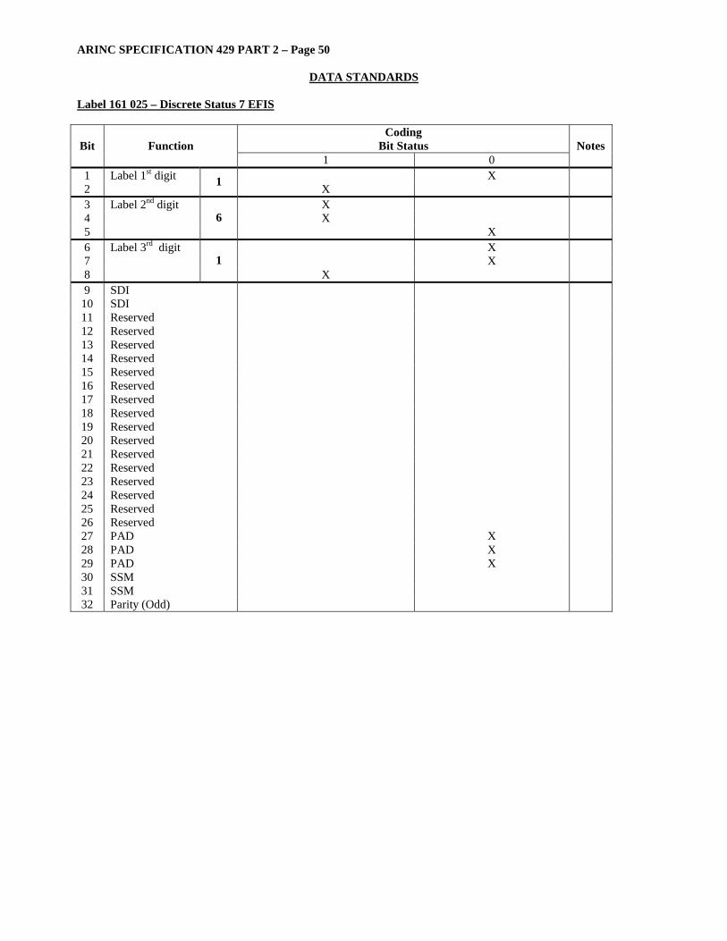
ARINC SPECIFICATION 429 PART 2 – Page 50
DATA STANDARDS
Label 161 025 – Discrete Status 7 EFIS
Coding Bit Status Bit Function
1 0 Notes
1 Label 1st digit X 2 1 X 3 Label 2nd digit X 4 X 5
6 X
6 Label 3rd digit X 7 X 8
1 X
9 SDI 10 SDI 11 Reserved 12 Reserved 13 Reserved 14 Reserved 15 Reserved 16 Reserved 17 Reserved 18 Reserved 19 Reserved 20 Reserved 21 Reserved 22 Reserved 23 Reserved 24 Reserved 25 Reserved 26 Reserved 27 PAD X 28 PAD X 29 PAD X 30 SSM 31 SSM 32 Parity (Odd)

ARINC SPECIFICATION 429 PART 2 – Page 51
DATA STANDARDS Label 161 04D – A Tank Faults
Function Signal* One State Zero State OCT Lab SDI Bits 9-10 Bit Loc AT/U 01 LO-Z Open Open OK 161 00 11 AT/U 02 LO-Z Open Open OK 161 00 12 AT/U 03 LO-Z Open Open OK 161 00 13 AT/U 04 LO-Z Open Open OK 161 00 14 AT/U 05 LO-Z Open Open OK 161 00 15 AT/U 06 LO-Z Open Open OK 161 00 16 AT/U 07 LO-Z Open Open OK 161 00 17 AT/U 08 LO-Z Open Open OK 161 00 18 AT/U 09 LO-Z Open Open OK 161 00 19 AT/U 10 LO-Z Open Open OK 161 00 20 AT/U 11 LO-Z Open Open OK 161 00 21 AT/U 01 Contam Contam OK 161 01 11 AT/U 02 Contam Contam OK 161 01 12 AT/U 03 Contam Contam OK 161 01 13 AT/U 04 Contam Contam OK 161 01 14 AT/U 05 Contam Contam OK 161 01 15 AT/U 06 Contam Contam OK 161 01 16 AT/U 07 Contam Contam OK 161 01 17 AT/U 08 Contam Contam OK 161 01 18 AT/U 09 Contam Contam OK 161 01 19 AT/U 10 Contam Contam OK 161 01 20 AT/U 11 Contam Contam OK 161 01 21 AT/U 01 Shorted Shorted OK 161 10 11 AT/U 02 Shorted Shorted OK 161 10 12 AT/U 03 Shorted Shorted OK 161 10 13 AT/U 04 Shorted Shorted OK 161 10 14 AT/U 05 Shorted Shorted OK 161 10 15 AT/U 06 Shorted Shorted OK 161 10 16 AT/U 07 Shorted Shorted OK 161 10 17 AT/U 08 Shorted Shorted OK 161 10 18 AT/U 09 Shorted Shorted OK 161 10 19 AT/U 10 Shorted Shorted OK 161 10 20 AT/U 11 Shorted Shorted OK 161 10 21 AT/U 01 LO-Z Shrt Short to Gnd OK 161 11 11 AT/U 02 LO-Z Shrt Short to Gnd OK 161 11 12 AT/U 03 LO-Z Shrt Short to Gnd OK 161 11 13 AT/U 04 LO-Z Shrt Short to Gnd OK 161 11 14 AT/U 05 LO-Z Shrt Short to Gnd OK 161 11 15 AT/U 06 LO-Z Shrt Short to Gnd OK 161 11 16 AT/U 07 LO-Z Shrt Short to Gnd OK 161 11 17 AT/U 08 LO-Z Shrt Short to Gnd OK 161 11 18 AT/U 09 LO-Z Shrt Short to Gnd OK 161 11 19 AT/U 10 LO-Z Shrt Short to Gnd OK 161 11 20 *L = Left Main Tank R = Right Main Tank C = Center Tank A = Auxiliary Tank

ARINC SPECIFICATION 429 PART 2 – Page 52
DATA STANDARDS
Label 161 10A – Full Authority Engine Control Maintenance Discretes
Coding Bit Status Bit Function
1 0 Notes
1 Label 1st digit X 2 1 X 3 Label 2nd digit X 4 X 5
6 X
6 Label 3rd digit X 7 X 8
1 X
9 SDI 10 SDI 11 Pad 12 Pad 13 Pad 14 Pad 15 Pad 16 Pad 17 Pad 18 Pad 19 Pad 20 Pad 21 Pad 22 Screen ID 1 23 Screen ID 1 24 Screen ID 1 25 Screen ID 1 26 Screen ID 1 27 Screen ID 1 28 Screen ID 1 29 Screen ID 1 30 SSM 31 SSM 32 Parity (Odd)
Note: [1] Screen ID Codes Value (HEX) Meaning
13 Ignition Test 14 Igniter Test in Progress 21 FADEC Test 22 FADEC Test in Progress
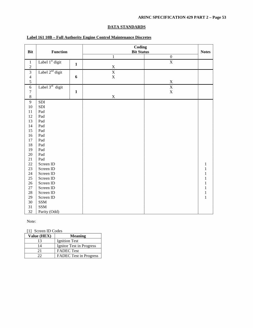
ARINC SPECIFICATION 429 PART 2 – Page 53
DATA STANDARDS Label 161 10B – Full Authority Engine Control Maintenance Discretes
Coding Bit Status Bit Function
1 0 Notes
1 Label 1st digit X 2 1 X 3 Label 2nd digit X 4 X 5
6 X
6 Label 3rd digit X 7 X 8
1 X
9 SDI 10 SDI 11 Pad 12 Pad 13 Pad 14 Pad 15 Pad 16 Pad 17 Pad 18 Pad 19 Pad 20 Pad 21 Pad 22 Screen ID 1 23 Screen ID 1 24 Screen ID 1 25 Screen ID 1 26 Screen ID 1 27 Screen ID 1 28 Screen ID 1 29 Screen ID 1 30 SSM 31 SSM 32 Parity (Odd)
Note: [1] Screen ID Codes Value (HEX) Meaning
13 Ignition Test 14 Ignitor Test in Progress 21 FADEC Test 22 FADEC Test in Progress
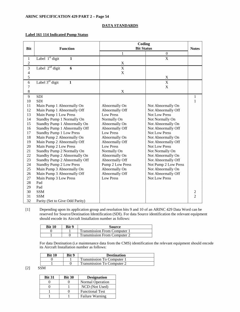
ARINC SPECIFICATION 429 PART 2 – Page 54
DATA STANDARDS
Label 161 114 Indicated Pump Status
Coding Bit Status Bit Function
1 0 Notes
1 Label 1st digit 1 X 2 X 3 Label 2nd digit 6 X 4 X 5 X 6 Label 3rd digit 1 X 7 X 8 X 9 SDI 1
10 SDI 1 11 Main Pump 1 Abnormally On Abnormally On Not Abnormally On 12 Main Pump 1 Abnormally Off Abnormally Off Not Abnormally Off 13 Main Pump 1 Low Press Low Press Not Low Press 14 Standby Pump 1 Normally On Normally On Not Normally On 15 Standby Pump 1 Abnormally On Abnormally On Not Abnormally On 16 Standby Pump 1 Abnormally Off Abnormally Off Not Abnormally Off 17 Standby Pump 1 Low Press Low Press Not Low Press 18 Main Pump 2 Abnormally On Abnormally On Not Abnormally On 19 Main Pump 2 Abnormally Off Abnormally Off Not Abnormally Off 20 Main Pump 2 Low Press Low Press Not Low Press 21 Standby Pump 2 Normally On Normally On Not Normally On 22 Standby Pump 2 Abnormally On Abnormally On Not Abnormally On 23 Standby Pump 2 Abnormally Off Abnormally Off Not Abnormally Off 24 Standby Pump 2 Low Press Pump 2 Low Press Not Pump 2 Low Press 25 Main Pump 3 Abnormally On Abnormally On Not Abnormally On 26 Main Pump 3 Abnormally Off Abnormally Off Not Abnormally Off 27 Main Pump 3 Low Press Low Press Not Low Press 28 Pad 29 Pad 30 SSM 2 31 SSM 2 32 Parity (Set to Give Odd Parity)
[1] Depending upon its application group and resolution bits 9 and 10 of an ARINC 429 Data Word can be
reserved for Source/Destination Identification (SDI). For data Source identification the relevant equipment should encode its Aircraft Installation number as follows:
Bit 10 Bit 9 Source
0 1 Transmission From Computer 1 1 0 Transmission From Computer 2
For data Destination (i.e maintenance data from the CMS) identification the relevant equipment should encode its Aircraft Installation number as follows:
Bit 10 Bit 9 Destination
0 1 Transmission To Computer 1 1 0 Transmission To Computer 2
[2] SSM
Bit 31 Bit 30 Designation 0 0 Normal Operation 0 1 NCD (Not Used) 1 0 Functional Test 1 1 Failure Warning
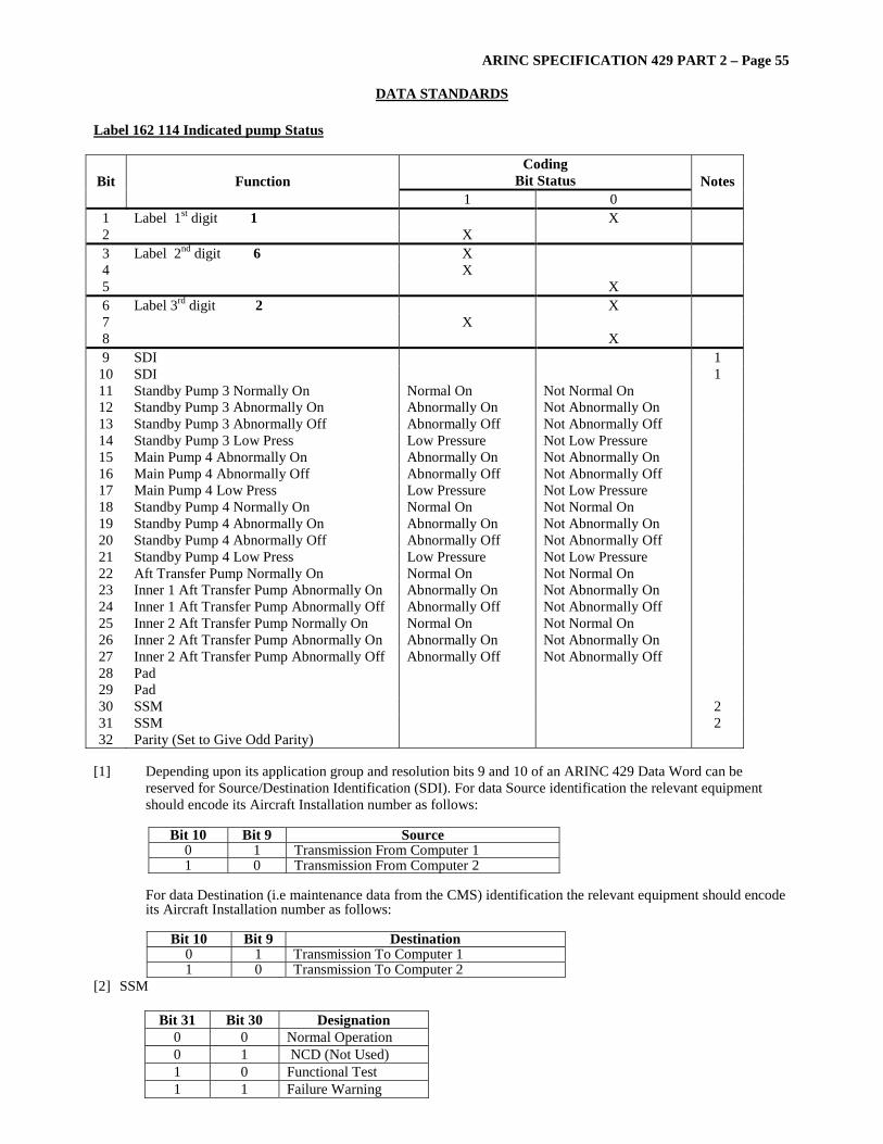
ARINC SPECIFICATION 429 PART 2 – Page 55
DATA STANDARDS Label 162 114 Indicated pump Status
Coding Bit Status Bit Function
1 0 Notes
1 Label 1st digit 1 X 2 X 3 Label 2nd digit 6 X 4 X 5 X 6 Label 3rd digit 2 X 7 X 8 X 9 SDI 1
10 SDI 1 11 Standby Pump 3 Normally On Normal On Not Normal On 12 Standby Pump 3 Abnormally On Abnormally On Not Abnormally On 13 Standby Pump 3 Abnormally Off Abnormally Off Not Abnormally Off 14 Standby Pump 3 Low Press Low Pressure Not Low Pressure 15 Main Pump 4 Abnormally On Abnormally On Not Abnormally On 16 Main Pump 4 Abnormally Off Abnormally Off Not Abnormally Off 17 Main Pump 4 Low Press Low Pressure Not Low Pressure 18 Standby Pump 4 Normally On Normal On Not Normal On 19 Standby Pump 4 Abnormally On Abnormally On Not Abnormally On 20 Standby Pump 4 Abnormally Off Abnormally Off Not Abnormally Off 21 Standby Pump 4 Low Press Low Pressure Not Low Pressure 22 Aft Transfer Pump Normally On Normal On Not Normal On 23 Inner 1 Aft Transfer Pump Abnormally On Abnormally On Not Abnormally On 24 Inner 1 Aft Transfer Pump Abnormally Off Abnormally Off Not Abnormally Off 25 Inner 2 Aft Transfer Pump Normally On Normal On Not Normal On 26 Inner 2 Aft Transfer Pump Abnormally On Abnormally On Not Abnormally On 27 Inner 2 Aft Transfer Pump Abnormally Off Abnormally Off Not Abnormally Off 28 Pad 29 Pad 30 SSM 2 31 SSM 2 32 Parity (Set to Give Odd Parity)
[1] Depending upon its application group and resolution bits 9 and 10 of an ARINC 429 Data Word can be
reserved for Source/Destination Identification (SDI). For data Source identification the relevant equipment should encode its Aircraft Installation number as follows:
Bit 10 Bit 9 Source
0 1 Transmission From Computer 1 1 0 Transmission From Computer 2
For data Destination (i.e maintenance data from the CMS) identification the relevant equipment should encode its Aircraft Installation number as follows:
Bit 10 Bit 9 Destination
0 1 Transmission To Computer 1 1 0 Transmission To Computer 2
[2] SSM
Bit 31 Bit 30 Designation 0 0 Normal Operation 0 1 NCD (Not Used) 1 0 Functional Test 1 1 Failure Warning
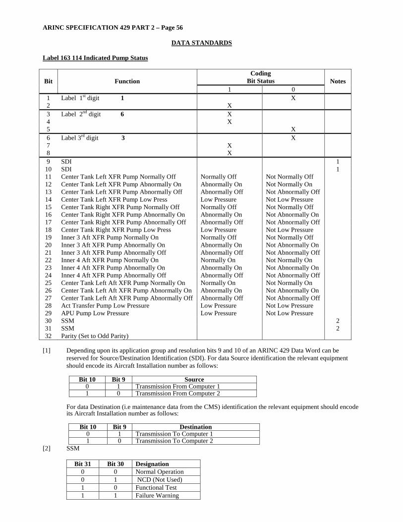
ARINC SPECIFICATION 429 PART 2 – Page 56
DATA STANDARDS
Label 163 114 Indicated Pump Status
Coding Bit Status Bit Function
1 0 Notes
1 Label 1st digit 1 X 2 X 3 Label 2nd digit 6 X 4 X 5 X 6 Label 3rd digit 3 X 7 X 8 X 9 SDI 1
10 SDI 1 11 Center Tank Left XFR Pump Normally Off Normally Off Not Normally Off 12 Center Tank Left XFR Pump Abnormally On Abnormally On Not Normally On 13 Center Tank Left XFR Pump Abnormally Off Abnormally Off Not Abnormally Off 14 Center Tank Left XFR Pump Low Press Low Pressure Not Low Pressure 15 Center Tank Right XFR Pump Normally Off Normally Off Not Normally Off 16 Center Tank Right XFR Pump Abnormally On Abnormally On Not Abnormally On 17 Center Tank Right XFR Pump Abnormally Off Abnormally Off Not Abnormally Off 18 Center Tank Right XFR Pump Low Press Low Pressure Not Low Pressure 19 Inner 3 Aft XFR Pump Normally On Normally Off Not Normally Off 20 Inner 3 Aft XFR Pump Abnormally On Abnormally On Not Abnormally On 21 Inner 3 Aft XFR Pump Abnormally Off Abnormally Off Not Abnormally Off 22 Inner 4 Aft XFR Pump Normally On Normally On Not Normally On 23 Inner 4 Aft XFR Pump Abnormally On Abnormally On Not Abnormally On 24 Inner 4 Aft XFR Pump Abnormally Off Abnormally Off Not Abnormally Off 25 Center Tank Left Aft XFR Pump Normally On Normally On Not Normally On 26 Center Tank Left Aft XFR Pump Abnormally On Abnormally On Not Abnormally On 27 Center Tank Left Aft XFR Pump Abnormally Off Abnormally Off Not Abnormally Off 28 Act Transfer Pump Low Pressure Low Pressure Not Low Pressure 29 APU Pump Low Pressure Low Pressure Not Low Pressure 30 SSM 2 31 SSM 2 32 Parity (Set to Odd Parity)
[1] Depending upon its application group and resolution bits 9 and 10 of an ARINC 429 Data Word can be
reserved for Source/Destination Identification (SDI). For data Source identification the relevant equipment should encode its Aircraft Installation number as follows:
Bit 10 Bit 9 Source
0 1 Transmission From Computer 1 1 0 Transmission From Computer 2
For data Destination (i.e maintenance data from the CMS) identification the relevant equipment should encode its Aircraft Installation number as follows:
Bit 10 Bit 9 Destination
0 1 Transmission To Computer 1 1 0 Transmission To Computer 2
[2] SSM
Bit 31 Bit 30 Designation 0 0 Normal Operation 0 1 NCD (Not Used) 1 0 Functional Test 1 1 Failure Warning

ARINC SPECIFICATION 429 PART 2 – Page 57
DATA STANDARDS Label 164 114 Indicated Pump Status
Coding Bit Status Bit Function
1 0 Notes
1 Label 1st digit 1 X 2 X 3 Label 2nd digit 6 X 4 X 5 X 6 Label 3rd digit 4 X 7 X 8 X 9 SDI 1
10 SDI 1 11 Center Tank Right Aft XFR Pump Norm On Normally On 12 Center Tank Right Aft XFR Pump Abnorm On Abnormally On Not Normally On 13 Center Tank Right Aft XFR Pump Abnorm Off Abnormally Off Not Abnormally Off 14 Trim Tank Left XFR Pump Normally Off Normally Off Not Normally Off 15 Trim Tank Left XFR Pump Abnormally On Abnormally On Not Normally On 16 Trim Tank Left XFR Pump Abnormally Off Abnormally Off Not Abnormally Off 17 Trim Tank Left XFR Pump Low Press Low Pressure Not Low Pressure 18 Trim Tank Right XFR Pump Normally Off Normally Off Not Normally Off 19 Trim Tank Right XFR Pump Abnormally On Abnormally On Not Normally On 20 Trim Tank Right XFR Pump Abnorm Off Abnormally Off Not Abnormally Off 21 Trim Tank Right XFR Pump Low Press Low Pressure Not Low Pressure 22 RCT XFR Pump A (Front) Normally Off Normally Off Not Normally Off 23 RCT Transfer Pump A (Front) Abnorm On Abnormally On Not Normally On 24 RCT XFR Pump A (Front) Abnormally Off Abnormally Off Not Abnormally Off 25 RCT XFR Pump A (Front) Low Press Low Pressure Not Low Pressure 26 26 RCT XFR Pump B (Rear) Normally Off Normally Off Not Normally Off 27 RCT XFR Pump B (Rear) Abnormally On Abnormally On Not Normally On 28 RCT XFR Pump B (Rear) Abnormally Off Abnormally Off Not Abnormally Off 29 RCT XFR Pump B (Rear) Low Press Low Pressure Not Low Pressure 30 SSM 2 31 SSM 2 32 Parity (Set to Give Odd Parity)
[1] Depending upon its application group and resolution bits 9 and 10 of an ARINC 429 Data Word can be
reserved for Source/Destination Identification (SDI). For data Source identification the relevant equipment should encode its Aircraft Installation number as follows:
Bit 10 Bit 9 Source
0 1 Transmission From Computer 1 1 0 Transmission From Computer 2
For data Destination (i.e maintenance data from the CMS) identification the relevant equipment should encode its Aircraft Installation number as follows:
Bit 10 Bit 9 Destination
0 1 Transmission To Computer 1 1 0 Transmission To Computer 2
[2] SSM
Bit 31 Bit 30 Designation 0 0 Normal Operation 0 1 NCD (Not Used) 1 0 Functional Test 1 1 Failure Warning
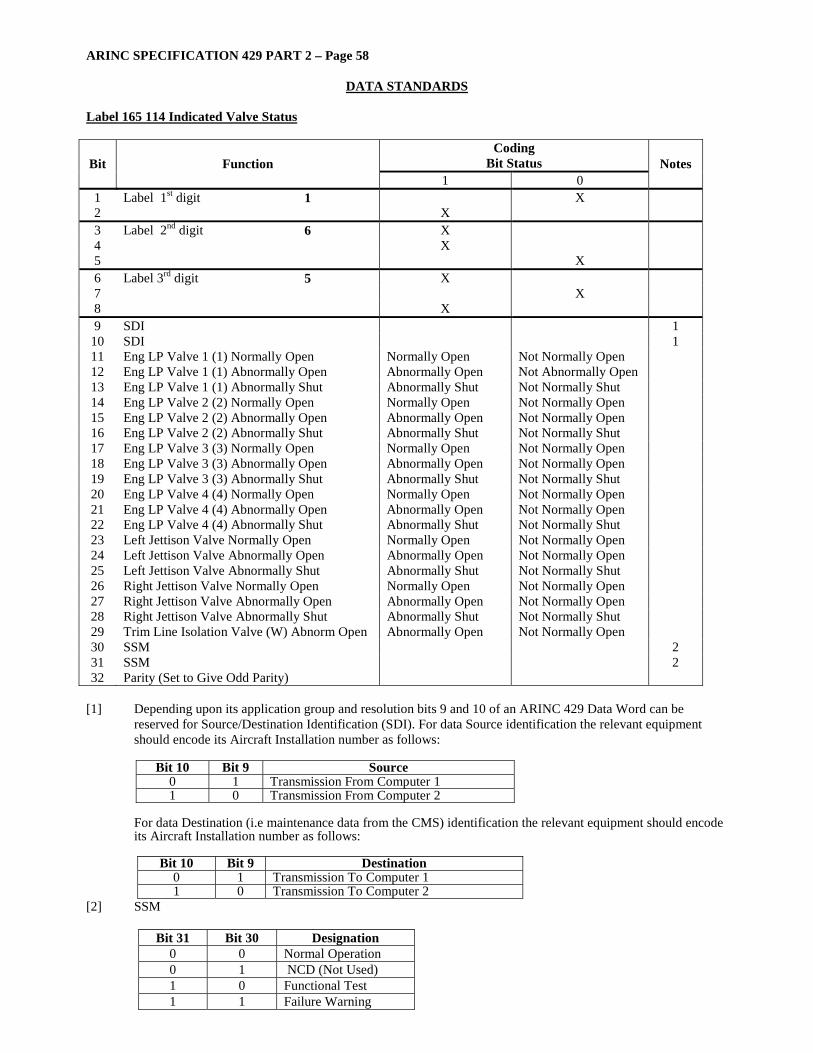
ARINC SPECIFICATION 429 PART 2 – Page 58
DATA STANDARDS
Label 165 114 Indicated Valve Status
Coding Bit Status Bit Function
1 0 Notes
1 Label 1st digit 1 X 2 X 3 Label 2nd digit 6 X 4 X 5 X 6 Label 3rd digit 5 X 7 X 8 X 9 SDI 1
10 SDI 1 11 Eng LP Valve 1 (1) Normally Open Normally Open Not Normally Open 12 Eng LP Valve 1 (1) Abnormally Open Abnormally Open Not Abnormally Open 13 Eng LP Valve 1 (1) Abnormally Shut Abnormally Shut Not Normally Shut 14 Eng LP Valve 2 (2) Normally Open Normally Open Not Normally Open 15 Eng LP Valve 2 (2) Abnormally Open Abnormally Open Not Normally Open 16 Eng LP Valve 2 (2) Abnormally Shut Abnormally Shut Not Normally Shut 17 Eng LP Valve 3 (3) Normally Open Normally Open Not Normally Open 18 Eng LP Valve 3 (3) Abnormally Open Abnormally Open Not Normally Open 19 Eng LP Valve 3 (3) Abnormally Shut Abnormally Shut Not Normally Shut 20 Eng LP Valve 4 (4) Normally Open Normally Open Not Normally Open 21 Eng LP Valve 4 (4) Abnormally Open Abnormally Open Not Normally Open 22 Eng LP Valve 4 (4) Abnormally Shut Abnormally Shut Not Normally Shut 23 Left Jettison Valve Normally Open Normally Open Not Normally Open 24 Left Jettison Valve Abnormally Open Abnormally Open Not Normally Open 25 Left Jettison Valve Abnormally Shut Abnormally Shut Not Normally Shut 26 Right Jettison Valve Normally Open Normally Open Not Normally Open 27 Right Jettison Valve Abnormally Open Abnormally Open Not Normally Open 28 Right Jettison Valve Abnormally Shut Abnormally Shut Not Normally Shut 29 Trim Line Isolation Valve (W) Abnorm Open Abnormally Open Not Normally Open 30 SSM 2 31 SSM 2 32 Parity (Set to Give Odd Parity)
[1] Depending upon its application group and resolution bits 9 and 10 of an ARINC 429 Data Word can be
reserved for Source/Destination Identification (SDI). For data Source identification the relevant equipment should encode its Aircraft Installation number as follows:
Bit 10 Bit 9 Source
0 1 Transmission From Computer 1 1 0 Transmission From Computer 2
For data Destination (i.e maintenance data from the CMS) identification the relevant equipment should encode its Aircraft Installation number as follows:
Bit 10 Bit 9 Destination
0 1 Transmission To Computer 1 1 0 Transmission To Computer 2
[2] SSM
Bit 31 Bit 30 Designation 0 0 Normal Operation 0 1 NCD (Not Used) 1 0 Functional Test 1 1 Failure Warning
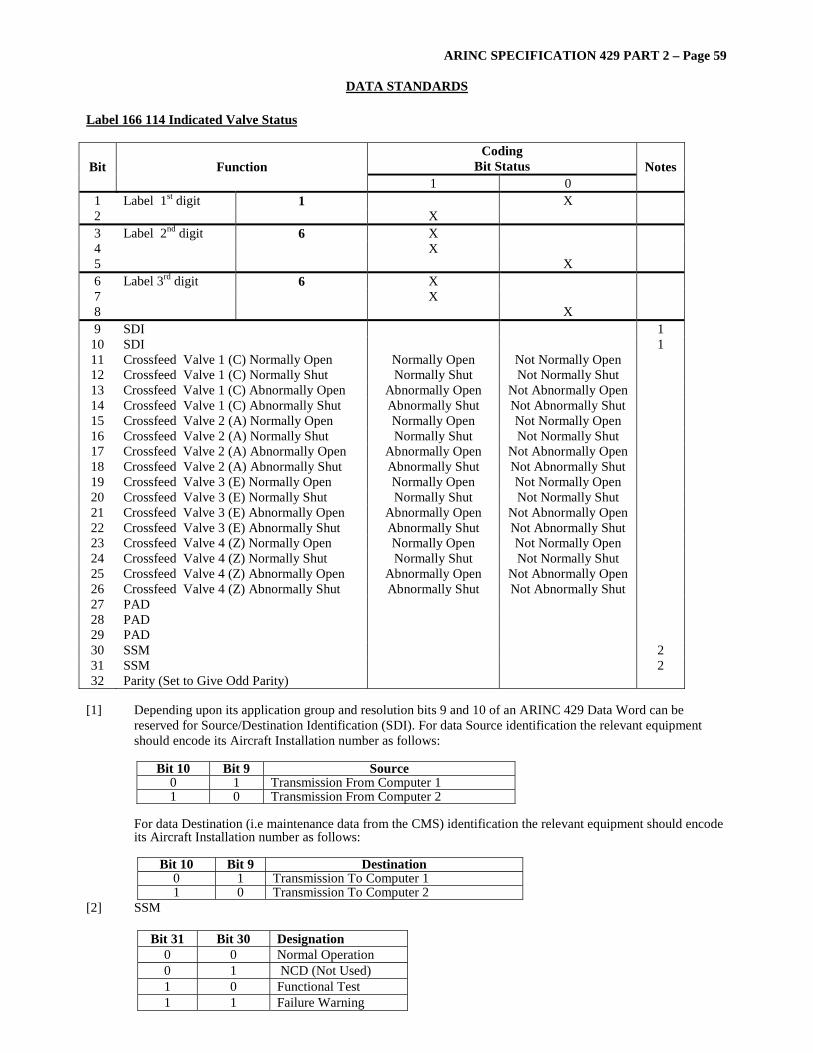
ARINC SPECIFICATION 429 PART 2 – Page 59
DATA STANDARDS Label 166 114 Indicated Valve Status
Coding Bit Status Bit Function
1 0 Notes
1 Label 1st digit 1 X 2 X 3 Label 2nd digit 6 X 4 X 5 X 6 Label 3rd digit 6 X 7 X 8 X 9 SDI 1
10 SDI 1 11 Crossfeed Valve 1 (C) Normally Open Normally Open Not Normally Open 12 Crossfeed Valve 1 (C) Normally Shut Normally Shut Not Normally Shut 13 Crossfeed Valve 1 (C) Abnormally Open Abnormally Open Not Abnormally Open 14 Crossfeed Valve 1 (C) Abnormally Shut Abnormally Shut Not Abnormally Shut 15 Crossfeed Valve 2 (A) Normally Open Normally Open Not Normally Open 16 Crossfeed Valve 2 (A) Normally Shut Normally Shut Not Normally Shut 17 Crossfeed Valve 2 (A) Abnormally Open Abnormally Open Not Abnormally Open 18 Crossfeed Valve 2 (A) Abnormally Shut Abnormally Shut Not Abnormally Shut 19 Crossfeed Valve 3 (E) Normally Open Normally Open Not Normally Open 20 Crossfeed Valve 3 (E) Normally Shut Normally Shut Not Normally Shut 21 Crossfeed Valve 3 (E) Abnormally Open Abnormally Open Not Abnormally Open 22 Crossfeed Valve 3 (E) Abnormally Shut Abnormally Shut Not Abnormally Shut 23 Crossfeed Valve 4 (Z) Normally Open Normally Open Not Normally Open 24 Crossfeed Valve 4 (Z) Normally Shut Normally Shut Not Normally Shut 25 Crossfeed Valve 4 (Z) Abnormally Open Abnormally Open Not Abnormally Open 26 Crossfeed Valve 4 (Z) Abnormally Shut Abnormally Shut Not Abnormally Shut 27 PAD 28 PAD 29 PAD 30 SSM 2 31 SSM 2 32 Parity (Set to Give Odd Parity)
[1] Depending upon its application group and resolution bits 9 and 10 of an ARINC 429 Data Word can be
reserved for Source/Destination Identification (SDI). For data Source identification the relevant equipment should encode its Aircraft Installation number as follows:
Bit 10 Bit 9 Source
0 1 Transmission From Computer 1 1 0 Transmission From Computer 2
For data Destination (i.e maintenance data from the CMS) identification the relevant equipment should encode its Aircraft Installation number as follows:
Bit 10 Bit 9 Destination
0 1 Transmission To Computer 1 1 0 Transmission To Computer 2
[2] SSM
Bit 31 Bit 30 Designation 0 0 Normal Operation 0 1 NCD (Not Used) 1 0 Functional Test 1 1 Failure Warning

ARINC SPECIFICATION 429 PART 2 – Page 60
DATA STANDARDS
Label 167 114 Indicated Valve Status
Coding Bit Status Bit Function
1 0 Notes
1 Label 1st digit 1 X 2 X 3 Label 2nd digit 6 X 4 X 5 X 6 Label 3rd digit 7 X 7 X 8 X 9 SDI 1
10 SDI 1 11 Act 1 Inlet Valve (Ag) Normally Open Normally Open Not Normally Open 12 Act 1 Inlet Valve (Ag) Normally Shut Normally Shut Not Normally Shut 13 Act 1 Inlet Valve (Ag) Abnormally Open Abnormally Open Not Abnormally Open 14 Act 1 Inlet Valve (Ag) Abnormally Shut Abnormally Shut Not Abnormally Shut 15 Act 2 Inlet Valve (Ah) Normally Open Normally Open Not Normally Open 16 Act 2 Inlet Valve (Ah) Normally Shut Normally Shut Not Normally Shut 17 Act 2 Inlet Valve (Ah) Abnormally Open Abnormally Open Not Abnormally Open 18 Act 2 Inlet Valve (Ah) Abnormally Shut Abnormally Shut Not Abnormally Shut 19 Act Isolation Valve (Ac) Abnormally Open Abnormally Open Not Abnormally Open 20 PAD 21 PAD 22 PAD 23 PAD 24 PAD 25 PAD 26 PAD 27 PAD 28 PAD 29 PAD 30 SSM 2 31 SSM 2 32 Parity ( Set to Give Odd Parity)
[1] Depending upon its application group and resolution bits 9 and 10 of an ARINC 429 Data Word can be
reserved for Source/Destination Identification (SDI). For data Source identification the relevant equipment should encode its Aircraft Installation number as follows:
Bit 10 Bit 9 Source
0 1 Transmission From Computer 1 1 0 Transmission From Computer 2
For data Destination (i.e maintenance data from the CMS) identification the relevant equipment should encode its Aircraft Installation number as follows:
Bit 10 Bit 9 Destination
0 1 Transmission To Computer 1 1 0 Transmission To Computer 2
[2] SSM
Bit 31 Bit 30 Designation 0 0 Normal Operation 0 1 NCD (Not Used) 1 0 Functional Test 1 1 Failure Warning

ARINC SPECIFICATION 429 PART 2 – Page 61
DATA STANDARDS Label 214 xxx ICAO 24-Bit Aircraft Address Word #1 – (Discrete) 32 31 30 29 28 27 26 25 24 23 22 21 20 19 18 17 16 15 14 13 12 11 10 9 8 7 6 5 4 3 2 1 P SSM A16--------------------------------------------------------------- A1 Octal Label MSB 214 001 100 01
Bit Function Coding Notes 1 Label 1 2 . 2 0 3 . 0 4 . 0 5 . 1 1 6 . 1 7 . 0 8 Label 4 0 9 PAD 10 . 11 . 12 . 13 PAD 14 ICAO 24-Bit Aircraft Address (Part 1) A1 (MSB) 15 . A2 16 . A3 17 . A4 18 . A5 19 . A6 20 . A7 21 . A8 22 . A9 23 . A10 24 . A11 25 . A12 26 . A13 27 . A14 28 . A15 29 ICAO 24-Bit Aircraft Address (Part 1) A16 30 SSM 1 31 SSM 1 32 Parity Odd
Notes: [1] Sign Status Matrix (SSM) Definition per ARINC Specification 429
Bit 31 30 Meaning
0 0 Normal Operation 0 1 NCD 1 0 Functional Test 1 1 Failure Warning
[2] All PAD bits are set to binary 0
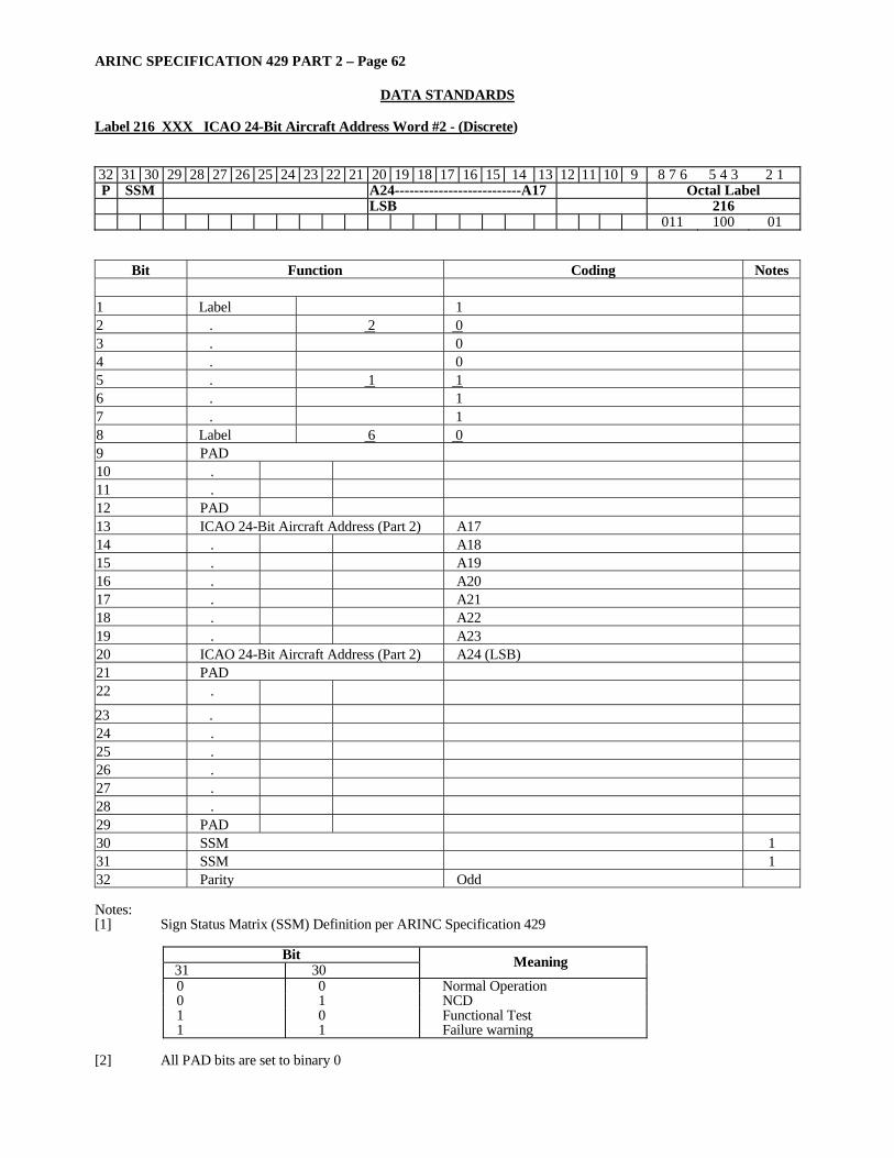
ARINC SPECIFICATION 429 PART 2 – Page 62
DATA STANDARDS
Label 216 XXX ICAO 24-Bit Aircraft Address Word #2 - (Discrete)
32 31 30 29 28 27 26 25 24 23 22 21 20 19 18 17 16 15 14 13 12 11 10 9 8 7 6 5 4 3 2 1 P SSM A24--------------------------A17 Octal Label LSB 216 011 100 01
Bit Function Coding Notes 1 Label 1 2 . 2 0 3 . 0 4 . 0 5 . 1 1 6 . 1 7 . 1 8 Label 6 0 9 PAD 10 . 11 . 12 PAD 13 ICAO 24-Bit Aircraft Address (Part 2) A17 14 . A18 15 . A19 16 . A20 17 . A21 18 . A22 19 . A23 20 ICAO 24-Bit Aircraft Address (Part 2) A24 (LSB) 21 PAD 22 .
23 . 24 . 25 . 26 . 27 . 28 . 29 PAD 30 SSM 1 31 SSM 1 32 Parity Odd Notes: [1] Sign Status Matrix (SSM) Definition per ARINC Specification 429
Bit 31 30 Meaning
0 0 Normal Operation 0 1 NCD 1 0 Functional Test 1 1 Failure warning
[2] All PAD bits are set to binary 0
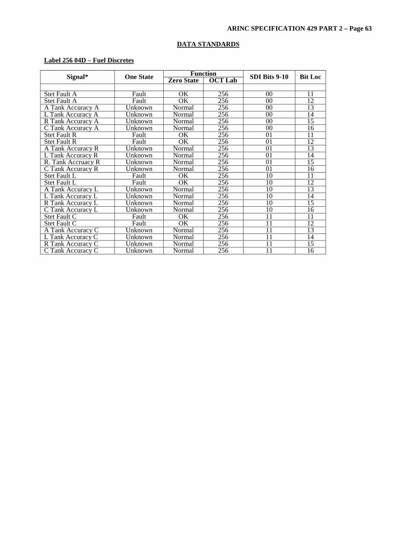
ARINC SPECIFICATION 429 PART 2 – Page 63
DATA STANDARDS Label 256 04D – Fuel Discretes
Function Signal* One State Zero State OCT Lab SDI Bits 9-10 Bit Loc Stet Fault A Fault OK 256 00 11 Stet Fault A Fault OK 256 00 12 A Tank Accuracy A Unknown Normal 256 00 13 L Tank Accuracy A Unknown Normal 256 00 14 R Tank Accuracy A Unknown Normal 256 00 15 C Tank Accuracy A Unknown Normal 256 00 16 Stet Fault R Fault OK 256 01 11 Stet Fault R Fault OK 256 01 12 A Tank Accuracy R Unknown Normal 256 01 13 L Tank Accuracy R Unknown Normal 256 01 14 R. Tank Accruacy R Unknown Normal 256 01 15 C Tank Accuracy R Unknown Normal 256 01 16 Stet Fault L Fault OK 256 10 11 Stet Fault L Fault OK 256 10 12 A Tank Accuracy L Unknown Normal 256 10 13 L Tank Accuracy L Unknown Normal 256 10 14 R Tank Accuracy L Unknown Normal 256 10 15 C Tank Accuracy L Unknown Normal 256 10 16 Stet Fault C Fault OK 256 11 11 Stet Fault C Fault OK 256 11 12 A Tank Accuracy C Unknown Normal 256 11 13 L Tank Accuracy C Unknown Normal 256 11 14 R Tank Accuracy C Unknown Normal 256 11 15 C Tank Accuracy C Unknown Normal 256 11 16
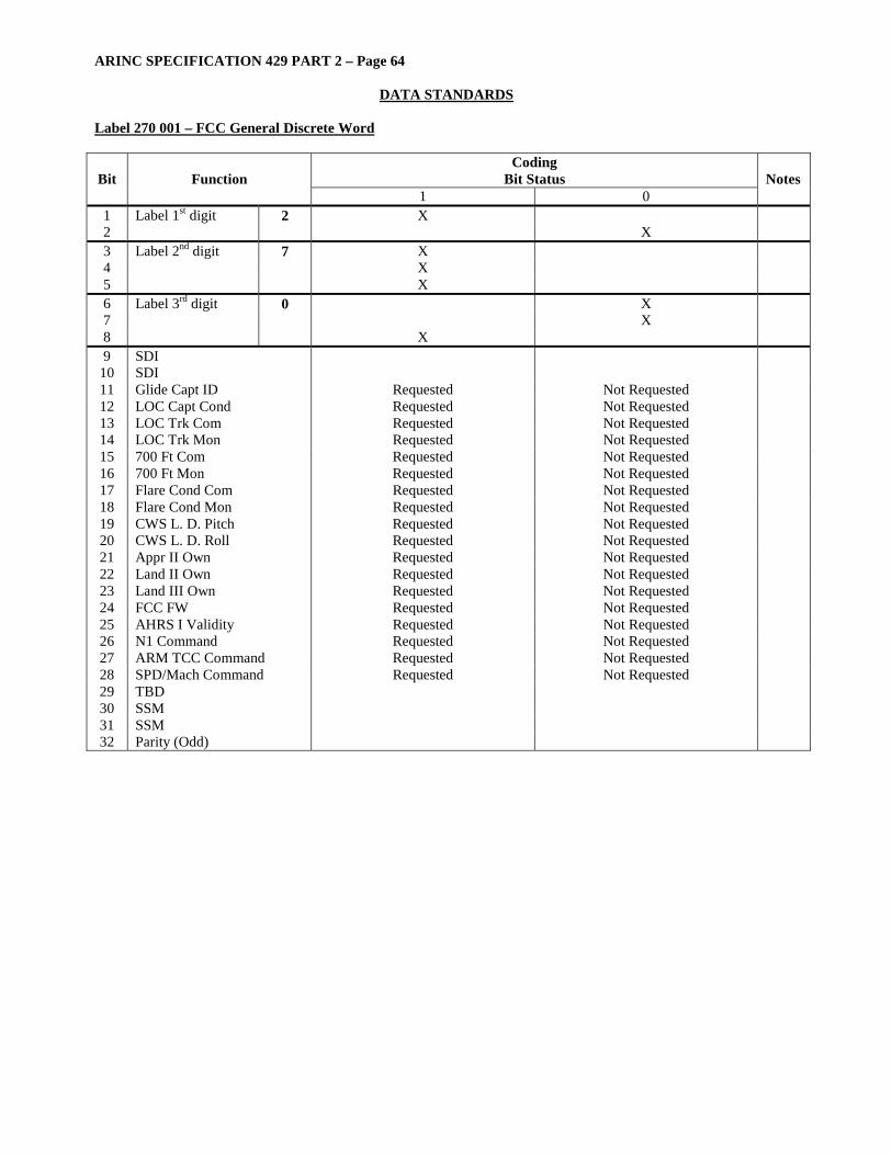
ARINC SPECIFICATION 429 PART 2 – Page 64
DATA STANDARDS
Label 270 001 – FCC General Discrete Word
Coding Bit Status Bit Function
1 0 Notes
1 Label 1st digit 2 X 2 X 3 Label 2nd digit 7 X 4 X 5 X 6 Label 3rd digit 0 X 7 X 8
X
9 SDI 10 SDI 11 Glide Capt ID Requested Not Requested 12 LOC Capt Cond Requested Not Requested 13 LOC Trk Com Requested Not Requested 14 LOC Trk Mon Requested Not Requested 15 700 Ft Com Requested Not Requested 16 700 Ft Mon Requested Not Requested 17 Flare Cond Com Requested Not Requested 18 Flare Cond Mon Requested Not Requested 19 CWS L. D. Pitch Requested Not Requested 20 CWS L. D. Roll Requested Not Requested 21 Appr II Own Requested Not Requested 22 Land II Own Requested Not Requested 23 Land III Own Requested Not Requested 24 FCC FW Requested Not Requested 25 AHRS I Validity Requested Not Requested 26 N1 Command Requested Not Requested 27 ARM TCC Command Requested Not Requested 28 SPD/Mach Command Requested Not Requested 29 TBD 30 SSM 31 SSM 32 Parity (Odd)
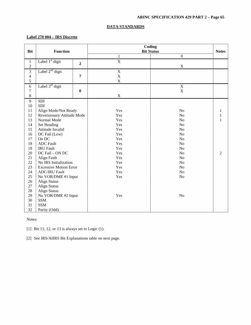
ARINC SPECIFICATION 429 PART 2 – Page 65
DATA STANDARDS Label 270 004 – IRS Discrete
Coding Bit Status Bit Function
1 0 Notes
1 Label 1st digit X 2 2 X 3 Label 2nd digit X 4 X 5
7 X
6 Label 3rd digit X 7 X 8
0 X
9 SDI 10 SDI 11 Align Mode/Not Ready Yes No 1 12 Reversionary Attitude Mode Yes No 1 13 Normal Mode Yes No 1 14 Set Heading Yes No 15 Attitude Invalid Yes No 16 DC Fail (Low) Yes No 17 On DC Yes No 18 ADC Fault Yes No 19 IRU Fault Yes No 20 DC Fail – ON DC Yes No 2 21 Align Fault Yes No 22 No IRS Initialization Yes No 23 Excessive Motion Error Yes No 24 ADC/IRU Fault Yes No 25 No VOR/DME #1 Input Yes No 26 Align Status 27 Align Status 28 Align Status 29 No VOR/DME #2 Input Yes No 30 SSM 31 SSM 32 Parity (Odd)
Notes: [1] Bit 11, 12, or 13 is always set to Logic (1). [2] See IRS/AHRS Bit Explanations table on next page.
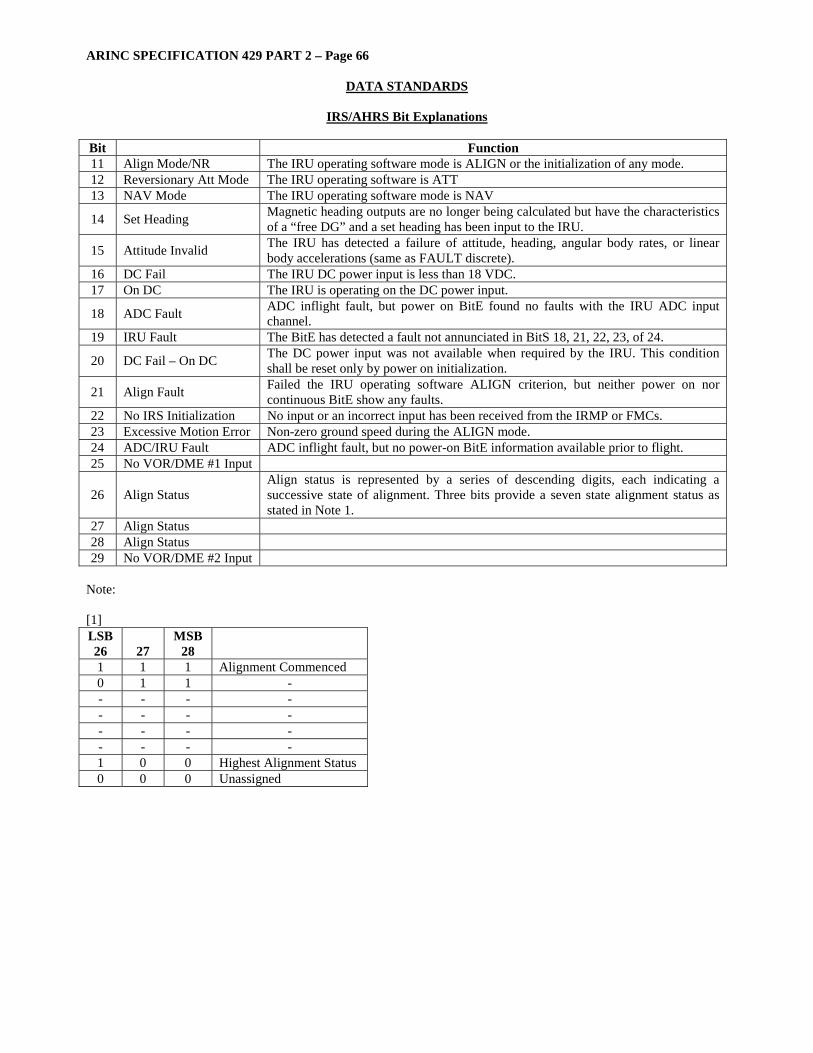
ARINC SPECIFICATION 429 PART 2 – Page 66
DATA STANDARDS
IRS/AHRS Bit Explanations Bit Function 11 Align Mode/NR The IRU operating software mode is ALIGN or the initialization of any mode. 12 Reversionary Att Mode The IRU operating software is ATT 13 NAV Mode The IRU operating software mode is NAV
14 Set Heading Magnetic heading outputs are no longer being calculated but have the characteristics of a “free DG” and a set heading has been input to the IRU.
15 Attitude Invalid The IRU has detected a failure of attitude, heading, angular body rates, or linear body accelerations (same as FAULT discrete).
16 DC Fail The IRU DC power input is less than 18 VDC. 17 On DC The IRU is operating on the DC power input.
18 ADC Fault ADC inflight fault, but power on BitE found no faults with the IRU ADC input channel.
19 IRU Fault The BitE has detected a fault not annunciated in BitS 18, 21, 22, 23, of 24.
20 DC Fail – On DC The DC power input was not available when required by the IRU. This condition shall be reset only by power on initialization.
21 Align Fault Failed the IRU operating software ALIGN criterion, but neither power on nor continuous BitE show any faults.
22 No IRS Initialization No input or an incorrect input has been received from the IRMP or FMCs. 23 Excessive Motion Error Non-zero ground speed during the ALIGN mode. 24 ADC/IRU Fault ADC inflight fault, but no power-on BitE information available prior to flight. 25 No VOR/DME #1 Input
26 Align Status Align status is represented by a series of descending digits, each indicating a successive state of alignment. Three bits provide a seven state alignment status as stated in Note 1.
27 Align Status 28 Align Status 29 No VOR/DME #2 Input
Note: [1] LSB 26
27
MSB 28
1 1 1 Alignment Commenced 0 1 1 - - - - - - - - - - - - - - - - - 1 0 0 Highest Alignment Status 0 0 0 Unassigned
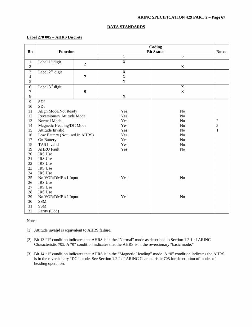
ARINC SPECIFICATION 429 PART 2 – Page 67
DATA STANDARDS Label 270 005 – AHRS Discrete
Coding Bit Status Bit Function
1 0 Notes
1 Label 1st digit X 2 2 X 3 Label 2nd digit X 4 X 5
7 X
6 Label 3rd digit X 7 X 8
0 X
9 SDI 10 SDI 11 Align Mode/Not Ready Yes No 12 Reversionary Attitude Mode Yes No 13 Normal Mode Yes No 2 14 Magnetic Heading/DC Mode Yes No 3 15 Attitude Invalid Yes No 1 16 Low Battery (Not used in AHRS) Yes No 17 On Battery Yes No 18 TAS Invalid Yes No 19 AHRU Fault Yes No 20 IRS Use 21 IRS Use 22 IRS Use 23 IRS Use 24 IRS Use 25 No VOR/DME #1 Input Yes No 26 IRS Use 27 IRS Use 28 IRS Use 29 No VOR/DME #2 Input Yes No 30 SSM 31 SSM 32 Parity (Odd)
Notes: [1] Attitude invalid is equivalent to AHRS failure. [2] Bit 13 “1” condition indicates that AHRS is in the “Normal” mode as described in Section 1.2.1 of ARINC
Characteristic 705. A “0” condition indicates that the AHRS is in the reversionary “basic mode.” [3] Bit 14 “1” condition indicates that AHRS is in the “Magnetic Heading” mode. A “0” condition indicates the AHRS
is in the reversionary “DG” mode. See Section 1.2.2 of ARINC Characteristic 705 for description of modes of heading operation.
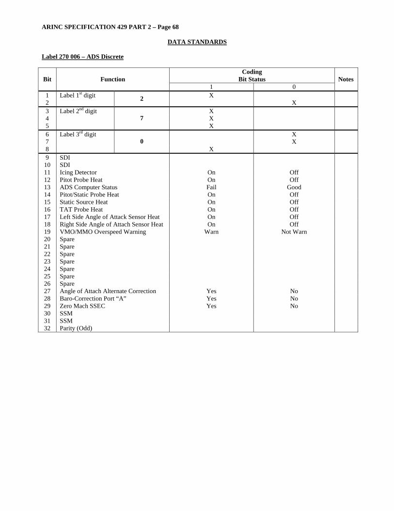
ARINC SPECIFICATION 429 PART 2 – Page 68
DATA STANDARDS
Label 270 006 – ADS Discrete
Coding Bit Status Bit Function
1 0 Notes
1 Label 1st digit X 2 2 X 3 Label 2nd digit X 4 X 5
7 X
6 Label 3rd digit X 7 X 8
0 X
9 SDI 10 SDI 11 Icing Detector On Off 12 Pitot Probe Heat On Off 13 ADS Computer Status Fail Good 14 Pitot/Static Probe Heat On Off 15 Static Source Heat On Off 16 TAT Probe Heat On Off 17 Left Side Angle of Attack Sensor Heat On Off 18 Right Side Angle of Attach Sensor Heat On Off 19 VMO/MMO Overspeed Warning Warn Not Warn 20 Spare 21 Spare 22 Spare 23 Spare 24 Spare 25 Spare 26 Spare 27 Angle of Attach Alternate Correction Yes No 28 Baro-Correction Port “A” Yes No 29 Zero Mach SSEC Yes No 30 SSM 31 SSM 32 Parity (Odd)
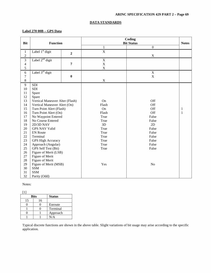
ARINC SPECIFICATION 429 PART 2 – Page 69
DATA STANDARDS Label 270 00B – GPS Data
Coding Bit Status Bit Function
1 0 Notes
1 Label 1st digit X 2 2 X 3 Label 2nd digit X 4 X 5
7 X
6 Label 3rd digit X 7 X 8
0 X
9 SDI 10 SDI 11 Spare 12 Spare 13 Vertical Maneuver Alter (Flash) On Off 14 Vertical Maneuver Alert (On) Flash Off 15 Turn Point Alert (Flash) On Off 1 16 Turn Point Alert (On) Flash Off 1 17 No Waypoint Entered True False 18 No Course Entered True False 19 2D/3D NAV 3D 2D 20 GPS NAV Valid True False 21 EN Route True False 22 Terminal True False 23 GPS High Accuracy True False 24 Approach (Angular) True False 25 GPS Self Test (Bit) True False 26 Figure of Merit (LSB) 27 Figure of Merit 28 Figure of Merit 29 Figure of Merit (MSB) Yes No 30 SSM 31 SSM 32 Parity (Odd)
Notes: [1]
Bits Status 15 16 0 0 Enroute 1 0 Terminal 0 1 Approach 1 1 N/A
Typical discrete functions are shown in the above table. Slight variations of bit usage may arise according to the specific application.

ARINC SPECIFICATION 429 PART 2 – Page 70
DATA STANDARDS
Label 270 01A – EEC Discrete
Coding Bit Status Bit Function
1 0 Notes
1 Label 1st digit X 2 2 X 3 Label 2nd digit X 4 X 5
7 X
6 Label 3rd digit X 7 X 8
0 X
9 SDI 10 SDI 11 Pad X 12 Pad X 13 Pad X 14 Pad X 15 EPR Loop Selected Yes No 16 N2 Loop Selected Yes No 17 EGT Loop Selected Yes No 18 Integrator on Min Stop Yes No 19 Integrator on Max Stop Yes No 20 EEC On/Off Discrete Off On 21 Initialization Yes No 22 Low Speed Latch Yes No 23 EAROM Failed Good 24 EEC Probe T2 Selected Yes No 25 Fault Light On Off 26 See Main Panel Yes No 27 TCC System Failed Good 28 TCA System Failed Good 29 Thrust Bump Inhibit Yes No 30 SSM 31 SSM 32 Parity (Odd)
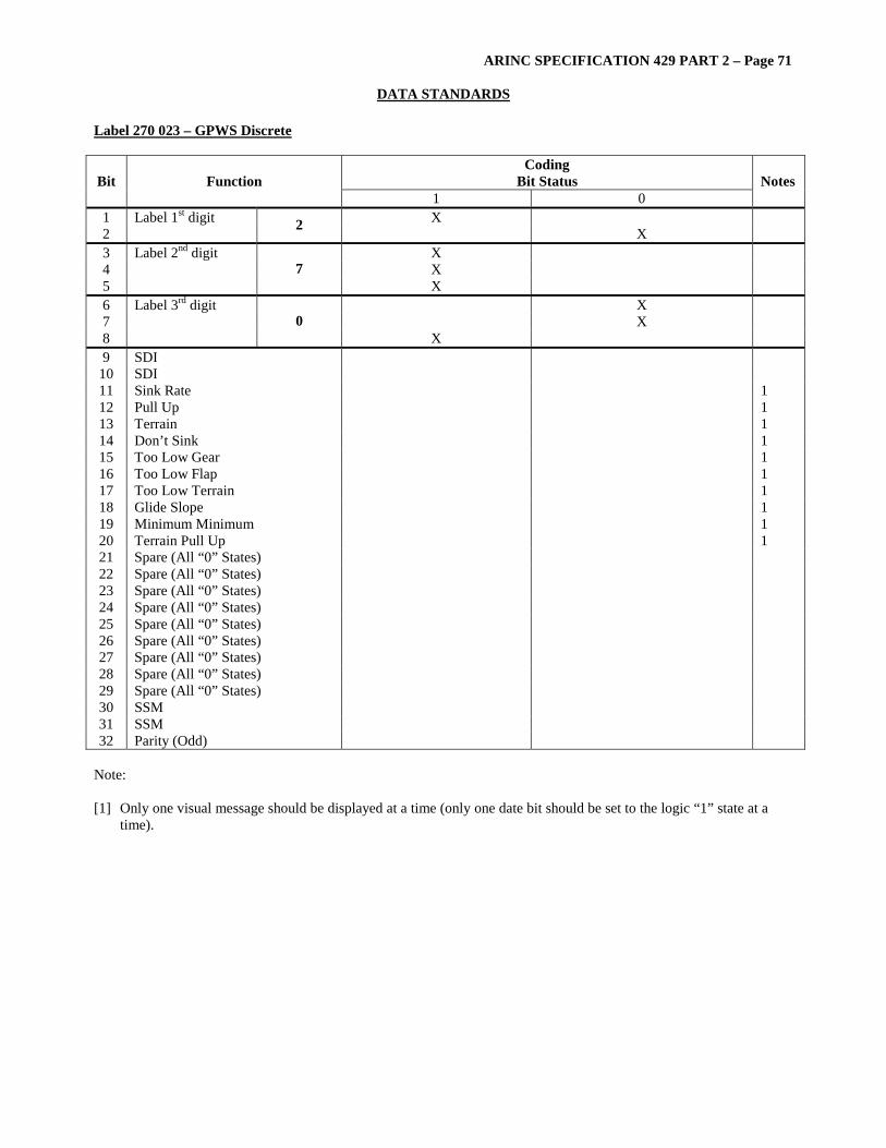
ARINC SPECIFICATION 429 PART 2 – Page 71
DATA STANDARDS Label 270 023 – GPWS Discrete
Coding Bit Status Bit Function
1 0 Notes
1 Label 1st digit X 2 2 X 3 Label 2nd digit X 4 X 5
7 X
6 Label 3rd digit X 7 X 8
0 X
9 SDI 10 SDI 11 Sink Rate 1 12 Pull Up 1 13 Terrain 1 14 Don’t Sink 1 15 Too Low Gear 1 16 Too Low Flap 1 17 Too Low Terrain 1 18 Glide Slope 1 19 Minimum Minimum 1 20 Terrain Pull Up 1 21 Spare (All “0” States) 22 Spare (All “0” States) 23 Spare (All “0” States) 24 Spare (All “0” States) 25 Spare (All “0” States) 26 Spare (All “0” States) 27 Spare (All “0” States) 28 Spare (All “0” States) 29 Spare (All “0” States) 30 SSM 31 SSM 32 Parity (Odd)
Note: [1] Only one visual message should be displayed at a time (only one date bit should be set to the logic “1” state at a
time).

ARINC SPECIFICATION 429 PART 2 – Page 72
DATA STANDARDS
Label 270 02F – EEC Status
Coding Bit Status Bit Function
1 0 Notes
1 Label 1st digit X 2 2 X 3 Label 2nd digit X 4 X 5
7 X
6 Label 3rd digit X 7 X 8
0 X
9 SDI X 10 SDI X 11 Pad X 12 Pad X 13 Pad X 14 PDIU Status Invalid OK 15 Spare 16 Channel Select Mode Secondary Auto 17 Primary Chan Manually selected Selected Not Selected 1 18 N2 Droop Control Mode Engaged Not Engaged 19 Reverser System Status Inoperative OK 20 Channel Controlling Status Controlling Not Controlling 21 2.5 Bleed System Failed Failed Operational 22 TCA Valve(s) Failed Closed Failed OK 23 Case Cooling Valve Stuck Failed OK 24 14th Stage Bleed System Failed Failed Operational 25 Channel Incapable (Failed) Incapable Capable 26 Oil Cooling System Status Faulted OK 27 SVA System Failed Failed Operational 28 Starter Cutout Command Cutout Not Cutout 29 Spare X 30 SSM X 31 SSM X 32 Parity (Odd) X
Note: [1] Typical discrete functions are shown in the above table. Slight variations of bit usage may arise according to the
specific application.

ARINC SPECIFICATION 429 PART 2 – Page 73
DATA STANDARDS Label 270 030 – Transponder Discrete
Coding Bit Status Bit Function
1 0 Notes
1 Label 1st digit X 2 2 X 3 Label 2nd digit X 4 X 5
7 X
6 Label 3rd digit X 7 X 8
0 X
9 SDI 10 SDI 11 Spare 12 Spare 13 Spare 14 Spare 15 Spare 16 Spare 17 Spare 18 Left 1 19 Left 1 20 Right 2 21 Right 2 22 Up 3 23 Up 3 24 Up 3 25 Up 3 26 Down 4 27 Down 4 28 Down 4 29 Down 4 30 SSM 31 SSM 32 Parity (Odd)
Notes: [1]
Bit Left Component 00 No Left Advisory 01 Turn Left 10 Don’t Turn Left 11 Not Used [2]
Bit Right Component 00 No Right Advisory 01 Turn Right 10 Don’t Turn Right 11 Not Used
[3] Bit Up Component
0000 No Up Advisory 0001 Climb 0010 Climb Faster than 500 FPM 0011 Climb Faster than 1000 FPM 0100 Climb Faster than 2000 FPM 0101 Don’t Descend 0110 Don’t Descend Faster than 500 FPM 0111 Don’t Descend Faster than 1000 FPM 1000 Don’t Descend Faster than 2000 FPM 1001-1111 Not Used [4]
Bit Down Component 0000 No Down Advisory 0001 Descend 0010 Descend Faster than 500 FPM 0011 Descend Faster than 1000 FPM 0100 Descend Faster than 2000 FPM 0101 Don’t Climb 0110 Don’t Climb Faster than 500 FPM 0111 Don’t Climb Faster than 1000 FPM 1000 Don’t Climb Faster than 2000 FPM 1001-1111 Not Used

ARINC SPECIFICATION 429 PART 2 – Page 74
DATA STANDARDS
Label 270 033
Coding Bit Status Bit Function
1 0 Notes
1 Label 1st digit X 2 2 X 3 Label 2nd digit X 4 X 5
7 X
6 Label 3rd digit X 7 X 8
0 X
9 SDI 10 SDI 11 Turbine Case Cooling Valve Open Closed 12 Upper Turbine Cooling Valve Open Closed 13 Lower Turbine Cooling Valve Open Closed 14 Fuel Heater Valve Open Closed 15 Spare (All “0” States) 16 Spare (All “0” States) 17 Spare (All “0” States) 18 Spare (All “0” States) 19 Spare (All “0” States) 20 Spare (All “0” States) 21 Spare (All “0” States) 22 Spare (All “0” States) 23 Spare (All “0” States) 24 Spare (All “0” States) 25 Spare (All “0” States) 26 Spare (All “0” States) 27 Spare (All “0” States) 28 Spare (All “0” States) 29 Spare (All “0” States) 30 SSM 31 SSM 32 Parity (Odd)

ARINC SPECIFICATION 429 PART 2 – Page 75
DATA STANDARDS Label 270 035 – TCAS Vertical RA Data Discrete
Coding Bit Status Bit Function
1 0 Notes
1 Label 1st digit X 2 2 X 3 Label 2nd digit X 4 X 5
7 X
6 Label 3rd digit X 7 X 8
0 X
9 SDI Bit 0 10 SDI Bit 1 11 Advisory Altitude Rate 100 ft/min 12 Advisory Altitude Rate 200 ft/min 13 Advisory Altitude Rate 400 f/min 14 Advisory Altitude Rate 800 ft/min 15 Advisory Altitude Rate 1600 ft/min 16 Advisory Altitude Rate 3200 ft/min 17 Advisory Altitude Rate Sign 18 Combined Control 1 19 Combined Control 1 20 Combined Control 1 21 Vertical Control 2 22 Vertical Control 2 23 Vertical Control 2 24 Up Advisory 3 25 Up Advisory 3 26 Up Advisory 3 27 Down Advisory 4 28 Down Advisory 4 29 Down Advisory 4 30 SSM 5 31 SSM 5 32 Parity (Odd)
Notes: [1] Combined Control
Bit Meaning 20 19 18 0 0 0 No Advisory 0 0 1 Clear of Conflict 0 1 0 Drop Track 0 1 1 Altitude Lost 1 0 0 Climb Corrective (1A) 1 0 1 Descend Corrective (1A) 1 1 0 Preventative 1 1 1 Not Used
[1A] CAS logic defined by RTCA DO-185 Change 6 does not discreminiate between Climb Corrective and Descend
Corrective. The omission is expected to be corrected in Change 7. Meanwhile, the receiving RA Display must assume a Climb Corrective when either a Climb Corrective or Descend Corrective is issued until the MOPS is revised.

ARINC SPECIFICATION 429 PART 2 – Page 76
DATA STANDARDS
Label 270 035 – TCAS Vertical RA Data Discrete (cont’d) [2] Vertical Control
Bit Meaning 23 22 21 0 0 0 Advisory is not one of the following types 0 0 1 Crossing 0 1 0 Reversal 0 1 1 Increase 1 0 0 Maintain 1 0 1 Not Used 1 1 0 Not Used 1 1 1 Not Used [3] Up Advisory
Bit Meaning 26 25 24 0 0 0 No Up Advisory 0 0 1 Climb 0 1 0 Don’t Descend 0 1 1 Don’t Descend > 500 1 0 0 Don’t Descend > 1000 1 0 1 Don’t Descend > 2000 1 1 0 Not Used 1 1 1 Not Used [4] Down Advisory
Bit Meaning 29 28 27 0 0 0 No Down Advisory 0 0 1 Descend 0 1 0 Don’t Climb 0 1 1 Don’t Climb > 500 1 0 0 Don’t Climb > 1000 1 0 1 Don’t Climb > 2000 1 1 0 Not Used 1 1 1 Not Used [5] The presence of a No Computed Data report in the SSM field indicates that the no RA exists or that information in
Bits 18 through 29 is unreliable. Therefore, no RA should be issued by the Display.
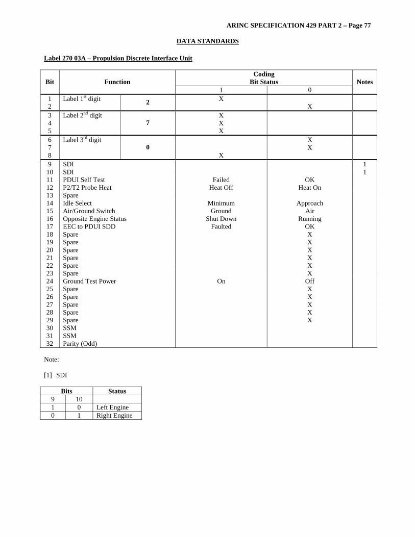
ARINC SPECIFICATION 429 PART 2 – Page 77
DATA STANDARDS Label 270 03A – Propulsion Discrete Interface Unit
Coding Bit Status Bit Function
1 0 Notes
1 Label 1st digit X 2 2 X 3 Label 2nd digit X 4 X 5
7 X
6 Label 3rd digit X 7 X 8
0 X
9 SDI 1 10 SDI 1 11 PDUI Self Test Failed OK 12 P2/T2 Probe Heat Heat Off Heat On 13 Spare 14 Idle Select Minimum Approach 15 Air/Ground Switch Ground Air 16 Opposite Engine Status Shut Down Running 17 EEC to PDUI SDD Faulted OK 18 Spare X 19 Spare X 20 Spare X 21 Spare X 22 Spare X 23 Spare X 24 Ground Test Power On Off 25 Spare X 26 Spare X 27 Spare X 28 Spare X 29 Spare X 30 SSM 31 SSM 32 Parity (Odd)
Note: [1] SDI
Bits Status 9 10 1 0 Left Engine 0 1 Right Engine

ARINC SPECIFICATION 429 PART 2 – Page 78
DATA STANDARDS
Label 270 03B
Coding Bit Status Bit Function
1 0 Notes
1 Label 1st digit X 2 2 X 3 Label 2nd digit X 4 X 5
7 X
6 Label 3rd digit X 7 X 8
0 X
9 SDI 10 SDI 11 INS Selected Not Selected 12 VOR/LOC Selected Not Selected 13 ILS/Land Selected Not Selected 14 Land Selected Not Selected 15 Altitude Hold Selected Not Selected 16 Altitude Select Selected Not Selected 17 Mach Selected Not Selected 18 IAS Selected Not Selected 19 Vertical Speed Selected Not Selected 20 TURB Selected Not Selected 21 PMS Selected Not Selected 22 Captain’s F/D On and Select Selected Not Selected 23 F/O F/D On and Select Selected Not Selected 24 Course Transfer No. 1 Selected Not Selected 25 Course Transfer No. 2 Selected Not Selected 26 A/P Engage Manual Selected Not Selected 27 A/P Engage Command Selected Not Selected 28 Spare (All “0” States) 29 Word Validity Invalid Valid 30 SSM 31 SSM 32 Parity (Odd)

ARINC SPECIFICATION 429 PART 2 – Page 79
DATA STANDARDS Label 270 03D – Status Word
Coding Bit Status Bit Function
1 0 Notes
1 Label 1st digit X 2 2 X 3 Label 2nd digit X 4 X 5
7 X
6 Label 3rd digit X 7 X 8
0 X
9 SDI 10 SDI 11 Data 12 Data 13 Data 14 Data 15 Data 16 Data 17 Data 18 Data 19 Data 20 Data 21 Data 22 Data 23 Data 24 Data 25 Data 26 Data 27 Data 28 Data 29 30 Status Matrix 31 Status Matrix 32 Parity (Odd)
Bit Parameter **11 AVM System Fault
*11 PAD 12 AVM System Fault
*13 AVM Engine 1 Alert **13 Broadband Alert – Engine 1
*14 AVM Engine 2 Alert **14 Broadband Alert – Engine 2 **15 AVM Engine 1 Double Channel Fault
*15 Pad **16 AVM Engine 2 Double Channel Fault
*16 Pad *17 Pad
**17 AVM Engine 1 Alert *18 Pad
**18 AVM Engine 2 Alert **19 Engine 1 High Broadband Alert
*19 Pad **20 Engine 2 High Broadband Alert
*20 Pad 21 NVRAM Failure 22 Fault History Erase 23 Pad
***23 Flight History Erase 24 Pad 25 Pad 26 Pad 27 Pad 28 Pad 29 Pad
* B757 Pratt & Whitney and 737 CFM-56 ** B757 Rolls Royce Only *** B737 CFM-56 Only

ARINC SPECIFICATION 429 PART 2 – Page 80
DATA STANDARDS
Label 270 03F – EEC Status
Coding Bit Status Bit Function
1 0 Notes
1 Label 1st digit X 2 2 X 3 Label 2nd digit X 4 X 5
7 X
6 Label 3rd digit X 7 X 8
0 X
9 SDI X 10 SDI X 11 Pad X 12 Pad X 13 Pad X 14 PDIU Status Invalid OK 15 Spare 16 Channel Select Mode Secondary Auto 17 Primary Chan Manually Selected Selected Not Selected 1 18 N2 Droop Control Mode Engaged Not Engaged 19 Reverser System Status Inoperative OK 20 Channel Controlling Status Controlling Not Controlling 21 2.5 Bleed System Failed Failed Operational 22 TCA Valve(s) Failed Closed Failed OK 23 Case Cooling Valve Stuck Failed OK 24 14th State Bleed System Failed Failed Operational 25 Channel Incapable (Failed) Incapable Capable 26 Oil Cooling System Status Faulted OK 27 SVA System Failed Failed Operational 28 Starter Cutout Command Cutout Not Cutout 29 Spare X 30 SSM X 31 SSM X 32 Parity (Odd) X
Note: [1] Secondary channel only. General Note: Typical discrete functions are shown in the above table. Slight variations of bit usage may arise according to the specific application.

ARINC SPECIFICATION 429 PART 2 – Page 81
DATA STANDARDS Label 270 114 Unusable, Empty and low Level Warning
Coding Bit Status Bit Function
1 0 Notes
1 Label 1st digit 2 X 2 X 3 Label 2nd digit 7 X 4 X 5 X 6 Label 3rd digit 0 X 7 X 8 X 9 SDI 1
10 SDI 1 11 Fuel On Board Unusable Unusable Usable 12 Left Outer Tank Fuel Unusable Unusable Usable 13 Right Outer Tank Fuel Unusable Unusable Usable 14 Center Tank Fuel Unusable Unusable Usable 15 Trim Tank Fuel Unusable Unusable Usable 16 Act1 Fuel Unusable Unusable Usable 17 Act2 Fuel Unusable Unusable Usable 18 RCT Fuel Unusable Unusable Usable 19 Left Outer Empty Empty Not Empty 20 Right Outer Empty Empty Not Empty 21 Center Tank Empty Empty Not Empty 22 Trim Tank Empty Empty Not Empty 23 Act1 Empty Empty Not Empty 24 Act2 Empty Empty Not Empty 25 RCT Empty Empty Not Empty 26 Inner 1+2 Tanks Low Level Low Not Low 27 Inner 3+4 Tanks Low Level Low Not Low 28 All Inner Tanks Low Level Low Not Low 29 PAD 30 SSM 2 31 SSM 2 32 Parity (Set to Give Odd Parity)
[1] Depending upon its application group and resolution bits 9 and 10 of an ARINC 429 Data Word can be
reserved for Source/Destination Identification (SDI). For data Source identification the relevant equipment should encode its Aircraft Installation number as follows:
Bit 10 Bit 9 Source
0 1 Transmission From Computer 1 1 0 Transmission From Computer 2
For data Destination (i.e maintenance data from the CMS) identification the relevant equipment should encode its Aircraft Installation number as follows:
Bit 10 Bit 9 Destination 0 1 Transmission To Computer 1 1 0 Transmission To Computer 2
[2] SSM
Bit 31 Bit 30 Designation 0 0 Normal Operation 0 1 NCD (Not Used) 1 0 Functional Test 1 1 Failure Warning
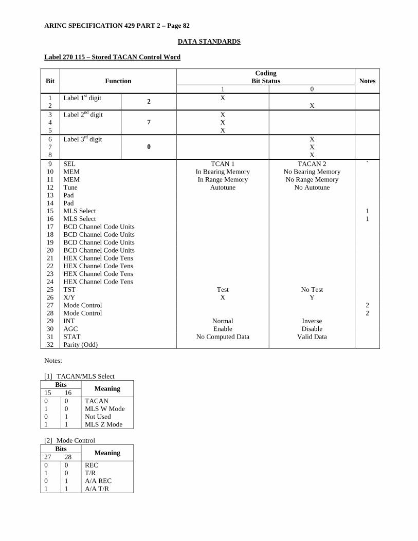
ARINC SPECIFICATION 429 PART 2 – Page 82
DATA STANDARDS
Label 270 115 – Stored TACAN Control Word
Coding Bit Status Bit Function
1 0 Notes
1 Label 1st digit X 2 2 X 3 Label 2nd digit X 4 X 5
7 X
6 Label 3rd digit X 7 X 8
0 X
9 SEL TCAN 1 TACAN 2 ` 10 MEM In Bearing Memory No Bearing Memory 11 MEM In Range Memory No Range Memory 12 Tune Autotune No Autotune 13 Pad 14 Pad 15 MLS Select 1 16 MLS Select 1 17 BCD Channel Code Units 18 BCD Channel Code Units 19 BCD Channel Code Units 20 BCD Channel Code Units 21 HEX Channel Code Tens 22 HEX Channel Code Tens 23 HEX Channel Code Tens 24 HEX Channel Code Tens 25 TST Test No Test 26 X/Y X Y 27 Mode Control 2 28 Mode Control 2 29 INT Normal Inverse 30 AGC Enable Disable 31 STAT No Computed Data Valid Data 32 Parity (Odd)
Notes: [1] TACAN/MLS Select
Bits 15 16 Meaning
0 0 TACAN 1 0 MLS W Mode 0 1 Not Used 1 1 MLS Z Mode [2] Mode Control
Bits 27 28 Meaning
0 0 REC 1 0 T/R 0 1 A/A REC 1 1 A/A T/R
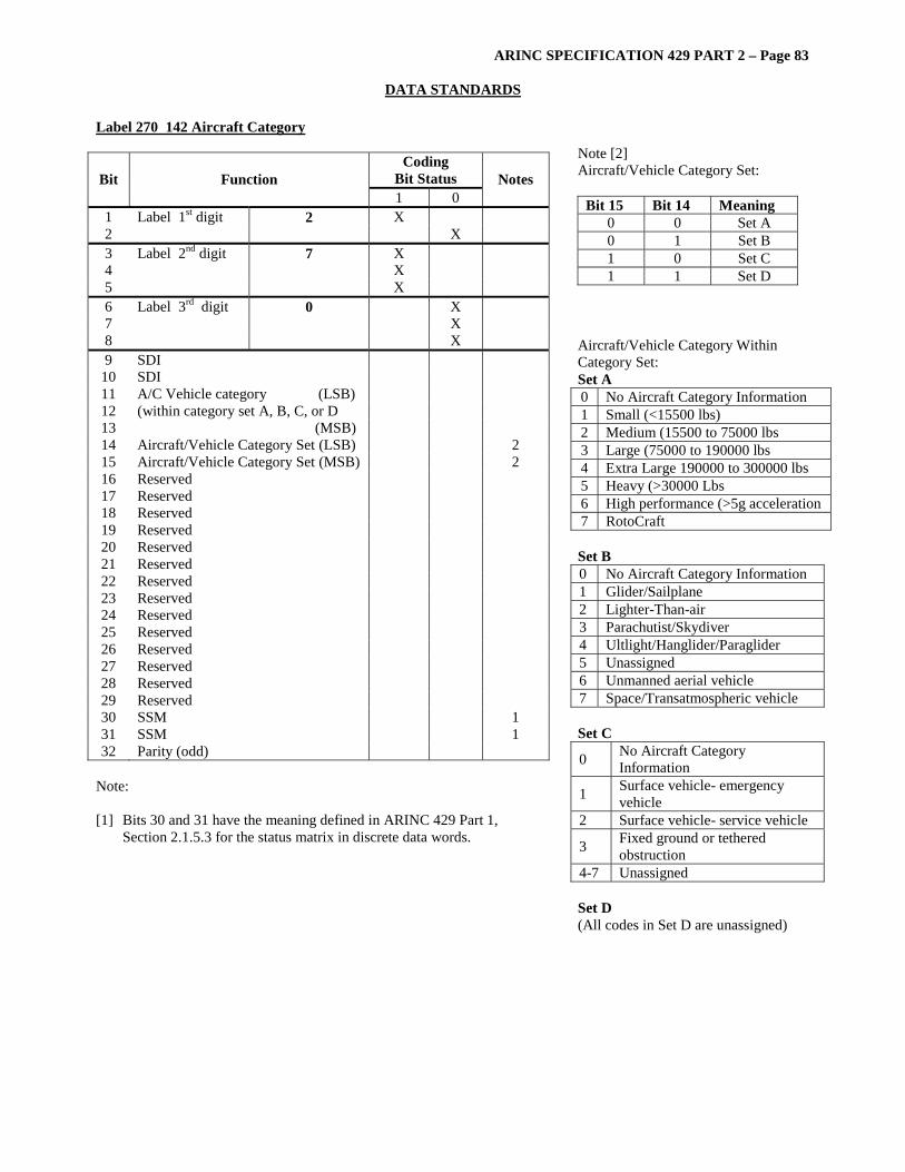
ARINC SPECIFICATION 429 PART 2 – Page 83
DATA STANDARDS Label 270 142 Aircraft Category
Coding Bit Status Bit Function 1 0
Notes
1 Label 1st digit 2 X 2 X 3 Label 2nd digit 7 X 4 X 5 X 6 Label 3rd digit 0 X 7 X 8 X 9 SDI
10 SDI 11 12 13
A/C Vehicle category (LSB) (within category set A, B, C, or D (MSB)
14 Aircraft/Vehicle Category Set (LSB) 2 15 Aircraft/Vehicle Category Set (MSB) 2 16 Reserved 17 Reserved 18 Reserved 19 Reserved 20 Reserved 21 Reserved 22 Reserved 23 Reserved 24 Reserved 25 Reserved 26 Reserved 27 Reserved 28 Reserved 29 Reserved 30 SSM 1 31 SSM 1 32 Parity (odd)
Note: [1] Bits 30 and 31 have the meaning defined in ARINC 429 Part 1,
Section 2.1.5.3 for the status matrix in discrete data words.
Note [2] Aircraft/Vehicle Category Set:
Bit 15 Bit 14 Meaning 0 0 Set A 0 1 Set B 1 0 Set C 1 1 Set D
Aircraft/Vehicle Category Within Category Set: Set A 0 No Aircraft Category Information 1 Small (<15500 lbs) 2 Medium (15500 to 75000 lbs 3 Large (75000 to 190000 lbs 4 Extra Large 190000 to 300000 lbs 5 Heavy (>30000 Lbs 6 High performance (>5g acceleration 7 RotoCraft Set B 0 No Aircraft Category Information 1 Glider/Sailplane 2 Lighter-Than-air 3 Parachutist/Skydiver 4 Ultlight/Hanglider/Paraglider 5 Unassigned 6 Unmanned aerial vehicle 7 Space/Transatmospheric vehicle Set C
0 No Aircraft Category Information
1 Surface vehicle- emergency vehicle
2 Surface vehicle- service vehicle
3 Fixed ground or tethered obstruction
4-7 Unassigned Set D (All codes in Set D are unassigned)
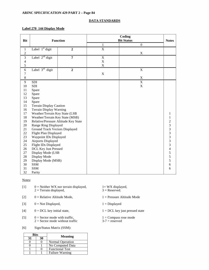
ARINC SPECIFICATION 429 PART 2 – Page 84
DATA STANDARDS
Label 270 144 Display Mode
Coding Bit Status Bit Function
1 0 Notes
1 Label 1st digit 2 X 2 X 3 Label 2nd digit 7 X 4 X 5 X 6 Label 3rd digit 2 X 7 X 8 X 9 SDI X
10 SDI X 11 Spare 12 Spare 13 Spare 14 Spare 15 Terrain Display Caution 16 Terrain Display Warning 17 Weather/Terrain Key State (LSB 1 18 Weather/Terrain Key State (MSB) 1 19 Relative/Pressure Altitude Key State 2 20 Range Ring Displayed 3 21 Ground Track Vectors Displayed 3 22 Flight Plan Displayed 3 23 Waypoint IDs Displayed 3 24 Airports Displayed 3 25 Flight IDs Displayed 3 26 DCL Key Just Pressed 4 27 Display Mode (LSB 5 28 Display Mode 5 29 Display Mode (MSB) 5 30 SSM 6 31 SSM 6 32 Parity
Notes: [1] 0 = Neither WX nor terrain displayed, 1= WX displayed,
2 = Terrain displayed, 3 = Reserved. [2] 0 = Relative Altitude Mode, 1 = Pressure Altitude Mode [3] 0 = Not Displayed, 1 = Displayed [4] 0 = DCL key initial state, 1 = DCL key just pressed state [5] 0 = Sector mode with traffic, 1 = Compass rose mode
2 = Sector mode without traffic 3-7 = reserved [6] Sign/Status Matrix (SSM):
Bits 31 30 Meaning 0 0 Normal Operation 0 1 No Computed Data 1 0 Functional Test 1 1 Failure Warning
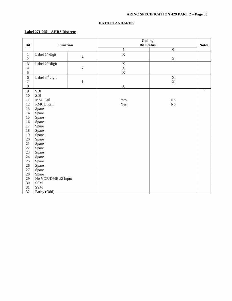
ARINC SPECIFICATION 429 PART 2 – Page 85
DATA STANDARDS Label 271 005 – AHRS Discrete
Coding Bit Status Bit Function
1 0 Notes
1 Label 1st digit X 2 2 X 3 Label 2nd digit X 4 X 5
7 X
6 Label 3rd digit X 7 X 8
1 X
9 SDI ` 10 SDI 11 MSU Fail Yes No 12 RMCU Rail Yes No 13 Spare 14 Spare 15 Spare 16 Spare 17 Spare 18 Spare 19 Spare 20 Spare 21 Spare 22 Spare 23 Spare 24 Spare 25 Spare 26 Spare 27 Spare 28 Spare 29 No VOR/DME #2 Input 30 SSM 31 SSM 32 Parity (Odd)

ARINC SPECIFICATION 429 PART 2 – Page 86
DATA STANDARDS Label 271 006 – ADS Discrete
Coding Bit Status Bit Function
1 0 Notes
1 Label 1st digit X 2 2 X 3 Label 2nd digit X 4 X 5
7 X
6 Label 3rd digit X 7 X 8
1 X
9 SDI 10 SDI 11 Zero Angle of Attack SSEC Yes No 12 Angle of Attach Sensor Status Fail Good 13 Spare 14 Spare 15 Spare 16 Spare 17 Spare 18 Spare 19 Spare 20 Spare 21 Spare 22 Spare 23 Spare 24 Spare 25 Spare 26 Spare 27 Spare 28 Spare 29 No VOR/DME #2 Input 30 SSM 31 SSM 32 Parity (Odd)

ARINC SPECIFICATION 429 PART 2 – Page 87
DATA STANDARDS Label 271 018 – TCAS Coordination Discrete (MTB, CVC, VRC, CHC, HRC, HSB, VSB) Transponder to TCAS – Bus 1 Word 1
Coding Bit Status Bit Function
1 0 Notes
1 Label 1st digit X 2 2 X 3 Label 2nd digit X 4 X 5
7 X
6 Label 3rd digit X 7 X 8
1 X
9 MTB RF MSG BIT 42 1 10 CVC 43 11 CVC 44 12 VRC 45 13 VRC 46 14 CHC 47 15 CHC 48 16 CHC 49 17 HRC 50 18 HRC 51 19 HRC 52 20 HSB 56 21 HSB 57 22 HSB 58 23 HSB 59 24 HSB 60 25 VSB 61 26 VSB 62 27 VSB 63 28 VSB 64 29 Pad 30 SSM 31 SSM 32 Parity (Odd)
Note: [1] ARINC 429 data word fields for which there are corresponding RF fields are transmitted with the MSB first in
order to maintain consistency between RF and ARINC 429 data. Normal ARINC 429 protocol calls for the transmission of the LSB of the field first.
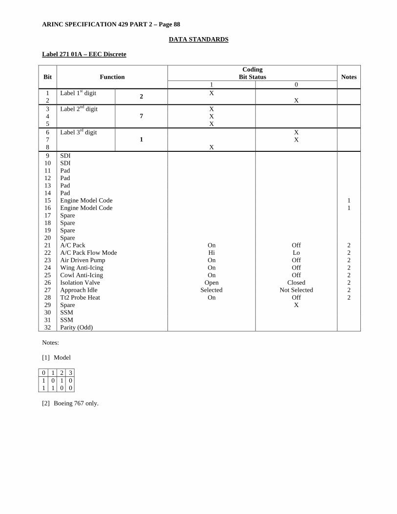
ARINC SPECIFICATION 429 PART 2 – Page 88
DATA STANDARDS Label 271 01A – EEC Discrete
Coding Bit Status Bit Function
1 0 Notes
1 Label 1st digit X 2 2 X 3 Label 2nd digit X 4 X 5
7 X
6 Label 3rd digit X 7 X 8
1 X
9 SDI 10 SDI 11 Pad 12 Pad 13 Pad 14 Pad 15 Engine Model Code 1 16 Engine Model Code 1 17 Spare 18 Spare 19 Spare 20 Spare 21 A/C Pack On Off 2 22 A/C Pack Flow Mode Hi Lo 2 23 Air Driven Pump On Off 2 24 Wing Anti-Icing On Off 2 25 Cowl Anti-Icing On Off 2 26 Isolation Valve Open Closed 2 27 Approach Idle Selected Not Selected 2 28 Tt2 Probe Heat On Off 2 29 Spare X 30 SSM 31 SSM 32 Parity (Odd)
Notes: [1] Model 0 1 2 3 1 1
0 1
1 0
0 0
[2] Boeing 767 only.

ARINC SPECIFICATION 429 PART 2 – Page 89
DATA STANDARDS Label 271 02F
Coding Bit Status Bit Function
1 0 Notes
1 Label 1st digit X 2 2 X 3 Label 2nd digit X 4 X 5
7 X
6 Label 3rd digit X 7 X 8
1 X
9 SDI X 10 SDI X 11 Pad X 12 Pad X 13 Pad X 14 Reverser Deploy Command On Off 15 Turbine Cooling Air Valve Solenoid On Off 16 Fuel-Oil Heat Ex Bypass Valve Sol On Off 17 Spare 18 Spare 19 14th Stage Bleed Command Closed Open 20 Spare 21 Spare 22 Spare 23 Spare 24 T/L Interlock Actuator Command Block Forward Block Reverse 25 Reserved (Spare Relay Command) X 26 Engine Type Code X 1 27 Engine Type Code X 1 28 Engine Type Code X 1 29 Engine Type Code 1 30 SSM X 31 SSM X 32 Parity (Odd) X
Notes: [1] 0000 = PW2037, Other Codes Invalid [2] Typical discrete functions are shown in the above table. Slight variations of bit usage may arise according to the
specific application.
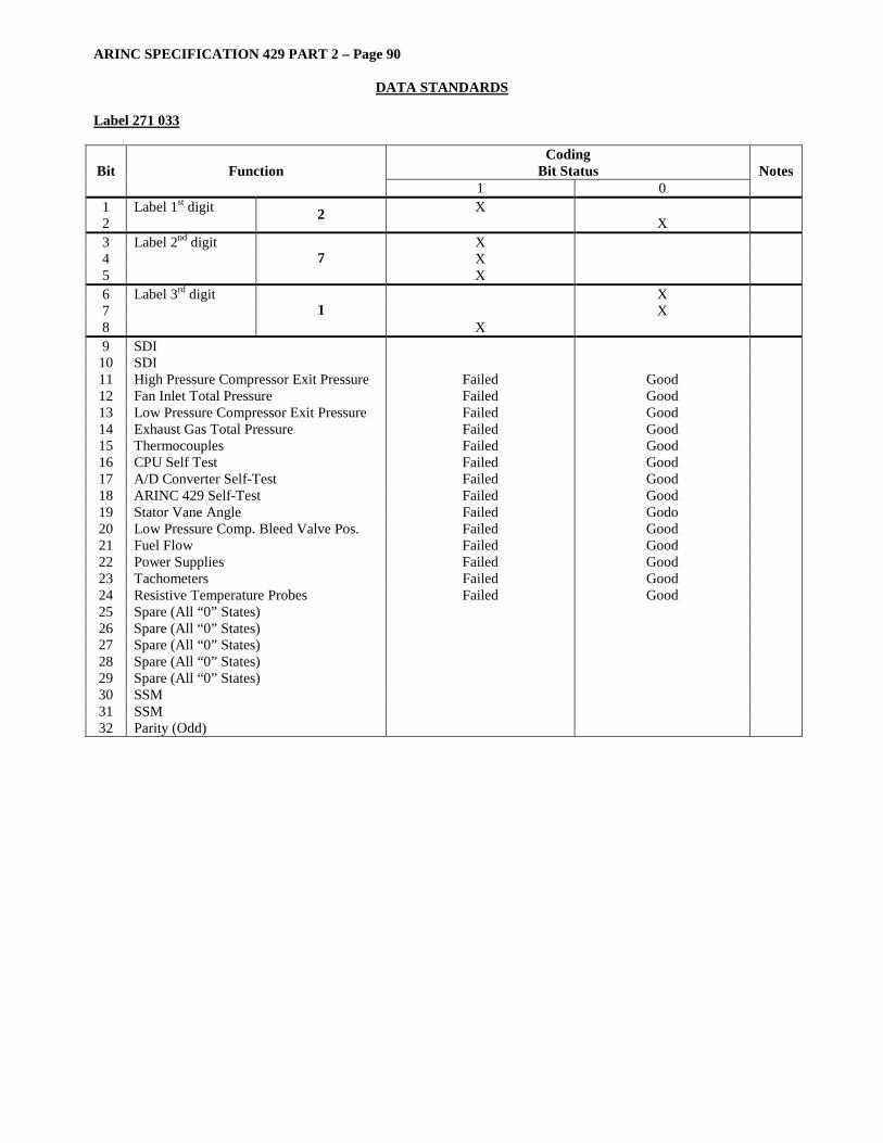
ARINC SPECIFICATION 429 PART 2 – Page 90
DATA STANDARDS Label 271 033
Coding Bit Status Bit Function
1 0 Notes
1 Label 1st digit X 2 2 X 3 Label 2nd digit X 4 X 5
7 X
6 Label 3rd digit X 7 X 8
1 X
9 SDI 10 SDI 11 High Pressure Compressor Exit Pressure Failed Good 12 Fan Inlet Total Pressure Failed Good 13 Low Pressure Compressor Exit Pressure Failed Good 14 Exhaust Gas Total Pressure Failed Good 15 Thermocouples Failed Good 16 CPU Self Test Failed Good 17 A/D Converter Self-Test Failed Good 18 ARINC 429 Self-Test Failed Good 19 Stator Vane Angle Failed Godo 20 Low Pressure Comp. Bleed Valve Pos. Failed Good 21 Fuel Flow Failed Good 22 Power Supplies Failed Good 23 Tachometers Failed Good 24 Resistive Temperature Probes Failed Good 25 Spare (All “0” States) 26 Spare (All “0” States) 27 Spare (All “0” States) 28 Spare (All “0” States) 29 Spare (All “0” States) 30 SSM 31 SSM 32 Parity (Odd)
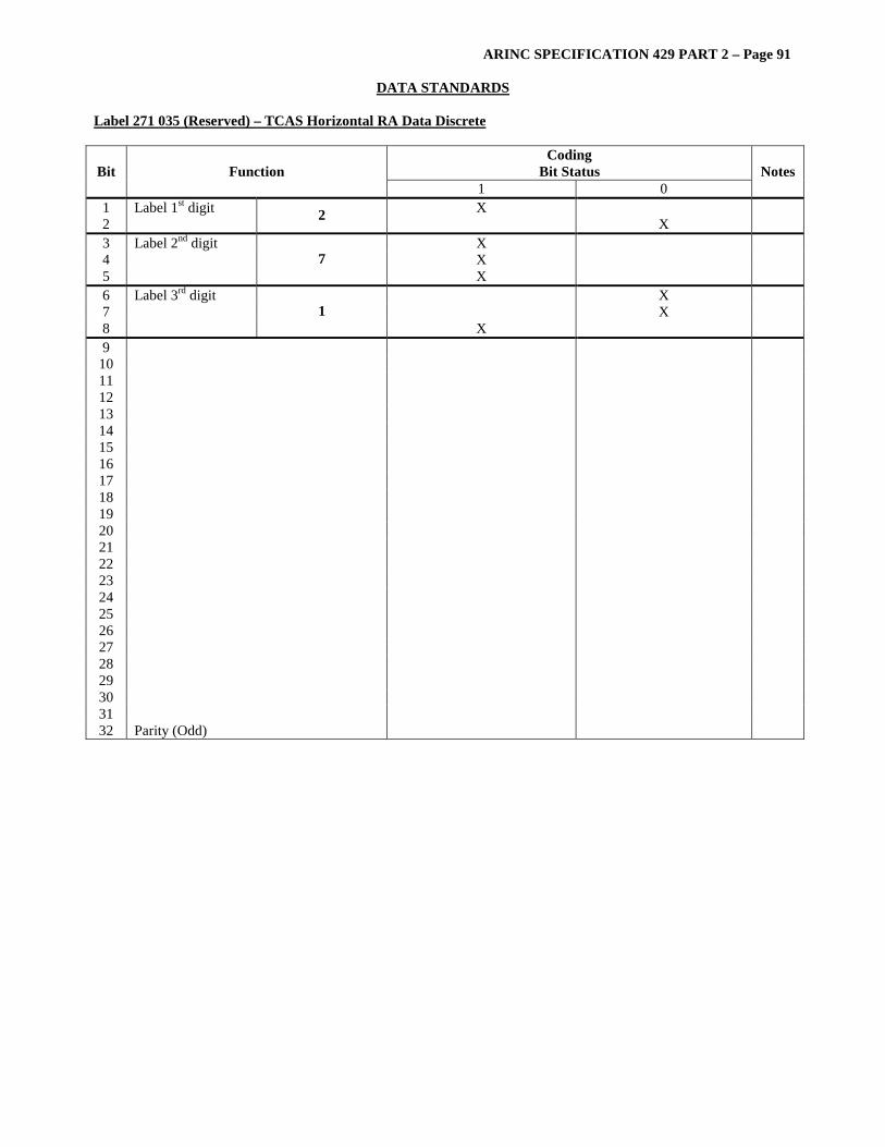
ARINC SPECIFICATION 429 PART 2 – Page 91
DATA STANDARDS Label 271 035 (Reserved) – TCAS Horizontal RA Data Discrete
Coding Bit Status Bit Function
1 0 Notes
1 Label 1st digit X 2 2 X 3 Label 2nd digit X 4 X 5
7 X
6 Label 3rd digit X 7 X 8
1 X
9 10 11 12 13 14 15 16 17 18 19 20 21 22 23 24 25 26 27 28 29 30 31 32 Parity (Odd)
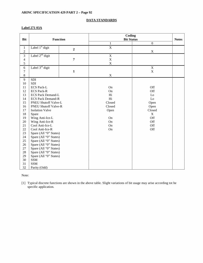
ARINC SPECIFICATION 429 PART 2 – Page 92
DATA STANDARDS Label 271 03A
Coding Bit Status Bit Function
1 0 Notes
1 Label 1st digit X 2 2 X 3 Label 2nd digit X 4 X 5
7 X
6 Label 3rd digit X 7 X 8
1 X
9 SDI 10 SDI 11 ECS Pack-L On Off 12 ECS Pack-R On Off 13 ECS Pack Demand-L Hi Lo 14 ECS Pack Demand-R Hi Lo 15 PNEU Shutoff Valve-L Closed Open 16 PNEU Shutoff Valve-R Closed Open 17 Isolation Valve Open Closed 18 Spare X 19 Wing Anti-Ice-L On Off 20 Wing Anti-Ice-R On Off 21 Cool Anti-Ice-L On Off 22 Cool Anti-Ice-R On Off 23 Spare (All “0” States) 24 Spare (All “0” States) 25 Spare (All “0” States) 26 Spare (All “0” States) 27 Spare (All “0” States) 28 Spare (All “0” States) 29 Spare (All “0” States) 30 SSM 31 SSM 32 Parity (Odd)
Note: [1] Typical discrete functions are shown in the above table. Slight variations of bit usage may arise according tot he
specific application.
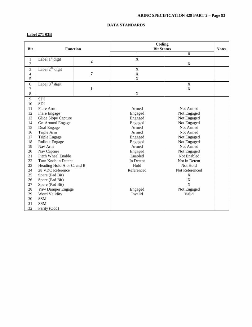
ARINC SPECIFICATION 429 PART 2 – Page 93
DATA STANDARDS Label 271 03B
Coding Bit Status Bit Function
1 0 Notes
1 Label 1st digit X 2 2 X 3 Label 2nd digit X 4 X 5
7 X
6 Label 3rd digit X 7 X 8
1 X
9 SDI 10 SDI 11 Flare Arm Armed Not Armed 12 Flare Engage Engaged Not Engaged 13 Glide Slope Capture Engaged Not Engaged 14 Go-Around Engage Engaged Not Engaged 15 Dual Engage Armed Not Armed 16 Triple Arm Armed Not Armed 17 Triple Engage Engaged Not Engaged 18 Rollout Engage Engaged Not Engaged 19 Nav Arm Armed Not Armed 20 Nav Capture Engaged Not Engaged 21 Pitch Wheel Enable Enabled Not Enabled 22 Turn Knob in Detent In Detent Not in Detent 23 Heading Hold A or C, and B Hold Not Hold 24 28 VDC Reference Referenced Not Referenced 25 Spare (Pad Bit) X 26 Spare (Pad Bit) X 27 Spare (Pad Bit) X 28 Yaw Damper Engage Engaged Not Engaged 29 Word Validity Invalid Valid 30 SSM 31 SSM 32 Parity (Odd)

ARINC SPECIFICATION 429 PART 2 – Page 94
DATA STANDARDS Label 271 03F
Coding Bit Status Bit Function
1 0 Notes
1 Label 1st digit X 2 2 X 3 Label 2nd digit X 4 X 5
7 X
6 Label 3rd digit X 7 X 8
1 X
9 SDI X 10 SDI X 11 Pad X 12 Pad X 13 Pad X 14 Reverser Deploy Command On Off 15 Turbine Cooling Air Valve Solenoid On Off 16 Fuel-Oil Heat Ex. Bypass Valve Sol. On Off 17 Spare 18 Spare 19 14th Stage Bleed Command Closed Open 20 Spare X 21 Spare X 22 Spare X 23 Spare X 24 T/L Interlock Actuator Command Block Forward Block Reverse 25 Reserved (Spare Relay Command) X 26 Engine Type Code X 1 27 Engine Type Code X 1 28 Engine Type Code X 1 29 Engine Type Code 1 30 SSM X 31 SSM X 32 Parity (Odd) X
Notes: [1] 0000 = PW2037, Other Codes Invalid [2] Typical discrete functions are shown in the above table. Slight variations of bit usage may arise according to the
specific application.

ARINC SPECIFICATION 429 PART 2 – Page 95
DATA STANDARDS Label 271 114 Fuel Transfer Indication
Coding Bit Status Bit Function
1 0 Notes
1 Label 1st digit 2 X 2 X 3 Label 2nd digit 7 X 4 X 5 X 6 Label 3rd digit 1 X 7 X 8 X 9 SDI
10 SDI 11 Left Outer Tank To Inner Tank 1 Auto Auto Not Auto 12 Left Outer Tank To Inner Tank 1 Abnormal Abnormal Not Abnormal 13 Left Outer Tank To Inner Tank 1 Manual Manual Not Manual 14 Left Outer Tank To Inner Tank 2 Auto Auto Not Auto 15 Left Outer Tank To Inner Tank 2 Abnormal Abnormal Not Abnormal 16 Left Outer Tank To Inner Tank 2 Manual Manual Not Manual 17 Right Outer Tank To Inner Tank 3 Auto Auto Not Auto 18 Right Outer Tank To Inner Tank 3 Abnormal Abnormal Not Abnormal 19 Right Outer Tank To Inner Tank 3 Manual Manual Not Manual 20 Right Outer Tank To Inner Tank 4 Auto Auto Not Auto 21 Right Outer Tank To Inner Tank 4 Abnormal Abnormal Not Abnormal 22 Right Outer Tank To Inner Tank 4 Manual Manual Not Manual 23 Inner Tank 1 To Trim Tank Auto Transfer Auto Not Auto 24 Inner Tank 1 To Trim Tank Abnormal Transfer Abnormal Not Abnormal 25 Inner Tank 2 To Trim Tank Auto Transfer Auto Not Auto 26 Inner Tank 2 To Trim Tank Abnormal Transfer Abnormal Not Abnormal 27 Inner Tank 3 To Trim Tank Auto Transfer Auto Not Auto 28 Inner Tank 3 To Trim Tank Abnormal Transfer Abnormal Not Abnormal 29 Manual Transfer Completed Completed Not Completed 30 SSM 2 31 SSM 2 32 Parity (Set to Give Odd Parity)
[1] Depending upon its application group and resolution bits 9 and 10 of an ARINC 429 Data Word can be
reserved for Source/Destination Identification (SDI). For data Source identification the relevant equipment should encode its Aircraft Installation number as follows:
Bit 10 Bit 9 Source
0 1 Transmission From Computer 1 1 0 Transmission From Computer 2
For data Destination (i.e maintenance data from the CMS) identification the relevant equipment should encode its Aircraft Installation number as follows:
Bit 10 Bit 9 Destination
0 1 Transmission To Computer 1 1 0 Transmission To Computer 2
[2] SSM
Bit 31 Bit 30 Designation 0 0 Normal Operation 0 1 NCD (Not Used) 1 0 Functional Test 1 1 Failure Warning
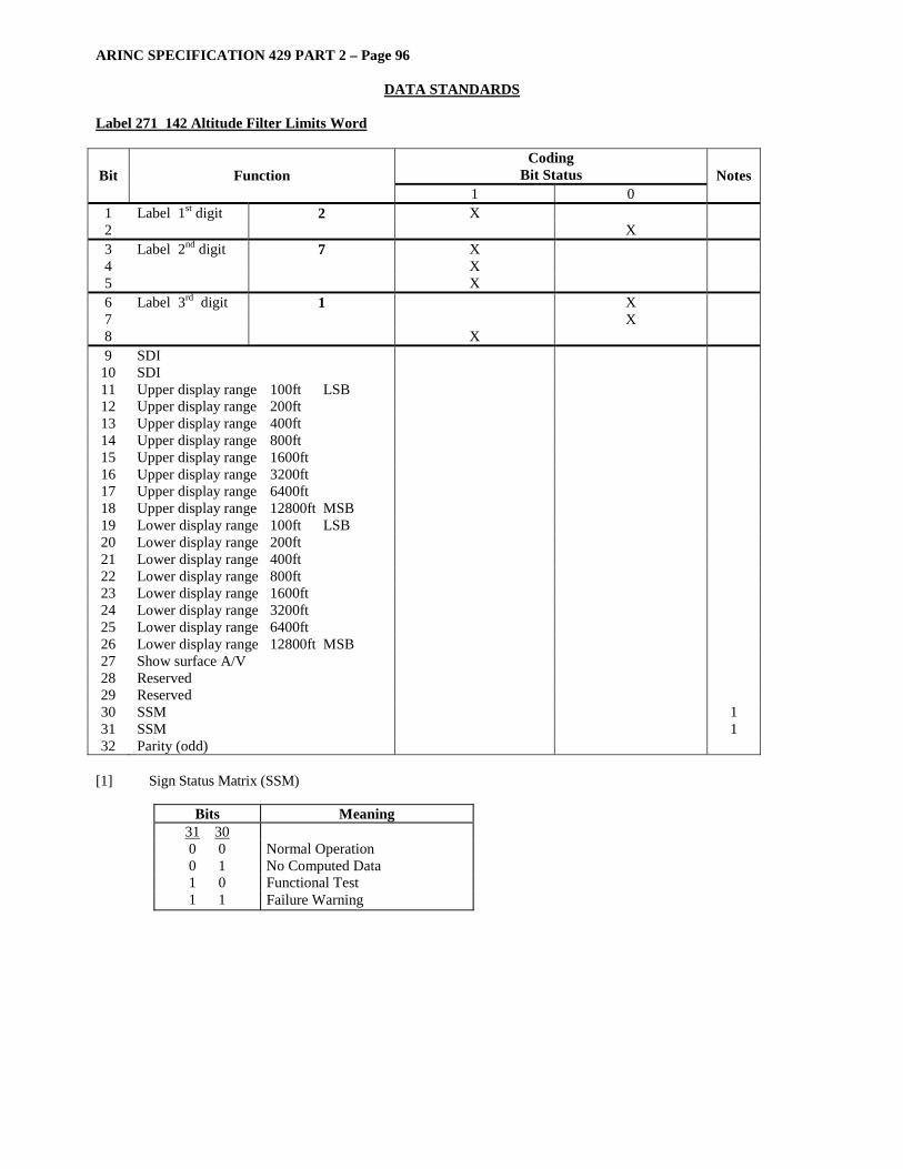
ARINC SPECIFICATION 429 PART 2 – Page 96
DATA STANDARDS Label 271 142 Altitude Filter Limits Word
Coding Bit Status Bit Function
1 0 Notes
1 Label 1st digit 2 X 2 X 3 Label 2nd digit 7 X 4 X 5 X 6 Label 3rd digit 1 X 7 X 8 X 9 SDI
10 SDI 11 Upper display range 100ft LSB 12 Upper display range 200ft 13 Upper display range 400ft 14 Upper display range 800ft 15 Upper display range 1600ft 16 Upper display range 3200ft 17 Upper display range 6400ft 18 Upper display range 12800ft MSB 19 Lower display range 100ft LSB 20 Lower display range 200ft 21 Lower display range 400ft 22 Lower display range 800ft 23 Lower display range 1600ft 24 Lower display range 3200ft 25 Lower display range 6400ft 26 Lower display range 12800ft MSB 27 Show surface A/V 28 Reserved 29 Reserved 30 SSM 1 31 SSM 1 32 Parity (odd)
[1] Sign Status Matrix (SSM)
Bits Meaning 31 30 0 0 Normal Operation 0 1 No Computed Data 1 0 Functional Test 1 1 Failure Warning

ARINC SPECIFICATION 429 PART 2 – Page 97
DATA STANDARDS Label 271 144 Altitude Filter Settings
Coding Bit Status Bit Function
1 0 Notes
1 Label 1st digit 2 X 2 X 3 Label 2nd digit 7 X 4 X 5 X 6 Label 3rd digit 1 X 7 X 8 X 9 SDI
10 SDI 11 Upper Display Range (LSB, 100 feet) 1 12 Upper Display Range (LSB, 100 feet) 13 Upper Display Range (400 feet) 1 14 Upper Display Range (800 feet) 1 15 Upper Display Range (1600 feet) 1 16 Upper Display Range (3200 feet) 1 17 Upper Display Range (6400 feet) 1 18 Upper Display Range (MSB, 12800 feet) 1 19 Lower Display Range (LSB, 100 feet) 2 20 Lower Display Range (200 feet) 2 21 Lower Display Range (400 feet) 2 22 Lower Display Range (800 feet) 2 23 Lower Display Range (1600 feet 2 24 Lower Display Range (3200 feet) 2 25 Lower Display Range (6400 feet) 2 26 Lower Display Range (MSB, 12800 feet) 2 27 Reserved X 28 Altitude Filter Settings Mode (LSB) 3 29 Altitude Filter Settings Mode (MSB 3 30 SSM 4 31 SSM 4 32 Parity
Notes: [1] Bits 11 to 18 hold an unsigned binary numeral giving the upper display range in 100-foot units. If the CDTI
display unit is in relative altitude mode (bit 19 of label 270 is zero), then this is the number shown above and to the right of the “LVL” abbreviation in the lower right corner of the display. If the CDTI display unit is in pressure altitude mode (bit 19 of label 270 is 1), then the number shown above and to the right of the “LVL” abbreviation is the sum of the number in bits 11 to 18 of label 270 and the own-ship pressure altitude in 100-foot units.
[2] Bits 19 to 26 hold an unsigned binary numeral giving the lower display range in 100-foot units. If the CDTI display
unit is in relative altitude mode (bit 19 of label 270 is zero), then this is the number shown below and to the right of the “LVL” abbreviation in the lower right corner of the display. If the CDTI display unit is in pressure altitude mode (bit 19 of label 270 is 1), then the number shown below and to the right of the “LVL” abbreviation is the difference, own-ship pressure altitude minus in 100-foot units minus the number in bits 19 to 26 of label 271.
[3] 0 = “Look Up” settings, 1 = “Look Down” settings,
2 = “Level (LVL)” settings, 3 = Present Value [4] Sign/Status Matrix (SSM):
Bits 31 30 Meaning 0 0 Normal Operation 0 1 No Computed Data 1 0 Functional Test 1 1 Failure Warning
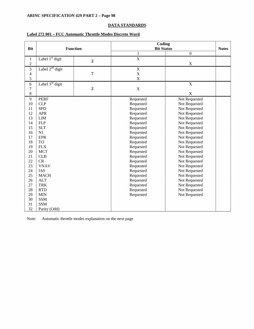
ARINC SPECIFICATION 429 PART 2 – Page 98
DATA STANDARDS Label 272 001 – FCC Automatic Throttle Modes Discrete Word
Coding Bit Status Bit Function
1 0 Notes
1 Label 1st digit X 2 2 X 3 Label 2nd digit X 4 X 5
7 X
6 Label 3rd digit X 7 X 8
2 X
9 PERF Requested Not Requested 10 CLP Requested Not Requested 11 SPD Requested Not Requested 12 APR Requested Not Requested 13 LIM Requested Not Requested 14 FLP Requested Not Requested 15 SLT Requested Not Requested 16 N1 Requested Not Requested 17 EPR Requested Not Requested 18 TO Requested Not Requested 19 FLX Requested Not Requested 20 MCT Requested Not Requested 21 CLB Requested Not Requested 22 CR Requested Not Requested 23 VNAV Requested Not Requested 24 IAS Requested Not Requested 25 MACH Requested Not Requested 26 ALT Requested Not Requested 27 TRK Requested Not Requested 28 RTD Requested Not Requested 29 MIN Requested Not Requested 30 SSM 31 SSM 32 Parity (Odd)
Note: Automatic throttle modes explanation on the next page
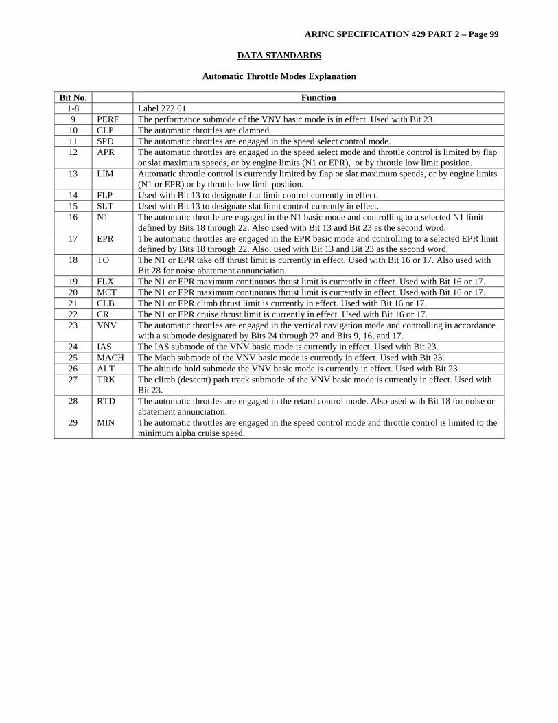
ARINC SPECIFICATION 429 PART 2 – Page 99
DATA STANDARDS
Automatic Throttle Modes Explanation Bit No. Function
1-8 Label 272 01 9 PERF The performance submode of the VNV basic mode is in effect. Used with Bit 23.
10 CLP The automatic throttles are clamped. 11 SPD The automatic throttles are engaged in the speed select control mode. 12 APR The automatic throttles are engaged in the speed select mode and throttle control is limited by flap
or slat maximum speeds, or by engine limits (N1 or EPR), or by throttle low limit position. 13 LIM Automatic throttle control is currently limited by flap or slat maximum speeds, or by engine limits
(N1 or EPR) or by throttle low limit position. 14 FLP Used with Bit 13 to designate flat limit control currently in effect. 15 SLT Used with Bit 13 to designate slat limit control currently in effect. 16 N1 The automatic throttle are engaged in the N1 basic mode and controlling to a selected N1 limit
defined by Bits 18 through 22. Also used with Bit 13 and Bit 23 as the second word. 17 EPR The automatic throttles are engaged in the EPR basic mode and controlling to a selected EPR limit
defined by Bits 18 through 22. Also, used with Bit 13 and Bit 23 as the second word. 18 TO The N1 or EPR take off thrust limit is currently in effect. Used with Bit 16 or 17. Also used with
Bit 28 for noise abatement annunciation. 19 FLX The N1 or EPR maximum continuous thrust limit is currently in effect. Used with Bit 16 or 17. 20 MCT The N1 or EPR maximum continuous thrust limit is currently in effect. Used with Bit 16 or 17. 21 CLB The N1 or EPR climb thrust limit is currently in effect. Used with Bit 16 or 17. 22 CR The N1 or EPR cruise thrust limit is currently in effect. Used with Bit 16 or 17. 23 VNV The automatic throttles are engaged in the vertical navigation mode and controlling in accordance
with a submode designated by Bits 24 through 27 and Bits 9, 16, and 17. 24 IAS The IAS submode of the VNV basic mode is currently in effect. Used with Bit 23. 25 MACH The Mach submode of the VNV basic mode is currently in effect. Used with Bit 23. 26 ALT The altitude hold submode the VNV basic mode is currently in effect. Used with Bit 23 27 TRK The climb (descent) path track submode of the VNV basic mode is currently in effect. Used with
Bit 23. 28 RTD The automatic throttles are engaged in the retard control mode. Also used with Bit 18 for noise or
abatement annunciation. 29 MIN The automatic throttles are engaged in the speed control mode and throttle control is limited to the
minimum alpha cruise speed.
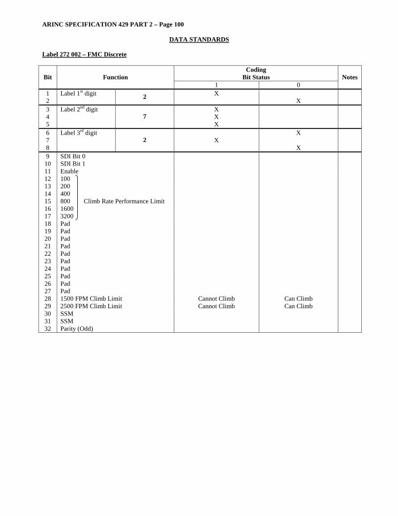
ARINC SPECIFICATION 429 PART 2 – Page 100
DATA STANDARDS Label 272 002 – FMC Discrete
Coding Bit Status Bit Function
1 0 Notes
1 Label 1st digit X 2 2 X 3 Label 2nd digit X 4 X 5
7 X
6 Label 3rd digit X 7 X 8
2 X
9 SDI Bit 0 10 SDI Bit 1 11 Enable 12 100 13 200 14 400 15 800 Climb Rate Performance Limit 16 1600 17 3200 18 Pad 19 Pad 20 Pad 21 Pad 22 Pad 23 Pad 24 Pad 25 Pad 26 Pad 27 Pad 28 1500 FPM Climb Limit Cannot Climb Can Climb 29 2500 FPM Climb Limit Cannot Climb Can Climb 30 SSM 31 SSM 32 Parity (Odd)

ARINC SPECIFICATION 429 PART 2 – Page 101
DATA STANDARDS Label 272 003 – FCC Discrete
Coding Bit Status Bit Function
1 0 Notes
1 Label 1st digit X 2 2 X 3 Label 2nd digit X 4 X 5
7 X
6 Label 3rd digit X 7 X 8
2 X
9 SDI 10 SDI 11 Automatic Throttle Failure/Warning Flag Normal 12 APR Engaged Not Engaged 1 13 Spare 14 Spare 15 Spare 16 Spare 17 Spare 18 Spare 19 Spare 20 Spare 21 Spare 22 Spare 23 Spare 24 Spare 25 Spare 26 Spare 27 Spare 28 Spare 29 Spare 30 SSM 31 SSM 32 Parity (Odd)
Note: [1] The automatic throttles are engaged in the speed select mode and throttle control is to the minimum alpha approach
speed.

ARINC SPECIFICATION 429 PART 2 – Page 102
DATA STANDARDS Label 272 018 – TCAS Coordination Discrete (MID Part 1) Transponder to TCAS – Bus 1 Word 2
Coding Bit Status Bit Function
1 0 Notes
1 Label 1st digit X 2 2 X 3 Label 2nd digit X 4 X 5
7 X
6 Label 3rd digit X 7 X 8
2 X
9 TCAS Broadcast Bit 1 10 MID Bit A 1 – MID (Part 1) (MSB) 65 RF MSG Bit 11 MID Bit A 2 66 12 MID Bit A 3 67 13 MID Bit A 4 68 14 MID Bit A 5 69 15 MID Bit A 6 70 16 MID Bit A 7 71 17 MID Bit A 8 72 18 MID Bit A 9 73 19 MID Bit A 10 74 20 MID Bit A 11 75 21 MID Bit A 12 76 22 MID Bit A 13 77 23 MID Bit A 14 78 24 MID Bit A 15 79 25 MID Bit A 16 80 26 Pad 27 Pad 28 Pad 29 Pad 30 SSM 31 SSM 32 Parity (Odd)
Notes: [1] TCAS Broadcast Bit
Bit 9 Meaning 0 Coordination Message 1 Received TCAS Broadcast
[2] ARINC 429 data word fields for which there are corresponding RF fields are transmitted with the MSB first in
order to maintain consistency between RF and ARINC 429 data. Normal ARINC 429 protocol calls for the transmission of the LSB of the field first.
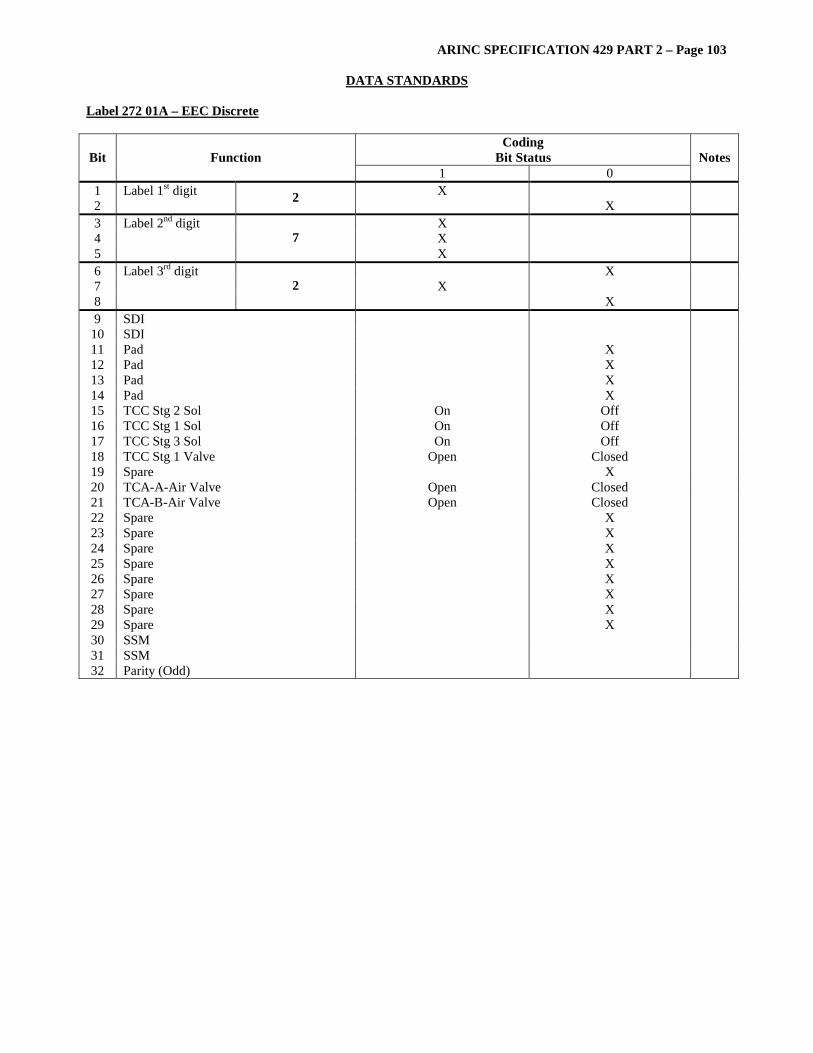
ARINC SPECIFICATION 429 PART 2 – Page 103
DATA STANDARDS Label 272 01A – EEC Discrete
Coding Bit Status Bit Function
1 0 Notes
1 Label 1st digit X 2 2 X 3 Label 2nd digit X 4 X 5
7 X
6 Label 3rd digit X 7 X 8
2 X
9 SDI 10 SDI 11 Pad X 12 Pad X 13 Pad X 14 Pad X 15 TCC Stg 2 Sol On Off 16 TCC Stg 1 Sol On Off 17 TCC Stg 3 Sol On Off 18 TCC Stg 1 Valve Open Closed 19 Spare X 20 TCA-A-Air Valve Open Closed 21 TCA-B-Air Valve Open Closed 22 Spare X 23 Spare X 24 Spare X 25 Spare X 26 Spare X 27 Spare X 28 Spare X 29 Spare X 30 SSM 31 SSM 32 Parity (Odd)
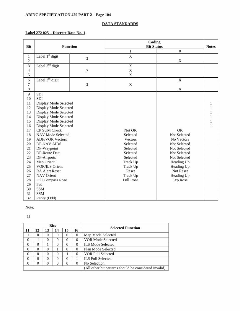
ARINC SPECIFICATION 429 PART 2 – Page 104
DATA STANDARDS Label 272 025 – Discrete Data No. 1
Coding Bit Status Bit Function
1 0 Notes
1 Label 1st digit X 2 2 X 3 Label 2nd digit X 4 X 5
7 X
6 Label 3rd digit X 7 X 8
2 X
9 SDI 10 SDI 11 Display Mode Selected 1 12 Display Mode Selected 1 13 Display Mode Selected 1 14 Display Mode Selected 1 15 Display Mode Selected 1 16 Display Mode Selected 1 17 CP SUM Check Not OK OK 18 NAV Mode Selected Selected Not Selected 19 ADF/VOR Vectors Vectors No Vectors 20 DF-NAV AIDS Selected Not Selected 21 DF-Waypoint Selected Not Selected 22 DF-Route Data Selected Not Selected 23 DF-Airports Selected Not Selected 24 Map Orient Track Up Heading Up 25 VOR/ILS Orient Track Up Heading Up 26 RA Alert Reset Reset Not Reset 27 NAV Orient Track Up Heading Up 28 Full Compass Rose Full Rose Exp Rose 29 Pad 30 SSM 31 SSM 32 Parity (Odd)
Note: [1]
Bits 11 12 13 14 15 16 Selected Function
1 0 0 0 0 0 Map Mode Selected 0 1 0 0 0 0 VOR Mode Selected 0 0 1 0 0 0 ILS Mode Selected 0 0 0 1 0 0 Plan Mode Selected 0 0 0 0 1 0 VOR Full Selected 0 0 0 0 0 1 ILS Full Selected 0 0 0 0 0 0 No Selection
(All other bit patterns should be considered invalid)
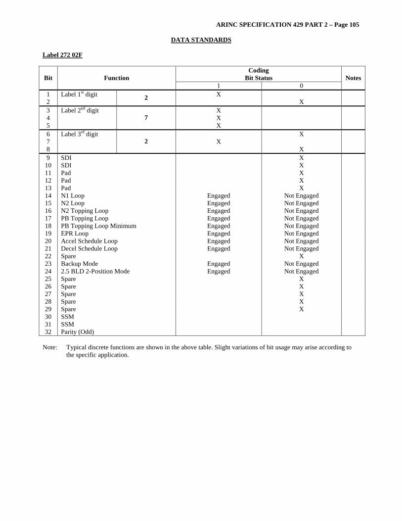
ARINC SPECIFICATION 429 PART 2 – Page 105
DATA STANDARDS Label 272 02F
Coding Bit Status Bit Function
1 0 Notes
1 Label 1st digit X 2 2 X 3 Label 2nd digit X 4 X 5
7 X
6 Label 3rd digit X 7 X 8
2 X
9 SDI X 10 SDI X 11 Pad X 12 Pad X 13 Pad X 14 N1 Loop Engaged Not Engaged 15 N2 Loop Engaged Not Engaged 16 N2 Topping Loop Engaged Not Engaged 17 PB Topping Loop Engaged Not Engaged 18 PB Topping Loop Minimum Engaged Not Engaged 19 EPR Loop Engaged Not Engaged 20 Accel Schedule Loop Engaged Not Engaged 21 Decel Schedule Loop Engaged Not Engaged 22 Spare X 23 Backup Mode Engaged Not Engaged 24 2.5 BLD 2-Position Mode Engaged Not Engaged 25 Spare X 26 Spare X 27 Spare X 28 Spare X 29 Spare X 30 SSM 31 SSM 32 Parity (Odd)
Note: Typical discrete functions are shown in the above table. Slight variations of bit usage may arise according to
the specific application.

ARINC SPECIFICATION 429 PART 2 – Page 106
DATA STANDARDS Label 272 03A
Coding Bit Status Bit Function
1 0 Notes
1 Label 1st digit X 2 2 X 3 Label 2nd digit X 4 X 5
7 X
6 Label 3rd digit X 7 X 8
2 X
9 SDI 10 SDI 11 RAM Inflight Monitor Failed OK 12 ROM Inflight Monitor Failed OK 13 WDT Inflight Monitor Failed OK 14 Discrete Output 1 IFM Failed OK 15 Discrete Output 1 IFM Failed OK 16 Serial Data Input – Primary Failed OK 17 Serial Data Input – Secondary Failed OK 18 Spare X 19 Discrete Input IFM Failed OK 20 Power Up RAM Failed OK 21 BIT:RAM Failed OK 22 BIT:ROM Failed OK 23 BIT:Discrete Output 1 Failed OK 24 BIT:Discrete Output 2 (Prov) Failed OK 25 BIT:Discrete Input Failed OK 26 BIT:Serial Data Failed OK 27 BIT:Watchdog Timer Failed OK 28 Spare X 29 Spare X 30 SSM 31 SSM 32 Parity (Odd)
Note: Typical discrete functions are shown in the above table. Slight variations of bit usage may arise according to
the specific application.
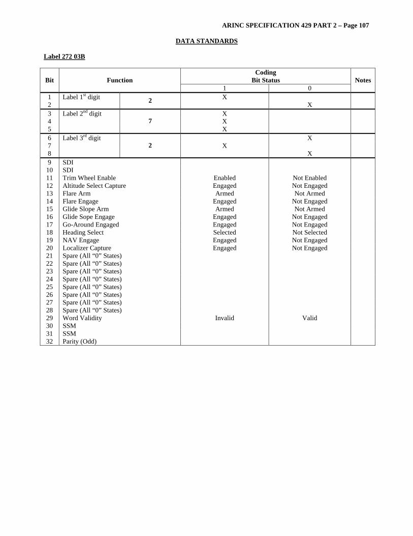
ARINC SPECIFICATION 429 PART 2 – Page 107
DATA STANDARDS Label 272 03B
Coding Bit Status Bit Function
1 0 Notes
1 Label 1st digit X 2 2 X 3 Label 2nd digit X 4 X 5
7 X
6 Label 3rd digit X 7 X 8
2 X
9 SDI 10 SDI 11 Trim Wheel Enable Enabled Not Enabled 12 Altitude Select Capture Engaged Not Engaged 13 Flare Arm Armed Not Armed 14 Flare Engage Engaged Not Engaged 15 Glide Slope Arm Armed Not Armed 16 Glide Sope Engage Engaged Not Engaged 17 Go-Around Engaged Engaged Not Engaged 18 Heading Select Selected Not Selected 19 NAV Engage Engaged Not Engaged 20 Localizer Capture Engaged Not Engaged 21 Spare (All “0” States) 22 Spare (All “0” States) 23 Spare (All “0” States) 24 Spare (All “0” States) 25 Spare (All “0” States) 26 Spare (All “0” States) 27 Spare (All “0” States) 28 Spare (All “0” States) 29 Word Validity Invalid Valid 30 SSM 31 SSM 32 Parity (Odd)
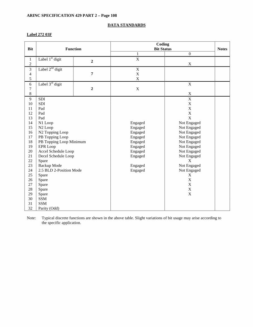
ARINC SPECIFICATION 429 PART 2 – Page 108
DATA STANDARDS Label 272 03F
Coding Bit Status Bit Function
1 0 Notes
1 Label 1st digit X 2 2 X 3 Label 2nd digit X 4 X 5
7 X
6 Label 3rd digit X 7 X 8
2 X
9 SDI X 10 SDI X 11 Pad X 12 Pad X 13 Pad X 14 N1 Loop Engaged Not Engaged 15 N2 Loop Engaged Not Engaged 16 N2 Topping Loop Engaged Not Engaged 17 PB Topping Loop Engaged Not Engaged 18 PB Topping Loop Minimum Engaged Not Engaged 19 EPR Loop Engaged Not Engaged 20 Accel Schedule Loop Engaged Not Engaged 21 Decel Schedule Loop Engaged Not Engaged 22 Spare X 23 Backup Mode Engaged Not Engaged 24 2.5 BLD 2-Position Mode Engaged Not Engaged 25 Spare X 26 Spare X 27 Spare X 28 Spare X 29 Spare X 30 SSM 31 SSM 32 Parity (Odd)
Note: Typical discrete functions are shown in the above table. Slight variations of bit usage may arise according to
the specific application.
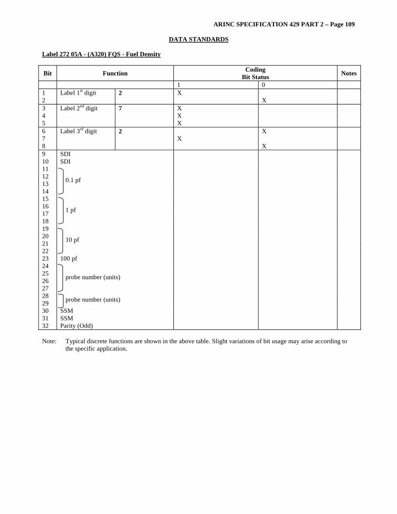
ARINC SPECIFICATION 429 PART 2 – Page 109
DATA STANDARDS Label 272 05A - (A320) FQS - Fuel Density
Bit Function Coding Bit Status Notes
1 0 1 Label 1st digit 2 X 2 X 3 Label 2nd digit 7 X 4 X 5 X 6 Label 3rd digit 2 X 7 X 8 X 9 SDI 10 SDI 11 12 13 14
0.1 pf
15 16 17 18
1 pf
19 20 21 22
10 pf
23 100 pf 24 25 26 27
probe number (units)
28 29 probe number (units) 30 SSM 31 SSM 32 Parity (Odd) Note: Typical discrete functions are shown in the above table. Slight variations of bit usage may arise according to
the specific application.
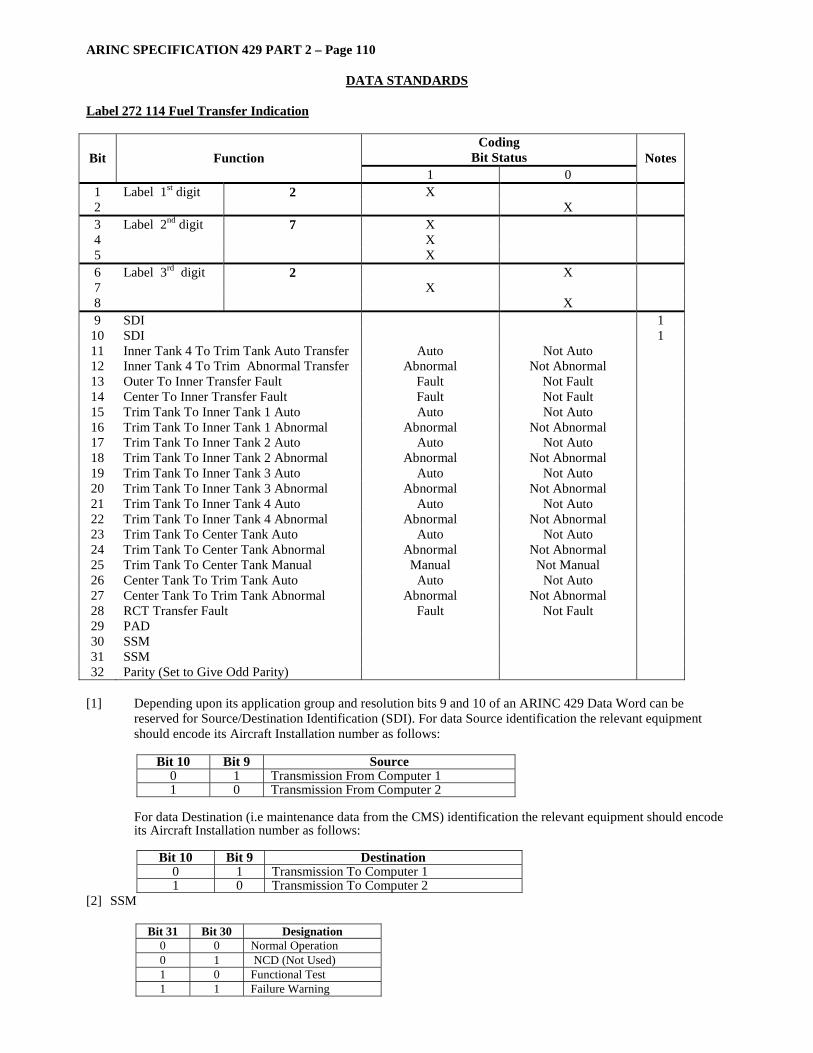
ARINC SPECIFICATION 429 PART 2 – Page 110
DATA STANDARDS Label 272 114 Fuel Transfer Indication
Coding Bit Status Bit Function
1 0 Notes
1 Label 1st digit 2 X 2 X 3 Label 2nd digit 7 X 4 X 5 X 6 Label 3rd digit 2 X 7 X 8 X 9 SDI 1
10 SDI 1 11 Inner Tank 4 To Trim Tank Auto Transfer Auto Not Auto 12 Inner Tank 4 To Trim Abnormal Transfer Abnormal Not Abnormal 13 Outer To Inner Transfer Fault Fault Not Fault 14 Center To Inner Transfer Fault Fault Not Fault 15 Trim Tank To Inner Tank 1 Auto Auto Not Auto 16 Trim Tank To Inner Tank 1 Abnormal Abnormal Not Abnormal 17 Trim Tank To Inner Tank 2 Auto Auto Not Auto 18 Trim Tank To Inner Tank 2 Abnormal Abnormal Not Abnormal 19 Trim Tank To Inner Tank 3 Auto Auto Not Auto 20 Trim Tank To Inner Tank 3 Abnormal Abnormal Not Abnormal 21 Trim Tank To Inner Tank 4 Auto Auto Not Auto 22 Trim Tank To Inner Tank 4 Abnormal Abnormal Not Abnormal 23 Trim Tank To Center Tank Auto Auto Not Auto 24 Trim Tank To Center Tank Abnormal Abnormal Not Abnormal 25 Trim Tank To Center Tank Manual Manual Not Manual 26 Center Tank To Trim Tank Auto Auto Not Auto 27 Center Tank To Trim Tank Abnormal Abnormal Not Abnormal 28 RCT Transfer Fault Fault Not Fault 29 PAD 30 SSM 31 SSM 32 Parity (Set to Give Odd Parity)
[1] Depending upon its application group and resolution bits 9 and 10 of an ARINC 429 Data Word can be
reserved for Source/Destination Identification (SDI). For data Source identification the relevant equipment should encode its Aircraft Installation number as follows:
Bit 10 Bit 9 Source
0 1 Transmission From Computer 1 1 0 Transmission From Computer 2
For data Destination (i.e maintenance data from the CMS) identification the relevant equipment should encode its Aircraft Installation number as follows:
Bit 10 Bit 9 Destination
0 1 Transmission To Computer 1 1 0 Transmission To Computer 2
[2] SSM
Bit 31 Bit 30 Designation 0 0 Normal Operation 0 1 NCD (Not Used) 1 0 Functional Test 1 1 Failure Warning

ARINC SPECIFICATION 429 PART 2 – Page 111
DATA STANDARDS Label 272 144 Target Selection Word
Coding Bit Status Bit Function
1 0 Notes
1 Label 1st digit 2 X 2 X 3 Label 2nd digit 7 X 4 X 5 X 6 Label 3rd digit 2 X 7 X 8 X 9 SDI X
10 SDI X 11 Selected Target Number (LSB) 12 Selected Target Number 13 Selected Target Number 14 Selected Target Number 15 Selected Target Number 16 Selected Target Number 17 Selected Target Number 18 Selected Target Number 19 Selected Target Number (MSB) 20 Reserved 21 Reserved 22 Target Selection State 1 23 Selected Target Change 2 24 Target Selection Failure 3 25 Reserved 26 Reserved 27 Action Taken 4 28 Action Taken 4 29 Action Taken 4 30 SSm 5 31 SSM 5 32 Parity
Notes: [1] 0 = no target selected, 1 = a target is currently selected [2] 0 = no change in selected target, 1 = change in selected target [3] 0 = okay, 1 = target selection failure [4] 0 = no action, 1 = select the target, 2 = add to favored target list,
3 = remove from favored target list, 4 = delete entire list, 5-7 = reserved [5] Sign/Status Matrix (SSM):
Bits 31 30 Meaning
0 0 Normal Operation 0 1 No Computed Data 1 0 Functional Test 1 1 Failure Warning

ARINC SPECIFICATION 429 PART 2 - Page 112
DATA STANDARDS Label 273 001 - FCC Arm Modes Discrete Word
Bit Function Coding Bit Status
Notes
1 0 1 Label 1st digit 2 X 2 X 3 Label 2nd digit 7 X 4 X 5 X 6 Label 3rd digit 3 X 7 X 8 X 9 Unassigned
10 Unassigned 11 Test Requested Not Requested 1 12 ALT Armed Not Armed 1 13 FMC Armed Not Armed 1 14 LNAV Armed Not Armed 1 15 VNAV Armed Not Armed 1 16 LOC Engaged Not Engaged 1 17 Back Course Engaged Not Engaged 1 18 Appr. 2 Engaged Not Engaged 1 19 Land 2 Engaged Not Engaged 1 20 Land 1 Armed Not Armed 1 21 Land 3 Armed Not Armed 1 22 Glideslope Armed Not Armed 1 23 VOR Armed Not Armed 1 24 Climb Armed Not Armed 1 25 Descent Armed Not Armed 1 26 Unassigned 1 27 Unassigned 1 28 Unassigned 1 29 Unassigned 1 30 SSM 31 SSM 32 Parity (Odd)
Note [1] Arm Modes Explanation
Bit Function 1-8 Label 273 001 9 10 11 TEST A test of interfacing systems has been requested. 12 ALT The Latitude preselect mode has been armed. 13 FMC The Lateral and vertical navigation modes of the flight management system have been armed. 14 LNAV The Lateral navigation submode of the FMS is armed. 15 VNAV The vertical navigation submode of the FMS is armed. 16 LOC The Localizer mode has been armed. 17 BACK COURSE The Localizer back course mode has been armed. 18 APPR The approach mode has been armed. 19 LAND 2 The autoload mode is armed on FCC No. 2. 20 LAND 1 The autoload mode is armed on FCC No. 1. 21 LAND 3 The autoload mode is armed on FCC No. 3. 22 GLIDE SLOPE The glideslope mode has been armed. 23 VOR The VOR mode has been armed. 24 CLIMB The climb submode of the VNV basic mode is armed. 25 DESCENT The Descent submode of the VNV basic mode is armed. 26-29
TBD

ARINC SPECIFICATION 429 PART 2 - Page 113
DATA STANDARDS
Label 273 003 - TCC Discrete
Coding Bit Status Bit Function
1 0 Notes
1 Label 1st digit X 2 2 X 3 Label 2nd digit X 4 X 5
7 X
6 Label 3rd digit X 7 X 8
3 X
9 SDI 10 SDI 11 No bleed air Requested Not Requested 12 One air conditioning pack Requested Not Requested 13 Two air conditioning packs Requested Not Requested 14 Three air conditioning packs Requested Not Requested 15 Half wing anti-icing Requested Not Requested 16 Total wing anti-icing Requested Not Requested 17 Engine cowling anti-icing Requested Not Requested 18 Engine operating condition (Engine Out) Requested Not Requested 19 Speed Brake Position - retract Requested Not Requested 20 Speed Brake Position - 1/3 Requested Not Requested 21 Speed Brake Position - 2/3 Requested Not Requested 22 Speed Brake Position - full Requested Not Requested 23 Landing gear position Requested Not Requested 24 Slat position - retract Requested Not Requested 25 Slat position - take off Requested Not Requested 26 Slat position - Land Requested Not Requested 27 Electronic Engine Control On-Off No. 1 On Off 28 Electronic Engine Control On-Off No. 2 On Off 29 Electronic Engine Control On-Off No. 3 On Off 30 SSM 31 SSM 32 Parity (Odd)
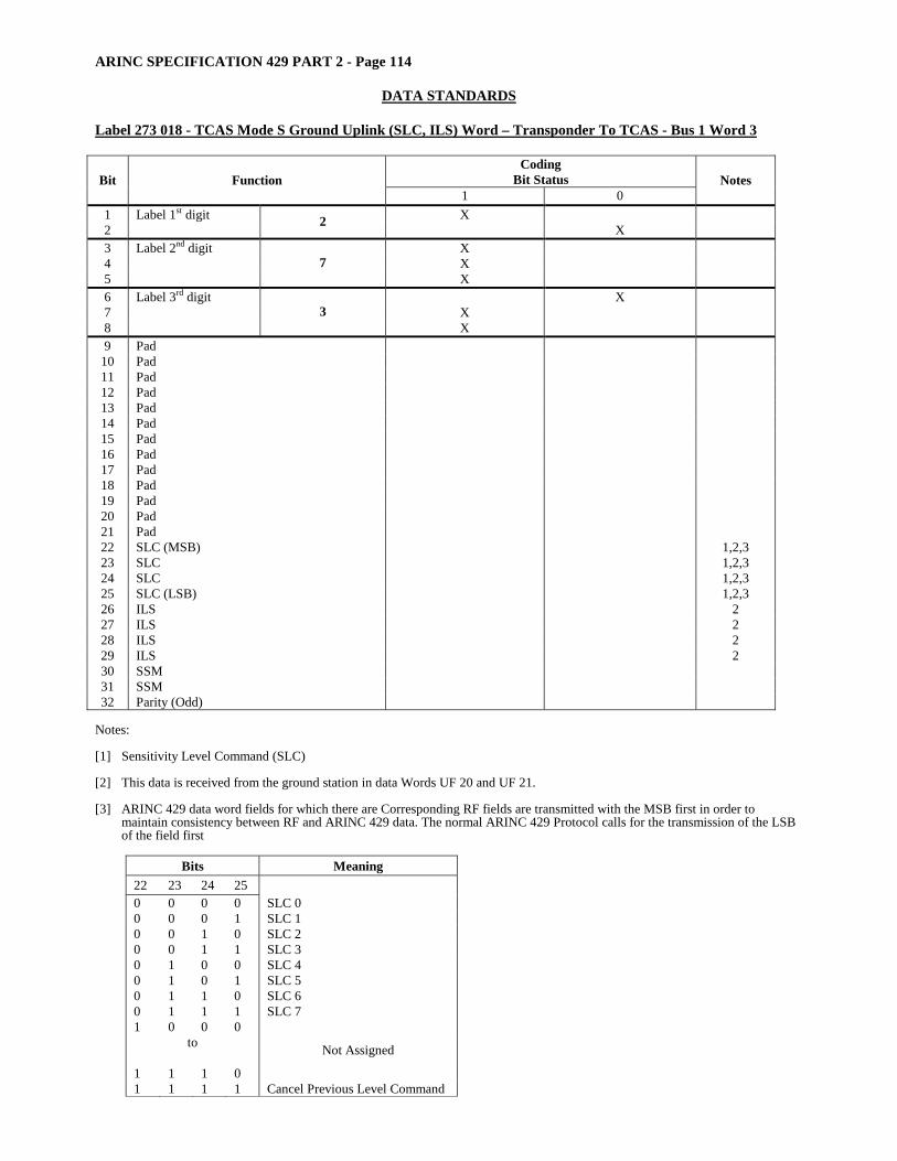
ARINC SPECIFICATION 429 PART 2 - Page 114
DATA STANDARDS Label 273 018 - TCAS Mode S Ground Uplink (SLC, ILS) Word – Transponder To TCAS - Bus 1 Word 3
Coding Bit Status Bit Function
1 0 Notes
1 Label 1st digit X 2 2 X 3 Label 2nd digit X 4 X 5
7 X
6 Label 3rd digit X 7 X 8
3 X
9 Pad 10 Pad 11 Pad 12 Pad 13 Pad 14 Pad 15 Pad 16 Pad 17 Pad 18 Pad 19 Pad 20 Pad 21 Pad 22 SLC (MSB) 1,2,3 23 SLC 1,2,3 24 SLC 1,2,3 25 SLC (LSB) 1,2,3 26 ILS 2 27 ILS 2 28 ILS 2 29 ILS 2 30 SSM 31 SSM 32 Parity (Odd)
Notes: [1] Sensitivity Level Command (SLC) [2] This data is received from the ground station in data Words UF 20 and UF 21. [3] ARINC 429 data word fields for which there are Corresponding RF fields are transmitted with the MSB first in order to
maintain consistency between RF and ARINC 429 data. The normal ARINC 429 Protocol calls for the transmission of the LSB of the field first
Bits Meaning
22 23 24 25 0 0 0 0 SLC 0 0 0 0 1 SLC 1 0 0 1 0 SLC 2 0 0 1 1 SLC 3 0 1 0 0 SLC 4 0 1 0 1 SLC 5 0 1 1 0 SLC 6 0 1 1 1 SLC 7 1 0 0 0
to 1 1 1 0
Not Assigned
1 1 1 1 Cancel Previous Level Command
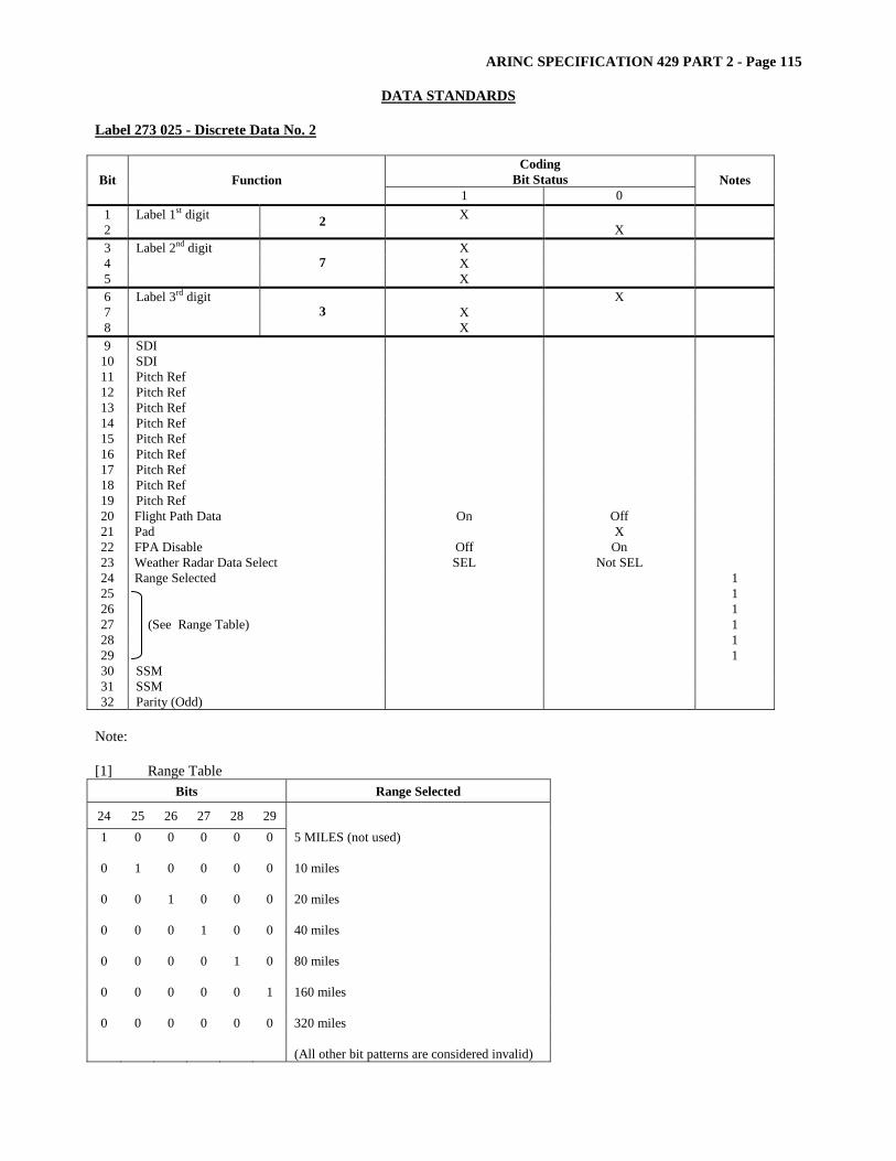
ARINC SPECIFICATION 429 PART 2 - Page 115
DATA STANDARDS
Label 273 025 - Discrete Data No. 2
Coding Bit Status Bit Function
1 0 Notes
1 Label 1st digit X 2 2 X 3 Label 2nd digit X 4 X 5
7 X
6 Label 3rd digit X 7 X 8
3 X
9 SDI 10 SDI 11 Pitch Ref 12 Pitch Ref 13 Pitch Ref 14 Pitch Ref 15 Pitch Ref 16 Pitch Ref 17 Pitch Ref 18 Pitch Ref 19 Pitch Ref 20 Flight Path Data On Off 21 Pad X 22 FPA Disable Off On 23 Weather Radar Data Select SEL Not SEL 24 Range Selected 1 25 1 26 1 27 1 28 1 29
(See Range Table)
1 30 SSM 31 SSM 32 Parity (Odd)
Note: [1] Range Table
Bits Range Selected
24 25 26 27 28 29 1 0 0 0 0 0 5 MILES (not used)
0 1 0 0 0 0 10 miles
0 0 1 0 0 0 20 miles
0 0 0 1 0 0 40 miles
0 0 0 0 1 0 80 miles
0 0 0 0 0 1 160 miles
0 0 0 0 0 0 320 miles (All other bit patterns are considered invalid)

ARINC SPECIFICATION 429 PART 2 - Page 116
DATA STANDARDS Label 273 02F
Coding Bit Status Bit Function
1 0 Notes
1 Label 1st digit X 2 2 X 3 Label 2nd digit X 4 X 5
7 X
6 Label 3rd digit X 7 X 8
3 X
9 SDI X 10 SDI X 11 Pad X 12 Pad X 13 Pad X 14 P4.9 Interface Failed OK 15 PB Interface Failed OK 16 P2 (Pamb) Interface* Failed OK 17 CJC Interface Failed OK 18 T2 Interface Failed OK 19 T4.9 Interface Failed OK 20 Tfuel/Toil Interface Failed OK 21 A/D Interface Failed OK 22 RES/LVDT Interface Failed OK 23 SVA Interface Failed OK 24 N1 Interface Failed OK 25 N2 Interface Failed OK 26 P4.9 Sensor PROM Failed OK 27 P2 (Pamb) Sensor PROM* Failed OK 28 PB Sensor PROM Failed OK 29 Background Execution Not Executing Executing 30 SSM X 31 SSM X 32 Parity (Odd)
* Primary channel uses P2; Secondary channel uses Pamb Note: Typical discrete functions are shown in the above table. Slight variations of bit usage may arise according to
the specific application.
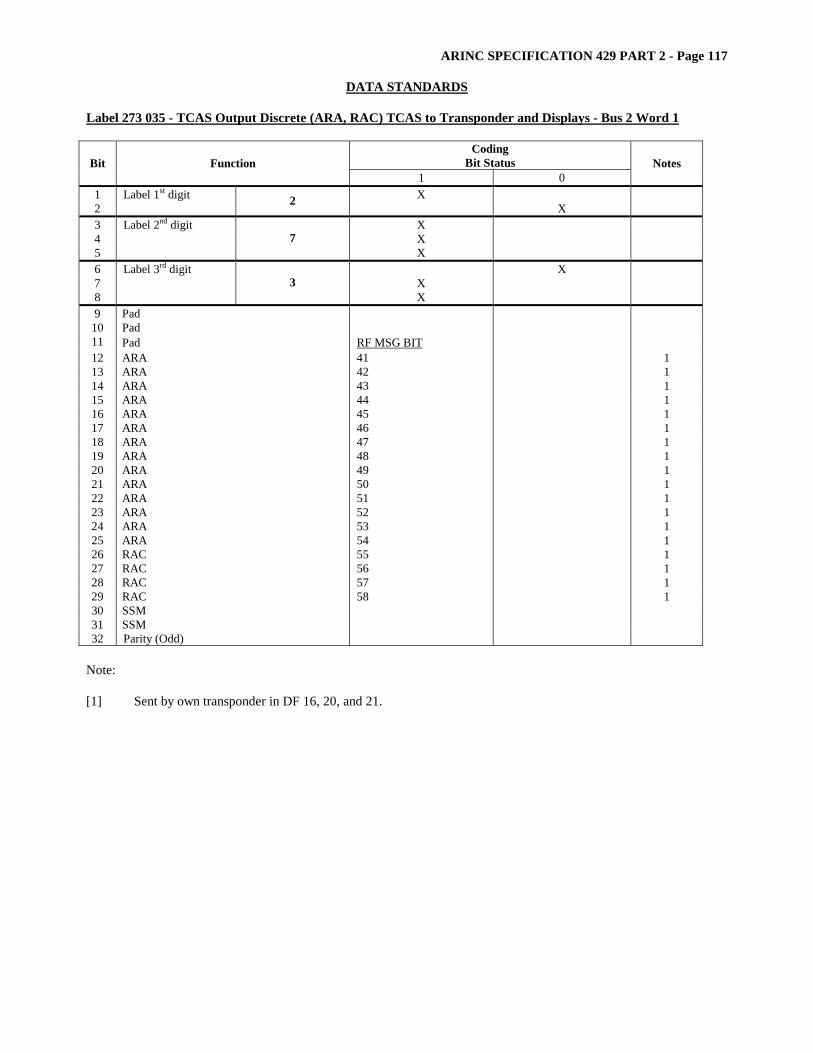
ARINC SPECIFICATION 429 PART 2 - Page 117
DATA STANDARDS
Label 273 035 - TCAS Output Discrete (ARA, RAC) TCAS to Transponder and Displays - Bus 2 Word 1
Coding Bit Status Bit Function
1 0 Notes
1 Label 1st digit X 2 2 X 3 Label 2nd digit X 4 X 5
7 X
6 Label 3rd digit X 7 X 8
3 X
9 Pad 10 Pad 11 Pad RF MSG BIT 12 ARA 41 1 13 ARA 42 1 14 ARA 43 1 15 ARA 44 1 16 ARA 45 1 17 ARA 46 1 18 ARA 47 1 19 ARA 48 1 20 ARA 49 1 21 ARA 50 1 22 ARA 51 1 23 ARA 52 1 24 ARA 53 1 25 ARA 54 1 26 RAC 55 1 27 RAC 56 1 28 RAC 57 1 29 RAC 58 1 30 SSM 31 SSM 32 Parity (Odd)
Note: [1] Sent by own transponder in DF 16, 20, and 21.

ARINC SPECIFICATION 429 PART 2 - Page 118
DATA STANDARDS Label 273 03B
Coding Bit Status Bit Function
1 0 Notes
1 Label 1st digit X 2 2 X 3 Label 2nd digit X 4 X 5
7 X
6 Label 3rd digit X 7 X 8
3 X
9 SDI 10 SDI 11 A/P Red Warning Lights Warn Normal 12 A/P Servo System Pitch/Roll Failed Normal 13 A/P Servo System Yaw Failed Normal 14 A/P Camout Pitch Camout Normal 15 A/P Camout Roll Camout Normal 16 A/P Camout Yaw Camout Normal 17 A/P Confidence Test Failed Passed 18 Spare (Pad Bit) X 19 Spare (Pad Bit) X 20 A/T Red Warning Lights Warn Normal 21 A/T Speed Flag Flag Normal 22 Spare (All “0” States) 23 Spare (All “0” States) 24 Spare (All “0” States) 25 Spare (All “0” States) 26 Spare (All “0” States) 27 Spare (All “0” States) 28 Spare (All “0” States) 29 Spare (All “0” States) Invalid Valid 30 SSM 31 SSM 32 Parity (Odd)

ARINC SPECIFICATION 429 PART 2 - Page 119
DATA STANDARDS
Label 273 03F
Coding Bit Status Bit Function
1 0 Notes
1 Label 1st digit X 2 2 X 3 Label 2nd digit X 4 X 5
7 X
6 Label 3rd digit X 7 X 8
3 X
9 SDI X 10 SDI X 11 Pad X 12 Pad X 13 Pad X 14 P4.9 Interface Failed OK 15 PB Interface Failed OK 16 P2 (Pamb) Interface* Failed OK 17 CJC Interface Failed OK 18 T2 Interface Failed OK 19 T4.9 Interface Failed OK 20 Tfuel/Toil Interface Failed OK 21 A/D Interface Failed OK 22 RES/LVDT Interface Failed OK 23 SVA Interface Failed OK 24 N1 Interface Failed OK 25 N2 Interface Failed OK 26 P4.9 Sensor PROM Failed OK 27 P2 (Pamb) Sensor PROM* Failed OK 28 PB Sensor PROM Failed OK 29 Background Execution Not Executing Executing 30 SSM X 31 SSM X 32 Parity (Odd) * Primary channel uses P2; Secondary channel uses Pamb
Note: Typical discrete functions are shown in the above table. Slight variations of bit usage may arise according to
the specific application.
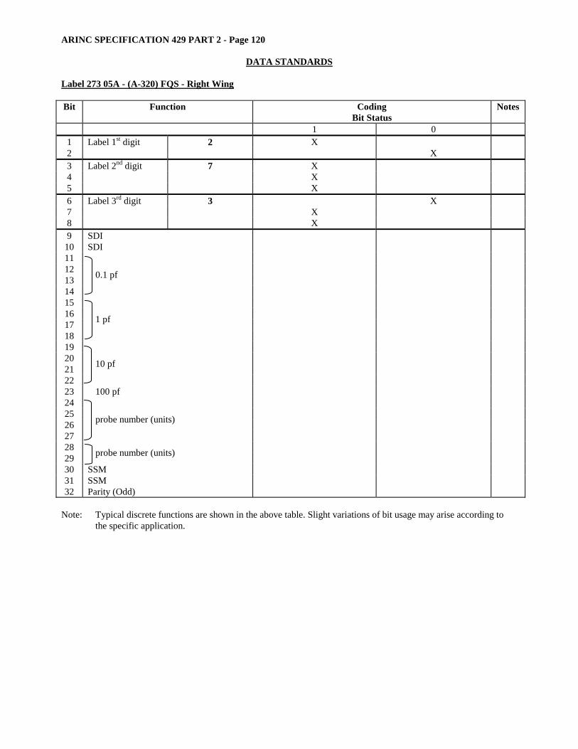
ARINC SPECIFICATION 429 PART 2 - Page 120
DATA STANDARDS Label 273 05A - (A-320) FQS - Right Wing Bit Function Coding
Bit Status Notes
1 0 1 Label 1st digit 2 X 2 X 3 Label 2nd digit 7 X 4 X 5 X 6 Label 3rd digit 3 X 7 X 8 X 9 SDI
10 SDI 11 12 13 14
0.1 pf
15 16 17 18
1 pf
19 20 21 22
10 pf
23 100 pf 24 25 26 27
probe number (units)
28 29 probe number (units) 30 SSM 31 SSM 32 Parity (Odd)
Note: Typical discrete functions are shown in the above table. Slight variations of bit usage may arise according to
the specific application.
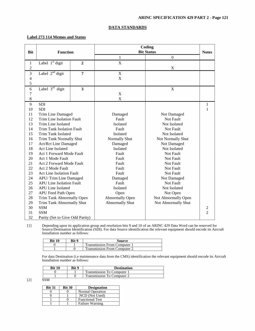
ARINC SPECIFICATION 429 PART 2 - Page 121
DATA STANDARDS
Label 273 114 Memos and Status
Coding Bit Status Bit Function
1 0 Notes
1 Label 1st digit 2 X 2 X 3 Label 2nd digit 7 X 4 X 5 6 Label 3rd digit 3 X 7 X 8 X 9 SDI 1
10 SDI 1 11 Trim Line Damaged Damaged Not Damaged 12 Trim Line Isolation Fault Fault Not Fault 13 Trim Line Isolated Isolated Not Isolated 14 Trim Tank Isolation Fault Fault Not Fault 15 Trim Tank Isolated Isolated Not Isolated 16 Trim Tank Normally Shut Normally Shut Not Normally Shut 17 Act/Rct Line Damaged Damaged Not Damaged 18 Act Line Isolated Isolated Not Isolated 19 Act 1 Forward Mode Fault Fault Not Fault 20 Act 1 Mode Fault Fault Not Fault 21 Act 2 Forward Mode Fault Fault Not Fault 22 Act 2 Mode Fault Fault Not Fault 23 Act Line Isolation Fault Fault Not Fault 24 APU/ Trim Line Damaged Damaged Not Damaged 25 APU Line Isolation Fault Fault Not Fault 26 APU Line Isolated Isolated Not Isolated 27 APU Feed Path Open Open Not Open 28 Trim Tank Abnormally Open Abnormally Open Not Abnormally Open 29 Trim Tank Abnormally Shut Abnormally Shut Not Abnormally Shut 30 SSM 2 31 SSM 2 32 Parity (Set to Give Odd Parity)
[1] Depending upon its application group and resolution bits 9 and 10 of an ARINC 429 Data Word can be reserved for
Source/Destination Identification (SDI). For data Source identification the relevant equipment should encode its Aircraft Installation number as follows:
Bit 10 Bit 9 Source
0 1 Transmission From Computer 1 1 0 Transmission From Computer 2
For data Destination (i.e maintenance data from the CMS) identification the relevant equipment should encode its Aircraft Installation number as follows:
Bit 10 Bit 9 Destination
0 1 Transmission To Computer 1 1 0 Transmission To Computer 2
[2] SSM
Bit 31 Bit 30 Designation 0 0 Normal Operation 0 1 NCD (Not Used) 1 0 Functional Test 1 1 Failure Warning
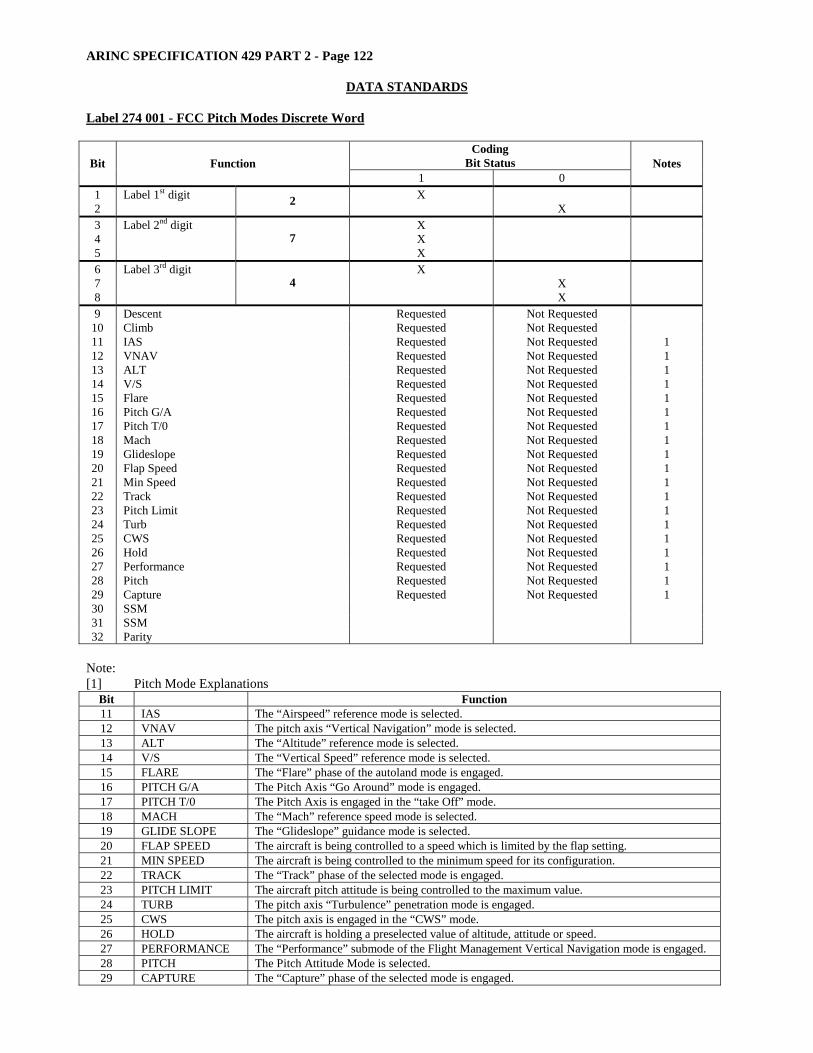
ARINC SPECIFICATION 429 PART 2 - Page 122
DATA STANDARDS Label 274 001 - FCC Pitch Modes Discrete Word
Coding Bit Status Bit Function
1 0 Notes
1 Label 1st digit X 2 2 X 3 Label 2nd digit X 4 X 5
7 X
6 Label 3rd digit X 7 X 8
4 X
9 Descent Requested Not Requested 10 Climb Requested Not Requested 11 IAS Requested Not Requested 1 12 VNAV Requested Not Requested 1 13 ALT Requested Not Requested 1 14 V/S Requested Not Requested 1 15 Flare Requested Not Requested 1 16 Pitch G/A Requested Not Requested 1 17 Pitch T/0 Requested Not Requested 1 18 Mach Requested Not Requested 1 19 Glideslope Requested Not Requested 1 20 Flap Speed Requested Not Requested 1 21 Min Speed Requested Not Requested 1 22 Track Requested Not Requested 1 23 Pitch Limit Requested Not Requested 1 24 Turb Requested Not Requested 1 25 CWS Requested Not Requested 1 26 Hold Requested Not Requested 1 27 Performance Requested Not Requested 1 28 Pitch Requested Not Requested 1 29 Capture Requested Not Requested 1 30 SSM 31 SSM 32 Parity
Note: [1] Pitch Mode Explanations
Bit Function 11 IAS The “Airspeed” reference mode is selected. 12 VNAV The pitch axis “Vertical Navigation” mode is selected. 13 ALT The “Altitude” reference mode is selected. 14 V/S The “Vertical Speed” reference mode is selected. 15 FLARE The “Flare” phase of the autoland mode is engaged. 16 PITCH G/A The Pitch Axis “Go Around” mode is engaged. 17 PITCH T/0 The Pitch Axis is engaged in the “take Off” mode. 18 MACH The “Mach” reference speed mode is selected. 19 GLIDE SLOPE The “Glideslope” guidance mode is selected. 20 FLAP SPEED The aircraft is being controlled to a speed which is limited by the flap setting. 21 MIN SPEED The aircraft is being controlled to the minimum speed for its configuration. 22 TRACK The “Track” phase of the selected mode is engaged. 23 PITCH LIMIT The aircraft pitch attitude is being controlled to the maximum value. 24 TURB The pitch axis “Turbulence” penetration mode is engaged. 25 CWS The pitch axis is engaged in the “CWS” mode. 26 HOLD The aircraft is holding a preselected value of altitude, attitude or speed. 27 PERFORMANCE The “Performance” submode of the Flight Management Vertical Navigation mode is engaged. 28 PITCH The Pitch Attitude Mode is selected. 29 CAPTURE The “Capture” phase of the selected mode is engaged.

ARINC SPECIFICATION 429 PART 2 - Page 123
DATA STANDARDS
Label 274 003 - TCC Discrete
Coding Bit Status Bit Function
1 0 Notes
1 Label 1st digit X 2 2 X 3 Label 2nd digit X 4 X 5
7 X
6 Label 3rd digit X 7 X 8
4 X
9 DFA Mode Armed Armed Not Armed 10 DFA Mode Engaged Engaged Not Engaged 11 ATS OFF OFF Passive 12 ATS Armed Armed Passive 13 ATS Mode Engaged Engaged Passive 14 Left Clutch Off Off Passive 15 Right Clutch Off Off Passive 16 Both Clutched Off Off Passive 17 VNV The automatic throttles are engaged in the vertical
Navigation mode and controlling in accordance with a Submode designated by bits 23 thru 26 and 29.
Engaged Not Engaged
18 ATS N1/EPR Mode Engaged Engaged Not Engaged 19 EPR Engaged Not Engaged 20 ATS Mach Mode Engaged Engaged Not Engaged 21 ATS Speed Mode Engaged Engaged Not Engaged 22 ATS Retard Activated Engaged Not Engaged 23 IAS The IAS submode of VNV basic mode currently in effect.
Used with bit 17. In Effect Not In Effect
24 MACH The Mach submode of VNV basic mode currently in Effect. Used with bit 17.
In Effect Not In Effect
25 ALT The altitude hold submode of VNV basic mode is currently in effect. Used with bit 17.
In Effect Not In Effect
26 TRK The climb (descent) path-track submode of the VNV basic mode is currently in effect. Used with bit 17.
In Effect Not In Effect
27 ATS Alpha Mode Activated Activated Not Activated 28 ATS Throttle Pusher Activated (Alpha Floor Protection) Activated Not Activated 29 PERF The Performance submode of the VNV basic mode is in
effect. Used with bit 17. In Effect Not in Effect
30 SSM 31 SSM 32 Parity
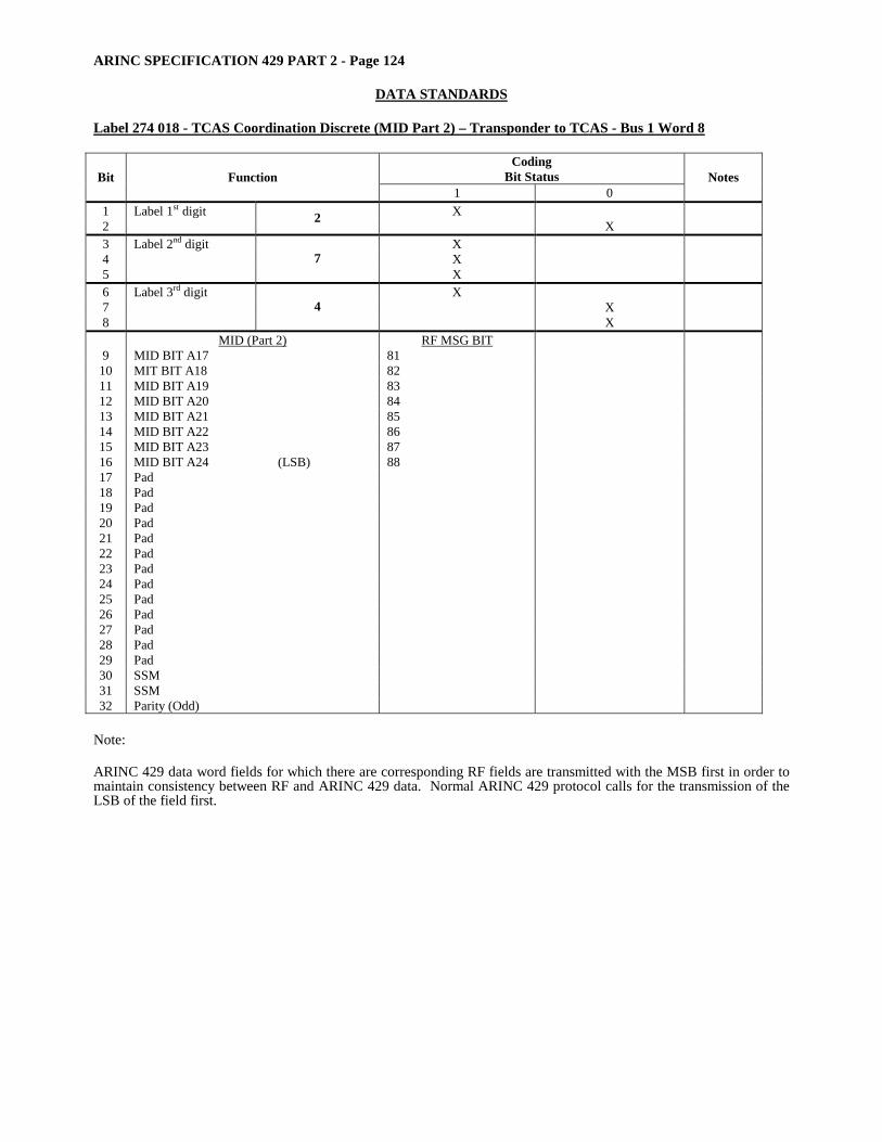
ARINC SPECIFICATION 429 PART 2 - Page 124
DATA STANDARDS Label 274 018 - TCAS Coordination Discrete (MID Part 2) – Transponder to TCAS - Bus 1 Word 8
Coding Bit Status Bit Function
1 0 Notes
1 Label 1st digit X 2 2 X 3 Label 2nd digit X 4 X 5
7 X
6 Label 3rd digit X 7 X 8
4 X
9
MID (Part 2) MID BIT A17
RF MSG BIT 81
10 MIT BIT A18 82 11 MID BIT A19 83 12 MID BIT A20 84 13 MID BIT A21 85 14 MID BIT A22 86 15 MID BIT A23 87 16 MID BIT A24 (LSB) 88 17 Pad 18 Pad 19 Pad 20 Pad 21 Pad 22 Pad 23 Pad 24 Pad 25 Pad 26 Pad 27 Pad 28 Pad 29 Pad 30 SSM 31 SSM 32 Parity (Odd)
Note: ARINC 429 data word fields for which there are corresponding RF fields are transmitted with the MSB first in order to maintain consistency between RF and ARINC 429 data. Normal ARINC 429 protocol calls for the transmission of the LSB of the field first.

ARINC SPECIFICATION 429 PART 2 - Page 125
DATA STANDARDS
Label 274 02F
Coding Bit Status Bit Function
1 0 Notes
1 Label 1st digit X 2 2 X 3 Label 2nd digit X 4 X 5
7 X
6 Label 3rd digit X 7 X 8
4 X
9 SDI X 10 SDI X 11 Pad X 12 Pad X 13 Pad X 14 Parity Test Hardware Error OK 15 ROM Checksum Failed OK 16 RAM Test Failed OK 17 Instruction Test Failed OK 18 High Speed Cross Link Text Failed OK 19 Foreground Software Execution Incorrect Correct 20 Watchdog Timer Error OK 21 Spare X 22 EAROM Failed OK 23 ROM Parity Error Caused Reset Yes No 24 RAM Parity Error Caused Reset Yes No 25 Watchdog Timer Error Caused Reset Yes No 26 Status Buffer Failed OK 27 Loss of Clock Caused Reset Yes No 28 SDD Output #1 W/A Failed OK 29 SDD Output #2 W/A Failed OK 30 SSM X 31 SSM X 32 Parity (Odd)
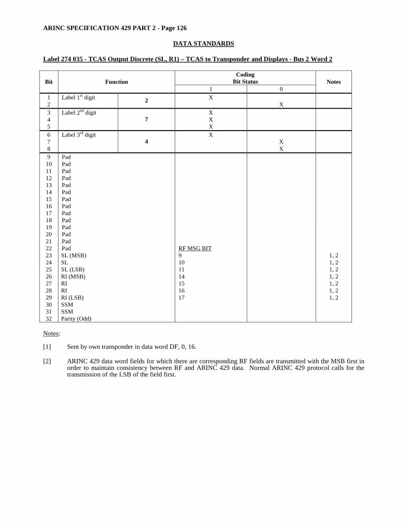
ARINC SPECIFICATION 429 PART 2 - Page 126
DATA STANDARDS Label 274 035 - TCAS Output Discrete (SL, R1) – TCAS to Transponder and Displays - Bus 2 Word 2
Coding Bit Status Bit Function
1 0 Notes
1 Label 1st digit X 2 2 X 3 Label 2nd digit X 4 X 5
7 X
6 Label 3rd digit X 7 X 8
4 X
9 Pad 10 Pad 11 Pad 12 Pad 13 Pad 14 Pad 15 Pad 16 Pad 17 Pad 18 Pad 19 Pad 20 Pad 21 Pad 22 Pad RF MSG BIT 23 SL (MSB) 9 1, 2 24 SL 10 1, 2 25 SL (LSB) 11 1, 2 26 RI (MSB) 14 1, 2 27 RI 15 1, 2 28 RI 16 1, 2 29 RI (LSB) 17 1, 2 30 SSM 31 SSM 32 Parity (Odd)
Notes: [1] Sent by own transponder in data word DF, 0, 16. [2] ARINC 429 data word fields for which there are corresponding RF fields are transmitted with the MSB first in
order to maintain consistency between RF and ARINC 429 data. Normal ARINC 429 protocol calls for the transmission of the LSB of the field first.

ARINC SPECIFICATION 429 PART 2 - Page 127
DATA STANDARDS
Label 274 03B
Coding Bit Status Bit Function
1 0 Notes
1 Label 1st digit X 2 2 X 3 Label 2nd digit X 4 X 5
7 X
6 Label 3rd digit X 7 X 8
4 X
9 SDI 10 SDI 11 Magnetic Heading flag Flag Normal 12 Localizer Flag Flag Normal 13 Glide Slope Flag Flag Normal 14 Low Range Radio Altimeter Flag Normal 15 ILS Limit Warn Warn Not Selected 16 ILS Frequency Select Selected Normal 17 INS Altitude Secondary Flags Flag Normal 18 INS True Heading Flags Flag Normal 19 INS HSI Nav Warn Warn Normal 20 CADC True Airspeed Flags Flag Normal 21 CADC Computer Airspeed Flags Flag Normal 22 CADC Corrected Altitude Flags Flag Normal 23 CADC Uncorrected Altitude Flag Flag Normal 24 CADC Mach Flag Flag Normal 25 Altitude Rate Module Flag Flag Normal 26 Spare (Pad Bit) X 27 Spare (Pad Bit) X 28 Spare (Pad Bit) X 29 Word Validity Invalid Valid 30 SSM 31 SSM 32 Parity (Odd)
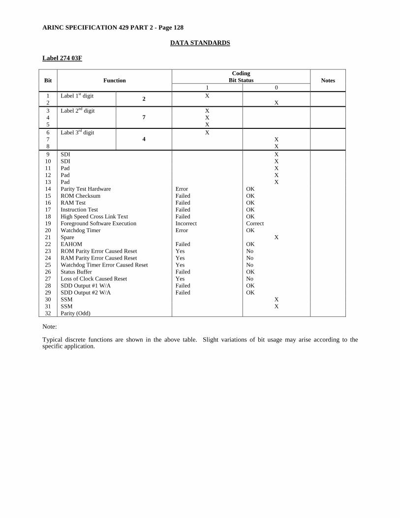
ARINC SPECIFICATION 429 PART 2 - Page 128
DATA STANDARDS Label 274 03F
Coding Bit Status Bit Function
1 0 Notes
1 Label 1st digit X 2 2 X 3 Label 2nd digit X 4 X 5
7 X
6 Label 3rd digit X 7 X 8
4 X
9 SDI X 10 SDI X 11 Pad X 12 Pad X 13 Pad X 14 Parity Test Hardware Error OK 15 ROM Checksum Failed OK 16 RAM Test Failed OK 17 Instruction Test Failed OK 18 High Speed Cross Link Text Failed OK 19 Foreground Software Execution Incorrect Correct 20 Watchdog Timer Error OK 21 Spare X 22 EAHOM Failed OK 23 ROM Parity Error Caused Reset Yes No 24 RAM Parity Error Caused Reset Yes No 25 Watchdog Timer Error Caused Reset Yes No 26 Status Buffer Failed OK 27 Loss of Clock Caused Reset Yes No 28 SDD Output #1 W/A Failed OK 29 SDD Output #2 W/A Failed OK 30 SSM X 31 SSM X 32 Parity (Odd)
Note: Typical discrete functions are shown in the above table. Slight variations of bit usage may arise according to the specific application.
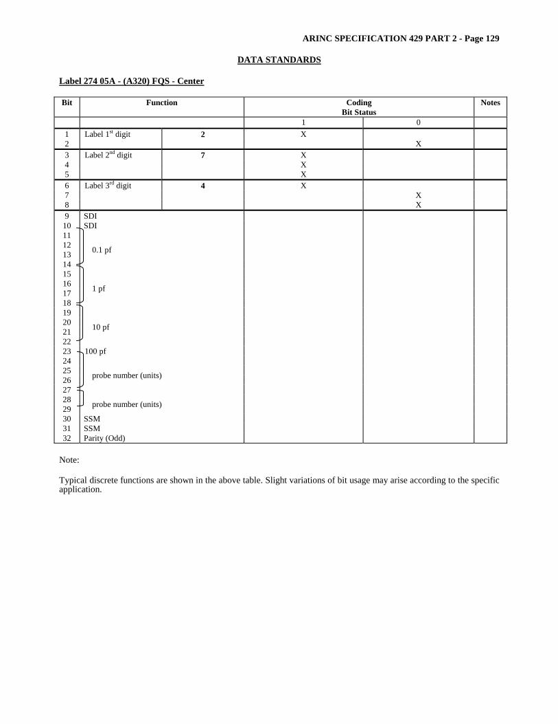
ARINC SPECIFICATION 429 PART 2 - Page 129
DATA STANDARDS
Label 274 05A - (A320) FQS - Center Bit Function Coding
Bit Status Notes
1 0 1 Label 1st digit 2 X 2 X 3 Label 2nd digit 7 X 4 X 5 X 6 Label 3rd digit 4 X 7 X 8 X 9 SDI
10 SDI 11 12 13 14
0.1 pf
15 16 17 18
1 pf
19 20 21 22
10 pf
23 100 pf 24 25 26 27
probe number (units)
28 29 probe number (units) 30 SSM 31 SSM 32 Parity (Odd)
Note: Typical discrete functions are shown in the above table. Slight variations of bit usage may arise according to the specific application.
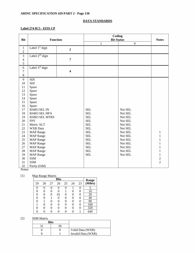
ARINC SPECIFICATION 429 PART 2 - Page 130
DATA STANDARDS Label 274 0C5 - EFIS CP
Coding Bit Status Bit Function
1 0 Notes
1 Label 1st digit 2 2 3 Label 2nd digit 4 5
7
6 Label 3rd digit 7 8
4
9 SDI 10 SDI 11 Spare 12 Spare 13 Spare 14 Spare 15 Spare 16 Spare 17 BARO SEL IN SEL Not SEL 18 BARO SEL HPA SEL Not SEL 19 BARO SEL MTRS SEL Not SEL 20 FPV SEL Not SEL 21 Metric ALT SEL Not SEL 22 WXR Data SEL Not SEL 23 MAP Range SEL Not SEL 1 24 MAP Range SEL Not SEL 1 25 MAP Range SEL Not SEL 1 26 MAP Range SEL Not SEL 1 27 MAP Range SEL Not SEL 1 28 MAP Range SEL Not SEL 1 29 MAP Range SEL Not SEL 1 30 SSM 2 31 SSM 2 32 Parity (Odd)
Notes: [1] Map Range Matrix
Bits 29 28 27 26 25 24 23
Range (Miles)
0 0 0 0 0 1 0 5 0 0 0 0 1 0 0 10 0 0 0 01 0 0 0 20 0 0 1 0 0 0 0 40 0 1 0 0 0 0 0 80 1 0 0 0 0 0 0 160 0 0 0 0 0 0 0 320 0 0 0 0 0 0 1 640
[2] SSM Matrix
Bits 31 30
0 0 Valid Data (WXR) 0 1 Invalid Data (WXR)

ARINC SPECIFICATION 429 PART 2 - Page 131
DATA STANDARDS
Label 274 114 Fuel Transfer Indication
Coding Bit Status Bit Function
1 0 Notes
1 Label 1st digit 2 X 2 X 3 Label 2nd digit 7 X 4 X 5 X 6 Label 3rd digit 4 X 7 X 8 X 9 SDI 1
10 SDI 1 11 Center Tank To Inner Tank 1 Auto Auto Not Auto 12 Center Tank To Inner Tank 1 Abnormal Abnormal Not Abnormal 13 Center Tank To Inner Tank 1 Manual Manual Not Manual 14 Center Tank To Inner Tank 2 Auto Auto Not Auto 15 Center Tank To Inner Tank 2 Abnormal Abnormal Not Abnormal 16 Center Tank To Inner Tank 2 Manual Manual Not Manual 17 Center Tank To Inner Tank 3 Auto Auto Not Auto 18 Center Tank To Inner Tank 3 Abnormal Abnormal Not Abnormal 19 Center Tank To Inner Tank 3 Manual Manual Not Manual 20 Center Tank To Inner Tank 4 Auto Auto Not Auto 21 Center Tank To Inner Tank 4 Abnormal Abnormal Not Abnormal 22 Center Tank To Inner Tank 4 Manual Manual Not Manual 23 Inner Tanks 1 & 4< 13t < 13t >13t 24 Inner Tank 1 To Inner Tank 2 Auto Auto Not Auto 25 Inner Tank 1 To Inner Tank 2 Abnormal Abnormal Not Abnormal 26 Inner Tank 4 To Inner Tank 3 Auto Auto Not Auto 27 Inner Tank 4 To Inner Tank 3 Abnormal Abnormal Not Abnormal 28 Act Isolation Fault Fault Not Fault 29 Trim Feed Latch Latched Not Latched 30 SSM 2 31 SSM 2 32 Parity (Set to Odd Parity)
[1] Depending upon its application group and resolution bits 9 and 10 of an ARINC 429 Data Word can be reserved for
Source/Destination Identification (SDI). For data Source identification the relevant equipment should encode its Aircraft Installation number as follows:
Bit 10 Bit 9 Source
0 1 Transmission From Computer 1 1 0 Transmission From Computer 2
For data Destination (i.e maintenance data from the CMS) identification the relevant equipment should encode its Aircraft Installation number as follows:
Bit 10 Bit 9 Destination
0 1 Transmission To Computer 1 1 0 Transmission To Computer 2
[2] SSM
Bit 31 Bit 30` Designation 0 0 Normal Operation 0 1 NCD (Not Used) 1 0 Functional Test 1 1 Failure Warning
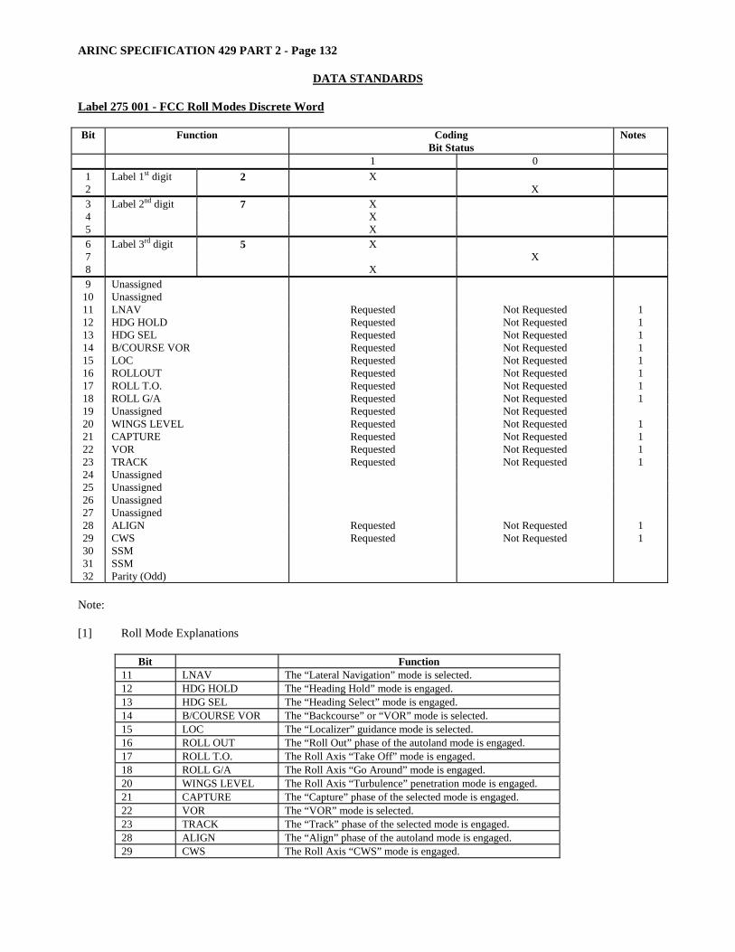
ARINC SPECIFICATION 429 PART 2 - Page 132
DATA STANDARDS Label 275 001 - FCC Roll Modes Discrete Word Bit Function Coding
Bit Status Notes
1 0 1 Label 1st digit 2 X 2 X 3 Label 2nd digit 7 X 4 X 5 X 6 Label 3rd digit 5 X 7 X 8 X 9 Unassigned
10 Unassigned 11 LNAV Requested Not Requested 1 12 HDG HOLD Requested Not Requested 1 13 HDG SEL Requested Not Requested 1 14 B/COURSE VOR Requested Not Requested 1 15 LOC Requested Not Requested 1 16 ROLLOUT Requested Not Requested 1 17 ROLL T.O. Requested Not Requested 1 18 ROLL G/A Requested Not Requested 1 19 Unassigned Requested Not Requested 20 WINGS LEVEL Requested Not Requested 1 21 CAPTURE Requested Not Requested 1 22 VOR Requested Not Requested 1 23 TRACK Requested Not Requested 1 24 Unassigned 25 Unassigned 26 Unassigned 27 Unassigned 28 ALIGN Requested Not Requested 1 29 CWS Requested Not Requested 1 30 SSM 31 SSM 32 Parity (Odd)
Note: [1] Roll Mode Explanations
Bit Function 11 LNAV The “Lateral Navigation” mode is selected. 12 HDG HOLD The “Heading Hold” mode is engaged. 13 HDG SEL The “Heading Select” mode is engaged. 14 B/COURSE VOR The “Backcourse” or “VOR” mode is selected. 15 LOC The “Localizer” guidance mode is selected. 16 ROLL OUT The “Roll Out” phase of the autoland mode is engaged. 17 ROLL T.O. The Roll Axis “Take Off” mode is engaged. 18 ROLL G/A The Roll Axis “Go Around” mode is engaged. 20 WINGS LEVEL The Roll Axis “Turbulence” penetration mode is engaged. 21 CAPTURE The “Capture” phase of the selected mode is engaged. 22 VOR The “VOR” mode is selected. 23 TRACK The “Track” phase of the selected mode is engaged. 28 ALIGN The “Align” phase of the autoland mode is engaged. 29 CWS The Roll Axis “CWS” mode is engaged.
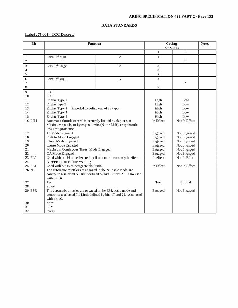
ARINC SPECIFICATION 429 PART 2 - Page 133
DATA STANDARDS
Label 275 003 - TCC Discrete
Bit Function Coding Bit Status
Notes
1 0 1 Label 1st digit 2 X 2 X 3 Label 2nd digit 7 X 4 X 5 X 6 Label 3rd digit 5 X 7 X 8 X 9 SDI 10 SDI 11 Engine Type 1 High Low 12 Engine type 2 High Low 13 Engine Type 3 Encoded to define one of 32 types High Low 14 Engine Type 4 High Low 15 Engine Type 5 High Low 16 LIM Automatic throttle control is currently limited by flap or slat
Maximum speeds, or by engine limits (N1 or EPR), or ty throttle low limit protection.
In Effect Not In Effect
17 To Mode Engaged Engaged Not Engaged 18 FLX to Mode Engaged Engaged Not Engaged 19 Climb Mode Engaged Engaged Not Engaged 20 Cruise Mode Engaged Engaged Not Engaged 21 Maximum Continuous Thrust Mode Engaged Engaged Not Engaged 22 GA Mode Engaged Engaged Not Engaged 23 FLP Used with bit 16 to designate flap limit control currently in effect In effect Not In Effect 24 N1/EPR Limit Failure/Warning 25 SLT Used with bit 16 to designate slat limit. In Effect Not In Effect 26 N1 The automatic throttles are engaged in the N1 basic mode and
control to a selected N1 limit defined by bits 17 thru 22. Also used with bit 16.
27 Test Test Normal 28 Spare 29 EPR The automatic throttles are engaged in the EPR basic mode and
control to a selected N1 Limit defined by bits 17 and 22. Also used with bit 16.
Engaged Not Engaged
30 SSM 31 SSM 32 Parity

ARINC SPECIFICATION 429 PART 2 - Page 134
DATA STANDARDS Label 275 018 - TCAS Control Discrete (MODE S Address Part 1) – Transponder to TCAS - Bus 1 Word 5
Bit Function Coding Bit Status
Notes
1 0 1 Label 1st digit 2 X 2 X 3 Label 2nd digit 7 X 4 X 5 X 6 Label 3rd digit 5 X 7 X 8 X 9 Pad
10 Pad 11 Pad 12 Pad 13 Pad
Mode S Address (Part 1) 14 Bit A1 (MSB) 1,2 15 Bit A2 1,2 16 Bit A3 1,2 17 Bit A4 1,2 18 Bit A5 1,2 19 Bit A6 1,2 20 Bit A7 1,2 21 Bit A8 1,2 22 Bit A9 1,2 23 Bit A10 1,2 24 Bit A11 1,2 25 Bit A12 1,2 26 Bit A13 1,2 27 Bit A14 1,2 28 Bit A15 1,2 29 Bit A16 (LSB) 1,2 30 SSM 31 SSM 32 Parity (Odd)
Notes: [1] Sent by own TCAS in data word UF-16. [2] ARINC 429 data word fields for which there are corresponding RF fields are transmitted with the MSB first in
order to maintain consistency between RF and ARINC 429 data. Normal ARINC 429 protocol calls for the transmission of the LSB of the field first.
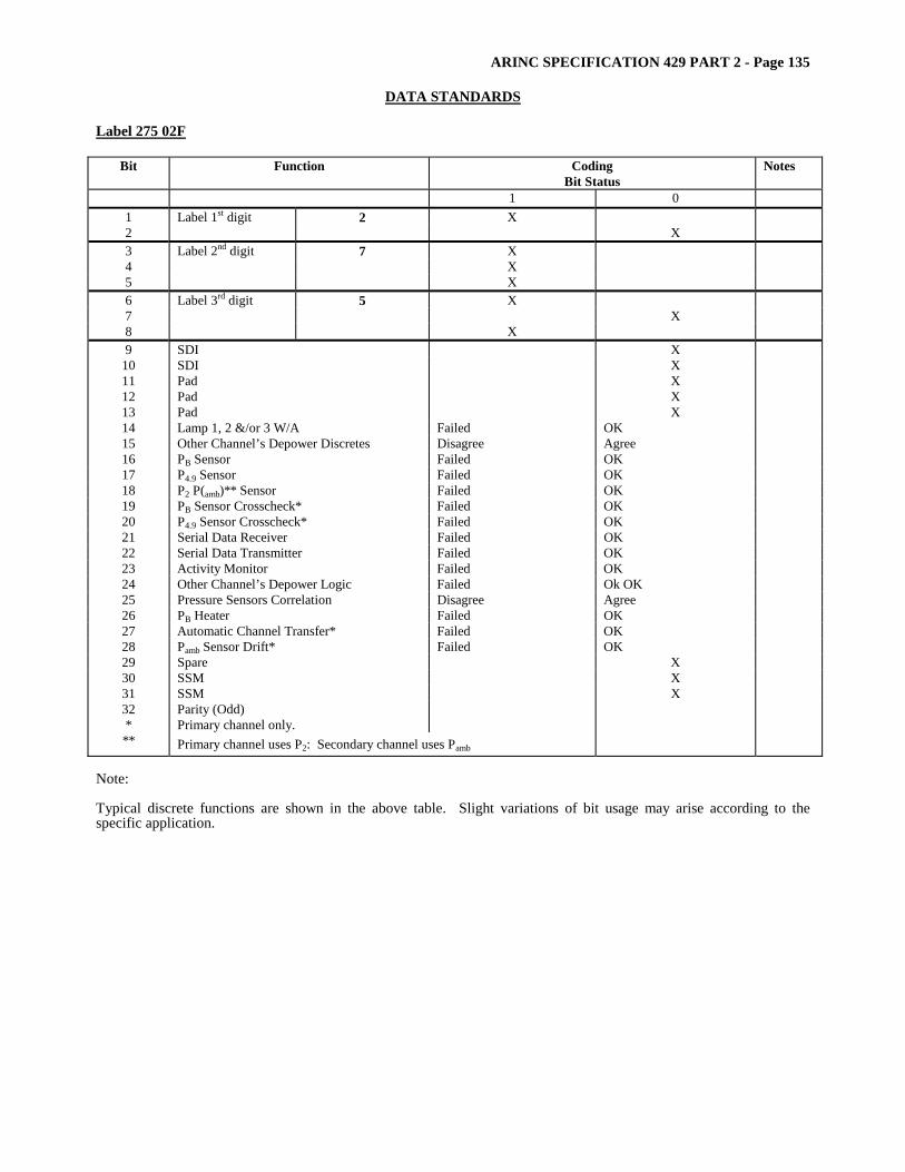
ARINC SPECIFICATION 429 PART 2 - Page 135
DATA STANDARDS
Label 275 02F
Bit Function Coding Bit Status
Notes
1 0 1 Label 1st digit 2 X 2 X 3 Label 2nd digit 7 X 4 X 5 X 6 Label 3rd digit 5 X 7 X 8 X 9 SDI X
10 SDI X 11 Pad X 12 Pad X 13 Pad X 14 Lamp 1, 2 &/or 3 W/A Failed OK 15 Other Channel’s Depower Discretes Disagree Agree 16 PB Sensor Failed OK 17 P4.9 Sensor Failed OK 18 P2 P(amb)** Sensor Failed OK 19 PB Sensor Crosscheck* Failed OK 20 P4.9 Sensor Crosscheck* Failed OK 21 Serial Data Receiver Failed OK 22 Serial Data Transmitter Failed OK 23 Activity Monitor Failed OK 24 Other Channel’s Depower Logic Failed Ok OK 25 Pressure Sensors Correlation Disagree Agree 26 PB Heater Failed OK 27 Automatic Channel Transfer* Failed OK 28 Pamb Sensor Drift* Failed OK 29 Spare X 30 SSM X 31 SSM X 32 Parity (Odd) * Primary channel only. ** Primary channel uses P2: Secondary channel uses Pamb
Note: Typical discrete functions are shown in the above table. Slight variations of bit usage may arise according to the specific application.
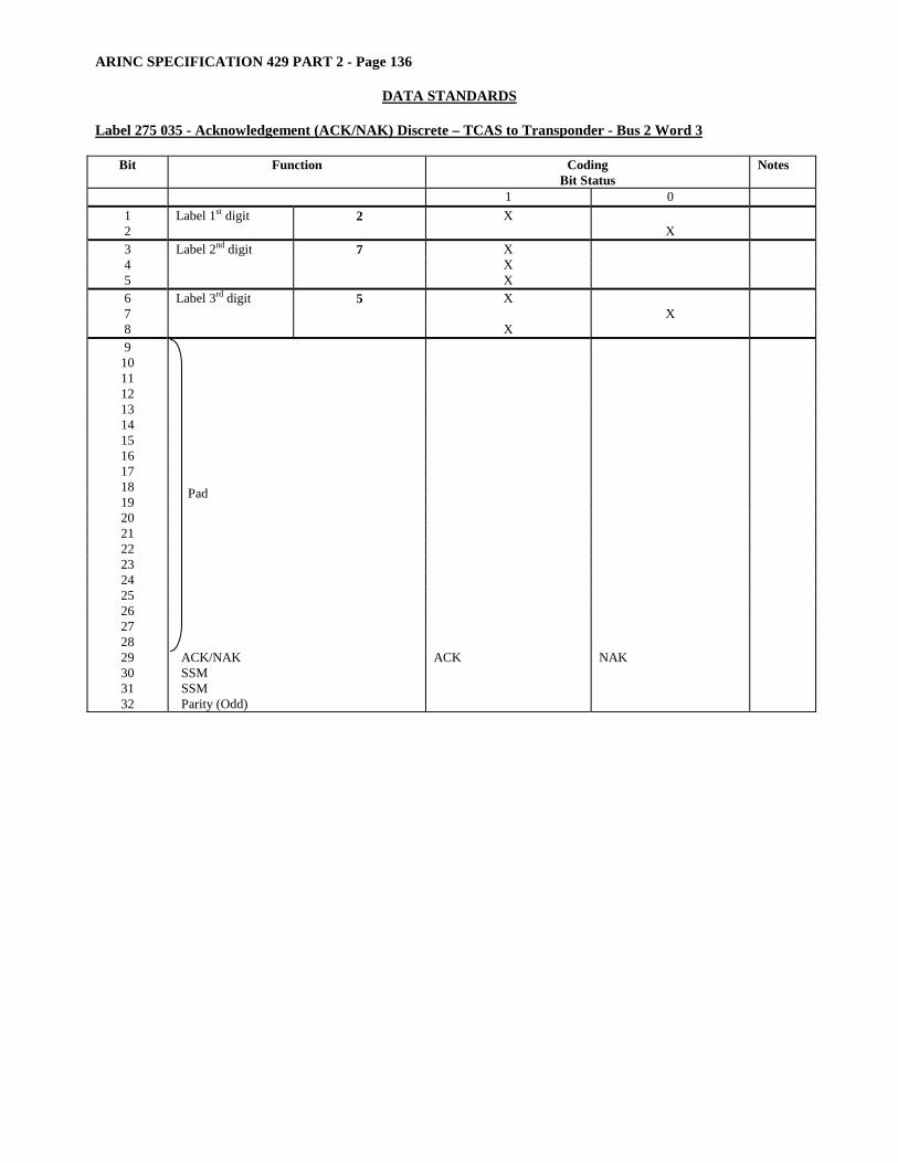
ARINC SPECIFICATION 429 PART 2 - Page 136
DATA STANDARDS Label 275 035 - Acknowledgement (ACK/NAK) Discrete – TCAS to Transponder - Bus 2 Word 3
Bit Function Coding Bit Status
Notes
1 0 1 Label 1st digit 2 X 2 X 3 Label 2nd digit 7 X 4 X 5 X 6 Label 3rd digit 5 X 7 X 8 X 9
10 11 12 13 14 15 16 17 18 19 20 21 22 23 24 25 26 27 28
Pad
29 ACK/NAK ACK NAK 30 SSM 31 SSM 32 Parity (Odd)
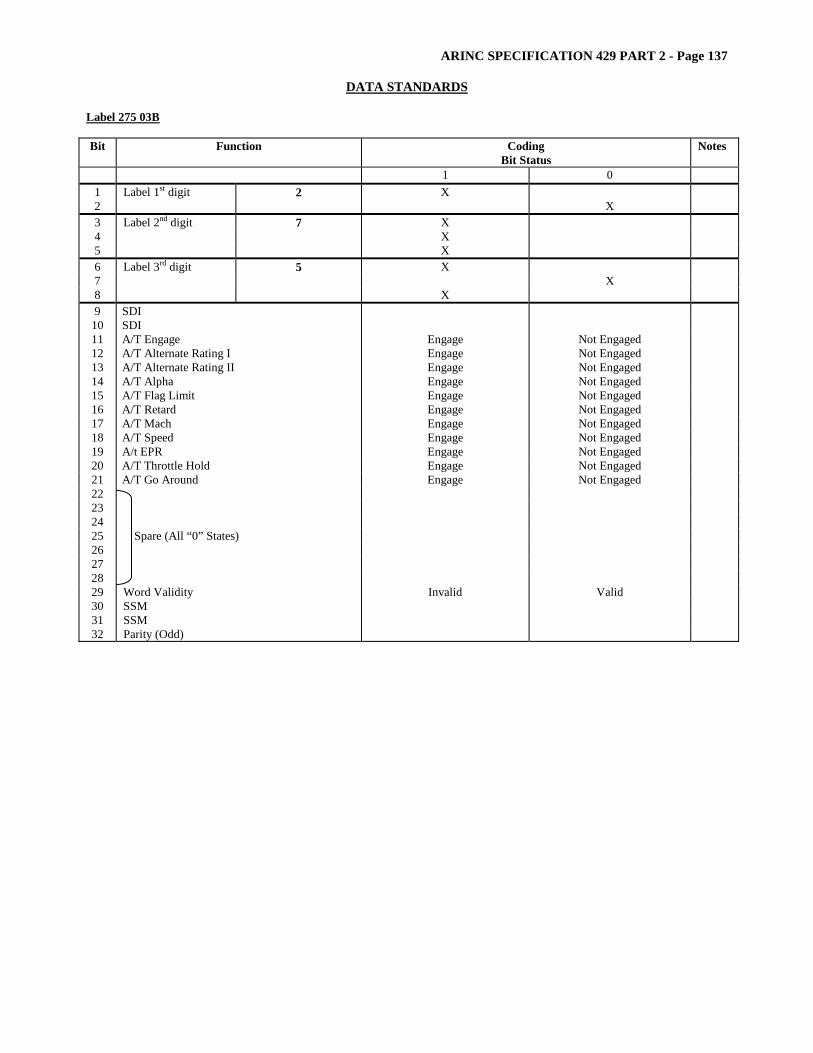
ARINC SPECIFICATION 429 PART 2 - Page 137
DATA STANDARDS
Label 275 03B Bit Function Coding
Bit Status Notes
1 0 1 Label 1st digit 2 X 2 X 3 Label 2nd digit 7 X 4 X 5 X 6 Label 3rd digit 5 X 7 X 8 X 9 SDI
10 SDI 11 A/T Engage Engage Not Engaged 12 A/T Alternate Rating I Engage Not Engaged 13 A/T Alternate Rating II Engage Not Engaged 14 A/T Alpha Engage Not Engaged 15 A/T Flag Limit Engage Not Engaged 16 A/T Retard Engage Not Engaged 17 A/T Mach Engage Not Engaged 18 A/T Speed Engage Not Engaged 19 A/t EPR Engage Not Engaged 20 A/T Throttle Hold Engage Not Engaged 21 A/T Go Around Engage Not Engaged 22 23 24 25 26 27 28
Spare (All “0” States)
29 Word Validity Invalid Valid 30 SSM 31 SSM 32 Parity (Odd)
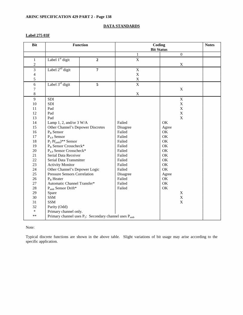
ARINC SPECIFICATION 429 PART 2 - Page 138
DATA STANDARDS Label 275 03F
Bit Function Coding Bit Status
Notes
1 0 1 Label 1st digit 2 X 2 X 3 Label 2nd digit 7 X 4 X 5 X 6 Label 3rd digit 5 X 7 X 8 X 9 SDI X
10 SDI X 11 Pad X 12 Pad X 13 Pad X 14 Lamp 1, 2, and/or 3 W/A Failed OK 15 Other Channel’s Depower Discretes Disagree Agree 16 PB Sensor Failed OK 17 P4.9 Sensor Failed OK 18 P2 P(amb)** Sensor Failed OK 19 PB Sensor Crosscheck* Failed OK 20 P4.9 Sensor Crosscheck* Failed OK 21 Serial Data Receiver Failed OK 22 Serial Data Transmitter Failed OK 23 Activity Monitor Failed OK 24 Other Channel’s Depower Logic Failed OK 25 Pressure Sensors Correlation Disagree Agree 26 PB Heater Failed OK 27 Automatic Channel Transfer* Failed OK 28 Pamb Sensor Drift* Failed OK 29 Spare X 30 SSM X 31 SSM X 32 Parity (Odd) * Primary channel only. ** Primary channel uses P2: Secondary channel uses Pamb
Note: Typical discrete functions are shown in the above table. Slight variations of bit usage may arise according to the specific application.
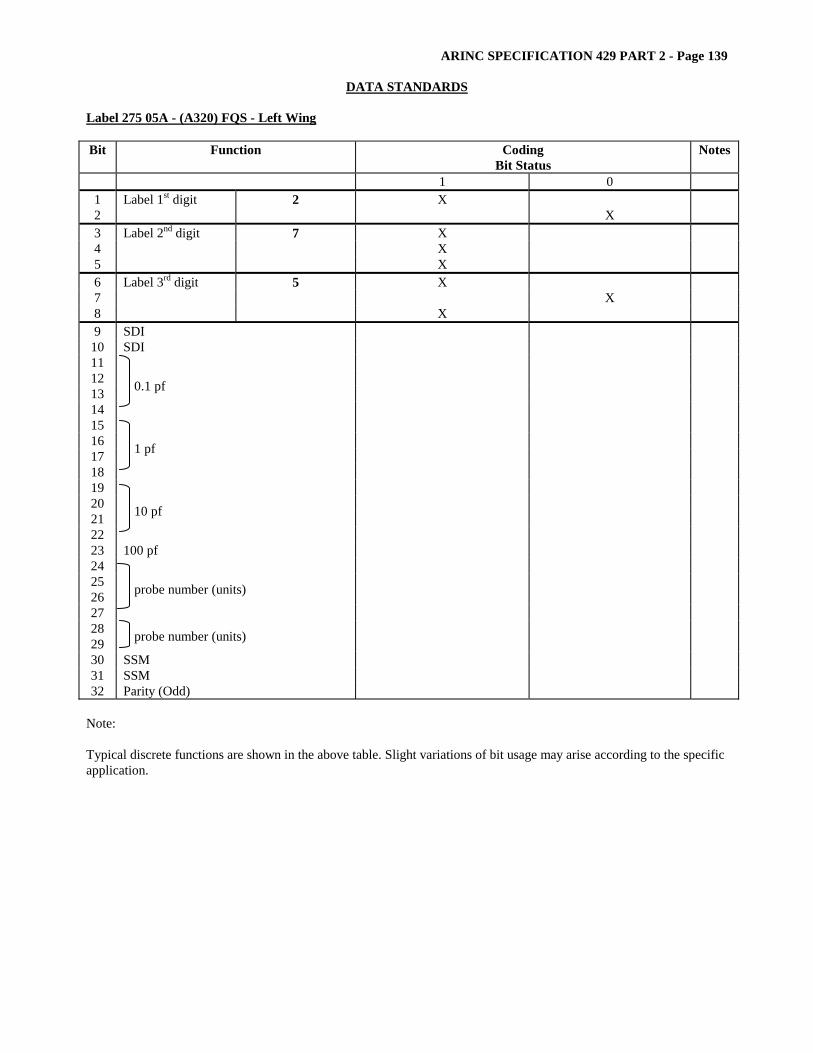
ARINC SPECIFICATION 429 PART 2 - Page 139
DATA STANDARDS
Label 275 05A - (A320) FQS - Left Wing Bit Function Coding
Bit Status Notes
1 0 1 Label 1st digit 2 X 2 X 3 Label 2nd digit 7 X 4 X 5 X 6 Label 3rd digit 5 X 7 X 8 X 9 SDI
10 SDI 11 12 13 14
0.1 pf
15 16 17 18
1 pf
19 20 21 22
10 pf
23 100 pf 24 25 26 27
probe number (units)
28 29 probe number (units) 30 SSM 31 SSM 32 Parity (Odd)
Note: Typical discrete functions are shown in the above table. Slight variations of bit usage may arise according to the specific application.
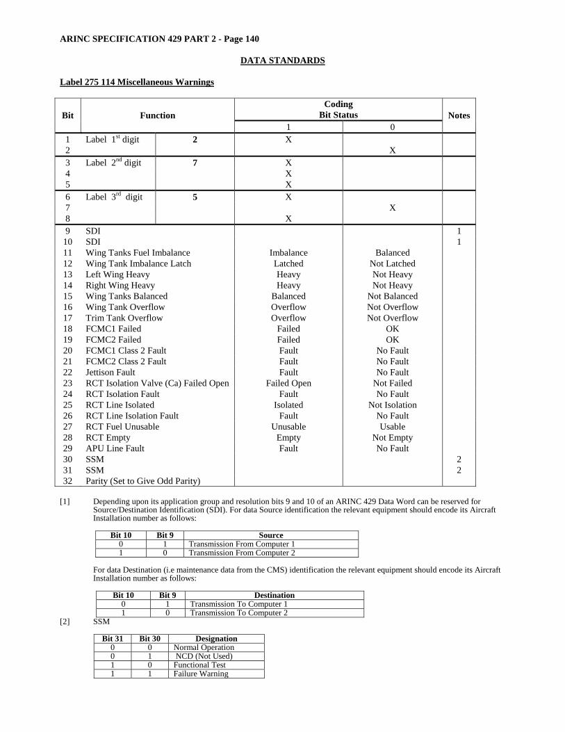
ARINC SPECIFICATION 429 PART 2 - Page 140
DATA STANDARDS Label 275 114 Miscellaneous Warnings
Coding Bit Status Bit Function
1 0 Notes
1 Label 1st digit 2 X 2 X 3 Label 2nd digit 7 X 4 X 5 X 6 Label 3rd digit 5 X 7 X 8 X 9 SDI 1
10 SDI 1 11 Wing Tanks Fuel Imbalance Imbalance Balanced 12 Wing Tank Imbalance Latch Latched Not Latched 13 Left Wing Heavy Heavy Not Heavy 14 Right Wing Heavy Heavy Not Heavy 15 Wing Tanks Balanced Balanced Not Balanced 16 Wing Tank Overflow Overflow Not Overflow 17 Trim Tank Overflow Overflow Not Overflow 18 FCMC1 Failed Failed OK 19 FCMC2 Failed Failed OK 20 FCMC1 Class 2 Fault Fault No Fault 21 FCMC2 Class 2 Fault Fault No Fault 22 Jettison Fault Fault No Fault 23 RCT Isolation Valve (Ca) Failed Open Failed Open Not Failed 24 RCT Isolation Fault Fault No Fault 25 RCT Line Isolated Isolated Not Isolation 26 RCT Line Isolation Fault Fault No Fault 27 RCT Fuel Unusable Unusable Usable 28 RCT Empty Empty Not Empty 29 APU Line Fault Fault No Fault 30 SSM 2 31 SSM 2 32 Parity (Set to Give Odd Parity)
[1] Depending upon its application group and resolution bits 9 and 10 of an ARINC 429 Data Word can be reserved for
Source/Destination Identification (SDI). For data Source identification the relevant equipment should encode its Aircraft Installation number as follows:
Bit 10 Bit 9 Source
0 1 Transmission From Computer 1 1 0 Transmission From Computer 2
For data Destination (i.e maintenance data from the CMS) identification the relevant equipment should encode its Aircraft Installation number as follows:
Bit 10 Bit 9 Destination
0 1 Transmission To Computer 1 1 0 Transmission To Computer 2
[2] SSM
Bit 31 Bit 30 Designation 0 0 Normal Operation 0 1 NCD (Not Used) 1 0 Functional Test 1 1 Failure Warning
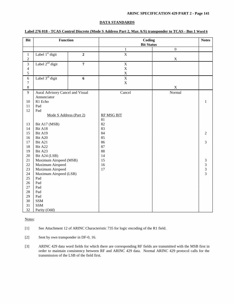
ARINC SPECIFICATION 429 PART 2 - Page 141
DATA STANDARDS Label 276 018 - TCAS Control Discrete (Mode S Address Part 2, Max A/S) transponder to TCAS - Bus 1 Word 6 Bit Function Coding
Bit Status Notes
1 0 1 Label 1st digit 2 X 2 X 3 Label 2nd digit 7 X 4 X 5 X 6 Label 3rd digit 6 X 7 X 8 X 9 Aural Advisory Cancel and Visual
Annunciator Cancel Normal
10 R1 Echo 1 11 Pad 12 Pad
Mode S Address (Part 2)
RF MSG BIT 81
13 Bit A17 (MSB) 82 14 Bit A18 83 15 Bit A19 84 2 16 Bit A20 85 17 Bit A21 86 3 18 Bit A22 87 19 Bit A23 88 20 Bit A24 (LSB) 14 21 Maximum Airspeed (MSB) 15 3 22 Maximum Airspeed 16 3 23 Maximum Airspeed 17 3 24 Maximum Airspeed (LSB) 3 25 Pad 26 Pad 27 Pad 28 Pad 29 Pad 30 SSM 31 SSM 32 Parity (Odd)
Notes: [1] See Attachment 12 of ARINC Characteristic 735 for logic encoding of the R1 field. [2] Sent by own transponder in DF-0, 16. [3] ARINC 429 data word fields for which there are corresponding RF fields are transmitted with the MSB first in
order to maintain consistency between RF and ARINC 429 data. Normal ARINC 429 protocol calls for the transmission of the LSB of the field first.
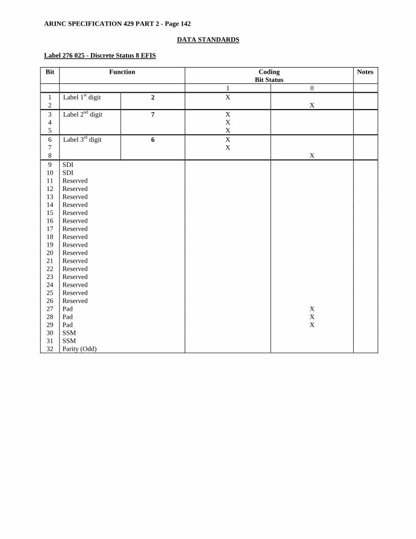
ARINC SPECIFICATION 429 PART 2 - Page 142
DATA STANDARDS
Label 276 025 - Discrete Status 8 EFIS Bit Function Coding
Bit Status Notes
1 0 1 Label 1st digit 2 X 2 X 3 Label 2nd digit 7 X 4 X 5 X 6 Label 3rd digit 6 X 7 X 8 X 9 SDI
10 SDI 11 Reserved 12 Reserved 13 Reserved 14 Reserved 15 Reserved 16 Reserved 17 Reserved 18 Reserved 19 Reserved 20 Reserved 21 Reserved 22 Reserved 23 Reserved 24 Reserved 25 Reserved 26 Reserved 27 Pad X 28 Pad X 29 Pad X 30 SSM 31 SSM 32 Parity (Odd)
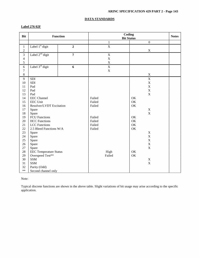
ARINC SPECIFICATION 429 PART 2 - Page 143
DATA STANDARDS Label 276 02F
Bit Function Coding Bit Status Notes
1 0 1 Label 1st digit 2 X 2 X 3 Label 2nd digit 7 X 4 X 5 X 6 Label 3rd digit 6 X 7 X 8 X 9 SDI X
10 SDI X 11 Pad X 12 Pad X 13 Pad X 14 EEC Channel Failed OK 15 EEC Unit Failed OK 16 Resolver/LVDT Excitation Failed OK 17 Spare X 18 Spare X 19 FCU Functions Failed OK 20 HCC Functions Failed OK 21 LCC Functions Failed OK 22 2.5 Bleed Functions W/A Failed OK 23 Spare X 24 Spare X 25 Spare X 26 Spare X 27 Spare X 28 EEC Temperature Status High OK 29 Overspeed Test** Failed OK 30 SSM X 31 SSM X 32 Parity (Odd) ** Second channel only
Note: Typical discrete functions are shown in the above table. Slight variations of bit usage may arise according to the specific application.
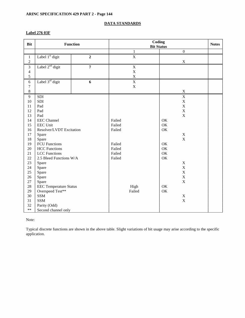
ARINC SPECIFICATION 429 PART 2 - Page 144
DATA STANDARDS
Label 276 03F
Bit Function Coding Bit Status Notes
1 0 1 Label 1st digit 2 X 2 X 3 Label 2nd digit 7 X 4 X 5 X 6 Label 3rd digit 6 X 7 X 8 X 9 SDI X
10 SDI X 11 Pad X 12 Pad X 13 Pad X 14 EEC Channel Failed OK 15 EEC Unit Failed OK 16 Resolver/LVDT Excitation Failed OK 17 Spare X 18 Spare X 19 FCU Functions Failed OK 20 HCC Functions Failed OK 21 LCC Functions Failed OK 22 2.5 Bleed Functions W/A Failed OK 23 Spare X 24 Spare X 25 Spare X 26 Spare X 27 Spare X 28 EEC Temperature Status High OK 29 Overspeed Test** Failed OK 30 SSM X 31 SSM X 32 Parity (Odd) ** Second channel only
Note: Typical discrete functions are shown in the above table. Slight variations of bit usage may arise according to the specific application.
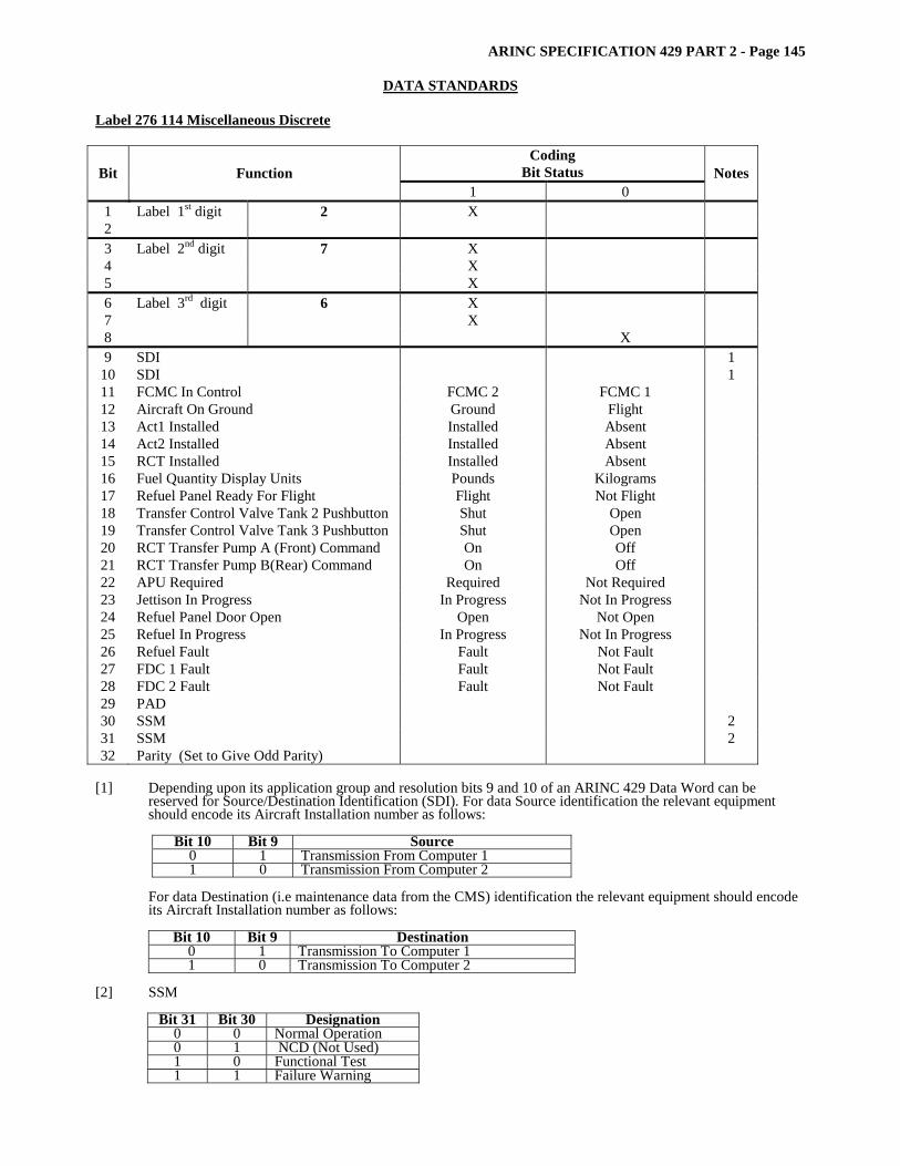
ARINC SPECIFICATION 429 PART 2 - Page 145
DATA STANDARDS Label 276 114 Miscellaneous Discrete
Coding Bit Status Bit Function
1 0 Notes
1 Label 1st digit 2 X 2 3 Label 2nd digit 7 X 4 X 5 X 6 Label 3rd digit 6 X 7 X 8 X 9 SDI 1
10 SDI 1 11 FCMC In Control FCMC 2 FCMC 1 12 Aircraft On Ground Ground Flight 13 Act1 Installed Installed Absent 14 Act2 Installed Installed Absent 15 RCT Installed Installed Absent 16 Fuel Quantity Display Units Pounds Kilograms 17 Refuel Panel Ready For Flight Flight Not Flight 18 Transfer Control Valve Tank 2 Pushbutton Shut Open 19 Transfer Control Valve Tank 3 Pushbutton Shut Open 20 RCT Transfer Pump A (Front) Command On Off 21 RCT Transfer Pump B(Rear) Command On Off 22 APU Required Required Not Required 23 Jettison In Progress In Progress Not In Progress 24 Refuel Panel Door Open Open Not Open 25 Refuel In Progress In Progress Not In Progress 26 Refuel Fault Fault Not Fault 27 FDC 1 Fault Fault Not Fault 28 FDC 2 Fault Fault Not Fault 29 PAD 30 SSM 2 31 SSM 2 32 Parity (Set to Give Odd Parity)
[1] Depending upon its application group and resolution bits 9 and 10 of an ARINC 429 Data Word can be
reserved for Source/Destination Identification (SDI). For data Source identification the relevant equipment should encode its Aircraft Installation number as follows:
Bit 10 Bit 9 Source
0 1 Transmission From Computer 1 1 0 Transmission From Computer 2
For data Destination (i.e maintenance data from the CMS) identification the relevant equipment should encode its Aircraft Installation number as follows:
Bit 10 Bit 9 Destination
0 1 Transmission To Computer 1 1 0 Transmission To Computer 2
[2] SSM
Bit 31 Bit 30 Designation 0 0 Normal Operation 0 1 NCD (Not Used) 1 0 Functional Test 1 1 Failure Warning

ARINC SPECIFICATION 429 PART 2 - Page 146
DATA STANDARDS
Label 277 018 - Acknowledgement (ACK/NAK) Discrete – Transponder to TCAS - Bus 1 Word 7
Bit Function Coding Bit Status
Notes
1 0 1 Label 1st digit 2 X 2 X 3 Label 2nd digit 7 X 4 X 5 X 6 Label 3rd digit 7 X 7 X 8 X 9 Pad
10 Pad 11 Pad 12 Pad 13 Pad 14 Pad 15 Pad 16 Pad 17 Pad 18 Pad 19 Pad 20 Pad 21 Pad 22 Pad 23 Pad 24 Pad 25 Pad 26 Pad 27 Pad 28 Pad 29 ACK/NAK ACK NAK 30 SSM 31 SSM 32 Parity (Odd)
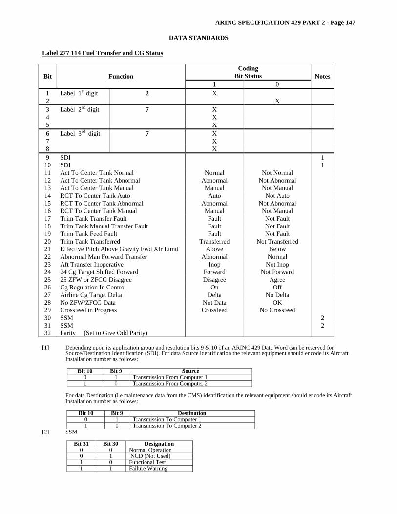
ARINC SPECIFICATION 429 PART 2 - Page 147
DATA STANDARDS Label 277 114 Fuel Transfer and CG Status
Coding Bit Status Bit Function
1 0 Notes
1 Label 1st digit 2 X 2 X 3 Label 2nd digit 7 X 4 X 5 X 6 Label 3rd digit 7 X 7 X 8 X 9 SDI 1
10 SDI 1 11 Act To Center Tank Normal Normal Not Normal 12 Act To Center Tank Abnormal Abnormal Not Abnormal 13 Act To Center Tank Manual Manual Not Manual 14 RCT To Center Tank Auto Auto Not Auto 15 RCT To Center Tank Abnormal Abnormal Not Abnormal 16 RCT To Center Tank Manual Manual Not Manual 17 Trim Tank Transfer Fault Fault Not Fault 18 Trim Tank Manual Transfer Fault Fault Not Fault 19 Trim Tank Feed Fault Fault Not Fault 20 Trim Tank Transferred Transferred Not Transferred 21 Effective Pitch Above Gravity Fwd Xfr Limit Above Below 22 Abnormal Man Forward Transfer Abnormal Normal 23 Aft Transfer Inoperative Inop Not Inop 24 24 Cg Target Shifted Forward Forward Not Forward 25 25 ZFW or ZFCG Disagree Disagree Agree 26 Cg Regulation In Control On Off 27 Airline Cg Target Delta Delta No Delta 28 No ZFW/ZFCG Data Not Data OK 29 Crossfeed in Progress Crossfeed No Crossfeed 30 SSM 2 31 SSM 2 32 Parity (Set to Give Odd Parity)
[1] Depending upon its application group and resolution bits 9 & 10 of an ARINC 429 Data Word can be reserved for
Source/Destination Identification (SDI). For data Source identification the relevant equipment should encode its Aircraft Installation number as follows:
Bit 10 Bit 9 Source
0 1 Transmission From Computer 1 1 0 Transmission From Computer 2
For data Destination (i.e maintenance data from the CMS) identification the relevant equipment should encode its Aircraft Installation number as follows:
Bit 10 Bit 9 Destination
0 1 Transmission To Computer 1 1 0 Transmission To Computer 2
[2] SSM
Bit 31 Bit 30 Designation 0 0 Normal Operation 0 1 NCD (Not Used) 1 0 Functional Test 1 1 Failure Warning
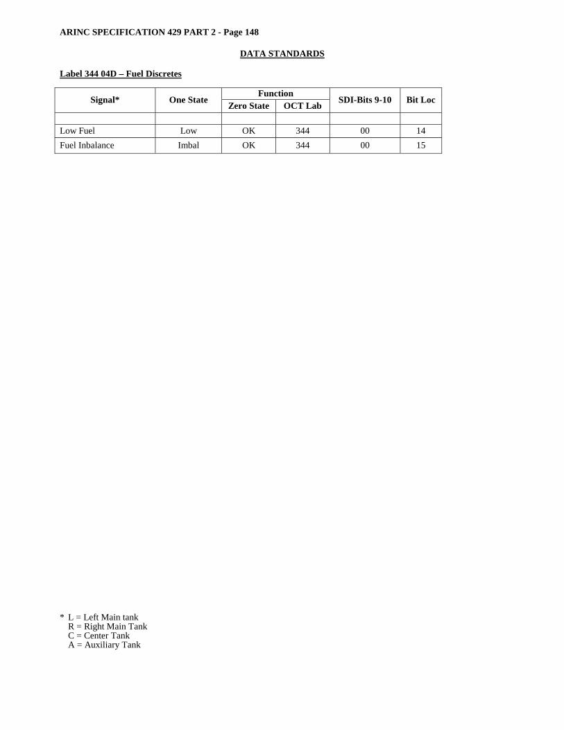
ARINC SPECIFICATION 429 PART 2 - Page 148
DATA STANDARDS
Label 344 04D – Fuel Discretes
Function Signal* One State Zero State OCT Lab SDI-Bits 9-10 Bit Loc
Low Fuel Low OK 344 00 14 Fuel Inbalance Imbal OK 344 00 15 * L = Left Main tank R = Right Main Tank C = Center Tank A = Auxiliary Tank
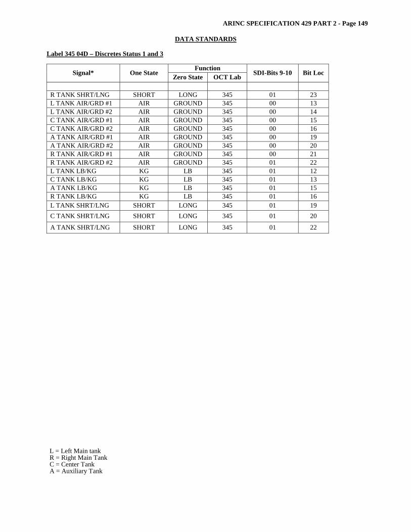
ARINC SPECIFICATION 429 PART 2 - Page 149
DATA STANDARDS Label 345 04D – Discretes Status 1 and 3
Function Signal* One State Zero State OCT Lab SDI-Bits 9-10 Bit Loc
R TANK SHRT/LNG SHORT LONG 345 01 23 L TANK AIR/GRD #1 AIR GROUND 345 00 13 L TANK AIR/GRD #2 AIR GROUND 345 00 14 C TANK AIR/GRD #1 AIR GROUND 345 00 15 C TANK AIR/GRD #2 AIR GROUND 345 00 16 A TANK AIR/GRD #1 AIR GROUND 345 00 19 A TANK AIR/GRD #2 AIR GROUND 345 00 20 R TANK AIR/GRD #1 AIR GROUND 345 00 21 R TANK AIR/GRD #2 AIR GROUND 345 01 22 L TANK LB/KG KG LB 345 01 12 C TANK LB/KG KG LB 345 01 13 A TANK LB/KG KG LB 345 01 15 R TANK LB/KG KG LB 345 01 16 L TANK SHRT/LNG SHORT LONG 345 01 19 C TANK SHRT/LNG SHORT LONG 345 01 20
A TANK SHRT/LNG SHORT LONG 345 01 22 L = Left Main tank R = Right Main Tank C = Center Tank A = Auxiliary Tank
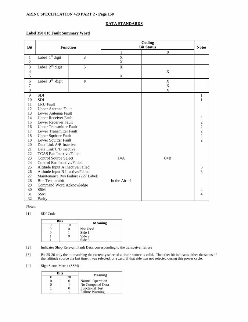
ARINC SPECIFICATION 429 PART 2 - Page 150
DATA STANDARDS
Label 350 018 Fault Summary Word
Coding Bit Status Bit Function
1 0 Notes
1 Label 1st digit 3 X 2 X 3 Label 2nd digit 5 X 4 X 5 X 6 Label 3rd digit 0 X 7 X 8 X 9 SDI 1
10 SDI 1 11 LRU Fault 12 Upper Antenna Fault 13 Lower Antenna Fault 14 Upper Receiver Fault 2 15 Lower Receiver Fault 2 16 Upper Transmitter Fault 2 17 Lower Transmitter Fault 2 18 Upper Squitter Fault 2 19 Lower Squitter Fault 2 20 Data Link A/B Inactive 21 Data Link C/D inactive 22 TCAS Bus Inactive/Failed 23 Control Source Select 1=A 0=B 24 Control Bus Inactive/Failed 25 Altitude Input A Inactive/Failed 3 26 Altitude Input B Inactive/Failed 3 27 Maintenance Bus Failure (227 Label) 28 Bite Test inhibit In the Air =1 29 Command Word Acknowledge 30 SSM 4 31 SSM 4 32 Parity
Notes: [1] SDI Code
Bits 9 10 Meaning 0 0 Not Used 0 1 Side 1 1 0 Side 2 1 1 Side 3
[2] Indicates Shop Relevant Fault Data, corresponding to the transceiver failure [3] Bit 25-26 only the bit matching the currently selected altitude source is valid. The other bit indicates either the status of
that altitude source the last time it was selected, or a zero, if that side was not selected during this power cycle. [4] Sign Status Matrix (SSM)
Bits 31 30 Meaning 0 0 Normal Operation 0 1 No Computed Data 1 0 Functional Test 1 1 Failure Warning

ARINC SPECIFICATION 429 PART 2 - Page 151
DATA STANDARDS Label 350 01A - EEC Discrete Bit Function Coding
Bit Status Notes
1 0 1 Label 1st digit 3 X 2 X 3 Label 2nd digit 5 X 4 X 5 X 6 Label 3rd digit 0 X 7 X 8 X 9 SDI X
10 SDI X 11 Pad X 12 Pad X 13 Pad X 14 Pad 15 Connector J2 Not Inst. Inst. 16 Connector J5 Not Inst. Inst. 17 T2 Probe Failed Good 18 EGT Assy. Failed Good 19 TLA Resol. Failed Good 20 RPX Failed Good 21 A Chan SDD In Failed Good 22 B Chan SDD In Failed Good 23 Coil Failed Good 24 Stg I Valve Malfunction Good 25 P2 Leak Leak Good 26 System Trim Required Good 27 TCA-A Valve Malfunction Good 28 TCA-B Valve Malfunction Good 29 Spare 30 SSM X 31 SSM X 32 Parity (Odd)
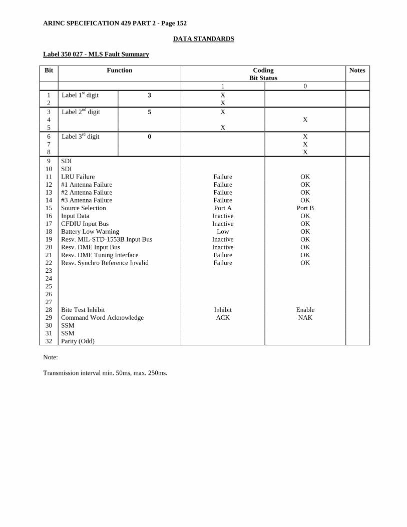
ARINC SPECIFICATION 429 PART 2 - Page 152
DATA STANDARDS
Label 350 027 - MLS Fault Summary Bit Function Coding
Bit Status Notes
1 0 1 Label 1st digit 3 X 2 X 3 Label 2nd digit 5 X 4 X 5 X 6 Label 3rd digit 0 X 7 X 8 X 9 SDI
10 SDI 11 LRU Failure Failure OK 12 #1 Antenna Failure Failure OK 13 #2 Antenna Failure Failure OK 14 #3 Antenna Failure Failure OK 15 Source Selection Port A Port B 16 Input Data Inactive OK 17 CFDIU Input Bus Inactive OK 18 Battery Low Warning Low OK 19 Resv. MIL-STD-1553B Input Bus Inactive OK 20 Resv. DME Input Bus Inactive OK 21 Resv. DME Tuning Interface Failure OK 22 Resv. Synchro Reference Invalid Failure OK 23 24 25 26 27 28 Bite Test Inhibit Inhibit Enable 29 Command Word Acknowledge ACK NAK 30 SSM 31 SSM 32 Parity (Odd)
Note: Transmission interval min. 50ms, max. 250ms.
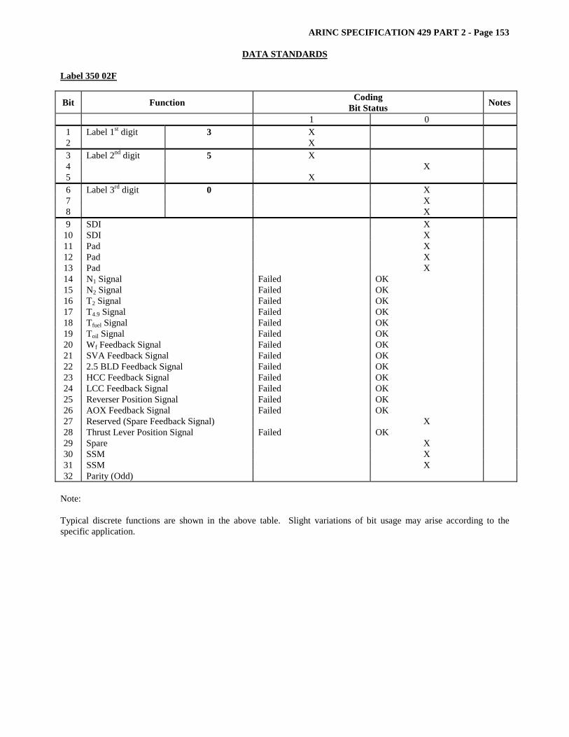
ARINC SPECIFICATION 429 PART 2 - Page 153
DATA STANDARDS Label 350 02F
Bit Function Coding Bit Status Notes
1 0 1 Label 1st digit 3 X 2 X 3 Label 2nd digit 5 X 4 X 5 X 6 Label 3rd digit 0 X 7 X 8 X 9 SDI X
10 SDI X 11 Pad X 12 Pad X 13 Pad X 14 N1 Signal Failed OK 15 N2 Signal Failed OK 16 T2 Signal Failed OK 17 T4.9 Signal Failed OK 18 Tfuel Signal Failed OK 19 Toil Signal Failed OK 20 Wf Feedback Signal Failed OK 21 SVA Feedback Signal Failed OK 22 2.5 BLD Feedback Signal Failed OK 23 HCC Feedback Signal Failed OK 24 LCC Feedback Signal Failed OK 25 Reverser Position Signal Failed OK 26 AOX Feedback Signal Failed OK 27 Reserved (Spare Feedback Signal) X 28 Thrust Lever Position Signal Failed OK 29 Spare X 30 SSM X 31 SSM X 32 Parity (Odd)
Note: Typical discrete functions are shown in the above table. Slight variations of bit usage may arise according to the specific application.
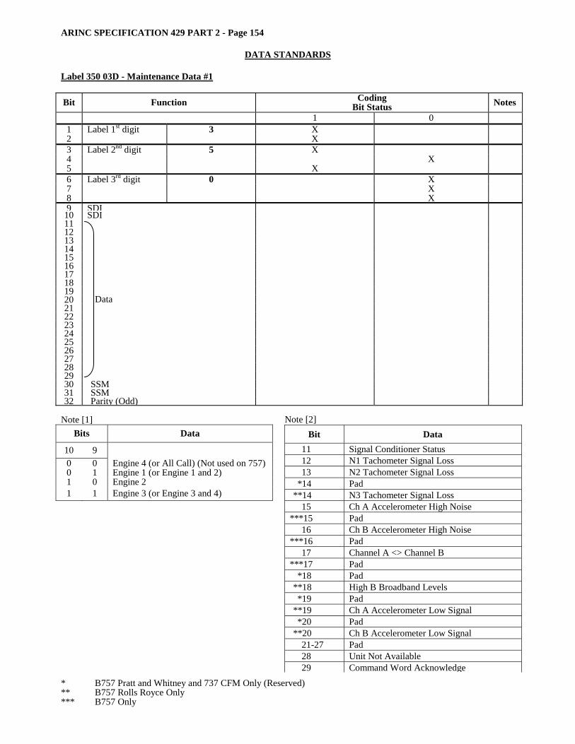
ARINC SPECIFICATION 429 PART 2 - Page 154
DATA STANDARDS
Label 350 03D - Maintenance Data #1 Bit Function Coding
Bit Status Notes 1 0
1 Label 1st digit 3 X 2 X 3 Label 2nd digit 5 X 4 X 5 X 6 Label 3rd digit 0 X 7 X 8 X 9 SDI
10 SDI 11 12 13 14 15 16 17 18 19 20 21 22 23 24 25 26 27 28 29
Data
30 SSM 31 SSM 32 Parity (Odd)
Note [1]
Bits Data
10 9 0 0 Engine 4 (or All Call) (Not used on 757) 0 1 Engine 1 (or Engine 1 and 2) 1 0 Engine 2 1 1 Engine 3 (or Engine 3 and 4)
* B757 Pratt and Whitney and 737 CFM Only (Reserved) ** B757 Rolls Royce Only *** B757 Only
Note [2] Bit Data
11 Signal Conditioner Status 12 N1 Tachometer Signal Loss 13 N2 Tachometer Signal Loss
*14 Pad **14 N3 Tachometer Signal Loss
15 Ch A Accelerometer High Noise ***15 Pad
16 Ch B Accelerometer High Noise ***16 Pad
17 Channel A <> Channel B ***17 Pad
*18 Pad **18 High B Broadband Levels *19 Pad
**19 Ch A Accelerometer Low Signal *20 Pad
**20 Ch B Accelerometer Low Signal 21-27 Pad 28 Unit Not Available 29 Command Word Acknowledge

ARINC SPECIFICATION 429 PART 2 - Page 155
DATA STANDARDS Label 350 03F
Bit Function Coding Bit Status Notes
1 0 1 Label 1st digit 3 X 2 X 3 Label 2nd digit 5 X 4 X 5 X 6 Label 3rd digit 0 X 7 X 8 X 9 SDI X
10 SDI X 11 Pad X 12 Pad X 13 Pad X 14 N1 Signal Failed OK 15 N2 Signal Failed OK 16 T2 Signal Failed OK 17 T4.9 Signal Failed OK 18 Tfuel Signal Failed OK 19 Toil Signal Failed OK 20 Wf Feedback Signal Failed OK 21 SVA Feedback Signal Failed OK 22 2.5 BLD Feedback Signal Failed OK 23 HCC Feedback Signal Failed OK 24 LCC Feedback Signal Failed OK 25 Reverser Position Signal Failed OK 26 AOX Feedback Signal Failed OK 27 Reserved (Spare Feedback Signal) X 28 Thrust Lever Position Signal Failed OK 29 Spare X 30 SSM X 31 SSM X 32 Parity (Odd)
Note: Typical discrete functions are shown in the above table. Slight variations of bit usage may arise according to the specific application.

ARINC SPECIFICATION 429 PART 2 - Page 156
DATA STANDARDS
Label 350 04D – Maintenance Data FQIS 1-3
Function Signal* One State Zero State OCT Lab SDI-Bits 9-10 Bit Loc
I/O Board Status Failed OK 350 00 11 L-Air/Grd Disc Failed OK 350 00 14 C-Air/Grd Disc Failed OK 350 00 15 A-Air/Grd Disc Failed OK 350 00 17 R-Air/Grd Disc Failed OK 350 00 18 IOC Air/Grd I/P Failed OK 350 00 22 IOC DIS Driver Failed OK 350 00 23 LD SEL Cable Fail Failed OK .350 00 24 Any Blanking Fail Blank OK 350 00 28 Any FQIS Failure Failure OK 350 00 29 Shrt/Lng Dis Jumper Failed OK 350 01 11 L Tnk Shrt/Lng Dis Failed OK 350 01 14 C Tnk Shrt/Lng Dis Failed OK 350 01 15 A Tnk Shrt/Lng Dis Failed OK 350 01 17 R Tnk Shrt/Lng Dis Failed OK 350 01 18 Lbs/Kgs Dis Jumper Failed OK 350 10 11 L-Lbs/Kgs Disc Failed OK 350 10 14 C-Lbs/Kgs Disc Failed OK 350 10 15 A-Lbs/Kgs Disc Failed OK 350 10 17 R-Lbs/Kgs Disc Failed OK 350 10 18 Bus To EICAS Fail Failed OK 350 11 27
L = Left Main Tank R = Right Main Tank C = Center Tank A = Auxiliary Tank
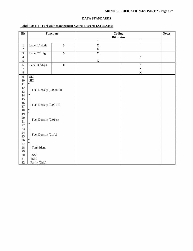
ARINC SPECIFICATION 429 PART 2 - Page 157
DATA STANDARDS Label 350 114 - Fuel Unit Management System Discrete (A330/A340) Bit Function Coding
Bit Status Notes
1 0 1 Label 1st digit 3 X 2 X 3 Label 2nd digit 5 X 4 X 5 X 6 Label 3rd digit 0 X 7 X 8 X 9 SDI
10 SDI 11 12 13 14
Fuel Density (0.0001’s)
15 16 17 18
Fuel Density (0.001’s)
19 20 21 22
Fuel Density (0.01’s)
23 24 25 26
Fuel Density (0.1’s)
27 28 29
Tank Ident
30 SSM 31 SSM 32 Parity (Odd)

ARINC SPECIFICATION 429 PART 2 - Page 158
DATA STANDARDS
Label 350 - 115 - TACAN Discrete
Coding Bit Status Bit Function
1 0 Notes
1 Label 1st digit X 2 3 X 3 Label 2nd digit X 4 X 5
5 X
6 Label 3rd digit X 7 X 8
0 X
9 10 11 12 13 14 15 16
LSB AGC (x 1/256 Full Scale) MSB
17 CPU Failed OK 18 RAM Failed OK 19 ROM Failed OK 20 2 Port RAM Failed OK 21 2 Port DATA Failed OK 22 NOVRAM Failed OK 23 Synthesizer Failed OK 24 Receiver Failed OK 25 Power Supply Failed OK 26 Xmit Power Failed OK 27 Audio Failed OK 28 Power Up Failed OK 29 Suppression Present Not Present 30 D/A Failed OK 31 TACAN Fail Failed OK 32 Parity (Odd)
Note: Bits 21 through 28 indicate self test status information.
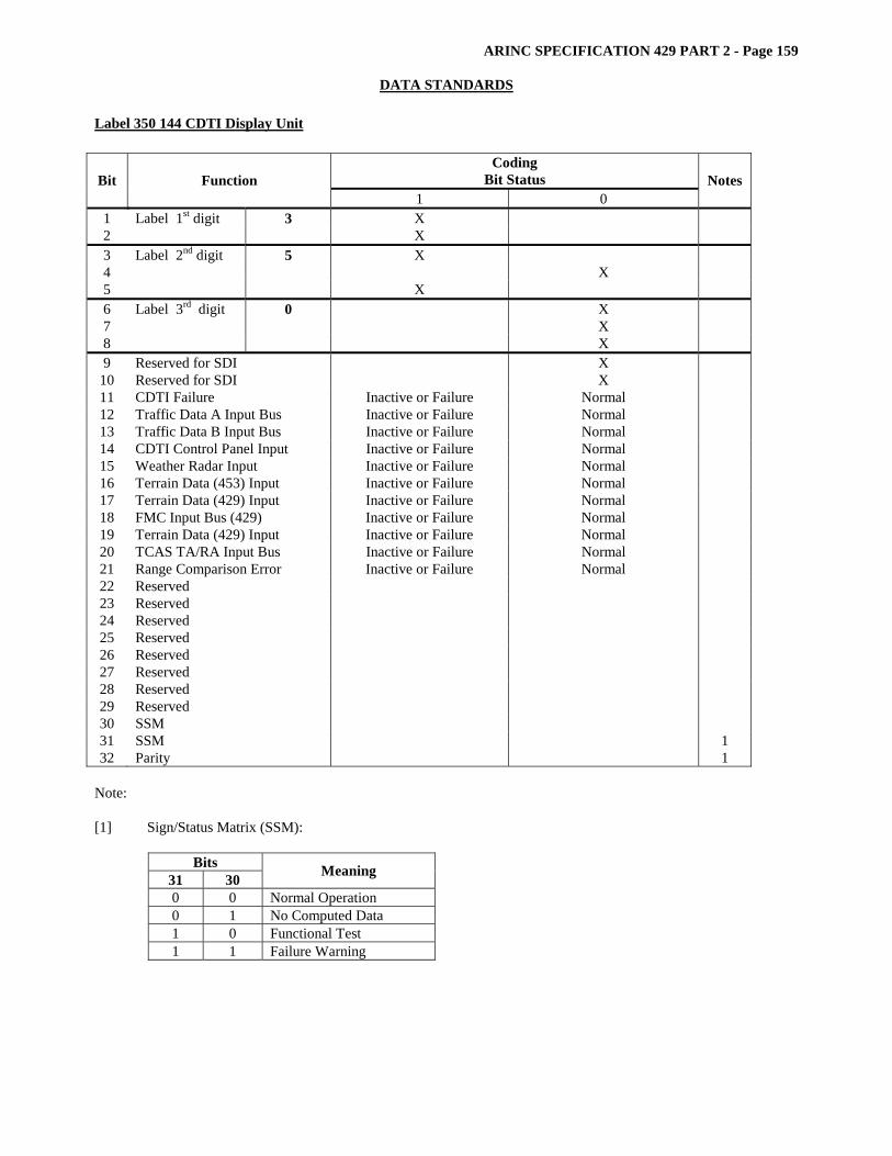
ARINC SPECIFICATION 429 PART 2 - Page 159
DATA STANDARDS Label 350 144 CDTI Display Unit
Coding Bit Status Bit Function
1 0 Notes
1 Label 1st digit 3 X 2 X 3 Label 2nd digit 5 X 4 X 5 X 6 Label 3rd digit 0 X 7 X 8 X 9 Reserved for SDI X
10 Reserved for SDI X 11 CDTI Failure Inactive or Failure Normal 12 Traffic Data A Input Bus Inactive or Failure Normal 13 Traffic Data B Input Bus Inactive or Failure Normal 14 CDTI Control Panel Input Inactive or Failure Normal 15 Weather Radar Input Inactive or Failure Normal 16 Terrain Data (453) Input Inactive or Failure Normal 17 Terrain Data (429) Input Inactive or Failure Normal 18 FMC Input Bus (429) Inactive or Failure Normal 19 Terrain Data (429) Input Inactive or Failure Normal 20 TCAS TA/RA Input Bus Inactive or Failure Normal 21 Range Comparison Error Inactive or Failure Normal 22 Reserved 23 Reserved 24 Reserved 25 Reserved 26 Reserved 27 Reserved 28 Reserved 29 Reserved 30 SSM 31 SSM 1 32 Parity 1
Note: [1] Sign/Status Matrix (SSM):
Bits 31 30 Meaning
0 0 Normal Operation 0 1 No Computed Data 1 0 Functional Test 1 1 Failure Warning

ARINC SPECIFICATION 429 PART 2 - Page 160
DATA STANDARDS
Label 351 01A - EEC Discrete
Coding Bit Status Bit Function
1 0 Notes
1 Label 1st digit X 2 3 3 Label 2nd digit X 4 X 5
5 X
6 Label 3rd digit X 7 X 8
1 X
9 SDI 10 SDI 11 Pad X 12 Pad X 13 Pad X 14 Pad X 15 ARINC Transmitter Fail Good 16 RPX Drift Fail Good 17 RPX Test Fail Good 18 TLA Correl Test Fail Good 19 Resolver Test Fail Good 20 Resolver Drift Fail Good 21 Angle Range Check Fail Good 22 Sine Range Check Fail Good 23 Spare X 24 LLDC Test #1 Fail Good 25 LLDC Drift #1 Fail Good 26 P2 Range Check (Boeing Only) Fail Good 27 P2 Range Check Fail Good 28 P7 Range Check Fail Good 29 EPR Range Check Fail Good 30 SSM 31 SSM 32 Parity (Odd)
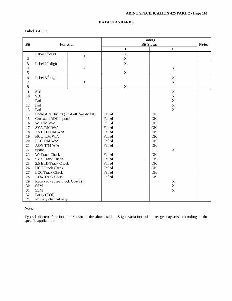
ARINC SPECIFICATION 429 PART 2 - Page 161
DATA STANDARDS Label 351 02F
Coding Bit Status Bit Function
1 0 Notes
1 Label 1st digit X 2 3 X 3 Label 2nd digit X 4 X 5
5 X
6 Label 3rd digit X 7 X 8
1 X
9 SDI X 10 SDI X 11 Pad X 12 Pad X 13 Pad X 14 Local ADC Inputs (Pri-Left, Sec-Right) Failed OK 15 Crosstalk ADC Inputs* Failed OK 16 Wf T/M W/A Failed OK 17 SVA T/M W/A Failed OK 18 2.5 BLD T/M W/A Failed OK 19 HCC T/M W/A Failed OK 20 LCC T/M W/A Failed OK 21 AOX T/M W/A Failed OK 22 Spare X 23 Wf Track Check Failed OK 24 SVA Track Check Failed OK 25 2.5 BLD Track Check Failed OK 26 HCC Track Check Failed OK 27 LCC Track Check Failed OK 28 AOX Track Check Failed OK 29 Reserved (Spare Track Check) X 30 SSM X 31 SSM X 32 Parity (Odd) * Primary channel only.
Note: Typical discrete functions are shown in the above table. Slight variations of bit usage may arise according to the specific application.
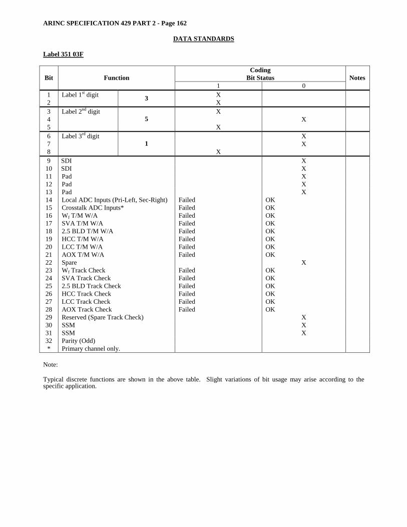
ARINC SPECIFICATION 429 PART 2 - Page 162
DATA STANDARDS
Label 351 03F
Coding Bit Status Bit Function
1 0 Notes
1 Label 1st digit X 2 3 X 3 Label 2nd digit X 4 X 5
5 X
6 Label 3rd digit X 7 X 8
1 X
9 SDI X 10 SDI X 11 Pad X 12 Pad X 13 Pad X 14 Local ADC Inputs (Pri-Left, Sec-Right) Failed OK 15 Crosstalk ADC Inputs* Failed OK 16 Wf T/M W/A Failed OK 17 SVA T/M W/A Failed OK 18 2.5 BLD T/M W/A Failed OK 19 HCC T/M W/A Failed OK 20 LCC T/M W/A Failed OK 21 AOX T/M W/A Failed OK 22 Spare X 23 Wf Track Check Failed OK 24 SVA Track Check Failed OK 25 2.5 BLD Track Check Failed OK 26 HCC Track Check Failed OK 27 LCC Track Check Failed OK 28 AOX Track Check Failed OK 29 Reserved (Spare Track Check) X 30 SSM X 31 SSM X 32 Parity (Odd) * Primary channel only.
Note: Typical discrete functions are shown in the above table. Slight variations of bit usage may arise according to the specific application.
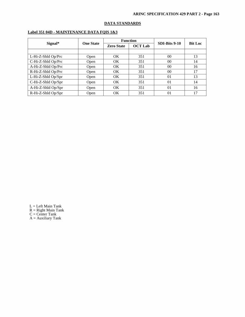
ARINC SPECIFICATION 429 PART 2 - Page 163
DATA STANDARDS Label 351 04D - MAINTENANCE DATA FQIS 1&3
Function Signal* One State Zero State OCT Lab SDI-Bits 9-10 Bit Loc
L-Hi-Z-Shld Op/Prc Open OK 351 00 13 C-Hi-Z-Shld Op/Prc Open OK 351 00 14 A-Hi-Z-Shld Op/Prc Open OK 351 00 16 R-Hi-Z-Shld Op/Prc Open OK 351 00 17 L-Hi-Z-Shld Op/Spr Open OK 351 01 13 C-Hi-Z-Shld Op/Spr Open OK 351 01 14 A-Hi-Z-Shld Op/Spr Open OK 351 01 16 R-Hi-Z-Shld Op/Spr Open OK 351 01 17
L = Left Main Tank R = Right Main Tank C = Center Tank A = Auxiliary Tank

ARINC SPECIFICATION 429 PART 2 - Page 164
DATA STANDARDS
Label 351 114 - Fuel Unit Management System Discrete (A330/A340)
Coding Bit Status Bit Function
1 0 Notes
1 Label 1st digit X 2 3 X 3 Label 2nd digit X 4 X 5
5 X
6 Label 3rd digit X 7 X 8
1 X
9 SDI 10 SDI 11 12 13 14
Probe Capacitance (0.1’s)
15 16 17 18
Probe Capacitance (1’s)
19 20 21 22
Probe Capacitance (10’s)
23 Probe Capacitance (100’s) 24 25 26 27
Probe Number (1’s)
28 29 Probe Number (10’s) 30 SSM 31 SSM 32 Parity (Odd)
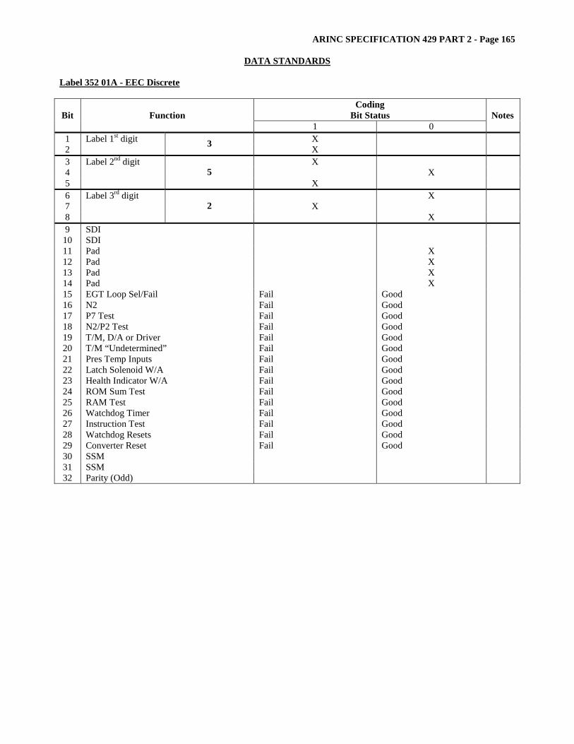
ARINC SPECIFICATION 429 PART 2 - Page 165
DATA STANDARDS Label 352 01A - EEC Discrete
Coding Bit Status Bit Function
1 0 Notes
1 Label 1st digit X 2 3 X 3 Label 2nd digit X 4 X 5
5 X
6 Label 3rd digit X 7 X 8
2 X
9 SDI 10 SDI 11 Pad X 12 Pad X 13 Pad X 14 Pad X 15 EGT Loop Sel/Fail Fail Good 16 N2 Fail Good 17 P7 Test Fail Good 18 N2/P2 Test Fail Good 19 T/M, D/A or Driver Fail Good 20 T/M “Undetermined” Fail Good 21 Pres Temp Inputs Fail Good 22 Latch Solenoid W/A Fail Good 23 Health Indicator W/A Fail Good 24 ROM Sum Test Fail Good 25 RAM Test Fail Good 26 Watchdog Timer Fail Good 27 Instruction Test Fail Good 28 Watchdog Resets Fail Good 29 Converter Reset Fail Good 30 SSM 31 SSM 32 Parity (Odd)
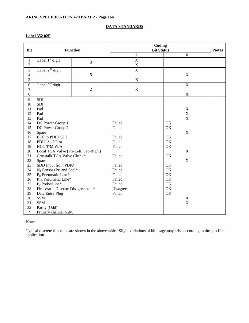
ARINC SPECIFICATION 429 PART 2 - Page 166
DATA STANDARDS
Label 352 02F
Coding Bit Status Bit Function
1 0 Notes
1 Label 1st digit X 2 3 X 3 Label 2nd digit X 4 X 5
5 X
6 Label 3rd digit X 7 X 8
2 X
9 SDI 10 SDI 11 Pad X 12 Pad X 13 Pad X 14 DC Power Group 1 Failed OK 15 DC Power Group 2 Failed OK 16 Spare X 17 EEC to PDIU SDD Failed OK 18 PDIU Self Test Failed OK 19 HCC T/M W/A Failed OK 20 Local TCA Valve (Pri-Left, Sec-Right) X 21 Crosstalk TCA Valve Check* Failed OK 22 Spare X 23 SDD Input from PDIU Failed OK 24 N1 Sensor (Pri and Sec)* Failed OK 25 PB Pneumatic Line* Failed OK 26 P4.9 Pneumatic Line* Failed OK 27 P2 Probe/Line* Failed OK 28 Fire Warn. Discrete Disagreement* Disagree OK 29 Data Entry Plug Failed OK 30 SSM X 31 SSM X 32 Parity (Odd) * Primary channel only.
Note: Typical discrete functions are shown in the above table. Slight variations of bit usage may arise according to the specific application.

ARINC SPECIFICATION 429 PART 2 - Page 167
DATA STANDARDS Label 352 03F
Coding Bit Status Bit Function
1 0 Notes
1 Label 1st digit X 2 3 X 3 Label 2nd digit X 4 X 5
5 X
6 Label 3rd digit X 7 X 8
2 X
9 SDI 10 SDI 11 Pad X 12 Pad X 13 Pad X 14 DC Power Group 1 Failed OK 15 DC Power Group 2 Failed OK 16 Spare X 17 EEC to PDIU SDD Failed OK 18 PDIU Self Test Failed OK 19 HCC T/M W/A Failed OK 20 Local TCA Valve (Pri-Left, Sec-Right) X 21 Crosstalk TCA Valve Check* Failed OK 22 Spare X 23 SDD Input from PDIU Failed OK 24 N1 Sensor (Pri and Sec)* Failed OK 25 PB Pneumatic Line* Failed OK 26 P4.9 Pneumatic Line* Failed OK 27 P2 Probe/Line* Failed OK 28 Fire Warn. Discrete Disagreement* Disagree OK 29 Data Entry Plug Failed OK 30 SSM X 31 SSM X 32 Parity (Odd) * Primary channel only.
Note: Typical discrete functions are shown in the above table. Slight variations of bit usage may arise according to the specific application.
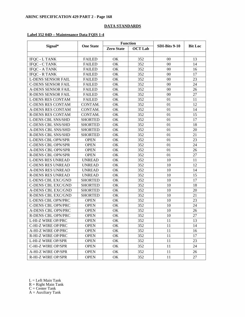
ARINC SPECIFICATION 429 PART 2 - Page 168
DATA STANDARDS
Label 352 04D – Maintenance Data FQIS 1-4
Function Signal* One State Zero State OCT Lab SDI-Bits 9-10 Bit Loc
IFQC - L TANK FAILED OK 352 00 13 IFQC - C TANK FAILED OK 352 00 14 IFQC - A TANK FAILED OK 352 00 16 IFQC - R TANK FAILED OK 352 00 17 L-DENS SENSOR FAIL FAILED OK 352 00 23 C-DENS SENSOR FAIL FAILED OK 352 00 24 A-DENS SENSOR FAIL FAILED OK 352 00 26 R-DENS SENSOR FAIL FAILED OK 352 00 27 L-DENS RES CONTAM FAILED OK 352 01 11 C-DENS RES CONTAM CONTAM. OK 352 01 12 A-DENS RES CONTAM CONTAM. OK 352 01 14 R-DENS RES CONTAM CONTAM. OK 352 01 15 L-DENS CBL SNS/SHD SHORTED OK 352 01 17 C-DENS CBL SNS/SHD SHORTED OK 352 01 18 A-DENS CBL SNS/SHD SHORTED OK 352 01 20 R-DENS CBL SNS/SHD SHORTED OK 352 01 21 L-DENS CBL OPN/SPR OPEN OK 352 01 23 C-DENS CBL OPN/SPR OPEN OK 352 01 24 A-DENS CBL OPN/SPR OPEN OK 352 01 26 R-DENS CBL OPN/SPR OPEN OK 352 01 27 L-DENS RES UNREAD UNREAD OK 352 10 11 C-DENS RES UNREAD UNREAD OK 352 10 12 A-DENS RES UNREAD UNREAD OK 352 10 14 R-DENS RES UNREAD UNREAD OK 352 10 15 L-DENS CBL EXC/GND SHORTED OK 352 10 17 C-DENS CBL EXC/GND SHORTED OK 352 10 18 A-DENS CBL EXC/GND SHORTED OK 352 10 20 R-DENS CBL EXC/GND SHORTED OK 352 10 21 L-DENS CBL OPN/PRC OPEN OK 352 10 23 C-DENS CBL OPN/PRC OPEN OK 352 10 24 A-DENS CBL OPN/PRC OPEN OK 352 10 26 R-DENS CBL OPN/PRC OPEN OK 352 10 27 L-HI-Z WIRE OP/PRC OPEN OK 352 11 13 C-HI-Z WIRE OP/PRC OPEN OK 352 11 14 A-HI-Z WIRE OP/PRC OPEN OK 352 11 16 R-HI-Z WIRE OP/PRC OPEN OK 352 11 17 L-HI-Z WIRE OP/SPR OPEN OK 352 11 23 C-HI-Z WIRE OP/SPR OPEN OK 352 11 24 A-HI-Z WIRE OP/SPR OPEN OK 352 11 26 R-HI-Z WIRE OP/SPR OPEN OK 352 11 27
L = Left Main Tank R = Right Main Tank C = Center Tank A = Auxiliary Tank
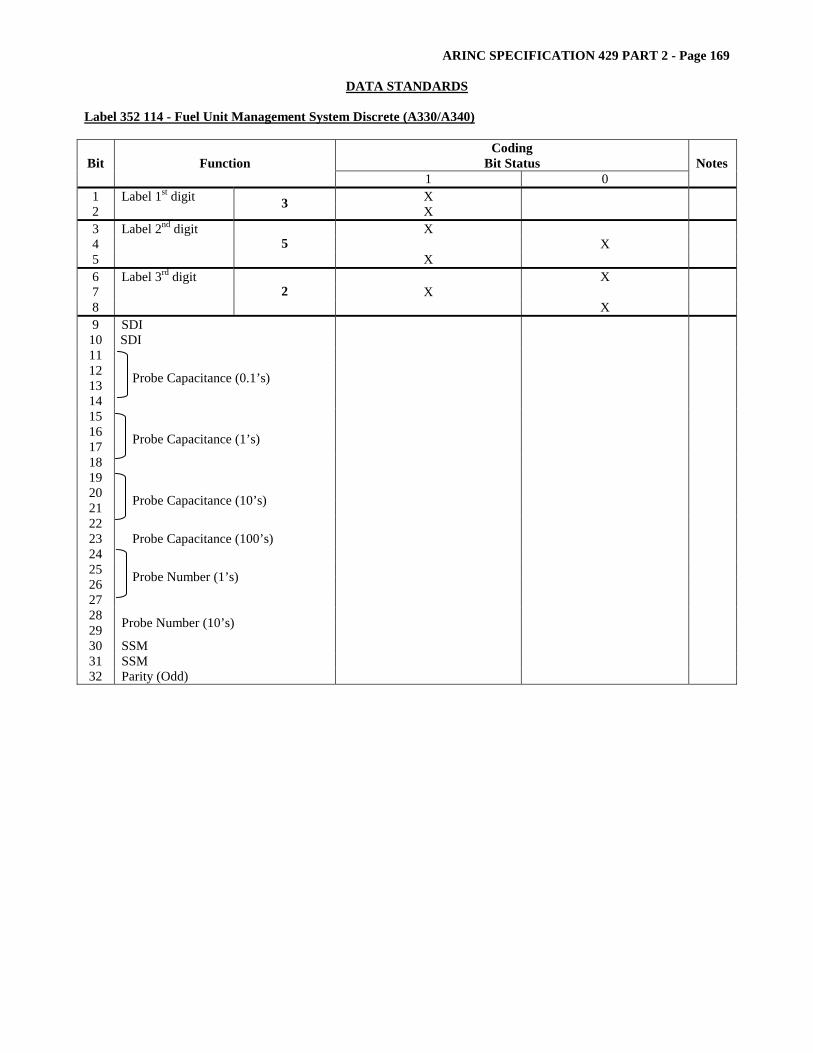
ARINC SPECIFICATION 429 PART 2 - Page 169
DATA STANDARDS Label 352 114 - Fuel Unit Management System Discrete (A330/A340)
Coding Bit Status Bit Function
1 0 Notes
1 Label 1st digit X 2 3 X 3 Label 2nd digit X 4 X 5
5 X
6 Label 3rd digit X 7 X 8
2 X
9 SDI 10 SDI 11 12 13 14
Probe Capacitance (0.1’s)
15 16 17 18
Probe Capacitance (1’s)
19 20 21 22
Probe Capacitance (10’s)
23 Probe Capacitance (100’s) 24 25 26 27
Probe Number (1’s)
28 29 Probe Number (10’s) 30 SSM 31 SSM 32 Parity (Odd)

ARINC SPECIFICATION 429 PART 2 - Page 170
DATA STANDARDS
Label 353 01A - EEC Discrete
Coding Bit Status Bit Function
1 0 Notes
1 Label 1st digit X 2 3 X 3 Label 2nd digit X 4 X 5
5 X
6 Label 3rd digit X 7 X 8
3 X
9 SDI 10 SDI 11 Pad X 12 Pad X 13 Pad X 14 Pad X 15 Spare X 16 EGT Loop Disabled Yes No 17 Synth Altitude Yes No 18 Synth Mach Number Yes No 19 SDD ‘A’ W/A Failure Good 20 ADD ‘B’ W/A Failure Good 21 Probe Heat (Boeing 767 Only) Disagreement Normal 22 Pressure Accuracy Degraded Normal 23 T/M Coil Yes No 24 TCC Schedule (Airbus Default Normal 25 Acft Pt Used 310,000 Yes No 26 P2 Range Check Only) Failed Good 27 TCA System Failed Good 28 TCC System Failed Good 29 System Trim Required OKay 30 SSM 31 SSM 32 Parity (Odd)
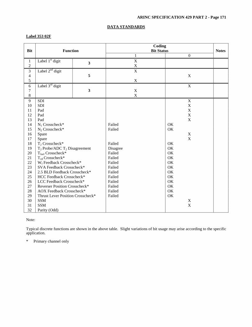
ARINC SPECIFICATION 429 PART 2 - Page 171
DATA STANDARDS Label 353 02F
Coding Bit Status Bit Function
1 0 Notes
1 Label 1st digit X 2 3 X 3 Label 2nd digit X 4 X 5
5 X
6 Label 3rd digit X 7 X 8
3 X
9 SDI X 10 SDI X 11 Pad X 12 Pad X 13 Pad X 14 N1 Crosscheck* Failed OK 15 N2 Crosscheck* Failed OK 16 Spare X 17 Spare X 18 T2 Crosscheck* Failed OK 19 T2 Probe/ADC T2 Disagreement Disagree OK 20 Tfuel Crosscheck* Failed OK 21 Toil Crosscheck* Failed OK 22 Wf Feedback Crosscheck* Failed OK 23 SVA Feedback Crosscheck* Failed OK 24 2.5 BLD Feedback Crosscheck* Failed OK 25 HCC Feedback Crosscheck* Failed OK 26 LCC Feedback Crosscheck* Failed OK 27 Reverser Position Crosscheck* Failed OK 28 AOX Feedback Crosscheck* Failed OK 29 Thrust Lever Position Crosscheck* Failed OK 30 SSM X 31 SSM X 32 Parity (Odd)
Note: Typical discrete functions are shown in the above table. Slight variations of bit usage may arise according to the specific application. * Primary channel only

ARINC SPECIFICATION 429 PART 2 - Page 172
DATA STANDARDS
Label 353 03D - Maintenance Data #4 Highest Vibration
Coding Bit Status Bit Function
1 0 Notes
1 Label 1st digit X 2 3 X 3 Label 2nd digit X 4 X 5
5 X
6 Label 3rd digit X 7 X 8
3 X
9 SDI 1 10 SDI 1 11 2 12 Accelerometer Source 2 13 X 14 X 15 X 16 X 17
PADS
X 18 3, 4, 5 19 Data ID 3, 4, 5 20 6 21 6 22 6 23 6 24 6 25 6 26 6 27 6 28
Data
6 29 SSM 7 30 SSM 7 31 SSM 7 32 Parity (Odd)
Note [1] SDI
Bits Data 10 9 0 0 Engine 4 0 1 Engine 1 1 0 Engine 2 1 1 Engine 3
Note [3] *Data ID
Bits Data 19 18 0 0 N1 Vibration (Label 354) 0 1 N2 Vibration (Label 355) 1 0 N3 Vibration (Label 356) 1 1 BB Vibration (Label 357)
Note [2] Accelerometer Source Bits Data
12 11 0 0 No Channel in command 0 1 Channel A 1 0 Channel B
Note [4] *B737 Data ID Bits Data
19 18 0 0 CN1 Vibration (Label 354) 0 1 CN2 Vibration (Label 355) 1 0 TN1 Vibration (Label 356) 1 1 TN2 Vibration (Label 357)

ARINC SPECIFICATION 429 PART 2 - Page 173
DATA STANDARDS Label 353 03D - Maintenance Data #4 Highest Vibration (cont’d) Note [5] *B757 Data ID
Bits Data 19 18 0 0 BB Vibration (Label 357) 0 1 N1 Vibration (Label 354) 1 0 N1 Vibration (Label 355) 1 1 N3 Vibration (Label 356)**
** Used on B757 Rolls Royce Engines only Note [6] Data Bit 28 27 26 25 24 23 22 21 20 MSB< >LSB Bit Encoding for Vibration Labels: Bits = 9 Resolution = 0.01 Range = 0 to 5.12 Units = Scalar Units Note [7] SSM
Bits Data 31 30 29 1 0 0 Self Test 1 1 0 Normal Operation

ARINC SPECIFICATION 429 PART 2 - Page 174
DATA STANDARDS
Label 353 03F
Coding Bit Status Bit Function
1 0 Notes
1 Label 1st digit X 2 3 X 3 Label 2nd digit X 4 X 5
5 X
6 Label 3rd digit X 7 X 8
3 X
9 SDI X 10 SDI X 11 Pad X 12 Pad X 13 Pad X 14 N1 Crosscheck* Failed OK 15 N2 Crosscheck* Failed OK 16 Spare X 17 Spare X 18 T2 Crosscheck* Failed OK 19 T2 Probe/ADC T2 Disagreement Disagree OK 20 Tfuel Crosscheck* Failed OK 21 Toil Crosscheck* Failed OK 22 Wf Feedback Crosscheck* Failed OK 23 SVA Feedback Crosscheck* Failed OK 24 2.5 BLD Feedback Crosscheck* Failed OK 25 HCC Feedback Crosscheck* Failed OK 26 LCC Feedback Crosscheck* Failed OK 27 Reverser Position Crosscheck* Failed OK 28 AOX Feedback Crosscheck* Failed OK 29 Thrust Lever Position Crosscheck* Failed OK 30 SSM X 31 SSM X 32 Parity (Odd)
Note: Typical discrete functions are shown in the above table. Slight variations of bit usage may arise according to the specific application. * Primary channel only
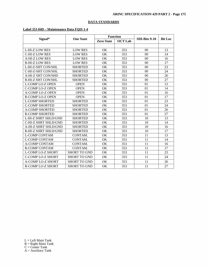
ARINC SPECIFICATION 429 PART 2 - Page 175
DATA STANDARDS Label 353 04D – Maintenance Data FQIS 1-4
Function Signal* One State Zero State OCT Lab SDI-Bits 9-10 Bit Loc
L-HI-Z LOW RES LOW RES OK 353 00 13 C-HI-Z LOW RES LOW RES OK 353 00 14 A-HI-Z LOW RES LOW RES OK 353 00 16 R-HI-Z LOW RES LOW RES OK 353 00 17 L-HI-Z-SHT CON/SHL SHORTED OK 353 00 23 C-HI-Z-SHT CON/SHL SHORTED OK 353 00 24 A-HI-Z SHT CON/SHD SHORTED OK 353 00 26 R-HI-Z SHT CON/SHL SHORTED OK 353 00 27 L-COMP LO-Z OPEN OPEN OK 353 01 13 C-COMP LO-Z OPEN OPEN OK 353 01 14 A-COMP LO-Z OPEN OPEN OK 353 01 16 R-COMP LO-Z OPEN OPEN OK 353 01 17 L-COMP SHORTED SHORTED OK 353 01 23 C-COMP SHORTED SHORTED OK 353 01 24 A-COMP SHORTED SHORTED OK 353 01 26 R-COMP SHORTED SHORTED OK 353 01 27 L-HI-Z SHRT SHLD/GND SHORTED OK 353 10 13 C-HI-Z SHRT SHLD/GND SHORTED OK 353 10 14 A-HI-Z SHRT SHLD/GND SHORTED OK 353 10 16 R-HI-Z SHRT SHLD/GND SHORTED OK 353 10 17 L-COMP CONTAM CONTAM. OK 353 11 13 C-COMP CONTAM CONTAM. OK 353 11 14 A-COMP CONTAM CONTAM. OK 353 11 16 R-COMP CONTAM CONTAM. OK 353 11 17 L-COMP LO-Z SHORT SHORT TO GND OK 353 11 23 C-COMP LO-Z SHORT SHORT TO GND OK 353 11 24 A-COMP LO-Z SHORT SHORT TO GND OK 353 11 26 R-COMP LO-Z SHORT SHORT TO GND OK 353 11 27
L = Left Main Tank R = Right Main Tank C = Center Tank A = Auxiliary Tank
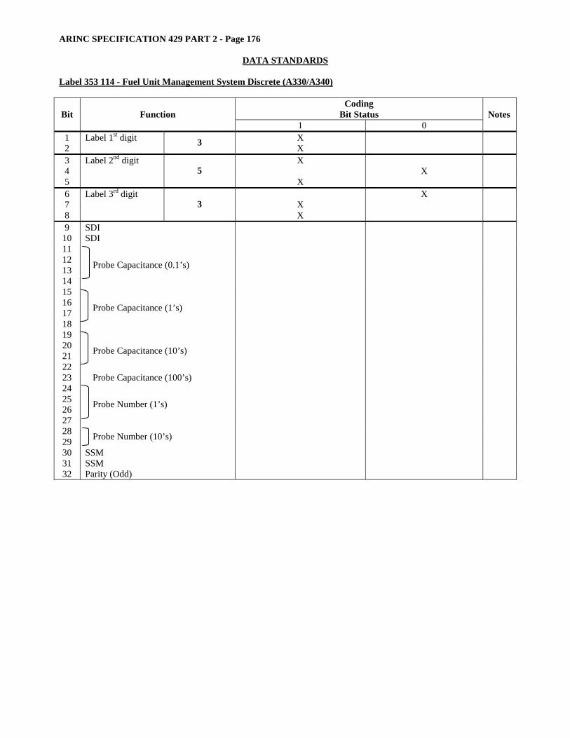
ARINC SPECIFICATION 429 PART 2 - Page 176
DATA STANDARDS
Label 353 114 - Fuel Unit Management System Discrete (A330/A340)
Coding Bit Status Bit Function
1 0 Notes
1 Label 1st digit X 2 3 X 3 Label 2nd digit X 4 X 5
5 X
6 Label 3rd digit X 7 X 8
3 X
9 SDI 10 SDI 11 12 13 14
Probe Capacitance (0.1’s)
15 16 17 18
Probe Capacitance (1’s)
19 20 21 22
Probe Capacitance (10’s)
23 Probe Capacitance (100’s) 24 25 26 27
Probe Number (1’s)
28 29 Probe Number (10’s) 30 SSM 31 SSM 32 Parity (Odd)
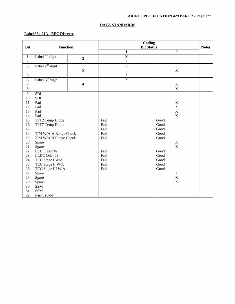
ARINC SPECIFICATION 429 PART 2 - Page 177
DATA STANDARDS Label 354 01A - EEC Discrete
Coding Bit Status Bit Function
1 0 Notes
1 Label 1st digit X 2 3 X 3 Label 2nd digit X 4 X 5
5 X
6 Label 3rd digit X 7 X 8
4 X
9 SDI 10 SDI 11 Pad X 12 Pad X 13 Pad X 14 Pad X 15 TPT2 Temp Diode Fail Good 16 TPT7 Temp Diode Fail Good 17 Fail Good 18 T/M W/A’A Range Check Fail Good 19 T/M W/A’B Range Check Fail Good 20 Spare X 21 Spare X 22 LLDC Test #2 Fail Good 23 LLDC Drift #2 Fail Good 24 TCC Stage I W/A Fail Good 25 TCC Stage II W/A Fail Good 26 TCC Stage III W/A Fail Good 27 Spare X 28 Spare X 29 Spare X 30 SSM 31 SSM 32 Parity (Odd)

ARINC SPECIFICATION 429 PART 2 - Page 178
DATA STANDARDS
Label 354 02F
Coding Bit Status Bit Function
1 0 Notes
1 Label 1st digit X 2 3 X 3 Label 2nd digit X 4 X 5
5 X
6 Label 3rd digit X 7 X 8
4 X
9 SDI X 10 SDI X 11 Pad X 12 Pad X 13 Pad X 14 REV Command Solenoid W/A Failed OK 15 TCA Solenoid W/A Failed OK 16 Reserved (Spare Solenoid W/A) X 17 Reserved (Spare Solenoid W/A) X 18 Reserved (Spare Relay W/A) X 19 14th Stage Bleed T/M W/A Failed OK 20 Spare X 21 Reserved (Spare Solenoid W/A) X 22 Oil Bypass Solenoid W/A Failed OK 23 Reserved (Spare Relay W/A) X 24 T/L Interlock Relay W/A Failed OK 25 Reserved (Spare Relay W/A) X 26 Spare X 27 Group 1 Overcurrent Sense Tripped OK 28 Group 2 Overcurrent Sense Tripped OK 29 Spare X 30 SSM X 31 SSM X 32 Parity (Odd)
Note: Typical discrete functions are shown in the above table. Slight variations of bit usage may arise according to the specific application.
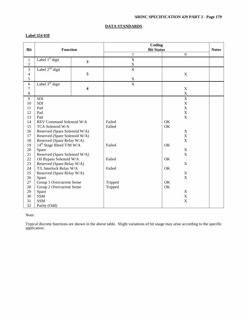
ARINC SPECIFICATION 429 PART 2 - Page 179
DATA STANDARDS Label 354 03F
Coding Bit Status Bit Function
1 0 Notes
1 Label 1st digit X 2 3 X 3 Label 2nd digit X 4 X 5
5 X
6 Label 3rd digit X 7 X 8
4 X
9 SDI X 10 SDI X 11 Pad X 12 Pad X 13 Pad X 14 REV Command Solenoid W/A Failed OK 15 TCA Solenoid W/A Failed OK 16 Reserved (Spare Solenoid W/A) X 17 Reserved (Spare Solenoid W/A) X 18 Reserved (Spare Relay W/A) X 19 14th Stage Bleed T/M W/A Failed OK 20 Spare X 21 Reserved (Spare Solenoid W/A) X 22 Oil Bypass Solenoid W/A Failed OK 23 Reserved (Spare Relay W/A) X 24 T/L Interlock Relay W/A Failed OK 25 Reserved (Spare Relay W/A) X 26 Spare X 27 Group 1 Overcurrent Sense Tripped OK 28 Group 2 Overcurrent Sense Tripped OK 29 Spare X 30 SSM X 31 SSM X 32 Parity (Odd)
Note: Typical discrete functions are shown in the above table. Slight variations of bit usage may arise according to the specific application.
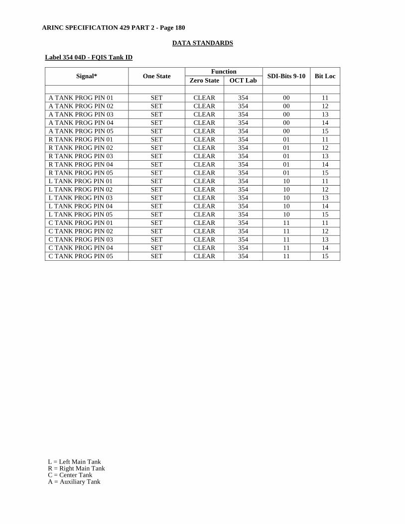
ARINC SPECIFICATION 429 PART 2 - Page 180
DATA STANDARDS
Label 354 04D - FQIS Tank ID
Function Signal* One State Zero State OCT Lab SDI-Bits 9-10 Bit Loc
A TANK PROG PIN 01 SET CLEAR 354 00 11 A TANK PROG PIN 02 SET CLEAR 354 00 12 A TANK PROG PIN 03 SET CLEAR 354 00 13 A TANK PROG PIN 04 SET CLEAR 354 00 14 A TANK PROG PIN 05 SET CLEAR 354 00 15 R TANK PROG PIN 01 SET CLEAR 354 01 11 R TANK PROG PIN 02 SET CLEAR 354 01 12 R TANK PROG PIN 03 SET CLEAR 354 01 13 R TANK PROG PIN 04 SET CLEAR 354 01 14 R TANK PROG PIN 05 SET CLEAR 354 01 15 L TANK PROG PIN 01 SET CLEAR 354 10 11 L TANK PROG PIN 02 SET CLEAR 354 10 12 L TANK PROG PIN 03 SET CLEAR 354 10 13 L TANK PROG PIN 04 SET CLEAR 354 10 14 L TANK PROG PIN 05 SET CLEAR 354 10 15 C TANK PROG PIN 01 SET CLEAR 354 11 11 C TANK PROG PIN 02 SET CLEAR 354 11 12 C TANK PROG PIN 03 SET CLEAR 354 11 13 C TANK PROG PIN 04 SET CLEAR 354 11 14 C TANK PROG PIN 05 SET CLEAR 354 11 15
L = Left Main Tank R = Right Main Tank C = Center Tank A = Auxiliary Tank
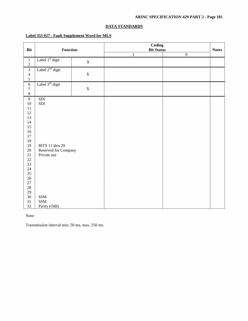
ARINC SPECIFICATION 429 PART 2 - Page 181
DATA STANDARDS Label 355 027 - Fault Supplement Word for MLS
Coding Bit Status Bit Function
1 0 Notes
1 Label 1st digit 2 3 3 Label 2nd digit 4 5
5
6 Label 3rd digit 7 8
5
9 SDI 10 SDI 11 12 13 14 15 16 17 18 19 20 21 22 23 24 25 26 27 28 29
BITS 11 thru 29 Reserved for Company Private use
30 SSM 31 SSM 32 Parity (Odd)
Note: Transmission interval min. 50 ms, max. 250 ms.
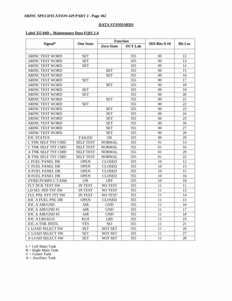
ARINC SPECIFICATION 429 PART 2 - Page 182
DATA STANDARDS
Label 355 04D – Maintenance Data FQIS 2-4
Function Signal* One State Zero State OCT Lab SDI-Bits 9-10 Bit Loc
ARINC TEST WORD SET 355 00 12 ARINC TEST WORD SET 355 00 13 ARINC TEST WORD SET 355 00 14 ARINC TEST WORD SET 355 00 15 ARINC TEST WORD SET 355 00 16 ARINC TEST WORD SET 355 00 17 ARINC TEST WORD SET 355 00 18 ARINC TEST WORD SET 355 00 19 ARINC TEST WORD SET 355 00 20 ARINC TEST WORD SET 355 00 21 ARINC TEST WORD SET 355 00 22 ARINC TEST WORD SET 355 00 23 ARINC TEST WORD SET 355 00 24 ARINC TEST WORD SET 355 00 25 ARINC TEST WORD SET 355 00 26 ARINC TEST WORD SET 355 00 27 ARINC TEST WORD SET 355 00 28 IOC STATUS FAILED OK 355 00 29 L TNK SELF TST CMD SELF TEST NORMAL 355 01 14 C TNK SELF TST CMD SELF TEST NORMAL 355 01 16 A TNK SELF TST CMD SELF TEST NORMAL 355 01 20 R TNK SELF TST CMD SELF TEST NORMAL 355 01 22 L FUEL PANEL DR OPEN CLOSED 355 10 12 C FUEL PANEL DR OPEN CLOSED 355 10 13 A FUEL PANEL DR OPEN CLOSED 355 10 15 R FUEL PANEL DR OPEN CLOSED 355 10 16 OVRD PUMPS C-TANK ON OFF 355 10 18 FLT DCK TEST SW IN TEST NO TEST 355 11 11 LD SEL IND TST SW IN TEST NO TEST 355 11 13 FUL PNL SYS TST SW IN TEST NO TEST 355 11 14 IOC A FUEL PNL DR OPEN CLOSED 355 11 15 IOC A AIR/GND AIR GND 355 11 16 IOC A AIR/GND #1 AIR GND 355 11 17 IOC A AIR/GND #2 AIR GND 355 11 18 IOC A LBS/KGS KGS LBS 355 11 19 IOC A TNK INSTL YES NO 355 11 21 L LOAD SELECT SW SET NOT SET 355 11 26 C LOAD SELECT SW SET NOT SET 355 11 27 A LOAD SELECT SW SET NOT SET 355 11 28
L = Left Main Tank R = Right Main Tank C = Center Tank A = Auxiliary Tank
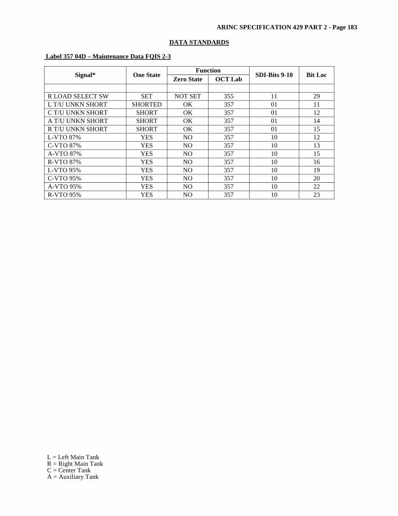
ARINC SPECIFICATION 429 PART 2 - Page 183
DATA STANDARDS Label 357 04D – Maintenance Data FQIS 2-3
Function Signal* One State Zero State OCT Lab SDI-Bits 9-10 Bit Loc
R LOAD SELECT SW SET NOT SET 355 11 29 L T/U UNKN SHORT SHORTED OK 357 01 11 C T/U UNKN SHORT SHORT OK 357 01 12 A T/U UNKN SHORT SHORT OK 357 01 14 R T/U UNKN SHORT SHORT OK 357 01 15 L-VTO 87% YES NO 357 10 12 C-VTO 87% YES NO 357 10 13 A-VTO 87% YES NO 357 10 15 R-VTO 87% YES NO 357 10 16 L-VTO 95% YES NO 357 10 19 C-VTO 95% YES NO 357 10 20 A-VTO 95% YES NO 357 10 22 R-VTO 95% YES NO 357 10 23
L = Left Main Tank R = Right Main Tank C = Center Tank A = Auxiliary Tank

ARINC SPECIFICATION 429 PART 2 - Page 184
DATA STANDARDS
Label 360 03D - N1 Rotor Imbalance Angle
Coding Bit Status Bit Function
1 0 Notes
1 Label 1st digit X 2 3 X 3 Label 2nd digit X 4 X 5
6 X
6 Label 3rd digit X 7 X 8
0 X
9 SDI 1 10 SDI 1 11 2 12 Accelerometer Source 2 13 X 14 X 15 X 16 X 17 X 18 X 19
Pads
20 3 21 3 22 3 23 3 24 3 25 3 26 3 27 3 28
Data
3 29 X 4 30 X 4 31
SSM (Normal Operation) X 4
32 Parity (Odd) Note [1] SDI
Bits Data 10 9 0 0 Engine 4 0 1 Engine 1 1 0 Engine 2 1 1 Engine 3
Note [3] Data Bit 28 27 26 25 24 23 22 21 20 MSB< >LSB Bit Encoding for Vibration Labels Bits = 9 Resolution = 1.0 Range = 0 to 360 Units = Degrees
Note [2] Accelerometer Source Bits Data
12 11 0 0 No Channel in command 0 1 Channel A 1 0 Channel B
Note [4] SSM Bits Data
31 30 29 1 0 0 Functional Test 0 1 0 No Computed Data 1 1 0 Normal Operation 0 0 0 Failure Warning
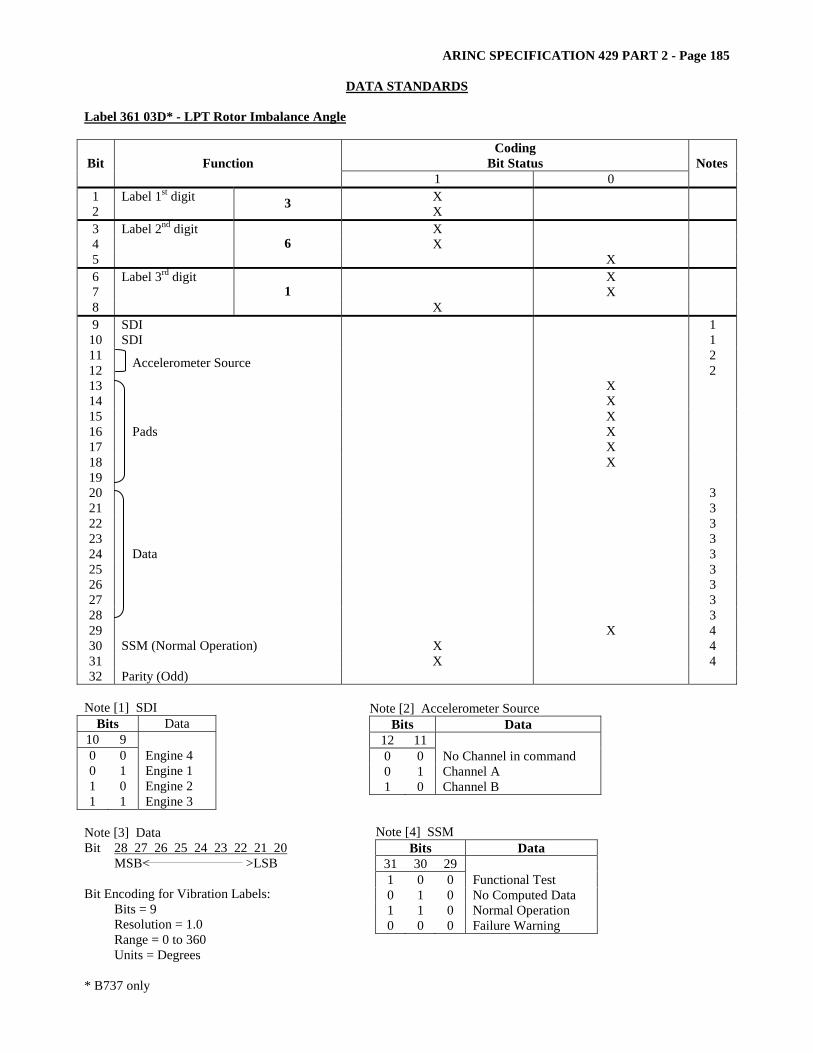
ARINC SPECIFICATION 429 PART 2 - Page 185
DATA STANDARDS Label 361 03D* - LPT Rotor Imbalance Angle
Coding Bit Status Bit Function
1 0 Notes
1 Label 1st digit X 2 3 X 3 Label 2nd digit X 4 X 5
6 X
6 Label 3rd digit X 7 X 8
1 X
9 SDI 1 10 SDI 1 11 2 12 Accelerometer Source 2 13 X 14 X 15 X 16 X 17 X 18 X 19
Pads
20 3 21 3 22 3 23 3 24 3 25 3 26 3 27 3 28
Data
3 29 X 4 30 X 4 31
SSM (Normal Operation) X 4
32 Parity (Odd) Note [1] SDI
Bits Data 10 9 0 0 Engine 4 0 1 Engine 1 1 0 Engine 2 1 1 Engine 3
Note [3] Data Bit 28 27 26 25 24 23 22 21 20 MSB< >LSB Bit Encoding for Vibration Labels: Bits = 9 Resolution = 1.0 Range = 0 to 360 Units = Degrees * B737 only
Note [2] Accelerometer Source Bits Data
12 11 0 0 No Channel in command 0 1 Channel A 1 0 Channel B
Note [4] SSM Bits Data
31 30 29 1 0 0 Functional Test 0 1 0 No Computed Data 1 1 0 Normal Operation 0 0 0 Failure Warning
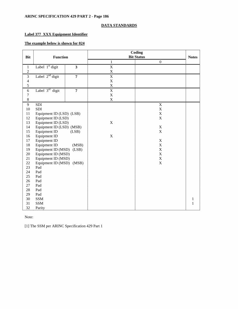
ARINC SPECIFICATION 429 PART 2 - Page 186
DATA STANDARDS
Label 377 XXX Equipment Identifier The example below is shown for 024
Coding Bit Status Bit Function
1 0 Notes
1 Label 1st digit 3 X 2 X 3 Label 2nd digit 7 X 4 X 5 X 6 Label 3rd digit 7 X 7 X 8 X 9 SDI X
10 SDI X 11 Equipment ID (LSD) (LSB) X 12 Equipment ID (LSD) X 13 Equipment ID (LSD) X 14 Equipment ID (LSD) (MSB) X 15 Equipment ID (LSB) X 16 Equipment ID X 17 Equipment ID X 18 Equipment ID (MSB) X 19 Equipment ID (MSD) (LSB) X 20 Equipment ID (MSD) X 21 Equipment ID (MSD) X 22 Equipment ID (MSD) (MSB) X 23 Pad 24 Pad 25 Pad 26 Pad 27 Pad 28 Pad 29 Pad 30 SSM 1 31 SSM 1 32 Parity
Note: [1] The SSM per ARINC Specification 429 Part 1
AERONAUTICAL RADIO, INC. 2551 Riva Road
Annapolis, Maryland 21401-7465
SUPPLEMENT 16
TO
ARINC SPECIFICATION 429
MARK 33 DIGITAL INFORMATION TRANSFER SYSTEM (DITS)
PART 2
DISCRETE WORD DATA STANDARDS
Published: December 17, 2004
Prepared by the Airlines Electronic Engineering Committee
Adopted by the Airlines Electronic Engineering Committee: October 27, 2004

SUPPLEMENT 16 TO ARINC SPECIFICATION 429 PART 2 – Page a A. PURPOSE OF THIS DOCUMENT This supplement introduces new discrete label assignments. B. ORGANIZATION OF THIS SUPPLEMENT The revision material introduced by this supplement, described in Part C, was integrated into the body of this specification to form an updated version of the standard. C. CHANGES TO ARINC SPECIFICATION 429 PART 2 INTRODUCED BY THIS SUPPLEMENT This section presents a complete tabulation of the changes, additions, and deletions to this ARINC Specification introduced by Supplement 16. Each change is identified by at least two elements: • the section number and title currently employed in specification prior to the incorporation of the change • a brief description of the change. 1.1.1 Relationship to Other Documents New section added. Data Standards The following discrete labels were added by Supplement 16:
Octal EQ ID Octal EQ ID 140 114 214 xxx 141 114 216 xxx 142 114 270 114 143 114 270 142 144 114 270 144 145 114 271 114 146 114 271 142 147 114 271 144 150 114 272 114 151 114 272 144 152 114 273 114 153 114 274 114 154 114 275 114 155 114 276 114 160 114 277 114 161 114 350 018 162 114 350 144 163 114 377 xxx 164 114

ARINC Project Initiation/Modification 12/22/04
15_APIM-VerJ.doc Page 1
ARINC IA Project Initiation/Modification (APIM) Guidelines for Submittal
1. ARINC Industry Activities Projects and Work Program A project is established in order to accomplish a technical task approved by one or more of the committees (AEEC, AMC, FSEMC) Projects generally but not exclusively result in a new ARINC standard or modify an existing ARINC standard. All projects are typically approved on a calendar year basis. Any project extending beyond a single year will be reviewed annually before being re-authorized. The work program of Industry Activities (IA) consists of all projects authorized by AEEC, AMC, or FSEMC (The Committees) for the current calendar year.
The Committees establish a project after consideration of an ARINC Project Initiation/Modification (APIM) request. This document includes a template which has provisions for all of the information required by The Committees to determine the relative priority of the project in relation to the entire work program.
All recommendations to the committees to establish or reauthorize a project, whether originated by an airline or from the industry, should be prepared using the APIM template. Any field that cannot be filled in by the originator may be left blank for subsequent action.
2. Normal APIM Evaluation Process Initiation of an APIM
All proposed projects must be formally initiated by filling in the APIM template. An APIM may be initiated by anyone in the airline community, e.g., airline, vendor, committee staff.
Staff Support
All proposed APIMs will be processed by committee staff. Each proposal will be numbered, logged, and evaluated for completeness. Proposals may be edited to present a style consistent with the committee evaluation process. For example, narrative sentences may be changed to bullet items, etc. When an APIM is complete, it will be forwarded to the appropriate Committee for evaluation.
The committee staff will track all ongoing projects and prepare annual reports on progress.
Committee Evaluation and Acceptance or Rejection
The annual work program for each Committee is normally established at its annual meeting. Additional work tasks may be evaluated at other meetings held during the year. Each committee (i.e., AMC, AEEC, FSEMC) has its own schedule of annual and interim meetings.

ARINC Project Initiation/Modification 12/22/04
15_APIM-VerJ.doc Page 2
The committee staff will endeavor to process APIMs and present them to the appropriate Committee at its next available meeting. The Committee will then evaluate the proposal. Evaluation criteria will include:
• Airline support – number and strength of airline support for the project, including whether or not an airline chairman has been identified
• Issues – what technical, programmatic, or competitive issues are addressed by the project, what problem will be solved
• Schedule – what regulatory, aircraft development or modification, airline equipment upgrade, or other projected events drive the urgency for this project
Accepted proposals will be assigned to a subcommittee for action with one of two priorities:
• High Priority – technical solution needed as rapidly as possible • Routine Priority – technical solution to proceed at a normal pace
Proposals may have designated coordination with other groups. This means that the final work must be coordinated with the designated group(s) prior to submittal for adoption consideration.
Proposals that are not accepted may be classified as follows: • Deferred for later consideration - the project is not deemed of sufficient
urgency to be placed on the current calendar of activities but will be reconsidered at a later date
• Deferred to a subcommittee for refinement – the subcommittee will be requested to, for example, gain stronger airline support or resolve architectural issues
• Rejected – the proposal is not seen as being appropriate, e.g., out of scope of the committee
3. APIM Template The following is an annotated outline for the APIM. Proposal initiators are requested to fill in all fields as completely as possible, replacing the italicized explanations in each section with information as available. Fields that cannot be completed may be left blank. When using the Word file version of the following template, update the header and footer to identify the project.
ARINC Project Initiation/Modification 12/22/04
15_APIM-VerJ.doc Page 3
ARINC IA Project Initiation/Modification (APIM)
Name of proposed project APIM #: _____
Name for proposed project. Suggested Subcommittee assignment Identify an existing group that has the expertise to successfully complete the project. If no such group is known to exist, a recommendation to form a new group may be made. Project Scope
Describe the scope of the project clearly and concisely. The scope should describe “what” will be done, i.e., the technical boundaries of the project. Example: “This project will standardize a protocol for the control of printers. The protocol will be independent of the underlying data stream or page description language but will be usable by all classes of printers.”
Project Benefit
Describe the purpose and benefit of the project. This section should describe “why” the project should be done. Describe how the new standard will improve competition among vendors, giving airlines freedom of choice. This section provides justification for the allocation of both IA and airline resources. Example: “Currently each class of printers implements its own proprietary protocol for the transfer of a print job. In order to provide access to the cockpit printer from several different avionics sources, a single protocol is needed. The protocol will permit automatic determination of printer type and configuration to provide for growth and product differentiation.”
Airlines supporting effort
Name, airline, and contact information for proposed chairman, lead airline, list of airlines expressing interest in working on the project (supporting airlines), and list of airlines expressing interest but unable to support (sponsoring airlines). It is important for airline support to be gained prior to submittal. Other organizations, such as airframe manufacturers, avionics vendors, etc. supporting the effort should also be listed.
Issues to be worked
Describe the major issues to be addressed by the proposed ARINC standard.
Recommended Coordination with other groups Draft documents may have impact on the work of groups other than the originating group. The APIM writer or, subsequently, The Committee may identify other groups which must be given the opportunity to review and comment upon mature draft documents.

ARINC Project Initiation/Modification 12/22/04
15_APIM-VerJ.doc Page 4
Projects/programs supported by work
If the timetable for this work is driven by a new airplane type, major avionics overhaul, regulatory mandate, etc., that information should be placed in this section. This information is a key factor in assessing the priority of this proposed task against all other tasks competing for subcommittee meeting time and other resources.
Timetable for projects/programs
Identify when the new ARINC standard is needed (month/year).
Documents to be produced and date of expected result
The name and number (if already assigned) of the proposed ARINC standard to be either newly produced or modified.
Comments
Anything else deemed useful to the committees for prioritization of this work.
Meetings
The following table identifies the number of meetings and proposed meeting days needed to produce the documents described above.
Activity Mtgs Mtg-Days
Document a # of mtgs # of mtg days
Document b # of mtgs # of mtg days
For IA staff use Date Received___________ IA staff assigned: __________________________________ Potential impact: ____ (A. Safety B. Regulatory C. New aircraft/system D. Other) Forward to committee(s) (AEEC, AMC, FSEMC): _________ Date Forward:___________ Committee resolution: ____ (0. Withdrawn 1. Authorized 2. Deferred 3. More detail needed 4. Rejected) Assigned Priority: ____ Date of Resolution:___________________ A. – High (execute first) B. – Normal (may be deferred for A.) Assigned to SC/WG ________________________________________
ARINC Standard – Errata Report
1. Document Title ARINC Specification 429P2-16: Mark 33 Digital Information Transfer System (DITS), Part 2 – Discrete Word Data Standards, Published: November 8, 2004
2. Reference Page Number: Section Number: Date of Submission:
3. Error (Reproduce the material in error, as it appears in the standard.)
4. Recommended Correction (Reproduce the correction as it would appear in the corrected version of the material.)
5. Reason for Correction (State why the correction is necessary.)
6. Submitter (Optional) (Name, organization, contact information, e.g., phone, email address.) Note: Items 2-5 may be repeated for additional errata. All recommendations will be evaluated by the staff. Any substantive changes will require submission to the relevant subcommittee for incorporation into a subsequent supplement. Please return comments to fax +1 410-266-2047 or [email protected]