Embed Size (px)
Citation preview

1
Mark Neil - Microprocessor Course
Decoding and Using a 4x4 Keyboard
2
The Keyboard
Mark Neil - Microprocessor Course
8 lines corresponding to 4 rows and 4 columns
By Pressing a button youconnect one of the row
lines to one of the column lines.

3
The PCB of the Key-Board
Mark Neil - Microprocessor Course
The buttons simply connect one row with
one column!
From this picture youCan see that the keyboard is
all PASSIVE: NoICs no Transistors

4Decoding what key is pressedStep 1: Row
We can provide power to the four rows, and readout the data
We write 0 to all columns
In the example on the right (the 5 is pressed) we will see a 0 on row 2 and 1 on the rest of the rows
We then have to determine which column has been pressed
Mark Neil - Microprocessor Course
0 0 0 0
1011

5
Step 2:Reading the ColumnIf instead of providing power to the rows, we provide power to the columns we can determine which column has a key pressed
We write 0 to all the rows
In this case we will read 0 on column 1 and 1 on the other rows
Hence we know that the ‘5’ was pressed as row 2 and col 1 have a key pressed
Mark Neil - Microprocessor Course
000
0
01 1 1

6
Pull-up Resistors on ATmeag128 Ports
Mark Neil - Microprocessor Course
PORTx : OUTPUT Register
DDRx : Direction Reg.
PINx : INPUT (no Register)
each pin in PORTx is independent!
There are pull-up resistors present on-board. Which allow us to put power on the PORT pins. These need to be enabled by writing high levels to input pins.
7
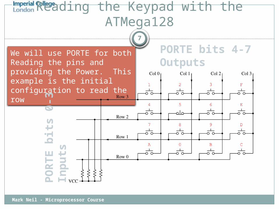
Reading the Keypad with the ATMega128
Mark Neil - Microprocessor Course
We will use PORTE for both Reading the pins and providing the Power. This example is the initial configuration to read the row
PORTE bits 4-7Outputs
PO
RTE b
its 0
-3
Inp
uts

8
Task Plan - Steps
Mark Neil - Microprocessor Course
Enable the pull-up resistors on bits 0-3 of PORTE and connect the 4 pins of the keyboard. Configure these pins as inputs, the 4 lines will be held high by the pull-up resistors.
Connect the rest of keyboard to pins 4-7 of PORTE and configure them as outputs.
Write a program that drives the output bits (4-7) of PORTE low all at once
read the 4 PORTE input pins (0-3). Determine which row has a key pressed
Now configure bits 0-3 as outputs and bits 4-7 as inputs Determine which column has a key pressed
Determine which key has been pressedEcho the PORTE input to PORTB to use the LEDs to do a
quick check of the keyboard. [also output to LCD.]

9
How to configure PORTE for Step 1
Mark Neil - Microprocessor Course
To configure PORTE 4-7 as outputs and PORTE 0-3 as inputs set DDRE:$F0
Set the PORT REGISTERS in such a way so that the inputs have pull up resistors and the outputs drive low set PORTE:$0F

10
Task
Mark Neil - Microprocessor Course
Write a routine that decodes the key on the 4x4 Keyboard and tells you what key was pressed on the LCD display
We need a reliable setup where the ATmega128 interprets relatively quickly any key pressed on the keyboard .
Notice that the microprocessor is faster than your finger and can ‘see’ the bouncing up and down that happens when you press the a button of the keyboard. Write a routine which reliably inputs a key press. Write a routine which reliably inputs a string of key presses