Embed Size (px)
Citation preview
The ENEXIO Selection Guide for Structured Packings and Liquid Distributors
MARKET LEADER FOR FUNCTIONAL SURFACESEFFICIENT SOLUTIONS FOR WATER AND AIR TREATMENT
[ 2 ]
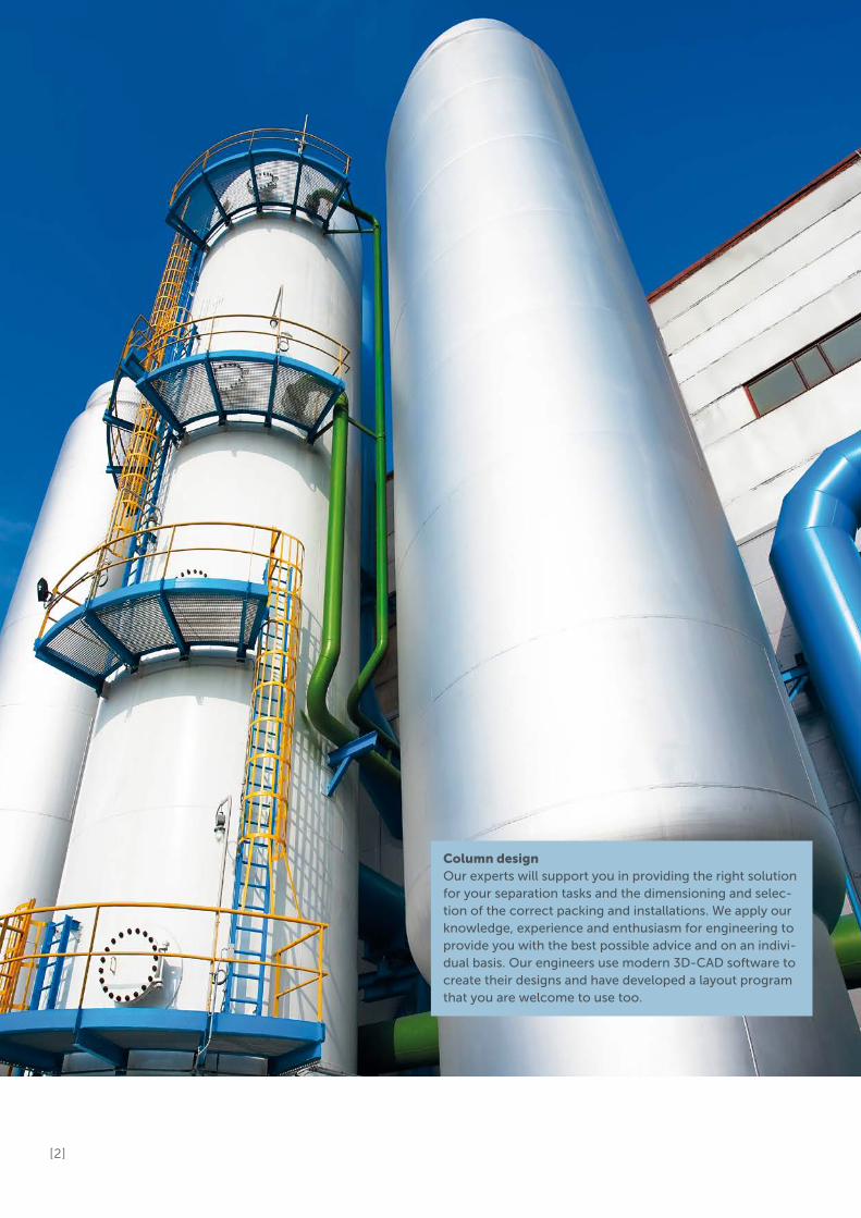
Column designOur experts will support you in providing the right solution for your separation tasks and the dimensioning and selec-tion of the correct packing and installations. We apply our knowledge, experience and enthusiasm for engineering to provide you with the best possible advice and on an indivi-dual basis. Our engineers use modern 3D-CAD software to create their designs and have developed a layout program that you are welcome to use too.

[ 3 ]
ENEXIO is a reflection of what we do and what we have accomplished as pioneer in the field
of industry-, process-, and power plant cooling, water and waste water treatment as well as
mass transfer over decades. At the same time, our name is a promise to our customers and
business partners – ENEXIO stands for Energy. Engineering. Excellence.
In Wettringen we develop and produce structured plastic packings for various areas of
application, including mass transfer. Our MASSdek® packings are used for air pollution
control, absorption and desorption and biological exhaust air treatment.
About ENEXIO
Structured packings can only make full use of their technical benefits compared with a
random packing when all installations and components have been precisely coordinated
with each other and adjusted to the appropriate process at the planning and basic
engineering stage. The aim must be to successfully and profitably solve the required
separation task.
At the beginning, it is only known which task is to be performed. The details required for
the process design and implementation are often only partially available. This is where
our experts are able to provide helpful support in the basic design and configuration of a
packing column. In addition to our support in the process engineering of the basic
design, we are also happy to review the overall concept which has already been drawn
up. We can offer tips and information regarding points at which the process could be op-
timised and what special types of packing and installation can be used most effectively.
For this the mechanical, hydraulic and separation process aspects in particular are taken
into account. Our experts will be happy to assist you with any questions you may have.
Many years of extensive experience in the engineering of structured plastic packings and
both plastic and metal installations make it possible for us to provide individual and
optimal advice to our customers in the dimensioning of the packing beds.
We calculate the main dimensions based on the data for ideal material systems and give
a guarantee for the column hydraulics based on these values. Our advice also includes
recommendations for the additional column installations, which are optimally coordina-
ted with the packings. Upon request, we will also take on the static inspection of con-
structional interfaces, such as on site support rings or supports.
We design and construct using the most up-to-date 3D CAD software. This enables
smooth communication with our customers right from the draft design stage. We are
also happy to provide you with our MASSdek® Pro design software.
Engineering and support from ENEXIO
This brochureis intended to assist you in the pre-selection of struc-tured packings and liquid distributors and to give you an initial overview. It is continuously expanded to include additional compo-nents and types.
[ 4 ]
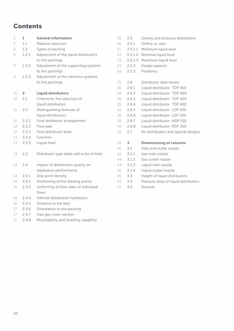
Contents
1 General information
1.1 Material selection
1.2 Types of packing
1.2.1 Adjustment of the liquid distributors
to the packings
1.2.2 Adjustment of the supporting systems
to the packings
1.2.3 Adjustment of the retention systems
to the packings
2 Liquid distributors
2.1 Criteria for the selection of
liquid distributors
2.2 Distinguishing features of
liquid distributors
2.2.1 Final distributor arrangement
2.2.2 Flow pad
2.2.3 Final distributor level
2.2.4 Function
2.2.5 Liquid feed
2.3 Distributor type table with a list of links
2.4 Impact of distribution quality on
separation performance
2.4.1 Drip point density
2.4.2 Positioning of the feeding points
2.4.3 Uniformity of flow rates of individual
flows
2.4.4 Internal distribution hydraulics
2.4.5 Distance to the bed
2.4.6 Orientation to the packing
2.4.7 Free gas cross-section
2.4.8 Mountability and levelling capability
5
5
6
9
9
9
10
10
11
11
12
12
13
13
13
13
14
14
16
16
16
17
17
17
2.5 Gravity and pressure distributors
2.5.1 Orifice vs. weir
2.5.1.1 Minimum liquid level
2.5.1.2 Nominal liquid level
2.5.1.3 Maximum liquid level
2.5.2 Design aspects
2.5.3 Problems
2.6 Distributor data sheets
2.6.1 Liquid distributor TDP 410
2.6.2 Liquid distributor TDP 400
2.6.3 Liquid distributor TDP 420
2.6.4 Liquid distributor TDP 430
2.6.5 Liquid distributor LDP 200
2.6.6 Liquid distributor LDP 220
2.6.7 Liquid distributor NDP 310
2.6.8 Liquid distributor PDP 350
2.7 Re-distributors and special designs
3 Dimensioning of columns
3.1 Inlet and outlet nozzle
3.1.1 Gas inlet nozzle
3.1.2 Gas outlet nozzle
3.1.3 Liquid inlet nozzle
3.1.4 Liquid outlet nozzle
3.2 Height of liquid distributors
3.3 Pressure drop of liquid distributors
3.4 Sources
18
20
21
23
23
23
24
25
26
28
30
32
34
36
38
40
25
42
42
42
44
44
45
45
45
47

[ 5 ]
1.1 Material selectionWhen designing a process, the materials to be used must be selected or pre-selected at
a very early stage. The main criteria for this are the temperature resistance and the
chemical resistance of the material.
As a rule, the orderer or planner must determine the desired material. Only the process
licenser is able to evaluate the suitability of the material based on its chemical resistance.
We are only able to draw on the statements from the base material producers and pass
them on to the customers.
Thermoplastics are not feasible in most cases for operating or design temperatures
greater than 120°C. Some fluorinated plastics may then be considered, however their use
is generally not economically advisable due to high costs and their comparable low
strength.
In the following it is assumed that the design temperature permits the use of thermo-
plastics.
1. General information
First stepsWhen designing a column, the material for the compo-nents to be used has to be defined first. Then the type of fill is determined and liquid and gas distributors, the drop-let separators, the support grids and the retention system are adjusted to this choice.
Optimal and efficient system solutions come about through• individual design• the latest production
methods• a wide product range• constant quality control• a highly motivated team• many years of expe- rience• continuous development
BACK TOCONTENTS
[ 6 ]
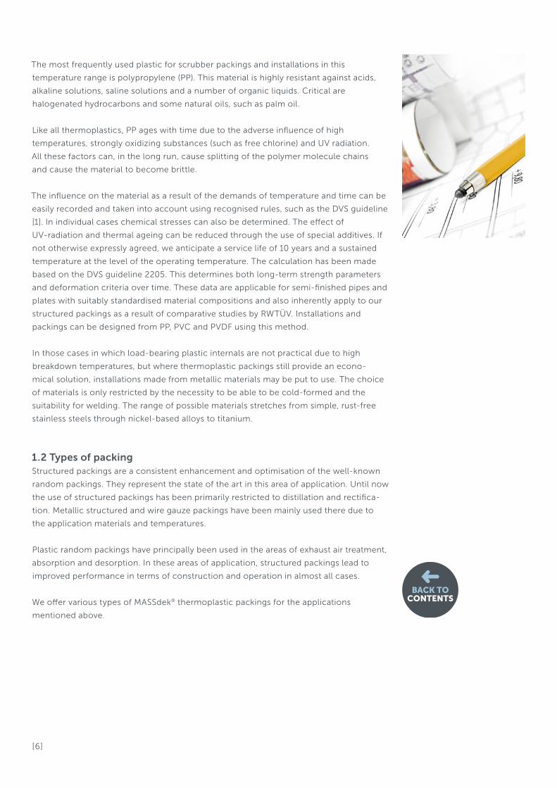
The most frequently used plastic for scrubber packings and installations in this
temperature range is polypropylene (PP). This material is highly resistant against acids,
alkaline solutions, saline solutions and a number of organic liquids. Critical are
halogenated hydrocarbons and some natural oils, such as palm oil.
Like all thermoplastics, PP ages with time due to the adverse influence of high
temperatures, strongly oxidizing substances (such as free chlorine) and UV radiation.
All these factors can, in the long run, cause splitting of the polymer molecule chains
and cause the material to become brittle.
The influence on the material as a result of the demands of temperature and time can be
easily recorded and taken into account using recognised rules, such as the DVS guideline
[1]. In individual cases chemical stresses can also be determined. The effect of
UV-radiation and thermal ageing can be reduced through the use of special additives. If
not otherwise expressly agreed, we anticipate a service life of 10 years and a sustained
temperature at the level of the operating temperature. The calculation has been made
based on the DVS guideline 2205. This determines both long-term strength parameters
and deformation criteria over time. These data are applicable for semi-finished pipes and
plates with suitably standardised material compositions and also inherently apply to our
structured packings as a result of comparative studies by RWTÜV. Installations and
packings can be designed from PP, PVC and PVDF using this method.
In those cases in which load-bearing plastic internals are not practical due to high
breakdown temperatures, but where thermoplastic packings still provide an econo-
mical solution, installations made from metallic materials may be put to use. The choice
of materials is only restricted by the necessity to be able to be cold-formed and the
suitability for welding. The range of possible materials stretches from simple, rust-free
stainless steels through nickel-based alloys to titanium.
1.2 Types of packingStructured packings are a consistent enhancement and optimisation of the well-known
random packings. They represent the state of the art in this area of application. Until now
the use of structured packings has been primarily restricted to distillation and rectifica-
tion. Metallic structured and wire gauze packings have been mainly used there due to
the application materials and temperatures.
Plastic random packings have principally been used in the areas of exhaust air treatment,
absorption and desorption. In these areas of application, structured packings lead to
improved performance in terms of construction and operation in almost all cases.
We offer various types of MASSdek® thermoplastic packings for the applications
mentioned above.
BACK TOCONTENTS
[ 7 ]
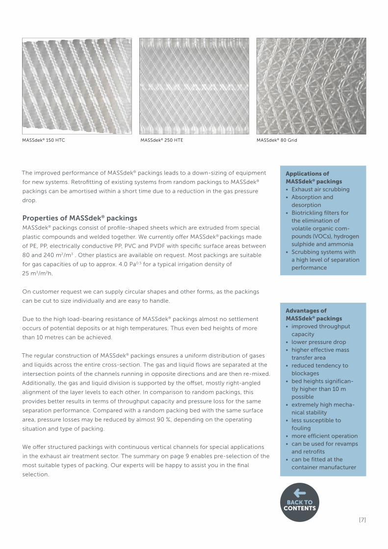
The improved performance of MASSdek® packings leads to a down-sizing of equipment
for new systems. Retrofitting of existing systems from random packings to MASSdek®
packings can be amortised within a short time due to a reduction in the gas pressure
drop.
Properties of MASSdek® packingsMASSdek® packings consist of profile-shaped sheets which are extruded from special
plastic compounds and welded together. We currently offer MASSdek® packings made
of PE, PP, electrically conductive PP, PVC and PVDF with specific surface areas between
80 and 240 m2/m3 . Other plastics are available on request. Most packings are suitable
for gas capacities of up to approx. 4.0 Pa0.5 for a typical irrigation density of
25 m3/m2h.
On customer request we can supply circular shapes and other forms, as the packings
can be cut to size individually and are easy to handle.
Due to the high load-bearing resistance of MASSdek® packings almost no settlement
occurs of potential deposits or at high temperatures. Thus even bed heights of more
than 10 metres can be achieved.
The regular construction of MASSdek® packings ensures a uniform distribution of gases
and liquids across the entire cross-section. The gas and liquid flows are separated at the
intersection points of the channels running in opposite directions and are then re-mixed.
Additionally, the gas and liquid division is supported by the offset, mostly right-angled
alignment of the layer levels to each other. In comparison to random packings, this
provides better results in terms of throughput capacity and pressure loss for the same
separation performance. Compared with a random packing bed with the same surface
area, pressure losses may be reduced by almost 90 %, depending on the operating
situation and type of packing.
We offer structured packings with continuous vertical channels for special applications
in the exhaust air treatment sector. The summary on page 9 enables pre-selection of the
most suitable types of packing. Our experts will be happy to assist you in the final
selection.
MASSdek® 150 HTC MASSdek® 250 HTE MASSdek® 80 Grid
Applications of MASSdek® packings• Exhaust air scrubbing• Absorption and desorption• Biotrickling filters for the elimination of volatile organic com- pounds (VOCs), hydrogen sulphide and ammonia• Scrubbing systems with a high level of separation performance
Advantages of MASSdek® packings• improved throughput capacity• lower pressure drop• higher effective mass transfer area• reduced tendency to blockages• bed heights significan- tly higher than 10 m possible• extremely high mecha- nical stability• less susceptible to fouling• more efficient operation• can be used for revamps and retrofits• can be fitted at the container manufacturer
BACK TOCONTENTS

[ 8 ]
MASSdek® – At a glance
TypeStruc-
tureSpecificsurface
Hydraulic capacity /
specific pressure
Separation perfor-mance
Resistance to scaling and
fouling
Specific pressure loss / separation
Typical applications
MASSdek®
250 HTECross
240
m²/m³+ +++ + ++
Scrubbing systems with the
highest levels of demand on
separation power
MASSdek®
250 HTCCross
240
m²/m³++ ++(+) + ++
Standard use for the elimination
of volatile organic compounds
(VOCs), hydrogen sulphide and
ammonia
MASSdek®
150 HTCCross
150
m²/m³+++ ++ ++ +++
Standard uses for absorption
and desorption
MASSdek®
125 HTCCross
125
m²/m³+++ + +++ ++
Stripper Exhaust air scrubber Biotrickling filter
MASSdek®
80 GridGrid
80
m²/m³+++ + +++ +++
Exhaust air scrubber and
biotrickling filter,
desulphurisation columns
BACK TOCONTENTS
[ 9 ]
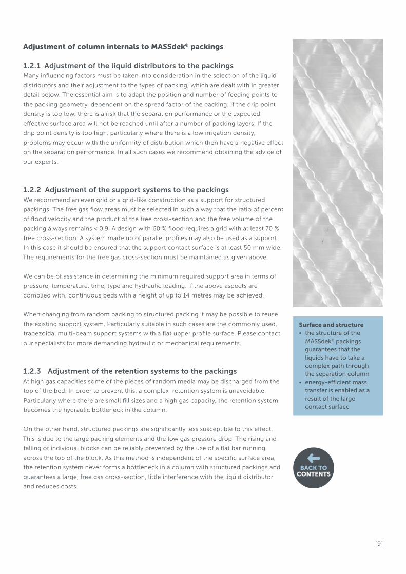
Adjustment of column internals to MASSdek® packings
1.2.1 Adjustment of the liquid distributors to the packingsMany influencing factors must be taken into consideration in the selection of the liquid
distributors and their adjustment to the types of packing, which are dealt with in greater
detail below. The essential aim is to adapt the position and number of feeding points to
the packing geometry, dependent on the spread factor of the packing. If the drip point
density is too low, there is a risk that the separation performance or the expected
effective surface area will not be reached until after a number of packing layers. If the
drip point density is too high, particularly where there is a low irrigation density,
problems may occur with the uniformity of distribution which then have a negative effect
on the separation performance. In all such cases we recommend obtaining the advice of
our experts.
1.2.2 Adjustment of the support systems to the packingsWe recommend an even grid or a grid-like construction as a support for structured
packings. The free gas flow areas must be selected in such a way that the ratio of percent
of flood velocity and the product of the free cross-section and the free volume of the
packing always remains < 0.9. A design with 60 % flood requires a grid with at least 70 %
free cross-section. A system made up of parallel profiles may also be used as a support.
In this case it should be ensured that the support contact surface is at least 50 mm wide.
The requirements for the free gas cross-section must be maintained as given above.
We can be of assistance in determining the minimum required support area in terms of
pressure, temperature, time, type and hydraulic loading. If the above aspects are
complied with, continuous beds with a height of up to 14 metres may be achieved.
When changing from random packing to structured packing it may be possible to reuse
the existing support system. Particularly suitable in such cases are the commonly used,
trapezoidal multi-beam support systems with a flat upper profile surface. Please contact
our specialists for more demanding hydraulic or mechanical requirements.
1.2.3 Adjustment of the retention systems to the packingsAt high gas capacities some of the pieces of random media may be discharged from the
top of the bed. In order to prevent this, a complex retention system is unavoidable.
Particularly where there are small fill sizes and a high gas capacity, the retention system
becomes the hydraulic bottleneck in the column.
On the other hand, structured packings are significantly less susceptible to this effect.
This is due to the large packing elements and the low gas pressure drop. The rising and
falling of individual blocks can be reliably prevented by the use of a flat bar running
across the top of the block. As this method is independent of the specific surface area,
the retention system never forms a bottleneck in a column with structured packings and
guarantees a large, free gas cross-section, little interference with the liquid distributor
and reduces costs.
Surface and structure• the structure of the MASSdek® packings guarantees that the liquids have to take a complex path through the separation column• energy-efficient mass transfer is enabled as a result of the large contact surface
BACK TOCONTENTS
[ 10 ]
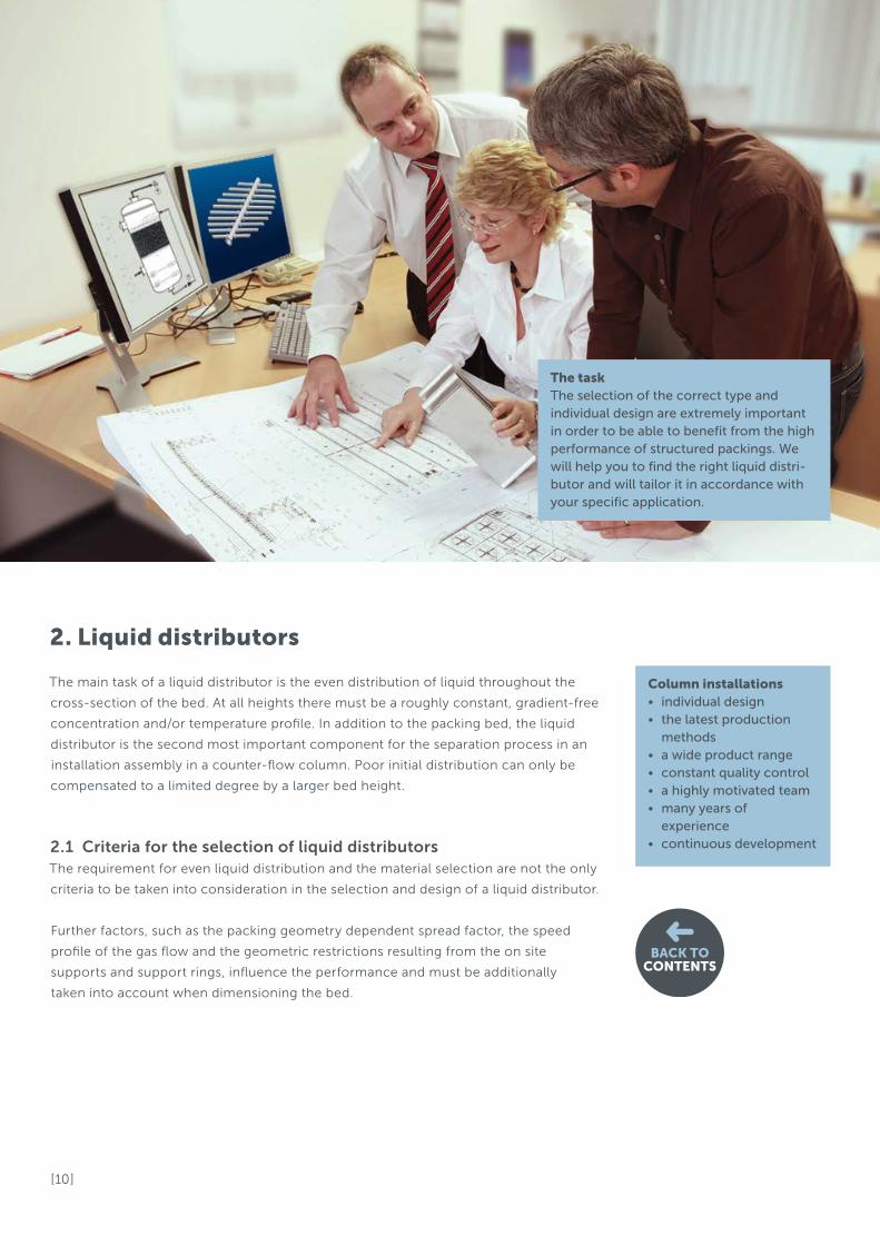
The main task of a liquid distributor is the even distribution of liquid throughout the
cross-section of the bed. At all heights there must be a roughly constant, gradient-free
concentration and/or temperature profile. In addition to the packing bed, the liquid
distributor is the second most important component for the separation process in an
installation assembly in a counter-flow column. Poor initial distribution can only be
compensated to a limited degree by a larger bed height.
2.1 Criteria for the selection of liquid distributorsThe requirement for even liquid distribution and the material selection are not the only
criteria to be taken into consideration in the selection and design of a liquid distributor.
Further factors, such as the packing geometry dependent spread factor, the speed
profile of the gas flow and the geometric restrictions resulting from the on site
supports and support rings, influence the performance and must be additionally
taken into account when dimensioning the bed.
2. Liquid distributors
The taskThe selection of the correct type and individual design are extremely important in order to be able to benefit from the high performance of structured packings. We will help you to find the right liquid distri-butor and will tailor it in accordance with your specific application.
Column installations• individual design • the latest production methods• a wide product range • constant quality control • a highly motivated team • many years of experience • continuous development
BACK TOCONTENTS
[ 11 ]
The main process parameters are defined by the following factors
• Diameter
• Load range (turn down)
• Dealing with dirt
• Specific liquid load
• Drip point density
Additional process parameters exert an influence on the selection and design of
a distributor
• Number of transfer units
• Gas capacity and influence on the gas distribution
• Feed composition (flashing feed)
• Limitations due to site construction requirements
Economic aspects also have to be taken into consideration
• Distributor costs vs. bed height costs
• Distributor costs vs. operating costs
The selection and design of a distribution system for a specific separation task is an iterative
process. We recommend determining the material first. If a plastic packing was selected for
cost reasons and not for reasons of corrosion, a metallic distributor should always be taken
into consideration as an additional option.
2.2 Distinguishing features of liquid distributors
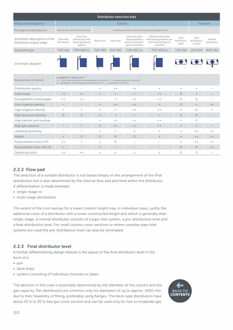
2.2.1 Final distributor arrangementIn the table Distributor selection aids a number of the aspects have been summarised which
lead to a recommendation for the final distributor arrangement.
The main distinguishing criteria here are the driving force of the liquid flow either by
• gravity or
• pressure
For gravity a differentiaton is necessary. The final distribution can take place as a
free overflow
• across a weir or as
• an outflow via one or more submerged holes
There are significant differences in the distribution quality between the two solutions.
A few millimetres in the sloping of the free surface due to the inflow and deviations
from the horizontal in a weir distributor can cause significant differences in the flow
rate at individual feed points. This influence is much lower for submerged holes.
Pressure force distributors are divided into distributors which generate a liquid jet or
a liquid spray.
BACK TOCONTENTS
[ 12 ]
2.2.3 Final distributor levelA further differentiating design feature is the layout of the final distributor level in the
form of a
• pan
• deck (tray)
• system consisting of individual channels or pipes
The decision in this case is essentially determined by the diameter of the column and the
gas capacity. Pan distributors are common only for diameters of up to approx. 1000 mm
due to their feasibility of fitting, preferably using flanges. The deck-type distributors have
about 25 % to 30 % free gas cross-section and can be used only for low to moderate gas
Distributor selection aids
Physical driving force Gravity Pressure
Principle of distribution Distributor with free overflow Distributor with liquid level using discharge holes
Schematic description of the distributor output stage
Overflow distributor
Overflow distributor with liquid guidance
system
Base hole Side hole
Side hole with liquid guidance
system and emer-gency overflow
Multiple side holes with liquid guidance sys-
tem and emergency overflow
Pipe distributor,
open
Pipe distributor,
closed
Nozzle distributor
Example/type TDP 410 TDP 410 So TDP 400 TDP 420 TDP 420 So TDP 420 So LDP 210 LDP 200 NDP 310
Schematic diagram
Assessment criterionsuitable in terms of “” :++ = very well suited or recommended in terms of | + = suited or good in terms of0 = partially or moderately suited in terms of | — = unsuited in terms of
Distribution quality – – + ++ ++ + + + –
Load range ++ ++ + + + ++ 0 + –
Susceptibility to blockages ++ ++ – + ++ ++ 0 0 –
Low irrigation density – – + ++ ++ + 0 + ++
High irrigation density + + + + ++ ++ + ++ +
High drip point density 0 0 ++ + + + 0 0 –
High transfer unit number – – + ++ ++ ++ + 0 –
High gas capacity – + 0 ++ ++ ++ + + –
Levelling sensitivity – – + + + + + ++ ++
Height + 0 0 0 0 + + ++ ++
Procurement costs in PP ++ + + 0 – – + ++ ++
Procurement costs CrNi-St. + – + – – – 0 0 ++
Operating costs ++ ++ + + + + 0 0 –
2.2.2 Flow padThe selection of a suitable distributor is not based simply on the arrangement of the final
distribution but is also determined by the internal flow pad and feed within the distributor.
A differentiation is made between
• single-stage or
• multi-stage distributors
The extent of the cost savings for a lower column height may, in individual cases, justify the
additional costs of a distributor with a lower constructed height and which is generally then
single-stage. A normal distributor consists of a pipe inlet system, a pre-distribution level and
a final distribution level. For small column cross-sections or where complex pipe inlet
systems are used the pre-distribution level can also be eliminated.
BACK TOCONTENTS

[ 13 ]
BACK TOCONTENTS
2.3 Distributor type table
Type Link
2.6.1 Overflow weir distributor Liquid distributor TDP 410
2.6.2 Trough distributor, 2-stage Liquid distributor TDP 400
2.6.3 Trough distributor, 2-stage with guide pipes Liquid distributor TDP 420
2.6.4 Trough distributor, 2-stage with splash plate Liquid distributor TDP 430
2.6.5 Closed pipe distributor with a central inflow Liquid distributor LDP 200
2.6.6 Closed pipe distributor with a central inflow Liquid distributor LDP 220
2.6.7 Spray nozzle distributor Liquid distributor NDP 310
2.6.8 Pan distributor, single-stage with guide pipes Liquid distributor PDP 350
2.4 Impact of distribution quality on separation performanceThe quality of the liquid distribution is crucially determined by
• a sufficient drip point density
• the drip point pattern on the packing bed
• the uniform flow rates of individual points
Additional influential factors are
• the distance to the top of the bed
• the orientation to the packing
• the free gas cross-section
• design aspects, such as mountability and levelling capability
capacities. For the most part pipe or trough type distributors are used. A modular
construction allows installation through manholes DN500 or DN600.
2.2.4 FunctionA significant criterion, particularly for larger column cross-sections, is the differentiation
based on the function as a
• feed distributor or
• as a re-distributor between two beds
Re-distributors have to mix a liquid passed from the upper bed before it is re-distributed
in order to compensate for any possible local differences in concentration. For larger
cross-sections and sophisticated separations an additional collecting device is arranged
upstream.
2.2.5 Liquid feedA further differentiation criterion can be seen in the type of the liquid feed. The feed can
be made via
• an inlet pipe from the outside
• an inlet pipe from the inside (collector/re-distributor)
• directly from the bed located above or
• for liquids with a gas proportion greater than 1-vol% from a flash gallery or other
special equipment
[ 14 ]
BACK TOCONTENTS
2.4.2 Positioning of the feeding points Extensive investigations have been carried out, particularly in distillation, to quantify the
influence of the liquid distribution quality on the separation performance. The results
derived from these studies confirm the importance of an optimal initial distribution.
A consensus exists that a macroscopic unequal distribution has a significantly greater
effect than variations among the individual feeding points where these occur spread
across the cross-section.
Macroscopic areas are continuous surfaces which take up more than 1/12 of the entire
cross-section. The division of the areas may be geometrical, not equal. Concentrical
areas, parallel segment areas, pie wedges or other regular geometric shapes, all of which
amount to 1/12 of the total cross-section area, are used for comparison.
Moor and Rukowena [2] have developed a graphical method which expresses the quality
of distribution as a value. This value varies between 30 % and 95 %. In a further investi-
gation the authors have calculated the influence of the distribution quality on the
separation performance. The exact method may be found in the literature.
The distributors shown on the following page appear similar at first glance, but there
are significant differences in the quality of their distribution. A distributor with a free
overflow concentrates the liquid into virtually one line between the troughs. A distributor
with a base hole generates a concentrated area below the troughs. A distributor with a
side hole and pipe guidance system has the best distribution pattern. For extremely
demanding applications a triangular pattern for the hole location and the avoidance
of the use of a support ring enable further improvements to be achieved.
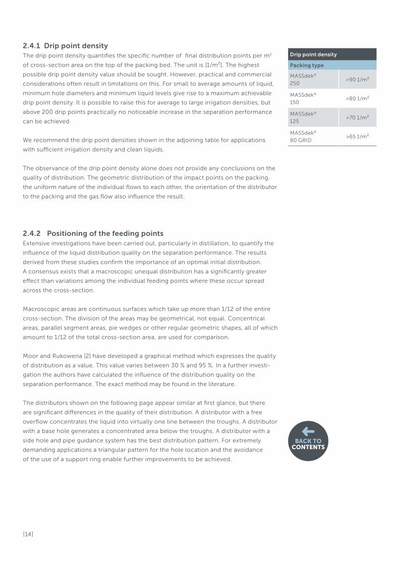
2.4.1 Drip point densityThe drip point density quantifies the specific number of final distribution points per m2
of cross-section area on the top of the packing bed. The unit is [1/m²]. The highest
possible drip point density value should be sought. However, practical and commercial
considerations often result in limitations on this. For small to average amounts of liquid,
minimum hole diameters and minimum liquid levels give rise to a maximum achievable
drip point density. It is possible to raise this for average to large irrigation densities, but
above 200 drip points practically no noticeable increase in the separation performance
can be achieved.
We recommend the drip point densities shown in the adjoining table for applications
with sufficient irrigation density and clean liquids.
The observance of the drip point density alone does not provide any conclusions on the
quality of distribution. The geometric distribution of the impact points on the packing,
the uniform nature of the individual flows to each other, the orientation of the distributor
to the packing and the gas flow also influence the result.
Drip point density
Packing type
MASSdek®
250> 90 1/m²
MASSdek®
150 > 80 1/m²
MASSdek®
125> 70 1/m²
MASSdek®
80 GRID> 65 1/m²

[ 15 ]
BACK TOCONTENTS
Distribution quality
Overflow Base hole Side hole with pipe guidance system
Distribution quality = ca. 40 % Distribution quality = ca. 60 % Distribution quality = ca. 80 %
The chart below shows that the quality of the distribution affects the separation result more
significantly as the Number of Transfer Units (NTU) increases. Hardly any influence can be
determined for 4 transfer units. For 12 transfer units the achievable number of transfer units
reduces from 12 to below 9 transfer units with a distribution quality of 60 %. This is equiva-
lent to the quality level of a normal distributor.
ac
tua
lly
ac
hie
ve
d N
TU
s [-
]
Distribution quality according to Moore & Rukovena [%]
Influence of the quality of the distribution on the
separation performance
[ 16 ]
2.4.5 Distance to the bedThe minimum distance to the bed is determined by the gas flow and the maximum
distance by the height which the liquid drops and its impact momentum on the packing.
Normal distances range between 80 mm to 250 mm. In most cases, distances ranging
from 120 to 160 mm provide trouble-free operation.
If the distance to the bed is too small, a directional flow of gas within the bed may arise.
In such cases, the separation performance deteriorates, particularly for distributors with
a low free gas cross-section. Generally the lower edge of the trough is taken as a
reference level. It is recommended that the distance is selected such that there is an
angle of at least 45° or preferably 60° between the upper edge of the bed and the area
for gas flow in between the distributor troughs. For a trough distributor with a regular
trough pitch of 300 mm and a trough width of 140 mm this results in a distance of at
least 70 mm, normally 140 mm. Where there is a high gas capacity and a lower distance
the gas flow may deflect the liquid jet from its planned point of impact.
It should be mentioned at this point that the normal number of transfer units (NTU) for
scrubbers is rarely more than 4 transfer units. Poor initial distribution and high hydraulic
loads may, however, lead to macroscopic areas with too high and too low irrigation density
and these may reach across the whole of the bed. This also reduces separation
performance.
2.4.3 Uniformity of flow rates of individual drip pointsThe observations given above naturally assume an uniformity in the flow rates from the
individual drip points. The geometric uniformity of the individual outflow holes or overflow
slots is of particular importance here. The distribution hydraulics system described below is
a further criterion.
2.4.4 Internal distribution hydraulicsThe aim of a good liquid distribution system is to prevent turbulence. The lower the
turbulence of the flow, the more even is the distribution.
Less costly distributors have a small flow cross-section and thus high flow velocities. These,
in turn, generate a pressure drop across the length of the individual distributor with effects
on the outflow volumes at the feed points.
Depending on the task in question, open trough distributors are designed with maximum
flow velocities ranging between 0.25 to 0.4 m/s. In closed systems the maximum flow
velocity can be set higher, provided that the inlet cross-sections have been sufficiently
dimensioned in comparison with the outlet cross-sections.
Particular attention should be paid to the feed system. The discharge speed of a liquid jet
which feeds an open trough should not be more than 1 m/s. For columns with a diameter
greater than 1000 mm it is recommended to spread the inlet volumes over several points.
Installations which interrupt the momentum, such as inlet baskets, packing elements, grids
or perforated plates, are often used.
BACK TOCONTENTS
[ 17 ]
As the distance from the bed increases, the speed of the falling liquid jet also increases and
the impact momentum on the bed is so high that a significant amount of fine splash
droplets is generated. These droplets may be carried away by the gas flow. Avoidable
entrainment problems may occur through a pressure increase in the droplet separator or, in
the worst case, through its flooding. Signs of erosion on the fills cannot be ruled out in
cases of extremely large distances and large amounts of liquid.
2.4.6 Orientation to the packingThe upper section of the bed does not achieve its full efficiency either with random or with
structured packings. The liquid must first spread out radially in order to be able to develop
an effective area typical for the actual loads and system. As a rule of thumb, a depth of 0.25
m is assumed for random fills and the depth of a layer for structured packings.
For structured packings, as compared with random packings, attention must be paid to the
orientation of the distributor to the direction of the packing sheets/foils. To ensure that
liquid is applied to as many gaps in between the foils as possible in the first layer, a
distributor orientation of 45° to the sheets is recommended. This is particularly important
for a splash plate distributor.
A 45° angle along the line of the greatest drip point density should be selected for
distributors which vary greatly from the ideal triangular or square drip point pattern.
2.4.7 Free gas cross-sectionLiquid distributors always present a resistance which generates a pressure loss for the gas flow.
The free gas cross-section should therefore be designed to be as large as possible. This is often
in conflict with the stipulated distribution quality. As a reference value we recommend
remaining below a gas capacity factor in between the troughs of FV= 4.5 Pa0.5 for distributors
with a free overflow. The free gas cross-section for other types should be at least 35 % of the
superficial cross-section of the column and, where possible, should not exceed a gas capacity
factor at the narrowest cross-section of 6.5 Pa0.5.
2.4.8 Mountability and levelling capabilityLiquid distributors should be aligned as precisely as possible to the horizontal. For some
types deviations outside the fixed tolerances lead to a drop in performance, for other types
deviations may be acceptable in some cases, as the performance is either little affected or
not at all. For this in particular the on-site supports must be taken into consideration.
Pipe and nozzle distributorFor a pipe and nozzle distributor the distance to the bed must be maintained so that the
intended pattern of impact is achieved. A low incline in the distributor is of less signifi-
cance. Both types are hung from clamps or hooked into place. Pipe distributors up
to a main pipe nominal width of DN 250 may be brought into the vessel over a DN 600
manhole. Cases must be assessed individually where there are larger nominal widths.
BACK TOCONTENTS

[ 18 ]
BACK TOCONTENTS
2.5 Gravity and pressure distributorsThe effective dynamic pressure height and the orifice discharge coefficient primarily
determine the outflow speed and thus the outflow volume for gravity distributors with
submerged holes and pressure distributors.
wa = μ • 2 • g • heff
wa = Outflow velocity [m/s]
heff = Effective dynamic pressure level [m]
μ = Orifice discharge coefficient [./.]
g = Gravitational acceleration [m/s²]
The orifice discharge coefficient is dependent on various parameters:
• The shape size and thickness of the holes
• Liquid properties
• Liquid level
• Cross-flow speed
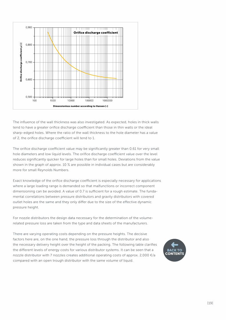
For sharp-edged holes the value ranges between 0.61 for high liquid levels and
0.83 for low levels. For rounded edged orifices the values are approx. 5 % to 10 % higher.
In a work by Hansen [3] from the first half of the last century the most significant
combinations were determined using dimensionless numbers. It was determined that
the orifice discharge coefficient was greatly determined by the Weber Number, the
Reynolds Number and by the geometric relationship of the hole diameter to the level.
Gravity distributorThe maximum permitted deviations from the horizontal during installation must be
maintained for gravity distributors. Fitting pieces are used for distributors which are
positioned on supports and support rings. Smaller distributors with a higher distribution
quality have adjusting devices which enable alignment.
Trough distributorsFor large plastic trough distributors, a calculation of deflection over time is additionally
required. For reasons of permanent deformation resistance larger trough cross-sections, or
alternatively additional supports, are often needed. A deflection of the on site supports must
also be considered and is counteracted where necessary by additional fitting pieces at the
support points. Trough distributors are not fixed to the constructed base in their standard
version. The position of the components is determined by designed features on the upper
distributor.
The effective weight of the distributor is, even when empty, many times greater than the
force resulting from the gas pressure drop. If a rapid momentum increase in gas pressure
drop could occur during operation of the column, we recommend securing the distributor
device.
Special versions are available on request. A manhole DN 600 is required for fitting. In most
cases DN 500 is also sufficient. Smaller installation openings will be reviewed on an
individual basis.
We can provide assistance with the positioning and design of on site supports and support
rings and the positioning of the manholes.
[ 19 ]
The influence of the wall thickness was also investigated. As expected, holes in thick walls
tend to have a greater orifice discharge coefficient than those in thin walls or the ideal
sharp-edged holes. Where the ratio of the wall thickness to the hole diameter has a value
of 2, the orifice discharge coefficient will tend to 1.
The orifice discharge coefficient value may be significantly greater than 0.61 for very small
hole diameters and low liquid levels. The orifice discharge coefficient value over the level
reduces significantly quicker for large holes than for small holes. Deviations from the value
shown in the graph of approx. 10 % are possible in individual cases but are considerably
more for small Reynolds Numbers.
Exact knowledge of the orifice discharge coefficient is especially necessary for applications
where a large loading range is demanded so that malfunctions or incorrect component
dimensioning can be avoided. A value of 0.7 is sufficient for a rough estimate. The funda-
mental correlations between pressure distributors and gravity distributors with covered
outlet holes are the same and they only differ due to the size of the effective dynamic
pressure height.
For nozzle distributors the design data necessary for the determination of the volume-
related pressure loss are taken from the type and data sheets of the manufacturers.
There are varying operating costs depending on the pressure heights. The decisive
factors here are, on the one hand, the pressure loss through the distributor and also
the necessary delivery height over the height of the packing. The following table clarifies
the different levels of energy costs for various distributor systems. It can be seen that a
nozzle distributor with 7 nozzles creates additional operating costs of approx. 2,000 €/a
compared with an open trough distributor with the same volume of liquid.
Ori
fic
e d
isc
ha
rge
co
effi
cie
nt
μ [
-]
Dimensionless number according to Hansen [-]
Orifice discharge coefficient
BACK TOCONTENTS

[ 20 ]
BACK TOCONTENTS
2.5.1 Orifice vs. weirAs described above, weir distributors and distributors with submerged holes vary
significantly in their distribution quality. Overflow distributors have two serious
disadvantages. On the one hand, the geometric points of impact on the packing bed are
dependent on height and are mostly poorly distributed (see Table Distributor selection
aids) and, on the other hand, they are extremely sensitive to level offset. The latter will be
explained and illustrated by the use of a comparison of various orifices and principles.
We will consider a column with a diameter of 3 m where the permitted tolerances for
variance of horizontal of a max. of 0.1 % of the diameter are maintained. A single
continuous trough could thus be located on one side 3 mm above and on the other side
3 mm below the nominal height.
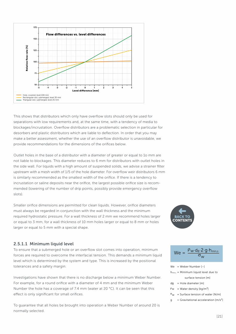
If a hole with a nominal 100 mm liquid level is now compared with a rectangular
overflow slot with a nominal 30 mm liquid level, for the same flow rate the variation for
the hole is +1.5 % / -1.5 % and for the rectangular slot +15.4 % / -14.6 %. For a triangular
slot with an opening angle of 45° and a nominal 25 mm level the changes in the values
even amount to +32.8 % / -27.4 %.
Operating cost comparison
Nozzle distributor Pipe distributor Trough distributor
Distance over bed [m] 0.6 0.5 0.75
Pressure drop [bar] 1 0.2 0
Delivery height [m] 10.41 2.462 0.75
Irrigation density [m³/m²h] 15 15 15
Column diameter [m] 3 3 3
Volume flow [m³/h] 106 106 106
Theoretical pump power [kW] 3.0 0.7 0.2
Motor power [kW] 3.7 0.9 0.3
Annual power consumption [kWh/a] 29647 7012 2136
Annual power costs [EUR/a] 2668 € 631 € 192 €
Net electricity price, industrial customers [EUR/kWh] 0.09
Hydraulic efficiency 0.9
Electrical efficiency 0.9
Annual operating hours [h/a] 8000
Fluid density [kg/m³] 998
Before deciding on the use of a particular type of distributor we recommend carrying out a
profitability analysis.
[ 21 ]
BACK TOCONTENTS
This shows that distributors which only have overflow slots should only be used for
separations with low requirements and, at the same time, with a tendency of media to
blockages / incrustation. Overflow distributors are a problematic selection in particular for
desorbers and plastic distributors which are liable to deflection. In order that you may
make a better assessment, whether the use of an overflow distributor is unavoidable, we
provide recommendations for the dimensions of the orifices below.
Outlet holes in the base of a distributor with a diameter of greater or equal to 1o mm are
not liable to blockages. This diameter reduces to 6 mm for distributors with outlet holes in
the side wall. For liquids with a high amount of suspended solids, we advise a strainer filter
upstream with a mesh width of 1/5 of the hole diameter. For overflow weir distributors 6 mm
is similarly recommended as the smallest width of the orifice. If there is a tendency to
incrustation or saline deposits near the orifice, the largest possible orifice size is recom-
mended (lowering of the number of drip points, possibly provide emergency overflow
slots).
Smaller orifice dimensions are permitted for clean liquids. However, orifice diameters
must always be regarded in conjunction with the wall thickness and the minimum
required hydrostatic pressure. For a wall thickness of 2 mm we recommend holes larger
or equal to 3 mm, for a wall thickness of 10 mm holes larger or equal to 8 mm or holes
larger or equal to 5 mm with a special shape.
2.5.1.1 Minimum liquid levelTo ensure that a submerged hole or an overflow slot comes into operation, minimum
forces are required to overcome the interfacial tension. This demands a minimum liquid
level which is determined by the system and type. This is increased by the positional
tolerances and a safety margin.
Investigations have shown that there is no discharge below a minimum Weber Number.
For example, for a round orifice with a diameter of 4 mm and the minimum Weber
Number the hole has a coverage of 7.4 mm (water at 20 °C). It can be seen that this
effect is only significant for small orifices.
To guarantee that all holes be brought into operation a Weber Number of around 20 is
normally selected.
We = Weber Number [–]
hmin,s = Minimum liquid level due to
surface tension [m]
dB = Hole diameter [m]
ρw = Water density [kg/m³]
σw = Surface tension of water [N/m]
g = Gravitational acceleration [m/s²]
We = ρw∙dB∙2∙g∙hmin,s
σw
Re
lati
ve
flo
w r
ate
[%
]
Level difference [mm]
Flow differences vs. level differences
Hole, covered, level 100 mm Rectangular slot, submerged, level 30 mm Triangular slot, submerged, level 25 mm

[ 22 ]
BACK TOCONTENTS
The gas pressure drop has a further effect. Depending on the gas capacity and free
cross-section of the distributor, gas pressure drops in the region of 0.2 to 2 mbar may
occur. For the liquid in the distributor the minimum liquid level would increase by the
equivalent amount of hydrostatic pressure. For water at 20 °C and 2 mbar this equates to
an additional liquid level of 20.5 mm.
The formation of a closed jet must also be ensured for larger holes. Additionally, vortex
formation must be avoided by ensuring that the minimum liquid level in no case falls
below 1.5 times the orifice diameter. This point must be taken into consideration in
particular for parting boxes with relatively large holes.
The demanded distribution quality similarly affects the minimum liquid level. For a
stipulated maximum deviation between the flow of the first and last outlet hole of a
channel section the minimum liquid level can be calculated through the conversion of
the dynamic pressure into liquid level. An assumed average flow speed of 0.3 m/s at the
channel inlet and a stipulated deviation of 10 % between the volumes of the first and last
outlet hole gives a minimum liquid level of 24.1 mm.
The following graph illustrates how the flow speed has an effect, in accordance with the
Bernoulli equation, at the channel inlet on the expected differences in the outflow
volume between the first and last hole in the channel. It is clear to see how the flow
speed influences the distribution quality. Particularly high demands on the distribution
quality with low minimum loads are then substantial factors in the dimensioning of the
trough cross-section.
If no special demands are derived from the customer specification, we
select a minimum liquid level for gravity distributors with outlet holes of
25 mm in the fine distributor and a minimum liquid level of 35 mm in the
upper distributor.
hmin,Ma = Minimum liquid due to hole to
hole flow deviation [m]
v1 = Average flow speed [m/s]
ηMa = Relative deviation of the
volumes [%/%]
g = Gravitational acceleration [m/s²]
v1 hmin,Ma =( 2 • g • (1 - (1- ηMa)²) ) ²
Ch
an
ge
in
th
e o
utfl
ow
vo
lum
e [
%]
Liquid level at the channel inlet [mm]
Influence of the flow velocity to the distribution quality
Flow speed, inlet; v = 0.2 m/s
Flow speed, inlet; v = 0.3 m/s
Flow speed, inlet; v = 0.4 m/s
Flow speed, inlet; v = 0.5 m/s
Flow speed, inlet; v = 0.6 m/s

[ 23 ]
BACK TOCONTENTS
2.5.1.2 Nominal liquid levelThe liquid level at nominal load is determined by the demands on the distribution quality
and by the distribution principle used. A nominal liquid level of 100 mm at 100 % load is
set for a type of distributor with base or side wall holes and normal demands. Demands
for minimum loads may, however, considerably increase this value. For example, at 40 %
nominal load this means, allowing for a minimum liquid level of 25 mm, a level of 156 mm,
at 30 % a level of 278 mm. Unless there are compelling reasons, the minimum loads should
not be specified too low. The maximum load should also not be larger than necessary
unless it is absolutely imperative.
Usual requirements for the load range are 50 to 110 %. Significant variations from this
require additional efforts or affect the distribution quality. Increased demands on the
distribution quality and the maintenance of minimum gas cross-section values may lead
here to larger construction heights.
For overflow weir distributors with a rectangular slot the liquid level planned in the
standard is 30 mm and for triangular slots 25 mm.
A discharge speed range of 0.9 to 1.5 m/s is planned for pipe pressure distributors. The
pressure loss resulting from the effective dynamic pressure height ranges from 100 to
300 mbar.
2.5.1.3 Maximum liquid levelThe trough height at maximum load is determined, with a safety margin of 10 %, from the
calculated liquid level plus 50 mm.
To ensure correct functioning at maximum load and where there is a tendency to
fouling, emergency overflow slots can prevent the distributor from overflowing in an
uncontrolled manner. As the component dimensions are greater as the liquid level
increases, the size of the installation opening is frequently critical for an economic
component design.
2.5.2 Design aspectsFor all distributors made up from individual pipes or channels the speed slows down
toward zero in the direction of flow. As a result, the liquid level increases in the open
trough in the direction of flow and the pressure in the pipe increases. These influences
can only be limited through appropriately low inlet speeds.
The increase in the delivery height (liquid height, equivalent dynamic pressure height)
across the length is calculated using the adjacent formula.
As a result of this effect on standard pipe distributors the flow increases by up to 4 %,
on standard trough distributors with submerged holes by up to 2.5 % and on standard
trough distributors with rectangular overflow slots by up to 20 %. The maximum design
inlet speed varies for each type of distributor and is lowest for overflow distributors.
This aspect may be ignored for spray nozzle distributors.
hd = Increase in the delivery height [m]
ve = Inlet speed [m/s]
g = Gravitational acceleration [m/s2]
hd = 2 • g1 ∙ v²e
[ 24 ]
BACK TOCONTENTS
2.5.3 Problems
High energy / momentum input
Where liquid flow intakes are poorly designed a large momentum may occur locally. This
risk is especially significant at high irrigation densities. To remedy this, many small feed
outlets instead of fewer larger ones can be used. This affects mainly the upper parting
box and therefore a trough-in-trough version or flow breakers in the form of cages,
structured packing elements or similar items may be useful.
Uncontrolled overflow
Where serious design errors in cross-section dimensioning or in the dimensioning of the
discharge points may be ruled out as the cause of an overflow, a number of discharge
points is usually blocked. This effect can also occur where there is an extremely large gas
pressure drop across the distributor and the recorded heights are too low.
Incrustation / saline deposits
If a warm saline solution which is near to its solubility limit is fed in, saline deposits or
incrustation may occur in the area of the orifices due to evaporation. Chemical reactions
between the liquid and the gas flow may also have a similar effect where the product of
the reaction falls below its solubility limit.
Erosion
A high flow speed together with a high proportion of solids may lead to signs of erosion.
This particularly occurs in the inlet area and in the orifices. A change in the orifice
discharge coefficient may be expected in this case and attention should be paid to this
from the beginning. The cross-sections of the inlets should be more generously
dimensioned.
Aeration
If the inflow momentum is too high, the liquid jet may contain gas. The resulting 2-phase
mixture then has a lower average density and takes up more space. This can lead to
overflows and also to locally and temporally significant variations in the uniformity of
distribution. At very high flow speeds and thus low retention time the liquid may, in some
cases, not be degassed. This also has a negative influence on the distribution
characteristics.
Floods in the spaces
On overflow weir distributors without guide pipes the liquid is fed horizontally into
the gas space between the troughs. A strongly constricted gas flow can fan out the
descending flow and pull it upwards to some extent. A spray regime layer of up
to 600 mm in height occurs which could then also flood the droplet separator. It is
reasonable to assume that the distribution quality will suffer as a result. This type of
distributor is only suited for low gas capacities.
Strongly directional gas flow
If the even distribution of the gas is affected when entering the bed by on site
supports or similar constructions or if the gas is improperly fed in, the separation
performance may be reduced and an increase in pressure loss occurs.

[ 25 ]
BACK TOCONTENTS
Minimum level / use of all drip points
Improper mounting and high liquid gradients may lead to some areas having too low a
liquid level which does not permit the use of all drip points.
2.6 Distributor data sheets on the following pages
2.6.1 Liquid distributor TDP 410
Weir distributor
2.6.2 Liquid distributor TDP 400
Trough distributor with base holes
2.6.3 Liquid distributor TDP 420 Trough distributor with side-wall holes and guide pipes, 2-stage
2.6.4 Liquid distributor TDP 430 Trough distributor with splash plate, 2-stage
2.6.5 Liquid distributor LDP 200 Closed pipe distributor with a central feed
2.6.6 Liquid distributor LDP 220 Closed pipe distributor with a side feed
2.6.7 Liquid distributor NDP 310 Spray nozzle distributor
2.6.8 Liquid distributor PDP 350 Pan distributor with guide pipes, single-stage
Trough distributor with side-wall holes and guide pipes, 2-stage
2.7 Re-distributors and special designsIn addition to the distributors shown here, other types, such as re-distributors or special
designs are available on request.
If the height in the column is restricted, single-stage gravity distributors may also be
used. Here the fine distributors are connected with a central parting distributor on one
level as a continuous system. The upper parting box is not required. Some height can
also be saved by the use of an inlet pipe connected by a flange to the side of the upper
distributor. For special designs it is also recommened to always check whether the
reduction in the column costs justifies the additional costs for the distributor.

[ 26 ]
BACK TOCONTENTS
Advantages• relative immunity to fouling and scaling
• low tendency to erosion
• large load range
• low component and operating costs
Standard versionIn the standard version a distributor consists of parallel
aligned U-troughs in the lower level and, above this, one
or more parting boxes. The parting distributors have got
overflow slots in their side walls on both sides. The liquid
is channelled into the fine distribution level via guiding
pipes. The liquid is then fed via regularly arranged over-
flow slots in the side walls of the lower troughs onto the
packing bed.
Main areas of applicationThe main areas of application are processes where liquids
with large and very large volumes of suspended solids are
to handle and liquids which are handled near to their
solubility limit, in such cases also with triangular slots.
The use of a weir distributor is preferable for absorption
processes with a low gas and liquid capacity and with a
low to mid-single digit number of transfer units.
NoteThe distribution quality is extremely sensitive where there
is a height offset. An overflow weir distributor can only be
used for low to average gas capacities.
Technical specifications
Application
Diameter range > 1,000 mm
Irrigation density range 15 to 40 (80) m³/m²h
Standard turn down2.5 : 1
(for triangular slots 4 : 1)
Range of the maximum gas capacity
2.25 Pa0,5
Susceptibility to fouling low
LIQUID DISTRIBUTOR TDP 410Overflow weir distributor
[ 27 ]
BACK TOCONTENTS
H1
H2
H3
Technical specifications
Functions
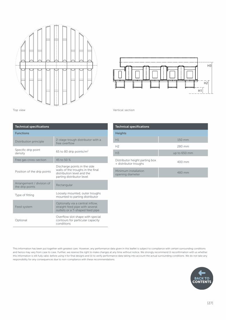
Distribution principle2-stage trough distributor with a free overflow
Specific drip point density
65 to 80 drip points/m2
Free gas cross-section 45 to 50 %
Position of the drip points
Discharge points in the side walls of the troughs in the final distribution level and the parting distributor level
Arrangement / division of the drip points
Rectangular
Type of fittingLoosely mounted, outer troughs mounted to parting distributor
Feed systemOptionally via a central inflow, straight feed pipe with several outlets or a T-shaped feed pipe
OptionalOverflow slot shape with special contours for particular capacity conditions
Technical specifications
Heights
H1 150 mm
H2 280 mm
H3 up to 650 mm
Distributor height parting box + distributor troughs
400 mm
Minimum installation opening diameter
480 mm
This information has been put together with greatest care. However, any performance data given in this leaflet is subject to compliance with certain surrounding conditions
and hence may vary from case to case. Further, we reserve the right to make changes at any time without notice. We strongly recommend (i) reconfirmation with us whether
this information is still fully valid, before using it for final designs and (ii) to verify performance data taking into account the actual surrounding conditions. We do not take any
responsibility for any consequences due to non-compliance with these recommendations.
Top view Vertical section

[ 28 ]
BACK TOCONTENTS
Advantages• low susceptibility to height offset
• uncomplicated construction
• low tendency to erosion
• large load range
• low component and operating costs
Standard versionIn the standard version a distributor consists of parallel
aligned U-troughs in the lower level and, above this, one
or more parting boxes. The parting distributors have got
outlet holes in the base plates. The liquid is channelled
into the fine distribution level from a direct drop. The
liquid is then fed onto the packing bed via outlet holes
arranged in two rows in the base of the lower troughs.
Main areas of applicationThe main areas of application are processes with clean or
less strongly with solids suspended liquids and liquids
which are handled near to their solubility limit, in such
cases additionally with triangular emergency slots. The
preferred use of a trough distributor with base holes is for
absorption processes with an average gas and liquid
capacity and with a mid-single digit number of transfer
units.
NoteRisk of blockages at low irrigation densities. This form of
trough distributor can only be used for up to average gas
capacities.
LIQUID DISTRIBUTOR TDP 400Trough distributor with base holes, 2-stage
Technical specifications
Application
Diameter range > 1,000 mm
Irrigation density range 12.5 to 60 (120) m³/m²h
Standard turn down 2.1 : 1
Range of the maximum gas capacity
2.75 Pa0,5
Susceptibility to fouling average to high
[ 29 ]
BACK TOCONTENTS
H1
H2
H3
Technical specifications
Functions
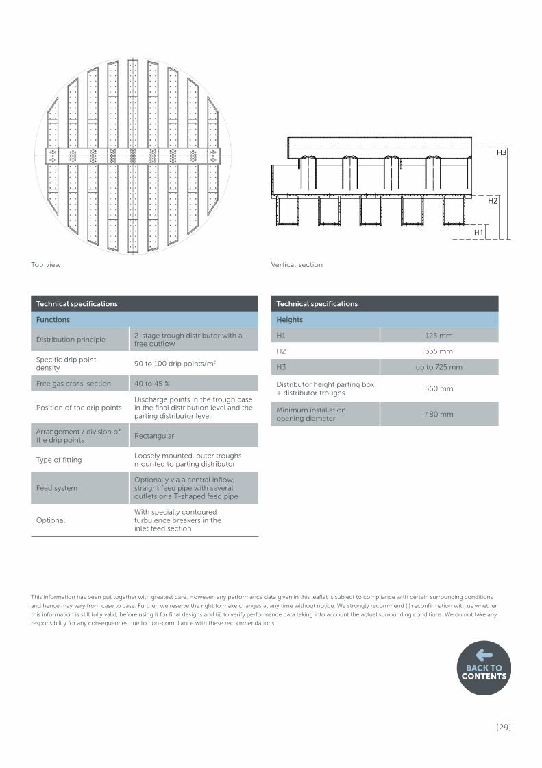
Distribution principle2-stage trough distributor with a free outflow
Specific drip point density
90 to 100 drip points/m2
Free gas cross-section 40 to 45 %
Position of the drip pointsDischarge points in the trough base in the final distribution level and the parting distributor level
Arrangement / division of the drip points
Rectangular
Type of fittingLoosely mounted, outer troughs mounted to parting distributor
Feed systemOptionally via a central inflow, straight feed pipe with several outlets or a T-shaped feed pipe
OptionalWith specially contoured turbulence breakers in the inlet feed section
Technical specifications
Heights
H1 125 mm
H2 335 mm
H3 up to 725 mm
Distributor height parting box + distributor troughs
560 mm
Minimum installation opening diameter
480 mm
This information has been put together with greatest care. However, any performance data given in this leaflet is subject to compliance with certain surrounding conditions
and hence may vary from case to case. Further, we reserve the right to make changes at any time without notice. We strongly recommend (i) reconfirmation with us whether
this information is still fully valid, before using it for final designs and (ii) to verify performance data taking into account the actual surrounding conditions. We do not take any
responsibility for any consequences due to non-compliance with these recommendations.
Top view Vertical section

[ 30 ] BACK TOCONTENTS
Advantages• low susceptibility to height offset
• low fouling tendency
• precisely positionable feed points
• high gas capacity
• low tendency to erosion
• large load range
• low operating costs
Standard versionIn the standard version a distributor consists of parallel
aligned U-troughs in the lower level and, above this, one
or more parting boxes. The parting distributors have got
outlet holes in the side walls. The liquid is channelled into
the fine distribution level via guiding pipes. The liquid is
then fed via submerged orifices arranged at regular
intervals on both sides of the side walls of the lower
troughs and then via guide pipes.
Main areas of applicationThe main areas of application are processes with mode-
rately with solids suspended liquids. For liquids near to
their solubility limit the distributor can optionally be fitted
with additional emergency overflow slots. The preferred
use of a trough distributor with side-wall holes and guide
pipes is for absorption processes with high gas capacities
and average liquid loadings and with an average to high
number of transfer units.
NoteThis type of liquid distributor has a more complex design.
LIQUID DISTRIBUTOR TDP 420Trough distributor with side-wall holes and guide pipes, 2-stage
Technical specifications
Application
Diameter range > 1,000 mm
Irrigation density range 12.5 to 50 (100) m³/m²h
Standard turn down2.1 : 1
(with multiple rows of holes: 10 : 1)
Range of the maximum gas capacity
3.60 Pa0,5
Susceptibility to fouling low to average
[ 31 ]
BACK TOCONTENTS
H1
H2
H3
Technical specifications
Functions
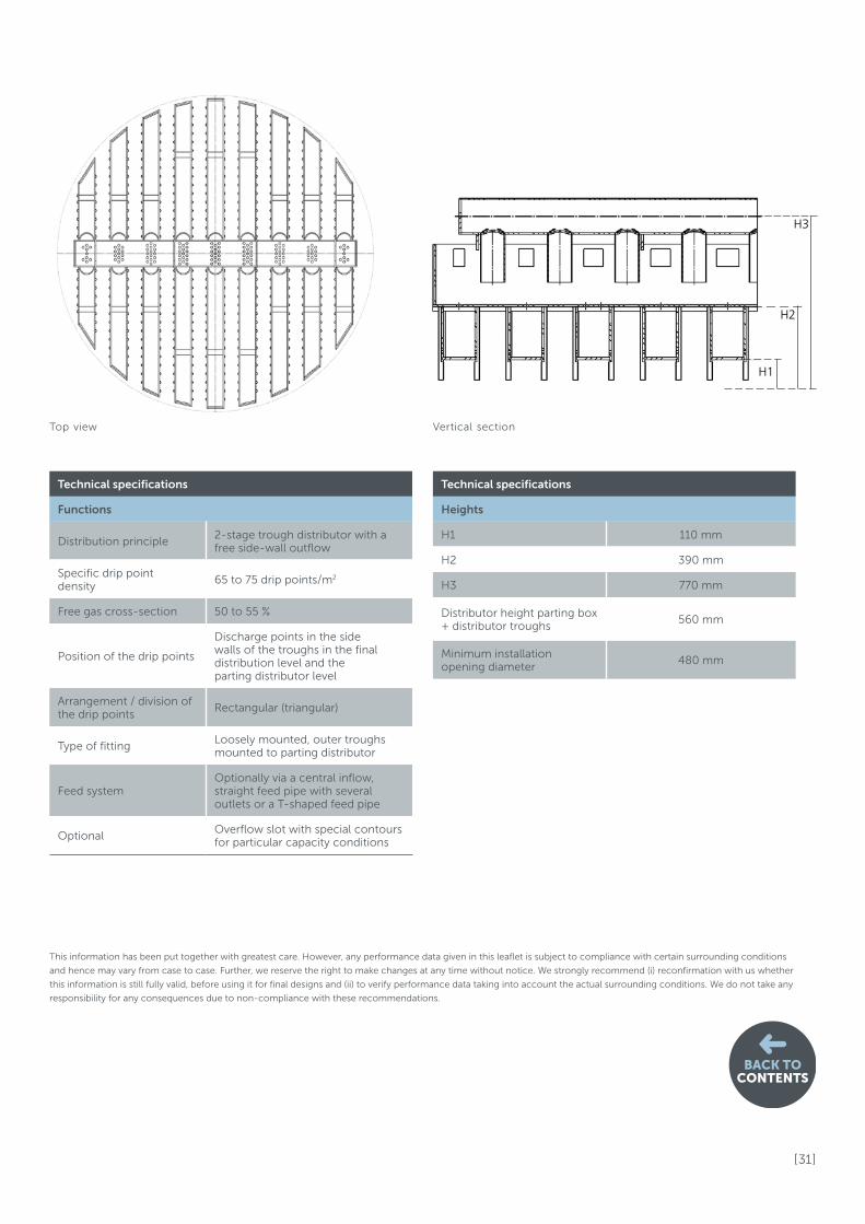
Distribution principle2-stage trough distributor with a free side-wall outflow
Specific drip point density
65 to 75 drip points/m2
Free gas cross-section 50 to 55 %
Position of the drip points
Discharge points in the side walls of the troughs in the final distribution level and the parting distributor level
Arrangement / division of the drip points
Rectangular (triangular)
Type of fittingLoosely mounted, outer troughs mounted to parting distributor
Feed systemOptionally via a central inflow, straight feed pipe with several outlets or a T-shaped feed pipe
OptionalOverflow slot with special contours for particular capacity conditions
Technical specifications
Heights
H1 110 mm
H2 390 mm
H3 770 mm
Distributor height parting box + distributor troughs
560 mm
Minimum installation opening diameter
480 mm
This information has been put together with greatest care. However, any performance data given in this leaflet is subject to compliance with certain surrounding conditions
and hence may vary from case to case. Further, we reserve the right to make changes at any time without notice. We strongly recommend (i) reconfirmation with us whether
this information is still fully valid, before using it for final designs and (ii) to verify performance data taking into account the actual surrounding conditions. We do not take any
responsibility for any consequences due to non-compliance with these recommendations.
Top view Vertical section

[ 32 ]
BACK TOCONTENTS
Advantages• multiple drip points
Applications with low drip point densities from 3 m3 / m²h
would exhibit either too low a drip point density or an
inadequate liquid level as a result of the minimum hole
diameter.
• low trough cross-section
This allows for a larger free gas cross-section. The free
gas cross-section near the drip edge is close to 100 %.
• low gas pressure drop
Standard versionIn the standard version a distributor consists of an upper
distributor trough or troughs and several fine distributor
troughs. The liquid is fed against a splash plate using
holes in the side walls of the trough. There it spreads out
and arrives as a film on the lower edge of the plate. A
number of drip points are then generated.
Main areas of applicationThe main areas of application are processes with an
average to high number of transfer units with low
irrigation densities at the same time.
NoteThis type of liquid distributor places great demands on
the exact alignment within the column and its complex
design.
LIQUID DISTRIBUTOR TDP 430Trough distributor with splash plate, 2-stage
Technical specifications
Application
Diameter range > 800 mm
Irrigation density range 3 to 30 (60) m³/m²h
Standard turn down 2.1 : 1
Range of the maximum gas capacity
3.90 Pa0,5
Susceptibility to fouling average

[ 33 ]
BACK TOCONTENTS
H1
H2
H3
Technical specifications
Functions
Distribution principle2-stage trough distributor with a side-mounted outlet and drip edge behind a splash plate
Specific drip point density
160 drip points/m2
Free gas cross-section 45 to 50 %
Position of the drip points
Discharge points in the base of the parting distributor level and in the side walls of the troughs in the final distribution level
Arrangement / division of the drip points
In line
Type of fittingLoosely mounted, end of troughs mounted to parting distributor
Feed systemOptionally via a central inflow, straight feed pipe with several outlets or a T-shaped feed pipe
Optional –
Technical specifications
Heights
H1 15 mm
H2 up to 500 mm
H3 up to 880 mm
Distributor height parting box + distributor troughs
780 mm
Minimum installation opening diameter
580 mm
This information has been put together with greatest care. However, any performance data given in this leaflet is subject to compliance with certain surrounding conditions
and hence may vary from case to case. Further, we reserve the right to make changes at any time without notice. We strongly recommend (i) reconfirmation with us whether
this information is still fully valid, before using it for final designs and (ii) to verify performance data taking into account the actual surrounding conditions. We do not take any
responsibility for any consequences due to non-compliance with these recommendations.
Top view Vertical section

[ 34 ]
BACK TOCONTENTS
Advantages• low gas pressure drop
• low susceptibility to height offset
• low height of internals
• low tendency to deposits
• low component and fitting costs
Standard versionIn the standard version a distributor consists of a main
pipe which is fed from one side by an internal flanged
nozzle. Flanged side pipes are fitted in a grid of approx.
330 mm on both sides. Underneath the side pipes and the
main pipe there are holes which provide an even impact
pattern at a fixed distance to the packing bed. In order to
increase the distribution quality the inflow is supplied to
the distributor centrally and vertically or at an angle of 45°
from above.
Main areas of applicationThe main areas of application are in gas humidification,
gas cooling, in absorption processes with a low to
average transfer unit number and for desorption. The
preferred use of a pipe distributor is for absorption
processes with an average to high gas capacity.
NoteErosion at the orifices may appear where there are
abrasive suspensions and a high loss of liquid pressure.
A fixed distance to the packing bed is required.
LIQUID DISTRIBUTOR LDP 200Closed pipe distributor with a central feed
Technical specifications
Application
Diameter range > 800 mm
Irrigation density range 8 to 30 (60) m³/m²h
Standard turn down 1.7 : 1
Range of the maximum gas capacity
3.90 Pa0,5
Susceptibility to fouling average
[ 35 ]
BACK TOCONTENTS
* May be even larger for large nominal widths
H1H2
H3
Technical specifications
Functions
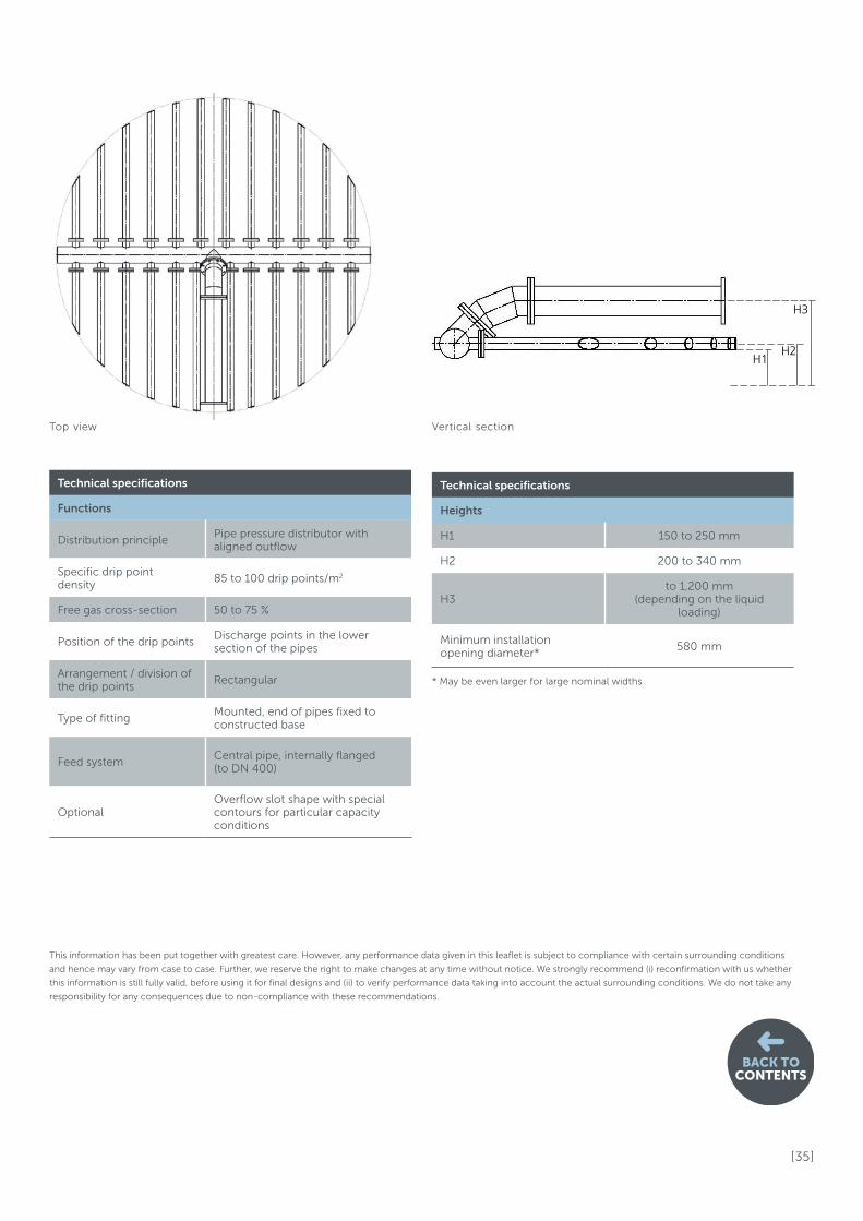
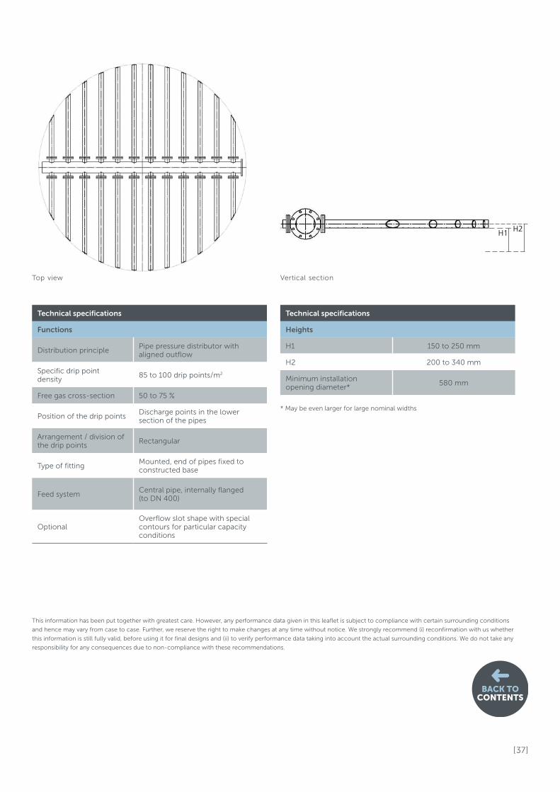
Distribution principlePipe pressure distributor with aligned outflow
Specific drip point density
85 to 100 drip points/m2
Free gas cross-section 50 to 75 %
Position of the drip pointsDischarge points in the lower section of the pipes
Arrangement / division of the drip points
Rectangular
Type of fittingMounted, end of pipes fixed to constructed base
Feed systemCentral pipe, internally flanged (to DN 400)
OptionalOverflow slot shape with special contours for particular capacity conditions
Technical specifications
Heights
H1 150 to 250 mm
H2 200 to 340 mm
H3to 1,200 mm
(depending on the liquid loading)
Minimum installation opening diameter*
580 mm
This information has been put together with greatest care. However, any performance data given in this leaflet is subject to compliance with certain surrounding conditions
and hence may vary from case to case. Further, we reserve the right to make changes at any time without notice. We strongly recommend (i) reconfirmation with us whether
this information is still fully valid, before using it for final designs and (ii) to verify performance data taking into account the actual surrounding conditions. We do not take any
responsibility for any consequences due to non-compliance with these recommendations.
Top view Vertical section
[ 36 ]
BACK TOCONTENTS
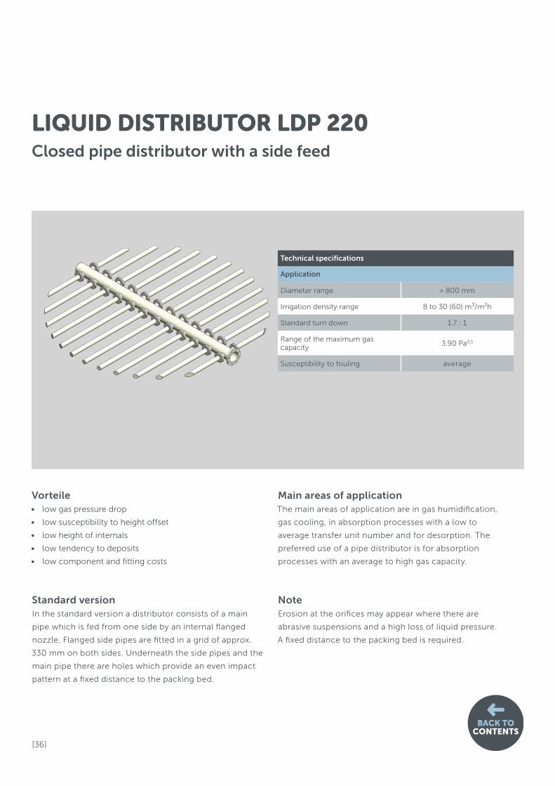
Vorteile• low gas pressure drop
• low susceptibility to height offset
• low height of internals
• low tendency to deposits
• low component and fitting costs
Standard versionIn the standard version a distributor consists of a main
pipe which is fed from one side by an internal flanged
nozzle. Flanged side pipes are fitted in a grid of approx.
330 mm on both sides. Underneath the side pipes and the
main pipe there are holes which provide an even impact
pattern at a fixed distance to the packing bed.
Main areas of applicationThe main areas of application are in gas humidification,
gas cooling, in absorption processes with a low to
average transfer unit number and for desorption. The
preferred use of a pipe distributor is for absorption
processes with an average to high gas capacity.
NoteErosion at the orifices may appear where there are
abrasive suspensions and a high loss of liquid pressure.
A fixed distance to the packing bed is required.
LIQUID DISTRIBUTOR LDP 220Closed pipe distributor with a side feed
Technical specifications
Application
Diameter range > 800 mm
Irrigation density range 8 to 30 (60) m³/m²h
Standard turn down 1.7 : 1
Range of the maximum gas capacity
3.90 Pa0,5
Susceptibility to fouling average
[ 37 ]
BACK TOCONTENTS
H1 H2
* May be even larger for large nominal widths
Technical specifications
Functions
Distribution principlePipe pressure distributor with aligned outflow
Specific drip point density
85 to 100 drip points/m2
Free gas cross-section 50 to 75 %
Position of the drip pointsDischarge points in the lower section of the pipes
Arrangement / division of the drip points
Rectangular
Type of fittingMounted, end of pipes fixed to constructed base
Feed systemCentral pipe, internally flanged (to DN 400)
OptionalOverflow slot shape with special contours for particular capacity conditions
Technical specifications
Heights
H1 150 to 250 mm
H2 200 to 340 mm
Minimum installation opening diameter*
580 mm
This information has been put together with greatest care. However, any performance data given in this leaflet is subject to compliance with certain surrounding conditions
and hence may vary from case to case. Further, we reserve the right to make changes at any time without notice. We strongly recommend (i) reconfirmation with us whether
this information is still fully valid, before using it for final designs and (ii) to verify performance data taking into account the actual surrounding conditions. We do not take any
responsibility for any consequences due to non-compliance with these recommendations.
Top view Vertical section
[ 38 ]
BACK TOCONTENTS
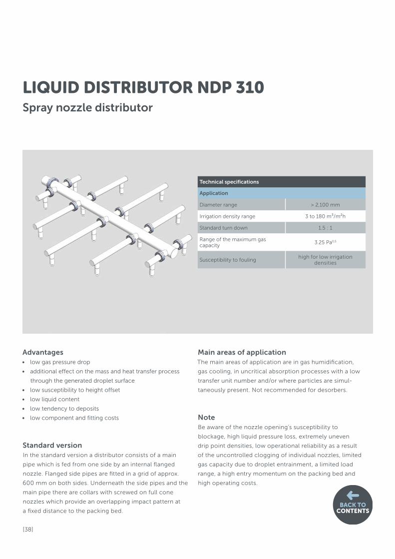
Advantages• low gas pressure drop
• additional effect on the mass and heat transfer process
through the generated droplet surface
• low susceptibility to height offset
• low liquid content
• low tendency to deposits
• low component and fitting costs
Standard versionIn the standard version a distributor consists of a main
pipe which is fed from one side by an internal flanged
nozzle. Flanged side pipes are fitted in a grid of approx.
600 mm on both sides. Underneath the side pipes and the
main pipe there are collars with screwed on full cone
nozzles which provide an overlapping impact pattern at
a fixed distance to the packing bed.
Main areas of applicationThe main areas of application are in gas humidification,
gas cooling, in uncritical absorption processes with a low
transfer unit number and/or where particles are simul-
taneously present. Not recommended for desorbers.
NoteBe aware of the nozzle opening’s susceptibility to
blockage, high liquid pressure loss, extremely uneven
drip point densities, low operational reliability as a result
of the uncontrolled clogging of individual nozzles, limited
gas capacity due to droplet entrainment, a limited load
range, a high entry momentum on the packing bed and
high operating costs.
LIQUID DISTRIBUTOR NDP 310Spray nozzle distributor
Technical specifications
Application
Diameter range > 2,100 mm
Irrigation density range 3 to 180 m³/m²h
Standard turn down 1.5 : 1
Range of the maximum gas capacity
3.25 Pa0,5
Susceptibility to fouling high for low irrigation
densities

[ 39 ]
BACK TOCONTENTS
H1
H2
Technical specifications
Functions
Distribution principle
Full cone or spiral nozzle with a spraying angle of between 90° and 120°, 0.7 bar to 1.5 bar gauge pre-pressure
Specific drip point density
0.5 to 2 drip points/m2
Free gas cross-section Greater than 90 %
Arrangement / division of the drip points
Circular or triangular
Type of fittingMounted or hung on supports, fixed with clamps
Feed system Internal radial nozzles
Optional –
Technical specifications
Heights
H1 300 to 600 mm
H2 550 to 850 mm
Minimum installation opening diameter
480 mm
This information has been put together with greatest care. However, any performance data given in this leaflet is subject to compliance with certain surrounding conditions
and hence may vary from case to case. Further, we reserve the right to make changes at any time without notice. We strongly recommend (i) reconfirmation with us whether
this information is still fully valid, before using it for final designs and (ii) to verify performance data taking into account the actual surrounding conditions. We do not take any
responsibility for any consequences due to non-compliance with these recommendations.
Top view Vertical section

[ 40 ]
BACK TOCONTENTS
Advantages• low susceptibility to height offset
• low fouling tendency
• precisely positionable feed points
• high gas capacity
• low tendency to erosion
• large load range
• low operating costs
Standard versionIn the standard version a distributor consists of a round
pan which has large gas risers in its central section. Holes
are arranged in all side walls. The liquid is fed over the
outlet holes and then via guide pipes onto the packing
bed. The distributor has a particularly high distribution
quality due to the geometric arrangement of the drip
points.
Main areas of applicationThe main areas of application are processes with mode-
rately with solids suspended liquids. For liquids near to
their solubility limit the distributor can optionally be fitted
with additional emergency overflow slots. The preferred
use of a pan distributor with side-wall holes and guide
pipes is for absorption processes with high gas capacities
and average liquid loads and with an average to high
number of transfer units.
NoteA complex design and fitting using a flange from above
are required.
LIQUID DISTRIBUTOR PDP 350Pan distributor with guide pipes, single-stage Trough distributor with side wall holes and guide pipes, 2-stage
Technical specifications
Application
Diameter range > 500 mm
Irrigation density range 12.5 to 80 m³/m²h
Standard turn down2.1 : 1
(with multiple rows of holes: 10 : 1)
Range of the maximum gas capacity
3.25 Pa0,5
Susceptibility to fouling low to average
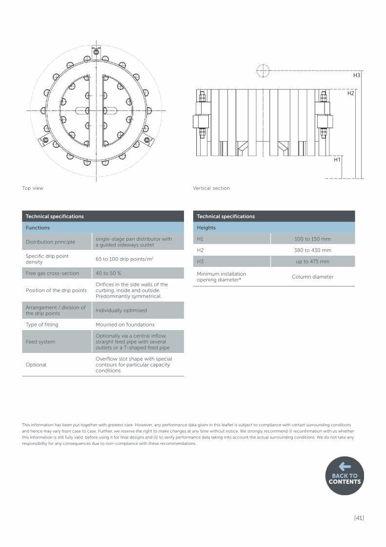
[ 41 ]
BACK TOCONTENTS
H1
H2
H3
Technical specifications
Functions
Distribution principlesingle-stage pan distributor with a guided sideways outlet
Specific drip point density
65 to 100 drip points/m2
Free gas cross-section 40 to 50 %
Position of the drip pointsOrifices in the side walls of the curbing, inside and outside. Predominantly symmetrical.
Arrangement / division of the drip points
Individually optimised
Type of fitting Mounted on foundations
Feed systemOptionally via a central inflow, straight feed pipe with several outlets or a T-shaped feed pipe
OptionalOverflow slot shape with special contours for particular capacity conditions
Technical specifications
Heights
H1 100 to 150 mm
H2 380 to 430 mm
H3 up to 475 mm
Minimum installation opening diameter*
Column diameter
This information has been put together with greatest care. However, any performance data given in this leaflet is subject to compliance with certain surrounding conditions
and hence may vary from case to case. Further, we reserve the right to make changes at any time without notice. We strongly recommend (i) reconfirmation with us whether
this information is still fully valid, before using it for final designs and (ii) to verify performance data taking into account the actual surrounding conditions. We do not take any
responsibility for any consequences due to non-compliance with these recommendations.
Top view Vertical section

[ 42 ]
BACK TOCONTENTS
3.1 Inlet and outlet nozzleFalse cross-sections, incorrect orientations and unsuitable vertical distances of the nozzles
to the packing bed or to other installations are frequently the cause for reductions in
performance or malfunctions in the application. Particularly the gas in-let nozzle must be
mentioned here.
3.1.1 Gas inlet nozzleOptimal separation assumes a uniform distribution of the gas flow speeds across the
cross-section of the column. The position and dimensions of the gas inlet nozzle influence
the gas flow significantly and must therefore be determined with care.
If the ratio of the kinetic energy at the inlet to the specific pressure loss of the packing is
too large, a gas bypass flow is likely. The gas flow collides against the opposite column
wall and then flows after the deflection at a far above-average speed in this local section
into the packing bed. This risk exists particularly for small and medium-sized columns
with a high inlet impact.
3. Dimensioning of columns
The optimisationOnce type of packing, column diameter and bed height have been fixed for the separation task, the position and size of the main gas and liquid nozzles must be dimensioned. The aim is to generate as near as possible a plug flow pattern. Following this, on-site supports, support rings, fixings and instal-lation openings must be selected.
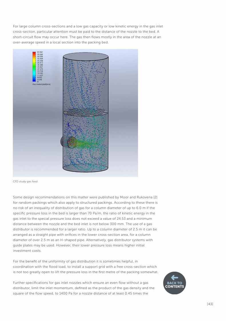
[ 43 ]
BACK TOCONTENTS
For large column cross-sections and a low gas capacity or low kinetic energy in the gas inlet
cross-section, particular attention must be paid to the distance of the nozzle to the bed. A
short-circuit flow may occur here. The gas then flows mostly in the area of the nozzle at an
over-average speed in a local section into the packing bed.
Some design recommendations on this matter were published by Moor and Rukovena [2]
for random packings which also apply to structured packings. According to these there is
no risk of an inequality of distribution of gas for a column diameter of up to 6.0 m if the
specific pressure loss in the bed is larger than 70 Pa/m, the ratio of kinetic energy in the
gas inlet to the special pressure loss does not exceed a value of 24.53 and a minimum
distance between the nozzle and the bed inlet is not below 300 mm. The use of a gas
distributor is recommended for a larger ratio. Up to a column diameter of 2.5 m it can be
arranged as a straight pipe with orifices in the lower cross-section area, for a column
diameter of over 2.5 m as an H-shaped pipe. Alternatively, gas distributor systems with
guide plates may be used. However, their lower pressure loss means higher initial
investment costs.
For the benefit of the uniformity of gas distribution it is sometimes helpful, in
coordination with the flood load, to install a support grid with a free cross-section which
is not too greatly open to lift the pressure loss in the first metre of the packing somewhat.
Further specifications for gas inlet nozzles which ensure an even flow without a gas
distributor, limit the inlet momentum, defined as the product of the gas density and the
square of the flow speed, to 1400 Pa for a nozzle distance of at least 0.45 times the
CFD study gas feed

[ 44 ]
container cross-section.
Our recommendation for the minimum nozzle distance, calculated from the centre of
the nozzle to the packing, is the simple nozzle diameter plus 300 mm. For this a
minimum pressure loss in the first metre of the packing of 70 Pa is assumed. Our
recommendation for the maximum specific inlet momentum for internally flush inlet
nozzles is 1000 Pa.
If the distance is lower, the inlet momentum is exceeded or if the pressure loss in the bed
is too low, we recommend the use of a gas distributor. Please contact our specialists on
this matter.
3.1.2 Gas outlet nozzleThe dimensioning of the gas outlet nozzle is generally determined by the droplet
separator as the last component in a column. A uniform flow must also be ensured here
through the distance to the nozzle.
For a centrally located nozzle we recommend a distance of half the column diameter
less half of the nozzle diameter plus 100 mm, but at least 300 mm. If the pressure
specifications permit, the maximum specific momentum of the gas outlet nozzle may be
up to 3400 Pa.
3.1.3 Liquid inlet nozzleFor aqueous media common practice has shown that an inlet velocity of approx.
2.5 m/s should be set for the nozzle. It is normal to use an internally flanged inlet pipe to
feed the distributor. The outflow then normally takes place in a downward direction.
If the feed involves free inflow, the aim will be to achieve a supply which is as low in
turbulence and as uniform as possible. For distributors with an upper parting box a
T-shaped feed pipe with submerged guiding pipes is recommended, for a distribution
system with 2 upper parting boxes an H-shaped feed system. Small column diameters
mostly have a centrally located feed. However, it must be ensured by the design of the
outlet that the discharge speed range is brought to less than 1.25 m/s.
By too large turbulence entry into the parting boxes, strongly fluctuating surfaces are
generated, which cause variations in volume, spillages or an overflow in the distributor
due to the entering of gas.
Our experts can, on request, design and offer you a complete distribution system
including the feed pipe distributors.
BACK TOCONTENTS
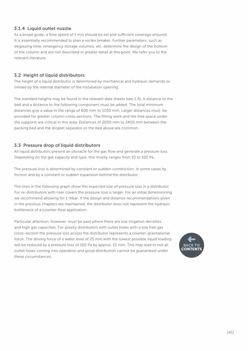
[ 45 ]
3.1.4 Liquid outlet nozzleAs a broad guide, a flow speed of 1 m/s should be set and sufficient coverage ensured.
It is essentially recommended to plan a vortex breaker. Further parameters, such as
degassing time, emergency storage volumes, etc. determine the design of the bottom
of the column and are not described in greater detail at this point. We refer you to the
relevant literature.
3.2 Height of liquid distributorsThe height of a liquid distributor is determined by mechanical and hydrauic demands or
limited by the internal diameter of the installation opening.
The standard heights may be found in the relevant data sheets (see 2.6). A distance to the
bed and a distance to the following component must be added. The total minimum
distances give a value in the range of 600 mm to 1200 mm. Larger distances must be
provided for greater column cross-sections. The fitting work and the free space under
the supports are critical in this area. Distances of 2000 mm to 2400 mm between the
packing bed and the droplet separator or the bed above are common.
3.3 Pressure drop of liquid distributorsAll liquid distributors present an obstacle for the gas flow and generate a pressure loss.
Depending on the gas capacity and type, this mostly ranges from 10 to 100 Pa.
The pressure loss is determined by constant or sudden constriction, in some cases by
friction and by a constant or sudden expansion behind the distributor.
The lines in the following graph show the expected size of pressure loss in a distributor.
For re-distributors with riser covers the pressure loss is larger. For an initial dimensioning
we recommend allowing for 1 mbar. If the design and distance recommendations given
in the previous chapters are maintained, the distributor does not represent the hydrauic
bottleneck of a counter-flow application.
Particular attention, however, must be paid where there are low irrigation densities
and high gas capacities. For gravity distributors with outlet holes with a low free gas
cross-section the pressure loss across the distributor represents a counter-gravitational
force. The driving force of a water level of 25 mm with the lowest possible liquid loading
will be reduced by a pressure loss of 100 Pa by approx. 10 mm. This may lead to not all
outlet holes coming into operation and good distribution cannot be guaranteed under
these circumstances.
BACK TOCONTENTS
[ 46 ]
BACK TOCONTENTS
When designing a distributor the minimum liquid level for this case must be increased by
the effective additional liquid level resulting from the gas pressure drop. A liquid distri-
butor does not just represent an obstacle for the gas flow but also leads to a directed
gas flow behind the distributor. Downstream components, such as droplet separators,
particularly require a uniform onflow velocity. Therefore, a sufficient height must be
planned behind a distributor so that a uniform flow can be brought about. For pipe and
nozzle distributors we recommend keeping a distance of 2 pipe diameters of the main
pipe, but at least 300 mm free.
For gravity distributors the distance between the gas outlet from the lower distribution
level and the downstream component should be at least 6 times the largest internal riser
width. Here, too, at least 300 mm above the inlet pipe should remain free.
Pre
ssu
re l
oss
[P
a]
Gas capacity factor, empty pipe, Fv [Pa˄0,5]
Pressure drop of liquid distributorsDepending on superfical gas load factor (without chimney hats and chimneys)
20% free gas cross-section
25% free gas cross-section
30% free gas cross-section
35% free gas cross-section
40% free gas cross-section
45% free gas cross-section
50% free gas cross-section
60% free gas cross-section

BACK TOCONTENTS
3.4 Sources[1] DVS guideline 2205-1
[2] F.Moore, F.Rukovena, „Liquid and gas distribution in commercial random packing
columns“, cav 1987, May, pp 33 – 41
[3] M.Hansen, „On the outflow problem“, VDI research paper 428, 1949/50
ENEXIO Water Technologies GmbH
2H Components and Solutions
Dieselweg 5, 48493 Wettringen, Germany
Phone +49 25 57 / 93 90 0, Fax +49 25 57 / 93 90 49
www.enexio.com

© E
NE
XIO
Wat
er
Tec
hn
olo
gie
s G
mb
H. A
ll ri
gh
ts r
ese
rve
d. K
2-0
7/2
018
_G
B
www.enexio.com