Embed Size (px)
Citation preview
gfgd
gfgd
1/65
Market Ready Covered Conductor Research and Developm
ent Project - Final Report - Rev. 1.1
gfgd
Market Ready Covered Conductor Research and Development Project
September 2017
Final Reportfor
Department of Environment, Land, Water and Planning (DELWP)
Document Reference GR7272-ER-05-P
Date 28th September 2017
Revision 1.1

gfgd
gfgd
2/65
Mar
ket R
eady
Cov
ered
Con
duct
or R
esea
rch
and
Deve
lopm
ent P
roje
ct - F
inal
Rep
ort -
Rev
. 1.1
Non-Disclosure Notice
The information in this document has been provided to the person or entity to whom it is addressed and shall not be disclosed to any other person or entity. It may not be reproduced in whole, or in part, nor may any of the information contained therein be disclosed without the prior consent of the project lead or directors of Groundline Limited or Groundline Australia Limited (T/A Groundline Engineering) “Groundline”. A re-cipient may not solicit, directly or indirectly (whether through an agent or otherwise) the participation of another institution or person without the prior written approval of the project lead or directors of Groundline.
The contents of this document have not been independently verified and does not purport to contain all the information that the reader may need. No representation, warranty or undertaking, expressed or implied is or will be made or given and no responsibility or liability is or will be accepted by Groundline or by any of its directors, employees or advisors in relation to the accuracy or completeness of this document or any other written or oral information made available in connection with Groundline.
Any form of reproduction, dissemination, copying, disclosure, modification, distribution and or publication of this material is strictly prohibited without the written consent of the project lead or directors of Groundline.
Rev. Description Author/Editor Reviewer Approver
1.0 (28/09/2017) Non-Confidential Re-lease D Ellis I Flatley I Flatley
1.1 (25/09/2018) Fixed spelling issues D Ellis I Flatley I Flatley
Document Control

gfgd
gfgd
3/65
Market Ready Covered Conductor Research and Developm
ent Project - Final Report - Rev. 1.1
Acknowledgements
Groundline Australia would like to acknowledge the important contribution to the success of this project by the following people and organisa-tions:
• Dr Joseph Brian Wareing (Ret.)• Jesper Svensson (Amokabel)• Fredrik Warme (Amokabel)• Christer Ohls (Amokabel)• Topi Virtanen (Ensto)• Michael Meraklis (United Energy)• Peter Livingston (United Energy)• Dave Denny (United Energy)• Professor Emad Gad (Swinburne University)• Kia Rasekhi (Swinburne University)• Dr Baraneedaran Sriskantharajah (Groundline Limited)• Ian Flatley (Groundline Limited)• Damian Ellis (Groundline Limited)• Brian Hinneberg (Advice Plus)• Jack Roughan (Fluid Limit)• Dr Peter Haberecht
Special acknowledgment and thanks to Dr Brian Wareing who retired on the 30th September 2017 following completion of this report after over 50 years of contributions to the international electrical industry. Brian imparted considerable experience and expertise in the application of covered conductor technology of which we are particularly appreciative of and has made important contributions to the success of this project. The project group and the organisations above wish Brian all the best for his well deserved retirement.

gfgd
gfgd
4/65
Mar
ket R
eady
Cov
ered
Con
duct
or R
esea
rch
and
Deve
lopm
ent P
roje
ct - F
inal
Rep
ort -
Rev
. 1.1
Executive Summary
On 19th October 2016, Groundline, in conjunction with a consortia of Participating Organisations, received a Grant of $291,375 to un-dertake testing and trials of Covered Conductor replacement options for three existing bare wire overhead conductors. The conductors tested are nominated in the Performance Specifications of the Pow-erline Bushfire Safety Program (PBSP) - Research & Development (R&D) Fund, Covered Conductor Grant Program - Guidelines docu-ment. This testing and trialling is being undertaken with investment from the PBSP - R&D Fund.
The objective of this project was to research and develop market ready covered conductor technology and associated hardware, accessories and installation techniques with the view to specific requirements for the Victorian Operating Environment. The Victorian Operating Environment was determined to be as follows:
• High summer temperatures (approximately 45°C maximum),• Low overnight winter temperatures (approximately -5°C minimum),• Very high UV exposure during summer and parts of autumn and spring months (Extreme UV exposure when considering Australian
Operating Environment),• High levels of salt spray in coastal areas,• High contaminant levels in some built up areas,• Conditions conducive to severe conductor vibration in some locations,• Potential of conductor coming into contact with trees of very high hardness level for extended periods (10+ Janka hardness rating for
many Victorian/Australian native species, proposed conductors have been tested against up to 4 Janka hardness species in Europe),
Figure 1: Powerline through bushland

gfgd
gfgd
5/65
Market Ready Covered Conductor Research and Developm
ent Project - Final Report - Rev. 1.1
• High fault currents on some assets that will potentially be replaced with covered conductor,
• Need for installation and maintenance in very remote locations (mini-mise need for very specialised tools, equipment and skills).
In relation to the above, the objective was to prove suitability of the proposed Amokabel Covered Conductor products for use in the above described Victorian Operating Environment. This was with consideration to the intent of Australian Standards, rather than meeting all prescriptive elements of some Australian Standards. These standards may not be considered relevant or are considered outdated, in addition, conductors was assessed against other international standards that were deemed relevant to the required objective of the project. Further, the overall objective of the project was to meet Recommendation 27 of the Final Report from the 2009 Victorian Bushfires Royal Commission which states:
The State amend the Regulations under Victoria’s Electricity Safety Act 1998 and otherwise take such steps as may be required to give effect to the following:
• the progressive replacement of all SWER (single-wire earth return) power lines in Victoria with aerial bundled cable, underground cabling or other technology that delivers greatly reduced bushfire risk. The replacement program should be completed in the areas of highest bushfire risk within 10 years and should continue in ar-eas of lower bushfire risk as the lines reach the end of their engineering lives
• the progressive replacement of all 22-kilovolt distribu-tion feeders with aerial bundled cable, underground ca-
Figure 2: Covered conductor product
gfgd
gfgd
6/65
Mar
ket R
eady
Cov
ered
Con
duct
or R
esea
rch
and
Deve
lopm
ent P
roje
ct - F
inal
Rep
ort -
Rev
. 1.1
bling or other technology that delivers greatly reduced bushfire risk as the feeders reach the end of their engineering lives. Priority should be given to distribution feeders in the areas of highest bushfire risk.
To meet the requirements of recommendation 27, this project sought to present a viable set of Covered Conductor types and associated hard-ware, accessories and installation techniques for bare conductor replacement for the Victorian Operating Environment.
• Suitable mechanical, electrical and environmental testing against relevant Australian and international standard to determine suitabili-ty of proposed Amokabel Covered Conductor products,
• Install lengths of a number of Amokabel Covered Conductor types on the Victorian Electrical Network to trial Amokabel Covered Con-ductor products and to develop installation methods, familiarise installation crews with product and determine required hardware and accessories required for installation in the Victorian Operating Environment.
• Determine applicable retrofit options for lines currently comprising bare overhead conductor based on the three Amokabel Covered Conductor products assessed.
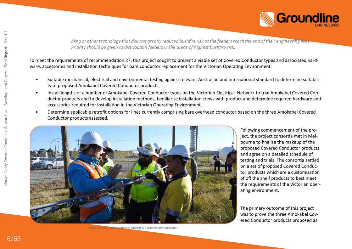
Following commencement of the pro-ject, the project consortia met in Mel-bourne to finalise the makeup of the proposed Covered Conductor products and agree on a detailed schedule of testing and trials. The consortia settled on a set of proposed Covered Conduc-tor products which are a customisation of off the shelf products to best meet the requirements of the Victorian oper-ating environment.
The primary outcome of this project was to prove the three Amokabel Cov-ered Conductor products proposed as
Figure 3: Work crew covered conductor & hardware demonstration

gfgd
gfgd
7/65
Market Ready Covered Conductor Research and Developm
ent Project - Final Report - Rev. 1.1
part of this project as suitable for the Victorian Operating Environment being;
• 25mm2 Aluminium Clad Steel (ACS) Conductor (Product newly developed by Amokabel specifically for Victoria)• 59mm2 Aluminium Conductor Steel Reinforced Conductor (ACSR) (Amokabel off the shelf product)• 159mm2 All Aluminium Alloy Conductor (AAAC) (Amokabel off the shelf product)
Following on from the above outcome, to make available to the Victorian distribution industry a viable, cost effective and proven set of Amoka-bel Covered Conductor products for use in retrofitting to existing high risk bare overhead lines within bushfire risk areas in Victoria.
The success of the intended outcomes of this project can only be measured by the level of acceptance of the proposed Amokabel Covered Conductor products by the wider Victorian distribution industry and further measured on installed kilometres of the three proposed Amokabel Covered Conductor products and other similar covered conductor products following project completion.
This report provides results of comprehensive tests pri-marily undertaken in Victoria. The comprehensive sched-ule of testing was undertaken to relevant International and Australian/New Zealand standards to determine suitability of market ready covered conductor types nominated as replacement options for existing bare wire conductor cur-rently being used in Victoria.
Figure 4: Amokabel covered conductor drums on stringing trailer

gfgd
gfgd
8/65
Mar
ket R
eady
Cov
ered
Con
duct
or R
esea
rch
and
Deve
lopm
ent P
roje
ct - F
inal
Rep
ort -
Rev
. 1.1
The testing encompassed:
• Electrical (voltage, current, resistance, current leakage, surge, and lightning strike),
• Mechanical (tension, vibration, abrasion, water penetration, and thermal),
• Exposure (UV exposure, flame and radiant heat exposure, and flora exposure).
The tests were conducted under the auspices of Profes-sor Emad Gad, Dean of Engineering, School of Engineer-ing at Swinburne University of Technology with support from Dr Baraneedaran Sriskantharajah firstly to relevant Australian standards. Where Australian standards were not available or were not deemed relevant to the con-ductor type being tested, suitable and applicable inter-national standards were sought and applied. Where a relevant standard did not exist, an appropriate test was designed in consultation between Swinburne University and the other participating organisations to determine the suitability of the proposed covered conductor prod-ucts for Victorian operating conditions.
Results from testing indicated generally that the pro-posed Covered Conductor products met or exceeded the requirements of applicable Australian/New Zealand and International standards. This project has focussed on the performance aspects of the proposed Covered Conductor products rather than on necessarily meeting
Figure 5: Stringing ACS covered conductor on SWER

gfgd
gfgd
9/65
Market Ready Covered Conductor Research and Developm
ent Project - Final Report - Rev. 1.1
the prescriptive and in some cases restrictive design requirements of Australian standards.
Following testing, two sites were selected for installation of trial sections of two of the proposed Covered Conductor replacement options. These sites have been selected to ensure a range of circuit types are trialled (SWER, single or three phase circuits) and considering a typical span for each conductor and circuit type within Victoria. In addition to the covered conductor products themselves, a range of covered conductor ac-cessories were required for the design and construction of the distribution system. The construction included non-standard materials for United Energy that were assessed and in some cases tested to measure performance against Australian and International standards. The test results were vital for United Energy to assess the level of risk present when trialling the materials on a live distribution network.
These trial sites have remained energized for more than six months without fault or concern. All required clearances and power quality metrics are being maintained with no deterioration to the equipment being trialled. The sites are being monitored on an ongoing basis through analyt-ics applied to the smart meter analytics and a more frequent inspection program.
Following completion of the trial phase of the project a final report was submitted to the Depart-ment of Environment, Land, Water and Planning for review and with a view to wider implementation of this technology within the Victorian Electrical Supply Industry.
Figure 6: Installed ACS covered conductor on SWER asset

gfgd
gfgd
10/65
Mar
ket R
eady
Cov
ered
Con
duct
or R
esea
rch
and
Deve
lopm
ent P
roje
ct - F
inal
Rep
ort -
Rev
. 1.1
This project has delivered a viable set of covered conductor products for the Victorian Operating Environment that far exceeds the performance and cost effectivness of any conductor that can be delivered in compliance with the current set of relevant Australian Standards.
Little has been done in the last twenty years or so to realistically improve the safety in design, installation and maintenance practices within the Victorian distribution (and wider transmission) industries despite the high risks associated with asset degradation and failure as a result of poor design, installation and maintenance practices. The result of this increases the risk of fire start from electrical assets and extended electri-cal supply outages. This project has demonstrated that for a relatively insignificant additional cost (long term there is expected to be a real cost saving) the use of high quality conductor, hardware and accessories and implementation of a rigorous design process and installation process to current standards and best practices, significant improvements to electrical network safety and reliability can be achieved. This project has demonstrated a viable cost efficient and rapidly deployable option to vastly improve safety of overhead lines in bushfire risk areas and is based on a three prong approach;
• Implementing sound engineering practices based on AS/NZS 7000 and other relevant international standards as part of a rigorous de-sign process
• Use of high quality and proven (through testing and overseas experience) covered conductor products and associated hardware and accessories
• Implementation of improved installation practices through development of those processes through collaboration with conductor and hardware/accessory manufacturers, asset owners, design consultants and installation services providers.
Further improvements to the safety of electrical assets will be realised as part of this project in relation to improved inspection and mainte-nance practices which have been implemented as part of the wider implications of trialling the proposed Amokabel Covered Conductor prod-ucts on the Victorian electricity network.
This project has demonstrated that the Amokabel Covered Conductor products offer significant cost advantages and installation efficiencies. Through the use of the Amokabel Covered Conductor products there is the opportunity to cover lengths of the existing bare distribution net-work many multiples over what is achievable using underground cable or other covered conductor technologies.

gfgd
gfgd
11/65
Market Ready Covered Conductor Research and Developm
ent Project - Final Report - Rev. 1.1
This project has further identified that there is a need to revise and update AS/NZS 3675 to incorporate realistic and achievable covered conduc-tor performance requirements and to bring the standard in line with equivalent international standards. This will further assist with wider indus-try acceptance of the proposed Amokabel Covered Conductor products investigated as part of this project and other similar covered conductor products in general.
Figure 7: Installation crew - Cape Schanck

gfgd
gfgd
12/65
Mar
ket R
eady
Cov
ered
Con
duct
or R
esea
rch
and
Deve
lopm
ent P
roje
ct - F
inal
Rep
ort -
Rev
. 1.1
Contents1 Project Background ............................................................17
1.1 Project Organisational Chart ................................................. 17
1.2 Project Key Personnel ........................................................... 18
1.3 Project Collaborations........................................................... 20
1.4 Amokabel Covered Conductor Technology ........................... 20
2 Project Commencement ....................................................22
2.1 Start-up Meeting (Scope Definition and Planning) ............... 22
3 TestingPreparations ..........................................................22
3.1 Electrical Testing ................................................................... 233.1.1 ResistivityTesting .................................................................233.1.2 Inter-strandConductivityTesting ........................................243.1.3 StaticAndDynamicWaterBlockingTesting ........................243.1.4 SparkTesting ........................................................................253.1.5 Four-HourHighVoltageTesting ...........................................253.1.6 InsulationResistanceTesting ...............................................253.1.7 LeakageCurrentTesting ......................................................26
3.2 Mechanical Testing ............................................................... 263.2.1 AdhesionTesting ..................................................................263.2.2 DrippingTesting ...................................................................273.2.3 ConductorStrandTesting ....................................................273.2.4 StrippingTesting ..................................................................273.2.5 VibrationTesting ..................................................................273.2.6 BendingTestingAtLowTemperature ..................................29
3.3 Environmental Testing .......................................................... 303.3.1 AbrasionTesting ...................................................................303.3.2 UV/WeatheringTesting ........................................................30
4 TestingResults ................................................................... 32
4.1 Electrical Testing ................................................................... 324.1.1 ResistivityTesting .................................................................324.1.2 Inter-strandConductivityTesting ........................................324.1.3 StaticAndDynamicWaterBlockingTesting ........................344.1.4 SparkTesting ........................................................................354.1.5 Four-HourHighVoltageTesting ...........................................354.1.6 LeakageCurrentTesting ......................................................36
4.2 Mechanical Testing ............................................................... 374.2.1 AdhesionTesting ..................................................................374.2.2 DrippingTesting ...................................................................374.2.3 ConductorStrandTesting ....................................................384.2.4 StrippingTesting ..................................................................404.2.5 VibrationTesting ..................................................................414.2.6 BendingTestAtLowTemperature .......................................43
4.3 Environmental Testing .......................................................... 444.3.1 AbrasionTesting ...................................................................444.3.2 UV/WeatheringTesting ........................................................46
5 TrialPreparation ................................................................ 50
5.1 Trial Site Selection ................................................................ 50
5.2 Design .................................................................................. 515.2.1 Preparation ..........................................................................515.2.2 ConstructionDesign ...........................................................535.2.3 ProductEvaluationAndRiskAssessment ............................53

gfgd
gfgd
13/65
Market Ready Covered Conductor Research and Developm
ent Project - Final Report - Rev. 1.1
5.3 Trial Installation And Post Installation ................................... 585.3.1 ConstructionExperience .....................................................585.3.2 InspectionAndMaintenance ..............................................595.3.3 RecommendationsForAcceptance .....................................60
6 Project Conclusion ............................................................. 62
6.1 The Objectives ...................................................................... 62
6.2 The Deliverables ................................................................... 63
6.3 The Intended Outcomes ....................................................... 64
6.4 Future Outlook...................................................................... 646.4.1 IndustryAcceptance ............................................................646.4.2 Safety,InstallationAndMaintenanceImprovements .........646.4.3 Improvement/UpdatingOfRelevantAustralianStandards 65

gfgd
gfgd
14/65
Mar
ket R
eady
Cov
ered
Con
duct
or R
esea
rch
and
Deve
lopm
ent P
roje
ct - F
inal
Rep
ort -
Rev
. 1.1
List Of FiguresFigure 1: Powerline through bushland ....................................................................................................................................................................................... 4Figure 2: Covered conductor product ......................................................................................................................................................................................... 5Figure3:Workcrewcoveredconductor&hardwaredemonstration ....................................................................................................................................... 6Figure 4: Amokabel covered conductor drums on stringing trailer ........................................................................................................................................... 7Figure 5: Stringing ACS covered conductor on SWER ................................................................................................................................................................. 8Figure 6: Installed ACS covered conductor on SWER asset ........................................................................................................................................................ 9Figure7:Installationcrew-CapeSchanck ................................................................................................................................................................................ 11Figure8:ProjectOrganisationalChart ...................................................................................................................................................................................... 17Figure9:CollaborationLinksDiagram ...................................................................................................................................................................................... 20Figure11:AmokabelCoveredConductorCross-SectionDiagrams ......................................................................................................................................... 21Figure10:AmokabelFactoryinAlstermo,Sweden .................................................................................................................................................................. 21Figure12:ProjectTeamPhoto,9thNovember2016 ............................................................................................................................................................... 22Figure13:ExcerptfromAS/NZS3675-2002-TestingRequirements ....................................................................................................................................... 23Figure15:SpectralpowerdistributionofUVA-340lampandsunlight ................................................................................................................................... 30Figure14:Abrasiontestsetupshowingtypicaltestspecimenwithlocationsofmeasurementofdiametersduringtesting ............................................... 30Figure17:UVTestingSpecimenPlate ...................................................................................................................................................................................... 31Figure16:YearlymeanofdailyUVirradiation ......................................................................................................................................................................... 31Figure18:InterstrandConductivityTestSetup ........................................................................................................................................................................ 33Figure19:TypicalViewDuringWaterBlockingTesting ............................................................................................................................................................ 34Figure20:SparkTestTypicalSetup ........................................................................................................................................................................................... 35Figure21:Four-HourHighVoltageTestingTypicalSetup......................................................................................................................................................... 36Figure22:DrippingTestSetup .................................................................................................................................................................................................. 38Figure23:TypicalStrandTensileTestingSetup ........................................................................................................................................................................ 39Figure24:StrandWrappingTestExample ................................................................................................................................................................................ 40Figure25:StrippingTestExample ............................................................................................................................................................................................. 40Figure27:TestSpanforConductorSelf-dampingTesting ........................................................................................................................................................ 41Figure26:Testspanforconductorself-dampingmeasurement ............................................................................................................................................. 41Figure28:7/2.12ACSVibrationTestingResultat15%UTSTension........................................................................................................................................ 42

gfgd
gfgd
15/65
Market Ready Covered Conductor Research and Developm
ent Project - Final Report - Rev. 1.1
Figure30:7/2.12ACSVibrationTestingResultat25%UTSTension........................................................................................................................................ 42Figure29:7/2.12ACSVibrationTestingResultat20%UTSTension........................................................................................................................................ 42Figure31:19/3.37AAACVibrationTestingResultat15%UTSTension ................................................................................................................................... 42Figure32:19/3.37AAACVibrationTestingResultat20%UTSTension ................................................................................................................................... 43Figure33:19/3.37AAACVibrationTestingResultat25%UTSTension ................................................................................................................................... 43Figure34:BendingTestatLowTemperatureExample ............................................................................................................................................................ 43Figure35:AbrasionTestingRig ................................................................................................................................................................................................. 44Figure36:AbrasionTestingExampleTestSpecimen ................................................................................................................................................................ 44Figure37:7/2.12ACSAbrasionTestingResults ....................................................................................................................................................................... 45Figure39:AbrasionTestSpecimensPostTest .......................................................................................................................................................................... 45Figure38:19/3.37AAACAbrasionTestingResult .................................................................................................................................................................... 45Figure43:Non-UVtreatedABSMaterial*-Photoorder:Intactsample,100hrsUV,200hrsUV&500hr .............................................................................. 46Figure40:HDPE/XLPECoveredConductorsample-Photoorder:Intactsample,336hrsagingtest,100hrsUV,200hrsUV&500hrsUV .......................... 46Figure41:XLPE/XLPECoveredConductorsample-Photoorder:Intactsample,100hrsUV,200hrsUV&500hrsUV .......................................................... 46Figure42:UnitedEnergyCablesample-Photoorder:Intactsample,100hrsUV,200hrsUV&500hrsUV .......................................................................... 46Figure45:HDPE/XLPEHybridCoveringMedianTensileStress(Measuredthickness) ............................................................................................................ 47Figure47:XLPE/XLPECoveringMedianTensileStress(Measuredthickness) ......................................................................................................................... 47Figure44:HDPE/XLPEHybridCoveringMedianTensileStress(Extrapolatedfor1mmthickness) ........................................................................................ 47Figure46:XLPE/XLPECoveringMedianTensileStress(Extrapolatedfor1mmthickness) ...................................................................................................... 47Figure48:HDPE/XLPEHybridCoveringMedian%Elongation(Measuredthickness) ............................................................................................................ 48Figure49:XLPE/XLPECoveringMedian%Elongation(Measuredthickness) ......................................................................................................................... 48Figure51:UESampleCoveringMedian%Elongation(Measuredthickness) ......................................................................................................................... 48Figure50:UESampleCoveringMedianTensileStress(Measuredthickness) ........................................................................................................................ 48Figure53:Non-UVTreatedABSSampleMedianTensileStress ............................................................................................................................................... 49Figure52:Non-UVTreatedABSSampleMedian%Elonation ................................................................................................................................................. 49Figure54:CapeSchanckTrialSectionRoute ............................................................................................................................................................................ 50Figure55:MordiallocTrialSectionRoute ................................................................................................................................................................................. 51Figure56:ExampleSagChartProducedforAmokabelCoveredConductor ........................................................................................................................... 52Figure57:NewProductAssessment-ThreatBarrierDiagram ................................................................................................................................................ 54Figure58:WireDown-ThreatBarrierDiagram ....................................................................................................................................................................... 57

gfgd
gfgd
16/65
Mar
ket R
eady
Cov
ered
Con
duct
or R
esea
rch
and
Deve
lopm
ent P
roje
ct - F
inal
Rep
ort -
Rev
. 1.1
Figure59:CoveredConductorInstallation ............................................................................................................................................................................... 58Figure60:VoltageandCurrentProfilePreandPostCoveredConductorInstallation ............................................................................................................ 59
List Of TablesTable1:ProjectKeyPersonnel .................................................................................................................................................................................................. 18Table2:ResistivityTestingSummaryResults ............................................................................................................................................................................ 32Table4:InterstrandConductivityTestingSummaryResults(OneStrand)............................................................................................................................... 33Table3:InterstrandConductivityTestingSummaryResults(OuterStrands) .......................................................................................................................... 33Table5:StaticWaterBlockingTestingResultsSummary ......................................................................................................................................................... 34Table7:Four-HourHighVoltageTestingResult ........................................................................................................................................................................ 35Table6:SparkTestingResult ..................................................................................................................................................................................................... 35Table8:InsulationResistanceTestingResultsSummary .......................................................................................................................................................... 36Table9:LeakageCurrentTestingResultsSummary ................................................................................................................................................................. 36Table10:AdhesionTestingSummaryResults .......................................................................................................................................................................... 37Table11:DrippingTesting ......................................................................................................................................................................................................... 37Table12:WireDiameterResultsSummary .............................................................................................................................................................................. 38Table13:UltimateTensileStressSummary .............................................................................................................................................................................. 38Table14:PercentageElongationTestSummary ....................................................................................................................................................................... 39Table16:StrippingTestResultSummary .................................................................................................................................................................................. 40Table15:WrappingTestSummary ........................................................................................................................................................................................... 40Table17:BendingTestatLowTemperatureResultSummary ................................................................................................................................................. 43Table18:Summaryoftop5risks .............................................................................................................................................................................................. 55

gfgd
gfgd
17/65
Market Ready Covered Conductor Research and Developm
ent Project - Final Report - Rev. 1.1
1 Project Background
1.1 Project Organisational Chart
IanFlatleyDirectorGroundline Engineering
DamianEllisSenior EngineerGroundline Engineering
DrBaraneedaranSriskantharajahSenior EngineerGroundline Engineering
Prof.EmadGadSenior EngineerSwinburneUniversity
JesperSvenssonCEOAmokabel
BrianHinnebergDirectorAdvice-Plus
FredrikWarmeTechnical ManagerAmokabel
ChristerOhlsProduct Development ManagerAmokabel
DrBrianWareingTechnical MentorBrianWareingTechLtd.
JackRoughanDirectorFluid Limit
PeterLivingstonSenior Asset Engineer - DistributionUnitedEnergy
MichaelMeraklisPrimary Assets ManagerUnitedEnergy
DaveDennyProject ManagerUnitedEnergy
MariaTerzakisSenior Distribution Design EngineerUnitedEnergy
KiaRasekhiTest EngineerSwinburneUniversity
IanDixHigh Voltage Lab TechnicianPowerLab Limited
NinaRodoredaSite Supervisor (Melbourne)AusTestLaboratories
InstallationCrewsDowner
DrPeterHaberechtMaterials and Durability ExpertMeterialandEnvironments(MATENV)
Figure 8: ProjectOrganisationalChart

gfgd
gfgd
18/65
Mar
ket R
eady
Cov
ered
Con
duct
or R
esea
rch
and
Deve
lopm
ent P
roje
ct - F
inal
Rep
ort -
Rev
. 1.1
1.2 Project Key Personnel
Table1:ProjectKeyPersonnel
Organisation Name Role Position
Ian Flatley Project Proponent / Oversight Director
Robert Lake Project Oversight / Technical Advisor Principal Lines Engineer (to end July 2017)
Damian Ellis Project Lead Lead Senior Lines Engineer
Dr Baraneedaran Sriskantharajah Project Testing Lead Senior Engineer (Seconded to Swinburne Uni.)
Kellie White Design Engineer Lines Engineer
Brian Hinneberg Independent Project Governance Director
Jesper Svensson Project Proponent CEO
Christer Ohls Technical Advisor / Conductor Supplier Product Development Manager
Fredrik Warme Technical Advisor Technical Manager
Professor Emad Gad Project Proponent Dean of School of Engineering
Kia Rasekhi Mechanical Testing Test Engineer
Topi Virtanen Hardware/Fittings Technical Advisor Product Manager
Dr Joseph Brian Wareing Technical Mentor CEO

gfgd
gfgd
19/65
Market Ready Covered Conductor Research and Developm
ent Project - Final Report - Rev. 1.1
Table1:ProjectKeyPersonnel
Organisation Name Role Position
Jack Roughan Technical Advisor Director
Michael Meraklis Installation and Monitoring Service Provider Distribution Team Leader
Peter Livingston Technical & Installation Advisor Senior Asset Engineer - Distribution
Craig Savage Project Proponent General Manager Asset Management
Maria Terzakis Distribution Design Engineer Senior Distribution Design Engineer
Dave Denny Installation Manager Project Manager
Dr Peter Haberecht Materials Expert

gfgd
gfgd
20/65
Mar
ket R
eady
Cov
ered
Con
duct
or R
esea
rch
and
Deve
lopm
ent P
roje
ct - F
inal
Rep
ort -
Rev
. 1.1
1.3 Project CollaborationsGroundline and Amokabel hold a Heads of Agreement and mutual Non Disclosure Document in which the collaborative effort of the parties is agreed and confirmed. Letters of support to Groundline from Amokabel, Swinburne University and United Energy have also been received and form the project collaboration links as described in the diagram below.
1.4 Amokabel Covered Conductor TechnologyAmokabel has manufactured covered conductors for use, predominant-ly in Europe, since 1997. The main two types produced are CCSX and CCST according to European standard, EN50397-1. CCSX is an XLPE, tri-ple layer covered conductor with a semi-conductive inner screen. The CCST is the thermoplastic version of the same type of conductor, which is 100% recyclable.
All production lines are equipped with hermetic gravimetric dosing units (airtight mass controlled polymer dosing process), to ensure that the highest quality plastic materials are blended to the highest accuracy and regularity. Both the CCST and the CCSX are triple extruded, which means that the semi-conductive, insulation and the jacketing materials are ex-truded in the same process to ensure 100% bonding between the layers Figure 9: CollaborationLinksDiagram

gfgd
gfgd
21/65
Market Ready Covered Conductor Research and Developm
ent Project - Final Report - Rev. 1.1
and to prevent impurities (like dust, air, etc.) in between the layers.
The covered conductors, specially designed for Victoria utilize the best from both CCSX and CCST. The insulation is XLPE, to enable high service temperature. The outer jacket is a UV and track resistant HDPE, which has very high abrasion resistance in case a branch or other foreign object scratch the jacket. The three different conductors that are intended to be used in Victoria are of different types, the largest is a 159mm2 AAAC (All Aluminium Alloy Conductor). The mid-size alternative is a 62mm2 ACSR (aluminium conductor steel reinforced). Both these are intended to be used in a conventional three phase system. The smallest and most specialized conductor is a 25mm2 ACS (aluminium clad steel conductor) with ex-cellent mechanical properties. This conductor can be used in either a three phase system or as a SWER (Single Wire Earth Return) conductor.
The design idea for the conductors proposed for Victoria has from the start been to combine well-known conductor alternatives used internationally and having a proven track record, with the design expertise of Amokabel to produce a viable set of covered conductor products for use in the Victorian environment. In particular the specially de-veloped covered conductor option for replacing small bare steel conductor SWER and three phase circuits with a covered conductor design is unique in its design including the requisite conductor covering, improved conductivity and is very high in tensile strength, while still being based on traditional bare conductor technologies that Victorian lines crews are familiar with.
In this way the products being investigated present a user friendly, safe and more cost effective product in comparison to other recently developed over-head conductor technologies and underground cable products.
Figure 10: AmokabelFactoryinAlstermo,Sweden
Figure 11: AmokabelCoveredConductorCross-SectionDiagrams

gfgd
gfgd
22/65
Mar
ket R
eady
Cov
ered
Con
duct
or R
esea
rch
and
Deve
lopm
ent P
roje
ct - F
inal
Rep
ort -
Rev
. 1.1
2 Project Commencement
2.1 Start-up Meeting (Scope Definition and Planning)Following project award on the 19th October 2016 arrangements were made for representatives from all the project participants to meet in Mel-bourne to define the project scope and assign task responsibilities for un-dertaking the work required to deliver the project. This meeting occurred within three weeks of project award and involved a panel of experts from five different countries (Finland, Sweden, United Kingdom, New Zealand and Australia.) The meeting took place over two days starting 8th Novem-ber 2016. The agenda for the meeting included a morning at Swinburne University Hawthorn Campus to inspect the laboratories where the test-ing would be undertaken, then a site visit to one of the earlier proposed trial sites near Frankston. Following this a meeting was held at United Energy’s offices in Glen Waverley involving additional personnel from United Energy. For the following day further meetings were held at Swinburne University to agree on the conductor testing requirements.
3 Testing PreparationsEarly test preparations commenced immediately after grant award, with the seeking of commercial test facilities for electrical and environmental testing that could not be undertaken with the equipment and expertise available at Swinburne University. Planning also commenced as to how Swinburne University would undertake the mechanical testing component of the project. Below is a description of the planning and intent of each form of testing undertaken on the three covered conductor types.
Figure 12: ProjectTeamPhoto,9thNovember2016

gfgd
gfgd
23/65
Market Ready Covered Conductor Research and Developm
ent Project - Final Report - Rev. 1.1
3.1 Electrical TestingInitially the consortia approached suitably accredited electrical testing labs both in Victo-ria (including a small lab in Bendigo), and interstate. However due to limited capabilities to complete the testing in the required time to meet project time-lines, or due to a lack of interest in completing the testing, the Project Management Team were forced to look outside of Victoria to find an interested lab with suitable capabilities to complete the schedule of testing required.
The Project Management Team approached PowerLab in Christchurch, New Zealand, where Groundline has an office. PowerLab confirmed that they had the technical exper-tise and capability to meet the project requirements and time-frames. Electrical testing was therefore undertaken at PowerLab Limited (http://www.powerlab.co.nz/).
Electrical testing was undertaken to Australian/New Zealand Standard AS/NZS 3675-2002 - Conductors - Covered Overhead - For working voltages 6.35/11 (12) kV up to and including 19/33 (36) kV. It is noted that a number of requirements of this standard are ei-ther outdated or excessively stringent based on comparable international standards and test methods. These matters are detailed below under the relevant test descriptions.
3.1.1 Resistivity TestingResistivity testing was undertaken on the three conductive strand types that make up the three Covered Conductor products being investigated by this project. Testing was based on that as specified in AS 1531-1991 - Conductors - Bare overhead - Aluminium and alu-
Figure 13: ExcerptfromAS/NZS3675-2002-TestingRequirements

gfgd
gfgd
24/65
Mar
ket R
eady
Cov
ered
Con
duct
or R
esea
rch
and
Deve
lopm
ent P
roje
ct - F
inal
Rep
ort -
Rev
. 1.1
minium alloy. This is referenced in Table 3.1 of AS/NZS 3675-2002.
3.1.2 Inter-strand Conductivity TestingInter-strand conductivity testing was undertaken on the three covered conductor products being investigated as part of this project. Testing was based on that specified in AS/NZS 3675-2002 Appendix C.
3.1.3 Static And Dynamic Water Blocking TestingStatic Water Blocking testing was undertaken on the 7/2.12 ACS and 19/3.26 AAAC covered conductors (smallest and largest cross section) based on AS/NZS 3675-2002 Appendix D requirements. It was decided that testing the largest and smallest cross section of conductor would provide an indicative performance for all covered conductor sizes and limit the time required to complete the testing.
It is considered that the pass criteria in AS/NZS 3675-2002 for both static and dynamic water blocking testing is overly stringent and well beyond the requirements of similar international standards. It is commonly acknowledged that it is very difficult to produce a conductor that is capable of meeting this requirement, and attempting to do so introduces other integrity issues with the conductor which are of a greater concern than the water blocking performance. This is noted in a 2006 paper by Sebire and Souprounovich for the Australian Strategic Technology Programme enti-tled, “Covered Conductors System for Distribution - Stage 2: High Voltage Covered Conductor from an Australian Perspective”. The authors stated that “the onerous water blocking requirement in AS/NZS 3675 produces a conductor covering which is eccentric. The standard also has no test for covering hardness. These result in a conductor that is difficult to use. This standard needs revision.”
Issues were experienced by PowerLab in preparing for this test due in part to the misleading apparatus listing in AS/NZS 3675-2002 Appendix D, specifically the requirement for the source of UV light to be at a wavelength of 254 nanometres. Operation of this form of light source presents a number of safety concerns particularly around use as an inspection light source. Through researching the specific requirements for the fluorescein sodium salt solution called for in the standard, it was concluded that a basic black-light was all that was required as a UV light source for this testing.
Further issues with the availability of the fluorescein sodium salt solution delayed preparations for this testing. The chemical was not available any-where in New Zealand and needed to be imported into the country. The chemical was received by the lab on the 7th April and testing immediately

gfgd
gfgd
25/65
Market Ready Covered Conductor Research and Developm
ent Project - Final Report - Rev. 1.1
commenced.
Dynamic Water Blocking testing was not completed. In consultation with Swinburne University and PowerLab it was decided to not progress with the Dynamic Water Blocking testing, on the basis that the conductors were already expected to fail the static water blocking test based on AS/NZS 3675-2002 requirements. There was therefore little additional knowledge to be gained from the more severe Dynamic Water Blocking test.
3.1.4 Spark TestingSpark testing was undertaken on the smallest of the three covered conductor products being investigated as part of this project. Testing was per-formed on one size of conductor as the test is intended to determine conductor covering performance only. Given all three covered conductor products have the same covering, results from one type of conductor is considered reflective of the performance of all conductors being investi-gated. Testing was based on that specified in AS 1660.3-1998 - Test methods for electric cables, cords and conductors - Method 3: Electrical tests. Which is referenced in Table 3.1 of AS/NZS 3675-2002.
3.1.5 Four-Hour High Voltage TestingFour-Hour High Voltage testing was undertaken on the smallest of the three covered conductor products being investigated as part of this project. Testing was based on that specified in AS 1660.3-1998 - Test methods for electric cables, cords and conductors - Method 3: Electrical tests. Which is referenced in Table 3.1 of AS/NZS 3675-2002.
3.1.6 Insulation Resistance TestingInsulation Resistance testing was undertaken on the smallest of the three covered conductor products being investigated as part of this project. Testing was based on that specified in AS/NZS 3808-2000 - Insulating and sheathing materials for electric cables, which is referenced in Table 3.1

gfgd
gfgd
26/65
Mar
ket R
eady
Cov
ered
Con
duct
or R
esea
rch
and
Deve
lopm
ent P
roje
ct - F
inal
Rep
ort -
Rev
. 1.1
of AS/NZS 3675-2002.
3.1.7 Leakage Current TestingLeakage Current testing was undertaken as an additional important test of the conductor covering performance not included in the nominated tests within AS/NZS 3675-2002. Testing was completed based on EN 50397-1-2006 - Covered conductors for overhead lines and the related acces-sories for rated voltages above 1 kV a.c. and not exceeding 36 kV a.c. - Part 1: Covered Conductors. Leakage currents pose a risk to both objects and people coming in contact with the covered conductor and to a less extent risk of fire start from contact with flammable objects.
3.2 Mechanical TestingMechanical testing was predominantly undertaken at the Hawthorn campus of Swinburne University of Technology in Melbourne. Due to the length of the area required by the test bed for the vibration testing, this testing was instead facilitated at Swinburne’s Croydon campus.
Mechanical testing was based on Australian/New Zealand Standard AS/NZS 3675-2002 - Conductors - Covered Overhead - For working voltages 6.35/11 (12) kV up to and including 19/33 (36) kV. It was noted that a number of requirements of this standard are either outdated or excessively stringent based on comparable international standards and test methods. These matters are detailed below under the relevant test descriptions.
3.2.1 Adhesion TestingAdhesion testing was undertaken on the 7/2.12 ACS and 19/3.26 AAAC covered conductor products being investigated as part of this project. It was decided that testing the largest and smallest cross sections of conductor would provide indicative performance for all covered conductor sizes and

gfgd
gfgd
27/65
Market Ready Covered Conductor Research and Developm
ent Project - Final Report - Rev. 1.1
limit the time required to complete testing. Testing was based on the requirements specified in Appendix G of AS/NZS 3675-2002.
3.2.2 Dripping TestingDripping testing was undertaken on all three of the covered conductor products being investigated as part of this project. Testing was based on the requirements specified in Appendix I of AS/NZS 3675-2002.
3.2.3 Conductor Strand TestingConductor Strand testing was undertaken on all three of the covered conductor products being investigated as part of this project. Note that individual tests were undertaken on both the aluminium and steel stranding found within the ACSR 62mm2 covered conductor specimen. Wire diameter testing was based on section 4.2 in AS 1531-1991 - Conductors - Bare overhead - Aluminium and aluminium alloy. Ultimate Tensile Stress testing was based on the method provided in AS 1391-2007 - Metallic materials - Tensile testing at ambient temperature, where the results were analysed against the results provided in Tables 2.2, 2.3, and 2.4. Percentage Elongation testing was based on the method provided in AS 1391-2007 where results were analysed against the values provided in Table 4.2. Wrapping testing was based on AS 2505.5-2002 - Metallic materials - Wire - Simple torsion test, where the results were analysed against the acceptance criteria in Table 4.3.
3.2.4 Stripping TestingStripping testing was undertaken on all three of the covered conductor products being investigated as part of this project. Testing was based on the requirements specified in Appendix F of AS/NZS 3675-2002.
3.2.5 Vibration TestingVibration testing was undertaken on the 7/2.12 ACS and 19/3.26 AAAC covered conductor products being investigated as part of this project. It was decided that testing the largest and smallest cross sections of conductor would provide indicative performance for all covered conductor

gfgd
gfgd
28/65
Mar
ket R
eady
Cov
ered
Con
duct
or R
esea
rch
and
Deve
lopm
ent P
roje
ct - F
inal
Rep
ort -
Rev
. 1.1
sizes and limit the time required to complete testing. Testing was based on AS 1154.1-2009 - Insulator and conductor fittings for overhead power lines - Performance, material, general requirements and dimensions and EN 62567-2013 - Overhead lines - Methods for testing self-damping char-acteristics of conductors.
Issues were experienced in preparing for this test due to the minimum span length required for this test. The Hawthorn campus of Swinburne University could not provide for the desired 30m span length, as such alternative locations were sought and their Croydon campus was selected.
In addition to determining exact test requirements from applicable standards, the rigging machine and test beds needed to be assembled before testing could commence.
Vibration testing was conducted to evaluate the conductor self-damping physical characteristic. The self-damping characteristic defines the con-ductor’s capacity to dissipate energy internally when subjected to vibration. For conventional stranded conductors, energy dissipation can be attributed partly to inelastic effects within the body of the wires but mostly to frictional damping, due to small relative movements between over-lapping individual wires, as the conductor flexes with the vibration wave shape.
The following standards and documents are used to find the non-dimensional viscous damping coefficient of a conductor:
• AS 1154.1-2009 Insulator and conductor fittings for overhead power lines - Performance, material, general requirements and dimen-sions
• EN62567 Overhead Lines - Methods for testing self-damping characteristics of conductors
• CIGRE: TF22.11.2 - Guide to vibration measurements on overhead lines
• There are three prescribed ways to determine the self-damping characteristics of conductors. These are:
» Power method: Determines the dissipation characteristics of a conductor by the measurement of the force and the vibration level imparted to the test span at the point of attachment to the shaker.
» ISWR method: Determines the power dissipation characteristics of a conductor by measurement of nodal and anti-nodal ampli-tudes on the span at each tunable harmonic.
» Decay method: Determines the power dissipation characteristics of a conductor by the measurement of the decay rate of the

gfgd
gfgd
29/65
Market Ready Covered Conductor Research and Developm
ent Project - Final Report - Rev. 1.1
amplitude of motion of a span following a period of forced vibration at a natural frequency and fixed amplitude.
The Power Method was adopted to evaluate the self-damping characteristic due to the anticipated cable properties, available time for testing the cable samples and simple data collection and processing function.
3.2.6 Bending Testing At Low TemperatureBending testing was undertaken on the 7/2.12 ACS type covered conductor only. As per AS/NZS 3675-2002 this is the only conductor that required testing based on a maximum diameter of 12.5mm for this type of testing. Testing was based on the requirements specified in Section 2.3 of AS/NZS 3675-2002.
A suitable testing rig was required to be fabricated in order to undertake this testing. The test rig was fabricated based on the requirements and diagrams provided in the above referenced standard.

gfgd
gfgd
30/65
Mar
ket R
eady
Cov
ered
Con
duct
or R
esea
rch
and
Deve
lopm
ent P
roje
ct - F
inal
Rep
ort -
Rev
. 1.1
3.3 Environmental Testing
3.3.1 Abrasion TestingA specific test setup had to be created for this test. In this setup, representative tim-ber segments were attached to an actuator which moved them in a linear manner (back and forth) while they are in contact with the covered conductors. This creates rubbing effects which could result from tree branches bearing against conductors. The test apparatus is shown below.
3.3.2 UV/Weathering TestingUV/Weathering testing was undertaken based on an alternative method to that specified in AS/NZS 3675-2002 Appendix H. Analysis of the testing method specified
in AS/NZS 3765, which refers to ASTM G155-Cycle 1 method and the associated intent of this test-ing method revealed that it was not an appropriate test when considering the deterioration of the mechanical properties of the cover is the primary intent of this testing. ASTM G155 is pri-marily aimed at determining the aesthetic deterioration of paint, coating materials and plastic objects that will be exposed to sunlight. It was decided that a more appropriate testing method would be used based on ASTM G154-Cycle 4. This test method exposes objects under test to a very close approximation of sunlight across wavelengths that are most damaging to polyeth-ylene based plastics at an intensity of approximately twice that of direct sunlight under worst case conditions. The test also requires exposure cycling of objects under test based on eight
Figure 14: Abrasiontestsetupshowingtypicaltestspecimenwithlocationsofmeasurementofdiameters during testing
Figure 15: Spectral power distribution of UVA-340 lamp and sunlight

gfgd
gfgd
31/65
Market Ready Covered Conductor Research and Developm
ent Project - Final Report - Rev. 1.1
hours of UV exposure at 70°C then four hours of exposure to condensation (without UV exposure) at 50°C.
Testing to ASTM G154 is typically undertaken with an expo-sure time of 1000 hours, although 500 hours and 2000 hours are also common. Given conductor coverings are designed to perform extremely well under UV/weathering exposure, it was decided to undertake testing over a period of 2000 hours. Sam-ples were taken after exposure periods of 100, 200, 500, 700, 1000, 1500, and 2000 hours to determine deterioration trends of the materials under test.
In addition to the HDPE/XLPE hybrid conductor covering under investigation, samples of XLPE/XLPE covering, the covering ma-terial used in High Voltage Aerial Bundled Cable, and samples of basic non-UV stabilised ABS material. The two additional conductor covering materials are intended for comparison with the HDPE/XLPE hybrid conductor covering material under test and the non-UV stabilised ABS material is intended for a comparison with material that is not UV stabilised and expected to deteriorate rapidly under the above specified test conditions.
Figure 16: YearlymeanofdailyUVirradiation
Figure 17: UVTestingSpecimenPlate
gfgd
gfgd
32/65
Mar
ket R
eady
Cov
ered
Con
duct
or R
esea
rch
and
Deve
lopm
ent P
roje
ct - F
inal
Rep
ort -
Rev
. 1.1
4 Testing Results
4.1 Electrical TestingThis consisted of a relevant range of tests as per the Australian Standard requirements.
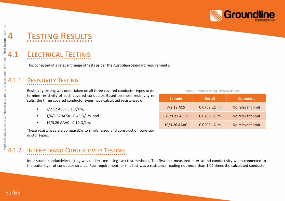
4.1.1 Resistivity TestingResistivity testing was undertaken on all three covered conductor types to de-termine resistivity of each covered conductor. Based on these resistivity re-sults, the three covered conductor types have calculated resistances of:
• 7/2.12 ACS - 3.1 Ω/km,
• 1/6/3.37 ACSR - 0.45 Ω/km, and
• 19/3.26 AAAC - 0.19 Ω/km.
These resistances are comparable to similar sized and construction bare con-ductor types.
4.1.2 Inter-strand Conductivity TestingInter-strand conductivity testing was undertaken using two test methods. The first test measured inter-strand conductivity when connected to the outer layer of conductor strands. Pass requirement for this test was a resistance reading not more than 1.02 times the calculated conductor
Table2:ResistivityTestingSummaryResults
Sample Result Comment
7/2.12 ACS 0.0769 μΩ.m No relevant limit
1/6/3.37 ACSR 0.0285 μΩ.m No relevant limit
19/3.26 AAAC 0.0295 μΩ.m No relevant limit

gfgd
gfgd
33/65
Market Ready Covered Conductor Research and Developm
ent Project - Final Report - Rev. 1.1
resistance. Results are as follows:
The second test measured inter-strand conductivity when connected to a single strand. Pass requirement for this test was a resistance reading not more than 1.02 times the result of the first test. Results are as follows:
These same conductors readily pass the individual strand tests when tested using the European method.
Subsequent discussions on this testing noted that the test setup was not as per typical European testing. However, as the full conductor test was a pass, the fail for the individual strands is less significant.
The requirement for this form of testing is as a direct result of the stringent water blocking requirement of AS/NZS 3675, which are far in excess of any other equivalent international standard. This conductor does not conform to the stringent water blocking requirements of AS/NZS 3675 (see below) and conductor strands are not pressed together in an attempt to meet the inter-strand conductivity requirements, as this results in other detrimen-tal effects to the finished conductor. Refer to paper “Covered Conductor Systems for Distribution” by Sebire and Souprounovich (2006) for further background information.
Table3:InterstrandConductivityTestingSummaryResults(OuterStrands)
Sample Result
7/2.12 ACS Pass
1/6/3.37 ACSR Pass
19/3.26 AAAC Pass
Figure 18: InterstrandConductivityTestSetup
Table4:InterstrandConductivityTestingSummaryResults(OneStrand)
Sample Result
7/2.12 ACS Fail (22% above minimum)
1/6/3.37 ACSR Fail (22% above minimum)
19/3.26 AAAC Fail (41% above minimum)

gfgd
gfgd
34/65
Mar
ket R
eady
Cov
ered
Con
duct
or R
esea
rch
and
Deve
lopm
ent P
roje
ct - F
inal
Rep
ort -
Rev
. 1.1
4.1.3 Static And Dynamic Water Blocking TestingStatic water blocking testing was undertaken as per the requirements of AS/NZS 3675-2002 Appendix D on both the 7/2.12 ACS and 19/3.26 AAAC conductors. As expected and briefly discussed above, both con-ductor types failed to meet the requirements of AS/NZS 3675-2002. It was decided to not progress with Dynamic Water Blocking Testing as per that specified in AS/NZS 3675-2002 as it was deemed that no addi-tional information would be obtained from such a test over the Static Water Blocking Testing as performed.
The stringent water blocking requirement of AS/NZS 3675, which are far in excess of any other equivalent international standard, make it imprac-tical to produce a conductor that meets this requirement as adding the excess of water blocking material required to meet this requirement has other detrimental effects on the conductor. These conductors pass the water blocking requirements of equivalent European standards which specify a maximum water penetration of one metre (compared to the AS/NZS 3675 requirement of 2mm). Refer to paper “Covered Conductor Systems for Distribution” by Sebire and Souprounovich (2006) for fur-ther background information.
AS/NZS 3675 was developed at a time when it was common practice to strip the outer layers of conductor off to make mechanical and electrical connections. The use of more recently developed water tight Insulation Piercing Connectors (IPCs) effectively negates the need for such strin-gent water blocking requirements.
Table5:StaticWaterBlockingTestingResultsSummary
Sample Result (Limit)
7/2.12 ACS Fail
19/3.26 AAAC Fail
Figure 19: TypicalViewDuringWaterBlockingTesting

gfgd
gfgd
35/65
Market Ready Covered Conductor Research and Developm
ent Project - Final Report - Rev. 1.1
4.1.4 Spark TestingSpark testing was undertaken to a DC voltage of 38 kV as per AS/NZS 1660.3 requirements. This voltage was applied to a 10m length of the 7/2.12 ACS conductor. As this test is a test of the performance of the conductor covering materials only one conductor required testing, as the covering material is the same for all covered conductors under investigation.
4.1.5 Four-Hour High Voltage TestingFour-Hour high voltage testing was undertaken based on the requirements of AS/NZS 1660.3 for cables rated between 0.6/1 kV and 19/33 kV. A five meter length of 7/2.12 ACS conductor was immersed in water at ambient temperature for twelve hours. A voltage was then applied between the con-ductor and water and gradually increased to 22 kV and held at that voltage for four hours. As this test is a test of the performance of the conductor cov-ering materials only one conductor required testing, as the covering material is the same for all covered conductors under investigation.
Table6:SparkTestingResult
Sample Result
7/2.12 ACS Pass - No breakdown of covering material
Figure 20: SparkTestTypicalSetup
Table7:Four-HourHighVoltageTestingResult
Sample Result
7/2.12 ACS Pass - No breakdown of covering material

gfgd
gfgd
36/65
Mar
ket R
eady
Cov
ered
Con
duct
or R
esea
rch
and
Deve
lopm
ent P
roje
ct - F
inal
Rep
ort -
Rev
. 1.1
Insulation Resistance TestingInsulation resistance testing was undertaken based on limits specified in AS/NZS 3808 Table 9 under the two conditions spec-ified in the standard. One being the insulation resistance at 20 °C and the other being the insulation resistance at 90 °C. Both tests were performed on the 7/2.12 ACS type conductor. Results are as follows:
4.1.6 Leakage Current TestingLeakage current testing was undertaken to EN 50397-1 for all three conductor types. The test involved wrapping a copper wire (the electrode) around each conductor type for a width of 100mm, applying a voltage of 15.4kV to the con-ductor and measuring the current leaking to ground through the electrode. Results are as follows:
Figure 21: Four-HourHighVoltageTestingTypicalSetup
Table8:InsulationResistanceTestingResultsSummary
Test Temperature Result (Limit)
20 °C Pass
90 °C Pass
Table9:LeakageCurrentTestingResultsSummary
Sample Result
7/2.12 ACS Pass
1/6/3.37 ACSR Pass
19/3.26 AAAC Pass

gfgd
gfgd
37/65
Market Ready Covered Conductor Research and Developm
ent Project - Final Report - Rev. 1.1
4.2 Mechanical TestingThis consisted of a relevant range of tests as per the Australian Standard requirements. Where no Australian Standard was applicable, tests as part of relevant International standards or internationally recognised test methods were used.
4.2.1 Adhesion TestingThe tension was applied steadily increasing it over a pe-riod of one minute up to 21% of the calculated break-ing load of the conductor and maintaining this tension for a further 10 minutes as per the requirements of AS/NZS 3675-2002 Appendix G. The change in distance be-tween various reference marks were then measured to determine changes and recorded as per the above ref-erenced standard.
The ‘Fail’ result of the 7/2.12 ACS conductor type is predominantly due to the very high tensile strength of the ACS material in comparison to the covering material and the prescriptive requirements for a pass result within AS/NZS 3675-2002 Appendix G. As a result of this test fail, only com-pression dead ends (tags/lugs) will be used for the 7/2.12 ACS conductor option.
4.2.2 Dripping TestingIn accordance with AS/NZS 3675-2002 Appendix I, the temperature inside an oven was held at 100°C and two samples each of all three conductor types were prepared and placed in the oven with a metal tray positioned under the samples in such a way that any dripping or oozing water blocking compound is caught in the tray. The samples were left in the oven for a period of 24 hours, at the end of this period the samples were removed and the samples and tray were inspected for the presence of any water blocking compound drips or oozing.
Table10:AdhesionTestingSummaryResults
Sample Result
7/2.12 ACS Fail (Reached >90% of test load)
19/3.26 AAAC Pass
Table11:DrippingTesting
Sample Comment
7/2.12 ACS Pass
1/6/3.37 ACSR Pass
19/3.26 AAAC Pass

gfgd
gfgd
38/65
Mar
ket R
eady
Cov
ered
Con
duct
or R
esea
rch
and
Deve
lopm
ent P
roje
ct - F
inal
Rep
ort -
Rev
. 1.1
4.2.3 Conductor Strand TestingTesting below was based on the requirements of AS 1531-1991 Section 4.2.
4.2.3.1 Wire Diameter
The diameter of the wire was measured and recorded.
4.2.3.2 Ultimate Tensile Stress Test
The ultimate tensile stress was calculated on the basis of the original cross-sectional area of the wire before testing.
Figure 22: DrippingTestSetup
Table12:WireDiameterResultsSummary
Sample Result
7/2.12 ACS Pass
1/6/3.37 ACSR Pass
19/3.26 AAAC Pass
Table13:UltimateTensileStressSummary
Sample Result
7/2.12 ACS Pass
1/6/3.37 ACSR (Steel) Pass
1/6/3.37 ACSR (Al) Pass
19/3.26 AAAC Pass

gfgd
gfgd
39/65
Market Ready Covered Conductor Research and Developm
ent Project - Final Report - Rev. 1.1
4.2.3.3 Percentage Elongation Test
The elongation of each sample for a gauge length of 250 mm, was not less than the appropriate values giv-en in the standards.
Table14:PercentageElongationTestSummary
Sample Average Result
7/2.12 ACS No test requirement in AS/NZS 3675
1/6/3.37 ACSR (Steel) No test requirement in AS/NZS 3675
1/6/3.37 ACSR (Al) Pass > 1.2%
19/3.26 AAAC Pass > 1.2%
Figure 23: TypicalStrandTensileTestingSetup

gfgd
gfgd
40/65
Mar
ket R
eady
Cov
ered
Con
duct
or R
esea
rch
and
Deve
lopm
ent P
roje
ct - F
inal
Rep
ort -
Rev
. 1.1
4.2.3.4 Wrapping Test
Each test specimen was wrapped around a wire of its own diameter to form a close helix of eight turns. Following this, the strands are inspected for any surface fractures. Strands also may not break during testing.
4.2.4 Stripping TestingAs per the requirements of AS/NZS 3675-2002 Appendix F, at the completion of the removal of the covering, the surface of the exposed conductor was examined and noted for any water blocking material remaining within or on the wires of the conductor.
Table15:WrappingTestSummary
Sample Comment
7/2.12 ACS Pass
1/6/3.37 ACSR (Steel) Pass
1/6/3.37 ACSR (Al) Pass
19/3.26 AAAC Pass
Figure 24: StrandWrappingTestExample
Table16:StrippingTestResultSummary
Sample Comment
7/2.12 ACS Pass
1/6/3.37 ACSR Pass
19/3.26 AAAC Pass
Figure 25: StrippingTestExample

gfgd
gfgd
41/65
Market Ready Covered Conductor Research and Developm
ent Project - Final Report - Rev. 1.1
4.2.5 Vibration TestingA schematic diagram of the test bed is shown be-low, as well as the actual test setup, in the following figures. The supports, fixtures and instruments are chosen to meet the requirements of the standards.
The test procedure used to evaluate the conductor self-damping coefficient (power method) is as follows:
1. Establish span resonance beginning at the first tunable harmonic within the pre-scribed frequency range (minimum of ten loops).
2. Measure and record the vibration frequency.
3. Locate a mid-span anti-node.
4. Adjust the anti-nodal amplitude to the prescribed level and record this value.
5. Record the input force and displacement and their phase angle differential at the driving point.
6. Measure and record the free loop length.
7. Proceed to the next tunable harmonic frequency.
8. Continue this procedure until the upper end of the required frequency range are reached.
Following capture of all required data, an analysis is undertaken to determine the self-damp-ening characteristics of the conductors under test. From this analysis the following results were obtained:
Figure 26: Testspanforconductorself-dampingmeasurement
Figure 27: TestSpanforConductorSelf-dampingTesting

gfgd
gfgd
42/65
Mar
ket R
eady
Cov
ered
Con
duct
or R
esea
rch
and
Deve
lopm
ent P
roje
ct - F
inal
Rep
ort -
Rev
. 1.1
Figure 28: 7/2.12ACSVibrationTestingResultat15%UTSTension Figure 29: 7/2.12ACSVibrationTestingResultat20%UTSTension
Figure 30: 7/2.12ACSVibrationTestingResultat25%UTSTension Figure 31: 19/3.37AAACVibrationTestingResultat15%UTSTension

gfgd
gfgd
43/65
Market Ready Covered Conductor Research and Developm
ent Project - Final Report - Rev. 1.1
4.2.6 Bending Test At Low TemperatureFollowing the requirements of AS/NZS 3675-2002 Section 2.3 the sam-ple of 7/2.12 ACS covered conductor was bent around a mandrel of approximately 55mm diameter (4.7x conductor diameter), after the conductor and apparatus were cooled in a Refrigerator (at approx. 4°C) for a period of 16 hours. Following this, the sample was inspected for cracks in the covering material.
Figure 32: 19/3.37AAACVibrationTestingResultat20%UTSTension Figure 33: 19/3.37AAACVibrationTestingResultat25%UTSTension
Figure 34: BendingTestatLowTemperatureExample
Table17:BendingTestatLowTemperatureResultSummary
Sample Result
7/2.12 ACS Pass - No breakdown of covering material
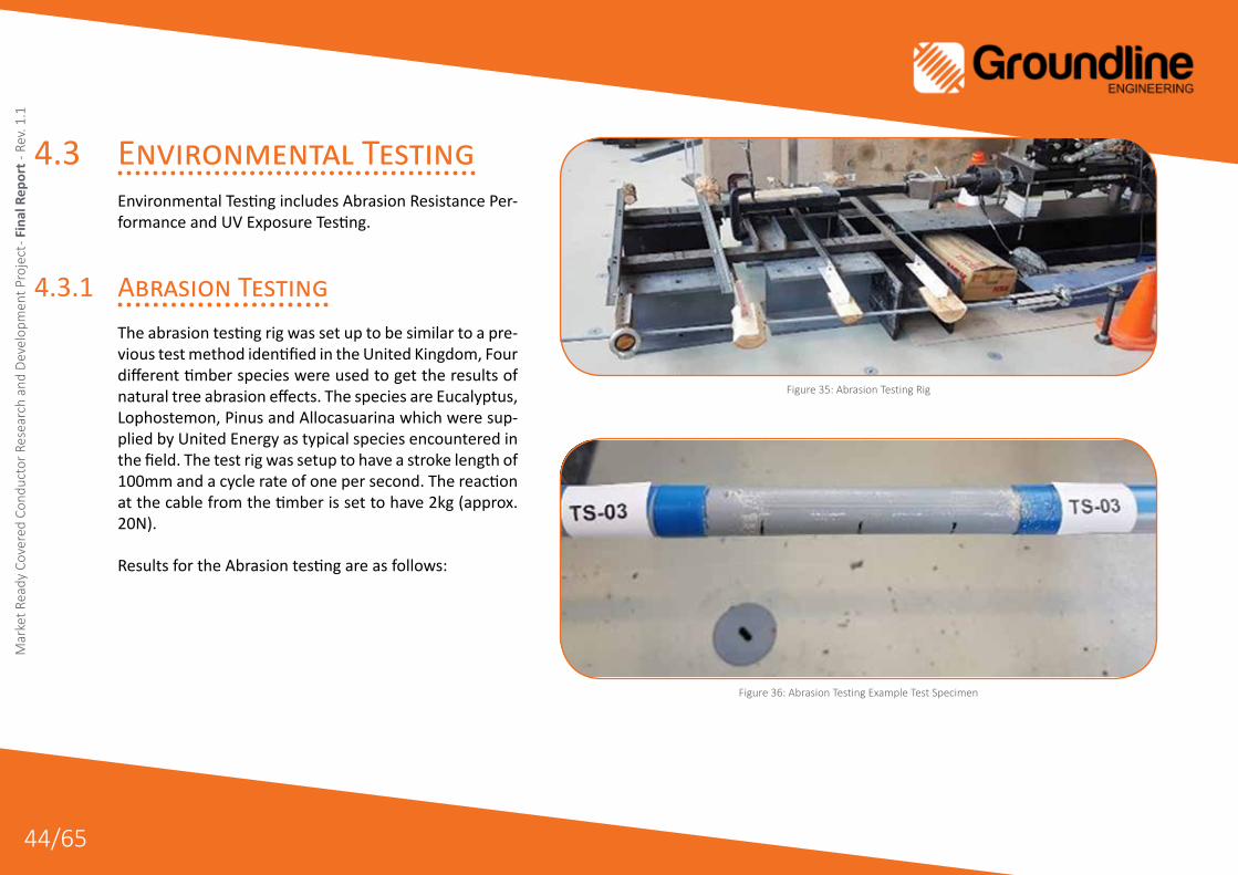
gfgd
gfgd
44/65
Mar
ket R
eady
Cov
ered
Con
duct
or R
esea
rch
and
Deve
lopm
ent P
roje
ct - F
inal
Rep
ort -
Rev
. 1.1
4.3 Environmental TestingEnvironmental Testing includes Abrasion Resistance Per-formance and UV Exposure Testing.
4.3.1 Abrasion TestingThe abrasion testing rig was set up to be similar to a pre-vious test method identified in the United Kingdom, Four different timber species were used to get the results of natural tree abrasion effects. The species are Eucalyptus, Lophostemon, Pinus and Allocasuarina which were sup-plied by United Energy as typical species encountered in the field. The test rig was setup to have a stroke length of 100mm and a cycle rate of one per second. The reaction at the cable from the timber is set to have 2kg (approx. 20N).
Results for the Abrasion testing are as follows:
Figure 35: AbrasionTestingRig
Figure 36: AbrasionTestingExampleTestSpecimen

gfgd
gfgd
45/65
Market Ready Covered Conductor Research and Developm
ent Project - Final Report - Rev. 1.1
The timber species adopted for the Abrasion testing are quite dense and hard, and are significantly harder than the earlier tests undertaken in the UK. However, it is concluded that the covered conductors performed well with the sam-ples showing material loss to below the outer covering layer after over 1,000,000 cycles.
Figure 37: 7/2.12ACSAbrasionTestingResults Figure 38: 19/3.37AAACAbrasionTestingResult
Figure 39: AbrasionTestSpecimensPostTest

gfgd
gfgd
46/65
Mar
ket R
eady
Cov
ered
Con
duct
or R
esea
rch
and
Deve
lopm
ent P
roje
ct - F
inal
Rep
ort -
Rev
. 1.1
4.3.2 UV/Weathering TestingFour different materials were tested for mechanical properties for intact (as new condition) and UV exposed conditions. The samples tested are as follows:
A. HDPE/XLPE Hybrid conductor covering material
B. XLPE/XLPE conductor covering material
C. United Energy Covering Sample
D. Non-UV Treat Sample
The UV testing was conducted as described in the ASTM G154 – Cycle 4. Accelerated test of UV-A radiation for 2000 hours (84 days) using UVA-340 lamps with 1.55W/m2/nm irradiance based on a cycle of 8 hours UV exposure at 70C black panel temp and 4 hours condensation at 50C black panel temperature. This was agreed through consultation with the project group and an exter-nal materials testing expert considering the time limitations on completing this testing.
Figure 40: HDPE/XLPECoveredConductorsample-Photoorder:Intactsample,336hrsagingtest,100hrsUV,200hrs UV & 500hrs UV
Figure 41: XLPE/XLPECoveredConductorsample-Photoorder:Intactsample,100hrsUV,200hrsUV&500hrsUV
Figure 42: UnitedEnergyCablesample-Photoorder:Intactsample,100hrsUV,200hrsUV&500hrsUV
Figure 43: Non-UVtreatedABSMaterial*-Photoorder:Intactsample,100hrsUV,200hrsUV&500hr

gfgd
gfgd
47/65
Market Ready Covered Conductor Research and Developm
ent Project - Final Report - Rev. 1.1
Figure 44: HDPE/XLPEHybridCoveringMedianTensileStress(Extrapolatedfor1mmthickness)Figure 45: HDPE/XLPEHybridCoveringMedianTensileStress(Measuredthickness)
Figure 46: XLPE/XLPECoveringMedianTensileStress(Extrapolatedfor1mmthickness)Figure 47: XLPE/XLPECoveringMedianTensileStress(Measuredthickness)
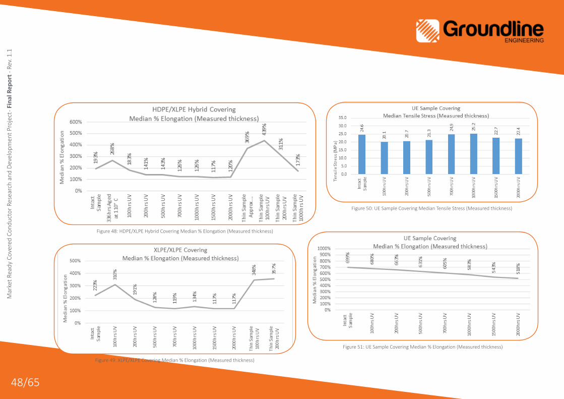
gfgd
gfgd
48/65
Mar
ket R
eady
Cov
ered
Con
duct
or R
esea
rch
and
Deve
lopm
ent P
roje
ct - F
inal
Rep
ort -
Rev
. 1.1
Figure 48: HDPE/XLPEHybridCoveringMedian%Elongation(Measuredthickness)
Figure 49: XLPE/XLPECoveringMedian%Elongation(Measuredthickness)
Figure 50: UESampleCoveringMedianTensileStress(Measuredthickness)
Figure 51: UESampleCoveringMedian%Elongation(Measuredthickness)

gfgd
gfgd
49/65
Market Ready Covered Conductor Research and Developm
ent Project - Final Report - Rev. 1.1
*Note: The non-UV treated samples could not be tested beyond 200 hours. At 500 hours and beyond, the non-UV treated samples were very brittle and disintegrated before they were removed from the test plates. The UV testing of these samples was performed for illustration purposes only.
NOTE: The listed exposure hours for the UV samples are the nominal hours (±24 hours).
The performance of the HDPE/XLPE Hybrid conductor covering material under UV exposure was shown to be better than a covering material tested in conjunction with the HDPE/XLPE material that is approved for use in Victoria (High Voltage Aerial Bundled Cable) achieving a variation of material properties in comparison with HV-ABC of 1.002 (AS/NZS3675-2002 minimum pass requirement is 0.80).
Figure 52: Non-UVTreatedABSSampleMedian%ElongationFigure 53: Non-UVTreatedABSSampleMedianTensileStress

gfgd
gfgd
50/65
Mar
ket R
eady
Cov
ered
Con
duct
or R
esea
rch
and
Deve
lopm
ent P
roje
ct - F
inal
Rep
ort -
Rev
. 1.1
5 Trial Preparation
5.1 Trial Site Selection The Business Case for the installation of the covered conductor at two trial sites on the United Energy (UE) network was approved by UE management in March 2017.
The trial provided the opportunity to evaluate a predominantly “off-the-shelf” solution with a comprehensive international in-service history. The trial locations were selected to demonstrate the capa-bility within the Australian environment of the tested covered con-ductor technologies, some of which were specifically adapted for the Victorian industry.
Two locations were been identified for the trial, being:
Cape Schanck – this is a section of SWER network (feeder RBD21) in an environmentally exposed rural area with dense coastal veg-etation that is susceptible to strong winds and salt spray. This in-stallation uses a combination of readily available covered conductor products and items specifically adapted for the Victorian industry.
Figure 54: CapeSchanckTrialSectionRoute

gfgd
gfgd
51/65
Market Ready Covered Conductor Research and Developm
ent Project - Final Report - Rev. 1.1
Mordialloc – this section is a bay-side location (feeder MC01) also susceptible to salt spray and has been chosen to allow for evaluation of the safety impacts of covered conductor in an exposed urban environment using a fully prov-en, in service covered conductor system. This is also an area with a high fault frequency and high fault current, and will allow for evaluation of the covered conductor system under electri-cal stress conditions.
5.2 Design
5.2.1 PreparationThe trial sites were surveyed to capture existing installation data as an input into the construc-tion design and to provide a benchmark for val-idation of the design post installation. To assess the likely cost to retrofit this solution to existing network infrastructure the decision was made to string the covered conductor on the existing infrastructure with the same sag and clearanc-es as that of the existing bare conductors. This was especially important as the covering on the conductor results in a heavier overall conductor that sags more that its equivalent bare conduc-tor at a given tension. Retrofitting this material
Figure 55: MordiallocTrialSectionRoute

gfgd
gfgd
52/65
Mar
ket R
eady
Cov
ered
Con
duct
or R
esea
rch
and
Deve
lopm
ent P
roje
ct - F
inal
Rep
ort -
Rev
. 1.1
to existing infrastructure will result in additional mechanical load on poles and/or reduced clear-ance to land. Providing a sample to estimate the cost implications of this consideration assists in identifying the design configuration that results in the lowest life-cycle cost for a system retrofit to existing infrastructure.
A required input to the design process is sag charts describing the sag/tension performance of covered conductors for various installed con-ditions. As these charts were not available for the required span length and tension charac-teristics for the Covered Conductors being con-sidered as part of this project, Groundline Engi-neering set about developing these charts from engineering first principles. An example of the sag charts produced is provided below:
Groundline Engineering produced a total of six sag charts for this project which are designed to match existing bare conductor sag charts. Groundline Engineering are further capable of producing additional covered conductor sag charts to any reasonable existing bare conduc-tor sag chart. Figure 56: ExampleSagChartProducedforAmokabelCoveredConductor

gfgd
gfgd
53/65
Market Ready Covered Conductor Research and Developm
ent Project - Final Report - Rev. 1.1
5.2.2 Construction Design The survey information was used in-conjunction with existing United Energy asset data, the covered conductor material spec-ifications and Groundline Engineering’s Sag and Tension charts to develop the final construction design. United Energy used nPoles overhead line design software to validate the Sag and Tension charts and bring together all these elements to cal-culate all applicable clearances and the new pole and footing loads with the new covered conductor system.
The application of the covered conductor on the existing net-work infrastructure did increase the load on the poles and foot-ings, however all serviceable poles were still within acceptable limits and the conductor installation itself did not result in any assets being overloaded or requiring replacement.
The Tension charts were used to string the covered conductor and post installation surveys performed to validate the Sag cal-culations and accuracy of the Sag charts. Following successful validation of the new stringing charts future installations will re-vert back to the standard practice of stringing by sag.
In parallel with United Energy design works, Groundline Engi-neering produced a PLS-CADD 3D line model for both the Cape Schanck and Mordialloc trial sites. The models have been devel-oped with information from United Energy’s internal databases and information obtained from site surveys of both trial sites. This includes, but is not limited to, structure orientation, struc-ture type, span lengths, conductor type, and sagging specifica-
tions. The intent of the PLS-CADD model was to verify both the sag charts produced based on engineering first principles and the line design produced by United Energy using nPoles.
5.2.3 Product Evaluation And Risk AssessmentUnited Energy have defined processes within their safety man-agement scheme for the adoption of new technology on the electricity network. These include product technical evaluation to confirm that the proposed product has been manufactured and conforms to approved industry standards, and a risk based assessment of the impact of the new equipment on operation and management of the electricity network.
Any new product must be technically assessed to determine the effect on the network and existing network assets, changes to existing work practices, and financial viability of the product. This evaluation is supported by a range of manufacturer’s in-formation that includes: application of recognised international standards throughout the life-cycle of the product evolution, certified recommendation of intended use, life-cycle testing, and installation, inspection and maintenance instructions. Eval-uation of in service experience of the product in similar environ-ments also forms part of the technical evaluation.
As such United Energy have been working closely with the cov-ered conductor system manufacturers, obtaining and reviewing technical data of the various components against the existing

gfgd
gfgd
54/65
Mar
ket R
eady
Cov
ered
Con
duct
or R
esea
rch
and
Deve
lopm
ent P
roje
ct - F
inal
Rep
ort -
Rev
. 1.1
United Energy design and construction standards. This has identified a number of deviations from the current standards, particularly where com-ponents of the covered conductor system are manufactured to comply with European standards that differ from Australian or international stand-ards. The United Energy technical evaluation has also included reviews of the testing of the various components and understanding the impact of these results on the electricity network.
The outcome of technical evaluation was a key input into the risk analysis of the covered conductor system components, where the use of the new equipment is evaluated based on the corporate United Energy risk assessment procedure. The risk assessment assesses known and potential failure modes identifying possible causes and determining appropriate controls and actions required to address the inherent risks. For the covered conductor material trialled here its deviations from existing Australian standards is addressed in the United Energy risk assessment.
Figure 57 below provides an overview of product evaluation risk assessment:
Figure 57: NewProductAssessment-ThreatBarrierDiagram

gfgd
gfgd
55/65
Market Ready Covered Conductor Research and Developm
ent Project - Final Report - Rev. 1.1
Table 18 below discusses the top 5 risks as assessed:
Table18:Summaryoftop5risks
Risk ExistingRating Cause Control Residu-
al Risk
Failure of new material - all - lead-ing to injury to personnel/public
Likely / Major
-Extreme
Standard methods for appraisal of material suitability for use are compromised;
scope of Australian standards is narrow (no Aust. Standard for covered conductor fittings)
performance criteria in existing Australian standard is inter-nationally recognized as onerous
UE does not have technical specifications for materialsdesign schedules and construction standards have not been
developed
Conduct a field trial of construction with the materials including the following;assess available test reports and material specs against Aust. and international
standardsdevelop design schedules for material and validate following construction
construction to bare construction standards with noted variations
Rare / Major
-High
Wire down - Fatality/Serious Injury with member of public, UE
staff or contractor
Possible / Major
-Very High
Live conductor not directly grounded due to insulation due to conductor/connector failure or assisted failure (vegetation,
third party contact)
Covered conductor HDPE outer coating provide strong mechanical protection and XLPE insulating layer provide electrical insulation against intermittent
contact.The lower sensitivity of protection to wire down scenario is offset by in-
creased resilience of system
Rare / Major
-High
Failure of new material - Covered Conductor CCSX 159 AAAC 22kV
W and CCSX 25 ACS 22kV W - leading to injury to personnel/
public
Possible / Major
-Very High
Damage to conductor covering/insulation due to water ingress
Avoid stripping where possible, use of insulation piercing connectors, cap cable ends, heat shrink over compression lug for CCSX 25 ACS W 22kV
Rare / Major
-High
Failure of new material - HV Insu-lation Piercing Connectors (IPC) - leading to injury to personnel/
public
Possible / Moder-
ate-
Medium
Electrical failure of materials SEW20.7, SLW26 or SLW27 when used as a branch (non-tension) connector under fault
(abnormal load) conditions
Material Complies with the testing requirements of Covered conductors for overhead lines and the related accessories for rated voltages above 1 kV AC and not exceeding 36 kV AC – Part 2: Accessories for covered conductors –
Tests and acceptance criteria for testing in combination with Amokabel BLL-T 157 AlMgSi covered conductor. Sample testing for UE of short-circuit with-
stand to 16kA for 1 sec was performedIncreased visual inspection and thermal survey frequency for trial sites
Unlikely / Mod-erate
-Medium

gfgd
gfgd
56/65
Mar
ket R
eady
Cov
ered
Con
duct
or R
esea
rch
and
Deve
lopm
ent P
roje
ct - F
inal
Rep
ort -
Rev
. 1.1
A specific risk assessment was performed as part of the material selection process looking at the impact of a “wire down” scenario. This risk as-sessment focussed on the differences between bare wire and covered conductor systems where a failure resulted in the live conductor falling to ground. Key risks identified were the likelihood of the downed conductor causing serious injury and death to a member of the public and the ability to detect the conductor on the ground.
The risk assessment determined that the likelihood of a covered conductor failure resulting in a live wire on the ground was reduced by a combi-nation of characteristics of the materials / system and the application of controls that lower the likelihood of network faults stressing of aging the assets. Bare live elements of an electrical system are exposed to environmental degradation and susceptible to contact from animals. Reducing the exposed bare elements by using a covered conductor and applying the control of using Insulation Piercing Connectors (IPCs) reduces the likelihood of network faults.
The covering on the conductor is capable of withstanding intermittent contact removing the susceptibility of the conductor to damage from clash-ing between conductors of different phases. The mechanical strength of the covering also provides an improved resistance to mechanical damage or failure from external forces and contact – from vegetation or third party contact – further lowering the likelihood of network faults.
The risk assessment recognised that a live covered conductor on the ground will be more difficult to detect than a bare conductor. Existing pro-tection techniques and settings were determined to be consistent with other utility companies employing different versions of insulated/covered
Table18:Summaryoftop5risks
Risk ExistingRating Cause Control Residu-
al Risk
Failure of new material – LV IPC used on 12.7kV network – leading
to injury to personnel/public
Possible / Moder-
ate-
Medium
Electrical failure of materials SLIW57 when used as a branch (non-tension) connector under normal load conditions
Material Complies with the testing requirements of EN 50483-4, Connector Class A1, for testing in combination with LV ABC conductor. Sample testing for UE - SLIW57 insulation piercing test at ambient temperature and short-circuit
testing with CCSX 25 ACS W 22kVIncreased visual inspection and thermal survey frequency for trial sites
Unlikely / Mod-erate
-Medium

gfgd
gfgd
57/65
Market Ready Covered Conductor Research and Developm
ent Project - Final Report - Rev. 1.1
conductors.
The reduced protection sensitivity was determined to be offset by the increased resilience of the system and subsequently the wire down risk was assessed as no worse when using covered conductor than is currently accepted with the use of bare conductor. Statistics on in-service expe-rience in Europe have demonstrated an increased resilience of covered conductor systems. UE is confident that experience gained in Australian conditions will demonstrate the increased resilience of this system and support an assessment that the risk in a wire down scenario is reduced.
Figure 58 below provides an overview of the wire down risk assessment.
Figure 58: WireDown-ThreatBarrierDiagram

gfgd
gfgd
58/65
Mar
ket R
eady
Cov
ered
Con
duct
or R
esea
rch
and
Deve
lopm
ent P
roje
ct - F
inal
Rep
ort -
Rev
. 1.1
United Energy also performed an installation specific risk as-sessment that is designed to capture the issues related to the installation of the new conductor on the network. This assess-ment identified risks and control measures related to conduc-tor stringing, field crew training, and ongoing maintenance and monitoring of the installation at the trial locations. Various con-trols were implemented to address the identified risks and up-dated throughout the installation process to ensure any learn-ings were captured and implemented as appropriate.
5.3 Trial Installation And Post Installation
5.3.1 Construction ExperienceIn general, the construction of the covered conductor is very similar to bare conductor. The use of Insulation Piercing Con-nectors (IPC), helical terminations and tie top insulators are all standard works practices on the United Energy network.
The covered conductor did however, introduce a small number of new accessories that required new construction practices. United Energy worked closely with the material suppliers and installation contractors to review the non-standard equipment and determine the appropriate works practices. The implemen-tation of depot based training provided an opportunity for the installation crews to evaluate and familiarise themselves with
the accessories and conductor for this trial.
The depot based training was supported with both United Ener-gy subject matter experts and representatives from the interna-tional suppliers (Amokabel and Ensto) present on site during the training. This provided opportunities for the installation crews to ask questions directly to the engineering and manufacturing representatives.
There were few issues experienced during the installation and the feedback from the installation teams was very positive. The installation teams appeared comfortable with the works practic-es for stringing and connecting the covered conductor and rarely relied on the United Energy subject matter experts who were available on site during the installation works to support the in-
Figure 59: Covered Conductor Installation

gfgd
gfgd
59/65
Market Ready Covered Conductor Research and Developm
ent Project - Final Report - Rev. 1.1
stallation teams.
A Post Implementation Review (PIR) was performed following the installation works. The PIR considered the design and installation phases of the covered conductor trial and allowed for the collation of feedback from the various stakeholders. Actions generated from the PIR learnings included the development of construction standards and updating training material prior to the broader adoption of the covered conductor on the network as well as implementation of increased in-service monitoring of the covered conductor at the trial locations.
5.3.2 Inspection And MaintenanceEvaluation of the in-service performance of the covered conductor will be facilitated by frequent site inspection and proactive monitoring using data and network analytics.
The covered conductor installations will be physically inspected every 6 months. This will include visual inspection – looking for connector or termination degradation, and signs of damage or bulging on the conductor covering. The covered conductor inspection will also include thermal assessment of the connectors and terminations looking for signs of overheating that could indicate degradation or failure of the connector.
The covered conductor sections will be patrolled fol-lowing faults on the feeders they are installed on spe-cifically to confirm the integrity of the system and look for signs of secondary damage such as clashing and connector, termination or tie failures.
The risk assessment identified that wire down faults may be more difficult to detect on a covered conduc-tor system. As such UE have implemented proactive monitoring of the network connected downstream of the covered conductor installations. This monitoring includes utilising AMI data for premises supplied from different substations to identify coincidental supply Figure 60: Voltage and Current Profile Pre and Post Covered Conductor Installation

gfgd
gfgd
60/65
Mar
ket R
eady
Cov
ered
Con
duct
or R
esea
rch
and
Deve
lopm
ent P
roje
ct - F
inal
Rep
ort -
Rev
. 1.1
failures that may indicate the loss of a conductor. The monitoring will initiate a notification that will trigger a patrol of the network to determine the nature of the failures. This has been implemented on both the SWER and 22kV network supplied by the covered conductor.
Network analytics data was also utilised post installation to validate that the IPC connections were applied correctly. As can be seen from Figure 60 the voltage profile for this particular substation was consistent both before and after the outage to install the covered conductor.
5.3.3 Recommendations For AcceptanceTo date, United Energy have focussed on evaluation of the covered conductor for its suitability to be trialled on the network. The performance of the covered conductor during the trial on the network forms part of the formal approval of the conductor for further operational use.
Additional to the evaluation of the trial locations, United Energy will need to consider the following prior to being able to formally approve the covered conductor for use:
• During the testing of the covered conductor it was determined that the water blocking did not meet the prescriptive requirements of AS/NZS3675-2002 however testing indicated that it will meet the equivalent European Standard requirement. The dynamic water blocking test needs to be revisited for the 25mm2 conductor and the performance of the conductor assessed against the current Euro-pean Standards.
• Independent test results for the water blocked 25mm2 ACS conductor, validating the internal testing and confirming its performance against the European Standard.
• Following failure of adhesion test on the 25mm2 conductor, the conductor was stripped and crimped to enable it to be installed to the appropriate tension and sag. During installation, it was determined that the stringing method for the smaller 25mm2 conductor needed to be revisited to enable the conductor to be strung to the tensions required for the maximum design spans. A new compres-sion lug will need to be designed to provide a connection for temporary stringing equipment separate to the permanent termination

gfgd
gfgd
61/65
Market Ready Covered Conductor Research and Developm
ent Project - Final Report - Rev. 1.1
connection.
• Improved markings on the conductor covering to facilitate positive identification of the composition of the covering.
• Engineering confirmation of the current rating of the covered conductor when compared with a similar bare conductor.
• Availability of local, ongoing support for the covered conductor product.
• Confirmation and comparison of the pricing for the covered conductor system against currently approved materials.
• Validation of in service application and history for other covered conductor installations.

gfgd
gfgd
62/65
Mar
ket R
eady
Cov
ered
Con
duct
or R
esea
rch
and
Deve
lopm
ent P
roje
ct - F
inal
Rep
ort -
Rev
. 1.1
6 Project Conclusion
6.1 The ObjectivesThe objective of this project was to research and develop market ready covered conductor technology and associated hardware, accessories and installation techniques with the view to specific requirements for the Victorian Operating Environment. The Victorian Operating Environment was determined to be as follows:
• High summer temperatures (approximately 45°C maximum),
• Low overnight winter temperatures (approximately -5°C minimum),
• Very high UV exposure during summer and parts of autumn and spring months (Extreme UV exposure when considering Australian Operating Environment),
• High levels of salt spray in coastal areas,
• High contaminant levels in some built up areas,
• Conditions conducive to severe conductor vibration in some locations,
• Potential of conductor coming into contact with trees of very high hardness level for extended periods (10+ Janka hardness rating for many Victorian/Australian native species, proposed conductors have been tested against up to 4 Janka hardness species in Europe),
• High fault currents on some assets that will potentially be replaced with covered conductor,
• Need for installation and maintenance in very remote locations (minimise need for very specialised tools, equipment and skills).
In relation to the above, the objective was to prove suitability of the proposed Amokabel Covered Conductor products for use in the above de-scribed Victorian Operating Environment. This was with consideration to the intent of Australian Standards, rather than meeting all prescriptive elements of some Australian Standards. These standards may not be considered relevant or are considered outdated, in addition, conductors was assessed against other international standards that were deemed relevant to the required objective of the project.

gfgd
gfgd
63/65
Market Ready Covered Conductor Research and Developm
ent Project - Final Report - Rev. 1.1
6.2 The DeliverablesRecommendation 27 of the Final Report from the 2009 Victorian Bushfires Royal Commission stated:
The State amend the Regulations under Victoria’s Electricity Safety Act 1998 and otherwise take such steps as may be required to give effect to the following:
• the progressive replacement of all SWER (single-wire earth return) power lines in Victoria with aerial bundled cable, under-ground cabling or other technology that delivers greatly reduced bushfire risk. The replacement program should be complet-ed in the areas of highest bushfire risk within 10 years and should continue in areas of lower bushfire risk as the lines reach the end of their engineering lives
• the progressive replacement of all 22-kilovolt distribution feeders with aerial bundled cable, underground cabling or other technology that delivers greatly reduced bushfire risk as the feeders reach the end of their engineering lives. Priority should be given to distribution feeders in the areas of highest bushfire risk.
To meet the requirements of recommendation 27, this project sought to present a viable set of Covered Conductor types and associated hard-ware, accessories and installation techniques for bare conductor replacement for the Victorian Operating Environment.
• Suitable mechanical, electrical and environmental testing against relevant Australian and international standard to determine suita-bility of proposed Amokabel Covered Conductor products,
• Install lengths of a number of Amokabel Covered Conductor types on the Victorian Electrical Network to trial Amokabel Covered Con-ductor products and to develop installation methods, familiarise installation crews with product and determine required hardware and accessories required for installation in the Victorian Operating Environment.
• Determine applicable retrofit options for lines currently comprising bare overhead conductor based on the three Amokabel Covered Conductor products assessed.

gfgd
gfgd
64/65
Mar
ket R
eady
Cov
ered
Con
duct
or R
esea
rch
and
Deve
lopm
ent P
roje
ct - F
inal
Rep
ort -
Rev
. 1.1 6.3 The Intended Outcomes
The primary outcome of this project is to prove the three Amokabel Covered Conductor products proposed as part of this project as suitable for the Victorian Operating Environment being;
• 25mm2 Aluminium Clad Steel (ACS) Conductor (Product newly developed by Amokabel specifically for Victoria)
• 62mm2 Aluminium Conductor Steel Reinforced Conductor (ACSR) (Amokabel off the shelf product)
• 159mm2 All Aluminium Alloy Conductor (AAAC) (Amokabel off the shelf product)
Following on from the above outcome, to make available to the Victorian distribution industry a viable, cost effective and proven set of Amokabel Covered Conductor products for use in retrofitting to existing high risk bare overhead lines within bushfire risk areas in Victoria.
This project has delivered a viable set of covered conductor products for the Victorian Operating Environment that far exceeds the performance and cost effectiveness of any conductor that can be delivered in compliance with the current set of relevant Australian Standards.
6.4 Future Outlook
6.4.1 Industry AcceptanceA key criterion for wider distribution industry acceptance will be through acceptance of the process undertaken as part of this project to prove viability of the proposed Amokabel Covered Conductor products and associated hardware, accessories and installation methods in the Victorian Operating Environment. This will be a contingent factor in the wider acceptance of the proposed Amokabel Covered Conductor products and as-sociated hardware and accessories by the other distribution asset owners within Victoria.
6.4.2 Safety, Installation And Maintenance ImprovementsLittle has been done in the last twenty years or so to realistically improve the safety in design, installation and maintenance practices within the Victorian distribution (and wider transmission) industries despite the high risks associated with asset degradation and failure as a result of poor

gfgd
gfgd
65/65
Market Ready Covered Conductor Research and Developm
ent Project - Final Report - Rev. 1.1
design, installation and maintenance practices. The result of this increases the risk of fire start from electrical assets and extended electrical sup-ply outages. This project has demonstrated that for a relatively insignificant additional cost (long term there is expected to be a real cost saving) the use of high quality conductor, hardware and accessories and implementation of a rigorous design process and installation process to current standards and best practices, significant improvements to electrical network safety and reliability can be achieved. This project has demonstrated a viable cost efficient option to vastly improve safety of overhead lines in bushfire risk areas and is based on a three prong approach;
• Implementing sound engineering practices based on AS/NZS 7000 and other relevant international standards as part of a rigorous design process
• Use of high quality and proven (through testing and overseas experience) covered conductor products and associated hardware and accessories
• Implementation of improved installation practices through development of those processes through collaboration with conductor and hardware/accessory manufacturers, asset owners, design consultants and installation services providers.
Further improvements to the safety of electrical assets will be realised as part of this project in relation to improved inspection and maintenance practices which have been implemented as part of the wider implications of trialling the proposed Amokabel Covered Conductor products on the Victorian electricity network.
This project has demonstrated that the Amokabel Covered Conductor products offer significant cost advantages and installation efficiencies. Through the use of the Amokabel Covered Conductor products there is the opportunity to cover lengths of the existing bare distribution network many multiples over what is achievable using underground cable or other covered conductor technologies.
6.4.3 Improvement/Updating Of Relevant Australian StandardsThis project has further identified that there is a need to revise and update AS/NZS 3675 to incorporate realistic and achievable covered conductor performance requirements and to bring the standard in line with equivalent international standards. This will further assist with wider industry acceptance of the proposed Amokabel Covered Conductor products investigated as part of this project and other similar covered conductor prod-ucts in general.